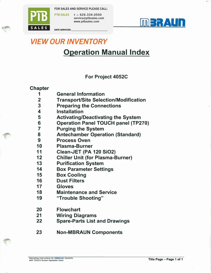
Chapter 1 2 3 4 5 6 7 8 9 10 11 12 13 14 15 16 17 18 19 20 21 22 23 lAUn Operation Manual Index For Project 4052C General Information Transport/Site Selection/Modification Preparing the Connections Installation Activating/Deactivating the System Operation Panel TOUCH panel (TP270) Purging the System Antechamber Operation (Standard) Process Oven Plasma-Burner Clean-JET (PA 120 SiO2) Chiller Unit (for Plasma-Burner) Purification System Box Parameter Settings Box Cooling Dust Filters Gloves Maintenance and Service "Trouble Shooting" Flowcha Wiring Diagrams Spare-Parts List and Drawings Non-MBRAUN Components Operating Instructions for MBRAUN-Systems with TOUCH Screen Operation Panel Title Page - Page 1 of 1

Welcome message from author
This document is posted to help you gain knowledge. Please leave a comment to let me know what you think about it! Share it to your friends and learn new things together.
Transcript
Chapter 1 2
3
4
5
6
7
8 9
10 11 12 13 14 15 16
17 18 19
20 21 22
23
Olli) lilAUn
Operation Manual Index
For Project 4052C
General Information Transport/Site Selection/Modification Preparing the Connections Installation Activating/Deactivating the System Operation Panel TOUCH panel (TP270) Purging the System Antechamber Operation (Standard) Process Oven Plasma-Burner Clean-JET (PA 120 SiO2) Chiller Unit (for Plasma-Burner) Purification System Box Parameter Settings Box Cooling Dust Filters Gloves Maintenance and Service "Trouble Shooting"
Flowchart Wiring Diagrams Spare-Parts List and Drawings
Non-MBRAUN Components
Operating Instructions for MBRAUN-Systems with TOUCH Screen Operation Panel Title Page - Page 1 of 1

r
Operating Instructions for MBRAUN - Systems with TOUCH Screen Operation Panel
Blank Page
Blank Page
Chapter 1 General Information
Contents
1.1. General lnformation .................................................................................................................................... 2
1.2. Entries Referring to the System ................................................................................................................ 2
1.3. General Safety Notice ................................................................................................................................. 3
1.4. Addresses .................................................................................................................................................... 3
Opomting Instructions for MBRAUN - Systoms with TOUCH Screen Operation Ponol General Information - Page 1 of 3
Chapter 1
1.1. General Information
General Information
This technical documentation is not liable to any obligations on the part of the manufacturer. The manufacturer MBRAUN GmbH reserves the right for technical and optical modifications as well as functional modifications on the systems or system's components described therein. Any duplication of this documentation, even in form of excerpts, is only permitted after having obtained the manufacturer's information and concession.
Tille: ........................................................................................................................................... Operating Instructions for MBRAUN - Systems with TOUCH Screen Operation Panel (TP270)
Edition: ..................................................................................................................................................... 2003 / See Tille Page for System Type
Copyright: .......................................................................................................... © 2003 MBRAUN GmbH, Dieselstrar..e 31. D-85748, Germany
1.2. Entries Referring to the System
This documentation is part of the system:
Designation / Type:
Serial number (s):
Person(s) in charge of the system:
Space left for notes on system settings, instructions for maintenance etc.
Opcrahng lnslructklns for MBRAUN - Systems with TOUCH Screen Oper3lJon Panel General Information - Page 2 of 3
Chapter 1
1.3. General Safety Notice
General Information
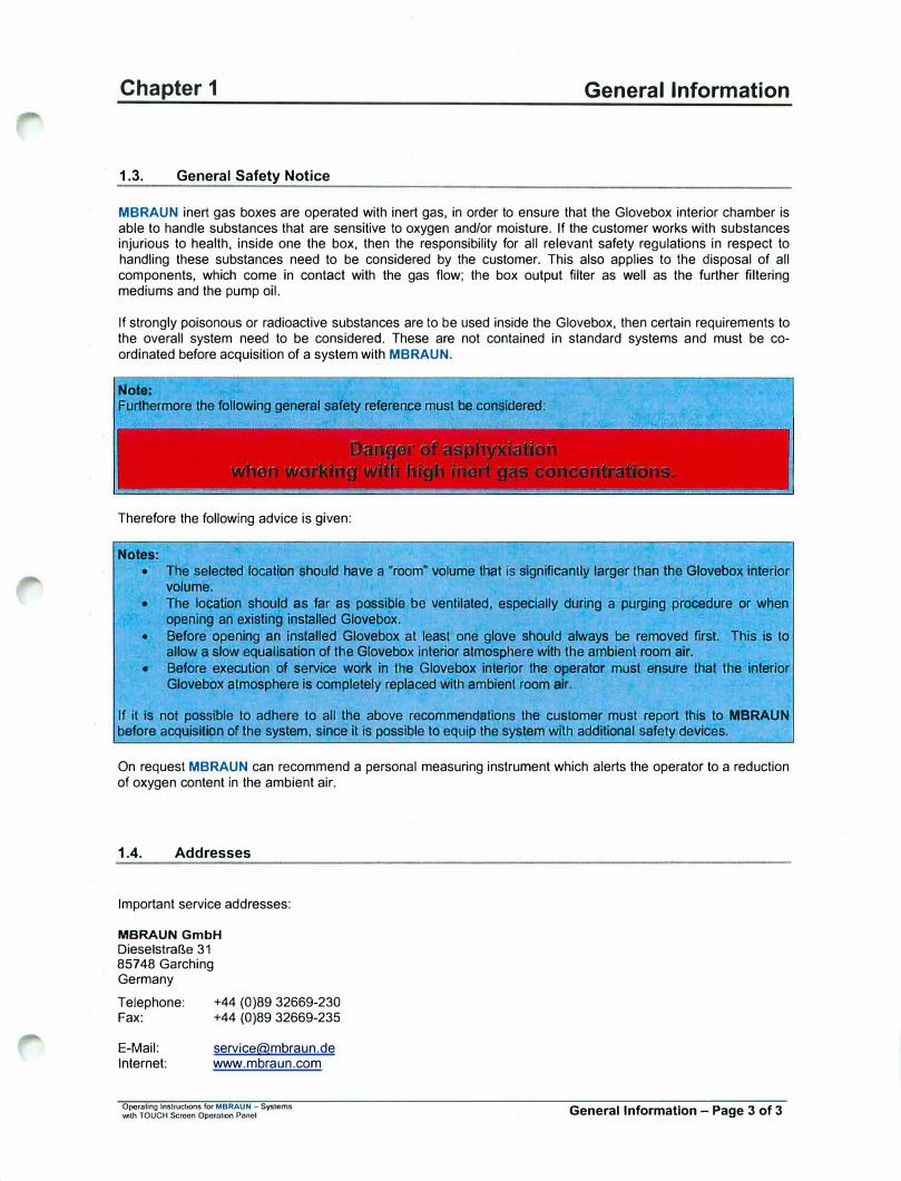
MBRAUN inert gas boxes are operated with inert gas, in order to ensure that the Glovebox interior chamber is able to handle substances that are sensitive to oxygen and/or moisture. If the customer works with substances injurious to health, inside one the box, then the responsibility for all relevant safety regulations in respect to handling these substances need to be considered by the customer. This also applies to the disposal of all components, which come in contact with the gas flow; the box output filter as well as the further filtering mediums and the pump oil.
If strongly poisonous or radioactive substances are to be used inside the Glovebox, then certain requirements to the overall system need to be considered. These are not contained in standard systems and must be coordinated before acquisition of a system with MBRAUN.
Note:
Furthermore the following general safety reference must be considered:
Therefore the following advice is given:
Notes:
• The selected location should have a "room" volume that is significantly larger than the Glovebox interiorvolume.
• The location should as far as possible be ventilated, especially during a purging procedure or whenopening an existing installed Glovebox.
• Before opening an installed Glovebox at least one glove should always be removed first. This is toallow a slow equalisation of the Glovebox Interior atmosphere with the ambient room air.
• Before execution of service work in the Glovebox interior the operator must ensure that the interiorGlovebox atmosphere is completely replaced with ambient room air.
If it is not possible to adhere to all the above recommendations the customer must report this to MBRAUN before acquisition of the system, since it is possible to equip the system with additional safety devices.
On request MBRAUN can recommend a personal measuring instrument which alerts the operator to a reduction of oxygen content in the ambient air.
1.4. Addresses
Important service addresses:
MBRAUN GmbH
Dieselstraf1e 31 857 48 Garching Germany
Telephone: Fax:
E-Mail:Internet:
+44 (0)89 32669-230+44 (0)89 32669-235
[email protected] www.mbraun.com
Oporaling Instructions for MBRAUN - Systems with TOUCH Scroon Operation Panel General Information - Page 3 of 3

Operating Instructions for MBRAUN - Systems with TOUCH Screen Operation Panel
Blank Page
Blank Page
Chapter 2
Contents
Transport / Site Selection / Modification
2.1. Transport of a System ................................................................................................................................ 2
2.2. Site Selection for a System ........................................................................................................................ 2
2.3. Modification of a System ........................................................................................................................... 2
Operating Instructions for MBRAUN - Systems with TOUCH Screen Operation Panel Transport / Site Selection / Modification - Page 1 of 2
Chapter 2
2.1. Transport of a System
Transport / Site Selection I Modification
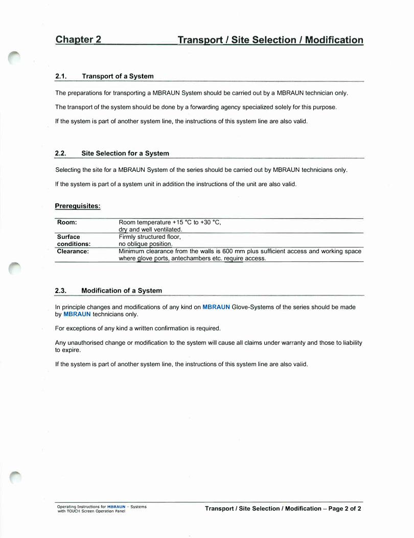
The preparations for transporting a MBRAUN System should be carried out by a MBRAUN technician only.
The transport of the system should be done by a forwarding agency specialized solely for this purpose.
If the system is part of another system line, the instructions of this system line are also valid.
2.2. Site Selection for a System
Selecting the site for a MBRAUN System of the series should be carried out by MBRAUN technicians only.
If the system is part of a system unit in addition the instructions of the unit are also valid.
Prerequisites:
Room:
Surface conditions: Clearance:
Room temperature +15 •c to +30 •c,
dry and well ventilated. Firmly structured floor, no oblique position. Minimum clearance from the walls is 600 mm plus sufficient access and working space where glove ports, antechambers etc. require access.
2.3. Modification of a System
In principle changes and modifications of any kind on MBRAUN Glove-Systems of the series should be made by MBRAUN technicians only.
For exceptions of any kind a written confirmation is required.
Any unauthorised change or modification to the system will cause all claims under warranty and those to liability to expire.
If the system is part of another system line, the instructions of this system line are also valid.
Operating Instructions for MBRAUN - Systems with TOUCH Screen Operation Panel Transport/ Site Selection / Modification - Page 2 of 2
Chapter 3 Preparing the Connections
Contents
3.1. General lnformation .................................................................................................................................... 2
3.2. Working Gases ............................................................................................................................................ 2 3.2.1. Working Gas .......................................................................................................................................... 2 3.2.2. Regeneration Gas ................................................................................................................................. 2 3.2.3. Purge Gas .............................................................................................................................................. 2
3.3. Equipment for Connections ....................................................................................................................... 3 3.3.1. Equipment for Working Gas Connections ............................................................................................. 3 3.3.2. Equipment for Regeneration Gas Connections ..................................................................................... 3 3.3.3. Equipment for Purge Gas ..................................................................................................................... .4 3.3.4. Equipment for Vacuum Pumps ............................................................................................................. .4 3.3.5. Equipment for the Water Cooling .......................................................................................................... 5 3.3.6. Power Connection ................................................................................................................................. 5
Operating Instructions for MBRAUN - Systems with TOUCH Screen Operation Panel Preparing the Connections - Page 1 of 5
Chapter 3 Preparing the Connections
3.1. General Information
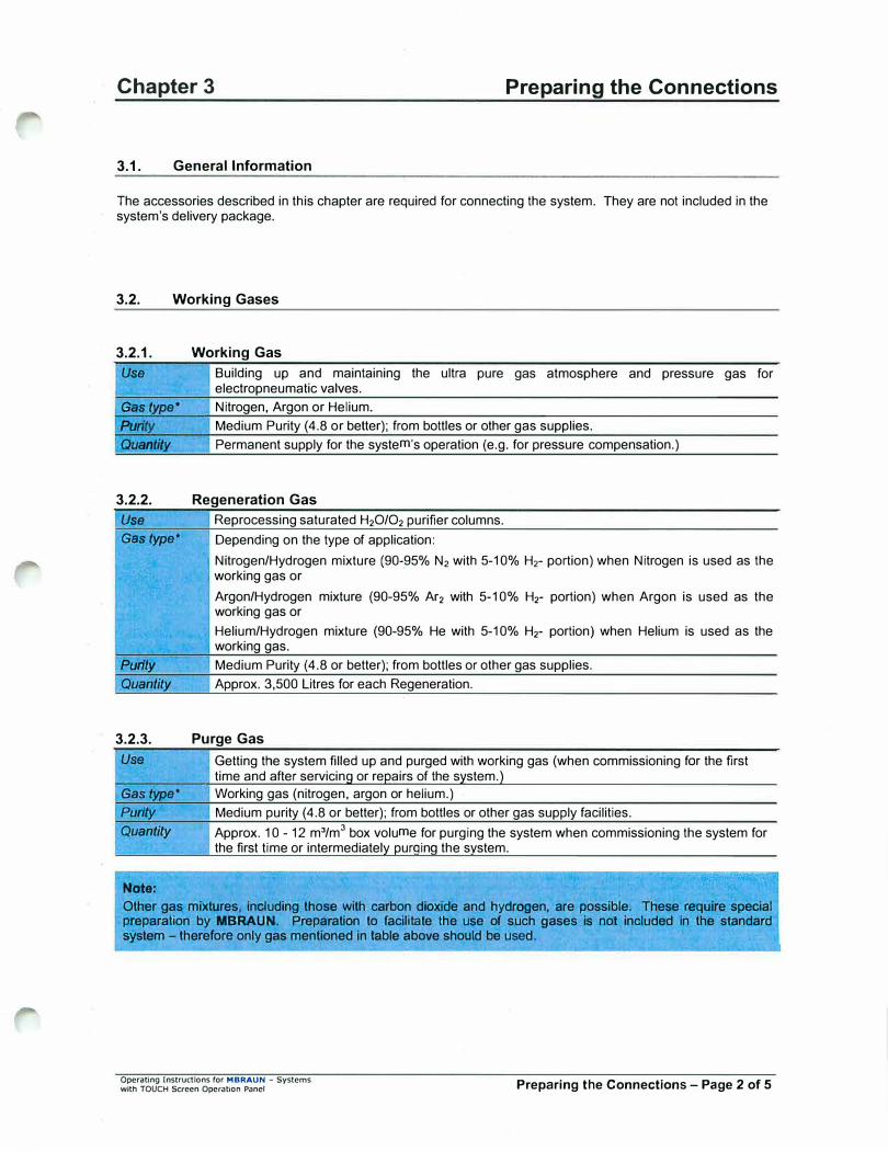
The accessories described in this chapter are required for connecting the system. They are not included in the system's delivery package.
3.2. Working Gases
3.2.1. Working Gas
Use Building up and maintaining electropneumatic valves.
Gas type• Nitrogen, Argon or Helium.
the ultra pure gas atmosphere
Purity Medium Purity (4.8 or better); from bottles or other gas supplies.
and pressure
Quantity Permanent supply for the system's operation (e.g. for pressure compensation.)
3.2.2. Regeneration Gas
Use Reprocessing saturated H2O/O2 purifier columns.
Gas type* Depending on the type of application:
gas for
Nitrogen/Hydrogen mixture (90-.95% N2 with 5-10% H2- portion) when Nitrogen is used as the working gas or
Argon/Hydrogen mixture (90-95% Ar2 with 5-10% Hr portion) when Argon is used as the working gas or
Helium/Hydrogen mixture (90-95% He with 5-10% Hr portion) when Helium is used as the working gas.
Purity Medium Purity (4.8 or better); from bottles or other gas supplies.
Quantity Approx. 3,500 Litres for each Regeneration.
3.2.3. Purge Gas
Use Getting the system filled up and purged with working gas (when commissioning for the first time and after servicing or repairs of the system.)
Gas type* Working gas (nitrogen, argon or helium.)
Purity Medium purity (4.8 or better); from bottles or other gas supply facilities.
Quantity Approx. 10 - 12 m3/m3 box volume for purging the system when commissioning the system for
the first time or intermediately purqinq the system.
Note:
Other gas mixtures, including those with carbon dioxide and hydrogen, are possible. These require special preparation by MBRAUN. Preparation to facilitate the use of such gases is not included in the standard system - therefore only gas mentioned in table above should be used.
Operating Instructions for MBRAUN - Systems with TOUCH Screen Operation Panel Preparing the Connections - Page 2 of 5

Chapter 3 Preparing the Connections
3.3. Equipment for Connections
Prior to delivery of the system the user will receive an information sheet specifying the necessary accessories required to make the connections. The following specifications are a general overview.
3.3.1. Equipment for Working Gas Connections
Pressure Reducing Valve for Working Gas
Use working gas pressure control system.
Material 200 bar primary, 5.5-6.0 bar secondary, with a flow rate of 200 I/min
Connection type 0 9 mm hose or 0 10 mm Swagelok"' fitting.
Supply Piping for Working Gas
Use Connecting the working gas source with the "Working Gas INLET" system connection.
Material Optional (length as required):
either: 0 9 mm reinforced hose, 3 mm wall thickness and adapter, 0 9 mm hose nozzle with 0 10 mm Swagelok
® fitting
or: 0 10 mm copper pipe and 0 10 mm Swagelok® fitting
or: 0 10 mm stainless steel pipe and 0 10 mm Swagelok® fitting.
Connection type 0 9 mm hose nozzle or 0 10 mm Swagelok® fitting.
3.3.2. Equipment for Regeneration Gas Connections
Note:
MBRAUN recommends ffie use of a special pressure red1,1ci11g valve fitted with a n1am-standard secondary 9auge that is calibrated between O - 1.5 mbar. This is available from MBRAUN - Part No. 2411006.
Pressure Reducing Valve for Regeneration Gas
Use Regeneration pressure control system.
Material 200 bar primary, 0.3-0.4 bar secondary, with a flow rate of 20 I/min
Connection type 0 9 mm hose or 0 10 mm Swagelok"' fitting.
Supply Piping for Regeneration Gas
Use Connecting the working gas source with the "Regeneration Gas INLET" system connection.
Material Optional (length as required):
either: 0 9 mm reinforced hose, 3 mm wall thickness and adapter, 0 9 mm hose nozzle with 0 10 mm Swagelok
® fitting
or: 0 10 mm copper pipe and 0 10 mm Swagelok® fitting or: 0 10 mm stainless steel pipe and 0 1 0 mm Swaqelok® fittinq.
Connection type 0 9 mm hose nozzle or 0 10 mm Swagelok"' fit1ing.
Operating Instructions for MBRAUN - Systems with TOUCH Screen Operation Panel Preparing the Connections - Page 3 of 5
Chapter 3 Preparing the Connections
Exhaust Outlet for Waste Regeneration Gas
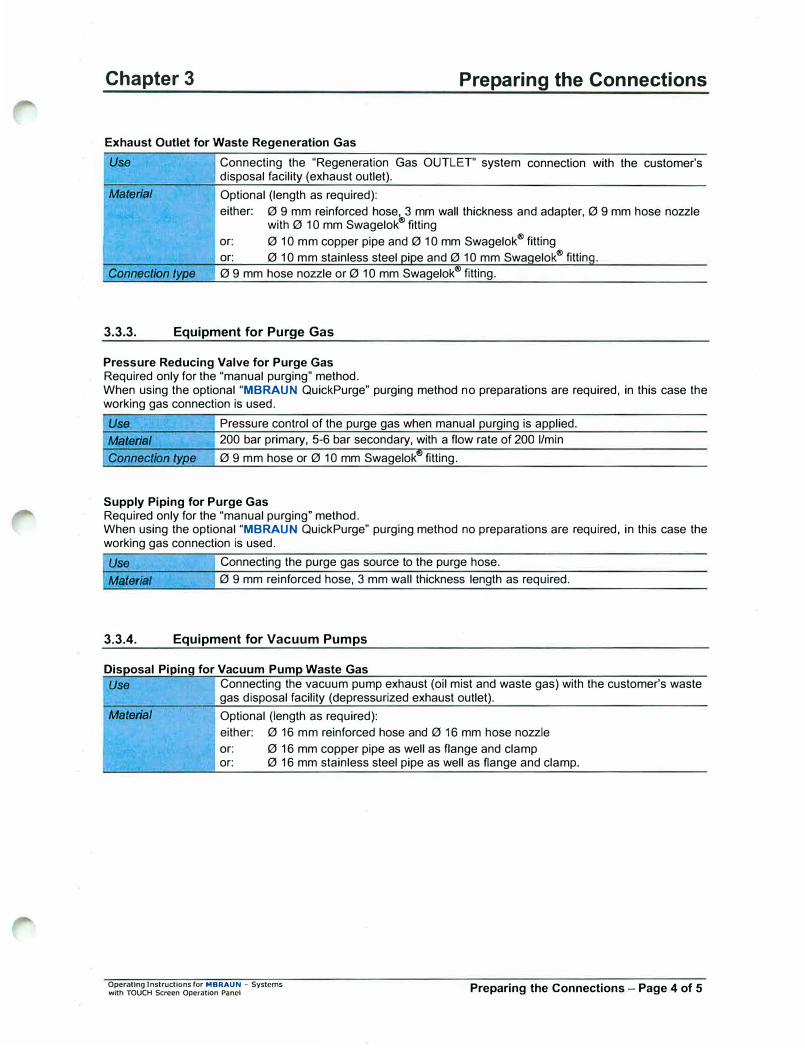
Use Connecting the "Regeneration Gas OUTLET" system connection with the customer's disposal facility (exhaust outlet).
Material Optional (length as required):
either: 0 9 mm reinforced hose, 3 mm wall thickness and adapter, 0 9 mm hose nozzle with 0 10 mm Swagelok
® fitting
or: 0 10 mm copper pipe and 0 10 mm Swagelok®
fitting
or: 0 10 mm stainless steel oioe and 0 10 mm Swaaelok®
fittina.
Connection type 0 9 mm hose nozzle or 0 10 mm Swagelok®
fitting.
3.3.3. Equipment for Purge Gas
Pressure Reducing Valve for Purge Gas Required only for the "manual purging" method. When using the optional "MBRAUN QuickPurge" purging method no preparations are required, in this case the working gas connection is used.
Use Pressure control of the purge gas when manual purging is applied.
Material 200 bar primary, 5-6 bar secondary, with a flow rate of 200 I/min
Connection type 0 9 mm hose or 0 10 mm Swagelok®
fitting.
Supply Piping for Purge Gas Required only for the "manual purging" method. When using the optional "MBRAUN QuickPurge" purging method no preparations are required, in this case the working gas connection is used.
Use Connecting the purge gas source to the purge hose.
Material 0 9 mm reinforced hose, 3 mm wall thickness length as required.
3.3.4. Equipment for Vacuum Pumps
Disoosal Pioina for Vacuum Pumo Waste Gas
Use Connecting the vacuum pump exhaust (oil mist and waste gas) with the customer's waste gas disposal facility (depressurized exhaust outlet).
Material Optional (length as required):
either: 0 16 mm reinforced hose and 0 16 mm hose nozzle
or: 0 16 mm copper pipe as well as flange and clamp or: 0 16 mm stainless steel pipe as well as flange and clamp.
Operating lnstructlons for MBRAUN - Systems with TOUCH Screen Operation Panel Preparing the Connections - Page 4 of 5
Chapter 3 Preparing the Connections
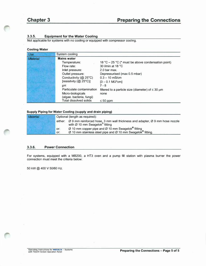
3.3.5. Equipment for the Water Cooling
Not applicable for systems with no cooling or equipped with compressor cooling.
Cooling Water
Use
Material
System cooling
Mains water
Temperature:
Flow rate:
Inlet pressure:
Outlet pressure:
Conductivity(@ 25°C)
[resisitvity (@ 25°C))
pH
18 •c - 25 •c (* must be above condensation point)
30 I/min at 18 •c
2.0 bar max.
Depressurised (max 0.5 mbar)
0.3-10 mS/cm
(3 - 0.1 MQ*cm] 7-8
Particulate contamination filtered to a particle size (diameter) of s 30 µm
Micro-biologicals (algae. bacteria, fungi) Total dissolved solids
none
s 50 ppm
Supply Piping for Water Cooling (supply and drain piping)
Material Optional (length as required):
3.3.6.
either: 0 9 mm reinforced hose, 3 mm wall thickness and adapter, 0 9 mm hose nozzle with 0 10 mm Swagelok
® fitting
or: 0 10 mm copper pipe and 0 10 mm Swagelok®
fitting or: 0 10 mm stainless steel pipe and 0 10 mm Swagelok
® fitting.
Power Connection
For systems, equipped with a MB200, a HT3 oven and a pump fill station with plasma burner the power connection must meet the criteria below:
50 kW @ 400 V 50/60 Hz.
Operating Jnstructions for MBRAUN - Systems with TOUCH Screen Operation Panel Preparing the Connections - Page 5 of 5

Opomllng Instructions for MBRAUN - Systems with TOUCH Screen Operation Panel
Blank Page
Blank Page

Chapter4 Installation
Contents
4.1. Safety Instructions ..................................................................................................................................... 2
4.2. Connecting the System .............................................................................................................................. 2 4.2.1. Connecting the Working Gas ................................................................................................................. 2 4.2.2. Connecting the Regeneration Gas ........................................................................................................ 2 4.2.3. Connecting the Disposal Piping for Used Regeneration Gas ............................................................... 3 4.2.4. Connecting the Disposal Piping for Vacuum Waste Gases .................................................................. 3 4.2.5. Connecting the Cooling Water ............................................................................................................... 3 4.2.6. Electric Power Connection .................................................................................................................... 3
Operating lnsbucllona for MBRAUN - Systems with TOUCH Screen Operation Panel Installation - Page 1 of 3
Chapter 4
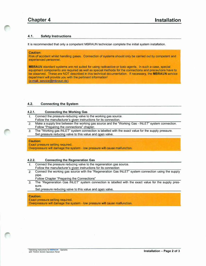
4.1. Safety Instructions
Installation
It is recommended that only a competent MBRAUN technician complete the initial system installation.
Caution: Risk of accident whilst handling gases. Connection of systems should only be carried out by competent and experienced personnel.
MBRAUN standard systems are not suited for using radioactive or toxic agents. In such a case, special equipment components are required as well as special methods for the connections and precautions have to be observed. These are NOT described in this technical documentation. If necessary, the MBRAUN service department will provide you with the pertinent information! (e-mail: [email protected])
4.2. Connecting the System
4.2.1. Connecting the Working Gas
1. Connect the pressure-reducing valve to the working gas source.Follow the manufacturer's given instructions for its connection.
2. Make a supply line between the working gas source and the "Working Gas - INLET" system connection.Follow "Preparing the connections" chapter.
3. The "Working gas INLET" system connection is labelled with the exact value for the supply pressure.Set pressure reducing valve to this value and open valve.
Caution: Exact pressure setting required. Overpressure will damage the system - low pressure will cause malfunction.
---��---------
4.2.2. Connecting the Regeneration Gas
1. Connect the pressure reducing valve to the regeneration gas source.Follow the manufacturer's given instructions for its connection
2. Connect the working gas source with the "Regeneration Gas INLET" system connection using the supplypipe.Follow Chapter "Preparing the Connections"
3. The "Regeneration Gas INLET" system connection is labelled with the exact value for the supply pressure.Set pressure reducing valve to this value and open valve.
Caution: Exact pressure setting required. Overpressure will damage the system - low pressure will cause malfunction.
Opcraling lnslrucbOnS for MBRAUN - Systoms with TOUCH Screen Operation Panol Installation - Page 2 of 3
Chapter 4
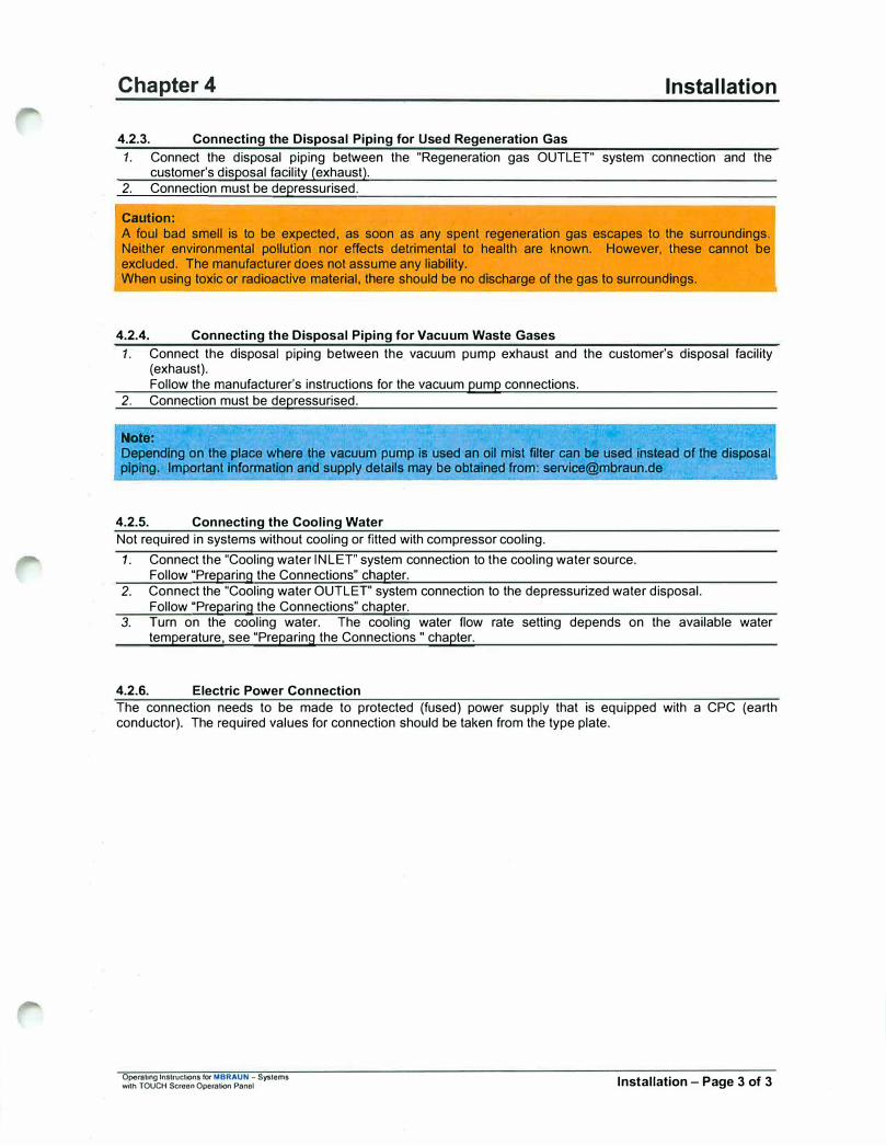
4.2.3. Connecting the Disposal Piping for Used Regeneration Gas
Installation
1. Connect the disposal piping between the "Regeneration gas OUTLET" system connection and thecustomer's disposal facility (exhaust).
2. Connection must be depressurised.
Caution:
A foul bad smell is to be expected, as soon as any spent regeneration gas escapes to the surroundings. Neither environmental pollution nor effects detrimental to health are known. However, these cannot be excluded. The manufacturer does not assume any liability. When using toxic or radioactive material, there should be no discharge of the gas to surroundings.
4.2.4. Connecting the Disposal Piping for Vacuum Waste Gases
1. Connect the disposal piping between the vacuum pump exhaust and the customer's disposal facility(exhaust).Follow the manufacturer's instructions for the vacuum pump connections.
2. Connection must be depressurised.
Note:
Dependrng on the place where the vacuum pump is used an oil mist filter can be used ihstead of the disposal piping. Important Information and supply details may be obtained from: [email protected]
4.2.5. Connecting the Cooling Water
Not required in systems without cooling or fitted with compressor cooling.
1. Connect the "Cooling water INLET' system connection to the cooling water source.Follow "Preparing the Connections" chapter.
2. Connect the "Cooling water OUTLET" system connection to the depressurized water disposal.Follow "Preparing the Connections" chapter.
3. Turn on the cooling water. The cooling water flow rate setting depends on the available watertemperature, see "Preparing the Connections " chapter.
4.2.6. Electric Power Connection
The connection needs to be made to protected (fused) power supply that is equipped with a CPC (earth conductor). The required values for connection should be taken from the type plate.
Operating lnstructK)ns for MBRAUN - Systems with TOUCH Scroon Operation Panol Installation - Page 3 of 3
Operating lnlllnlcl.lons far MBRAUN - Systems with TOUCH $croon Operation Panel
Blank Page
Blank Page

Chapter 5 Activating and Deactivating the System
Contents
5.1. Prerequisites ............................................................................................................................................ 2
5.2. Activating the System ............................................................................................................................. 2
5.3. Start Messages ......................................................................................................................................... 2
5.4. Deactivating the System ......................................................................................................................... 3
Table of Figures Figure 1: Main Switch ..................................................................................................................... 2 Figure 2: Touch Panel .................................................................................................................... 2 Figure 3: Start Screen .................................................................................................................... 3
Operating Instructions ror MBRAUN -Systems with TOUCH Screen Operation Panel Activating/Deactivating the System - Page 1 of 3

Chapter 5 Activating and Deactivating the System
5.1. Prerequisites
M All previous chapters observed
M Working gas connection properly made
M Regeneration gas connection properly made
M Exhaust facility for waste regeneration gas properly made
M Purge gas connection properly made
M Exhaust facility for vacuum pump waste gas properly made
M Cooling water connection properly made, if required
M Power connection properly made
M All piping and connections checked for its condition and firm mounting.
5.2. Activating the System
Figure 1: Main Switch
The main switch is located at the system's electrical cabinet.
Activating the system: Turn the main switch from the "O OFF" to position "I ON".
5.3. Start Messages
MBRAUN-Systems provided with the TOUCH Panel in the standard design have the panel located in a clearly visible central position.
After being activated, the system runs a self-test
Figure 2: Touch Panel
SIMl<TIC PANEL
:c
(J ::,
0 t-
Operating Instructions for MBRAUN -Syslcms with TOUCH Saccn Operation Panel Activating/Deactivating the System - Page 2 of 3
Chapter 5
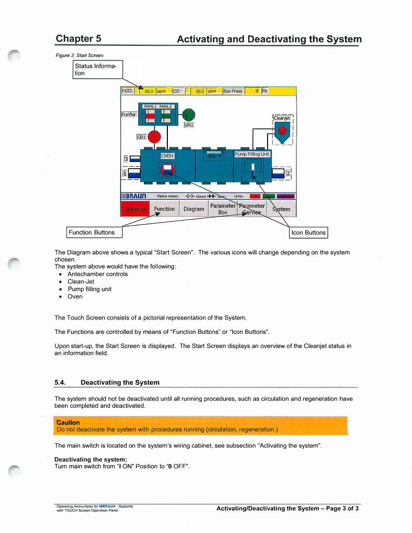
Figure 3: Start Screen
Status Information
Activating and Deactivating the System
00.0 jppm 102: r-1 00.0 jppm jBoxPress r--ofPa"
Function Buttons Icon Buttons
The Diagram above shows a typical "Start Screen". The various icons will change depending on the system chosen. The system above would have the following:
• Antechamber controls
• Clean-Jet
• Pump filling unit• Oven
The Touch Screen consists of a pictorial representation of the System.
The Functions are controlled by means of "Function Buttons" or "Icon Buttons".
Upon start-up, the Start Screen is displayed. The Start Screen displays an overview of the Cleanjet status in an information field.
5.4. Deactivating the System
The system should not be deactivated until all running procedures, such as circulation and regeneration have been completed and deactivated.
Caution Do not deactivate the system with procedures running (circulation, regeneration.)
The main switch is located on the system's wiring cabinet, see subsection "Activating the system".
Deactivating the system: Turn main switch from "I ON" Position to "O OFF".
Operating Instructions for MBRAUN -Sys1cms with TOUCH Screen Operolion Panel Activating/Deactivating the System - Page 3 of 3
Operating lnstrudions ror MBRAUN - Systems with TOUCH Screen Operation Panel
Blank Page
Blank Page
Chapter 6 TOUCH Panel Operation (TP270B)
Contents
6.1. Overview ................................................................................................................................................... 2
6.2. Display ...................................................................................................................................................... 2
6.3. Function Buttons ..................................................................................................................................... 2 6.3.1. Status of Function ....................................................................................................................... 3
6.4. Icon buttons ............................................................................................................................................. 3
6.5. Navigation Buttons .................................................................................................................................. 3
6.6. Input Fields and Buttons ......................................................................................................................... 4
Table of Figures Figure 1: Touch Panel ................................................................................................................................... 2 Figure 2: Input Fields .................................................................................................................................... 4
� Figure 3: Keypads ......................................................................................................................................... 4
Operating Instructions for MBRAUN -Systems with TOUCH Screen OperaUon Panel TOUCH Panel Operation - Page 1 of 4
Chapter 6
6.1. Overview
TOUCH Panel Operation (TP270B)
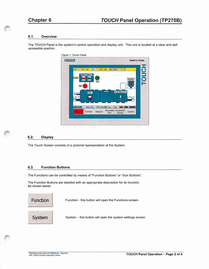
The TOUCH Panel is the system's central operation and display unit. This unit is located at a clear and well accessible position.
6.2. Display
Figure 1: Touch Panel
� IIMATIC PANEL
� -roo:or;;;;- �I";;; (.) ::::':":::::T'II ::,
0 ...
The Touch Screen consists of a pictorial representation of the System.
6.3. Function Buttons
The Functions can be controlled by means of "Function Buttons" or "Icon Buttons".
The Function Buttons are labelled with an appropriate description for its function. As shown below:
Function - this button will open the Functions screen.
System - this button will open the system settings screen.
Operating lnstrucUons for MBRAUN -Syslems with TOUCH Screen Operation Panel TOUCH Panel Operation - Page 2 of 4
Chapter 6 TOUCH Panel Operation (TP2708)
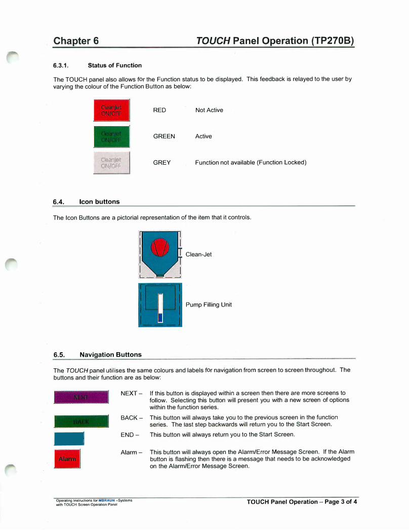
6.3.1. Status of Function
The TOUCH panel also allows for the Function status to be displayed. This feedback is relayed to the user by varying the colour of the Function Button as below:
RED Not Active
GREEN Active
c.,eanjet Ot-J/nFF
GREY Function not available (Function Locked)
6.4. Icon buttons
The Icon Buttons are a pictorial representation of the item that it controls.
Clean-Jet
Pump Filling Unit
6.5. Navigation Buttons
The TOUCH panel utilises the same colours and labels for navigation from screen to screen throughout. The buttons and their function are as below:
-
NEXT - If this button is displayed within a screen then there are more screens to follow. Selecting this button will present you with a new screen of options within the function series.
BACK - This button will always take you to the previous screen in the function series. The last step backwards will return you to the Start Screen.
END - This button will always return you to the Start Screen.
Alarm- This button will always open the Alarm/Error Message Screen. If the Alarm button is flashing then there is a message that needs to be acknowledged on the Alarm/Error Message Screen.
Operating Instructions f0< MBRAUN -Systems with TOUCH Screen Operation Pnnol TOUCH Panel Operation - Page 3 of 4
Chapter 6 TOUCH Panel Operation (TP2708)
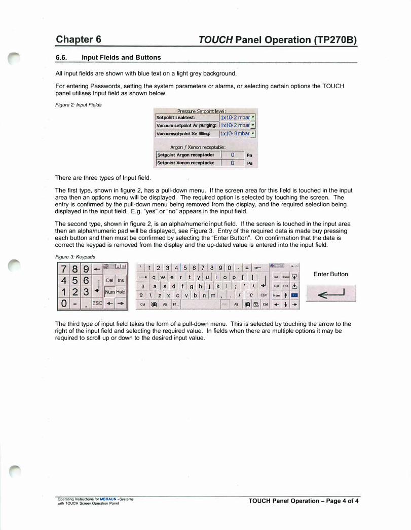
6.6. Input Fields and Buttons
All input fields are shown with blue text on a light grey background.
For entering Passwords, setting the system parameters or alarms, or selecting certain options the TOUCH panel utilises Input field as shown below.
Figure 2: Input Fields
There are three types of Input field.
Setpolnt Lealct�t: 1x 10⁻² mbar •
vacuum setpolnt Ar purging: 1x10⁻² mbar .:J Vacwmsotpolnt Xe tang: lxlO- 9 mbar •
Argon/ Xenon receptmle:
ISetpolnt Arp receptacle: I 0 ISetpolnt Xenon receptacle: I o
Pa
Pa
The first type, shown in figure 2, has a pull-down menu. If the screen area for this field is touched in the input area then an options menu will be displayed. The required option is selected by touching the screen. The entry is confirmed by the pull-down menu being removed from the display, and the required selection being displayed in the input field. E.g. "yes" or "no" appears in the input field.
The second type, shown in figure 2, is an alpha/numeric input field. If the screen is touched in the input area then an alpha/numeric pad will be displayed, see Figure 3. Entry of the required data is made buy pressing each button and then must be confirmed by selecting the "Enter Button". On confirmation that the data is correct the keypad is removed from the display and the up-dated value is entered into the input field.
Figure 3: Keypads
7 8 9 -,;r LJ.ltl
4 5 6 j
Del I ins
1 2 3 Num Help
0 - ESC +j+I
.J.,J
In• Hom 'i1 Enter Button
0,1 End c!J
0 esc Num t - <+- t ...
The third type of input field takes the form of a pull-down menu. This is selected by touching the arrow to the right of the input field and selecting the required value. In fields when there are multiple options it may be required to scroll up or down to the desired input value.
Operating lnslruct10ns fo, MBRAUN -Systems 'Wilh TOUCH Screen Operation Panel TOUCH Panel Operation - Page 4 of 4
r
Chapter7 Purging the System
Contents
7.1. General lnformatlon .................................................................................................................................... 2
7 .2. When Is Purging Necessary? .................................................................................................................... 2
7 .3. Purge Gas .................................................................................................................................................... 2
7 .4. Manual Purging ........................................................................................................................................... 3 7 .4.1. Prerequisites: ................................................................................................................................. 3 7 .4.2. Purging Procedure: ........................................................................................................................ 3
Table of Figures Figure 1: Example of Purge Gas consumption ..................................................................................................................................... 2 Figure 2: Manual Purging Procedure .................................................................................................................................................... 3
Operating Instructions for MBRAUN -Systems with TOUCH Screen Operation Panel Purging the System - Page 1 of 3

Chapter 7
7.1. General Information
Purging the System
Glove-Box systems either newly installed or opened for reasons of service contain ambient air. The prerequisite for the gas purification is a pure gas atmosphere of nitrogen, argon or helium within the box. Thus, at the beginning of the system's commissioning the ambient air should be replaced by nitrogen, argon or helium of medium purity.
Displacing the ambient air from the system is called purging. Working gas is used as purging gas.
7.2. When is Purging Necessary?
On principle, a system should be purged, when the 02 portion in the box atmosphere exceeds 100ppm.
The reasons for too high oxygen values are as follows:
• first commissioning of a system• servicing• air influx due to faulty operation• air influx due to damage (leaks)
Caution: A Glove-Box system should be purged using working gas until the 02 portion within the box atmosphere has <ilecreased to a value of <100 ppm. Operating the system with higher oxygen value may result in damaging the g · · n syste
7.3. Purge Gas
Working gas is used for purging the system; Nitrogen, argon or helium - medium purity - from bottles or any gas supply facilities.
Figure 1: Example of Purge Gas consumption
� 25.00
C
gc = f (v,c)
C = 1 ppm
20.00 ............. _, .... -... . � C = 10 ppm =======t=======t========t========t=:;;:::z�:::t:;::::::;2'.'.:::":::::::::j
i--""'" . .. ... .:;;,-...-,C •••.•..
15.00 t:.========--+
1--- -_ -_ -_ -_ -_--+----_ -_ -_+--
-=------=--"'9---
...---,.-::::.~_":"':___::..-;+_-_-_--___ --,i,. C = 100 ppm
C
1/) 10.00
5.00
0.00 0.00 0.50 1.00 1.50
Box Volume [ml ]
C = 500 ppm C = 1000 ppm
In the example, it shows that if a purity of 10 ppm is required, then about 14.50m3 of purge gas is required for 1 m3 box volume.
Operating Instructions for MBRAUN -Systems with TOUCH Screen Operation Panel Purging the System - Page 2 of 3
Chapter 7
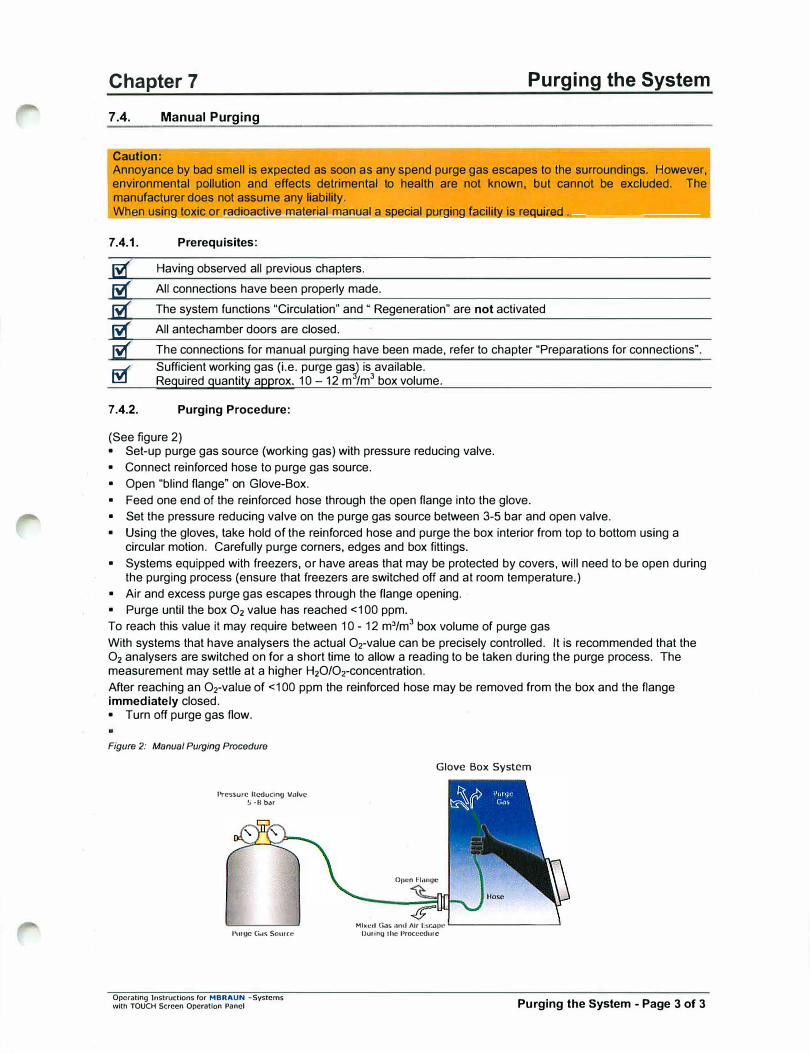
7 .4. Manual Purging
Caution:
Purging the System
Annoyance by bad smell is expected as soon as any spend purge gas escapes to the surroundings. However, environmental pollution and effects detrimental to health are not known, but cannot be excluded. The manufacturer does not assume any liability. Wh n using toxic or radioactive material manual a Si'.!ecial 1'.!Ur9irrg facili� is req,,,,u,.,,ir,,.e,.d .... _________ _,
7.4.1. Prerequisites:
5d': Having observed all previous chapters.
ti( All connections have been properly made.
lif' The system functions "Circulation" and " Regeneration" are not activated
!j(' All antechamber doors are closed.
� The connections for manual purging have been made, refer to chapter "Preparations for connections". � Sufficient working gas (i.e. purge gas) is available. 00 Required quantity approx. 10-12 m /m3 box volume.
7.4.2. Purging Procedure:
(See figure 2) • Set-up purge gas source (working gas) with pressure reducing valve.• Connect reinforced hose to purge gas source.• Open "blind flange" on Glove-Box.• Feed one end of the reinforced hose through the open flange into the glove.• Set the pressure reducing valve on the purge gas source between 3-5 bar and open valve.• Using the gloves, lake hold of the reinforced hose and purge the box interior from top to bottom using a
circular motion. Carefully purge corners, edges and box fittings.• Systems equipped with freezers, or have areas that may be protected by covers, will need to be open during
the purging process (ensure that freezers are switched off and at room temperature.)• Air and excess purge gas escapes through the flange opening.• Purge until the box 02 value has reached <100 ppm.To reach this value it may require between 10 - 12 m3/m3 box volume of purge gasWith systems that have analysers the actual Orvalue can be precisely controlled. It is recommended that the 02 analysers are switched on for a short lime to allow a reading to be taken during the purge process. The measurement may settle at a higher H20/0rconcentration. After reaching an Orvalue of <100 ppm the reinforced hose may be removed from the box and the flange immediately closed. • Turn off purge gas flow.
Figure 2: Manual Purging Procedure
Pressure ltt'"ducin<J Valve 5 -8 bar
Pm QC G.rs Sourtt:
Operating Instructions for MBRAUN -Systems with TOUCH Screen Operation Panel
Glove Box System
01lCn Flange
Mhtet.l G.)5 ond Air Esr ... "'lllC �------�
Du11n9 1hc l'>rocccdurc
Purging the System - Page 3 of 3

Operating lnstlUCtions ror MBRAUN - Systems with TOUCH Screen Operation Panel
Blank Page
Blank Page
Chapter 8 Antechamber Operation
Contents
8.1. General lnformatlon .................................................................................................................................... 2
8.2. Principle ....................................................................................................................................................... 2
8.3. Overview ...................................................................................................................................................... 3 8.3.1. Handmade (Standard) Antechamber Operation ............................................................................ 3 8.3.2. Automatic Antechamber Control .................................................................................................... 3
8.4. Push Button Operation .............................................................................................................................. 3
8.5. Important Notes .......................................................................................................................................... 4
8.6. Transferring Material Into the Box ............................................................................................................ 4 8.6.1. Preparation ..................................................................................................................................... 4 8.6.2. Evacuation in Manual Mode ........................................................................................................... 5 8.6.3. Refilling in Manual Mode ................................................................................................................ 5
8. 7. Information About the Automatic Antechamber Control. ....................................................................... &
8.8. Antechamber Parameters .......................................................................................................................... 7 8.8.1. Parameter Definitions ................. : ................................................................................................... 7
8.9. Trends for Antechamber ............................................................................................................................ 8
8.10. Transferring Material Out of the Box .................................................................................................... 9 8.10.1. Preparation ..................................................................................................................................... 9 8.10.2. Removal of Material from Antechamber ......................................................................................... 9
8.11. Circular Antechambers ......................................................................................................................... 1 O 8.11.1. Opening and Closing the Antechamber Door Outside the Box .................................................... 10 8.11.2. Opening and Closing the Antechamber Door Inside the Box ...................................................... 11
Table of Figures Figure 1: Principle of Antechamber Operation ........................................................................................... 2 Figure 2: Antechamber Control Screens .................................................................................................... 3 Figure 3: Principle of Automation Antechamber Cycles ............................................................................. 6
Oporating lnslrucllons for MBRAUN -System wHh TOUCH Screen Operation Panel Antechamber Operation (Standard) - Page 1 of 11

Chapter 8
8.1. General Information
Antechamber Operation
Antechambers are designed for transferring material into or out of the inert Glove Box System without polluting the box internal atmosphere during the respective procedures.
Antechamber Icons shown on Start Screen
8.2. Principle
Figure 1: Principle of Antechamber Operation
Transfer material into antechamber
Glove Box Sy&tem
echamber
Evacuate antechamber
Glove Box System
evacuating
Repeat evacuating and rerillling
Repeat evacuanng / refilling for several trmes
◊ ♦
Operating lnstrucUons for MBRAUN -System with TOUCH Screen Operation Ponel
H20:
Antechamber Screen
Close outer door
Glove Box System
I I ••
Refill antechamber with box gas
Glove Box System
refilling
Open box door/ transfer material lnlo box
Glove Box System
refilling
END
Antechamber Operation (Standard) - Page 2 of 11
Chapter 8 Antechamber Operation
8.3. Overview
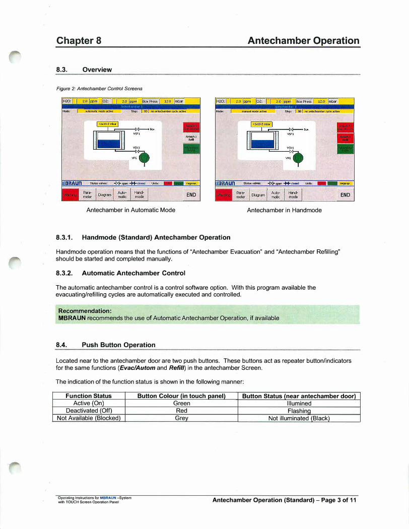
Figure 2: Antechamber Control Screens
_, ...
.. .......... , * _, *'""" u,.,, - - ,eq,,q
END
Antechamber in Automatic Mode
8.3.1. Handmode (Standard) Antechamber Operation
Antechamber in Handmade
Handmade operation means that the functions of "Antechamber Evacuation" and "Antechamber Refilling" should be started and completed manually.
8.3.2. Automatic Antechamber Control
The automatic antechamber control is a control software option. With this program available the evacuating/refilling cycles are automatically executed and controlled.
Recommendation: MBRAUN recommends the use of Automatic Antechamber Operation, if available
8.4. Push Button Operation
END
Located near to the antechamber door are two push buttons. These buttons act as repeater button/indicators for the same functions (Evac/Autom and Refill) in the antechamber Screen.
The indication of the function status is shown in the following manner:
Function Status Active (On)
Deactivated (Off) Not Available (Blocked)
Operaling lnslructions ror MBRAUN -System wilh TOUCH Screen Operation Panel
Button Colour (in touch panel) Button Status (near antechamber door) Green Illumined Red Flashing Grev Not illuminated (Black)
Antechamber Operation (Standard) - Page 3 of 11
Chapter 8 Antechamber Operation
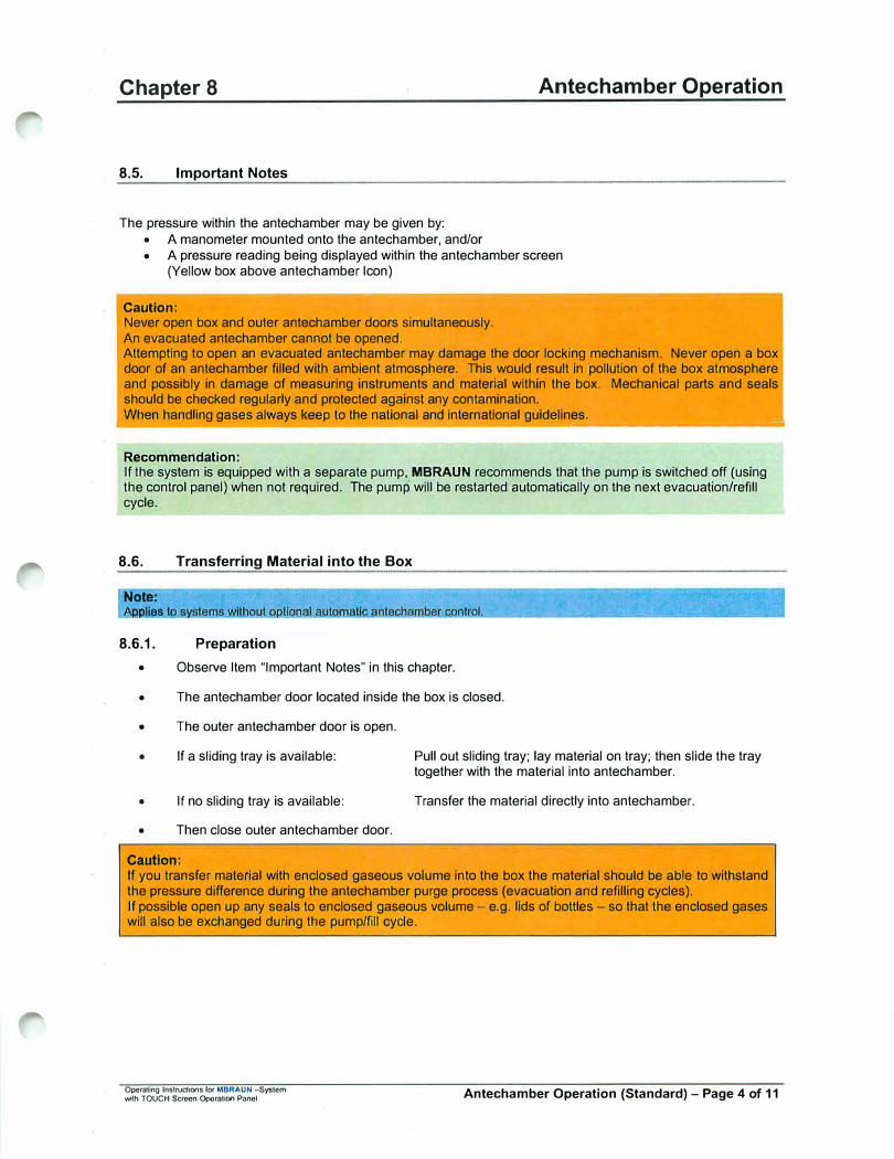
8.5. Important Notes
The pressure within the antechamber may be given by: • A manometer mounted onto the antechamber, and/or• A pressure reading being displayed within the antechamber screen
(Yellow box above antechamber Icon)
Caution: Never open box and outer antechamber doors simultaneously. An evacuated antechamber cannot be opened. Attempting to open an evacuated antechamber may damage the door locking mechanism. Never open a box door of an antechamber filled with ambient atmosphere. This would result in pollution of the box atmosphere and possibly in damage of measuring instruments and material within the box. Mechanical parts and seals should be checked regularly and protected against any contamination. When handling gases always keep to the national and international guidelines.
-------------
Recommendation:
If the system is equipped with a separate pump, MBRAUN recommends that the pump is switched off (using the control panel) when not required. The pump will be restarted automatically on the next evacuation/refill cycle.
8.6. Transferring Material into the Box
Note:
i:ii:ilies t I I.
8.6.1. Preparation
• Observe Item "Important Notes" in this chapter.
• The antechamber door located inside the box is closed.
• The outer antechamber door is open.
• If a sliding tray is available:
• If no sliding tray is available:
• Then close outer antechamber door.
Caution:
Pull out sliding tray; lay material on tray; then slide the tray together with the material into antechamber.
Transfer the material directly into antechamber.
If you transfer mate�ial with enclosed gaseous volume into the box the material should be able to withstand the pressure difference during the antechamber purge process (evacuation and refilling cycles). If possible open up any seals to enclosed gaseous volume - e.g. lids of bottles - so that the enclosed gases will also be exchanged during the pump/fill cycle.
Operating lnslrudK>flS r°' MBRAUN -System with TOUCH Screen Operation Panel Antechamber Operation (Standard) - Page 4 of 11

Chapter 8 Antechamber Operation
8.6.2. Evacuation in Manual Mode
Press the Evacuate/Start Autom button to start evacuation.
The antechamber is being evacuated. Status indicator of the "Evacuate/Start Autom" button is green, an appropriate status message appears at the top of the Antechamber screen and the "Blue Bar" in the antechamber icon will decrease to show current status.
Recommendation: MBRAUN recommends an evacuation of the antechamber up to a value of <0.5 mbar.
- - ------
Pressing the "Evacuate/Start Autom" button again will stop the process.
8.6.3. Refilling in Manual Mode
Note:
Press the "Refill" button to start refilling the antechamber.
The antechamber is being refilled with gas from the box atmosphere. Status indicator of the "Refill" button is green, an appropriate status message appears at the top of the Antechamber screen and the "Blue Bar" in the antechamber icon will increase to show current status.
Refill antechamber until pressure compensation between glove bo.x and antechamber is attained.
Pressing the "Refill" button again will close the valve between the antechamber and the box.
Caution: For obtaining a high degree of purity, the antechamber should undergo repeated evacuation and refilling procedures. In this case for inte�mediate refilling a pressure of approximately 200 mbar is sufficient. The last refilling step always has to be back to box pressure.
Operating Instructions for MBRAUN -System with TOUCH Sacen Operation Panel Antechamber Operation (Standard) - Page 5 of 11
Chapter 8 Antechamber Operation
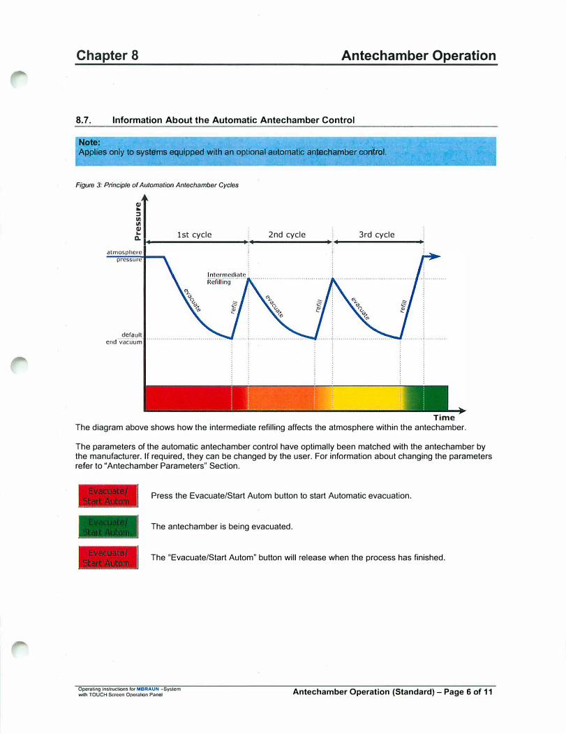
8.7. Information About the Automatic Antechamber Control
Note:
Applies only to systems equipped with an optional automatic antecliamber control.
Figure 3: Principle of Automation Antechamber Cycles
QI ...
::, Ill Ill QI
'- 1st cycle 2nd cycle 3rd cycle a. .., _________ ,..., _______ ��---------+
almospherc
pressure
derault end vacuum
Time The diagram above shows how the intermediate refilling affects the atmosphere within the antechamber.
The parameters of the automatic antechamber control have optimally been matched with the antechamber by the manufacturer. If required, they can be changed by the user. For information about changing the parameters refer to "Antechamber Parameters" Section.
Press the Evacuate/Start Autom button to start Automatic evacuation.
The antechamber is being evacuated.
The "Evacuate/Start Autom" button will release when the process has finished.
Operating lnslruclions fo, MBRAUN -System with TOUCH Screen Opcralion Panel Antechamber Operation (Standard) - Page 6 of 11
Chapter 8 Antechamber Operation
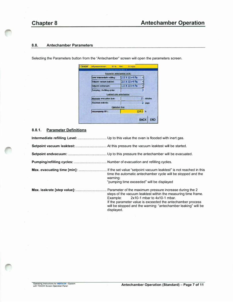
8.8. Antechamber Parameters
Selecting the Parameters button from the "Antechamber'' screen will open the parameters screen.
8.8.1. Parameter Definitions
rm, - rellDlg : 12.s X 10+4 Pa ·JIis,;;hl YOQUTI)oll<lell: 12.0 X 10+4 Pa ·JI ls.hi ...,.anu,i: I 1.0 X 10+4 Pa .:] �ng/Rtm,gqdes: I 3
jM..hllTI .. lrulUon Imo: 15 mhAos
�l ..... -m-m---�-,---,------2,lfl>S !JIIIUl.krl.lrnll
Iv-""'..., VPI: l�----12-4.-0 h
BACK I END
Intermediate refilling Level: .............................. Up to this value the oven is flooded with inert gas.
Setpoint vacuum leaktest: ................................ At this pressure the vacuum leaktest will be started.
Setpoint endvacuum: ........................................ Up to this pressure the antechamber will be evacuated.
Pumping/refilling cycles: .................................. Number of evacuation and refilling cycles.
Max. evacuating time [min]: ............................. If the set value "setpoint vacuum leaktest" is not reached in this time the automatic antechamber cycle will be stopped and the warning: "pumping time exceeded" will be displayed
Max. leakrate [step value]: ................................ Parameter of the maximum pressure increase during the 2 steps of the vacuum leaktest within the measuring time frame.
Operating Instructions for MBRAUN -System with TOUCH Screen Opomtion Panel
Example: 2x10⁻¹ mbar to 4x10⁻¹ mbar. If the parameter value is exceeded the antechamber process will be stopped and the warning: "antechamber leaking" will be displayed.
Antechamber Operation (Standard) - Page 7 of 11
Chapter 8
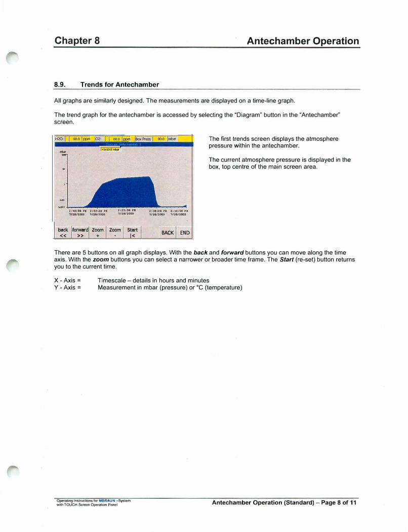
8.9. Trends for Antechamber
Antechamber Operation
All graphs are similarly designed. The measurements are displayed on a time-line graph.
The trend graph for the antechamber is accessed by selecting the "Diagram" button in the "Antechamber" screen.
-..
21<10,s-o •• 11:u:ze ,.
'U28/20CU 7/J:a/JOO,
back forward Zoom Zoom
<< >> +Stllrt
I<
hllaH Pl t1tQ1H ,■
i/H/200> '7/H/200)
BACK END
The first trends screen displays the atmosphere pressure within the antechamber.
The current atmosphere pressure is displayed in the box, top centre of the main screen area.
There are 5 buttons on all graph displays. With the back and forward buttons you can move along the time axis. With the zoom buttons you can select a narrower or broader time frame. The Start (re-set) button returns you to the current time.
X -Axis= Y -Axis=
Timescale - details in hours and minutes Measurement in mbar (pressure) or °C (temperature)
Operating lnstrucUons fOf MBRAUN -System with TOUCH Saecn Operation Panel Antechamber Operation (Standard) - Page 8 of 11
Chapter 8
8.10. Transferring Material Out of the Box
8.10.1. Preparation
• Observe Item "Important Notes" in this chapter.
• The outer antechamber door is closed.
• The antechamber door located inside the box is open.
Antechamber Operation
• If a sliding tray is available: Pull out sliding tray; lay material on tray; then slide the tray together with the material into antechamber.
• If no sliding tray is available:
• Then close inner antechamber door.
Transfer the material directly into antechamber.
8.10.2. Removal of Material from Antechamber
• Open the antechamber door located outside the box.
• If a sliding tray is available: Pull out sliding tray; remove material from tray; then slide the tray back into antechamber.
• If no sliding tray is available: Transfer the material directly out of the antechamber.
• Then close the outer antechamber door.
Caution:
Annoyance by bad smell is expected as soon as any waste purge gas is escaping to the surroundings. Environmental pollution and effects detrimental to health, however, are not known, but cannot be excluded. ifhe manufacturer does not assume any liability. When using toxic or radioactive material manual, by no means the gas should escape to the environment. Information about pertinent alternative methods: [email protected]
Recommendation:
Ensure that both outer and inner doors of the antechamber are closed when material is not being transferred through the antechamber. After having the outer antechamber door opened, it is recommended that at least one evacuation and refill cycle is completed for the antechamber to prevent possible condensation being deposited on the interior antechamber walls.
Operating Instructions for MBRAUN -System with TOUCH Saocn OpcrnUon Panel Antechamber Operation (Standard) - Page 9 of 11

Chapter 8 Antechamber Operation
8.11. Circular Antechambers
8.11.1. Opening and Closing the Antechamber Door Outside the Box
Operaling lnslructions for MBRAUN -System wilh TOUCH Screen Operation Panel
Observe all items of this chapter. Turn the locking mechanism until the antechamber door is free.
Caution: Antechamber under vacuum cannot be opened. If you try to open the antechamber under vacuum the opening mechanism can be damaged.
Carefully open the antechamber door in upward direction.
The antechamber door is held by the spring mechanism. It stays in the position (see picture).
Antechamber Operation (Standard)- Page 10 of 11
Chapter 8 Antechamber Operation
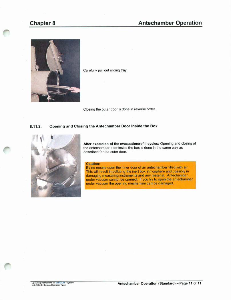
Carefully pull out sliding tray.
Closing the outer door is done in reverse order.
8.11.2. Opening and Closing the Antechamber Door Inside the Box
Operating lnstrucoons fa< MBRAUN -System wilh TOUCH Screen Operation Panel
After execution of the evacuation/refill cycles: Opening and closing of the antechamber door inside the box is done in the same way as described for the outer door.
Caution: By no means open the inner door of an antechamber filled with air. This will result in polluting the inert box atmosphere and possibly in damaging measuring instruments and any material. Antechamber under vacuum cannot be opened. If you try to open the antechamber under vacuum the opening mechanism can be damaged.
Antechamber Operation (Standard) - Page 11 of 11

� \
Operating Instructions rot MBRAUN - Systems with TOUCH Screen Operation Panel
Blank Page
Blank Page
� I
Chapter 9 Process Oven
Contents
9.1 Main Panel Operation .............................................................................................................................. 2
9.2 Parameters ............................................................................................................................................... 4
9.3 Diagrams ................................................................................................................................................... 6
9.4 Oven Trayhandllng .................................................................................................................................. 7
Operating lnatructiona fof MBRAUN - Systems wi1tl TOUCH Screen Opetation Panel Process Oven - Page 1 of 8
Chapter 9 Process Oven
9.1 Main Panel Operation
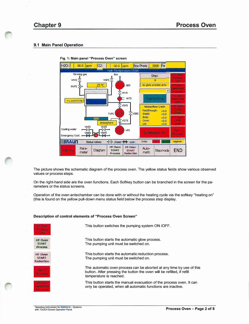
Fig. 1: Main panel "Process Oven" screen
1H20: r 1 oo.o lppm 1°2: r I oo.o I ppm !Box Press I COO) pa
formng gas Box
VA<S
RVF5 25°C
>l.lx10+5 Pa
VS85
Stab.Js vat.es: -IX)- closed* open
Pa-ameter
HT-Oven HT-Oven
Dlagam START START
Process Reduction
I SIEp: I 0 I ro glow process actlv
AulPmatlc Stepmode END
The picture shows the schematic diagram of the process oven. The yellow status fields show various observed values or process steps.
On the right-hand side are the oven functions. Each Softkey button can be branched in the screen for the parameters or the status screens.
Operation of the oven antechamber can be done with or without the heating cycle via the softkey "heating on" (this is found on the yellow pull-down menu status field below the process step display.
Description of control elements of "Process Oven Screen"
HT-Dven
START
Process
HT-Oven 1 START
Reduction
Operating Instructions for MBRAUN - Systems with TOUCH Screen Operation Panel
This button switches the pumping system ON /OFF.
This button starts the automatic glow process. The pumping unit must be switched on.
This button starts the automatic reduction process. The pumping unit must be switched on.
The automatic oven process can be aborted at any time by use of this button. After pressing the button the oven will be refilled, if refill temperature is reached.
This button starts the manual evacuation of the process oven. It can only be operated, when all automatic functions are inactive.
Process Oven - Page 2 of 8
Chapter 9
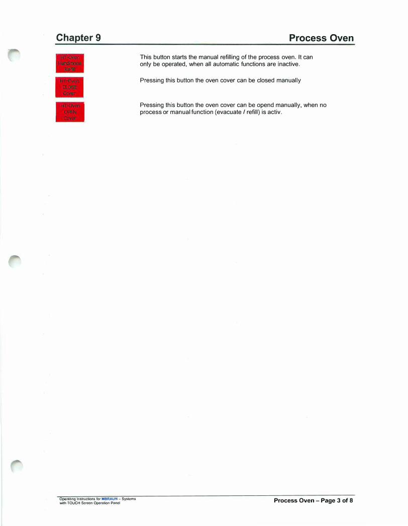
Operating Instructions for MBRAUN - Systems with TOUCH Semon Operation Pnnol
Process Oven
This button starts the manual refilling of the process oven. It can only be operated: when all automatic functions are inactive.
Pressing this button the oven cover can be closed manually
Pressing this button the oven cover can be opend manually, when no process or manual function (evacuate/ refill) is activ.
Process Oven - Page 3 of 8

Chapter 9 Process Oven
9.2 Parameters
J>,1rai11eler hie h lrn11 ier;iturn oven
jSetpolnt vocwm leaktest: tx10-5 mbar .:l ISetpolnt endvao.JJm: 1x10-Smbar .:l ISP endvacwm after heatlrg: 8x10⁻⁶mbar
jSP IEmperab..re prefloodlrg: 400 "C
ISetpolnt vao.JJm prefloodlrg: 100mbar
ISP t-emperab..re endfloodlrg: 300 "C
ISP oomperab..re process end: 150 "C
IMaxlmum evacuation time: 10 minutes
jtv1ax1mum leakralE: 10 steps
BACK
Fig. 2: "Parameter Oven" screen
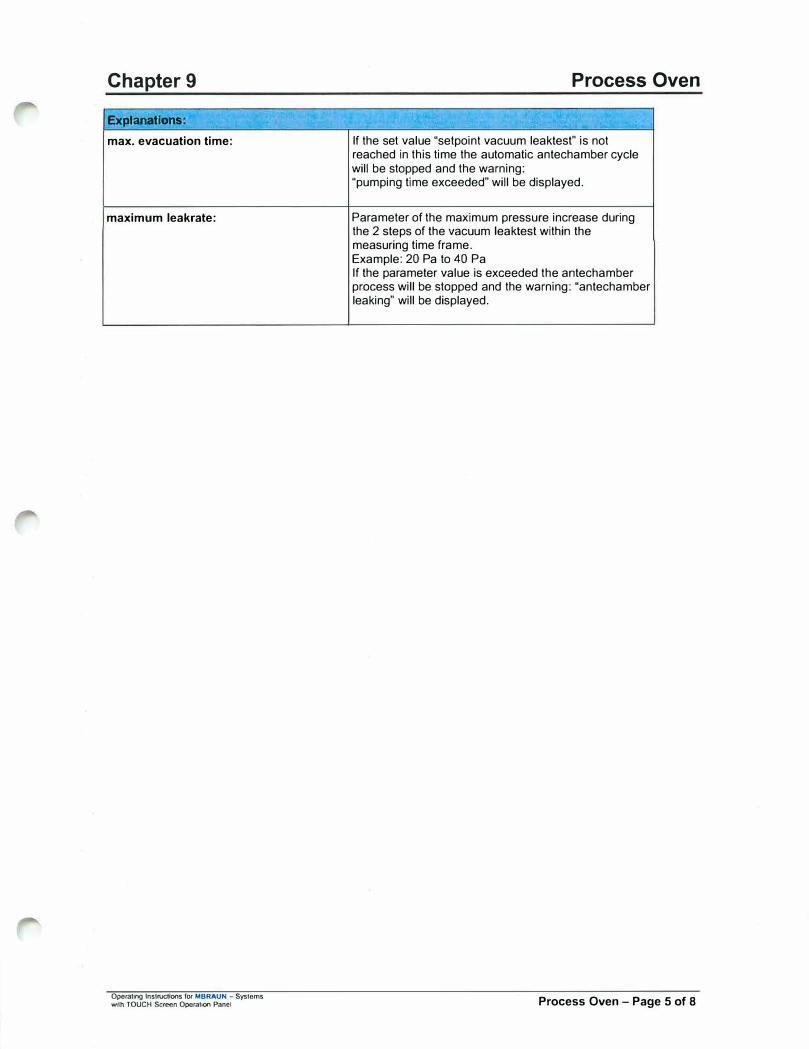
Explanations:
Setpoint Vacuum Leaktest:
Setpoint endvacuum:
SP endvacuum after heating:
SP temperature preflooding:
Setpoint Vacuum Preflooding:
SP temperature endflooding:
SP temperature process end:
Operating Instructions for MBRAUN - Systems with TOUCH Screon Oporalion Panel
At this pressure the vacuum leaktest will be started
Up to this pressure the antechamber will be evacuated.
The oven antechamber will be pumped to this level after the heating process.
The oven must cool to this level after the heating process; following this it may be flooded to the pre-flood pressure.
Up to this pressure the oven will be pre-flooded.
The oven must cool to this level after the heating process; following this it may be flooded to the atmospheric pressure. After the pre-flood cycle has completed the oven door lowers to the "Quick cool" position and begins the "Quick cool" process.
On reaching this temperature the "Quick cooling" process will end and the oven door will fully open. This completes the heating process.
Process Oven - Page 4 of 8
Chapter 9
Explana11ons:
max. evacuation time:
maximum leakrate:
Operaling lnstruc:tJons for MBRAUN - Systems with TOUCH Screen Operation Panel
Process Oven
.. -
If the set value "setpoint vacuum leaktest" is not reached in this time the automatic antechamber cycle will be stopped and the warning: "pumping time exceeded" will be displayed.
Parameter of the maximum pressure increase during the 2 steps of the vacuum leakiest within the measuring time frame. Example: 20 Pa to 40 Pa If the parameter value is exceeded the antechamber process will be stopped and the warning: "antechamber leaking" will be displayed.
Process Oven - Page 5 of 8
Chapter 9
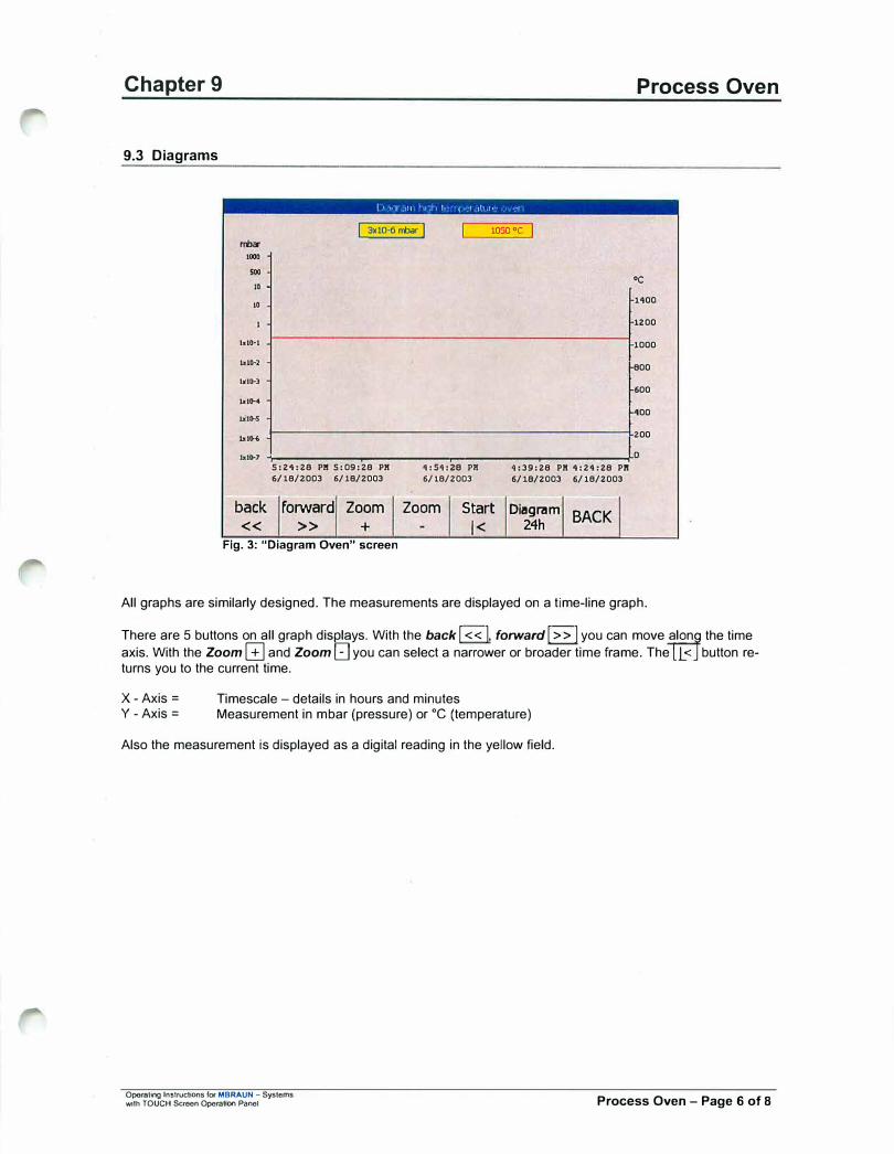
9.3 Diagrams
rroa-1000
500
10 •
10
ld0-1
blH
l.d�3
blH
bUK
I • 1• 1 ,11 I � ,l , r, 11 • 1 111 ,r, · • r
3xl0·6 rroar 1 1050 oC
Process Oven
oC
1100
1200
1000
f-800
600
1-100
.. ,� 1-------------------------200
,., .. , ;------..------..-------.-----�D
back
<<
5:21:28 Pl! 5:09:28 Pl!
6/18/2003 6/18/2003
forward Zoom >> +
Fig. 3: "Diagram Oven" screen
1:51:28 Pl!
6/18/2003 1:39:28 Pl! 1:21:28 Pl!
6/18/2003 6/18/2003
Zoom Start Diagram BACK
I< 24h
All graphs are similarly designed. The measurements are displayed on a time-line graph.
There are 5 buttons on all graph dis�ys. With the back I<< I, forward I>> I you can move j
l�
nf
the timeaxis. With the Zoom[±] and Zoom l.:J you can select a narrower or broader time frame. The < button returns you to the current time.
X-Axis =Y -Axis=
Timescale - details in hours and minutes Measurement in mbar (pressure) or °C (temperature)
Also the measurement is displayed as a digital reading in the yellow field.
Operating Instructions ror MBRAUN - Systems 'Nith TOUCH Screen Operation Panel Process Oven - Page 6 of 8

Chapter 9 Process Oven
9.4 Oven Trayhandling
With this button, in the "Oven process screen" you can select the "Trayhandling screen". In the "Trayhandling" screen" all the loading and unloading functions for the oven are available.
Fig. 4: "Oven Trayhandling" screen
H20: r< J <00.0 I <ff Jo2: F�I <-00-.o�J-<f-f JBox Press J <0000 jPa
[E] Actual Soop:
Top Position □ no process actlv
Middle Position
Down Position
Load ovan lklload
Auto- I Hcrdlnltlallze �- mcxle �� 1BACK�
This screen also displays the position of the oven handler and the gripper. The yellow status field displays the current process step.
Operating Instructions for MBRAUN - Systems ..;th TOUCH Screen OpernUoo Panel Process Oven - Page 7 of 8

Chapter 9
·-------------
Note:
Process Oven
With the "Load Tray" function the Charge-carrier would be transferred from the load position to the oven. After the tray is set down the handler moves onto the Unload position.
With the "Unload Tray" function the Charge-carrier would be collected from the oven and set down in the Unload position.
This function returns the Charge-carrier from the Unload position to the Load position.
All loading and unloading functions are only available, if the oven rover is rompletely lowered !
With this button the process chain would be set back a step. The Oven handling would remain in its last resting position.
Initialize By selecting this function the Oven handling would be set to its starting position.
Procedure: Both Hub cylinders are raised Oven-handling set to load position Both Hub cylinders are lowered Gripper opens.
The "Load Tray" function is not released until after the Oven handling has returned to its initial position.
Auto- Hand- Step-matic mode mode
I
Operating Instructions for MBRAUN - Syslcms with TOUCH Scroon Operalion Panel
These buttons control the operation mode of the Oven handling. Hand-mode and Step-mode are for Service personnel only and are password protected.
Process Oven - Page 8 of 8

Chapter 10 Plasma Burner Operation
Contents
10.1. General Information ............................................................................................................................. 2 10.1.1. Design of the MBraun Pumping Fllllng System ............................................................................ 2 10.1.2. Main components of the system ..................................................................................................... 2
10.2. Main Panel Operation .......................................................................................................................... 3 10.2.1. System Overview .............................................................................................................................. 3 10.2.2. Pump-FIiiing Process ....................................................................................................................... 4
10.2.2.1. Process Description .................................................................................................................... 4 10.2.3. Operation Modes .............................................................................................................................. 5
10.2.3.1. Automatic Mode .......................................................................................................................... 5
10.2.3.2. Manual Mode ............................................................................................................................... 7 10.2.4. Parameter Setting for Pump-FIiiing Unit ........................................................................................ 9
10.2.4.1. Pump Filling Unit Parameter description ..................................................................................... 9 10.2.5. Pump-Filling Unit Start-up Modes and Cleaning Plplng ............................................................. 12
10.2.5.1. Selecting Start-up Modes and Cleaning Piping Screen ............................................................ 12
10.2.5.2. Clean Piping Operation .............. : .............................................................................................. 13 10.2.5.3. Clean Receptacles Operation ................................................................................................... 14 10.2.5.4. Burner Adjustment ..................................................................................................................... 14
10.2.6. Preparing the Pump FIiiing System for 4 or 6 mm Tubes .......................................................... 15 10. 2. 6. 1. Parts Required for 4 mm-tubes ................................................................................................. 15
10.2.6.2. Parts needed for 6mm-tubes ..................................................................................................... 15
10.2.6.3. Exchange of Pump Fill Head Seals (4 I 6mm) .......................................................................... 16 10.2.6.4. Exchange of Guide Cone and Gripper (4 I 6 mm) .................................................................... 17
10.3. MBRAUN Plasma Burner System ..................................................................................................... 18 10.3.1. Overview .......................................................................................................................................... 18 10.3.2. Technical Speclflcatlons ................................................................................................................ 19
10.3.2.1. Plasma jet Controller MB-PL-C4 ............................................................................................... 19 10.3.2.2. Plasma Burner MB-PL-B1 ......................................................................................................... 22 10.3.2.3. DC-Power Supply Kemppi Mastertig 1500 ................................................................................ 2310.3.2.4. Feedthrough Plate ..................................................................................................................... 23 10.3.2.5. Water Flow Switch ..................................................................................................................... 23 10.3.2.6. Control Cables ........................................................................................................................... 24 10.3.2. 7. DC Power Cables ...................................................................................................................... 24 10.3.2.8. Cooling System ......................................................................................................................... 24
10.3.3. System Description ........................................................................................................................ 25 10.3.4. Operation (Software 8V1 .0) ............................................................................................................ 28
10.3.4.1. First Setup ................................................................................................................................. 28 10.3.4.2. First operation ........................................................................................................................... 29 10.3.4.3. External control ......................................................................................................................... 30 10.3.4.4. Setting the times in automatic mode (LOGO 8V1.0) ................................................................. 30 10.3.4.5. Plasma Current setting .............................................................................................................. 31 10.3.4.6. Current Limit Value Setting (FAIL- condition) .......................................................................... 32
10.3.5. The Plasma Burner MB-PL-B1 ....................................................................................................... 34 10. 3. 5. 1. Description ................................................................................................................................ 34
10.3.5.2. Exchange of the Anode Nozzle (Tip) ........................................................................................ 35 10.3.5.3. Exchange of the Ceramic lnsulator ........................................................................................... 36 10.3.5.4. Exchange of the Tungsten Cathode Rod I Grinding and Adjustment ....................................... 36 10.3.5.5. Adjustment Tool ........................................................................................................................ 38 10. 3. 5. 6. Skew I Distance adjustment of plasma burners (3 torch system) ............................................. 38
10.3.6. The Power Supply MASTERTIG 1500 ........................................................................................... 41 10.3.6.1. Setting of the controls: ............................................................................................................... 41 10.3.6.2. Operation ................................................................................................................................... 41
10.3.7. Enclosures ...................................................................................................................................... 42
Operating lnsttuctiona fof MBRAUN - Systems with TOUCH Screen Operation Panel Plasma Burner Operation - Page 1 of 42
Chapter 10 Plasma Burner Operation
10.1. General Information
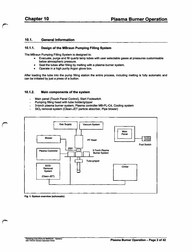
10.1.1. Design of the MBraun Pumping FIiiing System
The MBraun Pumping Filling System is designed to: • Evacuate, purge and fill quartz lamp tubes with user selectable gases at pressures customisable
below atmospheric pressure.• Seal the tubes after filling by melting with a plasma burner system.• Operate in a high purity Argon glove box.
After loading the tube into the pump filling station the entire process, including melting is fully automatic and can be initiated by just a press of a button.
10.1.2. Main components of the system
Main panel (Touch Panel Control), Start Footswitch Pumping filling head with tube holder/gripper 3-torch plasma burner system, Plasma controller MB-PL-C4, Cooling systemSi02 removal system (Clean-JET particle absorber, Pipe blower)
Blower
Plasma Controller
Si02-Removal System
(Clean-JET)
Gas Supply Vacuum System
PF Head
3-Torch PlasmaBurner System
Tube gripper
Main Panel
Chiller
Fig. 1: System overview (schematic)
Foot Switch
Operating Instructions (04' MBRAUN - Systems with TOUCH Seteon Operation Panel Plasma Bumer Operation - Page 2 of 42
Chapter 10 Plasma Burner Operation
10.2. Main Panel Operation
10.2.1. System Overview
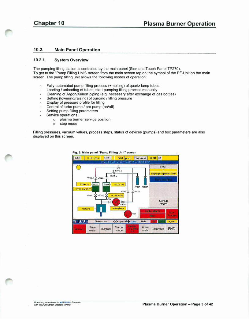
The pumping filling station is controlled by the main panel (Siemens Touch Panel TP270). To get to the "Pump Filling Unit"- screen from the main screen tap on the symbol of the PF-Unit on the main screen. The pump filling unit allows the following modes of operation:
Fully automated pump filling process (+melting) of quartz lamp tubes Loading / unloading of tubes, start pumping filling process manually Cleaning of Argon/Xenon piping (e.g. necessary after exchange of gas bottles) Setting {lowering/raising) of purging / filling pressure Display of pressure profile for filling Control of turbo pump / pre pump (on/off) Setting pump filling parameters Service operations
o plasma burner service positiono step mode
Filling pressures, vacuum values, process steps, status of devices (pumps) and box parameters are also displayed on this screen.
Fig. 2: Main panel "Pump FIiiing Unit" screen
Operating Instructions for MBRAUN - Systems with TOUCH S<:roon Operation Panel
>50J Pa
Paramebar
Dlagam Mcrual
mode
Plasma Burner Operation - Page 3 of 42
Chapter 10 Plasma Burner Operation
10.2.2. Pump-Filling Process
10.2.2.1. Process Description
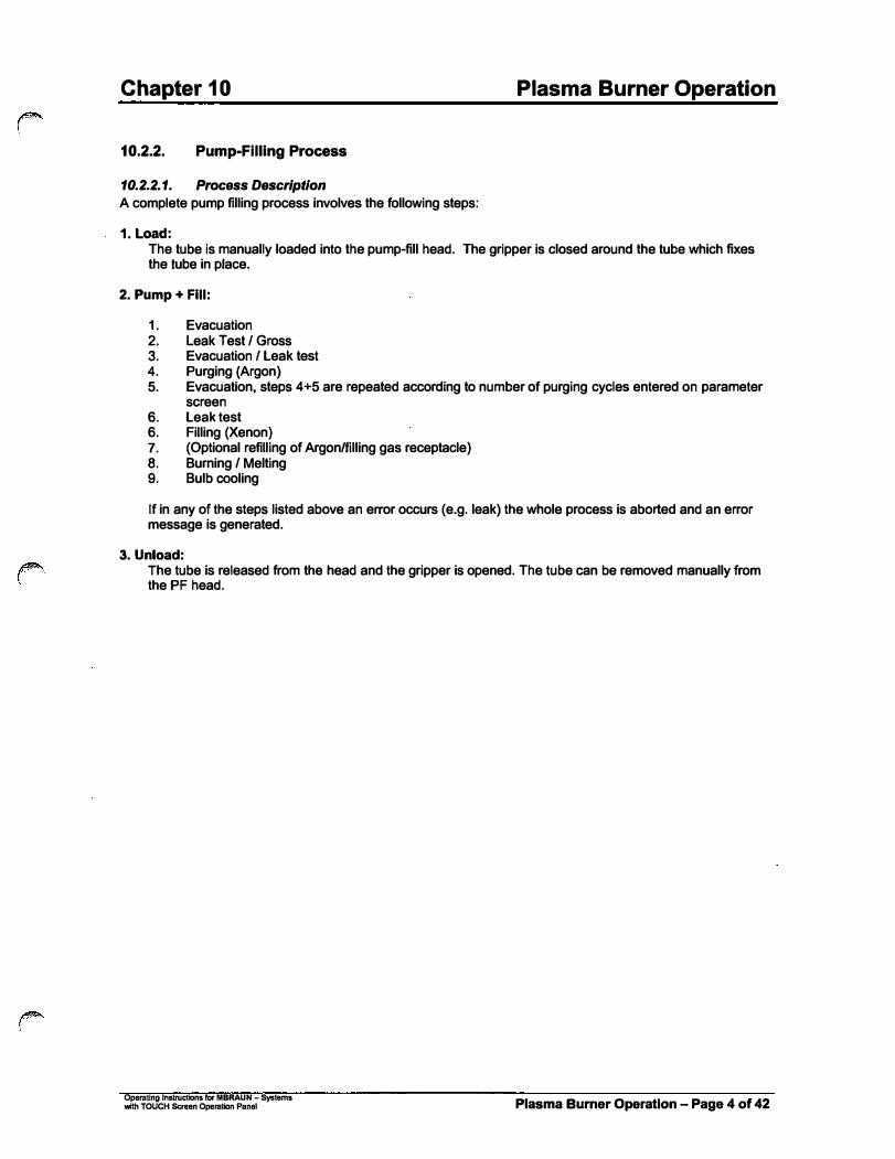
A complete pump filling process involves the following steps:
1. Load:
The tube is manually loaded into the pump-fill head. The gripper is closed around the tube which fixesthe tube in place.
2. Pump + Fill:
1. Evacuation2. Leak Test I Gross3. Evacuation I Leak test4. Purging (Argon)5. Evacuation, steps 4+5 are repeated according to number of purging cycles entered on parameter
screen6. Leak test6. Filling (Xenon)7. (Optional refilling of Argon/filling gas receptacle)8. Burning/ Melting9. Bulb cooling
If in any of the steps listed above an error occurs (e.g. leak) the whole process is aborted and an error message is generated.
3. Unload:The tube is released from the head and the gripper is opened. The tube can be removed manually fromthe PF head.
Operating Instructions hlf MBRAUN - Systems with TOUCH Screen Operation Panel Plasma Burner Operation - Page 4 of 42
�·
Chapter 10
10.2.3. Operation Modes
Plasma Burner Operation
There are two possible modes of operation to fill / melt a lamp tube:
a) Automatic:
This mode will fix the lamp tube, pump, fill and seal the quartz tubes.
b) Manual Mode (Panel operation)
This function is password protected for advanced user options.See section Manual Mode and Password Settings.
10.2.3.1. Automatic Mode
10.2.3.1.1. Pump Filling I Preparation Before starting the pump fill processes check the following items:
@ The Cooling unit Is switched on and operates at nominal temperature. @ The Particle absorber (Clean.JET) Is switched on and operates at nominal flow. @ Plasma Jet Controller (MB-PL-C4) Is switched on 0 All three burners are switched on and operated at low plasma current. 0 The gripper Is ready for loading. 0 The Pump station Is switched on and the turbo pump is up I.e. running at high speed (the symbols
for VP& and TVP6 are green, no warning that the turbo pump Is running up).
Carefully insert a tube into the PF-head. Make sure that the tube is inserted up to upper stop in the PF-head. Now the system is ready to start the pump fill cycle.
10.2.3.1.2. Start Pump-FIiiing The start foot switch for the pump-fill cycle is placed outside the glovebox. The operator can trigger the automatic pump-fill cycle with this foot switch after loading the lamp-pistons into the PF-head.
After starting the process described in section 10.2.2.1 runs automatically to its end. If there is any malfunction an error message is generated, the process is aborted and the 3-colored signal light is illuminated red. If the process is completed successfully, the signal light is illuminated green. During the process there is a yellow light.
Operating Instructions fOf MBRAUN - Systems with TOUCH Screen Operation Panel Plasma Burner Operation - Page 5 of 42

Chapter 10 Plasma Burner Operation
10.2.3.1.3. Pump-Filling details
>SOJ Pa
Ptra
meter
Ngan X""""
HVX6
Fig. 3 : Pump FIiiing Unit scroon
Description of control elements of "Pump Filling Unit Screen"
Automatic Stepmode
Operaling Instructions ror MBRAUN - Syslems with TOUCH $croon Oporalion Pnnol
The automatic Pump-fill process can be aborted at any time by use of this button. After pressing the button all valves will be closed. The lamp tube may then be unloaded.
With this button the pumping unit filling station is switched on.
This button selects the Manual Operation Mode. The Manual functions are password protected at a supervisor level.
These buttons switch the operation mode of the Pump-fill unit. The Step-mode is for service personnel only and is password protected.
Plasma Burner Operation - Page 6 of 42

Chapter 10 Plasma Burner Operation
10.2.3.2. Manual Mode
IH2a:IT oo.o r,;,,,- 102: I I .o I m
RVF6.l
50000 Pa
>SCX} Pa
Pira
meb!r
Fig. 4 : Pump Fllllng Unit screen
Description of control elements of "Pump Filling Unit Screen"
Opemting lnstrucUons for MBRAUN - Systems with TOUCH Screen Operotion Panel
Selecting this button will open the "Manual Mode" parameters screen.
Selecting this button will open the Trends screen for the Pump Fill Head.
This button manually switches the pumping system ON /OFF.
This button starts a single filling,_<;.,r..;o..;c-e_ss_. __________ _Note:
A lamp must be inserted into the pump head ancl the gripper mu'st be closed before this function is activated.
This button switches the servo-controller and power supply for the load utility ON or OFF. During pump-fill processes, this function always must be switched on.
With this function you load the lamp piston manually. Process: gripper close + lock tube in PF-head.
With this function you unload the lamp piston manually. Process: unlock PF-head + gripper open.
When this button is pressed the servomotor drives into reference position (uppermost position). For driving back into load postion, button "Fillingstation Unload Lamp" must be selected. The Initialize function should only be activated when the servomotor has lost its reference position.
When this button Is pressed the Alarm message from the Servo booster Is deleted. The Servomotor must be "Reset" to Its reference position (see above)
Plasma Burner Operation - Page 7 of 42
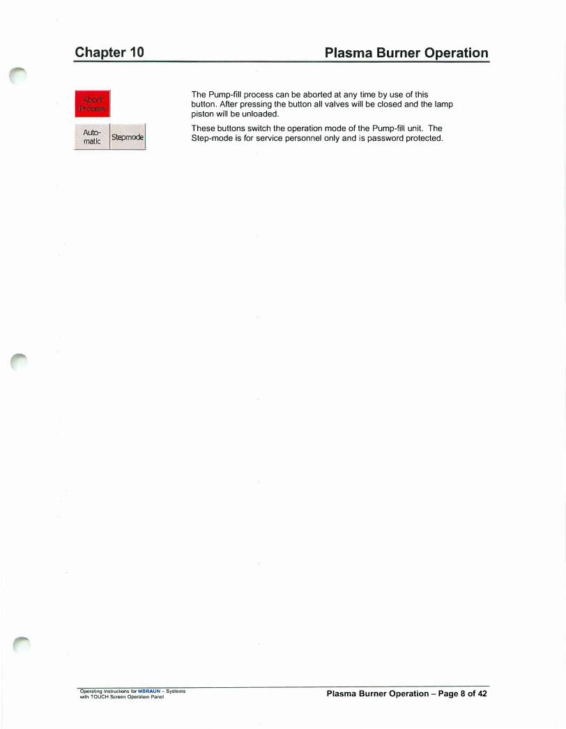
Chapter 10
Automatic S!Ef)mode
Opomting Instructions fo,- MBRAUN - Systems with TOUCH Setecn Operation Panol
Plasma Burner Operation
The Pump-fill process can be aborted at any time by use of this button. After pressing the button all valves will be closed and the lamp piston will be unloaded.
These buttons switch the operation mode of the Pump-fill unit. The Step-mode is for service personnel only and is password protected.
Plasma Burner Operation - Page 8 of 42
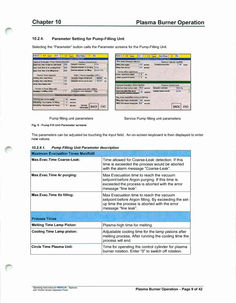
Chapter 10 Plasma Burner Operation
10.2.4. Parameter Setting for Pump-Filling Unit
Selecting the "Parameter'' button calls the Parameter screens for the Pump-Filling Unit.
:.-00:fl 0.0 1 ..... !o2: ii 0.0 l«>m .eox Pr""' r 0 !PaMlmunfvao.iMol lrnesMnd:I (soocnf�
i;;;.c..c.- .. � l-.twc:.1'1111111 to/V�:
!'M'-EY«-TIN toX.9'g-lwet
,,,...,... - (soocnf), �11••L--,Amin:
__ ,___ O'ditn .. �1.,.:
-ol�!:515e, IPl.n{q I A...,, ey.JM:
fwi' [ii:ii [ii:ii
fiFfwfw
I'
ai:w·· (o.tpati1 l.aal••: 15Pa 1v ...... -.,,.....15Pa -IY ......... ,... ... tllnu, JSdO-JP• ..:
Argcn/X......,_,.,.., � , ____ , sax:o ••
i.......--·- I sax:o ••
Ev...-..g:do m. �:fc-ttw, an. NM11ng17/es .:IClori"l,l� .. ,,.,p,/'Xlral"""10
1---.;�-;- 7 IO
0 ......
�f'I 0.0 r- :m:-r, oo
�-(pr ...... bol!noe),
1-•-- , ......... ,�---, 12.o-
On<ntolfse<�on,
Ion.,_.,.,;.;;;;-'° •• 1--....- r,, ...
�Ev-Trnes-:
i;;;:;: • ..,_, .. __ [ii:ii -
l=.:=:-.:...,.f 10 nu ..
fq - r....,.,U., � ccrdocmg.
t,a,g tllNI �' N!Cept.-1111: I O.D w,cand
r;;;; looxProoo I 0 !PaMlm1.nl-manfdd: /MabanlNlr-•: I lO
-•Se4por•IMI:
l.._..._ .. ,, 1500Pa ,Genecrbalancatw.t: 6Pa
.....
�
�--- I p::::,� END i-�""-' I 0 -
1,..,,, ... _..,..,,_, pa -�END
Pump filling unit parameters
Fig. 5 : Pump Fill Unit Parameter screens
Service Pump filling unit parameters
The parameters can be adjusted be touching the input field. An on-screen keyboard is then displayed to enter new values.
10.2.4.1. Pump Filling Unit Parameter description
Maximum Evacuation Times Manifold
Max.Evac.Time Coarse-Leak:
Max.Evac.Time Ar purging:
Max.Evac.Time Xe filling:
Process Times
Melting Time Lamp Piston:
Cooling Time Lamp piston:
Circle Time Plasma Unit:
Operating lnstn1ctions for MBRAUN - Systems with TOUCH Screen Opcralion Panel
Time allowed for Coarse-Leak detection. If this time is exceeded the process would be aborted with the alarm message "Coarse-Leak".
Max Evacuation time to reach the vacuum setpoint before Argon purging. If this time is exceeded the process is aborted with the error message "fine leak".
Max Evacuation time to reach the vacuum setpoint before Argon filling. By exceeding the set-up time the process is aborted with the error message "fine leak".
Plasma-high time for melting.
Adjustable cooling time for the lamp pistons after melting process. After running the cooling time the process will end.
Time for operating the control cylinder for plasma burner rotation. Enter "O" to switch off rotation.
Plasma Burner Operation - Page 9 of 42
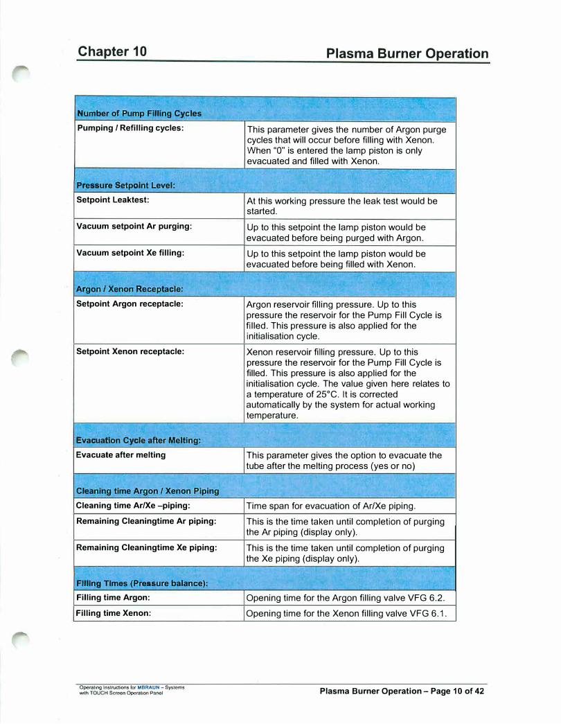
Chapter 10
Number of Pump FIiiing Cycles
Pumping / Refilling cycles:
Pressure Setpolnt Level:
Setpoint Leaktest:
Vacuum setpoint Ar purging:
Vacuum setpoint Xe filling:
Argon / Xenon Receptacle:
Setpoint Argon receptacle:
Setpoint Xenon receptacle:
Evacuation Cycle after Melting;
Evacuate after melting
Cleaning time Argon / Xenon Piping
Cleaning time Ar/Xe -piping:
Remaining Cleaningtime Ar piping:
Remaining Cleaningtime Xe piping:
FIiiing Times (Pressure balance):
Filling time Argon:
Filling time Xenon:
Operating Instructions for MBRAUN - Systems with TOUCH Screon Operation Panol
Plasma Burner Operation
This parameter gives the number of Argon purge cycles that will occur before filling with Xenon. When "O'' is entered the lamp piston is only evacuated and filled with Xenon.
-
At this working pressure the leak test would be started.
Up to this setpoint the lamp piston would be evacuated before being purged with Argon.
Up to this setpoint the lamp piston would be evacuated before being filled with Xenon.
Argon reservoir filling pressure. Up to this pressure the reservoir for the Pump Fill Cycle is filled. This pressure is also applied for the initialisation cycle.
Xenon reservoir filling pressure. Up to this pressure the reservoir for the Pump Fill Cycle is filled. This pressure is also applied for the initialisation cycle. The value given here relates to a temperature of 25°C. It is corrected automatically by the system for actual working temperature.
This parameter gives the option to evacuate the tube after the melting process (yes or no)
Time span for evacuation of Ar/Xe piping.
This is the time taken until completion of purging the Ar piping (display only).
This is the time taken until completion of purging the Xe piping (display only).
Opening time for the Argon filling valve VFG 6.2.
Opening time for the Xenon filling valve VFG 6.1.
Plasma Burner Operation - Page 10 of 42

Chapter 10 Plasma Burner Operation
Maximum Leakrate Manifold:
Maximum Leakrate: This is the maximum allowable leak rate before Xe filling, given in pressure steps.
Example: An increase in pressure from 2x10⁻³Pa to 4x10⁻³Pa would give 2 steps.
If the parameter value is exceeded the filling process will be stopped and the warning: "Fine leak" will be displayed.
Current Offset Capacltrons .. .
Offset Capacitron Argon: Offset value for the Argon reservoir pressure sensor (display only).
Offset Capacitron Xenon: Offset value for the Xenon pressure sensor device (display only).
Maximum Evacuation Times Manifold:
Max.Evac.Time Coarse-Leak: Time allowed for Coarse-Leak detection. When Overstepping this time the process would be interrupted with the alarm message "Coarse-Leak".
Max.Evacuationtime up to the Maximum evacuation time allowed for reaching setpoint "balance sensor": the pressure balance setpoint. Overstepping the
time will interrupt the process with the warning "Evacuation time overrun".
Pressure Setpolnt Level:
Setpoint Leaktest: Pressure at which leak test is performed
Sensor Balance Level: Balance of capacitron sensor
FIiiing Times Receptacles During Conditioning:
Filling time Argon receptacle
Filling time Xenon receptacle
Opornllno Instructions f0t MBRAUN - Systems with TOUCH Screen OperaUon Panel
Opening time for the Argon reservoir filling valve VFG 6.4 during operation cycle
Opening time for the Xenon reservoir filling valve VFG 6.3 during operation cycle
Plasma Burner Operation - Page 11 of 42
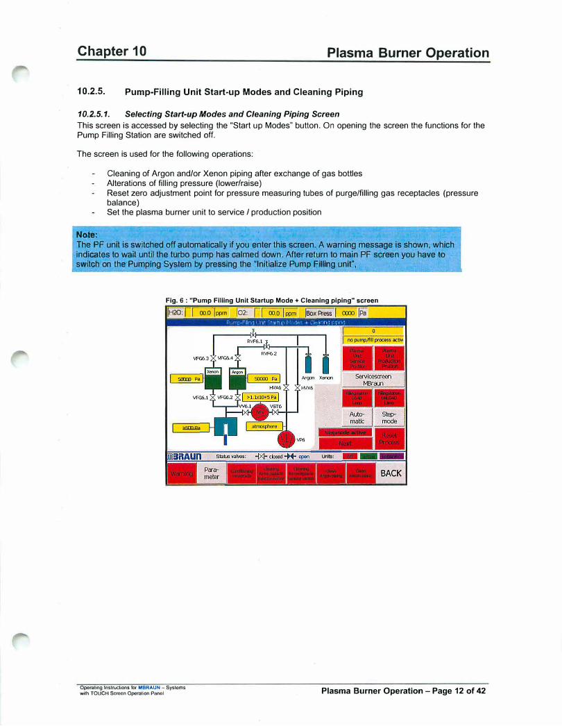
Chapter 10 Plasma Burner Operation
10.2.5. Pump-Filling Unit Start-up Modes and Cleaning Piping
10.2.5.1. Selecting Start-up Modes and Cleaning Piping Screen
This screen is accessed by selecting the "Start up Modes" button. On opening the screen the functions for the Pump Filling Station are switched off.
The screen is used for the following operations:
Cleaning of Argon and/or Xenon piping after exchange of gas bottles Alterations of filling pressure (lower/raise) Reset zero adjustment point for pressure measuring tubes of purge/filling gas receptacles (pressure balance) Set the plasma burner unit to service I production position
Note:
The PF unit is switched off automatically if you enter this screen. A warning message is shown, which indicates to wait until the turbo pump has calmed down. After return to main PF screen you have to switch on the Pumping System by pressing the "Initialize Pump Fillrng unit",
Fig. 6 : "'Pump FIiiing Unit Startup Mode + Cleaning piping" screen
IH20: nr 00.0 lppm !02: r I 00.0 I ppm !Box Press [ 00'.Xl jPa
5IDlJ Pa
>9:XJPa
U'llts:
--- - -- _, ---- ---
BACK
Operating Instructions for MBRAUN - Systems with TOUCH Screen Operation Pilnol Plasma Burner Operation - Page 12 of 42
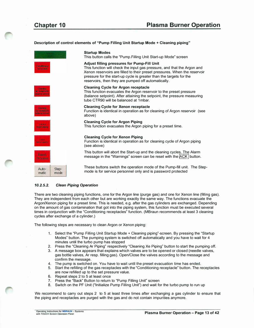
Chapter 10 Plasma Burner Operation
Description of control elements of "Pump Filling Unit Startup Mode+ Cleaning piping"
Startup Modes This button calls the "Pump.Filling Unit Start-up Mode" screen
Adjust filling pressures for Pump-Fill Unit This function will check the input gas pressure, and that the Argon and Xenon reservoirs are filled to their preset pressures. When the reservoir pressure for the start-up cycle is greater than the targets for the reservoirs, then they are pumped off automatically.
Cleaning Cycle for Argon receptacle This function evacuates the Argon reservoir to the preset pressure (balance setpoint). After attaining the setpoint, the pressure measuring tube CTR90 will be balanced at 1 mbar.
Cleaning Cycle for Xenon receptacle Function is identical in operation as for cleaning of Argon reservoir (see above)
Cleaning Cycle for Argon Piping This function evacuates the Argon piping for a preset time.
Cleaning Cycle for Xenon Piping Function is identical in operation as for cleaning cycle of Argon piping (see above)
This button will abort the Start-up and the cleaning cycles. The Alarm message in the "Warnings" screen can be reset with the� button.
These buttons switch the operation mode of the Pump-fill unit. The Stepmode is for service personnel only and is password protected
10.2.5.2. Clean Piping Operation
There are two cleaning piping functions, one for the Argon line (purge gas) and one for Xenon line (filling gas). They are independent from each other but are working exactly the same way. The functions evacuate the Argon/Xenon piping for a preset time. This is needed, e.g. after the gas cylinders are exchanged. Depending on the amount of gas contamination that got into the piping system, this function must be executed several times in conjunction with the "Conditioning receptacles" function. (MBraun recommends at least 3 cleaning cycles after exchange of a cylinder.)
The following steps are necessary to clean Argon or Xenon piping:
1. Select the "Pump Filling Unit Startup Mode + Cleaning piping" -screen. By pressing the "StartupModes" button. The pumping system is switched off automatically and you have to wait for 4minutes until the turbo pump has stopped
2. Press the "Cleaning Ar Piping" respectively "Cleaning Xe Piping" button to start the pumping off.3. A message box appears that explains which valves are to be opened or closed (needle valves,
gas bottle valves, Ar resp. filling gas). Open/Close the valves according to the message andconfirm the message.
4. The pump is switched on. You have to wait until the preset evacuation time has ended.5. Start the refilling of the gas receptacles with the "Conditioning receptacle" button. The receptacles
are now refilled up to the set pressure value.6. Repeat steps 2 to 5 at least once7. Press the "Back" Button to return to "Pump Filling Unit" screen8. Switch on the PF Unit ("Initialize Pump Filling Unit") and wait for the turbo pump to run up
We recommend to carry out steps 2 to 5 at least three times after exchanging a gas cylinder to ensure that the piping and receptacles are purged with the gas and do not contain impurities anymore.
Opemllng Instructions for MBRAUN - Systems 'Mth TOUCH Screen Oporation Panel Plasma Burner Operation - Page 13 of 42

Chapter 10 Plasma Burner Operation
10.2.5.3. Clean Receptacles OperaUon
There are two functions for cleaning the receptacles, one for the Argon line (purge gas) and one for Xenon line (filling gas). They are independent from each other but are working exactly the same way. The functions evacuate the Argon/Xenon reservoirs to the given pressure setpoint (balance pressure). After attaining the balanced setpoint the pressure measuring tube CTR90 would be balanced at 1 mbar. The balance set point should be set at less than 1x10⁻³Pa (default 7x10
-4Pa) in the parameters screen.
Note: For this function a sealed, leak-tight lamp tube must be inserted into the PF head. A message is displayed on the screen which must be confirmed when a tube is inserted.
The following steps are necessary to clean Argon or Xenon receptacles and balance sensors
1. Select the "Pump Filling Unit Startup Mode + Cleaning piping"-screen. By pressing the "StartupModes" button. The pumping system is switched off automatically and you have to wait for 4minutes until the turbo pump has stopped
2. Press the "Cleaning Ar Receptacle I balance sensor" respectively "Cleaning Xe receptacle /balance sensor" button to start the pumping off.
3. A message box appears that explains which valves are to be opened or closed (needle valves).Open/Close the valves according to the message and confirm the message.
4. The pump is switched on. You have to wait until the preset balance pressure is reached.5. Start the refilling of the gas receptacles with the "Conditioning receptacle" button. The receptacles
are now refilled up to the set pressure value.6. Press the "Back" Button to return to "Pump Filling Unit" screen7. Switch on the PF Unit ("Initialize Pump Filling Unit") and wait for the turbo pump to run up
10.2.5.4. Sumer Adjustment
To make adjustments of the plasma burners you can set the plasma burner holding plate to the service position by means of the "Plasma Unit Service Position" pushbutton. For description of burner adjustment see Section for plasma burner system. After finishing service the plate must be driven back to the working position using the push button "Plasma Unit Production Position"
Operating Instructions for MBRAUN - Systems with TOUCH Screon Operation Panel Plasma Burner Operation - Page 14 of 42
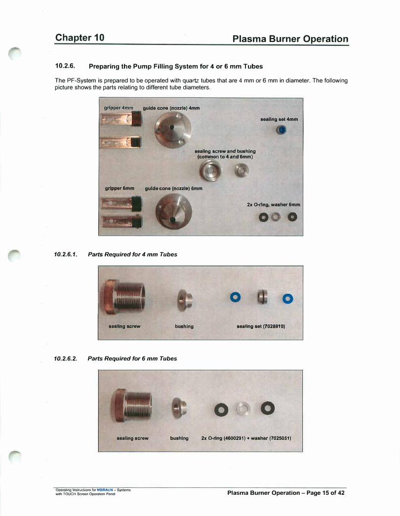
Chapter 10 Plasma Burner Operation
10.2.6. Preparing the Pump Filling System for 4 or 6 mm Tubes
The PF-System is prepared to be operated with quartz tubes that are 4 mm or 6 mm in diameter. The following picture shows the parts relating to different tube diameters.
guide cone (nozzle) 4mm
sealing screw and bushing (common to 4 and 6mm)
sealing set 4mm
grlpper 6mm guide cone (nozzle) 6mm
-·•. -:.. ____ ,.,,_,..,
10.2.6.1. Parts Required for 4 mm Tubes
•• •
1 , 14-••· l
seellng screw bushing
10.2.6.2. Parts Required for 6 mm Tubes
� .. ,,\ ...••.. _
sealing screw
Operattng Instructions fOI' MBRAUN -Syslcms with TOUCH Scroon Opcralion Panol
bushing
2x O-rtng, washer 6mm
0 0
0 0
sealing set (7028810)
0 0
2x O•rlng (4600291) + washer (7025051)
Plasma Burner Operation - Page 15 of 42
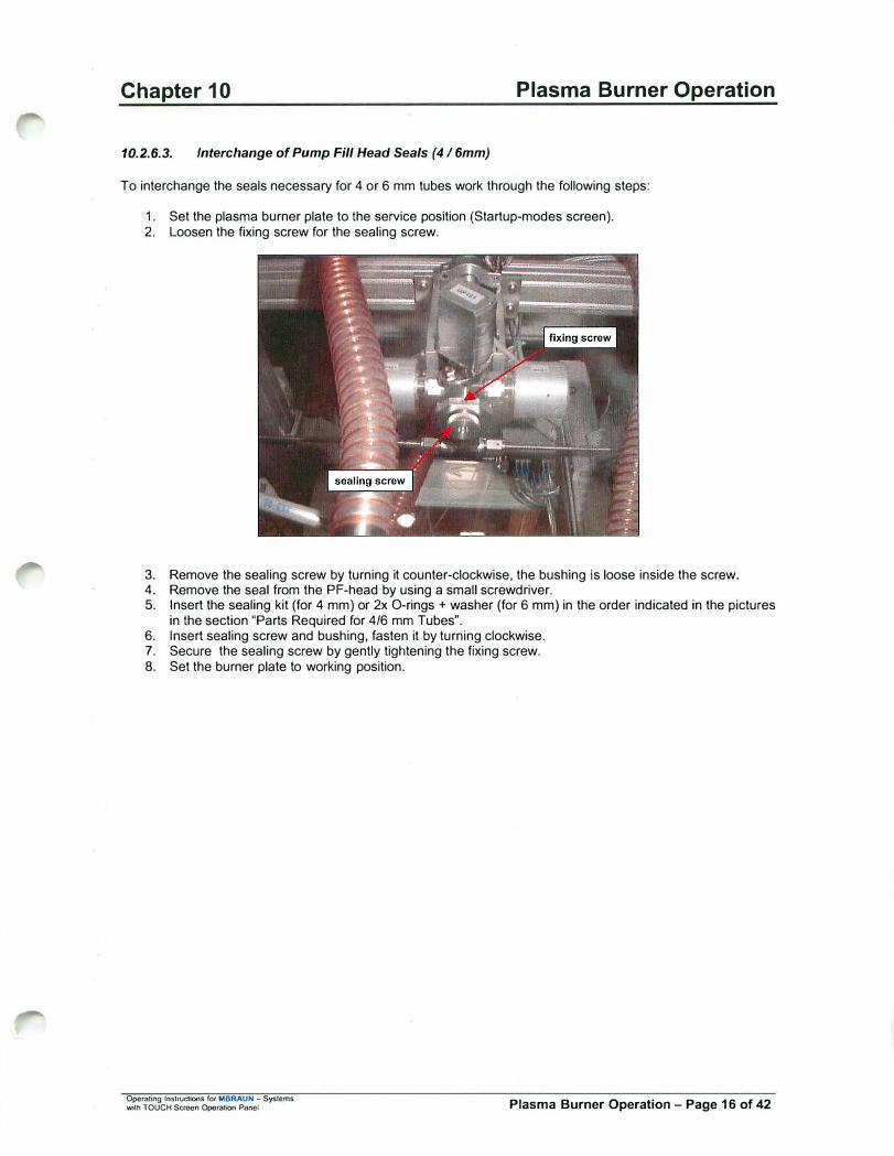
Chapter 10 Plasma Burner Operation
10.2.6.3. Interchange of Pump Fill Head Seals (4 I 6mm)
To interchange the seals necessary for 4 or 6 mm tubes work through the following steps:
1. Set the plasma burner plate to the service position (Startup-modes screen).2. Loosen the fixing screw for the sealing screw.
3. Remove the sealing screw by turning it counter-clockwise, the bushing is loose inside the screw.4. Remove the seal from the PF-head by using a small screwdriver.5. Insert the sealing kit {for 4 mm) or 2x O-rings + washer (for 6 mm) in the order indicated in the pictures
in the section "Parts Required for 4/6 mm Tubes".6. Insert sealing screw and bushing, fasten it by turning clockwise.7. Secure the sealing screw by gently tightening the fixing screw.8. Set the burner plate to working position.
Operating lnslructlOOS for MBRAUN - Systems with TOUCH Screen OporallOO Panel Plasma Burner Operation - Page 16 of 42

Chapter 10 Plasma Burner Operation
10.2.6.4. Interchange of Guide Cone and Gripper (4 I 6 mm)
To interchange grippers and guide cones proceed as follows:
1. Ensure the burner plate is in the working position.2. Remove the 2 screws from the gripper, and remove the gripper.3. Mount the selected gripper (4 or 6mm), secure it in place with the 2 screws.4. Remove the 3 guide cone screws.5. Remove the guide cone be sliding it downwards.6. Insert the selected guide cone (4 or 6mm).7. Secure the guide cone with the 3 screws.
Note:
Do not apply excessive force in any of the steps described. All parts must slide gently into position.
Operating Instructions for MBRAUN - Systoms with TOUCH Screen Operation Panel Plasma Burner Operation - Page 17 of 42

Chapter 10
10.3. MBRAUN Plasma Burner System
10.3.1. Overview
Plasma Burner Operation
The 3-torch plasma burner system is intended for the melting off of quartz glass tubes after filling it with gas at the pumping filling head. The system consists of:
1. The Plasma-Jet Controller (MB-PL-C4 ), the control electronics that is the central part of the system. Itcontains all electronics including a micro-PLC and relays to control the burners and DC-power supplies aswell as cooling water. For the Argon gas supply to the burners it is equipped with pressure control, electricvalves and flow-meters with integrated needle valves for flow adjustment. It can be operated from 115 to240 VAC. Remote control can be performed with potential-free relays.
2. The Plasma Burners (MB-PL-B 1) that emits Argon plasma to heat up non-conductive material (likequartz). It is constructed for long term operation and has only 3 parts to be exchanged if needed. Theburner is water-cooled.
3. The DC-Power Supply, which is a standard TIG power supply with remote control option.
4. The Feedthrough-Plate that supplies a gas-tight barrier between the inner clean Argon atmosphere andthe outside air. It contains all connections (water, Argon and DC-power) necessary to operate the plasmaburners inside the box.
5. The Flow Limit Switch to monitor the cooling water flow.
6. The control cables to and from the controller including a foot switch.
7. The DC.Power cables to the burners.
8. The cooling system which provides the cooling water for the plasma burners.
Ope,aUng Instructions fot MBRAUN - Systems with TOUCH Screen Operation Panel Plasma Burner Operation - Page 18 of 42
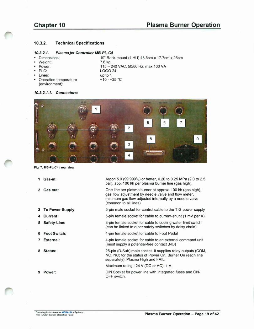
Chapter 10 Plasma Burner Operation
10.3.2. Technical Specifications
10.3.2.1. Plasma jet Controller MB-PL-C4
• Dimensions: 19" Rack-mount (4 HU) 48.5cm x 17.7cm x 26cm • Weight: 7.6 kg • Power. 115 - 240 VAC, 50/60 Hz, max 100 VA • PLC: LOGO 24 • Lines: up to 4 • Operation temperature +10 - +35 °C
(environment):
10.3.2.1.1. Connectors:
Fig. 7: MB-PL-C4 / rear view
1 Gas-in:
2 Gas out:
3 To Power Supply:
4 Current:
5 Safety-Line:
6 Foot Switch:
7 External:
8 Status:
9 Power:
Oporaling Instructions f0< MBRAUN - Systems with TOUCH Screen OporaHon Panel
Argon 5.0 (99.999%) or better, 0.20 to 0.25 MPa (2.0 to 2.5 bar), app. 100 1/h per plasma burner line (gas high).
One line per plasma burner at approx. 100 1/h (gas high), gas flow adjustment by needle valve and flow meter, minimum gas flow adjusted internally by a needle valve (common to all lines)
5-pin male socket for conlrol cable to the TIG power supply
5-pin female socket for cable to current-shunt (1 mV per A)
3-pin female socket for cable to cooling water limit switch(can be linked to other safety switches by daisy chain).
4-pin female socket for cable to Foot Pedal
4-pin female socket for cable to an external command unit(must supply a potential-free contact ,NO)
25-pin (D-Sub) male socket. It supplies relay outputs (COM,NO, NC) for the status of Power On, Burner On (each lineseparately), Plasma High and FAIL.
Maximum rating : 24 V (DC or AC), 1 A
DIN Socket for power line with integrated fuses and ONOFF switch.
Plasma Burner Operation - Page 19 of 42
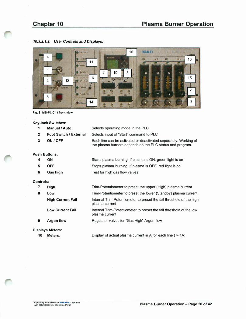
Chapter 10 Plasma Burner Operation
10.3.2.1.2. User Controls and Displays:
Fig. 8: MB-PL-C4 / front view
Key-lock Switches:
1 Manual / Auto
2 Foot Switch / External
3 ON/ OFF
Push Buttons:
4
5
6
ON
OFF
Gas high
Controls:
7 High
8 Low
High Current Fail
Low Current Fail
9 Argon flow
Displays Meters:
10 Meters:
Operating Instructions fO< MBRAUN - Systems with TOUCH Screen Opora1ion Panel
Selects operating mode in the PLC
Selects input of "Start" command to PLC
Each line can be activated or deactivated separately. Working of the plasma burners depends on the PLC status and program.
Starts plasma burning. If plasma is ON, green light is on
Stops plasma burning. If plasma is OFF, red light is on
Test for high gas flow valves
Trim-Potentiometer to preset the upper (High) plasma current
Trim-Potentiometer to preset the lower (Standby) plasma current
Internal Trim-Potentiometer to preset the fail threshold of the high plasma current
Internal Trim-Potentiometer to preset the fail threshold of the low plasma current
Regulator valves for "Gas High" Argon flow
Display of actual plasma current in A for each line(+- 1A)
Plasma Burner Operation - Page 20 of 42
Chapter 10
Display LEDs:
11 Foot pedal
External
Manual
Automatic
12 Safety llne
Gas high
Plasma high
13 Line 1-4
14 Fall
15 Flow meters
16 PLC-Display/Controls
Operating Instructions for MBRAUN - Systems with TOUCH Screen Operation Panel
Plasma Burner Operation
Indication of corresponding switch positions
Green if safety line is ok (Argon pressure and water flow)
Green if gas flow is high
Green if plasma current is high
Green if corresponding line is active (on)
Red in case if failure
Display of Argon flow
See separate description below
Plasma Burner Operation - Page 21 of 42

Chapter 10
10.3.2.2. Plasma Burner MB-PL-B1
• Overall length : 145 mm (except spare length of cathode)
• Width: 48 mm
• Height: 73 mm
• Weight: 1.4 kg
Plasma Burner Operation
• Cathode: Tungsten (LaOx) diameter 3.2 mm
• Cathode Up angle: 30°
• Anode: Mo / Cu
• Argon: 5.0 or better at 0.2 Mpa (2 bar) (80 to 1001/h)
• Water: *) 100 1/h at 0.2 MPa (2 bar), max. 0.4 MPa (4 bar) (min. drinking water quality), back pressure < 0.05 MPa (0.5 bar)
• Plasma current (Standby)
• Plasma current (High)
• Expected lifetime of Cathode
• Expected llfetlme of Anode
• Operation temperature(environment):
Max. temperature (inlet) 25 °c
Max. electric conductivity: 0.1 µSim ( 1 e-6 mm ho/cm)
pH value> 7
5.5-10A
50 - 110 A (Pulse mode 50% duty cycle) max 10 sec.
> 80 hours (Total High Current time at 80 A, 40% duty cycle)
> 300 hours (Total High Current time at 80 A, 40% duty cycle)
+10 - +40 °C
*) We recommend a separate electrically cooled cold well filled with distilled water for the cooling water supply of the burner heads.
Operating Instructions tOf MBRAUN - Systems with TOUCH Screen Operation Panel Plasma Burner Operation - Page 22 of 42
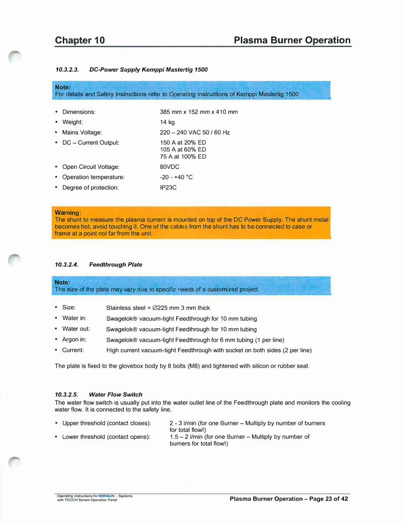
Chapter 10 Plasma Burner Operation
10.3.2.3. DC-Power Supply Kemppi Mastertig 1500
Note: For details and Safety Instructions refer to Operating Instructions of Kemppi Masteitig 1500
• Dimensions:
• Weight:
• Mains Voltage:
• DC - Current Output:
• Open Circuit Voltage:
• Operation temperature:
• Degree of protection:
Warning:
385 mm x 152 mm x 410 mm
14 kg
220 - 240 VAC 50 / 60 Hz
150 A at 20% ED 105 A at 60% ED 75 A at 100% ED
BOVDC
-20 - +40 °C
IP23C
The shunt to measure the plasma current is mounted on top of the DC Power Supply. The shunt metal becomes hot; avoid touching it. One of the cables from the shunt has to be connected to case or frame at a point not far from the unit.
10.3.2.4. Feedthrough Plate
Note: The size of the plate may vary due to specific needs of a customized project.
• Size: Stainless steel = 0225 mm 3 mm thick
• Water in:
• Water out:
• Argon in:
Swagelok® vacuum-tight Feedthrough for 10 mm tubing
Swagelok® vacuum-tight Feedthrough for 10 mm tubing
Swagelok® vacuum-tight Feedthrough for 6 mm tubing (1 per line)
• Current: High current vacuum-tight Feedthrough with socket on both sides (2 per line)
The plate is fixed to the glovebox body by 8 bolts (MB) and tightened with silicon or rubber seal.
10.3.2.5. Water Flow Switch
The water flow switch is usually put into the water outlet line of the Feedthrough plate and monitors the cooling water flow. It is connected to the safety line.
• Upper threshold (contact closes):
• Lower threshold (contact opens):
Operating lnstructk>ns for MBRAUN - Systems with TOUCH Saeon OpcraUon Panel
2 - 3 I/min (for one Burner - Multiply by number of burners for total flow!) 1.5 - 2 I/min (for one Burner - Multiply by number of burners for total flow!)
Plasma Burner Operation - Page 23 of 42
r
Chapter 10
10.3.2.6. Control Cables
The control cables are made to measure.
• Cable to water flow switch (Safety Line)• Cable to foot switch (Foot Switch)• Cable to DC-Power Supply (To Power Supply)• Cable to shunt at power supply (Current)
Plasma Burner Operation
The cables to external control and status have to be made by the customer. The plug for control cable is supplied with the controller.
10.3.2. 7. DC Power Cables
The power cables are made to measure. They are copper cables with a cross section of 16mm2 and furnished with the necessary plugs. The insulation material of the cables is silicon. The surface of the cables can get wann (max. 50 °C) especially at high plasma currents of 100A and more and long "high" periods.
10.3.2.8. Coollng System
Neslab chiller, operated with distilled water, flow is monitored by flow switch, insufficient flow creates a failure to the safety line on the plasma controller (MB-PL-C4)
Operating Instructions for MBRAUN - Systems with TOUCH Screen Operation Panel Plasma Burner Operation - Page 24 of 42

Chapter 10 Plasma Burner Operation
10.3.3. System Description
The MBraun Plasma Burner System has been designed for safe automatic operation. All adjustments and selections are made at the central controller.
A system overview is given below (Fig. 9).
Foot Switch
I
External
I
Argon
I
AC 110-220 V
I
Controller ·MB-PL-C4 Argon (1 • 4) Current I
(1 • 4)
I Shunt I
+ DC PowerSupply(TIG-
Converter
:·---··--···--
l�ling Water i·-·····-·-··-··-··� �
Fig. 9: Plasma Burner System Schematic
Oporatiog lnstructi<>M fDf MBRAUN - Systoms 'tYilh TOUCH Screen Operation Panel
I
-
I
Safety � Power I Line
Supply (1 • 4)
:1-GND
� Feedthrough IPlate
-
Plasma Burner
Flow Switch
Plasma Burner Operation - Page 25 of 42
Chapter 10 Plasma Burner Operation
Wamlngs: The MBraun Plasma Burner system has been designed especially for use of an Argon plasma flame in an Argon filled glove box. Use in other atmospheres may alter the specs and/or damage the burner head. The burner must not be operated in ambient air for any circumstances.
The plasma burners need a very clean (particles as well as ions) and cold water for long operational life. We recommend a separate electrically cooled cold well filled with distilled water for the cooling water supply of the burner heads.
l1he Plasma Burners emit an extremely hot plasma "flame" (several thousand degrees centigrade!) that may destroy material in less than a second and can cause severe burnings of skin (even through gloves, which melt immediately when exposed to the plasma!) The use of the plasma is fully under responsibility of the customer (operator) and only experienced or trained people should handle it. Additional shielding and safety switches may be necessary to protect operators.
The plasma emits an extremely intensive visible and UV radiation. Do not operate the plasma burner unless the eyes of fhe operators are protected (protection grade as for TIG welding!). Plastic and rubber material directly exposed to the UV radiation may rapidly age and become brittle and mechanically unstable. Proper shieldi171g of the radiation is highly recommended.
The Plasma Burner electrodes are mounted on an insulation plate. Do not connect any of the metal parts of the Anode to other ground parts to avoid ground loops! Keep away any metal parts from the Cathode at least 50 mm to avoid spurious plasma ignition.
The plasma burners have two modes of operation: stand-by mode (Plasma Low) and working-mode (Plasma High). Normally the burners are in stand by mode to prolong the life of the electrodes and to save power and gas. They can run for long time in this "Low Current" state. So the critical ignition of the plasma with the high frequency high voltage has to be done only after longer intervals where the whole system is switched off. The preset of the low current can be done with the "LOW" potentiometer. The burners are switched to work mode only for a short time when melting of quartz tubes is in progress. Adjustment of the high current is done with the "HIGH" potentiometers.
When the controller MB-PL-C4 is powered, the red "STOP" light is on indicating that the plasma burners are off. The "ON" push button does not work in this state.
If the cooling water flow and the plasma Argon pressure are within the specified range, the "Safety Line" LED is on (green). This safety line can be daisy chained and has the highest priority behind mains power to control whether the plasma can be on or off.
The plasma burner lines can be activated or deactivated line by line by the key switches. If this switch is ON, the gas valve for the respective line opens. When operating the pushbutton "GAS HIGH" the flow-meter shows the Argon flow through the burner; the flow can be adjusted with the needle valve below. A small gas flow bypasses the "GAS HIGH" valve to allow the low plasma operation (stand by), but if the line is switched OFF with the key, there is no flow at all. This has been made to save Argon gas.
Note: Activating a line by means of the key switch does not automatically mean to switch on the plasma of this line, but only puts this line into the main cycle. Deactivating a line means switch the burner off independent of 1he main cycle.
· ·
Activating the pushbutton "ON" when the safety line is ok will start the plasma burners (Ignition) that are switched on and will set them to standby mode. The pushbutton "ON" lights green and also the LED's of the activated lines are on. If the plasma of an activated line does not burn within the preset current limits, "FAIL" will be indicated (red light) and the system goes into the "OFF" state within 1 second. OFF state means that all burners of the controller are OFF. The "Fail" condition is reset with the "ON" pushbutton
Operating tnstrucUons for MBRAUN - Systems with TOUCH Screen Operalion Panel Plasma Burner Operation - Page 26 of 42
Chapter 10 Plasma Burner Operation
To activate the plasma burner for the high current operation, the DC-Power Supply gets the preset value from the "HIGH" potentiometer. The FAIL-electronics also switches to the higher threshold to watch the high plasma current. The controller allows two procedures to perform the "HIGH CURRENT" operation of the plasma burner:
1. Set the key switch to "MANUAL"The gas flow stays HIGH all the time. During activation of the foot pedal or external relay (contact) theplasma of the burner(s) works with the HIGH current. If the contact is deactivated, the plasma burns withthe LOW current. Adjustment of the high current is easily done for each line in this mode.
2. Set the key switch to "AUTO"The gas flow stays low. When the foot pedal or the external relay is activated, an automatic cycle startsindependent of the duration of the activation signal: The gas switches to HIGH, after a time interval 11 the plasma goes HIGH for a time 12, and then the gas stays HIGH for another time interval 13. The time intervals are programmed in the PLC (LOGO).
If one of the following conditions occurs:
• The safety line is disabled (water, gas)• The "OFF" pushbutton is pressed• The FAIL condition occurs (plasma current too low)
While the system is in any status described above or during the standby mode all burners are switched off immediately and after one second the gas flow is set to LOW.
The DC Power Supplies operate with the controller and do not need any operator activity. If they do not work, the FAIL signal will indicate that no plasma current is present.
The actual plasma current is displayed for each line by a front panel display. This display as well as the control circuits of the plasma current uses the voltage drop (in mV) across a shunt of 1 mO that is mounted on top of the TIG power supply. So 1 mV corresponds to 1 A.
Warning: The remote control of the Kemppi power supplies by the controller is only possible when all front switches of the Kemppi Mastertig 1500 are set properly (see also warning label at the power supply). A wrong setting can disable the shutoff possibility described above. This could destroy the burner completely and bring water into the glovebox
Operating Instructions for MBRAUN - Systems with TOUCH Screen Operation Panel Plasma Burner Operation - Page 27 of 42
Chapter 10
10.3.4. Operation (Software 8V1.0)
10.3.4.1. First Setup
Note:
Plasma Burner Operation
The description in this paragraph assumes that all electrical, g.rs and water connections are installed properly by MBRAUN and the box is still open to facilitate the mounting of the burners.
1. Check that all control cables to the controller unit (see encl. drawing "Plugs and Sockets") are connectedproperly. Each TIG Power Supply has own control cables (Line 1, 2, 3). The sockets at the rear side of thecontroller are different to avoid wrong connections.Check carefully that Line 1 control cables go to Line 1 TIG power supply etc.
2. Check connection of the foot switch to the socket "Foot Switch"
3. Check connection of the DC power lines from TIG power supply to the Feedthrough plate.
4. Check carefully, that: Line 1 plugs are in Line 1 sockets etc. (+) and(-) plugs are in the respective sockets.
5. Check connection of the protective ground cable of the DC power line to the box (screw). This cable isconnected with the + cable coming from the shunt.
6. Check connection of gas lines (GAS OUT) of Line 1 to the Feedthrough plate Line 1, etc.
7. Connect the Argon gas (Quality 5.0 or better) to the controller GAS IN. Use high quality pressure reducerssuited for high purity gas! Adjust the gas pressure to 0.2 MPa (2.0 bar) up to 0.3 MPa (3.0 bar).
Note:
If you use a new gas bottle it is recommended to apply a cleanin{I cycle several times: Open the bottle valve for a second while having the outlet of the pressure reducer closed. Let the gas stabilize for some seconds, then open the outlet valve until the pressure Is zero. Close the outlet valve. - This procedure removes oxygen even from the cavities of the pressure reducer and assures the quality of the Argon that is In the bottle.
8. Switch on the power of the controller. The red light of the pushbutton "OFF" must be on.
9. Switch lines to be used to ON (line 1 to 3) by means of the key switches.
10. Press the small button "GAS HIGH". Now the flow-meters of all lines must show a flow of around 100 1/h. If not, check the gas supply line to the controller and the gas pressure! Release the button and switch mainsoff.
11. Check connection of the burners inside the box with the DC power lines. Watch the Line number and thepolarity! Check connection of Water-In, Water-Out and Argon hoses to the appropriate connectors. Watchthe Line number, too! Be sure the Swagelok® connectors are securely fastened and tight. Do not applytoo much force!
12. Check the cooling water line outside the box. The line must be connected to the chiller operated withdistilled water (recommended) or a clean and cool water supply (see data 10.3.2.2). Activate the coolingwater supply and check the pressure. Check the water connections inside the box for tightness!
13. Now the box should be hermetically closed, flushed and operated under Argon.
Warning: The plasma burner must not at all be operated under air or gas containing more than 100 ppm of Oxygen. Even if the Argon supplied to the burner is Oxygen-free the plasma flame sucks Oxygen from the side and so the tip (Nozzle) will be oxidized and destroyed.
--------------�--------
Operating Instructions for MBRAUN - Systems with TOUCH Screen Operation Panel Plasma Burner Operation - Page 28 of 42

Chapter 10 Plasma Burner Operation
10.3.4.2. First operation
It is assumed that the box is under Argon and the Oxygen content is below 100 ppm.
Warning: The plasma burners now must be in a safe operation positionl This includes the safety distance to the lip of the burner as well as the necessary shielding against light and UV-radiation of the plasma flame. (see also 10.3.3: Warnings)
------
1. Switch on the power of the controller (power switch on rear panel). The red light "OFF" must be on.
2. Apply the Argon at nominal pressure
3. Switch on the cooling water (chiller)
4. Now the LED "Safety Line" must be on. If not:Check the control cable "Safety line" from the back to the flow switch.Check the cooling water flow and pressureCheck the Argon pressure (all valves open?)
Note: The 'flow switch for the cooling water has been adjusted for a minimum flow-rate of approx. 0.7§ 1/h fer eac:li line, so 2.251/h for the three-line assembly. It can be checked by removing the plug ef the flow-switeh and measuring whether the switch is closed (enough flow-rate) or opened. Usually the pressure of the water is too low when the switch is not activated. One reason can be that the back-pressure of the cooling water at the outlet of the flow-switch is too high. This results in a lower differential pressure of the cooling water between water In and Out and so in a lower flow-rate.
5. Set the key-switch AUTO I MANUAL to MANUAL (check corresponding LED).
6. Set the key switch FOOT SWITCH/ EXTERNAL to FOOT SWITCH (LED!)
7. Set the switch of Line 1 to on. Press the "GAS HIGH" pushbutton for at least 1 minute to flush all gas lineswith clean Argon. Watch the flow meter; if necessary readjust the flow rate with the needle valve. The gasflow of line 1 must be at 100 1/h.
8. Switch the power (mains) of the TIG DC Power Supply of Line 1 to ON (Green light in the power switchmust be on).
9. Press the foot switch down and hold it.
10. Now press the pushbutton ON. The plasma of line 1 must start immediately with a current of more than 50A. If FAIL comes (and there is no bright plasma flame) check all steps above! Is Safety Line still on? Ifthere is a flame but FAIL comes, the current fail threshold is higher than the actual plasma current. (see10.3.4.5 and 10.3.4.6)
11. Release the foot switch; the plasma burns at low current (approx. 5 A). The flame may look unstable asthe current is too low to fill the plasma chamber, this is normal.
12. Activate the foot switch again and the plasma burns immediately at high current.
13. Repeat from step 7 for the other lines (2 to 3).
14. Set the mode switch to AUTO. Watch the gas flow: it comes down to almost zero. The GAS HIGH LED is off.
15. Activate the foot switch. The gas flow will go up (GAS HIGH LED on), and then the plasma will go to HIGH(LED). The automatic cycle ends, when the foot switch is released. (The GAS HIGH will go down after ashort delay).
Operating Instructions for MBRAUN - Systems wilh TOUCH Screen Operation Panel Plasma Burner Operation - Page 29 of 42
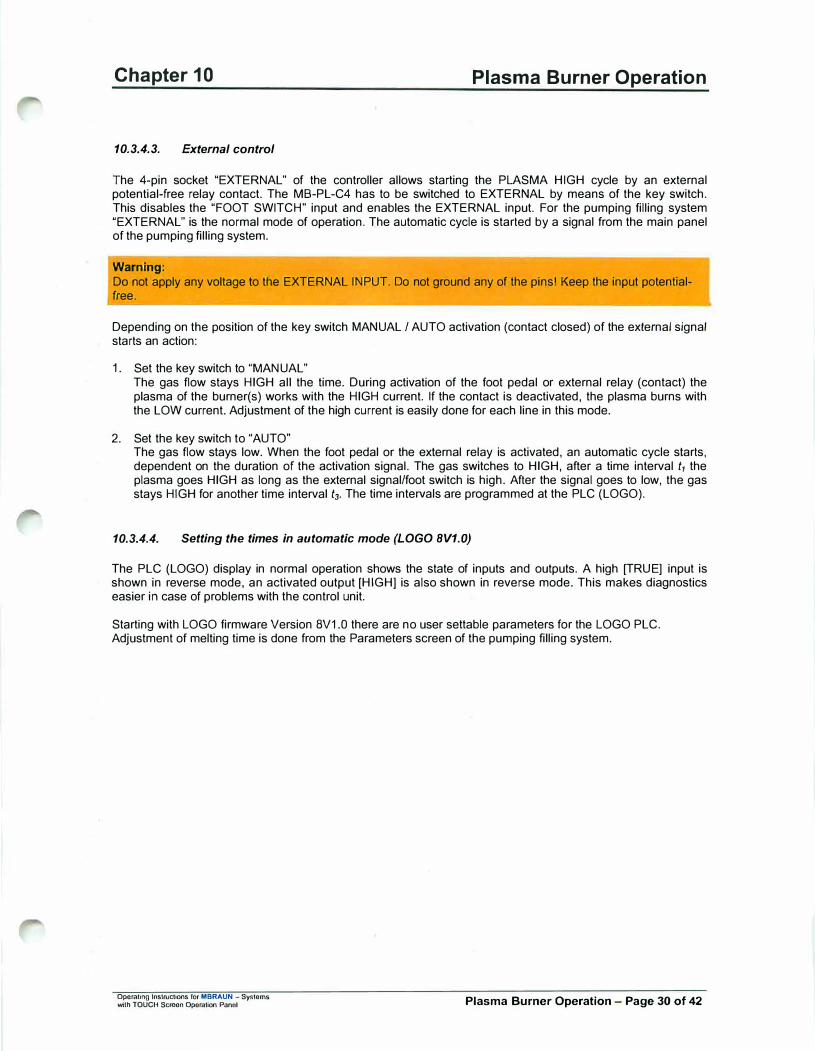
Chapter 10
10.3.4.3. External control
Plasma Burner Operation
The 4-pin socket "EXTERNAL" of the controller allows starting the PLASMA HIGH cycle by an external potential-free relay contact. The MB-PL-C4 has to be switched to EXTERNAL by means of the key switch. This disables the "FOOT SWITCH" input and enables the EXTERNAL input. For the pumping filling system "EXTERNAL" is the normal mode of operation. The automatic cycle is started by a signal from the main panel of the pumping filling system.
Warning: Do not apply any voltage to the EXTERNAL INPUT. Do not ground any of the pins! Keep the input potentialfree.
Depending on the position of the key switch MANUAL / AUTO activation (contact closed) of the external signal starts an action:
1. Set the key switch to "MANUAL"The gas flow stays HIGH all the time. During activation of the foot pedal or external relay (contact) theplasma of the burner(s) works with the HIGH current. If the contact is deactivated, the plasma burns withthe LOW current. Adjustment of the high current is easily done for each line in this mode.
2. Set the key switch to "AUTO"The gas flow stays low. When the foot pedal or the external relay is activated, an automatic cycle starts,dependent on the duration of the activation signal. The gas switches to HIGH, after a time interval t, theplasma goes HIGH as long as the external signal/foot switch is high. After the signal goes to low, the gasstays HIGH for another time interval t3. The time intervals are programmed at the PLC (LOGO).
10.3.4.4. Setting the times in automatic mode (LOGO 8V1.0)
The PLC (LOGO) display in normal operation shows the state of inputs and outputs. A high [TRUE] input is shown in reverse mode, an activated output [HIGH] is also shown in reverse mode. This makes diagnostics easier in case of problems with the control unit.
Starting with LOGO firmware Version 8V1 .0 there are no user settable parameters for the LOGO PLC. Adjustment of melting time is done from the Parameters screen of the pumping filling system.
Operating Instructions for MBRAUN - Systems with TOUCH Screon Operation Panol Plasma Burner Operation - Page 30 of 42
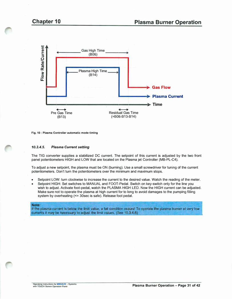
Chapter 10
-
C: Q) ... ... ::s 0 Q) -
n:,
0::
� 0 U::
, "
.
-
+--+ Pre Gas Time
(B13)
Gas High Time (806)
Plasma High Time (B14)
Fig. 10: Plasma Controller automatic mode timing
10.3.4.5. Plasma Current setting
Plasma Burner Operation
.
+--+ Residual Gas Time (=B06-B13-B14)
-,
---,
--,,
Gas Flow
Plasma Current
Time
The TIG converter supplies a stabilized DC current. The setpoint of this current is adjusted by the two front panel potentiometers HIGH and LOW that are located on the Plasma jet Controller (MB-PL-C4).
To adjust a new setpoint, the plasma must be ON (burning). Use a small screwdriver for tuning of the current potentiometers. Don't turn the potentiometers over the minimum and maximum stops.
• Setpoint LOW: turn clockwise to increase the current to the desired value. Watch the reading of the meter.• Setpoint HIGH: Set switches to MANUAL and FOOT-Pedal. Switch on key-switch only for the line you
wish to adjust. Activate foot-pedal, watch the PLASMA HIGH LED. Now the HIGH current can be adjusted.Make sure not to operate the plasma at high current for to long to avoid damages to the pumping fillingsystem by overheating(<= 30sec is safe). Release foot pedal.
Note:
If the plasma current is below the limit value, a fail condition occurs! To operate ffie plasma burner at very low currents it may be necessary to adjust the limit values. (See 10.3.4.6)
Operating lnstruct;Qns for MBRAUN - Systems with TOUCH Saeen Opomlion Panef Plasma Burner Operation - Page 31 of 42

Chapter 10 Plasma Burner Operation
10.3.4.6. Current Limit Value Setting (FAIL - condition)
Warning:
The operations described below are not necessary for normal plasma burner operation. Since change of these settings can invalidate safety features, we recommend contacting MBRAUN service for these operations.
For safety reasons the controller MB-PL-C4 contains an independent control electronic to monitor the plasma current and to trigger an alarm (FAIL) if one of·the lines is working at a too low current. If FAIL occurs, the controller is set to OFF mode, i.e. all burners are switched off immediately. Activating the ON pushbutton resets FAIL and starts the burners, but if the FAIL-condition is still valid, FAIL is set again after 1 - 2 seconds.
Note:
FAIL Is not activated by any failure condition of the SAFETY LINE. A failure condition on the safety line sets the controller Into OFF mode only and so also switches off all burners.
The control electronic has two limit values for each line, one for the LOW plasma current and one for the HIGH plasma current. Switching the plasma between HIGH and LOW also switches the limit values of the control electronic. The actual value for the current is taken from the shunt in the + line of the burner's current cable. 1 A corresponds to 1 mV across the shunt. This value is also used for the display of the actual current.
The values are factory set to 5 A LOW and 50 A HIGH. Accuracy is+- 5% (or 1A, if greater).
Notes: The FAIL thresholds are not designed to control the accuracy of the plasma current! They should be only used to trigger at major faults. So it rs strongly recommended to set the thresholds not higher than 90% of the nominal current (better 80%).
To change the limit values the controller MB-PL-C4 has to be disconnected from all rear connectors and after loosening the 4 front screws pulled out of the table top case.
Warning: The following procedure has to be performed only by skilled electronic experts. Special care has to be taken to avoid electric hazard, as near the mains connector and at the short line to the 24 V power supply the mains voltage is present. All other parts of the controller only operate with 24 VDC, but may be delicate electric or electronic parts.
----------
The electronic board is located at the right side of the controller (seen from front). The board contains four pairs of potentiometers (one pair for each channel) and a single potentiometer that should not be changed.
The LEDs beside the potentiometers are ON if the actual current is less the limit value. The LED HIGH is on when the thresholds HIGH are active. The LED FAIL indicates that the FAIL condition comes (short pulse) The Jumper JP1 allows switching to the HIGH condition when connected. Below each pair of potentiometers there is a test pin, the reference ground pin is near to the front.
Operating Instructions for MBRAUN - Syslems 'Mlh TOUCH Scrcon Operation Panol Plasma Burner Operation - Page 32 of 42
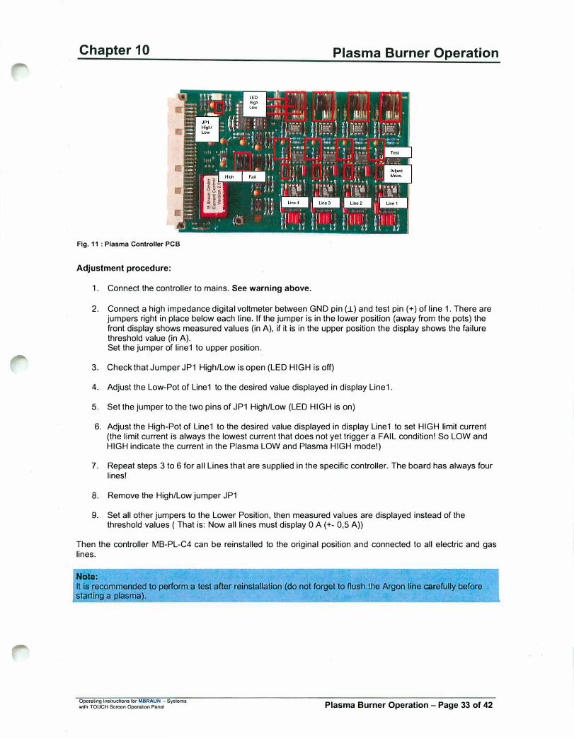
Chapter 10
Fig. 11 : Plasma Controller PCB
Adjustment procedure:
1. Connect the controller to mains. See warning above.
Plasma Burner Operation
2. Connect a high impedance digital voltmeter between GND pin (..L) and test pin(+) of line 1. There arejumpers right in place below each line. If the jumper is in the lower position (away from the pots) thefront display shows measured values (in A), if it is in the upper position the display shows the failurethreshold value (in A).Set the jumper of line1 to upper position.
3. Check that Jumper JP1 High/Low is open (LED HIGH is off)
4. Adjust the Low-Pot of Line1 to the desired value displayed in display Line1.
5. Set the jumper to the two pins of JP1 High/Low (LED HIGH is on)
6. Adjust the High-Pot of Line1 to the desired value displayed in display Line1 to set HIGH limit current(the limit current is always the lowest current that does not yet trigger a FAIL condition! So LOW andHIGH indicate the current in the Plasma LOW and Plasma HIGH mode!)
7. Repeat steps 3 to 6 for all Lines that are supplied in the specific controller. The board has always fourlines!
8. Remove the High/Low jumper JP1
9. Set all other jumpers to the Lower Position, then measured values are displayed instead of thethreshold values ( That is: Now all lines must display O A(+- 0,5 A))
Then the controller MB-PL-C4 can be reinstalled to the original position and connected to all electric and gas lines.
Note:
It is recommended to perform a test after reinstallation (do not forget to flush the Argon line carefully before starting a plasma).
Operating lnslructlOOS for MBRAUN - Systems wilh TOUCH Screen Operation Panol Plasma Burner Operation - Page 33 of 42

Chapter 10
10.3.5.
10.3.5.1.
The Plasma Burner MB-PL-81
Description
Anode nozzle
Fig. 12 : Plasma Burner MB-PL-81
Plasma Burner Operation
Removable cathode hol• der a■sembly
---> .... --... '
Argon In Water out
Water In connectors
The MB-PL-B1 consists of the Burner body and the removable cathode holder assembly.
The body has a base plate made of Delrin®. The base plate has the connectors for cooling water and Argon. It has inner pipes to conduct the water and gas to the metal parts. The base plate supplies two holes M6 to hold the whole burner and so insulate the burner electrodes from ground. Usually the Anode potential is near to ground level(+ approx. 100 mV); the (hot) cathode level is at approx. -10 to -20 VDC referred to ground. High frequency ignition is always at cathode.
Notes:
Do not connect any of the metal parts of the Anode to other ground parts to avoid ground loops Keep any metal parts away from the Cathode at least 50 mm to avord spurious plasma ignition.
The two M6 holes are 75 mm from front end of the baseplate at 36 mm distance from each other (symmetrical to the long axis of the baseplate)
Warnings: All other screws are for manufacturing purpose only! Never loosen any of the screws. There are no serviceable parts inside the burner.
Do not drill other holes to hold the burner.
The baseplate is fixed to the anode/cathode block. The larger anode has a central opening for the insulator and the cathode rod. The cooling water nows near to the Anode nozzle to remove the heat efficiently. The fixed part of he cathode holder is also water-cooled and separated from the anode by an insulator. The plasma gas (Argon) nows into a chamber between anode and cathode and then passes through the insulator pipe
(ceramic) to the nozzle.
The cathode holder assembly consists of three parts (and the Tungsten rod) and allows fixing the cathode rod even outside the box, so that adjustment of the cathode is not necessary inside the box. The standard welding rods are longer than necessary and have enough spare length for many times grinding the lip.
The fixed parts of anode and cathode have holes and screws to connect the 16 mm2 Copper cables for the plasma current.
Warning:
Operating Instructions for MBRAUN - Systems with TOUCH Sa-ocn Operation Panel Plasma Burner Operation - Page 34 of 42
Chapter 10 Plasma Burner Operation
Do not connect any of the electrodes to ground. The protective ground for the burner is at one point near the power supply only.
There are only three parts for replacement or field service:
1 . The Cathode Rod Standard is MBraun Part Number 701 2010
2. The Ceramic InsulatorStandard is MBraun Part Number 701 2011
3. The Anode Tip (nozzle)Standard is MBraun Part Number 701 2042
Note: The plasma burning chamber is fully Integrated inside the Anode Tip, so even "spurious burning" may only affect the exchangeable Anode Tip and not the anode body.
10.3.5.2. Exchange of the Anode Nozzle (Tip)
The anode nozzle is a bimetal device with a centre part made of Molybdenum and a screw part made of Copper. This has been designed to increase the heat transfer between the nozzle and the anode body.
The nozzle can be loosened and tightened using a 15mm open-ended wrench. To screw in a new nozzle do not use a tool but do it with the hand first. The new nozzle should fit easily and without force, so that a wrench is needed only for the last degrees of turning. Be sure that the cera'mic insulator is in place.
Warning:
I)
Do not use loo much force to tighten the nozzle. The Copper screw and its Copper counterpart are quite soft metals and will be destroyed by high force.
Note: The ceramic insulator tube must slip into the nozzle when the nozzle is screwed in. If there is a higher resistance when screwing the nozzle manually, take the nozzle and the insulator tube out and try how the tube fits into the back of the nozzle. It should easily slip into the copper part until it reaches the Molybdenum part. If it is too narrow, the copper opening has to be machined to 8 mm (+0.8 mm) inner diameter.
Opomling lnslructions for MBRAUN - Sysloms with TOUCH Scroon OperaUon Panel Plasma Burner Operation - Page 35 of 42
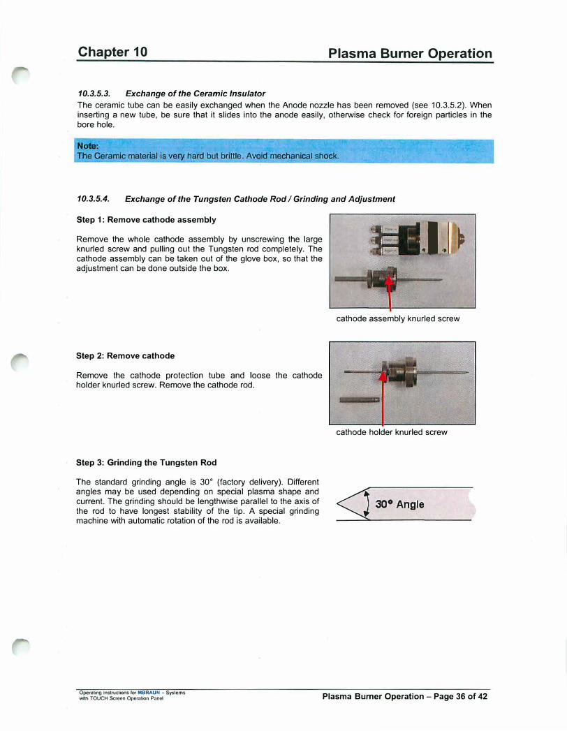
Chapter 10 Plasma Burner Operation
10.3.5.3. Exchange of the Ceramic Insulator
The ceramic tube can be easily exchanged when the Anode nozzle has been removed (see 10.3.5.2). When inserting a new tube, be sure that it slides into the anode easily, otherwise check for foreign particles in the bore hole.
Not&:
The Ceramic material is very hard but brittle. Avoid mechanical shock.
10.3.5.4. Exchange of the Tungsten Cathode Rod I Grinding and Adjustment
Step 1: Remove cathode assembly
Remove the whole cathode assembly by unscrewing the large knurled screw and pulling out the Tungsten rod completely. The cathode assembly can be taken out of the glove box, so that the adjustment can be done outside the box.
Step 2: Remove cathode
Remove the cathode protection tube and loose the cathode holder knurled screw. Remove the cathode rod.
Step 3: Grinding the Tungsten Rod
The standard grinding angle is 30° (factory delivery). Different angles may be used depending on special plasma shape and current. The grinding should be lengthwise parallel to the axis of the rod to have longest stability of the lip. A special grinding machine with automatic rotation of the rod is available.
1. ►
cathode assembly knurled screw
cathode holder knurled screw
<j 30° Angle
Operating Instructions for MBRAUN - Systems with TOUCH Scrocn OpomUon Panel Plasma Burner Operation - Page 36 of 42

Chapter 10 Plasma Burner Operation
Step 4: Adjustment of Cathode (Tungsten) Rod
Note:
The correct burning of the plasma and the long life of cathode and anode of the burner depends strongly on the accurate adjustment of the cathode tip in relation to the anode nozzle.
Step 4a: Longitudinal Adjustment:
Note:
It Is essential that the plasma burns primarily inside the Anode nozzle. Therefore tfie tip of the Tungsten .roamust be behind the surface of the anode but still wilhin the limits of the Molybdenum nozzle.
First fasten the cathode assembly without the Tungsten rod. Then insert an accurately ground tungsten rod until it touches the adjustment screw. Turn the rod by hand and look for straightness of the rod.
Note:
If the rod is bent, the tip of the rod cannot be centred in the anode nozzle! Then use a new cathode rod.
Fasten the rod with the smaller knurled screw. Then unscrew the large knurled screw and pull the assembly out of the tool. Remount the cathode protection tube.
The cathode assembly is now properly adjusted and ready to be mounted on the plasma burner by just inserting the Tungsten rod and fastening the large knurled screw.
Note:
If you use the adjustment tool for the first time it is recommended to adjust the tool with a well working cathode assembly prior to removal of the rod.
The tip of the cathode rod must be centred in the anode nozzle hole. Small misalignment can be changed by loosening and turning the whole cathode assembly and fastening it again. Eventually the procedure must be done several times
1-2mm
Fig. 13 : Correct position of cathode tip
Operating lnslructions for MBRAUN - Systems with TOUCH Scroon Operation Pnnol Plasma Burner Operation - Page 37 of 42
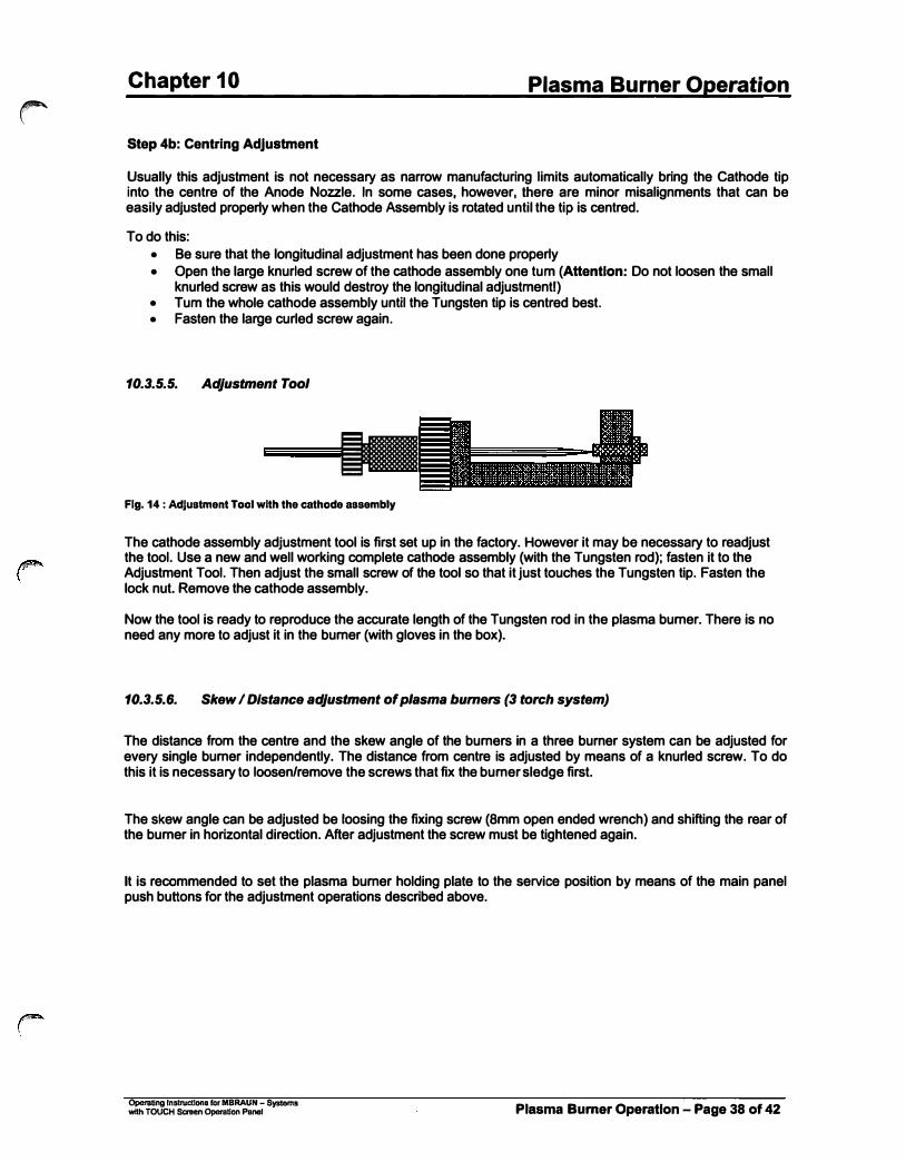
r
Chapter 10 Plasma Burner Operation
Step 4b: Centring Adjustment
�sually this adjustment is not necessary as narrow manufacturing limits automatically bring the Cathode tip into the centre of the Anode Nozzle. In some cases, however. there are minor misalignments that can be easily adjusted properly when the Cathode Assembly is rotated until the tip is centred.
To do this: • Be sure that the longitudinal adjustment has been done properly• Open the large knurled screw of the cathode assembly one tum (Attention: Do not loosen the small
knurled screw as this would destroy the longitudinal adjustmentr)• Tum the whole cathode assembly until the Tungsten tip is centred best.• Fasten the large curled screw again.
10.3.5.5. Adjustment Tool
-Fig. 14 : Adjustment Tool with the cathode assembly
The cathode assembly adjustment tool is first set up in the factory. However it may be necessary to readjust the tool. Use a new and well working complete cathode assembly (with the Tungsten rod); fasten it to the Adjustment Tool. Then adjust the small screw of the tool so that it just touches the Tungsten tip. Fasten the lock nut. Remove the cathode assembly.
Now the tool is ready to reproduce the accurate length of the Tungsten rod in the plasma burner. There is no need any more to adjust it in the burner (with gloves in the box).
10.3.5.6. Skew I Distance adjustment of plasma burners (3 torch system)
The distance from the centre and the skew angle of the burners in a three burner system can be adjusted for every single burner independently. The distance from centre is adjusted by means of a knurled screw. To do this it is necessary to loosen/remove the screws that fix the burner sledge first.
The skew angle can be adjusted be loosing the fixing screw (8mm open ended wrench) and shifting the rear of the burner in horizontal direction. After adjustment the screw must be tightened again.
It is recommended to set the plasma burner holding plate to the service position by means of the main panel push buttons for the adjustment operations described above.
Operating lnstn.ictlona for MBRAUN - Systems with TOUCH Screen Operation Panel Plasma Burner Operation - Page 38 of 42

Chapter 10 Plasma Burner Operation
• �.... _ .. ,,,,. . .,...•
. '.11
..... , .. . ' .
l
•. :�--� l f,,'llo.�_,,..-_
... � .�1f
�-�>
.. ., ·, ....
,.\ \ I . -- -·
Skow AnQle Ad1ustment Olslnnco Adiustmonl
Bumor Slodno FOOnA Screw
•·r . ., ,·•..i
.. )·''�...... '. ,., . .
-•-•· Fig. 15: Plasma burner skew and distance alignment
The distance from centre should be the same for all the 3 burners. To ensure this, a burner adjustment spacer (made of Aluminium) was provided with your system. To adjust the burners apply the following steps:
1. Set the plasma holder plate to service position
2. Un-mount the Si02-removal pipe
3. Set the plasma holder plate to working position
4. Insert a sample tube into the pumping filling head
5. Set the plasma holder plate to service position again
6. Loose the burner sledge fixing screws, use the knurled screws to set the all 3 burners to maximumdistance from centre
7. Remove the tube from the head, but hold it in hand, slide the adjustment spacer over the tube and reinsertthe tube into the head. The spacer is now in the room before the 3 plasma nozzles.
8. Use the distance knurled screws to shift every single burner to the centre so that the burner nozzles justtouch the spacer
9. Loose the skew fixing screws and adjust the burners that the nozzles are centred exactly to the middle ofthe sample tube. Fix the skew screws.
10. Remove the sample tube and spacer
11 . Remount the blower pipe
12. Set the plasma holder plate to working position
Operating Instructions for MBRAUN - Systems with TOUCH Screen Operalion Panel Plasma Burner Operation - Page 39 of 42

Chapter 10 Plasma Burner Operation
Each burner should now have the same distance from centre. Now only little corrections should be necessary to achieve a regular melting of the quartz tubes. Exact position of burners can be found be use of sample tubes and observation of the plasma flame by means of a welding view protection glass while the burner plate is in the service position (Use foot switch for manual operation of plasma burners).
Sample Tube
Fig. 16 : Allgnment of 3-torch system
OperaUng Instructions for MBRAUN - Systems with TOUCH Screen Operation Panel
Line3
Burner Adjustment Spacer
Plasma Burner Operation - Page 40 of 42

Chapter 10 Plasma Burner Operation
10.3.6. The Power Supply MASTERTIG 1500
For detailed data see MASTERTIG 1500 Operation Instructions!
Warning: The safe operation and control of the MASTERTIG 1500 in combination with the MBraun Controller MB-PL-C4and the Plasma Burner MB-PL-B 1 depends on the correct setting of the front panel switches of theMASTERTIG 15001 Always check the correct setting before first operation! We recommend to seal the frontwindow with a tape after connection of the control cable, so that any change of the setting is made impossible
10.3.6.1. Setting of the controls:
• All potentiometers must be at zero (left turn until stop)• The Upper Right Switch must be in DOWN Position (in Manual Mastertig it is Switch S22, Page 4 and 11 ).
This is the 2-Function position, where a closed contact (X21 socket) starts the current and an opencontact immediately stops the current.
Warning:
Wrong position of this switch (4-Function Position) disables the control of the ON-OFF function of the MB-PLC4 controller and especially disables the failure-shutdown ability. This can lead to complete destruction of the burner and to water in the box.
• The Lower Right Switch must be in the MIDDLE position (in Manual Mastertig it is Switch S21, Page 4 and11 ). This is the "Spark Ignition" Position, where a high voltage high frequency spark starts the plasma.Wrong position will not enable plasma in the burner.
• The Lower Middle Switch must be in the right position ("Remote Control") (in Manual Mastertig it is SwitchS12, Page 2 and 10). Wrong position will set the plasma current to the value selected on potentiometerR11 (that should be at zero according to first point above - and so no plasma current will flow). In thiswrong position it is not possible to select either HIGH or LOW current in the controller.
10.3.6.2. Operation
The Mastertig 1500 must be switched on before starting the plasma (see 10.3.4.2 Point 8) with the Power ON switch at the rear panel and the green Power light must be on. If the Mastertig is OFF or fails, the FAIL lamp (and relay output) in the controller will be triggered when the plasma is set to ON.
Warning: Pay attention to the current/ time limitations of the Mastertig (see operating instructions). When you exceed the rated power limits (in time) the Mastertig will shut down. In combination with the plasma burner, however, this is no practical limitation as the burner is also used in a pulsed mode at high current and in the continuous mode works only with a very low current.
Opcraling Instructions fOf MBRAUN - Systems with TOUCH Screen Operation Panol Plasma Burner Operation - Page 41 of 42

Chapter 10
10.3.7. Enclosures
• Mastertig 1500 Operating Instructions
• Logic Drawing of LOGO-Plasmas V 2.13 Software
• Electric Drawing of Controller
• Status socket MB-PL-C4
• Control cable circuit drawingso To Power Supply Cableo Safety Line Cable to water flow switcho Current control cable to shunto Foot-Switch cable (same as EXTERNAL)
Operating Instructions for MBRAUN - Systems with TOUCH Scroon Operation Panel
Plasma Burner Operation
Plasma Burner Operation - Page 42 of 42
Chapter 11 Clean-Jet Operation
Contents
11.1 Overview of the Screens ......................................................................................................................... 2
11.2 Main Screen - Clean-JET ........................................................................................................................ 3
11.3 Parameters Screen .................................................................................................................................. 4 11.3.1 Parameter Definitions ......................................................................................................................... 4
11.4 Trends for Clean-Jet ................................................................................................................................ 5
11.5 Clean-JET FIiter Replacement ................................................................................................................ 6 11.5.1 Purging the Clean-JET after filter maintenance ................................................................................. 7
11.6 Clean-JET Safety FIiter Replacement .................................................................................................... 8
11. 7 Purging the Clean-JET ............................................................................................................................ 9
Oporallng Instructions for MBRAUN - Systems with TOUCH Screen OperaUon Panel - Project 3939 Clean-JET Operation - Page 1 of 9
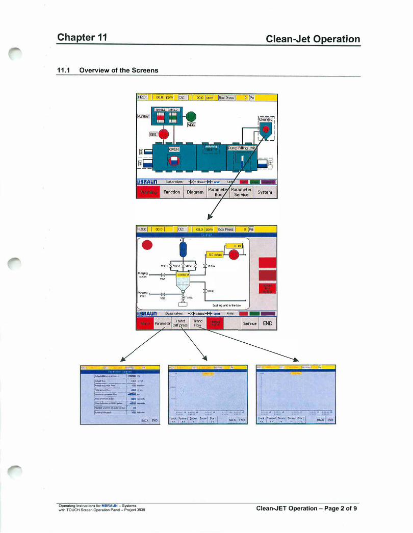
Chapter 11
11.1 Overview of the Screens
,H20: foo"of
•
""'"' .....,.
"'•"' nllt
.. , -
,..��-·--" ,�""
,-g:-.... _,.:::-.-... '""---� :: .-.., .... --- ., __ ..._,._ ... .; .... r,. ,n.� .. ;;;; I .......... . r..::;.-.;:;;;;;;;,.... r-.. .....�"-•�.ii•;u".,_'f -:. � ... a!.. r .........
'""' OiO
Operating lnstrucUons for MBRAUN - Systems wi1h TOUCH Sacen Operation Panel - Project 3939
Clean-Jet Operation
oi?"
--
Q..d�U"lthhbo>
---Service END
...... , "''
Clean.JET Operation - Page 2 of 9
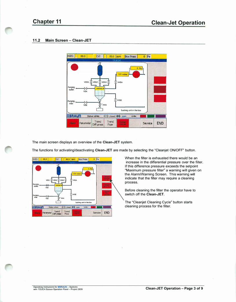
Chapter 11
11.2 Main Screen - Clean-JET
Clean-Jet Operation
IH20:1 00.0 102: r 00.0 ppm leox Press 101Pa"
-
Pllgng cut.let
Pllgng nlet
Statia valwtt:
Trend Pirame!Er
Dlff .p--ess Trend Flow
0.0 m/WC
""'51\ --
IIHSE -Suckng U'1l h Iha box
I.hill: ---Service END
The main screen displays an overview of the Clean-JET system.
The functions for activating/deactivating Clean-JET are made by selecting the "Cleanjet ON/OFF" button.
000 02: rrooo '""--;;;- �Press
•
"'51
"'1)�
... ,
$1.rl.�.....itnNbrff
p.,,.omet..- Dt�� ... Tr..-.d
Flow
Operating lnstruc:Lions ror MBRAUN - Systems with TOUCH Saccn Opornlioo Panel - Projoct 3939
-END
When the filter is exhausted there would be an increase in the differential pressure over the filter.
If this difference pressure exceeds the setpoint "Maximum pressure filter" a warning will given on the Alarm/Warning Screen. This warning will indicate that the filter may require a cleaning process.
Before cleaning the filter the operator have to switch off the Clean-JET.
The "Cleanjet Cleaning Cycle" button starts cleaning process for the filter.
Clean-JET Operation - Page 3 of 9
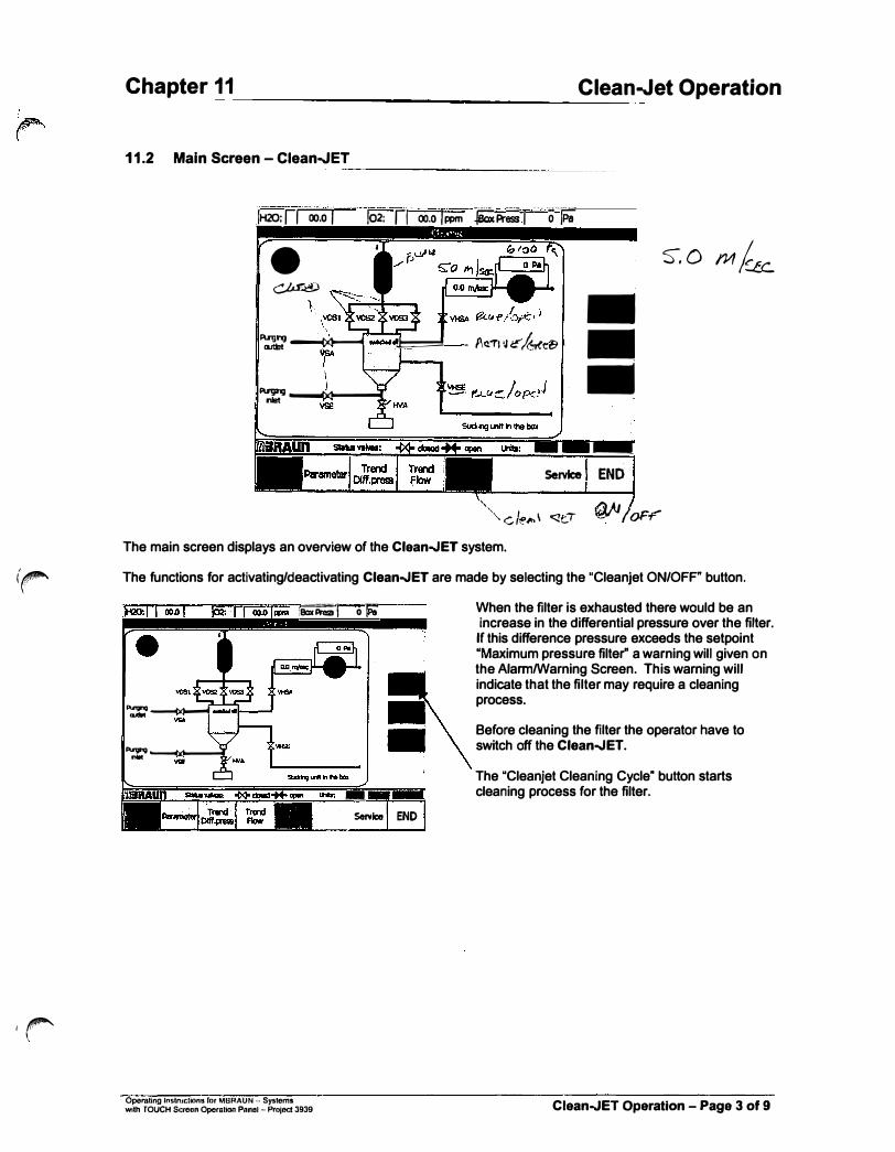
(r'
Ir
Chapter 11
11.2 Main Screen - Clean-JET
Clean-Jet Operation
,IH20; 1roo:oJ 102: r1 - oo.o I r:.>m -lb Pr� I . - . ·o ... /Pa
• �
Asgrg ----.M----,,,1 outtrt
��
� - l\cT1 1Jr:"/2ree.�
-• -
---
Service I END
S-.0 M&
""" c le�\ <it., � I oF-f'"
The main screen displays an overview of the Clean.JET system.
The functions for activating/deactivating Clean.JET are made by selecting the "Cleanjet ON/OFF" button.
:ikri�I o�
PlnJl'IQ----M-,......1 ...
""" � nlll
-Sffilca
Oporating lnstnJcliono ror MBRAUN - Systems with TOUCH Screon Operation P11nol - Project 3939
END
When the filter is exhausted there would be an increase in the differential pressure over the filter. If this difference pressure exceeds the setpoint "Maximum pressure filter" a warning will given on the Alami/Warning Screen. This warning will indicate that the filter may require a cleaning process.
Before cleaning the filter the operator have to switch off the Clean.JET.
The "Cleanjet Cleaning Cycle" button starts cleaning process for the filter.
Clean.JET Operation - Page 3 of 9

Chapter 11 Clean-Jet Operation
11.3 Parameters Screen
IAcllk11 difference 1�ess11'e: 0 P.i
jActual flow: 0.0 m/SP.k IRenw1hg ll\l'ge time: 00 mhutes
!Seti>0k1t gasflow: 8.0 mfsec
!Maximum pres&l'e fllter: 11000 Pil
lnne 1>ress11·e 1JUlse: 0.2 seconds lnme between f>t'essue pulse: 4.0 seconds
!Number ofpressm� pulse cycles:
IPt1·ghg time fllter: 5 lllkllAAS
BACK END
The "Parameters" screen is accessed by selecting the "Parameters" button on the main Clean-JET screen. The screen allows the user to define the settings for the Clean-Jet system.
11.3.1 Parameter Definitions
Actual difference pressure:
Actual Flow:
Remaining Purge Time:
Setpoint Gasflow:
Maximum pressure filter:
Time Pressure Pulse:
Time Between Pressure Pulse:
Number of Pressure Pulse Cycles:
Purging Time Filter:
Operaling lnslrucOons for MBRAUN - Systems with TOUCH Scroon OperaHon Panel - Project 3039
Shows the difference pressure of the Clean-JET blower
Shows the gas flow through the Clean-Jet system
Shows the remaining time for the Clean-JET purging process
This is the desired setpoint for the rate of gas flow through the Clean-JET. The default setting is 5 mis. An extreme gas flow, either too high or too low, will inhibit the performance of the CleanJET.
On reaching this pressure a warning "Cleanjet filter is full, please clean the filter" will be displayed. Before cleaning the filter with the button "Cleanjet Cleaning Cycle" the operator has to switch off the Clean-JET.
Duration of pressure pulse
Duration of lapse between pressure pulses
Number of cleaning cycles to complete on regeneration (cleaning) process. Range 1 - 9
Setpoint for total "Purging Time" for the Clean-Jet cleaning cycle.
Clean-JET Operation - Page 4 of 9

Chapter 11 Clean-Jet Operation
11.4 Trends for Clean-Jet
The Trends screens for the Clean-JET are accessed from the Main Clean-JET Screen. The Screens are laid out in the same manner - each screen having the same function button available.
·-
91e;.l1()'1 .ll 914113? lJI
S/10/0) S/lt/01
l1JS1D"I 4a
1/19/D>
back rOIWard Zoom Zoom Sl!lrt << >> + I<
,1211.i, U1 t110t01 H
1/19/� lilt/OJ
BACK END
The trends screens are in the form of a time graph.
,H20. I I oo.o T [02: 1
11a11s1 •• t1111u u
lfUJ1/0J l/lt/Ol
back forw!ll'd Zoom Zoom Smrt
<< >> + <
0 !Po
lhU1.U .U t1U1$J .Ut
JI UI OJ 111'/ 01
BACK END
There are 5 buttons on all graph displays. With the back«, forward>> you can move along the time axis. With the Zoom+ and Zoom- you can select a narrower or broader time frame. The Start I< button returns you to the current time.
Above the "graph" area is a yellow information box that displays the current value for the difference pressure or flow-rate through the Clean-JET as appropriate.
The smallest time frame for the X-axis is 1 minute.
Operaling Instructions for MBRAUN - Systoms with TOUCH $croon Operalion Panol - Project 3939 Clean-JET Operation - Page 5 of 9
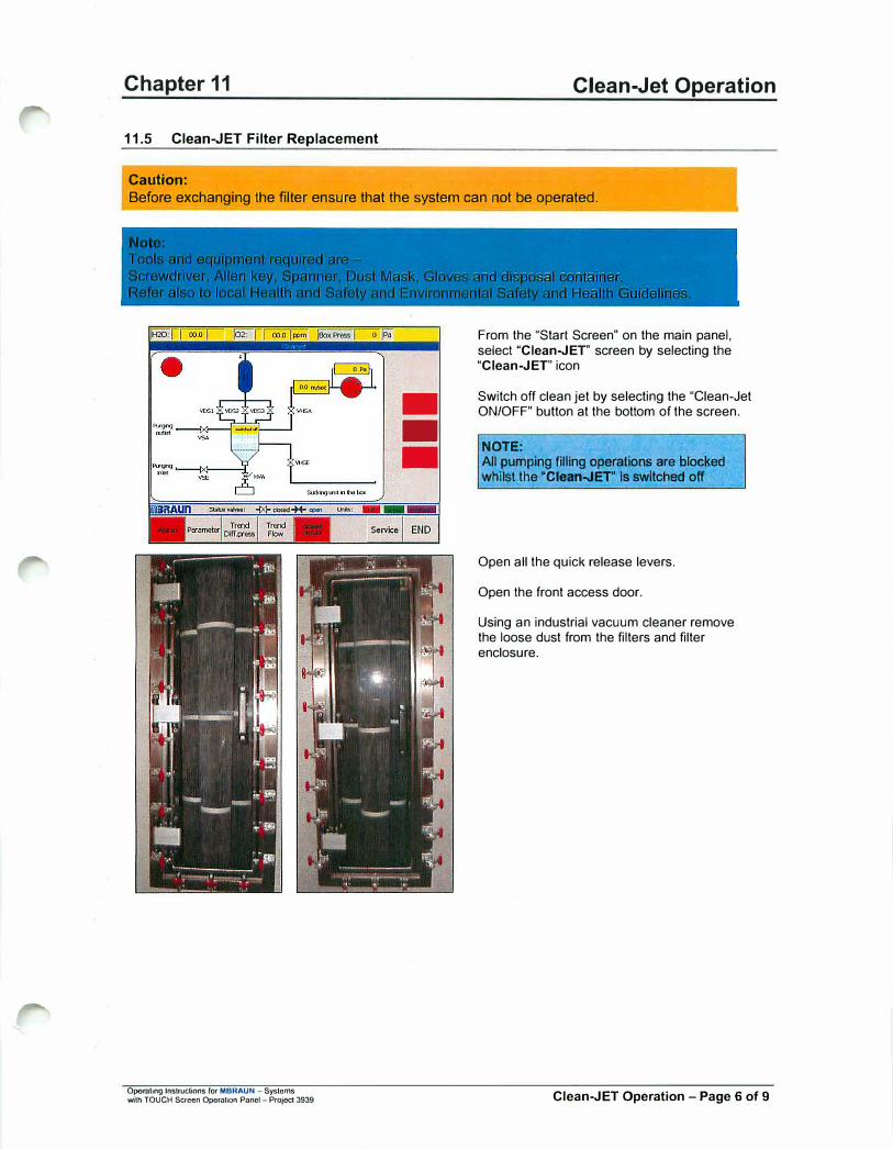
Chapter 11 Clean-Jet Operation
11.5 Clean-JET Filter Replacement
Caution:
Before exchanging the filter ensure that the system can not be operated.
---
Opornting Instructions ror MBRAUN - Sysloms with TOUCH Screen Operation Panel - Project 3939
From the "Start Screen" on the main panel, select "Clean-JET" screen by selecting the "Clean-JET" icon
Switch off clean jet by selecting the "Clean-Jet ON/OFF" button at the bottom of the screen.
NOTE: All pumping filling operations are blocked whilst the "Clean..JEr ls switched off
Open all the quick release levers.
Open the front access door.
Using an industrial vacuum cleaner remove the loose dust from the filters and filter enclosure.
Clean-JET Operation - Page 6 of 9

Chapter 11 Clean-Jet Operation
Remove the foremost filter by rotating it to the left, support the filter by holding the upper strap.
Lower the filter to rest on the cabinet floor, lilt it towards the cabinet door and carefully slide it out of the cabinet.
The other filters may now be accessed and removed in the same manner.
Remove dust from inside the cabinet and the front door using a vacuum cleaner.
Clean the Door Seal with lint free cloth and lightly smear with high vacuum grease.
Insert the new filters start from the rear left.
Ensure that each filter is carefully tightened, by rotating it to the right before inserting the next filter.
Close the front door.
Ensure that all the quick connect levers are correctly securing the door.
Caution: Ensure that all threads and seals are both correctly aligned and tightened.
11.5.1 Purging the Clean-JET after filter maintenance
Note:
After exchanging the filters, the Clean-JET has to be purged because excess Oxy{Jen flowing into the piping.
Removal of the Oxygen from the piping is carried out as follows: • On the main panel Clean.JET screen press "purge Clean.JET"• wait for the preset purging time (parameter screen), recommended time: 15min• switch on Clean.JET to continue pumping filling operation
The Clean.JET is now prepared to continue operation.
Operating Instructions for MBRAUN - Sysloms with TOUCH Screen Operation Panol - Project 3939 Clean.JET Operation - Page 7 of 9
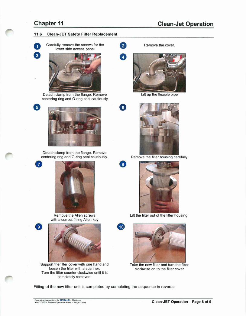
Chapter 11
11.6 Clean-JET Safety Filter Replacement
0
e
e
Carefully remove the screws for the lower side access panel
Detach clamp from the flange. Remove centering ring and O-ring seal cautiously
Detach clamp from the flange. Remove centering ring and O-ring seal cautiously.
Remove the Allen screws with a correct fitting Allen key
Support the filter cover with one hand and loosen the filter with a spanner.
Turn the filter counter clockwise until it is completely removed.
8
0
0
Clean-Jet Operation
Remove the cover.
Lift up the flexible pipe
Remove the filter housing carefully
Lift the filter out of the filter housing.
Take the new filter and turn the filter clockwise on to the filter cover
Fitting of the new filter unit is completed by completing the sequence in reverse
Opornling Instructions for MBRAUN - Systems with TOUCH Screen Operation Panel - Project 3939 Clean-JET Operation - Page 8 of 9

Chapter 11 Clean-Jet Operation
11.7 Purging the Clean-JET
Note:
After commissioning the system or exchanging safety filters, the Clean-JET has to be purged because excess Oxygen flowing into the piping.
Removal of the Oxygen from the piping is carried out as follows:
0
8
Set the Glove Box to+ 10mbar overpressure
e
0
Detach clamp from the flange that connects the Safety Filter's flexible hose to the Main filter inlet pipe. (this pipe usually runs to the to of the Clean-JET cabinet in order to connect to the filter head).
Carefully remove the centering ring and O-ring seal.
Leave the pipe open for at lease 2 minutes to allow the excess Oxygen flow out of the pipe.
Replace the centering ring and O-ring seal, and reclamp the flange connection.
The Clean.JET is now prepared to continue operation.
Operating Instructions for MBRAUN - Systems with TOUCH Screen OpornHon Panel - Projod 3939 Clean.JET Operation - Page 9 of 9
Operating lnstructlons ror MBRAUN - Systems wilh TOUCH Screen Operation Panel
Blank Page
Blank Page
Chapter 12 Chiller Unit - NESLAB-M25 (Short edtn.)
Contents
12.1. General Information ............................................................................................................................. 2
12.2. Operating Instructions ......................................................................................................................... 3 12.2.1. Front Panel ......................................................................................................................................... 3 12.2.2. Power On/Off ...................................................................................................................................... 3 12.2.3. Parameter Display / Change .............................................................................................................. 4 12.2.4. Warning .............................................................................................................................................. 4
Operating Instructions for MBRAUN - Systems with TOUCH Screen Operation Panel Chiller Unit - Page 1 of 4
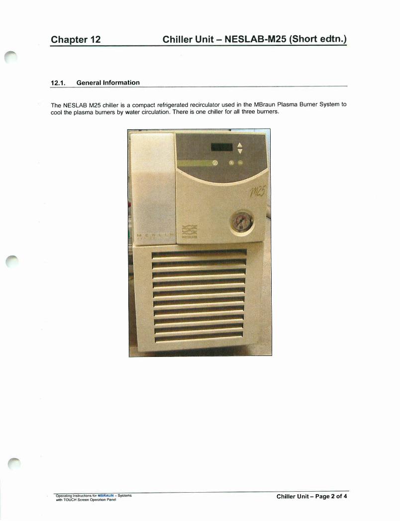
Chapter 12
12.1. General Information
Chiller Unit - NESLAB-M25 (Short edtn.)
The NESLAB M25 chiller is a compact refrigerated recirculator used in the MBraun Plasma Burner System to cool the plasma burners by water circulation. There is one chiller for all three burners.
Oporaling Instructions for MBRAUN - Systems Wtth TOUCH Scroon Operation Panel Chiller Unit - Page 2 of 4

Chapter 12 Chiller Unit - NESLAB-M25 (Short edtn.)
12.2. Operating Instructions
The chiller parameters are preset by MBRAUN to match the requirements of the plasma burner system. The information given here are only short instructions to operate the chiller and to set essential parameters. For detailed information refer to the manual of the manufacturer of the chiller which is part of your documentation package.
12.2.1. Front Panel
12.2.2. Power On/Off
First make sure that the main power switch located at the rear side of the chiller is switched to on (upper position).
Power on the chiller by pressing the on/off key on the front panel. The chiller pump starts and the actual temperature is displayed on the front panel display. To switch off press the button again.
Operating lnstruclions for MBRAUN - Systems with TOUCH Screen Operation Pano! Chiller Unit - Page 3 of 4

Chapter 12 Chiller Unit - NESLAB-M25 (Short edtn.)
12.2.3. Parameter Display / Change
During normal operation the actual temperature is displayed on the front panel. The displayed value should be near/equal to the set point temperature.
To display the other parameters press the menu/display key. By pressing the key the display cycles trough the values for set/low/high/actual temperature
Working temperature set point. (recommended value : 20°C)
Lower warning level (recommended value: 10
°
C)
Upper warning level (recommended value : 35°C)
To change the values of parameters use the up/down keys. To set the new nn value press the menu/display key
I.JU
12.2.4. Warning
If the low or high warning level is exceeded the chiller sends an acoustic warning signal. This signal can be reset by pressing of the acknowledge key.
Operating lnstruclions for MBRAUN - SY9lems with TOUCH Screen Oporotion Panel Chiller Unit - Page 4 of 4
Chapter 13 Purification System
Contents
13.1. General lnfonnatlon ............................................................................................................................. 2 13.1.1. Circulation Mode ................................ : ................................................................................................ 2 13.1.2. Regeneration Mode ............................................................................................................................ 2
13.2. Status of Purifier Filters ...................................................................................................................... 3
13.3. Prerequisites ......................................................................................................................................... 3 13.3.1. Circulation ........................................................................................................................................... 3 13.3.2. Regeneration ...................................................................................................................................... 3
13.3. Circulation Mode .................................................................................................................................. 4
13.4. Activating the Circulation Mode ......................................................................................................... 5
13.5. Activating the Regeneration Mode ..................................................................................................... 6
13.6. Executing the Regeneration Program ................................................................................................ 7
13.7. Purifier Screen ...................................................................................................................................... 8
13.8. Parameters ............................................................................................................................................ 9
Operating Instructions fot MBRAUN Syatems with TOUCH Screen Operation Panel Purification System - Page 1 of 9

Chapter 13
13.1. General Information
13.1.1. Circulation Mode
Figure 1: Principle of Circulation
Glove Box
Purification System
MBRAUN systems work by the principle of gas circulation, i.e. the working gas permanently circulates between the glove box and the H20/02 gas purification system. This process guarantees absolutely stable values of gas purity and cost-efficient processing.
Caution: When operating the Glove Box system the circulation mode should always be activated. Only in this case the atmosphere within the glove box is continuously purified to values down to < 1 ppm with regard to moisture and/or oxygen.
-----
The circulation mode is PLC-controlled and is operated and displayed via the TOUCH Operation Panel.
When used for quite a long period in the circulation mode the purification unit gets exhausted resulting in a drop of the purification performance leading to increasing H20/02 values. For this reason, the purifier column should be regenerated regularly or at the latest when there is a visible drop in performance. Refer to the "Regeneration" chapter.
The circulation mode should be deactivated while the regeneration procedure is running.
In systems with 2 purifier columns circulation mode can run via one purifier column while the other purifier column is undergoing regeneration.
13.1.2. Regeneration Mode
If a purifier column is saturated after having been used for a longer period, using the standard regeneration process will reactivate the column.
Regenerating the purifier column in regular intervals is recommended. Do not wait, until a drop in the purification performance is visible. These intervals between the respective regeneration procedures result from an experimental value, which differs depending on the respective system, way and time of use.
Recommendation: Apply the following method for determining the reasonable intervals for regeneration: Regenerate the purifier column after its first commissioning only when a drop of performance is visible. If such a drop occurs, write the operating hours run down. The operating hours reading minus 10 hours can be used as a reference value for the intervals between the respective regeneration procedures.
Operating Instructions fo, MBRAUN Systems with TOUCH Screen Operation Panol Purification System - Page 2 of 9
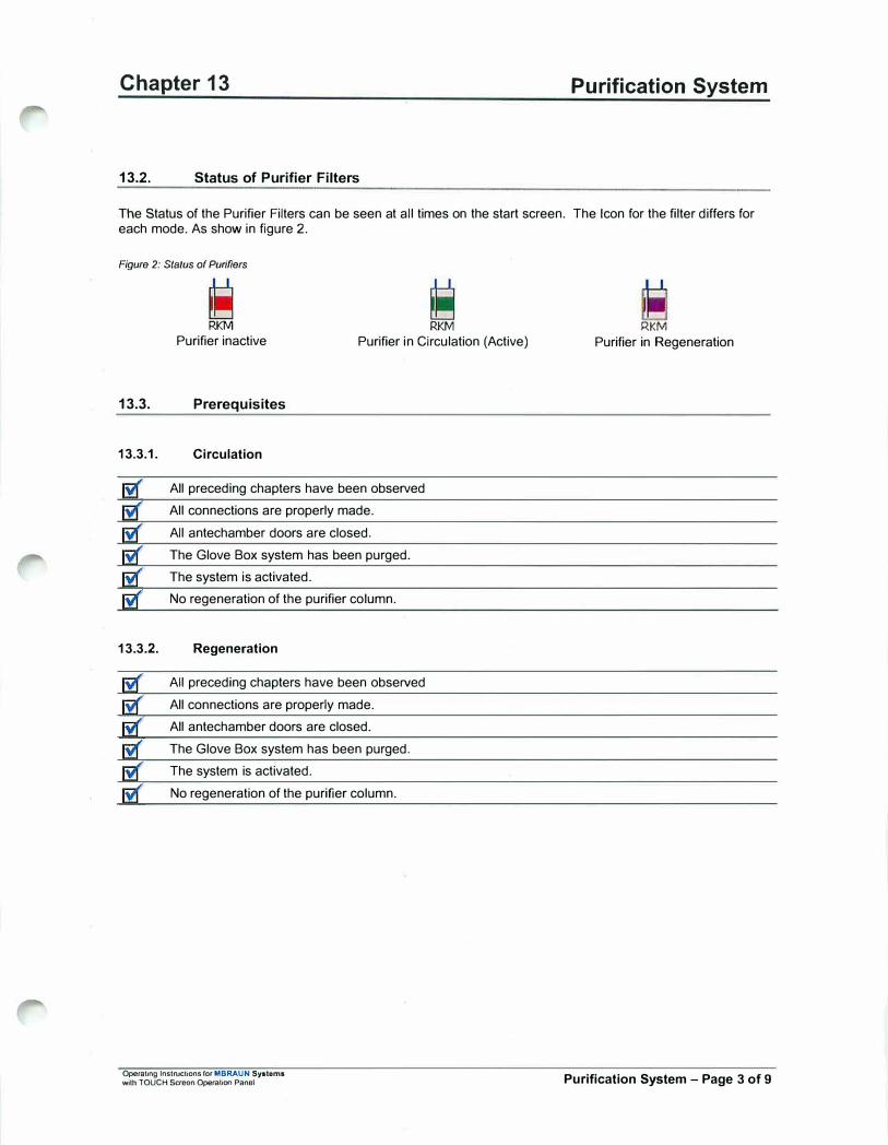
Chapter 13
13.2. Status of Purifier Filters
Purification System
The Status of the Purifier Filters can be seen at all times on the start screen. The Icon for the filter differs for each mode. As show in figure 2.
Figure 2: Status of Purifiers
RKM RKM
Purifier inactive Purifier in Circulation (Active)
13.3. Prerequisites
13.3.1. Circulation
All preceding chapters have been observed
All connections are properly made.
All antechamber doors are closed.
The Glove Box system has been purged.
The system is activated.
No regeneration of the purifier column.
13.3.2. Regeneration
All preceding chapters have been observed
All connections are properly made.
All antechamber doors are closed.
The Glove Box system has been purged.
The system is activated.
No regeneration of the purifier column.
Operating lnstrucnons for MBRAUN Sy1tem1 with TOUCH Screen Operation Panel
RKM
Purifier in Regeneration
Purification System - Page 3 of 9

Chapter 13
13.3. Circulation Mode
Note:
Purification System
The two purifier system allows greater flexibly in operation of the box by allowing one filter to be regenerated whilst the other Is in circulation (purifying) Mode. The position of buttons with the Touch Panel is the same for both systems. However only those relevant to the system supplied are displayed.
---------�-------------------""
Figure 3: Circulelion in Box
F2
Glove-Box
'
Note:
The diagram shows the gas flow in the circulation mode: (2 Purifier Column System)
• Glove Box• Dust filter (F1)• purifier column
either:
H2O/OrPurifier column 1 (R1) in circulation modeH2O/O2-Purifier column 2 (R2) can be regeneratedor:
H2O/OrPurifier column 2 (R2) in circulation modeH2O/OrPurifier column 1 (R 1) can be regenerated
• Blower unit (G)• Heat exchanger(K)• Dust filler (F2)
Circulation cannot run simultaneously lhrough both columns.
Note:
When commissioning the system for the first time, the circulation mode can be run via Purifier column 1, which was regenerated by the manufacturer prior to delivery. Purifier column 2 should be regenerated befote being used in circulation mode.
Operating lnstrvctions for MBRAUN System■ '-Mth TOUCH Screen Operation Panel Purification System - Page 4 of 9
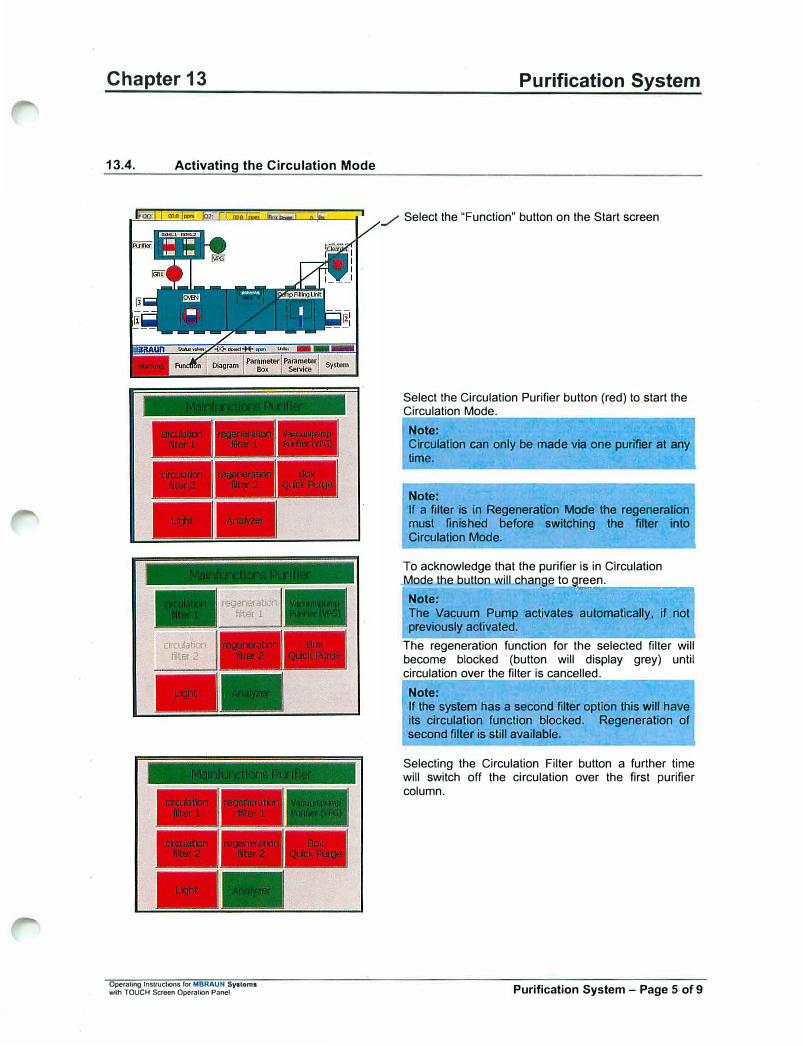
Chapter 13
13.4. Activating the Circulation Mode
, -11 ""D'"'"' im, r ..,. ,,,.,, ,,,._ •.•.
Operating lnstruc1ions for MBRAUN Systems with TOUCH Screon OperaHon Panel
Purification System
Select the "Function" button on the Start screen
Select the Circulation Purifier button (red) to start the Circulation Mode.
Note:
Circulation can only be made via one purifier at any time.
Note: If a filter is in Regeneration Mode tne regeneration must finished before switching the filter into Circulation Mode.
To acknowledge that the purifier is in Circulation Mode the button will change to g,,..r.;;.e.;;.en_. _____ _Note:
The Vacuum Pump activates automatically, if not previously activated.
The regeneration function for the selected filter will become blocked (button will display grey) until circulation over the filter is cancelled.
Note:
If the system has a second filter option this will have its circulation function blocked. Regeneration of second filter is still available.
Selecting the Circulation Filter button a further time will switch off the circulation over the first purifier column.
Purification System - Page 5 of 9
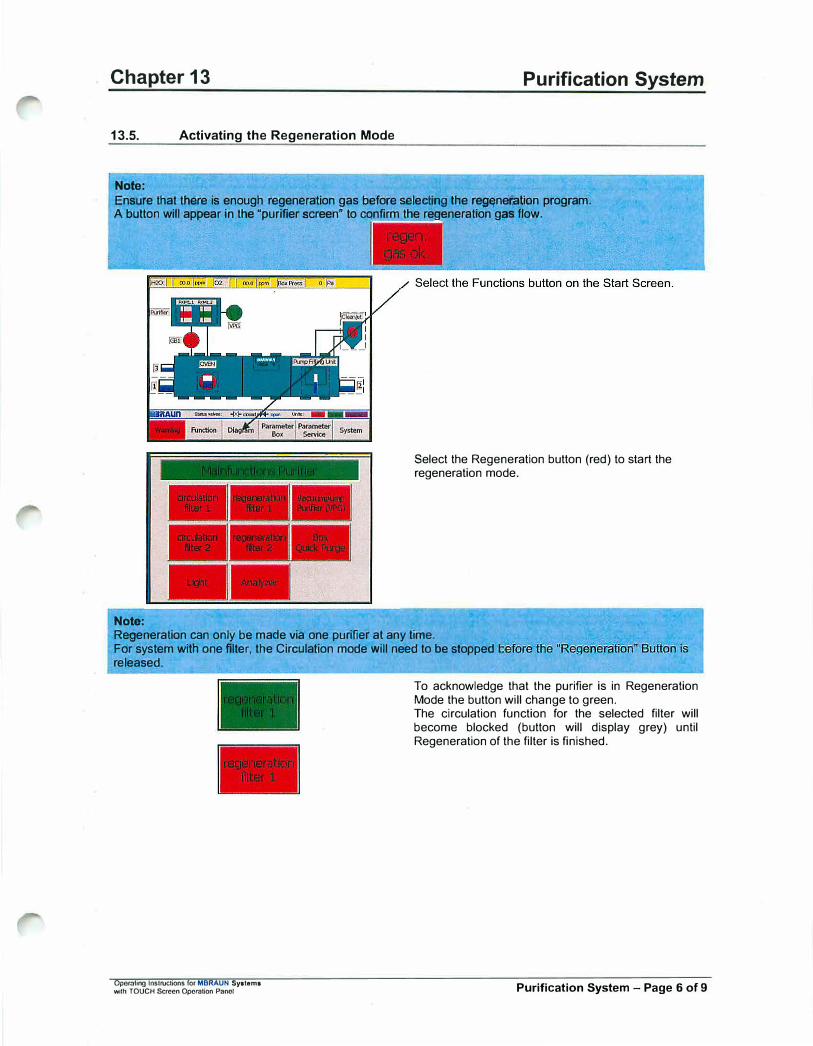
Chapter 13
13.5. Activating the Regeneration Mode
Nole:
Purification System
Ensure that there is enough regeneration gas before selectfng tfle regeneration program. A button will appear in the "purifier screen" to confirm the regeneration gas flow.
Note:
Select the Regeneration button (red) to start the regeneration mode.
Regeneration can only be made via one purifier at any time. For system with one filter, the Circulation mode will need to be stoppecl released.
Operating Instructions ror MBRAUN Syalema wilh TOUCH Screen Operation Pano!
To acknowledge that the purifier is in Regeneration Mode the button will change to green. The circulation function for the selected filter will become blocked (button will display grey) until Regeneration of the filter is finished.
Purification System - Page 6 of 9

Chapter 13 Purification System
13.6. Executing the Regeneration Program
The following table explains the various steps of the regeneration cycle. On activation of the program all the steps are run automatically.
Figure 4: Regeneration Program Table
0
1
2
Start O min. Regeneration deactivated
Regeneration gas test ON
Regeneration gas test OFF
3 -16 + Activation of the regenerated filter with proprietary intermediate steps
17 J- after 960 min. Program completed
Caution: By no means should the regeneration program be interrupted. Before activating the regeneration program make sure that sufficient gas supply is available. Refer to the "Preparing the connections" as well as the "Installation" chapters.
Note: In case of power failure the Automatic Regeneration System switches back to the activation level, which means, with the power supply restored, the complete regeneration procedure is rerun - regeneration levels already executed will be repeated. Therefore, prior to the restoration of power, ensure that a sufficient gas supply is available. The program will restart automatically.
Operating Instructions for MBRAUN Sy1toma with TOUCH Semen Operation Panel Purification System - Page 7 of 9

Chapter 13
13.7. Purifier Screen
In the Purifier Screen you can see: the actual status of the units the regeneration Step and
Purification System
the remaining time in the regeneration process
STEP: JO recieneratkln off
.Tlme:ro-mn
VSPA
VRAl
RKM1.1
G81
VS!
VG W vPG
Auto
matic
VRA2
VRV
YRSl
Exhaust
lkllts:
Stspmode
-- - ---• -� �--
On the right-hand side of the screen are found the buttons for controlling the RKM and below are those for screen branching and for the functions.
Operating lnstruchons for MBRAUN Systems with TOUCH $croon Operation Panel Purification System - Page 8 of 9
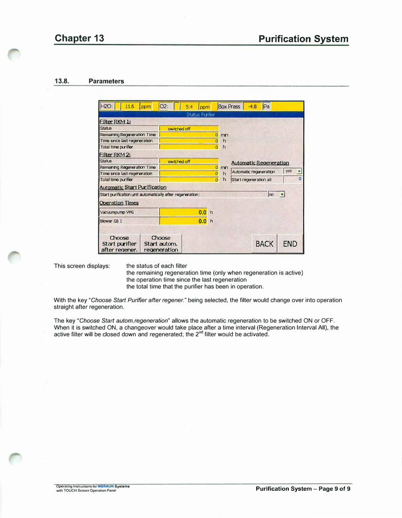
Chapter 13
13.8. Parameters
jH20:r! 11.6 lppm 102: ,1 5.4 lppm
Elllel: BKM 11 Stab.Js IRemanng Regeneration Time ITime sh:e last regeneration I Total time pu-lfter L
ElllecBKM2; Stab.Js IRemanng Regener atlon Time ITime slnee last regeneration I Total time pu-lfler I
AutQlllatlC Stact Bl:IDs;atlQO
swill:hed off
swill:had off
-
-
- --
Stai JUlf'catlon 111lt a.itDmati:ally after reger«atlon:
Operatlro Ih:m:5
Vacwmpuflll VPG
Blower GB 1
Choose Start pt.rifler after reaener,
I -I
Choose Start autom.
reaeneratlon
This screen displays: the status of each filter
0.0 h
0.0 h
Purification System
!Box Press j-4.8 fa
a rm 0 h
0 h
Aut!lfllallt Beoeneratlro a rm 0 h
jAUtomallc regeneration !Start regeneration all
IY883 0 h
�
BACK END
the remaining regeneration time (only when regeneration is active) the operation time since the last regeneration the total time that the purifier has been in operation.
With the key "Choose Start Purifier after regener." being selected, the filter would change over into operation straight after regeneration.
The key "Choose Start autom.regeneration" allows the automatic regeneration to be switched ON or OFF. When it is switched ON, a changeover would take place after a time interval (Regeneration Interval All), the active filter will be closed down and regenerated; the 2
nd filter would be activated.
Operating Instructions for MBRAUN Systems with TOUCH Semon Operation Pnnol Purification System - Page 9 of 9
Operating Instructions ror MBRAUN - Systems with TOUCH Screen Operal!on Panel
Blank Page
Blank Page
r
Chapter 14 Box Parameter Settings
Contents
14.1. Box Parameter ...................................................................................................................................... 2 14.1.1. Automatic Purging .............................................................................................................................. 2 14.1.2. Gas Purification Alarm Limits ............................................................................................................. 2 14.1.3. Setting the box pressure: .................................................................................................................... 2 14.1.4. Parameter Service .............................................................................................................................. 3
Operating Instructions far MBRAUN - Systems with TOUCH Screen Operation Panel Box Parameter Settings - Page 1 of 3
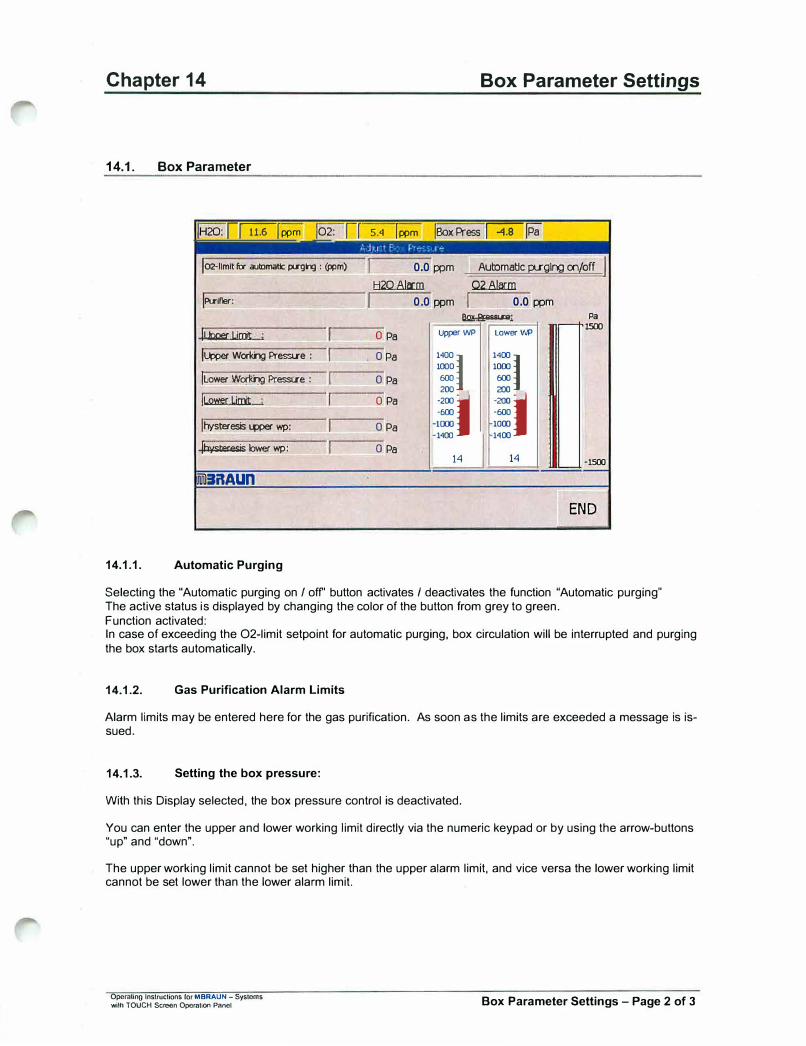
Chapter 14
14.1. Box Parameter
!H20: !J11.61 ppm 102: Ii
!02-nmtt fa automatic psglrg : (ppm)
IPl.rlf'er:
11 ooer Liait ' IL.wer Workng Pressue
!Lower Workng Pressue
IL2W!:t Liait
jhysteresis t.wer wp:
(hysteresis lower wp:
ililAUn
14.1.1. Automatic Purging
ii ii
I ii
I
'I
Box Parameter Settings
S.<I I ppm !Box Press ��
I 0.0 ppm Automatic pu-glr,g m/off I tl2Q 8la::m Q281a:m
I 0.0 ppm I 0,0 ppm ll!lx El:BSSU'8; Pa
0 Pa Upper WP Lower WP -1500
0 Pa 1400
1
1400
1 1000 1000
0 Pa 600 600
0 Pa
.:. :I ·600 ·600
0 Pa l(XXJ 1000 1400 1400
0 Pa 14 14 ·1500
END
Selecting the "Automatic purging on / off' button activates / deactivates the function "Automatic purging" The active status is displayed by changing the color of the button from grey to green. Function activated: In case of exceeding the 02-limit setpoint for automatic purging, box circulation will be interrupted and purging the box starts automatically.
14.1.2. Gas Purification Alarm Limits
Alarm limits may be entered here for the gas purification. As soon as the limits are exceeded a message is issued.
14.1.3. Setting the box pressure:
With this Display selected, the box pressure control is deactivated.
You can enter the upper and lower working limit directly via the numeric keypad or by using the arrow-buttons "up" and "down".
The upper working limit cannot be set higher than the upper alarm limit, and vice versa the lower working limit cannot be set lower than the lower alarm limit.
Opemlino Instructions for MBRAUN - Systems with TOUCH Screen Operation Panel Box Parameter Settings - Page 2 of 3
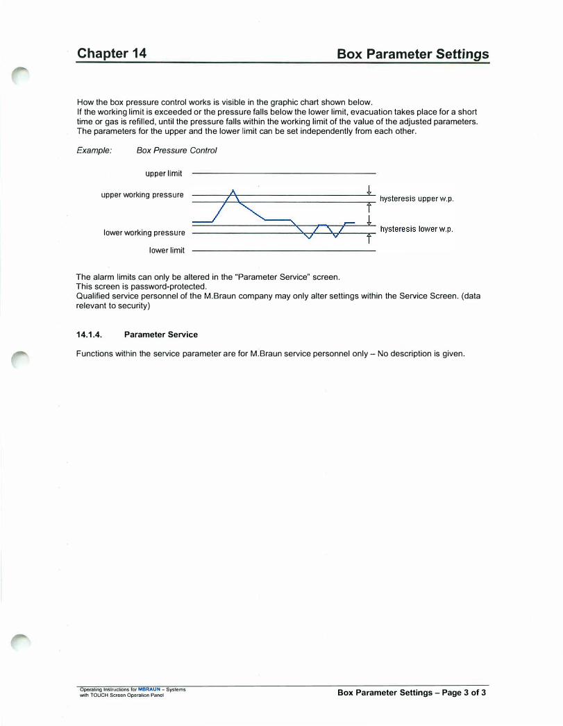
Chapter 14 Box Parameter Settings
How the box pressure control works is visible in the graphic chart shown below. If the working limit is exceeded or the pressure falls below the lower limit, evacuation takes place for a short time or gas is refilled, until the pressure falls within the working limit of the value of the adjusted parameters. The parameters for the upper and the lower limit can be set independently from each other.
Example: Box Pressure Control
upper limit
upper working pressure
lower working pressure
lower limit
The alarm limits can only be altered in the "Parameter Service" screen. This screen is password-protected. Qualified service personnel of the M.Braun company may only alter settings within the Service Screen. (data relevant to security)
14.1.4. Parameter Service
Functions within the service parameter are for M.Braun service personnel only - No description is given.
Operating Jnslmctions for MBRAUN - Systems ...,;th TOUCH Semen Operation Pnnel Box Parameter Settings - Page 3 of 3

Operating Instructions for MBRAUN - Systems with TOUCH Screen Operation Panel
Blank Page
Blank Page

Chapter 15 Box Cooling
Contents
15.1. Box Cooling .......................................................................................................................................... 2
15.2. Box Cooling Parameter ....................................................................................................................... 3
15.3. Activating / Deactivating Box Cooling ............................................................................................... 4
Operating Instructions for MBRAUN Spton,1 with TOUCH Screen Operation Panel Gloves - Page 1 of 4
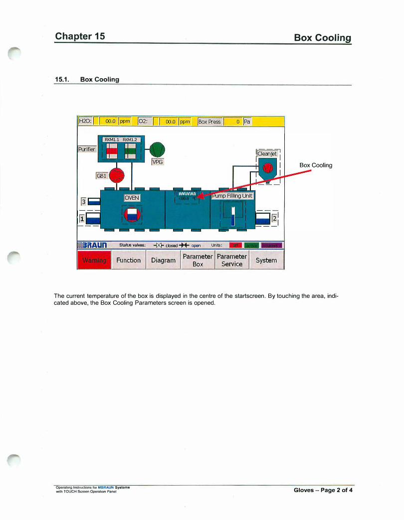
Chapter 15
15.1. Box Cooling
Status valves: -f><l- closed-++- open
Function Diagram Parameter Parameter
Box Service
Box Cooling
System
The current temperature of the box is displayed in the centre of the startscreen. By touching the area, indicated above, the Box Cooling Parameters screen is opened.
Operating lnotructions for MBRAUN Syalom• with TOUCH Screen Operation Panel Gloves - Page 2 of 4
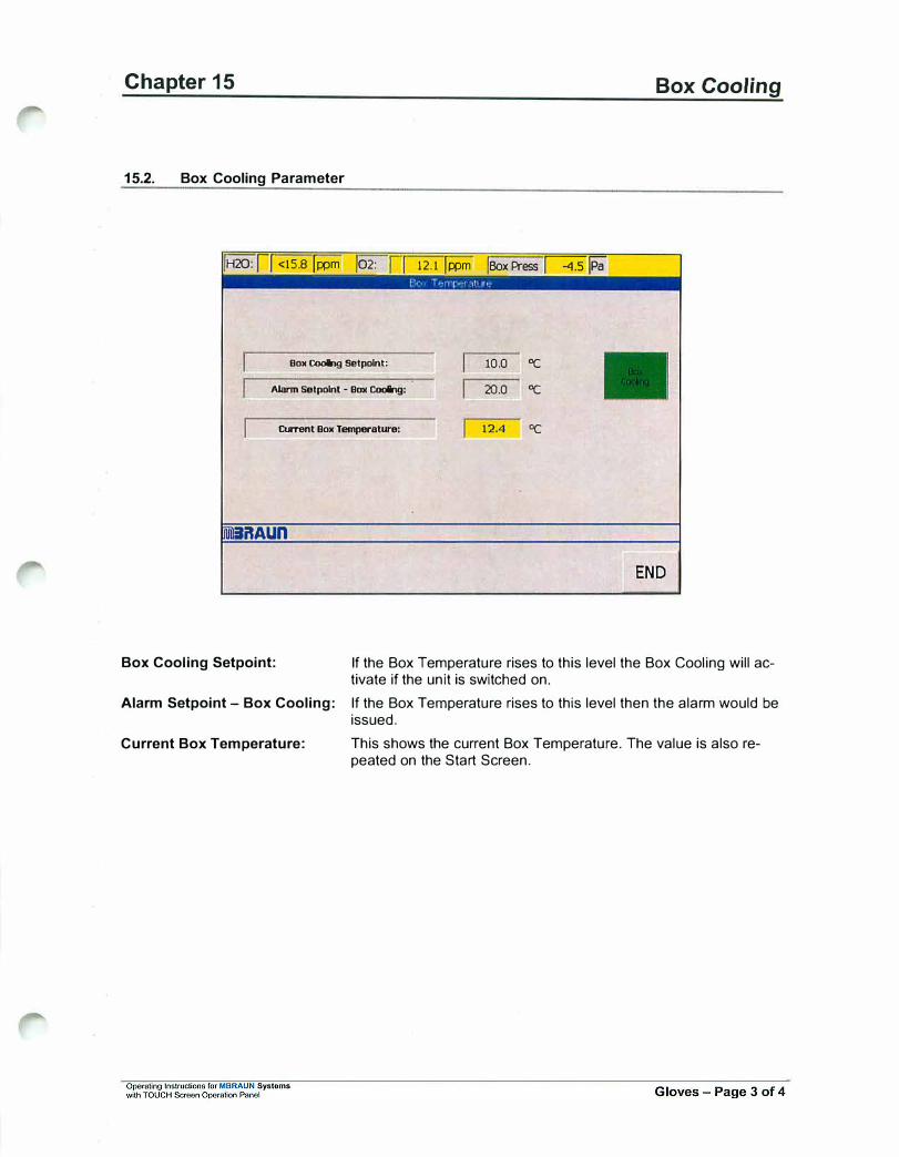
Chapter 15
15.2. Box Cooling Parameter
iH20: II <15.8 li:pm 102: [ I 12.1 it:Pm !Box Press �fa
Box Cooing Setpolnt:
Alarm setpolnt - Box Cooing:
Ctrrent Box Temperature:
:IRAUn
10.0 "C
20.0 "C
12.4 "C
Box Cooling
END
Box Cooling Setpoint: If the Box Temperature rises to this level the Box Cooling will activate if the unit is switched on.
Alarm Setpoint- Box Cooling: If the Box Temperature rises to this level then the alarm would be issued.
Current Box Temperature: This shows the current Box Temperature. The value is also repeated on the Start Screen.
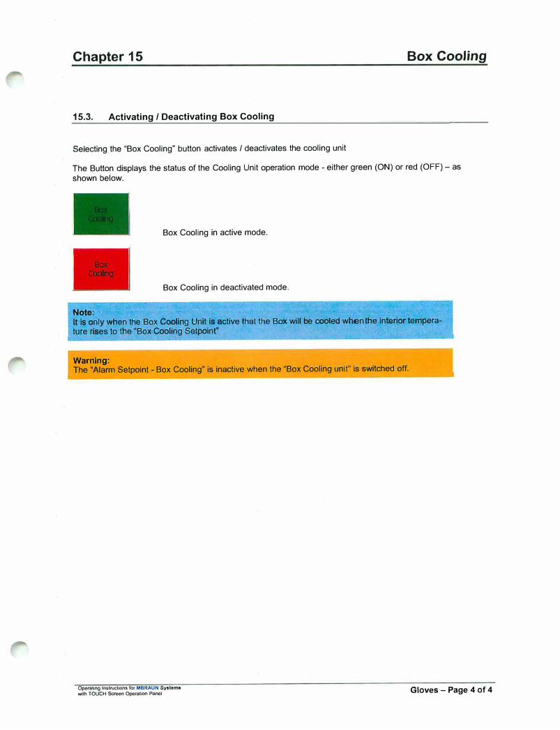
Chapter 15 Box Cooling
15.3. Activating / Deactivating Box Cooling
Selecting the "Box Cooling" button activates / deactivates the cooling unit
The Button displays the status of the Cooling Unit operation mode - either green (ON) or red (OFF) - as shown below.
Box Cooling in active mode.
Box Cooling in deactivated mode.
Note:
It is only when the Box Coolihg Unit is active that the Bo>< will be cooled wfren Ifie intl:lrior temperature rises to the "Box Cooling Setpolnr
Warning: The "Alarm Setpoint - Box Cooling" is inactive when the "Box Cooling unit" is switched off.
Opomling Instructions for MBRAUN Systems wtth TOUCH Screen Operation Panel Gloves - Page 4 of 4

Chapter 16 Dust Filters (inside Glove-box)
Contents
16.1. General Information ............................................................................................................................. 2
16.2. Technical Data ...................................................................................................................................... 2
16.3. Exchanging Dust Filters ...................................................................................................................... 3 16.3.1. Method for Exchanging the Filter: ............................................................................................... 3
Table of Figures Figure 1: Removing Filter ...................................................................................................................... 3 Figure 2: Replacing Filter ...................................................................................................................... 3
Operating Instructions for MBRAUN - Systems wllh TOUCH Screen Operation Panel Dust FIiters - Page 1 of 3

Chapter 16
16.1. General Information
Dust Filters (inside Glove-box)
MBRAUN glove boxes are equipped with dust filters at the gas outlet, as well as, at the gas inlet piping. The former protects the gas purification system against dust particles the maybe generated by the user inside the glove box. The latter filter ensures optimal particle free incoming gas.
16.2. Technical Data
The filter that is commonly used within the M.Braun Glove Box system has the following characteristics:-
0 118mm
E E (Y) 0
The standard filter is of a HEPA format (class H14)- i.e. filtering 99.995% of particles - typically down to 0.2 microns.
Note:
MBRAUN can also supply finer filters (e.g. Class· U15 - Filtering 99.9995% of particles) upon request.
Operating lnslructions for MBRAUN - Systems wUh TOUCH Scroon Opemlion Panel Dust Filters - Page 2 of 3

Chapter 16 Dust Filters (inside Glove-box)
16.3. Exchanging Dust Filters
Depending on the usage of the glove box system the filters need to be exchanged at least once a year.
16.3.1. Method for Exchanging the Filter:
Figura 1: Removing Filter
Unscrew used dust filter.
Figure 2: Replacing Filter
Screw new dust filter in place.
Note:
Depending upon the substances used inside the glove box, the replaced filter may need to be treated with care outside of the glove box atmosphere. Please refer to all local Environmental, Safety and Health guidelines that may apply for the type of substances used within the glove box.
Operating Instructions for MBRAUN - Systoms wilh TOUCH Saeen Opernllon Panel Dust Filters - Page 3 of 3

Operating Instructions for MBRAUN - Syutams with TOUCH Screen Operation Panel
Blank Page
Blank Page
Chapter 17 Gloves
Contents
17 .1. General Information ............................................................................................................................. 2
17.2. Technical Data ...................................................................................................................................... 2
17.3. Replacing Gloves ................................................................................................................................. 3
17 .4. Glove Port Covers ................................................................................................................................ 4
17.5. Standard Spare Parts and Accessories for M.Braun Gloves .......................................................... 4
Operating Instructions ror MBRAUN Systams with TOUCH Screen OpemUon Panel Gloves - Page 1 of 4
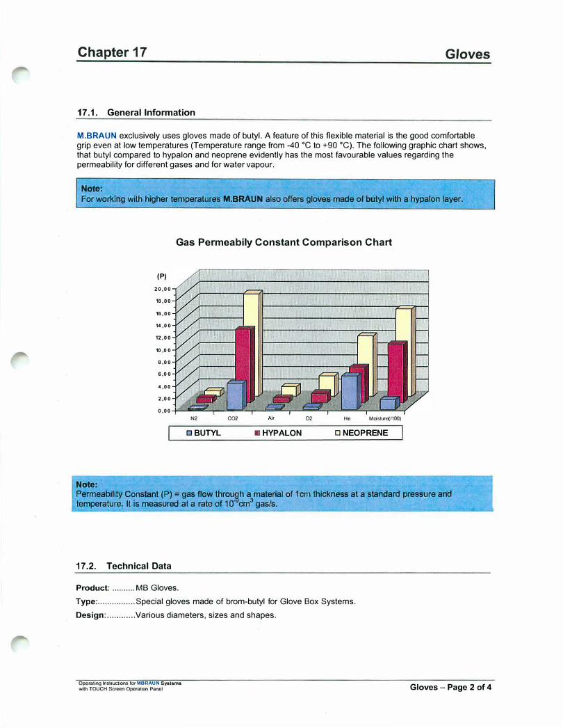
Chapter 17 Gloves
17 .1. General Information
M.BRAUN exclusively uses gloves made of butyl. A feature of this flexible material is the good comfortable grip even at low temperatures (Temperature range from -40 •c to +90 °C). The following graphic chart shows, that butyl compared to hypalon and neoprene evidently has the most favourable values regarding the permeability for different gases and for water vapour.
Note:
For working with higher temperatures M.BRAUN also offers gloves made of butyl with a hypalon layer.
Note:
Gas Permeabily Constant Comparison Chart
(P)
20,00
18,00
16,00
14 ,00
12,00
10 ,00
8 ,00
6,00
4 ,00
2,00
0,00 +---�---�-.---'-N2 CO2
□ BUTYL IIIHYPALON
02 He Moish<e(/100)
□ NEOPRENE
Permeability Constant (P) = gas flow throu�h a material of 1cm thickness at a standard pressure andtemperature. It is measured at a rate of 1 f
f
cm3 gas/s.
17.2. Technical Data
Product: .......... MB Gloves.
Type: ................ Special gloves made of brom-butyl for Glove Box Systems.
Design: ............ Various diameters, sizes and shapes.
Operating Instruction!. fot MBRAUN Systems with TOUCH Screen Operation Panel Gloves - Page 2 of 4
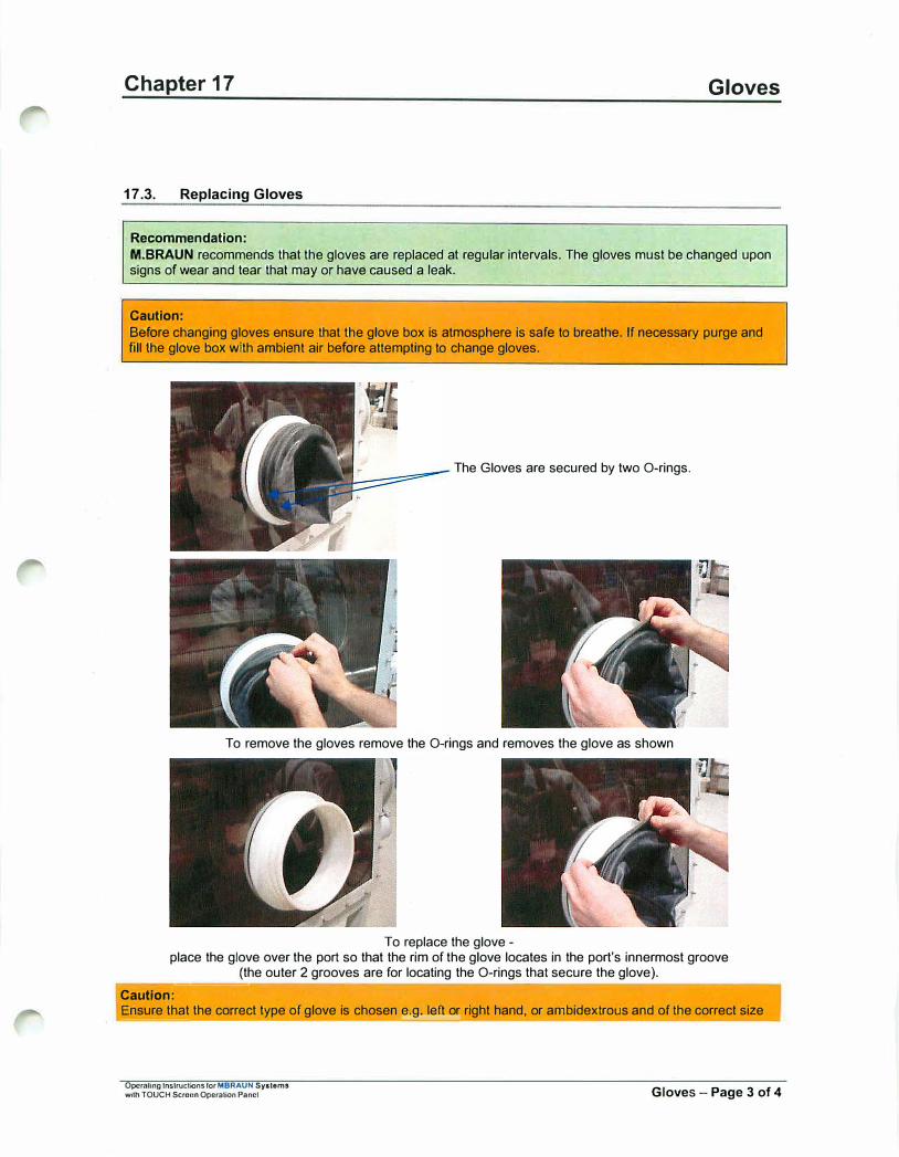
Chapter 17 Gloves
17 .3. Replacing Gloves
Recommendation:
M.BRAUN recommends that the gloves are replaced at regular intervals. The gloves must be changed uponsigns of wear and tear that may or have caused a leak.
Caution:
Before changing gloves ensure that the glove box is atmosphere is safe to breathe. If necessary purge and fill the glove box with ambient air before attempting to change gloves.
The Gloves are secured by two O-rings.
To remove the gloves remove the O-rings and removes the glove as shown
To replace the glove -place the glove over the port so that the rim of the glove locates in the port's innermost groove
(the outer 2 grooves are for locating the O-rings that secure the glove). -----
Caution:
Ensure that the correct type of glove is chosen e.g. left or right hand, or ambidextrous and of the correct size
Operaling lnslructions for MBRAUN Systems with TOUCH Scrofln OperalK>n Panel Gloves - Page 3 of 4

Chapter 17 Gloves
Check that the glove is orientated correctly and replace with new O-rings.
Note:
After lhe changing of gloves the glove box atmosphere will r1:3quire purging to remove any undesired oxygen and/or moisture. (see chapter on Purging the System)
--------------------�-----
17.4. Glove Port Covers
M.BRAUN glove port covers are available as an option. The glove port covers are for standard round gloveports and are available for either interior or exterior fitting.The glove port covers allow for the changing of gloves whilst preventing the influx of the outer-atmosphere intothe glove box.Glove port covers can be ordered from M.Braun Service Department
17.5. Standard Spare Parts and Accessories for M.Braun Gloves
1 Connection I Glove 1 M.Braun Order No. Description
I Diameter , Thickness ' Size I
3000047 Brom-butyl anatomical Glove 220mm 0.4 mm Large 3000048 Brom-butyl anatomical Glove 220mm 0.8mm Large 3240567 Brom-butyl ambidextrous Glove 220mm 0.4 mm Large 2340568 Brom-butyl ambidextrous Glove 220mm 0.8mm Large 3000018 Brom-butyl anatomical Glove 220mm 0.4 mm Medium
3005010 Hypalon anatomical Glove 220mm 0.4mm Large 3005009 Hypalon ambidextrous Glove 220mm 0.4 mm Large
3000050 Brom-butyl anatomical Glove 160mm 0.4 mm Large 3000051 Brom-butyl ambidextrous Glove 160 mm 0.4 mm Large
3005008 Brom-butyl ambidextrous Glove Oval 0.4 mm Large
2600239 O-Ring for Gloves 220mm 2600240 O-Ring for Gloves 160mm
9002371 Internal Glove Port Cover 220mm 7019882 External Glove Port Cover 220mm
7024831 Internal Glove Port Cover 160 mm 7024791 External Glove Port.Cover 160 mm
9004663 Glove Port Feed-Through 220mm 2400138 O-Ring (250•4) for Inner Glove Port Feed-Through 220mm 2400117 O-Ring (244.7) for Outer Glove Port Feed-Through 220mm
9004667 Glove Port Feed-Through 160mm
Other gloves, as well as O-Rings, are available by request from MBRAUN Service Department.
Oporaling Instructions f0< MBRAUN Systoma 'Mlh TOUCH Screen Operation Panel Gloves - Page 4 of 4
Chapter 18 Maintenance and Service
Contents
18.1. Components of Third.Party Manufacturers ....................................................................................... 2
18.2. Regular Maintenance and Service ...................................................................................................... 3
18.3. Quarterly and Annual Maintenance and Service .............................................................................. 4
Operating lnstrudions for MBRAUN - Systems with TOUCH Saeen Operation Panel Maintenance and Service - Page 1 of 4
Chapter 18
18.1. Components of Third-Party Manufacturers
Maintenance and Service
MBRAUN Glove Box systems are partly equipped with third-party manufacturers' components such as:
• Vacuum pump(s)• Compressor(s) for the system's compressor cooling• Compressor(s) for refrigerator systems• PLC control components (Siemens)• TOUCH Screen Operation Panel (Siemens)
The original third-party manufacturers' documents, in which the maintenance and service of the components are described, are included in the systems delivery.
Caution: The third-party manufacturers' maintenance and service instructions should be followed.
Operating Instructions f0< MBRAUN - Systems \Mth TOUCH Screen Operation Ponol
-----------
Maintenance and Service - Page 2 of 4
Chapter 18
18.2. Regular Maintenance and Service
Main glove box and window
Gloves
Antechambers
Connections
Components
Operating Instructions f0< MBRAUN - Systoms wUh TOUCH Screen OparallOO Panol
Maintenance and Service
Clean the exterior using conventional detergents (do not use caustic detergents); for this purpose use a soft, lint free cloth; or a vacuum cleaner if available, using a brush attachment.
Check the gloves for damage; in addition, use linen gloves to avoid humidity in the box gloves.
Caution: Do not use powder within the box or within a clean room environment. Replace gloves when damaged - by no means attempt to repair gloves.
Check antechamber seals for damage. If the antechamber doors are difficult to open or to close, grease or lubricate threads lightly.
Caution: Some areas of the system must be left without grease or lubrication. In this case, grease or lubricants should not be used.
Check connections for firm seat and are leak free.
Observe the maintenance instructions of the optional equipment components, such as analyser and refrigerator. Observe the third-party manufacturers' maintenance instructions.
Maintenance and Service - Page 3 of 4

Chapter 18 Maintenance and Service
18.3. Quarterly and Annual Maintenance and Service
Glove Box
Gas Purification System
Analysers
Operating lnslructions for MBRAUN - Systoms with TOUCH Screen Operation Panel
• Check the Omega sealingfor the windows
• Check the gloves and gloveports
• Check the magnetic valves• Complete leakage test• Function test
• Check the magnetic valves• Check the blower• Check the vacuum pump• Complete leakage test• Function Test
• Check the sensors• Check the flow rate meter• Complete leakage test
• Check and if necessaryreplace the sealing for thewindows
• Check the Omega sealing ofthe windows
• Check the gloves and gloveports
• Check the illuminatingequipment
• Check and if necessaryreplace the dust filters
• Check and if necessaryreplace the magnetic valves
• Complete leakage test• Function test
• Check the vacuum pump• Check and if necessary
replace the circulation blower• Check and if necessary
replace the filter medium• Dismantle pipe-work and
clean it. Replace all Vitonseals
• Check and if necessaryreplace the valve seals
• Check the cooling system• Check the cooling fluid• Complete leakage test• Function test
• Check and if necessaryreplace sensors
• Check the vacuum pump• Leak test piping• Complete leakage test• Check calibration
Maintenance and Service - Page 4 of 4

Chapter 19 Trouble Shooting
CONTENTS
19.1. General Information ................................................................................................................................ 2
19.2. Alarm and Warning Messages ............................................................................................................... 2
19.3. Definition of Error Messages ................................................................................................................. 3
Operating Instructions io, M.Braun - Systems With TOUCH Screen Operation Panel
Trouble Shooting - Page 1 of 12
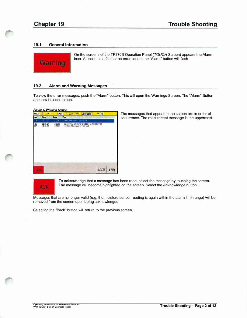
Chapter 19
19.1. General Information
Trouble Shooting
On the screens of the TP270B Operation Panel (TOUCH Screen) appears the Alarm icon. As soon as a fault or an error occurs the "Alarm" button will flash
19.2. Alarm and Warning Messages
To view the error messages, push the "Alarm" button. This will open the Warnings Screen. The "Alarm" Button appears in each screen.
S3 12:01:'P ]◄.OS,03 b�CRl)lllt:mo'D'prclDcth'eswlttlact,,,.1118d D9 12:01:25 l◄JJSJ)J MtTl!btl: PI.Jstl"l.'D..n'O' notrOMf
BACK' END
The messages that appear in the screen are in order of occurrence. The most recent message is the uppermost.
To acknowledge that a message has been read, select the message by touching the screen. The message will become highlighted on the screen. Select the Acknowledge button.
Messages that are no longer valid (e.g. the moisture sensor reading is again within the alarm limit range) will be removed from the screen upon being acknowledged.
Selecting the "Back" button will return to the previous screen.
Operating Instructions for M.Braun - Systems With TOUCH Screen Operation Pnnel Trouble Shooting - Page 2 of 12

Chapter 15
19.3.
Warning Number
2
3
4
5
6
7
8
9
10
11
12
41
42
Definition of Error Messages
Warning Description
motor protective switch vacuum pump VPG 1 activated
blower GB 1: motor protective switch activated or error frequency controller
purifier 1: filter 1 input main valve not open
purifier 1: filter 1 output main valve not open
purifier 1: filter 2 input main valve not open
purifier 1: filter 2 output main valve not open
purifier 1: pressure worl<ing gas too low
purifier 1: pressure purging gas too low
purifier 1: box purging outlet not open
purifier 1: box purging in operation
purifier 1: fuse filter heater activated
Cleanjet is switched off-\> no plasmabuming possible
Manifold: protection switch plasmaburner activated
Operatmg Instructions for M.Braun - Systems w,u, TOUCH Scr,,,,n Operatioo Panel
Possible Explanations
Vacuum pump faulty Coarse-leak in the piping
(vacuum pump oveiworl<ed due to size of the leak)
Main blower faulty Main piping stopped up
Main valve faulty Control pressure too low
Main valve faulty Control pressure too low
Main valve faulty Control pressure too low
Main valve faulty Control pressure too low
Worl<ing gas pressure too low Pressure-supervision defective or put in incorrectly
Pressure purging gas too low Pressure-supervision defective or put in incorrectly
Purging valve faulty Control pressure too low
Operator-hint
Filter heater faulty
Operator hint
Power supply plasma burner faulty
Trouble Shooting
Solutions
Replace vacuum pump Eliminate Coarse-leak
Vacuum pump check from MBraun - Service
Replace main blower Eliminate Constipation
Blower check from MBraun - Service
Replace main valve Set control pressure to 6 bar
Replace main valve Set control pressure to 6 bar
Replace main valve Set control pressure to 6 bar
Replace main valve Set control pressure to 6 bar
Set worl<ing gas pressure to 6bar Pressure supervision reset
Adjust pressure-supervision switch
Set purging gas pressure to 6bar Pressure supervision reset
Adjust pressure-supervision switch
Purging valve Replaces Set control pressure to 6 bar
No action required
Heater check from MBraun - Service
Operator has to switch on the Clean-JET
Replace plasma burner supply Check from MBraun-Service
Trouble Shooting - Page 3 of 12
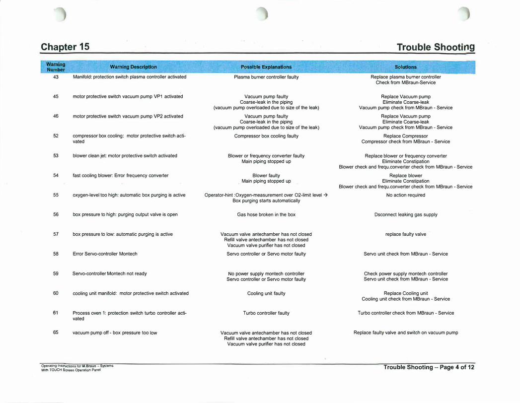
Chapter 15
Warning Number
43
45
46
52
53
54
55
56
57
58
59
60
61
65
Warning Description
Manifold: protection switch plasma controller activated
motor protective switch vacuum pump VP1 activated
motor protective switch vacuum pump VP2 activated
compressor box cooling: motor protective switch activated
blower clean jet: motor protective switch activated
fast cooling blower: Error frequency converter
oxygen-level too high: automatic box purging is active
box pressure to high: purging output valve is open
box pressure to low: automatic purging is active
Error Servo-controller Montech
Servo-controller Montech not ready
cooling unit manifold: motor protective switch activated
Process oven 1: protection switch turbo controller activated
vacuum pump off - box pressure too low
Operating lnstrvctions for M.Braun - Systems With TOUCH Screen Operation Panel
Possible Explanations
Plasma burner controller faulty
Vacuum pump faulty Coarse-leak in the piping
(vacuum pump overloaded due to size of the leak)
Vacuum pump faulty Coarse-leak in the piping
(vacuum pump overloaded due to size of the leak)
Compressor box cooling faulty
Blower or frequency converter faulty Main piping stopped up
Blower faulty Main piping stopped up
Operator-hint :Oxygen-measurement over O2-limit level ➔ Box purging starts automatically
Gas hose broken in the box
Vacuum valve antechamber has not closed Refill valve antechamber has not closed
Vacuum valve purifier has not closed
Servo controller or Servo motor faulty
No power supply montech controller Servo controller or Servo motor faulty
Cooling unit faulty
Turbo controller faulty
Vacuum valve antechamber has not closed Refill valve antechamber has not closed
Vacuum valve purifier has not closed
Trouble Shooting
Solutions
Replace plasma burner controller Check from MBraun-Service
Replace Vacuum pump Eliminate Coarse-leak
Vacuum pump check from MBraun • Service
Replace Vacuum pump Eliminate Coarse-leak
Vacuum pump check from MBraun - Service
Replace Compressor Compressor check from MBraun - Service
Replace blower or frequency converter Eliminate Constipation
Blower check and frequ.converter check from MBraun - Service
Replace blower Eliminate Constipation
Blower check and frequ.converter check from MBraun - Service
No action required
Dsconnect leaking gas supply
replace faulty valve
Servo unit check from MBraun - Service
Check power supply montech controller Servo unit check from MBraun - Service
Replace Cooling unit Cooling unit check from MBraun - Service
Turbo controller check from MBraun - Service
Replace faulty valve and switch on vacuum pump
Trouble Shooting - Page 4 of 12

Chapter 15
War
ning Number
66
96
97
98
99
100
101
102
103
104
105
106
107
108
Wamlng Description
Error Fieldbus Network
Clean the H20-sensor • Refer to instruction manual
purifier 1: filter 1 input main valve not closed
purifier 1: filter 1 output main valve not closed
purifier 1: regeneration filter 1 in operation
purifier 1: regeneration filter 1 service mode
Purifier 1: proof flow regeneration gas • ck?
purifier 1: filter 2 input main valve not closed
purifier 1: filter 2 output main valve not closed
purifier 1: regeneration filter 2 in operation
purifier 1: regeneration filter 2 service mode
purifier 1: H20 alarm
purifier 1: H20 sensor defective
purifier 1: 02 alarm
Operating lnstruc11ons for M.Braun - Syslems With TOUCH Screen Operation Panel
Possible Explanations
Field bus connector or cabel faulty Fieldbus slave faulty
Maintenance time H20-Sensor overstepped
Main valve purifier 1 faulty Control pressure too low
Main valve purifier 1 faulty Control pressure too low
Operator hint
Operating hint
Regeneration gas confirmation by the customer
Main valve purifier 2 faulty Control pressure too low
Main valve purifier 2 faulty Control pressure too low
Operator hint
Operator hint
H20-Measurement exceeds alarm-threshold: Antechamber leaky , piping leaky
Introduced item contains much moisture
H20-sensor faulty H20-sensor unplugged
02-Measurement exceeds alarm-threshold: Antechamber leaky , piping leaky
Introduced item contains much oxygen
Trouble Shooting
Solutions
Check fieldbus cabel and connector replace Fieldbus slave
Fieldbus check from Mbraun • Service
Clean H20-Sensor Reset maintenance lime H20-Sensor
Replace Main valve Set control pressure to 6 bar
Replace Main valve Set control pressure to 6 bar
No action required
No action required
Check gas flow regeneration gas and confirm condition
Replace Main valve Set control pressure to 6 bar
Main valve Replaces Set control pressure to 6 bar
No action required
No action required
Eliminate leakage Complete more pump-refill-cycles for the introduced item
Regenerate filter, use regenerated filter
Replace H20-sensor Plug-in H20-sensor
Eliminate leakage Complete more pump-refill-cycles for the introduced item
Regenerate filter, use regenerated filter
Trouble Shooting - Page 5 of 12
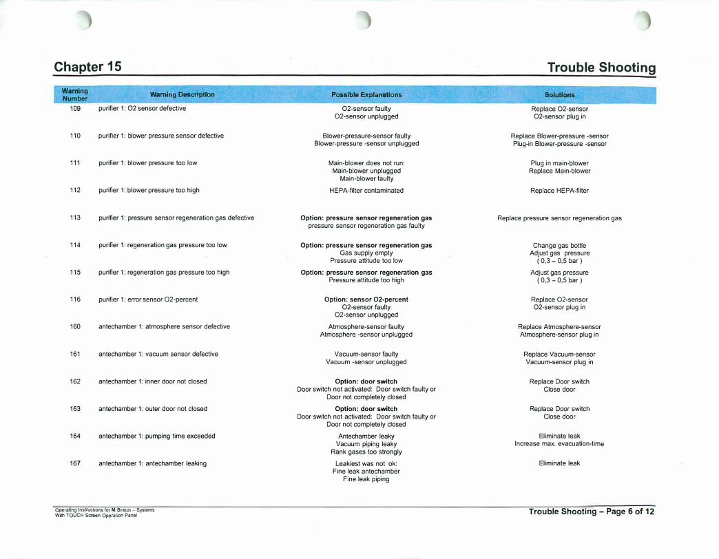
Chapter 15
Warning Number
109
110
111
112
113
114
115
116
160
161
162
163
164
167
Wamlng Description
purifier 1: 02 sensor defective
purifier 1: blower pressure sensor defective
purifier 1: blower pressure too low
purifier 1: blower pressure too high
purifier 1: pressure sensor regeneration gas defective
purifier 1: regeneration gas pressure too low
purifier 1: regeneration gas pressure too high
purifier 1: error sensor O2-percent
antechamber 1: atmosphere sensor defective
antechamber 1: vacuum sensor defective
antechamber 1: inner door not closed
antechamber 1: outer door not closed
antechamber 1: pumping time exceeded
antechamber 1: antechamber leaking
Operating lnstrucuons for M.Braun - Systems With TOUCH Screen Operation Panel
Possible Explanations
O2-sensor faulty O2-sensor unplugged
Blower-pressure-sensor faulty Blower-pressure -sensor unplugged
Main-blower does not run: Main-blower unplugged
Main-blower faulty
HEPA-filter contaminated
Option: pressure sensor regeneration gas pressure sensor regeneration gas faulty
Option: pressure sensor regeneration gas Gas supply empty
Pressure attitude too low
Option: pressure sensor regeneration gas Pressure attitude too high
Option: sensor O2-percent O2-sensor faulty
O2-sensor unplugged
Atmosphere-sensor faulty Atmosphere -sensor unplugged
Vacuum-sensor faulty Vacuum -sensor unplugged
Option: door switch Door switch not activated: Door switch faulty or
Door not completely closed
Option: door switch Door switch not activated: Door switch faulty or
Door not completely closed
Antechamber leaky Vacuum piping leaky
Rank gases too strongly
Leakiest was not ok: Fine leak antechamber
Fine leak piping
Trouble Shooting
SolutlOM
Replace O2-sensor O2-sensor plug in
Replace Blower-pressure -sensor Plug-in Blower-pressure -sensor
Plug in main-blower Replace Main-blower
Replace HEPA-filter
Replace pressure sensor regeneration gas
Change gas bottle Adjust gas pressure
( 0,3 - 0,5 bar )
Adjust gas pressure ( 0,3 - 0,5 bar )
Replace O2-sensor O2-sensor plug in
Replace Atmosphere-sensor Atmosphere-sensor plug in
Replace Vacuum-sensor Vacuum-sensor plug in
Replace Door switch Close door
Replace Door switch Close door
Eliminate leak Increase max. evacuation-time
Eliminate leak
Trouble Shooting - Page 6 of 12
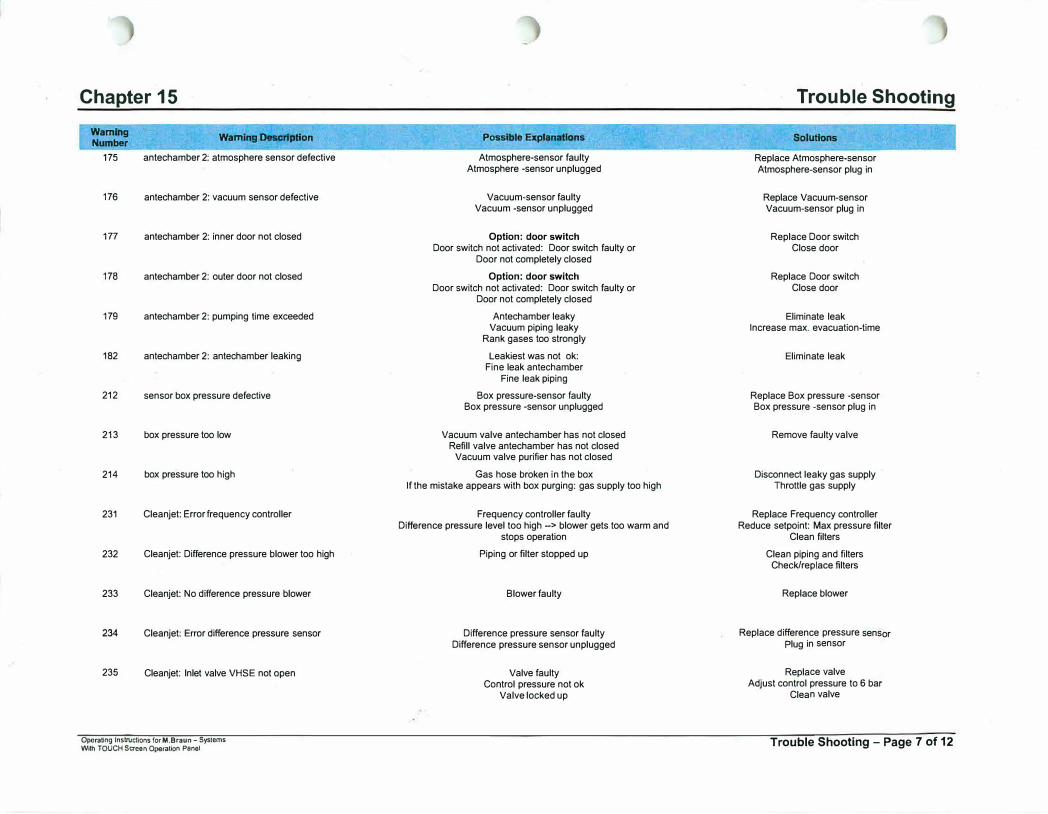
Chapter 15
Warning Number
175
176
177
178
179
182
212
213
214
231
232
233
234
235
Wamlng Description
antechamber 2: atmosphere sensor defective
antechamber 2: vacuum sensor defective
antechamber 2: inner door not closed
antechamber 2: outer door not closed
antechamber 2: pumping lime exceeded
antechamber 2: antechamber leaking
sensor box pressure defective
box pressure too low
box pressure too high
Cleanjet: Error frequency controller
Cleanjet: Difference pressure blower too high
Cleanjet: No difference pressure blower
Cleanjet: Error difference pressure sensor
Cleanjet: Inlet valve VHSE not open
Operating Instructions for M.Braun - Systems With TOUCH Screen Operation Panel
Possible Explanations
Atmosphere-sensor faulty Atmosphere -sensor unplugged
Vacuum-sensor faulty Vacuum -sensor unplugged
Option: door switch Door switch not activated: Door switch faulty or
Door not completely closed
Option: door switch Door switch not activated: Door switch faulty or
Door not completely closed
Antechamber leaky Vacuum piping leaky
Rank gases too strongly
Leakiest was not ok: Fine leak antechamber
Fine leak piping
Box pressure-sensor faulty Box pressure -sensor unplugged
Vacuum valve antechamber has not closed Refill valve antechamber has not closed
Vacuum valve purifier has not closed
Gas hose broken in the box If the mistake appears with box purging: gas supply too high
Frequency controller faulty Difference pressure level too high -> blower gets too warm and
stops operation
Piping or filter stopped up
Blower faulty
Difference pressure sensor faulty Difference pressure sensor unplugged
Valve faulty Control pressure not ok
Valve locked up
Trouble Shooting
Solutions
Replace Atmosphere-sensor Atmosphere-sensor plug in
Replace Vacuum-sensor Vacuum-sensor plug in
Replace Door switch Close door
Replace Door switch Close door
Eliminate leak Increase max. evacuation-time
Eliminate leak
Replace Box pressure -sensor Box pressure -sensor plug in
Remove faulty valve
Disconnect leaky gas supply Throttle gas supply
Replace Frequency controller Reduce setpoint: Max pressure filter
Clean filters
Clean piping and filters Check/replace filters
Replace blower
Replace difference pressure sensor Plug in sensor
Replace valve Adjust control pressure to 6 bar
Clean valve
Trouble Shooting - Page 7 of 12
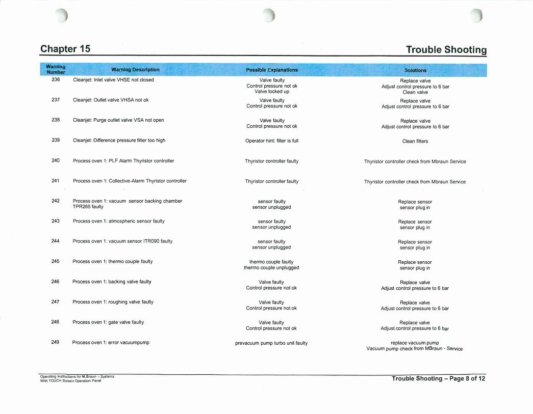
Chapter 15
Warning Number
236
237
238
239
240
241
242
243
244
245
246
247
248
249
Warning Description
Cleanjet: Inlet valve VHSE not closed
Cleanjet: Outlet valve VHSA not ok
Cleanjet: Purge outlet valve VSA not open
Cleanjet: Difference pressure filter too high
Process oven 1: PLF Alarm Thyristor controller
Process oven 1: Collective-Alarm Thyristor controller
Process oven 1: vacuum sensor backing chamber TPR265 faulty
Process oven 1: atmospheric sensor faulty
Process oven 1: vacuum sensor ITR090 faulty
Process oven 1: thermo couple faulty
Process oven 1: backing valve faulty
Process oven 1: roughing valve faulty
Process oven 1: gate valve faulty
Process oven 1: error vacuumpump
Operating lnstnJctions for M.Braun - Systems With TOUCH Screen Operation Panel
Possible Explanations
Valve faulty Control pressure not ok
Valve locked up
Valve faulty Control pressure not ok
Valve faulty Control pressure not ok
Operator hint: filter is full
Thyristor controller faulty
Thyristor controller faulty
sensor faulty sensor unplugged
sensor faulty sensor unplugged
sensor faulty sensor unplugged
thermo couple faulty thermo couple unplugged
Valve faulty Control pressure not ok
Valve faulty Control pressure not ok
Valve faulty Control pressure not ok
prevacuum pump turbo unit faulty
Trouble Shooting
Solutions
Replace valve Adjust control pressure to 6 bar
Clean valve
Replace valve Adjust control pressure to 6 bar
Replace valve Adjust control pressure to 6 bar
Clean filters
Thyristor controller check from Mbraun Service
Thyristor controller check from Mbraun Service
Replace sensor sensor plug in
Replace sensor sensor plug in
Replace sensor sensor plug in
Replace sensor sensor plug in
Replace valve Adjust control pressure to 6 bar
Replace valve Adjust control pressure to 6 bar
Replace valve Adjust control pressure to 6 bar
replace vacuum pump Vacuum pump check from MBraun - Service
Trouble Shooting - Page 8 of 12
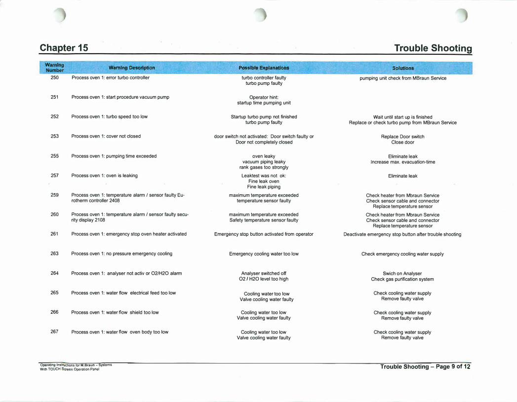
Chapter 15
Wamlng Number
250
251
252
253
255
257
259
260
261
263
264
265
266
267
Wamlng Description
Process oven 1: error turbo controller
Process oven 1: start procedure vacuum pump
Process oven 1: turbo speed too low
Process oven 1: cover not closed
Process oven 1: pumping time exceeded
Process oven 1: oven is leaking
Process oven 1: temperature alarm/ sensor faulty Eurotherm controller 2408
Process oven 1: temperature alarm/ sensor faulty security display 2108
Process oven 1: emergency stop oven heater activated
Process oven 1: no pressure emergency cooling
Process oven 1: analyser not acliv or O2/H2O alarm
Process oven 1: water flow electrical feed too low
Process oven 1: water flow shield too low
Process oven 1: water flow oven body too low
Operating lnslnJctions for M.Braun - Systems With TOUCH Screen Operation Panel
Possible Explanations
turbo controller faulty turbo pump faulty
Operator hint: startup time pumping unit
Startup turbo pump not finished turbo pump faulty
door switch not activated: Door switch faulty or Door not completely closed
oven leaky vacuum piping leaky
rank gases too strongly
Leakiest was not ck: Fine leak oven
Fine leak piping
maximum temperature exceeded temperature sensor faulty
maximum temperature exceeded Safety temperature sensor faulty
Emergency stop button activated from operator
Emergency cooling water too low
Analyser switched off 02 I H2O level too high
Cooling water too low Valve cooling water faulty
Cooling water too low Valve cooling water faulty
Cooling water too low Valve cooling water faulty
Trouble Shooting
Solutions
pumping unit check from MBraun Service
Wait until start up is finished Replace or check turbo pump from MBraun Service
Replace Door switch Close door
Eliminate leak Increase max. evacuation-time
Eliminate leak
Check heater from Mbraun Service Check sensor cable and connector
Replace temperature sensor
Check heater from Mbraun Service Check sensor cable and connector
Replace temperature sensor
Deactivate emergency stop button after trouble shooting
Check emergency cooling water supply
Swich on Analyser Check gas purification system
Check cooling water supply Remove faulty valve
Check cooling water supply Remove faulty valve
Check cooling water supply Remove faulty valve
Trouble Shooting - Page 9 of 12
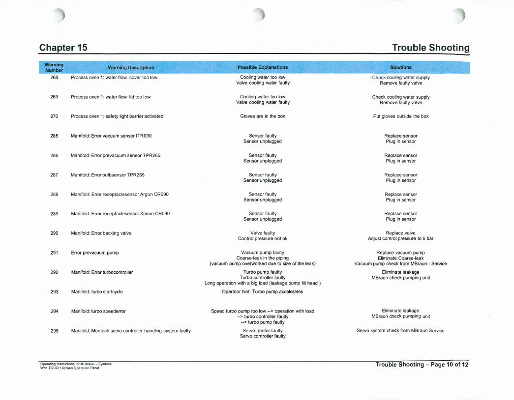
Chapter 15
Warning Number
268
269
270
285
286
287
288
289
290
291
292
293
294
295
Warning Description
Process oven 1: water flow cover too low
Process oven 1: water flow lid too low
Process oven 1: safety light barrier activated
Manifold: Error vacuum sensor ITR090
Manifold: Error prevacuum sensor TPR265
Manifold: Error bulbsensor TPR265
Manifold: Error receptaciesensor Argon CR090
Manifold: Error receptaclesensor Xenon CR090
Manifold: Error backing valve
Error prevacuum pump
Manifold: Error turbocontroller
Manifold: turbo startcycle
Manifold: turbo speederror
Manifold: Montech servo controller handling system faulty
Operattog lnstrucbons for M.Braun - Systems W"'1 TOUCH Screen Operation Panel
Possible Explanations
Cooling water too low Valve cooling water faulty
Cooling water too low Valve cooling water faulty
Gloves are in the box
Sensor faulty Sensor unplugged
Sensor faulty Sensor unplugged
Sensor faulty Sensor unplugged
Sensor faulty Sensor unplugged
Sensor faulty Sensor unplugged
Valve faulty Control pressure not ok
Vacuum pump faulty Coarse-leak in the piping
(vacuum pump oveiworked due to size of the leak)
Turbo pump faulty Turbo controller faulty
Long operation with a big load (leakage pump fill head )
Operator hint: Turbo pump accelerates
Speed turbo pump too low-> operation with load -> turbo controller faulty
-> turbo pump faulty
Servo motor faulty Servo controller faulty
Trouble Shooting
Solutions
Check cooling water supply Remove faulty valve
Check cooling water supply Remove faulty valve
Put gloves outside the box
Replace sensor Plug in sensor
Replace sensor Plug in sensor
Replace sensor Plug in sensor
Replace sensor Plug in sensor
Replace sensor Plug in sensor
Replace valve Adjust control pressure to 6 bar
Replace vacuum pump Eliminate Coarse-leak
Vacuum pump check from MBraun - Service
Eliminate leakage MBraun check pumping unit
Eliminate leakage MBraun check pumping unit
Servo system check from MBraun Service
Trouble Shooting - Page 10 of 12
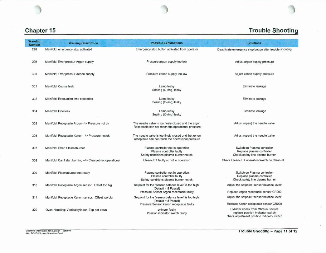
Chapter 15
Warning Number
296
299
300
301
302
304
305
306
307
308
309
310
311
320
Warning Description
Manifold: emergency stop activated
Manifold: Error pressur Argon supply
Manifold: Error pressur Xenon supply
Manifold: Course leak
Manifold: Evacuation time exceeded
Manifold: Fine leak
Manifold: Receptacle Argon --\> Pressure not ok
Manifold: Receptacle Xenon -\> Pressure not ok
Manifold: Error: Plasmaburner
Manifold: Can't start burning -\> Cleanjet not operational
Manifold: Plasrnaburner not ready
Manifold: Receptacle Argon sensor: Offset too big
Manifold: Receptacle Xenon sensor: Offset too big
Oven-Handling: Verticalcylinder -Top not down
Operating Instructions fOf M.BraUl'I - Systems Wllh TOUCH Semen Operation Panel
Posslble Explanations
Emergency stop button activated from operator
Pressure argon supply too low
Pressure xenon supply too low
Lamp leaky Sealing (0-ring) leaky
Lamp leaky Sealing (0-ring) leaky
Lamp leaky Sealing (0-ring) leaky
The needle valve is too finely closed and the argon Receptacle can not reach the operational pressure
The needle valve is too finely closed and the xenon receptacle can not reach the operational pressure
Plasma controller not in operation Plasma controller faulty
Safety conditions plasma burner not ok
Clean-JET faulty or not in operation
Plasma controller not in operation Plasma controller faulty
Safety conditions plasma burner not ok
Setpoint for the "sensor balance level" is too high. (Default= 8 Pascal)
Pressure Sensor Argon receptacle faulty
Setpoint for the "sensor balance level" Is too high. (Default= 8 Pascal)
Pressure Sensor Xenon receptacle faulty
cylinder faulty Position indicator switch faulty
Trouble Shooting
Solutions
Deactivate emergency stop button after trouble shooting
Adjust argon supply pressure
Adjust xenon supply pressure
Eliminate leakage
Eliminate leakage
Eliminate leakage
Adjust (open) the needle valve
Adjust (open) the needle valve
Switch on Plasma controller Replace plasma controller
Check safety line plasma burner
Check Clean-JET operation/switch on Clean-JET
Switch on Plasma controller Replace plasma controller
Check safety line plasma burner
Adjust the setpoint "sensor balance level"
Replace Argon receptacle sensor CR090
Adjust the setpoint "sensor balance level"
Replace Xenon receptacle sensor CR090
Cylinder check from Mbraun Service replace position indicator switch
check adjustment position indicator switch
Trouble Shooting - Page 11 of 12

Chapter 15
Warning Number
321
322
323
324
325
326
327
328
329
Warning Description
Oven-Handling: Verticalcylinder -Top not up
Oven-Handling: Verticalcylinder - Bottom not down
Oven-Handling: Verticalcylinder -Bottom not down
Oven-Handling: Horizontalcylinder 1 - not in unload position
Oven-Handling: Horizontalcylinder 1 - not In middle position
Oven-Handling: Horizontalcylinder 2 - not in load position
Oven-Handling: Horizontalcylinder 2 - not in oven position
Oven-Handling: Gribber not closed
Oven-Handling: Gribber not open
Operating Instructions for M.Braun - Systems With TOUCH Screen Operation Panel
Possible Explanations
cylinder faulty Position indicator switch faulty
cylinder faulty Position indicator svlitch faulty
cylinder faulty Position indicator switch faulty
cylinder faulty Position indicator switch faulty
cylinder faulty Position indicator switch faulty
cylinder faulty Position indicator switch faulty
cylinder faulty Position Indicator switch faulty
Gribber faulty Position indicator switch faulty
Gribber faulty Position indicator switch faulty
Trouble Shooting
Solutions
Cylinder check from Mbraun Service replace position indicator switch
check adjustment position indicator switch
Cylinder check from Mbraun Service replace position indicator switch
check adjustment position indicator switch
Cylinder check from Mbraun Service replace position indicator switch
check adjustment position Indicator switch
Cylinder check from Mbraun Service replace position indicator switch
check adjustment position indicator switch
Cylinder check from Mbraun Service replace position indicator switch
check adjustment position indicator switch
Cylinder check from Mbraun Service replace position indicator switch
check.adjustment position indicator switch
Cylinder check from Mbraun Service replace position indicator switch
check adjustment position indicator switch
Gribber check from Mbraun Service check adjustment Position switch indicator
Gribber check from Mbraun Service replace position indicator switch
check adjustment position indicator switch
Trouble Shooting - Page 12 of 1�
Related Documents