2010-11-15 X40083 Rev. Z Models: OLR105A12D OLR160B20C OUF105A12C OUF160B18C OLF105A12C NOLF105A12D NOUF105A12D Caution: Do not tamper with the unit or its controls. Call a qualified service technician. INSTALLER / SERVICE TECHNICIAN: USE THE INFORMATION IN THIS MANUAL FOR THE INSTALLATION AND SERVICING OF THE FURNACE AND KEEP THE DOCUMENT NEAR THE UNIT FOR FUTURE REFERENCE. HOMEOWNER: PLEASE KEEP THIS MANUAL NEAR THE FURNACE FOR FUTURE REFERENCE. Printed in Canada Printed on 100% recycled paper D N S - 0 5 6 0 R e v A OLR105 OLR160 D N S - 0 5 5 8 R e v A OUF105 OUF160 NOUF105 D N S - 0 5 6 1 R e v A OLF105 NOLF105 OIL FIRED FURNACE UPFLOW 445 01 4083 22 Manufactured by: Dettson Industries inc. 3400 Industrial Boulevard Sherbrooke, Quebec - Canada J1L 1V8

Welcome message from author
This document is posted to help you gain knowledge. Please leave a comment to let me know what you think about it! Share it to your friends and learn new things together.
Transcript
2010-11-15 X40083 Rev. Z
Models:
OLR105A12DOLR160B20COUF105A12COUF160B18COLF105A12CNOLF105A12DNOUF105A12D
Caution: Do not tamper with the unit or its controls.Call a qualified service technician.
INSTALLER / SERVICE TECHNICIAN:USE THE INFORMATION IN THIS MANUAL FOR THE INSTALLATION AND SERVICING OF THE FURNACE AND KEEP THE DOCUMENT NEAR THE UNIT FOR FUTURE REFERENCE.
HOMEOWNER:PLEASE KEEP THIS MANUAL NEAR THE FURNACE FOR FUTURE REFERENCE.
Printed in CanadaPrinted on 100% recycled paper
DN
S-05
60 R
ev A
OLR105 OLR160
DN
S-05
58 R
ev A
OUF105 OUF160NOUF105
DN
S-05
61 R
ev A
OLF105NOLF105
OIL FIRED FURNACE UPFLOW
445 01 4083 22
Manufactured by:
Dettson Industries inc.3400 Industrial BoulevardSherbrooke, Quebec - CanadaJ1L 1V8
PART 1 INSTALLATION
SAFETY CONSIDERATIONS
THE INSTALLATION OF OIL FIRED HEATING UNITS SHALL BE IN STRICT ACCORDANCE WITH THE REGULATIONS OF THE AUTHORITIES HAVING JURISDICTION. IN CANADA CSA B139 AND IN THE UNITED STATES NFPA NO.31-1992 INSTALLATION CODES FOR OIL BURNING EQUIPMENT APPLY.
DO NOT OPERATE FURNACE IN A CORROSIVE ATMOSPHERE CONTAINING CHLORINE, FLUORINE OR ANY OTHER DAMAGING CHEMICALS.
DO NOT STORE OR USE GASOLINE, OR OTHER FLAMMABLE VAPOURS AND LIQUIDS IN THE VICINITY OF THIS OR ANY OTHER APPLIANCE.
1.1 SAFETY LABELLING AND WARNING SIGNS DANGER, WARNING AND CAUTION The words DANGER, WARNING and CAUTION are used to identify the levels of seriousness of certain hazards. It is important that you understand their meaning. You will notice these words in the manual as follows:
DANGER
Immediate hazards which WILL result in death or serious injury.
WARNING
Hazards or unsafe practices which CAN result in death or injury.
CAUTION Hazards or unsafe practices which CAN result in personal injury, product or property damage.
1.2 SAFE INSTALLATION REQUIREMENTS
WARNING
Installation or repairs performed by unqualified persons can result in hazards to them and others. Installation MUST conform to local codes or, in the absence of same, to codes of the country having jurisdiction.
The information contained in this manual is intended for use by a qualified service technician familiar with safety procedures and equipped with the proper tools and test instruments.
Failure to carefully read and follow all instructions in this manual can result in death, bodily injury and/or property damage.
WARNING
Fire hazard.
The furnace must be installed in a level position, never where it will slope toward the front.
If the furnace is installed in that position, oil will drain into the furnace vestibule and create a fire hazard, instead of being directed into the combustion chamber.
NOTE: It is the personal responsibility and obligation of the customer to contact a qualified installer to ensure that the installation conforms to governing local and/or national codes and ordinances. a. This furnace is NOT approved for installation in mobile
homes, trailers or recreational vehicles; b. Do NOT use this furnace as a construction heater or to
heat a building under construction; c. There must be a sufficient supply of fresh air for
combustion as well as ventilation in the area where the furnace is located;
d. Use only the type of fuel oil approved for this furnace (see Rating Plate on unit). Overfiring will result in failure of heat exchanger and cause dangerous operating conditions;
e. Visually check all oil line joints for leaks; f. Connect furnace to a side-wall terminal or chimney; g. The points in Part 2 “Operation” are vital to the proper
and safe operation of the heating system. Take the time to ensure that all steps were followed;
h. Follow the regulations of the NFPA Pamphlet No.31 (USA) and CSA B-139 (Canada) or local codes for placing and installing the oil storage tank;
i. Follow a regular service and maintenance schedule for efficient and safe operation;
3
j. Before servicing, allow furnace to cool. Always shut off electricity and fuel to furnace when servicing. This will prevent electrical shock or burns;
k. Seal supply and return air ducts; l. The vent system MUST be checked to determine that it is
the correct type and size; m. Install correct filter type and size; n. Unit MUST be installed so that electrical components are
protected from direct contact with water. 1.2.1 Safety Rules Your unit is built to provide many years of safe and dependable service provided it is properly installed and maintained. However, abuse and/or improper use can shorten the life of the unit and create hazards for you, the owner.
a. The U.S. Consumer Product Safety Commission recommends that users of oil-burning appliances install carbon monoxide detectors. There can be various sources of carbon monoxide in a building or dwelling. The sources could be gas-fired clothes dryers, gas cooking stoves, water heaters, furnaces, gas-fired fireplaces, wood fireplaces, and several others. Carbon monoxide can cause death and/or serious bodily injury. Therefore, to help alert people of potentially dangerous carbon monoxide levels, you should have carbon monoxide detectors listed by a nationally recognised agency (Underwriters Laboratories or International Approval Services) installed and maintained in the building or dwelling (see Note below).
b. There can be numerous sources of fire or smoke in a building or dwelling. Fire or smoke can cause death, serious bodily injury, and/or property damage. Therefore, in order to alert people to potentially dangerous fire or smoke, you should have fire and smoke detectors listed by Underwriters Laboratories installed and maintained in the building or dwelling (see Note below).
NOTE: The manufacturer of your furnace does not test any detectors and makes no representations regarding any brand or type of detector.
CAUTION Ensure that the area around the combustion air intake terminal is free of snow, ice and debris.
CAUTION An air pressure switch MUST be used when the furnace is side-wall vented.
CAUTION Do not use any commercially available soot remover. This furnace has a ceramic fibre type of combustion chamber. Normal servicing of this unit does not require the cleaning of same. Use extreme caution if for any reason you have to work in the area of the combustion chamber.
1.2.2 Freezing Temperature and Your Structure
WARNING
Freezing temperature warning.
Turn off water supply.
If your heater remains shut off during cold weather, the water pipes could freeze and burst, resulting in serious water damage. Your unit is equipped with safety devices that may keep it from operating if sensors detect abnormal conditions such as exhaust flues obstructed by snow, ice or debris.
If the structure is unattended during cold weather you should take the following precautions: a. Turn off main water supply into the structure and drain the
water lines if possible. Open faucets in appropriate areas; b. Have someone check the structure frequently during cold
weather to make sure it is warm enough to prevent pipes from freezing. Contact a qualified service agency, if required.
1.2.3 Installation regulations All local and national code requirements governing the installation of oil burning equipment, wiring and flue connections MUST be followed. Some of the codes that may be applicable are:
CSA B139 Installation Code for Oil Burning Equipment
NFPA 31 Installation of Oil Burning Equipment ANSI/NFPA 90B Warm Air Heating and Air Conditioning
Systems ANSI/NFPA 70 National Electrical Code CSA C22.1 Canadian Electrical Code Only the latest issues of the above codes should be used. 1.3 POSITIONING THE FURNACE
CAUTION Carefully check your furnace upon delivery for any evidence of damage that may have occurred during shipping and handling. Any claims for damages or lost parts must be made with the transport company. 1.3.1 Location
The unit must be installed in a location where the ambient and return air temperatures are over 15°C (60°F).
Position the furnace as closely as possible to the chimney or vent terminal, providing ample clearance to permit easy accessibility for cleaning the inside of the furnace, the removal of filters, blower, motors, controls and flue connections.
4

TABLE 1 Minimum Installation clearances from combustible materials (Chimney installation*)
LOCATION APPLICATION OLR160 - OUF160 OLR105 - OLF105 - NOLF105 OUF105 - NOUF105
Furnace 2.54 cm (1") 2.54 cm (1") Sides Supply plenum, warm air duct within 6‘ of furnace 2.54 cm (1") 2.54 cm (1") Back Furnace 45.72 cm (18") 2.54 cm (1") Top Furnace casing or plenum 5.08 cm (2") 2.54 cm (1") Bottom Furnace – combustible floor ** ø ø Front Furnace 60.96 cm (24") 60.96 cm (24") * See paragraph 1.4.3, p. 6 for Direct Vent application clearances. ** Combustible floor requires accessory bases CFB-1 or HFB-1. However, do not install furnace directly on carpet or other combustible material which can trap air under the furnace floor.
The furnace must be installed level for safe and quiet operation.
The required minimum clearances for this furnace are specified in Table 1 above.
CAUTION Do NOT operate furnace in a corrosive atmosphere containing chlorine, fluorine or any other damaging chemicals. Refer to Part 1, section 5.2. 1.4 VENTING
1.4.1 General Furnaces can be vented in several ways: Chimney Vented Using the Beckett AFG or Riello 40-F burner, the furnaces can be chimney vented with or without a barometric damper. The unit will operate at a negative overfire draft and flue draft.
WARNING
Poisonous carbon monoxide gas, fire and explosion hazard.
Read and follow all instructions in this section.
Failure to properly vent this furnace can cause death, bodily injury and/or property damage.
WARNING
Poisonous carbon monoxide gas hazard.
Never vent this furnace together with another combustion appliance when side-wall venting.
To do so may result in asphyxiation and death to the occupants. Side-wall Vented Using the Beckett AFII or Riello 40-BF burner with the integral pre- and post-purge controls, the system can be side-wall vented for maximum efficiency and without the use of a side-wall power vent. The unit will operate at a positive overfire draft and flue draft.
1.4.2 Chimney installations When set up for chimney venting, this furnace is certified for use with an L-vent, A-vent, tile-lined and metal-liner-tile lined chimney, and can be vented both with and without a barometric draft damper. However, this furnace is not approved for use without a barometric damper if it is to be vented together with another oil-fired appliance such as a water heater. With a barometric damper This furnace may be vented into a chimney of suitable size and adequate chimney base temperature, as specified in the Installation Code. When a barometric damper is used, the air entering the damper reduces the possibility of vent condensation. The relevant excerpt from the code is found in this section and can be used as a guide where local or national codes do not exist. One option to increase the chimney base temperature is to use vent connection insulation.
WARNING
Poisonous carbon monoxide gas hazard.
Never install a hand operated damper in the vent pipe. However, any Underwriters Laboratories listed electrically operated automatic type vent damper may be installed if desired. Be sure to follow the instructions provided with vent damper. Read and follow all instructions in this section.
Failure to properly vent this furnace or other appliances can result in death, personal injury and/or property damage.
Without a barometric damper Due to the lack of dilution air that would ordinarily be drawn into the barometric damper, the dew point of the flue gases is raised. To offset the increased tendency for vent condensation, the chimney must be lined. The liner must be insulated according to the insulating procedure recommended by the manufacturer of the liner. Also, the vent connector should be as short as possible and be either of double wall construction or of single wall construction with 2.54 cm (1”) of insulation.
5

CAUTION When the furnace (chimney installation) is vented together with other combustion appliances such as a water heater, the allowable venting materials for use with those appliances must be investigated (“L”-vent, etc.). Flue pipe sizing The following table is an excerpt from the Installation Code and indicates the permitted flue sizes and minimum base temperatures for circular flues in chimneys with a thermal resistance of less than R6 (6 ft2 •hr •°F / Btu). Where a new appliance, burner, or chimney is installed, chimney vent sizes and maximum flue gas temperatures shall comply with Table 2 (measured at the chimney connector with the barometric damper shut, after 5 minutes of operation). Note: Thermal resistance values for typical chimneys are as follows: R2 (2 ft2 •hr •°F / Btu): Clay-lined masonry, A-vent
R3 (3 ft2 •hr •°F / Btu): Metal liner in clay-lined Masonry
R6 (6 ft2 •hr •°F / Btu): Metal or clay-lined masonry with R4.5 (4.5 ft2 •hr •°F / Btu) insulation between liner and masonry (e.g. 2” of expanded mica or 1 3/8” of high density glass fibreboard.)
Applying Table 2 If a furnace with a 0.60 USGPH nozzle is to be connected to a 6.1 m (20') tall clay-lined masonry chimney, the thermal resistance of this type of chimney is R2, (which is less than R6). The actual firing rate at 156 psig is 1.25 x .60 = .75 USGPH. Therefore this table shall apply as follows: The minimum size permitted shall be 10.16 cm (4") in. inside diameter; The maximum size permitted shall be 12.70 cm (5") inside diameter; The minimum base temperature shall be about 160°C (320°F). 1.4.3 Side-wall venting - DV-2000™
Direct Vent System The furnace can be side-wall vented, without the use of a side-wall power vent, with the high static pressure Beckett AFII and Riello 40-BF oil burners. Outdoor combustion air must be directly connected to the burner or the DV-2000™ venting system will not function.
The notable characteristics of the DV-2000™ system are as follows: a) Certified to use the following materials for ducting the
intake air from the terminal to the burner: Schedule 40 PVC DWV, Schedule 40 ABS DWV, and ASTM 2729 sewer Pipe;
b) One hole of minimal size 15.24 cm (6") is required to be cut into the side-wall, and the terminal is designed to fit through a minimum 2 x 8 joist space;
c) Incorporates a vent blockage safety shutdown system. If the vent or intake opening ever becomes partially or fully blocked, the burner will shut down before a #1 smoke condition occurs;
d) The intake and vent circuits within the terminal can be accessed for cleaning.
There are 3 main components to the DV-2000™ system; the vent terminal kit VTK-1 (for models OLF/R105, OUF105, NOUF105 and NOLF105) or VTK-2 (for models OLR160, OUF160) and the insulated flexible venting material IFV3 (for models OLF/R105, OUF105, NOUF105, NOLF105) or IFV4 (for models OLR160, OUF160) and the field-supplied 3” PVC or ABS intake piping.
WARNING
Poisonous carbon monoxide gas hazard.
Even though the flexible venting is insulated, it must not be run through an unheated space.
To do so can cause residual condensation inside the stainless steel liner. This may eventually perforate the liner and allow vent gasses to enter the dwelling, which can result in death, personal injury and/or property damage.
Insulated flexible venting - DV-2000™ The certified venting materials come in 3 lengths, Model No. IFV3-15, IFV3-23 and IFV3-30 or IFV4-15, IFV4-23 and IFV4-30 for 160 models correspond to 15, 23 and 30' of continuous lengths of vent. The vent construction is coaxial and incorporates a stainless steel corrugated flexible liner surrounded by a thick insulation blanket and covered with an outer layer of flexible corrugated aluminium sleeve to protect the insulation. Splicing vent lengths together is prohibited. The maximum and minimum continuous vent lengths permitted for installation are: 1.5 m (5') minimum 9 m (30') maximum
TABLE 2
Total input rating of all connected appliances Inside diameter of flue Minimum base temperature according to chimney height :
kW BTU/h USGPH Min. Max. 11' 20' 28' 36' 21 70000 0.50 7.62 cm (3") 12.70 cm (5") 149°C (300°F) 204°C (400°F) 279°C (535°F) 385°C (725°F) 27 91000 0.65 7.62 cm (3") 12.70 cm (5") 135°C (275°F) 171°C (340°F) 221°C (430°F) 279°C (535°F) 31 105000 0.75 10.16 cm (4") 12.70 cm (5") 127°C (260°F) 160°C (320°F) 193°C (380°F) 246°C (475°F) 36 119000 0.85 10.16 cm (4") 12.70 cm (5") 121°C (250°F) 149°C (300°F) 179°C (355°F) 221°C (430°F) 41 140000 1.00 10.16 cm (4") 15.24 cm (6") 107°C (225°F) 149°C (300°F) 185°C (365°F) 221°C (430°F) 51 175000 1.25 10.16 cm (4") 15.24 cm (6") 116°C 240°F) 135°C (275°F) 160°C (320°F) 185°C (365°F)
6
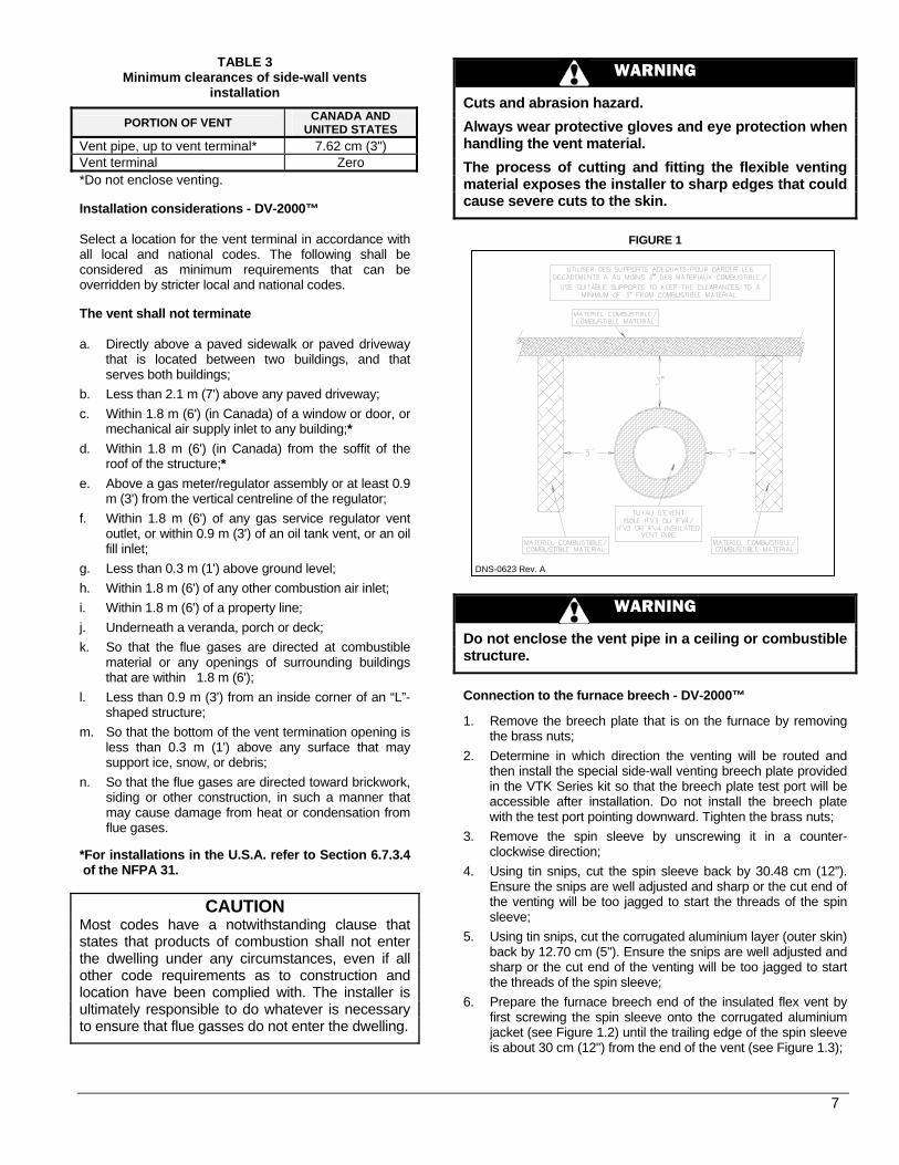
TABLE 3 Minimum clearances of side-wall vents
installation
PORTION OF VENT CANADA AND UNITED STATES
Vent pipe, up to vent terminal* 7.62 cm (3") Vent terminal Zero *Do not enclose venting. Installation considerations - DV-2000™ Select a location for the vent terminal in accordance with all local and national codes. The following shall be considered as minimum requirements that can be overridden by stricter local and national codes. The vent shall not terminate a. Directly above a paved sidewalk or paved driveway
that is located between two buildings, and that serves both buildings;
b. Less than 2.1 m (7') above any paved driveway; c. Within 1.8 m (6') (in Canada) of a window or door, or
mechanical air supply inlet to any building;* d. Within 1.8 m (6') (in Canada) from the soffit of the
roof of the structure;* e. Above a gas meter/regulator assembly or at least 0.9
m (3') from the vertical centreline of the regulator; f. Within 1.8 m (6') of any gas service regulator vent
outlet, or within 0.9 m (3') of an oil tank vent, or an oil fill inlet;
g. Less than 0.3 m (1') above ground level; h. Within 1.8 m (6') of any other combustion air inlet; i. Within 1.8 m (6') of a property line; j. Underneath a veranda, porch or deck; k. So that the flue gases are directed at combustible
material or any openings of surrounding buildings that are within 1.8 m (6');
l. Less than 0.9 m (3') from an inside corner of an “L”-shaped structure;
m. So that the bottom of the vent termination opening is less than 0.3 m (1') above any surface that may support ice, snow, or debris;
n. So that the flue gases are directed toward brickwork, siding or other construction, in such a manner that may cause damage from heat or condensation from flue gases.
*For installations in the U.S.A. refer to Section 6.7.3.4 of the NFPA 31.
CAUTION Most codes have a notwithstanding clause that states that products of combustion shall not enter the dwelling under any circumstances, even if all other code requirements as to construction and location have been complied with. The installer is ultimately responsible to do whatever is necessary to ensure that flue gasses do not enter the dwelling.
WARNING
Cuts and abrasion hazard.
Always wear protective gloves and eye protection when handling the vent material.
The process of cutting and fitting the flexible venting material exposes the installer to sharp edges that could cause severe cuts to the skin.
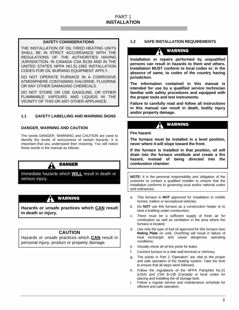
FIGURE 1
WARNING
Do not enclose the vent pipe in a ceiling or combustible structure.
Connection to the furnace breech - DV-2000™ 1. Remove the breech plate that is on the furnace by removing
the brass nuts; 2. Determine in which direction the venting will be routed and
then install the special side-wall venting breech plate provided in the VTK Series kit so that the breech plate test port will be accessible after installation. Do not install the breech plate with the test port pointing downward. Tighten the brass nuts;
3. Remove the spin sleeve by unscrewing it in a counter-clockwise direction;
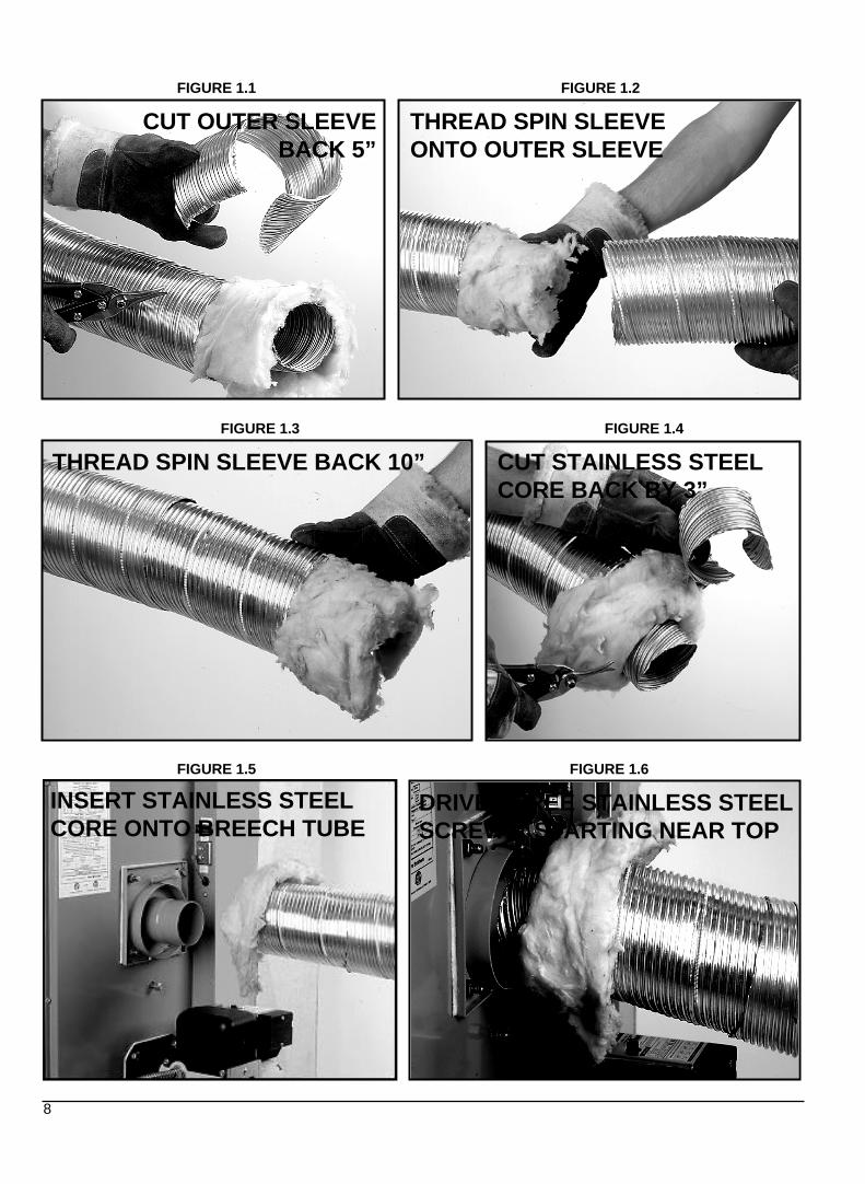
4. Using tin snips, cut the spin sleeve back by 30.48 cm (12”). Ensure the snips are well adjusted and sharp or the cut end of the venting will be too jagged to start the threads of the spin sleeve;
5. Using tin snips, cut the corrugated aluminium layer (outer skin) back by 12.70 cm (5"). Ensure the snips are well adjusted and sharp or the cut end of the venting will be too jagged to start the threads of the spin sleeve;
6. Prepare the furnace breech end of the insulated flex vent by first screwing the spin sleeve onto the corrugated aluminium jacket (see Figure 1.2) until the trailing edge of the spin sleeve is about 30 cm (12") from the end of the vent (see Figure 1.3);
DNS-0623 Rev. A
7
THREAD SPIN SLEEVE ONTO OUTER SLEEVE
CUT OUTER SLEEVEBACK 5”
THREAD SPIN SLEEVE BACK 10” CUT STAINLESS STEEL CORE BACK BY 3”
FIGURE 1.3 FIGURE 1.4
FIGURE 1.1 FIGURE 1.2
DRIVE THREE STAINLESS STEEL SCREWS, STARTING NEAR TOP
FIGURE 1.5 FIGURE 1.6
8
INSERT STAINLESS STEEL CORE ONTO BREECH TUBE
CORRECT BAND OVERLAP
FIGURE 1.9 FIGURE 1.10
FIGURE 1.7 FIGURE 1.8
SEALANT FLOWING OUT FROM UNDER BAND CLAMP AT TERMINAL
SEALANT OUTFLOW
FIGURE 1.11
APPLY THE SEALANT TOTHE TUBE END
9
SEALANT FLOWING OUT FROM UNDER BAND CLAMP AT BREECH
SEALANT OUTFLOW
TWIST SPIN SLEEVE TIGHTLY INTO BREECH COLLAR
TWIST SPIN SLEEVE TIGHTLY INTO RECESS
INSTALL STABILIZER SHROUD
CAULK TO SEAL STABILIZER SHROUD TO THE WALL
FIGURE 1.13 FIGURE 1.14
FIGURE 1.12
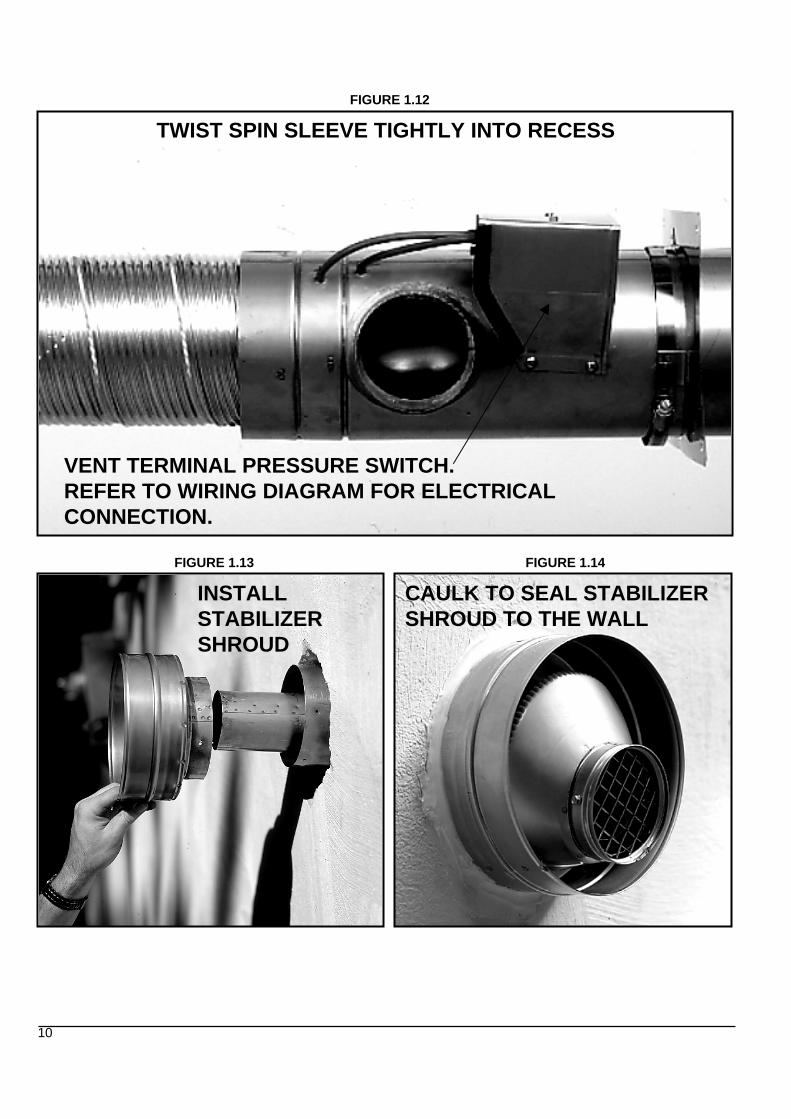
VENT TERMINAL PRESSURE SWITCH.REFER TO WIRING DIAGRAM FOR ELECTRICAL CONNECTION.
10
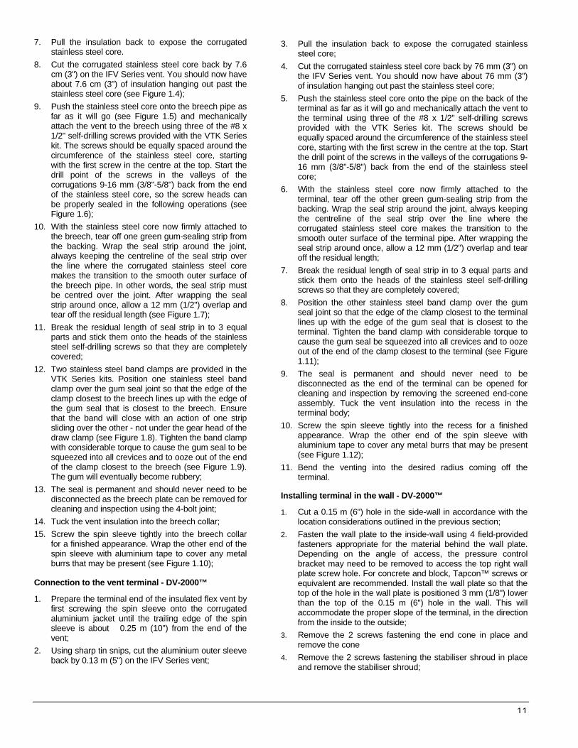
7. Pull the insulation back to expose the corrugated stainless steel core.
8. Cut the corrugated stainless steel core back by 7.6 cm (3") on the IFV Series vent. You should now have about 7.6 cm (3") of insulation hanging out past the stainless steel core (see Figure 1.4);
9. Push the stainless steel core onto the breech pipe as far as it will go (see Figure 1.5) and mechanically attach the vent to the breech using three of the #8 x 1/2" self-drilling screws provided with the VTK Series kit. The screws should be equally spaced around the circumference of the stainless steel core, starting with the first screw in the centre at the top. Start the drill point of the screws in the valleys of the corrugations 9-16 mm (3/8"-5/8") back from the end of the stainless steel core, so the screw heads can be properly sealed in the following operations (see Figure 1.6);
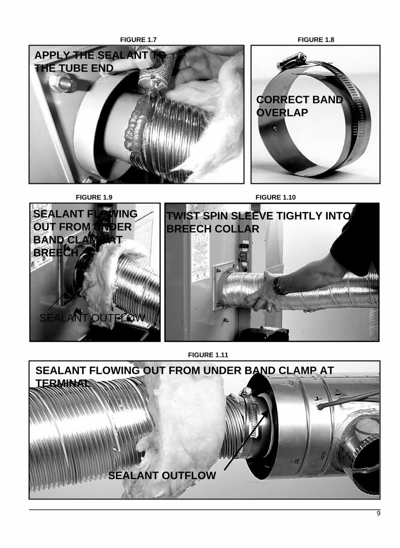
10. With the stainless steel core now firmly attached to the breech, tear off one green gum-sealing strip from the backing. Wrap the seal strip around the joint, always keeping the centreline of the seal strip over the line where the corrugated stainless steel core makes the transition to the smooth outer surface of the breech pipe. In other words, the seal strip must be centred over the joint. After wrapping the seal strip around once, allow a 12 mm (1/2") overlap and tear off the residual length (see Figure 1.7);
11. Break the residual length of seal strip in to 3 equal parts and stick them onto the heads of the stainless steel self-drilling screws so that they are completely covered;
12. Two stainless steel band clamps are provided in the VTK Series kits. Position one stainless steel band clamp over the gum seal joint so that the edge of the clamp closest to the breech lines up with the edge of the gum seal that is closest to the breech. Ensure that the band will close with an action of one strip sliding over the other - not under the gear head of the draw clamp (see Figure 1.8). Tighten the band clamp with considerable torque to cause the gum seal to be squeezed into all crevices and to ooze out of the end of the clamp closest to the breech (see Figure 1.9). The gum will eventually become rubbery;
13. The seal is permanent and should never need to be disconnected as the breech plate can be removed for cleaning and inspection using the 4-bolt joint;
14. Tuck the vent insulation into the breech collar; 15. Screw the spin sleeve tightly into the breech collar
for a finished appearance. Wrap the other end of the spin sleeve with aluminium tape to cover any metal burrs that may be present (see Figure 1.10);
Connection to the vent terminal - DV-2000™ 1. Prepare the terminal end of the insulated flex vent by
first screwing the spin sleeve onto the corrugated aluminium jacket until the trailing edge of the spin sleeve is about 0.25 m (10") from the end of the vent;
2. Using sharp tin snips, cut the aluminium outer sleeve back by 0.13 m (5") on the IFV Series vent;
3. Pull the insulation back to expose the corrugated stainless steel core;
4. Cut the corrugated stainless steel core back by 76 mm (3") on the IFV Series vent. You should now have about 76 mm (3") of insulation hanging out past the stainless steel core;
5. Push the stainless steel core onto the pipe on the back of the terminal as far as it will go and mechanically attach the vent to the terminal using three of the #8 x 1/2" self-drilling screws provided with the VTK Series kit. The screws should be equally spaced around the circumference of the stainless steel core, starting with the first screw in the centre at the top. Start the drill point of the screws in the valleys of the corrugations 9-16 mm (3/8"-5/8") back from the end of the stainless steel core;
6. With the stainless steel core now firmly attached to the terminal, tear off the other green gum-sealing strip from the backing. Wrap the seal strip around the joint, always keeping the centreline of the seal strip over the line where the corrugated stainless steel core makes the transition to the smooth outer surface of the terminal pipe. After wrapping the seal strip around once, allow a 12 mm (1/2") overlap and tear off the residual length;
7. Break the residual length of seal strip in to 3 equal parts and stick them onto the heads of the stainless steel self-drilling screws so that they are completely covered;
8. Position the other stainless steel band clamp over the gum seal joint so that the edge of the clamp closest to the terminal lines up with the edge of the gum seal that is closest to the terminal. Tighten the band clamp with considerable torque to cause the gum seal be squeezed into all crevices and to ooze out of the end of the clamp closest to the terminal (see Figure 1.11);
9. The seal is permanent and should never need to be disconnected as the end of the terminal can be opened for cleaning and inspection by removing the screened end-cone assembly. Tuck the vent insulation into the recess in the terminal body;
10. Screw the spin sleeve tightly into the recess for a finished appearance. Wrap the other end of the spin sleeve with aluminium tape to cover any metal burrs that may be present (see Figure 1.12);
11. Bend the venting into the desired radius coming off the terminal.
Installing terminal in the wall - DV-2000™ 1. Cut a 0.15 m (6") hole in the side-wall in accordance with the
location considerations outlined in the previous section; 2. Fasten the wall plate to the inside-wall using 4 field-provided
fasteners appropriate for the material behind the wall plate. Depending on the angle of access, the pressure control bracket may need to be removed to access the top right wall plate screw hole. For concrete and block, Tapcon™ screws or equivalent are recommended. Install the wall plate so that the top of the hole in the wall plate is positioned 3 mm (1/8") lower than the top of the 0.15 m (6") hole in the wall. This will accommodate the proper slope of the terminal, in the direction from the inside to the outside;
3. Remove the 2 screws fastening the end cone in place and remove the cone
4. Remove the 2 screws fastening the stabiliser shroud in place and remove the stabiliser shroud;
11
5. Insert the main body of the terminal through the wall plate so that the end of the terminal extends about 50 mm (2") past the outside wall;
6. Install the stabiliser shroud and replace the two mounting screws. (see Figure 1.13);
7. On concrete and block wall installations in particular, if it appears that the flange on the back of the stabiliser shroud is not large enough to cover the irregularities in the hole, a field fabricated wall plate can be constructed out of 304, 316, or 316L stainless steel;
8. Silicone seal the circumference of the joint where the stabiliser shroud connects to the main body of the terminal;
9. Apply caulking to the back plate of the stabiliser shroud and push the terminal back firmly against the wall, making sure the pressure switch is located at the top, in a horizontal position;
10. While pushing down gently on the top of the stabiliser shroud, install the 3 stainless steel 2" screws provided with the kit to secure the back of the shroud to the wall. Do not over tighten the screws or it will distort the stabiliser shroud. The screws will not be necessary in a concrete or block wall as the mortar can provide positive positioning;
11. Tighten the clamp on the wall plate to secure the terminal in place;
12. Apply more caulking all around the seam where the stabiliser shroud meets the wall. It is important to have a good seal to prevent water from entering the dwelling (see Figure 1.14). A considerable amount of caulking may be necessary for irregular wall surfaces such as lapped siding;
13. Install the end cone and replace the two mounting screws;
14. Support the vent and intake air piping so that a 6 to 13 mm (1/4 to 1/2") slope (toward the outside) results for proper drainage out the terminal body.
Connection of combustion air piping to the terminal DV-2000™ Refer to Part 1, section 5.3 (1.5.3), Outdoor Combustion Air – Side-wall Venting, DV-2000™ for a complete description. 1.5 AIR FOR COMBUSTION
WARNING
Poisonous carbon monoxide gas hazard.
Comply with NFPA or CSA standards for the installation of Oil Burning Equipment and applicable provisions of local building codes to provide combustion and ventilation air.
Failure to provide adequate combustion and ventilation air can result in death or personal injury.
1.5.1 General Oil furnaces must have an adequate supply of combustion air. It is common practice to assume that older homes have sufficient infiltration to accommodate the combustion air requirements for the furnace. However, home improvements such as new windows, doors, and weather stripping have drastically reduced the volume of air infiltration into the home.
Home air exhausters are common. Bathroom and kitchen fans, power vented clothes dryers and water heaters all tend to create a negative pressure in the home. Should this occur the chimney becomes less and less effective and can easily downdraft.
Heat Recovery Ventilation Systems (HRVS) are gaining in popularity. HRVS are not designed to supply combustion air. If not properly balanced, a serious negative pressure condition could develop in the dwelling. 1.5.2 Contaminated Combustion Air Installations in certain areas or types of structures will increase the exposure to chemicals or halogens which may harm the furnace. These instances will require that only outside air be used for combustion.
The following areas or types of structures may contain or be exposed to certain substances, potentially requiring outside air for combustion:
a. Commercial buildings; b. Buildings with indoor pools; c. Furnaces installed near chemical storage areas. Exposure to the following substances: a. Permanent wave chemicals for hair; b. Chlorinated waxes and cleaners; c. Chlorine based swimming pool chemicals; d. Water softening chemicals; e. De-icing salts or chemicals; f. Carbon tetrachloride; g. Halogen type refrigerants; h. Cleaning solvent (such as perchloroethylene); i. Printing inks, paint removers, varnishes, etc. ; j. Hydrochloric acid;
k. Solvent based glue; l. Antistatic fabric softeners for clothes dryers; m. Acid based masonry cleaning materials. 1.5.3 Ducted outdoor combustion air Three burners are set up to duct outside combustion air directly to the burner; the Beckett AFII and Riello 40-BF for side-wall venting and the Beckett AFG for use with conventional chimney venting. The Riello 40-F is not suitable for direct-connected outdoor air.
CAUTION The use of ducted outside combustion air is mandatory for the DV-2000™ venting system. This system operates on a balanced flue principle and will not function properly if the combustion air piping is not attached and sealed at all connections between the vent terminal and burner inlet.
12
Outdoor combustion air kit – chimney venting The following kit has been certified for use on this appliance. The kit contains an important safety feature, namely a vacuum relief valve, or VRV. During normal operation the burner aspirates outdoor air. If the intake terminal ever becomes partially blocked or fully blocked from ice or snow etc., the VRV will open to allow a proportion of air from the dwelling to enter the burner thus maintaining proper combustion. Once the blockage is removed, the VRV will close and the burner will draw all air from the outdoors again. CAS-2B Components (except air duct) for the Beckett AFG burner: The kit includes the intake terminal, vacuum relief valve (VRV) and special air boot connection with integral air adjustment means for the AFG burner. The CAS-2B can be used with a 0.10 m (4") galvanized steel air duct or with a 0.10 m (4") flexible aluminium air duct. It is recommended that the metallic air ducting material be insulated from the air intake up to 1.5 m (5') from the burner, to avoid condensation on the outside of the intake pipe. CAD-1 This air duct kit consists of 7.6 m (25') of insulated UL/ULC Listed Class 1 air duct and two 0.10 m (4") steel band clamps. The duct incorporates a corrugated flexible aluminium core, surrounded by fibreglass insulation and a vinyl vapour barrier.
CAUTION The CAS-2B does not turn the furnace installation into a direct vent system. Therefore, the building structure must provide for adequate combustion air to be delivered to the Vacuum Relief Valve. The burner will need to draw combustion air from the VRV’s surroundings if the intake ever becomes blocked. Therefore, non-direct vent installation codes must be followed.
Comprehensive installation instructions are provided with the kit. Outdoor combustion air – side-wall venting, DV-2000™ The DV-2000™ venting system is a sealed system and completely isolates the furnace from the interior of the building. The burner is totally unaffected by any pressure fluctuations within the building which makes it ideal for tight home construction.
The DV-2000 ™ venting system requires additional parts, which are not included with the kit. These additional parts must be constructed of 3" Schedule 40 PVC, PVC-SWV, SDR-26,SDR-21, Septic Sewer Pipe, or ABS plastic pipe, fittings and sealant. Also, installation procedures, piping and fittings must conform to the following ANSI /ASTM standards: PVC ASTM D-1785 SDR26, SDR21 ASTM D-2241 Septic Sewer Pipe ASTM D-2729 PVC-DWV ASTM D-2665 PVC Primer and Solvent Cement ASTM D-2564 ABS Pipe and Fittings ASTM D-2235 Procedure for Cementing Joints ASTM D-2855
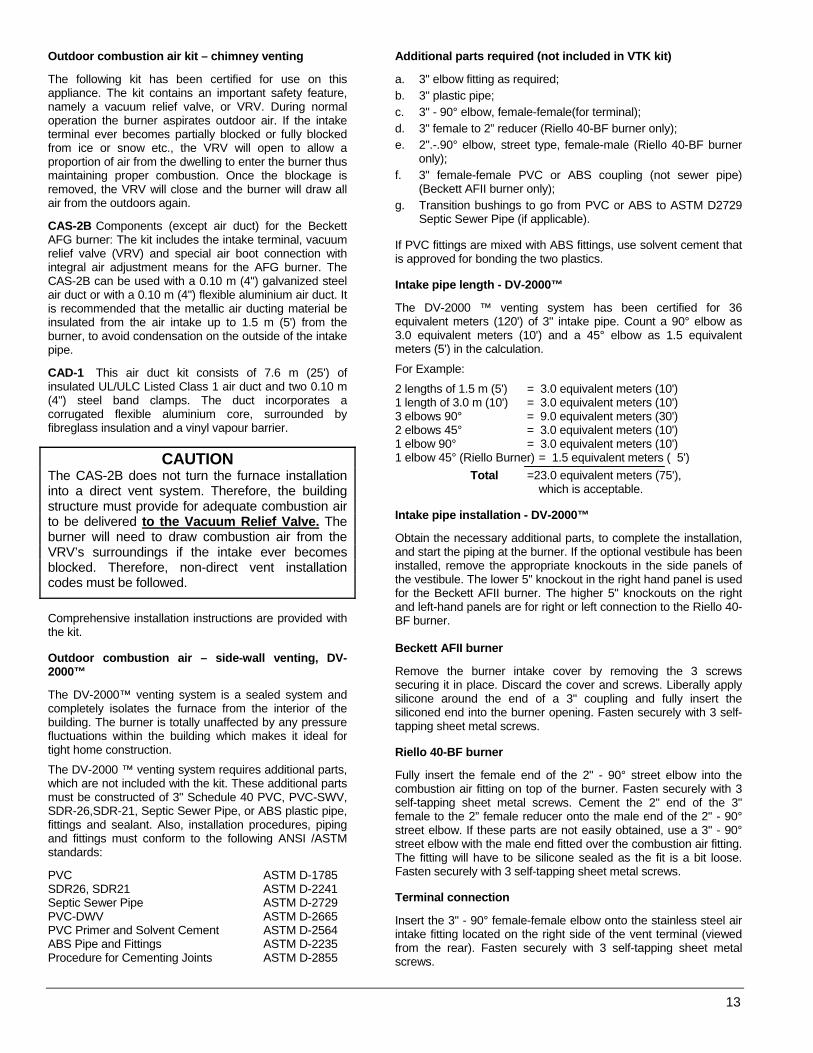
Additional parts required (not included in VTK kit) a. 3" elbow fitting as required; b. 3" plastic pipe; c. 3" - 90° elbow, female-female(for terminal); d. 3" female to 2” reducer (Riello 40-BF burner only); e. 2".-.90° elbow, street type, female-male (Riello 40-BF burner
only); f. 3" female-female PVC or ABS coupling (not sewer pipe)
(Beckett AFII burner only); g. Transition bushings to go from PVC or ABS to ASTM D2729
Septic Sewer Pipe (if applicable). If PVC fittings are mixed with ABS fittings, use solvent cement that is approved for bonding the two plastics. Intake pipe length - DV-2000™ The DV-2000 ™ venting system has been certified for 36 equivalent meters (120') of 3" intake pipe. Count a 90° elbow as 3.0 equivalent meters (10') and a 45° elbow as 1.5 equivalent meters (5') in the calculation.
For Example:
2 lengths of 1.5 m (5') = 3.0 equivalent meters (10') 1 length of 3.0 m (10') = 3.0 equivalent meters (10') 3 elbows 90° = 9.0 equivalent meters (30') 2 elbows 45° = 3.0 equivalent meters (10') 1 elbow 90° = 3.0 equivalent meters (10') 1 elbow 45° (Riello Burner) = 1.5 equivalent meters ( 5') Total =23.0 equivalent meters (75'),
which is acceptable. Intake pipe installation - DV-2000™ Obtain the necessary additional parts, to complete the installation, and start the piping at the burner. If the optional vestibule has been installed, remove the appropriate knockouts in the side panels of the vestibule. The lower 5" knockout in the right hand panel is used for the Beckett AFII burner. The higher 5" knockouts on the right and left-hand panels are for right or left connection to the Riello 40-BF burner. Beckett AFII burner Remove the burner intake cover by removing the 3 screws securing it in place. Discard the cover and screws. Liberally apply silicone around the end of a 3" coupling and fully insert the siliconed end into the burner opening. Fasten securely with 3 self-tapping sheet metal screws. Riello 40-BF burner Fully insert the female end of the 2" - 90° street elbow into the combustion air fitting on top of the burner. Fasten securely with 3 self-tapping sheet metal screws. Cement the 2" end of the 3" female to the 2” female reducer onto the male end of the 2" - 90° street elbow. If these parts are not easily obtained, use a 3" - 90° street elbow with the male end fitted over the combustion air fitting. The fitting will have to be silicone sealed as the fit is a bit loose. Fasten securely with 3 self-tapping sheet metal screws. Terminal connection Insert the 3" - 90° female-female elbow onto the stainless steel air intake fitting located on the right side of the vent terminal (viewed from the rear). Fasten securely with 3 self-tapping sheet metal screws.
13

Intermediate piping Piping between the terminal and the burner. Ensure that the 3" piping is routed and supported in accordance with local and national codes. Obey minimum furnace clearances to combustibles when routing any section of 3" piping in the vicinity of the furnace. If Septic Sewer Pipe is to be used, install transition bushings at the 3" female ends of the fittings at the burner and at the terminal. Transition bushings are readily available and are required because 3" PVC and ABS pipes have a typical outside diameter of 3.5", whereas Septic Sewer Pipe has a typical outside diameter of 3.25". 1.6 OIL TANKS AND LINES Check your local codes for the installation of the tank and accessories.
A manual shut-off valve and an oil filter shall be installed in sequence from tank to burner. Be sure that the oil line is clean before connecting to the burner. The oil line should be protected to eliminate any possible damage. Installations having the fuel oil tank below burner level must employ a two pipe fuel supply system with an appropriate fuel pump; for more than a 2.4 m (8') rise use a 2-stage pump; for more than 4.9 m (16') rise an auxiliary pump.
Follow the pump instructions to determine the size of tubing you need in relation of the lift, or the horizontal distance.
Prior to each heating season, have the entire oil distribution system checked for leaks. 1.7 BURNER INSTALLATION Mounting the burner 1. Check the insertion depth of the burner tube. Refer
to the Technical Specifications p. 23 to 25. 2. The burner mounting plate on the furnace has a 4-
bolt configuration; 3. Position the mounting gasket between the mounting
flange and the appliance burner mounting plate. Line up the holes in the mounting flange with the studs on the mounting plate and securely bolt in place.
After the burner is mounted a. Remove drawer assembly or air tube combination; b. Install nozzle (see specifications); c. Confirm electrode settings; d. Make the electrical connections; e. Complete oil line connections.
CAUTION Do not turn on the burner until you have checked the following:
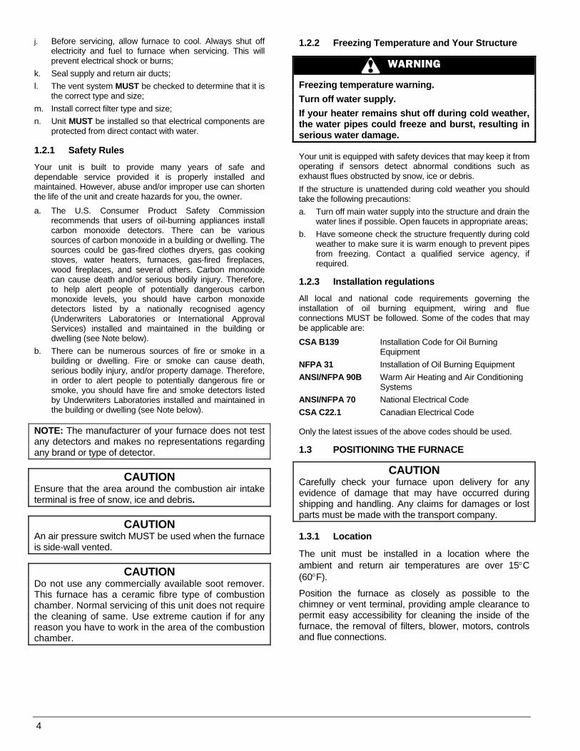
Checking the polarity The oil burner used on the furnace has a solid state control system which is sensitive to the proper connection of the hot and neutral power lines. The controls will be damaged if the two lines are reversed.
1. Set your voltmeter to line voltage; 2. Place one prong on your grounded electric entry box and one
prong on the black wire; 3. Read the voltage; 4. If the voltage is zero, check the white wire. If line voltage shows, reverse the 115-volt leads entering the furnace junction box; 5. If you do not have a voltmeter, use a pilot light.
FIGURE 2
Checking the nozzle
The burner is equipped with the appropriate nozzle. However, if another size nozzle or replacement nozzle is required, use the manufacturer’s nozzle data concerning spray angle, type as shown in Tables 4.1 to 4.3. Note that all nozzle sizes are based on a pump pressure of 100 psig. Always select nozzle sizes by working back from the actual desired flow rate at operating pressure, and not by the nozzle marking. Checking air and turbulator settings
Before starting the burner for the first time, adjust the air and turbulator settings to those listed in Tables 4.1 to 4.3. Once the burner becomes operational, final adjustments will be necessary. Checking the fuel supply system Fuel Specifications
NOTE: Use No.1 or No. 2 Heating Oil (ASTM D396) or in Canada, use No.1 or No.2 Furnace Oil. Before starting the burner be sure the fuel tank is filled with clean oil.
IMPORTANT When using nozzle sizes of less than .75 USGPH, the Installation Code for oil burning equipment requires the installation of a 10 (or less) micron filter in the fuel oil line. ICP requires that this practice be followed in order for the lifetime heat exchanger warranty to be kept intact.
DNS-0864 Rev. A
14

WARNING
Fire and explosion hazard.
Use only approved heating type oil in this furnace. DO NOT USE waste oil, used motor oil, gasoline or kerosene.
Use of these will result in death, personal injury and/or property damage.
NOTE: You may notice a slight odour the first time your furnace is operated. This will soon disappear. It is only the oil used on certain parts during manufacturing. 1.8 BLOCKED VENT SHUT-OFF DEVICE
(BVSO) For chimney venting
WARNING
It is imperative that this device be installed by a qualified technician.
This device is designed to detect the insufficient evacuation of combustion gases in the event of a vent blockage. In such a case the thermal switch will shut down the oil burner. The device will then need to be restarted MANUALLY. Refer to the wiring diagrams and the detailed instructions supplied with the BVSO for the installation and wiring procedures. The length of wires supplied with the unit is such that the safety device must be installed between the flue outlet of the appliance and the draft regulator, as indicated in the instructions. It is further imperative that the BVSO be maintained annually. Refer to the instructions supplied with the device itself, as well as Section 3. of this Manual.
CAUTION Do NOT use the BVSO on a positive pressure venting system (Sealed Combustion System or Direct Vent). Follow the instructions supplied with the venting system.
1.9 INSTALLING ACCESSORIES
WARNING
Electrical shock hazard.
Turn OFF electric power at fuse box or service panel before making any electrical connections and ensure a proper ground connection is made before connecting line voltage.
Failure to do so could result in death, bodily injury and/or property damage.
1.9.1 Electronic air cleaner Wire terminals are provided to direct 115 volts @ 0.5 Amp maximum to an Electronic Air Cleaner (EAC). Power will be available to the EAC at all times, so it must incorporate a flow proving switch if it is to be wired into the furnace control box. Most modern EACs have the required integral airflow proving switch. Wire the electronic air cleaner between terminals #5 and #2. Refer to wiring diagram, Figure 6. 1.9.2 Humidifier The red wire from burner can be used to direct 115 volts @ 1.0 Amp maximum to the transformer powering the humidifier. The humidifier will be energised anytime the burner is operating in the “Heating Mode”. Refer to wiring diagram, Figure 6. 1.9.3 Air conditioning An air conditioning coil may be installed on the supply air side only. Also, notwithstanding the evaporator coil manufacturer’s instructions, a minimum of 15 cm (6") clearance must be allowed between the bottom of the coil drain pan and the top of the heat exchanger. Wire the thermostat and condensing unit contactor as indicated in Figure 6. 1.9.4 Ductwork and Filter
Installation Design and install the air distribution system to comply with Air Conditioning Contractors of America manuals or other approved methods that conform to local and/or national codes and good trade practices.
When furnace supply ducts carry air outside furnace area, seal return air duct to furnace casing and terminate duct outside furnace space.
Install air conditioning cooling coil (evaporator) on downstream side from the supply air plenum of the furnace. If a separate evaporator and blower unit is used, install appropriate sealing dampers for air flow control. Cold air from the evaporator coil going through the furnace could cause condensation and shorten furnace life.
CAUTION Dampers (purchased locally) MUST be automatic.
WARNING
Poisonous carbon monoxide gas hazard.
Do NOT draw return air from inside a closet or utility room. Return air duct MUST be sealed to furnace casing.
Failure to properly seal duct can result in death, personal injury and/or property damage.
15
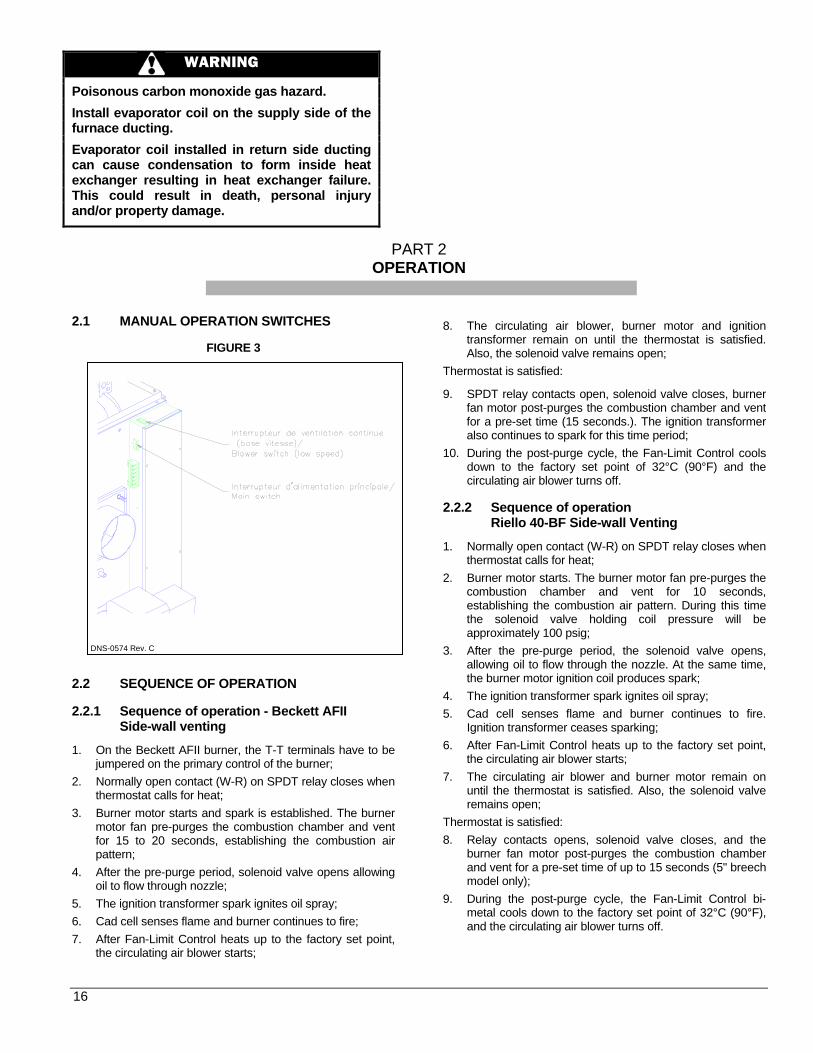
WARNING
Poisonous carbon monoxide gas hazard.
Install evaporator coil on the supply side of the furnace ducting.
Evaporator coil installed in return side ducting can cause condensation to form inside heat exchanger resulting in heat exchanger failure. This could result in death, personal injury and/or property damage.
PART 2 OPERATION
2.1 MANUAL OPERATION SWITCHES
FIGURE 3 2.2 SEQUENCE OF OPERATION 2.2.1 Sequence of operation - Beckett AFII
Side-wall venting 1. On the Beckett AFII burner, the T-T terminals have to be
jumpered on the primary control of the burner; 2. Normally open contact (W-R) on SPDT relay closes when
thermostat calls for heat; 3. Burner motor starts and spark is established. The burner
motor fan pre-purges the combustion chamber and vent for 15 to 20 seconds, establishing the combustion air pattern;
4. After the pre-purge period, solenoid valve opens allowing oil to flow through nozzle;
5. The ignition transformer spark ignites oil spray; 6. Cad cell senses flame and burner continues to fire; 7. After Fan-Limit Control heats up to the factory set point,
the circulating air blower starts;
8. The circulating air blower, burner motor and ignition transformer remain on until the thermostat is satisfied. Also, the solenoid valve remains open;
Thermostat is satisfied: 9. SPDT relay contacts open, solenoid valve closes, burner
fan motor post-purges the combustion chamber and vent for a pre-set time (15 seconds.). The ignition transformer also continues to spark for this time period;
10. During the post-purge cycle, the Fan-Limit Control cools down to the factory set point of 32°C (90°F) and the circulating air blower turns off.
2.2.2 Sequence of operation
Riello 40-BF Side-wall Venting 1. Normally open contact (W-R) on SPDT relay closes when
thermostat calls for heat; 2. Burner motor starts. The burner motor fan pre-purges the
combustion chamber and vent for 10 seconds, establishing the combustion air pattern. During this time the solenoid valve holding coil pressure will be approximately 100 psig;
3. After the pre-purge period, the solenoid valve opens, allowing oil to flow through the nozzle. At the same time, the burner motor ignition coil produces spark;
4. The ignition transformer spark ignites oil spray; 5. Cad cell senses flame and burner continues to fire.
Ignition transformer ceases sparking; 6. After Fan-Limit Control heats up to the factory set point,
the circulating air blower starts; 7. The circulating air blower and burner motor remain on
until the thermostat is satisfied. Also, the solenoid valve remains open;
Thermostat is satisfied: 8. Relay contacts opens, solenoid valve closes, and the
burner fan motor post-purges the combustion chamber and vent for a pre-set time of up to 15 seconds (5" breech model only);
9. During the post-purge cycle, the Fan-Limit Control bi-metal cools down to the factory set point of 32°C (90°F), and the circulating air blower turns off.
DNS-0574 Rev. C
16
NOTE: With burner relay contact open, the Riello 40-BF will post-purge when 115 volt power is applied to the burner.
2.2.3 Sequence of operation - Beckett AFG and
Riello 40-F, chimney venting 1. On the AFG burner, the T-T terminals have to be
jumpered on the primary control of the burner; 2. Normally open contact (W-R) closes when thermostat
calls for heat; 3. Burner motor starts. The burner motor fan pre-purges the
combustion chamber and vent for 10 to 15 seconds, establishing the combustion air pattern. After the pre-purge period, the solenoid valve opens, allowing oil to flow through nozzle. At the same time, the burner motor ignition coil produces a spark;
4. Spark ignites oil droplets; 5. Cad cell senses flame and burner continues to fire.
Ignition transformer ceases sparking (Riello R40-F); 6. After Fan-Limit Control heats up to the factory set point,
the circulating air blower starts; 7. The circulating air blower and burner motor remain on
until the thermostat is satisfied; Thermostat is satisfied: 8. Relay contacts open, solenoid valve closes, burner fan
motor shuts down and the ignition transformer ceases sparking;
2.2.4 Sequence of operation
DV-2000™ Venting system Normal operation
1. Before a call for heat, the contacts of the pressure switch are closed;
2. When the room thermostat calls for heat, the normally open contact W-R closes, the burner blower starts and creates suction in the intake piping circuit and pressure in the vent piping circuit;
3. The differential pressure set point of the pressure switch is not exceeded and the thermostat circuit remains closed until the call for heat has ended.
Abnormal operation Start-up 1. When the room thermostat calls for heat, the normally
open contact W-R closes, the burner blower starts and creates suction in the intake piping circuit and pressure in the vent piping circuit;
2. If there is a blockage in the intake or vent openings to cause a pressure differential beyond the set point of the pressure switch, then the thermostat circuit is opened and the burner will go into a 15 seconds post-purge and then shut down;
3. Once the burner blower shuts down, after the post-purge, the pressure switch contacts will re-close. If the call for heat remains, the burner will re-start. If the blockage still exists, the thermostat is again opened, and the burner post-purges again. The post-purge function thus becomes an inherent anti-short cycling device;
4. The unit will essentially go into a continuous re-cycling/post-purge mode with no heat being supplied to the dwelling, which will prompt a service call;
5. If, during the re-cycling/post-purges, the blockage of the terminal is removed, the burner will immediately fire up at the end of the current post-purge cycle.
During operation If the terminal vent or intake openings become blocked to the point where the set point of the pressure switch is exceeded during a firing cycle, the flame will shut down and the burner will go into the indefinite recycling post-purge mode as described above, until the blockage is removed. 2.3 CHECKS AND ADJUSTMENTS
2.3.1 General During initial start-up and subsequent yearly maintenance calls, the furnace must be thoroughly tested.
Open the oil bleed port screw and start the burner. Allow the oil to drain into a container for at least 10 seconds. The oil should flow absolutely free of white streaks or air bubbles to indicate that no air is being drawn into the suction side of the oil piping and pump. Then slowly close and tighten the bleed screw. Fire the burner. Adjust the oil pressure as indicated in Tables 4.1 to 4.3.
IMPORTANT The burner must be put in operation for at least 10 minutes before any test readings are taken. For new installations, set up the burner to the settings in Tables 4.1 to 4.3 before firing. These are rough adjustments but they will ensure that the burner will start and run smoke-free in advance of the final adjustments to be made. 2.3.2 Restart after burner failure 1. Set thermostat lower than the room temperature; 2. Press the reset button on the burner primary control (relay); 3. With side-wall venting and Riello burner, set thermostat higher
than the room temperature for 10 seconds, then set lower than room temperature. This will start pre-purge cycle. Repeat twice;
4. Set thermostat higher than the room temperature; 5. If the burner motor does not start or ignition fails, turn off the
disconnect switch and CALL A QUALIFIED SERVICE TECHNICIAN.
CAUTION Do not attempt to start the burner when excess oil has accumulated, when the furnace is full of vapour, or when the combustion chamber is very hot. Always keep the supply valve closed if the burner is shut down for an extended period of time.
17
2.3.3 Combustion chamber curing Some moisture and binders remain in the ceramic combustion chambers after fabrication. It is important to clear the chamber of this residue before testing. If you smoke test before curing, the instrument may become damaged. To cure the chamber, run the unit for 3 consecutive cycles, with 3 minutes of elapsed time in between each cycle. The burner must operate for about 3 minutes per cycle. The exhaust will have a pungent odour and produce a white cloud of steam. 2.3.4 Smoke / CO2 test 1. On chimney installations, pierce a test hole in the smoke
pipe 18’’ above the furnace breech. On side-wall vented installations, remove the threaded cap from the extended test pipe that is welded into the 4-bolt breech plate. Insert the smoke test instrument probe into the open hole;
2. From a cold start, let the unit operate during 5 to 10 minutes;
3. Set the burner air setting until just a trace of smoke results (#1 on the Bacharach scale);
4. Take a CO2 sample at the same test location where the #1 smoke reading was taken and make note of it. Example: 13.8% of CO2 or 2.5% of O2;
5. Adjust the burner air setting to obtain a CO2 reading 1.5% lower (or a O2 reading 2.0% higher) than the reading associated with the #1 smoke. Example: 12.3% or CO2 or 4.5% of O2;
6. This method of adjusting the burner will result in clean combustion and ensure the proper functioning of the system.
2.3.5 Perform the supply air temperature rise test 1. Operate the burner for at least 10 minutes; 2. Measure the temperature of the air in the return air
plenum; 3. Measure the temperature of the air in the largest trunk
coming off the supply air plenum, just outside the range of radiant heat coming off the heat exchanger; 30 cm (12") away from the plenum on the main take-off is usually sufficient;
4. The temperature rise is calculated by subtracting the return air temperature from the supply air temperature;
5. If the temperature rise exceeds the temperature specified in Tables 4.1 to 4.3, change to the next higher blower speed tap until the temperature rise falls to this temperature or below. If the excessive temperature rise cannot be reduced by increasing fan speed, investigate for ductwork restriction(s), dirty or improper air filter, overfiring caused by excessive pump pressure, or improper nozzle sizing.
2.3.6 Vent temperature test 1. After 5 to 10 minutes of operation, place a thermometer in
the test hole located in the breech pipe; 2. The vent temperature should be between 204 and
302°C (400 and 575°F). If not, check for improper air temperature rise, pump pressure, nozzle size, or for a badly sooted heat exchanger.
2.3.7 Overfire pressure test procedure
The overfire draft that is taken through the observation port, located above the burner, is a measurement necessary to determine if there is a blockage in the heat exchanger or the flue pipe. Refer to the Technical Specifications in this manual for overfire pressure values. A high pressure condition may be caused by excessive combustion air, due to the air band being too wide open, or a lack of flue draft (chimney effect) or some other blockage, such as soot in the secondary section of the heat exchanger or the use of an oversize nozzle input or high pressure pump.
2.3.8 Fan-Limit adjustment Modification of the “FAN ON” and “HI” limit settings on the Fan-Limit can cause a malfunctioning of the furnace and result in premature wear of the heat exchanger. Please refer to the different adjustment values in Figure 4.
CAUTION Modification of the factory set limits will void the warranty.
2.3.9 Limit control check After operating the furnace for at least 15 minutes, restrict the return air supply by blocking the filters or the return air register and allow the furnace to shut off on High Limit. The burner will shut off but the blower will continue to run. Remove the obstruction and the burner should restart after a few minutes.
18

FIGURE 4
1 “FAN OFF” Limit 90°F “FAN ON” Limit Model : OLR160 110°F 2 Model : OUF105, OLF105, OLR105, OUF160, NOUF105 &NOLF105 130°F
‘’HI’’ Limit Model : OLR160 170°F Model : OUF105, OLF105, OLR105, NOUF105 & NOLF105 180°F
3
Model : OUF160 220°F
2.3.10 DV-2000™ Blocked intake/blocked vent test On side-wall vented furnaces, the DV-2000™ venting system incorporates a safety shutdown system that will shut the burner down before #1 smoke occurs due to the presence of a blocked intake or blocked vent outlet. Test the system as follows: 1. Ensure that the furnace has been running for at least 10
minutes; 2. Gradually block the intake. The burner flame should shut
down before a #1 smoke reading occurs; 3. Gradually block the vent outlet. The burner flame should
shut down before a #1 smoke reading occurs; 4. If the burner does not shut down before a #1 smoke
occurs, ensure that the burner is set up according to Part 2, section 3.4 (2.3.4). Perform the CO2/ Smoke Test, and allow for the 1.5% CO2 operating play required by the instructions;
5. If the burner still does not shut down before a #1 smoke occurs, check for a blockage of the pressure hose, or at the hose connection points.
IMPORTANT The DV-2000™ safety shutdown system will shut down the burner flame during a blocked intake or blocked vent condition if and only if, the burner has been set up and calibrated in accordance with Tables 4.1, 4.2 or 4.3. Perform the CO2/ Smoke Test. For instance, if the burner is adjusted and final-set to a #1 smoke condition during normal operation, the burner flame cannot possibly shut down before #1 smoke occurs during a blockage condition.
2.3.11 BVSO performance test The purpose of the following test is to check that the electrical outlet on the furnace, designated to the BVSO, is functional. 1. Start up the burner; 2. Remove the three-pole plug from the BVSO outlet on
the furnace; 3. The burner must shut-off immediately, while the
blower continues to run to the end of the cool-down cycle.
If the test is not in line with the above, call a QUALIFIED SERVICE TECHNICIAN.
DNS-0355 Rev. B
19
PART 3
MAINTENANCE
3.1) GENERAL Preventive Maintenance "Preventive maintenance" is the best way to avoid unnecessary expense and inconvenience. Have your heating system and burner inspected at regular intervals by a qualified service technician.
WARNING
Electrical shock hazard.
Turn OFF power to furnace before any disassembly or servicing.
Failure to do so can result in bodily injury and/or death, property damage.
A complete combustion test must be performed after each annual service inspection of the unit, to maintain optimum performance and reliability. Do not tamper with the unit or controls. Call a qualified service technician. Before calling for service, check the following a. Check oil tank gauge and check if the valve is open; b. Check fuse or circuit breaker; c. Check if shut-off switch is “ON”; d. Set thermostat above room temperature; e. If ignition does not occur, turn off the disconnect switch
and call a qualified service technician. When ordering replacement parts, specify the complete furnace model and serial number. 3.1.1) Heat exchanger The entire heat exchanger should be inspected annually for soot accumulation. If the burner is operating normally there should be very little soot accumulation. If the heat exchanger requires scale removal, use a wire brush first, to loosen the scale and then vacuum the soot and scale that has fallen into the secondary heat exchanger (radiator) section. You will find that a 36" long flexible hose attachment will be helpful to reach into the back of the radiator. A piece of 1/2" flexible gas connector, or a piece of 1/2" liquid-tight vinyl jacket metallic electrical conduit works well as a makeshift device. Cleaning the heat exchanger Remove the 4-bolt flange from the front of the furnace to expose the clean-out port and check for soot deposits. If there is very little soot in the radiator section visible from the clean-out port, you will not need to clean it. However, if you notice scaling in the radiator, you should remove it.
The wrap-around radiator can now be cleaned entirely from the front inspection port. The furnace also has external clean-out ports so the soot does not fall into the fan compartment during the cleaning operation.
IMPORTANT Do not vacuum the ceramic chambers—they are easily damaged. Soot will have collected in the first sections of the heat exchangers only if the burner was started after the combustion chamber was flooded with fuel oil, or if the burner has been operating in a severely contaminated condition. 3.1.2) Refractory firepot Remove the burner and check the firepot.
IMPORTANT This furnace has a fibre type refractory combustion chamber. Normal servicing of this unit does not require cleaning of the combustion chamber. If cleaning of the pot should be required, use extreme care. After firing, the pot becomes very fragile. Do not use any commercially available soot removers. If the pot is damaged, it must be replaced. A damaged pot could lead to premature heat exchanger failure. Cracking of the firepot is normal, however, replace the pot only if the cracks have propagated more than 2/3 the way through the wall thickness. The average wall thickness of the firepot is 19 mm (3/4"). Flooding of the firepot
Flooding can occur when the oil primary control has been reset a number of times in a no-heat situation. Each time oil is fired into the pot and does not ignite, it is absorbed into the pot. Even if the burner is removed and the pot is felt for wetness, it is difficult to assess the degree of oil absorption by the pot.
There is only one way to properly service a flooded firepot, and that is to replace it.
CAUTION If you observe the red warning light on the burner, push ONLY once to try and restart. If the burner does not start, call a qualified service technician. Do NOT press the button again.
Self-aligning firepot The primary heat exchanger of the furnace is comprised of an upper and lower half. The lower half is essentially a “can” that contains a self-aligning firepot. The firepot fits into the bottom half in one direction only.
20
Removing the firepot The firepot is seldom replaced, but when it must be replaced one must simply:
1. Remove the burner; 2. Remove the burner Limit Control; 3. Remove the breech plate; 4. Remove the front panel; 5. Remove the brass nuts on the stainless steel heat
exchanger studs; 6. Pry the bottom half of the heat exchanger apart by using
the designated prying tabs; 7. Remove the bottom half of the heat exchanger through
the front of the furnace; 8. Pull the firepot up and out of the bottom half of the heat
exchanger; 9. Remove the old sealing gasket from the flange of the
upper half of the heat exchanger; 10. Scrape any residual gasket material off the matching
flanges of the heat exchanger. Replacing the firepot 1. Align the slot at the front part of the firepot with the burner
tube sleeve and gently lower the firepot into the bottom half of the heat exchanger;
2. Holding the firepot near the perimeter, gently push the firepot all the way into the bottom half of the heat exchanger until it is properly seated;
3. Thoroughly wet the gasket with water using a spray pump bottle, position the tabs over the studs, and push the gasket upward against the sealing flange of the upper half of the heat exchanger;
4. Install the brass nuts on the studs by engaging only 2 or 3 threads;
5. Position the bottom half of the heat exchanger under the upper half and align the bottom half so that the slots in the bolting tabs engage the stainless steel studs. There is no further need to hold onto the bottom half as it will now be suspended on the stud nuts;
6. Push upward on the housing and thread the nuts finger-tight as far as possible;
7. Intermittently tighten the brass nuts with a wrench in a sequence that will pull the heat exchanger halves together evenly. Tighten all nuts to 90 inch-lbs torque once and then alternately re-tighten all nuts again to 100 inch-lb. THE RE-TIGHTENING SEQUENCE IS ABSOLUTELY NECESSARY TO ENSURE A TIGHT JOINT;
8. Re-assemble the front panel, breech plate, Limit Control and burner in reverse sequence to their removal;
9. Follow the instructions for starting the burner for the first time to cure the firepot and perform combustion checks.
3.1.3) Drawer assembly Remove the drawer assembly. Clean all foreign matter from the retention head and electrodes. If a Beckett AFG burner has been installed, the burner will have to be removed to check the retention head. 3.1.4) Nozzle Replace the nozzle with the one specified in Tables 4.1 to 4.3.
3.1.5) Oil filter Tank filter The tank filter should be replaced as required. Secondary filter The 10 micron (or less) filter cartridges should be replaced annually. 3.1.6) Air filters Air filters are the disposable type. They should be replaced at least once a year. Dusty conditions, presence of animal hair etc. may require more frequent filter changes. Dirty filters will impact furnace efficiency and increase oil consumption. 3.1.7) Motor lubrication Do NOT lubricate the oil burner motor or the direct drive blower motor as it is permanently lubricated. 3.1.8) CAS-2B combustion air kit
(chimney venting) If used, check the CAS-2B combustion air kit for proper operation. Check to see that the inlet screen is not plugged. Block the air inlet completely and ensure that a zero smoke reading results. If a zero smoke reading is not obtained, set up the burner as indicated in Tables 4.1, 4.2 or 4.3.
Gradually block off the intake. The CO2 should increase to a maximum of 0.5 percentage points at the fully blocked condition. If not, check that the VRV gate is pivoting freely and that the pivot rod is in a horizontal position. Also, check that the counterweight has been properly adjusted in accordance with CAS-2B installation instructions. 3.1.9) BLOCKED VENT SHUT-OFF DEVICE (BVSO)
CLEANING For continued safe operation, the Blocked Vent Shut-Off System (BVSO) is required to be inspected and maintained annually by a qualified technician. 1. Disconnect the power to the appliance; 2. Remove the two screws holding the BVSO assembly
cover in place; 3. Remove the cover; 4. Remove the two screws holding the control box to the
heat transfer tube assembly. Sliding the control box in the appropriate direction will unlock it form the heat transfer tube assembly;
5. Carefully remove any build-up from the thermal switch surface;
CAUTION Do not dent or scratch the surface of the thermal switch. If the thermal switch is damaged, replacement is required.
6. Clear and remove any build-up or obstruction inside the
heat transfer tube; 7. Re-mount, lock and fasten the control box with the 2
screws removed in step 4; 8. Re-attach the assembly cover with the screws removed in
step 2; 9. Re-establish power to the appliance.
21
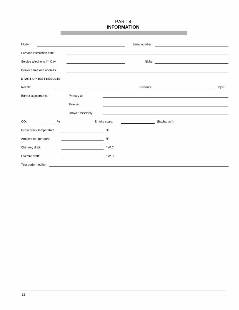
PART 4 INFORMATION
Model: Serial number:
Furnace installation date:
Service telephone # - Day: Night:
Dealer name and address:
START-UP TEST RESULTS
Nozzle: Pressure: lbpsi
Burner adjustments: Primary air
Fine air
Drawer assembly
CO2:
% Smoke scale: (Bacharach)
Gross stack temperature: °F
Ambient temperature: °F
Chimney draft: " W.C.
Overfire draft: " W.C.
Test performed by:
22
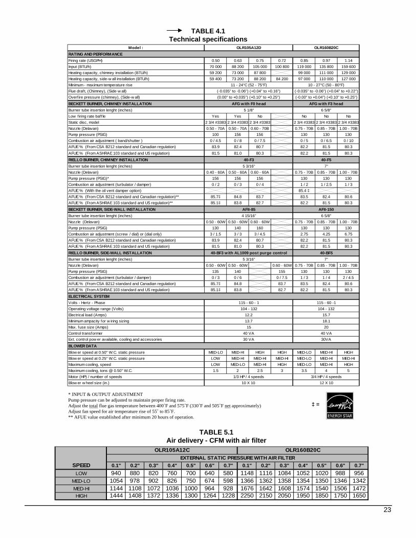
TABLE 4.1Technical specifications
TABLE 5.1Air delivery - CFM with air filter
SPEED 0.1" 0.2" 0.3" 0.4" 0.5" 0.6" 0.7" 0.1" 0.2" 0.3" 0.4" 0.5" 0.6" 0.7"LOW 940 880 820 760 700 640 580 1148 1116 1084 1052 1020 988 956
MED-LO 1054 978 902 826 750 674 598 1366 1362 1358 1354 1350 1346 1342MED-HI 1144 1108 1072 1036 1000 964 928 1676 1642 1608 1574 1540 1506 1472HIGH 1444 1408 1372 1336 1300 1264 1228 2250 2150 2050 1950 1850 1750 1650
OLR105A12C OLR160B20CEXTERNAL STATIC PRESSURE WITH AIR FILTER
Model :
Firing rate (USGPH) 0.50 0.63 0.75 0.72 0.85 0.97 1.14Input (BTU/h) 70 000 88 200 105 000 100 800 119 000 135 800 159 600Heating capacity, chimney installation (BTU/h) 59 200 73 000 87 800 99 000 111 000 129 000Heating capacity, side-w all installation (BTU/h) 59 400 73 200 88 200 84 200 97 000 110 000 127 000Minimum - maximum temperature riseFlue draft, (Chimney), (Side-w all)Overf ire pressure (chimney), (Side-w all)BECKETT BURNER, CHIMNEY INSTALLATIONBurner tube insertion lenght (inches)Low f iring rate baffle Yes Yes No No No NoStatic disc, model 2 3/4 #3383 2 3/4 #3383 2 3/4 #3383 2 3/4 #3383 2 3/4 #3383 2 3/4 #3383Nozzle (Delavan) 0.50 - 70A 0.50 - 70A 0.60 - 70B 0.75 - 70B 0.85 - 70B 1.00 - 70BPump pressure (PSIG) 100 156 156 130 130 130Combustion air adjustment ( band/shutter ) 0 / 4.5 0 / 8 0 / 7.5 0 / 5 0 / 6.5 0 / 10AFUE % (From CSA B212 standard and Canadian regulation) 83.9 82.4 80.7 82.2 81.5 80.3AFUE % (From ASHRAE 103 standard and US regulation) 81.5 81.0 80.3 82.2 81.5 80.3RIELLO BURNER, CHIMNEY INSTALLATIONBurner tube insertion lenght (inches)Nozzle (Delavan) 0.40 - 60A 0.50 - 60A 0.60 - 60A 0.75 - 70B 0.85 - 70B 1.00 - 70BPump pressure (PSIG)* 156 156 156 130 130 130Combustion air adjustment (turbulator / damper) 0 / 2 0 / 3 0 / 4 1 / 2 1 / 2.5 1 / 3AFUE % (With the oil vent damper option) 85.4 ‡AFUE % (From CSA B212 standard and Canadian regulation)** 85.7‡ 84.8 83.7 83.5 82.4 80.6AFUE % (From ASHRAE 103 standard and US regulation)** 85.1‡ 83.8 82.7 82.2 81.5 80.3
BECKETT BURNER, SIDE-WALL INSTALLATIONBurner tube insertion lenght (inches)Nozzle (Delavan) 0.50 - 60W 0.50 - 60W 0.60 - 60W 0.75 - 70B 0.85 - 70B 1.00 - 70BPump pressure (PSIG) 130 140 160 130 130 130Combustion air adjustment (screw / dial) or (dial only) 3 / 1.5 3 / 3 3 / 4.5 2.75 4.25 6.75AFUE % (From CSA B212 standard and Canadian regulation) 83.9 82.4 80.7 82.2 81.5 80.3AFUE % (From ASHRAE 103 standard and US regulation) 81.5 81.0 80.3 82.2 81.5 80.3RIELLO BURNER, SIDE-WALL INSTALLATIONBurner tube insertion lenght (inches)Nozzle (Delavan) 0.50 - 60W 0.50 - 60W 0.60 - 60W 0.75 - 70B 0.85 - 70B 1.00 - 70BPump pressure (PSIG) 135 140 155 130 130 130Combustion air adjustment (turbulator / damper) 0 / 3 0 / 6 0 / 7.5 1 / 3 1 / 4 2 / 4.5AFUE % (From CSA B212 standard and Canadian regulation) 85.7‡ 84.8 83.7 83.5 82.4 80.6AFUE % (From ASHRAE 103 standard and US regulation) 85.1‡ 83.8 82.7 82.2 81.5 80.3
Volts - Hertz - PhaseOperating voltage range (Volts)Electrical load (Amps)Minimum ampacity for w iring sizingMax. fuse size (Amps)Control transformerExt. control pow er available, cooling and accessories
Blow er speed at 0.50" W.C. static pressure MED-LO MED-HI HIGH HIGH MED-LO MED-HI HIGHBlow er speed at 0.25" W.C. static pressure LOW MED-HI MED-HI MED-HI MED-LO MED-HI MED-HIMaximum cooling, speed LOW MED-LO MED-HI HIGH MED-LO MED-HI HIGHMaximum cooling, tons @ 0.50" W.C. 1.5 2 2.5 3 3.5 4 5Motor (HP) / number of speedsBlow er w heel size (in.)
ELECTRICAL SYSTEM
BLOWER DATA
5 3/16'' 7''
115 - 60 - 1 115 - 60 -1104 - 132 104 - 132
12.2 15.7
5 3/16'' 7''
4 15/16'' 6 5/8''AFII-85 AFII-150
40-BF3 with AL1009 post purge control 40-BF5
OLR105A12D OLR160B20C
11 - 24°C (52 - 75°F) 10 - 27°C (50 - 80°F)
RATING AND PERFORMANCE
(-0.035" to -0.06") (+0.04" to +0.16") (-0.035" to -0.06") (+0.04" to +0.22")(0.00" to +0.035") (+0.10" to +0.25") (-0.00" to +0.04") (+0.10" to +0.25")
AFG with F0 head AFG with F3 head
40-F3 40-F5
5 1/8'' 6 5/8''
13.7 18.115 20
40 VA 40 VA30 VA 30VA
1/3 HP / 4 speeds 3/4 HP / 4 speeds10 X 10 12 X 10
23
* INPUT & OUTPUT ADJUSTMENTPump pressure can be adjusted to maintain proper firing rate.Adjust the total flue gas temperature between 400˚F and 575˚F (330˚F and 505˚F net approximately)Adjust fan speed for air temperature rise of 55˚ to 85˚F.** AFUE value established after minimum 20 hours of operation.
‡ =
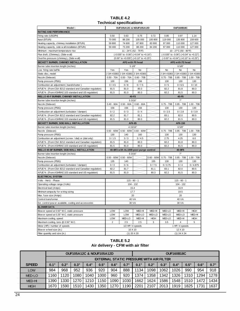
TABLE 4.2Technical specifications
TABLE 5.2Air delivery - CFM with air filter
SPEED 0.1" 0.2" 0.3" 0.4" 0.5" 0.6" 0.7" 0.1" 0.2" 0.3" 0.4" 0.5" 0.6" 0.7"LOW 984 968 952 936 920 904 888 1134 1098 1062 1026 990 954 918
MED-LO 1160 1120 1080 1040 1000 960 920 1374 1358 1342 1326 1310 1294 1278MED-HI 1390 1330 1270 1210 1150 1090 1030 1662 1624 1586 1548 1510 1472 1434HIGH 1670 1590 1510 1430 1350 1270 1190 2201 2107 2013 1919 1825 1731 1637
OUF160B18CEXTERNAL STATIC PRESSURE WITH AIR FILTER
OUF105A12C & NOUF105A12D
Model :
Firing rate (USGPH) 0.50 0.63 0.75 0.72 0.85 0.97 1.14Input (BTU/h) 70 000 88 200 105 000 100 800 119 000 135 800 159 600Heating capacity, chimney installation (BTU/h) 59 800 74 600 87 800 83 900 97 000 110 000 127 000Heating capacity, side-w all installation (BTU/h) 59 400 73 200 88 200 84 200 97 000 110 000 127 000Minimum - maximum temperature riseFlue draft, (Chimney), (Side-w all)Overfire pressure (chimney), (Side-w all)
BECKETT BURNER, CHIMNEY INSTALLATIONBurner tube insertion lenght (inches)Low f iring rate baff le Yes Yes No No No NoStatic disc, model 2 3/4 #3383 2 3/4 #3383 2 3/4 #3383 2 3/4 #3383 2 3/4 #3383 2 3/4 #3383Nozzle (Delavan) 0.50 - 70A 0.50 - 70A 0.60 - 70B 0.75 - 70B 0.85 - 70B 1.00 - 70BPump pressure (PSIG) 100 156 156 130 130 130Combustion air adjustment ( band/shutter ) 0 / 4.5 0 / 8 0 / 7.5 0 / 5 0 / 6.5 0 / 10AFUE % (From CSA B212 standard and Canadian regulation) 81.5 81.0 80.3 82.2 81.8 80.3AFUE % (From ASHRAE 103 standard and US regulation) 81.5 81.0 80.3 82.2 81.5 80.3RIELLO 40-F BURNER, CHIMNEY INSTALLATIONBurner tube insertion lenght (inches)Nozzle (Delavan) 0.40 - 60A 0.50 - 60A 0.60 - 60A 0.75 - 70B 0.85 - 70B 1.00 - 70BPump pressure (PSIG) 156 156 156 130 130 130Combustion air adjustment (turbulator / damper) 0 / 2 0 / 3 0 / 4 0 / 2.5 0 / 2.8 0 / 3.9AFUE % (From CSA B212 standard and Canadian regulation) 82.2 81.7 81.1 83.1 82.0 80.5AFUE % (From ASHRAE 103 standard and US regulation) 81.5 81.0 80.3 82.2 81.5 80.3
BECKETT BURNER, SIDE-WALL INSTALLATIONBurner tube insertion lenght (inches)Nozzle (Delavan) 0.50 - 60W 0.50 - 60W 0.60 - 60W 0.75 - 70B 0.85 - 70B 1.00 - 70BPump pressure (PSIG) 130 140 160 130 130 130Combustion air adjustment (screw / dial) or (dial only) 3 / 1.5 3 / 3 3 / 4.5 2.75 4.25 6.0AFUE % (From CSA B212 standard and Canadian regulation) 81.5 81.0 80.3 82.2 81.8 80.3AFUE % (From ASHRAE 103 standard and US regulation) 81.5 81.0 80.3 82.2 81.5 80.3
RIELLO 40-BF BURNER, SIDE-WALL INSTALLATIONBurner tube insertion lenght (inches)Nozzle (Delavan) 0.50 - 60W 0.50 - 60W 0.60 - 60W 0.75 - 70B 0.85 - 70B 1.00 - 70BPump pressure (PSIG) 135 140 155 130 130 130Combustion air adjustment (turbulator / damper) 0 / 3 0 / 6 0 / 7.5 0 / 3.75 0 / 4 0 / 4.875AFUE % (From CSA B212 standard and Canadian regulation) 82.2 81.7 81.1 83.1 82.0 80.5AFUE % (From ASHRAE 103 standard and US regulation) 81.5 81.0 80.3 82.2 81.5 80.3
Volts - Hertz - PhaseOperating voltage range (Volts)Electrical load (Amps)Minimum ampacity for w iring sizingMax. fuse size (Amps)Control transformerExt. control pow er available, cooling and accessories
Blow er speed at 0.50" W.C. static pressure LOW LOW MED-HI MED-HI MED-LO MED-HI HIGHBlow er speed at 0.25" W.C. static pressure LOW LOW MED-LO MED-LO MED-LO MED-LO MED-HIMaximum cooling, speed LOW MED-LO MED-HI HIGH MED-LO MED-HI HIGHMaximum cooling, tons @ 0.50" W.C. 2 2.5 2.5 3 3.5 4 5Motor (HP) / number of speedsBlow er w heel size (in.)Filter quantity and size (in.)
ELECTRICAL SYSTEM
RATING AND PERFORMANCE
10 X 10 12 X 10
20 2040 VA 40 VA
15.4 16.9
(1) 20 X 20 (1) 24 X 24
30 VA 30 VA
1/2 HP / 4 speeds 1 HP / 4 speeds
BLOWER DATA
17.7 19.5
115 - 60 - 1 115 - 60 - 1104 - 132 104 - 132
40-BF3 with AL1009 post purge control 40-BF55 3/16'' 7''
AFII-85 AFII-1504 15/16'' 6 5/8''
40-F3 40-F55 3/16'' 7''
(-0.00" to +0.04") (+0.10" to +0.25")
AFG with F0 head AFG with F3 head5 1/8'' 6 5/8''
(0.00" to +0.035") (+0.10" to +0.25")
OUF160B18C
11 - 24°C (52 - 75°F) 10 - 27°C (50 - 80°F)(-0.035" to -0.06") (+0.04" to +0.16") (-0.035" to -0.06") (+0.04" to +0.22")
OUF105A12C & NOUF105A12D
24
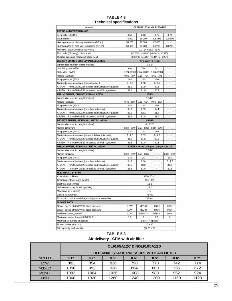
TABLE 4.3Technical specifications
TABLE 5.3Air delivery - CFM with air filter
SPEED 0.1" 0.2" 0.3" 0.4" 0.5" 0.6" 0.7"LOW 882 854 826 798 770 742 714
MED-LO 1056 992 928 864 800 736 672MED-HI 1092 1064 1036 1008 980 952 924HIGH 1360 1320 1280 1240 1200 1160 1120
OLF105A12C & NOLF105A12D
EXTERNAL STATIC PRESSURE WITH AIR FILTER
Model :
Firing rate (USGPH) 0.50 0.63 0.75 0.72Input (BTU/h) 70 000 88 200 105 000 100 800Heating capacity, chimney installation (BTU/h) 59 200 73 000 87 800Heating capacity, side-w all installation (BTU/h) 59 400 73 200 88 200 84 200Minimum - maximum temperature riseFlue draft, (Chimney), (Side-w all)Overf ire pressure (chimney), (Side-w all)
BECKETT BURNER, CHIMNEY INSTALLATIONBurner tube insertion lenght (inches)Low firing rate baff le Yes Yes NoStatic disc, model 2 3/4 #3383 2 3/4 #3383 2 3/4 #3383Nozzle (Delavan) 0.50 - 70A 0.50 - 70A 0.60 - 70BPump pressure (PSIG) 100 156 156Combustion air adjustment ( band/shutter ) 0 / 4.5 0 / 8 0 / 7.5AFUE % (From CSA B212 standard and Canadian regulation) 81.9 81.0 80.3AFUE % (From ASHRAE 103 standard and US regulation) 81.5 81.0 80.3
RIELLO BURNER, CHIMNEY INSTALLATIONBurner tube insertion lenght (inches)Nozzle (Delavan) 0.40 - 60A 0.50 - 60A 0.60 - 60APump pressure (PSIG) 156 156 156Combustion air adjustment (turbulator / damper) 0 / 2 0 / 3 0 / 4AFUE % (From CSA B212 standard and Canadian regulation) 83.8 83.3 81.8AFUE % (From ASHRAE 103 standard and US regulation) 81.5 81.0 81.0
BECKETT BURNER, SIDE-WALL INSTALLATIONBurner tube insertion lenght (inches)Nozzle (Delavan) 0.50 - 60W 0.50 - 60W 0.60 - 60WPump pressure (PSIG) 130 140 160Combustion air adjustment (screw / dial) or (dial only) 3 / 1.5 3 / 3 3 / 4.5AFUE % (From CSA B212 standard and Canadian regulation) 81.9 81.0 80.3AFUE % (From ASHRAE 103 standard and US regulation) 81.5 81.0 80.3
RIELLO BURNER, SIDE-WALL INSTALLATIONBurner tube insertion lenght (inches)Nozzle (Delavan) 0.50 - 60W 0.50 - 60W 0.60 - 60WPump pressure (PSIG) 135 140 155Combustion air adjustment (turbulator / damper) 0 / 3 0 / 6 0 / 7.5AFUE % (From CSA B212 standard and Canadian regulation) 83.8 83.3 81.8AFUE % (From ASHRAE 103 standard and US regulation) 81.5 81.0 80.3
Volts - Hertz - PhaseOperating voltage range (Volts)Electrical load (Amps)Minimum ampacity for w iring sizingMax. fuse size (Amps)Control transformerExt. control pow er available, cooling and accessories
Blow er speed at 0.50" W.C. static pressure LOW MED-HI HIGH HIGHBlow er speed at 0.25" W.C. static pressure LOW MED-HI HIGH HIGHMaximum cooling, speed LOW MED-LO MED-HI HIGHMaximum cooling, tons @ 0.50" W.C. 1.5 2 2.5 3Motor (HP) / number of speedsBlow er w heel size (in.)Filter quantity and size (in.)
BLOWER DATA
15
(1) 20 X 20
40 VA30 VA
1/3 HP / 4 speeds10 X 10
12.213.7
AFII-854 15/16''
40-BF3 with AL1009 post purge control5 3/16''
ELECTRICAL SYSTEM115 - 60 - 1104 - 132
AFG with F0 head5 1/8''
40-F35 3/16''
OLF105A12C & NOLF105A12D
11 - 24°C (52 - 75°F)(-0.035" to -0.06") (+0.04" to +0.16")(0.00" to +0.035") (+0.10" to +0.25")
RATING AND PERFORMANCE
25
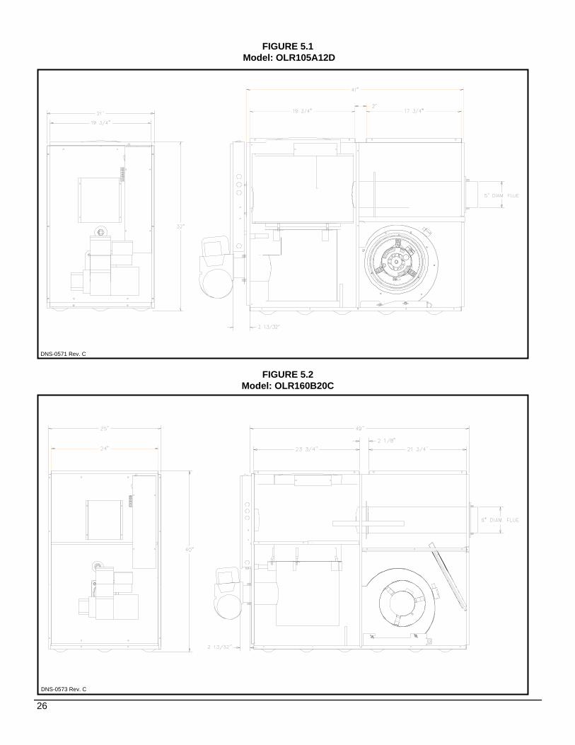
DNS-0571 Rev. C
DNS-0573 Rev. C
FIGURE 5.1Model: OLR105A12D
FIGURE 5.2Model: OLR160B20C
26
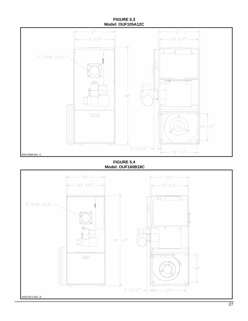
FIGURE 5.3Model: OUF105A12C
FIGURE 5.4Model: OUF160B18C
DNS-0572 Rev. D
DNS-0568 Rev. C
27

FIGURE 5.5Model : OLF105A12C
DNS-0570 Rev. C
FIGURE 5.6Model : NOUF105A12D
DNS-0674 Rev. E
28
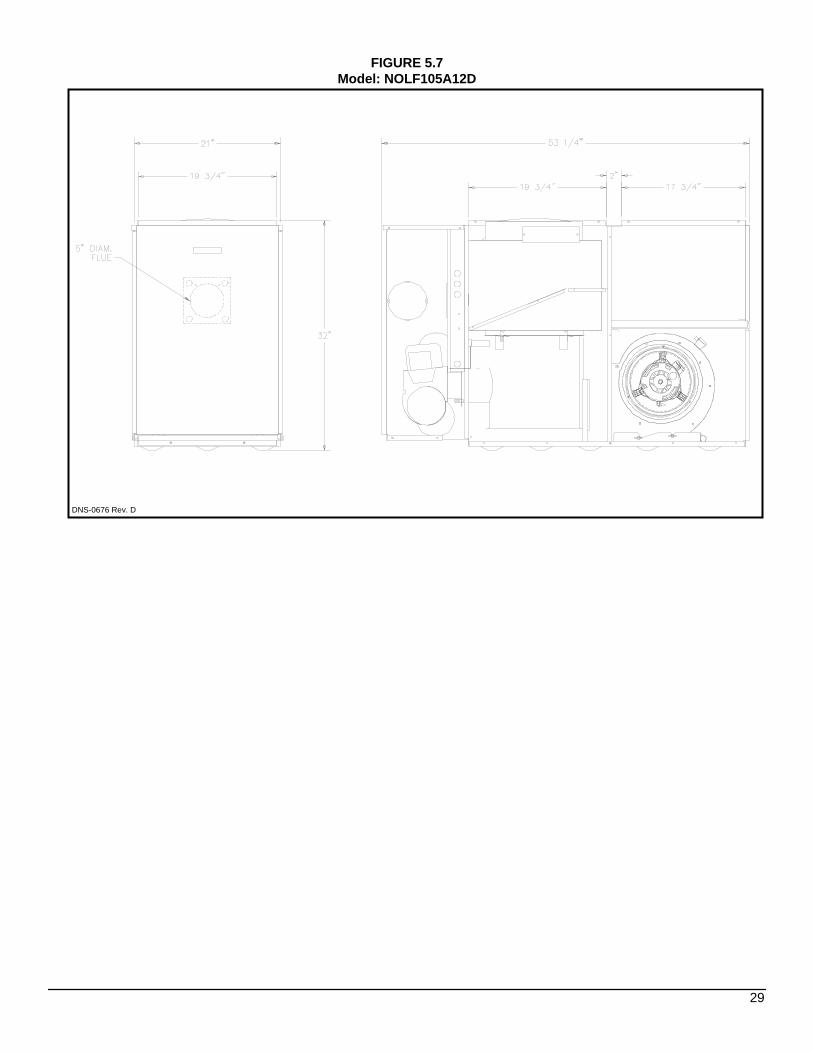
FIGURE 5.7Model: NOLF105A12D
DNS-0676 Rev. D
29

FIGURE 6Wiring diagram, OLR105A12D, OLR160B20C, OUF105A12C, NOUF105A12D, OUF160B18C,
OLF105A12C & NOLF105A12D
30
COMPONENTS
AND
REPLACEMENT PARTS
31
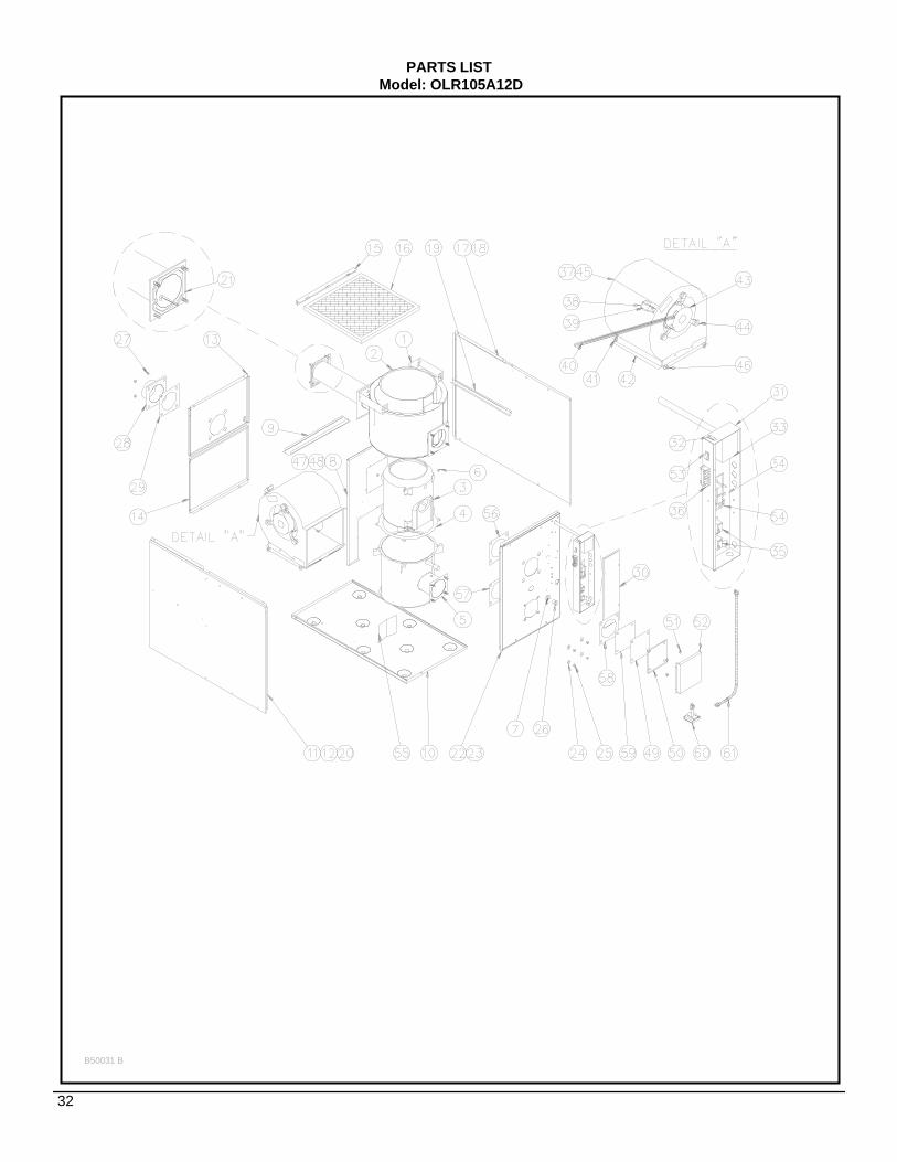
PARTS LISTModel: OLR105A12D
B50031 B
32
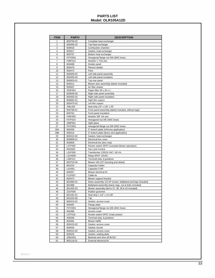
PARTS LISTModel: OLR105A12D
B50031 C
33
ITEM PART# DESCRIPTION1 B30756-02 Complete heat exchanger2 B30465-02 Top heat exchanger3 B30518 Combustion chamber4 B30517 Gasket, heat exchanger 5 B30757 Bottom heat exchanger6 F07O001 Hexagonal flange nut 3/8-16NC brass7 F06F015 Washer 1 7/16 zinc8 B30488 Divider panel9 B30478 Plenum divider
10 B30472 Floor11 B30509-02 Left side panel assembly12 B30493-04 Left side panel insulation13 B30833-01 Top rear panel14 B30512 Blower door assembly (labels included)15 B30507 Air filter drawer16 Z04F004 Paper filter 20 x 20 x 1 17 B30509-05 Right side panel assembly18 B30493-03 Right side panel insulation19 B30832-01 Right filter support20 B30479-02 Left filter support21 J06L002 Seal strip 1/4" x 1/8" x 25'22 B30768-01 Front panel assembly (labels included, without logo)23 B30762 Front panel insulation24 F06F005 Washer 3/8" AA zinc25 F07F024 Hexagonal nut 3/8-16NC brass26 Z99F061 Sight glass27 F07O001 Hexagonal flange nut 3/8-16NC brass
28A B30459 5" breech plate (chimney application)28B B30515 3" breech plate (direct vent application)29 B30415-02 Gasket, heat exchanger 30 B30808-01 Electrical box cover 31 B30828 Electrical box (box only)32 L07F003 Rocker switch SPST (constant blower operation)33 R02I005 Fan Limit Control34 L01F009 Transformer 120/24 VAC / 40 VA 35 L01H009 Relay SPDT 24VAC36 L05F011 Terminal strip, 6 positions 37 B03720-04 Blower 100-10T (housing and wheel)38 B01024 Capacitor holder39 L01I001 Capacitor 5 MF 40 B30057 Blower electrical kit41 F11F007 Cable tie42 B30473 Blower support bracket43 B01890-01 Motor assembly 1/3 HP (motor, bellyband and legs included)44 B01888 Bellyband assembly (band, legs, nut & bolts included)45 B01405-03 Blower assembly (items 37, 38, 39 & 43 included)46 Z01F006 Rubber grommet47 B01291-01 Seal strip 1 1/2" x 13 1/8" 48 B01025-99 Tab49 B30415-01 Gasket, access cover50 B30487 Flange plate51 F07O001 Hexagonal flange nut 3/8-16NC brass52 B30486 Access cover53 L07F016 Rocker switch SPST (main power)54 A00336 Terminal strip, 6 positions 55 B30481 Blower baffle56 B30415-02 Gasket, access cover57 B30534 Gasket, burner58 B30415-02 Gasket, access cover59 B30533 Gasket, sealing plate60 Z06G001 Blocked vent shut off BVSO61 B03118-01 External electrical kit
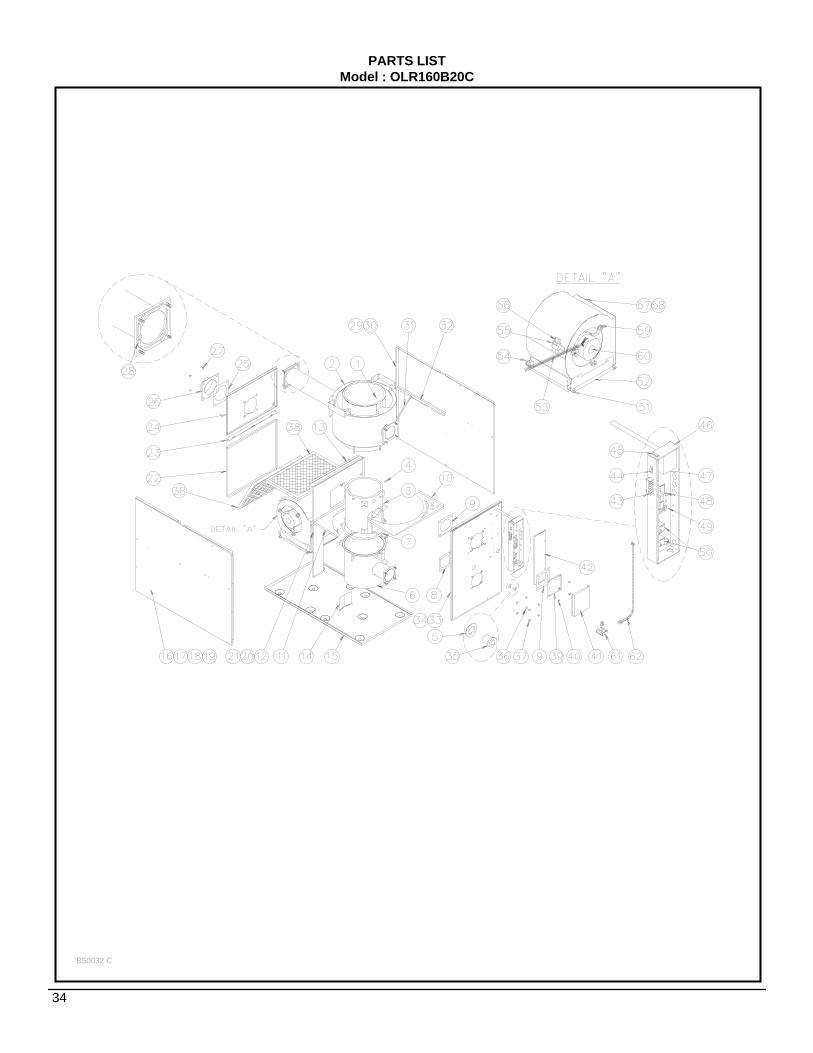
PARTS LISTModel : OLR160B20C
B50032 C
34

PARTS LISTModel : OLR160B20C
B50032 D
35
ITEM PART # DESCRIPTION1 B30786-02 Complete heat exchanger (combustion chamber included)2 B30596 Top heat exchanger3 B30531 Combustion chamber (item 7 included)4 F07O001 Hexagonal flange nut 3/8-16NC brass5 F06F015 Washer 1 7/16 zinc6 B30787 Bottom heat exchanger7 B30532 Gasket, heat exchanger8 B30534 Gasket, heat exchanger9 B30415-02 Gasket, heat exchanger
10 B30665 Front baffle11 B30664 Rear baffle12 B30666 Divider panel13 B30669 Plenum divider14 B30481 Blower baffle15 B30663 Floor16 B30680-02 Left side panel assembly17 B30686-02 Left side panel insulation18 B30668-02 Left bottom filter support19 B30667 Left top filter support20 B10256-99 Tab21 B01291-02 Gasket, seal strip22 B30683 Blower door assembly (labels included)23 B30678 Air filter drawer24 B30836-01 Top rear panel25 B30589-01 Gasket, breech plate
26A B30646 6" breech plate (chimney application)26B B30647 4" breech plate (direct vent application)27 F07O001 Hexagonal flange nut 3/8-16NC brass28 J06L002 Seal strip 1/2" x 1/8" x 25'29 B30680-05 Right side panel assembly30 B30686-01 Right side panel insulation31 B30668-01 Right bottom filter support32 B30835 Right top filter support33 B30782-01 Front panel assembly (labels included, without logo)34 B30780 Front panel insulation35 Z99F061 Sight glass36 F06F005 Washer 3/8" AA zinc37 F07F024 Hexagonal nut 3/8-16NC brass38 Z04F007 Paper filter 16 x 24 x 1 39 B30676 Flange plate40 F07O001 Hexagonal flange nut 3/8-16NC brass41 B30486 Access cover42 B30808-01 Electrical box cover43 L05F011 Terminal strip, 6 positions 44 L07F016 Rocker switch SPST (main power)45 L07F003 Rocker switch SPST (constant blower operation)46 B30828 Electrical box (box only)47 R02I005 Fan Limit Control 8"48 L01F009 Transformer 120/24 VAC / 40 VA 49 A00336 Terminal strip, 6 positions 50 L01H009 Relay SPDT 24VAC51 Z01F006 Rubber grommet.52 B01756 Blower support bracket53 B30530-01 Blower electrical kit54 L04I010 Strain release bushing55 B01024 Capacitor holder56 L01I005 15 MF capacitor57 B03720-05 Blower 120-10T (housing and wheel)58 B01406-06 Blower assembly (items 55, 56, 57, 59 and 60 included)59 B01889 Motor mount assembly (band, legs, nut & bolts included)60 L06I004 3/4 HP direct drive motor (without legs)61 Z06G001 Blocked vent shut off BVSO62 B03118-01 External electrical kit BVSO
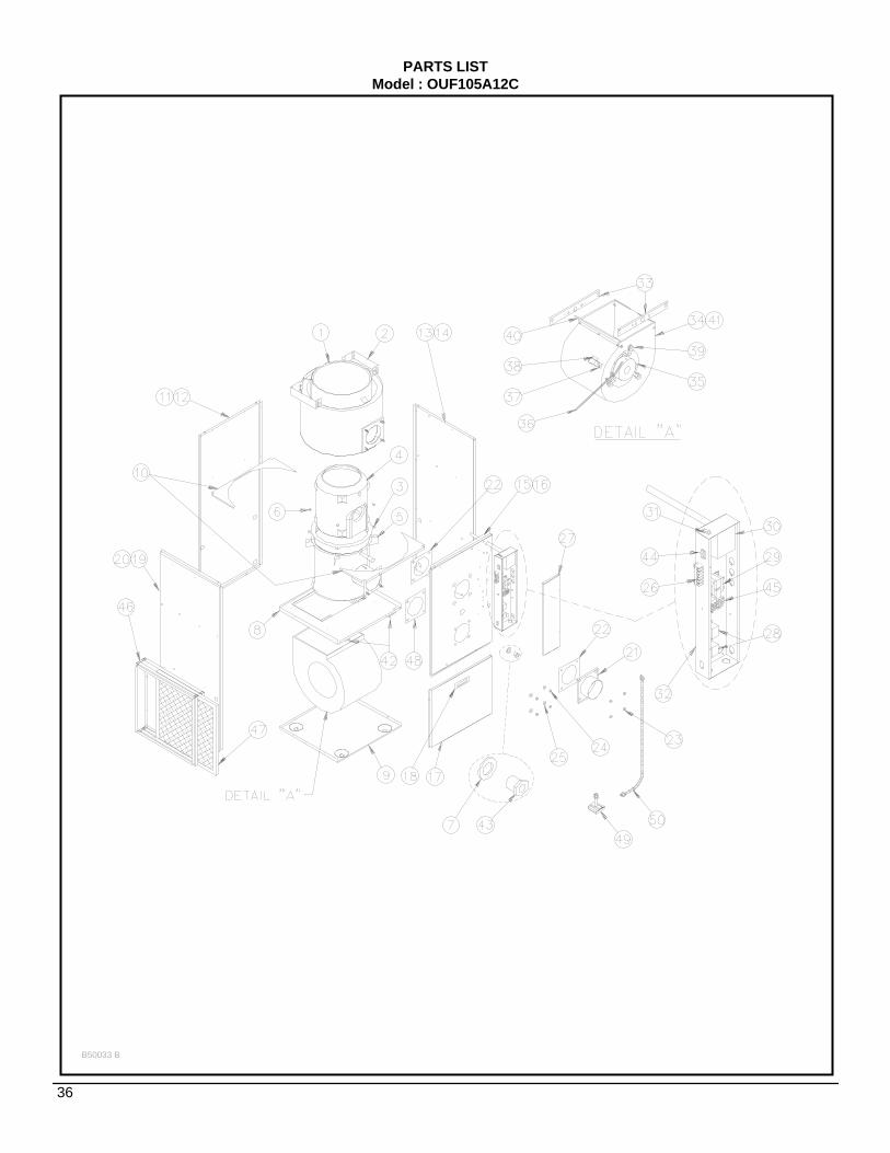
PARTS LISTModel : OUF105A12C
B50033 B
36
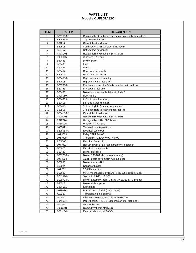
PARTS LISTModel : OUF105A12C
B50033 C
37
ITEM PART # DESCRIPTION1 B30756-01 Complete heat exchanger (combustion chamber included)2 B30465-01 Top heat exchanger3 B30517 Gasket, heat exchanger 4 B30518 Combustion chamber (item 3 included)5 B30757 Bottom heat exchanger6 F07O001 Hexagonal flange nut 3/8-16NC brass7 F06F015 Washer 1 7/16 zinc8 B30431 Divider panel9 B30430 Floor
10 B30426 Baffle11 B30457 Rear panel assembly12 B30419 Rear panel insulation13 B30458-01 Right side panel assembly14 B30418 Right side panel insulation15 B30760-01 Front panel assembly (labels included, without logo)16 B30761 Front panel insulation17 B30455 Blower door assembly (labels included)18 Z99F050 Door handle19 B30458-02 Left side panel assembly20 B30418 Left side panel insulation
21A B30459 5" breech plate (chimney application)21B B30515 3" breech plate (direct vent application)22 B30415-02 Gasket, heat exchanger 23 F07O001 Hexagonal flange nut 3/8-16NC brass24 F07F024 Hexagonal nut 3/8-16NC brass25 F06F005 Washer 3/8" AA zinc26 L05F011 Terminal strip, 6 positions 27 B30808-01 Electrical box cover28 L01H009 Relay SPDT 24VAC29 L01F009 Transformer 120/24 VAC / 40 VA 30 R02I005 Fan Limit Control 8"31 L07F003 Rocker switch SPST (constant blower operation)32 B30826 Electrical box (box only)33 B30433 Blower side rails34 B03720-04 Blower 100-10T (housing and wheel)35 L06H004 1/2 HP direct drive motor (without legs)36 B30096 Blower electrical kit37 B01024 Capacitor holder38 L01I002 7.5 MF capacitor39 B01888 Motor mount assembly (band, legs, nut & bolts included)40 B01291-01 Seal strip 1 1/2" x 13 1/8" 41 B01979-01 Blower assembly (items 34, 35, 37 38, 39 & 40 included)42 B30513 Blower slide support43 Z99F061 Sight glass44 L07F016 Rocker switch SPST (main power)45 A00336 Terminal strip, 6 positions 46 B30083 Filter rack assembly (supply as an option)47 Z04F004 Paper filter 20 x 20 x 1 (depends on filter rack size)48 B30534 Gasket, burner49 Z06G001 Blocked vent shut off BVSO50 B03118-01 External electrical kit BVSO

PARTS LISTModel : OUF160B18C
B50034 D
38
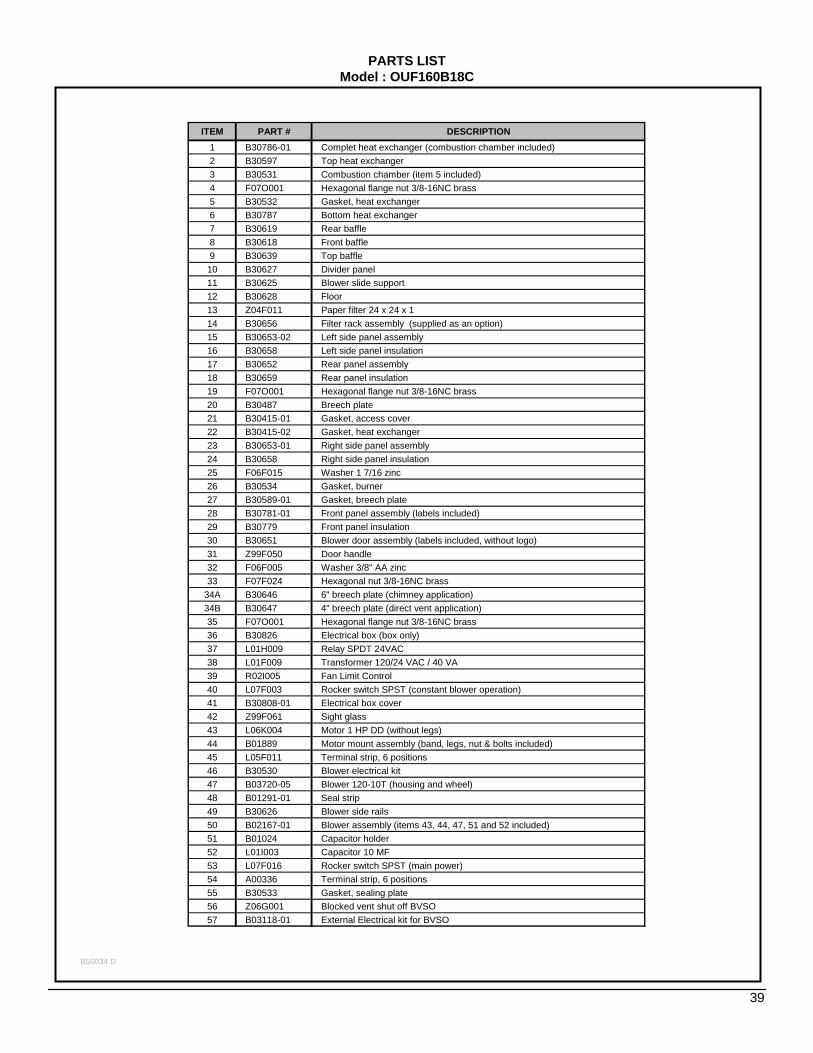
PARTS LISTModel : OUF160B18C
B50034 D
39
ITEM PART # DESCRIPTION1 B30786-01 Complet heat exchanger (combustion chamber included)2 B30597 Top heat exchanger3 B30531 Combustion chamber (item 5 included)4 F07O001 Hexagonal flange nut 3/8-16NC brass5 B30532 Gasket, heat exchanger6 B30787 Bottom heat exchanger7 B30619 Rear baffle8 B30618 Front baffle9 B30639 Top baffle10 B30627 Divider panel11 B30625 Blower slide support12 B30628 Floor13 Z04F011 Paper filter 24 x 24 x 1 14 B30656 Filter rack assembly (supplied as an option)15 B30653-02 Left side panel assembly16 B30658 Left side panel insulation17 B30652 Rear panel assembly18 B30659 Rear panel insulation19 F07O001 Hexagonal flange nut 3/8-16NC brass20 B30487 Breech plate21 B30415-01 Gasket, access cover22 B30415-02 Gasket, heat exchanger23 B30653-01 Right side panel assembly24 B30658 Right side panel insulation25 F06F015 Washer 1 7/16 zinc26 B30534 Gasket, burner27 B30589-01 Gasket, breech plate28 B30781-01 Front panel assembly (labels included)29 B30779 Front panel insulation30 B30651 Blower door assembly (labels included, without logo)31 Z99F050 Door handle32 F06F005 Washer 3/8" AA zinc33 F07F024 Hexagonal nut 3/8-16NC brass
34A B30646 6" breech plate (chimney application)34B B30647 4" breech plate (direct vent application)35 F07O001 Hexagonal flange nut 3/8-16NC brass36 B30826 Electrical box (box only)37 L01H009 Relay SPDT 24VAC38 L01F009 Transformer 120/24 VAC / 40 VA 39 R02I005 Fan Limit Control40 L07F003 Rocker switch SPST (constant blower operation)41 B30808-01 Electrical box cover42 Z99F061 Sight glass43 L06K004 Motor 1 HP DD (without legs)44 B01889 Motor mount assembly (band, legs, nut & bolts included)45 L05F011 Terminal strip, 6 positions 46 B30530 Blower electrical kit47 B03720-05 Blower 120-10T (housing and wheel)48 B01291-01 Seal strip49 B30626 Blower side rails50 B02167-01 Blower assembly (items 43, 44, 47, 51 and 52 included)51 B01024 Capacitor holder52 L01I003 Capacitor 10 MF 53 L07F016 Rocker switch SPST (main power)54 A00336 Terminal strip, 6 positions 55 B30533 Gasket, sealing plate56 Z06G001 Blocked vent shut off BVSO57 B03118-01 External Electrical kit for BVSO

PARTS LISTModel : OLF105A12C
B50035 B
40
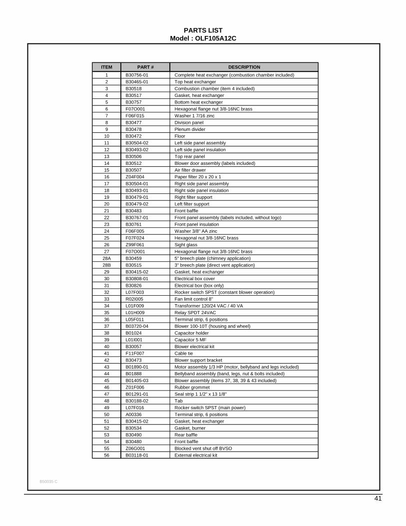
PARTS LISTModel : OLF105A12C
B50035 C
41
ITEM PART # DESCRIPTION1 B30756-01 Complete heat exchanger (combustion chamber included)2 B30465-01 Top heat exchanger3 B30518 Combustion chamber (item 4 included)4 B30517 Gasket, heat exchanger 5 B30757 Bottom heat exchanger6 F07O001 Hexagonal flange nut 3/8-16NC brass7 F06F015 Washer 1 7/16 zinc8 B30477 Division panel9 B30478 Plenum divider10 B30472 Floor11 B30504-02 Left side panel assembly12 B30493-02 Left side panel insulation13 B30506 Top rear panel14 B30512 Blower door assembly (labels included)15 B30507 Air filter drawer16 Z04F004 Paper filter 20 x 20 x 1 17 B30504-01 Right side panel assembly18 B30493-01 Right side panel insulation19 B30479-01 Right filter support20 B30479-02 Left filter support21 B30483 Front baffle22 B30767-01 Front panel assembly (labels included, without logo)23 B30761 Front panel insulation24 F06F005 Washer 3/8" AA zinc25 F07F024 Hexagonal nut 3/8-16NC brass26 Z99F061 Sight glass27 F07O001 Hexagonal flange nut 3/8-16NC brass
28A B30459 5" breech plate (chimney application)28B B30515 3" breech plate (direct vent application)29 B30415-02 Gasket, heat exchanger 30 B30808-01 Electrical box cover31 B30826 Electrical box (box only)32 L07F003 Rocker switch SPST (constant blower operation)33 R02I005 Fan limit control 8''34 L01F009 Transformer 120/24 VAC / 40 VA 35 L01H009 Relay SPDT 24VAC36 L05F011 Terminal strip, 6 positions 37 B03720-04 Blower 100-10T (housing and wheel)38 B01024 Capacitor holder39 L01I001 Capacitor 5 MF 40 B30057 Blower electrical kit41 F11F007 Cable tie42 B30473 Blower support bracket43 B01890-01 Motor assembly 1/3 HP (motor, bellyband and legs included)44 B01888 Bellyband assembly (band, legs, nut & bolts included)45 B01405-03 Blower assembly (items 37, 38, 39 & 43 included)46 Z01F006 Rubber grommet47 B01291-01 Seal strip 1 1/2" x 13 1/8" 48 B30188-02 Tab49 L07F016 Rocker switch SPST (main power)50 A00336 Terminal strip, 6 positions 51 B30415-02 Gasket, heat exchanger52 B30534 Gasket, burner53 B30490 Rear baffle54 B30480 Front baffle55 Z06G001 Blocked vent shut off BVSO56 B03118-01 External electrical kit
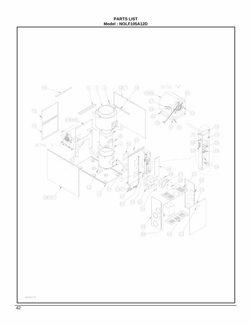
PARTS LISTModel : NOLF105A12D
B50037 B
42

PARTS LISTModel : NOLF105A12D
B50037 C
43
ITEM PART # DESCRIPTION1 B30756-01 Complete heat exchanger (combustion chamber included)2 B30465-01 Top heat exchanger3 B30518 Combustion chamber (item 4 included)4 B30517 Gasket, heat exchanger 5 B30757 Bottom heat exchanger6 F07O001 Hexagonal flange nut 3/8-16NC brass7 F06F015 Washer 1 7/16 zinc8 B30477 Divider panel9 B30478 Plenum divider10 B30472 Floor11 B30504-02 Left side panel assembly12 B30493-02 Left side panel insulation13 B30475 Top rear panel14 B30512 Blower door assembly (labels included)15 B30507 Air filter drawer16 B30504-01 Right side panel assembly17 B30493-01 Right side panel insulation18 B30479-01 Right filter support19 B30479-02 Left filter support20 B30483 Front baffle21 B30767-01 Front panel assembly (labels included, without logo)22 B30761 Front panel insulation23 Z99F050 Door handle24 F07F024 Hexagonal nut 3/8-16NC brass25 Z99F061 Sight glass26 F07O001 Hexagonal flange nut 3/8-16NC brass
27A B30459 5" breech plate (chimney application)27B B30515 3" breech plate (direct vent application)28 B30415-02 Gasket, heat exchanger29 B30808-01 Electrical box cover30 B30826 Electrical box (box only)31 L07F003 Rocker switch SPST (constant blower operation)32 R02I005 Fan Limit Control33 L01F009 Transformer 120/24 VAC / 40 VA 34 L01H009 Relay SPDT 24VAC35 L05F011 Terminal strip, 6 positions 36 B03720-04 Blower 100-10T (housing and wheel)37 B01024 Capacitor holder38 L01I001 Capacitor 5 MF 39 B30057 Blower electrical kit40 F11F007 Cable tie41 B30473 Blower support bracket42 B01890-01 Motor assembly 1/3 HP (motor, bellyband & legs included)43 B01888 Motor mount assembly (band, legs, nut & bolts included)44 B01405-03 Blower assembly (items 36, 37, 38 and 42 included)45 Z01F006 Rubber grommet46 B01297-01 Seal strip47 B01025-99 Tab48 L07F016 Rocker switch SPST (main power)49 A00336 Terminal strip, 6 positions 50 B30415-02 Gasket, breech plate51 B30534 Gasket, burner52 B30490 Rear baffle53 B30480 Front baffle54 B40292 Front door, vestibule55 B30729 Right panel, vestibule56 B30730 Left panel, vestibule57 B30723 Top panel, vestibule58 B30724 Bottom panel, vestibule59 Z06F001 Draft regulator60 N01J040 Beckett burner AFG-F061 Z06G001 Blocked vent shut off BVSO62 B03118-01 External electrical kit BVSO

PARTS LISTModel : NOUF105A12D
B50036 B
44
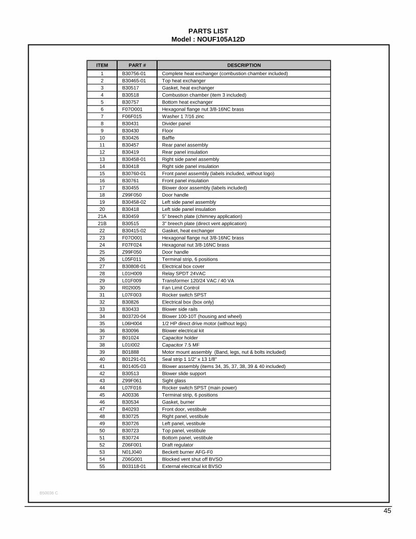
PARTS LISTModel : NOUF105A12D
B50036 C
45
ITEM PART # DESCRIPTION1 B30756-01 Complete heat exchanger (combustion chamber included)2 B30465-01 Top heat exchanger3 B30517 Gasket, heat exchanger 4 B30518 Combustion chamber (item 3 included)5 B30757 Bottom heat exchanger6 F07O001 Hexagonal flange nut 3/8-16NC brass7 F06F015 Washer 1 7/16 zinc8 B30431 Divider panel9 B30430 Floor10 B30426 Baffle11 B30457 Rear panel assembly12 B30419 Rear panel insulation13 B30458-01 Right side panel assembly14 B30418 Right side panel insulation15 B30760-01 Front panel assembly (labels included, without logo)16 B30761 Front panel insulation17 B30455 Blower door assembly (labels included)18 Z99F050 Door handle19 B30458-02 Left side panel assembly20 B30418 Left side panel insulation
21A B30459 5" breech plate (chimney application)21B B30515 3" breech plate (direct vent application)22 B30415-02 Gasket, heat exchanger23 F07O001 Hexagonal flange nut 3/8-16NC brass24 F07F024 Hexagonal nut 3/8-16NC brass25 Z99F050 Door handle26 L05F011 Terminal strip, 6 positions 27 B30808-01 Electrical box cover28 L01H009 Relay SPDT 24VAC29 L01F009 Transformer 120/24 VAC / 40 VA 30 R02I005 Fan Limit Control31 L07F003 Rocker switch SPST32 B30826 Electrical box (box only)33 B30433 Blower side rails34 B03720-04 Blower 100-10T (housing and wheel)35 L06H004 1/2 HP direct drive motor (without legs)36 B30096 Blower electrical kit37 B01024 Capacitor holder38 L01I002 Capacitor 7.5 MF 39 B01888 Motor mount assembly (Band, legs, nut & bolts included)40 B01291-01 Seal strip 1 1/2" x 13 1/8" 41 B01405-03 Blower assembly (items 34, 35, 37, 38, 39 & 40 included)42 B30513 Blower slide support43 Z99F061 Sight glass44 L07F016 Rocker switch SPST (main power)45 A00336 Terminal strip, 6 positions 46 B30534 Gasket, burner47 B40293 Front door, vestibule48 B30725 Right panel, vestibule49 B30726 Left panel, vestibule50 B30723 Top panel, vestibule51 B30724 Bottom panel, vestibule52 Z06F001 Draft regulator53 N01J040 Beckett burner AFG-F054 Z06G001 Blocked vent shut off BVSO55 B03118-01 External electrical kit BVSO
Related Documents