Welcome message from author
This document is posted to help you gain knowledge. Please leave a comment to let me know what you think about it! Share it to your friends and learn new things together.
Transcript


i

This page intentionally left blank

iii
A u s t r a l i a • C a n a d a • M e x i c o • S i n g a p o r e • S p a i n • U n i t e d K i n g d o m • U n i t e d S t a t e s
Margi Sirois, EdD, MS, RVTProgram Director of Veterinary TechnologyPenn Foster College Scottsdale, AZ
Elaine Anthony, MA, CVTSt. Petersburg CollegeSt. Petersburg, FL
Danielle Mauragis, CVTUniversity of FloridaGainesville, FL

© 2010 Delmar Cengage Learning
ALL RIGHTS RESERVED. No part of this work covered by the copyright herein may be reproduced, transmitted, stored, or used in any form or by any means graphic, electronic, or mechanical, including but not limited to photocopying, recording, scanning, digitizing, taping, Web distribution, information networks, or information storage and retrieval systems, except as permitted under Section 107 or 108 of the 1976 United States Copyright Act, without the prior written permission of the publisher.
For product information and technology assistance, contact us atCengage Learning Customer & Sales Support, 1-800-354-9706
For permission to use material from this text or product,submit all requests online at www.cengage.com/permissions.
Further permissions questions can be e-mailed [email protected]
Library of Congress Control Number: 2009905813
ISBN-13: 978-1-4354-2603-0ISBN-10: 1-4354-2603-7
Delmar
5 Maxwell DriveClifton Park, NY 12065-2919USA
Cengage Learning is a leading provider of customized learning solutions with of ce locations around the globe, including Singapore, the United Kingdom, Australia, Mexico, Brazil, and Japan. Locate your local of ce at: international.cengage.com/region
Cengage Learning products are represented in Canada by Nelson Education, Ltd.
To learn more about Delmar, visit www.cengage.com/delmar
Purchase any of our products at your local college store or at our preferred online store www.ichapters.com
Notice to the Reader
Publisher does not warrant or guarantee any of the products described herein or perform any independent analysis in connection with any of the product in-formation contained herein. Publisher does not assume, and expressly disclaims, any obligation to obtain and include information other than that provided to it by the manufacturer. The reader is expressly warned to consider and adopt all safety precautions that might be indicated by the activities described herein and to avoid all potential hazards. By following the instructions contained herein, the reader willingly assumes all risks in connection with such instructions. The publisher makes no representations or warranties of any kind, including but not limited to, the warranties of fi tness for particular purpose or merchantability, nor are any such representations implied with respect to the material set forth herein, and the publisher takes no responsibility with respect to such material. The publisher shall not be liable for any special, consequential, or exemplary damages resulting, in whole or part, from the readers’ use of, or reliance upon, this material.
Handbook of Radiographic Positioning for
Veterinary Technicians
Margi Sirois, Danielle Mauragis, and Elaine
Anthony
Vice President, Career and Professional Editorial: Dave Garza
Director of Learning Solutions: Matthew Kane
Acquisitions Editor: Benjamin Penner
Managing Editor: Marah Bellegarde
Senior Product Manager: Darcy M. Scelsi
Editorial Assistant: Scott Royael
Vice President, Career and Professional Marketing: Jennifer McAvey
Marketing Manager: Erin Brennan
Marketing Coordinator: John Sheehan
Production Director: Carolyn Miller
Production Manager: Andrew Crouth
Content Project Manager: Allyson Bozeth
Art Director: Dave Arsenault
Printed in the United States of America1 2 3 4 5 6 7 12 11 10 09 08

v
PREFACE viii
CHAPTER 1 General Principles of Small Animal Radiographic Positioning
Patient Preparation 2Directional Terminology 2Positioning Aids 4Procedures for Radiographic Positioning 5
CHAPTER 2 Thoracic Radiographs
Lateral Projection of the Thorax 10VD Projection of the Thorax 12DV Projection of the Thorax 14Standing Lateral Projection of the Thorax 16
CHAPTER 3 Abdominal Radiographs
Lateral Projection of the Abdomen 20VD Projection of the Abdomen 22
CHAPTER 4 Pelvic Radiographs
VD-Extended Hip Projection 26VD Frog Leg Projection 28Lateral Projection of the Pelvis 30
CHAPTER 5 Forelimb Radiographs
CdCr Projection of the Shoulder 34Lateral Projection of the Shoulder 36CdCr Projection of the Scapula 38Lateral Projection of the Scapula 40CdCr Projection of the Humerus 42Lateral Projection of the Humerus 44CrCd Projection of the Elbow 46Lateral Projection of the Elbow 48Flexed Lateral Projection of the Elbow 50CrCd Projection of the Radius and Ulna 52Lateral Projection of the Radius and Ulna 54Dorsopalmar Projection of the Carpus 56Lateral Projection of the Carpus 58Flexed Lateral Projection of the Carpus 60Extended Lateral Projection of the Carpus 62Lateral and Medial Oblique Projections of the Carpus 64Dorsopalmar Projection of the Metacarpals 66Lateral Projection of the Metacarpals 68Dorsopalmar Projection of the Digits 70Lateral Projection of the Digits 72
CHAPTER 6 Hindlimb Radiographs
Lateral Projection of the Femur 76Craniocaudal Projection of the Femur 78
Table of Contents

vi Table of Contents
Caudocranial Projection of the Stifl e 80Lateral Projection of the Stifl e 82Caudocranial Projection of the Tibia and Fibula 84Lateral Projection of the Tibia 86Dorsoplantar Projection of the Tarsus 88Lateral Projection of the Tarsus 90Flexed Lateral Projection of the Tarsus 92Extended Lateral Projection of the Tarsus 94Dorsolateral/Plantaromedial Oblique Projection of the Tarsus 96Dorsomedial/Plantarolateral Oblique Projection of the Tarsus 98Dorsoplantar Projection of the Metatarsus 100Lateral Projection of the Metatarsus 102Dorsopalmar Projection of the Digits 104Lateral Projection of the Digits 106
CHAPTER 7 Skull Radiographs
Lateral Projection of the Skull 110DV Projection of the Skull 112VD Projection of the Skull 114Rostrocaudal Sinuses Closed Mouth Projection 116Rostrocaudal Foramen Magnum Projection 118VD Rostrocaudal Nasal Open Mouth Projection 120Rostrocaudal Tympanic Bullae Open Mouth Projection 122DV Tympanic Bullae Projection 126Lateral Oblique Tympanic Bullae Projection 128Lateral Oblique Temporomandibular Joint Projection 130DV Temporomandibular Joint Projection 132
CHAPTER 8 Dental Radiographs
Canine Upper Incisor Arcade 137Canine Upper Canine Tooth 138Canine Upper Premolars 139Canine Upper Fourth Premolars and Molars 140Canine Lower Incisor Arcade 141Canine Lower Canine Tooth and Lower Premolar Arcade 142Canine Lower Premolar Arcade 143Canine Lower Molars 144Feline Upper Incisor Arcade 145Feline Upper Canine Tooth 146Feline Upper Premolars and Molar 147Feline Lower Incisor Arcade 148Feline Lower Canine Tooth 149Feline Lower Premolars and Molar Arcade 150
CHAPTER 9 Spinal Radiographs
VD Cervical Spine Projection 152Lateral Cervical Spine Projection 154Lateral Cervical Spine Extended Projection 156Lateral Cervical Spine Flexed Projection 158VD Thoracic Spine Projection 160Lateral Thoracic Spine Projection 162VD Thoracolumbar Spine Projection 164Lateral Thoracolumbar Spine Projection 166VD Lumbar Spine Projection 168Lateral Lumbar Spine Projection 170VD Lumbosacral Spine Projection 172Lateral Lumbosacral Spine Projection 174VD Coccygeal (Caudal) Spine Projection 176Lateral Coccygeal (Caudal) Spine Projection 178

Table of Contents vii
CHAPTER 10 Radiography of Avian and Exotic Animals
General Principles of Restraint 182Lateral View of the Avian Patient 184Ventrodorsal View of the Avian Patient 186Dorsoventral View of the Lizard 188Lateral View of the Lizard 190Lateral View of the Lizard with the Horizontal Beam 192Dorsoventral View of the Turtle 194Lateral View of the Turtle with the Horizontal Beam 196Lateral View of the Rabbit Abdomen 198Ventrodorsal View of the Rabbit Abdomen 200Lateral View of the Rabbit Thorax 202Ventrodorsal View of the Rabbit Thorax 204Lateral View of the Rabbit Skull 206Dorsoventral View of the Rabbit Skull 208Lateral Oblique View of the Rabbit Skull 210Lateral View of the Ferret Abdomen 212Ventrodorsal View of the Ferret Abdomen 214Lateral View of the Ferret Thorax 216Ventrodorsal View of the Ferret Thorax 218Lateral Whole Body View of the Ferret 220Ventrodorsal Whole Body View of the Ferret 222
INDEX 225

viii Preface
PrefaceRadiographic evaluation is a valuable diagnostic tool, and the veterinary techni-cian plays a vital role in providing high-quality images for evaluation by the clini-cian. Proper patient positioning is crucial to achieving diagnostic quality images. This book provides detailed information on positioning of dogs, cats, birds, and pocket pets for radiographic examination. Photographs are used to illustrate cor-rect patient positioning for each radiographic image. The resulting radiograph produced is also included, and diagrams are included for most images. Canine and feline dental radiographic techniques are also included. Although not meant to be a comprehensive radiology textbook, detailed information on patient position-ing, positioning aids, and labeling of radiographic images is included. Positioning techniques described are most useful for clinical locations in which patients are sedated or anesthetized for radiographic procedures. However, all procedures can also be performed while manually restraining the patient if needed. Positioning techniques presented will provide diagnostic quality images when used with either traditional or digital radiology systems. Readers are encouraged to consult a com-prehensive radiology textbook for additional information on production of x-rays, film processing, and safety issues related to the production of radiographs.
About the AuthorsDr. Sirois is the Program Director of Veterinary Technology at Penn Foster Col-lege. She received her AAS degree in veterinary technology from Camden County College, and also holds a BS and an MS in Biology and an EdD in instructional technology and distance education. She is certified as both a veterinary techni-cian and laboratory animal technician, and has over 20 years’ experience as a vet-erinary technician educator in both traditional and distance education programs. Dr. Sirois is a past president of the Association of Veterinary Technician Educators and a member of the editorial board for Veterinary Technician.
Elaine Anthony is an associate professor of veterinary technology in both the on-campus and online veterinary technology programs at St. Petersburg College, and is employed part-time at a veterinary internal medicine clinic. She holds an AS degree in veterinary technology from St. Petersburg College. She also holds an AA in music, a BS in elementary education, and MA in adult education. She is certified as a veterinary technician and has earned a certificate in Veterinary Hospital Management. She has over 20 years’ experience as a veterinary technician educator. She is also a consultant for Nestle Purina and a member of the editorial board for Veterinary Technician.
Ms. Anthony and Dr. Sirois speak at several veterinary conferences each year, and have published numerous journal articles and textbook chapters on a variety of veterinary technology topics. Dr. Sirois has also authored and edited several veteri-nary technology textbooks, including Principles and Practices of Veterinary Technology,Laboratory Animal Medicine: Principles and Procedures, and Laboratory Procedures for Veterinary Technicians, all published by Elsevier.
Danielle Futch Mauragis received her A.S. degree in veterinary technology from St. Petersburg College. After working in private practice, she joined the Diagnos-tic Imaging service at the University of Florida Veterinary Medical Center. Her duties include x-ray, CT, Nuclear Medicine, assisting in ultrasound, and teach-ing physics, techniques, and quality control of radiology to veterinary students. Her hobbies are photography and sewing, but her passion is training dogs for

Handbook of Radiographic Positioning for Veterinary Technicians ix
competition in agility. She shares her life with her husband Dennis, daughter Savannah, 2 dogs, Flik and Fizzy, and 1 ex-research cat name Pounce de Leon.
ContributorsLori A. Barnes, CVTAvian & Animal Hospital of Bardmoor, Largo, FL
Vickie Byard, CVT, VTS (Dentistry)Rau Animal Hospital Glenside, PA
Deborah L. Walker, CVTAvian & Animal Hospital of Bardmoor, Largo, FL
AcknowledgementsSpecial thanks to our families for putting up with us while we focused on this book. This book would not have been possible without your love and support. We are sending a special woof and extra dog treats to our favorite models, Dakota , Aspen, Woody, and Flik. We are grateful for the guidance and support of Senior Product Manager, Darcy Scelsi, and to our contributors for all their hard work.
ReviewersMary H. Ayers, BBA, RT(R)Virginia Medical Regional College Of Veterinary MedicineBlacksburg, VA
Karen Lee Hrapkiewicz, DVMWayne State UniversityDetroit, MI
Karl M. Peter, DVMFoothill CollegeLos Altos Hills, CA
Lois Sargent, DVMMiami Dade CollegeMiami, FL
P. Alleice Summers, DVMCedar Valley CollegeLancaster, TX
Frances Turner, RVTMcLennan Community CollegeWaco, TX
DedicationTo our students—past, present, and future. You are our inspiration.

This page intentionally left blank

1
OVERVIEW
Positioning of small animal patients for radiography requires knowledge of normal anatomy of
the species and descriptive directional terminology. When patients are not properly positioned,
inaccurate interpretation of the radiograph and subsequent incorrect diagnosis of the patient
can occur. Proper patient positioning usually requires that the patient be immobilized, either
using chemical restraint (administration of sedatives and anesthetics) or mechanical
restraint (use of radiology positioning aids). Manual restraint should be avoided due to the risk
of increased exposure of the handler to ionizing radiation. When manual restraint is necessary, the
handlers should take precautions to minimize exposure to ionizing radiation. This includes proper
positioning, as well as moving as far as possible from the primary x-ray beam and wearing proper
safety apparel, including lead-lined gloves, apron, thyroid shield, and glasses.
CHAPTER 1GENERAL PRINCIPLES OF SMALL ANIMAL RADIOGRAPHIC POSITIONING

2 Chapter 1: General Principles of Small Animal Radiographic Positioning
PATIENT PREPARATION
The veterinary technician should ensure that all ani-mals being radiographed have a clean, dry haircoat. Wet hair and debris can cause confusing artifacts on radiographs. If possible, remove all collars and leashes, topical medications, bandages, and splints.
Animals undergoing radiographic study must be properly restrained. Ideally, chemical restraint with sedatives or anesthetics will be used so a handler does not have to remain in the room. This will also minimize the possibility of motion artifacts on the finished radio-graph as well as minimize the anxiety of the animals. In some locations, laws prohibit manual restraint. When manual restraint is necessary, it should be accompanied by the use of positioning aids and the proper use of lead shielding to minimize exposure of the technician to radiation. The comfort of the patient must also be considered.
Careful planning and preparation will reduce the total time that patients must remain in position on the x-ray table. Identify all radiographic views needed, and prepare all supplies and equipment before placing the animal onto the x-ray table.
DIRECTIONAL TERMINOLOGY
A basic knowledge of directional terminology is required for proper patient positioning and for use when describ-ing radiographic projections. The American College of Veterinary Radiology (ACVR) determines standard nomenclature for radiographic projections. The accepted nomenclature system requires that radiographic projec-tions be named using only approved veterinary anatomi-cal directional terms or their abbreviations. Radiographic projections are described using the directional term that describes the penetration by the central ray of the pri-mary x-ray beam through the anatomical area of interest from the point of entrance to the point of exit. ACVR guidelines also include recommended nomenclature to be used when combinations of terms are needed and when oblique x-ray angles are used. In small animals, it is assumed that the primary x-ray beam is generated from a location above the animal unless otherwise indicated.
Commonly Used Directional Terminology:
Dorsoventral (DV): This term describes a radiograph produced when the primary x-ray beam enters the dorsal (topline or spinal) surface and exits the ventral (sternal or thorax and abdomen) surface of the patient (Figure 1-1a).
Ventrodorsal (VD): This term describes a radiograph produced when the primary x-ray beam enters the ventral
surface and exits the dorsal surface of the patient (Figure 1-1b).
Medial (M): This term refers to the direction toward an animal’s midline (Figure 1-2). The term is usu-ally used in combination with other directional terms to describe oblique projections. For example, dor-somedial refers to the direction of the x-ray beam from the dorsal surface toward the midline. Radio-graphs of the limbs taken with the primary x-ray beam entering the medial surface of the limb and exiting the lateral may be referred to as mediolateral, although this is normally shortened to simply L.
FIGURE 1-2
Medial versus lateral
Medial
Lateral
Midline
AnteriorView
© D
elm
ar/C
enga
ge L
earn
ing
(b) Ventrodorsal
(a) DorsoventralX-ray cassette
FIGURE 1-1
Dorsoventral versus ventrodorsal positioning.
© D
elm
ar/C
enga
ge L
earn
ing

Handbook of Radiographic Positioning for Veterinary Technicians 3
Lateral: The term describes a radiograph produced when the primary x-ray beam enters from the side, away from the medial plane or midline of the patient’s body. In the strictest use of ACVR nomenclature, a lateral pro-jection taken with an animal lying on its right side would be referred to as left to right lateral. However, by con-vention, this is usually shortened to simply right lateral, meaning that the patient is positioned in right lateral recumbency, indicating that the patient’s right side is closest to the x-ray cassette. Similarly, a limb radiographobtained with the patient in right lateral recumbency with the affected limb placed against the x-ray table or cassette and the x-ray beam penetrating from the me-dial to lateral direction is referred to as a right lateral projection.
Proximal (Pr): This is a relative directional term that indicates a structure located closer to a point of attach-ment or origin from another structure or closer to the midline of the animal (Figure 1-3).
Distal (Di): This is a relative directional term that indi-cates a structure located farther from the point of at-tachment or origin of another structure or away from the midline of the animal (Figure 1-3).
Rostral: This relative directional term indicates a struc-ture located closer to the nares from any point on the head (Figure 1-3).
Cranial (Cr): This relative directional term indi cates a structure located closer to the animal’s head from any part of the body (Figure 1-3).
Caudal (Cd): This relative directional term indicates a structure located closer to the animal’s tail from any part of the body (Figure 1-3).
Plantar: This term is used to describe the caudal (pos-terior) surface of the hindlimb distal to the tarsus; the correct term for the surface proximal to the tarsus is caudal (Figure 1-3).
Palmar: This term is used to describe the caudal (pos-terior) surface of the forelimb distal to the carpus; the correct term for the surface proximal to the carpus is caudal (Figure 1-3).
Craniocaudal (CrCd): This term describes a radio-graphic projection obtained by passing the primary x-ray beam from the cranial surface to the caudal surface of a structure. It is most commonly used for radiographs involving the extremities proximal to the carpus or tar-sus. Older veterinary literature may refer to this radio-graphic projection as anterior-posterior (AP).
Caudocranial (CdCr): This term describes a radio-graphic projection obtained by passing the primary x-ray beam from the caudal surface to the cranial surface of a structure. It is most commonly used for radiographs involving the extremities proximal to the carpus or tar-sus. Older veterinary literature may refer to this radio-graphic projection as posterior-anterior (PA).
Dorsopalmar (Dpa): This term is used to describe ra-diographic views distal to the carpus obtained by pass-ing the primary x-ray beam from the dorsal direction to the palmar surface of the forelimb. Older veterinary literature may refer to this radiographic projection as anterior-posterior (AP).
Palmar dorsal (PaD): This term is used to describe ra-diographic views distal to the carpus obtained by pass-ing the primary x-ray beam from the palmar surface of the forelimb toward the dorsal surface of the body. Old-er veterinary literature may refer to this radiographic projection as posterior- anterior (PA).
Dorsoplantar (Dpl): This term is used to describe ra-diographic views distal to the tarsus obtained by pass-ing the primary x-ray beam from the dorsal direction to the plantar surface of the hindlimb. Older veterinary literature may refer to this radiographic projection as anterior-posterior (AP).
Plantardorsal (PlD): This term is used to describe ra-diographic views distal to the tarsus obtained by passing the primary x-ray beam from the plantar surface of the forelimb toward the dorsal surface of the body. Older
FIGURE 1-3
Common directional and positioning terminology. The arrows
on this Boston terrier represent the following directional terms:
A = cranial, B = caudal, C = ventral, D = dorsal, E = rostral,
F = proximal, G = distal, H = palmar, I = plantar.
A B
D D
C
D
E
F
G
HI
© D
elm
ar/C
enga
ge L
earn
ing

4 Chapter 1: General Principles of Small Animal Radiographic Positioning
veterinary literature may refer to this radiographic pro-jection as posterior- anterior (PA).
Oblique (O): This term refers to radiographic projec-tions taken with the primary beam entering at an angle other than 90 degrees to the anatomical area of inter-est. Oblique projections are sometimes used to obtain images of structures that might be superimposed over other structures with standard 90-degree views. Nearly all dental radiographs are obtained using oblique an-gles. The angle used may vary depending on the site of interest. The specific angle should be included in the description of the radiograph along with the proper ter-minology to describe the direction of the primary beam. For example, a D60LMPaO indicates that the x-ray beam entered the dorsal surface at a 60-degree angle and exited at the medial area of the palmar aspect of the hindlimb. This nomenclature can become unwieldy and is often shortened for standardized oblique views used in a particular setting.
POSITIONING AIDS
Radiology positioning aids are used to increase the pa-tient’s comfort as well as ensure proper positioning for the radiographic evaluation. They may also allow for patient evaluation without a handler having to remain in the room. When manual restraint is needed, posi-tioning aids will assist the handler in maintaining the animal in the correct position. Positioning aids should be small and lightweight to allow ease of use and stor-age. Most positioning aids leave some density shadows on the finished radiograph and should, therefore, not be placed over or under the area of interest. Position-ing aids made of plastic are radiolucent, meaning x-rays can pass through the object. Reusable positioning aids must be waterproof, washable, and stain resistant. Reus-able positioning devices include sandbags, foam pads and wedges, beanbags, troughs, and ropes. Disposable positioning aids include porous nonelastic tape, plastic or latex tubing, and roll gauze.
Sandbags
Sandbags can be purchased commercially (Figure 1-4), or they can be made from materials purchased at a craft store. Commercially prepared bags usually come prefilled with clean silica sand and are perma-nently sealed. They are commonly made of vinyl or nylon with plastic linings. Empty bags with sealable openings may also be purchased and filled with sand. Canvas bags cannot be easily disinfected and should, therefore, be wrapped in disposable plastic material before each use.
Beanbags
Pads filled with polyester beads are commonly referred to as beanbags. They are similar in construction to sand-bags and available in a variety of sizes. Beanbags with vacuum hose connections are also available. This allows the handler to mold the bag around the patient by re-moving the air from the bag while it is in position on the patient. Beanbags are usually composed of vinyl or similar materials.
Foam Pads and Wedges
Foam pads and wedges are available in a wide variety of sizes and shapes (Figure 1-5). Triangular and rectangu-lar foam blocks are most common. Some foam wedges and pads have heavy vinyl covers that are washable. Plain foam pads and wedges cannot be easily disinfected and must be covered with disposable materials before use. Foam positioning aids are usually radiolucent, al-though some that are covered with heavy fabrics may leave density shadows on the finished radiograph.
Troughs
U- and V-shaped troughs are commonly used position-ing aids. They are available in a variety of widths and lengths. Troughs are designed to maintain a patient in dorsal recumbency. They are commonly composed of clear plastic (Figure 1-6) or may be vinyl-covered,
FIGURE 1-4
Sandbags used for radiographic positioning.
© D
elm
ar/C
enga
ge L
earn
ing
FIGURE 1-5
Foam wedges.
© D
elm
ar/C
enga
ge L
earn
ing

Handbook of Radiographic Positioning for Veterinary Technicians 5
trough-shaped foam (Figure 1-7). Plastic troughs are radiolucent. Head troughs are also available that are U-shaped and contain acrylic rods that can be used to maintain the position of the skull. When radiographingthe thorax or abdomen using a positioning trough, the length of the trough must be sufficient to allow the entire area of interest to remain fully within the trough. If using the trough to position an animal for other radiographic studies, such as the pelvis, the trough must be fully outside the collimated area of the film. If the trough is not a sufficient length or is positioned improperly, the finished radiograph may contain densityartifacts representing the edges of the trough.
Other Positioning Aids
Rope, roll gauze, adhesive tape, and plastic tubing make inexpensive and effective positioning aids. Adhe-sive tape can serve many functions as a positioning aid. It can be used to extend a limb or widen the space between the digits to increase visibility of the structures. It can also be used to rotate limbs and hold them in position to obtain oblique views, or maintain bones and joints perpendicular to the x-ray beam. Rope and gauze can be looped around a limb and used to extend the limb. The end of the rope can be tied to the table or can be held by the handler. Extending the limb by hold-ing the end of the rope or gauze increases the distance of the handler to the primary beam, thereby reducing exposure to ionizing radiation. Compression bands and paddles, wooden spoons, and Velcro can also be used to assist in immobilizing patients. A plastic-mouth speculum may be useful for positioning of some dental and skull radiographs.
Acrylic tubes are routinely used for immobilization of exotic animals for radiography. Although chemical restraint is generally required for most exotic animal patients, paper bags and pillowcases may be used to contain some exotic animal species. Detailed informa-tion on positioning aids used in exotic animals is pre-sented in Chapter 10. A large number of specialized radiographic positioning aids are also commercially available for use in small animals.
PROCEDURES FOR RADIOGRAPHIC
POSITIONING
Specific protocols for positioning of animals for radio-graphic evaluation vary depending on the anatomical area of interest and the species. For nearly all radio-graphic studies, two views are needed, taken at right angles to each other. Patients are usually positioned with the area of interest as close to the x-ray cassette as possible. This decreases magnification and increases detail. In some cases, magnification is desirable, and the radiograph exposure will be made with the area of interest elevated off the x-ray cassette so that it is closer to the x-ray tube. This is commonly performed when obtaining radiographs of exotic animals. Except for oblique views and some dental radiographs, the area of interest should remain perpendicular to the x-ray tube to minimize distortion of the area of interest on the resulting radiograph.
The patient should be placed on the x-ray table so that the thickest part of the area of interest is placed toward the cathode end of the x-ray tube. This takes advantage of the heel effect, which refers to the greater intensity of x-rays that originate from the cathode end
FIGURE 1-6
Clear plastic V-trough.
© D
elm
ar/C
enga
ge L
earn
ing
FIGURE 1-7
Vinyl-covered V-trough.
© D
elm
ar/C
enga
ge L
earn
ing

6 Chapter 1: General Principles of Small Animal Radiographic Positioning
finished radiograph. When the x-ray beam is centered correctly and the correct size cassette is used, it is usu-ally only necessary to verify one surface landmark on the Cr/Cd aspect of the patient and one on the D/V aspect.
In some cases, it is desirable to use an x-ray cas-sette twice as large as needed and expose one view on each side of the film. This is commonly referred to as “splitting the plate.” It is accomplished using a lead shield across half of the x-ray cassette to prevent exposure of the film when taking the first view (Figure 1-9). The lead shield is then moved to the other half of the cassette, and the second view is exposed on the other half of the film. It is important that the patient is oriented in the same direction each time so that the finished radiograph has the two views facing the same direction.
Measurement
A caliper is used to measure the patient so that the correct settings can be chosen on the x-ray machine (Figure 1-10). The measurement is obtained over the thickest part of the body in the area to be radiographed. Where there is a significant difference in size between the cranial and caudal surface landmarks, it may be nec-essary to use two cassettes to obtain the needed views. In that case, separate radiographs are taken of the cranial and caudal portions of the area of interest. This is most common in large, barrel-chested dogs requiring ab-dominal or thoracic radiographic studies. When using a V-trough that will be positioned within the collimated area, the trough is included in the total measurement taken with the caliper.
of the tube, and results in more even film density on the finished radiograph.
Centering and Collimation
The specific anatomical structures that must be included on the finished radiograph are based on sur-face landmarks. These are fixed areas on the patient’s body that can be seen or palpated. For example, the last rib, the angle of the mandible, and the scapula are useful palpable landmarks.
Animals should always be positioned so that the anatomical area of interest for the radiographic study is at the center of the x-ray film. For example, when survey radiographs of the abdomen are taken, the pri-mary x-ray beam is centered on the midline. However, if the anatomical area of interest is a canine patient’s spleen, the primary beam would be centered lateral to the midline so that the center of the spleen is located in the center of the finished radiograph.
Radiographs should include a large enough area to allow identification of the structures. For example, radiographs of long bones must include the joints proximal and distal to the bone, whereas radiographs of joints must include 1/3 of the bones proximal and distal to the joint.
The cassette size chosen must be slightly larger than needed to accommodate the needed view. The collimator is then used to restrict the size of the beam (Figure 1-8). This results in a reduction of scatter radiation, thereby reducing exposure of the handler to the primary beam as well as improving the overall quality of the image. Properly collimated films will have a clear, unexposed area on all four sides of the
FIGURE 1-8
Collimator.
© D
elm
ar/C
enga
ge L
earn
ing
FIGURE 1-9
Split plate.
© D
elm
ar/C
enga
ge L
earn
ing

Handbook of Radiographic Positioning for Veterinary Technicians 7
of the veterinarian or clinic, and the patient and cli-ent name. In addition to the patient information, the identification label may also designate the direction of entry and exit of the primary beam. Radiographic pro-jections of limbs may also be designated as forelimb or hindlimb on the film label. The identification label must be placed so that it does not overlap any anatomi-cal area of interest.
Directional markers must also be included on all radiographs. These markers are added before making the exposure. Directional markers can be composed of a lead shield cut to an R or L shape, or can be obtained commercially. A common type of directional marker is composed of metal with an R or L cut out. Markers are used to designate the position of the patient on its right or left side as well as the limb being radiographed. Markers on craniocaudal or caudocranial projections are placed on the lateral aspect of the limb. For lateral projections of limbs, the left or right marker is placed on the cranial aspect. For dorsoventral or ventrodorsal projections, the marker is used to indicate the right or left side of the patient. Multiple types of markers are
Labeling
There are several acceptable methods for labeling radiographs. Patient information may be written on lead tape placed on the film before exposure or may be imprinted on the film in the darkroom. When an imprinter is used (Figure 1-11), the x-ray cassette must contain a lead blocker to shield a portion of the film from exposure. Printed cards are used that are pre-pared with the patient information. The imprinter is used in the darkroom to flash white light through the previously unexposed area of the cassette to transfer information from the printed card to the x-ray film. Lead tape is used with density filters that are matched to the exposure settings for that radiographic study. In general, radiographic studies that utilize the grid with the cassette under the tabletop require a green density filter, whereas exposures made with the cas-sette on the tabletop utilize the white density filter (Figure 1-12). Digital systems usually utilize computer software to imbed the patient information on the fin-ished radiograph. Minimal required information in-cludes the date the radiograph was exposed, the name
FIGURE 1-10
Caliper used to obtain body measurement.
© D
elm
ar/C
enga
ge L
earn
ing
FIGURE 1-11
Radiographic label imprinter.
© D
elm
ar/C
enga
ge L
earn
ing
FIGURE 1-12
Lead radiograph label tape on density filters.
© D
elm
ar/C
enga
ge L
earn
ing

8 Chapter 1: General Principles of Small Animal Radiographic Positioning
available that can be used to designate detailed infor-mation on the patient position (Figures 1-13a—c).
Some radiographic contrast studies require expo-sure of sequential radiographs. These films must also be designated with a time marker (Figure 1-14). This usually refers to the elapsed time since the radiogra-phic study was started or can indicate the number of the radiograph in the series. The designation can be made on the lead tape identification label. Timer markers are also available that contain a clockface with rotating dials to indicate the elapsed time or the time the radiograph was exposed. Gravity markers that can be used to desig-nate that the patient is standing are also available.
FIGURE 1-14
Elapsed time marker.
© D
elm
ar/C
enga
ge L
earn
ing
FIGURE 1-13a—c
Directional markers.
(a)
(b)
(c)
© D
elm
ar/C
enga
ge L
earn
ing
© D
elm
ar/C
enga
ge L
earn
ing
© D
elm
ar/C
enga
ge L
earn
ing

9
CHAPTER 2THORACIC RADIOGRAPHS
OVERVIEW
Thoracic radiographs are primarily utilized for evaluation of the soft tissues of the thoracic cavity
(i.e., lungs, heart). Thoracic radiographs are usually exposed at peak inspiration. In patients with
suspected pneumothorax, exposures are usually made during the expiratory pause. The most
commonly used positions are the right or left lateral recumbency and ventrodorsal (VD). If VD,
dorsoventral (DV), and right and left lateral views are needed, the DV and VD exposures should
be performed fi rst to prevent positional collapse of the lungs.
For all thoracic projections, the forelimbs must be extended cranially to avoid overlap of
the shoulder muscles on the thoracic structures. For the DV and VD projections, the sternum
appears superimposed on the thoracic vertebrae. In properly positioned lateral projections,
the costochondral junctions of the ribs and the angles of the thoracic vertebrae are even
and superimposed in some areas. A horizontal beam may occasionally be used to identify the
presence of air or fl uid within the thoracic cavity. Lateral, DV, and VD views may be exposed with
the horizontal beam.
The following pages illustrate the proper positioning and technique for thoracic radiographs.

10 Chapter 2: Thoracic Radiographs
Lateral Projection of the Thorax Positioning:
Right lateral recumbency is preferred.•Forelimbs are extended cranially; hindlimbs caudally.•Place a foam pad under the sternum to avoid rotation and to maintain horizontal alignment of •the sternum and spine.Neck is in natural position.•
Centering:
Caudal border of scapula.•
Collimation:
Entire rib cage within collimated area.•Cranial border: thoracic inlet.•Dorsal border: spinous processes of spinal column.•Ventral border: xiphoid.•
Labeling:
R/L marker within collimated area ensuring that marker does not obscure any anatomical structure.•Identification label in caudal region within collimated area.•
Technique:
Measure at highest area.•
Comments:
Broad-chested animals may not require foam padding to position sternum.•Ensure that any sandbags are placed outside the collimated area.•
FIGURE 2-1
Proper positioning for lateral projection of the thorax.
© D
elm
ar/C
enga
ge L
earn
ing

Handbook of Radiographic Positioning for Veterinary Technicians 11
© D
elm
ar/C
enga
ge L
earn
ing
FIGURE 2-2
Lateral projection of the thorax.
© D
elm
ar/C
enga
ge L
earn
ing
Trachea
Scapula
Xiphoid
Diaphragm
Descending aorta
Caudal vena cavaManubriumof sternum
Humerus
Cardiacsilhouette
FIGURE 2-3
Anatomical features and landmarks: cardiac silhouette, caudal vena cava, trachea,
descending aorta, scapula, diaphragm, humerus, manubrium of sternum, and
xiphoid.

12 Chapter 2: Thoracic Radiographs
VD Projection of the ThoraxPositioning:
Dorsal recumbency.•Forelimbs are extended cranially with nose between forelimbs.•Hindlimbs are extended caudally.•Use a V-trough to superimpose the sternum and spine.•
Centering:
Caudal border of the scapula centered on midline.•
Collimation:
Cranial border: thoracic inlet.•V-trough entirely within collimated area.•Lateral borders: body wall.•
Labeling:
R/L marker cranial to axilla within V-trough.•Identification label in cranial or caudal region within collimated area.•
Technique:
Measure at highest point (usually the last rib).•
Comments:
Foam pads may be needed to maintain alignment of the sternum and spine, and to avoid rotation.•This position may also be used with horizontal beam x-ray and is referred to as the lateral decubitus view •(Figure 2-5). The patient is placed in lateral recumbency on top of a foam pad to elevate the patient off the tabletop. The beam is then directed ventrodorsally.
© D
elm
ar/C
enga
ge L
earn
ing
FIGURE 2-4
Proper positioning for VD projection of the thorax.
© D
elm
ar/C
enga
ge L
earn
ing
FIGURE 2-5
Lateral decubitus view.

Handbook of Radiographic Positioning for Veterinary Technicians 13
FIGURE 2-6
VD projection of the thorax.
© D
elm
ar/C
enga
ge L
earn
ing
FIGURE 2-7
Anatomical features and landmarks: scapulae, cardiac silhouette,
caudal vena cava, diaphragm, and dorsal spinous processes.
© D
elm
ar/C
enga
ge L
earn
ing
Scapulae
Dorsal spinous processes
Cardiac silhouette
Caudal vena cava
Diaphragm

14 Chapter 2: Thoracic Radiographs
DV Projection of the Thorax Positioning:
Sternal recumbency.•Forelimbs are extended slightly cranial with carpus at level of ears.•Hindlimbs are in natural flexed position.•Superimpose sternum and spine.•
Centering:
Caudal border of scapula.•
Collimation:
Cranial border-thoracic inlet.•Lateral borders-body wall.•
Labeling:
R/L marker caudal to axilla within collimated area.•Identification label in caudal region within collimated area.•
Technique:
Measure at highest point (usually the last rib).•
Comments:
Maintain alignment of sternum and spine.•This position may also be used for horizontal x-ray beam.•
© D
elm
ar/C
enga
ge L
earn
ing
FIGURE 2-8
Proper positioning for DV projection of the thorax.

Handbook of Radiographic Positioning for Veterinary Technicians 15
© D
elm
ar/C
enga
ge L
earn
ing
FIGURE 2-9
DV projection of the thorax.
FIGURE 2-10
Anatomical features and landmarks: scapula, cardiac silhouette,
stomach, diaphragm, caudal vena cava, dorsal spinous processes,
and rib.
© D
elm
ar/C
enga
ge L
earn
ing
Scapula
Cardiac silhouette
Caudal vena cava
Diaphragm
Stomach

16 Chapter 2: Thoracic Radiographs
© D
elm
ar/C
enga
ge L
earn
ing
FIGURE 2-11
Proper positioning for standing lateral projection with horizontal
beam of the thorax.
© D
elm
ar/C
enga
ge L
earn
ing
FIGURE 2-12
Lateral recumbent view.
Standing Lateral Projection of the Thorax Using the Horizontal Beam Positioning:
Right lateral preferred.•Natural standing position.•
Centering:
Caudal border of scapula.•
Collimation:
Entire rib cage within collimated area.•Cranial border: thoracic inlet.•Dorsal border: spinous processes of spinal col-•umn.Ventral border: sternum.•
Labeling:
R/L marker cranial to axilla within collimated •area.Identification label in caudal region within colli-•mated area.
Technique:
Measure at highest area.•
Comments:
Gravitational markers, such as the Mitchell marker, •should be used.Shoulder musculature is superimposed over the •cranial thorax.The horizontal beam can also be used for a recum-•bent lateral view. The patient is positioned in ster-nal recumbency on top of a foam pad with the fore-limbs gently extended forward and the hindlimbs in a natural crouched position (Figure 2-12).

Handbook of Radiographic Positioning for Veterinary Technicians 17
© D
elm
ar/C
enga
ge L
earn
ing
FIGURE 2-13
Standing lateral projection with horizontal beam of the thorax.
© D
elm
ar/C
enga
ge L
earn
ing
FIGURE 2-14
Anatomical features and landmarks: trachea, aorta, tracheal bifurcation,
cardiac silhouette, scapula, humerus, and diaphragm.
Scapula
Diaphragm
AortaTrachealbifurcation
Humerus
Cardiac silhouette
Trachea


19
CHAPTER 3ABDOMINAL RADIOGRAPHS
OVERVIEW
Abdominal radiographs are primarily utilized for evaluation of the soft tissues of the abdomen
(kidneys, bladder, liver, intestinal tract). Abdominal radiographs are exposed after full exhalation
and before initiation of inspiration (expiratory pause). Lateral and ventrodorsal (VD) views are
commonly performed.
For large dogs, it may be necessary to take cranial and caudal views of the abdomen if large
cassettes do not allow the entire abdomen to be exposed on one fi lm. Cranial views usually
require modifi cation of the exposure settings to avoid overexposure of the fi lm.
Some radiographic studies must be performed after the patient has been fasted for
12 hours unless medical conditions contraindicate fasting. If necessary, a cathartic or enema
may be given 3–4 hours before radiography to clear the intestinal tract of fecal matter. This will
enhance visualization of structures within the abdominal cavity.
The following pages illustrate the proper positioning and technique for abdominal
radiographs.

20 Chapter 3: Abdominal Radiographs
Lateral Projection of the AbdomenPositioning:
Right lateral recumbency.•Forelimbs are extended cranially; hindlimbs extended caudally.•Use foam pads to maintain horizontal alignment of sternum.•Use foam pads between stifles to maintain alignment.•
Centering:
Slightly caudal to last rib.•
Collimation:
Cranial border: halfway between the caudal border of scapula and the xiphoid.•Dorsal border: spinous processes of vertebral column.•Ventral border: sternum.•
Labeling
R/L marker within collimated area in inguinal region.•Identification label in caudal region within collimated area.•
Technique:
Measure at highest point (usually the last rib).•
Comments:
Collimated area should not extend beyond dorsal spinous processes, and caudal border must include the •cranial aspect of the greater trochanter. Should the patient be too large to include both cranial and caudal landmarks, two radiographs must be taken so that both the cranial and caudal abdomen can be evaluated.Extension of hindlimbs is crucial to avoid superimposing of abdominal muscles, but hyperextension must be •avoided because this may reduce visibility of abdominal organs.The standing or recumbent lateral views may also be used (see Figures 2-11 and 2-12 for patient positioning).•
© D
elm
ar/C
enga
ge L
earn
ing
FIGURE 3-1
Proper positioning for lateral projection of the abdomen.

Handbook of Radiographic Positioning for Veterinary Technicians 21
© D
elm
ar/C
enga
ge L
earn
ing
FIGURE 3-2
Lateral projection of the abdomen.
Bladder
Colon
Kidneys Small intestine
Liver Spleen
Caudalvena cava
Stomach
Diaphragm
© D
elm
ar/C
enga
ge L
earn
ing
FIGURE 3-3
Anatomical features and landmarks: liver, spleen, stomach, kidneys, colon,
small intestine, bladder, diaphragm, and caudal vena cava.

22 Chapter 3: Abdominal Radiographs
VD Projection of the Abdomen Positioning:
Dorsal recumbency.•Forelimbs extended cranially with nose between forelimbs.•Hindlimbs extended caudally.•Use a V-trough to superimpose the sternum and spine.•
Centering:
Medial aspect of last rib centered on sternum.•
Collimation:
Cranial border: on midline halfway between the caudal border of scapula and the xiphoid.•Lateral borders: abdominal wall within V-trough.•
Labeling:
R/L marker in V-trough within collimated area.•Identification label in caudal region within collimated area.•
Technique:
Measure at highest point (usually the last rib).•
Comments:
Foam pads may be needed on lateral aspect of body wall to avoid rotation and maintain alignment of sternum •and spine.Edges of V-trough must be outside the collimated area.•The VD projection with the horizontal beam may also be used (see Figure 2-5 for patient positioning).•
© D
elm
ar/C
enga
ge L
earn
ing
FIGURE 3-4
Proper positioning for VD projection of the abdomen.

Handbook of Radiographic Positioning for Veterinary Technicians 23
© D
elm
ar/C
enga
ge L
earn
ing
FIGURE 3-5
VD projection of the abdomen.
Liver
Stomach
Kidney
Spleen
Colon
Smallintestine
© D
elm
ar/C
enga
ge L
earn
ing
FIGURE 3-6
Anatomical features and landmarks: stomach, spleen, kidney, colon,
liver, and small intestine.

This page intentionally left blank

25
OVERVIEW
Pelvic radiographs are primarily utilized for visualization of the bones and joints that comprise
the hip. In patients with suspected hip dysplasia, a variety of specialized procedures are used. The
most common of these is the ventrodorsal (VD)-extended hip view utilized for certifi cation by
the Orthopedic Foundation of America. Always consult the foundation for specifi c application
procedures and requirements. Some practitioners use a diagnostic technique for hip dysplasia
known as the PennHIP method. This procedure requires specialized equipment, and can only be
performed by those who have undergone additional training and certifi cation.
For all pelvic projections, the hip joints and sacroiliac joints are mirror images of each other.
In addition to the VD-extended view, commonly performed projections of the pelvis include the
VD frog leg position and lateral.
The following pages illustrate the proper positioning and technique for pelvic radiographs.
CHAPTER 4PELVIC RADIOGRAPHS

26 Chapter 4: Pelvic Radiographs
© D
elm
ar/C
enga
ge L
earn
ing
FIGURE 4-1
Proper positioning for VD-extended hip.
VD-Extended Hip Projection Positioning:
Dorsal recumbency.•Forelimbs extended cranially and evenly with nose •between forelimbs.Hindlimbs extended caudally and evenly into full •extension.V-trough with foam pads on lateral aspect of body •wall to superimpose sternum and spine.Femurs rotated medially so they are parallel to one •another and the x-ray table, and the patella is cen-tered within the patellar groove over the stifle and taped in place.Align tail with spine.•
Centering:
Midline between the left and right ischial tuberos-•ity.
Collimation:
Cranial border: caudal to the wing of ilium and dis-•tal to the patella.Lateral borders: lateral to the ischium.•
Labeling:
R/L marker within collimated area away from bony •areas.Detailed permanent identification in caudal region •to include American Kennel Club-registered name, number or case number, hospital or veterinarian name, and date radiograph was taken.
Technique:
Measure thickest part of pelvis.•
Comments:
Hindlimbs must both be extended evenly so that •digits on both feet are even with each other.A long piece of tape can be used to rotate femurs •by applying tape sticky side up under the stifles, excluding the tail. Pull each end of the tape to the opposite side of the table, using the tape to pull the femurs medially. Hold the ends of the tape in place with sandbags, using the sandbag to place ad-ditional pressure on the tape.

Handbook of Radiographic Positioning for Veterinary Technicians 27
FIGURE 4-2
VD-extended hip projection.
© D
elm
ar/C
enga
ge L
earn
ing
FIGURE 4-3
Anatomical features and landmarks: femur, patella, obturator
foramen, wing of the ilium, ischium, and 7th lumbar vertebra.
Patella
Femur
Ischium
Obturator foramen
Wing ofthe ilium
7th lumbarvertebra
© D
elm
ar/C
enga
ge L
earn
ing

28 Chapter 4: Pelvic Radiographs
VD Frog Leg Projection
Positioning:
Dorsal recumbency.•Forelimbs are extended cranially.•Hindlimbs are in natural flexed position; in most normal patients, the femurs naturally assume an angle of •approximately 45 degrees to the spine. In some large dogs, the femurs may naturally assume a 90-degree angle to the spine.Use a V-trough with foam pads on lateral aspect of body wall to superimpose sternum and spine.•
Centering:
Midline between the left and right ischial tuberosity.•
Collimation:
Cranial border: cranial to the wing of ilium to caudal border of ischium.•Lateral border: to include proximal third of femur.•
Labeling:
R/L marker within collimated area away from bony areas.•Identification label in caudal region.•
Technique:
Measure thickest part of pelvis.•
Comments:
Sandbags placed outside of collimated area on tarsus can be used to maintain symmetry.•
FIGURE 4-4
Proper positioning for VD frog leg projection.
© D
elm
ar/C
enga
ge L
earn
ing

Handbook of Radiographic Positioning for Veterinary Technicians 29
FIGURE 4-6
Anatomical features and landmarks: femur, obturator foramen, ischium, wing
of the ilium, and 7th lumbar vertebra.
© D
elm
ar/C
enga
ge L
earn
ing
Ischium
Wing ofthe ilium
7th lumbarvertebra
Femur
Obturator foramen
FIGURE 4-5
VD frog leg projection.
© D
elm
ar/C
enga
ge L
earn
ing

30 Chapter 4: Pelvic Radiographs
Lateral Projection of the Pelvis
Positioning:
Right or left lateral recumbency (side of interest •closest to the cassette).Foam wedge placed between hindlimbs to super-•impose both sides of pelvis.Bottom leg extended cranially, top leg extended •caudally (scissor position).
Centering:
Greater trochanter of femur.•
Collimation:
Cranial edge of ilium to caudal border of ischium.•Dorsal border: dorsal to the wing of the ilium.•
Labeling:
R/L marker to indicate which limb is closest to the •cassette.Place identification label in right cranial region•or left caudal region within collimated area to avoid overlap of bone.
Technique:
Measure highest area at level of trochanter.•
Comments:
Limb furthest from cassette will be magnified.•
FIGURE 4-7
Proper positioning for lateral pelvis projection.
© D
elm
ar/C
enga
ge L
earn
ing

Handbook of Radiographic Positioning for Veterinary Technicians 31
FIGURE 4-8
Lateral pelvis projection.
© D
elm
ar/C
enga
ge L
earn
ing
FIGURE 4-9
Anatomical features and landmarks: femur, ilium, sacrum, 7th lumbar
vertebrae, obturator foramen, and ischium.
© D
elm
ar/C
enga
ge L
earn
ing
Sacrum
IschiumObturatorforamen
7th lumbar vertebrae Ilium
FemurFemur


33
OVERVIEW
Radiographic projections of the limbs of the thoracic girdle are often performed to detect
fractures. Careful positioning is needed to maintain the limb in a parallel plane against the x-ray
cassette to avoid magnifi cation and distortion of the image. The x-ray cassette is normally placed
on the tabletop rather than under the table due to the relatively small measurement of dog
and cat limbs. Collimation includes joints above and below a bone for images of long bones.
Radiographic projections of joints generally include approximately one-third the bones proximal
and distal to the joint. The beam is restricted to just the width needed to include all the necessary
structures. This reduces scatter radiation and results in a higher quality image. When patients
are exhibiting signs of pain, a horizontal beam may be used to minimize the need to manipulate
the limb. Supporting the limb on a foam pad and placing the x-ray cassette perpendicular to the
tabletop accomplish the horizontal beam projection.
Radiographic evaluation of the forelimbs includes lateral and caudocranial (CdCr) images of
the scapula, humerus, shoulder, elbow joint, radius, and ulna. Dorsopalmar and lateral views are
usually taken of the carpus, metacarpus, and phalanges. Oblique views are often needed for the
carpus, and fl exed views of the elbow and carpus are routinely performed.
CHAPTER 5 FORELIMB RADIOGRAPHS

34 Chapter 5 : Forelimb Radiographs
CdCr Projection of the Shoulder CdCr Positioning:
Dorsal recumbency in a V-trough with affected limb down.•Tape and extend both forelimbs cranially.•Head is pushed laterally away from the dependent limb to avoid having the cervical spine superimposed •over joint.
Centering:
Palpate proximal head of the humerus and the glenoid of the scapula. Center beam at the indentation •palpated.
Collimation:
Include the distal third of the scapula and proximal third of the humerus.•
Labeling:
Lateral to the joint.•
Technique:
Measure at the shoulder joint.•
FIGURE 5-1
Proper positioning for CdCr projection of the shoulder CdCr.
© D
elm
ar/C
enga
ge L
earn
ing

Handbook of Radiographic Positioning for Veterinary Technicians 35
FIGURE 5-2
CdCr projection of the shoulder CdCr.
© D
elm
ar/C
enga
ge L
earn
ing
FIGURE 5-3
Anatomical features and landmarks: scapula, spine of scapula,
humerus, and humeroscapular joint.
© D
elm
ar/C
enga
ge L
earn
ing
Humeroscapular joint
Spine of scapula
Scapula
Humerus

36 Chapter 5 : Forelimb Radiographs
Lateral Projection of the ShoulderPositioning:
Lateral recumbency with affected limb down.•Affected limb is extended cranially.•Opposite limb is pulled caudally to eliminate superimposition.•Head is pushed dorsally to avoid trachea overlying joint. •Sandbags can be used to keep head in dorsal position.•
Centering:
Palpate proximal head of the humerus and the glenoid of the scapula. •Center beam approximately 1 inch (2.5 cm) caudal from the front of the limb for a small dog and •approximately 2 inches caudal (5 cm) for a large dog.
Collimation:
Include the distal third of the scapula and proximal third of the humerus, excluding the upper leg that is •pulled caudally.
Labeling:
Cranial to the joint.•
Technique:
Measure at the shoulder joint, being careful not to include the upper leg that is pulled caudally.•
FIGURE 5-4
Proper positioning for lateral projection of the shoulder.
© D
elm
ar/C
enga
ge L
earn
ing

Handbook of Radiographic Positioning for Veterinary Technicians 37
FIGURE 5-5
Lateral projection of the shoulder. ©
Del
mar
/Cen
gage
Lea
rnin
g
ManubriumHumerus
Spine of scapula
Trachea
Scapula
FIGURE 5-6
Anatomical features and landmarks: scapula, spine of scapula, humerus,
trachea, and manubrium.
© D
elm
ar/C
enga
ge L
earn
ing

38 Chapter 5 : Forelimb Radiographs
CdCr Projection of the Scapula CdCr Positioning:
Dorsal recumbency.•V-trough to hold body straight with cranial half of thorax outside the trough.•Legs extended forward individually.•Head straight with spine.•Back legs extended caudally to stabilize.•
Centering:
Center of the scapula.•
Collimation:
Lateral to the body and medial to the spine.•Include the shoulder joint and the caudal border of scapula.•
Labeling:
Lateral to the scapula.•
Technique:
Measure at cranial border of the scapula.•
FIGURE 5-7
Proper positioning for CdCr projection of the scapula CdCr.
© D
elm
ar/C
enga
ge L
earn
ing

Handbook of Radiographic Positioning for Veterinary Technicians 39
FIGURE 5-8
CdCr projection of the scapula CdCr.
© D
elm
ar/C
enga
ge L
earn
ing
Acromion
Scapula
Humerus
FIGURE 5-9
Anatomical features and landmarks: humerus, acromion, and scapula.
© D
elm
ar/C
enga
ge L
earn
ing

40 Chapter 5 : Forelimb Radiographs
Lateral Projection of the Scapula
Positioning:
Patient is in lateral recumbency with affected scap-•ula up.Unaffected leg is extended forward.•Affected limb is pushed up dorsally and stabi-•lized with sandbag to push the scapula above the thoracic spine.Skull and neck are pushed downward and stabi-•lized with sandbag, if necessary.
Centering:
Center of the scapula.•
Collimation:
Proximal to the shoulder joint to the caudal edge •of the scapula.
Labeling:
Place dorsally and with marker to indicate the •affected limb.
Technique:
Measure from the dorsal side from table to height •of the scapula.
FIGURE 5-10
Proper positioning for lateral projection of the scapula.
© D
elm
ar/C
enga
ge L
earn
ing
Comments:
Scapula will be superimposed over the dorsal •spinous processes. Lateral scapula view can also be taken with the affected side down.Push the affected limb dorsally and secure with •sandbag.Pull the head ventrally to avoid superimposition of •the cervical spine.Extend the unaffected limb straight out and away •from the body with the limb parallel to the table-top, and then move the limb cranial as far as pos-sible to avoid superimposition.The scapula is a bone density within air of the tho-•rax. The thoracic exposure technique is not suf-ficient and bone technique will be too dark. The abdominal technique chart should be used when calculating the exposure settings.

Handbook of Radiographic Positioning for Veterinary Technicians 41
FIGURE 5-11
Lateral projection of the scapula.
© D
elm
ar/C
enga
ge L
earn
ing
Spine of scapulaHumerus
Scapula
FIGURE 5-12
Anatomical features and landmarks: humerus, scapula, and spine of scapula.
© D
elm
ar/C
enga
ge L
earn
ing

42 Chapter 5 : Forelimb Radiographs
CdCr Projection of the Humerus
Positioning:
Dorsal recumbency.•Front legs are extended forward individually.•If needed, tape legs together at the elbows to align and straighten the humerus.•
Centering:
Midshaft of humerus•
Collimation:
Proximal to the shoulder joint to distal to the elbow joint.•
Labeling:
Place lateral to the affected limb.•
Technique:
Measure from table to midshaft humerus.•
Comments:
Patients with severe degenerative joint disease may not be able to tolerate this position.•The alternative is to pull the humerus downward, and image cranial to caudal (Figures 5-14, 5-17, and 5-18). A •separate caudal to cranial shoulder projection may be needed.
FIGURE 5-13
Proper positioning for CdCr projection of the humerus.
© D
elm
ar/C
enga
ge L
earn
ing
FIGURE 5-14
Alternate positioning for CdCr projection of the humerus.
© D
elm
ar/C
enga
ge L
earn
ing

Handbook of Radiographic Positioning for Veterinary Technicians 43
FIGURE 5-17
CdCr projection of the humerus with alternate positioning technique.
© D
elm
ar/C
enga
ge L
earn
ing
Radius/ulna
Olecranon
Humerus
FIGURE 5-18
Anatomical features and landmarks: humerus, radius/ulna, and
olecranon.
© D
elm
ar/C
enga
ge L
earn
ing
FIGURE 5-15
CdCr projection of the humerus.
© D
elm
ar/C
enga
ge L
earn
ing
FIGURE 5-16
Anatomical features and landmarks: scapula, humerus, and olecranon.
© D
elm
ar/C
enga
ge L
earn
ing
Humerus
Olecranon (of ulna)
Scapula

44 Chapter 5 : Forelimb Radiographs
Lateral Projection of the Humerus Positioning:
Patient in lateral recumbency with the affected limb down.•The affected limb is extended down and forward.•The skull and neck are moved dorsally and stabilized with sandbags if necessary.•The unaffected top limb is extended up caudally to pull the shoulder off the affected limb.•
Centering:
Midshaft of the humerus.•
Collimation:
Proximal to the shoulder joint to distal to the elbow joint.•
Labeling:
Place cranially. •
Technique:
Measure midshaft erring on the proximal side.•
Comments:
Larger dogs may need two views due to the thickness difference between the elbow and shoulder. Take•separate measurements for each of the two views at the thickest area.
FIGURE 5-19
Proper positioning for lateral projection of the humerus.
© D
elm
ar/C
enga
ge L
earn
ing

Handbook of Radiographic Positioning for Veterinary Technicians 45
FIGURE 5-21
Anatomical features and landmarks: ulna, radius, humerus, scapula, glenoid cavity,
olecranon, humeral condyle, and spine of scapula.
Glenoid cavity
Ulna
Spine of scapula
Humerus
Humeral condyle
Radius
Scapula
Olecranon
© D
elm
ar/C
enga
ge L
earn
ing
FIGURE 5-20
Lateral projection of the humerus.
© D
elm
ar/C
enga
ge L
earn
ing

46 Chapter 5 : Forelimb Radiographs
CrCd Projection of the Elbow CrCd
Positioning:
Patient is in ventral (sternal) recumbency.•Both front legs are extended forward individually.•Head is extended laterally to the opposite side •of the affected limb and stabilized with tape or sandbag.V-trough can help stabilize caudal half of body.•Back legs may be extended caudally to assist in •keeping spine straight.
Centering:
Palpate and center on the humeral condyles.•
Collimation:
From the distal third of the humerus to the proxi-•mal third of the radius and ulna.
Labeling:
Placed laterally.•
Technique:
Measure the thickest part at the center of the •joint.
Comments:
The horizontal beam projection is accomplished •by placing the limb on sponges to have the limb extending straight out from the body (Figures 5-25 and 5-26). Center the beam on the joint as would be done in the ventral position. Tape or stabilize cassette with a sandbag. An alternate image includes the CrCd pronated po-•sition used when evaluating for presence of OCD lesions on the medial condyle, which requires a 10–15 degree oblique view.
FIGURE 5-22
Proper positioning for CrCd projection of the elbow.
© D
elm
ar/C
enga
ge L
earn
ing

Handbook of Radiographic Positioning for Veterinary Technicians 47
FIGURE 5-23
CrCd projection of the elbow.
© D
elm
ar/C
enga
ge L
earn
ing
© D
elm
ar/C
enga
ge L
earn
ing
FIGURE 5-26
CrCd projection of the elbow with the horizontal beam.
FIGURE 5-24
Anatomical features and landmarks: humerus, radius/ulna, and
olecranon.
© D
elm
ar/C
enga
ge L
earn
ing
Humerus
Olecranon
Radius/ulna
FIGURE 5-25
Proper positioning for CrCd projection of the elbow with the
horizontal beam.
© D
elm
ar/C
enga
ge L
earn
ing

48 Chapter 5 : Forelimb Radiographs
Lateral Projection of the Elbow Positioning:
Patient is in lateral recumbency with affected limb down.•Extend affected limb cranially.•Pull unaffected limb caudodorsally.•
Centering:
Palpate and center on the humeral condyles.•
Collimation:
Distal third of the humerus to the cranial third of the radius and ulna.•
Labeling:
Cranial to the joint.•
Technique:
Measure the thickest part at the joint.•
Comments:
May need to place sponge under shoulder dorsally to assist with making patient lateral.•An alternate image includes the CrCd supinated position, which is used when evaluating for presence of elbow •dysplasia, which requires a 10–15-degree oblique view.
FIGURE 5-27
Proper positioning for lateral projection of the elbow.
© D
elm
ar/C
enga
ge L
earn
ing

Handbook of Radiographic Positioning for Veterinary Technicians 49
FIGURE 5-28
Lateral projection of the elbow.
© D
elm
ar/C
enga
ge L
earn
ing
FIGURE 5-29
Anatomical features and landmarks: humerus, radius, ulna, humeral condyle, and olecranon.
© D
elm
ar/C
enga
ge L
earn
ing
Radius
Ulna
Humerus
Olecranon
Humeral condyle

50 Chapter 5 : Forelimb Radiographs
Flexed Lateral Projection of the Elbow Positioning:
Patient is in lateral recumbency with affected limb down.•Bend affected limb dorsally.•Place paw under skull, and stabilize with sandbag or tape.•Place sponge under shoulder to keep the elbow from moving medially when flexed.•
Centering:
Palpate and center on the humeral condyles.•
Collimation:
Center on joint, and include the distal third of the humerus and proximal third of radius and ulna.•
Labeling:
Place cranial to limb.•
Technique:
Measure thickest part at elbow joint. The flexed view will generally have a larger measurement than the un-•flexed lateral.
Comments:
This view is typically for younger patients when elbow dysplasia such as fragmented coronoid, ununited •anconeal, and osteochondrosis are suspected. Orthopedic Foundation of America certification requires this flexed medial to lateral view.
FIGURE 5-30
Proper positioning for flexed lateral projection of the elbow.
© D
elm
ar/C
enga
ge L
earn
ing

Handbook of Radiographic Positioning for Veterinary Technicians 51
FIGURE 5-32
Anatomical features and landmarks: humerus, radius, ulna, olecranon, anconeal process, and humeral condyle.
Humeral condyle
Anconeal process
Radius
Ulna
Humerus
Olecranon
© D
elm
ar/C
enga
ge L
earn
ing
FIGURE 5-31
Flexed lateral projection of the elbow.
© D
elm
ar/C
enga
ge L
earn
ing

52 Chapter 5 : Forelimb Radiographs
CrCd Projection of the Radius and Ulna Positioning:
Patient is in ventral (sternal) recumbency.•Front legs are extended forward individually.•Head is extended laterally and to the opposite side of the affected limb, and stabilized with sandbag or tape.•V-trough can help stabilize caudal half of body.•Back legs may be extended caudally to assist in keeping spine straight.•
Centering:
Midshaft of radius and ulna.•
Collimation:
From proximal to the elbow joint and distal to the carpal joint.•
Labeling:
Place lateral to radius and ulna.•
Technique:
Measure midshaft of radius and ulna.•
Comments:
The horizontal beam projection is exposed cranial to caudal by placing the limb on sponges to have the limb •extending straight out from the body (Figure 5-36). Position the beam and center on joint as would be done in the ventral position.
FIGURE 5-33
Proper positioning for CrCd projection of the radius and ulna.
© D
elm
ar/C
enga
ge L
earn
ing
FIGURE 5-34
Proper positioning for CrCd projection of the radius and ulna with
the horizontal beam.
© D
elm
ar/C
enga
ge L
earn
ing

Handbook of Radiographic Positioning for Veterinary Technicians 53
FIGURE 5-35
CrCd projection of the radius and ulna.
© D
elm
ar/C
enga
ge L
earn
ing
FIGURE 5-36
Anatomical features and landmarks: humerus, radius/ulna, carpus,
and metacarpals.
© D
elm
ar/C
enga
ge L
earn
ing
Carpus
Metacarpals
Humerus
Radius/ulna

54 Chapter 5 : Forelimb Radiographs
Lateral Projection of the Radius and Ulna Positioning:
Patient in lateral recumbency with affected limb down.•Unaffected limb extended caudodorsally.•
Centering:
Midshaft of the radius and ulna.•
Collimation:
From proximal to the elbow joint and distal to the carpal joint.•
Labeling:
Cranial to the radius and ulna.•
Technique:
Measure at midshaft of radius and ulna.•
Comments:
If working with a fixed (nonmovable) x-ray table, affected limb may be extended straight forward. A bend in •the elbow is an acceptable position for the radius and ulna.
FIGURE 5-37
Proper positioning for the lateral projection of the radius and ulna.
© D
elm
ar/C
enga
ge L
earn
ing

Handbook of Radiographic Positioning for Veterinary Technicians 55
FIGURE 5-39
Anatomical features and landmarks: humerus, humeral condyle, radius,
ulna, carpus, accessory carpal bone, and metacarpus.
Metacarpus
Radius Ulna Humeral condyle
Carpus
Accessorycarpal bone
Humerus
© D
elm
ar/C
enga
ge L
earn
ing
FIGURE 5-38
Lateral projection of the radius and ulna.
© D
elm
ar/C
enga
ge L
earn
ing

56 Chapter 5 : Forelimb Radiographs
Dorsopalmar Projection of the Carpus Positioning:
Patient is in ventral (sternal) recumbency.•Front legs are extended forward individually.•Elbow on affected limb is abducted slightly to straighten carpus.•Head is extended laterally and to the opposite side of the affected limb, and stabilized with sandbag or tape.•V-trough may help stabilize caudal half of body.•
Centering:
Center on carpus joint.•
Collimation:
From distal third of radius and ulna to proximal third of the metacarpals. Including all digits would also be •acceptable.
Labeling:
Lateral to carpus.•
Technique:
Measure carpal joint.•
Comments:
The horizontal beam projection may also be used. Place the limb on sponges to have the limb extending •straight out from the body. Position the beam and center on joint as would be done in the ventral position.
FIGURE 5-40
Proper positioning for the dorsopalmar projection of the carpus.
© D
elm
ar/C
enga
ge L
earn
ing

Handbook of Radiographic Positioning for Veterinary Technicians 57
FIGURE 5-41
Dorsopalmar projection of the carpus.
© D
elm
ar/C
enga
ge L
earn
ing
Radius
Ulna
Carpus
Metacarpus
FIGURE 5-42
Anatomical features and landmarks: radius, ulna, carpus, and metacarpus.
© D
elm
ar/C
enga
ge L
earn
ing

58 Chapter 5 : Forelimb Radiographs
Lateral Projection of the Carpus Positioning:
Patient is in lateral recumbency with affected limb down.•Affected limb is extended down in natural position.•Sponge is placed under elbow to make the limb even and assist with making carpus lateral.•
Centering:
Carpal joint.•
Collimation:
From distal third of radius and ulna to proximal third of the metacarpals. Including all digits would also be •acceptable.
Labeling:
Lateral to carpal joint.•
Technique:
Measure carpal joint.•
FIGURE 5-43
Proper positioning for the lateral projection of the carpus.
© D
elm
ar/C
enga
ge L
earn
ing

Handbook of Radiographic Positioning for Veterinary Technicians 59
FIGURE 5-44
Lateral projection of the carpus.
© D
elm
ar/C
enga
ge L
earn
ing
FIGURE 5-45
Anatomical features and landmarks: radius, ulna, carpus, accessory
carpal bone, and metacarpus.
Radius
Ulna
Accessory carpal bone
Carpus
Metacarpus
© D
elm
ar/C
enga
ge L
earn
ing

60 Chapter 5 : Forelimb Radiographs
Flexed Lateral Projection of the Carpus Positioning:
Patient is in lateral recumbency with affected limb extended down naturally.•Flex carpus by bending toes caudally toward radius and ulna.•Keep in flexion by taping in a figure-eight pattern around metacarpals and radius and ulna.•Place sponge under elbow to assist with maintaining lateral position.•
Centering:
Carpal joint.•
Collimation:
From distal third of radius and ulna to proximal third of metacarpals. Including all digits would also be •acceptable.
Labeling:
Cranial to flexed joint.•
Technique:
Measure thickest part of flexed joint.•
Comments:
May have to place sponge under shoulder dorsally to assist with maintaining lateral position of flexed carpus.•
FIGURE 5-46
Proper positioning for the flexed lateral projection of the carpus.
© D
elm
ar/C
enga
ge L
earn
ing

Handbook of Radiographic Positioning for Veterinary Technicians 61
Radius
Ulna
Accessory carpal bone
Carpus
Carpus
FIGURE 5-48
Anatomical features and landmarks: radius, ulna, carpus, and accessory carpal bone.
© D
elm
ar/C
enga
ge L
earn
ing
FIGURE 5-47
Flexed lateral projection of the carpus.
© D
elm
ar/C
enga
ge L
earn
ing

62 Chapter 5 : Forelimb Radiographs
Extended Lateral Projection of the Carpus Positioning:
Patient is in lateral recumbency with affected limb extended down naturally.•Extend carpus by bending toes anteriorly.•Keep in extension by taping in a figure-eight pattern around metacarpals and radius and ulna.•Place sponge under elbow to assist with maintaining lateral position.•
Centering:
Carpal joint.•
Collimation:
From distal third of radius and ulna to proximal third of metacarpals. Including all digits would also be •acceptable.
Labeling:
Cranial to flexed joint.•
Technique:
Measure thickest part of flexed joint.•
Comments:
May have to place sponge under shoulder dorsally to assist with maintaining lateral position of extended •carpus.
FIGURE 5-49
Proper positioning for the extended lateral projection of the carpus.
© D
elm
ar/C
enga
ge L
earn
ing

Handbook of Radiographic Positioning for Veterinary Technicians 63
FIGURE 5-50
Extended lateral projection of the carpus.
© D
elm
ar/C
enga
ge L
earn
ing
FIGURE 5-51
Anatomical features and landmarks: radius, ulna, carpus, accessory
carpal bone, and metacarpus.
Radius
Ulna
Accessory carpal bone
Carpus
Metacarpus
© D
elm
ar/C
enga
ge L
earn
ing

64 Chapter 5 : Forelimb Radiographs
Lateral and Medial Oblique Projections of the Carpus
Positioning:
Patient is in ventral (sternal) recumbency (oblique views are performed from the dorsal aspect of the joint).•Both front legs are extended forward individually.•Head is extended laterally to the opposite side of the affected limb and stabilized with tape or sandbag.•V-trough can help stabilize caudal half of body.•Hindlimbs may be extended caudally to assist in keeping spine straight.•Lateral oblique: • Pull elbow joint medially and stabilize with tape or sandbag.Medial oblique: • Pull elbow joint laterally and stabilize with tape or sandbag.
Centering:
Carpal joint.•
Collimation:
Distal third of radius and ulna and proximal third of metacarpals.•
Labeling:
Lateral and medial oblique markers are placed on the lateral side of both projections.•
Technique:
Measure over carpal joint. •Measurement should remain the same for both projections.•
FIGURE 5-52
Proper positioning of the lateral and medial oblique projections of
the carpus.
© D
elm
ar/C
enga
ge L
earn
ing

Handbook of Radiographic Positioning for Veterinary Technicians 65
FIGURE 5-53
Lateral and medial oblique projections of the carpus.
© D
elm
ar/C
enga
ge L
earn
ing
© D
elm
ar/C
enga
ge L
earn
ing
© D
elm
ar/C
enga
ge L
earn
ing
FIGURE 5-54
Anatomical features and landmarks: A, radius, ulna, radial carpal bone, ulnar carpal bone, accessory carpal bone, carpal bones, and metacarpal
bones. B, radius, ulna (superimposed with radius), radial carpal bone, carpal bones, metacarpal bone, proximal phalanx, distal phalanx,
accessory carpal bone, ulnar carpal bone, metacarpal bone II, metacarpal bone III, metacarpal bone IV, and metacarpal bone V.
A
Radius
Ulna
Accessory carpal bone
Metacarpal bones
Ulnar carpal boneRadial carpal bone
Carpal bones
© D
elm
ar/C
enga
ge L
earn
ing
B
Radius
Ulna (superimposed with radius)
Radial carpal boneCarpal boneCarpal boneCarpal bone
Metacarpal bone
Proximal phalanxDistal phalanx
Accessory carpal boneUlnar carpal boneCarpal bone
Metacarpal bone IIMetacarpal bone IIIMetacarpal bone IVMetacarpal bone V

66 Chapter 5 : Forelimb Radiographs
Dorsopalmar Projection of the Metacarpals Positioning:
Patient is in ventral (sternal) recumbency.•Front legs are extended forward individually.•Elbow on affected limb is abducted slightly to straighten metacarpus.•Head is extended laterally and to the opposite side of the affected limb, and stabilized with sandbag or tape.•V-trough can help stabilize caudal half of body.•
Centering:
Halfway between carpus and phalanges.•
Collimation:
Distal third of radius and ulna to proximal third of the digits.•
Labeling:
Lateral to metacarpals.•
Technique:
Halfway between carpus and phalanges.•
Comments:
The horizontal beam is accomplished by placing the limb on sponges to have the limb extending straight out •from the body. Position the beam, and center on joint as would be done in the ventral position. Typically the metacarpals and digits are radiographed in a single view.
FIGURE 5-55
Proper positioning for the dorsopalmar projection of the metacarpals.
© D
elm
ar/C
enga
ge L
earn
ing

Handbook of Radiographic Positioning for Veterinary Technicians 67
FIGURE 5-56
Dorsopalmar projection of the metacarpals.
© D
elm
ar/C
enga
ge L
earn
ing
Radius
Metacarpal bone I
Metacarpal bone II
Metacarpal bone IV
Metacarpal bone V
Sesamoids
Metacarpal bone III
FIGURE 5-57
Anatomical features and landmarks: radius, metacarpal bone I, metacarpal bone II,
metacarpal bone III, metacarpal bone IV, metacarpal bone V, and sesamoids.
© D
elm
ar/C
enga
ge L
earn
ing

68 Chapter 5 : Forelimb Radiographs
Lateral Projection of the Metacarpals Positioning:
Patient is in lateral recumbency with affected limb down.•Affected limb is extended down in natural position.•Sponge is placed under elbow to make the limb even and assist with making metacarpus lateral.•
Centering:
Halfway between carpus and phalanges.•
Collimation:
From the distal third of radius and ulna to the proximal third of the digits.•
Labeling:
Dorsal to metacarpal joint.•
Technique:
Halfway between carpus and phalanges.•
Comments:
Typically the metacarpal and digits are radiographed in a single view.•
FIGURE 5-58
Proper positioning of the lateral projection of the metacarpals.
© D
elm
ar/C
enga
ge L
earn
ing

Handbook of Radiographic Positioning for Veterinary Technicians 69
FIGURE 5-59
Lateral projection of the metacarpals. ©
Del
mar
/Cen
gage
Lea
rnin
g
Accessory carpal boneCarpus
Metacarpus
FIGURE 5-60
Anatomical features and landmarks: carpus, accessory carpal bone,
and metacarpus.
© D
elm
ar/C
enga
ge L
earn
ing

70 Chapter 5 : Forelimb Radiographs
Dorsopalmar Projection of the Digits Positioning:
Patient is in ventral (sternal) recumbency.•Front legs are extended forward individually.•Individually tape the medial toe (digit 2) and lateral toe (digit 5), and pull opposite of each other to spread the •toes. Alternatively, place cotton balls between each toe.Head is extended laterally and to the opposite side of the affected limb, and stabilized with sandbag or tape.•V-trough can help stabilize caudal half of body.•
Centering:
Center just above digits.•
Collimation:
From the metacarpals proximally to the end of the digits distally.•
Labeling:
Lateral to digits.•
Technique:
Measure midway between metacarpals and digits.•
Comments:
Taping the digits open provides better visualization of the individual bones. If the patient does not have a toe-•nail or it is very short, tape around the digit itself. Typically the metacarpal and digits are radiographed in a single view. A horizontal beam projection may also be used.
FIGURE 5-61
Proper positioning for the dorsopalmar projection of the digits.
© D
elm
ar/C
enga
ge L
earn
ing

Handbook of Radiographic Positioning for Veterinary Technicians 71
FIGURE 5-63
Anatomical features and landmarks: metacarpus, phalanx 1 of digit I, phalanx 1
of digit II, phalanx 1 of digit III, phalanx 1 of digit IV, phalanx 1 of digit V,
phalanx 2 of digit II, phalanx 2 of digit III, phalanx 2 of digit IV, phalanx 2
of digit V, and distal phalanx of digits I, and distal phalanges..
Metacarpus
Phalanx 1 of digit I
Distal phalanx of
digit I
Distal phalanges
Phalanx 1 of digit II
Phalanx 1 of digit III
Phalanx 2 of digit II
Phalanx 2 of digit III
Phalanx 2 of digit V
Phalanx 1 of digit V
Phalanx 1 of digit IV
Phalanx 2 of digit IV
© D
elm
ar/C
enga
ge L
earn
ing
FIGURE 5-62
Dorsopalmar projection of the digits. ©
Del
mar
/Cen
gage
Lea
rnin
g

72 Chapter 5 : Forelimb Radiographs
Lateral Projection of the Digits Positioning:
Patient is in lateral recumbency with affected limb down.•Affected limb is extended down in natural position.•Sponge is placed under elbow to make the limb even and assist with making metacarpus lateral.•Individually tape the lateral toe (digit 5) and medial toe (digit 2), and pull the lateral toe cranially and the •medial toe caudally.
Centering:
Center just above digits.•
Collimation:
From the metacarpals to the end of the digits.•
Labeling:
Dorsal to the lateral toe (digit 5).•
Technique:
Measure midway between metacarpals and digits.•
Comments:
Taping the digits open provides better visualization of the individual bones. If the patient does not have a •toenail or it is very short, tape around the digit itself. Typically the metacarpal and digits are radiographed in a single view.
FIGURE 5-64
Proper positioning for the lateral projection of the digits.
© D
elm
ar/C
enga
ge L
earn
ing

Handbook of Radiographic Positioning for Veterinary Technicians 73
FIGURE 5-65
Lateral projection of the digits.
© D
elm
ar/C
enga
ge L
earn
ing
FIGURE 5-66
Anatomical features and landmarks: metacarpus, phalanx 1 of digit II, phalanx 1 of digit III, phalanx
1 of digit IV, phalanx 1 of digit V, phalanx 2 of digit II, phalanx 2 of digit III, phalanx 2 of digit IV,
phalanx 2 of digit V, and distal phalanges.
Metacarpus
Phalanx 1 of digit II
Phalanx 1 of digit III
Phalanx 2 of digit II
Phalanx 2 of digit III
Phalanx 1 of digit V
Phalanx 1 of digit IV
Phalanx 2 of digit V
Phalanx 2 of digit IV
Distal Phalanges
© D
elm
ar/C
enga
ge L
earn
ing

This page intentionally left blank

75
OVERVIEW
Radiographic projections of the limbs of the pelvic girdle are often performed to detect fractures.
Careful positioning is needed to maintain the limb in a parallel plane against the x-ray cassette
to avoid magnifi cation and distortion of the image. The x-ray cassette is normally placed on the
tabletop rather than under the table due to the relatively small measurement of dog and cat
limbs. Collimation includes joints above and below a bone for images of long bones. Radiographic
projections of joints generally include approximately one-third of the bones proximal and distal to
the joint. The beam is restricted to just the width needed to include all the necessary structures.
This reduces scatter radiation and results in a higher quality image.
When patients are exhibiting signs of pain, a horizontal beam may be used to minimize the
need to manipulate the limb. The horizontal beam projection requires supporting the limb on a
foam pad and placing the x-ray cassette perpendicular to the tabletop.
Radiographic evaluation of the hindlimbs includes lateral and caudocranial images of the
femur, stifl e joint, tibia, and fi bula. Dorsoplantar and lateral views are usually taken of the tarsus,
metatarsus, and phalanges. Oblique views are often needed for the tarsus, and fl exed and
extended views of the tarsus are routinely performed.
CHAPTER 6HINDLIMB RADIOGRAPHS

76 Chapter 6: Hindlimb Radiographs
Lateral Projection of the Femur Positioning:
Patient is in lateral recumbency with affected limb down. •Unaffected limb is taped around stifle and tarsus, and abducted out of the way of the affected femoral head.•
Centering:
Midshaft of the femur halfway between the stifle and coxofemoral joint.•
Collimation:
From the ischium on the unaffected limb.•
Labeling:
Label affected limb cranially to stifle.•
Technique:
Measure at the midpart of the femur.•
Comments:
The femur is a more difficult bone in relation to technique because the femoral head is surrounded by thick •muscle, and the distal stifle is thin.Position the patient with the femoral head toward the cathode end of the x-ray tube. •With large-muscled dogs, it may be necessary to take two films measuring at both ends. •Another technique is to place a full-fluid bag over the distal stifle to mimic soft tissue and measure at the femo-•ral head. Note that the edges of the fluid bag will be seen on the film.
FIGURE 6-1
Proper positioning for lateral projection of the femur.
© D
elm
ar/C
enga
ge L
earn
ing
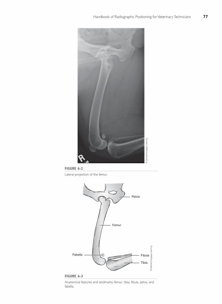
Handbook of Radiographic Positioning for Veterinary Technicians 77
FIGURE 6-2
Lateral projection of the femur.
© D
elm
ar/C
enga
ge L
earn
ing
Pelvis
Fabella
Femur
Fibula
Tibia
FIGURE 6-3
Anatomical features and landmarks: femur, tibia, fibula, pelvis, and
fabella.
© D
elm
ar/C
enga
ge L
earn
ing
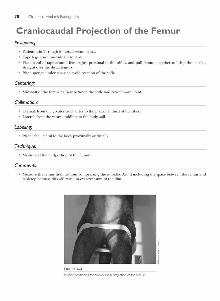
78 Chapter 6: Hindlimb Radiographs
Craniocaudal Projection of the Femur Positioning:
Patient is in V-trough in dorsal recumbency.•Tape legs down individually to table.•Place band of tape around femurs just proximal to the stifles, and pull femurs together to bring the patellas •straight over the distal femurs. Place sponge under tarsus to avoid rotation of the stifle.•
Centering:
Midshaft of the femur halfway between the stifle and coxofemoral joint.•
Collimation:
Cranial: from the greater trochanter to the proximal third of the tibia.•Lateral: from the ventral midline to the body wall.•
Labeling:
Place label lateral to the body proximally or distally.•
Technique:
Measure at the midportion of the femur.•
Comments:
Measure the femur itself without compressing the muscles. Avoid including the space between the femur and •tabletop because this will result in overexposure of the film.
FIGURE 6-4
Proper positioning for craniocaudal projection of the femur.
© D
elm
ar/C
enga
ge L
earn
ing

Handbook of Radiographic Positioning for Veterinary Technicians 79
FIGURE 6-5
Craniocaudal projection of the femur.
© D
elm
ar/C
enga
ge L
earn
ing
FIGURE 6-6
Anatomical features and landmarks: femur, patella, tibia, pelvis, and fabella.
Patella
Pelvis
Fabella
Femur
Tibia
© D
elm
ar/C
enga
ge L
earn
ing

80 Chapter 6: Hindlimb Radiographs
Caudocranial Projection of the Stifle Positioning:
Patient is in V-trough in ventral recumbency.•Pull both hindlimbs behind patient and place band of tape around femurs just proximal to the stifles, and pull •femurs together to bring the patellas straight over the distal femurs. Alternatively, flex the unaffected limb up next to the body if patient is more comfortable.•
Centering:
Center on stifle joint.•
Collimation:
Proximal to the distal third of the femur and distal to proximal third of the tibia.•
Labeling:
Place label lateral to the joint.•
Technique:
Measure at the center of the joint.•
Comments:
It is preferable to angle the x-ray tube head cranially approximately 10–15 degrees to obtain an image through •the stifle joint.The horizontal beam technique may also be useful (Figure 6-8). Place the limb on sponges so that the limb •extends straight from the body. Position the beam, and center on joint as you would in the ventral position.
FIGURE 6-7
Proper positioning for caudocranial projection of the stifle.
© D
elm
ar/C
enga
ge L
earn
ing
FIGURE 6-8
The horizontal beam technique for the caudocranial projection of
the stifle.
© D
elm
ar/C
enga
ge L
earn
ing

Handbook of Radiographic Positioning for Veterinary Technicians 81
FIGURE 6-9
Caudocranial projection of the stifle.
© D
elm
ar/C
enga
ge L
earn
ing
PatellaFabella
Femur
FibulaTibia
FIGURE 6-10
Anatomical features and landmarks: femur, patella, tibia, fibula, and fabella.
© D
elm
ar/C
enga
ge L
earn
ing

82 Chapter 6: Hindlimb Radiographs
Lateral Projection of the Stifle Positioning:
Patient is in lateral recumbency with affected limb down.•Unaffected limb is taped around stifle and tarsus, and pulled up and out of the way.•
Centering:
Center on stifle joint.•
Collimation:
Proximal to the distal third of the femur and distal to proximal third of the tibia.•
Labeling:
Place label cranial to joint.•
Technique:
Measure the center of the joint. Palpate indentation of joint (fat pad) on the dorsal aspect of stifle. Center on •indentation.
Comments:
It is important to include the soft tissues on the caudal aspect of the stifle joint to visualize the fascial stripe that •runs proximally and distally. When this stripe is absent, it is a sign of joint effusion.
FIGURE 6-11
Proper positioning for lateral projection of the stifle.
© D
elm
ar/C
enga
ge L
earn
ing

Handbook of Radiographic Positioning for Veterinary Technicians 83
FIGURE 6-12
Lateral projection of the stifle.
© D
elm
ar/C
enga
ge L
earn
ing
PatellaFabella
Femur
FibulaTibia
FIGURE 6-13
Anatomical features and landmarks: femur, patella, fabella, tibia, and
fibula.
© D
elm
ar/C
enga
ge L
earn
ing

84 Chapter 6: Hindlimb Radiographs
Caudocranial Projection of the Tibia and Fibula
Positioning:
Patient is in V-trough in ventral recumbency.•Pull both hind limbs behind patient and place band of tape around femurs just proximal to the stifles, and pull •femurs together to bring the patellas straight over the distal femurs. Alternatively, flex the unaffected limb up next to the body if patient is more comfortable.•
Centering:
Center on the midshaft of the tibia halfway between the stifle and tarsus.•
Collimation:
From proximal to the distal third of the femur to distal to the proximal third of the tarsus.•
Labeling:
Place label on the lateral side of the tibia.•
Technique:
Measure midshaft of the tibia.•
Comments:
The horizontal beam technique may also be useful (Figure 6-15). Place the limb on sponges so that the limb ex-•tends straight out from the body. Position the beam, and center on joint as would be done in the ventral position.
FIGURE 6-14
Proper positioning for caudocranial projection of the tibia and
fibula.
© D
elm
ar/C
enga
ge L
earn
ing
FIGURE 6-15
The horizontal beam technique for the caudocranial projection of
the tibia and fibula.
© D
elm
ar/C
enga
ge L
earn
ing

Handbook of Radiographic Positioning for Veterinary Technicians 85
FIGURE 6-16
Caudocranial projection of the tibia and fibula.
© D
elm
ar/C
enga
ge L
earn
ing
Patella Fabella
Femur
Fibula
CalcaneousTarsus
Tibia
FIGURE 6-17
Anatomical features and landmarks: femur, patella, fabella, tibia,
fibula, calcaneous, and tarsus.
© D
elm
ar/C
enga
ge L
earn
ing

86 Chapter 6: Hindlimb Radiographs
Lateral Projection of the Tibia Positioning:
Patient is in lateral recumbency with affected limb down.•Unaffected limb is taped around stifle and tarsus, and pulled up and out of the way.•
Centering:
Midshaft of the tibia halfway between the stifle and tarsus.•
Collimation:
From proximal to the distal third of the femur to distal to the proximal third of the tarsus.•
Labeling:
Place label cranial.•
Technique:
Measure midshaft of tibia.•
FIGURE 6-18
Proper positioning for lateral projection of the tibia.
© D
elm
ar/C
enga
ge L
earn
ing

Handbook of Radiographic Positioning for Veterinary Technicians 87
FIGURE 6-19
Lateral projection of the tibia.
© D
elm
ar/C
enga
ge L
earn
ing
Patella Fabella
Femur
Fibula
Tibia
CalcaneousTarsus
FIGURE 6-20
Anatomical features and landmarks: femur, patella, fabella, tibia,
fibula, calcaneous, and tarsus.
© D
elm
ar/C
enga
ge L
earn
ing

88 Chapter 6: Hindlimb Radiographs
Dorsoplantar Projection of the Tarsus Positioning:
Patient is in dorsal recumbency in the V-trough. •Place sponges under tarsus to bring cassette close to the tarsus.•Tape affected tarsus to table.•
Centering:
Center on tarsal joint halfway between the distal tibia and the proximal metatarsals.•
Collimation:
Proximal to the distal third of the tibia and distal to the proximal third of the metatarsals.•
Labeling:
Place label lateral to the joint.•
Technique:
Measure the center of the joint.•
FIGURE 6-21
Proper positioning for dorsoplantar projection of the tarsus.
© D
elm
ar/C
enga
ge L
earn
ing

Handbook of Radiographic Positioning for Veterinary Technicians 89
FIGURE 6-22
Dorsoplantar projection of the tarsus.
© D
elm
ar/C
enga
ge L
earn
ing
Fibula
Tibia
Calcaneous
Tarsus
Metatarsals
FIGURE 6-23
Anatomical features and landmarks: tibia, fibula, calcaneous, tarsus,
and metatarsals.
© D
elm
ar/C
enga
ge L
earn
ing

90 Chapter 6: Hindlimb Radiographs
Lateral Projection of the Tarsus Positioning:
Patient is in lateral recumbency with affected limb down.•Unaffected limb is taped around stifle and tarsus and dorsally.•
Centering:
Center on tarsal joint halfway between the distal tibia and the proximal metatarsals.•
Collimation:
Proximal to the distal third of the tibia and distal to the proximal third of the metatarsals.•
Labeling:
Place label cranial to the joint.•
Technique:
Measure the center of the joint.•
FIGURE 6-24
Proper positioning for lateral projection of the tarsus.
© D
elm
ar/C
enga
ge L
earn
ing

Handbook of Radiographic Positioning for Veterinary Technicians 91
FIGURE 6-25
Lateral projection of the tarsus.
© D
elm
ar/C
enga
ge L
earn
ing
Tibia
Calcaneous
Tarsus
Metatarsus
FIGURE 6-26
Anatomical features and landmarks: tibia, calcaneous, tarsus, and
metatarsus.
© D
elm
ar/C
enga
ge L
earn
ing

92 Chapter 6: Hindlimb Radiographs
Flexed Lateral Projection of the Tarsus Positioning:
Patient is in lateral recumbency with affected limb down.•Unaffected limb is taped around stifle and tarsus dorsally.•Tape around caudal tibia and proximal metatarsus to achieve full flexion of the tarsus.•
Centering:
Center on tarsal joint between the stifle and metatarsals.•
Collimation:
From the distal portion of the tibia to the proximal portion of the metatarsals.•
Labeling:
Place label cranial to the joint.•
Technique:
Measure to the center of the joint.•
FIGURE 6-27
Proper positioning for flexed lateral projection of the tarsus.
© D
elm
ar/C
enga
ge L
earn
ing

Handbook of Radiographic Positioning for Veterinary Technicians 93
FIGURE 6-28
Flexed lateral projection of the tarsus.
© D
elm
ar/C
enga
ge L
earn
ing
Fibula
Calcaneous
Tarsus
Metatarsus
FIGURE 6-29
Anatomical features and landmarks: fibula, calcaneous, tarsus, and
metatarsus.
© D
elm
ar/C
enga
ge L
earn
ing

94 Chapter 6: Hindlimb Radiographs
Extended Lateral Projection of the Tarsus Positioning:
Patient is in lateral recumbency with affected limb down.•Unaffected limb is taped around stifle and tarsus, and pulled dorsally.•Pull affected limb straight out away from body for full extension.•
Centering:
Center on tarsal joint between the stifle and metatarsals.•
Collimation:
From the distal portion of the tibia to the proximal portion of the metatarsals.•
Labeling:
Place label cranial to the joint.•
Technique:
Measure the center of the joint.•
FIGURE 6-30
Proper positioning for extended lateral projection of the tarsus.
© D
elm
ar/C
enga
ge L
earn
ing

Handbook of Radiographic Positioning for Veterinary Technicians 95
FIGURE 6-31
Extended lateral projection of the tarsus.
© D
elm
ar/C
enga
ge L
earn
ing
Tibia
Calcaneous
Tarsus
Metatarsus
FIGURE 6-32
Anatomical features and landmarks: tibia, calcaneous, tarsus, and
metatarsus.
© D
elm
ar/C
enga
ge L
earn
ing

96 Chapter 6: Hindlimb Radiographs
Dorsolateral/Plantaromedial Oblique Projection of the Tarsus
Positioning:
Patient is in dorsal recumbency in the V-trough. •Place sponges under tarsus to bring cassette close to the tarsus.•Tape affected tarsus to table.•Tilt patient from you approximately 15–20 degrees to achieve an oblique angle of the tarsus with the medial •side facing the tube.
Centering:
Center on tarsal joint.•
Collimation:
From the distal portion of the tibia to the proximal portion of the metatarsals.•
Labeling:
Place label lateral to the joint.•
Technique:
Measure at center of tarsal joint.•
Comments:
If x-ray machine is capable, use standard dorsoplantar position, and angle the x-ray head 15–20 degrees toward •the medial side of the tarsus.
FIGURE 6-33
Proper positioning for dorsolateral/plantaromedial oblique
projection of the tarsus.
© D
elm
ar/C
enga
ge L
earn
ing

Handbook of Radiographic Positioning for Veterinary Technicians 97
Fibula
Tibia
Calcaneous
Tarsus
Metatarsus
FIGURE 6-35
Anatomical features and landmarks: tibia, fibula, calcaneous, tarsus,
and metatarsus.
© D
elm
ar/C
enga
ge L
earn
ing
FIGURE 6-34
Dorsolateral/plantaromedial oblique projection of the tarsus.
© D
elm
ar/C
enga
ge L
earn
ing

98 Chapter 6: Hindlimb Radiographs
Dorsomedial/Plantarolateral ObliqueProjection of the Tarsus
Positioning:
Patient is in dorsal recumbency in the V-trough. •Place sponges under tarsus to bring cassette close to the tarsus.•Tape affected tarsus to table.•Tilt patient approximately 15–20 degrees to achieve an oblique angle of the tarsus with the lateral side facing •the tube.
Centering:
Center on tarsal joint.•
Collimation:
From the distal portion of the tibia to the proximal portion of the metatarsals.•
Labeling:
Place label lateral to the joint.•
Technique:
Measure at center of tarsal joint.•
Comments:
If x-ray machine is capable, use standard dorsoplantar position, and angle the x-ray head 15–20 degrees toward •the lateral side of the tarsus.
FIGURE 6-36
Proper positioning for dorsomedial/plantarolateral oblique projection
of the tarsus.
© D
elm
ar/C
enga
ge L
earn
ing

Handbook of Radiographic Positioning for Veterinary Technicians 99
FIGURE 6-37
Dorsomedial/plantarolateral oblique projection of the tarsus.
© D
elm
ar/C
enga
ge L
earn
ing
Tibia
Calcaneous
Tarsus
Metatarsus
FIGURE 6-38
Anatomical features and landmarks: tibia, calcaneous, tarsus, and
metatarsus.
© D
elm
ar/C
enga
ge L
earn
ing

100 Chapter 6: Hindlimb Radiographs
Dorsoplantar Projection of the MetatarsusPositioning:
Patient is in dorsal recumbency in the V-trough. •Place sponges under metatarsus to bring cassette close to the metatarsus.•Tape affected metatarsus to table.•
Centering:
Center on the metatarsal joint.•
Collimation:
From the distal portion of the tarsus to the proximal portion of the phalanges. Collimation through the distal •phalanges is also acceptable.
Labeling:
Place label lateral to the joint.•
Technique:
Measure the center of the joint.•
FIGURE 6-39
Proper positioning for dorsoplantar projection of the metatarsus.
© D
elm
ar/C
enga
ge L
earn
ing

Handbook of Radiographic Positioning for Veterinary Technicians 101
FIGURE 6-40
Dorsoplantar projection of the metatarsus.
© D
elm
ar/C
enga
ge L
earn
ing
Calcaneous
Tarsus
Sesamoids
Metatarsus
FIGURE 6-41
Anatomical features and landmarks: calcaneous, tarsus, metatarsus,
and sesamoids.
© D
elm
ar/C
enga
ge L
earn
ing

102 Chapter 6: Hindlimb Radiographs
Lateral Projection of the Metatarsus Positioning:
Patient is in lateral recumbency with affected limb down.•Unaffected limb is taped around stifle and tarsus, and pulled up and out of the way.•
Centering:
Center on metatarsal joint.•
Collimation:
From the distal portion of the tarsus to the proximal portion of the phalanges.•
Labeling:
Place label cranial to the joint.•
Technique:
Measure the center of the joint.•
FIGURE 6-42
Proper positioning for lateral projection of the metatarsus.
© D
elm
ar/C
enga
ge L
earn
ing

Handbook of Radiographic Positioning for Veterinary Technicians 103
FIGURE 6-43
Lateral projection of the metatarsus. ©
Del
mar
/Cen
gage
Lea
rnin
g
Tibia
Calcaneous
Tarsus
Metatarsus
Sesamoid
FIGURE 6-44
Anatomical features and landmarks: tibia, calcaneous, tarsus,
metatarsus, and sesamoid.
© D
elm
ar/C
enga
ge L
earn
ing

104 Chapter 6: Hindlimb Radiographs
Dorsopalmar Projection of the DigitsPositioning:
Patient is in dorsal recumbency.•Hindlimbs are pulled caudally individually.•Individually tape the medial toe (digit 2) and lateral toe (digit 5), and pull opposite of each other to spread the •toes. Alternatively place cotton balls between each toe.V-trough can help stabilize cranial half of body.•
Centering:
Center just above digits.•
Collimation:
Include metatarsus through the distal end of the digits.•
Labeling:
Lateral to digits.•
Technique:
Measure midway between metatarsus and digits.•
Comments:
Taping the digits open provides better visualization of the individual bones. If the patient does not have a • toenail or it is very short, tape around the digit itself. Typically, the metatarsus and digits are radiographed in a single view.•The horizontal beam technique may also be useful.•
FIGURE 6-45
Proper positioning for dorsopalmar projection of the digits.
© D
elm
ar/C
enga
ge L
earn
ing

Handbook of Radiographic Positioning for Veterinary Technicians 105
FIGURE 6-46
Dorsopalmar projection of the digits.
© D
elm
ar/C
enga
ge L
earn
ing
Metatarsus
Distal Phalanges
Phalanx 1 of digit V
Phalanx 1 of digit IV
Phalanx 2 of digit V
Phalanx 2 of digit IV
Phalanx 2 of digit II
Phalanx 1 of digit II
Phalanx 1 of digit III
Phalanx 2 of digit III
FIGURE 6-47
Anatomical features and landmarks: metatarsus, phalanx 1 of digit V, phalanx 1 of
digit IV, phalanx 1 of digit III, phalanx 1 of digit II, phalanx 2 of digit V, phalanx 2 of
digit IV, phalanx 2 of digit III, phalanx 2 of digit II, and distal phalanges.
© D
elm
ar/C
enga
ge L
earn
ing
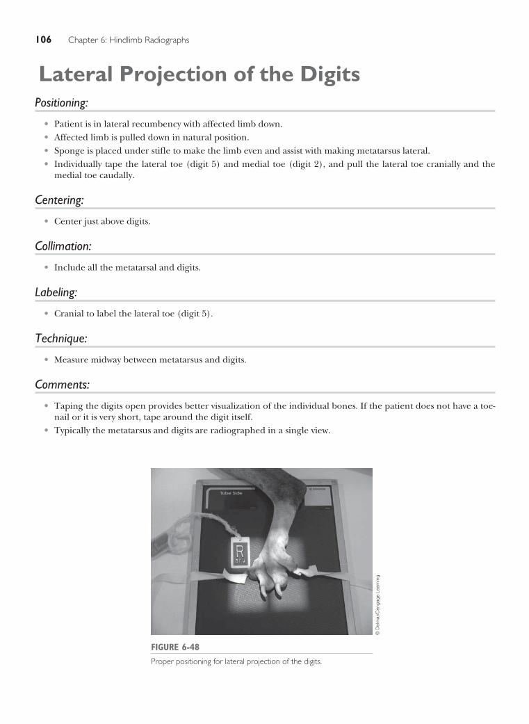
106 Chapter 6: Hindlimb Radiographs
Lateral Projection of the Digits Positioning:
Patient is in lateral recumbency with affected limb down.•Affected limb is pulled down in natural position.•Sponge is placed under stifle to make the limb even and assist with making metatarsus lateral.•Individually tape the lateral toe (digit 5) and medial toe (digit 2), and pull the lateral toe cranially and the •medial toe caudally.
Centering:
Center just above digits.•
Collimation:
Include all the metatarsal and digits.•
Labeling:
Cranial to label the lateral toe (digit 5).•
Technique:
Measure midway between metatarsus and digits.•
Comments:
Taping the digits open provides better visualization of the individual bones. If the patient does not have a toe-•nail or it is very short, tape around the digit itself. Typically the metatarsus and digits are radiographed in a single view.•
FIGURE 6-48
Proper positioning for lateral projection of the digits.
© D
elm
ar/C
enga
ge L
earn
ing

Handbook of Radiographic Positioning for Veterinary Technicians 107
FIGURE 6-49
Lateral projection of the digits.
© D
elm
ar/C
enga
ge L
earn
ing
Digit I
Metatarsus
Phalanx 1 of digit II
Phalanx 1 of digit III
Phalanx 2 of digit II
Phalanx 2 ofdigit III
Phalanx 1 of digit IV
Phalanx 1 of digit V
Phalanx 2 of digit V
Phalanx 2 of digit IV
Distal Phalanges
Distal Phalange
Distal Phalange
FIGURE 6-50
Anatomical features and landmarks: metatarsus, phalanx 1 of digit II, phalanx 1 of
digit III, phalanx 1 of digit IV, phalanx 1 of digit V, digit I, phalanx 2 of digit II,
phalanx 2 of digit III, phalanx 2 of digit IV, phalanx 2 of digit V, and distal phalanges.
© D
elm
ar/C
enga
ge L
earn
ing

This page intentionally left blank

109
OVERVIEW
Indications for examination of skull radiographs include evaluation of the tympanic bullae, nasal sinuses, and
foramen magnum, as well as evaluation to detect bone lesions. The patient must be positioned precisely
because evaluation often focuses on symmetry between the two sides of the skull. Nearly all patients
require general anesthesia for proper positioning. The endotracheal tube may need to be removed or
repositioned before obtaining the exposure depending on the purpose of the radiograph.
For most small animals, the skull is approximately the same width both laterally and dorsoventrally.
Most skull radiographs use a single measurement representing the widest area of the cranium.
Measurements for radiographs of the nasal passages are taken at a point slightly rostral to the widest area
of the cranium to avoid overexposing the air-fi lled sinuses.
For most routine radiographic studies of the skull, a lateral projection and either a ventrodorsal (VD) or
dorsoventral (DV) view are obtained. For evaluation of the tympanic bullae, a DV view, right and left lateral
oblique views, and an open mouth view are obtained. Evaluation of the nasal passages commonly requires a
lateral view, either a DV or VD view, a frontal (rostrocaudal) view, and an open mouth view. Commonly used
projections for evaluation of the temporomandibular joint include right and left lateral oblique views and a DV
view. Although the entire skull may be included for most views, to enhance detail, the radiograph should be
tightly collimated to the primary area of interest to reduce scatter radiation and provide a higher quality image.
The following pages illustrate the proper positioning and technique for skull radiographs.
CHAPTER 7SKULL RADIOGRAPHS

110 Chapter 7: Skull Radiographs
Lateral Projection of the Skull Positioning:
Right or left lateral recumbency with the affected side toward the cassette.•Foam pads placed under the mandible to maintain the sagittal plane of the skull in a position parallel to the •x-ray cassette.
Centering:
Lateral canthus of the eye socket.•
Collimation:
Occipital protuberance to the tip of the nose.•Dorsal right and ventral skull fully within collimated area.•
Labeling:
Mark the side against the x-ray cassette as either left or right.•
Technique:
Measure at the widest point of the cranium.•
Comments:
The rami of the mandible and tympanic bullae are superimposed on the finished radiograph. If nontrauma-•tized and present, the eyes and canine teeth can be a useful landmark in assisting with the lateral projection. Position the skull so that the eyes or canine teeth are even and parallel with the cassette.
FIGURE 7-1
Proper positioning for lateral projection of the skull.
© D
elm
ar/C
enga
ge L
earn
ing

Handbook of Radiographic Positioning for Veterinary Technicians 111
FIGURE 7-2
Lateral projection of the skull.
© D
elm
ar/C
enga
ge L
earn
ing
Maxilla
Cervical vertebra I
Tympanicbulla
Parietal bone
Frontal sinus
Mandible
MandibleTemporal bone
Zygomatic arch
FIGURE 7-3
Anatomical features and landmarks: tympanic bulla, temporal bone, mandible,
zygomatic arch, parietal bone, frontal sinus, maxilla, and cervical vertebra I.
© D
elm
ar/C
enga
ge L
earn
ing

112 Chapter 7: Skull Radiographs
DV Projection of the SkullPositioning:
Sternal recumbency.•Sandbag placed across the cervical region to maintain placement of the head against the x-ray cassette.•Tape can be used across the maxilla to maintain vertical alignment of the head on the x-ray cassette.•
Centering:
Midway between the tip of the nose to just caudal to the occipital protuberance at the base.•
Collimation:
Occipital protuberance to the tip of the nose.•Zygomatic arches fully within collimated area.•
Labeling:
Mark either left or right dependent side, or both.•
Technique:
Measure at the widest point of the cranium just caudal to the orbit.•
FIGURE 7-4
Proper positioning for DV projection of the skull.
© D
elm
ar/C
enga
ge L
earn
ing

Handbook of Radiographic Positioning for Veterinary Technicians 113
FIGURE 7-5
DV projection of the skull. ©
Del
mar
/Cen
gage
Lea
rnin
g
FIGURE 7-6
Anatomical features and landmarks: tympanic bulla, zygomatic arch, mandible,
and nasal septum.
Nasal septum
Mandible
Zygomatic arch
Tympanic bullaTympanic bulla
Zygomatic arch
Mandible
© D
elm
ar/C
enga
ge L
earn
ing

114 Chapter 7: Skull Radiographs
VD Projection of the Skull Positioning:
Dorsal recumbency. •Foam pad or sandbag is positioned under neck to maintain hard palate in parallel alignment with x-ray • cassette.A V-trough can be used to aid in maintaining vertical alignment.•Forelimbs are secured caudally.•Foam pad under head or tape across mandibles to avoid rotation of head.•
Centering:
Midway between the tip of the nose to just caudal to the occipital protuberance at the base.•
Collimation:
Occipital protuberance to the tip of the nose.•Zygomatic arches fully within collimated area.•
Labeling:
Mark either left or right dependent side, or both.•
Technique:
Measure at the widest point of the cranium just caudal to the orbit.•
Comments:
This view should be included in a nasal series because the nasal passages are on the dorsal portion of the skull •and closest to the cassette.
FIGURE 7-7
Proper positioning for VD projection of the skull.
© D
elm
ar/C
enga
ge L
earn
ing

Handbook of Radiographic Positioning for Veterinary Technicians 115
Nasal septum
Mandible
Tympanic bulla
Zygomatic archZygomatic arch
Tympanic bulla
Mandible
FIGURE 7-9
Anatomical features and landmarks: tympanic bulla, zygomatic arch, mandible,
and nasal septum.
© D
elm
ar/C
enga
ge L
earn
ing
FIGURE 7-8
VD projection of the skull. ©
Del
mar
/Cen
gage
Lea
rnin
g

116 Chapter 7: Skull Radiographs
Rostrocaudal Sinuses Closed Mouth Projection Positioning:
Dorsal recumbency. •Foam pad or sandbag is positioned under neck.•A V-trough can be used to aid in maintaining vertical alignment.•Forelimbs are secured caudally.•Tape or gauze to direct nose caudally to maintain hard palate perpendicular to the x-ray cassette and parallel •to the x-ray beam.
Centering:
Between the eyes.•
Collimation:
Include all of occipital crest to dorsal aspect of the nasal planum.•Zygomatic arches fully within collimated area.•
Labeling:
Mark either left or right dependent side, or both.•
Technique:
Measure midpoint at the level of the eyes.•
Comments:
This view is commonly referred to as the “skyline” view.•
FIGURE 7-10
Proper positioning for rostrocaudal sinuses closed mouth projection.
© D
elm
ar/C
enga
ge L
earn
ing

Handbook of Radiographic Positioning for Veterinary Technicians 117
FIGURE 7-12
Anatomical features and landmarks: turbinates, frontal sinuses, and zygomatic bone.
Turbinates
Frontal sinuses
Zygomaticbone
Zygomaticbone
© D
elm
ar/C
enga
ge L
earn
ing
FIGURE 7-11
Rostrocaudal sinuses closed mouth projection.
© D
elm
ar/C
enga
ge L
earn
ing

118 Chapter 7: Skull Radiographs
Rostrocaudal Foramen Magnum Projection Positioning:
Dorsal recumbency. •Foam pad or sandbag is positioned under neck.•A V-trough can be used to aid in maintaining vertical alignment.•Forelimbs are secured caudally.•Tape or gauze to direct nose caudally approximately 30 degrees with the mandible close to the chest.•
Centering:
Between the eyes.•
Collimation:
Include all of occipital crest to tympanic bullae.•Zygomatic arches fully within collimated area.•
Labeling:
Mark either left or right dependent side, or both.•
Technique:
Measure midpoint at the level of the eyes.•
Comments:
This view is also referred to as the “keyhole” or “town-crown” view.•
FIGURE 7-13
Proper positioning for rostrocaudal foramen magnum projection.
© D
elm
ar/C
enga
ge L
earn
ing

Handbook of Radiographic Positioning for Veterinary Technicians 119
Tympanic bulla
Foramen magnum
Lateral frontal sinus
Tympanic bulla
Zygomaticbone
Zygomaticbone
FIGURE 7-15
Anatomical features and landmarks: tympanic bulla, foramen magnum, zygomatic bone, and lateral frontal sinus.
© D
elm
ar/C
enga
ge L
earn
ing
FIGURE 7-14
Rostrocaudal foramen magnum projection.
© D
elm
ar/C
enga
ge L
earn
ing

120 Chapter 7: Skull Radiographs
VD Rostrocaudal Nasal Open MouthProjection
Positioning:
Dorsal recumbency.•With the skull placed outside, place caudal portion •of patient in V-trough to aid in keeping the skull and body straight.Position head so that the hard palate is in parallel •alignment with x-ray cassette, tape across maxillary canines, and secure to the sides of the table. Place tape across or behind mandibular canines, •and pull mandible along with the tongue and en-dotracheal tube to open the mouth. Secure tape to the sides of the V-trough.Pull forelimbs and secure caudally.•
Centering:
Tilt tube head caudally approximately 15 degrees, •centering on the back of the palate. If using the cassette/Bucky tray, line up tray and •collimator light to account for the tilt.
Collimation:
Horizontally inside the zygomatic arches, and ver-•tically from the tip of the maxilla to the back of the palate, beyond where the mandible will super-impose over it.
R
FIGURE 7-16
Proper positioning for VD rostrocaudal nasal open mouth projection.
© D
elm
ar/C
enga
ge L
earn
ing
Labeling:
Mark either left or right dependent side, or both.•
Technique:
Measure at the thickest area near the commissure •of the lip. Angling the beam may not be necessary in feline •patients, or the x-ray beam may be directed at a 5–10 degree angle.

Handbook of Radiographic Positioning for Veterinary Technicians 121
FIGURE 7-17
VD rostrocaudal nasal open mouth projection
© D
elm
ar/C
enga
ge L
earn
ing
Nasal andmaxillary turbinates
Nasal andmaxillary turbinates
Coronoid processof mandible
Coronoid processof mandible
Nasal septum
Zygomatic boneZygomatic bone
FIGURE 7-18
Anatomical features and landmarks: nasal and maxillary turbinates, zygomatic
bone, nasal septum, and coronoid process of mandible.
© D
elm
ar/C
enga
ge L
earn
ing

122 Chapter 7: Skull Radiographs
Rostrocaudal Tympanic Bullae Open Mouth Projection
Positioning:
Dorsal recumbency. •Foam pad or sandbag is positioned under neck.•A V-trough can be used to aid in maintaining verti-•cal alignment.Forelimbs are secured caudally.•Tape or gauze around maxilla to pull nose approxi-•mately 10 degrees cranially.Tape or gauze around mandible to pull mandible •approximately 10 degrees caudally.
Centering:
Beam is centered just above the base of the tongue •and just below the soft palate approximately at the commissure of the mouth.
Collimation:
Zygomatic arches fully within collimated area with •enough lateral to include the marker.
Labeling:
Mark either left or right dependent side, or both.•
Technique:
Measure at the commissure of the mouth.•
Comments:
A plastic-mouth speculum may also be used to main-•tain the open mouth position, taking care not to allow the weight of the speculum to rotate the head.A 1 mL syringe barrel with the plunger removed •works well if you do not have a speculum. Cut both ends of the barrel (nail trimmers work well for this), and place open ends on the upper and lower canine teeth. Length can be modified accordingly.The rostrocaudal projection in cats can also be •taken with the mouth closed and the skull tippedcranially approximately 10 degrees (Figures 7-20, 7-23,and 7-24). This is due to the fact that cat bullae are ana-tomically farther caudal on the skull than dog bullae.
FIGURE 7-19
Proper positioning for rostrocaudal tympanic bullae open mouth
projection.
© D
elm
ar/C
enga
ge L
earn
ing
FIGURE 7-20
Proper positioning for rostrocaudal projection in cats.
© D
elm
ar/C
enga
ge L
earn
ing

Handbook of Radiographic Positioning for Veterinary Technicians 123
FIGURE 7-21
Rostrocaudal tympanic bullae open mouth projection.
© D
elm
ar/C
enga
ge L
earn
ing
Tympanic bullaTympanic bulla
Zygomatic bone Zygomatic bone
Coronoid process
of the mandible
Coronoid process
of the mandible
Foramen
magnum
FIGURE 7-22
Anatomical features and landmarks: tympanic bulla, foramen magnum, coronoid process of the
mandible, and zygomatic bone.
© D
elm
ar/C
enga
ge L
earn
ing

124 Chapter 7: Skull Radiographs
FIGURE 7-23
Rostrocaudal projection in cats.
© D
elm
ar/C
enga
ge L
earn
ing
FIGURE 7-24
Anatomical features and landmarks: tympanic bulla, atlas (C1) cervical vertebra I, and
axis (C2) cervical vertebra II.
© D
elm
ar/C
enga
ge L
earn
ing
Tympanic bullaTympanic bulla
Atlas (C1) cervical vertebra I
Axis (C2) cervical vertebra II

This page intentionally left blank

126 Chapter 7: Skull Radiographs
DV Tympanic Bullae ProjectionPositioning:
Sternal recumbency.•Sandbag is placed across the cervical region to maintain placement of the head against the x-ray cassette.•Tape can be used across the maxilla to maintain vertical alignment of the head on the x-ray cassette.•
Centering:
Palpate the base of the ear to determine placement on the skull. Center the beam on the dorsal midline of the •skull between the ears.
Collimation:
Palpate the ear, and collimate just cranial and caudal to the ear.•Right and left side of skull is fully within collimated area.•
Labeling:
Mark either left or right dependent side, or both.•
Technique:
Measure at the widest point of the cranium just caudal to the orbit and over the bullae.•
Comments:
DV position is preferred due to the bullae being closer to the cassette.•
FIGURE 7-25
Proper positioning for DV tympanic bullae projection.
© D
elm
ar/C
enga
ge L
earn
ing

Handbook of Radiographic Positioning for Veterinary Technicians 127
Zygomatic bone
Coronoid process
of mandible
Tympanic bulla
Atlas-cervical vertebra I
Zygomatic bone
Coronoid process
of mandible
Tympanic bulla
Atlas-cervical vertebra I
Axis-cervical vertebra II
FIGURE 7-27
Anatomical features and landmarks: tympanic bulla, zygomatic bone, coronoid process of mandible,
atlas-cervical vertebra I, and axis-cervical vertebra II.
© D
elm
ar/C
enga
ge L
earn
ing
FIGURE 7-26
DV tympanic bullae projection.
© D
elm
ar/C
enga
ge L
earn
ing

128 Chapter 7: Skull Radiographs
Comments:
The projection should have the dependent bulla •isolated and not superimposed over the skull.This oblique projection can also be used to obtain •images of the mandible or maxilla by collimating to include the entire mandible or maxilla. Both right and left lateral oblique views are required.
Lateral Oblique Tympanic Bullae Projection
Positioning:
Place patient in lateral recumbency. •Right lateral recumbency for left oblique bulla.•
Left lateral recumbency for the right bulla. •
From the lateral position, allow the skull to oblique •itself naturally down toward the table approximately 30–40 degrees. This projects the down bulla and keeps it from being superimposed over the skull.
Centering:
Palpate and center over the ear to include both •dorsal and ventral skull.
Collimation:
Slightly cranial and caudal to the ear.•
Labeling:
Label the projected bulla. •The patient in right lateral recumbency will have •the right marker dorsal and the left marker ventral. The patient in left lateral recumbency will have the left marker dorsal and the right marker ventral.
Technique:
Measure at the widest point of the cranium just •caudal to the orbit and over the bullae.
FIGURE 7-28
Proper positioning for lateral oblique tympanic bullae projection.
© D
elm
ar/C
enga
ge L
earn
ing

Handbook of Radiographic Positioning for Veterinary Technicians 129
FIGURE 7-29
Lateral oblique tympanic bullae projection.
© D
elm
ar/C
enga
ge L
earn
ing
Mandible
Tympanic bullae
Tympanic bullae
Atlas C1
Axis C2
FIGURE 7-30
Anatomical features and landmarks: tympanic bulla, atlas-cervical vertebra,
and mandible.
© D
elm
ar/C
enga
ge L
earn
ing

130 Chapter 7: Skull Radiographs
Lateral Oblique Temporomandibular Joint Projection
Positioning:
Place patient in lateral recumbency; normally, both •right and left lateral oblique views are obtained from each patient.
Right lateral recumbency for the right temporo-•
mandibular joint.Left lateral recumbency for the left temporo-•
mandibular joint.From the lateral position, allow the skull to oblique •itself naturally down toward the table approxi mately10 degrees. This projects the temporomandibular joint down and keeps it from being superimposed over the skull.Place a small sponge to lift the rostral part of the •skull (at the nose) up approximately 10 degrees project the temporomandibular joint rostral and keep it from being superimposed over the skull.
Centering:
The beam is centered just cranial to the ear or •bulla.
Collimation:
Collimate just cranial and caudal to the joint.•
Labeling:
Label the dependent temporomandibular joint.•
Technique:
Measure just caudal to the orbit in front of the ear •over the joint.
Comments:
When evaluating for potential luxation, an open •mouth oblique view of each temporomandibular joint might be required.
FIGURE 7-31
Proper positioning for lateral oblique temporomandibular joint
projection.
© D
elm
ar/C
enga
ge L
earn
ing

Handbook of Radiographic Positioning for Veterinary Technicians 131
FIGURE 7-32
Lateral oblique temporomandibular joint projection.
© D
elm
ar/C
enga
ge L
earn
ing
FIGURE 7-33
Anatomical features and landmarks: temporomandibular joint,
tympanic bulla, and mandible.
© D
elm
ar/C
enga
ge L
earn
ing
Tympanic bullae
TMJ Temporomandibular joint
Mandible

132 Chapter 7: Skull Radiographs
DV Temporomandibular Joint Projection Positioning:
Sternal recumbency.•Sandbag is placed across the cervical region to maintain placement of the head against the x-ray cassette.•Tape can be used across the maxilla to maintain vertical alignment of the head on the x-ray cassette.•
Centering:
Palpate the base of the ear to determine placement just rostral on the skull. Center the beam on the dorsal •midline of the skull just rostral to the bullae or ears.
Collimation:
Collimate just cranial and caudal to the joint.•Right and left side of skull fully within collimated area.•
Labeling:
Mark either left or right dependent side, or both.•
Technique:
Measure at the widest point of the cranium just caudal to the orbit and over the joint.•
Comments:
DV is preferred because the temporomandibular joint is located on the ventral portion of the skull and closer •to the cassette.
FIGURE 7-34
Proper positioning for DV temporomandibular joint projection.
© D
elm
ar/C
enga
ge L
earn
ing

Handbook of Radiographic Positioning for Veterinary Technicians 133
Zygomatic arch
Articular process of mandibular ramus
Tympanic bullae
Zygomatic arch
Articular process of mandibular ramus
Left temporo- mandibular joint
Right temporo- mandibular joint
Tympanic bullae
Coronoid process of mandible
FIGURE 7-36
Anatomical features and landmarks: tympanic bulla, zygomatic arch, articular process of mandibular
ramus, and coronoid process of mandible.
© D
elm
ar/C
enga
ge L
earn
ing
FIGURE 7-35
DV temporomandibular joint projection.
© D
elm
ar/C
enga
ge L
earn
ing

This page intentionally left blank

135
CHAPTER 8DENTAL RADIOGRAPHS
OVERVIEW
Proper evaluation of the teeth requires specifi c positioning techniques to obtain an accurate and
suffi ciently detailed view of the teeth. Skull radiographs are not of suffi cient detail to be diagnostic
when evaluating oral pathology. Although standard x-ray machines can be used to position
patients for dental radiology, exposures can be most easily accomplished with a radiology unit
specifi c for dentistry.
Because the palate of dogs and cats is not arched as it is in humans, a bisecting angle technique
is used to position the head of the x-ray unit to create an exact image of the tooth on the fi lm.
Because the roots are embedded in the maxillary bone, if the fi lm was parallel to the tooth in the
maxillary arcade, the image of the roots would not be on the fi lm because the palate would get in
the way. To aid in understanding the bisecting angle technique, imagine a person standing in a fl at
desert with nothing around. The sun (beam) is directly over the individual’s head. A shadow (image)
would be a very undistinguishable blob on the ground (fi lm). It would not reveal any important
information as to the shape and size of the individual. Alternatively, if the sun (beam) sat just above
the horizon, the shadow would be 30 feet long, and still would not give any accurate information as
to shape and size of the individual. If the sun was positioned exactly halfway between its location at
high noon and just before sunset, the shadow behind the individual would be as tall as the individual

136 Chapter 8: Dental Radiographs
and would represent accurate details about the
individual’s image. At this exact point, the sun is creating
a beam that is hitting the bisecting angle perpendicularly.
Intraoral fi lm is positioned so that the vertical
axis of the tooth and the horizontal axis of the fi lm
create an angle. Bisect that angle or cut that angle in
half with an imaginary line. The x-ray beam is then
placed exactly perpendicular to that bisecting plane. If
the angle of the tube is too steep, the image will be
foreshortened. If the angle of the tube is too shallow,
the image will be too elongated.
The following pages illustrate the proper positioning
for dental radiographs. Note that there are slight
differences in the views taken for dogs and cats, so
each species is described separately. Also note that
collimation for intraoral x-ray units is automatic, and
fi lm identifi cation labels are always placed on the dimple
convex side of the fi lm toward the x-ray tube so each
required position contains descriptive information for
the patient positioning and centering of the x-ray beam.

Handbook of Radiographic Positioning for Veterinary Technicians 137
FIGURE 8-1
Proper positioning for canine upper incisor arcade. ©
Del
mar
/Cen
gage
Lea
rnin
g
FIGURE 8-2
Canine upper incisor arcade.
© D
elm
ar/C
enga
ge L
earn
ing
Canine Upper Incisor Arcade
Positioning:
Lateral or dorsal recumbency.•
Centering:
Center image so that two middle incisors are equi-•distant from edge of image and visualize at least 3 mm periapical bone.

138 Chapter 8: Dental Radiographs
Canine Upper Canine Tooth
Positioning:
Lateral or dorsal recumbency.•
Centering:
Apex of tooth visible with at least 3 mm periapical •bone.
FIGURE 8-3
Proper positioning for canine upper canine tooth.©
Del
mar
/Cen
gage
Lea
rnin
g
FIGURE 8-4
Canine upper canine tooth.
© D
elm
ar/C
enga
ge L
earn
ing

Handbook of Radiographic Positioning for Veterinary Technicians 139
Canine Upper Premolars
Positioning:
Lateral or dorsal recumbency.•
Centering:
Apex of teeth visible with at least 3 mm periapical •bone.
FIGURE 8-6
Canine upper premolars.
© D
elm
ar/C
enga
ge L
earn
ing
FIGURE 8-5
Proper positioning for canine upper premolars.
© D
elm
ar/C
enga
ge L
earn
ing

140 Chapter 8: Dental Radiographs
Canine Upper Fourth Premolars and Molars
Positioning:
Lateral or dorsal recumbency.•
Centering:
Apex of teeth visible with at least 3 mm periapical •bone.Swing tube head rostrally or distally to separate •superimposed mesial buccal and palatal roots of fourth premolar.
FIGURE 8-8
Canine upper fourth premolars and molars.
© D
elm
ar/C
enga
ge L
earn
ing
FIGURE 8-7
Proper positioning for canine upper fourth premolars and molars.
© D
elm
ar/C
enga
ge L
earn
ing

Handbook of Radiographic Positioning for Veterinary Technicians 141
Canine LowerIncisor Arcade
Positioning:
Lateral or dorsal recumbency.•
Centering:
Center image so that two middle incisors are equi-•distant from edge of image and visualize at least 3 mm periapical bone.
FIGURE 8-9
Proper positioning for canine lower incisor arcade.©
Del
mar
/Cen
gage
Lea
rnin
g
FIGURE 8-10
Canine lower incisor arcade.
© D
elm
ar/C
enga
ge L
earn
ing

142 Chapter 8: Dental Radiographs
Canine Lower Canine Tooth and Lower Premolar Arcade
Positioning:
Lateral or dorsal recumbency.•
Centering:
Apex of tooth visible with at least 3 mm periapical •bone.
Comments:
View may be taken with bisecting angle or parallel •technique.
FIGURE 8-12
Canine lower canine tooth and lower premolar arcade.
© D
elm
ar/C
enga
ge L
earn
ing
FIGURE 8-11
Proper positioning for canine lower canine tooth and lower premo-
lar arcade.
© D
elm
ar/C
enga
ge L
earn
ing

Handbook of Radiographic Positioning for Veterinary Technicians 143
Canine Lower Premolar Arcade
Positioning:
Lateral or dorsal recumbency.•
Centering:
Apex of teeth visible with at least 3 mm periapical •bone.
Comments:
View is to be taken using parallel technique.•
FIGURE 8-14
Canine lower premolar arcade.
© D
elm
ar/C
enga
ge L
earn
ing
FIGURE 8-13
Proper positioning for canine lower premolar arcade.
© D
elm
ar/C
enga
ge L
earn
ing
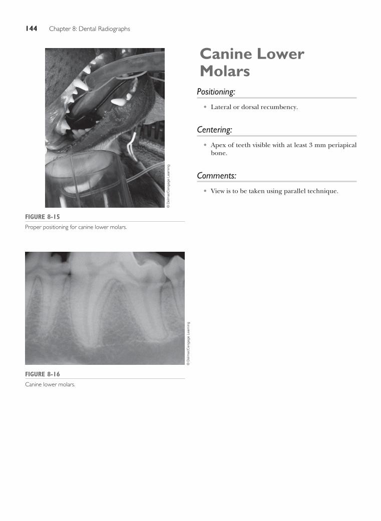
144 Chapter 8: Dental Radiographs
Canine Lower Molars
Positioning:
Lateral or dorsal recumbency.•
Centering:
Apex of teeth visible with at least 3 mm periapical •bone.
Comments:
View is to be taken using parallel technique.•
FIGURE 8-15
Proper positioning for canine lower molars.
© D
elm
ar/C
enga
ge L
earn
ing
FIGURE 8-16
Canine lower molars.
© D
elm
ar/C
enga
ge L
earn
ing

Handbook of Radiographic Positioning for Veterinary Technicians 145
Feline Upper Incisor Arcade
Positioning:
Lateral or dorsal recumbency.•
Centering:
Center image so that two middle incisors are equi-•distant from edge of image and visualize at least 3 mm periapical bone.
FIGURE 8-17
Proper positioning for feline upper incisor arcade.©
Del
mar
/Cen
gage
Lea
rnin
g
FIGURE 8-18
Feline upper incisor arcade.
© D
elm
ar/C
enga
ge L
earn
ing

146 Chapter 8: Dental Radiographs
Feline Upper Canine Tooth
Positioning:
Lateral or dorsal recumbency.•
Centering:
Apex of tooth visible with at least 3 mm periapical •bone.
FIGURE 8-19
Proper positioning for feline upper canine tooth.
© D
elm
ar/C
enga
ge L
earn
ing
FIGURE 8-20
Feline upper canine tooth.
© D
elm
ar/C
enga
ge L
earn
ing

Handbook of Radiographic Positioning for Veterinary Technicians 147
Feline Upper Premolars and Molar
Positioning:
Lateral or dorsal recumbency.•
Centering:
Apex of teeth visible with at least 3 mm periapical •bone.Swing tube head rostrally or distally to separate •superimposed mesial buccal and palatal roots of fourth premolar.FIGURE 8-21
Proper positioning for feline upper premolars and molar.©
Del
mar
/Cen
gage
Lea
rnin
g
FIGURE 8-22
Feline upper premolars and molar.
© D
elm
ar/C
enga
ge L
earn
ing

148 Chapter 8: Dental Radiographs
Feline Lower Incisor Arcade
Positioning:
Lateral or dorsal recumbency.•
Centering:
Center image so that two middle incisors are equi-•distant from edge of image and visualize at least 3 mm periapical bone.
FIGURE 8-23
Proper positioning for feline lower incisor arcade.
© D
elm
ar/C
enga
ge L
earn
ing
FIGURE 8-24
Feline lower incisor arcade.
© D
elm
ar/C
enga
ge L
earn
ing

Handbook of Radiographic Positioning for Veterinary Technicians 149
Feline Lower Canine Tooth
Positioning:
Lateral or dorsal recumbency.•
Centering:
Apex of tooth visible with at least 3 mm periapical •bone.
FIGURE 8-26
Feline lower canine tooth.
© D
elm
ar/C
enga
ge L
earn
ing
FIGURE 8-25
Proper positioning for feline lower canine tooth.©
Del
mar
/Cen
gage
Lea
rnin
g

150 Chapter 8: Dental Radiographs
Feline Lower Premolars and Molar Arcade
Positioning:
Lateral or dorsal recumbency.•
Centering:
Apex of teeth visible with at least 3 mm periapical •bone.
FIGURE 8-27
Proper positioning for feline lower premolars and molar arcade.©
Del
mar
/Cen
gage
Lea
rnin
g
FIGURE 8-28
Feline lower premolars and molar arcade.
© D
elm
ar/C
enga
ge L
earn
ing

151
CHAPTER 9 SPINAL RADIOGRAPHS
OVERVIEW
Radiographs of the vertebral column are used to detect bony lesions as well as evaluate intervertebral disc space. Careful
positioning is necessary to maintain the vertebral column parallel to the x-ray cassette and to allow the vertebral column
to be placed as near to the x-ray cassette as possible. Positioning aids are used as supportive devices to maintain the spine
parallel to the tabletop. Placing a piece of tape along the spinal column before moving the patient onto the x-ray table
may aid in maintaining proper alignment (Figure 9-1).
Commonly obtained views of the vertebral
column include lateral and ventrodorsal (VD)
projections of the cervical area, thoracic area,
thoracolumbar junction, lumbar area, lumbosacral
area, sacral area, and coccygeal (caudal) vertebrae.
Cervical spine evaluations may also require fl exed and
extended views. To enhance detail, spinal radiographs
are tightly collimated. Care must be taken to ensure
that directional and identifi cation labels placed before
making the exposure are within the collimated area and
not overlapping any portion of the vertebral column.
The following pages illustrate the proper positioning and
technique for spinal radiographs.
FIGURE 9-1
Use of tape to maintain proper alignment.
© D
elm
ar/C
enga
ge L
earn
ing

152 Chapter 9 : Spinal Radiographs
VD Cervical Spine Projection Positioning:
Dorsal recumbency.•Foam pad is placed under neck to maintain spinal column parallel to x-ray cassette.•Forelimbs are secured evenly and caudally.•
Centering:
C4--C5 intervertebral space.•
Collimation:
Base of the skull to the spine of the scapula.•
Labeling:
R/L marker within collimated area away from bony areas.•Identification label in caudal region.•
Technique:
Measure at the area of the C4--C5 intervertebral space.•
Comments:
For very large patients, when there is a significant difference in measurement between the cranial and caudal •areas of the cervical spine, two views should be taken. The first view is centered on the C2--C3 space and col-limated from the base of the skull to C4. The second view is remeasured and centered on the C5--C6 space and collimated to contain C4--T1.
© D
elm
ar/C
enga
ge L
earn
ing
FIGURE 9-2
Proper position for VD cervical spine projection.

Handbook of Radiographic Positioning for Veterinary Technicians 153
© D
elm
ar/C
enga
ge L
earn
ing
FIGURE 9-3
VD cervical spine projection.
C7
Skull
C1 (Atlas)
C2 (Axis)
C3
C4
C5
C6
© D
elm
ar/C
enga
ge L
earn
ing
FIGURE 9-4
Anatomical features and landmarks: skull, C1 (atlas), C2 (axis), C3,
C4, C5, C6, and C7.

154 Chapter 9 : Spinal Radiographs
Lateral Cervical Spine Projection Positioning:
Right or left lateral recumbency.•Foam pad is placed under mandible to maintain spinal column parallel to x-ray cassette and secured with a •sandbag.Forelimbs are secured evenly and caudally.•Foam pad may be needed along the sternum to avoid rotation of the spinal column.•
Centering:
C4--C5 intervertebral space.•
Collimation:
Base of the skull to the spine of the scapula.•
Labeling:
R/L marker within collimated area away from bony areas to indicate side facing closest to x-ray cassette.•Identification label in caudal region.•
Technique:
Measure at the area of the C4--C5 intervertebral space.•
Comments:
Neck should be in a natural position, not flexed or extended.•
FIGURE 9-5
Proper position for lateral cervical spine projection.
© D
elm
ar/C
enga
ge L
earn
ing

Handbook of Radiographic Positioning for Veterinary Technicians 155
FIGURE 9-6
Lateral cervical spine projection.
© D
elm
ar/C
enga
ge L
earn
ing
Occipital condyle Neural canal
Scapula
C5
C4
C3
Atlas Axis
C6
C7
FIGURE 9-7
Anatomical features and landmarks: occipital condyle, atlas, axis, C3, C4, neural canal, C5,
and scapula.
© D
elm
ar/C
enga
ge L
earn
ing

156 Chapter 9 : Spinal Radiographs
Lateral Cervical Spine Extended ProjectionPositioning:
Right or left lateral recumbency.•Foam pad is placed under mandible to maintain spinal column parallel to x-ray cassette and secured with a •sandbag.Forelimbs are secured evenly and caudally.•Foam pad may be needed along the sternum to avoid rotation of the spinal column.•The neck is extended or pushed dorsally.•
Centering:
C4--C5 intervertebral space.•
Collimation:
Base of the skull to the spine of the scapula.•
Labeling:
R/L marker within collimated area away from bony areas to indicate side facing closest to x-ray cassette.•Identification label in caudal region.•
Technique:
Measure at the area of the C4--C5 intervertebral space.•
Comments:
To be in true extension, it is not enough just to push the skull dorsally; the whole cervical spine from C7 cranial •needs to be extended dorsally.
FIGURE 9-8
Proper position for lateral cervical spine extended projection.
© D
elm
ar/C
enga
ge L
earn
ing
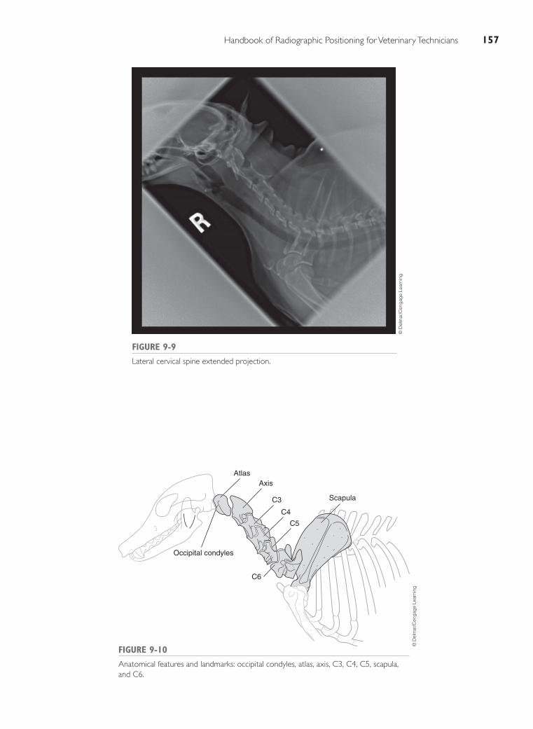
Handbook of Radiographic Positioning for Veterinary Technicians 157
FIGURE 9-9
Lateral cervical spine extended projection.
© D
elm
ar/C
enga
ge L
earn
ing
Atlas
Occipital condyles
Axis
C3
C4
C5
Scapula
C6
FIGURE 9-10
Anatomical features and landmarks: occipital condyles, atlas, axis, C3, C4, C5, scapula,
and C6.
© D
elm
ar/C
enga
ge L
earn
ing

158 Chapter 9 : Spinal Radiographs
Lateral Cervical Spine Flexed ProjectionPositioning:
Right or left lateral recumbency.•Head is directed ventrally and caudally toward the humeri and can be secured with a sandbag to maintain •flexion on the dorsal part of the skull.Forelimbs are secured evenly and caudally.•Foam pad may be needed along the sternum to avoid rotation of the spinal column.•
Centering:
C4--C5 intervertebral space.•
Collimation:
Base of the skull to the spine of the scapula.•
Labeling:
R/L marker within collimated area away from bony areas to indicate side facing closest to x-ray cassette.•Identification label in caudal region.•
Technique:
Measure at the area of the C4--C5 intervertebral space.•
Comments:
Take care not to hyperflex the neck. Flexion must be even throughout all cervical vertebrae starting at C7.•
FIGURE 9-11
Proper position for lateral cervical spine flexed projection.
© D
elm
ar/C
enga
ge L
earn
ing

Handbook of Radiographic Positioning for Veterinary Technicians 159
FIGURE 9-12
Lateral cervical spine flexed projection.
© D
elm
ar/C
enga
ge L
earn
ing
FIGURE 9-13
Anatomical features and landmarks: atlas C1, axis C2, C3, C4, and C5.
© D
elm
ar/C
enga
ge L
earn
ing
Atlas C1
Axis C2 C3 C4 C5

160 Chapter 9 : Spinal Radiographs
VD Thoracic Spine ProjectionPositioning:
Dorsal recumbency.•Forelimbs extended evenly and cranially.•V-trough or sandbags to maintain vertical alignment.•
Centering:
Caudal border of scapula at approximately the sixth or seventh thoracic vertebra.•
Collimation:
Halfway between xiphoid and last rib to spine of the scapula.•Must include C7--L1.•
Labeling:
R/L marker within collimated area away from bony areas.•Identification label in caudal region.•
Technique:
Measure at highest (thickest) point of sternum.•
FIGURE 9-14
Proper position for VD thoracic spine projection.
© D
elm
ar/C
enga
ge L
earn
ing

Handbook of Radiographic Positioning for Veterinary Technicians 161
© D
elm
ar/C
enga
ge L
earn
ing
FIGURE 9-15
VD thoracic spine projection.
C7
T12nd rib
Heart
Spinousprocess
of C7
T13
L1
© D
elm
ar/C
enga
ge L
earn
ing
FIGURE 9-16
Anatomical features and landmarks: L1, T13, T1, C7, spinous
process of C7, 2nd rib, and heart.

162 Chapter 9 : Spinal Radiographs
Lateral Thoracic Spine Projection Positioning:
Right or left lateral recumbency.•Forelimbs are extended evenly and slightly cranially.•Hindlimbs are extended evenly and slightly caudally.•Foam pad may be needed along the sternum to avoid rotation of the spinal column.•
Centering:
Caudal border of scapula at approximately the sixth or seventh thoracic vertebra.•
Collimation:
Halfway between xiphoid and last rib to spine of the scapula.•Must include C7--L1.•
Labeling:
R/L marker within collimated area away from bony areas to indicate side facing closest to x-ray cassette.•Identification label in caudal region.•
Technique:
Measure at the midpoint of the xiphoid or the highest point of the thorax.•
FIGURE 9-17
Proper position for lateral thoracic spine projection.
© D
elm
ar/C
enga
ge L
earn
ing

Handbook of Radiographic Positioning for Veterinary Technicians 163
FIGURE 9-18
Lateral thoracic spine projection.
© D
elm
ar/C
enga
ge L
earn
ing
FIGURE 9-19
Anatomical features and landmarks: T1, T6, T10, T12, T13, and L1.
© D
elm
ar/C
enga
ge L
earn
ing
L1T13T6 T10T1

164 Chapter 9 : Spinal Radiographs
VD Thoracolumbar Spine ProjectionPositioning:
Dorsal recumbency.•Forelimbs are extended evenly and slightly cranially.•Hindlimbs are extended evenly and slightly caudally.•Foam pad may be needed along the sternum to avoid rotation of the spinal column.•
Centering:
Halfway between collimation points.•
Collimation:
Xiphoid to last rib.•
Labeling:
R/L marker within collimated area away from bony areas.•Identification label in caudal region.•
Technique:
Measure at the midpoint of the xiphoid or the highest point of the thorax.•
FIGURE 9-20
Proper position for VD thoracolumbar spine projection.
© D
elm
ar/C
enga
ge L
earn
ing

Handbook of Radiographic Positioning for Veterinary Technicians 165
FIGURE 9-21
VD thoracolumbar spine projection.
© D
elm
ar/C
enga
ge L
earn
ing
FIGURE 9-22
Anatomical features and landmarks: T10–L2, intervertebral disc space
between T13 and L1, and spinous process.
© D
elm
ar/C
enga
ge L
earn
ing
Intevertebral disc
space between T13 and L1
T12
T11
Spinous process
T10
T13
L1
L2

166 Chapter 9 : Spinal Radiographs
Lateral Thoracolumbar Spine ProjectionPositioning:
Right or left lateral recumbency.•Forelimbs are extended evenly and slightly cranially.•Hindlimbs are extended evenly and slightly caudally.•Foam pad may be needed along the sternum to avoid rotation of the spinal column.•
Centering:
Halfway between collimation points.•
Collimation:
Xiphoid to last rib.•
Labeling:
R/L marker within collimated area away from bony areas to indicate side facing closest to x-ray cassette.•
Technique:
Measure at the midpoint of the xiphoid or the highest point of the thorax.•
FIGURE 9-23
Proper position for lateral thoracolumbar spine projection.
© D
elm
ar/C
enga
ge L
earn
ing

Handbook of Radiographic Positioning for Veterinary Technicians 167
FIGURE 9-24
Lateral thoracolumbar spine projection.
© D
elm
ar/C
enga
ge L
earn
ing
T13 L1 Spinous process
13th rib12th rib
Transverse process
Neural canal
FIGURE 9-25
Anatomical features and landmarks: T13, L1, 12th rib, 13th rib, neural canal, spinous process,
and transverse process.
© D
elm
ar/C
enga
ge L
earn
ing

168 Chapter 9 : Spinal Radiographs
VD Lumbar Spine ProjectionPositioning:
Dorsal recumbency.•Forelimbs are extended evenly and slightly cranially.•Hindlimbs are extended evenly and slightly caudally.•Foam pad may be needed along the sternum to avoid rotation of the spinal column.•
Centering:
Palpate xiphoid and the wing of the ilium, and place the center halfway between these two points.•
Collimation:
Xiphoid to acetabulum.•
Labeling:
R/L marker within collimated area away from bony areas.•Identification label in caudal region.•
Technique:
Measure at mid-lumbar spine.•
FIGURE 9-26
Proper position for VD lumbar spine projection.
© D
elm
ar/C
enga
ge L
earn
ing

Handbook of Radiographic Positioning for Veterinary Technicians 169
FIGURE 9-27
VD lumbar spine projection.©
Del
mar
/Cen
gage
Lea
rnin
g
FIGURE 9-28
Anatomical features and landmarks: 13th rib, spinous process, T13,
L1, spinous process of L5, L7, and wing of ilium.
T13
13th ribSpinousprocess
L1
L7
Spinous processof L5
Wing ofilium
© D
elm
ar/C
enga
ge L
earn
ing

170 Chapter 9 : Spinal Radiographs
Lateral Lumbar Spine ProjectionPositioning:
Right or left lateral recumbency.•Forelimbs are extended evenly and slightly cranially.•Hindlimbs are extended evenly and slightly caudally.•Foam pad may be needed along the sternum to avoid rotation of the spinal column.•
Centering:
L3--4.•
Collimation:
Xiphoid to acetabulum.•
Labeling:
R/L marker within collimated area away from bony areas to indicate side facing closest to x-ray cassette.•
Technique:
Measure mid-lumbar spine.•
FIGURE 9-29
Proper position for lateral lumbar spine projection.
© D
elm
ar/C
enga
ge L
earn
ing

Handbook of Radiographic Positioning for Veterinary Technicians 171
FIGURE 9-30
Lateral lumbar spine projection.
© D
elm
ar/C
enga
ge L
earn
ing
FIGURE 9-31
Anatomical features and landmarks: T13, 13th rib, spinous process of L4, wing of the ilium, L7,
and sacrum.
© D
elm
ar/C
enga
ge L
earn
ing
T13Spinous process of L4
Wing of the ilium
SacrumL713th Rib

172 Chapter 9 : Spinal Radiographs
VD Lumbosacral Spine ProjectionPositioning:
Dorsal recumbency in V-trough.•Forelimbs are extended evenly and slightly cranially.•Hindlimbs are extended evenly and slightly caudally.•Foam pad may be needed along the sternum to avoid rotation of the spinal column.•
Centering:
Palpate the wing of the ilium, and center just caudal and midpelvis.•
Collimation:
Sixth lumbar vertebra to iliac crest.•
Labeling:
R/L marker within collimated area away from bony areas.•Identification label in caudal region.•
Technique:
Measure at the wing of the ilium.•
FIGURE 9-32
Proper position for VD lumbosacral spine projection.
© D
elm
ar/C
enga
ge L
earn
ing

Handbook of Radiographic Positioning for Veterinary Technicians 173
FIGURE 9-33
VD lumbosacral spine projection.
© D
elm
ar/C
enga
ge L
earn
ing
6th lumbarvertebra
7th lumbar vertebra
Transverseprocess
Illium
Sacrum
Coccygealvertebra
FIGURE 9-34
Anatomical features and landmarks: 7th lumbar vertebra, sacrum, coccygeal
vertebra, ilium, 6th lumbar vertebra, and transverse process.
© D
elm
ar/C
enga
ge L
earn
ing

174 Chapter 9 : Spinal Radiographs
Lateral Lumbosacral Spine ProjectionPositioning:
Right or left lateral recumbency.•Forelimbs are extended evenly and slightly cranially.•Hindlimbs are extended evenly and slightly caudally.•Foam pad may be needed along the sternum to avoid rotation of the spinal column.•Foam wedge is placed between hindlimbs to superimpose both sides of pelvis.•
Centering:
Palpate the wing of the ilium and the dorsal spinous process of the lumbosacral region, and center just caudal •to the wing of the ilium. There is a distinct divot at the lumbosacral junction.
Collimation:
Cranial to include L-6 lumbar vertebrae to iliac crest to include the first cranial caudal vertebrae (tail).•
Labeling:
R/L marker is within collimated area away from bony areas to indicate side facing closest to x-ray cassette.•Place identification label in right cranial region or left caudal region within collimated area to avoid overlap •of bone.
Technique:
Measure thickest area just caudal to the wing of the ilium.•
Comments:
Alternate views include flexed and extended views of the lumbosacral junction.•
FIGURE 9-35
Proper position for lateral lumbosacral spine projection.
© D
elm
ar/C
enga
ge L
earn
ing

Handbook of Radiographic Positioning for Veterinary Technicians 175
FIGURE 9-36
Lateral lumbosacral spine projection.
© D
elm
ar/C
enga
ge L
earn
ing
FIGURE 9-37
Anatomical features and landmarks: 1st coccygeal vertebrae, 2nd coccygeal vertebrae, 3rd coccygeal
vertebrae, sacrum, spinous process of L7, spinous process of L6, spinous process of L5, transverse
process of L5, transverse process of L6, L5, L6, L7, ilia (superimposed), and wings of ilia.
3rd Coccygeal vertebrae
1st Coccygeal vertebrae
Sacrum
Spinousprocess of L7
Spinousprocess of L6
Spinousprocess of L5
Transverseprocess of L5
Transverseprocess of L6
L5 L6L7
Ilia (superimposed)
Wings of ilia
2nd Coccygeal vertebrae
© D
elm
ar/C
enga
ge L
earn
ing

176 Chapter 9 : Spinal Radiographs
VD Coccygeal (Caudal) Spine Projection Positioning:
Dorsal recumbency.•V-trough or sandbags to maintain dorsal recumbency.•Hindlimbs in natural position.•Tail extended caudally.•
Centering:
Midway from the sacrum to the tip of the tail.•
Collimation:
Cranial to the sacrum to the tip of the tail.•
Labeling:
R/L marker within collimated area away from bony areas.•Identification in caudal region.•
Technique:
Measure at thickest part of tail.•
Comments:
Tape may be used to maintain vertical alignment of the tail.•
FIGURE 9-38
Proper position for VD coccygeal (caudal) spine projection.
© D
elm
ar/C
enga
ge L
earn
ing

Handbook of Radiographic Positioning for Veterinary Technicians 177
Wing of ilium Wing of ilium
1st coccygeal vertebra
3rd coccygeal vertebra
Sacrum
Ishium
Ishium
Femoral head
Femoral head
2nd coccygeal vertebra
4th coccygeal vertebra
6th coccygeal vertebra
7th coccygeal vertebra
8th coccygeal vertebra
9th coccygeal vertebra
10th coccygeal vertebra
11th coccygeal vertebra
FIGURE 9-40
Anatomical features and landmarks: sacrum, wing of ilium, 1st coccygeal vertebra,
3rd coccygeal vertebra, 2nd coccygeal vertebra, ischium, femoral head, 4th coccygeal
vertebra, 6th coccygeal vertebra, 7th coccygeal vertebra, 8th coccygeal vertebra, 9th
coccygeal vertebra, 10th coccygeal vertebra, and 11th coccygeal vertebra.
© D
elm
ar/C
enga
ge L
earn
ing
FIGURE 9-39
VD coccygeal (caudal) spine projection.
© D
elm
ar/C
enga
ge L
earn
ing

178 Chapter 9 : Spinal Radiographs
Lateral Coccygeal (Caudal) Spine ProjectionPositioning:
Right or left lateral recumbency.•
Centering:
Midway from the sacrum to the tip of the tail.•
Collimation:
Cranial to the sacrum to the tip of the tail.•
Labeling:
R/L marker within collimated area away from bony areas.•Identification label in caudal region.•
Technique:
Measure at thickest part of tail.•
Comments:
Cassette may be elevated off the table to maintain alignment of the tail and spine, and bring the tail closer to •the x-ray cassette, or a sponge may be placed under the tail to make it parallel to the cassette; this will depend on the size of the patientTape may be needed to keep the tail in vertical alignment.•
FIGURE 9-41
Proper position for lateral coccygeal (caudal) spine projection.
© D
elm
ar/C
enga
ge L
earn
ing

Handbook of Radiographic Positioning for Veterinary Technicians 179
FIGURE 9-42
Lateral coccygeal (caudal) spine projection.
© D
elm
ar/C
enga
ge L
earn
ing
Cranial articular processes
Coccygealvertebral bodies
Intervertebralspace
FIGURE 9-43
Anatomical features and landmarks: cranial articular processes, coccygeal vertebral bodies, and intervertebral space.
© D
elm
ar/C
enga
ge L
earn
ing

This page intentionally left blank

181
CHAPTER 10RADIOGRAPHY OF AVIAN AND EXOTIC ANIMALS
OVERVIEW
There are many unique aspects of radiology relating to obtaining diagnostic quality radiographs of birds, reptiles,
amphibians, and small mammals. The type of fi lm and cassettes used, the focal point, collimation, exposure time,
and restraint procedures require modifi cation from the standard techniques used for dogs and cats.
Mammography fi lm and cassettes are routinely used for avian and exotic animal radiology.
Mammography fi lm is a single emulsion, and the cassettes are single intensifying screen cassettes. The fi lm is
placed in the cassette with the dark side of the fi lm facing the dark side of the cassette, and the light side
facing the light side (Figure 10-1).
The cassette is placed on the tabletop and the x-ray tube head moved to achieve a focal-spot distance
of 40 inches (100 cm). This results in a magnifi cation of the image on the fi lm and aids in evaluation of the
radiograph in these small species. Close collimation around the area of interest will help decrease scatter
radiation and maximize detail.
Exposure time and settings used will vary with the type of fi lm and radiographic equipment available.
When using mammography fi lm, a longer exposure time is required. A milliamperage (mA) setting of
300, exposure time of 1/10 second, and a kilovolt peak (kVp) between 40 and 50 will generally yield a
high-quality, high-detail image. When using double-sided fi lm, an mA setting of 300, exposure time of 1/60
second, and a kVp between 40 and 50 will achieve a good-quality fi lm.

182 Chapter 10: Radiography of Avian and Exotic Animals
GENERAL PRINCIPLES OF
RESTRAINT
Proper patient restraint is required to minimize or eliminate any movement that will result in a blurred or low-quality image. This can be accomplished with either physical restraint or chemical restraint.
In many avian patients, physical restraint is gener-ally considered unacceptable, especially in large, pow-erful birds, highly stressed or fractious birds, and birds with injuries that can be exacerbated with struggling. In these cases, chemical restraint is used. Inhalation anes-thesia (sevoflurane or isoflurane) is suitable for chemical
FIGURE 10-1
Proper film placement in cassette.
© D
elm
ar/C
enga
ge L
earn
ing
FIGURE 10-2
Radiography of birds.
© D
elm
ar/C
enga
ge L
earn
ing
FIGURE 10-3
Restraint techniques for reptiles.
© D
elm
ar/C
enga
ge L
earn
ing
FIGURE 10-4
Restraint technique for reptiles.
© D
elm
ar/C
enga
ge L
earn
ing
restraint. In some calm birds, physical restraint using tape or commercial restraint devices can be used. Heavy metal examination of avian patients can be quickly accomplished by placing a small bird in a paper bag (Figure 10-2). The bag is then placed directly on the x-ray cassette. Large birds can stand directly on the cas-sette, or the horizontal beam can be used and the bird placed in a perch.
Most lizards and turtles will quietly sit on the cas-sette without any restraint for the dorsal-ventral view. More excitable reptiles can be restrained with the use of tape, sandbags, or cotton ball Vetwrap hoods (Figures 10-3 and 10-4). The cotton ball Vetwrap hood helps

Handbook of Radiographic Positioning for Veterinary Technicians 183
calm the patient. Very fractious or aggressive patients may need some form of chemical restraint.
Restraint of a snake can be challenging. Tape and sandbag restraints prove to be ineffective. Generally, manual restraint is the best. Manual restraint or the use of acrylic tubes is the most common form of restraint for snakes (Figures 10-5 and 10-6).
Rabbits and ferrets can be physically restrained with techniques similar to those used with cats. Anesthesia may be recommended in the rabbit or ferret that is frac-tious or stressed.
FIGURE 10-5
Restraint of snakes.
© D
elm
ar/C
enga
ge L
earn
ing
FIGURE 10-6
Radiography of snakes.
© D
elm
ar/C
enga
ge L
earn
ing

184 Chapter 10: Radiography of Avian and Exotic Animals
Lateral View of the Avian PatientPositioning:
Right lateral recumbency.•Neck is extended, and sponges are used to support the head, parallel to the cassette.•Wings are extended dorsally and secured with tape at the carpal joint.•Sternum should be parallel to the cassette.•Legs are pulled caudally and secured with tape.•
Centering:
Midsternum.•
Collimation:
Whole body.•
Labeling:
Right marker within the collimated area in cranial aspect of the sternum.•
Technique:
Measure the thickest point of the chest.•

Handbook of Radiographic Positioning for Veterinary Technicians 185
FIGURE 10-7
Proper positioning for lateral view of the avian patient.
© D
elm
ar/C
enga
ge L
earn
ing
FIGURE 10-8
Lateral view of the avian patient.
© D
elm
ar/C
enga
ge L
earn
ing

186 Chapter 10: Radiography of Avian and Exotic Animals
Ventrodorsal View of the Avian PatientPositioning:
Dorsal recumbency.•Neck is extended, and sponges are used to support the head, parallel to the cassette.•Wings are extended lateral from the body and secured with tape at the carpal joint.•Sternum should be placed directly over the spinal column.•Legs are pulled caudally and secured individually with tape.•
Centering:
Midsternum.•
Collimation:
Whole body.•
Labeling:
R/L marker within the collimated area.•
Technique:
Measure the thickest point of the chest.•

Handbook of Radiographic Positioning for Veterinary Technicians 187
FIGURE 10-10
Ventrodorsal view of the avian patient.
© D
elm
ar/C
enga
ge L
earn
ing
FIGURE 10-9
Proper positioning for ventrodorsal view of the avian patient.
© D
elm
ar/C
enga
ge L
earn
ing

188 Chapter 10: Radiography of Avian and Exotic Animals
Dorsoventral View of the LizardPositioning:
Ventral recumbency.•Forelimbs and hindlimbs are gently placed lateral to the body.•Tape may be used to secure in position.•
Centering:
Midbody region.•
Collimation:
Whole body, include the head, legs, and cranial aspect of the tail.•
Labeling:
R/L marker within collimated area.•
Technique:
Measure the thickest point of the body.•

Handbook of Radiographic Positioning for Veterinary Technicians 189
FIGURE 10-11
Proper positioning for dorsoventral view of the lizard.
© D
elm
ar/C
enga
ge L
earn
ing
FIGURE 10-12
Dorsoventral view of the lizard.
© D
elm
ar/C
enga
ge L
earn
ing

190 Chapter 10: Radiography of Avian and Exotic Animals
Lateral View of the Lizard Positioning:
Right lateral recumbency.•Forelimbs are pulled ventral and cranial of the body.•Hindlimbs are pulled ventral and caudal of the body.•Both forelimbs and hindlimbs can be secured with Vetwrap to minimize struggling (Figure 10-13).•Secure limbs with tape.•Tape across shoulders and hips to secure the body; sponges may be used to maintain horizontal position.•
Centering:
Midbody region.•
Collimation:
Whole body, include the head, legs, and the cranial aspect of the tail.•
Labeling:
R/L marker within collimated area.•
Technique:
Measure the thickest point of the body.•
FIGURE 10-13
Restraint of the lizard.
© D
elm
ar/C
enga
ge L
earn
ing

Handbook of Radiographic Positioning for Veterinary Technicians 191
FIGURE 10-14
Proper positioning for lateral view of the lizard.
© D
elm
ar/C
enga
ge L
earn
ing
FIGURE 10-15
Lateral view of the lizard.
© D
elm
ar/C
enga
ge L
earn
ing

192 Chapter 10: Radiography of Avian and Exotic Animals
Lateral View of the Lizard with the Horizontal BeamPositioning:
Ventrodorsal recumbency.•Ensure that the body is as close to the cassette as possible.•
Centering:
Midbody region. •
Collimation:
Whole body, including head and cranial aspect of the tail.•
Labeling:
R/L marker taped to the cassette above the patient.•
Technique:
Measure the thickest point of the body.•

Handbook of Radiographic Positioning for Veterinary Technicians 193
FIGURE 10-16
Proper positioning for lateral view of the lizard with the horizontal beam.
© D
elm
ar/C
enga
ge L
earn
ing
FIGURE 10-17
Lateral view of the lizard with the horizontal beam.
© D
elm
ar/C
enga
ge L
earn
ing

194 Chapter 10: Radiography of Avian and Exotic Animals
Dorsoventral View of the TurtlePositioning:
Ventral recumbency.•Forelimbs and hindlimbs are gently placed lateral to the body.•Tape may be used to secure in position.•
Centering:
Midbody region.•
Collimation:
Whole body, include the head, legs, and cranial aspect of the tail.•
Labeling:
R/L marker within collimated area.•
Technique:
Measure the thickest point of the body.•

Handbook of Radiographic Positioning for Veterinary Technicians 195
FIGURE 10-18
Proper positioning for dorsoventral view of the turtle.
© D
elm
ar/C
enga
ge L
earn
ing
FIGURE 10-19
Dorsoventral view of the turtle.
© D
elm
ar/C
enga
ge L
earn
ing

196 Chapter 10: Radiography of Avian and Exotic Animals
Lateral View of the Turtle with the Horizontal BeamPositioning:
Ventrodorsal recumbency.•Ensure that the body is as close to the cassette as possible.•
Centering:
Midbody region.•
Collimation:
Whole body, including head and cranial aspect of the tail.•
Labeling:
R/L marker taped to the cassette above the patient.•
Technique:
Measure the thickest point of the body.•

Handbook of Radiographic Positioning for Veterinary Technicians 197
FIGURE 10-20
Proper positioning for lateral view of the turtle with the horizontal beam.
© D
elm
ar/C
enga
ge L
earn
ing
FIGURE 10-21
Lateral view of the turtle with the horizontal beam.
© D
elm
ar/C
enga
ge L
earn
ing

198 Chapter 10: Radiography of Avian and Exotic Animals
Lateral View of the Rabbit AbdomenPositioning:
Right lateral recumbency.•Forelimbs are extended cranially and hindlimbs caudally; secure with tape.•Sternum should be parallel to the cassette; this can be accomplished with the use of sponges.•
Centering:
Center slightly cranial of the last rib.•
Collimation:
Slightly cranial of the xiphoid and slightly caudal of the pubis.•
Labeling:
R marker is placed in the inguinal area.•
Technique:
Measure at the last rib.•

Handbook of Radiographic Positioning for Veterinary Technicians 199
FIGURE 10-22
Proper positioning for lateral view of the rabbit abdomen.
© D
elm
ar/C
enga
ge L
earn
ing
FIGURE 10-23
Lateral view of the rabbit abdomen.
© D
elm
ar/C
enga
ge L
earn
ing

200 Chapter 10: Radiography of Avian and Exotic Animals
Ventrodorsal View of the Rabbit AbdomenPositioning:
Dorsal recumbency.•The front portion is secured with sandbags to keep the trunk bilaterally symmetrical.•The hind limbs are extended and secured with sandbags or tape.•
Centering:
Slightly caudal to the last rib.•
Collimation:
Slightly cranial of the xiphoid and slightly caudal of the pubis.•
Labeling:
R marker is placed in the inguinal area.•
Technique:
Measure at the last rib.•

Handbook of Radiographic Positioning for Veterinary Technicians 201
FIGURE 10-24
Proper positioning for ventrodorsal view of the rabbit abdomen.
© D
elm
ar/C
enga
ge L
earn
ing
FIGURE 10-25
Ventrodorsal view of the rabbit abdomen.
© D
elm
ar/C
enga
ge L
earn
ing

202 Chapter 10: Radiography of Avian and Exotic Animals
Lateral View of the Rabbit ThoraxPositioning:
Right lateral recumbency.•Forelimbs are extended cranially and hindlimbs caudally; secure with tape.•Sternum should be parallel to the cassette; this can be accomplished with the use of sponges.•
Centering:
Center on sternum.•
Collimation:
Slightly cranial of the thoracic inlet and slightly caudal of the last rib.•
Labeling:
R marker is placed just behind the forelegs.•
Technique:
Measure at the last rib.•

Handbook of Radiographic Positioning for Veterinary Technicians 203
FIGURE 10-26
Proper positioning for lateral view of the rabbit thorax.
© D
elm
ar/C
enga
ge L
earn
ing
FIGURE 10-27
Lateral view of the rabbit thorax.
© D
elm
ar/C
enga
ge L
earn
ing

204 Chapter 10: Radiography of Avian and Exotic Animals
Ventrodorsal View of the Rabbit ThoraxPositioning:
Dorsal recumbency.•Forelimbs are extended cranially and hindlimbs caudally; secure with tape.•Sternum should be placed directly over the spinal column.•
Centering:
Center on fourth intercostal space.•
Collimation:
Slightly cranial of the thoracic inlet and slightly caudal of the last rib.•
Labeling:
R marker is placed just behind the forelegs.•
Technique:
Measure at the last rib.•

Handbook of Radiographic Positioning for Veterinary Technicians 205
FIGURE 10-28
Proper positioning for ventrodorsal view of the rabbit thorax.©
Del
mar
/Cen
gage
Lea
rnin
g
FIGURE 10-29
Ventrodorsal view of the rabbit thorax.
© D
elm
ar/C
enga
ge L
earn
ing
206 Chapter 10: Radiography of Avian and Exotic Animals
Lateral View of the Rabbit SkullPositioning:
Lateral recumbency.•Use sponge wedges under the neck and nose to align to skull parallel to the cassette and prevent obliquity.•Position the ears at the top of the skull, ensuring they are away from the area to be viewed.•
Centering
Midskull.•
Collimation:
Cranial of the nose and just caudal of the base of the skull.•
Labeling:
Just above the nose.•
Technique:
Thickest portion of the skull.•

Handbook of Radiographic Positioning for Veterinary Technicians 207
FIGURE 10-30
Proper positioning for lateral view of the rabbit skull.
© D
elm
ar/C
enga
ge L
earn
ing
FIGURE 10-31
Lateral view of the rabbit skull.
© D
elm
ar/C
enga
ge L
earn
ing

208 Chapter 10: Radiography of Avian and Exotic Animals
Dorsoventral View of the Rabbit SkullPositioning:
Dorsoventral recumbency.•Secure to head flat to the cassette with tape at the base of the skull.•Position the ears to the sides, ensuring they are away from the viewing area.•Ensure that the skull is parallel to the cassette.•
Centering:
Midskull.•
Collimation:
Cranial of the nose and just caudal of the base of the skull.•
Labeling:
Beside the nose.•
Technique:
Thickest portion of the skull.•

Handbook of Radiographic Positioning for Veterinary Technicians 209
FIGURE 10-33
Dorsoventral view of the rabbit skull.
© D
elm
ar/C
enga
ge L
earn
ing
FIGURE 10-32
Proper positioning for dorsoventral view of the rabbit skull.
© D
elm
ar/C
enga
ge L
earn
ing

210 Chapter 10: Radiography of Avian and Exotic Animals
Lateral Oblique View of the Rabbit SkullPositioning:
Lateral recumbency (right or left).•Sponge wedges are placed under the skull, tilting the head at a 45-degree angle to the cassette.•Position the ears to the sides, ensuring they are away from the viewing area.•
Centering:
Midskull.•
Collimation:
Cranial of the nose and just caudal of the base of the skull.•
Labeling:
Beside the nose.•
Technique:
Thickest portion of the skull.•

Handbook of Radiographic Positioning for Veterinary Technicians 211
FIGURE 10-34
Proper positioning for lateral oblique view of the rabbit skull.
© D
elm
ar/C
enga
ge L
earn
ing
FIGURE 10-35
Lateral oblique view of the rabbit skull.
© D
elm
ar/C
enga
ge L
earn
ing

212 Chapter 10: Radiography of Avian and Exotic Animals
Lateral View of the Ferret AbdomenPositioning:
Right lateral recumbency.•Forelimbs are extended cranially and hindlimbs caudally; secure with tape.•Sternum should be parallel to the cassette; this can be accomplished with the use of sponges.•
Centering:
Center slightly caudal of the last rib.•
Collimation:
Slightly cranial of the xiphoid and slightly caudal of the pubis.•
Labeling:
R marker is placed in the inguinal area.•
Technique:
Measure at the last rib.•

Handbook of Radiographic Positioning for Veterinary Technicians 213
FIGURE 10-36
Proper positioning for lateral view of the ferret abdomen.
© D
elm
ar/C
enga
ge L
earn
ing
FIGURE 10-37
Lateral view of the ferret abdomen.
© D
elm
ar/C
enga
ge L
earn
ing

214 Chapter 10: Radiography of Avian and Exotic Animals
Ventrodorsal View of the Ferret AbdomenPositioning:
Dorsal recumbency.•The front portion is secured with sandbags or tape to keep the trunk bilaterally symmetrical.•The hind limbs are extended and secured with tape.•
Centering:
Center slightly caudal of the last rib.•
Collimation:
Slightly cranial of the xiphoid and slightly caudal of the pubis.•
Labeling:
R marker is placed in the inguinal area.•
Technique:
Measure at the last rib.•

Handbook of Radiographic Positioning for Veterinary Technicians 215
FIGURE 10-39
Ventrodorsal view of the ferret abdomen.
© D
elm
ar/C
enga
ge L
earn
ing
FIGURE 10-38
Proper positioning for ventrodorsal view of the ferret abdomen.
© D
elm
ar/C
enga
ge L
earn
ing

216 Chapter 10: Radiography of Avian and Exotic Animals
Lateral View of the Ferret ThoraxPositioning:
Right lateral recumbency.•Forelimbs are extended cranially and hindlimbs caudally; secure with tape.•Sternum should be parallel to the cassette; this can be accomplished with the use of sponges.•
Centering:
Center on the xiphoid process.•
Collimation:
Slightly cranial of the thoracic inlet and slightly caudal of the dorsal aspect of the last rib.•
Labeling:
R marker is placed above the shoulders.•
Technique:
Measure at the last rib.•

Handbook of Radiographic Positioning for Veterinary Technicians 217
FIGURE 10-40
Proper positioning for lateral view of the ferret thorax.
© D
elm
ar/C
enga
ge L
earn
ing
FIGURE 10-41
Lateral view of the ferret thorax.
© D
elm
ar/C
enga
ge L
earn
ing

218 Chapter 10: Radiography of Avian and Exotic Animals
Ventrodorsal View of the Ferret ThoraxPositioning:
Dorsal recumbency.•The front portion is secured with sandbags or tape to keep the trunk bilaterally symmetrical.•The hind limbs are extended and secured with tape.•
Centering:
Center on the xiphoid process.•
Collimation:
Slightly cranial of the thoracic inlet and slightly caudal of the dorsal aspect of the last rib.•
Labeling:
R marker is placed above the shoulders.•
Technique:
Measure at the last rib.•

Handbook of Radiographic Positioning for Veterinary Technicians 219
FIGURE 10-42
Proper positioning for ventrodorsal view of the ferret thorax.
© D
elm
ar/C
enga
ge L
earn
ing
FIGURE 10-43
Ventrodorsal view of the ferret thorax.
© D
elm
ar/C
enga
ge L
earn
ing

220 Chapter 10: Radiography of Avian and Exotic Animals
Lateral Whole Body View of the FerretPositioning:
Right lateral recumbency.•Forelimbs are extended cranially and hindlimbs caudally; secure with tape.•Sternum should be parallel to the cassette; this can be accomplished with the use of sponges.•
Centering:
Halfway between the dorsal aspect of the last rib and the xiphoid process.•
Collimation:
Slightly cranial of the thoracic inlet and slightly caudal of the pubis.•
Labeling:
R marker is placed in the inguinal region.•
Technique:
Measure at the last rib.•

Handbook of Radiographic Positioning for Veterinary Technicians 221
FIGURE 10-44
Proper positioning for lateral whole body view of the ferret.
© D
elm
ar/C
enga
ge L
earn
ing
FIGURE 10-45
Lateral whole body view of the ferret.
© D
elm
ar/C
enga
ge L
earn
ing

222 Chapter 10: Radiography of Avian and Exotic Animals
Ventrodorsal Whole Body View of the FerretPositioning:
Dorsal recumbency.•The front portion is secured with sandbags or tape to keep the trunk bilaterally symmetrical.•The hind limbs are extended and secured with tape.•
Centering:
Halfway between the dorsal aspect of the last rib and the xiphoid process.•
Collimation:
Slightly cranial of the thoracic inlet and slightly caudal of the pubis.•
Labeling:
R marker is placed in the inguinal region.•
Technique:
Measure at the last rib.•

Handbook of Radiographic Positioning for Veterinary Technicians 223
FIGURE 10-46
Proper positioning for ventrodorsal whole body view of the ferret.
© D
elm
ar/C
enga
ge L
earn
ing
FIGURE 10-47
Ventrodorsal whole body view of the ferret.
© D
elm
ar/C
enga
ge L
earn
ing

224 Preface
A
Abdomen
ferret
lateral view, 212–213
VD view, 214–215
lateral projection, 20–21
rabbit, DV view, 200–201
radiographs, 19–23
VD projection, 22
Avian patient
lateral view, 184–185
radiography, 181–223
VD view, 186–187
B
Beanbags, 4
C
Caliper, 7
Canine lower canine tooth
and lower premolar
arcade, 142
Canine lower incisor arcade, 141
Canine lower molars, 144
Canine lower premolar
arcade, 143
Canine upper canine tooth, 138
Canine upper fourth premolars
and molars, 140
Canine upper incisor
arcade, 137
Canine upper premolars, 139
Carpus
dorsopalmar projection, 56–57
extended lateral projection,
62–63
fl exed lateral projection,
60–61
lateral and medial oblique
projections, 64–65
lateral projection, 58–59
Caudal (Cd), 3
Caudocranial (CdCr), 3
Centering, 6
canine
lower canine tooth and
lower premolar
arcade, 142
lower incisor arcade, 141
lower molars, 144
lower premolar arcade, 143
upper canine tooth, 138
upper fourth premolars and
molars, 140
upper incisor arcade, 137
upper premolars, 139
CdCr projection
humerus, 42
scapula, 38
shoulder, 34
stifl e, 80
tibia and fi bula, 84
closed mouth projection of
rostrocaudal sinuses, 116
CrCd projection
elbow, 46
femur, 78
radius and ulna, 52
dorsolateral/plantaromedial
oblique projection of
tarsus, 96
dorsomedial/plantarolateral
oblique projection of
tarsus, 98
dorsopalmar projection
carpus, 56
digits, 70
metacarpals, 66
dorsoplantar projection,
metatarsus, 100
Dpa projection, digits, 104
Dpl projection, tarsus, 88
DV projection
skull, 112
temporomandibular
joint, 132
thorax, 14
tympanic bullae, 126
DV view
lizard, 188
rabbit abdomen, 200
rabbit skull, 208
turtle, 194
extended lateral projection of
carpus, 62
extended lateral projection
of tarsus, 94
feline
lower canine tooth, 149
lower incisor arcade, 148
lower premolars and molar
arcade, 150
upper canine tooth, 146
upper incisor arcade, 145
upper premolars and
molar, 147
fl exed lateral projection
carpus, 60
elbow, 50
tarsus, 92
lateral and medial oblique
projections of carpus, 64
lateral extended projection of
cervical spine, 156
lateral fl exed projection of
cervical spine, 158
lateral oblique projection of
temporomandibular
joint, 130
lateral oblique projection of
tympanic bullae, 128
lateral oblique view of rabbit
skull, 210
lateral projection
abdomen, 20
carpus, 58
cervical spine, 154
coccygeal (caudal)
spine, 178
digits, 72, 106
elbow, 48
femur, 76
humerus, 44
lumbar spine, 170
lumbosacral spine, 174
metacarpals, 68
metatarsus, 102
pelvis, 30
radius and ulna, 54
scapula, 40
shoulder, 36
skull, 110
stifl e, 82
tarsus, 90
thoracic spine, 162
thoracolumbar spine, 166
thorax, 10
tibia, 86
lateral view
avian patient, 184
ferret abdomen, 212
ferret thorax, 216
with horizontal beam,
lizard, 192
with horizontal beam,
turtle, 196
lizard, 190
rabbit abdomen, 198
rabbit skull, 206
rabbit thorax, 202
whole body, ferret, 220
rostrocaudal open mouth
projection of tympanic
bullae, 122
rostrocaudal projection of
foramen magnum, 118
standing lateral projection of
thorax with horizontal
beam, 16
VD-extended hip
projection, 26
VD projection
abdomen, 22
cervical spine, 152
coccygeal (caudal)
spine, 176
frog leg, 28
lumbar spine, 168
lumbosacral spine, 172
rostrocaudal open
mouth, 120
skull, 114
thoracic spine, 160
thoracolumbar spine, 164
thorax, 12
Index

Index 225
VD view
avian patient, 186
ferret abdomen, 214
ferret thorax, 218
rabbit thorax, 204
whole body, ferret, 222
Cervical spine
lateral extended
projection, 156–157
lateral fl exed projection,
158–159
lateral projection, 154–155
VD projection, 152–153
Chemical restraint, 1
Coccygeal (caudal) spine
lateral projection, 178–179
VD projection, 176–177
Collimation, 6
CdCr projection
humerus, 42
scapula, 38
shoulder, 34
stifl e, 80
tibia and fi bula, 84
closed mouth projection of
rostrocaudal sinuses, 116
CrCd projection
elbow, 46
femur, 78
radius and ulna, 52
dorsolateral/plantaromedial
oblique projection of
tarsus, 96
dorsomedial/plantarolateral
oblique projection of
tarsus, 98
dorsopalmar projection
carpus, 56
digits, 70
metacarpals, 66
dorsoplantar projection of
metatarsus, 100
Dpa projection of digits, 104
Dpl projection of tarsus, 88
DV projection
skull, 112
temporomandibular
joint, 132
thorax, 14
tympanic bullae, 126
DV view
lizard, 188
rabbit abdomen, 200
rabbit skull, 208
turtle, 194
extended lateral
projection, 94
carpus, 62
fl exed lateral projection
carpus, 60
elbow, 50
tarsus, 92
lateral and medial oblique
projections of carpus, 64
lateral extended projection
of cervical spine, 156
lateral fl exed projection of
cervical spine, 158
lateral oblique projection of
temporomandibular
joint, 130
lateral oblique projection of
tympanic bullae, 128
lateral oblique view of
rabbit skull, 210
lateral projection
abdomen, 20
carpus, 58
cervical spine, 154
coccygeal (caudal)
spine, 178
digits, 72, 106
elbow, 48
femur, 76
lumbar spine, 170
lumbosacral spine, 174
metacarpals, 68
metatarsus, 102
pelvis, 30
radius and ulna, 54
scapula, 40
shoulder, 36
skull, 110
stifl e, 82
tarsus, 90
thoracic spine, 162
thoracolumbar spine, 166
thorax, 10
tibia, 86
lateral view
avian patient, 184
ferret abdomen, 212
ferret thorax, 216
lizard, 190
rabbit abdomen, 198
rabbit skull, 206
rabbit thorax, 202
lateral view with horizontal
beam, lizard, 192
lateral view with horizontal
beam, turtle, 196
lateral whole body view of
ferret, 220
rostrocaudal open mouth
projection of tympanic
bullae, 122
rostrocaudal projection of
foramen magnum, 118
standing lateral projection of
thorax with horizontal
beam, 16
VD-extended hip
projection, 26
VD projection
abdomen, 22
cervical spine, 152
coccygeal (caudal) spine, 176
frog leg, 28
lumbar spine, 168
lumbosacral spine, 172
skull, 114
thoracic spine, 160
thoracolumbar spine, 164
thorax, 12
VD rostrocaudal open mouth
projection, 120
VD view
avian patient, 186
ferret abdomen, 214
ferret thorax, 218
rabbit thorax, 204
whole body, ferret, 222
Cranial (Cr), 3
Craniocaudal (CrCd), 3
D
Dental radiographs, 135–150
Digits
dorsopalmar projection,
70–71
Dpa projection, 104–105
lateral projection, 72–73,
106–107
Directional markers, 8
Directional terminology, 2–4
Distal (Di), 3
Dorsopalmar (Dpa), 3
Dorsoplantar (Dpl), 3
Dorsoventral (DV), 2
E
Elapsed time marker, 8
Elbow
CrCd projection, 46–47
fl exed lateral projection,
50–51
lateral projection, 48–49
Exotic animal radiography,
181–223
F
Feline lower canine tooth, 149
Feline lower incisor arcade, 148
Feline lower premolars and
molar arcade, 150
Feline upper canine tooth, 146
Feline upper incisor arcade, 145
Feline upper premolars and
molar, 147
Femur
CrCd projection, 78–79
lateral projection, 76–77
Ferret
lateral view of abdomen,
212–213
lateral view of thorax,
216–217
lateral whole body view,
220–221
VD view of abdomen,
214–215
VD view of thorax, 218–219
VD whole body view,
222–223
Foam pads and wedges, 14
Foramen magnum, rostrocaudal
projection, 118–119
Forelimb radiographs, 33–73
Frog leg projection, VD, 28–29

226 Index
G
Gravitational markers, 16
H
Hindlimb radiographs, 75–107
Hip projection, VD-extended,
26–27
Horizontal beam, standing
lateral projection of
thorax, 16–17
Humerus
CdCr projection, 42–43
lateral projection, 44–45
L
Labeling, 7–8
CdCr projection
humerus, 42
scapula, 38
shoulder, 34
stifl e, 80
tibia and fi bula, 84
closed mouth projection of
rostrocaudal sinuses, 116
CrCd projection
elbow, 46
femur, 78
CrCd projection of radius and
ulna, 52
dorsolateral/plantaromedial
oblique projection of
tarsus, 96
dorsomedial/plantarolateral
oblique projection of
tarsus, 98
dorsopalmar projection
carpus, 56
digits, 70
metacarpals, 66
dorsoplantar projection of
metatarsus, 100
Dpa projection of digits, 104
Dpl projection of tarsus, 88
DV projection
skull, 112
temporomandibular
joint, 32
thorax, 14
tympanic bullae, 126
DV view
lizard, 188
rabbit abdomen, 200
rabbit skull, 208
turtle, 194
extended lateral
projection, 94
carpus, 62
fl exed lateral projection
carpus, 60
elbow, 50
tarsus, 92
lateral and medial oblique
projections of carpus, 64
lateral extended projection
of cervical spine, 156
lateral fl exed projection of
cervical spine, 158
lateral oblique projection of
temporomandibular
joint, 130
lateral oblique projection of
tympanic bullae, 128
lateral oblique view of rabbit
skull, 210
lateral projection
abdomen, 20
carpus, 58
cervical spine, 154
coccygeal (caudal)
spine, 178
digits, 72, 106
elbow, 48
femur, 76
humerus, 44
lumbar spine, 170
lumbosacral spine, 174
metacarpals, 68
metatarsus, 102
pelvis, 30
radius and ulna, 54
scapula, 40
shoulder, 36
skull, 110
stifl e, 82
tarsus, 90
thoracic spine, 162
thoracolumbar spine, 166
thorax, 10
tibia, 86
lateral view
avian patient, 184
ferret abdomen, 212
ferret thorax, 216
lizard, 190
rabbit abdomen, 198
rabbit skull, 206
rabbit thorax, 202
lateral view with horizontal
beam
lizard, 192
turtle, 196
lateral whole body view of
ferret, 220
rostrocaudal open mouth
projection of tympanic
bullae, 122
rostrocaudal projection of
foramen magnum, 118
standing lateral projection
of thorax with horizontal
beam, 16
VD-extended hip projection,
26
VD projection
abdomen, 22
cervical spine, 152
coccygeal (caudal)
spine, 176
frog leg, 28
lumbar spine, 168
lumbosacral spine, 172
skull, 114
thoracic spine, 160
thoracolumbar spine,
164
thorax, 12
VD rostrocaudal open
mouth projection,
120
VD view
avian patient, 186
ferret abdomen, 214
ferret thorax, 218
rabbit thorax, 204
VD whole body view of
ferret, 222
Lateral, 3
Lizard
DV view, 188–189
lateral view, 190–191
lateral view with horizontal
beam, 192–193
Lumbar spine
lateral projection,
170–171
VD projection, 168–169
Lumbosacral spine
lateral projection, 174–175
VD projection, 172–173
M
Measurement, 6
Mechanical restraint, 1
Medial (M), 2
Metacarpals
dorsopalmar projection,
66–67
lateral projection, 68–69
Metatarsus
dorsoplantar projection,
100–101
lateral projection, 102–103
Mitchell marker, 16
O
Oblique (O), 4
P
Palmar, 3
Palmar dorsal (PaD), 3
Patient preparation, 2
Pelvic radiographs, 25–31
Pelvis, lateral projection, 30–31
Plantar, 3
Plantardorsal (PID), 3
Positioning
canine lower canine tooth
and lower premolar
arcade, 142
canine lower incisor
arcade, 141
canine lower molars, 144
canine lower premolar
arcade, 143
canine upper canine
tooth, 138

Index 227
canine upper fourth
premolars and molars,
140
canine upper incisor
arcade, 137
canine upper premolars, 139
CdCr projection
humerus, 42
scapula, 38
shoulder, 34
stifl e, 80
tibia and fi bula, 84
closed mouth projection of
rostrocaudal sinuses, 116
CrCd projection
elbow, 46
femur, 78
radius and ulna, 52
dorsolateral/plantaromedial
oblique projection of
tarsus, 96
dorsomedial/plantarolateral
oblique projection of
tarsus, 98
dorsopalmar projection
carpus, 56
digits, 70
metacarpals, 66
dorsoplantar projection
metatarsus, 100
Dpa projection of digits, 104
Dpl projection of tarsus, 88
DV projection
skull, 112
temporomandibular
joint, 132
thorax, 14
tympanic bullae, 126
DV view
lizard, 188
rabbit abdomen, 200
rabbit skull, 208
turtle, 194
extended lateral
projection, 94
carpus, 62
feline lower canine tooth, 149
feline lower incisor arcade, 148
feline lower premolars and
molar arcade, 150
feline upper canine tooth, 146
feline upper incisor arcade, 145
feline upper premolars and
molar, 147
fl exed lateral projection
carpus, 60
elbow, 50
tarsus, 92
lateral and medial oblique
projections of carpus, 64
lateral extended projection
of cervical spine, 156
lateral fl exed projection of
cervical spine, 158
lateral oblique projection
temporomandibular
joint, 130
tympanic bullae, 128
lateral oblique view of rabbit
skull, 210
lateral projection
abdomen, 20
carpus, 58
cervical spine, 154
coccygeal (caudal)
spine, 178
digits, 72, 106
elbow, 48
femur, 76
humerus, 44
lumbar spine, 170
lumbosacral spine, 174
metacarpals, 68
metatarsus, 102
pelvis, 30
radius and ulna, 54
scapula, 40
shoulder, 36
skull, 110
stifl e, 82
tarsus, 90
thoracic spine, 162
thoracolumbar spine, 166
thorax, 10
tibia, 86
lateral view
avian patient, 184
ferret abdomen, 212
ferret thorax, 216
lizard, 190
rabbit abdomen, 198
rabbit skull, 206
rabbit thorax, 202
lateral view with horizontal
beam
lizard, 192
turtle, 196
lateral whole body view of
ferret, 220
rostrocaudal open mouth
projection of tympanic
bullae, 122
rostrocaudal projection of
foramen magnum, 118
standing lateral projection of
thorax with horizontal
beam, 16
VD-extended hip
projection, 26
VD projection
abdomen, 22
cervical spine, 152
coccygeal (caudal)
spine, 176
frog leg, 28
lumbar spine, 168
lumbosacral spine, 172
skull, 114
thoracic spine, 160
thoracolumbar spine, 164
thorax, 12
VD rostrocaudal open mouth
projection, 120
VD view
avian patient, 186
ferret abdomen, 214
ferret thorax, 218
rabbit thorax, 204
VD whole body view of
ferret, 222
Positioning aids, 4–5
Proximal (Pr), 3
R
Rabbit
DV view of abdomen,
200–201
DV view of skull, 208–209
lateral oblique view of skull,
210–211
lateral view of abdomen,
198–199
lateral view of skull, 206–207
lateral view of thorax, 202–203
VD view of thorax, 204–205
Radiographic positioning, 5–8
Radius and ulna
CrCd projection, 52–53
lateral projection, 54–55
Restraint, avian and exotic
animals, 182–183
Rostral, 3
Rostrocaudal nasal, VD open
mouth projection, 120–121
Rostrocaudal sinuses, closed
mouth projection, 116–117
S
Sandbags, 4
Scapula
CdCr projection, 38–39
lateral projection, 40–41
Shoulder
CdCr projection, 34–35
lateral projection, 36–37
Skull
DV projection, 112–113
lateral projection, 110–111
rabbit
DV view, 208–209
lateral oblique view, 210–211
lateral view, 206–207
radiographs, 109–133
VD projection, 114–115
Spinal radiographs, 151–179
Split plate, 6
Standing lateral projection,
thorax, 16–17
Stifl e
CdCr projection, 80–81
lateral projection, 82–83
T
Tarsus
dorsolateral/plantaromedial
oblique projection, 96–97
dorsomedial/plantarolateral
oblique projection, 98–99
Dpl projection, 88–89

228 Index
extended lateral projection,
94–95
fl exed lateral projection, 92–93
lateral projection, 90–91
Technique
CdCr projection
humerus, 42
scapula, 38
shoulder, 34
stifl e, 80
tibia and fi bula, 84
closed mouth projection of
rostrocaudal sinuses, 116
CrCd projection
elbow, 46
femur, 78
radius and ulna, 52
dorsolateral/plantaromedial
oblique projection of
tarsus, 96
dorsomedial/plantarolateral
oblique projection of
tarsus, 98
dorsopalmar projection
carpus, 56
digits, 70
metacarpals, 66
dorsoplantar projection of
metatarsus, 100
Dpa projection of digits, 104
Dpl projection of tarsus, 88
DV projection
skull, 112
temporomandibular joint, 132
thorax, 14
tympanic bullae, 126
DV view
lizard, 188
rabbit abdomen, 200
rabbit skull, 208
turtle, 194
extended lateral projection, 94
carpus, 62
fl exed lateral projection
carpus, 60
elbow, 50
tarsus, 92
lateral extended projection of
cervical spine, 156
lateral fl exed projection of
cervical spine, 158
lateral oblique projection of
temporomandibular
joint, 130
lateral oblique projection of
tympanic bullae, 128
lateral oblique view of rabbit
skull, 210
lateral projection
abdomen, 20
cervical spine, 154
coccygeal (caudal)
spine, 178
digits, 72, 106
elbow, 48
femur, 76
humerus, 44
lumbar spine, 170
lumbosacral spine, 174
metacarpals, 68
metatarsus, 102
pelvis, 30
radius and ulna, 54
scapula, 40
shoulder, 36
skull, 110
stifl e, 82
tarsus, 90
thoracic spine, 162
thoracolumbar spine, 166
thorax, 10
tibia, 86
lateral view
avian patient, 184
ferret abdomen, 212
ferret thorax, 216
lizard, 190
rabbit abdomen, 198
rabbit skull, 206
rabbit thorax, 202
lateral view with horizontal
beam
lizard, 192
turtle, 196
lateral whole body view of
ferret, 220
rostrocaudal open mouth
projection of tympanic
bullae, 122
rostrocaudal projection of
foramen magnum, 118
standing lateral projection of
thorax with horizontal
beam, 16
VD projection
abdomen, 22
cervical spine, 152
coccygeal (caudal)
spine, 176
frog leg, 28
lumbar spine, 168
lumbosacral spine, 172
skull, 114
thoracic spine, 160
thoracolumbar spine, 164
thorax, 12
VD rostrocaudal open mouth
projection, 120
VD view
avian patient, 186
ferret abdomen, 214
ferret thorax, 218
rabbit thorax, 204
VD whole body view of
ferret, 222
Temporomandibular joint
DV projection, 132–133
lateral oblique projection,
130–131
Thoracic radiographs, 9–17
Thoracic spine
lateral projection, 162–163
VD projection, 160–161
Thoracolumbar spine
lateral projection, 166–167
VD projection, 164–165
Thorax
DV projection, 14–15
ferret
lateral view, 216–217
VD view, 218–219
lateral projection, 10–11
rabbit
lateral view, 202–203
VD view, 204–205
standing lateral projection
with horizontal beam,
16–17
VD projection, 12–13
Tibia, lateral projection, 86–87
Tibia and fi bula, CdCr projection,
84–85
Troughs, 4–5
Turtle
DV view, 194–195
lateral view with horizontal
beam, 196–197
Tympanic bullae
DV projection, 126–127
lateral oblique projection,
128–129
rostrocaudal open mouth
projection, 122–124
V
Ventrodorsal (VD), 2
V-trough, 4

IMPORTANT! READ CAREFULLY: This End User License Agreement (“Agreement”) sets forth the condi-tions by which Cengage Learning will make electronic access to the Cengage Learning-owned licensed content and associated media, software, documentation, print-ed materials, and electronic documentation contained in this package and/or made available to you via this product (the “Licensed Content”), available to you (the “End User”). BY CLICKING THE “I ACCEPT” BUT-TON AND/OR OPENING THIS PACKAGE, YOU AC-KNOWLEDGE THAT YOU HAVE READ ALL OF THE TERMS AND CONDITIONS, AND THAT YOU AGREE TO BE BOUND BY ITS TERMS, CONDITIONS, AND ALL APPLICABLE LAWS AND REGULATIONS GOV-ERNING THE USE OF THE LICENSED CONTENT.
1.0 SCOPE OF LICENSE
1.1 Licensed Content. The Licensed Content may contain portions of modifiable content (“Modi-fiable Content”) and content which may not be modified or otherwise altered by the End User (“Non-Modifiable Content”). For purposes of this Agreement, Modifiable Content and Non-Modifiable Content may be collectively referred to herein as the “Licensed Content.” All Licensed Content shall be considered Non- Modifiable Content, unless such Licensed Content is pre-sented to the End User in a modifiable format and it is clearly indicated that modification of the Licensed Content is permitted.
1.2 Subject to the End User’s compliance with the terms and conditions of this Agreement, Cengage Learning hereby grants the End User, a nontrans-ferable, nonexclusive, limited right to access and view a single copy of the Licensed Content on a sin-gle personal computer system for noncommercial, internal, personal use only. The End User shall not (i) reproduce, copy, modify (except in the case of Modifiable Content), distribute, display, transfer, sublicense, prepare derivative work(s) based on, sell, exchange, barter or transfer, rent, lease, loan, resell, or in any other manner exploit the Licensed Content; (ii) remove, obscure, or alter any notice of Cengage Learning’s intellectual property rights present on or in the Licensed Content, including, but not limited to, copyright, trademark, and/or patent notices; or (iii) disassemble, decompile, translate, reverse engineer, or otherwise reduce the Licensed Content.
2.0 TERMINATION
2.1 Cengage Learning may at any time (without preju-dice to its other rights or remedies) immediately terminate this Agreement and/or suspend access
to some or all of the Licensed Content, in the event that the End User does not comply with any of the terms and conditions of this Agreement. In the event of such termination by Cengage Learn-ing, the End User shall immediately return any and all copies of the Licensed Content to Cengage Learning.
3.0 PROPRIETARY RIGHTS
3.1 The End User acknowledges that Cengage Learn-ing owns all rights, title and interest, including, but not limited to all copyright rights therein, in and to the Licensed Content, and that the End User shall not take any action inconsistent with such ownership. The Licensed Content is pro-tected by U.S., Canadian and other applicable copyright laws and by international treaties, in-cluding the Berne Convention and the Universal Copyright Convention. Nothing contained in this Agreement shall be construed as granting the End User any ownership rights in or to the Licensed Content.
3.2 Cengage Learning reserves the right at any time to withdraw from the Licensed Content any item or part of an item for which it no lon-ger retains the right to publish, or which it has reasonable grounds to believe infringes copy-right or is defamatory, unlawful, or otherwise objectionable.
4.0 PROTECTION AND SECURITY
4.1 The End User shall use its best efforts and take all reasonable steps to safeguard its copy of the Licensed Content to ensure that no unau-thorized reproduction, publication, disclosure, modification, or distribution of the Licensed Content, in whole or in part, is made. To the extent that the End User becomes aware of any such unauthorized use of the Licensed Content, the End User shall immediately notify Cengage Learning. Notification of such violations may be made by sending an e-mail to [email protected].
5.0 MISUSE OF THE LICENSED PRODUCT
5.1 In the event that the End User uses the Licensed Content in violation of this Agreement, Cengage Learning shall have the option of electing liqui-dated damages, which shall include all profits generated by the End User’s use of the Licensed Content plus interest computed at the maximum rate permitted by law and all legal fees and other expenses incurred by Cengage Learning in en-forcing its rights, plus penalties.

6.0 FEDERAL GOVERNMENT CLIENTS
6.1 Except as expressly authorized by Cengage Learn-ing, Federal Government clients obtain only the rights specified in this Agreement and no other rights. The Government acknowledges that (i) all software and related documentation incorporated in the Licensed Content is existing commercial computer software within the meaning of FAR 27.405(b)(2); and (2) all other data delivered in whatever form, is limited rights data within the meaning of FAR 27.401. The restrictions in this section are acceptable as consistent with the Gov-ernment’s need for software and other data under this Agreement.
7.0 DISCLAIMER OF WARRANTIES AND LIABILITIES
7.1 Although Cengage Learning believes the Licensed Content to be reliable, Cengage Learning does not guarantee or warrant (i) any information or materi-als contained in or produced by the Licensed Con-tent, (ii) the accuracy, completeness or reliability of the Licensed Content, or (iii) that the Licensed Content is free from errors or other material de-fects. THE LICENSED PRODUCT IS PROVIDED “AS IS,” WITHOUT ANY WARRANTY OF ANY KIND AND CENGAGE LEARNING DISCLAIMS ANY AND ALL WARRANTIES, EXPRESSED OR IMPLIED, INCLUDING, WITHOUT LIMITA-TION, WARRANTIES OF MERCHANTABILITY OR FITNESS FOR A PARTICULAR PURPOSE. IN NO EVENT SHALL CENGAGE LEARNING BE LIABLE FOR: INDIRECT, SPECIAL, PUNITIVE OR CONSEQUENTIAL DAMAGES INCLUDING FOR LOST PROFITS, LOST DATA, OR OTH-ERWISE. IN NO EVENT SHALL CENGAGE LEARNING’S AGGREGATE LIABILITY HERE-UNDER, WHETHER ARISING IN CONTRACT, TORT, STRICT LIABILITY OR OTHERWISE, EXCEED THE AMOUNT OF FEES PAID BY THE END USER HEREUNDER FOR THE LICENSE OF THE LICENSED CONTENT.
8.0 GENERAL
8.1 Entire Agreement. This Agreement shall constitute the entire Agreement between the Parties and supercedes all prior Agreements and understand-ings oral or written relating to the subject matter hereof.
8.2 Enhancements/Modifications of Licensed Content. From time to time, and in Cengage Learning’s sole discretion, Cengage Learning may advise the End User of updates, upgrades, enhance-ments and/or improvements to the Licensed
Content, and may permit the End User to access and use, subject to the terms and conditions of this Agreement, such modifications, upon pay-ment of prices as may be established by Cengage Learning.
8.3 No Export. The End User shall use the Licensed Content solely in the United States and shall not transfer or export, directly or indirectly, the Licensed Content outside the United States.
8.4 Severability. If any provision of this Agreement is invalid, illegal, or unenforceable under any ap-plicable statute or rule of law, the provision shall be deemed omitted to the extent that it is invalid, illegal, or unenforceable. In such a case, the re-mainder of the Agreement shall be construed in a manner as to give greatest effect to the original intention of the parties hereto.
8.5 Waiver. The waiver of any right or failure of ei-ther party to exercise in any respect any right provided in this Agreement in any instance shall not be deemed to be a waiver of such right in the future or a waiver of any other right under this Agreement.
8.6 Choice of Law/Venue. This Agreement shall be in-terpreted, construed, and governed by and in ac-cordance with the laws of the State of New York, applicable to contracts executed and to be wholly preformed therein, without regard to its principles governing conflicts of law. Each party agrees that any proceeding arising out of or relating to this Agree-ment or the breach or threatened breach of this Agreement may be commenced and prosecuted in a court in the State and County of New York. Each par-ty consents and submits to the nonexclusive personal jurisdiction of any court in the State and County of New York in respect of any such proceeding.
8.7 Acknowledgment. By opening this package and/or by accessing the Licensed Content on this Web site, THE END USER ACKNOWLEDGES THAT IT HAS READ THIS AGREEMENT, UNDER-STANDS IT, AND AGREES TO BE BOUND BY ITS TERMS AND CONDITIONS. IF YOU DO NOT ACCEPT THESE TERMS AND CON-DITIONS, YOU MUST NOT ACCESS THE LICENSED CONTENT AND RETURN THE LICENSED PRODUCT TO CENGAGE LEARN-ING (WITHIN 30 CALENDAR DAYS OF THE END USER’S PURCHASE) WITH PROOF OF PAYMENT ACCEPTABLE TO CENGAGE LEARN-ING, FOR A CREDIT OR A REFUND. Should the End User have any questions/comments re-garding this Agreement, please contact Cengage Learning at [email protected].

System Requirements for: Back of Book (BOB) Flash Shell CD/DVD-ROMs
Minimum System Requirements:
PC:• Operating System: Windows 2000 w/ SP4, XP w/ SP2,
Vista• Hard Drive space: 200MB• Screen resolution: 1024 x 768 pixels• 8x CD-ROM or DVD-ROM drive • Sound card and listening device required for audio
features• An Internet connection, Firefox 2 or Internet Explorer
6 & 7 for Internet based content• Microsoft® Word is required to edit the Instructor’s
Manual and Microsoft PowerPoint® is required to edit the presentations
Mac:• Operating System: Mac OS X 10.4 and 10.5• Microsoft Office® 2004 or greater (for viewing files)• Hard Drive space: 200 MB• Minimum Screen resolution: 1024 x 768 pixels• 8x CD-ROM or DVD-ROM drive • Sound card and listening device required for audio
features
• An Internet connection, Firefox 2 or Safari 3 for Internet based content
PC Setup Instructions:1. Insert disc into CD-ROM drive. The program should
start automatically. If it does not, go to step 2.2. From My Computer, double-click the icon for the
CD drive.3. Double-click the start.exe file to start the program.
Mac Setup Instructions1. Insert disc into CD-ROM drive. The Cengage icon
will pop up on your desktop and a window should pop up with a file called start. If it does not, go to step 3.
2. Double-click the start file, to start the program.3. Click on the Cengage icon on your desktop. Go to
Step 2.
Technical Support:Telephone: 1-800-648-74508:30 AM - 6:30 PM Eastern TimeE-mail: [email protected]
Microsoft®, Microsoft Office®, Microsoft PowerPoint®,Microsoft Word®, Windows®, Windows XP® and Windows Vista® are trademarks of the Microsoft Corporation.Mac® and Mac OS X® are trademarks of Apple Inc., reg-istered in the U.S. and other countries.
Related Documents