DE-EE0002663 Ocean Thermal Energy Conversion Life Cycle Cost Assessment Copyright Lockheed Martin 2012 1 of 161 30 May 2012 OCEAN THERMAL ENERGY CONVERSION LIFE CYCLE COST ASSESSMENT Final Technical Report 30 May 2012 Lockheed Martin Mission Systems and Sensors Award # DE-EE0002663 Revision A

Welcome message from author
This document is posted to help you gain knowledge. Please leave a comment to let me know what you think about it! Share it to your friends and learn new things together.
Transcript

DE-EE0002663 Ocean Thermal Energy Conversion Life Cycle Cost Assessment
Copyright Lockheed Martin 2012 1 of 161 30 May 2012
OCEAN THERMAL ENERGY CONVERSION LIFE CYCLE COST ASSESSMENT
Final Technical Report
30 May 2012
Lockheed Martin Mission Systems and Sensors
Award # DE-EE0002663
Revision A

DE-EE0002663 Ocean Thermal Energy Conversion Life Cycle Cost Assessment
Copyright Lockheed Martin 2012 2 of 161 30 May 2012
Acknowledgements
Contributions to this report were funded by the Wind & Water Power Program, Office of Energy Efficiency and Renewable Energy of the U.S. Department of Energy under Contract No. DE-EE0002663.
The following individuals and organizations, under contract to Lockheed Martin, prepared this report: Steven Rizea, Joe Van Ryzin – Makai Ocean Engineering Paul Smith, John Halkyard – John Halkyard and Associates: Glosten Associates Charles Morgan – Planning Solutions, Inc. Gary Noland – G. Noland and Associates, Inc. Laura Martel, Rick Pavlosky, Michael Thomas – Lockheed Martin Mission Systems & Sensors This report was prepared as an account of work sponsored by an agency of the United States Government. Neither the United States Government nor any agency thereof, nor any of their employees, makes any warranty, express or implied, or assumes any legal liability or responsibility for the accuracy, completeness, or usefulness of any information, apparatus, product, or process disclosed, or represents that its use would not infringe privately owned rights. Reference herein to any specific commercial product, process, or service by trade name, trademark, manufacturer, or otherwise does not necessarily constitute or imply its endorsement, recommendation, or favoring by the United States Government or any agency thereof. The views and opinions of authors expressed herein do not necessarily state or reflect those of the United States Government or any agency thereof. The authors would like to thank the following people and organizations whose contributions helped ensure the success of this project, including:
Ocean Thermal Extractable Energy Visualization Team Members: Matt Ascari, Lynn Therese Rauchenstein, Nick Langle
LM OTEC Team IPT Leads: Pat Grandelli, Eugene Jansen, Jim Hurtt, John Nagurny
LM OTEC Team Leaders: Laurie Meyer, Rob Varley, Dennis Cooper
LM Financial Analysts: Natesh Vaidyanathan, Olga Sudakova

DE-EE0002663 Ocean Thermal Energy Conversion Life Cycle Cost Assessment
Copyright Lockheed Martin 2012 3 of 161 30 May 2012
0 OTEC Life Cycle Cost Assessment Executive Summary
0.1 Overview The Ocean Thermal Energy Conversion (OTEC) Life Cycle Cost Assessment (OLCCA) is a study performed by members of the Lockheed Martin (LM) OTEC Team under funding from the Department of Energy (DOE), Award No. DE-EE0002663, dated 01/01/2010.
OLCCA objectives are to estimate procurement, operations and maintenance, and overhaul costs for two types of OTEC plants:
• Plants moored to the sea floor where the electricity produced by the OTEC plant is directly connected to the grid ashore via a marine power cable (Grid Connected OTEC plants)
• Open-ocean grazing OTEC plant-ships producing an energy carrier that is transported to designated ports (Energy Carrier OTEC plants)
Costs are developed using the concept of levelized cost of energy established by DOE for use in comparing electricity costs from various generating systems. One area of system costs that had not been developed in detail prior to this analysis was the operations and sustainment (O&S) cost for both types of OTEC plants. Procurement costs, generally referred to as capital expense and O&S costs (operations and maintenance (O&M) costs plus overhaul and replacement costs), are assessed over the 30 year operational life of the plants and an annual annuity calculated to achieve a levelized cost (constant across entire plant life)1
The thermal OTEC resource for Oahu, Hawai’i and projected build out plan were developed. The estimate of the OTEC resource and LCOE values for the planned OTEC systems enable this information to be displayed as energy supplied versus levelized cost of the supplied energy; this curve is referred to as an Energy Supply Curve. The Oahu Energy Supply Curve represents initial OTEC deployment starting in 2018 and demonstrates the predicted economies of scale as technology and efficiency improvements are realized and larger more economical plants deployed. Utilizing global high resolution OTEC resource assessment from the Ocean Thermal Extractable Energy Visualization (OTEEV) project (an independent DOE project), Global Energy Supply Curves were generated for Grid Connected and Energy Carrier OTEC plants deployed in 2045 when the predicted technology and efficiencies improvements are fully realized. The Global Energy Supply Curves present the LCOE versus capacity in ascending order with the richest, lowest cost resource locations being harvested first. These curves demonstrate the vast ocean thermal resource and potential OTEC capacity that can be harvested with little change in LCOE.
. Dividing this levelized cost by the average annual energy production results in a levelized cost of electricity, or LCOE, for the OTEC plants. Technical and production efficiency enhancements that could result in a lower value of the OTEC LCOE were also explored.
1 Both levelized and average annual costs are presented in this summary and are distinct from each other. Levelized costs represent a fixed annual cost that results in the same net present value as the predicted time-phased costs by taking the time value of money into account. Average annual costs are calculated by taking the total costs over the life of the plant and dividing by the number of service years. As such, levelized annual costs and average annual costs are distinct concepts and representations of the data. The labeling of results is used to distinguish which method was used to generate the values presented.

DE-EE0002663 Ocean Thermal Energy Conversion Life Cycle Cost Assessment
Copyright Lockheed Martin 2012 4 of 161 30 May 2012
0.1.1 OTEC Theory of Operation OTEC is a solar powered energy system using ocean water thermal storage capacity to drive a Rankine cycle to generate electricity. Warm surface water is used to evaporate a working fluid that passes through a turbine that turns a generator to create electricity as shown in Figure 0-1. Heat is then extracted from the working fluid vapor in a large heat exchanger using cold water from ocean depths causing the vapor to condense back into a liquid. A pump sends the working fluid back to the evaporator where the cycle is repeated.
0.1.2 Moored OTEC Plants with Electricity Cabled-to-shore, “Grid Connected” Figure 0-2 and Figure 0-3 are artistic renderings of an OTEC plant. Plants near shore are moored to the sea floor with electricity transmitted to the power grid ashore via a marine power cable, hence the nickname “Grid Connected” OTEC plant. The design depicted is used as the basis for the Life Cycle Cost Analysis (LCCA). It uses a semi-submersible platform to house portions of the OTEC system such as the power generation elements, system control room, personnel accommodations, spare parts, and spare ammonia working fluid tanks. The entire system is designed to withstand a possible 100-year storm. A helicopter pad enables rapid personnel transfer and an articulated personnel ramp offers easy access to the platform from workboats. This design is a scale up of the 10 MW OTEC Pilot Plant design developed under the NAVFAC Ocean Thermal Energy Conversion (OTEC) Project2
This study creates a model for full global development of suitable nearshore OTEC sites based on plants nominally sized at 100, 200 and 400 MW net generating capacity. Larger plants are
.
2 NAVFAC Ocean Thermal Energy Conversion (OTEC) Project, N62583-09-C-0083, CDRL A003, OTEC System Design Report, CONTRACT REPORT, CR 11.002-OCN, 17 September 2010.
Figure 0-1. OTEC Power Cycle
Figure 0-2. OTEC Plant Deck Artistic Rendering

DE-EE0002663 Ocean Thermal Energy Conversion Life Cycle Cost Assessment
Copyright Lockheed Martin 2012 5 of 161 30 May 2012
phased in over four years, beginning in the fifth year following the first 100 MW installation. Principal dimensions for the three plant sizes are shown in Table 0-1.
Table 0-1. OTEC Plant - Principal Dimensions
Plant Length Breadth Depth Platform Draft* Number of Power Modules
100 MW Grid Connected 72 m 72 m 44 m 20 m 8
200 MW Grid Connected 90 m 80 m 44 m 20 m 16
400 MW Grid Connected 110 m 110 m 44 m 20 m 16
* Operating draft of the platform only. Power modules extend well below the platform’s baseline.
0.1.3 Open Ocean Grazing OTEC Plantships, “Energy Carrier” An open-ocean OTEC plantship produces an energy carrier to transport energy from the OTEC plant to users ashore, hence the nickname “Energy Carrier” OTEC plant. The Grid Connected OTEC plant provides the basis for the design with the addition of an energy carrier synthesis plant and storage. Previous studies by the LM OTEC Team established anhydrous ammonia as the preferred energy carrier. This energy carrier has an immediate market as the feedstock for fertilizer and also has the potential to be used as a non-carbon based fuel as a transportation, industrial and even utility power plant energy source.
The Energy Carrier plants included in the global-development model are all of the 400 MW size. They are assumed to have the same length and
breadth as the 400 MW Grid Connected plant, but are somewhat deeper to accommodate the added weight of energy carrier synthesis equipment and temporary storage.
Ammonia is produced in an OTEC plant by using the electrical power produced to generate fresh water, decompose it into hydrogen and oxygen, separate nitrogen from the atmosphere, combine the hydrogen and nitrogen to produce ammonia, then refrigerate and store the ammonia as depicted in Figure 0-4.
Figure 0-3. OTEC Plant Artistic Rendering
Figure 0-4. Diagram of Ammonia Production Using Electrolysis

DE-EE0002663 Ocean Thermal Energy Conversion Life Cycle Cost Assessment
Copyright Lockheed Martin 2012 6 of 161 30 May 2012
0.1.4 LM OTEC Team Supporting the Study Companies participating in the OTEC Life Cycle Cost (LCC) Assessment are shown in Table 0-2 along with each company’s roles and responsibilities under this effort.
Table 0-2. OTEC LCC Assessment Team Roles and Responsibilities
Organization OTEC LCC Assessment Roles and Responsibilities
Lockheed Martin (LM)
• Prime contractor and technical lead for OTEC LCC Assessment • Develop Life Cycle Cost (LCC) estimates • Develop Energy Curves for global supply
Makai Ocean Engineering
(Makai)
• Develop technology development projections and efficiency improvements • Update MOTEM computer model of OTEC capital costs • Participate in analysis progress reviews
The Glosten Assoc. (Glosten)
• Update OTEC CAPEX estimates for cabled-to-shore and open-ocean grazing systems • Estimate transportation expenses for energy carrier • Provide expertise and experience to manning and O&M estimates
Planning Solutions Inc. (PSI)
• Estimate time and cost of system permitting effort for commercial OTEC systems • Review and comment on all portions of the analysis
G. Noland & Associates (GNA)
• Assist LM with developing LCOE values and calculating actual cost of electricity • Develop Energy Supply Curve for Oahu
0.2 Levelized Cost of Electricity/Energy (LCOE) DOE has developed a methodology called LCOE (Levelized Cost of Electricity or Energy)3,4
• Full capital recovery of initial acquisition and cost of installation
. This approach was developed to establish a uniform methodology for calculating electricity cost produced by renewable energy systems taking into account generic financing for:
• Warranty, insurance and fees • Cost to operate and maintain the facility over the life of the system • Costs of major overhauls and equipment replacement costs • Disposal Costs
This study employs this standardized approach to calculating a figure of merit for cost comparison. In order to provide a standard figure of merit across various projects, the LCOE calculation employed excludes project specific external cost factors such as specialized financing arrangements and incentives. Calculation of LCOE is for comparison purposes only and not intended to represent actual cost of electricity an end user might be charged.
The LCOE methodology purpose is to use common financial assumptions and accounting principles to calculate a single fixed value representing the total LCC of the system compared to the lifetime electricity production. By levelizing the cost of electricity across the entire system
3 Cost of Energy (COE) Calculation (USDOE/EERE Template) 4 Simple Levelized Cost of Energy (LCOE) Calculator Documentation, http://www.nrel.gov/analysis/tech_lcoe_documentation.html

DE-EE0002663 Ocean Thermal Energy Conversion Life Cycle Cost Assessment
Copyright Lockheed Martin 2012 7 of 161 30 May 2012
life cycle, the LCOE value becomes a figure of merit that can be used to compare different technologies independent of the projected life cycles and financial vehicles.
The reader will note that capital recovery is the largest single element of annual costs for energy production. This renders the capital cost estimates of critical importance to the LCOE. The team has identified and met the challenges associated with developing even rough-order-of-magnitude (ROM) cost estimates for bold extrapolations of existing technologies on a thirty-year time horizon. Capital Cost estimates for this project leverage previous work by the LM OTEC Team including a 2008 study that generated a conceptual design of a 100 MW OTEC plant to be located in Hawai’i and more recent system design and technology development of a 10 MW OTEC pilot plant also to be located in Hawai’i. Initial Capital Cost was estimated using a CAPEX model by separately estimating each of the major subsystems, including major purchased items for each subsystem, and then summing all these cost for a total value for each of the three sizes of Grid Connected OTEC plants and Energy Carrier OTEC plants.
O&S costs were estimated by combining specific inputs with the Cost Estimating Relationship (CER) approach. The capital cost components (from CAPEX) were reviewed and maintenance-significant items (MSI) identified. For each MSI, initial sparing requirements and the maintenance period for repair, overhaul or replacement was determined based on previous experience and subject matter expert input. CER factors were used to scale the CAPEX of the MSIs generating sparing and maintenance cost estimates. The project team developed estimates of the number and duties of operations personnel and developed cost estimates in accordance with general offshore labor and fringe benefit rates. A detailed estimate for the annual environmental monitoring costs was generated based on an analysis of the likely regulations and requirements. CERs were developed for system level expenses of packaging, handling, storage and transportation (PHS&T), program management office/contractor logistics support (PMO/CLS), training, and safety/contingency based on historical trends and subject matter expert input to derive the cost of these items from the annual maintenance, personnel, and environmental monitoring costs. O&S costs were phased by year over the life of the plant based on developed maintenance schedules.
0.2.1 Levelized Cost of Electricity Calculations The LCOE is provided in constant January 2010 dollars. LCOE is calculated for each OTEC plant with an expected operating life of 30 years using the following equation in Table 0-3.
Table 0-3. Equation for LCOE
Terms Definitions of Terms Values Used in this Analysis
LCOE = AEPnet (CRF+IWF) x ICC + LO&S
Calculated values of LCOE
where: LCOE ≡ Levelized Cost of Energy ($/kWh) (constant $2010)
CRF ≡ Capital Recovery Factor (1/yr) 5.78% (0.0578) based on DOE prescribed 4% (0.04) nominal discount rate
IWF ≡ Insurance, Warranty and Fees (1/yr) DOE recommended 1% (0.01)
ICC ≡ Initial Installed Capital Cost ($) Estimation from CAPEX
LO&S ≡ Levelized Operations and Sustainment Cost ($/yr) Estimation from O&S model AEPnet ≡ Net Annual Energy Production (kWh/yr) Capacity Factor = 92%
DE-EE0002663 Ocean Thermal Energy Conversion Life Cycle Cost Assessment
Copyright Lockheed Martin 2012 8 of 161 30 May 2012
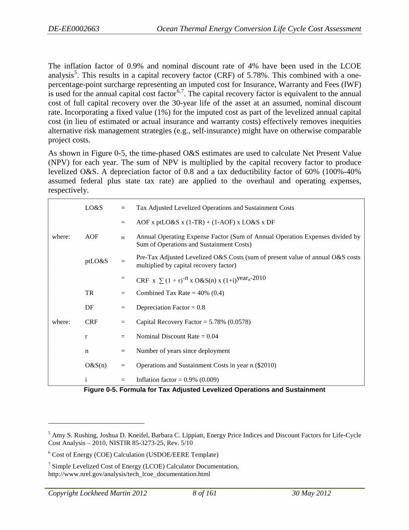
The inflation factor of 0.9% and nominal discount rate of 4% have been used in the LCOE analysis5. This results in a capital recovery factor (CRF) of 5.78%. This combined with a one-percentage-point surcharge representing an imputed cost for Insurance, Warranty and Fees (IWF) is used for the annual capital cost factor6,7
As shown in
. The capital recovery factor is equivalent to the annual cost of full capital recovery over the 30-year life of the asset at an assumed, nominal discount rate. Incorporating a fixed value (1%) for the imputed cost as part of the levelized annual capital cost (in lieu of estimated or actual insurance and warranty costs) effectively removes inequities alternative risk management strategies (e.g., self-insurance) might have on otherwise comparable project costs.
Figure 0-5, the time-phased O&S estimates are used to calculate Net Present Value (NPV) for each year. The sum of NPV is multiplied by the capital recovery factor to produce levelized O&S. A depreciation factor of 0.8 and a tax deductibility factor of 60% (100%-40% assumed federal plus state tax rate) are applied to the overhaul and operating expenses, respectively.
LO&S = Tax Adjusted Levelized Operations and Sustainment Costs
= AOF x ptLO&S x (1-TR) + (1-AOF) x LO&S x DF
where: AOF ≡ Annual Operating Expense Factor (Sum of Annual Operation Expenses divided by Sum of Operations and Sustainment Costs)
ptLO&S = Pre-Tax Adjusted Levelized O&S Costs (sum of present value of annual O&S costs multiplied by capital recovery factor)
= CRF x ∑ (1 + r)-n x O&S(n) x (1+i)yearn-2010
TR = Combined Tax Rate = 40% (0.4)
DF = Depreciation Factor = 0.8
where: CRF = Capital Recovery Factor = 5.78% (0.0578)
r = Nominal Discount Rate = 0.04
n = Number of years since deployment
O&S(n) = Operations and Sustainment Costs in year n ($2010)
i = Inflation factor = 0.9% (0.009) Figure 0-5. Formula for Tax Adjusted Levelized Operations and Sustainment
5 Amy S. Rushing, Joshua D. Kneifel, Barbara C. Lippiatt, Energy Price Indices and Discount Factors for Life-Cycle Cost Analysis – 2010, NISTIR 85-3273-25, Rev. 5/10 6 Cost of Energy (COE) Calculation (USDOE/EERE Template) 7 Simple Levelized Cost of Energy (LCOE) Calculator Documentation, http://www.nrel.gov/analysis/tech_lcoe_documentation.html

DE-EE0002663 Ocean Thermal Energy Conversion Life Cycle Cost Assessment
Copyright Lockheed Martin 2012 9 of 161 30 May 2012
Table 0-4 shows the terms in the LCOE equation for the three Grid Connected OTEC plants and the Energy Carrier OTEC plant.
Table 0-4. LCOE Values for Grid Connected and Energy Carrier OTEC Plants
100 MW Grid
Connected 200 MW Grid
Connected 400 MW Grid
Connected 400 MW Energy
Carrier Deployment Year 2018 2022 2026 2026 System Life 30 years 30 years 30 years 30 years CRF 5.8% 5.8% 5.8% 5.8% IWF 1.0% 1.0% 1.0% 1.0% ICC (in deployment year) $1,506,000,000 $2,494,000,000 $4,044,000,000 $4,168,000,000 Real Discount Rate 4.0% 4.0% 4.0% 4.0% Inflation Factor 0.9% 0.9% 0.9% 0.9% Levelized Capital Cost (ICC x 0.08) $102,100,000 $169,100,000 $274,300,000 $282,700,000 Levelized Tax Adjusted O&S Cost $40,700,000 $71,500,000 $119,300,000 $163,100,000 Total Annual Levelized Cost $142,800,000 $240,600,000 $393,600,000 $445,800,000 Availability Factor 92% 92% 92% 92% Annual Net Energy Output 805,920 MWh/y 1,611,840 MWh/y 3,223,680 MWh/y 3,223,680 MWh/y Levelized Cost of Energy $0.177/kWh $0.149/kWh $0.122/kWh $0.138/kWh
0.2.2 Technology and Efficiency Improvements As the OTEC industry develops and the rate of plant construction increases, innovative components and manufacturing techniques will result in reduced capital expense, reduced operations and sustainment costs, and increased plant efficiency. Analysis of specific technology insertion and manufacturing efficiency improvements results in projected capital cost savings of 11% and plant efficiency improvements of 12% in the 100 MW configuration. Furthermore, for the Grid Connected OTEC plant, significant cost savings are predicted for the power cable by transitioning from AC cables to DC cables (an emerging technology). Power cable costs are predicted to reduce by 70%. Using an assumed build out plan of two plants per year and assuming that technology and efficiency improvements would be realized by the 16th plant, these savings and improvements were applied to the LCOE analysis taking inflation and time phasing into account. The resulting LCOE values are presented in Table 0-5.
Table 0-5. Projected Future LCOE Values for 16th OTEC Plant of Each Configuration
Future LCOE Projections
100 MW Grid Connected
200 MW Grid Connected
400 MW Grid Connected
400 MW Energy Carrier
LCOE $0.157/kWh $0.132/kWh $0.108/kWh $0.123/kWh Year Realized 2037 2041 2045 2045
The above analysis is a conservative assessment of LCOE reductions over time. Previous studies indicate that transformative processes and technology, such as Mist Lift, could result in

DE-EE0002663 Ocean Thermal Energy Conversion Life Cycle Cost Assessment
Copyright Lockheed Martin 2012 10 of 161 30 May 2012
significant capital cost reductions greater than 20%8
0.2.3 Location Impacts
. A 20% reduction in capital cost by 2045 for the 400 MW Energy Carrier Producer OTEC plant results in a LCOE of $116/MWh – more than 5% lower than that resulting from the specific predicted improvements included herein.
Beyond technology developments and efficiency improvements, the ocean thermal resource available and installation location have an influence on the achievable LCOE. The analysis performed above assumes a nominal ocean thermal resource providing a temperature differential of 20̊ C. Makai OTEC Thermodynamic and Economic Model (MOTEM) is a computer model that predicts technical performance as well as system cost estimates based on a system’s environmental data and technical parameters. MOTEM provides a high-level estimate based on parametric analysis of a given location. Although the MOTEM approach is very different from that used to generate the detailed CAPEX estimates, the results of both approaches are comparable. For a 100 MW OTEC plant assuming a nominal 20̊C temperature differential, CAPEX and MOTEM estimates are within 10% of each other. Because MOTEM generates an estimate on a parametric basis, a conservative 20% factor is included in reported results to account for miscellaneous cost elements not explicitly estimated. As a result, reported MOTEM capital cost predictions tend to be more conservative than those reported for CAPEX.
Using MOTEM, capital expense was predicted for five different locations to provide a sense of the impact location has on the plant’s capital cost. Estimate results are provided in Table 0-6. These locations do not represent the extremes of the available OTEC resource globally but do show a variability of 20% or more based on location and available temperature differential.
Table 0-6. Location Specific MOTEM Capital Cost Results
Capital Cost ($ millions) Plant Size (Designed Net Power Output)
Temperature Differential
100 MW 200 MW 400 MW
Grid Connected
Hawai’i 21.4˚C $1,528 $2,546 $4,544
Guam 24.0˚C $1,395 $2,309 $4,075
Florida 20.4˚C $1,672 $2,791 $5,908
Energy Carrier Producer
West Atlantic 22.6˚C $1,457 $2,490 $4,502
West Pacific 24.7˚C $1,357 $2,302 $4,173
If the OTEC plant configuration is fixed, resource variation and distance from shore results in varying net power delivered to shore for nominally the same capital and O&S cost. Using the nominal OTEC plant configuration defined for the CAPEX estimates and adjusted only for distance from shore (power cable costs), LCOE was calculated as a function of resource “quality.” Resource “quality” is a quantitative measure translating a location specific thermal 8 Joseph Van Ryzin, Steven Rizea, Stuart Ridgway. Development of Mist Lift: A Cost Breakthrough for OTEC – 2010. DE-PS02-09ER09-27

DE-EE0002663 Ocean Thermal Energy Conversion Life Cycle Cost Assessment
Copyright Lockheed Martin 2012 11 of 161 30 May 2012
resource into an equivalent percentage of net power produced by the nominal OTEC plant compared to the net power produced by that plant under baseline design conditions. The nominal OTEC plant configuration was defined based on a thermal resource equal to that near Hawai’i (approximately 20˚ average temperature differential between surface water and water at 1000 m). Figure 0-6 presents the resulting LCOE values for the nominal 400 MW Grid Connected OTEC plant configuration9
as a function of resource quality for two different distances from shore. It is worth noting that even with a standard configuration, cold and warm water flow rates could be adjusted to optimize energy production for a given resource. Site specific configuration modifications and flow rate optimization could generate higher production rates than those predicted herein.
Figure 0-6. LCOE Location Variability for a Fixed Nominal 400 MW OTEC Plant Configuration
0.3 Energy Supply Curves Energy Supply Curves are useful in evaluating the size and desirability of a particular sustainable energy technology. These curves take into account the energy available in the region of interest for the energy resource under consideration. They also include the projected cost to deploy and operate the energy conversion systems that generate electricity or an energy carrier for transport to the consumer.
9 The 400 MW configuration projected for deployment in 2045 after predicted technology and efficiency improvements are realized was used for this analysis.

DE-EE0002663 Ocean Thermal Energy Conversion Life Cycle Cost Assessment
Copyright Lockheed Martin 2012 12 of 161 30 May 2012
The axes of Energy Supply Curves are LCOE measured in dollars per kilowatt-hour ($/kWh) versus Total Production Capacity measured in terawatt hours. In the case of OTEC, the available thermal resource and capital cost of the plant are major drivers of LCOE costs as evident in Figure 0-7. As the OTEC plants increase in size, the capital cost of the larger systems increase but the cost/megawatt decreases. Thus, there is a clear advantage of using the largest possible OTEC plant to meet the base-load energy needs in a region of interest. The region of interest and its available thermal resource will have a major impact on the resulting LCOE and shape of the energy supply curve. The following sections present Energy Supply Curves for initial OTEC deployment in Hawai’i starting in 2018 and Energy Supply Curves for the United States (U.S.) and globally for plants deployed in 2045.
0.3.1 Energy Supply Curve for Initial OTEC Deployment Hawai’i is highly dependent on energy imports and suffers from high energy prices making it eager to explore local, renewable energy sources. The island of Oahu, Hawai’i, has the largest population of all the Hawai’ian Islands and, therefore, the largest electricity demand. The island enjoys a good ocean thermal resource that is sufficiently close to shore to allow the electricity to be connected to the power grid by marine power cable. As a result, Oahu, HI was selected as the site of initial OTEC deployment for this study.
It is assumed that the initial OTEC plants will be situated in water depths between 1,000 m and 2,000 m to allow access to deep cold water. The regions with these water depths are indicated in green and orange in Figure 0-8. The region on the Southwest side of Oahu (indicated in orange) has the preferred OTEC region. Being on the leeward side of the island, surface water temperatures are generally 3º C warmer than on the windward (Northeast) side of the island. The white dotted line designates a distance of 20 km from shore that is within a reasonable distance for a marine power cable deployment.
Because this is the initial deployment of OTEC plants, the assumed build out plan starts with a single 100 MW plant and progressively adds more and larger plants. The first 100 MW plant is deployed in 2018 followed two years later by a second 100 MW plant. Two years later, the first 200 MW plant is deployed followed two years later by a second 200 MW plant. The first 400 MW plant is deployed in 2026 followed two years later by a second 400 MW plant. This progression from 100 MW plants to 400 MW plants is seen as a logical progression from smaller
Figure 0-7. LCOE Sensitivity Analysis Results
Figure 0-8. Oahu Preferred OTEC Region
-0.15 -0.1 -0.05 0 0.05 0.1 0.15
LCOE Sensitivity AnalysisEach Parameter Varied by +10% (upper bar) and -10% (lower bar)
Resource Quality
Availability
Capital
O&S
Nominal Discount Rate
Inflation
Distance from Shore

DE-EE0002663 Ocean Thermal Energy Conversion Life Cycle Cost Assessment
Copyright Lockheed Martin 2012 13 of 161 30 May 2012
to larger OTEC plants in the manufacturing process. These six plants can all be situated along the red line in Figure 0-8 with a square of 4 km on a side (16 km2) allocated to each OTEC plant to avoid the mooring lines from crossing each other.
Figure 0-9 shows the Energy Supply Curve for Oahu where electricity ranges from $177/MWh for the first 100 MW plant down to $116/MWh for the second 400 MW plant. The slight reduction in LCOE value between the first and second plant of each size results from improved manufacturing efficiency anticipated for the second plant compared to the first. The overall downward trend in the LCOE values shown in the Energy Supply Curve results from economies of scale of the larger plants compared to the smaller plants.
0.3.2 Global OTEC Energy Supply Curves OTEC has the potential to tap a vast global resource. Figure 0-10 is a map of the world showing the “quality” of the OTEC resource in the different ocean regions. The deep red color indicates the best OTEC thermal resource. The available temperature differential and density profile at a given location dictates how much electricity can be produced by a given plant configuration. This directly impacts the denominator of the LCOE calculation.
Figure 0-10. Global OTEC Resource Quality (foreground) and Plant Spacing (background)
Figure 0-9. Oahu Energy Supply Curve

DE-EE0002663 Ocean Thermal Energy Conversion Life Cycle Cost Assessment
Copyright Lockheed Martin 2012 14 of 161 30 May 2012
For the Global Energy Supply Curves, the levelized cost of energy is assessed at the point the energy enters the market. For Grid Connected OTEC plants, that occurs when the electricity reaches shore and can be connected into the grid. For the Energy Carrier Producer OTEC plants, that occurs when the transported ammonia reaches port. Therefore, the distance from shore or port has a direct impact on the levelized cost (the numerator of the LCOE calculation). Because Grid Connected OTEC plants and Energy Carrier Producer OTEC plants produce different energy products, two different Global Energy Supply Curves are developed, one for the resource that can be exploited by a Grid Connected OTEC plant and that which requires an Energy Carrier Producer OTEC plant.
Results from the OTEEV project are used to generate the Energy Supply Curves using the predicted “quality” of the OTEC resource, indicated by the equivalent annual net power that could be produced by a nominal 100 MW OTEC plant and the number of OTEC plants that each grid point can support.
The output from OTEEV is divided into 12 categories for Grid Connected OTEC Plants and 18 categories for Energy Carrier Producer OTEC Plants defined by distance to shore/port and resource quality. For each category, LCOE is calculated for a 400 MW OTEC plant in 2045 taking the predicted technology and efficiency improvements into account and adjusted for distance to shore or distance to port and resource quality.
To build the Energy Supply Curves, the LCOEs for each plant type are sorted in ascending order along with the total production capacity for each category. The LCOE for each category is plotted against the cumulative production capacity to produce incremental LCOE Energy Supply Curves as shown in Figure 0-11 and Figure 0-12. The incremental LCOEs are integrated over and divided by the cumulative production capacity resulting in a cumulative LCOE also shown in Figure 0-11 and Figure 0-12.
Figure 0-11. Global Grid Connected OTEC Energy Supply Curve
Figure 0-12. Global Energy Carrier OTEC Energy Supply Curve

DE-EE0002663 Ocean Thermal Energy Conversion Life Cycle Cost Assessment
Copyright Lockheed Martin 2012 15 of 161 30 May 2012
0.3.3 OTEC Energy Supply Curves for Exclusive Economic Zone of the United States The Global Energy Supply Curves provide an overview of the OTEC resource. For more specific insight into the OTEC resource available to the U.S., Energy Supply Curves were generated for the exclusive economic zones of the continental U.S., Hawai’i, and other U.S. islands. These curves are presented in Figure 0-13, Figure 0-14, and Figure 0-15 showing a total OTEC resource in the U.S. EEZs of 4,514 TWh/yr. This is nearly equal to the U.S. electricity consumption predicted by the U.S. Energy Information Administration of 4,481 TWh/yr by 203510
.
10 http://www.eia.gov/oiaf/aeo/tablebrowser/#release=AEO2011&subject=2-AEO2011&table=2-AEO2011®ion=1-0&cases=ref2011-d020911a
Figure 0-13. Continental U.S. Grid Connected OTEC Plants Energy Supply Curve
Figure 0-14. Hawai’i Grid Connected OTEC Plants
Energy Supply Curve
Figure 0-15. Other U.S. Islands Grid Connected
OTEC Plants Energy Supply Curve

DE-EE0002663 Ocean Thermal Energy Conversion Life Cycle Cost Assessment
Copyright Lockheed Martin 2012 16 of 161 30 May 2012
0.4 Areas for Future Studies While working on the various aspects of this project, we identified a number of specific areas having the potential to provide significant improvements for the prospects of OTEC commercial development. Table 0-7 summarizes these areas.
Table 0-7. Areas for Future Studies
Title Description Engineered Cost Estimates
Develop a design and associated cost estimate for a 400 MW OTEC plant for Hawai’I; Interpolate and scale estimate for other plant sizes and locations
Site-specific Design and Cost Estimates
Select the site for the first commercial OTEC plant; Develop designs for site-specific components; Develop cost estimates for the first commercial OTEC plant
Energy Carrier Concept of Operations
Analyze options for crew transport to grazing OTEC plants; Evaluate the benefits of incorporating Energy Carrier transport into the economics of the grazing OTEC plants; Evaluate station keeping options for grazing OTEC plants
Standards for OTEC Design
Assess the risks and impacts of reducing safety factors and design margins for OTEC plants relative to offshore oil rigs; Estimate cost savings impacts
Power Modules Standardization and Optimization
Develop a design for the Remoras for efficient manufacture; Estimate manufacture tooling and facility costs; Estimate future CAPEX for efficient manufactured OTEC Remoras
HX Design and Manufacture
Same as described for Power Modules Standardization and Optimization applied specifically to heat exchanger manufacturing
Water Intake and Plume Modeling
Develop detailed warm and cold water intake flows for improved understanding of densely packed OTEC plants
Heat Exchanger Materials
Investigate new heat exchanger materials for improved heat transfer and greater durability; Estimate the potential savings in CAPEX and O&S costs
Platform Materials and Construction
Investigate new materials and construction methods for platform construction and assembly; Estimate the potential savings in CAPEX and O&S costs
Energy Carrier Explore other potential energy carriers beyond ammonia; Develop concept designs for energy carrier production and transport; Estimate the potential savings in CAPEX and O&S costs
Binary Fluid Cycles
Investigate the Kalina and Uehara cycles and potentially others for OTEC use
Mist Lift Develop an R&D program including experimentation and computer modeling of the Mist Lift Concept
0.5 Conclusions The global ocean thermal resource shown in Figure 0-11 is a vast, available and sustainable energy source that can be harvested by OTEC for the benefit of the U.S. and the world. Most notably, OTEC can provide continuous energy. Other solar powered energy collection systems only collect energy that falls directly on the collector (i.e. photovoltaic panel). OTEC gathers thermal energy that resides in the warm surface layer of the ocean renewed daily from sunlight that is absorbed by this very efficient thermal fluid system. Since seawater is a fluid, it can flow to the OTEC plant where the stored thermal energy can drive a Rankine power cycle to generate large amounts of clean electrical energy. For remote locations the electricity can be used to produce anhydrous ammonia, a carbon-free energy carrier. This energy carrier allows for transportation of the stored energy to consumers ashore. The OTEC base-load feature provides a highly reliable energy system where the economics are not dependent on specific weather conditions as are wind and wave energy systems.

DE-EE0002663 Ocean Thermal Energy Conversion Life Cycle Cost Assessment
Copyright Lockheed Martin 2012 17 of 161 30 May 2012
This report provides an estimate of future costs of OTEC power based on the most current OTEC development work and advancement projections. Close examination of the capital, operations and sustainment expenses associated with OTEC has resulted in a detailed assessment of the cost associated with the long-term operation of OTEC plants that need to supply energy reliably for 30 or more years while operating in a harsh marine environment. Projected near-term and longer-term technology and efficiency improvements provide a strong basis for predicted reductions in OTEC LCOE. It is conceivable that within 20 years of deployment of the first commercial OTEC plant LCOE values could be driven well below 10 cents per kWh as the richest ocean thermal resource locations are tapped and new technologies with improved processes are employed.
During the course of this study and the previous work upon which it is based, several key aspects of OTEC were discovered or reinforced. First, OTEC harvests energy from a vast resource; the global OTEC resource is estimated to be between 3 and 7 TW. This needs to be emphasized in light of the widespread misconception that OTEC is a niche technology. OTEC has the capability to supply a significant portion of the world’s energy needs. Estimated global OTEC supply delivered to shore for Grid Connected and Energy Carrier OTEC plants is equivalent to 37,000 TWh. In comparison, total global electricity consumption projected for 2035 is 31,917 TWh11 and total U.S. energy use (including residential, commercial, transportation and industry consumption for all energy sources) is projected to be 31,653 TWh in 203512. Based on the total global energy consumption projected to be 225,674 TWh by 203513
In addition to size, OTEC does not compete with other critical resources such as water, land or food supplies. At most sites suitable for Grid Connected OTEC plants, OTEC has the ability to easily meet current and future local energy demands. With many communities struggling today to apply alternative power that provides only a small percentage of the required power intermittently, OTEC stands out as a unique, game changing technology by providing 100% firm alternative electrical energy. For island nations that are highly dependent on imported energy sources, such as Hawai’i, OTEC presents a unique opportunity to break that dependence, produce 100% of their own electricity and potentially become an energy exporter. The coastal market alone (25,367 TWh/year) is sufficiently large to justify and support a significant OTEC industry, one that expands and improves over decades.
, the estimated OTEC supply could provide up to 16% of the total global energy demand.
It is the opinion of the contributors to this study and report that the vast, virtually untapped ocean thermal resource and LCOE values predicted in this study present an exciting OTEC commercialization opportunity. OTEC commercialization represents a tremendous opportunity to develop an alternative, non-carbon based, renewable energy source that can provide stable, continuous energy. The study team recommends pursuing projects addressing one or more of the areas for future studies in furtherance of OTEC commercialization.
11 http://www.eia.gov/oiaf/aeo/tablebrowser/#release=IEO2011&subject=0-IEO2011&table=15-IEO2011®ion=4-0&cases=Reference-0504a_1630 12 http://www.eia.gov/oiaf/aeo/tablebrowser/#release=EARLY2012&subject=0-EARLY2012&table=1-EARLY2012®ion=0-0&cases=full2011-d020911a,early2012-d121011b 13 http://www.eia.gov/forecasts/ieo/index.cfm

DE-EE0002663 Ocean Thermal Energy Conversion Life Cycle Cost Assessment
Copyright Lockheed Martin 2012 18 of 161 30 May 2012
Table of Contents 0 OTEC Life Cycle Cost Assessment Executive Summary ...................................................3
0.1 Overview ..............................................................................................................................3
0.2 Levelized Cost of Electricity/Energy (LCOE) .....................................................................6
0.3 Energy Supply Curves .......................................................................................................11
0.4 Areas for Future Studies ....................................................................................................16
0.5 Conclusions ........................................................................................................................16
1 OTEC Life Cycle Cost Assessment Introduction ..............................................................25
1.1 OTEC Life Cycle Cost Assessment (OLCCA) Overview .................................................25
1.2 OLCCA Objectives ............................................................................................................25
1.3 OLCCA Approach .............................................................................................................26
1.4 Organization of the OLCCA Final Report .........................................................................27
2 Acronyms and Terminology Definition .............................................................................29
3 OTEC Plant Design............................................................................................................32
3.1 Grid Connected Plants .......................................................................................................33
3.2 Energy Carrier Plants .........................................................................................................35
3.3 OTEC Plant Configuration During Cold Water Pipe Fabrication .....................................38
4 Capital Cost Estimation Approach.....................................................................................39
4.1 Cost Models .......................................................................................................................39
4.2 Basis of Estimates (BOE) and Results for Grid Connected Plants ....................................42
4.3 BOE and Results for Energy Carrier Plants .......................................................................54
5 Operations and Sustainment (O&S) Cost Estimation Approach .......................................61
5.1 LCC Analysis Methodology ..............................................................................................63
5.2 OTEC O&S LCCA Cost Element Structure ......................................................................66
5.3 Grid Connected Plant Variant ............................................................................................68
5.4 Energy Carrier Plants .........................................................................................................73
5.5 OTEC Operations and Sustainment LCCA Results...........................................................77
5.6 O&S Estimate Summary ....................................................................................................86
6 Personnel Cost Analysis ....................................................................................................87
6.1 Personnel Requirements.....................................................................................................87
6.2 Personnel Cost Estimates ...................................................................................................89
7 Environmental Requirements and Costs ............................................................................91
7.1 Hawai’ian Site Requirements and Costs ............................................................................91
DE-EE0002663 Ocean Thermal Energy Conversion Life Cycle Cost Assessment
Copyright Lockheed Martin 2012 19 of 161 30 May 2012
7.2 Florida Site .......................................................................................................................111
7.3 Western Atlantic Site .......................................................................................................117
7.4 Western Pacific Site .........................................................................................................118
8 Technology and Efficiency Improvement Opportunities ................................................119
8.1 Cost Reduction and Efficiency Improvement Estimation Approach ...............................120
8.2 Components .....................................................................................................................121
8.3 Transformative OTEC Development ...............................................................................123
9 Levelized Cost of Electricity ...........................................................................................124
9.1 LCOE Approach ..............................................................................................................124
9.2 LCOE for the First OTEC Plants .....................................................................................129
9.3 Impact of Projected Technology and Efficiency Improvements on LCOE .....................130
9.4 Impact of Transmission/Transportation Losses on LCOE...............................................133
9.5 LCOE Sensitivity Analysis ..............................................................................................139
10 Energy Supply Curves .....................................................................................................140
10.1 Energy Supply Curves for Model Oahu, Hawai’i Initial OTEC Deployment ...........140
10.2 Global OTEC Energy Supply Curves ........................................................................145
10.3 OTEC Energy Supply Curves for Exclusive Economic Zone of the United States ..152
11 Areas for Future Study .....................................................................................................154
11.1 Engineered Cost Estimates ........................................................................................154
11.2 Site-specific Cost Refinement....................................................................................154
11.3 Energy Carrier Concept of Operation ........................................................................155
11.4 Standards for OTEC Design – Recommended Practices ...........................................155
11.5 Standardization and Optimization of Power Modules ...............................................156
11.6 Standardization of HX Design and Optimization of Manufacturing Processes ........157
11.7 Water Intake and Plume Modeling ............................................................................157
11.8 Heat Exchanger Materials ..........................................................................................157
11.9 Platform Materials and Construction .........................................................................157
11.10 Energy Carrier ............................................................................................................157
11.11 Transformative OTEC Development .........................................................................157
12 Conclusions ......................................................................................................................160

DE-EE0002663 Ocean Thermal Energy Conversion Life Cycle Cost Assessment
Copyright Lockheed Martin 2012 20 of 161 30 May 2012
List of Figures Figure 0-1. OTEC Power Cycle ...................................................................................................... 4
Figure 0-2. OTEC Plant Deck Artistic Rendering .......................................................................... 4
Figure 0-3. OTEC Plant Artistic Rendering ................................................................................... 5
Figure 0-4. Diagram of Ammonia Production Using Electrolysis ................................................. 5
Figure 0-5. Formula for Tax Adjusted Levelized Operations and Sustainment ............................. 8
Figure 0-6. LCOE Location Variability for a Fixed Nominal 400 MW OTEC Plant Configuration ....................................................................................................................................................... 11
Figure 0-7. LCOE Sensitivity Analysis Results ........................................................................... 12
Figure 0-8. Oahu Preferred OTEC Region ................................................................................... 12
Figure 0-9. Oahu Energy Supply Curve ....................................................................................... 13
Figure 0-10. Global OTEC Resource Quality (foreground) and Plant Spacing (background) ..... 13
Figure 0-11. Global Grid Connected OTEC Energy Supply Curve ............................................. 14
Figure 0-12. Global Energy Carrier OTEC Energy Supply Curve ............................................... 14
Figure 0-13. Continental U.S. Grid Connected OTEC Plants Energy Supply Curve ................... 15
Figure 0-14. Hawai’i Grid Connected OTEC Plants Energy Supply Curve ................................. 15
Figure 0-15. Other U.S. Islands Grid Connected OTEC Plants Energy Supply Curve ................ 15
Figure 3-1. Artistic Rendering of OTEC Plant Design ................................................................. 33
Figure 3-2. OTEC System Architecture ........................................................................................ 34
Figure 3-3. Diagram of Ammonia Production Using Electrolysis ............................................... 36
Figure 3-4. Artist’s Concept of OTEC Plant During Pipe Fabrication ......................................... 38
Figure 4-1. 2010 Single Remora, 5 MW Design .......................................................................... 42
Figure 4-2. 2008 8-Remora, 100 MW Design .............................................................................. 42
Figure 4-3. Summary of CAPEX for OTEC Plant Configurations .............................................. 48
Figure 4-4. Seasonal Temperature Difference for Grid Connected OTEC Plants ........................ 50
Figure 4-5. Summary of Grid Connected OTEC Plant Economy of Scale .................................. 53
Figure 4-6. Western Pacific Energy Carrier OTEC Plant Location .............................................. 57
Figure 4-7. Western Atlantic Energy Carrier OTEC Plant Location ............................................ 58
Figure 4-8. Energy Carrier Plant Economy of Scale .................................................................... 60
Figure 5-1. Life Cycle Cost Process ............................................................................................. 62
Figure 5-2. Cost Estimation Flow ................................................................................................. 65
Figure 5-3. Proposed OTEC Roll-out Plan for Oahu, Hawai’i ..................................................... 71
Figure 5-4. Proposed Energy Carrier OTEC Roll-out Plan .......................................................... 76

DE-EE0002663 Ocean Thermal Energy Conversion Life Cycle Cost Assessment
Copyright Lockheed Martin 2012 21 of 161 30 May 2012
Figure 5-5. 100 MW Grid Connected Cost Breakdown ............................................................... 78
Figure 5-6. 100 MW Yearly O&S Expenditures .......................................................................... 78
Figure 5-7. 200 MW Grid Connected Cost Breakdown ............................................................... 80
Figure 5-8. 200 MW Yearly O&S ................................................................................................ 80
Figure 5-9. 400 MW Grid Connected Cost Breakdown ............................................................... 82
Figure 5-10. 400 MW Yearly O&S .............................................................................................. 82
Figure 5-11. All Grid Connected Yearly O&S ............................................................................. 83
Figure 5-12. 400 MW Energy Carrier Cost Breakdown ............................................................... 84
Figure 5-13. Energy Carrier 400 MW Yearly O&S Cost ............................................................. 84
Figure 5-14. All Energy Carrier Plants Yearly O&S .................................................................... 85
Figure 5-15. Breakdown of Total Ownership Cost by OTEC Plant Configuration ...................... 86
Figure 5-16. Breakdown of Total Ownership Cost Per MW Installed by OTEC Plant Configuration ................................................................................................................................ 86
Figure 6-1. Estimated OTEC Personnel Requirements Survey Results ....................................... 88
Figure 7-1. NEPA Compliance ..................................................................................................... 92
Figure 7-2. Hawai‘i EIS Process ................................................................................................... 94
Figure 7-3. ESA Section 7 Consultation ..................................................................................... 105
Figure 7-4. Estimated Permitting Costs for 100 MW OTEC Plant in Hawai‘i .......................... 107
Figure 7-5. Estimated Permitting Costs for 200 MW OTEC Plant in Hawai‘i .......................... 108
Figure 7-6. Estimated Permitting Costs for 400 MW OTEC Plant in Hawai‘i .......................... 108
Figure 7-7. Estimated Permitting Costs for 100 MW OTEC Plant in Guam ............................. 112
Figure 7-8. Estimated Permitting Costs for 200 MW OTEC Plant in Guam ............................. 112
Figure 7-9. Estimated Permitting Costs for 400 MW OTEC Plant in Guam ............................. 113
Figure 7-10. Estimated Permitting Costs for 100 MW OTEC Plant in Florida .......................... 115
Figure 7-11. Estimated Permitting Costs for 200 MW OTEC Plant in Florida .......................... 115
Figure 7-12. Estimated Permitting Costs for 400 MW OTEC Plant in Florida .......................... 116
Figure 9-1. Equation for LCOE .................................................................................................. 125
Figure 9-2. Time Phased Operation and Sustainment Costs from the O&S Life Cycle Cost Model ..................................................................................................................................................... 127
Figure 9-3. Formula for Pre-tax Adjusted LO&S Costs ............................................................. 127
Figure 9-4. Formula for Tax Adjusted LO&S ............................................................................ 128
Figure 9-5. Formula for Net Annual Energy Production ............................................................ 128

DE-EE0002663 Ocean Thermal Energy Conversion Life Cycle Cost Assessment
Copyright Lockheed Martin 2012 22 of 161 30 May 2012
Figure 9-6. LCOE with Learning Curve Factor Applied for 100 MW Grid Connected OTEC Plant Configuration ..................................................................................................................... 131
Figure 9-7. LCOE with Learning Curve Factor Applied for 200 MW Grid Connected OTEC Plant Configuration ..................................................................................................................... 131
Figure 9-8. LCOE with Learning Curve Factor Applied for 400 MW Grid Connected OTEC Plant Configuration ..................................................................................................................... 132
Figure 9-9. LCOE with Learning Curve Factor Applied for 400 MW Energy Carrier OTEC Plant Configuration .............................................................................................................................. 132
Figure 9-10. Marine Power Cable Efficiency Versus Distance from Shore Modeling Results for Current Cable Technology .......................................................................................................... 134
Figure 9-11. Marine Power Cable Efficiency Versus Distance from Shore Modeling Results for Future Cable Technology ............................................................................................................ 134
Figure 9-12. LCOE Sensitivity Analysis Results ....................................................................... 139
Figure 10-1. Oahu with 1 km and 2 km Depth Contours ............................................................ 141
Figure 10-2. OTEC Region Less Than 20 km from Oahu .......................................................... 141
Figure 10-3. OTEC Thermal Resource (∆T) Leeward vs. Windward Sides of Oahu ................ 142
Figure 10-4. Estimating Length of OTEC Region ...................................................................... 143
Figure 10-5. Potential OTEC Plant Locations Around Oahu ..................................................... 144
Figure 10-6. Build Out Plan of OTEC Plants for Oahu .............................................................. 144
Figure 10-7. OTEC Energy Supply Curve for Oahu .................................................................. 145
Figure 10-8. Global OTEC Resource Quality (foreground) and Plant Spacing (background) ... 146
Figure 10-9. Impact of Resource Quality on the LCOE for Grid Connected OTEC Plants ....... 148
Figure 10-10. Impact of Resource Quality on the LCOE for Energy Carrier OTEC Plants ...... 148
Figure 10-11. Grid Connected OTEC Global Energy Supply Curve ......................................... 151
Figure 10-12. Energy Carrier OTEC Global Energy Supply Curve ........................................... 151
Figure 10-13. Continental U.S. Grid Connected OTEC Plants Energy Supply Curve ............... 152
Figure 10-14. Hawai’i Grid Connected OTEC Plants Energy Supply Curve ............................. 153
Figure 10-15. Other U.S. Islands Grid Connected OTEC Plants Energy Supply Curve ............ 153
List of Tables Table 0-1. OTEC Plant - Principal Dimensions .............................................................................. 5
Table 0-2. OTEC LCC Assessment Team Roles and Responsibilities .......................................... 6
Table 0-3. Equation for LCOE ........................................................................................................ 7
Table 0-4. LCOE Values for Grid Connected and Energy Carrier OTEC Plants ........................... 9

DE-EE0002663 Ocean Thermal Energy Conversion Life Cycle Cost Assessment
Copyright Lockheed Martin 2012 23 of 161 30 May 2012
Table 0-5. Projected Future LCOE Values for 16th OTEC Plant of Each Configuration ............... 9
Table 0-6. Location Specific MOTEM Capital Cost Results ....................................................... 10
Table 0-7. Areas for Future Studies .............................................................................................. 16
Table 3-1. OTEC Plant - Principal Dimensions ............................................................................ 33
Table 3-2. Technical Parameters of Grid Connected OTEC Plants .............................................. 35
Table 3-3. Technical Parameters of Energy Carrier OTEC Plants ............................................... 37
Table 4-1. 100 MW Cost Summary .............................................................................................. 43
Table 4-2. Segments Included in the OTEC System .................................................................... 43
Table 4-3. Segments Included in the OTEC Installation System ................................................. 44
Table 4-4. Segments Included in the CWP Fabrication Facility .................................................. 45
Table 4-5. 200 MW Capital Cost Summary, Scaled from 100 MW ............................................. 46
Table 4-6. 400 MW Plant Capital Cost Scaled from 200 MW ..................................................... 47
Table 4-7. Summary of CAPEX for OTEC Plant Configurations ................................................ 48
Table 4-8. Summary of Grid Connected OTEC Plant Locations and Capacity Analysis ............ 49
Table 4-9. Seasonal Seawater Temperatures and Distance to Shore for a Grid Connected OTEC Plant in Florida .............................................................................................................................. 50
Table 4-10. Seasonal Seawater Temperatures and Distance to Shore for a Grid Connected OTEC Plant in Hawai’i ............................................................................................................................ 50
Table 4-11. Seasonal Seawater Temperatures and Distance to Shore for a Grid Connected OTEC Plant in Guam ............................................................................................................................... 50
Table 4-12. Summary of CWP Cost Analysis .............................................................................. 51
Table 4-13. Summary of Power Cable Cost Analysis .................................................................. 51
Table 4-14. Summary of Mooring Cost Analysis ......................................................................... 52
Table 4-15. Summary of Deployment Cost Analysis ................................................................... 52
Table 4-16. MOTEM Grid Connected OTEC Plant Configuration Results ................................. 53
Table 4-17. Capital Cost Additions and Deductions to Derive CAPEX for Energy Carrier Plants from that of Grid Connected Plants .............................................................................................. 55
Table 4-18: Summary of Energy Carrier OTEC Plant Economic Analysis ................................. 56
Table 4-19. Seawater Temperature and Density Profiles for Western Pacific Energy Carrier Plant ....................................................................................................................................................... 57
Table 4-20. Seawater Temperature and Density Profiles for Western Atlantic Energy Carrier Plant .............................................................................................................................................. 58
Table 4-21. Summary of Energy Carrier Plant Economic Analysis ............................................. 60
Table 5-1. OTEC Grid Connected Configuration-Specific Assumptions .................................... 69

DE-EE0002663 Ocean Thermal Energy Conversion Life Cycle Cost Assessment
Copyright Lockheed Martin 2012 24 of 161 30 May 2012
Table 5-2 OTEC Grid Connected Common Equipment-Level Assumptions .............................. 70
Table 5-3. OTEC Grid Connected Plant-Specific Assumptions ................................................... 72
Table 5-4. OTEC Energy Carrier System-Level Assumptions ..................................................... 74
Table 5-5. OTEC Energy Carrier Producer Common Equipment-Level Assumptions ................ 75
Table 5-6. OTEC Energy Carrier Plant-Specific Assumptions .................................................... 77
Table 5-7. OTEC Grid Connected Summary Cost Table ............................................................. 79
Table 5-8. OTEC Grid Connected 200 MW Summary Cost Table .............................................. 81
Table 5-9 OTEC Grid Connected 400 MW Summary Cost Table ............................................... 83
Table 5-10 OTEC 400 MW Energy Carrier Summary Cost Table .............................................. 85
Table 6-1. Personnel Requirements for Grid Connected and Energy Carrier .............................. 88
Table 6-2. Representative Personnel Salary Data from Bureau of Labor Statistics ..................... 89
Table 6-3. OTEC Plant Personnel Requirements Summary ......................................................... 90
Table 7-1. NOAA Baseline Data Recommendations ................................................................... 96
Table 7-2. NOAA Monitoring Recommendations ........................................................................ 99
Table 7-3. Environmental Permit Requirements in Hawai‘i ...................................................... 103
Table 8-1. Cost Reductions ......................................................................................................... 119
Table 8-2. Component Efficiencies ............................................................................................ 119
Table 8-3. Summary of Projected Power Cable Cost Reductions with Use of HVDC Technology ..................................................................................................................................................... 123
Table 9-1. LCOE Calculations for First 100 MW, 200 M, and 400 MW OTEC Plants ............ 129
Table 9-2. LCOE Received at Shore Connection for Grid Connected OTEC Plants (20 km from Shore) .......................................................................................................................................... 135
Table 9-3. LCOE for Ammonia Delivered to Port for Energy Carrier OTEC Plants ................. 135
Table 9-4. Notional Energy Transport Voyages ......................................................................... 137
Table 9-5. Model Voyage Profile ............................................................................................... 138
Table 9-6. Transportation-Induced Ammonia Production Inefficiency ..................................... 139
Table 10-1. Grid Connected OTEC Categories .......................................................................... 150
Table 10-2. Energy Carrier Producing OTEC Categories .......................................................... 150

DE-EE0002663 Ocean Thermal Energy Conversion Life Cycle Cost Assessment
Copyright Lockheed Martin 2012 25 of 161 30 May 2012
1 OTEC Life Cycle Cost Assessment Introduction
1.1 OTEC Life Cycle Cost Assessment (OLCCA) Overview The Ocean Thermal Energy Conversion (OTEC) Life Cycle Cost Assessment (OLCCA) is a study performed by members of the Lockheed Martin (LM) OTEC Team under contract to the U.S. Department of Energy (DOE). This Final Report documents the results of the study and presents the information to enable the DOE to make clear comparisons between energy provided by OTEC and energy provided by other forms of renewable energy.
The LM Team OTEC design is in the pre-FEED stage of development where key portions of the system have been designed but the overall level of documentation is not sufficient for a shipyard to generate a price to build the system. Thus, all cost estimates developed to support the analysis in this report have been generated by the project engineering staff based on their experience and familiarity with large marine systems. The reader should note there are no commercial OTEC systems in existence today so the team had to apply good engineering judgment to estimate maintenance activities, equipment overhaul and replacement costs, operations requirements and costs, and initial capital costs to fabricate, assemble, deploy and test the final commercial systems.
1.2 OLCCA Objectives From the Statement of Project Objectives for the OLCCA project, the following list of objectives was used to establish the OLCCA work approach:
1) Modify existing Grid Connected OTEC design and cost estimates for application at multiple locations and OTEC sizes
2) Extrapolate our Grid Connected OTEC cost estimates to grazing OTEC plants 3) Identify start-up costs 4) Identify likely OTEC design evolutions for lower cost and higher performance 5) Define the required permitting and environmental compliance costs and schedule 6) Develop Life Cycle Cost (LCC) estimates for the baseline OTEC systems 7) Perform an economic analysis to derive OTEC cost of electricity (COE) as well as
generating Energy Supply Curves for future OTEC plants 8) Publish and present the results of the work as appropriate
We also established that two types of OTEC systems would be analyzed under the OLCCA effort:
1) Fixed OTEC plants located close to shore where output electricity is cabled directly to the power grid ashore, “Grid Connected”
2) Grazing open-ocean OTEC plant-ships that generate an energy carrier for transport to consumers ashore, “Energy Carrier”
The sizes of the Grid Connected OTEC plants to be analyzed were selected to be 100 MW, 200 MW and 400 MW. A single Energy Carrier OTEC plant-ship of 400 MW was selected for analysis.

DE-EE0002663 Ocean Thermal Energy Conversion Life Cycle Cost Assessment
Copyright Lockheed Martin 2012 26 of 161 30 May 2012
1.3 OLCCA Approach The LM OTEC Team’s approach to performing the study was to closely follow proposal task statements for this analysis as shown in Table 1-1.
Table 1-1. Analysis Tasks from the Statement of Project Objectives
Task Title Task Activities Final Report Sections
Task 1.0 - Near Shore Grid Connected Baseline
Define the baseline scenario and the capital cost requirements for a near shore grid connected OTEC plant and determine capital cost variations for several plant sizes and locations.
3 OTEC Plant Design, 4.2 Basis of Estimates (BOE) and Results for Grid Connected Plants
Task 2.0 - Offshore OTEC Industry Producing an Energy Carrier
Define the baseline scenario and the capital cost requirements for a large offshore OTEC system manufacturing an energy carrier and transporting that carrier to the continental U.S.
3 OTEC Plant Design, 4.3 BOE and Results for Energy Carrier Plants
Task 3.0 - Technology Development Program and Costs; Potential Technology Evolution
Investigate technology needs for early systems and likely technology changes as OTEC matures. 8 Technology and Efficiency
Improvement Opportunities
Task 4.0 - Environmental Cost Assessment
Define broad environmental concerns including permitting, licensing, and monitoring and establish an environmental cost assessment for an initial and subsequent OTEC plants.
7 Environmental Requirements and Costs
Task 5.0 – OTEC Life Cycle Cost Analysis (LCCA)
Develop Life Cycle Cost estimates for both near-shore OTEC plants with direct cable connection to the electrical power grid and open-ocean grazing OTEC producing an energy carrier.
5 Operations and Sustainment (O&S) Cost Estimation Approach

DE-EE0002663 Ocean Thermal Energy Conversion Life Cycle Cost Assessment
Copyright Lockheed Martin 2012 27 of 161 30 May 2012
Task 6.0 – OTEC Economic Analysis
Subtask 6.1
Perform a financial analysis of the cost of electricity (COE) for the near-shore OTEC plants and the open-ocean grazing OTEC plants
9 Levelized Cost of Electricity
Subtask 6.2
Develop Energy Supply Curves for projected Oahu OTEC plant build out plan, global near-shore OTEC plants and also a global fleet of grazing OTEC plants producing an energy carrier for transport to selected ports.
10 Energy Supply Curves
Task 7.0 – Project Management and Reporting
Reports and other deliverables will be provided in accordance with the Federal Assistance Reporting Checklist following the instructions included therein.
This document fulfills the Final Report requirement
Each of the above tasks was performed on a team basis with each subject matter expert taking the lead for his task under the direction of the Program Manager. Much of the material used in this analysis existed from previous efforts with the exception of the operations and maintenance estimates and replacement and overhaul estimates for the different subsystems. The LM Global Sustainment Group contributed their expertise to the task of estimating these costs in close association with each subsystem’s technical leads. This approach resulted in a very effective working group for developing this important cost information.
1.4 Organization of the OLCCA Final Report The following paragraphs provide a brief overview of the organization and content of the remainder of the OLCCA Final Report.
1.4.1 OTEC Plant Design The fundamental design of the Grid Connected OTEC plants and Energy Carrier OTEC plants are presented in Section 3.
1.4.2 Capital Cost Estimating Approach Section 4 describes the methods used to develop the CAPEX estimates for the OTEC systems. Throughout this report, the reader will see references to a MOTEM model of OTEC and a CAPEX model of OTEC. The Makai OTEC Thermodynamic and Economic Model (MOTEM) is a computer model that predicts technical performance as well as system cost estimates based on environmental data and technical parameters of the system. Capital Expense (CAPEX) is not actually a model at all but a method of keeping track of system capital cost estimates. CAPEX uses the OTEC system architecture established by the OTEC Systems Engineering group to describe the overall OTEC system as the bookkeeping framework for capital cost estimates.

DE-EE0002663 Ocean Thermal Energy Conversion Life Cycle Cost Assessment
Copyright Lockheed Martin 2012 28 of 161 30 May 2012
1.4.3 OTEC Operations and Sustainment (O&M + Replacement Costs) The effort to develop the estimates for operations and sustainment (O&S) of the OTEC systems is described in detail in Section 5.
1.4.4 OTEC Personnel Requirements Section 6 presents manpower requirements survey results to establish the crew size required to properly man each OTEC configuration under consideration and the associated costs. This section also addresses crew transport requirements and associated costs.
1.4.5 Environmental Requirements and Costs Since no floating OTEC plants have ever been licensed or deployed, the environmental requirements and resulting costs are relatively unknown. Section 7 provides the results of a detailed assessment of the likely requirements and costs required to achieve and maintain compliance and licensing.
1.4.6 Technology Development and Cost Reduction Opportunities As the OTEC industry develops and the rate of plant construction increases, innovative components and manufacturing techniques will result in reduced capital expense, reduced operations and sustainment costs, and increased plant efficiency. Specific technology insertion and manufacturing efficiency improvements are analyzed and projected to estimate possible cost savings and plant efficiency improvements. Section 8 describes the analysis, projections, and resulting cost reductions and improved plant efficiency.
1.4.7 Levelized Cost of Electricity/Energy (LCOE) The DOE paper on Levelized Cost of Electricity14
9
served as the basis for developing all costs used under this analysis effort. This approach provides a uniform methodology for calculating the COE produced by renewable energy systems taking into account generic financing for the capital cost of the installation, warranty, insurance and fees, the cost to operate and maintain the facility over the life of the system, and the costs of major equipment overhauls and replacement. The resulting LCOE values are for comparison purposes only and are not to be confused with the COE a customer might actually pay for electricity produced by these systems. The LCOE calculations are presented in Section .
1.4.8 Energy Supply Curves Energy Supply Curves for the island of Oahu, global Grid Connected OTEC plants and also a global fleet of Energy Carrier OTEC plants producing an energy carrier for transport to selected ports are presented and described in Section 10.
1.4.9 Future Studies, Conclusions and Recommendations These topics are covered in Section 10.3 and Section 12, respectively.
14 Cost of Energy (COE) Calculation (USDOE/EERE Template)

DE-EE0002663 Ocean Thermal Energy Conversion Life Cycle Cost Assessment
Copyright Lockheed Martin 2012 29 of 161 30 May 2012
2 Acronyms and Terminology Definition Acronym/Term Definition
ABL Allocated Baseline
BLNR Board of Land and Natural Resources
BOE Basis of Estimate
CAPEX Capital Expense
CDUP Conservation District Use Permit
CER Cost Estimating Relationship
CES Cost Element Structure
CI Configuration Item
CIA Cultural Impact Analysis
CM Configuration Management
COE Cost of Electricity/Energy – ratio of costs to energy produced resulting in $/unit of energy
COE US Army Corps of Engineers
CONOPS Concept of Operations
COTS Commercial Off-the-Shelf
CRF Capital Recovery Factor
CTD Conductivity Temperature Depth
CW Cold Water
CWA U.S. Clean Water Act
CWP Cold Water Pipe
CZM Coastal Zone Management
CZMA Coastal Zone Management Act
DA Department of the Army
DEP Department of Environmental Protection
DLNR Hawai‘i Department of Land & Natural Resources
DOE (United States) Department of Energy
DOT State Department of Transportation
DPP Department of Planning and Permitting
DRI Developments of Regional Impact
DE-EE0002663 Ocean Thermal Energy Conversion Life Cycle Cost Assessment
Copyright Lockheed Martin 2012 30 of 161 30 May 2012
dT Differential in Temperature
EA Environmental Assessment
EEZ Exclusive Economic Zone
EIS Environmental Impact Statement
EMF Electromagnetic Fields
EPA Environmental Protection Agency
ESA Endangered Species Act
EVMS Earned Value Management System
FOM Figure of Merit
FONSI Finding of No Significant Impact
FRP Fiber Reinforced Plastic
FWS Fish & Wildlife Service
GEPA Guam Environmental Protection Agency
HDD Horizontal Directional Drilling
HRS Hawai‘i Revised Statutes
HVDC High Voltage Direct Current
ICAR Intergovernmental Coordination and Review
ICC Initial Capital Cost
KIP Key Indicator(s) of Performance
KPP Key Performance Parameter
LCC Life Cycle Cost
LCCA Life Cycle Cost Analysis
LCOE Levelized Cost of Electricity/Energy – figure of merit value in $/unit of energy representing a constant COE over the life of the plant equating to the same net present value as the time phased capital and O&S costs
LM Lockheed Martin
LO&S Levelized Operations and Sustainment cost
LPG Liquefied Petroleum Gas
LRU Lowest Replaceable/Repairable Unit
MDO Marine Diesel Oil
MOE Measure of Effectiveness
DE-EE0002663 Ocean Thermal Energy Conversion Life Cycle Cost Assessment
Copyright Lockheed Martin 2012 31 of 161 30 May 2012
MOTEM Makai OTEC Thermodynamic and Economic Model
MSI Maintenance-significant Item
MW Mega-Watt
NEPA National Environmental Policy Act
NH3 Ammonia
NMFS National Marine Fisheries Service
NOAA U.S. National Oceanic & Atmospheric Administration
NPDES National Pollutant Discharge Elimination System
NRE Non-Recurring Engineering
O&M Operations and Maintenance
O&S Operations and Sustainment - traditional O&M cost components plus major overhaul and replacement costs
OCCL Hawai‘i State Office of Conservation & Coastal Lands
OCSLA Outer Continental Shelf Lands Act
OLCCA OTEC Life Cycle Cost Assessment
OTEC Ocean Thermal Energy Conversion
OTECA Offshore Thermal Energy Conversion Act
OTEEV Ocean Thermal Extractable Energy Visualization
PHS&T Packaging, Handling, Storage & Transportation
PMO/CLS Program Management Office/Contractor Logistics Support
PNGC Coast Management National Plan (Brazil)
POC Point of Contact
SMA Hawai‘i Special Management Area
U.S. United States
WQC Water Quality Certification
WW Warm Water

DE-EE0002663 Ocean Thermal Energy Conversion Life Cycle Cost Assessment
Copyright Lockheed Martin 2012 32 of 161 30 May 2012
3 OTEC Plant Design Six OTEC plant configurations were defined for the LCCA. The different configurations are defined based on the designed net power output and energy transportation method. Plants located nearshore can be moored to the seafloor and connected directly to the grid through a dynamic marine cable – referred to as “Grid Connected” OTEC plants. Plants deployed farther from shore cannot be directly cabled to the grid and may not be easily moored to the seafloor. Such plants generate an energy carrier that can be transported to shore by tanker ship. The selected energy carrier is ammonia. Net electricity produced on the plant is used to decompose seawater into hydrogen and oxygen. The hydrogen is then combined with atmospheric nitrogen to produce ammonia (NH3), which can be transported to port. These plants are referred to as “Energy Carrier” OTEC plants. Preliminary analysis has indicated that 60 km is the maximum distance at which a Grid Connected plant is more economical than an Energy Carrier plant when a standard alternating current power cable is used. High voltage direct current (HVDC) cables are predicted to extend the Grid Connected plant feasibility zone out to 240 kilometers.
Three sizes (100 MW, 200 MW and 400 MW), for both the Grid Connected OTEC plants and Energy Carrier OTEC plants, are included in this study to assess the economies of scale as net production is increased. Based on the economy of scale and assumption that all three plant sizes will be deployed for Grid Connected applications prior to the first Energy Carrier plant, the 400 MW configuration is the only Energy Carrier OTEC plant configuration included in the LCOE and Energy Supply Curve analysis.
All configurations included in this analysis are based on and scaled from the 10 MW OTEC Pilot Plant configuration defined under a LM-led program funded by NAVFAC15
Figure 3-1
and leverages conceptual design work performed for a 100 MW commercial scale OTEC plant performed in 2008. Supporting the OTEC plant is a ring-pontoon, column-stabilized, semi-submersible platform, as depicted in , housing the turbines, control room, personnel accommodations, maintenance equipment and helicopter pad. Heat exchangers and seawater pumps for the condenser and evaporator are housed in modular structures, referred to as “remoras,” that mount to platform’s sides. They are depicted as blue modules in the figure. These modules allow removal and replacement for required overhauls of the heat exchangers and seawater pumps for periodic overhaul with minimal downtime. When an overhaul is required, a new module is brought to the plant and exchanged with the module to be overhauled. The overhaul period is expected to be 15 years.
Based on the systems engineering work performed on the Pilot OTEC Plant design, the OTEC plant has been subdivided into five major segments, which include the following systems:
• OTEC • Cold Water Pipe Fabrication • Environmental Management • OTEC Installation • OTEC Decommissioning
OTEC System architecture is further broken down as shown in Figure 3-2. 15 NAVFAC Ocean Thermal Energy Conversion (OTEC) Project, N62583-09-C-0083, CDRL A003, OTEC System Design Report, CONTRACT REPORT, CR 11.002-OCN, 17 September 2010.

DE-EE0002663 Ocean Thermal Energy Conversion Life Cycle Cost Assessment
Copyright Lockheed Martin 2012 33 of 161 30 May 2012
Figure 3-1. Artistic Rendering of OTEC Plant Design
The following sections outline the technical features of each of the six OTEC plant configurations considered, as well as major OTEC components.
3.1 Grid Connected Plants Three different OTEC plant capacities were considered for Grid Connected plants: 100 MW, 200 MW and 400 MW. Principal dimensions for the three plant sizes are shown in Table 3-1. For each capacity, three different locations were considered: Hawai’i, Guam and Florida. Therefore, a total of nine site-specific configurations were developed. MOTEM was used to optimize the operating parameters of each of the nine configurations to minimize plant capital cost. The results of the MOTEM optimization are shown in Table 3-2.
Table 3-1. OTEC Plant - Principal Dimensions
Plant Length Breadth Depth Platform Draft* Number of Power Modules
100 MW Grid Connected 72 m 72 m 44 m 20 m 8
200 MW Grid Connected 90 m 80 m 44 m 20 m 16
400 MW Grid Connected 110 m 110 m 44 m 20 m 16
* Operating draft of the platform only. Power modules extend well below the platform’s baseline.

DE-EE0002663 Ocean Thermal Energy Conversion Life Cycle Cost Assessment
Copyright Lockheed Martin 2012 34 of 161 30 May 2012
Figure 3-2 shows the system architecture used to manage major system and subsystem development. This same architecture is used to organize cost estimates.
Figure 3-2. OTEC System Architecture
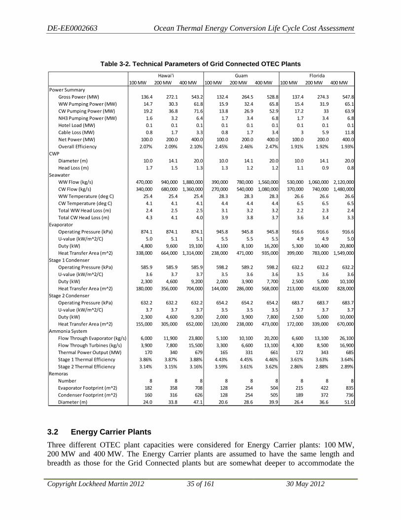
DE-EE0002663 Ocean Thermal Energy Conversion Life Cycle Cost Assessment
Copyright Lockheed Martin 2012 35 of 161 30 May 2012
Table 3-2. Technical Parameters of Grid Connected OTEC Plants
3.2 Energy Carrier Plants Three different OTEC plant capacities were considered for Energy Carrier plants: 100 MW, 200 MW and 400 MW. The Energy Carrier plants are assumed to have the same length and breadth as those for the Grid Connected plants but are somewhat deeper to accommodate the
100 MW 200 MW 400 MW 100 MW 200 MW 400 MW 100 MW 200 MW 400 MWPower Summary
Gross Power (MW) 136.4 272.1 543.2 132.4 264.5 528.8 137.4 274.3 547.8WW Pumping Power (MW) 14.7 30.3 61.8 15.9 32.4 65.8 15.4 31.9 65.1CW Pumping Power (MW) 19.2 36.8 71.6 13.8 26.9 52.9 17.2 33 63.9NH3 Pumping Power (MW) 1.6 3.2 6.4 1.7 3.4 6.8 1.7 3.4 6.8Hotel Load (MW) 0.1 0.1 0.1 0.1 0.1 0.1 0.1 0.1 0.1Cable Loss (MW) 0.8 1.7 3.3 0.8 1.7 3.4 3 5.9 11.8Net Power (MW) 100.0 200.0 400.0 100.0 200.0 400.0 100.0 200.0 400.0Overall Efficiency 2.07% 2.09% 2.10% 2.45% 2.46% 2.47% 1.91% 1.92% 1.93%
CWPDiameter (m) 10.0 14.1 20.0 10.0 14.1 20.0 10.0 14.1 20.0Head Loss (m) 1.7 1.5 1.3 1.3 1.2 1.2 1.1 0.9 0.8
SeawaterWW Flow (kg/s) 470,000 940,000 1,880,000 390,000 780,000 1,560,000 530,000 1,060,000 2,120,000CW Flow (kg/s) 340,000 680,000 1,360,000 270,000 540,000 1,080,000 370,000 740,000 1,480,000WW Temperature (deg C) 25.4 25.4 25.4 28.3 28.3 28.3 26.6 26.6 26.6CW Temperature (deg C) 4.1 4.1 4.1 4.4 4.4 4.4 6.5 6.5 6.5Total WW Head Loss (m) 2.4 2.5 2.5 3.1 3.2 3.2 2.2 2.3 2.4Total CW Head Loss (m) 4.3 4.1 4.0 3.9 3.8 3.7 3.6 3.4 3.3
EvaporatorOperating Pressure (kPa) 874.1 874.1 874.1 945.8 945.8 945.8 916.6 916.6 916.6U-value (kW/m^2/C) 5.0 5.1 5.1 5.5 5.5 5.5 4.9 4.9 5.0Duty (kW) 4,800 9,600 19,100 4,100 8,100 16,200 5,300 10,400 20,800Heat Transfer Area (m^2) 338,000 664,000 1,314,000 238,000 471,000 935,000 399,000 783,000 1,549,000
Stage 1 CondenserOperating Pressure (kPa) 585.9 585.9 585.9 598.2 589.2 598.2 632.2 632.2 632.2U-value (kW/m^2/C) 3.6 3.7 3.7 3.5 3.6 3.6 3.5 3.6 3.6Duty (kW) 2,300 4,600 9,200 2,000 3,900 7,700 2,500 5,000 10,100Heat Transfer Area (m^2) 180,000 356,000 704,000 144,000 286,000 568,000 213,000 418,000 828,000
Stage 2 CondenserOperating Pressure (kPa) 632.2 632.2 632.2 654.2 654.2 654.2 683.7 683.7 683.7U-value (kW/m^2/C) 3.7 3.7 3.7 3.5 3.5 3.5 3.7 3.7 3.7Duty (kW) 2,300 4,600 9,200 2,000 3,900 7,800 2,500 5,000 10,000Heat Transfer Area (m^2) 155,000 305,000 652,000 120,000 238,000 473,000 172,000 339,000 670,000
Ammonia SystemFlow Through Evaporator (kg/s) 6,000 11,900 23,800 5,100 10,100 20,200 6,600 13,100 26,100Flow Through Turbines (kg/s) 3,900 7,800 15,500 3,300 6,600 13,100 4,300 8,500 16,900Thermal Power Output (MW) 170 340 679 165 331 661 172 343 685Stage 1 Thermal Efficiency 3.86% 3.87% 3.88% 4.43% 4.45% 4.46% 3.61% 3.63% 3.64%Stage 2 Thermal Efficiency 3.14% 3.15% 3.16% 3.59% 3.61% 3.62% 2.86% 2.88% 2.89%
RemorasNumber 8 8 8 8 8 8 8 8 8Evaporator Footprint (m^2) 182 358 708 128 254 504 215 422 835Condenser Footprint (m^2) 160 316 626 128 254 505 189 372 736Diameter (m) 24.0 33.8 47.1 20.6 28.6 39.9 26.4 36.6 51.0
Hawai'i Guam Florida
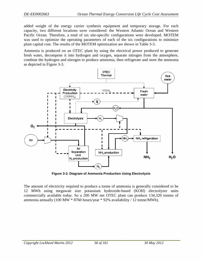
DE-EE0002663 Ocean Thermal Energy Conversion Life Cycle Cost Assessment
Copyright Lockheed Martin 2012 36 of 161 30 May 2012
added weight of the energy carrier synthesis equipment and temporary storage. For each capacity, two different locations were considered: the Western Atlantic Ocean and Western Pacific Ocean. Therefore, a total of six site-specific configurations were developed. MOTEM was used to optimize the operating parameters of each of the six configurations to minimize plant capital cost. The results of the MOTEM optimization are shown in Table 3-3.
Ammonia is produced on an OTEC plant by using the electrical power produced to generate fresh water, decompose it into hydrogen and oxygen, separate nitrogen from the atmosphere, combine the hydrogen and nitrogen to produce ammonia, then refrigerate and store the ammonia as depicted in Figure 3-3.
Figure 3-3. Diagram of Ammonia Production Using Electrolysis
The amount of electricity required to produce a tonne of ammonia is generally considered to be 12 MWh using megawatt size potassium hydroxide-based (KOH) electrolyzer units commercially available today. So a 200 MW net OTEC plant can produce 134,320 tonnes of ammonia annually (100 MW * 8760 hours/year * 92% availability / 12 tonne/MWh).
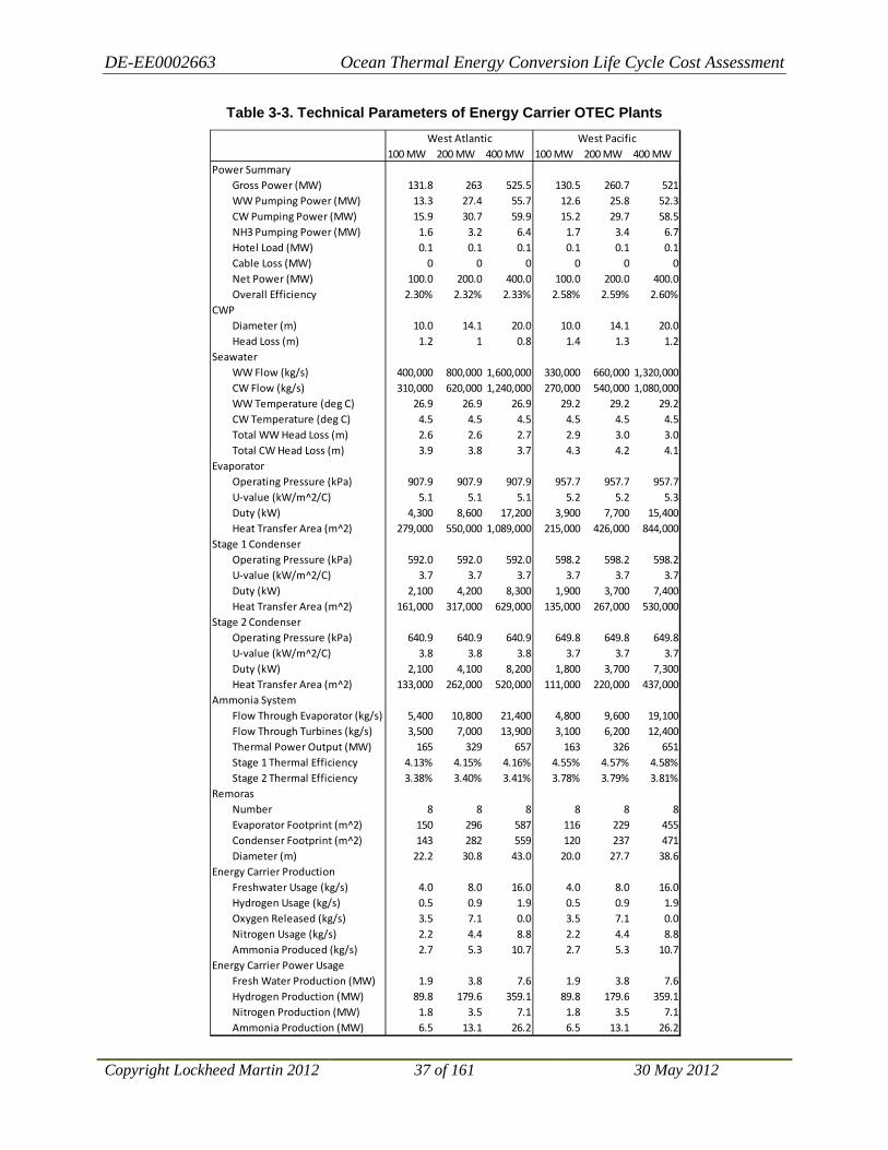
DE-EE0002663 Ocean Thermal Energy Conversion Life Cycle Cost Assessment
Copyright Lockheed Martin 2012 37 of 161 30 May 2012
Table 3-3. Technical Parameters of Energy Carrier OTEC Plants
100 MW 200 MW 400 MW 100 MW 200 MW 400 MWPower Summary
Gross Power (MW) 131.8 263 525.5 130.5 260.7 521WW Pumping Power (MW) 13.3 27.4 55.7 12.6 25.8 52.3CW Pumping Power (MW) 15.9 30.7 59.9 15.2 29.7 58.5NH3 Pumping Power (MW) 1.6 3.2 6.4 1.7 3.4 6.7Hotel Load (MW) 0.1 0.1 0.1 0.1 0.1 0.1Cable Loss (MW) 0 0 0 0 0 0Net Power (MW) 100.0 200.0 400.0 100.0 200.0 400.0Overall Efficiency 2.30% 2.32% 2.33% 2.58% 2.59% 2.60%
CWPDiameter (m) 10.0 14.1 20.0 10.0 14.1 20.0Head Loss (m) 1.2 1 0.8 1.4 1.3 1.2
SeawaterWW Flow (kg/s) 400,000 800,000 1,600,000 330,000 660,000 1,320,000CW Flow (kg/s) 310,000 620,000 1,240,000 270,000 540,000 1,080,000WW Temperature (deg C) 26.9 26.9 26.9 29.2 29.2 29.2CW Temperature (deg C) 4.5 4.5 4.5 4.5 4.5 4.5Total WW Head Loss (m) 2.6 2.6 2.7 2.9 3.0 3.0Total CW Head Loss (m) 3.9 3.8 3.7 4.3 4.2 4.1
EvaporatorOperating Pressure (kPa) 907.9 907.9 907.9 957.7 957.7 957.7U-value (kW/m^2/C) 5.1 5.1 5.1 5.2 5.2 5.3Duty (kW) 4,300 8,600 17,200 3,900 7,700 15,400Heat Transfer Area (m^2) 279,000 550,000 1,089,000 215,000 426,000 844,000
Stage 1 CondenserOperating Pressure (kPa) 592.0 592.0 592.0 598.2 598.2 598.2U-value (kW/m^2/C) 3.7 3.7 3.7 3.7 3.7 3.7Duty (kW) 2,100 4,200 8,300 1,900 3,700 7,400Heat Transfer Area (m^2) 161,000 317,000 629,000 135,000 267,000 530,000
Stage 2 CondenserOperating Pressure (kPa) 640.9 640.9 640.9 649.8 649.8 649.8U-value (kW/m^2/C) 3.8 3.8 3.8 3.7 3.7 3.7Duty (kW) 2,100 4,100 8,200 1,800 3,700 7,300Heat Transfer Area (m^2) 133,000 262,000 520,000 111,000 220,000 437,000
Ammonia SystemFlow Through Evaporator (kg/s) 5,400 10,800 21,400 4,800 9,600 19,100Flow Through Turbines (kg/s) 3,500 7,000 13,900 3,100 6,200 12,400Thermal Power Output (MW) 165 329 657 163 326 651Stage 1 Thermal Efficiency 4.13% 4.15% 4.16% 4.55% 4.57% 4.58%Stage 2 Thermal Efficiency 3.38% 3.40% 3.41% 3.78% 3.79% 3.81%
RemorasNumber 8 8 8 8 8 8Evaporator Footprint (m^2) 150 296 587 116 229 455Condenser Footprint (m^2) 143 282 559 120 237 471Diameter (m) 22.2 30.8 43.0 20.0 27.7 38.6
Energy Carrier ProductionFreshwater Usage (kg/s) 4.0 8.0 16.0 4.0 8.0 16.0Hydrogen Usage (kg/s) 0.5 0.9 1.9 0.5 0.9 1.9Oxygen Released (kg/s) 3.5 7.1 0.0 3.5 7.1 0.0Nitrogen Usage (kg/s) 2.2 4.4 8.8 2.2 4.4 8.8Ammonia Produced (kg/s) 2.7 5.3 10.7 2.7 5.3 10.7
Energy Carrier Power UsageFresh Water Production (MW) 1.9 3.8 7.6 1.9 3.8 7.6Hydrogen Production (MW) 89.8 179.6 359.1 89.8 179.6 359.1Nitrogen Production (MW) 1.8 3.5 7.1 1.8 3.5 7.1Ammonia Production (MW) 6.5 13.1 26.2 6.5 13.1 26.2
West Atlantic West Pacific

DE-EE0002663 Ocean Thermal Energy Conversion Life Cycle Cost Assessment
Copyright Lockheed Martin 2012 38 of 161 30 May 2012
3.3 OTEC Plant Configuration During Cold Water Pipe Fabrication To eliminate issues with deploying the very long cold water pipe at sea, the LM OTEC plant design incorporates a temporary pipe fabrication system that is installed on the platform. This fabrication system allows the cold water pipe to be fabricated in place as a continuous fiber reinforced plastic (FRP) pipe. Figure 3-4 shows a conceptual design for the floating, moored 10 MW OTEC Pilot Plant during the pipe fabrication phase. The green vertical structure shown in the center of the semi-submersible platform of the Pilot Plant is the assembly tower for construction of the cold water pipe (CWP). Also shown in the drawing are two deck cranes, a helicopter pad over a personnel accommodations facility, system control room, ammonia storage tanks and other OTEC power plant components. An accommodation ladder is shown on the far right. The platform is 60 m square with approximately 19 m from the waterline to the platform deck level. When ballasted to its operating condition, the host platform has a draft of 20 m, with the power modules extending significantly deeper.
Figure 3-4. Artist’s Concept of OTEC Plant During Pipe Fabrication
DE-EE0002663 Ocean Thermal Energy Conversion Life Cycle Cost Assessment
Copyright Lockheed Martin 2012 39 of 161 30 May 2012
4 Capital Cost Estimation Approach Recent engineering effort has focused on the design of a 10 MW Pilot Plant intended to prove OTEC’s technical and economic viability. Therefore, the most detailed technical and economic information available is associated with a plant at least 1/10th the scale of a commercial OTEC plant. Extrapolation of costs from 10 MW to 400 MW carries inherent uncertainty. These uncertainties were addressed by identifying those components that scale conveniently across a wide range of OTEC sizes, and by leveraging previous work.
Many OTEC components scale easily with capacity, even from 10 MW to 400 MW sizes. The most significant example is the heat exchangers. A 10 MW plant is expected to use heat exchangers at or near the maximum size available from manufacturers. Larger plants will simply use more heat exchanger units, and costs tend to scale linearly with capacity.
Other components must be scaled up from 10 MW, but not necessarily directly to 100 MW sizes. For example, turbo-generators, seawater pumps and ammonia pumps will likely use multiple units arranged in parallel. These units are larger than those used in the 10 MW design, but the scale factor is expected to be 2-3 rather than 10-40.
The largest component costs that do not scale conveniently are the buoyant structures supporting the plant: semi-submersible platform, remoras, and their mooring systems. The size of these structures is controlled by ocean-related design conditions (such as hurricanes) more than plant capacity. Therefore, it is difficult to scale the cost of such components from 10 MW to 400 MW reliably. Previous work by team members in 2008 included a conceptual design of a 100 MW OTEC plant to be located in Hawai’i. The costs and arrangement of components from that design were used to develop the cost of a 100 MW OTEC plant for this project. The 100 MW design was then scaled up to 400 MW. Use of the 2008 data significantly increased the 100 MW plant cost estimate accuracy, and, therefore, that of the 400 MW plant.
Overall, the costs of those components that scale conveniently with plant capacity (e.g., heat exchangers and pumps) have the least uncertainty. Those components that do not scale conveniently with scale (e.g., platforms and remoras) have greater uncertainty. Cost estimates can be refined based on conceptual designs for each configuration, which was beyond the scope of this project and recommended as a future improvement to the work described herein.
4.1 Cost Models Estimates of OTEC plant acquisition cost were developed using CAPEX, a spreadsheet based decomposition of capital cost estimates developed by Glosten, and MOTEM, a proprietary modeling tool developed by Makai. While both tools are designed to estimate total capital cost of commercial-scale OTEC plants, their underlying approaches are different. CAPEX is a line-item summary of all major components of the OTEC system, and must be reviewed for each plant capacity (i.e., net power output) and location to be considered. MOTEM utilizes parameterized cost models that automatically scale to a variety of plant sizes and locations.
The two models’ differing approaches allowed for semi-independent cost comparisons adding credibility to the cost estimates. The following OTEC component costs were refined based on comparison between MOTEM and CAPEX output:
• Seawater Pumps • Turbo-generators
DE-EE0002663 Ocean Thermal Energy Conversion Life Cycle Cost Assessment
Copyright Lockheed Martin 2012 40 of 161 30 May 2012
• Remora Construction • Moorings • Power Cable to Shore
4.1.1 CAPEX Development work on OTEC concepts has proceeded since 2008; first as an IRAD-funded project within LM, and later as a Government-funded project through various contracts with the DOE and Department of the Navy. Configurations of various embodiments of an OTEC design were advanced sufficiently during the design process to facilitate the preparation of rough-order-of-magnitude cost estimates. All configurations envisioned for this LCC study incorporate a host platform consisting of a ring-pontoon, column-stabilized, non-self-propelled semisubmersible to which is attached one or more power modules (Remoras) housing the heat exchangers and pumps vital to energy extraction.
Earlier work culminated in capital cost models for 5 MW, 10 MW, and 100 MW Grid Connected OTEC plants. These formed the basis from which capital expense models were derived for 100 MW, 200 MW, and 400 MW Grid Connected and Energy Carrier plants for use in LCC estimates for OTEC-generated energy at a global level. The CAPEX models reflect U.S. West Coast construction in 2010 U.S. dollars. Individual line items of the estimate are conservative, and no contingency margin has been added. The reader may note that significant cost savings could be realized if major assets were constructed or assembled outside of the U.S. No attempt has been made herein to quantify such savings because of the increasingly unpredictable behavior in commodities and foreign exchange markets.
The CAPEX models consist of a series of Excel® spreadsheets that drill down into the architecture of the system following the system architecture breakdown structure illustrated in Section 3. This architecture decomposition allows for a detailed bottoms-up estimate. Estimates at the lowest levels of the decomposition are established through a combination of quotes from potential suppliers, comparison to similar components on other projects, parametric cost estimating and engineering judgment.
CAPEX models for the 200 MW and 400 MW embodiments were derived by parametrically scaling the 100 MW cost estimate, which itself was largely a parametric scaling of the more highly evolved 10 MW design. The validity of the parametric scaling of capital acquisition costs upward from 100 MW can only be assessed on a global level. The results of parametric scaling indicated that doubling the output to 200 MW would require investing 1.6 times the capital. This is a reasonable and achievable economy of scale, which is one reflected in other capital intensive plants. Quadrupling the power output by increasing capital investment by a factor of 2.5 is similarly unremarkable.
CAPEX models for non-Grid Connected (grazing) plants are derived directly from the Grid Connected plants, reduced by the cost of power export cable and mooring system, and increased by the cost of creating the energy storage and transportation medium. For the sake of this model, it was assumed that ammonia would be used as the energy storage medium, which would be synthesized and temporarily stored onboard the OTEC plant prior to export via tank vessel.
The study has concluded these cost models produce defendable results in demonstrating relative costs of the array of plant sizes that can be used to create the global model for worldwide OTEC exploitation. Their value as true estimates of absolute cost is limited. While they may be useful

DE-EE0002663 Ocean Thermal Energy Conversion Life Cycle Cost Assessment
Copyright Lockheed Martin 2012 41 of 161 30 May 2012
as part of an analysis that disqualifies a capital investment from consideration, they should not be used to qualify an investment. They also should not be used to forecast financial returns to investors with any degree of certainty.
4.1.2 MOTEM MOTEM is a thermodynamic and economic OTEC plant optimization model originally developed as part of an Office of Naval Research Phase II SBIR in 2008. The model has been extended and enhanced over the course of several OTEC development contracts since completion of the SBIR. MOTEM combines a technical analysis of OTEC thermodynamics with the cost and physical definitions of the plant. This allows MOTEM to conceptually design, optimize, and economically evaluate an OTEC plant of a user specified size and location.
MOTEM was used to estimate OTEC component size, performance and cost at the various locations considered under this contract. Both Grid Connected and Energy Carrier plants were analyzed at 100 MW, 200 MW, and 300 MW scales.
The major inputs to MOTEM’s thermodynamic and economic algorithm can be split into external calculations and key user inputs.
External Calculations
Many of the variables incorporated into the optimization are well suited to the parametric approach used in the model. For example, the thermodynamic performance of heat exchangers is well understood and almost exclusively dependent on seawater temperatures and ammonia pressures; heat exchanger performance is easily parameterized for use in MOTEM. Other variables are not conveniently parameterized. For example, platform size is heavily dependent on metocean conditions at a particular site and does not scale well with plant capacity (i.e., even small plants need large platforms to survive storm conditions). Such variables are analyzed external to MOTEM and are input as case-specific parameters. Other major examples of externally calculated variables are the CWP, mooring system, deployment, and power cable to shore.
Key Input Data
Basic user inputs are: net power required from the plant, heat exchanger performance, component efficiencies (e.g., turbine, power cable, etc.), and site-specific seawater temperatures and bathymetric data. For this analysis, dual-stage brazed aluminum heat exchangers have been assumed for the heat exchanger style. This style of heat exchanger has experimental data available that confirms performance. Component efficiencies have been extracted from previous projects completed by Makai and LM.
A critical operating parameter of an OTEC plant is the differential in temperature (dT) between the warm surface seawater and cold deep seawater. Data from the World Ocean Database 2009 is used to define temperature differentials for specific locations.
Bathymetry is analyzed to determine the approximate cable distances and seabed profiles to shore for each site. Bathymetric data is obtained from various sources: GEBCO 2010, MGDS-Global Multi-Resolution Topography, and satellite seafloor estimations (Smith and Sandwell, 2009). The recently launched Virtual Ocean (www.virtualocean.org) interactive web-based earth

DE-EE0002663 Ocean Thermal Energy Conversion Life Cycle Cost Assessment
Copyright Lockheed Martin 2012 42 of 161 30 May 2012
browser was found to be a useful tool for browsing various bathymetric and topographic data sets.
4.2 Basis of Estimates (BOE) and Results for Grid Connected Plants
4.2.1 CAPEX BOE and Results for Grid Connected Plants
4.2.1.1 Basis of Estimate—100 MW Grid Connected Plant
The 100 MW plant cost estimate is the result of parametric scaling from the single-remora 2010 design effort (Figure 4-1) to the 8-remora 2008 conceptual design (Figure 4-2). This estimate was revised in 2011 to incorporate improved estimates for the costs associated with environmental monitoring and management, export power cables, and CWP manufacturing. The estimate was further revised to correct an overly pessimistic linear basis for parametric scaling of cold water and warm water pump costs.
Figure 4-1. 2010 Single Remora, 5 MW Design
Figure 4-2. 2008 8-Remora, 100 MW Design
Using the system architecture devised by LM, the top level of which is shown below in Table 4-1, individual line items were scaled by factors believed to be the principal drivers of cost.

DE-EE0002663 Ocean Thermal Energy Conversion Life Cycle Cost Assessment
Copyright Lockheed Martin 2012 43 of 161 30 May 2012
Table 4-1. 100 MW Cost Summary
4.2.1.2 OTEC System Expenses
By far the largest component of the rolled-up cost estimate, OTEC system expenses include those segments listed in Table 4-2.
Table 4-2. Segments Included in the OTEC System
Hull and other structural steel costs included in the platform segment were scaled by weight by a factor of 1.68, which was derived from independent steel weight estimates for the 10 MW and 100 MW plants from the 2008 concept designs. Quarters and deck outfitting were left unchanged with the size of platform. Within the power generation segment, elements of the power cycle underwent line item review, with the key cost driver being the volume of heat exchangers necessary. These were scaled at an overall cost factor of $3,000 per net KW of plant output. Other key cost elements included sea water pumps, which were scaled at 50% of linear escalation with power output16
16 Seawater flows vary linearly with power output. Linearly scaling the cost of pumping with required flow is a conservative approach. Doubling of the number of pumps doubles the flow rate and cost. However, it is believed that upsizing pumps will produce economies of scale.
and remora
GRANDSystem TOTAL NOTES / BASIS
$
Program Level Expenses $6,900,000OTEC System Expenses $1,222,300,000 US Construction base caseCWP Fabrication System $49,100,000Environmental Management System $4,600,000OTEC Installation System $97,900,000 Includes 8-leg permanent mooring caseOTEC Decommissioning System $20,800,000 Future activity cost
Total OTEC Capex $1,401,600,000
OTEC System A
GRANDElement Alias TOTAL
$
Platform Segment A1000 $279,765,772
Power Generation Segment A2000 $844,233,561
Power Delivery Segment A3000 $97,177,388
Integr. Instr . & Cntl Segment A4000 $1,150,000
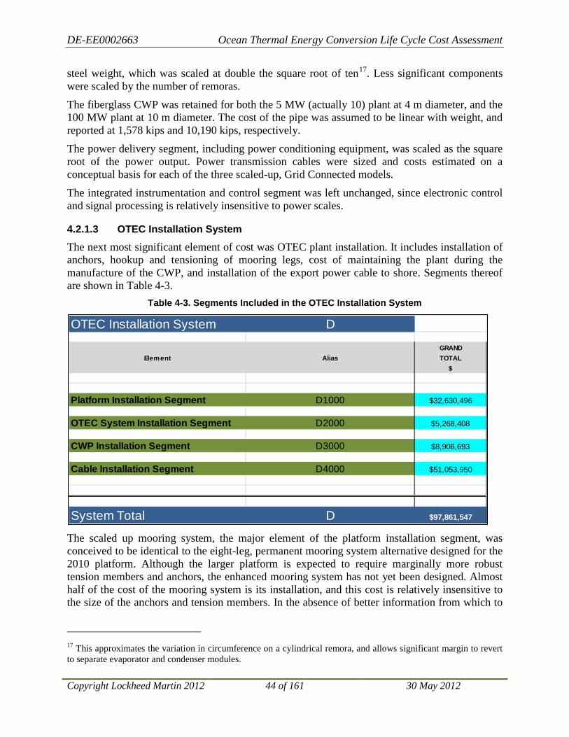
DE-EE0002663 Ocean Thermal Energy Conversion Life Cycle Cost Assessment
Copyright Lockheed Martin 2012 44 of 161 30 May 2012
steel weight, which was scaled at double the square root of ten17
The fiberglass CWP was retained for both the 5 MW (actually 10) plant at 4 m diameter, and the 100 MW plant at 10 m diameter. The cost of the pipe was assumed to be linear with weight, and reported at 1,578 kips and 10,190 kips, respectively.
. Less significant components were scaled by the number of remoras.
The power delivery segment, including power conditioning equipment, was scaled as the square root of the power output. Power transmission cables were sized and costs estimated on a conceptual basis for each of the three scaled-up, Grid Connected models.
The integrated instrumentation and control segment was left unchanged, since electronic control and signal processing is relatively insensitive to power scales.
4.2.1.3 OTEC Installation System
The next most significant element of cost was OTEC plant installation. It includes installation of anchors, hookup and tensioning of mooring legs, cost of maintaining the plant during the manufacture of the CWP, and installation of the export power cable to shore. Segments thereof are shown in Table 4-3.
Table 4-3. Segments Included in the OTEC Installation System
The scaled up mooring system, the major element of the platform installation segment, was conceived to be identical to the eight-leg, permanent mooring system alternative designed for the 2010 platform. Although the larger platform is expected to require marginally more robust tension members and anchors, the enhanced mooring system has not yet been designed. Almost half of the cost of the mooring system is its installation, and this cost is relatively insensitive to the size of the anchors and tension members. In the absence of better information from which to
17 This approximates the variation in circumference on a cylindrical remora, and allows significant margin to revert to separate evaporator and condenser modules.
OTEC Installation System D
GRANDElement Alias TOTAL
$
Platform Installation Segment D1000 $32,630,496
OTEC System Installation Segment D2000 $5,268,408
CWP Installation Segment D3000 $8,908,693
Cable Installation Segment D4000 $51,053,950
System Total D $97,861,547

DE-EE0002663 Ocean Thermal Energy Conversion Life Cycle Cost Assessment
Copyright Lockheed Martin 2012 45 of 161 30 May 2012
derive mooring system requirements, the decision was made to retain the mooring system cost estimate from the 10 MW permanently moored system unchanged.
The OTEC system installation segment is dominated by the cost of mobilizing, uprighting and installing remoras on the platform. This cost was scaled by the number of remoras installed, by a factor of 8 for moving from the 5 MW to the 100 MW plant.
The CWP installation cost is dominated by the labor associated with operating the pipe manufacturing facility around the clock over an estimated four-month window. The time necessary to produce 1000 m of cold water pipe was determined by curing time, insensitive to the diameter of the pipe. This portion of the estimate was not scaled.
The Cable Installation Segment is dominated by the fixed cost of mobilizing the cable lay vessel. The main variable costs were reduced to a linear relationship with the total weight of the cable being installed.
4.2.1.4 Cold Water Pipe Fabrication System
The CWP fabrication system can be considered a non-recurring cost. For the sake of this comparative estimate, however, it was retained as a direct unit cost (Table 4-4).
Table 4-4. Segments Included in the CWP Fabrication Facility
With costs divided among three major segments, each was scaled at a global level according to its principal driver. The CWP Grip and Handling Segment was presumed to vary as a function of total pipe weight, while the Fabrication Segment and its environmental enclosure were assumed to vary linearly with pipe diameter.
4.2.1.5 Program Level Expenses
Program level expenses, which incorporate project management office functions, were believed to be related only to the time scale of the project and insensitive to the plant size. Hence, since construction schedules are driven more by facility availability rather than plant size in this range, the line item was left unchanged. An argument could be made to adjust program level expenses per unit for multiple units under construction simultaneously. However, considering that expense
CWP Fabrication System B
GRANDElement Alias TOTAL
$
CWP Grip & Handling Segment B1000 $21,709,349
CWP Fabrication App. Segment B2000 $15,899,250
CWP Fabr. App. Env. Encl. Segment B3000 $11,482,302
System Total B $49,090,901

DE-EE0002663 Ocean Thermal Energy Conversion Life Cycle Cost Assessment
Copyright Lockheed Martin 2012 46 of 161 30 May 2012
was less than one-half of one percent of the total unit cost, such an adjustment would be immaterial.
4.2.1.6 Environmental Monitoring and Decommissioning Systems
Combined, these two systems account for less than 2% of the total capital cost of the OTEC plant. In the 5 MW design, environmental monitoring included planning and permitting functions, along with active monitoring of ecological activities during the early stages of operation. In scaling to the commercial plant, it was assumed that permitting expenses would be unchanged, while environmental monitoring expense would be reduced to zero.
The largest expense associated with decommissioning a unit is the recovery, segmenting and upland disposal of the plastic CWP. This was assumed to scale with the weight of the pipe.
4.2.1.7 Basis of Estimate – Scaling to 200 MW and 400 MW
In scaling from the 100 MW Grid Connected plant to the 200 MW Grid Connected plant, only the OTEC system and CWP fabrication facility were subjected to scaling (Table 4-5).
Table 4-5. 200 MW Capital Cost Summary, Scaled from 100 MW
Using very similar relationships as those used in the scale-up from 5 MW to 100 MW, costs for individual segments and systems were reviewed and scaled as necessary. The underlying assumption is that a doubling of power is achieved by doubling the number of remoras installed on the platform.
As before, the OTEC system is mostly made up of the Platform Segment, Power Generation Segment, and Power Delivery Segment. For the platform, it was expected to grow at its perimeter to accommodate twice the number of remoras as the 100 MW plant. As a result, the platform grew from 72 m square to measure 80 m x 90 m with the same depth, or a scale factor on displacement (proportional to steel weight) of about 1.4. The majority of components within the Power Generation Segment were doubled, except for the CWP, which grew by the square root of 2 to accommodate twice the volume of cooling water.
The CWP fabrication system was allowed to escalate in proportion to either the weight or the diameter of the pipe. It was assumed that wall thickness would not change and, therefore, both factors increased by the square root of 2.
GRANDSystem TOTAL NOTES / BASIS
$
Program Level Expenses $6,900,000OTEC System Expenses $2,025,000,000 US Construction base caseCWP Fabrication System $69,400,000Environmental Management System $6,200,000OTEC Installation System $111,200,000 Includes 8-leg permanent mooring caseOTEC Decommissioning System $20,800,000 Future activity cost
Total OTEC Capex $2,239,500,000
ScaledNo scaling required
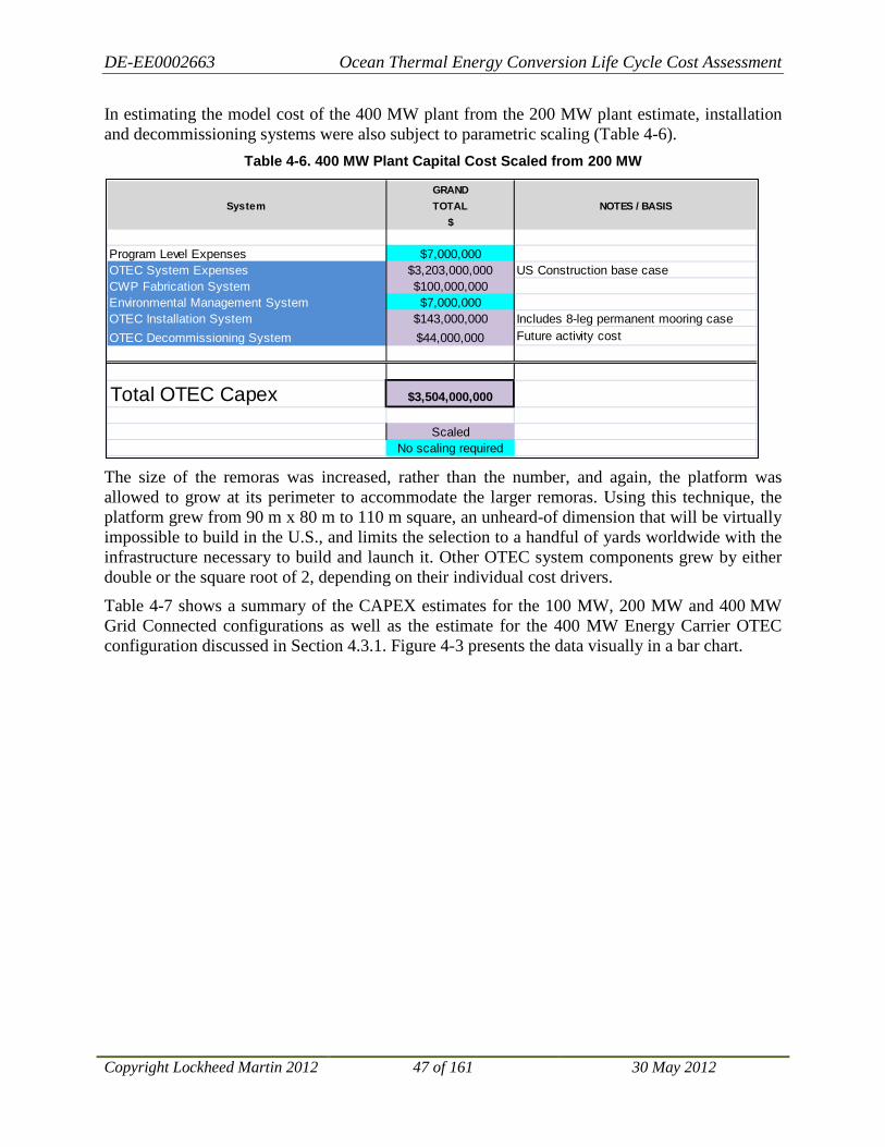
DE-EE0002663 Ocean Thermal Energy Conversion Life Cycle Cost Assessment
Copyright Lockheed Martin 2012 47 of 161 30 May 2012
In estimating the model cost of the 400 MW plant from the 200 MW plant estimate, installation and decommissioning systems were also subject to parametric scaling (Table 4-6).
Table 4-6. 400 MW Plant Capital Cost Scaled from 200 MW
The size of the remoras was increased, rather than the number, and again, the platform was allowed to grow at its perimeter to accommodate the larger remoras. Using this technique, the platform grew from 90 m x 80 m to 110 m square, an unheard-of dimension that will be virtually impossible to build in the U.S., and limits the selection to a handful of yards worldwide with the infrastructure necessary to build and launch it. Other OTEC system components grew by either double or the square root of 2, depending on their individual cost drivers.
Table 4-7 shows a summary of the CAPEX estimates for the 100 MW, 200 MW and 400 MW Grid Connected configurations as well as the estimate for the 400 MW Energy Carrier OTEC configuration discussed in Section 4.3.1. Figure 4-3 presents the data visually in a bar chart.
GRANDSystem TOTAL NOTES / BASIS
$
Program Level Expenses $7,000,000OTEC System Expenses $3,203,000,000 US Construction base caseCWP Fabrication System $100,000,000Environmental Management System $7,000,000OTEC Installation System $143,000,000 Includes 8-leg permanent mooring caseOTEC Decommissioning System $44,000,000 Future activity cost
Total OTEC Capex $3,504,000,000
ScaledNo scaling required

DE-EE0002663 Ocean Thermal Energy Conversion Life Cycle Cost Assessment
Copyright Lockheed Martin 2012 48 of 161 30 May 2012
Table 4-7. Summary of CAPEX for OTEC Plant Configurations
Figure 4-3. Summary of CAPEX for OTEC Plant Configurations
System/Segment100 MW Grid
Connected200 MW Grid
Connected400 MW Grid
Connected400 MW Energy
CarrierProgram Level Expenses $7,000,000 $7,000,000 $7,000,000 $7,000,000OTEC System Expenses $1,222,000,000 $2,025,000,000 $3,203,000,000 $2,955,000,000
Platform Segment $280,000,000 $363,000,000 $564,000,000 $586,000,000Power Generation Segment $844,000,000 $1,518,000,000 $2,368,000,000 $2,368,000,000Power Delivery Segment $97,000,000 $143,000,000 $270,000,000 $0Integr. Instr. & Cntl Segment $1,000,000 $1,000,000 $1,000,000 $1,000,000
CWP Fabrication System $49,000,000 $69,000,000 $99,000,000 $99,000,000CWP Grip & Handling Segment $22,000,000 $31,000,000 $61,000,000 $61,000,000CWP Fabrication App. Segment $16,000,000 $22,000,000 $22,000,000 $22,000,000CWP Fabr. App. Env. Encl. Segment $11,000,000 $16,000,000 $16,000,000 $16,000,000
Environmental Management System $4,600,000 $6,200,000 $7,000,000 $7,000,000OTEC Installation System $98,000,000 $112,000,000 $144,000,000 $29,000,000
Platform Installation Segment $33,000,000 $33,000,000 $33,000,000 $0OTEC System Installation Segment $5,000,000 $11,000,000 $11,000,000 $11,000,000CWP Installation Segment $9,000,000 $9,000,000 $18,000,000 $18,000,000Cable Installation Segment $51,000,000 $59,000,000 $82,000,000 $0
OTEC Decommissioning System $20,800,000 $20,800,000 $44,000,000 $44,000,000Ammonia Synthesis Equipment $0 $0 $0 $330,000,000Temporary Ammonia Storage $0 $0 $0 $140,000,000
Total OTEC CAPEX $1,401,000,000 $2,240,000,000 $3,504,000,000 $3,611,000,000
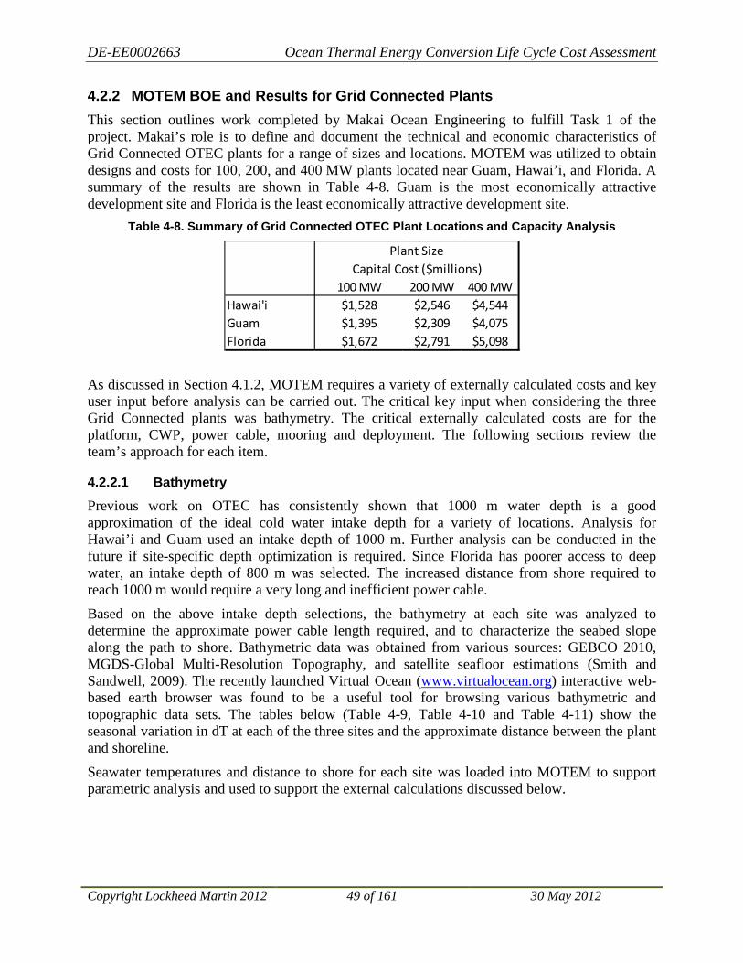
DE-EE0002663 Ocean Thermal Energy Conversion Life Cycle Cost Assessment
Copyright Lockheed Martin 2012 49 of 161 30 May 2012
4.2.2 MOTEM BOE and Results for Grid Connected Plants This section outlines work completed by Makai Ocean Engineering to fulfill Task 1 of the project. Makai’s role is to define and document the technical and economic characteristics of Grid Connected OTEC plants for a range of sizes and locations. MOTEM was utilized to obtain designs and costs for 100, 200, and 400 MW plants located near Guam, Hawai’i, and Florida. A summary of the results are shown in Table 4-8. Guam is the most economically attractive development site and Florida is the least economically attractive development site.
Table 4-8. Summary of Grid Connected OTEC Plant Locations and Capacity Analysis
As discussed in Section 4.1.2, MOTEM requires a variety of externally calculated costs and key user input before analysis can be carried out. The critical key input when considering the three Grid Connected plants was bathymetry. The critical externally calculated costs are for the platform, CWP, power cable, mooring and deployment. The following sections review the team’s approach for each item.
4.2.2.1 Bathymetry
Previous work on OTEC has consistently shown that 1000 m water depth is a good approximation of the ideal cold water intake depth for a variety of locations. Analysis for Hawai’i and Guam used an intake depth of 1000 m. Further analysis can be conducted in the future if site-specific depth optimization is required. Since Florida has poorer access to deep water, an intake depth of 800 m was selected. The increased distance from shore required to reach 1000 m would require a very long and inefficient power cable.
Based on the above intake depth selections, the bathymetry at each site was analyzed to determine the approximate power cable length required, and to characterize the seabed slope along the path to shore. Bathymetric data was obtained from various sources: GEBCO 2010, MGDS-Global Multi-Resolution Topography, and satellite seafloor estimations (Smith and Sandwell, 2009). The recently launched Virtual Ocean (www.virtualocean.org) interactive web-based earth browser was found to be a useful tool for browsing various bathymetric and topographic data sets. The tables below (Table 4-9, Table 4-10 and Table 4-11) show the seasonal variation in dT at each of the three sites and the approximate distance between the plant and shoreline.
Seawater temperatures and distance to shore for each site was loaded into MOTEM to support parametric analysis and used to support the external calculations discussed below.
100 MW 200 MW 400 MWHawai'i $1,528 $2,546 $4,544Guam $1,395 $2,309 $4,075Florida $1,672 $2,791 $5,098
Plant SizeCapital Cost ($millions)

DE-EE0002663 Ocean Thermal Energy Conversion Life Cycle Cost Assessment
Copyright Lockheed Martin 2012 50 of 161 30 May 2012
Table 4-9. Seasonal Seawater Temperatures and Distance to Shore for a Grid Connected OTEC Plant in Florida
Table 4-10. Seasonal Seawater Temperatures and Distance to Shore for a Grid Connected OTEC
Plant in Hawai’i
Table 4-11. Seasonal Seawater Temperatures and Distance to Shore for a Grid Connected OTEC
Plant in Guam
Figure 4-4. Seasonal Temperature Difference for Grid Connected OTEC Plants
0
5
10
15
20
25
30
Jan Feb Mar Apr May Jun Jul Aug Sep Oct Nov DecTem
pera
ture
Diff
eren
ce A
vaila
ble
(deg
C)
Month
Seasonal Temperature Difference for Grid-Connected OTEC Plants
Florida
Hawai'i
Guam
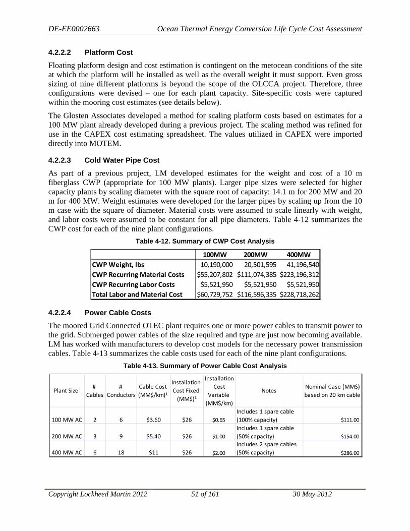
DE-EE0002663 Ocean Thermal Energy Conversion Life Cycle Cost Assessment
Copyright Lockheed Martin 2012 51 of 161 30 May 2012
4.2.2.2 Platform Cost
Floating platform design and cost estimation is contingent on the metocean conditions of the site at which the platform will be installed as well as the overall weight it must support. Even gross sizing of nine different platforms is beyond the scope of the OLCCA project. Therefore, three configurations were devised – one for each plant capacity. Site-specific costs were captured within the mooring cost estimates (see details below).
The Glosten Associates developed a method for scaling platform costs based on estimates for a 100 MW plant already developed during a previous project. The scaling method was refined for use in the CAPEX cost estimating spreadsheet. The values utilized in CAPEX were imported directly into MOTEM.
4.2.2.3 Cold Water Pipe Cost
As part of a previous project, LM developed estimates for the weight and cost of a 10 m fiberglass CWP (appropriate for 100 MW plants). Larger pipe sizes were selected for higher capacity plants by scaling diameter with the square root of capacity: 14.1 m for 200 MW and 20 m for 400 MW. Weight estimates were developed for the larger pipes by scaling up from the 10 m case with the square of diameter. Material costs were assumed to scale linearly with weight, and labor costs were assumed to be constant for all pipe diameters. Table 4-12 summarizes the CWP cost for each of the nine plant configurations.
Table 4-12. Summary of CWP Cost Analysis
4.2.2.4 Power Cable Costs
The moored Grid Connected OTEC plant requires one or more power cables to transmit power to the grid. Submerged power cables of the size required and type are just now becoming available. LM has worked with manufacturers to develop cost models for the necessary power transmission cables. Table 4-13 summarizes the cable costs used for each of the nine plant configurations.
Table 4-13. Summary of Power Cable Cost Analysis
100MW 200MW 400MWCWP Weight, lbs 10,190,000 20,501,595 41,196,540CWP Recurring Material Costs $55,207,802 $111,074,385 $223,196,312CWP Recurring Labor Costs $5,521,950 $5,521,950 $5,521,950Total Labor and Material Cost $60,729,752 $116,596,335 $228,718,262
Plant Size #
Cables#
ConductorsCable Cost (MM$/km)¹
Installation Cost Fixed
(MM$)²
Installation Cost
Variable (MM$/km)
NotesNominal Case (MM$)based on 20 km cable
100 MW AC 2 6 $3.60 $26 $0.65Includes 1 spare cable (100% capacity) $111.00
200 MW AC 3 9 $5.40 $26 $1.00Includes 1 spare cable (50% capacity) $154.00
400 MW AC 6 18 $11 $26 $2.00
Includes 2 spare cables (50% capacity) $286.00

DE-EE0002663 Ocean Thermal Energy Conversion Life Cycle Cost Assessment
Copyright Lockheed Martin 2012 52 of 161 30 May 2012
4.2.2.5 Mooring Cost
Although other options are available – such as dynamic positioning of the platform – it is assumed that Grid Connected OTEC plants will utilize a conventional mooring system to maintain station.
Mooring costs can be broken down into the following components:
• Water depth – affects mooring line length
• Seabed conditions – affects anchor type
• Environmental loading – affects anchor size
• Number of anchors – affects installation and manufacturing costs
• Distance from mobilization port – affects mobilization and shipping costs
• State of the vessel market – affects installation vessel availability and cost Makai Ocean Engineering developed a stand-alone cost model for OTEC plant moorings. For each of the plant configurations, Makai has estimated the necessary hardware, marine spread, and approximate installation schedule. The Table 4-14 summarizes estimated mooring costs.
Table 4-14. Summary of Mooring Cost Analysis
4.2.2.6 Deployment Cost
For the purposes of this study, it is assumed all Grid Connected floating OTEC plants will be configured as semi-submersible platforms with detachable “Remoras.” The remoras house the heat exchangers and pumps while the platform topsides support the turbines and control systems. The platforms and remoras are large and require significant marine operations to launch, tow, connect, and commission. Makai Ocean Engineering has developed a stand-alone model for estimating deployment operation costs. Table 4-15 below summarizes the model’s output.
Table 4-15. Summary of Deployment Cost Analysis
Florida Hawai'i Guam
100 MW $52.7 $65.7 $80.9
200 MW $78.6 $94.4 $115.7
400 MW $123.8 $145.4 $179.0
OTEC plant mooring cost, $m USD (hardware procurement and installation)
Florida Hawai'i Guam
100 MW $32.6 $72.5 $83.5
200 MW $49.0 $108.8 $125.3
400 MW $65.3 $145.0 $167.1
OTEC plant deployment cost, $m USD (launching, remora tow out, connection)

DE-EE0002663 Ocean Thermal Energy Conversion Life Cycle Cost Assessment
Copyright Lockheed Martin 2012 53 of 161 30 May 2012
4.2.2.7 MOTEM Grid Connected OTEC Modeling Summary
The platform, CWP, power cable, mooring, and deployment costs outlined above were input into MOTEM. Remaining parameterized costs were set based on previous experience with design and sizing of floating OTEC plants. Table 4-16 summarizes the technical parameters and capital cost of the nine configurations.
Table 4-16. MOTEM Grid Connected OTEC Plant Configuration Results
Guam is the lowest cost location for OTEC with a cost of $1.4 billion for a 100 MW plant. Florida is the highest cost location with a cost of $1.7 billion for a 100 MW plant. The results confirm the economy of scale expected to be realized with OTEC plants. The cost per MW of electricity generated falls as plant size increases. The economy of scale for all configurations is shown in Figure 4-5.
Figure 4-5. Summary of Grid Connected OTEC Plant Economy of Scale
Plant Capacity 100 MW 200 MW 400 MW 100 MW 200 MW 400 MW 100 MW 200 MW 400 MWTechnical
CWP Diameter (m) 10 14.14 20 10 14.14 20 10 14.14 20Gross Power (MW) 136.37 272.07 543.22 132.35 264.53 528.82 137.44 274.28 547.78WW Flow (kg/s) 470,000 940,000 1,880,000 390,000 780,000 1,560,000 530,000 1,060,000 2,120,000CW Flow (kg/s) 340,000 680,000 1,360,000 270,000 540,000 1,080,000 370,000 740,000 1,480,000
Cost (k$)Cold Water Pipe $61,000 $117,000 $229,000 $61,000 $117,000 $229,000 $49,000 $94,000 $183,000Platform Structure $190,000 $253,000 $400,000 $190,000 $253,000 $400,000 $190,000 $253,000 $400,000Side Spar Strcuture $141,000 $202,000 $297,000 $124,000 $180,000 $266,000 $151,000 $217,000 $318,000Mooring $66,000 $94,000 $145,000 $81,000 $116,000 $179,000 $53,000 $79,000 $124,000Deployment $73,000 $109,000 $145,000 $73,000 $125,000 $167,000 $33,000 $49,000 $65,000Condensers $185,000 $364,000 $721,000 $146,000 $289,000 $574,000 $212,000 $417,000 $825,000Evaporators $186,000 $367,000 $725,000 $131,000 $260,000 $516,000 $220,000 $432,000 $855,000Heat Exchanger Connections $54,000 $106,000 $210,000 $40,000 $80,000 $158,000 $63,000 $123,000 $244,000Ammonia Piping and Storage $5,000 $10,000 $20,000 $5,000 $10,000 $20,000 $5,000 $6,000 $20,000Ammonia Pumps $7,000 $14,000 $29,000 $7,000 $14,000 $29,000 $7,000 $14,000 $29,000Warm Water Pumps $50,000 $100,000 $200,000 $50,000 $100,000 $200,000 $50,000 $100,000 $200,000Cold Water Pumps $38,000 $63,000 $113,000 $38,000 $63,000 $113,000 $38,000 $63,000 $113,000Turbines $37,000 $73,000 $146,000 $37,000 $73,000 $146,000 $37,000 $73,000 $146,000General Topsides $84,000 $109,000 $162,000 $84,000 $109,000 $162,000 $84,000 $109,000 $162,000Power Cable to Shore $69,000 $90,000 $156,000 $69,000 $90,000 $156,000 $171,000 $244,000 $468,000Design, Permitting, Management $30,000 $51,000 $88,000 $28,000 $47,000 $81,000 $32,000 $54,000 $95,000Programmatic Costs $255,000 $424,000 $757,000 $232,000 $385,000 $679,000 $279,000 $465,000 $850,000
Total $1,528,000 $2,546,000 $4,544,000 $1,395,000 $2,309,000 $4,075,000 $1,672,000 $2,791,000 $5,098,000Capital Unit Cost (k$/MW-net) $15,280 $12,730 $11,360 $13,950 $11,545 $10,188 $16,720 $13,955 $12,745
Hawai'i Guam Florida
$0
$2,000
$4,000
$6,000
$8,000
$10,000
$12,000
$14,000
$16,000
$18,000
0 100 200 300 400 500
Leve
lized
Cap
ital
Cos
t (k
$/M
W)
Plant Capacity (MW)
Cost of Grid-Connected OTEC
Hawaii
Guam
Florida

DE-EE0002663 Ocean Thermal Energy Conversion Life Cycle Cost Assessment
Copyright Lockheed Martin 2012 54 of 161 30 May 2012
4.3 BOE and Results for Energy Carrier Plants
4.3.1 CAPEX BOE and Results for Energy Carrier Plants This section provides models for estimating capital expenses associated with non-Grid Connected OTEC plants that synthesize fuel for export, referred to as “Energy Carrier” OTEC plants. It has been assumed that anhydrous ammonia (NH3) is the energy storage and export medium. The models are presented as cost differentials between Grid Connected plants, where CAPEX has been modeled separately, and Energy Carrier plants. Major additions to capital costs for an Energy Carrier plant over a Grid Connected plant are those associated with ammonia synthesis and storage, while cost reductions should be expected because export cables and permanent mooring systems will not be needed.
4.3.1.1 Capital Cost of Synthesis
The 2008 Noland report18
In addition to the cost information, supplemental information has been developed that has produced estimates of the size and weight of ammonia synthesis equipment. It is expected that the synthesis plant will add about 320 tonnes of equipment weight per 100 MW of electrical power exporting capacity. Weight and footprint area of additional equipment will drive an increase in capital cost for the platform, modeled entirely as steel weight, and ranging from $6 to $22 million.
includes significant discussion of the cost of ammonia synthesis equipment, from a conservative estimate of $300 million for a 200 MW conventional electrolysis plant to an optimistic $130 million for a similarly-sized solid state synthesizer. Recent discussions with the lead author of that report indicated that early optimism over the solid state technology is waning. This effort has incorporated an intermediate value presented in the report of $165 million the capital cost of synthesis equipment.
4.3.1.2 Capital Cost of Temporary Ammonia Storage
Of necessity, transportation of produced ammonia will be a batch process, naturally incompatible with the continuous process of ammonia synthesis. Each OTEC plant has to be fitted with temporary storage to overcome this issue. A general operational philosophy that drives the requirements for temporary storage in this sort of discontinuous delivery process follows.
A ship should never have to wait for its cargo to be manufactured. Manufacturing should never be shut down waiting for a ship to carry away inventory.
The Noland report proposes a concept Energy Carrier system wherein one vessel services four OTEC plants. With a 24-day turnaround for the ship that services four plants, it is suggested that each plant be fitted with temporary storage of twice that amount. Production for 48 days from a 200 MW plant is 19,200 tonnes of ammonia, which occupies almost 36,000 cubic meters. Tankage to accommodate this volume could cost upwards of $70 million per OTEC plant. This has been added to the plant’s capital cost.
18 Economic Viability Assessment of Anhydrous Ammonia from OTEC Plantships in 2018, Report, 31 October 2008, G. Noland et al.

DE-EE0002663 Ocean Thermal Energy Conversion Life Cycle Cost Assessment
Copyright Lockheed Martin 2012 55 of 161 30 May 2012
4.3.1.3 Capital Savings for Mooring and Power Export Cabling
The concept for Energy Carrier plants assumes they can be allowed to drift in the relatively benign meteorological conditions in the equatorial region. Therefore, the expense attributed in the CAPEX model for mooring Grid Connected plants in place can be removed from the CAPEX cost of an Energy Carrier plant. Similarly, the expense of procuring and installing the electrical export cable to shore has been deducted to create a more accurate depiction of the cost of an Energy Carrier plant.
4.3.1.4 CAPEX Energy Carrier OTEC Summary Results
Table 4-17 shows a summary of the incremental costs of fuel synthesis and storage on an Energy Carrier OTEC plant over a Grid Connected plant. The last two line items, capital cost reductions for mooring system and electrical transmission cable, have been excerpted from the parametric capital cost models for the Grid Connected plant.
Table 4-17. Capital Cost Additions and Deductions to Derive CAPEX for Energy Carrier Plants
from that of Grid Connected Plants
Cost Element 100 MW Plant 200 MW Plant 400 MW Plant
Capital cost of synthesis equipment installed on OTEC plant.
$83 million $165 million $330 million
Capital cost of modifications to platform to accommodate synthesis equipment.
$6 million $11 million $22 million
Capital cost of temporary ammonia storage.
$35 million $70 million $140 million
Reduced capital cost of mooring system.
($33 million) ($33 million) ($33 million)
Reduced capital cost of power cable.
($148 million) ($203 million) ($352 million)

DE-EE0002663 Ocean Thermal Energy Conversion Life Cycle Cost Assessment
Copyright Lockheed Martin 2012 56 of 161 30 May 2012
4.3.2 MOTEM BOE and Results for Energy Carrier OTEC Plants This section presents work conducted by Makai Ocean Engineering in fulfillment of Task 2 of the project. Makai’s role was to evaluate the cost effectiveness of Energy Carrier OTEC plants that produce ammonia for shipment to shore. MOTEM was used to obtain technical and economic characteristics of Energy Carrier OTEC plants at 100 MW, 200 MW, and 400 MW sizes located in either the West Atlantic Ocean or West Pacific Ocean. A summary of the results of the analysis is shown in Table 4-18.
Table 4-18: Summary of Energy Carrier OTEC Plant Economic Analysis
Plants located in the Western Pacific would ship ammonia to Honolulu or Los Angeles. Plants located in the Western Atlantic would ship ammonia to Tampa. Western Pacific plants are less expensive because the seawater temperature differential is superior to that in the Atlantic.
4.3.2.1 Locations Considered
The two locations considered are the Western Pacific and Western Atlantic Oceans. Plant locations were selected based on available temperature differentials. Temperature and density data for each site was extracted from the World Ocean Atlas.
“Typical” OTEC water depths were used for the analysis: a warm water intake depth of 20 m and a deep water intake depth of 1000 m. Surface seawater temperatures are generally uniform in the top 40 m of the water column, so the warm water intake depth is not critical. Past optimization of OTEC plants has generally shown 1000 m water depth to be near-optimum, but some scenarios called for intake depths up to 1200 m. Further analysis can be done in the future if detailed cold water intake depth optimization is required.
Western Pacific Ocean
The plant in the Pacific Ocean will ship to Hawai’i or Los Angeles. Note that selection of the destination port has no impact on plant capital costs – only ammonia shipping costs. The Western Pacific was selected over the Eastern Pacific due to the significantly increased surface water temperatures available (~29oC northeast of Australia vs. ~25oC west of South America). It is located at Latitude 0o and Longitude 160o; about 5150 km from Honolulu and 9250 km from Los Angeles. The seawater temperature at 20 m depth is 29.2oC, and the seawater temperature at 1000 m depth is 4.5oC (see Figure 4-6 and Table 4-19).
100 MW 200 MW 400 MWWest Atlantic $1,457 $2,490 $4,502West Pacific $1,357 $2,302 $4,173
Plant SizeCapital Cost ($millions)
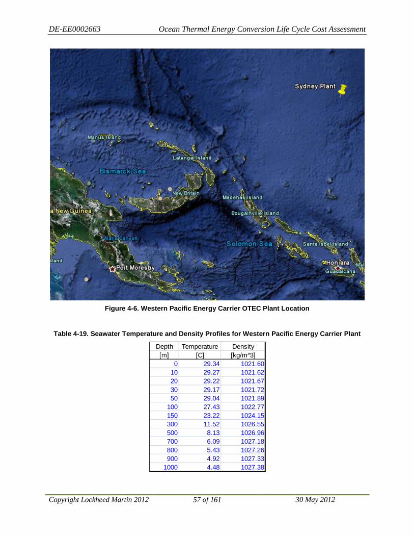
DE-EE0002663 Ocean Thermal Energy Conversion Life Cycle Cost Assessment
Copyright Lockheed Martin 2012 57 of 161 30 May 2012
Figure 4-6. Western Pacific Energy Carrier OTEC Plant Location
Table 4-19. Seawater Temperature and Density Profiles for Western Pacific Energy Carrier Plant
Depth Temperature Density[m] [C] [kg/m 3̂]
0 29.34 1021.6010 29.27 1021.6220 29.22 1021.6730 29.17 1021.7250 29.04 1021.89
100 27.43 1022.77150 23.22 1024.15300 11.52 1026.55500 8.13 1026.96700 6.09 1027.18800 5.43 1027.26900 4.92 1027.33
1000 4.48 1027.38

DE-EE0002663 Ocean Thermal Energy Conversion Life Cycle Cost Assessment
Copyright Lockheed Martin 2012 58 of 161 30 May 2012
Western Atlantic Ocean
The plant in the Atlantic Ocean has several options for delivery ports. Tampa has been selected as the nearest U.S. port. The use of alternative ports in South America would reduce ammonia shipping costs. The plant is located at Latitude 0o and Longitude -30o; about 6700 km from Tampa. The seawater temperature at 20 m depth is 27.1oC, and the seawater temperature at 1000 m depth is 4.5oC (see Figure 4-7 and Table 4-20).
Figure 4-7. Western Atlantic Energy Carrier OTEC Plant Location
Table 4-20. Seawater Temperature and Density Profiles for Western Atlantic Energy Carrier Plant
Depth Temperature Density[m] [C] [kg/m 3̂]
0 27.05 1023.4210 27.00 1023.4720 26.93 1023.5030 26.83 1023.5650 26.83 1023.63
100 18.65 1025.39150 13.59 1026.29300 10.87 1026.82500 7.01 1027.11700 5.18 1027.27800 4.73 1027.32900 4.52 1027.38
1000 4.45 1027.44

DE-EE0002663 Ocean Thermal Energy Conversion Life Cycle Cost Assessment
Copyright Lockheed Martin 2012 59 of 161 30 May 2012
4.3.2.2 Ammonia Production and Transport Costs
Ammonia production equipment, storage, and transport costs were extracted from The Glosten Associates’ work shown in Section 4.3.1. Parameterized values used in MOTEM include:
• Ammonia Production Equipment: $825,000 per MW devoted to NH3 production
• Ammonia Storage Tanks: $3,646 per tonne of ammonia to be stored
4.3.2.3 Ammonia Production Efficiency
Several technical parameters are involved in calculating ammonia production efficiency. The main factors are:
• Electrolyzer efficiency that produces hydrogen from fresh water • Amount of power required to produce fresh water • Amount of power to extract nitrogen from the air • Amount of power required to synthesize ammonia.
The parameters used in the analysis were extracted from Makai’s work on a Phase II SBIR funded by the Office of Naval Research:
• Electrolyzer Efficiency: 75% (193 MJ/kg)
• Freshwater Production: 5.5 kW/(m3/day)
• Nitrogen Extraction: 0.224 kW/(kg/hour)
• Ammonia Synthesis: 0.68 kW(kg/hour) The total energy cost of producing ammonia is 37.4 MJ/kg. A 100 MW plant can, therefore, make 2.67 kg/s of ammonia. About 90% of the power is consumed in the electrolysis process.
4.3.2.4 MOTEM Energy Carrier OTEC Modeling Results
A summary of the major parameters of each scenario are listed in the table and figure below (Table 4-21 and Figure 4-8). The Western Pacific is the least expensive location for ammonia production. However, shipping distances are greater than for the Western Atlantic (assuming U.S. destination ports). If non-U.S. ports are considered, then both locations have comparable shipping distances.
The results show an economy of scale in that the levelized cost of the plants ($/MW-net, which is equivalent to $/NH3-production-rate) shrinks as plant size increases. The economy of scale is the result of the fact that some OTEC components do not scale linearly with capacity – they scale more slowly. Most notably the platform, topsides, CWP, and deployment costs do not scale linearly. Contrast these with heat exchanger, remora, pump, and turbine costs, which do scale linearly with capacity.
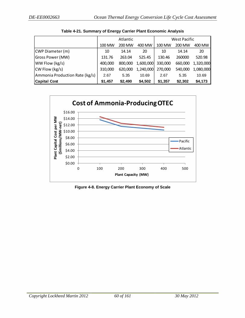
DE-EE0002663 Ocean Thermal Energy Conversion Life Cycle Cost Assessment
Copyright Lockheed Martin 2012 60 of 161 30 May 2012
Table 4-21. Summary of Energy Carrier Plant Economic Analysis
Figure 4-8. Energy Carrier Plant Economy of Scale
100 MW 200 MW 400 MW 100 MW 200 MW 400 MWCWP Diameter (m) 10 14.14 20 10 14.14 20Gross Power (MW) 131.76 263.04 525.45 130.46 260000 520.98WW Flow (kg/s) 400,000 800,000 1,600,000 330,000 660,000 1,320,000CW Flow (kg/s) 310,000 620,000 1,240,000 270,000 540,000 1,080,000Ammonia Production Rate (kg/s) 2.67 5.35 10.69 2.67 5.35 10.69Capital Cost $1,457 $2,490 $4,502 $1,357 $2,302 $4,173
Atlantic West Pacific
$0.00
$2.00
$4.00
$6.00
$8.00
$10.00
$12.00
$14.00
$16.00
0 100 200 300 400 500
Plan
t Ca
pita
l Cos
t pe
r M
W
($m
illio
ns/M
W-n
et)
Plant Capacity (MW)
Cost of Ammonia-Producing OTEC
Pacific
Atlantic

DE-EE0002663 Ocean Thermal Energy Conversion Life Cycle Cost Assessment
Copyright Lockheed Martin 2012 61 of 161 30 May 2012
5 Operations and Sustainment (O&S) Cost Estimation Approach This section provides details relative to the LCCA modeling performed for the O&S costs associated with proposed OTEC plants of various types and projected build out plans following the LCC process depicted in Figure 5-1. For the purpose of this study, two variants of OTEC plants have been assessed. The first variant discussed is the Grid Connected OTEC plant. The second is the Energy Carrier OTEC plant. While similar in many aspects, there are inherent differences that impact the projected O&S LCC of each type of plant as well as that of a projected roll-out plan encompassing multiple plants in the future. These differences are identified throughout this document where appropriate.
The OTEC operational cycle is a relatively simple Rankine engine. However, the large-scale, deep-water marine operating environment, and anticipated quantities of the various plants and equipment utilized in this application drive the initial capital procurement, build, and deployment costs of these plants. The O&S costs are those LCCs required to sustain all aspects of a plant for efficient use across a projected 30-year life.

DE-EE0002663 Ocean Thermal Energy Conversion Life Cycle Cost Assessment
Copyright Lockheed Martin 2012 62 of 161 30 May 2012
Figure 5-1. Life Cycle Cost Process
DE-EE0002663 Ocean Thermal Energy Conversion Life Cycle Cost Assessment
Copyright Lockheed Martin 2012 63 of 161 30 May 2012
5.1 LCC Analysis Methodology
5.1.1 Overview For the purpose of this LCCA, the following high-level assumptions were established prior to development of the O&S model:
• Initial deployed plant size: 100 MW • Largest proposed plant size: 400 MW • Individual plant life span: 30 years • Major Overhaul Frequency: 15 years
Additional impacting assumptions are highlighted as appropriate. The intent of this study is to perform a LCCA at a summary level, without going down to individual Lowest Replaceable Units (LRU). This study provides a preliminary assessment of the expected LCCs. A more detailed analysis to the lower level of system components, which would provide additional accuracy, is recommended for future studies.
This LCCA is based on the application of known or assumed factors, which would affect O&S cost across the life cycle of a deployed and operating OTEC plant. It was developed in a Microsoft® Excel® spreadsheet format, but a more-detailed LCCA would consider additional factors, at a lower level of system and operating detail, and incorporate the use of a commercial cost-modeling tool, such as the PRICE suite of tools. Regardless, the basic principles and methodology for the modeling are similar and independent of the actual tool set used.
A Cost Estimating Relationship (CER) is the technique used to estimate a particular cost or price by using an established relationship with an independent variable. In this exercise, the CERs were developed and used to scale the capital costs for various plant components to estimate O&S costs.
The basis for this LCC model was to build estimations around the major, high-level cost/functional components/subsystems anticipated for an OTEC plant. The capital costs used to establish LCCA O&S estimates are those defined in the CAPEX models for the defined plant configurations. These capital models are sufficiently detailed for use with this high level of cost modeling.
The capital cost components were then reviewed and the maintenance-significant items (MSI) were identified within each subsystem. A basic maintenance philosophy was identified and assigned to those items, or at a general subsystem level, as appropriate.
Projections were then established for maintenance actions relative to basic goals for operational availability of the plants—such that potential failures would ideally be identified and removed from the system via planned preventive maintenance prior to actual failure potentially impacting plant availability. The assumed requirement for Availability is 92%. The primary capital cost drivers of an OTEC plant are the following functional subsystems:
• Power Generation System (exclusive of the Turbines and Heat Exchangers, this item captures the maintenance and overhaul costs of the ammonia pumps)
• Turbines
DE-EE0002663 Ocean Thermal Energy Conversion Life Cycle Cost Assessment
Copyright Lockheed Martin 2012 64 of 161 30 May 2012
• Sea Water Pumps • Electrical Equipment • Heat Exchangers • Remoras • Control, Monitoring, and Safety Equipment • Base Platform and any variant-specific modifications • Energy Carrier Synthesis Equipment
The major cost drivers factored into the model were:
• Maintenance/overhaul • Spares procurement • Staffing • Packaging, handling, storage and transportation • Safety/contingency • Environmental monitoring
5.1.2 O&S LCCA Process Figure 5-2 shows the model using acquisition cost and configuration data provided in the CAPEX tool as a starting point for O&S cost analysis. Individual equipment costs are captured from CAPEX for each plant type: 100 MW, 200 MW and 400 MW. Factors or CERs are applied to those costs based on the type of cost and relationship to the equipment. Those CERs are listed under the assumptions in Sections 5.3 and 5.4.
The plant costs are then phased by year for 30 years as described in the assumptions. Overhaul costs are modeled per the assumptions for each specific equipment type and occur in the specified year. Inflation is added using the DOE recommended rate of 0.9% per year19
19 Amy S. Rushing, Joshua D. Kneifel, Barbara C. Lippiatt, Energy Price Indices and Discount Factors for Life-Cycle Cost Analysis – 2010, NISTIR 85-3273-25, Rev. 5/10
.

DE-EE0002663 Ocean Thermal Energy Conversion Life Cycle Cost Assessment
Copyright Lockheed Martin 2012 65 of 161 30 May 2012
Figure 5-2. Cost Estimation Flow
CAPEX - Procurement $ 400MW
Parameters:Number of RemorasSystemsYears
System_YearsPHS&T FactorOverhaul Frequency YrsSpares %
Overhaul Cost Factor
PMO/CLS %
Cost Elements:Spares $
Maintenance/Overhaul $
PHS&T
PMO/CLS
POL/Fuel
Personnel
Training
Safety/Contigency
Ongoing Environmental Monitoring Cost
Spares $Maintenance/Overhaul $PHS&TPMO/CLSPOL/FuelPersonnel
TrainingCrew Change
Safety/ContigencyOngoing Environmental Monitoring CostsSubtotalInflation
Support Years - 1, 2, 3, 4, 5,……..30
CAPEX - Procurement $ 200MW
CAPEX - Procurement $ 100MW
Power Generation
System
Turbines
Sea Water
Pumps
Electrical Equipm
ent
Heat Exchangers
Control Equipm
ent and Service
Platform
Costs Are Then Phased By Year (30Yrs)
100, 200 & 400MW Platform O&S Costs areEstimated By Element
Additional Detail & Inflation is added,Then Costs are Summed Per Platform
Finally All Platform Costs Are Summed
DE-EE0002663 Ocean Thermal Energy Conversion Life Cycle Cost Assessment
Copyright Lockheed Martin 2012 66 of 161 30 May 2012
5.2 OTEC O&S LCCA Cost Element Structure The Cost Element Structure section provides a listing of all O&S cost elements used in the model. The following paragraphs describe the major Cost Elements identified and utilized for the O&S LCCA.
5.2.1 Spares Costs Spares costs are assumptions made relative to the purchase plan, costs, and schedule for any spare parts anticipated as required for plant corrective maintenance. Spares would be assessed relative to location on the plant, or at some nearby parts depot, depending upon criticality and size. Some critical spares will be planned for procurement early as a system/plant availability dependency. Spares costs do not include the cost associated with parts and supplies required for preventive maintenance.
5.2.2 Maintenance/Overhaul Costs Maintenance and Overhaul costs are costs associated with preventive maintenance of the plant systems. For each Maintenance-Significant item, the required overhaul frequency was assumed based on overhaul frequency for similar equipment and engineering judgment. This assessment resulted in an Interim Overhaul Frequency of 10 years, and a Major Overhaul Frequency of 15 years. In reality, there will be preventive maintenance requirements at lesser intervals. Material costs for minor preventive maintenance are factored in the plant-level annual maintenance costs. Routine maintenance activities are assumed to be performed by the plant crew incurring no additional labor costs.
5.2.3 Packaging, Handling, Storage & Transportation (PHS&T) This cost element refers to costs for packaging, handling, storing and transporting plant systems and equipment used to support the plant operations and sustainment. A factor of 2% is applied to the Maintenance and Overhaul costs for each MSI.
5.2.4 Program Management Office/Contractor Logistics Support (PMO/CLS) The costs associated with the off-plant management and coordination of the overall program and subcontracted support personnel utilized for O&S. This includes items and tasks such as: Supply Chain Management, with related procurement and planning; operational and design engineering support for material and system operation, design, and obsolescence; as well as required oversight of shore-based storage and repair depot, and related activities. PMO/CLS is applied as a percentage of the total O&S costs. PMO/CLS of 4% used in this study is based on historical data for systems with similar O&S effort and nature to OTEC plant support operations.
5.2.5 Personnel The cost of staffing directly related to the day-to-day operation and maintenance of the individual plants is based on the personnel required to operate and maintain the systems and plant. For additional detail, refer to Section 6.

DE-EE0002663 Ocean Thermal Energy Conversion Life Cycle Cost Assessment
Copyright Lockheed Martin 2012 67 of 161 30 May 2012
5.2.6 Training Training costs associated with operators and maintainers for the plants. Training costs are estimated as a percentage of the annual personnel costs.
5.2.7 Crew Transport Costs associated with transporting crew from base port to plant. For Grid Connected plants, cost estimates are for crew transport vessel fees. For Energy Carrier plants, crew transport is performed by the Energy Carrier shipping vessel and no additional costs are incurred. Crew transport was estimated as part of personnel costs. For additional detail, refer to Section 6.
5.2.8 Safety/Contingency The costs related to Safety of the plants and personnel (i.e., navigation, radio, lifeboats, first aid, medical supplies), with Contingency referring to unplanned expenses. Safety/Contingency costs are estimated as a percentage of the capital cost of the MSIs per year.
The following list captures planned and unplanned costs that could be incurred over the life of the plant not captured with the MSI associated costs, as these costs are captured in the Safety/Contingency estimates.
• Safety Equipment and Supplies • Environmental Disasters
− Ammonia leaks/spills − Fuel leaks/spills − Damage to wildlife or the ocean − Energy Carrier plants drifting into something above or below the surface
• Natural Disasters − Hurricanes − Tsunamis − Other
• Energy Carrier or Transport Accidents (probably covered by #1 insurance) • Emergent Regulations • CW/WW Pipe Repair • Submarine Power Cable Surveillance/Repair • Major Unanticipated Repair/Maintenance • Geopolitical Impacts • Terrorism • Equipment/Systems Obsolescence • Energy Carrier Repositioning
5.2.9 Ongoing Environmental Monitoring Costs Costs related to the recurring environmental monitoring fees required to operate plants. For more detail, refer to OTEC Life Cycle Environmental Cost Estimates.

DE-EE0002663 Ocean Thermal Energy Conversion Life Cycle Cost Assessment
Copyright Lockheed Martin 2012 68 of 161 30 May 2012
5.2.10 Disposal Cost to properly and safely, as per required environmental and legal restrictions, remove and dispose of the plant and all related subsystem components at the end of the planned 30-year life. Disposal costs are currently included in the CAPEX model results and, therefore, not included in the O&S model.
5.2.11 Inflation Cost related to the time phasing of the operation and sustainment costs. Inflation is applied to the subtotal of all O&S costs by year at a compounding interest rate. The build out plan is assumed to start in 2018. Inflation is applied starting in 2010 giving results in 2010 constant dollars. DOE directed an assumed inflation rate of 0.9%.
5.3 Grid Connected Plant Variant
5.3.1 Grid Connected Variant Overview This variant refers to OTEC plants that are physically moored in one static location within a close proximity to land; within 100 Nautical Miles. This allows for the connection between the plant and local power utility grid on-shore via the use of a submarine cable between the plant and a land-based power/connection substation. It is currently estimated that a practical, future roll-out of Grid Connected plants would consist of plants of 100, 200, and 400 MW. Table 5-1 states the assumptions related to plant configurations.
5.3.2 Grid Connected - Common, System-Level Assumptions Due to the relatively close proximity to shore and transportation facilities, the crew assignment and rotation for a Grid Connected plant is planned to be a 14-day on/off rotation. The O&S cost model includes necessary transportation, via a crew transport boat, to/from the plant from nearest shore point. Any transportation to from/this embarking point from some other location is the responsibility of the personnel. The daily allowance provided while on station is intended to cover personally incurred transportation costs to the point of embarkation.
As with any ocean-going vessel or remote platform, there is always a remote chance of storm-induced damage. This is accounted for in the Safety/Contingency assumption.
Also, it is assumed there will be a ‘forward-deployed’ spares depot to ensure timely availability and delivery of critical spares. Naturally, close proximity to land-based repair facilities factors into the assumed turnaround time for repair and/or refurbishment of system components when required.

DE-EE0002663 Ocean Thermal Energy Conversion Life Cycle Cost Assessment
Copyright Lockheed Martin 2012 69 of 161 30 May 2012
Table 5-1. OTEC Grid Connected Configuration-Specific Assumptions
Common, System-Level Assumptions
100 MW/200 MW/ 400 MW
Comment/Rationale
System Support Years 30 Total system maintenance years per plant
PMO/CLS (%) 4 Program Management Office and Contractor Logistical support
Labor Overhead (%) 34 Overhead percentage added to manpower labor rates.
Inflation (%) 0.9 Annual rate
Crew Change Transportation Cost Factor ($)
6,500 Based on average day rate for crew boat
Crew Change Frequency (cycles/yr)
26 (365/14)
Travel Time (days per transit)
2 Assume on-going crew requires < 1 day to transit to plant, does turnover with existing crew, and off-going crew travels back in < 1 day the next day
Training (%) 2 % of personnel costs
Safety/Contingency (%) 1 % of Maintenance Significant Item capital cost per year
Ongoing Environmental Monitoring Cost ($/yr)
$260,000
PHS&T factor (%) 2
CWP Maintenance Required
No CWP assumed to have maintenance-free lifespan of plant (30 years)
Submarine Power Cable Maintenance Required
No Only ‘maintenance’ would be periodic monitor of cabling for condition, via UURV – cost contained within Safety/Contingency coverage
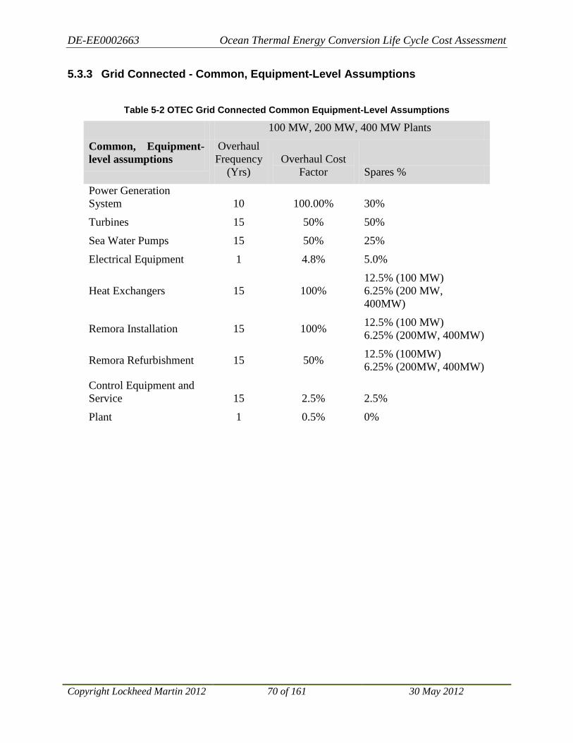
DE-EE0002663 Ocean Thermal Energy Conversion Life Cycle Cost Assessment
Copyright Lockheed Martin 2012 70 of 161 30 May 2012
5.3.3 Grid Connected - Common, Equipment-Level Assumptions
Table 5-2 OTEC Grid Connected Common Equipment-Level Assumptions
100 MW, 200 MW, 400 MW Plants
Common, Equipment-level assumptions
Overhaul Frequency
(Yrs) Overhaul Cost
Factor Spares % Power Generation System 10 100.00% 30%
Turbines 15 50% 50%
Sea Water Pumps 15 50% 25%
Electrical Equipment 1 4.8% 5.0%
Heat Exchangers 15 100% 12.5% (100 MW) 6.25% (200 MW, 400MW)
Remora Installation 15 100% 12.5% (100 MW) 6.25% (200MW, 400MW)
Remora Refurbishment 15 50% 12.5% (100MW) 6.25% (200MW, 400MW)
Control Equipment and Service 15 2.5% 2.5%
Plant 1 0.5% 0%

DE-EE0002663 Ocean Thermal Energy Conversion Life Cycle Cost Assessment
Copyright Lockheed Martin 2012 71 of 161 30 May 2012
5.3.4 Assumed Grid Connected Multiple Plant Roll-out Plan For this variant, the LCCA was bounded by utilizing the projected roll-out plan for Oahu, Hawai’i. This roll-out plan assumes the construction and deployment of two, 100 MW capacity plants, two 200 MW plants, and two 400 MW OTEC plants across an 11 time-span. This roll-out baseline was chosen for the modeling in order to bound the costing exercise. This allowed modeling of the O&S LCCs across a finite sample group. The proposed roll-out plan for Oahu, Hawai’i is shown in Figure 5-3. For the purposes of this cost assessment, year 1 is assumed to be 2018.
Figure 5-3. Proposed OTEC Roll-out Plan for Oahu, Hawai’i
MW1400 100 MW1300 200 MW1200 400 MW11001000
900800700600500400300200 100 MW #2100 100 MW #1
Year 2018 2019 2020 2021 2022 2023 2024 2025 2026 2027 2028
400 MW #2
400 MW #1
200 MW #2
200 MW #1

DE-EE0002663 Ocean Thermal Energy Conversion Life Cycle Cost Assessment
Copyright Lockheed Martin 2012 72 of 161 30 May 2012
5.3.5 Grid Connected, Roll-out, Plant-Specific Assumptions
Table 5-3. OTEC Grid Connected Plant-Specific Assumptions
Plant-Specific Assumptions
100 MW 200 MW
400 MW
Comment/Rationale
Quantities of plant configuration factored in proposed roll-out plan
2 2 2 Two of each configuration over a 10-year period
Remora Quantity 8 16 16 Number of Remoras per plant
Remora Net Power Generation
12.5MW 12.5MW 25MW Net power output per Remora
Plant net power 100 200 400 Available off-plant power capability
Personnel per plant 13 17 20 On station crew size

DE-EE0002663 Ocean Thermal Energy Conversion Life Cycle Cost Assessment
Copyright Lockheed Martin 2012 73 of 161 30 May 2012
5.4 Energy Carrier Plants
5.4.1 Energy Carrier Variant Overview This variant consists of OTEC plants that are not physically moored in place near land nor are they permanently moored at all. Instead, they are free-floating within a designated geographical area, generally within the equatorial zone. It allows these plants to ‘graze’ within these zones, which are specifically chosen because they pose a reduced risk from tropical storms/hurricanes/typhoons and take advantage of a temperature profile ideal for an efficient OTEC process. These plants generate electricity as do the Grid Connected plants, but it is completely consumed within the plant in the process of creating an ‘Energy Carrier’, NH3. This is done onboard via electrolysis to produce hydrogen, air separators to produce nitrogen, and a Haber-Bosch catalytic reaction to combine these ingredients into ammonia. Once created, the ammonia is temporarily stored in holding tanks on the platform, until such time as it can be offloaded into ocean-going tankers, similar to existing LPG carriers, for transport to a designated shore port facility for offloading.
It is envisioned the first Energy Carrier plants will be larger than the first Grid Connected plants due to the remote geographical locations where ideal environments for efficient OTEC thermal cycle operation is found, as well as the related efficiency and potential for high-volume production. It is estimated these variants would initially roll-out in a 400 MW configuration.
It is also assumed these plants would not contain any dedicated position-keeping subsystem. They would drift with ocean currents within a designated area. This results in the requirement to track position and movement, and ensure safe operation, as well as the occasional need to reposition the plants using a tug or other vessel. This repositioning is part of the corrective maintenance requirements factored into the Safety and Contingency section of the model.
5.4.2 Energy Carrier - Common, System-Level Assumptions Since the plants will be located far from shore, crew assignment and rotation for an energy-carrier is planned to be a 96-day rotation with an additional 24 days in transit. The O&S cost model assumes that transportation to/from the plant, for both the on-coming and off-going crews, is via the Energy Carrier transport vessels travelling to/from the individual plants to offload the Energy Carrier created and stored on that plant. Any transportation to from/this embarking point from some other location would be personnel’s responsibility. The daily allowance provided while on station is intended to cover personally incurred transportation costs to the point of embarkation of the Energy Carrier transport vessel.
As with any ocean-going vessel or remote platform, there is also a remote chance of storm-induced damage. This is accounted for in the Safety/Contingency assumption. Also, it is assumed there will be a ‘forward-deployed’ spares depot, to ensure timely availability and delivery of critical spares. Naturally, close proximity to land-based repair facilities factors into the assumed turnaround time for repair and/or refurbishment of system components when required.

DE-EE0002663 Ocean Thermal Energy Conversion Life Cycle Cost Assessment
Copyright Lockheed Martin 2012 74 of 161 30 May 2012
Table 5-4. OTEC Energy Carrier System-Level Assumptions
Common, System-Level Assumptions
400 MW Comment/Rationale
System Support Years 30 Total system maintenance years per plant
PMO/CLS (%) 4 Program Management Office and Contractor Logistical support
Labor Overhead (%) 34 Overhead percentage added to manpower labor rates
Inflation (%) 0.9 Annual rate
Crew Change Transportation Cost Factor ($)
0 Crew transport is provided via the Energy Carrier transport ship. There are no additional crew transport costs
Crew Change Frequency (cycles/yr)
3.8 Crew change every 96 days based on transport ship schedule
Travel Time (days per transit)
24 Transport ship round trip transit time is 24 days (18 days travel, 5 days loading, 1 day unloading). Crew turn-over occurs during Energy Carrier loading
Training (%) 2 % of personnel costs
Safety/Contingency (%) 1 % of MSI capital cost per year
Ongoing Environmental Monitoring Cost ($/yr)
260000
PHS&T factor (%) 2
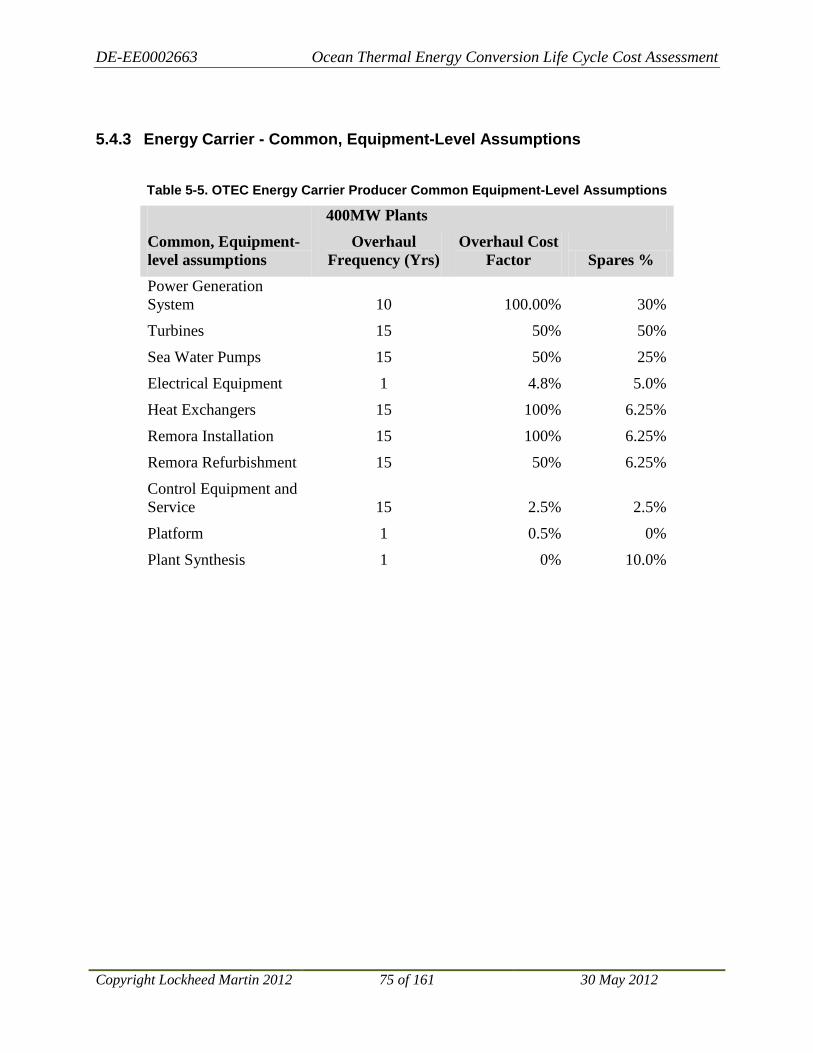
DE-EE0002663 Ocean Thermal Energy Conversion Life Cycle Cost Assessment
Copyright Lockheed Martin 2012 75 of 161 30 May 2012
5.4.3 Energy Carrier - Common, Equipment-Level Assumptions
Table 5-5. OTEC Energy Carrier Producer Common Equipment-Level Assumptions
400MW Plants Common, Equipment-level assumptions
Overhaul Frequency (Yrs)
Overhaul Cost Factor Spares %
Power Generation System 10 100.00% 30%
Turbines 15 50% 50%
Sea Water Pumps 15 50% 25%
Electrical Equipment 1 4.8% 5.0%
Heat Exchangers 15 100% 6.25%
Remora Installation 15 100% 6.25%
Remora Refurbishment 15 50% 6.25%
Control Equipment and Service 15 2.5% 2.5%
Platform 1 0.5% 0%
Plant Synthesis 1 0% 10.0%

DE-EE0002663 Ocean Thermal Energy Conversion Life Cycle Cost Assessment
Copyright Lockheed Martin 2012 76 of 161 30 May 2012
5.4.4 Energy Carrier Multiple Plant - Roll-out Plan The Energy Carrier Roll-out plan was assumed to be similar to that of the Grid Connected plants. A key difference is, that due to the favorable economic conditions of larger plants and based on the assumption that Grid Connected plants of all configurations will be deployed prior to the first Energy Carrier plant, only 400 MW Energy Carrier plants were assumed for this application.
This proposed roll-out plan is shown in Figure 5-4. For the purposes of this cost assessment, year 1 is assumed to be 2026.
Figure 5-4. Proposed Energy Carrier OTEC Roll-out Plan
MW2400 100 MW2300 200 MW2200 400 MW210020001900180017001600150014001300120011001000
900800700600500400300200100
Year 2026 2027 2028 2029 2030 2031 2032 2033 2034 2035 2036
400 MW #4
400 MW #3
400 MW #2
400 MW #1
400 MW #6
400 MW #5

DE-EE0002663 Ocean Thermal Energy Conversion Life Cycle Cost Assessment
Copyright Lockheed Martin 2012 77 of 161 30 May 2012
5.4.5 Energy Carrier Roll-out – Plant-Specific Assumptions
Table 5-6. OTEC Energy Carrier Plant-Specific Assumptions
Plant-Specific Assumptions
400 MW
Comment/Rationale
Quantities of plant configuration factored in proposed roll-out plan
6 One plant rolled out every two years
Remora Quantity 16 Number of Remoras per plant
Remora Net Power Generation
25MW Net power output per Remora
Plant net power 400 Available off-plant power capability
Personnel per plant 25 On-station crew size
5.5 OTEC Operations and Sustainment LCCA Results
5.5.1 Grid Connected OTEC Plant Results The Results section provides a set of O&S cost model outputs generated using the cost element structure described previously. The following diagrams, Figure 5-5 through Figure 5-10, and Table 5-7, Table 5-8, and Table 5-9 provide standard comparative views of the proportions, timing, and elements related to the projected Operations and Sustainment costs for the Grid Connected plants for the 100 MW, 200 MW and 400 MW configurations. Figure 5-11 provides a total O&S 30-year view of all six plants in an annual phased chart.

DE-EE0002663 Ocean Thermal Energy Conversion Life Cycle Cost Assessment
Copyright Lockheed Martin 2012 78 of 161 30 May 2012
5.5.1.1 Individual 100 MW Grid Connected Plant Results
.
Figure 5-5. 100 MW Grid Connected Cost Breakdown
Figure 5-6. 100 MW Yearly O&S Expenditures
Spares $6.53%
Maintenance/Overhaul $
44.92%
PHS&T0.90%
PMO/CLS3.18%
POL/Fuel0.00%
Personnel7.72%
Training0.15%
Crew Transport 0.59%
Safety/Contingency18.12%
Ongoing Environmental
Monitoring Costs0.46%
Inflation17.44%
100 MW Grid Connected Plant

DE-EE0002663 Ocean Thermal Energy Conversion Life Cycle Cost Assessment
Copyright Lockheed Martin 2012 79 of 161 30 May 2012
Table 5-7. OTEC Grid Connected Summary Cost Table
Cost Category Average $/yr Total Life Cycle $ Spares $ $3,722,742 $111,682,247 Maintenance/Overhaul $ $25,622,693 $768,680,775 PHS&T $512,454 $15,373,616 PMO/CLS $1,811,256 $54,337,673 POL/Fuel $0 $0 Personnel $4,405,090 $132,152,690 Training $88,102 $2,643,054 Crew Transport $338,000 $10,140,000 Safety/Contingency $10,332,314 $309,969,433 Ongoing Environmental Monitoring Costs $260,000 $7,800,000 Subtotal $47,092,650 $1,412,779,487 Inflation $9,944,440 $298,333,190 100 MW, Sys #1 Total $57,037,089 $1,711,112,676

DE-EE0002663 Ocean Thermal Energy Conversion Life Cycle Cost Assessment
Copyright Lockheed Martin 2012 80 of 161 30 May 2012
5.5.1.2 Individual 200 MW Grid Connected Plant Results
Figure 5-7. 200 MW Grid Connected Cost Breakdown
Figure 5-8. 200 MW Yearly O&S
Spares $5.20%
Maintenance/Overhaul $
46.03%
PHS&T0.92%
PMO/CLS3.06%
POL/Fuel0.00%
Personnel5.46%
Training0.11%
Crew Transport 0.34%
Safety/Contingency18.18%
Ongoing Environmental
Monitoring Costs0.26% Inflation
20.45%
200 MW Grid Connected Plant

DE-EE0002663 Ocean Thermal Energy Conversion Life Cycle Cost Assessment
Copyright Lockheed Martin 2012 81 of 161 30 May 2012
Table 5-8. OTEC Grid Connected 200 MW Summary Cost Table
Cost Category Average $/yr Total Life Cycle $ Spares $ $5,200,619 $156,018,571 Maintenance/Overhaul $ $46,021,024 $1,380,630,727 PHS&T $920,420 $27,612,615 PMO/CLS $3,059,349 $91,780,457 POL/Fuel $0 $0 Personnel $5,460,266 $163,807,989 Training $109,205 $3,276,160 Crew Transport $338,000 $10,140,000 Safety/Contingency $18,174,179 $545,225,357 Ongoing Environmental Monitoring Costs $260,000 $7,800,000 Subtotal $79,543,062 $2,386,291,875 Inflation $20,443,997 $613,319,924 200 MW, Sys #1 Total $99,987,060 $2,999,611,799

DE-EE0002663 Ocean Thermal Energy Conversion Life Cycle Cost Assessment
Copyright Lockheed Martin 2012 82 of 161 30 May 2012
5.5.1.3 Individual 400 MW Grid Connected Plant Results
Figure 5-9. 400 MW Grid Connected Cost Breakdown
Figure 5-10. 400 MW Yearly O&S
Spares $5.20%
Maintenance/Overhaul $
46.03%
PHS&T0.92%PMO/CLS
3.06%
POL/Fuel0.00%
Personnel5.46%
Training0.11%
Crew Transport 0.34%
Safety/Contingency18.18%
Ongoing Environmental
Monitoring Costs0.26%
Inflation20.45%
400 MW Grid Connected Plant
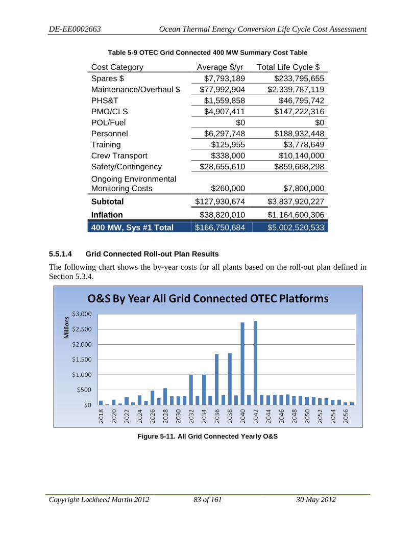
DE-EE0002663 Ocean Thermal Energy Conversion Life Cycle Cost Assessment
Copyright Lockheed Martin 2012 83 of 161 30 May 2012
Table 5-9 OTEC Grid Connected 400 MW Summary Cost Table
Cost Category Average $/yr Total Life Cycle $ Spares $ $7,793,189 $233,795,655 Maintenance/Overhaul $ $77,992,904 $2,339,787,119 PHS&T $1,559,858 $46,795,742 PMO/CLS $4,907,411 $147,222,316 POL/Fuel $0 $0 Personnel $6,297,748 $188,932,448 Training $125,955 $3,778,649 Crew Transport $338,000 $10,140,000 Safety/Contingency $28,655,610 $859,668,298 Ongoing Environmental Monitoring Costs $260,000 $7,800,000 Subtotal $127,930,674 $3,837,920,227 Inflation $38,820,010 $1,164,600,306 400 MW, Sys #1 Total $166,750,684 $5,002,520,533
5.5.1.4 Grid Connected Roll-out Plan Results
The following chart shows the by-year costs for all plants based on the roll-out plan defined in Section 5.3.4.
Figure 5-11. All Grid Connected Yearly O&S

DE-EE0002663 Ocean Thermal Energy Conversion Life Cycle Cost Assessment
Copyright Lockheed Martin 2012 84 of 161 30 May 2012
5.5.2 Energy Carrier OTEC Plant Results The Results section provides a set of O&S cost model outputs generated using the cost element structure described previously. As with the Grid Connected detail, Figure 5-12 and Figure 5-13 and Table 5-10 provide a similar view of Operations and Sustainment cost proportions, timing, and elements for a single 400 MW plant. Figure 5-15 provides a total O&S 30-year view of all six plants in an annual phased chart.
5.5.2.1 Individual 400 MW Energy Carrier Plant Results
Figure 5-12. 400 MW Energy Carrier Cost Breakdown
Figure 5-13. Energy Carrier 400 MW Yearly O&S Cost
Spares $3.26%
Maintenance/Overhaul $
46.01%
PHS&T0.92%
PMO/CLS2.70%
Energy Carrier Shipping
6.19%
Personnel3.74%
Training0.07%
Crew Transport 0.00%
Safety/Contingency13.46%
Ongoing Environmental
Monitoring Costs0.11%
Inflation23.54%
400 MW - Energy Carrier Plant

DE-EE0002663 Ocean Thermal Energy Conversion Life Cycle Cost Assessment
Copyright Lockheed Martin 2012 85 of 161 30 May 2012
Table 5-10 OTEC 400 MW Energy Carrier Summary Cost Table
Cost Category Average $/yr Total Life Cycle $ Spares $ $7,793,189 $233,795,655 Maintenance/Overhaul $ $109,999,237 $3,299,977,119 PHS&T $2,199,985 $65,999,542 PMO/CLS $6,461,853 $193,855,597 Energy Carrier Shipping $14,800,750 $444,022,500 Personnel $8,939,520 $268,185,605 Training $178,790 $5,363,712 Crew Transport $0 $0 Safety/Contingency $32,175,610 $965,268,298 Ongoing Environmental Monitoring Costs $260,000 $7,800,000 Subtotal $182,808,934 $5,484,268,029 Inflation $56,283,008 $1,688,490,255 400 mw, sys #1 Total $239,091,943 $7,172,758,283
5.5.2.2 Energy Carrier Roll-out Plan Results
The following chart shows the by-year costs for all Energy Carrier plants based on the roll-out plan defined in Section 5.4.4.
Figure 5-14. All Energy Carrier Plants Yearly O&S

DE-EE0002663 Ocean Thermal Energy Conversion Life Cycle Cost Assessment
Copyright Lockheed Martin 2012 86 of 161 30 May 2012
5.6 O&S Estimate Summary This study provides a high-level cost assessment for O&S of OTEC plant configurations consistent with the projected build out plan. The results of this study feed directly into the economic analysis for the OLCCA project. As reported in the results, O&S costs of OTEC plants are a significant factor in the total ownership cost LCC as shown in Figure 5-15 and Figure 5-16.
Figure 5-15. Breakdown of Total Ownership Cost by OTEC Plant Configuration
Figure 5-16. Breakdown of Total Ownership Cost Per MW Installed by OTEC Plant Configuration
$0
$1,000,000,000
$2,000,000,000
$3,000,000,000
$4,000,000,000
$5,000,000,000
$6,000,000,000
$7,000,000,000
$8,000,000,000
$9,000,000,000
$10,000,000,000
Grid Connected 100 MW
Grid Connected 200 MW
Grid Connected 400 MW
Energy Carrier 400 MW
Total Ownership Cost
Operation & Sustainment
Capital & Disposal
$0
$5,000,000
$10,000,000
$15,000,000
$20,000,000
$25,000,000
$30,000,000
Grid Connected 100 MW
Grid Connected 200 MW
Grid Connected 400 MW
Energy Carrier 400 MW
Total Ownership Cost per MW Installed
Operation & Sustainment
Capital & Disposal

DE-EE0002663 Ocean Thermal Energy Conversion Life Cycle Cost Assessment
Copyright Lockheed Martin 2012 87 of 161 30 May 2012
6 Personnel Cost Analysis
6.1 Personnel Requirements In order to define OTEC personnel requirements, input was solicited from multiple sources by way of a survey request to the project team. The survey respondents included expertise in the offshore industry, U.S. Navy, OTEC power systems, U.S. Navy logistics programs and control systems. The survey requested estimates for the number of billets required to fully staff the required on-board crew for the three configuration sizes being considered (100 MW, 200 MW, and 400 MW). The personnel per position reported in the survey results represent the total crew required to staff the billets on all shifts regardless of shift schedule. As an example, a response with four plant operators identified as required indicates that four plant operators must be on-board to staff all shifts. Those shifts could be one operator per shift with four shifts per day or two operators per shift with two shifts (or four half shifts) per day.
Results from the survey were compiled and statistics calculated. Because the respondents represented a wide range of experience and expertise, the personnel requirements defined by each varied significantly with standard deviations ranging between 35% and 45% of the mean. However, even with this wide distribution of results, there were similarities and areas of agreement.
To resolve the differences and arrive at a final personnel requirement for each configuration, a meeting was held to review survey results. Differences in assumptions and expectations were discussed and consensus was quickly reached on the appropriate levels of staffing for all three configurations. The resulting staffing requirements fell very close to the mean of the survey responses. The results of the survey and reconciliation meeting are presented in Figure 6-1.
This result seems to confirm the “wisdom of crowds” as defined by James Surowiecki in his book The Wisdom of Crowds: Why the Many Are Smarter Than the Few and How Collective Wisdom Shapes Business, Economies, Societies and Nations, published in 2004. The phenomenon addressed in Surowiecki’s book and other related studies is that averaging the estimates of independently-deciding individuals results in an estimate that is more accurate than any individual estimate.

DE-EE0002663 Ocean Thermal Energy Conversion Life Cycle Cost Assessment
Copyright Lockheed Martin 2012 88 of 161 30 May 2012
Figure 6-1. Estimated OTEC Personnel Requirements Survey Results
The consensus resulting from the survey and subsequent discussion defined the personnel requirements shown in Table 6-1 for the Grid Connected Total. For the Energy Carrier OTEC plants, additional plant operators are required to man the synthesis equipment. These additional crew requirements are also included in Table 6-1 in the Ammonia Synthesis Plant Ops row. The bottom total represents the total crew required for an Energy Carrier OTEC plant.
Table 6-1. Personnel Requirements for Grid Connected and Energy Carrier
Position Billets (crew onboard) 100 MW 200 MW 400 MW Plant Manager/Captain 1 1 1 Shift Supervisor/Ship Engineer 2 2 2 Plant Operators 3 4 5 Maintenance Tech 3 5 7 Able Body Seaman 2 3 3 Cook 2 2 2 Grid Connected Total 13 17 20 Ammonia Synthesis Plant Ops 3 4 5 Energy Carrier Total 16 21 25
0
5
10
15
20
25
30
35
100 MW 200 MW 400 MW
Input A
Input B
Input C
Input D
Input E
Mean
SD
Consensus

DE-EE0002663 Ocean Thermal Energy Conversion Life Cycle Cost Assessment
Copyright Lockheed Martin 2012 89 of 161 30 May 2012
6.2 Personnel Cost Estimates
6.2.1 Salaries For estimating the cost of the annual personnel requirements, data from the Bureau of Labor Statistics was referenced. NAICS 483100 - Deep Sea, Coastal, and Great Lakes Water Transportation data was used as this category most accurately represents the industry to which an OTEC plant would belong. Table 6-2 shows the OES categories that were selected best representing the OTEC plant positions defined.
Table 6-2. Representative Personnel Salary Data from Bureau of Labor Statistics
Position OES Title OES Rank/Rate
Salary Plant Manager/Captain General and Operations Managers 11-1021 $131,670 Shift Supervisor/Ship Engineer Ship Engineers 53-5031 $79,100 Plant Operators 1st-Line Supervisors (maint., repairs) 49-1011 $73,230 Maintenance Tech Maintenance and Repair Workers 49-9071 $37,770 Able Body Seaman Sailors and Marine Oilers 53-5011 $37,620 Cook Chefs and Head Cooks 35-1011 $48,840
6.2.2 Total Annual Personnel Because the OTEC plant must operator 24 hours a day, 365 days a year, multiple crews that rotate on and off the plant are required to fully staff the billets. For Grid Connected plants that are close to shore (one day or less transit time), crews will rotate every 14 days. For Energy Carrier plants (up to 24 days round trip transit time), the rotation period is 96 days. Since the transit to and from the plants occurs before and after the on-board duration, two crews can fully support this rotation scheme. As one crew rotates on the station, the current crew rotates off. However, to account for crew absences, an additional factor is added to calculate the total annual personnel required. Therefore, the numbers for on-board crew are multiplied by 2.6 to get the total annual personnel.
6.2.3 Overtime, Transit Time, Daily Allowance To account for planned and unplanned overtime, a 30% factor is applied to all salaries. This is based on team experience with average overtime incurred on offshore platforms. To account for transit time (crew transport and home port to deployment port travel) a 20% factor is applied to all salaries. A daily allowance for each day on-station of $20 is applied for each crew member. The average days on-station for each crew member based on the rotation schemes defined above is 183 days.
6.2.4 Benefits To account for benefits, a factor of 40% is applied to the base salary for all positions.
6.2.5 Energy Carrier Plant Premium For the OTEC Energy Carrier plants, the long transit time of up to 24 days round trip to transport crew on and off the plant, necessitates a longer crew rotation period. Ninety day rotations are customary under these conditions. To align with the ammonia transport shipping schedule, 96 day rotations are assumed for the Energy Carrier plants. Even with the longer rotation cycle, the longer transit time results in more days per year away from home (228 days compared to
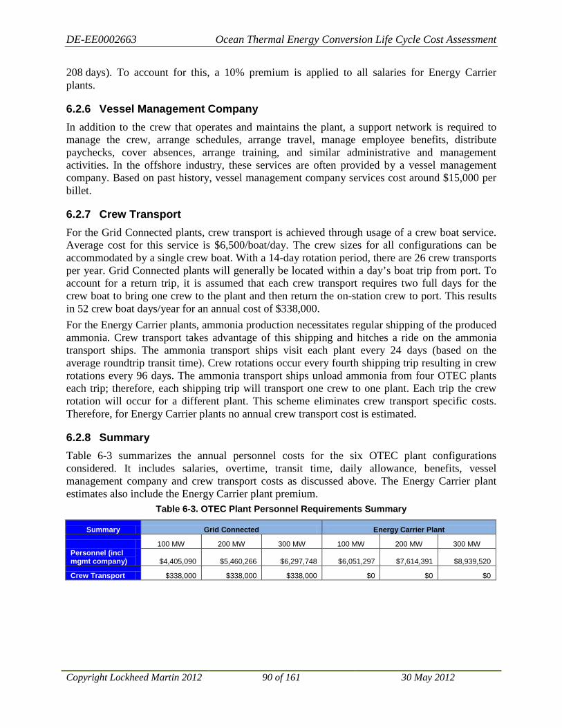
DE-EE0002663 Ocean Thermal Energy Conversion Life Cycle Cost Assessment
Copyright Lockheed Martin 2012 90 of 161 30 May 2012
208 days). To account for this, a 10% premium is applied to all salaries for Energy Carrier plants.
6.2.6 Vessel Management Company In addition to the crew that operates and maintains the plant, a support network is required to manage the crew, arrange schedules, arrange travel, manage employee benefits, distribute paychecks, cover absences, arrange training, and similar administrative and management activities. In the offshore industry, these services are often provided by a vessel management company. Based on past history, vessel management company services cost around $15,000 per billet.
6.2.7 Crew Transport For the Grid Connected plants, crew transport is achieved through usage of a crew boat service. Average cost for this service is $6,500/boat/day. The crew sizes for all configurations can be accommodated by a single crew boat. With a 14-day rotation period, there are 26 crew transports per year. Grid Connected plants will generally be located within a day’s boat trip from port. To account for a return trip, it is assumed that each crew transport requires two full days for the crew boat to bring one crew to the plant and then return the on-station crew to port. This results in 52 crew boat days/year for an annual cost of $338,000. For the Energy Carrier plants, ammonia production necessitates regular shipping of the produced ammonia. Crew transport takes advantage of this shipping and hitches a ride on the ammonia transport ships. The ammonia transport ships visit each plant every 24 days (based on the average roundtrip transit time). Crew rotations occur every fourth shipping trip resulting in crew rotations every 96 days. The ammonia transport ships unload ammonia from four OTEC plants each trip; therefore, each shipping trip will transport one crew to one plant. Each trip the crew rotation will occur for a different plant. This scheme eliminates crew transport specific costs. Therefore, for Energy Carrier plants no annual crew transport cost is estimated.
6.2.8 Summary Table 6-3 summarizes the annual personnel costs for the six OTEC plant configurations considered. It includes salaries, overtime, transit time, daily allowance, benefits, vessel management company and crew transport costs as discussed above. The Energy Carrier plant estimates also include the Energy Carrier plant premium.
Table 6-3. OTEC Plant Personnel Requirements Summary
Summary Grid Connected Energy Carrier Plant
100 MW 200 MW 300 MW 100 MW 200 MW 300 MW Personnel (incl mgmt company) $4,405,090 $5,460,266 $6,297,748 $6,051,297 $7,614,391 $8,939,520
Crew Transport $338,000 $338,000 $338,000 $0 $0 $0

DE-EE0002663 Ocean Thermal Energy Conversion Life Cycle Cost Assessment
Copyright Lockheed Martin 2012 91 of 161 30 May 2012
7 Environmental Requirements and Costs OTEC presents unusual challenges for environmental impact assessment and permitting. Technically, there are no precedents for the very large flows of deep and shallow seawater that provide the temperature differential for power generation and also constitute the most significant potential source of environmental impacts from this technology.
At this time, to the best of our knowledge, the U.S. is the only nation that has established a legal regime specifically governing construction and operation of OTEC facilities. Thus, the regulatory agency controls over OTEC operations undertaken outside of U.S. jurisdiction are not defined. The three Grid Connected sites listed above are all within U.S. jurisdiction, but the two other sites will present challenges to any developer to understand and comply with the regulatory regimes that might apply to this unprecedented activity. The following sections describe the anticipated environmental impact, permitting, and monitoring requirements for the Hawai’ian sites, which have been studied in far more detail than the other sites, and then examine the likely differences between the Hawai’ian sites and each of the other potential OTEC locations evaluated in this study.
7.1 Hawai’ian Site Requirements and Costs The Ocean Thermal Energy Conversion (OTEC) Act of 1980 established NOAA as the licensing agency for OTEC plants, while granting the Secretary of Energy the authority to help expedite OTEC development for designated “OTEC Demonstration Projects.” NOAA published OTEC regulations on July 31, 1981 (15 CFR 981). When it subsequently rescinded them on January 30, 1996 (61 FR 2970) because of inactivity, it left a permitting framework in place, but left the details to be worked out if and when the technology became financially feasible. NOAA is currently developing a new set of regulations that will guide its administration of U.S.-based OTEC plants.
In addition to the OTEC Permit itself, OTEC developments in Hawai‘i will require Federal, State, and Local permits and approvals. The following sections describe the key environmental assessment work and permitting information inputs needed to obtain all major permits and the expected requirements for environmental monitoring.
7.1.1 Environmental Impact Analysis
7.1.1.1 NEPA Compliance
7.1.1.1.1 General Considerations
All Federal actions must comply with the requirements of the National Environmental Policy Act (NEPA). There are three ways that a Federal action can do this, with the appropriate course for any specific action depending on the significance of its predicted impacts (see Figure 7-1). These three methods are: (1) categorical exclusion, (2) completion of an Environmental Assessment followed by a Finding of No Significant Impact (EA/FONSI); and (3) preparation and acceptance of an environmental impact statement (EIS).
Categorical Exclusion. Projects may be categorically excluded from a detailed environmental analysis if they meet specific criteria that a Federal agency has previously determined to have no significant environmental impact. Most Federal agencies have developed lists of actions which
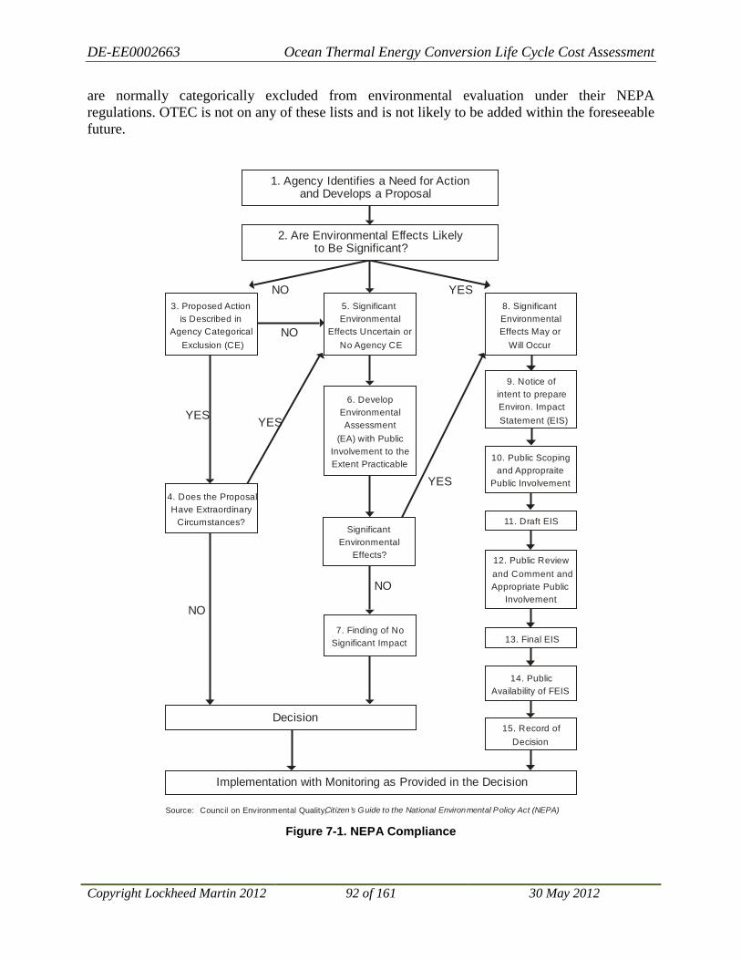
DE-EE0002663 Ocean Thermal Energy Conversion Life Cycle Cost Assessment
Copyright Lockheed Martin 2012 92 of 161 30 May 2012
are normally categorically excluded from environmental evaluation under their NEPA regulations. OTEC is not on any of these lists and is not likely to be added within the foreseeable future.
Figure 7-1. NEPA Compliance
2. Are Environmental Effects Likely to Be Significant?
3. Proposed Action is Described in
Agency Categorical Exclusion (CE)
4. Does the Proposal Have Extraordinary
Circumstances?
5. Significant Environmental
Effects Uncertain or No Agency CE
6. Develop Environmental Assessment
(EA) with Public Involvement to the Extent Practicable
8. Significant Environmental Effects May or
Will Occur
9. Notice of intent to prepare Environ. Impact Statement (EIS)
11. Draft EIS
13. Final EIS
15. Record of Decision
10. Public Scoping and Appropraite
Public Involvement
12. Public Review and Comment and Appropriate Public
Involvement
7. Finding of No Significant Impact
14. Public Availability of FEIS
Implementation with Monitoring as Provided in the Decision
Significant Environmental
Effects?
Decision
1. Agency Identifies a Need for Actionand Develops a Proposal
NO
YES
NO
YES
NO YES
NO
YES
Source: Council on Environmental Quality, Citizen ’s Guide to the National Environmental Policy Act (NEPA)

DE-EE0002663 Ocean Thermal Energy Conversion Life Cycle Cost Assessment
Copyright Lockheed Martin 2012 93 of 161 30 May 2012
EA/FONSI. For the second option, a Federal agency prepares a written EA to determine whether or not a Federal undertaking would significantly affect the environment. If the determination is that it will not, the agency issues a FONSI. If the EA determines the environmental consequences of a proposed federal project may be significant, an EIS is prepared.
EIS. An EIS is a more detailed evaluation of the proposed action and alternatives. The public, other Federal agencies and outside parties may provide input into the preparation of an EIS and then comment on the draft EIS when it is completed. If a Federal agency anticipates a project may significantly impact the environment, or if a project is environmentally controversial, a Federal agency may choose to prepare an EIS without having to first prepare an EA. After a final EIS is prepared and at the time of its decision, a Federal agency will prepare a public Record of Decision addressing how EIS findings have been incorporated into the agency's decision-making process.
The Federal agency responsible for an OTEC project must decide which of these two latter options to pursue. The EA/FONSI method is simpler and generally takes less time. The EIS option is less susceptible to challenge, since it does not have to conclude that the project has no significant environmental impacts.
7.1.1.1.2 Designation of Lead Agency and Definition of Project
The NEPA compliance process is initiated by a Federal agency when it defines an action, its purpose and the need for it. Implementation of an OTEC project will potentially involve several Federal agencies with different responsibilities, and it is of critical importance to have a clear definition of the actions being undertaken and the specific roles of the various agencies involved. For the construction and operation of a commercial plant under U.S. jurisdiction, NEPA compliance is necessary. It is likely that NOAA would be the lead agency and that its action would be the issuance of the NOAA license for the plant.
7.1.1.1.3 Definition of Alternatives to the Proposed Action
Environmental impact analysis carried out for NEPA compliance must include comparison of the impacts resulting from different alternatives that can meet the stated objectives for the proposed action, as well as the “No Action” alternative contemplating in this case NOAA’s denial of the license application. Careful definition of these alternatives is essential to efficient and adequate impact analysis. These alternatives can include modifications in place (e.g., put the plant at another site than the proposed site), in time (e.g., consider alternative schedules for project completion), or substance (e.g., consider different system designs or modes of operation).
7.1.1.2 State Environmental Impact Analysis Compliance
Hawai‘i State Law EIS requirements (HRS Chapter 343) are similar to and generally consistent with Federal NEPA law (see Figure 7-2) but apply to the actions of State agencies. In the case of an OTEC commercial plant, the likely requirement for a Conservation District Use Permit from the Department of Land and Natural Resources Office of Conservation and Coastal Lands (OCCL) and the proposed use of State-owned land for the cable route would both trigger the need for a Chapter 343 EA/FONSI or EIS for the project. Typically, both State and Federal (NEPA) requirements can be met using a single document that satisfies both Federal and State agency requirements. This typically imposes greater coordination requirements and, therefore, adds marginally to the time required.
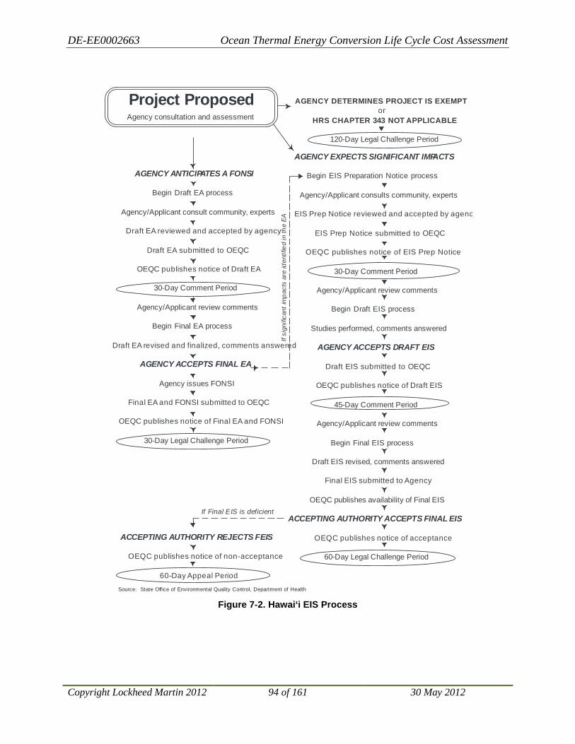
DE-EE0002663 Ocean Thermal Energy Conversion Life Cycle Cost Assessment
Copyright Lockheed Martin 2012 94 of 161 30 May 2012
Figure 7-2. Hawai‘i EIS Process
Source: State Office of Environmental Quality Control, Department of Health
AGENCY EXPECTS SIGNIFICANT IMPACTS
Begin EIS Preparation Notice process
Agency/Applicant consults community, experts
EIS Prep Notice reviewed and accepted by agenc
EIS Prep Notice submitted to OEQC
OEQC publishes notice of EIS Prep Notice
30-Day Comment Period
Agency/Applicant review comments
Begin Draft EIS process
Studies performed, comments answered
AGENCY ACCEPTS DRAFT EIS
Draft EIS submitted to OEQC
OEQC publishes notice of Draft EIS
45-Day Comment Period
Agency/Applicant review comments
Begin Final EIS process
Draft EIS revised, comments answered
Final EIS submitted to Agency
OEQC publishes availability of Final EIS
ACCEPTING AUTHORITY ACCEPTS FINAL EIS
OEQC publishes notice of acceptance
60-Day Legal Challenge Period
Project ProposedAgency consultation and assessment
AGENCY ANTICIPATES A FONSI
Begin Draft EA process
Agency/Applicant consult community, experts
Draft EA reviewed and accepted by agency
Draft EA submitted to OEQC
OEQC publishes notice of Draft EA
30-Day Comment Period
Agency/Applicant review comments
Begin Final EA process
Draft EA revised and finalized, comments answered
AGENCY ACCEPTS FINAL EA
Agency issues FONSI
Final EA and FONSI submitted to OEQC
OEQC publishes notice of Final EA and FONSI
30-Day Legal Challenge Period
AGENCY DETERMINES PROJECT IS EXEMPTor
HRS CHAPTER 343 NOT APPLICABLE
120-Day Legal Challenge Period
ACCEPTING AUTHORITY REJECTS FEIS
OEQC publishes notice of non-acceptance
60-Day Appeal Period
If si
gnifi
cant
impa
cts
are
iden
tifie
d in
the
EA
If Final EIS is deficient

DE-EE0002663 Ocean Thermal Energy Conversion Life Cycle Cost Assessment
Copyright Lockheed Martin 2012 95 of 161 30 May 2012
7.1.2 Baseline and Monitoring Requirements Though no OTEC baseline or monitoring requirements have yet been set by NOAA, some progress has been made in identifying the key parameters likely to be required. These are included in the final recommendations from a technical workshop that was sponsored by NOAA and convened in Honolulu, Hawai’i in June 2010. The following sections outline these results. This is not intended to list all impact topics to be covered in the impact analysis; rather it identifies topics needing early attention to provide adequate baseline coverage.
The highest priority is placed on oceanographic data collections in the water column where the plant intakes and discharges would occur. The very high rates of water flow make it crucial to establish confident baseline information that can be used to forecast potential impacts. These collection efforts should include at least the data types outlined in the following section and should be carried out quarterly for at least two years prior to completion of the environmental impact documentation for the Demonstration Project.
Additional, one-time studies to assess construction-related impacts along the seafloor power cable route and sites for onshore support facilities should also be conducted. A preliminary outline of the most important of these requirements is presented below.
7.1.2.1 Baseline Data Collection
Table 7-1 shows the outline of NOAA’s recommended baseline data collection plan20
7.1.2.1.1 Water Column Data (Two-Year Baseline)
. The following program is consistent with this plan and suggests specific techniques appropriate to Hawai’ian waters.
The effort calls for quarterly oceanographic cruises for two calendar years. Although it appears that the temporal variability in most oceanographic parameters is moderately bimodal (i.e., winter/summer) at most Hawai‘i sites, the finer detail offered by occupying stations four times per year (winter/spring/summer/ fall) as opposed to two times per year will lead to a fuller and more reliable understanding of overall temporal fluctuations. These surveys include the efforts described below.
7.1.2.1.1.1 In Situ Measurements
Conductivity, Temperature, Depth (CTD), fluorescence, and ocean current velocities (Acoustic Doppler Current Profiling) will be measured throughout the water column during the quarterly surveys. LM will also deploy a moored array for essentially continuous measurement of these parameters and then calibrate and augment these measurements with the quarterly survey data collections.
20 Ocean Thermal Energy Conversion: Assessing the Potential Physical, Chemical, and Biological Impacts and Risks, NOAA Office of Ocean and Coastal Resource Management and Coastal Response Research Center, U. of New Hampshire, June 22–24, 2010, Ala Moana Hotel, Honolulu

DE-EE0002663 Ocean Thermal Energy Conversion Life Cycle Cost Analysis
Copyright Lockheed Martin 2012 96 of 161 30 May 2012
Table 7-1. NOAA Baseline Data Recommendations
DE-EE0002663 Ocean Thermal Energy Conversion Life Cycle Cost Analysis
Copyright Lockheed Martin 2012 97 of 161 30 May 2012
7.1.2.1.1.2 Water Quality Parameters to Be Determined
Collected water samples will be tested for levels of the following constituents:
• Salinity • Dissolved oxygen • Dissolved inorganic carbon • Alkalinity • pH • Carbon dioxide partial pressure • Inorganic nutrients (dissolved P, N, and Si species) • Dissolved organic matter • Particulate C, N, P, and biogenic silica • Selected HPLC measurements of chlorophyll for calibration of fluorescence
measurements • Measurements of adenosine 5’-triphosphate (ATP) • Selected measurement of trace metals such as copper, iron, mercury, and others
7.1.2.1.1.3 Plankton Assays
The OTEC developer needs to characterize the species of cyanobacteria, phytoplankton, zooplankton, and larval plankton found within the top 200 m of the water column and estimate their temporal variation and long-term average densities as a function of water depth. This information is used to estimate the potential for entrainment and impingement interactions with surface water intakes and the potential for impacts on these organisms from the water discharge streams.
7.1.2.1.2 Seafloor Characterization
Detailed surveys of the seafloor will be undertaken to determine the engineering variables related to mooring configurations, cable routing and slope stability. Distinct but related survey work will be conducted to characterize the benthic habitats that occur in these areas. It may be possible to accommodate both engineering and environmental impact requirements using the same survey program, but that will be determined at a later date.
For environmental impact analysis, the seafloor in the vicinity of the Demonstration Project mooring sites and power cable route is examined using side-scan sonar to provide back-scatter imaging. For areas of particular interest identified during the side-scan survey (e.g., hard substrates that may be special habitats), surveys using video and selected submersible coverage (manned by qualified biological experts) are carried out to assess benthic habitats that could potentially be affected by the mooring or operation of the plant.
Qualified marine biologists identify and characterize the biological communities that might be affected by the cable installation using existing information. Divers conduct more intensive bottom surveys of shallow-water biological communities present near the cable landing site.

DE-EE0002663 Ocean Thermal Energy Conversion Life Cycle Cost Analysis
Copyright Lockheed Martin 2012 98 of 161 30 May 2012
7.1.2.1.3 Ambient Noise Levels
The moored array is equipped with a recording microphone that can determine ambient noise levels and also make it possible to determine the kinds and frequencies of passage of several marine mammal species.
7.1.2.1.4 Terrestrial Studies
Studies will be carried out in the second year to characterize the flora, fauna, and potential historic and cultural resources of the areas impacted by the land-based facilities associated with the cable landing and on-land support facilities. This work depends in part on the availability of site-specific design information for the cable landing and support facilities.
7.1.2.1.5 Cultural Impact Analysis
A key component of the initial impact analysis in Hawai‘i is a thorough Cultural Impact Analysis (CIA). This study examines the potential project impacts to native Hawai’ians through studies of local cultural practices and values and interviews of elders on Oahu. It is crucial to initiate the study early in the process to ensure that native Hawai’ian views are considered throughout the impact analysis and permitting work.
7.1.2.2 Monitoring Requirements
Key recommendations from the NOAA workshop, related to operational monitoring, are listed and described in the following section. As shown in Table 7-2, extensive monitoring efforts are recommended for every aspect of an OTEC system that interacts with the external environment. The following paragraphs examine the general methodologies involved for collection of different data types. They are organized according to the primary OTEC system components having the potential for environmental impact. The grouping is consistent with the topics covered by the NOAA workshop breakout groups.
7.1.2.2.1 Warm Water Intake
Due to its relatively shallow depth, the principal impacts from the warm water intake system are likely to be: (1) entrainment, when an organism or particle passes through screening or filters and enters the warm water intake system, and (2) impingement, when an organism is held against a surface by water flow or becomes stuck within a structure. These topics are the subject of intensive research by the electrical utility industry to find ways to provide cooling water to generating stations while minimizing entrainment and impingement effects on aquatic life. Because of the large volumes of water involved, this is a critical aspect in OTEC design.
Differences between typical power plant intake monitoring and that which is required for OTEC may arise from several sources. The most obvious is the fact that OTEC warm water intakes will be located well out to sea and in much deeper water than is typical for power plants. The abundance of marine life potentially affected by the intake will, in general, be much lower than occurs in coastal waters. Nevertheless, methods must be developed to assess and possibly mitigate impingement and entrainment effects for this intake.
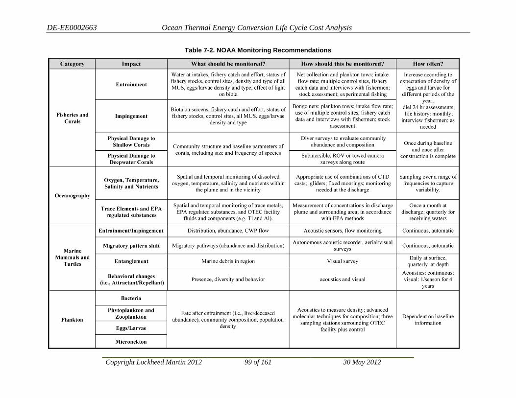
DE-EE0002663 Ocean Thermal Energy Conversion Life Cycle Cost Analysis
Copyright Lockheed Martin 2012 99 of 161 30 May 2012
Table 7-2. NOAA Monitoring Recommendations

DE-EE0002663 Ocean Thermal Energy Conversion Life Cycle Cost Analysis
Copyright Lockheed Martin 2012 100 of 161 30 May 2012
7.1.2.2.2 Cold Water Intake
Entrainment and impingement are also likely to be the primary impacts from the cold water intake system. However, due to the depth of the CWP intake (~1,000 m), the biomass concentration is likely to be much lower than at the warm water intake. On the other hand, maintaining any screens that might be used and monitoring what is going on is much more challenging at the depth the intake would be located. Development of in-line methods to assess the types and densities of organisms entrained by the cold-water flows is essential to the efficient assessment of impacts caused by this deep-water intake.
Baseline collections are not likely to provide sufficient data for confident quantitative description of the deep-water communities subject to entrainment, and conventional methods for this assessment, consisting of filtration of water samples followed by microscopic examination of the filtered solids, is very labor intensive and should preferably be used only for ground-truth acquisition of some in-line optical, acoustic, or electromagnetic system.
7.1.2.2.3 Discharges
After water from the cold water and warm water pipes has passed through heat exchangers and heat has been extracted, the water is returned to the ocean via discharge pipes. Discharge configurations may include individual cold and warm water return pipes, or a combined return where the cold and warm water are mixed and returned above the thermocline. The assessment of impacts from the discharge involves various monitoring technologies, including optical plankton counters, fluorometers, and collection of data and samples using autonomous vehicles, gliders, ships and stationary mooring sampling devices.
The current state of the art for mid- and far-field monitoring (i.e., hundreds to several thousand meters from the discharge) often relies on using gliders, which can operate continuously for several months, sweeping up and down through the water column, collecting temperature, salinity, and other data.
7.1.2.2.4 Physical Presence, Construction, and Accidents
The physical presence, construction, and potential accidental spills or discharges associated with an OTEC facility can have a variety of environmental impacts. The most disruptive aspects of installation are likely to be the placement of anchors, moorings and power cables. Installation and presence of these components could disrupt benthic and pelagic communities, including deep corals and crustaceans, vertebrate fish, marine mammals, sea birds, sea turtles, invertebrates, and microbial communities. Installation and presence of the power cable could locally increase suspended sediment, disturb specific coastal resources and coral reef communities, and could alter the behavior of other invertebrate and vertebrate communities.
Many impacts are likely to be similar to those observed during construction and installation of oil platforms and offshore wind farms, and techniques and methods used to monitor their impacts could be used to assess impacts and risk at an OTEC facility. It will be important to review the procedures and systems currently employed in the offshore oil industry for guidance in the development of monitoring procedures and measurement systems for OTEC.

DE-EE0002663 Ocean Thermal Energy Conversion Life Cycle Cost Analysis
Copyright Lockheed Martin 2012 101 of 161 30 May 2012
7.1.2.2.5 Noise and Electromagnetic Fields
The generation of noise and electromagnetic fields (EMF) are of concern due to the large number of marine organisms that regularly use acoustics (e.g., dolphins, whales, fish) and electromagnetic fields (e.g., sharks, turtles) for communication, detection of prey/predators, and navigation. Monitoring should continue throughout the construction, installation, and operational phase using the same equipment and locations to facilitate comparison. Existing technology, including autonomous broadband acoustic recorders coupled with validated acoustic propagation models, can be used to determine the range of sound levels to be expected.
7.1.3 Permits and Other Approvals Table 7-3 presents the major land use permits that could be required for an OTEC plant installed offshore within the Hawai’ian Islands. NEPA and Chapter 343 requirements are discussed above. The other approvals, listed in the table, are summarized below.
7.1.3.1 Federal Permits
7.1.3.1.1 OTEC License
The Offshore Thermal Energy Conversion Act, OTECA (42USC9101-9168), charges NOAA to “establish a legal regime which will permit and encourage the development of ocean thermal energy conversion as a commercial energy technology;” §9101(a)(4). The law requires NOAA to license commercial OTEC operations (§9111(a)) and authorizes the U.S. Department of Energy (DOE) to designate an OTEC project as a “demonstration project” and further to waive any requirements of the Act that it deems appropriate (§9126(b)).
7.1.3.1.2 National Pollutant Discharge Elimination System (NPDES) Permit
This approval is needed in order to discharge water from the facility. For any Hawai‘i-based OTEC plant, this permit must be obtained from EPA Region IX. The key evaluation parameters for permitting are the CWA §403 criteria (40CFR125.122), listed as follows:
1) The quantities, composition and potential for bioaccumulation or persistence of the pollutants to be discharged.
2) The potential transport of such pollutants by biological, physical or chemical processes. 3) The composition and vulnerability of the biological communities which may be exposed to
such pollutants, including the presence of unique species or communities of species, the presence of species identified as endangered or threatened pursuant to the Endangered Species Act, or the presence of those species critical to the structure or function of the ecosystem, such as those important for the food chain.
4) The importance of the receiving water area to the surrounding biological community, including the presence of spawning sites, nursery/forage areas, migratory pathways, or areas necessary for other functions or critical stages in the life cycle of an organism.
5) The existence of special aquatic sites including, but not limited to marine sanctuaries and refuges, parks, national and historic monuments, national seashores, wilderness areas and coral reefs.
6) The potential impacts on human health through direct and indirect pathways. 7) Existing or potential recreational and commercial fishing, including fin fishing and shell
fishing.

DE-EE0002663 Ocean Thermal Energy Conversion Life Cycle Cost Analysis
Copyright Lockheed Martin 2012 102 of 161 30 May 2012
8) Any applicable requirements of an approved Coastal Zone Management plan. 9) Such other factors relating to the effects of the discharge as may be appropriate. 10) Marine water quality criteria developed pursuant to section 304(a)(1).
In addition, NPDES permitting requires compliance with the Clean Water Act §316, which regulates the design and operation of cooling water intakes for power plants of all kinds.

DE-EE0002663 Ocean Thermal Energy Conversion Life Cycle Cost Analysis
Copyright Lockheed Martin 2012 103 of 161 30 May 2012
Table 7-3. Environmental Permit Requirements in Hawai‘i
Approval Regulating Agency Comments
Federal Approvals
NEPA EIS NOAA .
OTEC Permit NOAA No regulations currently in place
NPDES Discharge & Zone of Mixing Permits EPA Region IX
Department of the Army Permit COE COE will determine if WQC is required
CZM Certification State CZM Office Delegated by NOAA
Clean Water Act (S. 401) WQC State Dept. of Health Delegated by EPA Region IX; may not be required
Endangered Species Act Section 7 Consultation NMFS & FWS
State and County Approvals
Hawai‘i Revised Statute §343 HRS EIS DLNR/OCCL
Conservation District Use Permit DLNR/OCCL
Submerged Land Lease DLNR/Land Division
Onshore Land Lease or Easement DOT/HECO
Shoreline Certification DLNR/Land Division May not be necessary if HDD used
Special Management Area Use Permit County DPP May not be necessary if HDD used
Shoreline Setback Variance County DPP May not be necessary if HDD used
Acronyms:
COE-U.S. Army Corps of Engineers FWS-U.S. Fish and Wildlife Service CZM-Coastal Zone Management HDD-Horizontal Directional Drilling DLNR-State Department of Land and Natural Resources NEPA-National Environmental Policy Act DOT-State Department of Transportation NMFS-National Marine Fisheries Service (in NOAA) DPP-Department of Planning and Permitting NOAA-National Oceanic and Atmospheric Administration (in Dept. of Commerce) DOT-State Department of Transportation NPDES-National Pollutant Discharge Elimination System EIS-Environmental Impact Statement OCCL-Office of Conservation and Coastal Lands EPA-Environmental Protection Agency WQC-Water Quality Certification

DE-EE0002663 Ocean Thermal Energy Conversion Life Cycle Cost Analysis
Copyright Lockheed Martin 2012 104 of 161 30 May 2012
7.1.3.1.3 Department of the Army Permit
The Army Corps of Engineers issues two kinds of Department of the Army (DA) permits, one kind authorized under the Clean Water Act, §404 (33USC1344) and another under Section 10 of the Rivers and Harbors Act (33USC403). The former is required for projects that discharge materials (e.g., dredge spoils) in waters within State jurisdiction; the latter is required for the emplacement of any object that might obstruct navigation in these waters. The 404 permit requires an associated Water Quality Certification (33USC1341), issued in Hawai‘i by the State Department of Health. The Section 10 permit is generally much simpler to obtain and requires only that the emplaced object (in this case, the OTEC plant and cable to shore) not obstruct navigation. If the cable is emplaced simply on the seafloor and the landing is made using horizontal drilling technology rather than trenching, the COE Honolulu District will probably require only the Section 10 permit for an OTEC plant.
7.1.3.1.4 Coastal Zone Management Certification
In Hawai‘i this required certification for the project is obtained from the State Office of Planning. It requires completion of an extensive form detailing potential coastal zone impacts. For an OTEC project, this certification will be sought in conjunction with the NEPA process, since the topics listed in the certification form are all examined in the impact analysis.
7.1.3.1.5 Endangered Species Act (ESA), Section 7 Consultation
ESA Section 7 consultation is a detailed process used by the Fish and Wildlife Service (FWS) and National Marine Fisheries Service (NMFS) to determine whether an action proposed by another Federal agency jeopardizes the health of endangered or threatened species (Figure 7-3). FWS has review authority over predicted impacts to ESA-listed bird species that might occur near the project site (e.g., Newell’s Shearwater, Hawai’ian Petrel); NMFS is responsible for listed fish and marine mammal species (e.g., green turtles, monk seals).
This consultation takes place concurrently with the drafting of the environmental impact assessment and is made public in that document. It is an important part of the assessment process and includes specialist studies of the endangered species expected in the area. Results of these surveys and analyses can lead to requirements to modify the OTEC system design or constrain its operation in order to mitigate any potential impacts on listed species. Either of these can jeopardize the project’s feasibility. Hence, it is typically done as early in the process as is practical. This consultation usually also includes consideration of other non-threatened or endangered species protected by other legislation21
(e.g., non-endangered marine mammals and migratory birds).
21 Specifically, the Marine Mammal Protection Act (16USC §1361-1421h, October 21, 1972, as amended) and the Migratory Bird Treaty Act (16USC §703-711, as amended)


DE-EE0002663 Ocean Thermal Energy Conversion Life Cycle Cost Analysis
Copyright Lockheed Martin 2012 106 of 161 30 May 2012
7.1.3.2 State Permits
The following permits would be required for a private party to construct an OTEC plant that would be connected by a seafloor power cable to a Hawai‘i-based electrical grid.
7.1.3.2.1 Conservation District Use Permit (CDUP)
A CDUP is required for all activities taking place within three miles of the State-certified shoreline. This permit application is processed by the Office of Conservation and Coastal Lands (OCCL) within the State of Hawai‘i Department of Land and Natural Resources (DLNR). The Board of Land and Natural Resources (BLNR) issues the permit itself. A State EA/FONSI or EIS must be completed before OCCL will process the application. The Department has the option of whether or not to hold a formal public hearing to seek public input on the application; for a project such as OTEC it is likely to exercise this option.
Once it has completed its review of the application, supporting environmental documentation, and public comments, OCCL staff formulates recommendations to the Board as to whether, and with what conditions, a permit should be issued. OCCL presents its recommendations to BLNR. BLNR takes public testimony on the application and votes to deny, issue, or issue with conditions. The decision on the matter can be contested by any party that establishes standing, and the matter then goes before an Administrative judge hearing officer in a contested case hearing. The hearing officer then issues a ruling that goes to the BLNR for final action.
7.1.3.2.2 Submerged Land Lease
The project applicant must negotiate a land lease with the State for installation of the seafloor cable within State jurisdiction. The lease would be obtained from the BLNR, based on a recommendation from the DLNR Land Division after the CDUP is obtained.
7.1.3.2.3 Onshore Easements or Land Lease
The applicant must negotiate a land lease from the property owner along the landside cable route.
7.1.3.2.4 Special Management Area Use Permit (SMP)
This permit is required from the County of Honolulu for projects that propose to install developments within the Special Management Area (SMA). The SMA boundary is defined for all Hawai’ian coastlines. This permit also triggers the requirement for an EA/FONSI or EIS. The permit might not be required for Horizontal Directional Drilling (HDD) installations and would not be required for cable landings on Federal land.
7.1.3.2.5 Shoreline Certification
If the project requires an SMP, a survey of the landing site must determine the specific location of the shoreline, subject to approval by the State Surveyor and Director of DLNR. This is necessary to determine the boundary between the State Conservation District (seaward of the boundary) and the SMA (landward of the boundary).
7.1.3.2.6 Shoreline Setback Variance
This permit would be required from the County if it becomes necessary to install aboveground facilities within 40 feet of the shoreline. It is processed concurrently with the SMP.

DE-EE0002663 Ocean Thermal Energy Conversion Life Cycle Cost Analysis
Copyright Lockheed Martin 2012 107 of 161 30 May 2012
7.1.4 Costs Estimated costs to complete the above impact assessment, monitoring, and permitting tasks are presented for 100 MW, 200 MW, and 400 MW plants, respectively, in Figure 7-4, Figure 7-5, and Figure 7-6. The primary differences among these estimates is the anticipated increasing costs for oceanographic baseline and monitoring work with increasing size of the plant. The basis for these estimates includes direct experience completing utility and other EIS and permitting tasks in Hawai‘i and informal proposals from oceanographic experts.
Figure 7-4. Estimated Permitting Costs for 100 MW OTEC Plant in Hawai‘i
Q1 Q2 Q3 Q4 Q1 Q2 Q3 Q4 Q1 Q2 Q3 Q4Costs by Quarter 0.59 0.47 0.47 0.47 0.58 0.53 0.55 0.52 0.13 0.09 0.09 0.06
100 MWe OTEC Licensing & Permitting 100 MWe Plant Total 4.55State and Federal EIS
Complete Baseline Surveys & Oceanographic Studies 0.5 0.4 0.4 0.4 0.4 0.4 0.4 0.4 3.3Complete Additional Environmental Studies 0.04 0.04 0.04 0.04 0.05 0.05 0.05 0.31Complete Drafting of DEIS 0.05 0.03 0.03 0.03 0.03 0.03 0.03 0.02 0.02 0.27Complete Drafting of FEIS 0.02 0.02 0.02 0.06
Obtain NOAA License 0.02 0.02 0.02 0.01 0.01 0.08Obtain CZM Certification 0.02 0.01 0.03Obtain NPDES Discharge Permit 0.1 0.05 0.05 0.05 0.02 0.01 0.01 0.29Obtain Special Management Area Permit 0.02 0.02 0.01 0.01 0.06Obtain Conservation District Use Permit 0.01 0.02 0.01 0.04Obtain Department Of The Army Permit (Section 10 Only) 0.01 0.01 0.01 0.01 0.04Obtain Submerged Land Lease 0.01 0.02 0.03Obtain Land Easements 0.02 0.02 0.04
ALL COSTS IN 2011 Million DollarsYear 1 Year 2 Year 3 Grand
Total (M$)

DE-EE0002663 Ocean Thermal Energy Conversion Life Cycle Cost Analysis
Copyright Lockheed Martin 2012 108 of 161 30 May 2012
Figure 7-5. Estimated Permitting Costs for 200 MW OTEC Plant in Hawai‘i
Figure 7-6. Estimated Permitting Costs for 400 MW OTEC Plant in Hawai‘i
Q1 Q2 Q3 Q4 Q1 Q2 Q3 Q4 Q1 Q2 Q3 Q4Costs by Quarter (M$) 0.69 0.67 0.67 0.67 0.78 0.78 0.8 0.72 0.13 0.1 0.1 0.06
200 MWe OTEC Licensing & Permitting 200 MWe Plant Total 6.17State and Federal EIS
Complete Baseline Surveys & Oceanographic Studies 0.6 0.6 0.6 0.6 0.6 0.6 0.6 0.6 4.8Complete Additional Environmental Studies 0.04 0.04 0.04 0.04 0.05 0.05 0.05 0.31Complete Drafting of DEIS 0.05 0.03 0.03 0.03 0.03 0.03 0.03 0.02 0.02 0.27Complete Drafting of FEIS 0.02 0.02 0.02 0.06
Obtain NOAA License 0.02 0.02 0.02 0.01 0.01 0.08Obtain CZM Certification 0.02 0.01 0.03Obtain NPDES Discharge Permit 0.1 0.1 0.1 0.05 0.02 0.02 0.02 0.41Obtain Special Management Area Permit 0.02 0.02 0.01 0.01 0.06Obtain Conservation District Use Permit 0.01 0.02 0.01 0.04Obtain Department Of The Army Permit (Section 10 Only) 0.01 0.01 0.01 0.01 0.04Obtain Submerged Land Lease 0.01 0.02 0.03Obtain Land Easements 0.02 0.02 0.04
ALL COSTS IN 2011 Million DollarsYear 1 Year 2 Year 3 Grand
Total (M$)
Q1 Q2 Q3 Q4 Q1 Q2 Q3 Q4 Q1 Q2 Q3 Q4Costs by Quarter 0.79 0.67 0.77 0.67 0.88 0.78 0.9 0.77 0.16 0.13 0.13 0.06
400 MWe OTEC Licensing & Permitting 400 MWe Plant Total 6.71State and Federal EIS
Complete Baseline Surveys & Oceanographic Studies 0.7 0.6 0.7 0.6 0.7 0.6 0.7 0.6 5.2Complete Additional Environmental Studies 0.04 0.04 0.04 0.04 0.05 0.05 0.05 0.31Complete Drafting of DEIS 0.05 0.03 0.03 0.03 0.03 0.03 0.03 0.02 0.02 0.27Complete Drafting of FEIS 0.02 0.02 0.02 0.06
Obtain NOAA License 0.02 0.02 0.02 0.01 0.01 0.08Obtain CZM Certification 0.02 0.01 0.03Obtain NPDES Discharge Permit 0.1 0.1 0.1 0.1 0.05 0.05 0.05 0.55Obtain Special Management Area Permit 0.02 0.02 0.01 0.01 0.06Obtain Conservation District Use Permit 0.01 0.02 0.01 0.04Obtain Department Of The Army Permit (Section 10 Only) 0.01 0.01 0.01 0.01 0.04Obtain Submerged Land Lease 0.01 0.02 0.03Obtain Land Easements 0.02 0.02 0.04
ALL COSTS IN 2011 Million DollarsYear 1 Year 2 Year 3 Grand
Total (M$)

DE-EE0002663 Ocean Thermal Energy Conversion Life Cycle Cost Analysis
Copyright Lockheed Martin 2012 109 of 161 30 May 2012
The following sections discuss the other four sites selected for consideration in this study and the likely differences in procedures and costs between them and the Hawai’ian sites.
7.1.5 Guam Sites Two possible sites are considered here for locating Grid Connected OTEC plants off Guam. These sites are notional only and selected simply to allow examination of the different permitting considerations that could apply to a Guam OTEC facility. Either of these sites could host an OTEC plant that could serve potential commercial and military markets. The northern site is offshore from the Tanguisson Generating Station, a 53 MW plant that serves the general island grid. The Guam Navy Base site is offshore from the Naval Base Guam, which occupies all of Orote Point and adjacent harbor-side lands. This latter site is the shortest distance on the island between the shoreline and 1,000 m water depths. The following sections describe the key differences between the impact analysis and permitting for these sites and those in Hawai‘i.
7.1.5.1 Environmental Impact Analysis
Guam is a U.S. Territory, so OTEC facilities stationed offshore must comply with NEPA in exactly the same way as Hawai‘i-based OTEC facilities. The coastal offshore waters within three nautical miles are controlled either by the U.S. Department of Defense or by the Guam Territorial government. The notional site off the Navy base would fall completely within U.S. Navy jurisdiction, while the site off the Tanguisson Power Plant could conceivably be permitted under the jurisdiction of the Guam Territorial Government. In the former case, the U.S. Navy would be the Lead Agency for the environmental documentation. No Territorial approvals would be required, although U.S. Navy policy generally seeks to make its actions compatible with local land use policies and requirements when possible.
The OTEC facility off the Tanguisson Power Plant would require a NPDES permit from the U.S. EPA and also a Department of the Army Permit from the U.S. Corps of Engineers. These permit requirements trigger NEPA compliance as well. The Lead Agency would most likely be the Corps of Engineers, although this would have to be confirmed after the specific project plans are defined.
7.1.5.1.1 Territorial Environmental Impact Analysis Compliance
The Organic Act of 1950 (48CFR §1421) made Guam an organized, unincorporated territory of the U.S., conferring U.S. citizenship on the people of Guam and establishing local self-government. It is “unincorporated” because not all provisions of the U.S. Constitution apply to the territory. Guam is an “organized” territory because the Guam Organic Act of 1950 organized the government much as a constitution would. The Guam Organic Act provides a republican form of government with locally-elected executive and legislative branches and an appointed judicial branch. Guam also has an elected, non-voting representative to Congress. Policy relations between Guam and the U.S. are under the jurisdiction of the Office of Insular Affairs.
The Guam Environmental Protection Agency (GEPA) requires completion of an EIS for projects requiring land zoning changes or any variance from the existing permitted land uses22
22 Governor’s Executive Order No. 96-26
. However, it is not clear that an OTEC project would require such a variance or zoning change. It is

DE-EE0002663 Ocean Thermal Energy Conversion Life Cycle Cost Analysis
Copyright Lockheed Martin 2012 110 of 161 30 May 2012
important to consult with the GEPA to determine what, if any, territorial environmental impact analysis is required.
7.1.6 Baseline and Monitoring Requirements Baseline data collection and operation monitoring requirements are the same as described above for Hawai‘i. As discussed below, the costs for these efforts would be expected to be higher than for the Hawai’ian sites, since much of the expertise and equipment would have to be brought in from other locations.
7.1.7 Permits and Other Approvals
7.1.7.1 Federal Permits
The key Federal permits discussed above for Hawai‘i are also required for any Guam site. These include the OTEC license from the National Oceanic and Atmospheric Administration, a discharge and mixing zone permit from the EPA, a Department of the Army Permit, Coastal Zone Management (CZM) Certification, and the Endangered Species Act Consultations.
In Guam, the CZM certification is administered by the Bureau of Statistics and Plans through the Guam Coastal Management Program. The coastal zone on Guam includes all non-federal lands on the island, as well as offshore islands and non-federal submerged lands within three nautical miles (5.6 km) of the shoreline. Coastal Zone Management Act consistency determination assessments would be submitted to the Bureau of Statistics and Plans for its review and approval.
7.1.7.2 Other Permits
Grading, building, and perhaps other permits would be required for the land-based components of a Guam OTEC plant. Key discretionary permits required from the territorial government include the following.
7.1.7.2.1 Submerged Land Lease
A power cable connecting an offshore OTEC plant to the Tanguisson Power Plant would have to pass through the submerged land within three nautical miles of the shoreline that is under the jurisdiction of the Guam Territorial government. Installation of such a cable requires a land lease from the Department of Land Management23
7.1.7.2.2 Seashore Reserve Development Permit
. Leases are available for a maximum term of 25 years with the possibility of renewal.
Guam defines its Seashore Reserve as: “… that land and water area of Guam extending seaward to the ten (10) fathom contour, including all islands within the Government's jurisdiction except Cabras Island and those Villages wherein residences have been constructed along the shoreline prior to the effective date of the Seashore Act, and extending inland to the nearer of the following points: (1) From the mean high water line for a distance on a horizontal plane of ten (10) meters. (2) From the mean high water line to the inland edge of the nearest public right-of-way.24
23 Guam Administrative Rules, Title 18, Chapter 1, Article 5
24 Guam Territorial Seashore Protection Act of 1974; Title 21, Chapter 63, §63103
DE-EE0002663 Ocean Thermal Energy Conversion Life Cycle Cost Analysis
Copyright Lockheed Martin 2012 111 of 161 30 May 2012
Installation of the power cable would require a development permit from the Guam Territorial Seashore Protection Commission. The permit application has to demonstrate the installation will not have any substantial adverse environmental or ecological effect, and that it is consistent with the basic preservation objectives of the law.
7.1.8 Costs Estimated costs to complete the above impact assessment, monitoring, and permitting tasks are presented for 100 MW, 200 MW, and 400 MW plants, respectively, in Figure 7-7, Figure 7-8, and Figure 7-9. The primary differences between these estimates and the estimates for these tasks for Hawai‘i-based OTEC systems is an additional 20% added to the field activities and a 10% addition to the permitting work.
7.2 Florida Site One possible site off Miami might be considered for locating one or more Grid Connected OTEC plants. Water depths do not reach 1,000 m within U.S. jurisdiction off the southeastern Florida coast. In fact, the region off Miami is the only portion of the Florida shoreline where depths exceed 800 m within 20 km of the shoreline. Environmental impact analysis and permitting requirements, discussed below, are expected to be very similar to those required in Hawai‘i.
7.2.1 Environmental Impact Analysis
7.2.1.1 NEPA Compliance
Florida-based OTEC facilities must comply with NEPA in exactly the same way as Hawai‘i-based OTEC facilities. An OTEC facility off the Miami coast requires a NPDES permit from the U.S. EPA and also a Department of the Army Permit from the U.S. Corps of Engineers. These permit requirements trigger NEPA compliance as well. The Lead Agency would most likely be the Corps of Engineers, although this would have to be confirmed after the specific project plans are defined.
7.2.2 Florida State Environmental Impact Analysis Compliance Florida does not have additional state requirements for an EIS or a regulation requiring impact statements for state actions. Florida does have a similar requirement for certain developmental activities, whether government or privately funded, to undergo Developments of Regional Impact (DRI) review. DRIs are developments which, because of their character, magnitude, or location, are presumed to have a substantial effect upon the health, safety, or welfare of citizens of more than one county.
The variety of projects that can fall under DRI status include large-scale planned developments, airport expansions, office and industrial parks, mining operations, and sports and entertainment facilities. Guidelines and standards for developments required to undergo DRI review are provided in Florida Statutes, Chapter 380, administered by Florida’s Department of Environmental Protection (DEP). Consultation with DEP would be necessary to determine whether or not an offshore OTEC plant installation would trigger a DRI review.
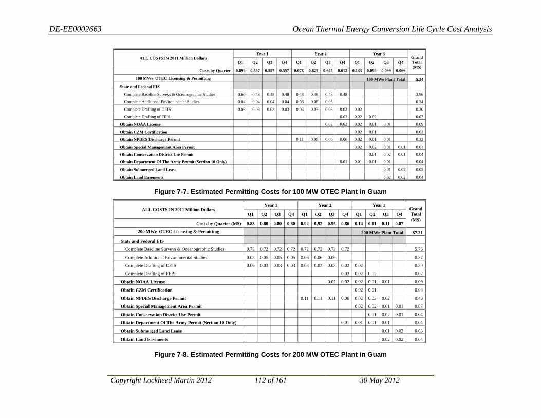
DE-EE0002663 Ocean Thermal Energy Conversion Life Cycle Cost Analysis
Copyright Lockheed Martin 2012 112 of 161 30 May 2012
Figure 7-7. Estimated Permitting Costs for 100 MW OTEC Plant in Guam
Figure 7-8. Estimated Permitting Costs for 200 MW OTEC Plant in Guam
ALL COSTS IN 2011 Million Dollars Year 1 Year 2 Year 3
Grand Total (M$)
Q1 Q2 Q3 Q4 Q1 Q2 Q3 Q4 Q1 Q2 Q3 Q4
Costs by Quarter 0.699 0.557 0.557 0.557 0.678 0.623 0.645 0.612 0.143 0.099 0.099 0.066
100 MWe OTEC Licensing & Permitting 100 MWe Plant Total 5.34
State and Federal EIS
Complete Baseline Surveys & Oceanographic Studies 0.60 0.48 0.48 0.48 0.48 0.48 0.48 0.48 3.96
Complete Additional Environmental Studies 0.04 0.04 0.04 0.04 0.06 0.06 0.06 0.34
Complete Drafting of DEIS 0.06 0.03 0.03 0.03 0.03 0.03 0.03 0.02 0.02 0.30
Complete Drafting of FEIS 0.02 0.02 0.02 0.07
Obtain NOAA License 0.02 0.02 0.02 0.01 0.01 0.09
Obtain CZM Certification 0.02 0.01 0.03
Obtain NPDES Discharge Permit 0.11 0.06 0.06 0.06 0.02 0.01 0.01 0.32
Obtain Special Management Area Permit 0.02 0.02 0.01 0.01 0.07
Obtain Conservation District Use Permit 0.01 0.02 0.01 0.04
Obtain Department Of The Army Permit (Section 10 Only) 0.01 0.01 0.01 0.01 0.04
Obtain Submerged Land Lease 0.01 0.02 0.03
Obtain Land Easements 0.02 0.02 0.04
ALL COSTS IN 2011 Million Dollars Year 1 Year 2 Year 3
Grand Total (M$)
Q1 Q2 Q3 Q4 Q1 Q2 Q3 Q4 Q1 Q2 Q3 Q4
Costs by Quarter (M$) 0.83 0.80 0.80 0.80 0.92 0.92 0.95 0.86 0.14 0.11 0.11 0.07
200 MWe OTEC Licensing & Permitting 200 MWe Plant Total $7.31
State and Federal EIS
Complete Baseline Surveys & Oceanographic Studies 0.72 0.72 0.72 0.72 0.72 0.72 0.72 0.72 5.76
Complete Additional Environmental Studies 0.05 0.05 0.05 0.05 0.06 0.06 0.06 0.37
Complete Drafting of DEIS 0.06 0.03 0.03 0.03 0.03 0.03 0.03 0.02 0.02 0.30
Complete Drafting of FEIS 0.02 0.02 0.02 0.07
Obtain NOAA License 0.02 0.02 0.02 0.01 0.01 0.09
Obtain CZM Certification 0.02 0.01 0.03
Obtain NPDES Discharge Permit 0.11 0.11 0.11 0.06 0.02 0.02 0.02 0.46
Obtain Special Management Area Permit 0.02 0.02 0.01 0.01 0.07
Obtain Conservation District Use Permit 0.01 0.02 0.01 0.04
Obtain Department Of The Army Permit (Section 10 Only) 0.01 0.01 0.01 0.01 0.04
Obtain Submerged Land Lease 0.01 0.02 0.03
Obtain Land Easements 0.02 0.02 0.04
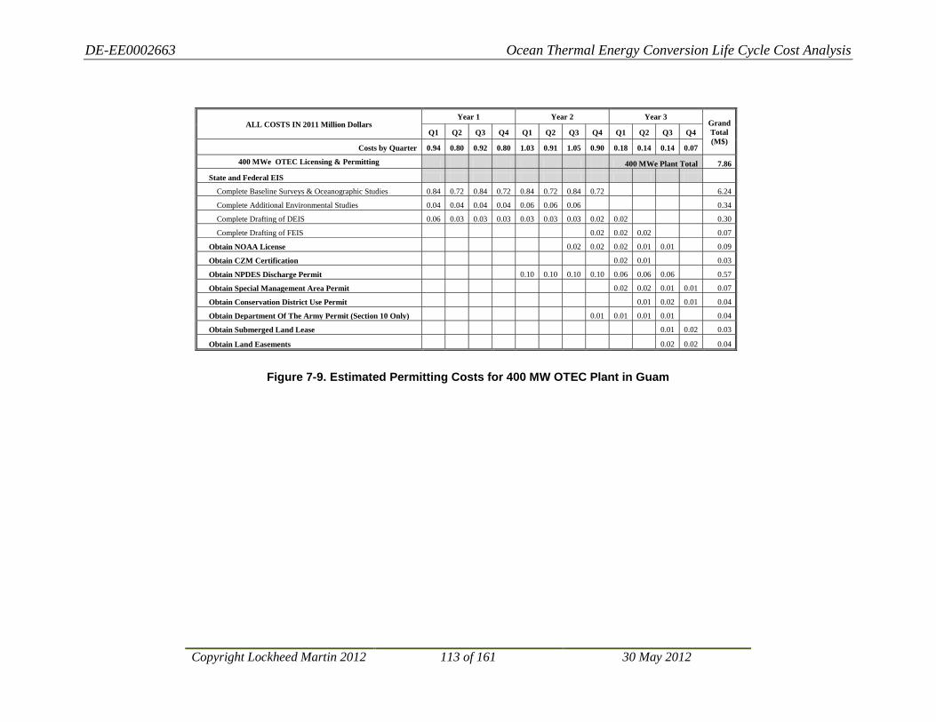
DE-EE0002663 Ocean Thermal Energy Conversion Life Cycle Cost Analysis
Copyright Lockheed Martin 2012 113 of 161 30 May 2012
Figure 7-9. Estimated Permitting Costs for 400 MW OTEC Plant in Guam
ALL COSTS IN 2011 Million Dollars Year 1 Year 2 Year 3
Grand Total (M$)
Q1 Q2 Q3 Q4 Q1 Q2 Q3 Q4 Q1 Q2 Q3 Q4
Costs by Quarter 0.94 0.80 0.92 0.80 1.03 0.91 1.05 0.90 0.18 0.14 0.14 0.07
400 MWe OTEC Licensing & Permitting 400 MWe Plant Total 7.86
State and Federal EIS
Complete Baseline Surveys & Oceanographic Studies 0.84 0.72 0.84 0.72 0.84 0.72 0.84 0.72 6.24
Complete Additional Environmental Studies 0.04 0.04 0.04 0.04 0.06 0.06 0.06 0.34
Complete Drafting of DEIS 0.06 0.03 0.03 0.03 0.03 0.03 0.03 0.02 0.02 0.30
Complete Drafting of FEIS 0.02 0.02 0.02 0.07
Obtain NOAA License 0.02 0.02 0.02 0.01 0.01 0.09
Obtain CZM Certification 0.02 0.01 0.03
Obtain NPDES Discharge Permit 0.10 0.10 0.10 0.10 0.06 0.06 0.06 0.57
Obtain Special Management Area Permit 0.02 0.02 0.01 0.01 0.07
Obtain Conservation District Use Permit 0.01 0.02 0.01 0.04
Obtain Department Of The Army Permit (Section 10 Only) 0.01 0.01 0.01 0.01 0.04
Obtain Submerged Land Lease 0.01 0.02 0.03
Obtain Land Easements 0.02 0.02 0.04
DE-EE0002663 Ocean Thermal Energy Conversion Life Cycle Cost Analysis
Copyright Lockheed Martin 2012 114 of 161 30 May 2012
7.2.3 Baseline and Monitoring Requirements Baseline data collection and operation monitoring requirements are the same as described above for Hawai‘i. As discussed below, the costs for these efforts would be expected to be somewhat lower than for the Hawai’ian sites.
7.2.4 Permits and Other Approvals
7.2.4.1 Federal Permits
The key Federal permits discussed above for Hawai‘i are also be required for any Florida site. These include the OTEC license from the National Oceanic and Atmospheric Administration, a discharge and mixing zone permit from the EPA, a Department of the Army Permit, CZM Certification, and the ESA Consultations.
In Florida the CZM certification and a more general review for evaluation of consistency between state policies and federal requirements is coordinated by DEP. DEP uses its review to influence projects to be permitted by the Federal Government. This review evaluates compliance with NEPA, CZMA, the National Historical Preservation Act, and Outer Continental Shelf Lands Act (OCSLA). Primarily, DEP reviews projects prepared for compliance with the NEPA and Federal consistency provisions of the CZMA. The formal name given to the entire process is Intergovernmental Coordination and Review (ICAR).
The Florida State Clearinghouse administers the ICAR for projects in Florida. The Clearinghouse is located in DEP and is Florida's single point–of–contact. As part of the Clearinghouse’s responsibilities under the NEPA, CZMA, Intergovernmental Coordination Act, and various Florida statutes, the Clearinghouse coordinates the review of proposed Federal actions and activities in Florida.
7.2.4.2 Other Permits
In addition to the Federal and State approvals, County-based grading, building, and perhaps other permits would be required for the land-based components of a Florida OTEC plant. A power cable connecting an offshore OTEC plant to the shore requires a submerged land lease, which is issued by the Southeastern District of DEP. This approval is acquired in coordination with the general DEP review process described above.
7.2.4.3 Costs
Estimated costs to complete the above impact assessment, monitoring, and permitting tasks are presented for 100 MW, 200 MW, and 400 MW plants, respectively, in Figure 7-10, Figure 7-11, and Figure 7-12. Florida is significantly less expensive than Hawai‘i to live and work.25
25 e.g. 36% less, based on calculator provided at URL: http://www.bankrate.com/calculators/savings/moving-cost-of-living-calculator.aspx
For this reason, costs for the tasks not included in the oceanographic field work are decreased from the Hawai‘i estimates by 25%.

DE-EE0002663 Ocean Thermal Energy Conversion Life Cycle Cost Analysis
Copyright Lockheed Martin 2012 115 of 161 30 May 2012
Figure 7-10. Estimated Permitting Costs for 100 MW OTEC Plant in Florida
Figure 7-11. Estimated Permitting Costs for 200 MW OTEC Plant in Florida
ALL COSTS IN 2011 Million Dollars Year 1 Year 2 Year 3
Grand Total (M$)
Q1 Q2 Q3 Q4 Q1 Q2 Q3 Q4 Q1 Q2 Q3 Q4
Costs by Quarter 0.57 0.45 0.45 0.45 0.57 0.52 0.54 0.50 0.10 0.07 0.07 0.05
100 MWe OTEC Licensing & Permitting 100 MWe Plant Total 4.34
State and Federal EIS
Complete Baseline Surveys & Oceanographic Studies 0.5 0.4 0.4 0.4 0.4 0.4 0.4 0.4 3.3
Complete Additional Environmental Studies 0.03 0.03 0.03 0.03 0.05 0.05 0.05 0.27
Complete Drafting of DEIS 0.04 0.02 0.02 0.02 0.02 0.02 0.02 0.02 0.02 0.20
Complete Drafting of FEIS 0.02 0.02 0.02 0.05
Obtain NOAA License 0.02 0.02 0.02 0.01 0.01 0.06
Obtain CZM Certification 0.02 0.01 0.02
Obtain NPDES Discharge Permit 0.10 0.05 0.05 0.05 0.02 0.01 0.01 0.28
Obtain Special Management Area Permit 0.02 0.02 0.01 0.01 0.05
Obtain Conservation District Use Permit 0.01 0.02 0.01 0.03
Obtain Department Of The Army Permit (Section 10 Only) 0.01 0.01 0.01 0.01 0.03
Obtain Submerged Land Lease 0.01 0.02 0.02
Obtain Land Easements 0.02 0.02 0.03
ALL COSTS IN 2011 Million Dollars Year 1 Year 2 Year 3
Grand Total (M$)
Q1 Q2 Q3 Q4 Q1 Q2 Q3 Q4 Q1 Q2 Q3 Q4
Costs by Quarter (M$) 0.67 0.65 0.65 0.65 0.77 0.72 0.74 0.70 0.10 0.07 0.07 0.05
200 MWe OTEC Licensing & Permitting 200 MWe Plant Total 5.84
State and Federal EIS
Complete Baseline Surveys & Oceanographic Studies 0.60 0.60 0.60 0.60 0.60 0.60 0.60 0.60 4.80
Complete Additional Environmental Studies 0.03 0.03 0.03 0.03 0.05 0.05 0.05 0.27
Complete Drafting of DEIS 0.04 0.02 0.02 0.02 0.02 0.02 0.02 0.02 0.02 0.20
Complete Drafting of FEIS 0.02 0.02 0.02 0.05
Obtain NOAA License 0.02 0.02 0.02 0.01 0.01 0.06
Obtain CZM Certification 0.02 0.01 0.02
Obtain NPDES Discharge Permit 0.10 0.05 0.05 0.05 0.02 0.01 0.01 0.28
Obtain Special Management Area Permit 0.02 0.02 0.01 0.01 0.05
Obtain Conservation District Use Permit 0.01 0.02 0.01 0.03
Obtain Department Of The Army Permit (Section 10 Only) 0.01 0.01 0.01 0.01 0.03
Obtain Submerged Land Lease 0.01 0.02 0.02
Obtain Land Easements 0.02 0.02 0.03

DE-EE0002663 Ocean Thermal Energy Conversion Life Cycle Cost Analysis
Copyright Lockheed Martin 2012 116 of 161 30 May 2012
Figure 7-12. Estimated Permitting Costs for 400 MW OTEC Plant in Florida
ALL COSTS IN 2011 Million Dollars Year 1 Year 2 Year 3
Grand Total (M$)
Q1 Q2 Q3 Q4 Q1 Q2 Q3 Q4 Q1 Q2 Q3 Q4
Costs by Quarter 0.77 0.65 0.75 0.65 0.87 0.72 0.84 0.70 0.10 0.07 0.07 0.05
400 MWe OTEC Licensing & Permitting 400 MWe Plant Total 6.24
State and Federal EIS
Complete Baseline Surveys & Oceanographic Studies 0.70 0.60 0.70 0.60 0.70 0.60 0.70 0.60 5.20
Complete Additional Environmental Studies 0.03 0.03 0.03 0.03 0.05 0.05 0.05 0.27
Complete Drafting of DEIS 0.04 0.02 0.02 0.02 0.02 0.02 0.02 0.02 0.02 0.20
Complete Drafting of FEIS 0.02 0.02 0.02 0.05
Obtain NOAA License 0.02 0.02 0.02 0.01 0.01 0.06
Obtain CZM Certification 0.02 0.01 0.02
Obtain NPDES Discharge Permit 0.10 0.05 0.05 0.05 0.02 0.01 0.01 0.28
Obtain Special Management Area Permit 0.02 0.02 0.01 0.01 0.05
Obtain Conservation District Use Permit 0.01 0.02 0.01 0.03
Obtain Department Of The Army Permit (Section 10 Only) 0.01 0.01 0.01 0.01 0.03
Obtain Submerged Land Lease 0.01 0.02 0.02
Obtain Land Easements 0.02 0.02 0.03

DE-EE0002663 Ocean Thermal Energy Conversion Life Cycle Cost Analysis
Copyright Lockheed Martin 2012 117 of 161 30 May 2012
7.3 Western Atlantic Site The Western Atlantic equatorial site selected for consideration for this study lies in waters approximately 4,000 m deep and is within the Exclusive Economic Zone of Brazil. Environmental impact analysis and permitting requirements, discussed below, would be under that country’s jurisdiction.
7.3.1 Environmental Impact Analysis The Federal Constitution of 1988 was the first in the Brazilian system to truly engage in the protection of the environment. According to its article 225, all individuals have the right to enjoy an ecologically balanced environment, while both the government and society are responsible for the achievement of such purpose. Pursuant to article 23, the federal government, states and municipalities are granted powers for passing statutes and regulations concerning the protection of the environment, as well as to safeguard the environment against pollution in all forms. The environmental protection constitutionally established also relies on other instruments such as the environmental permitting procedure, Environmental Impact Assessment, creation of protected areas, and environmental liability.
Coastal areas are constitutionally considered a part of the national patrimony, pursuant to paragraph 4 in article 225 of the Brazilian Constitution. Federal Decree 5.300/2004 sets forth the Coast Management National Plan (PNGC), which foresees rules of use and enjoyment of seacoasts, which includes maritime and land areas. Also, it is necessary to highlight that Federal Law 9.985/2000 does not distinguish between the marine environment and the land environment, meaning environmentally protected areas can also be established in marine environments. Additionally, fishing is regulated by the government for assuring the protection of endangered species.
For the purposes of this study, we assume that the Brazilian requirements for impact assessment of an OTEC project would be comparable to those of the U.S.
7.3.2 Baseline and Monitoring Requirements Baseline data collection and operation monitoring requirements are the same as described above.
7.3.3 Permits and Other Approvals
7.3.3.1 Brazilian National Permits
Brazil has not developed a regulatory regime for OTEC development and it is unclear at this time how it would regulate the installation of an unconnected OTEC plant within its Exclusive Economic Zone. Brazil does have an extensive offshore oil industry and a well established regulatory regime that controls its development. However, it is not possible to know without significant consultation with the government which, if any, of the provisions of this regulatory regime would apply to OTEC.
Permitting costs for the at-sea ammonia plant associated with the unconnected OTEC plant are likely to be significantly less than for a U.S. Grid Connected plant, since such permitting would not have to comply with U.S. permitting requirements. We assume that standard best management practices for health and safety would be followed and included in the system capital and operating costs. The cost of obtaining permits and other required approvals for an at-sea

DE-EE0002663 Ocean Thermal Energy Conversion Life Cycle Cost Analysis
Copyright Lockheed Martin 2012 118 of 161 30 May 2012
system is likely to be substantially lower than for a Grid Connected facility of the same size, but it is impossible to provide a more definitive answer without knowing the specifics of the plan. Assuming they are the same as those for the Grid Connected systems is a conservative way to estimate these costs and is the approach adopted here.
Anhydrous ammonia is stable as a liquid at much higher temperatures and lower pressures than liquid natural gas. For this reason, anhydrous ammonia is much easier to handle and transport than liquid natural gas, and permitting for transport barges is much simpler (see 46 CFR 151.50-32 for U.S. regulations for construction of ammonia transport systems). The key provisions of these regulations are designed to ensure safety of personnel and rapid response to potential leaks. They are likely to be very similar to the requirements for such systems within Brazilian jurisdiction, and would not impose significant additional permitting costs. However, it is important to note there can be major permitting expenses associated with the harbor/land facilities receiving the barge shipments from the at-sea ammonia plant. These are highly site-specific and are beyond this study’s scope.
7.3.3.2 Other Permits
The selected site for the unconnected OTEC plant is well outside of any Brazilian state or municipal jurisdictions and thus it is likely that only federal permits are required.
7.3.4 Costs The costs for these efforts are expected to be similar to the Hawai’ian sites, based on the fact that the cost of living index for Brasilia is comparable to that of Honolulu.26
7.4 Western Pacific Site
This assumes that adequate oceanographic vessels, scientists, and qualified environmental and permitting consultants are available in Brazil.
The Western Pacific equatorial site selected for consideration for this study lies in waters approximately 3,000 m deep and is in international waters. Environmental impact analysis and permitting requirements are limited to the controls imposed by the international treaties that are acceded to by the entity where the OTEC operator is incorporated. These are likely to include MARPOL,27 SOLAS,28
26 8http://www.numbeo.com/cost-of-living/compare_cities.jsp?country1=United+States&country2=Brazil&city1=Honolulu%2C+HI&city2=Brasilia
and possibly other international treaty obligations. If the OTEC operator is incorporated in the U.S., U.S. domestic law, including NEPA, the Clean Water Act, and other requirements described above for Hawai‘i and Florida also apply. It is not possible to provide cost estimates for the impact analysis and permitting at this site without significantly more information about the nature of the OTEC operator.
27 International Convention for the Prevention of Pollution From Ships, 1973 as modified by the Protocol of 1978 (MARPOL 73/78) 28 International Convention for the Safety of Life at Sea
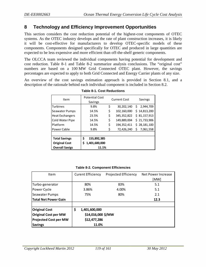
DE-EE0002663 Ocean Thermal Energy Conversion Life Cycle Cost Analysis
Copyright Lockheed Martin 2012 119 of 161 30 May 2012
8 Technology and Efficiency Improvement Opportunities This section considers the cost reduction potential of the highest-cost components of OTEC systems. As the OTEC industry develops and the rate of plant construction increases, it is likely it will be cost-effective for manufacturers to develop OTEC-specific models of these components. Components designed specifically for OTEC and produced in large quantities are expected to be less expensive and more efficient than off-the-shelf generic components.
The OLCCA team reviewed the individual components having potential for development and cost reduction. Table 8-1 and Table 8-2 summarize analysis conclusions. The “original cost” numbers are based on a 100 MW Grid Connected OTEC plant. However, the savings percentages are expected to apply to both Grid Connected and Energy Carrier plants of any size.
An overview of the cost savings estimation approach is provided in Section 8.1, and a description of the rationale behind each individual component is included in Section 8.2.
Table 8-1. Cost Reductions
Table 8-2. Component Efficiencies
Turbines 9.8% 30,202,140$ 2,944,709$ Seawater Pumps 14.5% 102,160,000$ 14,813,200$ Heat Exchangers 23.5% 345,352,822$ 81,157,913$ Cold Water Pipe 14.5% 149,889,004$ 21,733,906$ Platform 14.5% 194,352,411$ 28,181,100$ Power Cable 9.8% 72,426,240$ 7,061,558$
Total Savings 155,892,385$ Original Cost 1,401,600,000$ Overall Savigs 11.1%
Current Cost SavingsItemPotential Cost
Savings
Item Curent Efficiency Projected Efficiency Net Power Increase[MW]
Turbo-generator 80% 83% 5.1Power Cycle 3.86% 4.00% 5.1Seawater Pumps 75% 80% 2.1Total Net Power Gain 12.3
Original Cost 1,401,600,000$ Original Cost per MW $14,016,000 $/MWProjected Cost per MW $12,477,286Savings 11.0%

DE-EE0002663 Ocean Thermal Energy Conversion Life Cycle Cost Analysis
Copyright Lockheed Martin 2012 120 of 161 30 May 2012
8.1 Cost Reduction and Efficiency Improvement Estimation Approach
8.1.1 Component Cost Reduction Input from the entire team was used to generate a list of components for which significant development could be expected as the OTEC industry progresses. Two different aspects of technological development were considered: innovation and production efficiency. Innovation refers to technological advancements in the component itself allowing for a less expensive component. This category includes adaptation of generic components to OTEC-specific configurations.
Production efficiency refers to technological advancements in manufacturing methods and creation of economies of scale. Many OTEC-scale components are at the upper edge of the state of the art in capacity. As such, few specimens are manufactured annually. A healthy OTEC industry will have a large demand for high-capacity components, and production facilities can be optimized for higher volume production.
Each component was scored in each of the two categories according to the following rubric:
The two scores for each component were combined to yield an overall estimate of cost potential cost savings. The combination method was multiplicative rather than additive. For example, a component scoring “1” in both categories would have a projected cost that is 90.3% of the original cost (95% x 95%). The possible projected cost factors are shown below.
The rankings (and corresponding projected cost factors) were then applied to a baseline OTEC system in order to estimate the total cost reduction that could be expected over time. The baseline system is the 100 MW Grid Connected plant to be installed in Hawai’i, which forms the basis for the CAPEX cost estimate.
8.1.2 Component Efficiency Increase The team identified OTEC components with potential for thermal or electrical efficiency increases. Existing OTEC designs use standard off-the-shelf components that are not always optimized for OTEC use. Development of models specifically suited for OTEC applications will likely result in efficiency increases. In order to estimate the potential efficiency gains, the team reviewed the state of the industry at large to identify peak efficiency of state-of-the-art (but not necessarily OTEC-appropriate) components. For example, existing OTEC designs utilize an
Ranking1 Minimal Potential. 5% Cost Reduction2 Small Potential. 10% Cost Reduction3 Moderate Potential. 15% Cost Reduction4 High Potential. 20% Cost Reduction
1 2 3 41 90.3% 85.5% 80.8% 76.0%2 85.5% 81.0% 76.5% 72.0%3 80.8% 76.5% 72.3% 68.0%4 76.0% 72.0% 68.0% 64.0%
Innovation Ranking
Production Efficiency Ranking
DE-EE0002663 Ocean Thermal Energy Conversion Life Cycle Cost Analysis
Copyright Lockheed Martin 2012 121 of 161 30 May 2012
ammonia turbine that is 84% efficient. Similar turbines are available at 87% efficiency, but they are not suited to OTEC process conditions. It is projected that OTEC component efficiencies will approach these industry-leading values as OTEC-specific development continues.
Effects of component efficiency increases were modeled using MOTEM. An increase in component efficiency in an OTEC system increases net power (power available for export) produced by the plant. MOTEM was used to estimate the amount of additional net power for each component with increased efficiency. The effect of increases in efficiency in selected components was measured as a reduction in levelized capital cost ($/MW net power produced).
8.2 Components This section outlines each component and gives justification for scores given in each category.
8.2.1 Component Cost Reduction • Turbines
− Innovation score: 1
− Production efficiency score: 1
− Justification: Similarly sized turbines already exist in the process industry. There is minimal opportunity for innovation or production efficiency increases.
• Seawater Pumps
− Innovation score: 1
− Production efficiency score: 2
− Justification: Large pump technology is well understood. There is minimal opportunity for innovations to dramatically reduce costs. However, an OTEC industry would increase demand for high-capacity pumps resulting in economy of scale.
• Heat Exchangers
− Innovation score: 2
− Production efficiency score: 3
− Justification: Scores given above represent an aggregate score based on brazed aluminum, titanium twisted tube and graphite foam heat exchangers. These are representative of both existing and emergent heat exchanger designs. Heat exchanger performance under OTEC conditions has not been extensively studied and design improvements are likely. Heat exchangers are not typically constructed at OTEC scales, so there is significant opportunity for an economy of scale.
• Cold Water Pipe
− Innovation score: 1
− Production efficiency score: 2
− Justification: The existing CWP concept design is aggressive in cost-saving measures, and it is unlikely that further development will reduce costs. However, mobile

DE-EE0002663 Ocean Thermal Energy Conversion Life Cycle Cost Analysis
Copyright Lockheed Martin 2012 122 of 161 30 May 2012
manufacturing facilities are envisioned that could significantly reduce the cost of manufacture for multiple pipes.
• Platform (200 MW or smaller)
− Innovation score: 2
− Production efficiency score: 1
− Justification: Existing designs are based on standard oil rig concepts. OTEC-specific platform designs could reduce cost. However, manufacture of such OTEC-specific platforms will take place using standard construction methods and large increases in production efficiency are not expected.
• Power Cable to Shore
− Innovation score: 1
− Production efficiency score: 1
− Justification: AC power cable technology is well understood, and there is minimal opportunity for innovative cost reductions. OTEC will not significantly increase overall worldwide power cable demand. Minimal production efficiency increases are expected.
8.2.2 Component Efficiency Increase • Turbo-generator
− 84% assumed turbine efficiency based on preliminary sizing from manufacturers.
− Maximum ammonia turbine efficiency is 87%.
− OTEC-specific development is likely to allow use of 87% efficient turbines.
• Power Cycle
− Modern power plants based on the Rankine cycle (e.g., steam power plants) utilize efficiency enhancing equipment that has not been included in the thermodynamic analysis of OTEC plants. Inclusion of such equipment could increase the overall efficiency of the power cycle.
− Binary fluid OTEC cycles (such as the Kalina and Uehara cycles) have the potential to increase the efficiency of an OTEC plant by reducing heat exchanger pinch temperature. This would allow a greater pressure drop across the turbine and a higher thermal efficiency.
− Further research is required to accurately estimate the efficiency increase available from power cycle enhancement. An increase from the baseline value of 3.86% to 4.00% represents the team’s best projection.
• Seawater Pumps
− 75% wire-to-water efficiency based on preliminary sizing from manufacturers.
− Carefully designed pump systems can exceed 80% wire-to-water efficiency.
− OTEC-specific development is likely to allow use of 80% efficient pumps.
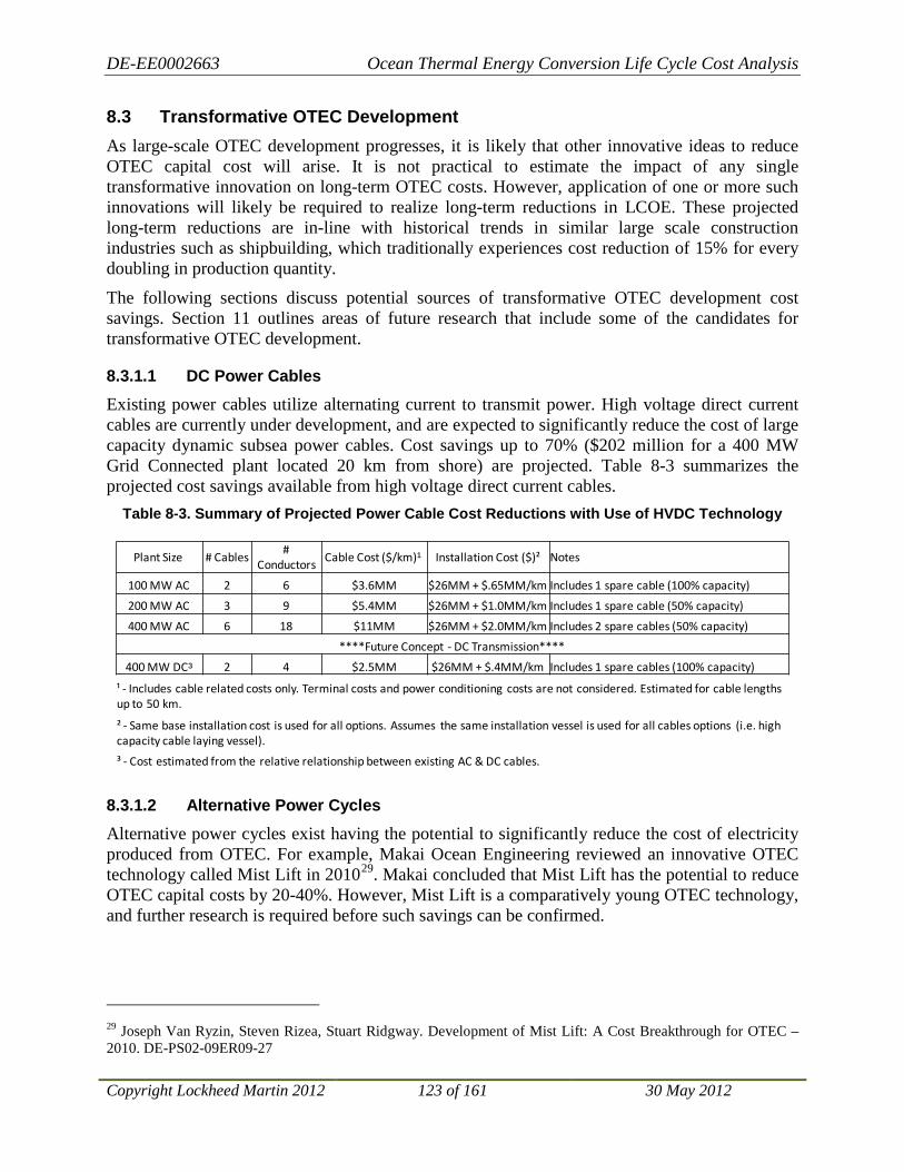
DE-EE0002663 Ocean Thermal Energy Conversion Life Cycle Cost Analysis
Copyright Lockheed Martin 2012 123 of 161 30 May 2012
8.3 Transformative OTEC Development As large-scale OTEC development progresses, it is likely that other innovative ideas to reduce OTEC capital cost will arise. It is not practical to estimate the impact of any single transformative innovation on long-term OTEC costs. However, application of one or more such innovations will likely be required to realize long-term reductions in LCOE. These projected long-term reductions are in-line with historical trends in similar large scale construction industries such as shipbuilding, which traditionally experiences cost reduction of 15% for every doubling in production quantity.
The following sections discuss potential sources of transformative OTEC development cost savings. Section 11 outlines areas of future research that include some of the candidates for transformative OTEC development.
8.3.1.1 DC Power Cables
Existing power cables utilize alternating current to transmit power. High voltage direct current cables are currently under development, and are expected to significantly reduce the cost of large capacity dynamic subsea power cables. Cost savings up to 70% ($202 million for a 400 MW Grid Connected plant located 20 km from shore) are projected. Table 8-3 summarizes the projected cost savings available from high voltage direct current cables.
Table 8-3. Summary of Projected Power Cable Cost Reductions with Use of HVDC Technology
8.3.1.2 Alternative Power Cycles
Alternative power cycles exist having the potential to significantly reduce the cost of electricity produced from OTEC. For example, Makai Ocean Engineering reviewed an innovative OTEC technology called Mist Lift in 201029
29 Joseph Van Ryzin, Steven Rizea, Stuart Ridgway. Development of Mist Lift: A Cost Breakthrough for OTEC – 2010. DE-PS02-09ER09-27
. Makai concluded that Mist Lift has the potential to reduce OTEC capital costs by 20-40%. However, Mist Lift is a comparatively young OTEC technology, and further research is required before such savings can be confirmed.
Plant Size # Cables#
ConductorsCable Cost ($/km)¹ Installation Cost ($)² Notes
100 MW AC 2 6 $3.6MM $26MM + $.65MM/km Includes 1 spare cable (100% capacity)
200 MW AC 3 9 $5.4MM $26MM + $1.0MM/km Includes 1 spare cable (50% capacity)
400 MW AC 6 18 $11MM $26MM + $2.0MM/km Includes 2 spare cables (50% capacity)
****Future Concept - DC Transmission****
400 MW DC³ 2 4 $2.5MM $26MM + $.4MM/km Includes 1 spare cables (100% capacity)
¹ - Includes cable related costs only. Terminal costs and power conditioning costs are not considered. Estimated for cable lengths up to 50 km.
² - Same base installation cost is used for all options. Assumes the same installation vessel is used for all cables options (i.e. high capacity cable laying vessel).
³ - Cost estimated from the relative relationship between existing AC & DC cables.

DE-EE0002663 Ocean Thermal Energy Conversion Life Cycle Cost Analysis
Copyright Lockheed Martin 2012 124 of 161 30 May 2012
9 Levelized Cost of Electricity This section describes the approach used in the OLCCA project to calculate the cost of electricity generated by the different sizes and configurations of OTEC plants. The sizes and configurations of OTEC plants evaluated under this study are: 100 MW, 200 MW and 400 MW net electrical power output plants where the electricity is cabled to shore via marine power cable (Grid Connected OTEC plant), and open ocean 400 MW OTEC plants producing anhydrous ammonia as an Energy Carrier for shipment to selected ports (Energy Carrier OTEC plant).
Calculating the cost of the electricity delivered to the end user is essential to evaluate financial viability of the different OTEC systems, particularly for comparison with competing renewable energy systems. The DOE has developed a standard figure of merit (FOM) methodology requiring minimum system cost information and avoiding many of the complications required for calculating the actual cost to deliver electricity to a particular end user. Due to its broad use and well-established methodology, LM used the DOE approach to develop the financial analysis under this study.
Calculation of LCOE is for comparison purposes and not intended to represent actual cost of electricity an end user might be charged. The purpose of the LCOE methodology is to use common financial assumptions and accounting principles to calculate a single fixed value representing the total LCC of the system compared to the life-time electricity production. By leveling the cost of electricity across the entire system life cycle, the LCOE value becomes a figure of merit that can be used to compare different technologies independent of the projected life cycles and financial vehicles.
9.1 LCOE Approach DOE has developed a methodology called Levelized Cost of Electricity (or Energy)30,31
. This approach was developed to establish a uniform methodology for calculating the cost of electricity produced by renewable energy systems taking into account generic financing for the capital cost of the installation, warranty, insurance and fees; the cost to operate and maintain the facility over the life of the system; and the costs of major overhauls and replacement. This study employs this standardized approach to calculating a FOM for cost comparison. In order to provide a standard FOM across various projects, the LCOE calculation employed excludes project specific external cost factors such as specialized financing arrangements and incentives.
30 Cost of Energy (COE) Calculation (USDOE/EERE Template) 31 Simple Levelized Cost of Energy (LCOE) Calculator Documentation, http://www.nrel.gov/analysis/tech_lcoe_documentation.html
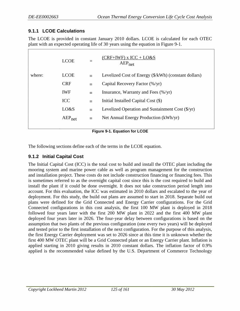
DE-EE0002663 Ocean Thermal Energy Conversion Life Cycle Cost Analysis
Copyright Lockheed Martin 2012 125 of 161 30 May 2012
9.1.1 LCOE Calculations The LCOE is provided in constant January 2010 dollars. LCOE is calculated for each OTEC plant with an expected operating life of 30 years using the equation in Figure 9-1.
LCOE = AEPnet (CRF+IWF) x ICC + LO&S
where: LCOE ≡ Levelized Cost of Energy ($/kWh) (constant dollars)
CRF ≡ Capital Recovery Factor (%/yr)
IWF ≡ Insurance, Warranty and Fees (%/yr)
ICC ≡ Initial Installed Capital Cost ($)
LO&S ≡ Levelized Operation and Sustainment Cost ($/yr)
AEPnet ≡ Net Annual Energy Production (kWh/yr)
Figure 9-1. Equation for LCOE
The following sections define each of the terms in the LCOE equation.
9.1.2 Initial Capital Cost The Initial Capital Cost (ICC) is the total cost to build and install the OTEC plant including the mooring system and marine power cable as well as program management for the construction and installation project. These costs do not include construction financing or financing fees. This is sometimes referred to as the overnight capital cost since this is the cost required to build and install the plant if it could be done overnight. It does not take construction period length into account. For this evaluation, the ICC was estimated in 2010 dollars and escalated to the year of deployment. For this study, the build out plans are assumed to start in 2018. Separate build out plans were defined for the Grid Connected and Energy Carrier configurations. For the Grid Connected configurations in this cost analysis, the first 100 MW plant is deployed in 2018 followed four years later with the first 200 MW plant in 2022 and the first 400 MW plant deployed four years later in 2026. The four-year delay between configurations is based on the assumption that two plants of the previous configuration (one every two years) will be deployed and tested prior to the first installation of the next configuration. For the purpose of this analysis, the first Energy Carrier deployment was set to 2026 since at this time it is unknown whether the first 400 MW OTEC plant will be a Grid Connected plant or an Energy Carrier plant. Inflation is applied starting in 2010 giving results in 2010 constant dollars. The inflation factor of 0.9% applied is the recommended value defined by the U.S. Department of Commerce Technology

DE-EE0002663 Ocean Thermal Energy Conversion Life Cycle Cost Analysis
Copyright Lockheed Martin 2012 126 of 161 30 May 2012
Administration National Institute of Standards and Technology for the U.S. Department of Energy Federal Energy Management Program.32
9.1.3 Capital Recovery Factor (CRF) and Insurance, Warranty and Fees (IWF)
On the advice and guidance of DOE, we have derived a simple multiplier on capital expense to represent the levelized capital cost. This capital cost factor includes a capital recovery factor equivalent to the annual cost of full capital recovery over the 30-year life of the asset at an assumed, nominal discount rate of 4%33. To the capital recovery factor is added a one-percentage-point surcharge representing an imputed cost for IWF 34
This is a critical aspect of the LCOE calculation, which results in a generic levelized capital cost independent of specific financing vehicles. This is not intended to provide insight into the finance costs that will actually be incurred by the system developer.
. Incorporating this imputed cost as part of the levelized annual capital cost (in lieu of estimated or actual insurance and warranty costs) effectively removes inequities that alternative Risk Management strategies (e.g., self-insurance) might have on otherwise comparable project costs.
9.1.4 Levelized Operations and Sustainment (LO&S) Costs The O&S model used for this study estimates all costs incurred after initial deployment and provides both annual O&M and Major Replacement/Overhaul costs on a yearly basis35
Figure 9-2 as shown
in . The time phasing of the costs is driven by the maintenance requirements for the component equipment, identifying the projected cost incurred each year. The by-year costs (with inflation applied) are input into the LO&S equation (Figure 9-3) to generate a single levelized O&S cost.
The LO&S calculation applies a CRF to the present value of each year’s O&S cost. Therefore, the LO&S calculation results in a single, constant value for each year that results in the same present value as the by-year phased O&S costs. The present value is calculated as of the deployment date for each configuration.
32 Amy S. Rushing, Joshua D. Kneifel, Barbara C. Lippiatt, Energy Price Indices and Discount Factors for Life-Cycle Cost Analysis – 2010, NISTIR 85-3273-25, Rev. 5/10 33 Walter Short, Daniel J. Packey, and Thomas Holt, A Manual for the Economic Evaluation of Energy Efficiency and
Renewable Energy Technologies , NREL/TP-462-5173, March 1995. 34 Cost of Energy (COE) Calculation (USDOE/EERE Template) 35 Rick Pavlosky, Michael Thomas, Laura Martel, Ocean Thermal Energy Conversion (OTEC) Operations and Maintenance Cost Analysis & Model Overview

DE-EE0002663 Ocean Thermal Energy Conversion Life Cycle Cost Analysis
Copyright Lockheed Martin 2012 127 of 161 30 May 2012
Figure 9-2. Time Phased Operation and Sustainment Costs from the O&S Life Cycle Cost Model
The LO&S Cost (in constant dollars) is calculated by multiplying the sum of present values of each year’s O&S costs by the CRF.
ptLO&S = Pre-Tax Adjusted Levelized Operations and Sustainment Costs
= CRF x ∑ PV(n)
where: CRF ≡ Capital Recovery Factor
≡ r /(1-(1+ r)-N)
where: r ≡ Nominal discount rate = 0.04
N ≡ Lifespan over which LCOE is being calculated = 30 years
and where: PV(n) = Present Value of annual O&S cost occurring in year (n)
≡ PVF(n) x O&S(n) x (1+i)yearn-2010 where: PVF(n) ≡ Present Value Factor for year (n) of O&S cost
= (1 + r)-n n = Number of years since deployment
i = Inflation factor (0.009)
r ≡ Nominal discount rate = (0.04)
O&S(n) ≡ Operations and Sustainment Cost Estimate in year n (2010$)
Figure 9-3. Formula for Pre-tax Adjusted LO&S Costs
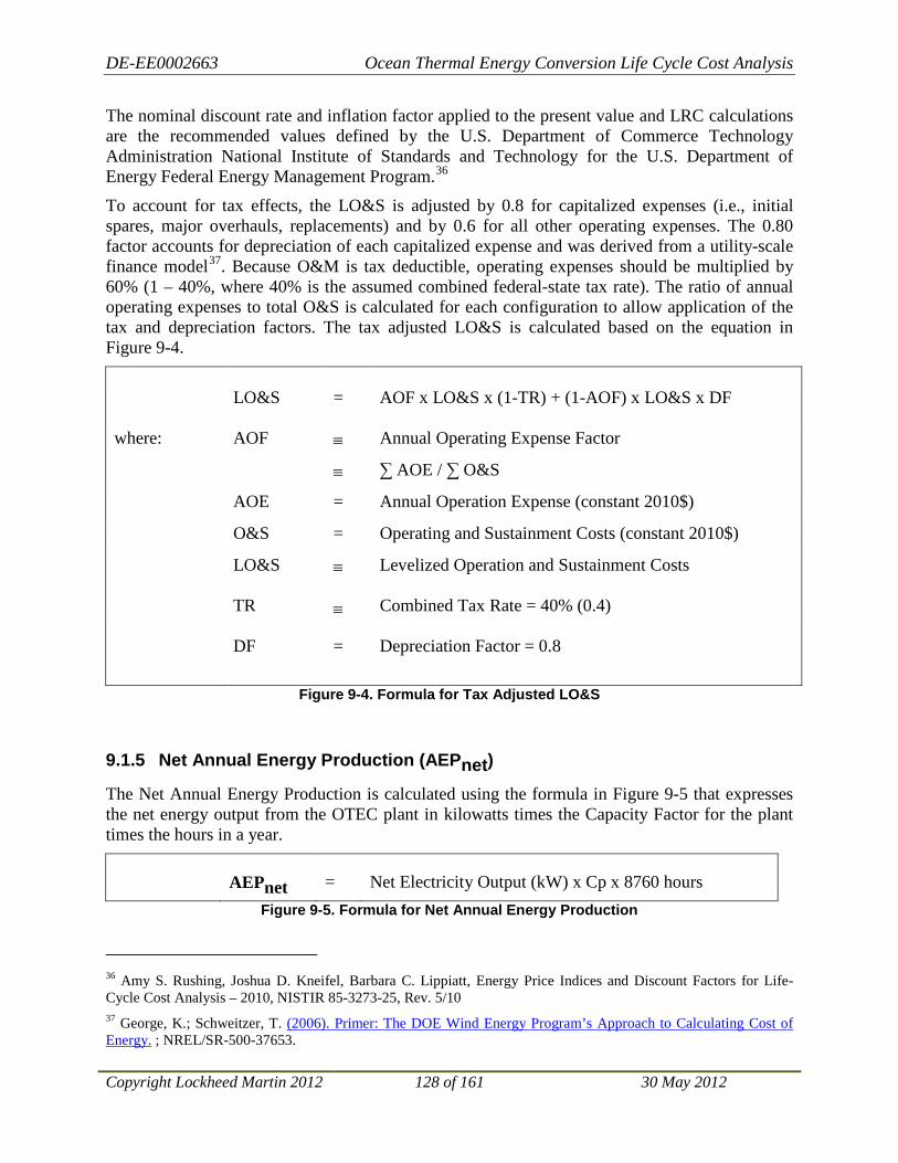
DE-EE0002663 Ocean Thermal Energy Conversion Life Cycle Cost Analysis
Copyright Lockheed Martin 2012 128 of 161 30 May 2012
The nominal discount rate and inflation factor applied to the present value and LRC calculations are the recommended values defined by the U.S. Department of Commerce Technology Administration National Institute of Standards and Technology for the U.S. Department of Energy Federal Energy Management Program.36
To account for tax effects, the LO&S is adjusted by 0.8 for capitalized expenses (i.e., initial spares, major overhauls, replacements) and by 0.6 for all other operating expenses. The 0.80 factor accounts for depreciation of each capitalized expense and was derived from a utility-scale finance model
37
Figure 9-4
. Because O&M is tax deductible, operating expenses should be multiplied by 60% (1 – 40%, where 40% is the assumed combined federal-state tax rate). The ratio of annual operating expenses to total O&S is calculated for each configuration to allow application of the tax and depreciation factors. The tax adjusted LO&S is calculated based on the equation in
.
LO&S = AOF x LO&S x (1-TR) + (1-AOF) x LO&S x DF where: AOF ≡ Annual Operating Expense Factor
≡ ∑ AOE / ∑ O&S
AOE = Annual Operation Expense (constant 2010$)
O&S = Operating and Sustainment Costs (constant 2010$)
LO&S TR
≡ ≡
Levelized Operation and Sustainment Costs Combined Tax Rate = 40% (0.4)
DF = Depreciation Factor = 0.8
Figure 9-4. Formula for Tax Adjusted LO&S
9.1.5 Net Annual Energy Production (AEPnet)
The Net Annual Energy Production is calculated using the formula in Figure 9-5 that expresses the net energy output from the OTEC plant in kilowatts times the Capacity Factor for the plant times the hours in a year.
AEPnet = Net Electricity Output (kW) x Cp x 8760 hours Figure 9-5. Formula for Net Annual Energy Production
36 Amy S. Rushing, Joshua D. Kneifel, Barbara C. Lippiatt, Energy Price Indices and Discount Factors for Life-Cycle Cost Analysis – 2010, NISTIR 85-3273-25, Rev. 5/10 37 George, K.; Schweitzer, T. (2006). Primer: The DOE Wind Energy Program’s Approach to Calculating Cost of Energy. ; NREL/SR-500-37653.

DE-EE0002663 Ocean Thermal Energy Conversion Life Cycle Cost Analysis
Copyright Lockheed Martin 2012 129 of 161 30 May 2012
The Capacity Factor incorporates system Availability A0 as well as variability in the net electricity output due to variations in the resource being harnessed. In the case of wind and solar, the Capacity Factor is significantly reduced due to periodic availability of the resource. That is not the case for OTEC where the resource is available continuously. There are variations in the resource mainly due to seasonal heating and cooling of the surface water; however, those variations are already taken into account in the Net Electricity Output, which is an average of the Net Electricity Output over a year based on the temperature profile variations. As a result, the Capacity Factor used in the calculation is actually the system Availability based on expected and unexpected down time due to maintenance and storms.
For this assessment, we have assumed a value of 92% for Cp of each OTEC plant38
9.2 LCOE for the First OTEC Plants
. Due to the redundant design of the OTEC plant, maintenance and overhaul activities do not require a complete system shutdown. Only part of the system must be shutdown to allow for planned maintenance allowing the plant to continue producing at a reduced capacity. The Capacity Factor used in this study includes the anticipated reduced capacity during maintenance and overhaul activities.
Table 9-1 shows the results of the LCOE calculations for the first OTEC plants of each configuration (100 MW, 200 MW and 400 MW Grid Connected and 400 MW Energy Carrier) using the LCOE calculation method described above for the capital, operating and sustainment cost results presented in Sections 4.2.1, 4.3.1, 5.5.1 and 5.5.2. As such, these LCOE values represent a nominal OTEC plant for each configuration deployed in a location with a resource equivalent to that available in Hawai’i39
Table 9-1. LCOE Calculations for First 100 MW, 200 M, and 400 MW OTEC Plants
. These LCOE values provide the FOM for the electricity produced on the plant at the output of the turbine.
100 MW Grid
Connected 200 MW Grid
Connected 400 MW Grid
Connected 400 MW Energy
Carrier Deployment Year 2018 2022 2026 2026 System Life 30 years 30 years 30 years 30 years CRF 5.8% 5.8% 5.8% 5.8% IWF 1.0% 1.0% 1.0% 1.0% ICC (in deployment year) $1,506,000,000 $2,494,000,000 $4,044,000,000 $4,168,000,000 Real Discount Rate 4.0% 4.0% 4.0% 4.0% Inflation Factor 0.9% 0.9% 0.9% 0.9% Levelized Capital Cost (ICC x 0.08) $102,100,000 $169,100,000 $274,300,000 $282,700,000 Levelized Tax Adjusted O&S Cost $40,700,000 $71,500,000 $119,300,000 $163,100,000
38 Availability of 92% is a required design parameter for the OTEC plant in order to meet Hawai’ian Electric Company’s availability requirement for base load power sources. Preliminary assessments indicate that the LM design will exceed this requirement. 39 See Section 10.2 for discussion of how location and available resource impact LCOE values.
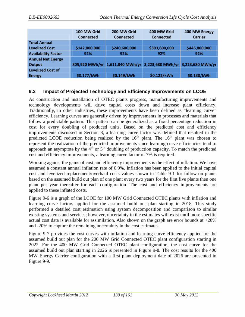
DE-EE0002663 Ocean Thermal Energy Conversion Life Cycle Cost Analysis
Copyright Lockheed Martin 2012 130 of 161 30 May 2012
100 MW Grid
Connected 200 MW Grid
Connected 400 MW Grid
Connected 400 MW Energy
Carrier Total Annual Levelized Cost $142,800,000 $240,600,000 $393,600,000 $445,800,000 Availability Factor 92% 92% 92% 92% Annual Net Energy Output 805,920 MWh/yr 1,611,840 MWh/yr 3,223,680 MWh/yr 3,223,680 MWh/yr Levelized Cost of Energy $0.177/kWh $0.149/kWh $0.122/kWh $0.138/kWh
9.3 Impact of Projected Technology and Efficiency Improvements on LCOE As construction and installation of OTEC plants progress, manufacturing improvements and technology developments will drive capital costs down and increase plant efficiency. Traditionally, in other industries, these improvements have been defined as “learning curve” efficiency. Learning curves are generally driven by improvements in processes and materials that follow a predictable pattern. This pattern can be generalized as a fixed percentage reduction in cost for every doubling of produced units. Based on the predicted cost and efficiency improvements discussed in Section 8, a learning curve factor was defined that resulted in the predicted LCOE reduction being realized by the 16th plant. The 16th plant was chosen to represent the realization of the predicted improvements since learning curve efficiencies tend to approach an asymptote by the 4th or 5th doubling of production capacity. To match the predicted cost and efficiency improvements, a learning curve factor of 7% is required.
Working against the gains of cost and efficiency improvements is the effect of inflation. We have assumed a constant annual inflation rate of 0.9%. Inflation has been applied to the initial capital cost and levelized replacement/overhaul costs values shown in Table 9-1 for follow-on plants based on the assumed build out plan of one plant every two years for the first five plants then one plant per year thereafter for each configuration. The cost and efficiency improvements are applied to these inflated costs.
Figure 9-6 is a graph of the LCOE for 100 MW Grid Connected OTEC plants with inflation and learning curve factors applied for the assumed build out plan starting in 2018. This study performed a detailed cost estimation using system decomposition and comparison to similar existing systems and services; however, uncertainty in the estimates will exist until more specific actual cost data is available for assimilation. Also shown on the graph are error bounds at +20% and -20% to capture the remaining uncertainty in the cost estimates.
Figure 9-7 provides the cost curves with inflation and learning curve efficiency applied for the assumed build out plan for the 200 MW Grid Connected OTEC plant configuration starting in 2022. For the 400 MW Grid Connected OTEC plant configuration, the cost curve for the assumed build out plan starting in 2026 is presented in Figure 9-8. The cost results for the 400 MW Energy Carrier configuration with a first plant deployment date of 2026 are presented in Figure 9-9.

DE-EE0002663 Ocean Thermal Energy Conversion Life Cycle Cost Analysis
Copyright Lockheed Martin 2012 131 of 161 30 May 2012
Figure 9-6. LCOE with Learning Curve Factor Applied for 100 MW Grid Connected OTEC Plant
Configuration
Figure 9-7. LCOE with Learning Curve Factor Applied for 200 MW Grid Connected OTEC Plant
Configuration
0.06
0.08
0.1
0.12
0.14
0.16
0.18
0.2
0.22
0.24
0 5 10 15 20
LCO
E Pr
oduc
ed($
/kW
h)
Years (Year 0 = 2018)
100 MW Grid Connected LCOE with Learning Curve
LCOE
-0.3
0.3
0.06
0.08
0.1
0.12
0.14
0.16
0.18
0.2
0.22
0.24
0 5 10 15 20
LCO
E Pr
oduc
ed (
$/kW
h)
Years (Year 0 = 2022)
200 MW Grid Connected LCOE with Learning Curve
LCOE
-0.3
0.3

DE-EE0002663 Ocean Thermal Energy Conversion Life Cycle Cost Analysis
Copyright Lockheed Martin 2012 132 of 161 30 May 2012
Figure 9-8. LCOE with Learning Curve Factor Applied for 400 MW Grid Connected OTEC Plant
Configuration
Figure 9-9. LCOE with Learning Curve Factor Applied for 400 MW Energy Carrier OTEC Plant
Configuration
0.06
0.08
0.1
0.12
0.14
0.16
0.18
0.2
0.22
0.24
0 5 10 15 20
LCO
E Pr
oduc
ed (
$/kW
h)
Years (Year 0 = 2026)
400 MW Grid Connected LCOE with Learning Curve
LCOE
-0.3
0.3
0.060.08
0.10.120.140.160.18
0.20.220.24
0 5 10 15 20
LCO
E Pr
oduc
ed (
$/kW
h)
Years (Year 0 = 2026)
400 MW Energy Carrier LCOE with Learning Curve
LCOE
-0.3
0.3

DE-EE0002663 Ocean Thermal Energy Conversion Life Cycle Cost Analysis
Copyright Lockheed Martin 2012 133 of 161 30 May 2012
The above analysis is based on cost and efficiency improvements applied to the baseline configurations considered for this study. In addition to these evolutionary improvements, transformative developments are also predicted that would result in significant reductions in capital cost and/or efficiency improvements. LCOE prediction for these transformative developments is beyond the scope of this analysis; however, it is conceivable that LCOE could be driven well below 10 cents per kilowatt hour within 20 years of deployment of the first OTEC plant.
9.4 Impact of Transmission/Transportation Losses on LCOE
9.4.1 Grid Connected Transmission Losses The LCOE values provided in Section 9.2 and Section 9.3 represent the cost of the electricity produced on the plants. They do not account for losses incurred during transmission or transportation of the electricity or energy carrier. For the Grid Connected OTEC plants, the efficiency of the marine power cable was modeled. A MATLAB model was generated based on cable RLC parameters and derating factor as defined in the ABB XLPE Guide with voltage regulation to maintain a constant voltage from no-load to full-load. Using the generated model, the efficiency of the marine power cable was calculated versus the distance from shore. The results of the modeling are presented in Figure 9-10 for current cable technology and in Figure 9-11 for predicted future cable technology. Due to cost and efficiency advantages and current availability, the 132 kV power cable was selected for initial OTEC deployment cost assessment. Based on the modeling results and a nominal distance from shore of 20 km, a cable loss of 1.2% was used to derate the electricity production. Recalculating the LCOE, with AEPnet reduced by 1.2%, results in a LCOE for the electricity received at shore where the marine power cable connects into the grid as shown in Table 9-2. For the global Grid Connected Energy Supply Curve (for OTEC plants deployed in 2045), the 150 kV DC power cable is used for costs and efficiency estimates.
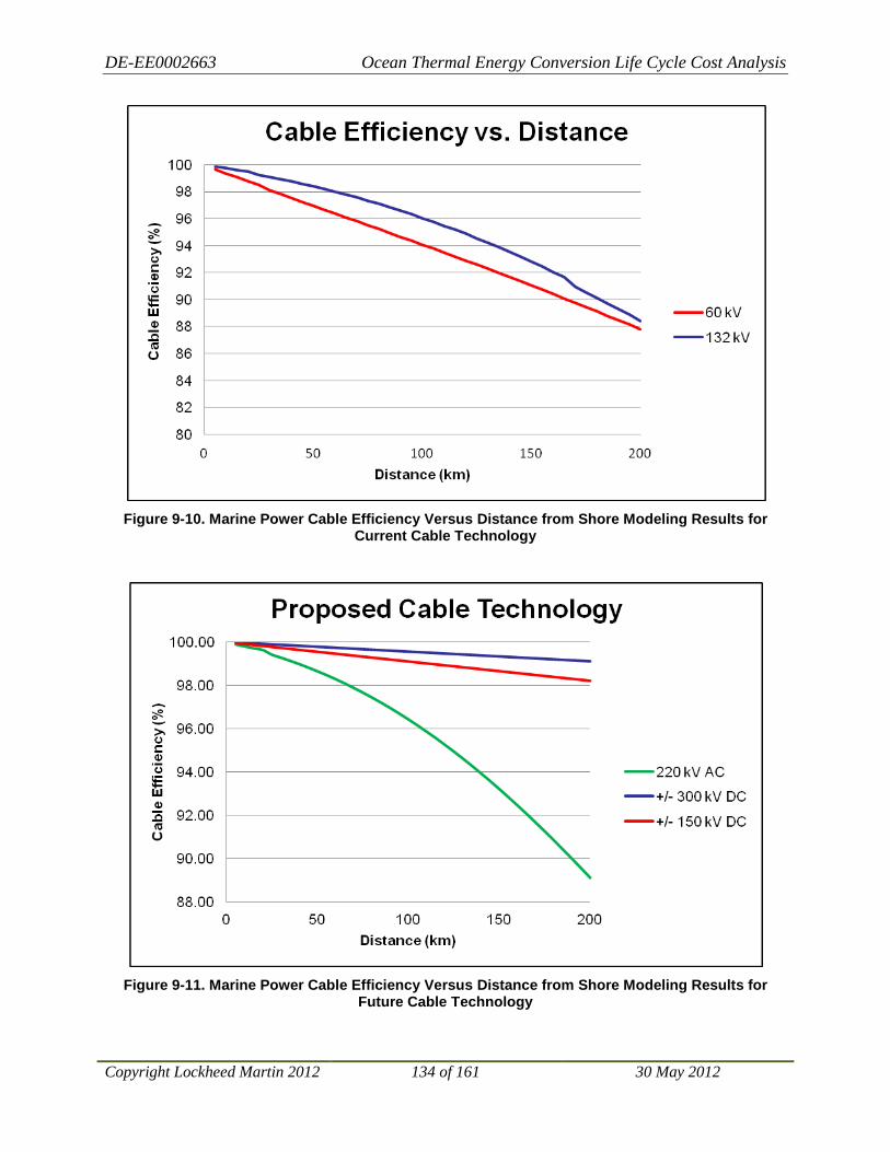
DE-EE0002663 Ocean Thermal Energy Conversion Life Cycle Cost Analysis
Copyright Lockheed Martin 2012 134 of 161 30 May 2012
Figure 9-10. Marine Power Cable Efficiency Versus Distance from Shore Modeling Results for
Current Cable Technology
Figure 9-11. Marine Power Cable Efficiency Versus Distance from Shore Modeling Results for
Future Cable Technology

DE-EE0002663 Ocean Thermal Energy Conversion Life Cycle Cost Analysis
Copyright Lockheed Martin 2012 135 of 161 30 May 2012
Table 9-2. LCOE Received at Shore Connection for Grid Connected OTEC Plants (20 km from Shore)
100 MW Grid
Connected 200 MW Grid
Connected 400 MW Grid
Connected LCOE at Shore Initial Deployment (2018-2026) $0.179/kWh $0.151/kWh $0.124/kWh LCOE at Shore Future Deployment (2037-2045) $0.157/kWh $0.133/kWh $0.108/kWh
9.4.2 Energy Carrier Transportation Costs and Losses For the Energy Carrier OTEC plant configuration, the net electricity produced is used to crack seawater into hydrogen and oxygen. The hydrogen is combined with atmospheric nitrogen to produce anhydrous ammonia (NH3). Using conventional electrolysis, 12 MWh of electricity are required to produce 1 tonne of ammonia. A 400 MW OTEC plant with an availability factor of 92% generates 3,224 GWh/year resulting in an annual ammonia production of 268,640 tonne.
Calculating the LCOE for the ammonia delivered to port requires an assessment of the transportation cost as well as transportation loss. Transportation costs are affected significantly by fuel costs. In order to remove uncertainty of future fuel costs from the levelized cost of energy model, this analysis has made the simplifying assumption that ammonia will be used to fuel the transport vessel. Transportation is modeled by a cost per tonne-km freight rate, ex-fuel, coupled with a transportation-induced ammonia production inefficiency to account for the cargo consumed during the voyage. These factors have been estimated at 0.1285 cents per tonne-km loaded and 0.000468% per km from port, respectively.
A 6,167 kilometer model voyage would consume approximately 3% of the gross cargo load and result in an annual cost for transporting ammonia produced by a 400 MW Energy Carrier OTEC plant in 2010 dollars of $2,129,000. Applying inflation to this value for each year of operation and calculating the net present value allows for the application of the CRF resulting in a levelized transportation cost of $2,478,000. Including this cost in the LCOE calculation and dividing by 97% of the amount of ammonia produced to account for what is consumed in transport results in the LCOE for ammonia delivered as shown in Table 9-3.
Table 9-3. LCOE for Ammonia Delivered to Port for Energy Carrier OTEC Plants
400 MW Energy
Carrier LCOE at Shore $1,714/tonne LCOE at Shore $1,531/tonne
The following sections discuss the analysis performed to determine the factors used for cost per tonne-km and ammonia consumed per km from port.
9.4.2.1 Marine Transportation Trends
There is active trading throughout the world in Liquefied Petroleum Gas (LPG); so much so that several shipping companies have invested in LPG ships, not just for long-term transportation
DE-EE0002663 Ocean Thermal Energy Conversion Life Cycle Cost Analysis
Copyright Lockheed Martin 2012 136 of 161 30 May 2012
contracts, but for the spot market as well. There are established trading routes throughout Europe, generally involving smaller parcels (3500 m3 and less) and shorter distances (less than 1000 miles). There are also established routes for larger parcels (80,000 m3 and larger) from the Middle East to Japanese and Brazilian markets. LPG ships are well suited to transporting ammonia as well and, hence, provide valuable market insight into the potential cost of transportation.
Several marine publications report regularly on chartering activity. Fixtures reported in 2010 for the short sea market ranged from $40 per tonne for a 300 mile voyage to $70 per tonne on an 1,100 mile voyage. Both voyages lifted approximately 3,500 m3 of cargo. This equates to a freight rate of between 6.4 and 11 cents per tonne-mile (3.46 and 5.94 cents per tonne-km).
Long voyage fixtures reportedly ranged from $28.70 to $33 per tonne for 7,500-mile transits, to $30 per tonne for a single 9,000-mile voyage. These equate to freight rates ranging from 0.33 cents per tonne-mile to 0.44 cents per tonne-mile (0.18 to 0.24 cents per tonne-km).
The same publications also reported one- and two-year time charters for nominal 80,000 m3 gas ships equivalent to about $15,000 per day, ex-fuel. Factoring in fuel consumption, and modeling a round-trip voyage that includes a dead-head return, would yield an equivalent freight rate of about 0.46 cents per tonne-mile (0.25 cents per tonne-km).
Glosten believes that the long-term cost of transportation is better represented by the time charters than the spot market voyages. World freight rates remained depressed in the first half of 2010, and the spot charters cited may have provided owners with reimbursement of out-of-pocket costs (labor and fuel) and a contribution margin that did not provide a full return on capital. Glosten suggests, therefore, that if a transportation system is conceived that relies on a carbon-based fuel, such as marine diesel oil (MDO), a freight rate of 0.5 cents per tonne-mile (0.27 cents per tonne-km) be used in future calculations. This freight rate would be very susceptible to the world price of fossil fuel.
9.4.2.2 An Alternative Freight Rate Construction
The foregoing model is highly dependent on stable petroleum prices, which is an assumption that has proven to be invalid in the last half decade.40 Fuel consumption represents more than half of the total cost of a ship voyage. An alternative model assumes the transport vessel uses ammonia as fuel rather than a petroleum product, such as MDO. This was the concept of operations used in first generation LNG ships, where boil-off from the cryogenic cargo tanks was used to fuel the boilers.41
40 Note: This assessment was originally prepared in November 2010, when marine diesel fuel prices averaged around $750 per tonne. In the first month of 2012, equivalent marine diesel fuel prices have been hovering well above $1,000 per tonne. This factor alone would drive the cost per tonne-mile by almost 20%, from 0.46 to 0.56 cents.
Assuming that an internal combustion engine can be converted to run on ammonia, the difference in the heating value between ammonia and MDO can be used to estimate ammonia consumption. An 80,000 m3 gas ship expected to burn 28 tonnes of MDO a day would burn
41 Gas-fired steam plants on LNG ships have given way to heavy fuel-capable, low-speed diesel engines for cost purposes. These are expected to be followed by an increased use of dual-fuel diesel engines, so operators can take best advantage of fuel price differentials. An interesting reversal of strategy accompanied the recent downward trends in natural gas pricing, LNG (and other) shipping interests are reconsidering switching back to gas fuel and dual fuel. Technology for dual-fuel diesel engines is advancing rapidly.
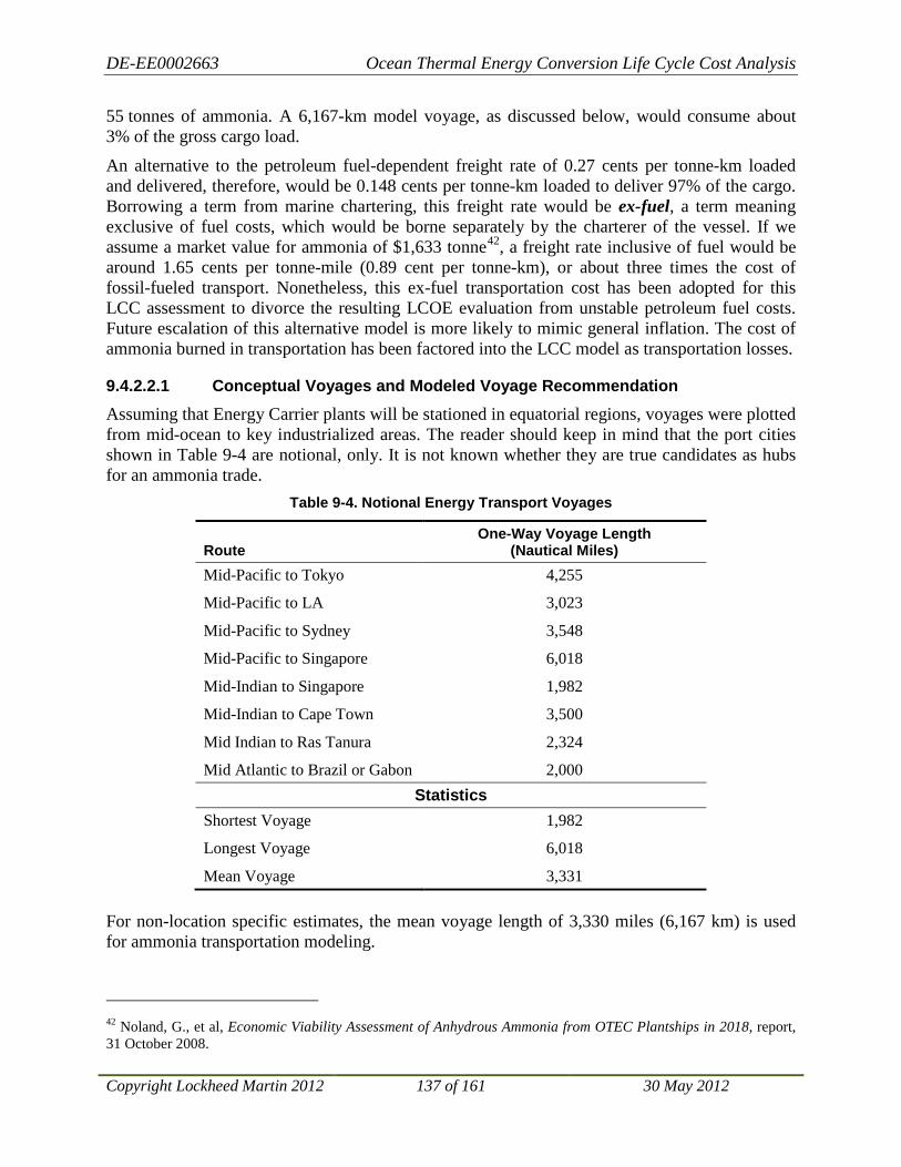
DE-EE0002663 Ocean Thermal Energy Conversion Life Cycle Cost Analysis
Copyright Lockheed Martin 2012 137 of 161 30 May 2012
55 tonnes of ammonia. A 6,167-km model voyage, as discussed below, would consume about 3% of the gross cargo load.
An alternative to the petroleum fuel-dependent freight rate of 0.27 cents per tonne-km loaded and delivered, therefore, would be 0.148 cents per tonne-km loaded to deliver 97% of the cargo. Borrowing a term from marine chartering, this freight rate would be ex-fuel, a term meaning exclusive of fuel costs, which would be borne separately by the charterer of the vessel. If we assume a market value for ammonia of $1,633 tonne42
9.4.2.2.1 Conceptual Voyages and Modeled Voyage Recommendation
, a freight rate inclusive of fuel would be around 1.65 cents per tonne-mile (0.89 cent per tonne-km), or about three times the cost of fossil-fueled transport. Nonetheless, this ex-fuel transportation cost has been adopted for this LCC assessment to divorce the resulting LCOE evaluation from unstable petroleum fuel costs. Future escalation of this alternative model is more likely to mimic general inflation. The cost of ammonia burned in transportation has been factored into the LCC model as transportation losses.
Assuming that Energy Carrier plants will be stationed in equatorial regions, voyages were plotted from mid-ocean to key industrialized areas. The reader should keep in mind that the port cities shown in Table 9-4 are notional, only. It is not known whether they are true candidates as hubs for an ammonia trade.
Table 9-4. Notional Energy Transport Voyages
Route One-Way Voyage Length
(Nautical Miles) Mid-Pacific to Tokyo 4,255
Mid-Pacific to LA 3,023
Mid-Pacific to Sydney 3,548
Mid-Pacific to Singapore 6,018
Mid-Indian to Singapore 1,982
Mid-Indian to Cape Town 3,500
Mid Indian to Ras Tanura 2,324
Mid Atlantic to Brazil or Gabon 2,000 Statistics
Shortest Voyage 1,982
Longest Voyage 6,018
Mean Voyage 3,331 For non-location specific estimates, the mean voyage length of 3,330 miles (6,167 km) is used for ammonia transportation modeling.
42 Noland, G., et al, Economic Viability Assessment of Anhydrous Ammonia from OTEC Plantships in 2018, report, 31 October 2008.

DE-EE0002663 Ocean Thermal Energy Conversion Life Cycle Cost Analysis
Copyright Lockheed Martin 2012 138 of 161 30 May 2012
9.4.2.2.2 Model Voyage
It was estimated that a single vessel could complete a round trip voyage in 24 days. As shown in Table 9-5, this assumes a five-day loading cycle and one-day discharge cycle at the shore facility. A ship would serve four to five 200 MW OTEC plants43
Table 9-5. Model Voyage Profile
. On a gross scale, each 80,000 m3 ship (~41,000 deadweight tonnes), working a 24-day round trip voyage, has a take-away capacity of about 1,700 tonnes per day, slightly overmatching the production capacity of four plants at a combined 1,600 tonnes per day. Each plant would be visited once every 24 days, and would be expected to transfer approximately 9,600 tonnes of produced ammonia to the export tanker. Offloading systems on the OTEC plants would be sized so the entire four- or five-unit constellation of OTEC plants can be offloaded in the five-day period.
Parameter Value Distance to Transportation Hub 6,167 km Speed 16 kts Round Trip Voyage 17.34 days Load Time 5 days Unload Time 1 days Total R/T Voyage 24 days
9.4.2.2.3 Summary of Marine Transportation Costs
The average cost of transporting a tonne of ammonia produced at sea can be approximated as
Cost = ($0.001285 * 6167) / 0.97 = $8.17 per tonne delivered (ex-fuel)
where 3% of the cargo (about 1,300 tonnes) is burned by the transport (round trip) on a 6,167 km passage with 40,000 tonnes loaded.
Using this value for estimating the total delivered cost of ammonia, the amount of ammonia produced must be increased by 3% to account for the amount burned during the voyage. That is, for every 100 tonnes landed ashore, 103 tonnes must be produced at sea to fuel the transportation. The model assumes this approach to remove future uncertainty inflicted on the cost model by unstable petroleum prices.
Within the size range being investigated (e.g., 100 to 400 MW OTEC plants) there is no apparent economy of scale. The cost per tonne-km may be applied linearly to alternative routes and quantities.
9.4.2.2.4 Transportation-Induced Ammonia Production Inefficiency
The alternative, ex-fuel freight rate constructed above relies on the ability of the ship to burn ammonia from the cargo. To remove any controversy over how to account for the market value of the cargo consumed as transportation fuel, the LCOE model includes a factor for “transportation-induced ammonia production inefficiency” based on distance from port.
43 This comes from Noland, G., et al, and assumes production rates of 400 tonnes per day per plant.

DE-EE0002663 Ocean Thermal Energy Conversion Life Cycle Cost Analysis
Copyright Lockheed Martin 2012 139 of 161 30 May 2012
Table 9-6 lists the key parameters in deriving the transportation inefficiency factor. From the 6,167 mile model voyage and 45,000 tonne capacity ship, it was estimated that slightly more than 1,300 tonnes of ammonia would be consumed in a single round-trip. This equates to a delivery inefficiency of 2.89% (rounded to 3% in the foregoing discussion) or 0.000468% per km from port. By applying this factor to the expected output of each plant, the cost of transportation fuel can be accounted for in the LCOE.
Table 9-6. Transportation-Induced Ammonia Production Inefficiency
Parameter Value NH3 Loaded 45,360 tonnes NH3 Delivered 44,051 tonnes Distance 6,167 km Delivery Inefficiency 2.886% Transportation-Induced Production Inefficiency 0.000468% per km from port
9.5 LCOE Sensitivity Analysis As described above, there are a number of factors contributing to the estimated LCOE. A sensitivity analysis was performed to determine the factors having the largest impact on the resulting LCOE. Sensitivity analysis results are shown in Figure 9-12. Sensitivity analysis was performed on the at-shore LCOE for the 400 MW OTEC Grid Connected plant to be deployed in 2045, which includes the realization of technology and efficiency improvements. Resource Quality and Availability have the greatest impact on LCOE since they are both directly proportional to annual energy production, which makes them inversely proportional to LCOE, a 10% increase in Availability results is a 9.1% (100%-1/110%) decrease in LCOE. Capital is the largest component of levelized cost and has the second largest impact on LCOE, a 10% increase in capital cost results in a 6.8% increase in LCOE. A 10% increase in O&S costs, Nominal Discount Rate and Inflation result in a less than 5% change in LCOE. Distance from shore has minimal impact on LCOE with less than a 2% change in LCOE for a 10% increase in distance (nominal distance for the sensitivity analysis was set to 240 km).
Figure 9-12. LCOE Sensitivity Analysis Results
-0.15 -0.1 -0.05 0 0.05 0.1 0.15
LCOE Sensitivity AnalysisEach Parameter Varied by +10% (upper bar) and -10% (lower bar)
Resource Quality
Availability
Capital
O&S
Nominal Discount Rate
Inflation
Distance from Shore

DE-EE0002663 Ocean Thermal Energy Conversion Life Cycle Cost Analysis
Copyright Lockheed Martin 2012 140 of 161 30 May 2012
10 Energy Supply Curves
10.1 Energy Supply Curves for Model Oahu, Hawai’i Initial OTEC Deployment Hawai’i is highly dependent on energy imports and suffers from high energy prices making it eager to explore local, renewable energy sources. The island of Oahu, Hawai’i has the largest population of all the Hawai’ian Islands and, therefore, the largest electricity demand. The island enjoys a good ocean thermal resource that is sufficiently close to shore allowing electricity to be connected to the power grid by marine power cable. As a result, Oahu was selected as the site of initial OTEC deployment for this study.
10.1.1 Assumptions The following assumptions were used to develop the criteria for establishing OTEC resources available to Oahu:
• Water depth for OTEC is at least 1,000 m for access to the cold water resource
• Maximum water depth for OTEC is 2,000 m to avoid excessive anchoring costs
• Maximum distance from shore is 20 km for reasonable marine power cable length
10.1.2 Process to Establish Oahu Energy Supply Curve A six-step process was used to develop the Energy Supply Curve for Oahu. The first step determined the OTEC region. The second step determined the minimum separation between OTEC plants. The third step established the area of the OTEC region around Oahu and, therefore, the maximum energy available from this region. The forth step identified potential locations for the OTEC plants needed to supply the desired electricity to Oahu. The fifth step developed the Energy Supply Curve based on the desired electricity for Oahu and the expected LCOE for those specific OTEC plants. The final step developed the conclusions that can be drawn from this analysis.
10.1.2.1 Step 1: Establishing the OTEC Region
Makai Ocean Engineering has access to a database of the bathymetry data around the island of Oahu. Makai used their database to draw the depth contour lines for the depths of 1 km and 2 km forming the boundaries of the OTEC resource region as stated in the above assumptions. See Figure 10-1 for the chart showing the island of Oahu with these two depth contours and the area between the contours colored in yellow. The chart of Figure 10-1 was superimposed on a projection of Oahu from Google Earth to establish the correct distance scale.
The maximum distance of 20 km from Oahu was selected to keep the power cable distance to a reasonable length. Analysis indicates that the loss from a 20 km power cable is only around 1.2% of the transmitted power. Figure 10-2 shows a perimeter around the island of Oahu that is roughly 20 km from the shore. The OTEC thermal region, shown in yellow within the 20 km perimeter, represents the potential OTEC deployment region.

DE-EE0002663 Ocean Thermal Energy Conversion Life Cycle Cost Analysis
Copyright Lockheed Martin 2012 141 of 161 30 May 2012
10.1.2.2 Step 2: Minimum Separation Between OTEC Plants
Greg Rocheleau of Makai used a computer model developed under a previous effort to determine the minimum separation between OTEC plants based on the water discharge from one plant impacting the operation of an adjacent plant. His model analyzed the discharge plumes and determined that even with a spacing of only 1.3 km between OTEC plants, the plumes acted independently of each other for 100 MW plants. However, the mooring lines to anchors on the seafloor will extend about 1,800 m from the OTEC plant. Adding 200 m to this distance provides a margin between anchor locations for closely spaced plants for a total of 2,000 m from the
Figure 10-1. Oahu with 1 km and 2 km Depth Contours
Figure 10-2. OTEC Region Less Than 20 km from Oahu
2,000 m 1,000 m

DE-EE0002663 Ocean Thermal Energy Conversion Life Cycle Cost Analysis
Copyright Lockheed Martin 2012 142 of 161 30 May 2012
OTEC plant to the edge of a square surrounding the plant. Thus, each OTEC plant is allocated a square on the ocean surface that is 4 km by 4 km for a total area of 16 km2. This spacing avoids having the anchor lines of adjacent plants crossing over each other.
10.1.2.3 Step 3: OTEC Region Area and Maximum Energy
The thermal resource around Oahu Hawai’i is significantly different between the leeward side of the island (the Southwest side that is sheltered from the wind by the island) and the windward side of the island (the East and North sides of Oahu). The surface water is cooled by the wind by about 3°C consistently throughout the year as the data in Figure 10-3 clearly indicates. The cooler surface water results in a decreased temperature difference between the surface water and the deep cold water, also called ∆T where ∆ refers to change, by the 3°C drop in the surface water temperature. Thus, the OTEC thermal resource on the east and north portions of Oahu are less desirable than on the west side of the island.
Figure 10-3. OTEC Thermal Resource (∆T) Leeward vs. Windward Sides of Oahu
To determine the size of the OTEC region, line segments corresponding to the scale of the chart were placed along the region to determine its length. Using only the W1, W2 and W3 line segments shown in Figure 10-4, a total length of 58 km is available to arrange OTEC plants linearly along these lines. The analysis above suggests that each OTEC plant requires 4 km along these lines. Thus, the leeward region of Oahu along these target lines can accommodate a total of

DE-EE0002663 Ocean Thermal Energy Conversion Life Cycle Cost Analysis
Copyright Lockheed Martin 2012 143 of 161 30 May 2012
14 OTEC plants within this preferred OTEC region. Using OTEC plants of 400 MW size, the maximum power available to Oahu from this OTEC region is ~ 5.6 GW. We further assume that approximately 20% of the possible sites will not be available due to unforeseen restrictions such as poor mooring conditions, proximity to shipping lanes, or other possible restrictions. This assumption reduces the estimated total power resource to be ~ 4 GW. Hawai’i has a goal that 70% of the electrical power for Oahu should come from sustainable energy sources and that amount of power is equal to 1.4 GW. Thus, the OTEC resource exceeds the total renewable energy target for Oahu by more than a factor of ~2.8.
Figure 10-4. Estimating Length of OTEC Region
10.1.2.4 Step 4: Potential Locations of OTEC Plants Around Oahu
Only six OTEC plants are needed to supply all of the 1,400 MW of power needed for Oahu to meet its goal of 70% electrical power from renewable energy sources; two 100 MW plants, two 200 MW plants and two 400 MW plants. The chart shown in Figure 10-5 indicates the potential locations for these six OTEC plants. These locations are suggested as notional locations since the actual locations depend on where Hawai’ian Electric Company prefers to have the electrical power tied into the grid and site surveys to determine appropriate anchoring and power cable path based on bottom characteristics.

DE-EE0002663 Ocean Thermal Energy Conversion Life Cycle Cost Analysis
Copyright Lockheed Martin 2012 144 of 161 30 May 2012
Figure 10-5. Potential OTEC Plant Locations Around Oahu
10.1.2.5 Step 5: Energy Supply Curve for Oahu
The Energy Supply Curve for Oahu uses the expected LCOE from the OTEC plants and the power capacity of these OTEC plants to produce the supply curve. As described above, six OTEC plants are expected to provide all the electrical power needed for Oahu to achieve the established renewable energy goal for the island. The build out plan of OTEC plants for Oahu is shown in Figure 10-6. The diagram shows the power produced by each plant and the year when the plant is assumed to be online. The deployment years match the build out plan assumed in the calculation of LCOE for application of inflation.
Figure 10-6. Build Out Plan of OTEC Plants for Oahu
MW1400 100 MW1300 200 MW1200 400 MW11001000
900800700600500400300200 100 MW #2100 100 MW #1
Year 2018 2019 2020 2021 2022 2023 2024 2025 2026 2027 2028
400 MW #2
400 MW #1
200 MW #2
200 MW #1

DE-EE0002663 Ocean Thermal Energy Conversion Life Cycle Cost Analysis
Copyright Lockheed Martin 2012 145 of 161 30 May 2012
Since the build out plan assumes the first OTEC plant will be 100 MW and two plants of each configuration will be deployed before the next size plant is built and because projected technology and efficiency improvements will result in lower LCOE for the second plant of each configuration, the Energy Supply Curve for Oahu, as shown in Figure 10-7, has a decreasing LCOE with increasing capacity. This trend is the inverse of a traditional Energy Supply Curve where additional capacity can only be obtained with more costly extraction or transportation but is a predictable and expected trend for the initial limited production of a new technology.
Figure 10-7. OTEC Energy Supply Curve for Oahu
The OTEC resource as calculated for the Oahu Energy Supply Curve is a direct function of the size of the OTEC plants and assumed build out plan. It does not represent the upper limit of the ocean thermal resource. With larger, more efficient OTEC plants, the ocean thermal resource surrounding Hawai’i can support much higher capacities as demonstrated in Section 10.3.
10.2 Global OTEC Energy Supply Curves OTEC has the potential to tap a vast global resource. Figure 10-8 is a map of the world showing the “quality” of the OTEC resource and plant spacing in the different ocean regions44
44 Results of the OTEEV project are available in the National Renewable Energy Lab Marine Hydrokinetic Atlas, http://maps.nrel.gov/mhk_atlas?visible=otec_power_ann&opacity=80&extent=-130,0,-20,0
. The red and orange regions indicate the best OTEC thermal resource. To generate global Energy Supply Curves, the global OTEC resource must be quantified in terms of cost (LCOE) and quantity (MW of capacity).
0
0.02
0.04
0.06
0.08
0.1
0.12
0.14
0.16
0.18
0.2
100 200 300 400 500 600 700 800 900 1000 1100 1200 1300 1400
Leve
lized
Cos
t of
Ene
rgy
($/k
Wh)
Cummulative Capacity (MW)
Oahu Energy Supply Curve
LCOE values in constant 2010$ for initial OTEC plant build out.Initial plant deployed in 2018, following plants deployed every 2 years.

DE-EE0002663 Ocean Thermal Energy Conversion Life Cycle Cost Analysis
Copyright Lockheed Martin 2012 146 of 161 30 May 2012
Figure 10-8. Global OTEC Resource Quality (foreground) and Plant Spacing (background)
Cost is assessed in terms of LCOE. To generate global Energy Supply Curves, the LCOE is assessed at the point the energy enters the market. For Grid Connected OTEC plants, that occurs when electricity reaches shore and can be connected into the grid. For the Energy Carrier Producing OTEC plants, that occurs when transported ammonia reaches port. Because Grid Connected OTEC plants and Energy Carrier Producer OTEC plants produce different energy products, the OTEC resource is divided into that which can be exploited by a Grid Connected OTEC plant and that which requires an Energy Carrier Producing OTEC plant so that two independent Energy Supply Curves can be generated45
Separating LCOE into its numerator (levelized cost) and denominator (annual energy produced) allows these two components to be evaluated separately. The distance from shore (Grid Connected plants) and port (Energy Carrier Producing plants) has a direct impact on the
.
45 Criterion for Grid Connected OTEC plants for the purposes of the Energy Supply Curves presented herein is defined as locations within 320 km of the shore. Beyond 240 km from shore, the capital cost of a Grid Connected OTEC plant (due to increased cost with increased power cable length) exceeds the capital cost of an Energy Carrier OTEC plant. Generation of two equally spaced distance bins, with the second bin centered on 240 km, results in a maximum distance of 320 km at the upper edge of the second bin. This transition point does not take the transportation costs and losses associated with an energy carrier into account, which would increase the distance to the transition point but it also does not take required cable laying path into account, which could increase the required cable length for a Grid Connected OTEC plant. Site surveys are required to determine the feasibility of Grid Connected or Energy Carrier OTEC plants for each OTEC installation considered based on specific site conditions to include distance from shore, bottom conditions, shore conditions, local energy demand, and availability of grid tie-in location.

DE-EE0002663 Ocean Thermal Energy Conversion Life Cycle Cost Analysis
Copyright Lockheed Martin 2012 147 of 161 30 May 2012
levelized cost. In addition to the distance from shore/port, metaocean driven configuration modifications, such as moorings, also drive site specific costs as demonstrated in Section 4.2.2 and Section 4.3.2. However, the difference in mooring costs from Hawai’i (least costly) to Guam (most costly) is $100M, which translates to $0.003 change in LCOE, which is less than 3%. Given the relatively small impact on LCOE and the complexity of trying to define mooring requirements for each global grid point, mooring costs are held fixed for the global energy curve analysis. In contrast to Section 4.2.2 and Section 4.3.2 where the configuration of the plant, such as the size of the Remoras, area of the heat exchangers and flow rates were tuned for each location to optimize the energy production for a fixed annual equivalent net power, for the global energy curve analysis the plant configurations were held fixed and the annual equivalent net power allowed to vary based on the available ocean thermal resource. Therefore, only the distance from shore and port affects the levelized cost. It is worth noting that even with a standard configuration, cold and warm water flow rates could be adjusted to optimize energy production for a given resource. Site specific configuration modifications and flow rate optimization were beyond the scope of this project but could generate higher production rates than those predicted herein.
The available temperature differential and density profile at a given location dictates the annual energy produced by a given plant configuration. The distance from shore and port also induce losses that must be adjusted to convert annual energy produced into annual energy delivered.
Results from the Ocean Thermal Extractable Energy Visualization (OTEEV) project (an independent DOE project) are used to generate the Energy Supply Curves. OTEEV characterizes the OTEC resource on a 1/12th degree grid globally. For each grid point, the “quality” of the OTEC resource is indicated by the equivalent average net power that could be produced by a nominal 100 MW OTEC plant. This allows calculation of the annual energy production based on the resource quality and designed capacity. A 400 MW plant located at an 80 MW grid point would produce 2.58 TWh/yr (400 MW * 80% resource quality * 8760 hours/year * 92% availability factor) and a 400 MW plant located at a 140 MW grid point would produce 4.51 TWh/yr. As seen in Figure 10-8, the quality of the OTEC resource varies significantly even in the equatorial region, which has a dramatic effect on the resulting LCOE. A doubling of the resource quality, halves the LCOE as can be seen in Figure 10-9 and Figure 10-10. The OTEEV project also calculates the number of OTEC plants that each grid point can support based on the cold water resource available to determine minimum plant spacing allowing for calculation of the total capacity supported for each grid point.
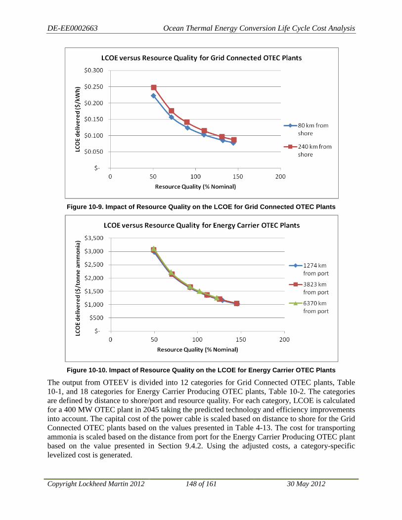
DE-EE0002663 Ocean Thermal Energy Conversion Life Cycle Cost Analysis
Copyright Lockheed Martin 2012 148 of 161 30 May 2012
Figure 10-9. Impact of Resource Quality on the LCOE for Grid Connected OTEC Plants
Figure 10-10. Impact of Resource Quality on the LCOE for Energy Carrier OTEC Plants
The output from OTEEV is divided into 12 categories for Grid Connected OTEC plants, Table 10-1, and 18 categories for Energy Carrier Producing OTEC plants, Table 10-2. The categories are defined by distance to shore/port and resource quality. For each category, LCOE is calculated for a 400 MW OTEC plant in 2045 taking the predicted technology and efficiency improvements into account. The capital cost of the power cable is scaled based on distance to shore for the Grid Connected OTEC plants based on the values presented in Table 4-13. The cost for transporting ammonia is scaled based on the distance from port for the Energy Carrier Producing OTEC plant based on the value presented in Section 9.4.2. Using the adjusted costs, a category-specific levelized cost is generated.

DE-EE0002663 Ocean Thermal Energy Conversion Life Cycle Cost Analysis
Copyright Lockheed Martin 2012 149 of 161 30 May 2012
The total capacity for each category is calculated by summing, over all grid points that meet the category criteria, the product of the equivalent average net power and the number of plants reported for each grid point. The LCOE for each category is calculated by multiplying the levelized cost by the number of plants and dividing by the total energy delivered. Because the OTEEV analysis uses a 100 MW nominal plant design and the Energy Supply Curves are based on a 400 MW nominal plant design, the number of plants predicted by OTEEV is divided by four to generate an equivalent number of 400 MW plants since a single 400 MW plant produces four times the electricity of a 100 MW plant by pumping four times the water.
For the Grid Connected OTEC plant, the annual energy delivered for each category is calculated by multiplying the total capacity by the production hours per year (8760 hours/year * 92% availability factor * 112.3% predicted efficiency improvement = 9,050.5 hours/year) and adjusting for the transmission loss due to the length of the power cable (0.01% loss per kilometer).
For the Energy Carrier OTEC plant, the annual energy delivered for each category is calculated by multiplying the total capacity by the production hours per year (8,760 hours/year * 92% availability factor * 112.3% predicted efficiency improvement = 9,050.5 hours/year), dividing by production required to produce a tonne of ammonia adjusted for the transportation loss based on distance from port (12,000 kWh/tonne*(1-0.000468%/km)).

DE-EE0002663 Ocean Thermal Energy Conversion Life Cycle Cost Analysis
Copyright Lockheed Martin 2012 150 of 161 30 May 2012
Table 10-1. Grid Connected OTEC Categories
Increasing Distance from Shore (Ls)
Increasing Power “Q
uality” (PQ)
40% < PQ ≤ 60% &
0 km < Ls ≤ 160 km
40% < PQ ≤ 60% &
160 km < Ls ≤ 320 km 60% < PQ ≤ 80%
& 0 km < Ls ≤ 160 km
60% < PQ ≤ 80% &
160 km < Ls ≤ 320 km 80% < PQ ≤ 100%
& 0 km < Ls ≤ 160 km
80% < PQ ≤ 100% &
160 km < Ls ≤ 320 km 100% < PQ ≤ 120%
& 0 km < Ls ≤ 160 km
100% < PQ ≤ 120% &
160 km < Ls ≤ 320 km 120% < PQ ≤ 140%
& 0 km < Ls ≤ 160 km
120% < PQ ≤ 140% &
160 km < Ls ≤ 320 km 140% < PQ
& 0 km < Ls ≤ 160 km
140% < PQ &
160 km < Ls ≤ 320 km
Table 10-2. Energy Carrier Producing OTEC Categories
Increasing Distance from Shore (Ls)
Increasing Power “Q
uality” (PQ)
40% < PQ ≤ 60% &
0 km < Lp ≤ 2548 km
40% < PQ ≤ 60% &
2548 km < Lp ≤ 5097 km
40% < PQ ≤ 60% &
5097 km < Lp 60% < PQ ≤ 80%
& 0 km < Lp ≤ 2548 km
60% < PQ ≤ 80% &
2548 km < Lp ≤ 5097 km
60% < PQ ≤ 80% &
5097 km < Lp 80% < PQ ≤ 100%
& 0 km < Lp ≤ 2548 km
80% < PQ ≤ 100% &
2548 km < Lp ≤ 5097 km
80% < PQ ≤ 100% &
5097 km < Lp 100% < PQ ≤ 120%
& 0 km < Lp ≤ 2548 km
100% < PQ ≤ 120% &
2548 km < Lp ≤ 5097 km
100% < PQ ≤ 120% &
5097 km < Lp 120% < PQ ≤ 140%
& 0 km < Lp ≤ 2548 km
120% < PQ ≤ 140% &
2548 km < Lp ≤ 5097 km
120% < PQ ≤ 140% &
5097 km < Lp 140% < PQ
& 0 km < Lp ≤ 2548 km
140% < PQ &
2548 km < Lp ≤ 5097 km
140 < PQ% &
5097 km < Lp

DE-EE0002663 Ocean Thermal Energy Conversion Life Cycle Cost Analysis
Copyright Lockheed Martin 2012 151 of 161 30 May 2012
To build the Energy Supply Curves, the LCOEs for each plant type are sorted in ascending order, implying a build out plan that exploits “lowest hanging fruit” first to produce a traditional Energy Supply Curve with LCOE increasing as total capacity increases. The total production capacity for each category is extracted from the OTEEV data. The LCOE for each category is plotted against the cumulative production capacity to produce incremental LCOE energy supply curves as shown in Figure 10-11 and Figure 10-12. The incremental LCOEs are integrated over and divided by the cumulative production capacity resulting in a cumulative LCOE also shown in Figure 10-11 and Figure 10-12.
Figure 10-11. Grid Connected OTEC Global Energy Supply Curve
Figure 10-12. Energy Carrier OTEC Global Energy Supply Curve
0 2000 4000 6000 8000 10000 12000
0
500
1000
1500
2000
2500
3000
3500
0 500 1000 1500 2000 2500
(Equivalent TWh/yr)
LCO
E (le
veliz
ed c
ost/
annu
al p
rodu
ctio
n) [
$/to
nne
amm
onia
]
Cumulative Capacity (Million Tonnes NH3/yr)
Energy Supply Curve of Global Energy Carrier OTEC Plants
Incremental LCOE Cumulative LCOE
LCOE values in constant 2010$ for OTEC plant deployment in 2045.

DE-EE0002663 Ocean Thermal Energy Conversion Life Cycle Cost Analysis
Copyright Lockheed Martin 2012 152 of 161 30 May 2012
10.3 OTEC Energy Supply Curves for Exclusive Economic Zone of the United States The Global Energy Supply Curves provide an overview of the OTEC resource. For more specific insight into the OTEC resource available to the U.S., Energy Supply Curves were generated for the exclusive economic zones of the U.S. An exclusive economic zone (EEZ) is a seazone over which a state has special rights over the exploration and use of marine resources, including production of energy from water and wind.46 Generally, the EEZ extends 200 nautical miles from the mean low water point of a country’s shore. Treaties and other international agreements establish the boundaries of EEZs where the 200 nautical mile limits of neighboring countries overlap. Energy Supply Curves were generated for the continental U.S., Hawai’i, and other U.S. islands47 Figure 10-13. These curves are presented in , Figure 10-14, and Figure 10-15 showing a total OTEC resource in the U.S. EEZs of 4,514 TWh/yr. This is nearly equal to the U.S. electricity consumption predicted by the U.S. Energy Information Administration of 4,481 TWh/yr by 203548
.
Figure 10-13. Continental U.S. Grid Connected OTEC Plants Energy Supply Curve
46 "Part V - Exclusive Economic Zone, Article 56". Law of the Sea. United Nations. https://www.un.org/depts/los/convention_agreements/texts/unclos/part5.htm. Retrieved 2011-08-28. 47 Other U.S. islands are American Samoa, Howland Baker, Jarvis, Johnston Atoll, Mariana Islands, Guam, Marshall Islands, Micronesia, Palau, Palmyra, Puerto Rico, U.S. Virgin Islands, Wake Island. 48 http://www.eia.gov/oiaf/aeo/tablebrowser/#release=AEO2011&subject=2-AEO2011&table=2-AEO2011®ion=1-0&cases=ref2011-d020911a
0
0.05
0.1
0.15
0.2
0.25
0.3
0 50 100 150 200 250 300
LCO
E (le
veliz
ed c
ost/
annu
al p
rodu
ctio
n)
[$/k
Whr
]
Cumulative Capacity (TWh/yr)
Energy Supply Curve of Continental US Grid Connected OTEC Plants
Incremental LCOE Cumulative LCOE
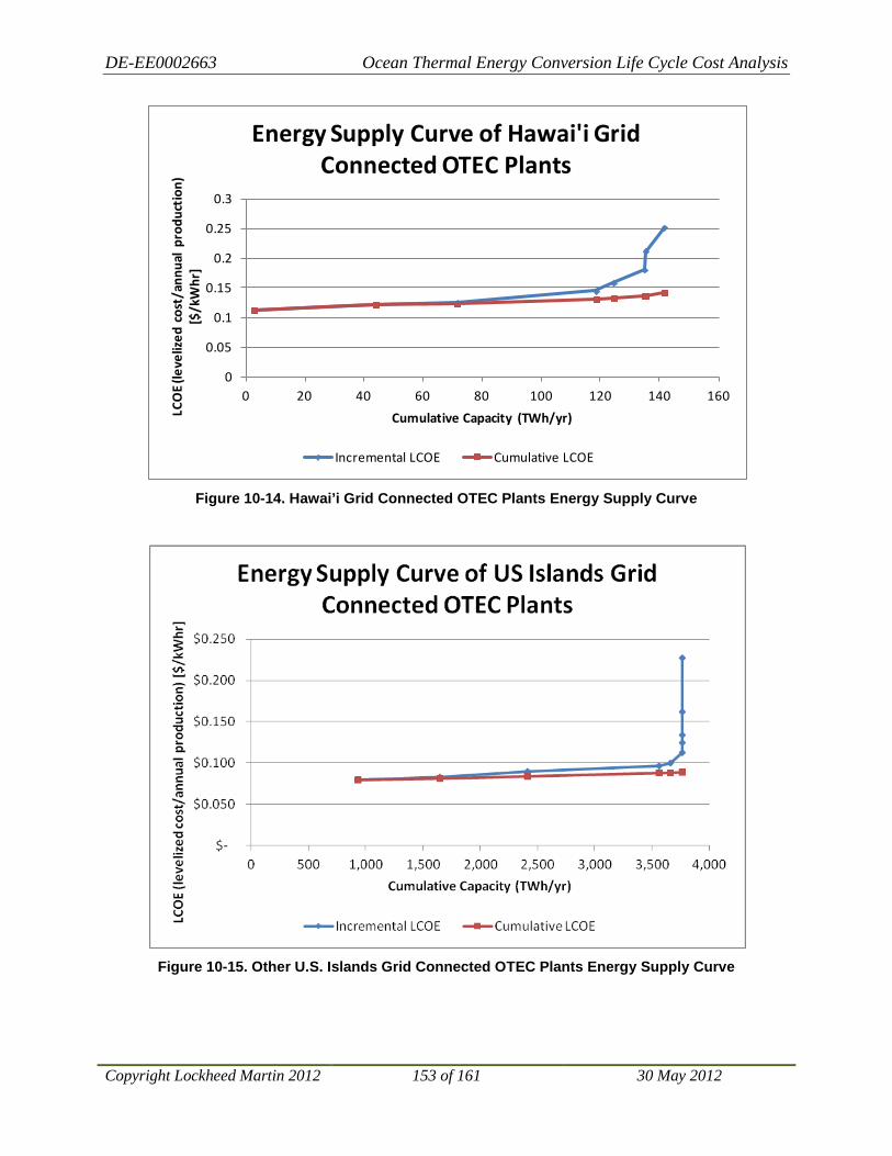
DE-EE0002663 Ocean Thermal Energy Conversion Life Cycle Cost Analysis
Copyright Lockheed Martin 2012 153 of 161 30 May 2012
Figure 10-14. Hawai’i Grid Connected OTEC Plants Energy Supply Curve
Figure 10-15. Other U.S. Islands Grid Connected OTEC Plants Energy Supply Curve
0
0.05
0.1
0.15
0.2
0.25
0.3
0 20 40 60 80 100 120 140 160
LCO
E (le
veliz
ed c
ost/
annu
al p
rodu
ctio
n)
[$/k
Whr
]
Cumulative Capacity (TWh/yr)
Energy Supply Curve of Hawai'i Grid Connected OTEC Plants
Incremental LCOE Cumulative LCOE

DE-EE0002663 Ocean Thermal Energy Conversion Life Cycle Cost Analysis
Copyright Lockheed Martin 2012 154 of 161 30 May 2012
11 Areas for Future Study While working on the various aspects of this project, the project team members have identified a number of specific areas having the potential for providing significant improvements for the prospects of commercial development of OTEC. These are outlined in the following sections.
11.1 Engineered Cost Estimates The cost estimates in this report were based on extrapolations from detailed costs prepared for a 10 MW pilot plant and leveraged the conceptual design for a 100 MW OTEC plant performed in 2008. The scope did not allow for engineering of the configurations assessed. Scale-up factors were largely based upon judgment and experience of the investigators. In order to gain a better understanding of the economies of scale, it would be beneficial to have the cost estimates for the OTEC plant configurations to be based on actual designs and an engineering cost estimate. We would recommend undertaking a design and cost study for a nominal condition such as Hawai’i and a 400 MW production rate. This is likely to provide a basis for the lowest LCOE based on scale, and would provide a solid basis for interpolating
The critical component of the concept presented in this study is the Remora, or power module. A critical part of this engineering study would be to determine the largest practical size of the power module, which in turn would lead to the required size for the platform. The study should include sizing of all the major equipment: heat exchangers, pumps, piping, turbine generators, etc. Using these sizes, general arrangements of the power modules and platform should be determined. The power module configuration needs to be analyzed to verify it can be upended, attached to the platform and that major equipment such as pumps can be serviced at sea. In essence, the 400 MW plant should be somewhat optimized before preparing a cost estimate.
costs for smaller units.
The cost estimate should incorporate vendor quotes for the major components and a shipyard estimate for structure and integration. As the level of engineering will still be preliminary, the cost estimate would still be budgetary; however, the confidence level would be higher than the estimates in this study allowing for a reduction in the presented error bands.
Once an engineered cost estimate for a 400 MW plant is determined, other costs may be derived from scaling and interpolation to other (smaller) sizes and different deployment locations.
11.2 Site-specific Cost Refinement The LCCA presented in this report has focused on a global approach to OTEC development. However, such global development must be preceded by the first commercial plant. The case to justify the first plant requires a more detailed cost estimate than the site-insensitive CAPEX or parametric MOTEM are able to provide. The results presented in this report can be used to guide selection of a specific site for the first commercial OTEC plant. Then, a more detailed study can be undertaken to create a site-specific design with more refined cost estimates. Tasks required for the development of the first commercial plant include:
• Site selection – Both Hawai’i and Guam have been shown to be viable markets for Grid Connected OTEC today. Energy carrier plants have been projected to follow Grid Connected plants. Further design efforts should be focused on a specific Grid Connected site.

DE-EE0002663 Ocean Thermal Energy Conversion Life Cycle Cost Analysis
Copyright Lockheed Martin 2012 155 of 161 30 May 2012
• Site-specific design – Those components of the plant that are highly dependent on site will need detailed design. Examples include the floating platform, mooring system, power cable to shore and CWP.
• Site-specific cost estimation – Every potential OTEC site will have different construction and deployment costs. The remote nature of good OTEC sites means that mobilization and shipping costs could make up a significant portion of the total capital cost of the plant. Local factors need to be taken into account to develop a site-specific cost estimate that is accurate enough to attract private investors.
11.3 Energy Carrier Concept of Operation The LM-led OTEC team has already developed a comprehensive concept of operation for Grid Connected OTEC Plants including crew rotations and transport, routine maintenance, and major maintenance periods. Many of those concepts are directly applicable to the Energy Carrier OTEC plant and included in the analysis results presented in this report. However, the Energy Carrier configuration introduces some additional logistic complexities. The concept of operations for the Energy Carrier OTEC plants assumed for this report’s analysis includes 90-day crew rotations with an average 24-day round-trip transport provided by the Energy Carrier transport vessel. Although this practice eliminates crew transport costs, the additional days at sea drive personnel costs and complicate personnel logistics. A detailed cost/benefit analysis should be performed for each Energy Carrier OTEC plant site area to determine the most time and cost-efficient crew transport method. The analysis should consider various methods of crew transport, such as seaplanes and floatplanes, transit to home port, and transit to closest airfield.
This study assumed that ammonia carriers are chartered. Since the ammonia carriers are likely to be fit for purpose it might be more suitable to include the capital cost of the carriers in the CAPEX and apply the same cost of capital to them that would be applied to the rest of the OTEC/Ammonia plant. This task requires an assessment of the CAPEX of the carriers and a calculation of the LCOE based on ownership.
Another aspect of the Energy Carrier concept of operation warranting additional investigation is the periodic repositioning required for the unmoored plants. The results in this report assume that the Energy Carrier OTEC plants need to be repositioned infrequently only when the position drifted to imposes a threat or results in reduced plant efficiency. The repositioning is performed by tugs and covered by the safety and contingency budget. Site specific conditions may drive the need for more positive position control. A specific site assessment of prevailing winds and currents should be performed to determine the preferred station keeping approach.
11.4 Standards for OTEC Design – Recommended Practices There are no industry standards for an offshore OTEC design. Previous design work has relied almost exclusively on standards developed for the offshore oil and gas industry. These standards reflect a safety level that is one of the highest among industrial standards. This is understandable considering the consequences of failure for an offshore oil and gas project: release of hydrocarbons and safety of personnel. However, the consequences of failure of an OTEC plant are much less than those for offshore oil and gas platforms. This raises the question of whether

DE-EE0002663 Ocean Thermal Energy Conversion Life Cycle Cost Analysis
Copyright Lockheed Martin 2012 156 of 161 30 May 2012
using offshore standards results in an overly conservative and expensive design vis-à-vis other renewable energy options49
a) In what areas is it reasonable to reduce standards from a risk perspective?
. There are two aspects to a future task:
b) Would reducing standards materially change the LCOE?
Answering the first of these questions requires a quantitative risk assessment showing the relative increase in risk of reducing the standards. Examples of reducing standards might include, for a “permanently moored” platform:
• Reducing the survival condition from a 100-year return period to a 50-year return period • Reducing safety factors on mooring components, in particular with one line missing • Reducing damaged stability requirements to include only tanks at the waterline
A preliminary assessment of the cost impact of reducing standards might help evaluate the importance of pursuing the risk assessment. Hence this study should be phased.
11.5 Standardization and Optimization of Power Modules The OTEC concept presented in this study made use of a relatively standard plant, with removable “Remoras,” or power modules. The Remoras are clearly the main OTEC component functionally and economically. To achieve a low LCOE for OTEC, the Remoras should be optimized and standardized, taking advantage of manufacturing efficiencies that come from producing multiple units of the same product (i.e., “mass production”). This idea is utilized to reduce the cost of “standard” items such as automobiles, airliners and tankers. Costs for one-off items like the Remoras is heavily weighted towards labor costs: cost of materials in standard shipbuilding is only 10-20% of the total cost (if you consider the materials in the heat exchangers vs. the manufactured costs, for example). The remaining costs are labor, G&A and overhead. Contrast this to a mass produced automobile where the material cost is about 87% of the total.50
a) Optimization of the arrangements of the power module for manufacturing and service
A standardized power module built in a facility designed for mass production should considerably reduce total costs, albeit at some investment in tooling, automation, etc. A study of the possible reduction in costs based upon different production levels would help refine future cost estimates. The study would involve:
b) Survey of efficient manufacturing processes in related industries (e.g., tanker construction)
c) Identification of an efficient manufacturing process for the power modules and estimating of tooling/facility costs
d) Estimation of cost savings for efficient manufacturing costs vs. contracted manufacturing costs
e) Assessment of minimum quantities required to justify investment in a fit for purpose manufacturing facility
49 This same argument could be made for offshore wind standards. 50 http://msl1.mit.edu/classes/esd123/vyas.pdf

DE-EE0002663 Ocean Thermal Energy Conversion Life Cycle Cost Analysis
Copyright Lockheed Martin 2012 157 of 161 30 May 2012
This will establish a target minimum OTEC market in order to justify investment in a dedicated manufacturing facility.
11.6 Standardization of HX Design and Optimization of Manufacturing Processes This is exactly analogous to the discussion above with regards to the power modules. The heat exchangers themselves make up about 20-30% of the total costs of a large OTEC plant. Setting up a manufacturing facility to mass produce these could result in a significant impact on the overall LCOE.
11.7 Water Intake and Plume Modeling Additional modeling and analysis of the warm and cold water flow into OTEC plant fields and the resultant effluent would aid in a better understanding of energy flow, water intake requirements, and minimum plant spacing. Makai has performed plume modeling for a three plant field, which has indicated that mooring requirements drove the minimum plant for the location investigated off Hawai’i. Detailed flow models should be considered for specific site investigations for total planned OTEC fields to understand potential interactions between densely packed OTEC plants.
11.8 Heat Exchanger Materials Improvements in the durability and heat transfer properties of the materials used in the fabrication of OTEC heat exchangers could dramatically improve the commercial viability of OTEC.
11.9 Platform Materials and Construction As well documented above, the most costly component of offshore OTEC systems is the platform that hosts the power generating components. Use of new, less expensive materials and development of lower cost construction methods could significantly lower capital costs for these systems.
11.10 Energy Carrier The commercial viability of OTEC systems not linked to electrical grids is directly dependent on the efficiency of the process used to store and transport energy generated by the system. The low efficiency of using electrolysis for generating hydrogen, the necessary precursor to ammonia production,51
11.11 Transformative OTEC Development
fundamentally limits enterprise profitability. Another, more efficient energy carrier could greatly enhance the commercial viability of these OTEC systems.
Most current OTEC research is focused on closed-cycle OTEC using a basic Rankine cycle. Such a configuration has been selected to minimize system complexity and technical risk. However, other OTEC technologies have been proposed that could reduce overall capital cost of OTEC power plants. The following sections outline a selection of such technologies. 51 requiring three times the energy required to produce hydrogen from natural gas
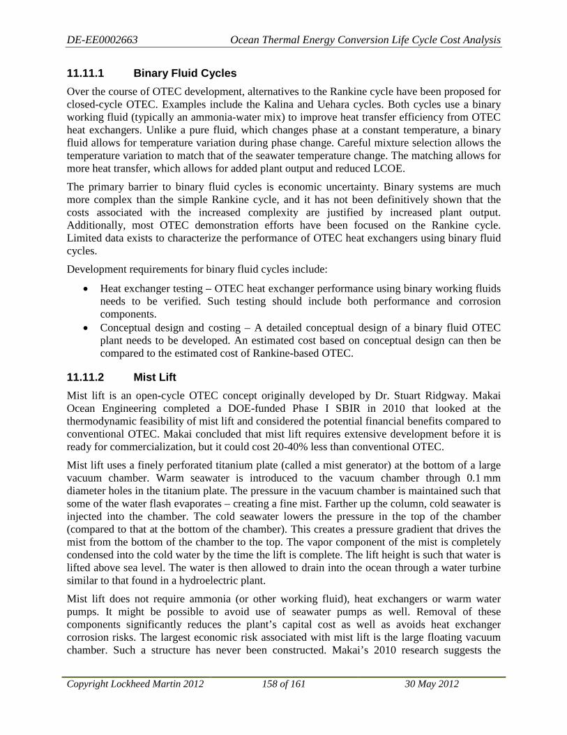
DE-EE0002663 Ocean Thermal Energy Conversion Life Cycle Cost Analysis
Copyright Lockheed Martin 2012 158 of 161 30 May 2012
11.11.1 Binary Fluid Cycles Over the course of OTEC development, alternatives to the Rankine cycle have been proposed for closed-cycle OTEC. Examples include the Kalina and Uehara cycles. Both cycles use a binary working fluid (typically an ammonia-water mix) to improve heat transfer efficiency from OTEC heat exchangers. Unlike a pure fluid, which changes phase at a constant temperature, a binary fluid allows for temperature variation during phase change. Careful mixture selection allows the temperature variation to match that of the seawater temperature change. The matching allows for more heat transfer, which allows for added plant output and reduced LCOE.
The primary barrier to binary fluid cycles is economic uncertainty. Binary systems are much more complex than the simple Rankine cycle, and it has not been definitively shown that the costs associated with the increased complexity are justified by increased plant output. Additionally, most OTEC demonstration efforts have been focused on the Rankine cycle. Limited data exists to characterize the performance of OTEC heat exchangers using binary fluid cycles.
Development requirements for binary fluid cycles include:
• Heat exchanger testing – OTEC heat exchanger performance using binary working fluids needs to be verified. Such testing should include both performance and corrosion components.
• Conceptual design and costing – A detailed conceptual design of a binary fluid OTEC plant needs to be developed. An estimated cost based on conceptual design can then be compared to the estimated cost of Rankine-based OTEC.
11.11.2 Mist Lift Mist lift is an open-cycle OTEC concept originally developed by Dr. Stuart Ridgway. Makai Ocean Engineering completed a DOE-funded Phase I SBIR in 2010 that looked at the thermodynamic feasibility of mist lift and considered the potential financial benefits compared to conventional OTEC. Makai concluded that mist lift requires extensive development before it is ready for commercialization, but it could cost 20-40% less than conventional OTEC.
Mist lift uses a finely perforated titanium plate (called a mist generator) at the bottom of a large vacuum chamber. Warm seawater is introduced to the vacuum chamber through 0.1 mm diameter holes in the titanium plate. The pressure in the vacuum chamber is maintained such that some of the water flash evaporates – creating a fine mist. Farther up the column, cold seawater is injected into the chamber. The cold seawater lowers the pressure in the top of the chamber (compared to that at the bottom of the chamber). This creates a pressure gradient that drives the mist from the bottom of the chamber to the top. The vapor component of the mist is completely condensed into the cold water by the time the lift is complete. The lift height is such that water is lifted above sea level. The water is then allowed to drain into the ocean through a water turbine similar to that found in a hydroelectric plant.
Mist lift does not require ammonia (or other working fluid), heat exchangers or warm water pumps. It might be possible to avoid use of seawater pumps as well. Removal of these components significantly reduces the plant’s capital cost as well as avoids heat exchanger corrosion risks. The largest economic risk associated with mist lift is the large floating vacuum chamber. Such a structure has never been constructed. Makai’s 2010 research suggests the

DE-EE0002663 Ocean Thermal Energy Conversion Life Cycle Cost Analysis
Copyright Lockheed Martin 2012 159 of 161 30 May 2012
vacuum chamber cost is significantly less than that of the heat exchangers and pumps, such that mist lift could be 20-40% cheaper than closed-cycle OTEC.
Although the thermodynamic feasibility of mist lift has been established, its technical characteristics are poorly understood. At present, no mathematical models or experimental data exist to describe how the mist lift process behaves and guide design. The major areas of research required to develop mist lift include:
• Mist generation – Mist lift process stability and efficiency is dependent on mist generator design. Only a single mist generator has been experimentally proven to work. Additionally, no experimental data exists to characterize mist behavior. Mathematical modeling and experimentation on a variety of mist generator configurations is required to understand the mist generation process. Then, a design can be created to produce a stable mist that maximizes power density and minimizes capital cost.
• Cold water injection – Makai’s research has shown that using the rising mist to “pump” the cold seawater results in a significant reduction in vacuum chamber size and cost. However, no research exists to characterize the pumping process required. Experimentation is required to determine mist lift pumping feasibility and efficiency.
• Water collection – Both the injected cold seawater and condensed mist must be collected at the top of the vacuum chamber so they can be discharged through the water turbine. Collection of a large quantity of freely rising water while accounting for wave-induced motions requires careful design.

DE-EE0002663 Ocean Thermal Energy Conversion Life Cycle Cost Analysis
Copyright Lockheed Martin 2012 160 of 161 30 May 2012
12 Conclusions The global OTEC thermal resource is a vast, available and sustainable energy source that can be harvested for the benefit of the U.S. and world. Most notably, unlike many alternative energy technologies, OTEC can provide continuous energy. Other solar powered energy collection systems only collect energy that falls directly on the collector like a solar thermal trough or photovoltaic panel. OTEC gathers thermal energy residing in the ocean’s warm surface layer that is renewed daily from the sunlight absorbed and stored by this very efficient thermal fluid system. Since seawater is a fluid, it can flow to the OTEC plant where the heat can drive the Rankine power cycle to generate large amounts of clean electrical energy. For plants that are not within cabling distance to shore, the electricity produced can be used to produce anhydrous ammonia. Anhydrous ammonia is an effective energy carrier and can be transported across oceans and delivered to consumers ashore. OTEC’s base-load feature provides a highly reliable energy system where economics are not dependent on variable weather conditions or the daily sun cycle.
This report provides a future costs estimate of OTEC power based on the most current OTEC development work and advancement projections. Close examination of OTEC capital, operations and sustainment expenses resulted in a detailed cost assessment associated with the long-term operation of OTEC plants that need to supply reliable energy for thirty or more years while operating in the harsh marine environment. Economies of scale favor large OTEC plants in rich resource locations. Projected near-term and longer-term technology and efficiency improvements provide a strong basis for predicted reductions in OTEC LCOE. It is conceivable that within 20 years of deployment of the first commercial OTEC plant, LCOE values could be driven well below 10 cents per kWh as the richest ocean thermal resource locations, new technologies and improved processes are employed.
The results presented in this report indicate that ocean thermal resource “quality” is a very important factor in the calculation of the LCOE. Any site selection process should place heavy emphasis on ocean thermal resource quality, which is effectively characterized by the average annual temperature differential. The results presented represent nominal and aggregate LCOE predictions. Site specific financial, economic, and environmental analysis is required for investment decisions and site specific plant configuration design.
During the course of this study and the previous work upon which it is based, several key aspects of OTEC were discovered or reinforced. First, OTEC harvests energy from a vast resource; the global OTEC resource is estimated to be between 3 and 7 TW. This needs to be emphasized in light of the widespread misconception that OTEC is a niche technology. OTEC has the capability to supply a significant portion of the world’s energy needs. Estimated global OTEC supply delivered to shore for Grid Connected and Energy Carrier OTEC plants is equivalent to 37,000 TWh/yr. In comparison, total global electricity consumption projected for 2035 is 31,917 TWh/yr52 and total U.S. energy use (includes residential, commercial, transportation and industry consumption for all energy sources) is projected to be 31,653 TWh/yr in 203553
52 http://www.eia.gov/oiaf/aeo/tablebrowser/#release=IEO2011&subject=0-IEO2011&table=15-IEO2011®ion=4-0&cases=Reference-0504a_1630
. Based
53 http://www.eia.gov/oiaf/aeo/tablebrowser/#release=EARLY2012&subject=0-EARLY2012&table=1-EARLY2012®ion=0-0&cases=full2011-d020911a,early2012-d121011b

DE-EE0002663 Ocean Thermal Energy Conversion Life Cycle Cost Analysis
Copyright Lockheed Martin 2012 161 of 161 30 May 2012
on the total global energy consumption projected to be 225,674 TWh/yr by 203554
In addition to size, OTEC does not compete with other critical resources such as water, land or food supplies. At most sites suitable for Grid Connected OTEC plants, OTEC has the ability to easily meet current and future local energy demands. With many communities struggling today to apply alternative power providing only a small percentage of the required power intermittently, OTEC stands out as a unique, game changing technology by providing 100% firm alternative electrical energy. For island nations that are highly dependent on imported energy sources, such as Hawai’i, OTEC presents a unique opportunity to break that dependence, produce 100% of their own electricity and potentially become an energy exporter. The coastal market alone (25,367 Terawatt-hours per year of capacity) is sufficiently large enough to justify and support a significant OTEC industry, one that expands and improves over decades.
, the estimated OTEC supply could provide up to 16% of the global energy demand.
It is the opinion of the contributors to this study and report that the vast, virtually untapped ocean thermal resource and LCOE values predicted in this study present an exciting OTEC commercialization opportunity. OTEC commercialization represents a tremendous opportunity to develop an alternative, non-carbon based, renewable energy source that can provide stable, continuous energy. The study team recommends pursuing projects addressing one or more of the areas for future studies in furtherance of OTEC commercialization.
54 http://www.eia.gov/forecasts/ieo/index.cfm
Related Documents


