Nyadi Hydropower Limited (NHL) GEOTECHNICAL BASELINE REPORT (GBR) OF NYADI HYDROPOWER PROJECT (30MW) GBR Report September, 2011 Hydro Consult Pvt. Ltd.

Welcome message from author
This document is posted to help you gain knowledge. Please leave a comment to let me know what you think about it! Share it to your friends and learn new things together.
Transcript

Nyadi Hydropower Limited (NHL)
GEOTECHNICAL BASELINE REPORT (GBR) OF NYADI HYDROPOWER PROJECT (30MW)
GBR Report
September, 2011
Hydro Consult Pvt. Ltd.

Nyadi Hydropower Limited (NHL)
Buddha Nagar, Kathmandu, Nepal
GEOTECHNICAL BASELINE REPORT “GBR” OF NYADI HYDROPOWER PROJECT
GBR Report
September, 2011
Hydro Consult Pvt. Ltd. P.O.Box:14408 Kathmandu, Nepal
Email: [email protected]
Quality Control Signature Date
Prepared by: T. C. Bhatta Checked by: Recommended by: Basanta Bagale Approved by: Bharat Raj Panday

Nysdi Hydropower Limited Geotechnical Baseline Report (GBR) of NHP
Hydro Consult Pvt. Ltd. i
TABLE OF CONTENTS Page no.
1. INTRODUCTION .................................................................................. 1
1.1 General ........................................................................................................................................................ 1
1.2 Purpose and Limitations ........................................................................................................................... 1
2. PROJECT DESCRIPTION .................................................................... 2
2.1 Project Location......................................................................................................................................... 2
2.2 Accessibility ................................................................................................................................................. 2
2.3 Project Layout ............................................................................................................................................ 2
3. GEOLOGICAL ASPECTS OF WORKS .............................................. 3
3.1 Regional Geology ....................................................................................................................................... 3
3.1.1 Kuncha Formation....................................................................................................................................... 3
3.1.2 Garnet Schist ................................................................................................................................................ 3
3.1.3 Graphitic Schist ............................................................................................................................................ 4
3.1.4 Carbonates.................................................................................................................................................... 4
3.1.5 Kyanite Schists and Quartzites ................................................................................................................ 4
3.1.6 Banded and Augen Gneisses..................................................................................................................... 4
3.2 Tectonic Setting and Seismicity .............................................................................................................. 5
3.3 In-situ stress conditions ........................................................................................................................... 8
3.4 Geology at Project Sites .......................................................................................................................... 9
3.4.1 Engineering Geological Mapping .............................................................................................................. 9
3.4.2 Site Conditions .......................................................................................................................................... 10
3.4.3 Subsurface Investigation........................................................................................................................... 11
3.4.3.1 Geophysical Surveys ................................................................................................................................. 11
3.4.3.2 Core drilling ................................................................................................................................................ 12
3.4.3.2.1 In-Situ Testing ............................................................................................................................................ 13
3.4.3.2.2 Laboratory Testing ................................................................................................................................... 15
3.4.3.2.3 Intact rock strength test .......................................................................................................................... 15
3.4.3.3 Test pits ....................................................................................................................................................... 18
3.4.4 Engineering Geology of Project Area .................................................................................................. 19
3.4.4.1 Headworks .................................................................................................................................................. 19
3.4.4.2 Intake and Inlet Portal .............................................................................................................................. 19
3.4.4.3 Diversion Tunnel, Inspection Tunnel and Flushing Tunnel ............................................................. 20
3.4.4.4 Underground Settling Basin .................................................................................................................... 20
3.4.4.5 Headrace tunnel (HRT) ........................................................................................................................... 21

Nysdi Hydropower Limited Geotechnical Baseline Report (GBR) of NHP
Hydro Consult Pvt. Ltd. ii
3.4.4.6 Naiche Adit ................................................................................................................................................. 22
3.4.4.7 Surge Shaft .................................................................................................................................................. 23
3.4.4.8 Outlet portal .............................................................................................................................................. 23
3.4.4.9 Penstock alignment ................................................................................................................................... 24
3.4.4.10 Drop Shaft and horizontal penstock tunnel ....................................................................................... 24
3.4.4.11 Underground Powerhouse ..................................................................................................................... 25
3.4.4.12 Tailrace Tunnel .......................................................................................................................................... 26
3.4.4.13 Access Tunnel to Underground Powerhouse ................................................................................... 26
4. ROCK MASS CLASSIFICATION ..................................................... 27 4.1 General ...................................................................................................................................................... 27
4.2 Excavation method .................................................................................................................................. 29
4.3 Geologic/Geomechanic Influences ...................................................................................................... 29
4.3.1 Geological Influence due to high overburden cover ........................................................................ 29
4.3.2 Infuelence of mineral constituent in rock ........................................................................................... 29
5. GROUND CHARACTERISATION AND BASELINES .................. 31 5.1 Baseline Conditions for Headworks ................................................................................................... 32
5.1.1 Geotechnical Baseline Conditions ........................................................................................................ 32
5.1.2 Hydrogelogic Baseline Conditions ........................................................................................................ 32
5.2 Baseline Condition for Intake Tunnel ................................................................................................. 32
5.2.1 Geotechnical Baseline Conditions ........................................................................................................ 32
5.2.2 Hydrogelogic Baseline Conditions ........................................................................................................ 32
5.3 Baseline Condition for Flushing Tunnel/Inspection Tunnel ........................................................... 32
5.3.1 Geotechnical Baseline Conditions ........................................................................................................ 32
5.3.2 Hydrogelogic Baseline Conditions ........................................................................................................ 32
5.4 Baseline Condition for Diversion Tunnel .......................................................................................... 32
5.4.1 Geotechnical Baseline Conditions ........................................................................................................ 32
5.4.2 Hydrogelogic Baseline Conditions ........................................................................................................ 33
5.5 Baseline Condition for Settling Basin .................................................................................................. 33
5.5.1 Geotechnical Baseline Conditions ........................................................................................................ 33
5.5.2 Hydrogelogic Baseline Conditions ........................................................................................................ 33
5.6 Baseline Condition for Headrace Tunnel .......................................................................................... 33
5.6.1 Geotechnical Baseline Conditions ........................................................................................................ 33
5.6.2 Hydrogelogic Baseline Conditions ........................................................................................................ 33
5.7 Baseline Condition for Surge shaft ...................................................................................................... 33
5.7.1 Geotechnical Baseline Conditions ........................................................................................................ 33

Nysdi Hydropower Limited Geotechnical Baseline Report (GBR) of NHP
Hydro Consult Pvt. Ltd. iii
5.7.2 Hydrogelogic Baseline Conditions ........................................................................................................ 33
5.8 Baseline Condition for Penstock ......................................................................................................... 34
5.8.1 Geotechnical Baseline Conditions ........................................................................................................ 34
5.8.2 Hydrogelogic Baseline Conditions ........................................................................................................ 34
5.9 Baseline Condition for Drop Shaft ...................................................................................................... 34
5.9.1 Geotechnical Baseline Conditions ........................................................................................................ 34
5.9.2 Hydrogeologic Baseline Conditions ..................................................................................................... 34
5.10 Baseline Condition for Underground Powerhouse ......................................................................... 34
5.10.1 Geotechnical Baseline Conditions ........................................................................................................ 34
5.10.2 Hydrogelogic Baseline Conditions ........................................................................................................ 34
5.11 Baseline Condition for Tailrace Tunnel ............................................................................................. 35
5.11.1 Geotechnical Baseline Conditions ........................................................................................................ 35
5.11.2 Hydrogelogic Baseline Conditions ........................................................................................................ 35
5.12 Access Tunnel to Underground Powerhouse .................................................................................. 35
5.12.1 Geotechnical Baseline Conditions ........................................................................................................ 35
5.12.2 Hydrogelogic Baseline Conditions ........................................................................................................ 35
6. PREVENTION / RESOLUTION OF DISPUTES ............................. 36

Nysdi Hydropower Limited Geotechnical Baseline Report (GBR) of NHP
Hydro Consult Pvt. Ltd. iv
LIST OF FIGURES Page no.
Figure 1 Geological map of Nepal showing project location 38
Figure 2 General layout of Nyadi Hydropower Project, Lamjung 39
Figure 3 Regional geological map of the Nyadi Hydropower Project area 40
Figure 4 Geological cross-section of the Nyadi Hydropower area showing main lithological units 41
Figure 5 Part of the map of Kaligandaki–Marsyangdi area (Colchen et al. 1981) 42
Figure 6 Assumed uniform seismic zones in Nepal (After BCDP, 1994) 43
Figure 7 Seismic hazard map of Nepal 43
Figure 8 Drilling and ERT line locations at Headworks area and Naiche adit 44
Figure 9 Drilling and ERT line locations at Powerhouse area 45
Figure 10 Geological plan of Headworks area 46
Figure 11 Geological Profile of Headrace tunnel 47
Figure 12 Geological plan of powerhouse area 48
Figure 13 Geological plan of Naiche area 49
Figure 14 Joint rossette showing the HRT alignment 50
Figure 15 Test pit location of construction materials 51
Figure 16 View of headrace tunnel level between Naiche adit and Nana 52
LIST OF TABLES Page no.
Table 1 Main lithological subdivisions in the Project area ............................................................................... 5
Table 2 Properties of weak zones ......................................................................................................................... 6
Table 3 Summary of larger magnitudes earthquakes of Nepal ....................................................................... 7
Table 4 Seismic design parameter for different hydropower projects of Nepal ........................................ 7
Table 5 Summary of measured Stress conditions in some Hydrpower projects in Nepal ...................... 8
Table 6 List of geological drawings ..................................................................................................................... 10
Table 7 Geological distribution in project area ............................................................................................... 10
Table 8 List of electrical resistivity survey sections conducted on July 1999 .......................................... 12
Table 9 Details of 2D-ERT surveys conducted on Sep. – Oct. 2007 ......................................................... 12
Table 10 Boreholes summary data ...................................................................................................................... 13
Table 11 In-situ test result ..................................................................................................................................... 13
Table 12 Summary of categorically performed laboratory examination .................................................... 15
Table 13 Laboratory test result............................................................................................................................ 15
Table 14 Laboratory test result............................................................................................................................ 17
Table 15 Laboratory test result............................................................................................................................ 18

Nysdi Hydropower Limited Geotechnical Baseline Report (GBR) of NHP
Hydro Consult Pvt. Ltd. v
Table 16 Discontinuity measurement at intake area ....................................................................................... 19
Table 17 Projected rock types along the tunnel alignment ........................................................................... 22
Table 18 Discontinuity measurement at Surge shaft area .............................................................................. 23
Table 19 Discontinuity measurement at outlet portal .................................................................................... 24
Table 20 Discontinuity measurement at powerhouse area ........................................................................... 26
Table 21 Estimation of rock mass quality based on surface mapping in the Headworks area and Desander area ............................................................................................................................................................ 27
Table 22 Estimation of rock mass quality based on surface mapping at Intake area ............................... 27
Table 23 Rock mass distribution along the Headrace tunnel ...................................................................... 27
Table 24 Estimation of rock mass quality based on surface mapping at Outlet portal .......................... 27
Table 25 Estimation of rock mass quality based on surface mapping in the Powerhouse area ........... 28
Table 26 Estimation of rock mass quality based on surface mapping in the Surge Shaft area ............. 28
Table 27 Estimation of rock mass quality based on surface mapping in the Tailrace tunnel area ...... 28
Table 28 Estimation of rock mass quality based on surface mapping at Naiche adit portal ................. 28
Table 29 Estimation of rock mass quality based on surface mapping in the Access tunnel area ........ 28
Table 30 Mineral content analysis of rock core samples .............................................................................. 30
Table 31 Techniques applied in obtaining geological and geotechnical information ............................... 31
ANNEX Annex– A1: Figures

Nysdi Hydropower Limited Geotechnical Baseline Report (GBR) of NHP
Hydro Consult Pvt. Ltd. vi
List of abbreviations
2D
ASTM
BPC
BPCH
DCPT
DH
ERT
FS
FSR
GBR
GoN
HRT
NHP
NHL
km
km2
m
m2
m3/s
masl
MBT
MCT
MPa
MW
NEA
NGI
PRoR
PSD
RQD
RMR
RoR
TBM
UCS
UFS
VDC
Two-dimensional
American Society of Testing of Materials
Butwal Power Company
BPC Hydroconsult
Direct Cone Penetration Test
Drill Hole
Electric Resistivity Tomography
Feasibility Study
Feasibility Study Report
Geological Baseline Report
Government of Nepal
Headrace Tunnel
Nyadi Hydropower Project
Nyadi Hydropwer Limited
Kilometer
Square Kilometer
Meter
Square Meter
Cubic meter per second
Meters above mean sea level
Main Boundary Thrust
Main Central Thrust
Mega Pascal
Mega Watt
Nepal Electrical Authority
Norwegian Geotechnical Institute
Peaking Run-of-River
Particle Size Distribution
Rock Quality Designation
Rock Mass Rating
Run-off-the-river
Tunnel Boring Machine
Uniaxial Compressive Strength
Updated Feasibility Study
Village Development Committee

Nysdi Hydropower Limited Geotechnical Baseline Report (GBR) of NHP
Hydro Consult Pvt. Ltd. 1 September, 2011
1. INTRODUCTION
1.1 General The Nyadi Hydropower Project (NHP) is a run-of-river type project, located in Lamjung District of Western Development Region of Nepal.
It was first identified in 1993 during the preparation of the Small Hydropower Master Plan. The study project was funded jointly by the Nepal Electricity Authority (NEA) and the German Development Agency (GTZ).
Following the JV Agreement between Butwal Power Company (BPC) and Lamjung Electricity Development Company (LEDCO) to develop Nyadi Hydropower Project on January 2007, BPC Hydroconsult had undertaken a revision and update of feasibility study of the Nyadi Hydropower Project (NHP) for Nyadi Hydropower Limited (NHL) from March 2007 to April 2010. Since, April 2010 Hydroconsult Pvt. Ltd is undertaking the update of feasibility study and detail design study.
In latest development, the probabilities of tapping the tail water flow of nearest tributaries Siuri Khola (Siuri Khola Hydropower Project) has been explored and decided to use Siuri tailrace water to make the project financially viable. Initially optimum project capacity was calculated as 20.0 MW based on Nyadi River. As per latest optimization using the additional tail water flow of Siuri Khola project, the project has an installed capacity of 30 MW.
1.2 Purpose and Limitations The purpose of Geotechnical Baseline Report (GBR) is to provide a description of anticipated ground conditions for design and construction of surface and subsurface facilities associated with the proposed project in terms of geotechnical baseline informtions. The GBR establishes baseline informations to evaluate the requirement for project works during preparation of bids. The interpretations and baseline statements contained in this GBR provide a contractual definition of ground condition that the contractor is expected to encounter during construction.
This GBR report is the outcome of the summary derived from the various related reports of different phase of investigations. However, there are still some limitations regarding baseline informations particularly for underground structures. Till this stage, geological conditions of undereground structures like approach intake tunnel, settling basin, headrace tunnel, drop shaft, powerhouse, tailrace tunnel, and access tunnel are interpretated on surface manifestation of rock discountinuity data and respective geotechnical data are inferred in reference to investigation data obtained from nearby headworks, surgeshaft area, powerhouse area and tailrace tunnel.

Nysdi Hydropower Limited Geotechnical Baseline Report (GBR) of NHP
Hydro Consult Pvt. Ltd. 2 September, 2011
2. PROJECT DESCRIPTION This report provides general overview of the project layout, components and geology. All the project descriptions are based on current updated feasibility study report. The drawings kept in Annex-A1 in this GBR are in schematic form and are not to scale. The Tender Drawings shall be considered for bidding purpose.
2.1 Project Location Nyadi Hydropower Project is located in Bahun Danda Village Development Committee (VDC), at Lamjung District, Western Development Region of Nepal. The proposed project lies between 84° 25' 25” E, 28°19' 20” N to 84° 28' 00” E, 28°21' 07” N ( Figure 1in Annex A1).
The proposed dam site is located across the Nyadi River is about 3 km upstream of the Naiche Village (Ward No. 2), which is approximately 7 km upstream of the confluence of Nyadi Khola with the Marsyangdi River. The powerhouse is located about 3 km downstream from Naiche at the village of Thulobesi, (Ward No. 7).
2.2 Accessibility The project lies in the Lumjung District and the nearest town is Besisahar, which is the Head Quarter of the Lumjung District. Besisahar is about 173 km from Kalanki-Kathmandu. The first 129 km section of route via Mungling to Dumre lies in Prithivi Rajmarg and rest 44 km from Dumre to Besisahar is linked by Bhanubhakta Highway. Similarly, from Besisahar to Thakanbesi lies in Besisahar-Chame district road and is about 17 km via Khudi Bazar and Bhulbule. The feeder road connecting the powerhouse area and headwork area is about 4.5 km and 10.6 km from bridge at Thakanbesi.
2.3 Project Layout The project is a run-of-river (ROR) type. The gross head and design discharge of the project are estimated at 333.90 m and 11.08 m3/ s respectively. The general project layout is shown in Figure 2 in Annex A1. The project comprises:
• Concrete weir with frontal intake and two radial bottom Sluice Gates,
• Orifice type Frontal intake (Himalayan Intake) on the right bank,
• Approach intake tunnel of about 57 m long with diameter 3 m of inverted D-shape,
• Underground settling basin cavern with diamension 128 m×8 m×10.3 m,
• Inspection/access tunnel with diameter 2 m of inverted D- shaped,
• Headrace Tunnel of about 3937 m long with diameter 3.2 m of inverted D-shape,
• NaicheTunnel adit of about 176 m long with diameter 3.2 m of inverted D-shape,
• Surge shaft with height 29.60 m and internal diameter 5 m,
• Surge shaft adit of about 65 m long with diameter 3.2 m of inverted D-shape,
• Ventilation adit of about 30 m long with diameter 3.2 m of inverted D-shape,
• Drop shaft of about 180 m height with diameter 1750 mm
• Underground Powerhouse with dimension (L× B × H) 53.25 m × 14.20 m × 14.90 m on the right bank.
• Tailrace Tunnel of about 225 m long with diameter 3.6 m of inverted D-shape,
• Access Tunnel to the powerhouse of about 130 m long with 4.8 m diameter of inverted D-shape.

Nysdi Hydropower Limited Geotechnical Baseline Report (GBR) of NHP
Hydro Consult Pvt. Ltd. 3 September, 2011
3. GEOLOGICAL ASPECTS OF WORKS
3.1 Regional Geology The rocks of the Project area (Figure 3 and Figure 4 in Annex A I) are classified into two large units named as the Lesser Himalayan succession and the Higher Himalayan succession. The essential difference between the two rock successions is in their lithostratigraphy. The Higher Himalayan succession is made up of medium- to high-grade metamorphic rocks such as sillimanite gneisses, kyanite schists and gneisses, and augen and banded gneisses, whereas the Lesser Himalayan succession contains essentially phyllites, quartzites, garentiferous schists, graphitic schists, and marbles. The Higher Himalayan rocks overlie the Lesser Himalayan rocks along the Main Central Thrust (Figure 3 & Figure 4 in Annex A I).
The Lesser Himalayan metamorphic rocks in the Marsyangdi valley constitute a rather monotonous and thick succession, which was called Série de Kunchha by Bordet (1961). The Project area lies in the north flank of the Kunchha–Gurkha Anticlinorium zone of Ohta et al. (1973) or Kunchha–Gorkha Anticlinorium of Pêcher (1977). The rocks belong to the Midland Metasediment Group and Himalayan Gneisses of Arita et al. (1973). A large portion of the present area belongs to the Kuncha Formation, Fagfog Quartzite, Dandagaon Phyllites, and Benighat Slates of Stöcklin (1980), whereas the area above the MCT is represented by his Bhimphedi Groups of rocks with augen and banded gneisses. Colchen et al. (1981, 1986) made a geological map of the Kaligandaki–Marsyangdi area. Part of the map is depicted in Figure 5 in Annex A I.
The main lithological units in the Project area are the following from south to north, respectively:
− Kuncha Formation, − Garnet Schist, − Graphitic Schist, − Carbonates, − Kyanite Schists and Quartzites, and − Banded and Augen Gneisses.
3.1.1 Kuncha Formation
The rocks of the Kuncha Formation are extensively distributed in the area south of Khudi. They are delimited in the north by pale yellow quartzites and alternating grey-green garnetiferous schists and quartzites. When weathered, the Kuncha Formation yields orange, red, and yellow-brown coloured soil.
The Kuncha Formation is a thick (more than 4 km) succession of green-grey, dark grey, and bluish grey phyllite, phyllitic metasandstone, granular phyllite, and quartzite. Sometimes, tiny muscovite flakes (0.5–1 mm) are observed along the foliation plane in phyllite and metasandstone. Rarely, pebbly phyllite with stretched clasts is present. Occasionally, a few amphibolite bands are also found in it.
3.1.2 Garnet Schist
The rocks between Khudi and Nyadi Bazaar are represented by garnet-muscovite-biotite schists and quartzites. They give rise to light grey to grey coloured soil. The size of garnets in the schist varies widely. Often, the garnets are from 1 to 2 mm in diameter, but may reach up to 6 mm. Frequently rolled garnets of 2–5 mm in diameter are also seen. They are surrounded by about 1 cm long lens-shaped biotite and muscovite envelopes. Generally, grey and dark grey schist and quartzite bands alternate with each other and their thickness varies from 10 to 30 cm and rarely exceeds 5 m. There are also a few bands (1–2 m thick) of graphitic schist and white quartzite. Numerous generations of quartz veins are common in the schist and often they are stretched and boudinaged. Rare pegmatite veins with tourmaline are also seen.

Nysdi Hydropower Limited Geotechnical Baseline Report (GBR) of NHP
Hydro Consult Pvt. Ltd. 4 September, 2011
The grade of metamorphism in this unit varies widely. Around Khudi, dark grey slate, phyllite, and garnetiferous schist are observed alternating with crystalline dolomite, marble, and calcareous quartzite, whereas in the area north of Tunikharka large kyanite crystals are encountered in the quartz veins.
3.1.3 Graphitic Schist
The succession of garnetiferous schist is followed upsection by intensely deformed and gently dipping zone of graphitic schist. When weathered, the graphitic schist gives rise to orange, red, brown, and grey soil.
In the graphitic schist unit, grey, green-grey, light grey, and white calcareous schist is alternating with light grey, green-grey, and white calcareous quartzite, dolomitic marble, and dark grey to black graphitic schist. Quartz and calcite veins of several generations ramify the rocks. In the area NW of Nyadi Bazaar, kyanite blades are seen in the graphitic schist.
3.1.4 Carbonates
In the area NW of Nyadi Bazaar, a thick carbonate band is observed in the vicinities of Kaule and Usta. In this area, the calcareous quartzite and dolomite bands are from 10 cm to 1.5 m thick and are alternating with 1 mm to 50 cm thick schist bands. Light grey, white, and cream coloured quartzite bands are up to 5 m thick. Generally, schist, quartzite, and marble bands are alternating.
3.1.5 Kyanite Schists and Quartzites
The Main Central Thrust (MCT) abruptly overrides the carbonates (Figure 3, Figure 4 & in Figure 5 Annex A1) and brings with it grey and dark grey, parallel-banded, coarse-grained, schist and quartzite containing kyanite, garnet, biotite, K-feldspar, muscovite, and quartz. Generally, the rock is massive to blocky. In the schist, kyanite and garnet crystalloblasts range in size from less than 1 mm to 5 mm.
3.1.6 Banded and Augen Gneisses
The banded and augen gneisses occupy most of the area north of Bahundanda and east of Thulibesi. They are represented by highly deformed and disrupted leucocratic bands as well as lenses containing feldspar, quartz, and muscovite alternating with melanocratic bands of biotite, tourmaline, and hornblende. They exhibit flow structures and many small-scale folds.
Therefore, the following rock units are separated on the basis of stratigraphy and lithology (Table 1 and Figure 3).

Nysdi Hydropower Limited Geotechnical Baseline Report (GBR) of NHP
Hydro Consult Pvt. Ltd. 5 September, 2011
Table 1 Main lithological subdivisions in the Project area
Rock unit Lithology Thickness, m Age
Banded and augen gneisses
Grey to dark grey feldspathic schist and banded gneiss with bands of quartzite; sporadically augen gneisses and highly lineated gneisses are also observed. Garnet and kyanite abundant
>2000
Precambrian
Kyanite schist and quartzite
Light grey to dark grey, intensely deformed, and folded schists and quartzites containing kyanite and garnet
800 – 1000
--------------------------------------------Main Central Thrust (MCT)----------------------------------------------------------
Carbonates Grey to light grey, very thick-banded, massive to laminated marble with mica parting and schist bands with garnet and kyanite
600 – 800
Precambrian Graphitic schist
Thin- to thick-banded, light grey to grey, laminated quartzite with mica partings, and bands of feldspathic schist, garnetiferous biotite schist and gneiss with sporadic kyanite zone
400 – 500
Garnet schist and quartzite
Dark grey feldspathic schist, banded gneiss, and laminated quartzite with garnet and rate kyanite
>2000 m
3.2 Tectonic Setting and Seismicity Thrust and faults are major tectonic boundaries for seismicity. The Main Central Thrust (MCT), Main Boundary Thrust (MBT) and Himalayan Frontal Thrust (HFT) are major tectonic boundaries in the Nepal Himalayas. Therefore, proximity to such structural features is important while assessing the seismicity of the Project.
Main Central Thrust (MCT)
The MCT is a major lithological, metamorphic and structural discontinuity, which passes about 2 km south of the project area. It is represented by high-grade metamorphic rock sequences formed in ductile condition in deeper parts of the crust. The MCT was active during the early phases of Himalayan orogeny but it is now considered to be inactive. The largest earthquake of 8 Rector Scale of magnitudes was recorded in 1833 around the MCT area. Based on both micro seismic and geodetic data of the Central Nepal the more frequent medium sized earthquakes of 6 to 7 Rector Scale of magnitudes are confined either to flat decollment beneath the Lesser Himalayas or the upper part of the middle crustal ramp (Pandey et. al., 1995). The ramp is occurring between 10 and 20 km depth below the foothills of the Higher Himalayas in the south of the MCT surface exposures.
The project area lies on the northern of the Main Central Thrust (Figure 3 and Figure 5). The project area falls in the seismicity zone-2 according to Seismicity Hazards and Risk Mapping of Nepal and is close to the border of the northern seismicity zone-3, Figure 6.
Nepal has experienced several large earthquakes over the past centuries that have resulted in substantial property damage and loss of life. Earthquakes of larger magnitudes occurred in Nepal are summarized in Table 3.

Nysdi Hydropower Limited Geotechnical Baseline Report (GBR) of NHP
Hydro Consult Pvt. Ltd. 6 September, 2011
Weak or shear zones
During the detailed geological mapping six major weak or shear zones were spotted in the east of Thulobesi, upstream of the Naiche village, downstream of the confluence with the Doranda (Siuri) Khola (Drawing No. 1220/02/20G01,2,3, Appendix K). These weak zones are characterised mainly by an alternation of closely spaced (1–8 cm) fractured gneisses and schists with sporadic 5 to 50 cm thick fault gouge. In the weak zone situated about 400 m downstream from the confluence with the Doranda (Siuri) Khola, the percentage of mica is higher than in other weak zones.
All weak zones run parallel to the foliation plane and oblique to the headrace tunnel alignment. The thickness of weak zones varies from 3 to 50 m. Apart from the above mentioned major weak zones, there are also other 10–50 cm thick weak or shear zones along the foliation. Similarly, there are also 1 to 3 m thick steeply dipping faults running parallel to the joint planes. The total affected length of shear or weak zones in the headrace tunnel alignment (having a total length of 4,240 m) is estimated at 130 m, which is about 3% of the total tunnel length.
Some properties of the weak zones and steep faults are given in Table 2.
Table 2 Properties of weak zones
Location of weak zone Lithology Orientation
(Strike/dip)
Thickness (m)
East of Thulibesi Highly weathered, grey, thinly foliated, weak schist with intercalation of quartzite
S60۫ºE/32º NE 15
About 600 m downstream from the confluence of Nyadi and Doranda Khola (Ch. 1742–1748 m)
Highly weathered garnet-biotite schist intercalated with banded gneiss
S59ºE/41ºNE 5
About 400 m downstream of confluence of Nyadi and Doranda Khola, on the right bank (Ch. 1380–1469 m)
5 m thick highly fractured zone, 30 m thick pale yellow, moderate weathered, crenulated, micaschist, and 15 m thick sheared schist with clay gouge
S59ºE/50ºNE 5+30+15
Around the confluence of Nyadi and Doranda Khola (Ch 699–738 m, 987–1000 m, 1095–1108 m)
Yellowish grey to yellowish brown, highly weathered, garnet-mica schist with clay gouge
S60ºE/40ºNE 3+ 5+15
Between intake and surge shaft section (Ch 681 m, 1072 m, 1305 m, 1412 m, 1938 m, 3857 m)
1 to 3 m thick steeply dipping fault with highly fractured zone
N10ºE/80ºE 2x 6

Nysdi Hydropower Limited Geotechnical Baseline Report (GBR) of NHP
Hydro Consult Pvt. Ltd. 7 September, 2011
Table 3 Summary of larger magnitudes earthquakes of Nepal
S.N. Location of Epicenter Year Magnitudes Approx. distance from the project
1. Udaypur, Eastern Nepal 1988 6.6 280 km east
2. Chainpur, Eastern Nepal 1934 8.3 300 km east
3. Dolakha, Central Nepal 1834 6.8 180 km east
4. Sindhupalchok, Central Nepal 1833 8.0 140 km east
5. Kaski, Western Nepal 1954 6.4 50 km west
6. Myagdi, Western Nepal 1936 7.0 90 km west
7. Bajhang, Far Western Nepal 1980 6.5 280 km west
8. Dharchula, Far Western Nepal 1966 6.1 400 km west
9. Dharchula, Far Western Nepal 1966 6.3 410 km west
10. Dharchula, Far Western Nepal 1916 7.3 420 km west
The latest recorded earthquake of 6.4 magnitudes in 1954 was Kaski situated about 50 km west from the Project area. Similarly, the Nepal-Bihar earthquake (Chainpur) of 8.3 magnitudes occurred in 1934, which is located about 300 km in the east direction. The earthquake destroyed more than 80,000 houses in Nepal. Likewise, the closest earthquakes to the Project area are Dolakha in 1834, Sindhupalchok in 1833, Chainpur in 1934, and Udayapur in 1988 (Table 3).
Chainpur and Udayapur earthquakes were more destructive earthquakes in Eastern Nepal based on historic data.
The seismic coefficients recommended based on deterministic approach and probabilistic approaches for different projects in Nepal are as follows (Table 4):
Table 4 Seismic design parameter for different hydropower projects of Nepal
S.N. Name of Project Study conducted by Recommended Seismic Coefficient
1. Arun III JICA 0.12 g for all components design
2. Upper Arun MKE, Lahmeyer, TEPSCO & NEPECON
0.12 g for dam
0.062 for underground powerhouse
3. Mulghat (Tamur) Electrowatt 0.20 g
4. Tamur-Mewa MSHP, CIWEC MDE = 0.25 g – 0.24 g
OBE = 0.16 g – 0.15 g
5. Dush Koshi I MHSP, CIWEC MDE = 0.37 g
OBE = 0.22 g – 0.23 g

Nysdi Hydropower Limited Geotechnical Baseline Report (GBR) of NHP
Hydro Consult Pvt. Ltd. 8 September, 2011
S.N. Name of Project Study conducted by Recommended Seismic Coefficient
6. Kaligandaki Morrison-Knudsen OBE = 0.30 g
7. Khimti I Beca Carter Hollings & Ferner
OBE = 0.25 g for Type I soil (BCDP)
OBE = 0.30 g for Type II soil (BCDP)
8. Middle Marsyandi Statkraft Groner & NEA MDE = 0.33 g – 0.32 g for soil
= 0.25 for bedrock
OBE = 0.29 g – 0.27 g for soil
= 0.22 for bedrock
9. Upper Tama Koshi Norconsult MDE = Expected PGA 5.05 (m/s2) for 500 yrs.
OBE = Expected PGA 3.46 (m/s2) for 200 yrs.
Note: OBE = Operation Basis Earthquake, MDE = Maximum Design Earthquake, PGA = Peak ground acceleration.
The project area falls in the Class having fair to high seismic risk; since according to the Nepalese and Indian Standards, the horizontal seismic coefficient for the dam has been estimated in 0.13 – 0.16.
3.3 In-situ stress conditions Empirical in situ stress conditions at surge shaft adit and Naiche adit are being planned to be carried out soon. At this stage theoretical assumption and references from near by project have been used. In this context, the present study report depicted the information on the in-situ stress results of the other hydropower projects as summarized in Table 5 Summary of measured Stress conditions in some Hydrpower projects in Nepal
(Table cited from Feasibility study report 1998). The Middle Marsyangdi hydropower project is the nearest to the Nyadi Hydropower project.
Table 5 Summary of measured Stress conditions in some Hydrpower projects in Nepal
Name of
project
Arun project Middle Marsyangdi project Karnali-Chisapani project
Stress category
Stress value (MPa)
Dip amount
Dip direction
Stress value (MPa)
Dip amount
Dip direction
Stress value (MPa)
Dip amount
Dip direction
σ1 10.0 880 1240 5.5 900 00 6.7 640 3530
σ2 3.0 10 2460 3.75 00 200 3.3 250 1900
σ3 3.0 20 2360 2.75 00 1100 2.9 750 980

Nysdi Hydropower Limited Geotechnical Baseline Report (GBR) of NHP
Hydro Consult Pvt. Ltd. 9 September, 2011
3.4 Geology at Project Sites A short description of the rock units which lie in the project area is the following.
Banded and Augen Gneisses
The banded and augen gneisses are well-exposed at Nana, Naiche, and in the banks of the Nyadi River at the Naiche suspension bridge (Figure 3). The schist is dominant in and around Nana (Surge shaft area) whereas gneisses are abundant at Naiche and in the intake area. The rocks of this unit are represented by grey to dark grey, coarse-grained, thickly banded to massive, medium strong to strong schists and gneisses. Kyanite and garnet are abundant in this rock unit.
The contact with the underlying kyanite schist and quartzite is a gradual transition. The thickness in the type area is more than 2000 m. The distribution of different rock types is schists with 40–50% and Gneisses with 50–60%.
This rock unit is expected throughout the tunnel alignment, from intake to surge shaft. Expected rock quality of this formation is fair to good. However, due to a high percentage of mica and schist bands, rock quality may be degrading in some sections of the tunnel alignment.
Kyanite Schists and Quartzites
The schists and quartzites are well exposed in the both banks of the Nyadi River below Tarachok, east of Thulibesi, and below Nana. They are composed essentially of very thick-banded to massive, medium- to coarse-grained, grey, strong quartzite and medium strong schist. The quartzite is frequently laminated (Figure 3). Garnet is abundant. The total thickness of this unit is about 800–1,000 m. This rock unit will not be encountered in the headrace tunnel and surge shaft area.
The distribution of different rock types is schist with 40 – 50% and quartzite with 50 – 60%.
Palaeochannel deposits
One of the unique features of the Project area is the occurrence of a thick (from 50 to about 200 m) palaeochannel deposits (Figure 3 & Figure 4). It is distributed around Nana (at the surge shaft, penstock, and powerhouse), west of Bhirpustung, around Thulibesi, in the vicinity of Bahundanda and Tarachok. The deposits contain large (up to 5 m and more) subangular boulders of augen gneiss, banded gneiss, and marble.
They also contain fine (sandy to silty), light grey to white matrix which is moderately compact. The proportion of matrix and the clasts varies widely. Generally the matrix constitutes to about 50 to 60% of the volume. There are also sporadic mudstone lumps in the palaeochannel deposits, especially in the area west of Thulibesi and Bahundanda.
Since the palaeochannel deposits are loose, they may pose serious problems while constructing a tunnel through them.
3.4.1 Engineering Geological Mapping
Surface geological mapping of the project area is carried out in 1998 in the first phase. During the next phase of updating the Detail Project Report, those geological maps are further verified and updated as par the latest project layout. Following geological maps are prepared for the project and are kept in Volume 4, Map and Drawings, Appendix K, Geological Maps. Bidderes can get real dimension and scale of the project components from those drawings.

Nysdi Hydropower Limited Geotechnical Baseline Report (GBR) of NHP
Hydro Consult Pvt. Ltd. 10 September, 2011
Table 6 List of geological drawings
Map Heading Drawing No.
GEOLOGICAL MAP OF PROJECT AREA Sheet 1 of 2 1220/02/20G01
GEOLOGICAL MAP OF PROJECT AREA Sheet 2 of 2 1220/02/10G02
STRUCTURAL GEOLOGY OF WATERWAYS 1220/02/10G03
GEOLOGICAL MAP Sheet 1-18 1220/02/20G05-1220/02/20G22
3.4.2 Site Conditions
The project as a whole is located in the Midland zone of Nepal. The Nyadi River has the side slopes of generally moderate to steep nature around the project area which is, in parts, forest covered, cultivated as well as barren. The both side at the dam site is very steep where the gneiss is exposed throughout the slope. Comparatively the right bank slope seems stable. There are patches of mass movement along the left bank slope.
The headrace tunnel passing through the Naiche and Nana village and conveys water from the settling basin to the surge tank. This hill divides the catchments between the Nyadi khola and the Marsyangdi valleys.
Surge shaft area is located at the rock cliff of Nana village. The exposed rock is grey to dark grey coarse grained kyanite-garnet schist and gneiss. The flat area around the outlet portal is white to light grey palaeochannel deposit with gneiss boulders (Figure 12).
The ground condition along the proposed penstock alignment is gentle to moderate slope in nature (10˚ to 70˚) with colluvial soil and paleochannel soil. There are grey schist and quartzite exposures closer to the lower portion of the penstock alignment along the stream from the surge shaft.
The drop shaft and underground powerhouse site is at the right bank of the Nyadi Khola near the suspension bridge at Tara Village. It is situated at the spur from the Nana Village. This location is at the safer position from the flood of the Nyadi Khola even during the period of the likely future GLOF outburst. The proposed site has poor to fair rock except at weak zone. The drill report shows the weak zone encountered at different depth at drop shaft.
The proposed tailrace follows through rocky terrain and the flat and cultivated ground which is abandoned flood plain of the Nyadi River. It is composed of the unconsolidated and compact bouldery gravel deposits. The presence of different geological materials respect to the project components are summarized in Table 7
Table 7 Geological distribution in project area
Project Component Rock Type/Soil
Hea
dwor
ks
Abutments Slightly weathered, coarse – grained banded gneiss and garnetiferous schist.
Foundation Boulder mixed dense alluvial materials
Inlet Portal Slightly weathered, coarse – grained banded gneiss and garnetiferous schist.
Underground Settling Basin Headrace Tunnel Slightly to moderately weathered banded gneiss and mica schist
Surge Shaft Moderately weathered, highly fractured banded gneiss with intercalation of grey garnetiferousschist
Outlet Portal

Nysdi Hydropower Limited Geotechnical Baseline Report (GBR) of NHP
Hydro Consult Pvt. Ltd. 11 September, 2011
Project Component Rock Type/Soil
Surface Penstock Dense to medium dense colluvial deposit and paleochannel deposit.
Drop Shaft Dense to medium dense colluvial deposit till 15 m below the surface level and then slightly to moderately wethered garnetiferous schist and quartzite
Underground Powerhouse Slightly to moderately wethered garnetiferous schist and quartzite
Tailrace Tunnel Garnetiferous schist and very dense to dense Alluvial deposit
Access Tunnel to Underground Powerhouse
Slightly to moderately wethered garnetiferous schist and quartzite
3.4.3 Subsurface Investigation
Subsurface Investigation during the Updated Feasibility Study is described below briefly with their outcomes. The location map of geophysical lines, borehole and test pits location are shown in Figure 8 and Figure 9. The details reports on Surface Investigation are kept in Volume II Investigation Annex. Subsurface Investigation includes:
• Geophysical survey
• Core drilling
• Insitu permeability test in drill holes
− Water pressure test in drill holes
− SPT test in drill holes
− Laboratory test of core samples
• Construction material test
• Test Pit Excavation
3.4.3.1 Geophysical Surveys
2D-Electrical Resistivity Tomography (ERT) surveys were carried out to find out types of overburden materials and its thickness, depth of bedrock and water table, and geological structures.
The project area was investigated by five 2D-ERT profiles in 1999. Total lengths of 2546m 2D-ERT surveys were carried out at tunnel, penstock alignment, outlet portal and powerhouse area during previous feasibility study.
The findings of 1999 mission have necessitated some additional investigations to be made in the project area. So, 2D-ERT surveys were carried out at the tunnel and penstock alignment, outlet portal, and powerhouse area with total length of 3224 m during the Feasibility Study dated Sep. – Oct. 2007, Table 8.

Nysdi Hydropower Limited Geotechnical Baseline Report (GBR) of NHP
Hydro Consult Pvt. Ltd. 12 September, 2011
Table 8 List of electrical resistivity survey sections conducted on July 1999
Traverse No.
Location Section horizontal length (m)
T1 Nana village to Powerhouse 1174.5 T2 Across to the Underground Powerhouse 479.12 T3 Across the old Surge Shaft 319.69 T4 Across the Tunnel near Nana village 393.94 T5 Parallel to the Naiche Adit 181.00
Further, 2D-ERT surveys of length 2575 m were conducted at underground powerhouse and tailrace area during June – July 2010 due to change in the location of the powerhouse area,Table 9.
Table 9 Details of 2D-ERT surveys conducted on Sep. – Oct. 2007
Profile No. Location Length (m)
Median depth (m)
ERT-1 Surface power Powerhouse 175 58.6 ERT-2 Surface power Powerhouse 168 43.95 ERT-3 Surface power Powerhouse 210 58.6 ERT-4 Penstock & Nana Valley 900 208.56 ERT-5 Penstock 600 208.56 ERT-6 Across Kholsi 266 43.95 ERT-7 Surge Outlet Portal 175 43.95 ERT-8 Along Surge Shaft Ridge 430 139.04 ERT-9 Across Nana Valley 300 139.04 Total 3224
In addition to ERT survey, Vertical Electrical Soundings (VES) were also conducted at fourteen locations to gather additional information of subsurface lithology and help for the better interpretation of ERT results. The Wenner electrode configuration was employed with electrode separations varying from 5m to 80m at the step of 5m. Findings of ERT are as follows:
• The 2-Dimensional Electrical Resistivity Tomography results have shown presence of overburden and bedrock. The overburden is composed of alluvial and colluvial deposits. The thickness of overburden varies from couple of meter to around 40m in general. However, its thickness reaches more than 40m in chainages in ERT 1 and ERT 2 in powerhouse area.
• The underlying bedrock is weathered / fractured as indicated by medium to low value resistivity contours in some profiles. The weathered and fresh bedrock also exist in the area as indicated by high value contours.
• These results have been obtained by using indirect method. In many situations these results represent actual subsurface geology. However, these results have to be substantiated by direct method like core drilling. Hence it is recommended that core drilling be done at locations where heavy structures have to be built and at other geologically critical locations.
3.4.3.2 Core drilling
A total of 250 m depth of core drilling is carried out during the Feasibility Study. Drilling and core testing program at drill location was discussed and agreed with the Client. Due time core drilling was carried out simultaneously with ERT survey. Drilling points were located on survey map after

Nysdi Hydropower Limited Geotechnical Baseline Report (GBR) of NHP
Hydro Consult Pvt. Ltd. 13 September, 2011
preliminary layout of project components. A total of 250 m depth of core drilling was carried out during this updated feasibility study, Table 10. In course of core drilling, in situ tests namely Permeability test, Water Percolation test and Dynamic Cone Penetration test were performed. Rock Strength Test (Point load and Uni-axial Compression Test), and Specific Gravity and Average Absorption were conducted in Lab. The findings of the drilling were utilized to fine tune the location and layout of the project components. The details of drilling are presented in Feasibility Report, Volume II Investigation Annex.
Table 10 Boreholes summary data
BH
No. Location Ground
level (m) Depth
(m)
Coordinates Angles
Easting Northing Bearing Angle to Horizontal
BH1 Intake (River Bed)
1374.80 20.0 3136505.2 545392.2 Vertical 90º
BH3 Desilting basin 1386.47 40.0 3136398.4 545323.4 355º 0º BH4 Surge Shaft 1410.00 40.1 3134848.0 541783.0 295º 45º DH1 Drop Shaft 1251 125 3134400 541588 Vertical 90º DH3 TailraceTunnel 1069 25 3134155 541416 Vertical 90º
3.4.3.2.1 In-Situ Testing
In situ test were conducted to categorise the subsurface ground condition during core drilling. Based on test data permeability, compaction of ground materials are presented in Table 11 below.
Table 11 In-situ test result
Seri
al N
umbe
r
Loca
tion
Dri
ll H
ole
No
Type of In-situ test conducted during drilling and the data interpretation
Constant Head Test Water Pressure Test Direct Cone
Penetration Test (DCPT)
Com
pact
ion
Tes
t
Dep
th (
m) Permeability
Value, k (cm/sec) Average
T
est
Dep
th m
)
Luge
on
Val
ue (
L)
Lugeon Pattern T
est
Dep
th (
m)
cm/blow
1 Intake (River Bed)
BH1 - - - - - - - -
2 Disilting Chamber BH3 - - - -
Fail due to high porosity
of river sediments
- - -
3 Surge Shaft BH4 - - 37.00– 40.10 0.25
Fail due to excessive water loss
- - -
3.00 6.94E-03 41.50-44.50 3.08 Laminar Flow
1.5 -3.0 8/80 to 6/80 VD
6.00 2.73E-03 50.50-53.50 2.38 Turbulent Flow
4.5-6.0 3/80 to16/80 VD
9.00 7.70E-04 53.50-56.50 2.69 Turbulent Flow
7.5-9.0 45/75 to9/50 VD

Nysdi Hydropower Limited Geotechnical Baseline Report (GBR) of NHP
Hydro Consult Pvt. Ltd. 14 September, 2011
Seri
al N
umbe
r
Loca
tion
Dri
ll H
ole
No
Type of In-situ test conducted during drilling and the data interpretation
Constant Head Test Water Pressure Test Direct Cone
Penetration Test (DCPT)
Com
pact
ion
Tes
t
Dep
th (
m) Permeability
Value, k (cm/sec) Average
T
est
Dep
th m
)
Luge
on
Val
ue (
L)
Lugeon Pattern T
est
Dep
th (
m)
cm/blow
4
Drop Shaft
DH1
12.00 3.89E-03 57-60 3.26 Turbulent Flow
10.5-12 12/80 to5/80 VD
- - 60-63 3.47 Turbulent Flow
13.5 13/80 VD
- - 63-66 3.58 Turbulent Flow
- - -
- - 66-69 3.77 Turbulent Flow
- - -
- - 71.50-74.50 7.45 Turbulent Flow
- - -
- - 75-78 4.91 Turbulent Flow
- - -
- - 79-82 9.94 Turbulent Flow
- - -
- - 82-85 7.42 Wash-Out - - -
- - 85-88 5.93 Wash-Out - - -
- - 88-91 8.02 Turbulent Flow
- - -
- - 94.50-97.50 3.02 Wash-Out - - -
- - 97.50-100.50 3.07 Turbulent Flow
- - -
- - 100.50-103.50
5.85 Turbulent Flow
- - -
- - 103.50-106.50
5.95 Turbulent Flow
- - -
- - 107.50-110.50
5.25 Turbulent Flow
- - -
- - 112-115 2.86 Turbulent Flow
- - -
- - 115-118 2.91 Turbulent Flow
- - -
- - 118-121 2.37 Turbulent Flow
- - -
- - 121-125 2.43 Turbulent Flow
- - -
5
Tai
lrac
e T
unne
l
DH3
3.00 3.47E-03 - - Turbulent Flow
1.5-3.0 12/50 to 19/80
VD
6.00 9.30E-03 - - - 4.5-6.0 7/80 to 18/80
VD
9.00 1.47E-02 - - - 7.5-9.0 14/80 to 21/80
VD
12.00 2.11E-03 - - - 10.5-12 26/80 to 12/80
VD

Nysdi Hydropower Limited Geotechnical Baseline Report (GBR) of NHP
Hydro Consult Pvt. Ltd. 15 September, 2011
Seri
al N
umbe
r
Loca
tion
Dri
ll H
ole
No
Type of In-situ test conducted during drilling and the data interpretation
Constant Head Test Water Pressure Test Direct Cone
Penetration Test (DCPT)
Com
pact
ion
Tes
t
Dep
th (
m) Permeability
Value, k (cm/sec) Average
T
est
Dep
th m
)
Luge
on
Val
ue (
L)
Lugeon Pattern T
est
Dep
th (
m)
cm/blow
15.00 5.73E-.3 - - - 13.5-15 7/80 to 14/80
VD
18.00 4.40E-03 - - - 16.5-18 9/80 to 4/80 VD
21.00 8.23E-04 - - - 19.50 7/80 VD
24.00 2.72E-03 - - - - - -
*Note: VD= Very Dense
3.4.3.2.2 Laboratory Testing
To assess the geomechanical properties of rocks of project, differen test were conducted in lab. Tests done so far are used here to project the baselines of geotechnical parameters. The Table 12 below summerised the type and tentative no of test conducted.
Table 12 Summary of categorically performed laboratory examination
Test category
UCS PLI SG FI LAA ST EI OI MC
Numbers of Test done
12 10 08 02 03 02 02 03 05
USC=Uniaxial compression strength; PLI= Point load index; SG= Specific Gravity; FI= Flakiness Index; LAA=Los Angeles Abrasion; ST= Sundness Test; EI=Elongation Index, OI= Organic Impurities,MC= Mica Content
3.4.3.2.3 Intact rock strength test
The results of the uniaxial compressive strength and point load tests done on the core samples of the different rock types during the Feasibility (1998), and Review and Updating (2010) studies. The minimum and maximum rock strength value obtained from both phase of study ranges from 40.584 Mpa to 6.34 Mpa (uniaxial compressive strength) and 0.38 Mpa to 7.81 Mpa (Point Load Index). In Table 13 and Table 14 test result of present updated feasibility Study are presented.
Table 13 Laboratory test result
S.N
Drill hole No.
Investigat-ion Site
UCS Point Load Test Specific Gravity and Average Absorption
Depth
(m) Kg/cm2 Test Depth
(m)
IS(50)
MPa Depth (m)
Sp.
Gravity
Average
Absorption (%)
1 BH1 Intake (River Bed)
- - - - - - - -

Nysdi Hydropower Limited Geotechnical Baseline Report (GBR) of NHP
Hydro Consult Pvt. Ltd. 16 September, 2011
S.N
Drill hole No.
Investigat-ion Site
UCS Point Load Test Specific Gravity and Average Absorption
Depth
(m) Kg/cm2 Test Depth
(m)
IS(50)
MPa Depth (m)
Sp.
Gravity
Average
Absorption (%)
2 BH3 Disilting Chamber
16.78-17.00 383.41
dII 11.85-12.00
1.537 - - -
P 1.748
34.70-34.85 405.84
dII 28.62-28.86
1.759 - - -
P 3.398
3 BH4 Surge Shaft
7.15-732 102.99
dII 7.32-7.50
1.236 - - -
P 3.926
37.65-37.80 94.32
dII 37.80-40.00
0.772 - - -
P 2.395

Nysdi Hydropower Limited Geotechnical Baseline Report (GBR) of NHP
Hydro Consult Pvt. Ltd. 17 September, 2011
Table 14 Laboratory test result
S.N
Drill hole No.
Investigat-ion Site
UCS Point Load Test Specific Gravity and Average Absorption
Depth
(m) Kg/cm2 Test Depth
(m)
IS(50)
MPa Depth (m)
Sp.
Gravity
Average
Absorption (%)
4 DH1 Drop Shaft
38.33-38.50 279.24
Diametrical 39.66-
39.82
3.18 54.54-54.64 2.74 0.35
Axial 5.43
39.51-39.66 149.78
Diametrical 54.54-
54.64
1.33 61.22-61.30 2.83 0.44
Axial 6.43
54.30-54.55 128.39
Diametrical 61.22-
61.30
2.29 69.82-69.89 2.74 0.35
Axial 3.69
57.72-57.81 231.81
Diametrical 68.69-
68.78
0.38 82.75-82.81 2.75 0.73
Axial 3.66
88.56-88.71 278.17
Diametrical 69.82-
69.89
1.15 92.15-92.24 2.70 0.42
Axial 2.44
99.74-99.89 124.53
Diametrical 82.75-
82.81
0.76 98.07-98.15 2.70 0.45
Axial 2.76
112.72-
112.83 340.79
Diametrical 92.15-
92.24
0.96 116.76-116.87 2.74 0.56
Axial 3.16
124.88-
125.00 64.64
Diametrical 98.07-
98.15
2.17 120.37-120.46 2.65 0.16
Axial 5.66
- -
Diametrical 116.76-
116.87
1.51 - - -
Axial 4.90
- -
Diametrical 120.37-
120.46
7.04 - - -
Axial 7.81
5 DH3 Tailrace Tunnel
- - - - - - - -

Nysdi Hydropower Limited Geotechnical Baseline Report (GBR) of NHP
Hydro Consult Pvt. Ltd. 18 September, 2011
3.4.3.3 Test pits
Purpose of test pit excavation is to collect the sedimentological data of the river bed and to quantify and assess the quality of the fine and coarse aggregates of potential quary sites. Altogether six test pits were excavated having dimension of 0.5 m×0.5 m×0.5 m to 1m×1m×0.75 m. Test pit of larger dimension was mainly focused to obtain information on gradational and compositional proportion of the sediments. All the test pit data show that the bed material is bould below,Table 15. Location map of the construction material is shown in Figure 15. The grain size distribution graph of pit 3 m × 3 m × 3 m is shown in below in Chart 1.
Table 15 Laboratory test result
Chart 1 Grain size distribution graph
Tes
t P
it
Location
Dep
th fr
om
the
surf
ace
(
m) USC Aggregate
Flakiness Index
(%)
Elongat-ion
Index (%)
Sundness Test (%)
Organic Impurities
Los Angeles Abrasion
Test (LAAT)
(Wear %)
Mica Content
(% by volume)
1 Intake
(Naije) 0.50 GP
Fine - - - Free from Organic - 18
Coarse 15 28 0.75 - 56 -
2 Intake 0.50 SP Fine - - 1.42 Free from
Organic - 15
Coarse 14 28 - - 40 -
3 Intake 0.60 GW No test - - - - - -
4 Chanaute 0.75 SP-SM No test - - - - 38 5
5 Dule Odar 0.50 SP No test - - - - - 15
6 Male Bagar
0.3-1.8 SP No test - - - - -
5 1.8-2.8 GP No test - - - - -
2.8-3.8 SP-SM No test - - - - -

Nysdi Hydropower Limited Geotechnical Baseline Report (GBR) of NHP
Hydro Consult Pvt. Ltd. 19 September, 2011
3.4.4 Engineering Geology of Project Area
Project geology has been investigated in this Updated Study. Based on the Feasibility Study Report and present Updated Feasibility Study, the detail engineering geology regarding the different components of the project layout is described hereunder. Anticipated risks are also discussed wherever, it is possible based on available data.
3.4.4.1 Headworks
About 14 m long Diversion Weir having 2 radial gates is the main diversion structure of the headworks (Figure 10). The weir is proposed at about 500 m upstream of confluence of Nyadi River and Doranda (Siuri) Khola. The headworks site consists of very steep slope to vertical rocky cliff. At the center of the weir axis the river deposit is present.
The headworks area comprises light grey, coarse grained garnetiferous banded gneiss alternating with coarse grained garnetiferous schist on the both bank (Figure 10). The percentage of the later one is upto 10%. Rock is exposed on the both banks of the weir axis while at the middle part the rock exposure couldn’t be encountered upto the depth of 20m from the natural rever bed. The recovery cores from the hole were generally riverbed alluvium deposits consisting of pebbles, cobbles and boulders of gneiss with medium to coarse grained sand. The clasts are rounded to subround. The core recovery percentage was 17-78%. The general orientation of the foliation is 113º/35ºNE.
Analysis of boreholes information shows that the alluvium below the foundation needs to be grouted to seal the permeable strata up to the depth of rock head. The uniaxial compressive strength of rock core of drill hole BH3 is 37.6 N/mm2 to 39.8 N/mm2 which is located on the right bank of Nyadi river. Based on the computed RMR and Q-values the rock mass quality is good to poor in the vicinity of headworks area, Table 21.
Anticipated risk
• Additional slope failure triggering forces like change in ground water level, recurrence of earthquake and toe cutting can remarkably decrease the slope stability.
3.4.4.2 Intake and Inlet Portal
Intake at right bank of the Nyadi River will be placed by excavating the moderate to steep slope consisting gneiss outcrops. The country rock consists of light grey, slightly weathered, moderately strong, banded gneiss intercalated with the garnetiferouns schist. The exposed rock is oriented with 1310/400 NE. The intake tunnel is of D-shape with dimension 3 m× 3 m. The orientation (dip/dip direction) of the strata at the inlet area is in Table 16.
The water from the weir with frontal intake is diverted to the gravel trap. It is also underground. The rock of gravel trap consists of banded gneiss alternated with garnetiferous schist. Then the approach tunnel begins which has the length of about 75m. The approach tunnel has also the same lithology as the gravel trap. Based on the computed RMR and Q values the rock mass quality is good to poor, Table 22. The intake tunnel alignment with respect to North, clockwise is 59˚.
Table 16 Discontinuity measurement at intake area
S.No. Discontinuity Plane
Attitude Description
1 Foliation Plane 30˚-40˚/30˚ Spacing: 20 cm to 1m , undulated and rough, no opening
2 Joint 1 20˚-35˚/60˚-70˚ Spacing: 30cm, Slightly rough, separation: 1mm, Infilling: clay
3 Joint 2 310˚/40˚ Spacing: >50 cm, Slightly rough, persistency: 30 cm, no opening.

Nysdi Hydropower Limited Geotechnical Baseline Report (GBR) of NHP
Hydro Consult Pvt. Ltd. 20 September, 2011
Anticipated risk(s)
• Additional slope failure triggering forces like change in ground water level, recurrence of earthquake and toe cutting can remarkably reduce the slope stability.
3.4.4.3 Diversion Tunnel, Inspection Tunnel and Flushing Tunnel
Diversion tunnel is located along left bank of the Nyadi River. It will be passes through the country rock consists of light grey, slightly weathered, moderately strong, banded gneiss intercalated with the garnetiferouns schist. Similarly inspection tunnel and flushing tunnels are being constructed through similar rock type along the right bank of Nyadi River.
Anticipated risk(s)
• No subsurface investigation or insitu tests for design parameter are carried out. Geological interpretation of ground condition is made on limited investigation data and surface manifestation of rock discontinuity data. Hence, the actual ground condition along with geotechnical baseline values/conditions can vary at structure grade.
• Ground water influx has to be monitored during excavation. This document does not include any geotechnical baseline condition for ground water influx and consequent changes in ground condition due to non availability of any subsurface data. However, proper percussions need to be taken in an appropriate construction methodology to predict and avoid any such adversities.
• However the stability of underground structure depends not only to the orientations of discontinuities but also depends on the magnitudes and direction of principle stresses with respect to the excavation dimension and direction.
The method of excavation and application of rock support may be the causes of geological overbreak.
3.4.4.4 Underground Settling Basin
Settling complex comprises two bays underground settling chambers of each dimension of 128 m long 8 m wide and 10 m high together with flushing and inspection tunnels. The inspection gallery running parallel from the middle part of these two bays which is about 4m above from the crown of the settling chamber. The general layout plan is shown in Figure 10.
The settling basin will be placed by excavating the light grey, slightly weathered, moderately strong, banded gneiss intercalated with the garnetiferous schist rock. The exposed rock is oriented with 1310/400 NE. Based on the computed RMR and Q values the rock mass quality is good to poor rock in the vicinity of settling basin area, Table 21. Bearing of settling basin with respect to North, clockwise is 59˚.

Nysdi Hydropower Limited Geotechnical Baseline Report (GBR) of NHP
Hydro Consult Pvt. Ltd. 21 September, 2011
Anticipated risk(s)
• No subsurface investigation or insitu tests for design parameter are carried out. Geological interpretation of ground condition is made on limited investigation data and surface manifestation of rock discontinuity data. Hence, the actual ground condition along with geotechnical baseline values/conditions can vary at structure grade.
• Ground water influx has to be monitored during excavation. This document does not include any geotechnical baseline condition for ground water influx and consequent changes in ground condition due to non availability of any subsurface data. However, proper percussions need to be taken in an appropriate construction methodology to predict and avoid any such adversities.
• However the stability of underground structure depends not only to the orientations of discontinuities but also depends on the magnitudes and direction of principle stresses with respect to the excavation dimension and direction.
The method of excavation may be the causes of geological overbreak.
3.4.4.5 Headrace tunnel (HRT)
The proposed 3,830 m long headrace tunnel passes through the Banded and Augen gneisses consisting of gneisses and schists (97%), and shear zones (3%) (Drawing No. 1220/02/20G01, 2 and 3; Volume 4, Map and Drawings, Appendix K). It will be inverted D shaped having 3.2 m finished diameter. Most of the tunnel alignment (060º–080º) will be oriented oblique (40º–60º) to the foliation plane (090º–130º) (Figure 14). Estimated minimum and maximum overburden are 120 m and 635 m. The headrace tunnel dissects the major discontinuity obliquely. Based on the surface rock mass classification, about 20% of the headrace tunnel length runs through very poor to extremely poor rock mass quality and 80% through fair to good rock mass quality. The orientation of foliation is 090º–130º/25º–40º N with two prominent joint sets of attitude 010º– 015º/80º–82ºE and 110º–115º/65º–70º SW.
The Banded gneiss observed in most of places is grey to dark grey, slightly to moderately weathered, medium to coarse -grained, moderately to thickly foliated and strong with two sets of joints. These gneisses are intercalated with the grey to greenish grey (somewhere pale yellow at mineralized zone), moderately weathered, moderately strong, thinly foliated, medium to coarse grained kyanite-garnet schist. The quartzite bands are white to light grey, slightly weathered, medium bedded, strong, fine to medium grained. The shear zone is observed at five different places which are tabulated above (Table 2).
The Nana valley is covered by the palaeochannel deposits. About 50 m high rock cliff is present near the surge shaft and outlet portal area. The exposed rocks are grey to dark grey, coarse-grained, thickly banded to massive, medium strong to strong schists and gneisses.
Tunnel excavation is possible through the surge shaft portal, intermediate adit and flushing tunnel. Based on the computed RMR and Q values the rock mass quality is exceptionally poor to fair,Table 23.
Geological cross section along the tunnel alignment is shown in Figure 11. The tentative percentage of rock expected to be encountered along tunnel alignment is presented in Table 17.

Nysdi Hydropower Limited Geotechnical Baseline Report (GBR) of NHP
Hydro Consult Pvt. Ltd. 22 September, 2011
Table 17 Projected rock types along the tunnel alignment
Rock Type Percentages
Grey to dark grey, slightly to moderately weathered, medium to coarse – grained, moderately to thickly foliated and strong augen and banded gneiss
60 - 70
Grey to greenish grey (somewhere pale yellow at mineralized zone), moderately weathered, moderately strong, thinly foliated, medium to coarse grained kyanite-garnet schist
25 - 30
White to light grey, slightly weathered, medium bedded, strong, fine to medium grained quartzite
7 - 10
Pale yellow to brownish yellow, Highly weathered shear zone 3 - 4
Anticipated risk(s)
In section Naiche adit to Nana valley, the tunnel excavation may be problematic below the Nana valley due to either shallow rock cover or the occurrence of palaeochannel deposits. No major shear or weak zones were observed in between the Naiche Adit and Nana valley but is observed between desander and Naiche adit..
According to the 2-D Electric Resistivity Tomography (ERT) data, the thickness of the palaeochannel deposits ranges from 50 to 110 m along the tunnel alignment (Drawing No. 1220/02/20G01, 2 and 3; Volume 4, Map and Drawings, Appendix K). The expected minimum rock cover along the tunnel section is about 40 m where the maximum depth of palaeochannel is 110 m. However, the depth of palaeochannel may be more than expected. In that case, the tunnel may lie in the palaeochannel deposits, and there could be serious construction problems.
In addition, 10–50 cm thick weak or shear zones along the foliation are also common within the rock unit. The weak zones occupy about 90 m length of the headrace tunnel alignment. They will create problems like overbreak, rock squeezing, and water ingress. In addition, more than two steeply dipping faults are likely to be encountered in the tunnel and they will induce water ingress problems. Geological interpretation of ground condition is made on limited investigation data and surface manifestation of rock discontinuity data. Hence, the actual ground condition along with geotechnical baseline values/conditions can vary at structure grade.
Geological overbreak problems are expected in fault and shear or weak zone containing fractured and sheared rock with clay gouge having very less stand up time in presence of seepage. In addition, the weak zone (schist band) is impermeable and hold huge amount of water above it which helps to trigger major overbreak. Similarly, the method of excavation and application of rock support are other causes of overbreak.
Rock squeezing problem is expected mainly in the shear/weak zones where contains considerable amount of clay during tunnel excavation.
3.4.4.6 Naiche Adit
Adit portal lies in the western slope of Naiche village. It is located about 100 m southwest of primary school of Naiche (Figure 13). The length of adit is about 175m. The rocks of the adit portal are grey to dark grey, medium grained, strong to very strong, thickly bedded kyanite banded gneiss. Quartz veins are also present. The attitude of foliation is 117º/33ºNE. The portal area has fair to poor rock mass quality, Table 28. Bearing of Naiche adit with respect to North, clockwise is 160˚.

Nysdi Hydropower Limited Geotechnical Baseline Report (GBR) of NHP
Hydro Consult Pvt. Ltd. 23 September, 2011
Anticipated risk(s)
2D ERT and surface mapping shows the area with rock mass quality, fair to poor. So, the method of excavation and application of rock support may be the causes of geological overbreak.
3.4.4.7 Surge Shaft
Surge shaft area is located at the rock cliff of Nana village. The exposed rock is grey to dark grey coarse grained kyanite-garnet schist and gneiss. The flat area around the outlet portal is white to light grey palaeochannel deposit with gneiss boulders (Figure 12). The attitude of foliation is 106˚/35˚ NE. This proposed location for surge shaft was investigated by 2D ERT and bore hole of 40 meter depth. The borehole log shows that the bedrock was encountered from the depth of 0.32 m. The orientation (dip/dip direction) of the strata at the surge shaft area is in Table 18.
Table 18 Discontinuity measurement at Surge shaft area
S.No. Discontinuity Plane
Attitude Description
1 Foliation Plane 20˚/20˚ Spacing: 30 cm 60 cm, Smooth, with opening 1mm to 3mm, infilling silt, persistency less than 1.5 m
2 Joint 1 270˚/30˚ Spacing: 15 cm Rough, irregular, persistency: 10 cm, separation: 2mm, infilling silty clay
3 Joint 2 60˚/50˚ Spacing: 55 cm , Slightly rough, no opening
4 Joint 3 190˚/75˚ Spacing: 35 cm, Slightly rough, persistency: 1.5 m, seperation:1mm, infilling: silt
Anticipated risk(s)
• It is reported in the geological log of the vertical drillhole DH 4 drilled at surge shaft location consists of slightly to moderately weathered, hard, strong, medium grained gneiss/ schistose gneiss with kyanite and garnet. Based on the computed RMR and Q values the rock mass quality is good to poor (Table 26) so, geological over break is more likely.
3.4.4.8 Outlet portal
The tunnel outlet portal face will be developed below 21 m from the present surface level. 2D Electrical Resistivity Tomogram depicts that colluviums deposit of thickness 20 meter is present at this place (Figure 12). So rock face will likely to encounter at the depth of portal location.
In the vicinity of outlet portal site, the exposed rock is grey to dark grey coarse grained kyanite-garnet schist and gneiss. The outcrop has three major joint set plus random discontinuities. Details of the discontinuities are presented in Table 19. Based on computed RMR and Q values the rock mass quality in the portal area is fair to poor, Table 24.

Nysdi Hydropower Limited Geotechnical Baseline Report (GBR) of NHP
Hydro Consult Pvt. Ltd. 24 September, 2011
Table 19 Discontinuity measurement at outlet portal
S.No. Discontinuity Plane
Attitude Description
1 Foliation Plane 20˚/20˚ Spacing: 30 cm 60 cm, Smooth, with opening 1mm to 3mm, infilling silt, persistency less than 1.5 m
2 Joint 1 270˚/30˚ Spacing: 15 cm Rough, irregular, persistency: 10 cm, separation: 2mm, infilling silty clay
3 Joint 2 60˚/50˚ Spacing: 55 cm , Slightly rough, no opening
4 Joint 3 190˚/75˚ Spacing: 35 cm, Slightly rough, persistency: 1.5 m, seperation:1mm, infilling: silt
Anticipated risk(s)
Huge cutting in overburden up to a depth of about 21 m at tunnel outlet portal is proposed, which may raise slope stability problem.
3.4.4.9 Penstock alignment
The penstock alignment is about 476 m which passes through the area with moderate slope in the uphill side portion whereas gentle in the lower portion towards drop shaft. The alignment consist paleo-channel and colluvial deposits varying in depth form 15 m to more than 30 m towards uphill side on the basis of drill report and 2D- ERT. The paleo-channel deposits of sub- rounded to rounded cobble, pebble and boulders of gneiss, quartzite, schist and phyllite, etc supported by the light grey sandy and silty matrix is observed along the stream (Figure 12).
Anticipated risk(s)
The surface penstock passes mainly through soil (palaeochannel deposits and colluvium) except about 200 m stretch in steeply dipping (<70°) rock cliff. The first stretch, about 100 m of the penstock alignment, runs through a steeply standing slope (<60°) which needs a toe excavation and hillside cutting for foundation works. There is a high risk of slope stability and requires a huge amount of cutting and a number of retaining structures for slope stabilization. Trimming of uphill slope and protection of the gully by constructing check dams could reduce the risk.
Likewise, the segment between the first stretch and start of rock cliff is moderately to gently dipping (<25°) and it contains colluvium deposits and palaeochannel sediments. This stretch is stable and has no major risk. However, the penstock has to cross a small gully at the lower section of the alignment and it requires especial design for gully crossing. The rock in this stretch of the penstock alignment is strong and massive with dips towards the hillside, which is a very favourable condition for box cutting. Rock cutting and anchoring are needed for installing the penstock. Finally, the last stretch runs through the moderately dipping (<25°) colluvium deposits which have formed a stable slope where minor slope protection works are needed. The alignment crosses a small dry gully which needs a special design for the crossing.
3.4.4.10 Drop Shaft and horizontal penstock tunnel
About 160 m vertical shaft with diameter 1.75 m is present near by the powerhouse which is connected with about 50 m of hozontalal penstock tunnel. The bore hole no DH 1 conducted at the drop shaft to the depth of 125 meters indicates that the presence of 15 m thick colluvium materials comprises of angular pebbles of schist with quartz vein and crushed rock fragments with fine materials of yellow to yellowish grey clayey silty sand to slity sand. Similarly, from 15 m to 125 m

Nysdi Hydropower Limited Geotechnical Baseline Report (GBR) of NHP
Hydro Consult Pvt. Ltd. 25 September, 2011
the bore hole consist highly fractured dark grey to black color fine grained garnetiferous biotite schist with quartz veins and micro folds.
There was no core recovery within the depth 6 m to 13 m but sludge of dark grey to black colored clayed silty fine sand was collected. Average core recovery within the overburden is about 20%. According to unified soil classification system the deposit can be categorized as SM-SC (sand-silt mixture to sand-clay mixture) and GC (clayey gravels, poorly graded gravel-sand-clay mixtures) types.
The country rock encountered is slightly to moderately weathered closely spaced with rough and planar joint surface infilled by clay and sand. The dipping of the foliation planne fron 15 m to 30 m is high (60˚-80˚) with respect to dipping of bed rock at nearly stream. But below 30 m the dipping of foliation plane lies between 48˚ to 8˚.
The micacous composition of the bed rock and its orientation in relation to the mechanical and hydraulic pressure of the drilling mechine has contributed in decreasing average core recovery with poor RQD at various setions.
Also, horizontal penstock tunnel with diameter 1.75 m to 1m consist same rock type as above described with low RQD.
Anticipated risk(s)
The drill hole DH1 at drop shaft to the depth of 125 m from the surface level of powerhouse shows weak zone which is also verified by the 2D- ERT. Geophysical investigation and drill near to the powerhouse area shows the area is weak and may face rock squeezing, geological overbreak and water leakage or ingress problems during the excavation in monsoon season.
3.4.4.11 Underground Powerhouse
The underground powerhouse site is located on the right bank of Nyadi Khola at Thuli Besi. The site consist bed rock of fine grained thin to medium bedded grey to dark grey micacous garnetiferous schist with fine grained thin to medium white to grey quartzite. White quartzite beds upto 1-1.5 m is observed in the powerhouse area, Figure 12. Along the road towards the powerhouse we can observe the fracture rock this indicates the weedy zone pass along the powerhouse area, (Figure 12). The outcrop has three major joint set plus random discontinuities. Details of the discontinuities are presented in Table 20 and rock mass quality is poor to fair, Table 25.
The drill hole DH1 about 50 m away from the underground powerhouse and ERT at powerhouse area exhibit that the area has poor quality rock with low RQD. Likewise, the stability of the underground cavern depends upon the stress condition, joint pattern, and excavation direction and method. Bearing of underground powerhouse is with respect to North, clockwise is 9˚.
Anticipated risk(s)
The drill hole DH1 at drop shaft to the depth of 125 m from the surface level of powerhouse shows weak zone which is also verified by the 2D- ERT. Geophysical investigation and drill near to the powerhouse area shows the area is weak and may face rock squeezing, geological overbreak and water leakage or ingress problems during the excavation.

Nysdi Hydropower Limited Geotechnical Baseline Report (GBR) of NHP
Hydro Consult Pvt. Ltd. 26 September, 2011
Table 20 Discontinuity measurement at powerhouse area
S.No. Discontinuity Plane
Attitude Description
1 Foliation Plane 30˚/30˚ Spacing: 10 cm to 1.5 m , Smooth to slightly rough, undulated, Separation: <2mm, clay and silt, persistency:>2m
2 Joint 1 140˚/80˚ Spacing: 15 cm, Slightly rough, , Separation:<1mm, persistency: >1m silt and clay
3 Joint 2 210˚/60˚ Spacing: 10cm to 15 cm, Spacing: Rough, with no opening, persistency:>30 cm
4 Joint 3 320˚/30˚ Spacing: 30 cm, Slightly rough, irregular , Sepration:1 to 2mm, Persistency: 40 cm to 60 cm silt and clay
3.4.4.12 Tailrace Tunnel
The alignment consist steep to gentle slope. The alignment consist grey schist with garnet inter-bedded with thin to medium bedded grey to white quartzite up to 1-1.5 m thick. The outlet portion of tailrace consist fine graine thin to medium foliated slightly to moderately weathered garnetoferous schist with yellowish white quartzite rocks. The hydrogeological condition of the area is dry to damp. Similarly, the recent and old deposits of alluvial soil are present along the bank of Nyadi Khola.
2D- ERT along the tailrace tunnel shows the tunnel passess through the alluvium deposits ranging in depth from 10 m to more than 40 m in along the point bar deposit. The bore hole no DH 3 conducted at tailrace tunnel up to the depth of 25 meters indicates that the presence of colluviums deposits upto 2 m and alluvium materials comprises of dark grey to dark brownish grey silty fine sand to fine sand with pebbles of gneiss, garnetoferus schist and quartzite and cobbles of gneiss (Figure 12). Rock mass quality is expected to be poor to fair along the tunnel alignment through the country rock. Bearing of tailrace tunnel with respect to North, clockwise is 34˚.
Anticipated risk(s)
Based on the computed RMR and Q-values the rock mass quality in the tunnel section is fair to poor, Table 27. Geophysical investigation and drill near to the tailrace tunnel shows the area is poor and may face rock squeezing, geological overbreak and water leakage or ingress problems during the excavation in rock. Tunneling in the soil will face the seepage problem.
3.4.4.13 Access Tunnel to Underground Powerhouse
Topographically, the area consists of steep slope greater than 70˚. The exposure consist gery garnetiferous schist with quartzite bed. The outcrops are slightly to moderately weathered and cover with residual deposits less than 50 cm in thickness. The coverage is sufficient for access tunnel.
Based on the computed RMR and Q values the rock mass quality is fair to poor, Table 29. Bearing of access tunnel to underground powerhouse with respect to North, clockwise is 160˚.
Anticipated risk(s)
Geophysical investigation and drill near to the access tunnel shows the area has fair to poor quality rock and may face rock squeezing, geological overbreak and water leakage or ingress problems during the excavation.

Nysdi Hydropower Limited Geotechnical Baseline Report (GBR) of NHP
Hydro Consult Pvt. Ltd. 27 September, 2011
4. ROCK MASS CLASSIFICATION
4.1 General Rock quality assessment is based primirally intwo system; rock mass rating based on RMR classification (Bieniawski, 1989) whereas the Q value is obtained from NGI Q-system (simplified from Grimstad and Barton, 1993). The input parameters for the estimation of rock mass classification are based on surface geological mapping and drilling data at the site and nearby area. Based on the rock mass assessment, ground condition of the key locations of different project components are presented in Table 21 to Table 29. The details of rock mass classification are given in Feasibility Study 2010 Volume 1: Main Report.
Table 21 Estimation of rock mass quality based on surface mapping in the Headworks area and Desander area
Classification system Rating Rock mass quality
RMR 54-67 Good
Q value 10.0 -3.4 Fair to Poor
Table 22 Estimation of rock mass quality based on surface mapping at Intake area
Classification system Rating Rock mass quality
RMR 62 Good
Q value 3.4 Poor
Table 23 Estimation of Rock mass quality along the Headrace tunnel
Rock mass class/ quality Q- value Percentages
I Fair 10.0-4.0 56
II Poor 4.0 -1.0 21
III Very poor 1.0 – 0.1 16
IV Extremely poor 0.1 – 0.01 4
V Exceptionally poor <0.01 3
Table 24 Estimation of rock mass quality based on surface mapping at Outlet portal
Classification system Rating Rock mass quality
RMR 56 Fair
Q value 2.7 – 3.2 Poor
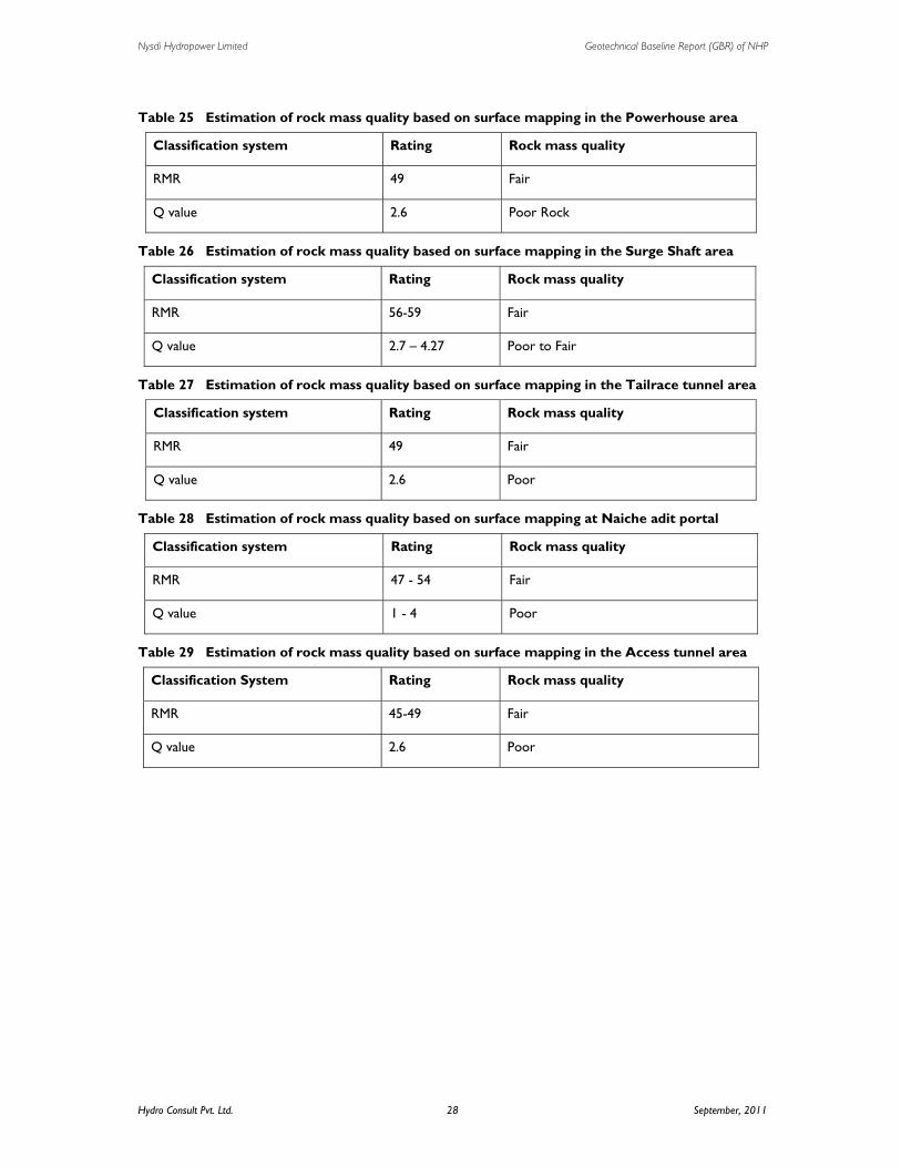
Nysdi Hydropower Limited Geotechnical Baseline Report (GBR) of NHP
Hydro Consult Pvt. Ltd. 28 September, 2011
Table 25 Estimation of rock mass quality based on surface mapping in the Powerhouse area
Classification system Rating Rock mass quality
RMR 49 Fair
Q value 2.6 Poor Rock
Table 26 Estimation of rock mass quality based on surface mapping in the Surge Shaft area
Classification system Rating Rock mass quality
RMR 56-59 Fair
Q value 2.7 – 4.27 Poor to Fair
Table 27 Estimation of rock mass quality based on surface mapping in the Tailrace tunnel area
Classification system Rating Rock mass quality
RMR 49 Fair
Q value 2.6 Poor
Table 28 Estimation of rock mass quality based on surface mapping at Naiche adit portal
Table 29 Estimation of rock mass quality based on surface mapping in the Access tunnel area
Classification System Rating Rock mass quality
RMR 45-49 Fair
Q value 2.6 Poor
Classification system Rating Rock mass quality
RMR 47 - 54 Fair
Q value 1 - 4 Poor

Nysdi Hydropower Limited Geotechnical Baseline Report (GBR) of NHP
Hydro Consult Pvt. Ltd. 29 September, 2011
4.2 Excavation method Mechanized Drilling and Blasting Method (DBM) shall be adopted for underground excavation. Thus tunneling activity will advance with mainly four working faces that will be available from the headworks, Naiche adit, flushing tunnel and outlet portals. The method follows the sequential steps such as alignment surveying, drilling, blasting, scaling mucking and temporary rock support.
4.3 Geologic/Geomechanic Influences 4.3.1 Geological Influence due to high overburden cover
• From the tunnel profile the maximum overburden is found at Ch 0+800 about 640 meter. This thickness of banded gneiss rock gives overburden pressure of about 16.64 MPa (taking Specific gravity of gneiss as 2.6). Whereas the rock mass strength for the gneiss stretch of tunnel is obtained as 383-406 kg/cm2. Hence due to exceeding the rock mass strength to overburden stress, instability problem is not likely to occur during tunneling.
• The HRT towards the downstream side after Chainage Ch 0+800 will pass through more or less similar lithology as headwork area. The rock mass strength of this stretch will vary from fair to poor rock. And the overburden stress is likely to less than rock mass strength. The core sample of those rocks bored at the surge shaft section yield low compressive strength of about 94-103 kg/cm2. Tunnel through this section has overburden depth greater than 125 m; this section will get stressed with overburden pressure of 3.25 MPa. In such condition the anticipated problem during tunneling is rock squeezing. Squeezing of the section may remarkably reduce the cross-section of the tunnel.
• Weak Zones/Share zones(Table 2 Properties of weak zones
• ) are present along the headrace tunnel may face with the following geological problems such as rock squeezing, geological overbreak due to low rock mass strength.
4.3.2 Infuelence of mineral constituent in rock
Minerals constituent in rock largely infuelence the boreability and blastability during excavation. Information of mineral content and its proportion help to select and design of appropriate drill bits. In this regards, petrographical examinations are carried to quantify the hard abrasive minerals like quartz content in the rock. The mineral constituent in the rock samples establish the baselines of boreability and blastability. Summary of mineral proposition in different rock types are presented in Table 30.

Nysdi Hydropower Limited Geotechnical Baseline Report (GBR) of NHP
Hydro Consult Pvt. Ltd. 30 September, 2011
Table 30 Mineral content analysis of rock core samples
Per
ce-
ntag
e Minerals
Rock Type
Grey Garnetiferous Schit Grey Mica Schist M
iner
al C
onst
itue
nt (
%)
Quartz 35-50 30
K-feldspar 10-15 25
Plagioclase 5-10 15
Muscovite 18-26 -
Biotite 12-15 25
Chlorite - 4
Tourmaline 3 -
Garnet 3-5 -
Opaque 1-5 1

Nysdi Hydropower Limited Geotechnical Baseline Report (GBR) of NHP
Hydro Consult Pvt. Ltd. 31 September, 2011
5. GROUND CHARACTERISATION AND BASELINES Ground characterizations are soley based on the information acquired from geological and geotechnical investigation that includes surface geological mapping, geophysical investigation (2D resistivity survey and vertical electrical sounding) and core drilling at different project components (Table 31). Details about the investigation results and analysis are kept in the Investigation Report Annex II; Feasibility Study 2010, Investigation (Core drilling) report 2010, 2D-ERT survey report 2010.
Table 31 Techniques applied in obtaining geological and geotechnical information
Location Techniques
Dam/Weir Site Surface mapping and core drilling
Settling Basin Surface mapping and core drilling
Headrace Tunnel Surface mapping, 2D resistivity survey, core drilling near the outlet portals
Surge Tank Surface mapping, 2D resistivity survey and core drilling
Penstock Alignment/ Drop shaft
Surface mapping, 2D resistivity survey and core drilling
Powerhouse Surface mapping, 2D resistivity survey and core drilling
At the present condition, the baselines for the geotechnical parameters are thus based on above listed investigation along with in situ test during core drilling and laboratory test results of the core samples and the construction materials. To obtain more relavent information of the underground condiotion at structure grade, test adit is planned to be excavated soon. Thus, the baselines information will be revised later after the completion of the test adit at surge shaft adit and Naiche adit.
Geotechnical Baseline Conditions
Following geotechnical parameters are considered for baseline conditions
• Rock mass quality/class
• Rock Strength
• Compactness from DCPT values
Hydrogeological Baseline Conditions
Following geotechnical parameters are considered for baseline conditions
• Lugeon Value
• Permeability condition

Nysdi Hydropower Limited Geotechnical Baseline Report (GBR) of NHP
Hydro Consult Pvt. Ltd. 32 September, 2011
5.1 Baseline Conditions for Headworks 5.1.1 Geotechnical Baseline Conditions
• Concrete weir abutted into slight to moderately weathered banded gneiss rock at both banks
• Founded into dense river channel deposits dominated with boulder mixed gravely sand
• Rock mass quality at the abutment is poor to good
• Rock mass strength (Uniaxial compressive strength)= 383-406 kg/cm2
5.1.2 Hydrogelogic Baseline Conditions
• Foundational material is high to moderately permeable alluvium soil
5.2 Baseline Condition for Intake Tunnel 5.2.1 Geotechnical Baseline Conditions
At the present stage the geomechanical properties of BH3 core samples and the surface rock mass quality is used as reference for baseline conditions.
• Poor to Good rock mass quality
• Rock strength (Uniaxial compressive strength)= 383-406 kg/cm2
5.2.2 Hydrogelogic Baseline Conditions
• Minor influence of groundwater
5.3 Baseline Condition for Flushing Tunnel/Inspection Tunnel 5.3.1 Geotechnical Baseline Conditions
At the present stage the geomechanical properties of BH3 core samples and the surface rock mass quality is used as reference for baseline conditions.
• Poor to Good rock mass quality
• Rock strength (Uniaxial compressive strength)= 383-406 kg/cm2
5.3.2 Hydrogelogic Baseline Conditions
• Minor influence of groundwater
5.4 Baseline Condition for Diversion Tunnel 5.4.1 Geotechnical Baseline Conditions
At the present stage the geomechanical properties of BH3 core samples and the surface rock mass quality is used as reference for baseline conditions.
• Fair to good rock mass quality
• Rock strength (Uniaxial compressive strength)= 383-406 kg/cm2

Nysdi Hydropower Limited Geotechnical Baseline Report (GBR) of NHP
Hydro Consult Pvt. Ltd. 33 September, 2011
5.4.2 Hydrogelogic Baseline Conditions
• Minor influence of groundwater
5.5 Baseline Condition for Settling Basin 5.5.1 Geotechnical Baseline Conditions
At the present stage the geomechanical properties of BH3 core samples and the surface rock mass quality is used as reference for baseline conditions. It can be predicted that the rock mass quality and its strength would be better than that indicated by the borehole logs since they are drilled in saturated river bed.
• Poor to Good rock mass quality
• Rock strength (Uniaxial compressive strength)= 383-406 kg/cm2
5.5.2 Hydrogelogic Baseline Conditions
Presently, the baseline condition is anticipated as minor inflow of groundwater from river basin. The gulliey adjacent to the vicinity is not perinnal springs, thus groundwater problem during excavation is in inferior side.
• Permeability: Fail due to highly jointed rock
5.6 Baseline Condition for Headrace Tunnel 5.6.1 Geotechnical Baseline Conditions
• Rock mass quality is exceptionally poor to fair
5.6.2 Hydrogelogic Baseline Conditions
• Water ingress problem expected only in monsoon as all gullies, weak zone and share zone, and streams in the vicinity are intermittent.
5.7 Baseline Condition for Surge shaft 5.7.1 Geotechnical Baseline Conditions
To assess the detail geotechnical condition and geology at the particular underground location the test tunnel at surge shaft adit is planned to construct. The baseline rock mass conditions are as follows:
• Poor to fair rock mass class
• Rock strength (Uniaxial compressive strength)= 94-103 kg/cm2
5.7.2 Hydrogelogic Baseline Conditions
• Groundwater not encountered at the drilling depth of 40 m; No permanenet water table exist at the elevation of surge shaft.
• Lugeon Values at 37-40.10 is 0.27 (Failure due to higly jointed rock)

Nysdi Hydropower Limited Geotechnical Baseline Report (GBR) of NHP
Hydro Consult Pvt. Ltd. 34 September, 2011
5.8 Baseline Condition for Penstock 5.8.1 Geotechnical Baseline Conditions
• Direct Cone Penetration (DCPT) value = 3/80 to 45/75
• Compaction: Dense to Very Dense
5.8.2 Hydrogelogic Baseline Conditions
• Permeability= 3.89E-03 – 7.70E-04 (cm/sec)
• Water Table will not be encountered upto the depth of excavation/foundation level.
5.9 Baseline Condition for Drop Shaft 5.9.1 Geotechnical Baseline Conditions
• Direct Cone Penetration (DCPT) value = 18/80 to 34/40
• Compection:Very dense to dense
The baseline rock mass conditions are as follows:
• Poor to fair rock mass class
• Rock strength (Uniaxial compressive strength)= 64.94-340.79 kg/cm2
5.9.2 Hydrogeologic Baseline Conditions
• Permeability= 3.89E-03 – 7.70E-04 (cm/sec)
• Lugeon Values is 2.37-9.94
• Groundwater inflow from stream from surge shaft during the monsoon may be encountered.
5.10 Baseline Condition for Underground Powerhouse 5.10.1 Geotechnical Baseline Conditions
The baseline rock mass conditions are as follows:
• Poor to fair rock mass class
• Rock strength (Uniaxial compressive strength)= 64.94-340.79 kg/cm2
5.10.2 Hydrogelogic Baseline Conditions
• Lugeon Values is 2.37-9.94
• Groundwater inflow from stream from surge shaft during the monsoon may be encountered.

Nysdi Hydropower Limited Geotechnical Baseline Report (GBR) of NHP
Hydro Consult Pvt. Ltd. 35 September, 2011
5.11 Baseline Condition for Tailrace Tunnel 5.11.1 Geotechnical Baseline Conditions
• Direct Cone Penetration (DCPT) value = 4/80 to 26/80
• Very dense to dense
5.11.2 Hydrogelogic Baseline Conditions
• Foundational material is alluvium
• Permeability= 1.47E-02 – 8.23E-04 (cm/sec)
• Moderately flow of groundwater from Nyadi River
5.12 Access Tunnel to Underground Powerhouse 5.12.1 Geotechnical Baseline Conditions
The baseline rock mass conditions are as follows:
• Poor to fair rock mass class
• Rock strength (Uniaxial compressive strength)= 64.94-340.79 kg/cm2
5.12.2 Hydrogelogic Baseline Conditions
• Lugeon Values is 2.37-9.94
• Groundwater inflow from stream from surge shaft during the monsoon may be encountered.

Nysdi Hydropower Limited Geotechnical Baseline Report (GBR) of NHP
Hydro Consult Pvt. Ltd. 36 September, 2011
6. PREVENTION / RESOLUTION OF DISPUTES All the preventive measures will be adapted to mantain harmonic relation in between all the associated parties until the execution of the project. However, especially in underground works being possibilities of high uncertainities, debets and disputes are likely to occur and should be handled promptly to execute the work. The procedure to resolve the dispute are mentioned in detail in “Clause 20: Claim, Disputes and Arbitration” in the “Conditions of Contract” Section of Contract documents.

Nysdi Hydropower Limited Geotechnical Baseline Report (GBR) of NHP
Hydro Consult Pvt. Ltd. 37 September, 2011
Annex –A1: Figures
Nyadi Hydroelectric Project
Geological Baseline Report
September 2011

Nysdi Hydropower Limited Geotechnical Baseline Report (GBR) of NHP
Hydro Consult Pvt. Ltd 38
Figure 1 Geological map of Nepal showing project location

Nysdi Hydropower Limited Geotechnical Baseline Report (GBR) of NHP
Hydro Consult Pvt. Ltd 39
Figure 2 General layout of Nyadi Hydropower Project, Lamjung

Nysdi Hydropower Limited Geotechnical Baseline Report (GBR) of NHP
Hydro Consult Pvt. Ltd 40
Figure 3 Regional geological map of the Nyadi Hydropower Project area

Nysdi Hydropower Limited Geotechnical Baseline Report (GBR) of NHP
Hydro Consult Pvt. Ltd 41
Figure 4 Geological cross-section of the Nyadi Hydropower area showing main lithological units

Nysdi Hydropower Limited Geotechnical Baseline Report (GBR) of NHP
Hydro Consult Pvt. Ltd 42
Figure 5 Part of the map of Kaligandaki–Marsyangdi area (Colchen et al. 1981)
MCT
Higher Himalayan Succession
Lesser Himalayan Succession
MCT
N
0 4 km 2
Scale

Nysdi Hydropower Limited Geotechnical Baseline Report (GBR) of NHP
Hydro Consult Pvt. Ltd 43
Figure 6 Assumed uniform seismic zones in Nepal (After BCDP, 1994)
Figure 7 Seismic hazard map of Nepal
Project Site
Project Site
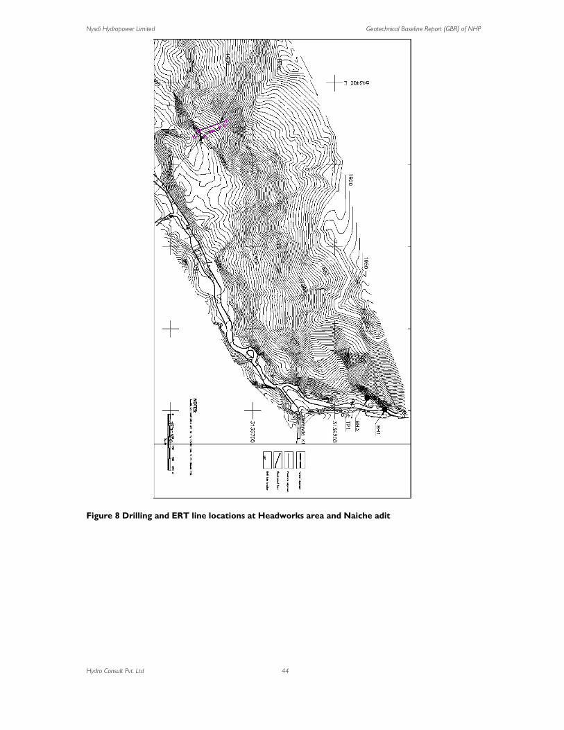
Nysdi Hydropower Limited Geotechnical Baseline Report (GBR) of NHP
Hydro Consult Pvt. Ltd 44
Figure 8 Drilling and ERT line locations at Headworks area and Naiche adit

Nysdi Hydropower Limited Geotechnical Baseline Report (GBR) of NHP
Hydro Consult Pvt. Ltd 45
Figure 9 Drilling and ERT line locations at Powerhouse area

Nysdi Hydropower Limited Geotechnical Baseline Report (GBR) of NHP
Hydro Consult Pvt. Ltd 46
Figure 10 Geological plan of Headworks area
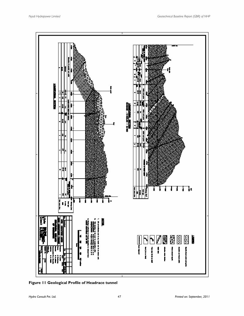
Nysdi Hydropower Limited Geotechnical Baseline Report (GBR) of NHP
Hydro Consult Pvt. Ltd. 47 Printed on: September, 2011
Figure 11 Geological Profile of Headrace tunnel

Nysdi Hydropower Limited Geotechnical Baseline Report (GBR) of NHP
Hydro Consult Pvt. Ltd. 48 Printed on: September, 2011
Figure 12 Geological plan of powerhouse area

Nysdi Hydropower Limited Geotechnical Baseline Report (GBR) of NHP
Hydro Consult Pvt. Ltd. 49 Printed on: September, 2011
Figure 13 Geological plan of Naiche area

Nysdi Hydropower Limited Geotechnical Baseline Report (GBR) of NHP
Hydro Consult Pvt. Ltd. 50 Printed on: September, 2011
Figure 14 Joint rossette showing the HRT alignment
Nana to Outlet
Intake to Naiche
Naiche to Nana
N

Nysdi Hydropower Limited Geotechnical Baseline Report (GBR) of NHP
Hydro Consult Pvt. Ltd. 51 Printed on: September, 2011
Figure 15 Test pit location of construction materials
TP5
TP1
TP3
TP2
TP4
TP6
TP Location

Nysdi Hydropower Limited Geotechnical Baseline Report (GBR) of NHP
Hydro Consult Pvt. Ltd. 52 Printed on: September, 2011
Figure 16 View of headrace tunnel level between Naiche adit and Nana
Tunnel level
Nana
Related Documents