ANZIAM J. 52 (CTAC2010) pp.C899–C913, 2011 C899 Numerical investigation of the ventilation performance of a solar chimney R. Khanal 1 C. Lei 2 (Received 30 January 2011; revised 19 October 2011) Abstract This article reports a two dimensional, steady state, numerical simulation of the air flow inside a solar chimney with a fixed absorber height but various air gap widths and inlet aperture heights. The ventilation performance of the solar chimney in terms of the mass flow rate is presented. The numerical results show that the mass flow rate is an increasing function of surface emissivity and input heat flux. It is also found that the mass flow rate is up to 59% higher with a surface emissivity of 0.9 than that with a zero surface emissivity. This investigation shows the importance of radiation heat transfer in a solar chimney system. The numerical results further show that the ventilation performance of the solar chimney is more sensitive to the change in the air gap width than to the change in the inlet aperture height, and an optimum inlet aperture height can be identified. http://journal.austms.org.au/ojs/index.php/ANZIAMJ/article/view/3947 gives this article, c Austral. Mathematical Soc. 2011. Published October 24, 2011. issn 1446-8735. (Print two pages per sheet of paper.) Copies of this article must not be made otherwise available on the internet; instead link directly to this url for this article.

Welcome message from author
This document is posted to help you gain knowledge. Please leave a comment to let me know what you think about it! Share it to your friends and learn new things together.
Transcript
ANZIAM J. 52 (CTAC2010) pp.C899–C913, 2011 C899
Numerical investigation of the ventilationperformance of a solar chimney
R. Khanal1 C. Lei2
(Received 30 January 2011; revised 19 October 2011)
Abstract
This article reports a two dimensional, steady state, numericalsimulation of the air flow inside a solar chimney with a fixed absorberheight but various air gap widths and inlet aperture heights. Theventilation performance of the solar chimney in terms of the massflow rate is presented. The numerical results show that the mass flowrate is an increasing function of surface emissivity and input heatflux. It is also found that the mass flow rate is up to 59% higher witha surface emissivity of 0.9 than that with a zero surface emissivity.This investigation shows the importance of radiation heat transfer ina solar chimney system. The numerical results further show that theventilation performance of the solar chimney is more sensitive to thechange in the air gap width than to the change in the inlet apertureheight, and an optimum inlet aperture height can be identified.
http://journal.austms.org.au/ojs/index.php/ANZIAMJ/article/view/3947
gives this article, c© Austral. Mathematical Soc. 2011. Published October 24, 2011. issn1446-8735. (Print two pages per sheet of paper.) Copies of this article must not be madeotherwise available on the internet; instead link directly to this url for this article.
Contents C900
Contents
1 Introduction C900
2 Solar chimney model C902
3 Problem formulation C903
4 Numerical solution details C904
5 Results and discussion C905
6 Conclusion C911
References C911
1 Introduction
A solar chimney is an excellent passive ventilation device which relies on anatural driving force, the energy from the sun, and is designed to maximisethe ventilation performance by maximising the solar gain [5]. The basicdriving mechanism of the air flow inside a solar chimney is thermal buoyancy.The thermal buoyancy is caused by the density variation of the fluid (air) dueto the temperature difference between the inside and outside of the building,and within different sections of the building.
The pioneering work on solar chimney performance was carried out by Bansalet al. [5], who proposed an expression for the volume flow rate of air by solvingthe energy balance and continuity equations. A number of experimentalinvestigations of a solar chimney were reported subsequently. To name onlya few, Arce et al. [2] and Afonso and Oliveira [1] studied the ventilationperformance of a full scale model of a solar chimney under realistic conditions,whereas Chen et al. [8] and later Burek and Habeb [7] considered large scale

1 Introduction C901
models under a controlled laboratory environment. Similarly, Mathur et al. [4]studied a window sized, small scale model under realistic conditions. Amongthe numerical studies, Moshfeg and Sandberg [14] considered conjugate heattransfer by convection and radiation for a 6.5 metre tall solar chimney withvarious aspect ratios, and revealed the importance of surface radiation onfluid flow inside the air channel. In contrast to Bacharoudis et al. [3], Zamoraand Kaiser [18] and others who modelled a solar chimney with a uniform walltemperature, Sandberg and Moshfeg [14] modelled the solar chimney withone wall adiabatic and the other with a uniform heat flux. We believe thelatter modelling strategy is a better representation of reality and hence weadopt similar thermal boundary conditions in the present study.
Many researchers identified the importance of the air gap width on theventilation performance of a solar chimney. However, Lee and Strand [11]identified the air gap width as the parameter with the least influence onventilation performance in terms of mass flow rate. Similarly, Miyazaki etal. [13] reported that for a solar chimney with an air gap width more than 0.2m,the mass flow rate is independent of the chimney air gap width. All theseworks contributed to our present understanding of the subject. However, thecontradictory results reported suggest that the solar chimney as a ventilationstrategy is not fully understood and thus needs further investigation. Thisis the motivation behind the present work. Moreover, very few numericalinvestigations have focused on small scale solar chimneys with absorber heightless than 1m.
The present work deals with numerical simulation of natural convection flowinside a solar chimney. Both convection and radiation heat transfer areconsidered as the mechanisms through which thermal energy is transferredwithin the solar chimney. The problem outlined has practical applicationsin building ventilation as well as theoretical appeal to understanding thecomplex thermo-fluid phenomena inside the solar chimney.
2 Solar chimney model C902
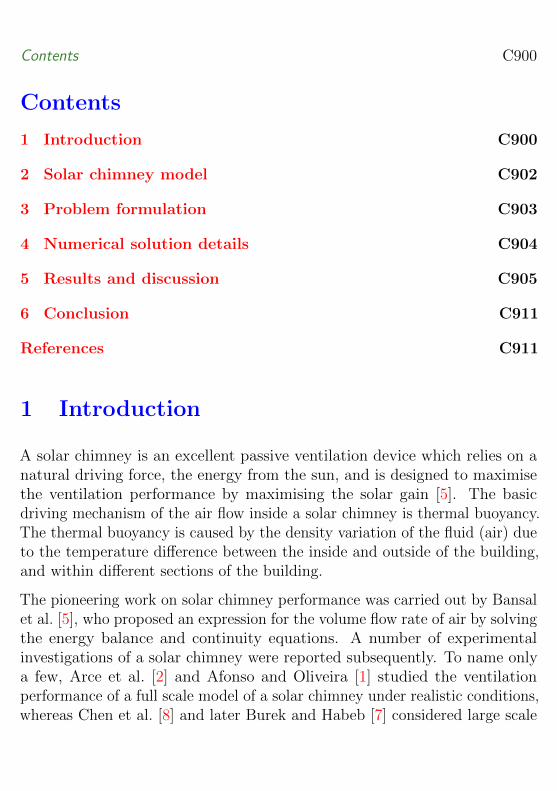
Figure 1: (a) Schematic diagram of a two dimensional solar chimney attachedto a room. (b) A truncated two dimensional solar chimney model withboundary conditions adopted in this study.
2 Solar chimney model
A typical two dimensional representation of the physical system of a solarchimney is depicted in Figure 1. The horizontal distance between the glazingand the absorber wall is referred to as the air gap width, Wgap. In this study,the absorber height, Hab, is fixed (0.7m) but the inlet aperture height, Hin,is variable, giving rise to different solar chimney heights. The typical rangesof parameters considered in this study are 0.1–0.4m for the air gap widthand 0.1–0.5m for the inlet aperture height, respectively. The other importantgoverning parameters are the Rayleigh and Prandtl numbers,
Ra =gβq ′′H4abανk
and Pr =ν
α, (1)

3 Problem formulation C903
where β is the coefficient of thermal expansion, ν is the kinematic viscosity,α is the thermal diffusivity, k is the thermal conductivity, and q ′′ is the inputheat flux. si units are adopted throughout.
3 Problem formulation
We expect that the temperature variation from the inlet to the exit of the solarchimney is not very large, and thus the Boussinesq approximation is adopted.Under this assumption, we solve simplified Navier–Stokes equations for a twodimensional Newtonian incompressible flow. As the governing equations areavailable in almost every numerical article on the subject and also in standardtextbooks, they are not presented here. For the radiation formulation, weassume that the channel wall surfaces are diffuse and grey. The radiative heatexchange between surface elements is then calculated from the relation [17]
N∑j=1
[δij − (1− εj)Fi−j
] qr,jεj
=
N∑j=1
(δij − Fi−j
)σT 4j , (2)
where i and j index the N surface elements, δij is the Kronecker delta, εj isthe surface emissivity, Fi−j is the configuration factor, qr,j is the radiativeheat flux, and σ is the Stefan–Boltzmann constant.
Assuming q ′′ = 100W/m2 and Hab = 0.7m, Equation (1) gives Rayleighnumber Ra = 8.36× 10¹⁰. For the case of natural convection adjacent to avertical, isothermally heated, flat plate, such a high value of the Rayleighnumber might suggest the flow is turbulent. However, Chen et al. [8] reportedthat, for natural convection adjacent to a vertical flat plate heated by auniform heat flux, the transition to turbulence occurs at Ra > 2 × 10¹³.Bejan [6] considered a similar range of Rayleigh numbers based on a constantheat flux for laminar flows. We therefore model the flow as laminar.

4 Numerical solution details C904
4 Numerical solution details
Results presented in this work are obtained numerically using the commercialcfd package ansys-fluent 12.0, which is based on a control volume method.The governing equations are solved on a staggered grid and the couplingbetween the momentum and continuity equations through pressure is basedon the simple (Semi Implicit Pressure Linked Equation) scheme [15]. Thesecond order, upwind, differencing scheme is applied for convective termsof the momentum and energy transport equations, whereas pressure is de-scretized using the presto (Pressure Staggering Option) scheme [9]. Toensure numerical stability, the discretized equations are solved by iterationwith under-relaxation factors of 0.3 for pressure, 0.7 for momentum and 1 fordensity, body force and energy. Solution convergence is controlled by settingthe convergence criterion (residual) to 10−5 for each equation except for theenergy equation, which is set to 10−6. All results reported in this article areobtained using a double precision solver.
Two dimensional quadrilateral elements are employed to create a non-uniformstructured mesh using ansys Workbench. In order to ensure the accuracyof the numerical results, a grid dependence study is performed with threedifferent meshes: 100× 36, 200× 72 and 400× 144. Based on this numericaltest, the medium mesh of 200 × 72 elements is adopted in this study, asit provides sufficient spatial resolution for a grid independent solution withmuch less computing time than the finest mesh.
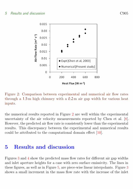
Validation of our numerical procedure for the solar chimney model is carriedout by comparing the present numerical data, obtained for a solar chimneywith vertical inlet, to the experimental data obtained for a 1.5-metre tallsolar chimney [8]. Figure 2 shows the comparison between the experimentaland numerical air flow rates obtained for a 200mm air gap width at 200, 300,400, 500 and 600W/m2 input heat fluxes, respectively. The figure shows aclear agreement between the experimental and numerical data, confirmingan increase in the air flow rate with an increase in the input heat flux. All
5 Results and discussion C905
Figure 2: Comparison between experimental and numerical air flow ratesthrough a 1.5m high chimney with a 0.2m air gap width for various heatinputs.
the numerical results reported in Figure 2 are well within the experimentaluncertainty of the air velocity measurements reported by Chen et al. [8].However, the predicted air flow rate is consistently lower than the experimentalresults. This discrepancy between the experimental and numerical resultscould be attributed to the computational domain effect [10].
5 Results and discussion
Figures 3 and 4 show the predicted mass flow rates for different air gap widthsand inlet aperture heights for a case with zero surface emissivity. The lines inthese figures, as well as in Figure 5, are piece-wise linear interpolants. Figure 3shows a small increment in the mass flow rate with the increase of the inlet

5 Results and discussion C906
Figure 3: Predicted mass flow rate at various input heat flux for a 0.1m airgap width with various inlet aperture heights.
aperture height from 0.1m to 0.2m, and further increase of the inlet apertureheight results in a decrease of the mass flow rate. This is attributed to thereduction of the flow kinetic energy with the increase of the inlet apertureheight.
Figure 4 shows the predicted mass flow rate at different air gap widthswith a given inlet aperture height for different input heat flux. The figureindicates that as the chimney air gap width increases for a fixed inlet apertureheight, the mass flow rate decreases. This is be attributed to the decrease ofthe flow kinetic energy with the increase in the chimney cross-section area.Furthermore, with the increase in the air gap width, a reverse flow occurs atthe chimney exit; as seen in Figure 6(c). We are currently investigating thisreverse flow and its impact on the ventilation performance, and will reportseparately.
Figures 3 and 4 indicate that the mass flow rate is more sensitive to thechange in the air gap width than to changes in the inlet aperture height. A

5 Results and discussion C907
Figure 4: Predicted mass flow rate at various input heat flux at an inletaperture height of 0.1m for various air gap widths.
Figure 5: Predicted mass flow rate at input heat flux of 100W/m2 and an airgap width of 0.3m for various inlet aperture heights for the case with zerosurface emissivity.
5 Results and discussion C908
typical case, with an absorber height of 0.7m and an air gap width of 0.3m,is now considered. The mass flow rate is calculated for a fixed input heat flux(100W/m2) and various inlet aperture sizes (0.1–0.5m), and the results arepresented in Figure 5. The figure clearly shows improvement in the mass flowrate up to a certain value of the inlet aperture height, after which furtherincrease in the inlet aperture height does not have any positive effect onimproving the mass flow rate. This result indicates that, based on the rangeof the tests (0.1–0.5m), there is an optimum value of the inlet aperture height.
In Figure 6, (a) and (c) show the isotherms and streamlines, respectively,for a selected case without surface emissivity. This behaviour changes tothat shown in (b) and (d) when surface emissivity is present. It is evidentfrom the figure that the thermal flow structure changes with the presence ofradiation heat exchange. Figure 6(a) shows that a thermal boundary layeris formed adjacent to the heated wall only, whereas in Figure 6(b) thermalboundary layers are formed adjacent to both walls. The thermal boundarylayer adjacent to the unheated wall is due to radiation heat exchange betweenthe two vertical surfaces of the solar chimney. Radiation heat exchangeincreases the mass flow rate through the chimney as more fluid is driven bythe buoyancy force in the region close to the walls in the thermal boundarylayer. Outside the thermal boundary layer, fluid is mainly driven by thepressure gradient resulting from the inlet pressure boundary condition [12].
Figure 6(c) shows a reverse flow at the exit of the solar chimney for thecase with zero emissivity. The reverse flow is due to thermal boundary layerentrainment of fresh air from the exterior of the solar chimney in order tosatisfy conservation of mass. The detailed mechanism of the boundary layerentrainment needs to be further investigated. For the case with an emissivityvalue of 0.9, Figure 6(d) shows no reverse flow at the exit of the chimney.However, a small circulation can be seen in the region near to the leading edgeof the thermal boundary layer, just above the inlet aperture at the heatedwall. This is attributed to the separation of the inlet flow at the leading edge.With the radiation effect, the inlet flow is stronger, and thus separation ismore likely.

5 Results and discussion C909
Figure 6: Contours of static temperature (a) and (c) and stream lines(c) and (d) for air gap width 0.3m, inlet aperture height 0.2m and absorberheight 0.7m. In each pair of figures, the case without radiation transfer is onthe left and the case with radiation transfer is on the right. For both cases,Ra = 8.36× 10¹⁰.
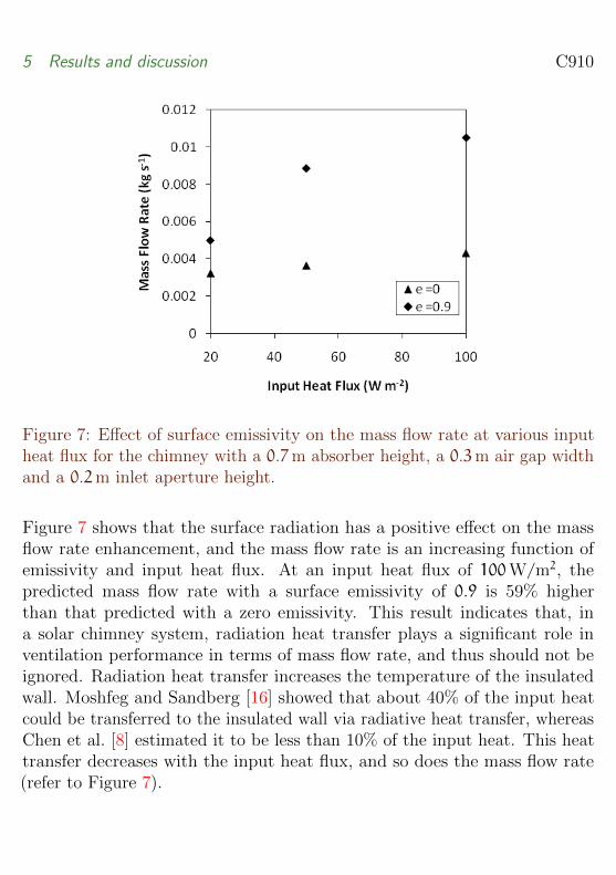
Figure 7 shows the effect of surface emissivity on the ventilation performancein terms of mass flow rate. Here the surface emissivity is considered for bothwalls (the heated and insulated walls). In one case, the surface emissivity isassumed to be 0.9 for both bounding walls. In the other case, the surfaceemissivity is assumed to be zero for both bounding walls, indicating noradiation heat exchange between the two bounding walls.
5 Results and discussion C910
Figure 7: Effect of surface emissivity on the mass flow rate at various inputheat flux for the chimney with a 0.7m absorber height, a 0.3m air gap widthand a 0.2m inlet aperture height.
Figure 7 shows that the surface radiation has a positive effect on the massflow rate enhancement, and the mass flow rate is an increasing function ofemissivity and input heat flux. At an input heat flux of 100W/m2, thepredicted mass flow rate with a surface emissivity of 0.9 is 59% higherthan that predicted with a zero emissivity. This result indicates that, ina solar chimney system, radiation heat transfer plays a significant role inventilation performance in terms of mass flow rate, and thus should not beignored. Radiation heat transfer increases the temperature of the insulatedwall. Moshfeg and Sandberg [16] showed that about 40% of the input heatcould be transferred to the insulated wall via radiative heat transfer, whereasChen et al. [8] estimated it to be less than 10% of the input heat. This heattransfer decreases with the input heat flux, and so does the mass flow rate(refer to Figure 7).
6 Conclusion C911
6 Conclusion
Almost all solar chimney studies are aimed at finding optimum design solutionsfor enhancing natural ventilation, taking into consideration different designparameters. We considered the inlet aperture height, air gap width and surfaceemissivity to study the ventilation performance of a small solar chimney interms of mass flow rate. Our study shows that the mass flow through a solarchimney is more sensitive to changes in the air gap width than to changesin the inlet aperture height. The present results also show the existence ofan optimum inlet aperture height. Without considering the radiation heatexchange, a reverse flow is observed at the chimney outlet even for a smallair gap width. This needs to be further investigated. Surface emissivity isfound to have a positive effect on the mass flow rate, and hence radiationheat exchange should not be ignored in solar chimney systems.
References
[1] C. Afonso and A. Oliveira. Solar chimneys: simulation and experiment.Energy and Buildings, 32:71–79, 2000.doi:10.1016/S0378-7788(99)00038-9. C900
[2] J. Arce, M. J. Jiminez, G. Alvarez J. D. Guzman, M. R. Heras, andJ. Xaman. Experimental study for natural ventilation on a solarchimney. Renewable Energy, 34:2928–2934, 2009.doi:10.1016/j.renene.2009.04.026. C900
[3] E. Bacharoudis, M. G. Vrachopoulos, D. Margaris M. K. Koukou, A. E.Filios, and S. A. Mavrommatis. Study of the natural convectionphenomena inside a wall solar chimney with one wall adiabatic and onewall under a heat flux. Applied Thermal Engineering, 27:2266–2275,2007. doi:10.1016/j.applthermaleng.2007.01.021. C901
References C912
[4] N. K. Bansal, J. Mathur, S. Mathur, and M. Jain. Modeling ofwindow-sized solar chimneys for ventilation. Building and Environment,40:1302–1308, 2005. doi:10.1016/j.buildenv.2004.10.011. C901
[5] N. K. Bansal, R. Mathur, and M. S. Bhandari. Solar chimney forenhanced stack ventilation. Building and Environment, 28:373–377,1993. doi:10.1016/0360-1323(93)90042-2. C900
[6] A. Bejan. Heat Transfer. John Wiley and Sons, Inc., 1993. C903
[7] S. A. M. Burek and A. Habeb. Air flow and thermal efficiencycharacteristics in solar chimneys and trombe walls. Energy andBuildings, 39:128–135, 2007. doi:10.1016/j.enbuild.2006.04.015. C900
[8] Z. D. Chen, P. Bandopadhayay, J. Halldorsson, C. Byrjalsen,P. Heiselberg, and Y. Li. An experimental investigation of a solarchimney model with uniform wall heat flux. Building and Environment,38:893–906, 2003. doi:10.1016/S0360-1323(03)00057-X. C900, C903,C904, C905, C910
[9] Fluent Incorporated. Fluent User’s Guide, 2006. C904
[10] G. Gan. Impact of computational domain on the prediction ofbuoyancy-driven ventilation cooling. Building and Environment,45:1173–1183, 2010. doi:10.1016/j.buildenv.2009.10.023. C905
[11] K. H. Lee and R. K. Strand. Enhancement of natural ventilation inbuildings using a thermal chimney. Energy and Buildings, 41:615–621,2009. doi:10.1016/j.enbuild.2008.12.006. C901
[12] F. Marcondes and C. Maliska. Treatment of the inlet boundaryconditions in natural-convection flows in open-ended channels.Numerical Heat Transfer, Part B: Fundamentals, 35:317–345, 1999.doi:10.1080/104077999275893. C908
[13] T. Miyazaki, A. Akisawa, and T. Kashiwagi. The effects of solarchimneys on thermal load mitigation of office buildings under the
References C913
Japanese climate. Renewable Energy, 31:987–1010, 2006.doi:10.1016/j.renene.2005.05.003. C901
[14] B. Moshfegh and M. Sandberg. Investigation of fluid flow and heattransfer in a vertical channel heated from one side by PV elements,Part I—Numerical study. Renewable Energy, 8:248–253, 1996.doi:10.1016/0960-1481(96)88856-2. C901
[15] S. V. Patankar. Numerical Heat Transfer and Fluid Flow. HemispherePublishing Corporation, New York, 1980. C904
[16] M. Sandberg and B. Moshfegh. Investigation of fluid flow and heattransfer in a vertical channel heated from one side by PV elements,Part II—Experimental study. Renewable Energy, 8:254–258, 1996.doi:10.1016/0960-1481(96)88857-4. C910
[17] R. Siegel and J. R. Howell. Thermal Radiation Heat Transfer.Hemisphere Publishing Corporation, Washington, 1981. C903
[18] B. Zamora and A. S. Kaiser. Thermal and dynamics optimization of theconvective flow in Trombe wall shaped channels by numericalinvestigation. Heat and Mass Transfer, 45:1393–1407, 2009.doi:10.1007/s00231-009-0509-6. C901
Author addresses
1. R. Khanal, School of Civil Engineering, The University of Sydney,NSW 2006, Australia.mailto:[email protected]
2. C. Lei, School of Civil Engineering, The University of Sydney, NSW2006, Australia.
Related Documents