Journal of Analysis and Computation (JAC) (An International Peer Reviewed Journal), www.ijaconline.com, ISSN 0973-2861 Volume XV, Issue V, May 2021 Abhilash D. Bhosale, Ashish R. Pawar 1 EXPERIMENTAL & NUMERICAL INVESTIGATION OF PRETENTION EFFECT ON FATIGUE LIFE OF DOUBLE LAP BOLTED JOINT UNDER DYNAMIC SHEAR LOADING Abhilash D. Bhosale 1 , Ashish R. Pawar 2 1 PG Scholar, 2 Assistant Professor, Department of Mechanical Engineering, ABMSP’s Anantrao Pawar College of Engineering & Research, Pune, Savitribai Phule Pune University, Maharashtra, India ABSTRACT Bolts, rivets or pins are removable joints which are used in Automotive industry for connecting various parts. Therefore, it is of great importance to minimize the effect of the stress concentration and improve the fatigue life. Preload is the technical term for the tension caused by torque tightening the nut that holds the assembled part together. It is evident that, most of machines and structures, such as automotive structures, in their service lives are subjected to multiaxial stresses in which two or three principal stresses vary with time; i.e., the corresponding principal stresses are out-of-phase or the principal directions change during a cycle of loading. Therefore, multiaxial fatigue analysis becomes an important tool for estimating the fatigue strength of these components [1]. In order to estimate fatigue life in the double lap bolted joints, for a reliable design, using multiaxial fatigue criteria is needed due to the complexity of stress distribution as a result of the tightening torque and longitudinal remote load. Therefore, the current investigation has sought to improve the existing body of knowledge about the performance of these multiaxial fatigue criteria in bolted joints in general and the effect of torque tightening on the fatigue life of double shear lap joints in particular. In the present study, the effects of torque tightening on the fatigue life of E34 Steel double lap bolted joints was investigated via experimental and multiaxial fatigue analysis. Cyclic longitudinal loading will be applied to carry out fatigue test. Keywords – Bolted Joints, Preload, Multiaxial Stresses, Cyclic Fatigue, Tightening Torque 1. INTRODUCTION In materials science, fatigue is the weakening of a material caused by repeatedly applied loads. It is the progressive and localized structural damage that occurs when a material is subjected to cyclic loading. Fatigue occurs when a material is subjected to repeat loading and unloading. If the loads are above a certain threshold, microscopic cracks will begin to form at the stress concentrators such as the surface, and grain interfaces. Eventually a crack will reach a critical size, the crack will propagate

Welcome message from author
This document is posted to help you gain knowledge. Please leave a comment to let me know what you think about it! Share it to your friends and learn new things together.
Transcript
Journal of Analysis and Computation (JAC) (An International Peer Reviewed Journal), www.ijaconline.com, ISSN 0973-2861
Volume XV, Issue V, May 2021
Abhilash D. Bhosale, Ashish R. Pawar 1
EXPERIMENTAL & NUMERICAL INVESTIGATION OF
PRETENTION EFFECT ON FATIGUE LIFE OF DOUBLE LAP
BOLTED JOINT UNDER DYNAMIC SHEAR LOADING
Abhilash D. Bhosale1, Ashish R. Pawar2
1PG Scholar, 2Assistant Professor, Department of Mechanical Engineering, ABMSP’s Anantrao Pawar College
of Engineering & Research, Pune, Savitribai Phule Pune University, Maharashtra, India
ABSTRACT
Bolts, rivets or pins are removable joints which are used in Automotive industry for connecting
various parts. Therefore, it is of great importance to minimize the effect of the stress concentration
and improve the fatigue life. Preload is the technical term for the tension caused by torque tightening
the nut that holds the assembled part together. It is evident that, most of machines and structures,
such as automotive structures, in their service lives are subjected to multiaxial stresses in which two
or three principal stresses vary with time; i.e., the corresponding principal stresses are out-of-phase
or the principal directions change during a cycle of loading. Therefore, multiaxial fatigue analysis
becomes an important tool for estimating the fatigue strength of these components [1]. In order to
estimate fatigue life in the double lap bolted joints, for a reliable design, using multiaxial fatigue
criteria is needed due to the complexity of stress distribution as a result of the tightening torque and
longitudinal remote load. Therefore, the current investigation has sought to improve the existing
body of knowledge about the performance of these multiaxial fatigue criteria in bolted joints in
general and the effect of torque tightening on the fatigue life of double shear lap joints in particular.
In the present study, the effects of torque tightening on the fatigue life of E34 Steel double lap bolted
joints was investigated via experimental and multiaxial fatigue analysis. Cyclic longitudinal loading
will be applied to carry out fatigue test.
Keywords – Bolted Joints, Preload, Multiaxial Stresses, Cyclic Fatigue, Tightening Torque
1. INTRODUCTION
In materials science, fatigue is the weakening of a material caused by repeatedly applied loads. It is
the progressive and localized structural damage that occurs when a material is subjected to cyclic
loading. Fatigue occurs when a material is subjected to repeat loading and unloading. If the loads are
above a certain threshold, microscopic cracks will begin to form at the stress concentrators such as the
surface, and grain interfaces. Eventually a crack will reach a critical size, the crack will propagate
EXPERIMENTAL & NUMERICAL INVESTIGATION OF PRETENTION EFFECT ON FATIGUE LIFE OF
DOUBLE LAP BOLTED JOINT UNDER DYNAMIC SHEAR LOADING
Abhilash D. Bhosale, Ashish R. Pawar 2
suddenly, and the structure will fracture. The shape of the structure will significantly affect the fatigue
life; square holes or sharp corners will lead to elevated local stresses where fatigue cracks can initiate.
Round holes and smooth transitions or fillets will therefore increase the fatigue strength of the
structure. A method for determining the behavior of materials under fluctuating loads. A specified
mean load (which may be zero) and an alternating load are applied to a specimen and the number of
cycles required to produce failure (fatigue life) is recorded. The bolted joints due to their proven
superior performance under static and cyclic loading, have been widely utilized for connecting key
components in the structure.
Fatigue failures occur at a stress much below its static strength due to the application of fluctuating
stresses. It has been estimated that fatigue contributes to approximately 90% of the mechanical service
failures. Fatigue is a problem that can affect any part or component that moves or subjected to high
temperatures. Automobile on roads, aircraft wings, and fuel gases, ships at sea, nuclear reactors, jet
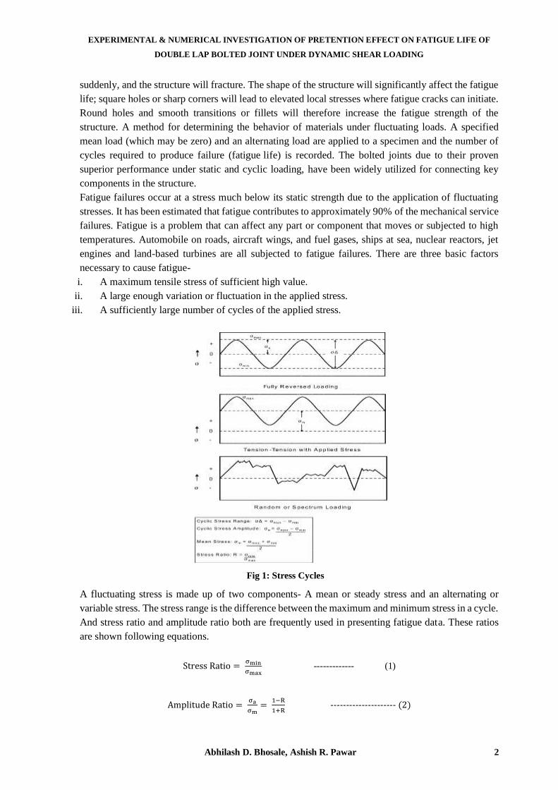
engines and land-based turbines are all subjected to fatigue failures. There are three basic factors
necessary to cause fatigue-
i. A maximum tensile stress of sufficient high value.
ii. A large enough variation or fluctuation in the applied stress.
iii. A sufficiently large number of cycles of the applied stress.
Fig 1: Stress Cycles
A fluctuating stress is made up of two components- A mean or steady stress and an alternating or
variable stress. The stress range is the difference between the maximum and minimum stress in a cycle.
And stress ratio and amplitude ratio both are frequently used in presenting fatigue data. These ratios
are shown following equations.
Stress Ratio = σmin
σmax ------------- (1)
Amplitude Ratio = σa
σm=
1−R
1+R --------------------- (2)
Journal of Analysis and Computation (JAC) (An International Peer Reviewed Journal), www.ijaconline.com, ISSN 0973-2861
Volume XV, Issue V, May 2021
Abhilash D. Bhosale, Ashish R. Pawar 3
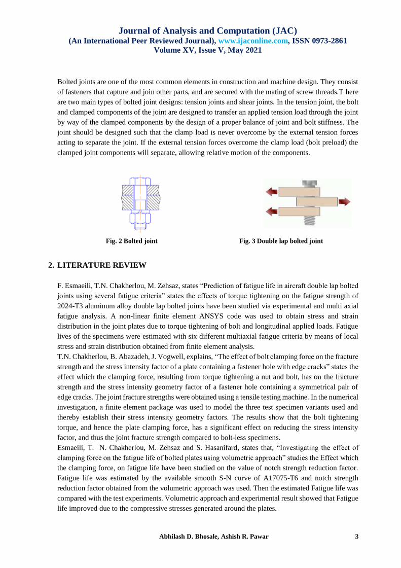
Bolted joints are one of the most common elements in construction and machine design. They consist
of fasteners that capture and join other parts, and are secured with the mating of screw threads.T here
are two main types of bolted joint designs: tension joints and shear joints. In the tension joint, the bolt
and clamped components of the joint are designed to transfer an applied tension load through the joint
by way of the clamped components by the design of a proper balance of joint and bolt stiffness. The
joint should be designed such that the clamp load is never overcome by the external tension forces
acting to separate the joint. If the external tension forces overcome the clamp load (bolt preload) the
clamped joint components will separate, allowing relative motion of the components.
Fig. 2 Bolted joint Fig. 3 Double lap bolted joint
2. LITERATURE REVIEW
F. Esmaeili, T.N. Chakherlou, M. Zehsaz, states “Prediction of fatigue life in aircraft double lap bolted
joints using several fatigue criteria” states the effects of torque tightening on the fatigue strength of
2024-T3 aluminum alloy double lap bolted joints have been studied via experimental and multi axial
fatigue analysis. A non-linear finite element ANSYS code was used to obtain stress and strain
distribution in the joint plates due to torque tightening of bolt and longitudinal applied loads. Fatigue
lives of the specimens were estimated with six different multiaxial fatigue criteria by means of local
stress and strain distribution obtained from finite element analysis.
T.N. Chakherlou, B. Abazadeh, J. Vogwell, explains, “The effect of bolt clamping force on the fracture
strength and the stress intensity factor of a plate containing a fastener hole with edge cracks” states the
effect which the clamping force, resulting from torque tightening a nut and bolt, has on the fracture
strength and the stress intensity geometry factor of a fastener hole containing a symmetrical pair of
edge cracks. The joint fracture strengths were obtained using a tensile testing machine. In the numerical
investigation, a finite element package was used to model the three test specimen variants used and
thereby establish their stress intensity geometry factors. The results show that the bolt tightening
torque, and hence the plate clamping force, has a significant effect on reducing the stress intensity
factor, and thus the joint fracture strength compared to bolt-less specimens.
Esmaeili, T. N. Chakherlou, M. Zehsaz and S. Hasanifard, states that, “Investigating the effect of
clamping force on the fatigue life of bolted plates using volumetric approach” studies the Effect which
the clamping force, on fatigue life have been studied on the value of notch strength reduction factor.
Fatigue life was estimated by the available smooth S-N curve of A17075-T6 and notch strength
reduction factor obtained from the volumetric approach was used. Then the estimated Fatigue life was
compared with the test experiments. Volumetric approach and experimental result showed that Fatigue
life improved due to the compressive stresses generated around the plates.
EXPERIMENTAL & NUMERICAL INVESTIGATION OF PRETENTION EFFECT ON FATIGUE LIFE OF
DOUBLE LAP BOLTED JOINT UNDER DYNAMIC SHEAR LOADING
Abhilash D. Bhosale, Ashish R. Pawar 4
A. Aragón, J. M. Alegre F. Gutiérrez-Solana explains that, “Effect of clamping force on the fatigue
behavior of punched plates subjected to axial loading” states a study of punched plate, with a simple
clamping nut-bolt, subjected to cyclic axial loading. The coefficient of friction between the materials
of the nut and the plate has been experimentally obtained. After that, a 3D finite element simulation
has been performed in order to obtain the contact stresses between the nut, bolt and the plate originated
by clamping and axial loading. T.N. Chakherlou, M.J. Razavi, A.B. Aghdam, B. Abazadeh states that,
“An experimental investigation of the bolt clamping force and friction effect on the fatigue behavior
of aluminum alloy 2024-T3 double shear lap joint” studies the effect which the clamping force,
resulting from torque tightening a nut and bolt, has on the fracture strength and the stress intensity
geometry factor of a fastener hole containing a symmetrical pair of edge cracks. Fatigue tests were
carried out on the bolt clamped double shear lap joint specimens made of aluminum alloy 2024-T3.
Richard G. Budynas, J.Keth Nisbett: “Shigley’s Mechanical Engineering Design” studies the Bolt
Clamping Force Formulas and theory of Bolt joint diagram. The textbook details the Clamping force
calculation and the types of joints theory.
3. DESIGN DETAILS & METHODOLOGY
In order to estimate fatigue life in the double lap bolted joints, for a reliable design, using multiaxial
fatigue criteria is needed due to the complexity of stress distribution as a result of the tightening torque
and longitudinal remote load. Therefore, the current investigation has sought to improve the existing
body of knowledge about the performance of these multiaxial fatigue criteria in bolted joints in general
and the effect of torque tightening on the fatigue life of double shear lap joints in particular. In the
present study, the effects of torque tightening on the fatigue life of E34 Steel double lap bolted joints
were investigated via experimental and multiaxial fatigue analysis. To do so, three batches of
specimens prepared and each subjected to torque of 1.5 N-m, 3.0 N-m and 4.5 N-m and then fatigue
tests were carried out at different cyclic longitudinal load levels. E34 Steel material with thickness of
2 mm, was selected for manufacturing of the specimens employed in this investigation. This type of
Steel has been extensively used in automotive structures.
Chemical properties of E34 Steel-
Material properties of E34 Steel-
The mechanical properties of this material have been illustrated in Tables 3.1 which obtained from
tension (static) tests in accordance with ASTM: E8/E8M-13a [11].
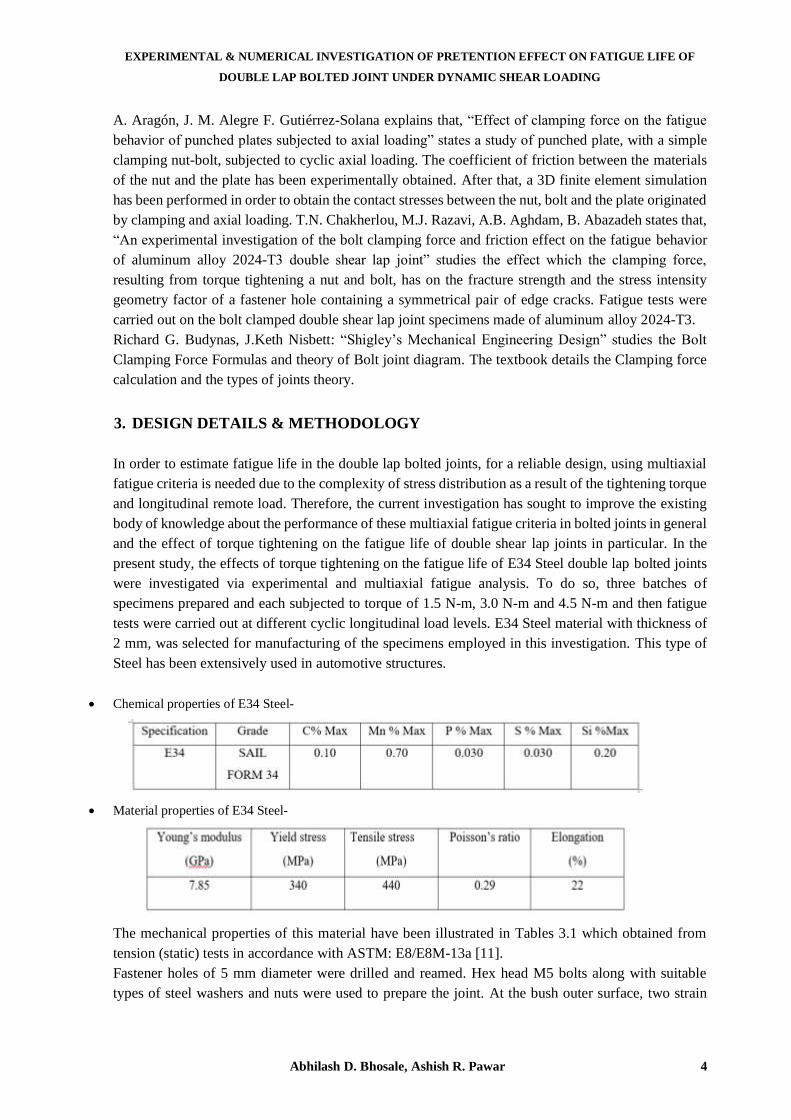
Fastener holes of 5 mm diameter were drilled and reamed. Hex head M5 bolts along with suitable
types of steel washers and nuts were used to prepare the joint. At the bush outer surface, two strain
Journal of Analysis and Computation (JAC) (An International Peer Reviewed Journal), www.ijaconline.com, ISSN 0973-2861
Volume XV, Issue V, May 2021
Abhilash D. Bhosale, Ashish R. Pawar 5
gauges were stuck to measure the compressive axial strain and so the stress in the bush using Hooke’s
stress–strain law. Having the bush cross-sectional area at hand and the axial stress, the axial force in
the bush and then the clamp force has been determined. To calculate the Clamping force Theoretical
formula as given in Eq.2 is used where Fcl is ‘Clamping Force’, K = ‘Coefficient of friction’ and D is
‘Dia of Bolt’. Generally, the Friction between Steel is considered in range of 0.15-0.2. To calibrate the
applied torque and clamping force, torques were applied in 1 N m increments from 1 to 7 N m to the
nut using a torque wrench, and then the axial strains were recorded for each value of the torques. This
test was repeated three times for each case to obtain the mean value of compressive strains (ɛm), and
determine the corresponding clamping forces using Eq. (2). The elastic modulus for the bush material
(Ebush) was also experimentally determined in order to obtain the accurate values for the mean axial
clamping force.
Theoretical Calculation- Fcl = T/KD = 1500/ (0.2 × 5) = 1000N ----------- (3)
Experimental Calculation-
--------- (4)
Fig. 4 Test specimen configuration and dimensions
Fig. 5 Isometric View

EXPERIMENTAL & NUMERICAL INVESTIGATION OF PRETENTION EFFECT ON FATIGUE LIFE OF
DOUBLE LAP BOLTED JOINT UNDER DYNAMIC SHEAR LOADING
Abhilash D. Bhosale, Ashish R. Pawar 6
Any assembly will have many components to fulfill the functional requirements. Globally, the OEM
practice is to validate any component design after, the drawing is created. The created design should
meet the performance standards. To test the validity of the designed component is in accordance to
the desired performance standard; the designer opts for physical or virtual validation. All the
components in the assembly will have their own structural properties like natural frequency, stiffness,
mass etc. Hence, the process of validation starts with static test.
Fig. 6 CAE methodology in design loop
i. Non-Linear Analysis
When structure response (deformation, stress and strain) is linearly proportional to the magnitude of
the load (force, pressure, moment, torque etc.) then the analysis of such a structure is known as linear
analysis. When the load to response relationship is not linearly proportional, then the analysis falls
under non-linear analysis. e.g., force (stress) vs displacement (strain) curve is non-liner (polynomial).
Stiffness [K] is the function of displacement [d] and deals with true stress & strain.
[M] ẍ (t) + [C] ẋ (t) + [K] x (t) = F(t) ------------------ (5)
Where,
M ẍ (t) = 𝑑2𝑥
𝑑𝑡2 = are the inertia forces, which are functions of the mass matrix M and the nodal
acceleration vector ẍ (t),
C ẋ (t) = 𝑑𝑥
𝑑𝑡 = the viscous damping forces, which are functions of the damping matrix C and the nodal
velocities x˙ (t),
K x (t) = the elastic forces, which are functions of the stiffness matrix K and the nodal displacement
vector x (t) and F (t) = the applied loads.
For non-linear analysis,
[M] ẍ = 0, [C] ẋ = 0, [K] is function of {d}, F(t) = constant

Journal of Analysis and Computation (JAC) (An International Peer Reviewed Journal), www.ijaconline.com, ISSN 0973-2861
Volume XV, Issue V, May 2021
Abhilash D. Bhosale, Ashish R. Pawar 7
Fig. 7 Non-linearity classification
ii. Fatigue Analysis
The FEMFAT BASIC program uses the load spectrum as the external stress, similar to the concept of
nominal stress. The treatment of the various stress relationships (Ri, ai) in the individual load
spectrum stages is performed in FEMFAT by determining the local component S/N curve
corresponding to the respective stress relationship (Ri, ai).
Fig. 8 Schematic representation of a component S/N curve
A local component S/N curve, such as that shown in figure 4.3, is described in a log-log plot by the
following three parameters:
The endurance stress limit af, C
The endurance cycle limit Ncf, C and
The slope kc.
Miner’s rule is probably the simplest cumulative damage model. It states that if there are k different
stress levels and the average number of cycles to failure at the ith stress, Si, is Ni, then the damage
fraction, C, is:
--------- (6)
Where,
EXPERIMENTAL & NUMERICAL INVESTIGATION OF PRETENTION EFFECT ON FATIGUE LIFE OF
DOUBLE LAP BOLTED JOINT UNDER DYNAMIC SHEAR LOADING
Abhilash D. Bhosale, Ashish R. Pawar 8
ni is the number of cycles accumulated at stress Si.
C is the fraction of life consumed by exposure to the cycles at the different stress levels.
In general, when the damage fraction reaches 1, failure occurs. The above equation can be thought of
as assessing the proportion of life consumed at each stress level and then adding the proportions for
all the levels together. Often an index for quantifying the damage is defined as the product of stress
and the number of cycles operated under this stress, which is
--------- (7)
Assuming that the critical damage is the same across all the stress levels, then:
--------- (8)
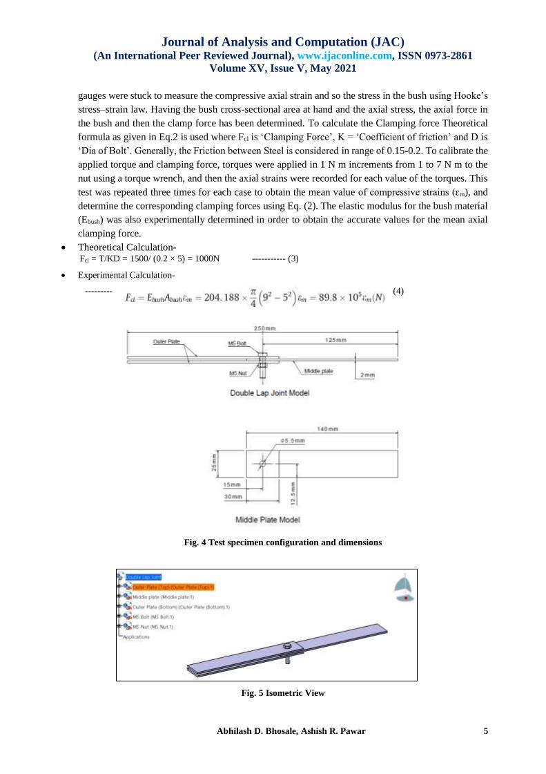
The stress amplitude a and the mean stress m can be defined as the nominal or local stress. Accordingly,
these concepts are known as the nominal stress concept or principal of local strains. In FEMFAT, these are the
local elastic stresses, and can be determined from the external stress by means of a structural elastic FEM analysis
of each component.
Fig. 9 Schematic representation of the modifications of Miner’s rule
Using the elementary Miner rule, the creep strength domain S/N curve with slope ‘k’ is extended until
stress amplitude a= 0.
Below the endurance stress limit e, the modified Miner rule employs a fictitious extension to the
creep strength domain with a slope 2k-1.
In automotive industries, fatigue life is estimated by using a numerical technique including both a
discretized model of the structure and an associated load-time history that represents a specified event
in the life of the structure. To facilitate this technique, FEM can be used. FEM is certainly a great
advantage when the fatigue life of complex geometries is being estimated. In this chapter, the advanced
fatigue mechanisms were discussed. Whether it is the S-N or E-N approach, high-cycles or low-cycles
fatigue, they all require obtaining stresses and strains [8].
4. FINITE ELEMENT ANALYSIS
4.1 Element Type
In analysis C3D10M element are used for analysis. For a 3D stress analysis, ABAQUS offers 4
different classifications of quadratic tetrahedral elements namely C3D10, C3D10M, C3D10H and
Journal of Analysis and Computation (JAC) (An International Peer Reviewed Journal), www.ijaconline.com, ISSN 0973-2861
Volume XV, Issue V, May 2021
Abhilash D. Bhosale, Ashish R. Pawar 9
C3D10I. Although it is very clear that C3D10H are hybrid elements and primarily intended for
simulating incompressible materials (e.g., Hyperplastic behavior modeling with rubber, human muscle
tissue etc.), many users often tend to confuse between using the remaining elements. Let us take a look
at using these elements with respect to contact analysis in ABAQUS/Standard.C3D10 are textbook
formulation second-order tetrahedral elements. Upon applying a uniform pressure load to its face these
elements generate zero nodal forces at corner node rendering them. C3D10 elements are recommended
for any contact involving finite sliding with node to surface or surface to surface formulation when
used with penalty enforcement method [9].
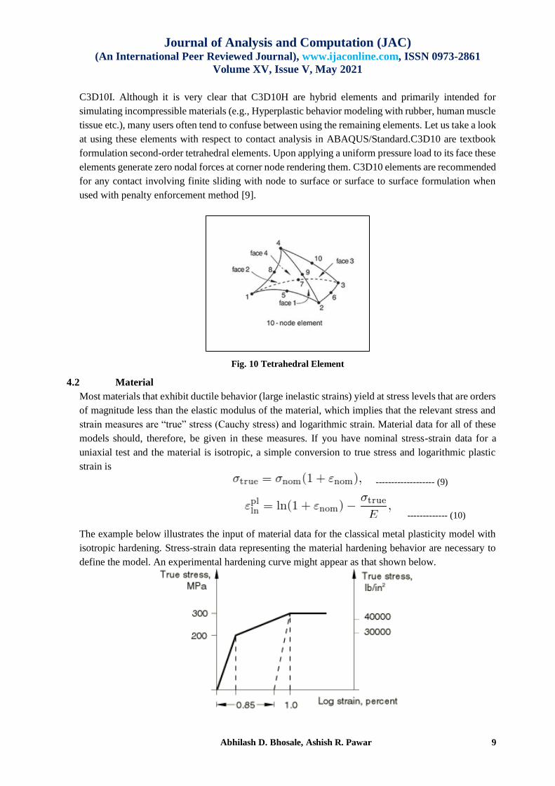
Fig. 10 Tetrahedral Element
4.2 Material
Most materials that exhibit ductile behavior (large inelastic strains) yield at stress levels that are orders
of magnitude less than the elastic modulus of the material, which implies that the relevant stress and
strain measures are “true” stress (Cauchy stress) and logarithmic strain. Material data for all of these
models should, therefore, be given in these measures. If you have nominal stress-strain data for a
uniaxial test and the material is isotropic, a simple conversion to true stress and logarithmic plastic
strain is
------------------- (9)
------------- (10)
The example below illustrates the input of material data for the classical metal plasticity model with
isotropic hardening. Stress-strain data representing the material hardening behavior are necessary to
define the model. An experimental hardening curve might appear as that shown below.

EXPERIMENTAL & NUMERICAL INVESTIGATION OF PRETENTION EFFECT ON FATIGUE LIFE OF
DOUBLE LAP BOLTED JOINT UNDER DYNAMIC SHEAR LOADING
Abhilash D. Bhosale, Ashish R. Pawar 10
Fig. 11 Stress-strain diagram representing material hardening
First yield occurs at 200 MPa. The material then hardens to 300 MPa at one percent strain, after which it is perfectly plastic. Assuming that the Young's modulus is 200000 MPa, the plastic strain at the one percent strain point is .01 –300/200000=.0085. When the units are newton’s and millimeters, the input is
Table 1 Stress-strain data Yield Stress (N/mm2) Plastic Strain
200 0.0
300 0.0085
4.3 Contact Non-Linearity
Abaqus provides more than one approach for defining contact. Abaqus/Standard includes the
following approaches for defining contact:
1. General contact
2. Contact pairs
3. Contact elements
Fig.12 Schematic Fig of Double Lap Shear Joint
4.5 Modelling Details
Fig.13 Plate orientation for Lap Joint
Plate2
Material: Steel (E34) Thickness: 2mm
Bolt M8
Material: Steel
Plate1
Material: Steel (E34)
Thickness: 2mm
Plate3
Material: Steel (E34)
Thickness: 2mm
Journal of Analysis and Computation (JAC) (An International Peer Reviewed Journal), www.ijaconline.com, ISSN 0973-2861
Volume XV, Issue V, May 2021
Abhilash D. Bhosale, Ashish R. Pawar 11
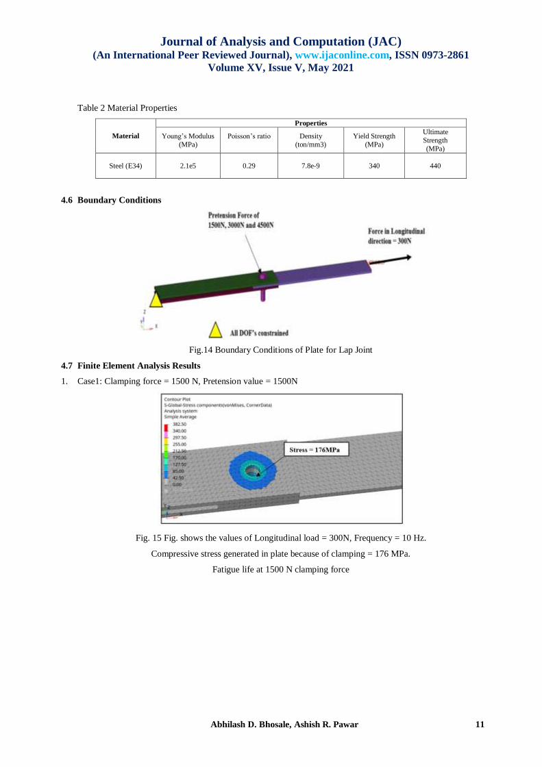
Table 2 Material Properties
Material
Properties
Young’s Modulus
(MPa)
Poisson’s ratio
Density
(ton/mm3)
Yield Strength
(MPa)
Ultimate
Strength
(MPa)
Steel (E34) 2.1e5 0.29 7.8e-9 340
440
4.6 Boundary Conditions
Fig.14 Boundary Conditions of Plate for Lap Joint
4.7 Finite Element Analysis Results
1. Case1: Clamping force = 1500 N, Pretension value = 1500N
Fig. 15 Fig. shows the values of Longitudinal load = 300N, Frequency = 10 Hz.
Compressive stress generated in plate because of clamping = 176 MPa.
Fatigue life at 1500 N clamping force

EXPERIMENTAL & NUMERICAL INVESTIGATION OF PRETENTION EFFECT ON FATIGUE LIFE OF
DOUBLE LAP BOLTED JOINT UNDER DYNAMIC SHEAR LOADING
Abhilash D. Bhosale, Ashish R. Pawar 12
Fig. 16 Fig. shows the values of Fatigue life (min) = 14200 cycles & Fatigue life (max) = 1e6 cycles
2. Case2: Clamping force = 3000 N, Pretension value = 3000N
Fig. 17 Fig. shows the values of Longitudinal load = 300N, Frequency = 10 Hz
Compressive stress generated in plate because of clamping = 301 MPa
Fatigue life at 3000 N clamping force
Fig. 18 Fig. shows the values of Fatigue life (min) = 64000 cycles
Fatigue life (max) = 1e6 cycles
3. Case3: Clamping force = 4500 N, Pretension value = 4500N
Journal of Analysis and Computation (JAC) (An International Peer Reviewed Journal), www.ijaconline.com, ISSN 0973-2861
Volume XV, Issue V, May 2021
Abhilash D. Bhosale, Ashish R. Pawar 13
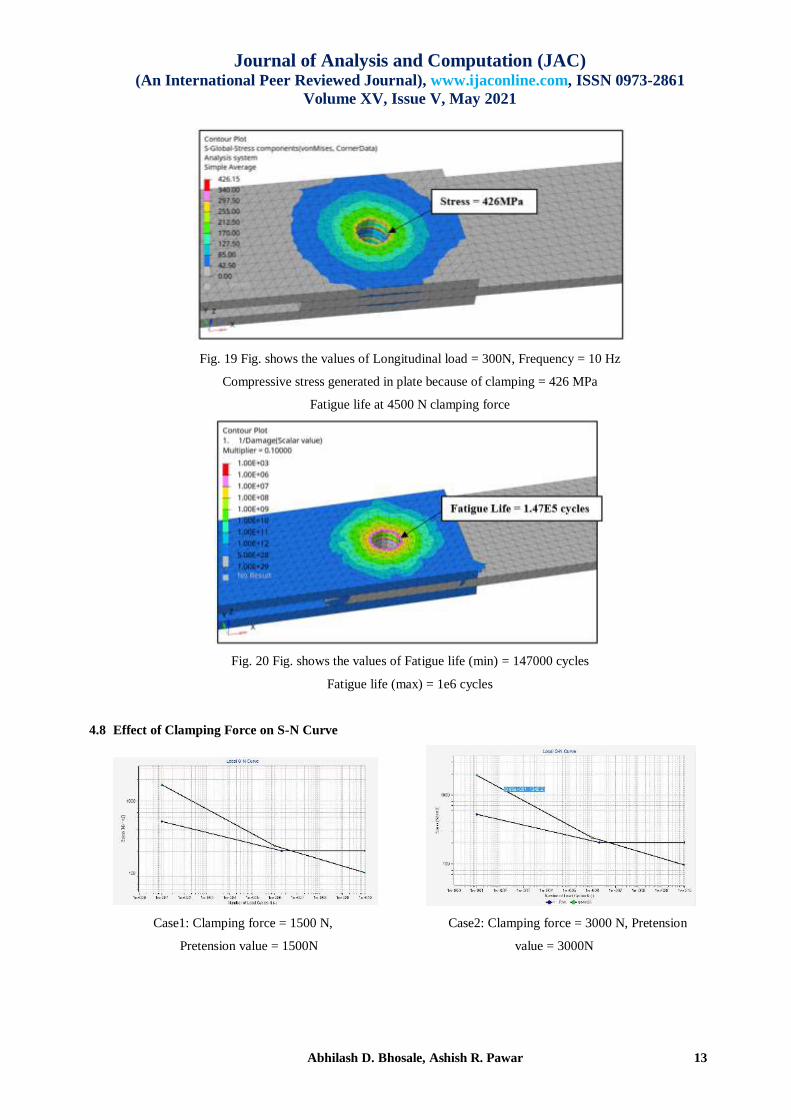
Fig. 19 Fig. shows the values of Longitudinal load = 300N, Frequency = 10 Hz
Compressive stress generated in plate because of clamping = 426 MPa
Fatigue life at 4500 N clamping force
Fig. 20 Fig. shows the values of Fatigue life (min) = 147000 cycles
Fatigue life (max) = 1e6 cycles
4.8 Effect of Clamping Force on S-N Curve
Case1: Clamping force = 1500 N, Case2: Clamping force = 3000 N, Pretension
Pretension value = 1500N value = 3000N
EXPERIMENTAL & NUMERICAL INVESTIGATION OF PRETENTION EFFECT ON FATIGUE LIFE OF
DOUBLE LAP BOLTED JOINT UNDER DYNAMIC SHEAR LOADING
Abhilash D. Bhosale, Ashish R. Pawar 14
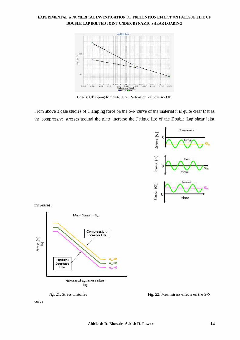
Case3: Clamping force=4500N, Pretension value = 4500N
From above 3 case studies of Clamping force on the S-N curve of the material it is quite clear that as
the compressive stresses around the plate increase the Fatigue life of the Double Lap shear joint
increases.
Fig. 21. Stress Histories Fig. 22. Mean stress effects on the S-N
curve
Journal of Analysis and Computation (JAC) (An International Peer Reviewed Journal), www.ijaconline.com, ISSN 0973-2861
Volume XV, Issue V, May 2021
Abhilash D. Bhosale, Ashish R. Pawar 15
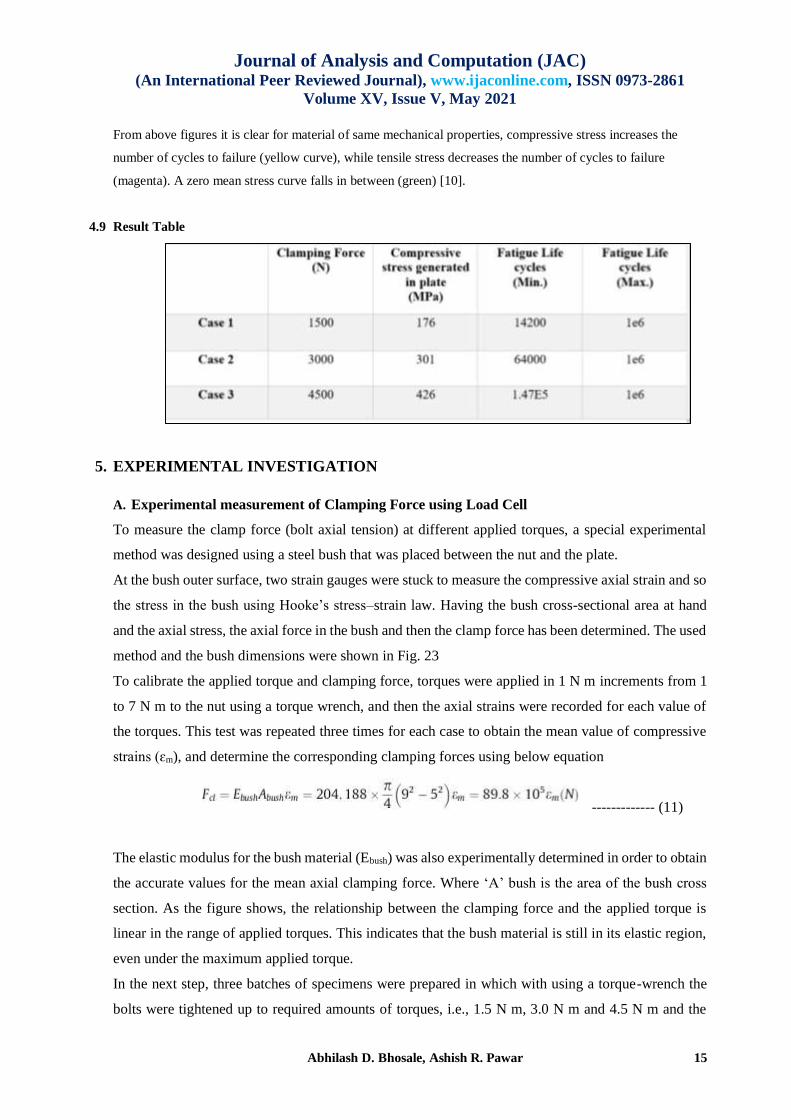
From above figures it is clear for material of same mechanical properties, compressive stress increases the
number of cycles to failure (yellow curve), while tensile stress decreases the number of cycles to failure
(magenta). A zero mean stress curve falls in between (green) [10].
4.9 Result Table
5. EXPERIMENTAL INVESTIGATION
A. Experimental measurement of Clamping Force using Load Cell
To measure the clamp force (bolt axial tension) at different applied torques, a special experimental
method was designed using a steel bush that was placed between the nut and the plate.
At the bush outer surface, two strain gauges were stuck to measure the compressive axial strain and so
the stress in the bush using Hooke’s stress–strain law. Having the bush cross-sectional area at hand
and the axial stress, the axial force in the bush and then the clamp force has been determined. The used
method and the bush dimensions were shown in Fig. 23
To calibrate the applied torque and clamping force, torques were applied in 1 N m increments from 1
to 7 N m to the nut using a torque wrench, and then the axial strains were recorded for each value of
the torques. This test was repeated three times for each case to obtain the mean value of compressive
strains (ɛm), and determine the corresponding clamping forces using below equation
------------- (11)
The elastic modulus for the bush material (Ebush) was also experimentally determined in order to obtain
the accurate values for the mean axial clamping force. Where ‘A’ bush is the area of the bush cross
section. As the figure shows, the relationship between the clamping force and the applied torque is
linear in the range of applied torques. This indicates that the bush material is still in its elastic region,
even under the maximum applied torque.
In the next step, three batches of specimens were prepared in which with using a torque-wrench the
bolts were tightened up to required amounts of torques, i.e., 1.5 N m, 3.0 N m and 4.5 N m and the

EXPERIMENTAL & NUMERICAL INVESTIGATION OF PRETENTION EFFECT ON FATIGUE LIFE OF
DOUBLE LAP BOLTED JOINT UNDER DYNAMIC SHEAR LOADING
Abhilash D. Bhosale, Ashish R. Pawar 16
observed Ɛm = 0.01086 mm, 0.031626 mm and 0.04654 mm respectively which created clamping
forces equal to Fcl = 1120, 2840 and 4180 N respectively, according to the linear equation obtained
from Fig. 24.
Fig. 23 Steel bush and its dimensions in mm and (b) position of prepared load cell in the joint.
Fig. 24 Linear relation between applied tightening torque and clamping force
B. Experimental measurement of Fatigue Life
Fatigue tests have been carried out for stress ratio of 0.1 and frequency of 10 Hz using servo-hydraulic 250 KN
Zwick/ Roell fatigue testing machine.

Journal of Analysis and Computation (JAC) (An International Peer Reviewed Journal), www.ijaconline.com, ISSN 0973-2861
Volume XV, Issue V, May 2021
Abhilash D. Bhosale, Ashish R. Pawar 17
Fig. 25 Servo-hydraulic 250 KN Zwick/Roell fatigue testing machine and fatigue test specimen
Fig. 26 S–N curve attained from experimental fatigue tests
Fig. 27 Fractured fatigue specimen with clamping force
Fcl = 1280 N that subjected to remote longitudinal load 7.0 KN
Fig. 26 shows that total 6 specimen were tested for each of the Pretention values and a curve was fit
for all three cases. It was quite clear that increasing the clamping force increased the fatigue life of
the specimen.
EXPERIMENTAL & NUMERICAL INVESTIGATION OF PRETENTION EFFECT ON FATIGUE LIFE OF
DOUBLE LAP BOLTED JOINT UNDER DYNAMIC SHEAR LOADING
Abhilash D. Bhosale, Ashish R. Pawar 18
6. CONCLUSIONS
In this investigation, the effects of clamping force on fatigue strength of double lap bolted joints have
been studied via experimental & fatigue analysis based on obtained results following conclusions can
be drawn,
As the tightening torque or the Clamping force is increase it leads to the improvement in the fatigue
life of Double Lap Shear joint.
By increasing the Clamping force, the Double lap shear joint induces compressive stresses around the
hole of the plate and this helps in enhancement of the fatigue life of the joint.
REFERENCES
1. F. Esmaeili, T. N. Chakherlou, M. Zehsaz, 2014, “Prediction of fatigue life in aircraft double lap bolted joints
using several multiaxial fatigue criteria”, Journal-Materials & Design.
2. Ashish Pawar, Harshal Dharmale, Ganesh Kondhalkar, “Numerical Investigation of Bolt Loosening in A
Bolted Joint Structure” in Journal of Analysis & Computation (IJAC, UGC), Volume XIV Issue VII, July 2020
ISSN: 0973-2861, pp. 1-12
3. F. Esmaeili, T. N. Chakherlou, M. Zehsaz, S. Hasanifard, 2013, “Investing the effect of clamping force on fatigue
life of bolted plates using volumetric approach” Faculty of Mechanical Engineering, University of Tabriz, Iran.
4. Ashish R. Pawar, Dr. K. H. Munde, Vidya Wagh, “Stress Analysis of Crane Hook with Different Cross Section
Using Finite Element Method” in Journal of Emerging Technologies and Innovative Research (JETIR, UGC),
Volume 6 Issue 1, Jan 2019 ISSN: 2349-5162, pp. 79-83
5. A. Aragon, J. M. Alegre, F. Gutierrez-Solana, 2005, “Effect of clamping force on the fatigue behavior of punched
plates subjected to axial loading”, Department of Civil Engineering, University of Burgos, Spain.
6. T. N. Cakherlou, B. Abazadeh, J. Vogwell, 2008, “The effect of bolt clamping force on the fracture strength and
the stress intensity factor of a plate containing a fastener hole with edge cracks”, Journal-Engineering failure
analysis.
7. T. N. Chakherlou, M. J. Razavi, A. B. Aghdam, B. Abazadeh, 2010, “An experimental investigation of the bolt
clamping force and friction effect on the fatigue behavior of aluminum alloy 2024-T3 double shear lap joint”,
Journal-Materials & Design.
8. Ashish Pawar, Sampada Ahirrao, Ganesh Kondhalkar, “Fatigue Analysis of Leaf Spring Bracket for Light
Duty Vehicles on Topology Optimization Approach” in Journal of Analysis & Computation (IJAC, UGC),
Volume XIV Issue VII, July 2020 ISSN: 0973-2861, pp. 1-11
9. Budynas RG, Nisbett JK. Shigley’s mechanical engineering design. 9thed. McGraw-Hill; 2011.
10. Chakherlou TN, Mirzajanzadeh M, Abazadeh B, Saeedi K. An investigation about interference fit effect on
improving fatigue life of a holed single plate in joints. Eur J Mech A – Solid 2010; 29:675–82.
11. https://www.weibull.com/hotwire/issue116/hottopics116.htm
12. https://abaqus-docs.mit.edu
13. https://community.sw.siemens.com/s/article/mean-stress-corrections-and-stress-ratios
14. https://www.jswsteelformsme.in/uploads/pdf/jsw-hot-rolled-brochure.pdf
15. Valtinat G, Hadrych I, Huhn H. Strengthening of riveted and bolted steel constructions under fatigue loading by
preloaded fasteners experimental and theoretical investigations. In: Published on conference: connections in steel
structures IV. AISC and ECCS, Roanoke/USA; 2000.ECCS, Roanoke/USA; 2000.
Journal of Analysis and Computation (JAC) (An International Peer Reviewed Journal), www.ijaconline.com, ISSN 0973-2861
Volume XV, Issue V, May 2021
Abhilash D. Bhosale, Ashish R. Pawar 19
16. McDiarmid DL. A general criterion for high cycle multiaxial fatigue failure. Fatigue Fract Eng Mat Struct
1991;14:429–53.
17. Chen X, Gao Q, Sun XF. Damage analysis of low cycle fatigue under nonproportional loading. Int J Fatigue
1994.
18. Chakherlou TN, Abazadeh B. Estimation of fatigue life for plates including pretreated fastener holes using
different multiaxial fatigue criteria. Int J Fatigue 2011;33:343–53.
19. Jiang Yanyao, Hertel Olaf, Vormwald Michael. An experimental evaluation of three critical plane multiaxial
fatigue criteria. Int J Fatigue 2007;29:1490–502.
20. Oskouei RH. An investigation into bolt clamping effects on distributions of stresses and strains near fastener
hole and its effect on fatigue life. MSc thesis, University of Tabriz; 2005 [chapter 3].
21. You BR, Lee SB. A critical review on multiaxial fatigue assessments of metals. Int J Fatigue 1996;18(4):235–
44.
22. Papadopoulos IV, Davoli P, Grola C, Filippini M, Bernasconi A. A comparative study on multiaxial high-cycle
fatigue criteria for metals. Int J Fatigue 1997;19(3):219–35.
23. Ashish R. Pawar, Deepak N. Patil, Ganesh E. Kondhalkar, “STRUCTURAL OPTIMIZATION OF
BUMPERFOG LAMP PUNCHING MACHINE” in Journal of Analysis & Computation (IJAC, UGC),
Volume XIV Issue I - VI, 2021 ISSN: 0973-2861, pp. 71-84
24. Ashish Pawar, Suraj Jadhav, “Experimental & Non-Linear Analysis to Investigate Optimum Shape Crash Box”
in Journal of Interdisciplinary Cycle Research (JICR, UGC), Volume XII Issue VII, July 2020 ISSN: 0022-
1945, pp. 966-973
Related Documents