Welcome message from author
This document is posted to help you gain knowledge. Please leave a comment to let me know what you think about it! Share it to your friends and learn new things together.
Transcript


ENO-30 ENG, #04v2,2014
NOx Analyzer (ENO-30)
User’s Guide
Distributed by Eicom USA: 7098 Miratech Dr, Ste 100, San Diego, CA 92121, USA
Phone: (888) 680-7775 FAX: (858) 560-8040 Email: [email protected]
Distributed by Eicom Europe: Hilton House Ardee Rd, Ground Floor, Rathimines Dublin 6, Ireland
Phone: +353 1 902 2700 FAX: +353 1 443 0784
Manufacturered by Eicom Corporation: 113 Kita Enmenden-cho, Shimotoba, Fushimi-ku Kyoto, Japan, 612-8497
Phone: +81-75-622-2112 FAX : +81-75-622-2114
Contents
1. INTRODUCTION --------------------------------------------------------------------------------------------------------------------------- 1
1-1. About this user’s guide ----------------------------------------------------------------- 1
1-2. Important Safety Information --------------------------------------------------------- 2
2. OVERVIEW ---------------------------------------------------------------------------------------------------------------------------------- 3
2-1. Principle of Measurement ------------------------------------------------------------- 3
2-2. Schematic of Parts and Functions -------------------------------------------------- 4
2-3. Tubing Flow Diagram ------------------------------------------------------------------- 6
2-4. Pump Seal Wash ------------------------------------------------------------------------ 7
2-5. Fittings and Tubing ---------------------------------------------------------------------- 8
3. INSTALLATION --------------------------------------------------------------------------------------------------------------------------- 10
3-1. Location ---------------------------------------------------------------------------------- 10
3-2. Power Plug ------------------------------------------------------------------------------ 10
3-3. Electrical connections (Detector Unit side panel) ----------------------------- 11
3-4 Electrical Connections (Pump Unit Signal Terminal) -------------------------- 12
3-5. Manual injector Tubing Connections --------------------------------------------- 13
3-6. Connect Tubing to Autosampler (optional) -------------------------------------- 13
4. PUMP UNIT OPERATION -------------------------------------------------------------------------------------------------------------- 14
4-1. Pump overview ------------------------------------------------------------------------- 14
4-2. Power On -------------------------------------------------------------------------------- 15
4-3. Key Pad ---------------------------------------------------------------------------------- 16
4-4. Display Screen ------------------------------------------------------------------------- 18
4-5. Log Function ---------------------------------------------------------------------------- 18
4-6. Adjusting the Settings ---------------------------------------------------------------- 19
4-7. Priming the Pump/ Purge Valve Operation ------------------------------------- 22
4-8. Pump error messages ---------------------------------------------------------------- 23
5. DETECTOR/OVEN OPERATION ---------------------------------------------------------------------------------------------------- 24
5-1. Power Switch --------------------------------------------------------------------------- 24
5-2. Setting Temperature ------------------------------------------------------------------ 24
5-3. Detector Readings --------------------------------------------------------------------- 24
5-4. Autozero Function --------------------------------------------------------------------- 24
6. ANALYSIS ---------------------------------------------------------------------------------------------------------------------------------- 25
6-1. Accurate Analysis ---------------------------------------------------------------------- 25
6-2. Water Quality --------------------------------------------------------------------------- 25
6-3. Reagent Quality ------------------------------------------------------------------------ 25
6-4. Carrier and Reactor Solutions Preparation ------------------------------------- 26
6-5. Standard Solution ---------------------------------------------------------------------- 27
6-6. Waste ------------------------------------------------------------------------------------- 27
6-7. Prepare for Analysis ------------------------------------------------------------------- 27
6-8. Start up ----------------------------------------------------------------------------------- 28
7. SAMPLE INJECTION ------------------------------------------------------------------------------------------------------------------- 29
7-1. Manual Injector Operation ----------------------------------------------------------- 29
7-2. Sample Amount ------------------------------------------------------------------------ 30
7-3. Autosampler Operation (optional) ------------------------------------------------- 30
8. SHUTDOWN AFTER ANALYSIS ----------------------------------------------------------------------------------------------------- 31
8-1. Short Shutdown, less than 2 weeks ---------------------------------------------- 31
8-2. Complete Shutdown, over 2 weeks ----------------------------------------------- 31
9. RESTART ---------------------------------------------------------------------------------------------------------------------------------- 32
9-1 After complete shutdown procedure ----------------------------------------------- 32
9-2. After short shutdown procedure ---------------------------------------------------- 32
10. PRECOLUMN --------------------------------------------------------------------------------------------------------------------------- 34
10-1. Determining the Precolumn Condition ------------------------------------------ 34
10-2. How to Repack the Precolumn --------------------------------------------------- 35
10-3. Filter Exchange ----------------------------------------------------------------------- 37
11. SEPARATION COLUMN (NO-PAK) ----------------------------------------------------------------------------------------------- 38
11-1. NO-PAK --------------------------------------------------------------------------------- 38
11-2. Identification of Separation Quality ---------------------------------------------- 38
11-3. Washing the Separation Column ------------------------------------------------- 38
12. REDUCTION COLUMN (NO-RED) ------------------------------------------------------------------------------------------------ 39
12-1. Structure and Maintenance -------------------------------------------------------- 39
12-2. Timing to Exchange ----------------------------------------------------------------- 39
12-3. Damage -------------------------------------------------------------------------------- 39
13. TROUBLESHOOTING ---------------------------------------------------------------------------------------------------------------- 40
13-1. Pump Problems ---------------------------------------------------------------------- 40
13-2. Checking the Flow Rate ------------------------------------------------------------ 40
13-4. Removing Air Bubbles -------------------------------------------------------------- 40
13-4. High Carrier Pump pressure ------------------------------------------------------ 41
13-5. Unstable Baseline -------------------------------------------------------------------- 41
13-6. Peak Shape --------------------------------------------------------------------------- 41
14. MAINTENANCE ------------------------------------------------------------------------------------------------------------------------- 42
14-1. Pump Head Parts -------------------------------------------------------------------- 42
14-2. Changing the Piston Seal and Piston ------------------------------------------- 43
15. APPENDICES --------------------------------------------------------------------------------------------------------------------------- 47
15-1. Autosampler and Data Processor (EPC-700) Connection ---------------- 47
15-2. Specifications ------------------------------------------------------------------------- 48
15-3. Sample Preparation ----------------------------------------------------------------- 49

1 | P a g e
1. Introduction
Thank you for purchasing the Eicom NOx Analyzer (ENO-30). Please read this user’s guide
before use.
The ENO-30 is an HPLC-based system designed to perform high sensitivity analysis of Nitrite
and Nitrate in biological samples. The lower half of the system is the pump unit. It has two
independent pumps and a two channel online degasser. The pump has s self-learning pulse
damping flow control which ensures stable liquid delivery, and is made of inert, non-metallic
parts for better salt and acid resistance.
The upper unit uses forced air and a Peltier device to maintain the columns, reaction loop, and
detector cell at the correct temperature for the analysis. The detector signal is taken from the
side terminals into a data process (EPC-700) and digitized for analysis in a PC with the Envision
software.
1-1. About this user’s guide
Latest-breaking information may be supplied separately.
We reserve the right to change the content of this document with or without notice.
No part of this guide may be reproduced by any means without the prior written permission
of Eicom. All rights reserved.
The ENO-30 requires a thorough understanding of this document for proper operation.
Please contact Eicom directly if you have any unanswered questions after reading this
document.
2 | P a g e
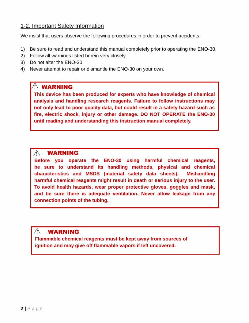
1-2. Important Safety Information
We insist that users observe the following procedures in order to prevent accidents:
1) Be sure to read and understand this manual completely prior to operating the ENO-30.
2) Follow all warnings listed herein very closely.
3) Do not alter the ENO-30.
4) Never attempt to repair or dismantle the ENO-30 on your own.
This device has been produced for experts who have knowledge of chemical
analysis and handling research reagents. Failure to follow instructions may
not only lead to poor quality data, but could result in a safety hazard such as
fire, electric shock, injury or other damage. DO NOT OPERATE the ENO-30
until reading and understanding this instruction manual completely.
WARNING
Before you operate the ENO-30 using harmful chemical reagents,
be sure to understand its handling methods, physical and chemical
characteristics and MSDS (material safety data sheets). Mishandling
harmful chemical reagents might result in death or serious injury to the user.
To avoid health hazards, wear proper protective gloves, goggles and mask,
and be sure there is adequate ventilation. Never allow leakage from any
connection points of the tubing.
WARNING
Flammable chemical reagents must be kept away from sources of
ignition and may give off flammable vapors if left uncovered.
WARNING
3 | P a g e
2. Overview
2-1. Principle of Measurement
The ENO-30 is a high sensitivity instrument for measuring nitrite and nitrate ion level in
biological fluids. This is achieved by combining a colorimetric diazo coupling method (Griess)
with the advantages of HPLC.
After the sample is injected it is filtered by the guard column. Then the separation column
interacts with the ions in such a way that they flow though the column at different rates. Nitrite
exits the column first, and then some minutes later, the Nitrate leaves the column. The NO2- and
NO3- next flow into the reduction column made is cadmium and copper.
Inside the reduction column, the NO3- is reduced to NO2
- through a reaction with the cadmium
and reduced copper. The NO2- that exited first will not react. So now there are two Nitrite peaks,
the first is from the Nitrite in the sample and the second is from the Nitrate in the sample. Both
are mixed with a Reactor solution supplied by a second pump at a 3-way joint, and then flow
into a reaction loop. This gives time for the reaction come to the right temperature and complete
formation of a light absorbing diazo compound that can measured at the detector.
In the detector cell, 540 nm (green) light passes through the sample, and the absorption is
proportional to the amount of diazo compound, and thus to the amount of Nitrite or Nitrate.
The response of the detector is transformed to a voltage which it generates at the CPU terminal.
The time/voltage change is traced by a data processor such as the optional Eicom EPC-700. By
comparing peak area or height shown on a chromatogram with a standard one, the exact
concentration Nitrite and Nitrate can be calculated.
4 | P a g e
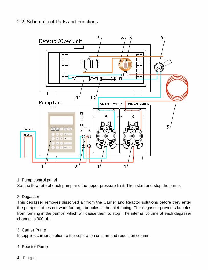
2-2. Schematic of Parts and Functions
1. Pump control panel
Set the flow rate of each pump and the upper pressure limit. Then start and stop the pump.
2. Degasser
This degasser removes dissolved air from the Carrier and Reactor solutions before they enter
the pumps. It does not work for large bubbles in the inlet tubing. The degasser prevents bubbles
from forming in the pumps, which will cause them to stop. The internal volume of each degasser
channel is 300 µL.
3. Carrier Pump
It supplies carrier solution to the separation column and reduction column.
4. Reactor Pump
5 | P a g e
It supplies the reactor solution to the reaction coil.
5. Reactor Backpressure Coil
It maintains high enough pressure that the reactor pump can work efficiently.
6. Manual Injector (and/or Autosampler)
Manual injection of up to 50 µL of sample using a blunt ended Hamilton syringe can be made
here.
7. Mixer
Mixes the column effluent with the Reactor solution before entering the reaction coil.
8. Reaction Coil
Gives time for the reaction to be heated and go to completion. It also helps to reduce mixing
noise.
9. Detector Cell
Detects absorbance at 540 nm.
10. Separation Column
Separates the Nitrite and the Nitrate from other biological compounds.
11. Reduction Column
Reduces the Nitrate to Nitrite so that it can react with the Greiss reagent.
6 | P a g e
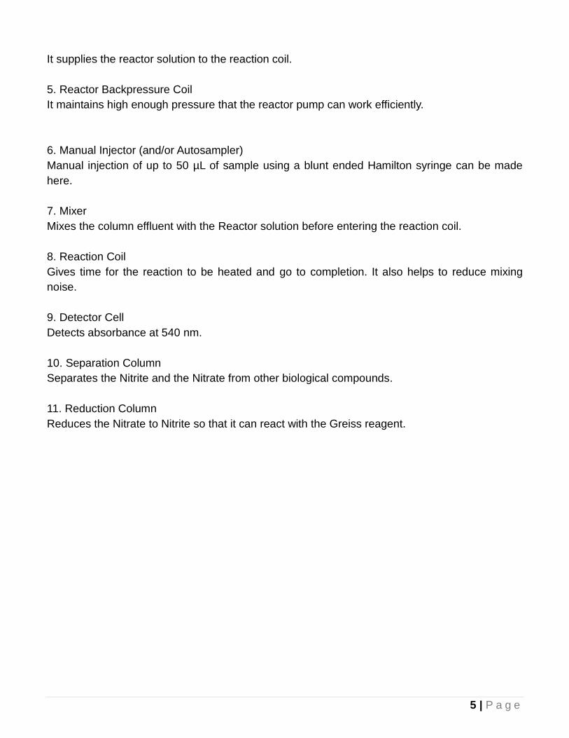
2-3. Tubing Flow Diagram
Please use this diagram as a guide in make all the proper tubing connections.
Important points:
The column effluent (Carrier) and the Reactor solution should enter the 3-way joint on
opposite sides of the straight part of the joint to improve mixing.
Be careful to never let the Reactor solution enter the separation column. It may be
severely damaged.
Also turn the Reactor pump off 1 minute before the Carrier pump in order to wash all the
Reactor solution out of the tubing because it can stain if left in place. This will lead to
higher background.
7 | P a g e
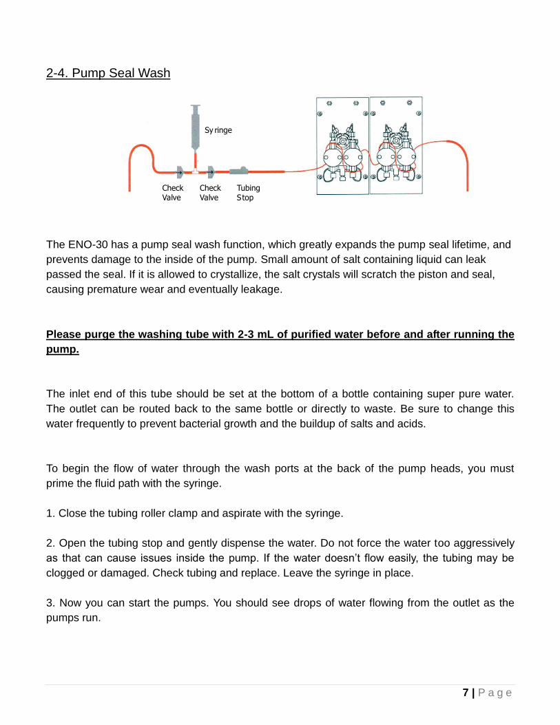
2-4. Pump Seal Wash
Sy ringe
CheckValve
CheckValve
TubingStop
The ENO-30 has a pump seal wash function, which greatly expands the pump seal lifetime, and
prevents damage to the inside of the pump. Small amount of salt containing liquid can leak
passed the seal. If it is allowed to crystallize, the salt crystals will scratch the piston and seal,
causing premature wear and eventually leakage.
Please purge the washing tube with 2-3 mL of purified water before and after running the
pump.
The inlet end of this tube should be set at the bottom of a bottle containing super pure water.
The outlet can be routed back to the same bottle or directly to waste. Be sure to change this
water frequently to prevent bacterial growth and the buildup of salts and acids.
To begin the flow of water through the wash ports at the back of the pump heads, you must
prime the fluid path with the syringe.
1. Close the tubing roller clamp and aspirate with the syringe.
2. Open the tubing stop and gently dispense the water. Do not force the water too aggressively
as that can cause issues inside the pump. If the water doesn’t flow easily, the tubing may be
clogged or damaged. Check tubing and replace. Leave the syringe in place.
3. Now you can start the pumps. You should see drops of water flowing from the outlet as the
pumps run.
8 | P a g e
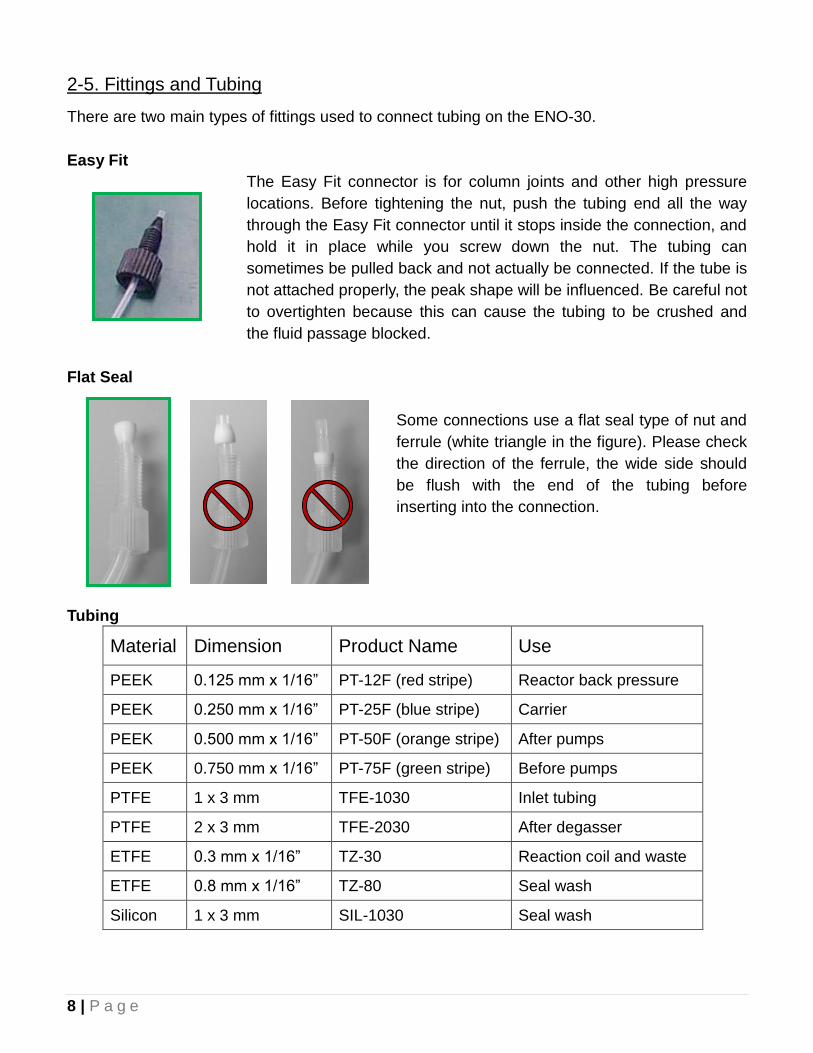
2-5. Fittings and Tubing
There are two main types of fittings used to connect tubing on the ENO-30.
Easy Fit
The Easy Fit connector is for column joints and other high pressure
locations. Before tightening the nut, push the tubing end all the way
through the Easy Fit connector until it stops inside the connection, and
hold it in place while you screw down the nut. The tubing can
sometimes be pulled back and not actually be connected. If the tube is
not attached properly, the peak shape will be influenced. Be careful not
to overtighten because this can cause the tubing to be crushed and
the fluid passage blocked.
Flat Seal
Some connections use a flat seal type of nut and
ferrule (white triangle in the figure). Please check
the direction of the ferrule, the wide side should
be flush with the end of the tubing before
inserting into the connection.
Tubing
Material Dimension Product Name Use
PEEK 0.125 mm x 1/16” PT-12F (red stripe) Reactor back pressure
PEEK 0.250 mm x 1/16” PT-25F (blue stripe) Carrier
PEEK 0.500 mm x 1/16” PT-50F (orange stripe) After pumps
PEEK 0.750 mm x 1/16” PT-75F (green stripe) Before pumps
PTFE 1 x 3 mm TFE-1030 Inlet tubing
PTFE 2 x 3 mm TFE-2030 After degasser
ETFE 0.3 mm x 1/16” TZ-30 Reaction coil and waste
ETFE 0.8 mm x 1/16” TZ-80 Seal wash
Silicon 1 x 3 mm SIL-1030 Seal wash
9 | P a g e
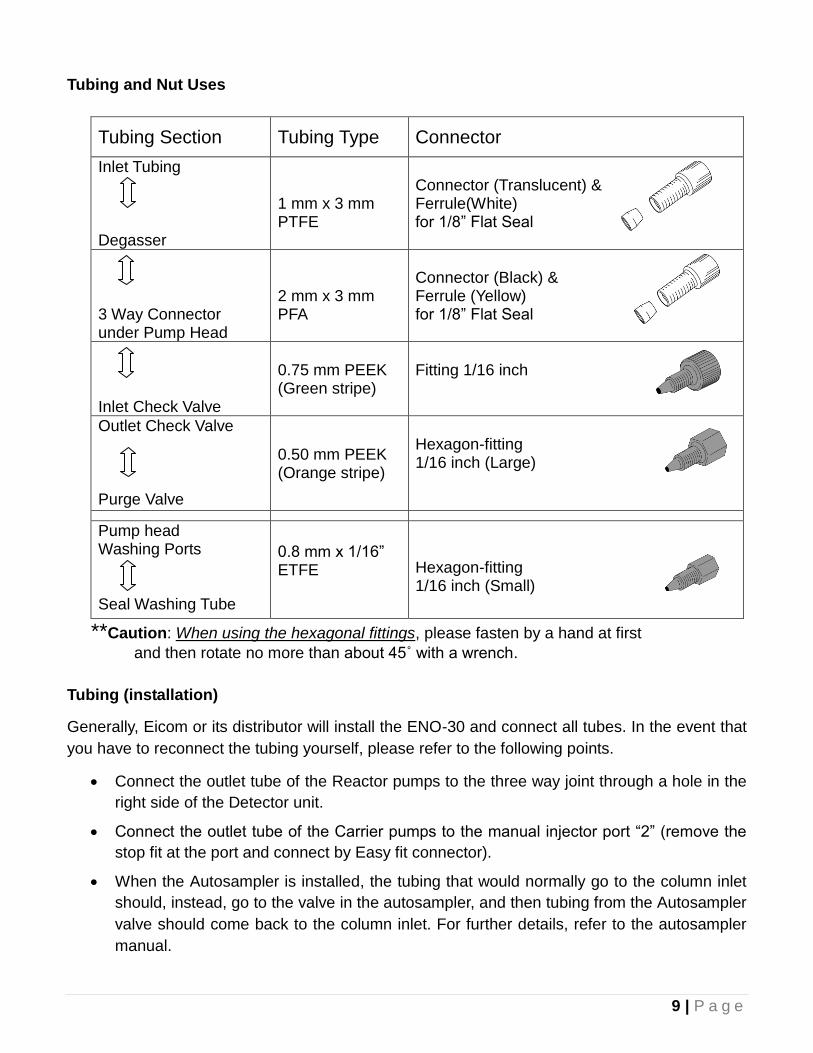
Tubing and Nut Uses
Tubing Section Tubing Type Connector
Inlet Tubing Degasser
1 mm x 3 mm PTFE
Connector (Translucent) & Ferrule(White) for 1/8” Flat Seal
3 Way Connector under Pump Head
2 mm x 3 mm PFA
Connector (Black) & Ferrule (Yellow) for 1/8” Flat Seal
Inlet Check Valve
0.75 mm PEEK (Green stripe)
Fitting 1/16 inch
Outlet Check Valve Purge Valve
0.50 mm PEEK (Orange stripe)
Hexagon-fitting 1/16 inch (Large)
Pump head Washing Ports Seal Washing Tube
0.8 mm x 1/16” ETFE
Hexagon-fitting 1/16 inch (Small)
**Caution: When using the hexagonal fittings, please fasten by a hand at first
and then rotate no more than about 45˚ with a wrench.
Tubing (installation)
Generally, Eicom or its distributor will install the ENO-30 and connect all tubes. In the event that
you have to reconnect the tubing yourself, please refer to the following points.
Connect the outlet tube of the Reactor pumps to the three way joint through a hole in the
right side of the Detector unit.
Connect the outlet tube of the Carrier pumps to the manual injector port “2” (remove the
stop fit at the port and connect by Easy fit connector).
When the Autosampler is installed, the tubing that would normally go to the column inlet
should, instead, go to the valve in the autosampler, and then tubing from the Autosampler
valve should come back to the column inlet. For further details, refer to the autosampler
manual.
10 | P a g e
3. Installation
The information in this section is given as a reference only. Everything should have been set up
by your Eicom Representative during the installation/training. However, if you need to move the
instrument or disconnect tubing or electrical connections, this section will be helpful.
3-1. Location
The ENO-30 is designed for use in laboratories for life science.
Do not expose to direct sunlight.
Install only on a sturdy, horizontal surface.
Leave space more than 4 inches of space around instrument.
Make sure nothing is liable to fall onto the ENO-30.
Do not leave anything on top of the ENO-30.
Do not place in a location that is prone to vibration.
This product should be operated only in room where there is a minimum of temperature
fluctuations. Maintain the temperature between 15-30 °C during use.
Do not expose the directly to drafts, including heating and air conditioning vents.
Keep away intense heat sources and other equipment that may produce strong magnetic
fields or electrical noise.
Do not use or store organic solvents or chemicals that emit caustic gases nearby. Always
maintain adequate ventilation.
The ENO-30 should be operated in a dust-free environment. Remove any dust from
around the ENO-30 frequently.
Do not block the ventilation slits on side of the ENO-30. Excessive heat from
the machine may accumulation inside the product and cause damage.
Maintain sufficient space around the ENO-30 to ensure adequate ventilation.
3-2. Power Plug
Power supply conditions of ENO-30 are as follow. Please make sure to use the included triple
core cable with grounding wire as power supply.
Power supply Voltage: AC 100V~240V Single Phase (±10V)
Frequency: 50 or 60 Hz
Power Supply: 2 x 200 W supplies
Connection: Cable with Grounding Wire (Triple Core)
Caution
11 | P a g e
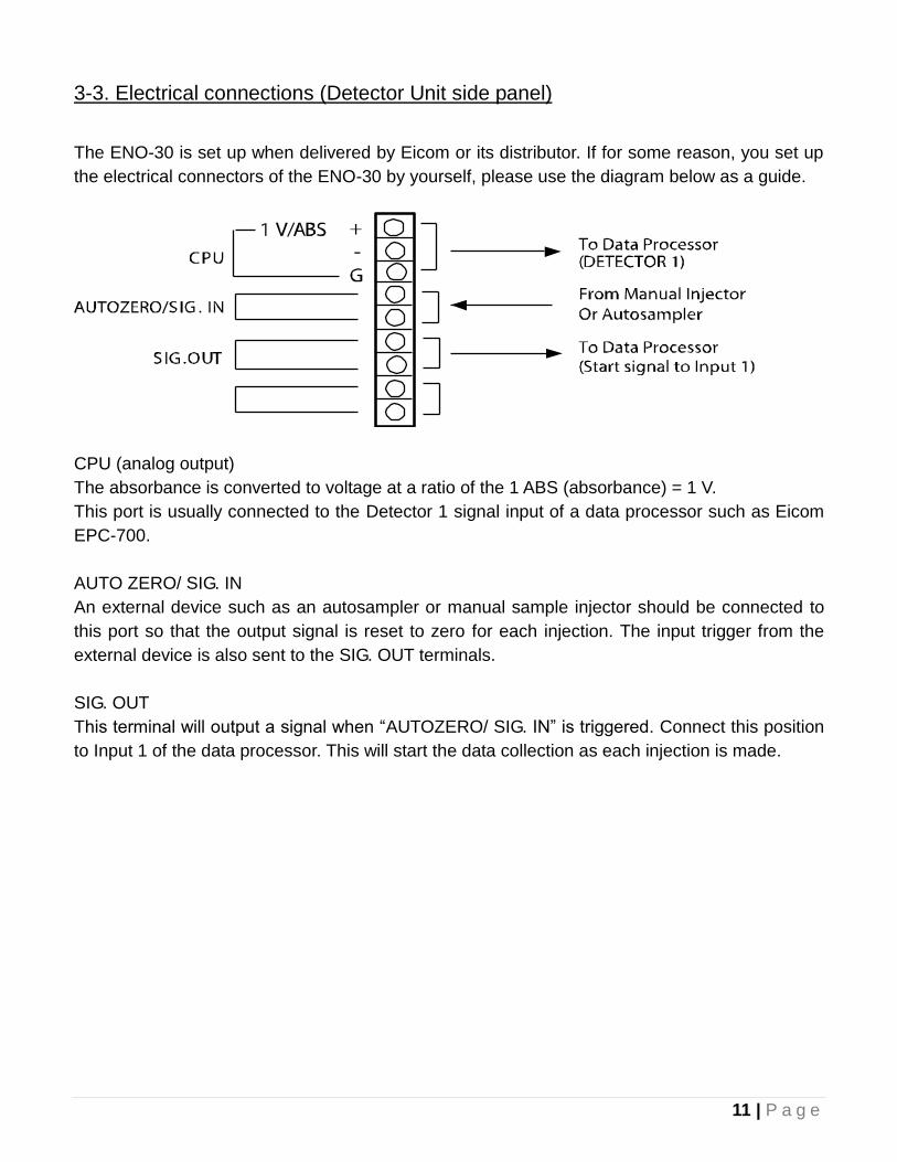
3-3. Electrical connections (Detector Unit side panel)
The ENO-30 is set up when delivered by Eicom or its distributor. If for some reason, you set up
the electrical connectors of the ENO-30 by yourself, please use the diagram below as a guide.
CPU (analog output)
The absorbance is converted to voltage at a ratio of the 1 ABS (absorbance) = 1 V.
This port is usually connected to the Detector 1 signal input of a data processor such as Eicom
EPC-700.
AUTO ZERO/ SIG. IN
An external device such as an autosampler or manual sample injector should be connected to
this port so that the output signal is reset to zero for each injection. The input trigger from the
external device is also sent to the SIG. OUT terminals.
SIG. OUT
This terminal will output a signal when “AUTOZERO/ SIG. IN” is triggered. Connect this position
to Input 1 of the data processor. This will start the data collection as each injection is made.
12 | P a g e
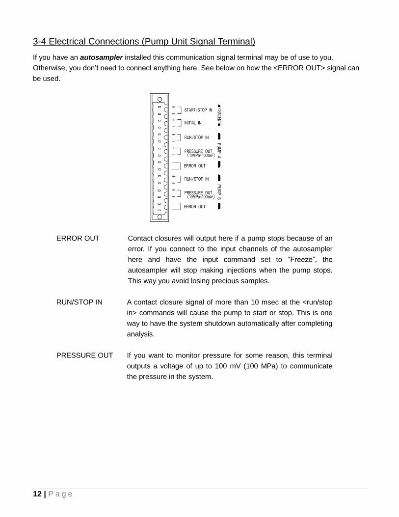
3-4 Electrical Connections (Pump Unit Signal Terminal)
If you have an autosampler installed this communication signal terminal may be of use to you.
Otherwise, you don’t need to connect anything here. See below on how the <ERROR OUT> signal can
be used.
ERROR OUT Contact closures will output here if a pump stops because of an
error. If you connect to the input channels of the autosampler
here and have the input command set to “Freeze”, the
autosampler will stop making injections when the pump stops.
This way you avoid losing precious samples.
RUN/STOP IN A contact closure signal of more than 10 msec at the <run/stop
in> commands will cause the pump to start or stop. This is one
way to have the system shutdown automatically after completing
analysis.
PRESSURE OUT If you want to monitor pressure for some reason, this terminal
outputs a voltage of up to 100 mV (100 MPa) to communicate
the pressure in the system.
13 | P a g e
3-5. Manual injector Tubing Connections
At the back of the manual injector:
Port #1 and #4 has the sample loop
Port #2 receives the tubing from the Carrier pump
Port #3 goes to the precolumn/separation column, or if installed, to an
autosampler. (tubing from the autosampler will come back and connect to
the columns)
Ports #5 and #6 are drain ports (check the crystals don’t form on the outlet
as that can prevent proper manual injection volumes)
3-6. Connect Tubing to Autosampler (optional)
On the valve inside and towards the top of the AS-700 autosampler:
Port # 2 and #5 has the sample loop
Port #1 receives the tubing from the port #2 of the manual injector, or if you
prefer, directly from the Carrier pump
Port #6 connects to the columns
Port #3 connects to the syringe via the buffering tube
Port #4 is where the sample needle connects
14 | P a g e
4. Pump Unit Operation
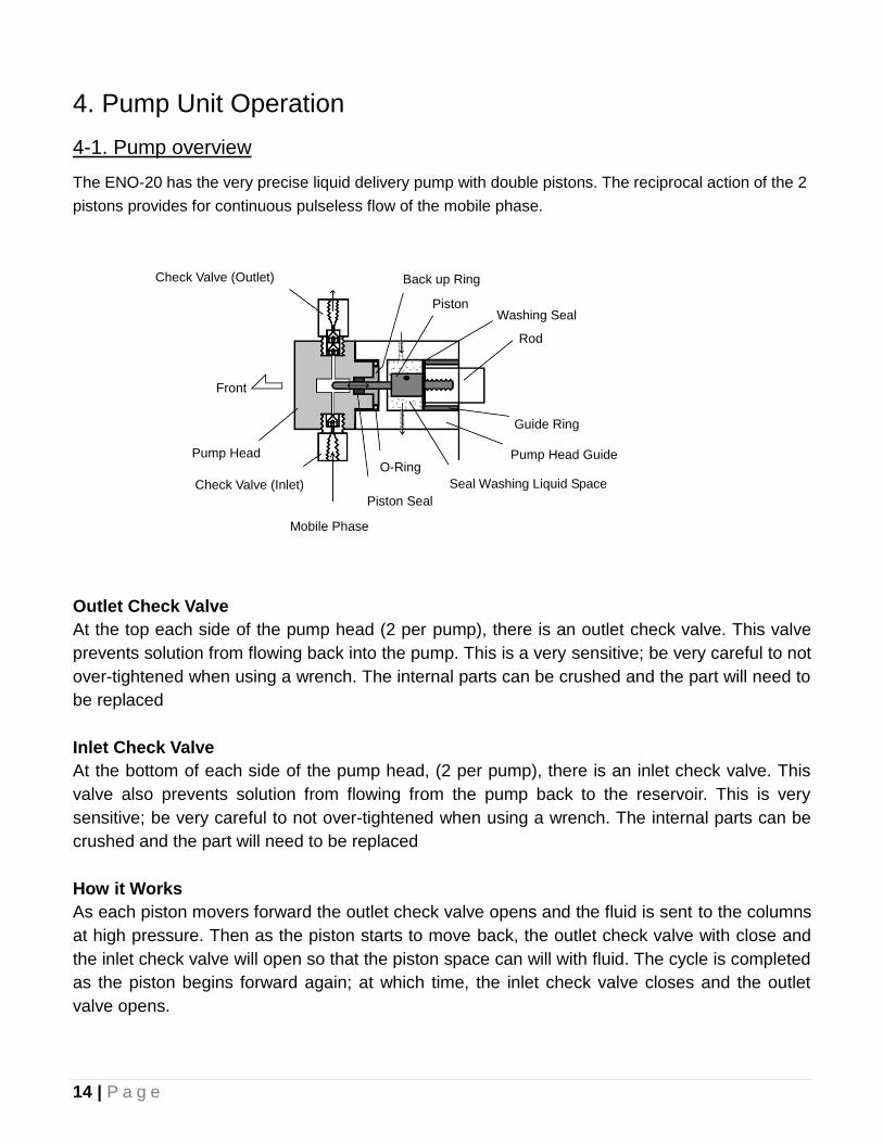
4-1. Pump overview
The ENO-20 has the very precise liquid delivery pump with double pistons. The reciprocal action of the 2
pistons provides for continuous pulseless flow of the mobile phase.
Outlet Check Valve
At the top each side of the pump head (2 per pump), there is an outlet check valve. This valve
prevents solution from flowing back into the pump. This is a very sensitive; be very careful to not
over-tightened when using a wrench. The internal parts can be crushed and the part will need to
be replaced
Inlet Check Valve
At the bottom of each side of the pump head, (2 per pump), there is an inlet check valve. This
valve also prevents solution from flowing from the pump back to the reservoir. This is very
sensitive; be very careful to not over-tightened when using a wrench. The internal parts can be
crushed and the part will need to be replaced
How it Works
As each piston movers forward the outlet check valve opens and the fluid is sent to the columns
at high pressure. Then as the piston starts to move back, the outlet check valve with close and
the inlet check valve will open so that the piston space can will with fluid. The cycle is completed
as the piston begins forward again; at which time, the inlet check valve closes and the outlet
valve opens.
Check Valve (Outlet)
Pump Head
Front
Mobile Phase
(Inlet)
Check Valve (Inlet)
Piston Seal
Back up Ring
O-Ring
Seal Washing Liquid Space
Pump Head Guide
Piston Washing Seal
Rod
Guide Ring
15 | P a g e
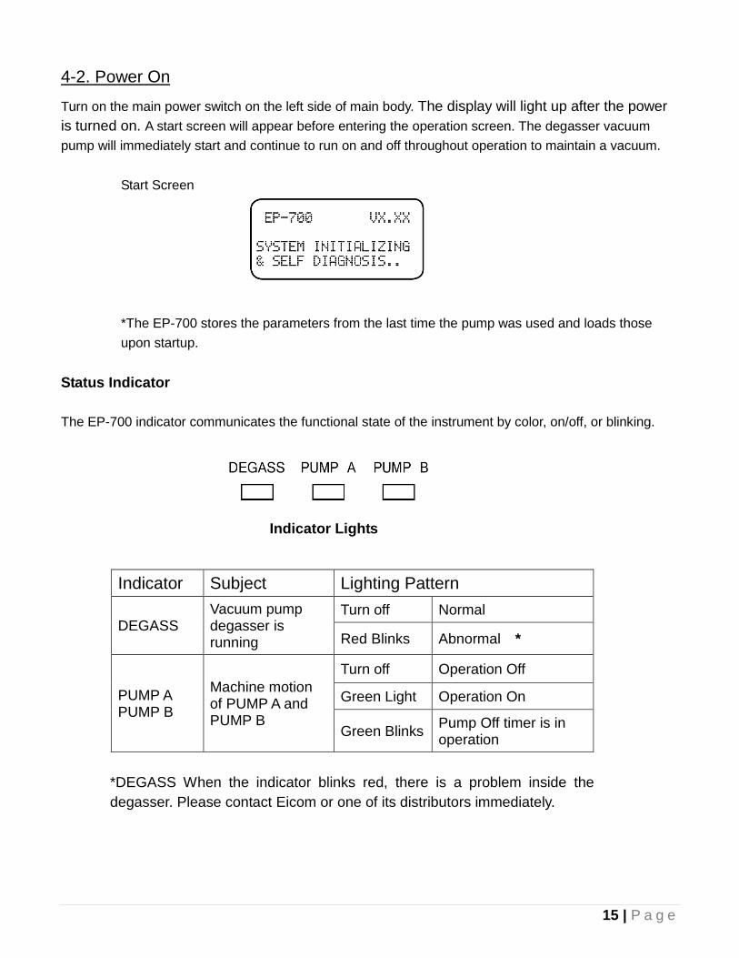
4-2. Power On
Turn on the main power switch on the left side of main body. The display will light up after the power
is turned on. A start screen will appear before entering the operation screen. The degasser vacuum
pump will immediately start and continue to run on and off throughout operation to maintain a vacuum.
Start Screen
*The EP-700 stores the parameters from the last time the pump was used and loads those
upon startup.
Status Indicator
The EP-700 indicator communicates the functional state of the instrument by color, on/off, or blinking.
Indicator Subject Lighting Pattern
DEGASS Vacuum pump degasser is running
Turn off Normal
Red Blinks Abnormal *
PUMP A PUMP B
Machine motion of PUMP A and PUMP B
Turn off Operation Off
Green Light Operation On
Green Blinks Pump Off timer is in operation
*DEGASS When the indicator blinks red, there is a problem inside the
degasser. Please contact Eicom or one of its distributors immediately.
Indicator Lights
16 | P a g e
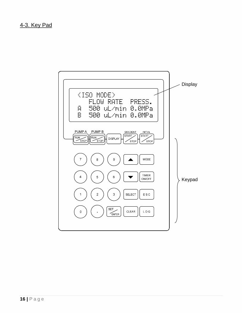
4-3. Key Pad
Display
Keypad
17 | P a g e
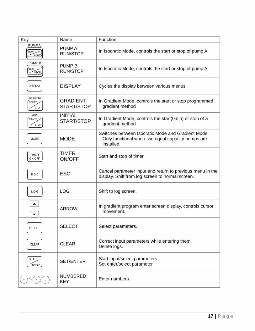
Key Name Function
PUMP A RUN/STOP
In Isocratic Mode, controls the start or stop of pump A
PUMP B RUN/STOP
In Isocratic Mode, controls the start or stop of pump A
DISPLAY Cycles the display between various menus
GRADIENT START/STOP
In Gradient Mode, controls the start or stop programmed gradient method
INITIAL START/STOP
In Gradient Mode, controls the start(0min) or stop of a gradient method
MODE Switches between Isocratic Mode and Gradient Mode.
Only functional when two equal capacity pumps are installed
TIMER ON/OFF
Start and stop of timer.
ESC Cancel parameter input and return to previous menu in the display. Shift from log screen to normal screen.
LOG Shift to log screen.
ARROW In gradient program enter screen display, controls cursor
movement.
SELECT Select parameters.
CLEAR Correct input parameters while entering them. Delete logs.
SET/ENTER Start input/select parameters. Set enter/select parameter
NUMBERED KEY
Enter numbers.
~ ,
18 | P a g e
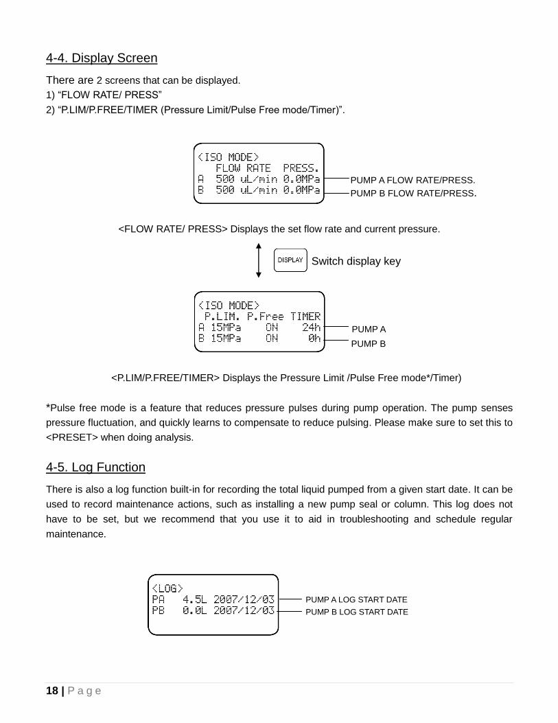
4-4. Display Screen
There are 2 screens that can be displayed.
1) “FLOW RATE/ PRESS”
2) “P.LIM/P.FREE/TIMER (Pressure Limit/Pulse Free mode/Timer)”.
<FLOW RATE/ PRESS> Displays the set flow rate and current pressure.
<P.LIM/P.FREE/TIMER> Displays the Pressure Limit /Pulse Free mode*/Timer)
*Pulse free mode is a feature that reduces pressure pulses during pump operation. The pump senses
pressure fluctuation, and quickly learns to compensate to reduce pulsing. Please make sure to set this to
<PRESET> when doing analysis.
4-5. Log Function
There is also a log function built-in for recording the total liquid pumped from a given start date. It can be
used to record maintenance actions, such as installing a new pump seal or column. This log does not
have to be set, but we recommend that you use it to aid in troubleshooting and schedule regular
maintenance.
Switch display key
PUMP A LOG START DATE
PUMP B LOG START DATE
PUMP A FLOW RATE/PRESS.
PUMP B FLOW RATE/PRESS.
PUMP A
PUMP B
19 | P a g e
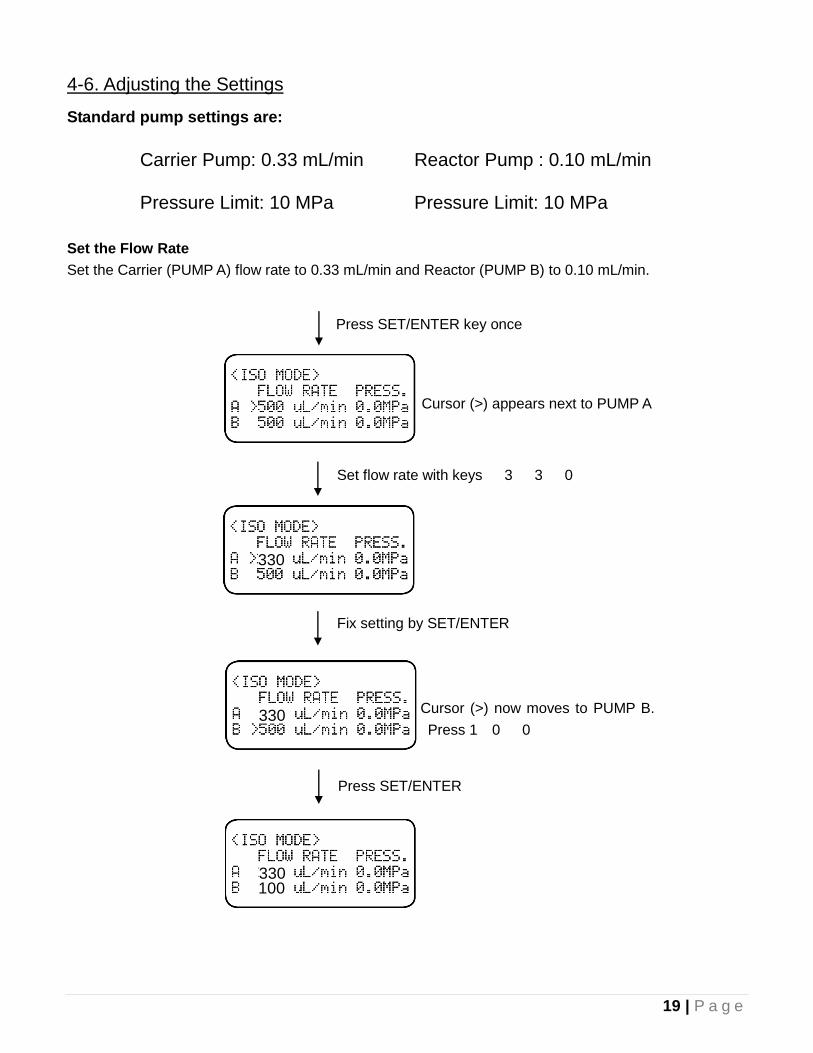
4-6. Adjusting the Settings
Standard pump settings are:
Carrier Pump: 0.33 mL/min Pressure Limit: 10 MPa
Reactor Pump : 0.10 mL/min Pressure Limit: 10 MPa
Set the Flow Rate
Set the Carrier (PUMP A) flow rate to 0.33 mL/min and Reactor (PUMP B) to 0.10 mL/min.
Press SET/ENTER key once
Cursor (>) appears next to PUMP A
Set flow rate with keys 3 3 0
Fix setting by SET/ENTER
Cursor (>) now moves to PUMP B.
Press 1 0 0
Press SET/ENTER
100
330
330
330
20 | P a g e
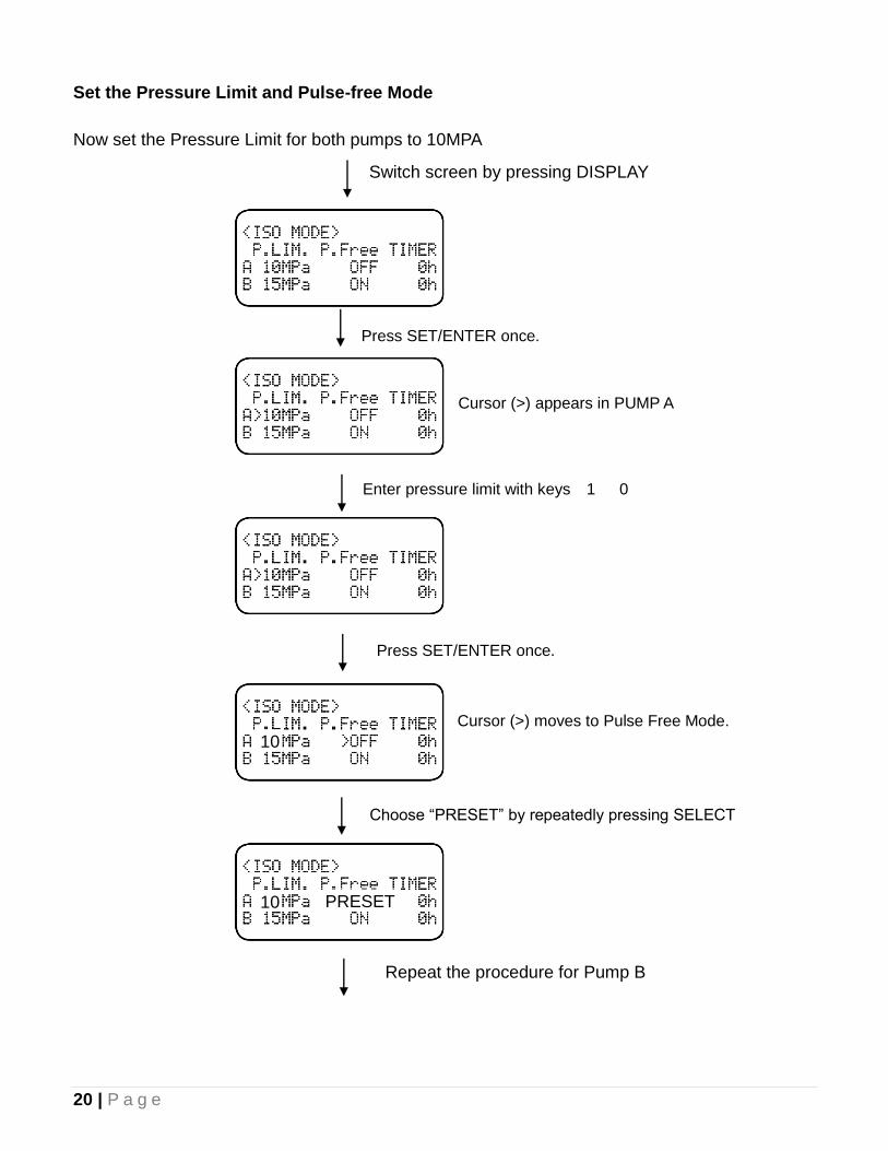
Set the Pressure Limit and Pulse-free Mode
Now set the Pressure Limit for both pumps to 10MPA
Switch screen by pressing DISPLAY
Press SET/ENTER once.
Enter pressure limit with keys 1 0
Cursor (>) moves to Pulse Free Mode.
Choose “PRESET” by repeatedly pressing SELECT
Cursor (>) appears in PUMP A
Press SET/ENTER once.
PRESET
10
Repeat the procedure for Pump B
10
21 | P a g e
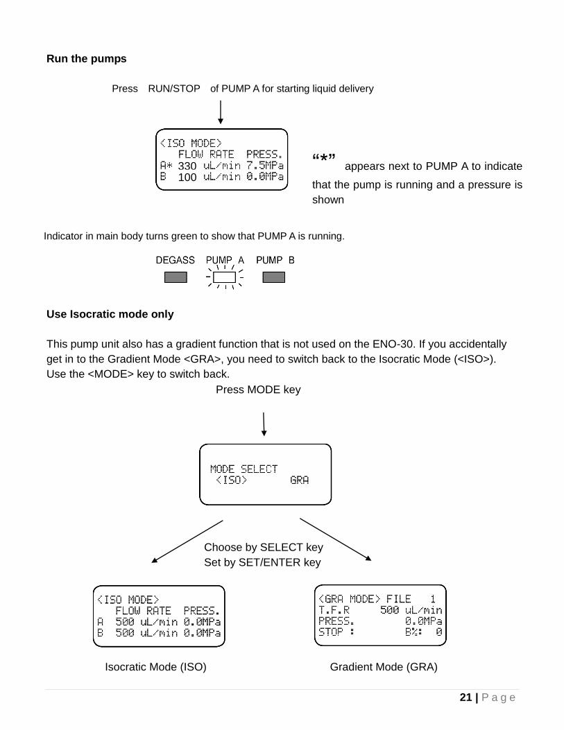
Run the pumps
Press RUN/STOP of PUMP A for starting liquid delivery
Use Isocratic mode only
This pump unit also has a gradient function that is not used on the ENO-30. If you accidentally
get in to the Gradient Mode <GRA>, you need to switch back to the Isocratic Mode (<ISO>).
Use the <MODE> key to switch back.
“*” appears next to PUMP A to indicate
that the pump is running and a pressure is
shown
Indicator in main body turns green to show that PUMP A is running.
Press MODE key
Choose by SELECT key
Set by SET/ENTER key
Isocratic Mode (ISO) Gradient Mode (GRA)
330 100
22 | P a g e
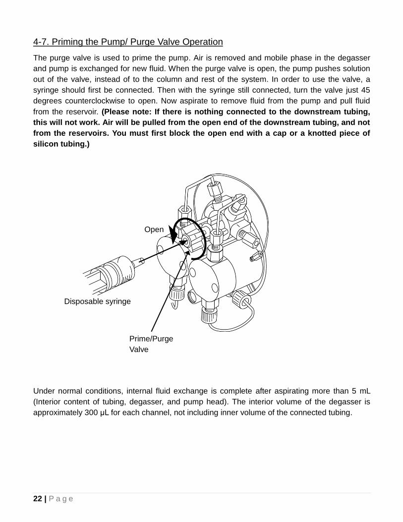
4-7. Priming the Pump/ Purge Valve Operation
The purge valve is used to prime the pump. Air is removed and mobile phase in the degasser
and pump is exchanged for new fluid. When the purge valve is open, the pump pushes solution
out of the valve, instead of to the column and rest of the system. In order to use the valve, a
syringe should first be connected. Then with the syringe still connected, turn the valve just 45
degrees counterclockwise to open. Now aspirate to remove fluid from the pump and pull fluid
from the reservoir. (Please note: If there is nothing connected to the downstream tubing,
this will not work. Air will be pulled from the open end of the downstream tubing, and not
from the reservoirs. You must first block the open end with a cap or a knotted piece of
silicon tubing.)
Under normal conditions, internal fluid exchange is complete after aspirating more than 5 mL
(Interior content of tubing, degasser, and pump head). The interior volume of the degasser is
approximately 300 μL for each channel, not including inner volume of the connected tubing.
Prime/Purge
Valve
Disposable syringe
Open
23 | P a g e
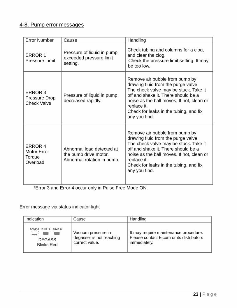
4-8. Pump error messages
Error Number Cause Handling
ERROR 1 Pressure Limit
Pressure of liquid in pump exceeded pressure limit setting.
Check tubing and columns for a clog, and clear the clog.
Check the pressure limit setting. It may be too low.
ERROR 3 Pressure Drop Check Valve
Pressure of liquid in pump decreased rapidly.
Remove air bubble from pump by drawing fluid from the purge valve. The check valve may be stuck. Take it off and shake it. There should be a noise as the ball moves. If not, clean or replace it. Check for leaks in the tubing, and fix any you find.
ERROR 4 Motor Error Torque Overload
Abnormal load detected at the pump drive motor. Abnormal rotation in pump.
Remove air bubble from pump by drawing fluid from the purge valve. The check valve may be stuck. Take it off and shake it. There should be a noise as the ball moves. If not, clean or replace it. Check for leaks in the tubing, and fix any you find.
*Error 3 and Error 4 occur only in Pulse Free Mode ON.
Error message via status indicator light
Indication Cause Handling
DEGASS Blinks Red
Vacuum pressure in degasser is not reaching correct value.
It may require maintenance procedure. Please contact Eicom or its distributors immediately.
24 | P a g e
5. Detector/Oven Operation
5-1. Power Switch
The power switch is on the left side, not too far back and toward the bottom edge. As soon as
the Detector Unit is turned on, the oven will begin to heat. You should feel air blowing inside the
chamber. When the door is open, the heat is off, but the fan stays on.
5-2. Setting Temperature
The oven temperature should normally be set to 35 °C. If it is not, you can set it by pressing the
set key and then using the arrow key to change the temperature. Press the enter key to confirm.
When the temperature of the column oven reaches 35 °C, the green light on the front of the
instrument is lit.
5-3. Detector Readings
The display can also show the current readings from the detector, such as Absorbance. Press
the Arrow and Enter keys and the same time to display the Absorbance value. Remember, the
“absorbance” is calculated by using the difference between the reference light which does not
pass through the sample and the light intensity after passing through the sample. To see the
individual Reference and Sample light signals press the Arrow and Enter keys again for the
Sample value and more time for the Reference value. These values are helpful for confirming if
the detector is working properly.
5-4. Autozero Function
You can press the autozero key at any point to manual zero the detector, such as during the
stabilization period just after starting the instrument. Remember that the instrument will
automatically autozero just after each injection of sample so it’s not necessary to manually
operate the autozero.
25 | P a g e
6. Analysis
6-1. Accurate Analysis
NO2 exists in the air and dissolves in water. NO2- is gradually oxidized to NO3
- in the solution.
Because most of labs’ equipment is polluted with NO2- and NO3
-, we have to pay careful
attention to removing contamination, especially for highly sensitive analysis. This pollution is
eliminated by a few rinses with non-polluted water (fresh super pure water). The microsyringe
and sample injector (manual and external) are easy to contaminate. It is sometimes difficult to
make the micro syringe clean. To make it clean, connect a microsyringe to an aspirator and
aspirate conc. HCl. Then rise with super pure water. The manual injector, and its injection port,
can be cleaned by super pure water flushed by a syringe with a port cleaner attachment. If this
flush does not resolve the contamination, disconnect the sample loop and wash the loop with
HCl and water. Super pure water is also the candidate of contamination removal. It is better not
to store the water; always use fresh super pure water. If storage is necessary, air tight bottle
made of glass is suitable for contamination prevention.
6-2. Water Quality
All water used for ENO-30 maintenance and sample preparation must be super pure water (18.2
Mega-Ohm x cm). Distilled or deionized water may be used, although this is not ideal for
ENO-30 and accurate analysis. It’s best that the water come directly from the water purification
system tap. These water quality recommendations help prevent cross contamination of NO2-
and NO3- and prolongs the life of the ENO-30.
6-3. Reagent Quality
Water; Fresh MilliQ water direct from tap od well maintained system or HPLC grade water. Do not store the water in a plastic bottle. Please use a glass bottle.
Hydrochloric acid; Analysis or Super grade, 35-37% Hydrochloride.
Methanol; HPLC Grade
Standard, reagent grade
26 | P a g e
6-4. Carrier and Reactor Solutions Preparation
For analysis of NO2- and NO3
-, the Carrier and Reactor should be prepared using Eicom Carrier
Powder (NO-CAP3) and Reactor A and B powders (NO-RAP3 and NO-RBP3). Reactor A and B
solution are made separately and just enough for one day’s analysis is prepare by mixing 1:1.
Carrier Solution
Add 900 mL of water to a 1 liter glass bottle. Add 100 mL of methanol to the bottle. Pour in
Carrier powder. Shake to dissolve. Rinse the bottle the powder came in with the prepared
Carrier solution to dissolve last of powder and return to prepared solution.
Reactor A
Add 450 mL of water to a 500 mL bottle. Add 100 mL of methanol to the bottle. Add 12.5 mL of
concentrated HCL (35-57%). Pour in Reactor A Powder. Shake to dissolve. Rinse the bottle the
powder came in with the prepared Reactor A solution to dissolve last of powder and return to
prepared solution.
Reactor B
Add 450 mL of water to a 500 mL bottle. Add 100 mL of methanol to the bottle. Pour in Reactor
B Powder. Shake to dissolve. Rinse the bottle the powder came in with the prepared Reactor B
solution to dissolve last of powder and return to prepared solution.
Complete Reactor Solution
Mix equal parts of Reactor A and B on the day of the analysis.
Storage
Carrier Solution can be stored for several months in the refrigeration. Do not run the system with
cold solution because air bubbles can form in the HPLC pumps and cause them to stop.
Complete Reactor solution can only be used for one or two days. Only mix enough for the day.
The solution can absorb NO2 from the air and turn pink. Also cover the bottle with aluminum foil
to protect it from light. If the Reactor has turned pink, it cannot be used for high sensitive
analysis. If the Reactor is stored in a transparent bottle, it is easier to judge any color change.
Do not allow any of the Reactor to enter into columns. Columns will suffer serious damage from
contact with the Reactor.
Reactor A and B can be stored for several months in the dark at room temperature or in the
refrigerator, but the longer they sit, the low the potency of the complete Reactor solution when
it’s prepared. It will be immediately pink, leading to lower sensitivity analysis.
27 | P a g e
6-5. Standard Solution
Dissolve the necessary amount of NaNO2 and NaNO3 in water taken directly from the purified
water tap. Then prepare a standard curve by diluting into water, Carrier solution, or the same
solution as the sample is in.
6-6. Waste
Collect Carrier and Reactor Waste into a bottle. This will be mainly an acidic 10% methanol
solution with significant cadmium levels.
The reduction column contains cadmium which slowly resolves into waste. The cadmium
in the waste can be concentrated by the method shown below. (If the total mass is small,
disposal cost for disposal can be reduced.)
Method to Concentrate Cadmium
1. Add 12 g NaOH for 1 L waste liquid and dissolve.
2. Dissolve 11 g of FeCl3-6H2O in 100 mL water, add to waste, and mix well.
3. Let precipitate for one day.
4. Filter the precipitate. The remaining supernatant should have low enough cadmium for
normal disposal.
6-7. Prepare for Analysis
Check the amount of Carrier and Reactor. Make fresh Carrier and Reactor as necessary.
For high sensitivity analysis, all solutions should be made fresh.
Aged or pink colored Reactor or very old Carrier will cause high noise generation and
reduce sensitivity. If the Reactor solution is stored in a transparent glass bottle covered
with aluminum foil, it’s easier to confirm the color of the solution.
Put the ends of the Carrier and Reactor inlet tubes into the bottom of each bottle. Check
degasser and pump markings to be sure. Cover the tops of each bottle with parafilm to
prevent dust falling in and to help hold the tubes in place.
Put the end of the pump seal wash inlet tube into the bottom of a bottle containing fresh
super pure water. Prime the seal wash lines before starting pumps.
Fill the autosampler wash bottle with fresh water or top off the 10% methanol.
Prepare a fresh precolumn if necessary.
Make sure the two-way joint is in place of the column.
28 | P a g e
6-8. Start up
1. Turn on the power switches for the Detector/Oven and Pump Unit. (located on the left side)
The oven will start to heat to 35 °C. The pump display with light and you will hear the
degasser start, but the pumps won’t start yet.
2. Turn on autosampler power. Read panel on left side. You will hear the tray move back and
forth as it initializes. The green light at the front will illuminate.
3. Run autosampler initial wash cycle.
4. Use the key pad to set the Carrier pump to 0.33 mL/min and start the Carrier pump first.
You may want to start it at a higher rate (0.5 mL/min) to fill the lines and wash out the lines,
but reset to 0.33 mL/min for analysis.
5. Now set the Reactor pump to 0.1 mL/min and start the pump. Again you can use a higher
setting initially if you prefer.
6. Confirm flow rates are correct by collecting fluid at the waste line. Run each pump
separately. Remember the columns should not be installed yet. Collect waste into small
microcentrifuge tube for one minute. If it is half the expected volume, then the pump has a
bubble and needs to be primed again to remove.
7. Confirm that the Reactor and Carrier solution are routed to the right pumps. If you install
the columns when the Reactor and Carrier solution are routed to the wrong pumps, the
columns will suffer serious damage. To avoid problems PLEASE BE AWARE OF
FOLLOWING:
DO NOT put Reactor tube in Carrier bottle.
DO NOT put Carrier tube in Reactor bottle.
DO NOT run the Reactor pump while the Carrier pump is OFF.
When REAC. PUMP is ON, DO NOT disconnect the line from Carrier pumps.
When REAC. PUMP is ON, DO NOT open the purge valve.
8. Now you can install the columns. Turn off the pumps. Replace the two way joint with the
columns and restart the pumps.
9. Start the Envision software, and monitor the detector signal in the Acquisition Monitor until
it stabilizes. (30-60 mins)
10. Inject 10 µL of 10 µM standard solution a calibration chromatogram. The sensitivity of
ENO-30 must be check by a standard solution before each analysis. The peak height of
NO2 - should be over 16 mV (10 µL 10 µM= 100 pmol).
29 | P a g e
7. Sample Injection
Always use correct blunt ended needle to make injections or risk damaging the valve!
The standard syringe is a 25 µL Hamilton syringe (702SNR). However, a 50 µL syringe may also
be used (705SNR).
When the injector knob is moved between LOAD and INJECT, the flow pattern is switched. In
the INJECT position the flow from the pump passes through the sample loop and on to the
column. The syringe port is connected to one of the drain tubes. The knob should remain in the
INJECT position at all times when there is not a syringe inserted in the valve. In the LOAD
position, the loop is taken out of the flow and connected to the syringe port. The other end goes
to the other drain tube. Do not move the knob to the LOAD position unless there is a syringe in
the valve port. When the valve is switched back to the INJECT position, the sample is injected
and an electric signal is sent to trigger the autozero function and start data collection. You
should hear a beep. Do not connect any other tubing to the drain port in order to avoid to
potential troubles.
7-1. Manual Injector Operation
1. Aspirate the sample into a microsyringe. If an air bubble is generated inside of the syringe,
please flush out the solution and air bubble and slowly re-aspirate.
2. We recommend that the knob is left at INJECT before and after Injection.
3. Insert a syringe needle until you feel it stop (3 mm further than a weak resistance). Don’t
depress plunger.
4. Slide the knob to LOAD and depress the plunger to load the sample into the sample loop
installed on the back of the manual injector. Slow smooth motion is required for best
results.
5. With syringe still in place, quickly and smoothly slide the knob from LOAD to INJECT
position. By moving the knob from LOAD to INJECT, an electrical signal is also generated
and you will hear a beep.
6. After completing these steps, remove the syringe and wash the syringe with super pure
water.
7. The needle port of the manual injector must be washed with super pure water using the
white port cleaner adapter attached to a syringe.
Caution; When there is second injection valve, such as an autosampler(AS-700) or online
injector (EAS-20s), installed between the manual injector and the column, the additional
injection valve should be set to the LOAD position. This will prevent the sample from going
through the sample loop of the second valve as it moves toward the column. If the sample were
30 | P a g e
to go through the sample loop of the second valve, the sample would spread out and cause a
broadened peak.
7-2. Sample Amount
The ENO-30 accepts 1-50 µL of sample or standard. For accurate analysis, the same quantity of
sample or standard should be used. It’s best if the samples and standard are in the same
solutions. Use Carrier solution to dilute samples that are too high.
7-3. Autosampler Operation (optional)
The autosampler is primarily controlled via the Envision software (Eicom EPC-700), more details
refer to the Envision Software manual. For complete instructions on the use of the autosampler,
refer to the autosampler manual. There are some basic autosampler operations that are
covered here.
Before starting any analysis, make sure that the autosampler wash reservoir is filled with 10%
methanol. Water may also be used, but in that case, you need to pay extra attention to the
reservoir such that it does not have microbial growth. Change the water frequently and use soap
to clean.
Run the initial wash cycle to fill the syringe and wash the sample needle before starting any
analysis. During this wash cycle, check that there are no bubbles in the syringe. If there are
bubbles suck to the syringe plunger, they should be removed before starting the analysis. The
fastest way to remove the bubble may be to remove the syringe and let some fluid out past the
plunger by pulling the plunger nearly all the way out of the barrel. For more details, refer to the
autosampler manual.
During heavy use, it is recommended that the syringe and valve seal should be replaced
annually.
31 | P a g e
8. Shutdown after Analysis
Extended storage period procedures are very important for the ENO-30. If the next analysis will
be in less than two weeks, then you can follow the procedure in section 13-1. If it will be more
than two weeks, follow the procedure in section 13-2.
8-1. Short Shutdown, less than 2 weeks
1. Stop the pumps, Reactor first. Wait for 5 min and stop the Carrier pump.
2. Log out of the software.
3. Turn off the power switches on the Detector unit, the Pump unit, and the Autosampler (if
installed).
4. Manually flush the pump seal wash with the syringe.
5. Make sure the inlet tubing and waste line are submerged.
8-2. Complete Shutdown, over 2 weeks
1. Stop the pumps, Reactor first.
2. Remove the columns (precolumn-separation column-reduction column) as a single piece
and stopper both ends.
3. Replace columns with two-way joint.
4. Put Reactor and Carrier inlet tubes in 10% methanol:water solution.
5. Set the pumps to 0.5 mL/min and run them for 20 minutes.
6. Log out of the software.
7. Turn off the power switches on the Detector unit, the Pump unit, and the autosampler (if
installed)
8. Manually flush the pump seal wash with the syringe.
9. The inlet and waste tubing should be submerged or capped with the vinyl end caps.
32 | P a g e
9. Restart
9-1 After complete shutdown procedure
When the ENO-30 was stored as explained at unit 8-2, please prepare for analysis as shown
below.
1. Set each inlet tubing in to the Reactor and Carrier bottles.
2. Aspirate from the purge valve on each pump to exchange fluid in the degasser and pump
head.
3. Set the Carrier pump 0.5 mL/min and start. Check the flow at the waste outlet.
4. Set the Reactor pump to 0.5 mL/min and start. Check the flow at the waste outlet.
5. If flow is not correct or you receive a pump error message, aspirate at the pump purge
valves again.
6. Once pumps are both running, adjust the flow rate of the Reactor pumps to 0.10 mL/min,
and then the flow rate of the Carrier to 0.33 mL/min
7. Turn off the Reactor pump and then the Carrier pump.
8. Install the columns and restart the pumps, Carrier pump first.
9. Leave the machine to run for 30 minutes and check the detector baseline by using the
Acquisition Monitor in the Envision software.
10. Inject appropriate standard to verify adequate sensitivity for analysis. Typically, 10 µL of
10 µM standard will give peaks of great than 16mV.
9-2. After short shutdown procedure
In case the ENO-30 was left containing Carrier and Reactor for more than just a couple of days
or up to two weeks, it may be necessary to clean the system, but first you can check the system
condition.
1. Start the Carrier pump and then the Reactor pump.
2. If everything is normal with the pressure, you can let the system run for 30 minutes to
stabilize, and check the sensitivity by injecting a standard.
3. If the pressure is high or the pumps shuts down because the upper pressure limit is
reached, there is probably a blockage somewhere that needs to be cleared. You need to
work backward from the waste tubing to determine where the blockage is. (remove the
detector inlet, then the reaction loop, then the columns, etc)
33 | P a g e
4. If the standard injection doesn’t produce good sensitivity and you have already prepared
fresh complete Reactor solution, you will need to clean the system.
Cleaning the system
1. Stop the pumps, remove the columns, and replace with two-way joint.
2. Switch the solution to 10% methanol for both pumps, and run the pumps at 0.5 mL/min
for 20 minutes.
3. Now switch the Reactor pump to 100% methanol and Then run the pump for 20 mins at
0.5 mL/min.
4. Switch the Reactor pump back to 10% methanol and aspirate 10 mL or more methanol
from the drain valve. Then run the pump for 10 mins, before switching to fresh Reactor
solution.
5. Switch the Carrier pump to fresh Carrier solution and run both pumps at 0.5 mL/min for
10 mins.
6. Stop the pumps and set to standard flow rates.
7. Install the columns and start the pumps, Carrier first.
8. Let the ENO-30 stabilize for 30 mins and inject standard solution to check sensitivity.
34 | P a g e
10. Precolumn
The guard column protects the separation column (P4-NO-PC) from contaminants and prolongs
the life of the column. The precolumn traps substances that will stick to the separation column
material, and not be able to be removed, before they can damage the separation column. The
packing material (NO-PRM) inside the precolumn can easily be replaced. Frequent changes of
the precolumn will increase the useable life of the separation column. As a rough estimation, the
life span of the precolumn column is about 100 injections of denatured protein samples taken
from blood serum plasma or tissue and 200 injections for lower protein samples. These
numbers are strongly influenced by sample preparation methods, precolumn packing and so
forth. Please refer to unit 15-1. (About sample preparation, please refer to Eicom technical
publication entitled “Nitrite and Nitrate Analysis” )
10-1. Determining the Precolumn Condition
If any of the following phenomena occur, it is time to change the precolumn.
As the precolumn is used, the peak shape loses its symmetry. This means that the back
of the peak returns to baseline very slowing and is said to be “tailing”.
Sometimes if a void develops, or is present after repacking, the peak-tip can be divided.
The pressure of the Carrier pump will rise as the precolumn’s filter becomes clogged. If
the carrier pumps pressure is 1.5 MPa higher than normal, please repack the precolumn
and change the upstream filter.
To confirm any suspicion that the precolumn is a problem, please replace the precolumn with a
two way joint and inject a standard. If the peak shape improves, the main column is in a good
condition and the pre-column should be replaced.
35 | P a g e
10-2. How to Repack the Precolumn
1) Turn off the reactor pumps and then turn off the carrier pumps.
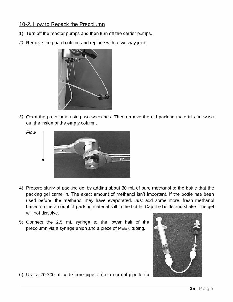
2) Remove the guard column and replace with a two way joint.
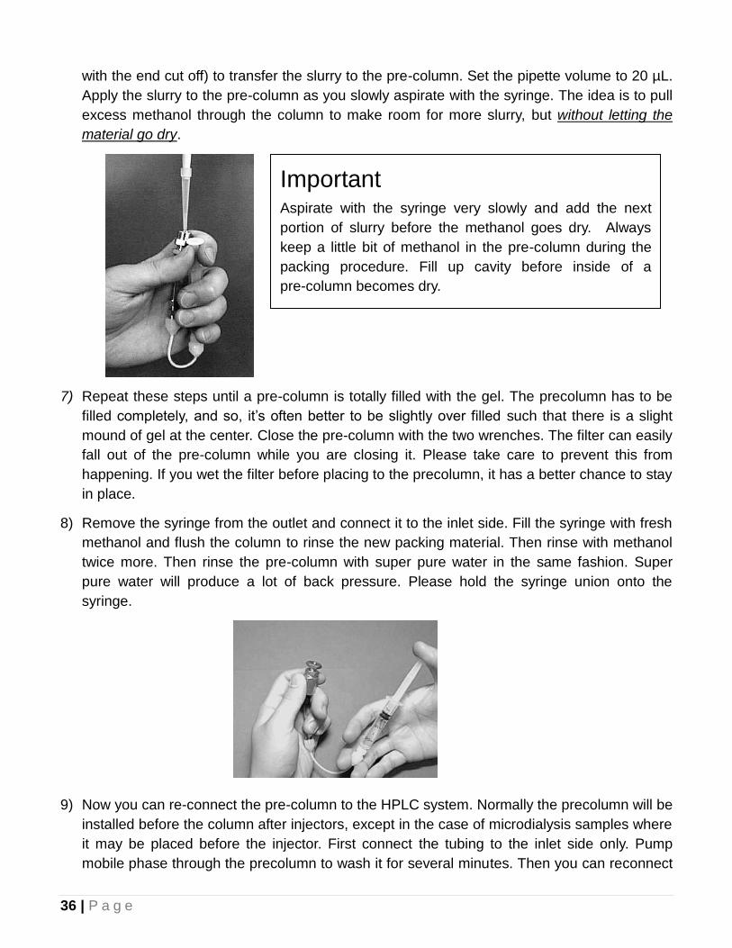
3) Open the precolumn using two wrenches. Then remove the old packing material and wash
out the inside of the empty column.
Flow
4) Prepare slurry of packing gel by adding about 30 mL of pure methanol to the bottle that the
packing gel came in. The exact amount of methanol isn’t important. If the bottle has been
used before, the methanol may have evaporated. Just add some more, fresh methanol
based on the amount of packing material still in the bottle. Cap the bottle and shake. The gel
will not dissolve.
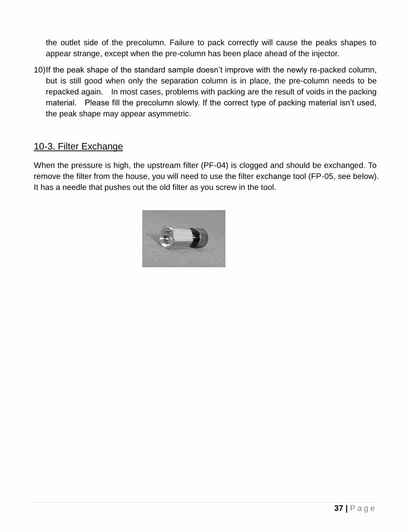
5) Connect the 2.5 mL syringe to the lower half of the
precolumn via a syringe union and a piece of PEEK tubing.
6) Use a 20-200 µL wide bore pipette (or a normal pipette tip
36 | P a g e
with the end cut off) to transfer the slurry to the pre-column. Set the pipette volume to 20 µL.
Apply the slurry to the pre-column as you slowly aspirate with the syringe. The idea is to pull
excess methanol through the column to make room for more slurry, but without letting the
material go dry.
7) Repeat these steps until a pre-column is totally filled with the gel. The precolumn has to be
filled completely, and so, it’s often better to be slightly over filled such that there is a slight
mound of gel at the center. Close the pre-column with the two wrenches. The filter can easily
fall out of the pre-column while you are closing it. Please take care to prevent this from
happening. If you wet the filter before placing to the precolumn, it has a better chance to stay
in place.
8) Remove the syringe from the outlet and connect it to the inlet side. Fill the syringe with fresh
methanol and flush the column to rinse the new packing material. Then rinse with methanol
twice more. Then rinse the pre-column with super pure water in the same fashion. Super
pure water will produce a lot of back pressure. Please hold the syringe union onto the
syringe.
9) Now you can re-connect the pre-column to the HPLC system. Normally the precolumn will be
installed before the column after injectors, except in the case of microdialysis samples where
it may be placed before the injector. First connect the tubing to the inlet side only. Pump
mobile phase through the precolumn to wash it for several minutes. Then you can reconnect
Important Aspirate with the syringe very slowly and add the next
portion of slurry before the methanol goes dry. Always
keep a little bit of methanol in the pre-column during the
packing procedure. Fill up cavity before inside of a
pre-column becomes dry.
37 | P a g e
the outlet side of the precolumn. Failure to pack correctly will cause the peaks shapes to
appear strange, except when the pre-column has been place ahead of the injector.
10) If the peak shape of the standard sample doesn’t improve with the newly re-packed column,
but is still good when only the separation column is in place, the pre-column needs to be
repacked again. In most cases, problems with packing are the result of voids in the packing
material. Please fill the precolumn slowly. If the correct type of packing material isn’t used,
the peak shape may appear asymmetric.
10-3. Filter Exchange
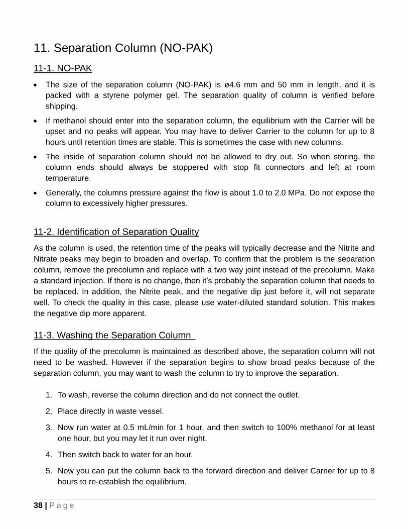
When the pressure is high, the upstream filter (PF-04) is clogged and should be exchanged. To
remove the filter from the house, you will need to use the filter exchange tool (FP-05, see below).
It has a needle that pushes out the old filter as you screw in the tool.
38 | P a g e
11. Separation Column (NO-PAK)
11-1. NO-PAK
The size of the separation column (NO-PAK) is ø4.6 mm and 50 mm in length, and it is
packed with a styrene polymer gel. The separation quality of column is verified before
shipping.
If methanol should enter into the separation column, the equilibrium with the Carrier will be
upset and no peaks will appear. You may have to deliver Carrier to the column for up to 8
hours until retention times are stable. This is sometimes the case with new columns.
The inside of separation column should not be allowed to dry out. So when storing, the
column ends should always be stoppered with stop fit connectors and left at room
temperature.
Generally, the columns pressure against the flow is about 1.0 to 2.0 MPa. Do not expose the
column to excessively higher pressures.
11-2. Identification of Separation Quality
As the column is used, the retention time of the peaks will typically decrease and the Nitrite and
Nitrate peaks may begin to broaden and overlap. To confirm that the problem is the separation
column, remove the precolumn and replace with a two way joint instead of the precolumn. Make
a standard injection. If there is no change, then it’s probably the separation column that needs to
be replaced. In addition, the Nitrite peak, and the negative dip just before it, will not separate
well. To check the quality in this case, please use water-diluted standard solution. This makes
the negative dip more apparent.
11-3. Washing the Separation Column
If the quality of the precolumn is maintained as described above, the separation column will not
need to be washed. However if the separation begins to show broad peaks because of the
separation column, you may want to wash the column to try to improve the separation.
1. To wash, reverse the column direction and do not connect the outlet.
2. Place directly in waste vessel.
3. Now run water at 0.5 mL/min for 1 hour, and then switch to 100% methanol for at least
one hour, but you may let it run over night.
4. Then switch back to water for an hour.
5. Now you can put the column back to the forward direction and deliver Carrier for up to 8
hours to re-establish the equilibrium.
39 | P a g e
12. Reduction Column (NO-RED)
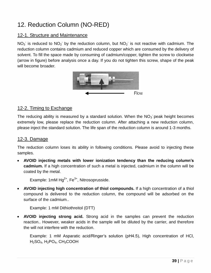
12-1. Structure and Maintenance
NO3- is reduced to NO2
- by the reduction column, but NO2- is not reactive with cadmium. The
reduction column contains cadmium and reduced copper which are consumed by the delivery of
solvent. To fill the space made by consuming of cadmium/copper, tighten the screw to clockwise
(arrow in figure) before analysis once a day. If you do not tighten this screw, shape of the peak
will become broader.
12-2. Timing to Exchange
The reducing ability is measured by a standard solution. When the NO3- peak height becomes
extremely low, please replace the reduction column. After attaching a new reduction column,
please inject the standard solution. The life span of the reduction column is around 1-3 months.
12-3. Damage
The reduction column loses its ability in following conditions. Please avoid to injecting these
samples.
AVOID injecting metals with lower ionization tendency than the reducing column’s
cadmium. If a high concentration of such a metal is injected, cadmium in the column will be
coated by the metal.
Example: 1mM Hg2+, Fe3+, Nitrosoprusside.
AVOID injecting high concentration of thiol compounds. If a high concentration of a thiol
compound is delivered to the reduction column, the compound will be adsorbed on the
surface of the cadmium..
Example: 1 mM Dithiothreitol (DTT)
AVOID injecting strong acid. Strong acid in the samples can prevent the reduction
reaction.. However, weaker acids in the sample will be diluted by the carrier, and therefore
the will not interfere with the reduction.
Example: 1 mM Asparatic acid/Ringer’s solution (pH4.5), High concentration of HCl,
H2SO4, H2PO4, CH3COOH
40 | P a g e
13. Troubleshooting
In the case that your analysis can not be performed by the ENO-30, and that troubles persist
after reading this document, please refer to this chapter. Please inject a standard sample to find
the cause of trouble. If this chapter is not helpful, please contact Eicom.
13-1. Pump Problems
This unit will explain how to determine if the liquid delivery method is normal or not. All delivery
problems will appear on the chromatogram chart, usually as a longer retention time than
expected. First, check that there are no slow leaks at the tubing connections (around manual
injector, valve in autosampler, column inlet/outlet, etc).
13-2. Checking the Flow Rate
For the Carrier pump, set the flow to 500 µL/min and collect liquid at the waste line outlet for 1
minute with only the Carrier pump running. If you use a small microcentrifuge tube, you can
estimate quickly whether it’s 500 µL or more like 250 µL. If it is only 250, then you have a
bubble.
For the Reactor pump, disconnect the tubing where it enters the three way joint by the reaction
loop. Collect a sample here for 1 minute by setting the pump to 500 µL/min and running only the
Reactor pump. If it’s close to 250 µL, there is a bubble.
13-4. Removing Air Bubbles
Air bubbles are the main problem encountered with the pump unit. Air-bubbles are sometimes
generated in the Carrier and Reactor Pumps. As long as air exists inside a pump, the pump will
not work as liquid delivery pump. To prevent this air generation, an online degasser is included.
So air generation will be very rare. However, if air is trapped in one of the pump heads during
washing or at start up, the following symptoms may occur.
lower than expected pressure?
lower than the expected volume at the waste line outlet based on the flow rate setting?
longer than expected retention times for the peaks?
frequent error 4?
smaller than expected standard peak heights, especially nitrite?
To clear the trapped air bubbles, there are several strategies.
1) The simplest method is to connect a syringe at the purge valve, open the valve and aspirate
to remove the bubble. Close the valve and check symptoms again. Repeat a couple of times.
2) If that doesn’t work, do the same things again except this time pull the syringe quickly and
41 | P a g e
release to “pop” the syringe. Then close the valve and check for symptoms again. Repeat a
couple of times.
3) The next option is to pull a large bubble through the pump head. Lift the solution inlet tubing
out of the liquid and aspirate at the purge valve until there is a large bubble in the tubing. Lower
the inlet back in the reservoir and aspirate until the air comes into the syringe.
4) The next method is to force liquid through the pump head by connecting a syringe to the
three way joint at the bottom of the pump head. There are details in video available on the
Eicom users’ site or directly from your Eicom representative.
13-4. High Carrier Pump pressure
Check the guard column. Remove the guard column and replace it with a two way. Check the
pressure. If the pressure is standard pressure, the guard column should be repacked (see
chapter 17).
13-5. Unstable Baseline
Has the system run for more than 30 minutes? It takes time for the system to stabilize and
the oven to get to temperature.
Have you check the pump flow rates? Maybe there is air in one of the pumps.
Are there any leaks at the tubing connections?
13-6. Peak Shape
Is the peak strange, asymmetry, or tailing? The peak shape is influenced mainly by the
separation column and guard column. See chapters 10 and 11.
42 | P a g e
14. Maintenance
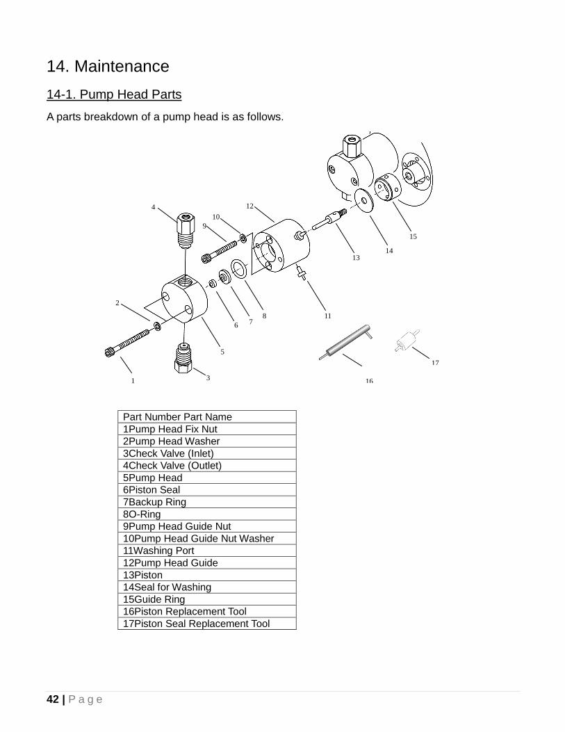
14-1. Pump Head Parts
A parts breakdown of a pump head is as follows.
Part Number Part Name
1Pump Head Fix Nut
2Pump Head Washer
3Check Valve (Inlet)
4Check Valve (Outlet)
5Pump Head
6Piston Seal
7Backup Ring
8O-Ring
9Pump Head Guide Nut
10Pump Head Guide Nut Washer
11Washing Port
12Pump Head Guide
13Piston
14Seal for Washing
15Guide Ring
16Piston Replacement Tool
17Piston Seal Replacement Tool
1
2
3
4
5
6 7 8
9
10
11
12
13 14
15
16
17
43 | P a g e
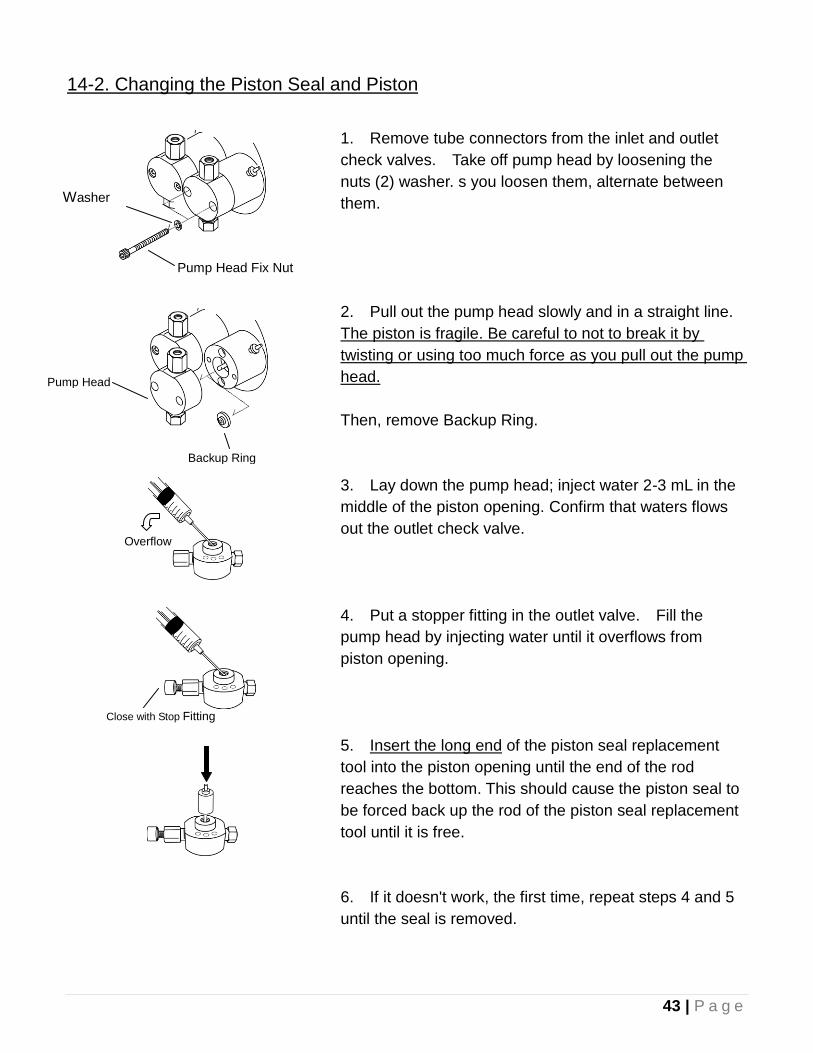
14-2. Changing the Piston Seal and Piston
1. Remove tube connectors from the inlet and outlet
check valves. Take off pump head by loosening the
nuts (2) washer. s you loosen them, alternate between
them.
2. Pull out the pump head slowly and in a straight line.
The piston is fragile. Be careful to not to break it by
twisting or using too much force as you pull out the pump
head.
Then, remove Backup Ring.
3. Lay down the pump head; inject water 2-3 mL in the
middle of the piston opening. Confirm that waters flows
out the outlet check valve.
4. Put a stopper fitting in the outlet valve. Fill the
pump head by injecting water until it overflows from
piston opening.
5. Insert the long end of the piston seal replacement
tool into the piston opening until the end of the rod
reaches the bottom. This should cause the piston seal to
be forced back up the rod of the piston seal replacement
tool until it is free.
6. If it doesn't work, the first time, repeat steps 4 and 5
until the seal is removed.
Pump Head Fix Nut
Washer
Pump Head
Backup Ring
Overflow
Close with Stop Fitting
44 | P a g e
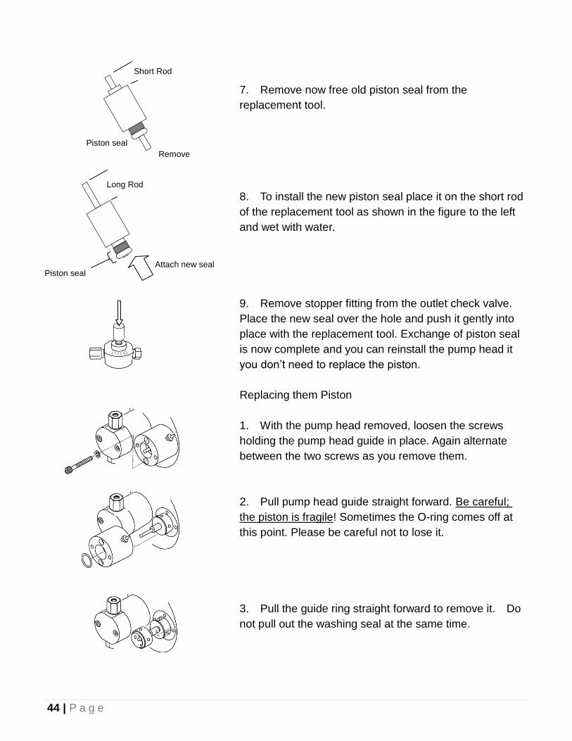
7. Remove now free old piston seal from the
replacement tool.
8. To install the new piston seal place it on the short rod
of the replacement tool as shown in the figure to the left
and wet with water.
9. Remove stopper fitting from the outlet check valve.
Place the new seal over the hole and push it gently into
place with the replacement tool. Exchange of piston seal
is now complete and you can reinstall the pump head it
you don’t need to replace the piston.
Replacing them Piston
1. With the pump head removed, loosen the screws
holding the pump head guide in place. Again alternate
between the two screws as you remove them.
2. Pull pump head guide straight forward. Be careful;
the piston is fragile! Sometimes the O-ring comes off at
this point. Please be careful not to lose it.
3. Pull the guide ring straight forward to remove it. Do
not pull out the washing seal at the same time.
Attach new seal Piston seal
Long Rod
Piston seal
Short Rod
Remove
45 | P a g e
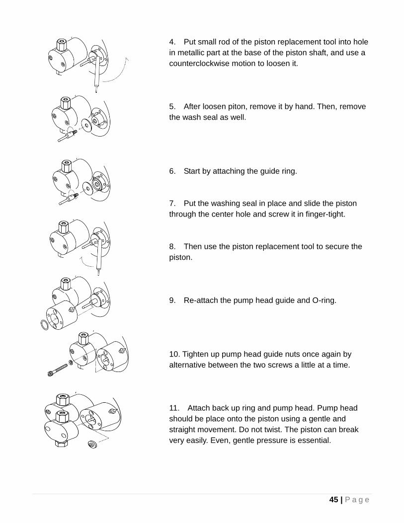
4. Put small rod of the piston replacement tool into hole
in metallic part at the base of the piston shaft, and use a
counterclockwise motion to loosen it.
5. After loosen piton, remove it by hand. Then, remove
the wash seal as well.
6. Start by attaching the guide ring.
7. Put the washing seal in place and slide the piston
through the center hole and screw it in finger-tight.
8. Then use the piston replacement tool to secure the
piston.
9. Re-attach the pump head guide and O-ring.
10. Tighten up pump head guide nuts once again by
alternative between the two screws a little at a time.
11. Attach back up ring and pump head. Pump head
should be place onto the piston using a gentle and
straight movement. Do not twist. The piston can break
very easily. Even, gentle pressure is essential.
46 | P a g e
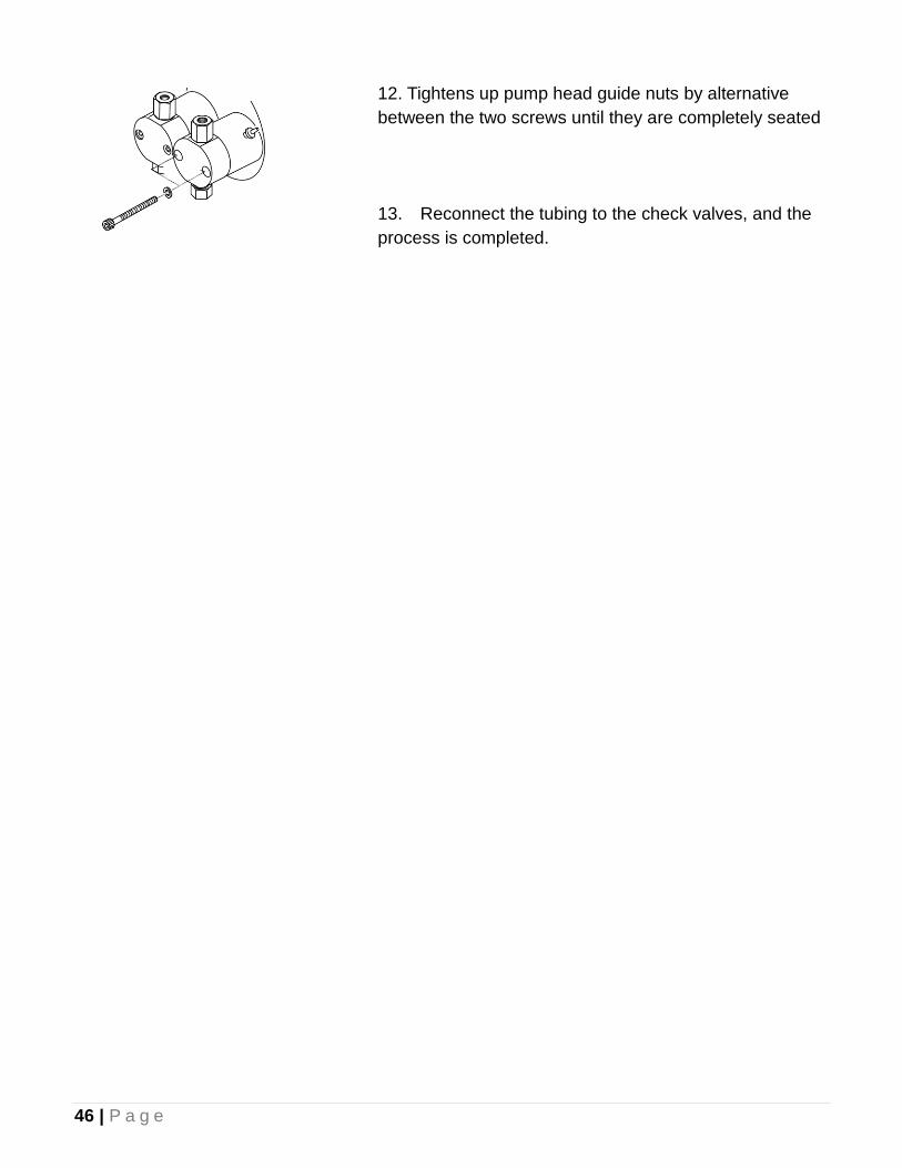
12. Tightens up pump head guide nuts by alternative
between the two screws until they are completely seated
13. Reconnect the tubing to the check valves, and the
process is completed.
47 | P a g e
15. Appendices
15-1. Autosampler and Data Processor (EPC-700) Connection
1. Disconnect the signal cable of the manual injector (black twisted cable) from the connector
located just behind the injector.
2. Connect the AS-700 output (black and red wires from the 3-wire portion of the signal cable)
to the AUTOZERO/SIG. IN of ENO-30.
3. Connect the CPU of the ENO-30 to the Detector 1 of the EPC-700 data processor.
4. Connect the SIG.OUT of the ENO-30 to the INPUT 1 of the EPC-700 data processor.
5. Connect the INPUT 2 to the ERROR OUT on the Pump Unit and set the software to use
INPUT 1 and 2 to “Freeze”
48 | P a g e
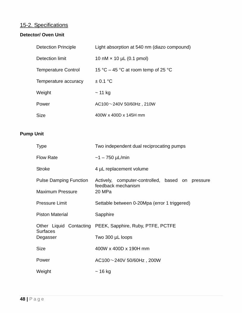
15-2. Specifications
Detector/ Oven Unit
Detection Principle Light absorption at 540 nm (diazo compound)
Detection limit 10 nM × 10 µL (0.1 pmol)
Temperature Control 15 °C – 45 °C at room temp of 25 °C
Temperature accuracy ± 0.1 °C
Weight ~ 11 kg
Power AC100~240V 50/60Hz , 210W
Size 400W x 400D x 145H mm
Pump Unit
Type Two independent dual reciprocating pumps
Flow Rate ~1 – 750 µL/min
Stroke 4 µL replacement volume
Pulse Damping Function Actively, computer-controlled, based on pressure feedback mechanism
Maximum Pressure 20 MPa
Pressure Limit Settable between 0-20Mpa (error 1 triggered)
Piston Material Sapphire
Other Liquid Contacting Surfaces
PEEK, Sapphire, Ruby, PTFE, PCTFE
Degasser Two 300 µL loops
Size 400W x 400D x 190H mm
Power AC100~240V 50/60Hz , 200W
Weight ~ 16 kg
49 | P a g e
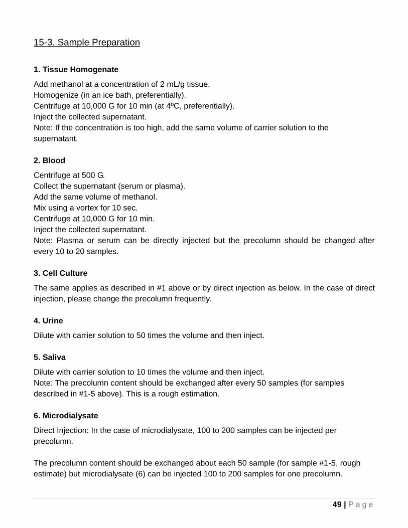
15-3. Sample Preparation
1. Tissue Homogenate
Add methanol at a concentration of 2 mL/g tissue.
Homogenize (in an ice bath, preferentially).
Centrifuge at 10,000 G for 10 min (at 4ºC, preferentially).
Inject the collected supernatant.
Note: If the concentration is too high, add the same volume of carrier solution to the
supernatant.
2. Blood
Centrifuge at 500 G.
Collect the supernatant (serum or plasma).
Add the same volume of methanol.
Mix using a vortex for 10 sec.
Centrifuge at 10,000 G for 10 min.
Inject the collected supernatant.
Note: Plasma or serum can be directly injected but the precolumn should be changed after
every 10 to 20 samples.
3. Cell Culture
The same applies as described in #1 above or by direct injection as below. In the case of direct
injection, please change the precolumn frequently.
4. Urine
Dilute with carrier solution to 50 times the volume and then inject.
5. Saliva
Dilute with carrier solution to 10 times the volume and then inject.
Note: The precolumn content should be exchanged after every 50 samples (for samples
described in #1-5 above). This is a rough estimation.
6. Microdialysate
Direct Injection: In the case of microdialysate, 100 to 200 samples can be injected per
precolumn.
The precolumn content should be exchanged about each 50 sample (for sample #1-5, rough
estimate) but microdialysate (6) can be injected 100 to 200 samples for one precolumn.
50 | P a g e
Limited Warranty
Warranty Period: One year from the original purchase date, as defined by the date of your Eicom
invoice. (Except for valve unit-which is warranted for 6 months from the
purchase date as defined by the date of your Eicom invoice).
Warranty Information: During warranty period, this Eicom’ product is covered by a limited liability
warranty covering manufacture defects. In case that the machine is defective, it
will be repaired or replaced free for charge. You will be responsible for return
shipping cost. Eicom will cover shipping cost after repairs.
Void of Warranty: The manufacturer's warranty will be void under the following conditions:
1) Failure to follow instructions and warnings relating to product’s use.
2) Repaired or altered by anyone other than Eicom.
3) Damage during shipping or transit, or any other accidental damage.
4) Damage due to use of improper voltages.
5) Damage due to improper setup of the equipment.
6) Damage due to any act of God.
7) Any other inappropriate usage of parts or consumables not authorized by
Eicom.
All rights reserved by Eicom. Use of images and /or wording of this manual without express permission
are completely prohibited. Specifications and descriptions in this user guide are subject to change
without prior notice. If you have any further questions, please feel free to contact to Eicom or its
distributors


Related Documents