1 | Page NORTH CAROLINA DIVISION OF AIR QUALITY Application Review Issue Date: MAY XY, 2020 Region: Wilmington Regional Office County: Duplin NC Facility ID: 3100179 Inspector’s Name: TBD Date of Last Inspection: TBD Compliance Code: TBD Facility Data Applicant (Facility’s Name): Align RNG, LLC (project BF Grady Road) Facility Address: (BF Grady Road) 2940 NC Highway 24 west Turkey, NC 28393 SIC: 1321/ Natural Gas Liquids NAICS: 211130/ Natural Gas Extraction Facility Classification: Before: Permit/Registration Pending After: Synth Min Fee Classification: Before: N/A After: Synthetic Minor Permit Applicability (this application only) SIP: X NSPS: NESHAP: PSD: PSD Avoidance: NC Toxics: 112(r): Other: Contact Data Application Data Application Number: 3100179.19A Date Received: 12/10/2019 Application Type: Greenfield Facility Application Schedule: State Existing Permit Data Existing Permit Number: N/A Existing Permit Issue Date: N/A Existing Permit Expiration Date: N/A Facility Contact Kraig Westerbeek V.P. Environmental and Manufacturing (910) 293-3434 PO Box 856 Warsaw, NC 28398 Authorized Contact Kraig Westerbeek V.P. Environmental and Manufacturing (910) 293-3434 PO Box 856 Warsaw, NC 28398 Technical Contact Kraig Westerbeek V.P. Environmental and Manufacturing (910) 293-3434 PO Box 856 Warsaw, NC 28398 Review Engineer: Dean Carroll Review Engineer’s Signature: Date: Comments / Recommendations: Issue: 10644/R00 Permit Issue Date: May XY, 2020 Permit Expiration Date: March 31 , 2028 1. Purpose of Application # 31/00179.19A This application was submitted by Mr. Kraig Westerbeek, VP of Environmental and Manufacturing, for an initial permit (greenfield facility) for BF Grady Road facility in Warsaw, NC, Duplin County. The parent company (Entity) for this facility is Align RNG, LLC in Richmond, VA. RNG is renewable natural gas. The actual location of the facility will be at 2940 NC Highway 24 West in Turkey, NC. 2. Facility Description This application is for a new facility which plans to receive biogas produced in anaerobic digesters at various independently owned and operated hog farms located in Duplin and Sampson counties. The projected biogas production amount has been calculated from other similar anaerobic digesters in NC using hog manure as the sole feedstock. The biogas (raw material) will be dried using biogas dehydration and compression systems (and a glycol chiller system) at each farm (roughly 19 total) and transported through a new low-pressure (< 10 psig) biogas pipeline to the BF Grady Rd facility.

Welcome message from author
This document is posted to help you gain knowledge. Please leave a comment to let me know what you think about it! Share it to your friends and learn new things together.
Transcript

1 | P a g e
NORTH CAROLINA DIVISION OF AIR QUALITY
Application Review Issue Date: MAY XY, 2020
Region: Wilmington Regional Office County: Duplin NC Facility ID: 3100179 Inspector’s Name: TBD Date of Last Inspection: TBD Compliance Code: TBD
Facility Data Applicant (Facility’s Name): Align RNG, LLC (project BF Grady Road) Facility Address: (BF Grady Road) 2940 NC Highway 24 west Turkey, NC 28393 SIC: 1321/ Natural Gas Liquids NAICS: 211130/ Natural Gas Extraction Facility Classification: Before: Permit/Registration Pending After: Synth Min Fee Classification: Before: N/A After: Synthetic Minor
Permit Applicability (this application only) SIP: X NSPS: NESHAP: PSD: PSD Avoidance: NC Toxics: 112(r): Other:
Contact Data Application Data Application Number: 3100179.19A Date Received: 12/10/2019 Application Type: Greenfield Facility Application Schedule: State
Existing Permit Data Existing Permit Number: N/A Existing Permit Issue Date: N/A Existing Permit Expiration Date: N/A
Facility Contact Kraig Westerbeek V.P. Environmental and Manufacturing (910) 293-3434 PO Box 856 Warsaw, NC 28398
Authorized Contact Kraig Westerbeek V.P. Environmental and Manufacturing (910) 293-3434 PO Box 856 Warsaw, NC 28398
Technical Contact Kraig Westerbeek V.P. Environmental and Manufacturing (910) 293-3434 PO Box 856 Warsaw, NC 28398
Review Engineer: Dean Carroll Review Engineer’s Signature: Date:
Comments / Recommendations: Issue: 10644/R00 Permit Issue Date: May XY, 2020 Permit Expiration Date: March 31 , 2028
1. Purpose of Application # 31/00179.19A
This application was submitted by Mr. Kraig Westerbeek, VP of Environmental and Manufacturing, for an initial permit (greenfield facility) for BF Grady Road facility in Warsaw, NC, Duplin County. The parent company (Entity) for this facility is Align RNG, LLC in Richmond, VA. RNG is renewable natural gas. The actual location of the facility will be at 2940 NC Highway 24 West in Turkey, NC.
2. Facility Description This application is for a new facility which plans to receive biogas produced in anaerobic digesters at various independently owned and operated hog farms located in Duplin and Sampson counties. The projected biogas production amount has been calculated from other similar anaerobic digesters in NC using hog manure as the sole feedstock. The biogas (raw material) will be dried using biogas dehydration and compression systems (and a glycol chiller system) at each farm (roughly 19 total) and transported through a new low-pressure (< 10 psig) biogas pipeline to the BF Grady Rd facility.

2 | P a g e
The biogas will be upgraded to renewable natural gas quality and injected into the Piedmont Natural Gas pipeline for offsite consumption. The non-methane constituents of the biogas, referred to as tail gas, will be scrubbed for hydrogen sulfide (H2S) using an iron sponge system (two iron sponge scrubbers, CD-1 and CD-2), followed by one enclosed hybrid flare (CD-3). A portion or all of this tail gas may also bypass the scrubbers. This constitutes Normal Operation. See the Source Emissions permit equipment table below for a description of the three (3) possible scenarios at this facility.
In the application, the nearest farm to the BF Grady Rd biogas facility was given as 1.1 miles (direct linear distance, “as the crow flies”) and the farthest farm to the facility was given as 20 miles (direct linear distance, “as the crow flies”). There are 19 total legs of pipeline from the 19 farms and a total amount of about 30 miles of linear pipe.
3. Application Chronology
December 10, 2019 – Application, $400.00 fee, and zoning consistency request received. December 12, 2019 – Acknowledgement letter sent to the applicant.
January 17, 2020 – Completeness Add Info letter sent to the Applicant dealing with
compliance issues with DAQ regulation 15A NCAC 2D .0516 (SO2 Emissions).
February 27, 2020 – First Add Info response letter received from the Applicant.
March 18, 2020 – Secondary Add Info letter sent to the Applicant dealing with various
equipment operations and parametric monitors and evaluation. March 27, 2020 – Secondary Add Info letter response received from the Applicant.
4. Source Emissions
The following sources were requested to be permitted. The level of detail in this permit review is more extensive than in the permit, for the sole purpose of explaining the technical nature of the biogas process.
Emission Source ID
Emission Source Description
Control System ID
Control System Description
ES-1 GUS Scenario 1
Normal Operation
(Including Start-Up Situations)
During Start-Up,
one Gas Upgrading System (ES-1 GUS) - Normal Operation: consisting of a pressure swing adsorption (PSA) media system that chemically and physically segregates the constituents of the biogas (raw material) at a molecular level (molecular sieve using patented Molecular Gate™ adsorbent) when under pressure (approx. 100 psig). This particular PSA media was designed to optimally segregate methane
CD-1 (CD1 and CD2 are
in parallel and may operate simultaneously)
one iron sponge (scrubber) system vessel with fixed bed media (iron oxide) for hydrogen sulfide removal
CD-2 (CD1 and CD2 are
in parallel and may operate simultaneously)
one iron sponge (scrubber) system vessel with fixed bed media (iron oxide) for hydrogen sulfide removal
CD-3 Enclosed Hybrid Flare receives treated tail gas from the iron sponge system vessels and
untreated tail gas directly
one enclosed hybrid flare (John Zink unit, 10 MM Btu/hr heat input, 2020 model year) for the combustion of tail gas that has been treated by CD-1 and/or CD-2. The flare uses natural gas as
3 | P a g e
Emission Source ID
Emission Source Description
Control System ID
Control System Description
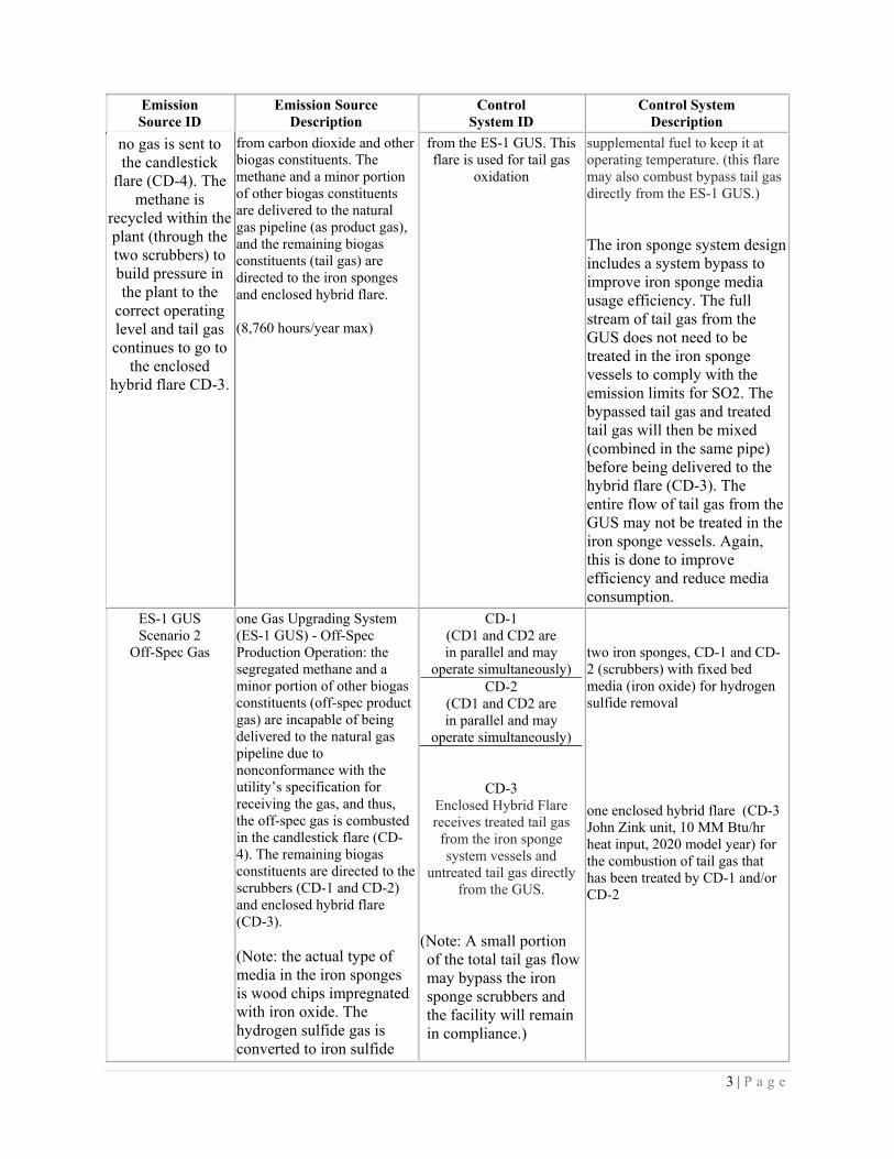
no gas is sent to the candlestick
flare (CD-4). The methane is
recycled within the plant (through the two scrubbers) to build pressure in the plant to the
correct operating level and tail gas continues to go to
the enclosed hybrid flare CD-3.
from carbon dioxide and other biogas constituents. The methane and a minor portion of other biogas constituents are delivered to the natural gas pipeline (as product gas), and the remaining biogas constituents (tail gas) are directed to the iron sponges and enclosed hybrid flare. (8,760 hours/year max)
from the ES-1 GUS. This flare is used for tail gas
oxidation
supplemental fuel to keep it at operating temperature. (this flare may also combust bypass tail gas directly from the ES-1 GUS.) The iron sponge system design includes a system bypass to improve iron sponge media usage efficiency. The full stream of tail gas from the GUS does not need to be treated in the iron sponge vessels to comply with the emission limits for SO2. The bypassed tail gas and treated tail gas will then be mixed (combined in the same pipe) before being delivered to the hybrid flare (CD-3). The entire flow of tail gas from the GUS may not be treated in the iron sponge vessels. Again, this is done to improve efficiency and reduce media consumption.
ES-1 GUS Scenario 2
Off-Spec Gas
one Gas Upgrading System (ES-1 GUS) - Off-Spec Production Operation: the segregated methane and a minor portion of other biogas constituents (off-spec product gas) are incapable of being delivered to the natural gas pipeline due to nonconformance with the utility’s specification for receiving the gas, and thus, the off-spec gas is combusted in the candlestick flare (CD-4). The remaining biogas constituents are directed to the scrubbers (CD-1 and CD-2) and enclosed hybrid flare (CD-3). (Note: the actual type of media in the iron sponges is wood chips impregnated with iron oxide. The hydrogen sulfide gas is converted to iron sulfide
CD-1 (CD1 and CD2 are in parallel and may
operate simultaneously) CD-2
(CD1 and CD2 are in parallel and may
operate simultaneously)
CD-3 Enclosed Hybrid Flare receives treated tail gas from the iron sponge system vessels and
untreated tail gas directly from the GUS.
(Note: A small portion of the total tail gas flow may bypass the iron sponge scrubbers and the facility will remain in compliance.)
two iron sponges, CD-1 and CD-2 (scrubbers) with fixed bed media (iron oxide) for hydrogen sulfide removal one enclosed hybrid flare (CD-3 John Zink unit, 10 MM Btu/hr heat input, 2020 model year) for the combustion of tail gas that has been treated by CD-1 and/or CD-2

4 | P a g e
Emission Source ID
Emission Source Description
Control System ID
Control System Description
which remains in the media bed) (360 hours/year max)
CD-4
Candlestick Flare receives Off-Spec product gas from the ES-1 GUS
one elevated candlestick flare (CD-4, ProPump unit, 45 MM Btu/hr heat input, 2020 model year)
ES-1 GUS Scenario 3
By-Pass Biogas
one Gas Upgrading System (ES-1 GUS); In By-Pass Biogas operation, the Gas Upgrading System is not in operation and the facility must direct biogas to CD-4. (240 hours/year max)
CD-4 Candlestick Flare
receives raw biogas that is not processed by the ES-1
GUS
one elevated candlestick flare (ProPump unit, 45 MM Btu/hr heat input, 2020 model year)
Actual and Potential Emissions from the Application (D1 Form):
Pollutant Actual (tons/year) Potential to Emit (tons/year)
CO 10.10 17.39 NOx 4.83 6.54
PM(TSP) 0.07 0.14 PM(10) 0.07 0.14 PM(2.5) 0.06 0.12
SO2 47-50 projected 193.24 VOC 0.76 1.53
This facility will be classified as a synthetic minor due to SO2 PTE > 100 tpy.
5. Applicable Regulations
Regulations for this facility will be: Title 15A North Carolina Administrative Code (NCAC), Subchapter 2D .0202, 2D .0516, 2D .0535, 2D .0540, 2Q .0315 (synthetic minor), and 2Q .0317 (PSD avoidance). Each regulation will be shown as it is presented in the actual permit:
1. Any air emission sources or control devices authorized to construct and operate above must be operated and maintained in accordance with the provisions contained herein. The Permittee shall comply with applicable Environmental Management Commission Regulations, including Title 15A North Carolina Administrative Code (NCAC), Subchapter 2D .0202, 2D .0516, 2D .0535, 2D .0540, 2Q .0315, and 2Q .0317 (PSD avoidance).
2. PERMIT RENEWAL AND EMISSION INVENTORY REQUIREMENT - The Permittee, at least 90 days prior to the expiration date of this permit, shall request permit renewal by letter in accordance with 15A NCAC 2Q .0304(d) and (f). Pursuant to 15A NCAC 2Q .0203(i), no permit application fee is required for renewal of an existing air permit (without a modification request). The renewal request (with application Form A) should

5 | P a g e
be submitted to the Regional Supervisor, DAQ. Also, at least 90 days prior to the expiration date of this permit, the Permittee shall submit the air pollution emission inventory report (with Certification Sheet) in accordance with 15A NCAC 2D .0202, pursuant to N.C. General Statute 143 215.65. The report shall be submitted to the Regional Supervisor, DAQ and shall document air pollutants emitted for the 2026 calendar year.
3. SULFUR DIOXIDE CONTROL REQUIREMENT - As required by 15A NCAC 2D .0516 "Sulfur Dioxide Emissions from Combustion Sources," sulfur dioxide emissions from one Gas Upgrading System (ID No. ES-1 GUS) and the facility flares (CD-3 and CD-4) shall not exceed 2.3 pounds per million Btu heat input.
Custom permit language was added to this permit due to compliance concerns with 2D .0516. This language was put in the permit at condition A.3.:
In order to meet the SO2 limit of 2.3 lbs/MMBtu heat input, a limitation of the hydrogen sulfide (lb/hr H2S) to the combustion source CD-3 (10MM Btu/hr heat input hybrid flare) is required. Additionally, CD-3 must be operated within no more than 10% of its maximum rated heat input of 10 MMBtu/hr during Normal and Off-Spec Operational Scenarios (OS1 and OS2 as described in the permit equipment list and in Specific Condition 6). To ensure compliance with this limitation, the following monitoring, recordkeeping, and reporting requirements are required:
a. Monitoring: The Permittee shall monitor; the H2S concentration (ppm) and flow (scfm) from the outlet of emission source (ES-1 GUS), the concentration (ppm) and flow (scfm) from the outlet of the iron sponge scrubbers, and calculate the flow (scfm) and concentration (ppm) of the tail gas bypassing the iron sponges once every 8 hours (three times per day / minimum of once per operating day) for each day the ES-1 GUS is in operation (see Specific Condition 6). The permittee shall also record the instantaneous natural gas flow rate to CD-3 in scfm at the same time as the measurements above are taken.
b. Recordkeeping: The Permittee shall record; the H2S concentration (ppm), flow
(scfm), and heat input rate (converted to MMBtu/hr) from the monitoring locations as identified in a. above. No later than the next day, the Permittee shall calculate the average emission rate of H2S (lb/hr) to the hybrid flare (CD-3) each day in lb/hr and compare this rate to the hydrogen sulfide limitation. If the calculated rate is higher than the calculated limit, the Permittee is in violation of 2D .0516. The formula for calculating the limit and amount of H2S (lb/hr) to the hybrid flare (CD-3) is as follows:
• (Qng)(63,000)(2.3E-06)(OF)(0.523) > 5.7 [(Qgus –
Qscrubber)(Cgus) + (Qscrubber)(Cscrubber)]+[(36X10-6 )(Qng)(0.523)]
(Qng)(63,000)(2.3X10-06)(OF)(0.523) is the Required Limit of H2S in lb/r.
Representing the 2.3 lb SO2/MMBtu/hr limit expressed as H2S (lb/hr) where 0.523 = Mole Wt H2S/Mole Wt SO2 (34.08/64.06)
6 | P a g e
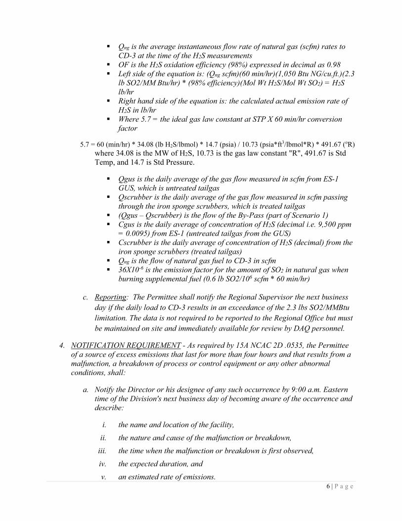
Qng is the average instantaneous flow rate of natural gas (scfm) rates to CD-3 at the time of the H2S measurements
OF is the H2S oxidation efficiency (98%) expressed in decimal as 0.98 Left side of the equation is: (Qng scfm)(60 min/hr)(1,050 Btu NG/cu.ft.)(2.3
lb SO2/MM Btu/hr) * (98% efficiency)(Mol Wt H2S/Mol Wt SO2) = H2S lb/hr
Right hand side of the equation is: the calculated actual emission rate of H2S in lb/hr
Where 5.7 = the ideal gas law constant at STP X 60 min/hr conversion factor
5.7 = 60 (min/hr) * 34.08 (lb H2S/lbmol) * 14.7 (psia) / 10.73 (psia*ft3/lbmol*R) * 491.67 (oR) where 34.08 is the MW of H2S, 10.73 is the gas law constant "R", 491.67 is Std Temp, and 14.7 is Std Pressure.
Qgus is the daily average of the gas flow measured in scfm from ES-1
GUS, which is untreated tailgas Qscrubber is the daily average of the gas flow measured in scfm passing
through the iron sponge scrubbers, which is treated tailgas (Qgus – Qscrubber) is the flow of the By-Pass (part of Scenario 1) Cgus is the daily average of concentration of H2S (decimal i.e. 9,500 ppm
= 0.0095) from ES-1 (untreated tailgas from the GUS) Cscrubber is the daily average of concentration of H2S (decimal) from the
iron sponge scrubbers (treated tailgas) Qng is the flow of natural gas fuel to CD-3 in scfm 36X10-6 is the emission factor for the amount of SO2 in natural gas when
burning supplemental fuel (0.6 lb SO2/106 scfm * 60 min/hr)
c. Reporting: The Permittee shall notify the Regional Supervisor the next business day if the daily load to CD-3 results in an exceedance of the 2.3 lbs SO2/MMBtu limitation. The data is not required to be reported to the Regional Office but must be maintained on site and immediately available for review by DAQ personnel.
4. NOTIFICATION REQUIREMENT - As required by 15A NCAC 2D .0535, the Permittee of a source of excess emissions that last for more than four hours and that results from a malfunction, a breakdown of process or control equipment or any other abnormal conditions, shall:
a. Notify the Director or his designee of any such occurrence by 9:00 a.m. Eastern time of the Division's next business day of becoming aware of the occurrence and describe:
i. the name and location of the facility, ii. the nature and cause of the malfunction or breakdown,
iii. the time when the malfunction or breakdown is first observed, iv. the expected duration, and v. an estimated rate of emissions.
7 | P a g e
b. Notify the Director or his designee immediately when the corrective measures have been accomplished.
This reporting requirement does not allow the operation of the facility in excess of Environmental Management Commission Regulations.
5. FUGITIVE DUST CONTROL REQUIREMENT - As required by 15A NCAC 2D .0540 "Particulates from Fugitive Dust Emission Sources," the Permittee shall not cause or allow fugitive dust emissions to cause or contribute to substantive complaints or excess visible emissions beyond the property boundary. If substantive complaints are received or excessive fugitive dust emissions from the facility are observed beyond the property boundaries for six minutes in any one hour (using Reference Method 22 in 40 CFR, Appendix A), the owner or operator may be required to submit a fugitive dust plan as described in 2D .0540(f). "Fugitive dust emissions" means particulate matter that does not pass through a process stack or vent and that is generated within plant property boundaries from activities such as: unloading and loading areas, process areas stockpiles, stock pile working, plant parking lots, and plant roads (including access roads and haul roads).
The 2D .0516 rule has been a source of difficulty to meet DAQ compliance. The applicant has been cooperative in explaining their efforts and plans to meet this rule “Sulfur Dioxide Emissions from Combustion Sources” (2.3 pounds per million Btu heat input) from the two flares. See the secondary add info response letter from BF Grady Rd dated March 27, 2020 by email. Question No. 5 of that response contained the following: A 12-month rolling total of SO2 emissions will be calculated using the recorded flow rate and gas composition values. For Bypass Operation, the total volume of biogas combusted in the candlestick flare (CD-4) and the average biogas composition entering the facility will be used to calculate SO2 emissions. For Normal Operation, the total volume of untreated and treated tail gas delivered to the enclosed hybrid flare (CD-3), as well as the H2S concentration of the treated and untreated tail gas, will be used to calculate SO2 emissions. In addition, the SO2 emissions generated from natural gas combustion in the enclosed hybrid flare will also be calculated. For Off-Spec Operation, SO2 emissions from the enclosed hybrid flare will be calculated in the same manner as during Normal Operation. In addition, SO2 emissions from product gas combustion in the candlestick flare will be calculated using the total volume of product gas combusted and the H2S concentration of the product gas as measured by the Envent Model 331SDS H2S Analyzer which will be housed in the facility’s product gas analyzer building. The calculation methods used to calculate the potential annual emissions without controls and limits and the actual annual emissions with controls and limits are provided below. See the secondary add info response letter from BF Grady Rd dated March 27, 2020 for the original response. The actual 2Q .0315 synthetic minor condition language is shown below (Section 6).
The potential annual emissions without controls and limits were calculated for the maximum rated inlet flow rate of 1,200 scfm for the Guild PSA system and the maximum expected H2S concentration of 3,500 ppm for the biogas. The calculations assume 8,760

8 | P a g e
hours of Normal Operation without H2S removal in the iron sponge vessels and 600 hours of Off-Spec Operation. The SO2 emission rates were calculated as follows:
ES-1, EP-1, with CD-3, Potential Emissions (Uncontrolled) To determine the mass flow rate of H2S given a biogas flow rate of 1,200 scfm and an H2S concentration of 3,500 ppm, the following formula was used:
For H2S, m = (60 x 34.08 x 14.7 x 1,200 x 0.0035) / (10.73 x 491.67) = 23.93 lb/hr H2S. The 0.0035 factor is used because the maximum expected H2S concentration for the biogas is 3,500 ppm. At a biogas flow rate of 1,200 scfm, that results in an H2S flow rate of 1,200 scfm x 0.0035 = 4.2 scfm. (60 minutes/hour conversion factor also used.) The molecular weight of SO2 is 64.06. To convert from H2S to SO2, the ratio of the MWs was used or 64.06 / 34.08 = 1.88. Therefore, m = 23.93 x 1.88 = 44.98 lb/hr SO2.
Assuming a 98% oxidation efficiency based on EPA 40 CFR 60.18 and AP-42 Section 13.5, that equates to 44.08 lb/hr SO2. For 8,760 operating hours per year, that equals 44.08 x 8,760 / 2000 = 193.08 tons/yr SO2 uncontrolled emissions. In addition to the mass balance above, the SO2 emission factor from AP-42 Section 1.4, which equals 0.60 lb/MMscf, was used to calculate emissions from the supplemental natural gas to the enclosed flare. The emission rate was calculated by adjusting the emission factor to the average heating value of the tail gas – natural gas mixture which is 165.79 Btu/scf. The maximum rated heat input of 10 MMBtu/hr to the enclosed hybrid flare was used. The emission rate was calculated as 0.6 lb/MMscf / 165.79 Btu/scf x 10 MMBtu/hr x 8,760 hr/yr / 2,000 lb/ton = 0.16 tons/yr. As reported on Calculations Pages 4 and 9 the total uncontrolled SO2 emission rate from EP-1 is calculated as 193.08 tons/yr + 0.16 tons/yr = 193.24 tons/yr. ES-1, EP-2, with CD-4, Potential Emissions (Uncontrolled) To determine the emissions from 600 hours of product gas combustion in the candlestick flare (CD-4), the SO2 emission factor from AP-42 Section 1.4, which equals 0.60 lb/MMscf, was used. The emission rate was calculated by adjusting the emission factor to the average heating value of the product gas which is 902.70 Btu/scf. The maximum rated heat input of 45 MMBtu/hr to the candlestick flare was used. The emission rate was calculated as 0.6 lb/MMscf / 902.70 Btu/scf x 45 MMBtu/hr x 600 hr/yr / 2,000 lb/ton = 0.01 tons/yr SO2.
9 | P a g e
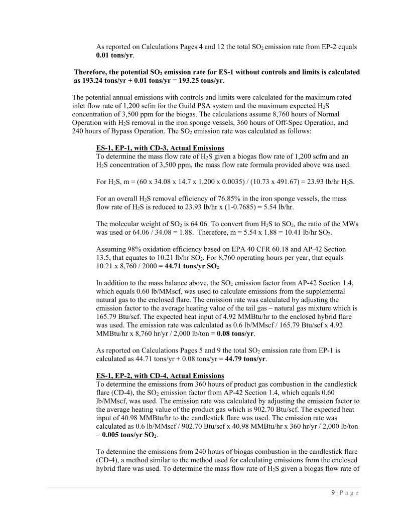
As reported on Calculations Pages 4 and 12 the total SO2 emission rate from EP-2 equals 0.01 tons/yr.
Therefore, the potential SO2 emission rate for ES-1 without controls and limits is calculated as 193.24 tons/yr + 0.01 tons/yr = 193.25 tons/yr.
The potential annual emissions with controls and limits were calculated for the maximum rated inlet flow rate of 1,200 scfm for the Guild PSA system and the maximum expected H2S concentration of 3,500 ppm for the biogas. The calculations assume 8,760 hours of Normal Operation with H2S removal in the iron sponge vessels, 360 hours of Off-Spec Operation, and 240 hours of Bypass Operation. The SO2 emission rate was calculated as follows:
ES-1, EP-1, with CD-3, Actual Emissions To determine the mass flow rate of H2S given a biogas flow rate of 1,200 scfm and an H2S concentration of 3,500 ppm, the mass flow rate formula provided above was used. For H2S, m = (60 x 34.08 x 14.7 x 1,200 x 0.0035) / (10.73 x 491.67) = 23.93 lb/hr H2S. For an overall H2S removal efficiency of 76.85% in the iron sponge vessels, the mass flow rate of H2S is reduced to 23.93 lb/hr x (1-0.7685) = 5.54 lb/hr. The molecular weight of SO2 is 64.06. To convert from H2S to SO2, the ratio of the MWs was used or 64.06 / 34.08 = 1.88. Therefore, m = 5.54 x 1.88 = 10.41 lb/hr SO2.
Assuming 98% oxidation efficiency based on EPA 40 CFR 60.18 and AP-42 Section 13.5, that equates to 10.21 lb/hr SO2. For 8,760 operating hours per year, that equals 10.21 x 8,760 / 2000 = 44.71 tons/yr SO2. In addition to the mass balance above, the SO2 emission factor from AP-42 Section 1.4, which equals 0.60 lb/MMscf, was used to calculate emissions from the supplemental natural gas to the enclosed flare. The emission rate was calculated by adjusting the emission factor to the average heating value of the tail gas – natural gas mixture which is 165.79 Btu/scf. The expected heat input of 4.92 MMBtu/hr to the enclosed hybrid flare was used. The emission rate was calculated as 0.6 lb/MMscf / 165.79 Btu/scf x 4.92 MMBtu/hr x 8,760 hr/yr / 2,000 lb/ton = 0.08 tons/yr. As reported on Calculations Pages 5 and 9 the total SO2 emission rate from EP-1 is calculated as 44.71 tons/yr + 0.08 tons/yr = 44.79 tons/yr. ES-1, EP-2, with CD-4, Actual Emissions To determine the emissions from 360 hours of product gas combustion in the candlestick flare (CD-4), the SO2 emission factor from AP-42 Section 1.4, which equals 0.60 lb/MMscf, was used. The emission rate was calculated by adjusting the emission factor to the average heating value of the product gas which is 902.70 Btu/scf. The expected heat input of 40.98 MMBtu/hr to the candlestick flare was used. The emission rate was calculated as 0.6 lb/MMscf / 902.70 Btu/scf x 40.98 MMBtu/hr x 360 hr/yr / 2,000 lb/ton = 0.005 tons/yr SO2. To determine the emissions from 240 hours of biogas combustion in the candlestick flare (CD-4), a method similar to the method used for calculating emissions from the enclosed hybrid flare was used. To determine the mass flow rate of H2S given a biogas flow rate of
10 | P a g e
1,200 scfm and an H2S concentration of 3,500 ppm, the mass flow rate formula provided above was used. For H2S, m = (60 x 34.08 x 14.7 x 1,200 x 0.0035) / (10.73 x 491.67) = 23.93 lb/hr H2S.
The molecular weight of SO2 is 64.06. To convert from H2S to SO2, the ratio of the MWs was used or 64.06 / 34.08 = 1.88. Therefore, m = 23.93 x 1.88 = 44.98 lb/hr SO2.
Assuming 98% oxidation efficiency based on EPA 40 CFR 60.18 and AP-42 Section 13.5, that equates to 44.08 lb/hr SO2. For 240 operating hours per year, that equals 44.08 x 240 / 2000 = 5.29 tons/yr SO2. In addition to the mass balance above, the SO2 emission factor from AP-42 Section 1.4, which equals 0.60 lb/MMscf, was used to calculate emissions. The emission rate was calculated by adjusting the emission factor to the average heating value of the biogas which is 594.54 Btu/scf. The expected heat input of 42.84 MMBtu/hr to the enclosed hybrid flare was used. The emission rate was calculated as 0.6 lb/MMscf / 594.54 Btu/scf x 42.84 MMBtu/hr x 240 hr/yr / 2,000 lb/ton = 0.005 tons/yr SO2. As reported on Calculations Page 5 the total SO2 emission rate from EP-2 is calculated as 0.005 tons/yr + 5.29 tons/yr = 5.30 tons/yr. Therefore, the potential SO2 emission rate for ES-1 with controls and limits is calculated as 44.79 tons/yr + 5.30 tons/yr = 50.09 tons/yr.
As shown in the calculations above and on Calculations Pages 4 and 5 of the Air Quality Permit Application, the potential annual emissions are reduced from 193.25 tons/yr to 50.09 tons/yr by utilizing the iron sponge system for hydrogen sulfide removal. As shown on Form D1 of the Application, the expected actual SO2 emissions for ES-1 with controls and limits are 47.02 tons/yr. The actual emissions were calculated for 8,160 hours of Normal Operation, 360 hours of Off-Spec Operation, and 240 hours of Bypass Operation for a total of 8,760 hours of operation per year. It is possible that the BF Grady Rd facility will exceed 8,160 hours of Normal Operation per year as reflected in the potential annual emissions with controls and limits.
6. Emissions Limits and Requirements
One thing to note in the synthetic minor condition (A.6.) – is that this permit will require a specific monthly recordkeeping of H2S concentration (ppm) and SO2 actual emissions calculations (ton/yr) which shall be reported to DAQ annually. This is because the facility has various components (moving parts) to meet the SO2 actual emissions (100 ton/yr synthetic minor limitation). The synthetic minor condition will utilize custom language showing flow rates, pressure drop, emission factors (emission rates), and hours of operation. The (custom) 2Q .0315 synthetic minor permit condition is shown below:
A.6. LIMITATION TO AVOID 15A NCAC 2Q .0501 - Pursuant to 15A NCAC 2Q .0315 "Synthetic Minor Facilities," to avoid the applicability of 15A NCAC 2Q .0501 "Purpose of Section and Requirement for a TV Permit," as requested by the Permittee, facility-wide emissions shall be less than the following:
11 | P a g e
Pollutant Emission Limit (Tons per consecutive 12-month period)
SO2 < 100
a. Operations Restrictions - To ensure emissions do not exceed the limitations above, the following restrictions shall apply:
i. The SO2 actual emissions shall be less than 100 ton/yr per consecutive 12-
month rolling period.
b. Inspection and Maintenance Requirements -
i. H2S Scrubber Requirements – SO2 emissions shall be controlled as described in the permitted equipment list. To comply with the provisions of this permit and ensure that SO2 emissions do not exceed the regulatory limits, the Permittee shall perform periodic inspections and maintenance (I&M) as recommended by the manufacturer. In addition, the Permittee shall perform an annual (for each 12 month period following the initial inspection) inspection of each H2S Scrubber system (CD-1 and CD-2). As a minimum, the I&M program and each annual inspection should include the following:
A. Inspect and maintain the structural integrity of each H2S Scrubber system / iron sponge (CD-1 and CD-2).
B. Inspect and maintain the structural integrity of duct work and piping leading to each H2S Scrubber system (CD-1 and CD-2).
ii. Hybrid Enclosed Flare and Candlestick Flare Requirements - The Permittee shall perform periodic inspections and maintenance (I&M) as recommended by the manufacturer. Each flare shall be equipped with a heat-sensing device, such as an ultraviolet beam sensor or a thermocouple, installed in proximity of the pilot light, to confirm the presence of a flame. The pilot flame must be present while biogas vapors are displaced to both flares to assure compliance with this permit condition.
iii. H2S Monitors - The Permittee shall perform periodic inspections and maintenance (I&M) as recommended by the manufacturer as well as periodic calibrations as recommended by the manufacturer.
iv. Flow Meters - The Permittee shall perform periodic inspections and maintenance (I&M) as recommended by the manufacturer as well as periodic calibrations as recommended by the manufacturer.
12 | P a g e
v. Pressure Meters - The Permittee shall perform periodic inspections and maintenance (I&M) as recommended by the manufacturer as well as periodic calibrations as recommended by the manufacturer.
c. Monitoring Requirements -
i. H2S Scrubber Requirements (CD-1 and CD-2) -
A. To ensure the proper performance of each H2S Scrubber system (CD-1 and CD-2), each H2S Scrubber system shall be equipped with a device to continuously measure the gauge pressure directly upstream and downstream of the Scrubber itself. Each device shall be installed in an accessible location and shall be maintained by the Permittee such that it is in proper working order at all times. The pressure drop across the bed shall be recorded electronically for each scrubber (iron sponge) once per day for each day the Gas Upgrading System and CD-1 and/or CD-2 is operating.
B. Monitoring for Breakthrough - Compliance with this permit may be demonstrated by either of the two following options:
I. Differential Pressure - The Permittee shall monitor and electronically record the differential pressure across the media bed for each iron sponge once per day for each day the Gas Upgrading System and CD-1 and/or CD-2 is operating. When the differential pressure across the media bed exceeds the allowable range as specified by the manufacturer (30 inches of water), the scrubber media shall be replaced.
II. Discontinuous Chemical Analysis – An analyzer shall be installed to determine the concentration of the regulated pollutant (hydrogen sulfide) in the outlet stream once every eight (8) hours (three times per day, and a minimum of once per day) for each day the Gas Upgrading System is operating. When the outlet concentration of hydrogen sulfide (H2S) is greater than 100 parts per million (ppm) (this is an operational guide and not a limit; the max allowable is per the permit limited hourly emissions of SO2; see Specific Condition A.3.) for two consecutive samples, the scrubber media shall be replaced.
d. Recordkeeping Requirements -
i. The Permittee shall record once (electronically) per every 8 hours of operation (minimum of once per operating day); this reading shall be taken at a set time of day; representative of the 8 hour period of
13 | P a g e
operations. The readings shall be calculated (averaged) monthly and kept on a spreadsheet to calculate the 12 month rolling basis the following:
A. flow rates (in standard cubic feet per minute (scfm)): each Emission Source Operating Scenario shall be recorded once per every 8 hours of operation (minimum of once per operating day):
• Tail gas flow produced by ES-1 gas upgrading system • Tail gas flow to each iron sponge vessel (CD-1 and CD-2) • Tail gas flow bypassing the iron sponges to enclosed flare
(CD-3) calculated as the difference between the two preceding values
• Product gas flow to CD-4 candlestick flare • Biogas flow to CD-4 candlestick flare • Total Biogas flow to the ES-1GUS (incoming raw material) • Natural gas fuel flow to each flare CD-3 and CD-4 when in
operation
B. Hydrogen sulfide (H2S) concentrations in parts per million, for each Emission Source Operating Scenario, shall be recorded once per every 8 hours of operation (minimum of once per operating day):
• Concentration of H2S in the tail gas exiting the ES-1 GUS • Concentration of H2S in the tail gas exiting CD-1 and/or
CD2 based on each scrubber’s operational status • Estimated concentration of H2S in Biogas bypassing the
ES-1 GUS and entering the candlestick flare (CD-4) C. The facility-wide actual SO2 emissions in ton/month; determined
by calculation given the comparative molecular weight of the gas constituents, flow rate of the gas, and operating time for the facility and equipment, given standards for pressure, temperature, and other constant values, as shown below.
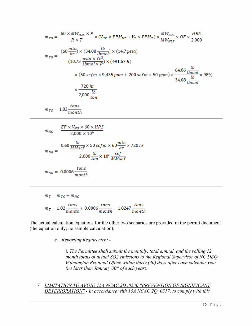
Sample Calculation for ES-1 Scenario 1 – Normal Operation – With Units
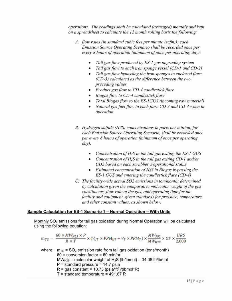
Monthly SO2 emissions for tail gas oxidation during Normal Operation will be calculated using the following equation:
where: mTG = SO2 emission rate from tail gas oxidation (tons/month) 60 = conversion factor = 60 min/hr
MWH2S = molecular weight of H2S (lb/lbmol) = 34.08 lb/lbmol P = standard pressure = 14.7 psia R = gas constant = 10.73 (psia*ft3)/(lbmol*R) T = standard temperature = 491.67 R

14 | P a g e
VUT = measured average monthly untreated tail gas volumetric flow rate (scfm) PPMUT = measured average monthly untreated tail gas H2S concentration (ppm) VT = measured average monthly treated tail gas volumetric flow rate (scfm) PPMT = measured average monthly treated tail gas H2S concentration (ppm) MWSO2 = molecular weight of SO2 (lb/lbmol) = 64.06 lb/lbmol OF = H2S oxidation efficiency = 98%1 HRS = total number of normal operating hours per month 2,000 = conversion factor = 2,000 lb/ton
Plus Monthly SO2 emissions for natural gas combustion (supplemental fuel) during normal operation will be calculated using the following equation:
where: mNG = SO2 emission rate from natural gas combustion (tons/month) EF = SO2 emission factor = 0.60 lb/MMscfm2 natural gas VNG = measured average monthly natural gas volumetric flow rate (scfm) 60 = conversion factor = 60 min/hr HRS = total number of normal operating hours per month 2,000 = conversion factor = 2,000 lb/ton 106 = conversion factor = 106 scf/MMscf
Total monthly SO2 emissions during Normal Operation will be calculated using the following equation:
where: mT = total SO2 emission rate during normal operation (tons/month) mTG = SO2 emission rate from tail gas oxidation during normal operation (tons/month) mNG = SO2 emission rate from natural gas combustion (supplemental fuel) during normal operation (tons/month)
The following calculations were completed by substituting actual numbers (expected realistic values) into the above equations to provide an example calculation and emission rate. The calculation below assumes an overall efficiency of 79.6% for the iron sponge system (CD-1 or CD-2) which was calculated using a capture efficiency of 80.0% (200 scfm / 250 scfm) and a control device efficiency of 99.5% (1 - 50 ppm / 9,455 ppm). The treated tail gas flow rate is assumed to be 200 scfm and the untreated (bypassed) tail gas flow rate is assumed to be 50 scfm. The treated tail gas H2S concentration is assumed to be 50 ppm. The biogas flow rate into the ES-1 GUS is assumed to be 675 scfm with an H2S concentration of 3,500 ppm. And use 720 hours of operation in a month.
1 Oxidation efficiency based on EPA 40 CFR 60.18 and AP-42 Section 13.5. 2 Emission factor from AP-42 Section 1.4.
15 | P a g e
The actual calculation equations for the other two scenarios are provided in the permit document (the equation only; no sample calculation). e. Reporting Requirement -
i. The Permittee shall submit the monthly, total annual, and the rolling 12 month totals of actual SO2 emissions to the Regional Supervisor of NC DEQ – Wilmington Regional Office within thirty (30) days after each calendar year (no later than January 30th of each year).
7. LIMITATION TO AVOID 15A NCAC 2D .0530 "PREVENTION OF SIGNIFICANT DETERIORATION" - In accordance with 15A NCAC 2Q .0317, to comply with this

16 | P a g e
permit and avoid the applicability of 15A NCAC 2D .0530 "Prevention of Significant Deterioration," as requested by the Permittee, emissions shall be limited as follows:
Affected Source(s) Pollutant Emission Limit (Tons Per Consecutive 12-month Period)
Facility Wide SO2 250
a. Operations Restrictions - To ensure emissions do not exceed the limitations above, the following restrictions shall apply:
i. For monitoring of SO2 actual emissions for this PSD avoidance condition (to remain below 250 ton/yr), please see the synthetic minor condition above for monitoring, recordkeeping, and reporting language. The same synthetic minor condition language shall suffice for this PSD avoidance condition.
b. Recordkeeping Requirements - The Permittee shall keep each monthly record on file for a minimum of three years. The following requirements for recordkeeping shall also apply:
i. For recordkeeping of SO2 actual emissions for this PSD avoidance condition, please see the synthetic minor condition above for monitoring, recordkeeping, and reporting language. The same synthetic minor condition language shall suffice for this PSD avoidance condition.
c. Reporting Requirements - Within 30 days after each calendar year (no later than January 30th of each year), regardless of the actual emissions, the following shall be reported to the Regional Supervisor, DAQ:
i. For reporting of SO2 actual emissions for this PSD avoidance condition, please see the synthetic minor condition above for monitoring, recordkeeping, and reporting language. The same synthetic minor condition language shall suffice for this PSD avoidance condition.
d. Calculation of the consecutive 12-month periods shall begin upon the issuance of the initial permit (10644R00).
7. Applicability of NSPS, NESHAPS, PSD, and 112(r)
N/A for NSPS, PSD, and 112(r). This is a minor source. No MACT or GACT standards were found to be applicable to this biogas / renewable natural gas (RNG) source.
NESHAP ZZZZ (RICE engines, Reciprocating Internal Combustion Engines) does not apply to this facility. There are no emergency back-up generators present.
8. NC Air Toxics

17 | P a g e
N/A – no NC air toxics were shown in the application to be above the 2Q .0711 de minimus value. The hydrogen sulfide toxic TPER per 2Q .0711 (b) for vertical and unobstructed stacks is 5.1 lb/day. The applicant stated that the highest scenario emission rate for hydrogen sulfide was 4.79 lb/day from scenario 3. The calculation method for this actual emission rate (provided by the applicant) is as follows:
The potential H2S Emission rate with controls/limits for ES-1 during normal operations (Scenario #1) is 0.11 lb/hr, based on the max flow rate of 1,200 SCFM and the upper expectation of H2S in the biogas of 3,500 ppm. Given the operation in Scenario #1, this yields an emission rate for H2S of 2.66 lb/day, as follows:
0.11 lb/hr X 24 hr/day = 2.64 lb/day (the applicant listed 2.66 lb/day, due to additional significant digits in the calculation; it is actually more like 0.1108 lb/hr of H2S).
Similarly, the emission rate for Scenario #3 uses a potential H2S emission rate of 0.48 lb/hr, based on the raw biogas being combusted in the candlestick flare (CD-4) at the same max operating flow of 1,200 SCFM and H2S concentration of 3,500 ppm:
0.48 lb/hr X 10 hr/day = 4.79 lb/day (again due to significant digits in the math). 10 hrs per day was selected as a limit of operations for full flow. In reality, the use of Scenario 3 will most likely not be at full flow, as the owner/permittee will be doing all possible to save the biogas for the production of renewable natural gas for pipeline injection rather than flaring it.
9. Compliance History
The facility has not been inspected yet by the WiRO staff. This will happen after being assigned to a DAQ inspector in this region upon permit issuance; full compliance status is expected.
10. Recommend Issuance of Air Permit No. 10644R00.
Related Documents