Nonlinear analysis of a SWCNT over a bundle of nanotubes Zhiling Li a , Prasad Dharap a , Satish Nagarajaiah a,b, * , Ronald P. Nordgren a,b , Boris Yakobson b a Civil and Environmental Engineering, Rice University, MS 318, 6100 Main Street, Houston, TX 77005, USA b Mechanical Engineering and Material Science, Rice University, MS 318, 6100 Main Street, Houston, TX 77005, USA Received 6 December 2003; received in revised form 22 May 2004 Available online 10 July 2004 Abstract The deformation of a single wall carbon nanotube (SWCNT) interacting with a curved bundle of nanotubes is analyzed. The SWCNT is modeled as a straight elastic inextensible beam based on small deformation. The bundle of nanotubes is assumed rigid and the interaction is due to the van der Waals forces. An analytical solution is obtained using a bilinear approximation to the van der Waals forces. The analytical results are in good agreement with the results of two numerical methods. The results indicate that the SWCNT remains near the curved bundle provided that its curvature is below a critical value. For curvatures above this critical value the SWCNT breaks contact with the curved bundle and nearly returns to its straight position. A parameter study shows that the critical curvature depends on the stiffness of the SWCNT and the absolute minimum energy associated with the van der Waals forces but it is inde- pendent of the SWCNT’s length in general. An analytical estimate of the critical curvature is developed. The results of this study may be applicable to composites of nanotubes where separation phenomena are suspected to occur. Ó 2004 Elsevier Ltd. All rights reserved. 1. Introduction Since the discovery (Iijima, 1991) of carbon nanotubes, they have been extensively investigated due to their unique mechanical and electrical properties. Numerous studies have shown that carbon nanotubes exhibit superior mechanical and electrical properties as compared to any other known materials and hold substantial promise as super strong fibers for composite. Recent studies have shown the use of nanotubes as actuator (Baughman et al., 1999), sensor (Collins et al., 2000), nanotweezers (Akita et al., 2001) and nanoswitch (Dequesnes et al., 2002). Studies have shown that it is very difficult to disperse carbon nano- tubes evenly in a matrix composite. Generally nanotubes form clusters and are found in bundles in composites. * Corresponding author. Address: Civil and Environmental Engineering, Mechanical Engineering and Material Science, Rice University, MS 318, 6100 Main Street, Houston, TX 77005, USA. Tel.: +1-713-3486207; fax: +1-713-3485268. E-mail address: [email protected] (S. Nagarajaiah). 0020-7683/$ - see front matter Ó 2004 Elsevier Ltd. All rights reserved. doi:10.1016/j.ijsolstr.2004.05.043 International Journal of Solids and Structures 41 (2004) 6925–6936 www.elsevier.com/locate/ijsolstr

Welcome message from author
This document is posted to help you gain knowledge. Please leave a comment to let me know what you think about it! Share it to your friends and learn new things together.
Transcript
International Journal of Solids and Structures 41 (2004) 6925–6936
www.elsevier.com/locate/ijsolstr
Nonlinear analysis of a SWCNT over a bundle of nanotubes
Zhiling Li a, Prasad Dharap a, Satish Nagarajaiah a,b,*, Ronald P. Nordgren a,b,Boris Yakobson b
a Civil and Environmental Engineering, Rice University, MS 318, 6100 Main Street, Houston, TX 77005, USAb Mechanical Engineering and Material Science, Rice University, MS 318, 6100 Main Street, Houston, TX 77005, USA
Received 6 December 2003; received in revised form 22 May 2004
Available online 10 July 2004
Abstract
The deformation of a single wall carbon nanotube (SWCNT) interacting with a curved bundle of nanotubes is
analyzed. The SWCNT is modeled as a straight elastic inextensible beam based on small deformation. The bundle of
nanotubes is assumed rigid and the interaction is due to the van der Waals forces. An analytical solution is obtained
using a bilinear approximation to the van der Waals forces. The analytical results are in good agreement with the results
of two numerical methods. The results indicate that the SWCNT remains near the curved bundle provided that its
curvature is below a critical value. For curvatures above this critical value the SWCNT breaks contact with the curved
bundle and nearly returns to its straight position. A parameter study shows that the critical curvature depends on the
stiffness of the SWCNT and the absolute minimum energy associated with the van der Waals forces but it is inde-
pendent of the SWCNT’s length in general. An analytical estimate of the critical curvature is developed. The results of
this study may be applicable to composites of nanotubes where separation phenomena are suspected to occur.
� 2004 Elsevier Ltd. All rights reserved.
1. Introduction
Since the discovery (Iijima, 1991) of carbon nanotubes, they have been extensively investigated due to
their unique mechanical and electrical properties. Numerous studies have shown that carbon nanotubes
exhibit superior mechanical and electrical properties as compared to any other known materials and hold
substantial promise as super strong fibers for composite. Recent studies have shown the use of nanotubes as
actuator (Baughman et al., 1999), sensor (Collins et al., 2000), nanotweezers (Akita et al., 2001) andnanoswitch (Dequesnes et al., 2002). Studies have shown that it is very difficult to disperse carbon nano-
tubes evenly in a matrix composite. Generally nanotubes form clusters and are found in bundles in
composites.
* Corresponding author. Address: Civil and Environmental Engineering, Mechanical Engineering and Material Science, Rice
University, MS 318, 6100 Main Street, Houston, TX 77005, USA. Tel.: +1-713-3486207; fax: +1-713-3485268.
E-mail address: [email protected] (S. Nagarajaiah).
0020-7683/$ - see front matter � 2004 Elsevier Ltd. All rights reserved.
doi:10.1016/j.ijsolstr.2004.05.043
Nomenclature
EI the bending stiffness of nanobeam
yðxÞ the deformation of the nanobeam in fixed coordinate
rðxÞ the relative deformation, defined by the distance between the center of the nanobeam in the
deformed position and the equilibrium position where the van der Waals force is zero
F ðrÞ van der Waals forces between the nanobeam and the substrate
U0 the minimum energy in the Lennard–Jones energy potential
ULinðrÞ the approximate van der Waals energy
rs the distance between the bottom of the nanobeam and top of the substrate when van derWaals force is zero
r0 the equilibrium distance between the nanobeam and the substrate where the van der Waals
force is zero (r0 ¼ rs þ d)
d the diameter of the nanobeam
k1 the tangent stiffness of the van der Waals forcing function where the van der Waals force is
zero
k2 the stiffness of the second linear segment in bilinear model
b2 the interception of the second linear segment in bilinear modelmcr the critical curvature of the substrate for the jump phenomenon to occur in the nanobeam
m� the critical curvature of the substrate for the jump phenomenon to occur in the nanobeam,
when the van der Waals forcing function is replaced by linear approximation
L half length of the nanobeam
6926 Z. Li et al. / International Journal of Solids and Structures 41 (2004) 6925–6936
Electronic transport through carbon nanotubes is generally discussed in terms of the idealized geometryof free nanotubes unperturbed by interaction with the matrix. But the carbon nanotubes interact with
surrounding material through van der Waals forces which are likely responsible for irregularities in the
electronic transport properties of adsorbed nanotubes (Hertel et al., 1998; Peng and Cho, 2000). Normally
the molecular dynamics (MD) method is applied to simulate the deformation of nanotubes influenced by
van der Waals forces. But the MD method needs to consider all the atoms forming the nanotubes. Also, the
time step required for a stable integration is very small; this leads to extremely slow convergence for larger
systems. Therefore a continuous elastic beam model is adopted in this paper to model and study the
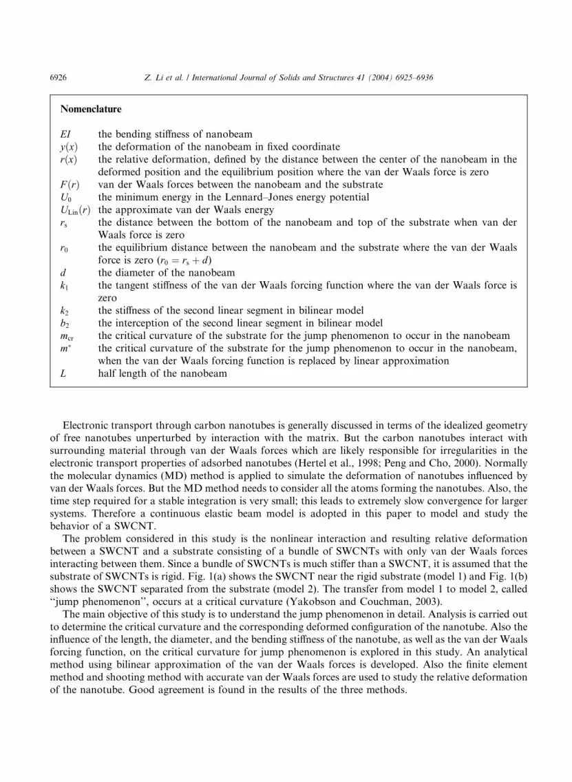
behavior of a SWCNT.The problem considered in this study is the nonlinear interaction and resulting relative deformation
between a SWCNT and a substrate consisting of a bundle of SWCNTs with only van der Waals forces
interacting between them. Since a bundle of SWCNTs is much stiffer than a SWCNT, it is assumed that the
substrate of SWCNTs is rigid. Fig. 1(a) shows the SWCNT near the rigid substrate (model 1) and Fig. 1(b)
shows the SWCNT separated from the substrate (model 2). The transfer from model 1 to model 2, called
‘‘jump phenomenon’’, occurs at a critical curvature (Yakobson and Couchman, 2003).
The main objective of this study is to understand the jump phenomenon in detail. Analysis is carried out
to determine the critical curvature and the corresponding deformed configuration of the nanotube. Also theinfluence of the length, the diameter, and the bending stiffness of the nanotube, as well as the van der Waals
forcing function, on the critical curvature for jump phenomenon is explored in this study. An analytical
method using bilinear approximation of the van der Waals forces is developed. Also the finite element
method and shooting method with accurate van der Waals forces are used to study the relative deformation
of the nanotube. Good agreement is found in the results of the three methods.
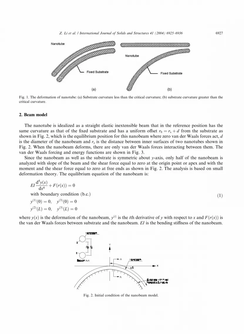
Fig. 1. The deformation of nanotube: (a) Substrate curvature less than the critical curvature; (b) substrate curvature greater than the
critical curvature.
Z. Li et al. / International Journal of Solids and Structures 41 (2004) 6925–6936 6927
2. Beam model
The nanotube is idealized as a straight elastic inextensible beam that in the reference position has the
same curvature as that of the fixed substrate and has a uniform offset r0 ¼ rs þ d from the substrate asshown in Fig. 2, which is the equilibrium position for this nanobeam where zero van der Waals forces act, dis the diameter of the nanobeam and rs is the distance between inner surfaces of two nanotubes shown in
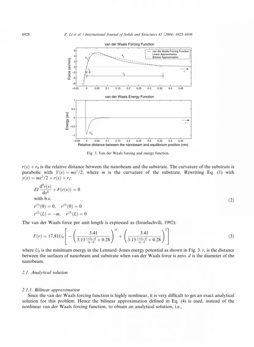
Fig. 2. When the nanobeam deforms, there are only van der Waals forces interacting between them. The
van der Waals forcing and energy functions are shown in Fig. 3.
Since the nanobeam as well as the substrate is symmetric about y-axis, only half of the nanobeam is
analyzed with slope of the beam and the shear force equal to zero at the origin point or apex and with the
moment and the shear force equal to zero at free ends as shown in Fig. 2. The analysis is based on small
deformation theory. The equilibrium equation of the nanobeam is:
EId4yðxÞ
dx4þ F ðrðxÞÞ ¼ 0
with boundary condition ðb:c:Þyð1Þð0Þ ¼ 0; yð3Þð0Þ ¼ 0
yð2ÞðLÞ ¼ 0; yð3ÞðLÞ ¼ 0
ð1Þ
where yðxÞ is the deformation of the nanobeam, yðiÞ is the ith derivative of y with respect to x and F ðrðxÞÞ is
the van der Waals forces between substrate and the nanobeam. EI is the bending stiffness of the nanobeam.
Fig. 2. Initial condition of the nanobeam model.
–0.05 0 0.05 0.1 0.15 0.2 0.25 0.3 0.35 0.4 0.45
–6
–4
–2
0
2
4
6
van der Waals Forcing Function
For
ce (
ev/n
m)
–0.05 0 0.05 0.1 0.15 0.2 0.25 0.3 0.35 0.4 0.45
–1
–0.5
0
0.5
1van der Waals Energy Function
Relative distance between the nanobeam and equilibrium position (nm)
Ene
rgy
(ev)
van der Waals Forcing FunctionLinear ApproximationBilinear Approximation
r1
r2
k1
k2
U0
r
r
Fig. 3. Van der Waals forcing and energy function.
6928 Z. Li et al. / International Journal of Solids and Structures 41 (2004) 6925–6936
rðxÞ þ r0 is the relative distance between the nanobeam and the substrate. The curvature of the substrate is
parabolic with Y ðxÞ ¼ mx2=2, where m is the curvature of the substrate. Rewriting Eq. (1) with
yðxÞ ¼ mx2=2 þ rðxÞ þ rs:
EId4rðxÞ
dx4þ F ðrðxÞÞ ¼ 0
with b:c:
rð1Þð0Þ ¼ 0; rð3Þð0Þ ¼ 0
rð2ÞðLÞ ¼ �m; rð3ÞðLÞ ¼ 0
ð2Þ
The van der Waals force per unit length is expressed as (Israelachvili, 1992):
F ðrÞ ¼ 17:81U0
24� 3:41
3:13 rþr0�dr0�d þ 0:28
!11
þ 3:41
3:13 rþr0�dr0�d þ 0:28
!535 ð3Þ
where U0 is the minimum energy in the Lennard–Jones energy potential as shown in Fig. 3. rs is the distance
between the surfaces of nanobeam and substrate when van der Waals force is zero. d is the diameter of the
nanobeam.
2.1. Analytical solution
2.1.1. Bilinear approximation
Since the van der Waals forcing function is highly nonlinear, it is very difficult to get an exact analytical
solution for this problem. Hence the bilinear approximation defined in Eq. (4) is used, instead of thenonlinear van der Waals forcing function, to obtain an analytical solution, i.e.,
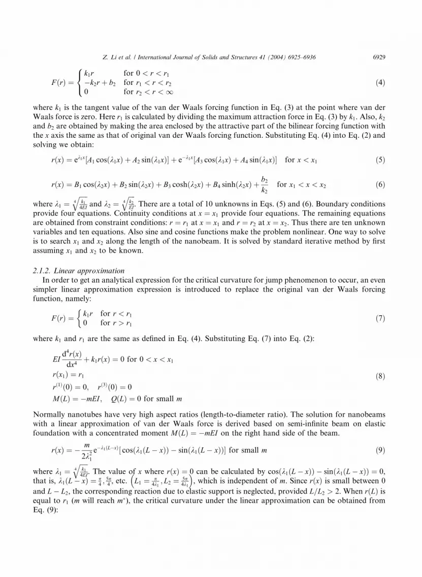
Z. Li et al. / International Journal of Solids and Structures 41 (2004) 6925–6936 6929
F ðrÞ ¼k1r for 0 < r < r1
�k2r þ b2 for r1 < r < r2
0 for r2 < r < 1
8<: ð4Þ
where k1 is the tangent value of the van der Waals forcing function in Eq. (3) at the point where van der
Waals force is zero. Here r1 is calculated by dividing the maximum attraction force in Eq. (3) by k1. Also, k2
and b2 are obtained by making the area enclosed by the attractive part of the bilinear forcing function with
the x axis the same as that of original van der Waals forcing function. Substituting Eq. (4) into Eq. (2) and
solving we obtain:
rðxÞ ¼ ek1x½A1 cosðk1xÞ þ A2 sinðk1xÞ þ e�k1x½A3 cosðk1xÞ þ A4 sinðk1xÞ for x < x1 ð5Þ
rðxÞ ¼ B1 cosðk2xÞ þ B2 sinðk2xÞ þ B3 coshðk2xÞ þ B4 sinhðk2xÞ þb2
k2
for x1 < x < x2 ð6Þ
where k1 ¼ffiffiffiffiffik1
4EI4
qand k2 ¼
ffiffiffiffik2
EI4
q. There are a total of 10 unknowns in Eqs. (5) and (6). Boundary conditions
provide four equations. Continuity conditions at x ¼ x1 provide four equations. The remaining equations
are obtained from constraint conditions: r ¼ r1 at x ¼ x1 and r ¼ r2 at x ¼ x2. Thus there are ten unknown
variables and ten equations. Also sine and cosine functions make the problem nonlinear. One way to solve
is to search x1 and x2 along the length of the nanobeam. It is solved by standard iterative method by first
assuming x1 and x2 to be known.
2.1.2. Linear approximation
In order to get an analytical expression for the critical curvature for jump phenomenon to occur, an even
simpler linear approximation expression is introduced to replace the original van der Waals forcingfunction, namely:
F ðrÞ ¼ k1r for r < r1
0 for r > r1
�ð7Þ
where k1 and r1 are the same as defined in Eq. (4). Substituting Eq. (7) into Eq. (2):
EId4rðxÞ
dx4þ k1rðxÞ ¼ 0 for 0 < x < x1
rðx1Þ ¼ r1
rð1Þð0Þ ¼ 0; rð3Þð0Þ ¼ 0
MðLÞ ¼ �mEI ; QðLÞ ¼ 0 for small m
ð8Þ
Normally nanotubes have very high aspect ratios (length-to-diameter ratio). The solution for nanobeamswith a linear approximation of van der Waals force is derived based on semi-infinite beam on elastic
foundation with a concentrated moment MðLÞ ¼ �mEI on the right hand side of the beam.
rðxÞ ¼ � m
2k21
e�k1ðL�xÞ cosðk1ðL½ � xÞÞ � sinðk1ðL� xÞÞ for small m ð9Þ
where k1 ¼ffiffiffiffiffik1
4EI4
q. The value of x where rðxÞ ¼ 0 can be calculated by cosðk1ðL� xÞÞ � sinðk1ðL� xÞÞ ¼ 0,
that is, k1ðL� xÞ ¼ p4; 5p
4, etc. L1 ¼ p
4k1; L2 ¼ 5p
4k1
�, which is independent of m. Since rðxÞ is small between 0
and L� L2, the corresponding reaction due to elastic support is neglected, provided L=L2 > 2. When rðLÞ isequal to r1 (m will reach m�), the critical curvature under the linear approximation can be obtained from
Eq. (9):
6930 Z. Li et al. / International Journal of Solids and Structures 41 (2004) 6925–6936
m� ¼ �ffiffiffiffiffiffiffiffik1r2
1
EI
rð10Þ
From Eq. (10) it can also be observed that m� does not depend on the length of the nanobeam if the length
of beam is long enough, such as L=L2 > 2. It is observed that m� is proportional to the square root of k1r21,
which is twice the area enclosed by the attraction forces of the linear function has shown in Eq. (7). This
term has dimensions of energy, which corresponds to the absolute minimum energy in the energy function
defined in Eq. (11).
ULinðrÞ ¼k1r2
2� k1r2
1
2r < r1
0 r > r1
(ð11Þ
It is assumed that the energy is zero when r approaches infinity. From the analysis in this section it can
be seen that the critical curvature is a function of the absolute minimum energy of the van der Waals
forcing function and the stiffness of the beam.
2.2. Finite element method (FEM)
FEM is used to calculate the deformations of the nanobeam and the results are compared with the
analytical results. Expressing Eq. (2) in Galerkin weak form:
Z Lx¼0
EId2wðxÞ
dx2
d2rðxÞdx2
�þ wðxÞF ðrðxÞÞ
�dx ¼ �mEI
dwðxÞdx
����x¼L
ð12Þ
where wðxÞ is admissible test function. The Newton–Raphson method is used to solve this problem where
the van der Waals forcing function is expressed as:
F ðrÞ ¼ F ð~r0Þ þd
drF ð~r0ÞDr þ OðDr2Þ ð13Þ
Setting w ¼P
A2ggCA/A, r ¼
PB2gðdB þ DdBÞ/B and Dr ¼
PB2g DdB/B, where / is shape function, DdB is
the unknown variable using which dB is computed, gg is the set of all unknown degrees of freedom at nodes
in the finite element mesh and g is total number of nodes multiplied by the degrees of freedom at each node.
Substituting Eq. (13) into Eq. (12) and using Newton–Raphson method:
XA2gg
CA
XB2g
Z L
x¼0
EId2/A
dx2
d2/B
dx2dx
"þZ L
x¼0
/AdF ð~r0Þ
dr/Bdx
!DdB
#
¼ �mEIdwðxÞ
dx
����x¼L
�XA2gg
CA
Z L
x¼0
/AF ð~r0Þdx
24 þ
XB2gg
Z L
x¼0
EId2/A
dx2
d2/B
dx2dx
� �dB
35 ð14Þ
Defining
KAB ¼Z L
x¼0
EId2/A
dx2
d2/B
dx2dx; K�
AB ¼Z L
x¼0
/AdF ð~r0Þ
dr/Bdx; FA ¼
Z L
x¼0
/AF ð~r0Þdx
and rewriting Eq. (14):
XA2gg
CA
XB2g
ðKAB
"þ K�
ABÞDdB
#¼ �mEI
dwðxÞdx
����x¼L
�XA2gg
CA
XB2g
KABdB
"þ FA
#ð15Þ
Z. Li et al. / International Journal of Solids and Structures 41 (2004) 6925–6936 6931
As there are four unknown variables for each element, minimum order of power series shape function for
one element should be 3. Hence Hermite interpolation polynomials are used:
/e1ðxÞ ¼ 1 � 3s2 þ 2s3; /e
2ðxÞ ¼ lesðs� 1Þ2
/e3ðxÞ ¼ s2ð3 � 2sÞ; /e
4ðxÞ ¼ les2ðs� 1Þð16Þ
where le is the length of one element. s ¼ x�x1
x2�x1, here x1 and x2 are the left and right coordinates of the
element.
Since the forcing function in Eq. (15) is highly nonlinear, the Newton–Raphson method may have
convergence difficulties if the initial guess dB is far away from the solution; hence an incremental load
method is used. First the substrate is assumed to be straight with zero curvature and initial solutions for the
beam are obtained. The curvature of the substrate, m, is increased and the solution in the previous step isused as an initial guess for this step and the convergent solution for this step is computed. Then m is in-
creased and the above steps are repeated till required m is reached.
2.3. Shooting method
This problem is solved as a two point boundary value problem using the numerical shooting method.
Here the unknown deflection yð0Þ and the curvature yð2Þð0Þ are assumed at the start. After reaching the free
end it is checked for zero moment as well as zero shear at the free end. Since the nanobeam is in equi-
librium, the summation of forces along the length of the nanobeam must be zero. This additional criterion
needs to be satisfied. If all these conditions are not satisfied then a new initial guess is assumed and the
procedure is repeated. These conditions can be written in a vector format as
F ¼yð2Þðx ¼ LÞyð3Þðx ¼ LÞPL
x¼0 f ðrðxÞÞ
8<:
9=; ¼ 0 ð17Þ
The Newton–Raphson method provides a systematic way of carrying out iterations. Iterations are carried
out till the discrepancy vector F ¼ 0 or is within tolerance limit. For the convergence of the shootingmethod it is necessary that the initial guess is close enough to the actual solution. Hence to start the
shooting method the initial guess for the unknown boundary conditions is obtained from the analytical
results.
3. Results and discussions
The stiffness of the nanobeam is calculated by using EI ¼ pCd3 (C ¼ 2152:8 eV/nm2 is the in-plane
stiffness, based on ab initio calculations (Kudin et al., 2001)), where d is the diameter of the nanobeam. In
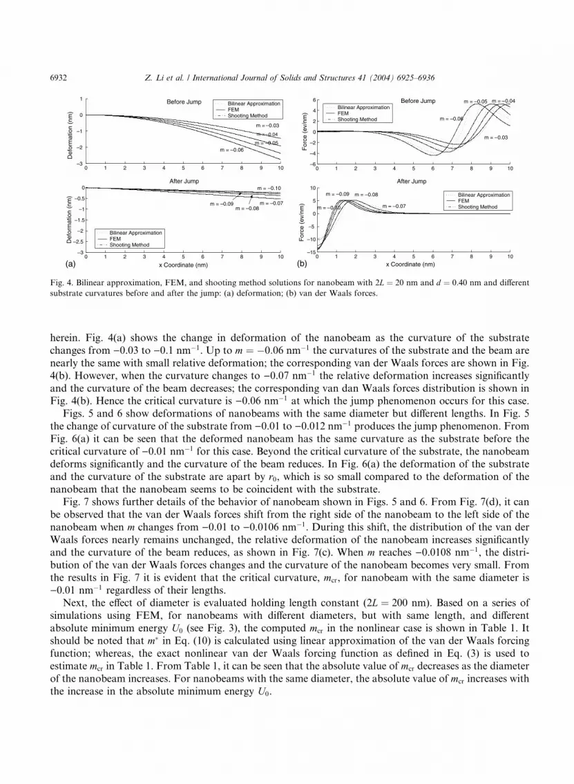
the following discussion, rðxÞ is termed as relative deformation.Deformations of the nanobeam, yðxÞ, for different curvatures of the substrate computed using FEM,
analytical method and shooting method, are shown in Fig. 4(a). Also, van der Waals forces for different
curvatures of the substrate are compared in Fig. 4(b). Since solution by FEM and shooting method
essentially agree it is hard to distinguish the two solutions from Fig. 4. From Figs. 4(a) and (b) it can be
observed that FEM results as well as shooting method results are in good agreement with the analytical
solution using bilinear approximation. This validates the results by FEM solution. Henceforth, the FEM
solution is used. For L ¼ 20 nm and d ¼ 0:40 nm nanotube, when the curvature of the substrate changes
from )0.06 to )0.07 nm�1, the relative deformations of the nanobeam suddenly change from smalldeformation to significant deformation as shown in Fig. 4(a), which is referred as jump phenomenon
0 1 2 3 4 5 6 7 8 9 10–3
–2
–1
0
1 Before Jump
Def
orm
atio
n (n
m)
0 1 2 3 4 5 6 7 8 9 10–3
–2.5
–2
–1.5
–1
–0.5
0 After Jump
x Coordinate (nm)
Def
orm
atio
n (n
m)
Bilinear ApproximationFEMShooting Method
Bilinear ApproximationFEMShooting Method
m = –0.03
m =
m = –0.05
–0.04
m = –0.06
m = –0.07m = –0.08
m = –0.09
m = –0.10
0 1 2 3 4 5 6 7 8 9 10–6
–4
–2
0
2
4
6 Before Jump
For
ce (
ev/n
m)
0 1 2 3 4 5 6 7 8 9 10–15
–10
–5
0
5
10After Jump
x Coordinate (nm)
For
ce (
ev/n
m)
Bilinear ApproximationFEMShooting Method
Bilinear ApproximationFEMShooting Method
m = –0.03
m = –0.06
m = –0.05 m = –0.04
m = –0.07
m = –0.08 m = –0.09
m = –0.10
(a) (b)
Fig. 4. Bilinear approximation, FEM, and shooting method solutions for nanobeam with 2L ¼ 20 nm and d ¼ 0:40 nm and different
substrate curvatures before and after the jump: (a) deformation; (b) van der Waals forces.
6932 Z. Li et al. / International Journal of Solids and Structures 41 (2004) 6925–6936
herein. Fig. 4(a) shows the change in deformation of the nanobeam as the curvature of the substrate
changes from )0.03 to )0.1 nm�1. Up to m ¼ �0:06 nm�1 the curvatures of the substrate and the beam are
nearly the same with small relative deformation; the corresponding van der Waals forces are shown in Fig.
4(b). However, when the curvature changes to )0.07 nm�1 the relative deformation increases significantly
and the curvature of the beam decreases; the corresponding van dan Waals forces distribution is shown inFig. 4(b). Hence the critical curvature is )0.06 nm�1 at which the jump phenomenon occurs for this case.
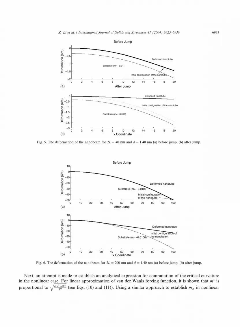
Figs. 5 and 6 show deformations of nanobeams with the same diameter but different lengths. In Fig. 5
the change of curvature of the substrate from )0.01 to )0.012 nm�1 produces the jump phenomenon. From
Fig. 6(a) it can be seen that the deformed nanobeam has the same curvature as the substrate before the
critical curvature of )0.01 nm�1 for this case. Beyond the critical curvature of the substrate, the nanobeam
deforms significantly and the curvature of the beam reduces. In Fig. 6(a) the deformation of the substrate
and the curvature of the substrate are apart by r0, which is so small compared to the deformation of the
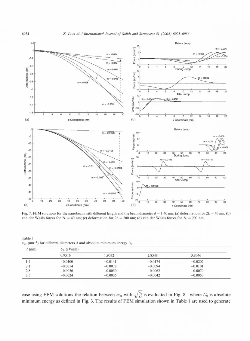
nanobeam that the nanobeam seems to be coincident with the substrate.Fig. 7 shows further details of the behavior of nanobeam shown in Figs. 5 and 6. From Fig. 7(d), it can
be observed that the van der Waals forces shift from the right side of the nanobeam to the left side of the
nanobeam when m changes from )0.01 to )0.0106 nm�1. During this shift, the distribution of the van der
Waals forces nearly remains unchanged, the relative deformation of the nanobeam increases significantly
and the curvature of the beam reduces, as shown in Fig. 7(c). When m reaches )0.0108 nm�1, the distri-
bution of the van der Waals forces changes and the curvature of the nanobeam becomes very small. From
the results in Fig. 7 it is evident that the critical curvature, mcr, for nanobeam with the same diameter is
)0.01 nm�1 regardless of their lengths.Next, the effect of diameter is evaluated holding length constant (2L ¼ 200 nm). Based on a series of
simulations using FEM, for nanobeams with different diameters, but with same length, and different
absolute minimum energy U0 (see Fig. 3), the computed mcr in the nonlinear case is shown in Table 1. It
should be noted that m� in Eq. (10) is calculated using linear approximation of the van der Waals forcing
function; whereas, the exact nonlinear van der Waals forcing function as defined in Eq. (3) is used to
estimate mcr in Table 1. From Table 1, it can be seen that the absolute value of mcr decreases as the diameter
of the nanobeam increases. For nanobeams with the same diameter, the absolute value of mcr increases with
the increase in the absolute minimum energy U0.
0 2 4 6 8 10 12 14 16 18 20–2
–1.5
–1
–0.5
0
Def
orm
atio
n (n
m)
Before Jump
0 2 4 6 8 10 12 14 16 18 20–3
–2.5
–2
–1.5
–1
–0.5
0
After Jump
Def
orm
atio
n (n
m)
x Coordinate
Substrate (m= –0.01)
Deformed Nanotube
Initial configuration of the nanotube
Substrate (m= –0.012)
Initial configuration of the nanotube
Deformed Nanotube
(a)
(b)
Fig. 5. The deformation of the nanobeam for 2L ¼ 40 nm and d ¼ 1:40 nm (a) before jump, (b) after jump.
0 10 20 30 40 50 60 70 80 90 100–50
–40
–30
–20
–10
0
10
Def
orm
atio
n (n
m)
Before Jump
0 10 20 30 40 50 60 70 80 90 100
–50
–40
–30
–20
–10
0
10
After Jump
Def
orm
atio
n (n
m)
x Coordinate
Deformed nanotube
Substrate (m= –0.010)
Substrate (m= –0.0106) Initial configuration ofthe nanobeam
Deformed nanotube
Initial configuration of the nanotube
(a)
(b)
Fig. 6. The deformation of the nanobeam for 2L ¼ 200 nm and d ¼ 1:40 nm (a) before jump, (b) after jump.
Z. Li et al. / International Journal of Solids and Structures 41 (2004) 6925–6936 6933
Next, an attempt is made to establish an analytical expression for computation of the critical curvaturein the nonlinear case. For linear approximation of van der Waals forcing function, it is shown that m� is
proportional to
ffiffiffiffiffiffiffiffiffiffiffiffiffiffi2jULinð0Þj
EI
q(see Eqs. (10) and (11)). Using a similar approach to establish mcr in nonlinear
0 2 4 6 8 10 12 14 16 18 20-1.6
-1.4
-1.2
-1
-0.8
-0.6
-0.4
-0.2
0
0.2
x Coordinate (nm)
Def
orm
atio
n (n
m)
m = -0.004
m = -0.006
m = -0.008
m = -0.010
m = -0.012
m = -0.014
0 2 4 6 8 10 12 14 16 18 20-5
0
5
10Before Jump
For
ce (
ev/n
m)
0 2 4 6 8 10 12 14 16 18 20-5
0
5
10 During Jump
For
ce (
ev/n
m)
0 2 4 6 8 10 12 14 16 18 20-20
-10
0
10 After Jump
For
ce (
ev/n
m)
x Coordinate (nm)
m = -0.004
m = -0.006
m = -0.008
m = -0.010
m = -0.012 m = -0.014
m = -0.010
m = -0.012
(a) (b)
0 10 20 30 40 50 60 70 80 90 100-50
-45
-40
-35
-30
-25
-20
-15
-10
-5
0
x Coordinate (nm)
Def
orm
atio
n (n
m)
m = -0.0108
m = -0.0106
m = -0.0104
m = -0.008
m = -0.01
m = -0.009
m = -0.0102
0 10 20 30 40 50 60 70 80 90 100-5
0
5
10Before Jump
For
ce (
ev/n
m)
0 10 20 30 40 50 60 70 80 90 100-10
0
10During Jump
For
ce (
ev/n
m)
0 10 20 30 40 50 60 70 80 90 100-20
-10
0
10After Jump
For
ce (
ev/n
m)
x Coordinate (nm)
m = -0.008
m = -0.009
m = -0.01
m = -0.0102 m = -0.0106
m = -0.0108 m = -0.0108
(c) (d)
Fig. 7. FEM solutions for the nanobeam with different length and the beam diameter d ¼ 1:40 nm: (a) deformation for 2L ¼ 40 nm; (b)
van der Waals forces for 2L ¼ 40 nm; (c) deformation for 2L ¼ 200 nm; (d) van der Waals forces for 2L ¼ 200 nm.
Table 1
mcr (nm�1) for different diameters d and absolute minimum energy U0
d (nm) U0 (eV/nm)
0.9516 1.9032 2.8548 3.8046
1.4 )0.0100 )0.0141 )0.0174 )0.0202
2.1 )0.0054 )0.0078 )0.0094 )0.0101
2.8 )0.0036 )0.0050 )0.0062 )0.0070
3.5 )0.0024 )0.0036 )0.0042 )0.0050
6934 Z. Li et al. / International Journal of Solids and Structures 41 (2004) 6925–6936
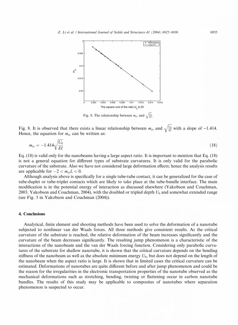
case using FEM solutions the relation between mcr withffiffiffiffiU0
EI
qis evaluated in Fig. 8––where U0 is absolute
minimum energy as defined in Fig. 3. The results of FEM simulation shown in Table 1 are used to generate
0 0.002 0.004 0.006 0.008 0.01 0.012 0.014 0.016
-0.02
-0.015
-0.01
-0.005
0
The square root of the ratio U0 to EI
mcr
FEM SolutionLinear Fit
Fig. 8. The relationship between mcr andffiffiffiffiU0
EI
q.
Z. Li et al. / International Journal of Solids and Structures 41 (2004) 6925–6936 6935
Fig. 8. It is observed that there exists a linear relationship between mcr andffiffiffiffiU0
EI
qwith a slope of )1.414.
Hence, the equation for mcr can be written as:
mcr ¼ �1:414
ffiffiffiffiffiffiU0
EI
rð18Þ
Eq. (18) is valid only for the nanobeams having a large aspect ratio. It is important to mention that Eq. (18)
is not a general equation for different types of substrate curvatures. It is only valid for the paraboliccurvature of the substrate. Also we have not considered large deformation effects; hence the analysis results
are applicable for �2 < mcrL < 0.
Although analysis above is specifically for a single tube-tube contact, it can be generalized for the case of
tube-duplet or tube-triplet contacts which are likely to take place at the tube-bundle interface. The main
modification is in the potential energy of interaction as discussed elsewhere (Yakobson and Couchman,
2003, Yakobson and Couchman, 2004), with the doubled or tripled depth U0 and somewhat extended range
(see Fig. 3 in Yakobson and Couchman (2004)).
4. Conclusions
Analytical, finite element and shooting methods have been used to solve the deformation of a nanotube
subjected to nonlinear van der Waals forces. All three methods give consistent results. As the critical
curvature of the substrate is reached, the relative deformation of the beam increases significantly and the
curvature of the beam decreases significantly. The resulting jump phenomenon is a characteristic of theinteractions of the nanobeam and the van der Waals forcing function. Considering only parabolic curva-
tures of the substrate for shallow nanotube, it is shown that the critical curvature depends on the bending
stiffness of the nanobeam as well as the absolute minimum energy U0, but does not depend on the length of
the nanobeam when the aspect ratio is large. It is shown that in limited cases the critical curvature can be
estimated. Deformations of nanotubes are quite different before and after jump phenomenon and could be
the reason for the irregularities in the electronic transportation properties of the nanotube observed as the
mechanical deformations such as stretching, bending, twisting or flattening occur in carbon nanotube
bundles. The results of this study may be applicable to composites of nanotubes where separationphenomenon is suspected to occur.

6936 Z. Li et al. / International Journal of Solids and Structures 41 (2004) 6925–6936
Acknowledgements
The authors wish to acknowledge the support of the Texas Institute for the Intelligent Bio-Nano
Materials and Structure for Aerospace Vehicles, funded by NASA Cooperative Agreement No. NCC-1-02038.
References
Akita, S., Nakayama, Y., Mizooka, S., Takano, Y., Okawa, T., Miyatake, Y., Yamanaka, S., Tsuji, M., Nosaka, T., 2001. Applied
Physics Letter 79, 1691–1693.
Baughman, R.H., Cui, C., Zakhidov, A.A., Lqbal, Z., Barisci, J.N., Spinks, G.M., Wallace, G.G., Mazzoldi, A., Rossi, D.D., Rinzler,
A.G., Jaschinski, O., Roth, S., Kertesz, M., 1999. Science 284, 1340–1344.
Collins, P.G., Bradley, K.B., Ishigami, M., Zettl, A., 2000. Science 287, 1801–1804.
Dequesnes, M., Rotkin, S.V., Aluru, N.R., 2002. Nanotechnology 13, 120–131.
Hertel, T., Walkup, R.E., Avouris, P., 1998. Physical Review B 58, 13870–13878.
Iijima, S., 1991. Nature 354, 56–58.
Israelachvili, J., 1992. Intermolecular and Surface Forces, Academic Press, second ed.
Kudin, K.N., Scuseria, G.E., Yakobson, B.I., 2001. Physical Review B 64, 235406/10.
Peng, S., Cho, K., 2000. Nanotechnology 11, 57–60.
Yakobson, B.I., Couchman, L.S., 2003. Persistence length and nanomechanics of random coils and bundles nanotubes, submitted for
publication.
Yakobson, B.I., Couchman, L.S., 2004. Carbon nanotubes: supramolecular mechanics. In: Schwartz, J.A. et al. (Eds.), Encyclopedia of
Nanoscience and Nanotechnology. Marcel Dekker, New York, DOI: 10.1081/E-ENN 120009130.
Related Documents


![New Results on Terahertz Detection by Carbon Nanotubes · [14], up to 2.5 THz. The SWCNT bundles were coupled to log-periodic antennas in much the same manner as is used to couple](https://static.cupdf.com/doc/110x72/5fd5dff6febba670d603dae7/new-results-on-terahertz-detection-by-carbon-14-up-to-25-thz-the-swcnt-bundles.jpg)


