2208 JOURNAL OF LIGHTWAVE TECHNOLOGY, VOL. 17, NO. 11, NOVEMBER 1999 Node Architecture and Protocol of a Packet-Switched Dense WDMA Metropolitan Area Network Chun-Kit Chan, Member, IEEE, Frank Tong, Senior Member, IEEE, Lian-Kuan Chen, Member, IEEE, Kwok-Wai Cheung, Senior Member, IEEE, Member, OSA, and Eddie T. P. Kong Abstract— This paper proposes a new node architecture and protocol for a wavelength division multiple access (WDMA) packet-switched metropolitan area network. The network op- erates on a dual-bus topology and the tunable-transmitter and fixed-receiver scheme is adopted to facilitate data multiaccess. The network protocol runs on a cycle mechanism and the cycle length can be adaptively changed according to the data traffic, thus provides high throughput. The photonic implementation of the proposed network architecture and network nodes are discussed and a new packet-signaling scheme is proposed to avoid data collision during multiaccess. An experimental demonstration is also presented to show its feasibility. Index Terms— Optical network, packet-switching, protocols, wavelength division multiplexing (WDM). I. INTRODUCTION T HE ever-increasing demand in communication bandwidth cannot be met with the existing infrastructure that largely based on copper and optical fiber carrying a single wavelength. To support future bandwidth-hungry Internet services where multiple interactive digital video- and voice-data and other large data files are required to be delivered over long distances, wavelength division multiple access (WDMA) is probably the most powerful technique to unlock the enormous bandwidth in optical fiber. Previous approaches to realize WDMA net- works were largely confined to a star-based topology [1], [2] using a fixed-tuned transmitter and tunable receiver (FTTR) scheme, where the optical receiver at each node will receive one to all wavelength channels from the transmitting nodes. A 32-channel WDMA prototype network using DFB laser transmitters with different wavelengths was reported by the IBM researchers in [3], [4]. Each channel had a capacity of 1-Gb/s, with the channel spacing set at 100-GHz. A dense WDMA star network with 100 channels, each spaced by 10- GHz and at a bit-rate of 622-Mb/s, was also reported by the NTT researchers in [5]. However, the channel selection for the NTT group was based on thermal tuning in a Mach–Zehnder lattice filter, and on piezoelectric tuning of a scanning fiber Manuscript received January 13, 1999; revised August 12, 1999. This work was supported in part by Hong Kong Research Grant Council CERG CUHK4157/98E and CUHK 4170/97E. C.-K. Chan was with the Optoelectronics Research Centre, City University of Hong Kong, Tat Chee Avenue, Kowloon, Hong Kong. He is now with Bell-Laboratories, Lucent Technologies, Holmdel, NJ 07733 USA (e-mail: [email protected]). F. Tong, L.-K. Chen, K.-W. Cheung, and E. T. P. Kong are with the Light- wave Communications Laboratory, Department of Information Engineering, The Chinese University of Hong Kong, Shatin, N.T., Hong Kong. Publisher Item Identifier S 0733-8724(99)08934-3. Fabry–Perot filter. The tuning time was largely limited to ms range, rendering the network unsuitable for packet switching. This paper intends to describe our work on a packet- switched metropolitan-area photonic network based on a dual looped-back bus configuration. The network is operated in tunable transmitter and fixed-tuned receiver scheme (TTFR) with a centralized multiwavelength light source. Each wave- length channel is partitioned into different time slots; and a simple and efficient media access control (MAC) protocol, called adaptive-cycle tunable access (ACTA) protocol [6], is employed to improve the channel utilization and the fairness among all network nodes. The protocol works in a cycle mechanism and the cycle-length can be adaptively adjusted according to the traffic requirement in the network. Simulation results show that high throughput and good fairness can be achieved. The occupancy of each wavelength channel is sig- nified simply by means of an radio frequency (RF) pilot tone, being multiplexed with the transmitting data, thus assuring that no data collision will occur during data multiaccess. The channel sensing time is of nanosecond or submicrosecond range, thus packet switching of gigabits per second data is allowed. The paper is organized as follows. Section II outlines the network architecture, and the details and the performance of the media access protocol, ACTA will be described. Section III presents the photonic implementation of the head-node and the network nodes. The packet-access signaling scheme will also be illustrated. Section IV discusses the bit error rate (BER) analysis of the wavelength channels as the network capacity is mainly limited by the accumulation of amplifier noises along the network. Some experimental results will be given in Section V and our work will be summarized in Section VI. II. TUNABLE CHANNEL PACKET-SWITCHED WDMA DUAL BUS NETWORK A. Network Architecture The proposed network architecture is shown in Fig. 1, con- sisting of one head node and many network nodes, arranged in a dual counterpropagating looped-back bus configuration. Each network node may serve as a router to local loop connecting to hundreds of workstations. The number of network nodes is scalable, mainly limited by the optical amplifier noise, and to a lesser degree, by the optical modulation index of the data channels, as will be discussed in Section IV. In addition to high efficiency and throughput, the dual looped-back bus 0733–8724/99$10.00 1999 IEEE

Welcome message from author
This document is posted to help you gain knowledge. Please leave a comment to let me know what you think about it! Share it to your friends and learn new things together.
Transcript
2208 JOURNAL OF LIGHTWAVE TECHNOLOGY, VOL. 17, NO. 11, NOVEMBER 1999
Node Architecture and Protocol of a Packet-SwitchedDense WDMA Metropolitan Area Network
Chun-Kit Chan,Member, IEEE,Frank Tong,Senior Member, IEEE,Lian-Kuan Chen,Member, IEEE,Kwok-Wai Cheung,Senior Member, IEEE, Member, OSA,and Eddie T. P. Kong
Abstract—This paper proposes a new node architecture andprotocol for a wavelength division multiple access (WDMA)packet-switched metropolitan area network. The network op-erates on a dual-bus topology and the tunable-transmitter andfixed-receiver scheme is adopted to facilitate data multiaccess.The network protocol runs on a cycle mechanism and the cyclelength can be adaptively changed according to the data traffic,thus provides high throughput. The photonic implementationof the proposed network architecture and network nodes arediscussed and a new packet-signaling scheme is proposed to avoiddata collision during multiaccess. An experimental demonstrationis also presented to show its feasibility.
Index Terms—Optical network, packet-switching, protocols,wavelength division multiplexing (WDM).
I. INTRODUCTION
T HE ever-increasing demand in communication bandwidthcannot be met with the existing infrastructure that largely
based on copper and optical fiber carrying a single wavelength.To support future bandwidth-hungry Internet services wheremultiple interactive digital video- and voice-data and otherlarge data files are required to be delivered over long distances,wavelength division multiple access (WDMA) is probably themost powerful technique to unlock the enormous bandwidthin optical fiber. Previous approaches to realize WDMA net-works were largely confined to a star-based topology [1], [2]using a fixed-tuned transmitter and tunable receiver (FTTR)scheme, where the optical receiver at each node will receiveone to all wavelength channels from the transmitting nodes.A 32-channel WDMA prototype network using DFB lasertransmitters with different wavelengths was reported by theIBM researchers in [3], [4]. Each channel had a capacity of1-Gb/s, with the channel spacing set at 100-GHz. A denseWDMA star network with 100 channels, each spaced by 10-GHz and at a bit-rate of 622-Mb/s, was also reported by theNTT researchers in [5]. However, the channel selection for theNTT group was based on thermal tuning in a Mach–Zehnderlattice filter, and on piezoelectric tuning of a scanning fiber
Manuscript received January 13, 1999; revised August 12, 1999. Thiswork was supported in part by Hong Kong Research Grant Council CERGCUHK4157/98E and CUHK 4170/97E.
C.-K. Chan was with the Optoelectronics Research Centre, City Universityof Hong Kong, Tat Chee Avenue, Kowloon, Hong Kong. He is now withBell-Laboratories, Lucent Technologies, Holmdel, NJ 07733 USA (e-mail:[email protected]).
F. Tong, L.-K. Chen, K.-W. Cheung, and E. T. P. Kong are with the Light-wave Communications Laboratory, Department of Information Engineering,The Chinese University of Hong Kong, Shatin, N.T., Hong Kong.
Publisher Item Identifier S 0733-8724(99)08934-3.
Fabry–Perot filter. The tuning time was largely limited to msrange, rendering the network unsuitable for packet switching.
This paper intends to describe our work on a packet-switched metropolitan-area photonic network based on a duallooped-back bus configuration. The network is operated intunable transmitter and fixed-tuned receiver scheme (TTFR)with a centralized multiwavelength light source. Each wave-length channel is partitioned into different time slots; and asimple and efficient media access control (MAC) protocol,called adaptive-cycle tunable access (ACTA) protocol [6], isemployed to improve the channel utilization and the fairnessamong all network nodes. The protocol works in a cyclemechanism and the cycle-length can be adaptively adjustedaccording to the traffic requirement in the network. Simulationresults show that high throughput and good fairness can beachieved. The occupancy of each wavelength channel is sig-nified simply by means of an radio frequency (RF) pilot tone,being multiplexed with the transmitting data, thus assuringthat no data collision will occur during data multiaccess. Thechannel sensing time is of nanosecond or submicrosecondrange, thus packet switching of gigabits per second data isallowed.
The paper is organized as follows. Section II outlines thenetwork architecture, and the details and the performance ofthe media access protocol, ACTA will be described. Section IIIpresents the photonic implementation of the head-node and thenetwork nodes. The packet-access signaling scheme will alsobe illustrated. Section IV discusses the bit error rate (BER)analysis of the wavelength channels as the network capacityis mainly limited by the accumulation of amplifier noisesalong the network. Some experimental results will be givenin Section V and our work will be summarized in Section VI.
II. TUNABLE CHANNEL PACKET-SWITCHED
WDMA DUAL BUS NETWORK
A. Network Architecture
The proposed network architecture is shown in Fig. 1, con-sisting of one head node and many network nodes, arranged ina dual counterpropagating looped-back bus configuration. Eachnetwork node may serve as a router to local loop connectingto hundreds of workstations. The number of network nodes isscalable, mainly limited by the optical amplifier noise, andto a lesser degree, by the optical modulation index of thedata channels, as will be discussed in Section IV. In additionto high efficiency and throughput, the dual looped-back bus
0733–8724/99$10.00 1999 IEEE
CHAN et al.: PACKET-SWITCHED DENSE WDM MAN 2209
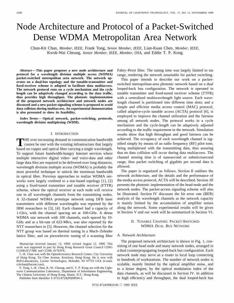
Fig. 1. Dual ring/bus network architecture. Inset shows the basic configu-ration of a network node. RX: receiver, TX: transmitter, and MAC: mediaaccess control.
configuration can also enhance the network’s survivability incase of node failure or fiber break. The network node nextto the failed node or fiber will route all traffic from one ringback to the other, which is similar to the self-healing feature[7] in the SONET ring network. Thus, the proposed network iscompatible with the existing deployed SONET ring networks.Besides, the head node also serves as the fault manager towhich all other network nodes report their surveillance andstatus information. In this way, the head node will be notifiedin case of failure in any network component, such as partialfailure of optical amplifier attaching to each node, and thusappropriate remedies can be made promptly.
At the head node, there is a centralized light source whichemits multiple and equally spaced wavelengths simultaneouslyon each bus and they are shared among all network nodesto perform data communications within the network. Thus,no laser source is required at each network node. This cen-tralized light source design [8] has the advantage of ease ofcontrol and maintenance as all light sources can be monitoredsimultaneously at one site. Nominally, channel separation islargely capped by the neighboring channel crosstalk due todrifting of emission wavelength caused by thermal or deviceaging. Centralized light source allows close monitoring ofemission wavelengths and power, thus making dense WDM(channel spacing 50 GHz) network of 100 channels over
30 nm Erbium gain bandwidth possible. Note that the opticaloutputs from these sources are continuous wave without anydata encoding. The data will be encoded on the destinedwavelength channel at the transmitting network node via anoptical modulator, possibly up to about 60 Gb/s with thepresent technology.
For all-optical networks, multiple access can be achievedeither by TTFR or FTTR. For the TTFR case, each nodeis assigned with a fixed wavelength for data reception. Thereceivers at node will only listen to wavelength channel
. Nodes intending to send data to node i have to tune theirtransmitters to wavelength . For the FTTR case, each node isassigned with a specific wavelength for data transmission. Totransmit data from nodeto node , signaling messages have tobe first sent to inform nodeto tune its receiver to wavelength
for data reception. However, in FTTR, there exists theproblem of receiver contention when data from more than one
transmitting node may arrive at the same destined node atthe same time. A possible solution to such problem is to useswitched delay lines [9]. In our network, we adopt the TTFRscheme to eliminate the receiver contention problem and wealso employ a new and simple packet access-signaling scheme(Section II) to avoid data collision during transmission.
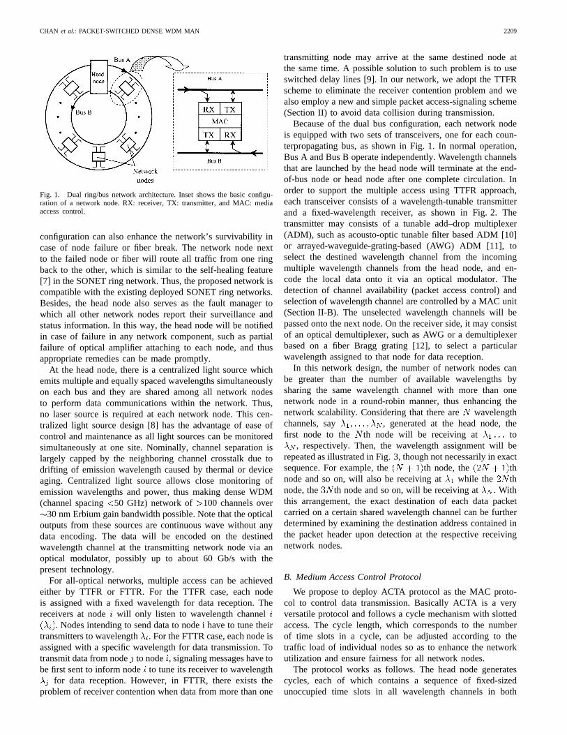
Because of the dual bus configuration, each network nodeis equipped with two sets of transceivers, one for each coun-terpropagating bus, as shown in Fig. 1. In normal operation,Bus A and Bus B operate independently. Wavelength channelsthat are launched by the head node will terminate at the end-of-bus node or head node after one complete circulation. Inorder to support the multiple access using TTFR approach,each transceiver consists of a wavelength-tunable transmitterand a fixed-wavelength receiver, as shown in Fig. 2. Thetransmitter may consists of a tunable add–drop multiplexer(ADM), such as acousto-optic tunable filter based ADM [10]or arrayed-waveguide-grating-based (AWG) ADM [11], toselect the destined wavelength channel from the incomingmultiple wavelength channels from the head node, and en-code the local data onto it via an optical modulator. Thedetection of channel availability (packet access control) andselection of wavelength channel are controlled by a MAC unit(Section II-B). The unselected wavelength channels will bepassed onto the next node. On the receiver side, it may consistof an optical demultiplexer, such as AWG or a demultiplexerbased on a fiber Bragg grating [12], to select a particularwavelength assigned to that node for data reception.
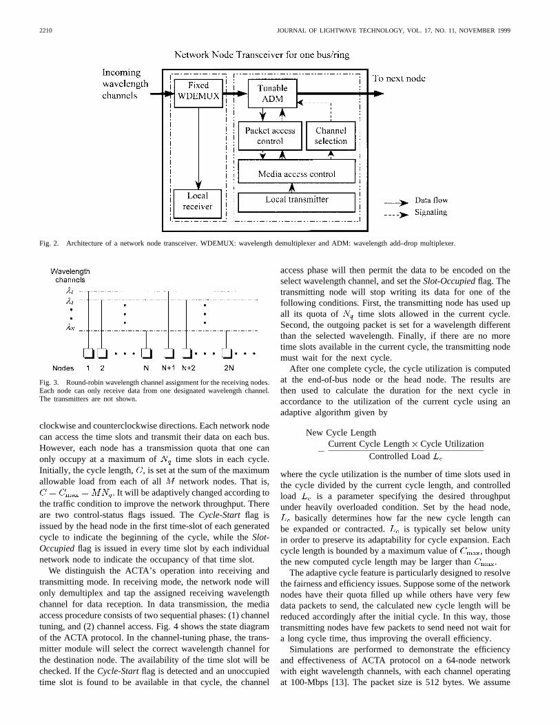
In this network design, the number of network nodes canbe greater than the number of available wavelengths bysharing the same wavelength channel with more than onenetwork node in a round-robin manner, thus enhancing thenetwork scalability. Considering that there arewavelengthchannels, say , generated at the head node, thefirst node to the th node will be receiving at to
, respectively. Then, the wavelength assignment will berepeated as illustrated in Fig. 3, though not necessarily in exactsequence. For example, the th node, the thnode and so on, will also be receiving at while the thnode, the th node and so on, will be receiving at . Withthis arrangement, the exact destination of each data packetcarried on a certain shared wavelength channel can be furtherdetermined by examining the destination address contained inthe packet header upon detection at the respective receivingnetwork nodes.
B. Medium Access Control Protocol
We propose to deploy ACTA protocol as the MAC proto-col to control data transmission. Basically ACTA is a veryversatile protocol and follows a cycle mechanism with slottedaccess. The cycle length, which corresponds to the numberof time slots in a cycle, can be adjusted according to thetraffic load of individual nodes so as to enhance the networkutilization and ensure fairness for all network nodes.
The protocol works as follows. The head node generatescycles, each of which contains a sequence of fixed-sizedunoccupied time slots in all wavelength channels in both
2210 JOURNAL OF LIGHTWAVE TECHNOLOGY, VOL. 17, NO. 11, NOVEMBER 1999
Fig. 2. Architecture of a network node transceiver. WDEMUX: wavelength demultiplexer and ADM: wavelength add–drop multiplexer.
Fig. 3. Round-robin wavelength channel assignment for the receiving nodes.Each node can only receive data from one designated wavelength channel.The transmitters are not shown.
clockwise and counterclockwise directions. Each network nodecan access the time slots and transmit their data on each bus.However, each node has a transmission quota that one canonly occupy at a maximum of time slots in each cycle.Initially, the cycle length, , is set at the sum of the maximumallowable load from each of all network nodes. That is,
. It will be adaptively changed according tothe traffic condition to improve the network throughput. Thereare two control-status flags issued. TheCycle-Start flag isissued by the head node in the first time-slot of each generatedcycle to indicate the beginning of the cycle, while theSlot-Occupiedflag is issued in every time slot by each individualnetwork node to indicate the occupancy of that time slot.
We distinguish the ACTA’s operation into receiving andtransmitting mode. In receiving mode, the network node willonly demultiplex and tap the assigned receiving wavelengthchannel for data reception. In data transmission, the mediaaccess procedure consists of two sequential phases: (1) channeltuning, and (2) channel access. Fig. 4 shows the state diagramof the ACTA protocol. In the channel-tuning phase, the trans-mitter module will select the correct wavelength channel forthe destination node. The availability of the time slot will bechecked. If theCycle-Startflag is detected and an unoccupiedtime slot is found to be available in that cycle, the channel
access phase will then permit the data to be encoded on theselect wavelength channel, and set theSlot-Occupiedflag. Thetransmitting node will stop writing its data for one of thefollowing conditions. First, the transmitting node has used upall its quota of time slots allowed in the current cycle.Second, the outgoing packet is set for a wavelength differentthan the selected wavelength. Finally, if there are no moretime slots available in the current cycle, the transmitting nodemust wait for the next cycle.
After one complete cycle, the cycle utilization is computedat the end-of-bus node or the head node. The results arethen used to calculate the duration for the next cycle inaccordance to the utilization of the current cycle using anadaptive algorithm given by
New Cycle LengthCurrent Cycle Length Cycle Utilization
Controlled Load
where the cycle utilization is the number of time slots used inthe cycle divided by the current cycle length, and controlledload is a parameter specifying the desired throughputunder heavily overloaded condition. Set by the head node,
basically determines how far the new cycle length canbe expanded or contracted. is typically set below unityin order to preserve its adaptability for cycle expansion. Eachcycle length is bounded by a maximum value of , thoughthe new computed cycle length may be larger than .
The adaptive cycle feature is particularly designed to resolvethe fairness and efficiency issues. Suppose some of the networknodes have their quota filled up while others have very fewdata packets to send, the calculated new cycle length will bereduced accordingly after the initial cycle. In this way, thosetransmitting nodes have few packets to send need not wait fora long cycle time, thus improving the overall efficiency.
Simulations are performed to demonstrate the efficiencyand effectiveness of ACTA protocol on a 64-node networkwith eight wavelength channels, with each channel operatingat 100-Mbps [13]. The packet size is 512 bytes. We assume
CHAN et al.: PACKET-SWITCHED DENSE WDM MAN 2211
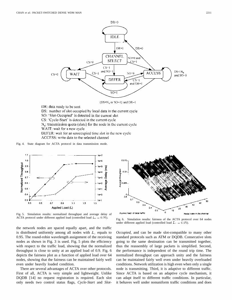
Fig. 4. State diagram for ACTA protocol in data transmission mode.
Fig. 5. Simulation results: normalized throughput and average delay ofACTA protocol under different applied load (controlled loadLc = 0:95).
the network nodes are spaced equally apart, and the trafficis distributed uniformly among all nodes with equals to0.95. The round-robin wavelength assignment of the receivingnodes as shown in Fig. 3 is used. Fig. 5 plots the efficiencywith respect to the traffic load, showing that the normalizedthroughput is close to unity at an applied load of 0.9. Fig. 6depicts the fairness plot as a function of applied load over 64nodes, showing that the fairness can be maintained fairly welleven under heavily loaded condition.
There are several advantages of ACTA over other protocols.First of all, ACTA is very simple and lightweight. UnlikeDQDB [14] no request registration is required. Each slotonly needs two control status flags,Cycle-Start and Slot-
Fig. 6. Simulation results: fairness of the ACTA protocol over 64 nodesunder different applied load (controlled loadLc = 0:95).
Occupied, and can be made slot-compatible to many otherstandard protocols such as ATM or DQDB. Consecutive slotsgoing to the same destination can be transmitted together,thus the reassembly of large packets is simplified. Second,the performance is independent of the round trip time. Thenormalized throughput can approach unity and the fairnesscan be maintained fairly well even under heavily overloadedconditions. Network utilization is high even when only a singlenode is transmitting. Third, it is adaptive to different traffic.Since ACTA is based on an adaptive cycle mechanism, itcan adapt itself to different traffic conditions. In particular,it behaves well under nonuniform traffic conditions and does
2212 JOURNAL OF LIGHTWAVE TECHNOLOGY, VOL. 17, NO. 11, NOVEMBER 1999
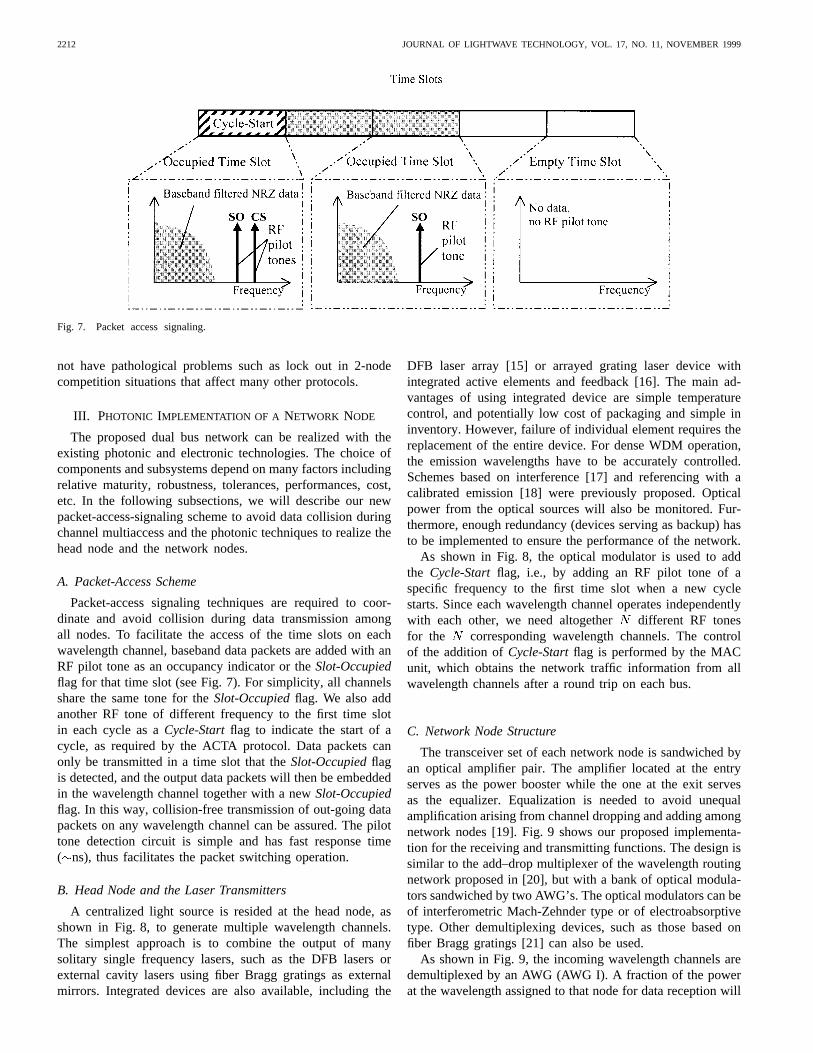
Fig. 7. Packet access signaling.
not have pathological problems such as lock out in 2-nodecompetition situations that affect many other protocols.
III. PHOTONIC IMPLEMENTATION OF A NETWORK NODE
The proposed dual bus network can be realized with theexisting photonic and electronic technologies. The choice ofcomponents and subsystems depend on many factors includingrelative maturity, robustness, tolerances, performances, cost,etc. In the following subsections, we will describe our newpacket-access-signaling scheme to avoid data collision duringchannel multiaccess and the photonic techniques to realize thehead node and the network nodes.
A. Packet-Access Scheme
Packet-access signaling techniques are required to coor-dinate and avoid collision during data transmission amongall nodes. To facilitate the access of the time slots on eachwavelength channel, baseband data packets are added with anRF pilot tone as an occupancy indicator or theSlot-Occupiedflag for that time slot (see Fig. 7). For simplicity, all channelsshare the same tone for theSlot-Occupiedflag. We also addanother RF tone of different frequency to the first time slotin each cycle as aCycle-Startflag to indicate the start of acycle, as required by the ACTA protocol. Data packets canonly be transmitted in a time slot that theSlot-Occupiedflagis detected, and the output data packets will then be embeddedin the wavelength channel together with a newSlot-Occupiedflag. In this way, collision-free transmission of out-going datapackets on any wavelength channel can be assured. The pilottone detection circuit is simple and has fast response time( ns), thus facilitates the packet switching operation.
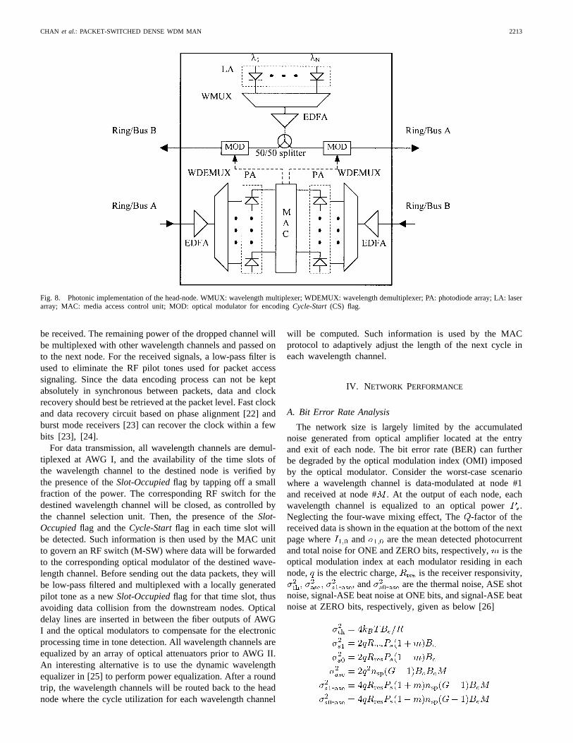
B. Head Node and the Laser Transmitters
A centralized light source is resided at the head node, asshown in Fig. 8, to generate multiple wavelength channels.The simplest approach is to combine the output of manysolitary single frequency lasers, such as the DFB lasers orexternal cavity lasers using fiber Bragg gratings as externalmirrors. Integrated devices are also available, including the
DFB laser array [15] or arrayed grating laser device withintegrated active elements and feedback [16]. The main ad-vantages of using integrated device are simple temperaturecontrol, and potentially low cost of packaging and simple ininventory. However, failure of individual element requires thereplacement of the entire device. For dense WDM operation,the emission wavelengths have to be accurately controlled.Schemes based on interference [17] and referencing with acalibrated emission [18] were previously proposed. Opticalpower from the optical sources will also be monitored. Fur-thermore, enough redundancy (devices serving as backup) hasto be implemented to ensure the performance of the network.
As shown in Fig. 8, the optical modulator is used to addthe Cycle-Startflag, i.e., by adding an RF pilot tone of aspecific frequency to the first time slot when a new cyclestarts. Since each wavelength channel operates independentlywith each other, we need altogether different RF tonesfor the corresponding wavelength channels. The controlof the addition ofCycle-Startflag is performed by the MACunit, which obtains the network traffic information from allwavelength channels after a round trip on each bus.
C. Network Node Structure
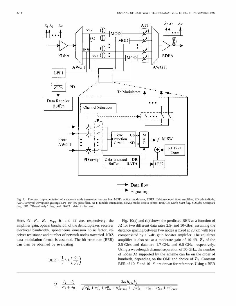
The transceiver set of each network node is sandwiched byan optical amplifier pair. The amplifier located at the entryserves as the power booster while the one at the exit servesas the equalizer. Equalization is needed to avoid unequalamplification arising from channel dropping and adding amongnetwork nodes [19]. Fig. 9 shows our proposed implementa-tion for the receiving and transmitting functions. The design issimilar to the add–drop multiplexer of the wavelength routingnetwork proposed in [20], but with a bank of optical modula-tors sandwiched by two AWG’s. The optical modulators can beof interferometric Mach-Zehnder type or of electroabsorptivetype. Other demultiplexing devices, such as those based onfiber Bragg gratings [21] can also be used.
As shown in Fig. 9, the incoming wavelength channels aredemultiplexed by an AWG (AWG I). A fraction of the powerat the wavelength assigned to that node for data reception will
CHAN et al.: PACKET-SWITCHED DENSE WDM MAN 2213
Fig. 8. Photonic implementation of the head-node. WMUX: wavelength multiplexer; WDEMUX: wavelength demultiplexer; PA: photodiode array; LA: laserarray; MAC: media access control unit; MOD: optical modulator for encodingCycle-Start(CS) flag.
be received. The remaining power of the dropped channel willbe multiplexed with other wavelength channels and passed onto the next node. For the received signals, a low-pass filter isused to eliminate the RF pilot tones used for packet accesssignaling. Since the data encoding process can not be keptabsolutely in synchronous between packets, data and clockrecovery should best be retrieved at the packet level. Fast clockand data recovery circuit based on phase alignment [22] andburst mode receivers [23] can recover the clock within a fewbits [23], [24].
For data transmission, all wavelength channels are demul-tiplexed at AWG I, and the availability of the time slots ofthe wavelength channel to the destined node is verified bythe presence of theSlot-Occupiedflag by tapping off a smallfraction of the power. The corresponding RF switch for thedestined wavelength channel will be closed, as controlled bythe channel selection unit. Then, the presence of theSlot-Occupiedflag and theCycle-Startflag in each time slot willbe detected. Such information is then used by the MAC unitto govern an RF switch (M-SW) where data will be forwardedto the corresponding optical modulator of the destined wave-length channel. Before sending out the data packets, they willbe low-pass filtered and multiplexed with a locally generatedpilot tone as a newSlot-Occupiedflag for that time slot, thusavoiding data collision from the downstream nodes. Opticaldelay lines are inserted in between the fiber outputs of AWGI and the optical modulators to compensate for the electronicprocessing time in tone detection. All wavelength channels areequalized by an array of optical attenuators prior to AWG II.An interesting alternative is to use the dynamic wavelengthequalizer in [25] to perform power equalization. After a roundtrip, the wavelength channels will be routed back to the headnode where the cycle utilization for each wavelength channel
will be computed. Such information is used by the MACprotocol to adaptively adjust the length of the next cycle ineach wavelength channel.
IV. NETWORK PERFORMANCE
A. Bit Error Rate Analysis
The network size is largely limited by the accumulatednoise generated from optical amplifier located at the entryand exit of each node. The bit error rate (BER) can furtherbe degraded by the optical modulation index (OMI) imposedby the optical modulator. Consider the worst-case scenariowhere a wavelength channel is data-modulated at node #1and received at node #. At the output of each node, eachwavelength channel is equalized to an optical power.Neglecting the four-wave mixing effect, The-factor of thereceived data is shown in the equation at the bottom of the nextpage where and are the mean detected photocurrentand total noise for ONE and ZERO bits, respectively,is theoptical modulation index at each modulator residing in eachnode, is the electric charge, is the receiver responsivity,
- , and - are the thermal noise, ASE shotnoise, signal-ASE beat noise at ONE bits, and signal-ASE beatnoise at ZERO bits, respectively, given as below [26]
-
-
2214 JOURNAL OF LIGHTWAVE TECHNOLOGY, VOL. 17, NO. 11, NOVEMBER 1999
Fig. 9. Photonic implementation of a network node transceiver on one bus. MOD: optical modulator, EDFA: Erbium-doped fiber amplifier, PD: photodiode,AWG: arrayed-waveguide gratings, LPF: RF low-pass filter, ATT: tunable attenuators, MAC: media access control unit, CS:Cycle-Startflag, SO:Slot-Occupiedflag, DR: “Data-Ready” flag, and DATA: data to be sent.
Here, and are, respectively, theamplifier gain, optical bandwidth of the demultiplexer, receiverelectrical bandwidth, spontaneous emission noise factor, re-ceiver resistance and number of network nodes traversed. NRZdata modulation format is assumed. The bit error rate (BER)can then be obtained by evaluating
BER
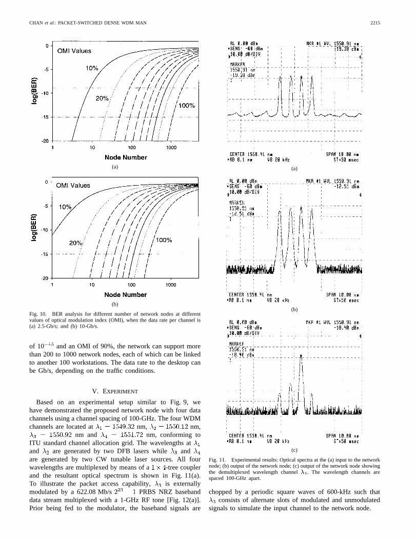
Fig. 10(a) and (b) shows the predicted BER as a function offor two different data rates 2.5- and 10-Gb/s, assuming the
distance spacing between two nodes is fixed at 20 km with losscompensated by a 5-dB gain booster amplifier. The equalizeramplifier is also set at a moderate gain of 10 dB. of the2.5-Gb/s and data are 1.7-GHz and 6.5-GHz, respectively.Using a wavelength channel separation of 50-GHz, the numberof nodes supported by the scheme can be on the order ofhundreds, depending on the OMI and choice of. ConstantBER of 10 and 10 are drawn for reference. Using a BER
- -
CHAN et al.: PACKET-SWITCHED DENSE WDM MAN 2215
(a)
(b)
Fig. 10. BER analysis for different number of network nodes at differentvalues of optical modulation index (OMI), when the data rate per channel is(a) 2.5-Gb/s; and (b) 10-Gb/s.
of 10 and an OMI of 90%, the network can support morethan 200 to 1000 network nodes, each of which can be linkedto another 100 workstations. The data rate to the desktop canbe Gb/s, depending on the traffic conditions.
V. EXPERIMENT
Based on an experimental setup similar to Fig. 9, wehave demonstrated the proposed network node with four datachannels using a channel spacing of 100-GHz. The four WDMchannels are located at nm, nm,
nm and nm, conforming toITU standard channel allocation grid. The wavelengths atand are generated by two DFB lasers while andare generated by two CW tunable laser sources. All fourwavelengths are multiplexed by means of a -tree couplerand the resultant optical spectrum is shown in Fig. 11(a).To illustrate the packet access capability, is externallymodulated by a 622.08 Mb/s PRBS NRZ basebanddata stream multiplexed with a 1-GHz RF tone [Fig. 12(a)].Prior being fed to the modulator, the baseband signals are
(a)
(b)
(c)
Fig. 11. Experimental results: Optical spectra at the (a) input to the networknode; (b) output of the network node; (c) output of the network node showingthe demultiplexed wavelength channel�3. The wavelength channels arespaced 100-GHz apart.
chopped by a periodic square waves of 600-kHz such thatconsists of alternate slots of modulated and unmodulated
signals to simulate the input channel to the network node.
2216 JOURNAL OF LIGHTWAVE TECHNOLOGY, VOL. 17, NO. 11, NOVEMBER 1999
(a) (b)
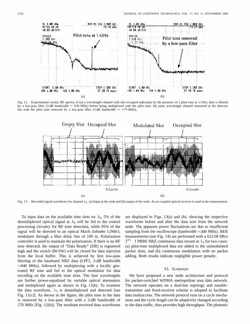
Fig. 12. Experimental results: RF spectra of (a) a wavelength channel with slot occupied indication by the presence of a pilot tone at 1-GHz; data is filteredby a low-pass filter (3-dB bandwidth= 640-MHz) before being multiplexed with the pilot tone; (b) same wavelength channel measured at the detectorbut with the pilot tone removed by a low-pass filter (3-dB bandwidth= 570-MHz).
(a) (b)
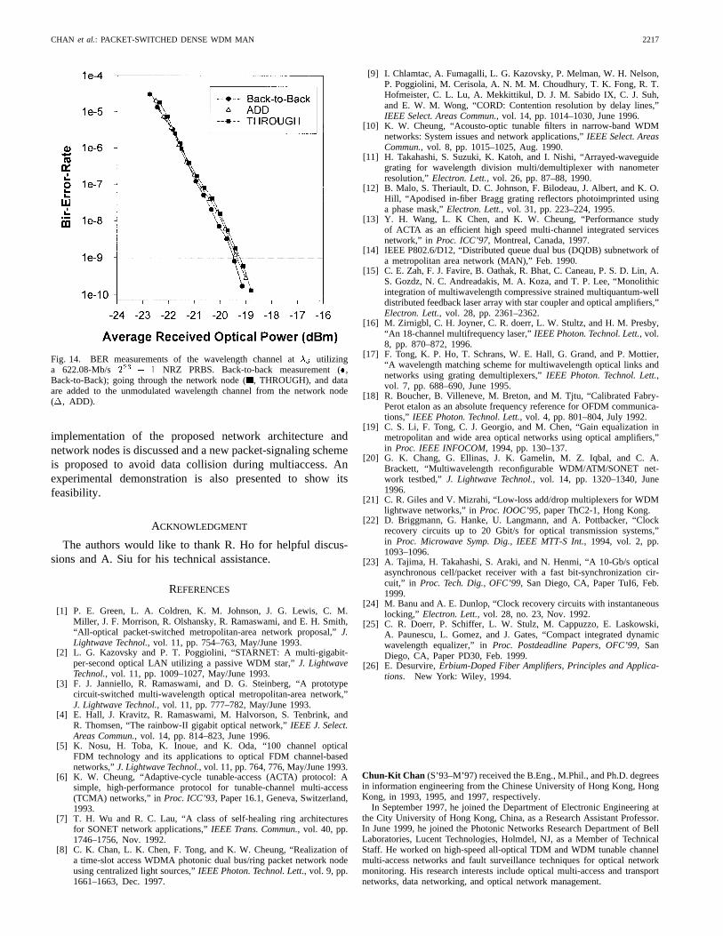
Fig. 13. Recorded signal waveforms for channel�3. (a) Input at the node and (b) output of the node. An ac-coupled optical receiver is used in the measurement.
To input data on the available time slots on, 5% of thedemultiplexed optical signal at will be fed to the controlprocessing circuitry for RF tone detection, while 95% of thesignal will be directed to an optical Mach–Zehnder LiNbO3
modulator through a fiber delay line of 100 m. Polarizationcontroller is used to maintain the polarization. If there is no RFtone detected, the output of “Data Ready” (DR) is registeredhigh and the switch (M-SW) will be closed for data injectionfrom the local buffer. This is achieved by first low-passfiltering of the baseband NRZ data (LPF2, 3-dB bandwidth
640 MHz), followed by multiplexing with a locally gen-erated RF tone and fed to the optical modulator for dataencoding on the available time slots. The four wavelengthsare further power-equalized by variable optical attenuatorsand multiplexed again as shown in Fig. 11(b). To examinethe data waveform, is demultiplexed and detected [seeFig. 11(c)]. As shown in the figure, the pilot tone in the datais removed by a low-pass filter with a 3-dB bandwidth of570 MHz [Fig. 12(b)]. The resultant received data waveforms
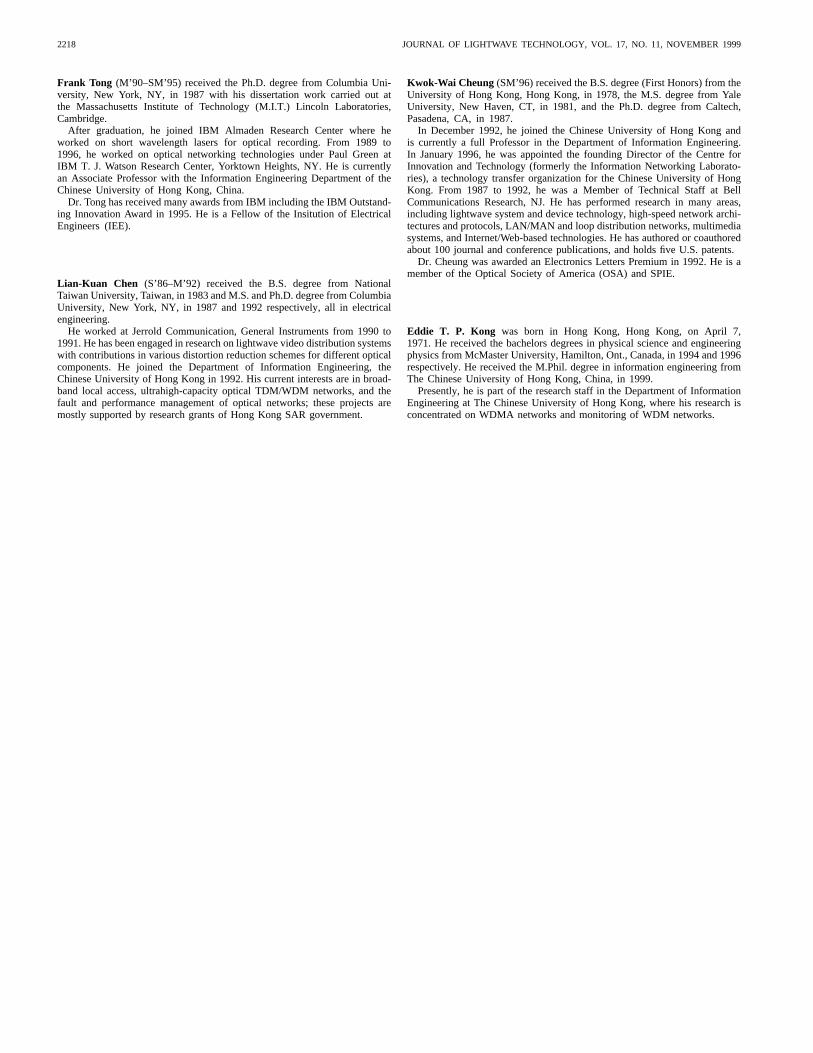
are displayed in Figs. 13(a) and (b), showing the respectivewaveforms before and after the data sent from the networknode. The apparent power fluctuations are due to insufficientsampling from the oscilloscope (bandwidth MHz). BERmeasurements (see Fig. 14) are performed with a 622.08 Mb/s
PRBS NRZ continuous data stream atfor two cases:(a) pilot-tone multiplexed data are added to the unmodulatedpacket slots, and (b) continuous modulation with no packetadding. Both results indicate negligible power penalty.
VI. SUMMARY
We have proposed a new node architecture and protocolfor packet-switched WDMA metropolitan area data network.The network operates on a dual-bus topology and tunable-transmitter and fixed-receiver scheme is adopted to facilitatedata multiaccess. The network protocol runs on a cycle mecha-nism and the cycle length can be adaptively changed accordingto the data traffic, thus provides high throughput. The photonic
CHAN et al.: PACKET-SWITCHED DENSE WDM MAN 2217
Fig. 14. BER measurements of the wavelength channel at�3 utilizinga 622.08-Mb/s 2
23� 1 NRZ PRBS. Back-to-back measurement (�,
Back-to-Back); going through the network node (, THROUGH), and dataare added to the unmodulated wavelength channel from the network node(�, ADD).
implementation of the proposed network architecture andnetwork nodes is discussed and a new packet-signaling schemeis proposed to avoid data collision during multiaccess. Anexperimental demonstration is also presented to show itsfeasibility.
ACKNOWLEDGMENT
The authors would like to thank R. Ho for helpful discus-sions and A. Siu for his technical assistance.
REFERENCES
[1] P. E. Green, L. A. Coldren, K. M. Johnson, J. G. Lewis, C. M.Miller, J. F. Morrison, R. Olshansky, R. Ramaswami, and E. H. Smith,“All-optical packet-switched metropolitan-area network proposal,”J.Lightwave Technol., vol. 11, pp. 754–763, May/June 1993.
[2] L. G. Kazovsky and P. T. Poggiolini, “STARNET: A multi-gigabit-per-second optical LAN utilizing a passive WDM star,”J. LightwaveTechnol., vol. 11, pp. 1009–1027, May/June 1993.
[3] F. J. Janniello, R. Ramaswami, and D. G. Steinberg, “A prototypecircuit-switched multi-wavelength optical metropolitan-area network,”J. Lightwave Technol., vol. 11, pp. 777–782, May/June 1993.
[4] E. Hall, J. Kravitz, R. Ramaswami, M. Halvorson, S. Tenbrink, andR. Thomsen, “The rainbow-II gigabit optical network,”IEEE J. Select.Areas Commun., vol. 14, pp. 814–823, June 1996.
[5] K. Nosu, H. Toba, K. Inoue, and K. Oda, “100 channel opticalFDM technology and its applications to optical FDM channel-basednetworks,”J. Lightwave Technol., vol. 11, pp. 764, 776, May/June 1993.
[6] K. W. Cheung, “Adaptive-cycle tunable-access (ACTA) protocol: Asimple, high-performance protocol for tunable-channel multi-access(TCMA) networks,” inProc. ICC’93, Paper 16.1, Geneva, Switzerland,1993.
[7] T. H. Wu and R. C. Lau, “A class of self-healing ring architecturesfor SONET network applications,”IEEE Trans. Commun., vol. 40, pp.1746–1756, Nov. 1992.
[8] C. K. Chan, L. K. Chen, F. Tong, and K. W. Cheung, “Realization ofa time-slot access WDMA photonic dual bus/ring packet network nodeusing centralized light sources,”IEEE Photon. Technol. Lett., vol. 9, pp.1661–1663, Dec. 1997.
[9] I. Chlamtac, A. Fumagalli, L. G. Kazovsky, P. Melman, W. H. Nelson,P. Poggiolini, M. Cerisola, A. N. M. M. Choudhury, T. K. Fong, R. T.Hofmeister, C. L. Lu, A. Mekkittikul, D. J. M. Sabido IX, C. J. Suh,and E. W. M. Wong, “CORD: Contention resolution by delay lines,”IEEE Select. Areas Commun., vol. 14, pp. 1014–1030, June 1996.
[10] K. W. Cheung, “Acousto-optic tunable filters in narrow-band WDMnetworks: System issues and network applications,”IEEE Select. AreasCommun., vol. 8, pp. 1015–1025, Aug. 1990.
[11] H. Takahashi, S. Suzuki, K. Katoh, and I. Nishi, “Arrayed-waveguidegrating for wavelength division multi/demultiplexer with nanometerresolution,”Electron. Lett., vol. 26, pp. 87–88, 1990.
[12] B. Malo, S. Theriault, D. C. Johnson, F. Bilodeau, J. Albert, and K. O.Hill, “Apodised in-fiber Bragg grating reflectors photoimprinted usinga phase mask,”Electron. Lett., vol. 31, pp. 223–224, 1995.
[13] Y. H. Wang, L. K Chen, and K. W. Cheung, “Performance studyof ACTA as an efficient high speed multi-channel integrated servicesnetwork,” in Proc. ICC’97, Montreal, Canada, 1997.
[14] IEEE P802.6/D12, “Distributed queue dual bus (DQDB) subnetwork ofa metropolitan area network (MAN),” Feb. 1990.
[15] C. E. Zah, F. J. Favire, B. Oathak, R. Bhat, C. Caneau, P. S. D. Lin, A.S. Gozdz, N. C. Andreadakis, M. A. Koza, and T. P. Lee, “Monolithicintegration of multiwavelength compressive strained multiquantum-welldistributed feedback laser array with star coupler and optical amplifiers,”Electron. Lett., vol. 28, pp. 2361–2362.
[16] M. Zirnigbl, C. H. Joyner, C. R. doerr, L. W. Stultz, and H. M. Presby,“An 18-channel multifrequency laser,”IEEE Photon. Technol. Lett., vol.8, pp. 870–872, 1996.
[17] F. Tong, K. P. Ho, T. Schrans, W. E. Hall, G. Grand, and P. Mottier,“A wavelength matching scheme for multiwavelength optical links andnetworks using grating demultiplexers,”IEEE Photon. Technol. Lett.,vol. 7, pp. 688–690, June 1995.
[18] R. Boucher, B. Villeneve, M. Breton, and M. Tjtu, “Calibrated Fabry-Perot etalon as an absolute frequency reference for OFDM communica-tions,” IEEE Photon. Technol. Lett., vol. 4, pp. 801–804, July 1992.
[19] C. S. Li, F. Tong, C. J. Georgio, and M. Chen, “Gain equalization inmetropolitan and wide area optical networks using optical amplifiers,”in Proc. IEEE INFOCOM, 1994, pp. 130–137.
[20] G. K. Chang, G. Ellinas, J. K. Gamelin, M. Z. Iqbal, and C. A.Brackett, “Multiwavelength reconfigurable WDM/ATM/SONET net-work testbed,”J. Lightwave Technol., vol. 14, pp. 1320–1340, June1996.
[21] C. R. Giles and V. Mizrahi, “Low-loss add/drop multiplexers for WDMlightwave networks,” inProc. IOOC’95, paper ThC2-1, Hong Kong.
[22] D. Briggmann, G. Hanke, U. Langmann, and A. Pottbacker, “Clockrecovery circuits up to 20 Gbit/s for optical transmission systems,”in Proc. Microwave Symp. Dig., IEEE MTT-S Int., 1994, vol. 2, pp.1093–1096.
[23] A. Tajima, H. Takahashi, S. Araki, and N. Henmi, “A 10-Gb/s opticalasynchronous cell/packet receiver with a fast bit-synchronization cir-cuit,” in Proc. Tech. Dig., OFC’99, San Diego, CA, Paper TuI6, Feb.1999.
[24] M. Banu and A. E. Dunlop, “Clock recovery circuits with instantaneouslocking,” Electron. Lett., vol. 28, no. 23, Nov. 1992.
[25] C. R. Doerr, P. Schiffer, L. W. Stulz, M. Cappuzzo, E. Laskowski,A. Paunescu, L. Gomez, and J. Gates, “Compact integrated dynamicwavelength equalizer,” inProc. Postdeadline Papers, OFC’99, SanDiego, CA, Paper PD30, Feb. 1999.
[26] E. Desurvire,Erbium-Doped Fiber Amplifiers, Principles and Applica-tions. New York: Wiley, 1994.
Chun-Kit Chan (S’93–M’97) received the B.Eng., M.Phil., and Ph.D. degreesin information engineering from the Chinese University of Hong Kong, HongKong, in 1993, 1995, and 1997, respectively.
In September 1997, he joined the Department of Electronic Engineering atthe City University of Hong Kong, China, as a Research Assistant Professor.In June 1999, he joined the Photonic Networks Research Department of BellLaboratories, Lucent Technologies, Holmdel, NJ, as a Member of TechnicalStaff. He worked on high-speed all-optical TDM and WDM tunable channelmulti-access networks and fault surveillance techniques for optical networkmonitoring. His research interests include optical multi-access and transportnetworks, data networking, and optical network management.
2218 JOURNAL OF LIGHTWAVE TECHNOLOGY, VOL. 17, NO. 11, NOVEMBER 1999
Frank Tong (M’90–SM’95) received the Ph.D. degree from Columbia Uni-versity, New York, NY, in 1987 with his dissertation work carried out atthe Massachusetts Institute of Technology (M.I.T.) Lincoln Laboratories,Cambridge.
After graduation, he joined IBM Almaden Research Center where heworked on short wavelength lasers for optical recording. From 1989 to1996, he worked on optical networking technologies under Paul Green atIBM T. J. Watson Research Center, Yorktown Heights, NY. He is currentlyan Associate Professor with the Information Engineering Department of theChinese University of Hong Kong, China.
Dr. Tong has received many awards from IBM including the IBM Outstand-ing Innovation Award in 1995. He is a Fellow of the Insitution of ElectricalEngineers (IEE).
Lian-Kuan Chen (S’86–M’92) received the B.S. degree from NationalTaiwan University, Taiwan, in 1983 and M.S. and Ph.D. degree from ColumbiaUniversity, New York, NY, in 1987 and 1992 respectively, all in electricalengineering.
He worked at Jerrold Communication, General Instruments from 1990 to1991. He has been engaged in research on lightwave video distribution systemswith contributions in various distortion reduction schemes for different opticalcomponents. He joined the Department of Information Engineering, theChinese University of Hong Kong in 1992. His current interests are in broad-band local access, ultrahigh-capacity optical TDM/WDM networks, and thefault and performance management of optical networks; these projects aremostly supported by research grants of Hong Kong SAR government.
Kwok-Wai Cheung (SM’96) received the B.S. degree (First Honors) from theUniversity of Hong Kong, Hong Kong, in 1978, the M.S. degree from YaleUniversity, New Haven, CT, in 1981, and the Ph.D. degree from Caltech,Pasadena, CA, in 1987.
In December 1992, he joined the Chinese University of Hong Kong andis currently a full Professor in the Department of Information Engineering.In January 1996, he was appointed the founding Director of the Centre forInnovation and Technology (formerly the Information Networking Laborato-ries), a technology transfer organization for the Chinese University of HongKong. From 1987 to 1992, he was a Member of Technical Staff at BellCommunications Research, NJ. He has performed research in many areas,including lightwave system and device technology, high-speed network archi-tectures and protocols, LAN/MAN and loop distribution networks, multimediasystems, and Internet/Web-based technologies. He has authored or coauthoredabout 100 journal and conference publications, and holds five U.S. patents.
Dr. Cheung was awarded an Electronics Letters Premium in 1992. He is amember of the Optical Society of America (OSA) and SPIE.
Eddie T. P. Kong was born in Hong Kong, Hong Kong, on April 7,1971. He received the bachelors degrees in physical science and engineeringphysics from McMaster University, Hamilton, Ont., Canada, in 1994 and 1996respectively. He received the M.Phil. degree in information engineering fromThe Chinese University of Hong Kong, China, in 1999.
Presently, he is part of the research staff in the Department of InformationEngineering at The Chinese University of Hong Kong, where his research isconcentrated on WDMA networks and monitoring of WDM networks.
Related Documents