NMPC-PID %ased &ontrol 6tructure 'esign for $voiding 8ncertainties in $ttitude and $ltitude 7racking &ontrol of Quad-5otor (UAV) M. Hassan Tanveer, D. Hazry, S. Faiz Ahmed, M. Kamran Joyo, Faizan. A. Warsi, H. Kamaruddin, Zuradzman M. Razlan, Khairunizam Wan, AB Shahriman Centre of Excellence for Unmanned Aerial System (COEUAS) Universiti Malaysia Perlis (UniMAP), Kangar, Perlis, Malaysia. Email: [email protected], [email protected], [email protected], [email protected], [email protected], [email protected], [email protected], [email protected], [email protected] Abstract— The extensive consideration in this research article is to utilize the advantages of two most popular control techniques which are Non-Linear Model Predictive Control (NMPC) and Proportional Integral and Derivative (PID) controller for better stabilizing of quad-rotor UAV under different noises and disturbance conditions. The idea is to satisfy the environmental and safety considerations and for that the study of noises and disturbance condition in UAV flight upon the performances of NMPC and PID respectively is being evaluated. Finally a new control method is developed by combing two techniques which can be able to handle different sort of uncertainties i.e. noises and external disturbances in quad-rotor type UAV systems. The simulation result proves that the proposed control structure technique works very well in altitude and attitude stabilization of quad-rotor under different perturbed and unperturbed conditions. Keywords— Quad-rotor, Attitude and Altitude Control, Auto-tune PID, Model Predictive Control (MPC). I INTRODUCTION Up to the present time, researchers made many efforts to improve the flight quality of quad-rotor by developing different strategies to solve its stabilization problem. In 2013 Bryan Godbolt used Model based PID control for Autopilot design for Helicopter, this article only focused on software framework optimization [3]. The PD control technique was used for tilt rotor UAV stabilization in year 2012 [4]. In year 2011 Z. Shaiful used Dynamic Surface Control (DSC) method for altitude control of quad-rotor UAV [5] in the same year active disturbance rejection controller was proposed by Xiong Hua only for attitude controlling of quad-rotor [7]. Several control techniques has been tested in which many of them work efficiently only in indoor environment but most of them do not consider outdoor’s external disturbances [2]. This paper deals with quad-rotor UAVs, in which concept of developing control laws for making a non-linear system stabilize under different uncertainties is presented. This article is structured as follows: In Section 2, a brief description of the quad-rotor dynamics and modelling configurations are given. In section 3, the development of NMPC and PID control structure design for translational and rotational movement of quad-rotor is presented. In Section 4, proposed structure is applied to altitude and attitude dynamics of system and results are presented in section 5. Finally, the major conclusions of the work are drawn in Section 6. II SYSTEM MODELLING Quad-rotor type UAV structure consist of four motors with propellers mounted on “X-shape” frame as shown in Fig. 1. One pair of motors moves clockwise and other moves anticlockwise. Vertical motion is produced by the rotation of propellers that generates vertical upward lifting force and lifts the quad-rotor body in the air. It has ability to move in pitch, roll, yaw, hover, take-off and landing positions. These different movements can be achieved by changing the propellers combination and speed of the quad-rotor motors described [8]. Fig. 1. Quad-rotor X-Frame 2014 IEEE 10th International Colloquium on Signal Processing & its Applications (CSPA2014), 7 - 9 Mac. 2014, Kuala Lumpur, Malaysia 978-1-4799-3091-3/14/$31.00 ©2014 IEEE 117

Welcome message from author
This document is posted to help you gain knowledge. Please leave a comment to let me know what you think about it! Share it to your friends and learn new things together.
Transcript

NMPC-PID ased ontrol tructure esign forvoiding ncertainties in ttitude and ltitude
racking ontrol of Quad- otor (UAV)M. Hassan Tanveer, D. Hazry, S. Faiz Ahmed, M. Kamran Joyo, Faizan. A. Warsi, H. Kamaruddin, Zuradzman M.
Razlan, Khairunizam Wan, AB Shahriman
Centre of Excellence for Unmanned Aerial System (COEUAS) Universiti Malaysia Perlis (UniMAP), Kangar, Perlis, Malaysia.
Email: [email protected], [email protected], [email protected], [email protected], [email protected], [email protected], [email protected], [email protected],
Abstract— The extensive consideration in this research article is to utilize the advantages of two most popular control techniques which are Non-Linear Model Predictive Control (NMPC) and Proportional Integral and Derivative (PID) controller for better stabilizing of quad-rotor UAV under different noises and disturbance conditions. The idea is to satisfy the environmental and safety considerations and for that the study of noises and disturbance condition in UAV flight upon the performances of NMPC and PID respectively is being evaluated. Finally a new control method is developed by combing two techniques which can be able to handle different sort of uncertainties i.e. noises and external disturbances in quad-rotor type UAV systems. The simulation result proves that the proposed control structure technique works very well in altitude and attitude stabilization of quad-rotor under different perturbed and unperturbed conditions.
Keywords— Quad-rotor, Attitude and Altitude Control, Auto-tune PID, Model Predictive Control (MPC).
I INTRODUCTION
Up to the present time, researchers made many efforts to improve the flight quality of quad-rotor by developing different strategies to solve its stabilization problem. In 2013 Bryan Godbolt used Model based PID control for Autopilot design for Helicopter, this article only focused on software framework optimization [3]. The PD control technique was used for tilt rotor UAV stabilization in year 2012 [4]. In year 2011 Z. Shaiful used Dynamic Surface Control (DSC) methodfor altitude control of quad-rotor UAV [5] in the same year active disturbance rejection controller was proposed by Xiong Hua only for attitude controlling of quad-rotor [7]. Several control techniques has been tested in which many of them
work efficiently only in indoor environment but most of them do not consider outdoor’s external disturbances [2].
This paper deals with quad-rotor UAVs, in which concept of developing control laws for making a non-linear system stabilize under different uncertainties is presented. This article is structured as follows: In Section 2, a brief description of the quad-rotor dynamics and modelling configurations are given. In section 3, the development of NMPC and PID control structure design for translational and rotational movement of quad-rotor is presented. In Section 4, proposed structure is applied to altitude and attitude dynamics of system and results are presented in section 5. Finally, the major conclusions of the work are drawn in Section 6.
II SYSTEM MODELLING
Quad-rotor type UAV structure consist of four motors with propellers mounted on “X-shape” frame as shown in Fig. 1. One pair of motors moves clockwise and other moves anticlockwise. Vertical motion is produced by the rotation of propellers that generates vertical upward lifting force and lifts the quad-rotor body in the air. It has ability to move in pitch, roll, yaw, hover, take-off and landing positions. These different movements can be achieved by changing the propellers combination and speed of the quad-rotor motors described [8].
Fig. 1. Quad-rotor X-Frame
2014 IEEE 10th International Colloquium on Signal Processing & its Applications (CSPA2014), 7 - 9 Mac. 2014, Kuala Lumpur, Malaysia
978-1-4799-3091-3/14/$31.00 ©2014 IEEE 117
A. Altitude Dynamic
The Quad-rotor can reach its altitude or can perform vertical take-off and landing by increasing or decreasing the speed of all four motors simultaneously shown in Fig.1. Increasing the speed of motors produces more thrust causing vertical movement. Decreasing the speed of motors generates opposite effect of positive vertical lift. In hovering condition all the four motors are kept on constant speed.
B. Attitude Dynamics
Quad-rotor UAV attitude is defined as the change of its angles which are pitch, roll and yaw. The pitch movement can be achieved by applying constant thrust on Motors M2 and M4 while motors M1 and M3 are altered to tilt the frame on certain angle. The pitching movement is along x-axis. The Roll movement can be achieved by altering the speed of the rotors M2 and M4 while M1 and M3 remains constant. The roll movement is along the y-axis. The movement in yaw is along Z-axis and can be achieved by altering the speed of any one pair of motor M1 & M3 or M2 & M4 at same time instance.
C Equations of Motion
The equations of motion are extracted from the Newton Euler method. The above-mentioned method is discussed comprehensively by [7].
zzzz
yyxx
yyyy
xxzz
xxxx
zzyy
IU
I
II
IU
III
IU
I
IIm
UgZ
mU
Y
mU
X
4
3
2
1
1
1
)1()coscos(
)cossinsinsincos(
)cossincossin(sin
max4
2max4
2max24
2max3
2max1
min4
max3
2max13
2max3
min3
max2
2max42
2max2
min2
max1
24
1
max1
min1
])()[(
])()[(
)2()()(
)()(
)(0
UdU
dU
UbUbU
UbUbU
UbUUi
i
Where,
The components of movement vector are U1, U2, U3 and U4, motor and drag constant are denoted by b and d respectively
while 4321 ,,, are quad-rotor angular velocity. The quad-rotor is equipped with four fixed-pitch rotors. Each of the propellers are mounted on individual brushless DC motor (BLDC). MATLAB is used to validate the rotor dynamics. The motor has first order transfer function expressed below.
1178.0936.0)(
ssG
(3)
Motor parameter, thrust and torque coefficient were carried out as explained [14].
III Control Approach
For better controlling of Quad-rotor under uncertainties a new interconnected controller model based on NMPC-PID is proposed. The control scheme is separately represented for translational and rotational subsystem of Quad-rotor. The overall block diagram of proposed control technique is presented in Fig. 2.
Fig. 2. Block diagram of control system
Generally during UAV flight, quad-rotor sensors gives noisy data to the controller and especially under windy conditions altitude and attitude controlling of quad-rotor is quite complex task. In this article a PID and NMPC shifter based controller is presented which can overcome noises and external disturbance problem efficiently during flight. PID controller works well under external disturbance condition while NMPC controller
2014 IEEE 10th International Colloquium on Signal Processing & its Applications (CSPA2014), 7 - 9 Mac. 2014, Kuala Lumpur, Malaysia
118
gives very good output response under noisy conditions. The main idea emphasizes behind this control structure is the decision making for control techniques as per UAV working conditions. Fig. 3 illustrates the inner block diagram of proposed NMPC-PID based control technique block. In this diagram shifter block plays an important role because during flight when external disturbance occur the quad-rotor changes its orientation and sometimes position from its reference point and generates a high error signal. The shifter detects this error signal and shifts itself as per conditions shown in (4).
Condition 1: e > shift PID (4)
Condition 2: e < shift MPCe is the error signal, is the threshold value.
Fig. 3. NMPC-PID Block
A. Applying proposed control algorithm on altitude and attitude of Quad-rotor (UAV)
For altitude and attitude controlling of Quad-rotor, only four equations will be used from equation of motion, as described in (1).
zzzz
yyxx
yyyy
xxzz
xxxx
zzyy
IU
I
II
IU
III
IU
I
IIm
UgZ
4
3
2
1
)5(
)coscos(
As described in previous section the proposed algorithm works in two conditions described in equation (4).
B Condition 1: > This condition arrised when external disturbance occurs in quad-rotor system, so the shifter block in the proposed controller switches the quad-rotor plant to PID controller technique which quickly stabilizes its altitude and attitude.
The altitude controller used to maintain the quad-rotor distance from the ground at a desired level. For stabilizing quad-rotor altitude, main requirement is to work on quad-rotor z axis and remaining all other axis constant. So we select only Z axis equation form (5), and by adding the effect of external disturbance, it can be written as following:z = g (cos cos ) + In above equation is the external disturbance, and are
constant values, and must be considered as 0 for hovering condition. Taking rotor dynamics into account from (3) and using Laplace Transform and taking all constants as g(cos cos ) = K , system will become:
Z(s) = .. + (6)
is the external disturbance
So the error signals e for PID control is:e = Z Z > 0
where Z is desired value and Z is actual output and PID controller can be define as:
)()( ssL T (7)
With,T
= DIp KKK ,, (8)
]1
,1,1[)(sT
ss
sf
Where the derivative time filter constant fTis supposed to be
known. Kp, Ki and Kd can be selected by auto tuning method [9]. Therefore close loop transfer function for the complete system will become:
( )( ) = e(s) . ( )( )
(9)
2014 IEEE 10th International Colloquium on Signal Processing & its Applications (CSPA2014), 7 - 9 Mac. 2014, Kuala Lumpur, Malaysia
119

where, K = (0.936) , K = 0.178So, (9) is the controller equation, which gives actual linearize and controlled output.
Similarly, for quad-rotor attitude controlling only orientation angles i.e pith, roll and yaw are controlled. So, we only chose 3 equations from (1). These equations can be more simplified by neglecting effects which are gyroscopic, torque and coriolis-centripetal as mentioned in [8]. After neglecting these terms the equation becomes simpler shown in (10). By applying Laplace Transform the transfer function of quad-rotor plant’s attitude which are roll, pitch and yaw obtained separately it becomes:
( )( ) = +( )( ) = + (10)
( )( ) = +
So for its controller designing, the error signals e , e ,e will be:e = e = e =
Where , , are desired signals, while , , are original output signals. The derivation is similar for all attitude angles. So, only the derivation of roll angle controller is presented.
For Roll angle controlling, following equation will be take in account from (10).
(S) = + (11)
After evaluating roll with rotor dynamics given in (3) the above equation becomes:
(s) = ( . ( . ) + U (12)
Where ( . ) is constant and can be taken equal to Ka.
After applying PID controller from Eq. (4.4) to the system for attitude stabilization of roll becomes:
= e(s) ( )( ). . U (13)
Similarly for other angles of attitude (i.e: pitch and yaw), can obtain by same above mentioned proposed method.
C Condition 2: <
This condition arrived when noise is injected in quad-rotor system, so the shifter block in the proposed controller switches the plant to NMPC controller technique which quickly estimates true value and stabilizes its altitude and attitude.
The objective of NMPC is to compute a future control sequence in a defined horizon in such a way that the prediction of the plant output is driven close to the reference [12]. NMPC is selected for better controlling of the system under noisy conditions, it predicts control signal in such a way that it minimizes a define cost function which is error signal between the output and desire value over specified prediction horizon. NMPC starts predicting the future control action by choosing the suitable values of control horizon M, prediction horizon P and control-weighting factor R. Once MPC completes its prediction process, it implements best control action and then at the next sampling interval, the control estimation is repeated again with the new available information. As a result, the performance of the system becomes increased.
Thus the objective function for system can be formulated as:
The dynamics of the true state is given in (14), can be expressed as:
)()()1( kBukAxkx
)()()1( kDukCxky (14)
For quad-rotor altitude:
)1()(
)(kz
kzkx
o
o
Prediction Horizon length N:
x(k) = x (k + 1 |k)x (k + N |k)
u(k) = u(k |k)u (k + N 1 |k)
and the estimation error is an additive term, applied at each time step, the error is uniformly distributed in every feedback.
2014 IEEE 10th International Colloquium on Signal Processing & its Applications (CSPA2014), 7 - 9 Mac. 2014, Kuala Lumpur, Malaysia
120

x(k+i+1|k)=Ax(k+i|k)+B u(k+i|k) (15))()()( ikzikCxiky o
x(k) = M x(k) + C u(k); is the state prediction.
The optimization cost function is then become:
1
0
22)|()|()|()(
N
i
TT kikuRkNkzkikzQkJ
(16)
Where Q and Q are weight coefficient. Evaluating all above equations in J. The constraint acts upon the estimated state, for the known system model. Therefore, subject to the constraint can be defined as:
0)|( kiku
)|()|()|( 21 kikXKkikzKkikUopt (17)
The optimal solution to the optimization problem of the plant will be:
)|(2)|(1)( kNkXKkikzKku (18)
In above equation the optimal ( z ) and estimated state (X)
vectors are shown and 1K & 2K are the controller gains. Similarly attitude controlling under noisy conditions can be derived by above same proposed altitude method.
IV Results and Discussion
In this section, the proposed control strategy has been tested on Matlab simulation tool box in order to verify the performance and effectiveness of proposed control method. This simulation demonstrates the strength of proposed control method for the altitude and attitude controlling of quad-rotor under disturbance and noisy conditions. For simulation purpose, physical parameters of quad-rotor are chosen as mention in Table I. The proposed control technique is also compared with Auto-tuned PID with its parameters of Kp = 0.00078, Ki = 0.000074 and Kd = 0.00084 and optimized NMPC controller with parameters setting mentioned in Table II.
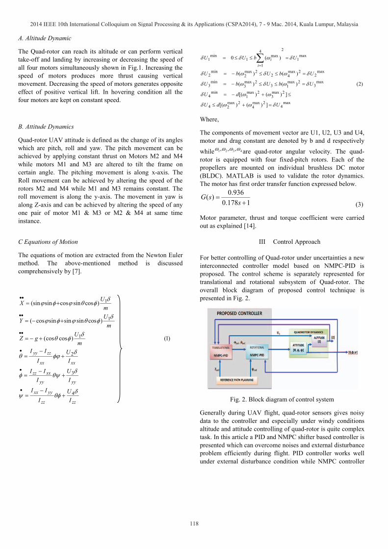
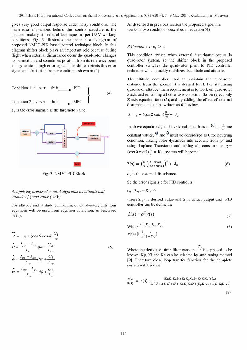
Fig. 4 shows the actual altitude tracking path. Fig. 5 shows the noise signal which is added in trajectory of system and sensor noises. Fig. 6 and 8 are the disturbance which is added in system in a particular time instances. Fig. 7 and 9 showscontrol techniques effect without disturbance and under disturbance and noisy conditions for altitude and attitude control respectively and dissipate the estimated results of parameters obtained by using proposed control technique.
Table I. Quad-rotor Calibration Data
Parameter Name Symbol Value Unit
Rotational Inertia Along Z-axis
I 0.0013 kg. mTotal Mass m 0.65 Kg
Thrust Constant b 3.13e N. sDrag Constant d 7.50e N. sArm Length l 0.23 M
Table II. NMPC Horizon Setting
Parameter Value
Control Interval 0.2
Prediction Horizon 10
Control Horizon 2
Fig. 4. Actual Altitude Path
Fig. 5. Gaussian noise added in System
Fig. 6. Disturbance
0 2 4 6 8 10 12 14 16 18 20
0
1
2
3
4
5
Ampli
tude
Time (secs)
Actual Path
Offset=0 (secs)
0 2 4 6 8 10 12 14 16 18 20
-0.3
-0.2
-0.1
0
0.1
0.2
0.3
Ampli
tude
Time (secs)
Noise
Offset=0 (secs)
0 2 4 6 8 10 12 14 16 18 20
0
0.5
1
1.5
2
Ampli
tude
Time (secs)
Disturbance
Offset=0 (secs)
2014 IEEE 10th International Colloquium on Signal Processing & its Applications (CSPA2014), 7 - 9 Mac. 2014, Kuala Lumpur, Malaysia
121
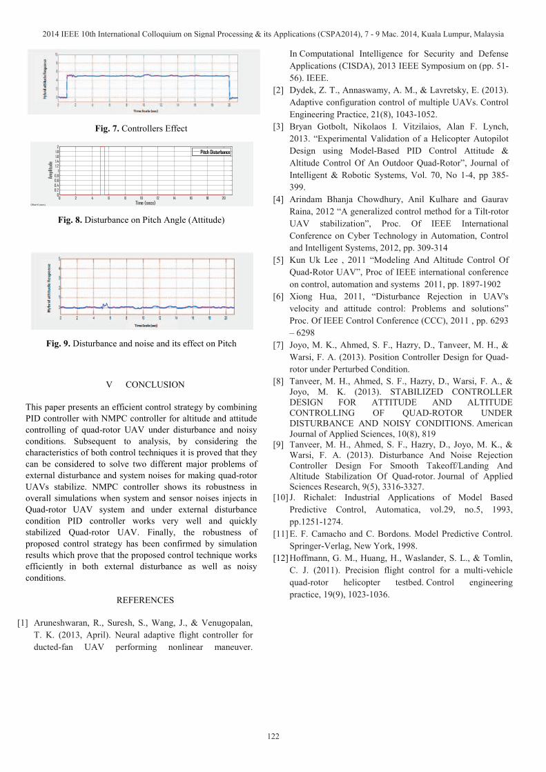
Fig. 7. Controllers Effect
Fig. 8. Disturbance on Pitch Angle (Attitude)
Fig. 9. Disturbance and noise and its effect on Pitch
V CONCLUSION
This paper presents an efficient control strategy by combining PID controller with NMPC controller for altitude and attitude controlling of quad-rotor UAV under disturbance and noisy conditions. Subsequent to analysis, by considering the characteristics of both control techniques it is proved that they can be considered to solve two different major problems of external disturbance and system noises for making quad-rotor UAVs stabilize. NMPC controller shows its robustness in overall simulations when system and sensor noises injects in Quad-rotor UAV system and under external disturbance condition PID controller works very well and quickly stabilized Quad-rotor UAV. Finally, the robustness of proposed control strategy has been confirmed by simulation results which prove that the proposed control technique works efficiently in both external disturbance as well as noisy conditions.
REFERENCES
[1] Aruneshwaran, R., Suresh, S., Wang, J., & Venugopalan,T. K. (2013, April). Neural adaptive flight controller for ducted-fan UAV performing nonlinear maneuver.
In Computational Intelligence for Security and Defense Applications (CISDA), 2013 IEEE Symposium on (pp. 51-56). IEEE.
[2] Dydek, Z. T., Annaswamy, A. M., & Lavretsky, E. (2013). Adaptive configuration control of multiple UAVs. Control Engineering Practice, 21(8), 1043-1052.
[3] Bryan Gotbolt, Nikolaos I. Vitzilaios, Alan F. Lynch, 2013. “Experimental Validation of a Helicopter Autopilot Design using Model-Based PID Control Attitude & Altitude Control Of An Outdoor Quad-Rotor”, Journal of Intelligent & Robotic Systems, Vol. 70, No 1-4, pp 385-399.
[4] Arindam Bhanja Chowdhury, Anil Kulhare and Gaurav Raina, 2012 “A generalized control method for a Tilt-rotor UAV stabilization”, Proc. Of IEEE International Conference on Cyber Technology in Automation, Control and Intelligent Systems, 2012, pp. 309-314
[5] Kun Uk Lee , 2011 “Modeling And Altitude Control Of Quad-Rotor UAV”, Proc of IEEE international conference on control, automation and systems 2011, pp. 1897-1902
[6] Xiong Hua, 2011, “Disturbance Rejection in UAV's velocity and attitude control: Problems and solutions” Proc. Of IEEE Control Conference (CCC), 2011 , pp. 6293 – 6298
[7] Joyo, M. K., Ahmed, S. F., Hazry, D., Tanveer, M. H., & Warsi, F. A. (2013). Position Controller Design for Quad-rotor under Perturbed Condition.
[8] Tanveer, M. H., Ahmed, S. F., Hazry, D., Warsi, F. A., & Joyo, M. K. (2013). STABILIZED CONTROLLER DESIGN FOR ATTITUDE AND ALTITUDE CONTROLLING OF QUAD-ROTOR UNDER DISTURBANCE AND NOISY CONDITIONS. American Journal of Applied Sciences, 10(8), 819
[9] Tanveer, M. H., Ahmed, S. F., Hazry, D., Joyo, M. K., & Warsi, F. A. (2013). Disturbance And Noise Rejection Controller Design For Smooth Takeoff/Landing And Altitude Stabilization Of Quad-rotor. Journal of Applied Sciences Research, 9(5), 3316-3327.
[10] J. Richalet: Industrial Applications of Model Based Predictive Control, Automatica, vol.29, no.5, 1993, pp.1251-1274.
[11] E. F. Camacho and C. Bordons. Model Predictive Control. Springer-Verlag, New York, 1998.
[12] Hoffmann, G. M., Huang, H., Waslander, S. L., & Tomlin, C. J. (2011). Precision flight control for a multi-vehicle quad-rotor helicopter testbed. Control engineering practice, 19(9), 1023-1036.
0 2 4 6 8 10 12 14 16 18 200
0.20.40.60.8
11.21.41.61.82
Ampli
tude
Time (secs)
Pitch Disturbance
Offset=0 (secs)
2014 IEEE 10th International Colloquium on Signal Processing & its Applications (CSPA2014), 7 - 9 Mac. 2014, Kuala Lumpur, Malaysia
122
Related Documents