Niland Public Safety Facility Joints in Concrete Structures 03290 - 2 3. ASTM D 412: Test Methods for Rubber Properties in Tension 4. ASTM D 624: Test Method for Rubber Property - Tear Resistance 5. ASTM D 638: Test Method for Tensile Properties of Plastics 6. ASTM D 746: Test Method for Brittleness Temperature of Plastics and Elastomers by Impact 7. ASTM D 747: Test Method for Apparent Bending Modulus of Plastics by Means of a Cantilever Beam 8. ASTM A 775: Specification for Epoxy-Coated Reinforcing Steel Bar 9. ASTM D 1056: Specification for Flexible Cellular Materials - Sponge or Expanded Rubber 10. ASTM D 1752: Specification for Preformed Sponge Rubber and Cork Expansion Joint Fillers for Concrete Paving and Structural Construction 11. ASTM D 2000: Standard Classification System for Rubber Product in Automotive Applications 12. ASTM D 2240: Test Method for Rubber Property - Durometer Hardness 13. ASTM D 2241: Specification for Poly Vinyl Chloride (PVC) Pressure-Related Pipe (SDR-series) 1.04 TYPES OF JOINTS A. Construction Joints: When fresh concrete is placed against a hardened concrete surface, the joint between the two pours is called a construction joint. Unless otherwise indicated, all joints in water bearing members shall be provided with a waterstop and/or sealant groove of the shape indicated. The surface of the first pour may also be required to receive a coating of bond breaker as indicated. B. Contraction Joints: Contraction joints are similar to construction joints except that the fresh concrete shall not bond to the hardened surface of the first pour, which shall be coated with a bond breaker. The slab reinforcement shall be stopped 4-1/2 inches from the joint; which is provided with a sleeve-type dowel, to allow shrinkage of the concrete of the second pour. Waterstop and/or sealant groove shall also be provided unless otherwise indicated on the Plans. C. Expansion Joints: To allow the concrete to expand freely, a space is provided between the two pours; the joint shall be formed as indicated. This space is obtained by placing a filler joint material against the first pour, which acts as a form for the second pour. Unless otherwise indicated, all expansion joints in water bearing members shall be provided with a center-bulb type waterstop. D. Control Joints: The function of the control joint is to provide a weaker plane in the concrete, where shrinkage cracks will likely occur. A groove, of the shape and dimensions indicated, is formed or saw-cut in the concrete. This groove is filled afterward with a joint sealant material as specified.

Welcome message from author
This document is posted to help you gain knowledge. Please leave a comment to let me know what you think about it! Share it to your friends and learn new things together.
Transcript
Niland Public Safety Facility
Joints in Concrete Structures
03290 - 2
3. ASTM D 412: Test Methods for Rubber Properties in Tension
4. ASTM D 624: Test Method for Rubber Property - Tear Resistance
5. ASTM D 638: Test Method for Tensile Properties of Plastics
6. ASTM D 746: Test Method for Brittleness Temperature of Plastics and
Elastomers by Impact
7. ASTM D 747: Test Method for Apparent Bending Modulus of Plastics by
Means of a Cantilever Beam
8. ASTM A 775: Specification for Epoxy-Coated Reinforcing Steel Bar
9. ASTM D 1056: Specification for Flexible Cellular Materials - Sponge or
Expanded Rubber
10. ASTM D 1752: Specification for Preformed Sponge Rubber and Cork
Expansion Joint Fillers for Concrete Paving and Structural Construction
11. ASTM D 2000: Standard Classification System for Rubber Product in
Automotive Applications
12. ASTM D 2240: Test Method for Rubber Property - Durometer Hardness
13. ASTM D 2241: Specification for Poly Vinyl Chloride (PVC) Pressure-Related
Pipe (SDR-series)
1.04 TYPES OF JOINTS
A. Construction Joints: When fresh concrete is placed against a hardened concrete surface,
the joint between the two pours is called a construction joint. Unless otherwise indicated,
all joints in water bearing members shall be provided with a waterstop and/or sealant
groove of the shape indicated. The surface of the first pour may also be required to
receive a coating of bond breaker as indicated.
B. Contraction Joints: Contraction joints are similar to construction joints except that the
fresh concrete shall not bond to the hardened surface of the first pour, which shall be
coated with a bond breaker. The slab reinforcement shall be stopped 4-1/2 inches from
the joint; which is provided with a sleeve-type dowel, to allow shrinkage of the concrete
of the second pour. Waterstop and/or sealant groove shall also be provided unless
otherwise indicated on the Plans.
C. Expansion Joints: To allow the concrete to expand freely, a space is provided between
the two pours; the joint shall be formed as indicated. This space is obtained by placing a
filler joint material against the first pour, which acts as a form for the second pour.
Unless otherwise indicated, all expansion joints in water bearing members shall be
provided with a center-bulb type waterstop.
D. Control Joints: The function of the control joint is to provide a weaker plane in the
concrete, where shrinkage cracks will likely occur. A groove, of the shape and
dimensions indicated, is formed or saw-cut in the concrete. This groove is filled
afterward with a joint sealant material as specified.
Niland Public Safety Facility
Joints in Concrete Structures
03290 - 3
1.05 CONTRACTOR SUBMITTALS
A. The Contractor shall submit the following in compliance with Section 01300 – Contractor
Submittals:
1. Waterstops: Before production of the required materials, qualification samples
shall be submitted. Such samples shall consist of extruded or molded sections of
each size or shape to be used, and shall be accomplished so that the material and
workmanship represents in all respects the material to be provided under this
Contract. The balance of the material to be used under this Contract shall not be
produced until after the Construction Manager has reviewed the qualification
samples.
2. Joint Sealant: Before ordering the sealant material, the Contractor shall submit
sufficient data to show general compliance with the requirements of the Contract
Documents.
3. Before the sealant is used on the job, the Contractor shall submit certified test
reports from the sealant manufacturer on the actual batch of material being
supplied indicating compliance with the above requirements.
4. Shipping Certification: The Contractor shall furnish written certification from
the manufacturer as an integral part of the shipping form, to show that all of the
material shipped to this project meet or exceed the physical property
requirements of the Contract Documents. Supplier certificates are not
acceptable.
5. Joint Location: The Contractor shall submit placement shop drawings
illustrating the location and type of all joints for each structure.
1.06 QUALITY ASSURANCE
A. Waterstop Inspection: All waterstop field joints shall be subject to rigid inspection, and
no such work shall be scheduled or started without the Contractor having made prior
arrangements with the Construction Manager to provide for the required inspections. Not
less than 48 hours’ notice shall be given to the Construction Manager for scheduling such
inspections.
B. All field joints in waterstops shall be subject to rigid inspection for misalignment,
bubbles, inadequate bond, porosity, cracks, offsets, and other defects which would reduce
the potential resistance of the material to water pressure at any point. All defective joins
shall be replaced with material which shall pass said inspection, and all faulty material
shall be removed from the site and disposed of by the Contractor at no increase in cost to
the Owner.
C. The following waterstop defects represent a partial list of defects which shall be grounds
for rejection:
1. Offsets at joints greater than 1/16 inch or 15 percent of material thickness, at any
point, whichever is less.
2. Exterior crack at joint, due to incomplete bond, which is deeper than 1/16 inch
or 15 percent of material thickness, at any point, whichever is less.
Niland Public Safety Facility
Joints in Concrete Structures
03290 - 4
3. Any combination of offset or exterior crack which will result in a net reduction
in the cross-section of the waterstop in excess of 1/16 inch or 15 percent of
material thickness, at any point, whichever is less.
4. Misalignment of joint which result in misalignment of the waterstop in excess of
1/2-inch in 10 feet.
5. Porosity in the welded joint as evidenced by visual inspection.
6. Bubbles or inadequate bonding which can be detected with a penknife test. If,
while prodding the entire joint with the point of a penknife, the knife breaks
through the outer portion of the weld into a bubble, the joint shall be considered
defective.
D. Waterstop Samples: Before use of the waterstop material in the field, a sample of a
fabricated mitered cross and a tee constructed of each size or shape of material to be used
shall be submitted to the Construction Manager for review. These samples shall be
fabricated so that the material and workmanship represent in all respects the fittings to be
provided under this Contract. Field samples of fabricated fittings will be selected at
random by the Construction Manager for testing by a laboratory at the Contractor’s
expense. When tested, PVC waterstops shall have a tensile strength across the joints
equal to at least 600 PSI.
E. Construction Joint Sealant: The Contractor shall prepare adhesion and cohesion test
specimens as indicated, at intervals of 5 working days while sealants are being installed.
F. The sealant material shall show no signs of adhesive or cohesive failure when tested in
accordance with the following procedure in laboratory and field tests:
1. Sealant specimens shall be prepared between two concrete blocks (1 inch to 2
inches by 3 inches). Spacing between the blocks shall be 1 inch. Coated
spacers (2 inches by 1 ½ inch by ½ inch) shall be used to ensure sealant cross-
sections of ½ inch by 2 inches with a width of 1 inch.
2. Sealant shall be cast and cured according to manufacturer’s recommendations
except that the curing period shall be not less than 24 hours.
3. Following curing period, the gap between blocks shall be widened to 1-1/2 inch.
Spacers shall be used to maintain this gap for 24 hours before inspection for
failure.
1.07 WARRANTY
A. The Contractor shall furnish a 5 year written warranty of the entire sealant installation
against faulty and/or incompatible materials and workmanship, along with a statement
that it agrees to repair or replace, to the satisfaction of the Owner and at no additional
cost to the Owner, any defects that appear during the warranty period.
PART 2 - PRODUCTS
2.01 GENERAL
A. All joint materials specified herein shall be classified by the Environmental Protection
Agency as acceptable for potable water use.
Niland Public Safety Facility
Joints in Concrete Structures
03290 - 5
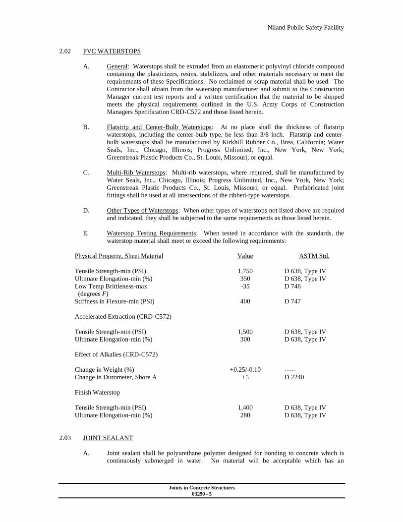
2.02 PVC WATERSTOPS
A. General: Waterstops shall be extruded from an elastomeric polyvinyl chloride compound
containing the plasticizers, resins, stabilizers, and other materials necessary to meet the
requirements of these Specifications. No reclaimed or scrap material shall be used. The
Contractor shall obtain from the waterstop manufacturer and submit to the Construction
Manager current test reports and a written certification that the material to be shipped
meets the physical requirements outlined in the U.S. Army Corps of Construction
Managers Specification CRD-C572 and those listed herein.
B. Flatstrip and Center-Bulb Waterstops: At no place shall the thickness of flatstrip
waterstops, including the center-bulb type, be less than 3/8 inch. Flatstrip and center-
bulb waterstops shall be manufactured by Kirkhill Rubber Co., Brea, California; Water
Seals, Inc., Chicago, Illinois; Progress Unlimited, Inc., New York, New York;
Greenstreak Plastic Products Co., St. Louis, Missouri; or equal.
C. Multi-Rib Waterstops: Multi-rib waterstops, where required, shall be manufactured by
Water Seals, Inc., Chicago, Illinois; Progress Unlimited, Inc., New York, New York;
Greenstreak Plastic Products Co., St. Louis, Missouri; or equal. Prefabricated joint
fittings shall be used at all intersections of the ribbed-type waterstops.
D. Other Types of Waterstops: When other types of waterstops not listed above are required
and indicated, they shall be subjected to the same requirements as those listed herein.
E. Waterstop Testing Requirements: When tested in accordance with the standards, the
waterstop material shall meet or exceed the following requirements:
Physical Property, Sheet Material Value ASTM Std.
Tensile Strength-min (PSI) 1,750 D 638, Type IV
Ultimate Elongation-min (%) 350 D 638, Type IV
Low Temp Brittleness-max
(degrees F)
-35 D 746
Stiffness in Flexure-min (PSI) 400 D 747
Accelerated Extraction (CRD-C572)
Tensile Strength-min (PSI) 1,500 D 638, Type IV
Ultimate Elongation-min (%) 300 D 638, Type IV
Effect of Alkalies (CRD-C572)
Change in Weight (%) +0.25/-0.10 -----
Change in Durometer, Shore A +5 D 2240
Finish Waterstop
Tensile Strength-min (PSI) 1,400 D 638, Type IV
Ultimate Elongation-min (%) 280 D 638, Type IV
2.03 JOINT SEALANT
A. Joint sealant shall be polyurethane polymer designed for bonding to concrete which is
continuously submerged in water. No material will be acceptable which has an
Niland Public Safety Facility
Joints in Concrete Structures
03290 - 6
unsatisfactory history as to bond or durability when used in the joints of water retaining
structures.
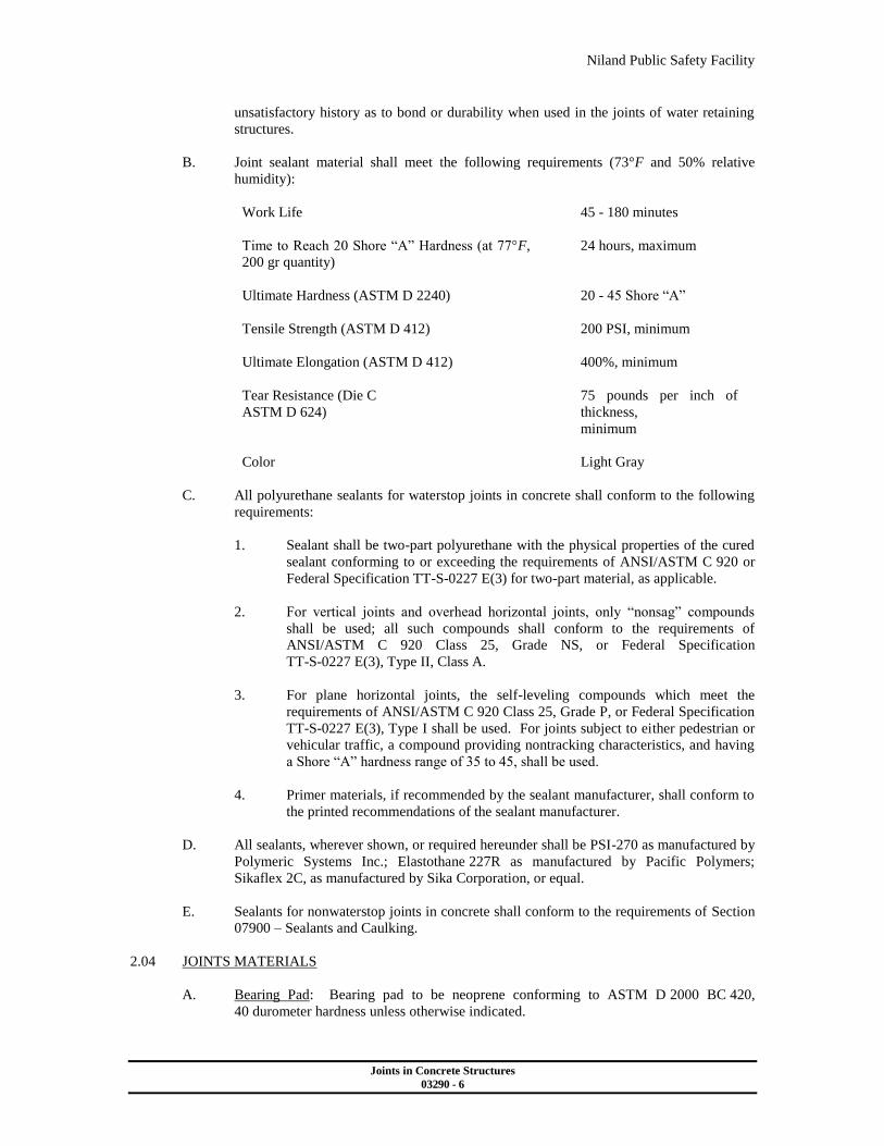
B. Joint sealant material shall meet the following requirements (73°F and 50% relative
humidity):
Work Life 45 - 180 minutes
Time to Reach 20 Shore “A” Hardness (at 77°F,
200 gr quantity)
24 hours, maximum
Ultimate Hardness (ASTM D 2240) 20 - 45 Shore “A”
Tensile Strength (ASTM D 412) 200 PSI, minimum
Ultimate Elongation (ASTM D 412) 400%, minimum
Tear Resistance (Die C
ASTM D 624)
75 pounds per inch of
thickness,
minimum
Color Light Gray
C. All polyurethane sealants for waterstop joints in concrete shall conform to the following
requirements:
1. Sealant shall be two-part polyurethane with the physical properties of the cured
sealant conforming to or exceeding the requirements of ANSI/ASTM C 920 or
Federal Specification TT-S-0227 E(3) for two-part material, as applicable.
2. For vertical joints and overhead horizontal joints, only “nonsag” compounds
shall be used; all such compounds shall conform to the requirements of
ANSI/ASTM C 920 Class 25, Grade NS, or Federal Specification
TT-S-0227 E(3), Type II, Class A.
3. For plane horizontal joints, the self-leveling compounds which meet the
requirements of ANSI/ASTM C 920 Class 25, Grade P, or Federal Specification
TT-S-0227 E(3), Type I shall be used. For joints subject to either pedestrian or
vehicular traffic, a compound providing nontracking characteristics, and having
a Shore “A” hardness range of 35 to 45, shall be used.
4. Primer materials, if recommended by the sealant manufacturer, shall conform to
the printed recommendations of the sealant manufacturer.
D. All sealants, wherever shown, or required hereunder shall be PSI-270 as manufactured by
Polymeric Systems Inc.; Elastothane 227R as manufactured by Pacific Polymers;
Sikaflex 2C, as manufactured by Sika Corporation, or equal.
E. Sealants for nonwaterstop joints in concrete shall conform to the requirements of Section
07900 – Sealants and Caulking.
2.04 JOINTS MATERIALS
A. Bearing Pad: Bearing pad to be neoprene conforming to ASTM D 2000 BC 420,
40 durometer hardness unless otherwise indicated.
Niland Public Safety Facility
Joints in Concrete Structures
03290 - 7
B. Neoprene Sponge: Sponge to be neoprene, closed-cell, expanded, conforming to ASTM
D 1056, Type 2C3-E1.
C. Joint Filler:
1. Joint filler for expansion joints in water holding structures shall be neoprene
conforming to ASTM D 1056, Type 2C5-E1.
2. Joint filler material in other locations shall be of the preformed nonextruding
type joint filler constructed of cellular neoprene sponge rubber or polyurethane
of firm texture. Bituminous fiber type will not be permitted. All nonextruding
and resilient-type preformed expansion joint fillers shall conform to the
requirements and tests set forth in ASTM D 1752 for Type I, except as
otherwise indicated.
2.05 BACKING ROD
A. Backing rod shall be an extruded closed-cell, polyethylene foam rod. The material shall
be compatible with the joint sealant used and shall have a tensile strength of not less than
40 PSI and a compression deflection of approximately 25% at 8 PSI. The rod shall be 1/8
inch larger in diameter than the joint width except that a 1 inch diameter rod shall be used
for a ¾ inch wide joint.
2.06 BOND BREAKER
A. Bond breaker shall be Super Bond Breaker as manufactured by Burke Company, San
Mateo, California; Select Cure CRB as manufactured by Select Products Co., Upland,
California, or equal. It shall contain a fugitive dye so that areas of application will be
readily distinguishable.
2.07 SLIP DOWELS
A. Slip dowels in joints shall be A 36 smooth epoxy-coated bars, as indicated on the Plans,
and conforming to ASTM A 775.
2.08 PVC TUBING
A. PVC tubing in joints shall be Schedule SDR 13.5, conforming to ASTM D 2241.
2.09 NSF / ANSI STANDARD 61
A. All cementitious material, admixtures, curing compounds, and other industrial produced
materials used in concrete, or for curing or repairing of concrete, that can contact potable
water or water that will be treated to become potable shall be listed in NSF / ANSI
Standard 61.
PART 3 - EXECUTION
3.01 GENERAL
A. Waterstops of the type indicated shall be embedded in the concrete across joints as
indicated. All waterstops shall be fully continuous for the extent of the joint. Splices
necessary to provide such continuity shall be accomplished in conformance to printed
instructions of manufacturer of the waterstops. The Contractor shall take suitable
precautions and means to support and protect the waterstops during the progress of the
Niland Public Safety Facility
Joints in Concrete Structures
03290 - 8
Work and repair or replace at its own expense any waterstops damaged during the
progress of the Work. All waterstops shall be stored so as to permit free circulation of air
around the waterstop material.
B. When any waterstop is installed in the concrete on one side of a joint, while the other half
or portion of the waterstop remains exposed to the atmosphere for more than 2 days,
suitable precautions shall be taken to shade and protect the exposed waterstop from direct
rays of the sun during the entire exposure and until the exposed portion of the waterstop
is embedded in concrete.
3.02 SPLICES IN WATERSTOPS
A. Splices in waterstops shall be performed by heat sealing the adjacent waterstop sections
in accordance with the manufacturer’s printed recommendations. It is essential that:
1. The material not be damaged by heat sealing.
2. The splices have a tensile strength of not less than 60% of the unspliced
material’s tensile strength.
3. The continuity of the waterstop ribs and of its tubular center axis be maintained.
B. Butt joints of the ends of two identical waterstop sections may be made while the
material is in the forms.
C. All joints with waterstops involving more than two ends to be joined together, and all
joints which involve an angle cut, alignment change, or the joining of two dissimilar
waterstop sections shall be prefabricated before placement in the forms, allowing not less
than 24 inch long strips of waterstop material beyond the joint. Upon being inspected
and approved, such prefabricated waterstop joint assemblies shall be installed in the
forms and the ends of the 24 inch strips shall be butt welded to the straight run portions of
waterstop in place in the forms.
D. Where a centerbulb waterstop intersects and is joined with a noncenterbulb waterstop,
care shall be taken to seal the end of the centerbulb, using additional PVC material if
needed.
3.03 JOINT CONSTRUCTION
A. Setting Waterstops: To eliminate faulty installation that may result in joint leakage,
particular care shall be taken of the correct positioning of the waterstops during
installation. Adequate provisions shall be made to support and anchor the waterstops
during the progress of the Work and to ensure the proper embedment in the concrete.
The symmetrical halves of the waterstops shall be equally divided between the concrete
pours at the joints. The center axis of the waterstops shall be coincident with the joint
openings. Maximum density and imperviousness of the concrete shall be ensured by
thoroughly working it in the vicinity of all joints.
B. In placing flat-strip waterstops in the forms, a means shall be provided to prevent them
from being folded over by the concrete as it is placed. Unless otherwise indicated, all
waterstops shall be held in place with light wire ties on 12 inch centers which shall be
passed through the edge of the waterstop and tied to the curtain of reinforcing steel.
Horizontal waterstops, with their flat face in a vertical plane, shall be held in place with
continuous supports to which the top edge of the waterstop shall be tacked. In placing
concrete around horizontal waterstops, with their flat face in a horizontal plane, concrete
Niland Public Safety Facility
Joints in Concrete Structures
03290 - 9
shall be worked under the waterstops by hand so as to avoid the formation of air and rock
pockets.
C. In placing centerbulb waterstops in expansion joints, the centerbulb shall be centered on
the joint filler material.
D. Waterstop in vertical wall joints shall stop 6 inches from the top of the wall where such
waterstop does not connect with any other waterstop and is not to be connected to a
future concrete placement.
E. Joint Location: Construction joints, and other types of joints, shall be provided where
indicated. When not indicated, construction joints shall be provided at 25 foot maximum
spacing for all concrete construction, unless noted otherwise. The location of all joints,
of any type, shall be submitted for acceptance by the Construction Manager.
F. Joint Preparation: Special care shall be used in preparing concrete surfaces at joints
where bonding between two sections of concrete is required. Unless otherwise indicated,
such bonding will be required at all horizontal joints in walls. Surfaces shall be prepared
in accordance with the requirements of Section 03300 - Cast-in-Place Concrete.
G. Premolded expansion joint material shall be installed with the edge at the indicated
distance below or back from finished concrete surface, and shall have a slightly tapered,
dressed, and oiled wood strip secured to or placed at the edge thereof during concrete
placement, which shall later be removed to form space for sealing material.
H. The space so formed shall be filled with a joint sealant material as specified. In order to
keep the two wall or slab elements in line the joint shall also be provided with a sleeve-
type dowel, unless otherwise indicated on Plans.
I. Construction Joint Sealant: Construction joints in water-bearing floor slabs, and
elsewhere as indicated, shall be provided with grooves, which shall be filled with a
construction joint sealant. The material used for forming the grooves shall be left in the
grooves until just before the grooves are cleaned and filled with joint sealant. After
removing the forms from the grooves, all laitance and fins shall be removed, and the
grooves shall be sandblasted. The grooves shall be allowed to become thoroughly dry,
after which they shall be blown out; immediately thereafter, they shall be primed, bond
breaker tape placed in the bottom of the groove, and filled with the joint sealant. The
primer used shall be supplied by the same manufacturer supplying the sealant. No
sealant will be permitted to be used without a primer. Care shall be used to completely
fill the sealant grooves. Areas designated to receive a sealant filler shall be thoroughly
cleaned, as outlined for the grooves, before application of the sealant.
J. The primer and sealant shall be placed strictly in accordance with the printed
recommendations of the manufacturer, taking special care to properly mix the sealant
before application. The sides of the sealant groove shall not be coated with bond breaker,
curing compound, or any other substance which would interfere with proper bonding of
the sealant. All sealant shall achieve final cure at least 7 days before the structure is filled
with water.
K. All sealant shall be installed by a competent waterproofing specialty contractor who has a
successful record of performance in similar installations. Before Work is commenced,
the crew performing the Work shall be instructed as to the proper method of application
by a representative of the sealant manufacturer.
L. Thorough, uniform mixing of two-part, catalyst-cured materials is essential; special care
shall be taken to properly mix the sealer before its application. Before any sealer is
Niland Public Safety Facility
Joints in Concrete Structures
03290 - 10
placed, arrange to have the crew performing the Work carefully instructed as to the
proper method of mixing and application by a representative of the sealant manufacturer.
M. Any joint sealant which, after the manufacturer’s recommended curing time for the job
conditions of the Work hereunder, fails to fully and properly cure shall be completely
removed; the groove shall be thoroughly sandblasted to remove all traces of the uncured
or partially cured sealant and primer, and shall be resealed with the indicated joint
sealant. All costs of such removal, joint treatment, resealing and appurtenant work shall
be at no additional cost to the Owner.
END OF SECTION 03290
Niland Public Safety Facility
Cast-in-Place Concrete
03300 - 1
SECTION 03300 - CAST-IN-PLACE CONCRETE
PART 1 - GENERAL
1.01 DESCRIPTION
A. The Contractor shall provide finished structural concrete, complete, in accordance with
the Contract Documents.
B. The following types of concrete are covered in this Section:
1. STRUCTURAL CONCRETE: Normal weight (145 PCF) concrete to be used in
all cases except where noted otherwise in the Contract Documents.
2. LEAN CONCRETE: Concrete to be used for thrust blocks, anchor blocks, pipe
trench cut-off blocks and cradles, where the preceding items are detailed on the
Plans as unreinforced. Concrete to be used as protective cover for dowels
intended for future connection.
C. The term “hydraulic structure” used in these Specifications refers to environmental
Construction Managering concrete structures for the containment, treatment, or
transmission of water, or other fluids.
1.02 RELATED WORK SPECIFIED ELSEWHERE
A. The Work of the following Sections applies to the Work of this Section. Other Sections,
not referenced below, shall also apply to the extent required for proper performance of
this Work.
1. Section 03100 - Concrete Formwork
2. Section 03200 - Reinforcement Steel
3. Section 03290 - Joints in Concrete Structures
4. Section 03315 – Grout
1.03 REFERENCE SPECIFICATIONS, CODES AND STANDARDS
A. Except as otherwise indicated in this Section, the Contractor shall comply with the latest
adopted edition of the Standard Specifications for Public Works Construction (SSPWC),
together with the latest adopted editions of the Regional Amendments.
B. The current edition of the Uniform Building Code (UBC) of International Conference of
Buildings Officials (ICBO).
C. National Sanitation Foundation
1. NSF / ANSI 61: Drinking Water System Components – Health Effects
D. Federal Specifications:
1. UU-B-790A(1)(2): Building Paper, Vegetable Fiber (Kraft, Water-
Proofed, Water Repellant and Fire Resistant)
Niland Public Safety Facility
Cast-in-Place Concrete
03300 - 2
E. Commercial Standards:
1. ACI 117: Standard Tolerances for Concrete Construction and Materials
2. ACI 214: Recommended Practice for Evaluation of Strength Test
Results of Concrete
3. ACI 301: Specifications for Structural Concrete for Buildings
4. ACI 309: Consolidation of Concrete
5. ACI 315: Details and Detailing of Concrete Reinforcement
6. ACI 318: Building Codes Requirements for Reinforced Concrete
7. ACI 350R: Environmental Construction Managering Concrete Structures
F. ASTM Standards in Building Codes:
1. ASTM C 31: Practice for Making and Curing Concrete Test
Specimens in the Field
2. ASTM C 33: Specification for Concrete Aggregates
3. ASTM C 39: Test Method for Compressive Strength of Cylindrical
Concrete Specimens
4. ASTM C 40: Test Method for Organic Impurities in Fine
Aggregates for Concrete
5. ASTM C 42: Test Method of Obtaining and Testing Drilled Cores
and Sawed Beams of Concrete
6. ASTM C 88: Test Method for Soundness of Aggregates by Use of
Sodium Sulfate or Magnesium Sulfate
7. ASTM C 94: Specification for Ready-Mixed Concrete
8. ASTM C 136: Test Method for Sieve Analysis of Fine and Coarse
Aggregates
9. ASTM C 138: Test Method for Unit Weight, Yield, and Air Content of
Concrete
10. ASTM C 143: Test Method for Slump of Hydraulic Cement Concrete
11. ASTM C 150: Specification for Portland Cement
12. ASTM C 156: Test Method for Water Retention by Concrete Curing
Materials
13. ASTM C 157: Test Method for Length Change of Hardened Hydraulic
Cement Mortar and Concrete
Niland Public Safety Facility
Cast-in-Place Concrete
03300 - 3
14. ASTM C 192: Practice for Making and Curing Concrete Test Specimens in
the Laboratory
15. ASTM C 231: Test Method for Air Content of Freshly Mixed Concrete by
the Pressure Method
16. ASTM C 260: Specification for Air-Entraining Admixtures for Concrete
17. ASTM C 289: Test Method for Potential Reactivity of Aggregates (Chemical
Method)
18 ASTM C 309: Specification for Liquid Membrane-Forming Compounds for
Curing Concrete
19. ASTM C 494: Specification for Chemical Admixtures for Concrete
20. ASTM C 107: Practice for Laboratories Testing Concrete and Concrete
Aggregates for Use in Construction and Criteria for Laboratory Evaluation
21. ASTM D 1751: Specification for Preformed Expansion Joint Fillers for
Concrete Paving and Structural Construction (Non-Extruding and Resilient
Bituminous Types)
22. ASTM D 2419: Test Method for Sand Equivalent Value of Soils and Fine
Aggregate
23. ASTM E 119: Method for Fire Tests of Building Construction and
Materials
1.04 CONTRACTOR SUBMITTALS
A. Mix Designs: Before starting the Work and within 14 days of the Notice to Proceed, the
Contractor shall submit to the Construction Manager, for review, preliminary concrete
mix designs which shall illustrate the proportions and gradations of all materials proposed
for each class and type of concrete specified herein in accordance with Specification
Section 01300 – Contractor Submittals. The mix designs shall be checked and certified
to conform to these Specifications by an independent testing laboratory acceptable to the
Construction Manager to be in conformance with these Specifications. All costs related
to such checking and testing shall be borne by the Contractor at no cost to the Owner.
B. Delivery Tickets: Where ready-mix concrete is used, the Contractor shall furnish
delivery tickets at the time of delivery of each load of concrete. Each ticket shall show
the state-certified equipment used for measuring and the total quantities, by weight, of
cement, sand, each class of aggregate, admixtures, and the amounts of water in the
aggregate added at the batching plant, and the amount of water allowed to be added at the
site for the specific design mix. In addition, each ticket shall state the mix number, total
yield in cubic yards, and the time of day, to the nearest minute, corresponding to the
times when the batch was dispatched, when it left the plant, when it arrived at the site,
when unloading began, and when unloading was finished.
C. The Contractor shall provide the following submittals in accordance with ACI 301:
1. Mill tests for cement.
Niland Public Safety Facility
Cast-in-Place Concrete
03300 - 4
2. Admixture certification for all admixtures. Chloride ion content must be
included.
3. Polymer certification for all polymers.
4. Aggregate gradation and certification.
5. Materials and methods for curing. Includes curing compound certification
documents.
6. Fibermesh Certification and manufactures data sheets.
D. The Contractor shall provide catalog cuts and other manufacturer’s technical data
demonstrating compliance with the requirements indicated and specified herein for all
admixtures used in the concrete mix design.
1.05 QUALITY ASSURANCE
A. GENERAL
1. Tests on component materials and for compressive strength and shrinkage of
concrete will be performed as specified herein. Test for determining slump will
be in accordance with the requirements of ASTM C 143.
2. The cost of all laboratory tests requested by the Construction Manager for
cement, aggregates, and concrete, will be borne by the Contractor. The
laboratory must meet or exceed the requirements of ASTM C 1077.
3. Concrete for testing shall be supplied by the Contractor at no cost to the Owner
and the Contractor shall provide assistance to the independent testing laboratory
acceptable to the Construction Manager in obtaining samples, and disposal and
clean up of excess material.
4. A minimum of one (1) set of concrete cylinders and a slump test shall be
obtained for every major concrete placement. A minimum of one (1) set of
concrete cylinders shall be obtained for all concrete structures, foundations and
slabs, driveway entrances, footings, etc. One (1) set of cylinders shall be
obtained for every fifty (50) yards of concrete placed for a particular pour. For
instance, if the walls of a structure require one hundred (100) yards of concrete;
then two (2) sets of concrete cylinders shall be required. If concrete cylinders
for compression testing and a slump test are not required, then the delivery
tickets accompanying the concrete vendor’s truck shall be forwarded to the
Construction Manager. A specific listing of major concrete placements for this
project follows:
ITEM
NO.
ITEM
TESTING REQUIRED
1.
Sidewalk, curb and gutter, solid
waste enclosure pad, solid
waste enclosure slab, generator
set pad, masonry wall footings,
chain link fence footings,
ribbon gutter, barrier curb, etc.
A minimum of one (1) set of
concrete cylinders and slump test
required for each day concrete is
installed. In addition, one (1) set
of cylinders and one (1) slump
test shall be obtained for each
50 yards of concrete placed for an
Niland Public Safety Facility
Cast-in-Place Concrete
03300 - 5
individual concrete pour.
2. Driveway Entrance along
Luxor Avenue
One (1) set of concrete cylinders
and slump test.
3. Alley Entrance on Third Street One (1) set of concrete cylinders
and slump test.
4. Public Safety Facility Building
Slab, footings and bond beam.
A minimum of one (1) set of
concrete cylinders and slump test
required for each day concrete is
installed. In addition, one (1) set
of cylinders and one (1) slump
test shall be obtained for each
50 yards of concrete placed for an
individual concrete pour.
5. All remaining minor concrete
pours.
No cylinders or slump test
required. Concrete vendor ticket
to be supplied to the Construction
Manager.
B. Field Compression Tests:
1. Compression test specimens will be taken during construction from the first
placement of each class of concrete specified herein and at intervals thereafter as
selected by the Construction Manager to ensure continued compliance with
these Specifications. Each set of test specimens will consist of four (4)
cylinders.
2. Compression test specimens for concrete shall be made in accordance with
Section 9.2 of ASTM C 31. Specimens shall be 6-inch diameter by 12-inch high
cylinders.
3. Compression tests shall be performed in accordance with ASTM C 39. One (1)
test cylinder will be tested at 7 days and two (2) at 28 days. The remaining
cylinder will be held to verify test results, if needed.
C. Evaluation and Acceptance of Concrete:
1. Evaluation and acceptance of the compressive strength of concrete shall be
according to the requirements of ACI 318, Chapter 5, “Concrete Quality”, and
as specified herein.
2. A statistical analysis of compression test results will be performed according to
the requirements of ACI 214. The standard deviation of the test results shall not
exceed 640 PSI, when ordered at equivalent water content as estimated by
slump.
3. If any concrete fails to meet these requirements, immediate corrective action
shall be taken to increase the compressive strength for all subsequent batches of
the type of concrete affected.
Niland Public Safety Facility
Cast-in-Place Concrete
03300 - 6
4. When the standard deviation of the test results exceeds 640 PSI, the average
strength for which the mix is designed shall be increased by an amount
necessary to satisfy the statistical requirement that the probability of any test
being more than 500 PSI below or the average of any three (3) consecutive tests
being below the specified compressive strength is 1 in 100. The required
average strength shall be calculated by Criterion No. 3 of ACI 214 using the
actual standard deviation.
5. All concrete which fails to meet the ACI requirements and these Specifications
is subject to removal and replacement at no cost to the Owner.
D. Construction Tolerances: Set and maintain concrete forms and perform finishing
operations so as to ensure that the completed Work is within the tolerances specified
herein. Surface defects and irregularities are defined as finishes and are to be
distinguished from tolerances. Tolerance is the specified permissible variation from
lines, grades, or dimensions shown. Where tolerances are not stated in the Specifications,
permissible deviations will be in accordance with ACI 117.
1. The following construction tolerances are hereby established and apply to
finished walls and slab unless otherwise illustrated:
Item Tolerance
Variation of the constructed linear outline
from the established position in plan.
In 10 feet: ¼ inch
In 20 feet or more: ½ inch
Variation from the level or from the grades
shown.
In 10 feet: ¼ inch
In 20 feet or more: ½ inch
Variation from the plumb. In 10 feet: ¼ inch
In 20 feet or more: ½ inch
Variation in the thickness of slabs and
walls.
Minus ¼ inch;
Plus ½ inch
Variation in the locations and sizes of slabs
and wall openings.
Plus or minus ¼ inch
E. Floor Slab Surface Hardener:
1. Job Mockup: In a location designated by the Construction Manager, place a
minimum 100 square feet floor mockup using materials and procedures
proposed for use in the Project. Revise materials and procedures as necessary to
obtain acceptable finish surface. Maintain the same controls and procedures
used in the acceptable mockup throughout the Project.
2. Field Service: During job mockup and initial period of installation, the
manufacturer of the surface hardener shall furnish the service of a trained, full-
time representative to advise on proper use of the product. Notify surface
hardener manufacturer at least three (3) days before initial use of the product.
3. Installer Qualifications: Installer shall have a minimum of three (3) years
experience and shall be specialized in the application of dry shake surface
hardeners.
Niland Public Safety Facility
Cast-in-Place Concrete
03300 - 7
PART 2 - PRODUCTS
2.01 CONCRETE MATERIALS
A. General:
1. All materials specified herein shall be classified by the Environmental
Protection Agency as acceptable for potable water use within 30 days of
application.
2. Materials shall be delivered, stored, and handled so as to prevent damage by
water or breakage. Only one (1) brand of cement shall be used. Cement
reclaimed from cleaning bags or leaking containers shall not be used. All
cement shall be used in the sequence of receipt of shipments.
B. All materials furnished for the Work shall comply with the requirements of Sections 201,
203, and 204 of ACI 301, as applicable.
C. Storage of materials shall conform to the requirements of Section 2.5 of ACI 301 or the
SSPWC.
D. Materials for concrete shall conform to the following requirements:
1. Cement shall be standard brand Portland Cement conforming to ASTM C 150
for Type V. A minimum of 85 percent of cement by weight shall pass a
325 screen. A single brand of cement shall be used throughout the Work, and
before its use, the brand shall be acceptable to the Construction Manager. The
cement shall be suitably protected from exposure to moisture until used.
Cement that has become lumpy shall not be used. Sacked cement shall be stored
in such a manner so as to permit access for inspection and sampling. Certified
mill test reports, including fineness, for each shipment of cement to be used
shall be submitted to the Construction Manager if requested regarding
compliance with these Specifications.
2. Water for mixing and curing shall be potable, clean, and free from objectionable
quantities of silty organic matter, alkali, salts and other impurities. The water
shall be considered potable, for the purposes of this Section, only if it meets the
requirements of the local governmental agencies. Agricultural water with high
total dissolved solids concentration (over 1,000 mg/l) shall not be used.
3. Aggregates shall be obtained from pits acceptable to the Construction Manager,
shall be nonreactive, and shall conform to ASTM C 33. Maximum size of
coarse aggregate shall be as specified herein. Lightweight sand for fine
aggregate will not be permitted.
a) Coarse aggregates shall consist of clean, hard, durable gravel, crushed
gravel, crushed rock or a combination thereof. The coarse aggregates
shall be prepared and handled in two or more size groups for combined
aggregates with a maximum size greater than ¾ inch. When the
aggregates are proportioned for each batch of concrete the two size
groups shall be combined. See the Paragraph in Part 2 entitled “Trial
Batch and Laboratory Tests” for the use of the size groups.
b) Fine aggregates shall be natural sand or a combination of natural and
manufactured sand that are hard and durable. When tested in
Niland Public Safety Facility
Cast-in-Place Concrete
03300 - 8
accordance with ASTM D 2419, the sand equivalency shall not be less
than 75 percent for an average of three samples, nor less than 70
percent for an individual test. Gradation of fine aggregate shall
conform to ASTM C 33, with 15 to 30 percent passing the number 50
screen and 5 to 10 percent passing the number 100 screen. The
fineness modulus of sand used shall not be over 3.00.
c) Combined aggregates shall be well graded from coarse to fine sizes,
and shall be uniformly graded between screen sizes to produce a
concrete that has optimum workability and consolidation
characteristics. Where a trial batch is required for a mix design, the
final combined aggregate gradations will be established during the trial
batch process.
d) When tested in accordance with ASTM C 33, the ratio of silica released
to reduction in alkalinity shall not exceed 1.0.
e) When tested in accordance with ASTM C 33, the fine aggregate shall
produce a color in the supernatant liquid no darker than the reference
standard color solution.
f) When tested in accordance with ASTM C 33, the coarse aggregate shall
show a loss not exceeding 42 percent after 500 revolutions, or 10.5
percent after 100 revolutions.
g) When tested in accordance with ASTM C 33, the loss resulting after
five cycles shall not exceed 10 percent for fine or coarse aggregate
when using sodium sulfate.
4. Ready-mix concrete shall conform to the requirements of ASTM C 94.
5. Admixtures: All admixtures shall be compatible and by a single manufacturer
capable of providing qualified field service representation. Admixtures shall be
used in accordance with manufacturer’s recommendations. If the use of an
admixture is producing an inferior end result, discontinue use of the admixture.
Admixtures shall not contain thiocyanates nor more than 0.05 percent chloride
ion, and shall be nontoxic after 30 days.
a) Set controlling and water reducing admixtures: Admixtures may be
added at the Contractor’s option to control the set, affect water
reduction, and increase workability. The addition of an admixture shall
be at no increase in cost to the Owner. The use of an admixture shall
be subject to acceptance by the Construction Manager. Concrete
containing an admixture shall be first placed at a location determined
by the Construction Manager. Admixtures specified herein shall
conform to the requirements of ASTM C 494. The required quantity of
cement shall be used in the mix regardless of whether or not an
admixture is used.
1) Concrete shall not contain more than one water-reducing
admixture. Concrete containing an admixture shall be first
placed at a location determined by the Construction Manager.
2) Set controlling admixture shall be either with or without
water-reducing properties. Where the air temperature at the
Niland Public Safety Facility
Cast-in-Place Concrete
03300 - 9
time of placement is expected to be consistently over 80°F, a
set retarding admixture such as Plastocrete by Sika
Corporation; Pozzolith 300R by Master Builders; Daratard by
W. R. Grace; or equal shall be used. Where the air
temperature at the time of placement is expected to be
consistently under 40°F, a noncorrosive set accelerating
admixture such as Plastocrete 161FL by Sika Corporation;
Pozzutec 20 by Master Builders; Daraset by W. R. Grace; or
equal shall be used.
3) Normal range water reducer shall conform to ASTM C 494,
Type A, WRDA 79 by W. R. Grace; Pozzolith 322-N by
Master Builders; Plastocrete 161 by Sika Corporation; or
equal. The quality of admixture used and the method of
mixing shall be in accordance with the manufacturer’s
instructions and recommendations.
4) High range water reducer shall conform to ASTM C 494,
Type F or G. Daracem 100 or WDRA 19 by W. R. Grace;
Sikament FF or Sikament 86 by Sika Corporation; Rheobuild
1000 or Rheobuild 716 by Master Builders; or equal. High
range water reducer shall be added to the concrete after all
other ingredients have been mixed and initial slump has been
verified. No more than 14 ounces of water reducer per sack of
cement shall be used. Water reducer shall be considered as
part of the mixing water when calculating water cement ratio.
5) If the high range water reducer is added to the concrete at the
job site, it may be used in conjunction with the same water
reducer added at the batch plant. Concrete shall have a slump
of 3 inches + ½ inch before adding the high range water
reducing admixture at the job site. The high range water-
reducing admixture shall be accurately measured and pressure
injected into the mixer as a single dose by an experienced
technician. A standby system shall be provided and tested
before each day’s operation of the job site system.
6) Concrete shall be mixed at mixing speed for a minimum of 30
mixer revolutions after the addition of the high range water
reducer.
7) Flyash: Flyash shall not be used.
2.02 CURING MATERIALS
A. Materials for curing concrete as specified herein shall conform to the following
requirements and ASTM C 309:
1. All curing compounds shall be white pigmented and resin based. Sodium
silicate compounds shall not be allowed. Concrete curing compound shall be
Spartan Cote Cure-Seal Hardener by the Burke Company; Super Rez Seal by
Euclid Chemical Company; MB-429 as manufactured by Master Builders; or
equal. Water-based resin curing compounds shall be used only where local air
quality regulations prohibit the use of a solvent-based compound. Water-based
Niland Public Safety Facility
Cast-in-Place Concrete
03300 - 10
curing compounds shall be Aqua Resincure by the Burke Company; Aqua-Cure
by Euclid Chemical Company; Masterkure-W by Master Builders; or equal.
2. Polyethylene sheet for use as a concrete curing blanket shall be white, and shall
have a nominal thickness of 6 mils. The loss of moisture when determined in
accordance with the requirements of ASTM C 156 shall not exceed 0.055 grams
per square centimeter of surface.
3. Polyethylene-coated water proof paper sheeting for use as concrete curing
blanket shall consist of white polyethylene sheeting free of visible defects,
uniform in appearance, having a nominal thickness of 2 mils and permanently
bonded to waterproof paper conforming to the requirements of Federal
Specification UU-B-790A(1)(2). The loss of moisture, when determined in
accordance with the requirements of ASTM C156, shall not exceed 0.055 gram
per square centimeter of surface.
4. Polyethylene-coated burlap for use as concrete curing blanket shall be 4 mils
thick, white opaque polyethylene film impregnated or extruded into one side of
the burlap. Burlap shall weigh not less than 9 ounces per square yard. The loss
of moisture, when determined in accordance with the requirements of ASTM
C 156, shall not exceed 0.055 gram per square centimeter of surface.
5. Curing mats for use in Curing Method 6 as specified herein, shall be heavy shag
rugs or carpets or cotton mats quilted at 4 inches on center. Curing mats shall
weigh a minimum of 12 ounces per square yard when dry.
6. Evaporation retardant shall be a material such as Confilm as manufactured by
Master Builders; Eucobar as manufactured by Euclid Chemical Company; or
equal.
2.03 NONWATERSTOP JOINT MATERIALS
A. Materials for nonwaterstop joints in concrete shall conform to the following
requirements:
1. Preformed joint filler shall be a nonextruding, resilient, bituminous type
conforming to the requirements of ASTM D 1751.
2. Mastic joint sealer shall be a material that does not contain evaporating solvents;
that will tenaciously adhere to concrete surfaces; that will remain permanently
resilient and pliable; that will not be affected by continuous presence of water
and will not in any way contaminate potable water; and that will effectively seal
the joints against moisture infiltration even when the joints are subject to
movement due to expansion and contraction. The sealer shall be composed of
special asphalts or similar materials blended with lubricating and plasticizing
agents to form a tough, durable mastic substance containing no volatile oils or
lubricants and shall be capable of meeting the test requirements set forth
hereinafter, if testing is required by the Construction Manager.
2.04 MISCELLANEOUS MATERIALS
A. Damp-proofing agent shall be an asphalt emulsion, such as Hydrocide 600 by Sonneborn;
Damp-proofing Asphalt Coating by Euclid Chemical Company; Sealmastic by W. R.
Meadows Inc., or equal.
Niland Public Safety Facility
Cast-in-Place Concrete
03300 - 11
B. Bonding agents shall be epoxy adhesives conforming to the following products for the
applications specified:
1. For bonding freshly-mixed, plastic concrete to hardened concrete, Sikadur 32
Hi-Mod Epoxy Adhesive, as manufactured by Sika Corporation; Concresive
Liquid (LPL), as manufactured by Master Builders; BurkEpoxy MV as
manufactured by The Burke Company; or equal.
2. For bonding hardened concrete or masonry to steel, Sikadur 31 Hi-Mod Gel as
manufactured by Sika Corporation; BurkEpoxy NS as manufactured by The
Burke Company; Concresive Paste (LPL) as manufactured by Master Builders;
or equal
2.05 CONCRETE DESIGN REQUIREMENTS
A. Mix Design:
1. General: Concrete shall be composed of cement, admixtures, aggregates and
water. These materials shall be of the qualities specified. The exact proportions
in which these materials are to be used for different parts of the Work will be
determined during the trial batch. In general, the mix shall be designed to
produce a concrete capable of being deposited so as to obtain maximum density
and minimum shrinkage and, where deposited in forms, to have good
consolidation properties and maximum smoothness of surface. In mix designs,
the percentage of sand of the total weight of fine and coarse aggregate shall not
exceed 41 for hydraulic structures or 50 for all other structures, unless noted
otherwise. The aggregate gradations shall be formulated to provide fresh
concrete that will not promote rock pockets around reinforcing steel or
embedded items. The proportions shall be changed whenever necessary or
desirable to meet the required results at no additional cost to the Owner. All
changes shall be subject to review by the Construction Manager.
2. Water-Cement Ratio and Compressive Strength: The minimum compressive
strength and cement content of concrete shall be not less than that specified in
the following table:
Min. 28-Day
Compressive
Strength
(PSI)
Max
Size
Aggregate
(in)
Minimum
Cement
Per
CU YD
(lb)
Max
W/C
Ratio
(by
weight)
Type of Work
Structural Concrete:
Project Concrete 4,500 3/4 611 0.45
NOTE: The Contractor is cautioned that the limiting parameters specified above are not
a mix design. Additional cement or water-reducing agent may be required to
achieve workability demanded by the Contractor’s construction methods and
aggregates. The Contractor is responsible for any costs associated with
furnishing concrete with the required workability.
3. Adjustments to Mix Design: The mixes used shall be changed whenever such
chance is necessary or desirable to secure the required strength, density,
Niland Public Safety Facility
Cast-in-Place Concrete
03300 - 12
workability, and surface finish and the Contractor shall be entitled to no
additional compensation because of such changes.
B. Consistency:
1. The quantity of water entering into a batch of concrete shall be just sufficient,
with a normal mixing period, to produce a concrete which can be worked
properly into place without segregation, and which can be compacted by the
vibratory methods herein specified to give the desired density, impermeability
and smoothness of surface. The quantity of water shall be changed as necessary,
with variations in the nature or moisture content of the aggregates, to maintain
uniform production of a desired consistency. The consistency of the concrete in
successive batches shall be determined by slump tests in accordance with ASTM
C 143. The slumps shall be as follows:
Part of Work Slump (in)
All concrete, unless noted 3 1/2 inches + 1/2-inch
otherwise
With high range water reducer 4 1/2 inches + 1/2-inch
added
C. Trial Batch and Laboratory Tests:
1. Before placing any concrete, a testing laboratory approved by the Construction
Manager will prepare a trial batch of each class of structural concrete, based on
the preliminary concrete mixes submitted by the Contractor. During the trial
batch the aggregate proportions may be adjusted by the testing laboratory using
the two coarse aggregate size ranges to obtain the required properties. If one
size range produces an acceptable mix, a second size range need not be used.
Such adjustments shall be considered refinements to the mix design and shall
not be the basis for extra compensation to the Contractor. All concrete shall
conform to the requirements of this Section, whether the aggregate proportions
are from the Contractor’s preliminary mix design, or whether the proportions
have been adjusted during the trial batch process. The trial batch will be
prepared using the aggregates, cement and admixture proposed for the project.
The trial batch materials shall be of a quantity such that the testing laboratory
can obtain 3 drying shrinkage, and six compression test specimens from each
batch. The cost of not more than three laboratory trial batch tests for each
specified concrete strength will be borne by the Contractor. The Contractor
shall furnish and deliver the materials in steel drums to the approved testing
laboratory. Any additional trial batch testing required shall be performed by the
testing laboratory at no additional cost to the Owner.
2. The determination of compressive strength will be made by testing 6-inch
diameter by 12 inch high cylinders; made, cured and tested in accordance with
ASTM C 192 and ASTM C 39. Three compression test cylinders will be tested
at 7 days and 2 at 28 days. The average compressive strength for the three
cylinders tested at 28 days for any given trial batch shall not be less than 125
percent of the specified compressive strength.
3. A sieve analysis of the combined aggregate for each trial batch shall be
performed according to the requirements of ASTM C 136. Values shall be
given for percent passing each sieve.
Niland Public Safety Facility
Cast-in-Place Concrete
03300 - 13
4. In lieu of trial batch and laboratory tests specified in this Section, the Contractor
may submit previously-designed, tested, and successfully-used concrete mixes,
using materials similar to those intended for this project, together with a
minimum of three certified test reports of the 28 day strength of the proposed
concrete mix.
D. Shrinkage Limitation:
1. The maximum concrete shrinkage for specimens cast in the laboratory from the
trial batch, as measured at 21 day drying age or at 28 day drying age shall be
0.036 percent or 0.042 percent, respectively. Use a mix design for construction
that has first met the trial batch shrinkage requirements. Shrinkage limitations
apply only to structural concrete.
2. The maximum concrete shrinkage for specimens cast in the field shall not
exceed the trial batch maximum shrinkage requirement by more than 25 percent.
3. If the required shrinkage limitation is not met during construction, take any or
all of the following actions, at no additional cost to the Owner for securing the
specified shrinkage requirements. These actions may include changing the
source of aggregates, cement and/or admixtures; reducing water content;
washing of aggregate to reduce fines; increasing the number of construction
joints, modifying the curing requirements; or other actions designed to minimize
shrinkage or the effects of shrinkage.
E. Measurement of Cement and Aggregate:
1. The amount of cement and of each separate size of aggregate entering into each
batch of concrete shall be determined by direct weighing equipment acceptable
to the Construction Manager.
2. Weighing Tolerances:
Material Percent of Total Weight
Cement 1
Aggregates 3
Admixtures 3
F. Measurement of Water:
1. The quantity of water entering the mixer shall be measured by a suitable water
meter or other measuring device of a type acceptable to the Construction
Manager and capable of measuring the water in variable amounts within a
tolerance of one percent. The water feed control mechanism shall be capable of
being locked in position so as to deliver constantly any specified amount of
water to each batch of concrete. A positive quick-acting valve shall be used for
a cut-off in the water line to the mixer. The operating mechanism must be such
that leakage will not occur when the valves are closed.
2.06 READY-MIXED CONCRETE
A. At the Contractor’s option, ready-mixed concrete may be used meeting the requirements
as to materials, batching, mixing, transporting, and placing as specified herein and in
accordance with ASTM C 94, including the following supplementary requirements.
Niland Public Safety Facility
Cast-in-Place Concrete
03300 - 14
B. Ready-mixed concrete shall be delivered to the site of the Work, and discharge shall be
completed within one and one-half hour (90 minutes) after the addition of the cement to
the aggregates or before the drum has been revolved 250 revolutions, whichever is first.
C. Truck mixers shall be equipped with electrically-actuated counters by which the number
of revolutions of the drum or blades may be readily verified. The counter shall be of the
resettable, recording type, and shall be mounted in the driver’s cab. The counters shall be
actuated at the time of starting mixers at mixing speeds.
D. Each batch of concrete shall be mixed in a truck mixer for not less than 70 revolutions of
the drum or blades at the rate of rotation designated by the manufacturer of equipment.
Additional mixing, if any, shall be at the speed designated by the manufacturer of the
equipment as agitating speed. All materials including mixing water shall be in the mixer
drum before actuating the revolution counter for determining the number of revolution of
mixing.
E. Truck mixers and their operation shall be such that the concrete throughout the mixed
batch as discharged is within acceptable limits of uniformity with respect to consistency,
mix, and grading. If slump tests taken at approximately the one-quarter (1/4) and
three-quarter (3/4) points of the load during discharge give slumps differing by more than
one inch (1”) when the specified slump is 3 inches or less, or if they differ by more than
2 inches when the specified slump is more than 3 inches, the mixer shall not be used on
the Work unless the causing condition is corrected and satisfactory performance is
verified by additional slump tests. All mechanical details of the mixer, such as water
measuring and discharge apparatus, condition of the blades, speed of rotation, general
mechanical condition of the unit, and clearance of the drum, shall be checked before a
further attempt to use the unit will be permitted.
F. Each batch of ready-mixed concrete delivered at the job site shall be accompanied by a
delivery ticket furnished to the Construction Manager in accordance with
Subsection 03300-1.04B.
G. The use of nonagitating equipment for transporting ready-mixed concrete will not be
permitted. Combination truck and trailer equipment for transporting ready-mixed
concrete will not be permitted. The quality and quantity of materials used in ready-mixed
concrete and in batch aggregates shall be subject to continuous inspection at the batching
plant by the Construction Manager.
2.07 FLOOR HARDENER (SURFACE APPLIED)
A. Surface hardener shall be a light reflective nonoxidizing metallic aggregate dry shake
surface hardener.
1. Surface hardener shall be premeasured, premixed and packaged at the factory.
2. Apply surface hardener at the rate of 1.8 to 2.5 lb per square foot.
3. Surface hardener shall be Alumiplate@, by Master Builders, Inc., or equal.
B. Curing Compound shall meet the moisture retention requirements of ASTM C 309 and
surface hardener manufacturer’s recommendations.
C. Monomolecular Film: Evaporation retarder shall be used to aid in maintaining concrete
moisture during the early placement stages of plastic concrete. Evaporation retarder shall
be as recommended by surface hardener manufacturer.
Niland Public Safety Facility
Cast-in-Place Concrete
03300 - 15
2.08 NSF / ANSI STANDARD 61
A. All cementitious material, admixtures, curing compounds, and other industrial produced
materials used in concrete, or for curing or repairing of concrete, that can contact potable
water or water that will be treated to become potable shall be listed in NSF / ANSI
Standard 61.
Niland Public Safety Facility
Cast-in-Place Concrete
03300 - 16
PART 3 - EXECUTION
3.01 PROPORTIONING AND MIXING
A. Proportioning: Proportioning of the concrete mix shall conform to the requirements of
Chapter 3, “Proportioning” of ACI 301.
B. Mixing: Mixing of concrete shall conform to the requirements of Chapter 7 of said
ACI 301 Specifications.
C. Slump: Maximum slumps shall be as specified herein.
D. Retempering: Retempering of concrete or mortar which has partially hardened shall not
be permitted.
3.02 PREPARATION OF SURFACES FOR CONCRETING
A. General: Earth surfaces shall be thoroughly wetted by sprinkling, before the placing of
any concrete, and these surfaces shall be kept moist by frequent sprinkling up to the time
of placing concrete thereon. The surface shall be free from standing water, mud, and
debris at the time of placing concrete.
B. Joints in Concrete: Concrete surfaces upon or against which concrete is to be placed,
where the placement of the concrete has been stopped or interrupted so that, as
determined by the Construction Manager, the new concrete cannot be incorporated
integrally with that previously placed, are defined as construction joints. The surfaces of
horizontal joints shall be given a compacted, roughened surface for good bond. The joint
surfaces shall be cleaned of all laitance, loose or defective concrete, foreign material, and
roughened to a minimum of ¼ inch amplitude. Such cleaning and roughening shall be
accomplished by hydroblasting or sandblasting (exposing aggregate) followed by
thorough washing. All pools of water shall be removed from the surface of construction
joints, and the joint surface shall be coated with an epoxy-bonding agent, unless indicated
otherwise, before the new concrete is placed.
C. Placing Interruptions: When placing of concrete is to be interrupted long enough for the
concrete to take a set, the working face shall be given a shape by the use of forms or other
means, that will secure proper union with subsequent Work; provided that construction
joints shall be made only where acceptable to the Construction Manager.
D. Embedded Items: No concrete shall be placed until all formwork, installation of parts to
be embedded, reinforcement steel, and preparation of surfaces involved in the placing
have been completed and accepted by the Construction Manager at least 4 hours before
placement of concrete. All surfaces of forms and embedded items that have become
encrusted with dried grout from concrete previously placed shall be cleaned of all such
grout before the surrounding or adjacent concrete is placed.
E. All inserts or other embedded items shall conform to the requirements herein.
F. All reinforcement, anchor bolts, sleeves, inserts, and similar items shall be set and
secured in the forms where illustrated on the Plans or by approved shop drawings and
shall be acceptable to the Construction Manager before any concrete is placed. Accuracy
of placement is the responsibility of the Contractor.
G. Casting New Concrete Against Old: Where concrete is to be cast against old concrete
(any concrete which is greater than 60 days of age), the surface of the old concrete shall
Niland Public Safety Facility
Cast-in-Place Concrete
03300 - 17
be thoroughly cleaned and roughened by hydroblasting or sandblasting (exposing
aggregate). The joint surface shall be coated with an epoxy bonding agent unless
indicated otherwise by the Construction Manager.
H. No concrete shall be placed in any structure until all water entering the space to be filled
with concrete has been properly cut off or has been diverted by pipes, or other means, and
carried out of the forms, clear of the Work. No concrete shall be deposited underwater
nor shall the Contractor allow still water to rise on any concrete until the concrete has
attained its initial set. Water shall not be permitted to flow over the surface of any
concrete in such manner and at such velocity as will injure the surface finish of the
concrete. Pumping or other necessary dewatering operations for removing ground water,
if required, will be subject to the review of the Construction Manager.
I. Corrosion Protection: Pipe, conduit, dowels, and other ferrous items required to be
embedded in concrete construction shall be so positioned and supported before placement
of concrete that there will be a minimum of 2 inches clearance between said items and
any part of the concrete reinforcement. Securing such items in position by wiring or
welding them to the reinforcement will not be permitted.
J. Openings for pipes, inserts for pipe hangars and brackets, and the setting of anchors shall,
where practicable, be provided for during the placing of concrete.
K. Anchor bolts shall be accurately set, and shall be maintained in position by templates
while embedded in concrete.
L. Cleaning: The surfaces of all metalwork to be in contact with concrete shall be
thoroughly cleaned of all dirt, grease, loose scale and rust, grout, mortar, and other
foreign substances immediately before the concrete is placed.
3.03 HANDLING, TRANSPORTING AND PLACING
A. General: Placing of concrete shall conform to the applicable requirements of Chapter 8
of ACI 301 and the requirements of this Section. No aluminum materials shall be used in
conveying any concrete.
B. Nonconforming Work or Materials: Concrete which upon or before placing is found not
to conform to the requirements specified herein shall be rejected and immediately
removed from the Work. Concrete which is not placed in accordance with these
Specifications, or which is of inferior quality, shall be removed and replaced at no
additional expense to the Owner.
C. Unauthorized Placement: No concrete shall be placed except in the presence of duly
authorized representative of the Construction Manager. The Contractor shall notify the
Construction Manager in writing at least 48 hours in advance of placement of any
concrete.
D. Placement in Wall Forms: Concrete shall not be dropped through reinforcement steel or
into any deep form, nor shall concrete be placed in any form in such a manner as to leave
accumulation of mortar on the form surfaces above the placed concrete. In such cases,
some means such as the use of hoppers and, if necessary, vertical ducts of canvas, rubber,
or metal shall be used for placing concrete in the forms in a manner that it may reach the
place of final deposit without separation. In no case shall the free fall of concrete exceed
4 feet below the ends of ducts, chutes, or buggies. Concrete shall be uniformly
distributed during the process of depositing and in no case after depositing shall any
portion be displaced in the forms more than 6 feet in horizontal direction. Concrete in
Niland Public Safety Facility
Cast-in-Place Concrete
03300 - 18
forms shall be deposited in uniform horizontal layers not deeper than 2 feet; and care
shall be taken to avoid inclined layers or inclined construction joints except where such
are required for sloping members. Each layer shall be placed while the previous layer is
still soft. The rate of placing concrete in forms shall not exceed 5 feet of vertical rise per
hour. Sufficient illumination shall be provided in the interior of all forms so that the
concrete at the places of deposit is visible from the deck or runway.
E. Conveyor Belts and Chutes: All ends of chutes, hopper gates, and all other points of
concrete discharge throughout the Contractor’s conveying, hoisting and placing system
shall be so designed and arranged that concrete passing from them will not fall separated
into whatever receptacle immediately receives it. Conveyor belts, if used, shall be of a
type acceptable to the Construction Manager. Chutes longer than 50 feet will not be
permitted. Minimum slopes of chutes shall be such that concrete of the specified
consistency will readily flow in them. If a conveyor belt is used, it shall be wiped clean
by a device operated in such a manner that none of the mortar adhering to the belt will be
wasted. All conveyor belts and chutes shall be covered.
F. Placement in Slabs: Concrete placed in sloping slabs shall proceed uniformly from the
bottom of the slap to the top, for the full width of the placement. As the Work
progresses, the concrete shall be vibrated and carefully worked around the slab
reinforcement, and the surface of the slab shall be screeded in an up-slope direction.
G. Temperature of Concrete: The temperature of concrete when it is being placed shall be
not more than 90°F nor less than 55°F for sections less than 12 inches thick nor less than
50°F for all other sections. Concrete ingredients shall not be heated to a temperature
higher than that necessary to keep the temperature of the mixed concrete, as placed, from
falling below the specified minimum temperature. When the temperature of the concrete
is 85°F or above, the time between the introduction of the cement to the aggregates and
discharge at the Site shall not exceed 45 minutes. If concrete is placed when the weather
is such that the temperature of the concrete would exceed 90°F, the Contractor shall
employ effective means, such as precooling of aggregates and mixing water using ice or
placing at night, as necessary to maintain the temperature of the concrete, as it is placed,
below 90°F. The Contractor shall be entitled to no additional compensation on account
of the foregoing requirements.
H. Cold Weather Placement:
1. Placement of concrete shall conform to ACI 306.1 - Standard Specification for
Cold Weather Concreting, and the following.
2. Remove all snow, ice and frost from the surfaces, including reinforcement,
against which concrete is to be placed. Before beginning concrete placement,
thaw the subgrade to a minimum depth of 6 inches. All reinforcement and
embedded items shall be warmed to above 32°F before concrete placement.
3. Maintain the concrete temperature above 50°F for at least 3 days after
placement.
I. Hot Weather Placement:
1. Placement of concrete shall conform to ACI 305R - Hot Weather Concreting,
and the following.
2. Only set retarding admixture shall be used in concrete when air temperature is
expected to be consistently over 80°F.
Niland Public Safety Facility
Cast-in-Place Concrete
03300 - 19
3. The maximum temperature of concrete shall not exceed 90°F immediately
before placement.
4. From the initial placement to the curing state, concrete shall be protected from
the adverse effect of high temperature, low humidity, and wind.
3.04 PUMPING OF CONCRETE
A. General: If the pumped concrete does not produce satisfactory end results, discontinue
the pumping operation and proceed with the placing of concrete using conventional
methods.
B. Pumping Equipment: The pumping equipment must have two (2) cylinders and be
designed to operate with one (1) cylinder only in case the other one is not functioning. In
lieu of this requirement, the Contractor shall maintain a standby pump on the site during
pumping.
C. The minimum diameter of the hose (conduits) shall be in accordance with ACI 304.2R.
D. Pumping equipment and hoses (conduits) that are not functioning properly, shall be
replaced.
E. Aluminum conduits for conveying the concrete shall not be permitted.
F. Field Control: Concrete samples for slump, air content, and test cylinders will be taken at
the placement (discharge) end of the line.
3.05 ORDER OF PLACING CONCRETE
A. The order of placing concrete in all parts of the Work shall be acceptable to the
Construction Manager. In order to minimize the effects of shrinkage, the concrete shall
be placed in units as bounded by construction joints. The placing of units shall be
accomplished by placing alternate units in a manner such that each unit placed shall have
cured at least 7 days for hydraulic structures and 3 days for all other structures before the
contiguous unit or units are placed, except that the corner sections of vertical walls shall
not be placed until the two (2) adjacent wall panels have cured at least 14 days for
hydraulic structures and 7 days for all other structures.
B. The surface of the concrete shall be level whenever a run of concrete is stopped. To
ensure a level, straight joint on the exposed surface of walls, a wood strip at least ¾ inch
thick shall be tacked to the forms on these surfaces. The concrete shall be carried about
½ inch above the underside of the strip. About one (1) hour after the concrete is placed,
the strip shall be removed and any irregularities in the edge formed by the strip shall be
leveled with a trowel and all laitance shall be removed.
3.06 TAMPING AND VIBRATING
A. As concrete is placed in the forms or in excavations, it shall be thoroughly settled and
compacted, throughout the entire depth of the layer which is being consolidated, into a
dense, homogeneous mass, filling all corners and angles, thoroughly embedding the
reinforcement, eliminating rock pockets, and bringing only a slight excess of water to the
exposed surface of concrete during placement. Vibrators shall be Group 3 (per ACI 309)
high speed power vibrators (8,000 to 12,000 rpm) of an immersion type in sufficient
Niland Public Safety Facility
Cast-in-Place Concrete
03300 - 20
number and with (at least one) standby units as required. Group 2 vibrators may be used
only at specific locations when accepted by the Construction Manager.
B. Care shall be exercised in placing concrete around waterstops. The concrete shall be
carefully worked by rodding and vibrating to make sure that all air and rock pockets have
been eliminated. Where flat-strip type waterstops are placed horizontally, the concrete
shall be worked under the waterstops by hand, making sure that all air and rock pockets
have been eliminated. Concrete surrounding the waterstops shall be given additional
vibration, over and above that used for adjacent concrete placement to assure complete
embedment of the waterstops in the concrete.
C. Concrete in walls shall be internally vibrated and at the same time rammed, stirred, or
worked with suitable appliances, tamping bars, shovels, or forked tools until it
completely fills the forms or excavations and closes snugly against all surfaces.
Subsequent layers of concrete shall not be placed until the layers previously placed have
been worked thoroughly as specified. Vibrators shall be provided in sufficient numbers,
with standby units as required, to accomplish the results herein specified within 15
minutes after concrete of the prescribed consistency is placed in the forms. The vibrating
head shall be kept from contact with the surfaces of the forms. Care shall be taken not to
vibrate concrete excessively or to work it in any manner that causes segregation of its
constituents.
3.07 FINISHING CONCRETE SURFACES
A. General: Surfaces shall be free from fins, bulges, ridges, offsets, honeycombing, or
roughness of any kind, and shall present a finished, smooth, continuous hard surface.
Allowable deviations from plumb or level and from the alignment, profiles, and
dimensions shown are defined as tolerances and are specified in Part 1, herein. These
tolerances are to be distinguished from irregularities in finish as described herein.
Aluminum finishing tools shall not be used.
B. Formed Surfaces: No treatment is required after form removal except for curing, repair
or defective concrete, and treatment of surface defects. Where architectural finish is
required, it shall be as specified or as shown.
1. Surface holes larger than ½ inch in diameter or deeper than ¼ inch are defined
as surface defects in basins and exposed walls.
C. Unformed Surfaces: After proper and adequate vibration and tamping, all unformed top
surfaces of slabs, floors, walls, and curbs shall be brought to a uniform surface with
suitable tools. Immediately after the concrete has been screeded, it shall be treated with a
liquid evaporation retardant. The retardant shall be used again after each Work operation
as necessary to prevent drying shrinkage cracks. The classes of finish specified for
unformed concrete surfaces are designated and defined as follows:
1. FINISH U1 - Sufficient leveling and screeding to produce an even, uniform
surface with surface irregularities not to exceed 3/8-inch. No further special
finish is required.
2. FINISH U2 - After sufficient stiffening of the screeded concrete, surfaces shall
be float finished with wood or metal floats or with a finishing machine using
float blades. Excessive floating of surfaces while the concrete is plastic and
dusting of dry cement and sand on the concrete surface to absorb excess
moisture will not be permitted. Floating shall be the minimum necessary to
produce a surface that is free from screed marks and is uniform in texture.
Niland Public Safety Facility
Cast-in-Place Concrete
03300 - 21
Surface irregularities shall not exceed 1/4-inch. Joints and edges shall be tooled
where shown or as determined by the Construction Manager.
3. FINISH U3 - After the floated surface (as specified for Finish U2) has hardened
sufficiently to prevent excess of fine material from being drawn to the surface,
steel troweling shall be performed with firm pressure such as will flatten the
sandy texture of the floated surface and produce a dense, uniform surface free
from blemishes, ripples, and trowel marks. The finish shall be smooth and free
of all irregularities.
4. FINISH U4 - Steel trowel finish (as specified for Finish U3) without local
depressions or high points. In addition, the surface shall be given a light
hairbroom finish with brooming perpendicular to drainage unless otherwise
shown. The resulting surface shall be rough enough to provide a nonskid finish.
D. Unformed surfaces shall be finished according to the following schedule:
UNFORMED SURFACE FINISH SCHEDULE
Area Finish
Grade slabs and foundations to be covered with concrete or
fill material
U1
Floors to be covered with grouted tile or topping grout U2
Slabs which are water bearing with slopes 10 percent and
less
U4
Sloping slabs which are water bearing with slopes greater
than 10 percent
U4
Slabs not water bearing U4
Driveways U4
Slabs to be covered with built-up roofing U2
Ribbon gutters U4
Interior slabs and floors to receive architectural finish U3
Curb and gutter and barrier curb U4
Top surface of walls U4
Sidewalks and ramps U4
E. Floor Hardener (Surface Applied) - Required
1. Provide concrete with the following additional requirements:
a) Maximum slump of 4 inches when peak ambient temperatures are
expected to be more than 65°F, and no more than 3 inches when
ambient temperatures are below 65°F.
Niland Public Safety Facility
Cast-in-Place Concrete
03300 - 22
b) Maximum air content of 3 percent.
c) Do not use calcium chloride or set-accelerating admixtures containing
calcium chloride.
d) Do not use admixtures that increase bleeding.
e) Do not use fly ash.
2. After the concrete has been leveled and as soon as the concrete will support an
operator and machine without disturbing the level or working up excessive fines,
float the surface of the slab with a mechanical float fitted with float shoes.
Following floating, apply 1/2 to 2/3 of the total amount of dry shake surface
hardener so that a uniform distribution of surface hardener is obtained. The use
of a mechanical spreader is recommended. Once the shake has absorbed
sufficient moisture (indicated by the darkening of the shake), float the surface.
Immediately apply the remaining 1/3 to 1/2 of the shake and allow to absorb
moisture. Do not place dry shake on concrete surface when bleed water is
present.
3. Use finishing machines with detachable float shoes. Compact surface by a third
mechanical floating if time and setting characteristics of the concrete will allow.
Do not add water to the surface.
4. As surface further stiffens, indicated by loss of sheen, hand or mechanically
trowel with blades set relatively flat. Remove all marks and pinholes in the final
raised trowel operation.
5. Follow all application instructions of the floor surface hardener manufacturer.
6. Cure finished floors using fill-forming curing compound recommended by
surface hardener manufacturer. Uniformly apply curing compound over the
entire surface at a coverage that will provide moisture retention in excess of the
requirements of ASTM C 309. Maintain ambient temperature of 50°F or above
during the curing period.
7. Keep floors covered and free of traffic and loads for a minimum of 14 days after
completion.
3.08 ARCHITECTURAL FINISH
A. General: Architectural finishes shall be required only where specifically called out on the
Plans. In all other cases, the paragraph above, entitled “Finishing Concrete Surfaces”,
shall apply.
1. Immediately after the forms have been stripped, the concrete surface shall be
inspected and any poor joints, voids, rock pockets, or other defective areas shall
be repaired and all form-tie holes filled as indicated herein.
2. Architectural finishes shall not be applied until the concrete surface has been
repaired as required and the concrete has cured at least 14 days.
Niland Public Safety Facility
Cast-in-Place Concrete
03300 - 23
3. All architecturally treated concrete surfaces shall conform to the accepted
sample required herein in texture, color, and quality. It shall be the Contractor’s
responsibility to maintain and protect the concrete finish.
B. Smooth Concrete Finish:
1. The concrete surface shall be wetted, and a grout shall be applied with a brush.
The grout shall be prepared by mixing one (1) part Portland Cement and one (1)
part of fine sand that will pass a No. 16 sieve with sufficient water to give it the
consistency of thick paint. The cement used in said grout shall be 1/2 gray and
1/2 white Portland Cement, as determined by the Construction Manager. White
Portland Cement shall be Atlas White or equal. Calcium chloride in the amount
of 5 percent by volume of the cement shall be used in the brush coat. The
freshly applied grout shall be vigorously rubbed into the concrete surface with a
wood float filling all small air holes. After all surface grout had been removed
with a steel trowel, the surface shall be allowed to dry and, when dry, shall be
vigorously rubbed with burlap to remove completely all surface grout so that
there is no visible paint-like film of grout on the concrete. The entire cleaning
operation for any area shall be completed the day it is started, and no grout shall
be left on the surface overnight.
2. Cleaning operations for any given day shall be terminated at panel joints. It is
essential that the various operations be carefully timed to secure the desired
effect which is a light-colored concrete surface of uniform color and texture
without any appearance of a point or grout film.
3. In the event that improper manipulation results in an inferior finish, rub such
inferior areas with carborundum bricks.
4. Before beginning any of the final treatment on exposed surfaces, treat in a
satisfactory manner a trial area of at least 200 square feet in some inconspicuous
place selected by the Construction Manager and preserve said trial area
undisturbed until the completion of the job.
C. Sandblasted Concrete Finish:
1. Sandblasting shall be done in a safe manner acceptable to local authorities and
per OSHA requirements. The sandblasting shall be a light sandblast to remove
laitance and to produce a uniform fine aggregate surface texture with
approximately 1/32 to 1/16 inch of surface sandblasted off. Corners, patches,
form panel joints, and soft spots shall be sandblasted with care.
2. A 3 square foot sample panel of the sandblasted finish shall be provided by the
Contractor for acceptance by the Construction Manager before staring the
sandblasting Work. The sample panel shall include a corner, plugs, and joints
and shall be marked after approval. All other sandblasting shall be equal in
finish to the sample panel.
3. Protection against sandblasting shall be provided on all surfaces and materials
not requiring sandblasting but within or adjacent to areas being sandblasted.
After sandblasting, the concrete surfaces shall be washed with clean water and
excess sand removed.
3.09 CURING AND DAMP-PROOFING
Niland Public Safety Facility
Cast-in-Place Concrete
03300 - 24
A. General: All concrete shall be cured for not less than 14 days after placing, in accordance
with the methods specified herein for the different parts of the Work, and described in
detail in the following paragraphs:
Surface To Be Cured or Damp-proofed Method
Unstripped forms 1
Wall sections with forms removed 6
Construction joints between footings and walls, and
between floor slab and columns
2
Encasement concrete and thrust blocks 3
All concrete surfaces not specifically provided for
elsewhere in this
Paragraph
6
Floor slabs on grade 6
Slabs not on grade 6
B. Method 1: Wooden forms shall be wetted immediately after concrete has been placed
and shall be kept wet with water until removed. If steel forms are used the exposed
concrete surfaces shall be kept continuously wet until the forms are removed. If forms
are removed within 14 days of placing the concrete, curing shall be continued in
accordance with Method 6, herein.
C. Method 2: The surface shall be covered with burlap mats which shall be kept wet with
water for the duration of the curing period, until the concrete in the walls has been placed.
No curing compound shall be applied to surfaces cured under Method 2.
D. Method 3: The surface shall be covered with moist earth not less than 4 hours, nor more
than 24 hours, after the concrete is placed. Earthwork operations that may damage the
concrete shall not begin until at least 7 days after placement of concrete.
E. Method 4: The surface shall be sprayed with a liquid curing compound.
1. It shall be applied in accordance with the manufacturer’s printed instructions at a
maximum coverage rate of 200 square feet per gallon and in such a manner as to
cover the surface with a uniform film which will seal thoroughly.
2. Where the curing compound method is used, care shall be exercised to avoid
damage to the seal during the curing period. Should the seal be damaged or
broken before the expiration of the curing period, the break shall be repaired
immediately by the new application of additional curing compound over the
damaged portion.
3. Wherever curing compound may have been applied by mistake to surfaces
against which concrete subsequently is to be placed and to which it is to adhere,
said compound shall be entirely removed by wet sandblasting just before the
placing of new concrete.
Niland Public Safety Facility
Cast-in-Place Concrete
03300 - 25
4. Where curing compound is specified, it shall be applied as soon as the concrete
has hardened enough to prevent marring on unformed surfaces, and within 2
hours after removal of forms from contact with formed surfaces. Repairs
required to be made to formed surfaces shall be made within the said 2 hour
period; provided, however, that any such repairs which cannot be made within
the said 2 hour period shall be delayed until after the curing compound has been
applied. When repairs are to be made to an area on which curing compound has
been applied, the area involved shall first be wet-sandblasted to remove the
curing compound, following which repairs shall be made as specified herein.
5. At all locations where concrete is placed adjacent to a panel which has been
coated with curing compound, the previously coated panel shall have curing
compound reapplied to an area within 6 feet of the joint and to any other
location where the curing membrane has been disturbed.
6. Before final acceptance of the Work, all visible traces of curing compound shall
be removed from all surfaces in such a manner that does not damage surface
finish.
F. Method 5:
1. Until the concrete surface is covered with curing compound, the entire surface
shall be kept damp by applying water using nozzles that atomize the flow so that
the surface is not marred or washed. The concrete shall be given a coat of
curing compound in accordance with Method 4, herein. Not less than 1 hour nor
more than 4 hours after the coat of curing compound has been applied, the
surface shall be wetted with water delivered through a fog nozzle, and concrete-
curing blankets shall be placed on the slabs. The curing blankets shall be
polyethylene sheet, polyethylene-coated waterproof paper sheeting or
polyethylene-coated burlap. The blankets shall be laid with the edges butted
together and with the joints between strips sealed with 2 inch wide strips of
sealing tape or with edges lapped not less than 3 inches and fastened together
with a waterproof cement to form a continuous watertight joint.
2. The curing blankets shall be left in place during the 14 day curing period and
shall not be removed until after concrete for adjacent Work has been placed.
Should the curing blankets become torn or otherwise ineffective, replace
damaged sections. During the first 3 days of the curing period, no traffic of any
nature and no depositing, temporary or otherwise, of any materials shall be
permitted on the curing blankets. During the remainder of the curing period,
foot traffic and temporary depositing of materials that impose light pressure will
be permitted only on top of plywood sheets 5/8 inch minimum thickness, laid
over the curing blanket. Add water under the curing blanket as often as
necessary to maintain damp concrete surfaces at all times.
G. Method 6: This method applies to both walls and slabs.
1. The concrete shall be kept continuously wet by the application of water for a
minimum period of at least 14 consecutive days, beginning immediately after
the concrete has reached final set or forms have been removed or until the
concrete surface is covered with the curing medium. The entire surface shall be
kept damp by applying water using nozzles that atomize the flow so that the
surface is not marred or washed.
Niland Public Safety Facility
Cast-in-Place Concrete
03300 - 26
2. Heavy curing mats shall be used as a curing medium to retain the moisture
during the curing period. The curing medium shall be weighted or otherwise
held in place to prevent being dislodged by wind or any other causes and to be
substantially in contact with the concrete surface. All edges shall be
continuously held in place.
3. The curing blankets and concrete shall be kept continuously wet by the use of
sprinklers or other means both during and after normal working hours. The
concrete shall be maintained in a cool condition from the heat of hydration and
the solar heat of the sun.
4. Immediately after the application of water has terminated at the end of the
curing period, the curing medium shall be removed, any dry spots shall be
rewetted, and curing compound shall be immediately applied in accordance with
Method 4, herein.
5. Dispose of excess water from the curing operation to avoid damage to the Work.
H. Damp-proofing: The exterior surface of all buried roof slabs shall be damp-proofed as
follows:
1. Immediately after completion of curing the surface shall be sprayed with a
damp-proofing agent consisting of an asphalt emulsion. Application shall be in
two (2) coats. The first coat shall be diluted to 1/2 strength by the addition of
water and shall be sprayed on so as to provide a maximum coverage rate of
100 square feet per gallon of dilute solution. The second coat shall consist of an
application of the specified material, undiluted, and shall be sprayed on so as to
provide a maximum coverage rate of 100 square feet per gallon. Damp-proofing
material shall be as specified herein.
2. As soon as the asphalt emulsion, applied as specified herein, has taken an initial
set, the entire area thus coated shall be coated with whitewash. Any formula for
mixing the whitewash may be used which produces a uniformly coated white
surface and which so remains until placing of the backfill. Should the
whitewash fail to remain on the surface until the backfill is placed, apply
additional whitewash.
3.10 PROTECTION
A. Protect all concrete against injury until final acceptance by the Owner.
B. Fresh concrete shall be protected from damage due to rain, hail, sleet, or snow. Provide
such protection while the concrete is still plastic and whenever such precipitation is
imminent or occurring.
3.11 CURING IN COLD WEATHER
A. Water curing of concrete may be reduced to 6 days during periods when the mean daily
temperature in the vicinity of the worksite is less than 40°F; provided that, during the
prescribed period of water curing, when temperatures are such that concrete surfaces may
freeze, water curing shall be temporarily discontinued.
B. Concrete cured by an application of curing compound will require no additional
protection from freezing if the protection at 50°F for 72 hours is obtained by means of
approved insulation in contact with the forms or concrete surfaces; otherwise the concrete
Niland Public Safety Facility
Cast-in-Place Concrete
03300 - 27
shall be protected against freezing temperatures for 72 hours immediately following 72
hours protection at 50°F. Concrete cured by water curing shall be protected against
freezing temperatures for 3 days immediately following the 72 hours of protection at
50°F.
C. Discontinuance of protection against freezing temperatures shall be such that the drop in
temperature of any portion of the concrete will be gradual and will not exceed 40°F in 24
hours. In the spring, when the mean daily temperature rises above 40°F for more than 3
successive days, the specified 72 hour protection at a temperature not lower than 50°F
may be discontinued for as long as the mean daily temperature remains above 40°F;
provided, that the concrete shall be protected against freezing temperatures for not less
than 48 hours after placement.
D. Where artificial heat is employed, special care shall be taken to prevent the concrete from
drying. Use of unvented heaters will be permitted only when unformed surfaces of
concrete adjacent to the heaters are protected for the first 24 hours from an excessive
carbon dioxide atmosphere by application of curing compound; provided, that the use of
curing compound for such surfaces is otherwise permitted by these Specifications.
3.12 TREATMENT OF SURFACE DEFECTS
A. As soon as forms are removed, all exposed surfaces shall be carefully examined and any
irregularities shall be immediately rubbed or ground in a satisfactory manner in order to
secure a smooth, uniform, and continuous surface. Plastering or coating of surfaces to be
smoothed will not be permitted. No repairs shall be made until after inspection by the
Construction Manager. In no case will extensive patching of honeycombed concrete be
permitted. Concrete containing minor voids, holes, honeycombing, or similar depression
defects shall have them repaired as specified herein. Concrete containing extensive
voids, holes, honeycombing, or similar depression defects, shall be completely removed
and replaced. All repairs and replacements herein specified shall be promptly executed
by the Contractor at its own expense.
B. Defective surfaces to be repaired shall be cut back from trueline in a minimum depth of
½ inch over the entire area. Feathered edges will not be permitted. Where chipping or
cutting tools are not required in order to deepen the area properly, the surface shall be
prepared for bonding by the removal of all laitance or soft material, and not less than 1/32
inch depth of the surface film from all hard portions, by means of an efficient sandblast.
After cutting and sandblasting, the surface shall be wetted sufficiently in advance of
shooting with shotcrete or with cement mortar so that while the repair material is being
applied, the surfaces under repair will remain moist, but not so wet as to overcome the
suction upon which a good bond depends. The material used for repair proposed shall
consist of a mixture of 1 sack of cement to 3 cubic feet of sand. For exposed walls, the
cement shall contain such a proportion of Atlas White Portland Cement as is required to
make the color of the patch match the color of the surrounding concrete.
C. Holes left by tie-rod cones shall be reamed with suitable toothed reamers so as to leave
the surfaces of the holes clean and rough. These holes then shall be repaired in an
approved manner with dry-packed cement grout. Holes left by form-tying devices having
a rectangular cross-section, and other imperfections having a depth greater than their least
surface dimension, shall not be reamed but shall be repaired in an approved manner with
dry-packed cement grout.
D. All repairs shall be built up and shaped in such a manner that the completed Work will
conform to the requirements of this Section, as applicable, using approved methods
which will not disturb the bond, cause sagging, or cause horizontal fractures. Surfaces of
Niland Public Safety Facility
Cast-in-Place Concrete
03300 - 28
said repairs shall receive the same kind and amount of curing treatment as required for
the concrete in the repaired section.
E. Before filling any structure with water, all cracks that may have developed shall be
“vee’d” and filled with construction joint sealant for water-bearing structures conforming
to the materials and methods specified in Section 03290 - Joints in Concrete Structures.
This repair method shall be accomplished on the water bearing face of members. Before
backfilling, faces of members in contact with fill, which are not covered with a
waterproofing membrane, shall also have cracks repaired as specified herein.
Niland Public Safety Facility
Cast-in-Place Concrete
03300 - 29
3.13 PATCHING HOLES IN CONCRETE
A. Patching Small Holes:
1. Holes which are less than 12 inches in their least dimension and extend
completely through concrete members, shall be filled as specified herein.
2. Small holes in members which are water-bearing or in contact with soil or other
fill materials, shall be filled with nonshrink grout. Where a face of the member
is exposed to view, the nonshrink grout shall be held back 2 inches from the
finished surface. The remaining 2 inches shall then be patched according to the
paragraph in Part 3 entitled - Treatment of Surface Defects.
3. Small holes through all other concrete members shall be filled with nonshrink
grout, with exposed faces treated as above.
B. Patching Large Holes:
1. Holes which are larger than 12 inches in their least dimension, shall have a
keyway chipped into the edge of the opening all around, unless a formed
keyway exists. The holes shall then be filled with concrete as specified.
2. Holes which are larger than 24 inches in their least dimension and which do not
have reinforcing steel extending from the existing concrete, shall have
reinforcing steel set in grout in drilled holes. The reinforcing added shall match
the reinforcing in the existing wall unless required otherwise by the
Improvement Plans or approved shop drawings.
3. Large holes in members which are water bearing or in contact with soil or other
fill, shall have a bentonite type waterstop material placed around the perimeter
of the hole as specified in the Section 03290 - Joints in Concrete Structures,
unless there is an existing waterstop in place.
3.14 CARE AND REPAIR OF CONCRETE
A. The Contractor shall protect all concrete against injury or damage from excessive heat,
lack of moisture, overstress, or any other cause until final acceptance by the Owner.
Particular care shall be taken to prevent the drying of concrete and to avoid roughening or
otherwise damaging the surface. Any concrete found to be damaged, or which may have
been originally defective, or which becomes defective at any time before the final
acceptance of the completed Work, or which departs from the established line or grade,
or which, for any other reason, does not conform to the requirements of the Contract
Documents, shall be satisfactorily repaired or removed and replaced with acceptable
concrete at the Contractor’s expense.
END OF SECTION 03300
Niland Public Safety Facility
Grout
03315 - 1
SECTION 03315 - GROUT
PART 1 - GENERAL
1.01 DESCRIPTION
A. The Contractor shall provide grout in accordance with the Contract Documents.
B. The following types of grout shall be covered in this Section:
1. Cement Grout
2. Packaged Grout
A. Nonshrink Grout: This type of grout is to be used wherever grout is
illustrated in the Contract Documents unless another type is specifically
referenced.
B. Epoxy Grout
C. Pump and Motor Grout
3. Topping Grout and Concrete Fill
1.02 RELATED WORK SPECIFIED ELSEWHERE
A. The Work of the following Sections apply to the Work of this Section. Other Sections,
not referenced below, shall also apply to the extent required for proper performance of
this Work.
1. Section 03300 - Cast-in-Place Concrete.
1.03 REFERENCE SPECIFICATIONS, CODES AND STANDARDS
A. Commercial Standards:
1. CRD-C 621 Corps of Construction Managers Specification for Non-Shrink
Grout
B. National Sanitation Foundation
1. NSF / ANSI 61: Drinking Water System Components – Health Effects
C. ASTM Standard in Building Codes:
1. ASTM C 109: Test Method for Compressive Strength of Hydraulic Cement
Mortars (Using 2-in or 50-mm Cube Specimens)
2. ASTM C 531: Test Method for Linear Shrinkage and Coefficient of Thermal
Expansion of Chemical Resistant Mortars, Grouts, and Monolithic Surfacings
3. ASTM C 579: Test Methods for Compressive Strength of Chemical Resistant
Mortars, Grouts, and Monolithic Surfacings
Niland Public Safety Facility
Grout
03315 - 2
4. ASTM C 827: Test Method for Change in Height at Early Ages of Cylindrical
Specimens from Cementitious Mixture
5. ASTM C 881: Specification for Epoxy-Resin-Base Bonding System for
Concrete
6. ASTM C 882: Standard Test for Bond Strength of Epoxy-Resin Systems Used
with Concrete
7. ASTM C 884: Standard Test Method for Thermal Compatibility Between
Concrete and an Epoxy-Resin Overlay
8. ASTM D 638: Standard Test Methods for Tensile Properties of Plastics
9. ASTM D 696: Test Method for Coefficient of Linear Thermal Expansion of
Plastics
10. ASTM D 2471: Standard Test Methods for Gel Time and Peak Exothermic
Temperature of Reacting Thermosetting Resins
1.04 CONTRACTOR SUBMITTALS
A. The Contractor shall submit certified test results verifying the compressive strength,
shrinkage, and expansion requirements indicated herein; and manufacturer’s literature
containing instructions and recommendations on the mixing, handling, placement and
appropriate uses for each type of nonshrink and epoxy grout used in the Work in
accordance with the requirements of the Specification Section 01300 – Contractor
Submittals.
1.05 QUALITY ASSURANCE
A. Field Tests:
1. Compression test specimens will be taken during construction from the first
placement of each type of grout, and at intervals thereafter as selected by the
Construction Manager to ensure continued compliance with these
Specifications. The specimens will be prepared by a Geotechnical
Consultant/Laboratory to be compensated by the Contractor. The Construction
Manager shall approve the Geotechnical Consultant/Laboratory firm.
2. Compression tests and fabrication of specimens for cement grout and nonshrink
grout shall be performed as specified in ASTM C 109 at intervals during
construction as determined by the Construction Manager. A set of three (3)
specimens will be prepared for testing at 7 days, 28 days, and each additional
time period as appropriate. The Contractor shall bear the expenses related to
this item.
3. Compression tests and fabrication of specimens for epoxy grout shall be
performed as specified in ASTM C 579, Method B, at intervals during
construction as determined by the Construction Manager. A set of three (3)
specimens will be prepared for testing at 7 days, and each earlier time period as
appropriate. The Contractor shall bear the expenses relative to this item.
4. Placed grout, which fails to meet the requirements of these Specifications, is
subject to removal and replacement at no additional cost to the Owner.
Niland Public Safety Facility
Grout
03315 - 3
5. The cost of all laboratory tests on grout will be borne by the Contractor. The
Contractor shall assist the approved Geotechnical Consultant/Laboratory Firm in
obtaining specimens for testing. The Contractor shall also be responsible,
without additional cost to the Owner, for additional tests and investigation on
work performed which is non-compliant with the Specifications. The
Geotechnical Consultant/Laboratory Firm shall supply all materials necessary
for fabricating the test specimens.
B. Construction Tolerances: Construction tolerances shall be as specified in the Section
03300 - Cast-in-Place Concrete, except as modified herein or elsewhere in the Contract
Documents.
PART 2 - PRODUCTS
2.01 CEMENT GROUT
A. Cement Grout: Cement grout shall be composed of one part cement, three parts sand,
and the minimum amount of water necessary to obtain the desired consistency. Where
needed to match the color of adjacent concrete, white Portland Cement shall be blended
with regular cement as needed. The minimum compressive strength at 28 days shall be
5,000 PSI.
B. Cement grout materials shall be as specified in Section 03300 - Cast-in-Place Concrete.
2.02 PREPACKAGED GROUTS
A. Nonshrink Grout:
1. Nonshrink grout shall be a prepackaged, inorganic, nongas-liberating,
nonmetallic, cement-based grout requiring only the addition of water. The
manufacturer’s instructions shall be printed on each bag or other container in
which the materials are packaged. The specific formulation for each class of
nonshrink grout indicated herein shall be that recommended by the manufacturer
for the particular application.
2. Class A nonshrink grouts shall have a minimum 28 day compressive strength of
6,000 PSI; shall have no shrinkage (0.0 percent) and a maximum 4.0 percent
expansion in the plastic state when tested in accordance with ASTM C 827; and
shall have no shrinkage (0.0 percent) and a maximum of 0.2 percent expansion
in the hardened state when tested in accordance with CRD-C 621.
3. Class B nonshrink grouts shall have a minimum 28-day compressive strength of
5,000 PSI and shall meet the requirements of CRD-C 621.
4. Application:
a) Class A nonshrink grout shall be used for the repair of all holes and
defects in concrete members which are water bearing or in contact with
soil or other fill material, grouting under all equipment base plates, and
at all locations where grout is indicated; except, for the applications of
Class B nonshrink grout and epoxy grout indicated herein. Class A
nonshrink grout may be used in place of Class B nonshrink grout for all
applications.
Niland Public Safety Facility
Grout
03315 - 4
b) Class B nonshrink grout shall be used for the repair of all holes and
defects in concrete members which are not water bearing and not in
contact with soil or other fill material, grouting under all base plates for
structural steel members, and grouting railing posts in place.
B. Epoxy Grout:
1. Epoxy grout shall be a pourable, nonshrink, 100 percent solids system. The
epoxy grout system shall have three components: resin, hardener, and specially
blended aggregate, all premeasured and prepackaged. The resin component
shall not contain any nonreactive diluents. Resins containing butyl glycidyl
either (BGE) or other highly volatile and hazardous reactive diluents are not
acceptable. Variation of component ratios is not permitted unless specifically
recommended by the manufacturer. Manufacturer’s instructions shall be printed
on each container in which the materials are packaged. Epoxy grout shall be
BurkEpoxy Anchoring Grout by The Burke Company, Sika or an approved
equal.
2. The chemical formulation of the epoxy grout shall be that recommended by the
manufacturer for the particular application.
3. The mixed epoxy grout system shall have a minimum working life of 45
minutes at 75°F.
4. The epoxy grout shall develop a compressive strength of 5,000 PSI in 24 hours
and 10,000 PSI in 7 days when tested in accordance with ASTM C 579, Method
B. There shall be no shrinkage (0.0 percent) and a maximum 4.0 percent
expansion when tested in accordance with ASTM C 827.
5. The epoxy grout shall exhibit a minimum effective bearing area of 95 percent.
This shall be determined by a test consisting of filling a 2 inch diameter by 4
inch high metal cylinder mold covered with a glass plate coated with a release
agent. A weight shall be placed on the glass plate. At 24 hours after casting, the
weight and plate shall be removed and the void area in the plate measured. The
surface of the grout shall be probed with a sharp instrument to locate all voids.
6. The peak exotherm of a 2-inch diameter by 4 inch high cylinder shall not exceed
95°F when tested with 75°F material at laboratory temperature. The epoxy
grout shall exhibit a maximum thermal coefficient of 30 x 10-6
inches/inch/degree F when tested according to ASTM C 531 or ASTM D 696.
7. Application: Epoxy grout shall be used to embed all anchor bolts and
reinforcing steel required to be set in grout, and for all other applications in the
Contract Documents where grout type is not specifically indicated.
8. For crack repair, the Contractor shall use pressure injection epoxy grout as
recommended by the manufacturer and approved by the Construction Manager.
C. Grout for Pumps and Motors
1. Grout for pumps and motors shall be epoxy grouts meeting the following
minimum requirements:
a) Creep shall be less than 0.005 in/in when tested by ASTM C 881
method. The test shall be at 70°F and 140°F with a load of 400 PSI.
Niland Public Safety Facility
Grout
03315 - 5
b) Linear shrinkage shall be less than 0.080 percent and thermal expansion
less than 17 x 10-6
in/in/degree F when tested by ASTM C 531.
c) The compressive strength shall be a minimum of 12,000 PSI in 7 days
when tested by ASTM C 579 Method 8, modified.
d) Bond strength of grout to Portland Cement concrete shall be greater
than 2,000 PSI when using ASTM C 882 test method.
e) Grout shall pass the thermal compatibility test when overlayed on
Portland Cement concrete using test method ASTM C 884.
f) Tensile strength and modulus of elasticity shall be determined by
ASTM D 638. The tensile strength shall not be less than 1,700 PSI and
the modulus of elasticity shall not be less than 1.8 x 10⁶ PSI.
g) Gel time and peak exothermic temperature shall be determined by
ASTM D 2471. Peak exothermic temperature shall not exceed 110° F
when a specimen 6 inches in diameter by 12 inches high is used. Gel
time shall be at least 150 minutes.
h) The grout shall be suitable for supporting precision machinery subject
to high impact and shock loading in industrial environments while
exposed to elevated temperatures as high as 150°F, with a load of
2,000 PSI.
2. Primer, if required, shall conform to the written recommendations of the grout
manufacturer.
3. Surface preparations shall conform to the written recommendations of the grout
manufacturer.
4. Placement and Curing:
a) Placement and curing procedures shall be in accordance with the
written recommendations of the grout manufacturer.
b) A grouting performance demonstration/training session shall be
conduced by the grout manufacturer’s representative prior to
foundation and base plate preparation and the first grouting on site.
This training session shall demonstrate proper preparation and
installation methods and that the grouting material meets the strength
requirements.
5. Grout shall be Escoweld, Chockfast Red Epoxy Grout as manufactured by
Philadelphia Resin Corp.; Five Star DP Epoxy Grout as manufactured by Five
Star Products, Inc.; or equal.
Niland Public Safety Facility
Grout
03315 - 6
2.03 TOPPING GROUT AND CONCRETE FILL
A. Grout for topping of slabs and concrete fill for built-up surfaces of tank, channel, and
basin bottoms shall be composed of cement, fine aggregate, coarse aggregate, water, and
admixtures proportioned and mixed as specified herein. All materials and procedures
specified for normal concrete in Section 03300 - Cast-in-Place Concrete, shall apply
except as noted otherwise herein.
B. Topping grout and concrete fill shall contain a minimum of 564 pounds of cement per
cubic yard with a maximum water cement ratio of 0.45. Where concrete fill is thicker
than 3 inches, sitework concrete, as specified in Section 03300 - Cast-in-Place Concrete,
may be used when accepted by the Construction Manager.
C. Coarse aggregate shall be graded as follows:
U.S. Standard
Sieve Size
Percent by Weight
Passing
1/2” 100
3/8” 90 - 100
No. 4 20 - 55
No. 8 5 - 30
No. 16 0 - 10
No. 30 0
D. Final mix design shall be as determined by trial mix design under supervision of the
approved testing laboratory.
E. Strength: Minimum compressive strength of topping grout and concrete fill at the end of
28 days shall be 4,000 PSI.
2.04 CURING MATERIALS
A. Curing materials shall be as specified in Section 03300 - Cast-in-Place Concrete for
cement grout and as recommended by the manufacturer of prepackaged grouts.
2.05 MEASUREMENT OF INGREDIENTS
A. Measurements for cement grout shall be made accurately by volume using containers.
Shovel measurement shall not be allowed.
B. Prepackaged grouts shall have ingredients measured by means recommended by the
manufacturer.
2.06 NSF / ANSI STANDARD 61
A. All cementitious material, admixtures, curing compounds, and other industrial produced
materials used in concrete, or for curing or repairing of concrete, that can contact potable
water or water that will be treated to become potable shall be listed in NSF / ANSI
Standard 61.

Niland Public Safety Facility
Grout
03315 - 7
PART 3 - EXECUTION
3.01 GENERAL
A. All surface preparation, curing, and protection of cement grout shall be as indicated in
Section 03300 - Cast-in-Place Concrete. The finish of the grout surface shall match that
of the adjacent concrete.
B. The manufacturer of Class A nonshrink grout and epoxy grout shall provide on-site
technical assistance to Contractor upon request.
C. Base concrete or masonry must have attained its design strength before grout is placed,
unless authorized by the Construction Manager.
D. The consistency of grouts shall be that necessary to completely fill the space to be
grouted for the particular application. Dry pack consistency is such that the grout is
plastic and moldable but will not flow. Where “dry pack” is called for in the Contract
Documents, it shall mean a grout of that consistency; the type of grout to be used shall be
as indicated herein for the particular application.
E. The slump for topping grout and concrete fill shall be adjusted to match placement and
finishing conditions but shall not exceed 4 inches.
3.02 GROUTING PROCEDURES
A. Prepackage Grouts: All mixing, surface preparation, handling, placing, consolidation,
curing, and other means of execution for prepackaged grouts shall be accomplished
according to the instructions and recommendations of the manufacturer.
B. Base Plate Grouting:
1. For base plates, the original concrete shall be blocked out or finished off a
sufficient distance below the plate to provide for a minimum 1 inch thickness of
grout or a thickness as indicated on the Plans.
2. After the base plate has been set in position at the proper elevation by steel
wedges or double nuts on the anchor bolts, the space between the bottom of the
plate and the original pour of concrete shall be filled with non-shrink-type grout.
The mixture shall be of a trowelable consistency and tamped or rodded solidly
into the space between the plate and the base concrete. A backing board or stop
shall be provided at the back side of the space to be filled with grout. Where
this method of placement is not practical or where required by the Construction
Manager, alternate grouting methods shall be submitted for acceptance by the
Construction Manager.
C. Topping Grout and Concrete Fill:
1. All mechanical, electrical, and finish Work shall be completed prior to
placement of topping or concrete fill. The base slab shall be given a roughened
textured surface by sandblasting or hydroblasting exposing the aggregates to
ensure bonding to the base slab.
2. The minimum thickness of grout topping and concrete fill shall be one inch (1”)
unless otherwise specified by the Plans. Where the finished surface of concrete
fill is to form an intersecting angle of less than 45° with the concrete surface it is
Niland Public Safety Facility
Grout
03315 - 8
to be placed against, a key shall be formed in the concrete surface at the
intersection point. The key shall be a minimum of 3-1/2 inches wide by
1-1/2 inches deep.
3. The base slab shall be thoroughly cleaned and wetted prior to placing topping or
concrete fill. No topping or concrete fill shall be placed until the slab is free
from standing pools, ponds of water. A thin coat of neat Type II cement grout
shall be broomed onto the surface of the slab just before topping or concrete fill
placement. The topping or concrete fill shall be compacted by rolling or
tamping, brought to established grade, and floated. Grouted concrete fill for
tank and basin bottoms where scraping mechanism are to be installed shall be
screeded by blades attached to the revolving mechanism of the equipment in
accordance with the procedures outlined by the equipment manufacturer after
the grout is brought to the established grade.
4. Topping grout placed on sloping slabs shall proceed uniformly from the bottom
of the slab to the top, for the full width of the placement.
5. The surface shall be tested with a straight edge to detect high and low spots
which shall be immediately eliminated. When the topping or concrete fill have
hardened sufficiently, it shall be steel troweled to a smooth surface free from
pinholes and other imperfections. An approved type of mechanical trowel may
be used to assist in this operation, but the last pass over the surface shall be by
hand-troweling. During finishing, no water, dry cement or mixture of dry
cement and sand shall be applied to the surface.
3.03 CONSOLIDATION
A. Grout shall be placed in such a manner, for the consistency necessary for each
application, so as to assure that the space to be grouted is completely filled.
END OF SECTION 03315
Niland Public Safety Facility
Concrete Sealers
03320 - 1
SECTION 03320 - CONCRETE SEALERS
PART 1 -- GENERAL
1.01 DESCRIPTION
A. Work included: Seal, harden or color concrete surfaces where indicated on the Drawings,
as specified herein, and as needed for a complete and proper installation.
B. Concrete floor sealer/hardener/densifier shall react with concrete surfaces to produce a
dense, hydrophobic, insoluble, moisture barrier to seal out contaminants, while hardening
and densifying concrete surface.
C. Related work:
1. Documents affecting work of this Section included, but are not necessarily
limited to, Special Conditions, and Sections in Division 1 of these
Specifications.
2. Section 03300: Cast-In-Place Concrete
3. Section 03345: Concrete Finishing
1.02 QUALITY ASSURANCE
A. Use adequate numbers of skilled workmen who are thoroughly trained and experienced in
the necessary crafts and who are completely familiar with the specified requirements and
the methods needed for proper performance of the work of this Section.
B. Use an applicator currently approved in writing by the manufacturer of the specified
product.
1.03 SUBSTITUTIONS
Substitutions will not be allowed unless otherwise specified on the plans or approved during the
submittal phase by the Construction Manager.
1.04 SUBMITTALS
A. Submit in accordance with Section 01300 – Contractor Submittals of the Specifications.
B. Product data: Within 35 calendar days after the Contractor has received the Owner's
Notice to Proceed, submit:
1. Sufficient technical data to prove compliance with the specified requirements.
2. Evidence satisfactory to the Architect that the proposed applicator is currently
approved by the manufacturer of the specified product.
1.05 JOB CONDITIONS
A. Ensure concrete has been cured a minimum of 3-days, is free of curing compounds and other
sealers, and is free of laitance, grease, oil, and contaminants.
B. Protect adjacent surfaces/areas from damage due to over-spray
1.06 EXTENDED WARRANTY
Warranty sealed concrete floors to be free of dusting from abrasion for a period of 10-years from
date of Substantial Completion. This warranty shall be in addition to and not a limitation of other
rights the Owner may have against the Contractor under the Contract Documents.
Niland Public Safety Facility
Concrete Sealers
03320 - 2
PART 2 -- PRODUCTS
2.01 SEALER
A. Wherever the Drawing indicates concrete with sealer, the surface shall be treated with
ready-to-apply clear sealing compound. Where a sealer is used in conjunction with a
hardener with color, use only a product recommended by the manufacturer of the
hardener as accepted by the Architect.
B. Comply with ASTM C 309, Type I, Class B.
C. Acceptable products:
1. Curcrete Chemical Company Inc. (Springville, Utah) “Ashford Formula”.
2. "Industrial Concrete Sealer" by Burke Company, San Mateo, California, (213)
724-6690.
3. "Sealtight Intex" by W.R. Meadows, Inc., Benica, California, (714) 759-5006.
4. "Lithothane Concrete Sealer" by L.M. Scofield Company, Los Angeles,
California, (213) 723-5285.
2.02 HARDENER
A. Wherever the Drawings indicate concrete with hardener, the surface shall be treated with
a non-metallic dust-on floor hardener.
B. Acceptable products:
1. "Non-metallic Floor Hardener" by Burke Company.
2. "Mastercron" by Master Builders, Inc., Anaheim, California, (714) 978-6961.
3. "Lithocrome" by L.M. Scofield.
2.03 HARDENER WITH COLORS
A. Wherever the Drawings indicate colored concrete floor hardener, the surface shall be
treated with a non-metallic dust-on hardener in colors selected by the Architect.
B. Acceptable products:
1. "Lithocrome Color Hardener" by L.M. Scofield Company.
2. "Colorcron" by Master Builders, Inc.
PART 3 -- EXECUTION
3.01 EXAMINATION
A. Examine the areas and conditions under which the work of this Section will be performed.
B. Correct conditions detrimental to timely and proper completion of the Work.
C. Do not proceed until unsatisfactory conditions are corrected.
D. Beginning of installation means acceptance of conditions.
3.02 APPLICATION OF SEALER
A. Preparation:
1. On freshly finished concrete surfaces, no additional surface preparation is
required.
Niland Public Safety Facility
Concrete Sealers
03320 - 3
2. On areas where forms are recently removed, remove all form oil and breaking
compound residue to assure penetration of the product in to the pores of the
material to be treated.
3. On existing concrete, vertical surfaces, and masonry surfaces:
a. Sweep all areas to be treated, using a fine bristle broom, or hose off
with water and let dry to remove all surface dust and dirt.
b. Free the surface from all contaminants which would inhibit penetration
of the product into the pores of the material to be treated.
c. Remove all curing, sealing, and coating agents by use of chemical or
mechanical means as necessary.
d. If acid is used to remove surface coatings, flush the surface with water
sufficiently to remove all acid and acid residue.
4. When applying near windows, mask the glass.
5. Avoid contact with plant life, glass, aluminum, and other finished surfaces.
Where contact occurs, immediately wipe a damp cloth or flush with water.
6. Avoid contact with asphaltic concrete.
B. Application:
1. On freshly finished surfaces, spray the product with a low pressure sprayer
immediately following the finishing operation.
a. To assure proper curing, apply the product to the entire surface as soon
as the surface is firm enough to walk on, and before checking and
temperature cracking begins.
b. Keep the entire surface wet for 30 minutes by brooming excess product
on to the dry spots, or by re-spraying the dry spots immediately.
c. As the product begins to dry into the surface and becomes slippery
underfoot, lightly sprinkle the surface with water to aid penetration and
to bring alkali to the surface.
d. As the product again begins to dry into the surface and become slippery
underfoot, flush the surface with water and squeegee the surface totally
dry, removing all excess product and alkali or other impurities brought
to the surface.
2. On broom-finished surfaces, no flushing is required, but squeegee or broom the
excess product form surface after 30 to 40 minutes.
3. On cured concrete surfaces, saturate the surface with the specified product.
a. If dry spots appear, broom excess material onto the dry spots or re-
spray them immediately.
b. Keep the entire surface wet with the product for 30 minutes.
c. If, after 30 to 40 minutes, the majority of the product has not been
absorbed into the surface, broom or squeegee the excess product from
low spots and puddles so it will be absorbed into the surface, or remove
such excess product from the surface.
d. If, after 30 to 40 minutes, the majority of the product is still on the
surface, wait until the surface becomes slippery underfoot and then
flush the entire surface with clear water and squeegee completely dry.
Niland Public Safety Facility
Concrete Sealers
03320 - 4
If no water is available, squeegee the excess product from the surface
after 30 minutes so that the surface is completely dry.
3.03 APPLICATION OF HARDENER
Apply the hardener after the surface of the concrete has reached the stage where no excess
moisture shows, but while still plastic.
1. Hardener shall be applied at the rate of 40 pounds per 100 square feet of surface
for the initial application.
2. Hardener shall be evenly distributed and thoroughly floated into the surface
mortar with a wood float. 20 pounds of additional hardener shall be applied over
each uniform color and texture.
3. All hardener and/or colored concrete floors shall be cured and protected with
concrete curing paper or plastic until just prior to final cleaning.
4. Before applying curing paper or plastic, interior floors treated with colored
hardener shall be given a heavy protective coat of colored wax left unpolished,
and then immediately covered with the paper. If wax is not applied within two
(2) hours after final troweling, the concrete shall be sprayed with a fine water
mist and kept continuously moist until wax is applied, unless spraying is not
recommended by the manufacturer of the hardener.
5. Cleaning and finishing: After all other work including plastering and painting
has been completed, the curing paper shall be removed and waxed floors cleaned
of protective wax coating. Clean all floors to remove dirt, stains or blemishes,
and repair and restore damaged floors to their original condition. The hardener
manufacturer's recommendations, directions, and recommended materials and
methods shall be used for the protective wax coating, cleaning and finishing
work.
END OF SECTION 03320
Niland Public Safety Facility
Concrete Finishing
03345 - 1
SECTION 03345 - CONCRETE FINISHING
PART 1 -- GENERAL
1.01 DESCRIPTION
Work included: Provide finishes on cast-in-place concrete as called for on the Drawings, as
specified herein, and as needed for a complete and proper installation.
1.02 QUALITY ASSURANCE
A. Use adequate numbers of skilled workmen who are thoroughly trained and experienced in
the necessary crafts and who are completely familiar with the specified requirements and
the methods needed for proper performance of the work of this Section.
B. Except as may be modified herein or otherwise directed by the Architect, comply with
ACI 301, "Specifications for Structural Concrete for Buildings".
1.03 SUBSTITUTIONS
Substitutions will not be allowed unless otherwise specified on the plans or approved during the
submittal phase by the Construction Manager.
1.04 SUBMITTALS
A. Submit in accordance with Section 01300 – Contractor Submittals of the Specifications.
B. Product data, submit:
1. Materials list of items proposed to be provided under this Section;
2. Manufacturer's specifications and other data needed to prove compliance with
the specified requirements;
3. Manufacturer's recommended installation procedures which, when accepted by
the Architect, will become the basis for accepting or rejecting actual installation
procedures used on the Work.
1.05 PRODUCT HANDLING
Comply with pertinent provisions of Division 1.
1.06 CLOSE-OUT: also comply with the requirements of Section 01700 – Project Closeout.
A. Reports:
None required.
B. As-Builts:
Not required
C. Operation and Maintenance Data:
None required.
D. Extra Materials:
None required.
E. Extended Warranty:
Comply with the requirements of General Condition Article 6 and Section 01700.
Niland Public Safety Facility
Concrete Finishing
03345 - 2
PART 2 -- PRODUCTS
2.01 MATERIALS
A. General:
1. Carefully study the Drawings and these Specifications, and determine the
location, extent, and type of required concrete finishes.
2. As required for the Work, provide the following materials, or equals accepted in
advance by the Architect.
B. Liquid bonding agent: "Weld-Crete," manufactured by the Larsen Products Corporation.
C. Curing and protection paper:
1. Comply with ASTM C171, Type 1, regular.
2. Accepted products:
a) "Sisalkraft, Seekure 896";
b) Equal non-staining products faced with polyethylene film.
D. Slip-resistant abrasive aggregate:
1. Provide aluminum oxide grains, uniformly graded, screen size 12-13, 14-36 or
16-30.
2. Acceptable product:
a) Emerchrome Floor Hardener by L.M. Scofield Company.
b) Frictex H by Sonneborn.
c) or approved equal.
2.02 OTHER MATERIALS
Provide other materials, not specifically described but required for a complete and proper
installation, as selected by the Contractor subject to the acceptance of the Architect.
PART 3 -- EXECUTION
3.01 EXAMINATION
A. Examine the areas and conditions under which work of this Section will be performed.
B. Correct conditions detrimental to timely and proper completion of the Work.
C. Do not proceed until unsatisfactory conditions are corrected.
D. Beginning of installation means acceptance of conditions.
3.02 FINISHING OF FORMED SURFACES
A. General:
1. After removal of forms, give exposed concrete surfaces the finish specified
below.
2. Revise the finish as needed to secure the acceptance of the Architect.
Niland Public Safety Facility
Concrete Finishing
03345 - 3
B. Rubbed finish:
1. Do not start cleaning operations until all contiguous surfaces to be cleaned are
completed and accessible.
2. Do not permit cleaning as the work progresses.
3. Mix one part portland cement and 1-1/2 parts fine sand with sufficient water to
produce a grout having the consistency of thick paint.
4. Substitute white portland cement for part of the gray portland cement as required
to produce a color matching the color of surrounding concrete, as determined by
a trial patch.
5. Wet the surface of the concrete sufficiently to prevent absorption of water from
the grout, and apply the grout uniformly with brushes or spray gun.
6. Immediately after applying the grout, scrub the surface vigorously with a cork
float or stone to coat the surface and fill all air bubbles and holes.
7. While the grout is still plastic, remove all excess grout by working the surfaces
with a rubber float, sack, or other means.
8. After the surface whites from drying (above 30 minutes at normal temperatures),
rub vigorously with clean burlap.
9. Keep the surface damp for at least 36 hours after final rubbing.
3.03 FINISHING SLABS
A. Definition of finishing tolerances:
1. "Class A": True plane within 1/8" in ten feet as determined by a ten foot
straightedge placed anywhere on the slab in any direction.
2. "Class B": True plane within 1/4" in ten feet as determined by a ten foot
straightedge placed anywhere on the slab in any direction.
B. Scratched finish: For surfaces scheduled to receive bond-applied cementitious
applications.
1. After the concrete has been placed, consolidated, struck off, and leveled to a
Class B tolerance, roughen the surface with stiff brushes or rakes before the final
set.
C. Floated finish: For surfaces intended to receive roofing.
1. After the concrete has been placed, consolidated, struck off, and leveled, do not
work the concrete further until ready for floating.
2. Begin floating when the water sheen has disappeared and when the surface has
stiffened sufficiently to permit the operation.
3. During or after the first floating, check the planeness of the surface with a ten
foot straightedge applied at not less than two different angles.
4. Cut down high spots and fill low spots, and produce a surface with a Class B
tolerance throughout.
5. Refloat the slab immediately to a uniform sandy texture.
Niland Public Safety Facility
Concrete Finishing
03345 - 4
D. Troweled finish:
1 Provide a floated finish as described above, followed by a power troweling and
then a hand troweling which is relatively free from defects, but which still may
show some trowel marks.
a. Monolithic Trowel Finish: For all floor surfaces not otherwise
specified. Steel trowel and retrowel to smooth surface. After concrete
has set enough to ring true, retrowel to a burnished impervious finish,
free of trowel marks or other blemishes.
b. Steel Float Finish: for all slabs to receive resilient tile, waterproof
membrane, or carpeting. Same as monolithic finish except omit burnish
retroweling.
c. Fine Swirl Finish (when shown on the Drawings): Prepare same as
steel float finish. When ready, perform such finishing operations as
necessary to produce Architect-selected fine textured, non-slip finish.
Construct sample panel for Architect's acceptance prior to placement.
Sample panel shall consist of tooled edges and have a tooled joint
within field of panel.
2 Provide a finished surface essentially free from trowel marks, uniform in texture
and appearance, and in a plane of Class A tolerance.
E. Broom finish: For slabs to receive thin set tiles, apply steel float finish followed by very
fine broom finish. For surfaces to receive mortar setting beds and for exterior concrete
driveway ramps, curbs and gutters, spandrels, etc.
1. Provide a finished surface uniform in texture and appearance, and in a plane of
Class A tolerance. Roughen surface with coarse broom.
F. Rock Salt finish: Exterior walkways and pavings except where non-slip finish is specified.
1. Provide a floated finish as described above.
2. While the surface is still plastic, broadcast rock salt into the surface and embed
uniformly into the surface by light tamping.
3. Float the surface until it has been brought to a true plane with Class B tolerance.
4. After the concrete has completely set, flood the surface with water to dissolve
the rock salt, using a fine bristle brush as necessary to remove the salt.
5. Provide a sample panel at the site of the proposed finish and receive the
acceptance of the Architect of that finish prior to placing of the paving.
G. Non-slip finish: For exterior platforms, steps, and landings; and Interior and
exterior pedestrian ramps.
1. Provide a floated finish as described above.
2. While the surface is still plastic, broadcast abrasive aggregate as specified in
Paragraph 2.01.F above and work into the surface according to the
manufacturer's recommendations.
3. Complete finishing surface as described above for a troweled finish, and as
recommended by the aggregate manufacturer.
Niland Public Safety Facility
Concrete Finishing
03345 - 5
3.04 CURING AND PROTECTION
A. Beginning immediately after placement, protect concrete from premature drying,
excessively hot and cold temperatures, and mechanical injury.
B. Preservation of moisture:
1. Unless otherwise directed by the Architect, apply one of the following
procedures to concrete not in contact with forms, immediately after completion
of placement and finishing.
a. Ponding or continuous sprinkling;
b. Application of absorptive mats or fabric kept continuously wet;
c. Application of sand kept continuously wet;
d. Continuous application of team (not exceeding 150° F) or mist spray;
e. Application of waterproof sheet materials specified in Part 2 of this
Section;
f. Application of other moisture-retaining covering as accepted by the
Architect.
g. Where forms are exposed to the sun, minimize moisture loss by keeping
the forms wet until they can be removed safely.
2. Cure concrete by preserving moisture as specified above for at least ten days.
C. Temperature, wind, and humidity:
1. Cold weather:
a) When the mean daily temperature outdoors is less than 40° F, maintain
the temperature of the concrete between 50° F and 70° F for the
required curing period.
b) When necessary, provide proper and adequate heating system capable
of maintaining the required heat without injury due to concentration of
heat.
c) Do not use combustion heaters during the first 24 hours unless
precautions are taken to prevent exposure of the concrete to exhaust
gases which contain carbon dioxide.
2. Hot weather: When necessary, provide wind breaks, fog spraying, shading,
sprinkling, ponding, or wet covering with a light colored material, applying as
quickly as concrete hardening and finishing operations will allow.
3. Rate of temperature change: Keep the temperature of the air immediately
adjacent to the concrete during and immediately following the curing period as
uniform as possible and not exceeding a change of 5° F in any one hour period,
or 50° F in any 24 hour period.
D. Protection from mechanical injury:
During the curing period, protect the concrete from damaging mechanical disturbances
such as heavy shock, load stresses, and excessive vibration.
1. Protect finished concrete surfaces from damage from construction equipment,
materials, and methods, by application of curing procedures, and by rain and
running water.
Niland Public Safety Facility
Concrete Finishing
03345 - 6
2. Do not load self-supporting structures in such a way as to over stress the
concrete.
END OF SECTION 03345
Niland Public Safety Facility
Precast Concrete
03400 - 1
SECTION 03400 - PRECAST CONCRETE
PART 1 -- GENERAL
1.01 DESCRIPTION
A. The Contractor shall furnish all tools, equipment, materials, and supplies and shall perform
all labor required to complete the precast concrete work in accordance with the Contract
Documents.
B. This Section covers the design, fabrication, delivery and installation of all plant precast
concrete units, including connections, complete, in place, as shown and specified.
1.02 RELATED WORK SPECIFIED ELSEWHERE
A. Section 03315 - Grout
B. Section 07900 – Sealants and Caulking
1.03 REFERENCE SPECIFICATIONS, CODES AND STANDARDS
A. Comply with reference standards of the General Requirements.
B. NSF / ANSI 61: Drinking Water System Components – Health Effects
C. Comply with the current provisions of the following Codes and Standards, as applicable:
1. Commercial Standards:
ACI 301 Specifications for Structural Concrete
ACI 304 Guide for Measuring, Mixing, Transporting and
Placing Concrete
ACI 311 Guide for Concrete Plant Inspection and Testing of
Ready-Mixed Concrete
ACI 315 Details and Detailing of Concrete Reinforcement
ACI 318 Building Code Requirements for Reinforced Concrete
ACI 347 Guide to Formwork for Concrete
AWS A5.4 Welding Rods and Electrodes
AWS D1.1 Welding and Cutting
AWS D1.4 Structural Welding Code – Reinforcing Steel
ASTM A 184 Specification for Fabricated Deformed Steel Bar Mats
for Concrete Reinforcement
ASTM A 185 Specification for Steel Welded Wire, Fabric, Plain, for
Concrete Reinforcement
Niland Public Safety Facility
Precast Concrete
03400 - 2
ASTM A 193 Specification for Alloy-Steel and Stainless Steel
Bolting Materials for High-Temperature Service
ASTM A 194 Specification for Carbon and Alloy Steel Nuts for
Bolts for High-Pressure and High-Temperature
Service
ASTM A 351 Specification for Steel Castings, Austenitic, for High-
Temperature Service
ASTM A 497 Specification for Welded Deformed Steel Wire Fabric
for Concrete Reinforcement
ASTM A 580 Specification for Stainless and Heat-Resisting Steel
Wire
ASTM A 615 Specification for Deformed and Plain Billet-Steel Bars
for Concrete Reinforcement
ASTM A 666 Specification for Austenitic Stainless Steel, Sheet,
Strip, Plate, and Flat Bar for Structural Applications
ASTM A 775 Specifications for Epoxy-Coated Reinforcing Steel
Bars
ASTM C 33 Specification for Concrete Aggregates
ASTM C 67 Method for Sampling and Testing Brick and Structural
Clay Tile
ASTM C 127 Test Method for Specific Gravity and Absorption of
Coarse Aggregate
ASTM C 128 Test Method for Specific Gravity and Absorption of
Fine Aggregate
ASTM C 150 Specification for Portland Cement
ASTM C 173 Test Method for Air Content of Freshly Mixed
Concrete by the Volumetric Method
ASTM C 204 Test Method for Fineness of Portland Cement by Air
Permeability Apparatus
ASTM C 231 Test Method for Air Content of Freshly Mixed
Concrete by the Pressure Method
ASTM C 260 Specification for Air-Entraining Admixtures for
Concrete
ASTM C 311 Method for Sampling and Testing Fly Ash or Natural
Pozzolans for Use as a Mineral Admixture in Portland
Cement Concrete
ASTM C 494 Test Method for Shear Fatigue of Sandwich Core
Materials
Niland Public Safety Facility
Precast Concrete
03400 - 3
ASTM D 2240 Test Method for Rubber Property -- Durometer
Hardness
AWS B2.1 Specification for Welding Procedure and
Performance Qualification
PCI MNL-116 Manual for Quality Control for Plants and Production
of Structural Precast Concrete Products
PCI MNL-117 Manual for Quality Control for Plants and Production
of Architectural Precast Concrete Products
PCI MNL-121 Manual for Structural Design of Architectural Precast
Concrete
2. Government Standards:
CSS Caltrans Standard Specifications.
1.04 CONTRACTOR SUBMITTALS
A. Submittals shall be made in accordance with the General Requirements.
B. Shop Drawings:
1. Shop drawings shall provide details in accordance with ACI 315 and ACI 318
including installation details.
2. Shop drawings, including design computations, shall be stamped and signed by a
Civil or Structural Construction Manager registered in the State of California and
shall be approved by the Construction Manager.
3. Shop drawings shall indicate precast unit identification marks, location of units in
the Work, elevations, fabrication details, welding details, reinforcement,
connections, dimensions, interface with adjacent members, and special handling
instructions in sufficient detail to cover manufacture, handling, and erection. Shop
drawings shall include erection drawings. Shop drawings shall also include design
computations for above-mentioned drawings.
4. Shop drawings shall be divided into complete separate submittals for each
structure. Each complete submittal shall consist of a panel schedule and shop
drawings.
a. Panel Schedule: Showing all exterior elevations of the structure,
including all precast concrete enclosure faces exposed to view, in its
associated shop drawing submittal. Elevations at a minimum scale of
1/8" = 1'-0" shall be drawn, identifying the type and location of each
panel by a number which corresponds to the panel number appearing on
an associated shop drawing; this same number shall be permanently
marked on the back of each panel as they are fabricated.
b. Shop Drawings: Showing all elevations, dimensions, horizontal and
vertical sections, openings, inserts, reinforcing, anchorage devices, pick-
up points, details, design computations, and other requirements for each
different type of panel to be incorporated into the portion of the project
Niland Public Safety Facility
Precast Concrete
03400 - 4
covered by the submittal. Drawings shall be 24 inches x 36 inches
maximum.
c. For bridge structures, shop drawings for precast concrete piles shall
conform to Section 49-3 of the CSS.
C. Small Samples:
1. Unless otherwise specified on the contract documents, two 72 inch by 72 inch
samples of precast concrete unit finish shall be submitted, as required for the
project. Each sample shall show matrix color, surface color, surface texture, and
panel back finish.
2. When so requested by the Construction Manager, submit samples of cast-in
gaskets, anchorages and other attachments and accessories.
3. The face of each sample shall contain at least two areas of approved size and
shape which have been chipped out and then patched and repaired and one form
joint; the color, texture and appearance of patched areas and form joint shall match
that of adjacent surface.
4. Samples will be inspected for color and texture match to the samples selected by
the Construction Manager, uniformity of color and texture throughout the panel
and acceptability of patching and joint treatment. Exposed face of samples shall
be tested for efflorescence in accordance with ASTM C 67; rating shall not be
more than "slightly effloresced."
5. If the Construction Manager rules a sample, or samples, to be unacceptable, the
Contractor shall fabricate and resubmit additional samples at no additional cost to
the Owner.
6. When approved, one sample will be kept at the Construction Manager's office and
the other shall be picked up by the Contractor and returned to the manufacturing
plant. These sample panels will be used as a comparison to judge acceptability of
the full-size panel samples and, where necessary, the production precast units.
D. Full-Size Panel Samples at Manufacturing Plant:
1. After the small samples and shop drawings have been approved, and prior to
fabricating panels for the project, a full-size panel of specified color and each
finish shall be produced and erected at the manufacturing plant for inspection and
approval by the Construction Manager.
2. The full-size panels shall be fabricated utilizing tools, forms, materials and
techniques proposed and the dimensions, profile cross section, color and texture
required for the project. Panels will be inspected for color and texture to match
approved samples, uniformity of color and texture throughout the panel, accuracy
and sharpness of shape, acceptability of patched and repaired areas, and form joint
treatment.
3. If the Construction Manager rules a sample to be unacceptable, the Contractor
shall fabricate additional revised panel(s) at no additional cost to the Owner.
When approved, panels shall be preserved, remain at the plant, and become the job
standard against which all panels will be compared as they come off the
production line.
Niland Public Safety Facility
Precast Concrete
03400 - 5
E. Full-Size Panel Samples at Project Site: From the first loads of acceptable panels for the
Project, the Construction Manager will select one panel of each texture which is scheduled
to be erected in a prominent location. If the Construction Manager chooses, panels may be
selected from a later load. The selected panel(s) together with the Small Sample from
Section 1.4.C kept at the Construction Manager's office, will become the Site standard
against which all panels will be compared.
F. Mix Proportions: Prior to commencing operations, including fabrications of the precast
concrete for any mock-up, a statement shall be submitted giving the nominal maximum
aggregate size and proportions of all ingredients that will be used in the manufacture of
concrete. The statement shall include test results from an approved testing laboratory, with
certification stamp and signature by a Civil or Structural Construction Manager registered
in the State of California. No substitutions shall be made in materials used in the concrete
mix without approval and additional tests to verify that the concrete properties are
satisfactory. A copy shall be submitted of concrete mix with each set of samples.
G. Test Reports: Tests for compressive strength of concrete shall be performed by an
approved independent commercial testing laboratory at no cost to the Owner. Copies of test
reports including all test data and all test results shall be submitted for review and approval
of the Construction Manager.
H. Certificates of Compliance: Certificates of compliance shall be submitted attesting that
materials and products meet or exceed specified requirements.
I. Manufacturer's Qualifications: Prior to commencing operations, a statement shall be
submitted giving the qualifications of the precast concrete Manufacturer, and evidence that
the Manufacturer and plant are PCI certified.
1.05 QUALITY ASSURANCE
A. General Requirements: Design precast members under direct supervision of a Professional
Structural Construction Manager experienced in design of precast concrete units, registered
in the State of California and conforming to requirements of PCI MNL-121 and to ACI
318.
1. Precast Manufacturer and erectors shall be qualified in accordance with PCI
MNL-117 and MNL-116.
2. Welding shall be in accordance with AWS D 1.1, AWS D 12.1, AWS B 2.1, and
AWS A 5.4.
3. Manufacture, Transportation and Installation: The Manufacturer shall specialize
in providing precast products and services normally associated with precast
concrete construction with high quality architectural finishes similar to that
indicated on the Plans, using procedures complying with PCI MNL-116 and
MNL-117, and PCI plant certified for at least 5 years.
4. Use adequate number of skilled workers who are thoroughly trained and
experienced in the necessary crafts and who are completely familiar with the
specified requirements and methods needed for proper performance of the Work
of this Section.
B. Sample:
Niland Public Safety Facility
Precast Concrete
03400 - 6
1. Prebid samples representing the color, surface, texture and panel back finish
specified and required for this project can be viewed at the Construction Manager's
office, by bidders and precast concrete Manufacturers prior to submitting bids.
2. It shall be the Contractor’s responsibility to assure that all precast architectural
concrete conforms to specified requirements for quality and appearance. The only
appearance criterion is that all precast architectural finishes provided for this
project conform in appearance, when viewed from a distance of 20 feet, to the
design, color, and texture as represented by the prebid sample except that closeup
inspection shall not exhibit any evidence of "bugholes" on exposed surfaces
exceeding 1/8 inch and in quantity not more than 2 average per square foot.
C. Sample Construction (Building structures only):
1. A typical precast concrete combination sectioned wall and related perimeter
window assembly shall be constructed and provided by the Contractor. This
sample construction, after approval, shall serve for comparison as a sample of
construction requirements for the rest of the building.
2. The precast concrete units shall structurally support the window assemblies and
include anchorage inserts for windows as indicated. Use of drilled-in anchorage
inserts for window supports and anchorage of other items is prohibited. Sample
construction shall be sealed and finished as required for completed wall.
3. The sample construction shall demonstrate precast concrete units and window
framing, sealants, anchorage, and other elements of construction. The sample
construction will be inspected and judged for compliance with requirements and
visual appearance including, but not limited to, uniformity of color and texture,
acceptability of patching and repair, and conformance to required tolerances. If
the sample does not provide an acceptable window assembly or meet visual
appearance or tolerance requirements as determined by the Construction Manager,
the Contractor shall modify, repair, or reconstruct the sample at no additional cost.
4. At the Construction Manager's request, the Contractor shall dispose of the sample
at no cost to the Owner.
1.06 DESIGN REQUIREMENTS
A. General: The precast concrete panel and connection designs shown hereon represent
minimum precast construction requirements. The Manufacturer shall verify the panel and
connection designs for all handling, erection, and service conditions, and shall provide any
additional materials necessary to meet the design conditions.
B. Standards and Loads (Building Structures only): The precast panel and connection design
and construction shall conform to all applicable codes and AISC Specification for the
Design, Fabrication and Erection of Structural Steel for Buildings. The precast or
prefabricated, nonbearing, nonshear wall panels and connections which are attached to or
enclose the exterior, shall resist, in addition to initial handling and erection loads and dead
loads, the following forces:
1. Wind pressure and load combinations relative to panel design in accordance with
the latest edition of the California Building Code.
2. Seismic loads relative to panel design in accordance with the latest edition of the
California Building Code.
Niland Public Safety Facility
Precast Concrete
03400 - 7
3. The design shall be based on a differential temperature of 50°F between interior
and exterior faces of the units and 80°F (40 degrees from erected temperature)
average panel temperature differential.
4. Stresses due to restrained volume changes caused by shrinkage and temperature
differentials shall be accounted for.
C. Connections (Building Structures only): Prior to submitting shop drawings, the Contractor
shall verify the precast connection designs shown against the aforementioned and following
design criteria and provide any additional materials necessary to meet the design conditions.
1. The panel joints shall be designed to accommodate an in-plane movement
between stories of 0.005 times the story height in inches but not less than ¾ inch.
2. Panel connections shall accommodate building movement and permit panels to
move freely so as not to resist in plane deformation of the main frame structural
system. Adjustment shall be provided to accommodate misalignment of structure
without permanent distortion, damage to components, racking of joint connection,
breakage of seals, or moisture penetration.
D. Concrete Mix: The concrete mix shall be designed by the Manufacturer, with certification
stamp and signature by a Civil or Structural Construction Manager registered in the State of
California, and approved by the Construction Manager, using the materials and quantities
specified to meet all of the requirements of this specification.
1. Proportioning of Concrete Mixes: Mixes shall be proportioned by weight except
water and admixtures may be batched by volume if desired. Trial mixes and
testing to meet requirements of the strengths of concrete specified is the
Contractor's responsibility. Design mix shall contain similar materials as those
proposed for use in the Work.
2. Admixtures: Concrete shall contain an air entraining admixture in proportion so
as to provide 4 percent plus or minus 1 percent total air in the concrete as
determined by ASTM C 173 or C 231. Set retarding admixtures may be used
provided cement content is not reduced. Water reducing admixtures may be used
provided they are used in the mix design studies. High-range water reducers
(superplasticizers) shall be used only where specifically called for in this Section,
otherwise superplasticizers shall not be used without written approval from the
Construction Manager. No admixture may contain chlorides, bromides, or
fluorides.
3. Water: Clean, potable water. The Contractor shall provide tests to assure that no
more than 200 parts per million total aggregated content of chlorides, bromides,
and fluorides are present.
4. If a variance from the Local Authority is required for the precast concrete mix
design, the Contractor shall be responsible for submitting and obtaining the
4,500 PSI precast concrete mix variance. The admixtures used in the mix design
shall be used in approved combinations and proportions in accordance with the
local requirements.
E. Formwork: Formwork shall be designed to withstand high-frequency vibration and to
ensure finished units.
Niland Public Safety Facility
Precast Concrete
03400 - 8
F. Pickup Points and Boxouts: Pickup points, boxouts, and inserts on panel faces and surfaces
to be exposed are prohibited except as approved by the Construction Manager.
1.07 DELIVERY, STORAGE AND HANDLING
A. General: Deliver precast concrete units to the job-site in such quantities and at such times
as to assure the continuity of construction. Precast members shall be handled to position
consistent with their shape and design; they shall be lifted and supported from design
incorporated support points and provided with strong backs and other devices as required.
Lifting or handling equipment shall be capable of maintaining units during manufacture,
storage, transportation, erection, and in position for fastening.
B. Blocking and supports, lateral restraints and protective materials during transport and
storage shall be clean, nonstaining, without causing harm to exposed surfaces, including
temporary support to prevent bowing and warping. Lateral restraints shall be provided to
prevent undesirable horizontal movement. Edges and exposed faces of members shall be
protected to prevent straining, chipping, or spalling of concrete.
C. Units shall be marked with date of production and final position in structure in location not
visible after erection.
D. Precast units shall be stored off the ground in a manner to keep markings visible, and to
prevent cracking, distortion, warping, staining or other physical damage, and they shall be
protected from weather, marring, and overload.
E. Stainless Steel Hardware: Stainless steel hardware shall be transported, handled, stored,
and protected in wood crates.
PART 2 – PRODUCTS
2.01 CONCRETE MATERIALS
A. Cement: ASTM C 150, Type V, "low alkali," white color. "Low alkali" requirement may
be waived if not reactive as defined in Appendix to ASTM C 33. Submit laboratory test
reports.
B. Aggregate: ASTM C 33, ½ inch maximum coarse aggregate size fine aggregate ratio to
total aggregate volume = 0.35 min, 0.55 max.
1. Water Absorption, Coarse Aggregate: ASTM C 127.
2. Water Absorption, Fine Aggregate: ASTM C 128.
C. Reinforcing Steel: ASTM A 615, Grade 60, deformed epoxy coated in accordance with
ASTM A 775.
D. Welded Wire Fabric:
1. Plain: ASTM A 185, epoxy coated.
2. Deformed Steel: ASTM A 497, epoxy coated.
3. Fabricated Steel Bar or Rod Mats: ASTM A 184, epoxy coated.
E. Tie Wire: ASTM A 580, Type 316L, cold finished annealed, Huntington Alloy Co.
"Monel", "Inconel", or an approved equal.
Niland Public Safety Facility
Precast Concrete
03400 - 9
F. Air Entrainment Admixture: ASTM C 260.
G. Water Reducing or Retarding Admixtures: ASTM C 494, Type C, D, or F/G, with no
chloride, bromide, and fluoride ingredients. Use Pozzolith 300-R manufactured by Master
Builders, Plastiment manufactured by Sika Chemical Corp., or an approved equal.
H. Silica Fume Slurry Admixture: 45 to 50 percent silica fume, water, and superplasticizer as
dispersant. Silica Fume: 85 percent amorphous silicon dioxide in accordance with ASTM
C 311; loss on ignition shall not exceed 6 percent and moisture shall not exceed 3 percent in
accordance with ASTM C 311. Surface area not less than 10,000 square meters per
kilogram at bed porosity of 0.50 in accordance with ASTM C 204.
Reduce water in mix by 5.6 to 9.5 lbs. for each gallon of slurry added to mix, as
recommended by slurry Manufacturer used.
Add Owner-approved slurry to concrete mix to achieve 7.5 percent dry silica fume by
weight of cement. Mixing procedures as recommended by silica fume slurry manufacturer.
Sika "Sikacrete 950"; W.R. Grace "Force 10,000" or approved equal. Submit applicable
Owner-approved Research Report with shop drawing submittal.
I. Pigment: Pure mineral type, color-resistant to alkalis, nonfading. Color as required to
produce finished concrete matching color and appearance of prebid sample and the 72 inch
by 72 inch sample at the Construction Manager's office.
2.02 SUPPORT DEVICES
Unless otherwise specified on the Plans, the following requirements shall apply:
A. Connecting and Support Devices: ASTM A 666, Type 316L stainless steel.
B. Bolts: ASTM A 193, Grade B8M (Type 316).
C. Nuts and Washers: ASTM A 194, Grade 8M (Type 316).
D. Weld Filler Metal for Stainless Steel: Stainless steel to stainless steel; AWS A5.4, Grade
316L filler metal; stainless steel to carbon steel, AWS A5.4, Grade 309 filler metal, 3/32
inch diameter.
E. Primer: Zinc-dust, zinc oxide primer in a phenolic resin spare varnish vehicle, TT-P-641
Type III (for galvanized surfaces).
2.03 ACCESSORIES
Unless otherwise specified on the Plans, the following requirements shall apply:
A. Plates, Angles, Anchors, and Studs: ASTM A 666, Type 316L stainless steel. Austenitic
Steel Castings for Embedments and Anchorage Assemblies: ASTM A 351, Type CF3M,
with Type 316 stainless steel bolts, nuts, and washers.
B. Reglets: Plastic, shaped and flanged to remain in place once cast; tape closed to prevent
concrete intrusion.
C. Bearing Pads: Neoprene, molded to size or cut from molded sheet, 70-80 Type A
durometer, ASTM D 2240.
Niland Public Safety Facility
Precast Concrete
03400 - 10
D. Sealant: Specified in Section 07900 – Sealants and Caulking.
E. Gaskets: ASTM C 509, preformed, firm, cellular, neoprene, sized to be under constant
compression at the joints, and manufactured in lengths to minimize field splices.
F. For bridge structures, expansion and fixed joints and bearings shall conform with CSS
Section 51-1.12.
2.04 FORMS AND MOLDS
A. Forms: Manufacturer's standard with smooth, hard, dense, and rigid casting surface;
without bow, warpage, oil canning, or other imperfections. Comply with PCI MNL 117,
Division V, Section 2, Article 5.2.1.
B. Form Release Agent: Manufacturer's standard, nonstaining, nonpetroleum based;
compatible with concrete surface sealer.
C. Surface Sealer: Clear, flat, penetrating, nonyellowing, nonclouding solution; high
concentration of organosilane in an aqueous alcoholic vehicle which is designed to provide
water repellent concrete surfaces from which graffiti can be easily removed. Oil-type
silicones, paraffins, waxes, vinyls, modified urethanes, or acrylics shall not be used.
Sealant shall be tested by Manufacturer and proved compatible with surface sealer.
D. Molds: Fabricate using steel, concrete, fiberglass, reinforced plastic or wood.
a. Selection of materials for molds shall be at manufacturer's option, except that
wood shall not be used without specific prior approval of the Construction
Manager.
b. Cast elements in molds of rigid construction, accurate in detail with precise
corners and arises, and designed to provide close control of dimensions, radii,
and details as indicated on the Plans.
c. Prior to casting of precast elements, molds shall have surface joints, radii, and
corners filled, ground, filed, straightened, or otherwise removed to provide
finished concrete surface that is smooth and dense, free of honeycombing, air
pockets, offsets, sinkages, or other irregularities.
d. Mold Release Agents: Synthetic resin or organic compound containing no wax,
oil, silicates, or varnish, and compatible with specified coatings, sealants, fresh
concrete, curing process, and adhesives.
e. Cast molds with release agents to facilitate removal of elements from molds.
2.05 MIX
Silica Fume Concrete: Minimum 5,000 PSI (unless noted otherwise on the project plans), 28 day
compressive strength; aggregate 3/8 inch max; water - 305 lbs per cu yd; cement - 750 lbs per cu yd;
w/c ratio 0.40 max; slump range 3 inches to 5 inches with silica fume slurry; air entrainment 4
percent plus or minus 1 percent; 7.5 percent dry silica fume by weight of cement, provided through
specified silica fume slurry; add superplasticizer to achieve desired working slump for precast
concrete as may be required by silica fume slurry Manufacturer. Add colorant as required to achieve
match with Construction Manager's sample. Moist cure by spray mist.
Niland Public Safety Facility
Precast Concrete
03400 - 11
2.06 FABRICATION
A. General: Precast concrete units shall be fabricated by a licensed shop in accordance with
ACI 318, PCI MNL-116 (structural features), PCI MNL-117 (nonstructural features,
surface treatments, patching, and tolerances). Plant records and quality control program
shall be maintained during production of precast units. Records and access to plant shall be
available to the Construction Manager upon request.
Rigid molds shall be used, constructed to maintain precast unit uniform in shape, size, and
finish, free from castings and dents, gouges, oil canning, or other irregularities that will
adversely affect appearance or strength of units. Consistent quality shall be maintained
during manufacture.
Equipment for handling epoxy-coated reinforcing bars shall have protected contact areas.
Bundles of coated bars shall be lifted at multiple pickup points to prevent bar-to-bar
abrasion from sags in the bundles. Coated bars or bundles of coated bars shall not be
dropped or dragged. Coated bars shall be stored on protective cribbing. The maximum
amount of damage shall not exceed 2 percent of the surface area of each bar.
Reinforcing steel, anchors, inserts, plates, angles, and other cast-in-place items shall be
embedded as indicated on shop drawings. Reinforcement shall be fabricated and placed in
conformance with ACI 318. No tack welding of or to reinforcement permitted. Welding
when allowed shall conform to AWS D 1.4 requirements. No carbon steel chairs, spacers,
nails or tie wire shall be used in positioning reinforcing and embedments.
Adequate reinforcing steel shall be provided to control cracking. Maximum permissible
crack width:
Surfaces exposed to weather: 0.005 inch.
Surfaces exposed to view but not weather: 0.01 inch
Connecting devices, plates, angles, items fit to steel framing members, inserts, bolts, and
accessories shall be fabricated to permit initial placement and final attachment.
Anchors, inserts, lifting devices, and other accessories shall be placed and embedded in
accordance with approved shop drawings, accurately positioned in their designed location
and anchored to prevent dislocation during panel construction. Do not use powder
actuated fasteners for surface attachment of accessory items except as specifically
approved by the Construction Manager and specifically accepted by the precast unit
manufacturer. Flashing reglets shall be placed and embedded continuous and straight, with
lifting devices to permit removal after erection.
Units shall be moist cured with water mist to develop concrete quality and to minimize
surface drying and appearance blemishes such as nonuniformity, staining, or surface
cracking.
Precast units shall be removed from formwork using procedures conforming to PCI MNL-
117. Minor patching in plant acceptable, providing structural adequacy and appearance of
units are not impaired. Each precast unit shall be identified with corresponding code on
erection drawings, in location not visible to finished work.
Repair of damaged epoxy coating, when required, shall be made with patching material
conforming to ASTM A 775. Repair shall be in accordance with the material
Manufacturer's recommendations.
Niland Public Safety Facility
Precast Concrete
03400 - 12
B. Fabrication and Tooling of Stainless Steel Connections and Embedments: All tools used
during fabrication shall be made of stainless steel. Use of carbon steel tools is prohibited.
Welding of stainless steel shall conform to AWS A 5.4, AWS B 2.1 and AWS D1.1, using
tungsten inert gas procedures and 316L filler metal for stainless steel to stainless steel and
309 filler metal for stainless steel to carbon steel. Surfaces shall be sanded smooth (do not
grind), and oxidized discoloration removed (blue heat tint). Threaded parts of stainless
steel bolts shall be lubricated with graphite suspended in alcohol (Neo-Lube) every time
that nut is run on or off the threads. No other lubricant is acceptable.
Erection slings, cables, blocking, hardware and restraints shall be nonmetallic or stainless
steel. Cribbing or crating shall be wood.
2.07 FINISH OF PRECAST UNITS
A. Backs and Sides (Unexposed Edges): Smooth, dense, uniform surface free from blemishes.
Defects in backs and sides (unexposed edges) shall be repaired as approved.
B. Faces: Appearance, color, and texture finish of all panels shall match appearance, color and
texture of the approved sample panels constructed by the Contractor. Panels that do not
match shall be rejected. Repairs will be acceptable only if structural adequacy and
appearance of product are not impaired and the repair and surrounding area match the
approved sample panels at the Construction Manager's office.
Mechanical finishing of panels at precast plant shall be at essentially the same age (or
strength) of concrete to assure finished appearance is uniform from panel to panel.
To reduce possibility of stains occurring during transportation and erection, sealer shall be
applied at the plant as recommended by Manufacturer and the precaster and shall be
guaranteed in writing that sealer will not alter or yellow the original precast concrete color
in any way and that it is compatible with the joint sealants to be used on the project. Seal
finish surfaces of precast units to be exposed in completed Work as follows: apply a
uniform coat of surface sealer in accordance with Manufacturer's written instructions.
Apply sealer by method and in quantity required to provide coverage specified by sealer
Manufacturer. Forty-eight (48) hours after application of sealer, apply water to face of each
panel in sufficient quantity to determine if full sealer coverage was achieved. Panels not
fully sealed shall be resealed and retested. A second coat shall be applied at the Site after
erection and cleanup in accordance with the Manufacturer's instructions.
2.08. PRECAST PRESTRESSED CONCRETE SLAB BRIDGES
Precast prestressed concrete slab bridges shall conform to the provisions in Section 51, “Concrete
Structures," of the CSS and these specifications.
Forms for providing the circular voids in the slabs shall be watertight and shall be constructed of
an approved material that will resist breakage or deformation during the placement of the concrete
and will not materially increase the dead load of the span. The forms shall be properly supported
and tied and shall remain in correct position at all times during the placement of the concrete.
Except where otherwise shown on the Plans, the top surface of the slab shall be given a coarse
texture by brooming with a stiff bristled broom or by other suitable devices which will result in
uniform transverse scoring, in advance of curing operations. The requirements of the seventh
paragraph of Section 51-1.17, "Finishing Bridge Decks," of the CSS shall not apply.
When slab spans with concrete deck are shown on the Plans, the top surfaces shall be cleaned as
specified for construction joints in Section 51-1.13, "Bonding," of the CSS. 5. When slab spans
Niland Public Safety Facility
Precast Concrete
03400 - 13
with an asphalt concrete overlay are shown on the Plans, the removal of laitance and curing
compound from the top surfaces will not be required.
After the concrete slabs are in final position, the anchor dowel holes shall be filled with mortar.
2.09 PRECAST PRESTRESSED CONCRETE BRIDGE MEMBERS
Precast reinforced concrete girders shall conform to the provisions in Section 51, “Concrete
Structures," of the CSS.
The top surface of the member shall be given a coarse texture by brooming with a stiff bristled
broom or by other suitable devices that will result in uniform transverse scoring, in advance of
curing operations. That portion of the top surface of box girders that is to be covered by expanded
polystyrene shall be given a wood float finish. Remaining portions of the surface of the girders
shall be given the coarse textured finish. The requirements of the seventh paragraph of Section
51-1.17, "Finishing Bridge Decks," of the CSS shall not apply.
When box girders with a concrete deck are shown on the plans, surfaces noted to be given a coarse
broom finish shall be cleaned of surface laitance and curing compound before placing deck
concrete. Exposure of clean aggregate will not be required.
When Double T girders with concrete deck are shown on the Plans, surfaces noted to be given a
coarse broom finish shall be cleaned of surface laitance and curing compound before placing deck
concrete. Exposure of clean aggregate will not be required.
2.10 NSF / ANSI STANDARD 61
A. All cementitious material, admixtures, curing compounds, and other industrial produced
materials used in concrete, or for curing or repairing of concrete, that can contact potable
water or water that will be treated to become potable shall be listed in NSF / ANSI
Standard 61.
PART 3 - EXECUTION
3.01 INSTALLATION
A. Examination: The Contractor shall verify that the structure, anchors, devices, and openings
are ready to receive Work of this Section. Beginning of installation means acceptance of
existing condition.
B. Preparation: The Contractor shall provide for erection procedures and induced loads,
during erection, maintain temporary bracing in place until final support is provided, provide
necessary hoisting equipment and safety and protective devices.
C. Erection: The units shall be erected in accordance with approved shop/erection drawings
without damage to shape or finish or adjacent work. Damaged panels shall be replaced or
repaired. Unless otherwise shown, members shall be erected level and plumb within
allowable tolerances.
The Contractor shall align and maintain uniform horizontal and vertical joints as erection
progresses, provide approved shims and wedges as required, and when members required
adjustment beyond design or tolerance criteria, discontinue affected work. Units shall be
secured in place and field welds, scratches and otherwise damaged steel surfaces shall be
touched up.
Niland Public Safety Facility
Precast Concrete
03400 - 14
Field fabrication and erection of stainless steel shall conform to the procedures outlined in
the paragraph entitled "Fabrication and Tooling of Stainless Steel Connectors and
Embedments."
The vertical units shall be set dry, without grout, attaining joint dimension with lead or
plastic shims and spacers.
Pickup points, boxouts, inserts, bearing surfaces, and open spaces at connections and joints
shown shall be grouted with non-shrink grout system(s) recommended by the manufacturer
of the precast units, in accordance with Section 03315 - Grout. The color and texture of
concrete surfaces of adjacent areas shall be finished to match in the same plane. Provide
forms or other acceptable method to retain the grout in place until it is sufficiently hard to
support itself. Pack spaces with stiff grout material, tamping voids completely full.
Place the grout in a manner to finish smooth, plumb, and level with adjacent concrete
surfaces. Keep grouted surfaces damp for not less than 24 hours after grout has taken its
initial set. Promptly remove grout material from exposed surfaces before its hardens.
D. Tolerances: In accordance with requirements of PCI MNL-117 unless otherwise indicated.
1. Variation from Plane of Location: ¼ inch in 10 feet and 3/8 inch in 100 feet
maximum, compensating not cumulative.
2. Offset from True Alignment between Two Connecting Members: ¼ inch
maximum.
3. Out of Square: 1/8 inch in 10 feet maximum, noncumulative.
4. Variation in Dimensions Indicated in Shop Drawings: Plus or minus 1/8 inch.
5. Misalignment of Anchors, Inserts, Openings: 1/8 inch, maximum.
6. Bowing or Warpage of Units: 1/700 of panel dimension.
7. Exposed Joint Dimension: ¾ inch plus or minus 1/8 inch.
8. Location of Reglets: ¼ inch from true position.
E. Joint Sealing: Specified in Section 07900 – Sealants and Caulking.
3.02 CLEANING
A. No sooner than 72 hours after joints are sealed, faces and other exposed surfaces of precast
units shall be cleaned using a cleaning detergent recommended by the sealer manufacturer
and water applied with a soft bristle brush, and thoroughly rinsed using clean water or other
approved procedures.
B. Units shall be cleaned when temperature and humidity conditions are such that surfaces dry
rapidly (e.g., 70°F and rising, 50 percent Relative Humidity or less).
C. Discolorations which cannot be removed by these procedures shall be considered defective
work, and repaired or replaced as directed by the Construction Manager.
D. Just before final acceptance by the Construction Manager, clean precast units to remove
dirt and stains.
Niland Public Safety Facility
Precast Concrete
03400 - 15
3.03 PROTECTION
Adjacent surfaces shall be protected from damage during sealing and cleaning operations and against
damage, disfiguration or discoloration from subsequent operations. Noncombustible shielding shall
be used during welding operations.
3.04 PRECAST PRESTRESSED CONCRETE SLAB BRIDGES
Transverse connections for precast deck units shall conform to the following requirements:
A. After the deck units are in final position, the anchor bars shall be mortared in and the
mortar between the ends and in the keyways between the members shall be placed.
B. No equipment or other loads shall be allowed on spans that have mortar between the deck
units or in the anchor bar holes that has been in place less than 72 hours.
C. Deck shear connector rods, shown as tie rods on the Plans, shall conform to the
following:
1. Bolts, rods, nuts, and plate or beveled washers shall be structural steel; lock
washers shall be ANSI heavy duty spring washers; and all metal shall be hot-dip
galvanized after fabrication in conformance with the provisions in Section
75-1.05, "Galvanizing," of the CSS.
2. Openings for transverse connections shall be accurately placed and shall
conform to the details shown on the Plans.
3. Nuts shall be tightened to a snug fit after the deck units are positioned and prior
to placing mortar in the keyways.
4. Nuts shall be tightened after the mortar in the keyways between the units has
been in place at least 24 hours. Threads at the ends of bolts or rods shall be
burred to prevent loosening of the nut.
5. Where the ends of transverse rods will be exposed, the nuts and ends of rods
shall be recessed so that all metal will be at least 1” inside the surface of the
member. After the nuts have been tightened, the recess shall be filled with
mortar.
3.05 PRECAST PRESTRESSED CONCRETE BRIDGE MEMBERS
Temporary lateral bracing shall be provided for precast girders. The bracing shall be installed at
each end of each girder, except notched ends, prior to the release of the erection equipment from
the girder and shall remain in place until 2 days after the concrete diaphragms have been placed.
The bracing shall be adequate to prevent overturning of the girders prior to completion of the
Work and as a minimum shall be capable of resisting a lateral force of 15 PSF of girder side area
applied laterally in either direction to the top of the girder. Girder erection shall not be started
until the temporary lateral bracing proposed for use by the Contractor has been approved by the
Construction Manager.
Keyways shall be filled with Class 1 concrete, conforming with CSS Section 90-1, produced from
aggregate with a 1 inch, maximum grading. The penetration of the concrete shall be near the lower
limit of the specified nominal penetration. Keyways shall be mortar-tight before placing concrete.
The concrete shall be thoroughly consolidated.
Niland Public Safety Facility
Precast Concrete
03400 - 16
No equipment or other loads will be allowed on spans until at least 72 hours after the last mortar
has been placed in the anchor dowel holes or the last concrete has been placed in the keyways.
Deck shear connector rods, shown as tie rods on the Plans, shall conform to the following:
A. Bolts, rods, nuts and plate or beveled washers shall be structural steel; lock washers shall
be ANSI heavy duty spring washers; and all metal shall be hot-dip galvanized after
fabrication in conformance with the provisions in Section 75-1.05, "Galvanizing," of the
CSS.
B. Openings for transverse connections shall be accurately placed and shall conform to the
details shown on the Plans.
C. Nuts shall be tightened to a snug fit after the deck units are positioned and prior to
placing mortar in keyways.
D. Nuts shall be tightened after the mortar in the keyways between the units has been in
place at least 24 hours. Threads at the ends of bolts or rods shall be burred to prevent
loosening of the nut.
E. Where the ends of transverse rods will be exposed, the nuts and ends of rods shall be
recessed so that all metal will be at least 1” inside the surface of the member. After the
nuts have been tightened, the recess shall be filled with mortar.
The anticipated deflection and method to accommodate deflection of precast prestressed concrete
girders, prior to the time the deck concrete is placed, shall be shown on the Plans in conformance
with the provisions in General Requirements. The deflection shall include the following:
i. Anticipated upward deflection caused by the prestressing forces.
ii. Downward deflection caused by the dead load of the girder.
iii. Deflection caused by the creep and shrinkage of the concrete for the time
interval between the stressing of the girders and the planned placement of the
deck.
Such deflection shall be substantiated by calculations that consider the ages of the girder concrete
at the time of stressing and the Contractor's planned placement of the deck. All deflection
calculations shall be based on the concrete producer's estimate of the modulus of elasticity at the
applicable concrete age.
Adjustments to accommodate girder deflections, which occur prior to the time the deck concrete is
placed, may include revisions in bearing seat elevations, but any such adjustments shall be limited
by the following conditions:
A. The minimum permanent vertical clearance under the structure as shown on the Plans
shall not be reduced.
B. The profile grade and cross slope of the deck shall not be changed.
C. A minimum of 1 inch of deck slab concrete between the top of the precast girders and the
deck slab reinforcement shall be maintained.
D. A minimum of 1 inch of deck slab concrete between the top of the expanded polystyrene
in the area between the girder webs and the deck slab reinforcement shall be maintained.
Niland Public Safety Facility
Precast Concrete
03400 - 17
Girders with unanticipated girder deflection and which cannot comply with conditions A, B, and C
will be rejected in conformance with the provisions in General Requirements.
Adjustments to accommodate girder deflections will not be considered a change in dimensions.
Full compensation for increases in the cost of construction, including increases in the quantity of
deck or bearing seat concrete, resulting from adjustments to accommodate girder deflections shall
be considered as included in the Contract price paid for the various items of work involved and no
additional compensation will be allowed therefore.
END OF SECTION 03400
Niland Public Safety Facility
Reinforced Masonry
04100 - 1
SECTION 04100- REINFORCED MASONRY
PART 1 - GENERAL
1.01 DESCRIPTION
A. Description: The work under this section includes furnishing all labor, materials and
equipment, and performing all operations in connection with all masonry work and
concrete block indicated on the Drawings, specified herein, or reasonably required to
complete all masonry work. Coordinate with other trades and install all embeds and
inserts required.
B. Related Work: The following related work is described under other sections of these
Specifications:
1. Section 03200 - Reinforcement Steel
2. Section 04200 - Mortar and Grout for Masonry Work
1.02 SUBMITTALS
A. Submit shop drawings indicating bar sizes, spaces, locations, quantities of reinforcement,
bending and cutting schedules and spacing devices.
B. Submit product data on masonry units.
C. Coating System for masonry walls.
1.03 QUALITY CONTROL
A. Company specializing in performance of work of this Section for a minimum of 5 years.
Use adequate numbers of skilled workmen who are thoroughly trained and experienced in
the necessary crafts and who are completely familiar with the specified requirements and
the methods needed for proper performance of the work of this Section.
B. Masonry work shall be inspected under the direction of a Registered Civil Construction
Manager experienced in design of this work and licensed in the State of California.
1.04 DELIVERY AND STORAGE
A. All materials shall be delivered, stored and handled so as to prevent the inclusion of
foreign materials and/or damage. Packaged materials shall be delivered and stored in
original packages until ready for use. Packages or materials showing evidence of damage
shall be rejected.
PART 2 - PRODUCTS
2.01 MASONRY UNITS
A. Concrete block shall be hollow concrete masonry units conforming to the requirements
for Grade N units, Type I under ASTM Specification C 90.
B. Masonry units shall be 8”x8”x16” nominal as manufactured by Orco Block Co. or
approved equal.
Niland Public Safety Facility
Reinforced Masonry
04100 - 2
1. Block types, sizes, and patterns as indicated on the Drawings.
2.02 MORTAR AND GROUT
A. Mortar shall be as specified in Section 04200 and shall develop a compressive strength of
not less than 750 lbs. per square inch at seven (7) days or less than 1800 pounds per
square inch at twenty-eight (28) days or as specified on the Plans. The total clay content,
including that in the sand, shall not exceed 2 percent of the sand content or 6 percent of
the cement content.
B. Grout fill for cells shall consist coarse grade. Minimum grout strength to be 2000 pounds
per square inch (PSI) unless otherwise specified on the Plans.
PART 3 - EXECUTION
3.01 EXAMINATION
A. Verify that field conditions are acceptable and are ready to receive work.
B. Verify items provided by other Sections of work are properly sized and located.
C. Verify that built-in items are in proper location, and ready for roughing into masonry
work.
D. Beginning of installation means installer accepts existing conditions.
3.02 PREPARATION
A. Direct and coordinate placement of metal anchors per the Plans.
B. Provide temporary bracing during installation of masonry work as required. Maintain in
place until building structure provides permanent bracing.
C. Preparation: Concrete surface to receive masonry shall be free from all dirt, oil, curling
compound, or other deleterious substance. All such surfaces shall be thoroughly washed
with water before laying block and shall be in a condition to provide maximum suction at
the time the mortar bed is placed.
3.03 COURSING
A. Establish lines, levels, and coursing indicated. Protect from displacement.
B. Maintain masonry courses to uniform dimension. Form vertical and horizontal joints of
uniform thickness.
C. Lay concrete masonry units in running bond. One Course is one unit and one mortar
joint and is equal to 8 inches. Form flush mortar joints. Do not use chipped or broken
units.
3.04 ENVIRONMENTAL CONDITIONS
A. Do not place masonry units when air temperature is below 40°F.
B. Protect masonry from direct exposure to wind and sun when erected in ambient air
temperature of 99°F or greater in the shade, with relative humidity less than 50%.
Niland Public Safety Facility
Reinforced Masonry
04100 - 3
3.05 PLACING AND BONDING - CMU
A. General:
1. Do not commence installation of the work of this Section until horizontal and
vertical alignment of foundation is within ½ inch of plumb and the lines shown
on the Plans.
2. Use masonry saws to cut and fit masonry units.
3. Set units plumb, true to line, and with level courses accurately spaced.
4. Clean the top surface of foundation free from dirt, debris, and laitance, and
expose the aggregate prior to start of installing first course of sandblasting or
water blasting.
5. Accurately fit the units to plumbing, ducts, openings, and other interfaces, neatly
patching all holes.
6. Keep the walls continuously clean, preventing grout and mortar stains. If grout
does run over, clean immediately.
7. All bolts embedded in masonry shall be grouted in place with not less than 1
inch of grout between the bolt and a masonry unit and shall be accurately set
with templates.
B. Do not use chipped or broken units. If such units are discovered in the finished wall, the
Construction Manager shall require the immediate removal and replacement of the
damaged units with new units at no additional cost to the Owner.
C. Laying Up: Pattern shall be running bond.
1. Place units in mortar with full shoved bed and head joints.
2. Align vertical cells of hollow units to maintain a clear and unobstructed system
of flues.
3. Hold racking to an absolute minimum.
4. Provide running bond with vertical joints located at center of masonry units in
the alternate course below.
5. Lay solid masonry units in full bed or mortar, with full head joints, uniformly
jointed with other work.
6. Interlock intersections and external corners.
D. Buttering corners of joints or excessive furrowing of mortar joints shall not be permitted.
E. Remove excess mortar as Work progresses.
F. Do not shift or tap masonry units after mortar has achieved initial set. Where adjustment
must be made, remove mortar and replace.
Niland Public Safety Facility
Reinforced Masonry
04100 - 4
G. Perform job site cutting of masonry units with proper tools to provide straight, clean,
unchipped edges. Prevent broken masonry unit corners or edges.
H. Cut mortar joints flush where resilient base is scheduled. Joints shall be 3/8 inch thick.
Split block joints shall be raked.
I. Isolate masonry partitions from vertical structural framing members with a control joint.
J. Isolate top joint of masonry partitions from horizontal structural framing members and
slabs or decks with compressible joint filler.
3.06 REINFORCEMENT AND ANCHORAGES - CONCRETE UNIT MASONRY
A. Install horizontal joint reinforcement 16 inches unless Plans note otherwise.
B. Place joint reinforcement continuous in first joint below top of walls or as illustrated on
the Plans.
C. Lap joint reinforcement ends minimum 40 bar diameters. Install reinforcement in first
horizontal course above openings. Extend minimum 24 inches each side of openings.
D. Support and secure reinforcing bars from displacement. Maintain position with ½ inch of
dimensioned position. Provide metal accessories to ensure adequate alignment of steel
during grout filling operations.
E. Embed anchors attached to structural steel members. Embed anchorages in every second
block joint.
F. Reinforce joint corners and intersections with strap anchors 16 inches OC or as illustrated
on the Plans.
3.07 GROUTED COMPONENTS
A. Support and secure reinforcing bars from displacement. Maintain position within ½ inch
of dimensioned position.
B. Place and consolidate grout fill without displacing reinforcing. Solidly fill all cells and
courses unless otherwise indicated on the Drawings. Maximum grout lift shall be
24 inches.
C. Consolidate grout at time of pour by puddling with mechanical vibrator to completely fit
all voids and interstices in the masonry work.
3.08 CONSTRUCTION MANAGERED MASONRY
A. Lay masonry units with core cells vertically aligned clear of mortar and unobstructed.
B. Place mortar in masonry unit bed joints back ¼ inch from edge of unit grout spaces, bevel
back and upward. Permit mortar to cure seven (7) days before placing grout.
C. Reinforce masonry unit cores with reinforcement bars and grout as indicated.
D. Retain vertical reinforcement in position at top and bottom of cells and at intervals not
exceeding 192 bar diameters or as illustrated on the Plans. See the Plans for indication of
locations where splicing is unacceptable.
Niland Public Safety Facility
Reinforced Masonry
04100 - 5
E. Wet masonry unit surfaces in contact with grout just prior to grout placement.
F. Grout spaces less than 2 inches in width with fine grout using low lift grouting
techniques. Grout spaces equal to or greater than 2 inches in width with course grout
using high or low lift grouting techniques.
G. When grouting is stopped for more than one (1) hour, terminate grout 1-1/2 inch below
top of upper masonry unit to form a positive key for subsequent grout placement.
H. Low Lift Grouting: Place first lift of grout to a height of 16 inches and rod for grout
consolidation. Place subsequent lifts in 8 inch increments and rod for grout
consolidation.
3.09 CONTROL AND EXPANSION JOINTS
A. Do not continue horizontal joint reinforcement through control joints.
B. Install performed control joint devices in continuous lengths. Seal butt and corner joints
in accordance with manufacturer’s instructions. Control joints shall be 12’-0” O.C.
maximum.
3.10 BUILT-IN WORK
A. As work progresses, build in metal door frames, anchor bolts, plates, and other items
furnished by other Sections.
B. Build in items plumb and level.
C. Bed anchors of metal doorframes in adjacent mortar joints. Fill frame voids solid with
grout. Fill adjacent masonry cores with grout minimum 12 inches from framed openings.
D. Do not build in organic materials subject to deterioration.
3.11 DEFECTIVE MASONRY OR MATERIALS
A. Any masonry materials delivered to the job site that do not conform to the requirements
of these Specifications, shall be immediately removed from the Work. Completed
masonry that does not conform to the requirements of the Plans and these Specifications
shall be deemed defective materials and/or workmanship, and the Contractor shall
remove it from the site, at no extra cost to the Owner.
3.12 CURING
A. All masonry work shall be kept continuously moist until and for not less than three (3)
days after grouting. Curing water shall not be permitted to pond around buildings or
structures.
3.13 TOLERANCES
A. Maximum Variation from Alignment of Columns: ¼ inch.
B. Maximum Variation from Unit to Adjacent Units: 1/32 inch.
C. Maximum Variation from Plane of Wall: ¼ inch in 10 feet and ½ inch in 20 feet or more.
D. Maximum Variation from Plumb: ¼ inch per story non-cumulative.
Niland Public Safety Facility
Reinforced Masonry
04100 - 6
E. Maximum Variation from Level Coursing: 1/8 inch to 3 feet and ¼ inch in 10 feet; ½
inch in 30 feet.
F. Maximum Variation of Joint Thickness: 1/8 inch in 3 feet.
3.14 CUTTING AND FITTING
A. Cut and fit for pipes, conduits, sleeves, and grounds. Coordinate with other Sections of
work to provide correct size, shape, and location.
B. Obtain Construction Manager approval prior to cutting or fitting masonry work not
indicated or where appearance or strength of masonry work may be impaired.
3.15 CLEANING
A. Clean surfaces of masonry as required for proper application of the specified finishes.
B. Concrete Unit Masonry:
1, Use all means necessary to prevent staining of the exposed face by mortar,
grout, and other material.
2. Remove mortar and grout stains as the work progresses.
3. Upon completion of the work of this Section, clean all exposed veneer surfaces
with a 10% solution of muriatic acid in clear water, using fiber bristle brooms or
brushes, followed by thorough rinsing with clear water.
4. In the event ordinary cleaning is not adequate, use a light sandblasting or other
means as directed by the Construction Manager, and at no additional cost to the
Owner.
5. Replace defective mortar. Match adjacent work.
3.16 CONTINUOUS INSPECTION
A. Masonry work shall be inspected during laying of masonry units, placing of reinforcing
bars and grouting by the Construction Manager. The Construction Manager shall
coordinate the obtaining of test samples with the approved Geotechnical Testing
Consultant Firm employed by the Contractor. The Construction Manager shall check the
materials, details of construction and construction procedures.
3.17 TEST
A. Test masonry prisms as per quantity and method in U.B.C. 7105.3.2.
B. Mortar shall be tested as per U.B.C. Standards.
C. Grout shall be tested as per U.B.C. Standards.
Niland Public Safety Facility
Reinforced Masonry
04100 - 7
3.18 PROTECTION OF FINISHED WORK
A. Protect finished installation.
B. Without damaging completed work, provide protective boards at exposed external
corners, which may be damaged by construction activities.
END OF SECTION 04100
Niland Public Safety Facility
Mortar and Grout for Masonry Work
04200- 1
SECTION 04200 - MORTAR AND GROUT FOR MASONRY WORK
PART 1 - GENERAL
1.01 DESCRIPTION
A. Description:
1. Mortar and grout for masonry construction.
B. Related Work:
1. Section 04100 - Reinforced Masonry
1.02 SUBMITTALS
A. Submit product data and samples.
1.03 DELIVERY, STORAGE AND HANDLING
A. Deliver products to site. Protection of products delivered to the site.
B. Maintain packaged materials clean, dry, and protected against dampness, freezing, and
foreign matter.
1.04 ENVIRONMENTAL REQUIREMENTS
A. Maintain materials and surrounding air temperatures to minimum 40°F prior to, during,
and 48 hours after completion of masonry work.
B. Protect construction from direct exposure to wind and sun when erected in ambient air
temperature of 99°F or greater in the shade, with relative humidity less than 50%.
1.05 MIX TESTS
A. Testing of Mortar Mix: In accordance with ASTM C 780. Test mortar mix for
compressive strength. Minimum compressive strength shall be 1,800 pounds per square
inch.
B. Testing of Grout Mix: In accordance with ASTM C 1019. Test grout mix for
compressive strength. Minimum compressive strength shall be 2,000 pounds per square
inch. For this project, the contractor shall be required to compensate a Geotechnical
Consultant for all costs to perform a minimum of four (4) separate compressive strength
tests.
PART 2 - PRODUCTS
2.01 MATERIALS
A. Portland Cement: ASTM C 150, Type V.
B. Mortar Aggregate: ASTM C 144, standard masonry type.
Niland Public Safety Facility
Mortar and Grout for Masonry Work
04200- 2
1. Provide clean, sharp, well-graded aggregate free from injurious amounts of dust,
lumps, shale, alkali, surface coatings, and organic matter complying with UBC
Standards.
2. Not less than 3% shall pass the No. 100 sieve.
C. Hydrated Lime: ASTM C207, Type S.
D. Grout “Coarse”: 1 part Portland Cement to 2-1/4 parts minimum to 3 parts maximum of
damp loose sand to 1/10 part lime putty and 2 parts coarse of maximum 3/8 inch
aggregate with sufficient water to achieve fluid consistency per ASTM C476. Not less
than 5% of the sand shall pass No. 100 sieve. Use in grout spaces 2 inches wide or more
and in all filled cell construction.
E. Grout “Fine”: 2-1/4 to 3 parts maximum damp, loose sand to 1/2 to 1/4 part lime putty
with 1 part Portland Cement and sufficient water to achieve fluid consistent per ASTM C
476. Not less than 5% of the sand shall pass No. 100 sieve. To be used where shown on
Plans and where grout space is less than 2 inches in the least dimension.
F. Water: Clean, potable and free from deleterious amounts of acids, alkalis and organic
materials.
G. Lime Putty: Shall be made from pulverized (processed) quick lime or from hydrated
lime.
2.02 COLOR
A. Mortar and Grout Color: Provide pre-ground mineral oxides, non-fading and alkali proof
as manufactured by L.M. Scoffield or approved equal. Color shall be selected by the
Construction Manager.
2.03 MORTAR MIXING
A. Thoroughly mix mortar ingredients in quantities needed for immediate use in accordance
with ASTM C 270 - Type S.
B. Add mortar color in accordance with manufacturer’s instructions. Provide uniformity of
mix and coloration.
C. Do not use anti-freeze compounds to lower the freezing point of mortar. Do not use any
admixtures unless specifically accepted in advance by the Construction Manager through
the submittal process.
D. Use mortar within 2 hours after mixing at temperatures of 80°F, or 2-1/2 hours at
temperatures under 50°F.
E. Mechanically mix in a batch mixer for not less than 3 minutes, using only sufficient water
to produce a mortar which is spreadable and of a workable consistency.
F. Re-temper mortar with water as required to maintain high plasticity. Do not re-temper
mortar after 1-1/2 hours following initial mixing.
2.04 GROUT MIXING
A. Mix concrete in accordance with ASTM C 94.
Niland Public Safety Facility
Mortar and Grout for Masonry Work
04200- 3
B. Add admixtures in accordance with manufacturer’s instructions when previously
approved. Provide uniformity of mix.
1. Waterproofing admixture shall be A.C. Horn’s “Hydratite” or approved equal.
2. To reduce early water loss and produce expansive action admixture shall be Sika
Grout Aid.
C. Do not use anti-freeze compounds to lower the freezing point of grout.
PART 3 - EXECUTION
3.01 EXAMINATION
A. Request inspection of spaces to be grouted. Do not proceed until all sub-surfaces and
spaces are acceptable.
3.02 INSTALLATION
A. Install mortar and grout to requirements of the specific masonry Sections.
B. Work grout into masonry cores and cavities to eliminate voids.
C. Do not displace reinforcement while placing grout.
D. Remove grout spaces of excess mortar.
END OF SECTION 04200
Niland Public Safety Facility
Resilient Gate Valves, Butterfly Valves, OS&Y Valves and Swing Check Valves
15615 - 1
SECTION 15615 - RESILIENT GATE VALVES, BUTTERFLY VALVES,
OS&Y VALVES AND SWING CHECK VALVES
PART 1 - GENERAL
1.01 DESCRIPTION
A. The Contractor shall provide all tools, supplies, materials, equipment, and labor
necessary for furnishing, epoxy coating, installing, adjusting, and testing of all valves,
check valves, combination air and vacuum release valves and appurtenant work,
complete and operable, in accordance with the requirements of the Contract Documents.
Where buried valves are illustrated on the Plans, the Contractor shall furnish and install
valve boxes to grade, with covers, extensions, and position indicators.
B. The provisions of this Section shall apply to all valves and valve operators specified in
the various Sections of Divisions 2, 13, 15 and 17 of these Specifications except where
otherwise specified in the Contract Documents. Valves and operators in particular
locations may require a combination of units, sensors, limit switches, and controls
specified in other sections of these Specifications.
1.02 RELATED WORK SPECIFIED ELSEWHERE
A. Divisions 2 and 15, applicable sections, Pipe, Fittings, and Valves
1.03 REFERENCE SPECIFICATIONS, CODES AND STANDARDS
A. Comply with the reference specifications of the General Requirements.
B. Comply with the current provisions of the following Codes and Standards.
ANSI B 16.1 Cast Iron Pipe Flanges and Flanged Fittings, Class
25, 125, 250, and 800
ANSI B 16.5 Pipe Flanges and Flanged Fittings, Steel Nickel Alloy
and Other Special Alloys
ANSI/ASME B 1.20.1 General Purpose Pipe Threads (inch)
ANSI/ASME B 31.1 Power Piping
ASTM A 36 Specification for Structural Steel
ASTM A 48 Specification for Gray Iron Castings
ASTM A 126 Specification for Gray Iron Castings for Valves,
Flanges, and Pipe Fittings
ASTM A 536 Specification for Ductile Iron Castings
ASTM B 61 Specification for Steam or Valve Bronze Castings
ASTM B 62 Specification for Composition Bronze or Ounce
Metal Castings
ASTM B 148 Specification for Aluminum-Bronze Castings
Niland Public Safety Facility
Resilient Gate Valves, Butterfly Valves, OS&Y Valves and Swing Check Valves
15615 - 2
ASTM B 584 Specification for Copper Alloy Sand Castings or
General Applications
ANSI/AWWA C 500 Gate Valves for Water and Sewage Systems
ANSI/AWWA C 502 Dry-Barrel Fire Hydrants
ANSI/AWWA C 503 Wet-Barrel Fire Hydrants
ANSI/AWWA C 504 Rubber-Seated Butterfly Valves
ANSI/AWWA C 506 Backflow Prevention Devices - Reduced Pressure
Principle and Double Check Valves Types
ANSI/AWWA C 507 Ball Valves 6 inches through 48 inches
AWWA C 508 Swing-Check Valves for Waterworks Service, 2
inches Through 24 inches NPS
ANSI/AWWA C 509 Resilient-Seated Gate Valves for Water and Sewage
Systems
AWWA C 550 Protective Interior Coatings for Valves and Hydrants
SSPC-SP-5 White Metal Blast Cleaning
NSF / ANSI 61 Drinking Water System Components – Health Effects
MSS-SP-70 Manufacturers Standardization Society of the Valve
and Fitting Industry; Cast Iron Gate Valves. Flanged
and Threaded Ends
1.04 CONTRACTOR SUBMITTALS
A. Submittals shall be made in accordance with General Requirements. In addition to
product information, the Contractor shall submit for approval lay-out drawings showing
valve locations within the piping system, supports, and identification numbers.
B. The following submittals and specific information shall be provided.
1. Shop Drawings: Shop drawings of all valves and operators including associated
wiring diagrams and electrical data, shall be furnished as specified in General
Requirements. Submit for approval the following:
a. Manufacturer's literature, illustrations, paint certifications,
specifications, detailed drawings, data and descriptive literature on all
valves and appurtenances.
b. Deviations from Contract Documents
c. Construction Managering data including dimensions, materials, size
and weight.
d. Fabrication, assembly and installation drawings.
e. CV values, head loss curves, and as required, calculations.
Niland Public Safety Facility
Resilient Gate Valves, Butterfly Valves, OS&Y Valves and Swing Check Valves
15615 - 3
f. Special tools list.
2. Valve Labeling: The Contractor shall submit a schedule of valves to be labeled
indicating in each case the valve location and the proposed wording for the
label. Complete nameplate data of valves and actuators is required.
3. Operation and Maintenance Manuals:
a. Submit complete installation, operation and maintenance manuals
including test reports, maintenance data and schedules, description of
operation, and spare parts information.
b. Furnish Operation and Maintenance Manuals in conformance with the
requirements of the General Requirements.
4. Shop Tests: Hydrostatic tests shall be performed, when required by the valve
specifications included herein.
5. Certificates: Where specified or otherwise required by Construction Manager,
submit Test Certificates and Certificates of Compliance with AWWA standards
and other specifications, especially where it concerns the suitability of the
materials of construction for the particular application.
1.05 QUALITY ASSURANCE
A. Valve Testing: Valves shall be shop tested per manufacturer's recommendations and
applicable AWWA/ANSI specifications prior to shipment. Manufacturer's certification
that valves have been shop tested shall be submitted for approval 30 days prior to
scheduled shipment.
B. Bronze Parts: Where specified, all interior bronze parts of valves shall conform to the
requirements of ASTM B 62, or, where not subject to dezincification, to ASTM B 584.
C. Shop Inspection: Shop inspection of valve construction, testing and coating shall be
witnessed and approved by the CONSTRUCTION MANAGER. All valves will be shop
inspected unless otherwise waived in writing by the Construction Manager.
D. The Contractor shall demonstrate that each valve installed as a part of a piping system
will operate under field conditions in a manner consistent with the design of the system.
All testing of valves shall be witnessed and approved by the Construction Manager.
E. For all pneumatic, hydraulic, and electric motor operators and controls, it shall be the
responsibility of the Contractor to provide a qualified representative of the valve
manufacturer to perform all field adjustments to set operator limit switches for the
required functions. The cost of providing a qualified representative of the valve
manufacturer for field adjustments shall be included in the Contractor’s bid. All wiring
of motor operators shall be identified with a unique number unlike any other wiring
identification. It is the responsibility of the Contractor to coordinate the requirements of
this section with those involving both specifications of Division 16, "Electrical" and
Division 17, "Instrumentation."
F. All adjustments, calibration, and/or testing shall be done in the presence of the
Construction Manager.
1.06 PRODUCT DELIVERY, STORAGE AND HANDLING
Niland Public Safety Facility
Resilient Gate Valves, Butterfly Valves, OS&Y Valves and Swing Check Valves
15615 - 4
A. Deliver materials to the site to ensure uninterrupted progress of the Work. Deliver
anchorage devices, which are to be embedded in cast-in-place concrete, in ample time to
not delay the Work.
B. All boxes, crates and packages shall be inspected by Contractor upon delivery to the site.
Contractor shall notify Construction Manager if any loss or damage exists to equipment
or components. Replace loss and repair damage to new condition, in accordance with
manufacturer’s instructions.
C. Store materials to permit easy access for inspection and identification. Keep all material
off the ground, using pallets, platforms or other supports. Protect steel members and
packaged materials from corrosion and deterioration.
D. Provide full-face protectors of waterproof material fastened to each side of the valve
body to protect joints and the valve interior.
PART 2 - PRODUCTS
2.01 GENERAL VALVE REQUIREMENTS
A. General: The Contractor shall furnish all valves, operators, actuators, valve-operating
units, stem extensions, and other accessories as shown or specified. All valves shall have
the name of the manufacturer and the site of the valve cast on the body or bonnet or
shown on a permanently attached plate in raised letters. All valves shall be new and of
current manufacture. All valves, 6 inch and larger, shall have operators with position
indicators. Where buried, these valves shall be provided with valve boxes and covers
containing position indicators, and valve extensions.
B. Valve Flanges: The flanges of valves shall be in accordance with Division 2.
C. Valve Stems: Except where otherwise specified, valves with motorized operators shall
have stems conforming to ASTM A 276 Type 316 stainless steel with minimum tensile
strength of 95,000 psi, and a minimum yield point of 75,000 PSI, and elongation of 25%
in 2 inches. Manually operated valves shall have silicon-bronze stems conforming to
ASTM B 584-875, having minimum tensile strength of 60,000 PSI, a minimum yield
point of 24,000 PSI, and elongation of 16% in 2 inches. Where subject to dezincification,
manually operated valve stems shall be of bronze conforming to ASTM B 62, containing
no more than 5% zinc, nor more than 2% aluminum.
D. Protective Coating: Except where otherwise specified, ferrous surfaces, exclusive of
stainless steel surfaces, in the water passages of all valves 4 inch and larger, as well as the
exterior surfaces of all submerged, buried or aboveground valves and operators, shall be
fusion bonded epoxy. Flange faces of valves shall not be coated. The valve
manufacturer shall certify in writing that such coating has been applied and tested in the
manufacturing plant prior to shipment, in accordance with these Specifications.
E. Valve Operators:
1. Where shown, certain valves shall be furnished with electric operators, provided
by the valve manufacturer. All operators of a given type shall be furnished by
the same manufacturer. Where these operators are supplied by different
manufacturers, the Contractor shall coordinate their selection to provide
uniformity of each type of electric operator. All valve operators, regardless of
type, shall be installed, adjusted, and tested by the valve manufacturer at the
Niland Public Safety Facility
Resilient Gate Valves, Butterfly Valves, OS&Y Valves and Swing Check Valves
15615 - 5
manufacturing plant. Unless otherwise specified, all electric, pneumatic, and
hydraulic valve operators shall be in accordance with Sections of Division 17:
"Instrumentation and Controls."
2. All manual operators shall have levers or handwheels, unless otherwise shown.
Where buried, the valves 4 feet or more below finish pavement grade as
measured to top of pipe shall have extensions with square nuts.
G. Nuts and Bolts: All nuts and bolts on valve flanges and supports shall be 316 stainless
steel. All bolts on valve bonnets and exterior valve hardware shall be Type 316
stainless steel.
2.02 RESILIENT SEATED GATE VALVES
Resilient seated gate valves shall conform to AWWA C 509, latest edition. The wedge shall be
fully encapsulated in the elastomer, including the guides. The brass stem nut shall be rigidly
enclosed in the wedge to maintain alignment. The valve body shall be composed of ductile iron.
The stem shall have two (2) O-rings and a wiper above the collar and one (1) O-ring below the
collar. Stem seals must be replaceable with the valve under pressure.
The stem material shall be standard bronze. Stainless steel (ANSI-420) shall also be acceptable
for use as an alternative.
The waterway shall be full size to allow for tapping use; no cavities or depressions shall be
permitted in the seat area.
Valve body and bonnet shall be electrostatically applied, fusion bonded, epoxy coated both inside
and out by the valve manufacturer. The coating shall meet the requirements of AWWA C 550,
latest edition. Coating shall be applied only at the valve manufacturer’s facilities. Exterior
hardware shall be composed of Type 316 stainless steel.
The bonnet bolts shall not be exposed to the environment.
O-ring style seals shall be used as gaskets on the bonnet and on the stuffing box. The below grade
valves shall be supplied with a standard 2 inch operating nut. All valves shall be wrapped with a
polyethylene material.
The valves shall be an AFC, CLOW, AVK, Waterous, M&H Valve Company, or Mueller resilient
wedge gate valve or an approved equal. All valves shall be resilient wedge gate valves.
2.03 BUTTERFLY VALVES
A. General:
All butterfly valves shall be of the rubber-seated tight-closing type. They shall meet or
exceed AWWA Standard C 504, latest edition. All valves shall be CLOW 4500,
American AVK, Henry Pratt, Mueller Butterfly Valves or an approved equal.
Both valve ends shall be mechanical-joint (or other, as available) per AWWA Standard C
111. Accessories (bolts, glands and gaskets) shall be supplied by the valve manufacturer.
All valves must use full AWWA C 504 Class 150B valve shaft diameter, and full
Class 150B underground-service-operator torque rating throughout entire travel, to
provide capability for operation in emergency service. All valves shall be NSF approved.
Niland Public Safety Facility
Resilient Gate Valves, Butterfly Valves, OS&Y Valves and Swing Check Valves
15615 - 6
B. Valve:
Valve body shall be composed of ductile iron with 18-8 Type 304 stainless steel body
seat. Valve vane shall be ductile iron, having rubber seat mechanically secured with an
integral 18-8 stainless steel clamp ring and 18-8 stainless steel self-locked screws.
Rubber seat shall be a full-circle 360 degree seat not penetrated by the valve shaft. For
valves 4” - 12”, the valve shaft shall be one piece, extending full size through the entire
valve. Valve shaft shall be 304 stainless steel. Packing shall be O-ring cartridge
designed for permanent duty in underground service. For 14 inches and larger valve
shaft shall be 18-8 stainless steel stub shaft design keyed to the vane with stainless steel
taper pins.
Body Type: All butterfly valves shall be of the rubber-seated tight-closing type. They
shall meet or exceed AWWA Standard C 504. All valves shall be CLOW butterfly
valves, or approved equal.
Valve ends shall be: (select desired).
Wafer type body suitable for installation between 125# or 150# ASA flanges (available 4
inch through 20 inch).
Flanged: Short body valves per Table 2 of AWWA Spec C 504. Flanges shall be 125#
ANSI (available all sizes). Also flanged by MJ in 6 inch, 8 inch and 16 inch sizes.
Mechanical Joint: Both ends of valve shall be “MJ” per AWWA C 111. “MJ”
accessories (bolts, glands, gaskets) must be supplied by valve manufacturer (available all
sizes - also flanged by MJ in 6 inch, 8 inch, 12 inch and 16 inch sizes). Both ends of
valve shall be “MJ” per AWWA C111. “MJ” accessories (bolts, glands, gaskets) shall be
supplied by valve manufacturer (available all sizes - also flanged by MJ in 6 inch, 8 inch,
12 inch and 16 inch sizes).
C. Operator:
Valve operator shall be of the traveling-nut type, sealed, gasketed, and lubricated for
underground service. It shall be capable of withstanding an overload input torque of
450 ft. lbs at full-open or full-closed position without damage to the valve or valve
operator. It shall be designed for submergence in water to 25 feet head pressure for up to
72 hours.
Valve shall be capable of easy closure by one man using standard valve key, even under
emergency line-break conditions as severe as those that would cause a valve maximum
opening torque requirement of as much as two times AWWA Class 150B.
All valves shall open left (clockwise to close), and be equipped with 2 inch AWWA
operating nut.
Crank, Handwheel or Chainwheel: All manual operators for service other than
underground shall have position indicator and shall be totally enclosed and permanently
lubricated. In any event, a maximum pull of 80 pounds on the crank or wheel shall
produce full Table 1 output torque throughout entire travel. Operators shall full-closed
positions without damage to valve or operator. Operators shall be of the “traveling-nut”
type. All valves shall open left (clockwise to close).
Cylinder: Cylinder operator shall be of the base mounted configuration. Cylinder barrel
shall be of molybdenum-disulfide lined glass fiber reinforced epoxy tubing, to provide a
Niland Public Safety Facility
Resilient Gate Valves, Butterfly Valves, OS&Y Valves and Swing Check Valves
15615 - 7
corrosion-free, self-lubricated high strength barrel. Rod seal shall be of urethane,
molybdenum-disulfide filled, to provide a self-lubricated, long life seal.
Piston rod shall be of hard chromium plated 18-8 stainless steel, and shall be top and
bottom guided in a heavy cast iron mechanism housing for positive alignment. Guiding
shall be accomplished by bronze bearings at ends of housing straddling all side loads
improved in operation. Entire operator including piston rod shall be fully enclosed.
Operator shall produce full AWWA Standard C 504 Table 1 output torque throughout
entire travel for Class (25A) (25B) (75B) (150B) with a minimum supply pressure of PSI
(water) (air) (oil).
D. Coating:
Standard coating shall be universal primer. Coating shall be applied to entire valve body
and vane before final assembly.
Valve body shall be electrostatically applied, fusion bonded, epoxy coated to all surfaces
of valve body and vane to an average minimum film thickness of 5 mils, conforming to
AWWA C 550 Standard. Coating shall be applied only at the valve manufacturer’s
facilities. Exterior valve hardware shall be composed of Type 316 stainless steel
hardware. Butterfly valve flange hardware shall consist of flouropolymer coated
hardware as manufactured by Tripac (Tripac 2000 Blue) or an approved equal.
E. Tests:
All valves shall be tested bottle-tight at rated working pressure by the manufacturer as
follows:
4” through 12” 200 PSI
14” Up 150 PSI
In addition, a hydrostatic test with vane partially open shall be given to the assembled
valve as follows:
4” 400 PSI
14” Up 300 PSI
2.04 OS&Y GATE VALVES
Resilient seated gate valves shall conform to AWWA C 509, latest edition. The wedge gate valve
shall be of the outside screw and yoke (OS&Y) type. The wedge shall be fully encapsulated in the
elastomer, including the guides. The brass stem shall be rigidly attached to the wedge to maintain
alignment. The elastomer shall be bonded to the wedge. The valve body shall be composed of
ductile iron.
The stem shall have two (2) O-rings and a wiper above the collar and one (1) O-ring below the
collar. Stem seals must be replaceable with the valve under pressure.
The stem material shall be bronze per Item 2.1.C. Stainless steel (ANSI-420) shall also be
acceptable for use as an alternative.
The waterway shall be full size to allow for tapping use; no cavities or depressions shall be
permitted in the seat area.
Valve body, bonnet and yoke shall be electrostatically applied, fusion bonded, epoxy coated both
inside and out by the valve manufacturer. The coating shall meet the requirements of AWWA C
Niland Public Safety Facility
Resilient Gate Valves, Butterfly Valves, OS&Y Valves and Swing Check Valves
15615 - 8
550, latest edition. Coating shall be applied only at the valve manufacturer’s facilities. Exterior
valve body, bonnet, etc. hardware shall be composed of Type 316 stainless steel.
O-ring style seals shall be used as gaskets on the bonnet and on the stuffing box.
2.05 INSERT VALVES
Insert Valves shall be manufactured by InsertValve or an approved equal. The insert valves shall
be provided with a resilient seat gate with an iron wedge encapsulated with molded rubber. The
insert valve shall be manufactured for potable water applications. The insert valve shall be epoxy
coated meeting ANSI/AWWA C550 Standards and ANSI/NSF 61 Standards. The insert valve
shall meet ANSI/AWWA C515 Standards. The insert valve body shall be constructed of ductile
iron with a nominal 10 mil epoxy coating. The insert valve shall be provided with a 2 inch square
operating nut with a non-rising stem. The insert valve shall be provided with a triple O-ring seal
stuffing box (2 upper & 1 lower O-rings). The insert valve shall possess a maximum working
pressure of 250 psig. Valve hardware is to be composed of 316 stainless steel.
2.06 VALVE RISER AND VALVE COVER
Valve riser and cover shall be in accordance with the Plans.
A 6 inch diameter cast iron valve riser and ductile iron cover shall be placed over each below
grade valve. The 6 inch diameter cast iron valve riser and cover shall be manufactured by Star
Pipe Products, or an approved equivalent of equal substance and function.
Place an 8 inch deep, 8 inch wide PCC collar concentric with the exterior of the valve extension
riser. Place the top of the riser 0.10-feet above the finish grade.
Two (2) 6-foot valve keys for operating of gate valves shall be furnished by the Contractor to the
Owner prior to completion of the project.
2.07 SWING CHECK VALVES
The check valves shall be manufactured of gray cast iron in conformance with ASTM A 126
Grade B. The swing check valves shall comply with AWWA C 508, latest revision. The check
valve shall be provided with flanges in accordance with ANSI B 16.1, Class 125.
The valve design shall be full flow equal to nominal pipe diameter at all points through the valve.
The valve shall be capable of passing 3 inch diameter sphere. The seating surface shall be on a 45
degree angle to minimize disc travel. A threaded port with pipe plug shall be provided on the
bottom of the valve to allow for field installation of a backflow actuator, without special tools or
removing the valve from the line.
The top access port shall be full size, allowing removal of the disc without removing the valve
from the line. The access cover shall be domed in shape to provide flushing action over the disc
for operating in lines containing high solids content. A threaded port with plug shall be provided
in the access cover to allow for field installation of a mechanical, disc position indicator.
The disc shall be of one-piece construction, precision molded with an integral O-ring type sealing
surface, and contain alloy steel and nylon reinforcement in the flexible hinge area. The flex
portion of the disc shall be warranted for 25 years. Non-slam closing characteristics shall be
provided through a short 35 degree disc stroke and a memory disc return action.
The valve body and cover shall be constructed of ductile iron per ASTM A 536
Grade 65-45-12.
Niland Public Safety Facility
Resilient Gate Valves, Butterfly Valves, OS&Y Valves and Swing Check Valves
15615 - 9
The disc shall be precision molded Buna N (NBR), ASTM D 2000-BG.
The exterior and interior of the valve shall be coated with an ANSI/NSF 61 approved fusion
bonded epoxy coating.
2.08 NSF / ANSI STANDARD 61
Piping, fittings, and appurtenances in contact with potable water or water that will be treated to
become potable shall be listed in NSF / ANSI Standard 61 as being suitable for contact with
potable water.
PART 3 - EXECUTION
3.01 VALVE INSTALLATION
A. General: All valves, operating units, controls, stem extensions, valve boxes, and
accessories shall be handled in a manner to prevent any injury to any part of the valve.
Valves shall be installed in accordance with the manufacturer's written instructions and as
shown and specified. All valves shall be adequately braced to prevent warpage and
bending under the intended use. Valves shall be firmly supported to avoid undue stresses
on the pipe. All valves shall be installed so that the valve stems are plumb.
B. Access: All valves shall be installed to provide easy access for operation, removal, and
maintenance and to avoid conflicts between valve operators and structural members or
handrails.
C. Valve Accessories:
1. Where combinations of valves, sensors, switches, and controls are specified, it
shall be the responsibility of the Contractor to properly assemble and install
these various items so that all systems are compatible and operating properly.
The relationship between interrelated items shall be clearly noted on Shop
drawing submittals.
2. Valve operators and controls are to be installed where specified and designated
on the Plans. The Contractor is responsible for installation of the correct valve
operator and control as specified to provide a complete piping system as
specified.
D. All valves shall be field tested following installation to demonstrate that the valve
operates under field conditions in a manner consistent with the design of the system.
E. All testing of valves shall be witnessed and approved by the Construction Manager.
F. The Contractor shall demonstrate that each valve operator and control installed as a part
of a piping system will operate under field conditions as designed and in the manner for
which the operator was specified.
END OF SECTION 15615
PROJECT MANUAL for:
NILAND PUBLIC SAFETY FACILITY PROJECT
June 17, 2019
Funded by: California Department of Housing and Community Development (HCD)
Through Its Community Development Block Grant (CDBG) Program
CDBG Grant No. 17-CDBG-12013 HCD Project No. ICCED-012
for
Imperial County Workforce & Economic Development Department 2799 South 4th Street
El Centro, CA 92243 Point of Contact: Jade Padilla
Office (442) 265-1104 Fax (442) 265-1118
VOLUME 4 OF 4 ARCHITECTURAL SPECIFICATIONS
Prepared by:
Holt Architecture

THIS PAGE IS INTENTIONALLY BLANK
PROJECT MANUAL VOLUME 4 OF 4 00 01 10 – TABLE OF CONTENTS NILAND PUBLIC SAFETY FACILITY 1 OF 4
SECTION 00 01 10
TABLE OF CONTENTS
DIVISION 0 – CONTRACTING REQUIREMENTS
Refer to Volume 1 for Contracting Requirements DIVISION 1 – GENERAL REQUIREMENTS
Refer to Volumes 1 & 2 for General Requirements
00 00 00 - Coversheet Volume 4 00 01 10 - Table of Contents DIVISION 2 – EXISTING CONDITIONS
Refer to Volume 3 for site related work. DIVISION 3 – CONCRETE
Refer to Volume 3 for site related work
03 10 00 - Concrete Formwork and Accessories 03 21 00 - Reinforcing Steel 03 24 00 - Fibrous Reinforcing 03 30 00 - Cast-In-Place Concrete DIVISION 4 – MASONRY
Refer to Volume 3 for site related work DIVISION 5 – METALS
05 12 00 - Structural Steel 05 12 24 - Welding of Moment Frames 05 50 00 - Metal Fabrications 05 51 33.13 - Metal Ladders DIVISION 6 – WOOD, PLASTICS, AND COMPOSITES
06 10 00 - Rough Carpentry 06 17 33 - Wood I-Joists 06 18 00 - Glue-Laminated Construction 06 20 00 - Finish Carpentry 06 41 00 - Architectural Casework 06 60 00 - Plastic Fabrications 06 71 13 - Structural Composite Lumber 06 83 16 - Fiberglass Reinforced Paneling
PROJECT MANUAL VOLUME 4 OF 4 00 01 10 – TABLE OF CONTENTS NILAND PUBLIC SAFETY FACILITY 2 OF 4
DIVISION 7 – THERMAL AND MOISTURE PROTECTION
07 05 00 - Concrete Floor Testing 07 21 00 - Thermal Insulation 07 25 00 - Weather Barrier 07 26 16 - Below-Grade Vapor Barrier 07 54 00 - Thermoplastic Membrane Roofing 07 60 00 - Flashing and Sheet Metal 07 84 00 - Firestopping 07 90 00 - Joint Protection DIVISION 8 – DOORS AND WINDOWS
08 11 00 - Metal Doors and Frames 08 11 16 - Aluminum Doors, Door Frames and Window Frames 08 14 00 - Wood Doors 08 33 23 - Overhead Coiling Doors 08 71 00 - Door and Window Hardware 08 80 00 - Glazing DIVISION 9 – FINISHES
09 05 61.13 - Moisture Vapor Emission Control 09 21 13 - Plaster Assemblies 09 29 00 - Gypsum Board 09 30 00 - Tiling 09 51 00 - Acoustical Ceilings 09 61 19 - Concrete Floor Staining 09 65 00 - Resilient Flooring and Base 09 68 00 - Carpeting 09 90 00 - Painting DIVISION 10 – SPECIALTIES
10 14 00 - Signage 10 26 00 - Wall Protection Systems 10 28 13 - Toilet Accessories 10 41 00 - Emergency Access Cabinets 10 44 00 - Fire Protection Specialties 10 51 13 - Metal Lockers 10 75 00 - Flagpoles DIVISION 11 – EQUIPMENT
11 31 13 - Appliances
DIVISION 12 – FURNISHINGS
12 20 00 - Window Treatment 12 93 14 - Bicycle Storage
PROJECT MANUAL VOLUME 4 OF 4 00 01 10 – TABLE OF CONTENTS NILAND PUBLIC SAFETY FACILITY 3 OF 4
DIVISION 13 – SPECIAL CONSTRUCTION
NOT USED DIVISION 14 – CONVEYING EQUIPMENT
NOT USED DIVISION 21 – FIRE SUPPRESION
21 10 00 - Water-Based Fire-Suppression Systems DIVISION 22 – PLUMBING
22 00 10 - Basic Plumbing Requirements 22 05 17 - Sleeves and Sleeve Seals for Plumbing Piping 22 05 18 - Escutcheons for Plumbing Piping 22 05 23 - General-Duty Valves for Plumbing Piping 22 05 29 - Hangers and Supports for Plumbing Piping and Equipment 22 05 48 - Vibration and Seismic Controls for Plumbing 22 05 53 - Identification for Plumbing Piping and Equipment 22 07 19 - Plumbing Piping Insulation 22 10 05 - Plumbing Piping 22 10 06 - Plumbing Piping Specialties 22 30 00 - Plumbing Equipment 22 40 00 - Plumbing Fixtures DIVISION 23 – HEATING, VENTILATING, AND AIR CONDITIONING (HVAC)
23 00 10 - Basic Mechanical Requirements 23 05 29 - Hangers and Supports 23 05 48 - Vibration and Seismic Controls for HVAC 23 05 93 - Testing, Adjusting, And Balancing for HVAC 23 07 13 - Duct Insulation 23 08 00 - Commissioning of HVAC 23 23 00 - Refrigerant Piping 23 31 00 - HVAC Ducts and Casings 23 33 00 - Air Duct Accessories 23 35 16 - Vehicle Exhaust System 23 37 00 - Air Outlets and Inlets 23 74 13 - Packaged Outdoor Central-Station Air-Handling Units 23 74 33 - Dedicated Outdoor Air Units 23 81 19 - Self-Contained Air-Conditioners DIVISION 26 – ELECTRICAL
26 00 10 - Basic Electrical Requirements 26 05 19 - Low-Voltage Electrical Power Conductors and Cables 26 05 26 - Grounding and Bonding for Electrical Systems 26 05 29 - Hangers and Supports for Electrical Systems 26 05 33.13 - Conduit for Electrical Systems 26 05 33.16 - Boxes for Electrical Systems
PROJECT MANUAL VOLUME 4 OF 4 00 01 10 – TABLE OF CONTENTS NILAND PUBLIC SAFETY FACILITY 4 OF 4
26 05 53 - Identification for Electrical Systems 26 08 02 - Installation and Acceptance Testing of Electrical Systems 26 09 23 - Lighting Control Devices 26 24 13 - Switchboards 26 24 16 - Panelboards 26 27 26 - Wiring Devices 26 28 13 - Fuses 26 28 16.16 - Enclosed Switches 26 51 00 - Interior Lighting 26 51 20 - Automatic Lighting Control System 26 56 00 - Exterior Lighting DIVISION 27 – COMMUNICATIONS
NOT USED
DIVISION 28 – ELECTRONIC SAFETY AND SECURITY NOT USED
DIVISION 31 – EARTHWORK
Refer to Volume 3 for site related work DIVISION 32 – EXTERIOR IMPROVEMENTS
Refer to Volume 3 for site related work 32 33 00 - Site Furnishings DIVISION 33 – UTILITIES
Refer to Volume 3 for site related work
END OF SECTION
PROJECT MANUAL VOLUME 4 OF 4 03 10 00 – CONCRETE FORMWORK AND ACCESSORIES NILAND PUBLIC SAFETY FACILITY 1 OF 4
SECTION 03 10 00
CONCRETE FORMWORK AND ACCESSORIES
PART 1 – GENERAL
1.01 GENERAL REQUIREMENTS
The following General Requirements apply to this Section:
A. Project Manual Volume 1 of 4, Contract Documents.
B. Project Manual Volume 2 of 4, Special Conditions.
1.02 SCOPE OF WORK SUMMARY
A. Design, furnish and install forms for concrete as indicated on drawings and specified here. Remove forms and shores at specified time. Clean up.
B. Related Work
1. Reinforcing Steel: Section 03 21 00.
2. Cast-In-Place Concrete: Section 03 30 00.
3. Structural Steel: Section 05 12 00.
4. Metal Fabrications: Section 05 50 00.
5. Rough Carpentry: Section 06 10 00.
6. Items relating solely to mechanical or electrical work are included under those Divisions, except as specifically indicated otherwise on Drawings.
1.03 STANDARDS AND REFERENCES
A. 2016 California Building Code (CBC).
B. American Concrete Institute (ACI).
1. ACI 303R - “Guide to Cast-In-Place Architectural Concrete Practice”
2. ACI 318 – “Building Code Requirements for Structural Concrete”
3. ACI 347 - "Recommended Practice for Concrete Formwork”
C. Standard Grading and Dressing Rules #17, West Coast Lumber Inspection Bureau (For Douglas Fir Form Lumber).
D. U.S. Product Standard PS 1 (For Plywood Form Lumber).
1.04 QUALITY ASSURANCE
A. General:
1. Conform to all requirements of ACI 347 and ACI 318 Section 6.1 and 6.2.
2. Concrete formwork shall be designed and constructed to safely support fluid concrete and superimposed construction loads without excessive deflection or concrete leakage. Provide bracing to maintain accurate alignment and to resist all anticipated lateral loads. Forms shall conform with drawings as to shape, line, and dimension. Design, engineering and construction of forms shall be Contractor's responsibility. Formwork for exposed concrete shall be constructed to tolerances indicated in ACI 303R.
3. Cooperate and coordinate with other trades who furnish and/or install piping, conduit, reglets, anchors, inserts, sleeves, hangers, etc., as their work requires; including provisions for recesses and chases.
PROJECT MANUAL VOLUME 4 OF 4 03 10 00 – CONCRETE FORMWORK AND ACCESSORIES NILAND PUBLIC SAFETY FACILITY 2 OF 4
1.05 SUBSTITUTIONS
Substitutions will be considered per:
A. Project Manual Volume One, Sections 00710, Article 6.05 – Substitutes and “Or-Equals”.
B. Project Manual Volume One, Sections 00800, SC-6.05 – Substitutes and “Or-Equals”.
1.06 SUBMITTALS
A. Provide in accordance with Project Manual Volume One, Sections 00710, Article 6.17 – Shop Drawings and Samples.
B. Provide in accordance with Project Manual Volume One, Sections 00800, SC-6.17 – Shop Drawings and Samples.
C. Submittals:
1. Product Data. Provide manufacturers data and installation instructions for the following:
a. Tie rods and spreaders
b. Formwork for exposed concrete.
c. Form coating and release agents.
1.07 DELIVERY, STORAGE AND HANDLING
Provide in accordance with:
A. Project Manual Volume One, Sections 00710, Article 6.03 – Services, Materials and Equipment.
B. Project Manual Volume One, Sections 00800, SC-6.03.B – Services, Materials and Equipment.
1.08 OPERATION AND MAINTENANCE DATA
Not required.
1.09 EXTRA MATERIALS
Not required.
1.10 RECORD DRAWINGS
Not required.
1.11 WARRANTY
Provide in accordance with:
A. Project Manual Volume One, Sections 00710, Article 6.12 – Contractor’s General Warranty and Guarantee.
B. Project Manual Volume One, Sections 00800, SC-6.19.C. – Contractor’s General Warranty and Guarantee.
C. Provide Manufacturer’s Standard Warranty in accordance with Section 01 77 00.
PART 2 - PRODUCTS
2.01 MATERIALS
A. Form Material:
1. Smooth Concrete exposed to view: 5/8 inch minimum APA Plyform or steel.
2. Concrete concealed from view: 5/8 inch minimum APA Plyform, steel or clean and sound 1 x 8 Standard Grade Douglas Fir.
PROJECT MANUAL VOLUME 4 OF 4 03 10 00 – CONCRETE FORMWORK AND ACCESSORIES NILAND PUBLIC SAFETY FACILITY 3 OF 4
B. Fiber Forms: Tubular column forms spirally constructed of laminated plies of fiber. Plies shall be laminated using a non-water sensitive adhesive and surface wax impregnated for moisture protection. Forms shall give a smooth and seamless appearance to the cast concrete. Provide reveals, as shown on the drawings, as supplied by the form manufacturer. Forms shall be as manufactured by Sonoco Products, plastic lined; Burke Smoothtube by Burke Co.; or approved equal.
C. Form Clamps: Assembly to have cone washers, (1 inch break back) 3/8” inch center rod.
D. Form Ties:
1. Concrete exposed to view: Snap ties allowing full 1 inch break back.
2. Concrete concealed from view: Snap ties or wire.
3. Verify special spacing requirements with architectural drawings at exposed concrete.
E. Spreaders: Metal (no wood).
F. Form Coating: Non-grain and non-staining types of form coating that will not leave a residual matter on the face of the concrete or adversely affect proper bonding of any subsequent paint or other surface applications.
1. Form coating containing mineral oils or other non-drying materials will not be permitted for any concrete work.
G. Joint Tape: No. 471 plastic film tape 3 inches wide, as manufactured by the Industrial Tape Division of 3M Company.
H. Expansion Joint Filler (Preformed): ½ inch thick; Flexcell by Celotex Corporation, Elastic Fiber Expansion Joint by Phillip Carey Mfg. Co., or Sealtight Fiber Expansion Joint by W.R. Meadows, Inc.
I. Extruded Polystyrene Foam: ASTM C578 type IV. Dow Chemical Corp. "Styrofoam", UC Industries "Foamular", or approved equal.
PART 3 - EXECUTION
3.01 FORM CONSTRUCTION
A. Construct substantial forms to the shapes, lines, grades and elevations shown, sufficiently tight to prevent leakage of mortar, and tied, clamped and braced to prevent spreading, shifting or settling. Plywood joints shall be square and tight; plywood shall be arranged in such manner as to minimize number of joints and to provide a smooth, attractive finished concrete surface.
B. Apply form coating to forms before reinforcing steel is in place.
C. Sleeves, anchors and bolts, including those for angle frames, supports, ties and other materials in connection with concrete construction, shall be secured in position before the concrete is placed.
D. Proper provisions shall be made for openings, blockouts, sleeves, offsets, sinkages, recesses and depressions required by other trades and suppliers prior to placing concrete.
1. The Contractor shall also see that sleeves have been installed and other provisions have been made for the installation of mechanical, electrical and other equipment.
2. Coordinate with all trades to insure proper placement of all items in forms and to provide proper blockouts wherever required.
E. Concrete work out of alignment, level or plumb will be cause for rejection of the whole work affected and, if so rejected, such work shall be removed and replaced, as directed by Architect, with no additional cost to the Owner.
F. Form Not Required: Concrete footings may be poured directly against cut earth where feasible
PROJECT MANUAL VOLUME 4 OF 4 03 10 00 – CONCRETE FORMWORK AND ACCESSORIES NILAND PUBLIC SAFETY FACILITY 4 OF 4
and when the Architect’s approval has been obtained.
1. See structural drawings for requirements for placing concrete footings directly against earth without forms.
G. Use ¾ inch minimum wood chamfer strips typical at all exposed corners unless noted otherwise on drawings.
3.02 CLEANING OF FORMS
A. All dirt, chips, sawdust, rubbish, water, etc. shall be completely removed from form by water hosing and air pressure before any concrete is deposited therein. No wooden ties or blocking shall be left in concrete except where indicated for attachment of other work.
B. Thoroughly clean and patch all holes in formwork and re-coat as required before reusing. Forms not suited to obtain concrete surfaces and tolerances in conformity with Contract requirements will be rejected by Architect.
1. Reuse of forming materials shall be limited only as required to produce the finishes as specified, free from blemishes and other defects unless covered by other building materials in which case blemish free concrete is not required.
3.03 INSPECTION OF FORMS
A. Notify the Architect at least 48 hours in advance of the beginning of pouring operations and at the completion of formwork and location of all construction joints. An inspection of forms and joints will be made for approval of finished work and general layout only. The foregoing inspection shall in no way relieve the Contractor of responsibility of design and safety or formwork, bulkheads and shorings.
3.04 REMOVAL OF FORMS AND SHORING
A. Do not remove forms until concrete has attained sufficient strength to support its weight and any construction loading. Concrete must be allowed to cure long enough to avoid damage during form removal. Contractor or his representative in charge of concrete construction shall be present during removal of forms and shores, and shall be personally responsible for safety of this operation at all times and under all conditions.
B. As a minimum, formwork and shoring shall remain in place for the following periods:
1. Concrete on grade: 24 hours
2. Walls and Columns: 3 days
3. Formwork may be removed and reshores installed before the times indicated above, provided the concrete has cured sufficiently to avoid damage when formwork is removed. Shores must be immediately replaced with reshores in a sequence designed to avoid inducing stress in the concrete member.
3.05 ADJUSTING AND CLEANING
A. Upon completion of this Work, clean up and remove from Site all equipment and debris resulting from this work.
B. Surfaces to be painted shall be smooth and free of substances such as dirt, wax, excessive latence, grease or materials that would prevent proper bonding of finishes.
1. Removal of foregoing contaminants, and complete removal of parting and curing compounds affecting proper paint bond, shall be responsibility of this Section of Work. Sandblast cleaning shall not be employed without specific approval of Structural Engineer.
END OF SECTION
PROJECT MANUAL VOLUME 4 OF 4 03 21 00 – REINFORCING STEEL NILAND PUBLIC SAFETY FACILITY 1 OF 6
SECTION 03 21 00
REINFORCING STEEL
PART 1 - GENERAL
1.01 GENERAL REQUIREMENTS
The following General Requirements apply to this Section:
A. Project Manual Volume 1 of 4, Contract Documents.
B. Project Manual Volume 2 of 4, Special Conditions.
1.02 SCOPE OF WORK SUMMARY
Unless noted otherwise, furnish and install reinforcing for all concrete, including dowels, chairs, spacers, bolsters, etc., necessary for supporting and fastening reinforcement in place as shown on the Drawings and specified herein.
1.03 STANDARDS AND REFERENCES
A. 2016 California Building Code (CBC).
B. American Concrete Institute (ACI).
1. ACI 301 - "Specifications for Structural Concrete for Buildings".
2. ACI 315 - "Details and Detailing of Concrete Reinforcing".
3. ACI 318 – “Building Code Requirements for Structural Concrete”
C. American Society for Testing and Materials (ASTM).
1. ASTM A82 - "Cold Drawn Wire for Concrete Reinforcement".
2. ASTM A185 - "Welded Steel Wire Fabric for Concrete Reinforcement".
3. ASTM A615 - "Deformed and Plain Billet-Steel Bars for Concrete Reinforcement".
4. ASTM A706 – “Low Alloy Steel Deformed Bars for Concrete Reinforcement”.
D. Concrete Reinforcing Steel Institute (CRSI) - "Manual of Standard Practice".
E. American Welding Standard (AWS): AWS D1.4 - "Structural Welding Code – Reinforcing Steel".
1.04 QUALITY ASSURANCE
A. General:
1. Acceptable Manufacturers: Regularly engaged in the manufacture of steel bar and welded wire fabric reinforcing.
2. Installer Qualifications: Installation shall be done only by an installation firm normally engaged in this business. All work shall be performed by qualified mechanics working under an experienced supervisor.
3. Welding Qualifications: Welding procedures, welding operators and welders shall be qualified in accordance with AWS D1.4 - "Structural Welding Code Reinforcing Steel".
a. Welders whose work fails to pass inspection shall be re-qualified before performing further welding.
4. Reinforcement Work shall conform to ACI 301 and ACI 318 Chapter 25, as minimum standards.
5. Allowable Tolerances:
PROJECT MANUAL VOLUME 4 OF 4 03 21 00 – REINFORCING STEEL NILAND PUBLIC SAFETY FACILITY 2 OF 6
a. Fabrication:
i. Sheared length: 1 inch.
ii. Depth of truss bars: Plus or minus ½-inch.
iii. Ties: Plus or minus ½-inch.
iv. All other bends: Plus or minus 1 inch.
b. Placement:
i. Concrete cover to form surfaces: Plus or minus ¼-inch.
ii. Minimum spacing between bars: Plus or minus ¼-inch.
iii. Crosswise of members: Spaced evenly within 2 inches of stated separation.
iv. Lengthwise of members: Plus or minus 2 inches.
c. Maximum bar movement to avoid interference with other reinforcing steel, conduits, or embedded items: 2 bar diameters.
1.05 SUBSTITUTIONS
Substitutions will be considered per:
A. Project Manual Volume One, Sections 00710, Article 6.05 – Substitutes and “Or-Equals”.
B. Project Manual Volume One, Sections 00800, SC-6.05 – Substitutes and “Or-Equals”.
1.06 SUBMITTALS
A. Provide in accordance with Project Manual Volume One, Sections 00710, Article 6.17 – Shop Drawings and Samples.
B. Provide in accordance with Project Manual Volume One, Sections 00800, SC-6.17 – Shop Drawings and Samples.
C. Submittals:
1. Shop Drawings: Prepare in accordance ACI 315. Indicate bending diagrams, assembly diagrams, splicing and laps of bars and shapes, dimensions and details of bar reinforcing and assemblies. Correctness of all reinforcing requirements and work is the responsibility of Contractor. Identify such shop drawings with reference thereon to sheet and detail numbers from Contract Drawings.
i. Do not use scaled dimensions from Contract Drawings in determining the lengths of reinforcing bars.
ii. No reinforcing steel shall be fabricated without approved shop drawings.
iii. Any deviations from the contract documents must be clearly indicated as a deviation on the shop drawings.
iv. Areas of high congestion, including member joints and embed locations shall be fully detailed to verify clearances and assembly parameters and coordination with other trades.
2. Certified mill test reports of supplied reinforcing indicating chemical and physical analysis. Tensile and bend tests shall be performed by the mill in accordance with ASTM A615.
3. Product Data:
i. Manufacturer's specifications and installation instructions for splice devices.
PROJECT MANUAL VOLUME 4 OF 4 03 21 00 – REINFORCING STEEL NILAND PUBLIC SAFETY FACILITY 3 OF 6
ii. Bar Supports.
4. Certificates of Compliance with specified standards:
i. Reinforcing bars.
ii. Welded wire fabric.
iii. Welding electrodes.
5. Samples: Only as requested by Architect.
D. Tests and Inspections:
1. A testing program is required prior to start of construction. Testing program to be done in compliance with the CBC requirements and in collaboration with Testing Laboratory, Design team, contractor, owner and submitted for review by the agency in charge of building enforcement. Requirements below are minimum requirements; additional requirements may be required in final testing program.
2. All reinforcing steel whose properties are not identifiable by mill test reports shall be tested in accordance with ASTM A615. One Series of tests for each missing report to be borne by the Contractor.
3. When inspections are indicated for reinforcement placement on the Structural drawings, a special inspector shall be employed to inspect reinforcing placement per CBC Section 1704.
4. When tests are indicated for reinforcing steel on the structural drawings, the reinforcing steel used shall be tested in accordance with ASTM A615. One tensile and one bend test for each 2-1/2 tons of steel or fraction thereof, shall be made.
5. Inspect shop and field welding in accordance with AWS D1.4, including checking materials, equipment, procedure and welder qualification as well as the welds. Inspector will use non-destructive testing or any other aid to visual inspection that he deems necessary to assure himself of the adequacy of the weld.
6. Tests and inspection shall be performed by Owners testing agency except when needed to justify rejected work, in which case the cost of retests and reinspection shall be borne by the Contractor.
1.07 DELIVERY, STORAGE AND HANDLING
A. Provide in accordance with Project Manual Volume One, Sections 00710, Article 6.03 – Services, Materials and Equipment.
B. Provide in accordance with Project Manual Volume One, Sections 00800, SC-6.03.B – Services, Materials and Equipment.
C. Deliver reinforcement to project site in bundles marked with metal tags indicating bar size and length.
D. Handle and store materials to prevent contamination.
1. Store reinforcement in a manner that will prevent excessive rusting or coating with grease, oil, dirt, and other objectionable materials. Storage shall be in separate piles or racks so as to avoid confusion or loss of identification after bundles are broken.
E. Deliver and store welding electrodes in accordance with AWS D1.4.
1.08 OPERATION AND MAINTENANCE DATA
Not required.
1.09 EXTRA MATERIALS
Not required.
PROJECT MANUAL VOLUME 4 OF 4 03 21 00 – REINFORCING STEEL NILAND PUBLIC SAFETY FACILITY 4 OF 6
1.10 RECORD DRAWINGS
Not required.
1.11 WARRANTY
Provide in accordance with:
A. Project Manual Volume One, Sections 00710, Article 6.12 – Contractor’s General Warranty and Guarantee.
B. Project Manual Volume One, Sections 00800, SC-6.19.C. – Contractor’s General Warranty and Guarantee.
C. Provide Manufacturer’s Standard Warranty in accordance with Section 01 77 00.
PART 2 - PRODUCTS
2.01 MATERIALS
A. Reinforcement Bars: ASTM A615, Grade 60 for all bars.
1. Bar reinforcement to be welded shall meet chemical requirements of ASTM A706.
2. Longitudinal reinforcement in column and beams of special moment-resisting frames shall meet the chemical requirements of ASTM A706.
B. Stirrups and Ties: ASTM A615, Grade 60 for all bars.
C. Steel Dowels: Same grade as bars to which dowels are connected.
D. Welded wire Fabric: ASTM A185.
E. Tie Wires: FS-QQ-W-461, annealed steel, black, 16 gauge minimum.
F. Welding Electrodes: AWS D1.4, low hydrogen, E70XX series.
G. Bar Supports:
1. Typical, unless noted otherwise; CRSI Class 2 wire supports.
i. Do not use wood, brick or other objectionable materials.
ii. Do not use galvanized supports.
2. Supports placed against ground: Pre-cast concrete blocks not less than 4 inches square with embedded wire.
H. Mechanical Couplers: Comply with ACI 318 section 25.5.7.1
PART 3 - EXECUTION
3.01 FABRICATION
A. Shop fabricate reinforcement to meet requirements of Drawings.
B. Fabricate reinforcement in accordance with the requirements of ACI 315 where specific details are not shown or where Drawings and Specifications are not more demanding.
C. Steel reinforcement shall not be bent or straightened in a manner that will injure the material. Bars with kinks or bends not shown on the Drawings shall not be used. Heating of bars for bending will not be permitted.
D. Reinforcing shall not be field bent or straightened without structural engineer’s review.
E. Provide offsets in rebar (1:6 maximum) where required to maintain clearances.
PROJECT MANUAL VOLUME 4 OF 4 03 21 00 – REINFORCING STEEL NILAND PUBLIC SAFETY FACILITY 5 OF 6
3.02 CONDITION OF SURFACES
A. Examine surfaces and conditions receiving or affecting the work. Do not proceed until unsuitable conditions have been corrected.
3.03 GENERAL
A. Concrete shown without reinforcing shall be reinforced as similar parts shown with reinforcing except where concrete is specifically noted to be unreinforced.
3.04 PLACEMENT
A. All reinforcement shall be accurately set in place, lapped, spliced, spaced rigidly and securely held in place and tied with specified wire at all splices and crossing points. All wire tie ends shall point away from the form. Carefully locate all dowel steel to align with wall and column steel.
1. Bars shall be in long lengths with laps and splices as shown. Offset laps in adjacent bars. Place steel with clearances and cover as shown. Bar laps shall be as indicated on the Drawings. Tie all laps and intersections with the specified wire.
2. Maintain clear space between parallel bars not less than 1-1/2 times nominal diameter, but in no case shall clear space be less than 1-1/2 times maximum size concrete aggregate.
3. Reinforcing dowels for slabs shall be placed as detailed. Sleeves may be used if reviewed by the Structural Engineer before installation. Install dowel through all construction and expansion joints for all slabs on grade.
B. Bar Supports: Support and securely fasten bars with chairs, spacers and ties to prevent displacement by construction loads or placement of concrete beyond the tolerances specified. Conform to CRSI as a minimum standard.
C. Steel Adjustment:
1. Move within allowable tolerances to avoid interference with other reinforcing steel, conduits, or embedded items.
2. Do not move bars beyond allowable without concurrence of Structural Engineer.
3. Do not heat, bend, or cut bars without concurrence of Structural Engineer.
4. Reinforcement shall not be bent after being embedded in hardened concrete.
D. Splices:
1. Splice reinforcing as shown.
2. Lap Splices: Tie securely with wire to prevent displacement of splices during placement of concrete.
3. Splice Devices: Install in accordance with manufacturer's written instructions. Obtain Structural Engineer’s review before using.
4. Do not splice bars except at locations shown without concurrence of Structural Engineer.
i. Where splices in addition to those indicated are required, indicate location on shop drawings clearly and highlight "for Engineer’s approval".
E. Welding:
1. Welding is not permitted unless specifically detailed on Drawings or approved by Engineer.
2. Employ shielding metal-arc method and meet requirements of AWS D1.4.
3. Welding is not permitted on bars where the carbon equivalent is unknown or is determined to exceed 0.55.
PROJECT MANUAL VOLUME 4 OF 4 03 21 00 – REINFORCING STEEL NILAND PUBLIC SAFETY FACILITY 6 OF 6
4. Welding shall not be done within two bar diameters of any bent portion of a bar which has been bent cold.
5. Welding of crossing bars is not permitted.
F. Welded Wire Fabric: Install in long lengths, lapping 24 inches at end splices and one mesh at side splices. Offset laps in adjacent widths. Place fabric in approximately the middle of the slab thickness unless shown otherwise on the Drawings by dimension. Wire tie lap joints at 12-inch centers. Use concrete blocks to support mesh in proper position.
G. Reinforcement shall be free of mud, oil or other materials that may reduce bond at the time concrete is placed. Reinforcement with tightly adhered rust or mill scale will be accepted without cleaning provided that rusting has not reduced dimensions and weights below applicable standards. Remove loose rust.
H. Protection against rust:
1. Where there is danger of rust staining adjacent surfaces, wrap reinforcement with impervious tape or otherwise prevent rust staining.
2. Remove protective materials and clean reinforcement as required before proceeding with concrete placement.
I. Drawing Notes: Refer to notes on Drawings for additional reinforcement requirements.
J. Mechanical and Electrical Drawings: Refer to Mechanical and Electrical Drawings for formed concrete requiring reinforcing steel. All such steel shall be included under the work of this Section.
END OF SECTION
PROJECT MANUAL VOLUME 4 OF 4 03 24 00 – FIBROUS REINFORCING NILAND PUBLIC SAFETY FACILITY 1 OF 4
SECTION 03 24 00
FIBROUS REINFORCING
PART 1 – GENERAL
1.01 GENERAL REQUIREMENTS
The following General Requirements apply to this Section:
A. Project Manual Volume 1 of 4, Contract Documents.
B. Project Manual Volume 2 of 4, Special Conditions.
1.02 SCOPE OF WORK SUMMARY
A. Supply and install all fibrous reinforcing, as shown on Drawings and as specified herein, including all materials and labor for a timely, complete and proper installation.
B. Section includes, but is not limited to:
1. Polypropylene fibers used as concrete secondary reinforcement.
C. Related Sections:
1. Section 03 20 00 - Reinforcing Steel.
2. Section 03 30 00 - Cast-in-Place Concrete.
1.03 STANDARDS AND REFERENCES
A. ASTM C 94 - Standard Specification for Ready-Mixed Concrete.
B. ASTM C 1116 - Standard Specification for Fiber-Reinforced Concrete and Shotcrete.
C. Southwest Certification Services (SWCS), Omega Point Laboratories No. 8662-1.
D. UL Report File No. R8534-11.
1.04 QUALITY ASSURANCE
A. Manufacturer’s Qualifications:
1. Synthetic fiber reinforcement manufactured in ISO 9001:2000 certified facility.
2. Minimum 10-year satisfactory performance history of specified synthetic fiber reinforcement.
1.05 SUBSTITUTIONS
Substitutions will be considered per:
A. Project Manual Volume One, Sections 00710, Article 6.05 – Substitutes and “Or-Equals”.
B. Project Manual Volume One, Sections 00800, SC-6.05 – Substitutes and “Or-Equals”.
1.06 SUBMITTALS
A. Provide in accordance with Project Manual Volume One, Section 00710, Article 6.17 – Shop Drawings and Samples.
B. Provide in accordance with Project Manual Volume One, Section 00800, SC-6.17 – Shop Drawings and Samples.
C. Product Data: Submit manufacturer’s product data, including application rate and mixing instructions.
D. Samples: Submit manufacturer’s sample of synthetic fiber reinforcement.
PROJECT MANUAL VOLUME 4 OF 4 03 24 00 – FIBROUS REINFORCING NILAND PUBLIC SAFETY FACILITY 2 OF 4
E. Manufacturer’s Certification:
1. Submit manufacturer’s certification that synthetic fiber reinforcement complies with specified requirements.
2. Submit evidence of manufacturer’s ISO 9001:2000 certification.
3. Submit evidence of satisfactory performance history of synthetic fiber reinforcement.
1.07 DELIVERY, STORAGE AND HANDLING
A. Provide in accordance with Project Manual Volume One, Section 00710, Article 6.03 – Services, Materials and Equipment.
B. Provide in accordance with Project Manual Volume One, Section 00800, SC-6.03B – Services, Materials and Equipment.
C. Delivery: Deliver synthetic fiber reinforcement in manufacturer’s original, unopened, undamaged containers and packaging, with labels clearly identifying product name, unique identification number, code approvals, directions for use, manufacturer, and weight of fibers.
D. Storage:
1. Store synthetic fiber reinforcement in clean, dry area indoors in accordance with manufacturer’s instructions.
2. Keep packaging sealed until ready for use.
E. Handling: Protect synthetic fiber reinforcement during handling to prevent contamination.
1.08 OPERATION AND MAINTENANCE DATA
Provide in accordance with:
A. Project Manual Volume One, Article 6.12 – Record Documents.
B. Project Manual Volume One, Sections 00800, SC-6.12.A. – Record Documents
C. Project Manual Volume Four, Section 01 78 23 – Operation and Maintenance Data.
1.9 EXTRA MATERIALS
Provide in accordance with Project Manual Volume Four, Section 01 78 00.
1.10 RECORD DRAWINGS
Provide in accordance with:
A. Project Manual Volume One, Sections 00710, Article 6.12 – Record Documents.
B. Project Manual Volume One, Sections 00800, SC-6.12.A – Record Documents.
C. Project Manual Volume Four, Section 01 78 39 – Project Record Documents.
1.11 WARRANTY
Provide in accordance with:
A. Project Manual Volume One, Sections 00710, Article 6.12 – Contractor’s General Warranty and Guarantee.
B. Project Manual Volume One, Sections 00800, SC-6.19.C. – Contractor’s General Warranty and Guarantee.
C. Provide Manufacturer’s Standard Warranty in accordance with Section 01 77 00.
PROJECT MANUAL VOLUME 4 OF 4 03 24 00 – FIBROUS REINFORCING NILAND PUBLIC SAFETY FACILITY 3 OF 4
PART 2 – PRODUCTS
2.01 MANUFACTURER
A. Basis of Design: Propex Operating Company, LLC, PO Box 22788, Chattanooga, TN 37422. Toll Free (800) 621-1273. Website: www.fibermesh.com
B. Or Architect approved equal.
2.02 SYNTHETIC FIBER REINFORCEMENT
A. Synthetic Fiber Reinforcement: Fibermesh 300.
1. Material: 100 percent virgin homopolymer polypropylene multifilament fibers, containing no reprocessed olefin materials.
2. Conformance: ASTM C 1116, Type III.
3. Fire Classifications:
i. UL Report File No. R8534-11.
ii. Southwest Certification Services (SWCS), Omega Point Laboratories No. 8662-1.
4. Fiber Length: Graded and Single-cut lengths.
5. Alkali Resistance: Alkali proof.
6. Absorption: Nil.
7. Specific Gravity: 0.91.
8. Melt Point: 324 degrees F (162 degrees C).
PART 3 – EXECUTION
3.01 EXAMINATION
A. Examine the areas and conditions under which work of this Section will be performed.
B. Notify the Construction Manager and Architect in writing of any conditions detrimental to the proper and timely completion of the installation.
C. Correct conditions detrimental to timely and proper complete of the Work.
D. Do not proceed until unsatisfactory conditions are corrected.
E. Beginning of installation means acceptance of conditions.
3.02 MIXING
A. Add synthetic fiber reinforcement to concrete mixture in accordance with manufacturer’s instructions.
B. Add synthetic fiber reinforcement into concrete mixer before, during, or after batching other concrete materials.
C. Application Rate: Add synthetic fiber reinforcement at standard application rate of 1.5 pounds per cubic yard (0.90 kg/m3) of concrete.
D. Mix synthetic fiber reinforcement in concrete mixer in accordance with mixing time and speed of ASTM C 94 to ensure uniform distribution and random orientation of fibers throughout concrete.
E. Concrete shall be as specified in Section 03 30 00.
PROJECT MANUAL VOLUME 4 OF 4 03 24 00 – FIBROUS REINFORCING NILAND PUBLIC SAFETY FACILITY 4 OF 4
3.03 PLACING AND FINISHING
Placing and finishing concrete shall be as specified in Section 03 30 00.
END OF SECTION
PROJECT MANUAL VOLUME 4 OF 4 03 30 00 – CAST-IN-PLACE CONCRETE NILAND PUBLIC SAFETY FACILITY 1 OF 16
SECTION 03 30 00
CAST-IN-PLACE CONCRETE
PART 1 – GENERAL 1.01 GENERAL REQUIREMENTS
The following General Requirements apply to this Section:
A. Project Manual Volume 1 of 4, Contract Documents.
B. Project Manual Volume 2 of 4, Special Conditions.
1.02 SCOPE OF WORK SUMMARY
A. Furnish, place and finish cast in place concrete and related work as indicated on the Drawings and specified here.
1. Install miscellaneous metal and other items furnished by other trades to be installed in concrete work.
2. Provide facilities for job curing of test cylinders and transporting to Testing Laboratory.
B. Provide grouting of steel base plates as indicated on the Drawings and specified here.
C. Related Work
1. Concrete Formwork: Section 03 10 00.
2. Reinforcing Steel: Section 03 21 00.
3. Structural Steel: Section 05 12 00.
4. Metal Fabrications: Section 05 50 00.
1.03 STANDARDS AND REFERENCES
A. Standards and References: (Latest Edition unless otherwise noted)
1. 2016 California Building Code (CBC).
2. American Concrete Institute (ACI)
i. ACI 117 – “Standard Tolerances for Concrete Construction and Materials”
ii. ACI 211.1 – “Standard Practice for Selecting Proportions for Normal, Heavyweight, and Mass Concrete”
iii. ACI 211.2 – “Standard Practice for Selecting Proportions for Structural Lightweight Concrete”
iv. ACI 301 – “Structural Concrete for Buildings”
v. ACI 302 – “Guide for Concrete Floor and Slab Construction”
vi. ACI 305R – “Hot Weather Concreting”
vii. ACI 306R – “Cold Weather Concreting”
viii. ACI 318 – “Building Code Requirements for Structural Concrete”
ix. ACI 360 – “Design of Slabs-On-Ground”
3. American Society for Testing and Materials (ASTM)
i. ASTM C31 – “Making and Curing Concrete Test Specimens in the Field”
ii. ASTM C33 – “Concrete Aggregates”
PROJECT MANUAL VOLUME 4 OF 4 03 30 00 – CAST-IN-PLACE CONCRETE NILAND PUBLIC SAFETY FACILITY 2 OF 16
iii. ASTM C39 – “Compressive Strength of Cylindrical Concrete Specimens”
iv. ASTM C42 – “Obtaining and Testing Drilled Cores and Sawed Beams of Concrete”
v. ASTM C94 – “Ready-Mixed Concrete”
vi. ASTM C109 – “Test of Hydraulic Cement Concrete”
vii. ASTM C143 – “Slump of Hydraulic Cement Concrete”
viii. ASTM C150 – “Portland Cement”
ix. ASTM C172 – “Sampling Freshly Mixed Concrete by the Volumetric Method”
x. ASTM C192 – “Making and Curing Concrete Test Specimens in the Laboratory”
xi. ASTM C260 – “Air-Entraining Admixtures for Concrete”
xii. ASTM C330 – “Lightweight Aggregates for Structural Concrete”
xiii. ASTM C494 – “Chemical Admixtures for Concrete”
xiv. ASTM C618 – “Fly Ash and Raw or Calcined Natural Pozzolan for Use as a Mineral Admixture in Portland Cement Concrete”
xv. ASTM C685 – “Volumetric Batching and Continuous Mixing”
xvi. ASTM C1157 – “Hydraulic-Cement”
1.04 QUALITY ASSURANCE
A. Tests and Inspections:
1. Provide special inspections and testing as described in the “Statement of Structural Special Inspections and Testing” within the structural drawings and as required by this section.
2. A testing program is required prior to start of construction. Testing program to be done in Compliance with the CBC requirements and in collaboration with Testing Laboratory, Design team, contractor, owner and submitted for review by the agency in charge of building enforcement. Requirements below are minimum requirements; additional requirements may be required in final testing program.
3. The following tests shall be made by a recognized testing laboratory selected by the Owner and approved by the governing agency. All tests shall be in accordance with the previously mentioned standards and ACI 318 Section 26.12. A complete record of all tests and inspections shall be kept per CBC Section 1903.1.
i. Compressive Strength: Make and cure in accordance with ASTM C-31. Test in accordance with ASTM C-39 and ACI 318 Section 26.12.
1) A record shall be made of time and of locations of concrete from which samples were taken.
2) Four identical cylinders shall be taken from each pour of 150 cubic yards or 5000 square feet or part thereof, being placed each day per ACI 318 Section 26.12.2. One cylinder shall be tested at age 7 days, and two at age 28 days unless otherwise specified. Preserve remaining cylinder for future use.
i. Drying Shrinkage: (applies to lightweight concrete only unless noted otherwise)
1) A record shall be made of time cylinders and of locations of concrete from which samples were taken.
2) Three identical 4" x 4" x 11" specimens shall be made from same concrete as used in structure. Percent of shrinkage shall be reported
PROJECT MANUAL VOLUME 4 OF 4 03 30 00 – CAST-IN-PLACE CONCRETE NILAND PUBLIC SAFETY FACILITY 3 OF 16
at 21 days after 7 day moist curing period. Average results of 3 specimens shall be used as the accepted value. The value for laboratory cast specimens shall not exceed .075%. If field test specimens are used in lieu of laboratory specimens, a tolerance of +33% may be used.
3) Test specimens in accordance with ASTM C157.
i. Concrete consistency (slump) shall be tested in accordance with ASTM C143.
4. Provide full time inspection per CBC Section 1704.3 during the taking of test specimens and during the placing of all concrete and embedded steel.
5. See Section 03 21 00 for reinforcing steel tests and inspections.
6. Provide concrete batch plant inspections per ASTM C685.
1.05 SUBSTITUTIONS
Substitutions will be considered per:
A. Project Manual Volume One, Sections 00710, Article 6.05 – Substitutes and “Or-Equals”.
B. Project Manual Volume One, Sections 00800, SC-6.05 – Substitutes and “Or-Equals”.
1.06 SUBMITTALS
A. Provide in accordance with Project Manual Volume One, Sections 00710, Article 6.17 – Shop Drawings and Samples.
B. Provide in accordance with Project Manual Volume One, Sections 00800, SC-6.17 – Shop Drawings and Samples.
C. Submit the following.
1. Concrete mix designs. See “Mix Design” below. Include results of test data used to establish proportions.
2. Certificates of Compliance from Manufacturer
i. Cement certificates
ii. Aggregates
iii. Admixtures.
3. Data regarding hardeners and sealers.
4. Grout samples for sacked surface textures and colors upon Architects request only.
5. Layout drawings for construction, control and expansion joints.
6. Transit-mix delivery slips:
i. Keep record at the job site showing time and place of each pour of concrete, together with transit-mix delivery slips certifying contents of the pour.
ii. Make the record available to the Architect for his inspection upon request.
iii. Upon completion of this portion of the work, deliver the record and the delivery slips to the Architect.
7. See Section 03 21 00 for reinforcing steel submittals.
1.07 DELIVERY, STORAGE AND HANDLING
Provide in accordance with:
A. Project Manual Volume One, Sections 00710, Article 6.03 – Services, Materials and Equipment.
B. Project Manual Volume One, Sections 00800, SC-6.03.B – Services, Materials and Equipment.
PROJECT MANUAL VOLUME 4 OF 4 03 30 00 – CAST-IN-PLACE CONCRETE NILAND PUBLIC SAFETY FACILITY 4 OF 16
1.08 OPERATION AND MAINTENANCE DATA
Not required.
1.09 EXTRA MATERIALS
Not required.
1.10 RECORD DRAWINGS
Provide in accordance with:
A. Project Manual Volume One, Sections 00710, Article 6.12 – Record Documents.
B. Project Manual Volume One, Sections 00800, SC-6.12.A – Record Documents.
C. Project Manual Volume Four, Section 01 78 39 – Project Record Documents.
1.11 WARRANTY
Provide in accordance with:
A. Project Manual Volume One, Sections 00710, Article 6.12 – Contractor’s General Warranty and Guarantee.
B. Project Manual Volume One, Sections 00800, SC-6.19.C. – Contractor’s General Warranty and Guarantee.
C. Provide Manufacturer’s Standard Warranty in accordance with Section 01 77 00.
PART 2 - PRODUCTS 2.01 MATERIAL
A. Portland Cement: ASTM C 150, Type II or Type V. One brand of cement shall be used throughout to maintain uniform color for all exposed concrete.
B. Concrete Aggregate: Fine and coarse aggregates shall be regarded as separate ingredients. Each size of coarse aggregate, as well as combination of sizes when two or more are used, shall conform to grading requirements of appropriate ASTM Standards and ACI 318.
1. Concrete Aggregates for Standard Weight Concrete: ASTM C 33. Aggregate shall be crushed granite or Perkins type.
2. Concrete Aggregates for Lightweight Concrete: ASTM C330 to produce concrete weighing no more than 115 pcf at 28 days. Aggregate shall be vacuum saturated expanded shale as produced through the rotary kiln method.
C. Water: Clean and free from injurious amounts of oil, acids, alkali, organic matter and other deleterious substances; suitable for domestic consumption.
D. Admixtures shall be subject to prior approval by the Architect, in accordance with ACI 318 Section 26.4.1.4. Calcium Chloride is not permitted.
1. Water Reducing
i. ASTM C494 Type A - for use in cool weather.
ii. ASTM C494 Type D - for use in hot weather.
2. Air Entraining
i. Conform to ASTM C 260
3. Fly Ash
i. Conform to ASTM C 618
PROJECT MANUAL VOLUME 4 OF 4 03 30 00 – CAST-IN-PLACE CONCRETE NILAND PUBLIC SAFETY FACILITY 5 OF 16
4. Mid-Range Water-Reducers
i. Master Builders “Polyheed” or approved equal.
5. Fly Ash Pozzolan
i. Conforming to ASTM A-618 Class F
E. Slab on Grade Vapor Retarder
1. Vapor Retarder must have the following qualities:
i. 15 mil thickness minimum
ii. WVTR less than 0.008 as tested by ASTM E 96
iii. ASTM E 1745 Class A (Plastics)
2. Vapor Retarder Products
i. Stego Wrap Vapor Retarder by STEGO Industries LLC.
ii. Perminator by W.R. Meadows.
3. Vapor Retarder Tape
i. Water Vapor Transmission Rate: ASTM E 96, 0.3 perms or lower
ii. Minimum 6-mils thick
iii. Minimum 3 3/4 inches wide
iv. Manufactured from High Density Polyethylene
v. Pressure Sensitive Adhesive
F. Sand: Clean, dry, well graded.
G. Abrasive aggregate for non-slip finish: Fused aluminum oxide grits, graded 12/30. Use factory-graded rustproof and non-glazing material that is unaffected by freezing, moisture and cleaning materials.
1. Products offered by manufacturers to comply with the above requirements include: A-H Alox; Anti-Hydro Waterproofing Co., Toxgrip; Toch Div. - Carboline, or approved equal.
H. Expansion Joint Filler:
1. Joint fill shall be a preformed non-extruded resilient filler, saturated with bituminous materials and conforming to ASTM D 1751. Products shall be equivalent to Burke "Fiber Expansion Joint", W.R. Meadows "Fibrated Expansion Joint Filler", or approved equal.
I. Bonding Agent: Sonneborn "Sonobond"; the Euclid Chemical Company "Euco-Weld"; Larsen Products Corp., "Weld-Crete" or approved equivalent.
J. Concrete Sealer: Cure and Seal, as manufactured by the Euclid Chemical Company "Aqua-Cure VOX", Sonneborn "Kure-N-Seal WB", Burke "Spartan-Cote",W.R. Meadows "Intex" or approved equal conforming to ASTM C-309, Type I, Class B requirements, and conforming to State of California Air Resources Board VOC Regulations.
K. Concrete Hardener/Sealer: Clear, water soluble, sprayable in-organic silicate based hardener/sealer or acrylic co-polymer resin. Products shall be equal to Euclid Chemical Company "Eucosil", Burke "Spartan-Cote", Sonneborn "Sonosil", W.R. Meadows "Pena-Lith", or approved equal and must conform to State of California Air Resources Board VOC Regulations.
L. Concrete Cure: Water based curing compound conforming to ASTM C-309, Type 1, Class A and B, and AASHTO Specification M-148; Type 1, Class A and B requirements, and State of California Air Resources Board VOC Regulations. Product shall be equivalent to Euclid Chemical Company "Kurez VOX", Burke "No. 1127" or "Aqua-Resin Cure", W.R. Meadows "1100 Clear", or approved equal.
PROJECT MANUAL VOLUME 4 OF 4 03 30 00 – CAST-IN-PLACE CONCRETE NILAND PUBLIC SAFETY FACILITY 6 OF 16
M. Non-Shrink Grout: See Section 2.2.A.6.
2.02 CONCRETE
A. Concrete Mixes:
1. Type A Concrete: Strength: 3000 lbs. per square inch at 28 days. Maximum Aggregate Size: 1-1/2 inch. Cement Content: As required by mix design (ACI 318 Section 26.4.3). 5.0 sacks per yard minimum. Maximum Water to Cement Ratio: 0.58 Admixture: Water Reducing. Weight: 145 lbs. per cubic foot Use for unexposed foundation concrete except as otherwise specified. At Contractor's
option, Type B concrete may be substituted for this.
2. Type B Concrete: Strength: 3500 lbs. per square inch at 28 days. Maximum Aggregate Size: 1 inch. Minimum Cement Content: As required by mix design. (ACI 318 Section 26.4.3). 5.5 sacks per yard minimum. Maximum Water to Cement Ratio: 0.45 Admixture: Water reducing. Weight: 145 lbs. per cubic foot Use for building slab on grade
3. Type C Concrete: Strength: 4000 lbs. per square inch at 28 days. Maximum Aggregate Size: 1 inch. Minimum Cement Content: As required by mix design (ACI 318 Section 26.4.3). 6.5 sacks per yard minimum. Maximum Water to Cement Ratio: 0.50 Admixture: Water reducing. Weight:145 lbs. per cubic foot Use for columns, beams, walls and overhead structural slabs except as otherwise
specified
4. Type D Concrete: Strength: 3500 lbs. per square inch at 28 days. Maximum Aggregate Size: 3/4 inch. Minimum Cement Content: As required by mix design (ACI 318 Section 26.4.3). 6.0 sack per cubic yard minimum. Maximum Water to Cement Ratio: 0.52 Admixture: Water reducing. Weight:145 lbs. per cubic foot Use for normal weight concrete over metal deck
5. Type E Concrete: Strength: 3,000 lbs. per square inch at 28 days. Maximum Aggregate Size: 3/4 inch. Minimum Cement Content: As required by mix design (ACI 318 Section 26.4.3). 6.0 sacks per yard minimum. Maximum Water to Cement Ratio: 0.52 Admixture: Water reducing. Weight: 115 + 3 lbs. per cubic foot. Use for lightweight concrete over metal deck.
6. Grout shall be non-shrink, non-metallic, flowable Type "713" or "928" by BASF.
i. Metallic grout equivalent to Master Builders "Embeco" may be used only where
PROJECT MANUAL VOLUME 4 OF 4 03 30 00 – CAST-IN-PLACE CONCRETE NILAND PUBLIC SAFETY FACILITY 7 OF 16
covered by earth, concrete, or masonry.
ii. Acceptance by Architect required before using.
B. Consistency of Concrete: Concrete slump, measured in accordance with ASTM C 143, shall fall within following limits.
1. For General concrete placement: 4 inch plus or minus 1 inch.
2. Mixes employing the specified mid-range water reducer shall provide a measured slump not to exceed 7 inch +1 inch after dosing, 2 inch +1 inch before dosing.
3. Concrete slump shall be taken at point of placement. Use water reducing admixtures as required to provide a workable consistency for pump mixers. Water shall not be added at the jobsite without written review by the structural engineer.
C. Mix Design:
1. Initial mix design shall be prepared for all concrete in accordance with ACI 318 Section 26.4.3. Mix proportions shall be determined in accordance with ACI 318 Section 26.4.3 or 26.4.4. In the event that additional mix designs are required due to depletion of aggregate sources, aggregate not conforming to Specifications or at request of Contractor, these mixes shall be prepared as above.
2. Contractor shall notify the Testing Laboratory and Architect of intent to use concrete pumps to place concrete so that mix designs can be modified accordingly.
3. Fly ash shall not exceed 25% of the total cementitious material.
4. Provide 6% air entrainment typical for exterior concrete exposed to freeze-thaw cycles.
5. Owner’s testing laboratory shall review all mix design before submittal.
D. Mixing:
1. Equipment: All concrete shall be machine mixed. Provide adequate equipment and facilities for accurate measurement and control of materials.
2. Method of Mixing:
i. Transit Mixing: Comply with ASTM C 94. Ready mixed concrete shall be used throughout, except as specified below.
ii. On-Site Mixing: Use only if method of storing material, mixing of material and type of mixing equipment is approved by Architect. Approval of site mixing does not relieve Contractor of any other requirements of Specifications.
iii. Mixing shall be in accordance with ASTM C94 or ASTM C685.
3. Mixing Time: After mix water has been added, concrete shall be mixed not less than 1-1/2 minutes nor more than 1-1/2 hours. Concrete shall be rejected if not deposited within the time specified.
4. Admixtures:
i. Air entraining and chemical admixtures shall be charged into mixer as a solution and shall be dispensed by an automatic dispenser or similar metering device. Powdered admixtures shall be weighed or measured by volume as recommended by manufacturer. Accuracy of measurement of any admixture shall be within plus or minus 3%.
ii. Two or more admixtures may be used in same concrete, provided such admixtures are added separately during batching sequence, and provided further that admixtures used in that combination retain full efficiency and have no deleterious effect on concrete or on properties of each other.
iii. All admixtures are to be approved by Structural Engineer prior to commencing
PROJECT MANUAL VOLUME 4 OF 4 03 30 00 – CAST-IN-PLACE CONCRETE NILAND PUBLIC SAFETY FACILITY 8 OF 16
this work.
5. Retempering:
i. Concrete shall be mixed only in quantities for immediate use. Concrete which has set shall be discarded, not retempered.
ii. Indiscriminate addition of water to increase slump is prohibited.
iii. When concrete arrives at project with slump below that suitable for placing, water may be added only if neither maximum permissible water-cement ratio nor maximum slump is exceeded. Water shall be incorporated by additional mixing equal to at least half of total mixing time required. Any addition of water above that permitted by limitation of water-cement ratio shall be accompanied by a quantity of cement sufficient to maintain proper water-cement ratio. Such additions shall only be used if approved by Architect. In any event, with or without addition of cement, not more than 2 gallons of water per cubic yard of concrete, over that specified in design mix, shall be added.
6. Cold Weather Batching: When average of the highest and lowest air temperature falls below 40 degrees F for more than three consecutive days, provide adequate equipment for heating concrete materials. No frozen materials or materials containing ice shall be used. When placed in forms, concrete placed in these temperatures shall have a minimum temperature based on dimensions of concrete sections placed per ACI 301.
7. Hot Weather Batching: Concrete deposited in hot weather shall have a placing temperature below 90 degrees F per ACI 301. If necessary, ingredients shall be cooled to accomplish this.
2.03 FLOOR LEVELING AND FILL MATERIALS
A. Epoxy Concrete Mortar: Floor leveling, non-shrink trowel applied epoxy concrete mortar; TPM 115 General Polymers Corp., A-H Emery Epoxy Topping #170 Anti-Hydro Corp., or approved equal, where areas to fill are less than 1/4 inch thick.
B. Concrete Mortar: Floor leveling, patching and repair, non-shrink trowel applied concrete mortar; Master Builders EMBECO 885, Euclid EUCO, or approved equal, where areas of fill are greater than 1/4 inch thick.
C. Cementitious Floor Leveling Material: Shall be self-leveling or trowelable with a minimum 28 day compressive strength of 3000 psi in accordance with ASTM C-109. Material shall be equal to Quickrete No. 1249, Ardex V-800/K-55, Mapei "Ultra/Flex" or approved equal.
PART 3 - EXECUTION 3.01 PLACEMENT
A. Before any concrete is placed, the following items of work shall have been completed in the area of placing.
1. Forms shall have been erected, adequately braced, cleaned, sealed, lubricated if required, and bulkheaded where placing is to stop.
2. Any wood forms other than plywood shall be thoroughly water soaked before placing any concrete. The wetting of forms shall be started at least 12 hours before concreting.
3. Reinforcing steel shall have been placed, tied and supported.
4. Embedded work of all trades shall be in place in the forms and adequately tied and braced.
5. The entire place of deposit shall have been cleaned of wood chips, sawdust, dirt, debris, hardened concrete and other foreign matter. No wooden ties or blocking shall be left in
PROJECT MANUAL VOLUME 4 OF 4 03 30 00 – CAST-IN-PLACE CONCRETE NILAND PUBLIC SAFETY FACILITY 9 OF 16
the concrete except where indicated for attachment of other work.
6. Reinforcing steel, at the time the concrete is placed around it, shall be cleaned of scale, mill scale or other contaminants that will destroy or reduce bond.
7. Concrete surfaces to which fresh concrete is to be bonded shall be brush cleaned to remove all dust and foreign matter and to expose the aggregate, and then coated with the bonding adhesive herein specified.
8. Prior to placing concrete for any slabs on grade, the moisture content of the subgrade below the slabs shall be adjusted to at least optimum moisture.
9. No concrete shall be placed until formwork and reinforcement has been approved by Architect. Clean forms of all debris and remove standing water. Thoroughly clean reinforcement and all handling equipment for mixing and transporting concrete. Concrete shall not be placed against reinforcing steel that is hot to the touch. Notify Structural Engineer 48 hours in advance of concrete pour.
B. Conveying: Handle concrete from mixer to place of final deposit by methods which will prevent separation or loss of ingredients. Deposit concrete in forms as nearly as practicable at its final position in a manner which will insure that required quality is obtained. Chutes shall slope not less than 4 inches and not more than 6 inches per foot of horizontal run.
C. Depositing: Deposit concrete into forms in horizontal layers not exceeding 24 inches in thickness around building, proceeding along forms at a uniform rate and consolidating into previous pour. In no case shall concrete be poured into an accumulation of water ahead of pour, nor shall concrete be flowed along forms to its final place of deposit. Fresh concrete shall not be permitted to fall from a height greater than 6 feet without use of adjustable length pipes or, in narrow walls, of adjustable flexible hose sleeves. Concrete shall be scheduled so that placing is a continuous operation for the completion of each section between predetermined construction joints. If any concreting operation, once planned, cannot be carried on in a continuous operation, concreting shall stop at temporary bulkheads, located where resulting construction joints will least impair the strength of the structure. Location of construction joints shall be as shown on the drawings or as approved by Structural Engineer. The rate of rise in walls shall not be less than 2 feet per hour.
1. Consolidation: Concrete shall be thoroughly compacted and worked to all points with solid continuous contact to forms and reinforcement to eliminate air pockets and honeycombing. Power vibrators of approved type shall be used immediately following pour. Spading by hand, hammering of forms or other combination of methods will be allowed only where permitted by Structural Engineer. In no case shall vibrators be placed against reinforcing steel or used for extensive shifting of deposited fresh concrete. Provide and maintain standby vibrators, ready for immediate use.
2. Hot Weather Concreting: Unless otherwise directed by the Architect, perform all work in accordance with ACI 305 when air temperature rises above 75 degrees F and the following:
i. Mixing Water: Keep water temperature as low as necessary to provide for the required concrete temperature at time of placing. Ice may be required to provide for the design temperature.
Aggregate: Keep aggregate piles continuously moist by sprinkling with water. Temperature of Concrete: The temperature of the concrete mix at the time it is
being placed in the forms shall not exceed 90 degrees F per ACI 301. The method employed to provide this temperature shall in no way alter or endanger the design mix or the design strength required.
Dampen subgrade and formwork before placing concrete. Remove all excess water before placing concrete. Keep concrete continuously wet when air temperature exceeds 85 degrees F for a minimum of 48 hours after placing concrete. For slab on grade construction, see Section 3.1.E.
Protection: Minimize evaporation from concrete in place by providing shade and windbreaks. Maintain such protection in place for 14 days minimum.
PROJECT MANUAL VOLUME 4 OF 4 03 30 00 – CAST-IN-PLACE CONCRETE NILAND PUBLIC SAFETY FACILITY 10 OF 16
3. Cold Weather Concreting: Follow recommended ACI 306 procedures when average of the highest and lowest air temperature falls below 40 degrees F for more than three consecutive days, as approved by Architect. Concrete placed in these temperatures shall have a minimum temperature based on dimensions of concrete sections placed as shown in ACI 301. No chemicals or salts shall be used to prevent freezing and no accelerating agents shall be used without prior approval from Architect.
D. Construction Joints: Install only as indicated and noted on Drawings. Joints not indicated on Drawings shall be so located, when approved, as to least impair strength of structure, and shall conform to typical details. Construction joints shall have level tops, vertical sides. Horizontal construction joints shall be thoroughly cleaned and roughened by removing entire surface film and exposing clean aggregate solidly embedded in mortar matrix. Joints between concrete and masonry shall be considered construction joints. Vertical construction joints need not be roughened. See Drawings for doweling and required keys.
1. Roughen construction joints by any of following methods:
i. By sandblasting joint.
ii. By thoroughly washing joint, using a high pressure hose, after concrete has taken initial set. Washing shall be done not less than 2 hours nor more than 4 hours after concrete has been poured, depending upon setting time.
iii. By chipping and wire brushing.
2. All decisions pertaining to adequacy of construction joint surfaces and to compliance with requirements pertaining to construction joints shall be reviewed with the Structural Engineer.
3. Just before starting new pour, horizontal and vertical joint surfaces shall be dampened (but not saturated).
4. Before placing regular concrete mix, horizontal construction joint surfaces shall be covered with a layer of mortar composed of cement and fine aggregate of same proportions as that used in prescribed mix, but omitting coarse aggregate.
5. For slabs, construction joints shall be in locations shown on plan. If not shown, locate at intervals not exceeding 150 feet in each direction. Refer to drawings for proper details for reinforcing at construction joints.
E. Concrete Slabs on Grade:
1. Exterior and interior concrete slabs on grade shall be poured as required under this Section. Base shall be accurately leveled and compacted prior to placing of concrete.
2. Typically, interior slabs on grade shall be poured over a minimum of four (4 inch) inches of compacted crushed rock, unless otherwise indicated, over a vapor retarder.
3. Protect slab on grade subbase from moisture prior to placing concrete. Avoid wetting rock layer to allow adequate concrete curing and avoid future vapor transmission. If the subbase has been wet excessively, verify that water has been eliminated prior to placement of concrete.
4. Vapor Retarder installation shall be in accordance with manufacturer’s instructions and ASTM E 1643.
i. Unroll Vapor Retarder with the longest dimension parallel with the direction of the pour.
ii. Lap Vapor Retarder over footings and seal to foundation walls.
iii. Overlap joints 6 inches and seal with specified tape.
iv. Seal all penetrations (including pipes) per manufacturer’s instructions.
PROJECT MANUAL VOLUME 4 OF 4 03 30 00 – CAST-IN-PLACE CONCRETE NILAND PUBLIC SAFETY FACILITY 11 OF 16
v. No penetration of the Vapor Retarder is allowed except for reinforcing steel and permanent utilities.
vi. Repair damaged areas by cutting patches of Vapor Retarder, overlapping damaged area 6 inches and taping all four sides with tape.
F. Control Jointing - Slabs on Grade:
1. Joints shall be in locations indicated on Drawings, or as directed by Architect.
2. Joints in interior slabs shall be made by one of following methods:
i. By use of construction joints laid out in checkerboard pattern; pour and allow alternate slabs to set; fill out balance of checkerboard pattern with second pour.
ii. By use of dummy groove joints at least 1/4 depth of slab, and at least 1/8 inch wide. These joints may be sawcut as soon as wet concrete can support the weight of the equipment and operator. Delaying sawcutting past this point will make jointing ineffective.
3. Control jointing in exterior paving slabs shall be laid out in a checkerboard pattern; pour as described above, but with joint edges tooled to provide a uniform joint at least 3/8 inch in depth.
4. Slab reinforcing need not be terminated at control joints.
5. Construction and expansion joints shall be counted as control joints.
G. Expansion Joints:
1. Unless otherwise indicated, use 3/8 inch thick expansion joint filler. See Section 2.1.H
2. Joints in interior slabs on grade shall be only in locations indicated.
3. Joints in exterior slabs on grade shall be installed at each side of structures, at curb transitions opposite apron joints, at ends of curb returns, at back of curb when adjacent to sidewalk, and at uniformly spaced intervals not exceeding 20 feet.
4. Edges of concrete at joints shall be edger finished to approximately 3/8 inch radius.
5. Interrupt reinforcing at all expansion joints.
H. Score markings on exterior slabs on grade shall be located as indicated. Where not indicated, mark slabs into rectangles of not less than 12 square feet nor more than 20 square feet using a scoring tool which will leave edges of score markings rounded.
3.02 CURING AND PROTECTION
A. Curing: Exposed surfaces of all concrete used in structure shall be maintained in a moist condition for at least 7 days after placing. The following final curing processes shall normally be considered to accomplish this. Concrete shall be maintained at not less than 50 degrees F nor more than 100 degrees F for a period of 72 hours after being deposited.
1. Flatwork to be exposed, stained, or painted shall have curing process submitted and approved by the architect prior to construction.
2. Initial Curing Process - Flat Work:
i. Mist Spraying: As soon as troweling of concrete surfaces is completed, exposed concrete shall be sprayed continuously with a special atomizer spray nozzle, capable of producing a fine mist. Spraying shall be done without any dripping of water from nozzle. Amount of spraying shall be such as to maintain surface of concrete moist without any water accumulating on surface. Maintain spraying for a minimum of 12 hours, or until such time as hereinafter described curing process is applied. Mist spraying will not normally be required when the ambient air temperature is below 90 degrees F.
PROJECT MANUAL VOLUME 4 OF 4 03 30 00 – CAST-IN-PLACE CONCRETE NILAND PUBLIC SAFETY FACILITY 12 OF 16
3. Final Curing Process - Flatwork: Except as noted, use any of following:
i. Water Curing: Concrete shall be kept wet by mechanical sprinklers or by any other approved method which will keep surfaces continuously wet.
ii. Saturated Burlap Curing: Finished surfaces shall be covered with a minimum of two layers of heavy burlap which shall be kept saturated during the curing period.
iii. Curing Compounds: Membrane curing compounds of chlorinated rubber or resin type conforming to ASTM C309 may be used only if specifically approved by Architect. Use of membrane curing compound will not be permitted on surfaces to be painted, or to receive ceramic tile, membrane water-proofing or hardeners and sealers. Membrane curing compound may be used in areas to receive resilient floor tile, provided it is wax-free, compatible with adhesive used and approved by adhesive manufacturer. Agitate curing compounds thoroughly by mechanical means continuously during use and spray or brush uniformly in accordance with manufacturer's recommendations. Apply immediately following final finishing operation. All curing compounds shall conform to State of California Air Resources Board VOC Regulations.
iv. Waterproof paper conforming to ASTM C 171, or opaque polyethylene film, may be used. Concrete shall be covered immediately following final finishing operation. Anchor paper or film securely and seal all edges in such a manner as to prevent moisture escaping from concrete.
4. Curing Process - Formed Surfaces: Forms heated by sun shall be kept moist during curing period. If forms are to be removed during curing period, curing as described for flatwork shall be commenced immediately.
B. Refer to Drawings for areas of concrete slab not to receive curing compounds or hardening compounds. Where concrete floors are to receive heavy duty coatings, waterproof coatings and the like, verify with coating installer the type of finish required for specified coating.
C. Protection: Contractor shall be responsible for protection of finished concrete against injury by rain, cold, vibration, animal tracks, marking by visitors, vandalism, etc.
D. Provide additional curing agents or compounds, not necessarily listed herein, but as recommended and or required for use with shake type hardeners or other special coatings and coverings by their manufacturers for a complete and proper installation.
3.03 FINISHES
A. Formed Surfaces:
1. Rough Form Finish: Surfaces shall be reasonably true to line and plane with no specified requirements for selected facing materials. Tie holes and defects shall be patched and fins exceeding 1/4 inch in height shall be rubbed down with wooden blocks. Fins and other rough spots at surfaces to receive membrane waterproofing shall be completely removed and the surfaces rubbed smooth. Otherwise, surfaces shall be left with the texture imparted by forms.
i. Rough finish shall be used for the following areas:
1) Below grade and unexposed surfaces.
2.. Smooth Plywood Form Finish: Finish shall be true to line and plane. Tie holes and defects shall have been patched and ground with surface fins removed. Arrangement of plywood sheets shall be orderly, symmetrical, as large as practical and free of torn grain or worn edges. Surface concrete shall be treated with 1 part muriatic acid, in three parts water solution, followed immediately by a thorough rinsing with clear water. Surfaces which are glazed, have efflorescence, or traces of form oil, curing compounds or parting compounds shall be cleaned or treated to match other formed surfaces, except as
PROJECT MANUAL VOLUME 4 OF 4 03 30 00 – CAST-IN-PLACE CONCRETE NILAND PUBLIC SAFETY FACILITY 13 OF 16
otherwise indicated or specified.
i. Smooth Plywood Form Finish shall be used for the following areas:
1) All surfaces above grade unless otherwise specified.
2) At Contractor's option, may also be used in lieu of rough form finish.
3. Smooth Plastic Liner Finish: Surface shall be smooth, concrete free of honeycombing, air pockets larger than 1/8 inch in diameter, and fins.
i. This finish shall be used only where indicated on the Drawings.
B. Flatwork:
1. Unless otherwise indicated or specified, flatwork shall have an integral monolithic finish.
2. Integral Monolithic Finish: Apply as soon as freshly poured concrete slabs will bear weight of workers. Pour slabs full thickness to finish floor elevations indicated. At proper time, tamp surface repeatedly with a wire mesh or grid tamper in a manner to force aggregate down below surface and to bring sufficient mortar to surface to provide for a smooth coating of cement mortar over entire surface. Allow surface mortar to partially set, then float with wooden floats and finish with one of following, as required.
i. Broom Finish: Steel trowel surface to a smooth dense surface free of lines, tool marks, cat faces and other imperfections. After troweling, and before final set, give surface a broom finish, brushing in direction noted on Drawings, or as directed. Broom finish shall be used typically on exterior flatwork except as otherwise indicated or specified and shall be "medium" texture as approved by Architect.
ii. Smooth Steel Trowel Finish: Apply 2 steel trowelings to obtain hard, smooth surface. All lips, irregularities, uneven levels, etc. shall be worked out before last troweling. All interior flatwork shall have a smooth steel trowel finish unless specified otherwise.
3. Tolerances: i. For tolerances not indicated, refer to ACI 117.
ii. Slabs on grade – Comply with FF & FL as specified by Architect, or at a minimum shall be sufficiently even to contact a 10' long straightedge with a tolerance of 1/8 inch.
iii. Concrete over metal deck – Refer to Section 05 30 00 for minimum requirements.
iv. Elevated slabs – Comply with Architectural requirements.
v. Finished surfaces of exterior integral finished flatwork shall not vary more than 1/4 inch from a 10' long straightedge, except at grade changes.
C. Sacked Surfaces: Exposed surfaces that are unacceptable in appearance to the Architect shall be sacked.
1. Prepare concrete surfaces in accordance with the referenced standards. Remove any form release materials by stoning by hand, power grinding or other method approved by the Architect.
2. Prepare concrete surfaces to receive sack finishing with a light sand blasting. 3. For best results, grout application and rubbing should be performed when areas to be
treated are shaded and during cool, damp weather. When work is to be performed in hot and dry weather, a fog spray should be available for continuous use.
4. Prepare grout samples for matching of concrete surfaces for approval by the Architect. These shall be made in the following proportions of gray cement to white cement to sand: 1:1:2, 1:2:3, and 2:1:3, etc. until the correct matching color is obtained on the test areas.
PROJECT MANUAL VOLUME 4 OF 4 03 30 00 – CAST-IN-PLACE CONCRETE NILAND PUBLIC SAFETY FACILITY 14 OF 16
Sand should be fine enough to pass the Number 30 sieve. Mixes should be made to a good workable consistency in a clean container and the mix with the best color chosen, or modified if needed.
5. Provide sufficient qualities of sand and cement from the same source for the complete work at the job site.
6. Mixing and Application:
i. Mixing of grout on the job should be timed for it to be used up within 1 to 1-1/2 hours.
ii. Let the grout stand 20 to 30 minutes after mixing, and then remixed before applying.
iii. Soak the concrete surface thoroughly with water at least 15 minutes before applying grout and again just before application so that the surface is adequately wet during the operation.
iv. Apply grout with plasterer's trowel or sponge rubber float in sweeping strokes from the bottom up. Brush or spray gun applications may be used when approved by the Architect.
v. Work in freshly applied grout vigorously with a sponge rubber float, then let sit until some of its plasticity is gone but not until it loses its damp appearance. At this point it shall be rubbed with clean, dry burlap to remove the excess grout, leaving no visible film on the surface but filling all air holes.
vi. Keep the surface wet for a day after grouting and sack rubbing are completed.
7. Alternate methods of application and materials shall be subject to the approval of the Architect.
3.04 PATCHING
A. Formed Surfaces:
1. Promptly upon removal of contact forms and after concrete surfaces have been inspected, form ties shall be removed and all necessary patching and pointing shall be expertly done.
2. Honeycombed areas shall be removed down to sound concrete, coated with a bonding grout or approved compound and patched using a low shrinkage high bond mortar. Patched areas shall be cured by being kept damp for at least 5 days.
3. Tie holes shall be cleaned, dampened and filled solid with patching mortar or cement plugs of an approved variety.
B. Slabs on Grade: After entire slab is finished, shrinkage cracks that may appear shall be patched as follows:
1. Where slab is not exposed or where appearance is not important, cracks larger than 1/32 inch wide shall be filled with cement grout and struck off level with surface.
2. Where slab is exposed and appearance is important, unsightly cracks shall be repaired in a manner satisfactory in appearance to Architect. If this cannot be accomplished, concrete shall be considered defective.
3.05 DEFECTIVE CONCRETE
A. Defective concrete shall mean any of the following:
1. Concrete not meeting 100 percent of the specified 28 day compressive strength.
2. Concrete exhibiting rock pockets, voids, spalls, streaks, cracks, exposed reinforcing to extent that strength, durability, or appearance is adversely affected.
3. Concrete significantly out of place, line, or level.
4. Concrete not containing the required embedded items.
PROJECT MANUAL VOLUME 4 OF 4 03 30 00 – CAST-IN-PLACE CONCRETE NILAND PUBLIC SAFETY FACILITY 15 OF 16
B. Upon determination that concrete strength is defective:
1. Should cylinder tests fall below minimum strength specified, concrete mix for remainder of work shall be adjusted to produce required strength. Core samples shall be taken and tested from cast-in-place concrete where cylinders and samples indicate inferior concrete with less than minimum specified strength.
i. Cores of hardened concrete shall be taken and tested in accordance with ASTM C 42 and C 39. Number and location of such cores shall be subject to the approval of Architect.
ii. Cost of core sampling and testing will be paid for by the Contractor.
iii. “85 percent” reduction in ACI 318 Section 26.12.4 will not justify low cylinder tests.
C. Upon determining that concrete surface is defective, Contractor may restore concrete to acceptable condition by cutting, chipping, pointing, patching, grinding, if this can be done without significantly altering strength of structure. Permission to patch defective areas will not be considered a waiver of the right to require removal if patching does not, in the opinion of the Architect, satisfactorily restore quality and appearance.
D. If core tests indicate that concrete is below the strength specified, or if patching does not restore concrete to specified quality and appearance, the concrete shall be deemed defective, and shall be removed and replaced without additional cost to the Owner.
E. No repair work shall begin until procedure has been reviewed by the Architect and Structural Engineer.
3.06 SURFACE HARDENER AND SEALER
A. Seal all interior exposed flatwork with clear sealer, except surfaces receiving ceramic tile, quarry tile, poured flooring or other special finishes specified, or as scheduled on the Drawings.
1. Apply sealer in 2 or 3 coats, in accordance with manufacturer's directions, using the maximum quantity recommended.
i. Concrete floors must be thoroughly cured for a minimum of 30 days and completely dry before treatment.
ii. Surfaces to be treated must be clean, free of membrane curing compounds, dust, oil, grease and other foreign matter.
iii. Upon completion, concrete surfaces shall be clean and without discoloration or traces of excess hardener left on the surface.
B. Apply sprayable hardener/sealer at locations as scheduled or as indicated on the Drawings. Apply in accordance with the manufacturer's favorably reviewed application instructions and recommendations.
3.07 GROUTING
A. Prepare and place grout materials at locations as indicated on the Drawings in accordance with the manufacturer's recommendations and installation instructions.
B. Pack grout materials solidly between bearing surfaces and bases or plates as indicated and to ensure no voids.
3.08 ADJUSTING AND CLEANING
A. Remove all debris, excess materials, tools and equipment resulting from or used in this operation at completion of this work.
END OF SECTION
PROJECT MANUAL VOLUME 4 OF 4 03 30 00 – CAST-IN-PLACE CONCRETE NILAND PUBLIC SAFETY FACILITY 16 OF 16
THIS PAGE IS INTENTIONALLY BLANK
PROJECT MANUAL VOLUME 4 OF 4 05 12 00 – STRUCTURAL STEEL NILAND PUBLIC SAFETY FACILITY 1 OF 14
SECTION 05 12 00
STRUCTURAL STEEL
PART 1 - GENERAL
1.01 GENERAL REQUIREMENTS
The following General Requirements apply to this Section:
A. Project Manual Volume 1 of 4, Contract Documents.
B. Project Manual Volume 2 of 4, Special Conditions.
1.02 SCOPE OF WORK SUMMARY
A. Furnish and install all structural steel as shown and specified including, but not necessarily limited to the following:
1. Prime coat painting and touch up.
2. All cast-in-place anchor bolts, nuts, plates, etc.
3. 10 gauge steel or 3/4 inch plywood templates for column anchor bolts.
B. Related Work
1. Metal Fabrications: Section 05 50 00.
2. Cast-In-Place Concrete: Section 03 30 00.
3. Welding of Moment Resisting Frames: Section 05 12 24.
1.03 STANDARDS AND REFERENCES
A. Except where other requirements are specified, comply with the following standards (latest edition unless noted otherwise)
1. AISC 360-10 "Specification for Structural Steel Buildings".
2. AISC 303-10 "Code of Standard Practice for Steel Buildings and Bridges".
3. AISC 341-10 “Seismic Provisions for Structural Steel Buildings”
4. AISC 358-10 “Prequalified Connections for Special and Intermediate Steel Moment Frames for Seismic Applications”
5. RCSC "Specifications for Structural Joints Using High Strength Bolts".
6. AISC 303-10 Section 10, Architecturally Exposed Structural Steel, Code of Standard Practice for Steel Buildings and Bridges
7. AWS D1.1 "Structural Welding Code - Steel" – latest edition
8. AWS D1.8 “Structural Welding Code – Seismic Supplement” – latest edition
9. ASTM A6 "General Requirements for Delivery of Rolled Steel Plates, Shapes, Sheet Piling and Bars for Structural Use".
10. SSPC-Vis 1 Pictorial Surface Preparation Standards for Painting Steel Structures
11. SSPC-SP2 Hand Tool Cleaning
12. SSPC-SP3 Power Tool Cleaning
13. SSPC-SP6 Commercial Blast Cleaning
14. SSPC-PA2 Measurement of Dry Paint Thickness with Magnetic Gauges
PROJECT MANUAL VOLUME 4 OF 4 05 12 00 – STRUCTURAL STEEL NILAND PUBLIC SAFETY FACILITY 2 OF 14
15. California Building Code (CBC) – latest edition
1.04 QUALITY ASSURANCE
A. General:
1. Comply with the referenced ASTM standards for materials.
2. Perform all welding only with AWS certified welders.
3. Verification of accuracy:
i. Engage and pay for a registered civil engineer or licensed land surveyor to check the alignment, plumbness, elevation, and overall accuracy of the erected framing at appropriate stages during construction and at completion of erection. Prior to erection, a survey shall be made of the as-built locations of all anchor rods and other embedded items associated with the attachment of structural steel. The party providing the survey shall submit written verification that the entire installation is in accordance with the contract documents and meets the allowable erection tolerances as set forth in the AISC "Code of Standard Practice for Steel Buildings and Bridges”.
ii. Columns shall be verified at each lift. Column shim details and procedures shall be submitted for review.
4. Paint:
i. Single Source Responsibility: Provide primers and other undercoat paint produced by same manufacturer as finish coats. Use thinners approved by paint manufacturer, and use within recommend limits.
ii. Coordination of Work: Review other Sections in which prime paints are to be provided to ensure compatibility of coatings system for various substrates. Upon request, furnish information or characteristics of finish materials to be used.
iii. Requirements of Regulatory Agencies: Comply with applicable rules and regulations of governing agencies for air quality control.
B. Tests and Inspections:
1. Provide special inspections and testing as described in the “Statement of Structural Special Inspections and Testing” within the structural drawings and as required by this section.
2. Testing Laboratory:
i. All materials, work, methods and equipment shall be subject to inspection at the mill, fabricating plant and at the building site. Material or workmanship not complying fully with the Contract Documents will not be accepted. The Contractor shall give the Testing Laboratory reasonable notice when ready for inspection and shall supply samples and test pieces and all facilities for inspection without extra charge. The Owner will assume the expense of making the tests and inspection except as otherwise specified in Division 1.
3. Cost of Testing and Inspection: Costs of testing and inspection of structural steel, except as specified hereunder and in Division 1, will be paid for by the Owner.
i. All transportation costs and per diem living costs for inspection at fabricators' plant further than 75 miles from the job site will be back-charged to the Contractor.
ii. It is assumed that all fabrication will take place in one shop location only. All additional inspection costs will be back-charged to the Contractor.
iii. All mill tests and costs of re-test of plain materials shall be at the expense of the
PROJECT MANUAL VOLUME 4 OF 4 05 12 00 – STRUCTURAL STEEL NILAND PUBLIC SAFETY FACILITY 3 OF 14
Contractor.
iv. Costs of tests required due to Contractor's failure to provide steel identifiable in accordance with the indicated ASTM designation shall be at the expense of the Contractor.
4. Structural Steel Testing and Inspection:
i. Structural Steel: If structural steel tests are indicated as required on the structural drawings, one tension and one bend test shall be made for each size of structural shape, plate and for each tube and pipe size. Tests to be made in accordance with requirements of appropriate ASTM designations.
ii. If structural steel tests are not indicated as required on the structural drawings, then for shapes, plates, bars, pipe and tubing, manufacturer's certified mill test reports and analysis for each heat will be acceptable for steel identifiable in accordance with indicated ASTM designation. Mill test reports shall indicate the physical and chemical properties of all structural steel used. Correlate individual heat numbers with each specified structural section.
iii. Unidentifiable Steel:
1) For Fy less than or equal to 36.0 ksi : Provide one tension and elongation test and one bend for each 5 tons or fraction thereof for each size.
2) For Fy greater than 36.0 ksi : Provide one tension and elongation test and one bend or flattening for each piece.
iv. Costs of retests and additional testing required by the use of unidentifiable steels shall be the Contractor's responsibility. Additional costs of testing incurred by the Owner shall be deducted from the Contract Final Payment.
5. Expansion Anchors: Load test as indicated on drawings.
6. Welding Inspection:
i. For Moment Resisting Frame Welding inspection and testing requirements, see specification Section 05 12 24 - Welding of Moment Resisting Frames.
ii. If shop or field welding inspection is indicated on the structural drawings or required by the applicable referenced standards, shop and field welded operations shall be inspected in accordance with AISC 360 Section N by a qualified welding inspector employed by the Testing Laboratory. Such inspector will be a person trained and thoroughly experienced in inspection of welds. The inspector's ability to distinguish between sound and unsound welding will be reliably established
iii. The welding inspector will make a systematic record of all welds. This record shall include:
1) Identification marks of welders.
2) List of defective welds.
3) Manner of correction of defects.
iv. The welding inspector will check the material, equipment and procedure, as well as the welds. He will also check the ability of the welder. He will furnish the Architect with a report, duly verified by him that the welding which is required to be inspected is proper, and has been done in conformity with the Contract Documents, and that he has used all means to determine the quality of the welds.
v. All full penetration groove welds will be subject to ultrasonic testing, as per AWS
PROJECT MANUAL VOLUME 4 OF 4 05 12 00 – STRUCTURAL STEEL NILAND PUBLIC SAFETY FACILITY 4 OF 14
D1.1, Clause 6 "Inspection, Part "F", Ultrasonic Testing (UT) of Groove Welds. All defective welds shall be repaired and retested with ultrasonic equipment at the Contractor's expense.
vi. Column Flanges: An area extending 6 inches above and below point where girder flanges are attached will be inspected. Column flange edges will be inspected visually and entire area ultrasonically for lamination, plate discontinuities, and non-metallic inclusions.
vii. When ultrasonic indications arising from the weld root can be interpreted as either a weld defect or the backing strip itself, the Engineer will be notified. The Engineer may require the removal of backing strip. The backing strip will be removed at the expense of the Contractor, and if no root defect is visible the weld will be retested. If no defect is indicated on this retest, and no significant amount of base and weld metal have been removed, no further repair of welding is necessary. If a defect is indicated, it will be repaired and retested at Contractor's expense.
viii. The ultrasonic instrumentation will be calibrated by the technician to evaluate the quality of the welds in accordance with AWS D1.1.
ix. Other methods of inspection, for example, X-Ray, gamma ray, magnetic particle, or dye penetrant, may be used on welds if felt necessary by the inspection laboratory, and with the approval of the Engineer.
x. Base metal thicker than 1-1/2 inches, when subjected to through thickness weld shrinkage strains, shall be ultrasonically inspected for discontinuities directly behind such weld before and after joint completion.
xi. End-welded studs shall be sampled, tested, and inspected per the requirements of AWS D1.1, Clause 7 Stud Welding.
xii. At the discretion of the owner's testing agency, the ultrasonic testing frequency may be reduced but may not be less than the following:
xiii. Initially, all welds requiring ultrasonic testing will be tested at the rate of 100 percent in order to establish the qualifications of each individual welder. If the reject rate is demonstrated to be less than 5 percent of the welds tested for each welder, then the frequency of testing for that welder may be reduced to 25 percent. If the reject rate increases to 5 percent or more, 100 percent testing will be re-established until the rate is reduced to less than 5 percent. The percentage of rejects will be calculated for each welder independently.
xiv. A sampling of a least 40 completed welds will be made for such reduction evaluation. Reject rate is defined as the number of welds containing rejectable defects divided by the number of welds completed. For evaluating the reject rate of continuous welds over 3 ft in length where the effective throat is 1” or less, each 12 inch increment or fraction thereof shall be considered as one weld. For evaluating the reject rate of continuous welds over 3 ft in length where the effective throat is greater than 1”, each 6 inch of length or fraction thereof shall be considered one weld.
7. High Strength Bolting Tests and Inspection:
i. Furnish certified test reports for each lot of bolts in accordance with Section 9 of ASTM A325 and A490. Install bolts under the supervision of a qualified inspector in accordance with Section 9, Research Council "Specifications for Structural Joints using ASTM A325 or A490 Bolts".
ii. If high strength bolting inspection is indicated on the structural drawings or required by the applicable referenced standards, the testing laboratory shall provide inspection in accordance with AISC 360 Section N.
PROJECT MANUAL VOLUME 4 OF 4 05 12 00 – STRUCTURAL STEEL NILAND PUBLIC SAFETY FACILITY 5 OF 14
iii. While the work is in progress, the Inspector shall determine that the requirements of this Specification are met in the work. The Inspector shall observe the calibration procedures and shall monitor the installation of bolts to determine that all plies of connected material have been drawn together and that the selected procedure is properly used to tighten all bolts.
1) In addition to the requirement of the foregoing paragraph, for all connections specified to be slip critical (SC), the Inspector shall assure that the specified procedure was followed to achieve the pretension specified in the AISC. The pretension shall be verified by the inspector for these bolts.
2) Bolts in connections identified as not being slip-critical nor subject to direct tension need not be inspected for bolt tension other than to ensure that the piles of the connected elements have been brought into snug contact.
1.05 SUBSTITUTIONS
Substitutions will be considered per:
A. Project Manual Volume One, Sections 00710, Article 6.05 – Substitutes and “Or-Equals”.
B. Project Manual Volume One, Sections 00800, SC-6.05 – Substitutes and “Or-Equals”.
1.06 SUBMITTALS
A. Provide in accordance with Project Manual Volume One, Sections 00710, Article 6.17 – Shop Drawings and Samples.
B. Provide in accordance with Project Manual Volume One, Sections 00800, SC-6.17 – Shop Drawings and Samples.
C. Provide the following:
1. Product Data: Include laboratory test reports and other data to show compliance with specifications (include specified standards). Include certified copies of mill reports covering chemical and physical properties of each type of structural steel.
2. Shop Drawings:
i. Shop drawings shall include complete details and schedules for fabrication and assembly of structural steel members, procedures, and diagrams.
ii. Include details of cuts, connections, camber, holes, and other pertinent data. Indicate welds by standard AWS symbols, and show size, length, and type of each weld.
iii. Provide setting drawings, templates, and directions for installation of anchor bolts and other anchorages to be installed by others.
iv. Dimensions required to locate structural steel for manufactured items such as mechanical equipment, electrical equipment, dock levelers, etc., shall be coordinated and provided by the General Contractor. General Contractor shall also coordinate and provide dimensions to locate structural steel for window washing supports such as davits, tie-backs, etc.
3. Procedures:
i. Provide weld procedures for both prequalified welds and special welds to be submitted to the Owner's Testing Laboratory and the Architect.
ii. Provide installation procedure and inspection for direct tension indicator washers detailed in supplemental specifications provided by the manufacturer for approval.
PROJECT MANUAL VOLUME 4 OF 4 05 12 00 – STRUCTURAL STEEL NILAND PUBLIC SAFETY FACILITY 6 OF 14
iii. Procedures shall be submitted for both shop and field welds.
1.07 DELIVERY, STORAGE AND HANDLING
A. Provide in accordance with Project Manual Volume One, Sections 00710, Article 6.03 – Services, Materials and Equipment.
B. Provide in accordance with Project Manual Volume One, Sections 00800, SC-6.03.B – Services, Materials and Equipment.
C. Store materials to permit easy access for inspection and identification. Keep steel members off the ground, using pallets, platforms, or other supports. Protect steel members and packaged materials from erosion and deterioration.
D. Do not store materials on structure in a manner that might cause distortion or damage to members or supporting structures. Repair or replace damaged materials or structures as directed.
1.08 OPERATION AND MAINTENANCE
Not required.
1.09 EXTRA MATERIALS
Not required.
1.010 RECORD DRAWINGS
Provide in accordance with:
A. Project Manual Volume One, Sections 00710, Article 6.12 – Record Documents.
B. Project Manual Volume One, Sections 00800, SC-6.12.A – Record Documents.
C. Project Manual Volume Four, Section 01 78 39 – Project Record Documents.
1.011 WARRANTY
Provide in accordance with:
A. Project Manual Volume One, Sections 00710, Article 6.12 – Contractor’s General Warranty and Guarantee.
B. Project Manual Volume One, Sections 00800, SC-6.19.C. – Contractor’s General Warranty and Guarantee.
C. Provide Manufacturer’s Standard Warranty in accordance with Section 01 77 00.
1.012 SEQUENCING/SCHEDULING
A. Cooperate and coordinate this work with other trades for anchor bolts, and other required inserts, templates, etc. Align this work prior to installation of other materials.
PART 2 - PRODUCTS
2.01 MATERIALS
A. Structural Steel: Except where indicated on drawings.
1. W shapes: ASTM A572-50 or ASTM A992-50 unless indicated otherwise on drawings.
2. Channels and other rolled shapes: ASTM A36 unless indicated otherwise on drawings.
3. Angles, plates and bars: ASTM A36 unless indicated otherwise on drawings.
B. AISC group 4 and 5 shapes and plates greater than 2 inches thick: ASTM A36 and/or ASTM A572 Grade 50 with supplementary requirements S91 Fine Austenitic Grain Size and S5 Charpy
PROJECT MANUAL VOLUME 4 OF 4 05 12 00 – STRUCTURAL STEEL NILAND PUBLIC SAFETY FACILITY 7 OF 14
V-Notch Impact Test. For location of Charpy V-Notch test, see ASTM A6 Supplementary Requirement S30. Charpy V-Notch test shall be per ASTM A673, frequency P and shall meet a minimum average value of 20 ft-lbs absorbed energy at 70o F.
C. Cold-Formed Steel Tubing: ASTM A500, Grade B.
D. Steel Pipe: ASTM A53, Type E or S, Grade B.
E. Anchor Bolts: All anchor bolts cast in concrete or masonry shall be headed bolts with cut threads conforming to ASTM F1554 grade 36, 55 (weldable per S1 Supplementary Requirements), or 105 as indicated on drawings.
F. Machine Bolts: ASTM A307.
G. High Strength Bolts, Nuts and Washers: Install in accordance with requirements for A325 and A490 slip critical and snug tight conditions as indicated on drawings. Install high strength bolts with snug tight type connections with threads included in shear plane except as otherwise noted. Install hardened washers in conformance with AISC Specifications.
1. Bolt Specifications: Bolts shall conform to the requirements of the current edition of the Specifications of the American Society for Testing and Materials for High-Strength Bolts for Structural Steel Joints, ASTM A325, Heat Treated Steel Structural Bolts, 150 ksi Minimum Tensile Strength, ASTM A490 as indicated on drawings.
2. Bolt Geometry: Bolt dimensions shall conform to the current requirements of the American National Standards Institute for Heavy Hex Structural Bolts, ANSI Standard B18.2.1. The length of bolts shall be such that the end of the bolt will be flush with or outside the face of the nut when properly installed.
3. Nut Specifications: Nuts shall conform to the current chemical and mechanical requirements of the American Society for Testing and Materials Standard Specification for Carbon and Alloy Steel Nuts, ASTM A563, Appendix Table X1.1. Provide Grade A Heavy Hex nuts for Grade 36 and 55 threaded rods. Provide Grade DH or ASTM A194-2H Heavy Hex nuts for Grade 105 threaded rod.
4. Washers: Flat circular washers and square or rectangular beveled washers shall conform to the current requirements of the American Society for Testing and Materials Standard Specification for Hardened Steel Washers, ASTM F436. Washers for base plates shall be placed top and bottom of plate and shall be ASTM A36 square or circular unless ASTM F844 are permitted on the drawings.
5. Tension Control Fastener System: Bolts shall conform to the requirements of the current edition of the Specifications of the American Society for Testing and Materials for Twist Off Type Tension Control Structural Bolt/Nut/Washer Assemblies, ASTM F1852, providing equivalent properties to ASTM A325 or A490 as indicated on drawings.
H. Headed Stud-Type Shear Connectors: ASTM A108 Grade 1015 or 1020 Cold-finished carbon steel with dimensions complying with AISC Specifications.
1. Tensile strength, 60,000 psi.
2. Elongation in 2 inches, 20 percent
3. Reduction of area, 50 percent.
I. Provide hexagonal heads and nuts for all connections per ASTM A563, Appendix Table X1.1.
J. Electrodes for Welding: Comply with AWS Code, E70 Series minimum. Fabricator to select proper electrodes according to weld procedures as submitted.
K. Shop Primer – See Section 3.4, Painting and Cleaning
L. Powder Driven Fasteners (Shot Pins): Tempered steel pins with special corrosive resistant plating or coating. Pins shall have guide washers to accurately control penetration. Fastening shall be accomplished by low-velocity piston-driven power activated tool. Pins and tool shall be as
PROJECT MANUAL VOLUME 4 OF 4 05 12 00 – STRUCTURAL STEEL NILAND PUBLIC SAFETY FACILITY 8 OF 14
manufactured by Hilti Fastening Systems.
M. Expansion Bolts: Hilti Fastening Systems “Kwik-Bolt Concrete Expansion Anchors” to concrete; Ramset “Dynabolt Sleeve Anchors” to masonry or approved equal.
PART 3 - EXECUTION
3.01 FABRICATION
A. Shop Fabrication and Assembly: Fabricate and assembly structural assemblies in shop to greatest extent possible. Fabricate items of structural steel in accordance with AISC Specifications and as indicated on final shop drawings. Provide camber in structural members where indicated to provide the flattest floor possible. The contractor shall coordinate member tolerances with finishes.
Properly mark and match-mark materials for field assembly. Fabricate for delivery sequence which will expedite erection and minimize field handling of materials.
Where finishing is required, complete assembly, including welding of units, before start of finishing operations. Provide finish surfaces of members exposed in final structure free of markings, burrs, and other defects.
B. Connections: Weld or bolt shop connections, as indicted. Bolt field connections, except where welded connections or other connections are indicated.
C. Unless noted otherwise, make holes 1/16 inches larger than the nominal bolt diameter.
D. Welding, Shop and Field: Weld by shielded arc method, submerged arc method, flux cored arc method, or other method approved by AWS. Perform welding in accordance with AWS Code. All welders, both manual and automatic, shall be certified in accordance with AWS "Standard Qualification Procedure" for the Work to be performed. See paragraph "welding" herein, for detailed requirements. If sizes of fillet welds are not shown on drawings, use AWS minimum weld size but not less than 3/16 inch fillet welds.
E. Bolt Holes for Other Work: Provide holes required for securing other work to structural steel framing.
Provide threaded nuts welded to framing, and other specialty items as indicated to receive other work.
Cut, drill, or punch holes perpendicular to metal surfaces and remove all burrs. Do not flame cut holes or enlarge holes by burning. Drill holes in bearing plates.
F. AISC Group 4 and 5 shapes and built up members shall meet the requirements for joints in AISC Sections J1.5, J1.6, J2.7 and M2.2.
G. High Strength Bolts:
1. Installation and Tightening:
i. Handling and Storage of Fasteners: Fasteners shall be protected from dirt and moisture at the job site. Only as many fasteners as are anticipated to be installed and tightened during a work shift shall be taken from protected storage. Fasteners not used shall be returned to protected storage at the end of the shift. Fasteners shall not be cleaned of lubricant that is present in as-delivered condition.
ii. Tension Calibrator: A tension measuring device shall be required at all job sites where bolts in slip-critical joints are being installed and tightened. The tension measuring device shall be used to confirm: (1) the suitability to satisfy the requirements of AISC for the complete fastener assembly, including lubrication if required to be used in the work, (2) calibration of wrenches, if applicable, and (3) the understanding and proper use by the bolting crew of the method to be used. The frequency of confirmation testing, the number of tests to be performed and
PROJECT MANUAL VOLUME 4 OF 4 05 12 00 – STRUCTURAL STEEL NILAND PUBLIC SAFETY FACILITY 9 OF 14
the test procedure shall be as specified in 1.d. below, as applicable. The accuracy of the tension measuring device shall be confirmed through calibration by an approved testing agency at least annually.
iii. Joint Assembly and Tightening of Shear/Bearing Connections: Bolts in connections not within the slip-critical category shall be installed in properly aligned holes, but need only be tightened to the snug tight condition. The snug tight condition is defined as the tightness that exists when all plies in a joint are in firm contact. This may be attained by a few impacts of an impact wrench or the full effort of a man using an ordinary spud wrench. If a slotted hole occurs in an outer ply, a flat hardened washer or common plate washer shall be installed over the slot.
iv. Joint Assembly and Tightening of Connections Requiring Full Pre-tensioning. Slip-critical connections shall be installed in properly aligned holes and tightened by one of the following methods.
1) Turn-of-nut Tightening: When turn-of-nut tightening is used, hardened washers are not required except as specified in the AISC. A representative sample of not less than three bolts and nuts of each diameter, length and grade to be used in the work shall be checked at the start of work in a device capable of indicating bolt tension. The test shall demonstrate that the method of estimating the snug-tight condition and controlling turns from snug tight to be used by the bolting crews develops a tension not less than five percent greater than the tension required for slip-critical connections.
2) Installation of Alternate Design Bolts: A representative sample of not less than three bolts of each diameter, length and grade shall be checked at the job site in a device capable of indicating bolt tension. The test assembly shall include flat hardened washers, if required in the actual connection, arranged as in the actual connections to be tensioned. The calibration test shall demonstrate that each bolt develops a tension not less than five percent greater than the tension required by AISC. Manufacturer's installation procedure shall be followed for installation of bolts in the calibration device and in all connections. When alternate design features of the fasteners involve an irreversible mechanism such as yield or twist-off of an element, bolts shall be installed in all holes of the connection and initially brought to a snug tight condition. All fasteners shall then be tightened, progressing systematically from the most rigid part of the connection to the free edges in a manner that will minimize relaxation of previously tightened fasteners prior to final twist-off or yielding of the control or indicator element of the individual fasteners. In some cases, proper tensioning of the bolts may require more than a single cycle of systematic tightening.
v. Mark bolts that have been completely tightened with an identifying symbol.
3.02 WELDING
A. General: Quality of materials and design and fabrication of all welded connections shall conform to AISC "Specifications for the Design, Fabrication and Erection of Structural Steel for Building," "AWS Code for Welding in Building Construction," and requirements of this section.
Location and type of all welds shall be as shown. Make no other welded splices, except those shown on drawings, without prior approval of the architect.
B. Automatic Welding: Use electrode wire and flux for automatic and semi-automatic welding acceptable to Structural Engineer. All methods, sequences, qualification and procedures, including preheating, and post heating if necessary, shall be detailed in writing and submitted to the Structural Engineer for review.
PROJECT MANUAL VOLUME 4 OF 4 05 12 00 – STRUCTURAL STEEL NILAND PUBLIC SAFETY FACILITY 10 OF 14
C. Qualification of Welders:
1. Structural steel welding: Manual and automatic welds for structural steel construction shall be made only by operators who have been previous qualified by tests, as prescribed in AWS D1.1 to perform type of work required.
2. Welders shall be checked by welding inspector. Those not doing satisfactory work may be removed, and may be required to pass qualification tests again. All qualification testing shall be at the Contractor's expense.
3. Only welders whose weld procedures and pre-qualification by testing that have passed shall be considered qualified for such welds.
D. Control cooling process after weld is completed by either step down post heat or thermal blankets as determined by procedures and prequalification.
E. Box columns and built-up members shall have ultrasonic testing before and after welding.
F. Flame cut surfaces shall be ground to remove contaminated steel layer to provide welds proper fusion without impurities.
G. Preparation of surface: Surfaces to be welded shall be free of loose scale, slag, rust, grease, paint, and any other foreign material.
H. Welding equipment: Welding equipment to be used in each case shall be acceptable to welding inspector. Use equipment with suitable devices to regulate speed, and manually adjust operating amperage and voltage. The amperage capacity shall be sufficient to overcome line drop, and to give adequate welding heat.
I. Remove runoff tabs and grind surfaces smooth where the tabs would interfere with fireproofing and architectural finishes.
J. End-welded studs:
1. Automatic end-welded studs: Automatically end-weld in accordance with the manufacturer's recommendations in such a manner as to provide complete fusion between the end of the stud and the plates. There shall be no porosity or evidence of lack of fusion between the welded end of the stud and the plate. The stud shall decrease in length during welding approximately 1/8 inch for 5/8 inch, and 3/16 inch for 3/4 inch diameter. Stud sizes indicated on drawings represent the finish stud height.
2. Fillet-end welded studs: Studs may be welded using prequalified FCAW, GMAW, or SMAW processes provided the requirements of the AWS D1.1 Chapter 7 Section 7.5.5 are met as well as any other pertinent requirements of D1.1.
K. Provide mill camber as shown on the construction documents within AISC tolerance. Place mill tolerance upward for all beams specified no camber.
3.03 ERECTION
A. Structural steel erection: Comply with AISC "Specification for the Design, Fabrication and Erection of Structural Steel for Building", latest edition.
B. Erection Sequence: Erect steel in accordance with special erection sequences where special erection sequences are indicated on the contract documents.
C. Before and during erection, keep all structural steel clean. Ship, handle and store steel in manner to avoid injury to members. Steel members showing evidence to rough handling or injury will be rejected.
D. Mark each member with erection identification corresponding to mark shown on erection drawings. Carefully plan erection of structural steel so that no cutting and removal of material will be necessary. Do not torch burn in the field, unless specifically permitted by Engineer.
E. Provide sufficient bracing, shoring and guys to effect safe and satisfactory erection. Provide
PROJECT MANUAL VOLUME 4 OF 4 05 12 00 – STRUCTURAL STEEL NILAND PUBLIC SAFETY FACILITY 11 OF 14
bracing and shoring capable of holding steel work plumb and properly aligned while field connections are being made, and until lateral force resisting elements are deemed by Architect capable of bracing structure. Temporary bracing shall be adequate to resist lateral forces from wind or seismic prior to the completion of the lateral resisting system.
F. Set bearing and base plates with extreme care. Bring level, to line and grade with leveling plates or by leveling nuts and bolts. Grout solid under plates with a flowable non-shrink grout per Section 03 30 00 prior to applying vertical load.
G. Field Assembly: Set structural framing accurately to the lines and elevations indicated. Align and adjust the various members forming a part of a complete frame or structure before permanently fastening. Before assembly, clean bearing surfaces and other surfaces which will be in permanent contact. Perform necessary adjustments to compensate for discrepancies in elevations and alignment.
Shimming or other adjustments not indicated on drawings shall be approved by the Engineer prior to installation. Level and plumb individual members of the structure within specified AISC tolerances except as noted herein. Column shimming shall be 1/4 inch.
H. All welds shall be full and clean, and conform to AISC and AWS specifications.
I. Erection Tolerances: Individual pieces shall be erected so that the deviation from plumb, level and alignment shall not exceed 1 to 500 plus:
1. The maximum displacement of the center line of columns adjacent to elevator shafts, from the established column line, shall not be more than 1 inch at any point.
2. In order to provide a true, flat plane for the exterior elevations, install all steel framing at the exterior walls of the building, so that the center lines of such framing does not vary by more than 1 inch for the length of the building. Also install each vertical member on such grids so that its vertical center line does not vary by more than 1/2 inch from a vertical line for each story and 1 inch for its full height.
3. All columns and beams shall adhere to Section M2.7 of the referenced "Specification for Structural Steel for Buildings" which states that completed members shall be free of twists, bends, and open joints. Take special care that column base plates are parallel and perpendicular to faces of columns and that bolt holes are accurately placed.
J. Temporary Flooring:
1. Provide planking and scaffolding necessary in connection with erection of structural steel, support of erection machinery, and construction materials. Temporary floors and use of steel shall be as required by applicable regulatory requirements.
2. If steel decking is used as a working platform, it shall be temporarily tack-welded to supports to extent necessary for such use in accordance with applicable regulatory requirements. The concentrated loading from welding machines and other heavy machinery required for steel erection shall be distributed by planking or other approved means. Metal decking that becomes damaged as the result of being used as a working platform shall be replaced at no additional cost to the Owner.
K. Tower Crane: The design for the support and bracing for a tower crane shall be the responsibility of the General Contractor. The design shall be prepared by a structural engineer licensed in the state of California. Drawings and calculations shall be stamped and signed by the structural engineer. Concentric, torsional, and/or eccentric loading to the main structure shall be resolved by the addition of structural steel for shear tabs, stiffeners, drag ties, bracing struts, etc., Such items shall be designed, detailed, furnished and installed by the contractor.
3.04 PAINTING AND CLEANING
A. Prior to prime coat application, clean all loose rust, mill scale, oil, dirt, and all other materials from all steel to be left exposed. Use hand tool, power tool, sandblasting, chemical cleaning, and any other method necessary to provide a smooth, sound surface for painting.
PROJECT MANUAL VOLUME 4 OF 4 05 12 00 – STRUCTURAL STEEL NILAND PUBLIC SAFETY FACILITY 12 OF 14
B. Shop prime all steel except the following:
1. Steel encased in concrete.
2. Contact surfaces for slip-critical (sc) high strength bolts.
3. Areas within 4 inches of field welds.
4. Tops of members to receive metal decking.
5. Steel to be fireproofed.
6. Surfaces to be galvanized.
C. Use the following Type A shop painting systems on all normal environment interior steelwork:
1. Surface Preparation: SSPC-SP2 Hand Tool Cleaning or SSPC-SP3 Power Tool Cleaning. Where jobsite exposure is expected to exceed 6 months, SSPC-SP6 Commercial Blast Cleaning is required.
2. Application: Follow coating manufacturer's printed directions.
3. Material: Type A Tnemec Company, Inc., Series V10; Sherwin Williams Steel Spec Universal; Metal Case 94-231 Series or approved equal
4. Number of Coats: One
5. Dry Film Thickness: 2.0 mils minimum.
6. Volume Solids: 56.0 +/- 2.0% minimum
7. Generic Description: Modified Alkyd.
D. Unless noted otherwise in subsection H, use the following Type B shop painting systems on all exterior steelwork and interior steelwork subjected to wet conditions or fumes (see subsection H for additional requirements)
1. Surface Preparation: SSPC-SP6 Commercial Blast Cleaning
2. Application: Follow coating manufacturer's printed directions.
3. Material: Type B Tnemec 90-97 Tneme-Zinc primer or approved equal
4. Number of Coats: One
5. Dry Film Thickness: 2.5 to 3.5 mils
6. Volume Solids: 63% +/- 2%
7. Generic Description: Zinc-Rich Urethane
E. Unless noted otherwise in subsection H, use the following finish painting systems on all exterior steelwork and interior steel work subjected to wet conditions or fumes (see subsection H for additional requirements):
1. Application: Follow coating manufacturer’s printed directions. Apply over Type B primer system above.
2. Material: Tnemec Series 750 UVX paint or approved equal
3. Number of Coats: One
4. Dry Film Thickness: 2.5 to 5 mils
5. Volume Solids: 72% +/- 2%
6. Generic Description: Polyfunctional Hybrid Polyurethane
F. Primers and paints shall meet all federal and state environmental and air quality requirements.
G. Apply two shop prime coats to areas which will be inaccessible after erection.
PROJECT MANUAL VOLUME 4 OF 4 05 12 00 – STRUCTURAL STEEL NILAND PUBLIC SAFETY FACILITY 13 OF 14
H. All exterior steelwork and all interior steelwork subjected to wet conditions or fumes, including all welds, bolts, washers and other connection components, shall be primed and painted or hot-dip galvanized, as specified by the Architectural finish specifications. In the absence of Architectural finish specifications, all exterior steelwork and all interior steelwork subjected to wet conditions and fumes, including all welds, bolts, washers and other connection components, shall be hot-dip galvanized, conforming to the requirements set forth in ASTM A123/A123M and ASTM A153/A153M.
I. Clean contact surfaces of high strength bolts of all burrs and material which might prevent solid seating of the parts. Steel to receive bolts shall be primer painted except beneath the contact area of slip-critical bolts.
J. After erection, field touch up all welded areas, high strength bolts and damaged areas. For all steel to remain exposed, remove all blemishes, paint drips, and touch up prime coat.
3.05 HOISTING AND BRACING
A. Provide all hoisting and erecting equipment and power.
B. Provide and maintain any and all safety railings, toe boards, etc., required for the erection of steel framing and metal decking.
C. Brace the erected frame in a manner which will assure safety and proper alignment to receive the metal decking and until the concrete slabs have been poured and have set.
D. Erect building frame true and level. Erect columns in a manner to allow for movement due to welding shrinkage and thermal expansion and contraction of framing. Check plumbness after erection of each level. Maintain structural stability of frame during erection. Provide temporary bracing where necessary to maintain frame stability and to support required loads, including equipment and its operation.
END OF SECTION

PROJECT MANUAL VOLUME 4 OF 4 05 12 00 – STRUCTURAL STEEL NILAND PUBLIC SAFETY FACILITY 14 OF 14
THIS PAGE IS INTENTIONALLY BLANK
PROJECT MANUAL VOLUME 4 OF 4 05 12 24 – WELDING OF MOMENT FRAMES NILAND PUBLIC SAFETY FACILITY 1 OF 8
SECTION 05 12 24
WELDING OF MOMENT FRAMES
PART 1 - GENERAL
1.01 GENERAL REQUIREMENTS
The following General Requirements apply to this Section:
A. Project Manual Volume 1 of 4, Contract Documents.
B. Project Manual Volume 2 of 4, Special Conditions.
1.02 SCOPE OF WORK SUMMARY
A. Furnish materials and perform all labor necessary for the welding of Moment Resisting Frames. This includes both field and shop welding for the complete moment resisting joint.
B. Welding:
1. All Welding shall be performed in full accordance with the latest edition of the AWS D1.1 Structural Welding Code-Steel, except as supplemented or modified by this specification. Reiteration or amplification of code provisions as contained in the specification shall not reduce the necessity of compliance with all other code requirements. All aspects of design, workmanship, technique, qualifications of welders, welding procedure specifications, and inspection shall comply with code requirements. The provisions of Clause 2 Part B, Specific Requirements for Design of Nontubular Connections (Statically or Cyclically Loaded), shall apply.
2. Comply with provisions of AWS D1.8 and AISC 341 Chapter J.
C. Related Work: Structural Steel, Section 05 12 00.
1.03 STANDARDS AND REFERENCES
A. Standards and References: (Latest Edition unless specified otherwise)
1. Reference Data:
i. If the year of the adoption or latest revision is omitted from the designation, it shall mean the specification, manual or test designation in effect the date the Notice to Proceed with the Work is given.
2. American Welding Society
i. Structural Welding Code - Steel (AWS D1.1)
ii. Structural Welding Code – Seismic Supplement (AWS D1.8)
3. American Institute of Steel Construction
i. Specification for Structural Steel for Buildings (AISC 360)
ii. Code of Standard Practice for Steel Buildings and Bridges (AISC 303)
iii. Seismic Provisions For Structural Steel Buildings (AISC 341)
iv. Prequalified Connections for Special and Intermediate Steel Moment Frames for Seismic Applications (AISC 358)
4. California Building Code (CBC).
1.04 QUALITY ASSURANCE
A. Welder Qualification:
PROJECT MANUAL VOLUME 4 OF 4 05 12 24 – WELDING OF MOMENT FRAMES NILAND PUBLIC SAFETY FACILITY 2 OF 8
1. All welders, welding operators, and tack welders shall be qualified by test and hold a current valid certificate issued by an independent testing agency, to perform the type of welds required by the work; including the process, position, and thickness of materials used (D1.1: Section 4).
2. In addition to meeting the requirements above, welders shall have experience and/or training to enable them to successfully make the welds required in the special moment resisting frames. Additional training for welders that are otherwise "qualified" may be necessary. Each contractor shall be responsible to ensure that all welders employed on the project have proper training and qualification testing consistent with the requirements of AWS D1.8 Section 5
3. All welders on the project shall be capable of understanding and following the requirements of the written WPS.
4. Each welder employed on the project shall understand all the requirements of this welding specification before welding on the project.
B. Tests and Inspections:
1. Provide special inspections and testing as described in the “Statement of Structural Special Inspections and Testing” within the structural drawings and as required by this section.
2. A testing program is required prior to start of construction. Testing program to be done in Compliance with the CBC, AISC 360 and 341 requirements and in collaboration with Testing Laboratory, Design team, contractor, owner and submitted for review by the agency in charge of building enforcement. Requirements below are minimum requirements; additional requirements may be required in final testing program.
3. Inspections
i. Owner shall engage an independent testing and inspection agency. See Section 01 45 00
ii. Qualifications: All Inspectors shall meet the requirements of AWS D1.1, paragraph 6.1.4, AWS D1.8 Section 7.2, AISC 360 Section N4, and AISC 341 Section J4.
iii. Inspection Agency Responsibility: The inspection agency shall perform all code required inspection including AWS D1.1 Section 6, AWS D1.8 Section 7, AISC 360 Section N5, AISC 341 Sections J5 through J9, and the requirements specified herein.
iv. In-Process Inspection: The Inspector is responsible for in-process inspection which includes the following:
1) Inspect materials and equipment (D1.1: 6.2)
2) Review WPS's (D1.1: 6.3)
3) Review welder qualifications (D1.1: 6.4)
4) Observe the joint preparation, assembly practice, welding technique, and performance of each welder (D1.1: 6.5.2)
5) Inspect the final weld to ensure that it is of the proper size, length, and location (D1.1: 6.5.1)
6) Confirm that the specific welding parameters employed are within the applicable limits of the written WPS (D1.1: 6.3.3)
7) Inspect the weld to ensure it is crack free (D1.1: table 6.1)
8) Inspect the weld to ensure that thorough fusion exists between layers of
PROJECT MANUAL VOLUME 4 OF 4 05 12 24 – WELDING OF MOMENT FRAMES NILAND PUBLIC SAFETY FACILITY 3 OF 8
weld metal and between the weld metal and base metal (D1.1: Table 6.1)
9) Ensure that all craters are filled to the complete cross-section of the weld (D1.1: Table 6.1)
10) Ensure that the weld profiles meet the geometric requirements (D1.1: 5.24)
11) Inspect the weld to ensure length meets the minimum requirements and any required corrections are made (D1.1: Table 6.1)
12) Inspect weld to ensure that any undercut does not exceed the limits of D1.1, Table 6.1
13) Inspect the weld to ensure that any porosity does not exceed the limits of D1.1 Table 6.1
14) The Inspector shall also ensure that all the requirements of this specification are met (D1.1: 6.1.4)
3. Testing
i. One hundred percent of complete joint penetration (CJP) groove welds shall be subject to ultrasonic testing (UT), and twenty five percent of complete joint penetration (CJP) beam-to-column groove welds shall be subject to magnetic particle testing (MT) per AWS D1.1, Section 6.10, 6.13 and AISC 341 Chapter J. All defective welds shall be repaired and retested with ultrasonic equipment at the Contractor's expense.
ii. The amount of MT testing on CJP groove welds is permitted to be reduced if the requirements of AISC 341 Chapter J, Section J6.2h are satisfied.
iii. Column Flanges: An area extending 6" above and below point where girder flanges are attached shall be inspected. Column flange edges shall be inspected visually, and entire area ultrasonically for lamination, plate discontinuities, and non-metallic inclusions.
iv. Ultrasonic inspections of CJP welds shall be conducted from both the top and bottom sides of the beam flange, and from the back side of the column flange as necessary to determine potential rejectable welding defects.
v. All weld tabs shall be removed. The affected area shall be ground smooth and magnetic particle tested for defects. (Dye penetrant may used where required).
vi. Where back-up bars are required to be removed, the weld root area shall be magnetic particle tested for defects.
vii. Base metal thicker than 1-1/2" loaded in tension in the through-thickness direction in tee and corner joints, where the connected material is greater than ¾” and contains CJP groove welds, shall be ultrasonically tested for discontinuities behind and adjacent to the fusion line of such welds per AISC 341 Chapter J, Section J6.2c.
1.05 SUBSTITUTIONS
Substitutions will be considered per:
A. Project Manual Volume One, Sections 00710, Article 6.05 – Substitutes and “Or-Equals”.
B. Project Manual Volume One, Sections 00800, SC-6.05 – Substitutes and “Or-Equals”.
1.06 SUBMITTALS
A. Provide in accordance with Project Manual Volume One, Sections 00710, Article 6.17 – Shop Drawings and Samples.

PROJECT MANUAL VOLUME 4 OF 4 05 12 24 – WELDING OF MOMENT FRAMES NILAND PUBLIC SAFETY FACILITY 4 OF 8
B. Provide in accordance with Project Manual Volume One, Sections 00800, SC-6.17 – Shop Drawings and Samples.
C. Submittals: (Submit under provisions of Section 01 33 00)
1. Fabricator and Erector Documents
i. Submit all documents required by AISC 360 Section N3.1 and AISC 341 Section J.2
2. Quality Assurance (Testing) Agency Documents
i. Submit all documents required by AISC 341 Section J3.
1.07 DELIVERY, STORAGE AND HANDLING
Provide in accordance with:
A. Project Manual Volume One, Sections 00710, Article 6.03 – Services, Materials and Equipment.
B. Project Manual Volume One, Sections 00800, SC-6.03.B – Services, Materials and Equipment.
1.08 OPERATION AND MAINTENANCE DATA
Not required.
1.09 EXTRA MATERIALS
Not required.
1.10 RECORD DRAWINGS
Provide in accordance with:
A. Project Manual Volume One, Sections 00710, Article 6.12 – Record Documents.
B. Project Manual Volume One, Sections 00800, SC-6.12.A – Record Documents.
C. Project Manual Volume Four, Section 01 78 39 – Project Record Documents.
1.11 WARRANTY
Provide in accordance with:
A. Project Manual Volume One, Sections 00710, Article 6.12 – Contractor’s General Warranty and Guarantee.
B. Project Manual Volume One, Sections 00800, SC-6.19.C. – Contractor’s General Warranty and Guarantee.
C. Provide Manufacturer’s Standard Warranty in accordance with Section 01 77 00.
PART 2 - PRODUCTS
2.01 MANUFACTURERS
A. Acceptable Manufacturers:
1. Manufacturers of materials are listed to set a standard for design and product performances.
2. Subject to the requirements of DIVISION 1, products of manufacturers not listed may be proposed for substitution, provided that they are equal in design, product performance and warranty to the products specified.
3. The burden of proof of equality of proposed products is on the Contractor.
PROJECT MANUAL VOLUME 4 OF 4 05 12 24 – WELDING OF MOMENT FRAMES NILAND PUBLIC SAFETY FACILITY 5 OF 8
2.02 MATERIALS
A. Electrodes:
1. All electrodes used in moment frame connections shall provide a minimum charpy V-notch (CVN) toughness of 20 ft-lbs at -20 o F and 40 ft-lbs at 70 o F in accordance with the appropriate AWS classification and AISC 341.
2. For all self-shielded flux core arc welding (FCAW), use E70T7-K2, E70T-6, or E71T-8 electrodes for all flat and horizontal position welds. For welds other than flat or horizontal position, use E71T-8 electrodes. This shall include reinforcing fillet welds placed at the root of groove welds after back up bar removal and fillet welds connecting the shear tabs to the beam webs.
3. For all shielded metal arc welding (SMAW), use E7018 electrodes for all welds.
4. For flat and horizontal welds use 7/64” diameter electrodes maximum. For other welds use 5/64” diameter electrodes maximum.
5. Electrodes, unless noted otherwise herein, shall be AWS A5.1 E70XX electrode minimum.
B. Plates: ASTM A572 - Grade 50 typical, ASTM A-36 where specified.
2.03 WELDING PROCESSES
A. Prequalified Welding Processes At the contractor's option, SMAW, FCAW (gas-shielded and self shielded), GMAW (except short-
circuited transfer), and SAW may be used with prequalified welding procedure specifications (See 3.1). (D1.1: 3.2.1)
B. Other Welding Processes ESW, EGW and GTAW may be used at the contractor's option, providing the welding procedure
specifications are qualified by test. Other processes may be employed, subject to the Architect’s approval. (D1.1: 3.2.2)
PART 3 - EXECUTION
3.01 WELDING PROCEDURE SPECIFICATION (WPS)
A. All welding shall be performed in strict adherence to a written WPS, whether or not the WPS is prequalified or qualified by test.
B. All WPS's shall be prepared by qualified individuals and the same individual responsible for the suitability of the WPS shall be recorded on the WPS.
C. The written WPS shall be available to the welder, welding supervisor, and inspector.
D. The welding machinery shall be equipped with suitable meters which are in proper working conditions to enable the welder to control the essential welding parameters listed in the WPS. (D1.1: 5.11) If the equipment is not so equipped, or if the instrumentation is not functioning, external measuring devices shall be used, provided they are available to all individuals as required for maintenance welding parameters.
E. WPS's may be prequalified providing they meet all the requirements of AWS D1.1 Clause 3. Any deviation from the prequalified WPS requirements shall necessitate qualifications by test. (D1.1: 3.1)
F. WPS's that are not prequalified shall be subject to the qualification testing specified in D1.1, Clause 4. For WPS's that have been qualified by test, the supporting procedure qualification record (PQR) shall be available to the welding supervisor and inspector upon their request. (D1.1: 4.7)
PROJECT MANUAL VOLUME 4 OF 4 05 12 24 – WELDING OF MOMENT FRAMES NILAND PUBLIC SAFETY FACILITY 6 OF 8
G. The written WPS shall contain all the necessary information required by the code, this specification, and any other information necessary to produce welds that are in compliance with these requirements.
1. The WPS shall list the applicable base metal types and thicknesses.
2. The WPS shall contain a sketch of the joint and shall list the welding joint details, including type, weld type, joint geometry, and applicable dimensions. Individual weld passes shall be identified in the sketch and numbered to identify the maximum layer thickness and bead widths. In no case shall the layer thickness exceed 1/4", nor shall the maximum bead width exceed 5/8".
3. The WPS shall list the applicable welding processes.
4. The WPS shall list the filler metal specification and AWS classification, as well as details regarding shielding material used.
5. The WPS shall indicate the minimum preheat requirements. The minimum specified preheat shall meet the requirements of D1.1, Table 3.2.
6. The WPS shall list all applicable electrical characteristics for the process employed. The WPS shall clearly indicate the acceptable values required for each welding pass. These electrical characteristics shall include at a minimum the following:
i. Type of current, and acceptable ranges of current measured in amperage. For wire feed processes, at the contractor's option, wire feed speed may be listed in lieu of current.
ii. Voltage (for wire feed processes)
iii. Travel speed (range)
iv. Electrode extension for wire feed processes
v. Amperage, voltage and electrode extension (as applicable) shall be within the filler metal manufacturer's recommendation.
7. The diameter of the electrodes specified on the WPS shall not exceed that indicated in this specification.
8. The WPS shall indicate that each pass shall be completed in its entirety before subsequent passes are deposited.
3.02 FABRICATION
A. Weld Access Holes: Weld access holes shall be adequately sized to ensure adequate access for welding and inspection (D1.1: 5.17). A minimum length from the toe of the weld preparation to the end of the hole is made. The height of the access hole shall be a minimum of the thickness of the material in which the hole is made, but in no case shall be less than 3/4". Shear tabs shall be sized to ensure the weld access hole region remains unobstructed. The radii of weld access holes shall be smooth and free of notches. Weld access holes for beam flange welds shall be in compliance with the requirements indicated on the drawings and AWS D1.8 Subclause 6.10.1.2.
B. Assembly:
1. Assembly tolerances shall not exceed those for the prequalified joint detail employed, or the limits of D1.1: 5.22, as applicable. The minimum root opening dimension shall be maintained for the length of the joint. For joints where the minimum root opening dimension is less than the minimum requirement, compensation may be made by increasing the root opening by gouging, chipping, or grinding. At the contractor's option, an alternate approved written WPS suitable for the smaller root opening may be employed. Root openings that exceed the maximum allowable may be corrected by welding to acceptable dimensions prior to joining the parts by welding. The Architect and Structural Engineer shall be notified when the root opening exceeds the allowable
PROJECT MANUAL VOLUME 4 OF 4 05 12 24 – WELDING OF MOMENT FRAMES NILAND PUBLIC SAFETY FACILITY 7 OF 8
tolerance range.
2. Bolts shall be fully torqued only after welds have been completed for both flanges. The fillet weld from beam web to shear tab shall be made after the bolts are fully torqued.
C. Tack Welds:
1. All tack welds shall be of the same quality as the final welds and shall be made with a qualified or prequalified WPS and by qualified personnel (D1.1: 5.18.1). This includes the requirements for preheat, unless the final weld is made by a submerged arc weld that remelts the single pass tack weld. ( D1.1: 5.18.5).
D. Peening:
1. At the contractor's option, peening may be used on intermediate layers for control of shrinkage stresses to prevent cracking or distortion or both. No peening shall be done on the root pass or surface layers (D1.1: 5.27).
E. Weld Cleaning:
1. Before welding over previously deposited metal, all slag shall be removed from the weld and the adjacent base metal shall be brushed clean. The final weld layers shall be cleaned by brushing or other suitable means (D1.1: 5.30).
F. Sequencing of Bottom Flange to Column Weld:
1. Complete joint penetration (CJP) groove welds of beam bottom flanges to column flanges, or to continuity plates, using weld access holes shall be sequenced as follows (AWS D1.8, 6.14):
i. Weld starts and stops shall not be made directly under the beam web.
ii. Each layer shall be completed across the full width of the flange before beginning the next layer.
iii. For each layer, the weld starts and stops shall be on the opposite side of the beam web, as compared to the previous layer.
G. Steel Backing:
1. Groove welds made with the use of steel backing shall have the weld metal thoroughly fused with the backing (D1.1: 5.10.1)
2. Steel backing shall be made continuous for the full length of the joint, and shall continue into the area of weld tabs. (D1.1: 5.10.2)
3. Steel backing at beam flange to column flange joints shall not be welded to the underside of the beam flange. Tack welds are not permitted in this area (D1.8: 6.9.2).
4. Steel backing on the bottom flange connection of special moment resisting frames shall be removed and proper treatment shall be given to the weld root (D1.8: 6.7). Unless detailed otherwise on the drawings, reinforcing fillet with a leg size of 5/16” minimum shall be applied (D1.8: 6.8). Where column flanges are being welded (i.e. column splices), both flanges shall receive this treatment.
H. Weld Tabs:
1. Weld tabs shall be employed to enable welds to be terminated at the end of the joint in a manner that will ensure sound welds (D1.1: 5.31.1). Weld tabs shall extend a minimum of 1” or thickness of the part, whichever is greater, beyond the edge of the joint. Weld tab length need not exceed 2” (D1.8: 6.11.1). The weld tabs shall substantially duplicate the groove weld profile.
2. "End dams" that result in the application of auxiliary metal that is perpendicular to the longitudinal length of the weld shall not be used.
PROJECT MANUAL VOLUME 4 OF 4 05 12 24 – WELDING OF MOMENT FRAMES NILAND PUBLIC SAFETY FACILITY 8 OF 8
3. Weld tabs shall be removed upon completion and cooling of the weld unless noted otherwise on the drawings, and the ends of the weld shall be made smooth and flush with the edges of abutting parts. ( D1.1: 5.31.3). Removal requirements shall be in compliance with AWS D1.8, subclause 6.11.3.
END OF SECTION
Related Documents