TECHNICAL REPORTS SERIES No. Neutron Monitoring for Radiological Protection INTERNATIONAL ATOMIC ENERGY AGENCY, VIENNA, 1985

Welcome message from author
This document is posted to help you gain knowledge. Please leave a comment to let me know what you think about it! Share it to your friends and learn new things together.
Transcript

TECHNICAL REPORTS SERIES No.
Neutron Monitoring for
Radiological Protection
INTERNATIONAL A T O M I C ENERGY AGENCY, V IENNA, 1985


NEUTRON MONITORING FOR RADIOLOGICAL PROTECTION

The following States are Members of the International Atomic Energy Agency:
AFGHANISTAN ALBANIA ALGERIA ARGENTINA AUSTRALIA AUSTRIA BANGLADESH BELGIUM BOLIVIA BRAZIL BULGARIA BURMA BYELORUSSIAN SOVIET
SOCIALIST REPUBLIC CAMEROON CANADA CHILE CHINA COLOMBIA COSTA RICA CUBA CYPRUS CZECHOSLOVAKIA DEMOCRATIC KAMPUCHEA DEMOCRATIC PEOPLE'S
REPUBLIC OF KOREA DENMARK DOMINICAN REPUBLIC ECUADOR EGYPT EL SALVADOR ETHIOPIA FINLAND FRANCE GABON GERMAN DEMOCRATIC REPUBLIC GERMANY, FEDERAL REPUBLIC OF GHANA GREECE GUATEMALA
HAITI HOLY SEE HUNGARY ICELAND INDIA INDONESIA IRAN, ISLAMIC REPUBLIC OF IRAQ IRELAND ISRAEL ITALY IVORY COAST JAMAICA JAPAN JORDAN KENYA KOREA, REPUBLIC OF KUWAIT LEBANON LIBERIA LIBYAN ARAB JAMAHIRIYA LIECHTENSTEIN LUXEMBOURG MADAGASCAR MALAYSIA MALI MAURITIUS MEXICO MONACO MONGOLIA MOROCCO NAMIBIA NETHERLANDS NEW ZEALAND NICARAGUA NIGER NIGERIA NORWAY PAKISTAN PANAMA
PARAGUAY PERU PHILIPPINES POLAND PORTUGAL QATAR ROMANIA SAUDI ARABIA SENEGAL SIERRA LEONE SINGAPORE SOUTH AFRICA SPAIN SRI LANKA SUDAN SWEDEN SWITZERLAND SYRIAN ARAB REPUBLIC THAILAND TUNISIA TURKEY UGANDA UKRAINIAN SOVIET SOCIALIST
REPUBLIC UNION OF SOVIET SOCIALIST
REPUBLICS UNITED ARAB EMIRATES UNITED KINGDOM OF GREAT
BRITAIN AND NORTHERN IRELAND
UNITED REPUBLIC OF TANZANIA
UNITED STATES OF AMERICA URUGUAY VENEZUELA VIET NAM YUGOSLAVIA ZAIRE ZAMBIA
The Agency's Statute was approved on 23 October 1956 by the Conference on the Statute of the IAEA held at United Nations Headquarters, New York; it entered into force on 29 July 1957. The Headquarters of the Agency are situated in Vienna. Its principal objective is " to accelerate and enlarge the contribution of atomic energy to peace, health and prosperity throughout the world".
© IAEA, 1985
PermissiofTto reproduce or translate the information contained in this publication may be obtained by writing to the International Atomic Energy Agency, Wagramerstrasse 5, P.O. Box 100, A-1400 Vienna, Austria.
Printed by the IAEA in Austria September 1985

TECHNICAL REPORTS SERIES No. 252
NEUTRON MONITORING FOR
RADIOLOGICAL PROTECTION
A MANUAL PREPARED BY
J.A.B. GIBSON ATOMIC ENERGY RESEARCH ESTABLISHMENT,
HARWELL, UNITED KINGDOM
AND
E. PIESCH KERNFORSCHUNGSZENTRUM KARLSRUHE GmbH,
FEDERAL REPUBLIC OF GERMANY
INTERNATIONAL ATOMIC ENERGY AGENCY VIENNA, 1985

NEUTRON MONITORING FOR RADIOLOGICAL PROTECTION IAEA, VIENNA, 1985
STI/DOC/lO/252 ISBN 9 2 - 0 - 1 2 5 4 8 5 - 7

FOREWORD
One of the more important problems of radiation protection is the assess-ment of the dose equivalent to organs of the body resulting from the exposure to neutrons. The practical measurement of neutrons presents special problems. As they are uncharged particles, their detection is based on the products of their interaction with matter. The major difficulties arise from a number of factors, namely (a) the wide range of neutron energies, from a few hundredths of an electron volt to several hundred million electron volts, (b) the irregular variation of neutron interaction cross-sections with energy, particularly in the inter-mediate energy range where sharp resonance peaks are found, (c) the presence of other types of radiation, especially gamma rays, and (d) the fact that no detector can mimic exactly the artificial factors which are introduced to provide the dose equivalent. All these give rise to problems in the development of techniques of neutron monitoring, the design of monitoring instruments and the assessment of organ dose equivalents resulting from exposure to neutrons alone or to mixed radiation fields.
The main sources of neutrons are sealed radionuclide sources, nuclear reactors and particle accelerators (including neutron generators). Neutrons are encountered in the enrichment of fissile materials and in the processing of spent fuels. Neutron sources are also widely used in medicine and industry. Neutron monitoring is therefore a subject of increasing general interest and considerable attention is being paid to the development of improved techniques and methods for neutron monitoring. The Agency, therefore, considered it important to prepare a guide on the subject of neutron monitoring for radiation protection purposes.
The present Manual is intended for those persons or authorities in Member States, particularly developing countries, who are responsible for the organization of neutron monitoring programmes and practical neutron monitoring.
An earlier draft of the Manual was prepared jointly by F.F. Haywood, Oak Ridge National Laboratory, Oak Ridge, Tennessee, USA, and J.U. Ahmed, IAEA. In the preparation of the revised Manual some of their material has been included.
The authors are grateful for comments by Dr. J.A. Dennis (UK), Mr. J.A. Douglas (UK), Dr. D.E. Hankins (USA), Dr. K.G. Harrison (UK) and Mr. J.R. Harvey (UK), and Dr. Alberts, Dr. Heinzelmann, Mr. Burgkhardt, and Dr. Wagner (Federal Republic of Germany).


CONTENTS
Chapter 1. INTRODUCTION 1
Chapter 2. NEUTRON DOSIMETRY 3
2.1. Introduction 3
2.2. Properties of neutrons 3 2.2.1. Thermal neutrons 3 2.2.2. Intermediate neutrons 4 2.2.3. Fast neutrons 4 2.2.4. Relativistic neutrons 5
2.3. Interaction of neutrons with matter 5 2.3.1. Elastic scattering (n,n) 5 2.3.2. Inelastic scattering (n,n'), (n,n7) 5 2.3.3. Capture (n, 7 ) 5 2.3.4. Non-elastic reactions (n,2n), (n,p), (n,d), (n,a) ,
(n,t), (n,ap), etc 6 2.3.5. Fission (n,f) 6
2.4. Interaction of neutrons with tissue 6 2.4.1. Interaction of thermal and intermediate neutrons 6 2.4.2. Interaction of fast neutrons 7
2.5. Radiation quantities and units 7 2.5.1. Absorbed dose (D) 7 2.5.2. Kerma(K) 8 2.5.3. Dose equivalent (H) 8 2.5.4. Ambient dose equivalent, H*(d) 10 2.5.5. Individual dose equivalent 11
2.6. Distribution of dose and dose equivalent in man 12 2.6.1. Dose equivalent 12 2.6.2. Kerma 15 2.6.3. Depth distributions 16 2.6.4. Albedo neutrons 17
2.7. Dose-equivalent limits 17
2.8. Comparison between the old and the new dose-equivalent quantities 19

Chapter 3. SOURCES OF NEUTRONS 21
3.1. Introduction 21
3.2. Radionuclide neutron sources 21
3.3. Accelerator neutron sources 22 3.3.1. Neutrons produced by ion beams 23 3.3.2. Photonuclear reactions 30
3.4. Nuclear reactors 31 3.4.1. Prompt fission neutrons 32 3.4.2. Delayed neutrons 32 3.4.3. Photoneutrons 32 3.4.4. Gamma radiation 33
3.5. Nuclear fuel reprocessing plants 33
Chapter 4. DYNAMIC METHODS OF NEUTRON DETECTION 35
4.1. Introduction 35
4.2. Ionization chambers 35
4.3. Recombination ionization chambers 38
4.4. Fission ionization detectors 40
4.5. Proportional counters 40 4.5.1. Recoil-proton proportional counters 41
4.5.2. Rossi proportional counters 45
4.6. Semiconductor detectors 45
4.7. Scintillation detectors 46
Chapter 5. FIELD INSTRUMENTS 49
5.1. Introduction 49
5.2. Survey meters for measuring neutron dose equivalent 49 5.2.1. Thermal and intermediate neutrons 49 5.2.2. Fast neutron measurements with proton-recoil counters .... 49 5.2.3. Recombination ionization chambers 51 5.2.4. Wide-range neutron survey instruments using moderators .. 51 5.2.5. Development of the Rossi proportional counter 56
5.3. Simple field spectrometers 56 5.3.1. The two-sphere system 56 5.3.2. The four-detector system 57 5.3.3. Multi-sphere neutron spectrometers 57

5.4. Laboratory spectrometers for calibration and field use 60 5.4.1. Time-of-flight neutron spectrometers 60 5.4.2. Organic scintillator neutron spectrometers 60 5.4.3. Hydrogen and methane proportional counter neutron
spectrometers 61 5.4.4. Helium-3 proportional counter neutron spectrometer 62
Chapter 6. PASSIVE METHODS OF NEUTRON DETECTION 63
6.1. Introduction 63
6.2. Nuclear emulsion 63
6.3. Activation detectors 71 6.3.1. Intermediate neutrons 72 6.3.2. Thermal neutrons 73 6.3.3. Fast neutrons 73 6.3.4. Activation of gamma-ray detectors 73 6.3.5. Activation of the body 73
6.4. Fission detectors 76
6.5. Track-etch detectors 78 6.5.1. Techniques 78 6.5.2. Detectors without radiators 81 6.5.3. Detectors with inactive radiators 84 6.5.4. Detectors with radiators of fissionable materials- 85
6.6. Thermoluminescent detectors (TLDs) 85 6.6.1. Factors influencing the response of TL materials 86 6.6.2. TL response to high LET radiations 89 6.6.3. Theoretical TL response to neutrons 89 6.6.4. Experimental response of TL materials to thermal
neutrons 91 6.6.5. Experimental response of TL materials to intermediate
and fast neutrons 91
6.7. Thermally stimulated exoelectron emission (TSEE) 99
6.8. Radiophotoluminescent (RPL) glass detectors 100 6.8.1. Direct interactions 100 6.8.2. Activation methods 101
6.9. Other types of neutron dosimeter 104 6.9.1. Lyoluminescence 104 6.9.2. Electrets 104 6.9.3. Bubble-damage polymer detectors 105

6.10. Passive detectors for field use 105 6.10.1. Neutron telescope spectrometers 107 6.10.2. Multisphere spectrometers 107 6.10.3. The single-sphere albedo system 107 6.10.4. Measurement of low neutron doses I l l
Chapter 7. PERSONNEL DOSIMETERS 113
7.1. Introduction 113
7.2. Nuclear emulsion dosimeters 113
7.3. Albedo dosimeters using TLDs 113 7.3.1. Design of albedo dosimeters 116 7.3.2. Calibration techniques 119 7.3.3. Properties of albedo dosimeters 123
7.4. Albedo dosimeters using other methods 129
7.5. Fission foil dosimeters 131
7.6. Recoil track-etch detectors 136 7.6.1. Polycarbonate track detectors 136 7.6.2. CR-39 track detectors 137
7.7. Personal alarm neutron dosimeters 140 7.7.1. Choice of detectors 141 7.7.2. Data processing 142 7.7.3. Harwell personal alarm neutron dosimeter 143 7.7.4. KFA Jiilich personal neutron dosimeter 145 7.7.5. EG&G pocket neutron dosimeter 146 7.7.6. Rockwell personal neutron dosimeter 149 7.7.7. Soreq NRC personal neutron dosimeter 151 7.7.8. Comparison between dosimeters 153
Chapter 8. DESIGN OF OPERATIONAL SYSTEMS 155
8.1. Introduction 155
8.2. Selection of the appropriate personnel dosimetry system 155 8.2.1. Neutron field type A (Hn < 1.5 mSv/a) 155 8.2.2. Neutron field type B (Hn < 15 mSv/a; H n <0 .2 ( H n + H T ) ) 157 8.2.3. Neutron field type C (Hn < 15 mSv/a; constant
spectrum) 157 8.2.4. Neutron field type D (Hn < 50 mSv/a; variable
spectrum, correlated with a measured ratio) 157

8.2.5. Neutron field type E (Hn < 50 mSv/a; variable spectrum; E n < 1 MeV, no correlation with a measurable ratio) 158
8.2.6. Neutron field type F (Hn < 50 mSv/a; variable spectrum; E n : 1 to 20 MeV) „....: 158
8.2.7. Neutron field type G (Hn < 50 mSv/a; E n > 20 MeV) .... 159
8.3. Specialized equipment 159
8.4. Nuclear accident dosimetry systems 160
Chapter 9. EXAMPLES OF EXISTING STRAY NEUTRON FIELDS
AND NEUTRON DOSIMETRY SYSTEMS 161
9.1. Introduction 161
9.2. Nuclear fuel reprocessing plant 161
9.3. Reactor environments 164 9.3.1. Research reactors 165 9.3.2. Power reactors 171
9.4. Radioisotope neutron sources and a radionuclide production
plant 176
9.5. Linear accelerator in a gamma-ray therapy department 177
9.6. 14 MeV neutrons and cyclotron used for neutron therapy 180
Chapter 10. CALIBRATION AND INTERPRETATION 183
10.1. Introduction 183
10.2. Neutron calibration facility 187 10.2.1. Homogeneity and influence of scattered radiation 187 10.2.2. Fluence standards 188
10.3. Calibration method 190 10.3.1. Corrections for scattered neutrons 190 10.3.2. Radioactive sources 193 10.3.3. Accelerator sources 194 10.3.4. Thermal neutron sources 195 10.3.5. Frequency of calibration 197
10.4. Development of new neutron sources for calibration 197
10.5. Routine calibration 197

10.6. Calibration of particular instruments 200 10.6.1. Survey meters 2 0 0
10.6.2. Personal dosimeters 200 10.6.3. Neutron spectrometers 200
10.7. Interpretation 201
REFERENCES 203

Chapter 1
INTRODUCTION
The measurement of neutron dose equivalent is not a new problem but it has always presented many difficulties and it is fortunate that in the past the actual levels have been very small, or that simple methods of measurement have been valid. Thus it has been possible to measure a limited part of the neutron spectrum and apply a correction factor based upon practical experience, i.e. a field calibration. In the future, it is expected that neutrons will become more of a problem because of the increased reprocessing of 'high burnup' nuclear fuels containing plutonium and the higher actinides, which decay by spontaneous fission or produce neutrons by («,n) reactions. In addition, the increasing use of neutron therapy in hospitals will present problems outside the nuclear energy industry. A third effect to be taken into account is the pressure to reduce doses to as low as reasonably achievable — the ALARA principle of ICRP [ 1 ] — so that measuring instruments, particularly personnel dosimeters, have to be much more sensitive. For example, personnel dosimeters should be capable of detecting 5 mSv (500 mrem) in a working year. Translated into an hourly rate (2000 hours per year) this is 2.5 juSv/h (250 jurem/h). These levels are at or below the limits of detection of most, if not all, measuring systems currently in use and this increased sensitivity requirement presents the instrument designer with many problems.
Decisions about limiting levels have been complicated by the debate on the quality factor for neutrons [2] and by the uncertainty about the operational quantity that will be used for environmental and individual monitoring. Reference [3] recommends the use of 'ambient dose equivalent', H*(d), for environmental monitoring, and 'individual dose equivalent, penetrating', H p(d) , where d = 10 mm for both cases. The ICRU recommendations are designed for use with the dose limitation system of ICRP [ 1, 4, 5], The data published in the literature and presented here are based upon the maximum dose equivalent in the body [6] and comparative data with the new quantities will be provided; this may require some redesigning of instruments in the future. In this manual, the terminology presented in ICRU 33 [7] has been used and SI units, with the former units in parentheses, are given except where it seemed appropriate to retain the original data. Further details of the quantities and units used in neutron dosimetry are discussed in Chapter 2 with a description of the different sources of neutrons in Chapter 3.
It is never an appropriate time to write a review of techniques because research workers are always developing new methods for neutron monitoring [7a, 7b]; thus, in describing the various techniques, it has been necessary also to consider what will be available in the next few years and to indicate problems that may
1

2 CHAPTER 2
arise. General descriptions of active methods of neutron dosimetry and currently available field instruments are given in Chapters 4 and 5, respectively. Passive methods of neutron dosimetry are described in Chapter 6 and practical techniques for personnel dosimetry are discussed in Chapter 7. The emphasis is on the practicality and simplicity of operation and, in particular, ease of interpretation of all operational measurements. The design of an appropriate operational system depends upon the nature of the problem and the resources available for its resolution and Chapter 8 is devoted to a step-by-step appraisal of the design. As part of the design of the system, it is necessary to include the administrative procedures required to operate it and to respond to alarms and the assessment of accidents. Examples of how the problems have been solved in typical plants are given in Chapter 9, with calibration techniques described in Chapter 10.
This manual is largely restricted to neutron energies up to 20 MeV as techniques for higher energies are described in detail in Refs [8,9] , Further, nuclear accident dosimetry and criticality alarms are not discussed in any detail,as both subjects have already been covered in previous Agency publications [10, 11] and in Refs [12, 12a], The intention here is to provide a coherent guide to the subject.

Chapter 2
NEUTRON DOSIMETRY
2.1. INTRODUCTION
The neutron is a nuclear particle having a mass slightly greater than that of a proton. It has no charge and hence suffers no Coulomb-force interaction with either the orbital electrons or the nucleus of an atom. For an interaction to occur with an atom, the neutron must enter the nucleus or come sufficiently close to it for the nuclear forces to act. This Chapter includes a discussion of the properties of neutrons, their interactions and biological effects, including the definition of quantities and units for radiological protection.
2.2. PROPERTIES OF NEUTRONS
Neutrons are generally classified according to their kinetic energies and interactions, although the boundaries between the various divisions are not sharply defined. A common energy classification is as follows:
- Thermal <0 .4 eV - Intermediate 0.4 eV - 200 keV
The term 'epithermal neutrons' may be used for neutrons from 0.4 to about 100 eV.
2.2.1. Thermal neutrons
While traversing matter, neutrons suffer collisions in which they lose energy until their energy distribution is the same as that of the atoms and molecules of the surrounding medium. The neutrons are then in thermal equilibrium with the surrounding medium at ordinary room temperature and are, therefore, termed thermal neutrons. At equilibrium, the thermal neutrons will have a Maxwellian distribution of velocities [13, 14] such that the neutron density as a function of velocity n(v) is
where n(v)dv is the number density with velocities between v and v + dv; m is the mass of the neutron; k is the Boltzmann constant; and T is the absolute temperature in degrees Kelvin.
— Fast — Relativistic
200 keV - 10 MeV > 1 0 MeV
3/2
n(v)dv = (2.1)
3

4 CHAPTER 2
The total neutron density nth is given by oo
"th = J n ( v ) v • dv
0 /
The most probable velocity is 1 /2
V0 =
and has a value of 2200 m/s at 20°C. The most probable energy of thermal neutrons is E0 = kT = 1/2 mvo and has the value 0.0253 eV at 20°C. It is apparent that the energy of a thermal neutron will depend on the temperature of the surroundings and, although not all thermal neutrons will have the same energy, most will lie close to the most probable value. All thermal neutrons are considered to have energies below 0.4 eV, which corresponds to a sharp change in the absorption by cadmium.
The most common interaction of thermal neutrons with matter is capture, but reactions such as (n,7), (n,p), (n ,a) , or (n, fission) may also occur. In some nuclides, such as 10B, the energy dependence of the neutron cross-section, a, is inversely proportional to the neutron velocity (commonly known as the 1/v law). It is therefore possible to measure neutron fluences using neutron activation in a 1/v foil since the activation is proportional to nth (see Ref.[14] p.46).
2.2.2. Intermediate neutrons
Intermediate-energy neutrons are produced as a result of the elastic scattering of fast neutrons in materials with a low atomic number, e.g. in a moderator of carbon or hydrogen or in the human body. Elastic scattering means that energy and momentum are conserved between the particles as in classical 'billiard ball' collisions. Neutrons moderated in this way often exhibit a spectrum, 0(E), which is proportional to 1/E between energies of 0.4 eV and 200 keV.
Interactions of the intermediate neutrons include the 1/v interaction discussed above for thermal neutrons, but for elements of intermediate and higher atomic numbers, resonant capture reactions such as (n,p), (n, a), (n, fission) and inelastic scattering (n,n ') are all possible. In inelastic scattering the classical theory does not apply and the target nucleus is left in an excited state.
2.2.3. Fast neutrons
In this manual fast neutrons are defined as those having an energy greater than 200 keV, which is used here because fast-neutron monitoring instruments

NEUTRON DOSIMETRY 5
become insensitive and inaccurate below this energy. Interaction with light nuclei (e.g. hydrogen, carbon and oxygen) is primarily through elastic scattering although, with increased energies or higher atomic number nuclei, inelastic scattering becomes predominant.
2.2.4. Relativistic neutrons
With neutron energies in the relativistic range ( > 1 0 MeV), inelastic scattering is more important than elastic scattering and for the high atomic number materials the elastic cross-section is negligible.
The main form of non-elastic collision is the ejection of protons or neutrons f rom the target nucleus. At very high energies, the energy appearing as gamma radiation is negligible in comparison with that transferred to the cascade protons, neutrons and other nuclei in a spallation process. These interactions are not considered fur ther in this manual.
2.3. INTERACTION OF NEUTRONS WITH MATTER
The interaction of neutrons with matter is quite different f rom that of either charged particles or gamma radiation. Depending on the energy, various processes may be involved, as outlined below [15].
2.3.1. Elastic scattering (n,n)
In an elastic scattering interaction, the neutron shares its initial kinetic energy with the target nucleus, which suffers only a recoil and is not left in an excited state. The kinetic energy of the recoil nucleus plus kinetic energy of the neutron af ter interaction is equal to the kinetic energy of the incident neutron, so the total kinetic energy in the system remains constant. Momentum is conserved in the reaction and hence classical kinetic theory can be used.
2.3.2. Inelastic scattering (n,n ') , (n,n7)
Inelastic scattering is only possible with fast neutrons. The scattered neutron and the recoil nucleus have less energy than that of the incident neutron and the nucleus is left in an excited state. In the (n,ny) process, the excitation energy is released by the nucleus through the emission of a prompt gamma ray, whereas in the (n,n ' ) process the nucleus remains in a metastable state.
2.3.3. Capture (n, 7)
Thermal neutron capture is possible in nearly all nuclides. In this process the target nucleus captures the incident neutron and forms a compound nucleus

6 CHAPTER 2
which is left in an excited state. The excitation energy may be emitted in one or more gamma rays. Some elements have a high cross-section (proportional to 1/v) for thermal neutron capture and others (e.g. gold) show resonance capture.
2.3.4. Non-elastic reactions (n, 2n), (n, p), (n, d), (n, a) , (n, t), (n, ap ) , etc.
In this process the incident neutron is captured by the target nucleus and particles such as protons, deuterons, alpha particles, tritons, etc., may be emitted. The (n, 2n) reaction can occur at incident energies above 10 MeV. These reactions are not usually uniform with incident energy but show resonances which make calculations of the interactions of a complex neutron spectrum difficult.
2.3.5. Fission (n, f)
Interactions of neutrons with fissile nuclei cause the formation of a compound nucleus which then splits into two fission fragments and one or more neutrons. Fission may occur in several isotopes of Th, U, Np, Pu and higher actinides when irradiated with neutrons. Common reactor fuel materials include 233 U, 235 U and 239Pu. In breeder reactors 2 3 2Th is used to form 233U, and 2 3 8U is used to form 239Pu. Many of these materials plus 2 3 7Np are used as neutron detectors because it is relatively simple to detect the fission products, as will be discussed later. Although the cross-section for fission in 233U, 2 3 5U and 239Pu is considerably higher when the incident neutrons are at thermal energy, fission occurs at practically all neutron energies. In 2 3 2Th and 2 3 8U practically no fissions take place at neutron energies below 1 MeV.
2.4. INTERACTION OF NEUTRONS WITH TISSUE
Living tissue is mainly composed of elements with low atomic mass such as hydrogen, oxygen, carbon and nitrogen. These elements are efficient moderators for fast neutrons. Neutrons are uncharged particles and therefore cannot cause ionization directly. The ionization produced in tissue results from the production of charged particles by neutrons or the interaction of gamma radiation emitted following the capture of thermal neutrons by the hydrogen nuclei.
2.4.1. Interaction of thermal and intermediate neutrons
Thermal and intermediate neutrons interact principally with two of the elements in tissue:
(a) Capture in hydrogen, where the neutron is absorbed by the hydrogen nucleus, producing a deuteron and the emission of a gamma ray of 2.2 MeV, ^ ( n , 7)2 H,

NEUTRON DOSIMETRY 7
(b) Capture in nitrogen, where the incident neutron interacts with a nitrogen nucleus, emitting a 0.62 MeV proton in the process through the reaction 1 4N(n,p)1 4C.
The 2.2 MeV gamma ray in turn interacts with tissue by photoelectric, Compton or pair-production processes and the electrons produced in such interactions cause ionization along their tracks. Protons and recoil nuclei on the other hand, being charged particles, cause ionization directly along their tracks.
2.4.2. Interaction of fast neutrons
The important interaction of fast neutrons is elastic scattering with the constituents of tissue. In an impact with a hydrogen nucleus, a fast neutron loses, on the average, half of its kinetic energy. The hydrogen nucleus acquires enough energy to be liberated from any chemical bonds and recoils as a heavily ionizing proton. During the slowing-down process, a 1 MeV neutron would suffer an average of 20 collisions to come to the thermal equilibrium and would travel a distance of 5 cm in tissue. The slowed-down neutron then diffuses for a few centimetres before being captured by a hydrogen nucleus with the emission of a gamma ray, or by a nitrogen nucleus followed by the ejection of a 0.62 MeV proton. In some cases the neutrons can be scattered out of the body and are then referred to as 'albedo' neutrons. Fast neutrons also suffer collisions with other constituents of tissue, but the loss of energy in such collisions is relatively small. Neutrons of energies between 0.5 and 5 MeV lose 90% of their energy in collisions with hydrogen nuclei.
2.5. RADIATION QUANTITIES AND UNITS
For a full description of the radiation quantities and units used in neutron dosimetry, ICRU 33 [7] and ICRU 39 [3] should be consulted.
2.5.1. Absorbed dose (D)
As defined by ICRU [7], the absorbed dose (D) is the quotient of dE by dm, where dE is the mean energy imparted by ionizing radiation to matter of mass dm, i.e.
The SI units for D are joules per kilogram and the special name for the unit is the gray (Gy): 1 Gy = 1 J/kg. (The old unit of absorbed dose is the rad: 1 rad = 10~2 J/kg.)

8 CHAPTER 2
The absorbed dose (D) is the most important physical quantity employed to specify the irradiation of biological material. However, the relation between a given biological radiation effect and absorbed dose will change when the type of radiations or other conditions are varied.
2.5.2. Kerma(K)
Kerma is an abbreviation for 'kinetic energy released in material' and is defined by the quotient [7],
K = ^ t L . (2.3) dm
where dEtr is the sum of the initial kinetic energies of all the charged ionizing particles liberated by the uncharged ionizing particles in a material of mass dm. The quantity dEtr includes the kinetic energy expended by these charged particles in collisions and the energy radiated as bremsstrahlung and also the energies of any secondary charged particles such as the delta radiations produced within the volume element.
In situations where charged particle equilibrium exists at the point of interest and the bremsstrahlung losses are negligible, kerma is approximately equal to the absorbed dose at that point. Kerma is slightly less than the absorbed dose when there is a transient charged particle equilibrium in beams of moderately high-energy X- or gamma radiation or neutrons.
2.5.3. Dose equivalent (H)
All ionizing radiations can produce the same kind of biological effect. However, certain radiations are more effective than others per unit absorbed dose. This means that a smaller absorbed dose of such radiations is required to produce a given degree of effect because the biological effect appears to depend upon the spatial distribution of the energy released along the track of the ionizing particle. Generally, the effect of radiation on cell structures increases with increasing energy loss per unit path length (linear energy transfer, LET), although certain single-hit effects, such as the inactivation of bacteria and viruses, become less efficient per unit energy absorbed as the LET increases. The RBE (relative biological effectiveness) is defined as follows:
^ _ Absorbed dose due to 250 kVp X-rays causing a specific effect Absorbed dose due to other radiation causing the same effect
The use of the term RBE both in radiobiology and radiation protection presented certain problems, so the International Commission on Radiation Units and

NEUTRON DOSIMETRY 9
TABLE 2.1. RELATIONSHIP BETWEEN THE RESTRICTED ENERGY-TRANSFER COEFFICIENT (L^) AND THE QUALITY FACTOR (Q) [1, 17]
L^ in water Quality factor, (keV-Aim"1) Q
3.5 or less 1
7 2
23 5
53 10
175 and above 20
Measurements [16] recommended that the term RBE be used in radiobiology only. For radiological protection purposes a separate term, the quality factor (Q), is used.
The absorbed dose (D) can be weighted by a number of dimensionless factors (N) in such a way that the resultant quantity correlates with the magnitude or the probability of a biological effect. The dose equivalent (H) is defined by the equation [7, 16]
H = DQN (2.4)
At present, N is taken to be equal to 1 for irradiation by external sources. The dose equivalent has the same dimensions as the absorbed dose but it is not the same quantity. The special unit of H is the sievert (Sv): 1 Sv = 1 J/kg (the old unit of dose equivalent is the rem: 1 rem = 10 - 2 J/kg).
The relationship between Q and L „ recommended for radiation protection is given in Table 2.1 [ 1 ]. The relationship between the maximum dose equivalent HMADE and neutron fluence is given in Table 2.2 [6]. These currently accepted factors are evaluated at the maximum of the depth-dose-equivalent curves in a 30 cm thick slab of tissue-equivalent material. The values of fluence to dose equivalent factors in Table 2.2 will be changed by the use of ambient and individual dose equivalent as defined below in Sections 2.5.4 and 2.5.5. Also, it is important to consider the contribution of secondary gamma radiation to the dose (and dose equivalent), particularly for small volume elements [18].

10 CHAPTER 2
TABLE 2.2. RELATIONSHIP BETWEEN THE MAXIMUM DOSE EQUIVALENT, HMADE. AND THE NEUTRON FLUENCE [6]
Conversion factors'1
Neutron Quality ( cm- 2 s - ' \ / c m 2 - s _ I \ ( cm"2 ) { cm"2 ) energy (MeV)
factor2 , Q
V MSv/h \ mrem/h J u J V rem )
Thermal 2.3 26 260 9.36 X 10¹⁰ 9.36 X 10s
1 X 10"7 2.0 24 240 8.64 X 10¹⁰ 8.64 X 10s
1 X 10"6 2.0 22 220 7.92 X 10'° 7.92 X 10⁸
1 X 10" s 2.0 23 230 8.28 X 10¹⁰ 8.28 X 10⁸
1 X 10"4 2.0 24 240 8.64 X 10¹⁰ 8.64 X 10⁸
1 X 10~3 2.0 27 270 9.27 X 10¹⁰ 9.72 X 10®
1 X 10~2 2.0 28 280 1.01 X 1 0 u 1.01 X 10⁹
1 X 10"1 7.4 4.8 48 1.73 X 10¹⁰ 1.73 X 10⁸
5 X 10"' 11.0 1.4 14 5.04 X 10⁹ 5.04 X 10⁷
1 10.6 0.85 8.5 3.06 X 10⁹ 3.06 X 10⁷
2 9.3 0.70 7.0 2.52 X 10⁹ 2.52 X 10⁷
5 7.8 0.68 6.8 2.45 X 10⁹ 2.45 X 10⁷
10 6.8 0.68 6.8 2.45 X 10⁹ 2.45 X 10⁷
20 6.0 0.65 6.5 2.34 X 10⁹ 2.34 X 10⁷
50 5.0 0.61 6.1 2.20 X 10⁹ 2.20 X 10⁷
1 X 10² 4.4 0.56 5.6 2.02 X 10⁹ 2.02 X 10⁷
a Maximum dose equivalent divided by the absorbed dose at the depth where the maximum dose equivalent occurs.
b Fluence per unit H M A D E calculated at the maximum of the depth-dose equivalent curve in a slab phantom of thickness 30 cm for a plane parallel beam of neutrons (normal incidence).
2.5.4. Ambient dose equivalent, H*(d)
For the purpose of environmental monitoring, ICRU [3] has defined the ambient dose equivalent, H* (d), at a point in a radiation field, as the dose equivalent that would be produced by the corresponding aligned and expanded field, in the ICRU sphere at a depth, d, on the radius opposing the direction of the aligned field.

NEUTRON DOSIMETRY 11
Notes
1. The ICRU sphere [7] is a 30 cm diameter, tissue-equivalent sphere with a density of 1 g e m - 3 and a mass composition of 16.2% oxygen, 11.1% carbon, 10.1% hydrogen and 2.62% nitrogen.
2. The currently recommended depth, d, for environmental monitoring in terms of H*(d) is 10 mm, and H*(d) may then be written as H*(10).
3. An instrument that has an isotropic response and is calibrated in terms of H* will measure H* in any radiation fields that are uniform over the dimensions of the instrument.
4. The definition of H* requires that the design of the instrument take account of backscatter.
2 . 5 . 5 . I n d i v i d u a l d o s e e q u i v a l e n t
T w o c o n c e p t s a r e i n t r o d u c e d f o r p u r p o s e s o f i n d i v i d u a l m o n i t o r i n g . T h e f i r s t o f t h e s e c o n c e p t s , t h e i n d i v i d u a l d o s e e q u i v a l e n t , p e n e t r a t i n g , H p ( d ) , is a p p r o p r i a t e f o r t h e i r r a d i a t i o n o f d e e p o r g a n s b y n e u t r o n s ; s e c o n d , t h e i n d i v i d u a l d o s e e q u i v a l e n t , supe r f i c i a l , H s ( d ) , is s u i t a b l e f o r s h a l l o w o r g a n s i r r a d i a t e d b y n e u t r o n s .
2.5.5.1. Individual dose equivalent, penetrating, Hp(d)
T h e i n d i v i d u a l d o s e e q u i v a l e n t , p e n e t r a t i n g , H p ( d ) , is t h e d o s e e q u i v a l e n t in s o f t t i s sue b e l o w a s p e c i f i e d p o i n t o n t h e b o d y a t a d e p t h , d , t h a t is a p p r o p r i a t e f o r s t r o n g l y p e n e t r a t i n g r a d i a t i o n .
Notes
1. This quantity, H p , can be measured with a detector worn at the surface of the body and covered with an appropriate thickness of dissue-equivalent (or surrogate) material.
2. The recommended depth, d, for individual monitoring in terms of H p (d) is 10 mm, and Hp(d) may then be written as Hp(10) .
3. The calibration of the dosimeters is done under simplified conventional conditions at the depth d in an appropriate phantom. For dosimeters worn on the trunk, a suitable phantom is the ICRU sphere.
4. For neutron irradiation in the A/P direction there is an overestimate of the effective dose equivalent, He , at energies in the 100 keV region and this overestimate may be reduced by using a larger value of d.
5. For a dosimeter worn on the anterior portion of the trunk, the 10 mm depth produces a large underestimate (factor of perhaps 3 or 4) of He for lateral irradiation with neutron energies below a few hundred keV. When such responses are unacceptable, consideration might be given to calibration on the surfaces of the ICRU sphere under cap that may have different thicknesses in some directions f rom that corresponding to the 10 mm depth.

12 CHAPTER 2
2.5.5.2. Individual dose equivalent, superficial, Hs(d)
The individual dose equivalent, superficial, H s(d), is the dose equivalent in soft tissue below a specified point on the body at a depth, d, that is appropriate for weakly penetrating radiation.
Notes
1. This quantity, Hs, can be measured with detectors worn at the surface of the body and covered by the appropriate thickness of tissue-equivalent (or surrogate) material.
2. The recommended depth, d, for monitoring in terms of Hs(d) is 0.07 mm and Hs(d) may then be written as Hs(0.07).
3. The calibration of the dosimeters is made under simplified conventional conditions on an appropriate phantom. For dosimeters worn on the trunk, a suitable phantom is the ICRU sphere.
2.5.5.3. Lens of the eye
The lens of the eye is at a depth of 3.0 mm and, except for thermal neutrons, the individual dose equivalent, penetrating, is more restrictive.
2.6. DISTRIBUTION OF DOSE AND DOSE EQUIVALENT IN MAN
To assess any radiation field from the standpoint of personnel protection it is necessary to consider the quality of radiation and the range of interactions taking place in the body. It may be necessary, in cases of an over-exposure, to determine the detailed characteristics of radiation fields, such as the energy and angular distribution of the incident radiation. However, with conventional monitoring techniques this is difficult. Patterns of dose in the body are even more difficult to measure and must therefore be estimated through the use of rather sophisticated techniques.
Of all the reactions occurring in the body (Section 2.4) gamma rays from the 1 H(n , 7 ) 2 H reaction are the largest single contributors to the dose for neutrons with energies below about 0.2 MeV. Above 1.2 MeV, protons from the elastic collisions with hydrogen account for the largest fraction. These two reactions are by far the most important for neutrons from thermal energies to 10 MeV. Above 10 MeV, the 1 H(n, ? ) 2 H reaction becomes less significant relative to a large number of other reactions as shown in Fig.2.1. The 1 4N(n,p)1 4C reaction is important in calculating the dose equivalent at less than about 0.1 MeV.
2.6.1. Dose equivalent
Dose, dose equivalent, and LET spectra for neutrons in a tissue phantom were presented by NCRP in 1971. The introduction of new dose-equivalent

NEUTRON DOSIMETRY 1 3
Neutron energy (keVI
FIG.2.1. Contributions to the dose in a man-sized phantom in terms of neutron energy [ i P ] .
quantities has necessitated the recalculation of much of these data for the ICRP sphere. Table 2.3 shows the dose equivalent and quality factors for neutron energies from thermal (0.025 eV) to 20 MeV. For 252Cf neutrons [20] H*(10) and H p (10) are very similar; the data for the lens of the eye (Hp(3.0)) are also included in Table 2.3 to indicate that they are only limiting for thermal neutrons [21 ].
Because of the fact that dose equivalent is a quantity which is either calculated or estimated on the basis of a measurement of radiation intensity, as well as a measurement (or estimate) of the particle spectrum, it is accepted as a concept for evaluating risk of damage to the body. However, most acute biological

14 CHAPTER 2
TABLE 2.3. SPECIFIED DEPTH DOSE EQUIVALENT (in pSv cm2) AND QUALITY FACTORS, Q (in Sv/Gy) AS A FUNCTION OF INCIDENT NEUTRON ENERGY, E N (in eV) [20]
EN H p (0 .07) Q H p (3 .0) Q H* (10) Q
2.50E-02 7.5 3.6 8.9 3.8 8.2 3.5
1.00E+00 4.2 1.8 6.7 2.5 10.3 3.1
1.00E+01 2.8 1.7 5.3 2.7 7.4 3.0
1.00E+02 2.8 1.5 4.3 2.0 6.7 2.6
5.00E+02 2.2 1.5 3.5 2.0 5.7 2.5
1.00E+03 2.4 1.6 3.6 2.0 5.8 2.4
2.00E+03 2.9 1.9 3.7 2.1 5.7 2.6
3.00E+03 3.4 2.1 4.0 2.3 6.6 2.3
6.00E+03 5.4 2.8 6.0 2.8 6.9 2.6
8.00E+03 7.1 3.4 7.3 3.2 7.6 2.8
1.00E+04 8.8 3.9 8.9 3.3 8.3 3.1
2.00E+04 18.1 5.8 16.4 5.4 13.3 4.2
3.00E+04 28.5 7.3 26.1 6.8 19.6 5.5
5.00E+04 48.2 8.9 45.0 8.5 32.3 6.8
1.00E+05 93.0 11.3 87.9 10.5 67.1 9.5
2.00E+05 155.0 12.6 154.9 12.4 128.8 11.7
3.00E+05 190.2 12.8 208.3 12.8 164.5 12.3
4.00E+05 257.1 13.3 245.6 13.2 221.7 12.8
5.00E+05 243.5 12.8 249.2 12.8 222.3 12.6
6.00E+05 261.5 12.4 261.5 12.5 257.6 12.4
8.00E+0S 290.7 12.1 299.9 12.2 302.0 12.3
1.00E+06 392.2 12.4 381.8 12.3 375.0 12.2
1.50E+06 331.2 10.7 343.7 10.7 339.0 11.1
2.00E+06 348.6 9.8 335.1 9.9 352.1 10.1
2.50E+06 305.4 8.7 340.2 8.9 352.1 9.1
3.00E+06 289.3 8.5 365.3 8.7 402.2 9.1
5.00E+06 254.2 8.7 373.9 7.6 409.5 7.8
5.12E+06 335.2 8.5 480.4 7.7 451.6 7.9
5.24E+06 219.1 8.5 354.5 7.4 380.1 7.6
7.50E+06 289.9 10.3 437.3 7.4 439.3 7.3
1.00E+07 303.0 11.0 474.0 7.1 492.8 7.2

NEUTRON DOSIMETRY 15
TABLE 2.3 (cont.)
E n Hp (0.07) Q Hp (3.0) Q H*(10) Q
1.20E+07 360.1 12.3 525.6 7.1 528.7 7.1
1.40E+07 389 .0 13.3 546.6 7.2 561.5 7.2
1.60E+07 419.8 14.0 571.3 7.5 575.3 7.5
1.80E+07 444 .5 14.2 570.8 7.4 576.6 7.4
2.00E+07 506.7 15.7 626.7 8.2 642.1 8.2
Cf-252 293.3 10.2 331.6 9.8 350.5 9.9
effects which are manifested in one of the common radiation syndromes are related to either the absorbed dose in a small tissue sample or to the maximum absorbed dose at a point in the body (usually 25 mm below the surface). There-fore, it should be understood that the terms 'dose' and 'dose equivalent' should not be used interchangeably and that dose equivalent should be used only for estimating the risk to man from exposure to low levels of radiation.
The techniques for estimating the dose equivalent are conservative in most cases. The quality factor (Q) is defined by ICRP [ 1 ] in terms of the restricted energy transfer coefficient (L^ ) and is tabulated in Table 2.1, with the values of Q for neutrons of different energies given in Table 2.2. The Q values for the new quantities are given in Table 2.3 and a comparison between the old and the new quantities will be given in Section 2.8.
2.6.2. Kerma
By contrast, kerma is calculated for a small mass of material (tissue for protection purposes) in free space. The reactions of importance to this concept are somewhat different from those in a man phantom. Whereas the reaction of prime importance in determining the total dose in man for most energies was 'H(n, 7)2H, the major contributor to tissue kerma at an energy above 1 MeV is the elastic reaction with hydrogen. Gamma radiation liberated in the small mass of tissue does not contribute to the tissue kerma (only the kinetic energy of charged particles in the small tissue sample is summed). In traversing the sample, this gamma radiation produces only an insignificant number of electrons and thus the energy is deposited elsewhere.

16 CHAPTER 2
> 1 0 - ' u —
FIG.2.2. Dose equivalent as a function of depth for neutron energies from thermal to 60 MeV [22, 23].
2.6.3. Depth distributions
The dose equivalent per unit neutron fluence as a function of depth is shown in Fig. 2.2 for broad parallel beams of neutrons with energies'between 0.025 eV and 60 MeV. The data for neutrons of < 1 4 MeV were calculated for broad parallel beams normal to the front surface of a cylindrical phantom whose radius is 15 cm [22], The dose-equivalent variation with depth for 60 MeV neutrons was calculated for neutrons normal to one face of a semi-infinite slab of tissue 30 cm thick [22, 23],

NEUTRON DOSIMETRY 17
FIG.2.3. Fluence of albedo neutrons per sievert as a function of neutron energy [24],
2.6.4. Albedo neutrons
Neutrons entering the human body are moderated and back-scattered, thus creating a neutron fluence at the body surface, especially in the thermal- and intermediate-energy range. The back-scattered neutrons from the human body are called albedo neutrons and can be detected by a dosimeter placed on the body. The neutron albedo factor, defined as the ratio of neutron fluence scattered from the body to the total incident neutron fluence entering the body, varies between 0.8 for thermal neutrons and 0.1 for neutrons of 1 MeV. The relative response expected for an albedo dosimeter, taking into account the fluence-to-dose-equivalent conversion factors, is shown in Fig.2.3 [24]. The use of this information will be discussed further in Chapters 6 and 7.
2.7. DOSE-EQUIVALENT LIMITS
The dose-equivalent limits are not intended to be design or planning objectives but are the lower boundary of a forbidden region of values. Values above the limits are specifically not permitted, but values below the limits are not automatically permitted. In this sense, the limits are the constraint for the optimization procedures. The dose-equivalent limits for workers are as follows [ 1 ]:
(i) To prevent the occurrence of non-stochastic effects, a limit of 0.5 Sv (50 rem) in a year applies to all tissues except the lens of the eye, for which the recommended annual limit is 0.15 Sv (15 rem). These values apply irrespective of whether tissues are exposed singly or in combination with other tissues, and are intended to constrain exposures that fulfil the limitation for stochastic effects given below.

18 CHAPTER 2
FIG. 2.4. Ratio of effective dose equivalent to ambient dose equivalent as a function of neutron energy for anterior and lateral irradiation by a broad beam of neutrons [25].
T A B L E 2.4. E F F E C T I V E D O S E E Q U I V A L E N T , H E , I T S R A T I O T O H * ( 1 0 ) A N D M A X I M U M D O S E E Q U I V A L E N T , H M A D E , F O R A P A R A L L E L B R O A D B E A M , A N T E R I O R - P O S T E R I O R I R R A D I A T I O N [26]
Energy HE HMADE HE/HMADE H E / H * ( 1 0 )
(MeV) (Sv) (Sv) (Sv/Sv) (Sv/Sv)
1.4E+1 5 . 0 0 4 E - 10 4.295E— 10 1 .165E+0 9 . 1 1 5 E - 1
1.0E+1 3 . 4 8 5 E - 10 4.085E— 10 8.531E—1 7.596E—1
7 . 0 E + 0 3 . 5 3 9 E - 10 3.508E— 10 1 .009E+0 8.787E—1
5 .0E +0 3 . 6 2 8 E - 10 3.157E— 10 1 .149E+0 8.882E—1
2 . 5 E + 0 2 . 6 1 6 E - 10 3.768E— 10 6.943E—1 7.682E—1
1.0E+0 1 . 7 8 3 E - 10 3 . 2 6 8 E - 10 5.456E—1 5.403E—1
5.0E— 1 1 . 1 0 2 E - 10 1 . 9 8 4 E - 10 5.554E—1 4.833E—1
1 . 0 E - 1 2 . 4 0 8 E - 11 5 . 7 8 7 E - 11 4.161E—1 3.834E—1
1 . 0 E - 2 6 . 6 3 9 E - 12 9 . 9 2 1 E - 12 6.692E—1 7.201E—1
1 . 0 E - 3 6 . 3 7 6 E - 12 1 . 0 2 9 E - 11 6.196E—1 1 .006E+0
1 . 0 E - 4 7 . 1 3 7 E - 12 1 . 1 5 7 E - 11 6.169E—1 1 .017E+0
1 . 0 E - 5 7 . 2 5 9 E - 12 1 . 2 0 8 E - 11 6.009E—1 8.11 IE—1
1 . 0 E - 6 7 . 5 7 2 E - 12 1 .263E- 11 5.995E—1 6.884E—1
1 . 0 E - 7 7 . 1 6 3 E - 12 1 . 1 5 7 E - 11 6.191E—1 S.412E—1
2 . 5 E - 8 5 . 5 8 4 E - 12 1 . 0 6 8 E - 11 5.228E—1 3.775E—1

NEUTRON DOSIMETRY 19
(ii) For stochastic effects, the quantity which is limited is the effective dose equivalent Hg, the annual limit being 50 mSv (5 rem). The effective dose equivalent is given by:
where He is the sum of the weighted organ dose equivalents, called the 'effective dose
equivalent'; w j is a factor representing the fraction of risk resulting from tissue T when
the whole body is irradiated uniformly; and H t is the dose equivalent in tissue T. The values of w j recommended by the ICRP are:
Gonads 0.25 Breast 0.15 Red bone marrow 0.12 Lung 0.12 Thyroid 0.03 Bone 0.03 Remainder 0.30
Regarding the remainder, the ICRP recommends that a value of w j = 0.06 be applied to each of the five organs receiving the highest dose equivalent, and that the exposure of the other remaining organs be neglected. The gastro-intestinal tract is treated as four separate organs (stomach, small intestine, upper large intestine and lower large intestine). The skin, lens of the eye, hands, forearms, feet and ankles are not included separately in the remainder.
2.8. COMPARISON BETWEEN THE OLD AND THE NEW DOSE-EQUIVALENT QUANTITIES
The effective dose equivalent He, as required in ICRP 26 [ 1 ] cannot be realized in practice and so the ambient and individual dose equivalent units were devised by ICRU [3]. The latter provide for a measurement system that gives an adequate approximation (avoiding underestimation and too much overestimation) to the effective dose equivalent from external sources (Fig.2.4) [25]. A comparison between H E , H M A D E and H*(10) is given in Table 2.4.
(2.5)


Chapter 3
SOURCES OF NEUTRONS
3.1. INTRODUCTION
Neutrons are produced in four main ways:
(a) from radionuclide sources via (a, n) and (7, n) reactions and by spontaneous fission
(b) from accelerated particle reactions involving mainly protons and deuterons but also including photonuclear neutron production
(c) from nuclear reactors (both prompt- and delayed-fission neutrons) (d) from fuel reprocessing plants in which (a, n) reactions and spontaneous
fission occur in nuclear fuel that has had a long irradiation.
Neutrons are also produced in the atmosphere by cosmic rays and add a small amount to the general exposure of man. The man-made sources may constitute a hazard requiring monitoring but they can be used for the calibration and type testing of instruments. A brief description of all types is given in this chapter. The hazards from these different sources have been discussed by Harvey [27, 28],
3.2. RADIONUCLIDE NEUTRON SOURCES
Sources of neutrons are required for the startup of experimental reactors, for radiotherapy and for instrument calibration. Originally they used mainly (a, n) reactions with 226Ra or 241 Am as the alpha particle source and beryllium as the target, which was combined as a ceramic with the radionuclide. Sources using the (7, n) reaction are also produced, with 124Sb, for example. The (a, n) reactions result in a broad neutron spectrum which is dependent upon the source dens'ity and containment. An efficient moderator (e.g. polyethylene) can be added to give thermal neutrons or to reduce the risk involved in transporting the source. Other sources of neutrons are neutron-rich actinides such as 244Cm and 2S2Cf which decay by spontaneous fission. The characteristics of ISO recommended types of source are given in Table 3.1 and further details of the neutron spectrum of 252Cf are shown in Table 3.2. A more detailed discussion-of these sources will be found in Refs [30,31]. Typical spectra are given in Figs 3 .1-3.4 and Table 3.3.
In addition to neutrons, there is a large gamma-ray component from some sources (see Table 3.4 for a 252Cf source). 210Po-Be sources have the smallest inherent amount of associated gamma radiation and the 60 keV gamma rays from 241 Am can be easily reduced to an insignificant level by employing a thick container of steel or lead.
21

22 CHAPTER 3
TABLE 3.1. ISO REFERENCE RADIOACTIVE NEUTRON SOURCES FOR CALIBRATING NEUTRON MEASURING DEVICES [29]
Source a Half-life b
(a)
Dose equivalent average energy c
(MeV)
Specific source strength d
( s - ' - k g - 1 )
Specific neu-tron dose-equivalent rate at 1 m distance e
(Sv-s- ' -kg"1)
Specific photon dose-
f equivalent rate at 1 m distance,6
r T
(Sv-s-1 • kg"1)
252 Cf with D 2 O g
(moderated sphere 30 cm in diameter) 2 5 2 c f
2.65
2.65
2.2
2.4
2.1 X 10¹⁵
2.3 X 101S
1.5
6.5
0.25
0 .31 h
(a) (MeV) ( s - ' - B q - ' ) (Sv-s_1-Bq"') (Sv-s- ' -Bq"')
241 Am-B (a, n) 432 2.8 1.6 X 10~5 5.0 X 10"20 1.9 X 10"19
241 Am-Be ( a ,n ) 432 4.4 6.6 X 10"5 2.0 X 10"19 1.9 X 10 ' 1 9
a In addition to the sources listed, 2 3 8 Pu-Be (a, n) is also used. However, it is recommended that laboratories should not start using Pu-Be sources if they are not already doing so.
b 1 a = 1 mean solar year, 1 a = 31 556 926 s or 1 a = 365.24220 d. c Neutron spectra of sources are given in Figs 3.1—3.4 d The specific source strength is the source strength B related to the mass of 1 kg or the
source activity of 1 Bq. e For 2S2Cf sources this is related to the mass of Cf contained in the source, for the other
sources this is related to the activity of the 241Am contained in the source. f Conversion of exposure to dose equivalent was performed using the factor 0.01 Sv-R"'. g Yield of neutrons for 30 cm diameter heavy-water sphere covered with Cd shell of thickness
approximately 1 mm. h For approximately 2.5 mm thick steel encapsulation.
3.3. ACCELERATOR NEUTRON SOURCES
Accelerators are widely used for the medical irradiation of cancer patients as well as for nuclear physics experiments and radionuclide production. Low-energy accelerators are also very useful for calibrating new designs of dosimeters by pro-viding beams of monoenergetic neutrons. The neutrons are produced by accelerated ions (e.g. protons, deuterons, etc.) hitting a target or by photoreactions (7, n) involving a bremsstrahlung source of electrons. Data for spectra calculations and a discussion of the hazards from high-energy accelerators can be found in IAEA Technical Reports Series No. 188 [8].

SOURCES OF NEUTRONS 23
TABLE 3.2. NEUTRON FLUENCE RATES AND DOSE RATES 1 m FROM 1 g 252Cf [6]
Absorbed dose Energy interval Fluence rate rate in tissue Dose-equivalent rate (MeV) (neutrons-cm"2 'S"') (rad-lT1)3 (rem-h- 1)"
0 - 0 . 5 2.2 X 10⁶ 1.3 X 101 1.1 X 10²
0 .5 -1 .0 2.9 X 10⁶ 3.5 X 101 3.5 X 10²
1.0-2 .0 6.1 X 10⁶ 9.1 X 101 8.5 X 10²
2.0—3.0 3.7 X 10⁶ 5.9 X 101 4.8 X 10²
3 . 0 - 4 . 0 2.2 X 10⁶ 3.7 X 101 2.9 X 10²
4 . 0 - 5 . 0 1.3 X 10⁶ 2.6 X 101 1.7 X 10²
5 . 0 - 6 . 0 4.5 X 10s 1.0 X 101 6.3 X 101
6 . 0 - 7 . 0 3.2 X 10s 8.0 X 10° 4.8 X 101
7 . 0 - 8 . 0 1.0 X 10⁵ 2.5 X 10° 1.5 X 101
8 . 0 - 1 0 . 0 7.9 X 10⁴ 2.1 X 10° 1.2 X 101
10.0-13.0 1.8 X 10⁴ 4.5 X 10"1 2.7 X 10°
0 - 1 3 . 0 1.9 X 10⁷ 2.8 X 10² 2.4 X 10³
a To convert to Gy-h 1 multiply by 0.01. b To convert to Sv-h"1 multiply by 0.01.
3.3.1. Neutrons produced by ion beams
Van de Graaff, Cockcroft-Walton and cyclotron accelerators are used to produce neutrons via a wide range of reactions - mainly (p, n), (d, n) and (a, n) reactions on the light nuclei of deuterium, tritium, lithium and beryllium [32], •The most useful reactions (in terms of neutron energy spectrum and yield) from a 6 MeV accelerator are:
7Li(p, n) 7Be 3H(p, n ) 3 He 2H(d, n ) 3 He 3H(d, n) 4He
Q = -1.646 MeV En
Q = -0.764 MeV E„ Q = +3.266 MeV En
Q =+17.586 MeV E n
0.05-0.3 MeV 0.3-5 MeV 2 .5-6 MeV 14-22 MeV
The neutron energy varies with the angle relative to the incident beam direction. The best spectra are obtained at 0°, but by working at angles between 30° and
Text continued on page 30.

2 4 CHAPTER 3
Neutron energy (MeV)
FIG.3.1. Neutron spectrum from a 252 Cf spontaneous fission source in the centre of a D20 sphere with a radius of 15 cm [29],
Neutron energy (MeV)
FIG.3.2 Neutron spectrum from a 252Cf spontaneous fission source [29],

SOURCES OF NEUTRONS 627
I I I I I I I I I I
A I 1
I I I I I I I I -
0.005 0.01 0.05 0.1 0.5 1 5 10
Neutron energy (MeV)
FIG.3.3. Neutron spectrum from a M1Am-B(a, n) source [29],
Neutron energy (MeV)
FIG.3.4. Neutron spectrum from a M1Am-Be(a, n) source [29],

26 CHAPTER 3
TABLE 3.3. VALUES OF GROUP SOURCE STRENGTH PER LOGARITHMIC ENERGY INTERVAL (a) For a 252 Cf spontaneous fission source in the centre of a D20 sphere with a radius of 15 cm [29]
E AB 0 /A ln (E/EO) E AB0/A In (E/E0) (MeV) (s"1) (MeV) (s"1)
4.14 X 10~7 - 7.0 X 10"1 5.08 X 10"2
1.00 X 10"6 2.15 X 10"2 8.0 X 10"1 5.08 X 10"2
1.00 X 10"s 2.74 X 10"2 9.0 X 10"' 4.88 X 10"2
5.00 X 10"5 3.75 X 10"2 1.0 3.39 X 1CT2
1.00 X 10~4 4.57 X 10"2 1.2 4.10 X 10"2
2.00 X 10"4 4.92 X 10~2 1.4 5.47 X 10"2
4.00 X 10"4 5.51 X 10"2 1.6 6.84 X 10"2
7.00 X 10"4 5.86 X 10 - 2 1.8 7.26 X 10"2
1.00 X 10~3 6.29 X 10""2 2.0 7.66 X 10"2
3.00 X 10~3 6.88 X 10"2 2.3 9.57 X 10"2
6.00 X 10"3 7.34 X 10"2 2.6 1.18 X 10"1
1.00 X 10"2 7.42 X 10~2 3.0 1.04 X 10"1
2.00 X 10~2 7.89 X 10"2 3.5 8.01 X 10"2
4.00 X 10""2 7.38 X 10"2 4.0 6.13 X 10""2
6.00 X 10"2 7.30 X 10"2 4.5 6.88 X 10"2
8.00 X 10~2 6.95 X 10"2 5.0 6.21 X 10"2
1.00 X 10"1 6.52 X 10~2 6.0 4.77 X 10"2
1.50 X 10"1 6.10 X 10"2 7.0 3.20 X 10"2
2.00 X 10" ! 5.54 X 10"2 8.0 1,81 X 10 ' 2
2.50 X 10"1 5.12 X 10~2 9.0 1.10 X 10"2
3.00 X 10"1 4.88 X 10"2 10.0 7,27 X 10"3
3.50 X 10"' 4.26 X 10"2 11.0 4.65 X 1 0 ' 3
4.00 X 10 - 1 3.66 X 10"2 12.0 1.86 X 10~3
4.50 X 10""' 2.25 X 10"2 13.0 1.55 X 10"3
5.00 X 10"1 2.98 X 10~2 14.0 8.00 X 10"4
5.50 X 10"' 4.41 X 10"2 15.0 4.10 X 10"4
6.00 X 10"1 4.73 X 10"2

SOURCES OF NEUTRONS 27
TABLE 3,3. VALUES OF GROUP SOURCE STRENGTH PER LOGARITHMIC ENERGY INTERVAL (b) For a 2S2Cf spontaneous fission source [29]
E A B 0 / A l n ( E / E 0 ) E A B 0 / A l n ( E / E 0 ) (MeV) Or 1 ) (MeV) C O
4.14 X l < r 7 - 2.80 4.42 X 10"1
0.01 4.40 X 10"s 3.00 4.27 X 10"1
0.05 2.74 X 10"3 3.40 4.01 X 10"1
0.10 1.24 X 10"2 3.70 3.66 X 10"'
0.20 3.33 X 10"2 4.20 3.25 X 10"1
0.25 6.04 X 10"2 4.60 2.78 X 10"1
0.30 7.90 X 10"2 5.00 2.39 X 10""1
0.40 1.07 X 10"1 5.50 1.99 X 10"1
0.50 1.46 X 10"1 6.00 1.61 X 10"'
0.60 1.84 X 10"1 6.50 1.28 X 10"1
0.70 2.21 X 10"1 7.00 1.01 X 10"1
0.80 2.55 X 10"1 7.50 7.92 X 10"2
1.00 3.01 X 10"' 8.00 6.16 X 10"2
1.20 3.53 X 10"1 8.50 4.76 X 10"2
1.40 3.95 X 10"1 9.00 3.65 X 10"2
1.50 4.19 X 10"1 9.50 2.79 X 10"2
1.60 4.32 X 10"1 10.00 2.13 X 10"2
1.80 4.46 X 10"1 11.00 1.42 X 10"2
2.00 4.58 X 10"1 12.00 8.04 X 10"3
2.20 4.62 X 10"1 13.00 4.51 X 10"3
2.30 4.61 X 10"1 14.00 2.50 X 10"3
2.40 4.59 X 10"1 16.00 1.08 X 10 - 3
2.60 4.53 X 10"1 18.00 3.20 X 10"4

28 CHAPTER 3
TABLE 3.3. VALUES OF GROUP SOURCE STRENGTH PER LOGARITHMIC ENERGY INTERVAL (c) For a 24lAm-B (ex, n) source [29]
E AB0/A In (E/E„) E AB 0 /A In (E/E0) (MeV) (s"1) (MeV) (s"1)
4.14 X 10~7 - 4.13 5.35 X 10"1
0.82 1.21 X 10"3 4.27 5.17 X 10"1
1.09 3.97 X 10"2 4.41 4.49 X 10"1
1.34 3.91 X 10"2 4.55 3.19 X 10"1
1.56 1.38 X 10_ I 4.69 2.46 X 10"1
1.78 3.44 X 10"1 4.83 1.16 X 10~l
1.98 5.93 X 10"1 4.96 8.26 X 10~2
2.17 8.72 X 10"1 5.09 4.49 X 10"2
2.36 1.06 5.22 1.20 X 10"2
2.54 1.26 5.35 1.09 X 10"2
2.72 1.41 5.48 9.83 X 10"3
2.89 1.37 5.61 4.92 X 10"3
3.05 1.31 5.74 6.34 X 10"3
3.22 1.23 5.86 6.74 X 10"3
3.38 1.03 5.98 1.37 X 10"2
3.53 9.26 X 10"1 6.11 8.28 X 10"3
3.68 7.62 X 10"1 6.19 2.24 X 10"2
3.83 7.59 X 10"1 6.25 0
3.98 6.57 X 10"1

SOURCES OF NEUTRONS 29
TABLE 3.3. VALUES OF GROUP SOURCE STRENGTH PER LOGARITHMIC ENERGY INTERVAL (d) For a 241Am-Be (a, n) source [29]
,E A B 0 / A l n ( E / E 0 ) E A B 0 / A l n ( E / E 0 ) (MeV) (s-1) (MeV) (s-1)
4.14 X 1(T7 -
0.11 1.15 X 10"3 5.89 5.67 X 10"1
0.33 3.04 X 10~2 6.11 4.95 X 10"1
0.54 6.35 X 10"2 6.32 5.23 X 10"1
0.75 8.56 X 10"2 6.54 5.96 X 10 ' 1
0.97 9.72 X 10~2 6.75 5.79 X 10"1
1.18 1.09 X 10"1 6.96 5.32 X 10"1
1.40 1.16 X 10_1 7.18 5.39 X 10"1
1.61 1.25 X 10"1 7.39 5.83 X 10"1
1.82 1.57 X 10_1 7.61 6.42 X 10"1
2.04 1.95 X 10"1 7.82 6.75 X 10"1
2.25 2.19 X 10"1 8.03 6.37 X 10"1
2.47 2.41 X 10"1 8.25 5.31 X 10"1
2.68 2.79 X 10"1 8.46 3.85 X 10"1
2.90 3.74 X 10_ 1 8.68 2.54 X 10"1
3.11 5.09 X 10"1 8.89 1.78 X 10"1
3.32 5.64 X 10"1 9.11 1.50 X 10"1
3.54 5.39 X 10"' 9.32 1.67 X 10"1
3.75 5.32 X 10"1 9.53 2.27 X 10"1
3.97 5.26 X 10_ 1 9.75 2.74 X 10"1
4.18 5.22 X 10_ 1 9.96 2.59 X 10"1
4.39 5.84 X 10"' 10.18 2.14 X lO"1
4.61 6.50 X 10"1 10.39 1.81 X 10"1
4.82 6.90 X 10"1 10.60 1.39 X 10"1
5.04 7.47 X 10"1 10.82 7.37 X 10 ' 2
5.25 7.45 X 10"1 11.03 1.89 X 10 - 2
5.47 6.67 X 10"1 11.09 0
5.68 6.19 X 10"1

3 0 CHAPTER 3
TABLE 3.4. PHOTON FLUENCE RATES AND DOSE RATES 1 m FROM 1 g 2 5 2Cf[6]
Absorbed dose Energy interval Fluence rate rate in tissue (MeV) (photons-cm"2^"1) (rad-h"1)3
0 - 0 . 5 3.7 X 10⁷ 1.7 X 101
0 . 5 - 1 . 0 4.5 X 10⁷ 6.1 X 101
1.0-1 .5 1.4 X 10⁷ 3.0 X 101
1.5-2 .0 6.1 X 10⁶ 1.6 X 101
2 .0 -2 .5 1.8 X 10⁶ 5.8 X 10°
2 .5 -3 .0 8.8 X 10s 3.3 X 10°
3 .0-3 .5 4.5 X 10s 1.9 X 10°
3 .5 -4 .0 2.4 X 10s 1.1 X 10°
4 .0 -4 .5 1.4 X 10s 7.0 X 10"1
4 . 5 - 5 . 0 6.5 X 10⁴ 3.4 X 10"'
5 .0 -5 .5 3.9 X 10⁴ 2.3 X 10"'
5 . 5 - 6 . 0 1.4 X 10⁴ 8.7 X 10"2
6.0-6 .5 8.0 X 10³ 5.3 X 10"2
0 - 6 . 5 1.1 X 10⁸ 1.4 X 10²
a To convert to Gy-h 1 multiply by 0.01.
90° it is possible to use a monitor chamber at a similar angle to the beam to determine the output during an irradiation. Ideally a pulsed van de Graaff accelerator can be used and then time-of-flight spectrometry will give the neutron spectrum, which will vary with target thickness.
3.3.2. Photonuclear reactions
In electron accelerators, neutrons are produced through the photonuclear process (7, n), (7, an), (y, np), etc., in which X-rays are the incident radiation. The (7, n) photoneutron reaction has been observed for a wide range of target elements and for X-ray threshold energies varying between 8 and 16 MeV. With linear electron accelerators of about 20 MeV energy, the neutron yields are small, varying from 107 to 109 neutrons per mole of target material for 1 Gy (100 rad)

SOURCES OF NEUTRONS 3 1
FIG. 3.5. Total photonuclear cross-section per nucleon as a function of photon energy [23].
of primary X-ray beam dose. At energies between 20 and 100 MeV, photodisinte-gration of nucleon pairs within the nucleus is an important source of neutrons. Figure 3.5 shows the total photonuclear cross-section per nucleon as a function of photon energy.
Giant resonances are observed in photoneutron reaction cross-section with photons of energies about 20 MeV. The yield increases with electron energy and can be expressed most simply as 0.4E0 neutrons per incident electron, where E0
is the electron energy in GeV. With a 600 MeV linear electron accelerator the neutron yield for 1 /xA current is about 1012 neutrons per second [33]. Giant-resonance neutrons are of low energy (a few mega electronvolts) and the maximum cross-section for their production is 1 to 2 mb/neutron. Besides the giant-resonance neutrons, the electron accelerators can also produce another group of 'high-energy' neutrons of about 100 MeV energy. Their yield is about one thousandth of those of giant-resonance neutrons.
3.4. NUCLEAR REACTORS
Nuclear reactors operate through nuclear fission which is sustained in a self-supporting chain reaction. A discussion of the principles of operation of

32 CHAPTER 3
different types of reactors is beyond the scope of this manual. For detailed information see Ref. [34]. The radiation emanating from nuclear reactors consists mainly of neutrons and gamma rays.
3.4.1. Prompt fission neutrons
Prompt fission neutrons are emitted almost simultaneously with the fission process and their energies vary from values less than 5 keV to more than 17 MeV. The average number of neutrons emitted per thermal fission (denoted by T>) has been determined for several fissile nuclei:
v (238U, fast fission) = 2.55
It may be noted that the number of neutrons emitted in any one fission process must be an integer, but the average value need not be an integer. Prompt neutrons constitute more than 99% of all fission neutrons.
3.4.2. Delayed neutrons
The short-lived fission products 87Br, 89Br and 1371 decay by neutron emission with half-lives of 55, 4.5 and 22 s, respectively. Since there is an apparent delay between the fission process and the emission of these neutrons, the term delayed neutrons is used. These delayed neutrons have energies of the order of 0.5 MeV or less and constitute less than 1% of all neutrons resulting from fission, but their existence is important for the control of reactors. Almost all the delayed neutrons are emitted within one minute of the fission event. With circulating-fuel reactors, the delayed neutrons are an important factor in the design of shielding because the fuel moves rapidly from the core to the exterior.
There are also other short-lived nuclides which may be produced in a reactor and emit neutrons. The most important example is 17N, which is produced by the reaction 170(n, p)17N. This decays by beta ray emission (T1/2 = 4 s) to an excited state of 1 7 0 which then decays ( T ^ « 10"14s) by neutron emission to 1 60. The energy of the neutrons is either 0.4, 1.2 or 1.8 MeV. A water, air or C0 2 coolant can transfer the 17N outside the biological shield and thus give rise to a hazard.
3.4.3. Photoneutrons
i7(235U) i7(233U) ~v (23?Pu)
2.47 ± 0.03 2.51 + 0.03 2.90 ± 0.04
In reactors, photoneutron emission is rarely of significance. However, the following four materials may give appreciable photoneutron production in the reactor shield (Et is the threshold energy):

SOURCES OF NEUTRONS 33
2D: Et = = 2.23 MeV 9Be: Et = = 1.67 MeV 13C: E t = = 4.9 MeV 6 l i : Et = = 5.3 MeV
The photoneutron cross-section are small (of the order of a few millibarns). They are significant only in special cases such as with a shield which attenuates neutrons rapidly but is transparent to gamma radiation. In such a situation photo-neutrons can provide most of the observed neutron dose in the outer regions of the shield. After reactor shutdown they constitute almost the only source of neutrons. Photoneutrons can also make small contributions to the reactivity of reactors involving the use of heavy water or beryllium.
3.4.4. Gamma radiation
Prompt gamma rays are emitted almost simultaneously with any fission event. The number of prompt gamma rays emitted per fission is about 7 with the range of energies mainly from 0.3 to 10 MeV. The energy emitted in the form of gamma rays after fission is of the order of 5.5 MeV. These gamma rays are emitted by both short-lived and long-lived fission products. The long-lived products are signifi-cant sources of gamma radiation after the shutdown of a reactor. In the reactor shielding, capture gamma rays are the most important effect to be considered. Gamma rays are also produced in a reactor by other processes such as inelastic neutron scattering, activation processes, positron annihilation, and bremsstrahlung production.
3.5. NUCLEAR FUEL REPROCESSING PLANTS
The reprocessing of 'high-burnup' nuclear fuels in thermal and fast reactors presents a major problem in neutron dosimetry because of the presence of curium (242 and 244) and plutonium (239 to 242) radionuclides which produce neutrons through spontaneous fission decay or by (a, n) reactions. The different degrees of shielding required to protect the operators against the fission product radioactivity and the release of air radioactivity mean that a wide range of neutron spectra are encountered in a plant. Normally the curium radionuclides will be well shielded because they will stay with the fission product stream after separation of the uranium and plutonium, but it is possible that neutron levels around steel transport flasks may be high and neutron dosimetry is then necessary.
The separated plutonium and uranium will normally be handled in lightly shielded but well-sealed glove boxes and here the neutron dose equivalent may well exceed that from gamma radiation. The neutron spectrum will be highly variable so correction factors to a simple albedo dosimeter may vary by up to a

3 4 CHAPTER 3
factor of 10 [35}. The neutron-to-gamma ray dose equivalent rates vary by a similar factor but in different locations. The neutrons may come from more than one direction as is shown by the ratio of the dose equivalent on the front of a phantom to the total dose equivalent as measured by a neutron survey meter.
Thus any method of personnel monitoring will require a very careful survey of the plant to establish that it is viable under all the conditions in which a person may work. This question is discussed further in Chapter 9.

Chapter 4
DYNAMIC METHODS OF NEUTRON DETECTION
4.1. INTRODUCTION
This chapter outlines a description of the types of detectors that can be used to obtain an immediate indication of neutron dose equivalent or fluence. These detectors may form the basis of neutron survey meters or be used in neutron spectrometers to measure the field or calibration conditions under which integrating (or passive) dosimeters are to be used. The passive methods are discussed in Chapters 6 and 7.
The detectors are of two main types: (a) those which rely upon a measure of the ionization current, and (b) those which produce a light pulse to be measured with a photomultiplier tube. Both methods can be used to produce pulses or a continuous current which is proportional to the input neutron fluence as modified by the detector response. The ionization detectors can be further subdivided into:
(i) ionization chambers; (ii) recombination ionization chambers;
(iii) fission ionization detectors; (iv) proportional counters (v) semiconductor detectors.
Each detector is discussed below in some detail. The detailed application of detectors as survey meters or spectrometers is considered in Chapters 5 and 7.
4.2. IONIZATION CHAMBERS
Ionization chambers were first developed to measure exposure to X- and gamma-radiation. However, if hydrogen is introduced into the walls and the gas, they can be made more sensitive to neutrons [36]. There still remains a sensitivity to photon radiation and so it is necessary to provide a second chamber which is relatively insensitive to neutrons (e.g. with graphite walls and a C0 2 gas mixture) to correct for the gamma radiation which is always associated with neutrons. Ionization chambers measure the neutron dose, not the dose equivalent. Since their response to gamma radiation per unit dose is similar to that for neutrons, it is not possible to discriminate efficiently between the two radiations and so ioniza-tion chambers are not particularly useful for neutron monitoring. However, they are used in the dose calibration of neutron fields (of energy > 1 0 keV), in radiation biology and for therapy purposes [37—39],
35

36 CHAPTER 3
HIGH VOLTAGE CONNECTOR
COLLECTOR ELECTRODE
CH P T F E
1 0 " " i QUARTZ MAGNOX
FIG.4.1(a). Cylindrical ionization chamber [38],
Briefly, the neutron plus gamma-ray detector uses a tissue-equivalent chamber with walls of conducting plastic (CnHn). Acetylene or a tissue-equivalent gas is used to fill the chamber. The walls of the chamber are designed to be sufficiently thick and the gas volume sufficiently small to ensure that the conditions required by the cavity theory are fulfilled [39], The neutron dose (D m ) to the wall of the ionization chamber is derived from the measured ionization per unit mass of gas (J) by the Bragg-Gray theorem
Dm = Sm ,gWnJ/e (4.1)
where Wn is the mean energy dose per ion pair in the gas; Sm>g is the mean stopping-power ratio for the wall and the gas; and e is the electron charge.
The neutron dose in tissue (D t) is then derived from Dm by means of a theoretical kerma ratio (Kt/Km) calculated for the neutron spectrum, which must be measured separately. For a homogeneous chamber, Sm>g is usually assumed to be unity (the density effect being disregarded) and the value of Wn must either be measured [38] or calculated [40, 41], For acetylene Wn/W/j is less than 1.2 for neutron energies above 0.2 MeV but is as high as 1.7 for C02 at 0.24 MeV, reducing to about 1.3 at 2 MeV. (Wp is the mean energy required to produce an ion pair from an electron.) The correction for gamma-ray dose may be made by using Geiger-Muller (GM) counters, which have a very low neutron sensitivity (kn/y = 0.01 to 0.1% of the gamma-ray sensitivity for 1 MeV neutrons [38, 42].
Examples of tissue-equivalent ionization chambers used in a limited CENDOS comparison are given in Fig.4.1 [37, 38], Graphite chambers of similar construc-tion can be used for the gamma-ray measurements kn/^ « 10 to 20%) or,

DYNAMIC METHODS OF NEUTRON DETECTION 37
Gas f l o w — j [ inlet
Tissue-equivalent
bui ld-up cap
Spacer for cap
Gas inlet
Guard, a luminium High voltage High voltage wire Signal insulator, polystyrene Signal wire, copper
High voltage insulator, nylon Gas out let (in new design)
- Gas outlet
A l - connector
block
High voltage
T = c f
Tissue-equivalent plastic
Polyethylene
A lumin ium outer electrode
- Phenol reson
„ Polyethylene
.Guard , conduct ing coating
. Sensitive electrode
Triaxial - Amphenol
connector
Signal
Kerma chamber CENF
EGG chamber GSFM
Spherical chamber T N O
Inner diameter chamber
Wall thickness
Build-up caps
Outer diameter of collector
Electrical connection
Gasflow connection
Provisions for use in water phantom
Possibilities fo r disassembling
11 m m *
0.5 m m
1,2 ,3 ,4+ 5 m m
4 m m
Separate signal and high voltage connectors
In- and out let through stem
A-150 plastic tube
Yes
12.5 m m
1.35 m m
1.25, 2.4, 3.55 + 4.75 m m
2.5 m m
Separate signal and high voltage connectors
Inlet: through stem Out le t : orif ice at midl ine posit ion of chamber
Close f i t t ing rubber sleeve (condome)
Yes
16 m m
3.5 m m
4 m m
Triaxial plug
Inlet: through stem Out let : orif ice in chamber wall near stem
Close f i t t ing rubber sleeve (condome)
Yes
* For this chamber the value for the circular cross-section is given.
* * For attenuation measurements T N O used a disc-type chamber. The wall thickness was varied by adding A-150 plastic discs.
FIG.4.1(b). Tissue-equivalent ionization chambers used in the CENDOS inter comparison [37],

3 8 CHAPTER 3
alternatively, GM counters, thermoluminescent dosimeters or films can be used to correct for gamma radiation.
Calibration of both the tissue-equivalent and graphite chambers is normally required because it is difficult to measure the cavity volume precisely. Thus, a source such as 226Ra, 137Cs or 60 Co is commonly employed to calibrate ionization chambers for subsequent use in a neutron field. Note that it may be necessary to provide 'buildup caps' to ensure adequate electronic equilibrium during photon calibration and to correct for this lack of equilibrium when the gamma-ray contamination of neutron fields is measured. Details of the calibration and sub-sequent use of the detector are given in Ref. [39],
4.3. RECOMBINATION IONIZATION CHAMBERS
According to the theory of Jaffe, the initial recombination of ions in a gas-filled tissue-equivalent ionization chamber with low voltage results in an ion collection efficiency (Fig. 4.2) which is a linear function of the quality factor of the radiation [43, 44],
Jr 1
1 + m(L/L0) (4.2)
15
5 -
Pulse height (arbitrary units) I I I I 111 1 1—I M i l l ] 1 1—I I I I 11
Quality factor versus LET
Ionization chamber gain versus pulse height
0 — ' i i i i 11 i i i I I i 11 10 102
LET coll ision stopping power in water (keV/f im)
103
FIG.4.2. Comparison of quality factor as a function of LET and the gain of a recombination ionization chamber as a function of pulse-height \43\

DYNAMIC METHODS OF NEUTRON DETECTION 39
where J r is the ionization current; Js is the saturation current; L is the linear energy transfer, with L0 = 3.5 keV/jum; and m is a coefficient dependent on field strength, the kind of gas and the
gas pressure.
For the measurement of dose equivalent in mixed radiation fields, twin tissue-equivalent ionization chambers with different gas pressures and applied voltages are used. The applied voltages are selected to produce a saturation current J s (Uj) in chamber 1 and an ionization current J r(U2) to produce an appropriate linear relation between the quality factor Q, and the ion collection efficiency from the columnar recombination in the gas. The saturation current J s(Ui) is a measure of the dose rate and the difference between the currents J s(Ui) — J r(U2) is a measure of the dose-equivalent rate. The quotient of J r(U2) and J s(Ui) is used as an estimate of the quality factor of the mixed radiation fields:
m + 1 Q m
j _ J r ( u 2 )
J s O J i )
and the dose-equivalent rate is then
(4.3)
H = ^ (1 + m ) ( J s (U 1 ) - J r (U 2 ) )« ^ ( j s ( U , ) - J r ( U 2 ) ) (4.4)
where Q is the quality factor; and a = D/J s(Ui) is the calibration constant for the chamber system.
Recombination chambers with multiple electrodes and two electrometers make possible the simultaneous measurement of dose rate and quality factor, or if the polarity of the voltage is reversed,of dose rate and dose-equivalent rate.
The difference current obtained with two different recombination conditions can be measured with:
(a) the same chamber by changing the polarization potential (this assumes that the radiation field is constant in time);
(b) a double chamber by measuring the difference in current (this assumes identical volumes and a uniform radiation field over the two chambers);
(c) a double chamber by changing alternatively the polarizing voltage between the two values required to give the correct response. The mean of the difference current from both chambers is independent of the chamber volumes and any non-uniformity of the radiation field [45].
Various recombination survey meter designs have been described in the past to measure the dose equivalent in mixed gamma-ray and neutron fields,especially for application with high energy accelerators [43, 45, 46].

4 0 CHAPTER 3
To achieve sufficient sensitivity, a chamber volume of about 5 L and a tissue-equivalent gas with a pressure of lOOkPa (750 mmHg) are required. At high dose rates, volume recombination results in an overestimation of the dose equivalent; the dose-rate range is therefore limited. For pulsed radiation, the dose per pulse should not exceed ~ 10 nS\ (1 mrem).
Recombination chambers are calibrated with two types of radiation, e.g. that from 137Cs and Am-Be. The electrode voltage is chosen so that the sensitivity of the chamber is a linear function of the quality factor.
The main advantage of the recombination chamber is the application in mixed gamma-ray and neutron stray radiation fields with unknown spectra, where the total dose equivalents of both types of radiation are measured. New calibration experiments have shown the excellent energy independence of the neutron dose equivalent indication of this detector type (see Section 5.2.3).
4.4. FISSION IONIZATION DETECTORS
Ionization chambers are used to detect fission fragments from neutron interactions in fissionable material coated on the electrodes of the chamber. The materials that can be used are 235U for thermal neutron detection and 232Th, 238U and 237Np for fast neutrons. The details of the response to fast neutrons are discussed in Section 6.4. These types of detector are not normally used for radiological protection purposes but are widely used in reactors to monitor the power level and in the calibration of instruments to monitor the fluence of neutrons above the threshold for the fission reaction [47]. Fission chambers working in the proportional region are also used.
4.5. PROPORTIONAL COUNTERS
The proportional counter is the most widely used detector for neutron dosimetry. They work either by monitoring the neutrons after thermalization with a BF3 or 3He gas filling or by detecting protons scattered from a hydrogenous wall. The first major advantage over the ionization chamber is that the alpha particles from the BF3, protons and tritons from the 3He reactions and the scattered protons in the hydrogen detector can be easily distinguished from the electrons from gamma radiation incident upon the chamber. Second, by choosing an appropriate thickness for a moderating shield, or by varying the wall thickness and the gas mixture and pressure, the response to neutrons can be adjusted to give an output which is proportional to the dose equivalent or to the dose. A third advantage is to use for the walls or gas of the counter materials which are sensitive to thermal neutrons. For example, BF3 counters are used to measure the fluence and hence the dose equivalent of thermal neutrons via the reaction

DYNAMIC METHODS OF NEUTRON DETECTION 4 1
P O L Y E T H Y L E N E LINER
P O L Y E T H Y L E N E F I E L D TUBE
T E F L O N " O " RING
6 V O L T SOLENOID
CENTRE WIRE CONNECTOR
0.05 cm D I A . STAINLESS STEEL WIRE
F I E L D TUBE V O L T A G E
0 5
SCALE 1 • • • I 1 cm
FIG. 4.3. Proportional counter lined with polyethylene and filled with cyclopropane. Field tubes define the active volume and use of an alpha source permits direct calibration [48\
10B(n, a)7Li. The alpha particles are easily distinguished from any gamma radiation which may accompany the neutrons. The reaction 3He(n, p)3H is also used in proportional counters both to provide adequate discrimination against gamma radiation for thermal neutrons and to allow use as a neutron spectrometer above about 200 keV (the Q value for the reaction is 480 keV). The use of these counters is discussed in Chapter 5.
4.5.1. Recoil-proton proportional counters
The recoil-proton proportional counter, as developed by Hurst [48 ], was cylindrical in shape (see Fig.4.3). The cavity was completely lined with poly-ethylene and then filled with either ethylene (C2H4) at 100 kPa (750 mm Hg), or cyclopropane (C3H6) at a pressure of 70 kPa (500 mmHg). Whatever the gas filling, efforts were made to match the composition of the wall and gas. On the basis of energy and range relationship calculations, the wall thickness was chosen so that the system satisfied the requirements of the Bragg-Gray principle. Such a design has been used as a fundamental standard at numerous laboratories for several years. There are two unique features of this system. The active volume of the counter is defined by field tubes first developed by Cockroft and Curran [49], In addition, a 239Pu alpha source enclosed in the wall of the counter (with a solenoid-actuated shutter) provides an energy-loss calibration for the unit. Data

4 2 CHAPTER 3
FIG.4.4. Integral pulse-height distributions for lwPo-Be neutrons and 239Pu alpha particles, and 60Co gamma radiation [49],
are thus available for calibrating the counter in units of MeV/s. The effect of gamma-ray interactions with the system can be held to a minimum by providing a suitable bias voltage. This fact may be observed in Fig.4.4, where the actual pulse-height distribution of gamma radiation, fast neutrons and alpha particles is given.
A pulse from this counter is proportional in height to the number of primary ion pairs created in the active volume and is therefore proportional to the energy absorbed at that point. When the pulse-height curve for the alpha-particle source is differentiated, the point at which the curve has a maximum is taken to correspond

DYNAMIC METHODS OF NEUTRON DETECTION 43
H I Tissue-equivalent plastic
Lucite
t : : A l u m i n i u m
a 1
— Experimental
— Theoretical
LET (keV/nm of tissue)
FIG.4.5(a). Rossi and Rosenzweig spherical proportional counter [57].
FIG.4.5(b). Response of counter to Po-B neutrons [57].
1 inch
FIG.4.5 (c). Cutawayview of a multi-element tissue-equivalent proportional counter [55].

4 4 CHAPTER 3
Particle energy (MeVI
40 60 80 100
Channel number
140
FIG.4.6. Thermal neutron pulse-height distribution of the Harshaw silicon diffusion detector [64] which is covered by (1) 6 nm natural boron (2) 50 jum lithium tetraborate (3) 5.9 urn (1.546 mg/cm2) (4J 22.6 nm (5.877 mg/cm2) }
on plastic backing
6LiF on stainless steel backing
to the energy of the alpha particle. This energy calibration thus provides a means for interpreting the absorbed dose due to the energy deposited (by neutrons). The pulse-height curve is integrated and the area compared to that from the alpha pulse-height curve. A complete neutron monitoring system using the counter described above has been developed.
To measure neutron dose equivalent rather than dose, Gupton and Kukushi [50] and Dennis and Loosemore [51 ] attempted to match the instrument response to the ICRP dose-equivalent curve [52] but because of the need to make the instrument insensitive to gamma radiation the instruments had an effective threshold of about 100 keV. Further developments by Yoshida and Dennis [53] and Delafield et al. [54 ] used a lower gas pressure to extend the dose-equivalent response down to about 10 keV. The use of pulse shape discrimination was also proposed by Sievers and Zill [55]. The 'Yoshida' counter has now been developed furher into a personal alarm neutron dosimeter and is presently being

DYNAMIC METHODS OF NEUTRON DETECTION 45
tested in the United Kingdom [56], The detector wall contains 3% nitrogen to provide a response to thermal neutrons and uses the albedo principle (see Section 2.6.4) to give a response to intermediate-energy neutrons. The 14N(n, p)14C reaction produces 600 keV protons which are easily detected in the counter. The neutron sensitivity is 1 count per £tSv (10 counts per mrem). The gamma-ray sensitivity is less than 5% of the neutron dose-equivalent sensitivity and the spurious counting rate is less than 50 counts or 50 /iSv (5 mrem) in 8 hours.
4.5.2. Rossi proportional counters
Rossi and Rosenzweig [57] proposed a tissue-equivalent proportional counter (Fig.4.5(a)) which could be used to measure neutron dose as a function of specific ionization and hence the LET of the deposited energy (Fig.4.5(b)). The LET can then be used to determine the mean quality factor Q using the standard ICRP curve [59, 60] which can be incorporated into the electronics of the instrument. Thus dose can be converted to dose equivalent. Various attempts are being made to produce practical instruments which may display both dose and dose equivalent and which may be made more sensitive by using multi-element counters [58] (see Fig.4.5(c)).
4 . 6 . S E M I C O N D U C T O R D E T E C T O R S
Semiconductor detectors are normally based on silicon and germanium and are not used directly for neutron measurements. However, they can be used in neutron spectrometers to measure secondary particles such as protons, tritons and alpha particles. They are small and sensitive — for example, the ionization yield is about 10 times larger than in ionization chambers — and their density is about 1000 times that of the gas in a chamber [61]. General information on semiconductor radiation detectors can be found elsewhere [61, 62] and their use as neutron spectrometers is discussed by Dennis et al. [63].
In a recent experiment, Venkataraman et al. [64] investigated the properties of an active neutron monitor using surface barrier detectors and silicon diffusion detectors. To increase the thermal neutron sensitivity, a Harshaw diffusion junction detector of area 400 mm2 was covered by different converter foils of lithium borate, boron, 6LiF, polyethylene and polycarbonate and the pulse-height spectrum was recorded. Good discrimination was found against background as well as gamma radiation. With a 6LiF converter of 5.9 mg/cm2, a thermal neutron sensitivity of about 3 X 10⁴ counts/mrem was obtained (Fig.4.6). For Am-Be neutrons, sensitivities of 10, 200 and 500 counts/mrem, respectively, were obtained for exposure in free air, in an albedo mode and in a survey meter configuration. The neutron responses of silicon detectors covered by different (n, a) converters are presented in Table 4.1. Diffusion junction and surface barrier detectors covered with converters can be used as thermal neutron detectors in portable battery

46 CHAPTER 3
TABLE 4.1. NEUTRON RESPONSE OF SILICON DETECTORS COVERED BY DIFFERENT CONVERTERS [64]
Relative response Converter Diffusion junction Surface barrier
detector detector3
Thermal neutrons bare - 250 boron 5.9 -
Li 2 B 4 0, 18.7 -6LiF 600 700 6LiF 970 1000b
Am-Be neutrons 6LiF 0.44 0.45 cellulose nitrate
1 1.1
a A relative response of 1000 is equal to 3000 counts per /iSv, counts integrated from channel No. 20 to 100.
b Lithium fluoride coated.
operated survey instruments with the advantages of small size, low operating voltage and negligible background.
The change of conductance of a silicon diode has been used by Svansson et al. [65], Wall [66] and Kriiger et al. [67] for neutron dose measurements above 0.1 Gy (10 rad). Such devices are most useful for biological and accident dosimetry. Their response is proportional to the neutron dose above about 200 keV and there is a very small response to gamma radiation ( < 10~3 relative to the neutron sensitivity). Attempts by Brackenbush and Quam [68] to produce hydrogenous diodes did not produce the required response.
4.7. SCINTILLATION DETECTORS
Organic scintillation detectors offer a potentially simple method of neutron dosimetry and spectrometry because they can be made tissue equivalent and small in volume. There are two major drawbacks: (i) the scintillation efficiency for light production is low, typically 1 to 2 keV being required to produce a photoelectron at the first stage of a multiplier phototube, and (ii) they are very sensitive to gamma radiation and it requires about three times as much energy

DYNAMIC METHODS OF NEUTRON DETECTION 4 7
FIG.4.7. Light output of NE213 and Stilbene. Le is the light output due to electrons; Lp
is the light output due to protons; La is the light output due to alpha particles;', and Lc is the light output due to recoil carbon nuclei [69],
to produce a photoelectron from a recoil proton and ten times as much for an alpha particle [69] (see Fig.4.7). However, it is possible to use pulse-shape discrimination to separate charged-particle events from those produced by electrons [70—72]. There is also a non-linear relationship between the energy of the recoil proton and the magnitude of the light pulse but this can be corrected for in a neutron spectrometer during the unfolding process. All these limitations

48 CHAPTER 3
restrict the energy range of the detector from about 0.2 to 20 MeV. These disadvantages of scintillators mean that they have rarely been used to measure dose or dose equivalent, although a proposal by Harvey [73] to use an ultra-thin scintillator may have possibilities.
For the dosimetry of thermal and intermediate-energy neutrons, scintillators containing elements with a high thermal cross-section can be used, e.g. 6LiI crystals or 10B-loaded zinc sulphide [74], These types of detector can also be used in moderating spheres to produce a dose-equivalent response [75, 76] similar to that obtained with proportional counters (Section 4.5). The sensitivity of Lil crystals to high-energy gamma radiation precludes their use near reactors where 16N radiation (6 MeV gamma rays) is present.

Chapter 5
FIELD INSTRUMENTS
5.1. INTRODUCTION
The possible dynamic methods of neutron detection have been discussed in Chapter 4 but not all of the techniques described there can be used for defining the parameters of the neutron field. The basic requirements for routine monitoring of neutrons are:
(i) a neutron survey meter to delineate the area in which personnel dosimeters are required or in which limited access is to be specified;
(ii) a simple spectrometry system to provide guidance on the sophistication required in the personnel system and to provide data for field calibrations;
(iii) a more precise field spectrometer for complex neutron spectra; and (iv) special instruments which serve as primary fluence or dose standards for
calibration purposes.
Each part of the system will now be discussed in more detail.
5.2. SURVEY METERS FOR MEASURING NEUTRON DOSE EQUIVALENT
5.2.1. Thermal and intermediate neutrons
The detection and measurement of thermal neutrons is relatively straight-forward in that any detector with a thermal neutron sensitivity can be used. The most common are proportional counters filled with either BF3(10B(n,a:)7Li) or 3He(3He(n,p)3H) to produce recoils which are counted and converted to a meter reading through a ratemeter circuit. These detectors have a 1/v response and so detect intermediate-energy neutrons as well but with a very low efficiency. To extend the range up to about 10 keV, Basson [76, .77] proposed the use of a small moderating sphere. Boot and Gibson [78] used a 3He counter in a small moderating sphere of 63 mm diameter (Fig.5.1); this had auniform response to neutron energies from thermal to 10 keV.
5.2.2. Fast neutron measurements with proton-recoil counters
The detection of fast neutrons originally relied on the detection of recoil protons in a proportional counter with hydrogenous wall (see e.g. Fig.5.2a and Ref.[51]). The neutron energy threshold of such detectors is about 100 keV
49

50 CHAPTER 3
P o l y t h e n e
FIG.5.1. Boot counter: 3He counter design [75].
Stainless steel
Polythene proton radiators
JL
Helical spring
Crimped copper pump-stem
6 inches
J
FIG.5.2. Fast neutron detector [5i].
(a). Proportional counter FN2/3 [ 5 i ] . (b) Average response of three Type FN 2/3 counters as a function of neutron energy. The solid line is the response required according to the ICRP recommendations [6] for a counting rate of 0.9 counts-s'1- (25 fiSv/h)'1 [52], The dashed line is the theoretical response of the counter for end-on irradiation at a bias level equivalent to 0.09 MeV.

FIELD INSTRUMENTS 51
FIG.5.3. Response of recombination ionization chambers at the Euratom intercomparison [79].
(Fig.5.2b) and they can seriously underestimate the total neutron dose in some fields. The sensitivity is not adequate for many present applications.
5.2.3. Recombination ionization chambers
For dose measurements in mixed neutron/gamma-ray fields near high energy accelerators, commercially available recombination chambers show a good dose-equivalent response as a function of neutron energy [79—81]. Figure 5.3 presents the response for the Metronix REM-2 recombination chamber and the Rem Ionization Chamber (RIC) which is the AERE Type No. 95/0071-1/6, 20th Century Instruments Ltd. (see also Section 4.3).
5.2.4. Wide-range, neutron survey instruments using moderators
By thermalizing the neutrons in a hydrogenous moderator, Andersson and Braun [82] were able to produce a detector with a reasonable response to all neutron energies up to about 10 MeV. Their instrument used BF3 proportional counters surrounded by a perforated cadmium shield in a cylindrical moderator and suffered from some anisotropy in response (factor of 2 and more, see Refs [83—84]). This anisotropy has been largely overcome by the use of spherical moderators of polythene of diameter between 20 and 30 cm. Detectors such as 6LiI scintillators and 3He proportional counters have been used as alternatives to the BF3 counter. The main characteristic of all these instruments is an over-response to intermediate-energy neutrons (Fig.5.4). The 30 cm sphere provides the best measurement of dose equivalent for intermediate and fast neutrons but it underestimates the thermal neutron dose equivalent by a factor of 3 and the weight of about 15 kg makes it difficult to use where portability is important.

52 C H A P T E R 3
10 u 2 5 101 2 5 1 0 2 2 5 1 0 J 2
thermal Neutron energy (keV)
• 201-12 A U 300 (3He) x 202- 6 REM COUNTER (BFo) A 203-12 BF 300 (LIJ)
2 5 1 0 2 2 5
Neutron energy (keV)
x 211-13 BONNER SPHERE (TLD) , A D D . U N C . I N C L . O 212- 6 S I N G L E SPHERE (TLD) A 213-14 BONNER SPHERE (3He BARE) O 214-14 BONNER SPHERE (Dy, Cd)
FIG.5.4, Response of 30 and 25 cm diameter instruments as a function of neutron energy [86],
(a) Moderating spheres, 30 cm dia.
(b) Moderating spheres, 25 cm dia.

FIELD INSTRUMENTS 53
104 105
Neutron energy (eV)
Neutron energy (eV)
FIG.5.5. Response of the Leake dosimeter (AERE Type 95/0075) [<SS].
(a). Measurements of the response of the Harwell 95/0075 neutron survey meter design prototype to monoenergetic neutrons [S<?]. (Error bars are 99% confidence of maximum limits, i
(b) Dose-equivalent response of the Harwell 95/0075 neutron survey meter derived from the solid curve in Fig.5.5(a) and fluence to dose-equivalent conversion factors from ICRP [6], The sensitivity of the instrument is assumed to be 1.152 X 101 counts-Sv~l
(1.152 X 101 counts-rem'1).

54 CHAPTER 3
TABLE 5.1. CALCULATED DOSE-EQUIVALENT RESPONSE OF THE 95/0075 SURVEY METER TO VARIOUS NEUTRON SPECTRA [88]
Range of values indicated d.e.a/true d.e.
Uncollided fission 0.73
Fission neutrons through 5—50 cm water 0 .77--0.68
Fission neutrons through 20—60 cm concrete 0 .83--0.86
Fission neutrons through 10—50 cm iron 0 .80--1.04
Water-moderated fission neutrons through 20—60 cm concrete 0 .89--0.82
Water-moderated fission neutrons through 2—50 cm iron 0 .83--1.13
14.5 MeV neutrons through 10—60 cm concrete 0 .41- 0.63
7 calculated spectra for a fuel-reprocessing plant 0.71--1.37
9 measured spectra for a fuel fabrication plant 0 .80--1.07
E _ 1 (0 .5 eV—103eV) 2.50
E - 1 (0 .5 eV—104 eV) 2.87
E_ 1(0.5 eV—10s eV) 2.62
E_ 1(0.5 e V - 1 0 6 eV) 1.51
E_ 1(0.5 e V - 1 0 7 eV) 0.95
a Assumes 1.15 X 10⁹ counts-Sv 1 (indicated), d.e. = dose equivalent.
Commercially available instruments have generally used smaller spheres to improve portability. The Leake survey instruments [75] (AERE Type 0949 and 0075) have a sphere of diameter 20.3 cm (8 in) and a 3He counter in a perforated cadmium shield which has the response shown in Fig.5.5. Harrison [87—89] and Rantanen [90] have shown that in most situations in which it is used for surveying the response in within ±40% of the true value of the dose equivalent (Table 5.1). In the very specific case of ducts around power reactors, overestimation by up to a factor of 5 is possible, but this situation is well known and appropriate calibration factors can be used. The Eberline (Type PNR-4) instrument with a 33 cm (9 in) sphere and the Studsvik (Type 5210B) instrument based on a cylinder (both are made of cadmium loaded polyethylene) are available in most parts of the world. They have a response similar to the Leake counter (Figs 5.6 and 5.7) and should be used with appropriate calibration factors around power reactors.
Recently Mourgues et al. [93] produced an instrument, the Dineutron, which uses two moderating spheres (107 and 64 mm in diameter) in a single case to produce an instrument weighing 3 kg covering the dose-equivalent range from

FIELD INSTRUMENTS 5 5
therm. 101 1 0 2 10 3 10 4
Neutron energy (keV)
FIG.5.6. Response of neutron measuring instruments at the European intercomparison [91~\.
Neutron energy
FIG.5.7. Neutron energy response curve of the Eberline 9 in sphere [92],
10 mSv/h (1 mrem/h) to 200 mSv/h (20 rem/h) with an energy response of + 15 to - 3 0 % over the energy range from thermal to 10 MeV. The response of the larger sphere is corrected using the ratio of the count rates in the two spheres which varies from 0.15 to 0.8 for observed neutron spectra. The correction varies from 1.2 to 22 over this range and the correction is automatically made in the instrument.
In using all these instruments it is necessary to realize that they will over-estimate the dose equivalent compared with a dosimeter on a man when there are neutron sources around the detector. This is because of the rapid attenuation of neutrons through the body and the fact that the maximum dose equivalent in the body rather than a weighted average is measured. The concept of dose-equivalent ceiling [94] helps in understanding this effect.

56 CHAPTER 3
5.2.5. Development of the Rossi proportional counter
The development of the Rossi counter into a portable system has been made possible by the miniaturization of the electronics required to analyse the spectra over up to 6 decades from tissue-equivalent proportional counters. The counter gives an absolute measure of absorbed dose in a tissue-equivalent medium and by measuring the lineal energy, Y (keV/jum) it is possible to determine the quality factor and hence the dose equivalent. Survey instruments and pocket alarm neutron dosimeters (Section 7.7) are under development in Europe and the USA [59, 95—97a]. These instruments should all be much lighter than the instruments based upon moderating spheres.
5.3. SIMPLE FIELD SPECTROMETERS
To provide the information on the neutron fluence or dose equivalent in different parts of the neutron energy spectrum required for choosing appropriate personnel dosimeters it is necessary to use field spectrometers.
The simplest method of neutron spectrometry is to use the ratio of the readings of an instrument with a small moderating sphere [76—78] and a survey meter. This idea can be extended to include a fast-neutron detector and a cadmium covered detector to give the thermal and intermediate neutrons separately [98]. A simple passive method is to use a large sphere (30 cm dia.) with a thermal detector (usually a TLD) at the centre and albedo dosimeters outside the sphere (Refs [99—102] and Section 6.10.3). Foramore extended analysis of the neutron spectrum, a set of moderating spheres of different diameters can be used. These techniques are discussed in Chapters 6 and 9, where passive detectors are included.
5.3.1. The two-sphere system
This technique was developed by Harvey et al. [103] to provide a correction factor for his albedo dosimeter. Basically it consists of taking the ratio of the readings from a small sphere and a survey meter. Originally Basson [76, 77] produced a detector for intermediate-energy neutrons which incorporated a thin ZnS scintillator (boron loaded) of 25 mm diameter as a thermal neutron detector at the centre of a polythene sphere of 63 mm diameter. Lil detectors have also been used, but they are sensitive to gamma radiation. Boot and Gibson [78] modified the design to incorporate a 3He proportional counter into the same size of sphere (Fig.5.1). The sphere size was chosen so that the instrument measured the neutron dose equivalent independent of neutron energy from thermal to 10 keV. The response to thermal and intermediate neutrons can be derived by taking measurements with and without a cadmium shield. The detector can be calibrated with a thermal neutron beam from a reactor [104] to give a sensitivity

FIELD INSTRUMENTS 57
of 46 (counts•s~1)/(fiS\-h~1) (460 (counts -s'^/Onrem'-h-1)). The gamma-ray rejection is about 10 -7 in dose-equivalent terms. The dose-equivalent response of the Harvey albedo dosimeter (Section 7.3) is uniform for neutrons from thermal to 10 keV, so the ratio of the Boot or Basson counter to a Leake counter (AERE Type 0075; Ref. [75]) gives a correction factor which can be applied to convert the measured response of the albedo dosimeter to a total equivalent for neutrons.
A simple technique for a quick field analysis was proposed by Hankins [105]. The ratio given by the readings from a 230 mm (9 in) sphere, which serves as a dose-equivalent meter, and a 76 mm (3 in) sphere with a 10-mil cadmium shield may be used to interpret the neutron field in terms of a mean neutron energy or to calibrate a simple albedo dosimeter, the response of which is assumed to be similar to that of the small sphere (see also Section 7.3.2). The ratio (9 in/3 in) is widely used in the USA to obtain the calibration factor for albedo dosimeters and is legally accepted. A third technique using the ratio of 300 mm (12 in) to 50 mm (2 in) spheres may be used [106] to measure the effective energy of the neutron spectrum. The latter two techniques are discussed further in Chapter 7 (see for example Fig.7,7).
All these techniques should be used with care in complex fields, particularly where there are marked changes in the ratios over an operating plant.
5.3.2. The four-detector system
Wilson [98] extended the two-sphere system to include a fast neutron detector [51 ] and a thermal neutron detector [107]. The thermal neutron dose equivalent can be deduced from a measurement with and without cadmium on the small sphere or a bare 3He counter. The neutron spectrum can then be divided into four parts:
(i) thermal: deduced from the bare response minus the response under cadmium; (ii) 0.5 eV to 10 keV: deduced from the response under cadmium corrected
for the fast neutrons; (iii) 10 to 100 keV: the Leake survey meter response minus the weighted readings
from the other detectors; (iv) > 1 0 0 keV: the response of the fast neutron dosimeter.
Some minor refinements are necessary, particularly to obtain group (iii), since the Leake survey meter will overestimate the dose equivalent between 0.5 and 50 keV. However, the method is basically simple to operate and does give adequate spectral information for most purposes without a complicated mathematical analysis.
5.3.3. Multi-sphere neutron spectrometers
At the next stage of complexity is the multi- or Bonner sphere system [108] with active thermal detectors at the centre (3He or 6LiI) or a TLD for integrating

TABLE 5.2. DETECTORS USED FOR NEUTRON SPECTRUM MEASUREMENTS [69] 00
Detector No. Scintillators
Energy (MeV)
Energy resolution (%)
Useful neutron intensity (n -cm^-s" 1 )
101
103
105
104
102
401
201
204
206
208
207
604
602
301
303
302
5.08 X 11.4 cm diaNE213
7.6 X 3.8 cm diaNE213
5.08 X 5.08 cm diaNE213
2.5 X 2.5 cm dia NE213
1.3 X 1.3 cm dia NE213
1.0 X 1.3 cm dia Stilbene
Proportional counters
20 X 3.8 cm dia 3 atm H2
46 X 5.1 cm dia 1 atm H2
91 X 15.2 cm dia 0.5 atm H2
91 X 15.2 cm dia 1 atm H2
91 X 15.2 cm dia 1 atm H 2 + 1 atm Kr
91 X 15.2 cm dia 1 atm CIL,
91 X 5.1 cm dia 2 atm CH 4 + 4 atm Kr
46 X 5.1 cm dia 4 atm 3He + 3 atm Ar
46 X 4.1 cm dia 4 atm 3He + 3 atm Kr
15 X 2.5 cm dia 3 atm 3He
0 . 5 - 2 0
0 . 5 - 2 0
0 . 5 - 2 0
0 . 5 - 2 0
0 . 5 - 2 0
0 . 5 - 2 0
0.01-0.8
0 . 0 2 - 1 . 0
0 .02 -1 .0
0 .05-1 .5
0 . 1 - 2 . 0
0 . 5 - 1 0
0 . 2 - 3 . 0
0 . 2 - 3 . 0
0 . 1 - 1 . 0
0 . 1 - 1 0 *
0 . 5 - 1 0 4
0.5 —104
5— 10s
5 0 - 1 0 6
50—106
3 0 - 3 0 0 0
5 - 5 0 0
1 - 1 0 0
0 . 5 - 5 0
0 . 5 - 5 0
0 . 2 - 2 5
0 . 5 - 5 0
5 - 5 0 0
5 - 5 0 0
5 0 - 5 0 0 0
o se > H m

FIELD INSTRUMENTS 59
the reading (Section 6.6). In both cases a sophisticated unfolding procedure is required to give the neutron spectrum [109—111 ].
There are as many Bonner sphere systems [108] as there are types of detectors used for the detection of thermal neutrons at the centre of a series of moderating spheres. The spheres, usually of polyethylene, normally range in diameter from 50 mm (2 in) up to 254 or 305 mm (10 or 12 in). The detectors may be proportional counters, e.g. 3He, or scintillators (e.g. 6LiI crystals) or passive detectors such as 6LiF TLDs (Section 6.10.2). The principle is to expose each sphere in turn until a sufficient reading is obtained and then, from known response functions for each sphere, to unfold the incident spectrum by computer methods [109]. The response functions are dependent on the detector type and size, particularly for the smaller spheres.
The spectrum analysis is normally based upon some type of model of the neutron spectrum after subtraction of the thermal neutron component, <j>th, which can be measured by the bare detector minus the reading under cadmium. Then, for example, the spectrum is divided into an intermediate region and a fast region such that the measured fluence, is given by
where E is the neutron energy; and a , 0 and 7 are constants to be determined for each spectrum.
The quantities 0th> 0e and <pf (thermal, intermediate and fast fluences) are also determined from the unfolding programme and can be converted into the respective dose equivalents. It is also possible to add a further fast component if the neutron spectrum is complex owing to scattering in iron or copper shields but the number of unknowns is limited to the number of spheres used (normally 8 to 15) with the addition of measurements by a gamma-ray detector. Where the number of measure-ments exceeds the number of unknowns it is usual to minimize the square of the differences between the calculated and measured response for each sphere. Various techniques for analysis have been described by Bricka [111], Huyskens and Jacobs [11 la], Routti and Sandberg [111b], Hajnal et al. [112], Harrison and Thomas [113], McGuire [114], Nachtigall and Burger [115] and Wetzel [116],
The main limitation of the system is the long time needed to make the measurements and it is not suitable for use in rapidly changing fields. Also, it is not advisable to use more than one sphere at a time because of interference between them.
(5.1)

60 CHAPTER 3
5.4. LABORATORY SPECTROMETERS FOR CALIBRATION AND FIELD USE
In the type-testing of new instruments with monoenergetic spectra it is necessary to measure the incident spectrum to confirm that it is as predicted theoretically. With a pulsed accelerator, time-of-flight methods can be used or, alternatively, organic scintillators, 3He- and H2-filled proportional counters, are available (Table 5.2). In all cases some unfolding of the measured output is required to give the incident neutron spectrum. The most recent developments are described by Ing et al. [117],Thorngateand Griffith [118] and Birch et al. [119, 120].
There have been some developments to adapt laboratory spectrometers based upon 3He- and hydrogen-filled proportional counters and organic scintillators and these could prove useful in the future if microelectronic circuits can be used to analyse the data inside the instrument. Weight should not be a problem, but cost probably will limit the spread of such instruments.
5.4.1. Time-of-flight neutron spectrometers
This is a highly specialized technique which can only be used with pulsed machines [32] or with reactors which have a mechanical beam chopper to produce pulses of neutrons. It is the most precise method of neutron spectrometry and is particularly useful for checking spectra used for calibration purposes. The method has been used for many years and there is a series of references in ICRU [74],
The principle is based upon the accurate timing of short pulses of neutrons (< 1 ns width) over an accurately measured distance to give the velocity and hence the energy. Scintillators are normally used as the detectors as they provide very short pulses (~ 1 ns) for precise timing. For example, a lithium-loaded glass scintillator of 50 mm diameter and 12 mm thickness (Nuclear Enterprises Type NE 905) with a multiplier phototube (Type 56AVP) has been used by Delafield and Harrison [38] as a neutron detector. The flight distance was 3.72 m and the range of timing, with a 1 MHz oscillator, was from 100 to 900 ns (7 MeV down to 80 keV). Linearity was very good (± 1%) over the timing range and the random error in timing was of the order of ± 1%. The prompt gamma-ray peak was used as a time marker and had a FWHM of about 5 ns. The efficiency of the detector must be known or at least not be significantly variable over the energy range chosen. Typical spectra obtained with this system and used for calibration by Delafield and Harrison [38] are shown in Fig.5.8.
5.4.2. Organic scintillator neutron spectrometers
Organic scintillators have been used for many years to measure neutron spectra. A recent review by Slaughter et al. [69] describes such methods and

FIELD INSTRUMENTS 61
7 L i (p,n) 7Be
E n = 0.236 MeV
3 H (p.n) 3 H e
E n = 1.12 MeV n =
A
A 0.4 0.6 0.8 1
Neutron energy (MeV)
2
FIG.5.8. Neutron spectra measured by time-of-flight [38).
gives a list of useful references. Materials used are pure hydrocarbons produced either as solids or liquids in cylinders from 10—13 mm up to 50—110 mm diameter (or larger) to cover the fluence-rate range from 0.1 to 106n-cm~2-s_1. The useful energy range is from 0.5 to 20 MeV with an energy resolution of about 7% (Table 5.2). The usual method of detection is by conversion of the neutron energy into recoil energy, mainly with hydrogen nuclei. Other recoils are detected inefficiently because the light output is reduced for densely ionizing particles such as carbon recoils and the light output for protons is reduced over that for electrons of similar energy (a factor of 5 at 1 MeV). This limitation means that the detector is non-linear with neutron energy and that there is a high sensitivity to gamma radiation compared with neutrons. Fortunately, the shapes of the pulses from electrons and protons are sufficiently different to enable pulse-shape discrimination to be used to separate them. At low energies (<0.5 MeV) it is difficult to distinguish between neutron and gamma-ray interactions and a limit on counting rate of about 10s counts • s_1 restricts the intensity range over which the discrimination technique is effective.
5.4.3. Hydrogen and methane proportional counter neutron spectrometers
Another method of detecting the proton recoils is to use a gas proportional counter based on hydrogen (H2) or methane (CH4) as a filling gas. The review by Slaughter et al. [69] provides many useful references. Because the density of these counters is less than that of the scintillators, their sensitivity is very much lower or, conversely, a much larger detector is required to achieve the source sensitivity (Table 5.2). This resolution is similar to the scintillator at 7% but it is possible to

62 CHAPTER 3
work down to much lower energies (between 1 and 10 keV). The dynamic range is similar to that of the scintillator, being restricted by the energy loss of an electron crossing the counter and by the length of the proton recoil track length relative to the size of the counter. Therefore, it may be necessary to use several counters to cover the required range for dosimetry purposes. Discriminiation against gamma-ray induced electrons is good because they produce much lower energy deposition and a simple discriminator is adequate except for very high gamma-ray fluence rates. The charge collection time of the proportional counters is long (2 to 10 s) and it cannot be operated at counting rates above about 2 X 10⁴ counts-s_1 and retain good energy resolution.
5.4.4. Helium-3 proportional counter neutron spectrometer
The 3He gas proportional counter is similar in construction to the hydrogen and methane counters except that it is based not on recoils but on the 3He(n, p)3H reaction (a ~ 1 b) which produces a proton and triton which share the reaction energy of 0.764 MeV. This is equivalent to a threshold of 0.764 MeV, which means that the rejection of gamma-ray induced electrons is very good but the detector is extremely sensitive to thermal neutrons (a = 5000 b) and must be wrapped in cadmium to reduce their effect, both directly and through pulse pile-up. At energies above about 1 MeV recoil events due to elastic scattering produce interference which can be suppressed with pulse-shape discrimination but with a loss of sensitivity. The dynamic range is restricted to about 0.2 to 3 MeV (Table 5.2) owing to the threshold at low energies and recoils plus a reduction in cross-section at high energies.

Chapter 6
PASSIVE METHODS OF NEUTRON DETECTION
6.1. INTRODUCTION
This chapter covers all practical methods which require some form of 'develop-ment' to provide the dose equivalent. This type of method is useful for personal dosimetry over periods up to several months. The types include the widely used nuclear emulsion, activation and fission targets used with etched track detectors, thermoluminescent detectors (TLDs), and thermally stimulated exoelectron emission (TSEE) methods, radiophotoluminescence and the recent development of lyoluminescent and electret dosimeters.
6.2. NUCLEAR EMULSION
In nuclear emulsions recoil protons are produced by the elastic scattering of hydrogen atoms by neutrons in the emulsion and the surrounding hydrogenous material, e.g. backing, radiators, etc. For monoenergetic neutrons incident on the emulsion, the protons have a uniform energy distribution between 0 and E n (the incident energy). Recoil protons produce ionization along the track length and a latent image is formed by the interaction with silver halide grains. After chemical processing, the tracks became visible under the microscope when a magnification of about 500 times is used. The shortest identifiable track is about 5 ftra in length and consists of four developed silver grains, which correspond to a proton energy of about 0.7 MeV. Track densities are determined by manually counting the tracks in a given area. Several semi-automatic scanning techniques are used, mainly for neutron spectrometry purposes to determine the spatial distribution of tracks and track lengths in emulsions.
In neutron monitoring the personal neutron monitoring film (Kodak, type NTA) is most commonly used to measure the dose equivalent of fast neutrons [121^123]. On the basis of calibration with an Am-Be source, the number of tracks/cm2 is correlated to neutron fluence or to dose equivalent, taking into account the corresponding fluence-to-dose equivalent conversion factor.
The dose-equivalent range of the Kodak NTA film is between 200 /iSv (20 mrem) and 0.5 Sv (50 rem), but it is dependent on neutron energy and the gamma-ray dose contribution. The lower detection limit depends on the number of areas counted. For a dose equivalent of 0.2 mSv (20 mrem), for instance, there would' be 0.4 tracks per area of 11.4 X 10"4 cm2 (magnification 600 times) resulting in a relative standard deviation of about 16% for the counting of 100 areas.
63

64 CHAPTER 6
1.75
1.50
UJ S 1.25
a: »— z 1.00
5 0.75 a
0.50 Q Ul < 0.25 Z
. KODAK NTA FILM
f \ 14 A m Be
- / / Y **a
> /
10" NEUTRON ENERGY (MeV)
10'
FIG.6.1. Normalized dose equivalent response of NTA emulsion as a function of neutron energy in MeV [122],
In the energy range 0.7 to 14 MeV there is an energy dependence of the order of ±45% for the measurement of the dose equivalent and ±30% for the measurement of kerma (Fig.6.1). Additional radiators or combinations of radiators and aluminium absorbers in front of the film (Table 6.1 and Ref. [124]) can extend the neutron response up to energies of 30 MeV (Fig. 6.2). Because of different radiators inside the packed film or inside the film badge, the response varies according to whether the radiation is from the front or rear. This characteristic changes for exposure in personnel monitoring owing to backscattering and absorption of neutrons from the body (Fig.6.3).
In personnel monitoring the numerous disadvantages of the nuclear emulsion limit its application to high-energy neutron fields which have practically no signifi-cant gamma-ray contribution. These disadvantages include:
— the effective detector threshold of 0.7 MeV; — the sensitivity to thermal neutrons; — the darkening of the emulsion due to gamma rays; and — the fading of the latent image as a function of temperature and humidity.
Because of the nitrogen content in the emulsion the nuclear track film also detects thermal neutrons via the 14N(n,p)14C reaction. This reaction creates protons with energies of 0.6 MeV, corresponding to a track length of about 5 fim.

DYNAMIC METHODS OF NEUTRON DETECTION 65
TABLE 6.1. PACKING OF THE KODAK NTA NUCLEAR FILM TYPE A AND TYPE B, AND VARIOUS DOSIMETER COMBINATIONS [123]
Film packing (mg/cm2)
Kodak NTA film
Type A Type B
Cheka combin-ation3
Combin-ation I with type A
Combin-ation II with type A
Combin-ation with type B
Cellulose 76 Al foil 85 Cellulose 24.2 116 116 227 Cellulose 16.8 14.2 10.3 Alfoi l - 27 27 27 54 Cellulose 8 20.7b 28.5° Emulsion - - -
Carrier of the emulsion 25.6 25.6 28.5b Type A Type A Type B
Al foil - 27 27 Cellulose 16 14.2 10.3 Cellulose 12 24.2 Alfoi l 85 27 54 Cellulose 76 116 116 227
a The currently available NTA film type B is different f rom the nuclear track film originally used in the Cheka combination.
b Empty film. c Emulsion carrier of inverted film.
NEUTRON ENERGY (MeV)
FIG.6.2. Calculated recoil proton yield of (a) a Kodak NTA nuclear film, and (b) a film combination shielded by a 57 mg/cm2 aluminium foil and a plastic radiator of 116 mg/cm2
thickness as a function of neutron energy. Film and combination were irradiated from the front ( ) and the back ( ) [121 ].

66 CHAPTER 3
FIG.6.3. Directional dependence of Kodak NTA Type A film by phantom irradiation [121 ].
FIG.6.4. Detection of proton-recoil tracks against the background gamma-ray fog as function of gamma-ray dose for a nuclear emulsion [125\.

DYNAMIC METHODS OF NEUTRON DETECTION 67
STORAGE T I M E (weeks)
FIG. 6.5. Relative efficiency of sealing in a desiccator to normal procedure [126].
t (months)
FIG. 6.6. Change in track density as a function of storage time at room temperature for the NTA film sealed in nitrogen atmosphere by different laboratories [127],
The thermal response of the Kodak NTA film is 1.45 times higher than that owing to the response of Am-Be neutrons [122], In areas around reactors and critical experiments it is therefore recommended that an additional 0.6 mm thick cadmium shield be used to discriminate against thermal neutrons which can then be detected by an alternative method.
In neutron stray-radiation fields additional gamma- or X-ray contributions may cause a darkening of the film for doses above 10 mSv (1 rem) in the case of

68 CHAPTER 3
TABLE 6.2. THERMAL AND INTERMEDIATE-ENERGY NEUTRON DETECTORS [129]
» , . D Part of resonance Isotopic Thermal Resonance , , Resonance
integral due to abundance cross-section integral , energy
1/v cross-section
Material and reaction
(%) (b) (b) (b) (eV)
Indium u 5 I n ( n , 7 ) 1 1 6 m I n 96 150.0 2640.0 87.0 1.46
1 1 5 In(n ,7 ) 1 1 6 In
" 3 I n ( n , 7 ) 1 1 4 m I n u 3 In (n ,7 ) 1 1 4 In
Gold
96
4
4
Au(n,7) Au 100
52.0
56.0
2 . 0
98.8
1050.0
1556.0
26.0
45.0
2.4
4.9
Manganese 5 SMn(n,7)5 6Mn 100 13.2 11.8 5.9 337.0
Copper (n,7
6 SCu(n ,7)6 6Cu
6 3Cu(n,7)6 4Cu 69
31
4.5
1.8
4.4
2.2
1.9
0.9
590.0
240.0
Zinc 6 4 Zn(n,7) 6 5 Zn 49 6 8 Zn(n , 7 ) 6 9 m Zn 19 6 8 Zn(n , 7 ) 6 9 Zn 19 7 0 Zn(n , 7 ) 7 1 Zn 0.6
0.44
0.097
1.0
0.085
Silver 107 Ag(n ,7)1 0 8Ag 51
9 Ag(n,7) 1 I 0 m Ag 49
4.5
3.2
74.0 13.0 16.5
9Ag(n ,7)1 1 0Ag 49 8.7 1160.0 37.0 5.2
Resonance Integral Data from: Resonance Capture Integrals, R.L. Machlin, H.S. Pomerance, Proc. 1st Int. Conf. Atomic Energy 5 96 (1956).

DYNAMIC METHODS OF NEUTRON DETECTION 69
Half-life
Radiations per disintegration
Disintegration rate per rad of 1/E neutrons (dis-min~'-g~1-rad~1)
Disintegration rate per rad of thermal neutrons (dis-muT'-g- ' -rad"1)
54.0 min > 0 . 6 M e V / T , 100% 3.3 X 10⁷ 1.6 X 10⁸
1.27 MeV 7, 75% 3.3 X 10⁷ 1.6 X 10⁸
13.9 s 3.3 MeV j3~, 100% - 1.4 X 10¹⁰
50.0 d 0.2 MeV % 97% 5.4 X 10² 1.9 X 10³
72.0 s > 0 . 7 M e V / T , 100% - 4.3 X 10⁶
2.7 d 0.96 MeV p r , 99% 2.05 X 10s 9.2 X 10s
0.41 MeV 7 , 100% 2.05 X 10s 9.2 X 10s
2.6 h > 0 . 6 5 MeV 100% 1.4 X 10s 1.1 X 10⁷
0.85 MeV 7 , 100% 1.4 X 10s 1.1 X 10⁷
12.8 h 0.66 MeV (3+, 19% 5.9 X 10³ 4.6 X 10s
5.2 min > 1 . 5 MeV /3 , 99% 2.2 X 10s 1.2 X 10⁷
1.0 MeV 7, 90% 2.2 X 10⁴ 1.2 X 10⁷
245.0 d 1.1 MeV 7 , 44% — 6.9 X 10
13.8 h 0.4 MeV 7 , 100% - 2.5 X 10³
57.0 min 0.9 M e V / T , 100% - 3.7 X 10s
2.2 min 2.4 M e V / T , 100% - 2.6 X 10⁴
0.5 MeV 7 , 100% — 2.6 X 10⁴
2.3 min 1.8 M e V / T , 97% 1.6 X 10⁷ 6.7 X 10⁸
253.0 d > 0 . 1 M e V / T 100% - 2.8 X 10²
0.66 MeV 7 , 96% - 2.8 X I02
24.0 s > 2 . 2 M e V / T 99% 1.4 X 10⁹ 6.6 X 10⁹
0.66 MeV 7 , 60% 1.4 X 1 0 9 6.6 X 10⁹
1 rad surface absorbed recoil dose = 3.90 X 10⁹ n-cm 2 of 1/E neutrons from 0.12 eV to 1 MeV = 1.72 X 10¹⁰ n-cm" 2 of the thermal neutrons. Multiply by 100 to convert to Gy" 1 .

o
TABLE 6.3. DETECTORS FOR FAST NEUTRONS [129]
Reaction Type of Isotopic Threshold reaction abundance energy
(%) (MeV)
Mean cross-section for fission neutrons (mb)
Half-life
Disintegration rate Fission rate per Radiations per per rad of fission rad of fission, disintegration neutronsa neutrons3
(dis-min"1 -g"1 • rad"1) (fissions -g"1 • rad"1)
J37Np(n,f) Fission _ 0.6 1280.0 _ - - 1.03 XlO6
115ln(n,n')115mIn Activation 96 1.2 183.0 4.5 h 0.335 MeV y (50%) 7.47 X 10⁵ -
J38U(n,f) Fission - 1.6 278.0 - - - 2.22 X 10s
31P(n,p)31Si Activation 100 2.7 30.0 2.6 h 1.48 MeV /3 (100%) 8.19 X 10² -
33S(n,p)3JP Activation 95 2.8 63.0 14.3 d 1.71 MeV (3 (100%) 1.20 X 10 -
58Ni(n,p)s8Co Activation 67 2.8 111.0 71.0 d 0.810 MeV y (99%) 1.63 -
57Al(n,p)27Mg Activation 100 4.7 32.0 9.5 min 1.01 MeV 7(30%) 0.84 MeV y (70%)
1.65 X10⁴
!6Fe(n,p)S6Mn Activation 92 6.3 0.92 2.58 h 0.85 MeV y (99%) 1.29 X 10
"Mgfn .p^Na Activation 79 7.2 1.3 15.0 h 1.37 MeV 7(100% 2.75 MeV 7 (100%) 6.19 -
27Al(n,a)MNa Activation 100 7.3 0.60 15.0 h 1.37 MeV 7(100%) 2.75 MeV 7(100%) 3.26 -
O Hi > H M fe
a 1 rad recoil surface absorbed dose = 3.16 X 10s n"'-cm2 of fission neutrons.

DYNAMIC METHODS OF NEUTRON DETECTION 71
gamma radiation, or 0.4 mSv (40 mrem) for X rays. Because of the fogging it is not possible to observe or distinguish recoil tracks in the high background (Fig.6.4).
The fading of the latent image is influenced significantly by the relative humidity, the temperature and the oxygen content of the emulsion. The rate of fading may be reduced by sealing the film in an aluminized plastic foil in a dry oxygen-free atmosphere. Experimental results for the NTA film inside individual moisture-proof packages are presented in Fig. 6.5 for storage periods up to 1 month at different temperatures. The track stability is improved by sealing the films under a dry nitrogen atmosphere [ 126, 127], The short proton tracks of less than 2 MeV fade more rapidly than those of higher energy because the loss of a few grains, at low energies, means the complete disappearance of the track. (Fig.6.6).
In the past nuclear emulsions have been applied in beam geometry to deduce neutron spectra by determining the annular distribution of tracks in thick emulsions. However, this technique is not applicable in routine monitoring because nothing is known about the direction of the radiation.
6.3. ACTIVATION DETECTORS
Activation detectors are used mainly in accident dosimetry and are a useful supplement to the more sensitive neutron dosimeters. They may give additional information about the neutron spectra after an overexposure in routine monitoring. Generally, activation detectors are made as thin foils or pellets of the natural elements such as sulphur, phosphorus or sodium. Neutron-induced nuclear reactions including (n,7), (n,p), (n,a), (n,f), etc., leave the reaction product in an excited state. The specific activity induced in the detector is a measure of the neutron fluence in a given energy range. The following discussion is brief since in IAEA Manual No.211 on Nuclear Accident Dosimetry [11] and in a review by Holt [128] these techniques are discussed in detail.
The commonly used activation reactions are presented in Tables 6.2 and 6.3 [129—131]. The energy response functions of neutron-activation detectors for high neutron energies are given in Fig.6.7. This technique involves counting of gamma rays or beta particles.
The response functions of the detectors used vary with neutron energy and, in order to determine fluence levels above the threshold, the cross-section for the nuclear reaction must be weighted in proportion to the best estimate of the incident neutron spectrum. For purposes of data analysis it is therefore necessary to adjust the values of the effective-energy cross-section for any given neutron spectrum by using the following relation:
oo oo oo
(6.1) 0 0 E e f f

72 CHAPTER 3
FIG. 6.7. Cross-section of different threshold detectors for fast neutrons as a function of-neutron energy [132\.
where CT(E) is the cross-section at energy E; 0(E) is the neutron fluence per unit energy interval for the spectrum; 0 is the cross-section averaged over the spectrum; Eeff is the effective threshold energy; and creff is the effective cross-section (assumed to be constant above the
effective threshold energy Eeff and zero below it).
Data for aeff have been tabulated for numerous threshold detectors and neutron spectra by Ing and Makra [10] and are particularly useful in nuclear accident dosimetry.
6.3.1. Intermediate neutrons
The estimation of intermediate neutrons is sometimes based on a neutron fluence spectrum which is assumed to be proportional to 1 /E in the energy range 0.4 eV to 200 keV. The activation detectors have to be placed in a cadmium case to eliminate thermal neutrons. Here the following relation is used:
J o(E) • 0(E) • dE = <K0 J 0(E) ~ = I = I r + Ii/y (6.2)
Ei E t

DYNAMIC METHODS OF NEUTRON DETECTION 73
where I is called the 'resonance integral', with a part I R due to the resonance peak of the cross-section curve and a part due to the 1/v cross-section; Ej is the effective cut-off energy of cadmium, and v is the neutron velocity.
6.3.2. Thermal neutrons
Thermal neutrons are detected from the difference between two readings found with two identical detectors one of which is shielded by cadmium.
6.3.3. Fast neutrons
Threshold detectors are used for measuring high intensity fields such as those in main beams near reactors and accelerators. However, it is possible to incorporate these devices into personnel monitoring badges, and also to use them for monitoring radiation leaking through heavy shields enclosing reactor cores, accelerator targets and reprocessing plants.
The application in personnel monitoring is limited to high exposures and to such cases where the irradiation period is well known. A combination of activation and threshold detectors, for instance gold, gold in cadmium, 237Np, 232Th and sulphur has been used to analyse neutron fields from a 2s2Cf source inside a glove box or behind different shieldings (Fig. 6.8). An alternative method [10] is to find the best fit to activation data (see e.g. Fig. 6.9).
6.3.4. Activation of gamma-ray detectors
Nuclear reactions in the gamma-ray dosimeter, either in the detector itself or in the encapsulation, may be used to estimate neutron dose. The main nuclear reactions in thermoluminescent and radiophotoluminescent detectors are described in Sections 6.6 and 6.8. In the phosphate-glass gamma-ray dosimeter, for instance, the activation of phosphorus via the (n,7) and (n,p) reactions makes it possible to separate the beta-ray activities o f 3 1 Si and 32P induced by thermal and fast neutrons by selective measurements [133, 134], As a result of the 6Li(n,a)3H reaction, tritium is produced in thermoluminescent detectors. The long-term accumulated exposure effect of intrinsic tritium can be used to re-estimate the contribution from thermal neutrons [135, 136],
6.3.5. Activation of the body
After an overexposure to neutrons the activity of 2 4 Na, 32P and 31 Si can be measured in the body directly or in prepared samples of blood, hair, etc. More information about accident dosimetry and the application of activation detectors may be found in Refs [11 ,129-131] and detailed Monte-Carlo calculations have been performed by Cross [137, 138].

74 CHAPTER 3
FREE A I R
r -I I
5 cm A l — •
5 cm Fe - —
5 cm PVC
n t h 0 . 7 - 1 . 5 1 . 5 - 3 > 3 MeV
N E U T R O N ENERGY (MeV)
FIG.6.8. Neutron energy histogram of a 252Cf source for various shieldings of 5 cm thickness [132].

DYNAMIC M E T H O D S O F N E U T R O N D E T E C T I O N 75
ENERGY (eV)
Rh
In
S
P
Np
Th
U
HPRR (unshielded)
0.481
0.107
0.0351
0.0169
0.988
0.0381
0 . 1 6 2
HPRR (shielded w i t h 12 cm lucite)
0.419
0.1025
0.0426
0.201
0.790
0.409
0.167
HPRR (shielded w i th 13 cm steel)
0.248
0.0384
0.00813
0.0039
0.590
0 . 0 1 0 6
0.0481
K D DT. 5 7
2.13
2.44
26.5
0.252
1.75
2.04
20.4
0 . 2 8 6
1.54
1.63
20.37
0.284
FIG.6.9. Spectra from the Health Physics Research Reactor (HPRR) and activation levels-in different foils [10],

76 CHAPTER 6
1600
m eg
10~2 10"1 10 102 103 10 ' 105 106 107
NEUTRON ENERGY (eV)
FIG.6.10. Theoretical dose-equivalent sensitivity oflinNp to neutrons (free-air) [139, 140],
6.4. FISSION DETECTORS
The use of fissile material as a neutron threshold detector is based on the ease of detection of the recoiling fission fragments from the (n,f) reaction in 237Np, 232Th and 238U. Generally, it is possible to register fission fragments leaving the fission foil by means of an ionization chamber (fission counter), scintillation counter or track detector. Alternatively, the fission products may be counted immediately after exposure by means of a gamma-ray spectrometer.
Fission detectors can be thin metal foils of thorium or uranium in the form of (i) an alloy of Al and the fissile material, or (ii) thin oxide layers of 40 ng/cm2
to 2 mg/cm2 thickness, electro-plated, vacuum deposited or coated on a steel plate. The foil is placed in contact with a polymer foil to register fission-fragment tracks.
The cross-section of 237Np, 232Th and 238U is such that there is a fairly constant response above the corresponding fast-neutron threshold of 0.6 MeV, 1.3 MeV and 1.5 MeV, whereas 235 U is mainly used for the detection of thermal neutrons (Fig. 6.7). To obtain the maximum sensitivity from a radiator foil, its thickness

DYNAMIC METHODS OF NEUTRON DETECTION 77
should be of the order of the maximum range of fission fragments in the material (2 mg/cm2).
The application of 237Np as a threshold detector is limited mainly by the relatively high sub-threshold cross-section below 50 keV and the fine resonance structure in the intermediate energy range. The subthreshold cross-section of 237Np tabulated by Delafield et al. [131], and presented graphically in Fig.6.10, is an interpolation of three reference sources. These data were found to be in good agreement with recent experiments by Harrison [139, 140] (see Section 7.5). The cross-section is plotted in terms of a dose-equivalent sensitivity in the unit fissions/rem for a free-air irradiation of 4 mg of neptunium. This response changes significantly as a result of the backscattered 'albedo neutrons' at the surface of the body (see Section 7.5). In high-energy gamma-ray fields above 5 MeV — for instance at accelerators or around reactors — where high-energy gamma rays of 6—10 MeV from 16N decay occur, the (7 , f ) cross-section of 237Np should be taken into account (Fig. 6.11).
FIG.6.11. Theoretical dose-equivalent sensitivity of231Np to gamma radiation (free-air) [139, 140].

7 8 CHAPTER 3
For application in long-term dosimetry the main disadvantages of fission detectors have been found to be:
— in the contamination risk, especially for 237Np layers of more than 40 mg/cm2; — in the a- and 7-radiation of fissile materials, which results in a higher back-
ground level for neptunium (0.7 /iCi/mg); — in the spontaneous fission rate, which is too high for 238U (equivalent to 0.4 mGy)
(40 mrad) per month of neutrons) but acceptable for 237Np (2 fissions -mg-1 -a -1) and 232Th (<10~2 fissions-mg-1- a - 1) . 237Np is the most suitable detector because of the lower threshold of about
0.6 MeV compared with 1.3 MeV for 232Th; its cross-section is about ten times that of 232Th. However, in practice, thorium foils are commonly used because of the lower cost of foil preparation, the easier handling, the lower background radiation and contamination risk as well as negligible sensitivity below the threshold.
6.5. TRACK-ETCH DETECTORS
A recent conference on solid-state nuclear track detectors [141, 143] gives up-to-date information on the use of these dosimeters and reviews [142, 144, 145] include the techniques discussed below.
6.5.1. Techniques
Non-photographic track registration in insulating solids, such as mica, glass or organic polymers, is based on the creation of radiation damage along the track of energetic charged particles such as fission fragments, alpha particles, recoil nuclei and protons. The latent tracks are made visible by applying a chemical etching treatment which preferentially dissolves the detector material in the damage centre at the detector surface.
Detector foils used for the registration of alpha particles are cellulose nitrate, a red-dyed cellulose nitrate (Kodak type LR-115), and cellulose acetate. Poly-carbonate foils (Makrofol E made by Bayer AG, Kimfoil made by Kimberly-Clark, and Lexan made by General Electric, etc.) are usually used for the registration of fission fragments or neutron-induced recoils and alpha particles. More recently, a new plastic, CR-39, has become available and looks very promising as a track detector. These materials are cheap and are usually available in large quantities. The quality can be variable and a new batch should always be checked for response and background.
The conventional etching process results in etch pits or nuclear tracks having diameters between 0.5 and 20 jum, depending mainly on the type of energetic

DYNAMIC METHODS OF NEUTRON DETECTION 79
FIG. 6.12. Fading characteristics of various detectors [154].
particle, the chemical composition of both the detector and solvent, the tempera-ture of the etching bath, the length of the etching process, and the nature of the pre- and post-irradiation treatment of the detector material (high temperature, presence of oxygen, etc.). Acceptable reproducibility of track registration for a given type of particle depends on optimization of the etching conditions and a carefully performed etching procedure. Particles of different energy and LET may be discriminated against by the selection of the detector material and/or etching technique.
The track density can be counted with a microscope (manually or with an automatic spot counter) for track densities of 103 to 106 cm -2 or with an optical densitometer for higher track densities. For the low track densities which are expected in neutron monitoring, the spark counter technique developed by Cross and Tommasino [146] is widely used. The spark counter makes use of electrical discharges through holes produced in thin polycarbonate films of 6 - 1 5 £im

80 CHAPTER 3
§ CE
£ 10 >
Q1
MAK ROF( >L
/ CEL JJLOSE NITRATE
LRED DYED
J6zefo [157
/vicz-/ i /
/ _ r i Hassib/Medveczk
1158) y
JIHkPAPk COU NTINGh COU
7 / & Bee <er/Ab j-el Razek 1 11601
/ o Jasiak/Riesch 11611
05 1 2 5 10 20
NEUTRON ENERGY (MeV)
FIG. 6.13. Energy dependence of recoil track counting in Makrofoi and cellulose nitrate [157-161]
thickness. This technique allows an automatic counting of single sparks through fission fragment holes over a large detector area up to track densities of about 3000 holes/cm2, where saturation occurs owing to an overlapping of the replica holes in the thin aluminium-coated mylar electrode. Here better control of the etching and counting conditions are necessary. Even if individual tracks are counted, the statistical counting uncertainty is given by y/N, where N is the total number of holes measured.
An electrochemical etching technique (ECE), proposed by Tommasino [147], has been recently applied for the registration of recoil tracks in polycarbonate foils [148-153]. The application of an electric field at frequencies of 1 - 1 0 kHz and a high voltage of about 1 kV causes chemical etching along the conductive path combined with a continuous breakdown process at the tip of the damage track in the plastic. The tracks are enlarged up to a diameter of 100—300 jum and can be easily viewed with a microfiche reader or automatic particle counter.
The main advantages of non-photographic track-etch detectors are their insensitivity to gamma radiation, the low fading characteristic compared with nuclear emulsions (Fig. 6.12) up to temperatures below the melting point of the

PASSIVE METHODS OF NEUTRON DETECTION 81
FIG. 6.14. Energy dependence of electrochemically etched Makrofol E of thickness 300 ixm [ 7 5 i ] ,
detector material, the enlargement of nuclear tracks up to 300 Aim diameter, and the capability of automatic counting of single tracks up to high track densities over a range of eight decades. Urban et al. [155] have shown that there is practically no fading of Makrofol after electrochemical etching.
6.5.2. Detectors without radiators
The detection of neutron-induced recoil particles produced by direct inter-action in the dielectric material is the most promising technique in neutron moni-toring. A survey of current techniques for neutron monitoring is provided by Spurny and Turek [156]. On the basis of a conventional etching technique the threshold neutron energy for track registration by direct interaction in Makrofol (Fig. 6.13) was found to be between 1 and 2 MeV [157], Here, the spark-counting technique cannot be applied because of the breakdowns that occur in foils which have been etched for a long time, the inadequate reproducibility and the significant energy dependence [159], The microscope counting of recoil tracks results in a sensitivity of about 1.5 X 10"5 tracks per neutron. As a result of the high back-ground in unirradiated polycarbonate foils, the neutron dose range was found to be 5 mGy to 5 Gy (0.5 to 500 rad). In nuclear accident dosimetry, a belt of

82 CHAPTER 6
1 1 I I r
100°
ANGLE OF DETECTOR TO NEUTRON INCIDENCE
FIG. 6.15(a). Relative number of recoil and a-particle tracks in Makrofol E as a function of the detector angle to the direction of radiation incidence [132].
ELECTROCHEMICAL TRACK ETCH DETECTOR 160 MAKROFOL E 3 0 0 p m
COVERED WITH OTHER FOIL
140 , o
^ S . Am-Be NEUTRONS o V 90°
120
100 o \ .
A \ 80
\\ ° 60
X \ 40
o
20 o NEUTRON INCIDENT SURFACE
A NEUTRON EXIT SURFACE
n 1 0 10 30 50 70 90
ANGLE OF INCIDENCE IN DEGREE
FIG. 6.15(b). Response of Makrofol E as a function of angle of incidence [168],

PASSIVE METHODS OF NEUTRON DETECTION 685
NEUTRON ENERGY (MeV)
FIG.6.16. Response of LR-115 as a function of neutron energy [755],
FIG.6.1 7. Dose equivalent response of a CR-39 neutron dosimeter with a 1-mm-thick poly ethylene radiator. The curves are drawn from calculated values [169, 1 70],

84 CHAPTER 6
polycarbonate may serve to estimate the direction of the incident radiation [132]. The use of cellulose nitrate (LR-115) has been discussed by Palfalvi et al. [162, 163].
For routine monitoring, recent advances have been made by means of the electrochemical etching (ECE) technique [148-152 , 164 -167] with 28% KOH etchant, a potential of 800—1500 V at a frequency of 2 or 0.5 kHz applied for 5 hours at room temperature. Before the ECE, the polycarbonate foils may be pre-etched for one hour in a mixture of ethyl alcohol and 28% KOH with a volume ratio 4:1 in order to reduce the background tracks to 5 tracks-cm-2 corresponding to 170 /xSv (17 mrem) [152]. For 252Cf fission neutrons a sensitivity of 5—10 tracks-cm~2-mSv_1 (50—100 tracks-cm-2-rem-2) has been found. The energy dependence of recoil-track counting in Makrofol is presented in Fig.6.14 [153] and shows a constant response above the threshold. There is a significant dependence of neutron-induced recoils on the direction of the radiation incidence: the situation may be improved by the effect of body scatter in personnel monitoring (Fig. 6.15).
A polycarbonate foil which registers neutron-induced recoils is of course the most inexpensive and simple dosimeter for fast neutrons and has the best fading characteristics. In contrast to Makrofol, other kinds of plastic detectors such as Kodak LR-115 or CR-39 show a detector sensitivity which increases more or less in proportion to the neutron energy (Figs 6.16 and 6.17). However, CR-39 plastic is the most promising detector with the physical properties of glass; it provides a threshold of 50 keV (without pre-etching) and 150 keV (with pre-etching) and a lower detection limit of 0.2 mSv (20 mrem) of fast neutrons [171 — 176] (see also Section 7.6). In combination with Makrofol both energy dependent detectors can be used to determine the dose equivalent of fast neutrons [281 ].
6.5.3. Detectors with inactive radiators
This type of detector uses mainly (n,a) reactions in converter foils such as in 6Li, 10B for the detection of thermal neutrons and in 27 Al for the detection of neutrons above 7 MeV. The main advantages compared with thermoluminescent detectors are the complete insensitivity to gamma rays and the high sensitivity to thermal neutrons.
The efficiency for the detection of neutron-induced alpha particles produced in a thin layer near to the surface of the radiator depends on the thickness of the radiator and the short range of alpha particles in the radiator and detector foil. This should be taken into account in the design of the dosimeter combination. There are four detector types in use:
(i) Cellulose nitrate (Kodak PATHE, type CA 80-15) with coated lithium borate etched conventionally and counted in a microscope [177],
(ii) Polycarbonate in contact with radiator foils which are electrochemically etched [166, 168, 178],

PASSIVE METHODS OF NEUTRON DETECTION 85
(iii) Cellulose nitrate or polycarbonate films doped with a boron compound [179-181] .
(iv) CR-39 (and polycarbonate) in contact with 10B [182, 182a].
Polycarbonate foils in contact with lithium fluoride or lithium borate are commonly used as a thermal track-etch detector in albedo dosimeters (see Section 7.4) or in thermalizing spheres for the detection of the neutron dose equivalnet down to 1 juSv(0.1 mrem) [167, 178].
6.5.4. Detectors with radiators of fissionable materials
For the detection of fast neutrons, neutron-induced fission in radiators in contact with polycarbonate detectors can be utilized. The threshold energies are 0.6 MeV (237Np), 1.3 MeV (232Th) and 1.5 MeV (238U). 23SU is used as a high sensitivity thermal detector. The sensitivity of fission-fragment detectors has been found to be proportional to the neutron fluence and the cross-section of the fission reaction, but independent of both the detector and converter material. The resulting track density is 1.16 X 10~5 tracks n"1 b"1 for saturation thickness of the converter foil and normal radiation incidence [ 183, 184],
The sensitivity of fission fragment detectors depends mainly on the thickness of the fission foil, the detector area and the etching and counting conditions. On the basis of spark counting of a detector area of 1 cm2, the lower detection limit above the threshold energy is between 0.2 and 50 mSv (0.02 and 5 rem) [140],
The response of fission fragment detectors is a function of energy and corresponds to the cross-section function of the fission reactions (see Section 6.4). In neutron fields the threshold detector registers mainly fast neutrons above the threshold of 0.6 MeV and 1.3 MeV for 237Np and 232Th, respectively. In the case of 237Np there is, in addition, a significant response below the threshold which produces detection of albedo neutrons in personnel monitoring [185, 185a] (see also Section 7.4).
Fission-fragment track detectors have been used in neutron dosimetry for more than 15 years. A general introduction into the application of this technique is given by Becker [183] and for the application to accident dosimetry see Refs [ 10, 11 ]. A description of routinely used detector combinations is presented in Section 7.5.
6.6. THERMOLUMINESCENT DETECTORS (TLDs)
In mixed neutron and gamma-ray dosimetry, thermoluminescent materials with a high response to thermal neutrons are most commonly used. The neutron sensitivity depends on the detector compounds, the environment and, above all, the neutron energy. For the purpose of neutron dosimetry the neutron and • gamma-ray dose contributions must be separated by using two detectors of different

86 CHAPTER 6
neutron sensitivities or applying separate glow-peak evaluation with a single detector. Gibson [186, 186a, 186b] has produced a full review of available data and there are excellent review by Becker [187],McKinlay [188], Oberhofer and Scharmann [ 188a] and Horowitz [ 189] giving the techniques for using TL materials.
The response of TL materials to thermal neutrons is a particular problem in that many materials, e.g. 6LiF, are 'black' to these neutrons and so the thickness of material irradiated is required for any evaluation. The response to fast neutrons is dependent both on the kerma for the interaction in the TL material and the relative TL efficiency which depends, to a first order, upon the linear energy transfer (LET) of the reaction products. The response to intermediate-energy neutrons depends mainly on the cross-section (commonly proportional to the inverse of the neutron velocity but with due allowance for resonances). Information for neutron energies above 20 MeV is not so readily available since any theoretical analysis requires a detailed consideration of the LET of all of the reaction products.
6.6.1. Factors influencing the response of TL materials
The dosimetry of neutron radiation with TLDs is not as simple or as precise as the dosimetry of gamma radiation because of the numerous energy-transfer processes involved and the variation of the reaction cross-sections with neutron energy. The transfer of energy from neutrons to a medium is a two-stage process involving the production of ionizing particles or radiation either in the detection medium or in the material adjacent to it. These secondary radiations dissipate the transferred energy by undergoing electronic and nuclear collisions in the medium. In this section the major variables are identified so that the conditions for any comparison can be clearly defined.
6.6.1.1. Neu tron cross-section of TL materials
The initial interaction of a neutron with any material depends upon the atomic composition of that material. Starting at thermal neutron energies, many materials demonstrate a '1/v' response, where v is the neutron velocity and the cross-section is proportional to the time the neutron spends close to the nucleus. Above thermal neutron energies, materials may continue this 1/v response up to 1 MeV or more whilst others may show a cut-off or a series of resonant energies where the cross-section increases rapidly. Only 6Li (e.g. 6LiF) and 10B (e.g. 6Li2
10B4O7) are used in TL materials for the detection of thermal neutrons. 10B exhibits a truly 1/v response but 5Li has a resonance at 250 keV. The thermal neutron cross-section may be so large (> 1000 b) that even a trace of either of these materials could give a response to any thermal neutrons in a field. Scattering or absorbing material around the dosimeter (or activation of the holder) can have a marked effect on the neutron response. But, if the composition is known, then the response due to thermal neutrons for a given geometry can be predicted.

PASSIVE METHODS OF NEUTRON DETECTION 87
6.6.1.2. Luminescence spectra of TL materials
The light emission spectrum will depend both on the material and may depend on the incident radiation. Wide variations in the spectra make it difficult to select a single multiplier phototube to compare the response of TL materials such as LiF:Mg, Ti and Li 2B 40 7:Mn. Thus a statement of the spectral response of the phototube (plus filters) should be provided in any comparative study of materials.
6.6.1.3. Glow curves for different neutron and photon energies
The emission spectra reflect the different traps associated with photon and neutron irradiations. These differences can be seen also when glow curves of light intensity against temperature are produced. The major difference between the 210 and 285°C peaks in LiF was exploited by Marshall et al. [190] and Nash and Johnson [191] to separate photon and neutron doses. The effect is clearly one of LET as was demonstrated by Budd et al. [192] using X-rays, gamma rays and neutrons.
6.6.1.4. The effect of the heating cycle
A second observation on the glow-curve shape is that the choice of heating cycle can have a marked effect on any comparison. It is essential to measure the area under the glow curve rather than the height of the main peak. Second, it is important to maintain good thermal contact between the TL material and the heating tray, if one is used, and regular checks on glow-curve shape for a standard irradiation are recommended.
Annealing must be considered as part of the heat treatment of a TLD. Zimmerman et al. [193] showed that the optimum anneal for TLD 100 (nat. LiF) is 1 h at 400°C followed by 16 to 24 h at 80°C. Many alternatives have been proposed including special anneals for TLDs in a matrix which cannot be heated to the higher temperature. Storage, handling and environmental factors can affect the response of TL materials and the use of UV to obtain a second readout may change the sensitivity forfurtureuse. In considering all of these effects it should be noted that change in sensitivity for a neutron irradiation may be different from that for gamma radiation because of the different shape from the flow curve.
6.6.1.5. Supralinearity and sensitization
It is a well-known effect for gamma irradiation of LiF that the response per unit absorbed dose increases above about 1 Gy (100 rad) and then saturates at about 100 Gy (104 rad) [ 194]. The effect of neutrons is not so marked. A second effect of a high dose of gamma radiation can be to increase the sensi-tivity of the dosimeter for future use. The effects of neutrons are more complex.
88 CHAPTER 6
There is some evidence that fast or thermal neutrons alter the sensitivity to gamma radiation given at the same time. If this really is the case then it makes the use of TLDs for mixed radiation fields practically impossible for measuring high doses. Mason [195] found that the exposure of 7LiF to thermal neutrons enhanced its response to subsequent gamma irradiation because supralinearity appeared at a lower level after the neutron exposure compared with that for gamma radiation. Oltman et al. [196] found the opposite effect in that neutrons reduced the response to simultaneous irradiation with 60Co gamma radiation. This could well be an effect of the change in glow-curve shape or of the photon emission spectrum of LiF. Blum et al. [ 197] used CaF2 :Mn with a very much simpler glow curve and found no effect of pre-irradiation by neutrons on the response to gamma radiation. It is recommended that such effects be studied before any TL material is used for mixed-field dosimetry.
6.6.1.6. Self-sh ielding
The large cross-section o f 6 Li or 10 B used in some TL materials means that thermal neutrons are absorbed very close to the surface of the dosimeter. At higher neutron energies and for gamma radiation the dose is absorbed uniformly throughout the dosimeter. For solid dosimeters (as opposed to powder), the transparency of the material to light (including the matrix) becomes important in comparing the response to thermal neutrons and gamma radiation. This can be seen in the wide variation in this relative response for apparently the same material as measured by different investigators. It is recommended that the geometry be described in any comparison experiment and that the effects of self-absorption be calculated.
6.6.1. 7. Composition of the TL material
Composition has been mentioned in terms of the neutron cross-section in Section 6.6.1.1. Equally important are the impurities and lattice defects in crystals which, in many cases, form the trapping centres for the deposited energy from ionizing radiations and may absorb the light emitted during readout of a TLD. For example, lithium borate doped with manganese has an emission in the orange part of the spectrum but doping with copper results in blue TL emission. Batch-to-batch variations can occur and a TL material which has been heavily irradiated can have a very different response to virgin material — an effect which is used to increase the sensitivity of some TL materials. Irradiation with neutrons can produce radioactive products, e.g. 6Li(n,a)3H, which will produce an enhanced background for future use [135, 136]. Composition and radiation history need to be recorded.

PASSIVE METHODS OF NEUTRON DETECTION 89
6.6.1.8. Environmental effects
Some TL materials are permanently encapsulated and so do not suffer from the effects of dirt, humidity or handling, although the effects of temperature and light during irradiation or subsequent storage can affect all types of TL material. Composition and surface finish even can affect the background response of materials. The deliberate use of UV light to re-read a TLD may create problems for its future use by changing the trap structure and its occupancy, unless the dosimeter is properly annealed at a high temperature (>400°C for LiF).
6.6.2. TL response to high LET radiations
There are various models to explain the shape of the glow curve. The most useful for explaining the observed loss of TL efficiency with increased linear energy transfer (LET) is due to Attix [198], A detailed discussion of LET effects is given by McKinlay [188].
There have been many studies of the TL response of a number of phosphors as a function of LET of the incident radiation. The measurements have normally been made using alpha-particle irradiation, but protons and heavy ions have also been used. For lithium fluoride, there is a general agreement that the TL response of this phosphor decreases with increasing LET. This effect is not so clear for other TL materials.
6.6.3. Theoretical TL response to neutrons
6.6.3.1. Neutron response relative to the gamma-ray response
Neutron interactions in TL materials result in a wide range of particles with high LET and so the TL efficiency per gray of neutron energy transferred is less than that due to the same kerma of gamma radiation. Taking 60Co gamma radiation as the standard, the response of a particular reader plus TLD is
where Rs may be a number of counts (or charge); 7js is the efficiency for converting gamma-ray kerma to light photons and
hence counts (counts Gy_1); and KSjCi is the kerma of 60Co gamma radiation in the dosimeter (Gy).
The response for neutron radiation is
R s ~ I s ^ d (6.3)
R n ~ f n ^ d (6.4)

90 CHAPTER 6
where r?n is the efficiency for converting neutron kerma to light photons and hence counts (counts • Gy - 1); and
Kn j is the neutron kerma in the dosimeter.
The responses relative to kerma in tissue are
Rs,t = ^sKs.d/^s.t (6.5) Rn,t = T?nKn,d/Kn,t
where and Kn t are the kerma in tissue for 60Co gamma radiation and neutrons, respectively. The relative tissue-kerma sensitivity (relative sensitivity) is then defined as
k _ Rn.t_7?n [Kn .d/Kn , t] _7?n [Cn] Rs,t VS [Ks,d/Ks,t] Vs [Cs]
and the units are equivalent 60Co gamma-ray Gy (in tissue) per Gy (in tissue) of neutrons.
TABLE 6.4. SUMMARY OF DATA ON THERMAL NEUTRON RESPONSE [186b]
TL phosphor % c 5
0 «
£ n C s
Vn kC s / C n
Vs 4>J<t>
Range (a) (b) Range
A 1 2 0 3 1.7 1.0 1.476 X 10"3 8000 (c)
BeO 0 . 6 2 - 2 . 4 1.0 - -
C a F 2 0 . 5 - 1 6 . 8 1.0 0 .03193 1 5 - 5 0 0
C a S 0 4 1 . 0 1 - 2 . 9 1.0 0 .03657 2 8 - 6 8
L i 2 B 4 0 7 1 1 0 0 - 3 2 0 0 0.72 2.544 X 10⁴ 0 . 0 6 0 - 0 . 1 7 5
L i F ( n a t ) 31 1 - 2 5 6 0 0.72 8571 0 . 0 5 0 - 0 . 4 1 4 6 LiF 4 2 0 0 - 1 2 600 0.48 1.021 X 10⁵ 0 . 0 8 6 - 0 . 2 5 7 7 LiF 0 . 9 1 - 1 1 0 1.00 3 .638 X 10"4 2 5 0 0 - 3 X 1 0 s
(0 .007% 6 Li) 1.00 7.147 0 . 1 2 7 - 1 5
Mg 2SiQ 4 1.01 1.00 7.806 X 10"4 1300
Notes: (a) Self absorpt ion fac tor assumed. (b) Kerma rat io [186b] with no correct ion for activation of the detector . (c) Vn/Vs = 4.7 f o r A j 0 3 when corrected for activation.

PASSIVE METHODS OF NEUTRON DETECTION 91
6.6.4. Experimental response of TL materials to thermal neutrons
Experimentally observed thermal neutron sensitivities of common TL materials are given in Table 6.4.
The large variations in sensitivity are due to
(i) self-shielding in the strongly absorbing TL materials, (ii) variations in 6 Li content in the highly enriched 7LiF TLDs [199],
(iii) variations in Mn or Dy content in the CaF2:Dy, CaF2:Mn and CaS04:Dy phosphors [200],
(iv) batch and material variations leading to changes in v [201, 202], (v) sample size and geometry effects [200, 203].
The following TL materials have high responses to thermal neutrons: 6LiF either as TLD 600 or TLD 100 Li2B407:Mn (natural) CaS04(Mn,6 Li)
There are many TL materials with a low response. Douglas [204] has discussed the response of individual TL materials to thermal neutrons in detail and a fuller discussion will be given in the CENDOS report [186a].
6.6.5. Experimental response of TL materials to intermediate and fast neutrons
6.6.5.1. Introduction
In general TL materials have lower responses to fast neutrons than to equal doses of beta or gamma radiations because there is enhanced recombination and saturation along the tracks of high LET particles such as recoil nuclei. In addition, TL materials are non-hydrogenous so that the absorbed dose is less than in tissue, for the same fluence.
Because the data are uncorrected for the factors discussed in Section 6.6.1 it is very difficult to compare data from different authors. Kovar and Spurny [205] fitted functions to their data and those obtained by Portal [206] but the quality of the data is not really adequate for this approach. Elimination of the effects of energy absorption in the material by dividing the observed relative sensitivity k by Cn/C s (Eq. 6.6) gives the neutron efficiency relative to the efficiency for 60Co gamma radiation (Tjn/rjs) (ideally an integration of Cn/C s over the neutron spectrum should be made but the data hardly warrant this approach). This relative effi-ciency is far less dependent upon neutron energy than the relative sensitivity, k. Inspection of the data for all phosphors indicated that r}n/r}s is essentially constant up to 7.4 MeV with a rise in response above that energy for some TL materials. Thus a simple mean and standard error has been calculated for data at neutron energies less than 10 MeV and a second mean and standard error was obtained for

92 CHAPTER 6
1 1 1 1 ' 1 1 1 1 1
G Spurny etal. 12071
i i 1 ' i i i
• Portal 191]
-
Hashikura et al. 1213) theory
-
-
• 1 sd a
-
•
X
-1 sd
• •
- •
•1 sd.
X - -
V / T "
i . i
•
. i i 1 i i i i
-1 s.d.
01 0 2 0 5 10 2 5 10 20
NEUTRON ENERGY (MeV)
FIG. 6.18. Neutron efficiency relative to 6 0 Co gamma radiation for A 1 2 0 3 TL phosphor [186b\.
1 •
1 1 . 1 1 1 1 1 1 > 1 < Tochilin et al. 1210]
k Goldstein et al. (211 1 o
- o Tanaka & Furata 1208J +1 sd. • Scarpa 12091
— Hashikura et al. 12131 theory
X A
O - I s d o ° O a
• i sd °
O • BO X
a ; o 0
-1 s.d.
1
o —
, l , , , , I I , , i , •
NEUTRON ENERGY (MeV)
FIG. 6.19. Neutron efficiency relative to 6 0 Co gamma radiation for BeO TL phosphor [186b~[.

PASSIVE METHODS OF NEUTRON DETECTION 93
energies between 1Q and 20 MeV. Only the main sources of data have been used and in many cases it has been necessary to obtain the information from published graphs as the original data was not available from the authors.
6.6.5.2. Aluminium oxide (A1203)
This TL material was developed in France and the major sources of data are from Portal [206] and Spurny et al. [207]. The relative sensitivity k was measured and is shown in Fig. 6.18. The authors quote higher values of 17n/r?s
because of lower values of the kerma ratio Cn /C s quoted here. There is clearly a significant increase in 7?n/i?s for 15 MeV neutrons over the relative efficiency for neutrons of energy less than 10 MeV.
6.6.5.3. Beryllium oxide (BeO)
The main sources of data on the neutron response are taken from Refs [208-211] , Data on the kerma ratio Cn /C s are not available on the NBS data file, so it has been determined from the curves of Tanaka and Furuta [208], The original data were not available in tabular form so the results have been abstracted from the figures of the authors to give the results in Fig.6.19. Again there is a significant increase in i?n/7js for 15 MeV neutrons. These data could be changed if kerma data on BeO became available from NBS.
6.6.5.4. Calcium fluoride (CaF2)
Calcium fluoride is produced with activators Dy, Tm and Mn. Scarpa [209] has measured the relative sensitivity, k, for all three types but many of the data are not statistically significant, so only results that are significant are given. As the differences in the mean data [211, 212] for the separate activators were not statistically significant, the data have been bulked to give an overall mean. The ratio of relative efficiencies above and below a neutron energy of 10 MeV is significantly different from the data given in Fig.6.20. This is supported by the theoretical data of Hashikura et al. [213] for neutron energies of less than 10 MeV but the theory underestimates the response above this energy.
6.6.5.5. Calcium sulphate (CaSO4)
The main sources of data reproduced in Fig.6.21 are Refs [205, 206, 208, 209, 211,212] , (The data from the latter reference were obtained from their Fig. 3.) Calcium sulphate is produced as CaS04: Dy and CaS04: Tm. As there was no significant difference between the relative efficiencies for the two materials, the data have been combined. There is a twofold increase in relative efficiency 0?n/ls) between neutron energies less than and greater than 10 MeV. This is

94 CHAPTER 6
i • +
i •
Handioser
' 1 ' • i i
k Goldstein [211] - • Blum et al. (1971 -
f Rossiter et al. - * Pearson 12121 -
• Scarpa 12091 o Schraube & Weitzenegger *
Hashikura et al. 12131 theory • • 1 sd
• • 1 sd
— e r '
- • \ • f i V - o — \ *
• • 1 sd \*a
- -1 s.d. — - V ^ - — / D a
\ B -0-- a
- A ,o<x>o y • -
— - Isd .
i a
i . . . . i i , 1 , • 11 0 1 0 2 0 5 1 0 2 5 10 2 0
NEUTRON ENERGY IMeV)
FIG.6.20. Neutron efficiency relative to 6 0Co gamma radiation for C a F j TL phosphor [186b].
NEUTRON ENERGY (MeV)
FIG.6.21. Neutron efficiency relative to 6 0 Co gamma radiation for C a S 0 4 TL phosphor [186b],

PASSIVE METHODS OF NEUTRON DETECTION 95
-i | • • • i n 1 Goldstein et al. 12111 T Rossiter et al. • Scarpa 1209]
Hashikura et al. 12131 theory
0 5 10 2 NEUTRON ENERGY (MeV)
J i 20
FIG. 6.22. Neutron efficiency relative to 6 0 Co gamma radiation for L i j B 4 0 7 TL phosphor [186b].
~T~ ~T 1 Goldstein et al. 1211] 0 Tanaka & Furata 1208] • Rossiter et al. • Portal 1911 and Kovar & Spurny 1205] • Pearson 1212] • Scarpa 12091
— Hashikura et al. 12131 theory
0 1 0 2 0 5 10 2 NEUTRON ENERGY (MeV)
FIG.6.23. Neutron efficiency relative to 6 0 Co gamma radiation for nat LiF TL phosphor [186b],

96 C H A P T E R 6
l 1 ' 1 ' ' * ' 1 o Tanaka & Furata 1208)
....
o Scarpa 1209) Hashikura et al. 12131 theory
-
° ° o a
i . . . . ._
° _ • lsd. " _ o -o 0-002-H---O0 004
o o ° o °
i
-o
^o-sr-n
0 0°
-1 i.ct
1 • 1 . . . . t 1 . i . . . . 0 01 002 0 05 0-1 0-2 0-5 1 0 2 5 10 15
NEUTRON ENERGY IMeVI
FIG. 6.24. Neutron efficiency relative to 6 0 C o gamma radiation for 6 L i F T L phosphor [186b\.
1 1
A i 1 1 • • • i i i i 1 1 1 1 1
Wingate et al. 1215] • Tochilin et al. [2101 A Goldstein et al. [2111 T Rossiter O Tanaka & Furata [2081 • Portal 191 ] and Kovar & Spurny [205] V Douglas et al. [217] _ X Knipe [2161 a Scarpa 1209) -
-
Hashikura et al. [213) theory -
-
o » 4 , f d •
M •
O -1 s d
/ _o i f ^ A * - i x f e g r r .
*) s <S X
-1 s d. r r . "
•
0 1 0 2 0 5 1 0 2 5 10 20 NEUTRON ENERGY (MeV)
FIG. 6.25. Neutron energy relative to 6 0 C o gamma radiation for 7 L i F T L phosphor [186b],

PASSIVE METHODS OF NEUTRON DETECTION 9 7
supported by the theoretical calculations of Hashikura et al. [213] although the experimental data is very scattered.
6.6.5.6. Lithium borate (Li 2 B 4 0 7 : natural)
Lithium borate is normally used as a thermal neutron detector and so there is very little information on its fast neutron response. Scarpa [209] and Goldstein [211] report some measurements and these are given in Fig. 6.22. Care should be exercised in using these data as any contamination by thermal neutrons can seriously affect the measured response (k t h /k f a s t = 104) and comparison with the theoretical data [213] shows that his may well be the case. There is no significant difference in the relative neutron efficiency below and above 10 MeV.
6.6.5. 7. Lithium fluoride (LiF: natural)
Measurements from French laboratories dominate the results given in Fig.6.23. Kovar and Spumy [205] provided some analyses of the data from Portal [206] and Spumy et al. [207]. Also included are data from Scarpa [209] and Goldstein [211 ]. As with lithium borate, any contamination of the radiation beam with thermal neutrons can seriously affect the measured response (k t h /k f a s t = 104). rjn/i7s shows a significant increase above 10 MeV. For example, Pearson [212] shows a factor of two decrease at 14.8 MeV when the phosphor is covered by a 6Li shield although this is not obvious from the theoretical data [213].
6.6.5.8. Lith ium fluoride (6 LiF)
6 LiF has been widely studied with the most comprehensive set of data from Tanaka and Furuta [214,214a] with data at higher energies from Scarpa [209]. Again it has been necessary to obtain the data from graphs which will reduce their value and the interference of thermal neutrons could be very significant (k t h /k f a s t s 10s). The range of neutron energies down to 2 keV is increased over other phosphors studied but the consistency in i?n/7js with energy is clear from Fig. 6.24. There are few data above 10 MeV from which to draw conclusions as to the value of r?n/rjs although the theoretical data [213] indicates that there should be little change.
6.6.5.9. Lithium fluoride (7LiF)
7 LiF is the most widely studied phosphor in respect of its response to fast neutrons [205-211 , 215—217], 44 measurements are given in Fig.6.65. The consistency of the r?n/r?s data is good. The recent data of Knipe [216] is the most consistent in its deviation from the mean with only 1 point out of 9 outside 1 standard deviation from the mean of all measurements. There is a clear increase

TABLE 6.5. NEUTRON EFFICIENCY RELATIVE TO 60Co, r?n/T?s, FOR VARIOUS TL MATERIALS [186b]
VO 00
Thermal neu t rons Fast neu t rons Rat io
TL phosphor TL phosphor
Range3 Up to 10 MeV mean ± se
n 1 0 - 2 0 MeV mean ± se
n 1 0 - 2 0 M e V < 1 0 MeV
A 1 2 0 3 8000 (4.7) 0 .24 ± 0.06 5 0 .63 ± 0.05 3 2.6 ± 0.7
BeO - 0.30 ± 0 .03 20 0.76 ± 0 .13 4 2.5 ± 0.5
CaF 2 15 to 500 0.29 ± 0 .04 20 0 .54 ± 0.05 12 1.9 ± 0.3
C a S 0 4 : ( D y + T m ) 28 to 68 (0.65 to 2.0)
0.19 ± 0.02 24 0 .44 ± 0 .04 9 2.2 ± 0.3
L i 2 B 4 0 7 : Mn .0 .060 to 0 .175 0.53 ± 0.06 4 0.62 ± 0.21 3 1.2 ± 0 . 8
LiF(nat ) 0 .050 to 0 .414 0 .13 ± 0 .02 15 0.25 ± 0.02 9 1.9 ± 0 . 3 6 L i F 0 .046 to 0.257 0.35 ± 0.02 2 4 0 .63 ± 0 .38 2 1.8 ± 1 . 0 7LiF (allowing for 0.007% 6 Li)
2500 to 30 000 0.13 to 15
0.12 ± 0.01 44 0.26 ± 0.02 11 2.1 ± 0.2
M g B 4 0 7 : Dy - 0.370 1 0 .984 1 2.7
Mg 2 SiQ 4 1300 - - 0 .393 1 -
a Figures in parenthesis include the correction for de tec tor activation.
Notes: se: Standard error on the mean. n : Number of observations of the relative eff iciency.

PASSIVE METHODS OF NEUTRON DETECTION 99
of a factor of 2 in r?n/77s for neutron energies greater than 10 MeV which is not reflected in the theoretical calculations [213].
6.6.5.10. Magnesium compounds
Other studies include MgB407:Dy and Mg2Si04:Tb. There are insufficient data to plot a curve or draw any significant conclusions except that for the former material the experimental data is 3 to 4 times that from theory [213] while theory and experiment are in good agreement for the latter material.
6.6.5.11. Application of the neutron data
It is clear from the foregoing discussion for each phosphor that the neutron efficiency relative to the efficiency for 60Co gamma radiation (r \ n h s ) is relatively constant below neutron energies of 10 MeV. This constancy extends down to intermediate energies and for phosphors sensitive to thermal neutrons down to 0.025 eV. For this type of phosphor self-shielding becomes important at low neutron energies and contamination of the beam with thermal neutrons at higher energies.
Data for thermal neutrons and fast neutrons up to 10 MeV and from 10 to 20 MeV are summarized in Table 6.5. The approximate agreement between thermal and fast neutrons for lithium borate, lithium fluoride and lithium-6 fluoride can be seen. Phosphors insensitive to thermal neutrons show an apparently very high thermal-neutron efficiency but this is due to activators and contaminants sensitive to thermal neutrons as can be seen when allowance is made in 7LiF for 0.007% of 6LiF.
The experimental values of r?n /r?s f ° r neutrons below an energy of 10 MeV range from 0.13 for LiF to 0.42 for CaF2. The increase in 7?n/r?s at energies greater than 10 MeV probably reflects the increasing energy of the recoil and other particles produced by neutrons and the consequent decrease in the average LET deposited in the TL phosphor. Budd et al. [192] have shown that for low energy X-rays the TL response follows the LET, particularly for the higher energy peaks in LiF. As indicated in Section 6.6.2, it is the phosphors with the complex glow curve, e.g. LiF, which show the most dependence on LET, and Li 2 B 4 0 7 , with its simple glow curve, shows the least effect with changing LET. There are clearly competing effects because any two-hit effects will show an increased sensitivity with LET. Also, as the neutron energy is increased above 20 MeV, other nuclear reactions will occur and introduce different particles with a range of LETs, so extrapolation of the data should be considered carefully.
6.7. THERMALLY STIMULATED EXOELECTRON EMISSION (TSEE)
After exposure to ionizing radiation as well as after mechanical treatment, chemical reactions, phase transitions or absorption processes, many ionic crystals

100 CHAPTER 6
emit spontaneously, or during thermal or optical stimulation, low-energy electrons which are called exoelectrons. The thermally stimulated exoelectron emission (TSEE) is similar to thermoluminescence, which is a volume effect, whereas TSEE is purely a surface effect.
Since 1969 [218] (the year of Kramer's initial work was 1952) the dosimetric applications of TSEE have been investigated intensively using all available materials. A list of publications since that time is given, for instance, in Refs [219—223]. BeO, LiF and A1203 seem to have good dosimetric properties [224-227] , Compared with TLD systems, TSEE detectors have certain advantages, i.e. relatively high sensitivity and flat energy response. But some difficulties arise from the electrical non-conductivity of exoemitters, which results in a non-linear dose response. In addition, many environmental influences such as humidity, oxygen and visible light may change the dosimetric properties [228, 229]; there-fore TSEE has not found widespread practical application up to now.
For the detection of fast neutrons, two identical TSEE dosimeters which are covered by a hydrogenous material such as polyethylene and a non-hydrogenous material such as Teflon or carbon have been used [220, 227], In mixed neutron/ gamma radiation fields the difference between the dose readings indicates the neutron-induced recoil proton dose.
6.8. RADIOPHOTOLUMINESCENT (RPL) GLASS DETECTORS
In phosphate glass dosimetry, three main techniques have been used to detect neutrons, viz.:
(i) The direct interaction of neutrons with glass compounds providing additional RPL centres which are measured together with the gamma-ray dose component;
(ii) Because of the production of radioactive isotopes the glass dosimeter may serve as an activation detector for thermal and fast neutrons;
(iii) Glass dosimeters can be applied as neutron track-etch detectors by using glass types with an additional content of fissile materials (U, Th, Np) or by sandwiching them between converter foils [230].
6.8.1. Direct interactions
The neutron sensitivity of silver phosphate glasses is mainly based on the production of RPL centres caused by the (n,a) reactions in lithium and boron and by lithium and oxygen recoil nuclei due to elastic scattering in the fast-neutron range. The neutron response of the phosphate glass routinely applied in gamma-ray dosimetry is presented in Fig. 6.26 as a function of neutron energy [231 ]. In Tables 6.6 and 6.7 the experimental neutron sensitivity is presented for different

PASSIVE METHODS OF NEUTRON DETECTION 101
TOSHIBA FD-1 GLASS • SPHERE DOSIMETER » 1 m m Cd A 1 .2mm Sn
10"' 10 10° 10° 10' NEUTRON ENERGY (eV)
FIG.6.26. Energy dependence of phosphate glass dosimeters [231 ].
glass types at a fluence of 1010 n-cm - 2 in terms of a 60Co gamma-ray equivalent exposure [232]. The neutron response depends mainly on the isotopic content, the thickness, size and encapsulation of the glass, and the irradiation conditions. A shielding of 1 mm Cd or the boron plastic in perforated tin spheres gives an approximate dose-equivalent reading of the FD-1 glass for both thermal neutrons and gamma rays.
6.8.2. Activation methods
In mixed neutron and gamma-ray fields of high intensity, the activation of phosphate glasses by (n,7), (n,p) and (7,n) reactions (Table 6.8) [134] can be used for separate measurement of thermal and fast neutrons and/or high energy gamma rays above 10 MeV. In normal phosphate glass dosimeters (size 8 X 8 X 4.7 mm) the reactions 31P(n,p)31Si (T1/2 = 2.6 h) and 31P(n,7)32P (T1/2 = 14 d) are used by making measurements at two times after irradiation to separate the activation from fast neutrons and thermal and intermediate neutrons [133]. The neutron activation is preferably measured in a liquid scintillation counter by means of the Cerenkov radiation produced by the 0-particle interaction directly in the transparent glass. This technique provides high efficiency (~50%), discrimination against both background radiation and ^-particles below 1 MeV and a dose range above 5 mGy (0.5 rad) for thermal and fast neutrons.
A special arsenic-phosphate glass makes use of the reaction 7SAs(n,7)76As (T j / 2 = 26 h) resulting in a dose reading above 1 mGy (100 mrad) for neutron spectra with effective energies from about 0.1 to several MeV if the measurement is performed within eight hours after high-level short exposures [132], The acti-vation of silver in the glass as well as of tin or cadmium in the dosimeter capsule can be used for the detection of slow neutrons above 0.1 Gy (10 rad). New types

102 CHAPTER 6
TABLE 6.6. RESPONSE OF RPL GLASSES TO THERMAL NEUTRONS [232]
Response for neu t ron f luence of 101 0 cm 2
Response for exposure of 1 R 6 0 Co 7-rays
Schulman glass (1 m m 0 X 6 mm)
high-Z 3.4 [233]
low-Z 28 [233]
Toshiba (8 X 8 X 4.7 m m 3 )
FD-1 in 1.2 m m Sn 36 [234]
in 1 m m Cd 12 [234]
in spherical capsule 7.1 [133]
FD-3 31 [235]
CEC 1 - 3 0 [236]
CEC 5 ~ 4 0 [236]
CEC 33 in 2 m m graphite 8.9 [237]
Schot t RPL V 1.2 [238]
TABLE 6.7. RESPONSE OF RPL GLASSES TO FAST NEUTRONS [232]
Response for neutron fluence of 1010 cm 2
Response for exposure of 1 R 60 Co 7-rays
Neutron energy or source
Refs
Schulman glass, high-Z 0.135 1.5 MeV [233] 5.5 14 MeV [233a]
Toshiba FD-1 0.14 ~ 0 . 5 MeV [238] 2.0 14 MeV [239]
FD-3 2.0 14 MeV [239]
CEC 33 0.16 2S2Cf-fission [240] 0.27 Pu-Be [240] 3.3 14 MeV [240]
Schot t RPL V 0.07 ~ 0 . 5 MeV [238] 0.9 4.5 MeV [238]

TABLE 6.8. DETECTION OF NEUTRONS BY ACTIVATION OF PHOSPHATE GLASS DOSIMETERS [134]
Nuclear reaction Isotope fract ion
(%) Resonance energy3 Half-life
Energy (MeV)
Emission per (%)
3 l P(n ,p ) 3 1 Si 100 Threshold > 2.5 MeV 2.6 h r 1.48 100
3 I P ( n , 7 ) 3 2 P 100 Epithermal (similar to Ag) 14.3 d r 1.71 100
1 0 9 A g ( n > 7 ) n o m A g 48.65 5.2 eV to 200 eV 253 d 7 0.656 96
7 0 .884 72
U 2 S n ( n , 7 ) 1 1 3 S n 0.95 119 d 7 0 .393 73 20 eV to 1 keV
u 6 S n ( n , 7 ) n 7 m S n 14.24 14 d 7 0.162 91
7 0 .159 100
1 1 4 Cd(n , 7 ) 1 1 5 Cd 28.86 0.5 eV and 53 d 7 0 .335 100 (20 eV to 1 keV) 7 0.523 24.
6 3 C u ( n , 7 ) 6 4 C u b 69.09 580 eV 12.8 h 7 0.51 38
2 3 Na(n , 7 ) 2 4 Na 100 2.850 keV; 30 keV 15.Oh r 1.39 100
7 5 As(n,7) 7 6 As 100 47 eV to 3 keV 26.5 h r 3.0 100
1 0 7 Ag ( 7 ,n ) 1 0 6 Ag 51.53 26 min 7 0.51 126 Threshold > 10 MeV
1 0 7Ag(n, 2n)1 0 6Ag 51.53 26 min 7 0.19 100
> i/i W w S w H a o a K O z m C H SO o z o W H W O H M O Z
Neutron sensitivity in the range of epithermal neutrons in addit ion to the high sensitivity for thermal neut rons < 0 . 5 eV. Low content of copper in tin.
O w

1 0 4 CHAPTER 6
of RPL detectors have properties suitable for measuring gamma-ray doses; they are superior to many other common detectors and should not be overlooked as a component of a modern personnel dosimeter [134, 240a, 240b].
6.9. OTHER TYPES OF NEUTRON DOSIMETER
Many methods have been proposed for neutron dosimetry but without wide application. The two techniques of using lyoluminescence and electrets will be briefly discussed.
6.9.1. Lyoluminescence
Organic materials, after irradiation, emit light when dissolved in water. This phenomenon is called lyoluminescence. Many organic materials, above all mono-saccharides and amino acids, have been found to have good lyoluminescence properties. The principal advantage of lyoluminescence dosimetry is that lyolumi-nescent phosphors may be used which closely approximate the chemical composition of tissue. Therefore, the kerma measured in the phosphor will approxi-mate kerma in tissue, and by suitable design of a dosimeter there will be a similar correspondence for absorbed dose, giving an essentially energy-independent detector.
The application of lyoluminescent materials in dosimetry has been reported by Ettinger and Atari [240c] and Takavar et al. [240d]; Puite and Zoetelief [240e, 240f], Bartlett [240g] and Ettinger and Miola [240h] have discussed their use in neutron dosimetry. In Fig.6.27 the dose response curves of mannose are given for gamma-ray and neutron irradiation. The data are plotted as a function of the total dose in ICRU muscle tissue. The relative effectiveness of neutrons in mannose has been found to be 0.74 for 15 MeV neutrons, 0.63 for 5.3 MeV neutrons and 0.34 for fission neutrons when compared with the response to 60 Co gamma rays. These values agree well with data on neutron effectiveness from radical measurements in alanine powder and Fricke dosimeters.
Currently the minimum detectable dose is about 0.1 Sv (10 rad) and thus the only immediate applications are in radiobiological, radiotherapeutic and criticality dosimetry.
6.9.2. Electrets
Electrets are charged insulators which have been discharged by radiation [241, 241a]. Campos et al. [241] have used them to detect proton recoils from a Lucite radiator and have found a sensitivity of about 100 juGy (10 mrad) for their preliminary studies.

PASSIVE METHODS OF NEUTRON DETECTION 105
FIG.6.27. Lyoluminescence dose response curves of mannose (BDH) for 6 0 Co gamma rays, neutrons having a degraded fission spectrum with an average energy of 1.7, 5.3 and 15 MeV neutrons from d+D and d+T reactions, respectively [238].
6 . 9 . 3 . B u b b l e - d a m a g e p o l y m e r d e t e c t o r s
A new type of direct-reading neutron dosimeter has been developed at the Chalk River Nuclear Laboratories [242, 243]. This detector is prepared by suspending super-heated droplets and can be triggered by neutrons giving rise to visible vapour bubbles which are trapped at the sites of formation and then counted to give a measure of the neutron dose. Apfel and Roy [244] are developing a similar system.
6.10. PASSIVE DETECTORS FOR FIELD USE
The main application of passive detectors is as personal dosimeters and this are discussed in detail in Chapter 7. However, detectors such as TLDs can be used as neutron telescope and in multisphere spectrometers, and for defining field conditions.

106 CHAPTER 6
PAIRS OF
FIG.6.28(a). Spectrometer-dosimeter system.
10 15 20
DEPTH IN P O L Y E T H Y L E N E (cm)
FIG. 6.28(b). Relative dosimeter reading versus depth of the passive neutron spectrometer for different neutron spectra \245\

PASSIVE METHODS OF NEUTRON DETECTION 107
6.10.1. Neutron telescope spectrometers
In.this method a polyethylene cylinder (25 cm dia. and 25 cm long) has a series of TLDs positioned along its axis at 1 cm intervals (Fig. 6.28) [245]. Response functions can be used and the spectrum unfolded in a similar way to that for the Bonner spheres [246]. The method can only be used in mono-directional fields. To overcome this limitation, an array of TLDs can be placed along the radius of a sphere [247] and, if necessary, up to six directions can be chosen, but unfolding the spectrum can prove difficult and careful calibration is required. These methods can be used up to high neutron energies (200 MeV) provided that the sphere or the cylinder are of sufficient size (up to 450 mm).
6.10.2. Multisphere spectrometers
TLDs can be used to detect thermal neutrons at the centre of a series of spheres as described in Section 5.3.3. The response function using TLDs will be different from that with proportional counters and should be calculated for the specific geometry used.
6.10.3. The single-sphere albedo system
The radiation field may be very variable in time (e.g. in a hospital therapy department) or the dose-equivalent rate may be low; in either case an integrating system is required. Piesch and Burgkhardt [99, 248] and Pieschet al. [101] have combined the moderating sphere principle (with a 6 LiF TLD as a thermal neutron detector) with two albedo dosimeters placed either side of a polythene sphere (30 cm dia.) to provide information on the neutron field. The single-sphere albedo instrument is shown diagrammatically in Fig.6.29, which also shows the response of the TLD in the sphere and the albedo dosimeter on the sphere.
To reduce the energy response of the detector c in the sphere, two independent approaches have been made in the past.
In the first approach [99, 101] the detector reading of the sphere has been separated into three fractions of thermal, epithermal and fast neutrons and then corrected for energy dependence by using constant response factors for the energy range of thermal and epithermal neutrons, and the actual response for fast neutrons found by means of an energy parameter.
Because of the energy dependence of the detector response, the dosimeter readings are divided into three energy groups: thermal, epithermal and fast neutrons with energies of < 0 . 4 eV; 0.4 eV to 10 keV; > 10 keV. The TLD readings, corrected for the gamma-ray dose are:
a(k) = a t h (k) + a e (k) + a f(k)
a(k) = R 0 ) t h (k)-0 t h + R 0 ) e (k)-0 e + R 0 j f(k)-0 f
(6.7)
(6.8)

108 CHAPTER 6
10"2 10~1 10° 101 102 103 104 105
N E U T R O N E N E R G Y (eV)
10® 107
FIG. 6.29. Fluence response functions of the 6 L i F detectors used in the polyethylene sphere of 30 cm dia. and in the Karlsruhe albedo dosimeter [102],
where </>e and <pf are the neutron fluence components due to thermal, epi-thermal and fast neutrons and R0 th(k), R0 e(k), R^ fCk) are the expected values of the fluence response for the energy groups at thermal; epithermal, and fast neutrons and are obtained for the four detectors k = a, m, i, c in Fig.6.29.
The set of four simultaneous equations may be represented by a response matrix and solved for the Karlsruhe albedo neutron dosimeter by using constant R^th and R^ e factors. The first two equations of the matrix are used to calculate the contributions of thermal and epithermal neutrons a^Ck) and a e(k) and thus the reading due to fast neutrons a f(k) given by the equation
Of(k) = a(k) - a ^ k ) - a e(k) (6.9)
An energy parameter, E0 , is derived from the actual reading ratio given by the equation:
^ = f * f ^ = f(E0) (6.10)
R^ f(k) can be estimated from the measured value of E0 by using the response functions in Fig.6.29.

PASSIVE METHODS OF NEUTRON DETECTION 109
TABLE 6.9. CALIBRATION FACTORS, lq, OF THE SINGLE SPHERE ALBEDO TECHNIQUE USING THE LINEAR COMBINATION OF THREE DETECTOR READINGS [249]
Neutron detector <t>
(10~6 cm 2 )
Least square fit factors, kj, for
D H M A D E H * ( 1 0 )
(10~2 mGy) (10"1 mSv) (10~1 mSv) H E
(10"1 mSv)
a k j = 1.1 k 4 = 0.62 k 7 = 0.16 k 1 3 = 0.13 kio = 0 .084
i k 2 = 5.9 k 5 = 1.4 kg = - 1 . 2 k i 4 = —1.5 k „ = - 0 . 9
c k 3 = 1.4 k 6 = 8.8 k 9 = 8.3 k 1 5 = 8.3 k 1 2 = 5.8
Finally, the total neutron dose equivalent and the actual response of the albedo neutron detector i is given by:
H = Ha, + He + Hf = hfc-tffl, + h e - 0 e + h f - R # E o -« f(c) (6.11)
a(i) R(i) = - r r (6.12) ri
where H ^ , He and Hf are the dose equivalents from thermal, epithermal and fast neutrons, h ^ , h e and h f are the conversion factors from fluence to dose equivalent for the same energy groups.
In a new approach [102, 249, 250] independent of the former one, the linear superposition of the readout of three detectors k = a, i, c directly allows the estimation of the neutron fluence, absorbed dose, dose equivalent and quality factor almost independent of the neutron energy:
0 = k , -a (a) + k 2 - a ( i ) + k 3 - a ( c ) (6.13)
D = k 4 • a(a) + k s • a(i) + k6 • a(c) (6.14)
H M A D E =k7-o:(a) + k 8 -a ( i ) + k 9 - a ( c ) (6.15)
where a(k) is the reading of the detector with k = a, i, c and kj being constant factors with kj = 1 to 9. D is the dose and H^ade is the maximum dose equivalent.
Knowing the fluence response functions R^ k(E) = a(k)/4>, energy independence is realized by using Eq.(6.13)
k 1 -R 0 ) a (E) + k 2 -R 0 i i (E) + k 3 -R 0 > c (E)= 1 (6.16)

1 1 0 CHAPTER 6
1.5
0.5
N E U T R O N FLUENCE
4> = k 1 -a + k 2 ' i + k g - c
\ „1Q-2 1Q-1 IpO 1p1 1Q2 IQ3 1 0 4 1 0 5 1 0 6 1 0 7
ABSORBED DOSE
D = k 4 a + kg-i + k g - c
2 2
1.5
10~2 10"1 10° 101 102 103 104 105 106 107
0.5
Q U A L I T Y FACTOR
q = h M A D E / d
10"z 10"1 10° 101 102 103 104
N E U T R O N E N E R G Y (eVI
10° 10° 1 0 '
FIG. 6.30(a). Linear superposition of three detector readings a, i and c for the estimation of neutron fluence 0, absorbed dose D, dose equivalent H, and quality factor Q as a function of neutron energy based on the response functions [249].
101 102 10 3 104 10 5
N E U T R O N E N E R G Y (eVI
FIG. 6.30(b). Relative dose equivalent response H^ADE °f a 30 cm polyethylene sphere and of the single sphere albedo system using three detector readings [249].

PASSIVE METHODS OF NEUTRON DETECTION 111
To obtain the best approximation, the constant factors lq have been evaluated by a least square fit using a system of 200 equations for different energies from thermal to 20 MeV neutrons. The corresponding response functions Rd k(E) for dose, and dose equivalent, R^ k(E) have been obtained from k(E) taking into account the recommended fluence-to-absorbed dose and neutron fluence-to-dose equivalent conversion factors for the maximal dose equivalent HM A D E tabulated for discrete energies in ICRP 21 [6].
The result of this approach is presented in Table 6.9 and Fig.6.30 (dashed lines) for the estimation of the neutron fluence, absorbed dose, dose equivalent and the quality factor Q = HM A D E /D. In the case of a neutron spectrum, the energy response becomes smoother compared with that of monoenergetic neutrons. This is shown in Fig. 6.30 (solid lines) where the neutron energy can be interpreted as a mean energy of a neutron spectrum having a Gaussian distribution with a full width at half maximum value which is similar to that of an unmoderated fission spectrum. At each energy the response is the mean response for this spectrum.
For 0 and D, the energy dependence does not exceed ±20% in the neutron energy range of interest. With respect to dose equivalent, the linear superposition reduces energy dependence of the 30 cm sphere from a factor of 4 to ±50% for monoenergetic neutrons and to about ±30% in stray neutron fields. Using cali-bration factors presented in Table 6.9, the single-sphere albedo technique results in energy independence for HE within ±20%, but for H*( 10) within ±42% only [249]. The on-line program provides a computer controlled evaluation of the dosimeter readout, the calculation of H, D, <t> and d, h, Q-values, and a complete data output immediately after the readout of the TLDs [250, 251 ].
With respect to the estimation of the neutron dose equivalent.the single-sphere albedo system eliminates the over-response of the 30 cm sphere at epithermal and fast neutron energies as the under-response for thermal neutrons. This technique has been widely used in the Federal Republic of Germany for field calibrations and measurements in research and power reactors and other establish-ments [252—255] and the results are discussed in Chapter 9.
6.10.4. Measurement of low neutron doses
The routine monitoring of low neutron dose rates at the level of the natural neutron background of about 20 MSv/a requires the application of passive neutron detectors of high sensitivity and excellent gamma discrimination. For this purpose mainly track-etch detectors using fissile materials or (n,a) radiators with the advantage of an absolute insensitivity to photons have been early recommended and used as thermal detectors in the centre of moderators (Table 6.10). With respect to long-term monitoring periods, however, such detectors have shown disadvantages, namely due to the spontaneous fission rate and the high alpha track density of fissile material and the need to measure low track densities by using

1 1 2 CHAPTER 6
TABLE 6.10. COMPARISON OF ENVIRONMENTAL NEUTRON MONITORS USING TRACK-ETCH DETECTORS IN A MODERATING SPHERE [167]
Radiator Detec tor 3
thickness (Aim)
Etching/ counting
2 3 5U PC/12 CE/Spark
6 LiF CN CE/Ms 400X
2 3 5 U PC CE/Ms 430X
235 jj PC/10 CE/Spark
lOg PC/560 ECE/Ms40X
Bnat PC/300 ECE/Ms40X
No. of pits Lowest measurable (cm" 2 -mre i r f 1 ) dose (mrem)
1 0.5 b [256]
14 7 b [257]
100 9 [258]
38 0.1 [259]
155 0.1 [167]
27 0.5 [178]
a PC = polycarbonate, CN = cellulose nitrate, CE = chemical etching, ECE = electrochemical etching, Ms = microscope.
b Identical to the background equivalent.
the spark counting technique or a time consuming microscopic counting of low track densities which implies high uncertainties in the lower dose range.
The most promising detectors are those using polycarbonate foils in contact with boron to use the (n, a) reaction to produce tracks which are developed by electrochemical etching. The limit of sensitivity is about 1 juSv (100 jirem) and so the technique can be applied to the measurement of background radiation [167, 178, 260],

Chapter 7
PERSONNEL DOSIMETERS
7.1. INTRODUCTION
The methods of detection were discussed in detail in Chapters 4 and 6 and it is now necessary to consider practical designs of dosimeters which can be worn on the body. These range from nuclear emulsion through albedo dosimeters to the latest developments in track-etch detectors. Blood samples for activation analysis and chromosome counting are not considered here as they are more applicable to accident dosimetry [11], For more details on dosimeter systems and the trend in personnel dosimetry, see review articles [171, 172, 261—263],
7.2. NUCLEAR EMULSION DOSIMETERS
This dosimeter has been fully described in Section 6.2. It has been widely used throughout the development of nuclear energy but perhaps it is fortunate that the number of exposures to neutrons has been small as the developing and reading can only be done by skilled staff. Another major drawback is the high threshold, which can cause a gross underestimate of the dose equivalent in nuclear reprocessing plants [56, 264], The problem of fading has been partially overcome but still presents difficulties in hot, humid conditions [25,126,127,265].
By using the nuclear emulsion with the film dosimeter under a cadmium filter it is possible to get some information on the neutron spectrum [266] but the major drawback is the spatial variation of the thermal neutron dose-equivalent rate in the field. Overall, the use of the nuclear emulsion device should decrease as the track-etch detectors described below became more reliable.
7.3. ALBEDO DOSIMETERS USING TLDs
The albedo dosimeter which relies upon neutrons reflected from the body of the wearer was the first major development in neutron dosimetry after the nuclear emulsion. The reflected or albedo neutrons have energies from thermal up to the incident energy and by using a 1/v detector shielded from the direct radiation it is possible to have a response which is approximately proportional to the incident fluence (Fig.2.3). This means that the albedo dosimeter measures the dose equivalent up to 10 keV and has a rapidly decreasing response beyond this (Figs 7.1 and 7.2).
113

1 1 4 CHAPTER 6
1 0 3 t r -
io
i i i i u i j — i i • 11111|—i 111• r i i |—i i i i i i i i | — r m t i
. N O R M A L L Y INCIDENT FLUENCE Trr
i i mini—i 11mill—i 11 linn—rmT — v r = o
L J — V„ • 2 cm
~ m7 1 0 '
1 0 ° -
1 0 5 —
10
ISOTROPIC A L L Y INCIDENT FLUENCE
^ g * N O R M A L L Y INCIDENT F L U E N C E _
T ISOTROPIC A L L Y INCIDENT FLUENCE
i i iiiiiii I 11 mill i i mini i i i i n nl i i mini i I mini i 1 I 111 lull L. 10"' 10 i"6 10 10 r 4 1 0 " 3 1 0 ~ 2 1 0 " '
ENERGY (MeV)
10° 10 ' 102
FIG. 7.1. Relative response, F$, versus incident neutron energy for monoenergetic normally and isotropically incident neutron fluences and a 6LiF detector shielded by a flat cadmium foil in front of the detector at the side facing the source [24],
FIG. 7.2. Relative response versus neutron energy of6LiF detectors in a boron-plastic encapsulation with the albedo detector in position i [102],

PERSONNEL DOSIMETERS 115
ALBEDO DOSIMETER TYPES
H A N K I N S 1268]
(a)
'll 'u [ O O | - CADMIUM
H A R V E Y U 0 3 I
(b)
/ O O B O H PLASTIC
til. 1 .<1 i "1/ ..1
H A R V E Y U 0 3 I
(b)
K O C H E R et al. 1275]
(c)
CADMIUM
hT >11- >iP W / / / / / / / / / / / / / / / / / M / / M J :
B R U N S K I L L 1273]
(d)
V°8 /!
• • ..G- -CADMIUM
H O Y |272|
(e)
PIESCH , B U R G K H A R O T
12761
m
'll 'll
W/WM/WWWWMA
PIESCH , B U R G K H A R O T
12771
(g)
• u \ I H i ' I I 1 1 K WON PLASTIC
1 / PIESCH , B U R G K H A R O T
12771
(g)
H A S S I B , P I E S C H ) 168)
(h)
_ _ _ T M A ^.CADMIUM
" 1 f r W F B I M t
M O B A N — C A D M I U M
H A S S I B , P I E S C H ) 168)
(h) W/W/MW/W/MW/MVs.
EISEN et al. 1301]
( i) 60 SO M
D KS33 t ^ J
VMWM/MMM
I COO
1 w/
|0B
A B S O R B E R CONVERTER
1 — B O R O N -^ ^ P I A S T I C
B U R G K H A R O T . H A S S I B
P IESCH 12981
( j )
® I I \ L ' U ' U
0 — C W V g R1F B
tAi J I 'IL . BOSON -
O . IRACK E I C H 0 E I E C 1 0 R M • MODERATOR
FIG. 7.3. Albedo neutron dosimeters with boron and cadmium shield using TLD and track-etch detectors [263].

116 CHAPTER 6
N E U T R O N ENERGY (eV)
FIG. 7.4. Energy dependence of various albedo dosimeters [105, 267 , 272],
The following sections will discuss the design, calibration, properties and range of albedo dosimeters. It is not proposed to provide an exhaustive discussion of all types but to concentrate upon the basic ideas involved, drawing upon particular designs for illustrative purposes.
7.3.1. Design of albedo dosimeters
Various types of albedo dosimeters are illustrated in Fig. 7.3, which shows the successive degrees of sophistication from two bare TLDs of 6LiF and 7LiF (for neutron plus gamma radiation and gamma radiation, respectively) to a six-element system (3 pairs) in Fig.7.3f. Cadmium or boron absorbers are used to separate albedo neutrons from field neutrons as well as to analyse the neutron stray-radiation field. (Note: cadmium produces an additional gamma-ray dose owing to the (n, 7) reaction.) An additional moderator incorporated in the dosimeter increases the albedo detector response due to moderated incident neutrons. Various albedo dosimeter types have been developed in the past in order to improve the dosimetric properties, especially the energy response function (Fig.7.4):
(i) The non-discriminating type detects equally the incident and the backscattered neutrons with a single detector without the use of an asymmetrical neutron shield on one part of the capsule;
(ii) The discriminating type detects mainly backscattered neutrons by using a single detector inside a neutron shield in front of the dosimeter which is open on the side facing the body;
(iii) The discriminating analyser type detects incident as well as albedo neutrons by using at least two detectors, one of which is positioned inside and the other outside a neutron shield so as to obtain additional information on the incident neutron field.

PERSONNEL DOSIMETERS 1 1 7
In routine monitoring the following commercially available albedo dosimeter types are the ones mainly used (see Fig.7.3):
(i) The cadmium shielded dosimeter (Fig.7.3a) developed by Hankins [268—270] uses a polyethylene moderator which increases the epithermal neutron albedo response of 6LiF in the centre. The dosi-meter was designed to give a response to thermal neutrons equal to the albedo response to fast neutrons of 1 MeV. The response to fast neutrons at 1 MeV is only about 1.5% of that at energies below 10 keV This simple design is insensitive to thermal neutrons. It is also possible to use simple survey measurements with small and large moderation spheres to 'calibrate' the dosimeter in the working environment (see Sections 5.3.1 and 7.3.2). A modified version of the dosimeter makes use of a TL card for automatic evaluation [271].
(ii) The boron plastic capsule (Fig.7.3b) developed by Harvey et al. [103] results in an effective albedo response which is in the same order for thermal and epithermal neutrons up to 10 keV. This albedo dosimeter type is used at nuclear power stations in the United Kingdom to measure intermediate and thermal neutrons. Local correction factors
k = H tota l /Hth-10 keV
are used (where Htotal is the total dose equivalent and Hth-io keV is the dose equivalent for neutrons of energy < 10 keV) and are found to be constant within a working area in any given facility. They may be determined from the ratio of survey measurements with a Basson counter [76, 77] and a neutron survey meter. The correction factor is applied to correct for the dose equivalent fraction of fast neutrons above 10 keV.
(iii) The albedo dosimeter (Fig.7.3e) developed by Hoy [272] makes use of a cadmium shield, an incorporated moderator and two pairs of 6LiF and 7LiF TLDs. The contribution of field thermal neutrons measured outside the cadmium shield will be subtracted from the albedo reading of the detector facing the body. With the Hankins dosimeter [105] thermal neutrons as well as fast neutrons (1 MeV) are measured. This dosimeter is fixed on a belt. The calibration technique is based on survey measurements with 229 and 76 mm diameter spheres.
(iv) The albedo dosimeter developed by Brunskill [273] (Fig.7.3d) is a two-component device with Li 2 B 4 0 7 detectors below and above boron. The detectors are used with natural lithium and boron for neutron detection and with the TLD material depleted in 6Li and 10B for gamma-ray detection. The TLDs are cemented on to graphite discs and heated by an RF field. A later development of this dosimeter gives deep and' shallow gamma-ray doses as well as thermal and albedo responses [274].

8 CHAPTER 6
DETECTOR READING RATIO a ( i ) / o ( o )
FIG. 7.5. An example of the interpretation of the Karlsruhe albedo dosimeter [ 106].
(v) The albedo dosimeter developed by Kocher et al. [275] at Hanford (Fig.7.3c) can separate field thermal neutrons by the addition of TLD-600 (6LiF) behind a cadmium shield. The three TLDs are read in an automatic reader. There is no contact with the body, which means that erroneous readings may occur in practice.
(vi) The albedo dosimeter of the analysing type (Fig.7.3f) developed by Piesch and Burgkhardt [106, 276] makes use of three pairs of 6LiF and 7LiF detector elements inside a boron-loaded plastic capsule allowing a separate indication of albedo neutrons (detector i), incident thermal neutrons (detector a) and incident as well as backscattered intermediate neutrons (detector m). The thermal response is equal to the albedo response to neutrons of 100 keV and to that found in the stray radiation field of nuclear power stations. On the basis of a field calibra-tion technique (Section 6.10.2), this dosimeter design provides an internal correction of the calibration factor.

PERSONNEL DOSIMETERS 119
(vii) A two-component albedo dosimeter has recently been developed by Piesch and Burgkhardt [277 -279 ] (Fig.7.3g), for commercial TLD systems with automatic readout from the manufacturer Alnor, Harshaw, Panasonic, Teledyne, Vinten. The boron-loaded encapsulation of the albedo dosimeter makes use of detector pairs behind a '/3-window' on the side facing the source to detect mainly thermal neutrons and behind a collimated 'albedo neutron window' on the side facing the body to detect albedo thermal neutrons. An additional advantage of the universal |3/7/n dosimeters is the low effect of body-to-dosimeter distance [280] (Section 7.3.3.2). The addition of a Makrofol and CR-39 track-etch detector enables information to be provided for the dose-equivalent components from beta, gamma and neutron radiation [279, 281],
On the basis of a field calibration with monoenergetic neutrons, the albedo response of all dosimeter types has been found to be similar in energy dependence and to differ mainly in the thermal response as can be seen in Fig.7.4 [267]. Albedo dosimetry provides a dose-equivalent indication of thermal and intermediate neutrons up to energies of about 10 keV and requires a correction factor to include the response above this energy. Therefore, simple albedo dosimeters can only be applied in such areas around facilities where the local neutron spectrum and/or the calibration factor is essentially constant (± 30%) for working locations. However, at most facilities where the calibration factor varies significantly (e.g. Fig.7.5), a multi-component dosimeter is used to correct for the local change of the albedo response and, as has been shown by Douglas and Marshall [282] and Glickstein [283], such corrections are open to considerable doubt and should be used with great care.
7.3.2. Calibration techniques
In neutron monitoring today, the application of albedo dosimeters is based on survey measurements or dosimeter field calibrations in the environment of each neutron facility. Reference instruments for field calibrations are survey meters, preferably a polyethylene sphere of between 230 and 300 mm diameter [102, 106, 262] and the Basson or Boot counter for fluence and dose measurements in the neutron energy range thermal to 10 keV [103]. The use of survey meters of the Anderson-Braun [82], Leake [75] and other types with moderating spheres results in a significant overestimation of the intermediate neutron dose equivalent at about 1 keV (see Fig.5.6) and this may introduce an additional uncertainty into the measurement. The special problems and aspects of field calibration have been discussed in review articles [284, 285].
In albedo dosimetry the following calibration techniques are applied: (i) Field calibration uses the albedo dosimeter fixed on to a suitable human
phantom such as a cylindrical polyethylene bottle filled with water or on the moderator of the reference survey meter used in an integrate
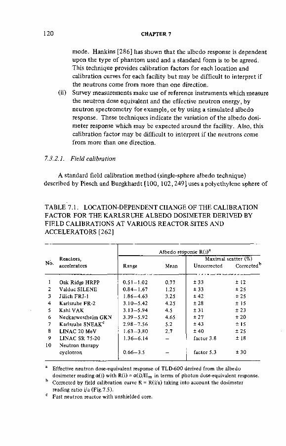
120 CHAPTER 6
mode. Hankins [286] has shown that the albedo response is dependent upon the type of phantom used and a standard form is to be agreed. This technique provides calibration factors for each location and calibration curves for each facility but may be difficult to interpret if the neutrons come from more than one direction,
(ii) Survey measurements make use of reference instruments which measure the neutron dose equivalent and the effective neutron energy, by neutron spectrometry for example, or by using a simulated albedo response. These techniques indicate the variation of the albedo dosi-meter response which may be expected around the facility. Also, this calibration factor may be difficult to interpret if the neutrons come from more than one direction.
7.3.2.1. Field calibra tion
A standard field calibration method (single-sphere albedo technique) described by Piesch and Burgkhardt [100, 102,249] uses a polyethylene sphere of
TABLE 7.1. LOCATION-DEPENDENT CHANGE OF THE CALIBRATION FACTOR FOR THE KARLSRUHE ALBEDO DOSIMETER DERIVED BY FIELD CALIBRATIONS AT VARIOUS REACTOR SITES AND ACCELERATORS [262]
Albedo response R(i)a
No. Reactors, Maximal scatter (%)
No. accelerators Range Mean Uncorrected Corrected11
1 Oak Ridge HRPP 0 . 5 1 - 1 . 0 2 0.77 ± 33 + 12 2 Valduc SILENE 0 . 8 4 - 1 . 6 7 1.25 ± 33 ± 2 5 3 Jiilich FRJ-1 1 .86-4 .63 3.25 ± 4 2 ± 2 5 4 Karlsruhe FR-2 3 .10 -5 .42 4.25 ± 2 8 ± 15 5 Kahl VAK 3 . 1 3 - 5 . 9 4 4.5 ± 31 ± 2 3 6 Neckarwestheim GKN 3 . 3 9 - 5 . 9 2 4.65 ± 2 7 ± 2 0 7 Karlsruhe SNEAKC 2 . 9 8 - 7 . 5 6 5.2 ± 4 3 ± 15 8 LINAC 20 MeV 1 .63-3 .80 2.7 ± 4 0 ± 2 5 9 LINAC SR 75-20 1 .36-6 .14 - factor 3.8 ± 18
10 Neutron therapy cyclotron 0 . 6 6 - 3 . 5 — factor 5.3 ± 30
a Effective neutron dose-equivalent response of TLD-600 derived from the albedo dosimeter reading a(i) with R(i) = a ( i ) /H m in terms of photon dose-equivalent response.
b Corrected by field calibration curve R = R(i/a) taking into account the dosimeter reading ratio i/a (Fig.7.5).
c Fast neutron reactor with unshielded core.

PERSONNEL DOSIMETERS 121
diameter 300 mm as both a survey meter and a phantom for the albedo dosimetry system. The albedo dosimeter readings on the front and rear position of the phantom as well as the reference reading of the survey meter form the basis for establishing the albedo response at the location of the sphere centre (Section 6.10.3). Also, in non-uniform multi-directional fields both detector readings are, to a first approximation, independent of the direction of incidence of the radiation. Some survey meters underestimate the dose equivalent for thermal neutrons (see also Fig.5.6) but this can be corrected with the help of a field analysis with additional albedo dosimeter readings as described for the single-sphere albedo technique in Section 6.10.3.
If albedo dosimeters are used for personnel monitoring it is necessary to establish separate calibration curves for every neutron facility under surveillance. An example of field calibration curves is given in Fig.7.5 for the Heidelberg Compact Cyclotron and the Karlsruhe Research Reactor FR 2 [106, 287]. Even for a person moving in the stray-radiation field, the reading ratio albedo/incident thermal neutrons (i/a) of the personal dosimeter provides sufficient information for the correction of local changes of the albedo response. Further results of field calibrations around research and power reactors and linear accelerators are presented in Chapter 9.
It has been found in field calibrations that the albedo dosimeter response changes in the neutron stray-radiation fields around one facility by a factor of 10 to 20. This is mainly due to the thermal neutron dose component (variation from 3 to 70%) and to changes in the effective neutron energy Eeff (from 5 to 0.05 MeV). Albedo dosimeters which are able to analyse neutron stray-radiation fields may reduce this measuring uncertainty to about 25% in most cases (Table 7.1) [262],
7.3.2.2. Survey measurement calibration
Survey measurements as well as spectrometry techniques may serve to establish local correction factors for the albedo dosimeter. A simple, quick technique proposed by Hankins [269] uses a 230 mm (9 in) sphere as a reference survey meter and a 76 mm (3 in) sphere shielded by cadmium as the equivalent of the albedo dosimeter response. The ratio of the 230 to the 76 mm sphere readings is used to obtain a correction factor for the albedo dosimeter response (Fig.7.6). However, in the neutron energy range below 100 keV, the 230/76 mm sphere ratio does not change significantly compared with the actual albedo dosimeter response function (Fig.7.7) and this results in calibration errors of about a factor of 3 (see also Fig.7.6). Additional uncertainties arise from the energy dependence of the 230 mm survey meter [25, 106]. This may explain the significant differences (by a factor of 10) for reported calibration factors at a power reactor found with various calibration techniques [289],

1 2 2 CHAPTER 7
10
2 o
uj cc
o h-- 0.5
O o
0.2
0.1
•
\ ( •
•
V • • •
•
V (
\ M 79 \ l
• 1 . 1 1 ' I I I I !
t •
\
Neutron source
14 MeV
— PuB at 40 cm
4.5 MeV — PuBe at 40 cm
PuF4 at 40 cm : — 2 MeV
2 S 2 C f at 40 cm
1 MeV
/ - PuLi at 40 cm
— 500 keV
L 200 keV
100 keV
70 keV
30 keV V 25 keV
• 2 keV
0.1 0.2 0.5 1
C A L I B R A T I O N FACTOR
FIG. 7.6. Calibration factors for Hankins-type albedo dosimeters [269] ,
FIG. 7. 7. A comparison of field calibration techniques [267],

PERSONNEL DOSIMETERS 123
0 0.5 1.0 1.5 2.0 2.5
R A T I O ( T H E R M A L ) TO ( 0 . 5 e V - 1 0 k e V ) and I N C I D E N T / A L B E D O
FIG. 7.8. Correction of an albedo dosimeter using a thermal detector [56].
If the albedo dosimeter includes a detector for incident thermal neutrons [273, 276, 278] then a calibration curve can be produced, based upon the ratio of the two spheres (survey meter to Boot counter) and the thermal-to-epicadmium ratio using a cadmium shield around the small sphere (Fig.7.8) [56]. The variations in the thermal neutron dose equivalent make this a rather uncertain technique.
The use of passive spectrometers [245, 288, 289] results in a low energy resolution below 100 keV and this technique may be applied only for beam exposures. The Bonner multi-sphere technique (see Section 5.3.3), on the other hand, may serve for an extended analysis of the stray-radiation field [78, 111a, 112, 290—292], In comparison with this sophisticated and time-consuming technique, the single-sphere albedo technique offers advantages in providing field analysis and the direct measurement of the actual albedo dosimeter response at the location of interest.
7.3.3. Properties of albedo dosimeters
7.3.3.1. A ngular dependence
In addition to the energy dependent response, evidenced by the variation in calibration factor, albedo dosimeters show directional dependence for monoenergetic neutrons. Stray-radiation fields improve this situation by making the source more isotropic as a result of the detection of neutrons backscattered

1 2 4 C H A P T E R 7
1.0
0.1
2
Si 0.01
READING RATIO ^^^ ^r a
9 0 ° / 0°
MONOENERGETIC NEUTRONS
180°/ 0° / o ' • r n ABOVE FLOOR
* o
1.0
0.1
i/> z o O-
I UJ 001 ai 1 10
NEUTRON ENERGY (MeV)
NEUTRON SPECTRA
1.0 -
0.1 -
9 0 ° / 0"
180° / 0° 1 . 2 5 m A B O V E F L O O R
CI F\jB« UMtV I . .I I •
m < i— 2:
•8 IJO
0.1
o.oi w i io
NEUTRON ENERGY (MeV)
FIG. 7.9. Directional response of the Karlsruhe albedo dosimeter versus energy [ 1 0 6 ] .
from the floor and wall. This effect can be seen in Fig.7.9 for irradia-tions at 0 and 90°. A dosimeter belt which is used to maintain a constant distance between the dosimeter and the body can reduce the directional dependence if dosimeters are worn on the front and rear of the body.
Figure 7.10 shows the variation of response with angle of incidence for the Harvey dosimeter. The angular response of albedo dosimeters, however, is relatively low in comparison with track-etch detectors (see Section 7.6).
Most of the energy from incident neutrons is deposited close to the point of entry into the body. The dose equivalent is thus proportional to the number

P E R S O N N E L D O S I M E T E R S 1 2 5
of neutrons per unit area of body surface, which in turn is proportional to the cosine of the angle of incidence. Hence a dosimeter, which basically has a cosine response, is acceptable for personnel dosimetry. The increased response for higher energies at some angles is an extra safety factor.
7.3.3.2. Detector-to-body distance effect
The effect of the dosimeter-to-body distance on the albedo reading is high for thermal neutrons but the effect can be reduced if the albedo neutron window in the encapsulation is collimated (Fig.7.11). For 2 s2Cf neutrons the effect does not differ significantly for dosimeter types which preferentially measure either
UJ cc
0.4 -
0.3 -
0.2
0.1
0
700 keV NEUTRONS
E L L I P T I C A L P H A N T O M (20X30 c m ) \
X 100 keV NEUTRONS
O 700 keV NEUTRONS
• 1700 keV NEUTRONS
C Y L I N D R I C A L PHANTOM (20 cm dia.) V 2 5 2 C f SOURCE
10° 20° 30° 40° 50° 60° 70° 80° 90°
A N G L E OF INCIDENCE
FIG. 7 . 1 0 . E f f e c t of the angle of incidence on the response of Harvey dosimeters [ 2 8 2 ].

1 2 6 CHAPTER 6
1 0 r
S •
2 •
1.0
0.9
OB
0.7
0.6
0.5
/ " J L a W ^ i ;
2SJCf NEUTRONS
y/z/z/My/m.
I 2 3 4 5 6
DETECTORTOPHANTOM DISTANCE (cml
FIG. 7.11. Albedo response as a function of detector-to-phantom distance on a spherical phantom, irradiated with thermal neutrons and 252Cf neutrons in 1.25 m source distance and height above floor, for the universal albedo neutron dosimeter, the Karlsruhe albedo dosimeter and a cadmium shielded TLD 600/TLD 700 detector [260].
thermal or epithermal albedo neutrons [280], It can be seen from Fig.7.11 that, in the unfavourable case when the relative thermal neutron dose contribution is 30% and the detector-to-body distance is 5 cm, the actual increase in the response of the universal albedo dosimeter in stray neutron fields is expected to be 20%. However, this increase may be compensated for by a corresponding decrease for field neutrons.
7.3.3.3. Dose range
The sensitivity achieved in albedo dosimetry depends on the dosimeter type and the neutron spectrum. For a moderated neutron fission spectrum around reactors, for instance, the neutron response is found to be 3 times (Hankins, Harvey, Piesch type) or up to 30 times (Hoy type) that of the gamma-ray response. The lowest detectable neutron dose equivalent, D ( l d U , depends on the neutron energy. In neutron stray-radiation fields, values between 50 < H < 200 jiS\ (5 < H < 20 mrem) have been found for the Karlsruhe type at

PERSONNEL DOSIMETERS 1 2 7
RATIO i / a
FIG. 7.12. Experimental results of the albedo response, the dose-equivalent ratio Hs/Hn
and the relative standard deviation an found in the stray-radiation field of the cyclotron at DKFZ Heidelberg [294],
reactors as well as around DT generators (14 MeV neutrons), with a gamma-ray dose equivalent of 100 /uSv (10 mrem) as the detection limit of the TLD system.
In the high dose-equivalent range above 1 Sv (100 rem), the supralinearity of 6LiF and 7LiF differs for gamma-ray and neutron exposures [194, 293], but dose-equivalent readings up to more than 10 Sv (1000 rem) can be evaluated by means of a calibration curve. After accumulation of high neutron exposures the multiple response of 6LiF detectors is limited owing to the buildup of tritium from the reaction 6Li(n, a)3H. This gives rise to a time-dependent zero dose-equivalent reading after longer storage periods and was found in one case to be about 2 mGy (200 mrad) three months after a thermal neutron exposure to 10 mGy (1 rad) [135, 136],

1 2 8 CHAPTER 6
DOSE READING ((iGyl
FIG. 7.13. Relative standard deviation versus dose reading after gamma irradiation of TLD 600 and TLD 700 and a readout of peak 5 as well as of peak 5 and 6 in the Pitman Toledo reader [251].
7.3.3.4. Gamma-ray sensitivity
In mixed neutron and gamma-ray fields the subtraction of the 7LiF reading from the 6LiF reading may cause a high measuring uncertainty for the estimation of the neutron dose equivalent depending upon (a) the neutron energy, (b) the dose equivalent ratio H 7 /H n and (c) the neutron dose equivalent Hn . The relative statistical uncertainty for the total dose-equivalent estimation has been found to be less than 10% for a theoretical dose-equivalent ratio H-y/Hn = 1 and neutron energies less than 2 MeV but sufficiently low around most neutron facilities [294].
In fast neutron fields the gamma-ray dose contribution as well as the albedo response increase with the distance from the neutron source, resulting in a relative standard deviation which may be less than 6% for a H^/Hn ratio of 5 (Fig.7.12). Similar uncertainties are found with the two-temperature readout developed by Marshall et al. [190].
7.3.3.5. R eproducibility
The reproducibility in the lower dose range depends on the readout and annealing technique as well as on the variability of the TLD batch and the reader [251, 295, 296]. The readout techniques for LiF detectors are:
(i) reading of TL peak 5 only; (ii) reading of TL peak 5 and TL peak 6; this results in a higher relative
neutron sensitivity;

PERSONNEL DOSIMETERS 1 2 9
(iii) separated reading of TL peak 5 and TL peak 6, resulting in a separate evaluation of gamma-ray and neutron dose equivalent by means of a single TLD 100 or TLD 600 detector [190-192] ,
The effect of the readout conditions on the reproducibility is presented in Fig.7.13. The larger uncertainty for the double-peak readout is caused by an increase in zero dose reading at the higher heating temperature. A larger zero dose reading is also responsible for the difference in the results for TLD 600 and TLD 700.
7.4. ALBEDO DOSIMETERS USING OTHER METHODS
Although TLDs are normally used as the neutron detector, other materials can be used to measure the thermal and intermediate albedo neutrons from the body. Again, cadmium or boron may be used to discriminate between field and albedo neutrons: cadmium produces an additional gamma-ray dose owing to the (n, y) reaction. However, track-etch detectors are particularly insensitive to gamma radiation when used with fissile materials such as 2 3 5U or with inactive radiators such as 6Li or 10B. The recoil particles are registered in cellulose nitrate or polycarbonate (Makrofol) foils. It is necessary to use a second foil without a radiator to discriminate against (and measure) neutrons with energies greater than 1 MeV which are detected directly in the foils.
A combined albedo and track-etch detector based on cellulose nitrate (Kodak type LR-115) with a LiF (n, a) converter was developed by Tymons and Tuyn [297] for use around the CERN high energy accelerator. It is not suitable for use at low energies because of a marked energy dependence. A similar technique using Makrofol for neutrons above 1.5 MeV and a two-component albedo system with Makrofol as detector and lithium borate as a radiator were developed by Hassib et al. [168, 298, 299] (Fig.7.3h, j). This system has a reasonable neutron response from thermal to 20 MeV but lacks the sensitivity for most personnel dosimetry applications. In the universal albedo dosimeter (Fig.7.3g) the TLDs may be replaced by, or combined with, (n, a) radiators in contact with Makrofol detectors [279, 281 ]. The properties of this albedo dosimeter are high sensitivity and gamma-ray discrimination, but the dose range is reduced significantly (Table 7.2). Palvalvi [163, 300] has investigated the sensitivity of LR-115 track-etch detectors with (n, a) converters used as albedo dosimeters.
A new type of albedo dosimeter described by Eisen et al. [182,182a, 301 ] (Fig.7.3i) makes use of a polycarbonate or CR-39 detector foil for the registration of alpha particles from the reaction 10B(n, a)7Li. The detector is shielded by 10B absorbers of different thickness both facing the source and on the body side of the dosimeter.

TABLE 7.2. RESPONSE AND DOSE RANGE OF THE NEUTRON DETECTORS IN THE UNIVERSAL ALBEDO NEUTRON DOSIMETER [279]
Neutron detector
Radiation field
Neutron response (mSv"1)
Background Neutron dose range Lowest value Highest value (mSv) (mSv)
Thermoluminescence detector
TLD 600 Thermal neutrons Power reactors
2Cf 252/-
7 mSv equiv. 2 3 0.25
7 mSv equiv. 0.02 0.03
0.01 0.12
103
103
103
Track-etch detector (n, a ) radiator Thermal neutrons 3200 3 0.0025 1.2 + Makrofol Power reactors 4000 3 0.002 1
2S2Cf 400 3 0.02 10
Recoil detectors Makrofol 2S2Cf 12 3 0.2 300 CR-39 2 s 2Cf 336 80 0.1 8

PERSONNEL DOSIMETERS 131
Griffith and Hankins [171], Griffith et al. [302] and Griffith and McMahon [303, 304] proposed a multicomponent dosimeter with different types of neutron detectors: the Hankins albedo dosimeter for the detection of low-energy neutrons plus LR-115; polycarbonate and CR-39 for an energy-dependent detection of fast neutrons. It is too early to say whether any of these systems will have the sensitivity and reproducibility for routine applications, but the use of CR-39 combined with albedo dosimeters seems to be the most promising.
7.5. FISSION FOIL DOSIMETERS
In personal neutron monitoring, fission foil detectors are routinely applied in areas where high neutron exposures are expected or nuclear accident dosimetry is required. Fissile materials with different thresholds are used together with activation detectors such as gold foils to estimate neutron fluence and dose in different energy ranges for a qualitative interpretation of the neutron spectrum at selected work places such as glove boxes in reprocessing plants. For application in personnel dosimetry there are several drawbacks:
(i) The converter is a fissile material which may have a significant level of associated beta or gamma radiation which will require additional lead shielding in the dosimeter;
(ii) The spontaneous fission rate limits the use of some materials such as 238U, which gives a background reading equivalent to about 10 mSv (1 rem) per week;
(iii) 237Np layers must be prepared by vacuum- or electro-deposition (in thin layers) or by a special painting technique followed by heating, and care is required to reduce the contamination risk and to protect the foil against accidental damage;
(iv) There is an insensitivity to neutrons below the threshold of detection by fission, i.e. in the 10—500 keV energy range which is of great interest for personnel monitoring in stray-radiation fields.
At nuclear research centres, reprocessing plants and nuclear reactor power stations, there are several detector combinations in use today which are commercially available.
For extremities dosimetry, a special finger system was developed by Buijs et al. [305] to monitor the hands of persons working with transuranium elements and neutron sources. A thin thorium foil (0.06 mm) is used inside a steel container in conjunction with three pieces of Makrofol as shown in Fig.7.14. Makrofol foil (0.3 mm) is placed on the other surface. A routine analysis of the thin foil by spark counting techniques is generally performed. The thicker Makrofol foil is used to determine higher track densities. As seen in Fig.7.14, a second 0.3 mm foil serves for protection of the thinner foil and may be directly analysed for tracks due to neutron-induced recoils. The sensitivity of this fission fragment

1 3 2 CHAPTER 6
1 cm
FIG. 7.14. KfK neutron finger dosimeter [305].
detector was found to be 2 tracks-cm -2 mSv -1 (20 tracks cm - 2 rem - 1) for Am-Be neutrons (see Fig.7.15) and the background from inherent fissions is about 2 tracks •cm - 2 -month - 1 (1 mSvor 100 mrem). Recently the thorium foil was replaced by a Makrofol track-etch detector and ECE techniques are employed to develop the tracks.
Pretre [184, 306] developed a neutron dosimeter employing two fission foils, one to detect neutrons above an energy of about 1.3 MeV (a thoron metal foil) and one to detect neutrons with energies less than 0.5 eV (an alloy of Al and 235U). Both detectors have thin Makrofol foils (12 jum) and a spark counter is used for counting the tracks. The system measures thermal neutron doses from 3 piGy (0.3 mrad) to 6 Gy (600 rad) and fast neutrons (E > 1.3 MeV) from 80 fiGy (8 mrad) to 200 Gy (20 krad). The dosimeter system, originally developed for accident dosimetry, will be routinely applied in Switzerland.

PERSONNEL DOSIMETERS 735
SPARK COUNTING
* 1976 • 1978
5 10 15
N E U T R O N ENERGY (MeV)
20
FIG. 7.15. Energy response of the 232Th track detector [ 153],
0 5 10 15 20
N E U T R O N E N E R G Y (MeV)
FIG. 7.16. Energy response of the ™Np track detector. 40 jug /cm s [ 153 ] ,

1 3 4 CHAPTER 6
TABLE 7.3. EXPERIMENTALLY MEASURED RESPONSE OF THE 237Np DOSIMETER TO NEUTRONS [139]
Neutron Neutron Conversion Experimental response source energy factor Free-air On-phantom Ratio6
(mean) (cm" 2 - rem" 1 ) (counts/rem) (counts/rem)
GLEEP thermal 9.36 X 10⁸ 156 + 13 (281) d (1.8) moderated
Sb-Be ~ 0.5 keV 6.37 X 10⁸ 313 ± 2 0 410 ± 1 0 0 1.31 ± 0 . 3 3
Sb-Be 23 keV a 5.40 X 10⁸ 39 ± 5 183 ± 2 1 4.69 ± 0.81
IBIS 0.10 MeV 1.73 X 10⁸ (16) c 50 ± 10 (3.1) c
IBIS 0.24 MeV 8.28 X 1 0 7 b 19 ± 2 30 ± 3 1.58 ± 0.23
IBIS 0.55 MeV 4.50 X 1 0 7 b 152 ± 6 193 + 7 1.27 ± 0.08
IBIS 1.12 MeV 2.95 X 10⁷ 223 ± 5 260 ± 6 1.17 ± 0 . 0 4
IBIS 1.72 MeV 2.63 X 10⁷ 241 ± 5 279 ± 12 1.16 ± 0.06 252Cf 2.13 MeV 2.95 X 1 0 7 b 260 ± 6 266 + 5 1.02 ± 0 . 0 3
Pu-Be 4.04 MeV 2.77 X 1 0 7 b 293 + 11 314 ± 11 1.07 ± 0.05
a 375 keV component subtracted. b Spectrum-averaged values. 0 Theoretical free-air value (using an interpolated spark counter efficiency of 0.49). d Assumes a thermal neutron albedo of 0.8. e Ratio of on-phantom to free-air.
At Karlsruhe, the U/Al alloy in the commercial dosimeter device containing a lead shield was replaced by a thin 237Np converter. The thin neptunium oxide layer of 40 jug/cm2, electrodeposited on a steel holder, provides a sensitivity of about 100 tracks -cm - 2 -Sv"1 (1 track cm - 2 rem - 1) for 252Cf fission neutrons. The energy dependence of the neptunium detector is shown in Fig.7.16 and compared with the corresponding cross-section.
The fission-fragment dosimeter developed at Harwell [139, 140,185a, 307] makes use of a 237Np layer of thickness 0.5 mg/cm2 coated on a 30 X 30 mm2
square aluminium backing foil and shielded by an aluminized polycarbonate foil (2 nm). The technique applied for the preparation of the fissile foil was to paint on a solution of neptunium nitrate in ethanol and to burn in the deposit on to the aluminium plate [148, 183], The track detector is a polycarbonate (Makrofol KG) foil (10 jum) which is counted in a spark counter. The sensitivity for 2s2Cf

PERSONNEL DOSIMETERS 135
FIG. 7.17. The calculated dose-equivalent response [185] of a neptunium dosimeter, containing 4 mg of23lNp, in free air and on the body obtained (a) using the cross-sections from Delafield etal. [131] and (b) using the cross-sections from Cross and Ing [308].
fission neutrons was found to be about 18 tracks/mSv (180 tracks/rem) corresponding to about 2 tracks • cm ~2 mSv -1 (20 tracks cm - 2 - rem - 1) and the background is 1.8 tracks/month, equivalent to 100 /iSv (10 mrem). The dosimeter holder contains a 3 mm lead shield and 3 mm of plastic to reduce gamma-ray background radiation to the wearer from the fission foil. The surface dose-equivalent rate was measured to be 110 /xSv (11 mrem) per 40 h on the surface facing the wearer with an average whole-body dose of about 20 /zSv (2 mrem) in a working year. The neptunium detector shows a significant fission cross-section in the energy range below 100 keV (see Section 6.4 and Fig.6.10). Taking into account the albedo effect in the body of the wearer, the neutron response of the Harwell 237Np dosimeter (Table 7.3 and Fig.7.17) was found to be comparable for both the neutron energy range below 50 keV and for neutrons above the threshold of 600 keV. Also, in a range of typical radiation fields the dosimeter gave results within ± 30% of the true dose equivalent when a small correction based upon the 237Np-to-albedo ratio was applied (Fig.7.18).

136 CHAPTER 7
1 . 5
1.0
0.5
—a"
a a — a - o
— •
- 3 0 %
CALCULATED FOR THEORETICAL SPECTRA THROUGH SHIELDING OF PFR PLANT CALCULATED FOR 9 LOCATIONS OF THE EXPERIMENT EXPERIMENTAL MEASUREMENTS WITH STANDARD DEVIAT ION CALCULATED FOR REACTOR SPECTRA WITH DIFFERENT SHIELDS CALCULATED FOR SPECTRA FROM PUNO3 SOLUTION WITH DIFFERENT SHIELDS FITTED LINE TO THEORETICAL DATA V - 10.0119 1 0.00511 x + 10.858 1 0.0481
I | 10 15 20 25
R A T I O OF THE NEPTUNIUM RESPONSE TO T H E A L B E D O RESPONSE N / H
FIG. 7.18. Response of the neptunium dosimeter as a function of the neptunium to albedo ratio for a wide range of theoretical and experimental neutron spectra [264].
7.6. RECOIL TRACK-ETCH DETECTORS
There is now a major effort throughout the world to develop track-etch detectors which register neutron-induced recoils from inactive radiators or from within the detector foil itself. These types of detectors under investigation are mainly polycarbonate foils (Makrofol), where tracks from carbon and oxygen recoils and alpha particles are counted after electrochemical etching, or CR-39 detectors in contact with hydrogenous radiators to count proton recoil tracks after etching.
7.6.1. Polycarbonate track detectors
Polycarbonate detector foils have a relatively low sensitivity after electro-chemical etching, with a small number of background tracks and an energy threshold of about 2 MeV. The major advantage is that tracks may be counted in a microfiche reader rather than under a microscope. Oswald and Wheeler [164, 309] developed a commercially available dosimeter for large-scale personnel monitoring on the basis of electrochemically etched polycarbonate. The reported sensitivity is 1.4 tracks • cm~2 mSv -1 (14 tracks •cm -2 -rem'1) and a lower detection limit of

PERSONNEL DOSIMETERS 1 3 7
0.3 mSv (30 mrem) for Am-Be neutrons. An improvement in sensitivity was found by Hassib and Piesch [151, 152], Here a pre-etching technique is applied to reduce the number of background tracks (which depend on the foil quality). A comparison between ECE polycarbonate and CR-39 in Table 7.4 shows that the polycarbonate detectors are 40 times less sensitive than the CR-39. Poly-carbonate has a lower detection limit of 0.25 mSv (25 mrem) for Am-Be neutrons which is acceptable for most routine applications. The smaller variability of the polycarbonate leads to smaller uncertainties than are currently obtained with CR-39 (Fig.7.19).
Eisen et al. [182] have described a wide range (1 eV to 14 MeV) detector based upon boron foil absorber/radiators which can be used with a CR-39 foil if required [182a]. The boron makes the dosimeter quite expensive.
7.6.2. CR-39 track detectors
This method of detecting recoil and proton tracks looks to be the most promising for the future. A comparison with a polycarbonate detector (Makrofol) is given in Table 7.4 and Fig.7.19. The major advantages [ 169,169a] appear.to be the much lower threshold energy for detection of neutrons (140 keV) (Fig.6.17) and the improved sensitivity of 2.3 tracks-cm -2 -juSv-1 (23 tracks• cm - 2 • mrem - 1) with a 1 mm polyethylene radiator. The background is relatively high and equivalent to about 70 /uSv (7 mrem) but this can be reduced in some batches of CR-39.
A combination of normal and electrochemical etching (ECE) can be used to enhance the recoil tracks [170, 175, 303] and to give registration of low-energy proton tracks (see also Fig.7.19). The energy dependence of electrochemically etched CR-39, which has been found to be of the order of a factor of 10, may be reduced by increasing the applied voltage but this technique is not effective in practice because of the significant increase in background tracks [310], By using ECE without pre-etching, the lower energy threshold has been found to be 50 keV (Fig.7.19). However, the high background of greater than 800 tracks/cm2 for commercially available CR-39 means that these techniques cannot be applied for routine monitoring. The sensitivity after ECE (Table 7.4) is reduced below that for normal etching alone to 0.8 tracks-cm-2 - j l i S v - 1
(8 tracks-cm -2-mrem -1); however, it increases significantly, by a factor of about 6, if pre-etching is not applied. Passive neutron spectrometers make use of CR-39 behind different proton radiators [311, 312]: additional measurements were made of the track-size distribution using a fully automatic image-analysis system [313, 314]. In comparison with polycarbonate detectors, the uncertainty for track counting is still high for electrochemically etched CR-39 detectors from the same sheet (Fig.7.20); however, the uncertainty can be reduced after empirical correction for the effect of detector thickness [315].

TABLE 7.4. CHARACTERISTICS OF NEUTRON-INDUCED RECOIL TRACK-ETCH DETECTORS u> oo
Makrofol CR-39 PE a radiator, 1 mm
CR-39 without PE a
radiator
CR-39 PE a radiator , 2 mm
Reference Piesch et al. Benton et al. Griffi th et al. Piesch et al. Tommasino et al. [ 277 ,299] [169] [173] [277, 299] [175, 176]
Etching technique Normal + ECEb Normal Normal + ECE b ECE
Sensitivity (Am-Be) (tracks • cm" 2 -^Sv" 1 ) 0.018 2.3 0.8 0.18 5 (tracks • cm "2 • mrem ) 0.18 23 8 1.8 50
Energy range > 1 . 5 MeV > 140 keV—14 MeV 50 keV—15 MeV
Energy dependence factor of 4 factor of 20 factor of 10 - factor of 3
Direction dependence ratio 45°/0° 0.8 0.4 - 0.4 > 40° no tracks for E n < 0.5 MeV
Background (tracks • c m - 2 ) 10 ± 4 160 ± 135 - 86 ± 4 0 > 8 0 0
Lower detection limit (juSv) 250 200 50 600 -
(mrem) 25 20 5 60 -
Track counting 45 X microscope 45 X 45 X microscope
Pie-etching and 2 h at 20°C 3 h at 60°C 3 h at 20°C 50 Hz and 40 kV/cm ECE 3 kHz and 23 kV/cm - 2 kHz and 5 kHz and
31.5 keV/cm 29 keV/cm 5 h at 20°C 5 h at 20°C 3 h at 20°C 5 h at 60°C
a PE: polyethylene. b ECE: electrochemical etching.

PERSONNEL DOSIMETERS 139
FIG. 7.19. Neutron energy response of electrochemically etched CR-39 detectors with (open circles) and without (closed circles) pre-etching [175].
100
50
20
10
5 UJ > h-< UJ
CR 39 PERSHORE,CORRECTED
AMERICAN ACRYLICS
MAKROFOL
RECOIL TRACK ETCH DETECTOR
io° ro1 KT IO1 IO'
NUMBER OF NEUTRON INDUCED TRACKS / c m '
FIG. 7.20. Relative standard deviation versus track density for electrochemically etched Makrofol E and CR-39, Pershore detectors corrected for detector thickness [281 ].

1 4 0 CHAPTER 6
1.2 2 5 2 C f SOURCE
MAKROFOL/ CR 39
CR 39/ MAKROFOL
A RADIATOR 0
30° 60° 90' ANGLE a
FIG. 7.21. Neutron angular response for TLD 600, Makrofol and CR-39 in the universal albedo dosimeter [ 279 ] .
Disadvantages of CR-39 include a poor angular response (Fig.7.21) (see also Refs [316—318]); large batch-to-batch variations in sensitivity and background; and a sensitivity to alpha-particle activity in the environment. These problems should be overcome by good quality control, careful selection of etching conditions and the appropriate choice of radiator material to exclude alpha particles and improve the response. A discussion of the latest developments is given in the Proceedings of the Acapulco conference in 1983 [143],
7.7. PERSONAL ALARM NEUTRON DOSIMETERS
Development of neutron dosimeters that can be worn on the body and yet provide an indication of the neutron dose equivalent is required to help in the control of the dose equivalent to the wearer. There are five dosimeters, three based upon proportional counters and two using a silicon surface-barrier detector with a polyethylene radiator. The three proportional-counter instruments are quite large ( = 1 8 X 8 X 5 cm3) and weigh about 600 g. Potentially, the semi-conductor instruments should be smaller and lighter. The sensitivity of the

PERSONNEL DOSIMETERS 141
dosimeters is sufficient to detect about 50 ytSv (5 mrem) in 8 hours and if more sensitivity is required then the counter based upon the rate of energy deposition (dE/dx) principle can detect 0.5 juSv (50 jurem) in 8 hours. No system is fully developed so as to be available commercially and at a price of about US $2000 each, it is unlikely that this type of dosimeter will be widely used. There is a need for a suitable rechargeable battery and for producing very stable power supplies (<0.1% variation) for this type of dosimeter.
The provision of neutron dosimeters which indicate the dose equivalent presents the instrument designer with major problems. To produce an instrument which is small and light enough to be worn on the body is an even more difficult task. The problem with the direct measurement of recoil protons is that to measure 1 //Sv (0.1 mrem) with a detector of area 10 cm2 , the number of neutrons incident on the counter would be 3 X 10⁴. The detection efficiency for recoil protons will be between 10~3 and 10~4, which means that a maximum of only between 3 and 30 counts will be observed for 1 ixSv of neutrons of energies of about 1 MeV. The use of a threshold bias to reduce the contribution from gamma radiation can further reduce the sensitivity. Thus the requirement to produce a small, light-weight detector for the pocket severely limits the sensitivity which can be achieved for neutron measurements.
There have been five groups in the world reporting work on pocket neutron dosimeters. Yoshida and Dennis [53] proposed the development of the Hurst [319] counter for measuring recoil protons and their ideas have been further developed by Delafield et al. [54] and Gibson [56]. Heinzelmann et al. [320—322] proposed the use of a 3He detector in a small polyethylene moderator with a shield against thermal neutrons. More recently, Quam et al. [323, 324] have used the Rossi-counter principle [325] with a microprocessor to convert counts into either absorbed dose or dose equivalent. Tyree and Falk [326, 327] have described the use of a silicon surface-barrier detector to detect recoil ions from a polyethylene radiator. Eisen et al. [328] have proposed the use of four silicon surface-barrier detectors with three 10B radiators and one polyethylene radiator. The use of a single detector with a two-part polyethylene radiator has been developed into a portable instrument [329], A full review of these instruments has been produced by Gibson [330],
7.7.1. Choice of detectors
The measurement of absorbed dose from neutrons can be made with ionization chambers but they are too insensitive for radiological protection purposes and the small size required largely precludes their use in personal dosimeters except for thermal neutrons. Proportional counters have been the main choice for both survey instruments and personal dosimeters because they have adequate sensitivity, they can be made to give a response close to that required by ICRP [6] and they are insensitive to gamma radiation. Scintillators

1 4 2 CHAPTER 6
have been used in survey instruments but not in personal dosimeters. Their main disadvantage is their high gamma-ray sensitivity resulting in a high threshold for detecting recoils. Semiconductor detectors can be used to detect proton recoils and can be used to discriminate against gamma radiation. By using a micro-processor with any type of detector it is possible to measure the dose equivalent by applying an appropriate algorithm to the pulse height detected.
7.7.2. Data processing
For detectors which measure the rate of energy deposition (LET or dE/dx) from recoils the increment of dose, dD, is given by
dD = k e n(e)de (7.1)
where n(e)de is the number of events with dE/dx between e and e + de;
e is dE/dx (MeV-m2-kg - 1); k is a constant (1.6 X 10~13/ c; J-MeV"1 -m"2); and a is the effective cross-section of the counter (m2).
The total absorbed dose (Gy) is
which can be expressed as a summation over the channels of a pulse-height analyser so that
(7.2)
(7.3)
i= 1
where n(ei) • Ae; is the number of counts in the ith channel; and is the mean dE/dx for the ith channel (e, = e2).

PERSONNEL DOSIMETERS 1 4 3
The dose equivalent can be determined by using the appropriate quality factor, q(eO, obtained from the ICRP curve and stored in the microprocessor so that
In principle, Eqs (7.3) and (7.4) can be used with any detector by using a further modifying factor M(e;) which can be determined empirically and stored in the microprocessor.
7.7.3. Harwell personal alarm neutron dosimeter
The current dosimeter is a development of a proportional counter first proposed by Hurst e ta l . in 1951 [319], used by Dennis and Loosemore [51] in a portable instrument in 1961 and then proposed as a personal dosimeter by Yoshida and Dennis in 1968 [53]. Development of the counter for operational use was made by Delafield et al. [54] in the same year but problems with micro-phony prevented commercial development. The same counter was used for the current development reported first in 1977 by Gibson [56].
The proportional counter used has a hydrogenous wall and neutrons with energies above 10 keV are detected by counting recoiling hydrogen nuclei. The reaction 14N(n, p)14C is used to detect thermal neutrons and albedo neutrons reflected from the body of the wearer by counting the recoil protons of energy 0.6 MeV. The basis of the design, as shown in Fig.7.22(a) and (b), is a smaller version of the Yoshida and Dennis [53] counter but with an increase in the proportion of nitrogen in the wall to give 10.4% N, 9.7% H, 79.0% C and 0.7% O by weight. Theory suggests that for the counter response to be proportional to the neutron dose equivalent over the energy range 10 keV to 15 MeV, the minimum bias level applied to the counter must be equivalent to an energy loss by protons of between 5 and 10 keV. The maximum energy of detected protons is required to be 0.8 to 1 MeV and this is achieved by using a reduced gas pressure. Ethylene at a pressure of 1.6 kPa (12 mmHg or 0.016 atm) is used as a filling gas. A polyethylene sleeve of thickness 10 mm is used to improve the response to low-energy neutrons. ThePAND (AERE type 9 5 / 0 9 3 4 - 1 / 6 ) consists of the dosimeter itself with microelectronics to reduce the weight. Power is supplied from a rechargeable battery with a life of 16 h when fully charged. A special charging rack (AERE type 9 5 - 0 9 4 4 - 1 / 6 ) is used.
(7.4)
i= 1

1 4 4 CHAPTER 10
Pumpjng Conduct ing Glass Metal Seal H.T. Connection
FIG. 7.22(a). Cut-away view of the Harwell proportional counter [56].
in RT.F.E. Case Tungsten Insulator
Wire
FIG. 7.22(b). Photograph of the Harwell neutron dosimeter and its reader [56],

PERSONNEL DOSIMETERS 1 4 5
10"' 10"* 10'* 10"' 10"' Neutron Energy (MeV)
FIG. 7.22(c). Response of the Harwell neutron dosimeter on the wearer as a function of neutron energy [56],
The energy response of the detector is given in Fig.7.22. The normal sensitivity of the dosimeter is 1 count//uSv (10 counts/mrem) with a maximum variation of +50% and -50% over the neutron energy range from thermal to 10 MeV. The gamma-ray sensitivity to 60Co gamma radiation is less than 5% of the dose-equivalent response to neutrons. Microphony has been reduced by circuit design to less than 50 counts in 8 h ( < 6 /iSv/h, < 0.6 mrem/h). Alarms are provided at 0.2 and 1 mSv(20 and 100 mrem) and the dosimeter can be read on a special reader (AERE type 9 5 - 3 2 4 5 - 1 / 6 ) which also provides a print-out of the alarm settings. More details will be included in the final comparison below. The major problem with the dosimeter has been with finding suitable rechargeable batteries and this limitation is still preventing full exploitation of this instrument.
7.7.4. KFA Julich personal neutron dosimeter
In 1976 Heinzelmann et al. [ 3 2 0 - 3 2 2 ] proposed the use of a 3He detector as the basis for both portable and personal neutron dosimeters. The personal

146 CHAPTER 10
dosimeter detects albedo neutrons reflected from the body of the wearer and therefore the moderator of the dosimeter must be very small. By using a detector for thermal neutrons in a small polyethylene sphere (127 mm diameter), an energy-independent response can be achieved up to 10 keV. The 3He detector counts thermal neutrons and, with far less sensitivity, neutrons of higher energy. With the 3He counter in the small polyethylene sphere and by use of a discriminator it is possible to reduce the sensitivity for low-energy neutrons more than that for fast neutrons and so obtain a response which is nearly independent of neutron energy.
The use of a discriminator level above the thermal neutron peak (0.764 MeV) makes the system very sensitive to both this level and to the voltage on the counter and so extremely stable and reliable power supplies and electronics are required. A change in discriminator level of 1% produces a 6.6% change in neutron sensitivity and a change of detector voltage of 1% produces a 7.5% change in sensitivity.
The sensitivity of the personal neutron dosimeter is 0.14 counts//zSv (1.4 counts/mrem). The background noise is less than 0.06 counts/h and the gamma-ray sensitivity is less than 1% of the neutron dose-equivalent response to neutrons at about 50 mSv/h. No more information is available other than that given below in the comparison table, and development ceased in 1977.
7.7.5. EG&G pocket neutron dosimeter
The dosimeter developed by Quam et al. [323, 324] is based upon a tissue-equivalent (TE) proportional counter but, instead of measuring the counts, it produces a signal proportional to the absorbed dose in the counter. Following the principles developed by Rossi [325], the counter is used to measure the rate of energy deposition (dE/dx or linear energy transfer, LET) from particles produced from neutron interactions. Then, for each particle (or pulse of particles from an event), the LET is converted to a quality factor, Q, based upon the ICRP function [1], The product of the absorbed dose and Q gives an output proportional to the dose equivalent, for the event. The dosimeter could be used to give the total (neutron plus gamma-ray) dose equivalent but, in fact, it is used to measure neutrons alone by biasing against the lower LET electrons.
Three cylindrical TE proportional counters are used for neutron detection (Fig.7.23(a)). The counters are 127 mm in length by 19 mm in diameter inside a stainless-steel tube of thickness 0.41 mm lined with TE plastic of thickness 1.27 mm. The TE counting gas is methane based at a pressure of 3.4 kPa (25 mmHg, 0.033 atm). The low gas pressure simulates a cavity of approximately 1 ^m in diameter in unit density material. High-stability power supplies were developed using a simple 9 V battery. An analog circuit (Fig.7.23(b) and (c)) uses a charge-to-voltage converter and the voltage can then be converted to a digital signal proportional to the absorbed dose or converted to a quality factor

PERSONNEL DOSIMETERS 147
FIG. 7.23(a). EG&G personal neutron dosimeter prototype [323, 324].
FIG. 7.23(b). Block diagram of the EG&G analogue and digital circuits [323, 324],

1 4 8 C H A P T E R 10
T A B L E 7 . 5 . C A L I B R A T I O N D A T A F O R T H E E G & G
D O S I M E T E R [ 3 2 4 ]
(Neutron spectra f r o m LLNL f a c i l i t y )
S o u r c e S h i e l d R e l a t i v e
d o s i m e t e r
r e s p o n s e
2 5 2 C f 0 1 . 0 0
l O c m C H j 0 . 8 7
15 c m D j O 0 . 9 0
2 5 c m D 2 0 0 . 7 8
2 0 c m A l 0 . 9 9 2 3 8 P u B e 0 0 . 9 9
1 0 c m C H 2 0 . 9 7
15 c m D 2 0 0 . 9 1
2 5 c m D 2 0 1 . 0 0
2 0 c m A l 0 . 9 1
8 Pin (SIP) Ampl i f ier (or 50mm 2 D i f f used Junc t ion Detec tor
Cd Bock Shield-
L o v i t e Ring. M o u n t e d S u r f a c e . B a r r i e r 300mm' ( Gold Window 1 Polyethy lene Cover
0 . 0 2 2 in P r i n t e d C i r c u i t B o a r d (PCB)
TOP VIEW
P o l y u r e t h a n e F o a m -'/t6 in t h i c k
Detector • L i6F • Cd
Polyethy lene - I fo in
0 . 0 2 2 in PCB I
• A m p l i f i e r - 3 0 0 m m Detector (SIP)
SIDE VIEW
BOTTOM V IEW
FIG. 7.24(a). Schematic diagram of the detectors in the Rockwell personal neutron dosimeter [ 3 2 7 ].

PERSONNEL DOSIMETERS 149
Thermal Neutron-Alpha 6 Li F
Disc.
Cadmium Shielded Window towards Body
Fast Neutron NeutronTProton
300mm' Surface Barr Detector Window Away from Body
Mono. Osc. Stable Scaler - w -
Disc.
)mm' [ — Amp f a c e A rier Z j l ^ T
r
n
DH
W
Mono. Stoble
Mono. Stoble
- W - i
k 4
MMono. f g Stoble I
Osc. Sca le r - w -
3 Decode LCO Display
t V
Printed Circuit Connector
Decade Counter Dose Count
Storage
Binary Counter Alarm Set
n u n Alarm Select
Audio Sig Gen
Audio Disable 15 seconds
Hearing Aid
tHK j speaker
FIG. 7.24(b). Block diagram of the Rockwell personal neutron dosimeter [327].
before multiplying by the absorbed dose to give a second digital signal proportional to the dose equivalent. A microprocessor (Motorola type 6805 E2) is used to provide the quality-factor algorithm and to carry out the ADC functions (Fig.7.23(c)).
No details are provided on the energy response to monoenergetic neutrons but details of the response to various neutron spectra are given in Table 7.5. By using a nominal response of 1.12 for 252Cf the energy response can be reduced to ±12% for these neutron spectra. No information is available on either the thermal neutron or albedo responses of the instrument (1 4N in the wall could give some response). The sensitivity to 2S2Cf is 6.19 counts/juGy (61.9 counts/mrad) which, after electronic conversion, results in 57.6 counts/juSv (576 counts//xrem). The system noise is 3.2 counts/h (150 nSv/h, 15 /irem/h) giving a signal-to-noise ratio of about 180 in a nominal neutron field of 10 jzSv/h (1 mrem/h). The gamma-ray sensitivity to 60Co is less than 1% of the dose-equivalent response to neutrons. A digital display is controlled by a five position switch giving hours, counts, Gy (rad) or Sv (rem). The battery life is greater than 40 h and there is a 'low-battery' indicator on the display. More details are given in Table 7.6.
7.7.6. Rockwell personal neutron dosimeter
A fourth method of detection proposed by Tyree and Falk [326, 327] uses a silicon surface-barrier detector to measure the magnitude of proton recoils from

1 5 0 CHAPTER 10
FIG. 7.25(a). Block diagram of the Soreq NRC personal neutron dosimeter [328, 329],
(b) 1°'
to ~
9
10'
0 5 10 15 E n ( M e V )
(c|
01 Ul c o a. i/i cc •o Of N
o e o z
0 5 10 15
E (MeV)
FIG.7.25(b)&(c). Energy response of the Soreq NRC personal neutron dosimeter [328, 329]. (b) Theoretical. (c) Measured for three neutron spectra.
"•M00mg/cm2
4||10)4l100ll
***10mg/cm'

PERSONNEL DOSIMETERS 151
a polyethylene convertor. Each pulse is then weighted according to which of three discrimination levels it exceeds. This system is still being developed and some extra information from the authors is included. In particular they have included a second detector with a 6LiF radiator to detect albedo neutrons by the 6Li(n, a)3H reaction.
The detectors have an area which has been increased from 100 to 300 mm2 . One is covered by the polyethylene convertor of thickness 0.79 mm. The detector with 6LiF radiator is covered by cadmium to remove incident thermal neutrons (Fig.7.24(a)). A block diagram of the circuit is given in Fig.7.24(b). The level 1 discriminator channel is used to detect electrons from gamma radiation and the other channels are used for proton counting.
The response to 252Cf neutrons is 5 counts/juSv (50 counts/mrem) with a variation of ±26% for a range of five moderating conditions from a 252Cf source (moderators from 0 to 95 mm). Exposure to monoenergetic neutron sources is planned. The background is 2.25 counts/h (0.2 juSv/h, 0.02 mrem/h) and the response to 137Cs gamma radiation is about 0.1%. More details are given in Table 7.6.
7.7.7. Soreq NRC personal neutron dosimeter
The most recent proposals come from the Soreq Nuclear Research Centre (NRC). Two designs based upon silicon surface-barrier detectors have been discussed in the literature. Eisen et al. [328] proposed a development of their earlier passive dosimeters using boron enriched in 10B as radiator/shield for neutrons of energy less than 1 MeV and a polyethylene radiator for neutron energies from 1 to 14 MeV. A single detector with a dual thickness poly-ethylene radiator has been developed into a prototype dosimeter [329] and this development will be described below. The use of four radiator/shields and four detectors may have applications for survey instruments but could be unwieldy and expensive for personal dosimeters.
Neutrons are detected via the recoil protons that emerge from two poly-ethylene radiators (thickness 10 and 100 mg/cm2) positioned in front of a silicon surface-barrier detector (area 100 mm2 , depletion depth 100 fim). The poly-ethylene radiators, combined in proportions [8/9(10) + 1/9(100)] mg/cm2, give a flatter energy response than that from a single radiator. A block diagram of the electronic circuit is given in Fig.7.25(a). Two channels are used; one from 50 to about 700 keV for photon radiation and one above 700 keV for neutrons.
The neutron sensitivity is 1 count/juS v (10 counts/mrem) in the neutron channel and about 0.2 counts/mSv (2 counts/mrem) in the photon channel. The corresponding response to photons in the two channels is 0.025 counts//iSv (0.25 counts/mrem) and 450 counts//iSv (4500 counts/mrem), respectively. This means that the cross-response for neutrons is less than 1% and for photons is 2.5% (assuming equal dose equivalents of each). The neutron energy response

TABLE 7,6. COMPARATIVE DATA FOR POCKET NEUTRON DOSIMETERS [330]
Laboratory Harwell [56] KFA Julich [320] EG&G [323] Rockwell [326] Soreq NRC [329]
Detector Low press PC 3 He PC TE PC Si SBD Si SBD Electronics Thick film g Microcomp Chips g Battery 12 V, 200 mA h - 9 V 2 V 80 AIA 4 X 1.5 VAA Battery life 16 h (rechargeable) - > 4 0 h i 100 h Dimensions (cm3) 18 X 7.5 X 3.2 1 5 X 8 X 6 20 X 8 X 5 i 16 X 9 X 4 Weight (g) 600 - 630 90h 550 Cost (US $) 1800 — 2000 i 1
Detection method H-Recoilf 3He(n, p)3H Recoil LET H-recoils H-recoil Dose or dose equivalent DE DE Both DE DE Sensitivity c/mSva 1000 110 5.7 X 10⁴ 3 500 1000 Background noise c/h < 6 0.06 3.2 2.25 3 0.1 Precisionb ± 15% ±35% ± 1.5% ±9% ± 11% Sensitivity /jSv/8 hc 35 90 0.5 50 4 Response to 7-raysd <5% <1% 1% 7% 2.5% Response (fast) Fig.2 Fig. 5 Table 1 1 - 1 4 MeV 1 - 1 4 MeV Response (thermal)6 1.6 small none as fast none
Display Reader _ Digital i Digital Alarms (mSv) 0.2 & 2 — i i 0.1
Notes: PC: proportional counter; TE: tissue equivalent; Si SBD: silicon surface-barrier detector. a 2SJCf neutrons. b Precision based upon detection of 80 jUSv in 8 h (8 mrem in 8 h): 1 standard deviation. c .Limit of sensitivity based upon 3 standard deviations on the mean in juSv/8 h. d Fractional response of equivalent neutron Sv per Sv of gamma radiation (%). e Including albedo effect for dosimeter on the body. ' With 14N(n,p)14C for thermal and albedo neutrons. g With pulse-height discrimination. 11 LCD display as a separate plug in unit. 1 Not measured or data not yet available.

PERSONNEL DOSIMETERS 1 5 3
of the dosimeter is shown in Fig.7.25(b) and (c). Figure 7.25(b) shows the response to monoenergetic neutrons and 7.25(c) shows the response to various neutron spectra. There is a factor of 2 increase between 252Cf neutrons ( E = 2 MeV) and 14.5 MeV neutrons. The cutoff below 1 MeV could be very significant for many applications. There is also a very significant angular dependence [329], The instrument displays either the dose equivalent for neutrons or for photons or the rate for either, has test displays and an audible alarm on dose equivalent or dose-equivalent rate. There is a facility for displaying the 'temporary' dose equivalent over any period without destroying the total dose equivalent since the dosimeter was issued. More details of the response, etc. are given in Table 7.6.
7.7.8. Comparison between dosimeters
None of the five dosimeters discussed above is, as yet, fully developed and commercially available; so the data as presented in Table 7.6 must be subject to change in the future. In some cases the information is either incomplete or it is a target for design purposes. However, there are many similarities; in particular oversize, price and weight for the proportional counter instruments. The limit of sensitivity expressed as 3a is similar for three of the instruments lying between 35 and 90 /uSv/8 h. The EG&G counter of Quam is clearly superior to all the other dosimeters and the Soreq NRC counter has an intermediate limit of sensitivity. The gamma-ray sensitivities are all sufficiently small. The energy response of the first two dosimeters is adequate for most neutron spectra likely to be encountered in practice. The three later counters have been specifically designed for fast neutrons and this could present problems in many applications, e.g. nuclear fuel processing, nuclear reactor surveys, heavily shielded sources, etc.
Clearly there are still problems with designing a personal neutron dosimeter. Battery performance severely limits most designs and a suitable rechargeable battery is required. The Harwell system could be improved by using a micro-processor to correct for the energy dependence. The Jiilich system clearly needs very stable power supplies as, to a lesser extent, do the other three systems which rely on multichannel analysis or fixed discriminators. In terms of size and weight the Rockwell and the Soreq NRC systems are likely to be the most acceptable to the wearer, but the EG&G system has the greatest potential in terms of sensitivity (the use of only one proportional counter may well be adequate). This area of neutron dosimetry is still open to future developments.


Chapter 8
DESIGN OF OPERATIONAL SYSTEMS
8.1. INTRODUCTION
In the past, exposure to neutrons has been very limited, and relatively simple dosimetry methods using nuclear emulsions or albedo dosimeters have sufficed. The reprocessing of high burnup nuclear fuels from an extended nuclear power programme, including fast reactors, and the wider use of neutron therapy in hospitals using accelerators and 252 Cf sources makes it necessary to provide adequate personal and area dosimeters to cover the range of neutron spectra to be found in each of these working environments. This chapter attempts a logical approach to the question of designing a complete dosimetry system, with a definition of the types of neutron fields that will be encountered, followed by a discussion of the additional require-ments for the more complex fields. Examples of systems developed for reprocessing plants, hospital environments and reactor areas will be given in the next chapter. The development of a nuclear accident dosimeter will be briefly considered.
8.2. SELECTION OF THE APPROPRIATE PERSONNEL DOSIMETRY SYSTEM
Once it is decided that neutrons may be present, the first requirement is a survey meter to make measurements to determine the dose-equivalent rate in the working environment. This could be an instrument such as an Andersson-Braun or a Leake counter to identify dose-equivalent rates above 0.75 juSv/h (75 /irem/h) or a series of phantoms or spheres, with dosimeters attached to them, placed at strategic positions where personnel may be working. The dosimeters need to be exposed for periods of several hours (possibly overnight if this is typical of the 'normal' conditions). If there is a significant neutron dose-equivalent in the environment then a second, smaller detector, e.g. a 76 mm (3 in) sphere [268], or a Boot counter [78] may be used. The term 'significant' will be defined below. The levels chosen in the following sections are only illustrative and the actual control will depend upon the facility in question and the legislation of the country concerned. Table 8.1 provides a summary of the discussion presented below.
8.2.1. Neutron field type A (Hn < 1.5 mSv/a)
A neutron dose equivalent rate (Hn) greater than 1.5 mSv/a (150 mrem/a) or 750 nSv/h (75 jurem/h) is considered significant in the context of the working
155

TABLE 8.1. A METHOD OF SELECTING THE APPROPRIATE DOSIMETRY SYSTEM o\
Category Dose-equivalent rate
H n + H (mSv/a) (mrem/a) <AiSv/h)a (;urem/h)a H„ + Hr
Neutron spectrum
Personnel monitoring for neutrons
Survey instruments for neutrons
Special requirements
<1.5 <150 <0.75 <75
<15 <1500 <7.5 <750
<15 <1500 <7.5 <750
< 5 0
<50
< 5 0
< 5 0
<5000
<5000
<5000
<500
<25
<25
<25
<25
<2500
<2500
<2500
<2500
< 1
<0.2
>0.2
>0.2
> 0 . 2
> 0 . 2
> 0 . 2
Variable
Variable
Constant
Variable, E n < 1 MeV, correlation with ratio e^. V
albedo orH t h /H f
Variable, E < 1 MeV,
n no correlation
Variable, l < E n < 20 MeV
Variable, E n
> 20 MeV
Gamma-ray dosimeter Gamma-ray dosimeter Simple albedo or track-etch detector Analyser albedo or track-etch detector system
Recoil track-etch detector and analyser albedo
NTA fim or track-etch detector
Nuclear emulsion, activationb
threshold detectors
DE meter
DE meter
DE meter, sphere ratio
DE meter, sphere ratio, thermal detector
DE meter and multi-sphere ratio or single-sphere albedo technique DE meter recoil proportional counter Ion chamber
Thermal or simple albedo dosimeter Simple albedo dosimeter Single-sphere albedo technique
Single-sphere albedo technique. Personal alarm dosimeter. Phantom measure-ment for calibration
Personal alarm dosi-meter. Npb and albedo installed dosimeter
Special calibration. Personal alarm dosimeter
Special calibration and equipment
o a > H M K
a Assuming 2000 working hours/a. b Under strict administrative control; may be replaced by CR-39.

DESIGN OF OPERATIONAL SYSTEMS 157
environment, but lower rates (1 /10) may need to be measured for control of more general areas (e.g. offices, workshops, canteens, etc.)1. A type A field is defined as not being greater than 1.5 mSv/a (150 mrem/a) and in this case no personnel monitoring is required. However, it is necessary to maintain surveillance of the environment, by means of a simple area monitor (e.g. a thermal neutron detector) or regular use of a survey meter. Personal albedo dosimeters may be suitable for this purpose if this approach is considered to be cheaper than regular surveys of the plant.
8.2.2. Neutron field type B (Hn < 15 mSv/a; Hn < 0.2 (Hn + H7))
If the neutron dose-equivalent rate is significant but is a small fraction (<20%) of the total external dose equivalent from neutrons and gamma radiation then the neutron component can be allowed for by applying a correction to the measured gamma-ray dose equivalent. Again, a simple albedo dosimeter can be used to confirm that the neutron dose-equivalent rate is not changing.
8.2.3. Neutron field type C (Hn < 15 mSv/a; constant spectrum)
If the neutron dose-equivalent rate is significant, both absolutely and relative to the gamma-ray dose equivalent, then it is necessary to make a simple measure-ment of the neutron spectrum. This may be done by using the sphere-ratio technique discussed in Section 5.3.1 or by using the single-sphere albedo technique (Section 6.10.3). If it can be shown that the ratio of the reading of the small to the large sphere is essentially constant (± 50%) and independent of location, then a simple albedo dosimeter can be used and the sphere ratio will provide the correc-tion factor [94, 268]. Routine surveys, at least at monthly intervals, are to be recommended where changes in procedure or shielding may occur. Installed passive dosimetry systems could fulfil this requirement.
8.2.4. Neutron field type D (Hn < 50 mSv/a; variable spectrum, correlated with a measured ratio)
Again the neutron dose-equivalent rate is significant but now the sphere ratio is not sufficiently constant throughout the working environment to provide a unique correction factor for a simple albedo dosimeter. A further parameter is thus required for estimating the dose equivalent. This may be the thermal-to-epicadmium ratio as used by Gibson [264] or the albedo-to-incident (i/a) ratio used by Piesch and Burgkhardt [106, 276]. The main requirement is that the dosimeter provides a correction factor which should be proportional to or corre-lated with the measured ratio to within ±30% as discussed in Section 7.3. The
1 A working year is taken to be 2000 hours in all the examples in this Chapter.

1 5 8 CHAPTER 10
correction factor method is only precise for personnel moving around an environment with a variable neutron spectrum if the correction factor is directly proportional to the measured ratio. It should be noted that the thermal neutron component can vary rapidly in space and also in time owing to changes in the plant and movement of personnel around the environment, so any method using this component may be liable to significant errors. An alternative could be to use a track-etch detector or the nuclear emulsion with an albedo detector to obtain a correction factor. A personal alarm dosimeter is recommended for use above 15 mSv/a (1.5 rem/a).
8.2.5. Neutron field type E (Hn < 50 mSv/a; variable spectrum; En < 1 MeV, no correlation with a measurable ratio)
If the neutron dose equivalent is significant and neither the thermal nor the intermediate neutron response relative to the albedo response can be used to measure the appropriate correction factor for an albedo dosimeter, then it is necessary to provide a direct measurement of the fast-neutron dose equivalent. The nuclear emulsion and some track-etch detectors have a threshold of about 0.7 MeV and so for many spectra with a mean neutron energy En < 1 MeV, they may considerably underestimate the neutron dose equivalent. In this case, the 237Np dosimeter with a response below 0.5 MeV will provide a reliable estimate (Fig.7.17). This dosimeter has to be used under strict administrative control and it is not accepted in some countries and so it will probably be replaced by the CR-39 track-detector system as it becomes more reliable. An albedo dosimeter will still be required to cover the low energy neutron dose equivalent. The 237Np dosimeter can be used for calibration and area monitoring on phantoms. At dose equivalents between 15 and 50 mSv/a (1.5 and 5 rem/a) a personal alarm neutron dosimeter is recommended to meet the ALARA principle.
8.2.6. Neutron field type F (Hn < 5 0 mSv/a; variable spectrum; En: 1 to 20 MeV)
The conditions are as for type E, but the majority of the dose equivalent (>50%) is in the neutron energy range between 1 and 20 MeV. The nuclear emulsion is suitable for this type of neutron spectrum that is commonly found around low-energy accelerators or where (a, n) sources are used. A track-etch detector is preferable and the neptunium dosimeter has a good dose-equivalent response in this energy region. Care should be taken in locations away from the main working area where scattered neutrons are present because the mean energy may be less than 1 MeV. Erroneous results can be avoided if an albedo dosimeter is used in addition to the fast neutron dosimeter. A personal alarm dosimeter is recommended for use above 15 mSv/a (1.5 rem/a).

DESIGN OF OPERATIONAL SYSTEMS 159
8.2.7. Neutron field type G (Hn < 50 mSv/a; E n > 20 MeV)
The high-energy (relativistic) neutron fields present particular problems which are largely outside the scope of this manual and a more detailed discussion is contained in an IAEA Technical Report on Radiological Safety Aspects of the Operation of Linear Accelerators [8]. Threshold activation and track-etch detectors can be used for personnel neutron dosimetry, but special survey techniques are required to define the field conditions [80].
8.3. SPECIALIZED EQUIPMENT
In the more complex neutron fields, designated C to F above, it is desirable to have some type of system for neutron spectrometry, an installed alarm system, installed phantoms and personal alarm neutron dosimeters for use in radiation fields above 7.5 ySv/h (750 /irem/h). A check on the energy of accompanying gamma radiation is also required as some detectors are sensitive to high-energy gamma rays.
The Bonner multisphere system of neutron spectrometry provides a very sensitive active system which is easy to operate but does require a sophisticated computer program to analyse the results (Section 5.3.3) [113, 185a], An alternative four-detector system used by Wilson [98] may be simpler to analyse but will provide less information (Section 5.3.2). The single-sphere albedo technique [102, 249] will provide similar information from an analysis using a microcomputer (Section 6.10.3). This technique is particularly useful where the dose-equivalent rate is low or where the rate changes rapidly with time, e.g. around accelerators. At energies between 1 and 20 MeV, a scintillation spectrometer would be required if the neutron spectrum is to be measured.
Most facilities have some form of alarm system for detecting criticality acci-dents but these are normally based upon gamma-ray detectors [332]. If the neutron dose equivalent can exceed that from gamma radiation, then installed neutron detectors are desirable. Those based upon a thermal detector (e.g. 3He counter) in a moderating sphere should be suitable for this purpose and can be placed strategically to detect sudden changes in neutron dose-equivalent rate. Also, it is important to detect sudden changes by using personal alarm monitors in glove-box-type operations. These techniques are useful for general environmental monitoring outside the working area of the plant where integrating systems with moderators can be installed. Additional information can be obtained from installed phantoms with passive dosimeters that are read weekly or monthly. They may not give results representative of the dose equivalent received by persons in the plant as they will be exposed continuously, but in certain cases they can assist in interpreting personnel dosimeters and warn of slow changes in the environment.

160 CHAPTER 10
Finally, it is important to make some measurement of the gamma-ray spectrum (Section 5.4) if the neutron detectors are particularly sensitive to, say, high-energy photons. A simple Nal(Tl) detector system is usually sufficient to identify such radiation (e.g. 6 MeV gamma rays around nuclear reactors).
8.4. NUCLEAR ACCIDENT DOSIMETRY SYSTEMS
The system for measuring the neutron dose in the very unlikely event of a criticality accident requires special detectors for alarms and a series of detectors for personnel dosimetry over the dose range 0.25 Gy (25 rad) to 20 Gy (2000 rad). Such systems have been studied by an IAEA panel for a number of years since the first meeting in 1969 [14], which was followed by a series of four intercomparison experiments at Valduc (France), Oak Ridge National Laboratory (USA), Vinca (Yugoslavia) and Harwell (UK). The techniques developed by different countries are presented in IAEA Technical Reports Series No.211 [11 ] and the neutron spectra used for accident assessment are contained in an earlier IAEA report [10]. Thus it is not considered necessary to provide here a further discussion of systems used for nuclear accident dosimetry.

Chapter 9
EXAMPLES OF EXISTING STRAY NEUTRON FIELDS AND NEUTRON DOSIMETRY SYSTEMS
9.1. INTRODUCTION
The following examples of the use of neutron dosimetry systems are included to illustrate some particular problems.
9.2. NUCLEAR FUEL REPROCESSING PLANT
The following example is taken from an operational test in a reprocessing plant, where separated plutonium is handled in a series of glove boxes and is converted from plutonium oxalate to plutonium oxide [56]. The plant is not large and in places there are glove boxes on three sides of an operator. Nine locations were chosen to cover as wide a range of neutron spectra as possible.
Measurements were made with Leake and Boot counters and gamma-ray survey instruments both before and during the experiment, in which 237Np and albedo dosimeters of the Harvey type were exposed on the front and the back of phantoms for periods of from one to four weeks. Prototype pocket alarm neutron dosimeters (PANDs) (AERE type 0934) were also used on the front of phantoms. At the start and at the end of the experiment, measurements of the neutron spectra were made with a Bonner multi-sphere system. The data from the spectrum measurements are given in Table 9.1.
According to the criteria set out in Section 8.2: (a) The neutron dose-equivalent rate exceeded 0.75 /zSv/h (75 /urem/h) at all
locations; (b) The neutron-to-gamma ray ratio exceeded 0.2 in all but one location and
varied from 0.1 to 8; (c) The spectrum was highly variable, with sphere ratios (Leake counter/Boot
counter) varying from 6 to 40 (9 to 70 by the Bonner multi-sphere method); (d) It was found that the ratio of the Boot counter (thermal to 10 keV) to the
Leake counter (neutron dose equivalent) readings is a constant function of the thermal-to-intermediate (0.5 eV to 10 keV) ratio as measured by the Boot counter using a cadmium shield (Fig.7.8);
(e) Additional tests with an albedo dosimeter with a detector for incident thermal neutrons [273] showed large variations in individual readings when Fig.7.8 was used (±40% standard deviation). A 237Np or CR-39 dosimeter is therefore recommended for this plant. Also, it is to be noted that all the neutron spectra had mean energies of less than 1 MeV and that nuclear emulsions gave a response between 10 and 30% of the neutron dose equivalent.
161

TABLE 9.1. SPECTRUM MEASUREMENTS IN A PLUTONIUM PROCESSING PLANT [56]
Percentage dose-equivalent rate Ratio of total: (0.5 eV to 10 keV)
Ratio neptunium : albedo
Thermal 0.5 eV to 10 keV to >500 keV Spectrum Range of ratio Experiment0 Theory Location lOkeV 500 keV /Leake counter3)
St Se S. 1 Sf
100 S e
V Boot counterby in cadmium
Front N F / H F
Total
V H F Total
1 7.5 6.5 15.7 70.3 15.4 7.3 - 20.6 5.3 ± 2.0 6.3 ± 1.6 8.7
2 7.7 5.8 15.8 70.7 17.2 5.8 - 11.9 12.4 + 2.6 11.7 ± 2.2 9.1
3 1.0 1.5 8.0 89.5 66.7 29.1 - 40.0 66.0 ± 4 3 . 0 - 20.2
4 5.4 5.6 14.7 74.3 17.8 14.6 - 16.6 16.9 ±4 .7 11.2 ± 2 . 0 9.8
5 2.3 4.1 15.3 78.3 24.4 17.3 - 20.7 21.8 ± 2.5 17.7 ± 1.5 12.1
6 14.5 11.1 18.4 56.0 9.0 7.0 - 12.4 9.6 ±2 .2 7.4 ± 1.3 4.8
1 7.1 6.9 17.9 68.1 14.5 8.2 - 12.0 10.4 ± 2.3 9.5 ± 1.7 8.0
8 4.6 5.7 16.8 72.9 17.5 8.8 - 12.6 17.3 ± 4 . 4 11.0 ±2 .5 9.7
9 13.6 7.7 17.1 61.6 13.0 7.9 - 8.5 7.4 ± 1.5 6.8 ± 1.1 6.9
Notes: a Large spherical counter [75], b Small spherical counter [78], c N F : 237Np dosimeter on front of phantom [139],
V - N F + N B
'Np dosimeter on back of phantom [139]. H F H B
« T
Harvey albedo dosimeter on front of phantom [103], Harvey albedo dosimeter on back of phantom [103].
H F + H B

TABLE 9.2. MEASUREMENTS OF THE RELATIVE DOSE-EQUIVALENT RATE FOR THE PERSONNEL DOSIMETRY SYSTEM IN A PLUTONIUM PROCESSING PLANT [56]
Neptunium dosimeter Albedo dosimeter3 Neptunium dosimeter correctedb Ratio of Ratio of
Location / P A N D V neutron Location / P A N D V neutron
Experiment Theory Experiment Theory UF) Total
Front Total Total Front Total Total Front Total N F /L N T / L H F «T N'F/L N'F/L PF /N'F
1 0.42 ± 0 . 1 4 0.72 ± 0 . 1 5 0.954 0.079 ±0 .012 0.114 ±0 .018 0.110 0.45 ± 0 . 1 3 0.77 ± 0 . 1 6 1.25 ±0 .35 0.55
2 0.77 ±0 .15 0.95 ± 0 . 1 3 0.979 0.062 ± 0.005 0.081 ± 0 . 0 1 0 0.108 0.76 ±0 .15 0.95 ±0 .13 0.95 ±0 .11 0.52
3 0.73 ± 0 . 1 3 - 0.961 0.011 ±0 .007 0.061 ± 0 . 0 1 9 0.039 0.73 ± 0 . 1 3 - - 0.11
4 0.71 ± 1.10 1.20 ± 0 . 1 1 0.972 0.042 ±0 .010 0.107 ±0 .016 0.099 0.66 ± 0.09 1.20 ±0 .11 1.09 ± 0 . 1 8 0.52
5 0.85 ± 0.04 0.94 ± 0.04 0.958 0.039 ± 0.004 0.053 ± 0 . 0 0 4 0.079 0.75 ± 0.04 0.87 ± 0.04 0.78 ±0 .02 0.88
6 0.50 ± 0 . 1 0 0.95 ± 0 . 1 4 0.861 0.052 ±0 .006 0.128 ± 0 . 0 1 3 0.181 0.51 ± 0 . 1 0 1.00 ±0 .15 1.11 ±0 .27 0.75
7 0.81 ± 0 . 1 6 1.09 ± 0 . 1 5 0.963 0.078 ±0 .008 0.115 ±0 .013 0.120 0.82 ± 0 . 1 6 1.11 ±0 .15 0.83 ±0 .16 0.76
8 0.85 ± 0 . 1 3 1.34 ± 0 . 1 7 0.975 0.049 ± 0.010 0.122 ±0 .023 0.101 0.79 ± 0 . 1 2 1.34 ±0 .17 0.86 ± 0 . 1 7 0.46
9 0.67 ± 0 . 1 0 0.94 ± 0.09 0.969 0.091 ±0 .012 0.139 ±0 .017 0.141 0.71 ±0 .10 0.99 ±0 .09 0.74 ± 0.09 0.66
Mean SD (%)
1.02 ± 0 . 1 9 19
1.03 ±0 .18 17
0.95 ±0 .18 19
Notes:
H B
Harvey albedo dosimeter on front of phantom [103], Harvey albedo dosimeter on back of phantom [103]. H F + HB .
N p : 237Np dosimeter on front of phantom corrected for N F / H p ratio [139].
Ngi 237Np dosimeter on back of phantom corrected for NB/H f i ratio [137],
N ^ : N'f + N'b
L: Large spherical counter [75]. P F : Pocket alarm neutron dosimeter on f ront of phantom [54], Os W

1 6 4 CHAPTER 10
The measurements showed that a type E system for neutron dosimetry (Section 8.2.5) was required although it could be possible that a type D system (Section 8.2.4) could be used if Fig.7.8 can be confirmed for an operational dosi-meter. The tests of the system are shown in Table 9.2 for nine locations. Compari-son between the neptunium dosimeter and the Leake counter gave a standard deviation of ±19%, which could be reduced slightly by using the ratio of the 237Np/albedo dosimeters to give a measure of the neutron spectrum (Fig.7.18).
It should be noted that the fraction of the neutron dose equivalent as measured by the front 237Np dosimeter relative to the Leake counter, which measures the 'dose-equivalent ceiling' [94], varies from 0.5 to 0.9. Thus., in all cases a single 237Np dosimeter on the front would be adequate since it is the maximum dose-equivalent reading that is required for record purposes, not the sum or the average. A similar front-to-total ratio for the albedo dosimeter varied from 0.18 to 0.76. Clearly, interpretation of these measurements for record purposes is more difficult and the use of survey instruments to provide a correction factor for albedo dosimeters can give misleading results especially for simple albedo dosi-meters without separation of thermal field neutrons. The pocket alarm neutron dosimeter (PAND) was in good agreement with the 237Np dosimeters.
9.3. REACTOR ENVIRONMENTS
At nuclear reactors it is necessary to distinguish between:
(i) Research reactors, where the neutron field changes with time, particularly close to beam holes and the thermal column during experiments or irradiations;
(ii) Power reactor stations, where the neutron field is more or less constant and small for most of the working places. (The neutron field becomes significant O 1 0 mSv/h; 1 rem/h) if a shield is open or if operators are working inside the containment.)
. At reactor sites, care should be taken in the use of survey meters, which mostly overestimate the dose equivalent in the energy range below 100 keV (Section 5.2.4). On the basis of a calibration with bare 252Cf fission neutrons, the survey meter with a 203 mm sphere will over-respond to stray neutrons from a reactor by more than a factor of 3 [291 ]. The 306 mm sphere has a smaller over-response [333].
For the estimation of the neutron spectrum, the multi-sphere technique or the single-sphere albedo technique may be used. The response ratio of two spheres should be applied very cautiously. Extensive experiments in reactors have shown that the average energy, En , of reactor spectra cannot be determined from the correlation between En and the response ratio of two spheres as deter-mined with calibration sources. Hajnal and Sanna [112] also used the multi-sphere

STRAY NEUTRON FIELDS AND NEUTRON DOSIMETRY SYSTEMS 1 6 5
E (MeV)
80
i? 2 6 0 <0 "D f 4 0
c
20
• Neutron f lux r * Absorbed dose rate f f
— • Dose equivalent rate J ' (b)
i *r**t***\ \ i i i i
10'8 10"6 10"4 10"2 10° 102
E (MeV)
FIG.9.1. Differential neutron energy spectra measured in the vicinity of the pressure vessel of a PWR on the operating floor: (a) differential energy spectra; (b) cumulative percentage of neutron flux, absorbed dose and dose-equivalent rates versus the neutron energy [112].
technique with six different diameter spheres and a bare and a cadmium shielded detector. The neutron energy spectra derived by unfolding the multi-sphere measurement spectra are connected to a differential energy spectrum. An example for a neutron stray radiation spectrum is given in Fig.9.1 [112]. This was measured on the operating floor near the reactor cavity and the control-drive mechanism. For this relatively 'hard' neutron spectrum, values of En = 90 keV, Hn = 0.19 mSv/h (19 mrem/h), and a quality factor of 6.4 were reported. About 18% of the total dose equivalent was from thermal neutrons with only 13% of the total above an energy of 300 keV.
The single-sphere albedo technique (Section 6.10.3; [99, 101, 102, 249]) can be used to estimate the energy parameter E0 and to correct for energy dependence of the 300 mm sphere in the thermal, intermediate and fast energy range and so calculate the fluenee, dose and dose-equivalent rates in the field. In addition, the measurement acts as a calibration of the albedo dosimeter.
Examples of the actual neutron stray-radiation field at research reactors and power reactors are discussed below.
9.3.1. Research reactors
The following examples are taken from a routine application of an analyser albedo dosimeter in personnel monitoring and from operational tests in different

CHAPTER 9
0 1 2 3 4
DOSE EQUIVALENT RATIO Hy-/ H n
o < UJ a: u_ o cc UJ m z
0 0.5 1 READING RATIO FRONT TO FRONT • REAR
FIG.9.2. Results of personnel monitoring found at the FR-2 research reactor [267]. (a) For the ratio H IH and the standard deviation versus H IH . 1 / yf n yl n (bj For the directional dependence of the albedo dosimeter reading.
ALBEDO DOSIMETER BELT ROUTINE MONITORING AT FR 2
— 0 ~ - _ ( b ) FRONT — REAR
REAR ISOT ?OP FRONT
i . , r T < S i ,

TABLE 9.3. RESULTS OF THE SINGLE-SPHERE ALBEDO SYSTEM AT RESEARCH REACTORS [262]
Neutron dose equivalent Energy No. Comments H« H,h He »f Eo H„/Hj i/Hb„ i/ac
(mrem/h) (%) (%) (%) (keV) H„/Hj i/Hb„
Karlsruhe FR 2 1 Neutron experiment 6.2 9.7 6.3 83.9 86 1.2 5.11 0.59
2 In the containment 0.42 27.1 2.7 70.2 151 0.7 3.15 0.17
3 0.31 17.1 5.9 77.0 239 0.1 3.38 0.26
4 In-pile irradiations 0.39 6.3 3.9 89.8 93 3.3 4.27 0.76
Julich FRJ 1 1 1.2 m in beam 270.3 2.3 2.0 95.7 238 8.1 2.00 0.88
4 4.2 m 30.5 6.6 1.7 91.7 183 3.6 2.35 0.47
12 3.4 m 37.6 5.3 1.9 92.7 175 9.9 2.46 0.57
16 2.0 m outside 1.7 15.2 4.5 80.3 139 2.5 3.67 0.32
10 1.5 m beam 9.4 20.6 5.0 74.4 98 7.0 4.47 0.29
Oak Ridge HPRR 52 Unshielded 8 621.7 0.2 0.1 99.6 894 25.8 0.50 2.08
56 Lucite shield 2 400.7 4.0 0.5 95.5 746 6.7 0.77 0.27
62 Concrete shield 5 603.7 3.2 0.8 96.0 521 16.1 1.01 0.42
Valduc SILENE 4 2m inside 51008.0 1.4 0.5 98.1 564 58.5 0.83 0.74
46 4 m shielding 89 086.5 2.4 0.6 97.0 531 37.6 0.94 0.51
1 6 m «10 W 7 923.0 3.9 0.8 95.2 469 34.3 1.10 0.38
29 19 m ' behind shielding 39.6 8.5 0.7 90.7 418 2.0 1.26 0.21
33 12 m '=1000 W 42.9 14.1 1.1 84.8 330 2.3 1.67 0.17
CO H SO > Mi Z M d H se o z 5 r o CO > Z O z m c H ?0 O z o o CO 2 w H SO «< CO M! CO H m 2 CO
a Energy parameter E0 derived from the single-sphere albedo system. b Albedo neutron response. c Ratio of albedo (i) and thermal neutron field detector (a). Os -J

168 CHAPTER 10
TABLE 9.4(a). RATIO OF NEUTRON FIELD QUANTITIES CALCULATED FROM THE SUPERPOSITION OF THREE DETECTOR READINGS AND CALCULATED DIRECTLY FROM THE NEUTRON SPECTRUM. KfK AND NBS DETECTOR READINGS HAVE BEEN CORRECTED FOR ROOM RETURN NEUTRONS [249]
Neutron spectrum a Ratio Measured FIT/Calculated SP
4> D H Q
Am-Be (KfK) 1.11 0.98 1.08 1.10 252Cf (KfK) 1.11 1.02 1.00 0.98 252Cf + D20 (NBS) 0.97 1.00 0.98 0.98
HPRR No shield S P l b 1.00 0.96 0.88 0.92
SP2 b 1.03 1.01 0.93 0.92
Lucite 1.26 1.33 1.29 0.97
Concrete 0.79 0.84 0.81 0.96
a Irradiation of the single-sphere albedo system at the KfK, NBS and ORNL. Two calculated spectra for the unshielded reactor.
TABLE 9.4(b). RATIO OF NEUTRON FIELD QUANTITIES CALCULATED FROM THE SUPERPOSITION OF THREE DETECTOR READINGS (FIT) ON THE BASIS OF THE DETECTOR RESPONSE FUNCTIONS AND CALCULATED DIRECTLY FROM THE NEUTRON SPECTRUM (SP) [2491
Neutron spectrum Ratio
Calculated FIT/Calculated SP $ D HMADE Q
HPRR
No shield SP1 1.07 1.10 1.03 0.94 SP2 1.07 1.10 1.02 0.92
Lucite 1.05 1.12 1.09 0.97
Concrete 1.03 1.08 1.02 0.95
Power reactor spectra® Site F, Location 5 1.01 0.99 0.74 0.75 Site F, Location 1.1 0.99 0.99 0.97 0.98 Site G, Location 9 0.98 0.98 0.96 0.98 Site H, Location 12 1.01 1.01 0.82 0.81 Site I, Location 1 1.04 1.06 0.78 0.74
a Multisphere neutron spectra from Endres et al. [292] (see also Fig.9.3).

STRAY NEUTRON FIELDS AND NEUTRON DOSIMETRY SYSTEMS 169
TABLE 9.5. DISTRIBUTION OF AVERAGE ENERGY, Ejj, AND OF QUALITY FACTOR, Q, FROM PWR NEUTRON MEASUREMENTS[ 112]
En (MeV) Frequency Q Frequency
l < \ 1 6 - 7 9
0.1-1.0 13 5 - 6 10
10~ 2 -10 - 1 13 4 - 5 5
10"3-10~2 2 3 - 4 1
10~4-10~3 2 2 - 3 6
reactors [255, 267]. The calibration was made with the single-sphere albedo technique, which uses 6LiF and 7LiF detectors, in the centre of a 300 mm sphere and the Karlsruhe albedo dosimeters, at the front and rear of the sphere.
At the heavy-water-moderated Karlsruhe Research Reactor FR 2, single spheres have been exposed over a period of 1 month. The main neutron sources in the reactor hall are the thermal column and several irradiation beam holes which are opened briefly during neutron experiments in the hall or for sample activation or irradiation at the top of the reactor. The experiments were made in the reactor hall where persons are working and only short-term exposures have to be considered.
At the FR 2 reactor the following conditions have been found:
(a) For persons working in the environment closest to the beam holes, the long-term accumulated neutron dose equivalent exceeded 5 mSv/a (500 mrem/a).
(b) The ratio of gamma-ray-to-neutron dose equivalent at the working places varied with location and time between 0.2 and 4 (Fig.9.2(a)).
(c) Near the beam hole the neutron spectrum was nearly constant; the thermal neutron fraction increased in the stray-radiation field near the shielding. The effective neutron energy was found to be in the range 100—300 keV (Table 9.3).
(d) At beam holes, survey meters are not used because of the short exposure periods. Integrated or passive methods are required for neutron monitoring.
(e) Because of the high local change in the thermal neutron fraction, a simple albedo dosimeter is not sufficient for personnel monitoring around research reactors. A two-component albedo dosimeter with internal correction of the albedo reading was found to indicate the neutron dose equivalent to within an uncertainty of ±20% compared with ±45% for a simple albedo dosimeter. In routine monitoring large variations in individual readings have been found with the direction of the mean radiation incidence (Fig.9.2(b)) and the neutron dose equivalent per month received by workers varied from 0.15 to 1 mSv (15 to 100 mrem).

T A B L E 9.6 . F L U E N C E A N D DOSE-EQUIVALENT SPECTRA A R O U N D THE FESSENHEIM REACTOR [ 3 3 6 ] —i o
Point of measurement
Fluence rate (neutrons • cm 2 • s Dose-equivalent rate (mrem/h) Ratio Point of measurement
0th 0int <t> f 0total Dth Dint D f D total 0 t / D t 0 i /D t
-3 .5 m
A2 128 833 90 555 18 025 237 416 520 379 1 011 1 910 124 47 18 981 1 151 256 2 389 4 5 10 19 125 61
0.0 m
45 4 897 4 430 881 10 208 20 18 31 69 148 64
4.0 m
55 44 34 6 84 0.18 0.14 0.15 0.47 179 72 63 193 083 312 500 87 027 592 777 787 1 294 3 643 5 724 104 55
8.0 m
d 18 777 51 250 30 055 100 083 77 206 1 235 1 518 66 34 81 52 944 163 111 95 694 311 666 218 662 4 554 5 434 57 30
21 .0m
D1 12 050 24 441 9 972 46 472 49 101 463 613 76 40 D2 20 795 57 890 30 565 109 250 85 235 1 136 1 456 75 40 D6 16 919 37 194 13 933 68 055 69 153 621 844 81 44 E 3 525 5 278 1 862 10 667 14 22 119 155 69 34 Z 6 347 11 939 4 383 22 667 26 49 224 299 76 40

STRAY NEUTRON FIELDS AND NEUTRON DOSIMETRY SYSTEMS 171
FIG.9.3. Neutron fluence spectra at different reactors according to multisphere data reported by Endres et al. [292 ]with: (1) site G/9, (2) site H/12, (3) site F/5, (4) sitel/l and site F/ll.
Additional results of measurements performed in the beam as well as in stray-radiation fields are given in Tables 9.3 and 9.4 for other research reactors. At the Health Physics Research Reactor (HPRR) at Oak Ridge [101], for instance, the annual intercomparison experiments for personnel dosimeters are usually performed with the bare reactor as well as with additional shields of lucite, concrete, steel or steel and concrete. These spectra are representative of lightly shielded reactors and criticality experiments and are of interest in both routine and accident dosimetry [334, 335]. The Silene reactor at Valduc, France, is a criticality facility which uses a 235U solution and a reactor shield of 20 cm lead. At lightly moderated reactors the effective neutron energy was found to be in the range 300 keV to 1 MeV.
9.3.2. Power reactors
A range of information is available on the neutron stray-radiation field inside the containment of pressurized water reactors (PWRs):
(a) Hajnal and Sanna [112] reported a survey at six PWRs using a multi-sphere system with six polyethylene spheres. A summary of the En and QF values in Table 9.5 shows:
(i) there was a wide range in En from 0.1 keV to about 1 MeV (mainly between 10 keV and 1 MeV);

1 7 2 CHAPTER 10
N E U T R O N DOSE E Q U I V A L E N T
R A T E H n
A N D H n / I H 7
H O R I Z O N T A L PROFILE
1.0
01
-5 0 5
DISTANCE (m)
X
X o < DC
FIGS.4. Neutron and gamma-ray dose-equivalent rate near the open cavity at the Neckarwestheim reactor [252,255], (a) Dosimeter positions, (b) Dose-equivalent rate and neutron-to-gamma-ray ratio as a function of distance.

STRAY NEUTRON FIELDS AND NEUTRON DOSIMETRY SYSTEMS 1 7 3
(ii) quality factors varied from 4 to 7 on the operating floor and lower values, Q < 3, were found for the middle levels of the reactor;
(iii) there was no simple correlation between En and Q. (b) Bricka [336] reported results for the Fessenbeim reactor with two different
multi-element techniques, the Bonner spheres and a system of different fission chambers [47]. Results are presented in Table 9.6, from which it may be noted that: (i) the neutron dose-equivalent rates were between 5 juSv/h (0.5 mrem/h)
for a location in the annular space along the building wall (point 55) and more than 50 mSv/h (5 rem/h) for some places near voids in the reactor tank shielding (points 63 and 81);
(ii) the shape of the neutron spectra was found to be proportional to 1/E with a slight peak near 500 keV at most locations, but for well-shielded points (low-dose-equivalent rate) there is an important thermal peak with a steady decrease in dose equivalent up to the MeV energy range.
(c) Hankins and Griffith [337] studied the neutron spectra of the Alabama reactor using the multi-sphere technique. They found a very constant spectrum throughout the reactor area, consisting of a 25 keV component superimposed on a 1/E spectrum; this results in a variation in the reading of a simple albedo dosimeter of ±33%. In a final report, average neutron energies between 25 and 100 keV have been measured inside six PWR containments and between 150 and 250 keV at a BWR plant [292], Representative multisphere spectra from this study are given in Fig.9.3 and Table 9.4(b).
(d) Piesch and Burgkhardt [252, 255] applied the single-sphere albedo technique to measure the vertical and horizontal profile of the neutron stray-radiation field in the containment of the Neckarwestheim reactor for the special conditions of an opened plug in the shielding of the inner reactor cavity. Figure 9.4 shows the change in the neutron dose-equivalent rate and the ratio Hn/H,y as a function of distance to the hole. Table 9.7 gives more details for some representative locations. It was observed that:
(i) the neutron dose rate exceeded 10 jiSv/h (1 mrem/h) inside the con-tainment if the hole was opened;
(ii) the ratio neutron-to-gamma ray dose equivalent varied significantly with the location in the range from 0.1 to 6;
(iii) the fast-neutron component of the spectrum was nearly constant, with E0 values of about 100 keV. The thermal contribution to the dose equivalent was found to vary between 10 and 20%, the intermediate contribution was below 10%. A high level (about 60%) of thermal neutrons was found in the entrance to the reactor sump;

TABLE. 9.7. RESULTS OF THE SINGLE-SPHERE ALBEDO SYSTEM AT POWER REACTORS [252, 262] -o -p>.
No. Comments H„ (mrem/h)
Neutron dose equivalent H th H e (%) .(%)
Hf (%)
Energy Eg (keV)
H /H. n' j i/Hb ' n i/ac
Neckarwestheim GKN 91 Personnel 17.8 15.4 4.0 80.6 102 0.9 4.11 0.35 92 dosimeters 10.6 19.4 6.4 74.2 161 0.7 4.02 0.27
3 6.4 m in containment, 2.9 22.2 4.9 72.8 165 0.4 3.62 0.22 in containment, 22.2 165 0.4 3.62 0.22
2 4.2 m distance 5.3 15.3 3.4 81.3 173 0.7 3.04 0.27
1- 2.3 m to open 13.0 16.8 4.5 78.7 163 1.3 3.43 0.27
16 1.0 m reactor cavity
129.6 84.1 16 1.0 m reactor cavity
129.6 10.8 5.1 84.1 91 4.1 4.64 0.52
304 Entrance to sump 0.064 67.3 2.2 30.5 131 0.3 3.56 0.08
VAK Kahl 6 Control rod room 213.7 21.1 4.5 74.3 110 5.1 4.12 0.26
15 steam heat- 15.8 27.7 3.8 68.5 187 1.3 3.23 0.16
7 exchanger 4.4 16.8 5.2 78.1 83 0.4 4.87 0.38
1 inside containment 3758.2 5.5 3.0 91.4 127 2.1 3.33 0.69
27 0.61 24.0 7.3 68.8 61 0.2 6.10 0.33
12 piping chase
12 5.9 46.7 7.0 46.3 26 0.1 7.71 0.23
a Energy parameter E0 derived from the single-sphere albedo system, k Albedo neutron response. c Ratio of albedo (i) and thermal neutron field detector (a).

STRAY NEUTRON FIELDS AND NEUTRON DOSIMETRY SYSTEMS 175
Energy (MeV)
FIGS.5. Flux density per unit lethargy as a function of the energy for the 241Am-Be source. The measurements were performed at 1 m and at 3 m. The spectrum for the bare source is given (curve Kj and the uppermost curve gives the ratio of the flux density at 3 m multiplied by a factor 9 to that of 1 m[lll].
(iv) the specific properties of the Karlsruhe albedo dosimeter resulted, at most locations, in an energy dependence variation of ±30% with no correction factor applied. Nevertheless, there was a highly local directional dependence on the radiation incidence. Therefore, a dosi-meter belt is recommended for intervention work.
The neutron spectra around early gas-cooled power reactors of the Magnox type have a high proportion of intermediate energy neutrons [27]. This has been

176 CHAPTER 10
TABLE 9.8. MULTISPHERE RESULTS OF THE SPECTRUM ANALYSIS AND DERIVED DOSIMETRIC QUANTITIES AROUND A CYCLOTRON [111]
No. Source 0 tot E h(E) Eeff h(Ee f f)
(106m~2 • s _ 1 ) (MeV) (10~14 S v m 2 ) (MeV) (10'1 4 S v m 2 )
1 241 Am-Be 0.642 4.26 4.1 1.86 3.7
2 241 Am-Be 0.727 3.98 4.1 1.45 3.5
3 241Am-Be 0.125 2.90 4.0 0.77 2.7
4 252cf 2.35 1.97 3.8 0.89 3.0
5 123j 1780 0.56 2.2 0.10 0.56
6 123j 28.0 0.69 2.5 0.11 0.62
7 123j 4.30 1.21 3.4 0.14 0.76
8 123j 4.31 0.074 0.44 0.022 0.17
demonstrated by measurements with the four-component survey system [98] (Section 5.3.2) and with a multi-sphere system (Section 5.3.3) using gold foils as passive activation detectors [338], The proportion of intermediate energy neutrons, which is much higher than in a 1 /E spectrum encountered with hydrogenous shields, can be explained by multiple scattering in steel gas ducts together with an enhancement of 24 keV neutrons by transmission through the steel walls (iron has a 'neutron window' at 24 keV).
9.4. RADIOISOTOPE NEUTRON SOURCES AND A RADIONUCLIDE PRODUCTION PLANT
The neutron stray-radiation field around radioisotope neutron sources such as Am-Be and 252Cf as well as around a cyclotron used for the production of radionuclides such as 123I varies significantly with the distance from the source and the shielding applied. Field measurements have been performed by Huyskens and Jacobs [111] with the multi-sphere technique using 15 polyethylene spheres. The radioisotope sources were placed in the centre of the concrete hall of 14 X 18 X 10 m 3 . Results of the neutron spectra at different distances of the Am-Be source and around a cyclotron for 123I production are presented in Fig.9.5 and Table 9.8.
Because of the high energy dependence of the neutron fluence to dose equivalent conversion factor, h(E), the effective neutron energy E ff is a more important quantity than the mean energy En of the neutron fluence spectrum. Eeff is related to h(Eg f f) by the equation
h(Ee f f) = S h i ( E ) - ^ ( E ) / p i ( E )

STRAY NEUTRON FIELDS AND NEUTRON DOSIMETRY SYSTEMS 177
the St. VincentiusHospital, Karlsruhe [254].
where E) is the fluence in the i'th energy band. Table 9.8 shows differences between the calculated values of En and Ee f f . It should be noted that:
(a) the proportion of scattered neutrons increased with the distance, resulting in a significant change of the neutron spectrum (source 1, corrected for scattered neutrons);
(b) scattered neutrons changed the values for Ee f f and h(Egf f) significantly from the commonly used En and h(En) values;
(c) with additional shielding present, the calculated h(En) values may over-estimate h(Egf f) by up to a factor of 4 as is shown for four different shielding conditions in the cyclotron field. Sources 6 and 7 differ by the addition of a 0.2 m paraffin layer;
(d) for practical field conditions it was therefore not possible to interpret the reading of energy dependent detectors or threshold detectors on the basis of theoretical neutron spectra.
9.5. LINEAR ACCELERATOR IN A GAMMA-RAY THERAPY DEPARTMENT
Neutron stray-radiation fields are expected in the environment of linear accelerators used for radiotherapy. As a result of the interaction of high-energy

TABLE 9.9. RESULTS OF THE SINGLE-SPHERE ALBEDO SYSTEM AT ACCELERATORS [253,254, 262]
Neut ron dose equivalent Energy No. C o m m e n t s H„ Ha, He Hf ES » V H | i /H» i /a c
( m r e m / h ) (%) (%) (%) (keV)
Linac Mevatron 20 MV 2 Pat ient 's posi t ion 1 m 4 0 1 5 . 2 4 .9 2.9 92 .3 2 2 4 1.2 2 .38 0 .56
10 3.9 m 1 785 .9 8.1 1.7 90.2 222 2.1 2 .11 0 .35
8 3.2 m (wall) 1 710 .8 11.5 2.1 86 .5 191 2.6 2 .46 0 .29
11 4.2 m (wall) 1 4 2 6 . 5 10.4 1.9 87 .7 159 2.4 2 .66 0 .35
5 4 .6 m 8 0 5 . 3 11.6 3 .3 85 .2 122 2.1 3.51 0 .40
16 Ent rance maze
Linac SL 75-20
74 .7 33 .9 3.7 62 .4 120 4.7 3.81 0 .16
2 1.0 m 82 783 .8 1.5 0 .7 97 .9 298 7.8 1.36 1.05
7 2.3 m 14 7 4 6 . 6 3 .4 1.3 95 .3 251 7 .9 1.77 0 .64
5 5 .0 m 2 3 9 8 . 3 9 .7 2.5 87 .8 181 9 .0 2 .63 0 .36
6 7.5 m (wall) 1 139.8 17.5 2.8 79 .7 149 8 .2 3 .11 0 .25
10 Behind 63 .8 29 .5 5.6 64 .9 85 2 .9 4 . 9 0 0 .23
11 shielding 13.0 4 8 . 4 6 .0 45 .6 41 0.8 6 .27 0 .18
Compact cyclot ron 29 3.1 m nearby 4 7 9 . 0 2 .8 0 .4 96 .8 844 23.8 0 .68 0 .33
31 2.3 m phan tom 4 8 1 . 8 3 .3 0.6 96.1 8 4 5 24 .8 0 .75 0 .31
19 5.5 m 118.3 6 .4 1.0 92 .6 5 5 0 11.4 1.11 0 .24
33 5.2 m . 199.5 12.4 1.5 86.1 265 10.2 1.95 0 .22
10 12.0 m 139.4 15.5 1.7 82 .8 307 7.2 1.93 0.18
9 10.0 m behind 82 .7 27.8 2.4 69 .8 308 5.5 2 .38 0 .12
4 14.0 m 1 conrete 19.5 51.2 3 .7 4 5 . 0 200 1.2 3 .51 0 .10
3 Energy parameter E<> derived f r o m the single-sphere a lbedo system. b Albedo neu t ron response. c Rat io of a lbedo (i) and thermal neu t ron field de tec to r (a).

STRAY NEUTRON FIELDS AND NEUTRON DOSIMETRY SYSTEMS 1 7 9
10-
T H E R A P Y F A C I L I T I E S
ELECTRON ACCELERATOR MEVATRON 20 M V / S L 75-20
NEUTRON THERAPY CYCLOTRON d(d.ri). PHANTOM
600 800
N U C L E A R R E A C T O R S
V\ 1000 keV
HEAVILY SHIELDED
J1 5 -
LIGHTLY SHIEL0E0
1 S I L E N E
_ F R J - 1 _ , ^ NEAR BEAM _
a l l no 200
HPRR
ICONCRETE LUCITE BARE
^00 <00 500 600 700 M 900
n e u t r o n e n e r g y p a r a m e t e r EQ (keV)
FIG.9.7. Frequency distribution of the energy parameter E0 found with the single-sphere albedo technique at different accelerators (a) and reactors (b) [ 100, 250].
electrons and bremsstrahlung (in the range above 10 MeV) with high atomic number nuclides, neutrons are produced via (7, n) reactions in the bismuth target and the lead shielding. The primary neutrons from the target and shielding have an isotropic distribution and an energy spectrum which is similar to that of fission neutrons. The neutron energy is degraded inside the target, the collimator and the accelerator shielding, or after scattering by the concrete wall of the irradiation room. The fraction of fast neutrons of energy above 0.5 MeV is insignificant within the access maze and outside the concrete shielding.
The neutron contribution was negligible for an 8 MeV X-ray facility and was found to be up to 0.15% of the therapy dose (neutron dose equivalent to X-ray exposure in Sv/Gy (rem/rad)) for 16 MeV X-ray facilities. In the irradiation room the neutron dose equivalent decreases as a function of distance, r, as 1/r to 1/r2. For spectral data in the neutron field around linear accelerators see McCall et al. [339—341a].
Measurements have been made on a high-frequency linear accelerator (Mevatron) at various locations in the irradiation room of the St. Vincentius Hospital at Karlsruhe with the single-sphere albedo technique using a 300 mm diameter sphere and the Karlsruhe albedo dosimeter system (Fig.9.6). The linear accelerator is installed inside a shielded room with an entrance maze.

180 CHAPTER 10
During therapy exposure the entrance to the irradiation room is closed and access is generally not allowed to anyone other than the patient. The data presented in Table 9.9 relate to X-ray fields of 3 Gy/min (300 rad/min), for the Mevatron and 4.2 Gy/min (420 rad/min) for the SL-75-20 facility at 1 m from the target at the PTB, Braunschweig. Further data for high energy medical accelerators are given in Refs [342, 343], It was observed that:
(a) the neutron dose-equivalent rate exceeded 10 mSv/h (1 rem/h) inside the irradiation room but was below 1 mSv/h (100 mrem/h) in the entrance maze and in the rooms outside the shielding;
(b) in the stray radiation field, the neutron-to-gamma ray ratio of the dose equivalent varied, at the Mevatron 20, from 2 inside the room up to 6.0 in the entrance maze;
(c) the neutron spectrum was variable with respect to the thermal neutron contribution, which increases from about 1% at the tube to 17% in front of the wall and up to 30% in the maze. The mean neutron-energy parameter E0
of the albedo dosimeter was below 300 keV in the irradiation room and 100 keV in the entrance maze (Fig.9.7);
(d) the change in the albedo response with position was found to be ±40% at the Mevatron and a factor of 3.8 at the Linac SR-75-20 for the Karlsruhe albedo dosimeter. This can be reduced to ±25% by applying correction factors on the basis of the albedo dosimeter reading ratio i/a. Because of the low mean neutron energy of less than 300 keV, nuclear emulsions cannot be used. In view of the short exposure periods in the therapy depart-ment, there is no need for personnel neutron monitoring.
9.6. 14 MeV NEUTRONS AND CYCLOTRON USED FOR NEUTRON THERAPY
Neutron therapy facilities make use of collimated neutron beams. In the stray-radiation field the effective neutron energy is degraded by the collimator, by the scattering of neutrons in the irradiated patient (or phantom) and by backscattering from the walls and floor. Here, neutrons are produced mainly by two reactions:
(i) the T(d,n) reaction in a tritium gas target results in a highly intensive neutron source of about 1012 neutrons/s. For example, the stray radiation field around the Karin Therapy Facility at the Heidelberg Cancer Research Centre was measured in the irradiation room, which is approximately 5 X 10 m2 in size;
(ii) the Compact Cyclotron Therapy Facility of the Heidelberg Cancer Research Centre makes use of the D(d,n) reaction. The collimated neutron source produced by 10.5 MeV deuterons and a deuterium gas target is used to give a therapy dose of 0.2 Gy/h (20 rad/h) at 4.5 m from the target. In the stray-radiation field, the ratio of the neutron dose equivalent to the therapy dose Sv/Gy (or rem/rad) was found to be in the order of 2.5%. The compact cyclotron is installed in a large experimental hall.

STRAY NEUTRON FIELDS AND NEUTRON DOSIMETRY SYSTEMS 181
Because of the collimated beam (average neutron energy 8.5 MeV), a patient (in the experiment, a phantom) in the beam acts as the neutron stray-radiation source. The neutron dose equivalent was found to diminish with the distance approximately as an inverse law when thermal neutrons backscattered from the walls at larger distances are ignored. Measurements at the cyclotron [100, 253] were made with the single-sphere albedo technique and the results are presented in Table 9.9. It was observed that:
(a) the neutron dose-equivalent rate exceeded 1 mSv/h (100 mrem/h) inside the experimental hall and was reduced by a factor of 20 behind concrete shields at 16 m from the source. At 4 m from the phantom the neutron dose-equivalent rate exceeded 10 mSv/h (1 rem/h) for the 14 MeV accelerator;
(b) because the patient or phantom is a neutron stray-radiation source of high intensity, the neutron-to-gamma ray ratio was high and decreased with increased distance and greater shielding from a value of about 20 to 1.2 for the cyclotron and from 15 down to 9 for 14 MeV neutrons;
(c) because of backscattered neutrons from the floor and wall, the neutron spectrum was highly variable at the cyclotron (see Fig.9.7). The thermal neutron dose-equivalent component varies from 2 to 51% as the effective neutron energy is reduced from 1 MeV to 200 keV. In the small irradiation room of the 14 MeV neutron facility the thermal neutron dose was less than 5% and the effective neutron energy greater than 0.5 MeV;
(d) because of the rapid change in neutron energy around the cylcotron, the response of a simple albedo dosimeter varies by a factor of more than 10. Local correction factors can only be applied with a two component albedo dosimeter which provides corrections through the use of the reading ratio i/a (0.12 to 3.6 for the Karlsruhe albedo dosimeter). The local change of the albedo response was found to be smaller than ±30% for personnel moving between extreme locations in the stray-radiation field [106, 285];
(e) measurements with a survey meter of 300 mm diameter were found to be less dependent on neutron direction and energy than those with an Anderson-Brauntype. The stray-radiation field at the cyclotron is multi-directional for both the thermal neutrons and the total neutron dose equivalent resulting in an albedo reading ratio (rear to front) of between 0.16 and 1.64. Here an albedo dosimeter belt is required for personnel monitoring;
(f) all neutron spectra at the cyclotron, excluding locations less than 3 m from the neutron source, had effective neutron energies under 1 MeV. Compared with the albedo dosimeter, nuclear emulsions and track-etch detectors underestimate the neutron dose and can not be recommended as the basic neutron dosimeter. There is an advantage in having a threshold detector. A CR-39 or Makrofol recoil-track detector may be added to the albedo dosi-meter for a better spectral interpretation after an overexposure at the cyclotron [298-299] .

182 CHAPTER 10
There is no need for personnel neutron monitoring outside the irradiation room. At the working places, neutron monitoring can be reduced to a survey with a dose-equivalent meter. If necessary, a passive detector or a single-sphere albedo dosimeter may be used for a long-term dose-equivalent estimation over a period of about three months or more.

Chapter 10
CALIBRATION AND INTERPRETATION
10.1. INTRODUCTION
Calibration and interpretation of neutron dosimeters are by no means straight-forward and great care is required. The main problem stems from the concept of dose equivalent which is not a physical quantity but contains energy-dependent weighting factors. A second problem arises because of the rapid attenuation of neutrons in the human body and the necessity to provide survey instruments which are portable and are considerably smaller than a 70 kg person whom they simulate. Thus, in isotropic fields, the requirement to measure the maximum dose equivalent in the body with personal dosimeters could be different from the dose equivalent measured by a survey meter with an isotropic response (the survey meter can over-respond by a factor of up to 6 times). The concept of 'dose-equivalent ceiling' [94] recognized this limitation and in doing so showed the difference between a laboratory calibration and a field calibration. A third point to be borne in mind is that any dosimeter placed on the body will respond to albedo neutrons (deliberately in most cases) and so, in contrast to gamma-ray calibrations which are made in free air, most personnel neutron dosimeters must be calibrated on a phantom. A fourth problem stems from the lack of agreement on the quantity to be measured, e.g. surface dose equivalent, dose-equivalent index, effective dose equivalent, etc., and until this problem is resolved the quantity defined by the fluence-to-dose-equivalent conversion table [6] (Table 2.2) will continue to be used. The fluence-to-dose-equivalent conversion factors recommended by ISO [29] are presented in Table 10.1 for monoenergetic neutrons and in Table 10.2 for radionuclides. The essential approach is to produce a consistent calibration in terms of neutron energy and fluence and then convert to the dose-equivalent response retaining the original data for later conversion if other quantities are used.
In this chapter, the appropriate types of calibration will be described with an indication of the procedures to be adopted. Field calibration methods fpr particular instruments have already been discussed under the appropriate headings and were reviewed by Eisenhauer et al. [344] and Hunt [345, 346].
183

00
TABLE 10.1. FLUENCE-TO-DOSE CONVERSION FACTORS FOR MONOENERGETIC NEUTRONS [29]
Neutron energy
(MeV)
Neutron fluence-to-dose equivalent conversion factors according to ICRP 21a
h<t, (Svcm 2 )
Neutron fluence-to-charged particle dose conversion factorb
(Gy-cm2)
Neutron fluence-to-photon dose conversion factor for 1H(n Jy)2D doseb
(Gy cm2)
Neutron fluence-to-kerma conversion factor for Standard Man according, to ICRU 26°
(Gy cm2)
Thermal 1.07 X 10" u
0.002 9.43 X 10"12 4.79 X 10~13 3.63 X 10~12 2.00 X 10"13
0.025 1.93 X 10~n 1.76 X 10 - 1 2 3.42 X 10"12 2.15 X 10"12
0.144 7.73 X 10" u 6.55 X 10"12 3.28 X 10"12 8.07 X 10 -12
0.250 1.18 X 10"10 9.90 X 10"12 0.34 X 10~n 1.11 X 10" n
0.565 2.20 X 10"10 1.83 X 10~n 0.27 X 10" u 1.66 X 10"11
1.20 3.52 X 10~10 3.01 X 10~n 0.22 X 10"11 2.46 X 10"11
2.50 4.06 X 10"10 4.03 X 10" u 0.18 X 10" u 3.27 X 10" u
2.80 4.09 X 10"10 4.23 X 10"11 0.17 X 10"" 3.49 X 10"11
3.20 4.10 X 10"10 4.46 X 10"11 0.17 X 10"11 3.83 X 10" u
5.0 4.08 X 10~10 5.33 X 10~u 0.15 X 10"11 4.46 X 10~u
14.8 4.18 X 10"10 8.23 X 10~u 0.76 X 10" u 6.56 X 10"11
19.0 4.26 X 10"10 9.10 X 10"11 0.82 X 10"11 7.07 X 10" n

a The dose equivalent is the maximum value for a unidirectional broad beam of monoenergetic neutrons incident normally on to a slab or cylinder of tissue-equivalent material with a thickness or diameter of 30 cm. It should be realized that these values are an accepted convention and may not correspond to actual values for real phantoms or the human body. Values of h<j> for monoenergetic neutrons were calculated from the dose-equivalent rate to fluence rate conversion factors given in Table 4 of App. 6 of ICRP Pub. 21 with additional values of 305, 170 and 85 c m " 2 ' S " ' mrem - 1 h at energy values of 0.005, 0.02, and 0.05 MeV taken from Fig.14 of ICRP Pub.21 to improve the interpolation procedure. Intermediate values of h<j, at energies not given directly in ICRP Publ.21 were interpolated using the following Lagrange Four Point Inter-polation Formula
l ogd i^EVhS , ) = 2 ( logdWhS, ) • n ( log(E/Eo)- log(EK /Eo)) /( log(E i /Eo)- log(EK /Eo)) £ i = 0 K = 0 C
( K # i ) W SO •
with E0 = 1 MeV and = 1 Sv-cm2 (arbitrary). g Z
Absorbed dose in element 57 of tissue-equivalent cylinder (30 cm diameter; 60 cm height). ^ 2
Kerma is approximated by absorbed dose for a small piece of material with the composition of standard man irradiated free in air under the o conditions of charged particle equilibrium. 5
H w 7) "0 to ffl H > H O 2
00

TABLE 10.2. FLUENCE-TO-DOSE CONVERSION FACTORS FOR RADIONUCLIDE SOURCES [29]
Radionuclide sources Mean neutron fluence-to-dose equivalent conversion factor a b
(Sv-cm2)
Mean neutron-fluence-to-charged particle dose
conversion factor"0
(Gy cm2)
Mean neutron-fluence-to-photon-dose conversion factor for 'H(n,7)2D doseac
(Gy cm2)
Mean neutron fluence-to-kerma conversion factor a d
k<i> (Gy cm2)
2S2Cf + DjO moderator (Cd shielded)
9.1 X 10"11 8.8 X 10"12 3.4 X 10'1 2 7.6 X 10"12
2S2Cf 3.4 X 10"10 3.1 X 10'1 1 2.1 X 10~12 2.8 X 10 - 1 1
M1Am-B(a,n) 3.9 X 10"10 4.1 X 10"11 1.8 X 10'1 2 3.3 X 10" n
241Am-Be(a,n) 3.8 X 10"10 4.8 X 10~n 1.9 X 10"12 3.7 X 10"11
a Mean neutron fluence-to-dose equivalent conversion factors were calculated according to hj, = ~ / B E -h $ (E)dE. Corresponding relationships
apply to the calculation of k<j,, d | , and d j . 0
b Calculated for the spectra in Figs 3 .1-3.4 and Table 3.3 with h<I)(E) for monoenergetic neutrons according to ICRP 21. c Absorbed dose in volume element 57 of a tissue-equivalent cylinder (30 cm diameter; 60 cm height). d Calculated for the spectra in Figs 3 .1-3.4 and Table 3.3 with k ^ E ) for monoenergetic neutrons for material with the composition of Standard
Man (ICRU 26).

CALIBRATION AND INTERPRETATION 1 8 7
10.2. NEUTRON CALIBRATION FACILITY
The general calibration arrangement should be as described below.
(a) Irradiation facility
The experimental area shall be a room having minimum internal dimensions of 7 X 7 X 6 m height.
(b) Source
This will be either a radioactive neutron source, an accelerator or a nuclear reactor with shielding and collimation as appropriate. Any associated timing errors owing, for example, to source transit times or shutter operation should be known. For the accelerator source, the target position shall be at least 2.5 m above the solid floor.
(c) Shielding
Appropriate shielding may be necessary with accelerators to ensure that only neutrons generated originally in the target contribute significantly to the response of the instrument under test. The buildup of secondary targets can also be reduced by using appropriate collimators. The effect of the secondary neutrons produced at the target by competing reactions can be assessed by the use of dummy targets.
(d) Monitoring instrument
For calibrations using an accelerator or reactor, the neutron output may be monitored with a suitable instrument. The readings from the instrument under test and secondary standard measurements may be normalized via the monitor instrument readings. A radioactive neutron source does not require a monitor instrument.
10.2.1. Homogeneity and influence of scattered radiation
(a) Uniformity of irradiation
The neutron intensity and quality should not vary significantly over an area adequate for the calibration of the instrument. A uniform beam smaller than the detector area may also be scanned over the detector. For accelerator sources, the total energy variation across the front of the instrument under test should be less than one half the neutron-energy spread due to the thickness of the target.

188 CHAPTER 10
FIG. 10.1. De Pangher long counter efficiency relative to that obtained using a californium source [349\.
(b) Calibration
A support system should be used to position both the instrument under test and, if used, the laboratory's standard equipment, at a known distance and angle relative to the calibration source. The support should be rigid and the design such that the scattered radiation produced is insignificant at the instrument position.
Variations in dose-equivalent rate may be achieved by the use of different radioactive source strengths, variations in accelerator current, variations in reactor power, or adjustment of the source-to-detector distance.
The contributions to the calibration errors of radiation scattered from the laboratory environment and shielding and from photon radiation associated with the neutron source should be assessed.
The scattered radiation or photon radiation associated with the neutron source should not affect the response of the instrument under test to unscattered source neutrons by more than 15% (e.g. intense photon radiation may reduce the effective gas gain of BF3 proportional counters, thus reducing their sensitivity to neutrons).
10.2.2. Fluence standards
There are no recognized standards for producing dose equivalent directly and so there is no equivalent primary standard such as a calorimeter for measuring absorbed dose or a free-air chamber for measuring exposure. Thus, it is necessary

CALIBRATION AND INTERPRETATION 189
TABLE 10.3. DE PANGHER LONG COUNTER EFFICIENCY RELATIVE TO THAT OBTAINED USING A CALIFORNIUM SOURCE [349]
Energy Relative Energy Relative Energy Relative (MeV) efficiency (MeV) efficiency (MeV) efficiency
0.02 0.933 2.10 1.031 4.96 0.958
0.10 0.933 2.20 1.033 5.00 0.959
0.20 0.933 2.40 1.029 5.25 0.958
0.30 0.933 2.60 1.021 5.30 0.957
0.40 0.934 2.80 1.000 5.36 0.913
0.50 0.939 2.90 0.975 5.40 0.942
0.60 0.948 2.95 0.962 5.45 0.946
0.70 0.961 3.00 1.019 5.60 0.947
0.80 0.979 3.10 1.010 5.80 0.943
0.90 1.001 3.20 0.988 6.00 0.935
1.00 1.024 3.40 0.961 6.10 0.929
1.10 1.041 3.60 0.955 6.20 0.919
1.20 1.047 3.80 0.955 6.22 0.864
1.30 1.050 4.00 0.959 6.26 0.864
1.40 1.050 4.20 0.955 6.30 0.888
1.50 1.049 4.25 0.950 6.35 0.917
1.60 1.046 4.30 0.941 6.40 0.922
1.70 1.043 4.35 0.945 6.50 0.925
1.80 1.040 4.40 0.949 6.60 0.940
1.90 1.039 4.60 0.959 6.70 0.931
2.00 1.037 4.80 0.961 6.80 0.930
2.05 1.035 4.90 0.959 6.90 0.929
2.08 0.959 4.93 0.942 7.00 0.928
to define fluence standards to cover the range of neutron energies for which calibration is required.
The thermalization of fast neutrons along the axis of a cylindrical moderator was found by Hanson and McKibben [347] using a coaxially placed cylindrical detector to have an energy response which varies very little from 1 keV to 14 MeV. Paraffin wax was used as a moderator in early 'long counters', as they were named, but since the development of plastics, polyethylene has been used. The most widely used long counter is based upon a design by De Pangher [348] and uses

190 CHAPTER 10
Ul
0. 2 3 5 6 0 U N e u t r o n e n e r g y ( M e V )
FIG.10.2. Effective centre (ro) of De Pangher long counter measured from moderator front-face [349],
a BF3 counter as the thermal neutron detector. The response of such a counter is given in Fig. 10.1 and Table 10.3. The position to which the fluence measure-ment should be related depends upon the effective centre of the counter — which is a function of energy, as demonstrated in Fig. 10.2.
Transfer standards such as fission chambers or proton-recoil detectors can be used if the neutron spectrum is known and their energy response has been determined. Great care is needed in their interpretation.
10.3. CALIBRATION METHOD
Calibration may be made with radioactive neutron sources, accelerators or thermal neutron sources which may be produced from the thermal beam of a nuclear reactor. Fundamental to the use of all these sources is the problem of scattering from the surroundings and from air and so this problem will be discussed first.
10.3.1. Corrections for scattered neutrons
It is important to correct the readings of the instrument under test and those of the standard instrument for the effects of scattered neutrons. These corrections should be determined by means of shadow-cone measurements for distances greater than 50 cm. The shadow-cone should be constructed from

CALIBRATION AND INTERPRETATION 191
FIG.10.3. Plot of M-r2 versus r2 for TLD detectors in 30 cm diameter polyethylen sphere and bare 252Cf source at 1.25 m height above floor, 8mX.12mX.8m high calibration room [JJ5].
polyethylene or paraffin wax impregnated with at least 5 wt.% of boron. The area of its base should be sufficient to totally screen the detector from primary neutrons and its base to apex distance should be sufficient to permit the absorption of neutrons with the energies being used. For distances less than 50 cm, the contribution must be inferred by means of measurements made at greater distances. At distances from the target between 50 and 120 cm, shadow-cones may distort the pattern of scattered radiation. An investigation of this possibility may be required in some circumstances. Care should be taken when a monitor instrument is employed that neutrons scattered either from the standard instrument and that under test or from shadow-cones do not affect the reading.
Another semi-empirical technique, recommended by Eisenhauer and Schwartz, takes into account the inverse square law relation of the detector reading, M, and the detector-to-source distance, r. The reading of source neutrons at unit distance in a vacuum is found by an extrapolation of the graphical plot M r2 versus r2 to a distance of r = 0 (Fig. 10.3). This plot was found to be a straight line in small detector-to-source distances [350—352].
The calibration laboratory shall be capable of measuring the scattered component to an overall uncertainty of 5% or less.

192 CHAPTER 10
For the corrections for room-scattered neutrons, generally, three calibration techniques have been used in neutron monitoring up to now to obtain the neutron response of survey instruments and detectors:
— standard calibration technique: both the detector reading, M, and the dose equivalent reference value, H, are corrected for the total scattered neutron components of reading Mg and dose equivalent Hs
Ri = (M - MS)/(H - Hs) (10.1)
— routine calibration technique: the dose-equivalent reference value is corrected for room return neutrons
R 2 = M / ( H - H S ) (10.2)
— field calibration technique: the total reading and dose-equivalent reference value is used without any correction of the scattered component
R 3 = M / H (10.3)
Survey instruments and detectors, the response of which does not change significantly in stray neutron fields, should be calibrated under standard field conditions using short detector-to-source distances of less than 3 m and a correction for room-scattered neutrons by means of shadow-cone measurements or the technique recommended by Eisenhauer et al. [350]. There is no need to calibrate in the centre of large calibration rooms. Reproducibility and com-patibility with other laboratories are guaranteed.
The routine calibration procedure performed today in most laboratories, which corrects for the scattered components of the dose-equivalent reference value only, should be avoided. This technique fails in the estimation of both the standard or the field calibration factor.
Dosimeters such as albedo detectors with a highly variable energy response, do not need any standard calibration if field calibration factors have been derived for routine monitoring. Appropriate field reference instruments with a small energy response in the thermal and intermediate neutron energy range should be used to give the scattered neutron component in terms of dose equivalent. Intercomparison experiments and type tests of those dosimeters should be performed under field conditions at a height of 1.25 m above the floor to simulate the dosimeter irradiation at the surface of the body of the dosimeter. (For details see Refs [284, 285].)

CALIBRATION AND INTERPRETATION 193
10.3.2. Radioactive sources
If a radioactive neutron source (e.g. 252Cf, 241 Am-Be, 239Pu-Be,etc.)isused for calibration either its effective emission rate should be determined from measurements of its total emission rate and evaluation of the anisotropy of its output, or the fluence at the position of the instrument under test should be determined with the laboratory's standard instrument.
If a source showing an anisotropic neutron emission must be used for calibration, a reference direction shall be marked on its surface. The number rate dN of neutrons emitted into a small solid angle d£"2 with conical shape opening into the reference direction shall be measured and an 'anisotropic factor'
f = * L < 5 L (10.4) B df t
shall be determined by a reference laboratory. The conventionally true source strength B of the source multiplied by this factor gives the apparent source strength B' of an isotropically emitting source producing the observed neutron number rate dft emitted into d £2 around the reference direction.
Due regard must be paid to the influence of any associated photon radiation from the source on the response of the standard instrument and the possibility of anisotropy in the spectrum of neutrons about the source.
The neutron fluence rate at the instrument calibration distance, r, can be calculated from the effective source emission rate per steradian in the direction of the instrument under test by means of the following equation
(effective source emission rate per steradian) Neutron fluence rate = :
F A ( r ) r 2
where F A M is the correction for air attenuation of the neutrons (as defined in a report from the National Physical Laboratory (NPL), United Kingdom [345]), which is made by assuming exponential attenuation of the neutrons and calculating the absorption coefficient from the total cross-section of air averaged over the neutron fluence spectrum of the source. The fluence rate can be converted into dose-equivalent rate by means of the data given in Table 2.2, Table 10.1 and Table 10.2.
Corrections must be applied to the reference value of the dose-equivalent rate and to the readings of the instrument under test for the effect of scattered neutrons. These corrections can be determined by shadow cone measurements or by the Eisenhauer and Schwartz technique as described in Section 10.3.1.
Calibration distances of less than 30 cm should not normally be used, except with very small detectors. The calibration distance is the distance from

1 9 4 CHAPTER 10
the geometrical centre of the radioactive source to the effective centre of the detector.
10.3.3. Accelerator sources
When an accelerator target is used as the source of neutrons, the instrument under test should be calibrated against a standard instrument.
The laboratory's standard instruments may be either dynamic devices such as a De Pangher counter, a proton recoil instrument, a fission counter, or an associated-particle counter attached to the accelerator. Alternatively, passive devices such as a metal or other foil in which radioactivity is induced by a neutron reaction, e.g. 56Fe(n,p)56Mn, 27Al(n,a)24Na, or fissionable material used in conjunction with materials which can register particle tracks may be employed.
For the measurement of the neutron fluence rate at the calibration position it is recommended that the De Pangher long counter should be adopted as the standard instrument. For the neutrons from the T(d,n)4He reaction, the long counter's response varies significantly with neutron energy and a system based on the production of 54Mn in natural iron foils using a 4tc beta- or 4n beta/gamma-ray coincidence counter for the measurement of the manganese activity is recommended. The iron foils should be of inactive iron of 99.5% purity, 0.1 mm thick and diameter not exceeding 25.4 mm, although this method is restricted to the measurement of fluence rates in excess of 10s cm - 2 -s"1.
The adopted standard instruments should be calibrated at a primary laboratory. If they have a known energy response, this calibration can be confined to one or two representative energies.
The calibration is made in terms of the fluence rate; this can be converted to dose-equivalent rate by means of the data given in Table 2.2.
Some method of routinely checking the laboratory's standard instruments should be employed, e.g. by a radioactive neutron source for dynamic detectors, by a radioactive source for radioactive foil measuring equipment, or by determination of the alpha-particle activity for fission foils and chambers. This check should be carried out at intervals of not more than six months and the results recorded. The characteristics of the detectors should not change significantly (i.e. <0.5%).
There are three commonly used techniques for employing the standard instruments:
(a) The standard instrument and the instrument under test are placed at equal distances from the accelerator target and at equal angles to the bombarding beam. A direct comparison is made between the two for the same exposure period. In this method it is important to establish that both the direct neutron fluence rate and the contribution of scattered neutrons are identical at the two positions to within ±5%. This may be done by inter-changing the positions of the standard instrument and that under test.

CALIBRATION AND INTERPRETATION 195
(b) The standard instrument and that under test are placed alternately in the same position and their readings normalized via a monitor instrument.
(c) In a variation of (b) above, the standard instrument and the instrument under test are placed alternately at the same angle to the accelerator target and the bombarding beam, but at different distances. The fluence at the position of the instrument under test is obtained from the standard instrument measurements by correcting for distance using the inverse square law together with an allowance for air attenuation and scatter if necessary.
Calibration distances of less than 30 cm should not be used, except for foil detectors or other very small detectors (i.e. linear dimensions less than 5 cm). The calibration distance is the distance from the geometrical centre of the accelerator target to the effective centre of the detector.
For calibration distances greater than three times the greatest linear dimension of the detector of the instrument under test, the effective centre of that instrument may be taken as the geometrical centre. Corrections for the effect of scattered neutrons can be determined by shadow-cone technique as described in Section 10.3.1.
10.3.4. Thermal neutron sources
Thermal neutron fields for the calibration of instruments can only be obtained by slowing down fast neutrons in suitable moderating assemblies. Typical arrangements might be either the thermal column from the core of a nuclear reactor or a block of moderating material surrounding an accelerator source. Ideally, the fast-neutron source should be of sufficient intensity and the moderating assembly sufficiently large that a useful range of dose-equivalent rates from thermal neutrons can be obtained in free-air and scatter-free conditions. A laboratory capable of providing these conditions should either calibrate the thermal neutron field with respect to a thermal neutron monitor and by reference to a primary laboratory free-air thermal neutron field by means of gold foils or, alternatively, calibrate the field by means of a thermal neutron measuring instrument, e.g. a BF3 proportional counter that has itself been calibrated by the primary laboratory. At the calibration position, the intensity and distribution of the thermal flux density should be measured over the area to be occupied by the instrument under test. The neutron flux density should be uniform to within ±5% of the mean value over this area.
In general it will not be possible to provide a free-air thermal neutron field of sufficient intensity, and a sufficient dose rate of thermal neutrons is obtained by embedding radioactive neutron sources in a moderator surrounding a cavity in which the instrument under test is placed. With this arrangement, the intensity and distribution of the thermal neutron field is altered by absorption of neutrons

196 CHAPTER 10
within the detector of the instrument under test. Careful supplementary measure-ments are required to ensure that the arrangement is satisfactory. Two possible calibration procedures are recommended.
The first and preferred procedure is to calibrate a selected instrument of the type under test at the primary laboratory and use this to calibrate the cavity. For this procedure to be valid it is essential that the detectors of the selected instrument and of the instrument under test are identically constructed and are situated in the same position within the cavity.
If the above substitution procedure is not practicable, the intensity and distribution of the thermal flux density should be measured over the area of the detector with the instrument in the calibration position. This measurement should be carried out by means of gold foils as described below. This calibration procedure is acceptable if the neutron flux density is uniform to within ±5% of the mean value. The measured flux should be reduced by a certain factor to allow for the thermal neutron albedo from the detector to the foils. The intensity of the measured field should be related to the readings of a monitor instrument placed within the moderator and employing thermal neutron detectors, e.g. BF3
counters, placed in close proximity to the calibration position. This will allow subsequent calibrations on the same instrument type to be carried out without the use of foils.
Thermal neutron fluence calibration measurements should be made with gold foils by the cadmium difference method. The foils should be standardized by sending inactive foils of 99.95% purity of approximate thickness 0.025 mm and diameter not greater than 25.4 mm to a primary laboratory for irradiation in their standard neutron fluence. The irradiated foils will be returned to the laboratory for the calibration of its equipment for the measurement of the induced 198Au activity. Details of the primary standard integrated fluence, date and time of irradiation will be supplied to the laboratory. It is recommended that a 47r beta- or a 4tt beta/gamma-ray coincidence counter should be used for the foil measurement, although alternative detectors are acceptable provided that a reproducible foil/detector geometry is used and foils of identical dimensions are employed for all measurements.
The characteristics of the thermal neutron detectors employed in monitor • instruments should be checked by means of a radioactive neutron source in a reproducible geometry at intervals of not more than six months and should be recorded. The characteristics should not change significantly.
The thermal neutron field may be contaminated by intermediate and fast neutrons as well as by gamma radiation. The contribution of these radiations to the reading of the instrument under test should be estimated by means of the cadmium or 6 Li difference method in which readings are taken with and without shields around the instrument. The contribution of intermediate and fast neutrons and gamma radiation to the uncertainty of the calibration of the instrument under test should be assessed.

CALIBRATION AND INTERPRETATION 1 9 7
The dose-equivalent rate from thermal neutrons is based on the 'true' Maxwellian flux density nv and not on the 'conventional' flux density nv0. At 20°C the 'true' Maxwellian flux density is a factor of 1.128 greater than the 'conventional' flux density.
10.3.5. Frequency of calibration
It is advisable to have the standard instrument (e.g. long counter) calibrated periodically against a reference installation. This should be done at least once every two years.
10.4. DEVELOPMENT OF NEW NEUTRON SOURCES FOR CALIBRATION
Below 50 keV there are, as yet, very few sources of neutrons. An antimony-beryllium source (7,n) produces neutrons of about 21.5 keV with a small component at 375 keV, and by enclosing the source in a boron shield it is possible to produce neutrons with a mean energy of 0.5 keV [354], An alternative method is to employ filtered neutron beams from a research reactor as was used by PTB, Braunschweig [86, 355] for European intercomparison. These beams are also available at the NBS in Washington. Mean neutron energies of 2 keV and 24 keV have been obtained by this method. Developments of these methods are under way at various reactor centres. Mills and Harvey [356] have considered possibilities for future development of filters and scattered neutron sources and some of these ideas could be developed for calibration in the future.
One further method for use with pulsed instruments is the development of mechanically chopped neutron beams at epithermal energies or time-of-flight methods with a neutron booster where electrons are used to produce bursts of photo-fission neutrons in a uranium target. Basson [76] demonstrated that the method would work but further developments are necessary before it comes into routine use.
10.5. ROUTINE CALIBRATION
Calibration of a tertiary instrument of each type in use would normally be performed initially in a large room of dimensions of at least 7 X 7 X 6 m height to reduce scattering, with the source and detector at least 3 m from the nearest solid object. An excellent standard for the calibration is 252Cf but a 241 Am-Be or 239Pu-Be source can be used with a calibrated De Pangher long counter as the standard for the tertiary instrument. This tertiary instrument can subsequently be used to calibrate a jig containing a 252 Cf or possibly a 241 Am-Be

198 CHAPTER 10
FIG. 10.4. Neutron fluence spectra versus neutron energy for a bare 2 5 2Cf source; 2 5 2Cf is the centre of a D 2 0 sphere of 30 cm dia. and in the environment of the Farley Nuclear Power Plant [557] .
source. The jig is finally used to calibrate all instruments of the same type. The jig should be checked annually against the 252 Cf source with the tertiary standard instrument as a transfer standard.
For the calibration of survey instruments and personnel dosimeters, routinely used at nuclear reactors, D 2 0 moderated 252 Cf sources are recommended as a standard source. The neutron spectrum of such a neutron source (Fig. 10.4) simulates the actual reactor spectrum sufficiently, especially in the energy range of intermediate neutrons, where most instruments overresponse neutrons [351,352].
In most laboratories the neutron calibration of survey meters and dosimeters is performed with 241 Am-Be sources which have been calibrated at a national laboratory. If the source strength and the anisotropy of the neutron field is known the neutron fluence at a distance from the source can be calculated. Errors arise as a result of moderated and backscattered neutrons from the floor and the wall of the irradiation room. The effect of backscattered neutrons was recently investigated by Eisenhower and Schwartz [358] and Singh et al. [285, 353],
For a 252 Cf source in a 6 m cubical concrete room at a source-to-detector distance of 0.8 m, the response of a neutron survey meter or a long counter to the room-scattered neutrons will be about 10% of the response to the direct neutrons. The relative room-scattered response will vary approximately with

CALIBRATION AND INTERPRETATION 1 9 9
( a )
/ TOTAL ROOM RETURN H 0 « H S | 0
Ho
THERMAL NEUTRONS H 0 « H s i h
H 0
==== -̂Q ft SOURCE NEUTRONS H 0 r 2
0 1 2 3
S O U R C E - T O - D E T E C T O R D I S T A N C E ( m )
(b)
TOTAL ROOM RETURN H 0 » H S 1 0
THERMAL NEUTRONS H a « H s t l l
Ho
SOURCE NEUTRONS H 0 r 2
5 L 1 2 3
S O U R C E - T O - D E T E C T O R D I S T A N C E ( m )
FIG. 10.5. Relative dose-equivalent reading versus source-to-detector distance, shadow cone measurements with Anderson-Braun counter. Bare 252Cf source at (a) 1.25 m and (bJ 4 m height above floor, calibration room 8 mX 12 m X 8 m height [2S5].

2 0 0 CHAPTER 10
the square of the source-to-detector distance and .inversely with the surface area of the room.
At a distance of 1.5 m above the floor, the response to the room-scattered neutrons will be about 30% of the response to source neutrons (Fig. 10.5).
For calibration under both conditions, shadow cone measurements or the Eisenhauer and Schwartz technique are recommended to correct for the contribution of room-scattered neutrons (see Section 10.3.1) [285, 346, 350].
10.6. CALIBRATION OF PARTICULAR INSTRUMENTS
10.6.1. Survey meters
It is suggested that2 4 1 Am-Be be used as a standard and the dose equivalent at the centre of the survey meter be taken as the calibration point. It is important that the source-to-detector distance be greater than five times the maximum dimension of the detector: thus for a sphere of 180 to 300 mm, distances of about 1 m are required. Shadow-cone measurements are usually needed for the initial type tests. Routine calibrations can be made at closer distances without shadow-cones provided that the geometry is reproducible.
10.6.2. Personal dosimeters
Personal dosimeters may be direct reading (nuclear-track emulsions) or rely almost entirely on the albedo neutrons reflected from the body. Some (e.g. the 237Np dosimeter) use a combination of both effects. Therefore, it is recommended that the dose equivalent on the surface of the body directly under the dosimeter should be taken as the point of interest [352], If necessary, correction factors can be calculated by Monte Carlo methods [89]. If dose equivalent index quantities are used then the centre of a sphere of diameter 30 cm would be used as the point of interest but this would create many practical difficulties. The techniques of field calibration for albedo dosimeters have been discussed in Section 7.3 [245, 284],
10.6.3. Neutron spectrometers
To get good results from the time-of-flight spectrometer requires accurately measured distances and times. The relative efficiency of the detector must also be known. Thus, calibrations with uncertainties of better than ± 1% are achievable. The use of tabulated energies for given reactions always assumes an infinitely thin source and it is usually necessary to check the spectrum with a time-of-flight spectrometer.
It is suggested that other spectrometry systems be referred to the time-of-flight method as a standard.

CALIBRATION AND INTERPRETATION 2 0 1
10.7. INTERPRETATION
Initially, the neutrons will have been measured with some form of survey meter which will be used to identify areas in which personnel dosimetry is required. If the source is a distributed one then the survey meter, if it has an isotropic response, will measure the dose-equivalent ceiling [94]. This reading should not be used generally in stray neutron fields to calibrate single dosimeters placed on a phantom. Gibson [56] has shown that in some cases the dose-equivalent rate is equal on both sides of the phantom and so careful interpretation is required. Similar results have been found in personnel monitoring using two albedo dosimeters by Piesch and Burgkhardt [267] (see also Fig.9.2). The . personnel dosimeters should be calibrated as discussed in Section 10.6.2 and, if necessary, a correction factor should be determined in the area on the basis of neutron spectrometry and measurements on a phantom. In particularly complex areas more than one dosimeter on the front and rear of the body should be worn. It is recommended that the maximum dose equivalent measured with one of the dosimeters should be recorded on the person's record.
It should be kept in mind that for the purpose of dosimeter calibration and interpretation of test results national and international intercomparisons are necessary. Such intercomparisons and performance tests have been organized in the past [11, 86, 335, 359—369] and will be performed in the future.


REFERENCES
[1] INTERNATIONAL COMMISSION ON RADIOLOGICAL PROTECTION, Recommendations of the International Commission on Radiological Protection, Annals of the ICRP 1 3, ICRP Publication N o . 26, Pergamon Press, Oxford (1977).
121 - ROSSI, H . , A proposal for revision of the quality factor, Radiat. Environ. Biophys. 2 1 (1977) 275.
[3] INTERNATIONAL COMMISSION ON RADIATION UNITS AND MEASUREMENTS, Determination of Dose Equivalents for External Radiation Sources, ICRU, Washington, D C , R e p . N o . 39 (1985).
[4] INTERNATIONAL COMMISSION ON RADIOLOGICAL PROTECTION, Recommendations of the International Commission on Radiological Protection, Annals of the ICRP 2 1, Pergamon Press, Oxford (1978).
[5] INTERNATIONAL COMMISSION ON RADIOLOGICAL PROTECTION, Recommendations of the International Commission on Radiological Protection, Annals of the ICRP ± 3/4, Pergamon Press, Oxford (1980).
[6] INTERNATIONAL COMMISSION ON RADIOLOGICAL PROTECTION, Data for Protection Against Ionizing Radiation from External Sources: Supplement to ICRP Publication N o . 15, ICRP Publication N o . 21, Pergamon Press, Oxford (1973).
[7] INTERNATIONAL COMMISSION ON RADIATION UNITS AND MEASUREMENTS, Radiation Quantities and Units, ICRU, Washington, D C , Rep. N o . 33 (1980).
[7a] ING, H . , PIESCH, E . (Eds), Neutron Dosimetry in Radiation Protection, Special Issue of Radiat. Prot. Dosim. 10^ 1-4 (1985) .
[7b] ING, H . , PIESCH, E . , "The status of neutron dosimetry", Neutron Dosimetry in Radiation Protection, Special Issue of Radiat. Prot. Dosim. 10 1-4 (1985) 5.
[8] SWANSON, W . P . , Radiological Safety Aspects of the Operation of Electron Linear Accelerators, Technical Reports Series N o . 188, IAEA, Vienna (1979).
[9] THOMAS, R.H., STEVENSON, G . R . , "Radiation protection around high energy accelerators", Neutron Dosimetry in Radiation Protection, Special Issue Radiat. Prot. Dosim. 10 1-4 (1985) 283.
[10] ING, H . , M A K R A , S . , Compendium of Neutron Spectra in Criticality Accident Dosimetry, Technical Reports Series N o . 180, IAEA, Vienna (1978).
[11] INTERNATIONAL ATOMIC ENERGY AGENCY, Dosimetry for Criticality Accidents. A Manual, Technical Reports Series No.211, IAEA, Vienna (1982).
[12] DELAFIELD, H.J., "Nuclear accident dosimetry". Neutron Dosimetry in Radiation Protection, Special Issue Radiat. Prot. Dosim. 1£ 1-4 (1985) 237.
[12a] MAJBORN, B . , A Critical Review of Nuclear Accident Dosimeters, Commission of the European Communities R e p . EUR-6838 EN (1980).
[13] KAPLAN, I., Nuclear Physics, Addison-Wesley, Reading, MA (1956). [14] INTERNATIONAL ATOMIC ENERGY A G E N C Y , Nuclear Accident Dosimetry Systems,
Panel Proc. Series, IAEA, Vienna (1970). [15] PRICE, W . J . , Nuclear Radiation Detection, McGraw Hill, New York (1964). [16] INTERNATIONAL COMMISSION ON RADIATION UNITS AND MEASUREMENTS,
Conceptual Basis for the Determination of Dose Equivalent, ICRU, Washington, DC, Rep. N o . 25 (1976).
[17] INTERNATIONAL COMMISSION ON RADIATION UNITS AND MEASUREMENTS, Radiation Quantities and Units (1971) and Supplement on Dose Equivalent (1973), ICRU, Washington, D C , R e p . N o . 19 (1973).
[18] CROSS, W . G . , ING, H . , "Conversion and quality factors relating neutron fluence and dosimetric quantities", Neutron Dosimetry in Radiation Protection, Special Issue Radiat. Prot. Dosim. Jj) 1-4 (1985) 29.
[19] AUXIER, J.A., SNYDER, W . S . , JONES, T . D . , "Neutron interactions and penetration in tissue". Radiation Dosimetry (ATTIX, F . H . , ROESCH, W . C . , Eds), Vol. 1 , Academic Press, New York (1968) 275.
2 0 3

2 0 4 REFERENCES
[20] JAHR, R., HOLLNAGEL, R., SIEBER, B.R.L., "Calculations of specified depth dose equivalent in the ICRU sphere resulting from external neutron irradiation with energies ranging from thermal to 20 MeV", Neutron Dosimetry in Radiation Protection, Special Issue Radiat. Prot. Dosim. 10 1-4 (1985) 75.
[21] WAGNER, S.R., "Quantities and units for neutron dosimetry in radiation protection", Neutron Dosimetry in Radiation Protection, Special Issue Radiat. Prot. Dosim. 10 1-4 (1985) 23.
[22] NATIONAL COUNCIL FOR RADIATION PROTECTION AND MEASUREMENT, Protection Against Neutron Radiation, NCRP, Washington, DC, Reps No. 38, 39 (1971).
[23] IRVING, D.C., ALSMILLER, R.G., MORAN, H.S., Tissue current-to-dose conversion factors for neutrons with energies from 0.5 to 61 MeV, Nucl. Instrum. Methods 51 (1967) 129.
[24] ALSMILLER, R.G., BARISH, J., The calculated response of 6
L i F albedo dosimeters to neutrons with energies up to 400 MeV, Health Phys. 26_ (1974) 13.
[25] WAGNER,'S.R., "Definition and realization of the operational quantities used or proposed for radiation protection measurements", Proc. Euratom Workshop on Practical Implementation of Microdosimetry Counters in Radiation Protection, Radiat. Prot. Dosim. j) 3 (1985) 153.
[26] WITTMANN, A . , BURGER, G., Organ doses and effective dose equivalent for external neutron beams derived by the chord-method, GSF-Bericht (1980) 708.
[27] HARVEY, J.R., "Neutron exposure: Present and future significance", Radiation Protection Dosimeter Intercomparison Progress, Proc. 2nd Sem. Berkeley, 1978.
[28] HARVEY, J.R., "Neutron exposure; Sources and radiological significance", Neutron Dosimetry in Radiation Protection, Special Issue Radiat. Prot. Dosim. JLO 1-4 (1985) 17.
[29] ISO, Neutron References - Radiations for Calibrating Neutron Measuring Devices, 1981 (in preparation).
[30] MARION, J.B., FOWLER, J.L., Fast Neutron Physics, Part Is Techniques, Interscience, New York (1960).
[31] NATIONAL BUREAU OF STANDARDS, Measurement of Neutron Flux and Spectra for Physical and Biological Applications, NBS, Washington, DC, Handbook No. 72 (1960).
[32] FERGUSON, A.T.G., IBIS: A fast neutron time-of-flight system, Contemp. Phys. 5 (1963/64) 270-279.
[33] BLATZ, H., Radiation Hygiene Handbook, McGraw Hill, New York (1959). [34] BLIZZARD, E.P. (Ed.), Reactor Handbook, Vol. Ill, Part B , Interscience,
New York (1962). [35] GIBSON, J.A.B., "Radiological protection problems in the processing of
PFR fuel". Int. Conf. Radiation Protection in Nuclear Power Plants and the Fuel Cycle, Vol.1, BNES, London (1978) 125.
[36] ROSSI, H.H., FAILLA, G., Tissue-equivalent ionization chambers, Nucleonics 42 (1956) 32.
[37] BROERSE, J.J. (Ed.), Ion Chambers for Neutron Dosimetry, Commission of the European Communities, Brussels, Rep. EUR-6782-EN (1980).
[38] DELAFIELD, H.J., HARRISON, K.G., Ionization measurements and the derivation of W
n in acetylene and carbon dioxide irradiated with
neutrons, Phys. Med. Biol. 24 2 (1979) 271.
[39] INTERNATIONAL COMMISSION ON RADIATION UNITS AND MEASUREMENTS, Neutron Dosimetry for Biology and Medicine, ICRU, Washington, DC, Rep. No. 26 (1977).
[40] DENNIS, J.A., Computed ionization and kerma values in neutron irradiated values, Phys. Med. Biol. 2 1 (1973) 379.
[41] DENNIS, J.A., EDWARDS, A.A., Alternative Formulations for the Energy Dependence of W Values, National Radiological Protection Board, Harwell, Rep. NRPB-M20 (1975).

REFERENCES 2 0 5
[42] JONES, D.T.L., BARTLE, C.M., HOUGH, J.H., McMURRAY, W.R., Absolute measurement of the neutron sensitivity of a ZP1320 Geiger-Muller counter using the associated-particle technique. Health Phys. 42 (1982) 715.
[43] ZIELCZYNSKI, M., ZHARNOVETSKY, K., "A differential recombination chamber". Neutron Monitoring (Proc. Symp. Vienna, 1966), IAEA, Vienna (1967) 125.
[44] PSZONA, S., A new approach for determining quality factor and dose equivalent in mixed radiation fields. Health Phys. (1969) 9.
[45] SULLIVAN, A.H., An ionization chamber for the direct measurement of dose equivalent. Rep. Int. Congr. Protection against Acce. Space Radiation, Vol. 1, CERN, Geneva (1971) 415.
[46] ZIELCZYNSKI, M., PSZONA, S., A Personnel Dose Equivalent Meter for Mixed Radiation, Vol. 1, European Organization for Nuclear Research, Rep. CERN-71-16, Geneva (1971) 403.
f471v MOURGUES, M., "Utilisation de chambres a fission de grande sensibilite pour la spectrometrie et la dosimetric des neutrons". Advances in Radiation Protection Monitoring (Proc. Symp. Stockholm, 1978), IAEA, Vienna (1979) 183.
[48] HURST, G.S., An absolute tissue dosimeter for fast neutrons, Br. J. Radiol. 27 (1954) 353.
[49] COCKCROFT, A.L., CURREN, S.C., The elimination of end effects in counters, Rev. Sci. Instrum. 22 (1951) 37-42.
[50] GUPTON, KUKUSHI, Energy Response, Gamma Discrimination and Stability of ORNL Model Q-2047 Fast Neutron Survey Meter, Oak Ridge National Lab., TN, Rep. ORNL-TM-653 (1963).
[51] DENNIS, J., LOOSEMORE, W.R., "A fast-neutron counter for dosimetry". Selected Topics in Radiation Dosimetry (Proc. Symp. Vienna, 1960), IAEA, Vienna (1961) 443.
[52] INTERNATIONAL COMMISSION ON RADIOLOGICAL PROTECTION, Report of Committee IV on Protection Against Electromagnetic Radiation above 3 MeV and Electrons, Neutrons and Protons, ICRP Publication No. 4 (1964).
[53] YOSHIDA, Y., DENNIS, J.A., A proportional counter for personnel neutron dosimetry, Health Phys. 16 (1969) 727.
[54] DELAFIELD, H.J., SPARKE, W.G., YOSHIDA, Y., LOOSEMORE, W.R., DENNIS, J.A., "A wide range personnel neutron dosimeter based on a proportional counter", Conf. on Nucleonic Instruments, IEE No. 47 (1968) 223.
[55] SIEVERS, H.-F., ZILL, H.W., "Measurement of absorbed doses from intermediate and fast neutrons by means of the Hurst proportional counter method", Neutron Monitoring for Radiation Protection purposes (Proc. Symp. Vienna, 1972), Vol. 1, IAEA, Vienna (1973) 247.
[56] GIBSON, J.A.B., "A neutron dosimetry system for use in processing plants". Advances in Radiation Protection Monitoring (Proc. Symp. Stockholm, 1978), IAEA, Vienna (1979) 196.
[57] ROSSI, H.H., ROSENZWEIG, W., Measurement of neutron dose as a function of linear energy transfer, Radiat. Res. 2 (1955) 417.
[58] ROSSI, H., Multi-element dosimeters for radiation protection measurements, Health Phys. 44 (1983) 403.
[59] HARTMANN, G., MENZEL, H.G., SCHUHMACHER, H., "Different approaches to determine effective quality factors and dose equivalent using the Rossi-counter", Neutron Dosimetry (Proc. Euratom 4th Symp. Neuherberg, 1981), Vol. 1, Rep. EUR-7448 (1981) 225.
[60] BORAK, T.B., STINCHCOMB, T.G., Errors in estimating neutron quality factor using lineal energy distributions measured in tissue-equivalent proportional counters, Health Phys. £3 (1982) 219.
[61] FOWLER, J.F., "Solid state electrical conductivity dosimeters". Radiation Dosimetry (ATTIX, F.H., ROESCH, W.C., TOCHILIN, E., Eds), Vol: 2, Academic Press, New York (1966) 291.

206 REFERENCES
[62] DEARNALEY, G., NORTHROP, D.C., Semiconductor counters for nuclear radiations, Spon Ltd, London (1963).
[63] DENNIS, J.A., DELAFIELD, H.J., PEAPLE, L.H.J., BOOT, S.J., Somatic aberration induction in Tradescantia occidentalis by neutrons, X- and gamma-radiations. Int. J. Radiat. Biol. Relat. Stud. Phys., Chem. Med. 29 (1976) 311.
[64] VENKATARAMAN, G., BORGKHARDT, B., SCHMITT, A., PIESCH, E., "Study of design parameters for a neutron detector using silicon detectors", Neutron Dosimetry (Proc. Euratom 4th Symp. Neuherberg, 1981), Vol. 1, Rep. EUR-7448 (1981).
[65] SVANSSON, SWEDBERG, P., WIDELL, P.O., WIK, M., Silicon Diode Dosimeter for Fast Neutrons, Aktiebolaget Atomenergi, Studsvik, Rep. AE399 (1968).
[66] WALL, B.F., "Fast neutron dosimetry using wide based n-pp silicon diodes", Neutron Dosimetry in Biology and Medicine (Proc. 1st Symp. Neuherberg) (BURGER, G., SCHRAUBE, H., EBERT, H.G., Eds), Rep. CEC-EUR-4896 (1972) 343.
[67] KRUEGER, H., TUMBRAEGEL, G., METZNER, R., KOCH, H., "Fast-neutron dosimetry with silicon diodes. Comparative investigations of different commercial types", Neutron Monitoring for Radiation Protection Purposes (Proc. Symp. Vienna, 1972), Vol. 2, IAEA, Vienna (1973) 401.
[68] BRACKENBUSH, L.W., QUAM, W., "Hydrogenous semiconductor neutron detectors", Neutron Dosimetry in Radiation Protection, Special Issue Radiat, Prot. Dosim. 10 1-4 (1985) 303.
[69] SLAUGHTER, D.R., RUEPPEL, D.W., FUESS, D.A., Neutron Spectrum Measurements for Radiation Protection Purposes, Lawrence Livermore National Lab. Rep. UCRL-52415 (1978).
[70] OWEN, R.P., Pulse shape discrimination - A survey of current techniques, IEEE Trans. Nucl. Sci. 9 (1962) 285.
[71] BURRUS, W.R., VERBINSKI, V.V., Fast neutron spectroscopy with thick organic oscillators, Nucl. Instrum. Methods 6_8 (1969) 181.
[72] ADAMS, J.M., WHITE, G., A versatile pulse shape discriminator for charged particle separation and its application to fast neutron time-of-flight spectroscopy, Nucl. Instrum. Methods 156 (1978) 459.
[73] HARVEY, J.R., The basis of a suggested instrumental approach to the surveying of neutron fields and the measurement of personal dose from neutrons, Phys. Med. Biol, (in press).
[74] INTERNATIONAL COMMISSION ON RADIATION UNITS AND MEASUREMENTS, Neutron Fluence, Neutron Spectra and Kerma, ICRU, Washington, DC, Rep. No. 13 (1969) .
[75] LEAKE, J.W., An improved spherical dose equivalent neutron detector, Nucl. Instrum. Methods £3 (1968) 329.
[76] BASSON, J.K., "Counting intermediate energy neutrons", Neutron Dosimetry (Proc. Symp. Harwell, 1962), Vol. 2, IAEA, Vienna (1963) 249.
[77] BASSON, J.K., A Detector for Intermediate Energy Neutrons, UKAEA Atomic Energy Research Establishment, Harwell, Rep. AERE-R-3864 (1962).
[78] BOOT, S.J., GIBSON, J.A.B., A Counter for Measuring Neutron Dose Equivalent from Thermal Energies to 10 keV, UKAEA Atomic Energy Research Establishment, Harwell, Rep. AERE-R-9357 (1978).
[79] H6FERT, M., "Strahlenschutzmessungen in Mischstrahlenfeldern", Neutronenmessgerate fur den Strahlenschutz (JAHR, R., Ed.), Physikalisch-Technische Bundesanstalt, Braunschweig, Rep. PTB-ND-18 (1979) 39.
[80] HfiFERT, M., A Comparison of Dose Equivalent Measurements around a GeV Proton Accelerator, CERN Rep. DJ/HP/187 (1975).
[81] HOFERT, M., RAFFNSOE, Ch,, Measurement of absolute absorbed dose and dose equivalent response for instruments used around high energy proton accelerators, Nucl. Instrum. Methods 176 (1980) 441.
[82] ANDERSSON, I.O., BRAUN, J., A Neutron rem Counter, Aktiebolaget Atomenergi, Studsvik, Rep. AE-132 (1964); see also Neutron Dosimetry (Proc. Symp. Harwell, 1962), Vol. 2, IAEA, Vienna (1963) 87.

REFERENCES 2 0 7
[83] HANKINS, D.E., A modified A-B rem-meter with improved directional dependence and thermal neutron sensitivity. Health Phys. 3£ (1978) 249.
184) COSAK, M., LESIECKI, H., STRZELSZYK, H., "Dependence of the response of eight neutron dose equivalent survey meters with regard to the energy and direction of incident neutrons". Neutron Dosimetry (Proc. Euratom 4th Symp. Neuherberg, 1981), Rep. EUR-7448 (1981).
(851 COSACK, M., LESIECKI, H., "Dose equivalent survey meters". Neutron Dosimetry in Radiation Protection, Special Issue Radiat. Prot. Dosim. 10 1-4 (1985) 111.
[86] ALBERTS, W.G., et al., European Workshop on Neutron Dosimetry for Radiation Protection, Physikalisch-Technische Bundesanstalt, Braunschweig, Rep. PTB-ND-17 (1979).
[87] HARRISON, K.G., HARVEY, J.R., BOOT, S.J., The calibration of neutron instruments and dosimeters at intermediate energies, Nucl. Instrum. Methods 148 (1978) 511.
[88] HARRISON, K.G., The response of a spherical neutron survey meter, Nucl. Instrum. Methods 166 (1979) 197.
[89] HARRISON, K.G., The calibration of neutron detectors with spherical moderators, Nucl. Instrum. Methods 184 (1981) 595.
[90] RANTANEN, E., Response of an Andersson-Braun neutron rem counter to various neutron spectra, Health Phys. 4tl (1981) 671.
[91] PORTAL, G., SEGUIN, H., WAGNER, S., "Calibration of dosemeters used for radiation protection in the European Community", Advances in Radiation Protection Monitoring (Proc. Symp. Stockholm, 1978), IAEA, Vienna (1979) 639.
[92] HANKINS, D.E., CORTEZ, J.R., Energy dependence of four remmeter instruments, Health Phys. 28 (1975) 305.
[93] MOURGUES, M., CAROSSI, J.C., PORTAL, G., "A light rem-counter of advanced technology", Neutron Dosimetry, Proc. Euratom 5th Symp., Neuherberg, 1984.
[94] HARVEY, J.R., An approach to the surveying of radiation environments for radiation protection purposes, Phys. Med. Biol. 20̂ (1975) 1003.
[95] ARBEL, A., BOOZ, J., MULLER, K.D., NEUHAUSS, H., Development of a portable microdosimetric radiation protection monitor covering a dynamic range of 120 dB above noise, IEEE Trans. Nucl. Sci. NS-31 (1984) 691.
[96] BRACKENBUSH, L.W., McDONALD, J.C. , ENDRES, G.W.R., QUAM, W., "Mixed field dose equivalent measuring instruments". Neutron Dosimetry in Radiation Protection, Special Issue Radiat. Prot. Dosim. ^0 1-4 (1985) 307.
[97] NGUYEN, V.D., LUCCIONI, C., PARMENTIER, N., "Average quality factor and dose equivalent meter based on microdosimetry techniques". Neutron Dosimetry in Radiation Protection, Special Issue Radiat. Prot. Dosim. 10 1-4 (1985) 277.
[97a] VASILIK, D.G., ERKKILA, B.H., WAECHTER, D.A., "A portable neutron spectrometer/dosemeter", Neutron Dosimetry in Radiation Protection, Special Issue Radiat. Prot. Dosim. 1-4 (1985) 121.
[98] WILSON, R., The Calibration of a Four Part Neutron Dosimetry System, Central Electricity Generating Board, UK, Rep. RD/B/N3935 (1978).
[99] PIESCH, E., BURGKHARDT, B., "A new technique for neutron monitoring in stray radiation fields", Proc. 5th Int. Congr. IRPA, Jerusalem, Vol. 3 (1980) 121.
[100] PIESCH, E., BURGKHARDT, B., "Application of a single sphere albedo technique in stray neutron fields". Personnel Neutron Dosimetry (Proc. 8th DOE Workshop Louisville, 1981), Rep. Battelle Pacific Northwest Labs PNL-SA-9950 (1981) 111.
[101] PIESCH, E., BURGKHARDT, B., VENKATARAMAN, G., Experimental study of standardized fluence and dose data, neutron fluence-to-dose conversion factors and quality factors for the Health Physics Research Reactor using the single sphere albedo technique, Radiat. Prot. Dosim. 1-2 (1982) 25.

208 REFERENCES
[102] PIESCH, E., BURGKHARDT, B., COMPER, W. , "The single sphere Albedo system - A useful technique in neutron dosimetry". Neutron Dosimetry in Radiation Protection, Special Issue Radiat. Prot. Dosim. 1£ 1-4 (1985) 147.
[103] HARVEY, J.R., HUDD, W.H.R., TOWNSEND, S., "Personal dosimeter for measuring the dose from thermal and intermediate-energy neutrons and from gamma and beta radiation", Neutron Monitoring for Radiation Protection Purposes (Proc. Symp. Vienna, 1972), Vol. 2, IAEA, Vienna (1973) 199.
[104] BOOT, S.J., Calibration of reference thermal and epithermal neutron flux densities from the GLEEP reactor at AERE Harwell, Nucl. Instrum. Methods 164 (1979) 513.
[105] HANKINS, D.E., "The effect of energy dependence on the evaluation of albedo neutron dosimeters", Proc. 9th Mid-year Topical Symp. Health Physics Society, Denver, CO, 1975.
[106] PIESCH, E., BURGKHARDT, B., "Advances in albedo neutron dosimetry". Advances in Radiation Protection Monitoring (Proc. Symp. Stockholm, 1978), IAEA, Vienna (1979) 207.
[107] GAYT0N, F.M., A Transportable Spectrally Sensitive System for Neutron Surveys, Central Electricity Generating Board, London, Rep. RD/B/N339 (1964).
[108] BRAMBLETT, R.L., EWING, R.K., BONNER, T.W., A new type of neutron spectrometer, Nucl. Instrum. Methods j} (1960) 1.
[109] AWSCHALOM, M., "Use of the multisphere neutron detector for dosimetry of mixed radiation fields", Neutron Monitoring (Proc. Symp. Vienna, 1966), IAEA, Vienna (1967) 289.
[110] AWSCHALOM, M., SANNA, R.S., "Applications of Bonner sphere detectors in neutron field dosimetry", Neutron Dosimetry in Radiation Protection, Special Issue Radiat. Prot. Dosim. 10 1-4 (1985) 89.
[111] BRICKA, M., La formulation lineaire en spectrom^trie des neutrons -methodes des spectres modeles, CEA, Rep. CEA-R-4825 (1977).
[111a] HUYSKENS, C.J., JACOBS, G.J.H., "Calibration and application of multisphere technique in neutron spectrometry and dosimetry", Proc. 5th Int. Congr. IRPA, Jerusalem, Vol. 2 (1980) 181.
[lllb] ROUTTI, J.T., SANDBERG, J.V., "Unfolding activation and multisphere detector data", Neutron Dosimetry in Radiation Protection, Special Issue Radiat. Prot. Dosim. 10 1-4 (1985) 103.
[112] HAJNAL, F., SANNA, R.S., RYAN, R.M., DONNELLY, E.H., "Stray neutron fields in the containments of PWRs", Occupational Radiation Exposure in Nuclear Fuel Cycle Facilities (Proc. Symp. Los Angeles, 1979), IAEA, Vienna (1980) 397.
[113] HARRISON, K.G., THOMAS, P.M., "Multisphere neutron spectrometry", Neutron Dosimetry (Proc. Euratom 4th Symp. Neuherberg, 1981), Vol. 1, Rep. EUR-7448 (1981) 537.
[114] McGUIRE, S.A., A Dose Monitoring Instrument for Neutrons from Thermal to 100 MeV, Los Alamos Scientific Lab., NM, Rep. LA-3435 (1966).
[115] NACHTIGALL, D., BURGER, G., "Dose equivalent determinations in neutron fields by means of moderator techniques" (ATTIX, F.H., Ed.), Copies in Radiation Dosimetry, Suppl. 1, Academic Press, New York (1972) 385.
[116] WETZEL, L., et al., "Experimental investigation of the sensitivity of the Lil (Eu) scintillation chamber with spherical polyethylene moderators", Radiation Problems on Accelerators and Charged Particles (Proc. Symp. Dubna) (1969) 201.
[117] ING, H., CROSS, w.G., BUNGE, P.J., "Spectrometers for radiation protection at Chalk River Nuclear Laboratories", Neutron Dosimetry in Radiation Protection, Special Issue Radiat. Prot. Dosim. 1£ 1-4 (1985) 137.
[118] THORNGATE, J.H., GRIFFITH, R.V., "Neutron spectrometers for radiation monitoring at Lawrence Livermore National Laboratory", Neutron Dosimetry in Radiation Protection, Special Issue Radiat. Prot. Dosim. 10 1-4 (1985) 125.

REFERENCES 209
[119] BIRCH, R., PEAPLE, L.H.J., DELAFIELD, H.J., Measurement of Neutron Spectra with Hydrogen Proportional Counters: Part I. Spectrometry Systems and Calibration, UKAEA Atomic Energy Research Establishment, Harwell, Rep. AERE-R-11397 (1984) (HMSO).
[120] BIRCH, R., MARSHALL, M., PEAPLE, L.H.J., Measurement of Neutron Spectra with Hydrogen Proportional Counters: Part II. Analysis of Proton Recoil Distributions, UKAEA Atomic Energy Research Establishment, Harwell, Rep. R-11398 (1984) (HMSO).
[121] PIESCH, E., Zur Dosimetrie schneller Neutronen mit Kernspurfilmen, Atompraxis 9 (1963) 179.
[122] BARTLETT, D.T., BIRD, T.V., MILES, J.C.H., The NRPB Nuclear Emulsion Dosemeter, NRPB Report No. 99 (1980).
[123] HijFERT, M., PIESCH, E., "Neutron dosimetry with nuclear emulsions". Neutron Dosimetry in Radiation Protection, Special Issue Radiat. Prot. Dosim. 10 1-4 (1985) 189.
[124] MASSAND, O.P., SINGH, D., Computed response of Kodak NTA dosimeter for moderated neutron spectra. Health Phys. 42 (1982) 226.
[125] HAGSGARD, S., WIDELL, C.O., Personnel Neutron Monitoring at AB Atomenergi, Aktiebolaget Atomenergi, Studsvik, Rep. AE-137 (1964).
[126] BARTLETT, D.T., KNIGHT, A., MARSHALL, T.O., A Study of the NRPB Fast Neutron Personal Monitoring Service, National Radiological Protection Board, Harwell, Rep. NRPB-R-40 (1975).
[127] HOFERT, M., LEHMANN, F., Fading of Tracks from High-Energy Hadrons in the NTA Emulsion, European Organization for Nuclear Research Rep. TIS-RP/135/CF, presented at the Personnel Radiation Dosimetry Symposium, Knoxville, TN, 15-18 October 1984 (to be published).
[128] HOLT, P.D., "Passive detectors for neutron fluence measurements", Neutron Dosimetry in Radiation Protection, Special Issue Radiat. Prot. Dosim. 10 1-4 (1985) 251.
[129] DELAFIELD, H.J., DENNIS, J.A., GIBSON, J.A.B., Nuclear Accident Dosimetry Part I, UKAEA Atomic Energy Research Establishment, Harwell, Rep. AERE-R-7485 (1973).
[130] DELAFIELD, H.J., DENNIS, J.A., GIBSON, J.A.B., Nuclear Accident Dosimetry Part II, UKAEA Atomic Energy Research Establishment, Harwell, Rep. AERE-R-7486 (1973).
[131] DELAFIELD, H.J., DENNIS, J.A., GIBSON, J.A.B., Nuclear Accident Dosimetry Part III, UKAEA Atomic Energy Research Establishment, Harwell, Rep. AERE-R-7487 (1973).
[132] PIESCH, E., "Development of new neutron detectors for accident dosimetry". Advances in Physical and Biological Radiation Detectors (Proc. Symp. Vienna, 1970), IAEA, Vienna (1971) 399.
[133] PIESCH, E., "Neutron dose measurements by means of the Cerenkov effect of induced beta radiation in gamma and activation detectors". Neutron Monitoring (Proc. Symp. Vienna, 1966), IAEA, Vienna (1967) 471.
[134] PIESCH, E., "Developments in radiophotoluminescence dosimetry". Topics in Radiation Dosimetry (ATTIX, F.H., Ed.) (1972) 461.
[135] PIESCH, E., BURGKHARDT, B., SAYED, A.M., Activation and damage effects in TLD600 after neutron irradiation, Nucl. Instrum. Methods 157 (1978) 179.
[136] BURGKHARDT, B., PIESCH, E., Estimation of the build up of zero dose reading in ®LiF thermoluminescence dosemeters due to neutron produced tritium, Radiat. Prot. Dosim. 2 (1982) 105.
[137] CROSS, W.G., Neutron activation of sodium in phantoms. Health Phys. £1 (1981) 105.
[138] CROSS, W.G., ING, H., "Sodium activation in the human body", Neutron Dosimetry in Radiation Protection, Special Issue Radiat. Prot. Dosim. 10 1-4 (1985) 265.
[139] HARRISON, K.G., A neutron dosimeter based upon 2 3 7Np fission, Nucl. Instrum. Methods 157 (1978) 169.

2 1 0
[140]
[141]
[142]
[143]
[144]
[145]
[146]
[147]
[148]
[149]
[150]
[151]
[152]
[153]
[154]
[155]
[156]
[157]
[158]
[159]
[ 1 6 0 ]
REFERENCES
HARRISON, K.G., HANCOCK, I.B., A Neptunium Dosimeter and Spark-Counting System for Routine Personnel Monitoring, UKAEA Atomic Energy Research Establishment, Harwell, Rep. AERE-R-8951 (1978). FOWLER, P.H., CLAPHAM, V.M., Solid State Nuclear Track Detectors (Proc. 11th Int. Conf. Bristol, 1981), Pergamon Press, Oxford (1982). DURRANI, S.A., The use of solid-state nuclear track detectors in radiation dosimetry, medicine and biology, Nucl. Tracks 6 (1982) 209. Proceedings of the 12th International Conference, Solid State Nuclear Track Detectors, Acapulco, Nucl. Tracks 8 1-4 (1984). HARRISON, K.G., TOMMASINO, L., "Damage track detectors for neutron dosimetry: II. Characteristics of different detection systems", Neutron Dosimetry in Radiation Protection, Special Issue Radiat. Prot. Dosim. 10 1-4 (1985) 219. TOMMASINO, L., HARRISON, K.G., "Damage track detectors for neutron dosimetry: I. Registration and counting methods", Neutron Dosimetry in Radiation Protection, Special Issue Radiat. Prot. Dosim. 10 1-4 (1985) 207. CROSS, W.G., TOMMASINO, L., Rapid reading techniques for nuclear particle damage tracks in thin foils, Radiat. Eff. 5̂ (1970) 85. TOMMASINO, L., "Electrochemical etching of damage track detectors by H.V. pulse and sinusoidal waveforms", Proc. 7th Int. Coll. Corpuscular Photog. Solid Detectors; see also TOMMASINO, L. and ARMELLINI, Radiat. Eff. 20 (1970) 253. SOHRABI, M., The amplification of recoil particle tracks in polymers and its application in fast neutron personnel dosimetry. Health Phys. 27 (1974) 598. SOHRABI, M., "Some data on neutron dosimetry research and development at the atomic energy organization of Iran", Personnel Neutron Dosimetry (Proc. 7th DOE Workshop London), Battelle Pacific Northwest Labs, Richland, WA, Rep. PNL-2807 (1978) 82. GRIFFITH, R.V., FISHER, J.C., HARDER, C.A., "LLL development of a combined etch track-albedo dosimeter", Personnel Neutron Dosimetry (Proc. 6th ERDA Workshop), Oak Ridge, TN, Battelle Pacific Northwest Labs, Richland, WA, Rep. PNL-2449 (1977) 105. HASSIB, G.M., PIESCH, E., "Improvements of the electrochemical etching technique for fast neutron dosimetry", Personnel Neutron Dosimetry (Proc. 7th DOE Workshop London), Battelle Pacific Northwest Labs, Richland, WA, Rep. PNL-2807 (1978) 71. HASSIB, G.M., A pre-electrochemical etching treatment to improve neutron recoil track detection, Nucl. Tracks 3 (1978) 45. HASSIB, G.M., KASIM, S.A., PIESCH, E., Neutron energy dependence of different track etch detectors, Radiat. Eff. 45 (1979) 57. SAYED, A.M., PIESCH, E., Study of the Latent Fading of NTA Film and Track Etching Detectors at Various Temperatures and Humidities, Kernforschungszentrum Karlsruhe GmbH Rep. KFK-2032 (1974). URBAN, M., BURGKHARDT, B., PIESCH, E., Temperature and humidity dependent fading of neutron induced recoil and a-particle tracks in Makrofol E, Nucl. Tracks 8 1-4 (1984) 175. SPURNY, F., TUREK, K., Polymer solid state nuclear track detectors in neutron dosimetry, Radiat. Prot. Dosim. 1. (1981) 51. JOZEFOWICZ, K., Energy threshold for neutron detection in a Makrofol dielectric track detector, Nucl. Instrum. Methods £3 (1971) 369. HASSIB, G.M., MEDVECZKY, L., "New characteristics for CN as a neutron recoil track detection", Neutron Dosimetry (Proc. 2nd Symp. Neuherberg), Vol. 1 (1975) 534. PIESCH, E., JASIAK, J., Automatic spark counting of fast neutron induced recoil particles in polymers, Nucl. Instrum. Methods 147 (1977) 57. BECKER, K., EL-RAZEK, M.A., Automatic spark counting of fast-neutron-induced recoil-particle tracks in polymer foils, Nucl. Instrum. Methods 124 (1975) 557.

REFERENCES 211
[161] JASIAK, J., PIESCH, E., Automatic spark counting of neutron-induced recoil tracks in polycarbonate foils, Nucl. Instrum. Methods 128 (1975) 447.
[162] PALFALVI, J., BHAGWAT, A.M., MEDVECZKY, L., Investigations on the neutron sensitivity of Kodak-Pathe LR 115 recoil track detector, Health Phys. 41 (1981) 505.
[163] PALFALVI, J., "Neutron sensitivity measurements of LR115 track detector with some (n, a ) converters". Nuclear Tracks and Radiation Measurements, Vol. 9, No. 1 (1984) 47-57.
[164] OSWALD, R.A., WHEELER, R.V., Development and implementation of a dosimetry system for large scale personnel monitoring of fast neutrons utilizing electrochemical etching of polycarbonate track detectors. Abstract in Health Phys. 35 6 (1978) 894.
[165] GAMMAGE, R.B., CHOWDHURY, A., Partial optimization of electrochemical-etching parameters for highly sensitive CR-39 fast neutron dosimeters, Health Phys. £3 (1982) 225.
[166] KUMAMOTO, Y., Measurement of low neutron fluences with polycarbonate foils electrochemically etched with methyl alcohol-KOH solution, Health Phys. 42 (1982) 497.
[167] KUMAMOTO, Y., MARUYAMA, T., Measurement of natural neutron background using electrochemically etched polycarbonate foils. Health Phys. £3 (1982) 719.
[168] HASSIB, G.M., PIESCH, E., MASSERA, G.E., "A wide energy range neutron dosimeter using electrochemical track etch detectors". Solid State Nuclear Track Detectors, Proc. 10th Int. Conf. Lyon (1979) 389.
[169] BENTON, E.V., OSWALD, R.A., FRANK, A.L., WHEELER, R.V., Proton-recoil neutron dosimeter for personnel monitoring, Health Phys.; see also: Solid State Nuclear Track Detectors (FRANCOIS, H., et al., Eds), Pergamon Press, New York (1980) 459.
[169a] HARVEY, J.R., WEEKS, A.R., "A neutron dosemeter based on the chemical etching of CR-39", Proc. 5th Symp. on Neutron Dosimetry, Neuherberg(1984).
[170] CROSS, W.G., ARNEJA, A., ING, H., "Background and neutron response of electrochemically etched CR-39", Personnel Neutron Dosimetry (Proc. 9th DOE Workshop, Las Vegas, 1981) , Battelle Pacific Northwest Labs, Richland, WA, Rep. PNL-SA-10714 (1982) 38.
[171] GRIFFITH, R.V., HANKINS, D.E., "A systematic approach to personnel neutron monitoring", Proc. 5th Int. Congr. IRPA, Jerusalem, Vol. 1 (1980) 237.
[172] GRIFFITH, R.V., HANKINS, D.E., GAMMAGE, R.B., TOMMASINO, L., WHEELER, R.V., Recent developments in personnel neutron dosimeters - A review. Health Phys. 36 (1979) 235.
[173] GRIFFITH, R.V., et al., Monoenergetic neutron response of selected etch plastics for personnel neutron dosimetry, Radiat. Prot. Dosim. 1 (1981)61.
[174] TOMMASINO, L., ZAPPAROLI GRIFFITH, R.V., FISCHER, J.C., "Electrochemical etching CR-39 foils for personnel fast neutron dosimetry", Proc. 5th Int. Congr. IRPA, Jerusalem, Vol. 2 (1980) 205.
[175] TOMMASINO, L., ZAPPAROLI, G., SPIEZIA, P., GRIFFITH, R.V., ESPINOSA, G., Different etching processes of damage track detectors for personnel neutron dosimetry, Nucl. Tracks fj 1-4 (1984) 335.
[176] TOMMASINO, L., ZAPPAROLI, G., DJEFFAL, S., CROSS, W.G., "Proton and neutron registration by chemically and electrochemically etched CR-39 detectors", Proc. 5th Symp. on Neutron Dosimetry, Neuherberg (1984).
[177] CHAPUIS, A.M., "La dosimetrie des neutrons par detecteurs h ionogravure", Controle des Rayonnements Ionisants, Proc. 9th Congr. Grenoble, 1975.
[178] JASIAK, J., BURGKHARDT, B., PIESCH, E., "A passive neutron dose equivalent meter for environmental and area monitoring in the low dose range", Proc. 5th Symp. on Neutron Dosimetry, Neuherberg (1984).
[179] SCHULTZ, W.W., 1/v Dielectric Track Detectors from slow Neutron, Knolls Atomic Power Lab., Schenectady, NY, Rep. KAPL-M-7121 (1970).

2 1 2 REFERENCES
[180] TSURUTA, T., SAKAMOTO, M., Measurement of neutron dose with boron-doped cellulose nitrate film, Nucl. Sci. Technol. 1J5 (1978) 602.
[181] TSURUTA, T., TAKAGAKI, M., Neutron dosimetry by the spark counting of tracks in brown-doped film, Health Phys. £3 (1982) 705.
[182] EISEN, Y., et al., A rem-equivalent personnel neutron dosimeter for neutron energies of 1 eV to 14 MeV, Health Phys. £1 (1981) 349.
[182a] EISEN, Y., et al., A wide energy-range personnel neutron dosimeter and its dose evaluation system, Radiat. Prot. Dosim. 2 (1982) 55.
[183] BECKER, K., "Dosimetric applications of track etching". Topics in Radiation Dosimetry (ATTIX, F.H., Ed.) (1966).
[184] PRETRE, S., TOCHILIN, E., GOLDSTEIN, N., "A standardized method for making neutron fluence measurements by fission fragment tracks in plastics. A suggestion for an emergency dosimeter with rad response", Proc. Int. Congr. IRPA, Rome, Part I (1968) 491.
[185] HARRISON, K.G., TAYLOR, A.J., GIBSON, J.A.B., The neutron response of a neptunium dosimeter worn on the body, Radiat. Prot. Dosim. 2 (1982) 95.
[185a] HARRISON, K.G., THOMAS, P.M., DONOGHUE, B.R., "Recent developments in personal neutron dosimetry at AERE", Radiological Protection - Advances in Theory and Practice (Proc. 3rd Int. Symp. Inverness, 1982), Vol. 1, Society for Radiological Protection, Berkeley (1982) 311-316.
[186] GIBSON, J.A.B., DOUGLAS, J.A., "The response of thermoluminescent material to neutrons: A review of available data", Proc. 5th Symp. on Neutron Dosimetry, Neuherberg (1984).
[186a] GIBSON, J.A.B., The Relative Tissue Kerma Sensitivity of Thermoluminescent Materials to Neutrons: A Review of Available Data, CEC Report (in press).
[186b] GIBSON, J.A.B., The relative tissue kerma sensitivity of thermoluminescent materials to neutrons, Radiat. Prot. Dosim. (in press).
[187] BECKER, K., Solid State Dosimetry, CRC Press Inc., Cleveland, Ohio (1973).
[188] McKINLAY, A.F., Thermoluminescence Dosimetry, Med. Phys. Handbooks, 5 Adam Hilger Ltd, Bristol (1981).
[188a] OBERHOFER, M., SCHARMANN, A. (Eds), Applied Thermoluminescence Dosimetry, Adam Hilger Ltd, Bristol (1981).
[189] HOROWITZ, Y.S., The theoretical and microdosimetric basis of thermoluminescence and application to dosimetry, Phys. Med. Biol. 26 (1981) 765.
[190] MARSHALL, M., DOUGLAS, J.A., BUDD, T., CHURCHILL, W.L., "A two temperature readout of thermoluminescent LiF, its properties and its uses for personnel dosimetry", Proc. Conf. International Radiation Protection Association, Vol. 4 (1977) 1257.
[191] NASH, A.E., JOHNSON, T.L., "LiF (TLD600) thermoluminescence detectors for mixed thermal neutron and gamma dosimetry", Luminescence Dosimetry, Proc. 5th Int. Conf. Sao Paulo (1977) 393.
[192] BUDD, T., MARSHALL, M., PEAPLE, L.H.J., DOUGLAS, J.A., The low- and high-temperature response of lithium fluoride dosemeters to X-rays, Phys. Med. Biol. 24 (1979) 71.
[192a] RASSOW, J., TEMME, A., HENSLEY, Z., ZOETELIEF, J., BROERSE, J.J., VYNCKIER, S., DUHR, R., "Spectral dependence of response coefficients and applicability of the two-peak TLD method in mixed neutron-photon radiation fields", Proc. 5th Symp. on Neutron Dosimetry, Neuherberg (1984) .
[193] ZIMMERMAN, D.W., RHYNER, C.R., CAMERON, J.R., Thermal annealing effects on the thermoluminescence of LiF, Health Phys. 12̂ (1966) 525.
[194] PIESCH, E., BURGHARDT, B., KABADJOVA, S., Supralinearity and re-calculation of different LiF dosimeter types, Nucl. Instrum. Methods 126 (1975) 563.
[195] MASON, E.W., The effect of the thermal neutron irradiation on the thermoluminescent response of CONRAD type-7 lithium fluoride, Phys. Med. Biol. 15 (1970) 79.

REFERENCES 2 1 3
[196] OLTMAN, B.G., KASTNER, J., PADEN, C., "Spectral analysis of therraoluminescence curves", Proc. 2nd Int. Symp. Luminescence Dosimetry, Gatlinburg, USAEC Conf-680920 (1968) 623.
[197] BLUM, E., BEWLEY, D.K., HEATHER, J.D., Thermoluminescent dosimetry for fast neutron beams using CaF2: Mn, Phys. Med. Biol. If) (1973) 116.
[198] ATTIX, F.H., Further consideration of the track-interaction model for thermoluminescence in LiF (TLD 100) , J. Appl. Phys. 14̂ (1975) 81.
[199] AYYANGER, I., REDDY, A.R., BROWNELL, G.L., "Some studies in thermoluminescence from lithium fluoride and other materials exposed to neutrons and other radiations", Proc. 2nd Int. Symp. Luminescence Dosimetry, Gatlinburg, USAEC Conf.-680920 (1968) 525.
[200] HOROWITZ, Y.S., BEN SHAHAR, B., DUBI, A., PINTO, H., Thermoluminescence in CaF2:Dy and CaF2:Mn induced by monoenergetic, parallel beam 81.09 meV diffracted neutrons, Phys. Med. Biol. 22 (1977) 500.
[201] HOROWITZ, Y.S., FRAIER, I., KALEF-EZRA, J., PINTO, H., GOLDBART, Z., Non-universality of the TL-LET response in thermoluminescent Li2B407: the effect of batch composition, Nucl. Instrum. Methods 165 (1979) 27.
[202] HOROWITZ, Y.S., FRAIER, I., KALEF-EZRA, J., PINTO, H., GOLDBART, Z., Non-universality of the TL-LET response in thermoluminescent LiF: the effect of batch composition, Phys. Med. Biol. 2± (1979) 1268.
[203] HOROWITZ, Y.S., BEN SHAMAR, B., MORDECHAI, S., DUBI, A., PINTO, H., Thermoluminescence in LiF induced by monoenergetic, parallel beam, 13.8 and 18.0 meV neutrons, Radiat. Res. 69 (1977) 402.
[204] DOUGLAS, J.A., The Applications of TL Materials in Neutron Dosimetry, UKAEA Atomic Energy Research Establishment, Harwell, Rep. AERE-R-9196 (1978) and in Applied Thermoluminescent Dosimetry (OBERHOFER, M., SCHARMANN, A., Eds), Adam Hilger, Bristol (1981) 229.
[205] KOVAR, S., SPURNY, F., Another approach to fast neutron response of some thermoluminescent materials, Jaderna Energia 2£ (1980) 455.
[206] PORTAL, G., Etude et developpement de la dosimetrie par radiothermoluminescence, CEA Rep. R 4943 (1978).
[207] SPURNY, F., KRALIK, M., MEDIONI, R., PORTAL, G., A new thermoluminescent dosimeter for 14.7 MeV neutrons, Nucl. Instrum. Methods 137 (1976) 593.
[208] TANAKA, S., FURUTA, Y., "Neutron responses of thermoluminescent dosimeters, BeO(Na) CaSO^Tm) and its mixture with 6LiF and 7LiF", Luminescence Dosimetry (Proc. 4th Int. Conf. Krakow) (1974) 1213.
[209] SCARPA, G., New experimental data on the sensitivity to fast neutrons of a number of sintered commercial TL phosphors, Radiat. Prot. Dosim. 6 (1978) 313.
[210] TOCHILIN, E., GOLDSTEIN, N., MILLER, N.G., Beryllium oxide as a thermoluminescent dosimeter. Health Phys. (1969) 1.
[211] GOLDSTEIN, N., MILLER, W.G., RAGO, P.F., Additivity of neutron and gamma exposures for TLD dosimeters, Health Phys. If! (1970) 157.
[212] PEARSON, D.W., Response of some TLDs to 14.8 MeV neutrons, USDOE Rep. No. DOE/EV/01105-297 (1982).
[213] HASHIKURA, H., HAIKAWA, K., TANAKA, S., OKA, Y., AN, S., Calculation of neutron responses of thermoluminescence dosimeters, private communication (1984).
[214] TANAKA, S., FURUTA, Y., Revised energy responses of 6LiF and 7LiF thermoluminescence dosimeters to neutrons, Nucl. Instrum. Methods 140 (1977) 395.
[214a] TANAKA, S., FURUTA, Y., Usage of thermoluminescent dosimeter as a thermal neutron detector with high sensitivity, Nucl. Instrum. Methods 133 (1976) 495.
[215] WINGATE, C.L., TOCHILIN, E., GOLDSTEIN, N., "Response of lithium fluoride to neutrons and charged particles". Luminescence Dosimetry (Proc. 1st Int. Conf. Stanford, 1965), US Atomic Energy Commission, Oak Ridge, TN, Rep. USAEC CONF-65Q637 (1967) 421.

2 1 4 REFERENCES
[216] KNIPE, A.D., Absolute energy deposition measurements in a mixed gamma-ray and fast neutron environment, Radiat. Prot. Dosim. (6 (1983) 75.
[217] DOUGLAS, J.A., BAKER, D.M., MARSHALL, M. BUDD, T., The effect of LET on the efficiency of dose re-estimation in LiF using UV phototransfer, Nucl. Instrum. Methods 175 (1980) 54.
[2181 KRAMER, J., Oberflachenuntersuchung an Metallen und Nichtmetallen mit Exo- und Photoelektronen, Z. Phys. 133 (1952) 629.
[219] BECKER, K., Principles of thermally stimulated exoelectron emission (TSEE) dosimetry, At. Energy Rev. 8 (1970) 173.
[220] BECKER, K., CRASE, K.W., A sensitive integrating fast neutron dosimeter based on TSEE, Nucl. Instrum. Methods j52 (1970) 297.
[221] BECKER, K., RAZEK, M.A., Fast-neutron response characteristics of TSEE dosimeters, Nucl. Instrum. Methods 113 (1973) 611.
[222] BOHUN, A., SCHARMANN, A., Exoelectron Emission and Dosimetry, Proc. 5th Int. Symp. Zvikov (1976).
[223} PORTAL, G., SCHARMANN, A. (Eds), "Exoelectron emission and its applications" (Proc. Vllth Int. Symp. Strasbourg, 1983), Radiat. Prot. Dosim. 4 3-4 (1983) 133.
[224] CRASE, K.W., BECKER, K., GAMMAGE, R.B., Parameters Affecting the Radiation-Induced Thermally Stimulated Exoelectron Emission from Ceramic Beryllium Oxide, Oak Ridge National Lab., TN, Rep. ORNL-TM-3572 (1971).
[225] DOERFEL, H., Eine Modelltheorie, ihre experimentelle Uberpriifung sowie die dosimetrische Anwendung der thermisch stimulierten Exoelektronenemission, Kernforschungszentrum Karlsruhe GmbH Rep. KFK-2848 (1979).
[226] HOLZAPFEL, G., Zur Exoelektronenemission [Kramer-Effekt] von Berylliumoxyd, PhD. Thesis No. D 83, Technical University Berlin, 1968.
[227] PETEL, M., "Dosimetric aspects of exoelectron emission from dielectrics", Exoelectron Emission and Related Phenomena (Proc. 4th Polish Sem. Karpacs, 1977).
[228] GAMMAGE, R.B., CHEKA, J.S., "Reference bank of exoelectron dose meters". National and International Standardization of Radiation Dosimetry (Proc. Symp. Atlanta, 1977), Vol. 1, IAEA, Vienna (1978) 175.
[229] SIEGEL, V., RASP, W., KIRCHNER, H.H., Adsorption-induced exoelectron maximum of BeO ceramics, Phys. Status Solidi (1979) 123.
[230] BECKER, K., Nuclear Track Registration in Dosimeter Glasses for Neutron Dosimetry in Mixed Radiation Fields, U.S. Naval Radiological Defense Laboratory, San Francisco, Rep. USNRDL-TR-904 (1965).
[231] PIESCH, E., BURGKHARDT, B., HOFMANN, I., Calibration of Neutron Detectors in Radiation Protection, Kernforschungszentrum Karlsruhe GmbH Rep. KFK-2847 (1979).
[232] EURATOM, Technical Recommendations for the Use of Radiophotoluminescence Dosimetry for Individual Monitoring, Commission of the European Communities, Luxembourg, Rep. EUR-5655 (1977).
[233] BERNARD, C.H., THORNTON, W.T., AUXIER, J.A., Silver metaphosphate glass for X-ray measurements in coexistent neutron- and gamma-radiation fields, Health Phys. 4 (1961) 236.
[233a] KONDO, S., Neutron response of silver-activated phosphate glass, Health Phys. 4 (1960) 236.
[234] PIESCH, E., Die Verwendung von silberaktivierten Metaphosphatglasern zur Bestimmung einer Personen- und Ortsdosis von Gamma- und Neutronenstrahlung, Atompraxis JL0 (1964) 268.
[235] YOKOTA, R., NAKAJIMA, S., BINGO, K., Lithium-7 dosimeter glass for simultaneous measurement of thermal neutron and coexisting X-ray dose, J. Nucl. Sci. Technol. 6 (1969) 224.
[236] CHAPUIS, A.M., private communication, CEA, Fontenay-aux-Roses. 1237] SPURNY, F., PORTAL, G., "Sensibilites de divers materiaux RTL et RPL
aux neutrons thermiques", Proc. 4th CEA Conf. Int. Dos. par Thermo-luminescence, Cracovia, CEA Conf. 2744 (1974).

REFERENCES 2 1 5
[238] DOERFEL, H.„ Bestimmung der Heizung in schnellen kritischen Anocdnungen mit Phosphatglasern, Thesis, Institut fur Neutronenphysik und Reaktortechnik, Universitat Karlsruhe (1972).
[239] KERR, G.D., CHEKA, J.S., A lithium-7 phosphate glass detector for exposure measurements in mixed neutron gamma-ray radiation fields. Health Phys. 16 (1969) 231.
[240] SPURNY, F., MEDIONI, R., PORTAL, G., Sensibilite de Detecteurs RTL, RPL et Photographies aux Neutrons de 14,7 MeV, CEA Rep. CEA-R-4687 (1975).
[240a] PIESCH, E., REGULA, D.F., "Phosphate glass dosimetry: A potential alternative in personnel monitoring", Proc. 5th Int. Congr. IRPA, Jerusalem (1980) 249.
[240b] R(3BER, H.G., BURGKHARDT, B., PIESCH, E., A new phosphate glass dosimeter system for automatic evaluation, Nucl. Instrum. Methods 175 (1980) 131.
[240c] ETTINGER, K.V., ATARI, N.A., "Lyoluminescence in some organic solids and its application to radiation dosimetry", Luminescence Dosimetry (Proc. 4th Int. Conf.), Vol. 2 (1974) 417.
[240d] TAKAVAR, A., ETTINGER, K.V., MALLARD, J.R., ATARI, N., SRIRATH, S., "Progress in lyoluminescence dosimetry using saccharides", Luminescence Dosimetry, Proc. 5th Int. Conf. S3o Paulo (1977) 169.
[240e] PUITE, K.J., Thermoluminescent response of CaF2:Mn mixed with organic liquids in thermal and fast neutron fields, Health Phys. 1/7 (1969) 661.
[240f] PUITE, K.J., ZOETELIEF, J., "The application of lyoluminescence in fast neutron fields", Neutron Dosimetry (Proc. 3rd European Symp.) (1977).
[240g] BARTLETT, D.T., Lyoluminescence Neutron Dosimetry (Proc. 7th DOE Workshop, Battelle Pacific Northwest Labs, Richland, WA, Personnel Rep. PNL-2807, (1978) 101.
[240h] ETTINGER, K.V., MIOLA, U.J., "Lyoluminescent phosphors for measurement of neutron absorbed dose and fluences", Neutron Dosimetry in Radiation Protection, Special Issue Radiat. Prot. Dosim. 10 1-4 (1985) 319.
[241] CAMPOS, L.L., SUAREZ, G.G., MASCARENHAS, S., A new electret dosimeter for fast neutrons, Health Phys. 43 (1982) 731.
[241a] BROADHURST, M.G., BUR, A.J., SCHWARTZ, R.B., The effect of neutron irradiation on electric conductivity in cellulose acetate, Radiat. Prot. Dosim. 3 1/2 (1982) 197.
[242] ING, H., BIRNBOIM, H.C., A bubble-damage polymer detector for neutrons, Nucl. Tracks 8 1-4 (1984) 285.
[243] ING, H., BIRNBOIM, H.C., "Bubble-damage polymer detectors for neutron dosimetry", Proc. 5th Symp. on Neutron Dosimetry, Neuherberg, September 1984 (to be published).
[244] APFEL, R.E., ROY, S.C., "Superheated drop detector: A possible alternative for neutron dosimetry". Neutron Dosimetry in Radiation Protection, Special Issue Radiat. Prot. Dosim. 10 1-4 (1985) 327.
[245] SINGH, D., BURGKHARDT, B., PIESCH, E., A passive neutron spectrometer and dosimeter using LiF:Mg, Ti thermoluminescent detectors, Nucl. Instrum. Methods 142 (1977) 409.
[246] LONGWORTH, J.P., A Neutron Flux Spectrometer with Nearly Constant Sensitivity over the Energy Range Thermal to 14 MeV, Central Electricity Generating Board, London, Rep. RD/B/N1416 (1970).
[247] ENGELKE, M.J., ISRAEL, H.I., A method for establishing effective neutron energy and fluence in mixed radiation fields, Health Phys. 27. (1974) 173-179.
[248] PIESCH, E., BURGKHARDT, B., Application of the TLD albedo technique for monitoring and interpretation of neutron stray radiation fields, Nucl. Instrum. Methods 175 (1980) 180.
[249] PIESCH, E., BURGKHARDT, B., "Measurement of neutron field quantities using the single sphere albedo technique", Proc. 5th Symp. on Neutron Dosimetry, Neuherberg (1984).
[250] BURGKHARDT, B., PIESCH, E., "The single sphere albedo technique: A reference instrument for dosemeter calibration and analysis of stray neutron fields", Proc. 6th IRPA Congr., Berlin, Vol. 3 (1984) 1174.

216 REFERENCES
[251] BURGKHARDT, B., PIESCH, E., A computer assisted evaluation technique for albedo thermoluminescence dosemeters, Radiat. Prot. Dosim. 2 (1982) 221.
[252] BURGKHARDT, B., PIESCH, E., SEYFFER, U., Messung des Neutronen-Streustrahlungsfeldes im GKN Neckarwestheim (1979), classified report.
[253] BURGKHARDT, B., KRAUSS, O., PIESCH, E., Neutronendosismessungen im Streustrahlungsfeld der Kompaktzyklotron-Neutronentherapieanlage im DKFZ in Heidelberg, Med. Physik (1979) 61.
[254] BURGKHART, B., PIESCH, E., SCHMID, S., Messung der Neutronenstor-strahlung im Strahlenfeld des medizinischen Linearbeschleunigers Mevatron 20, Med. Physik (1979) 67.
[255] PIESCH, E., BURGKHARDT, B., "Measurement of stray neutron fields in the containment of nuclear reactors". Neutron Dosimetry (Proc. Euratom 4th Symp. Neuherberg, 1981), Vol. 1, Rep. EUR-7448 (1981) 549.
[256] MIJNHEER, B.J., PAUW, H., VAN HERK, G., Jr., ATEN, A.H.W., Jr., Fluence and dose equivalent determination in a neutron field by means of moderating spheres containing fission track detectors. Health Phys. 2£ (1973) 423.
[257] KUMAMOTO, Y., Alpha tracks in cellulose nitrate as detector elements for spherical moderator type neutron monitors. Health Phys. (1973) 558.
[258] RAGO, P.F., BARRALL, R.C., CARTER, T.G., A sensitive fast neutron monitor using fission-foil lexan detectors, Health Phys. 2£ (1974) 102.
[259] APT, K.E., SCHIAGER, K.J., A passive environmental neutron dosemeter. Health Phys. 28 (1975) 474.
[260] PIESCH, E., BURGKHARDT, B., "Multipurpose neutron dosemeter system with standardized evaluation technique for TLD and track etch detectors". Personnel Neutron Dosimetry (Tenth DOE Workshop Acapulco), Battelle Pacific Northwest Laboratory, Richland, WA, Rep. PNL-SA-12352 (1983) 177.
[261] BRACKENBUSH, L.W., ENDRES, G.W.R., SELBY, J.M., VALLARIO, E.J., Personnel Neutron Dosimetry at Department of Energy Facilities, Battelle Pacific Northwest Labs, Richland, WA, Rep. PNL-3213 (1980).
[262] PIESCH, E., Albedo neutron dosimetry. Int. J. Appl. Radiat. Isot. 33 11 (1982) 1081.
[263] PIESCH, E., BURGKHARDT, B., "Albedo neutron dosimetry", Neutron Dosimetry in Radiation Protection, Special Issue Radiat. Prot. Dosim. 10 1-4 (1985) 175.
[264] GIBSON, J.A.B., "The Harwell neutron dosimetry system", Personnel Neutron Dosimetry (Proc. 7th DOE workshop, London), Battelle Pacific Northwest Labs, Richland, WA, Rep. PNL-2807 (1978) 109.
[265] PIESCH, E., SAYED, A.M., Latent fading of gamma and neutron monitoring films, Nucl. Instrum. Methods 123 (1975) 397.
[266] SMITH, J.W., Personnel Dosimetry for Neutrons, UKAEA Atomic Energy Research Establishment Harwell, Rep. AERE-R5125 (1966).
[267] PIESCH, E., BURGKHARDT, B., "The role of an analyser type albedo dosimeter in routine monitoring and the current situation for the calibration technique". Personnel Monitoring Dosimetry (Proc. 7th Workshop), Battelle Pacific Northwest Labs, Richland, WA, Rep. PNL-2807 (1978).
[268] HANKINS, D.E., A Small Inexpensive Albedo-Neutron Dosimeter, Los Alamos Scientific Lab., NM, Rep. LA-5261 (1973).
[269] HANKINS, D.E., "Response of albedo neutron dosimeters to low energy neutrons". Personnel Neutron Dosimetry (Proc. 5th ERDA Workshop), Battelle Pacific Northwest Labs, Richland, WA, Rep. PNL-2449 UC-48 (1977).
[270] HANKINS, D.E., "A new technique to improve the accuracy of albedo neutron dosemeter evaluations", Proc. 6th IRPA Congr., Berlin, Vol. 3 (1984) 1170.

REFERENCES 2 1 7
[270a] HANKINS, D.E., "Use of wrist albedo neutron dosemeters". Personnel Neutron Dosimetry (Proc. 10th DOE Workshop Acapulco), Battelle Pacific Northwest Lab., Richland, WA, Rep. PNL-SA-12352 (1983) 91.
[271] BLACKSTOCK, A.W., CORTEZ, I.R., LITTLEJOHN, G.I., STORM, E., Neutron Response of a New Albedo-Neutron Dosimeter, Los Alamos Scientific Lab. Rep. LA-UR-78-40 (1978).
[272] HOY, J.E., Personnel Albedo Neutron Dosimeter with Thermoluminescent ®Li and 7LiF, Savannah River Lab., DuPont de Nemours (E.I.) and Co., Aiken, SC, Rep. DP-1277 (1972).
[273] BRUNSKILL, R.T., Albedo-type neutron dosimeter. Health Phys. 32 (1977) 455.
[274] BRUNSKILL, R.T., HWANG, F.S.W., A personnel thermoluminescence dosimeter for the measurement of f } / y - 7/e, and neutron dose, Nucl. Instrum. Methods 175 (1980) 156.
[275] KOCHER, L.F., ENDRES, G.W.R., NICHOLS, L.L., SHIPLER, D.B., HAVERFIELD, A.J., The Hanford Thermoluminescent Multipurpose Dosimeter, Battelle Pacific Northwest Labs, Richland, WA, Rep. BNWL-SA-2955 (1971).
[276] PIESCH, E., BURGKHARDT, B., "An LiF albedo neutron dosimeter for personnel monitoring in mixed radiation fields". Luminescence Dosimetry (Proc. 4th Int. Conf. Krakow) (1974) 1123.
[277] PIESCH, E., BURGKHARDT, B., HASSIB, G.M., "A universal albedo neutron dosimeter combined with a track etch detector". Personnel Neutron Dosimetry (Proc. 9th DOE Workshop Las Vegas, 1981), Battelle Pacific Northwest Labs, Richland, WA, Rep. PNL-SA-10714 (1982).
[278] PIESCH, E., BURGKHARDT, B., A universal beta/gamma/neutron albedo dosemeter for personnel monitoring, Radiat. Prot. Dosim. £ (1984) 281.
[279] PIESCH, E., BURGKHARDT, B., "Universal beta-gamma-neutron albedo dosemeter for commercial TLD cards and track etch detectors", Proc. 6th IRPA Congr., Berlin, Vol. 3 (1984) 1147.
[280] PIESCH, E., BURGKHARDT, B., VENKATARAMAN, G., Study of the phantom distance effect of albedo neutron dosemeters, Radiat. Prot. Dosim. 3̂ 1-2 (1982) 39.
[281] PIESCH, E., JASIAK, J., URBAN, M., Makrofol and CR-39 recoil track etch detectors as a supplement of a universal albedo neutron dosimeter, Nucl. Tracks 8 1-4 (1984) 323.
[282] DOUGLAS, J.A., MARSHALL, M., The response of some TL albedo neutron dosimeters. Health Phys. 35 (1978) 315.
[283] GLICKSTEIN, S.S., Analytical modelling of thermoluminescent albedo detectors for neutron dosimetry. Health Phys. 4£ (1983) 103.
[284] PIESCH, E., Calibration techniques for personnel dosemeters in stray neutron fields, Radiat. Prot. Dosim. 10 (1985) 159.
[285] SINGH, D., PIESCH, E., BURGKHARDT, B., "Investigation of room return neutrons and their importance for the calibration of albedo dosemeters", Proc. 5th Symp. on Neutron Dosimetry, Neuherberg (1984).
[286] HANKINS, D.E., Phantoms for calibrating albedo neutron dosimeters. Health Phys. 39 (1980) 580.
[287] PIESCH, E., BURGKHARDT, B., "Measurement of neutron field reference data using a standardized single sphere albedo technique", Personnel Neutron Dosimetry (Proc. 9th DOE Workshop Las Vegas, 1981), Battelle Pacific Northwest Labs, Richland, WA, Rep. PNL-SA-10714 (1982).
[288] FACEY, R.A., "Neutron spectra from reactors by the delta spectrometer". Personnel Neutron Dosimetry (Proc. 6th ERDA Workshop Oak Ridge, TN), Battelle Pacific Northwest Labs, Richland, WA, Rep. PNL-2449 UC-48 (1977).
[289] FACEY, R.A.WALSH, M.L., Calibration of an Albedo Dosimetry System in a Reactor Environment, Annual Meeting of the Health Physics Society, Minneapolis (1978).
[290] GRIFFITH, R.V., et al., "Multi-technique characterization of neutron fields from moderated Cf-252 and PuBe-238 sources". National and International Standardization of Radiation Dosimetry (Proc. Symp. Atlanta, 1977), Vol. 2, IAEA, Vienna (1978) 167.

2 1 8 REFERENCES
[291] SANNA, R.S., HAJNAL, F., MCLAUGHLIN, J.E., GULBIN, I.P., RYAN, R.M., Neutron Measurements Inside PWR Containments, US Department of Energy, Environmental Measurements Lab., New York, Rep. EML-379 (1980).
[292] ENDRES, G.W.R., et al., Neutron Dosimetry at Commercial Nuclear Power Plants, Final Report of Subtask A: Reactor Containment Measurements, Battelle Pacific Northwest Labs, Richland, WA, Rep. PNL-3585 (1981).
[293] PIESCH, E., BURGKHARDT, P.B., SAYED, A.M., "Supralinearity and re-evaluation of TLD600 and TLD700 in mixed neutron and gamma fields". Luminescence Dosimetry (Proc. 4th Int. Conf. Krakow) (1974) 1201.
[294] BURGKHARDT, B., HEINZEU1ANN, M., PIESCH, E., VIRAGH, E., Statistical errors of dose estimation in personnel neutron monitoring with albedo dosimeters, Nucl. Instrum. Methods 160 (1979) 533.
[295] BURGKHARDT, B., PIESCH, E., Reproducibility of TLD-systems - A comprehensive analysis of experimental results, Nucl. Instrum. Methods 175 (1980) 159.
1296] BURGKHARDT, B., PIESCH, E., Systematical and statistical errors in using reference light sources to calibrate TLD readers. Health Phys. 40 (1981) 549.
[297] TYMONS, B.J., TUYN, J.W.N., Personnel neutron dosimetry by means of cellulose nitrate film combined with LiF as both radiator and TLD, Health Phys. 32 (1977) 547.
[298] BURGKHARDT, B., HASSIB, G.M., PIESCH, E., "Development of a new high sensitive albedo dosimeter for routine monitoring". Neutron Dosimetry (Proc. Euratom 4th Symp. Neuherberg, 1981), Vol. 1, Rep. EUR-7448 (1981) 641.
[299] HASSIB, G.M., PIESCH, E., "A new personnel albedo neutron dosimeter using track etch detectors - Design and performance", Solid State Nuclear Track Detectors (Proc. 11th Int. Conf. Bristol, 1981), Pergamon Press, Oxford (1982) 495.
[300] PALFALVI, J., Neutron-sensitivity calculations for simple albedo track detectors, Nucl. Tracks 6 (1982) 185.
[301] EISEN, Y., et al.. Development of polycarbonate fast neutron dosimetry and comparison with conventional emulsion dosimeter, Health Phys. 38 (1980) 497.
[302] GRIFFITH, R.V., FISHER, J.C., TOMMASINO, L., ZAPPAROLI, G., "Development of a personnel neutron dosimetry/spectrometer", Proc. 5th Int. Congr. IRPA, Jerusalem, Vol. 2 (1980) 169.
[303] GRIFFITH, R.V., McMAHON, T.A., "Progress on development of a passive, personnel neutron dosimeter/spectrometer - DOSPEC", Personnel Neutron Dosimetry (Proc. 9th DOE Workshop Las Vegas, 1981), Battelle Pacific Northwest Labs, Richland, WA, Rep. PNL-SA-10714 (1982) 103.
[304] GRIFFITH, R.V., McMAHON, T., "Development of an operational multicomponent personnel neutron dosemeter/spectrometer DOSPEC", Proc. 6th IRPA Congr., Berlin, Vol. 3 (1984) 1239.
[305] BUIJS, K., VAANE, J.P., BURGKHARDT, B., PIESCH, E., "Operational experience with a finger dosimeter for fast neutrons". Neutron Monitoring for Radiation Protection Purposes (Proc. Symp. Vienna, 1972), Vol. 2, IAEA, Vienna (1973) 159.
[306] PRETRE, S., "Personal neutron dosimeter, based on automatic fission-track and spark counting, for routine and emergency use", Neutron Monitoring for Radiation Protection Purposes (Proc. Symp. Vienna, 1972), Vol. 2, IAEA, Vienna (1972) 99.
[307] HARRISON, K.G., HANCOCK, I.B., HOLT, P.D., WYLIE, T.W., The Spark Counting of Etched Fission-Fragments Tracks in Polycarbonate for a Personnel Neutron Dosimetry System, UKAEA Atomic Energy Research Establishment, Harwell, Rep. AERE-R-8844 (1977).
[308] CROSS, W.G., ING, H., Effects of sub-threshold fission neutron dose measurements made with 2 3 7Np detectors. Health Phys. 34 (1978) 161.

REFERENCES 2 1 9
[309] Number not used. [310] HARRISON, K.G., PERKS, C.A., "Neutron dosimetry studies using CR-39
plastic". Solid State Nuclear Track Detectors (Proc. 11th Int. Conf. Bristol, 1981) Pergamon Press, Oxford (1982) 461.
[311] FAERMAN, S., EISEN, Y., SCHLESINGER, T., OVADIA, E., "Spectroscopy and dosimetry of fast neutrons in the energy range 0.5-15 MeV using CR-39", Personnel Neutron Dosimetry (Proc. 9th DOE Workshop Las Vegas, 1981), Battelle Pacific Northwest Labs, Richland, WA, Rep. PNL-SA-10714 (1982) 92.
[312] FAERMAN, S., EISEN, Y., SCHLESINGER, T., OVADIA, E., "Spectroscopy and dosimetry of fast neutrons in the energy range (0.5-15) MeV using CR-39", Personnel Neutron Dosimetry (Ninth DOE Workshop Las Vegas), Battelle Pacific Northwest Laboratory, Richland, Washington, Rep. PNL-SA-10714 (1982).
[313] TURNER, T.W., HENSHAW, D.L., FEWS, A.P., A CR-39 neutron spectrometer of sensitivity 1 mrem in the energy range 100 keV - 20 MeV with personal dosimetry applications, Nucl. Tracks <} 1-4 (1984) 341.
[314] FEWS, A.P., PORTWOOD, T., HENSHAW, D.L., TURNER, T.W., "A CR-39 neutron spectrometer with application in 10 /iSv dosimetry", Proc. 5th Symp. on Neutron Dosimetry, Neuherberg (1984).
[315] HASSIB, G.M., PIESCH, E., Effect of some manufacturing parameters on the application of CR-39 in neutron dosimetry, Nucl. Tracks 8 1-4 (1984) 271.
[316] PITT, E., SCHARMANN, A., WERNER, B., "Electrochemical etching of CR-39 neutron detectors", Proc. 5th Symp. on Neutron Dosimetry, Neuherberg (1984) .
[317] BARTLETT, D.T., STEELE, J.D., "The NRPB CR-39 fast neutron personal dosemeter", Proc. 6th IRPA Congr., Berlin, Vol. 3 (1984) 1111.
[318] BARTLETT, D.T., STEELE, J.D., "The energy and angle dependence of response of the NRPB CR-39 fast neutron dosemeter", Proc. 5th Symp. on Neutron Dosimetry, Neuherberg (1984) .
[319] HURST, G.S., RITCHIE, R.H., WILSON, H.N., A count-rate method of measuring fast neutron tissue dose. Rev. Sci. Instrum. 22 (1951) 981.
[320] HEINZELMANN, M., Neutron Dosimetry, Report for the Project Group on Neutron Dosimetry of the CEC, Rep. EUR-5484 (1976) 91.
[321] HEINZELMANN, M., OPLADEN, G., SCHUEREN, H., "An energy independent albedo dosimeter for neutrons", Proc. 4th IRPA Congr., Paris, Vol. 1 (1977) 143.
[322] HEINZEMANN, M., et al., Neutronenmessgerate fur den Strahlenschutz, Physikalisch-Technische Bundesanstalt, Braunschweig, Rep. PTB-ND-18 (1979).
[323] QUAM, W., DEL DUCA, T., PLAKE, W., GRAVES, G., DEVORE, T., Pocket neutron rem meter, CONF-811012-63 (1982) 637.
[324] QUAM, W., et al., "Pocket neutron rem meter". Personnel Neutron Dosimetry (Proc. 9th DOE Workshop Las Vegas, 1981), Battelle Pacific Northwest Labs, Richland, WA, Rep. PNL-SA-10714 (1982) 114.
[325] ROSSI, H.H., Energy distribution in the absorption of radiation. Adv. Biol. Med. Phys. 2 (1967) 27.
[326] TYREE, W.H., FALK, R.B., "A personnel neutron dosimeter". Personnel Neutron Dosimetry (Proc. 9th DOE Workshop Las Vegas, 1981) , Battelle Pacific Northwest Labs, Richland, WA, Rep. PNL-SA-10714 (1982) 154.
[327] FALK, R.B., TYREE, W.H., Personnel Electronic Neutron Dosimeter, US Patent No. A6-354-419, 1982.
[328] EISEN, Y., ENGLER, G., OVADIA, E., SHAMAI, Y., A combined real time wide energy range neutron dosimeter and survey meter for high neutron dose rates with Si surface barrier detectors, Nucl. Instrum. Methods 211 (1983) 171.

2 2 0 REFERENCES
[329] EISEN, Y., ENGLER, G., OVADIA, E., SHAMAI, Y., BAUM, Z., LEVY, Y., "A small size neutron and gamma dosimeter with a single silicon surface barrier detector", Personnel Neutron Dosimetry (Proc. 10th DOE Workshop Acapulco, 1983), Battelle Pacific Northwest Labs, Richland, WA, Rep. PNL-SA-12352 (1983) 157.
[330] GIBSON, J.A.B., Personal alarm neutron dosemeter, Radiat. Prot. Dosim. 10 (1985) 197.
[331] Number not used. [332] DELAFIELD, H.J., BIRCH, R., The detection of criticality incidents with
a gamma dose rate alarm employing an ionization chamber. Health Phys. 36 (1979) 195.
[333] WITTMANN, A., BURGER, G., KOLLERBAUR, J., SCHRAUBE, H., "Neutron occupational exposure and radiological protection", Proc. 5th Symp. on Neutron Dosimetry, Neuherberg (1984).
[334] SWAJA, R.E., GREEN, R.T., DICKSON, H.W., Sixth Personnel Dosimetry Intercomparison Study, Oak Ridge National Lab., TN, Rep. ORNL/TM-7615 (1981).
[335] SIMS, C.S., DICKSON, H.W., "Neutron dosimetry intercomparison studies", Neutron Dosimetry in Radiation Protection, Special Issue Radiat. Prot. Dosim. 10 1-4 (1985) 331.
[336] BRICKA, M., "Neutron measurements near PWR power reactors". Personnel Neutron Dosimetry (Proc. 7th DOE Workshop London), Battelle Pacific Northwest Labs, Richland, WA, Rep. PNL-2807 UC-48 (1978).
[337] HANKINS, D.E., GRIFFITH, R.V., "A survey of neutrons inside the containment of a pressurised water reactor", Proc. American Nuclear Society Meeting, Washington, DC, Nov. 1978 (1979).
[338] AXTON, E.J., BARDELL, A.G., "Neutron fields available at the National Physical Laboratory and the need for low-energy neutron standards", Proc. IAEA Advisory Group on Reactor Dosimetry, IAEA, Vienna, 13-17 November 1978.
[339] McCALL, R.C., JENKINS, T.M., SHORE, R.A., "Transport of accelerator produced neutrons in a concrete room", Appl. Small Acc. (Proc. 5th Conf.), Stanford Linear Accelerator Center, CA, Rep. SLAC-PUB-2214 (1978).
[340] McCALL, R.C., JENKINS, T.M., SHORE, R.A., LA RIVIERE, P.D., "Personnel hazards from medical electron accelerator photoneutrons", Proc. 5th IRPA Congr., Jerusalem, Vol. 1 (1980) 193.
[341] McCALL, R.C., SWANSON, W.P., "Neutron production and leakage from medical electron accelerators", Proc. 5th IRPA Congr., Jerusalem, Vol. 1 (1980) 53.
[341a] SWANSON, W.P., McCALL, R.C., "Neutrons from medical electron accelerators", Appl. Acc. (Proc. 3rd Ail-Union Conf. Leningrad), Stanford Linear Accelerator Center Rep. SLAC-PUB-2346 (1979).
[342] HASSIB, G.M., SPYROPOULOS, B., Neutron leakage characteristic in high energy medical accelerators, Radiat. Prot. Dosim. 2 (1982) 67.
[343] FEHRENTZ, D., HASSIB, G.M., SPYROPOPOULOS, B., Neutronenverschmutzung in Rontgenstrahlenbiindel von Elektronenbeschleunigern, Strahlentherapie 159 (1983) 703-711.
[344] EISENHAUER, C.M., HUNT, J.B., SCHWARTZ, R.B., "Calibration techniques for neutron personal dosimetry", Neutron Dosimetry in Radiation Protection, Special Issue Radiat. Prot. Dosim. 1£ 1 - 4 (1985) 43.
[345] HUNT, J.B., The Calibration and Use of Long Counters for the Accurate Measurement of Neutron Flux Dosimetry, National Physical Laboratory, Teddington, Rep. RS 5 (1976).
[346] HUNT, J.B., The calibration of neutron sensitive spherical devices, Radiat. Prot. Dosim. 6 (1984) 239.
[347] HANSON, H.O., McKIBBEN, J.L., A neutron detector having uniform sensitivity from 10 keV to 3 MeV, Phys. Rev. 72 (1947) 673.
[348] DE PANGHER, T., A Reproducible Precision Polythene Long Counter for Measuring Fast Neutron Flux, General Electric Co., Richland, WA, Rep. HW-SA-2140 (1961).

REFERENCES 2 2 1
[349] BRITISH CALIBRATION SERVICE, Supplementary Criteria for Laboratory Approval: Calibrations of Radiological Protection Level Instruments: Neutrons, National Physical Laboratory, Teddington, UK, Rep. No. 0813 (1977).
[350] EISENHAUER, C.M., SCHWARTZ, R.B., JOHNSON, T., Measurement of neutrons reflected from the surfaces of a calibration room, Health Phys. £2 (1982) 489.
[351] SCHWARTZ, R.B., EISENHAUER, C.M., Processes for Calibrating Neutron Personnel Dosimeters, US Dept Comm. Washington, National Bureau of Standards, Washington, DC, Special Publication 633 (1982).
[352] SCHWARTZ, R.B., EISENHAUER, C.M., Procedures for Calibrating Neutron Personnel Dosemeters, NBS Special Publication 633 (1982).
[353] PIESCH, E., SINGH, D., "Measurement of reflected neutrons in a calibration room simulating realistic field conditions". Personnel Neutron Dosimetry (Proc. Tenth DOE Workshop Acapulco), Battelle Pacific Northwest Labs, Richland, WA, Rep. PNL-SA-12352 (1983) 189.
[354] HARVEY, J.R., BENDING, R.C., A neutron source with an effective energy of 0.5 keV, Phys. Med. Biol, n (1976) 85.
[355] ALBERTS, W.G., LESIECKI, H., Neutron flux density measurement and rem counter calibration at the 24.5 keV filtered beam of the FMRB, Radiat. Prot. Dosim. 2 4 (1982) 241.
[356] MILL, A.J., HARVEY, J.R., "Reactor and accelerator based filtered beams", Proc. IAEA Meeting on Neutron Source Properties, Debrecen, Hungary, 17 March 1980 INDC (NDS) -114/GT, IAEA, Vienna.
[357] SCHWARTZ, R.B., EISENHAUER, C.M., The Design and Construction of a D2-Moderated 2 5 2Cf Source for Calibrating Neutron Personnel Dosemeters used at Nuclear Power Reactors, USNRC Rep. NUREG/CR-1204 (1980).
[358] EISENHOWER, C.M., SCHWARTZ, R.B., "The effect of room scattered neutrons on the calibration of radiation protection instruments", Neutron Dosimetry (Proc. Euratom 4th Symp. Neuherberg, 1981), Rep. EUR-7448 (1981).
[359] SCHRAUBE, H., PARETZKE, H.G., "Neutron fluence measurement with track detectors: preliminary results of INFIT", Proc. 9th Int. Conf. Solid State Nuclear Track Detectors, CONF-760964-18 (1976).
[360] SCHRAUBE, H., BURGER, E., SEGUIN, H., "Comparison of neutron personnel monitors, preliminary results of a European intercomparison programme". Advances in Radiation Protection Monitoring (Proc. Symp. Stockholm, 1978), IAEA, Vienna (1979) 165.
[361] SIMS, C.S., SWAJA, R.E., Personnel dosimetry intercomparison studies at the Health Physics Research Reactor: A summary (1947-80), Health Phys. 42 (1982) 3.
[362] SWAJA, R.E., SCHRAUBE, H., SIMS, C.S., BURGER, G., GREENE, R.T., 1982 ORNL-CEC Neutron Personnel Dosimetry Intercomparison Study, Rep. ORNL/TM-8697 (1983).
[363] PLATO, P., MIKLOS, J.A., "Performance testing of neutron dosemeters at the University of Michigan", Neutron Dosimetry in Radiation Protection, Special Issue Radiat. Prot. Dosim. 10 1-4 (1985) 341.
[364] SCHWARTZ, R.B., ENDRES, G.W.R., CUMMINGS, F.M., Neutron Dosimetry Performance and Associated Calibrations at Nuclear Power Plants, US Nuclear Regulatory Commission, Washington, DC, Rep. NUREG/CR-2223 (1982).
[365] EISENHAUER, C.M., SCHWARTZ, R.B., Analysis of Measurements with Personnel Dosimeters and Portable Instruments for Determining Neutron Dose Equivalent at Nuclear Power Plants, US Nuclear Regulatory Commission, Washington, DC, Rep. NUREG/CR-3400 (1984).
[366] ALBERTS, W.G., AMBROSI, P., KLUGE, H., "The response of some photon dosemeters to slow neutrons", Proc. 6th IRPA Congr., Berlin, Vol. 3 (1984) 1161.

2 2 2 REFERENCES
[367] GULDBAKKE, S., JAHR, R., LESIECKI, H., SCHOLERMANN, H., "Neutron sensitivity of Geiger-Muller photon dosemeters for neutron energies between 100 keV and 19 MeV", Proc. 5th Int. Congr. IRPA, Jerusalem, Vol. 2 (1980) 173.
[368] BROERSE, J.J., BURGER, G., COPPOLA, M., A European Neutron Dosimetry Intercomparison Project (ENDIP): Results and Evaluation, Commission of the European Communities, Brussels, Rep. EUR-6004-EN (1978).
[369] BROERSE, J.J., ZOETELIEF, J., BURGER, G., SCHRAUBE, H., RICOURT, A., A Small-Scale Neutron Dosimetry Intercomparison, Commission of the European Communities, Brussels, Rep. EUR-6567-EN (1979).

HOW TO ORDER IAEA PUBLICATIONS An exclusive sales agent for IAEA publications, to whom all orders
and inquiries should be addressed, has been appointed in the following country:
UNITED STATES OF AMERICA UNIPUB, P.O. Box 433, Murray Hill Station, New York, NY 10157
In the following countries IAEA publications may be purchased from the sales agents or booksellers listed or through your major local booksellers. Payment can be made in local currency or with UNESCO coupons.
A R G E N T I N A
A U S T R A L I A BELGIUM
CHILE
CZECHOSLOVAKIA
FRANCE
H U N G A R Y
INDIA
ISRAEL
I T A L Y
JAPAN N E T H E R L A N D S
PAKISTAN POLAND
ROMANIA SOUTH A F R I C A
SPAIN
SWEDEN
UNITED K INGDOM
U.S.S.R. Y U G O S L A V I A
Comision Nacional de Energi'a Atomica, Avenida'del Libertador 8250, RA-1429 Buenos Aires Hunter Publications, 58 A Gipps Street, Collingwood, Victoria 3066 Service Courrier UNESCO, 202, Avenue du Roi, B-1060 Brussels Comisidn Chilena de Energi'a Nuclear, Venta de Publicaciones Amunategui 95, Casilla 188-D, Santiago S.N.T.L., Mikulandska 4, CS-116 86 Praha 1 Al fa, Publishers, Hurbanovo namestie 3, CS-815 89 Bratislava Off ice International de Documentation et Librairie, 48, rue Gay-Lussac, F-75240 Paris Cedex 05 Kultura, Hungarian Foreign Trading Company P.O. Box 149, H-1389 Budapest 62 Oxford Book and Stationery Co., 17, Park Street, Calcutta-700 016 Oxford Book and Stationery Co., Scindia House, New Delhi-110 001 Heiliger and Co., Ltd., Scientific and Medical Books, 3, Nathan Strauss Street, Jerusalem 94227 Libreria Scientifica, Dot t . Lucio de Biasio "aeiou", Via Meravigli 16, 1-20123 Milan Maruzen Company, Ltd., P.O. Box 5050, 100-31 Tokyo International Martinus Ni jhof f B.V., Booksellers, Lange Voorhout 9-11, P.O. Box 269, NL-2501 The Hague Mirza Book Agency, 65, Shahrah Quaid-e-Azam, P.O. Box 729, Lahore 3 Ars Polona-Ruch, Centrala Handlu Zagranicznego, Krakowskie Przedmiescie 7, PL-00-068 Warsaw l lexim, P.O. Box 136-137, Bucarest Van Schaik Bookstore (Pty) Ltd., P.O. Box 724, Pretoria 0001 Diaz de Santos, Lagasca 95, E-28006 Madrid Diaz de Santos, Balmes 417, E-08022 Barcelona AB Fritzes Kungl. Hovbokhandel, Fredsgatan 2, P.O. Box 16356, S-103 27 Stockholm Her Majesty's Stationery Office, Publications Centre, Agency Section 51 Nine Elms Lane, London SW8 5DR
Mezhdunarodnaya Kniga, Smolenskaya-Sennaya 32-34, Moscow G-200 Jugoslovenska Knjiga, Terazije 27, P.O. Box 36, YU-11001 Belgrade
Orders from countries where sales agents have not yet been appointed and requests for information should be addressed directly to:
Division of Publications International Atomic Energy Agency Wagramerstrasse 5, P.O. Box 100, A-1400 Vienna, Austria


It would greatly assist the International Atomic Energy Agency in its current review of its publications programme if you could kindly fill in one of the attached postcards and return it to the address shown. Your co-operation is greatly appreciated. IAEA
1. Title of book:
2. Did you purchase the book? [ Did you borrow it f rom a library? [ ]
3. By what means did you learn of its existence? A book notice [ ]; a book review [ ] ; the IAEA publications catalogue [ ]; IAEA meetings [ ]; IAEA newsletters [ ]; a professional colleague [ ]; scientific literature [ ]; other means (please specify) [ ]:
4. How do you rate the usefulness of the content? Very useful, not found elsewhere [ ] ; useful as a survey [ ] ; useful for reference [ ]; useful because of its international character [ ] ; useful for training or study purposes [ ] ; not very useful [ ].
5. How do you normally purchase IAEA publications? Through booksellers [ ] ; through direct purchase [ ] ; through your national Atomic Energy Commission or similar body [ ].
6. Would you like to have a free subscription to the IAEA publications catalogue?
1. Title of book:
2. Did you purchase the book? [ Did you borrow it f rom a library? [ ]
3. By what means did you learn of its existence? A book notice [ ]; a book review [ ]; the IAEA publications catalogue [ ] ; IAEA meetings [ ]; IAEA newsletters [ ] ; a professional colleague [ ] ; scientific literature [ ]; other means (please specify) [ ]:
4. How do you rate the usefulness of the content? Very useful, not found elsewhere [ ] ; useful as a survey [ ] ; useful for reference [ ] ; useful because of its international character [ ]; useful for training or study purposes [ ] ; not very useful [ ].
5. How do you normally purchase IAEA publications? Through booksellers [ ] ; through direct purchase [ ] ; through your national Atomic Energy Commission or similar body [ ].
6. Would you like to have a free subscription to the IAEA publications catalogue?
Yes [ ] No [ ]
-
Yes [ ] No [ ]

Sender:
Name:
Address:
City:
Postal Code:
Country:
International Atomic Energy Agency Sales and Promotion Unit P.O. Box 100 Wagramerstrasse 5 A-1400 Vienna Austria
Sender:
Name:
Address:
City:
Postal Code:
Country:
International Atomic Energy Agency Sales and Promotion Unit P.O. Box 100 Wagramerstrasse 5 A-1400 Vienna Austria

It would greatly assist the International Atomic Energy Agency in its current review of its publications programme if you could kindly fill in one of the attached postcards and return it to the address shown. Your co-operation is greatly appreciated. IAEA
1. Title of book:
2. Did you purchase the book? [ Did you borrow it f rom a library? [
3. By what means did you learn of its existence? A book notice [ ]; a book review [ ]; the IAEA publications catalogue [ ]; IAEA meetings [ ]; IAEA newsletters [ ] ; a professional colleague [ ] ; scientific literature [ ] ; other means (please specify) [ ]:
4. How do you rate the usefulness of the content? Very useful, not found elsewhere [ ] ; useful as a survey [ ] ; useful for reference [ ]; useful because of its international character [ ]; useful for training or study purposes [ ] ; not very useful [ ].
5. How do you normally purchase IAEA publications? Through booksellers [ ]; through direct purchase [ ] ; through your national Atomic Energy Commission or similar body [ ].
6. Would you like to have a free subscription to the IAEA publications catalogue?
1. Title of book:
2. Did you purchase the book? [ ] Did you borrow it f rom a library? [ ]
3. By what means did you learn of its existence? A book notice [ ]; a book review [ ] ; the IAEA publications catalogue [ ] ; IAEA meetings [ ]; IAEA newsletters [ ] ; a professional colleague [ ]; scientific literature [ J; other means (please specify) [ ]:
4. How do you rate the usefulness of the content? Very useful, not found elsewhere [ ] ; useful as a survey [ ] ; useful for reference [ ] ; useful because of its international character [ ] ; useful for training or study purposes [ ]; not very useful [ ].
5. How do you normally purchase IAEA publications? Through booksellers [ ]; through direct purchase f ] ; through your national Atomic Energy Commission or similar body [ ].
6. Would you like to have a free subscription to the IAEA publications catalogue?
Yes [ ] No [ ]
Yes [ ] No [ ]

Sender:
Name:
Address:
City:
Postal Code:
Country:
International Atomic Energy Agency Sales and Promotion Unit P.O. Box 100 Wagramerstrasse 5 A-1400 Vienna Austria
Sender:
Name:
Address:
City:
Postal Code:
Country:
International Atomic Energy Agency Sales and Promotion Unit P.O. Box 100 Wagramerstrasse 5 A-1400 Vienna Austria

I N T E R N A T I O N A L SUBJECT GROUP: II A T O M I C E N E R G Y A G E N C Y Nuclear Safety and Envi ronmental Protect ion/Radiological Safety V I E N N A , 1985 PRICE: Austr ian Schil l ings 4 8 0 , -
Related Documents