-u S. DEPARTMENT OF I Technical & Management Support Services SCIENCE APPIJCA7TONS INTERNATIONAL CORPORATION a YUCCA R MOUNTAIN w MOuMIN PROJECT ENVIRONMENTAL RADIOLOGICAL MONITORING TECHNICAL PROCEDURE MANUAL VOLUME IV WORK PERFORMED UNDER CONTRACT NO. DE-ACO8-87NV10576 ()Qo 1o -rý, fl k ENERGY ý ýo ýj

Welcome message from author
This document is posted to help you gain knowledge. Please leave a comment to let me know what you think about it! Share it to your friends and learn new things together.
Transcript

-u S. DEPARTMENT OF
I
Technical & Management Support Services
SCIENCE APPIJCA7TONS INTERNATIONAL CORPORATION
a YUCCA R MOUNTAIN w MOuMIN PROJECT
ENVIRONMENTAL RADIOLOGICAL
MONITORING TECHNICAL PROCEDURE
MANUAL
VOLUME IV
WORK PERFORMED UNDER CONTRACT NO. DE-ACO8-87NV10576
()Qo 1o -rý, fl k
ENERGY
ý ýo ýj

U ______ z
& z
I,'c�. � I g *1
'-V U (0 -
I -
'2 � m .1 Is, (:3 fl�I(3 '-•2
C) (3
0
______ 0 U (,)
MODEL HD-28A
CONSTANT FLOW AIR SAMPLER
INSTRUCTION MANUAL
February 1981
,,ý/RADECO 4060 Sorrento Valley Blvd. San Diego, CA 92121

TABLE OF CONTENTS
GENERALL ...........
SIZE/WEIGHT .........
POWER REQUIREXENTS...
SAMPLE HOLDERS .....
PREPARATION F,R USE . .
OPERATION ..........
MAINTENANCE .........
SYSTEM DESCRIPTIOCI
A. Vacuum Pump
B. Operator Controls
C. Calibration . . .
Page
1
2 1
1
l
2
2
and Visual Indicators
2
2-3
3
LIST OF FIGURES
FIGURE 1 - Constant Flow Range and Pump Head Curves ..........
FIGURE 2 - Wiring Diagram........................
FIGURE 3 - Flow Diagram .......... .....................
4
5
6
ATTACFM'EN'TS
APPENDIX A - Pump Operation and Maintenance ..... ........... 7- 8
APPENDIX B - HD-29A Replacement Parts List....... .......... 9-10
APPENDIX C - HD-28A Recommended Spare Parts For Two-Years Operation ...... ............. .. .. 11
i
I
III
IIII
IV
VI.
VIIl
VIII.
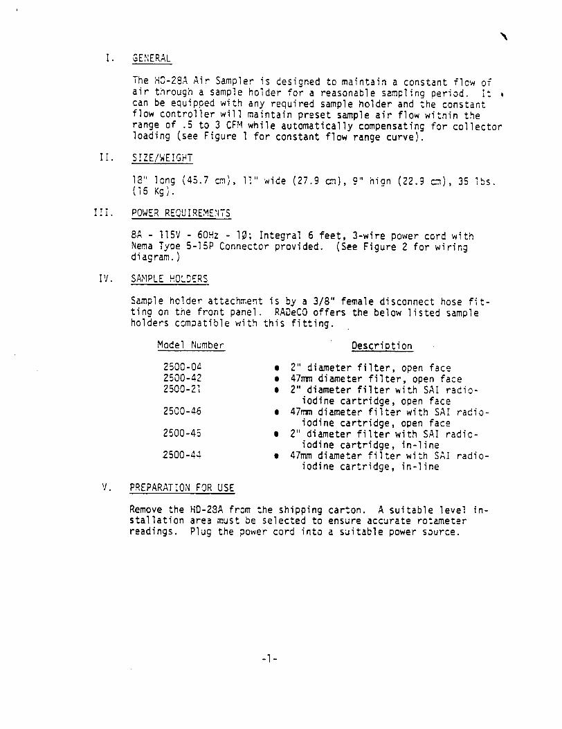
I. GENERAL
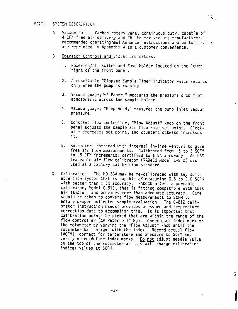
The HO-28A Air Sampler is designed to maintain a constant flow of air through a sample holder for a reasonable sampling period. It can be equipped with any required sample holder and the constant flow controller will maintain preset sample air flow within the range of .5 to 3 CFM while automatically compensating for collector loading (see Figure 1 for constant flow range curve).
II. SIZE/WEIGHT
18" lcng (45.7 cm), 11" wide (27.9 cm), 9" hign (22.9 cm), 35 lbs. (15 Kg).
111. POWER REQUIREMENTS
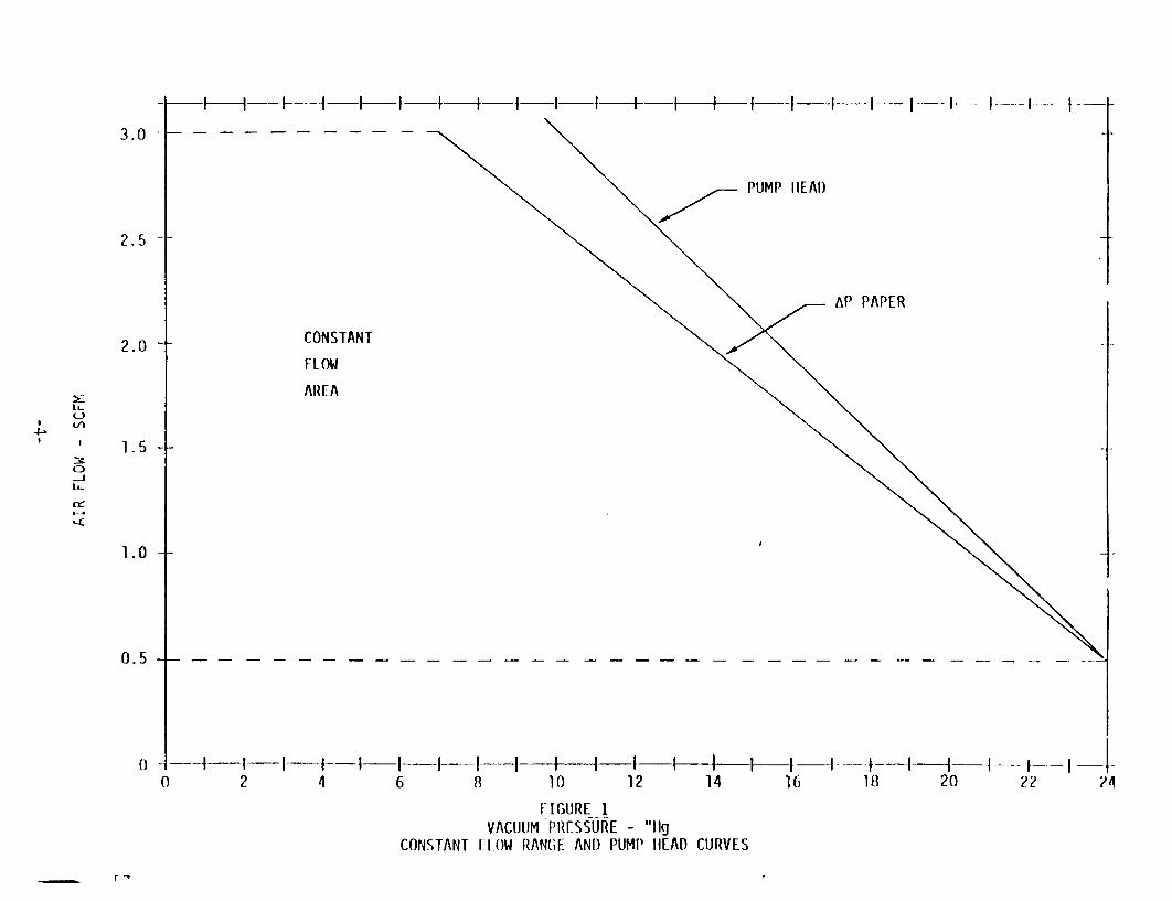
SA - 115V - 60Hz - 10; Integral 6 feet, 3-wire power cord with Nema Type 5-15P Connector provided. (See Figure 2 for wiring diagram.)
IV. SAMPLE HOLDERS
Sample holder attachment is by a 3/8" female disconnect hose fitting on the front panel. RADeCO offers the below listed sample holders compatible with this fitting.
Model Number Description
250C-04 . 2" diameter filter, open face 2500-42 e 47mm diameter filter, open face 2500-21 * 2" diameter filter with SAI radio
iodine cartridge, open face 2500-46 9 47mm diameter filter with SAI radio
iodine cartridge, open face 2500-45 9 2" diameter filter with SAI radio
iodine cartridge, in-line 2500-44 * 47mm diameter filter with SAI radio
iodine cartridge, in-line
V. PREPARATION FOR USE
Remove the HD-28A from the shipping carton. A suitable level installation area must be selected to ensure accurate rotameter readings. Plug the power cord into a suitable power source.
-I-
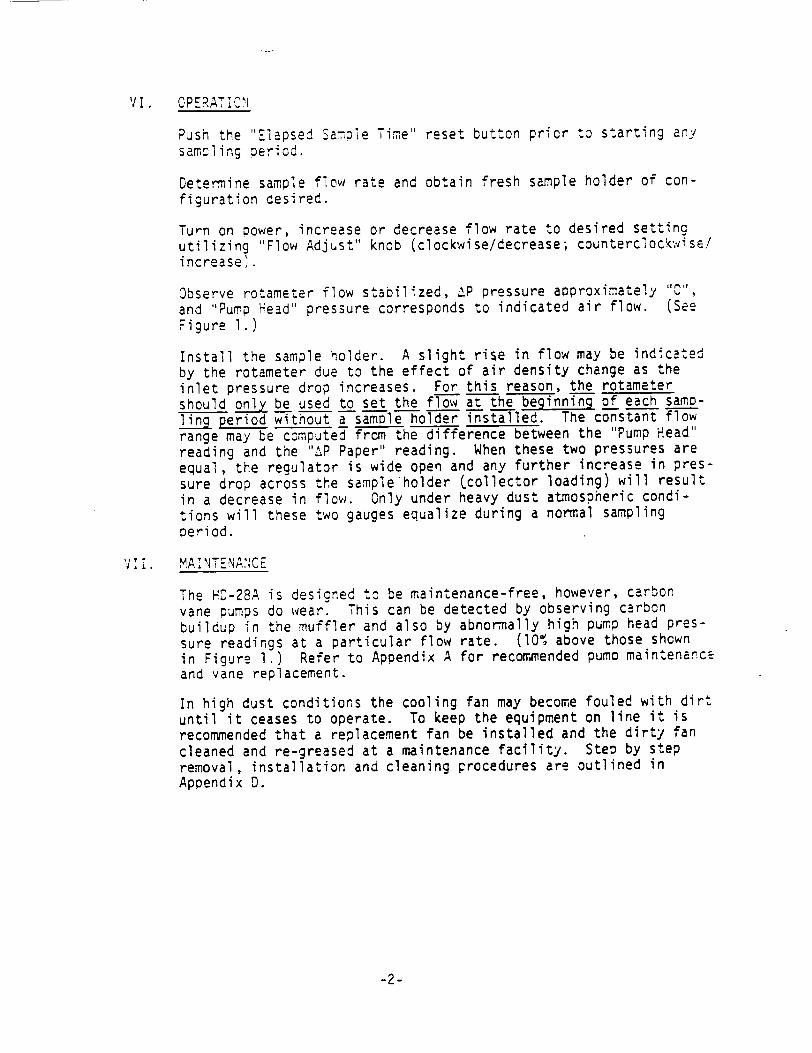
VI. OPERATIOC
Push the "Elapsed Sampie Time" reset button prior to starting any sampling period.
Determine sample flow rate and obtain fresh sample holder of configuration desired.
Turn on power, increase or decrease flow rate to desired setting utilizing "Flow Adjust" knob (clockwise/decrease; counterclockwise! increase).
Observe rotameter flow stabilized, •P pressure approximately "C", and "Pump Head" pressure corresponds to indicated air flow. (See Figure 1.)
Install the sample holder. A slight rise in flow may be indicated by the rotameter due to the effect of air density change as the inlet pressure drop increases. For this reason, the rotameter should only be used to set the flow at the beginning of each sam_ling period without a sample holder installed. The constant flow range may be computed frcm the difference between the "Pump Head" reading and the "",P Paper" reading. When these two pressures are equal, the regulator is wide open and any further increase in pressure drop across the sample holder Ccollector loading) will result in a decrease in flow. Only under heavy dust atmospheric conditions will these two gauges equalize during a normal sampling period.
V XA: , ANN E
The HD-28A is designed to be maintenance-free, however, carbon vane pumps do wear. This can be detected by observing carbon buildup in the muffler and also by abnormally high pump head pres
sure readings at a particular flow rate. (10% above those shown in Figure 1.) Refer to Appendix A for recommended pump maintenance and vane replacement.
In high dust conditions the cooling fan may become fouled with dirt until it ceases to operate. To keep the equipment on line it is recommended that a replacement fan be installed and the dirty fan
cleaned and re-greased at a maintenance facility. Step by step removal, installation and cleaning procedures are outlined in Appendix 0.
-2-
VIII. SYSTEM DESCRIPTION
A. Vacuum Pumo: Carbon rotary vane, continuous duty, capable of 4 CFM free air delivery and 26" Hg max vacuum; manufacturers recommended cperating/maintenance instructions and parts lis: are reprinted in Appendix A as a customer convenience.
B. Operator Controls and Visual Indicators:
1. Power on/off switch and fuse holder located on the lower right of the front panel.
2. A resettable "Elapsed Sample Time" indicator which recorts only when the pump is running.
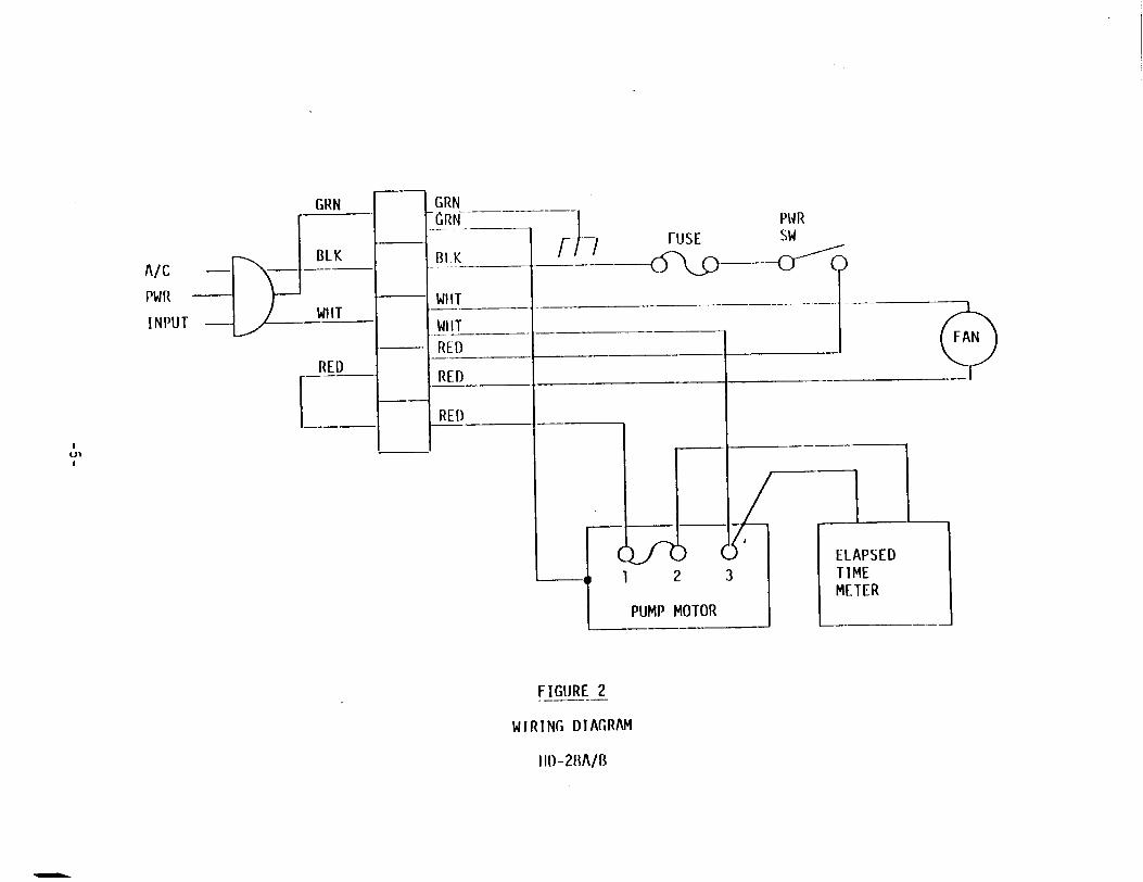
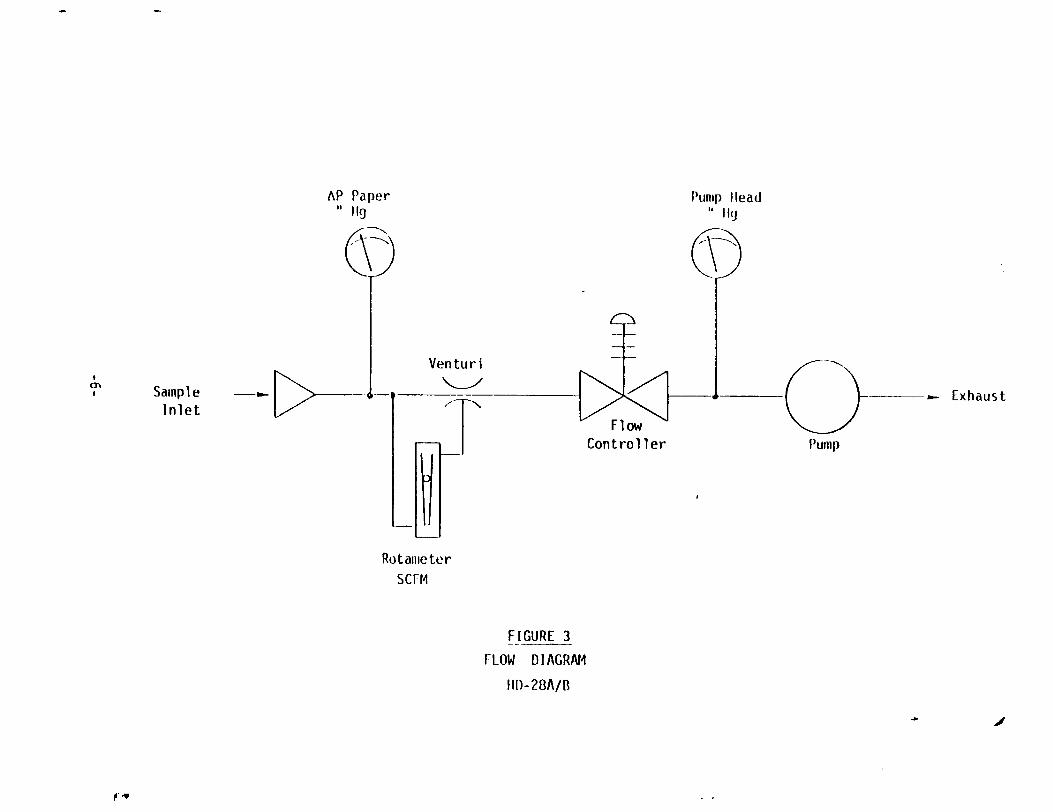
3. Vacuum guage;'"P Paper," measures the pressure drop from atmospheric across the sample holder.
4. Vacuum guage; "Pump Head," measures the pump inlet vacuum pressure.
5. Constant flow controller; "Flow Adjust" knob on the front panel adjusts the sample air flow rate set point. Clockwise decreases set point, and counterclockwise increases it.
6. Rotameter; combined with internal in-line venturi to give free air flow measurements. Calibrated from .5 to 3 SCFM in .5 CFM increments; certified to ± 5% accuracy. An NBS traceable air flow calibrator (RADeCO Model C-812) was used as a factory calibration standard.
C. Calibration: The HD-23A may be re-calibrated with any suitable flow system that is capable of measuring 0.5 to 3.0 SCF'1 with better than = 5'a accuracy. RADeCO offers a portable calibrator, Model C-812, that is fitting compatible with this air sampler, and provides more than adequate accuracy. Care should be taken to convert flow measurements to SCFM to ensure proper collected sample evaluation. The C-812 calibrator instruction manual provides pressure and temperature correction data to accomplish this. It is important that calibration points be picked that are within the range of the flow controller (AP Paper > 1" Hg). Check each index mark on the rotameter by varying the "Flow Adjust" knob until the rotameter ball aligns with the index. Record actual flow (ACFM), correct for temperature and pressure to SCFM and verify or re-define index marks. Do not adjust needle value on the top of the rotameter as this will change calibration indices values at SCFM.
-3-
F ---- [I I --I---I- ---- I--I I -f--I
AP PAPER
CONSTANT
FLOW
AREA
-- At--I------2 2
1 4
t g-- I I-- I
6- 8---- I---t--I t1 I 4I
8 10 12 14I 1-
16I....18 --I I-- I--2I 18 20 22
FIGURE 1 VACUUM PRE-SSUr1E - "11g
CONSTANT FIOW RANGE AND PUMP HEAD CURVES
3.0
2.5
2.0 t
1.5 +
1.0
0.5
0 -
C
F a
PIUM.--I .. -- l--- -- I HE. A-D
PUMP IlEAl)
A/C
PWR WIIT
INPUT WIHT WIIT
RED RED RED
RED
1 Q
FIGURE 2
WIRING DIAGRAM
II)-28A/B
Pump Head "I lg
Venturi
-- Exhaust
Controller Pump
Rotameter
ScUM
FIGURE 3
FLOW DIAGRN4
IHID-28A/B
Il
AP Paper "h 1g
a'
Sample Inlet
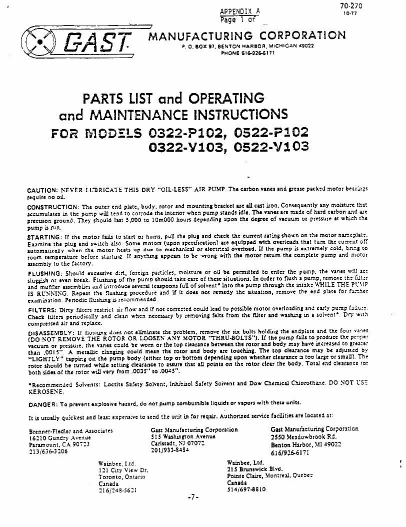
70-270 APPENDIX A 10-77 Page 1 of
r C ASo'MANUFACTURING CORPORATION P. o. BOX 97, BENTON HARBOR, MiCHIGAN 49022
__ PHONE 616-926-6171
PARTS LIST and OPERATING and MAINTENANCE INSTRUCTIONS
FOR tIODEMLS 0322-P102, 0522-P102 0322-V103, 0522-V103
CAUTION: NEVER LLBRICATE THIS DRY "OIL-LESS" AIR PUMP. The carbon vanes and grease packed motor bear.ngs
require no oil.
CONSTRUCTION: The outer end plate, body, rotor and mounting bracket are all cast iron. Consequently any moisture that
accumulates in the pump will tend to corrode the interior when pump stands idle. The vanes are made of hard carbon and are
precision ground. They should last 5,000 to 10m000 hours depending upon the degee of vacuum or pressure at which the
pump is run.
STARTING: If the motor fails to start or hums, pull the plug and check the current rating shown on the motor na..eplate.
Examine the plug and switch also. Some motors (upon specification) are equipped with overloads that turn the current off
automatically when the motor heats up due to mechanical or electrical overload. If the pump is extremely cold, br'.ng to
room temperature before starting. If anything appears to be 'ý'rong with the motor return the complete pump and motor
assembly to the factory.
FLUSHING: Should excessive dirt, foreign particles, moisture or oil be permitted to enter the pump, the vanes will act
slug'.sh or even break. Flushing of the pump should take care of these situations. In order to flush a pump, remove the filte:
and muffler assemblies and introduce several teaspoons full of solvent* into the pump through the intake WHILE THE PUMP
IS RUNNING. Repeat the flushing procedure and if it does not remedy the situation, remove the end plate for fur:ner
examination. Periodic flushing is recommended.
FILTERS: Dirty filters restrict air flow and if not corrected could lead to possible motor overloading and ear!y pump fa'•:e.
Check filters periodically and clean when necessary by removing felts from the filter and washing in a solvent*. Dry with
compressed air and replace.
DISASSEMBLY: If flus-rdng does not eliminate the problem, remove the six bolts holding the endplate and the four vanes
(DO NOT REMOVE THE ROTOR OR LOOSEN ANY MOTOR '"THRU-BOLTS"). If the pump fails to produce the proper
vacuum or pressure, the vanes could be worn or the top clearance between the rotor and body may have increased to greare:
than .0015". A metaiLic clanging could mean the rotor and body are touching. The top clearance may be adjusted by
"LIGHTLY" tapping on the pump body (either top or bottom depending upon whether clearance is too large or small). The
rotor should be turned while setting clearance to assure that all points on the rotor clear the body. Total end clearance fo:
both sides of the rotor will vary from .0035" to .0045".
"Recomrnmended Solvents: Loctite Safety Solvent, Inhibisol Safety Solvent and Dow Chemical Chlorothane. DO NOT USE
KEROSENE.
DANGER: To prevent explosive hazard, do not pump combustible liquids or vapors with these units.
It is usually quickest and least expensive to send the ur.it in for reqair. Authorized service facilities are located at:
Brenner-Fiedler and Associates Git Manufacturing Corporation Gast Manufacturing Corporation
16210 Gundry Avenue 5 I5 Washington Avenue 2550 Meadowbrook Rd.
Paramount, CA 907:3 Carlstadt, NJ 0707: Benton Harbor, Ml 49022
213/636-3206 201/933-8484 616/926-6171
Wainbee, Ltd. Wainbee, Ltd.
121 City View Dr. 215 Brunswick Blvd.
Toronto, Ontario Pointe Claire, Montreal, Quebec
Canada Canada
2161:48-56:1 514/697-810
-7-
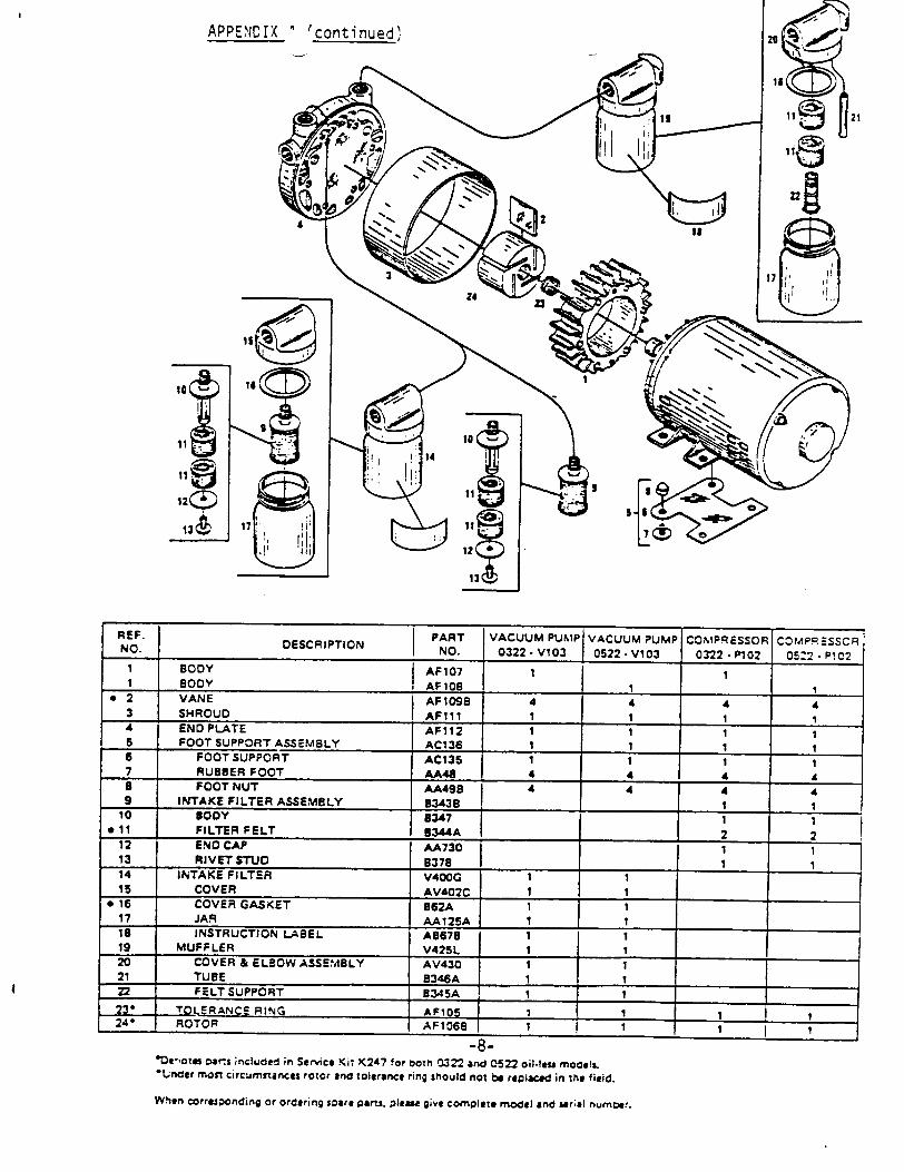
APPENDIX t continued•
REF. PART VACUUM PUMP VACUUM PUMP COQMPRESSOR CFMP.ESSCR NO. DESCRIPTION NO. 0322 - V103 0522 - V103 0322 - P102 05:2 - P!C2
1 BODY AF107 1 1 I BODY AF108 1 - 1
0 2 VANE AFI09B 4 4 4 4 3 SHROUD AF111 I 1 1 1 4 END PLATE AF112 1 1 5 FOOT SUPPORT ASSEMBLY AC136 1 1 1 1 6 FOOT SUPPORT AC135 1 I 1 7 RUBBER FOOT AA48 4 4 4 4 a FOOT NUT AA498 4 4 4 4 9 INTAKE FILTER ASSEMBLY B343B 1 1
10 BODY 8347 1 911 FILTER FELT 8344A 2 2
12 END CAP AA730 1 13 RIVET STUD B37811
14 INTAKE FILTER V40OG 1 1 15 COVER AV402C I 1
* 16 COVER GASKET 862A 1 17JAR A.A125 I
18 INSTRUCTION LABEL A8678 1 1 19 MUFFLER V425L 1 I 20 COVER & ELBOW ASSEMBLY AV430 1 1 21 TUBE B346A 1 1 22 FELT SUPPORT B345A 1 1 23# TO ERANCE RING AF10 24- ROTOR AF1068 ¶ ¶ 1 
-8'De-,otes •er.s included in Service Kiti K247 for both 0322 and 0522 oil-leg mo0e0l. *Under moDS circumstances rotor and tolerance ring should not be replaced in the field.
When Corresponding or ordering soare parts. P|leM give complete model and ser;el oumber.
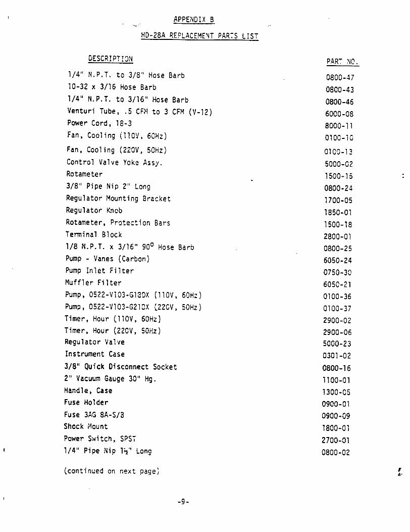
APPENDIX B
HD-28A REPLACEMENT PARTS LIST
DESCRIPTION PART NC.
1/4" N.P.T. to 3/8" Hose Barb 0800-47 10-32 x 3/16 Hose Barb 0800-43 1/4" N.P.T. to 3/16" Hose Barb 0800-46 Venturi Tube, .5 CFM to 3 CFM (V-12) 6000-08 Power Cord, 18-3 8000-11 Fan, Cooling (11OV, 60Hz) 0100-13
Fan, Cooling (220V, 50Hz) 0100-13
Control Valve Yoke Assy. 5000-02 Rotameter 1500-15 3/8" Pipe Nip 2" Long 0800-24 Regulator Mounting Bracket 1700-05 Regulator Knob 1850-01 Rotameter, Protection Bars 1500-18 Terminal Block 2800-01 1/8 N.P.T. x 3/16" 900 Hose Barb 0800-25 Pump - Vanes (Carbon) 6050-24 Pump Inlet Filter 0750-30 Muffler Filter 6050-21 Pump, 0522-VlO3-G13X (1lOV, 60Hz) 0100-36 Pump, 0522-VIO3-G21DX C220V, 50Hz) 0100-37 Timer, Hour CllOV, 60Hz) 2900-02 Timer, Hour (220V, 50Hz) 2900-06 Regulator Valve 5000-23 Instrument Case 0301-02 3/8" Quick Disconnect Socket 0800-16 2" Vacuum Gauge 30" Hg. 1100-01 Handle, Case 1300-05 Fuse Holder 0900-01 Fuse 3AG 8A-S/3 0900-09 Shock Mount 1800-01 Power Switch, SPST 2700-01 1/4" Pipe Nip 1½" Long 0800-02
(continued on next page)
-9-
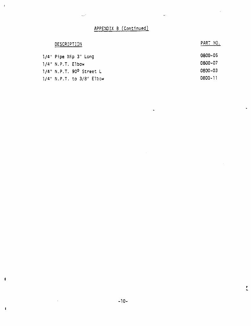
APPENDIX B (Continued)
DESCRIPTION PART NO.
1/4" Pipe Nip 3" Long 0800-05
1/4" N.P.T. Elbow 0800-07
1/4" N.P.T. 900 Street L 0800-03
1/4" N.P.T. to 3/8" Elbow 0800-11
r
-10-
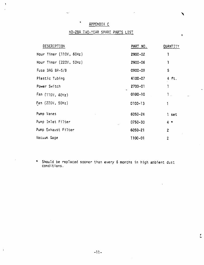
APPENDIX C
HD-28A TWO-YEAR SPARE PARTS LIST
DESCRIPTION
Hour Timer (11OV,
Hour Timer (220V,
Fuse 3AG 8A-S/B
Plastic Tubing
Power Switch
Fan (11OV, 60Hz)
Fan (220V, 50Hz)
60Hz)
50Hz)
PART NO.
2900-02
2900-06
0900-09
4100-07
2700-01
0100-10
0100-13
Pump Vanes
Pump Inlet Filter
Pump Exhaust Filter
Vacuum Gage
6050-24
0750-30
6050-21
1100-01
QUANTITY
1
1
5
4 ft.
1
1 set
4*
2
2
* Should be replaced sooner than every 6 months in high ambient dust conditions.
r
-11-
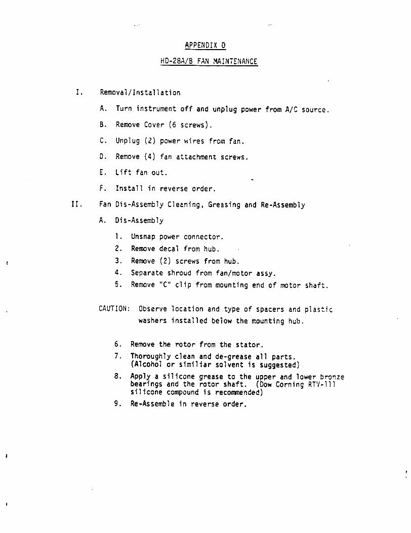
APPENDIX 0
HO-28A/B FAN MAINTENANCE
I. Removal/Installation
A. Turn instrument off and unplug power from A/C source.
B. Remove Cover (6 screws).
C. Unplug (2) power wires from fan.
0. Remove (4) fan attachment screws.
E. Lift fan out.
F. Install in reverse order.
II. Fan Dis-Assembly Cleaning, Greasing and Re-Assembly
A. Dis-Assembly
1. Unsnap power connector.
2. Remove decal from hub.
3. Remove (2) screws from hub.
4. Separate shroud from fan/motor assy.
5. Remove "C" clip from mounting end of motor shaft.
CAUTION: Observe location and type of spacers and plastic
washers installed below the mounting hub.
6. Remove the rotor from the stator.
7. Thoroughly clean and de-grease all parts. (Alcohol or similiar solvent is suggested)
8. Apply a silicone grease to the upper and lower bronze bearings and the rotor shaft. (Dow Corning RTV-lll silicone compound is recommended)
9. Re-Assemble in reverse order.
1
-w *�. - '*.-4
Y
.t�.. .2 '�
vJ� .'-� **
� �
�
'. <A ��1e ..
- *
K �::� -c � i--' -
� � -q% -.
-v
44 IL,
A ar
IN
= � �
0
0
AIR FLOW CALIBRATOR
INSTRUCTION MANUAL
SAE7RDOCO. 10373 Roselle St. San Diego, CA 92121 (619) 458-3831 (619) 452-9983 REV 061786
N'
GENERAL DESCRIPTION
The Air Flow Calibrator you have received is an accurate, low pressure drop,
secondary level device for the calibration of all types of air samplers and
monitors. It is especially useful for calibrating air samplers where the
pressure drop across the calibrator must not interfere with the calibration
of the sampler.
Your calibrator has been calibrated using Meriam a4r flow measuring instru
mentation having traceability to the National Bureau of Standards. Each
marking on the meter face has been corrected to 29.92" inches of mercury
barometric pressure and an air temperature of 70°F and has a guaranteed ac
curacy of better than 5% under these conditions. During the calibration,
the inlet of the calicorator is at atmospheric pressure.
Your calibrator is reasonably rugged and will withstand the rigors of rou
tine handling. However, the continued accuracy will depend upon the clean
liness of the air in the calibration area. The unit should not be used in
heavily dust ladened atmospheres because dust will foul the venturi tube
throat, enter into the bellows of the Meriam gauge, or plug up the inter
connecting hose fittings. The calibrator should never be openly exposed
to oil vapors, fumes or airborne corrosive materials.
Breathing type low pressure air may be blown through the venturi tube to
remove dust only after the interconnecting hoses to the Magnahelic gauge
have been disconnected. Failure to disconnect the interconnecting hoses can
-1-
cause permanent and irreparable damage to the Magnahelic gauge.
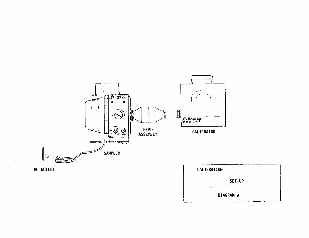
AIR SAMPLER INTERCONNECT
For SAI /RADiCO H-809 Series of samplers, the interconnect should be as
shown in Diagram A.
1. The air inlet of the air flow calibrator must be open and exposed to the
atmosphere.
2. The interconnect may be one of SAI /RADeCO's Calibrator Adaptor Kits or
any other suitable leak-free mechanism.
3. The Sample Holder must contain the appropriate filter disc and/or cartridge
that is to be used in the routine operation of the sampler.
4. The H-809 sampler should be run approximately five minutes prior to the
final interconnect to the Air Flow Calibrator to assure temperature
stabilization of the sampler.
For SAI /RADeCO samplers (K-Flows) which have a constant flow regulator (such
as the AVS-28, AVS-28A, AVS-60, AVS-60A, HD-28A, HD-28B, HD-29, and HD-29A),
the interconnect will be made through a male Quick Disconnect on the outlet
of the calibrator. Since the constant flow regulator automatically corrects
the air flow rate for most inlet pressure drops, no sample holder with filter
paper and/or sampling cartridge should be used between the sampler and the
calibrator. The male Quick Disconnect should be snapped directly into the
female quick disconnect on the inlet of the sample.
-2-
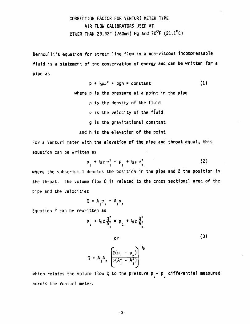
CORRECTION FACTOR FOR VENTURI METER TYPE
AIR FLOW CALIBRATORS USED AT
OTHER THAN 29.92" (760mm) Hg and 70°F (21.1 0C)
Bernoulli's equation for stream line flow in a non-viscous incompressable
fluid is a statement of the conservation of energy and can be written for a
pipe as
p + ½pv2 + pgh - constant (1)
where p is the pressure at a point in the pipe
p is the density of the fluid
v is the velocity of the fluid
g is the gravitational constant
and h is the elevation of the point
For a Venturi meter with the elevation of the pipe and throat equal, this
equation can be written as
p + ½pv2 = p + ½pv2 (2) 11 2 2
where the subscript 1 denotes the positi6n in the pipe and 2 the position in
the throat. The volume flow Q is related to the cross sectional area of the
pipe and the velocities
Q=Av =A v 1 1 2 2
Equation 2 can be rewritten as
1 2 PI + ip• " 2 + IsP ý2
1 2
or (3)
p-p)
Q = A IA2Az 2
which relates the volume flow Q to the pressure p - p differential measured 1 2
across the Venturi meter.
-3-
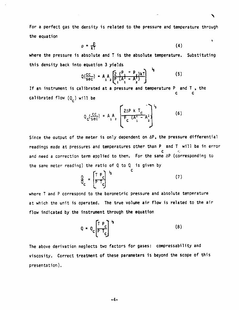
For a perfect gas the density is related to the pressure and temperature through
the equation
-P- (4 ) P=kT
where the pressure is absolute and T is the absolute temperature. Substituting
this density back into equation 3 yields
Cc A A 2 P T] ( sec 1 2P(A-A)
If an instrument is calibrated at a pressure and temperature P and T , the C C
calibrated flow (Qc) will be
Q (cc2AP k T c (6) c sec 1 2 pAc 1A2
Since the output of the meter is only dependent on AP, the pressure differential
readings made at pressures and temperatures other than P and T will be in error C
and need a correction term applied to them. For the same AP (corresponding to
the same meter reading) the ratio of Q to Q is given by C
c = (7)
where T and P correspond to the barometric pressure and absolute temperature
at which the unit is operated. The true volume air flow is related to the air
flow indicated by the instrument through the equation
Q [ Qc TPC (8)
The above derivation neglects two factors for gases: compressability and
viscosity. Correct treatment of these parameters is beyond the scope of this
presentation).
-4-
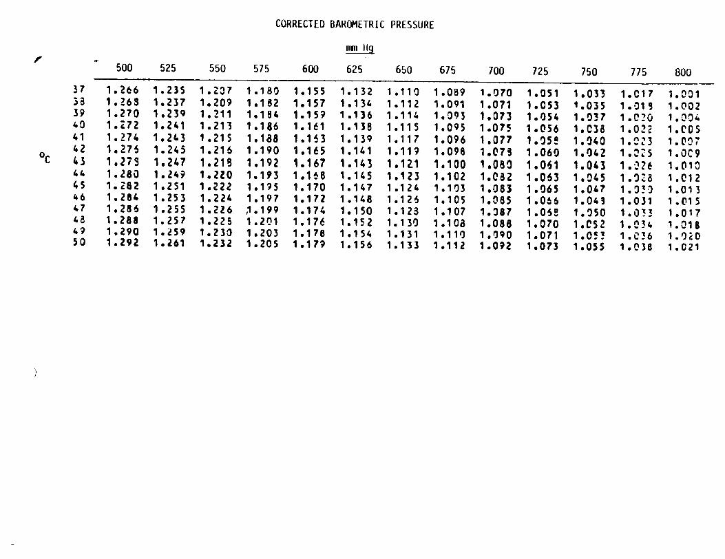
USE OF THE AIR FLOW CALIBRATOR
There is one basic method of using the air flow calibrator. This is to correct
the air flow calibrator reading for atmospheric conditions other than NPT (29.92"
or 760 mm Hg and 70°F or 21.111 0 C) and compare the corrected air flow through
the calibrator with the air flow indicator on the air sampler.
Using Equation 8 from the derivation:
lTe 1% 2
or
Q = Qc (C.F.)
where Qc = Calibration Flow
C.F. = Correction Factor from Table
Q = Air Flow - Calculated
Barometric pressure reading devices often require the application of various
correction factors to give the real barometric pressure. Please study the
manual for your particular device and apply the appropriate factors before
using the attached tables to look up the air flow correction factor you are to
use.
To utilize the attached tables, it is suggested that you choose the block of
numbers which is most appropriate to the existing conditions at your facility
and extrapolate between the numbers to give a more precise set of correction
factors. This is a fine tuning of the numbers for your particular application.
-5-
On examining the correction factor equation, you will readily see that the
inlet pressure is the major controlling factor. Constrictions of any type on
the inlet to the calibrator will have a deleterious effect on the accuracy of
the calibrator.
CAUTION
It is directed to your special attention and to the attention of your Quality
Assurance Department that when the Air Flow Calibrator is used with devices
which blow or push air through the venturi tube of the calibrator, the
calibration of the Air Flow Calibrator will no longer be accurate and the
certification of the calibration of the Air Flow Calibrator is voided.
-6-
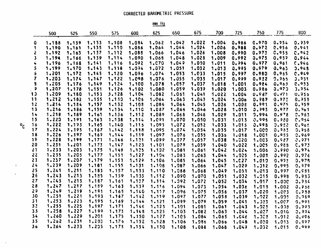
CORRECTED BAROMETRIC PRESSURE
500 525 550 575 600 625 650 675 700 725 750 775 800
0 1.188 1.159 1.133 1.108 1.084 1.062 1.042 1.022 1.004 0,986 0.970 0.954 0.939 1 1.190 1.161 1.135 1.110 1.086 1.0616 1.044 1.024 1,006 0.988 0.972 0.956 0.941 2 1.192 1.163 1.137 1.112 1.088 1.066 1.046 1.026 1.008 0.990 0.973 0.955 C.042 3 1.194 1.166 1.139 1.114 1.090 1.068 1.048 1.028 1.009 0.992 3.975 0.959 0.944 4 1.196 1.168 1.141 1.116 1.092 1.C70 1.049 1.030 1.011 0,994 0.977 0.961 C.946 5 1.199 1,170 1.143 1.118 1.0;4 1.072 1.051 1.032 1.013 0.995 0.979 0.963 3.943 6 1.201 1.172 1.145 1.120 1.096 1.074 1.053 1,033 1.015 0.997 0.980 0.965 0.949 7 1.203 1.174 1.147 1.122 1.098 1.076 1.055 1.035 1.017 0.999 0.932 0.966 3.251 5 1.205 1.176 1.149 1.124 1.100 1.078 1.057 1.037 1.018 .1.001 0.9a4 0.963 0.053 9 1.207 1,178 1.151 1.126 1.102 1.060 1.059 1.039 1.020 1.003 0.986 3.Q73 3.954
13 1.209 1.180 1.153 1.128 1.104 1.082 1.061 1.041 1.022 1.004 0.9d? 0.Y71 U.955 11 1.212 1.182 1.155 1.130 1.106 1.084 1.063 1.043 1.024 1.00o 0.989 0.973 0. ?55 12 1.214 1.184 1.157 1.132 1.102 1.086 1.064 1.045 1.026 1.00 0.901 0.075 0.459 13 1.216 1,186 1.159 1.134 1.11C 1.087 1.066 1.046 1,028 1.010 3.?93 0.977 0.2o1 14 1.218 1.189 1.161 1.136 1.112 1.089 1.068 1.046 1.029 1.011 0.994 0.978 0.963 15 1.223 1.191 1.163 1.138 1.114 1.091 1.070 1.050 1.031 1.013 0.996 0.9-O 0.054
oC 16 1.222 1.193 1.165 1.140 1.116 1.093 1.072 1.052 1.033 1.015 0.99S 3.912 C.9617 1.224 1.195 1.167 1.142 1.118 1.095 1.074 1,054 1,035 1.017 1.G00 0.953 0.968 18 1.226 1.197 1.169 1.144 1.119 1.097 1.076 1.055 1,036 1.018 1.0C0 0.055 0.969 19 1.228 19199 1.171 1.146 1.1?1 1.099 1.077 1.057 1.038 1.20 1.0C3 0.1;87 0.971 20 1.231 1.201 1.173 1.147 1.123 1.101 1.079 1.059 1.040 1.022 1.005 0.983 C.973 21 1.233 1.203 1.175 1.149 1.125 1.102 1.081 1.061 1.042 1.024 1.006 3.990 0.974 22 1.235 1.205 1.177 1.151 1.127 1.104 1.083 1.063 1.044 1.025 1.002 0.992 0.976 23 1.237 1.207 1.179 1.153 1.129 1.106 1.085 1.064 1.045 1.C27 1.013 0.993 0.97% 24 1.239 1.209 1.181 1.155 1.131 1.108 1.087 1.066 1.047 1.029 1.312 0.995 0.;79 25 1.241 1.211 1.183 1.157 1.133 1.110 1.088 1.068 1.049 1.031 1.013 0.997 0.931 26 1.243 1.213 1.185 1.159 1.135 1.112 1.090 1.070 1.051 1.032 1.015 0.998 0.953 27 1.45 1.215 1.187 1.161 1.137 1.114 1.092 1.072 1.052 1.034 1.017 1.00C 3.934 28 1.247 1.217 1.109 1.163 1,132 1.116 1.094 1.073 1.054 1.036 1.013 1.002 0.936 29 1.249 1.219 1.191 1.165 1.140 1.117 1.096 1.075 1.056 1.037 1.020 1.003 C.998 30 1.251 1,221 1.193 1.167 1.142 1.119 1.097 1.077 1,058 1.039 1.022 1.005 0.'169 31 1.253 1.223 1.195 1.169 1.144 1.121 1.099 1.079 1.059 1.041 1.323 1.007 0.091 32 1.255 1.225 1.197 1.171 1.144 1.123 1.101 1.081 1.061 1.043 1.0225 1.0-3 0.993 33 1.258 1.227 1.199 1.173 1.148 1.125 1.103 1.082 1.063 1.044 1.027 1.010 3.994 34 1.260 1.229 1,201 1.175 1.150 1.127 1.105 1.084 1.065 1.G4t 1.3Z! 1.012 0.996 35 1.262 1.231 1.203- 1.17 1.152 1.128 1.106 1.086 1.066 1.048 1.030 1.013 0.997 3o 1.264 1.233 1.235 1.173 1,154 1.130 1.108 1.088 1.068 1.049 1.332 1.015 0.Q99
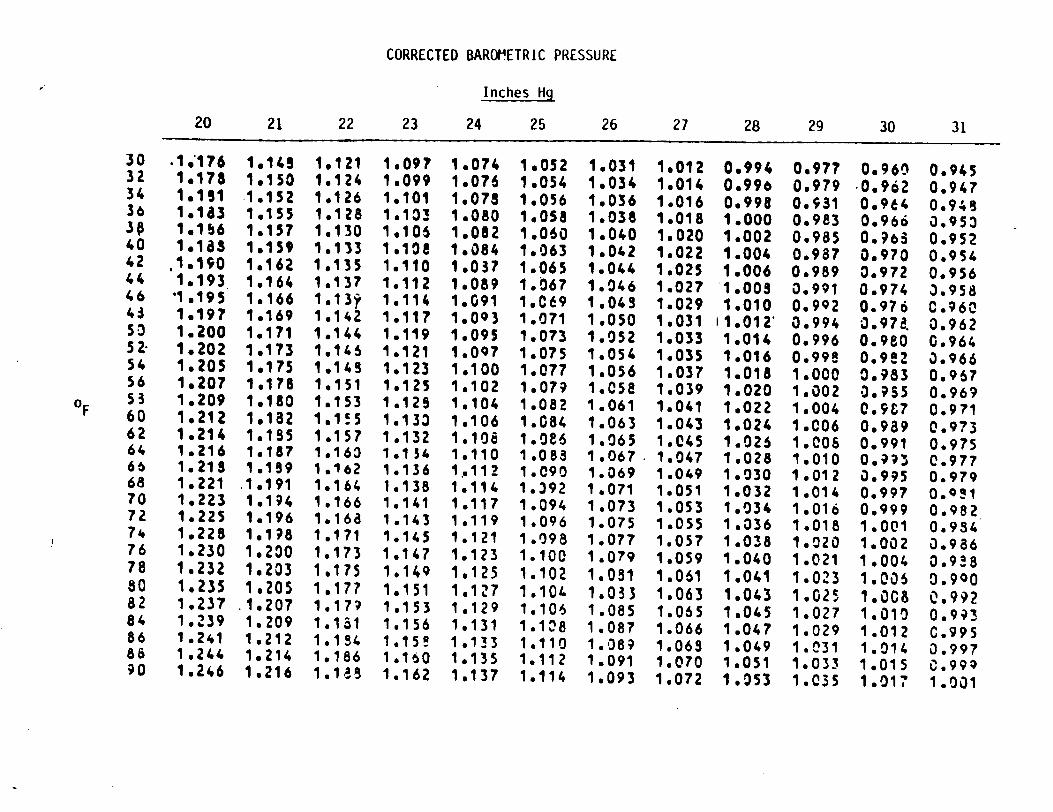
CORRECTED BAROIETRIC PRESSURE
Inches Hg
20 21 22 23 24 25 26 27 28 29 30 31
30 .1176 1,148 1,121 1,097 1.074 1,052 1.031 1,012 0.994 0,977 0.960 0.945 32 1,178 1,150 1,124 1,099 1.076 1.054 1,034 1.014 0.996 0.979 0,962 0.947 34 1.191 1.152 1.126 1.101 1.078 1.056 1.036 1.016 0.998 0.931 0.964 0.94s 3a 1.163 1,155 1.128 1,103 1,080 1,058 1.038 1.018 1.000 0.983 0,966 0.953 30 1,1b6 1.157 1.130 1,105 1.082 1.060 1.040 1.020 1.002 0.985 0.965 0.952 40 1.163 1.159 1.133 1.101 1.084 1.063 1.042 1.022 1.004 0.987 0.970 0.954 42 1,190 1,162 1,135 1.110 1.037 1.065 1.044 1.025 1.006 0.989 0.972 0.956 44 1.193 1.164 1.137 1.112 1.089 1.067 1.046 1.027 1.00S 0.991 0.974 3.958 46 "1 195 1.166 1.13? 1.114 1.091 1.C69 1.04S 1.029 1.010 0.992 0.976 0.960 43 1,197 1.169 1.142 1,117 1,093 1.071 1.050 1.031 11.012 0.994 0.974 0.962 50 1.200 1.171 1.144 1.119 1.095 1.073 1.052 1.033 1.014 0.996 0.980 0.964 52 1.202 1,173 1.145 1,121 1,097 1,075 1,054 1,035 1,016 0.998 0.9!2 3.966 54 1,205 1,175 1,143 1.123 1,100 1.077 1.056 1,037 1.018 1,000 0.983 0.967 56 1,207 1,178 1.151 1.125 1,102 1.079 1.058 1.039 1.020 1.002 0,955 0.969 0F 53 1.209 1.180 1.153 1.129 1.104 1.082 1.061 1.041 1.022 1.004 0.907 0.971 60 1,212 1,132 1,1;5 1.133 1.106 1.084 1.063 1.043 1.024 1.006 0.989 0.973 62 1.214 1.185 1.157 1.132 1.106 1.086 1.065 1.045 1.025 1.00S 0.991 0.975 64 1,216 1,187 1,160 1,154 1,110 1.088 1.067. 1.047 1.028 1,010 0,9.3 0.977 66 1.218 1.199 1.162 1,136 1,112 1.090 1.069 1.049 1.030 1,012 0,995 0.979 68 1,221 .1.191 1,164 1.138 1,114 1.392 1.071 1.051 1,032 1.014 0.997 0.0!1 70 1,223 1.194 1.166 1.141 1.117 1.094 1.073 1.053 1.034 1.016 0.999 0.982 72 1.225 1.196 1.168 1.143 1.119 1.096 1.075 1.055 1.036 1.018 1.001 0.934 74 1,228 1,1;8 1.171 1.145 1.121 1.098 1.077 1.057 1.038 1.020 1.002 0.986 76 1.230 1,200 1.173 1.147 1.123 1.100 1.079 1.059 1.040 1.021 1.004 0.9!8 78 1.232 1.203 1.175 1.149 1,125 1.102 1.051 1.061 1.041 1.023 1.006 0.900 80 1.235 1,205 1.177 1.151 1.127 1.10L 1.033 1.063 1.043 1.025 1.008 0.992 82 1.237 .1.207 1.17? 1,153 1,129 1.106 1.085 1.065 1.045 1.027 1.010 0.993 84 1.239 1.209 1.131 1.156 1,131 1.108 1.087 1.066 1.047 1.029 1.012 C.995 86 1.241 1,212 1,154 1.15! 1,133 1.110 1.089 1.068 1.049 1.031 1.014 0.997 88 1.244 1.214 1.186 1,160 1,135 1.112 1.091 1.070 1.051 1.033 1.015 0.99q 90 1.246 1.216 1.11. 1.162 1,137 1.114 1.093 1.072 1.053 1.035 1.017 1.001
CORRECTED BAROMETRIC PRESSURE
iimi II
500 525 550 575 600 625 650 675 700 725 750 775 800
37 1.266 1.235 1.237 1.180 1.155 1.132 1.110 1.089 1.070 1.051 1.033 1.017 1.001 38 1.268 1.237 1.209 1.182 1.157 1.134 1.112 1.091 1.071 1.053 1.035 1.015 1.002 39 1.270 1.239 1.211 1.184 1.159 1.136 1.114 1.093 1.073 1,054 1.037 1.C20 1.004 40 1.272 1.241 1.213 1.186 1.161 1.138 1.115 1.095 1.075 1.056 l.C38 1.022 1.C05 41 1.274 1.243 1.215 1.188 1.163 1.139 1.117 1.096 1.077 1.05! 1.040 1.MZ3 1.0)7 42 1.275 1.245 1.216 1.190 1.165 1.141 1.119 1.098 1,075 1.060 1.042 1.%25 1.0C9 43 1.27S 1.247 1.218 1.192 1.167 1.143 1.121 1.100 1.080 1.061 1.043 1.026 1.010 44' 1.280 1.249 1.2ZO 1.193 1.1ý8 1.145 1.123 1.102 1.082 1.063 1.045 1.328 1.012 45 1.262 1.251 1.222 1.195 1.170 1.147 1.124 1.103 1.083 1.065 1.047 1.30) 1.013 46 1.284 1.253 1.224 1.197 1.172 1.148 1.126 1.105 1.005 1.066 1,043 1.031 1.015 47 1.286 1.255 1.2Z6 1.199 1.174 1.150 1.123 1.107 1.387 1.062 1.350 1.033 1.017 1.8 1.281 1.257 1.225 1.201 1.176 1.152 1.130 1.108 1.088 1.070 1.C52 1.034 1.315 4? 1.290 1.Z59 1.230 1.203 1.178 1.154 1.131 1.110 1,090 1.071 1,0!3 1.036 1.020 50 1.292 1.261 1.232 1.205 1.179 1.156 1.133 1.112 1.092 1.073 1.055 1.038 1.021
HEAD ASSEMBLY
CAL IBRATOR
CALIBRATION
SET-UP
DIAGRAM A
AC OUTLET
SAMIPLER
I
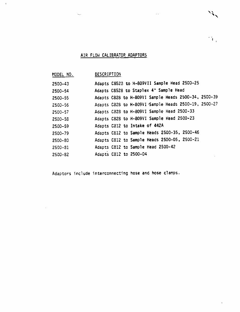
AIR FLOW CALIBRATOR ADAPTORS
DESCRIPTION
Adapts C8523 to H-809VII Sample Head 2500-25
Adapts C8528 to Staplex 4" Sample Head
to
to
to
to
to
to
to
to
to
H-809VI
H-809VI
H-809VI
H-809VI
Intake
Sample
Sample
Sample
2500-04
Sample Heads 2500-34,
-Sample Heads 2500-19,
Sample Head 2500-33
Sample Head 2500-23
of 442A
Heads 2500-35, 2500-46
Heads 2500-05, 2500-21
Head 2500-42
2500-39 2500-27
Adaptors include interconnecting hose and hose clamps.
MODEL NO.
2500-43
2500-54
2500-55
2500-56
2500-57
2500-58
2500-59
2500-79
2500-80
2500-81
2500-82
Adapts
Adapts
Adapts
Adapts
Adapts
Adapts
Adapts
Adapts
Adapt's
C828 C828
C828
C828
C8 12
C812
C812
C812
C812
i l
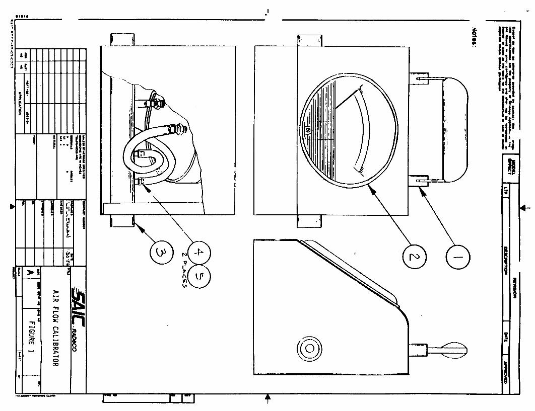

LEGEND - FIGURE 1
AIR FLOW CALIBRATOR
Item No. (From Drawing)
1
2
3
4
5
Description
Handle
Magnehelic Gage
Venturi
Hose Barb
Washer, Fibre
Model ESP-1 Eberline Smart Portable Technical Manual
Eberline
A OIViSiON OF:
F Thermo Electron CORPORATION
SAIC/T&MSS
NOV 16 1987
CCF RECEIVED
z
A DIVISION 0P
Eberlne TEerctron Service Centers CORPORATION
CERTIFIED CALIBRATION REPAIR Eberline Instrument Certified Calibration ....................................... Call Service Center for prices Other Manufacturer Instrument Certified Calibration ................................... Sl1O.OO each Repair Rate above Calibration plus Parts at List Price ................................... S60.00/hour Contractual rates are available on periodic repair and/or calibration. Contact Service Center for prices.
THREE-YEAR (3) EXTENDED WARRANTY
This includes Certified Calibration plus Parts
1. Eberline Instruments, FOB Eberline Instrument Repair and Calibration Facility ........... S70.00 each/quarter
MISCELLANEOUS
1. Turn Around Time: Calibration: Five (5) working days on Eberline instruments. Repair: Twelve (12) working days on Eberline instruments unless parts have to be ordered.
2. FOB Santa Fe, New Mexico, or West Columbia, South Carolina
3. Instruments for warranty repair, repair, or calibration must be sent to:
Instrument Repair and Calibration Instrument Repair and Calibration Eberline Instrument Corporation Eberline Instrument Corporation P.O. Box 2108, Airport Road 312 Miami Street Santa Fe, New Mexico 87504-2108 West Columbia, South Carolina 29169 Telephone: (505) 471-3232 Telephone: (803) 796-3604
4. In addition, the following Customer Service Centers are available for customers outside the United States.
Thermo Electron, Ltd. Safety Supply Canada Woolborough Lane 214 King Street E Crawley, West Sussex Toronto, Ontario England, RHIO 2AQ Canada MSA I J8 Telephone: (44) 293-544811 Telephone: (416) 364-3234
Prices at these locations will vary from U.S. prices. Please contact the facilities for current price and delivery information.
February 1986
EBERLINE INSTRUMENTS STANDARD WARRANTY
One-Year Warranty: Seller warrants to replace or repair, at its option, any products or parts thereof (excluding tubes, crystals and batteries (tubes and crystals 90 days] ) which are found defective in material or workmanship within one year from date of shipment. Seller's obligation with regard to such products or parts shall be limited to replacement or repair, FOB seller's factory or authorized repair station, at seller's option. The aforesaid warranty will be voided if repair has been attempted by other than seller's authorized personnel. In no event shall seller be liable for consequential or special damages, transportation, installation, adjustment, work done by customer or other expenses which may arise in connection with such defective product or parts.
Exclusion of Warranties and Limitation of Liability: The foregoing warranty is expressly made In lieu of any and all other warranties express or Implied Including the warranties of merchantability and fitness for a particular purpose. Under no circumstances shall seller be liable for any indirect, special, Incidental or consequential damages to customer or to any third party.

A OIVISI•N OF
Eberine E Thermo Eberlne FTElectron C O•P OR AT ION
P.O. Box 2106 Santa Fe. New Mexico 87504-2108 (505) 471-3232 TWX: 910-985-0678

MODEL ESP-1
LIST OF EFFECTIVE PAGES I
TOTAL NUMBER OF PAGES IN THIS MANUAL IS 67, CONSISTING OF THE FOLLOWING:
Change In EffectPage
Title A
i1 iii
1-62
Change Change Change Change Change Change
Latest Publication Date
March 13, March 13, March 13, March 13, March 13, March 13,
1986 1986 1986 1986 1986 1986
Pages 12, 22 and 38 are blank.
Copyright © 1984 by Eberline Instrument CorporationA March 13, 1986
MODEL ESP-l
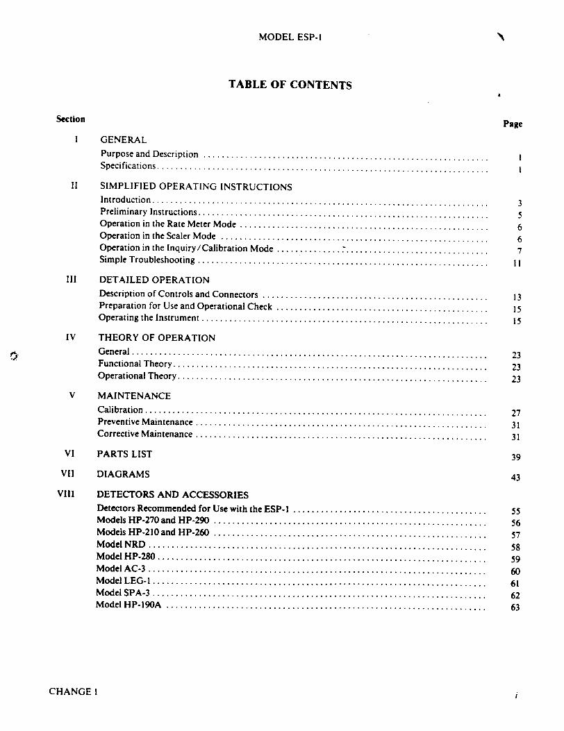
TABLE OF CONTENTS
Section Page
I GENERAL
Purpose and D escription .............................................................. I S pecificatio ns ........................................................................ I
II SIMPLIFIED OPERATING INSTRUCTIONS
In tro d uctio n ......................................................................... 3 Prelim inary Instructions............................................................... 5 Operation in the Rate M eter M ode ...................................................... 6 O peration in the Scaler M ode .......................................................... 6 Operation in the Inquiry/Calibration M ode .............. ............................... 7 Sim ple Troubleshooting ............................................................... I I
III DETAILED OPERATION
Description of Controls and Connectors ................................................. 13 Preparation for Use and Operational Check .............................................. 15 O perating the Instrum ent .............................................................. 15
IV THEORY OF OPERATION
G eneral .................................................... ........................ 23 Functional T heory .................................................................... 23 O perational T heory ................................................................... 23
V MAINTENANCE
C alibration .......................................................................... 27 Preventive M aintenance ............................................................... 31 Corrective M aintenance ............................................................... 31
VI PARTS LIST 39
VII DIAGRAMS 43
VIII DETECTORS AND ACCESSORIES
Detectors Recommended for Use with the ESP-I .......................................... 55 M odels H P-270 and H P-290 ........................................................... 56 M odels H P-210 and H P-260 ........................................................... 57 M odel N R D ......................................................................... 58 M odel HP-280 ..................................................................... 59 M odel A C -3 ......................................................................... 60 M odel LE G -I ........................................................................ 61 M odel SP A -3 ........................................................................ 62 M odel H P-190A ..................................................................... 63
CHANGE I i

MODEL ESP-1
LIST OF ILLUSTRATIONS
Figure Page
1-1 M o d el E S P - I ........................................................................ ii 2-1 ESP-1 External Controls and Displa..................................................... 4 3-1 ESP -I Internal C ontrols ............................................................... 14 3-2 Rate M eter M ode Block Diagram ....................................................... 19 3-3 Scaler M ode Block Diagram ........................................................... 20 3-4 Inquiry/Calibration M ode Block Diagram ............................................... 21 5-1 Typical D etector Plateau .............................................................. 28 5-2 ESP-I with Bottom Cover Rem oved ..................................................... 32 7-1 M icrocomputer Functional Block Diagram ............................................... 43 7-2 Functional Block Diagram for Amplifier, High Voltage and Speaker ......................... 44 7-3 Low Voltage Functional Block Diagram ................................................. 45 7-4 Printed C ircuit Board Set .............................................................. 46 7-5 C om ponent Layout ................................................................... 47 7-6 Amplifier/High Voltage Schematic, 11292-DO4D(sheet 2) ................................... 48 7-7 Microcomputer Schematic, 1 1292-DO4D (sheet 1) .......................................... 49 7-8 Logic Flow - Applying Power ......................................................... 50 7-9 Logic Flow - Rate M eter M ode ........................................................ 51 7-10 Logic Flow - Inquiry/Calibration ...................................................... 52 7-11 Logic Flow - Scaler M ode ............................................................ 53 7-12 Logic Flow - Param eter Setting ........................................................ 54
LIST OF TABLES
Table Page
I Input Sensitivity vs Threshold Voltage ................................................... 27 2 Suggested Calibration Levels ........................................................... 29 3 Calculating Calibration Constant ....................................................... 30 4 C heck V oltages ...................................................................... 34
CHANGE1 ii
MODEL ESP-I
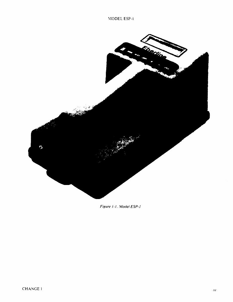
Figure 1-1. Model ESP- I
CHANGE1 III
MODEL ESP-I
SECTION I GENERAL
A. PURPOSE AND DESCRIPTION
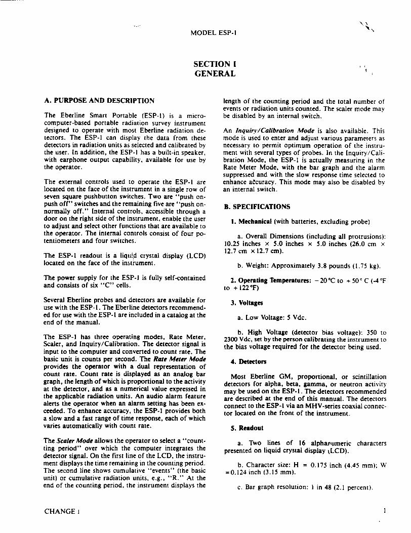
The Eberline Smart Portable (ESP-l) is a microcomputer-based portable radiation survey instrument designed to operate with most Eberline radiation detectors. The ESP-I can display the data from these detectors in radiation units as selected and calibrated by the user. In addition, the ESP-1 has a built-in speaker, with earphone output capability, available for use by the operator.
The external controls used to operate the ESP-I are located on the face of the instrument in a single row of seven square pushbutton switches. Two are "push onpush off" switches and the remaining five are "push onnormally off." Internal controls, accessible through a door on the right side of the instrument, enable the user to adjust and select other functions that are available to the operator. The internal controls consist of four potentiometers and four switches.
The ESP-l readout is a liquid crystal display (LCD) located on the face of the instrument.
The power supply for the ESP-I is fully self-contained and consists of six "C" cells.
Several Eberline probes and detectors are available for use with the ESP-l. The Eberline detectors recommended for use with the ESP-I are included in a catalog at the end of the manual.
The ESP-1 has three operating modes, Rate Meter, Scaler, and Inquiry/Calibration. The detector signal is input to the computer and converted to count rate. The basic unit is counts per second. The Rate Meter Mode provides the operator with a dual representation of count rate. Count rate is displayed as an analog bar graph, the length of which is proportional to the activity at the detector, and as a numerical value expressed in the applicable radiation units. An audio alarm feature alerts the operator when an alarm setting has been exceeded. To enhance accuracy, the ESP-I provides both a slow and a fast range of time response, each of which varies automatically with count rate.
The Scaler Mode allows the operator to select a "countting period" over which the computer integrates the detector signal. On the first line of the LCD, the instrument displays the time remaining in the counting period. The second line shows cumulative "events" (the basic unit) or cumulative radiation units, e.g., "R." At the end of the counting period, the instrument displays the
length of the counting period and the total number of events or radiation units counted. The scaler mode may be disabled by an internal switch.
An Inquiry/Calibration Mode is also available. This mode is used to enter and adjust various parameters as necessary to permit optimum operation of the instrument with several types of probes. In the Inquiry/Calibration Mode, the ESP-l is actually measuring in the Rate Meter Mode, with the bar graph and the alarm suppressed and with the slow response time selected to enhance aecuracy. This mode may also be disabled by an internal switch.
B. SPECIFICATIONS
1. Mechanical (with batteries, excluding probe)
a. Overall Dimensions (including all protrusions): 10.25 inches x 5.0 inches x 5.0 inches (26.0 cm x 12.7 cm x 12.7 cm).
b. Weight: Approximately 3.8 pounds (1.75 kg).
2. Operating Temperatures: - 20 *C to + 50' C (-4• F to + 122"F)
3. Voltages
a. Low Voltage: 5 Vdc.
b. High Voltage (detector bias voltage): 350 to 2300 Vdc, set by the person calibrating the instrument to the bias voltage required for the detector being used.
4. Detectors
Most Eberline GM, proportional, or scintillation detectors for alpha, beta, gamma, or neutron activity may be used on the ESP-I. The detectors recommended are described at the end of this manual. The detectors connect to the ESP-I via an MHV-series coaxial connector located on the front of the instrument.
5. Readout
a. Two lines of 16 alphat'umeric characters presented on liquid crystal display kLCD).
b. Character size: H = 0.175 inch (4.45 mm); W =0.124 inch (3.15 mm).
c. Bar graph resolution: I in 48 (2.1 percent).
CHANGE 1 I
MODEL ESP-I
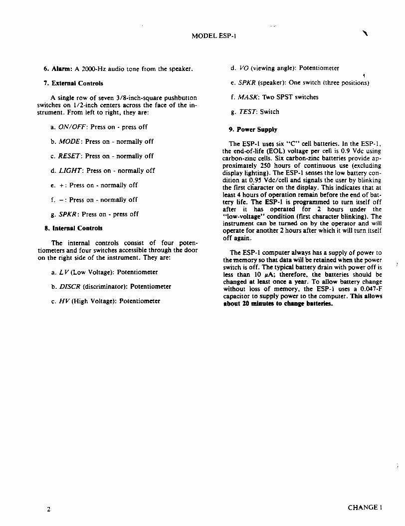
6. Alarm: A 2000-Hz audio tone from the speaker.
7. External Controls
A single row of seven 3/8-inch-square pushbutton switches on 1/2-inch centers across the face of the instrument. From left to right, they are:
a. ON/OFF: Press on - press off
b. MODE: Press on - normally off
c. RESET: Press on - normally off
d. LIGHT: Press on - normally off
e. +: Press on - normally off
f. -: Press on - normally off
g. SPKR: Press on - press off
8. Internal Controls
The internal controls consist of four potentiometers and four switches accessible through the door on the right side of the instrument. They are:
a. L V (Low Voltage): Potentiometer
b. DISCR (discriminator): Potentiometer
c. HV (High Voltage): Potentiometer
d. VO (viewing angle): Potentiometer
e. SPKR (speaker): One switch (three positions)
f. MASK: Two SPST switches
g. TEST: Switch
9. Power Supply
The ESP-1 uses six "C" cell batteries. In the ESP-1, the end-of-life (EOL) voltage per cell is 0.9 Vdc using carbon-zinc cells. Six carbon-zinc batteries provide approximately 250 hours of continuous use (excluding display lighting). The ESP-I senses the low battery condition at 0.95 Vdc/cell and signals the user by blinking the first chiaracter on the display. This indicates that at least 4 hours of operation remain before the end of battery life. The ESP-l is programmed to turn itself off after it has operated for 2 hours under the "low-voltage" condition (first character blinking). The instrument can be turned on by the operator and will operate for another 2 hours after which it will turn itself off again.
The ESP-l computer always has a supply of power to the memory so that data will be retained when the power switch is off. The typical battery drain with power off is less than 10 #A; therefore, the batteries should be changed at least once a year. To allow battery change without loss of memory, the ESP-l uses a 0.047-F capacitor to supply power to the computer. This allows about 20 minutes to change batteries.
CHANGE 12
MODEL ESP-I
SECTION II SIMPLIFIED OPERATING INSTRUCTIONS
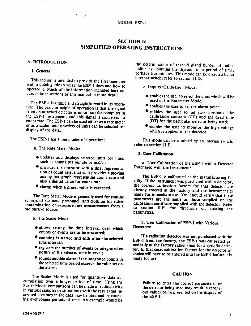
A. INTRODUCTION
1. General
This section is intended to provide the first time user with a quick guide to what the ESP-I does and how to operate it. Much of the information included here occurs in later sections of this manual in more detail.
The ESP-1 is simple and straightforward in its operation. The basic principle of operation is that the signal from an attached detector is input into the computer in the ESP-I instrument, and this signal is convened to count rate. The ESP-I can be used either as a rate meter or as a scaler, and a variety of units can be selected for display of the data.
The ESP-l has three modes of operation:
a. The Rate Meter Mode:
* updates and displays selected units per C:tme, such as counts per minute or mR/h;
0 provides the operator with a dual representation of count rate; that is, it provides a moving analog bar graph representing count rate and also a digital value for count rate;
0 alarms when a preset value is exceeded.
The Rate Meter Mode is generally used for routine surveys of surfaces, personnel, and clothing for either contamination or exposure rate measurements from a radioactive source.
b. The Scaler Mode:
* allows setting the time interval over which counts or events are to be measured;
* counting is started and ends after the selected time interval;
* registers the number of events or integrated exposure in the selected time interval;
* sounds audible alarm if the integrated counts in the selected time period exceeds the value set on the alarm.
The Scaler Mode is used for quantitive data accumulation over a longer period of time. Using the Scaler Mode, comparisons can be made of radioactivity in various samples or situtations with the result that increased accuracy in the data may be obtained by counting over longer periods of time. An example would be
the determination of thyroid gland burden of radioiodine by counting the thyroid for a period of time, perhaps five minutes. This mode can be disabled by an internal switch; refer to section lI.D.
c. Inquiry/Calibration Mode:
e enables the user to select the units which will be used in the Ratemeter Mode;
* enables the user to set the alarm point; * enlibles the user to set two constants, the
calibration constant (CC) and the dead time (DT) for the particular detector being used;
* enables the user to monitor the high voltage which is applied to the detector.
This mode can be disabled by an internal switch; refer to section II.E.
2. User Calibration
a. User Calibration of the ESP-I with a Detector Purchased with the Instrument:
The ESP-I is calibrated at the manufacturing facility. If the instrument was purchased with a detector, the correct calibration factors for that detector are already entered at the factory and the instrument is ready for immediate use. You should verify that these parameters are the same as those supplied on the calibration certificate supplied with the detector. Refer to section II.E. for directions on viewing the parameters.
b. User Calibration of ESP-1 with Various Detectors:
If a radiation detector was not purchased with the ESP-I from the factory, the ESP-l was calibrated generically at the factory rather than for a specific detector. In that case, calibration factors for the detector of choice will have to be entered into the ESP-l before it is ready for use.
CAUTION
Failure to enter the correct parameters for the detector being used may result in erroneous values being presented on the display of the ESP-I.
CHANGE 1 3
.MODEL ESP-1
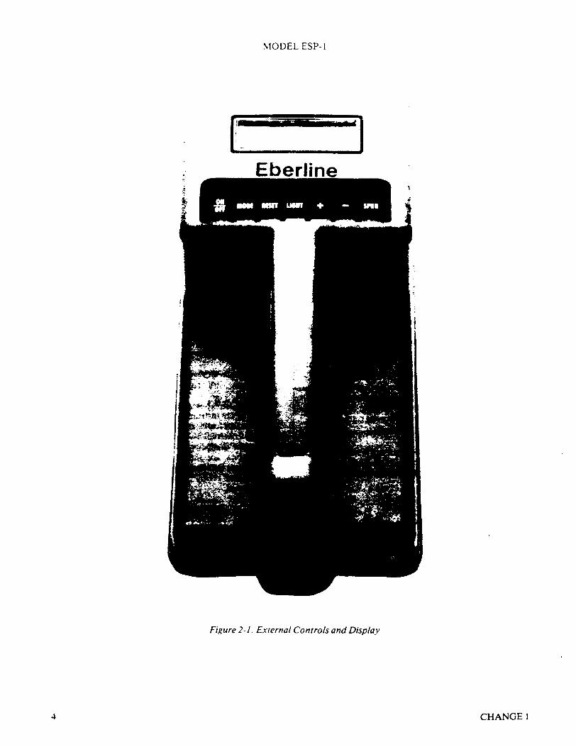
•_ -- ilam 1
Figure 2- 1. External Controls and Display
CHANGEI4
MODEL ESP- I
The parameters which require being set for a particular detector are:
Section1) Alarm Point 2) Units 3) Calibration Constant 4) Detector Dead Time 5) High Voltage
II.E.I. II.E.2. II.E.3. II.E.4. II.E.5.
The last four are preset at the factory for the detector which was purchased with the ESP-1. The alarm point is set at a high value at the factory and, thus, should be reset to a user determined value if it is desired to use this feature of the instrument.
Section II.E. provides simple instructions on how to reset (recalibrate) the items when changing detectors or recalibrating the instrument.
The high voltage should be checked or readjusted for a new detector, PRIOR to connecting the detector. Failure to do so may result in damage to the detector.
3. Calibrations Required by Regulatory Agencies
Regulatory agencies generally require routine laboratory calibration of radiation survey instruments by an approved facility at least once per year. To have your instrument recalibrated return the ESP-1 and detector to the factory in Santa Fe, to the Eberline repair facility in Columbia, South Carolina, or to another approved calibration facility. If your facility has been approved for such calibrations, this may be accomplished by using the procedures given in section V., "Calibration."
B. PRELIMINARY INSTRUCTIONS
Upon receiving the ESP-l perform the following before proceeding.
1. Set Up the ESP-1 and Detector
The ESP-1 has an MHV connector on its front surface for connection to a radiation detector. This connector supplies high voltage to the detector and also transmits the detector signal to the ESP-l for processing and display. If the ESP-I is already connected to a detector then it is reasonable to assume that the high voltage has been previously set. If you are not sure that the high voltage has been properly adjusted, disconnect the detector from the instrument by rotating the cable connector counterclockwise. You can proceed through these instructions without the detector being connected.
CAUTION
Failure to disconnect the detector from the instrument before turning it on can damage the detector if the high voltage is not set properly for the particular detector. Instructions for checking and setting the high voltage can be found in section II.E.5.
When you are ready to connect the detector, verify that you have the proper cable. It should have a MHV connector on one end which mates to the ESP- I and a connector on the other end to mate with the detector. Refer to the ESP-I catalog sheet for the proper cable to use with the specific detector. The cable number is printed somewhere along the length of the cable. The MHV end of the cable connector typically has white insulation in the center which extends slightly beyond the end of the metal portion of the connector. In contrast, a BNC cable connector typically has the insulation flush with the connector end. To connect the cable, rotate the connector clockwise.
2. Turn the Instrument ON and OFF
Press the ON/OFF switch to turn the instrument on. The same switch will have to be pressed to turn the instrumen. off.
When the instrument is turned on, the display should indicate a numerical value on the lower line and a bar graph on the upper line. The bar graph may be offscale, so press the RESET button to get it back on scale. The ESP-I is in its Rate Meter Mode. Refer to section II.C. for more information on the displayed information.
If the instrument has been properly calibrated and is connected to a detector, it is ready to use. Refer to section II.E. for instructions on how to view and change the calibration parameters.
A quick check to determine that the instrument is functioning is to compare the numerical value being displayed to the background radiation level. If they are close, then the instrument is operating and ready to use. Remember that normal statistical fluctuations can cause relatively large changes in the displayed reading at low levels. Press the SPKR button and you should hear a click corresponding to each detector event. If this is not the case, the speaker rate switch could be in the wrong position. Refer to section III.A.2.
3. Determine Low Battery Condition and Battery Replacement
Examine the first character space in the display (upper left hand corner). If it is blinking, the batteries are
CHANGE1 5
MODEL ESP-1
low and need replacing. The ESP-I uses six "C" cell batteries.
The instrument automatically turns itself off two hours after the low battery condition signal is given. The ESP-I can be turned back on after it turns off, but will turn itself off again after two hours.
To change batteries, remove the large screw in the bottom of the case, and carefully remove the case bottom while being careful not to disconnect the grounding wire which is connected to the bottom of the case. Replace the batteries while being careful to orient the batteries according to the diagram printed on the bottom surface of the compartment which holds the batteries. (See figure 5-2.)
C. OPERATION IN THE RATE METER MODE
The ESP-I is automatically placed in the Rate Meter Mode when the instrument is turned on. Examine the display. It will show:
1. Analog Bar Graph (at the top of the display)
The length of the moving analog bar graph is proportional to the detector count rate. One purpose of the moving bar graph is to permit more rapid recognition of a sudden increase or decrease in the radiation field being measured as compared to visual recognition from the changing numbers.
If the bar graph is off scale in either direction, it may be brought back on scale by pressing the RESETbutton. The full scale value of the bar depends on the level of radiation being measured. Pressing the RESET button always resets the value of the full scale of the bar graph to a point that is 33 percent of full scale. If the bar graph is displayed and is varying, the ESP-l is working.
2. Numerical Value of Count Rate (at the bottom of the display)
The second line of the display is the numerical value of the count rate. The value is expressed as a number followed by a second positive or negative number. The second number corresponds to a power of 10. Example: 1.00 + 02 mR/h is I x 102 =100 mR/h.
3. Alarm
The alarm point is a selected value which results in an audible alarm when the counting rate reaches that value. To silence the alarm, press SPKR key. The alarm will sound even if the speaker is off at the time the alarm is activated.
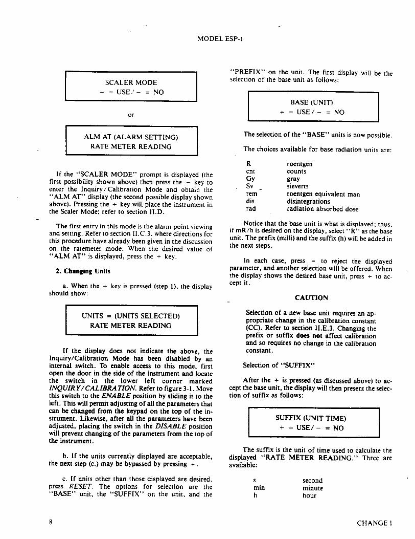
The alarm point can be viewed and set by pressing the MODE key. The display will contain either the1 ",ALM AT" (Alarm Setting) display or will contain the "SCALER MODE?" prompt. If the latter is displayed, press the - key and you will see:
ALM AT (ALARM SETTING) RATE METER READING
The value of the alarm setting "ALM AT" can be increased or decreased as desired by simultaneously pressing RESET and + or RESET and -.
Note that the longer the RESET and + or - are held down, the faster the value changes. In this manner large changes in value can be made in a relatively short period of time. When the changing value approaches the desired value, release the keys and then press them down again to permit slow changes in the displayed numbers until the desired value is reached.
When the desired value of "ALM AT" is displayed, press the MODE key to return to the bar graph display.
CAUTION
While "ALM AT" is being displayed, the instrument will not provide an audible alarm even if the counting rate exceeds the alarm point. The audible alarm is only active in the Rate Meter Mode when the bar graph is displayed (regardless of whether the bar graph is on scale or not).
4. Overrange Indication
When the detector pulse rate exceeds the capability of the ESP-I to maintain a linear relationship between radiation level and displayed reading, the words "OVERRANGE" will appear on the display in place of the analog bar graph. Numerical value will still be displayed but should not be relied upon as the useful range of the ESP-l and detector has been exceeded. This is a latching condition, and once it occurs, the words "OVERRANGE" will be displayed in all three modes of operation. To clear the condition, the ESP-I must be turned off and then back on. The overrange determination is based upon the detector pulse rate and the dead time (see section II.E.4.). This feature requires that the ESP-l and detector be properly calibrated for it to function correctly.
D. OPERATION IN SCALER MODE
Start with the instrument in the Rate Meter Mode. Press
CHANGE I6
MODEL ESP- I
the MODE switch. The display should read:
SCALER MODE + = USE/- = NO
If the display does not indicate the above, the Scaler Mode has been disabled by an internal switch. To enable access to this mode, first open the door in the side of the instrument and locate the switch in the lower left corner marked SCALER. Refer to figure 3-1. Move this switch to the ENABLE position by sliding it to the left.
If the + key is pressed, the Scaler function will be selected. If the - switch is pressed, the instrument will again be placed in the Inquiry/Calibration Mode provided it has not been disabled by the internal switch. Press the + key. The display will read:
UNITS = EVENTS + =USE/- = NO
or
UNITS = (UNITS SELECTED) + =USE/- = NO
Units are either events or the selected rate meter units (e.g., mR, rem, CNT). To select units, press - until the desired unit is displayed. Then press + to accept the unit displayed. The units selected will utilize the same calibration constant as was used in the Rate Meter Mode. The display will change to:
UNITS = (AS SELECTED) ALM AT (ALARM SETTING)
The alarm indicated here is not the rate meter alarm, but is one that sounds if the set value of total (integrated) events or selected units is exceeded. Pressing RESET and + or - simultaneously will increase or decrease the total at which the alarm sounds. Press +. The display will read:
UNITS = (AS SELECTED) CNT FOR (COUNT PERIOD)
The count period can be set by the operator for any interval from I second to 4 hours. Pressing RESET~nd or - simultaneously will increase or decrease the length of the counting period.
To obtain a total count over a set count period, press +. The display will read:
CNT FOR (X:XX:XX)(h:m:s) RESET TO START
Press RESET. After one second, the display will read:
(X:XX:XX) LEFT (h:m:s) (TOTAL COUNT SO FAR)
When the count period has expired, the display will read:
CNT FOR (X:XX:XX) (TOTAL CQUNT)
For another total count, pressing RESET. erases the previous count and starts a new counting interval. Dur
ing the count period, the audio alarm will sound if the alarm limit is exceeded.
When operations or settings in the Scaler Mode have been completed,, pressing MODE twice will shift the ESP-l to the ratemeter mode. The display will read:
1111 (BAR GRAPH) RATE METER READING
E. OPERATION IN INQUIRY/CALIBRATION MODE
I. Selecting of Inquiry/Calibration Mode and Setting the Alarm
After turning on the instrument it will be in the ratemeter mode. Press the MODE key and the display will read:
CHANGE 1 7
MODEL ESP-I
SCALER MODE - = USE,'- = NO
or
ALM AT (ALARM SETTING) RATE METER READING
If the "SCALER MODE" prompt is displayed (the first possibility shown above) then press the - key to enter the Inquiry/Calibration Mode and obtain the "ALM AT" display (the second possible display shown above). Pressing the + key will place the instrument in the Scaler Mode; refer to section II.D.
The first entry in this mode is the alarm point viewing and setting. Refer to section II.C.3. where directions for this procedure have already been given in the discussion on the ratemeter mode. When the desired value of "ALM AT" is displayed, press the + key.
2. Changing Units
a. When the + key is pressed (step I), the display should show:
UNITS = (UNITS SELECTED) RATE METER READING
If the display does not indicate the above, the Inquiry/Calibration Mode has been disabled by an internal switch. To enable access to this mode, first open the door in the side of the instrument and locate the switch in the lower left corner marked INQUIR Y/CALIBRA TION. Refer to figure 3-1. Move this switch to the ENABLE position by sliding it to the left. This will permit adjusting of all theparameters that can be changed from the keypad on the top of the instrument. Likewise, after all the parameters have been adjusted, placing the switch in the DISABLE position will prevent changing of the parameters from the top of the instrument.
b. If the units currently displayed are acceptable, the next step (c.) may be bypassed by pressing +.
c. If units other than those displayed are desired, press RESET. The options for selection are the "BASE" unit, the "SUFFIX" on the unit, and the
"PREFIX" on the unit. The first display will be the selection of the base unit as follows:
BASE (UNIT) + = USE/- = NO
The selection of the "BASE" units is now possible.
The choices available for base radiation units are:
R cnt Gy Sv rem dis rad
roentgen counts gray sieverts roentgen equivalent man disintegrations radiation absorbed dose
Notice that the base unit is what is displayed; thus, if mR/h is desired on the display, select "R" as the base unit. The prefix (milli) and the suffix (h) will be added in the next steps.
In each case, press - to reject the displayed parameter, and another selection will be offered. When the display shows the desired base unit, press + to accept it.
CAUTION
Selection of a new base unit requires an appropriate change in the calibration constant (CC). Refer to section II.E.3. Changing the prefix or suffix does not affect calibration and so requires no change in the calibration constant.
Selection of "SUFFIX"
After the + is pressed (as discussed above) to accept the base unit, the display will then present the selection of suffix as follows:
SUFFIX (UNIT TIME) + = USE/- = NO
The suffix is the unit of time used to calculate the displayed "RATE METER READING." Three are available:
5
min h
second minute hour
CHANGE 18
MODEL ESP- I
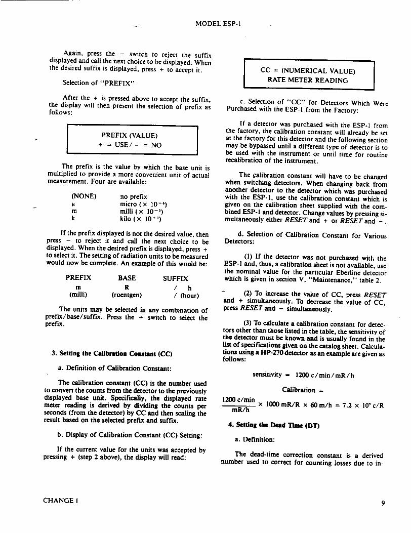
Again, press the - switch to reject the suffix displayed and call the next choice to be displayed. When the desired suffix is displayed, press + to accept it.
Selection of "PREFIX"
After the + is pressed above to accept the suffix, the display will then present the selection of prefix as follows:
PREFIX (VALUE) + = USE/ - = NO
The prefix is the value by which the base unit is multiplied to provide a more convenient unit of actual measurement. Four are available:
(NONE) AL m k
no prefix micro (x 10-') milli (x 10-1) kilo (x 10+1)
If the prefix displayed is not the desired value, then press - to reject it and call the next choice to be displayed. When the desired prefix is displayed, press + to select it. The setting of radiation units to be measured would now be complete. An example of this would be:
PREFIX m
(milli)
BASE R
(roentgen)
SUFFIX / h / (hour)
The units may be selected in any combination of prefix/base/suffix. Press the + switch to select the prefix.
3. Setting the Calibration Constant (CC)
a. Definition of Calibration Constant:
The calibration constant (CC) is the number used to convert the counts from the detector to the previously displayed base unit. Specifically, the displayed rate meter reading is derived by dividing the counts per seconds (from the detector) by CC and then scaling the result based on the selected prefix and suffix.
b. Display of Calibration Constant (CC) Setting:
If the current value for the units was accepted by pressing + (step 2 above), the display will read:
CC = (NUMERICAL VALUE) RATE METER READING
c. Selection of "CC" for Detectors Which Were Purchased with the ESP-l from the Factory:
If a detector was purchased with the ESP-I from the factory, the calibration constant will already be set at the factory for this detector and the following section may be bypassed until a different type of detector is to be used with the instrument or until time for routine recalibration of the instrument.
The calibration constant will have to be changed when switching detectors. When changing back from another detector to the detector which was purchased with the ESP-I, use the calibration constant which is given on the calibration sheet supplied with the combined ESP-l and detector. Change values by pressing simultaneously either RESET and + or RESET and -.
d. Selection of Calibration Constant for Various Detectors:
(1) If the detector was not purchased with the ESP-I and, thus, a calibration sheet is not available, use the nominal value for the particular Eberline detector which is given in section V, "Maintenance," table 2.
- (2) To increase the value of CC, press RESET and + simultaneously. To decrease the value of CC, press RESET and - simultaneously.
(3) To calculate a calibration constant for detectors other than those listed in the table, the sensitivity of the detector must be known and is usually found in the list of specifications given on the catalog sheet. Calculations using a HP-270 detector as an example are given as follows:
sensitivity = 1200 c/min/mR/h
Calibration = 1200 c/mmn x 1000mR/R x 60m/h = 7.2 x IO'c/R
mR/h
4. Setting the Dead Time (DT)
a. Definition:
The dead-time correction constant is a derived number used to correct for counting losses due to in-
CHANGE 1 9

MODEL ESP- I
ability of the detector to recover at high counting rates. This correction results in a more linear response to the radiation field being measured and extends the useful range of some detectors used with the ESP-I by a factor of as much as ten times (which provides the equivalent of an extra range on a standard rate meter).
b. Selection of "DT" for Detectors which were Purchased from the Factory with the Instrument:
If the ESP-l was purchased with a detector from the factory, the DT value will be correctly set at the factory and the next section may be bypassed until it is necessary to use a different detector or until time for routine calibration.
When changing back from another detector to the detector purchased with the ESP-l, use the DT given on the calibration sheet supplied with the combined ESP-l and detector.
c. Selection of DT for Various Detectors:
(1) If the detector was not purchased with the ESP-l and, thus, a combined calibration data sheet is not available, use the nominal value for the particular detector which is given in Section V, "Maintenance," table 2 (page 29).
(2) To increase the value of DT, simultaneously press RESET and +. To decrease the value of DT, simultaneously press RESET and -.
(3) For a detailed discussion of DT consult sec
tion V.A., "Calibration."
CAUTION
If you do change detectors, the calibration constant (CC) and the dead time (DT) must be changed. Use the procedures just described in section II.E., steps 3 and 4.
5. Setting the High Voltage for the Detector of Choice
CAUTION
Do not press any of the keys! The high voltage is not changed from the top of the instrument. Proceed as follows:
a. Selection of High Voltage for Detectors which were Purchased from the Factory with the Instrument:
If a detector was purchased from the factory with the instrument, the operating high voltage will already be set at the factory for this detector, and the following
section may be bypassed until a different type of detector is to be used with the instrument.
b. Selection of High Voltage for Various Detectors:
(1) If the calibration data sheet supplied with the detector is available, use the recommended operating high voltage which is given there.
(2) If the calibration sheet supplied with the detector is not available, use the following general recommendations:
(a) Geiger-type detectors (HP-190, HP-260, HP-270): use 900 volts (exception: HP-290 requires 500 volts).
(b) Scintillation detectors: determine the plateau response of the detector according to the procedure described section V.A.3.c. and figure 5-1, and select as the operating voltage a value which is 75 volts above the beginning of the plateau.
c. Procedure for Determining the Present Setting for the High Voltage as Viewed on the Display:
After the desired value for DT is selected (as discussed above), press +. The display will then show the present value for the high voltage setting and will look like this:
HV = (NUMERICAL VALUE)
RATEMETER READING
If this value is not the recommended high voltage for the detector which you plan to use with the instrument, change the value using the directions given in step d. (following).
CAUTION Do not attempt to adjust the high voltage using the keys on top of the instrument. This adjustment is accomplished by an internal potentiometer.
d. Changing the High Voltage:
(1) Disconnect the detector from the instrument by rotating the MHV connector counterclockwise and then open the door on the side of the instrument.
(2) Refer to figure 3-1. Using a small screwdriver, adjust the potentiometer marked HV (the third potentiometer from the right) until the value seen on the display is the value desired for the operating high voltage.
CHANGE 110
MODEL ESP-lI
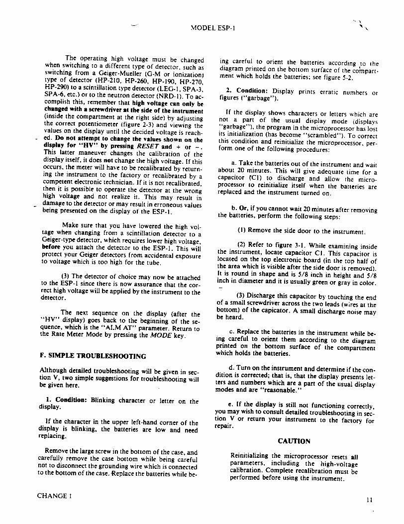
The operating high voltage must be changed when switching to a different type of detector, such as switching from a Geiger-Mueller (G-M or ionization) type of detector (HP-210, HP-260, HP-190, HP-270, HP-290) to a scintillation type detector (LEG-I, SPA-3, SPA-6, etc.) or to the neutron detector (NRD-l). To accomplish this, remember that high voltage can only be changed with a screwdriver at the side of the instrument (inside the compartment at the right side) by adjusting the correct potentiometer (figure 2-3) and viewing the values on the display until the decided voltage is reached. Do not attempt to change the values shown on the display for "HV" by pressing RESET and + or -. This latter maneuver changes the calibration of the display itself, it does not change the high voltage. If this occurs, the meter will have to be recalibrated by returning the instrument to the factory or recalibrated by a competent electronic technician. If it is not recalibrated, then it is possible to operate the detector at the wrong high voltage and not realize it. This may result in damage to the detector or may result in erroneous values being presented on the display of the ESP-1.
Make sure that you have lowered the high voltage when changing from a scintillation detector to a Geiger-type detector, which requires lower high voltage, before you attach the detector to the ESP-I. This will protect your Geiger detectors from accidental exposure to voltage which is too high for the tube.
(3) The detector of choice may now be attached to the ESP-I since there is now assurance that the correct high voltage will be applied by the instrument to the detector.
The next sequence on the display (after the "HV" display) goes back to the beginning of the sequence, which is the "ALM AT" parameter. Return to the Rate Meter Mode by pressing the MODE key.
F. SIMPLE TROUBLESHOOTING
Although detailed troubleshooting will be given in section V, two simple suggestions for troubleshooting will be given here.
1. Condition: Blinking character or letter on the display.
If the character in the upper left-hand corner of the display is blinking, the batteries are low and need replacing.
Remove the large screw in the bottom of the case, and carefully remove the case bottom while being careful not to disconnect the grounding wire which is connected to the bottom of the case. Replace the batteries while be-
ing careful to orient the batteries according tc the diagram printed on the bottom surface of the compartment which holds the batteries, see figure 5-2.
2. Condition: Display prints erratic numbers or figures ("garbage").
If the display shows characters or letters which are not a part of the usual display mode (displays "garbage"), the program in the microprocessor has lost its initialization (has become "scrambled"). To correct this condition and reinitialize the microprocessor, perform one of the following procedures:
a. Take the batteries out of the instrument and wait about 20 minutes. This will give adequate time for a capacitor TCI) to discharge and allow the microprocessor to reinitialize itself when the batteries are replaced and the instrument turned on.
b. Or, if you cannot wait 20 minutes after removing
the batteries, perform the following steps:
(I) Remove the side door to the instrument.
(2) Refer to figure 3-1. While examining inside the instrument, locate capacitor Cl. This capacitor is located on the top electronic board (in the top half of the area which is visible after the side door is removed). It is round in shape and is 5/8 inch in height and 5/8 inch in diameter and it is usually green or gray in color.
(3) Discharge this capacitor by touching the end of a small screwdriver across the two leads (wires at the bottom) of the capicator. A small discharge noise may be heard.
c. Replace the batteries in the instrument while being careful to orient them according to the diagram printed on the bottom surface of the compartment which holds the batteries.
d. Turn on the instrument and determine if the condition is corrected; that is, that the display presents letters and numbers which are a part of the usual display modes and are "reasonable."
e. If the display is still not functioning correctly, you may wish to consult detailed troubleshooting in section V or return your instrument to the factory for repair.
CAUTION
Reinitializing the microprocessor resets all parameters, including the high-voltage calibration. Complete recalibration must be performed before using the instrument.
CHANGE III
\
MODEL ESP- I
SECTION III DETAILED OPERATION
A. DESCRIPTION OF CONTROLS AND CONNECTORS
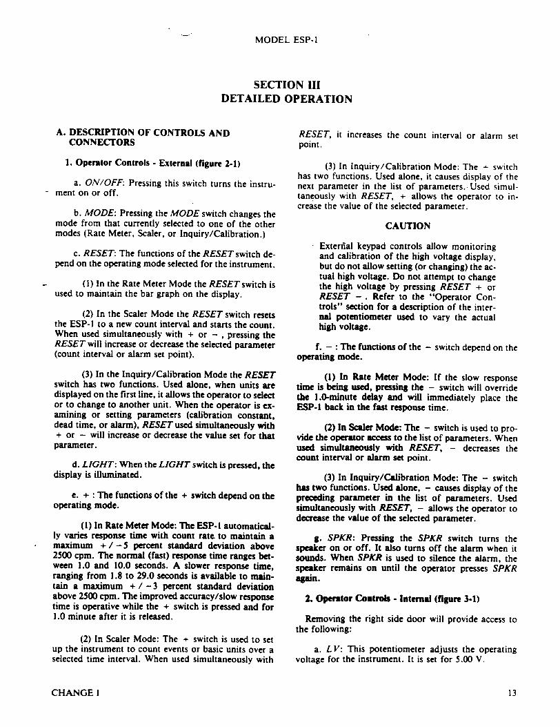
1. Operator Controls - External (figure 2-1)
a. ON/OFF: Pressing this switch turns the instrument on or off.
b. MODE: Pressing the MODE switch changes the mode from that currently selected to one of the other modes (Rate Meter, Scaler, or Inquiry/Calibration.)
c. RESET: The functions of the RESET switch depend on the operating mode selected for the instrument.
(1) In the Rate Meter Mode the RESET switch is used to maintain the bar graph on the display.
(2) In the Scaler Mode the RESET switch resets the ESP-I to a new count interval and starts the count. When used simultaneously with + or - , pressing the RESET will increase or decrease the selected parameter (count interval or alarm set point).
(3) In the Inquiry/Calibration Mode the RESET switch has two functions. Used alone, when units are displayed on the first line, it allows the operator to select or to change to another unit. When the operator is examining or setting parameters (calibration constant, dead time, or alarm), RESET used simultaneously with + or - will increase or decrease the value set for that parameter.
d. LIGHT: When the LIGHT switch is pressed, the display is illuminated.
e. + : The functions of the + switch depend on the operating mode.
(1) In Rate Meter Mode: The ESP-I automatically varies response time with count rate to maintain a maximum + / -5 percent standard deviation above 2500 cpm. The normal (fast) response time ranges between 1.0 and 10.0 seconds. A slower response time, ranging from 1.8 to 29.0 seconds is available to maintain a maximum + /- 3 percent standard deviation above 2500 cpm. The improved accuracy/slow response time is operative while the + switch is pressed and for 1.0 minute after it is released.
(2) In Scaler Mode: The + switch is used to set up the instrument to count events or basic units over a selected time interval. When used simultaneously with
RESET, it increases the count interval or alarm set point.
(3) In Inquiry/Calibration Mode: The - switch has two functions. Used alone, it causes display of the next parameter in the list of parameters. Used simultaneously with RESET, + allows the operator to increase the value of the selected parameter.
CAUTION
Exterfilal keypad controls allow monitoring and calibration of the high voltage display, but do not allow setting (or changing) the actual high voltage. Do not attempt to change the high voltage by pressing RESET + or RESET -. Refer to the "Operator Controls" section for a description of the internal potentiometer used to vary the actual high voltage.
f. - : The functions of the - switch depend on the operating mode.
(1) In Rate Meter Mode: If the slow response time is being used, pressing the - switch will override the 1.0-minute delay and will immediately place the ESP-1 back in the fast response time.
(2) In Scaler Mode: The - switch is used to provide the operator access to the list of parameters. When used simultaneously with RESET, - decreases the count interval or alarm set point.
(3) In Inquiry/Calibration Mode: The - switch has two functions. Used alone, - causes display of the preceding parameter in the list of parameters. Used simultaneously with RESET, - allows the operator to decrease the value of the selected parameter.
g. SPKR: Pressing the SPKR switch turns the speaker on or off. It also turns off the alarm when it sounds. When SPKR is used to silence the alarm, the speaker remains on until the operator presses SPKR again.
2. Operator Controls - Internal (figure 3-1)
Removing the right side door will provide access to the following:
a. L V: This potentiometer adjusts the operating voltage for the instrument. It is set for 5.00 V.
CHANGE I 13
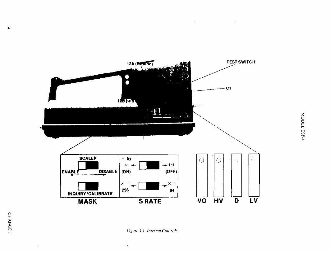
TEST SWITCH
C'1
0 m
m
0 0
VO HV D LV
Figure 3-I. Internal ControlAs
SCALER ÷ by
DEm x~u~l ENABLE DISABLE (ON) (OFF)
-
N ML256 64 INQUIRY/ICALIBRATE
MASK S RATE
m
12A (@mw
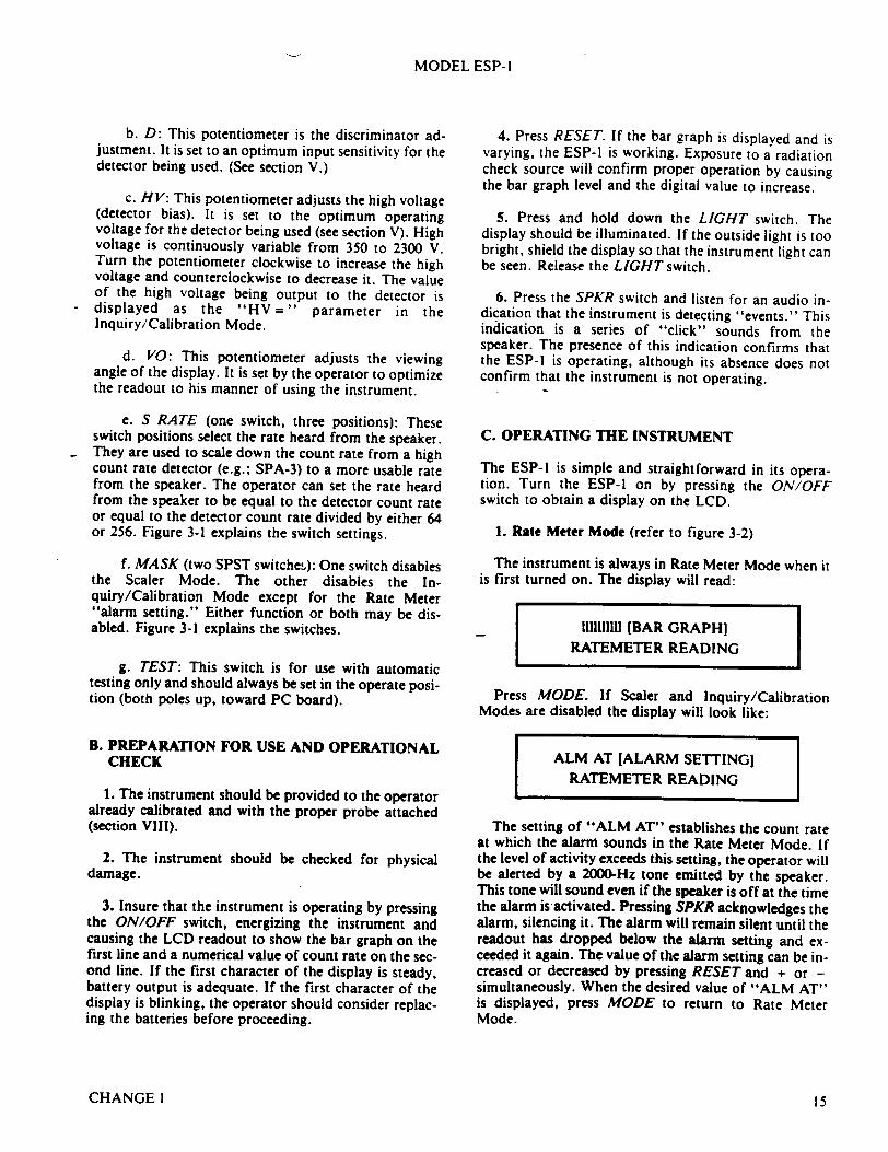
MODEL ESP- I
b. D: This potentiometer is the discriminator adjustment. It is set to an optimum input sensitivity for the detector being used. (See section V.)
c. HV: This potentiometer adjusts the high voltage (detector bias). It is set to the optimum operating voltage for the detector being used (see section V). High voltage is continuously variable from 350 to 2300 V. Turn the potentiometer clockwise to increase the high voltage and counterclockwise to decrease it. The value of the high voltage being output to the detector is displayed as the "HV=" parameter in the Inquiry/Calibration Mode.
d. VO: This potentiometer adjusts the viewing angle of the display. It is set by the operator to optimize the readout to his manner of using the instrument.
e. S RATE (one switch, three positions): These switch positions select the rate heard from the speaker. They are used to scale down the count rate from a high count rate detector (e.g.; SPA-3) to a more usable rate from the speaker. The operator can set the rate heard from the speaker to be equal to the detector count rate or equal to the detector count rate divided by either 64 or 256. Figure 3-1 explains the switch settings.
f. MASK (two SPST switches): One switch disables the Scaler Mode. The other disables the Inquiry/Calibration Mode except for the Rate Meter "alarm setting." Either function or both may be disabled. Figure 3-1 explains the switches.
g. TEST: This switch is for use with automatic testing only and should always be set in the operate position (both poles up, toward PC board).
B. PREPARATION FOR USE AND OPERATIONAL CHECK
1. The instrument should be provided to the operator already calibrated and with the proper probe attached (section VIII).
2. The instrument should be checked for physical damage.
3. Insure that the instrument is operating by pressing the ON/OFF switch, energizing the instrument and causing the LCD readout to show the bar graph on the first line and a numerical value of count rate on the second line. If the first character of the display is steady, battery output is adequate. If the first character of the display is blinking, the operator should consider replacing the batteries before proceeding.
4. Press RESET. If the bar graph is displayed and is varying, the ESP-I is working. Exposure to a radiation check source will confirm proper operation by causing the bar graph level and the digital value to increase.
5. Press and hold down the LIGHT switch. The display should be illuminated. If the outside light is too bright, shield the display so that the instrument light can be seen. Release the LIGHT switch.
6. Press the SPKR switch and listen for an audio indication that the instrument is detecting "events." This indication is a series of "click" sounds from the speaker. The presence of this indication confirms that the ESP-1 is operating, although its absence does not confirm that the instrument is not operating.
C. OPERATING THE INSTRUMENT
The ESP-l is simple and straightforward in its operation. Turn the ESP-l on by pressing the ON/OFF switch to obtain a display on the LCD.
1. Rate Meter Mode (refer to figure 3-2)
The instrument is always in Rate Meter Mode when it is first turned on. The display will read:
1I11111111 [BAR GRAPH] RATEMETER READING
Press MODE. If Scaler and Inquiry/Calibration Modes are disabled the display will look like:
ALM AT [ALARM SETTING] RATEMETER READING
The setting of "ALM AT" establishes the count rate at which the alarm sounds in the Rate Meter Mode. If the level of activity exceeds this setting, the operator will be alerted by a 2000-Hz tone emitted by the speaker. This tone will sound even if the speaker is off at the time the alarm is activated. Pressing SPKR acknowledges the alarm, silencing it. The alarm will remain silent until the readout has dropped below the alarm setting and exceeded it again. The value of the alarm setting can be increased or decreased by pressing RESET and + or simultaneously. When the desired value of "ALM AT" is displayed, press MODE to return to Rate Meter Mode.
CHANGE1 15
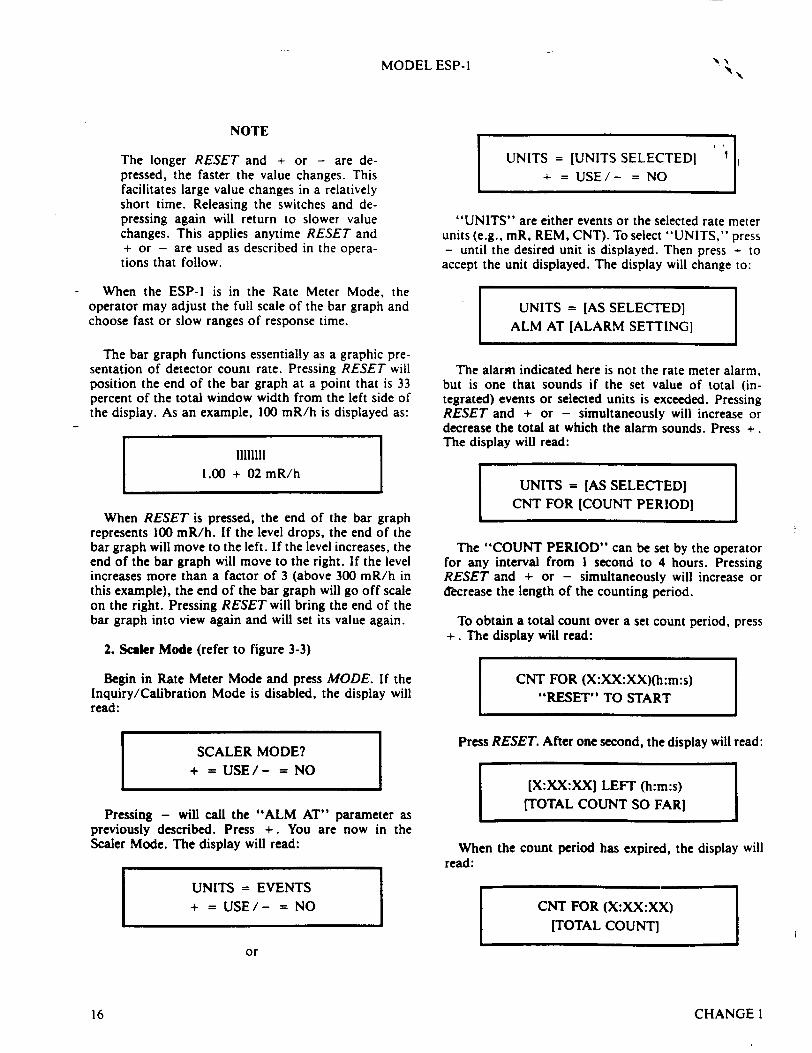
MODEL ESP-I
NOTE
The longer RESET and + or - are depressed, the faster the value changes. This facilitates large value changes in a relatively short time. Releasing the switches and depressing again will return to slower value changes. This applies anytime RESET and + or - are used as described in the operations that follow.
When the ESP-l is in the Rate Meter Mode, the operator may adjust the full scale of the bar graph and choose fast or slow ranges of response time.
The bar graph functions essentially as a graphic presentation of detector count rate. Pressing RESET will position the end of the bar graph at a point that is 33 percent of the total window width from the left side of the display. As an example, 100 mR/h is displayed as:
11111111 1.00 + 02 mR/h
When RESET is pressed, the end of the bar graph represents 100 mR/h. If the level drops, the end of the bar graph will move to the left. If the level increases, the end of the bar graph will move to the right. If the level increases more than a factor of 3 (above 300 mR/h in this example), the end of the bar graph will go off scale on the right. Pressing RESET will bring the end of the bar graph into view again and will set its value again.
2. Scaler Mode (refer to figure 3-3)
Begin in Rate Meter Mode and press MODE. If the Inquiry/Calibration Mode is disabled, the display will read:
SCALER MODE? + = USE/- = NO
Pressing - will call the "ALM AT" parameter as previously described. Press +. You are now in the Scaler Mode. The display will read:
UNITS = EVENTS + = USE/- = NO
UNITS = [UNITS SELECTEDI
+ = USE/- = NO
"UNITS" are either events or the selected rate meter units (e.g., mR, REM, CNT). To select "UNITS," press - until the desired unit is displayed. Then press - to accept the unit displayed. The display will change to:
UNITS = [AS SELECTED] ALM AT [ALARM SETTING]
The alarm indicated here is not the rate meter alarm, but is one that sounds if the set value of total (integrated) events or selected units is exceeded. Pressing RESET and + or - simultaneously will increase or decrease the total at which the alarm sounds. Press +. The display will read:
UNITS = [AS SELECTED) CNT FOR [COUNT PERIOD]
The "COUNT PERIOD" can be set by the operator for any interval from I second to 4 hours. Pressing RESET and + or - simultaneously will increase or decrease the length of the counting period.
To obtain a total count over a set count period, press +. The display will read:
CNT FOR (X:XX:XX)(h:m:s) "RESET" TO START
Press RESET. After one second, the display will read:
[X:XX:XX] LEFT (h:m:s) (TOTAL COUNT SO FAR]
When the count period has expired, the display will read:
CNT FOR (X:XX:XX) [TOTAL COUNT]
or
CHANGEI16
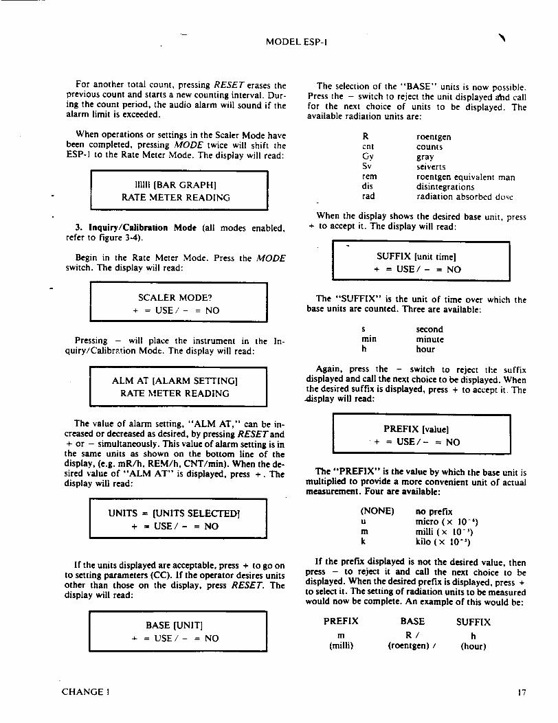
MODEL ESP-I
For another total count, pressing RESET erases the previous count and starts a new counting interval. During the count period, the audio alarm will sound if the alarm limit is exceeded.
When operations or settings in the Scaler Mode have been completed, pressing MODE twice will shift the ESP-] to the Rate Meter Mode. The display will read:
111111 [BAR GRAPH) RATE METER READING
3. Inquiry/Calibration Mode (all modes enabled, refer to figure 3-4).
Begin in the Rate Meter Mode. Press the MODE switch. The display will read:
SCALER MODE? + = USE/- = NO
Pressing - will place the instrument in the Inquiry/Calibrption Mode. The display will read:
ALM AT [ALARM SETTING] RATE METER READING
The value of alarm setting, "ALM AT," can be increased or decreased as desired, by pressing RESETand + or - simultaneously. This value of alarm setting is in the same units as shown on the bottom line of the display, (e.g. mR/h, REM/h, CNT/min). When the desired value of "ALM AT" is displayed, press +. The display will read:
UNITS = [UNITS SELECTED] + = USE/- = NO
If the units displayed are acceptable, press + to go on to setting parameters (CC). If the operator desires units other than those on the display, press RESET. The display will read:
BASE [UNIT] + = USE/- = NO
The selection of the "BASE" units is now possible. Press the - switch to reject the unit displayed ahd call for the next choice of units to be displayed. The available radiation units are:
R cnt Gy Sv rem dis rad
roentgen counts gray seiverts roentgen equivalent man disintegrations radiation absorbed dose
When the display shows the desired base unit, press + to accept it. The display will read:
SUFFIX [unit time] + = USE/- = NO
The "SUFFIX" is the unit of time over which the base units are counted. Three are available:
min h
second minute hour
Again, press the - switch to reject the suffix displayed and call the next choice to be displayed. When the desired suffix is displayed, press + to accept it. The
.display will read:
PREFIX [value] +=USE/- =NO
The "PREFIX" is the value by which the base unit is multiplied to provide a more convenient unit of actual measurement. Four are available:
(NONE) no prefix u micro( x 10-') m milli (x 10-') k kilo (x 10+1)
If the prefix displayed is not the desired value, then press - to reject it and call the next choice to be displayed. When the desired prefix is displayed, press + to select it. The setting of radiation units to be measured would now be complete. An example of this would be:
PREFIX
m (milli)
BASE
R / (roentgen)/
SUFFIX
h (hour)
CHANGEI 17

MODEL ESP-I
The units may be selected in any combination of prefix/base/suffix. Press the + switch to select the prefix and prepare the instrument for the setting of parameters, (i.e. calibration). Section V, "Maintenance," provides nominal values of the following parameters as they apply to the particular detector being used. The display will read:
CC = (numerical value] RATE METER READING
The calibration constant (CC) is the number used to convert the detector count rate to the displayed base unit previously selected. Specifically, the displayed rate meter reading arrived at by dividing the counts per second (from the detector) by CC and then scaling the result based on the selected prefix and suffix. To increase the value of CC, press RESET and +
-simultaneously. To decrease the value of CC press RESET and - simultaneously. Keep in mind that increasing or decreasing CC will have the inverse affect on the rate meter reading. With the rate meter reading always displayed on the bottom line, the changing value of CC and its affect on the reading is immediately noticeable. When the desired value of CC is displayed, press +. The display will read:
DT (SEC) [numerical value]
RATE METER READING
This parameter is the dead time (DT) of the detector, in seconds. It is used to correct for coincidence loss from the detector, yielding a more linear response to the radiation field being measured. An extra decade of range is possible from most detectors due to the DT correction. Typical values of DT are in microseconds (x 10-'). To increase the value of DT, press RESET and + simultaneously. To decrease the value of DT, press RESET and - simultaneously.
NOTE
For a more detailed explanation on setting "CC" and "DT," as well as nominal values for various detectors, refer to section V.A.
When the desired value of DT is displayed, press + ." The display will read:
HV = [numerical value]
RATE METER READING
The "HV" value is the high voltage bias applied to the detector. Adjusting the actual high voltage is performed with the internal control potentiometer (labeled "HV"). The external controls, RESETand + or -, are to be used only when calibrating the displayed HV readout to match the actual high voltage (refer to section V). When properly calibrated, the HV parameter allows for high voltage monitoring on the top line of the display and the rate meter reading on the bottom. This is particularly useful when running detector plateaus. Pressing + will return the display to the "ALM AT" parameter. Pressing - repeatedly will step the instrument through the parameters in reverse order from that shown in the preceding paragraphs. Pressing the MODE switch anytime a parameter and rate meter reading are displayed, will revert the instrument to the Rate Meter Mode.
Summarizing, the ESP-l provides the following to the
operator.
a. In the Rate Meter Mode:
0 Bar graph graphically displaying count rate. * Count rate in selected units per unit time. * Audible alarm if the rate exceeds the value set.
b. In Scaler Mode:
e Time remaining in the counting period which was set.
* Integrated value and selected units so far in the counting period.
• End of counting period, total time, and integrated value in selected units at the end of the counting period.
* Audible alarm if set limit on total count is exceeded during the set count period.
c. In the Inquiry/Calibration Mode
e Ability to set the rate meter alarm point. * Enables the selection of units to be used in Rate
Meter Mode. * Ability to set the CC and DT (calibrate) to the
detector being used.
0 Monitor the high voltage applied to the detector. Set the high voltage readout to match the actual HV.
The current rate meter reading is displayed on the bottom line whenever the "ALM AT," "UNITS =," "CC = , 9 9DT," or "HV =" parameters are displayed on the top line.
CHANGE 118
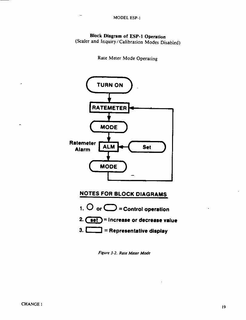
MODEL ESP- I
Block Diagram of ESP-1 Operation (Scaler and Inquiry /Calibration Modes Disabled)
Rate Meter Mode Operating
NOTES FOR BLOCK DIAGRAMS
1. 0 or ( =Control operation
2. ( = Increase or decrease value
3. = Representative display
Figure 3-2. Rate Meter Mode
CHANGEI19

MODEL ESP-I
Block Diagram of ESP-1 Operation (Inquiry/Calibration Mode Disabled)
Scaler Mode Operating
Figure 3-3. Scaler Mode
CHANGEl20
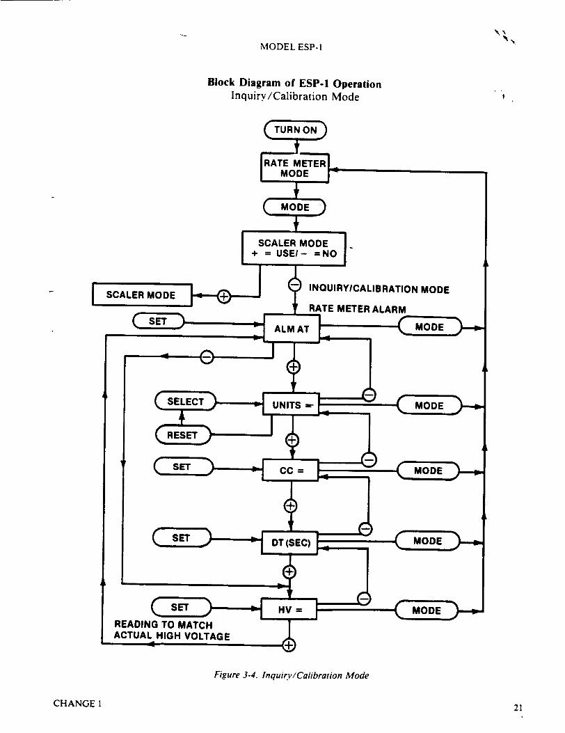
N'MODEL ESP-1
Block Diagram of ESP-1 Operation Inquiry/Calibration Mode
Figure 3-4. InquirvyCalibration Mode
CHANGE1 21
MODEL ESP-l
SECTION IV THEORY OF OPERATION
5. Microcomputer
The ESP-I employs current technology to provide to the user a compact instrument that can be used to measure several kinds of radiation as detected by different detectors. In addition, the ESP-I is portable and will operate for over 250 hours before battery replacement becomes necessary. The instrument's most important function is the delivery of accurate information to the operator efficiently and rapidly.
B. FUNCTIONAL THEORY
The ESP-l consists of six functional sections as detailed
below (see figures 7-1, 7-2, 7-3).
1. Detector
The detector connected to the ESP-I is selected to optimize its output for the radiation of interest. It provides the pulse signal to the electronics for counting. The pulse rate from the detector is proportional to the radiation-field intensity at the detector.
2. High-Voltage Supply
The high-voltage supply provides the bias voltage to the detector as required for proper operation. The high voltage is adjustable to provide the correct operating voltages for a large selection of detectors and regulated to enhance operating stability.
3. Amplfler/Diicriminstor
The amplifier is a linear, fixed-gain, multistage design. It amplifies the signal from the probe to a usable level at the amplifier output. The discriminator provides a signal on its output only if the signal from the amplifier exceeds its adjustable threshold. This, in turn, provides a means for counting only the radiation signals and to reject any noise and/or unwanted signals.
4. Speaker/Alarm
The speaker/alarm section provides an audible "click rate" from the speaker, which is proportional to the output of the amplifier/discriminator. This rate can be scaled down to enhance the usefulness of the speaker when high-count rate (very sensitive) detectors are employed. When the alarm is activated, the speaker emits a continuous 2000-Hz tone.
The microcomputer is an eight-bit device programmed to function as the interface between the ESP-i operator and the information provided by the radiation detector (probe). Its program logic and speed of execution allow the ESP-l to be extremely versatile by applying mathematical functions and logic to its input signals and displaying the results to the operator in an understandable format.
6. Low:Voltage Supply
The low-voltage supply regulates and provides the control point for the operating voltage for the ESP-I electronics.
C. OPERATIONAL THEORY
For the discussion that follows, please refer to figures 7-1 through 1.12.
1. Low-Voltage Power Supply
Power is supplied to the ESP-I electronics by six C-type dry-cell batteries and regulated to 5.0 volts with AI01. The battery output limits are 9 volts for new batteries down to approximately 5.4 volts for "dead" batteries. The lower limit is set by the voltage differential between the input and output of AI01 and enables A1O1 to maintain voltage regulation.
Computer voltage (Vc) is always applied to the computer to maintain its random-access memory (RAM). With the ESP-l off, battery drain consists of the normal leakage current of CMOS, typically less than 50 microamperes. During battery changeout, capacitor Cl (0.047 F) provides power for RAM for about 20 minutes (instrument off). This power maintains all the operating parameters at the values entered during calibration.
Pressing the ON/OFF keypad causes the microcomputer to initialize the program at BEGIN (figure 7-8).
If the ESP-I is operating when the keypad is pressed, it sets "PWR ON" to Al, HI (+ 5 V), turning off the low voltage (QI01, Q102, Q103) to all electronics except the microcomputer and its program access (Al, A2, A3).
CHANGE 1
A. GENERAL
23
MODEL ESP-I
If the ESP-I is off when the ON/OFF keypad is pressed, it sets "PWR ON" low (0.0 volts) turning QIOI on. This supplies the operating voltage ( + V) to the amplifier, high-voltage control, display, and speaker circuitry. It also switches on the battery voltage (VBB) to the HV oscillator and battery sense via Q102 and Q103. (All circuits are now energized.)
Integrated circuit (IC) A I I converts + V to a negative voltage to provide a bias voltage (Vo) to the display (LCD). Adjustment of Vo allows the operator to optimize the viewing angle of the display.
Battery condition is monitored by one of the comparators in A103. Pin 15 is connected to the regulated reference (amplifier "bias"). When the voltage at pin 14 falls below this reference, the output (pin 16) goes low. This voltage transition is input to the microcomputer, causing it to initiate blinking of the first character on the LCD. The blinking indicates a low battery condition to the operator. This switch point occurs when the battery output is approximately 5.9 volts and allows the instrument to operate properly for about another four hours or until the battery voltage reaches its minimum.
Pressing the LIGHT keypad lights the LCD via QI and DSI mounted on the keyboard. Diodes CR2 and CR3 set Q I and R3 as a current source that maintains a constant drain on the batteries and prolongs lamp life.
2. High-Voltage Power Supply
High voltage is obtained by stepping up (TI) the voltage of the oscillator, (Q10), rectifying it (CRI0) and filtering the output (C12, C13, R 11). High voltage is regulated by feeding back the output to control the oscillator. At turn on, Q103 is on, causing QIO to turn on. Current flow through TI (pins 2, 3) feeds back via TI (pins 4, 5), turning off (blocking) QIO. With QIO off, blocking stops and QIO turns on. This is a blocking oscillator, the frequency of which is limited by C16-RIO, maintaining best efficiency of TI.
The high-voltage output is fed back via resistive divider R12 to a voltage follower (AI02, pin 3). This stage, with a high input impedance, allows R12 to be large, presenting a minimal current load for the supply. The output of the voltage follower is then proportional to the high-voltage output. Because the input impedance to this stage is high, CR104, R113, and C114 provide filtering to reduce noise interference.
The filtered high voltage sample is input to a comparator (AI02, pin 15) that is referenced to the high voltage adjusting potentiometer, R 17. When the sample (pin 15) exceeds the reference (pin 14), the output at pin 16 goes low, turning off Q103, which turns off the oscillator, reducing high voltage. As the sample decreases to less
than the reference, pin 16 goes high, turning Q103 on. The oscillator then runs to increase the high voltage. In this way, the high voltage is regulated to a value set by the HV adjusting potentiometer, R17.
The filtered output of the high voltage sample is also applied to pin 5 of A102. This stage is connected with Q104 to achieve a voltage-to-current conversion with current through RI14 proportional to high voltage. Current-to-frequency conversion is performed by the voltage comparator A102, pins 11, 12, and 10. The outputt at pin 10 is a frequency (FHv) that is proportional to high voltage. This frequency is input to the microcomputer, which can then convert FHV to a digital value and display it as high voltage.
3. Amplifier/Discriminator
Transistor Q106 and the amplifier section of A103 form a dc-coupled linear amplifier. The gain of this amplifier is set by R 126 and the output impedance of the preamplifier, Q106, along with R127-RI28 and the gain of the preamplifier stage. Feedback via R141 provides dc stability. The dc bias is set by R131-RI32 to half of + V (-2.5 volts) for a linear swing of signal on the
amplifier outputs. Input protection is provided by CRI03R122, which gives a charge path for input capacitor CI 1 when high voltage is shorted.
The amplifier output signal is coupled to the discriminator (AI03, pin 12) with capacitor C110. An output
-(AI03, pin 10) occurs when the amplitude of the signal (pulse) exceeds the reference (A 103, pin 11) set by the discriminator potentiometer, R16.
The discriminator output is divided down by 2, A 105, yielding a binary input for the microcomputer. The microcomputer counts the binary transitions and calculates and displays the result as either rate or integrated value for the operator.
4. Speaker
Pulses that cause an output from the discriminator are input to the speaker control either directly or counted down for slower audible rate. In either case, the rate from the speaker is proportional to the radiation level at the detector (probe). The speaker is enabled or disabled by the microcomputer when the operator presses the SPKR keypad. The speaker is enabled when "SPKR" is low (0 volt).
One-half of A104 is interconnected as a monostable multivibrator (TRIGGER). The output pulse (TRIGGER) width is set by R136-CI12 time constant. The other half of A104 is configured as an oscillator. It is running while the trigger output (pin 11) is low, driving the speaker via QI I and Q12. The input signal to the
CHANGEI24

MODEL ESP- 1
trigger is differentiated by CI I1-R135 to prevent excessive trigger pulse widths.
The alarm is activated by "ALM" and "SPKR" set low (0 volts) by the microcomputer. This sets the trigger output low (pin 11), turning on the oscillator frequency to the speaker.
"ALM" low also activates the auxiliary alarm ("A") providing an active low output for external indication (250 mA, 20 Vdc maximum).
5. Keyboard
The switch poles are etched on the PC board. Contact between the poles is made by a conductive pad cast into each keypad. Pressing a keypad effectively short-circuits the poles.
The ON/OFF keypad pulls the "RST" (pin 9) of the microcomputer high. This causes the computer to reset itself and begin running its program at the program beginning (see figure 7-8). The LIGHT keypad causes DSI to turn on via QI, lighting the display.
All other keypads are inputs to the microcomputer via its input/output (I/O) port Pl, which is configured as an input port under program control. These inputs are normally high. Pressing a keypad pulls the corresponding port input low.
The program running in the microcomputer performs the contact debounce, determines the switch(es) pressed, and logically performs the task(s) associated with the keyboard condition.
6. Microcomputer
Simply stated, a computer must have provisions for moving data in and out (I/O), a logical means of handling and saving data (memory), and logical elements to control I/O and memory (central processing unit, CPU). To perform any task, the CPU must execute a series of logical steps (program), which is contained in read-only memory (ROM). Memory used to save data written to or read from it is random-access memory (RAM). The RAM contains the parameters (variables), logic flags, data, scratch pads, etc., used by the program.
a. Inputs:
(1) Keyboard inputs are the operator's input to the computer. Under program control, the inputs cause the task associated with the keypad(s) to be performed (see section III).
(2) Mask (SlI) switch inputs are used to signal (flag) the program to perform certain tasks differently or omit them completely (see section III).
(3) FHV is a frequency, the rate of which is proportional to the high voltage applied to the detector (probe). When the program is displaying high voltage (HV) to the user, it converts this frequency input to its HV equivalent.
(4) LO BATT (low battery) input (normally high) switches low when the low-battery condition is sensed (see "Low Voltage," section IV.4.C.l). This causes the program to blink the first character on the display at each display update (output), warning the operator of the-low-battery condition.
(5) CNT (count) input is a signal the rate of which is proportional to the radiation intensity at the detector. The rate is calculated by the program (counts/ time). The calibration constant (CC) and correction factor (CF [based on detector dead time]) result in a value in radiation units as calibrated. The length of the bar graph is also calculated. The results are then output to the display for the operator.
b. Outputs:
(1) "PWR ON" (power on, active low) is output under program control to turn the power to the instrument on or off (see "Low Voltage Supply," section IV.C. 1).
(2) "SPKR" (speaker on, active low) is output under program control when the SPKR keypad is pressed. The output is complemented at each press of the keypad. This results in a push-on/push-off action of the SPKR keypad (see "Speaker," section IV.C.4).
(3) "ALM" (alarm output, active low) is outputactivated when the program has sensed that the calculated reading has exceeded the value input by the operator for "ALM AT" (alarm setting). "SPKR" output is also activated to turn the speaker on (see "Speaker," section IV.C.4).
(4) The display is a liquid crystal (LCD) 5 x 7 dot matrix character, 2 lines of 16 characters per line. This allows the full alphanumeric ASCII character set as well as the special characters used to display the analog bar graph. The LCD is a "smart" display in that it is supported by its own microprocessor and program, thus relieving the computer of this processing load.
The computer outputs to the LCD command instructions and data to be displayed based on the tasks being performed. These data/commands are passed to the display via the 8-bit address-data bus (Al. port P0). A command (instruction) is differentiated from data (character-to-display) by address line 14 (Al, pin 27), high equals command. The command/data are accepted by the LCD when "WR" (Al, pin 16) is low simultaneously with address line 15 (Al, pin 28) being low. This
CHANGE !25
MODEL ESP-1
yields an address of 8000H for data and OCOOOH for commands.
The LCD requires its "E" (enable, pin 6) to be strobed 0.14 microseconds (minimum) after data and addresses are stable. The quad NOR gate, A4 and resistance-capicitance R-C time constants provided by R2-C6 and RI-C5 accomplish this delay.
The viewing angle of the display may be changed by varying the V, input (pin 3).
The display is not considered to be field repairable.
c. Memory and CPU:
All RAM registers and timers are contained within the microcomputer chip and are not available to be observed. Their functions are solely to control the program (i.e., program counter and stack pointer) or for use by the program to perform its tasks (RAM and ALU).
Port P0, Al, is the address-data bus. It is bidirectional (input and output). Port P2, Al, outputsthe upper eight bits of the address. On a typical program step:
(1) The address (program counter) is output at P0 (low byte) and P2 (high byte).
(2) ALE (address latch enable) is asserted and latches the address low byte in A3.
(3) PSEN (program store enable) is asserted, enabling the addressed byte to be input to the computer via P0.
(4) The program step is executed.
The program is stored in A2.
26 CHANGE I
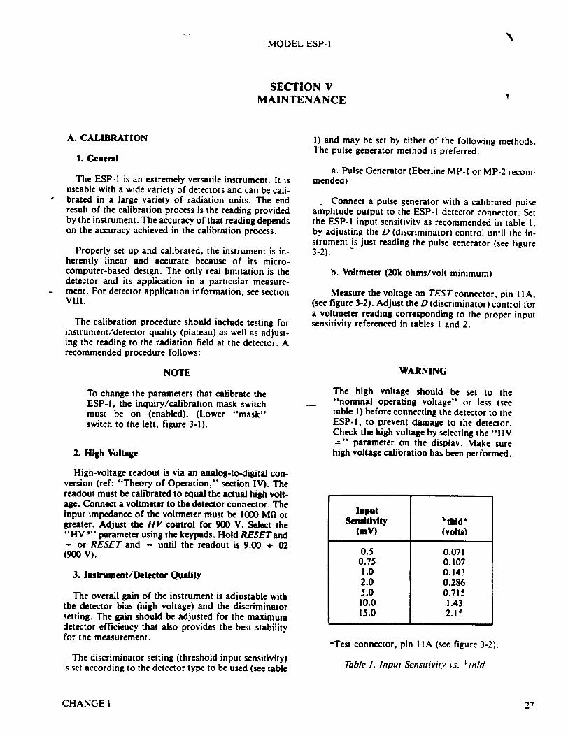
MODEL ESP-l
SECTION V MAINTENANCE
1) and may be set by either of the following methods. The pulse generator method is preferred.
A. CALIBRATION
1. General
The ESP-I is an extremely versatile instrument. It is useable with a wide variety of detectors and can be calibrated in a large variety of radiation units. The end result of the calibration process is the reading provided by the instrument. The accuracy of that reading depends on the accuracy achieved in the calibration process.
Properly set up and calibrated, the instrument is inherently linear and accurate because of its microcomputer-based design. The only real limitation is the detector and its application in a particular measurement. For detector application information, see section VIII.
The calibration procedure should include testing for instrument/detector quality (plateau) as well as adjusting the reading to the radiation field at the detector. A recommended procedure follows:
NOTE
To change the parameters that calibrate the ESP-1, the inquiry/calibration mask switch must be on (enabled). (Lower "mask" switch to the left, figure 3-1).
2. High Voltage
High-voltage readout is via an analog-to-digital conversion (ref: "Theory of Operation," section IV). The readout must be calibrated to equal the actual high voltage. Connect a voltmeter to the detector connector. The input impedance of the voltmeter must be 1000 MO or greater. Adjust the HV control for 900 V. Select the "HV "' parameter using the keypads. Hold RESET and + or RESET and - until the readout is 9.00 + 02 (900 V).
3. Instrument/Detector Quality
The overall gain of the instrument is adjustable with the detector bias (high voltage) and the discriminator setting. The gain should be adjusted for the maximum detector efficiency that also provides the best stability for the measurement.
The discriminator setting (threshold input sensitivity) is set according to the detector type to be used (see table
a. Pulse Generator (Eberline MP-I or MP-2 recommended)
- Connect a pulse generator with a calibrated pulse amplitude output to the ESP-l detector connector. Set the ESP-) input sensitivity as recommended in table 1, by adjusting the D (discriminator) control until the instrument is just reading the pulse generator (see figure 3-2).
b. Voltmeter (20k ohms/volt minimum)
Measure the voltage on TEST connector, pin I IA, (see figure 3-2). Adjust the D (discriminator) control for a voltmeter reading corresponding to the proper input sensitivity referenced in tables I and 2.
WARNING
The high voltage should be set to the "nominal operating voltage" or less (see table 1) before connecting the detector to the ESP-I, to prevent damage to the detector. Check the high voltage by selecting the "HV =" parameter on the display. Make sure high voltage calibration has been performed.
Input Sensitivity Vthld*
(mY) (volts)
0.5 0.071 0.75 0.107 1.0 0.143 2.0 0.286 5.0 0.715 10.0 1.43 15.0 2.1Xf
*Test connector, pin I IA (see figure 3-2).
Table 1. Input Sensitivity vs. I thld
CHANGE 1 27

MODEL ESP-1
c. Connect the detector to the ESP-I. With the discriminator properly set, the plateau curve can be plotted. This is the only data that can truly verify that the detector and instrument are operating properly and, with the possible exception of G-M detectors, should be plotted anytime a detector is changed or repaired.
The bias (high voltage) operating point for a G-M detector is fixed by its physical properties (i.e., size, counting gas, anode size, and fill pressure). Therefore, a check of its sensitivity or efficiency may preclude the plateau. It should be within + / - 20 percent of specified sensitivity at the specified operating voltage (see section VIII).
To plot the plateau (figure 5-1):
(1) Select the "HV = " parameter on the display (inquiry/calibration mode). The second line of the display shows the current average rate from the detector.
(2.) Adjust the HV control for a low reading from the detector. Record the reading and the high voltage.
(3) Increase HVin steps of 50 volts, recording the high voltage reading at each step. Allow enough time at each step for the reading to stabilize.
(4) Select the operating high voltage and adjust the H V control accordingly.
10,000
C
0 U.
5,000
1,000
500
100
28
4. Rate Meter Calibration
For clarity, a brief overview of the readout determination follows:
a. The average count rate is calculated each onehalf second. This average is maintained in counts per second (cps) and is the basic unit for all readout displays. This average is also corrected for detector dead time (parameter DT).
b. The average (AVG) is divided by the calibration constant (parameter CC) (see table 3) and the proper factors, specified in the units, prefix, and suffix are applied, converting the cps to the radiation units selected. This is performed and displayed every 2.0 seconds.
The calibration is performed by adjusting the CC and DT values so that the rate meter reading agrees with the radiation intensity at the detector.
Note that the dead-time correction is applied to the average before CC. At lower count rates, this correction is insignificant.
Refer to table I for the following:
(1) Set the instrument to Inquiry/Calibration Mode (discussed in section III.C.).
(2) Set the high voltage and input sensitivity to suggested values for detector being calibrated.
1.2
CHANGE1
0.7 0.8 0.9 1.0 1.1
HIGH VOLTAGE (x 1000)
Figure 5-1. Typical Detector Plateau
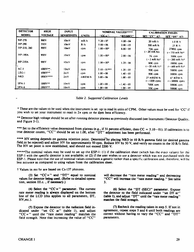
DETECTOR HIGH INPUT NOMINAL VALUES***** CALIBRATION FIELDS MODEL VOLTAGE SENSITIVITY UNITS "cc-. DTiSEC)". SET "CC" AT: SET "DT" AT:
I'!P-270 900V lOmV mR/h 7.20+07 1.00-04 20 mR/h 1.0 R'h HP-290 550V IOmV R/h 5.00-4-06 2.00-05 500 mR/h 25 Rih HP-210. 260 900V 10mY cpm 1.00+000 8.00-05 72K cpm 2700K cpm
(-20 mR/h)t (-750 mR/h)t HP-190A 900V |0mV cpm 1.00 + 00* 2.00-04 5K Cpm 500K cpm
(-2 mR/h)t (-200 mR/h)t HP-230A 900V IOmV cpm 1.00+000 1.20-04 60K cpm 1800K cpm
(-20 mR/h)t (-600 mR/hI)t AC-3 I000V**. OmV dpm 3.10-01"' 1.20-05 50K cpm 3000K cpm LEG-I 1000V' 2mV cpm 1.00+00 1.40-05 50K cpm 3000K cpm NRD 1800Voo** 2mV mREM/h 3.00+06 1.00-05 27 mREM/h 67 REM/h
(- 1200 cpm) - 3000K cpm) SPA-3 1000VM I0m V cpm 1.00+00 - 1.40-05 700K cpm 3000K cpm SPA-6 I1000oV* I10mV cpm 1.00+00 1.00-05 50K cpm 3000K cpm
Table 2. Suggested Calibration Levels
These are the values to be used when the instrument is set up to read in units of CPM. Other values must be used for 'CC' if you wish to set your instrument to read in 2v cpm or 41r dpm beta efficiency. ** Detector high voltage should be set after running detector plateau as previously discussed (see Instrument/Detector Quality, and Figure 5-1).
*** Set to the efficiency value determined from plateau (e.g., if 31 percent efficient, then CC = 3.10- 01). If calibration is to true detector counts, "CC" should be set to 1.00, after "DT" adjustment has been performed.
•*** HV setting depends on gamma rejection point. Determine-by placing NRD in 10 R/h gamma field (or desired gamma field to be rejected) and adjust HV for approximately 50 cpm. Reduce HV by 50 V, and verify no counts in the 10 R/h field. The HV set point is now established, and should not exceed 2200 V.
*****The nominal values may be used to set up the ESP-l: (1) if the calibration sheet (which has the exact values) for the ESP-I with the specific detector is not available; or (2) if the user wishes to use a detector which was not purchased with the ESP-1. Please note that the use of nominal values constitutes a generic rather than a specific calibration and. therefore, will be less accurate as compared to using values from the calibration sheet.
t Values in mr/hr are based on Cs-137 photons.
(3) Set "CC=" and "DT" equal to nominal values for detector being used. (Refer to detailed operation, section Il.c. , if necessary.)
(4) Select the "CC=" parameter. The current rate meter reading is always displayed on the bottom line of the LCD (this applies to all parameters, DT, HV,etc.).
(5) Expose the detector to the radiation field indicated under "set CC at" (table 1), and adjust "CC =" until the "rate meter reading" matches the field strength. Note that increasing the value of "CC"
will decrease the "rate meter reading" and decreasing "CC" will increase the "rate meter reading." See table 3.
(6) Select the "DT (SEC)" parameter. Expose the detector to the field indicated under "set DT at" (table 1), and adjust "DT" until the "rate meter reading" matches the field strength.
(7) Recheck the reading taken in step 5. If not in agreement, repeat steps 5 and 6 until both readings are correct without having to vary the "CC" and "DT" parameters.
CHANGEI 29
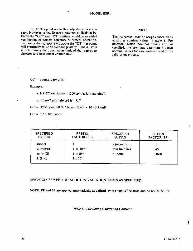
MODEL ESP-I
(8) At this point no further adjustment is necessary. However, a few linearity readings at fields in between the "CC" and "DT" settings would be an added verification of correct detector/instrument operation. Increasing the radiation field above the "DT" set point, will eventually cause an over-range alarm. This is useful in determining the upper range limit of that particular detector and instrument combination.
NOTE
The instrument may be rough-calibrated by adjusting nominal values in table 1. For detectors which nominal values are not specified, the user may determine his own nominal values for ease and/or speed of the calibration process.
CC = counts/base unit.
Example:
a. HP-270 sensitivity is 1200 cpm/mR/h (nominal).
b. "Base" unit selected is "R."
CC = (1200 cpm/mR/h * 60min/h)/I x 10-3 R/mR
CC = 7.2 x 10⁷ cnt/R
(AVG/CC) * SF * PF = READOUT IN RADIATION UNITS AS SPECIFIED.
NOTE: PF and SF are applied automatically as defined by the "units" selected and do not affect CC.
Table 3. Calculating Calibration Constant
CHANGEI
SPECIFIED PREFIX SPECIFIED SUFFIX PREFIX FACTOR (PF) SUFFIX FACTOR (SF)
(none) 1 s (second) I u (micro) 1 x 10-( min (minute) 60 m (milli) I x 10-1 h (hour) 3600 k (kilo) I x 10,
I
30
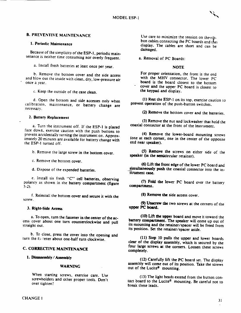
MODEL ESP-I
B. PREVENTIVE MAINTENANCE
1. Periodic Maintenance
Because of the simplicity of the ESP-l, periodic maintenance is neither time consuming nor overly frequent.
a. Install fresh batteries at least once per year.
b. Remove the bottom cover and the side access and blow out the inside with clean, dry, low-pressure air once a year.
c. Keep the outside of the case clean.
d. Open the bottom and side accesses only when calibration, maintenance, or battery change are necessary.
2. Battery Replacement
a. Turn the instrument off. If the ESP-I is placed face down, exercise caution with the push buttons to prevent accidentally turning the instrument on. Approximately 20 minutes are available for battery change with the ESP-l turned off.
b. Remove the large screw in the bottom cover.
c. Remove the bottom cover.
d. Dispose of the expended batteries.
e. Install six fresh "C" cell batteries, observing polarity as shown in the battery compartment (figure 5-2).
f. Reinstall the bottom cover and secure it with the screw.
3. Right-Side Access
a. To open, turn the fastener in the center of the access cover about one turn counterclockwise and pull straight out.
b. To close, press the cover into the opening and turn the t:., ener about one-half turn clockwise.
C. CORRECTIVE MAINTENANCE
1. Disasseunbly/Assembly
WARNING
When starting screws, exercise care. Use screwholders and other proper tools. Don't over tighten!
Use care to minimize the tension on therpbon cables connecting the PC boards and th e display. The cables are short and can be damaged.
a. Removal of PC Boards:
NOTE
For proper orientation, the front is the end with the MHV connector. The lower PC board is the board closest to the bottom cover and the upper PC board is closest to the keypad and display.
(1) Rest the ESP-I on its top, exercise caution to prevent operation of the push-button switches.
(2) Remove the bottom cover and the batteries.
(3) Remove the nut and lockwasher that hold the coaxial connector at the front of the instrument.
(4) Remove the lower-board mounting screws (one at each corner, one in the center of the opposite end near speaker).
(5) Remove the screws on either side of the speaker (in the semicircular retainer).
(6) Lift the front edge of the lower PC board and simultaneously push the coaxial connector into the instrument case.
(7) Fold the lower PC board over the battery compartment.
(8) Remove dte side access cover.
(9) Unscrew the two screws at the corners of the upper PC board.
(10) Lift the upper board and move it toward the battery compartment. The speaker will come up out of its mounting and the retainer/spacer will be freed from its position. Set the retainer/spacer aside.
(11) Step 10 pulls the upper and lower boards clear of the display assembly, which is secured by the four large screws at the corners. Loosen these screws completely.
(12) Carefully lift the PC board set. The display assembly will come out of its position. Take the screws out of the Lucite® mounting.
(13) The light heads extend from the button contact board to the Lucite® mounting. Be careful not to break these leads.
CHANGEI31
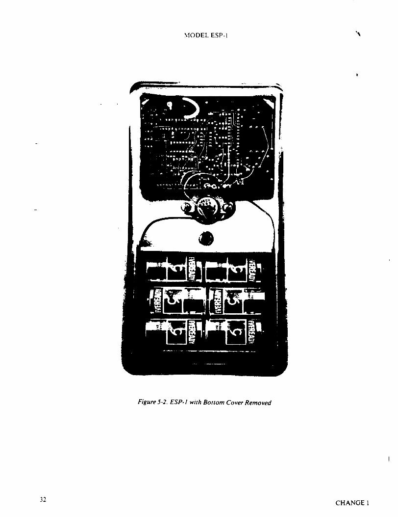
MODEL ESP-I
Figure 5-2. ESP-I with Bottom C
32
.over Removed
CHANGE 1
MODEL ESP- I
(14) To remove the board complex completely from the case, unsolder the battery leads from the lower board.
(15) To remove the speaker, unsolder the speaker leads from the lower board.
b. Reinstallation of PC boards:
(1) Insert the four screws into the corner holes of the Lucite® display mounting so that it holds the keypad board in place and so that the screws in the Lucite- line up with the threaded holes in the case. Tighten the screws.
(2) Position the upper PC board, component side up, so that the holes in the board line up with the threaded holes in the corners of the instrument case. Insen the screws and screw them down loosely.
(3) Holding up the lower board, position the speaker in its mounting.
(4) Pulling up carefully on the lower board, raise the forward edge of the upper board enough to allow the speaker retainer's channel-shaped support for the upper board to be positioned so that the board is in the
-channel. The holes in the speaker retainer should be lined up with the threaded holes in the case.
(5) Making sure that the speaker leads are not pinched under the retainer, screw the retainer in tight.
(6) Tighten the two screws on the upper board.
(7) Guide the coaxial-connector lead through the cutout at the rear of the lower board.
(8) Insert the coaxial connector through the opening in the front of the case and guide the lower board into position.
(9) The hole in the center (rear edge) of the lower board should line up with the threaded hole in the speaker retainer.
(10) Insert the screw and turn it down loosely.
(11) Insert the screws to hold each corner of the upper board.
(12) Tighten the mounting screws on the lower PC board.
(13) Install the lockwasher and nut on the coaxial connector and tighten nut.
(14) If the speaker was removed, solder the
speaker leads to the points on either end of the label SPK on the lower circuit board.
(15) If the battery leads were unsoldered, solder the red lead to the + point and the black lead to the point on the lower circuit board.
(16) Install the side access cover.
(17) Install the batteries noting polarity.
(18) Install the bottom cover.
2. Troubleshooting
The ESP-! uses the latest state-of-the-art components and circuitry available at the time of its design. Eberline's experience using similar components has shown them to be very reliable and trouble free. Realizing that failures and problems will occur, this section is intended to assist the technician with the task of repair.
Eberline provides a repair and calibration service at two locations in the United States and one in England for the European market. Contact Eberline for details (see front of manual).
To hold downtime to the minimum possible, users might consider changing the entire printed-circuit-board set. By maintaining a spare board set and exchanging the board set when a failure occurs, downtime (ineluding recalibration) can probably be limited to less than one hour. The inoperative board(s) can then be repaired in-house or by Eberline without taking the ESP-l out of service for lengthy periods of time.
NOTE
Always recalibrate after repair.
a. General Procedure
A thorough understanding of the ESP-l circuitry and program operation is necessary before any field repairs are attempted. For component problems, review section IV, "Theory of Operation" and the schematic and logic drawings, section V. For problems related to operation, review section III "Detailed Operation" and the logic flow charts, section VII.
The incorporation of a microcomputer in the ESP-l does not change the general approach to troubleshooting and repair. In short, the problem must be defined, the trouble isolated, and the defect identified. Only then can effective repair be accomplished.
The circuitry used in the ESP-l employs CMOS technology. These CMOS devices are sensitive to elec-
CHANGEI 33
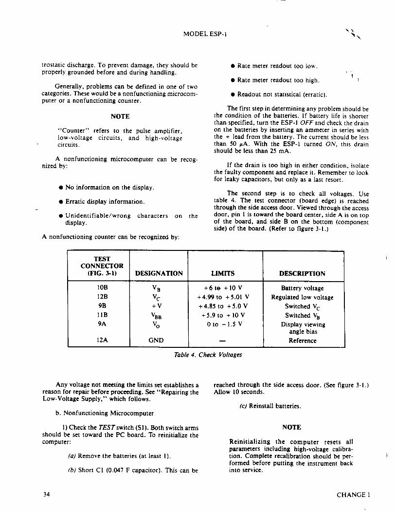
MODEL ESP-I
trostatic discharge. To prevent damage, they should be properly grounded before and during handling.
Generally, problems can be defined in one of two categories. These would be a nonfunctioning microcomputer or a nonfunctioning counter.
NOTE
"Counter" refers to the pulse amplifier, low-voltage circuits, and high-voltage circuits.
A nonfunctioning microcomputer can be recognized by:
"* No information on the display.
"* Erratic display information.
"* Unidentifiable/wrong characters on the display.
A nonfunctioning counter can be recognized by:
TEST CONNECTOR
(FIG. 3-1) DESIGNATION LIMITS DESCRIPTION
lOB VB +6 te- + 10 V Battery voltage 12B VC +4.99 to +5.01 V Regulated low voltage 9B +V + 4.85 to + 5.0 V Switched VC IIB VBB + 5.9 to + 10 V Switched VB 9A Vo 0 to -1.5 V Display viewing
angle bias 12A GND Reference
Table 4. Check Voltages
Any voltage not meeting the limits set establishes a reason for repair before proceeding. See "Repairing the Low-Voltage Supply," which follows.
b. Nonfunctioning Microcomputer
1) Check the TESTswitch (SI). Both switch arms should be set toward the PC board. To reinitialize the computer:
(a) Remove the batteries (at least 1).
(b) Short CI (0.047 F capacitor). This can be
reached through the side access door. (See figure 3-1.) Allow 10 seconds.
(c) Reinstall batteries.
NOTE
Reinitializing the computer resets all parameters including high-voltage calibration. Complete recalibration should be performed before putting the instrument back into service.
CHANGE 1
"* Rate meter readout too low.
"* Rate meter readout too high.
"* Readout not statistical (erratic).
The first step in determining any problem should be the condition of the batteries. If battery life is shorter than specified, turn the ESP-I OFF and check the drain on the batteries by inserting an ammeter in series with the + lead from the battery. The current should be less than 50 utA. With the ESP-I turned ON, this drain should be less than 25 mA.
If the drain is too high in either condition, isolate the faulty component and replace it. Remember to look for leaky capacitors, but only as a last resort.
The second step is to check all voltages. Use table 4. The test connector (board edge) is reached through the side access door. Viewed through the access door, pin I is toward the board center, side A is on top of the board, and side B on the bottom (component side) of the board. (Refer to figure 3-1.)
34
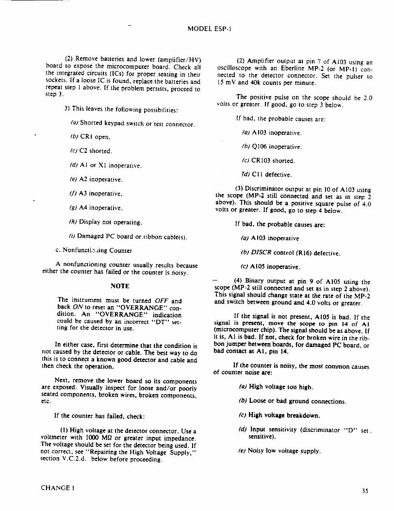
MODEL ESP-I
(2) Remove batteries and lower (amplifier/HV) board to expose the microcomputer board. Check all the integrated circuits (ICs) for proper seating in their sockets. If a loose IC is found, replace the batteries and repeat step 1 above. If the problem persists, proceed to step 3.
3) This leaves the following possibilities:
(a) Shorted keypad switch or test connector.
(b) CRI open.
(2) Amplifier output at pin 7 of A103 using an oscilloscope with an Eberline MP-2 (or MP-l) connected to the detector connector. Set the pulser to 15 mV and 40k counts per minute.
The positive pulse on the scope should be 2.0 volts or greater. If good, go to step 3 below.
If bad, the probable causes are:
(a) A103 inoperative.
(c) C2 shorted. '(b) Q106 inoperative.
(d) Al or X1 inoperative.
(e) A2 inoperative.
(f) A3 inoperative.
(g) A4 inoperative.
(h) Display not operating.
(ij Damaged PC board or ribbon cable(s).
c. Nonfuncti..iing Counter
A nonfunctioning counter usually results because either the counter has failed or the counter is noisy.
NOTE
The instrument must be turned OFF and back ON to reset an "OVERRANGE" condition. An "OVERRANGE" indication could be caused by an incorrect "DT" setting for the detector in use.
In either case, first determine that the condition is not caused by the detector or cable. The best way to do this is to connect a known good detector and cable and then check the operation.
Next, remove the lower board so its components are exposed. Visually inspect for loose and/or poorly seated components, broken wires, broken components, etc.
If the counter has failed, check:
(1) High voltage at the detector connector. Use a voltmeter with 1000 M12 or greater input impedance. The voltage should be set for the detector being used. If not correct, see "Repairing the High Voltage Supply," section V.C.2.d. below before proceeding.
(c) CRI03 shorted.
Td) CI I defective.
(3) Discriminator output at pin 10 of A103 using the scope (MP-2 still connected and set as in step 2 above). This should be a positive square pulse of 4.0 volts or greater. If good, go to step 4 below.
If bad, the probable causes are:
(a) A103 inoperative
(b) DISCR control (R16) defective.
(c) A105 inoperative.
- (4) Binary output at pin 9 of AI05 using the scope (MP-2 still connected and set as in step 2 above). This signal should change state at the rate of the MP-2 and switch between ground and 4.0 volts or greater.
If the signal is not present, AI05 is bad. If the signal is present, move the scope to pin 14 of Al (microcomputer chip). The signal should be as above. If it is, Al is bad. If not, check for broken wire in the ribbon jumper between boards, for damaged PC board, or bad contact at Al, pin 14.
If the counter is noisy, the most common causes of counter noise are:
(a) High voltage too high.
(b) Loose or bad ground connections.
(c) High voltage breakdown.
(d) Input sensitivity (discriminator "D" set sensitive).
(e) Noisy low voltage supply.
CHANGE 1 35
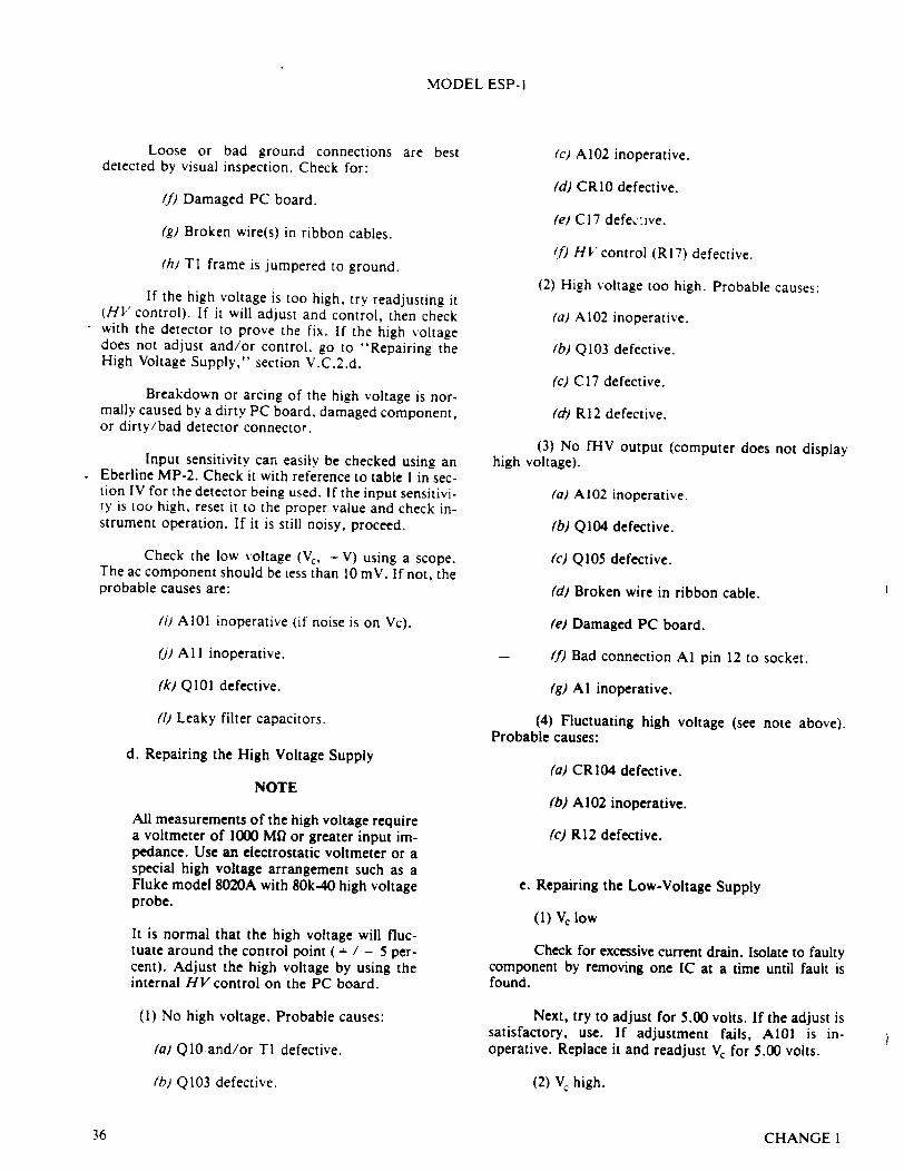
MODEL ESP-I
Loose or bad ground connections are best detected by visual inspection. Check for:
ff) Damaged PC board.
(g) Broken wire(s) in ribbon cables.
(h) TI frame is jumpered to ground.
If the high voltage is too high, try readjusting it (HV control). If it will adjust and control, then check with the detector to prove the fix. If the high voltage does not adjust and/or control, go to "Repairing the High Voltage Supply," section V.C.2.d.
Breakdown or arcing of the high voltage is normally caused by a dirty PC board, damaged component, or dirty/bad detector connector.
Input sensitivity can easily be checked using an Eberline MP-2. Check it with reference to table I in section IV for the detector being used. If the input sensitivity is too high, reset it to the proper value and check instrument operation. If it is still noisy, proceed.
Check the low voltage (Va, - V) using a scope. The ac component should be iess than 10 mV. If not, the probable causes are:
() AI01 inoperative (if noise is on Vc).
('j) AI I inoperative.
(k) QIlI defective.
(I) Leaky filter capacitors.
d. Repairing the High Voltage Supply
NOTE
All measurements of the high voltage require a voltmeter of 1000 Mi or greater input impedance. Use an electrostatic voltmeter or a special high voltage arrangement such as a Fluke model 8020A with 80k-40 high voltage probe.
It is normal that the high voltage will fluctuate around the control point ( + / - 5 percent). Adjust the high voltage by using the internal HV control on the PC board.
(1) No high voltage. Probable causes:
(a) Q1O and/or TI defective.
(b) Q103 defective.
(c) A102 inoperative.
(d) CRI0 defective.
(e) C17 defe&yive.
(f) HV control (R17) defective.
(2) High voltage too high. Probable causes:
(a) A102 inoperative.
(b) Q103 defective.
(c) C17 defective.
('&) R12 defective.
(3) No fHV output (computer does not display high voltage).
(a) A102 inoperative.
(b) Q104 defective.
(c) Q105 defective.
(d) Broken wire in ribbon cable.
(e) Damaged PC board.
-- (f) Bad connection Al pin 12 to socket.
(g) Al inoperative.
(4) Fluctuating high voltage (see note above). Probable causes:
(a) CRI04 defective.
(b) A102 inoperative.
(c) R12 defective.
e. Repairing the Low-Voltage Supply
(1) V, low
Check for excessive current drain. Isolate to faulty component by removing one IC at a time until fault is found.
Next, try to adjust for 5.00 volts. If the adjust is satisfactory, use. If adjustment fails, A101 is inoperative. Replace it and readjust Vc for 5.00 volts.
(2) V, high.
CHANGE136
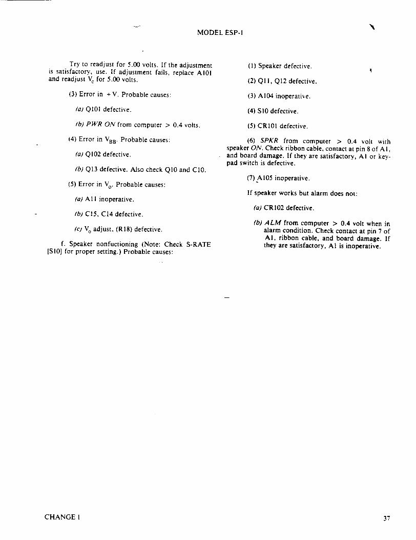
MODEL ESP- I
Try to readjust for 5.00 volts. If the adjustment is satisfactory, use. If adjustment fails, replace AIO and readjust V, for 5.00 volts.
(3) Error in + V. Probable causes:
(a) QIO0 defective.
(b) PWR ON from computer > 0.4 volts.
(4) Error in VBB. Probable causes:
(a) Q102 defective.
(b) Q13 defective. Also check QI0 and CIO.
(5) Error in V0 . Probable causes:
(a) AI I inoperative.
(b) C15, C14 defective.
(c) Vo adjust, (R18) defective.
f. Speaker nonfuctioning (Note: Check S-RATE [SI0] for proper setting.) Probable causes:
(1) Speaker defective.
(2) QI 1, Q12 defective.
(3) A104 inoperative.
(4) SIO defective.
(5) CR101 defective.
(6) SPKR from computer > 0.4 volt with speaker ON. Check ribbon cable, contact at pin 8 of A 1, and board damage. If they are satisfactory, AI or keypad switch is defective.
(7) Al05 inoperative.
If speaker works but alarm does not:
(a) CRI02 defective.
(b) ALM from computer > 0.4 volt when in alarm condition. Check contact at pin 7 of Al, ribbon cable, and board damage. If they are satisfactory, Al is inoperative.
CHANGE 1 37
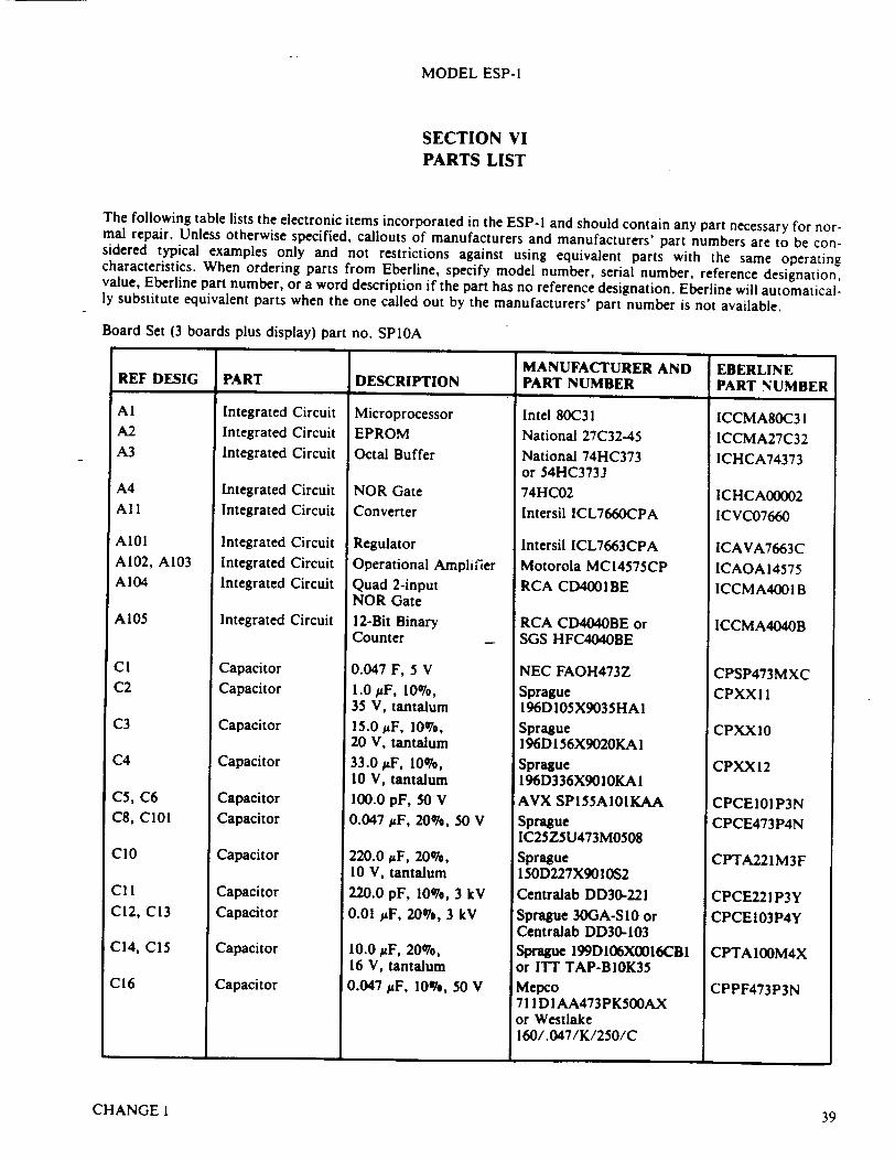
MODEL ESP-1
SECTION VI PARTS LIST
The following table lists the electronic items incorporated in the ESP-I and should contain any part necessary for normal repair. Unless otherwise specified, callouts of manufacturers and manufacturers' part numbers are to be considered typical examples only and not restrictions against using equivalent parts with the same operating characteristics. When ordering parts from Eberline, specify model number, serial number, reference designation, value, Eberline part number, or a word description if the part has no reference designation. Eberline will automatically substitute equivalent parts when the one called out by the manufacturers' part number is not available.
Board Set (3 boards plus display) part no. SPIOA
MANUFACTURER AND I EBERLINE REF DESIGI PART DESCRIPTION PART NUMBER PART NUMBER
Integrated Integrated
Integrated
Circuit Circuit Circuit
Integrated Circuit Integrated Circuit
Integrated Circuit Integrated Circuit Integrated Circuit
Integrated Circuit
Capacitor Capacitor
Capacitor
Capacitor
Capacitor Capacitor
Capacitor
Capacitor
Capacitor
Capacitor
Capacitor
Microprocessor EPROM
Octal Buffer
NOR Gate Converter
Regulator Operational Amplifier Quad 2-input NOR Gate 12-Bit Binary Counter
0.047 F, 5 V 1.0 pF, 10%, 35 V, tantalum 15.0 &F, 10%, 20 V, tantalum 33.0,•F, 10%, 10 V, tantalum 100.0 pF, 50 V 0.047 ItF, 20%, 50 V
220.0 %F, 20%, 10 V, tantalum
220.0 pF, 10%, 3 kV 0.01 uF, 20%, 3 kV
10.0 OtF, 20%, 16 V, tantalum 0.047 ItF, 10%, 50 V
Intel 80C31 National 27C32-45 National 74HC373 or 54HC373J 74HC02
Intersil ICL7660CPA
Intersil ICL7663CPA Motorola MCI4575CP RCA CD4001 BE
RCA CD404OBE or SGS HFC4040BE
NEC FAOH473Z Sprague 196DI05X9035HA1 Sprague 196D I56X9020KA 1 Sprague 196D336X9010KAI AVX SP155A101KAA Sprague IC25Z5U473MO508 Sprague 150D227X90 ! 0S2 Centralab DD30-221 Sprague 30GA-S 10 or Centralab DD30-103 Sprague 199D106X0016CBI or IT'T TAP-BlOK35 Mepco 71ID1AA473PK500AX or Westlake 160/.047/K/250/C
ICCMA8OC31
ICCMA27C32 ICHCA74373
ICHCA00002 ICVC07660
ICAVA7663C ICAOA 14575 ICCMA4001 B
ICCMA4040B
CPSP473MXC
CPXXI1
CPXXI0
CPXX12
CPCE101P3N CPCE473P4N
CPTA221 M3F
CPCE221P3Y
CPCE 103P4Y
CPTAIOOM4X
CPPF473P3N
1 __________ 1. _____________ ______________ L
CHANGE 1 39
Al A2 A3
A4
All
AIO1 A102, A103 A104
Al05
CI C2
C3
C4
C5, C6 C8, CIOl
CIO
CiI
C 12, C13
C14, C15
C16
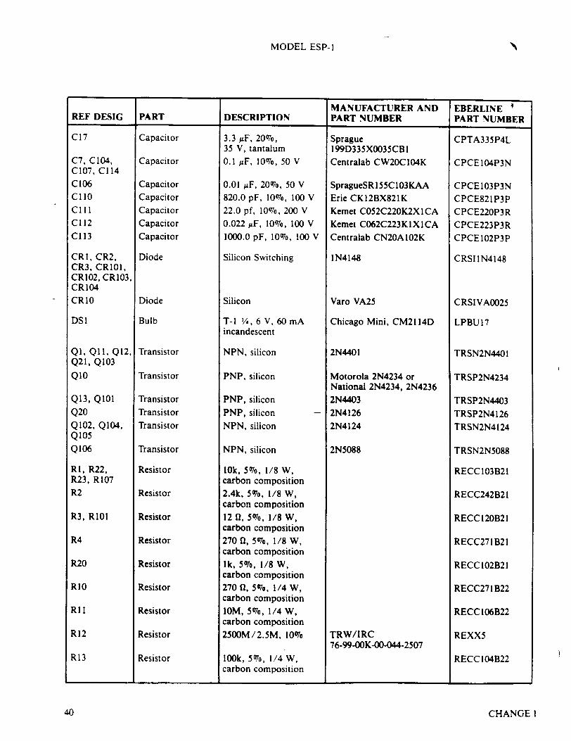
MODEL ESP- I
MANUFACTURER AND EBERLINE € REF DESIG PART DESCRIPTION PART NUMBER PART NUMBER
C17
C7, C 104, C107, C114
C106 CiIo
CII1 C112 Cl13
CRI, CR2, CR3, CR101, CR102, CR103, CRI04 CR10
DSI
QI, QIl, Q12, Q21, Q103
QIO
Q13, QIOl
Q20
Q102, Q104, Q105 Q106
RI, R22, R23, R107 R2
R3, RIOI
R4
R20
RIO
RII
R12
R13
Capacitor
Capacitor
Capacitor Capacitor
Capacitor
Capacitor
Capacitor
Diode
Diode
Bulb
Transistor
Transistor
Transistor
Transistor
Transistor
Transistor
Resistor
Resistor
Resistor
Resistor
Resistor
Resistor
Resistor
Resistor
Resistor
3.3 uF, 20076, 35 V, tantalum
0.1 uF, 10%, 50 V
0.01 ;zF, 20%, 50 V
820.0 pF, 1007o, 100 V
22.0 pf, 1007o, 200 V
0.022 JF, 1007o, 100 V
1000.0 pF, 1007o, 100 V
Silicon Switching
Silicon
T-1 /A, 6 V, 60 mA incandescent
NPN, silicon
PNP, silicon
PNP, silicon
PNP, silicon
NPN, silicon
NPN, silicon
10k, 5070, 1/8 W, carbon composition 2.4k, 5076, 1/8 W, carbon composition 12 0, 5076, 1/8 W, carbon composition 270 0, 5076, 1/8 W, carbon composition 1k, 5%, 1/8 W, carbon composition 270 0l, 5076, 1/4 W, carbon composition
IOM, 5076, 1/4 W, carbon composition
250OM/2.5M, 1007o
10ok, 5076, 1/4 W, carbon composition
Sprague I99D335XOO35CB 1 Centralab CW20CI04K
SpragueSR 155C1O3KAA Erie CK 12BX821K Kemet C052C220K2XICA
Kemet C062C223K1X1 CA Centralab CN20A 102K
1N4148
Varo VA25
Chicago Mini, CM2114D
2N4401
Motorola 2N4234 or National 2N4234, 2N4236 2N4403
2N4126
2N4124
2N5088
TRW/IRC 76-99-OOK-00-044-2507
CPTA335P4L
CPCE104P3N
CPCE103P3N CPCE821P3P
CPCE220P3R CPCE223P3R CPCE 102P3P
CRSIIN4148
CRSIVA0025
LPBU17
TRSN2N4401
TRSP2N4234
TRSP2N4403
TRSP2N4126
TRSN2N4124
TRSN2N5088
RECC 103B21
RECC242B21
RECC 120B21
RECC271 B21
RECC 102B21
RECC271 B22
RECC 106B22
REXX5
RECC 104B22
CHANGEI
'N
40
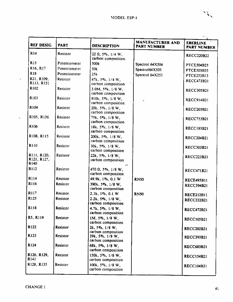
MODEL ESP-I
MANUFACTURER AND EBERLINE i REF DESIG PART DESCRIPTION PART NUMBER I PART NUMBER
R14
RI5 R16, R17 RI8 R21, R109, R113, Ri51 RI 02
Ri 03
R104
RI05, R136
R106
R108, RI15
RI 10
RIll, R120, R121, R127, R140 RI12
R114
Rl16
R117 R125
R118
R5, R119
R122
R123
R124
R126, R129, R141
R128, R135
Resistor
Potentiometer
Potentiometer Potentiometer Resistor
Resistor
Resistor
Resistor
Resistor
Resistor
Resistor
Resistor
Resistor
Resistor
Resistor
Resistor
Resistor
Resistor
Resistor
Resistor
Resistor
Resistor
Resistor
Resistor
Resistor
22 Q, 507o, 1/4 W, carbon composition 500k 50k 25k 47k, 5%, 1/4 W, carbon composition 3.OM, 507o, 1/8 W, carbon composition 910k, 5%, 1/8 W, carbon composition 20k, 507o, 1/8 W, carbon composition 75k, 5%, 1/8 W, carbon composition 18k, 507o, 1/8 W, carbon composition 200k, 5%, 1/8 W, carbon composition 30k, 507o, 1/8 W, carbon composition 22k, 5%, 1/8 W, carbon composition
470 01, 5076, 1/8 W, carbon composition 49.9k, 1076, 0.1 W 390k, 5%, 1/8 W, carbon composition 2.1k, 1076, 0.1 W 2.2k, 5%, 1/8 W, carbon composition 4.7k, 5%, 1/8 W, carbon composition IM, 5%, 1/8 W, carbon composition 2k, 5076, 1/8 W, carbon composition 39k, 5076, 1/8 W, carbon composition 68k, 5%, 1/8 W, carbon composition 150k, 5%, 1/8 W, carbon composition 100k, 5%, 1/8 W, carbon composition
Spectrol 64X504 Spectro164X503 Spectrol 64X253
RN50
RN50
RECC220B22
PTCE504B23 PTCE503B33 PTCE253B13
RECC473B21
RECC305B21
RECC914B21
RECC203B2 I
RECC753B21
RECC183B21
RECC204B21
RECC303B21
RECC223 B2 1
RECC471B21
RECE493BI I RECC394B21
RECE212BI I RECC222B21
RECC472B21
RECCI05B21
RECC202B2 1
RECC393B21
RECC683B2 1
RECC154B2 1
RECC 104B21
I I I
CHANGE 1 41
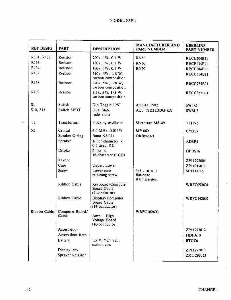
MODEL ESP-1
MANUFACTURER AND EBERLINE REF DESIG PART DESCRIPTION PART NUMBER PART NUMBER
R131, R132
R133 R134 R137
R138
R139
S1 S10, Sib
TI
xI
Ribbon Cable
Resistor
Resistor
Resistor Resistor
Resistor
Resistor
Switch Switch SPDT
Transformer
Crystal Speaker O-ring
Speaker
Display
Keypad Case Screw
Ribbon Cable
Ribbon Cable
Computer Board/ Cable
Access door Access door latch
Battery
Display lens
Speaker Retainer
200k, 1076, 0.1 W 130k, 107o, 0.1 W 100k, 107, 0.1 W 510k, 507o, 1/8 W, carbon composition 270k, 5076, 1/8 W, carbon composition 3.3k, 507o, 1/8 W, carbon composition
Dip Toggle 2PST Dual Slide right angle
blocking oscillator
6.0 MHz, 0.015% Buna N2-021 1-inch-diameter x 0.6 deep, 8 f2 2-line x 16-character (LCD)
Upper, Lower Lower-case retaining screw
Keyboard/Computer Board Cable (9-conductor)
Display/Computer Board Cable (14-conductor)
Amp.-High Voltage Board (16-conductor)
1.5 V, "C" cell, carbon-zinc
RN50
RN50
RN50
Alco JDTP-02
Alco TSD21DDG-RA
Microtran M8149
MP-060 ORBN2021
3/8 - 16 x I flat-head, stainless-steel
WRFC 162603
RECE2O4Bi I RECEI34B 11 RECEI04B 11 RECC514B21
RECC274B21
RECC332B21
SWTO I SWSL7
TFHV5
CYOS9
ADSP4
OPDS16
ZP 11292005 ZP 11919011 SCFH3716
WRFC092601
WRFC142602
ZP 11292012
HDFAI0
BTCZ6
ZP 11292013 ZX 11292013
_________ I _________________ ___________
CHANGE142
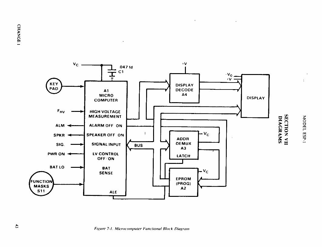
Figure 7-1. Microcomputer Functional Block Diagrain
C) z' a. mZ
Vc
4 0
r-
4. (a,
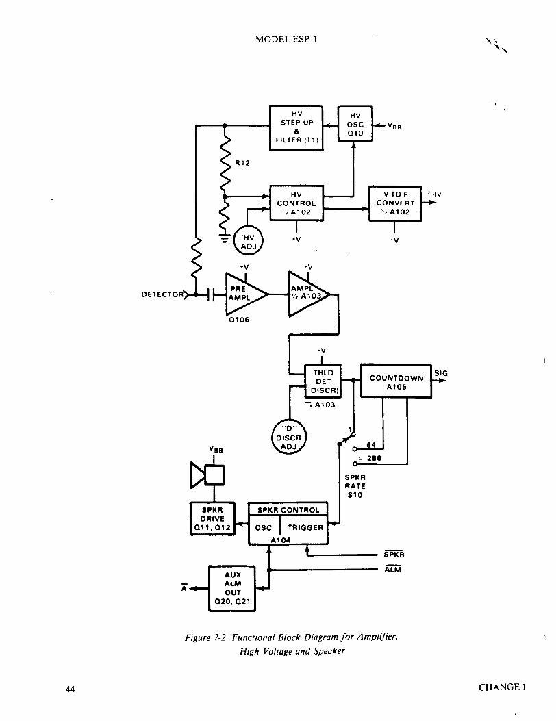
MODEL ESP- I -A"
-| STEP-UP "*- (B
& 01
R12
•, -- • '2 A102 `2 Al 02/
DETECTORJ AIO- -
Vas
SPKR RATE S1O
z
Figure 7-2. Functional Block Diagram for Amplifier,
High Voltage and Speaker
CHANGEI44
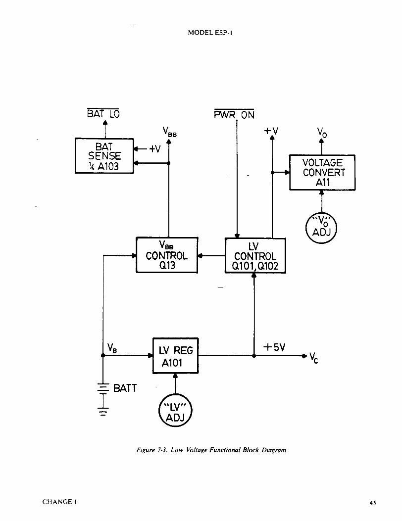
MODEL ESP-I
BAT LO
VBB
VB
- BATT
I
Figure 7-3. Low Voltage Functional Block Diagram
CHANGE1
Vo
+5VVc
45

MODEL ESP- I
Figure 7-4. Printed Circuit Board Set
CHANGE 146
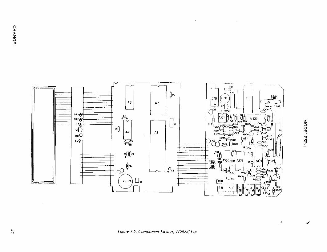
C)
j RIO
1 1
__ __ -o 0210 C46 F CRI04 R12
021 D CO4 -CZjRIOi
CR&-RI K6jC4
3(b~l~sJ R104 8Cj 14-
-4ZJ0R10 O7 010 -\ -7J=RI R116 ' R2311R20 A~iI
d o0u 020 Cc14)~ ~R2 Do ~ Lj fl3 ~R?120 U CI? RjJRI4I U
-CROI I A04 A15 R A103 [R1 127
CR10 AI -1
C4+C3 -E(I 3 R3 ~ R33
4ý14 Figure 7-5. Component LayVout, 11292-CI7B
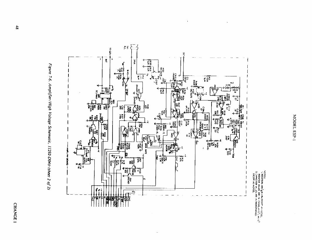
<' 200 Al R N1' I - ___
es I
K". 0
.- 42: :oN w '
I 05 -. a
.6..FN4
06 <
Fg
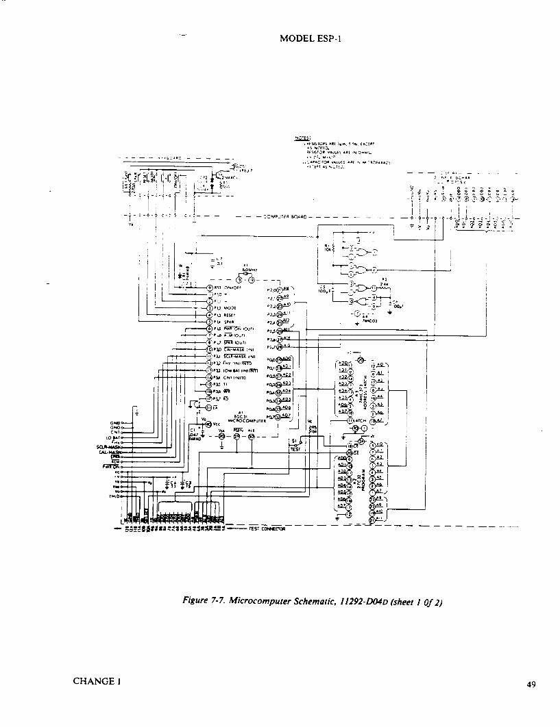
MODEL ESP-I
4 9SFORS A'o 1.., 5 f:, E-CEPT AS NOTEI3
* C. -,M
APAC ,TO VA0. -t AE? AELC -AS-, ~tAS NI t.,
- -- CMPUTER BOARD -
- A
- - S'c
� 0
'3d
jo� 00; � -�
Figure 7-7. Microcomputer Schematic, 11292-DO4D (sheet I Of 2)
CHANGE I
S....... hGga• .. .. ..
49
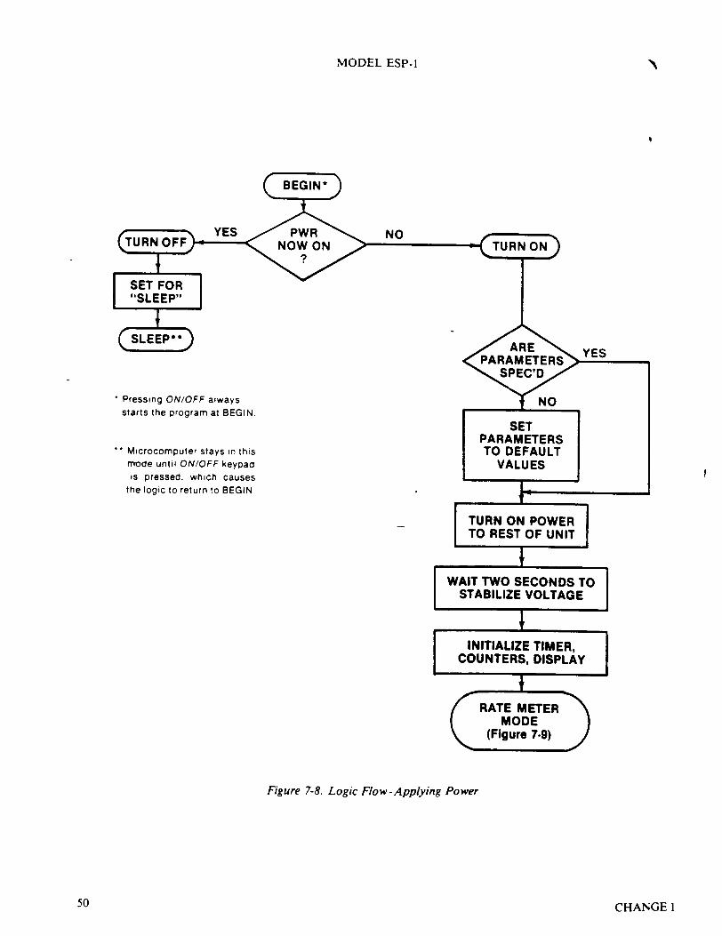
MODEL ESP-I
NO
* Pressing ON/OFF always starts the program at BEGIN.
Microcomputer stays in this mode until ON/OFF keypad is pressed. which causes
the logic to return to BEGIN.
TURN ON POWER TO REST OF UNIT
WAIT TWO SECONDS TO STABILIZE VOLTAGE
INITIALIZE TIMER, COUNTERS, DISPLAY
Figure 7-8. Logic Flow - Applying Power
50 CHANGEI
N.4

Figure 7-9. Logic Flow-Rate Meter Mode
z C)
0 0 rri m Cd)
.4,
I-' A,
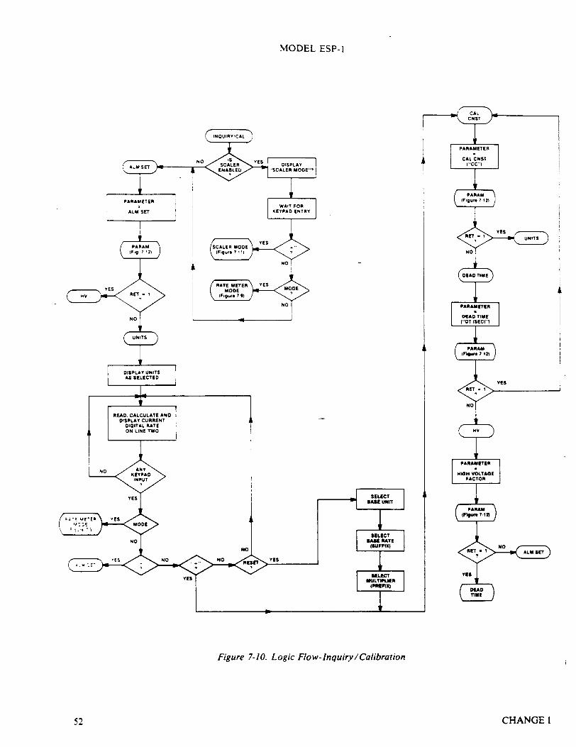
MODEL ESP-1
4
Figure 7-10. Logic Flow-Inquiry /Calibration
CHANGE 152
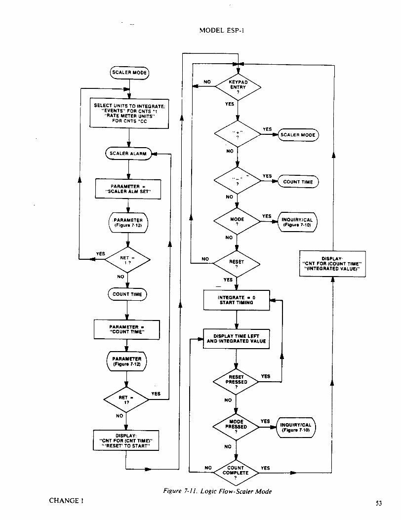
MODEL ESP-1
Figure 7-11. Logic Flow-Scaler ModeCHANGE I 53
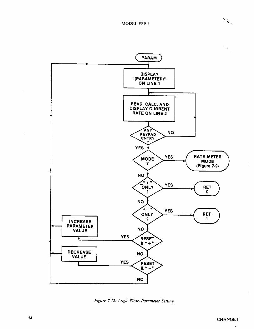
MODEL ESP-I
Figure 7-12. Logic Flow - Parameter Setting
CHANGEI54

MODEL ESP-1
SECTION VIII DETECTORS AND ACCESSORIES
DETECTORS RECOMMENDED FOR USE WITH ESP-1
RANGE WITH ESP-! MODEL NO. TYPE MEASUREMENT USEFUL + /- 5 PERCENT*
HP-270 Exposure or Exposure Rate Background to 3000 mR/h I to 3000 mR/h HP-290 Exposure or Exposure Rate 0.005 to 60 R/h 0.01 to 40 R/h HP-190A Beta-gamma Contamination Background to 25,000 cnts/s 14 to 25,000 cnts/s HP-210L Beta-gamma Contamination Background to 100,000 cnts/s 14 to 100,000 cnts/s HP-210T Beta-gamma Contamination Background to 100,000 cnts/s 14 to 100,000 cnts/s HP-260 Beta-gamma Contamination Background to 100,000 cnts/s 14 to 100,000 cnts/s AC-3 Alpha Contamination Background to 50,000 cnts/s 14 to 50,000 cnts/s NRD Neutron Dose Equivalent or
Dose Equivalent Rate 0.001 to 200 rem/h 0.02 to 200 rem/h LEG-I Low Energy Gamma or X-Ray Background to 50,000 cnts/s 14 to 50,000 cnts/s SPA-3 High Sensitivity Gamma Background to 50,000 cnts/s 14 to 50,000 cnts/s SPA-6 Medium Sensitivity Gamma Background to 50,000 cnts/s 14 to 50,000 cnts/s
*Rate Meter Mode provides + / - 5 percent standard deviation readout capability or better over the indicated range.
CHANGE 1 5
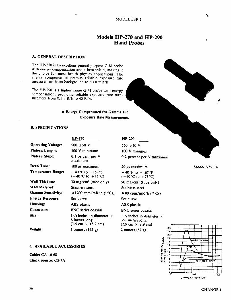
A. GENERAL DESCRIPTION
The HP-270 is an excellent general purpose G-M probe witn energy compensation and a beta shield, making it the choice for most health physics applications. The energy compensation permits reliable exposure rate measurement from background to 3000 mR/h.
The HP-290 is a higher range G-M probe with energy compensation, providing reliable exposure rate measurement from 0.1 mR/h to 40 R/h.
9 Energy Compensated for Gamma and Exposure Rate Measurements
B. SPECIFICATIONS
Operating Voltage:
Plateau Length:
Plateau Slope:
Dead Time:
Temperature Range:
Wall Thickness:
Wall Material:
Gamma Sensitivity:
Energy Response:
Housing:
Connector:
Size:
Weight:
HP.270
900 t+50V
100 V minimum
0.1 percent per V maximum
100 ;s maximum
-4 0 °F to + 167°F (-400C to +750C) 30 mg/cm' (tube only)
Stainless steel
=_ 1200 cpm/mR/h ("'Cs)
See curve
ABS plastic
BNC series coaxial
I '/s inches in diameter x 6 inches long (3.5 cm x 15.2 cm)
5 ounces (142 g)
HP-290
550 t. 50 V
100 V minimum 0.2 percent per V maximum
20-As maximum
-4 0 °F to + 167°F (- 4 0 °C to + 75 °C)
90 mg/cm' (tube only)
Stainless steel
-= 80 cpm/mR/h ("'Cs) See curve
ABS plastic
BNC series coaxial
1 /a inches in diameter x 31½ inches long (2.9 cm x 8.9 cm)
2 ounces (57 g)
C. AVAILABLE ACCESSORIES
Cable: CA-16-60
Check Source: CS-7A
Model HP-2 70
z Z
E E
GAMMA ENERGY (keV)
CHANGEI
2
MODEL ESP-1
Models HP-270 and HP-290 Hand Probes a
./
56
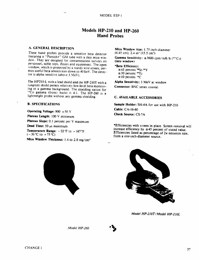
MODEL ESP-]
Models HP-210 and HP-260 Hand Probes
A. GENERAL DESCRIPTION These hand probes provide a sensitive beta detector featuring a "Pancake" GM tube with a thin mica window. They are designed for contamination surveys on personnel, table tops, floors and equipment. The open window, which is protected by a sturdy wire screen, permits useful beta sensitivities down to 40 keV. The detector is alpha sensitive (above 3 MeV).
The HP210-L with a lead shield and the HP-210T with a tungsten shield permit relatively low-level beta monitoring in a gamma background. The shielding ration for "C0Co gamma (front: back) is 4:1. The HP-260 is a lightweight probe without any gamma shielding.
B. SPECIFICATIONS
Operating Voltage: 900 ± 50 V Plateau Length: 100 V minimum Plateau Slope: 0.1 percent per V maximum Dead Time: 50 us maximum Temperature Range: - 22 'F to + 167 'F (-30°Cto +75°C)
Mica Window Thickness: 1.4 to 2.0 mg/cm2
Mica Window Size: 1.75-inch -diameter (4.45 cm); 2.4 in2 (15.5 cm2 )
Gamma Sensitivity: a3600 cpm/mR/h (1"Cs) (into window)
*Beta Efficiency: -45 percent '*Sr-"Y
30 percent "Tc 10 percent '4C
Alpha Sensitivity: 3 MeV at window Connector: BNC series coaxial
C. AVAILABLE ACCESSORIES
Sample Holder: SH-4A for use with HP-210 Cable: CA-16-60
Check Source: CS-7A
*Efficiencies with screen in place. Screen removal will increase efficiency by =-45 percent of stated value. Efficiencies listed as percentage of 21r emission rate, from a one-inch-diameter source.
Model HP-21OT/Model HP-210L
Model HP-260
CHANGE 1 57

MODEL ESP-I
Model NRD Neutron rem Detector
A. GENERAL DESCRIPTION The Model NRD neutron rem detector is a nine-inchdiameter, cadmium-loaded polyethelene sphere with a BF, tube in the center for use as an area monitor. This detector has been shown to have an energy response which closely follows the theoretical dose from neutrons over the energy range from 0.025 eV (thermal) to about 10.00 MeV.' 2 The BF3 tube allows excellent gamma rejection.
B. SPECIFICATIONS
Gamma Rejection: Up to 500 R/h, dependent on high voltage setting.
Sensitivity: Approximately 50 cpm per mrem per hour (3000 counts per mrem).
Connector: MHV Series coaxial.
Size: 9-inch-diameter x 97/s-inch cm x 25.1 cm).
Weight: 13.75 pounds (6.24 kg).
overall height (22.9
Detector: BF, tube in nine-inch cadmium-loaded polyethelene sphere.
Plateau: Approximately 200 V with a slope of 5 percent per 100 V.
Operating Voltage: Dependent on sensitivity of counter and cable length. Typically 1600 to 2000 V.
Directional Response: Within ± 10 percent.
Energy Range: Thermal to approximately 10 MeV.
#4
C. AVAILABLE ACCESSORIES
Cable: CA-15-36
Bracket: Wall Mounting Model ZP10478021
"A Modified Sphere Neutron Detector." D.E. Hankins. LA-3595.
" The Substitution of a BF, Tube for the Lil Crystal in Neutron rem Meters". D.E. Hankins: Health Physics Journal. Volume 14, Number 5, May 1968.
NRD
e MEASURES NEUTRON DOSE RATE FROM THERMAL THROUGH FAST
* BF TUBE GIVES HIGH GAMMA REJECTION 3
ICHANGE 1
"tN
58
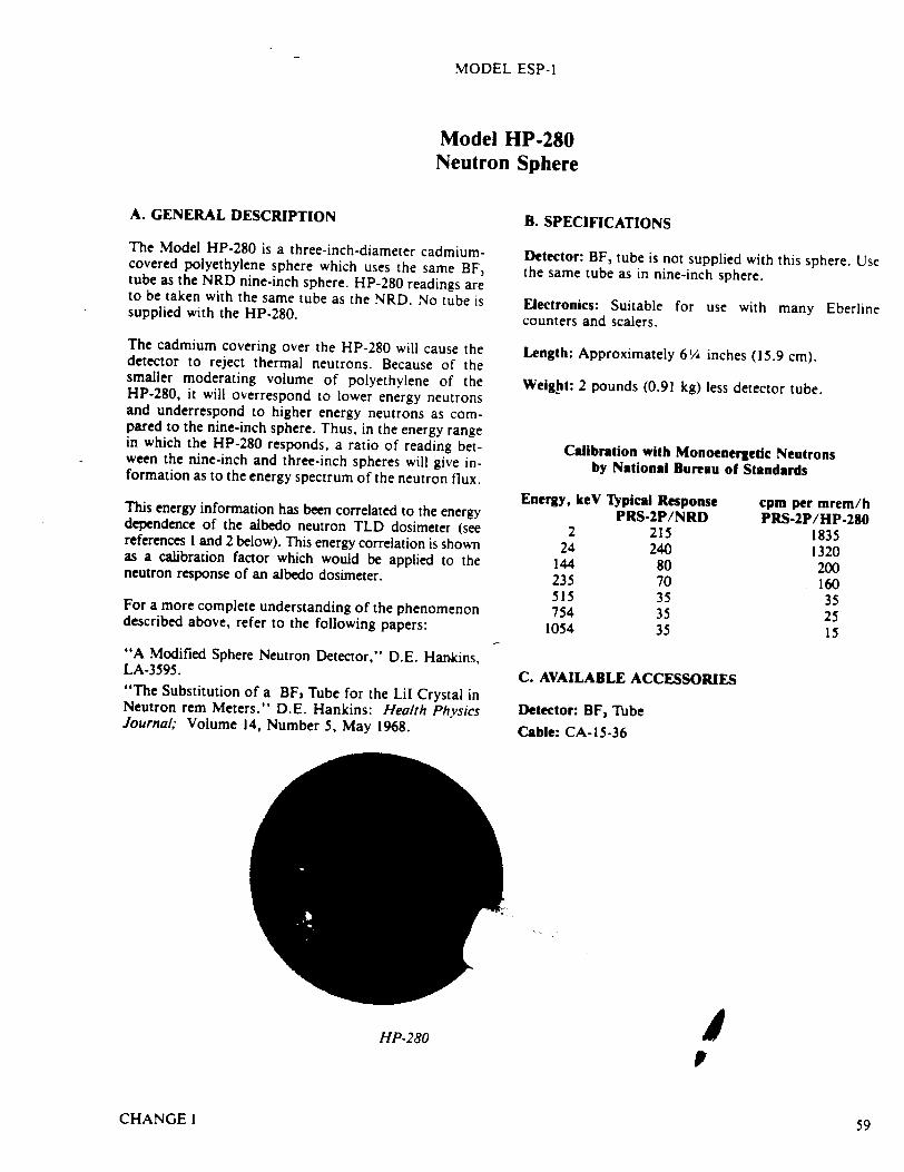
MODEL ESP-I
Model HP-280 Neutron Sphere
A. GENERAL DESCRIPTION
The Model HP-280 is a three-inch-diameter cadmiumcovered polyethylene sphere which uses the same BF, tube as the NRD nine-inch sphere. HP-280 readings are to be taken with the same tube as the NRD. No tube is supplied with the HP-280.
The cadmium covering over the HP-280 will cause the detector to reject thermal neutrons. Because of the smaller moderating volume of polyethylene of the HP-280, it will overrespond to lower energy neutrons and underrespond to higher energy neutrons as compared to the nine-inch sphere. Thus, in the energy range in which the HP-280 responds, a ratio of reading between the nine-inch and three-inch spheres will give information as to the energy spectrum of the neutron flux.
This energy information has been correlated to the energy dependence of the albedo neutron TLD dosimeter (see references I and 2 below). This energy correlation is shown as a calibration factor which would be applied to the neutron response of an albedo dosimeter.
For a more complete understanding of the phenomenon described above, refer to the following papers:
"A Modified Sphere Neutron Detector," D.E. Hankins, LA-3595. "The Substitution of a BF 3 Tube for the LiI Crystal in Neutron rem Meters." D.E. Hankins: Health Physics Journal; Volume 14, Number 5, May 1968.
B. SPECIFICATIONS
Detector: BF, tube is not supplied with this sphere. Use the same tube as in nine-inch sphere.
Electronics: Suitable for use with many Eberline counters and scalers.
Length: Approximately 6¼ inches (15.9 cm).
Weight: 2 pounds (0.91 kg) less detector tube.
Calibration with Monoenergetic Neutrons by National Bureau of Standards
Energy, keV Typical Response PRS-2P/NRD
2 215 24 240
144 80 235 70 515 35 754 35
1054 35
C. AVAILABLE ACCESSORIES
Detector: BF, Tube Cable: CA-15-36
cpm per mrem/h PRS-2P/HP-280
1835 1320 200 160 35 25 15
jHP-280
CHANGE 1 59

MODEL ESP-I
Model AC-3 Alpha Scintillation Probe
A. GENERAL DESCRIPTION To meet the various requirements in the field of alpha monitoring and the different types of instruments, the AC-3 alpha scintillation probe has been designed for alpha surveys or for persontiel monitoring. The AC-3 is a rugged alpha probe designed to work with several Eberline portable survey or radiation monitoring instruments.
There are two versions of the AC-3, differing only in the window assembly. The AC-3-7 designates a maximum
B. SPECIFICATIONS
Active Area: 9.1-in" (59 cml) within 5.75-inch x 2-inch (14.6 cm x 5.1 cm) sampling area.
Window Thickness: 0.5 mg/cm' aluminized MylarO .
Efficiency: From a I-inch-diameter source or from 59 cm' of a large distributed area "139Pu source (2r).
Q~%e
open area window for alpha surveys, and the AC-3-8 designates a rugged window which has a fine mesh protector over the Mylar* for personnel monitoring.
The Mylar* window is a "sandwich" assembly which can be replaced by the removal of six screws. This window can also be used on older AC-3 probes without modification.
There is a clear plastic probe face cover supplied to protect the window when the probe is not in use.
AC-3-7 window: 28 percent minimum, 31 percent typical. AC-3-8 window: 18 percent minimum, 20 percent typical.
C. ACCESSORIES
Cable: CA-12-60
Check Source: C-10 or C-12
"* LARGE AREA COVERAGE "* SUBMERSIBLE FOR DECONTAMINATION "* FACE ASSEMBLY EASILY CHANGED
AC-3-7 shown with optional check source
CHANGEI60
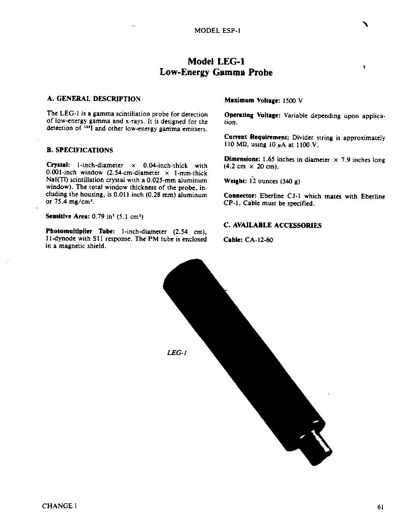
MODEL ESP-I
Model LEG-1 Low-Energy Gamma Probe
A. GENERAL DESCRIPTION Maximum Voltage: 1500 V
The LEG-i is a gamma scintillation probe for detection of low-energy gamma and x-rays. It is designed for the detection of 'I1 and other low-energy gamma emitters.
B. SPECIFICATIONS
Crystal: 1-inch-diameter x 0.04-inch-thick with 0.001-inch window (2.54-cm-diameter x I-mm-thick NaI(TI) scintillation crystal with a 0.025-mm aluminum window). The total window thickness of the probe, including the housing, is 0.011 inch (0.28 mm) aluminum or 75.4 mg/cm3 .
Sensitive Area: 0.79 in' (5.1 cm')
Photomultipller Tube: 1-inch-diameter (2.54 cm), I I-dynode with S 11 response. The PM tube is enclosed in a magnetic shield.
Operating Voltage: Variable depending tion.
Current Requirement: Divider string is 110MU, using 10AA at 1100 V.
upon applica
approximately
Dimensions: 1.65 inches in diameter x 7.9 inches long (4.2 cm x 20 cm).
Weight: 12 ounces (340 g)
Connector: Eberline CJ-I which CP-l. Cable must be specified.
C. AVAILABLE ACCESSORIES
Cable: CA-12-60
mates with Eberline
LEG-I
CHANGEI 61
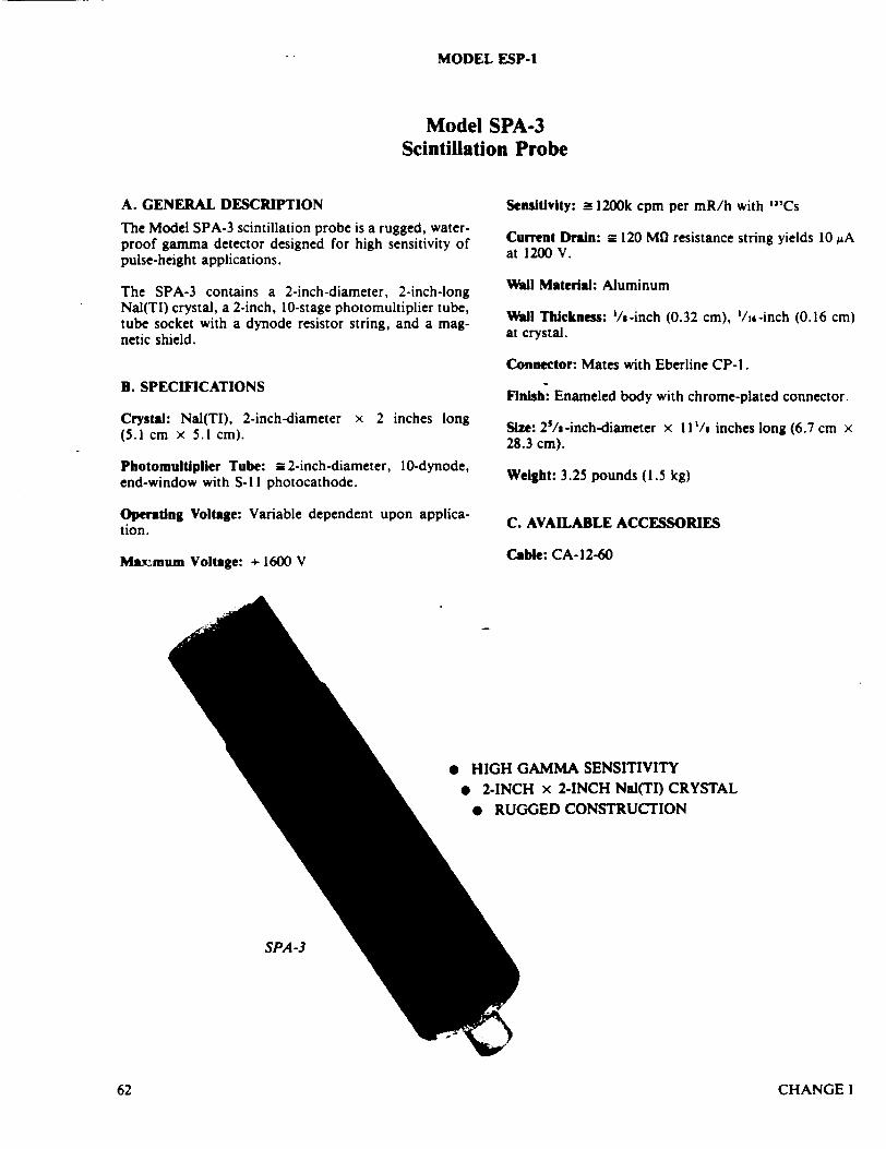
MODEL ESP-I
Model SPA-3 Scintillation Probe
A. GENERAL DESCRIPTION
The Model SPA-3 scintillation probe is a rugged, waterproof gamma detector designed for high sensitivity of pulse-height applications.
The SPA-3 contains a 2-inch-diameter, 2-inch-long Nal(TI) crystal, a 2-inch, 10-stage photomultiplier tube, tube socket with a dynode resistor string, and a magnetic shield.
B. SPECIFICATIONS
Crystal: Nal(TI), 2-inch-diameter x 2 inches long (5.1 cm x 5.1 cm).
Photomultlplier Tube: -2-inch-diameter, 10-dynode, end-window with S-I I photocathode.
Operating Voltage: Variable dependent upon application.
Maxmum Voltage: + 1600 V
Sensitivity: _= 1200k cpm per mR/h with "'Cs
Current Drain: _ 120 MG resistance string yields 10 •A at 1200 V.
Will Material: Aluminum
Wall Thickness: Is-inch (0.32 cm), /j6-inch (0.16 cm) at crystal.
Connector: Mates with Eberline CP-l.
Finish: Enameled body with chrome-plated connector.
Size: 2'/&-inch-diameter x 11 I/s inches long (6.7 cm x 28.3 cm).
Weight: 3.25 pounds (1.5 kg)
C. AVAILABLE ACCESSORIES
Cable: CA-12-60
e HIGH GAMMA SENSITIVITY
* 2-INCH x 2-INCH Nal(TI) CRYSTAL
* RUGGED CONSTRUCTION
SPA-3
CHANGE I62
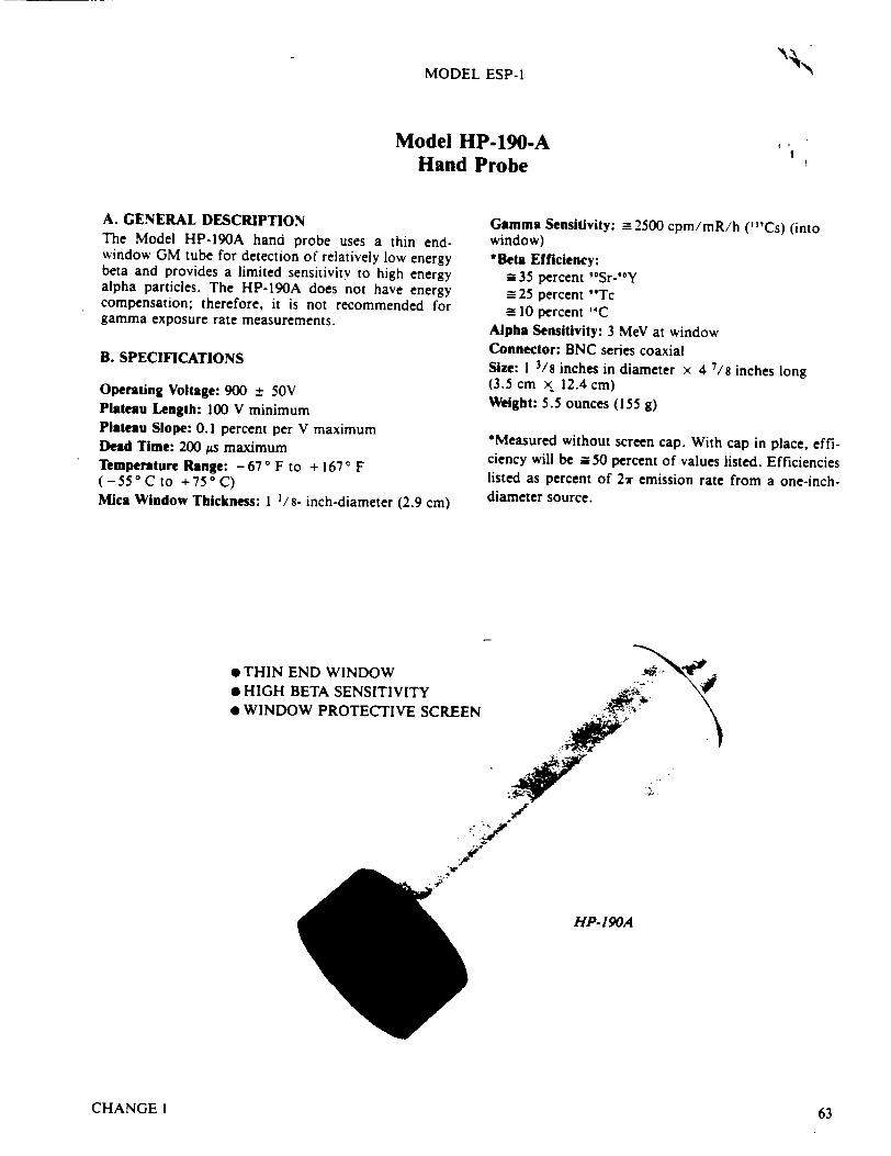
MODEL ESP-l
Model HP-190-A Hand Probe
A. GENERAL DESCRIPTION The Model HP-190A hand probe uses a thin endwindow GM tube for detection of relatively low energy beta and provides a limited sensitivity to high energy alpha particles. The HP-190A does not have energy compensation; therefore, it is not recommended for gamma exposure rate measurements.
B. SPECIFICATIONS
Operating Voltage: 900 ± 50V Plateau Length: 100 V minimum Plateau Slope: 0.1 percent per V maximum Dead Time: 200 us maximum Temperature Range: -67 OF to + 167 F (-55°Cto +750 C) Mica Window Thickness: I 1/8- inch-diameter (2.9 cm)
"* THIN END WINDOW "* HIGH BETA SENSITIVITY "* WINDOW PROTECTIVE SCREEN
Gamma Sensitivity: M 2500 cpm/mR/h ("Cs) (into window) *Beta Efficiency:
=_35 percent '*Sr-'OY =-25 percent "Tc = 10 percent "C
Alpha Sensitivity: 3 MeV at window Connector: BNC series coaxial Size: 1 3/S inches in diameter x 4 7/s inches long (3.5 cm x 12.4 cm) Weight: 5.5 ounces (155 g)
*Measured without screen cap. With cap in place, efficiency will be = 50 percent of values listed. Efficiencies listed as percent of 2 1 emission rate from a one-inchdiameter source.
4'Ap
HP-190A
CHANGE 1
10,
63
Instruction Manual LUDLUM MODEL 65 PORTABLE GAS PROPORTIONAL COUNTER
LUDLUM MEASUREMENTS, INC, so OAK 915,. -234S P.o0. BOX o
SiEWTWATZEL TEXAS. U.S.A. MW
SAIC/T&MSS
NOV 16 1987
CCF RECEIVED
]D=CWINR AND MANTAO=TURZgR
INSTRUMENTS
WARRANTY CERTIFICATE
Ludlum NIeasurements, Inc. warrants the products covered in this Instruction Manual to be free of defects due to workmanship, materials, and design for a period of twelve months from dare of delivery, with the exception of photo tubes and geiger tubes, which are warranted defect free to 90 days. In event of instrument failure, notify Ludlum Measuremen.s Inc. for re-air or replacement. Liability of this warranty is limited to the purchase price of the instrument.
REC2IVING CONDITION EXAMNTION
Be sure to verify that the shipping carton is received in perfectly good condition. For example, that no damage should be visible. Should the instrument be received in a damaged condition, save the shipping container and the packing material and request an immediate inspection by the carrier. Ludlum Measurements, Inc. is not responsible for the damage which occurs during shipment but will make every effort to help obtain restitution from the carrier.
RETURN OF GOODS TO MANUFACTURER
If equipment needs to be returned to Ludlum Measurements, Inc. for repair, calibration, etc., please do so by the appropriate method of shipment. All shipments should include documentaticn containing shipping address, customer name and telephone number, and all other necessary information.
Your cooperaticn will expedite the return of your equipment.
LUDLUM MODEL 65 PORTABLE GAS PROPORTIONAL CUNTER
TABLE OF CONTENTS
1. GENERAL 2
2. SPECIFICATIONS 2
3. DESCRIPTION OF CONTROLS AND FUNCTIONS 3
4. OPERATING PROCEDURES 4
5. CALIBRATION 5
6. CALIBRATION AND MAINTENANCE 6
7. OVERHAUL 6
8. BILLS OF MATERIALS 7
--. I-
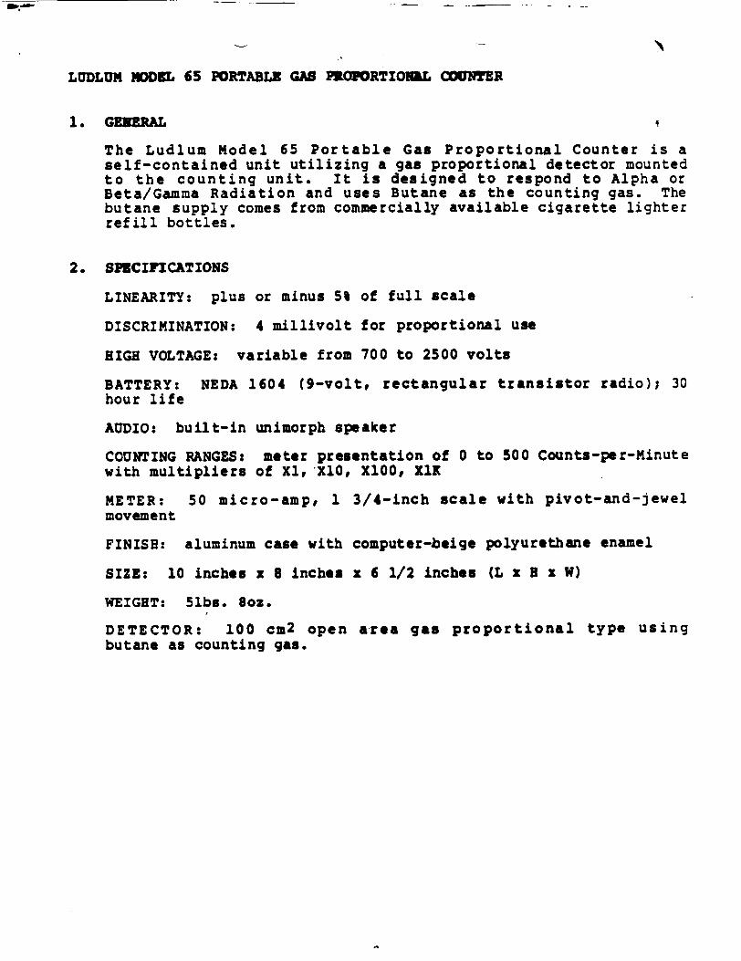
LUDLUM ODnEL 65 PORTABLE GAS PKOPORTIOIQL COUNTER
1. GENERAL
The Ludlum Model 65 Portable Gas Proportional Counter is a self-contained unit utilizing a gas proportional detector mounted to the counting unit. It is designed to respond to Alpha or Beta/Gamma Radiation and uses Butane as the counting gas. The butane supply comes from commercially available cigarette lighter refill bottles.
2. SPECIFCATIONS
LINEARITY: plus or minus 5% of full scale
DISCRIMINATION: 4 millivolt for proportional use
HIGH VOLTAGE: variable from 700 to 2500 volts
BATTERY: NEDA 1604 (9-volt, rectangular transistor radio); 30 hour life
AUDIO: built-in unimorph speaker
COUNTING RANGES: meter presentation of 0 to 500 Counts-per-Minute with multipliers of Xl, X0o, XlO0, XI1
METER: 50 micro-amp, 1 3/4-inch scale with pivot-and-jewel
movement
FINISH: aluminum case with computer-beige polyurethane enamel
SIZE: 10 inches x 8 inches x 6 1/2 inches (L x H x W)
WEIGHT: 5lbs. Boz.
DETECTOR: 100 cm2 open area gas proportional type using butane as counting gas.
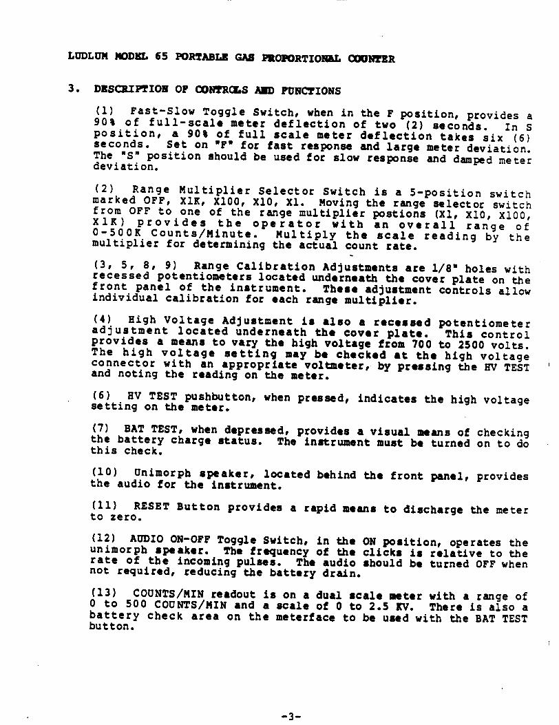
LUDLUW MODEL 65 PORTABLE GAB PROPORTIOIGL (INTER
3. DESCRIPTION OF CONTROLS AND FUNCTIONS
(1) Fast-Slow Toggle Switch, when in the F position, provides a 90% of full-scale meter deflection of two (2) seconds. In S position, a 90% of full scale meter deflection takes six (6) seconds. Set on OF* for fast response and large meter deviation. The NS" position should be used for slow response and damped meter deviation.
(2) Range Multiplier Selector Switch is a 5 -position switch marked OFF, XlK, Xl00, X10, Xl. Moving the range selector switch from OFF to one of the range multiplier postions (Xl, X10, X100, XlK) provides the operator with an overall range of 0-500K Counts/Minute. Multiply the scale reading by the multiplier for determining the actual count rate.
(3, 5, 8, 9) Range Calibration Adjustments are 1/80 holes with recessed potentiometers located underneath the cover plate on the front panel of the instrument. These adjustment controls allow individual calibration for each range multiplier.
(4) High Voltage Adjustment is also a recessed potentiometer adjustment located underneath the cover plate. This control provides a means to vary the high voltage from 700 to 2500 volts. The high voltage setting may be checked at the high voltage connector with an appropriate voltmeter, by pressing the HV TEST and noting the reading on the meter.
(6) BV TEST pushbutton, when pressed, indicates the high voltage setting on the meter.
(7) BAT TEST, when depressed, provides a visual means of checking the battery charge status. The instrument must be turned on to do this check.
(10) Unimorph speaker, located behind the front panel, provides the audio for the instrument.
(11) RESET Button provides a rapid means to discharge the meter to zero.
(12) AUDIO ON-OFF Toggle Switch, in the ON position, operates the unimorph speaker. The frequency of the clicks is relative to the rate of the incoming pulses. The audio should be turned OFF when not required, reducing the battery drain.
(13) COUNTS/MIN readout is on a dual scale meter with a range of 0 to 500 COUNTS/MIN and a scale of 0 to 2.5 KV. There is also a battery check area on the meterface to be used with the BAT TEST button.
-3-
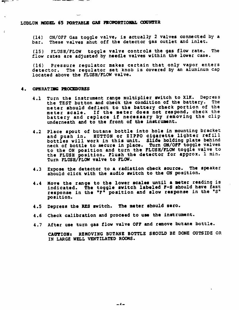
LUDLUM MODEL 65 PORTABLE GAS PROPORTIONAL COUNTER
(14) ON/OFF Gas toggle valve, is actually 2 valves connected by a bar. These valves shut off the detector gas outlet and inlet.
(15) FLUSH/FLOW toggle valve controls the gas flow rate. The flow rates are adjusted by needle valves within the lower case.
(16) Pressure regulator makes certain that only vapor enters detector. The regulator set knob is covered by an aluminum cap located above the FLUSH/FLOW valve.
4. OPERATING PROEURES
4.1 Turn the instrument range multiplier switch to XlK. Depress the TEST button and check the condition of the battery. The meter should deflect to the battery check portion of the meter scale. If the meter does not respond, check the battery and replace if necessary by removing the clip underneath and to the front of the instrument.
4.2 Place spout of butane bottle into hole in mounting bracket and push in. HUTTON or ZIPPO cigarette lighter refill bottles will work in this unit. Slide holding plate behind neck of bottle to secure in place. Turn ON/OFF toggle valves to the ON position and turn the FLUSH/FLOW toggle valve to the FLUSH position. Flush the detector for approx. 1 min. Turn FLUSH/FLOW valve to FLOW.
4.3 Expose the detector to a radiation check source. The speaker should click with the audio switch to the ON position.
4.4 Move the range to the lower scales until a meter reading is indicated. The toggle switch labeled F-S should have fast response in the IFN position and slow response in the IS" position.
4.5 Depress the RES switch. The meter should zero.
4.6 Check calibration and proceed to use the instrument.
4.7 After use turn gas flow valve OFF and remove butane bottle.
CAUTION: REMOVING BUTANE BOTTLE SHOULD BE DONE OUTSIDE OR IN LARGE WELL VENTILATED ROOMS.
-A--.
006- --
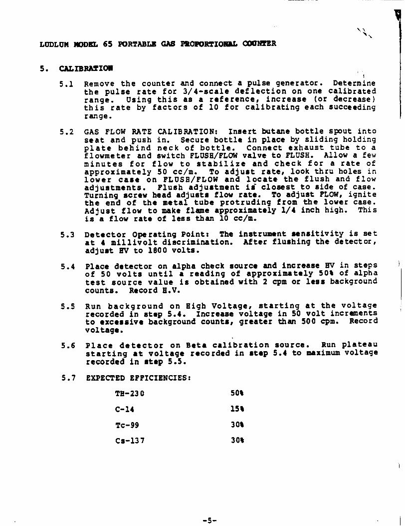
LUDLUM IODEL 65 PORTABLE GAS PROPORTIONL CU MR
5. CALIBRATION
5.1 Remove the counter and connect a pulse generator. Determine the pulse rate for 3/4-scale deflection on one calibrated range. Using this as a reference, increase (or decrease) this rate by factors of 10 for calibrating each succeeding range.
5.2 GAS FLOW RATE CALIBRATION: Insert butane bottle spout into seat and push in. Secure bottle in place by sliding holding plate behind neck of bottle. Connect exhaust tube to a flowmeter and switch FLUSH/FLOW valve to FLUSH. Allow a few minutes for flow to stabilize and check for a rate of approximately 50 cc/m. To adjust rate, look thru holes in lower case on FLUSH/FLOW and locate the flush and flow adjustments. Flush adjustment is" closest to side of case. Turning screw head adjusts flow rate. To adjust FLOW, ignite the end of the metal tube protruding from the lower case. Adjust flow to make flame approximately 1/4 inch high. This is a flow rate of less than 10 cc/m.
5.3 Detector Operating Point: The instrument sensitivity is set at 4 millivolt discrimination. After flushing the detector, adjust HV to 1800 volts.
5.4 Place detector on alpha check source and increase EV in steps of 50 volts until a reading of approximately 50% of alpha test source value is obtained with 2 cpm or less background counts. Record H.V.
5.5 Run background on High Voltage, starting at the voltage recorded in step 5.4. Increase voltage in 50 volt increments to excessive background counts, greater than 500 cpm. Record voltage.
5.6 Place detector on Beta calibration source. Run plateau starting at voltage recorded in step 5.4 to maximum voltage recorded in step 5.5.
5.7 EXPECTED EFFICIENCIES:
TH-230 50%
C-14 15%
Tc-99 30%
Cs-137 30%
-5-

LUDLUM NODE. 65 PORTABLE GAS PROPORTIOILL COUNTER
6. •AINTENANCE
NOTE: NEVER STORE THE INSTRUMENT OVER 30 DAYS WITHOUT REMOVING BATTERY. ALTHOUGH THIS INSTRUMENT WILL OPERATE AT VERY HIGH AMBIENT TEMPERATURES, BATTERY SEAL FAILURE CAN OCCUR AT TEMPERATURES AS LOW AS 1000 FAHRENHEIT.
Instrument maintenance consists of keeping the instrument clean and periodically checking the battery and calibration.
An instrument operational check should be performed prior to each use by exposing detector to a known source and confirming proper reading on each scale.
Remove the battery when not in daily use. Test the reinstalled battery with the battery test switch.
7. OvERHAL
To remove the counter, remove the four thumbscrews.
To remove the probe face, remove the face screws. Keep the probe clean. Replace the face.
To open the counting instrument: (1) remove it from the probe, (2) remove the four screws on the bottom of the adaptor plate, (3) lift open the counting instrument.
CAUTION: With the instrument open, the 2500-volt high voltage contact is exposed.
To access flow valves, remove the six screws holding the probe onto lower case.
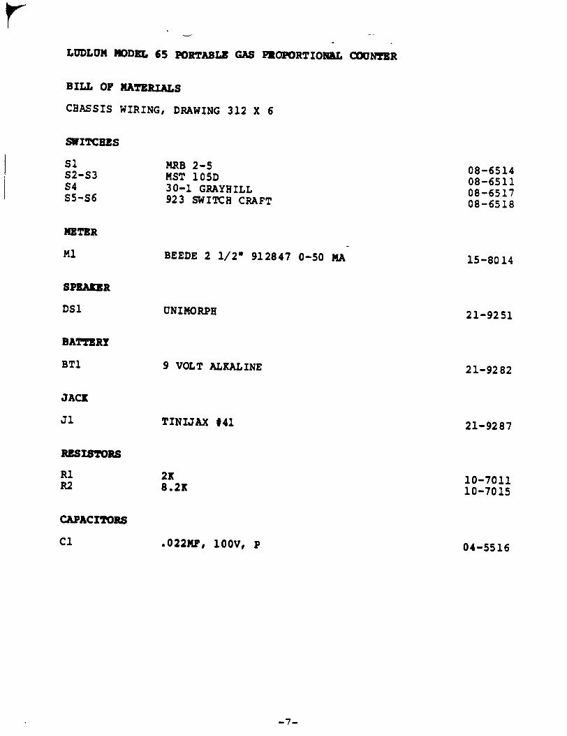
LUDLUM MODEL 65 PORTABLE GAS PROPORTIONAL COUNTER
BILL OF MATERIALS
CHASSIS WIRING, DRAWING 312 X 6
SWITCHES
MRB 2-5 MST 105D 30-1 GRAYHILL 923 SWITCH CRAFT
BEEDE 2 1/2w 912847 0-50 MA
UNIMORPH
9 VOLT ALKALINE
TINIJAX #41
RESISTORS
R1 R2
CAPACITORS
Cl
2K 8.2K
.022MF, 100V, P
Sl $2-S3 S4 S5-S6
METER
Ml
SPEAKER
08-6514 08-6511 08-6517 08-6518
DS1
BATTERY
15-8014
BTI
JACK
Ji
21-9251
21-9282
21-9287
10-7011 10-7015
04-5516
-7-
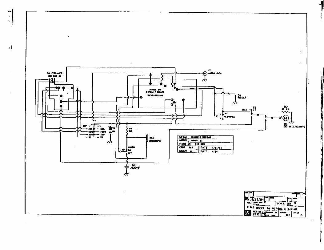
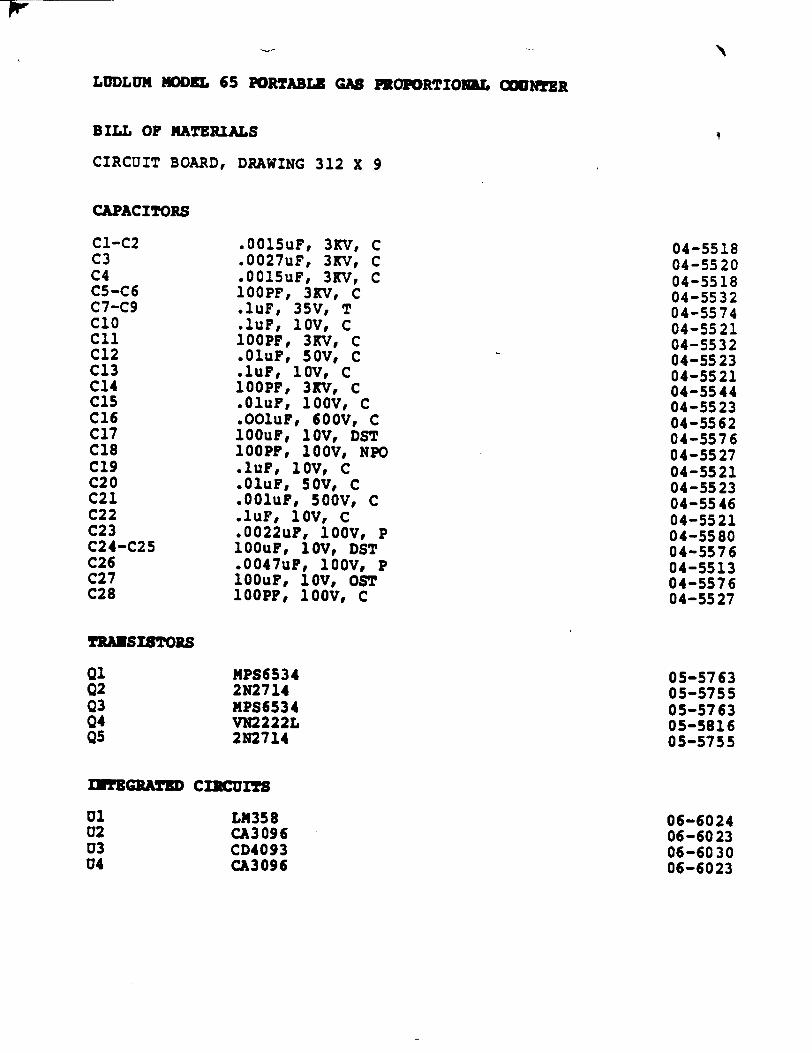
LUDLUM MODEL 65 PORTABLE GAS PEOPORTIOQUL COUNTER
BILL OF MATERIALS
CIRCUIT BOARD, DRAWING 312 X 9
CAPACITORS
.0015uF, 3KV, C
.0027uF, 3KV, C •0015uF, 3KV, C i00PF, 3KV, C iuF, 35V, T lur, ov, C
100PF, 3KV, C .01uF, 50V, C
urF, loV, C 100PF, 3KV, C .o0uF, 0OOV, C •OO1uF, 600V, C i1OuF, loV, DST 10OPF, 10OV, NPO .IuF, 1oV, C .01uP, 50V, C .ooiuF, 500V, C .iuF, loV, C •0022uF, 100V, P iO0UF, loV, DST .0047uF, i00V, P io0uF, 1oV, OST
0OOPF, 1O0V, C
MPS6534 2N2714 MPS6534 VN2222L 2N2714
ITEGRATED CICU ITS
LM358 CA3096 CD4093 CA3096
C1-C2 C3 C4 C5-C6 C7-C9 Ci0 C1l C12 C13 C14 C15 C16 C17 cis C19 C20 C21 C22 C23 C24-C25 C26 C27 C28
04-5518 04-5520 04-5518 04-5532 04-5574 04-5521 04-5532 04-5523 04-5521 04-5544 04-5523 04-5562 04-5576 04-5527 04-5521 04-55 23 04-5546 04-5521 04-5580 04-5576 04-5513 04-5576 04-5527
TRANSISTORS
Qi 02 03 04 Q5
Ul U2 U3 U4
05-5763 05-5755 05-5763 05-5816 05-5755
06-6024 06-6023 06-6030 06-6023

LUDLUM MODEL 65 PORTABLE GAS PZOPORTIOML COUNTER
DIODES
CR1-CR4 CR5 CR6
MR250-2 AD589 1N4148
RESISTORS
R1 R2-R3 R4 R5 R6 R7 R8 R9 R1%0 R111 RI12 R13 R14 R15 R16 R17 RI8 R19 R20 R21 R23 R2 4 R25-R28 R29 R30 R31 R32 R33 R34 R35-R36 R37 R38 R39 R41 R42-R45 R46 R47 R48 R49 R50 R51
-a-
07-6266 07-6057 07-6272
1OM 22M 47K 270 OHM 2.2K 10K IM 10K 47K 100K 10K 100K 1K 100K 10K 47K 2.7M 10K 2.2M 500K TRIMMER POTENTIOMETER 10m 100K TRIMMER POTENTIOMETER 500K TRIMMER POTENTIOMETER 560K 330K 10K 47K 10M 100K 10K 2.7K 120K 390K 150K I MEG 10K 10K TRIMMER POT 1K 22K 68K IGIG
10-7031 10-7034 10-7020 10-7007 10-7012 10-7016 10-7028 10-7016 10-7020 10-7023 10-7016 10-7023 10-7009 10-7023 10-7016 10-7020 10-7029 10-7016 10-7052 09-6792 10-7031 09-6789 09-6792 10-7027 10-7051 10-7016 10-7020 10-7031 10-7023 10-7016 10-7055 10-7050 10-7069 10-7024 10-70 28 10-7016 09-6794 10-7009 10-7070 10-7049 12-7686
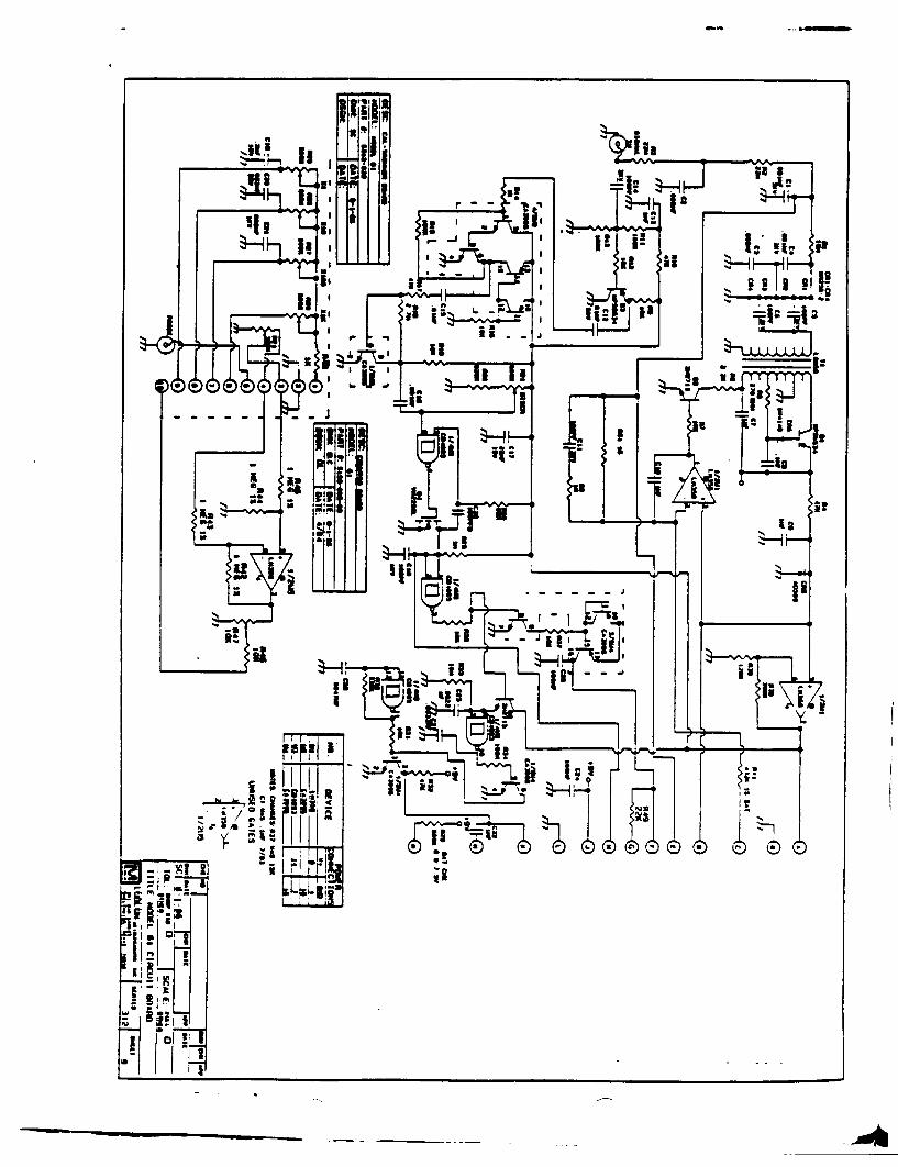
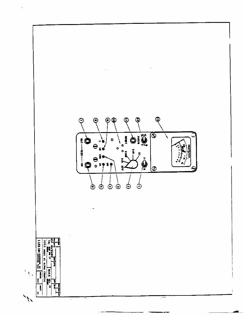
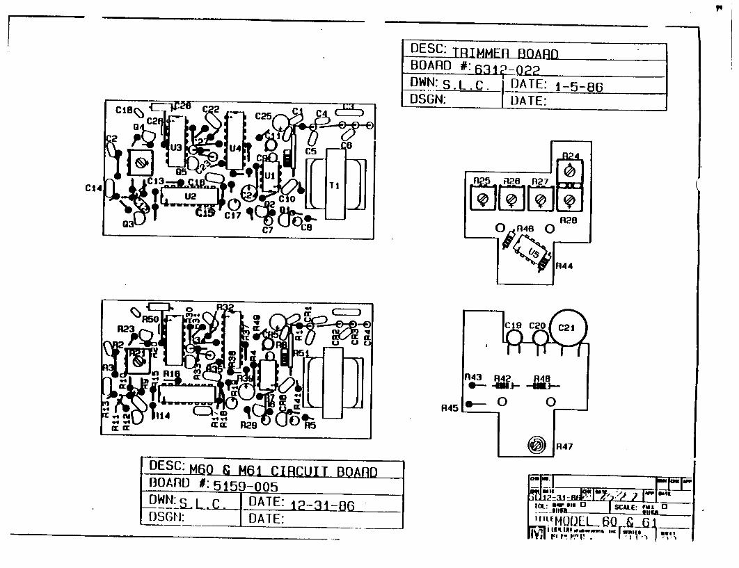
DESC:T B-iOARD OWN: S.i
C27
U45 czDi C13
C14[ $2 242 FLJJ
RIMMEE-BOARD #:63~ 1 -22 L.c. DATE: 156
I DATE:
DESC~ffi g M61 CIRCUIT BOARD BOARD #:515 -005 OWN: S_ LC DATE: 12--31-83( DSGN: IDATE:
qim mall"i 1112z3 -cia mar .7 ga
3 JLFOL6 -& __ JOL o w ' E [ rrn u 1& 
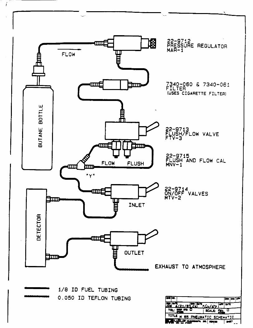
22-9712 PRESSURE REGULATOR MAR-1
7340-060 & 7340-061 FILTER (USES CIGARETTE FILTER)
22-9713 FLUSH/FLOW VALVE FTV-3
22-9715 FLUSH AND FLOW CAL MNV-1
22-9714 ON/OFF VALVES MTV-2
EXHAUST TO ATMOSPHERE
1/8 ID FUEL TUBING
0.050 ID TEFLON TUBING

4''
4'4
4 ' 'i-v ''f' '1
.'4'"� t � �'r �
F' ' '
4'
,,s. '4Th AM
4
* 4E ,�
4,. 6�
4 #� 4 � '4'2.
,: .&�
� j� � 44��9
sf4' �
*�' 21 - .4
'I;:: *t49 4,9 4 ii. V *� �' $ � �
"'1
'#4.' 4'
K9 - � .94
.4"
K . 'A- "' 4 ."44V * 44' - 4
-It..
4'4'; *�4"
,4�, '-. 4'
4 1
I 24 - K -' ' "� 4 � W' '4"' "lw'-.2 N A
jaw
I'
4.
a
4,.' 4
a
"'"'.4"
I £
4 4'
A
""4
'I'
C"
-4611
4
9"Z' -i"' a-.'
k 4
4'
44.44 N
ii" 4''
C
Instruction Manual LUDLUM MODEL 19 MICRO R. METER
LUDLUM MEASUREMENTS, INC OAK on5 * 206m 0. 0. boX
uWIuW ATNE. TEXAS. VA.. ?UUS
N',D ARIUMNQTS
INSTRUMENTS
N'
WARRANTY CERTIFICATE
Ludlum Measurements, Inc. warrants the products covered in this Instruction Manual to be free of defects due to workmanship, materials, and design for a period of twelve months from the date of delivery, with the exception of photomultiplier tubes and geiger tubes, which are warranted defect free to 90 days.
In the event of instrument failure, notify Ludlum Measurements, Inc. for repair or replacement. Liability of this warranty is limited to the purchase price of the instrument.
RECEIVING CONDITION EXAMINATION
Be sure to verify that the shipping carton is received in perfectly good condition. For example, that no damage should be visible.
Should the instrument be received in a damaged condition, save the shipping container and the packing material and request an immediate inspection by the carrier.
Ludlum Measurements, Inc. is not responsible for the damage which occurs during shipment, but will make every effort to help obtain restitution from the carrier.
RETURN OF GOODS TO MANUFACTURER
If equipment needs to be returned to Ludlum Measurements, Inc. for repair, calibration, etc., please do so by the appropriate method of shipment. All shipments should include documentation containing shipping address, customer name and telephone number, and all other necessary information.
Your cooperation will expedite the return of your equipment.

***MODEL 19 ADDENDUM SHEE. **
Q5 AND Q6 HAVE BEE12 CHANGED FROM 2N3877 TO 2N3904.
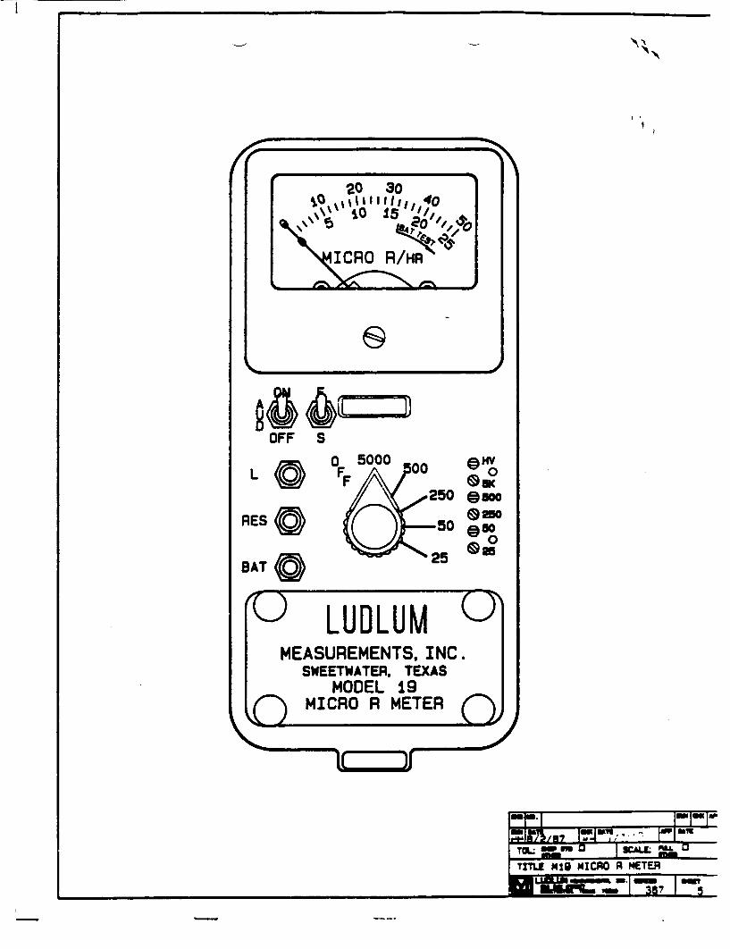
@Hmy 0
.250 @500
-50 w 0
- 25
II
20 30
ICRO R/HR
OFF S
RES
BAT
'U LUDLUM (J MEASUREMENTS, INC.
SWEETWATER. TEXAS MODEL 19
(• MICRO R METERIIwJ
owe%i
ifu
LUDLUX MODEL 19 MICRO R METER
TABLE OF CONTENTS
Page No.
2GENERAL
SPECIFICATIONS
DESCRIPTION OF CONTROLS AND FUNCTIONS
OPERATING PROCEDURES
CALIBRATION
MAINTENANCE
BILLS OF MATERIALS AND SCHEMATICS
REV 9/88 (59965)
1.
2.
3.
4.
5.
6.
7.
2
3
4
4
5
7
LUDLUK MODEL 19 MI 0 R METER
1. GENERAL
The Ludlum M~lodel 19 Micro R Meter utilizes an internally-mounted, 1" x 1" NaI(Tl) scintillator to offer an optimum performance in counting low-level gamma radiation. Designed to be moisture and dust resistant, conveniences are not overlooked as the unit features a pushbutton lighted meter.
Five range divisions are provided from which to select the most desirable range in the 0-5000 micro R/Hr spectrum. The meter face is made up of two scales, 0-50 and 0-25, plus battery test. The 0-50 scale corresponds to the 50, 500 and 5000 positions on the range selector switch. The 0-25 scale corresponds to the 25 and 250 positions on the range selector switch.
The instrument is capable of using either the standard flashlight battery or the nickel-cadmium, rechargeable battery. However, the Model 19 does not include circuitry for, recharging the batteries.
All controls, including a calibration potentiometer for each range, are located on the front panel. Two OD' cell batteries are located in an isolated compartment and easily changed from the front panel. The meter is housed in a rugged, two-piece aluminum bezel with waterproof seals.
2. SPECIFICATIONS
LINEARITY: plus or minus 5% of full scale
INPUT IMPEDANCE: 0.1 megohm
HIGH VOLTAGE: variable from 400 to 1500 volts DC, electronically regulated to within -1%
CALIBRATION STABILITY: less than 15% variance to battery end point
BATTERY COMPLEMENT: two standard size *DO cell batteries, secured with screws and a gasket for dust and moisture proofing
AUDIO OUTPUT: built-in unimorph speaker and ON-OFF switch provided on front panel
COUNTING RANGES: 2-scale meter face presenting 0-50 Micro R/Hr with full scale range positions of X5000, X500 and X50; and 0-25 Micro R/Hr with range selections of X250 and X25
METER: lmA, 2 1/2-inch scale
LUDLUX MODEL 19 MI( ) R METER
HV Adjustment provides a means to vary the high voltage from 400 to 1500 volts.
Range Calibration Adjustments are recessed potentimeters located under the calibration cover, on the right side of the front panel. These adjustment controls allow individual calibration for each range multiplier.
4. OPERATIMG PRO URES
The Model 19 is a simple instrument to operate. All controls and adjustments are located on the front panel along with the battery compartment. The 1l x 10 NaI(Tl) Scintillator is mounted internally, deleting external cords or cables.
4.1 Prior to Turn-on
a. Check the batteries -- type installed and condition. b. Adjust the audio ON-OFF switch as desired. c. Adjust the meter response switch as desired.
4.2 Turn-on
a. Range Selector Switch: Select the 0-5000 range. b. BAT TEST Button: Depress. Check the BAT test on the
appropriate scale. Replace the batteries if the meter pointer is below the battery CHK line.
c. Light Button: Depress. Check for light on the meter face.
d. Meter Response Switch: Check the response in the "F" and "SO positions.
e. Audio ON-OFF Switch: Check for audio indication. f. Check the instrument for the proper scale indication with
a known source. Check all the ranges for the appropriate scale indication.
g. Reset Button: Depress. Check to see that the meter pointer returns to the zero position.
h. The instrument is ready for monitoring.
5. CALIBRATION
The. Model 19 radiation response is energy-sensitive. The detector plateau-characteristic must be detemined for the anticipated radiation nuclide. The following is an example calibration:
5.1 Remove the instrument from its case.
-4-
LUDLUM MODEL 19 MI( C R METER
DETECTOR: RCA 6199 coupled to a 1" x 1" NaI(Tl) crystal mounted inside the instrument housing
FINISH: instrument housing of drawn-and-cast aluminum fabrication with computer-beige, polyurethane enamel and silk-screened nomenclature; rubber-booted switches
SIZE: 6.4 inches x 3.4 inches x 8.0 inches (H x W x L exclusive of handle)
WEIGHT: 4.5 pounds
3. DESCRIPTION OF coNTRmLS AUD FUNCTIONS
Range Selector Switch is a 6-position switch marked OFF, 5000, 500, 250, 50 and 25. Moving the range selector switch to one of the range positions (5000, 500, 250, 50, 25) provides the operator with an overall range of 0-5000 Micro R/Hr. Note that the range positions 5000, 500 and 50 are screened in black and correspond to the meter scale, screened in black. The range positions 250 and 25 are screened in red and correspond to the meter scale, screened in red.
AUDIO ON-OFF Toggle Switch, in the ON position, operates the unimorph speaker, located on the left side of the instrument. The frequency of the clicks is relative to the rate of the incoming pulses. The higher the rate is, the higher the audio frequency. The audio should be turned OFF when not required to reduce battery drain.
Fast-Slow Toggle Switch provides meter response. Selecting the "F" position of the toggle switch provides 90% of full scale meter deflection in 3 seconds. In "S" position, 90% of full scale meter deflection takes 11 seconds. In "F" position, there is fast response and large meter deviation. .Sn position should be used for slow response and damped, meter deviation.
BATTERY Pushbutton Switch, when depressed, indicates the battery charge status on the meter. The range selector switch must be out of the OFF position.
RES Button, when depressed, provides a rapid means to drive the meter to zero.
Light Pushbutton Switch, when depressed, lights the meter face. This switch is marked with an 'Ll.
-3-
LUDLUM MIODEL 19 MI ) R METER
NOTE: NEVER STORE THE INSTRUMENT OVER 30 DAYS WITHOUT RE4OVING THE BATTERIES. ALTHOUGH THIS INSTRUMENT WILL OPERATE AT VERY HIGH AMBIENT TEMPERATURES, BATTERY SEAL FAILURE CAN OCC;JR AT TEMPERATURES AS LOW AS I00O FAHRENHEIT. NEGLECTED BA1TTERY SEAL FAILURE WILL SURELY CAUSE ONE AWFUL MESS!
Instrument maintenance consists of keeping the instrument clean and periodically checking the batteries and calibration. Once initial calibration is performed, recalibration should not be required if the batteries are maintained in good condition.
An instrument operational check should be performed prior to each use by exposing the detector to a known source and confirming the proper reading on each scale.
Under certain conditions, the NRC requires instrument recalibration every three months.- Check the appropriate regulations to determine the recalibration schedule.
Also at three month intervals, the batteries should be removed and the battery contacts cleaned of any corrosion. If the instrument has been exposed to a very dusty or corrosive atmosphere, more frequent battery servicing should be used.
Use a spanner wrench to unscrew the battery contact insulators, exposing the internal contacts and battery springs. Removing the handle will facilitate access to these contacts.
-6-

LUDLUR MODEL 19 MIS J R METER
5.2 With the instrument off, remove the HV jumper at the C19-R5 junction.
5.3 Connect a pulser to the Cl-R5 junction.
a. Set the pulse height at 80 millivolts, negative. b. Calibrate the scales as follows:
Scale Reading Pulses/Minute 25 20 3,200 50 40 6,400
250 200 32,000 500 400 64,000
5,000 4,000 640,000
5.4 Connect the jumper back to the C19-R5 junction.
5.5 Replace instrument can Note: The detector is not light-tight outside of the can.
5.6 Plateau instrument using Americium-241 using H.V. adjust potentionmeter on front panel.
5.7 Determine the plateau center voltage
a. Remove can b. Measure H.V. at the detector plug on circuit board.
NOTE: The voltmeter must have a 1,000 megohm/volt, or greater input impedance or use a Model 500 Pulser.
5.8 Replace instrument can.
5.9 Take the Model 19 to a certified calibration range. Calibrate each scale for best fit at 1/5 and 4/5 scale. If the reading error exceeds 10% of reading, record the field versus the meter reading at 5 points on the scale. Place a copy of this meter correction on the instrument case.
5.10 If the calibration range background is too high for the Micro R scales, calibrate the 5000 scale as in Step 5.9.
a. Turn instrument off and remove instrument from can. .b. Remove H.V. Jumper
c. Turn instrument on d. Connect pulser and determine pulse rate verses micro R/hr
calibration point on 5000 scale. e. Calibrate the lower scales with Pulser using information
in step (c). f. Turn instrument off and reconnect H.V. Jumper. g. Replace can
5.11 Recheck all operating functions of the instrument prior to
use.
6. A INTEIANK:Z
-5-
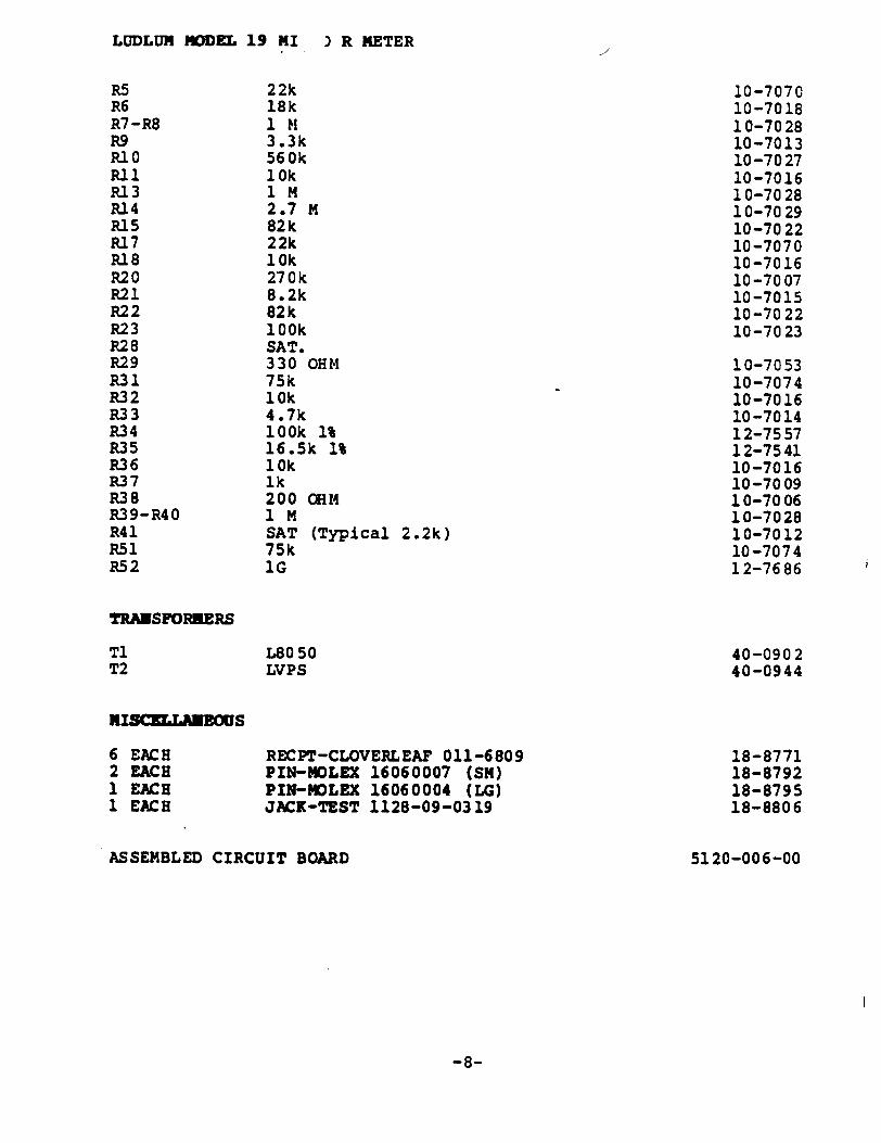
LUDLUM MODEL 19 MI ) R METER
R5 22k 10-7070 R6 18k 10-7018 R7-R8 1 M 10-7028 R9 3.3k 10-7013 RI0 560k 10-7027 Rl1 10k 10-7016 R13 I M 10-7028 R14 2.7 M 10-7029 R15 82k 10-7022 R17 22k 10-7070 R18 10k 10-7016 R20 270k 10-7007 R21 8.2k 10-7015 R22 82k 10-7022 R23 100k 10-7023 R28 SAT. R29 330 OHM 10-7053 R31 75k 10-7074 R32 10k 10-7016 R33 4.7k 10-7014 R34 100k 1% 12-7557 R35 16.5k 1% 12-7541 R36 10k 10-7016 R37 1k 10-7009 R38 200 OHM 10-7006 R39-R40 1 M 10-7028 R41 SAT (Typical 2.2k) 10-7012 R51 75k 10-7074 R52 IG 12-7686
TRANSFORMERS
Ti L8050 40-0902 T2 LVPS 40-0944
RISXTLAUEOWS
6 EACH RECPT-CLOVERLEAF 011-6809 18-8771 2 EACH PIN-14OLEX 16060007 (SM) 18-8792 1 EACH PIN-MOLEX 16060004 (LG) 18-8795 1 EACH JACK-TEST 1128-09-0319 18-8806
ASSEMBLED CIRCUIT BOARD 5120-006-00
-8-
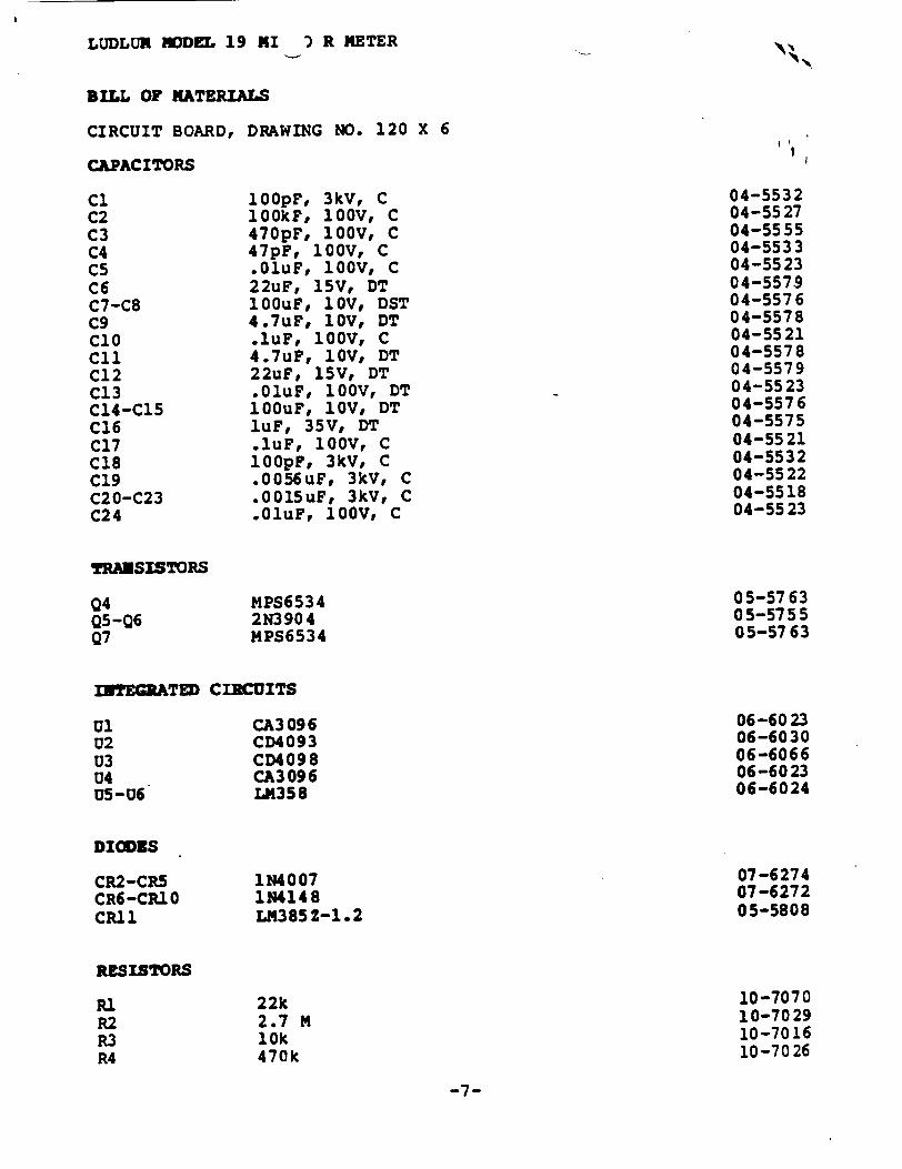
LUDLUM MODEL 19 MI ) R METER
BILL OF MATERIALS
CIRCUIT BOARD, DRAWING NO. 120 X 6
CAPACITORS
10OpF, 3kV, C lOOkF, 100V, C 470pF, 100V, C 47pF, 100V, C .OluF, 100V, C 22uF, 15V, DT 1OOuF, 1OV, DST 4.7uF, 1OV, DT .luF, 100V, C 4.7uF, 1OV, DT 22uF, 15V, DT .OluF, 100V, DT 10OuF, 1OV, DT luF, 35V, DT .luF, 100V, C lOOpF, 3kV, C .0056uF, 3kV, C .0015uF, 3kV, C .01uF, 100V, C
TRANSISTORS
MPS6534 2N3904 MPS6534
INTEGRATED CIRCUITS
CA3096 CD4093 CD4098 CA3096 LM358
CR2-CR5 CR6-CR1 0 CR11
RESISTORS
R1 R2 R3 R4
1N4007 1N4148 LM385Z-1.2
22k 2.7 M 10k 470k
Cl C2 C3 C4 Cs C6 C7-C8 C9 CI0 Cli C12 C13 C14-C15 C16 C17 C18 C19 C20-C23 C24
04-5532 04-5527 04-5555 04-5533 04-5523 04-5579 04-5576 04-5578 04-55 21 04-5578 04-5579 04-5523 04-5576 04-5575 04-5521 04-5532 04-5522 04-5518 04-5523
Q4 Q5-Q6 Q7
U' U2 U3 U4 05-U6
0 5-57 63 05-5755 05-5763
DIODES
06-6023 06-6030 06-6066 06-6023 06-6024
07-6274 07-6272 05-5808
-7-
10-7070 10-7029 10-7016 10-7026
!I
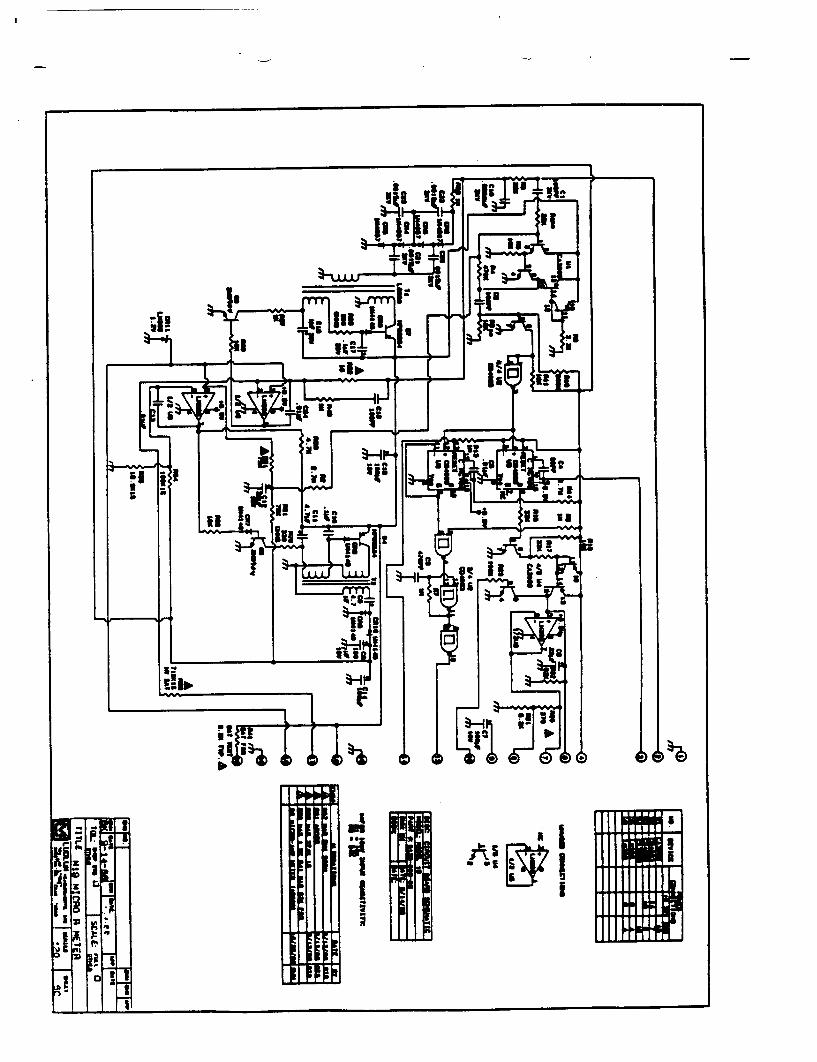
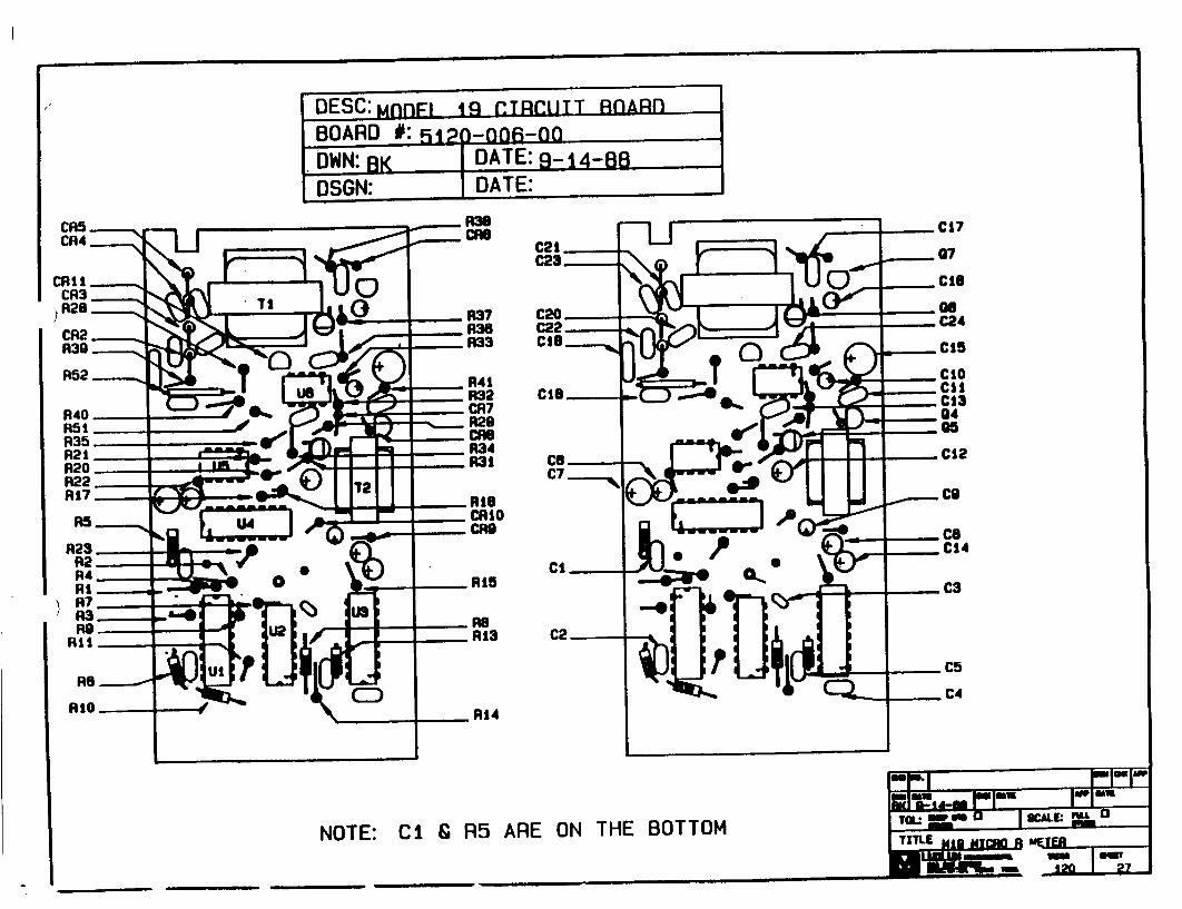
DESC:MnnFL Ig CTgRjTT RnARn
BOARD #: 512p-oOR-oo
DWN: BK DATE: 9-14-883 DSGN: DATE:
NOTE: Ci & R5 ARE ON THE BOTTOM

LUDLUM MODEL 19 MICP- R METER
BILL OF MATERIALS
WIRING DIAGRAM, DRAWING NO. 120 X 5
AUDIO
UNIMORPH 60690
CONNECTORS
RIBBON-05 0-010-455 10PIN
SWITCEBS
PA-60 0-21 0 7101-SYZ-QE TOGGLE 7101-SYZ-QE TOGGLE 30-1-PB GRAYHILL 30-1-PB GRAYHILL 923 PB SWTCHCRFT
BATTERY
"Do DURACELL BATTERY "Do DURACELL BATTERY
DETECTOR
iM loM 18.2M
CAPACITORS
0.0luF, 2kV
RISC.LhNEOUS
M19 BATTERY BOX LID BATTERY CONTACT SET DEEP CAN M19 CASTING M19 MAIN HARNESS M19 RIBBON HARNESS M19 METER PORTABLE HANDLE PORTABLE KNOB
9120-023 40-17 07 40-0266
9367-004 8120-009-00
8367-00 5 40-1808
70 01-01 2-01 08-6613
-9-
DS1
P1
21-9251
Si S2 S3 S4 s5 S6
13-8064
BT1 BT2
08-65 01 08-6511 08-6511 08-6517 08-6517 08-6518
Rl R2-RI 0 Rl 1
21-93 13 21-93 13
Cl
10-70 28 10-70 31 10-7033
*
*
04-5525
Ml *
*
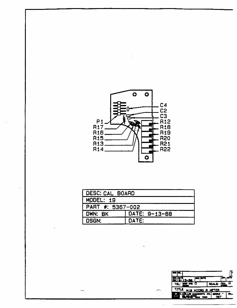
C4 C2
_ •_ C3
P - Ri2 R17 RIB R16 Ri9 Ri5 R20 R13- R2I R14" R22
0
OESC: CAL BOARD MPOEL: 19 PART #: 5367-002 DWN: BK DATE: 9-13-88 OSGN: DATE:
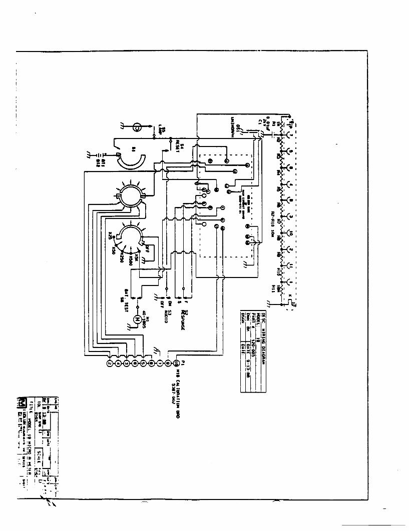
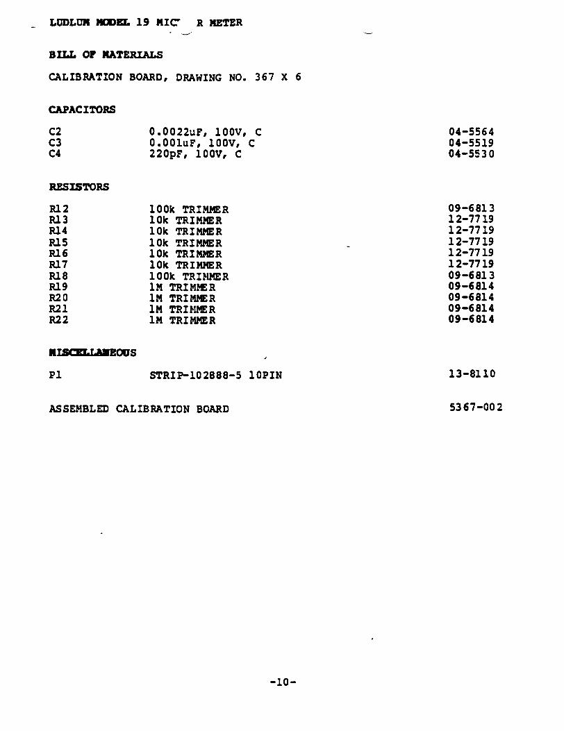
LUDLUI RODEL 19 MIC' R METER
BILL OF MATERIALS
CALIBRATION BOARD, DRAWING NO. 367 X 6
CAPACITORS
C2 0.0022uF, 100V, C C3 0.001uF, 100V, C C4 220pF, 100V, C
RESISTORS
100k TRIMMER 10k TRIMMER 10k TRIMMER 10k TRIMMER 10k TRIMMER 10k TRIMMER 100k TRIMMER 1M TRIMMER IM TRIMMER IM TRIMMER 1M TRIMMER
RISCLANEOUS
STRIP-102888-5 10PIN 13-8110
53 67-00 2ASSEMBLED CALIBRATION BOARD
-10-
04-5564 04-5519 04-5530
Rl2 R13 R14 R15 RI6 P17 R18 R19 R20 R21 R22
09-6813 12-77 19 12-77 19 12-7719 12-77 19 12-7719 09-6813 09-6814 09-6814 09-6814 09-6814
P1
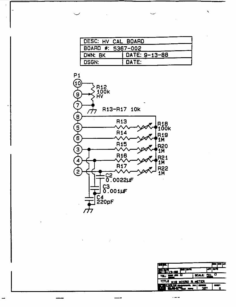
DESC: HV CAL BOARD
BOARD #: 5367-002
Pi
TI allu mac A1 ~
p
I
t .�: � �
YK.*
low,�d- 
lq
* .4 411
'I,
I I
I, i.t�
'I.
M"

instruction Manual MODEL 12 COUNT RATEMETE
LUDLUM MEASUR EMENTS, INC. WI AX on - U.UM P.O aO bo s
SWUmrWAT.& TZAMAI V.LA.._ 1r
INSTRUMENTS
N'
WARRANT! CERTIFICATE
Ludlum Measurements, Inc. warrants the products covered in this Instruction Manual to be free of defects due to workmanship, materials, and design for a period of twelve months from the date of delivery, with the exception of photomultiplier tubes and geiger tubes, which are warranted defect free to 90 days.
In the event of instrument failure, notify Ludlum Measurements, Inc. for repair or replacement. Liability of this warranty is limited to the purchase price of the instrument.
RECEIVING CONDITION XINL•TION
Be sure to verify that the shipping carton is received in perfectly good condition. For example, that no damage should be visible.
Should the instrument be received in a damaged condition, save the shipping container and the packing material and request an immediate inspection by the carrier.
Ludlum Measurements, Inc. is not responsible for the damage which occurs during shipment, but will make every effort to help obtain restitution from the carrier.
RETURN OF GOODS TO MANUFACTURER
If equipment needs to be returned to Ludlum Measurements, Inc. for repair, calibration, etc., please do so by the appropriate method of shipment. All shipments should include documentation containing shipping address, customer name and telephone number, and all other necessary information.
Your cooperation will expedite the return of your equipment.
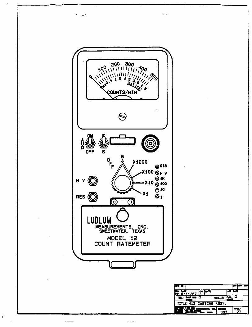
LUDLUXI MODEL 12 COUNT RATEMETER
TABLE OF CONTENTS
Page No.
1. GENERAL 2
2. SPECIFICATIONS 2
3. DESCRIPTION OF CONTROLS AND FUNCTIONS 3
4. OPERATING PROCEDURES 4
5. CALIBRATION 6
6. MAINTENANCE 7
7. BILL OF MATERIALS 9
REV. 8/9/88 (58320)
LUDLUM MODEL 12 C&..d1! RATEMETER
1 . GENERAL
The Model 12 Count Ratemeter provides the required electronic circuitry for radiation monitoring with proportional, scintillation and G-M detectors.
This manual includes general description, control functions, operation, calibration and maintenance instructions. In the event that further information is desired, please contact the factory or our field representatives.
2. SPECIFICATIONS
POWER: two flashlight batteries, standard *DO cells; Mercury or rechargeable cells directly interchangeable
HIGH VOLTAGE: adjustable from -200 to 2,400 volts; electronically regulated to 1%; HV support of scintillation loads to 1,500 volts, proportional to 2,400 volts.
SENSITIVITY: adjustable from 2 to 60 millivolts.
INPUT IMPEDANCE: 0.1 Megohm
METER: lmA, 2 1/2-inch scale, pivot-and-jewel movement
RANGE: 0 to 500,000 Counts/Minute (CPM)
LINEARITY: ±5% full scale
CALIBRATION STABILITY: less than 5% variance to battery endpoint
CALIBRATION CONTROLS: individual, locking potentiometers for each range; accessible from the front cover while in operational status
AUDIO: built-in unimorph speaker with On-Off switch
RESPONSE: 4 or 22 seconds for 90% of final meter reading
CONNECTOR: Series OC"
SIZE: 4.2 inches by 3.4 inches by 8.0 inches (H x W x L, exclusive of handle)
WEIGHT: 3.5 pounds
FINISH: drawn-and-cast aluminum fabrication, with computer-beige pclyurethane enamel and silk-screened nomenclature
-2-
LUDLUN MODEL 12 CC f RATEMETER
3. DESCRIPTION OF CONTROLS AND FUNCTIONS
Range Multiplier Selector Switch is a 6-position switch marked OFF, BAT, X1000, X100, X10, Xl. Turning the range selector switch from OFF to BAT position provides the, operator with a battery check of the instrument. A BAT check scale on the meter provides a visual means of checking the battery-charge status. Moving the range selector switch to one of the range multiplier positions (Xl000, Xl00, Xl0, Xl) provides the operator with an overall range of 0 to 500,000 CPM. Multiply the scale reading by the multiplier for determining the actual scale reading.
AUDIO ON-OFF Toggle Switch in the ON position operates the unimorph speaker, located on the left side of the instrument. The frequency of the clicks is relative to the rate of the incoming pulses. The higher the rate is, the higher the audio frequency. The audio should be turned OFF when not required to reduce battery drain.
Fast-Slow Toggle Switch provides meter response selection. Selecting the "F" position of the toggle switch provides 90% of the final meter reading in 4 seconds. In I"S position, 90% of the final meter reading takes 22 seconds. Set on "F" for fast response and large meter deviation. ISO position should be used for slow response and damped meter deviation.
RES Button, when depressed, provides a rapid means to drive the meter to zero.
HV Test Button, when depressed, displays the detector high voltage on the meter.
Range Calibration Adjustments are recessed potentiometers located on line with each multiplier position. These adjustment controls allow individual calibration for each range multiplier.
HV is a screwdriver adjustment that provides a means to vary the high voltage from 200 to 2,400 volts. The high voltage setting may be checked at the connector with an appropriate voltmeter.
GAIN Adjustment allows the input sensitivity to be adjusted from 2 to 60 millivolts. The GAIN is normally set for 10 millivolts at the factory.
-3-
LUDLUK MODEL 12 COWIT RATEMETER
4. OPERATING PROCEDURES
4.1 Slide the battery box button down. Open the lid and install two ID" size batteries. Note (+) (-) marks on the inside of the lid. Match the battery polarity to these marks.
NOTE: Center post of flashlight battery is positive.
DO NOT TWIST LID BUTTON - It slides to the rear.
Close the battery box lid.
4.2 Switch the range switch to BAT. The meter should deflect to the battery check portion of the meter scale. If the meter does not respond, recheck that the batteries have proper polarity.
4.3 Turn the instrument range multiplier switch to X1000. Expose the detector to a radiation check source. The speaker should click with the audio switch turned to the ON position.
4.4 Move the range switch to the lower scales until a meter reading is indicated. The toggle switch labeled F-S should have fast response in OF" position and slow response in "SO position.
4.5 Depress the RES switch. The meter should zero.
4.6 The operating point for the instrument and probes is established by setting the probe voltage and instrument sensitivity (HV and GAIN). The proper selection of this point is the key to instrument performance. Efficiency, background sensitivity, and noise are fixed by the physical makeup of the given detector and rarely varies from unit to unit. However, the selection of the operating point makes a marked difference in the apparent contribution of these three sources of count.
In setting the operating point, the final result of the adjustment is to establish the system GAIN so that the desirable signal pulses are above the discrimination level and the unwanted pulses from background radiation and noise are below the discrimination level and are not counted.
The total system gain can be controlled by adjusting either the instrument GAIN or the high voltage. Voltage affects control in the probe; GAIN controls the amplifier gain. .
-4-

LUDLUM MODEL 12 COU'Wf RATEMETER
In the special case of G-M detectors, a minimum voltage must be applied to establish the Geiger-Mueller characteristic. Further changes in gain will not affect this type probe.
The operating point for each detector is set at a compromise point of sensitivity, stability and background contribution. These operating points are best for general monitoring. In application, these arbitrarily selected points may not be the best. In order to select a better operating point, the following guides are presented:
a. G-M detectors are not capable of amplitude discrimination; so, the discriminator control has no function. The ratemeter will operate at any setting of the GAIN control with a G-M detector. Set the GAIN control at 50% clockwise and adjust the HV control for 900 volts. If a voltmeter is not available, increase the output voltage until a sharp increase in count rate is observed without a source. Then back off slightly and check the probe with a source. AFTER SETTING THE VOLTAGE, RECHECK THE GAIN SETTING TO INSURE THAT THE INSTRUMENT DOES NOT DOUBLE PULSE.
b. For proportional detectors, set the GAIN control for 2-millivolt discrimination (near maximum clockwise). Expose the detector to a check source. Adjust the HV until the low energy source is detected. Refine the HV adjustment for an optimum source count with a minimum acceptable background count.
c. For air proportional alpha detectors, set the GAIN for 2-millivolt discrimination. Adjust the HV until the detector just breaks down (shown by a very rapid increase of count rate without a source present). Measure the HV output; then decrease the HV setting to operate 100 volts below breakdown.
d. For scintillators, set the GAIN for 10 millivolts. Carefully increase the HV until the instrument plateau's on the background count. This provides the most stable operating point for the detector.
4.7 Check the calibration and proceed to use the instrument.
-5-
N'LUDLUN MODEL 12 COUf RATE1ETER
5. CALIBRATION
Calibration controls are located on the instrument cover in line with the multiplier index of each scale. The controls may be adjusted with an 1/8-inch blade screwdriver.
The instrument may be calibrated to true reading; or, when used with a single source, geometry calibration may be used. Both methods are described below. Unless otherwise specified, the instrument is calibrated to true reading at the factory.
5.1 True Reading Calibration requires the following steps:
a. Connect the input of the instrument to a negative pulse generator. CAUTION: The instrument input operates at a high potential. Connect the pulse generator through a
0.01 NFD, 2,000-volt capacitor unless the pulse
generator is already protected.
b. Adjust the pulser frequency to correspond to the 3/4-scale value of the instrument. Increase the pulser output voltage until a stable meter reading is obtained. Adjust the calibration potentiometer for a 3/4-scale reading. Repeat for each range.
c. To correlate this calibration to detected radiation value, probe efficiency must be determined. Select the operating point for the probe used as outlined in the previous section. Then determine the count-rate with the probe exposed to a calibrated source. The ratio of the instrument count-rate versus the known source value is the probe efficiency. This degree will be different for various types of probes and sources. By using probe efficiency, one determines the actual emission rate of an unknown source.
NOTE: For proportional and scintillation detectors, changes in the HV and GAIN controls will change the apparent detector efficiency for many sources.
5.2 Geometry calibration is often used when the instrument is utilized to measure radiation with a limited spectrum, for example, a single isotope contamination. To calibrate the instrument using this technique, obtain calibration sources with a spectrum similar to the unknown radiation. Expose the probe to the source and adjust the calibration control until the meter reading corresponds to the source value. Repeat this procedure with scaled sources for each instrument range.
-6-
LUDLUM. MODEL 12 COUNT RATENETER
NOTE: In the event that only one source is available, calibrate the corresponding range to that source. Disconnect the probe and connect a pulse generator to the instrument. Determine the pulse rate for 3/4-scale deflection on the calibrated range. Using this reading as a reference, increase (or decrease) this rate by factors of ten for calibrating each succeeding range.
6. NAINTENANCE
NOTE: NEVER STORE THE INSTRUMENT OVER 30 DAYS WITHOUT RE4OVING THE BATTERIES. ALTHOUGH THIS INSTRUMENT WILL OPERATE AT VERY HIGH AMBIENT TEMPERATURES, BATTERY SEAL FAILURE CAN OCCUR AT TEMPERATURES AS LOW AS 100 0 F. NEGLECTED BATTERY SEAL FAILURE WILL SURELY CAUSE ONE AWFUL MESS.
Instrument maintenance consists of keeping the instrument clean and periodically checking the batteries and calibration. It is recommended that automatic recalibration not be used with this instrument. The instrument design is quite redundant and once initial calibration is performed, recalibration should not be required if the batteries are maintained in good condition.
An instrument operational check should be performed prior to each use by exposing the detector to a known source and confirming the proper reading on each scale.
Under certain conditions, the NRC requires instrument recalibration every three months. Check the appropriate regulations to determine the recalibration schedule.
Also at three month intervals, the batteries should be removed and the battery contacts cleaned of any corrosion. If the instrument has been exposed to a very dusty or corrosive atmosphere, more frequent battery servicing should be used.
Use a spanner wrench to unscrew the battery contact insulators, exposing the internal contacts and the battery springs. Removing the handle will facilitate access to these contacts.
-7-
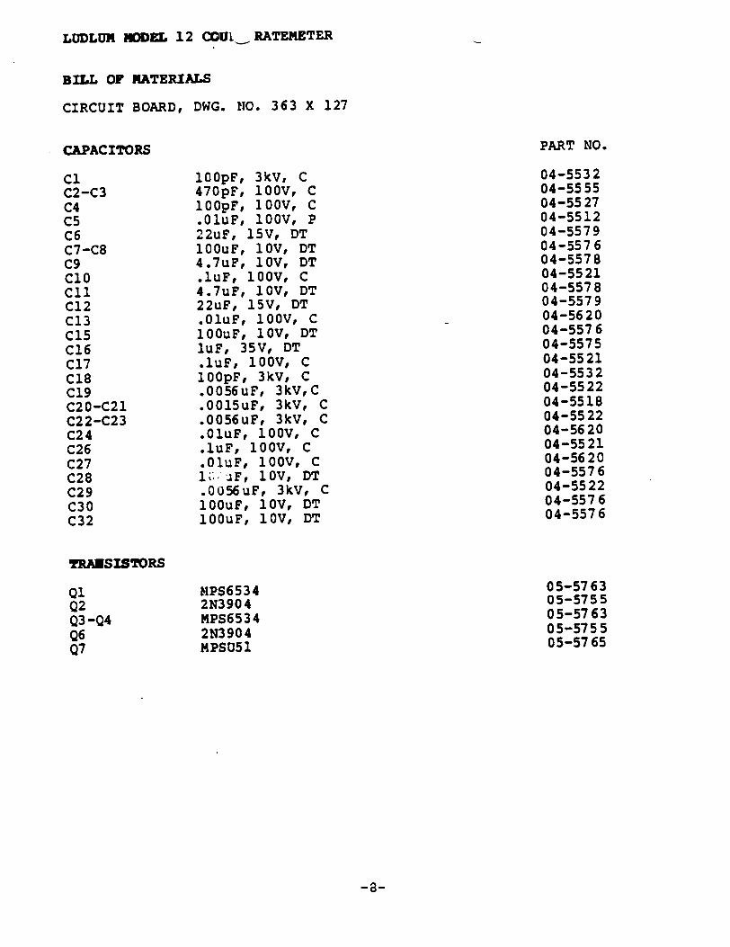
LUDLUN MODEL 12 CCUI_ RATEMETER
BILL OF MATERIALS
CIRCUIT BOARD, DWG. NO. 363 X 127
Cl C2-C3 C4 C5 C6 C7-C8 C9 ClO Cli C12 C13 C15 C16 C17 C18 C19 C20-C21 C22-C23 C24 C26 C27 C28 C29 C30 C32
MPS6534 2N3904 MPS6534 2N3904 MPSU51
CAPACITORS
05-5763 05-5755 05-5763 05-575 5 05-5765
-8-
PART NO.
04-5532 04-5555 04-5527 04-5512 04-5579 04-557 6 04-5578 04-5521 04-5578 04-5579 04-5620 04-5576 04-5575 04-5521 04-5532 04-5522 04-5518 04-5522 04-5620 04-5521 04-5620 04-5576 04-55 22 04-5576 04-5576
100pF, 3kV, C 470pF, 100V, C 100pF, 10OV, C .01uF, 100V, P 22uF, 15V, DT 100uF, 1OV, DT 4.7uF, 1OV, DT .luF, 100V, C 4.7uF, 1OV, DT 22uF, 15V, DT .01uF, 10OV, C 100uF, 1OV, DT luF, 35V, DT .luF, 100V, C 100pF, 3kV, C .0056uF, 3kV,C .0015uF, 3kV, C .0056uF, 3kV, C .01uF, 100V, C .luF, 100V, C .01uF, 100V, C It-1--F, 10V, DT .0U56uF, 3kV, C 1OOuF, 1OV, DT 1O0uF, 1OV, DT
TRANSISTORS
Q1 Q2 Q3 -Q4 Q6 Q7
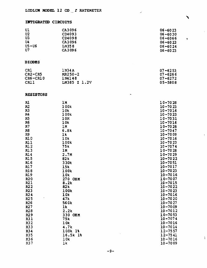
LUDLUM MODEL 12 CO _ 1f RATEMETER
INTEGRATED CIRCUITS
Ul U2 U3 U4 U5-U6 U7
DIODES
CA3096 CD4093 CD4098 CA3096 Lb35 8 CA3 096
CR1 CR2-CR5 CR6-CRI 0 CRI1
RESISTORS
RI R2 R.3 R4 R5 R6 R7 R8 R.9 RI0 Ri 1 Ri 2 R13 R14 RP.5 RI.6 R17 RI 8 Ri 9 R220 R21 R222 R23 R24 R225 R26 R27 R228 R29 R331 R3 2 R333 R334 R35 R3 6 R37
1N34A MR2 50 -2 1N4148 LM385 Z 1.2V
iM 100k 10k 100k 10 M 10k iM 6.8k Ik 10k 100k 75k iM 2.7M 82k 330k 15k 100k 10k 270 OHM 8.2k 82k 100k 10k 47k 560k ik 2.2k 330 OHM 75k 10k 4.7k 100k 1% 16.5k 1% 10k ik
06-6023 06-6030 06-6066 06-6023 06-6024 06-6023
07-6253 07-6266 07-6272 05-5808
10-7028 10-70 23 10-7016 10 -70 23 10-7031 10 -70 16 10-70 28 10 -7047 10-7009 10 -7016 10 -70 23 10 -7074 10-70 28 10-7029 10-7022 10 -70 51 10-7017 10 -70 23 10-7016 10-70 07 10 -7015 10-7022 10 -70 23 10-7016 10-70 20 10-7027 10 -70 09 10-7012 10-7053 10-7074 10-7016 10 -7014 12-75 57 12-7541 10-7016 10-7009
-9-
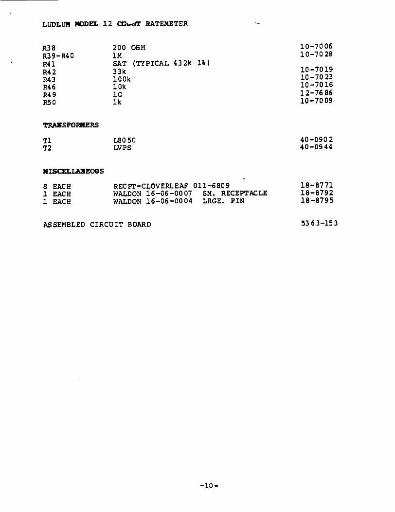
LUDLUM MODEL 12 CGff RATEMETER
R38 R39-R40 R41 R42 R4 3 R4 6 R4 9 R5 0
TRANSFORHERS
Ti T2
MISCELLANEOUS
8 EACH 1 EACH 1 EACH
200 OHM iM SAT (TYPICAL 432k 1%) 33k 100k 10k IG 1k
L80 50 LVPS
RECPT-CLOVERLEAF 011-6809 WALDON 16-06-0007 SM. RECEPTACLE WALDON 16-06-0004 LRGE. PIN
ASSEMBLED CIRCUIT BOARD
10-7006 10-7028
10-7019 10 -70 23 10-7016 12-76 86 10-7009
40-0902 40-0944
18-8771 18-8792 18-8795
53 63-153
-10-
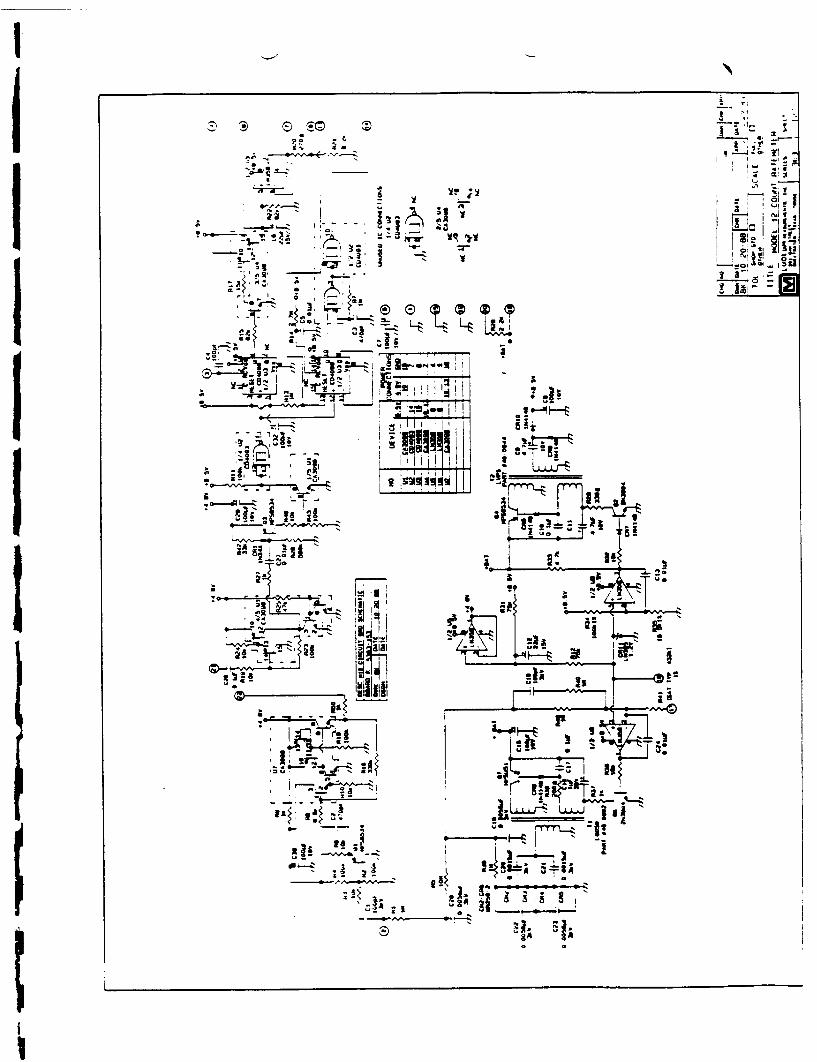
C-0 Z-
LwA L".j
Z;2 1
-0
I.

C) cuU
NM~J cMcNcNJVMcvu ""O"M~ UC-mUU Cm
N O N~CO)\ N u-'UaO="a .C. N CCC u U UUUUUU
C-
DESC: BOARD LAYOUT MODEL: 12 PART #: 5363-153 DWN: BK DATE: 8/8/88 DSGN: DATE:
C30 01 C2
C5
C28 CR1
C3 03
C21 C20
CR11 C13 C24 06 C17 CR6

I
R12 R35 R31 R34 R38
v~cJ\J'~ q-qq-4qm-.gn V u D m (Y(JY(Jr,*_
MODEL: 12 PART #: 5363-153 OWN: BK DATE: 10-13-88 DSGN: DATE:
R8 RI6 R50 R9 RIO R18 R42 R26 R46 R43
DESC: BOARD LAYOUT
J '

LUDLUR MODEL 12 X .,T RATEMETER
BILL OF MATERIALS
WIRING DIAGRAM, DWG. NO. 363 X 59
A1UDIO
UNIMORPH 60690 21-9251
UG706/U SERIES C CONNECTOR RIBBON-499568-2 14PIN
SWITCHES
Si S2 S3 S4 S5
BATTERY
BT1 BT2
13-7751 13-7971
PART NO.
08-6501 08-6518 08-6517 08-6511 08-6511
PA600-21 0 SWTCHCRFT 923 PB GRAYHILL 30-1 PB 7101-SYZ-QE TOGGLE 7101-SYZ-QE TOGGLE
"Di" DURACELL BATTERY "D" DURACELL BATTERY
21-93 13 21-93 13
MODEL 12 BATTERY BOX LID BATTERY CONTACT SET MODEL 12 CASTING MODEL 12 MAIN HARNESS MODEL 12; 139 RIBBON HARNESS PORTABLE CAN PORTABLE HANDLE PORTABLE KNOB PORTABLE METER (15-8030)
90 62-112 40-1707
9363-045 80 62-03 0-00
83 63-04 9 40-0045
70 01-012-01 08-6613 40-1805
-11-
DS1
CONNECTORS
Ji P1
NIS=:LANEOUS
*
*
*
*
*
*
*
*
Ml
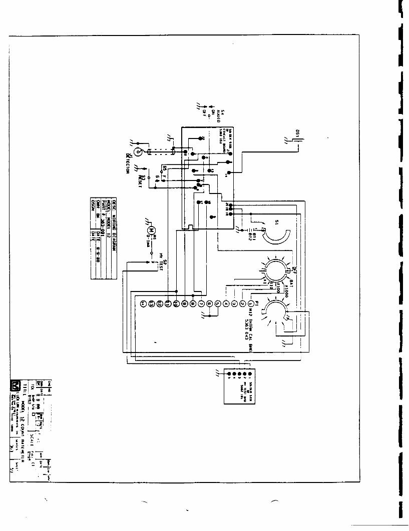
I
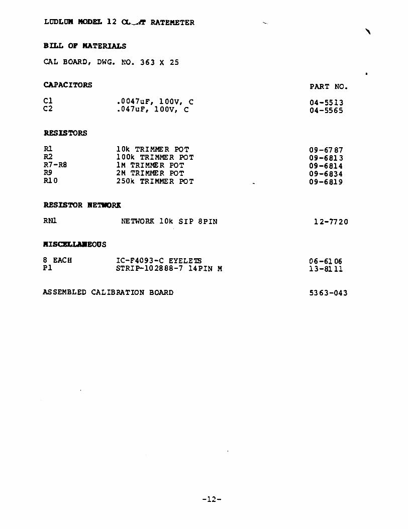
LUDLUM MODEL 12 (XAT RATEMETER
BILL OF MATERIALS
CAL BOARD, DWG. NO. 363 X 25
CAPAC ITORS
Cl C2
RESISTORS
.0047uF, 100V, C
.047uF, 100V, C
PART NO.
04-5513 04-5565
10k TRIMMER POT 100k TRIMMER POT IM TRIMMER POT 2M TRIMMER POT 250k TRIMMER POT
09-6787 09-6813 09-6814 09-6834 09-6819
NETWORK 10k SIP 8PIN
IC-F4093-C EYELE7 STRIP-102888-7 14PIN M
12-7720
06-6106 13-8111
53 63-043ASSEMBLED CALIBRATION BOARD
-12-
RI R2 R7 -R8 R9 RIO
RESISTOR NETWURK
RN1
MISC]MJA EOUS
8 EACH P1
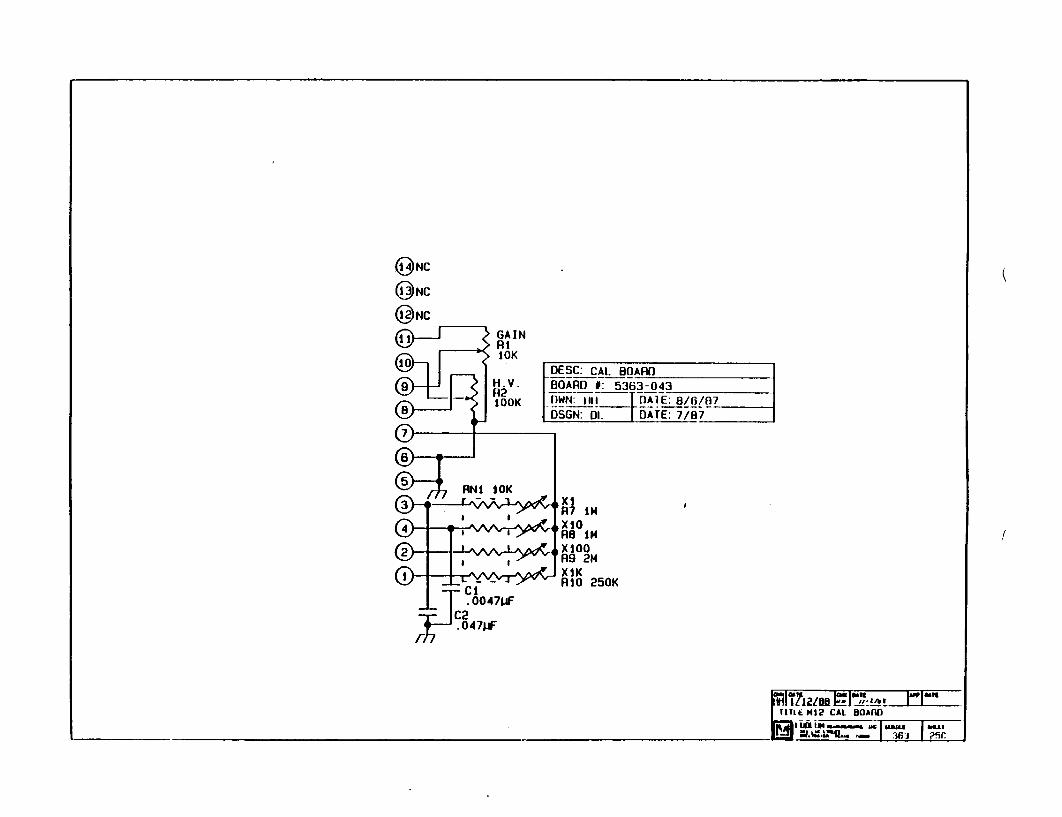
@RNC
@NC
@NC
[DESC: CAL BOARD BOARD 0: 5363-043 OWN:_fill I DATE: 8/6/07 6-dSGN: DL - DATE: 7/87
X1 R7 IM4 XIO RB IN XO00 R9 214 XIK RIO0 250K
1111E M12 CAL 80ARD W-J9L - 36] ?5C
I
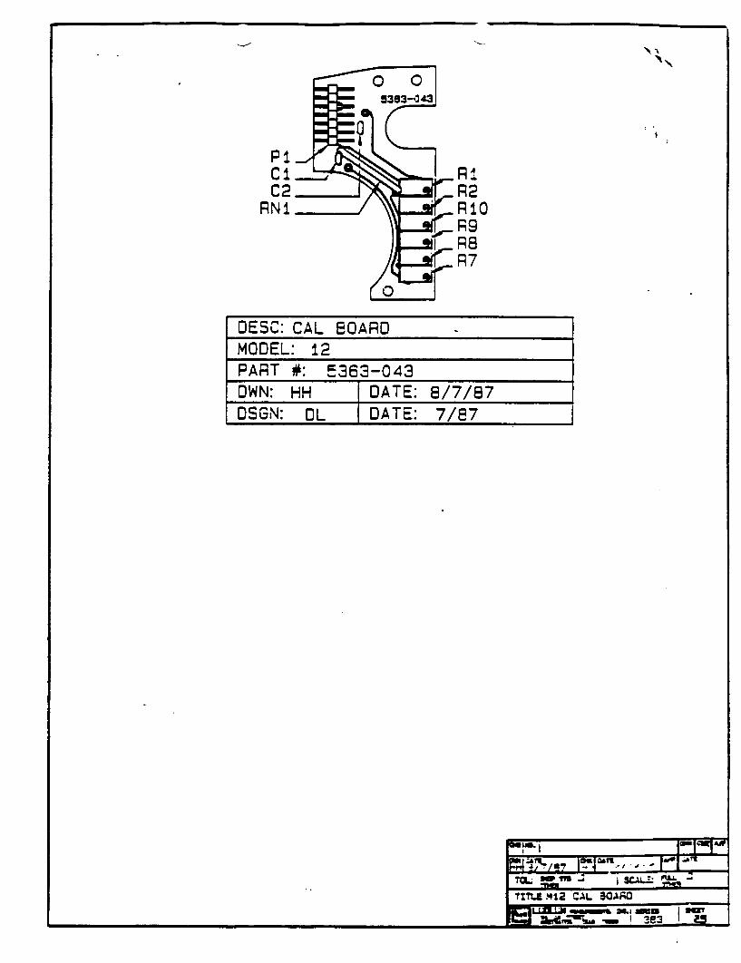
N
P1
C2 R2 "NI RIO
R9 - .1 R8
DESC: CAL BOARD MODEL: 12 PART #: 5363-043 OWN: HH IDATE: 8/7/87 OSGN: IOL DATE: 7/E7
| TL. .412 CAL i3OAi;O Mm' . mBe v

LUDLUI MODEL 12 COUR RATEMETER
BILL o0 KATERIALS
HV TEST BRD, DWG. NO. 363 X 126
INTEGRATED CIRCUITS
Ul ICL 7621
RESISTORS
R12-R13 750K 1% R14-R15 IM 1% R16 10K TRIMMER POT
ASSEMBLED HV TEST BOARD
PART NO.
06-6171
12-7693 12-7609 09-6822
5062-191
-13-
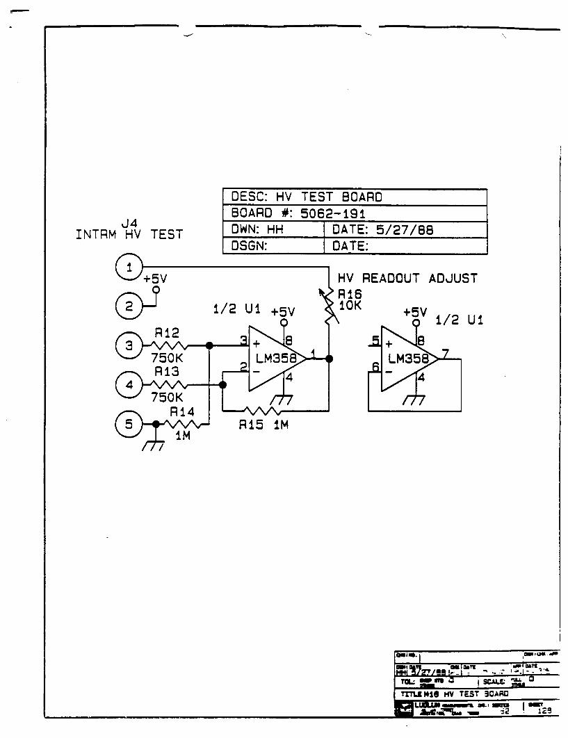
J4 INTRM HV TEST
DESC: HV TEST BOARD BOARD #: 5062-191 OWN: HH DATE: 5/27/88 OSGN: DATE:
asIa. �,GU *�
I-u-.T1L. -SCALL•: A i
I• .Z7L MINV TEST 30AROLLJDN -mm. =-t
- I UT
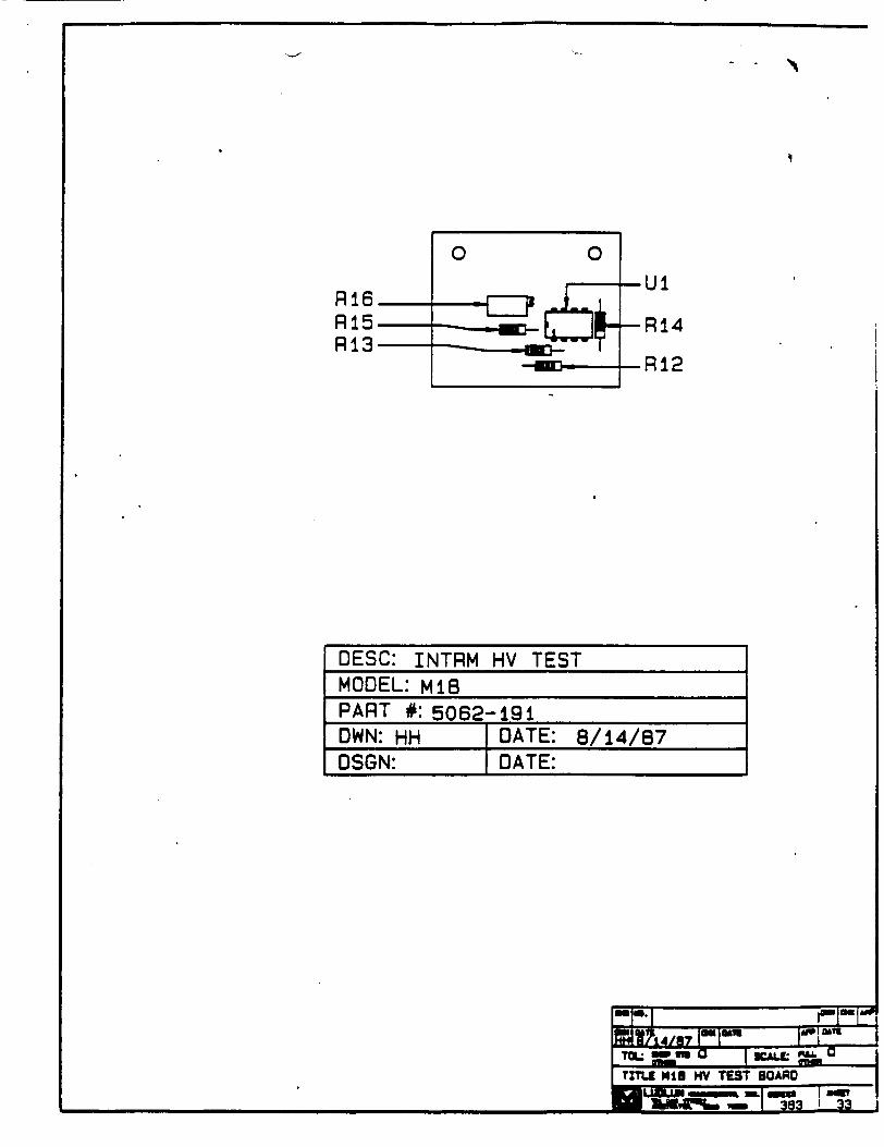
0 0
Ul R16 R15 -R14 R13
R12
DESC: INTRM HV TESTMODEL: Mi8 PART #:5062-191OWN: HH DATE: 8/i4/87 DSGN: DATE:
Received w/Ltr Dated.
INSTRUCTIONAL MANUAL
1540 SERIES
DIGITAL PORTABLE MASS FLOW CALIBRATORS
KURZ INSTRUMENTS, INC. 2411 Garden Road
Monterey, CA 93940 (408) 646-5911 (800) 4-AIRFLO
16:,?-

TABLE OF CONTENTS
SECTION 1 Description
SECTION 2 Principle of Operation
SECTION 3 Operating Instructions
SECTION 4 Specifications
SECTION 5 Maintenance A. Battery Life B. Probe C. Calibration
SECTION 6 Warranty
December 1983
Copyright 1983 Kurz Instruments, Inc.
SECTION 1
Description
The KTURZ Series 1540 Digital Portable Mass Flow Calibrators are highly accurate easy-to-use, battery-powered instruments for measuring Mass Flow rates.
The Series 1540 instruments provide accurate measurements of extremely low flow rates, with exceptional sensitivity and readability. (down to 1OSCC.¶) KURZ solid-state "DuraFlow" sensing elements are extremely rugged, and their large size renders them immune from particulate contamination. The standard probe's -558C to +1250C operating range permits use in a wide variety of industrial applications.
KURZ Digital Portable Mass Flow Calibrators have umsurpassed accuracy and repeatability: ±2% accuracy for each full-scale range, and t.025% of full scale reproducibility. The large LCD display iqmpoves speed and accuracy of readout, and it is easily read outdoors. A linear, analog output voltage permits time history recordings with easy-to-interpret linear amplitude calibration. The analog output is in engineering units, with a maximum of 0 to 2 VDC full scale.
All series 1540 systems come complete with Kurz Instruments Flow Transducer; a 3" long is NPT pipe nipple for flow straightening (*); a hose nipple for V" tubing; a fifteen foot cable; LCD Readout Meter; 115 VAC, 60 Hz or 230 VAC, 50 Hz Battery Charger; rugged carrying case and operation Manual.
*CAUTION: The flow straightener or an equivalent length of pipe must be used on the inlet side (marked "in*) of the flow body for proper operation. Otherwise insufficient flow straightening will occur, and turbulent air may hit the sensor causing an error. (Note, in extrem situations, such as when using an 1/8" inlet line or a swedgelok with an 1/8" hole, a longer straight section may be needed to prevent "jet* effects.)
SECTION 2
Principle of Operation
The mass flow transducer incorporates the Kurz "DuraFlo° unique temperature and flow sensors. The flow sensor is heated and operated as a constant-temperature thermal anemometer and responds to the mass flow by sensing the cooling effect of the air as it passes over the heated flow sensor. The temperature sensor accurately compensates for a wide range of ambient temperature variations. The output is directly displayed in mass flow units of Standard Liters Per Minute. (SLPM) (referenced to 250C and 760 mm Hg.) Because the sensors are large and rugged, they are breakage resisitant, insensitive to dirt, and are easily cleaned. The flow-t-hrough design of the transducer minimizes pressure drop and eli.-n.nates susceptability to pluqginq as experienced with capillary tube type thermal flow sensors.
It should be noted that both sensors are constructed from high density aluminum oxide, wound with platinum, and have a special glass coating. It is a similar construction to that used by the National Bureau of Standards for their reference platinum resistance temperature standards. This construction gives the extremely high repeatability of the Kurz mass flow calibrators.
It should also be noted that the mass flow readings of the Series 1540 Portable Mass Flow Calibrators are refferenced to standard conditions of 250C and 760 m Hq pressure and if volumetric flowrate is desired, the following relation should be used:
d
Qact "ind xs
ds- air density at standard conditions of 25'C and 760 - Hg,
d a actual air density inside the transducer, a Qac- Volumetric flow rate (LPM), and
Qind" Indicated mass flow rate (SLPM)
SECTION 3
Operating Instructions
All KURZ portable meters are shipped with the battery in a low-charge condition. With the range switch in the "OFF" position, charge the batteries before use. Plug the charger into the front panel receptacle labeled "CHARGER". Plug the other end of the charger into an AC Wall socket. Charge the unit for a period of at least on hour before operating.
A charge of 12-16 hours is recommended to achieve a full charge. The charger is intended for charging purposes only. It's use is not recommended during operation.
To check the battery voltage, turn the-control knob to the "BATT OK" position. For proper operation, the indicator should read in excess of 9 volts. A fully-charged condition is approximately 10.2 volts. At full charge, the instrument can be operated for about 8 hours of typical use. For maximum operating time between charges, turn the system off between measurements.
To operate, plug the probe connector into the OPROBE" receptacle, preferably when the control switch is in the "OFF" Position. Allow about 30 seconds for warm up.
Please Note: The markings on the flow body orient the unit so the air ALWAYS flows from *In" to "Out". Next, turn the range switch past "Battery" to the highest flow range position and the down range if necessary. The Portable Mass Flow Calibrator is now operating and will respond to the slightest air movement. Set the control knob to the "FAST" position. If the digital indication is not stable, switch to the mSLOW" position. The "FAST" and "SLOW" positions have time constants corresponding to 1 second and 2 seconds.
You have a choice of continuous measurement in the "DISPLAY" mode, or you can stop the display from updatinq and hold a reading in the "HOLD" mode. Switch to the lower range, if provided, to obtain increased resolution at low flows.
Remember to turn the range switch "OFF" when putting the system back into the carrying case. It is also suggested, to save battery time, to turn the meter "OFF= if there are long periods between measurements. If possible, operate the transducer with clean air. The use of an upstream air filter is highly recommended. This will insure long-term calibration accuracy.
All Series 1540 Portable Mass Flow Calibrators have an analog output signal available via jacks on the front panel. The voltage is proportional to the mass flow rate in standard liters per minute.
(Continued)
SECTIOZ 3
Cperating Instructions (cont'd)
The output signal level is directly related to engineering u~nits of the measured variable, with a maximum of 2 VDC full scale. For example, a range of 0 to 200 LPM has an output of 0 to 2 V; a range of 0-50 LPM has 0 to .5 V; 0-3 LPM has 0 to 0.3 V.
SECTION 4
Specifications
The specifications for Kurz Series 1540 are listed on th following page.
SECTION 5
Maintenance
A. BATTERY LIFE
As with all rechargeable nickel-cadmium battery systems, the batteries will have longer life if they are not allowed to become overly discharged. It is recommended that the batteries be kept fully charged whenever possible and that the battery voltage be checked from time to time while using the instrument. Simply set the control knob to the "BATT OK" position and read battery voltage on the display. At full charge, the reading will be about 10.2 volts. Minimum voltage for instrument operation is about 9 volts. When the batteries are fully charged, the instrument can be typically used for about eight hours unless high flow rates are- measured for extended periods of time. It is recommended that the instrument be turned off between measurements.
Temporary degradation, peculiar to nickel-cadmium batteries, may cause a decrease in operating period between recharges. If this occurs, let the batteries discharge to below 9 volts and then fully recharge them. This should correct the temporary degradation.
B. TROBE
Although the relatively large diameter of the velocity sensor renders it immune to particulate contamination in most environments, continuous use in dirty environments may necessitate periodic cleaning. Clean the sensor with a camel's hair brush and clean water, followed by an alcohol rinse. The sensor should be dry before resaming operation.
Store or transport the meter and probe in the convenient foam-padded carzryng case to prevent shock damage.
USERS SHOULD NOTE THAT PROM AZ NOT WrZRCHAGA . Each probe is matched, for torature co-mpensation and calibration, by circuit components in the instrument with which it was delivered. Accurate measurements can be made only when an instrument is used with the probe with which it was delivered.
C. Calibration
Calibration should be checked periodically, normally anually, depending on accuracy requirements and extent of instrument use. The meter must be returned to Kurz Instruments, Inc. (*) for recalibration. Calibrations are traceable to the National Bureau of Standards (NBS). Before sending the meter to Kurz, you must contact the Factory Service Departent for a Return Authorization Number. Units that do not have the Return Authorization Nmbers on the box or the packing slip will be returned to the sender.
(continued)
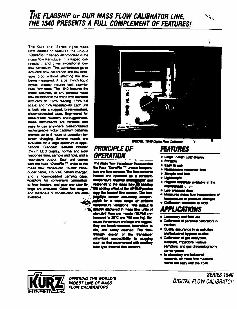
THE FLAGSHIP &,'r OUR MASS FLOW C7ALIBRATOR LINE, THE 1540 PRESENTS A FULL COMPLEMENT OF FEaTwRs'
The Kurz 1 540 Series digrIal mass flow calibrator features the unique "Durapao - sensor incorporated in Mhe mass flow transducer It is rugged. dirtresistant, and gives exceptional lowflow sensitivity. This combinaton gives accurate flow calibration and low presure drop wiftiout affecting fte flow being mneasured. A lar" .74iicfl liquid crystal disiplay insures faet. easy-10- a
read f~low, rates. The 1540 temiuree the finest accuracy of any portle "mms flow callibraWo in fth world widh stilindard accuracy of = (2% readWng + 1% full scale) and 14~% repiaatilty. Eac unit is buillt amo a mugged.brd-eltW shock Proe cam.s. Enigroine d IlwI *a" of use. relsabilliy. and rugiiesse " milsm istuurnmerf am Wsei anV easy Io use araywttere. Seloftinimil rechegemble nrke cadnpm bd~i Waiowd up~ lo S hours of operdo beo
tween igilng. Severail .. el are N=- law avalisbile for a large upectrin of OPPcnomn. Standard Feasarin liride: PRN I E .7-irk-i LCD ditsplay. noraill Kid Wow PRN IU OF respne Wret wpWard h0w4a OPEPRA77ON IIIccdabe ouut. Esic unit omiee
with me Kurz lWUwnf ffmP k in fte The =Mn ftw vu--ad" .p mass flow transducer. ¶ 5ico rare. ft KiWE j%~j~~ ~~ Wwwr duceir cal. 115 VAC baeely dmgw, IS nd 9W w minrs. Th 1Mewinr and a fomrn,-padded cu.wt0 cmi h@EWm NOd ope 9-111fteriAdapillis for oonvetwer awwwie NNY4WWA I 3 rw to Neitr holders, wand poe mid UM0 W-NWd 1b ft m W98g am availablem 01111 lw I qn ft~ 090 ~dig d New loom arid mnaterals of ccotI uctk we mb OW 13 ME If IIIIIIS VO Ow avalabile. Mo Mims" offlon
.4* m0 t a wW mll duviOwn
-ww Elle per mbuam (8UP4 Cw kniie o 2M &Wd M6 mm ftJ. lb.
ftvLt deg o f 13 uuiaw fil I NA1111Ilf 18p3 p
suha VW eixF ' cd wO aomIfu lltto-" Viennel flaw uwm
ft Almi fiillil
FARTURES * Lap .7400 LCD dle is Pam*
Ho =Up@ - w~ffif in t3
"*pak N5 emm lwhdwW a
0 C&M~ 111matt NN
APPLICATION 0 Ldallry &wIMuilii
*0f sal mwum In &V polkAr
*Covmdn d go wiiywu
o In habrm" w'd buko" miseelili ai mmrlllll flow rinee re
ffwftwe my wiftw 15SW
INSTRUMENTS I NC
OFFERING THE WVMLD'S WWEST UNE OF MASS FLOW CAL JRATORS
SERIES 1540 DIGITAL FLOW CALIBRATOR
N.'

SPECIFIC4 TIONS MODEL NUMMER 1540 1541 1542 1543 1544
FLOW RANGES (SLPN) 0-.3 0-S 0-20 0-50 0-200 (REFERENCED TO 2WV 0-3 AND 730 - Hg ACCURACY ±(2% o1teeIn m& + % otf U scow) #o eei flow range Over a W, Veagur ranW
d1-20'C to+ 0*C ~ad pre WIQS 0.25 to2a xOwpIU (appkiabile abve 10 Sit)
REPE.ATADIUTY ±0.25% ot kA mcae #or each rang. T MPEATIURE RANGE Towuiim -4M ED + 12M; m@W: O-C to 50CC
RESPONSE TWME Trwuducsr 0. 1 aond; Mhew Peeoft: 0. 5 aswid MAXJMUM PRESSURE ROF4P 4.5 am 14,0 hig rwWg (1.8 in 1,0)
0.1Ilgm 14,0 R*d-"wg (W0 in 140) 0.007 am 14,0 bw iuq (.003 in H2,0)
PRESSURE RANGE OF ThANSOUiCEN 50 pl(ainviny WwuftW to 30 psi) POWE ON"dl~u bot v#0 1 I0 VAC, KW Z charger. operates up to segmt
NET WGNIT OF MlETER 1.25 KIs 2.75 WAN ThANOUcmR SHIPPMNG WEIU 2-3 KW 7 b. METE RELADOUT Ciiif sAW~dI. 004~N" .74ne 0* ay" doiy esliW" handle,
FLOW TRANSDUCER MATERIAL Nkkol~~e skoww wrl lexa Now body; cwwa. pwonum and epoxcy wwor. SnLvds glo
TRANSDUCER DOSMENSONS 2.54 arn x I am x 5.3 an, W4 WT lnae Nm W a "d OuZOW lor 1544 wSit .V¾11111 1i -f Am 10 Won"
CONTROLS zuo and sw ccol a~d maNIII$Wr Pang* uW b@My vo w* an orwt pw*
DNMENSIONS meow r rx F; Cwrymg osme3 Tx IWx14* P~l CASISETTE ADAPTOR Alow udld seOcwner to t- cd 37 nncmm mon (odd *-8' to. mcdI rine)
OP (AN modole oinp 1544) ar 47 mm commn (@Wd ---P to moft hIrmw) ppju~yjm(47 urn) CASSETTE E~blik-Iin 11111802 when odlbrn11g vklrwM h~q@ (add*--C to md
ouiebo whien aids"l) REC IRACflLE CANLE OPiO 6 OW Ot MC110 1s l (1"10 hWm lue coded) rp go iado 8-W oeable
(so --w 10 we"i MWaWm STAINLESS STEEL OPTION Add a-S37Or for 31 @dm smo NOw body WARRWANTY I *A yew porlim wW laor
SEMSS54
11MCNIPCATMO SHUT NO. 1540-2W3
* W IM 11TWHM7, 111. Zit 01901111111 mwIUEY. CA m1"
14.1 IWil-11 USA ?111 I7WI FAX (do) U6-l
CALL A KURZ APPLICATION ENGINEER FOR 1AMAEOIATE SERVICE
INTUMNSN ATIONWIDE (f8-424-73Se1
SECTION 5
Maintenance
C. CA.:BRATION (cont'd)
Be sure to include the battery charger and probe as well as the user's name, address and phone number to expedite the recalibration process. Allow 4 to 6 weeks turn around time.
* KURZ INSTRUMENTS, INC.
2411 Garden Road Monterey, CA 93940_ Attn; Service Dept.
SECTION 6
Warranty
All products manufactured by Kurz Instruments, Inc. carry a warranty against defective parts and workmanship to the original purchaser for a period of ONE YEAR after date of delivery. Damage caused by heat or corrosives, misuse, or neqligence is not covered by this warranty.
"DuraFlow" probes are NOT interchangeable and are not covered by warranty. Please inspect and verify that the unit is operational upon receipt of all Kurz products. All units are shipped after NBS-traceable calibration.
CD
r
* �L.V
C
,' N)
a
0 0
a
I 5? C CO
Un r 7' Ni
z 0
5. C,,
2 0
C
0o
Table of Contents
Dear Customer:
Congratulations! We at Fluke are proud to present you with the Model 8024B
Multimeter. This instrument represents the very latest in integrated circuit and
display technology. As a result, the end product is a rugged and reliable instrument whose performance and design exhibit the qualities of a finely engineered lab instrument.
To fully appreciate and protect your investment, we suggest you take a few
moments to read the manual. As always, Fluke stands behind your 8024B with a
full 2-year warranty and a worldwide service organization. If the need arises, please don't hesitate to call on us.
Thank you for your trust and confidence.
John Fluke Mfg. Co., Inc.
SECTIONPAGETlTL
I INTRODUCTION AND SPECWICATIONS ............... 1-1 I-I. INTRODUCTION ................................ I-1
1-3. SPECIFICATIONS ............................... I-I
OPERATING INSTRUCTIONS .......................... 2-1
2-1. INI'ROI)II ION ................................ 2-1
2-3. PREPARING FOR OPERATION .................. 2-1
2-4. Ulnpacking ...................................... 2-1
2.7. Battery or Fuse Installation/ Replacement ........... 2
2-9. PHYSICAl. FEAI IIRES ........................... 2-3
2-11. OPERATING NOrIF"S ............................. 2-6
2-13. Input Overload ProtcCtion ........................ 2-6
2-15. Input Connection to COMMON ................ 2-6
2-17. Fuse Check ..................................... 2-7
2-19. Fuse Replacement ............................... 2-7
2-21. The Display ............................... 2-9
2-26. OPERATION .................................... 2-9
2-28. ACI DC Volts IV) Operation ...................... 2-9
2-30. AC/ DC Current (mA) Operation .................. 2-9
2-32. Resistace (fl Operatiom ......................... 2-9
2-34. Cootinuity Testing ............................... 2-13
2-36. Diode Teuting ................................... 2-13 2-38. Concdutame IS) Ope, tiop ....................... 2-13
2-40. Temperutwef (C) Opestion ...................... 2-13
2-43. Level Detector Opealton ......................... 2-16
2-45. Peak Hold Operation ............................ 2-17
2-47. INITIAl CHECK-OUT PROCIDIIRE .............. 2-19
2-49. MEASUI IREMENT TECHNIQU ES .................. 2-21
2-S1. Temperature ConvelrioU .......................... 2-21
2-53. Conductsncc-to-Resistance Conversion ............. 2-24
2-53. AC Measurenents ............................... 2-24
2-S7. AC/ DCI Voltage Memsurements ................ 2-24
2-60. AC/ DC Current Measurements .................... 2-24
i (continu'd on page i)
,-K '-
8024B
I I I
TABLE OF CONTENTS continand
SECTION
2-64. 2-67. 2-69. 2-70.
2-73. 2-75.
TITLE PAGE
Resistance Measurements ......................... APPLICATIONS ................................. THERMOCOUPLES .............................. Introduction ..................................... Monitoring More Than One Thermocouple .......... Leakage Tester ...................................
3 THEORY OF OPERATION ..............................
3-1. INTRODUCTION ................................ 3-3. OVERALL FUNCTIONAL D)ESCRIPTION ......... 3-5. A/ D Converter .................................. 3-14. Voltage Measurement Function .................... 3-16. Current Measurement Function..................... 3-18. Temperaure (°C) Measurement Function ........... 3-20. Resisance Measurement Function ................. 3-23. Conductance Measurement Function ............... 3-25. Peak Hold Circuit Level .......................... 3-27. Level Detector Circuit ............................
2-27 2-29 2-29 2-29 2-31 2-31
4-1
3-1 3-1 3-1 3-6 3-6 3-6 3-6 3-11 3-11 3-11
4 MAINTENAN C................ ................... 3-1
4-1 INTRODUCTION .............................. 4-1 4-3 SERVICE INFORMATION ........................ 4-1 4-7. GENERAL INFORMATION ....................... 4-3 48. Access Information ............................... 4-3 4-17 (Cleaning ........................................ 4-5 4-19. Battery/Backup Fuse Replacement ................. 4-6 4-21. PERFORMANCE TEST ........................... 4-6 4-23. Initial Procedure ................................. 4-6 4-25. Display Test ..................................... 4-7 4-27. Voltage Test ..................................... 4-8
4-29. Current Test ..................................... 4-8 4-3V Resistance/Conductanc lesIt- ...................... 4-8
4-33. Peak Hold Test ................................... 4-I1 4-35. Continuity Test .................................. 4-11
4-37. l evel I)etector Test ............................... 4-12 4-39. BT Test .......................................... 4-12 4-41. Temperature Test ................................ 4.14 4-43. CALIBRATION ADJUSTMENTS .................. 4-14
4-46. IROUBLESHOOIING ............................ 4-15
3 LIST OF REPLACEABLE PARTS ........................ 5-1
5-1 IN ITROI)UJCTION ................. .............. 5-1 5-4. HOW 10 BIAAIN PAR'IS ........................ 5-2
TABLE OF CONTENTS. cota hod
SECTION TITLE
ACCESSORE INFORMATION ........................ 6-1. INTRODUCTION ................................ 6-3. DELUXE CARRYING CASE (CS) ............. 6-5. RUGGED CARRYING CASE (YIIS) ........... 6-7. TYPE K SHEATHED THERMOCOUPLE (YI102) ... 6-8. Introductio .................................... 6-10. Specification ................................... 6-11. TYPE K BEAD THERMOCOUPLE (Y1103) ......... 6-12. Introduction .................................... 6-14. Specifications ................................... 6-15. THERMOCOII'I.E TERMINATION (YII4) ........ 6-17. TEMPERATURE PROBES (ITr-150C and UST-15F-). 6-18. Intredu ioa .................................... 6-20. Speciicatio s ................................... 6-21. HIGH VOLTAGE PROE (3OK61) .................. 6-22. Introduction .................................... 6-24. Specificatioes ................................... 6.25. HIGH VOLTAGE PROBE (OK-40) ................. 6-26. Introduction .................................... 6-28. Specifcatoum . .... .............................. 6-29. HIGH FREQUENCY PROBE (83RF) ...............
6-30. Introduction .................................... 6-32. Specificat ions ................................... 6-33. HIGH FREQUENCY PROBE (8SRF) ............... 6-34. Introduction .................................... 6-36. Specificatio s ................................... 6-37. CURRENT TRANSFORMER (301-40) ............. 6.33. Introduction .................................... 640. Speclm eatiom ................................... 6.41. CURRENT SHUNT (8.-IO) ....................... 6-42. Introduction .................................... 6-44. Specificatio s ................................... 6-45. BATTERY El IMINA1OR (ASI) ................... 647. AC/DC CURRENT PROBE (0800) ................ 6-43. Intraduction . .................................. 6-50. Specificatieoi .r. ..... ........... ..............
6-5I. AC CURRENT TRANSFORMER (Y810) ........... 6-52. Introduction .................................... 6-54 Specifications ................................... 6-55 SAFETY DESIGNED TEST LEAI) SEI (Y8132) ..... 6-57. DEL IJXE TEST I EAD SET (Y8134) ................ 6-59. SLIM FlEX TEST IEAI)SET(YUI40) ..............
I SCHEMATIC DIAGRAMS ............................... A MANUAL CHANGE AND BACKDATING INFORMATION .
(conlinued (ni page ui)hiWi
80248 80248
PAGE
S-I 6-1 6-1 6-1 6-1 6-1 6-4 6-4 6-4 6-4 6-4 6-3 6-s 6-5 6-5 6-S 6-5 6-5 6-5 6-6 6-6 6-6 6-6 6-6 6-6 6-7. 6-7 6-7 6-7 6-7 6-7 6-7 6-8 6-8 6-3 6-8 6-9 6-9 6-9 6-9 6-10 6-10
7-1 A-1
802487
80248
List of Tables List of Illustrations
TITLE PAGE
30248 Accessories ............... ................... 80248 Specifications ............ ............. Controls, Indicators. and Connectors ............. Input Overlhad limits ............ .................. Celsius-to-nFarenheil Conversion Scale ...................... Voltage/lCurrent Capability of Resistance Ranges ............ Test Equipment Required ................................. Display Test ....................... ............... Voltage Test ............................................ C urrent lest ............................................ Resistance/Conductance Test ............................. Troubleshooting Guide ................................... 80248 Final Assembly .................................... A I Case Assembly ....................................... A2 Main PCB Assembly .................................. A3 Switch PCB Assembly .................................
Federal Supply Codes for Manufacturers ....................
1-2 1-3 2-4 2-7 2-22 2-29 4-2 4-7 4-9 4-1I0 4-11 4-17 5-3 5-6 5-8 5-12 5-15
FIGURE
2-1. 2-2. 2-3. 2-4. 2-5. 2-6. 2-7. 2-8. 2-9. 2-10. 2-11. 2-12. 2-13
2-14. 2-15. 2-16. 2-17 2-1. 2-19. 2-20. 3-1. 3-2. 3-3. 3-4.
3-5 3-6 3-7. 3-8. 3-9. 4-1.
4-2
TITLE
Removing the B titery Cover .............................. Battery Removal ........................................ Controls. Indikators, and Connectors .......................
D)isplay ............... ................................
Abnormal Status Indicators ............................... Volts Operation .........................................
Current Operation .......................................
Resistance Operation ..................................... Conductance Operation ..................................
Temperature Operation ...................................
Level DeICctor Operation .................................
Peak Hold Operation .................................... Temperature Correction Factor For K-Type
1 hermocouples ..........................................
Conductance-to-Resistance Conversion .....................
Waveform Convwrs n .................................... Voltage Measurement Error Calculations ................... Current Measurement Calculations .........................
I hermocouples ..........................................
I hermocouple Termination Unit ........................... M ullipoint Selecion .....................................
80249 Block Diagram ....................................
AlI) Converter Functional Diagram .......................
Integrate Capacitor Waveform ............................. Voiltage Measurement ...............................
Current Measurement ....................................
1 emperature Measurement ................................
Rtc.islance/Conductance Measurement .....................
Simplilfed Peak Hold Circuit ..............................
Simplilied level Detector Circuit ..........................
Ca'libration Adjustments L.ocation .........................
I (,I) Display Assembly ...................................
I't v (continurd tn page viid)
TABLE
-I.. 1-2. 2-1. 2-2. 2-3. 24. 4-1. 4-2. 4-3. 44. 4-5. 4-6. 5-1. 5-2. 5-3. 54. 5-5.
PAGE
2-2 2-3 2-4 2-8 2-9 2-1O 2-11 2-12 2-14 2-15 2-17 2-1S
2-21 2-25 2-26 2-27 2-28 2-30 2-32 2-32 3-2 34 3-5 '-7 '1-3 3-9 3-10 3-12 3-13 4-3 4-5
-- I

8024B
LIST OF ILLUSTRATIONS, continumd
FIGURE
General Equipment Connection ............................ General Equipment Connection -- Current .................. BT Test ................................................ Lag Bath ............................................... 8024B Final Assembly .................................... A I Case Assembly ....................................... A2 Main PCB Assembly .................................. A3 Switch PCB Assembly ................................. X024R Accema.i, ic .......................................
4-7 4-10 4-13 4-16
5-7 5-11
5-12 6-2
SecUon 1
Introduction & Specifications
W' 1-1
TITLE
4-3. 4-4. 4-5. 4-6. 5-I. 5-2. 5-3. 5-4. 6-I.
PAGE
8024B
1-1. INTROOUCTION I-2. Your John Fluke Model 8024B is a pocket-sir. digital muftimeter that is ideally suiled for application in the field. laboratory, shop. or horn. Some of the features of your instrumenu are:
FUNCI IONS: All standard VOM mesumrement functiomn - ac/dc voltage. ac/dc current, resistance - plus:
Conductance: A new muhimeter function that allows fast., accurate, noise-free resistance measurements up to 10.000 MIL
lemperature: Used with a K-type thermocouple, this lunction provides direct display in degrees Celsius for K-type thermocouples.
Peak-Hol: Provides shorm-erm memory for capturing the peak value of transient ac or de signals such as motor starting current.
Continuity: Provides an immediate visual and audible indication, when ctmtinuily.is detected (use for pasive circuit testing).
L.evel Detector: Senses logic levels and other active signals less than 250V dc or ac rms. Visual and audible indications of the results are provided.
RANGE for each function has:
Full autopolarity
Overrange indication
Effective protection from overloads
Dual slope integration measurement technique to ensure noise-free measurements
I
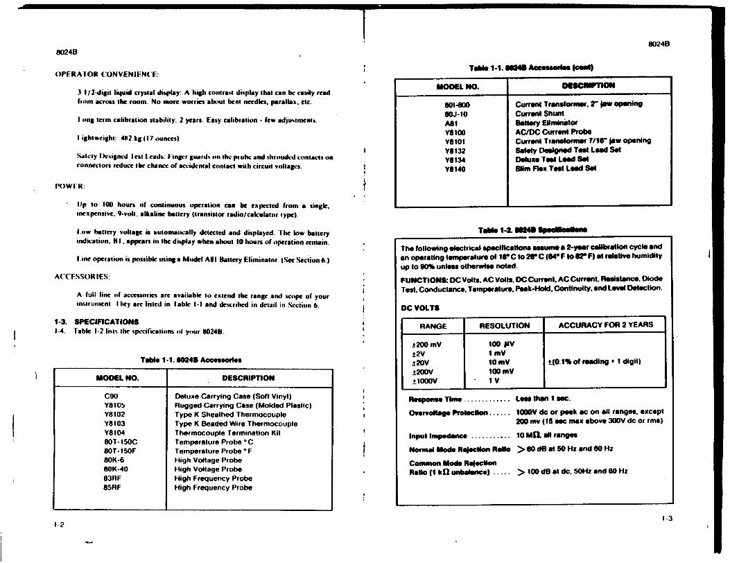
I8024B
8024B
OPERA IOR CONVENIIN('IC:
3 I/ 2-digit liquid crystal display: A high contra•t display that can bc easily read from across the room. No more worries about bent needles, parallax. etc.
I tong term calibration stability: 2 years. Easy calibration - few adjustments.
I ightweighl: .4182 kg 17 ounces)
Salety ),csigncd lest I cads: IingFr guard, out the polbe and shrouded contacts on connectors reduce the chance of accid•ental contact with circuit voltages.
P1)WI:R:
lip to 100 hours of continuous operation can be expected from a single.
inexpensive. 9-volt, alkaline battery (transistor radio/calculator type).
V.ow battery voltage is automatically detected and displayed. ' he low battery indication. h 1. appears in the display when about 10 hours of operation remain.
Line operation is possible using a Model A11I Battery Eliminator. (See Section 6.)
ACCESSOR IES:
A full line of accessories are available to extend the range and scope of your instrutent. I hey are listed in lable I-I and descrihed in detail in Section 6.
1-3. SPECIFICATIONS 1-4. Table I-2 lists the specilications ol your 8024B.
Table 1-1.80248 Accessories
MODEL NO. DESCRIPTION
C90 Deluxe Carrying Case (Soft Vinyl) Y8105 Rugged Carrying Case (Molded Plastic) YO 102 Type K Sheathed Thermocouple Y8 103 Type K Beaded Wire Thermocouple Y8104 Thermocouple Termination Kit SOT- 150C Temperature Probe °C 8OT-i50F Temperature Probe * F 80K-6 High Voltage Probe O0K-40 High Voltage Probe 83RF High Frequency Probe 85RF High Frequency Probe
Table 1-1. @NO Aesessodn (ased)
MODEL NO. DESCnIPTION
801-600 Current Translormer. 2" Jaw opening uOJ-1O Current Shunt All1 Batery Eliminitor Y1IOG AC/DC Current Probe Y11101 Current Transformer 7/1" jaw opening Y8132 Safety Designed Test Lead Set Y6134 Deluxe Test Lead Set Y6140 Slim Flex Test Lead Set
Tate 1-2. M Spoleealeute
1-2
The following electrical specifications assume a 2-year calibration cycle and an operating temperature of fir C to 299 C (640 F to 82" F) at relative humidity up to 90% unless otherwise noted.
FUNCTIONS: DC Volts. AC Volts, DC Current. AC Current. Resistance. Diode Test. Conductance. Temperature. Peak-Hold. Continuity, and Level Detection.
DC VOLTS
RANGE RESOLUTION ACCURACY FOR 2 YEARS
-t200 mV 100 IV ±2V I mV i20V 10 mV t(O.1% of reading + I digit) t200V 100mV ±1000V I V
Response Time ............. Les then I sec.
Overvoltage Protection ...... 1000V do or peak sc on all ranges, except
200 my (15 sec max above 300V dc or rms)
Input Impedance ........... 10 ME all ranges
Normal Mode Refection Ratio > 80 dO at 50 Hz and 60 Hz
Common Mode Rejecton Ratio (1 kh' unboalance) ..... > 100 dB at dc. 50Hz and 60 Hz
1-3
i i
! r
i I
t t
t
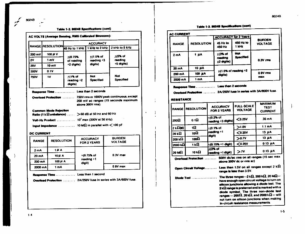
802408024B
Table 1-2.1102413 Spc•cons (cent)
AC VOLTS (Aslage Sensing, "us Caibraled Sinewave):
ACCURACY RANGREOLUION45 Hz to IkHz I klzto 2kHz 2 kHz to 5kHz
200 mV 100 puV _*(0.75% ±_(I.5% of 1*(5% of
2V 1 mV of reading reading +3 reading
20V 10 ýV- 42 digits) digits) +5 digits)
200V 0.1VI
750V IV _+(1% of Not Not
reading +2 Specified Specified digits)
Response Time Less then 2 seconds
Overloadl Protection . 750V rms or 1000V peak continuous, except
200 mV ac ranges (15 seconds maximum above 300V rms).
Common Mode Rejectlon
Ratio (I kt l1 unbalance) ..... >60 dB at 50 HZ and 60 Hz
Volt-Ha Product ........... 10' max (200V at 50 kHz)
Inpult Impednce .......... 10 Mi" in parallel with <t00 pF
DC CURRENT
RANGE RESOLUTION ACCURACY BURDEN FOR 2 YEARS VOLTAGE
2mA IP A
20 mA 101 A +(0.75%of 03V max reading + I
200 mA 100I LA digit)
2000 mA 1 mA 0.9V max
Respone Time........... Less than 1 second
Overload Proection ........ 2A/250V fuse in series with 3A/600V fuse.
1-4
if '-p
2 mA I AA2 mA
20 mA
200 mA 2000 mA
I 11A
10 pA
I00 mA
1 mA
±-(3%• reeding .2 digits)
Not
t1.s5% of reeding .2 digits)
0.3V flue 0.OVm
0.9v rms nMlx
I .5 ____________ - ___-
R esmp Time ............. Le• than 2 9sconds
ODerload Pprelsoe ........ 2A/250V fuse In series with 3A/SO0V fuse.
RESISTANCE
RANGE RESOLUTION
20o0o10
ACCURACY FOR 2 YEARS
±(0.2% of reading +3 digits)
FULL-SCALE
VOLTAGE
<0o.25V
MAXIMUM TEST
CURRENT
.35 mA
2 kfW]l• 41 *(0.1% of •>1.0V 1.1 mA
20 kfl 100 reading +I <,0.25V 13 pA
S200 W•' 1001 >O.TV 3A
2000 k'n. I kW *0. 15% *1 di"i) <•0.25V 0.13 pUA
12OM1 10kil roeding +1 diglt) >IsV 0.13 pA
S @ PProiecion ........ 500V dc/ac rmu on all ranges (15 sec max above 300V dc or rnm ac)
Open Ckcui VoMlte ........ Less than 1.5V on all ranges except 2 kfl range Is less than 3.5V.
Diode Test ................. The three ranges-2 kQ. 200 kfl. 20 MIlhave enough open circuit voltage to turn on
silicon lunclions allowing d diode test. The
2 k"l range Is preflrred and Is marked with a
diode symbol. The three non-diode test
ranges - 20011. 20 Wk. and 2000 kI (I - will
not turn on silicon junctions when making
in-circuit resistance measurements.
1-5
Table 1-2. 024 SPsdbea'c 5 (0e.1)
AC CURRENT ACCURACY for 2 Yeas
BURDEN
RANGE RESOLUTION 45 Hz to 450 Ha to VOLTAGE 450 Ha I kHW
)
Table 1-2. M48 Spedfleadons (cont)
ISpciie
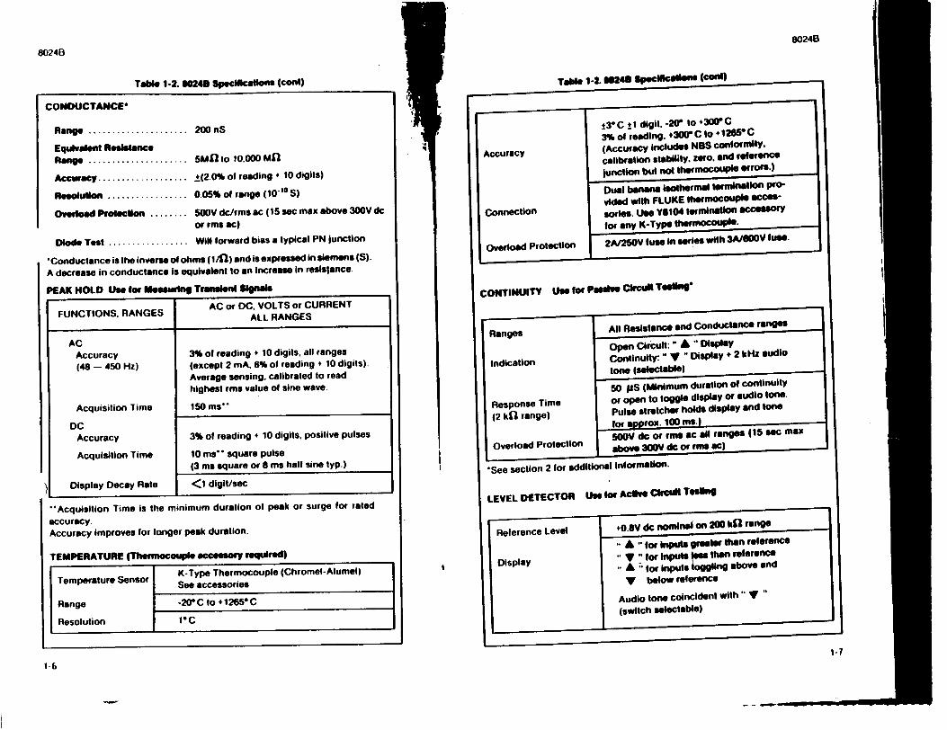
8024B
80246
Table 1-2. 80248 SpecIfIca1on (cent)
CONDUCTANCE*
Range ..................... 200 nS
Equivalent Reslstance
Range ..................... SUME to i0.0X) M1l
Accuracy ................... *(2.0% of reading * 10 digits)
Resolution ............... 0.05% of range (10' 10 S)
Overload Protection ........ 500V dc/rms ac (15 sac max above 300V dc or rms ac)
Diode Test ................. Will forward bias a typical PN junction
"*Conductance is the inverse of ohms (1/4) and is expressed in siemens (S).
A decrease in conductance is equivalent to an increase in retslsance.
PEAK HOLD Use for Measuring Trmasen Iignals
AC or DC. VOLTS or CURRENT
FUNCTIONS. RANGES ALL RANGES
AC Accuracy 3% of reading + 10 digits, all ranges
(48 - 450 Hz) (except 2 mA, 6% of reading + 10 digits). Average sensing. calibrated to read
highest rms value of sine wave.
Acquisition Time 150 ms"
DC Accuracy 3% of reading + 10 digits, positive pulses
Acquisition Time 10 ms- square pulse (3 ms square or S ms hall sine typ.)
Display Decay Rate <1 digit/sec
"-Acquisition Time is the minimum duration of peak or surge for rated
accuracy. Accuracy Improves for longer peak duration.
TEMPERATURE (Thermocouple accesseory requird)
K-Type Thermocouple (Chromel-Alumel)
Temperature Sensor See accessories
Range -20 C to +1265" C
Resolution 1 C
Table 1-2.0 6243 Spec1111Callefb (ConR)
___ --- --d7i.12 t 30
II I AccuracyAccuracy
Connection
Overload Protection
13 C j I digit. -2V" to 4300 C 3% of reading. +300" C to 1265 C
(Accuracy includes NBS conformity.
calibration stability, zero. and reference
junction but not thermocoupl errors.)
Dual banana isothermal tIMmination pro
vided with FLUKE thermocouPI acces
soies. Use YfiI04 termination accessOry
for any K-Type thermocOuPle.
2A/250V fuse in series with 3A/S0V fuse.
II
I
1-6
1-7
CONTINUITY Use for Passive Circuit Too"n*
Ranges All Resistance and Conductance ranges
open Circuit:" A " Display
Indication Continuity:" Y " Display + 2 kHlz audio tone (selectable)
50 laS (Minimum duration of continuity
Response Time or open to toggle display or audio tone.
(2 kil range) Pulse stretcher holds display and tone for approx. 100 ms.I
Overload Protection 5V dc or rms ac ill ranges (15 sec max Oa L above 300V drc or rms ac)
*See section 2 for additional information.
LEVEL DETECTOR Use for Active McM Tes1ng
Reference Level 0o.aV dc noninaln on 200 ki' range
A "for Inputs greeoer than reference
isplay .. for Inputs ees than reference FDisplay •A for inputs loggling above and
V below reference
Audio tone coincident with" y'" (switch selectable)
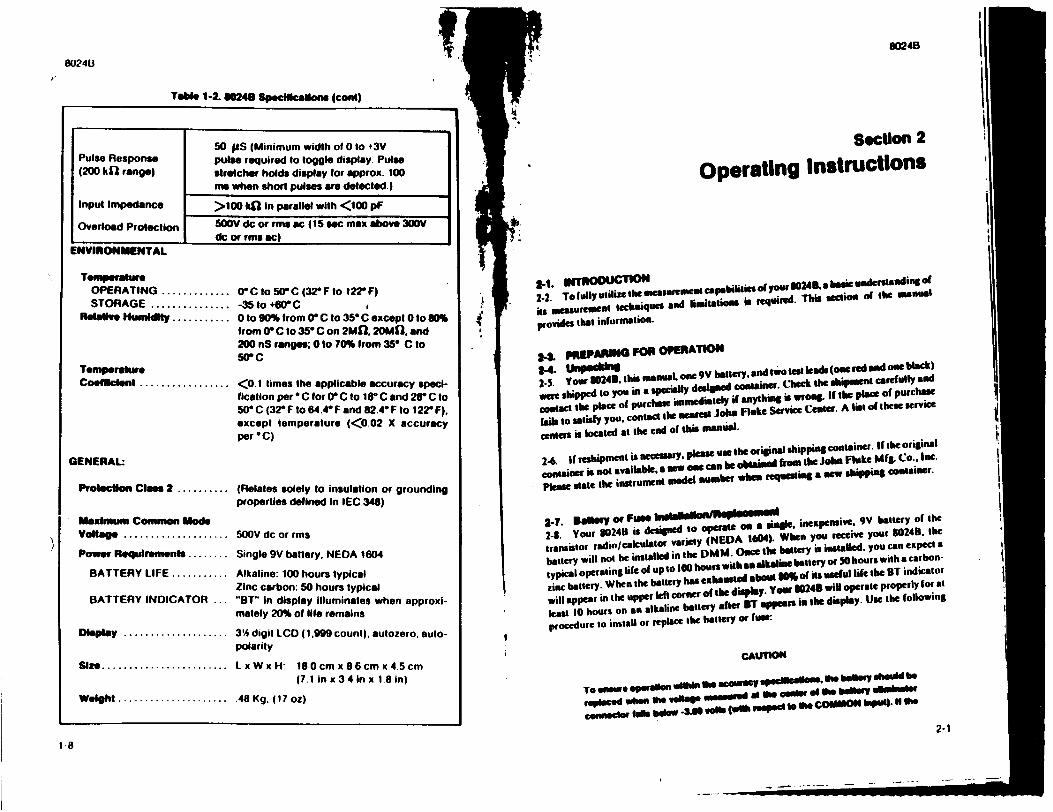
8024B
Table 1-2. 60248 Speclitcallone (cetd)
50 5LS (Minimum width of 0 to #3V
Pulse Response pulse required to toggle display Pulse
(200 kfl range) stretcher holds display for approx. 100
nm when short pulses are detected.)
Input Impedance >100 kfl in parallel with <100 pF
Overload Protection 500V dc or rms ac (15 sec max above 300V
I dc or rms ac)
ENVIRONMENTAL
Temperahre
OPERATING ........... 0C to 50WC (32?F to 122F)
STORAGE .............- 35 to +0C
Relailve Hunsdly ........... 0 to 90% from 0o C to 35" C except 0 to 80%
from (r C to 350 C on 2ME'. 20ME0. and
200 nS ranges; 0 to 70% from 3,5 C to
50 C Temperature
Coeficlent ............... <0.1 times the applicable accuracy speci
fication per * C for 0( C to 18" C and 21r C to
50"C (32"F to 64,40 F and 82.4* F to 122?F).
except temperature (<0.02 X accuracy
per "C)
GENERAL:
Prolecifton Class 2 .......... (Relates solely to insulation or grounding properties defined in IEC 348)
Maximum Common Mode
Voltage .................. V dc or rms
Power Requlremenft ........ Single 9V battery. NEDA 1604
BATTERY LIFE .......... Alkaline: 100 hours typical Zinc carbon: 50 hours typical
BATTERY INDICATOR ... "BT" in display illuminates when approximately 20% of life remains
Display ................. 3 digit LCD (1.999 count), autozero. autopolarity
Size.................... LxWxH: 180cmx86cmx45cm (7.1 in x 3.4 in x 18 in)
Weight .................. 48 Kg. (17 oz)
fil
To ~en te o~ shin sm 'cur a s"p lenlts. Se batery shoul 0 a rplced when sl e welM inaugg a Se ea of ele bVlry k
2-1
I. 8024B
Section 2
Operating InstrUctions
2_2. To fuly.ilize- emsurgatentmpsblilcs ol yow 24 ,a basic understaudins of
it, ueasuremeun techniques ard limntations is require. This sectio of the manual
provides that information.
" pREPARNG FOR OPERATION
*45 ourP~b Ibis.th manuat, one 9V battery. and tw test leads (ontered and oneblack) 2-5. Your 0024B. wi nena
were shipped to you in a specially designed container. Check the sIsippelnt carefully and
contact the place of purchase i•mieditely if anything sWrong. If The place of purchase
faisto satisfy you. contact the nearest Jobs Flake Service Cene. A list of these service
centers is located at the end of this manual.
2-6, If reshipment is netesUary, please use the oriinal shipping container. If the of iginal
container is not available. a sew one can be obtained from the Jobs Fluke M&g. Co.. Inc.
Please state the instrument model number when requeting a new shippiNg container.
2-7. Bsely or Fuse - _ _ _Ibdh1fl
2-8. Your 30248 is desgned to operate on a siase. inexpensive. 9V battery of the
transistor radio/calculator variety (NEDA 104). When you receive your 80248. the
battery will not be installed in the DMM. Once the battery is installed, you can expect a
typical operating life of up to t00 hours with as alkaline battery or 50 hours with a carbon
zinc battery. When the battery has exhausted about 89% of its useful life the ST indicator
will appear in the upper left corner of the display. Your 30245 will operate properly for at
least 10 hours on an alkaline battery after BT appeas is the display. Use the following
procedure to install or replace the battery or fuse.
CAUTION
1-8
'I
t
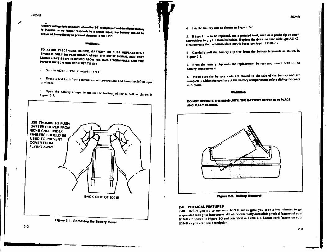
le
Figure 2-1. Removing lhe Battery Cover
2-2
batr.ry volag tils DOaPOinI wherehe 'BY Is dheplayed andlihe .ta display is inpcil or no io nger r eponds to a signal Input, "e heft I sh ou ld be
rYOPaced lati latly Io prevent daage o the LCD.
WARNING
TO AVOID ELECTRICAL SHOCK, BATTERY OR FUSE REPLACEMENT SHOULD ONLY BE PERFORMED AFTER THE INPUT SIGNAL AND TEST LEADS HAVE BEEN REMOVED FROM THE INPUT TERMINALS AND THE POWER SWITCH HAS BEEN SET TO OFF.
I. Set the M0240 POWER wi'tch to OfI..
2. Remove teisl lads from cxlernal circuit conneClions and Irom the 11024H input terminals.
3 Open the hbattry comparlmenl on Ihe bollttom of the 802411 us shown in F-igure 2-I.
F'guft 2-L selery Removal
2-9. PHYSICAL FEATURES 2-10. IWofore you try to use your 5024., we sugest you take a lew minutes tip get
acquainted with your instrument. All of the externally accessible physical features ol your
80240 are shown in Figure 2-3 and described in rable 2-1. Locate each feature on your
30240 as you read the description.
2-3
4. I il the battcry out as shown in Figure 2-2.
S. If fuse FI is to be replaceduse a pointed fool. such as a•probe tip or small
screwdriver to pry FI from its holder. Replace the defective fuse with type A(GX2.
(Instruments that accommndate metric fuses use type 1711100-2.)
6. Carefully pull the battery clip free from the battery terminals as shown in
Figure 2-2.
7. Press the battery clip onto the replacement battery and return both to the
battery comparttment.
8. Make sure the battery leads are roused to the side of the battery and arc
completely within the confines of the battery comportment before sliding the cover
into place.
WARNO
DO NOT OPERATE THE M4@ UNTIL THE BATTERY COVER IS IN PLACE
AND FULLY CLOSED.
80248 8024B
i
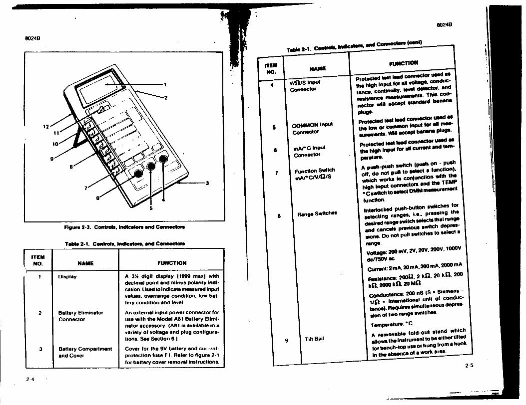
80248
0024B
Figure 2-3. Controls, Indicators and Connecters
Table 2-1. Controls, Indicators, and Connectors
ITEM
NO. NAME FUNCTION
1 Display A 3'% digit display (1999 max) with
decimal point and minus polarity Indi
cation. Used to indicate measured input
values. overrange condition, low bat
tery condition and level.
2 Battery Eliminator An external input power connector for
Connector use with the Model A81 Battery Elimi
nator accessory. (ASI is available in a
variety of voltage and plug configura
tions. See Section 6.)
3 Battery Compartment Cover for the 9V battery and cu, ient
and Cover protection fuse FI. Refer to figure 2-1
for battery cover removal Instructions.
2-4
Tabe 2_1. Controls, hnitestrO. apd CeOlas (Pent)
"N. NAME FUNCTION
N.protected tet lod coecte use as
S V/fl/S Input the high Input aorl S tae. conduc
connector tance. continUitY, te* 61etecto., and
resistance measreE nts. Thi Con
nector will accept standard banana
"protected test lead connector used as
5 COMMON Input the low or bonwwon input for 0 me
Connector Wjoent VON a b Plugs
6 mAr C Input protected test lead connctor used as
connector die high Input for alt current and tow'per atitre.
7 Function Switch A push-push switch (push on - push
Coff. do not putt to select a function). mA/' C/V/•IS which worts in cor4fundilon with the
high Input connectors and the TEMP
- C switchto select WW i measurement
function.
S Range Switches Interlocked push-button switches for selecting ranges. i.e.. pressing the
desired range switch selects that range
and cancels previous switch depres
sions. Do not pull switches to select a
range. Voltage: 200 mV. 2V. 20V. 20oV. 1000V
dc/750V ec
Currnt: 2mA. 20mA. 200mA, 2000mA
ResIstance: 2o0fl. 2 ktl. 20 k1l4 200 kQl 2000 kQl 20 MCf
Conductance: 200 nS (S = Siemens =
1/1f " International unit of conduc
tance). Requires simultaneous depres
Sion of two range switches.
Tilt Bail A removable fold-out stand which allowS the Instrument to be either tilted
for bench-tOp use or hung Irom a hook
In the absence of a work area.
2-5
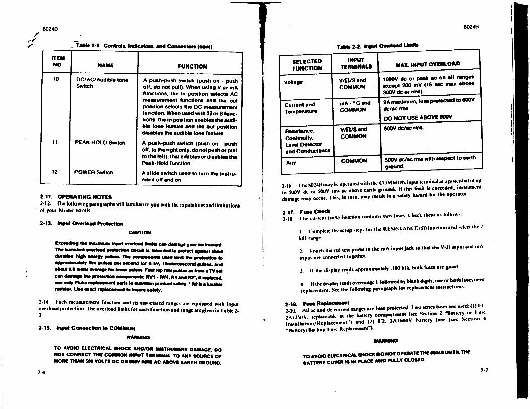
!780248
'-
"Table 2-1. Controls, indicators, and Connectors (coet)
ITEM NO. NAME FUNCTION
10 DC/AC/Audible tone A push-push switch (push on - push
Switch off. do not pull) When using V or mA functions, the in position selects AC
measurement functions and the out position selects the OC measurement function. When used with 12 or S functions, the in position enables the audible tone fealure and the out position disables the audible tone feature.
S! PEAK HOLD Switch A push-push switch (push on - push
off. to the right only, do not push or pull to the left), that edables or disables the
Peak-Hold function.
12 POWER Switch A slide switch used to turn the instrument off and on
2-11. OPERATING NOTES 2-12. T1 he following paragraphs will familiarite you with thl capabilities and limitations
of your Model •024R.
2-13. Input Overload Protection
CAUTION
Exceeding the m iauban input erload •mi•t can damage your Inslrturnnt.
The kraniel nt oeda protectN n crcurt Is Intended to protect agaireut soon duloa hIo h eNers y pubes. The oomponsens used 111" the protection to
approaus-atey Ike pulses per second for S kV. iOicrosecond pulses, and about 0.6 wat ains ae law lo wer puses. FInl rep rate puleseas beoo a TV set
can damage Ow vreIeclion compneno•s; RYI - RV4, Al and R2, it replaced, use only FbAe replacenent pilt 0o mnallain product solely. * R2 la a luebls reslster. Use exact replacement to Insure alealy.
2-14. t-ach mcasurcment function and its associated ranges are cquipped with input
overload protection. 1he overload limits for each function and langc arc given in ] able 22
2-1S. Input Conneclimn o COMMON
WARNING
TO AVOID ELECTRICAL SHOCK AND/OR INSTRUMENT DAMAGE, DO
NOT CONNECT THE COMMON INPUT TERMINAL TO ANY SOURCE OF MORE THAN 50S VOLTS DC ON U81 RUt AC ABOVE EARTH GROUND.
2-6
ISELECTED FUNCTION
Voltage
Current and Temperature
Resistance. Continuity, Level Detector and Conduc-tMce
Any
Table 2-2. Inp10011t Overload U k " te INPUT
TERMINALS MAX. INPUT OVERLOAD
v/flS and COMMON
mA - -C and
COMMON
v/'//S and COMMON
COMMON
I(0OV dc or peak ac on all ranges except 200 mV (15 sec max above 300V dc of rms). 2A maximum, fuse protected to 6WOY
dc/ec rimn.
DO NOT USE ABOVE OyV.
SOOV dc/ac rm.
5oov dc/ac rms with respect to earth ground.
2-16. I h• P0)2411 may he opc:al.cd wilh the (4 )M Mt IN input termnillal at a potential 411 s1p
to 5UOV dc- or 500V rnb me above earth ground. It this limit is cexcede•t. instrunwnt
damage may o-cur. I his, in turn, may result in a safely ha/ard for the Operator.
2-17. Fuse Check
2-Il. I he cirrent (IliA) unctlion contains two lues. (heKl the"' as llthows:
I. Compleitc lhc sclup stpC% lto 1he kElSIS l AN(1E0I)iunctisn anal %•ekcl the 2
kit range.
2. I ouch the red test probe to the mA input jack so that the V-it input and ,uiA
input arC connected together.
3. It he display reads approximately .100 kif, both fuses are good.
4. If the display reads overrange I followed by blank digits, one or both luses need
replacement. %ee the following paragraph for repla.ement instructions.
2-19. Fuse ReplMaeO*mNilt
2-20. All ac and dc current ranges arc fuse prcted. Iwo series (uses are used 11)11.
2A//I2IV, replaceable at the battery conspestinlel (jsee Section 2 'atltery OFr 1lo4e
Ins•allattilonieplaccment") and (21 1F2. 3A/tMOV battery fuse (see Sctlion 4
"ltAttCry/IBackup Viuew Rerlaccment-).
WARNING
TO AVOID ELECTRICAL SHOCK DO NOT OPERATE THE U28 UNTIL THE
BATTERY COVER IS IN PLACE AND FULLY CLOSED.
2-7
8024(1
I
!i
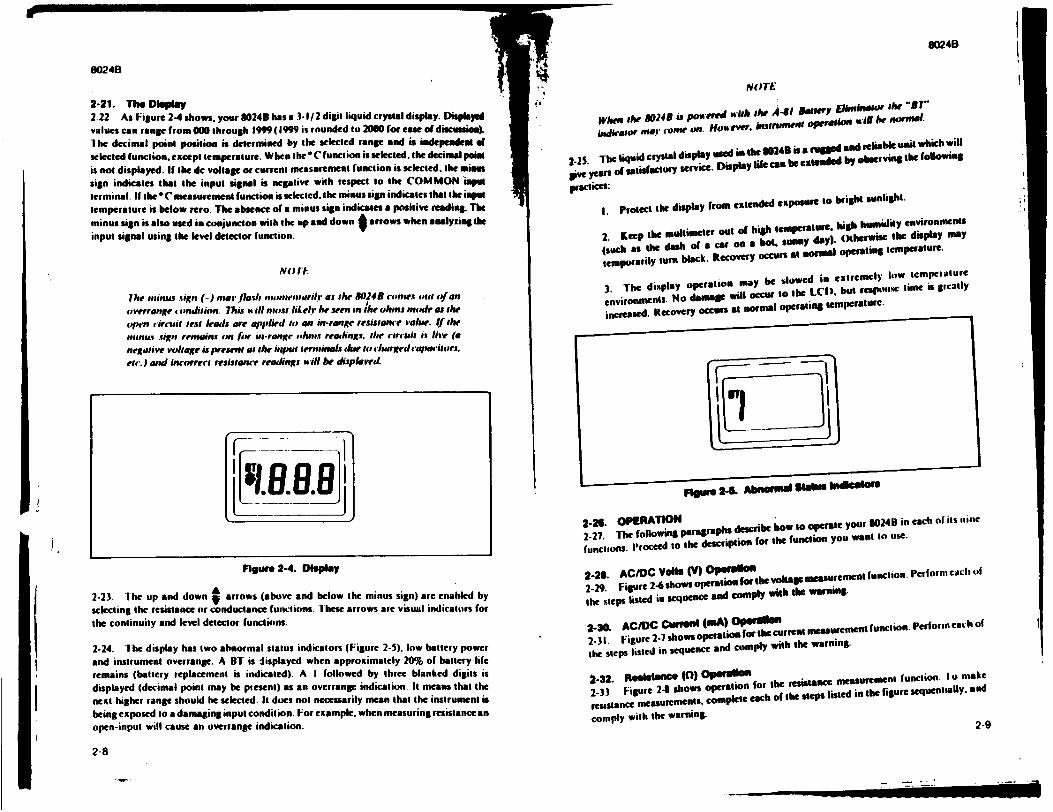
8024B
2-21. The Display 2.22 As Figure 2-4 shows, your 3024B has a .3-1/2 digit liquid crystal display. Displaye
values can range from 000 through 1999 (1999 is rounded to 2000 for ease of discussi.).
"I he decimal point position is determined by the selected range and is indepeadea ,o
selected function, except temperature. When the (C function is selected, the decimalpsia
is not displayed. If Ihe dc voltage or current measurement function is selected. the mimes
sign indicates that the input signal is negative with respect to the COMMON impt
terminal. If the "C measurement function is selected. the minus sign indicates that ihe impet
temperature is below rero. The absence of a minus sign indicates a positive reading. The
minus sign is also used in conjuncton with the up and down t arrows when analyriag the
input signal using the level detector function.
NO) ITI
7he m"inus sign (-) rlser flesh ,,urw~ewtawilt' as the 80248 copmnes mtl of an
ose•rrange condition. This will nhost liLet he seen in Ihe ohmj momie as the
open circuit test leads are applied to an in-range reseance vaohr. I.f the
nou.iid n sign remain don low in-rang. sphm.s rea•hngs. the ctircuit is i•,e (a
negative voltagce is present at the ipumt term•rninls wdhi to charged cap•'itors.
etc.) and Incorrec: resistance read ings will be displalvel.
Figure 2-4. Display
2-23. The up and down 9 arrows (above and below the minus sign) are enabled by
selecting the resistance or conductance functions. these arrows are visual indicators for
the continuity and level detector functions.
2-24. 1 he display has two abnormal status indicators (Figure 2-5). low battery power
and instrument ovcrrange. A UT is displayed when approximately 20% of battery life
remains (battery replacement is indicated). A I followed by three blanked digits is
displayed (decimal point may be present) as an overrange indication. It means that the
next higher range should he selected. It does not necessarily mean that the instrument is
being exposed to a damaging input condition. For example. when measuring resistance an
open-input will cause an overrange indication.
2-8
8024B
[:1NloTE
Whewn ihe 8024B is powered nith the A4-81 awwiry E:kWF the "Il"
indliator 19.1 come on. How ever, dtrlei oper %IoN wilie norwmw.
2-25. The liquid crystal display used in &he 30243 is& mtgged aad reliable unit which will
give years If satisfactory service. Display life can be extndUd by obrwving the following
piactices:
I. protect the display from extended exposure to height sunlight"
2. Keep the multimetcr Out Of high teperat .e. high ishmiity enviroments
(such as the dash of a Car on a hot1. suamy day). thrse h i y
temporarily turn black. Recovery occurs at ormua operating temperature.
3. The display operation may be slowed in extremely low temperttture
environments. No damage will occur to the LCI), but reSlWs time is greatly
increased. Recovery occurs at normal operating temperaturc.
Figul 2-1- AOIF0utd Staim bmlgcSo
2-26. OPERATION I o024B in each of its iine 2-27. The following paragraphs describe how toote You functions. P'roceed to the description for the function you want to use.
2-28. AC/DC Vanls (V) OphISUtm
2-29. Figure 2-6 shows opem- for the volta.em m
the steps listed in sequence and comply with the warning.
2-30. AC/DC Cuaefi (•A) OGw atm e t
2-31. Figure 2 .- shows operation for tbecurreatmeasuremetfunctin performneachof
the steps listed in sequence and comply with the warning.
n-32. AnsistUnce (0) Opa, twrSc
2-33. Figure 2- shows operation for the ce munction. Io a
resistance measuremenifts, complete each Of the steps listed in the figure sequentially. and
comply with the warning.
2-9
F
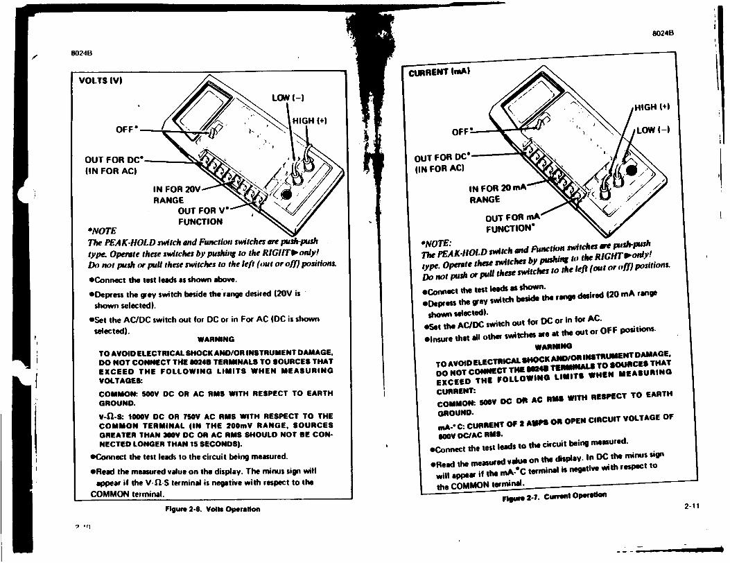
80246
VOLTS IV)
OFF*
(IN FOR AC)
IN FOR 20V---"' RANGE
OUT FOR V' FUNCTION
"NOTE The PEAK-HOLD svitch and Function switches are push-push
type. Operate these switches by pushing to the RIGIIT' only!
Do not push or pull these switches to the left (out or off) positions.
•Connect the test leads as shown above.
6l:epress the grey switch beside the range desired (20V is
shown selected).
eSet the AC/DC switch out for DC or in For AC (DC is shown
selected). WARNING
TO AVOID ELECTRICAL SHOCK AND/OR INSTRUMENT DAMAGE,
DO NOT CONNECT T14E 90248 TERMINALS TO SOURCES THAT
EXCEED THE FOLLOWING LIMITS WHEN MEASURING VOLTAGES:
COMMON: SOOV DC OR AC RMS WITH RESPECT TO EARTH
GROUND.
V-1l-S: I0V DC OR SOV AC RMS WITH RESPECT TO THE
COMMON TERMINAL (IN THE 200mV RANGE, SOURCES
GREATER THAN 300V DC OR AC RMS SHOULD NOT BE CON
NECTED LONGER THAN 15 SECONDS).
eConnect the test leads to the circuit being measured.
eRead the measured value on the display. The minus sign will
appear if the V-1-S terminal is negative with respect to the
COMMON terminal.
Ii
Figure 2-6. Volls Operation
9 .[)
OIJR NT |e~l • • " HIGH +10
OF:F*•"• LOW ( -1
OUT FOR DC" (IN FOR AC)
IN FOR 20 mA
RANGE
OUT FOR MA FUNCTION"
*NOTE: The PEAK-.IOLD switch and Function switches are push-push
type. operate these switches by pushing to the RIGHTw'only!
Do not push or puli these switches to the left (out or off) positions.
*Connect the test leads as shown.
*Depress the grey switch beside the range desired (20 mA range
shown selected).
eSet the AC/DC switch out for DC or in for AC.
*Insure that ill other switches are at the out or OFF positions. WARNING
TO AVOID ELECTRICAL SHOCK AN/OR INSTRUMENT DAMAGE,
Do NOT CONNECT THE @045 TERMINALS TO SOURCES THAT
EXCEED THE FOLLOWING LIMITS WHEN MEASURING CURRENT:
COMMON:- SMV DC OR AC RMS WITH RESPECT TO EARTH
GROUND.
mA-- C: CURRENT OF 2 AMPS OR OPEN CIRCUIT VOLTAGE OF
lOOV DC/AC RMS.
*Connect the test leads to the circuit being measured.
*Read the measured value on the display. In DC the minus sign
will appea if the mA-C terminal is negative with respect to
the COMMON terminal.
Ftgue 2-7. Curmit OPeaIokn2
80248
f I
II
2-11
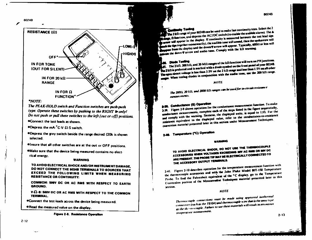
8024B
8024B
RESISTANCE I1-l*ha,1 tan? o yToo" .0243 -S b d make last continuity tests. Select the 2
. ,I.m * . d depoWen the AC4 DC switch (t enable 'be audible alarm) TheA
10fam ws ap desplay..•. . Icontinuityt is seasur lidbtween the test lead tips
tips lOgeath" m1oniuFtariy). the audible tone wil soud. theathe iuslrow will
u .a._ ,the display and the dow ,Warlow .- appal. Typically. 00M or less will
"P t oN allo and audio ton. Comply with the kO warnilg. ilW The dlownv T"'"- "
IN FOR TONE
(OUT FOR SILENT)
IN FOR 20 kfl'
RANGE
IN FOR 0 FUNCTION"
*NOTE: The PEAK-HOLD switch and Function switches are push-push
type. Operate these switches by pushing to the RIGHT No onlyl
Do not push or pull these switches to the left (out or offl positions.
eConnect the test leads as shown.
ODepress the mA-0 C-V-fl-S switch.
*Depress the grey switch beside the range desired 120k is shown
selected.
*insure that all other switches are at the out or OFF positions.
eMake sure that the device being measured contains no elect-
rical energy. WARNING
TO AVOID ELECTRICAL SHOCK AND/OR INSTRUMENT DAMAGE,
DO NOT CONNECT THE 60243 TERMINALS TO SOURCES THAT
EXCEED THE FOLLOWING LIMITS WHEN MEASURING
RESISTANCE OR CONTINUITY:
COMMON: OYV DC OR AC RMS WITH RESPECT TO EARTH
GROUND.
V-'3-S: NOV DC OR AC RMS WITH RESPECT TO THE COMMON
TERMINAL
eConnect the test leads across the device being measured.
*Read the measured value on the display.
I
'I
. Mde Th m 2lUl M.a. . 1ofthe kf lunctio" will tur On PN junction. The 2 kf. n0o klX uad 2 0 in d.ade syland ON tie (lost ipoed o1 your¢ 802411.
in is prdelend and is marked witha
~bepe diwt volages less than 33SV os the 2 k aS ~ and leaa*8 tha -IV oasal other
Swhlen c eatuit dodstaIgceou with the audie tolnS. te the 20 kn range. N L W h om testing do des .. . .c • . ...o
NOTE1
lhe 2tiIL0VkiL. and 2M1 All rae Vnr•*el wurd for its-Crcir' reuislwkf
rnwaswrellpfI.
29fipe29shopmo~ m n I) for the condutance measuremti function. To make
2-39. Figure 2-9 1 ompleteo' eh of the steps listed in the figile sequentially' ""Wlctn em asurepcn als, cofpu• ea h disphayed su its .is equal to lI fl. For the
and comply with the warninll. Siemes thet the
iesistand equivalnt to the displayed value, refer to the condueant-iresistence
coeve•sion material presented later in this section under Msure ientechniques.
24S. TmRf4r1 O C'C) OptUblon
WARNING
TO AVOID ELECTRCAL SMO Do NOT USE THE TErWMOCOUPL.
ACCESSOD WE1 VOlr v-TAGES XCEDING WV AC on O 6V oC
ARE P09EENT. THE POROE TIp MAy 1 ELCTfCAIV CONECT.ED.TO
TH ACCUESOV OuTT TOWMN'"
iI dr o on for the temperature "neasurlrolnt function with
the thermocouple accessories and with the -o F luke M o O the Temperature
Prghe. To find the Fahrenheit equivalnt o the C displa O she terntui
(onvCeSiOn portion o1 the MeasureIntut Teclsauls mteria presented later in thSs
section. NOTE
7erehrIpllR iq'sPl conne•'lslt$i nes#st be maek esing ipproehl isothe'rnal
cu-tetotE (Sauoh as the Y8104) end therrsmc'oulk N ire that is she sa50111trpe
as the t,,. 0-,*,mormpwk. Fldurl to u1we these nmaltihils will resuht in emrfeemus
teinjitr re" t plUUV 4 '-l.
2-12
II
I
I,
Figure 2-0. Reglalt-ce Operetlon
I
i
I
I
£ -1,,
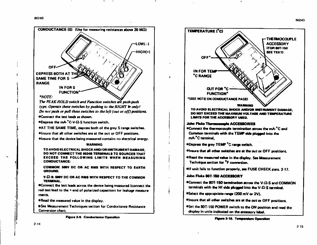
8024B8024B
CONDUCTANCE (S) (Use for measuring resistances above 20 Mfl)
S\ ." ," ' HIGH(+
DEPRESS BOTH AT TH SAME TIME FOR S RANGE
IN FOR S _ FUNCTION*
"*NOTE: The PEAK-HOLD switch and Function switches are push-push type. Operate these switches by pushing to the RIGHT I0 only! Do not push or pull these switches to the left (out or off) positions. eConnect the test leads as shown.
ODepress the mA-0C-V-fl-S function switch. eAT THE SAME TIME. depress both of the grey S range switches. elnsure that all other switches are at the out or OFF positions.
oinsure that the device being measured contains no electrical energy.
WARNING TO AVOID ELECTRICAL SHOCK AND/OR INSTRUMENT DAMAGE, DO NOT CONNECT THE M0243 TERMINALS TO SOURCES THAT EXCEED THE FOLLOWING LIMITS WHEN MEASURING CONDUCTANCE: . COMMON: SOV DC OR AC RMS WITH RESPECT TO EARTH GROUND.
V-11-S: 10V DC OR AC RMS WITH RESPECT TO THE COMMON TERMINAL.
*Connect the test leads across the device being measured (connect the red test lead to the + end of polarized capacitors for leakage measurements. *Read the measured value in the display. eSee Measurement Techniques section for Conductance-Resistance Conversion chart.
TEMPERATURE (*C)
OFF
IN FOR TEl *C RANGE
OUT FOR "C FUNCTION*
"ISEE NOTE ON CONDUCTANCE PAGEI
WARNING "V TO AVOID ELECTRICAL SHOCK ANDION INSTRJMENT DAMAGE. DO NOT EXCEED THE MAXIMUM VOLTAGE AND TEMPERATURE LIMITS FOR THE ACCESSORY USED.
I
Figure 2-9. Conductance Operation Figure 2-10. Temperature Operailon
2-142-15
Johm FRake Thermouple ACCESSORIES eConnect the thermocouple termination across the mA-°C and
Commnon terminals with the TEMP side plugged into the mA-°C terminal.
ODepress the grey TEMP 6C range switch.
*lnsure that all other switches are at the out or OFF positions.
*Read the measured value in the display. See Measurement Technique section for *F convesion.
elf unit fails to function properly, ae FUSE CHECK para. 2-17.
John Fluke SOT-150 ACCESSORY
*Connect the 80T-150 teWmiation across the V-fl-S and COMMON terminals with the HI side pluged Into the V-f-S terminal.
eSelect the appropriate rnge (200 mV or 2V).
elnsure that all other switches are at the out or OFF positions.
*Set the 80T-150 POWER switch to the ON position and read the display in units indicated on the accessory label.
; I
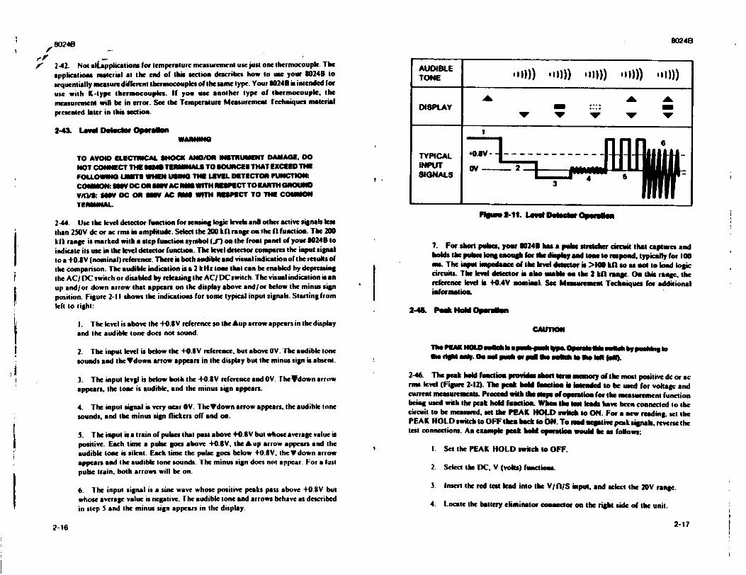
80241
K 2-42. Not aliAppikcatious for temperature measurement use just one thermocouple. The applications material at the end of this section describes how to use your 1024B to sequentially measuredifferent thermocouples of the ume type. Your 8024B is intended for use with K-type thermocouples. If you use another type of thermocouple, the measurement will be in error. See the Temperature Measurement rechniques material presented later in this section.
2-43& Levl Detectwo OperInWARNI
TO AVOID ELECTRICAL SHOCK AND/OR INSTRUMENT DAMAGE, DO NOT CONiECT THE MOB TERMINALS TO MIOUCES THAT EXCEED THE FOLLOWING UIMITS WHEN USING THE LEVEL DETECTOR FUNCTIOft COMMON: MOV DC OR NIgV AC INS WITH R1ESPECT TO EARTH GROUND VICYS: NOV DC OR 111M AC 1I11 WITH RESPECT TO THE COMMON TERMINAL
2-44. Use the level detector function for sensing loic levels and other active signals less than 250V dc or ac rss in amplitude. Select the 200 kOI range on the 1i function. The 200 kil range is marked with a step function symbol (J") on the front panel of your 80240 to indicate its use in the level detector function. The level detector compares the input signal to a +0.8V (nominal) reference. There is both audible and visual indication of the results of the comparison. The audible indication is a 2 kHz lone that can be enabled by depressing the AC/ DC switch or disabled by releasing the AC/DC switch. The visual indication is an up and/or down arrow that appears on the display above and/or below the minus sign position. Figure 2-1I shows the indications for some typical input signals. Starting from left to right:
I. 1he level is above the +0.8V reference so the Aup arrow appears in the display
and the audible tone does not sound.
2. The input level is below the +0.8V reference, but above 0V. The audible tone sounds and the Ydown arrow appears in the display but the minus sign is absent.
3. The input levgl is below both the +0.8V reference and OV. rheydown arrow appears, the tone is audible, and the minus sign appears.
4. The input signal is very near OV. TheVdown arrow appears, the audible tone sounds, and the minus sign flickers off and on.
5. The input is a train of pulses that pans above +0.8V but whose average value is positive. Each time a pulse goes above +-.8V, theAup arrow appears and the audible tone is silent. Each time the pulse goes below +O.8V, the Vdown arrow appears and the audible tone sounds. The minus sign does not appear. For a last pulse train, both arrows will be on.
6. 1 he input signal is a sine wave whose positive peaks pass above +0.8V but whose average value is negative. The audible tone and arrows behave as described in step 5 and the minus sign appears in the display.
80246
PIgtm 2-11. Lmev eleDerou O I
7. For short pubes, your 50243 bas a puoe stretchek cimv that captures and holds the pubes long enough for the dislpy and tone to respond, typically for 100 me. The input impedance of the level detector is >100 kit so as nol to load logic circuits. The level detector is also mnab oe the 2 kl range. On this range. the reference level is +0.4V nominaL See Measurement Techniques for additional information.
2-40, Peek Hold Opewde
CAUTION
Thef PEA HOLD su bhapuse!" mbh Ope @psmdsIfeb by p.56tl, to the dim eAof. Do met puls or pu the sno to keft (eff)
2-46. The peak hold function provide short ter, memosn of the most positive dc or ac Fru elevel (Figure 2-12). The peak bold fclion is inselded to be used for voltage and current measurements. Proesed with te ps ofr operation for the measurement function being used with the peak bold function. When the lest lends have been connected to the circuit to be measured, set the PEAK HOLD switch to ON. For a new reading, set the PEAK HOLD switch to OFF then beck to ON. To lead negative peak signals, reverse the test connections. An example peak bold operation would he as folows:
1. Set the PEAK HOLD switch to OFF.
2. Select the DC, V (volts) functions.
3. Insert the red test lead into the V/fl/S input, and select the 20V range.
4. Locate the bettery eliminator connector on the right side of the unit.
2-16
AUDIBLE TOME,, ),. ) |1) ,))
ALA AL DISPI.AY m :I..
TYPICAL -O.6V -INPUT ALS2 Z ." SIGNALS' ------- --- U *
2-17
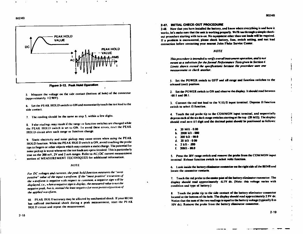
8024B
Flgure 2-12. Peak Hold Operalono
5. Measure the voltage on the side contact (bottom of hole) of the connector
(approximately +2.90V).
6. Set the PEAK HOLD switch to ON and momentarily touch the test lead to the
side contact.
7. The reading should he the same as step 3, within a few digits.
8. ialse reading% may result if the range or function switches are changed while
the PEAK 1101.1) switch is set it) ON. Ii avoid these errors, rci.ct the PEAK
HOLD circuit atter each range or function change.
9. Static electricity and noise pickup may cause errors when using the PEAK
HOLD function. While the PEAK HOLl) switch is ON. avoid touching the probe
tips to fingers or other objects which may contain a static charge. Ihe potential for
noise pickup is worst whenever the test leads are open circuited. I his is particularly
true on the 200 mV. 2V and 2 mA ranges. Refer to ACI DC current neasurement
section of MEASUREMENT TECHNIQUES for additional information.
N07"IE
For DC voltages and currents. tih peak holdfiunricon mneasures the ",bost
positive" value Of the input a•sefirm. If the "most positive" e reursiotn Of
Ihe wavefowin is negative A iih respect to conion, a negative sign will be
displayed. i.e.. " hen a negative sign is di.xplatq. the measured value is not tihe
negative peak. but is. sinstead the least negative (oriimost posifiiWjiortiEI itfi
the applied toaveformi.
10. PEAK H1O1.D) accuracy may be affected by mechanical shock. It your I0241t
has suffered mechanical shock during a peak measurement, reset the PIAK
HOLD circuit and repeat the measurement.
2-47. WITIAL CHECK-OUT PIOCEDUME 2-48. Now that you have intialled the battery. and know where everything is and how it
works. lets nake sure thai the unit is working properly. Well rum through a simple check
out procedure starting with trm-oa. No equipment other Obw tea leadn wig be required. If a problem is encountered. please check battery, fuse, switch stting Tad test lead
connection before contacting your nearest John Fluke Senie Center.
NOTE
This procedure is inte ndedo wry ovserdllhssrutmst operatk•o mendi not mvean as. sulstiute for the foruWi nerfoemisre Tesu giwu. in Seiedon 4.
Lirlts show'n excewd the specrueia brem..v Ik e anorr tar mesrment to check eAtwr.
I. Set the POWER switch to OFF and all range and function switches to the
relsed (out) position.
2. Set the POWER switch to ON auni observe the display. It should read between -00.1 and 00.1.
3. Connect the red test lead to the V/II/S input terminal. Depress 1I function switch to select (I function.
4. Touch the red probe lip to the COMMON input terminal, and sequentially
depress each of the six dark rnge switches starting at thetop (20 Mfl). Thedisplay
should read zero ±I digit and the decimal point should be positioned as follows:
a. 20 Mt1-0.00 b. 2000 kfl - 000 c. 200 kfI - 00.0 d. 20 kf| - 0.00 e. 2 kfl- .00 L 2000 - 00.0
5. Press the 20V range switch and remove the probe from the COM MON input
terminal. Release functon switch to slect volts funtioa.
6. Look inside the battery ellissetor connector on the right side of the 1024B and locate the connector contacts.
7. Touch the red probetothecamnterp•ptoire batteryelbuntorconanctor. The
display should read approximately -&IV de. (Note: this voltage varies with condition and type of battery.)
B. Touch the probe tip to the side contact of the battery eliminator connector
located at the bottom of the hole. The display should read approximately 2.9V dc.
Notice that the sum of the two readings is equal to the battery voltage (typically 8 to tOV dc). Remove the probe from the battery eliminator comnector.
2-192-18
80248
I1
!
i
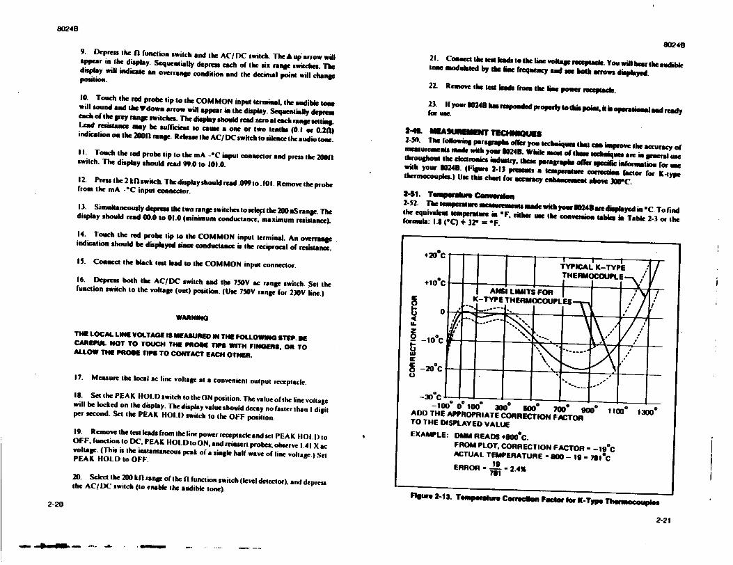
8024B
9. Depress the 0 function switch and the AC/DC switch. The A up arrow will appear in the display. Sequentially depress each of the six mape switches. The display will indicate an overranse condition sand the decimal point will change position.
10. Touch the red probe tip to the COMMON input terminal, the audible tone will sound and the Ydown arrow will appear in the display. Sequentially depres each of the grey range switches. The display should read zero at each range setting. Lead resistance may be sufi'cient to caire a one or two tenths (0. 1 or 0.20) indication on the 20011 rane. Release the AC/ DC switch to silence the audio tone.
II. Touch the red probe tip to the mA -OC input connector and press the 20011 switch. The display should read 99.0 to 101.0.
12. Press the 2 kfl switch. The display should rcad.099 to. I01. Remove the probe from the mA -*C input connector.
13. Simultaneously depress the two range switches toselept the 200 nS range. The display should read 00.0 to 01.0 (minimum conductance, maximum resistance).
14. Touch the red probe tip to the COMMON input terminal. An overrange indication should be displayed since conductance is the reciprocal of resistance.
15. Connect the black test lead to the COMMON input connector.
16. Depress both the AC/DC switch and the 750V ac range switch. Set the function switch to the voltage (out) position. (Use 750V range for 230V line.)
WARNING
THE LOCAL LINE VOLTAGE IS MEASURE IN THE FOLLOWING STEP. BE CAREFUL NOT TO TOUCH THE PROE TIPS WITH FINGERS, OR TO ALLOW THE PROME TIP$ TO CONTACT EACH OTHER.
17. Measure the local ac line voltage at a convenient output receptacle.
18. Set the PEAK HOLD switch to the ON position. The value of the line voltage will be locked on the display. The display value should decay no faster than I digit per second. Set the PEAK HOLD switch to the OFF position.
19. Remove the test leads from the line power receptacle and set PEAK HOLD.) to OFF, function to DC. PEAK HOLD to ON. and reinsert probes; observe 1.41 X ac voltage. (This is the instantaneous peak of a single half wave of line voltage.) Set PEAK HOLD to OFF.
20. Select the 200 kfl range of the fI function switch (level detector), and depress the AC/DC switch (to enable the audible tone).
80241
21. Conaect the mes leads t the line voltage receptack. You will hear the audible tone modulated by the line frequency and me both arrow displayed.
22. Remove the lad leads from the liem power receptacle.
23. If your 80240 has responded propedy to thi poit. it is operational and ready for use.
2-43. MEASUEMUNT TECH4NKS 2-50. The following peragruphe offer you technoilues that cen improve the accuracy of measurcmena made with yow 80241. While asom of tChee tsediqus are in generl use throughout the electronics indiutry. these paragraphs offer speciic informmtion for use with your 80243. (Figure 2-13 presents a emperamtu correction fator for K-type thermocouples.) Use this charg for accacy ealhancemea above 3001C.
2-51. Tanpemurm Cdenieersd 2-52. The temperature measuemens made with yow 243 are displayed in *C. To rind the equivalent temperature in OF. either ue the conavion tables in Table 2-3 or the formula: 1.8 (oC) + 32? = oF.
+20o'C
K-TYPE THERMOCOUPLES
" "-0" .
-20°C
-300C -100 00 100 3000 W00 7000 9000 11000 13000 ADO THE APPROPRIATE CORRECTION FACTOR
TO THE DISPLAYED VALUE EXAMPLE: DMM READS +800eC.
FROM PLOT, CORRECTION FACTOR - -19°C ACTUAL TEMPERATURRE - 00 - 19 - 7810C ERROR - - - 2.4%
Figure 2-13. Temperature Corteegen Fagciw for K-Typqe Thermocotplae2-20
2-21
M iO.- L - , J6 ' . .
i I I
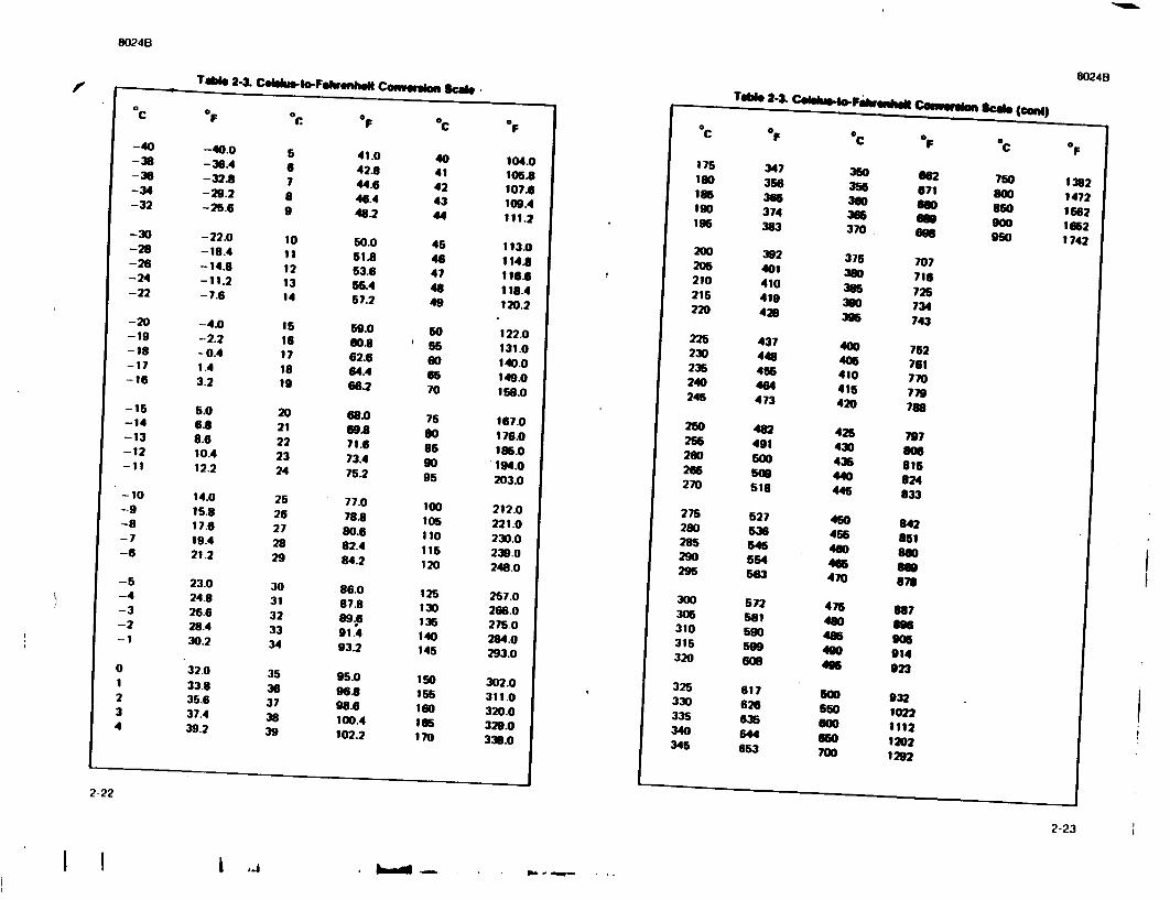
8024B
TAb% 24. CgbkwS.o-Fsh.wUI.W Conwggm, Scabe
2-22
8024B
2-23
I I I
le
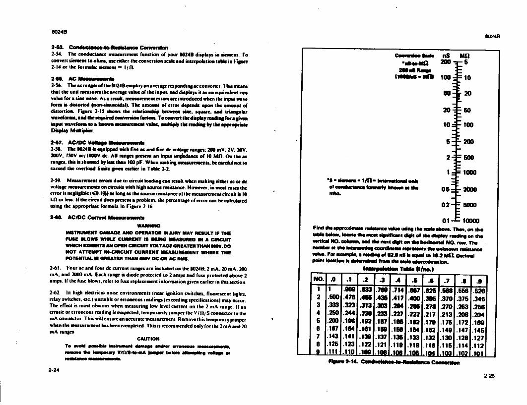
S8024
UYJ48
2-53& -edcneeRgeae Ceovecash 2-54. The conductance measurement function of your 80248 displays in siemens. To convert siemens to ohn., use eiher the conversion scale and interpolation table in Figure 2-14 or the formula: siemens = Ifl.
2-66, AC Maenewemeass 2-56. The ae ranges of the 3024B employ an average responding ac converter. This mans that the unit measures the average value of the input, and displays itas an equivalnt ruan value for a sine wave. As a result. measuement errors are introduced when the input wave form is distorted (non-sinusoidal). The amount of error depends upon the amount of distortion. Figure 2-15 shows the relationship between sine, square, and triangular waveforms, and the required conversion factor To€oavert the display reading bra give. input waveforn to a klnow meaurement vale. mutkiply the reading by the appropirie Display Multiplier.
2-57. AC/DC V~ llo.etuemuft 2-53. The g0248 is eqipped with five me and five dc vokage ranges; 2W6 mV. 2V. 20V. 200V. 750V ac/1009v dc. AN ranges present an input imniedance of 10 MD. On the me ranges, this is shunted by tes than 100 pF. When making measurements, be careful not to exceed the overload limits given earlier in Table 2-2.
2-59. Measurement errors due to circuit loading can result when making either ac or dc voltage measurements on circuits with high source resistance. However. in most cases the error is negligible (40. 1%) as long as the source resistance of the measurement circuit is IO kfl or less. If the circuit does present a problem, the percentage of error can he cak'ulated using the appropriate formula in Figure 2-16.
2-40. AC/DC Cuwtnt Melaeuemwen
WARNING INSTRUMENT DAMAGE AND OPERATOR iNJURY MAY RESULT IF THE FUSE SLOWS WHILE CURRENT 18 RIFNG MEASURED IN A CIRCUIT WHICH EXHEINTS AN OPEN CIRCUIT VOLTAGE GREATER THAN gISV. DO NOT ATTEMPT IN-CIRCUIT CURRENT MEASUREMENT WHERE THE POTENTIAL IS GREATER THAN 6W DC OR AC RMS.
2-61. Four ac and four dc current rangs are included on the 80240; 2 mA. 20 mA, 200 mA, and 2000 mA. Each range is diode protected to 2 amps and fuse protected above 2 amps. If the fuse blows, refer to fuse replacement information given earlier in this section.
2-62. In high electrical noise environments (near ignition switches, fluorescent lights, relay switches, etc.) unstable or erroneous readings (exceeding specifications) may occur. The effect is most obvious when measuring low level current on the 2 mA range. If an erratic or erroneous reading is suspected, temporarily jumper the V/Il S connector to the mA connector. This will ensure an accurate measurement. Remove this temporary jumper when the measurement has been completed. This is recommended only for the 2 mA and 20 mA ranges.
CAUTION To aod possibl instrumenl dmage and/or erroneous measurments. nmeo the tempoary V/fl/S-bo-mA lumper beore atempting 11ege Or
-e-an moeuremonl
CemN-tn sim
li3ssw -11111
"e8- de-O eNs - 141- Inunead unak of coaduotnme founedy knwn a dse mha.
nS MO
Its 20W
100A
50
20-.
10
2
I:
05 =
02-
Find doe pproxime reslstance vohm usiag the mob ashove. Then, on the table below, lanet se mome significant dilg of the diI I reading on the Verticl NO. column, and Use next digt en Vte helatonid NO. row. The numrber o the *ner"n'A eordliname opuenss the untknown resistance value. Per enaITple. a reading of 52.0.a Is equ to 10.2 MEL Decimal Point loastion le des-and frem Udo mole opprexlI -len.
I - vnhlniem TAMl If/no.)
5
10
20
=50
-100
200
=500
= 1000
510 150090
.0 .1 .2 .3 .4 .5 .6 .7 .8 .91 2 3 4 5 6 7 8 a9 .1 . .11v w • • II
9
.500
.333
.250 .200 .167 .143 .125 .1111
.476
.323
.244
.196
.164 .141 .123 .110i
.110.1M.11 .10 .14 .03-102 i
1.551 1.466 .313 .230
.192
.161
.139 .122 -l081
.700 .436 .303
.233
.137
.166
.137
.121 -I1Oi
.714
.417
.294 .227 .186 .166 .135 .119 insI
.857 .400
.282
.182
.154
.133 .118 .106
.625 .386 .278 .217 .179 .152 .132 .116 .1041
.588 .370 .270 .213 .175 .149 .130 .115 .Ina
.556
.375
.263
.208
.172
.147
.128
.114
Plgstre 2-1&. Cen0ata0e4e-Realtes1M Cesertatllen
.526
.345 .256 .204 .169 .145 .127 .112
2-242-25
I
Of1-
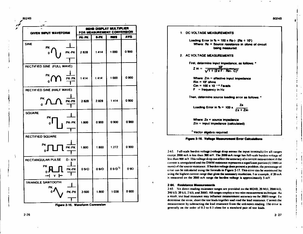
80248
'Il
GIVEN INPJUT WAVEFORM FOR MEASUREMENT CONVERSION
PK-PK 6-PK H~mS AVG
SIN E PK
0 PK-PK 2828 1.414 1000 0 900
RECTIFIED SINE (FULL WAVE)
PKI m PK-PK 1.414 1.414 1000 0900
RECTIFIED SINE (HALF WAVE)
PK-PK 2.828 2828 1414 0.900
SQUARE PKL_
0 PK-PK 1.800 0.900 0900 0.900
RECTIFIED SQUARE
PF -I PK-PK 1.800 1.800 1,272 0900
RECTANGULAR PULSE D-XIY
PK j~_n J PK-PK 09/D 0.9/D 0 9/D 0 9D
--.-I Y '
TRIANGLE SAWTOOTH
0 PK-PK 3600 1.800 1038 0900
Figure 2-15. Waveform Conversion
8024B
Figure 2-10. V~lta Meurem edl Error Camuialons
2-63. Full-scale burden voltage (voltage drop across the input terminal%) for all ranges except 2000 mA is less than 300 mV. "'h 2000 mA range Ias full-.%ale burden voltage of klss than 900 mV. 1 his voltage dropcan affect theaccuracy ofua current measurement if the current is unregulated and the DM M resistance represents a significant portion (I/ I aINNr i
1utre) of the source resistance. If burden voltage does present a problem, the percentage ol crror can be calculated using the formula in Figure 2-17. This error can be minimied by using the highest current range that gives the necessay resolution. I-or example, if 20 mA i% measured on the 2000 mA range the bunrie voltage is approximately S mV.
2-64. Resi-sa e Me weuemenls 2-65. Six direct reading resistan-ce ranges are provided on the 1024B; 20 MIL 200 kall. 240 khl. 20 kil. 2 fll. and 2001). All ranges employ a two wire measurement te-hniqlue. As a result, test lead resistance may influence measurement accuracy on the 20011 range. I o determine the error, short the test leads together and read the lead resistance. Correct the measurement by subtracting the lead resistance from the unknown reading. I he error is generally on the order of 0.2 to 0.3 ohms for a standard pair of test leads.
2-26
1. DC VOLTAGE MEASUREMENTS
Loading Error in % = 100 x R.s- JR + 10') Whore: RA = Source resisanuce in ohms of circuit
bei measured.
2. AC VOLTAGE MEASUREMENTS
First. determine input Impedance, as ollows:
Z in = 3W VTI+ (2 a IF. - F. C)f
Where: Zin = effective Input Impedance Ain = 10' ohms Cin = 100 x 10 -"2 Farads F = frequency in Hz
Then. determine source loading error n follows:
Ze Loading Error in % = 100 a Zs + Zin
Where: Za = source Impedence Zin = Input impedance (calculated)
Vector algebra required.
2- 27
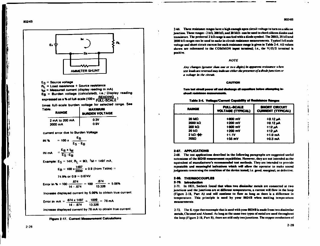
- -- -
RtLEs
ES = Source voltage RL Load rnesistance + Source resistance IM Measured current (display reading in mA)
EB = Burden voltage (calculated). I.e.! Display reading
expresed as a % of lul-scale (100 x -)
times full-scale burden voltage for selected range. See
Table. MAXIMUM RANGE BqUROEN VOLTAGE
2 mA to 2W0 mA O.3V 2000 mA o.gv
current error due to Burden Voltage
IN% =10Ox ES - EB
INmA - ES xIM
Example: ES = 14V. RL = 90, IM = 1497 mA.
EB = 100 x4 x 0.9 (from Table) = 2000
74.9% or 0.9 = 0.674V .674 .674
Error In % = 100 = 100 - = 506% 14- .674 13.326
Increese displayed current by 5.06% to obtain true current.
Error in mA = .674x 1497 = 1009 = 76mA 14- .674 13.326
Increase displayed current by 76 mA to obtain true current.
Figere 2-17. Current Measurement Calculations
2-28
O0W408024B
2-66. Three resistance ramis have a high enough open circuit voltage to turn on a silcon
junction. Thee ramps - 2 khA 20I5W. and 30 MA -can be used So check silicon diodes and traniston. The prefe 2 W ranp is marked wi•h a diode symbol. The 200. 20 kW and 2000 kh ranmps can be used to make hi-circuit rmesutisae measuire•ens. Typical full scale voltage and ahort circuit current lor mb resistance ra p is give. Table 2-4. AlU values shown are referenced to the COMMON isput Terminal i.e.. dhe VI/lS terminal is positive.
NOTE
Any changes (grener thaea o or 'to dlfs) be qpo t resin e wbhen smlen kh .rrmvrdamvy kedirteft rr t heprsencurofedio*ujsio m or
a vohadr be #w chruk.
Tem led s Pster all mind db a. a epis beftn dhsmpig Insbul redn se o nmessmmele
Toble 2.4" Vulhp/Cimusi Capsut of Resistm e fmtgs
RANGE FULL-SCALIE oI ra CCUIT VOLTAGE (TYM CMJ C WNT (TYPICAL)
20 Ma +4110 mV +0. 12 #A 2000 IT +gO0 mV +0.12 pA 2000 I+2-00 mV -Ot-2/aA 20W kO+SW MV +12 pA 20 kW +200 mV +12 pA 2k'-- +1.1V +1.0 mA
2000 +56 mV +0.3 mA
2-47. APPUCAllONS 2-68. The test applicaSiom described in the following paragraphs are suggested useful extensiom of the 30248 mm 1ue1, capebilities. However, they are not intended as the equivalent of manuaiacures recasmended tlea methods. They are intended to provide repeatable and meaningful indlcation which will allow the operator to make sound judgments concerning the condition mthe device Usiad Le. pod, marginal, or defective.
240, THERMOCOUPLES 2-71L knbeistele 2-71. In 1g21. Seebeck fossil the wh•en two dissimilar metas are connected at two junction and the junctions are at dilhren Temperatures, a curret will flow in the loop (Figure 2-1, Paut A) aul will ontinue to flow as long as here is a difference in temperature. This principle is used by your 8243 when making temperature
measurements.
2-72. The K-type thermocouple that is used with yoerU024S is made irrom two dissimilar
metals.Chromel and Alumd. As long as the same two types ofmetal are ued throughout the loop (Figure 2-18, Part 3). there are still only twojunctions. The copper conductors of
2-29
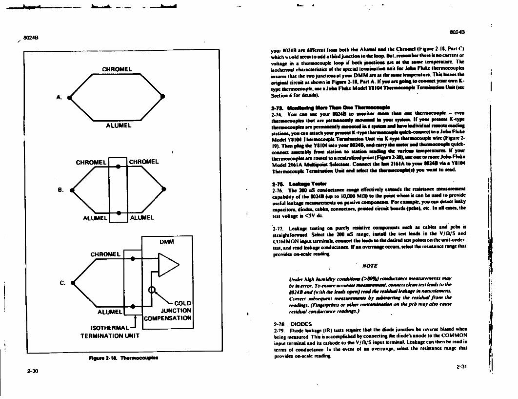
L- A
8024B80248
CHROMEL
A.
ALUMEL
CHROMEL
ALUMEL
K
C.
CHROMEL
ALUMEL
ISOTHERMAL,TERMINATION UNIT
Figure 2-18. Thermocouples
2-30
your 1024R are different from both the Aluiel and the Chromel (Figure 2-18, Part C)
which t ould were to add a tbird junction to the loop. let, rimember there is no current or
voltage in a thermocouple loop if both junction are at the same temperature. The
isothermal characteristics of the special termination unit for Jobe Fluke thermocouples
insues that the two junctions at your DM M are at the same tempertur. This leaves the
original circult as shown in Figure 2-1l. Paon A. If you are il to conect your own K
type thermocouple, use a John Fluke Model YI04 Tbhrmecouple Termination Unat (oe Section 6 for detaib).
2-&. Noon on Moen Th•n One Thumouals 2-74. You can use your 30245 to monitor mme thian oe thermocouple - even
thermocouples that are peruamntly moumted in your system. If yoaw present K-type
thermocouples are permaeatly mounled in * system and have ind Iidual remote rading
stations you can maach your pres K-type tWermouple qulck-coanet to a Jobs Fluke
Model Y9104 Thermocouple Termuatiost Unit vim K-ype therm ouple wi (Fiure 2
19) Then pIlg the Y$104 Inot your WHOS, and cry The mater and thermocouple quick
connect asemby from Nation to station reading the varios Temperatures. If your
thermocoupls ae routed to acelt•ained point (Figur 2-25), use on oormoe Jon Fluke
Model 2161A Mutipol Selector Connect the las 2161A to your 30243 via a Y8104
Thermocouple Termination Unit and select the thermocouple(s) you want to read.
2-71. Le~kags Teeter 2-76. The 200 aS conductance ranp effectively extends the reistance measurement
capability of the 3024B (up to IO0000 Mfl) to the pouit where it con be used to provide
useful leakage measurements oa passive components. For example, you can detect leaky
capacitor, diodes, cables, connectors, printed circuit boards (pcebs), etc. In aU cases, the
test voltage is <5V dc.
2-77. Leakage testing on purely resistive components such as cables and pcbe is
straightforward. Select the 200 nS range, install the test leads in the V/fl/S and
COMMON input terminals, connect the leads to the desired tesW points on the unit-under
test, and read leakage conductance. If an overramp occurs, select the resistance range that
provides on-scale reading.
NOTE
Under high humidity conditlns r40) conductae measuremrns may
be in error. To ensure accurae mertwemmeE, connect cltn test letas to the
80243 and (wish the lead open) red the mkl Leakage int sanosiensetm. Correr subseqWnt measusemm bi auboratbwi the residua from the
readings. (Fingerprints or other comnMsuatlio on the peb may aho camu residual conductanee reodinws.)
2-78. DIODES 2-79. Diode leakage (IR) tests require that the diode junction he reverse biased when
being measured. This is accomplished by connecting the diodes anode to the COM MON
input terminal and its cathode to the V/fl/S input terminal. Leakage can then be read in
terms of conductance. In the event of an overrange. select the resistance range that
provides on-scale reading.
2-31 I,
I
I!
!1
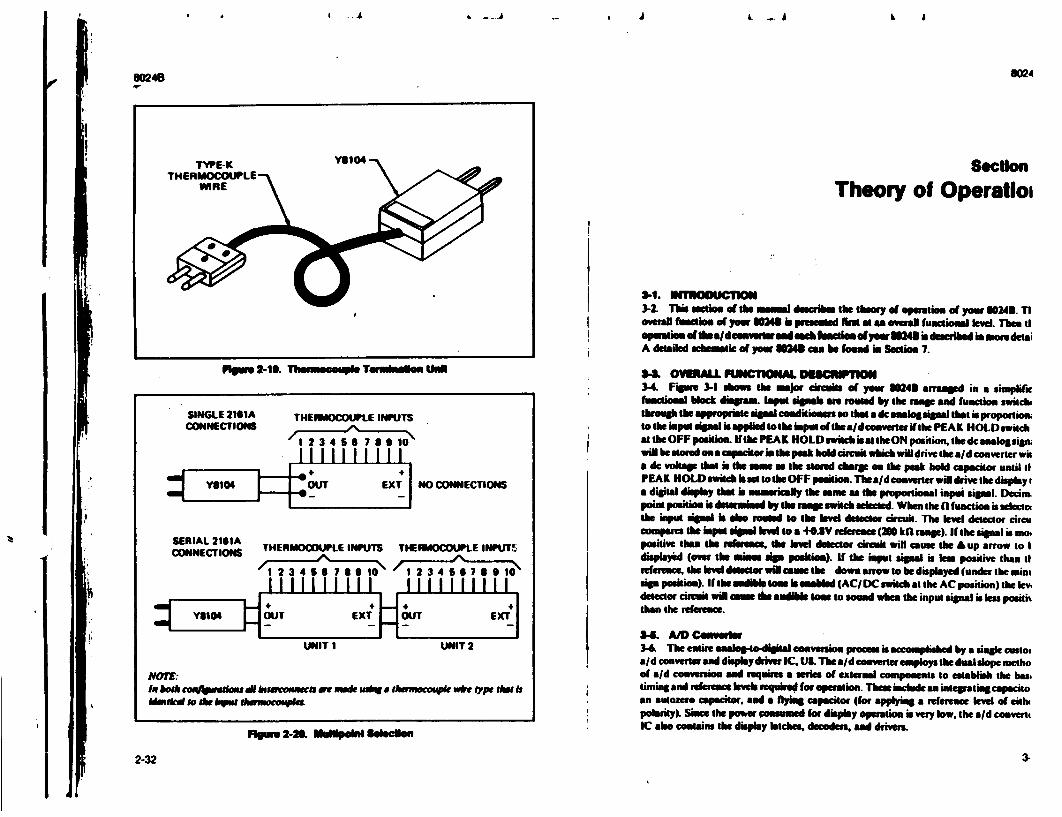
L .. L A
or
ti
I.3-1. 1119WOOUCTIO 32. This secti of the nmel dcri the theory of opertiom of yow 10243. TI overall fumietl of yw 80MI4 in pesened fis at an oveal fmnctioual level. Then d operatiom ofthe aldemvenmo d eied fInenoti alyow i4 is destibed lame detai A detailed schematlc of yow 88M ma be found i Seetio 7.
rlpur 2-11. Thermmoauple TWmildon Ul A
SINGLE 2161A THERMOCOUPLE INPUTS
CONNECTION 2 3 ý4 6 733 10ll
ONO CONNECTIONS
SERIAL 2111A CONNECTIONS THERMOCOUPLE INPUTS
I 2 3 4 5 36 7 9 10
THERIOCOUPLE INPUTS
1I 2 346
NOTE: In both c"wmaedmsa I ntecotmCro wae nude ut* S &muoE4cpk wit jtpe tlht Is Madkrd so the - tmocomphu.
lnsu 2-21. umllpolnt Seoeclen
3-L OVEALL FUNCTlIONAL DSCNNPTION 3-4. Figu r-I sh1ows the major circuits of yrw 3243 arranled in a simplilic fuwkmed block diagram. IWput gneb ae roued by the rmap and function switch, through the appropriate signal conditioners so that a dc analog signal that is proportiorn to the input tpdal is applied to the input ofthe a/d eonverteri ithe PEAK HOLD switch attheOFFpasiton If thePEAK HOLD switch is al theON position, the dc asaos sigLn will be stored oe calpciiornthe peak hold circuit which will drive the aid converter wit a dc voltage that is the am a the stond charp on the peak hold capacitor until tl PEAK HOLD 0witch ibet to the OFF position. The aid converter will drive the display i a digital display that is aunurimly the am at the proportional input signal. Decim; point position is determined by the mpe switch seleced. When the ( fuaction is wWeect the input sinal is alo rouled to the Ilvel detector circuit. The level detector circu ompare the input sine Inle to a +O-8V reere-ce (200 kW rFne). If the signal i moe positive than the referenPe, the level delector circuit will come the A up arrow to I displayd (over the mins lin position). if the input sig• a is lea positive than t rerence, thelevel de• or wil muse tle down anow to be displmyed (under the mini sin position). It the d te b enabled (AC/ DC switc at the AC position) the lev,
detector ciruit wiN caw ILe audible low to sound when the input siSnal is ess posith than the ref terce.
34L A/D Conveter 3-4 The entire mnalogo-diit converuion prom. is accomplished by a nole cutto, aid converter and dislpmy driver IC. U8. The aid converter employs the dual dope metho of a/d conversion and requires a eria of external components to establish the bas, timing and rference ve require for operion. These include an inreatincgapacito an autozero capecitor. nad a flying capacitor (for applying a reerence level of cislo polakrity). Siam the power onumed s or display operation is very low, the aid convent IC she conatis the display latches. decoders. ad drivers.
2-32
Section
Theory of Operatlo,
OO248
i . .- k __.-A
3-

80248 mu
3-7. The digital control portion of the a/d converter proCem is a internal function of US. and is keyed to the external cry"ta frequeacy. Ass . hi. the conversion process is
0 continuously repeated, and the display is updated at the end of every conversion cycle. J I
7 c 3-8. A simplified circuit diagram of the analog portion of the a/d converter is shown in
S- Figure Each of the switches shoin repes analog; pals which are operated by the 0 digital section of the aid convener. (Sheet I of the Schlutie &boe illustrates the aid
, 5 convener ia block Ionr.) Basic dting for switch opratioe and; therefore. a complete 10 . z n mesuremencycle isshows i Figure 3-3. r:Eo J3-9. Any given measurement cycle performed by the aid conveer can be divided into
lbree consecutive time periods. autoasro (AZ), integrate (INTEG), and mad. Both autozero and integrate an Fixed time period& whsen lengths ore multiples of the clock
I frequency. A counter determines the keno of both time periods by providingan overflow a- -at the end of every 10.000 dock pules. The rend period is a variable time which is
proportional to Rim unknown input valtagle. The vallue of The voltage is determined by D counting the nmber of clock pulses that occur daring the read period.
I W 3-10. During autoero a grounl dref is applied as aa input to the aid converer.
-0 Under Ideal coditions the output of the comparator would also go to zero. However, z z W input-offse-volhage crors accumulate in the amplifier loop. and appear at the
compsawao output as an error voltage. This error is impresse os the AZ capacitor 0 whelr It is stored for the resmainder of the mnesusnmieft cycle. The stored level is used to
c provide offset voltage correction during the integrate and read periods.
Aw 5W 3-11. The integrate period begins at the end of theautmxro period. As the period begins. Sa o the AZ switch pensand the INTEG switch doses. TiUapplies the unknown input voltage Su 0tootheinput sothe aid conveter. Thevolage i buffered and pased onto the inteprator to - Ti >determine the charge rate (slope)on The INTEG capacitor. At the end of the fixed integrate
0 period, the capacitor is chard to a level proportional to the unknown input voltage. This >voltage it imranslte to a digital indicatim by discharging the capacitor at a fixed rate
a, during the rend period, and counting the number of dock pules that occur before it Sreturns to the originalautceero levw.
t 3-12. As the read period begins, the INTEG switch opens and the rad switch coses. This Ja- &pplieas known refence voltage to The input of the aid converter. The polarity of this
voltage is automatically seiected to be opposite that of the unknown input voltage, thus
o4 causing the INTEG capacitor to discharge at a fixed ratelslope). When the charge is equal to thc initial strtin point (a e linde), the read period is ended. Since the discharge
E slope is fixed during the rend period, the time required for ditcharge is proportional to the
> U. unknown input voltage.
> 3-13. The autozero period, and thus a new measurement cycle, begins at the end of the rmad period. At the same time the counter it released for operation by transferring its contents (previous measurement value) to a series of latches. This stored data is then
Floure 3-1. 80240 Block Diagram decoded and buffered before being used for driving the liquid crystal display.
3-2
IIUPl• A O
3-3
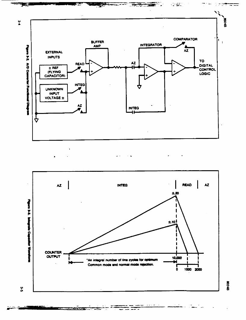
to
BUFFERCOMPARATOR
AMP INTEGRATOR
INPUTS
:t REF TDIGITAL I(LYN +- + ,.. -÷ CONTROL
CAPACITOR) NE+LOI
INE
INPUT VOLTAGE±
•AZ INTrEG
I lom
"0 An integral number of line cyclee for ol1m.u0|
Common mode and normal mde reNlon. 0 1000 20O
- - - - -- - '-

8024B
8024B
2-14. Voltage Mansurmil Functib" 3-14. Both ac and de volage meawrement functions use an overvoltage protected 10
MI) input divider to scale down the input voltag. tinder normal conditiom (assuming a
dc input signal on the proper ramep) the dividea output isa dc voltage that is directly
proportional to the input signal level, If the AC function is selected, the output ol the
divider is ac coupled to an active Wll-wave rectiier whose dc output is calibrated to equal
the rFu level of the ac input (for sine wave inputs). it the PEAK HOLD switch is at the
OFF position. the dc voltage from the divider or the acconverer is passed through a kiter
and applied to the aid converter as the unknown input (Figure 3-4). Peak Hold operation.
will be covered later.
3-16. Cuwn• M SnWntmrd Fensmo
3-17. Current measurements are made using a fuse protected. switchable, current shunt
(0. 1fL I f[ .10HI or 1000) to perform the current4o-voltaie co wnyeinn required by the aid
converter (Figure 3-5). The voltage (JR) drop produced acrosa the selected shunt "my he
either ac or dc. if the input current is dc and the DC function is selected, the IR drop is
passed through a low-paos fier, and presented as the unknown input to the aid converter.
However, if the input current is mc and the AC function is selected, the IR drop is rectifibd
by the ac converter If the PEAK HOLD switch is at the OFF position, the dc signal from
either the ac converter or the current shunt is routed through a filter to the a/d converter.
This unknown input voltage to the aod converter is proportional to the current pastoa
through the current shunt.
3-18. TnmpeiwSs ('C) mIkmVOUU Function
3-19. As Figure 3-6 shows, the input from the thermocouple accessory is applied across
the mA and COM MON termin;: If the PEAK HOLD switch is in the OFF position the
input will be routed through a falter to the aid converter unknown input. The COMMON
terminal is thermally tied to the collector and base leads of transistor Q3. This provides
reference junction temperature compensation. Q3changes with temperature and provides
an offset voltage to counter the thermocouple at the input jacks to ensure the integrity of
the reading at the measurement end.
3-20. IteM N NMsa R10001 Fmnio in t
3-21. Resistance measurements am made using a ratio technique as shown in Figure 3-7.
Whem the kfO function is selected. a simple series of circuits are formed by the internal
reference voltage, a reference resistor from the voltage divider (selected by range switches).
and the external unknown resistor. The ratio of the two resistors is equal to the ratio of
their respective voltage drops. Therefor, since the value of one resistor is known, the value
of the second can be deengmined by using the voltage drop across the known resistor as a
reference. This determination is made directly by the a/d converter.
3-22. Overall operation of the a/d converter during* resistance m•u•rent is basically
as described earlier in this section. with oneexceptum The reference voltage present
during a voltage measurelent is replaced by the voltage drop across the reference resistor.
This allows the voltage across the unknown resistor to be read during the integraite period,
and compared against the refcrence resistor dufing the read period. As before, the length
of the read period is a direct indication of the value of the unknown. The PEAK HOLD
switch should always be in the OFF position when making resistance measurements.
3-6
FPgse 3-4. Volt~e Missmwood
3-7
1 =-� - A , E := . 4 , !
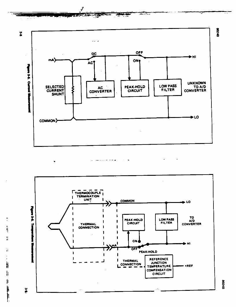
________________
I
rTH ERMOCO;PLE, I TERMINATION UNIT g
TO A/D CONVERTER
. . .. .PEAK4-OLD
I -- /~ I THERMAL UREFERENCE
COMPENSATION CIRCUIT
wb
I to
I I I
I
I I
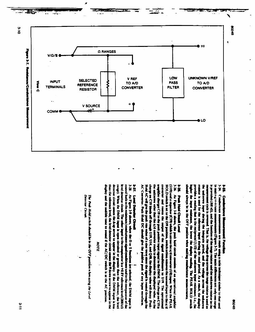
S.... =di.•nm "- .
S HI
UNKNOWN V/REF TO A/D
CONVERTER
- LO
ii p
I I
-q
0
C3
I �4
I I I
4
'fiji
I
U ii ii
* 3.
I I.
5 3. 3.
C
Icp
-. _ = w�
Ii
0

DM a RM25 r'COMPARATOR 0MM
INPUT > I P A U21 STRTCH R -- DISPLAY
REFERENCE AC DC
Lin
R5
SIGNAL CONDITIONERS
I
I I I L
COMMON
I
I I I I
C.,
L
I

60248 8048
Some onslcondudoe Ond CUeoM IC9 can, be damaged by electfeOIeic diechwele during
11nii Ths noh, emplamn how you Can minimize the chwmn @1 d@Wtoyin such danced by
IKnowngl= e W4 ere elfa pooeleM 2LeaNin lme gultbmeshn Ill' had Wgsao
3 Usming Ow peocedufs and pechain slid bmenh aecnques OWe we recommended.
The SainOc SanMiwe15 IdSvece1 Wet 'onsdn the FIAk Wehricamnal partsOW blle wish Ohe ovwsho
The Ilmgpraclimscelhouid be Imloio d Jo m~nkmize damage 10 8SS eie
6SL USE ANTI-STATI CONITAINERS FOR
HANDLING AND TRANSPORT S. HANDLEF S.6. DEVIDES ONLY AT A S1TATOC-FREE WORK STATIN
*. ONLY ANTI-SATIC TYPE SOLDERSGKSVW WHOULD Ki USED
wS ONLY GROUNDED11 TIP` SOLDERING mSHOUL aiu USED.
IMINIMIZE HANDLING
2 KEEP PARTS IN ORIGINAL CONTAINERS UNTIL READY FOR UKE.
*. 00 NOT mum 1114 DEvICES OVER ANY SURACE
3 DISCHARGE PERS0ONAL STATIC BEFORE HANDLING DEVICES
7 AVOID PLASTIC. VINYL AND STYROFOAM IN WORK AREA
4 HANDLE S S. DEVICES BY THE WOYV
AnN-uMits bog& NaIF g IS device or pcbs wish Oweeedreeloen Ilef ean be erdeved koom #he Johrn Pk*Ae Uig. Co.. in.. Onuoeun 5i~oSny owhFas
..eai puN nutW~ftW4Wimn rdr tglUme. peia
hap.
John Fbidi
-465
-455
Sag111e
If- a 24
12" a IS*
I
3-14 3-15/3-16
'K rt
OW48
(a static awarEnESS (@]
3-14
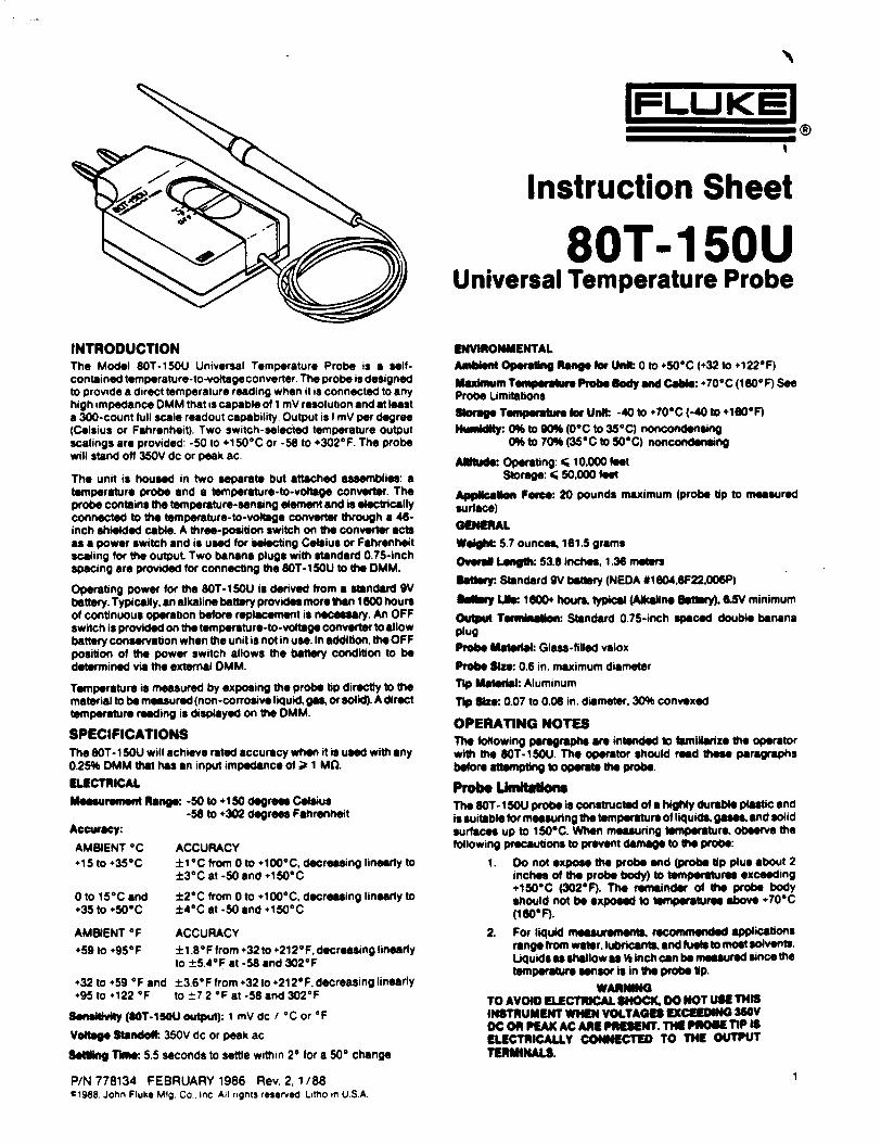
INTRODUCTION The Model 80T-150U Universal Temperature Probe is a selfcontained temperature-to-voltageconverter. The probe is designed to provide a direct temperature reading when it is connected to any high impedance DMM that is capable of I mV resolution and at least a 300-count full scale readout capability. Output is I mV per degree (Celsius or Fahrenheit). Two switch-selected temperature output scalings are provided: -50 to +1506C or -58 to +3026F. The probe will stand off 350V dc or peak ac.
The unit is housed in two separate but attached assemblies: a temperature probe and a temperature-to-voltage convefter. The probe contains the temperature-sensing element and is electrically connected to the temperature-to-voltage converter through a 46inch shielded cable. A three-position switch on the converter acts as a power switch and is used for selecting Celsius or Fahrenheit scaling for the output Two banana plugs with standard 0.75-inch spacing are provided for connecting the 80T-150U to the DMM.
Operating power for the 80T- I SOU is derived from a standard 9V battery. Typically, an alkaline battery provides more than 1600 hours of continuous operation before replacement is necessary. An OFF switch is provided on the temperature-to-voltage converter to allow battery conservation when the unit is not in use. In addition, the OFF position of the power switch allows the battery condition to be determined via the external DMM.
Temperature is measured by exposing the probe tip directly to the material to be measured (non -corrosive liquid, gas, or solid). A direct temperature reading is displayed on the DMM.
SPECIFICATIONS The 80T-I5OU will achieve rated accuracy when it is used with any 0.25% DMM that has an input impedance of ;= 1 MQ.
ELECTRICAL
Mseasureet Ii Range: -50 to +150 degrees Celsius -58 to +302 degrees Fahrenheit
Accuracy:
AMBIENT 0C +15 to +356C
0 to 150C and +35 to +506C
ACCURACY ±1 °C from 0 to +1000C, decreasing linearly to ±30C at -50 and +1500C
±20C from 0 to +1000C, decreasing linearly to ±40C at -50 and +1500C
AMBIENT OF ACCURACY +59 to +95°F ±I .8 F from ÷32 to +2120F. decreasing linearly
to ±5.40F at -58 and 302OF
+32 to +59 OF and ±3.6OF from +32 to +2120F, decreasing linearly +95 to +122 OF to ±7.2 OF at -58 and 3020F
Sensit"vly (SOT-150U output): 1 mV dc / °C or OF
Vo~ta Standoi. 350V dc or peak ac
SeWn TTIme: 5.5 seconds to settle within 20 for a 50* change
P/N 778134 FEBRUARY 1986 Rev. 2,1/88 c1988. John Fluke Mfg. Co.. Inc All rights reserved Liho in U.S.A.
IFLUKEI
Instruction Sheet
80T-1 50U Universal Temperature Probe
ENVIRONMENTAL Ambient Operating Range for UnIt: 0 to ÷500C (+32 to +1220F)
Maxdmium Temperature Probeody and Cable: .70°C (160F) See Probe iUmitations
Storage Temperatue for Unit: -40 to +700C (-40 to +160°F)
Humidify: 0% to 90% (0°C to 350C) noncondensing 0% to 70% (350C to 500C) noncondensing
AtI1tudm: Operating: 4 10,000 feet Storage: 4 50.000 lfet
Application Ferll: 20 pounds maximum (probe tip to measured surface)
GENERAL
WeIght 5.7 ounces. 161.5 grams
Overal Length: 53.8 inches, 1.36. meers
Batler:. Standard 9V battery (NEDA #1604.6F22.006P)
Bafttmy ls: 16100+ hours, typical (Alkaline fthery 6.5V minimum
Outpd Teminatkion: Standard 0.75-inch spaced double banana plug
Probe Malterfal: Glass-filled valox
Probe Size: 0.6 in. maximum diameter
Tip Material: Aluminum
Tip Size: 0.07 to 0.08 in. diameter. 30% convexed
OPERATING NOTES The following paragraphs are intended to lamiliarize the operator with the 80T-150U. The operator should read these paragraphs before attempting to operate the probe.
Probe kimftailons The 80T-I5OU probe is constructed of a highly durable plastic and is suitable for measuring the temperature of liquidsk gases, and solid surfaces up to 1500C. When measuring temperature. observe the following precautions to prevent damage to fe probe:
1. Do not expose the probe end (probe Up plus about 2 inches of the probe body) to temperatures exceeding ÷150*C (302"F). The remainder of th probe body
should not be exposed to lemperatures above +70*C (1eOF).
2. For liquid measurements, recommnded applications range from water, lubricants. and fuels to most solventa. Liquids as shallow as % inch can be measured since the temperature sensor is in the probe Up.
WARNING TO AVOID ELECTRICAL SHOCK, DO NOT USE THIS INSTRUMENT WHEN VOLTAGES EXCEEDING 38V DC OR PEAK AC ARE PRESENT. THE PROME TIP 18 ELECTRICALLY CONNECTED TO THE OUTPUT TERMINALS.
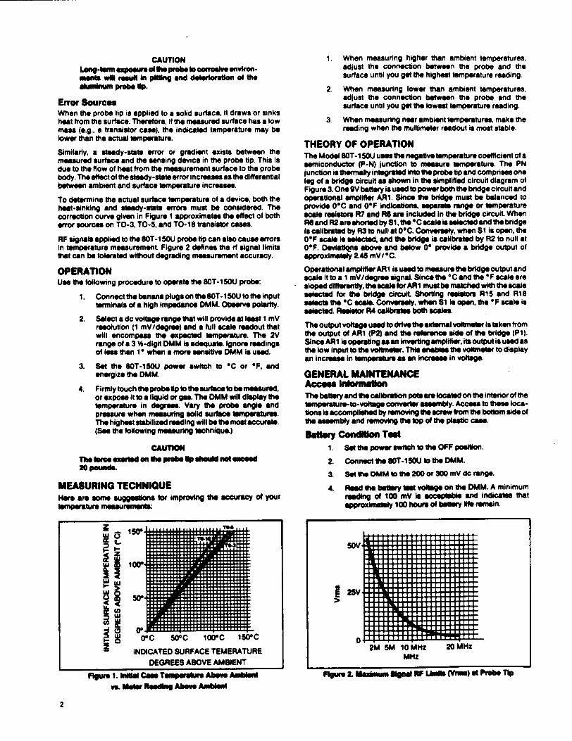
CAUTION Long-tem exposure of le probe t correlve environments wll resu•t itng " and deftrivatkIon the alminum o 1p.
Error Sources When the probe tip is applied to a solid surface, it draws or sinks heat from the surface. Therefore, if the measured surface has a low mass (e.g., a transistor case), the indicated temperature may be lower than the actual temperature.
Similarly, a steady-state error or gradient exists between the measured surface and the sensing device in the probe tip. This is due to the flow of heat from the measurement surface to the probe body. The effect of the steady-state error increases as the differential between ambient and surface temperature increases.
To determine the actual surface temperature of a device, both the heat-sinking and steady-state errors must be considered. The correction curve given in Figure 1 approximates the effect of both error sources on TO-3, TO-5. and TO-lI transistor cases.
RF signals applied to the 0T--1 5OU probe tip can also cause errors In temperature measurement Figure 2 defines the rf signal limits that can be tolerated without degrading measurement accuracy.
OPERATION Use the following procedure to operate the SOT-I 5OU probe:
1. Connect the banana plugs on the SOT-I 15OU to the input terminals of a high impedance DMM. Observe polarity.
2. Select a dc volage range that will provide at leist 1 mV resolution (1 mV/degree) and a full scale readout that will encompass the expected temperature. The 2V range of a 3 %-digit DMM is adequate. Ignore readings of les than 10 when a more sensitive 0MM is used.
3. Set the 8OT-15OU power switch to OC or OF, and energize the DMM.
4. Firmly touch the probe tip to the surface to be measured. or expose It to a liquid or gas. The DMM will display the temperature in degrees. Vary the probe angle and pressure when measuring solid surface temperatures. The highest stabilized reading will be t most accurate. (See the following measuning tIchnique.)
CAUTION
The oee exerusd en tie - lp shou not essed 20pn.
MEASURING TECHNIQUE Here are some suggeelns for improving the accuracy of your temperature measurements:
0L i Oo I0° I5°
-- INDICATED SURFACE TEMERATURE
DEGREES ABOVE AMUIENT
Fmgur 1. hille Case Tem•mpeaw bv Axmbient VS Metif IReadhi Abe,. Ambient
1. When measuring higher than ambient temperatures, adjust the connection between the probe and the surface until you get the highest temperature reading.
2. When measuring lower than ambient temperatures, adjust the connection between the probe and the surface until you get the lowest temperature reading.
3. When measuring near ambient temperatures, make the reading when the multimeter readout is most stable.
THEORY OF OPERATION The Model SOT-1i U use the negative temperature coefficient of a semiconductor (P-N) junction to moesure temperature. The PN junction is thermally integrated Into the probe Up and comprises one leg of a bridge circuit as shown in the simplified circuit diagram of Figure 3. One 9V battery is used to power both the bridge circuit and operational amplifier AR1. Since the bridge must be balanced to provide 0"C and 0"F indications, separate range or temperature scale resistors R7 and RS are included in the bridge circuit When R6 and R2 are shorted by Si. the C scale i selected and the bridge Is calibrated by R3 to null at 09C. Conversely, when Si is open. the 01F scale Is slectd, and the bridge is calibrtedI by R2 to null at O0F. Devitliqns above and below 00 provide a bridge output of approximately 2.45 mV/OC.
Operational amplifier ARI is used to measure the bridge output and scale It to a 1 mV/degree signal. Since the C and the OF scale are sloped differently, the scale for ARI must be matched with the scale selected for the bridge circuit Shorting 9eis R15 and R18 selects the OC scale. Conversely, when Si is open, the OF scale is selected. Resistor R4 calibrate both scales.
The output voltage used to drive the external voltmeter is taken from the output of ARi (P2) and the reference side of the bridge (Pl). Since ARi is operating a an Invortig ampliier, Its output is usead s the low input to the voltmeter. This enables the voltmeter to display an Increase in temperature as an lIn in voltage.
GENERAL MAINTENANCE Access Infornmw The battery and the calibration pote are located on the interior of the temperature-to-voelage converter tseembly. Access to these locations is accomplished by removing the sorew from the bottom side of the assembly and remoVng te top of the plastic cae.
Battery Condion Ted 1. Set the power switch to the OFF position.
2. Connect the SOT-1 SOU to the DMM.
3. Setthe OMM to the 200 or 300 mV dc range.
4. Read the bamly tent voltage on the DMM. A minimum reading of 100 mV is acceptable and indkates that approximately 100 hours of bair Ille remain.
I
-----------5UV .... I.. 13ý
. . .. . . ..LJLIJ-J1 1 1 1 1 1 1 JLJIý
rlý rr71rrTTTTTT-J7rT17E1:1ý
25V
7rr717137CT37ET3DEEI3D111JLLLL_ 71717173711IM371EMIDDEELIJU-1-L 7rTl7rTlNrTl7r37rl3ZEI3:LIJU-LL.
rTl7rTl7CY117rT37[13:[I]:LLLL.L171771=71=717111937ýý
fficrl=]ý f9FE&LIZOMU-1
0 =1=141LL2M 5M 10 MHz 20 MHz
MHz
fturs 2. M11datidm Signal RIF LhmES (Viet) at Probe TIP
2
Figure 3. SWkI~ Ckeco Warem
Satiey Replae met
WARNING
TO AVOID ELECTRICAL SHOCK, REMOVE THE PROSE FROM THE MEASUREMENT SURFACE BEFORE OPENING THE CASE. TOTALLY REASSEMBLE THE INSTRUMENT BEFORE ATrEMPTING TO USE IT.
1. Set the power switch to the OFF position.
2. Disconnect the 8OT-15OU from the OMM.
3. Turn the 80T-1 50U so the power switch is facing down. Remove the single screw located between the banana plugs.
4. Grasp one case half in each hand. Pull the two halves apart beginning at the end with the banana plugs.
5. Remove and replace the baIttry.
6. Reassemble the SOT-150U as folows Mate the two case halves at the end where the cable eiew the case, then "hinge" the two halves together. Replace the case screw, being careful not to pinch the probe cable or battery wires.
PERFORMANCE TEST Complete the calibration procedure without opening the temperature-to-voltage converter assembly and without making any calibration adjustments. Observe the readings given In [brackls. Other readings are for cal-bra0on only.
CALIBRATION A calibration cycle of one year is recommended to maintain the unit within the specifications given earlier. The equipment required for calibration is listed in the table following the calibration procedure.
NOTE t Values given in brackets apply to the Per'ormance Tear.
Perform the following steps to calibrate the SOT-150U:
1. Access the interior of the temperature-to-voltage converter by removing the bottom case screw and separating the case halves.
2. Connect the 80T-1 50U to a DVM with I0 pV resolution. and select mV dc range.
3. Select the OC position of the switch. Immerse the probe tip 2 inches into a mercury thermometer monitored 0C bath, and allow 60 seconds for the readings to stabilize.
4. Adjust R3 (see Figure 4) to obtain the following reading: 0.00 ± 0.05 mV dc (0 ± 2 mV dc)
5. Select the °F position of the switch, and adjust R2 to obtain the following reading:
32.0 ± 0.1 mV dc 132.0:±14 mV dc]
6. Selectthe *C position, mad movlthe probe tip to a 700C to 90"C bath and again allow the readinge to stabilize.
7. Adjust R4 to obtain a DVM reading that agrees with the bath temperature (IM) as monitored by a mercury thermometer.
"*C ST ± 0.05 mV dc (ST ± 2 mV dc)
8. Select ths F positlon, and verofy that the output is within ± 4 mV dc of the bath thermometer reading. If necessary, change the DVM range to obtain an on-scale reading.
9. Return the probe tip to the 0"C bath and check the output. If readjustment is necessary, repeat steps 4 through 8 until readings can be obtained without adjustment
10. Set the SOT-1SOU switch to the OFF position, and remove the SOT-1S0U from the DVM.
11. Reaseemble the ST-150U.
12. The 90T-1501U is now calibrated.
PROBE REPLACEMENT A probe kIt (eOT-110-70M K. PN 431023) in av be for replacing demed or delecive probes The Idt Includes a probe and cable
essembty and en -i-MRon and brdoWi luction set
I.ST OF REPLACEABLE PARTS A Schematic of the 80T-150U is shown In Figure 4. A list of replacebo Parts is shown in Figure 5. When ordering parts, provid the description. Fluke pert number, and the quantity required.
For applioation or operation assistance or information on Fluke producls call:
800-426-0361 In moa of U.SA. 206-356-5400 from AK HI, and WA 206-356-5500 from other countrea
John Fluke MIg. Co. Inc P.O. Box CSOW5 EvorostWA 96206
3
Test EqlPWAed ReSW~emeets ____ ___________
INSTRUMENT T MINUM USE SPICIPICATIONS RECOUMENDED MODEL
Mercury Thermometer 0.19C Resolution Pr.nco Model SAMA-CP45
Dewar Flask and Cap 1 -Pint Cap•ity (or Ice t hSa) Thermos Botle
Metal or Glaaa Container 1-Pint capacity Suitable for Boiling Water
Digital Vottmeter 100 mV Range with 10 pV Fluke Model IhIIA Resolution 1000 mV Range with 100 pV Resolution
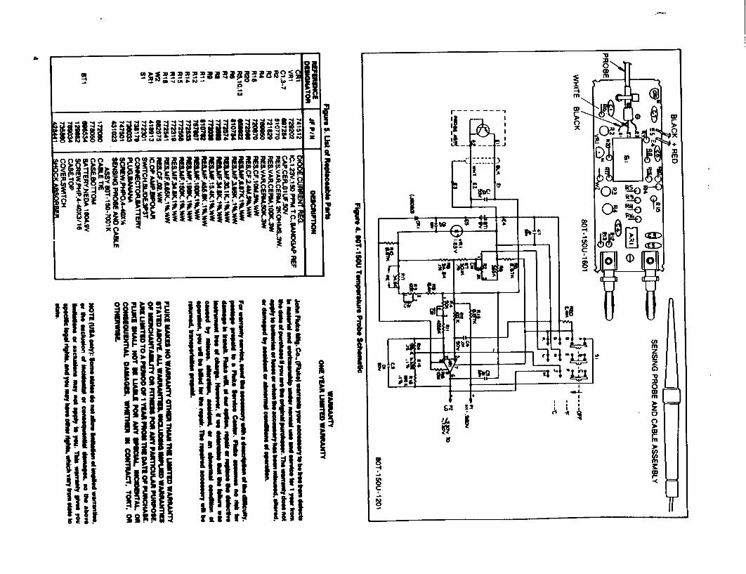
I S -4
-4
I I
I I
G8
S -4
C
0
I
U) m z C', z G) -D
0 w m
2 a C) w
0
I
ii I
Ifill"
.ii Ii"
lii
I
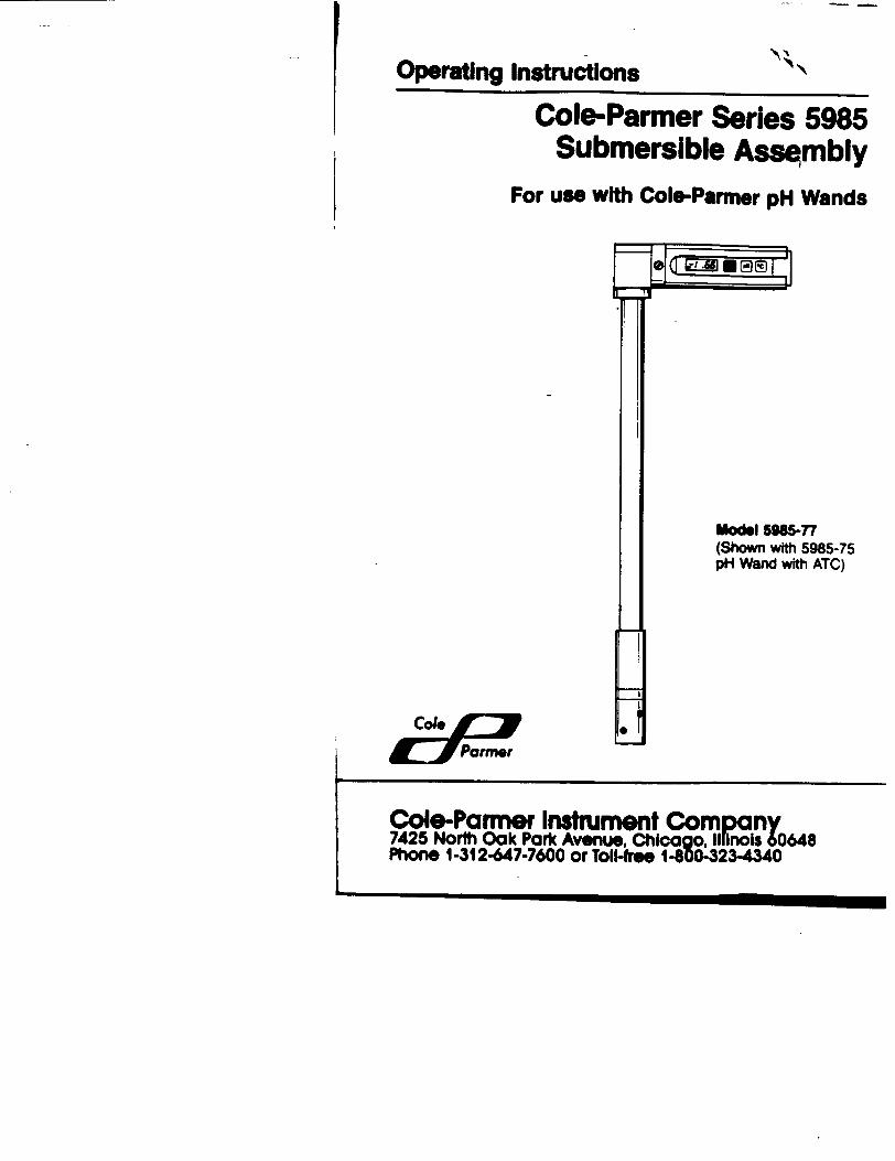
Operating Instructions IN
Cole-Parmer Series 5985 Submersible Assembly
For use with Cole-Parmer pH Wands
Model 5985-77 (Shown with 5985-75 pH Wand with ATC)
Cole-Parner Instrument Company 7425 North Oak Park Avenue, Chicago, llfrnol$ 60648 Phone 1-312-647-7600 or Toll-free 1400-23-4340
jI-"::Parm~r
Table of Contents
General Description & Specifications ......................... Page 1 Assem bly .............................................. Pages 2-3
Diagram & Instructions Operation & Cleaning ....................................... Page 4 Warranty & Return of Items ............................. Back Page
General Description
This submersible assembly is designed specifically for use with ColeParmer's Series 5985 pH Wands. The assembly lets you measure pH in tanks, large baths, drums, etc., or wherever a submersible extension is necessary or desirable. The assembly installs between the pH wand and the electrode, to extend the measurement reach to a full 26". The upper section holding the pH wand, the meter holder, rotates a full 3600 for comfortable viewing from all angles. The lower portion, the assembly shaft, has a PVC sleeve with watertight Viton, O-ring, to protect the electrode from bumps or jolts during measurements. Two assemblies are available:
Model 5985-65, for use with Model 5985-50 pH Wand Model 5985-77, for use with Model 5985-75 pH Wand with ATC
Specifications
Model numbers: 5985-77: For 5985-75 ATC pH Wand 5985-65: For 5985-50 pH Wand
Assembly shaft: Length: 26.0" (71.1 cm) Diameter: 1.25" (3.2 cm)
Meter holder: Length: 7.250 (18.4 cm) W x D: 2.0" x 1.5" (5.1 x 3.8 cm)
Protective sleeve: PVC, w/Viton" O-ring Shipping weight: 31 lbs. (1.4 kg)
Page 1
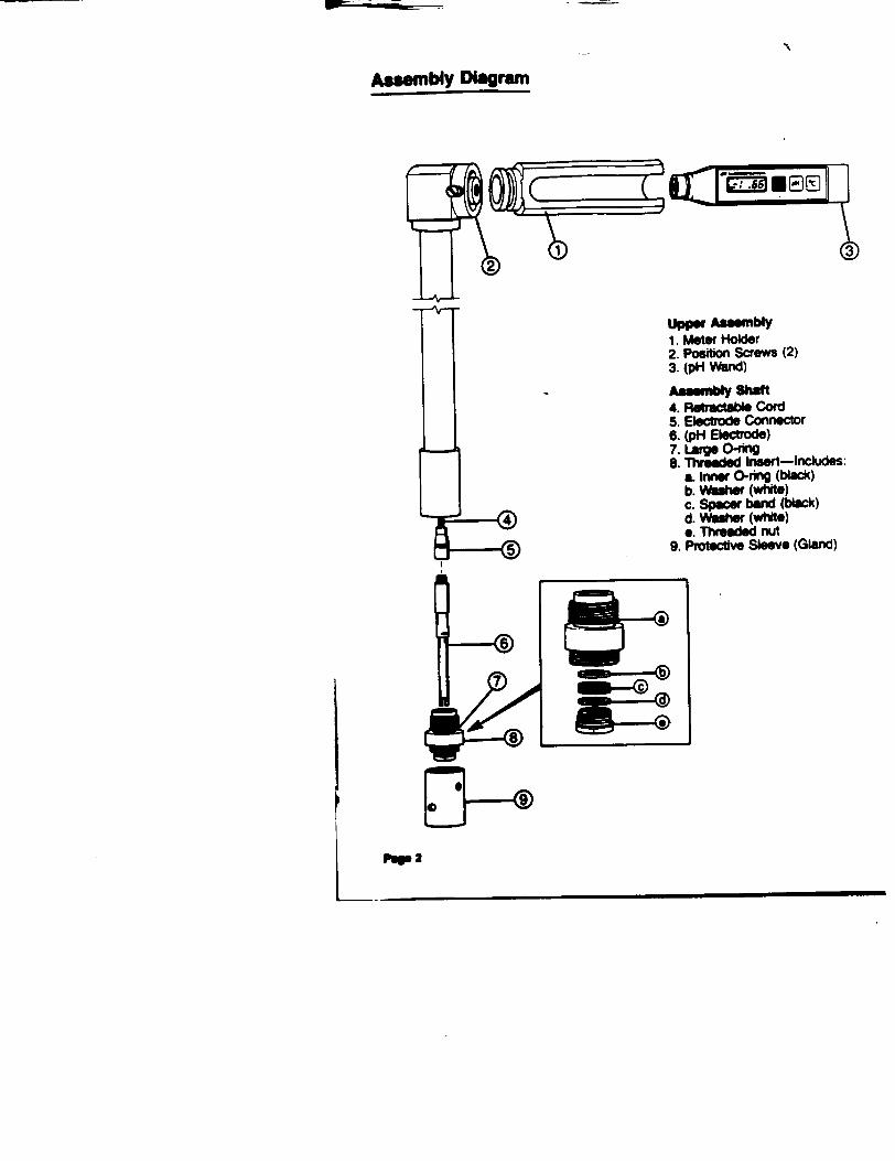
Assembly Diagram
upper Assmbly 1. Meter Holder 2. Position Screws (2) 3. (pH Wand)
A-M y, Shaft 4. Retractable Cord 5. Electrode Connector 6. (pH Electrode) 7. Large O-ring 8. Threaded Insert-Includes:
a. Inner O-ring (black) b. Washer (white) c. Spacer band (black) d. Washer (white) e. Threaded nut
9. Protective Sleeve (Gland)
pop 2
Assembly Instructions •
The submersible assembly consists of two major sections, the electrode holder and the meter holder. Refer to Assembly Diagram as needed. To Install the electrode: 1. Unscrew and remove the protective sleeve (gland) from th• bottom of
the assembly shaft. Put it to one side. 2. Next unscrew and remove the double-threaded insert, which houses
a threaded nut, spacer band, two washers and O-ring. Put it aside, also.
3. At this point the end of the electrode connector is exposed, hanging from a retractable cord. Pull it out from the assembly shaft until the electrode connector is accessible.
4. Unscrew and remove the electrode from the pH wand, and screw it into the electrode connector in the assembly shaft.
5. Remove the threaded nut from the bottom of the double-threaded insert. Push the tip of the electrode all the way through the insert, until the insert touches the rubber sleeve of the electrode's refill cap. NOTE: Some of the parts-washers, 0-ring or spacer band-may
fall out from tt• threaded nut when it is removed from the insert. 6. When the insert is in place on the electrode sheath, screw the
threaded nut (and whatever other parts have become disassembled in the process) back into place and hand tighten to secure.
7. Replace the protective sleeve (gland) at the bottom of the threaded insert and screw it back into position.
8. Next, push the electrode (with insert and sleeve) back up into the assembly shaft and screw it into position. The lower portion of the assembly is now ready. NOTE: Make sure to hand tighten all threaded connections in the
lower assembly before use. To install the pH wand: 1. Push the pH wand (without electrode) as far into the meter holder as
possible. This will ensure electrical contact with the connection cable in the assembly shaft. NOTE: Make sure that the front panel controls are exposed.
2. To position pH wand at comfortable viewing angle, loosen the two screws at the neck of the meter holder. The upper portion of the assembly rotates 360, for a wide range of comfortable angles. Tighten the screws again to lock the meter holder in place.
PqP 3
Operation
After assembly, put the assembly shaft into the liquid to be measured. To make sure that the electrode tip is fully submerged, cover the protective PVC sleeve completely with the liquid. Push the "On/Off" switch on the pH wand and allow approximately 3 minutes for the pH wand to stabilize, then read the display. When measurements have been taken, turn off the pH wand and remove the assembly from the drum or tank. Refer to pH wand instruction manual for more details on operation.
Cleaning
Because the assembly shaft is submerged in liquid during use, it should be cleaned periodically to prevent clogging. The assembly should also be cleaned when changing from one liquid to another to avoid contaminating samples being measured. Between uses, wipe the assembly dry with a clean cotton cloth. For a more thorough cleaning, use a good general-purpose laboratory or industrial cleaning solution, or mild soap and water to clean the PVC sheath and meter holder. NOTE: The cleaning solution used will depend on the liquids being
measured. For advise on selecting a cleaner, call us for technical assistance.
Pop 4
Warranty -"*N
The Cole-Parmer Instrument Company warrants this product to be free from defects in material and workmanship for a period of six months from date of purchase, If repair or adjustment is necessary and ýas not been the result of abuse or msuse within the six month peq, please retur-freight prepaid-and correction of the defect will be made without charge. Out-of-warranty products will be repaired on a charge basis.
Return of Items
Authorization must be obtained from our Customer Service Department before returning items for any reason. When applying for authorization, please include data regarding the reason the items are to be returned. For your protectio, items must be carefull packed to prevent damage in shipment and insured against possible damage or loss. Cole-Parmer will not be responsible for damage resulting from careless or insufficient packing. A 15% restocking charge will be made on all unauthorized returns.
NOTE: The Cole-Parmer Instrument Company reserves the right to make improvements in design, construction and appearance of our products without notice.
Cole-Parmw Instrumont Compan 7425 Norl Oak Pork Avenue. Chi:cg. Illnoi Phone 1-312-647-7600 or Toll-free 1-800-323-4340

IAND-IL.D BAROMETER
OPERATOR'S GUIDE
Model AXR-RB-lA
Copyriqht*1985 Atmospheric Instrumentation Research, Inc.
1880 S. Flatiron Court Boulder, Colorado 80301
3003-443-7187
Version 1.1 October 18, 1985
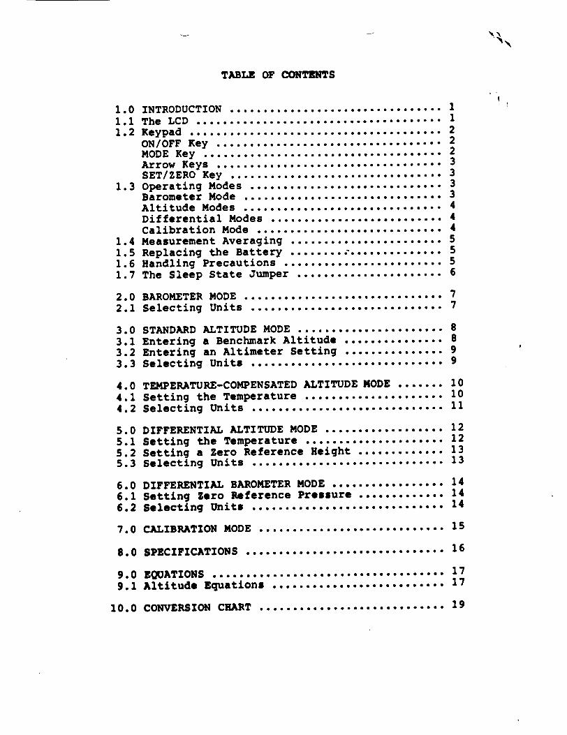
TABLE OF CONTENTS
1.0 INTRODUCTION ...................... ....... . 1 1.1 The LCD ..................................... 1 1.2 Keypad ...................................... 2
ON/OFF Key .................................. 2 MODE Key .................................... 2 Arrow Keys .................................. 3 SET/ZERO Key ................................ 3
1.3 Operating Modes ................ .............. 3 Barometer Mode .............................. 3 Altitude Modes ............................... 4 Differential Modes ................... ...... 4 Calibration Mode ..................... ........ 4
1.4 Measurement Averaging ....................... 5
1.5 Replacing the Battery ......... .............. 5 1.6 Handling Precautions ........................ 5 1.7 The Sleep State Jumper ...................... 6
2.0 BAROMETER MODE ................. ... .... 7 2.1 Selecting Units ................ .. . . . . 7
3.0 STANDARD ALTITUDE MODE . .................... 8 3.1 Entering a Benchmark Altitude .............. 8 3.2 Entering an Altimeter Setting ............... 9 3.3 Selecting Units ........ . ...... o............ ... 9
4.0 TEMPERATURE-COMPENSATED ALTITUDE MODE ....... 10 4.1 Setting the Temperature ..................... 10 4.2 Selecting Units ........ o......o.......... .... 11
5.0 DIFFERENTIAL ALTITUDE MODE .................. 12 5.1 Setting the Temperature ..................... 12
5.2 Setting a Zero Reference Height ............. 13 5.3 Selecting Units ............................. 13
6.0 DIFFERENTIAL BAROMETER MODE ................. 14 6.1 Setting Zero Reference Pressure ............ 14
6.2 Selecting Units ............................... 14
7.0 CALIBRATION MODE ................. ........... 15
8. 0 SPECIFICATIONS ............... ............... 16
9 .0 EQUATIONS ................................... 17
9.1 Altitude Equations .......................... 17
10.0 CONVERSION CHART ................. .......... 19
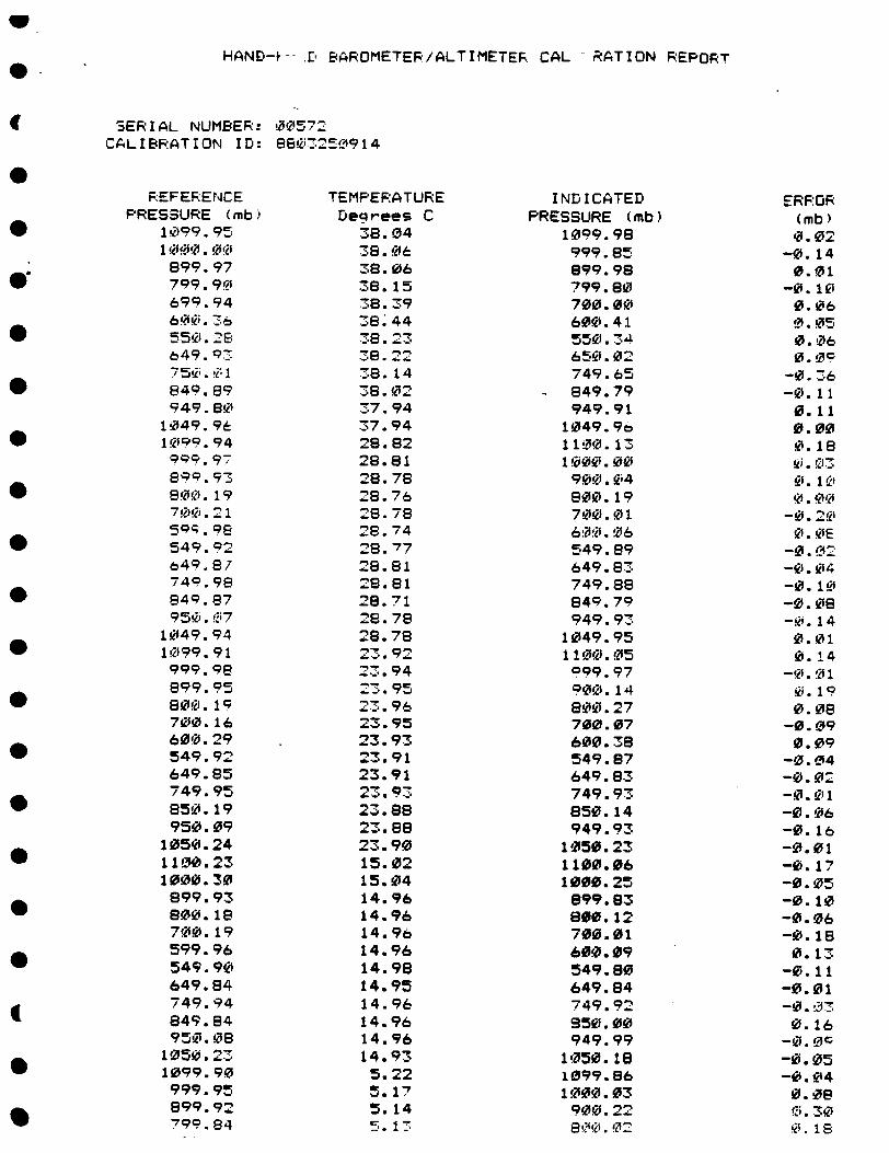
HAND-i- . BAROMETER/ALTIMETER CAL RATION REPORT
SERIAL NUMBER: 00572 CALIBRATION ID: 88'eJ'32914
REFERENCE PRESSURE (mb)
I 199. 95
899.97 799.9C) 699.94 600. 36 550.26 649.3 '7 750.!1 849.89 949.8S
1049.96 1099.94
89c?. 9-7 899.93
800. 19 700.21
549. 92 64 9 .87 749.98
849.87 950. E7
1049.94 If99.91 999.98e 899.95 800.19 7010.16 600.29 549.92 649.85 749.95 850.19 950.09
1050.24 1100.23 1000.30 899.93 800. 18
700.19 599.96 549.90 649.84 749.94 849.84 952.08
1050.23 1099.90 999.95 899.92 799.84
TEMPERATURE Deqrees C
38.04 3-8.06• 38. 06
38. 15 38.39 38.44
38. 2
38. 14 38. 02 "37.94 37.94 28.82 28.81 28.78 28.76 28.78 28.74 28.77 28.81 28.81
28.71 28.78 28.78 2.92 : 94 2.95 23. 96 2.3.95 23.93 23. 91 23.91 23. Q3 23.88 23.88 23.90 15.02 15.04 14.96 14.96 14.96 14.96 14.98 14.95 14.96 14.96 14.96 14.93 5.22 5.17 5.14 5.13
INDICATED PRESSURE (mb)
1009.98 999.85 899.98 799.80 700.00 600. 41 550. 34 650.02 749.65 849.79 949.91
1049.96 11.0.13 1000.00 900. 04 800.19 700.01 60.0.116 549.89 649.83 749.88 849.79 949.93
1049.95 1100.05 099.97 P00. 14 800.27 700.07 600.38 549.87 649.83 749.93 850.14 949.93
1050.23 1100.06 1000.25 899.83 800.12 700.01 600.*09 549.80 649.84 749.92 950.00 949.99
1050. 18 1099.86
1000.03 900.22~ 800. 02
ERFOR (mb) 0.02
-0. 14 0.01
-0. 1k 0.06 0. 05 0.06 0. 00
-0.3''6 -0. 11 0.11 0.00 0.18 •'. 1'CJ 0. 1.@ 0j.0
-020
0. OE -0. 02I1 -0. 04 -0. 10i -0.08 -0. 14 0.01 0b.14
0. 1 9 0. 08
-0.09 0.09
-0. 04 -0. 0Z -0. 0 1 -0. 06 -0. 16 -0.01 -0. 17 -0.05 -0. 10 -0.06 -0. 18 0.13
-0. 11 -0.01 -0•. o:1
0.16 -0. 0c -0.05 -1. 04 0.08 0. 138
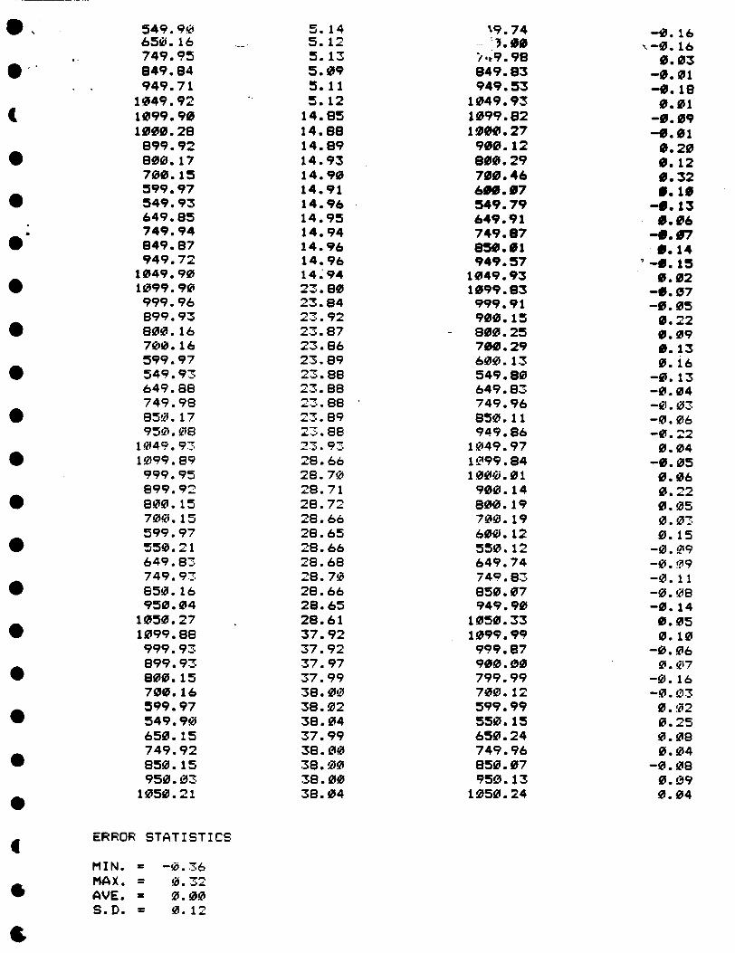
549. 90 650.16 749.95 849.84 949.71
1049.92 1099.90 1000.28 899.92 800.17 700.15 599.97 549.93 649.85 749.94 849.87 949.72
1049.90 1099.90 999.96 899.93 800.16 700.16 599.97 549.93 649.88 749.98 850.17 950.08
1049.9U 1099.89 999.95 899.92 800. 15 700.15 599.97 550.21 649.83 749.93 650.16 950.04
1050.27 1099.88 999.93 899.93 800.15 700.16 599.97 549.90 650.15 749.92 850.15 950.03
1050.21
ERROR STATISTICS
MIN. = -0.36 MAX. = 0.32 AVE. - 0.00 S.D. = 0.12
5.14 5.12 5.13 5.09 5.11 5.12
14.85 14.88 14.89 14.93 14.90 14.91 14.96 14.95 14.94 14.96 14.96 14.94 23.80 23.84 23.92 23.87 23.86 23.89 23.88
2 3.89 2."88 -,-. •23.9:3
28.66 28.70 28.71 28.72 28.66 28.65 28.66 28.68 28.70 28.66 28.65 28.61 37.92 37.92 37.97 37.99 38.00 38.02 38.04 37.99 38.00 38.00 38.00 38.04
%9.74 3 *.00
/.19.98 849.83 949.53
1049.93 1099.82 1000.27 900.12 800.29 700.46 6W.07 549.79 649.91 749.87 850.01 949.57
1049.93 1099.83 999.91 900.15 800.25 700.29 600.13 549.80 649.83 749.96 850.11 949.86
1049.97 1099.84 1000.01 900.14 800.19 700.19 600.12 550.12 649.74 749.83 850. 07 949.90
1050.33 1099.99 999.87 900.00 799.99 700.12 599.99 550.15 650.24 749.96 850.07 950.13
1050.24
-0.16 ",-0. 16
0.03 -0.01 -0. 18 0.01
-0.09 -0.01 0.20 0.12 0.32 0.10
-0. 13 0.06
-0.97 0.14
'-0. 15 0.02
-0.07 -0.05 0.22 0.09 0.13 0.16
-0.13 -0.04 -0.03 -0.06 -0.22 0.04
-0.05 0.06 0.22 0.05 0.03 0.15
-0. 09 -0. 09 -0.11 -0.08 -0.14 0.05 0.10
-0.06 0.07
-0. 16 -0.03 0.02 0.25 0.08 0.04
-0.08 0.09 0.04

IS U C S C S '5 S U
2i
iii '12. loll
'p
I1
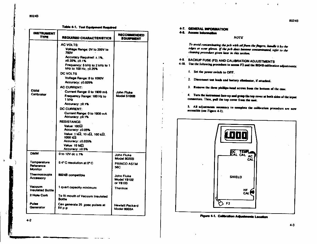
80248
INSTRUMENT TYPE
0MM Calibrator
DMM
Toab* 4-1. Test Equipmenl Required
Temperature Reference Monitor
Thermocouple Accesory
Vacuum Insulated Bottle
2 Hole Cork
Pulse Generator
RECOMMENDED REQUIRED CHARACTERISTICS I EaUIPnsi
I
AC VOLTS: Voltage Range: 0V to 200V to ?G0V Accuracy Required: *.1%. *0.35%. ±0.1% Frequency: 5 kHz to 2 kHz to 1 kHz to 100 Hz. t0.25%
DC VOLTS Voltage Range: 0 to 1000V Accuracy: ±0.025%
AC CURRENT: Current Range: 0 to 1900 mA Frequency Range: 100 Hz to 1 kHz Accuracy: ±0.1%
DC CURRENT: Current Range: 0 to 1900 mA Accuracy: 10.1%
RESISTANCE: Value: 1000 Accuracy: t0.05% Value: 1 kh, 10 141, 100 kO, I0OW kfl Accuracy: t0.025% Value: 10 M11 Accuracy: 10.5%
0 to 12V dc t.1%
0.4" C resolution at 0° C
8W48 compatible
1 quart capacity minimum
To fit mouth of Vacuum Insulated softle
Can generate 25 psec pulses at 5V p-p
John Fluke Model 51009
John Fluke Model 80208
PRINCO ASTM 56C
John Fluke Model Y8102 or Y8103
Thermos
Hewlett Packard Model 8003A
4-2P go n 4-1. Cabral el n As uegpa m- a Le cal- _ ,
4-3
4-7. GENERAL UMPOMATION 41-. Acmes hiernsben
NOTE
To avoid cofsme-bw de prb wkh oiltM 1A te jlrWM hemdb i by the eders or urn g lows. If oshe peb �m eau-e wunwse4 refer 1o 1he ck.ming procedre Sgiem lr linle ttic.m
4-9. BACKUP FUSE (F2) AND CALIBRATION ADJUSTMENTS 4-10. Use the following procedure to mm F2 mad the 11024 calibration adjutmets:
I. Set the power seitch to OFF.
2. Disousect t eads mud baad be l dimiao, if attsched.
3. Remove the thm philips-head c sm fro the bottoam ad the can.
4. Tuo the ilnasu mea bce-up and pp tdo top we. at hah sides of the impe coamectors. Then. pul the top cover from lik unit.
5. AN adjmmems Mem ry to Compplete the calibration procedure are now accessible (an Fipure 4-1).
8024B

I, &2•48
4-11. PC9 4-12. The• ae two PCi a•umblie, Mais and Switch. Ue the foloWin Wcedure to remove the Main PCB Assembly from the cane:
I. Camplete the Calibratiom Adjustmeins ccess procedune
2. Remme the rew from the shild covering the aemembly. 3. Using your index inger, k up the ower rgth a mnd coner of te p•b Mtil it is free. The pal the pcb to the right umii it dean the sdhf under te biutto. 4. Reasmble in the logical revese order.
NOTE
Mam bmaidift sheb. route b••ery-cD, 1 Ar &*e d dhe pew on dt k1. hind •dad fi bottom ow. Abo m'el awe dt Mrrm *wevaobkep~ locted bk•h d rth e aw a6*ch pwhhbuw 6 properly eimad in thI bottomiems.ad tA th ga pwow-wd v q Is n& m uaos 5 u th peuw
4-13. DISPLAY ACCESS 4-14. RIler to Fgure 4-2 mad the following procedure to remove/repl-re the LCD assembly.
I. Remove the Main PCI Assembly using the PCIB amce procedure I Place your thumbs on either side of the display lens and carefully push the lens out of the LCD bracket.
3. Turning LCD bracket upside down gently tap into your palm. LCD shouldfall out.
NOTE
Pa.M buteils tlhe LCD makgt certak tha tr fles surfer. isferbng out snd Ua coenestor pattern & on sop of and makes conact wlk the flexibk layered connector.
4-15. LSI (US) ACCESS 4-M6 Use the following procedure to remove/replace the a/d converter and display driver IC, Us:
I. Remove the pb ambly using the PCB access procedure. 2. On the bottom olthe pcb locate and remove the two phillips-head screws from the display -ssembly.
4-4
4-5
a
3. LMk hes disply "asse•l from the pel to aupe Us.
puee f "I Mk lo b Ibb "adlem Niqw TIOmble OiMS baes
POft~ftInsn gleesion e toples sam u t&,Teutsetgm bt 4. Un a smu - or a emomble siubsthLue to rock (by prying up on each end of th IC) the IC ot of its socket.
S. When imtalming Uo make swe al pins are lined up in the socket, and then pre
Us carefully into phw..u ntesceadte rs 4-17. C "sang
CAMMu cMumo"
D.' nu me m a*mw • mm hrtm~ig. Thss
Do aer ft" arl diplay to eh. to m ei et a motnte. I n p e eha • qP w ma m b Ip1b iu w u ll i . . a i d . n I l l l b o w k * m u e . bop m boss- t,, . ...
1q
ft " C 11111FAmmm ,My
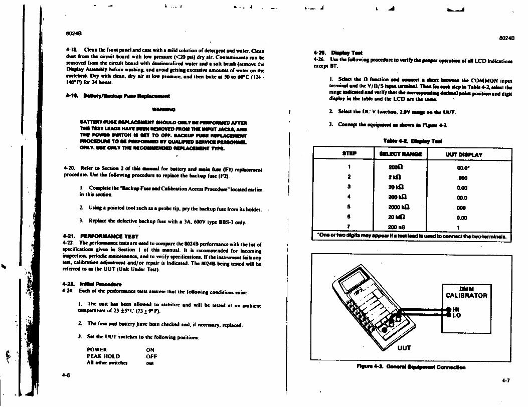
L A
4-18. Clean the front panel and case with a mild solution of detergent and water. Clean dust from the circuit board with low pressure (<20 psi) dry air. Contaminants can be removed from the circuit board with demineralized water and a soft brush (remove the Display Assembly before washing, and avoid etling excessive amounts of water on the switches). Dry with dean. dry air at low pressure, end then bake at 30 to 609C (124 140-F) for 24 bows.
4-Io. 11aoM'vekdw UFse Ropl-mo nl
WAUENG
*ATTINIPIUSE WACEEUN SHOULD ONLY S PRFORMED AFTSR THE TEST LEADS HAVE 100 NREMOVED MO THE INPUT JACKS. AND THE POWER SWITCH S SET TO OFF. BACKUP FUN REPIACEMEiIT PRiOCEDUIRE TO PIEROw MEo T O1mya PLND SERVICE PIRNOWNNL ONLY. UM ONLY THE RECOMiNDED REPLACIMENT TYPE.
4-20. Refer to Section 2 of this manual for bettery and min fuse (FI) replacement procedure. Use the folowing procedure to replace the backup fuse (F2).
I. Complete he "Backup Fuse and Calibration Access Procedure"located earlier in this ection.
2. Using a pointed tool such as a probe tip. pry she backup fuse from its holder.
3. Replace the defective backup fuse with a 3A, 600V type BBS-3 only.
4-21. IPERFORMANCE TEST 4-22. The performance teats are used to compare the 3024B performance with the list of specifications given in Section I of this manual. It is recommended for incoming inspection, periodic maintenance, and to verify specifications. If the instrument fails any test, calibration adjustment and/or repair is indicated. The 8024B being tested will be referred to as the UUT (Unit Under Teat).
4-2& hilEd Procedure 4-24. Each of the performsance tests assume that the following conditions exist:
I. The unit has been allowed to stabilize and will be tested at an ambient temperature of 23 ±5°C (73 ± 91 F).
2. The fuse and battery )have been checked and, if necessary, replaced.
3. Set the UUT switches to the following positions:
POWER PEAK HOLD AN other switches
ON OFF out
80248
4-25. Dlephy Teat 4-26. Use the following procedure to verify the prope operation of all LCD indications except BT.
I. Select the f0 function and cousact a sebo between the COMMON input termiuaal and the V/fl/S input terminal. Thea fr seaeh sep in Table 4-2. select she range indimted and verify that the cmrresponding deemnal point position and digit display in the table and the LCD ae the some.
2 Seect the DC V function, 2.OV mae on the UUT.
3. Connes the equipment as dlowa in Figure 4-3.
Tobe 4-4 0I1pl-y Teo
"Oneor two d•igt. may appoe I a tet lead Is used to omnect the tweteornmnas.
Ngur "-• -Gee Eqasp Coeaeon4-6
4-7
STEP SEC RaCNG UUT DISMPLA
2aof oo.o"
2 2hfk .000
3 20ka 0.00
4 200kfl 00.0
s 2100 kfl 000 0 20 Mn 0.0o 7 200 n8 1
I 2
'I
I
80248
& - J . - L- J
r
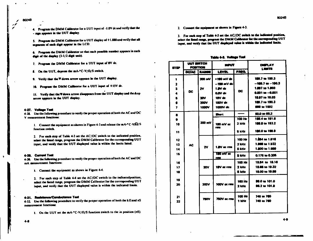
80248 80248
f ,'-p
4-27. Vo~tge Ted 4-28. Use the following procedure to verify the proper operation of both the AC and DC V measurement function:
I. Conne: the equipment as shown in Figure 4-3 and release the mA-* C-V/CI S function switch.
2. For each step of Table 4-3 at the AC/DC switch to the indicated position, select the ialed mar, program the DMM Calibrator for the corrponding UUT input, and verify that the UUT displayed value is within the limits listed.
4-20. Cuwusd Ted 4-30. Use the following procedure to verify the proper operation of both the AC and DC
mA measurement functions:
I. Comnem the equipment a shown in Figure 4-4.
2. For each step of Table 4-4 set the AC/DC switch to the indicatedposition. select the listed range. progpam the DMM Calibrator for the corresponding UUT input, and verify that the UUT displayed value is within the indicated limits.
4-31. WCotm ae. Tedl 4-32. Use the followiag procedure to verify the proper operation of both the k (land nS measurement functions:
I. On the UUT set the mA-oC-V/fl/S function switch to the in position (nS).
4-8
4. Proormi the DMM Calibrator for a UUt input of - L.0V dc and verify that the
- sip appeats i the UUT display.
S. Propas tie DiM Calibrato for a UUT display of + 1.888md vrify tht a
segmeats of each digit appear.m the LCD.
&. Progpam the DMM Calibrator so that each possible number appears in each
digit of the display (3-1/2 digit unit).
7. Proora the DMM Caiibrator form UUT input ofV dc.
8. On the UUT. depreas the mA-oC-V/fllS switch.
9. Verify that theV dowm arrow appears im the UUT display.
10. Progpam the DMM Calibrator for a UUT input of +1SV dc.
I. Verify that the*Vdown arrow disappears from the UUT display and theAup
arrow appears ia the UUT display.
2. Conma te equ merm as sow. in Figure 4-3.
3. For emah sue of Tabl 4-.a thes AC/DC wIilbM todo indiet positimo. sel the Mood naok prgrams the DMM Calibmar for the eonupodmui UUT input. and verily that the UUT disld umhls b ladisied •mits.
Tl. 44 V ON Ted
ITr mTCH winV OMW V ST1Ip POULTnl
WDC LEVIL Fna .___ _
1 200 WV +190 mV dr 199.7 to 190.3
2 --190 myV d --1.7 to -190.3
3 D 2Vd D I@7 to S1.0
4 DC e do DC 0.001 to -0.001 6 20V 19V do 1927 to IJ•03
6 2RV 190V di 1N.7 to 190.3
7 IOOV 100I V d M to 1002
a short - 00.0Io00.2
9 100Ho , IUA to 19 A
10 200 mV 0 -,mc 2 klz IA. to 193.2 row
1 5 kHz* 1N.0 to 190.9
12 100HE IA84 to 1.916
13 AC 2 kMslz A.0m tIA.932
14 V Ig ms 6k1 10 1 1W10tIs"
5 kHz 0.175 ts0o 0
16 100HE B1M84 to 19.16
17 2WV 1iV W Fm. 2kdz Is 11 to 19.32
1 5k I 18.00 to 1929
19 10011 W00s 101.0
20 20WV W10V at M 1Hto101.0 2 id4: 98.20to10120
21 lW 1001 740 to 0
21 1 kHz 7402070
4-9
a I
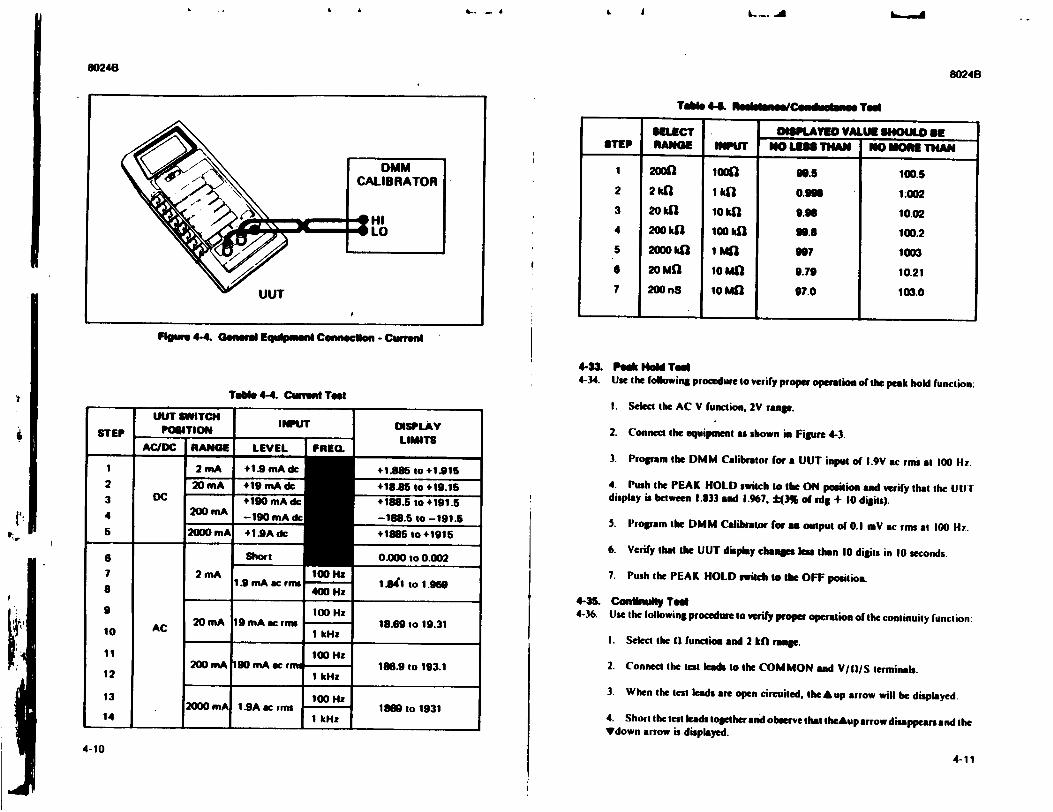
4- - 6 L A
8024B 6024B
T41i1 4-4. R- ----- CIeg-e-eNN Ted
Figues 4-4. Generdl Equlpuen Connecdon - Currn
Tabl 4-4. Cufrent TeOM
UUT SWITCH POSITION
AC/DC RANGE I
INPUT
LEVEL I FREQ. 1I 2nA 1 +1.9 mA dle 2 20mA +19 mA dc
3 DC +190 mA dh 4 20DmA -g0 mAd 5 2000 mA +I_.9Adc
AC
2 mA
Short
1.9 mA ac rms100 1.
400 Hz
DISPLAY LIMITS
+1B86M to +1,915
+18.85 to +19.15
+188.5 to +191.5
-188.5 to -191.6
+1615 to +1915
0.000 to 0.002
1 Awl to 1.960
100 Hz 20 mA 19 mA acf r -s 18.69 to 19.31
1 kHz
100 Hz 200 mA 190 mA ac r m - 196.9 to 193.1
1 kHz1
100 Hz
I kHz1860 to 1931
4-33, Peak Hol TeM 4-34. Use the following procedure to verify proper operation of the peak hold function:
I. Select the AC V function, 2V ramp.
2. Conned the equipment as shown in Figure 4-3.
3. Program the DMM Calibrator for a UUT input of 1.9V ac rms at 100 Hz.
4. Push the PEAK HOLD switch to the ON position and verify that the UITJdisplay is between 1.833 and 1.967, :(3% of rdg + 10 digits).
5. Program the DMM Calibrator for an output of @0.1 mV ac rms at 100 H.
6. Verify thot the UUT display champs less than 10 digits in 10 seconds.
7. Push the PEAK HOLD switch to the OFF position.
4-3S. Conlinull Tedt 4-36. Use the following procedure to verify proper operation of the continuity function:
I. Select the II function and 2 khE rangle.
2. Connect the test leads to the COMMON and V/il)/S terminals.
3. When the test leads are open circuited, the A up arrow will he displayed.
4. Short the test leads together and observe that theAup arrow disappears and the Ydown arrow is displayed.
4-11
SELECT DISPLAYED VALUE SHOULD gE STEP RANGE INPUT NO LESS THAN NO OSE 11THAN
1 2000 10o 90.5 100.5
2 2 kQ I kO 0.911 1.002 3 20 ki, 10 ko 9.96 10.02 4 200 k11 100 kh 99.3 100.2 5 2000 k11 IM 997 1003
6 20 Mf1 10 IM 9.79 10.21
7 200 nS 10 11 97.0 103.0
STEP
6
7
8
9
10
11
12
13
142000 mA
4-10
I .A ac rim
& A L.- -A
II
I I
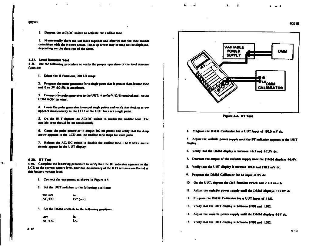
I I L. - A
80248 60248I S. Depress the ACIDC switch to activate the audible tone.
6. Momeatarily short the No leads together and observe that the tone sou$s coincident with thie down arrow. TeA•up arrow may or may.no te dispayed. depending on the duration of the short.
4417. Lewd n 1 bI@ Ted 4-38. Use the following procedume to verify the proper operation of the level detector fiuction:
I. Seect the fl fuctions, 200 kG mran.
2. Progpam the pulse nerator for a uingle pulse that is greater than 0 uteo wide and 0 to 3V :0.5% in amplitude.
3. Commecttepubseeneratortothe UUT: +totmeVVfkIS termialand -tothe COMMON terwmiaL
4. Cause the pulse gmerator to output single pubes aid verify that theAup arrow appears momentarily in the LCD of the UUT for each sinml pulse.
S. On the UUT depress the AC/DC switch to enable the audible towe. The audible tone should he on cointiuously.
6. Cause the pulse lenerator to output 500 in pules and verify that the A up arrow appears in the LCD and the audible tone stops for each pule.
7. Release the AC/DC switch to disable the audible tone. The Ydown arrow should appear in the UUT display.
4-3m. BT Tedo 4-40. Complete the following procedure to verify that the ST indicator appears on the LCD at the omct battery level. and that the accuracy of the U-T remains unaffected at this battery voltage level:
I. Connect the equipmet as shown in Figure 4-5.
2. Set the UUT switches to the following positions:
20 mV in AC/DC DC (out)
3. Set the DMM controls to the following positions:
20V in AC/DC DC
4. Prouam the DMM Calaibrtor for a UUT input of 190.0 mV dc.
S. Adjust the varib power supply util the ITladiwotr appears im the UUT display.
6. Verify that the DMM display is betwuee +6. aid +7.3V dr.
7. Decrease the output of the variable supply until the DMM displays +4.0V.
1. Verify t the UUT display is bhemm 18.8 and 190.2 mV dc
9. Program the DMM Calibrator for aa imput of OV dc.
10. on the UUT. deprem the 0I/S fuauts switch and 2 kh switch.
II. Adjust the variable power supply ainl the DM M displays +-10.OV dc.
12. Propanm the DMM Calibrator fmr aUUT mpult of I kiL
13. Verify that the UUT display is betweeI 0.99 and 1.002.
14. Adjust the variable power supply umil the DMM displays +6V dc.
IS. Verify that the UUT display is between 0.9ll aid 1.002.
4-124-13
Rsp 44L BT Tog
11
L. A k -

L
80248
4-41. Tempmukm Toot WARNING
DO NOT PERFORM THIS PROCEDURE IF THE TIP OF THE THEROMOCOUPLE ACCESSORY HAS SEEN EXPOSED TO TOXIC MATERALS. INSTEAD USE THE ALTERNATE PROCEDURE DESCRIBED B. THE FOLLOWING CALIBRATION ADJUSTMENTS PROCEDURE.
4-42. The following procedure takes advantage of the inherent stability of human body temperature to verify proper operation of the *C temperature function. If there is amy doubt about this procedure, if the thermocouple tip has been exposed to toxic materials, or if extremeaccuracy ofimeasurement is desired, use (as& reference) the lag bath described in the *C Adjustment procedure in the following Calibration portion of this section.
I. Depress the TEMP 'C range switch and release the fl/S switch on the UUT.
2. Connect the John Fluke thermocouple accpsory to the UUT.
3. Wipe the tip of the thermocouple accessory dean and place the tip between your thumb and index finger until the UUT display readings stabilize,
NOTE
Normal body temperetwe of hunos is 37-C (98.6- FA
4. Verify that the UUT display is between 34 and 390C.
4-43. CALIBRATION ADJUSTMENTS 4-44. Under normal operating conditions the 10240 should he calibrated once every two years to maintain the specifications given in Section I of this manual. If your 80249 has been repaired or if your 80243 has failed any of the Performance Tests, immediate calibration is indicated. Test equipment needed for the calibration adjustment is listed in Table 4-1. If the test equipment is not available, your nearest John Fluke Service Center will be gliad to help. A list of these centers is liven in Section 5 of this manual. For verification, complete the Performance Tests after the calibration adjustments are made. The 10240 beingcalibrated will he referred to as the UUT (Unit Under Test).
4-45. Use the following procedure to perform the calibration adjoatments:
I. Allow the UUT to stabilize for at least 30 minutes at an ambient temperature of 21*C to 2..C (70OF to 77F).
2. Complete the calibration access procedure presented earlier in this section.
3. Select the DC V function. 200 mV range on the UI I.
4. ('onnect the equipment as shown in Figure 4-3.
5. Program the DMM Calibrator for a UIJT input of +190.0 mV dc.
8024B
6. Adjust the DC CAL (R6) for a UUT display of exactly 199.0.
7. Connect a jumper acros QO0.
S. Push the PEAK HOLD switch to the ON position.
9. Adjust RI7 (Peak Hold offset) for a U(T display of exactly 190.0.
10. Remove the jumper from across Q 10.
II. Push the PEAK HOLD switch to the OFF posiion.
12. Connect the equipment as shown in Figure 4-3.
13. On the UUT. deprms the AC/DC switch.
14. Programlhe DMM Calibratorfora UUTinputof 190.OmVacrmsat 180Hz.
IS. Adjust the AC CAL (R4) for a UUT display of exactly 190.0.
16. On the JUT, depress the 2V range.
17. Program the I)MM Calibrator for a UUT input of 1.9V ac rms at 5 kHz.
1. Adjust the HF CAL (CIO for a UUT display between 1.105 and 1.995.
19. Establisha log bath (ice point environment) as shown in Figure 4-6 and allow the lag bath to sit for 30 minutes to reach thermal equilibrium.
20. Connect the Thermocouple Accessory to the UUT.
21. Adjust theTEMPCAL(RI0)for& UU'I displaythesmeastheIemperature Reference Monitor reading.
4-46. TROUBLESHOOTING CAUTION
Stale dlsdss eIas damage MOS smmpaaela s conined In We IM64. Avoid Imnkumast dasmae by .emp" lng wIthe promaum. en the Stale Awareness sheit whon tal.shee" O rleg spoidag son O643.
4-47. Never remove. install. or otherwise connect or disconnect components without first turning the 8024B POWER switch to OFF.1 able 4-6 is a troubleshooting guide for the 10248. 1 o properly use the guide, complete the performance tests given earlier in this sect ion and note any discrepancies. Then locate the heading of the procedure in question in the Test and Symptom column (1 able 4-6). Under that heading isolate the symptom that 'approximates the observed malfunction. Possible causes are listed to the right of the selected symptom. Details necessary to isolate s particular cause can he derived from the "1 heory of Operation in Section 3 and the schematic diagrams in Section 7.
4-144-15
A a - A

L. .A ... I
8024B
TErT ANID SYWTOU POS•I.E CAUSE
INITIAL PROCEDURE ST Is displayed when unit Is turned on Low battery volage. U1SC. UT, (see ST procedure aleo). Note. ST will U1 normaly be displayed for some ie voltkgs when lIe l ine elminator accesmory Is used.
Display blank. Dead battery. POWER switch (S1). VR2 shorted. US. J5A
DISPLAY TEST One or more segments wil not Nght Display Intrconnection. Display through entir test. (US)
US Decadenperallm or one or more• el. US mn-i syh,, IL
Improper decimal point Indliaon. Check aignise at U7. Are they OK?
YES: Display (US).
NO: Range switches or Interconnod.
Minus sign Improper•y displayed. us Display it but dose not respond to PEAK HOLD switch Is at the ON changes In Input. position (if you pushed toward
the lft to set the PEAK HOLD switc to the OFF position, the swaitc is Ma11 lat the ON position). VRI. U. Yi. •CS horted. or knterconnet.
VOLTAGE TEST DC: Display reading Is out of tolerance DC CAL (RI1) out of calibration. on 200 mV range. VR1
Us Us, so Display readinge out of tolerance on U1. U2. U3 all ranges except 200 mY.
AC: Display reading out-of IOlernce AC CAL (R4) out of calibration. on the2Vrange with I.gVac rms, 5 kHz. AC Converter Input.
Display readings out of tolerance on U1 all ranges except the 200 mV range. Ingre" -. Lg Mat,
4-164-17
• ._j
80248
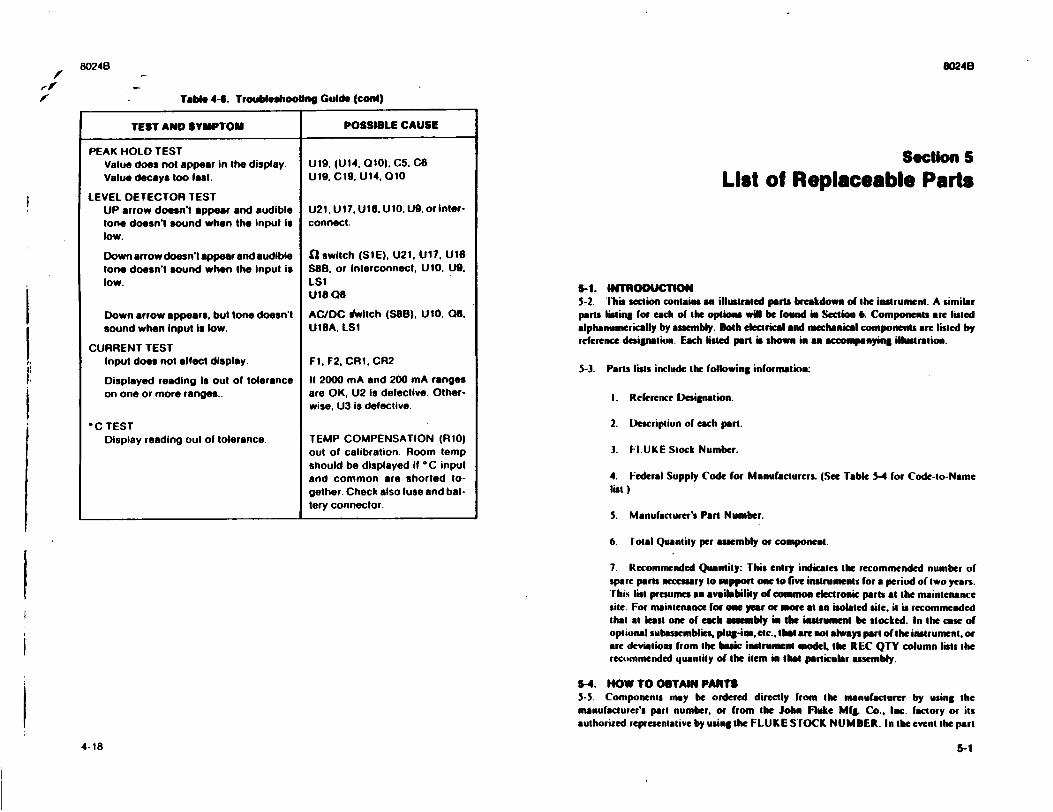
80248
,v-
4-18
Table 4-S. Troubleshooting Guide (coal)
TEST AND SYMPTOM POSSIBLE CAUSE
PEAK HOLD TEST Value does not appear in the display. U19. (UI4. 010), C5. C6 Value decays too last. U19, C19. U14, 010
LEVEL DETECTOR TEST UP arrow doesn't appear and audible U21. U17, U16. UIO, U9, or intertone doesn't sound when the input is connect. low.
Down arrow doesn't appear and audible 0 switch (SIE), U21, U17, U16 tone doesn't sound when the input is S88. or interconnect. UIO. U9. low. LS1
UIS as
Down arrow appears, but tone doesn't AC/DC dwitch (S88). UlO, 06, sound when input is low. U18A, LS1
CURRENT TEST Input does not affect display. Fl. F2, CRI. CR2
Displayed reading is out of tolerance If 2000 mA and 200 mA ranges on one or more ranges.. are OK, U2 is defective. Other
wise, U3 is defective.
"C TEST Display reading out of tolerance. TEMP COMPENSATION (RIO)
out of calibration. Room temp should be displayed if *C input and common are shorted together. Check also fuse and battery connector.
Section 5
List of Replaceable Parts
5-1. INTRODUCTION 5-2. l'bis section contain an illustrated parts breakdown of the instrument. A similar parts liming for each of the optios will be found is %cclion 6. Components are listed alphanumerically by assembly. Both electrical and mechanical components are listed by reference designation. Each listed part is shown in an accompanying illustrafion.
5-3. Parts lists include the following information:
I. Reference Designation.
2. Description of each part.
3. F.UKE Stock Number.
4. Federal Supply Code for Manufacturers. (See Table 5-4 for Code-to-Name list.)
5. Manufacturer's Part Number.
6. Total Quantity per assembly or component.
7. Recommended Quantity: This entry indicates the recommended number of spare parts necessary to support one to five instruments for a period of two years. This list presumes an availability of common electronic parts at the maintenance site. For maintenance for one year or more at an isolated site. it is recommended that at least one of each assembly in the instrument be stocked. In the case of optional subassemblies, plug-ins, etc.. that are not always part of the instrument, or are deviations from the basic instrument model, the REC QTY column lists the recommended quantily of the item in that particular assembly.
5-4. NOW TO OBTAIN PARTS S-S. Components may be ordered directly from the manufacturer by using the manufacturer's part number, or from the John Fluke Mfg, Co.. Inc. factory or its authorized representative by using the FLU KE STOCK NUM BER. In the event the part
5-1
8024B
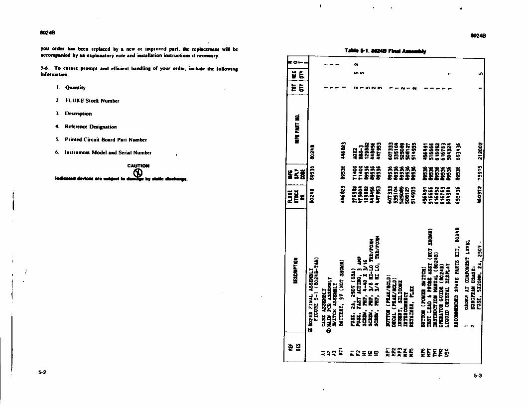
SM48 $0248
you order has been replaced by a new or improved part, the rcplacement will be accompanied by an explanatory note and installation instructions if necessary. 5-6. To ensure prompt and efficient handling of your order, include the following
information.
I. Quantity
2. FLUKE Stock Number
3. Description
4. Reference Designation
5. Printed Circuit Board Part Number
6. Instrument Model and Serial Number
CAUTION
khtoad d device w aubled e r by sle dlmching.
Table 5-1. llU Find Agealf
0=0--
m m
d cU
IU
U- .
W% -In
WN
- P-Inmn -- OS-ft t- --r
~;It Vea- --
X in' 40-- a fn k
*0 An f
21 f~t A %a w- n 1
46 AV. II. AV 2VU' * !*'
Am - 4Id0
got P.- :48
~ 12
5-25-3
I
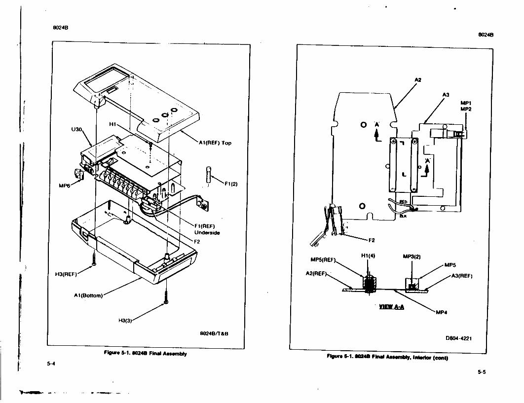
8024B
80248
Figure 5-1. 10248 Final Assembly
D804-4221
Floure 5-1. U14U Final Assembly. Inedor (cant)5-4
5-511
80248
!
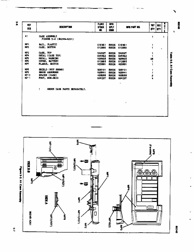
1! 'I. t.1
I
'I, -4
!REF FLUKE MG TiT NiEC 0 f.mPTmi STOCK PULY II PURT 1O. DESNo CODE IpTy T
Al CASE AS•SN]LY 1 FIGURE 5-2 (60248-4201)
MPI BAIL, PLASTIC 616961 89536 616961 NP2 CASE, BOTTOM 613950 89536 613950
3P3 CASE, TOP 542027 09536 542027 1 3104 DECAL (CASE TOP) 604062 69536 604462 1 I(P5 DECAL, WARNING 428938 69536 026936 Alt m"6 COVER, BATTERY 613968 89536 613968 1 3(17 FLANGE, SWITCH 455881 89536 558681 1
MP8 SIELD (NOT SUOWN) 508101 69536 506101 1 3(9 MOCK A33013ER 028441 89536 426041 1 3(plo SPACER (CASE) 450588 89536 458588 2
FP, FOOT, NON-SXID 604397 59536 604397 4
1 ORDER CASE PARTS SEPARATELY.
wu
I

O, REF FLUKE MF G TOT NEC N DEF OESCNIPTION STOCK SPLY iF. PART NO. 0
DES NO. CODE OTY QTy T
A2 MAIN PCB LSSEMBLY ORDER ONLY AT COPFONENT LEVEL REF FIGURE 5-3 (8024A-4011/40115)
C5 CAP, CER, 0.22 OF */-20%, 50V 519157 51406 RPI111ZS224MSOV I C6 CAP, POLY, 0.047 OF ./-10%, 100V 446773 89536 446773 2
C7 CAP, CU., 500 PF */-110%, iKV 105692 71590 2DDU6ONSOIK 2 C8 CAP, POLYPROP, .047 OF ./-10%, 100V 446773 89536 446773 37 8' C9 CAP, POLY, 0.10 OF ./-10%, 10OV 446781 89536 446781 1 ' C1o CAP, AL. ELECT, 22 UF ./-20%, 16V 614750 89536 614750 1 Cll CAP, MYLAR, 0.22 OF +/-10%, IOOV 436113 73445 C2801AB/L220K 1
C12 CAP, CER, 500 PF +/-110%, 1KV 105692 71590 2DDH60N501K REF C13 CAP, MICA, 150 PF +/-5%, 500V 148478 72136 CM15F151J 1 C14 CAP, MYLAR, 0.0220U ./-10%, 400V 369165 73445 C281A/A22[ 2 0 C15 CAP, MTL, .022 OF ./-10%, 400V 369165 73445 C281A/A229 REF C19 CAP, POLY, 1.0 UF +/-10%, 50V 615427 84411 14630W-1.0-10P-SOV 1
C20 CAP, CER, 0.01 OF +/-20%, 1001 407361 72982 8121-A1OO-WSP,-103M 2 C21 CAP, CER, 0.01 OF */-20%, 1OOV 407361 72982 8121-AOO-W5N-1034 REF C24 CAP, CI., 470 PF +/-20%, IOOV 358275 72982 8141-AlOO-WSR-471M I CR1 DIODE, S: 3417559 141099 1N54100 2 1
CR2 DIODE, :: 347559 14099 151400 REF
CR8 DIODE, HI-SPEED SWITCHING 203323 07910 IN4448 1 1 J14 JACK, DC POWER, PC MOUNT 423897 89536 423897 1 J5 CONTACT AS-SDBL! 535278 69536 535278 1 J6 WIRE AS LY (RED) 516088 89536 516088 1 J.T WIRE ASSE3BLY (BLI) 516070 89536 516070 1
NEF FLUKE !I M TOT NEC 0N DES OECNIPTON STOCK SPLY MR PART U. 11 DES no. CODE OTy qTy T
1.51 TRANSDUCER 513101 89536 513101 1 UPi FUSE CAP 540716 89536 540716 1 MP2 FUSE CLIP 534925 89536 534925 1
•MP3 FUSE CLIP 535203 89536 535203 1 MP4 SPRING, FUSE (USA) 535211 89536 535211 1
MP6 INSULATOR (NOT SHOWI) 175125 89536 175125 1 MT SPRING, FUSE (KUROPIAI) 535229 89536 535229 1 Q3 3.73, si, UN 168716 07263 319254 1 1 08 ZST", SIp1 195974 04713 2113906 1 1 Q1O ISTIt, J-flT 357905 89536 357905 11
Ri as, COmP, 1001 ./-10%, 1V 109397 01121 031041 1 R2 3ts, WVr 1000 */-10%, aV 474060 89536 474080 1 R5 US, IM. C.U, IN 1-5S%, 1/4W 348987 80031 C2251-4-SPIN 3 m6 U. VAR. 500 +/-10%, 0.5V 417730 09536 447730 1 R8 RIS, DIP. CR, 220K ./-S, 1/4V 348953 80031 C1251-4-"F220K 2
R10 R1S, VAR, 5 .+/-10%, 0.5V 478883 89536 4t8863 1 313 3US, COMP, ION */-5, 1/4 194944 01121 C31065 3 314 3us, CO"P, ION */-5S%, 1/4V 19944 01121 CR1065 A1f 116 3ES, DEP. CAN, 2201 */-5%, 1/4W 348953 80031 C251-4-5P220[ w 1 117 113, VAR, IN */-10%, 0.5V 461343 89536 461343 1
R20 R33, DEP. CAR, 30K ./-5%, 1/4W 368753 80031 C1251-4-5r30[ I 321 33S, DIP. CAR, 2[ */-5S%, 1/4W 441469 80031 C1251-4-512[ I 122 US, DEP. CAR, 101 +/-5%, 1/4W 348839 80031 Cl251-4-5P10[ 1 124 RES, COUP, ION */-5%, 1/4 194944 01121 CB106S 331 R25 RES, DEP. CAR, 1001 +/-5%, 1/4W 348920 80031 C1251-"-SPI1O 1
w
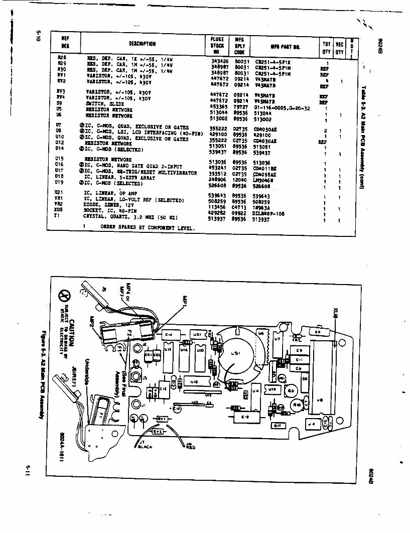
)E FLUm`TONKE MFG ' BE$ DESC rTI STOCM PILY 4F6 PUT * TOT I NECo0 NO. CUOEOT TT A28 I1R, DSP. CAR, I1 K/-55, 1/4W 343426 60031 C2251-45pI 1K R29 I31, DEP. CAR, 1i M/-5%, 1/4W 348987 80031 C1251-4-5PIH REF 130 3M1, DEP. CAR, 1M +/-5%, 1/4W 348987 80031 Ct251-4-SP1N R" 1V1 V1ItSTOR, +/-10- , 430V 447672 09214 V143NAT 41 RV2 VARLItSOR, +/-10%, 430V 447672 09214 VI43NA7B It
RV3 VARIT3OR, +/-10O, 430V 447672 09214 143NATS W 114 VARItSTOR, ./-10%, 430V 144672 09214 "3rA 3 S9 SWITCH, SLIDE 77 091 3N137Ej U5 IMISTCH MMODE 453365 79727 01-116-0005,.-20-32 1 U6 RESISTOR IETWORK 513044 89536 513044 US RI.STOR NEJVORK[ 513002 89536 513002 1 07 D0IC, C-NO., QUAD, EXCLUSIVE OR GATES 355222 02735 CD4030AE 2 1 ! U8 0 IC, C-MS, LSI, LCD INTERFACING (40-PIN) 429100 89536 429100 1 1 010 1IC, C-NOS, QUAD, EICLUSIVE OR GATES 355222 02735 C04030At REF 012 RESISTOR NETWOK 513051 89536 513051 1 014 01C, C-NOS (SELECTED) 539437 89536 539437 1 015 F3513TOR NETWORK 513036 09536 513036 1 U16 MIC, C-MOS, MAND GATE QUAD 2-INPUT 453241 02735 CD4011BE 1 1 017 MIC, C-lOS, RE-TRIG/RESET MULTIVIBRATOR 393512 02735 D4098A0E 1 018 IC, LINEAR, 5-1STR ARRAY 248906 12040 LX304611 1 U19 0IC, C-NOS (SELECTED) 526608 89536 526608 1 1 021 IC, LINEAR, OP AMP 539643 89536 539643 1 VR1 IC, L]I]nE , LO-VOLT REF (SELECTED) 508259 89536 508259 1 1R2 DIODE, ZKER, 121 113456 04713 1N963A 1 1U8 SOCKET, IC, 4O-PIN 429282 09922 DUMLBOP-108 1 Y1 CRYSTAL, QUARTZ, 3.2 MHZ (50 HZ) 513937 89536 513937 1
1 ORDER SPARES By COMPONENT LEVEL.
U I4 w
c Cot
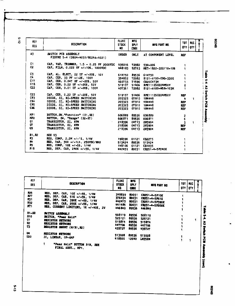
REF FLUKE MFG DES DESCRIPTION STOCK SPLY MFG PART NO. TOT NEC
N No. CODE OTY QTY o
A3 SITCH PCB ASSEMBLY ORDER ONLY AT COMPONENT LEVEL REF FIGURE 5-4 (D8O4-4031/8024A-4021)
Cl CAP, VAR, TRIMMER, 1.5 - 0.25 PF 2000VDC 435016 72982 530-006 1 C2 CAP, FILM, 0.022 OF +/-105, 1000VDC 448183 52763 MKT-1822-322/10+105 1
C3 CAP, AL. ELECT, 22 UT +/-205, 16V 614750 89536 614750 1,1 C4 CAP, CU, 33 PF +/-2%, 100V 354852 72982 8121-AIOO-COG-330G 1 C17 CAP, CER, 0.047 OF +/-205, 50V 460733 71590 CW20C473M 1 ! Cie CAP, CER, 0.22 UF +/-20%, 50V 519157 51406 RPE111Z5U22XMSOV 2 C22 CAP, CER, 0.01 UT +/-20%, 100V 407361 72982 8121-A1OO-VSR-103M 1
C23 CAP. CER, 0.22 UT ./-20%, 50V 519157 51406 RPE111Z5U224MSOV REPF CR3 DIODE, SI, HI-SPEED SWITCHING 203323 07910 1I4448 4 1 H CR4 DIODE, SI, HI-SPEED SWITCHING 203323 07910 4N4448 REP CR5 DIODE, SI, HI-SPEED SWITCHING 203323 07910 1114448 REP CR6 DIODE, SI, HI-SPEED SWITCHING 203323 07910 1N4448 REF
MP1 BUTTON,SWFunctlon" (S1,38) 606889 89536 606889 2 5 MP2 B0TTON, SW, 'Range* (S2-S7) 606871 89536 606871 6 QI TRANSISTOR, SI, NPN 218396 04713 2N3904 3 1 Q7 TRANSISTOR, SI, NPN 218396 04713 2113904 REF Q9 TRANSISTOR, SI, NPN 218396 04713 213904 REF
R1,R2 SEE U3 R3 RES, COMP, 2.2M ./-T%, 1/4W 198390 01121 CB2275 1 R1 3RS, VAR, 300 */-1C%. 250VDC/RMS 513424 89536 513424 1 R9 35, CONP, 1O1 +/-55, 1/4W 148106 01121 CB1035 1 RIB RES, DEP. CAR, 240K +/-55, 1/4W 442459 80031 CR251-4-5P2401 1
REF FLUKE MFG N DES DESCRIPTIOR STOCK SPLY MFG PART NO. TOT REC NO. CUE QTY QTY T I F
1:26 3S, DEP. CAR, 10o ./-5%, 1/411 348839 80031 CI251-4-SP10o 1 R27 113, DEP. CLR, 51K */-5S, 1/4v 376434 80031 C1251.4.-5P5 11 1 1R31 US, DEP. CA1, 3901 */-5S, 1/4W 442475 80031 C1251-4-5P 3 9 0 9 ¶ R32 Z35, DIP. CAU, 2001 */-55, 1/4V 441485 80031 C1251-4-5P2009 1 371 us5, CURlINIT LIMDTING, 1K */-405, 2W 446849 89536 446849 1
31-38 WrIT'C A330LT 508119 89536 508119 1 310 XITCH, hsk R0odQ 525121 89536 525121 1 1 1l 1RE11TOl ITOiKo 515874 89536 515874 1 02 REZSISOR RI"WORK 447706 89536 447706 1 U3 UISTOMR MOT (V/I1,22) 435727 89536 435T27 1
U4 RE•ISOt NETWOIU 513028 89536 513028 020 IC, LINEAR, OP-AMP 418566 12040 LM35SN 1 1
S *Peak Hold BUOTTON P/N, SEE FINAL ASSY., MIP.
b
I
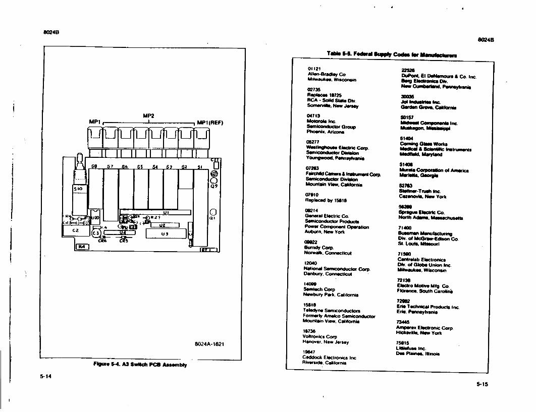
8024B
8024B
Flore "-4. A3 Switch PCO Assembly
TOle 5-L Fedwal Supply Cod Ow Mm fou WM
01121 Allen-Bradley Co. Milwaukee. Wisconsin
02735 Replce1s 18725 RCA - Solid Stage Di. Somervi. New Jersy
04713 Motorola Inc Semiconduclor Group Phoenix. Arizona
08277 Westinghouse Electric Corp. Semconductor Orileon Youngwood. Pennslvanta
07263 Fasichlld Caners & Ilqujmm Corp
MSemiopjr1nductoW Division Mdountan View. Caliornia
07910 Replaced by 15616
09214 General Electric Co. Semicondutctor Products Power Component Operation Auburn. Now York
ON22 Surndy Corp. Norwalk. Conneclicut
12040 National Semiconductokr Corp. Danbuy. Connecticut
140W9 Semlech Corp Newbury Park. Calilornia
15816 Teledyne Semiconduclors Formerly Amelco Semiconductor Mountain View. Calilornla
18736 Voltronics Corp Hanover. New Jersey
19647 Caddock Eleclronics Inc. Riverside. California
Dont, El DeNsmours & Co. Inc. Bgeql estrona, Div. Now Cumnbe'nd. Pennaylvanis
30O6 Jot Induetw Ibu. Garden ,0Gr , CanNoill
0157 Iea'-I Componenft Inc.
Mukgn Missssppi 61404 Corning Glae Works Medical & Scienif Instrumen
514101
Murat Corporation of America Marieft GeOrgl
52M6 Slksne-Ttinh Inc.
Cazenovia. New York
56M Sprague Electric Co. North Adams. Masachusets
714O Bunsman manudulran DIV. of McGraw-Edison Co. St. LouIs. Missouri
71560 Centrelab Electronics Div. of Globe Union Inc. Milwaukee. Wisconsin
72136 Eledro Motive MIg Co. Florence. South Cosrollnt
72982 Ede Technical Products Inc. Erie. Pennsylvania
73445 Amperex Electronic Corp. Hicksville. New York
75015 Littleluse Inc. Des Pla•ne. Ilinois
5-14
5-15
a
8024B 8024B
Table 5-5. Federal Supply Codes for Manufaclurers (conl)
79727 84411 C - W Industries TRW Electronic Components Warminster. Pennsylvania TRW Capacitors
Ogal•a. Nebraska Section 6 WWI1 Mepco/El0ctra Corp 89536 Accessory Information Morristown. New Jersey John Fluke Manufacturing Co. Inc
Everett. Washington
6-1. INTRODUCTION 6-2, rhis section of the manual Contains information concerning the accessories available for use with the Model $0240 Digital Multinseter. (There are no options available as this time.) The accessories, some of which are shown in Figure 6-1, are dcscihltd in general terms under a separate major heading containing the accessory model numier. Uhe depth of detail is intended to give the prospective user an adequate first acquaintance with the features and capabilities of each accessory. Additional information, when necessary, is supplied with the accessory.
6-3. DELUXE CARRYING CASE (C90) 6-4 Ihe CV0 Deluxe Carrying Case is a pliable, vinyl, zipper-closed pouch that provides in-field-transport protection for your DMM, as well as convenient storage locations for test leads, operator's guide, and other small accesasories. A finger or bell loop is included on the case as a carrying convenience.
6-5. RUGGED CARRYING CASE (Y810S) 6-6. Your YS 105 is a rigid plastic cse that provides protection from dirty, damp. abusive environments. The rugged case is large enough to hold your DM M. test leads, operator's guidc card, a temperature measuring accessory, an ac current measuringaccessory. a spare battery, and a spare fuse.
6-7. TYPE K SHEATHED THERMOCOUPLE (Y8102) "6-6. Introductlon 6-9. Your Y8 102 can be used for almost any application, but is best suited for use as a liquid immersion type probe In most liquids, the grounded measuring junction of your V8 102 provides fast response time. the special isothermal termination unit that plugs into your I)MM eliminates temperature gradient problems by keeping the two DMM junctions at the same temperature. See Section 2 of this manual for applications.
5-16 6-1
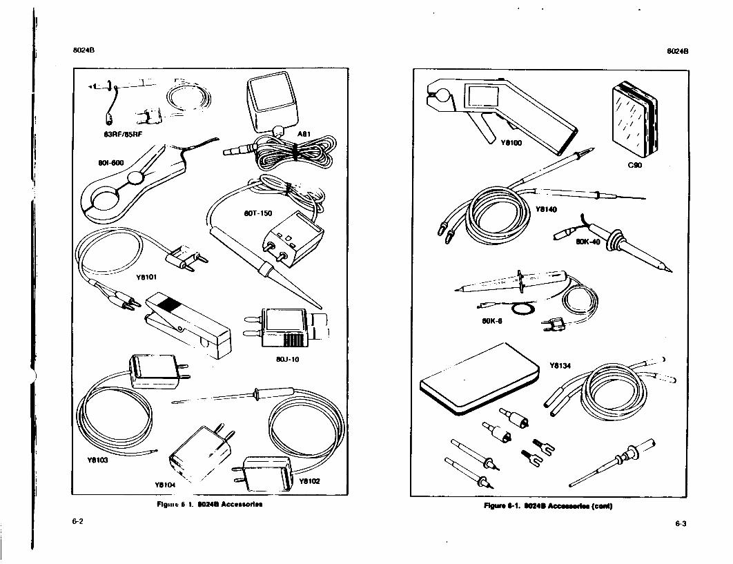
6024B804
SOK-6
)
)
FRgisse 6 1. $0248 Accessorles Fig"r 6-1. O624 Accesewlse (cadi)
6-26-
8024B
6-3

8024B/ I, K 6-10. SpdtlcallosM
TYPE .......................... ACCURACY (with respect to NBS tables) .....................
TIME CONSTANr . ............
SAMPIL.IN(G iP Maximum Temperature Rating Sheath Material ...............
DIMENSIONS .................
6-11. TYPE K BEAD THERMOCOUPLE (YI1103) 6-12. Inkoduelon 6-13. Your Y8103 can be used for any measuring application (in Teflon compatilk environments) except penetration. I he exposed tip ,iicans extremely fast response time. The special isothermal termination unit that plugs into your DMM elimituimes thermal gradient problems by keeping the two DMM junctions at the same tentpliaturc. See Section 2 of this manual for applications.
6-14. Sp.cticallions TYPE .......................... K (( i,-iticl vs Alhmel). RANGE ........................ 1500( to 2600 ( 2380F Io 500°F)continuous. ACCURA(Y (with respect to
NBS tables) .................... 2 2.2C (40-) over the range of 17.8(` to 260C (OF to 5(011.) (Above accmracy and range specilications apply to thermoncouple accessory only. Ilse 80248 Temperature function specifications when using the V8I103 accessory with the 80248 multimeter.)
TIME CONSTIANT ............. 2 seconds (for air at room temperature and one atmosphere of pressure moving with a velocity of 65 ft/sec).
INSULAFION IYPE ............ Teflon Fused -ape
S-15. THERMOCOUPLE TERMINATION (YSI104) 6-16. The Y8104 is a special isothermal termination kit that is dcsigned to provide a junction between a dual male banana plug and thermocouple wire. I he termination unit eliminates thermal gradient errors by keeping the two DMM terminals at the same temperature. I he maximum thermocouple wire size is 14. lhe duail banana plug spacing is
.75 inches.
6-4
K (('hromel vs Alumrl).
12.2*C (401.) over the ranige ul O f " to 276.70C
(320F to 5300F). ±3/4% of temperature over the range of 276.7"C
to 926.7 0 C (530DF- to 17(000F). (Abovcaccimiicyand rangespecifications apply to thern1OCoulil accessory only. Use 10240
Temperature function specifications whein using the Y8102 accessory with the S0429 multimeter.)
10 seconds (for air at room temperature and one
atmosphere of pressure moving at 65 fl/scc).
927-C (170r F). Inconel. 3.175 mm (I/8 inch) in diameter. 15.24 cm (6 inches) in length. Conductor length 48 inches nominal.
6-17. TEMPERATURE PROBES (SOT-lSOC and il0T-11OW) 6-10. Iniroducllon 6-19 INe 101-150 leIfmperature Probe converts the instrument into adirect-reading(l mV dt:!*)*C or °1- thermometer. It is ideally suited for surface, ambient and liquid iewasurenwrni. and lends itsell easily to a wide range of design. trouhleshotming. and cumluation applications. A rugged. fast-responding probe-lip with a 350V dc standoff
makets the 1N01- I 150 tine of the most versatile and easy-to-use temperature probes available.
6-20. Spedifcallone
RANGE I*C/0'I) (ficld selectable by internal jumpers) ................- 500C to *I500C (gOT-150): -580F to *302t1
(NOT-I 501') A(IIRACY ................... 11(" (I.1l') front W( to lO00C(. dccreasing
linearly to ±-)(" 15.4*1V) at WPC and +-I.50" RE.SOlA I ION ................. 0.10C on 200 mV range VOI I AGE S I ANIX)FI. ......... 350V dc or peak ac
POW:R ....................... Internal disposable battery; 1.000 hours of continuous use
6-21. HIGH VOLTAGE PROBE (10K4) 6-22. Inlroduclon 6-23. I he UOK-6 is a high voltage probe designed to extend the voltage measuring capability of an a dc voltmeter to 6000 volts. A 100O:1 voltage divider provides the prohe with a high input impedance. I he divider also provides high accuracy when used with a voltmeter having a 10 megohi input impedance. A molded plastic body houses thc divider aid protects the user from the voltage being measured.
6-24. Specficallons
VOl IA(;IE RANGE ............. 0 to6 kV, dc or peak ac INPlI I IMPMl)AN(E ........... 75 megohms nominal D)IVISION RAII() ............... 100:01 A((IJRACY
IX, to 5WN) II/ ................. ±1% 540)0 i/ to I klI .............. ±2% Above I kilt ................. Output reading falls. I ypically, 03t, at It) kIll.
6-25. H.GH VOLTAGE PROBE (110K-40) 6.-2. Introducltmon 6-27. I he ModJcl WK -40 cxtends the voltage measurement capability of tIhe inst rument up io 40 kV. Internally, the probe contains a special 1000:1 resistive divider. Metal-film rcsistor with matched temperature coefficients comprise the divider and provide the probe withl its excellent accuracy and stability characteristics. Also. an unusually high input imipedance (I111 MQ) minitnires circuit loading, and thereby contributes to measurement aCcuracy.
6-5
8024B
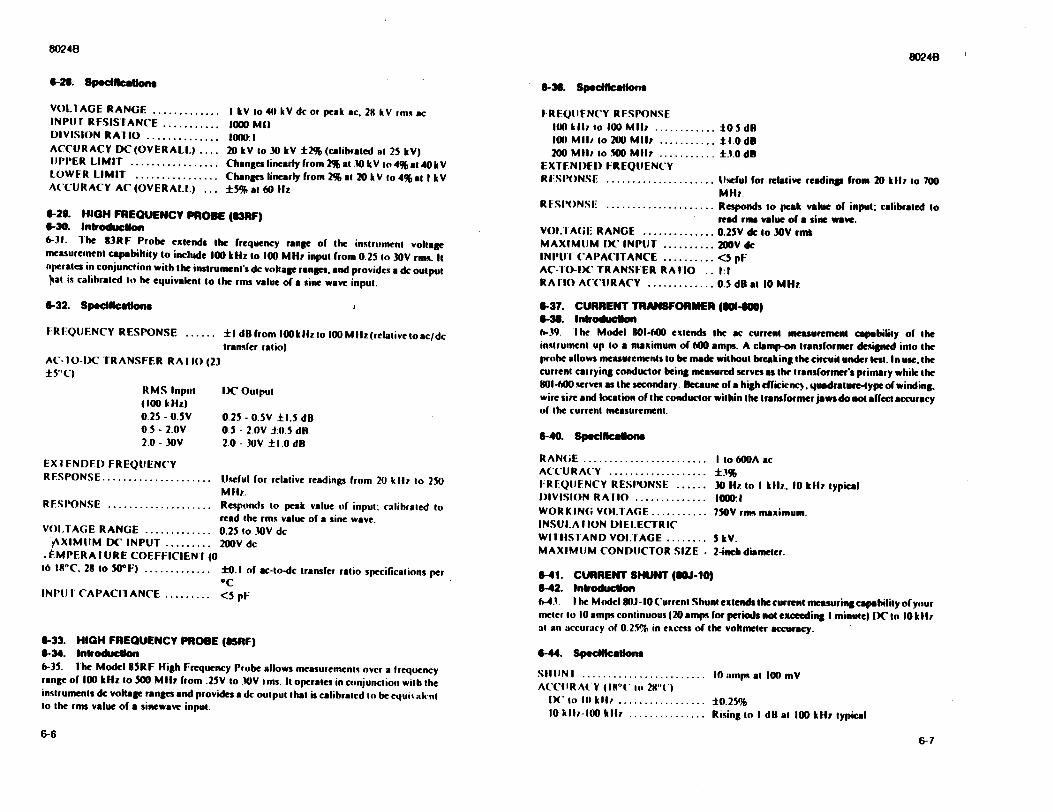
8024B
6-28. Spedlfkaton 6-36. SplefIcallons
I kV to 40 kV dc or peak ac. 29 kV rms ac 1000 MI1 10o: 1 20 kV to 30 kV ±2% (calibrated at 25 kV) Changes linearly from 2% at .0 kV to 4% at 40kV Changes linearly from 2% at 20kV to 4%at I kV ±5% at 60 Hlz
6-29. HIGH FREQUENCY PROBE (l3RF) 6-30. Introdlucon 6-31. ihe 83RF Probe extends the frequency range of the instrument vollage measurement capabiltily to include 100 kHz to 100 MHz input from 0.25 to 30V rimn. It operates in conjunction with the instrument's dc voltage ranges, and provides a dc output ýat is calibrated so he equivalent to the rms value of a sine wave input.
6-32. SpecIlicakona
FREQUENCY RESPONSE ...... 1 dB from 100Ikizio 100 M liz(relative toac/dc transfer ratio)
AC-TO-DC TRANSFER RA IIO (23 ±5"C)
RMS Input DK Outpul (100 kHz) 0.25 - 0.SV 0.25 - 0.5V ±1.5 dB 05 - 2.0V 0.5 - 2.OV ±(I.5 dh 2.0 -30V 2.0 - 30V ± 1.0 dB
EX I FNDIFD FREQUENCY RESPONSE ..................... Useful for relative readings from 20) kli to 250
MFH,.R S•IS ONSE .................... Responds to peak value of input: ralihrated to
read the rms value of a sine wave.VOI.TAGE RANGE ............. 0.25 to _10V dc
•XIMIUM DC INPUT ......... 200V dc - tMPERA IURE COEFFICIEN F (0
16 111"C. 28 to 50 F) ............. ±0.1 of ac-to-dc transfer ratio specifications per 0C
INI'U1 CAPACIlANCE ......... <5 pF
6-33. HIGH FREQUENCY PROBE (S5RF) 6-34. Introducllon 6-35. ihe Model 85RF High Frequency Probe allows measurements over a frequency range of 100 kHz to 500 M 1II from .25V to .OV rms. It operates in conjunction with the instruments dc voltage ranges and provides a dc output that is calibrated to he equi% alcnl to the rms value of a sinewave input.
VOL AGE RANGE ............. INPU r RESISTANCE ........... DIVISION RATIO .............. ACCURACY DC(OVERALLj .... UPPER LIMIT ................. LOWER LIMIT ................ ACCURACY AC (OVERALL,) ...
6-66-7
FREOQIIFNCY RESPONSE I14) k~ll to I(0 Mli ............ ±005 dR 100 MIl., to 200 Mll ........... ±1.0 dB 200 Milz to 50 MliI ........... ±3.0 dB
EXTENI)EI) FREQUENCY R•SPIONSE ..................... U.eful for relative readings from 20 kllz to 700
MHz. RFSPONSE ..................... Responds to peak value of input. calibrated to
read rms value of a sine wave. VOL.I A(GE RANGE ............. 0.25V de to 30V rms MAXIMUM DC INPUT .......... 200V de INPU I CAPACITANCE .......... <5 pF AC-10-I)C TRANSFER RAISO .. 1:1 RA 110 ACCURACY ............. 0.5 dl at 10 MHz
6-37. CURRENT TRANSFORMER (114100) 6-36. Inlroduaclon 6-39. Ihe Model 801-600 extends the ac current measurement capability of the instrument up to a maximum of 6M0 amps. A clamp-on transformer designed into the prohe allows measurements to be made without breaking the circuit under test. In use, the current carrying conductor being measured serves as the transformer's primary while the 801-M0 serves as the secondary. Because of a high efficictncy, quadrature-type of winding. wire size and location of the conductor within the transformer jaws do not affect accuracy of the current measurement.
6-40. Spefincalona
RANGE ........................ I to 600A ac A(CU R A(Y ................... ±3% FREQUENCY RESPONSE ...... 30 Hy to I klz,. 10 kilz typical I)IV•SION RAIIO .............. 1000I WORKING VOLTAGE ........... 7SOV rms maximum. INSULA fION DIELECTRIC WIIISFIAND VOl.IAGE ........ 5 kV. MAXIMUM CONDUCTOR SIZE • 2-inch diameter.
6-41. CURRENT SHUNT (U6J-10) 642. Introduclon 6-43. I he Model 80J- 10 Cuurrent Shunt extends the current measuringeapabilisy of your meter to 10 amps continuous (20 amps for periods io exeeeding I minute) DC to 10k Hi at an accuracy of 0.25% in excess of the voltmeter accuracy.
6-44. Spedklcallons
SHUN I ........................ I1 amps at 100 mV ACCIIRA( Y (I I (" to 29"(')
IX to III kil, ................. ± 0.25% 10 kii-100 ki ................ Rising to I dB at 100 kHz typical
8024B I
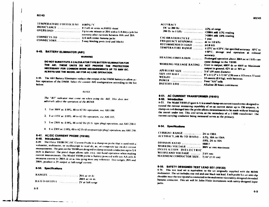
8024B80248
I
NO/1.
The "filB' nthliatUr cloar Eipit ct ithrti hl'IIoirg tIh AsI. IhJi dolA nor adve'r.whr .,l/el ithe clw'rgtlei ct INh', 8024 f.
I. I or 0I0IV ac :ll1,. 48 to 62 I1/ operation. use A AI-ItI).
2. Ior Il5V ac: :t11'%. 411 to 62 II, opciatoon..use A•t- IIS.
3. lIor 2.14V ac ±10%. 481 to 621 I/(tJ. tyle plug) opcialtmon. use AKI-2.t)-I
4. I r 2.4EV ae ± II%. 41 to 62 1 urolpcan type plug lopcratio. use A1I-2.41
6-47. AC/DC CURRENT PROBE (01500) 646. Introducllon 6-49. 1 he I luke Y18I00 IX/A(' Current Iloohe is a clamp-on piohle that i% used with a voltmeter, mulhimecr, or oscilloscope Io read de, ac. or compolte (ac on dc) curre•tm measurcmenns. I he jaws on the Y8100 are designed tlo clanip aruourd conductors up io 31/4 inch in diameter. I he pistol shape allows %ale, eay. onc-haid uoperalion when making current measurnments. Ihe Momdcl YVIXI prohe is halter), powercd with %i/e AA O.clls.hI measures current to 2(XIA dc or ac ron using moist any vomltimlct. I %%0 ranges. 20A and 200JA, pruduce a 2V ouipol at full-range current.
6-SO. Speciflalons
RANIES ..................... 20A ac (r dc 2tN)A ac or dc
RAIl I)()III'lI .............. 2V at lull range
AC'IIRA(y IX , to 20N) II/ ................. 211K)I1 i to I kIl/ ..............
('Al ItRA I ION ('YC'IE ........ FRI QUI-NCy RFSPONSE ...... RE('OMMENI)FI) LOAI) ....... IEMI'ERAIUIRIl R4N(;F .......
+2, ol range <I[OA add *3':, reading >100A add t6% reading I year dc to 1.0 kIll -3.0 kil +l5(' to +35*('; for specified accuracy IOC to +50*(.; storage and operatio at reduced
IFMPERA1 IIRF ((Il*II(' IINI i0I5%p1*" INI)UC'IAN( ................. .1 3 rill in %crics W/11.Oil shu"nt OVERIOAI) ................... Ilp to one nuinulc al 20A with a 1/4 duty cyckl for
recoovcry alter currents beLwcen I0A amnl 20A (ONNECIS 10 ................ 3/4 inch center banana jacks ('ONNECIORS ................. 5-way binding pints tred and black)
"6-45. BATTERY ELIMINATOR (All)
WARNING
DO NOT SUBSTITUTE A CALCULATOR TYPE BATTERY ELIMINATOR FOR THE A11. THESE UNITS DO NOT PROVIDE THE PROTECTION NECESSARY FOR COMMON MODE MEASUREIMENTS UP TO SOV DC. ALWAYS USE THE MODEL A"I FOR AC-LINE OPERATION.
6-46. 1he ANI Battery Eliminalor replaces the output ol the I)MM battery Ituallow acline operalion of the I)MM. Select oi- correct AII conliguration according to the list below:
6-86-9
m
accuracy. IIEA I IN(6 I IMI I A I ION ........ Prolonged operation above 200A ac or I kil, can cause damage to Ihe Y8IOO.
WORKIN(, VOL I AGE KAI ING . Core to output; 600V dc or 480V ac Maximum output to ground; 42V dc or .10V ac
APIR I I IRE sizI .............. I3/4'09 m) dianmetcr SIZIA-) VI RAI I 9 'x 4-i/2"x 1-7/16 (2.10 monx 115 mum .7 nom) WEI(oII I ...... 14 ounces (0.4 kg). with batteries POWER ........ ......... Four 'AA" cells RAIlI iRY ILIFE ................ Alkaline-20 hours continuous
6-51. AC CURRENT TRANSFORMER (Y1601) 6-52. Inlroduclion 6-3.1. 1 he Model Y11101 (F igure 6-I) is a small clamp-on current translormer designed io extend the current measuring capability of an ac current meier up to I5 amperes. A clamp-on coil desinged into the probe allows measurements to be made without breaking the circuit under test. This coil serves as the secondary of a 1:1000 transformer. Ihe current-carrying conductor being measured serves as the prinmary.
6.-4. Speillcallnms
(IIRR.NI RANGE ............. 2A to 150A AC'(CIRA('Y. (418 H, 10 10 kIlt) . 121", 10A to I15A
±$%. 2A to IOA DIVISION RAIlO .............. Io: I WORKIN(G VOI IAGE ...... 100V ac rms maximum INSIUI A IION DI)IFI. .'RIC"
WIIHSIANI) VOI.AGE ....... 3 kV rms MAXIMUM ('ONI)ICTOR SIZE. 7/16-I(I.i cm)
6-5S. SAFETY DESIGNED TEST LEAD SET (Y1132) 6-56. [his its.t kleod set is equivalent to the set originally supplied with the 118208 multimeter. I hIe set includes one red and one black test lead. -ach probe lo.s all anti-slip shoulder near the test lip and is connected to the multnelter via a salcty-designcd shrouded banana connector. I his set will lit John Fluke instruments with safety-designed input jacks.
I
J
8024B S043
6-67. DELUXE TEST LEAD SET (Y@134) 6-38. FhI VY8134 is a deluxe test lead set. rhe attachments provided allow interconnection with a wide variety oflcads and electronic components. Included in the kit
are:
i. iwo test leads (one red and one black). Ihe Y 1.14 leads have a shrouded Section 7 banana connectors on each end. Schematic Diagrams 2. Two test probes
3. Two insulated Alligator clips
4. Two spade lugs
5. One squeeze hook TADLE OF CONTENTS
6. One test lead pouch FIGUIME TITLE PAGE 7. One instruction sheet 7-1. 30240 Schematic ........................................... 7-3
6-$1. SUM FLEX TEST LEAD SET (Y8140) 6-60. The Y1140 Test Lead Set (Figure 6-1) consists of one red and one Mack 60-inch (1.52 meter) test lead, each with a standard banana plug on one end and an extendable tip probe on the other end. This flexible metallic tip conductor may be extended up to 2.5 inches and is insulated to within 0. 1 inch of its tip. This insulation reduces the chance of creating an inadvertent short ciicuit while using the probes in their extended configuration. Intended primarily for measuring voltages, the VI140 leads may also be used for measuring modest currents.
6-10 7-1
I Jill -- ,81001 -- -" -L _Jr
Al ib,,.
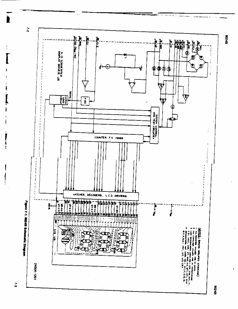
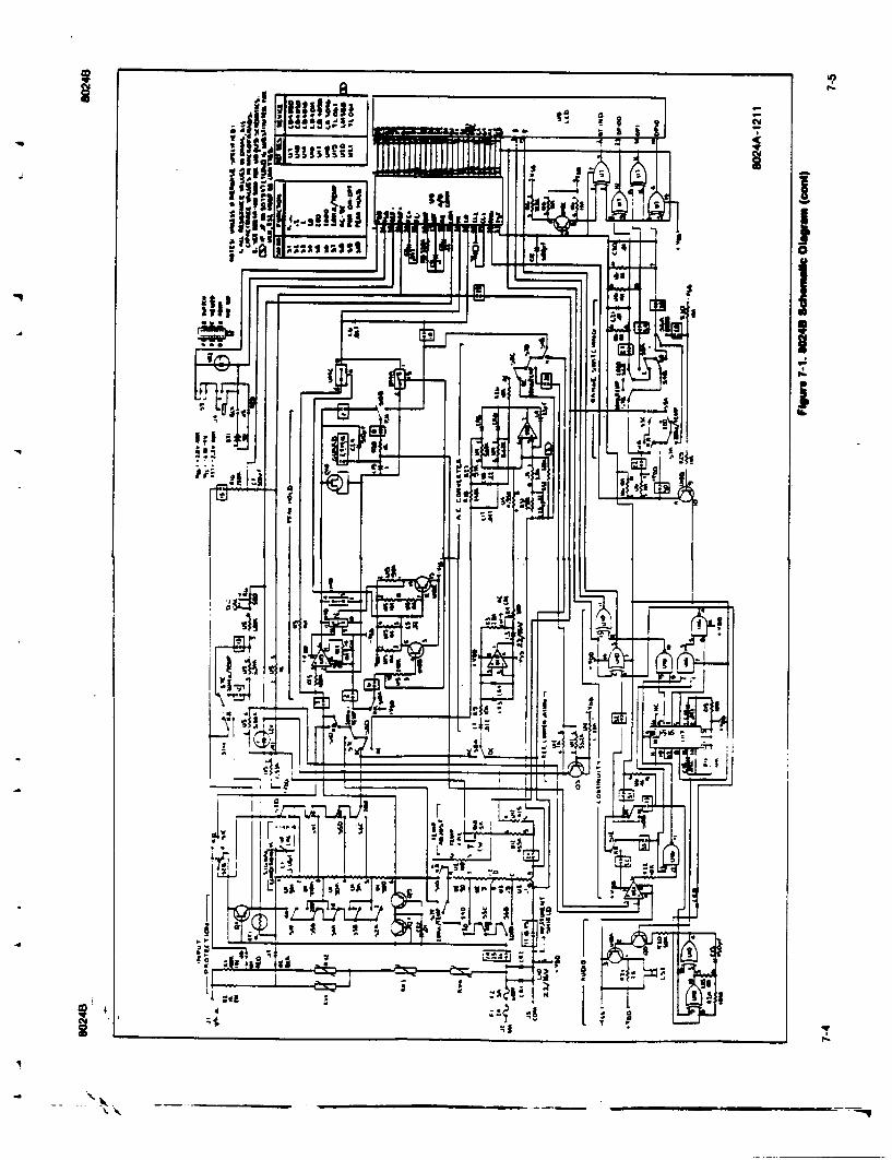
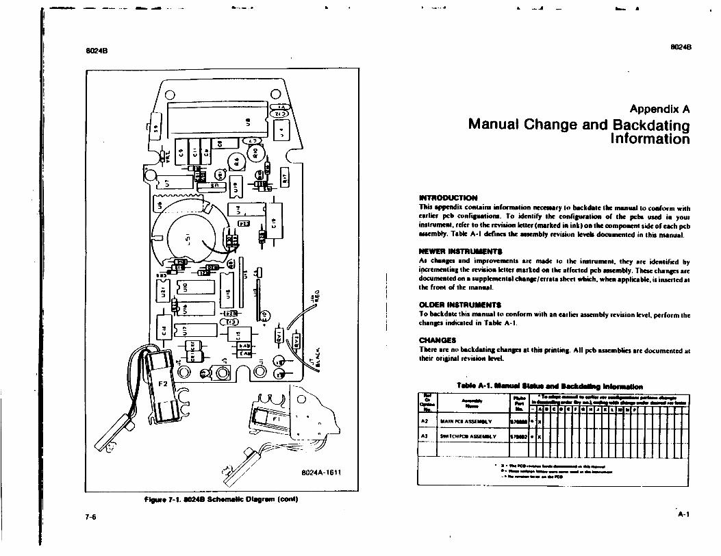
&..- -.- A - &.- a
024B 0024B
Appendix A
Manual Change and Backdating Information
IINTRODUCTION This appendix contains information necessary to backdale the manual to conform with earlier pcb conrlgualion. To identify the configuration of the pcbs used in your instrument, refer to the revision letter (marked in ink) on the component side of each pcb assembly. Table A-I defines the usembly revision levels documented in this manual.
NEWER INSTRUMENTS As changes and improvements are made to the instrument. they are identified by incrementing the revision letter marked on the alfected pcb assembly. These changes are docunmented on a supplemental chanc/lerrala shcet which, when applicable, is inserted at the front of the inanual. a
R -oaf lOLDER INSTRUMENTS To backdate this manual to conform with an earlier assembly revision level, perform the
CED *changes indicated in Table A-I.
A2F [~]CHANGES There are no backdating changes at this printing. All pcb assemblies are documented at atheir original revision alev l.
(P ' Vý 9 1-\ Ta.e A-1. Man"• $1se wW BakdeUd" Inkmosaw
or I i. - ,Te * o 96 0 e , a -m 0..m
A2 MAIN " ASSWEMf-Y lISS • I
A3SWITCHPCU A SSEMJ. sl ow N I
C /I 8024A-1611 " '- m
FIguwe 7-1. 60240 Schemlac Dagram (cont)
a.-..
"A-17-6

I I I x , I V I I
';! witI S
I
*1
w
(0
U' I
I 'Iii jij!� 'i ij I�k
!I�iI ill jj�ii i�i jilt! jh full �HJ i*If I SIj!
0 *
£
i1Jt� !I;i
I I 3
I a
i 8 I I S
I
ii
________________________
ai a i aI a al
if I Fi~ ig~ j111111 89 :~ h d~g :
IL 3. 40
z OC
fitl Jfill is,
UI I I
ii ii I, ii ii Ii Ii
p
L f
I
'B
Iii
ii il II Iisit
*8
�Ii II �1i hi !II
851
!15
105 tg
iii �II � I'
iii I �; iii
I
oji
'if
jilt
I I I II
I I 3I
I a-0 I I
I I
I
I U I Mi£
I I
I
I
I S
I I!6
mill oi l
£ 1 I 1 ! I j
u91iijj S
Zo H!NH
AIN !m ill! i
I ~.. I Ill all I i-F i iii'1:I
fil
I 1- 3 WI I '�i
! 9.�! i I 111 33 -5
*jl �1�- �
iII!iIIji
!I ;
1 11Mdi
fil j ,~ ig
::I:' H. I-.
- . 1 .0 a
Clo H 14 j fi] 10 i i o1I
I.IJ~~83 JulI31AI~~ 133 1 Hi!111
=
w
0
m 2 i
I!
I
a
"liii
I I
@1 w
U. a'. a 6 w -I
0 -a z 2 Iz 'U I-
fil Il! illi;
I Uv 1 1 I I A! I~~~~~e ~ w!-1 . -dijd ; IM 1 1 ;
cc~~ '
L I;I Ug~
z (i li2 11t1 1 l il (
A~~~p 12 M. g 1I il*J J
4M
I I I a
IWE
iii 0* a
t
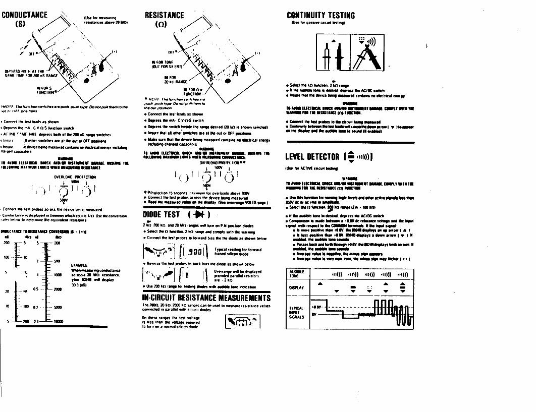
tNG rF Th.funClooswifchalStorpuSh Pushftpe Domne/imflthtmfOthe .. I , ( FF prseOmos
Conrwrl the rest leads as shown
Qppmrs the mA C V 0 S hoimction switch
nAT Itl* VA lIMO• depress bolh of the, 20 nS range Swiches
Stnsu t
other switches are at the rol or OFF poetM
toimire * device being measured contains no eleciklcal energy including hargod capacitors
WEit"
IS AIll ILOICIta SItCK aTHO t/O M1MlEIF Mt MI. NIUNE VOE aLOWINe MAXINMU LiOTY WNEE UiASUM lf=ItA I
OVFALtOA PmOtICImOW
IT Connect the test piohes acloss the device betiti rieasured
SCoi•In tlawpes displaVed in Se*rru•enKs whu•iheals t1/) Usel l convers•tion ,atrn lielw In' deteonmiore lhe equmivalent oesrstarn'e
smcascon as aSSSC unna I-/l
2010 C 0- 1 M011 /
EXAMPLE.
5 "0
20 'D 05
10 10 0 2
5 200 ot-
When measuring conductance acrosso a MO mesastece. your 1246 wIl display 3)3 1ruSO
low0
1 70
RESISTANCE (0) , ý
INOFOR TONF
4tut OIR SHIN)\
20 Ito RAIIC[
N FOR (5*
#mesh yxmoSh type DO Imnlpui Pime0 I;:
"a Connemect ltest leads as Vown
" Depress 11he mRA. C V-WS Switch
"o Deopess the switch beside the mange domed 120 htO is shown selecled) "o Inssee #hat aN othem swoaclies are et me out or OFF pesitum
"* Make sure thar the device being measured contains no elec0rica energy including charged capacileirs
to AV"a1 (tLCIICMA $Sick AI/" EIBUV~lb 03m. n110EV! to FILLIIS UIVAWtI LIS WfI 1111i1 COIIUCAII :
OVIY ROAS0P10IF(:IM OlJ**
**(Protecion IS Seconds maximmnon lto overloads above 300V "* Coiuect the lest probes across the device bMin measured "* fleed me measured value, on The display S vra VlS page I
DIODE TEST 1I ) 06
2 to lift and 20 Mo 0anges will twun on P'N l •tm on diodes "* Select the 0 Itincl•n. 2 ko range and comply with the weaning
"* Conmect the lest poobes to towaid bras lhe the diode as shown below
S.. ...'~ l! •atypicalt eidon for toowaods• ,4
e Reverse the lost probes 10 back bias Ole diode as shown below
Orefiange wilt be daispayd ' p lo v i drd p a ra lle l l e s i s i0 '
* Use 200 too mgtom lesing diodes With -udible lone indication
IN-CIRCUIT RESISTANCE MEASUREMENTS lhe Mo00.0 20 bo M00 Ito mantes can be used to mesuie tesislamre valies crolmmected in paualtlel with silicon diodes
On these ranges the test voltage us leSs than m1e vo"age reuhrmed to lhnn on a normal silicon dmde L�1
CONTINUITY TESTING (IUse lt passive co cuwt lestmg)
-IA. * Select It. kO function. 2 Io rannge
N lIhe audible l-k Is dasked, deose me ACIOC swld, * bnswe that Ite device being meosseed cOilangM electimcat aegem
To A i AM0 MI WAtt Om lAMi hULK. CMWI N I NV YE W Ia IN on aEMIAiN (T) FMti.
6 Connect eel uitttpobe to lieract being mtimin ed • etntIulyhbe gowumekttadewitusesetbtdeearowt V Itoeappew
0ftme display aFd me audible om so seemfL IIN nleWOdI
LEVEL DETECTOR + ,))Il AV
fUse for ACIIIFF ckcuOl tesOtin
TO AMII tttCILK3 311 AiN/ I~mOa l aKClfSE MM lt IKN 1111111 l • N Mt .ISCInU
Sit Vile otOutnce ome henaim, k t meglevls andw otlier Kll"ve lmpels lss ion
Select me a tIenme. 211 Ito rangeZika - l TOM
I It the audble mm in rd. doopiess me ACIDC Swi•ch * Ceompaiosen Is made between a ,O.5 de leeec voltage O•n me imopol Signal, wirh respeclto 1Vie CWMMO loormhoals It me Mod signal "O more peallive "Fan low. omead ays amnp ermow I )
"ol les NoS illfve OiW 49 IV. OM4Sdisplays adewn street IypIlt "enale. te aou~bl ton lewd$ eoPasme back mod folifeii egi #4.$V. melwudisplays both arrows OF enabe", me WA"b 1am souaede "a Average volve 10 neawo*. me itrionesip agqmiowe "o Average valveo is vey neaeo, Me. inte WAWAp mary Ncker m:u 3
A e msil mill) t 1
T • .I
OISPLAY
TYPICAL IPUT SIGNALS
4e IV --- ---Ll -k - -
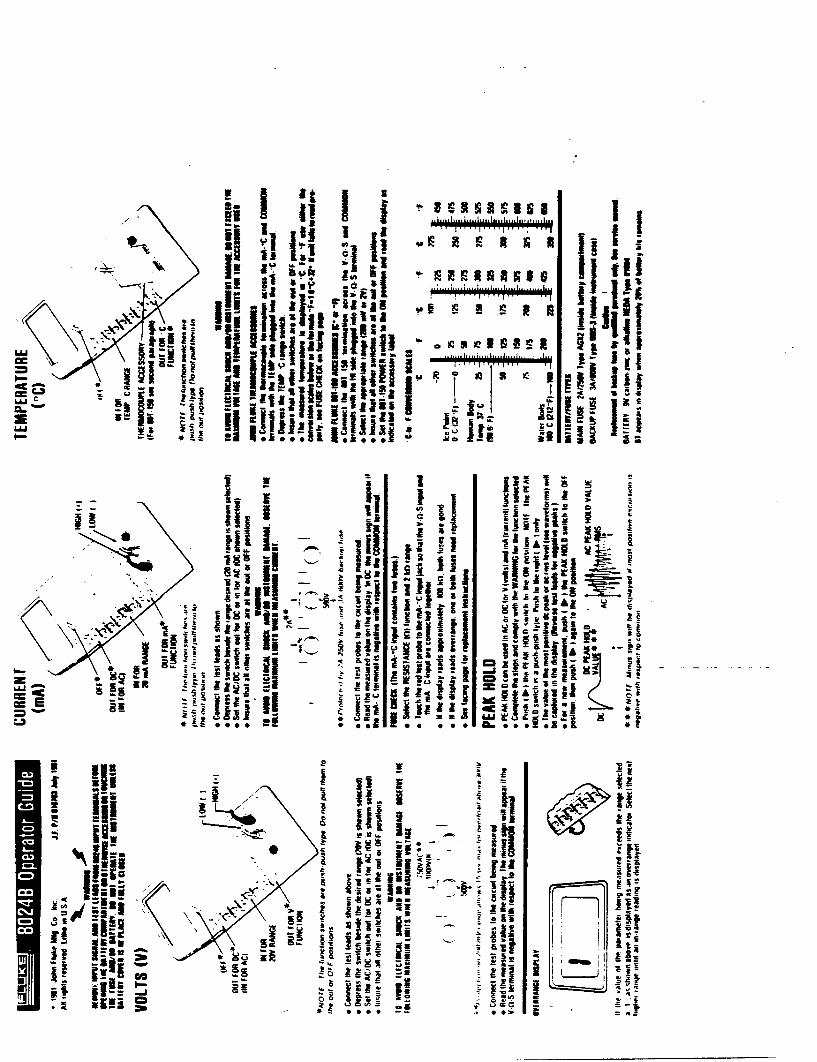
Lt~ft RA
1~~ V I
3 mm 'I
ii Ii II
iii
I;
III Ii
I �
I.i � �ii II � � [F�
� � I
!�;:i ti 1111111
If
1.; :..
t� S
* -.
39
C*
Jull
cc c
U
I Ii
I
Ii � IIII II II" I � �Ij I
N I
ui� III �Ii Iii
bg
RR-i
C7
'U
U
2c
ii I [� I � � ii ; ii
� II 1� �I
I"
'��5 C4 3-.---
I G
a I I I I II 1w .11
IL CC f) I'DCu 0S
,I IJ.'s j~ ji II
�ih
3 It I
ill I **�j f B I I JIB (3(3 (3(3(3(3
13!
fil "Imi
fift JIllV!!
1W I; 'I 31
B B (3(3(3 � � �
24
.. �
£ L.
ILi
Sid2 w. wj
to cc 0z w C. w P,.
':1Co
C
2
a
1~~~~~~~ ~~~~ 19 1 1 d I I 3fIIIIM I t 1fl 149 11
Ililtuil~~1 ii ftlIu~hdii~uIil; panui
'31 c I I w i!
1! 1:1;, f f1 1w fF
I IF 9i 11 ftII 1131313 13 a a 111 ll 111 1.1 9 1 lls 1l 11 figI I ll I 3
IiI11iili Allz~~ it i gEN~i i i as! ge g e
'4
cr)l 0Ii h j'1 j will 1i jj 9 1j
1iditn! n a1.1 allJI~JijIi lI I
a* E
'El I lv
III
I.-.'
7
� i 33 1
I,
I I! �
I 'I 3�I �
ijI [I pa
Ii F
*. .
ii � I g� a'
II I' aI
II
ItIw
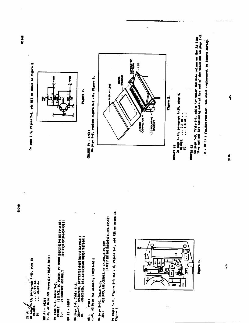
FIL &I
I if, b%0
in ~ wit* 0 . m in
0.4
a I C ; I'M"". I U
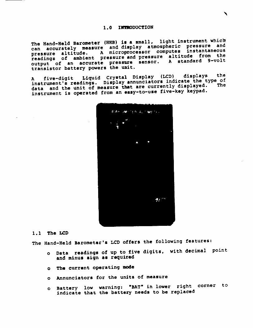
1.0 INUODUCTION
The Hand-Held Barometer (HHB) is a small, light instrument which
can accurately measure and display atmospheric pressure and
pressure altitude. A microprocessor computes instantaneous
readings of ambient pressure and pressure altitude from the
output of an accurate pressure sensor. A standard 9-volt
transistor battery powers the unit.
A five-digit Liquid Crystal Display (LCD) displays the
instrument's readings. Display annunciators indicate the type of
data and the unit of measure that are currently displayed. The
instrument is operated from an easy-to-use five-key keypad.
1.1 The LCD
The Hand-Held Barometer's LCD offers the following features:
o Data readings of up to five digits, with decimal point
and minus sign as required
o The current operating mode
o Annunciators for the units of measure
o Battery low warning: "BAT" in lower right corner to
indicate that the battery needs to be replaced
The Hand-Held Barome-'r
1.2 Keypad
The five keys on the Hand-Held Barometer can be used to turn the
device on or off, to select operating modes, to select the type
of units in which data are displayed, and, in some operating,
modes, to set reference values.
ON/OFF Key
The ON/OFF key powers the instrument on or off. The key works as
a toggle switch; pressing the ON/OFF key when the instrument is
off turns it on, and pressing the key when the instrument is on
turns it off.
To conserve power, an internal jumper's default setting allows
the Hand-Held Barometer to automatically shut itself off. When
more than two minutes have transpired since any key was pressed,
the instrument shuts off. (Refer to section 1.7 *The Sleep
State Jumper" for instructions on changing this jumper setting to
disable automatic sleep state.)
To reactivate the HHB, press the ON/OFF key. The Hand-Held
Barometer always remembers the operating mode and the units of
measure that were displayed during the last power on, and
automatically returns to this display when the unit is turned on.
MODE Ke
The MODE key allows you to select the operating mode. These
modes are identified by an annunciator on the left side of the
display. Modes are presented in a cyclic fashion as follows:
Operating Mode Annunciator
----------------------- ---------------Barometer PRESSURE Standard Altitude ALTITUDE (AS)
Temperature-Compensated Altitude ALTITUDE (TC)
Differential Altitude £ALTITUDE Differential Barometer £ PRESSURE
Each time MODE is pressed, the display advances to the next
operating mode. When MODE is pressed from Differential Barometer
mode (A PRESSURE), the display returns to Barometer mode
(PRESSURE).
-2-
The Lnd-Held Barometer
In addition to the modes listed in the preceding chart, a
Calibration mode may be selected by simultaneously pressing the
SET/ZERO key and the MODE key.
==Operating Mode jAnnunciator
Calibration CAL
Arrow Keys
The arrow keys are used either separately to select the units
in which data readings are displayed, or with the SET/ZERO key to
set a known reference level. Used by itself, an arrow key causes
the display to change to the next unit. Reference values may be
set by displaying the current reference value, then
simultaneously pressing an arrow key with the SET/ZERO key until
the desired reference value is displayed.
SET/ZERO Key
The SET/ZERO key is used either separately to "zero" the
differential altitude or differential pressure, or with the arrow
keys to set the barometric or altitude reference level. Used
alone, the SET/ZERO key in a differential mode sets the current
zero reference level. Non-zero reference values may be set by
displaying the current reference value, then simultaneously
pressing an arrow key with the SET/ZERO key until the desired
reference value is displayed.
1.3 Operating Modes
Atmospheric pressure or pressure altitude may be displayed by
selecting one of five operating modes. To select a mode, you
"scrollm through the modes by pressing the 8MODE' key. These
modes are Barometer mode, Standard Altitude mode, Temperature
Compensated Altitude mode, Differential Altitude mode, and
Differential Barometer mode.
Barometer Mode
When you select the Barometer mode, the instrument acts as a
simple barometer. Atmospheric pressure can be displayed in one
of six units of measure, as described in section 2.0.
The Hand-Held Barome r
Altitude Modes
Barometric pressure is converted to a pressure altitude when the
Standard Altitude mode is selected. In this mode the instrument
operates as a normal aircraft altimeter would operate; that is,
altitude above sea level in the ICAO Standard Atmosphere is
displayed. Since atmospheric conditions are rarely 'standard,'
you may correct this altitude reading for current atmospheric
conditions by entering the local "altimeter setting," as recorded
by the local airport. Alternatively, if your current altitude is
known, you may enter this value as an altitude reference level.
Refer to section 3.0 for more information.
If, however, neither the "altimeter setting" nor the current
altitude are available, you can use the Temperature-Compensated
Altimeter mode. Accuracy is improved by entering the ambient
temperature to correct for the difference in temperature between
the site atmosphere and the Standard Atmosjphere. This mode is
described in detail in section 4.0.
Differential Modes
Differential Altimeter mode can display a change in altitude
between a 'zero" reference level and your current site position.
A surveyor might use this mode, for example, to directly measure
the height of a hill. The surveyor could zero the differential
altimeter reading to make a benchmark at the bottom of the hill
and then walk to the top; the reading at the top would be the
height of the hill above the benchmark. Refer to section 5.0 for
instructions on using this mode.
Similarly, Differential Barometer mode measures the change in
atmospheric pressure between your selected zero reference level
and the current pressure. This mode allows you, for example, to
quickly determine the change in pressure from one day to the
next. This mode is described in detail in section 6.0.
Calibration Mode
Calibration mode is entered by simultaneously pressing the MODE
and SET/ZERQ keys. This mode allows you to set the barometric
pressure in millibars when a reading from an external, highly
accurate barometer is available. This procedure is required only
infrequently to correct for long-term drifts in instrumentation.
Refer to section 7.0.
-A-

The xnd-Held Barometer
1.4 Measurement Averaging
The HHB makes four measurements each second. Any measurement
displayed by the Hand-Held Barometer is an average of the last
eight measurements. Each time a new measurement is made, iti
replaces the oldest of the eight stored measurements, and is
averaged with the seven previous measurements. The display is
continuously updated with these new averages.
The averaging of pressure and altitude readings removes short
term fluctuations from ambient pressure bursts that are caused by
wind or by rapid movement of the instrument. If a sudden, large
change in pressure or altitude has occurred, the display is
stable and accurate after two seconds. Averaging also removes
fluctuations from the residual noise of the electronic circuits.
1.5 Replacing the Battery
The Hand-Held Barometer is shipped with a 9-volt alkaline battery
installed. This should be replaced when the 'BAT" annunciator
is constantly illuminated. A 9-volt alkaline battery, NEDA No.
1604A (Eveready No. 522), should be used. A new alkaline battery
should last for approximately 80 hours of continuous usage.
Note: When the battery is replaced, the pressure offset from
Calibration mode is lost; the offset is reset to zero. Enter
Calibrate mode and write down this offset BEFORE removing the
battery, and reenter this value after replacing the battery. In
addition, any reference values (such as the temperature in
Temperature-Compensated Altitude mode and the altimeter setting
in Standard Altitude mode), are lost and must also be reentered.
To replace the battery, loosen and remove the four screws from
the back cover. Lift off the back cover. The battery will be
visible in the lower left corner of the instrument. Remove the
old battery, gently prying the connector on the battery terminal
up and off of the battery.
Snap the two-position battery connector onto the new battery and
set the new battery into position. Replace the back cover and
tighten the four screws. . Turn the unit on by pressing the ON/OFF
key and verify that the LCD works properly and that the "BAT"
annunciator is no longer visible. Reenter the pressure offset,
altimeter setting, and temperature.
1.6 Handling Precautions
The electronics and pressure sensor are housed in an impact
resistant plastic case. The case is, however, NOT water tight.
Do not imnmerse the instrument under any cirauuttflces. Also note
that the front cover is somewhat pliant. if you press hard
against the front of the unit you can cause erroneoul readings.
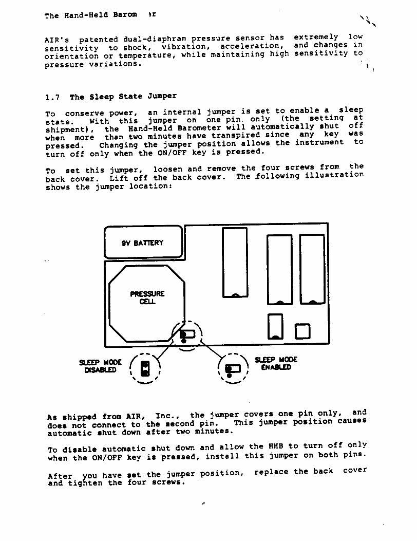
The Hand-Held Barom ir
AIR's patented dual-diaphram pressure sensor has extremely low
sensitivity to shock, vibration, acceleration, and changes in
orientation or temperature, while maintaining high sensitivity to pressure variations.
1.7 The Sleep State Jumper
To conserve power, an internal jumper is set to enable a sleep
state. With this jumper on one pin, only (the setting at
shipment), the Hand-Held Barometer will automatically shut off
when more than two minutes have transpired since any key was
pressed. Changing the jumper position allows the instrument to
turn off only when the ON/OFF key is pressed.
To set this jumper, loosen and remove the four screws from the
back cover. Lift off the back cover. The following illustration
shows the jumper location:
PRESSURE CELL
SLEEP MODE SL5EEP MODE DISABLED ENA
As shipped from AIR, Inc., the jumper covers one pin only, and
does not connect to the second pin. This jumper position causes
automatic shut down after two minutes.
To disable automatic shut down and allow the HHB to turn off only
when the ON/OFF key is pressed, install this jumper on both pins.
After ou have set the jumper position, replace the back cover
and tighten the four screws.
I
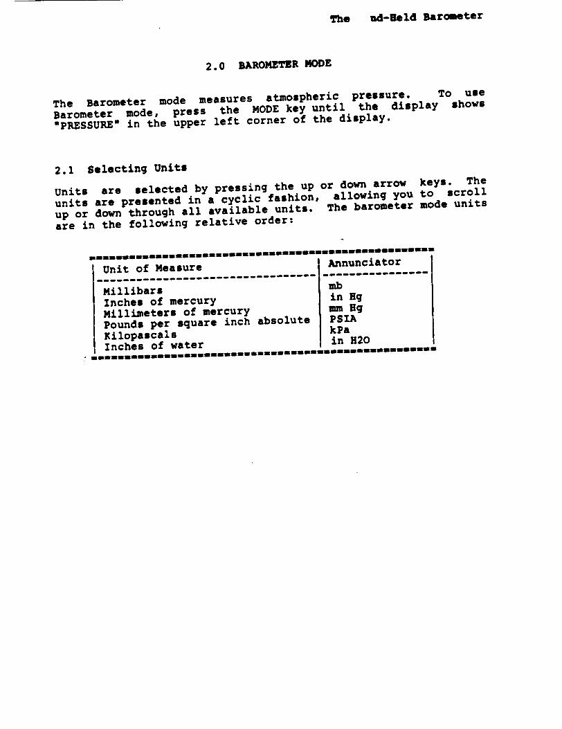
The ad-Held Barometer
2.0 BAROMETER MODE
The Barometer mode measures atmospheric pressure. To use
Barometer mode, press the MODE key until the display shows
"PRESSURE" in the upper left corner of the display.
2.1 Selecting Units
Units are selected by pressing the up or down arrow keys. The
units are presented in a cyclic fashion, allowing you to scroll
up or down through all available units. The barometer mode units
are in the following relative order:
Unit of Measure Annunciator -------------------------------- ---------------
Millibars mb
Inches of mercury in Hg
Millimeters of mercury mm Hg
Pounds per square inch absolute PSIA
Kilopascals kPa
Inches of water in H20
The Hand-Held Barom, ir
3.0 STANDARD ALTITUDE NODE
The Standard Altitude mode measures the current pressure altitude
above sea level. To select this mode, press the MODE key until
the "ALTITUDE (AS)" annunciator appears.
The Hand-Held Barometer determines the altitude based upon the
relationship between altitude and atmospheric pressure in the
ICAO Standard Atmosphere. At any site, however, conditions can
differ significantly from the standard atmospheric conditions.
To obtain an accurate altitude reading, you must therefore enter
either the current "altimeter setting" (as available from a local
airport) or your current altitude (as available from an accurate
topographical map) which the HEB can use as a reference or
"benchmark."
Altitude can be displayed in feet or meters. A reference
(benchmark) altitude can also be set from this display. The
current altimeter setting can be displayed (and set) in either
millibars (mb) or inches of mercury (in Hg).
Note: Since the HHB cannot be connected to an aircraft static
pressure port, it is not suitable as an aircraft pressure
altimeter.
3.1 Entering a Benchmark Altitude
To calibrate the instrument to a known altitude at a benchmark,
press an arrow key until the desired units, feet (ft) or meters
(m), are displayed. Set this value by holding down the SET/ZERO
key while pressing the up arrow key to increment the altitude
reading or the down arrow key to decrement the reading.
When you set either an altitude or altimeter reference value, you
can hold an arrow key depressed. The longer you hold the key
down, the faster the reading changes values.
Note that at a given site the altitude reading will change with
time due to weather induced pressure changes. New benchmark
settings may therefore be required periodically to assure
accurate readings.
Standard Altitude mode can also be used to determine the
altimeter setting when the current altitude is known. To
determine the altimeter setting from Standard Altitude mode,
select feet (ft) or meters (m), and enter the present altitude.
Select millibars (mb) or inches of mercury (in Hg) to see the
current altimeter setting.
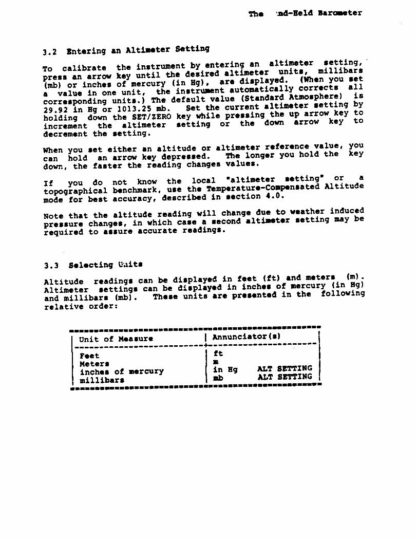
The ,ad-Held Barometer
3.2 Entering an Altimeter Setting
To calibrate the instrument by entering an altimeter setting,
press an arrow key until the desired altimeter units, millibars
(mb) or inches of mercury (in Hg), are displayed. (When you set
a value in one unit, the instrument automatically corrects all
corresponding units.) The default value (Standard Atmosphere) is
29.92 in Hg or 1013.25 mb. Set the current altimeter setting by
holding down the SET/ZERO key while pressing the up arrow key to
increment the altimeter setting or the down arrow key to
decrement the setting.
When you set either an altitude or altimeter reference value, you
can hold an arrow key depressed. The longer you hold the key
down, the faster the reading changes values.
If you do not know the local waltimeter setting" or a
topographical benchmark, use the Temperature-Compensated Altitude
mode for best accuracy, described in section 4.0.
Note that the altitude reading will change due to weather induced
pressure changes, in which case a second altimeter setting may be
required to assure accurate readings.
3.3 Selecting Uaits
Altitude readings can be displayed in feet (ft) and meters (m).
Altimeter settings can be displayed in inches of mercury (in Hg)
and millibars (mb). These units are presented in the following relative order:
Unit of Measure Annunciator(s)
-----------------------------Feet ft Meters a inches of mercury in Hg ALT SETTING millibars mb ALT SETTING
The Hand-Held Barometer
4.0 TUMPERATURE-COMPENSATED ALTITUDE MODE
The Temperature-Compensated Altitude mode measures the pressure
altitude above sea level. This mode should be used when the
ambient air temperature is known but neither the "altimeter
setting" nor an altitude benchmark is known.
Altitude can be displayed in feet (ft) or meters (m). The
current air temperature can be displayed (and then set) in
degrees Fahrenheit or degrees Celsius.
To enter Temperature-Compensated Altitude mode, press the MODE
key until the 'ALTITUDE (TC)* annunciator is displayed.
4.1 Setting the Temperature
To calibrate the instrument with a known ambient temperature,
press an arrow key until the temperature is displayed in degrees
Fahrenheit or degrees Celsius. (When you set the temperature in
either unit, the HHB will automatically correct the other unit.)
Hold down the SET/ZERO key and press the up arrow key to
increment the temperature value or the down arrow key to
decrement the temperature.
Note that when you set the temperature, you can hold an arrow key
depressed. The longer you hold the key down, the faster the
reading changes values.
The temperature setting is stored in the Hand-Held Barometer's
memory until you physically change it. This setting is used by
both the Temperature-Compensated Altitude mode and the
Differential Altitude mode, described in section 5.0.
If you do not know the 'altimeter setting," a benchmark height,
or the ambient air temperature, you should approximate the
ambient air temperature as best you can and use the Temperature
Compensated Altitude mode. This method generally offers the most
accurate altitude readings under those circumstances.
To obtain the most accurate altitude measurements, you should
enter the ambient air temperature at each new altitude that you
wish to measure.
-10-
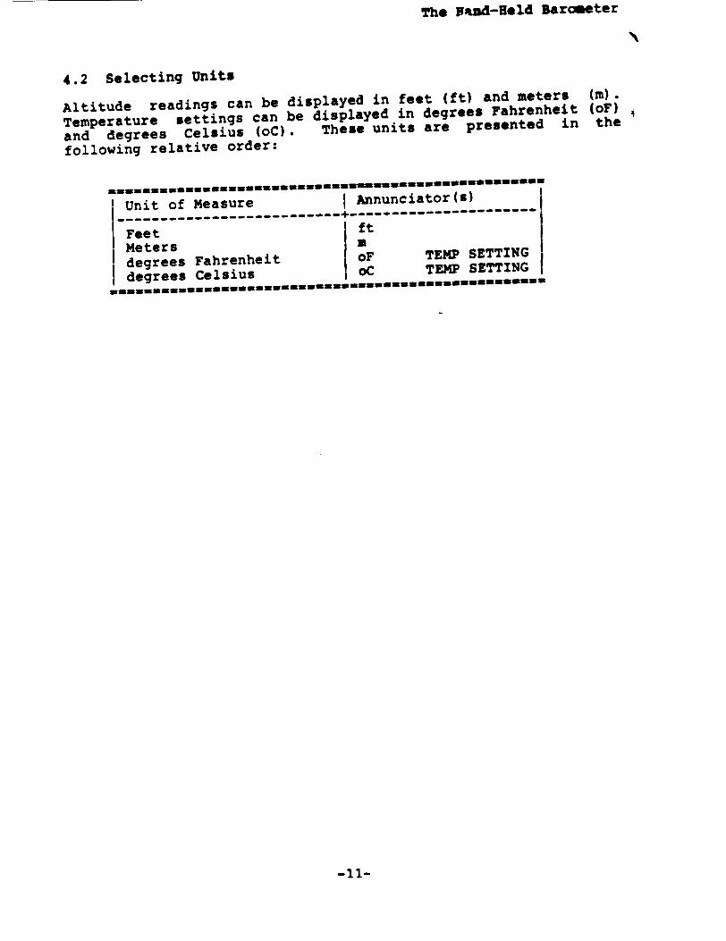
The Vand-Ueld Barometer
4.2 Selecting Units
Altitude readings can be displayed in feet (ft) and meters (m).
Temperature settings can be displayed in degrees Fahrenheit (oF)
and degrees Celsius (oC). These units are presented in the
following relative order:
Unit of Measure I Annunciator(s)
I-Feet ---------------------- ft------------------Meters I m
degrees Fahrenheit oF TEMP SETTING
degrees Celsius oC TEMP SETTING
-11-
The Hand-Held Barome~er
5.0 DIFFERENTIAL ALTITUDE OCE
Differential Altitude mode is used to measure the change in
altitude relative to a reference height. For accuracy of
measurement, the ambient air temperature should be entered.
To use Differential Altitude mode, press the MODE key until the
display shows "A ALTITUDE" in the lower left corner of the display.
Altitude can be displayed in feet (ft) or meters (m). The
current air temperature can be displayed (and then set) in
degrees Fahrenheit or degrees Celsius.
5.1 Setting the Temperature
To calibrate the instrument with a known ambient temperature,
press an arrow key until the temperature is displayed in degrees
Fahrenheit or degrees Celsius. (When you set the temperature in
either unit, the HHB will automatically correct the other unit.)
Hold down the SET/ZERO key and press the up arrow key to
increment the temperature reading or press the down arrow key to
decrement the reading.
Note that when you set the temperature, you can hold an arrow key
depressed. The longer you hold the key down, the faster the
reading changes values.
The temperature setting is stored in the Hand-Held Barometer's
memory until you physically change it. This setting is used by
both the Differential Altitude mode and the Temperature
Compensated Altitude mode, described in section 4.0.
If you do not know the local ambient air temperature, use an
estimated value. You can expect reasonable accuracy over a
limited range of differential altitude.
Note: To obtain the best accuracy of differential altitude
measurements, enter the ambient air temperature at each altitude
that is measured.
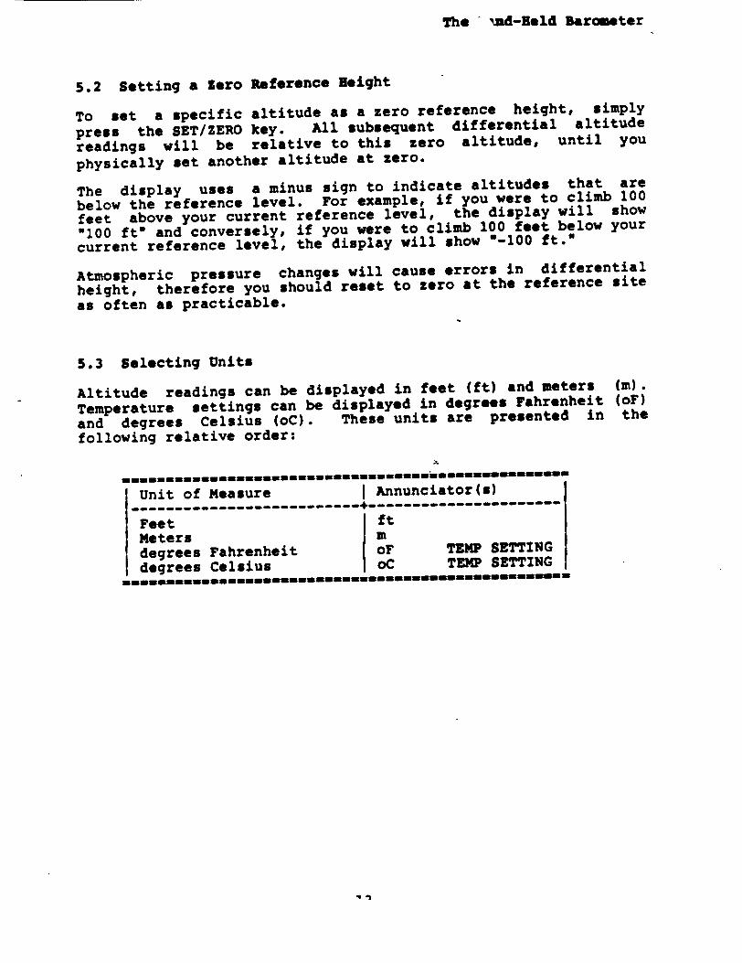
The '.d-Held Barometer
5.2 Setting a Zero Reference Height
To set a specific altitude as a zero reference height, simply
press the SET/ZERO key. All subsequent differential altitude
readings will be relative to this zero altitude, until you
physically set another altitude at zero.
The display uses a minus sign to indicate altitudes that are
below the reference level. For example, if you were to climb 100
feet above your current reference level, the display will show
"100 ft" and conversely, if you were to climb 100 feet below your
current reference level, the display will show 0-100 ft."
Atmospheric pressure changes will cause errors in differential
height, therefore you should reset to zero at the reference site
as often as practicable.
5.3 Selecting Units
Altitude readings can be displayed in feet (ft) and meters Wm).
Temperature settings can be displayed in degrees Fahrenheit (oF)
and degrees Celsius (oC). These units are presented in the
following relative order:
Unit of Measure Annunciator(s) --------------------------- ------------- n- ---
Feet ft Meters m degrees Fahrenheit oF TEMP SETTING degrees Celsius oC TEMP SETTING
9i
The Hand-Held Baror "er
6.0 DIFFERENTIAL BAROMETER MODE
The Differential Barometer mode is used to read the change in barometric pressure relative to a reference pressure. To use Differential Barometer mode, press the MODE key until the display shows "A PRESSURE".
6.1 Setting Zero Reference Pressure
A reference point for barometric pressure is established by defining the current barometric pressure as zero. To set pressure at zero, simply press the SET/ZERO key. All subsequent differential barometric readings will be relative to this zero pressure level, until you physically set another pressure reading at zero.
The display uses a minus sign to indicate pressure readings that are below your reference level. For example, if pressure were to drop 0.2 millibars, the display would show 0-0.2 mb," and conversely, if pressure were to rise by 0.2 millibars the display would show "0.2 mb."
6.2 Selecting Units
The barometric reading can be displayed in the following units: millibars (mb), inches of mercury (in Hg), millimeters of mercury (mm Hg), pounds per square inch absolute (PSIA), kilopascals (ka), and inches of water (in H20).
Units are selected by pressing the up or down arrow keys. The units are presented in a circular fashion, in the following relative order:
-14-
Unit of Measure Annunciator
Millibars mb Inches of mercury in Hg Millimeters of mercury mm Hg Pounds per square inch absolute PSIA Kilopascals kPa Inches of water in H20
The And-Held Barometer
7.0 CALIBRATION NODE
The Calibration mode allows you to enter a pressure offset to, compensate for slight long-term drifts that occur during normal'] operation. This offset is stored in the Hand-Held Barometer's battery powered memory. When the battery is changed you will have to reenter this pressure offset.
To use the Calibration mode, enter Barometer mode by pressing the MODE key until the PRESSURE annunciator is displayed, then press an arrow key until the desired units is displayed. Make a careful comparison of the barometric pressure standard to the HHB's reading, averaging one minute's readings. Determine the offset by subtracting the HHB value from the barometric pressure standard. The resulting difference (retaining the algebraic sign) is the offset.
Press and hold down the SET/ZERO key, then press and hold down the MODE key. The display will show the letters CAL for one second. The current pressure offset is then displayed. The HHB is shipped with a pressure offset of 0.0.
Holding the SET/ZERO and MODE keys depressed, press the up arrow key to increment this offset, or the down arrow key to decrement the offset. The pressure offset must be in the range of -1.28 mb to 1.27 mb. (Refer to section 10.0 for unit conversion factors.) If the measured offset exceeds +/-1.2 b, the accurncy of the reference barometer should be verified. If the reference barometer proves to be correct, return the Hand-Held Barometer to AIR, Inc. for factory recalibration.
This calibration should only be necessary every few months, and only if you have a pressure standard available which is more accurate than the Hand-Held Barometer.
To exit Calibration mode and return to Barometer mode, release the MODE key then the SET/ZERO key. Verify your offset by comparing the current EBB reading to the barometric pressure standard. HHB readings (averaged for one minute) and the barometric pressure standard should now be equal.
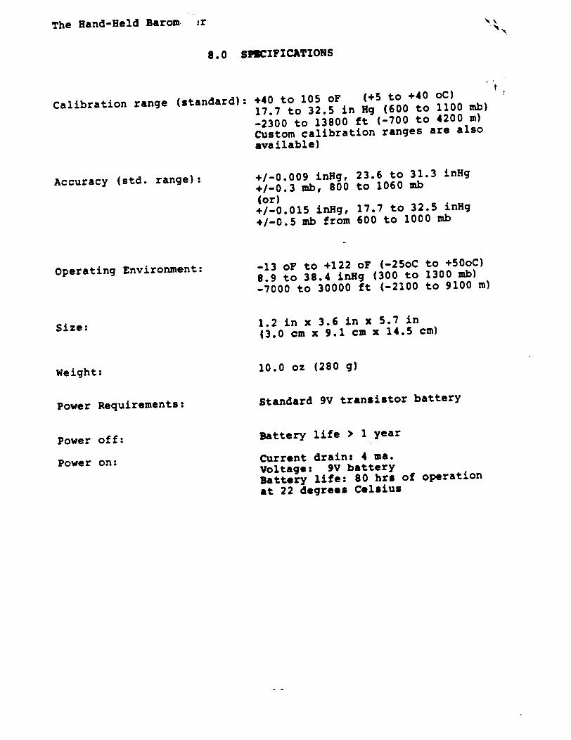
The Hand-Held Barom ,r
8.0 SPECIFICATIONS
Calibration range (standard):
Accuracy (std. range):
Operating Environment:
Size:
Weight:
Power Requirements:
Power off:
Power on:
+40 to 105 oF (+5 to +40 oC) 17.7 to 32.5 in Hg (600 to 1100 mb)
-2300 to 13800 ft (-700 to 4200 m) Custom calibration ranges are also available)
+/-0.009 inHg, 23.6 to 31.3 inHg +/-0.3 mb, 800 to 1060 mb (or) +/-0.015 inHg, 17.7 to 32.5 inHg +/-0.5 mb from 600 to 1000 mb
-13 oF to +122 oF (-25oC to +50oC) 8.9 to 38.4 inHg (300 to 1300 mb) -7000 to 30000 ft (-2100 to 9100 m)
1.2 in x 3.6 in x 5.7 in (3.0 cm x 9.1 cm x 14.5 cm)
10.0 oz (280 g)
Standard 9V transistor battery
Battery life > 1 year
Current drain: 4 ma. Voltage: 9V battery Battery life: 80 hrs of operation at 22 degrees Celsius
f

The * id-Reld Barometer
9.0 EQUATIONS
Mathematical equations are used by the HHB to calculate the
output parameters.
Pressure in millibars is calculated by a fifth-order polynomial
equation with temperature dependent cross product terms. The
equation is used to convert raw data to a numeric pressure value.
9.1 Altitude Equations
The equation for standard altitude is:
H - 44330.77 * ( 1 - I Po / Pr I ** 0.19026 )
Where: H - altitude above sea level in meters. Po - site pressure as measured by the instrument in mb.
Pr - the "altimeter setting" in millibars.
Note: This instrument uses the altimeter equations for the
standard atmosphere between sea level (h - 0 m) and the top of
the troposphere (h - 11000 m) (lapse rate assumed to be 0.0065
deg C / m). This same assumption is made for negative altitudes
even though the standard atmosphere is not defined below sea
level.
You may correct the altimeter by adjusting Pr to the correct
altimeter setting or by adjusting H to a known height. If you
adjust H, a new Pr in millibars is calculated according to the
following equation:
Pr - ( Po ) / ( I - H / 44330.77) * [1/0.19026]
The equation for temperature compensated altitude is:
H - ( To / 0.0065 ) * ( 1013.25 / Po ] * 0.19026 - 1 )
Where: H - altitude above sea level in meters. Po - site pressure as measured by the instrument in mb.
To - site temperature in deg K as measured by the operator.
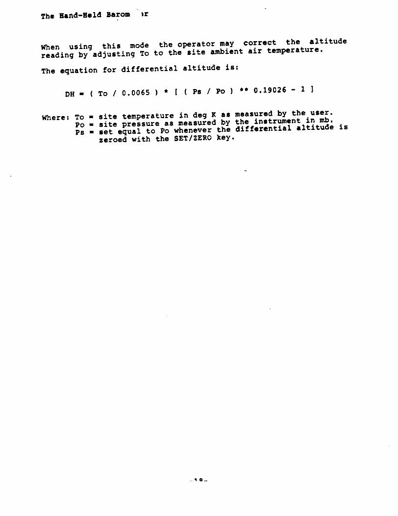
The Hand-Hold Barom ir
When using this mode the operator may correct the altitude
reading by adjusting To to the site ambient air temperature.
The equation for differential altitude is:
DH - ( To / 0.0065 ) * [ ( Ps / Po ) ** 0.19026 - I 3
Where: To - site temperature in deg K as measured by the user.
Po - site pressure as measured by the instrument in mb.
Ps - set equal to Po whenever the differential altitude is
zeroed with the SET/ZERO key.
I O-
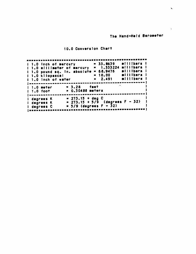
The Hand-Hold Barometer
10.0 Conversion Chart
1 1.0 Inch of mercury a 33.8639 millbars I 1 1.0 millimeter of mercury a 1.333224 millibars I
1 1.0 pound sq. In. absolute a 68.9476 millibars I 1 1.0 kllopascal : 10.00 millibars I 1 1.0 Inch of water - 2.491 millibars I
I ------------------------------------------------' - I
1 1.0 meter a 3.28 feet " 1 1.0 foot - 0.30488 meters I ------------------------------- -------------- I I degrees K - 273.15 + deg C I degrees K - 273.15 + 5/9 (degrees F - 32) 1
1 degrees C a 5/9 (degrees F - 32) *..mDauumaaauuauBBmmaammaaauaumauuuauBuummuaammsuu
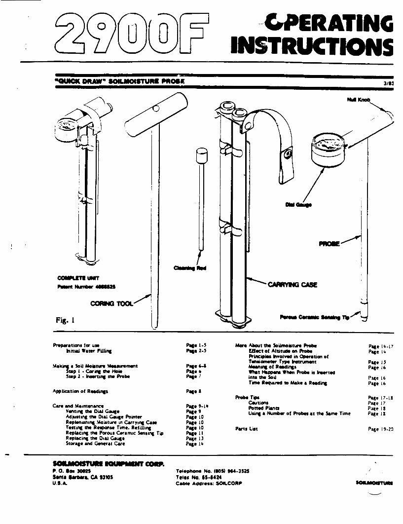
0 U 0
Null
COWILET Uw
POW" Ntm- 8m8
CORM TOOL
Fig. I Pemm Comaf
Preparations for use intud Water Irdling
Maki•a Soi Moisatre rmasument Suop i : Z= 0e Hole Step 2 - luertan me Probe
Application of Readings
Care and Maintenance Venting the 0Dia Gauge Adptng the Dial Gauge Pointer Replenishing Moisture in Carrying Case Testing the Response Time. Refilling Replacing the Porous Ceramic Sensing Tip Replacing the Dial Gauge Storage and General Care
Page I.5 Page 2-5
Page -4 Page b Page
Page 8
Page 9-is Pages Page 10 Page L0 Page i0 Page iI Page 13 Pago 14
Uore About the Soaimoaure Probe Effect of Altitue on Probe Principles Invodved in Operation of Toniometer Type Instrument Meaning of Remalings What Happens When Probe is Inerted into the Sod Time Riequred to Make a Reading
Probe Tep Cautions Potted Plants Using a Number of Probes at the Sam Time
Parts List
P.O. son 3HN2S Seant 8a~n.ra CA 13105 U.S.A.
Teleihone No. (80S) tH4-352S Telex No. 65.8424 Cable Address: SOILCORP
"w= DRAW" SOILMOGSTURE PROSE3/83
Page 14-07 Page 1'
Page 15 Page 16
Page 16 Page 16
Page 17-13 Page 17 Page Is Page Ill
Page 19-20
3/83
", AFOIGa CASE
56111.1110015rume
L, PERATING INSTRUCTIONS
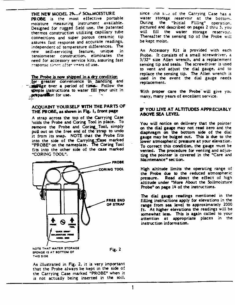
THE NEW MODEL 2%_._i SOu.MOISTUR E PROBE is the most effective portable moisture measuring instrument available. Designed for rugged field use, the patented thermos construction utilizing capillary tube connections and super porous ceramic tip assures fast response and accurate readings, independent of temperature differences. The new self-servicing feature, unique in tensiometer construction, eliminates the need for accessory service kits, assuring fast !-sponse tirnn-ý z•.!te- v-Rrs of use.
The Probe is now shiped in a dry condition .pr- greater convenience -in bandling and
-•*_lgL-e over a period of tim4- Follow the *nple instructions to water ffll your unit in -p'tpaa onfor use.... -
ACQUAINT YOURSELF WITH THE PARTS OF THE PROBE, as shown in Fig. 1, front page
A strap across the top of the Carrying Case holds the Probe and Coring Tool in place. To remove the Probe and CoringTool, simply pull out on the free end of the -strap to undo it from its snap. NOTE that the Probe fits into the side of the Carrying-ame marked "PROBE" on the nameplate. The Coring Tool fits into the other side of the case marked "CORING TOOL".
NOTE THAT WATER STORAGE
SPONGE IS AT BOTTOM OF
THIS SIDE
since --nis s-__ of the Carrying Case has a water storage reservoir at the bottom. During the "Initial Filling" operation, pictured and described on pages 2 thru 5, you will fill the water storage reservoir. Thereafter the sensing tip of the Probe will be kept moist.
An Accessory Kit is provided with each Probe. It consists of a small screwdriver, a 3/32" size Allen wrench, and a replacement sensing tip and seals. The screwdriver is used to vent and adjust the dial gauge, and to replace the sensing tip. The Allen wrench is used in the event the dial gauge needs replacement.
With proper care the Probe will give you many, many years of excellent service.
MF YOU LIVE AT ALTITUDES APPRECIABLY ABOVE SEA LEVEL
You will notice on delivery that the pointer on the dial gauge may not read zero and the diaphragm on the bottom side of the dial gauge may be bulged out. This is due to the lower atmospheric pressure at your elevation. To correct this condition, the gauge must be vented. The procedure for venting and adjusting the pointer is covered in the "Care and Maintenance" section.
High altitude limits the operating range of the Probe due to the reduced atmospheric pressure. Read about the effect of high altitude under "More About the Soilmoisture Probe" on page 14 of the instructions.
The dial gauge readings mentioned in the filling instructions apply for elevations in the range from sea level to approximately 2000 ft. At higher elevations the readings will be somewhat less. This is again called to your attention at appropriate places in the instruction information.
Fig. 2
As illustrated in Fig. 2, it is very important that the Probe always be kept in the side of the Carrying Case marked "PROBE" when it is not actually being inserted in the soil,
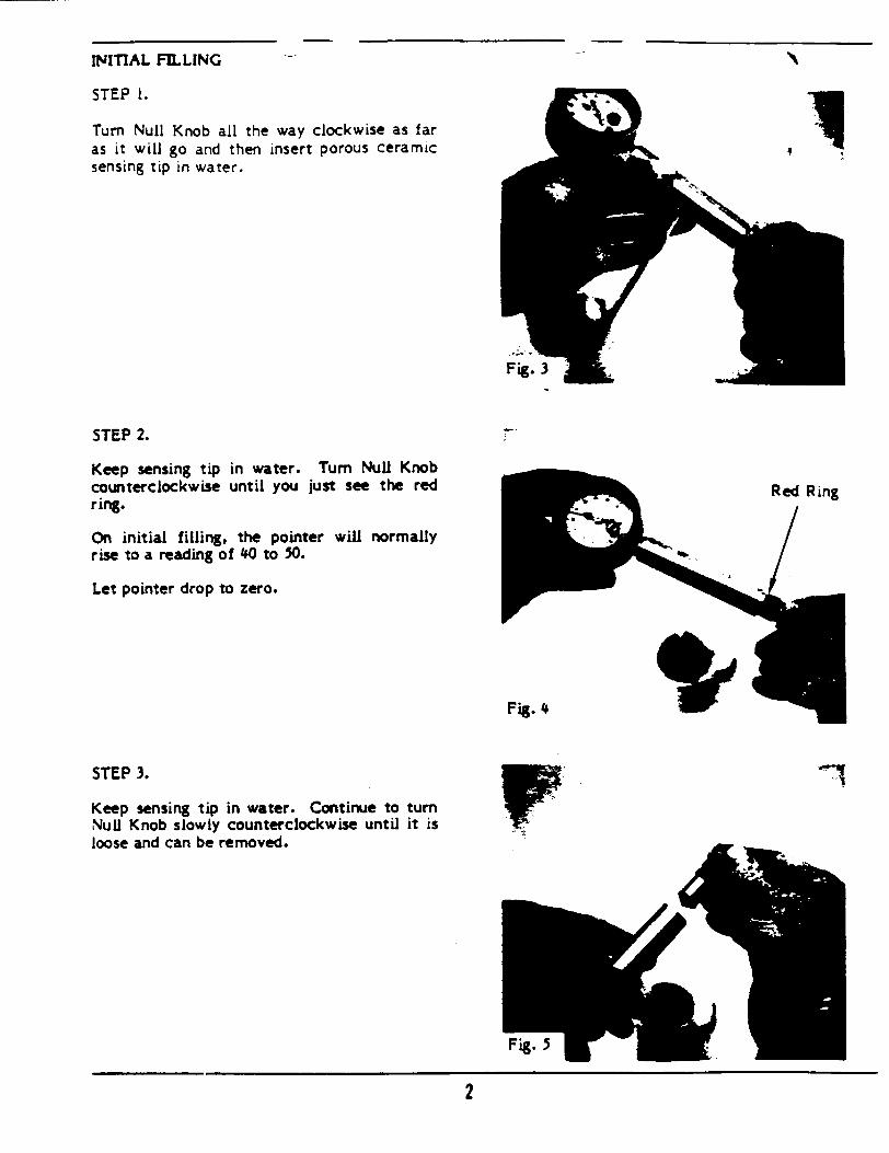
INITIAL FILLING
STEP I.
Turn Null Knob all the way clockwise as far as it will go and then insert porous ceramic sensing tip in water.
STEP 2.
Keep sensing tip counterclockwise ring.
in water. until you
Turn Null Knob just see the red
On initial filling, the pointer will normally rise to a reading of #0 to 50.
Let pointer drop to zero.
STEP 3.
Keep sensing tip in water. Continue to turn Null Knob slowly counterclockwise until it is loose and can be removed.
2
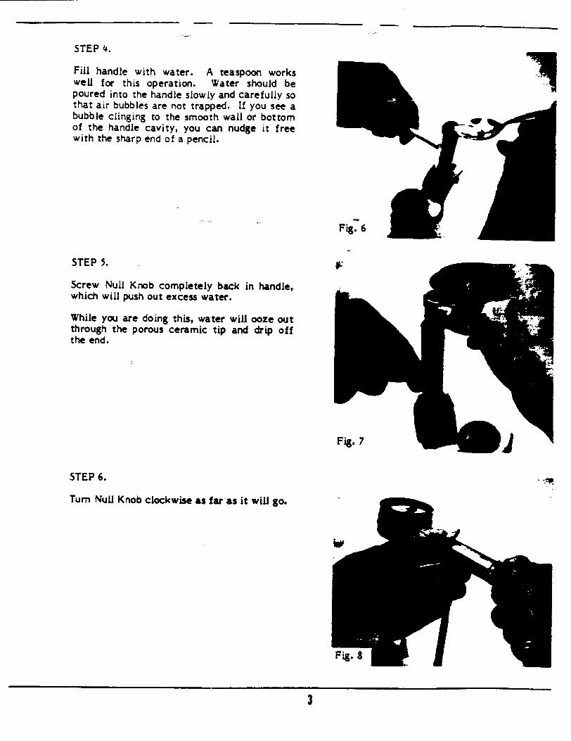
STEP 4.
Fill handle with water. A teaspoon works well for this operation. Water should be poured into the handle slowly and carefully so that air bubbles are not trapped. If you see a bubble clinging to the smooth wall or bottom of the handle cavity, you can nudge it free with the sharp end of a pencil.
Fig. 6
STEP 5.
Screw Null Knob completely back in handle, which will push out excess water.
While you are doing this, water will ooze out through the porous ceramic tip and drip off the end.
STEP 6.
Turn Null Knob clockwise as far as it will go.
3
9'
Zy-
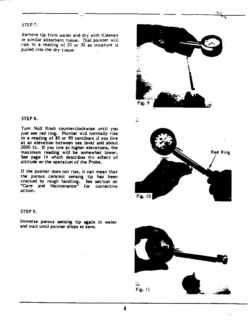
STEP 7.
Remove tip from water and dry with Kleenex or similar absorbent tissue. Dial pointer will rise to a reading of 20 or 30 as moisture is p pulled into the dry tissue.
Fig. 9
STEP 8.
Turn Null Knob counterclockwise until you just see red ring. Pointer will normally rise to a reading of 10 or 90 centibars if you live at an elevation between sea level and about 2000 ft. If you live at higher elevations, the maximum reading will be somewhat lower. See page 14 which describes the effect of altitude on the operation of the Probe.
If the pointer does not rise, it can mean that the porous ceramic sensing tip has been cracked by rough handling. See section on "Care and Maintenance" for corrective action.
Fig. 10
STEP 9.
Immerse porous sensing tip again in water and wait until pointer drops to zero.
Fig. II
4
N"b.b
a
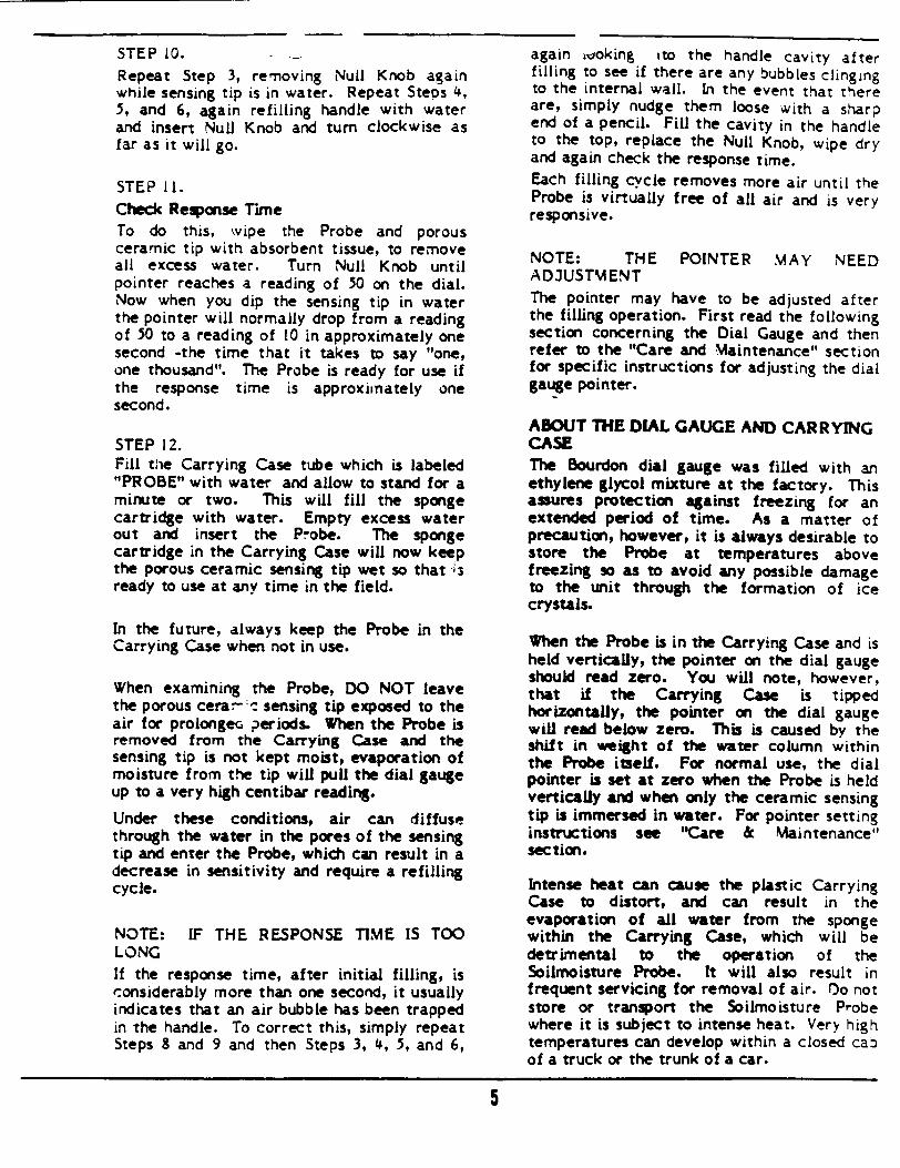
STEP 10. Repeat Step 3, removing Null Knob again while sensing tip is in water. Repeat Steos 4, 5, and 6, again refilling handle with water and insert Null Knob and turn clockwise as far as it will go.
STEP 1I. Check Response Time To do this, wipe the Probe and porous ceramic tip with absorbent tissue, to remove all excess water. Turn Null Knob until pointer reaches a reading of 50 on the dial. Now when you dip the sensing tip in water the pointer will normally drop from a reading of 50 to a reading of 10 in approximately one second -the time that it takes to say "one, one thousand". The Probe is ready for use if the response time is approximately one second.
STEP 12. Fill the Carrying Case tube which is labeled "PROBE" with water and allow to stand for a minute or two. This will fill the sponge cartridge with water. Empty excess water out and insert the Probe. The sponge cartridge in the Carrying Case will now keep the porous ceramic sensing tip wet so that -;3 ready to use at any time in the field.
In the future, always keep the Probe in the Carrying Case when not in use.
When examining the Probe, DO NOT leave the porous cerar-: sensing tip exposed to the air for prolonge• periods. When the Probe is removed from the Carrying Case and the sensing tip is not kept moist, evaporation of moisture from the tip will pull the dial gauge up to a very high centibar reading.
Under these conditions, air can diffuse through the water in the pores of the sensing tip and enter the Probe, which can result in a decrease in sensitivity and require a refilling cycle.
NOTE: IF THE RESPONSE TIME IS TOO LONG If the response time, after initial filling, is considerably more than one second, it usually indicates that an air bubble has been trapped in the handle. To correct this, simply repeat Steps 8 and 9 and then Steps 3, 4, 5, and 6,
again woking ito the handle cavity after filling to see if there are any bubbles clinging to the internal wall. In the event that there are, simply nudge them loose with a sharp end of a pencil. Fill the cavity in the handle to the top, replace the Null Knob, wipe dry and again check the response time. Each filling cycle removes more air until the Probe is virtually free of all air and is very responsive.
NOTE: THE POINTER MAY NEED AD3USTMENT The pointer may have to be adjusted after the filling operation. First read the following section concerning the Dial Gauge and then refer to the "Care and Maintenance" section for specific instructions for adjusting the dial gauge pointer.
ABOUT THE DIAL GAUGE AND CARRYING CASE The Bourdon dial gauge was filled with an ethylene glycol mixture at the factory. This assures protection against freezing for an extended period of time. As a matter of precaution, however, it is always desirable to store the Probe at temperatures above freezing so as to avoid any possible damage to the unit through the formation of ice crystals.
When the Probe is in the Carrying Case and is held vertically, the pointer on the dial gauge should read zero. You will note, however, that if the Carrying Case is tipped horizontally, the pointer on the dial gauge will read below zero. This is caused by the shift in weight of the water column within the Probe itself. For normal use, the dial pointer is set at zero when the Probe is held vertically and when only the ceramic sensing tip is immersed in water. For pointer setting instructions see "Care & Maintenance" section.
Intense heat can cause the plastic Carrying Case to distort, and can result in the evaporation of all water from the sponge within the Carrying Case, which will be detrimental to the operation of the Soilmoisture Probe. It will also result in frequent servicing for removal of air. Oo not store or transport the Soilmoisture Probe where it is subject to intense heat. Very high temperatures can develop within a closed cao of a truck or the trunk of a car.
5
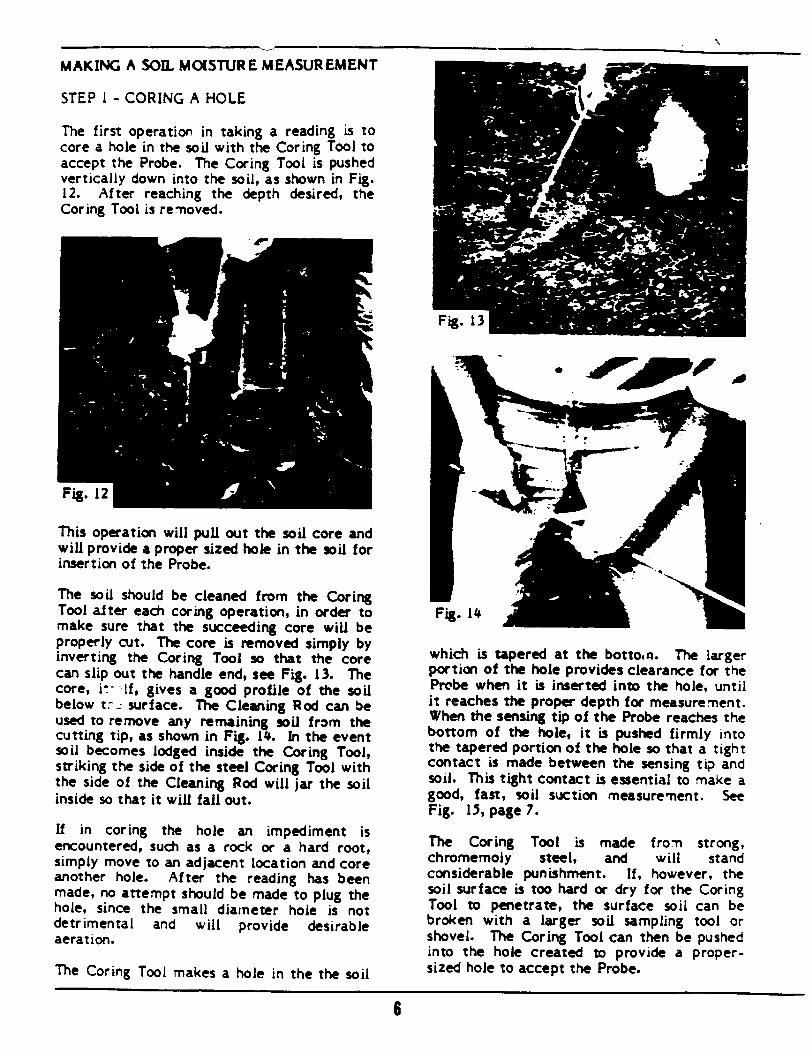
N
MAKING A SOIL MOISTURE MEASUREMENT
STEP I - CORING A HOLE
The first operation in taking a reading is to core a hole in the soil with the Coring Tool to accept the Probe. The Coring Tool is pushed vertically down into the soil, as shown in Fig. 12. After reaching the depth desired, the Coring Tool is removed.
This operation will pull out the soil core and will provide a proper sized hole in the soil for insertion of the Probe.
The soil should be cleaned from the Coring Tool after each coring operation, in order to make sure that the succeeding core will be properly cut. The core is removed simply by inverting the Coring Tool so that the core can slip out the handle end, see Fig. 13. The core, i- If, gives a good profile of the soil below t-. surface. The Cleaning Rod can be used to remove any remaining soil from the cutting tip, as shown in Fig. 14. In the event soil becomes lodged inside the Coring Tool, striking the side of the steel Coring Tool with the side of the Cleaning Rod will jar the soil inside so that it will fall out.
If in coring the hole an impediment is encountered, such as a rock or a hard root, simply move to an adjacent location and core another hole. After the reading has been made, no attempt should be made to plug the hole, since the small diameter hole is not detrimental and will provide desirable aeration.
The Coring Tool makes a hole in the the soil
which is tapered at the bottocn. The larger portion of the hole provides clearance for the Probe when it is inserted into the hole, until it reaches the proper depth for measurement. When the sensing tip of the Probe reaches the bottom of the hole, it is pushed firmly into the tapered portion of the hole so that a tight contact is made between the sensing tip and soil. This tight contact is essential to make a good, fast, soil suction measurement. See Fig. 15, page 7.
The Coring Tool is made from strong, chromemoly steel, and will stand considerable punishment. If, however, the soil surface is too hard or dry for the Coring Tool to penetrate, the surface soil can be broken with a larger soil sampling tool or shovel. The Coring Tool can then be pushed into the hole created to provide a propersized hole to accept the Probe.
6
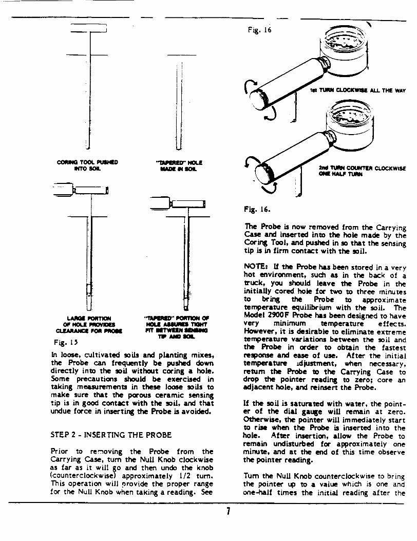
IiWEED HOLE
K-= IN SOIL
=3=::
I CORM TOOL PUSE
W4'o SOL
LANK PORTION OF HOLE PROVIDE
cLEARANcIE FOR POS
Fig. 15In loose, cultivated soils and planting mixes, the Probe can frequently be pushed down directly into the soil without coring a hole. Some precautions should be exercised in taking measurements in these loose soils to make sure that the porous ceramic sensing tip is in good contact with the soil, and that undue force in inserting the Probe is avoided.
STEP 2 - INSERTING THE PROBE
Prior to removing the Probe from the Carrying Case, turn the Null Knob clockwise as far as it will go and then undo the knob (counterclockwisel approximately 1/2 turn. This operation will provide the proper range for the Null Knob when taking a reading. See
Fig. 16.
The Probe is now removed from the Carrying Case and inserted into the hole made by the Coring Tool, and pushed in so that the sensing tip is in firm contact with the soil.
NOTE: If the Probe has been stored in a very hot environment, such as in the back of a truck, you should leave the Probe in the initially cored hole for two to three minutes to bring the Probe to approximate temperature equilibrium with the soil. The Model 2900F Probe has been designed to have very minimum temperature effects. However, it is desirable to eliminate extreme temperature variations between the soil and the Probe in order to obtain the fastest response and ease of use. After the initial temperature .djustment, when necessary, return the Probe to the Carrying Case to drop the pointer reading to zero; core an adjacent hole, and reinsert the Probe.
If the soil is saturated with water, the pointer of the dial gauge will remain at zero. Otherwise, the pointer will immediately start to rise when the Probe is inserted into the hole. After insertion, allow the Probe to remain undisturbed for approximately one minute, and at the end of this time observe the pointer reading.
"Turn the Null Knob counterclockwise to bring the pointer up to a value which is one and one-half times the initial reading after the
7
"•*OW~" PORTION OF HOLE -SUR TUGH "m NETW N SmINI
TP AND SOIL
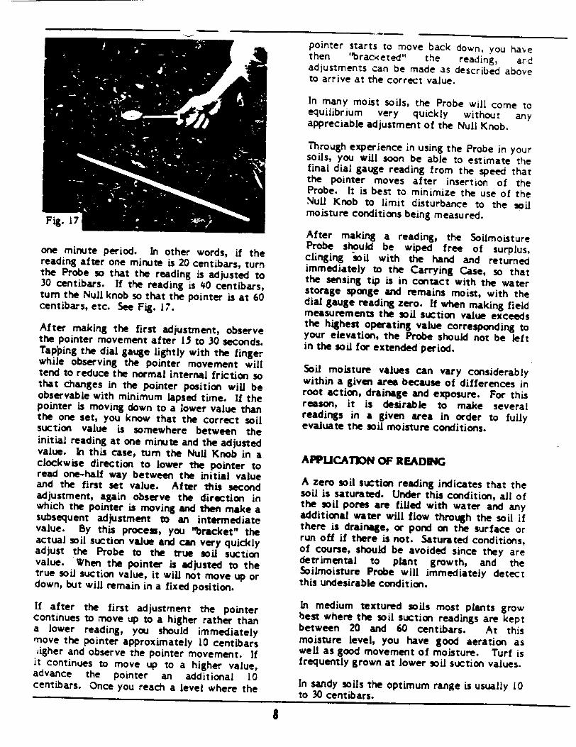
one minute period. In other words, if the reading after one minute is 20 centibars, turn the Probe so that the reading is adjusted to 30 centibars. If the reading is 40 centibars, turn the Null knob so that the pointer is at 60 centibars, etc. See Fig. 17.
After making the first adjustment, observe the pointer movement after l1 to 30 seconds. Tap'ping the dial gauge lightly with the finger while observing the pointer movement will tend to reduce the normal internal friction so that changes in the pointer position will be observable with minimum lapsed time. If the pointer is moving down to a lower value than the one set, you know that the correct soil suction value is somewhere between the initial reading at one minute and the adjusted value. In this case, turn the Null Knob in a clockwise direction to lower the pointer to read one-half way between the initial value and the first set value. After this second adjustment, again observe the direction in which the pointer is moving and then make a subsequent adjustment to an intermediate value. By this proces, you "bracket" the actual soil suction value and can very quickly adjust the Probe to the true soil suction value. When the pointer is adjusted to the true soil suction value, it will not move up or down, but will remain in a fixed position.
If after the first adjustment the pointer continues to move up to a higher rather than a lower reading, you should immediately move the pointer approximately 10 centibars digher and observe the pointer movement. If it continues to move up to a higher value, advance the pointer an additional 10 centibars. Once you reach a level where the
pointer starts to move back down, you have then "bracketed" the reading, ard adjustments can be made as described above to arrive at the correct value.
In many moist soils, the Probe will come to equilibrium very quickly without any appreciable adjustment of the Null Knob.
Through experience in using the Probe in your soils, you will soon be able to estimate the final dial gauge reading from the speed that the pointer moves after insertion of the Probe. It is best to minimize the use of the Null Knob to limit disturbance to the soil moisture conditions being measured.
After making a reading, the Soilmoisture Probe should be wiped free of surplus, clinging soil with the hand and returned immediately to the Carrying Case, so that the sensing tip is in contact with the water storage sponge and remains moist, with the dial gauge reading zero. If when making field measurements the soil suction value exceeds the highest operating value corresponding to your elevation, the Probe should not be left in the soil for extended period.
Soil moisture values can vary considerably within a given area because of differences in root action, drainage and exposure. For this reason, it is desirable to make several readings in a given area in order to fully evaluate the soil moisture conditions.
APPUCATION OF READING
A zero soil suction reading indicates that the soil is saturated. Under this condition, all of the soil pores are filled with water and any additional water will flow through the soil if there is drainage, or pond on the surface or run off if there is not. Saturated conditions, of course, should be avoided since they are detrimental to plant growth, and the Soilmoisture Probe will immediately detect this undesirable condition.
In medium textured soils most plants grow best where the soil suction readings are kept between 20 and 60 centibars. At this moisture level, you have good aeration as well as good movement of moisture. Turf is frequently grown at lower soil suction values.
In sandy soils the optimum range is usually 10 to 30 centibars.
8
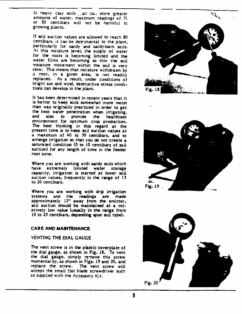
Fig. 20
9
In heavy clay soils -at ca,, store greater amounts of water, maximum readings of 7C* or 80 centibars will not be harmful tc growing plants.
If soil suction values are allowed to reach 80 centibars, it can be detrimental to the plant, particularly for sandy and sandyloam soils. At this moisture level, the supply of water for the roots is becoming limited and the water films are becoming so thin the soil moisture movement within the soil is very slow. This means that moisture withdrawn by a root, in a given area, is not readily replaced. As a result, under conditions of bright sun and wind, destructive stress conditions can develop in the plant. FigIS
It has been determined in recent years that it is better to keep soils somewhat more moist than was originally practiced in order to get the best water penetration when irrigating, and also to provide the healthiest environment for optimum crop production. The best thinking in this regard at the present time is to keep soil suction values at a maximum of 40 to 50 centibars, and to arrange irrigation so that you do not create a saturated condition (0 to 10 centibars of soil suction) for any length of time in the feeder root zone.
Where you are working with sandy soils which have extremely limited water storage capacity, irrigation is started at lower soil suction values, frequently in the range of 15 44 to 20 centibars. Fig 1 Fi.19. Where you are working with drip irrigation systems and the readings are made approximately 12" away from the emitter, soil suction should be maintained at a relatively low value (usually in the range from 10 to 25 centibars, depending upon soil type).
CARE AND MADNTENANCE
VENTING THE DIAL GAUGE
The vent screw is in the plastic coverplate of the dial gauge, as shown in Fig. 18. To vent the dial gauge, simply re-nove this screw momentarily, as shown in Figs. 19 and 20, and replace the screw. The vent screw will accept the small flat blade screwdriver such as supplied with the Accessory Kit.
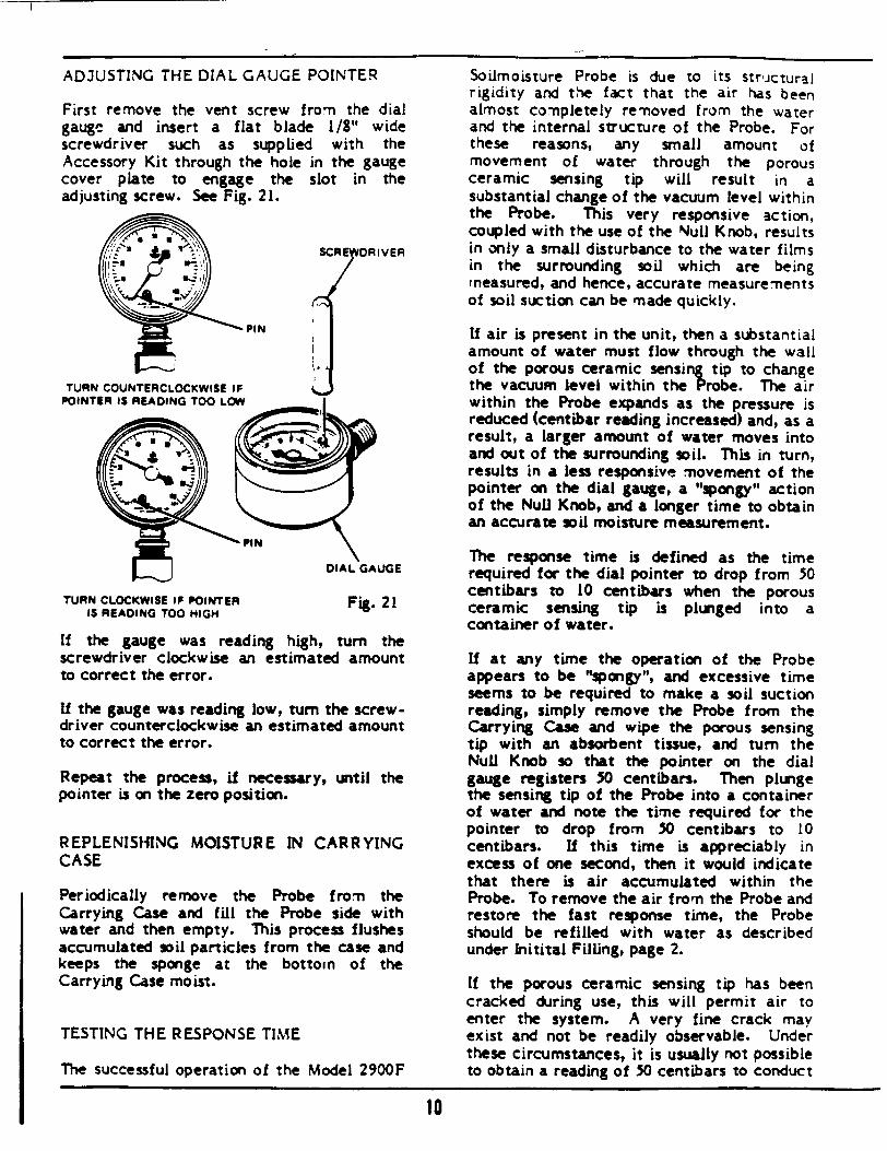
ADJUSTING THE DIAL GAUGE POINTER
First remove the vent screw from the dial gauge and insert a flat blade 1/8" wide screwdriver such as supplied with the Accessory Kit through the hole in the gauge cover plate to engage the slot in the adjusting screw. See Fig. 21.
TURN CLOCKWISE IF POINTER 15 READING TOO HIGH
Fig. 21
If the gauge was reading high, turn the screwdriver clockwise an estimated amount to correct the error.
If the gauge was reading low, turn the screwdriver counterclockwise an estimated amount to correct the error.
Repeat the process, if necessary, until the pointer is on the zero position.
REPLENIStilNG MOISTURE IN CARRYING CASE
Periodically remove the Probe from the Carrying Case and fill the Probe side with water and then empty. This process flushes accumulated soil particles from the case and keeps the sponge at the bottom of the Carrying Case moist.
TESTING THE RESPONSE TIME
The successful operation of the Model 2900F
Soilmoisture Probe is due to its structural rigidity and the fact that the air has been almost comnpletely remnoved from the water and the internal structure of the Probe. For these reasons, any small amount of movement of water through the porous ceramic sensing tip will result in a substantial change of the vacuum level within the Probe. This very responsive action, coupled with the use of the Null Knob, results in only a small disturbance to the water films in the surrounding soil which are being measured, and hence, accurate measurements of soil suction can be made quickly.
If air is present in the unit, then a substantial amount of water must flow through the wall of the porous ceramic sensing tip to change the vacuum level within the Probe. The air within the Probe expands as the pressure is reduced (centibar reading increased) and, as a result, a larger amount of water moves into and out of the surrounding soil. This in turn, results in a less responsive movement of the pointer on the dial gauge, a "spongy" action of the Null Knob, and a longer time to obtain an accurate soil moisture measurement.
The response time is defined as the time required for the dial pointer to drop from 50 centibars to 10 centibars when the porous ceramic sensing tip is plunged into a container of water.
If at any time the operation of the Probe appears to be "spongy", and excessive time seems to be required to make a soil suction reading, simply remove the Probe from the Carrying Case and wipe the porous sensing tip with an absorbent tissue, and turn the Null Knob so that the pointer on the dial gauge registers 50 centibars. Then plunge the sensing tip of the Probe into a container of water and note the time required for the pointer to drop from 50 centibars to 10 centibars. If this time is appreciably in excess of one second, then it would indicate that there is air accumulated within the Probe. To remove the air from the Probe and restore the fast response time, the Probe should be refilled with water as described under Initital Filling, page 2.
If the porous ceramic sensing tip has been cracked during use, this will permit air to enter the system. A very fine crack may exist and not be readily observable. Under these circumstances, it is usually not possible to obtain a reading of 50 centibars to conduct
10
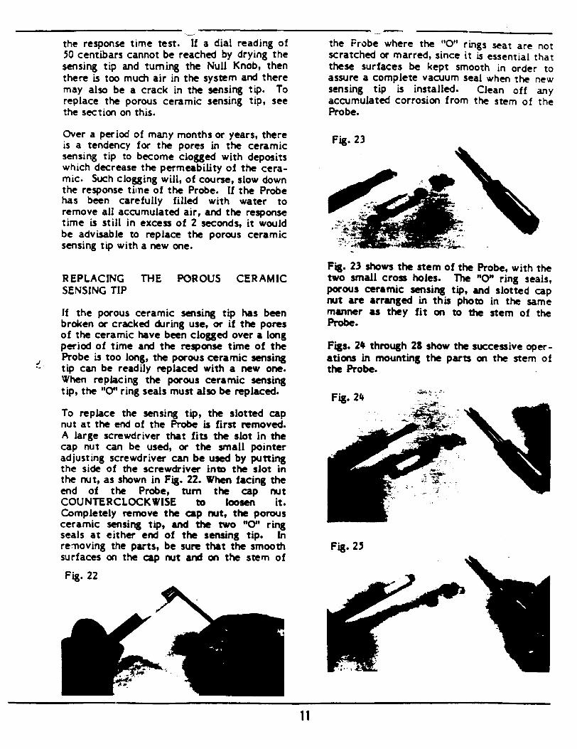
the response time test. If a dial reading of 50 centibars cannot be reached by drying the sensing tip and turning the Null Knob, then there is too much air in the system and there may also be a crack in the sensing tip. To replace the porous ceramic sensing tip, see the section on this.
Over a period of many months or years, there is a tendency for the pores in the ceramic sensing tip to become clogged with deposits which decrease the permeability of the ceramic. Such clogging will, of course, slow down the response time of the Probe. If the Probe has been carefully filled with water to remove all accumulated air, and the response time is still in excess of 2 seconds, it would be advisable to replace the porous ceramic sensing tip with a new one.
REPLACING THE POROUS CERAMIC SENSING TIP
If the porous ceramic sensing tip has been broken or cracked during use, or if the pores of the ceramic have been clogged over a long period of time and the response time of the Probe is too long, the porous ceramic sensing tip can be readily replaced with a new one. When replacing the porous ceramic sensing tip, the "0" ring seals must also be replaced.
To replace the sensing tip, the slotted cap nut at the end of the Probe is first removed. A large screwdriver that fits the slot in the cap nut can be used, or the small pointer adjusting screwdriver can be used by putting the side of the screwdriver into the slot in the nut, as shown in Fig. 22. When facing the end of the Probe, turn the cap nut COUNTERCLOCKWISE to loosen it. Completely remove the cap nut, the porous ceramic sensing tip, and the two "0" ring seals at either end of the sensing tip. In removing the parts, be sure that the smooth surfaces on the cap nut and on the stem of
Fig. 22
Fig. 23 shows the stem of the Probe, with the two small cross holes. The "0" ring seals, porous ceramic sensing tip, and slotted cap nut are arranged in this photo in the same manner as they fit on to the stem of the Probe.
Figs. 24 through 28 show the successive operations in mounting the parts on the stem of the Probe.
Fig. 24
Fig. 25
11
the Probe where the "0" rings seat are not scratched or marred, since it is essential that these surfaces be kept smooth in order to assure a complete vacuum seal when the new sensing tip is installed. Clean off any accumulated corrosion from the stem of the Probe.
Fig. 23
xoý
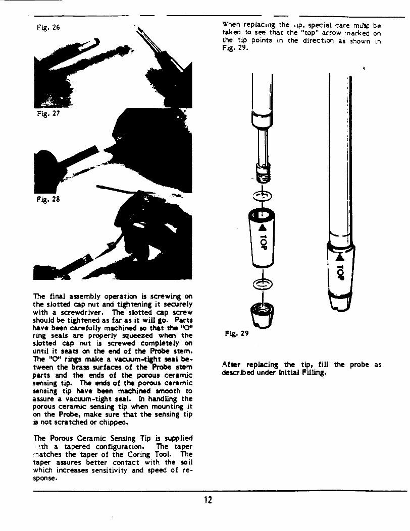
When replacing the LLp, special care mu'V be taken to see that the "top" arrow marked on the tip points in the direction as shown in Fig. 29.
The final assembly operation is screwing on the slotted cap nut and tightening it securely with a screwdriver. The slotted cap screw should be tightened as far as it will go. Parts have been carefully machined so that the "0' ring seals are properly squeezed when the slotted cap nut is screwed completely on until it seats on the end of the Probe stem. The "'0 rings make a vacuum-tight seal between the brass surfaces of the Probe stem parts and the ends of the porous ceramic sensing tip. The ends of the porous ceramic sensing tip have been machined smooth to assure a vacuum-tight seal. In handling the porous ceramic sensing tip when mounting it on the Probe, make sure that the sensing tip is not scratched or chipped.
The Porous Ceramic Sensing Tip is supplied Sit h a t a p e r e d c o n f i g u r a t i o n . T h e t a p e r
:-atches the taper of the Coring Tool. The taper assures better contact with the soil which increases sensitivity and speed of response.
-4 0
Fig. 29
After replacing the tip, fill the probe as described under Initial Filling.
12
1*. p
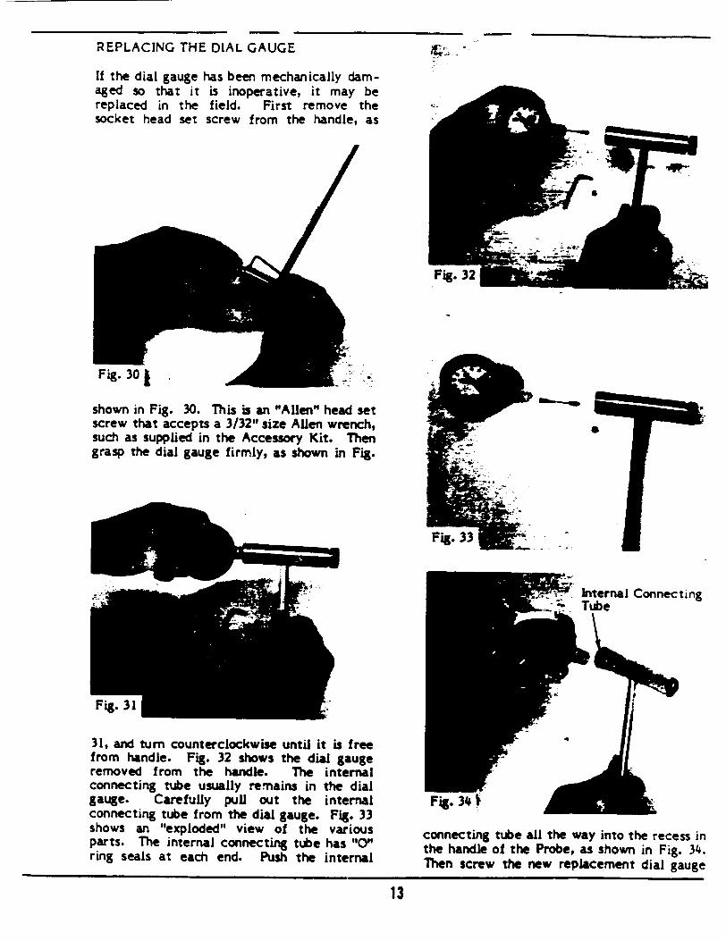
REPLACING THE DIAL GAUGE
If the dial gauge has been mechanically damaged so that it is inoperative, it may be replaced in the field. First remove the socket head set screw from the handle, as /
shown in Fig. 30. This is an "Allen" head set screw that accepts a 3/32' size AUen wrench, such as supplied in the Accessory Kit. Then grasp the dial gauge firmly, as shown in Fig.
31, and turn counterclockwise until it is free from handle. Fig. 32 shows the dial gauge removed from the handle. The internal connecting tube usually remains in the dial gauge. Carefully pull out the internal connecting tube from the dial gauge. Fig. 33 shows an "exploded" view of the various parts. The internal connecting tube has "CY0 ring seals at each end. Push the internal
connecting tube all the way into the recess in the handle of the Probe, as shown in Fig. 34. Then screw the new replacement dial gauge
13
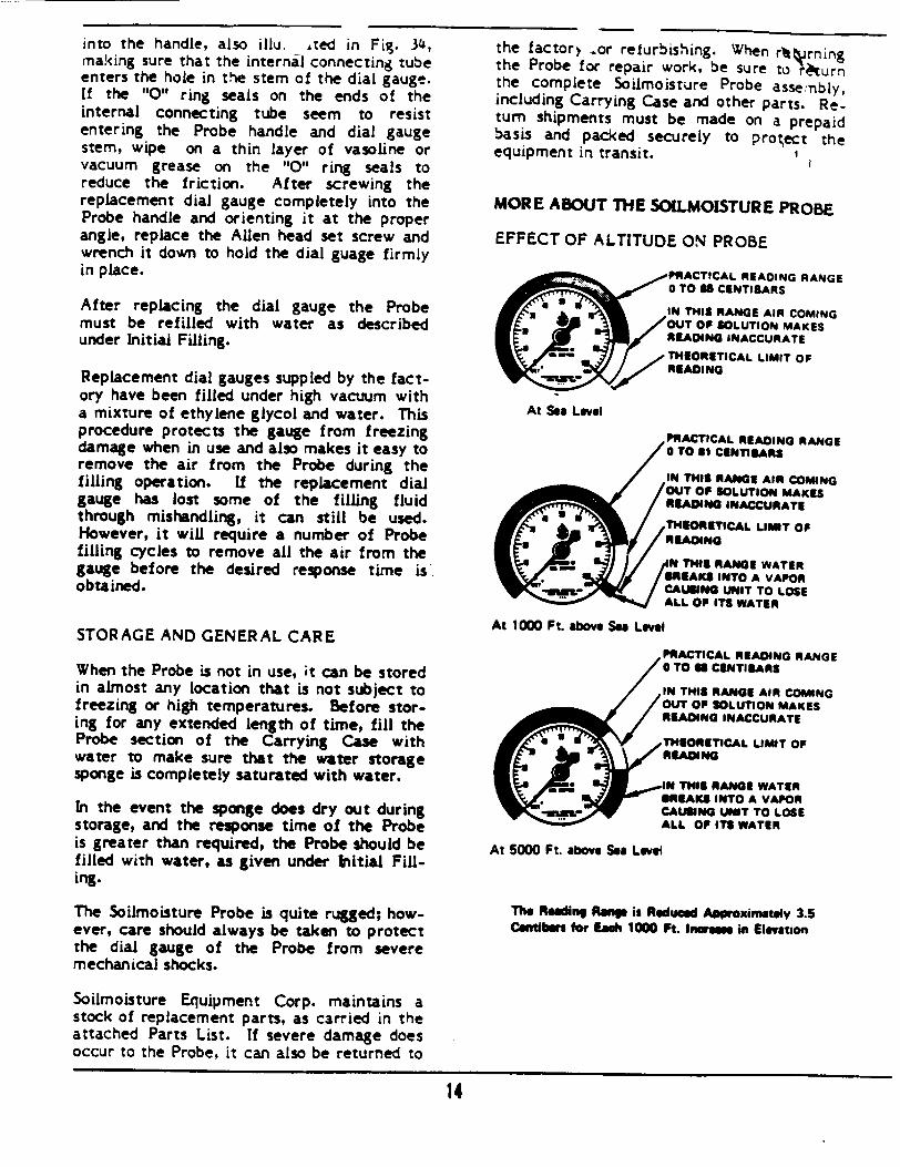
into the handle, also illu. ,ted in Fig. 34, making sure that the internal connecting tube enters the hole in the stem of the dial gauge. If the "0" ring seals on the ends of the internal connecting tube seem to resist entering the Probe handle and dial gauge stem, wipe on a thin layer of vasoline or vacuum grease on the "O" ring seals to reduce the friction. After screwing the replacement dial gauge completely into the Probe handle and orienting it at the proper angle, replace the Allen head set screw and wrench it down to hold the dial guage firmly in place.
After must under
replacing the dial gauge the Probe be refilled with water as described Initial Filling.
Replacement dial gauges suppled by the factory have been filled under high vacuum with a mixture of ethylene glycol and water. This procedure protects the gauge from freezing damage when in use and also makes it easy to remove the air from the Probe during the filling operation. If the replacement dial gauge has lost some of the filling fluid through mishandling, it can still be used. However, it will require a number of Probe filling cycles to remove all the air from the gauge before the desired response time is obtained.
STORAGE AND GENERAL CARE
When the Probe is not in use, ;t can be stored in almost any location that is not subject to freezing or high temperatures. Before storing for any extended length of time, fill the Probe section of the Carrying Case with water to make sure that the water storage sponge is completely saturated with water.
In the event the sponge does dry out during storage, and the response time of the Probe is greater than required, the Probe should be filled with water, as given under Initial Filling.
The Soilmoisture Probe is quite rugged; however, care should always be taken to protect the dial gauge of the Probe from severe mechanical shocks.
the factory .or refurbishing. When r% rning the Probe for repair work, be sure to 'turn the complete Soilmoisture Probe asse:nbly, including Carrying Case and other parts. Return shipments must be made on a prepaid basis and packed securely to protect the equipment in transit.
MORE ABOUT THE SOILMOISTURE PROBE
EFFECT OF ALTITUDE ON PROBE
PRACTICAL READING RANGE 0 TO IS CENTISARS
IN THIS RANGE AIR COMING OUT OF SOLUTION MAKES READING INACCURATE
THEORETICAL LIMIT OF ~READING
At Sea Level
PRACTICAL READING RANGE 0 TO S1 CINTIIARS
OUT OF SOLUTION MAKES READING INACCURATE
THEORETICAL LIM.T OF
SPEAKS INTO A VAPOR CAUSING UNIT TO LOSE
At 1000 Ft. above Sea Level
PRACTICAL READING RANGE O TO U CIENTISARS
IN THIS RANGE AIR COMING OUT OP SOLUTION MAKES READING INACCURATE
e THEORETICAL LIMIT OP READING
- IN THIS RANGE WATER SN/BREAKS INTO A VAPOR CAUSING UNIT TO LOSE ALL OF ITS WATER
At 5000 Ft. above Sea Level
The Reading Rasp is Reduced Approximatoely 3.5 Centibm for Each 1000 Ft. Inwesee in Elevation
Soilmoisture Equipment Corp. maintains a stock of replacement parts, as carried in the attached Parts List. If severe damage does occur to the Probe, it can also be returned to
14

PRINCIPLES INVOLVL-- IN THE OPERATION OF A TENSIOMETER-TYPE MEASURING INSTRUMENT
SRemovable Cap
/
Fig. 35 above shows a section view cf a tensiometer in place in the soil. A tensiometer consists essentially of a tube, sealed at one end by a porous ceramic cup which is in contact with the soil. The other end of the tube is above ground and is connected to a vacuum gauge. This end of the tube is sealed with a removable cap after the tube has been filled completely with water.
The insert in Fig. 35 shows a magnified view of the porous cup in contact with the soil particles. The special thing about the porous ceramic is the size of the pores. The pores are reasonably uniform and of controlled maximum size. When the porous ceramic is wetted and the pores filled with water, the surface tension of the water at the air-water interface at each of the pores, seals the pores. Water can flow through the pores, but the water film at each pore acts like a thin rubber diaphragm and will not let free air pass, throughout the working range of the tensiometer.
pores in the ceramic cup. These same strong molecular forces make it increasingly difficult for plants to extract moisture from the soil as the soil dries out.
As water is sucked from the tensiometer by the soil, a partial vacuum is created in the tensiometer, since the unit is completely sealed except for the porous cup. As more water is removed, the vacuum inside the unit becomes higher. The amount of the vacuum is registered on the vacuum dial gauge. Water is sucked from the tensiometer by the soil until such time as the vacuum created inside the tensiometer is just sufficient to overcome the suction of the soil. At this point, an equilibrium is reached and water ceases to flow from the cup. The tensiometer then reads directly the amount of '!poil suction". As the soil moisture is further depleted through evaporation, drainage, or the action of plant roots, the soil suction increases. More water is then sucked from the tensiometer until the vacuum in the unit is increased and a new equilibrium point reached.
When water is added to the soil fro-n rainfall or irrigation, the soil suction is reduced. Then the high vacuum in the tensiometer causes soil moisture to be drawn from the soil through the walls of the porous cup into the unit. This flow of water back into the tensiometer reduces the vacuum. The flow continues until the vacuum in the tensiometer drops to the value where it is just balanced by the soil suction. If water is added to the soil until the soil is completely saturated, then the vacuum dial gauge on the tensiometer will drop until it reads zero.
As outlined above, a tensiometer always is maintaining a balance with the soil suction, and the vacuum gauge on the unit indicates the value of the soil suction at the porous cup.
The insert also shows the water film which surrounds each soil particle. These films of water are bound to each of the soil particles by strong molecular forces. As soil dries out, these water films become thinner and more tightly bound. The "tension" thus produced within these water films causes water to be sucked from the tensiometer through the
15
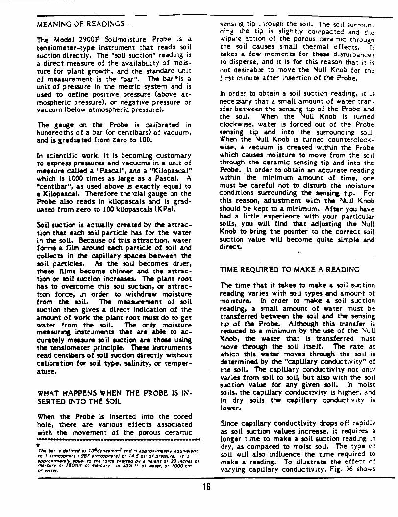
MEANING OF READINGS -
The Model 2900F Soiliroisture Probe is a tensiometer-type instrument that reads soil suction directly. The "soil suction" reading is a direct measure of the availability of moisture for plant growth, and the standard unit of measurement is the "bar". The bar'is a unit of pressure in the metric system and is used to define positive pressure (above atmospheric pressure), or negative pressure or vacuum (below atmospheric pressure).
The gauge on the Probe is calibrated in hundredths of a bar (or centibars) of vacuum, and is graduated from zero to 100.
In scientific work, it is becoming mustomary to express pressures and vacuums in a unit of measure called a "Pascal", and a "Kilopascal" which is 1000 times as large as a Pascal. A "centibar", as used above is exactly equal to a Kilopascal. Therefore the dial gauge on the Probe also reads in kilopascals and is graduated from zero to 100 kilopascals (KPa).
Soil suction is actually created by the attraction that each soil particle has for the water in the soil. Because of this attraction, water forms a film around each particle of soil and collects in the capillary spaces between the soil particles. As the soil becomes drier, these films become thinner and the attraction or soil suction increases. The plant root has to overcome this soil suction, or attraction force, in order to withdraw moisture from the soil. The measurement of soil suction then gives a direct indication of the amount of work the plant root must do to get water from the soil. The only moisture measuring instruments that are able to accurately measure soil suction are those using the tensiometer principle. These instruments read centibars of soil suction directly without calibration for soil type, salinity, or temperature.
WHAT HAPPENS WHEN THE PROBE IS INSERTED INTO THE SOIL
When the Probe is inserted into the cored hole, there are various effects associated with the movement of the porous ceramic
The bar s defined as F06dynec'cm2
and is aoOroxzma retv eOupvalenr to I arrmolonere f.987 rtmosoetere) of 74.5 0Sl of pressure. it aODroximaota/v eausi to Me 'orce exerreo by a heighr of 30 mncnes of mercury or 750mm o mercury . or 333 ft. of werer. or 7000 cm of water.
sensing tip .,irougn the soil. The soil surround&rg che tip is slightly co'npacted and the wipu-. action of the porous ceramic through the soil causes small thermal effects. It takes a few moments for these disturbances to disperse, and it is for this reason that it is not desirable to move the Null Knob for the first minute after insertion of the Probe.
In order to obtain a soil suction reading, it is necessary that a small amount of water transfer between the sensing tip of the Probe and the soil. When the Null Knob is turned clockwise, water is forced out of the Probe sensing tip and into the surrounding soil. When the Null Knob is turned counterclockwise, a vacuum is created within the Probe which causes moisture to move from the soil through the ceramic sensing tip and into the Probe. In order to obtain an accurate reading within the minimum amount of time, one must be careful not to disturb the moisture conditions surrounding the sensing tip. For this reason, adjustment with the Null Knob should be kept to a minimum. After you have had a little experience with your particular soils, you will find that adjusting the Null Knob to bring the pointer to the correct soil suction value will become quite simple and direct.
TIME REQUIRED TO MAKE A READING
The time that it takes to make a soil suction reading varies with soil types and amount of moisture. In order to make a soil suction reading, a small amount of water must be transferred between the soil and the sensing tip of the Probe. Although this transfer is reduced to a minimum by the use of the Null Knob, the water that is transferred must move through the soil itself. The rate at which this water moves through the soil is determined by the "capillary conductivity" of the soil. The capillary conductivity not only varies from soil to soil, but also with the soil suction value for any given soil. In moist soils, the capillary conductivity is higher, and in dry soils the capillary conductivity is lower.
Since capillary conductivity drops off rapidly as soil suction values increase, it requires a longer time to make a soil suction reading in dry, as compared to moist soil. The type ot soil will also influence the time required to make a reading. To illustrate the effect of varying capillary conductivity, Fig. 36 shows
16
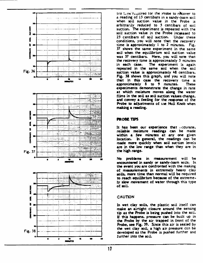
I6-
4g�
I N
! U
I
i
W
Fig.
I
Fig..
3
F-.U1
8
0 S U minanhI
15mA
.. . .. .. .
-. 7.
...........
*t • -.• .. .. ; : : ....: . ....: .: : 7:: : : : : : : : :: :
* S U IS U U
7-f .. . . . ... . -i i
37-
. .. .. . ... . .- . . .-
It has been our experience that ,,,icurate, reiiable moisture readings can be made within a few minutes at any one given location. In general, the readings can be made more quickly when soil suction levels are in the low range than when they are in the high range.
No problems in measurement will be encountered in sandy or sandy-loam soils. In the event you are confronted with the making of measurements in extremely heavy clay soils, more time than normal will be required to reach equilibrium because of the extremely slow movement of water through this type of soil.
CAUTION
In wet clay soils, the plastic soil itself can make an airtight closure around the sensing tip as the Probe is being pushed into the soil. If this happens, pressure can be built up in the Probe by the air trapped in front of the Probe, see Fig. 39. Since this air is sealed by the wet clay soil, a high air pressure can be developed as the Probe is pushed further and further into the soil.
22
17
PROBE TIPS
tWe -..ne-rn.;uireG tor the Probe to rkover to a reading of 13 centibars in a sandy-loam soil when soil suction value in the Probe is arbitrarily reduced to 5 centibars of soil suction. The experiment is repeated with the soil suction value in the Probe incqeased to 25 centibars of soil suction. Under these conditions, you will note that the recovery time is approximately I to 2 minutes. Fig. 37 shows the same experiment in the same soil when the equilibrium soil suction value was 37 centibars. Here, you will note that the recovery time is approximately 3 minutes in each case. The experiment is again repeated in the same soil when the soil suction value is approximately 43 centibars. Fig. 33 shows this graph, and you will note that in this cae the recovery time is approximately 8 to 9 minutes. These expeciments demonstrate the change in rate at which moisture moves along the water films in the soil as soil suction values change, and convey a feeling for the reponse of the Probe to adjustments of tie NuU Knob when making a reading.
w
3
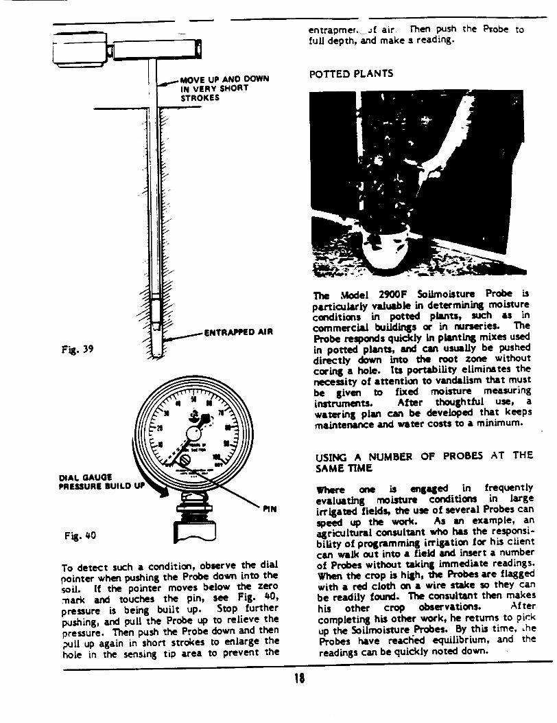
-ENTRAPPED AIR
DIAL GAUGE PRESSURE BUILD
Fig. 40N
To detect such a condition, observe the dial pointer when pushing the Probe down into the soil. If the pointer moves below the zero -hark and touches the pin, see Fig. 40,
pressure is being built up. Stop further
pushing, and pull the Probe up to relieve the pressure. Then push the Probe down and then
pull up again in short strokes to enlarge the hole in the sensing tip area to prevent the
entrapmer. Jf air full depth, and make
POTTED PLANTS
rhen push the Probe to a reading.
The Model 2900F Soilmoisture Probe is particularly valuable in determining moisture conditions in potted plants, such as in commercial buildings or in nurseries. The Probe responds quickly in planting mixes used in potted plants, and can usually be pushed directly down into the root zone without coring a hole. Its portability eliminates the necessity of attention to vandalism that must be given to fixed moisture measuring instruments. After thoughtful use, a watering plan can be developed that keeps maintenance and water costs to a minimum.
USING A NUMBER OF PROBES AT THE SAME TIME
Where one is engaged in frequently evaluating moisture conditions in large irrigated fields, the use of several Probes can speed up the work. As an example, an agricultural consultant who has the responsibility of programming irrigation for his client can walk out into a field and insert a number of Probes without taking immediate readings. When the crop is high, the Probes are flagged with a red cloth on a wire stake so they can be readily found. The consultant then makes his other crop observations. After completing his other work, he returns to pirk up the Soilmoisture Probes. By this time, Lhe Probes have reachied equilibrium, and the readings can be quickly noted down.
18
Fig. 39
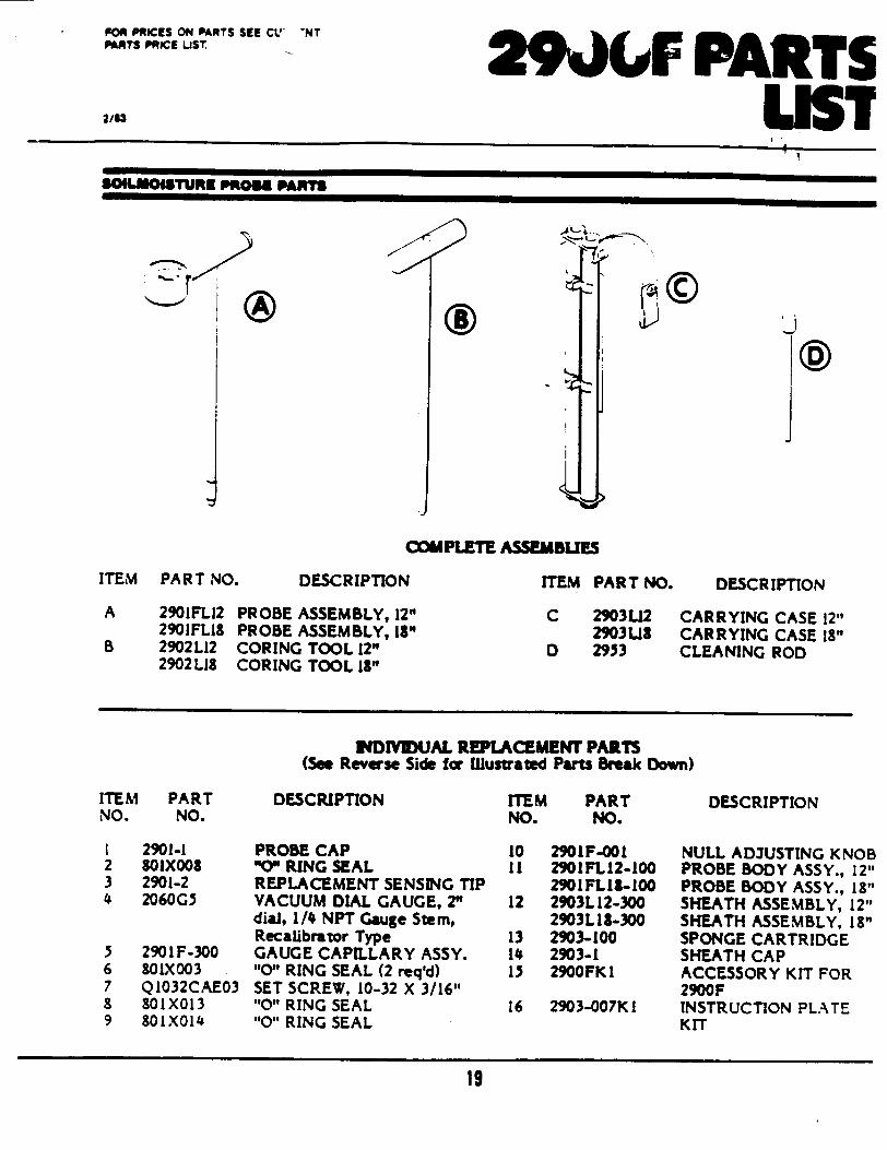
FOR PRICES ON PARTS SEE CVL NT PARTS PRICE LIST
2/93
29JLF PARTS LIST
�a.a �------
W01%A1e TURK PRUOW PAmmT
COMPLETE ASSEMBLES
ITEM PAR T NO.
A 2901FL12 I 2901FLIS
B 2902L12 ( 2902 L8 C
DESCRIPTION
PROBE ASSEMBLY, 12" )ROBE ASSEMBLY, 18" :ORING TOOL 12" :ORING TOOL 13"
ITEM PART NO.
C 2903142 29031.8
D 2953
DESCR IPTION
CARRYING CASE 12" CARRYING CASE 18" CLEANING ROD
INDIYIUAL REPLACEMENT PARTS (See Reverse Side fcr Ulustrated Parts Break Down)
ITEM PART NO. NO.
1 2901-1 2 SOIX008 3 2901-2 4 2060G5
5 2901F-300 6 801X003 7 QI032CAE03 8 801X013 9 801X01 4
DESCRIPTION
PROBE CAP "O" RING SEAL REPLACEMENT SENSING TIP VACUUM DIAL GAUGE, 2" dial, 1/ NPT Gauge Stem, Recalibrator Type GAUGE CAPILLARY ASSY. "O" RING SEAL (2 req'd) SET SCREW, 10-32 X 3/16" "O" RING SEAL "0" RING SEAL
ITEM PART NO. NO.
10 2901F-001 1I 2901FL12-100
2901FL1I-100 12 2903112-300
2903L 18-300 13 2903-100 14 2903-1 1, 2900FK 1
16 2903-007K I
DESCRIPTION
NULL AD3USTING KNOB PROBE BODY ASSY., 12" PROBE BODY ASSY., 18" SHEATH ASSEMBLY, 12" SHEATH ASSEMBLY, 18" SPONGE CARTRIDGE SHEATH CAP ACCESSORY KIT FOR 2900F INSTRUCTION PLATE KIT
19
a) ,J @

0 I.
IV 2"%
j~16
*
20
Related Documents