DS-90 Data Sheet , V 2.0b ,NOV 2012 The DS-90 is a member of the DS series of Electric Encoders, based on Netzer Precision proprietary technology. These encoders offer many advantages, some unparalleled: Low profile (10 mm). Hollow, floating shaft. No bearings or other contacting elements. High precision. High tolerance to temperature, shock, moisture, EMI, RFI and Magnetic fields. Very low weight. Analog or multiple digital interface options. Extremely low power options. The DS-90 is suited to demanding application such as: aerospace, medical, instrumentation, automation, etc. DS-90 Absolute position, rotary Electric Encoder™ The holistic structure of the Electric Encoder™ provides generous mounting tolerance, thus obviating the need for internal ball bearings. The lack of bearings and components such as flexible couplers, glass disc, light sources and detectors, along with very low power consumption makes the DS-90 encoder virtually failure free. The internally shielded, DC operated Electric Encoder™ includes an electric field generator, a field receiver, a sinusoidal shaped dielectric rotor, and processing electronics. The outputs signals of Electric Encoder™ are analog Sine / Cosine representing the rotation angle. The digital outputs are obtained by further processing which may be either internal or external to the encoder. Performance Electrical Cycles – Fine/Coarse channels 64 / 3 Angular resolution (using 12 bit A/D conversion) 19 bits Static error (with offset compensation) < 10 mDeg (0.17mrad) Maximum operational speed 750 rpm Measurement range Unlimited rotation Output Digital SSi , Incremental AqB+ index , Analog BIT (build in tests , optional) Included (SSi version) Environment - common to all types EMC IEC 6100-6-2, IEC 6100-6-4 Operating temperature range -40°C to +85°C Relative humidity <98 % - non condensing Shock endurance IEC 60068-2-27 100 g for 11 ms Vibration endurance IEC 60068-2-6 20 g 10 – 2000 Hz Protection IP 40 Electrical - common to all types Supply voltage 5V ± 5% Interconnection Ø 3.5 mm Shielded cable Mechanical Allowable mounting eccentricity , opera- tional ±0.1 mm Allowable rotor axial motion; operational ±0.1 mm Rotor inertia 2,812 gr mm 2 Total weight 50 gr Outer diameter / Inner diameter / Profile 90 /50 /10 mm Material (stator, rotor) Ultem ™ polymer Material mounting clamps , M2 S.S. ELECTROMATE Toll Free Phone (877) SERVO98 Toll Free Fax (877) SERV099 www.electromate.com [email protected] Sold & Serviced By:

Welcome message from author
This document is posted to help you gain knowledge. Please leave a comment to let me know what you think about it! Share it to your friends and learn new things together.
Transcript
DS-90 Data Sheet , V 2.0b ,NOV 2012
The DS-90 is a member of the DS series of Electric Encoders,
based on Netzer Precision proprietary technology. These
encoders offer many advantages, some unparalleled:
Low profile (10 mm).
Hollow, floating shaft.
No bearings or other contacting elements.
High precision.
High tolerance to temperature, shock, moisture, EMI, RFI and
Magnetic fields.
Very low weight.
Analog or multiple digital interface options.
Extremely low power options.
The DS-90 is suited to demanding application such as: aerospace, medical, instrumentation, automation, etc.
DS-90 Absolute position, rotary Electric Encoder™
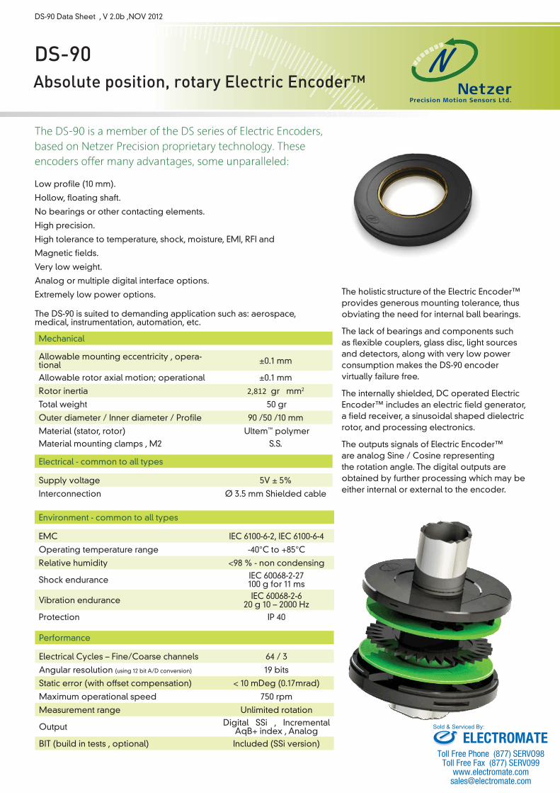
The holistic structure
of the Electric Encoder™
provides generous mounting tolerance, thus obviating the need for internal ball bearings.
The lack of bearings and components such as flexible couplers, glass disc, light sources and detectors, along with very low power consumption makes the DS-90 encoder virtually failure free.
The internally shielded, DC operated Electric Encoder™ includes an electric field generator, a field receiver, a sinusoidal shaped dielectric rotor, and processing electronics.
The outputs signals of Electric Encoder™ are analog Sine / Cosine representing the rotation angle. The digital outputs are obtained by further processing which may be either internal or external to the encoder.
Performance
Electrical Cycles – Fine/Coarse channels 64 / 3
Angular resolution (using 12 bit A/D conversion) 19 bits
Static error (with offset compensation) < 10 mDeg (0.17mrad)
Maximum operational speed 750 rpm
Measurement range Unlimited rotation
Output Digital SSi , Incremental AqB+ index , Analog
BIT (build in tests , optional) Included (SSi version)
Environment - common to all types
EMC IEC 6100-6-2, IEC 6100-6-4
Operating temperature range -40°C to +85°C
Relative humidity <98 % - non condensing
Shock endurance IEC 60068-2-27 100 g for 11 ms
Vibration endurance IEC 60068-2-6 20 g 10 – 2000 Hz
Protection IP 40
Electrical - common to all types
Supply voltage 5V ± 5%
Interconnection Ø 3.5 mm Shielded cable
Mechanical
Allowable mounting eccentricity , opera-tional ±0.1 mm
Allowable rotor axial motion; operational ±0.1 mm
Rotor inertia 2,812 gr · mm2
Total weight 50 gr
Outer diameter / Inner diameter / Profile 90 /50 /10 mm
Material (stator, rotor) Ultem™ polymer Material mounting clamps , M2 S.S.
ELECTROMATEToll Free Phone (877) SERVO98
Toll Free Fax (877) SERV099www.electromate.com
Sold & Serviced By:
- 2 -
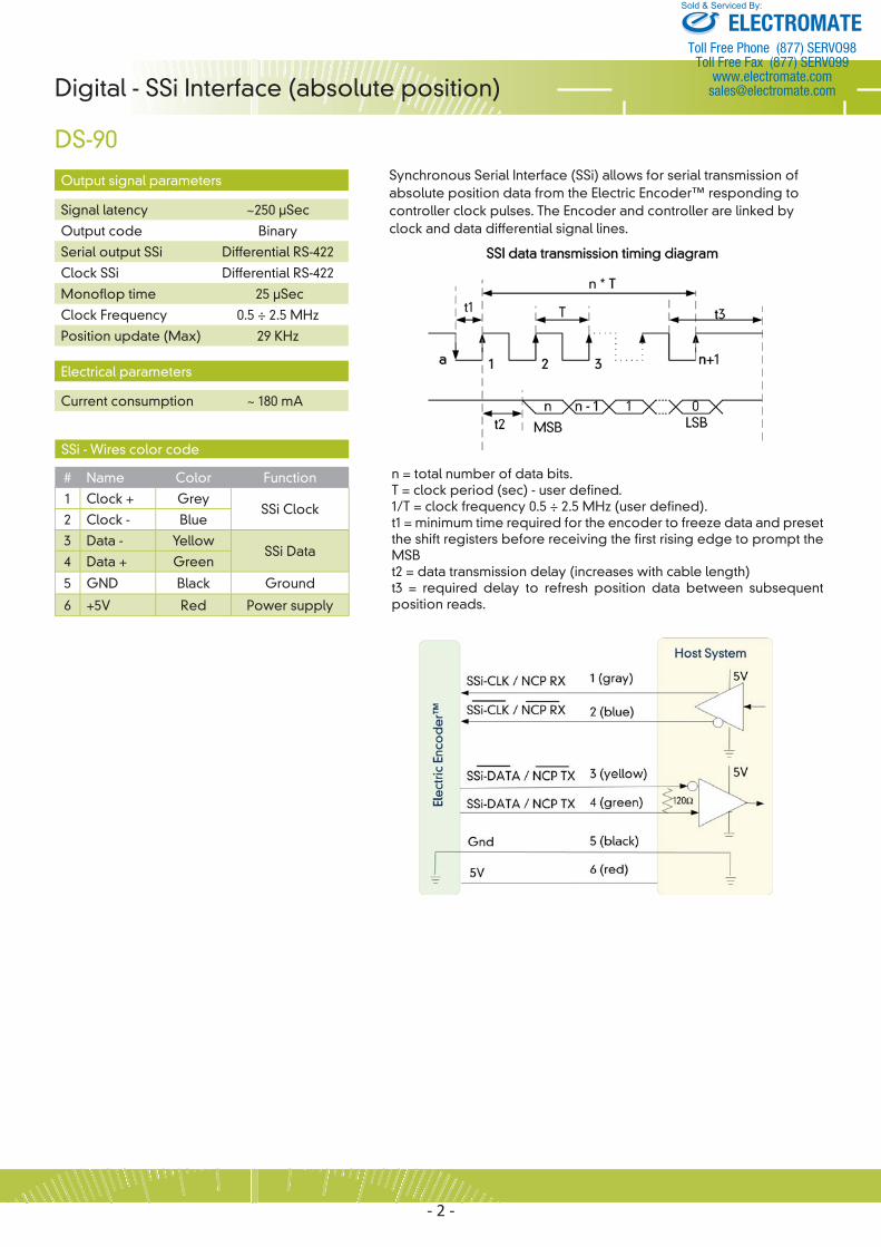
Synchronous Serial Interface (SSi) allows for serial transmission of absolute position data from the Electric Encoder™ responding to controller clock pulses. The Encoder and controller are linked by clock and data differential signal lines.
Digital - SSi Interface (absolute position)
DS-90
n = total number of data bits. T = clock period (sec) - user defined.1/T = clock frequency 0.5 ÷ 2.5 MHz (user defined). t1 = minimum time required for the encoder to freeze data and preset the shift registers before receiving the first rising edge to prompt the MSB t2 = data transmission delay (increases with cable length) t3 = required delay to refresh position data between subsequent position reads.
Output signal parameters
Signal latency ~250 μSec
Output code Binary
Serial output SSi Differential RS-422
Clock SSi Differential RS-422
Monoflop time 25 μSec
Clock Frequency 0.5 ÷ 2.5 MHz
Position update (Max) 29 KHz
SSi - Wires color code
# Name Color Function
1 Clock + GreySSi Clock
2 Clock - Blue
3 Data - YellowSSi Data
4 Data + Green
5 GND Black Ground
6 +5V Red Power supply
Electrical parameters
Current consumption ~ 180 mA
ELECTROMATEToll Free Phone (877) SERVO98
Toll Free Fax (877) SERV099www.electromate.com
Sold & Serviced By:
- 3 -
Digital - SSi Interface (absolute position)
DS-90Software tools:
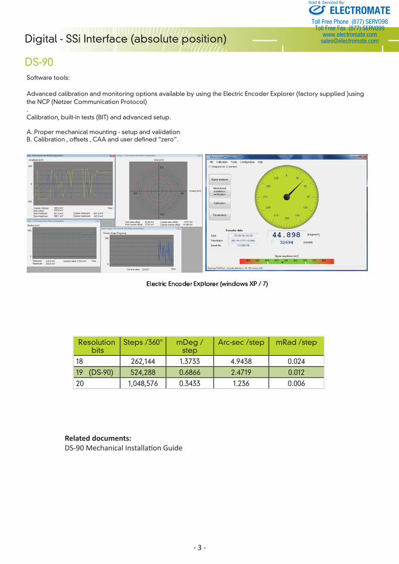
Advanced calibration and monitoring options available by using the Electric Encoder Explorer (factory supplied )using the NCP (Netzer Communication Protocol). Calibration, built-in tests (BIT) and advanced setup.
A. Proper mechanical mounting - setup and validation B. Calibration , offsets , CAA and user defined “zero”.
Resolution bits
Steps /360° mDeg /step
Arc-sec /step mRad /step
18 262,144 1.3733 4.9438 0.02419 (DS-90) 524,288 0.6866 2.4719 0.01220 1,048,576 0.3433 1.236 0.006
Related documents:DS-90 Mechanical Installa on Guide
ELECTROMATEToll Free Phone (877) SERVO98
Toll Free Fax (877) SERV099www.electromate.com
Sold & Serviced By:
- 4 -
Incremental - AqB + Index Interface
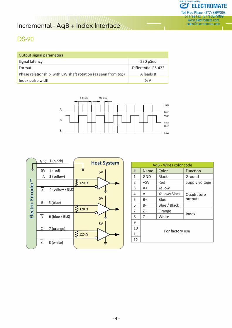
DS-90 Output signal parametersSignal latency 250 μSecFormat Diff eren al RS-422Phase rela onship with CW sha rota on (as seen from top) A leads BIndex pulse width ½ A
AqB - Wires color code# Name Color Func on 1 GND Black Ground 2 +5V Red Supply voltage3 A+ Yellow
Quadrature outputs
4 A- Yellow/Black5 B+ Blue6 B- Blue / Black7 Z+ Orange
Index8 Z- White9
For factory use101112
ELECTROMATEToll Free Phone (877) SERVO98
Toll Free Fax (877) SERV099www.electromate.com
Sold & Serviced By:
- 5 -
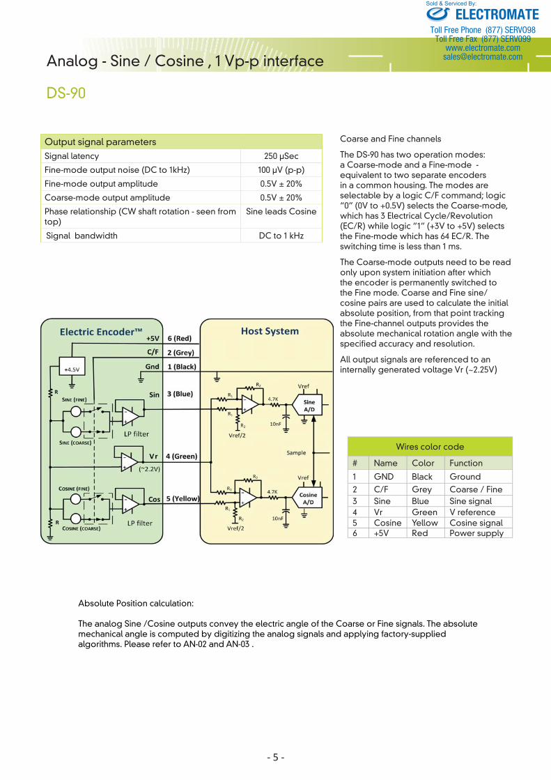
Analog - Sine / Cosine , 1 Vp-p interface
DS-90
Wires color code
# Name Color Function
1 GND Black Ground
2 C/F Grey Coarse / Fine3 Sine Blue Sine signal4 Vr Green V reference5 Cosine Yellow Cosine signal6 +5V Red Power supply
Output signal parameters Signal latency 250 μSec
Fine-mode output noise (DC to 1kHz) 100 μV (p-p)
Fine-mode output amplitude 0.5V ± 20%
Coarse-mode output amplitude 0.5V ± 20%
Phase relationship (CW shaft rotation - seen from top)
Sine leads Cosine
Signal bandwidth DC to 1 kHz
Coarse and Fine channels
The DS-90 has two operation modes: a Coarse-mode and a Fine-mode - equivalent to two separate encoders in a common housing. The modes are selectable by a logic C/F command; logic “0” (0V to +0.5V) selects the Coarse-mode, which has 3 Electrical Cycle/Revolution (EC/R) while logic ”1” (+3V to +5V) selects the Fine-mode which has 64 EC/R. The switching time is less than 1 ms.
The Coarse-mode outputs need to be read only upon system initiation after which the encoder is permanently switched to the Fine mode. Coarse and Fine sine/cosine pairs are used to calculate the initial absolute position, from that point tracking the Fine-channel outputs provides the absolute mechanical rotation angle with the specified accuracy and resolution.
All output signals are referenced to an internally generated voltage Vr (~2.25V)
Absolute Position calculation:
The analog Sine /Cosine outputs convey the electric angle of the Coarse or Fine signals. The absolute mechanical angle is computed by digitizing the analog signals and applying factory-supplied algorithms. Please refer to AN-02 and AN-03 .
ELECTROMATEToll Free Phone (877) SERVO98
Toll Free Fax (877) SERV099www.electromate.com
Sold & Serviced By:
- 6 -
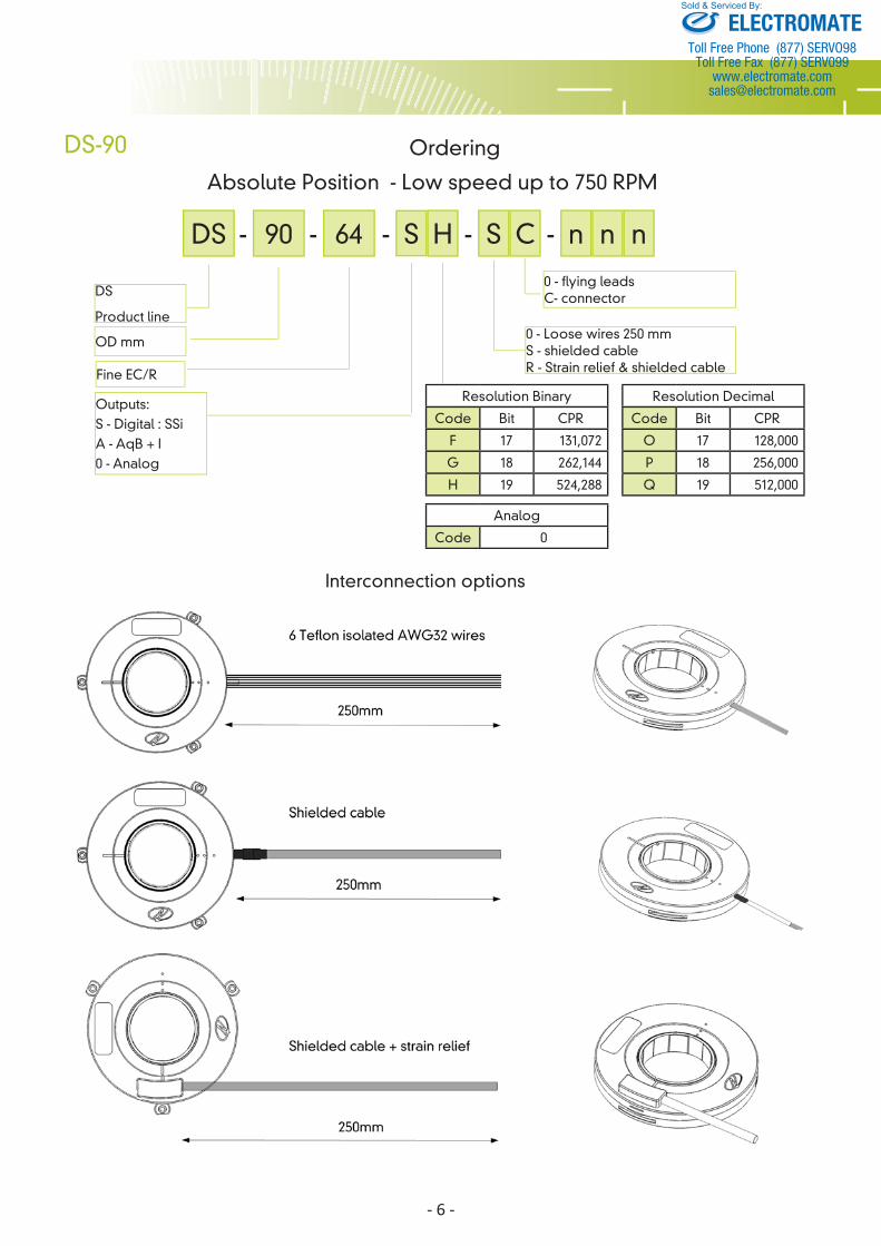
Interconnection options
DS-90
DS
Product line
OD mm
Outputs:S - Digital : SSi A - AqB + I0 - Analog
0 - Loose wires 250 mmS - shielded cable R - Strain relief & shielded cable
Ordering
Absolute Position - Low speed up to 750 RPM
Resolution Binary
Code Bit CPR
F 17 131,072
G 18 262,144
H 19 524,288
Resolution Decimal
Code Bit CPR
O 17 128,000
P 18 256,000
Q 19 512,000
DS - 90 - 64 -S- S-
Fine EC/R
H C
0 - flying leads C- connector
n- n n
Analog
Code 0
ELECTROMATEToll Free Phone (877) SERVO98
Toll Free Fax (877) SERV099www.electromate.com
Sold & Serviced By:
- 7 -
DS-90
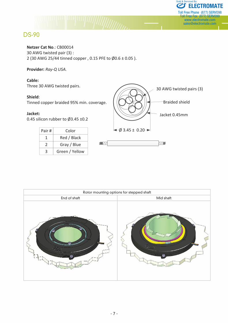
30 AWG twisted pairs (3)
Braided shield
Jacket 0.45mm
Ø 3.45 ± 0.20
Netzer Cat No.: CB0001430 AWG twisted pair (3) :2 (30 AWG 25/44 tinned copper , 0.15 PFE to Ø0.6 ± 0.05 ).
Provider: Ray-Q USA.
Cable:Three 30 AWG twisted pairs.
Shield: Tinned copper braided 95% min. coverage.
Jacket:0.45 silicon rubber to Ø3.45 ±0.2
Pair # Color123
Red / BlackGray / Blue
Green / Yellow
Rotor mounting options for stepped shaft
End of shaft Mid shaft
ELECTROMATEToll Free Phone (877) SERVO98
Toll Free Fax (877) SERV099www.electromate.com
Sold & Serviced By:
- 8 -
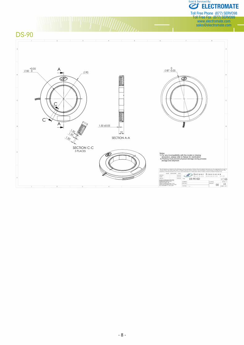
DS-90
ELECTROMATEToll Free Phone (877) SERVO98
Toll Free Fax (877) SERV099www.electromate.com
Sold & Serviced By:
Related Documents


