ELECTRICAL SAFETY MANUAL Second Edition, January 2007 NORTH DELHI POWER LIMITED (A Tata Power and Delhi Government Joint Venture) 33 KV GRID SUB STATION BUILDING, HUDSON LINES, KINGSWAY CAMP, DELHI – 110009

Welcome message from author
This document is posted to help you gain knowledge. Please leave a comment to let me know what you think about it! Share it to your friends and learn new things together.
Transcript

ELECTRICAL SAFETY MANUAL Second Edition, January 2007
NORTH DELHI POWER LIMITED (A Tata Power and Delhi Government Joint Venture)
33 KV GRID SUB STATION BUILDING, HUDSON LINES, KINGSWAY CAMP,
DELHI – 110009

2
PREFACE
It is my pleasure to present the Electrical Safety Manual for the benefit of all those who are engaged in the profession across the organization. To make it more useful, elaborate safe operating procedures have been described along with sketches / photographs wherever possible. I hope it will not only provide a new dimension but as well generate interest in the users. I need not emphasis the point here that safety needs complete attention in every aspect as it touches all sphere of our day to day life. If we desire to make accident & injury free NDPL, we have to develop a healthy safety culture not for an individual or for our fellow colleagues, but in the public interest at large and also in the interest of company’s property. I would like to take an opportunity to thank all members of Business Excellence Group (BEG) for taking pains to bring out such a valuable manual. I am confident that with your co-operation the safety culture will be strengthened on a continuous way, and in near future NDPL may be benchmarked in this aspect. Let us take pledge to make our and other’s lives safe and productive. May almighty keep all of us safe and healthy!
April 2007 Praveen Chorghade New Delhi GM (Operations)

3
FOREWORD
NDPL has completed over four years and has in this process initiated several measures aimed at improving operational, technical, financial and commercial efficiency of the organization. Towards this end, it is the valuable services of the NDPL employees which have catapulted this organization to the high level of appreciation and regard it commands today. I congratulate every employee for bringing NDPL to where it stands. While efficiency and effectiveness in all our processes are of prime importance, safety remains our first priority. I appeal to all my fellow colleagues to think about dependents who worry about your safe reaching home every day after performing duties. They always pray that no untoward incident takes place which may affect their lives. We have done so many activities to bring awareness of safety at work places to make safety a habit. We are aware of some occasions when our friends got injured, and in some sad cases even lost their lives, due to lack of awareness and practice of safety rules & procedures. I appeal to every employee to follow the safety rules & procedures of the company for the sake of safe working and happy and long life. Each one of us should involve ourselves in bringing awareness about safety among our colleagues and all concerned stakeholders. Please ensure to wear proper Personnel Protection Equipments prior to start of the day’s work. Some zones have already started taking Safety Oath very at the beginning of the day, and this good practice should be spread across the organization. Stop any activity where safety is being compromised. Most importantly, pause for a few moments before working on any energized circuit / system to think, plan and execute necessary precautionary and preventive measures. I pray to God to continuously bless our employees, associates, communities and their families.
Sunil Wadhwa April 2007 CEO & Executive Director New Delhi North Delhi Power Limited

4
Contents
CHAPTERS TITLE PAGE NOS. Safety Policy 6
1 Purpose and Scope 7 2 Definition 8 3 Do’s And Don’ts 10 4 Earthing 12 5 Permit to Work System 15 6 Safety Instructions 30 7 Housekeeping 41 8 Personnel Protective Equipments and Devices 42 9 Construction 44
10 Transportation 46 11 Safe Guarding the Public 47 12 Fire 48 13 Accident Reports, Records and Investigation 51 14 First Aid 52 15 Emergency Preparedness and Response 56 16 Safety Audits and Records 57 17 “5S” Practices 58
Annexures 63 Annexure -I Safety Document COR-P-12 64 Annexure -II Safety Concerns Committee 71 Annexure -III Near Miss / Incident Record - F01 (COR-P-12) 72 Annexure –IV Accident Reporting - F02 (COR-P-12) 73 Annexure –V Permit to Work F03 (COR-P-12) 75 Annexure –VI Permit to Work Audit F04 (COR-P-12) 77 Annexure –VII Field Job Audit -F05 (COR-P-12) 78 Annexure –VIII Tool Bag Audit -F06 (COR-P-12) 79 Annexure –IX Safety Audit -F07 (COR-P-12) 80 Annexure –X First Aid Box Record -F08 (COR-P-12) 81 Annexure –XI Fire Extinguisher Record -F09 (COR-P-12) 82 Annexure –XII Information of Accident – F10 (COR-P-12) 82 Annexure –XIII Accident Investigation Report (Local) -F11 (COR-P-12) 83
Annexure –XIV Accident Investigation Report (Accident Committee) -F12 (COR-P-12) 84
Annexure –XV Electrical Accidents Causes Sharing Form -F13 (COR-P-12) 84
Annexure –XVI Rectification of Cable Faults W01-(COS-P-06) 85 Annexure –XVII Fire Extinguisher History Card 88 Annexure –XVIII Fire Incident Report 89 Annexure –XIX Zonal Tool Kit List 90 Annexure –XX Grid Tool Kit Items 92
Annexure –XXI Work Instructions for Accident Reporting W01 – (COR-P-12) 95
Abbreviations 97 Bibliography 98
Index 99
5
AMENDMENT SHEET Amendment Details (If any)
Amendment Discard Insert Notes on Amendments No. Date Section No. Rev. No. Section No. Rev. No.

6

7
CHAPTER - 1
PURPOSE AND SCOPE
This Electrical Safety Manual provides guidelines on safety procedures and practices, especially focusing on electrical work.
It gives direction to implement requirements and achieve compliance with regard to occupational health, safety and statutory guidelines.
This Electrical Safety Manual is being widely circulated to promote an electrically safe workplace free from unauthorized exposure to electrical hazards for all employees and outsourced personnel so as to prevent accidents to themselves, the public (community) and the company’s property.
The Electrical Safety Manual shall apply to all premises (offices, Sub-Stations and Grids) of the company and electrical network system managed by the company as on date.

8
CHAPTER – 2
DEFINITIONS
To clarify the intent and meaning of the wording used in this Safety Manual, the following definitions are given:- APPROVED When applied to articles of protective equipment means that these articles have been specified for use by the NDPL's & outsourced employees as per IS Codes or by the approval authority (i.e. Safety Concerns Committee) constituted by the G.M. (Operations). AUTHORIZED PERSON An Authorized person is a person authorized under Rule No.3 of the Indian Electricity Rule 1956 to carry out such duties incidental to the transmission, distribution and use of electrical energy, the nature of which shall depend upon the technical knowledge and experience of the individual and he shall not be less in authority than a lineman, jointer, fitter and mechanic.
EARTH Earth means the conducting mass of earth or a conductor / strip / wire connected to it through very small impedance. ELECTRICAL EQUIPMENT It means all the electrical apparatus pertaining to the sub transmission, distribution and utilization of electrical energy. EMERGENCY Emergency means that an unusual condition exists which endangers life and or property. EMPLOYEE Employee means a person who is in receipt of pay, salary and other benefits from the company time to time in lieu of services render by him. HAZARD It is any unsafe act or unsafe condition that may lead to injury of persons or damage to property.
ISOLATED It means physically disconnected from all possible sources of supply.
PERMIT TO WORK It means a form of declaration issued by an Authorized Person (PSC) to another Authorized Person (sub transmission / distribution) for a work to be carried out on any equipment in normal & break down conditions.
9
POWER SYSTEM CONTROL It means the main controlling agency which controls & coordinates all switching operations of entire network (sub transmission and distribution) of NDPL including issue of PTW. PROTECTIVE DEVICES It means equipment specially designed for the protection of workmen and includes fire extinguishers also.
QUALIFIED Qualified means any person who has adequate knowledge of the hazards involved in any operation.
WORKING PARTY It means the persons under the immediate supervision of an Authorized Person.
NOTE: - All words / expressions used herein and not defined shall have the meanings assigned to them in the Indian Electricity Act – 2003 and The Indian Electricity Rules – 1956.

10
CHAPTER - 3
GENERAL SAFETY PRECAUTIONS S.No DO’s S.No DO NOT’s 1 Before replacing a lamp or handling a
fan, make sure that the supply is switched off.
1 Do not connect single pole switch or fuse in a neutral circuit, but always connect in the live or phase wire.
2 Place Safety Tagging or other warning boards on main switch before commencing work.
4 Do not close any switch, unless you are familiar with the circuit which it controls and know the reason for its being open.
3 Before working on any circuit or apparatus, make sure that the controlling switches are open and locked.
5 Do not touch or tamper with any electrical gear or conductor, unless you have made sure that it is dead and earthed. High voltage apparatus may give leakage shock or flash over even without touching.
4 Always treat circuit as live until you have proved them to be dead, the insulation of the conductor may be defective.
6 Do not work on live circuit without the orders of the authorized person. Make certain that all safety precautions have been taken.
5 Cultivate the habit or turning your face away whenever the flash or an arc may occur.
7 Do not disconnect earthing connection or render it ineffective of the safety gadgets installed on mains and apparatus.
6 Guard against arcs as well as high voltage; remember that burns from arc are very severe.
8 Do not tamper with the meter board and cut-outs, unless you are authorized to do so.
7 See that all the splices and connections are securely made.
9 Do not expose your eyes to an electrical arc. Painful injury may result even with short exposure.
8 Use extreme care when breaking an inductive circuit as dangerously high voltage is likely to result.
10 Do not close or open a switch slowly or hesitatingly. Do it quickly and positively.
9 Thoroughly discharge to earth all cables before working on cores.
11 Do not place any part of your body in circuit either to ground or across the terminal when making a connection or doing operation.
10 Test rubber gloves periodically. 12 Do not touch an electrical circuit when your hands are wet, bleeding from a cut or have an abrasion.
11 Place rubber mats in front of electrical switchboard.
13 Do not work on energized circuit without taking extra precautions, such as the use of rubber gloves. Do not use metal case flash light around apparatus which is energized.
12
Preach and practice safety at all the time. Good work can be spoiled by an accident.
12 Do not wear loose clothing, metal watch straps, bangles or finger rings while working on appliances. Do not hang clothes and such other things on electric fittings. Do not touch the circuit with bare fingers or hand or other makeshift devices to determine whether or not it is live.
13 Work deliberately and carefully. Haste causes many accidents. Be sure of what you are doing.
13 Do not work on pole or any elevated position if there is a live part on it, without the safety belt and rubber gloves and unless the authorized person stand on the
Do’s and Don’t s

11
ground nearby to direct operation and give warning. 14 Always obey the safety instructions given
by the person in-charge. 14 Do not use a ladder without a lashing rope, otherwise
the ladder should be held firmly by another person. Do not remove Safety Tags or other signs or interface with safety barriers or go beyond them.
15 Always report immediately to the person in-charge or to any other proper authority of any dangerous condition or a practice, which you may observe.
15 Do not bring naked light near battery. Smoking in the battery room is prohibited. Do not allow visitors and un-authorized person to touch or handle electrical apparatus or come within the danger zone of high voltage apparatus.
16 Ensure that all portable appliances are provided with 3 pin plug and socket connections. Also the metal work of the apparatus is effectively earthed.
16 Do not use a lamp in a metal holder fixed to the end of a loose flexible wire as a portable hand lamp. Do not disconnect a plug by pulling the flexible cable or when the switch is on.

12
CHAPTER - 4
EARTHING DEFINITIONS:- DEAD: - the term used to describe a circuit / equipment to indicate that a voltage is not applied. LIVE PART: - a conductor or conductive part intended to be energized in normal use including a neutral conductor. NEUTRAL CONDUCTOR: - a conductor connected to the neutral point of a system and capable of contributing to the transmission of Electrical Energy. EARTH GRID: - a system grounding electrodes consisting of inter connected connectors burried in the earth to provide a common ground for electrical devices and metallic structures. EARTH MAT:-a grounding system formed by a grid horizontally burried conductor / plate and which serves to dissipate the earth fault current to earth and also as equipment bonding conductor system. A. OBJECTIVES OF EARTHING The basics of safe grounding are:
1. To design and construct system that is capable to carry current under normal and fault conditions to ground.
2. The earth path should be capable of handling magnitude and duration of current as per the over-current protection of the system without any fire or flash or explosion.
3. Persons in the vicinity of earthed structures and installations shall not be exposed to the dangers of electrical shocks.
B. GENERAL GUIDELINES FOR EARTHING An effective grounding system must satisfy the following conditions: -
1. Provide a low impedance path to ground for personnel and equipment. 2. Withstand and dissipate repeated faults and surge currents 3. Provide ample corrosion allowance to various chemicals to ensure continuous service during life
of the equipment being protected. 4. Provide rugged mechanical properties for easy driving of earth electrodes with minimum
difficulty. 5. All non current carrying metal parts associated with installation shall:-
Be effectively earthed to a grounding system or mat which will limit the touch and step potential to tolerable values. Limit the ground potential rise to tolerable values so as to prevent danger due to transfer of potential through ground, earth wires, cable sheath fences, pipe lines etc. Maintain the resistance of the earth connection to such a value as to make operation of the protective device effective. C. STATUTORY STIPULATIONS
1. All medium voltage equipment shall be earthed by two separate and distinct connections.
2. As far as possible, all earth connections shall be visible for inspection.
13
3. Each earth system shall be so designed that testing of individual earth electrode should be possible.
4. Resistance of earth system shall conform to degree of shock protection desired.
D. SAFETY PRECAUTIONS FOR EARTHING The precautions mentioned below should be adapted to the extent applicable and possible. 1) Examine earthing devices periodically and always prior to their use. 2) Use only earthing switches or any other special apparatus where provided for earthing. 3) Verify that the circuit is dead by means of discharging rod. The indicator itself should first be tested on a live circuit or proving unit before and after the verification. 4) Earthing should be done in such a manner that the persons doing the job are protected by earth connections on both sides of their working zone. 5) All the three phases should be effectively earthed and short circuited though work may be proceeding on one phase only.
EARTHING OF OVERHEAD LINES All metal supports, all reinforced and pre-stressed cement concrete supports of overhead lines and metallic fittings attached thereto shall be permanently and effectively earthed. For this purpose a continuous earth wire shall be provided and securely fastened to each pole and connected with earth ordinarily at three points in every kilometer, the spacing between the points being as nearly equidistance as possible. Alternatively, each support and the metallic fitting attached thereto shall be efficiently earthed.
1. Metallic bearer wire used for supporting insulated wire of low and medium voltage overhead service lines shall be efficiently earthed or insulated.
2. Each stay wire shall be similarly earthed unless insulator has been placed in it at a height not less
than 3.0 meters from the ground. EARTHING AND SHORT –CIRCUITING MAINS
1. High voltage mains shall not be worked upon unless they are discharged to earth, after making them dead are earthed, short-circuited with earthing. Short circuiting equipment is adequate to carry possible short circuit currents. All earthing switches wherever installed should be locked up.
2. If a cable is required to be cut, a steel wedge shall be carefully driven through it at the point where
it is to be cut.
3. After testing the cable with DC voltage the cable shall be discharged through 2 mega ohms resistance and not directly owing to dielectric absorption, which is particularly prominent in the DC voltage testing of high voltage cables. The cable shall be discharged for sufficiently long period to prevent rebuilding up of the voltage as per the work instructions W01 (COS-P-06) ( see annexure – XII)
4. The earthing device when used shall be first connected to an effective earth. The other end of the
device shall then be connected to the conductors to be earthed.
5. Except for the purpose of testing, phasing etc. the earthing and the short-circuiting devices shall remain connected for the duration of the work.

14
REMOVING THE EARTH CONNECTIONS On completion of work, removal of the earthing and short circuiting devices shall be carried out in the reverse order to that adopted for placing, that is, the end of earthing device attached to the conductors of the earthed mains or apparatus shall be removed first and the other end the connected to earth shall be removed last. The conductor shall not be touched after the earthing device has been removed from it. TESTING AND RECORD
1. All earthing systems belonging to the utility shall in addition, be tested for resistance on dry day during the dry season not less than once every two years. 2. A record of every earth test made & the result thereof shall be kept by the utility for a period of not less than two years after the day of testing. 3. It shall be available to the Electrical Inspector or any officer appointed to assist the Inspector & authorized.

15
CHAPTER - 5
PERMIT TO WORK SYSTEM Permit to work system provides in-built safety to workmen engaged in electrical work. PERMIT TO WORK 1. INTRODUCTION The “Permit to Work & Safety Tagging System (PTW & STS)” is the process, introduced in NDPL: -a power distribution utility- to put in place standard working practice which will promote a culture of safe working among its personnel while carrying out any work in electrical equipment/system. This in turn will ensure safety of personnel, safety of equipment and safety of society at large. This document defines the process of obtaining a permit to work on a certain electrical equipment of NDPL and also puts in place the usage of the relevant “Tags” to designate the electrical equipment under maintenance or during any activity that puts off the circuit or abnormal conditions. NDPL system requires ‘Power System Control (PSC)’, Distribution, Network, Grid Maintenance and Projects personnel to coordinate and to carry out the work on the equipment / system. PTW & STS then becomes a “Safety Contract” between all the personnel and facilitates a safe working environment. The STS is used in conjunction with PTW or otherwise to provide visible cautions / signage about the area and dangers associated with handling of the electrical equipment / system. 2. AUTHORIZATION The key to ensure the safe operation and maintenance of the electrical equipment in NDPL network is that the charge of the equipment should lie with the individual who is formally authorized by the controlling authority, PSC in the case of NDPL, to perform the required tasks on the electrical equipment / systems. 2.1. PROCESS OF AUTHORIZATION IN NDPL a) Following are the functional areas in which staff will be identified for authorization to take charge of the equipments for carrying out the activities of respective functions. Distribution Network – Operation & Maintenance Grid Substation & Transmission Lines – Operation & Maintenance Projects Testing & Protection and Automation will work under the PTW availed by owner member b) All ‘Section Heads’ of the aforesaid functions will identify the members of their group who they deem fit (based upon the work experience / knowledge of the system / level) for working on the electrical equipment of NDPL network pertaining to the purview of their functional area. A list (herein after known as “Tagging List”) based upon the aforesaid exercise will be formed & forwarded to PSC after the due approvals from the functional heads as mentioned below –
Function Areas Authorizing Functional Head
Distribution – O&M Districts – Motinagar, Keshavpuram & Pitampura Circle Head – City Circle
Distribution – O&M Districts – Civil Lines, Shaktinagar & Model Town Circle Head – Town Circle
Distribution – O&M Districts – Rohini & Mangolpuri Circle Head – Metro Circle

16
Distribution – O&M Districts – Badli & Shalimarbagh Circle Head – Urban Circle Distribution – O&M Districts – Narela & Bawana Circle Head – Sub Urban Circle Grid Substation & Transmission Lines – O&M
Systems – North, North-West & Central HOD – HV Network Management
Projects NDPL Network System Chief Projects c) The authorized personnel who are recommended by the respective sectional / functional head will be assessed & cleared by PTW & STS committee comprising of HoD (Operations) & HoG (PSC). The names thus cleared will form the tagging list following which it will be released for the daily process implementation in the related functions of NDPL system. d) The PTW & STS committee will review the aforesaid tagging list of authorized personnel in the first week of April every year. HoG (PSC) & the respective functional heads will review the tagging list every 3 months & update the same with respect to transfers, new entrants, retirements, disciplinary actions etc. e) The tagging list thus prepared has to be kept at the office premises of the respective section of the functions and at the PSC. f) No person shall be deemed to be authorized unless his / her name has been entered in the tagging list maintained at PSC authorizing him / her and giving the purpose for which such person is authorized to work on NDPL system. g) An existing employee, by virtue of his knowledge of the network, may not get automatically qualified to be in the tagging list when transferred inter-departmentally unless approved by the concerned area Manager / District Manager in the tagging list. Thus, Project Engineers are not directly included in the tagging list. However HoG (Projects) should also prepare a list of the personnel (duly cleared by the PTW & STS committee) to whom the PTW can be transferred. This list will be forwarded to PSC, Systems & Distribution with their areas specified. The PTW (with the same number mentioned) will be transferred to the Project Engineer for carrying out the work. On completion of work, he will transfer back it to the Engineer who handed it over to him. h) The authorization of PTW will generally cover only main electrical equipment for which the PSC has issued the Permit. In case, outage of the associated equipment is also to be availed along with the main equipment under the same Permit, the outage request to PSC should clearly specify the same and the isolations should be carried out accordingly. i) No authorization of PTW issuance, whatsoever, will be given / transferred to the ‘Business Associate’ employees. The PTW shall be issued to member of the owner function / section and it will be deemed that the teams comprising of the members of NDPL / Business Associate will work under the permit holder’s guidance / supervision. j) The Franchisee who are in charge of certain areas of NDPL duly authorized by HOG (Franchisee) will have to forward the list of the Supervisors (Engineering degree holders / Diploma Holders / ITI Certificate Holders) whom they deem fit (based upon the work experience / knowledge of the system / level) to guide / supervise the working teams on the electrical equipment of NDPL network. The supervisors will then be assessed by a review committee comprising of HOG (PSC) & the Manager of the concerned area. Only the supervisors cleared by the reviewing committee will be included in the tagging list and will be authorized for PTW. 2.2 IE RULES: AUTHORIZATION The statutory document governing the criteria of authorization is “IE Rules 1956”. Following are the references to the IE Rules pertaining to authorization –

17
a) IE Rule – 3: Provides the details pertaining to the level of the individual who is to be authorized and the type of installation where he / she is purported to work b) IE Rule – 36: Provides the details pertaining to the safety procedures and the related authorizations that need to be adopted while carrying out work on “Electric Supply Lines & Apparatus”. (NOTE: - Please see all the aforementioned in IE Rules (Appendix – II) 3. GUIDELINES 3.1 PTW & THE RELATED PROCESSES – a) PSC will issue the PTW only to employees covered in tagging list and belonging to the Distribution & Grid-Transmission Lines Operation & Maintenance (OWNER MEMBERS). In case of manned Grid Substations, the Grid Operation staffs will handover the PTW to the party requesting the Permit. Owner Members for Grids---HMC, SLMC & SMC Owner Members for Zones (Distribution Network) ----ZM, ZRDMO & ZSO b) The person to whom the PTW is issued will be called “Permit Holder”. c) Permit Holder has to ensure that the – Electrical equipment is properly isolated and grounded. However in a manned Grid Substation, this activity will be carried out by the concerned grid operation staff & the Permit Holder in this case has to confirm the same before starting the job Electrical equipment is properly cordoned off before starting the job Permit Holder’s team members (NDPL / Business Associates) are duly informed about the scope of job and safe working methods The circuit conditions are same and that there are no modifications from the conditions at the time of take over. However if any modification in the circuit in terms of feed and physical layout has been carried out by the Permit Holder during the course of his work, the same should be duly notified to PSC or the concerned Grid Operation Staff (in case of manned Grid Substations). PTW requests & the operations carried out by the Permit Holder are chronologically logged in the “LOG BOOK”. (In case of manned Grid Substations, Grid Operation Staff shall carry out the operations and log the same in the “LOG BOOK”). d) Permit has to be requested for all types of job works namely, planned, unplanned and emergency. e) Do Not Operate (DNoP)* Tags shall be used in conjunction with the PTW at the suitable locations / isolation points that are clearly visible to the working circuit breaker personnel. Additionally, in case of the unmanned Grid Substations, wherein the circuit breaker operations are performed by PSC through SCADA, the “Operation Disabled Tag” ** shall be placed for the concerned equipment in the SCADA Screen. f) Caution* Tag shall be used to designate any abnormal condition of electrical equipment / system. g) If the outage is to be availed for project related work, the PTW will be issued to the Owner Member of the equipment & the same will be subsequently transferred to the Project Officer who is authorized as per the tagging list. The transfer should be duly notified to PSC. h) If the outage is to be availed for project related testing jobs, PSC will issue the PTW to the Owner Member & the same will be subsequently transferred to the Project Officer who is authorized as per the tagging list. The transfer should be duly notified to PSC. i) The Project Officer who takes over the PTW, on completion of work, will transfer back the PTW to the Owner Member.

18
j) At the time of transferring back the PTW, the Project Officer has to ensure that – All portable & permanent grounds put by him are removed. All his men and material are removed from the work area . All modifications carried out during the course of work are duly notified to the concerned Owner Member. k) The PTW will be cleared by the permit holder after finishing the job and the same has to be duly notified to PSC. In case of manned Grid Substations, the permit holder has to hand over the permit to the Grid Operation staff who in turn will clear the same to PSC. l) At the time of clearance of the PTW the permit holder has to ensure / confirm that – All portable & permanent grounds are removed Cordoning off has been removed All the concerned working parties are duly informed about the subsequent charging of the electrical equipment / system. (This will serve the purpose of double check since transfer of PTW is involved) m) If the Permit Holder is not available at the time of giving clearance for a certain job due to any unavoidable circumstances, the PTW shall be cleared by his / her immediate senior as designated in the tagging list. n) A ‘separate PTW format’ shall be used for the jobs of long duration especially, more than 3 days that fall under the category of electrical / civil related project work. Additionally, the Permit Holder has to ensure that necessary precautions should be taken so that the concerned equipment is not energized by any normal switching operation. For example – Remove the jumpers between the Line Isolator & the Circuit Breaker during a long outage of the breaker in grid substation Remove the HT cable connection at the RMU end o) If multiple parties intend to work on the same equipment / system, the PSC shall issue separate PTWs for each work. Unless all the PTWs are cleared, the equipment / system, under no circumstances, should be fed with any known source of electrical energy for any purpose (E.g.: Trial operations of circuit breaker). When testing or protection related work is being done, energizing for the purpose of testing should not be done when there are multiple permits existing on the same equipment. p) For Line Outages in manned grids, grid operation staff will hand over PTW to SLMC crew. In unmanned grids, HMC/SMC will hand over Permit to SLMC. (All isolations should be done by either grid operation staff or HMC & SMC crew) 3.2 PROCEDURE TO AVAIL PLANNED OUTAGE a) Authorized person requesting PTW shall send the ‘Outage Request’ in the prescribed format to ZM / APSM / APM of the concerned network / area for verification with respect to the purpose, availability of other equipments / lines and other associated outages. b) The Outage request shall then be forwarded (through E-Mail / FAX / Courier) by the ZM / APSM / APM of the concerned network / area to PSC for approval “at least 3 days in advance”. c) On receipt of the ‘Outage Request’ PSC shall perform following tasks – Check the NDPL – Power System Conditions and other scheduled outages for the day. Schedule the Outage one day prior to the date requested as per the conditions mentioned above. Inform ZM / APSM / APM through telephone / E-Mail / FAX one day prior to the scheduled outage who in turn will intimate the same to the party who has requested the PTW.

19
Shall send a FAX message to State Load Dispatch Center (SLDC) or PSC of other Power Utilities (e.g. Reliance Energy) with details of outage, if operation of the equipment in their area is required for outage / maintenance of a certain electrical equipment / system. NOTE : Maintenance Planning Group (MPG) is now entering monthly outages in SAP in consultation with PSC. d) On the scheduled day of the planned outage the person who has requested the PTW shall confirm the intentions to avail the outage at least 15 minutes prior to the scheduled outage so as to allow PSC to finally check the existing system conditions with respect to the trippings, load shedding etc. In case of manned grid substations, the intentions to avail the outage will be routed through the concerned Grid Operation staff e) PSC will issue the PTW on the name of the engineer who is in charge of the outage and also confirm - That all the appropriate isolations are done The DNoP Tags are properly placed at all the isolation points so as to show the visible signage for the isolated electrical equipment / system. The engineer shall also ensure that the isolator/GO switch shall be safely locked in open position and DNOP Tag placed f) If any outage is availed to alter / modify the circuit condition with respect to the feed or physical changes, it is the responsibility of the Permit Holder to notify such modifications to PSC as follows - Prior to availing the outage – if the outage is planned to facilitate the proposed / approved alteration During or after the outage – if the alteration / modification is due to tripping / lack of appropriate supply / load shedding etc. Layout / Single Line Diagram / Drawing of the aforementioned changes shall be duly forwarded to PSC for updating the central circuit database. 3.3 PROCEDURE TO AVAIL UNPLANNED / EMERGENCY OUTAGES a) In case of any equipment being needed to be maintained immediately, prior notification to PSC shall be given through phone and the outage shall be availed on issuance of PTW. PSC shall check the circuit conditions & scrutinize the modes of back feeding / optimum load distribution prior to approving the outage. PTW request shall be made after ensuring that the affected portion of the circuit is not live In case of circuit tripping and immediate repairs are necessary. Tripping due to any untoward incident need to be duly notified to PSC such as personal injury, damage to equipment etc. should be immediately conveyed to PSC by the engineer at site / reaching the site. b) Once the PTW is issued for the unplanned / emergency outages, as mentioned above, the Permit Holder shall then proceed for emergency maintenance as required. c) Similar procedure as mentioned above shall be followed for LT network outages (planned / unplanned / emergency). d) All the PTW requests & the related records shall be duly logged chronologically by the ‘Zonal Shift Officer (ZSO)’ in the Zonal “LOG BOOK” for LT outages. The concerned sectional heads namely DM / APSM / PSM shall closely monitor the implementation of the aforementioned process and forward the monthly MIS to respective functional heads & HoG (PSC). f) All the procedure as mentioned above shall remain same and any changes whatsoever on account of introduction of SAP etc. shall be notified as and when deemed necessary by PSC.

20
4 FLOW CHART OF PTW & STS
ZSO / ZRDMO / ZM PSO / APSM PO / APM
Inform PSC and clear PTW
Ensure that all the DNoP tags are placed at all the isolated points so as to provide the visible signage for prevention of the
electrical equipment to be charged Ensure that the site is cordoned off
Ensure that all the material & the safety gear is arranged at site and the grounds
(permanent / portable) are placed at proper locations.
On Completion of work, ensure removal of material, portable grounds and cordon
from the outage site & working personnel are away from site
Normalize the isolating points & remove the DNoP Tags & tally them
with the no. of tags placed
Send the Outage Request to PSC, 3 days in advance through E-Mail /
FAX / Courier
Check the status & decide for the Outage (Maintenance / Circuit Condition modification) of the electrical Equipment / system
PSC shall schedule the outage & inform the same to working parties through E-Mail / FAX / Courier 1 day in advance
On the day of the Outage, PSC staffer on duty to ensure that the electrical equipment under outage is properly isolated & safeguarded, the affected
area is “Backfed” (wherever possible). PTW issued to is the authorized person
All work to be carried out only after proper isolations, grounds & DNoP
Tags in place
Energize the electrical equipment and restore the power supply Normalize the grid / circuit /
network conditions and make log entries.
PSC shall forward the scheduled outages along with the areas affected to Corporate Communication & NDPL
Call Center for information to the consumers supposed to be affected
on account of the outage
SANCHAR / FM / PRESS RELEASE to be arranged by Corporate
Communications to inform the area consumers

21
PERMIT TO WORK FORMAT (see annexure –V) Book No – …………… Sr. No. – ……………… PTW No. – …………… PTW Issued by – ………………………………………………………………………………………. Name of the Electrical equipment – ………………………………………………………. Name of the Station / Line – ………………………………………………………………………….. Voltage Level – ……………………. PTW Issued to – ………………………………………………………………………………………..
DESCRIPTION REMARKS
Nature of work to be carried out on the equipment / system
Equipment / Line isolated at location(s)
Grounding Locations
DNoP Tags placed at location(s)
Particulars of the keys handed over, if any NOTE-1 : All other equipment(s) / system(s) are live Time to clear in emergency (hours)
Validity of PTW From To
Date Time
Name Design. Time Sign. Authorized Person handing over PTW Authorized Person receiving PTW If PTW issued to more than one person, indicate the other PTW Nos.
Extension of the PTW required – YES / NO (If YES, fill the details below) Reason for extension
New Validity of PTW From To
Date Time
Name Design. Time Sign. Authorized Person requesting extension of PTW Authorized Person approving the extension of PTW Authorized Person handing over extended PTW Transfer of PTW in case of – Shift Change / Permit Holder going off duty due to any unavoidable reason or to Project personnel. Name Design. Time Sign. PTW transferred by PTW transferred to I hereby declare that all men under my charge have been withdrawn and warned that it is no longer safe to work on the equipment / line specified on this PTW and that all the tools, temporary earth and other connections are all removed. The equipment / line is ready for taking into service and the PTW be cleared
Name Designation Sign Date Time All isolation points mentioned are checked YES NO Safety Zone is created by Permit Holder YES NO Personnel Protective gears are available (Helmets, Safety Belts, Rubber Gloves, Safety Shoes etc.) YES NO
Safety Tags are installed at all requisite locations YES NO All safety measures including earthing of lines and usage of proper tools and tackles must be ensured before taking up the work on the equipment / line by the Permit Holder General • PTW – Permit to Work • Portable grounding to be done at the place of work after
checking that equipment / system is dead and the same should be removed after completion of work
• PTW can be issued / received only by individuals authorized by NDPL
• This form should be with the Permit Holder and the same to be preserved in the records after completion of work & clearance of PTW
• The apparatus mentioned here in must not be charged till the PTW is cleared

22
5 POCKET PTW FORMAT–
PTW Cleared at/ Transferred to
Nature of work
Name of equipment
Authorized by
Time Taken over by
Time
Issued by
PTW No.
Date
Zone/District
PERMIT TO WORK
form no.
120 mm
70 mm

23
6 INSTALLATION WORK PERMIT SYSTEM – Following Form Shall be used for Civil / Long duration works at Grid Substations / Transmission & Sub-Transmission Lines Installation Work Permit for Civil / Long Duration work at Grid Substations / Transmission & Sub-Transmission Lines Form No. – ………………………… Work Permit No. – ………………… Name of the Grid Substation – ……………………………………………………………………… Name of the Transmission Line – …………………………………………………….. …………… Voltage level (kv) – ……………………………………………………………………………………. Zone – …………………………………………………………………………………………………. District – ……………………………………………………………………………………………….. System – ………………………………………………………………………………………………. Location – ……………………………………………………………………………………………… Date – ……………………………………………… Time (hours) – ……………………………….. Installation Work Permit Issued by – ………………………………. Employee Code – ………… Installation Work Permit Issued to – .………………………………. Employee Code – ………… No. of Tags – DnoP – ……………………………………. Caution – ……………………………... Type / Nature of work – ……………………………………………………………………………… …………………………………………………………………………………………………………... …………………………………………………………………………………………………………… …………………………………………………………………………………………………………… Type of Association of working party with NDPL – Business Associate / Franchisee Name & Designation of the Working Party Supervisor – …………………………………………. …………………………………………………………………………………………………………… Installation Work Permit Transferred to – …………………………………………………………… (Wherein the employee is transferred on long leave etc.) Installation Work Permit Cleared by – ……………………………….(Employee Code – ………... Any Other Observation – …………………………………………………………………………………………………………... …………………………………………………………………………………………………………… …………………………………………………………………………………………………………… …………………………………………………………………………………………………………... …………………………………………………………………………………………………………… …………………………………………………………………………………………………………… …………………………………………………………………………………………………………... …………………………………………………………………………………………………………… ……………………………………………………………………………………………………………

24
7. SAFETY TAGGING SYSTEM 7.1 SAFETY TAGGING SYSTEM GUIDELINES The safety tagging system is intended to achieve following standards in the working lives of the personnel in NDPL – a) Safety of the personnel and the public at large b) Safety of equipment & property c) Designate the abnormal conditions in the circuit of NDPL network All circuits, equipment & systems are deemed to be in energized state unless the tags are placed to designate otherwise 7.2 TYPES OF SAFETY TAGS AND THEIR USAGE – Do Not Operate (DNoP) Tag Caution Order Tag a) DO NOT OPERATE (DNoP) TAG
• DNoP tags are associated with the outage of the circuit/equipment for which the PTW is obtained from Power System Control.
• DNoP will have the same number as the PTW for the circuit/equipment. • DNoP has to be filled by the permit holder and to be necessarily placed at all the
isolating/grounding points for the circuits/equipments that are taken out or isolated from the system & are not energized.
• The Permit Holder to notify the Power System Control about the number of DNoP tags placed on isolating/grounding points for the circuits/equipments that are taken out or isolated from the system & are not energized.
• DNoP tags are to be attached to open switches, breakers, isolators, disconnects. Jumpers, taps, GO Switches & other means through which known sources of electric energy may be supplied to the lines & equipment.
• The DNoP tag acts as a lock. Once the tag is attached to a piece of equipment that equipment cannot be connected to known sources of electric energy; not even for test purposes.
• A personnel carrying out isolation operations of the particular equipment is responsible for placement & removal of DNoP tags.
The DNoP tags are of specific dimensions & are for the purpose of preventing the personnel from charging the equipment under outage hence have “RED” colour with the danger mark (skull & crossed bones).

25
Equipment
Name & Contact No.
Date
PTW No.
Safety first & always !!
Leaf to be filled & inserted
Front
Fill PTW leaf & paste
here
100 mm
80 mm
80 mm
30 mm
DANGER DO NOT OPERATE
Safety first & always !!
Back
80 mm
DANGER DO NOT OPERATE
MEN AT WORK
100 mm

26
b) CAUTION ORDER TAG:- A Caution Order tag may be used in conjunction with a PTW or Independently. A Caution Order shall be used to provide general information on the status of new, abandoned, or abnormal equipment, cables, abnormal isolating features, also Transformer and breaker alarms. The caution order is used to notify any abnormal condition of the equipment and thus technically has a tag that is yellow in colour & with specific dimensions. 1. PURPOSE Caution Order tag is used to indicate abnormal conditions such as failure, hazards, relay inoperative, equipment not in service, temporary changes in operating rules etc. This tag can be placed on either energised or de-energised equipment. This Caution Order tag may be issued either to a person or placed on equipment to designate a particular operating condition. 2. DESIGNATING EQUIPMENT FAILURE / DEFECT. Equipment failures/defects are designated by placing Caution Order tags on control switches, valves etc. until the equipment is taken out for inspection and repairs. 3.DESIGNATING HAZARDS, CAUTIONING AGAINST OPERATION OF SWITCHES, DISCONNECTS, VALVES AND PUMPS (WHICH PROHIBITS THE OPERATION OF EQUIPMENT) 4. ISSUING TO A PERSON The Caution Order may be issued to a person when he/she is working near energised lines or equipment and there is a possibility that the working personnel accidentally come in contact or foul the equipment. While getting a caution order issued, the working party should indicate to the operating party the possible hazards by way of nature of caution and by way of nature of work. For transmission lines with auto-re-closing facility, when a Caution Order of this nature is issued, the re-closing gear is to be made INOPERATIVE. NOTE : - It should be clearly understood that a caution order issued to a person neither authorises him / her to operate the equipment nor does it prevent him / her from operation or energising of the equipment except when an automatic trip out occurs.

27
CAUTION
Safety first & always!!
Fill Caution order leaf &
paste here
100 mm
80 mm
30 mm
Leaf to be filled & inserted
Front
80 mm
Purpose
Name & Contact No.
Date
Caution No.
CAUTION
Safety first & always!!
Back
If this tag has a Caution No. Contact JE/Officer – Zone/Power System or
PSC before removing or altering conditions
CIRCUITS OR EQUIPMENT ABNORMAL
100 mm
80 mm

28
7.3 RESPONSIBILITIES – Permit holder is responsible for
• Contacting the Power System Control to avail the applicable permit. • In case of manned grid stations operation staff will contact PSC for availing the permit and
subsequently hand over the same.
• Co-coordinating equipment conditions & work activities with all job site supervisors.
• Communicating the conditions of circuits or equipment to all crews/Job site supervisors
• Informing Power System Control of any permit transfers to other authorized personnel. In manned
grid substations this notification will be done through operation staff. • Notifying Power System Control if there is a change in the scope of work or job conditions
• Contacting Power System Control to report clear of the applicable permit as soon as the work is
completed. In manned grid substations, the permit holder will return the permit to the operation staff who in turn will clear the permit to PSC.
• Advising Power System Control of any special circumstances as a result of the work performed
that may affect the operation of the system • Ensuring that it is safe for the circuit/equipment to be re-energized • Returning all switching devices & equipment back to the configurations found when accepting the
permit.
• Reviewing & answering that all applicable work practices are followed
• Responsible for the safety of all personnel at the work location & for the overall coordination & supervision of the job
Power System Control is responsible for
• Ensuring that the person requesting the permit is authorized to receive the permit • Authorizing permits
• Audit the implementation & the record upkeep of the PTW & STS with the help of the concerned
DM / APSM / APM The Functions / Sections / Groups that utilize the permit & tagging system are responsible for
• Ensuring that revisions / updates to the authorized personnel list (tagging list) are completed

29
• Ensuring that initial training & annual refresher training of permit & tagging procedure are completed
• Ensuring that personnel they have authorized are trained & qualified as permit holders
For further details refer WORK INSTRUCTION – PTW ISSUING GUIDELINES W01 (COR – P-12)
30
CHAPTER - 6
SAFETY INSTRUCTIONS
This section gives details of safety measures and recommendations for providing safe working conditions at site. INSPECTION OF SAFETY EQUIPMENTS
All equipment used for working on overhead lines and apparatus shall be surveyed every month by a responsible official and he shall take random checks; on the equipment to satisfy himself that the equipment is in good condition paying special attention to the safety equipment such as safety belt, gloves, ropes used for hoisting etc as per schedule. Any replacement due to wear and tear shall be made immediately. Every authorized person / in charge of a working party before commencing his work shall ensure that all equipment being used are in safe condition and not weakened by deterioration, abrasion etc. He shall not permit the work to be carried out if for any reason he is in doubt that the equipment is unsuitable or deteriorated to the extent that it is likely to cause a hazard A. SAFETY INSRUCTIONS FOR WORKING ON MAINS AND APPARATUS UP TO AND INCLUDING 650 VOLTS. A.1 WORK ON DEAD MAINS AND APPARATUS Only Authorized person is authorized to work on live low and medium voltage mains and apparatus, all mains and apparatus to be worked upon shall be isolated from all sources of supply before starting the work, proved dead, earthed and short circuited. For earthing and short-circuiting only appropriate methods (earthing chains, earthing rods etc.) should be used. Measures shall be taken against, the inadvertent energizing (back charging) of the mains and the apparatus. A.2 WORK ON LIVE MAINS AND APPARATUS Only competent, experienced and authorized persons shall work on live mains and apparatus, and such persons should take all safety measures as may be required under the Indian Electricity Rules 1956. Safety Tags shall be attached on or adjacent to the live apparatus and at the limits of the zone in which work may be carried out. Immediately before starting work, rubber gauntlets, if used, shall be thoroughly examined by authorized person / user to see whether they are in sound condition. Under no circumstances shall a person work with unsound gauntlets, mats, stools, platforms or other accessories, proper testing should be carried out as per manufacturer guidelines. A.3 CONNECTING DEAD MAINS TO LIVE MAINS When dead mains are connected to live mains, all connections to the live parts shall be made last, and in all cases the phases sequence should be checked to ensure that only like phases are connected together by testing Phase Sequence tester Rod & Phase Sequence Meter for HT & LT respectively. Before inserting fuses or links in distribution pillar controlling the cable on which a fault has been cleared, each phase shall first be connected through a test switch fuse lower than the value of the load. B. SAFETY INSTRUCTIONS FOR WORKING ON MAINS AND APPARATUS AT VOLTAGES ABOVE 650 VOLTS.

31
B.1 GENERAL 1) All high voltage mains and apparatus shall be regarded as live and a source of danger and treated accordingly, unless it is positively known to be dead and earthed. 2) No person shall work on, test or earth mains or apparatus unless covered by a permit to work and after providing the mains dead except for the purpose of connecting the testing apparatus etc. which is specially designed for connecting to the live parts. 3) The operations of proving dead, earthing and short-circuiting of any mains shall be carried out only by an authorized person under the instructions of the person in charge of the work. 4) While working on mains, the following precautions shall be taken: No person, after receiving a permit to work, shall work on, or in any way interfere with, any mains or conduits containing a live mains except under the personal instructions and supervision, on the site of work, of competent person. When any live mains is to be earthed, the procedure prescribed scrupulously followed. The earths and short circuits, specified on the permit to work shall not be removed or interfered with except by authority from the person in charge of the work. B-2 MINIMUM WORKING DISTANCE No person shall work within minimum working distance from the exposed live mains and apparatus. The minimum working distance depends upon the actual voltages. Exposed live equipment in the vicinity shall be guarded off so that the persons are working on the released equipment in service. The guarding shall be done in such a way that it does not hinder the movement of the maintenance personnel. If necessary a person for observing safety could be posted.
All barriers, shutters etc. of high voltage equipments must always be kept locked except when required for carrying out work under a permit to work (Safety Tagging) wherever possible. Keys controlling locks, except those in the possession of specified officials, shall be kept in safer place in control room or zonal office. The controlling / movement of keys shall only be retained by authorized persons / site in-charges.
STATUTORY CLEARNCES
IE Rule – 87: Minimum Clearances (in meters) between Lines when crossing each other
System Voltage 11-66 kV 110-132 kV 220 kV 400 kV 800 kV
Low & medium 2.44 3.05 4.58 5.49 7.94
11-66 kV 2.44 3.05 4.58 5.49 7.94
110 – 132kV 3.05 3.05 4.58 5.49 7.94
220 kV 4.58 4.58 4.58 5.49 7.94
400 kV 5.49 5.49 5.49 5.49 7.94
800 kV 7.94 7.94 7.94 7.94

32
IE RULE – 80: Clearance From building from EHV Lines. Vertical Clearance: Voltage up to & including 33kV – 3.7m For EHV line – 3.7 m plus 0.3 m for additional 33kV Horizontal Clearance For high voltage lines up to & including 11kV – 1.2m For high voltage line above 11kV up to 33kV – 2.0m For EHV line– 2.0 m plus 0.3 m for every additional 33 kV IE RULE -77: Clearance above the ground of the lowest overhead conductor including service lines erected across road/street: Low & medium voltage line - 5.8 m High voltage line - 6.1 m Clearance above ground of overhead line conductor erected elsewhere other than along or across street: For low, medium & high voltage up to 11kv (Bare) - 4.6 m For low, medium & high voltage up to 11kV (insulated) - 4.6 m For high voltage above 11 kV – 5.2 m For EHV lines - 5.2 m plus 0.3 m for every 33kV
C. OPERATIONS OF SWITCHES AND ISOLATORS GENERAL No high voltage switch, isolator or earthing switch shall be operated or earth connection attached or removed without the sanction of an authorized person, except in the case of moveable earth connection on high voltage overhead lines, which may be fixed or moved by an authorized person under the direction of the permit to work, which authorizes him to carry out the work. When a switching operation has to be carried out, the authorized person shall convey his instructions to the operating person detailed to carry out the operations. On receipt of the instructions the Operating person shall notify the authorized person of any objections to the carrying out of such instructions, the authorized person shall then decide whether the work is to proceed. The authorized person shall immediately after this, inform the Power System Control of his instructions and the objections if any. The authorized person shall also inform the same receiving station of the operations he is to perform just prior to carrying them out, with objections if any. The procedure for delivering the message and logging them shall be carried out in all cases. The two messages shall be checked by Shift in charge / Shift Officer of Grid / PSC and clearance given for carrying out the work, if in order. On completion the authorized person shall report back to the grid station & perform operations according to the guide lines of Power System Control. EMERGENCY In case of danger to life, switches may be opened without instructions but in no case must a switch be closed (as per PTW guidelines) except with previous written instruction or special permission from an authorized person or when a switch trips on temporary faults, and then only twice in succession.

33
When any operation is carried out in an emergency in case of grave danger without the permit to work being issued or without emergency authorization or in case of trapping due to temporary faults the grid station from which supply is received shall be informed as soon as possible and the message logged on log sheet & GDR. The number of the message on the log sheet shall be marked in the report of occurrence. Such messages shall also be conveyed immediately to the APSM / DM or the person authorized by him in this behalf.
D. TESTING OF MAINS AND APPARATUS No person shall apply test voltage to any mains unless he has received a permit to work and has warned all persons working on the mains of the proposed application of the test voltage. If any part, which will thus become alive is exposed, the person in charge of the test shall take due precautions to ensure that the exposed live portion does not constitute danger to any person. It should also be ensured before the application of test voltage, that no other permit to work has been issued for working on this main.
D.1 AUTHORIZATION FOR TESTING When equipment is isolated from the mains supply for the testing, the official responsible may give sanction for the operation of switches, isolators, earthing switches, earth connections etc. and for the application of testing supplies to the isolated section, without reference to him. The person in charge of the testing then becomes wholly responsible for the safety precautions within the isolated sections but no switch or isolator connecting any isolated sections to the main supply system shall be operated without direct sanction of the responsible official except for purpose of obtaining testing supplies.
D.2 DEVICES FOR PROVING MAINS & APPARATUS DEAD D.2.1 HIGH VOLTAGE INDICATORS RODS (NEON TESTER) High voltage neon lamp contact indicator rods are used for proving exposed mains and apparatus dead. Each rod is fitted with an indicating neon bulb, (it should always be tested before using) which glow, when the contact end of the rod comes in contact with exposed live parts. Each rod is clearly marked for maximum voltage on which it may be safely used and shall not, under any circumstances, be used on higher voltages.
D.2.2. USE OF HIGH VOLTAGE INDICATOR RODS Contact indicator and phasing rods are provided for phasing and proving exposed mains and apparatus dead. A set consists of two rods connected in series by a length of insulated rods. Both rods are fitted with contact tips and indicating tubes. When the contact tip of one rod is applied to exposed live part and that of the other to earth or other exposed live part provided there is sufficient voltage difference between the two, the indicating tubes should glow. Each set of rods is normally marked for the maximum voltage on which it can be safely used and shall not, under any circumstances, be used on higher voltages. D.2.3 TESTING AND MARKING OF DEVICES It shall be ensured that all devices for proving high voltage mains and apparatus dead are marked clearly with the maximum voltage for which they are intended and should be tested periodically as per manufacturer guidelines. E. WORKING ON CABLES E.1 IDENTIFICATION OF CABLES TO BE WORKED UPON A cable shall be identified as that having been proved dead prior to cutting or carrying out any operation which may involve work on or movement of the cable, A neon-contact indicating rod, induction testing set

34
may be used for proving the cable dead. Simply with the help of neon-contact indicating rod cable shall be checked after switched off.
E.2 WORKING ON HIGH VOLTAGE CABLE Work on high voltage cables shall be only permitted on receipt of the permit to work. In addition to the precautions taken under the person carrying out such work shall be personally instructed on the spot by an authorized person who shall first satisfy himself that the cable has been made dead isolated and earthed and if possible, the switch controlling the cable drawn from the cubicle and suitable danger boards installed in position E.3 WORKING ON UNDER GROUND CABLES 1) For isolation of cables open at least one set of disconnecting switches or fuses in every source through which the cables can be made alive including leads to the cable of potential transformers and then discharge the cable to earth. 2) Cable route indicators should be provided and cable route records maintained. It would access the particulars of all underground cables correctly in the vicinity of the faulty cable. 3) Use of sharp edged crowbars or pick axes should be avoided during excavation while locating the faulty cable or laying new cable. 4) All the cables in the vicinity in the fault area shall be exposed and identified to establish the identification of the faulty cable. 5) Before any high voltage joint of chamber is to be opened in circumstances where it is not desirable to spike the cables or earthing the joint or chambers, the authorized person shall satisfy from cable route record and, if necessary, by approved tests that the joint or chamber is associated with the particular cable which has been made dead and it is safe to work on it. 7) Employees shall not step on live cables even though those are insulated and enclosed in a lead sheath. Tools and materials shall not be rested against the sheath of the cable. F. WORKING ON HEIGHT
Before any work is began on any pole or tower of a high voltage overhead line, which is adjacent and parallel to any other high voltage overhead line with conductors “alive” or any pole or tower which supports, more than one set of high voltage conductors “alive” the following special precautions, in addition to the foregoing, shall be taken in every case: 1) The authorized person in charge of the work shall ensure that each workman who is to work on the poles or towers is definitely informed and thoroughly understands on which set of conductors the work is to be carried out. 2) A “red” flag / Caution Tape (or lamp at night) which are available with maintenance crew, shall be displayed on the side of the pole or structure on which the conductors are “alive”. 3) Work shall not be performed on any higher position of tower / line when a line below is energized.
G. WORKING ON HIGH VOLTAGE APPARATUS AND OVERHEAD LINES Work on high voltage apparatus:- Before commencing any work of repairs, alterations, extensions, additions or cleaning of high voltage apparatus, the following operations shall be carried out in sequence.
35
1) The apparatus or cable or transmission line shall be switched out and isolated from all points of supply under the direction of the authorized person. 2) The switches, isolators and control links shall be locked in position by the keys provided for the purpose. 3) Safety Tags (as per PTW guidelines) (see chapter – 5) shall be placed at all points where apparatus can be made alive. 4) All apparatus shall be discharged to earth and efficiently connected to earth near all points from which supply could be connected to it or between such points and the place of the work. All earthing shall be done by the approved methods. The earthing leads used for earthing shall be of adequate cross section according to voltage levels to enable passage of the fault current without fusing. Safety Tags shall be removed by an authorized person. 5) Earthing shall also be carried out at the point of work by means of temporary earths on each phase and in no case shall the temporary earths be removed from two phases simultaneously while the work is being carried out.
H. WORKING ON LOWER PORTION OF TOWERS CARRYING LIVE LINES Painting and other work on the lower portion of towers or supports carrying live lines, and above the anti-climbing device may be permitted under the permit to work card provided that suitable precautions are taken to ensure that all persons carrying out work are acquainted with the distinctive marks (caution order) that have been placed on the tower and the support. For this purpose all the towers and the supports shall be distinctly marked either by color or by other positive manner above which no operation shall be carried out without making the line dead. Distinctive marking shall be so provided that it is not possible to get nearer than a minimum distance of 6 feet from a live conductor.
I. WORKING ON DEAD LINES AND EQUIPMENTS
I.1. GROUNDING OF LINES AND EQUIPMENTS (1) Before doing any work on dead lines or equipment where there is a possibility of their becoming energized from any source, such line or equipment should be short circuited and grounded between the location of work and all possible sources of energy. (2) Conductors to be grounded should be checked for potential by an approved method before the ground is installed. (3) Temporary grounding cables shall be flexible stranded copper not less than No.10 and shall be equipped with approved clamps at each end. (4) Grounding cables should be inspected before each use. (5) When grounding lines or equipment, the connection to the ground shall be made first and that to the circuit or equipment last. In removing grounds, first remove the connection to the circuit or apparatus and then remove the ground connection. Insulated hot-sticks should be used in making the ground connection to the circuit or apparatus. (6) Grounds shall be placed on all phases even if work is to be carried out on one phase only.

36
(7) For work on the line, ground shall be placed at nearest tower on each side of the point of work, but in no case should earths be more than six spans apart. As an additional safety measure, if possible, in addition to above grounds, line should also be grounded on the tower where the work is to be carried out. (8) When work is to be carried out on lines of all-insulated construction and grounding point is not provided at point of work, temporary grounds shall be connected at point of work to an efficient portable earth stake driven into the ground. The line shall also be grounded at the nearest line grounding point on either side of the point of work. (9) Where two or more crews are working independently on the same line or equipment, each crew shall properly protect themselves by placing their own temporary grounds. I.2 LINE WORK ON POLES AND TOWERS (1) Before climbing any elevated structure, every employee shall first assure himself that the structure is strong enough to sustain his weight safely. (2) If poles or cross arms are apparently unsafe because of decay or unbalanced tensions of wires on them, they shall be properly braced or guyed before they are climbed. (3) Linemen shall wear their safety lines while working on the poles and towers. (4) Wire hooks shall not be attached to linemen’s belts. (5) Safety straps should not be placed above the top cross arm when it is at the top of the pole.
Full Body Safety Harness
I.3 WORKING ON LINES UNDER ADVERSE WEATHER CONDITIONS In the event of the near approach of lightning or thunderstorm all work on overhead lines shall cease immediately. J. WORKING ON SWITCHING OPERATIONS 1) Every message relating to the switching operations on the high voltage system shall, wherever practicable, be written down. Every such message shall be repeated in full to the sender to ensure that the message has been accurately received (as per PTW guidelines) (see chapter-5) 2) A record of high voltage switching will be entered in station log.

37
3) All breakers and isolators should bear lettering or sign boards to indicate the circuit they control. 4) When releasing the electric circuits, breakers or equipment for work on them, the associated breaker and disconnecting switches shall be opened in the following order: 4.1 The breaker will be opened first. 4.2 The isolator will be opened, but before operating the isolator, it shall be made sure that the breaker is open. 5) After opening isolators and air break switches, check carefully to see that all blades are in full open position. 6) When lines and circuits are taken out of service, the breaker control circuit should be opened either by operating the opening device or by removing the control circuit fuses. 7) If the circuit is controlled by automatic re-closing breaker, the re-closing mechanism shall be made inoperative. 8) Isolators shall be closed in firm positive manner, using sufficient force to make full contact of blades. 9) Before removing fuses, switches should be opened if provided. Removing fuses from inductive circuit carrying current without opening the switch is hazardous.
K. WORKING IN SUB STATIONS
1) Safety Tags should be placed on all enclosures of high voltage equipment and wherever necessary warn persons of the presence of high voltage equipment. The different safety audits to be conducted as per guidelines provided in document (COR-P-12) (see annexure-I) 2) Gates in switchyard fences and doors to switch gear and other enclosures containing live equipment, or other hazards, should be kept locked at all times except when Authorized Person entered for working inside. 3) When carrying ladders, pipes, conduits, reinforced rods and other long material in to stations, switchyards, switch gear rooms and other places where there is a danger of touching the live parts, the material should be held by two men, one at each end, and carried in the hands and not on the shoulders. 4) When working in the vicinity of circuit breakers or buses use every precaution to avoid injury from arcing. 5) Area is to be guarded off wherever possible, where men are working on H.T. equipment.
L. WORKING ON TRANSFORMER 1) When work is to be carried out on a transformer, both low and high tension breakers and isolators shall be opened. Similarly, during isolation of transformers to which potential transformers are connected, such potential transformers shall be isolated. 2) Before starting any work on a transformer installation, it is important to check carefully for back feed, abnormal voltage or other dangerous conditions. Unusual circuit conditions may exist which require special consideration.

38
3) Whenever transformers are replaced, the new transformer should be checked carefully for voltage, polarity and phase sequence before taking into service. 4) Area should always be cordoned off & Safety tagging should be done prior to starting the job on transformer.
L.1 WORKING ON INSTRUMENT TRANSFORMERS 1) The cases of all instrument transformers should be grounded. 2) Current transformers secondaries should never be open circuited when current is flowing in the primary. 3) The secondary circuit of current transformers should be connected to ground at all times when the transformer is in service. 4) Potential transformers secondaries should never be shorted. 5) The low voltage winding of potential transformers should always have one side permanently and effectively grounded. L.2 WORKING ON POLE MOUNTED SUB STATIONS (DISTRIBUTION TRANSFORMER)
The following precautions shall be observed in case of carrying out work on the pole-mounted sub-stations (i.e. Distribution transformers)
1. The work shall be carried out under a permit to work.
2. Before changing or replenishing oil or painting, all exposed live parts of the transformers shall be disconnected.
3. While working on poles that have lightning arresters installed on them, the workman shall avoid
touching lightning arresters and lightning arresters jumper.
L.3 WORKING ON FILTERATION OF OIL OF TRANSFORMER When carrying out work of filtering of oil on transformers, care shall be exercised that all exposed live conductors are suitably barricaded so that no person and no apparatus such as flexible hose etc. that is being handled comes in contact with the live parts. All such work shall be carried out under the direct supervision of an authorized person.
M. WORKING ON CIRCUIT BREAKERS
For isolation purposes it shall be ensured that
1. Disconnecting switches on sides, control switches, relay trip blocking switches and compartments doors are open.
2. Mechanical blocking, wherever necessary, to prevent unauthorized movement of the mechanism is installed.
3. In OCBs trip-free feature should be blocked.
N. WORKING ON METAL CLAD, SWITCH GEAR AND CONTROL PANEL 1) While working on manually operated panel mounted circuit breakers when the operating handle is on the front and the circuit breaker is on the rear of switchgear or on another panel, a danger notice shall be placed on the handle. 2) When the work is to be carried out on the bus bars spouts the following operations shall be carried out.

39
2.1 The section of bus bars on which the work is to be carried out shall be made dead and shall be isolated from all points of supply.
2.2 The isolating arrangements and the shutters of live spouts shall be locked so that they cannot be operated.
2.3 Where duplicate switches in one tank or on load bus bar isolators are installed and is impossible to isolate them from all points of supply, then all switches and selectors that could be closed on the bus bars on which work is to be carried out shall have their mechanism locked in the open position and the closing mechanism shall be made inoperative.
2.4 The bus bar shall be earthed with approved earthing equipment at a panel other than at which work is to be done and the isolated section of the bus bars.
O. WORKING ON OUTDOOR STRUCTURE O.1 BUS BARS 1) In isolating the point of work from supply, care shall be taken to disconnect right points in case of sectionalized, and/or mesh schemes of bus bars. 2) Isolators/switches closing on the section of bus bars on which work is to be carried out shall be locked in open position and the closing mechanism rendered inoperative. 3) While working on the outdoor structure at a height more than 3 meters from the ground level, safety equipment such as safety belts, handling, etc. should be used. 4) No person shall stand directly below the place of work when the work is in progress in the outdoor structure to avoid any tools or bolts or nuts or clamps etc. falling on their heads. 5) Helmets should be invariably used while working on the outdoor structures, on the outdoor structures, both by the men stationed at the ground and those on the structures.
O.2 CAPACITORS 1) Every capacitor shall be treated as hot until proved otherwise. Capacitors stores energy and are not necessarily dead when disconnected from the line. Once charged, a capacitor may retain its charge for several hours after it has been disconnected. 2) When a capacitor is to be worked on, first open all cutouts or disconnecting devices to the capacitor, then wait for at-least five minutes for the internal resistors to reduce the voltage. Next, using the hot stick (discharge rod), short circuit and ground all terminals of the capacitors. These terminals should remain short circuited and grounded while work is being done on the capacitor. 3) To bring the capacitor banks back into service, first remove the jumpers with hot sticks, and then close the cutouts.
O.3 LIGHTNING ARRESTOR 1) No work shall be done on the lightning arresters unless it is disconnected from the line circuit and grounded at both the lines and ground terminals.

40
P. WORKING ON STORAGE BATTERIES
1) When making electrolyte for storage batteries always pour acid into the water. The reverse method may cause an explosion. Suitable goggles or face shields should always be worn when making electrolyte. Ensuring the usage of PPE’s by out sourcing staff is the responsibility of the Shift Officer. 2) Smoking and use of matches or other open flames are not permitted in battery rooms or while inspecting filling, testing or handling batteries.

41
CHAPTER -7
HOUSEKEEPING
Workmen are frequently injured, by stumbling, stepping on, or bumping into tools, material and other objects left lying around, or by objects falling from above. A. To ensure good housekeeping following precautions should be observed:
1. Walks, stairways, fire escapes and all other passageways shall be kept clear of all obstructions.
2. Tools and materials should not be placed where they may cause tripping or stumbling hazards or where they may fall and strike anyone below.
3. Puddles of oil and water create slipping hazards and should be cleaned up promptly. 4. Nails in boards, such as those removed from scaffolds, forms and packing boxes, constitute
hazards and should be removed. The boards should be carefully stacked or stored. 5. Dirty and oily waste rags should be deposited in approved containers and disposed off as
soon as practicable to avoid fire hazard. B. Broken light bulbs, glass metal and scrap and other sharp objects should be dumped in places
or containers provided specially for them. C. Discarded fluorescent and other gas filled tubes shall be disposed off safely. D. Places where persons work or pass in emergencies, shall be provided during time of use with
adequate lighting (natural / artificial / or both) for operations or special type of work performed.
E. General lighting shall be of a uniform level widely distributed. F. In big installations / offices emergency lighting shall be provided. G. Adequate ventilation shall be provided in work places by natural / artificial means.
42
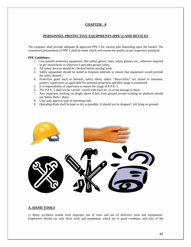
CHAPTER - 8
PERSONNEL PROTECTIVE EQUIPMENTS (PPE’s) AND DEVICES
The company shall provide adequate & approved PPE’s for various jobs depending upon the hazard. The centralized procurement of PPE’s shall be made which will ensure the quality as per respective standards. PPE Guidelines:-
1. Use suitable protective equipment, like rubber gloves, mats, safety glasses, etc., wherever required as per instructions or wherever it provides greater safety.
2. All safety devices should be checked before starting work. 3. Safety equipment should be tested at frequent intervals to ensure that equipment would provide
the safety desired. 4. Protective gears such as helmets, safety shoes, safety “Rassi-Zolis” are issued to linesmen,
jointers, supervisors as applicable for personal protection and their usage is monitored. 5. It is responsibility of supervisor to ensure the usage of P.P.E.’s. 6. The P.P.E.’s shall not be carried / stored with tools etc. to avoid damage to them. 7. Any employee working on height above 8 feet from ground except working on platform should
use Safety Belts / Rassi. 8. Uses only approve type of operating rods. 9. Operating Rods shall be kept as dry as possible. It should not be dropped / left lying on ground.
A. HAND TOOLS 1) Many accidents results form improper use of tools and use of defective tools and equipments. Employees should use only those tools and equipment, which are in good condition, and only of the

43
purpose for which they are designed. Where proper and safe tools are not available for the work at hand, then employee shall report the fact to his supervisor. 2) Tools, which develop defects while in use, should be removed from the service, tagged and not used again until brought in good condition. 3) Impact tools such as chisels, drills, hammers and wedges with mushrooms heads should not be used until they have been reconditioned. 4) Hammers, axes, shovel and similar tools should not be used if handles are loose, cracked or splintered. 5) Defective wrenches such as open end and adjustable wrenches with spread jaws or pipe wrenches with dull teeth should not be used, as they are likely to slip. 6) Pipe or other extensions should not be used on a wrench handle to increase the leverage unless the wrench is specifically designed for such an extension. 7) Portable electric tools should be equipped with 3 - wire cord having the ground wire permanently connected to the tool frame and is to be grounded at the other end. 8) Metal rules, metal tape lines or lines containing wires shall not be used around electric conductors or equipments. 9) All tools carried on trucks should be inspected each month and defective tools repaired or replaced. B. LADDERS
1. Inspect the ladder before use. 2. Ensure firm footing. 3. Secure at top or have a man at the foot. 4. Ensure correct angle (75 degree) or position ladder 1 foot out at base for every 4 feet of vertical
height. 5. Ensure that the ladder rises 3 feet above landing point. 6. Face the ladder when climbing or descending. 7. Avoid make shift arrangement in lieu of ladder. 8. Ensure the rubber shoes at both arms and at each terminal. i.e. at each end. 9. Before fixing confirm that no electrically charged conductor is passing nearby.
C. PROTECTIVE BARRIER (TEMPORARY)
When the work is conducted along public streets or highways, pedestrian and vehicular traffic shall be warned by signs and flags by day and red lights or flares by night. Wherever necessary, signalmen should be provided. D. EARTHING DEVICES
1. Only approved earthing devices shall be used in all work. 2. Care shall be taken to maintain earthing by ensuring condition of clamps. 3. Neon line tester may be used to check the bus bar area, cables, over head conductors but prior to
use it should be ensured that tester is in good condition.
44
CHAPTER -9
CONSTRUCTION During construction activity, it is important to keep in mind various aspects relating to
1. Excavation 2. Scaffolding 3. Rigging and Hoisting
EXCAVATION
1. Proper and adequate timber shoring and bracings shall be provided to prevent sliding or slipping of loose or unstable earth, rock or other material or caving in of excavation.
2. Under cutting of banks of trenches and other excavations shall be avoided. 3. Excavated material shall be dumped away from the edge of the excavated trench to avoid the
slipping of the excavated material in to the trench. 4. Excavations shall be properly fenced to protect men and animals from falling in. 5. Warning signals shall be placed near the excavation to warn the approaching traffic and men. At
nigh, red danger light shall be displayed at a conspicuous place near the excavation. SCAFFOLDING
1. Scaffolds shall be build of sound material, securely fastened, and be capable of supporting four times the combined weight of men land materials, which may be placed on them.
2. Wood planks used in scaffolds should be not less than ten inches wide and two inches thick, and shall not extend beyond the outer supports more than twelve inches nor less than six inches unless securely fastened down. Wooden planks without any nails projecting should be used; similarly planks or bellies with cracks should not be used for scaffolding purposes.
3. Guardrails and toe boards shall be installed on all scaffolds that are ten feet or more in height, land on all scaffolds immediately adjacent to excavations, deep water, machinery or other sources of danger.
RIGGING AND HOISTING
1. Man in-charge of working party shall be responsible for the safe loading and use of ropes, chains, cables, slings, jacks, skids and other hoisting and rigging apparatus. In no case shall such equipment be used until the foreman has determined that it is free from defects land safe for use.
2. Before operating crane, derrick or other hoisting equipment, the operator should sound warning
and accept only one person’s signal to start raising, lowering or swinging load. However, the operator shall stop immediately upon signal from anyone.
3. Never place yourselves near cables under tension, and under no condition within the angle formed
by ropes or cables. When anyone is in this or other dangerous position, the hoist operator shall never place tension on a rope or cable.
4. Employees shall familiarize themselves with the proper use of knots, ties, land hitches, and safe
methods of hooking and slinging required in their work.
5. Particular care must be exercised to see that cables, chains and other hoisting equipment are not unduly stressed by improper use. All ropes, cables chains etc., shall be discarded when they have worn or deteriorated to the point where their safe use may be questionable in the judgment of the supervisor.
6. Chains shall not be spliced or joined by makeshift means such as open links, bolts, or wire. Some
competent person shall insert new links, or the chain returned to the manufacturer for repairs.
7. Wire ropes or cables should not be allowed to kink as this weakens them.

45
8. When applying U-bolt clips to cables, a sufficient number should be used. Hooks, rings, clevises
and other fittings used on chains or cables shall exceed the carrying capacity of the chain or cable.
ROPES Fiber rope shall be properly cared for to retain its strength and lasting quality. Following precautions will preserve the strength and life of rope:
1. Where a rope sling passes over sharp edges, pads should be used to protect the fibers against cutting and undue stress.
2. Do not drag rope on the ground unnecessarily as dirt chafes the fibers. 3. Do not use too small a sheave. 4. Do not use sheaves with rough surface or broken edges. 5. Do not let rope slip on which drum or lie idle on moving drum. 6. Do not place kinked rope under stress. 7. Do not allow rope to unravel. Finish the ends. 8. Do not tie the knobs where splices should be used. 9. Do not allow ropes to become oil-soaked nor exposed to acid or corrosive substances. 10. Do not allow rope to remain dirty or gritty. Wash and dry. 11. Do not allow rope to remain exposed to weather any more than necessary. Carefully dry rope
when it becomes wet. 12. Do not use excessive heat when drying rope.
LIFTING AND CARRYING
1) Most lifting accidents are due to improper lifting methods rather than due to lifting too heavy loads. When lifting heavy objects, the back should be kept close to vertical and the lifting done with leg and arm muscles rather than with back muscles. 2) Bulky loads should be carried in such a way as to permit unobstructed view ahead. 3) Pipes, conduits, reinforcing rods and other conducting material should not be carried on shoulders near exposed live electrical equipment or conductors. 4) Rope tackle and slings wherever required should be checked to ascertain that they have sufficient strength to perform the work in hand. 5) Chain hoists should not be used until their condition is known to be satisfactory. Care should be taken to avoid overstraining hoisting equipment. Chains should be inspected before use and at intervals during extended operations to avoid failure of worn or weakened links, hooks, or other parts. 6) No one shall stand or pass under any suspended load being handled by a crane, derrick or other hoisting equipment.
TREE TRIMMING
The public shall be protected against hazards of tree trimming along public streets & highways by placing danger signs & signals.
1. Before climbing a tree, the trimmer should look it over carefully to decide how best to climb it. The limbs should be carefully inspected to make sure that they could hold the trimmers weight.
2. Axes should not be used aloft, always use saw or bill hooks. 3. All tools should be raised & lowered by hand lines in such way as to avoid Conductors. 4. Before cutting down the tree all limbs should be cut off for sufficient height to avoid striking
electric lines. Where there is danger that the tree may be strike & damage property, block & tackle should be used to control the direction of fall.
6. Felling operation once started, should be finished before the crew leaves for break etc.

46
CHAPTER -10
TRANSPORTATION
1. Vehicle should be kept in good operating condition & driven in a safe manner so as to prevent injury to you and others & save damage or loss of valuable equipments. Driving of vehicle is a responsibility not a privilege.
2. Every driver of company shall be thoroughly familiar & comply with the state/city traffic laws covering the territory where he operates.
3. Before operating a company vehicle each driver should make sure that it is in proper operating condition.
4. Before filling the patrol tank the engine should always be shut off. The hose nozzle should be kept in contact with the tank to avoid static sparks.
5. Switch off the mobile phone while in the petrol / diesel station. Most traffic accidents can be prevented by faithful observance of three things:- a) Control Speeds b) Avoid Distractions c) Drive Defensively
1. Park the vehicle on the proper side of the street. 2. When parking along a highway at night, light shall be left on but dimmed. 3. Before leaving a parked vehicle, always remove the ignition key to prevent theft or
unauthorized starting of vehicle. 4. Loading of vehicles should not exceed their rated capacity & objects should not be permitted
to extend beyond the sides. 5. The man in charge of party should carefully inspect the loading of material before starting a
vehicle. 6. In case of accidents do not become involved in an argument as to who was responsible for an
accident. 7. Do not loose your temper, try to be helpful.

47
CHAPTER -11
SAFE GUARDING THE PUBLIC 1) Every effort should be made to protect the public at all times where company’s work is in progress by the use of signs, barricades or personal warning. 2) When working on customer’s premises or public property, every effort should be made to avoid hazards to persons or unnecessary property damage. 3) Barriers shall be placed around all open manholes, exposed open ditches and excavations.
4) Authorized visitors shall not be left to find their own way. 5) Public shall be encouraged to report dangerous situation which may come to their notice. 6) Visitors shall be provided proper Personnel Protective Equipments wherever required.
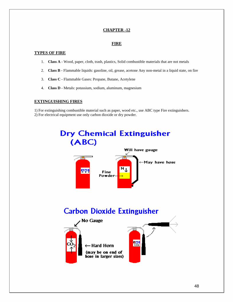
48
CHAPTER -12
FIRE
TYPES OF FIRE
1. Class A - Wood, paper, cloth, trash, plastics, Solid combustible materials that are not metals
2. Class B - Flammable liquids: gasoline, oil, grease, acetone Any non-metal in a liquid state, on fire
3. Class C - Flammable Gases: Propane, Butane, Acetylene
4. Class D - Metals: potassium, sodium, aluminum, magnesium EXTINGUISHING FIRES 1) For extinguishing combustible material such as paper, wood etc., use ABC type Fire extinguishers. 2) For electrical equipment use only carbon dioxide or dry powder.

49
PRINCIPLE OF FIRE FIGHTING
Eliminate one of three factors causing fire HEAT: - By cooling water etc. OXYGEN: - by smothering and exclusion of air. FUEL: - is eliminated by segregation, cooling or smothering.
TO PREVENT FIRE AND EXPLOSIONS 1) Waste paper, rags and other combustible material should not be allowed to accumulate. 2) Flammable liquids shall be kept in approved safety cans and identified by proper labels. 3) Varnish, paints, lacquers and thinners are highly inflammable and should be stored away from all open flames or possible sources of ignition. Matches and open flames should not be used where varnish paint or lacquer is being applied with a spray gun. 4) Open flames and smoking are prohibited in all areas where inflammable liquids or gases are stored or being used. Such areas shall be posted with appropriate warning signs. 5) All employees should be familiar with the location and proper use of fire extinguishers in their work area. 6) No employee should smoke or use matches or open flames on customer’s premises unless it is positively known that such action do not conflict with the customer’s rules. FIRE AND FIRE PROTECTION How to use a Fire Extinguisher Simply follow the following steps “P-A-S-S “ P – Pull the pin Pull the Pin at the top of the extinguisher A – Aim the nozzle low Aim the nozzle or the outlet towards the base of the fire. Some hose assemblies are clipped to the body of the extinguisher, then release the hose and point.

50
S – Squeeze the handle, lever Squeeze the handle, lever to release the extinguishing agent. In some cases valves are present. Before approaching the fire try a short burst. S – Sweep Sweep from side to side at the base of the fire until it is out. After fire is doused, watch for the smoldering hot spots and possible re-flash. Put off the fire completely.

51
CHAPTER -13
ACCIDENT REPORTS, RECORDS AND INVESTIGATION 1) Accident records are essential aids for prevention of accidents. They show the type of accidents most frequently encountered where they occur and their relative severity. A study of these records emphasis common hazards and prompts a better understanding of the causes of accidents and most effective methods of preventing them. 2) All accidents, which result in injury or not shall be promptly reported to Manager. Many injury-free accidents, which are not reported, recur with serious injuries. 3) All accidents to the public involving company personnel, equipment or property shall be reported promptly to Manager. 4) Accidents are reported to Safety section, in writing by concerned Manager. Accident Committee analyzes these reports, for corrective & preventive measures. 5) Every accident should be investigated to determine the cause and what steps are needed to prevent a recurrence. It shall be the responsibility of the person in charge of the work to get complete details of the accident as soon as possible after it occurs. 6) All accidents, whether they result in personal injury or not, shall be promptly investigated by the Manager or his representative. The stipulated guidelines as per The Indian Electricity Rule, 1956 are as follows: 44A. Intimation of Accident- If any accident occurs in connection with the generation, transmission, supply or use of energy in or in connection with, any part of the electric supply lines or other works of any person and the accident results in or is likely to have resulted in loss of human or animal life or in any injury to a human being or an animal, such person or any authorized person of the State Electricity Board/Supplier, not below the rank of a Junior Engineer or equivalent shall send to the Inspector a telegraphic report within 24 hours of the knowledge of the occurrence of the fatal accident and a written report in the form set out in F02- COR P 12 (see annexure IV) within 48 hours of the knowledge of occurrence of fatal and all other accidents. Where practicable a telephonic message should also be given to the Inspector immediately the accident comes to the knowledge of the authorized officer of the State Electricity Board/ Supplier or other person concerned.] Form (F02-COR-P-12): To be filled for submission to Chief Electrical Inspector for reporting of Accident. For detail work instructions please refer W01 (COR-P-12) Work Instructions for Accident Reporting (Annexure – XXI). The information will be given to:- 1. Chief Electrical Inspector 2. Asst. Electrical Inspector Address:- Govt. of National Capital Territory of Delhi, Office of the Secretary (Labour), (Electrical Inspectorate), 5, Sham Nath Marg, Delhi-110054 (Room No. – 71, D-block) Ph - 23968706 (O)

52
CHAPTER - 14
FIRST AID GENERAL First Aid means what one should do to reduce the suffering of the patient after an accident until the doctor arrives, it may give life to dying person.
FIRST AID INSTRUCTIONS
1. Remove the patient from the source of accident / remove the cause of injury. 2. Keeps the injured person lying down in a comfortable position. 3. If the breathing has ceased, immediate measures must be taken to restore it. 4. If the patient has received burns attend to them. 5. When the patient has fractured a bone, no attempt must be made to move him. 6. Treat the patient for shock. 7. Send for medical help. 8. Never give water to patient. 9. Keep by standards away from the patient. 10. Keep the patient warm.
INSPECTION OF FIRST AID EQUIPMENTS AND BOX All first aid equipment and box in grid station, substations and vans shall be checked periodically by an authorized person who will sign the format F08 (COR – P-12) (see annexure X) placed therein together with the date on which the check was carried out.
TREATMENT FOR THE ELECTRIC SHOCK RELEASE FROM CONTACT Switch off the electric supply immediately or send someone to do so. Do not attempt to remove a person from contact with high voltages unless suitable articles insulated for the system voltages are used for the purposes. When attempting to free a person from contact with low or medium voltage use rubber gloves, shoes, mat or insulated stick, but if these are not available use a loop of rope, cap or coat to drag the person free. Whatever is used should be dry and non-conducting. AFTER RELEASE As soon as the victim is clear off the conductor and is found breathless, rapidly feel with your finger in his mouth and throat and remove any foreign matter (tobacco, false teeth etc.). Then begin artificial respiration. Do not stop to loosen the victim’s clothing now; every moment of delay is serious. Keep the patient warm.
ARTIFICAL RESPIRATION (HOLGER NIELSEN) POSITION Place the patient with face downwards, head turned slightly to one side, with arms raised and bent, and the side of the head resting where the hands join. Slap patient between the shoulders smartly with the flat of the hand several times. Kneel on right knee opposite patient’s hand and place left foot by the patients elbow.

53
a) FIRST MOVEMENT Keep arm straight, palms of hands between & below shoulder blades and thumbs on spine. Rock forward with firm pressure and take 2.5 seconds for this movement.
b) SECOND MOVEMENT Release pressure quickly and gradually slide your hands out to the patient’s elbows and then raise the patient’s arms and pulls slightly towards you, taking 2.5 seconds for this movement.

54
c) THIRD MOVEMENT Lay the patient’s arm down again and replace your hands below shoulder blades. d) Repeat the complete cycle twelve times to the minute. e) IF THERE ARE CHEST INJURIES Lay the patient face downwards with head turned slightly to one side, with arms raised and bent, and the side of the head resting where the hands join. Grasp the patient’s elbows and then pull slightly towards you, taking 2.5 seconds for this movement. Return the arms to first position and repeat the movements at the rate of 12 times per minute. (In case of chest injuries if possible, the hip-lift backpressure should be given preference). f) IF THE ARMS ARE INJURED Lay the patient’s head downward with his arms in such a position as to minimize risk of increasing injury. Keep your arm straight with palms on patient’s shoulder blades and thumbs on spine, rock forward with firm pressure for 2.5 seconds. Release pressure gradually and slide your hands to the armpits and pull slightly towards you, taking 2.5 seconds for this movement. g) Continue the artificial respiration without interruption, until natural breathing is restored, or until the physician arrives. A brief return to natural respiration is not a certain indication for stopping the resuscitation. The patient must be watched, and if natural breathing stops, artificial respiration be resumed at once. h) In carrying out resuscitation it may be necessary to change the operator. This change must be made without losing the rhythm of respiration. By this procedure no confusion results at the time of change of operator and a regular rhythm is kept up. i) Send for medical assistance. j) If patient recovers before the medical assistance arrives, regulate your artificial respiration to the rate of the patient’s breathing, and when he has sufficiently recovered make him comfortable and give hot tea. Do not allow patient to exert himself even by walking until a doctor has seen him as the shock may have affected his heart.
BURNS AND PHYSICAL SHOCK BURNS Burns should be treated with “Burn Dressings” and covered to exclude the air. PHYSICAL SHOCK In addition to suffering from electric shock it is also probable the patient will be suffering from physical shock, and it is important that this condition be treated. The patient must be kept warm with blankets or coats, and if available, hot water bottles should be applied on the feet.

55
HEAT STROKE Heat Stroke in proper is an entirely different reaction in the human body, to the same conditions, which favors Heat Exhaustion. It is serious and often lead to fatal condition. Hot, humid atmosphere and inadequate drinking of water favors development of Heat Stroke. Casualty shows mental excitement, restlessness vomiting, muscular cramps and high temp. TREATMENT
• Wrap him up completely in cold water soaked bed sheet. • Fan vigorously. • Send for doctor.
HEAT EXHAUSTION
Heat Exhaustion occurs among the workers in stuffy atmosphere or in overheated, poorly ventilated room. There may be feeling of giddiness or fainting skin is always cold & moisture prevention by wearing loose clothing, drinking large quantities of water is possible.
ACTIVE FIRST AID TREATMENT FOR HEAT EXHAUSION
• Remove patient to cooler conditions in the fresh air. • Lay him down & loose all clothing around neck. • Fan him vigorously. • Dash cold water on the neck & head to stimulate.

56
CHAPTER -15
EMERGENCY PREPAREDNESS AND RESPONSE PURPOSE To establishes a system for dealing with emergency situations to minimize hazards to human health & Safety. SCOPE Applicable to any fire, explosion or other disaster leading to emergency situation, which means, any significant, on-routine situation, which endangers the personnel property, other interested parties or surrounding environment. Separate procedures may be followed for personnel injuries/medical emergencies. ACTIVITY Identify potential accident conditioned emergency situations for the activities in different departments in consultation with concerned HOG & make all concerned personnel aware of the significant risk attached to their area of work that may lead to emergency situation and discuss the situations with concerned team headland make emergency plan & also check their emergency preparedness and response to such situations and clearly identify responsibilities while preparing emergency pal, consider providing controls for and mitigating the safety hazards associated with the activity, i.e. post effect. And train the personnel in dealing with emergency situations as per emergency plan. By carry out periodic drills i.e. mock-drills/fire drills etc. (at least once a year) creating emergency situations and keep records.
57
CHAPTER -16
SAFETY AUDITS AND RECORDS
PURPOSE Verifying the existence and implementation of elements of occupational safety and health system and for verifying the system’s ability to achieve defined safety objectives. (IS: 14489 – 1998) SCOPE It is applicable to all installations, Offices, O&M & Projects sites. ACTIVITY It will help in timely auditing of different requirements (as per annexures indicated below) for maintaining the system accident / incident free and also to maintain records required for Indian Electricity Rules and Integrated Management System. These activities are to be carried out as per Safety Document (COR-P-12) (see annexure I) and other related documents as indicated below:-
1. Incident Report F01 (COR-P-12) (see annexure - III) 2. PTW Audit F04 (COR-P-12) (see annexure –VI) 3. Field Job Audit F05 (COR-P-12) (see annexure –VII) 4. Tool bag Audit F06 (COR-P-12) (see annexure – VIII) 5. Safety Audit F07 (COR-P-12) (see annexure – IX) 6. First Aid Box Record F08 (COR-P-12) (see annexure – X) 7. Fire Extinguisher Record F09 (COR-P-12) (see annexure – XI) 8. Information of Accident F10 (COR-P-12) (see annexure – XII) 9. Accident Investigation Report (Local) F11 (COR-P-12) (see annexure – XIII) 10. Accident Investigation Report (Accident Committee) F12 (COR-P-12) (see annexure – XIV) 11. Electrical Accidents Causes Sharing Form F13 (COR-P-12) (see annexure – XV) 12. Rectification of Cable Faults W01 (COS-P-06) (see annexure – XVI) 13. Fire Extinguisher History Card (See Annexure – XVII) 14. Fire Incident Report (See Annexure – XVIII) 15. Zonal Tool Kit List (See Annexure – XIX) 16. Grid Tool Kit Items (See Annexure – XX) 17. Work Instructions for Accident Reporting W01 (COR-P-12) (see annexure – XXI)

58
CHAPTER -17
5S Practices
Principle of 5 S The concept of “5S” originated in Japan. It is an integral tool of TQM which lays a very strong foundation for quality movement within the organization. The 5S are pre-requisites (basics) for any improvement programme. 5S Philosophy focuses on effective work place organization, simplifying work environment, reducing waste while improving quality and safety. There is no other way for improving efficiency or quality in work place. The five S stands for the five first letters of these Japanese words:
Japanese Term English Equivalent Seiri Sort
Seiton Set In Order Seiso Shine
Seiketsu Standardize Shitsuke Sustain
Meanings:- Calling these principles as "5S" is a good way to remember their meaning and content. They stand for:- Seiri Sorting, keep the necessary in work area, dispose or keep in a distant storage area less frequently used items, unneeded items are discarded. Seiri fights the habit to keep things because they may be useful someday. Seiri helps to keep work area tidy, improves searching and fetching efficiency, and generally clears much space. Seiri is also excellent way to gain valuable floor space and eliminate old broken tools, obsolete jigs and fixtures, scrap and excess raw material. Seiton Systematic arrangement for the most efficient and effective retrieval. A good example of Seiton is the tool panel. Seiton means tidily putting things away after you have used them. Putting things away requires following three rules: Decide where things belong; Decide how things should be put away; Follow the put-away rules to leave things where they can be quickly and properly found next time they are needed Seiton saying would be: "A place for everything and everything on its place." Seiso Cleaning. After the first thorough cleaning when implementing 5S, daily follow-up cleaning is necessary in order to sustain this improvement. Cleanliness is also helpful to notice damages on equipment such as leaks, breakage and misalignment. These minor damages, if left unattended, could lead to equipment failure and loss of production. Regular cleaning is a type of inspection. Seiso is an important part of basic TPM; Total Productive Maintenance and Safety matter through cleanliness is obvious. Seiketsu

59
Standardizing. Once the first three S have been implemented, it should be set as a standard without which, the situation will deteriorate right back to old habits. Have an easy-to-follow standards and develop a structure to support it. Allow employees to join the development of such standards. Thus the 3 first S are often executed by order. Seiketsu helps to turn it into natural, standard behavior. Shitsuke Finally, to keep first 4 S alive, it is necessary to keep educating people maintaining standards. By setting up a formal system; with display of results, follow-up, the complete 5S get insured to live, and be expanded beyond their initial limits, in an ongoing improvement way. The effect of continuous improvement leads to less waste, better quality and faster leads times. Objectives:- The objective of the 5S may be summarized as below:- Safety and the 5S Emphasizing the orderly workplace But what this really means is that you have to pay attention to the little things. Are you wearing your helmet and safety shoes? Are you being careful when you transport things? Are the paths clear? It is these little things – these seemingly insignificant things – that make the difference. That is why people have emphasized the importance of an orderly workplace. In addition to these things, the 5S’s are also important to personal safety and health for everyone in preventing fires and slippage accidents due to oil leaks, in preventing pollution from filings and fumes, and in preventing the other things that are so dangerous to human health and safety. Efficiency and the 5S The craftsman takes care of his tools. The famous chef, the skilled carpenter, the greater painter – they all take care of their tools. There are no rusted knives, no saws with teeth missing, and no matted brushes. They use good tools, and they take good care of them. They do not waste a lot of time when they are working. They keep everything in order to take and use easily whenever required. Breakdowns and the 5S Settle the places at first There is a common “Monday Morning Syndrome” at some manufacturing plants. This is where sludge-clogged oil drains overflow on Monday morning, where the machinery seems to stick on Monday morning, and where hydraulic and pneumatic equipment pressure levels are low on Monday morning. All of these things happen because the buildup of grime over the course of the work week has had time to harden and to settle into places where it should not be. All of these things happen because the company does not practice the 5S during the week. Quality and the 5S Need For Cleanliness Today electronics and other machinery demand very high levels of precision and cleanliness. Just a spot of grime can cause a computer to crash. Filings and burrs can mean that things do not fit tightly. Dropping things on an assembly line can mean that the wrong parts are put together or that the product is shipped to

60
the wrong client. There are all kinds of major problems caused by seemingly minor “5S” lapses. It is clear that the 5S’s are prerequisite to quality, and this cannot be overemphasized. Problems discovered in the cleaning process:-
• Filings in the conveyance chutes lead to scratching. • Scraps in the die lead to faculty pressings. • Things fall off the equipment and get into the products. • Things get dented or bent in conveyance. • Filings and other particles contaminate the resin. • Dirty coolant leads to clogging. • Dust and other substances ruin the paint jobs. • Bad connections are made because the electrical contacts are dirty. • Fires are caused because garbage shorted the electrical equipment.
Equipment Although you will need a detailed and exhaustive checklist for each piece of machinery, it is possible to mention some of the main items common to most equipment.
• Cleaning: Grime, clogging, rust, leakage etc. • Heat: Oil tanks, heaters, control planes, washing or cleaning water etc. • Breakage: Breakage, meters that do not return to zero, cracked glass, handles that have come off,
broken switches or buttons, cables or bundles of wires that have come unraveled, things that are misshapen, etc.
• Electrical: Control panel covers, control panel interiors, lamps, light bulbs, switches, etc. • Tools and measurement devices: Tools, measurement devices, gauges etc. • Equipment-specifics: transport equipment, etc.
Launching of 5S – Operative Activities Recording the present situation Identifying abnormalities by visual control Because it is people who control and manage things, it is essential that your people be able to tell the difference between normality and abnormality and be able to act accordingly. Yet, as seen in industrial defect rates, the possibility of abnormalities occurring is generally 1% or less, and most of the time things will be operating as normal with no problems. It is in the midst of this normality that people must identify abnormality. Visual management – an answer How can you best make sure that abnormalities surface? In our everyday work, we use our minds to remember things and all five senses to do our best work. What is important here is to transform these static senses into dynamic awareness and to make them come alive for us. And it is the visual sense-the sense of sight-that is the most important. It has been estimated that 60% of all human activity starts with sight. Of course, we also learn from our sense of hearing and our sense of feel, and it is also important to make the
Before launching into 5S activities, the very first thing to do is to take photographs around the workplace. These will be very useful for comparison purposes when 5S is in full swing.

61
fullest possible use of these senses as well, but it is our sense of sight that dominates. That is why visual management is sometimes referred to as the embodiment of visual awareness. Points to remember in making visual control tools Checkpoints
• Clearly determine the position each picture was taken from, so that you will be able to have before and after photographs
• Date all photos. If possible, use a camera which prints the date on the negative Analyzing Why and What Every piece of equipment fulfills specific functions, and understanding these functions will make you a better inspector. This understanding can be vastly enhanced if you ask yourself why for each of the problems and minor defects that you identify. Ask yourself:
1. Why is this important? 2. Why has this been overlooked or ignored? 3. What can be expected to happen if we leave this the way it is? What impact will it have? What are
the principles and mechanisms involved here?
4. Why has this gone so long before being detected? What could have been done so that it would
have been detected earlier? 5. Why is it this way? Does anybody know about this? Does everybody know about this?
By constantly asking yourself the whys and whats, you will get to the core of the problem and will be able to involve the small-group (quality circles) as well as management in finding and implementing solutions. Inspections are all well and good, but they are not the end of the process. The purpose of an inspection is to find problems and then to solve them so that they do not show up on the next inspection. The Differences 5S make:- • Although the “5S” movement obviously results in major improvements in 5S areas, it is even more
important in changing the way people approach their work and what they do. • It is impossible to mount a “5S” campaign with just one or two people. You need to have everyone
actively involved. Each of the individual things that need to be done is simple enough in itself. The difficult thing is to keep doing them. This requires determination, persistence, and cooperation. But that combination in turn creates a new sense of team identity and a better corporate climate.
1. Make them easy to see from a distance 2. Put the displays on the things they are for 3. Make them so that everyone can tell what is right and what is wrong 4. Make them so that anybody can use them easily and conveniently 5. Make them so that anybody can follow them and make the necessary corrections easily 6. Make them so that using them makes the workplace brighter and more orderly

62
• It is important to start by doing. No matter how well you understand the theory, the theory does not produce results. Only doing does. And this doing has the power to change the way people look at things. It has the power to transform them.
• Every part of the “5S” process is important. Every step has the potential for opening our eyes. The 5S’s are the best way to eliminate waste.
The Pledge
• I will not get things dirty. • I will not spill. • I will not scatter things around. • I will clean things right away. • I will rewrite things that have gotten erased. • I will tape up things that have come down
5S - It's a way of building business.

63
ANNEXURES - CONTENTS
Annexure -I Safety Document COR-P-12 Annexure -II Safety Concerns Committee Annexure -III Near Miss / Incident Record - F01 (COR-P-12) Annexure –IV Accident Reporting - F02 (COR-P-12) Annexure –V Permit To Work (COR-P-12) Annexure –VI Permit to Work Audit F04 (COR-P-12) Annexure –VII Field Job Audit -F05 (COR-P-12) Annexure –VIII Tool Bag Audit -F06 (COR-P-12) Annexure –IX Safety Audit -F07 (COR-P-12) Annexure –X First Aid Box Record -F08 (COR-P-12) Annexure –XI Fire Extinguisher Record -F09 (COR-P-12) Annexure –XII Information of Accident Annexure –XIII Accident Investigation Report (Local) -F11 (COR-P-12)
Annexure –XIV Accident Investigation Report (Accident Committee) -F12 (COR-P-12)
Annexure –XV Electrical Accidents Causes Sharing Form -F13 (COR-P-12)
Annexure –XVI Rectification of Cable Faults W01-(COS-P-06) Annexure –XVII Fire Extinguisher History Card Annexure –XVIII Fire Incident Report Annexure –XIX Zonal Tool Kit List Annexure –XX Grid Tool Kit Items
Annexure –XXI Work Instructions for Accident Reporting W01 – (COR-P-12)

64
Annexure -I Safety Document COR-P-12
1.0 PURPOSE:
To establish a system of safe work practices, to ensure safety of personnel, resources and timely detection and extinguishing of fire at the earliest.
2.0 SCOPE:
Applicable to all the personnel of NDPL & Franchisees. 3.0 DEFINITIONS: 4.0 RESPONSIBILITY: HOD (Operations) is overall responsible and individual activity responsibility is given below.
S. No Activity Responsibility Authority
1 Safety Concerns committee (SCC) meetings Chairman (SCC) HOD (Opr)
2 Inspection of electrical installations, equipment earthing and fire extinguishers in manned Stations.
AM in charge of the Grid Station.
Circle Head / System Head / Fire Officer
3 Inspection of electrical installations, equipment earthing and fire extinguishers in FLC van
FLC Manager HOD (OPS) / Fire Officer
4 Inspection of electrical installations, equipment earthing and fire extinguishers in all NDPL offices
Concerned Manager / Building Owner / Fire Officer
Circle Head / System Head
5 Inspection of outdoor jobs and workmen Tool Kit.
Zonal Manager / AM (Sys)
District Manager / System Manager
6 Verification of Permit to work procedure and permit books HOG (PSC) / SCC HOD (Operations)
7 Training on Safety SCC Chairman (SCC) / HOG (Trg.)
8 Investigation and analysis of electrical accidents. Accident Committee Chairman (Accident
committee)
FLC - Fault Locating Cell
DM - Disaster Management

65
5.0 PROCESS APPROACH: 5.1 PROCESS INPUTS:
S. No Inputs Source Frequency Ref. Doc Review
Criteria
5.1.1 Cases of Incidents/Accidents
Concerned Deptt. As & When
F01(COR-P-12), F02(COR-P-12)
Nature of Incident/Accident
5.1.2 Results of Safety Audit -do- -do- F07(COR-P-12)
No. & Types of Safety breaches
5.1 DESCRIPTION:-
S. No ACTIVITY RESPONSIBILITY REF. DOC
5.1 SAFETY
5.1.1
HOD (OPS) appoints a Safety Committee which is known as Safety Concerns Committee. This committee comprises of representatives of Circle Heads / System Heads and Officer (safety).
HOD (OPS)
5.1.2
Safety Concerns Committee comprising of Additional HOD(Operations), HOG(PSC), Officer (Safety), Fire Officer, AM(IR), One member from (Distribution, System North & NW), Member form Security & Union representative meets at least once in a month to review implementation of safety practices and consider new suggestions.
Chairman (SCC) / Officer (Safety)
5.1.3
Various safety measures and precautions to be adopted by personnel have been documented in the Safety Manual & revised as & when requires..
Officer (Safety)
5.1.4 Personnel are imparted Safety training on a need basis.
Concerned Manager / AM
HOG (Safety)
5.1.5
Work is outsourced to companies / agencies that can provide assurance of the Safety training imparted to its personnel who are deputed to work with NDPL.
HOG (Safety)

66
S. No ACTIVITY RESPONSIBILITY REF. DOC
5.1.6
Protective gears such as helmets, safety shoes, and safety “Rassi-Zolis” is issued for linesmen, jointers, supervisors as applicable for personal protection and their usage is monitored.
Concerned Manager / AM
5.1.7
First Aid box and Artificial Respiration chart are kept in each manned Station, Zones and mobile maintenance vans and FLC vans.
Concerned Manager / AM / Executive / Officer/ JE
5.1.8 The working areas are adequately illuminated and suitable approaches are made available in all working areas.
Concerned Manager / AM / Executive / Officer/ JE
5.1.9 The respective MGR / AMs to ensure that inspection of safety equipment is carried out every month.
Concerned Manager / AM
5.1.10
The Safety Concerns Committees carry out safety audits periodically with concerned AM to
• Check permit to work procedure and permit books
• Identify potential hazards and initiate action for the prevention of accidents
• Inspect all tools and tackles that are used during the work
• Review of safety practices
Circle Heads / System Heads
F03(COR-P-12) F04(COR-P-12) F05(COR-P-12) F06(COR-P-12) F07(COR-P-12) F03(COR-P-13)
5.1.11 After occurrence of any Near Miss / Incident it is recorded by AM / ZM & at the end of the month Mgr. shall review all the incidents and sent to Safety Dept. & Officer Safety shall issue CAPA. Accident Investigation report shall be prepared by Officer safety and analysed to initiate CAPA and revise Work Instruction/Operating Guidelines / DMP as necessary.
DM Group, Safety Officer Concerned AM / ZM / Mgr.
Minutes of MRM, F01(COR-P-12) F02(COR-P-12)
5.1.12 Share accident/ emergency occurred & action taken with other Location In-charge.
DM Group e-mail
5.1.13 Review Incident, Accident, DMP & CAPA in Management Review Meeting.
MR/MA COR-P-07

67
S. No ACTIVITY RESPONSIBILITY REF. DOC
5.1.14 Before commencing work on equipment proper safety precautions need to be taken.
Shift Officer / In- charge / Recipient of PTW
W01(COR-P-12)
5.1.15 The Record of First Aid Box is to be maintained at all locations & updated time to time.
Concerned ZM / AM F8(COR-P-12)
5.2 FIRE-FIGHTING
5.2.1
Isolate equipment, control fire with the help of the appropriate fire fighting equipment and inform Fire brigade without delay.
Concerned Manager / AM
5.2.3 Quickly decide the Fire fighting method. Shift Officer / In Charge Ref. DMP
5.2.4
In case of any event of fire and its subsequent control, report is generated within 24 hours for review of HOD(Operations)
Concerned Manager / AM
5.2.5
Ensure that the inspection and testing of the Fire extinguishers are carried out at the predetermined intervals either in-house or by an out side agency.
Concerned Manager / AM / Fire Officer
F09(COR-P-12)
5.2.6 Ensure that the empty or partially empty Fire extinguishers are refilled.
Concerned Manager / AM / Fire Officer
5.2.7
Ensure that the Mock drills are carried out at predetermined intervals to check the readiness of the system (personnel and material).
AGM (Admn.) / Fire Officer / Officer (Safety)
5.2.8
The areas covered for fire fighting are as below: a) Manned stations b) Stores c) Corporate Office d) District/Zonal/Complaint Offices e) Associate Offices
Fire Officer
5.2.9
Following fire protection systems are installed for fire fighting in the above locations: a) Portable fire extinguishers b) Trolley type fire extinguishers c) Sand buckets d) Automatic Fire Detection System
Concerned Manager / AM /Fire officer
68
S. No ACTIVITY RESPONSIBILITY REF. DOC
5.2.10
The Record of Fire Extinguishers is to be maintained at all locations & updated time to time by carrying out inspection by Approved Agency.
Concerned ZM / AM F09(COR-P-12)
5.3 TRAINING
5.3.1
SCC identifies the training needs and forwards the same to the Human Resources Department.
Few could be • Different types of fires and their control • Use of portable extinguishers • First Aid • Electrical safety
Concerned Manager / AM
Officer(Safety) / Fire Officer
5.3 PROCESS OUTPUT:
S. No Outputs To Ref. Doc 5.3.1 Incident Report Concerned Manager F01(COR-P-12) 5.3.2 Accident Reporting Format -do- F02(COR-P-12) 5.3.3 Permit to Work Within Department F03(COR-P-12) 5.3.4 Permit to Work Audit Concerned ZM/AM F04(COR-P-12) 5.3.5 Field Job Audit -do F05(COR-P-12) 5.3.6 Tool bag Audit -do- F06(COR-P-12) 5.3.7 Safety Audit -do- F07(COR-P-12) 5.3.8 First Aid Box Record -do- F08(COR-P-12)
5.3.9 Fire Extinguisher Record Concerned ZM/AM/Fire Officer F09(COR-P-12)
5.3.10 Information of Accident Concerned ZM/AM/Fire
Officer F10(COR-P-12)
5.3.11
Accident Investigation Report (Local)
Concerned ZM/AM/Fire Officer F11(COR-P-12)
5.3.12
Accident Investigation Report (Accident Committee)
Concerned ZM/AM/Fire Officer F12(COR-P-12)
5.3.13
Electrical Accident Causes Sharing Form
Concerned ZM/AM/Fire Officer F13(COR-P-12)
5.4 PROCESS MONITORING:
S. No
Monitoring Brief
Monitoring Criteria Responsibility Frequency Ref. Doc
5.4.1
Timely sending Incident/Accident Investigation report
2nd of each month for Incidents record of previous month
Section In- Charge
Daily / As & when requires
F01(COR-P-12) F02(COR-P-12)

69
S. No
Monitoring Brief
Monitoring Criteria Responsibility Frequency Ref. Doc
Within 24hrs. for Elect. Accidents
5.4.2
Timely Conducting CAPA review drafted by ZM /AM for all Incidents
As per consolidated reports of all sites in SCC monthly meeting.
SCC 2nd Week of Month
F01(COR-P-12)
5.4.3 Timely conducting Safety Audit
1st Week of Every Month AM/ZM Monthly F07(COR-P-12)
5.4.4
Timely conducting CAPA review drafted by ZM/AM for all accidents
Within 1 Week for General & within 24 Hrs for Electrical Accidents
SCC-FOR General Accidents
As & When F02(COR-P-12) Accident
Committee-For Electrical Accidents
5.4.4
Timely preparing trend charts for all accidents
Every Month Safety Officer Monthly Minutes of EHS Task Force Meeting
5.4.5
Timely conducting PTW & Field Job Audit
Monday every week AM/ZM Weekly
F04(COR-P-12) F05(COR-P-12)
5.4.6 Timely conducting Tool Kit Audit
1st Week of Every Month AM/ZM Monthly
F06(COR-P-12) F07(COR-P-12)
5.4.7
Timely conducting First Aid Box Audit
1st Week of Every Month AM/ZM Monthly F08(COR-P-12)
5.4.8
Timely conducting Fire Extinguisher Health Monitoring
As per Annual Audit Plan Fire Officer Monthly F09(COR-P-12)

70
6.0 RECORDS:
F01(COR-P-12) - Near Miss / Incident Record
F02(COR-P-12) - Accident Reporting Format
F03(COR-P-12) - Permit to Work
F04(COR-P-12) - Permit to Work Audit
F05(COR-P-12) - Field Job Audit
F06(COR-P-12) - Tool bag Audit
F07(COR-P-12) - Safety Audit
F08(COR-P-12) - First Aid Box Record
F09(COR-P-12) - Fire Extinguisher Record
F10(COR-P-12) - Information of Accident
F11(COR-P-12) - Accident Investigation Report(Local)
F12(COR-P-12) - Accident Investigation Report(Accident Committee)
F13(COR-P-12) - Electrical Accident Causes Sharing Form
7.0 REFERENCES:
Clause 7.5.1 of ISO-9001:2000 , Clause 4.4.7 of ISO 14001:2004 & Clause 4.5.1 & 4.5.2 of
OHSAS 18001:1999 Standard
Section 04 of IMS Manual
I.E. Rules 1956
Safety Manual
W01(COR-P-12) - PTW Issuing Guidelines
COR-P-16 - Emergency Preparedness & Response
COR-P-07 - Management Review
W02 (COR-P-12) - Accident Reporting

71
Annexure - II
SAFETY CONCERNS COMMITTEE HOD (Operations) appoints a Safety Committee under chairmanship of Addl. HOD (Operations), which is known as Safety Concerns Committee (SCC). This committee comprising of HOD(CIM - N), HOG(PS&T), Officer (Safety), Fire Officer, AM(IR), One member from (Distribution, System North, NC & NW), Member form Security & Union representative meets at least once in a month to review implementation of safety practices and consider new suggestions. The Safety Concerns Committee:-
1. Determine strength and weakness of the system.
2. Review permit to work procedure and permit books.
3. Identifying potential hazards and to take action for prevention of accidents.
4. Review of safety practices Accidents are reported to Officer (Safety) & Chairman, SCC, in writing by concerned manager as per Document (COS-GEN-03) for Electrical Accidents. These reports are analyzed by Accident Committee for preventive measures. Few are mentioned below:-
• First Aid box is kept in each location and in Vans.
• The respective AM’s / ZM’s ensure inspection of equipment every month as per schedule mentioned in work instructions (COR P-12). Safety audit and verification of permit to work procedure are carried out by Officer (Safety) periodically. Review the same in Safety Concern Committees.
• Safety practices while operating and maintenance of electrical equipment are observed by
respective personnel.

72
Annexure-III
F01 (COR-P-12) NEAR MISS / INCIDENT RECORD
Incident / Near Miss Record
S.No. Place & Location Date Time Type Root Cause
Analysis CAPA Responsibility Target Date
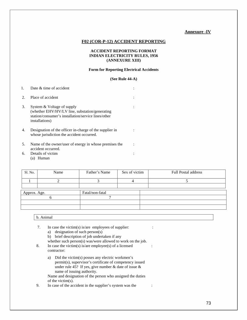
73
Annexure -IV
F02 (COR-P-12) ACCIDENT REPORTING
ACCIDENT REPORTING FORMAT INDIAN ELECTRICITY RULES, 1956
(ANNEXURE XIII)
Form for Reporting Electrical Accidents
(See Rule 44-A)
1. Date & time of accident
:
2. Place of accident :
3. System & Voltage of supply (whether EHV/HV/LV line, substation/generating station/consumer’s installation/service lines/other installations)
:
4. Designation of the officer in-charge of the supplier in whose jurisdiction the accident occurred.
:
5. Name of the owner/user of energy in whose premises the accident occurred.
:
6. Details of victim (a) Human
:
Sl. No. Name Father’s Name Sex of victim Full Postal address
1 2 3 4 5
b. Animal 7. In case the victim(s) is/are employees of supplier:
a) designation of such person(s) b) brief description of job undertaken if any whether such person(s) was/were allowed to work on the job.
:
8. In case the victim(s) is/are employee(s) of a licensed contractor:
a) Did the victim(s) posses any electric workmen’s permit(s), supervisor’s certificate of competency issued under rule 45? If yes, give number & date of issue & name of issuing authority.
Name and designation of the person who assigned the duties of the victim(s).
:
9. In case of the accident in the supplier’s system was the :
Approx. Age. Fatal/non-fatal 6 7

74
permit to work (PTW) taken.
10. a) Describe fully the nature and extent of injuries, e.g. fatal/disablement (permanent/temporary) of any portion of the body or burns or other injuries.
In case of fatal accident, was the post-mortem performed?
:
11. Detailed causes leading to the accident
:
12. Action taken regarding first-aid, medical attendance etc. immediately after the occurrence of the accident (give details).
:
13. Whether the District Magistrate and Police station concerned have been notified of the accident (if so, give details).
:
14. Steps taken to preserve the evidence in connection with the accident to extent possible.
:
15. Name(s) & designation(s) of person(s) Assisting, supervising the person(s) killed or injured.
:
16. What safety equipments were given to and used by the person(s) who met with the accident (eg. Rubber gloves, rubber mats, safety belts and ladders etc.)
Whether isolating switches and other sectionalising devices were employed to deaden the sections for working on the same? Whether working section was earthed at the site of work?
:
18. Whether the work on the live lines was undertaken by authorized person(s)? If so, name and designation of such person(s) may be given.
:
19. Whether artificial resuscitation treatment was given to the person(s) who met with the electrical accident. If yes, how long was it continued before its abandonment?
:
20. Names and designations of person(s) present at and witnessed the accident.
:
21. Any other information/remarks
Signature: ______________ Place: Name: Time: Designation: Address of the person reporting:

75
Annexure -V
F03 (COR-P-12) PERMIT TO WORK
PERMIT TO WORK Book No______________________ S. No ____________
PSC PTW No ____________ Name of the PSSO _______________
You are allowed to work on the following Equipment / Line
Name of the Equipment / Line:__________________________________________________________ Station Name: Voltage Level:__________________
PTW Issued To (Name) PTW Issued By (Name)
DESCRIPTION REMARKS
Nature of work that will be carried out on the above Equipment / Line
Above Equipment / Line is Isolated at the following location (s)
Above Equipment / Line is connected to earth at the following locations
Safety Tags have been posted at the following locations
Note1: All other equipment/parts are live and dangerous
Authorized person issuing PTW Designation Sign
Authorized person receiving PTW Designation Sign
If PTW has been issued on the above Equipment / Line to more than one person, indicate the other PTW Nos. also
Time: _________ AM / PM Date: _________________________
Transfer of Ownership of PTW
PTW held by Name Sign
This PTW is transferred to Name Sign Time Date

76
I hereby declare that all men under my charge have been withdrawn and warned that it is no longer safe to work on the Equipment / Line specified on this PTW and those tools, temporary earth and other connections are all removed, leaving that portion of the Equipment / Line ready for taking into service. Name Designation Sign Time Date
I hereby declare this PTW Cancelled Name Designation Sign Time Date
Extension of the above PTW needed: Yes/No If Yes, give reason below Reason for Extension: New Validity of the PTW
From Date From Time To Date To Time
Authorized person requesting the Extension of PTW Name Sign
Authorized person approving the Extension of PTW Name Sign
Authorized person issuing the Extended of PTW Name Sign
Time: _________ AM / PM Date: _________________________
All Isolated point mentioned is ensured & checked from all concerns. Yes / No Safety Zone is created by PTW owner. Yes / No Personnel Protective Equipment is available.( Helmets, Safety Belt, Rubber Gloves, Shoes) Yes / No Safety Tags are installed at various locations. Yes / No All Safety Measures including Earthing of Lines and uses of proper tools and tackles are to be used and the PTW owner will getting the work done must ensure before taking up the work on the line / Equipments. General: PTW – Permit To Work PTW can be issued / received only by individuals Authorized by the Company. The apparatus mentioned here in must not be again made live until this PTW has been signed and returned by the authorized person who has received the PTW. In cases where more than one gang of personnel are working on the same apparatus, it must not be again made live until similar PTWs have been signed and returned by all the authorized person (s) who have received the PTW. Portable grounding to be done at the place of work after checking the presence of Power by Power Tester and the same to be removed after completion of the work. Person receiving the PTW is to ensure that the Equipment / Line is Dead, Isolated and Earthed properly at two locations before commencing work. This form after being signed for the work must be retained by the authorized person in charge of the work until the work is completed.

77
Annexure – VI
F04 (COR-P-12) PERMIT TO WORK AUDIT
PERMIT TO WORK AUDIT
Report No: Date:
Location: ________________________________________________________ Date: _____________
1. Name of AM / J.E. / Supervisor: ________________________________
2. Emp No: _________________
3. Department:_________________
4. Permit Book No:______________
5. Observations:
a) No permit book with him b) Permit book incomplete c) Permit book not properly filled
d) Poor condition of permit book
6. Remarks:
MANAGER /AM
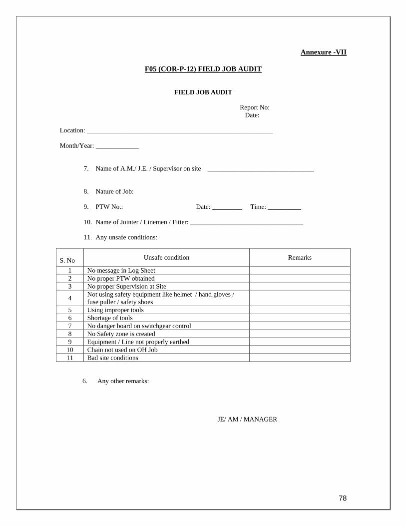
78
Annexure -VII
F05 (COR-P-12) FIELD JOB AUDIT
FIELD JOB AUDIT
Report No: Date:
Location: ________________________________________________________ Month/Year: _____________
7. Name of A.M./ J.E. / Supervisor on site ________________________________ 8. Nature of Job: 9. PTW No.: Date: _________ Time: __________ 10. Name of Jointer / Linemen / Fitter: __________________________________ 11. Any unsafe conditions:
6. Any other remarks:
JE/ AM / MANAGER
S. No Unsafe condition Remarks
1 No message in Log Sheet 2 No proper PTW obtained 3 No proper Supervision at Site
4 Not using safety equipment like helmet / hand gloves / fuse puller / safety shoes
5 Using improper tools 6 Shortage of tools 7 No danger board on switchgear control 8 No Safety zone is created 9 Equipment / Line not properly earthed
10 Chain not used on OH Job 11 Bad site conditions

79
Annexure - VIII
F06 (COR-P-12) TOOL BAG AUDIT
TOOL BAG AUDIT FORM
Report No: Date:
Date: _____________
12. Name of Linesman/Jointer/Fitter: ________________________________
13. Emp No: _________________ 14. Department: _________________
15. Observations:
5. Any other remarks:
AMC Supervisor AM / MANAGER
S. No Observation Remarks
1 Condition of tools and its insulation 2 No proper tools 3 Shortage of tools 4 Condition of tool box / tool bag
5 Condition and availability of personnel protective equipment like helmet / hand gloves / fuse puller / safety shoes etc.

80
Annexure - IX
F07 (COR-P-12) SAFETY AUDIT
SAFETY AUDIT
Report No: Date:
Location: ________________________________________________________ Month/ Year: _____________
S. No DESCRIPTION REMARKS
1 TRANSFORMER (POWER / DTR) a) Earthing b) Stenciling c) Oil leakage
2 H.T./L.T. SWITCHGEAR a) Earthing b) Stenciling c) Rubber mat d) Oil leakage
3 BATTERY ROOM a) Exhaust Fan b) No smoking board
4 RUBBER MAT 5 LIGHTING FIXTURES 6 DANGER BOARD 7 ARTIFICIAL RESPIRATION CHART 8 FIRE EXTINGUISHERS 9 FIRE BUCKET
10 FIRST AID BOX
REMARKS: Any unsafe condition noticed.
AM / MANAGER

81
Annexure -X
F08 (COR-P-12) FIRST AID BOX RECORD
First Aid Box Maintenance Register
S.No. Name of Medicines
Date Of Expiry Quantity Consumed by
& Date Balance Remarks

82
Annexure -XI
F09 (COR-P-12) FIRE EXTINGUISHER RECORD
Fire Extinguishers Record
S.No. Type Of Fire Extinguisher & Date of Manufacturing
Cylinder No. Capacity Class Make Date Of
Refilling Date Of Maint. Remarks
Annexure -XII
F10 (COR-P-12) INFORMATION OF ACCIDENT
Information of Accident Date Time Type
(Fatal / Non Fatal)
Zone / Grid / Site
Location Dist. / System
Category (Employee, Contract./ Gen. Public / Animal)
Voltage Level
PTW Status
Reportable / Non Reportable( To Electrical Inspector)
Brief of Accident
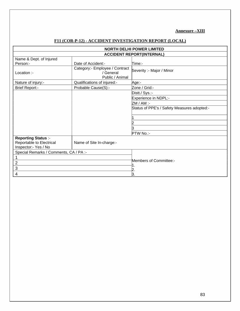
83
Annexure –XIII
F11 (COR-P-12) - ACCIDENT INVESTIGATION REPORT (LOCAL)
NORTH DELHI POWER LIMITED ACCIDENT REPORT(INTERNAL)
Name & Dept. of Injured Person:- Date of Accident:- Time:-
Location :- Category:- Employee / Contract
/ General Public / Animal
Severity :- Major / Minor
Nature of injury:- Qualifications of injured:- Age:- Brief Report:- Probable Cause(S):- Zone / Grid:-
Distt./ Sys.:- Experience in NDPL:- ZM / AM :- Status of PPE's / Safety Measures adopted:-
1 2 3 PTW No.:-
Reporting Status :- Reportable to Electrical Inspector:- Yes / No
Name of Site In-charge:-
Special Remarks / Comments, CA / PA :-
Members of Committee:- 1. 2. 3.
1 2 3 4

84
Annexure –XIV
F12 (COR-P-12) ACCIDENT INVESTIGATION REPORT (ACCIDENT COMMITTEE) 1. Date of Accident 2. Location 3. Type 4. Category 5. Witness Name 6. Zonal Manager / Astt. Manager 7. DM / APSM / APM 8. Description of Accidents (Sequential details) 9. Analysis of Root Causes 10. Corrective & Preventive Actions 11. Responsibility Centre 12. Target Date
Annexure –XV
F13 (COR-P-12) ELECTRICAL ACCIDENTS CAUSES SHARING FORM
S. No.
Date Zone Distt. / System
Location Type Voltage Level
Category
Root Cause
Description of Accident
Corrective and Preventive Actions
Responsibility Centre

85
Annexure -XVI
W01 (COS-P-06) RECTIFICATION OF CABLE FAULTS
A. RECTIFICATION OF CABLE FAULT
1. Detail of the cable faults occurring in the network is intimated by the respective Zonal Managers /
ZSO to Circle Control (PSC) daily, as and when faults occur. Information on the cable fault is taken over the telephone by COS cable group every morning by 7.00 am.
2. Service Provider(s) has/have been appointed to undertake Cable repair work in NDPL. On
occurrence of a cable fault and its detection by FLC, intimation is given by the concerned ZSO/ZM to either of the Service providers to take up the digging and repair work.
3. Every morning the service providers submit “Status Report” on cable fault being attended by them
through e-mail to COS Cable Network Group (CNG). Ref Doc F 02 ( COS - P - 06 )
4. Service providers shall carry out the work as given in Annexure-A (Given below) of the work order placed on them. Jointing work shall be strictly done by the service providers as per the instruction sheet of the manufacture of jointing kit.
5. As a corrective measure, reducer ferrules have been introduced to take care of the jointing of
cables of dissimilar sizes. Similar action has been initiated for copper to aluminum connections of cable. Special mechanical connectors have been introduced for such cases.
6. Cable joint failures that have been recently rectified are analyzed by the service providers in the
presence of CNG. Cause of failure is ascertained and necessary corrective action is issued to service providers.
7. A databank of each fault is maintained in a specific format (Refer F04(COS-P-06). This databank
helps in analyzing the frequency of failure of each cable fault. Cables having frequency of failure more than 5 times in a financial year are identified as “Sick cables”. Every year, a consolidated list is submitted to System Engineering in the first week of April to prepare scheme for replacement of Sick cable.
8. On completion of the cable repair work, the ZM/O/ZSO shall fill in the “Cable Fault Repair
Report” (Given below in Annexure-B) to certify the job completed by the service provider/agency.
Annexure- A GUIDELINES FOR EXCAVATION AND CABLE LAYING
1) Once the cable fault is pinpointed and the location of fault is known, the service provider shall deploy his crew for excavation at site. Meanwhile, concerned JE/AM shall submit an “Intimation letter” with all the relevant details to the office of the MCD/PWD regarding excavation.
2) Use of crow bars shall be restricted for removal of the hard upper crust of the earth. Thereafter,
excavation shall be carried out with pick axes.
3) If, during the progress of excavation, warning covers of NDPL cables or of other utilities are exposed, earth around these covers shall be scooped carefully with phawra/fencing pins/tip of a pick axe. After loosening the covers they shall be removed and stacked for reuse. Every care shall be taken to avoid damage of any nature to any of equipment of any of the utilities during the course of work.
86
4) The entire trench along the length shall be barricaded with corrugated sheets painted with red and
white strips.
5) Warning lights shall be provided over the trench in the night to avoid accident.
6) Wherever crossing of lanes are involved, cable shall be laid in Hume pipes.
7) The excavated material should be stacked on both sides of the trench to avoid inconvenience to public and traffic.
8) In case the depth of the trench is more than 1.5 m appropriate shoring of walls shall be done to
prevent collapse of the excavated trench.
9) Wherever possible, the depth of the cable that shall be laid for repair will be as given below. LT cable (1.1kv) – 0.6 m HV cable (11kv) – 0.9 m EHV cable (33kv) – 1.2 m EHV cable (66kv) – 1.5 m
10) The jointing pit shall preferably be of the size 2 m x 5 m, as to give enough working space for the jointer.
11) In case the HT cable that is cut, has to be kept open in the trench for more than 2 days then the
ends of the cable shall be sealed. Sealing can be done by plumbing for PILC cables and by sealing caps for XLPE cables.
12) If digging or jointing is to be done in the evening or night then arrangement for lighting for
sufficient illumination shall be made by the service provider. 13) The jointing pit shall be covered with tarpaulin or plastic sheet before the jointing work is started. 14) After jointing work is over, soft soil (if available at site) or sand shall be used for bedding and
shall cover the cable by 100 mm below and above. Warning covers/bricks then shall be placed over the cables and thereafter the earth that is stacked shall be used for backfilling.
15) While backfilling, care should be taken to consolidate the earth below the joints and cables to
avoid subsequent subsidence.
16) While backfilling, the crown of the earth left shall be between 50 mm to 100 mm above road surface and shall be free from sharp stones and boulders. The backfilled earth shall be rammed to level the surface as far as possible.
17) After completion of the entire job and the cable is put into load service, Letter for Road
Restoration with the relevant details and signed by the JE/AM shall be submitted to the MCD/PWD.
ELECTRICAL TEST ON CABLES
1) Meggar Test shall be carried out on HT cable before and after Jointing. The acceptable value for the Test is minimum 50 Mega ohms. By and large the meggar values for all the phases should be equal. If the values are unequal then HV Test shall be conducted on the cable. 2) High Voltage shall be carried out after jointing .Test shall be carried out by applying the rated voltage on one core and grounding the other two phases. The voltage shall be increased gradually .The leakage current should be steady during the test. The voltage and time duration for the test is as given below.

87
Rating of the cable Test Voltage Test Time Acceptable leakage
current 11 kV 6.5 kV 5 min Less than 0.5mA 33 kV 20 kV 5 min Less than 0.05mA 66 kV 40 kV 5 min Less than 0.01mA
Annexure- B
CABLE FAULT REPAIR REPORT Complaint / Job Ref. No.: 1 Name of the Feeder 2 Name of District / Zone 3 Type & Voltage of cable 4 Date & Time of fault reporting 5 Name of the fault reporting person 6 Date & Time of location of fault 7 Date & Time of receipt of permission from
MCD / PWD
8 Date & Time of starting of excavation 9 Depth of cable at the point of fault 10 Nature of the fault Joint / Termination / External damage/
Insulation failure 11 Whether moisture present in the cable 12 Type , size & length of new cable laid Length- No. of joints-
No. of Termination - 13 Date & Time of completion of Jointing/
Termination
14 Type of jointing kit used 15 Date & Time of Testing of cable after repairs 16
Test Results IR Test results HV D.C Test
R – E R - Y Y – E Y - B B – E B – R R – E : _________ mA Y – E : _________ mA B – E : _________ mA
17 Meggar provided by Hipot set provided by
NDPL / Agency NDPL / Agency
18 Warning tapes provided Yes / No 19 Date & Time of refilling of trench 20 Location of new Joints ( Sketch to be prepared ) 21 Name of the Jointer 22 Fault Analysis Remarks : Certified by: Signature of ZSO/ O/ZM Name of ZSO/ O/ZM

88
Annexure -XVII
Fire Extinguisher History Card
Location ____________
Type_____________
Extinguisher No. _________
Manf. Date ______________
DAT WORK DONE Next Remark
This card is property of NDPL. Kindly do not remove it from the Fire Extinguisher. During refilling it should be handed over to the person in charge. For any enquire contact BEG 66112341 / 66112346 / 9910492500 / 9910492499

89
Annexure -XVIII
FIRE INCIDENT REPORT
Date:
Describe the Incident:
[ ] Near Miss [ ] First Aid Incident [ ] Lost Workday Case
[ ] Preliminary Report [ ] Final Report
Location of Fire: Exact location of fire: Responsibility: Regular Supervisor: Incident Date: Time: Possible Reason: Material Involved: Loss due to fire: other expenditure due to fire:
Detail of contributing Factors:
SIGNATURE:-
In-charge - Affected HoD –Site Affected HoG - BEG

90
Annexure -XIX
ZONAL TOOL KIT LIST CUSTODIAN : OFFICER(ZONE)
45 Numbers Kits are required as we have 45 numbers B/D Vans. Sr. No.
Description of material Quantity Location
1 Screw driver Blade length 200mm 1 no. B/D Van 2 Screw driver Blade length 250mm 1 no. B/D Van 3 Screw driver Blade length 300mm 1 no. B/D Van 4 Cutting Pliers (351AS) 150mm 1 no. B/D Van 5 Grounding Cables (1x10 sq mm, 5 meters) 1 set.(03
nos.) B/D Van
6 Hammer (ball peen) 606/500 1 no. B/D Van 7 Rubber Hand Gloves (rated for 11 KV) 01 Pair B/D Van 8 Hacksaw frame tubular type 1 no. B/D Van 9 Canvas tool bag 1 no. B/D Van
10 Four cell torch 1 no. B/D Van 11 Chisel 1 no. B/D Van 12 Safety belt 1 no. B/D Van 13 Nut Splitter 1 no. B/D Van 14 Tommy Bar (1 meters length) 1 no. B/D Van 15 Double open end spanners 6 mm to 36 mm
( metric / chrome plated) 1 set each B/D Van
16 Ring Spanner set size 6 mm to 36 mm ( metric / chrome plated)
1 set each B/D Van
17 Adjustable Wrench (BF) 66-150 mm 1 No. B/D Van 18 Flat File (1' long) 1 No. B/D Van 19 Half Round File (1' long) 1 No. B/D Van 20 Insulated Pliers (351 AS)
150 mm 1 No. B/D Van 175 mm 1 No. B/D Van 200 mm 1 No. B/D Van
21 Long Nose Pliers (125 mm) 1 No. B/D Van 22 Vice Grip Pliers 250 mm 1 No. B/D Van 23 Wire Striping Pliers 160 mm 1 No. B/D Van 24 Transverse end Cutter 125 mm 1 No. B/D Van 25 Diagonal Cutting Pliers 1 No. B/D Van 26 Pipe Wrench 250 mm 1 No. B/D Van 27 Hammer Ball Pen (1 pound)
Hammer Cross Pen (1 pound) 1 No. 1 No.
B/D Van
28 Pipe Wrench 66 mm 1 No. B/D Van 29 Bolt Cutter 450 m 1 set each B/D Van 30 Heavy Duty Tool Kit NO 1006 complete with canvas bag (xx) 1 No. Service
Center 31 Screw Driver set (717) 1 set each B/D Van

91
32 Bench vice 4 Inch Bench vice 6 Inch
1 No. 1 No.
B/D Van
33 Measuring tape (15 meters.) 1 no B/D Van 34 Box Spanners Set 8 mm to 32 mm containing 22 sockets and 6
Accessories 1 No. B/D Van
35 Fiber Extension Ladder Closed Height 8 Feet Extended Height 13 Feet
1 No. B/D Van
36 3 M, SCOTCH 23 EPR Based Self Amalgamating Tape 1 Inch wide in roll of 30 feet each.
2 Rolls Service Center
37 Honda Gen. Set EB-2200 1 No. Service Center
38 Motwane make 11-33kv HV Line detector (Neon Tester) model HV-50
1 No. B/D Van
39 Insulation Tester Battery Operated 500v-5000v 1 No. B/D Van 40 Motwane make Digital Clamp-on Meter Model DCM 30 A 1 No. B/D Van 41 Hydraulic Crimping tool (240 - 630 sq mm) 1 No. Service
Center 42 Hand Operated Crimping tool Model Sangram (50 - 400 sq mm) 1 No. Service
Center 43 Digital Earth Resistance Meter Service
Center 44
Fuse wires (14 SWG,16 SWG, 20 SWG,22 SWG) 500 gms
each B/D Van
45 Insulation Tapes (coloured) 3 no. B/D Van 46 Insulation Tape (11 KV rating) 1 roll B/D Van 47
DO fuse operating Rod 1 no. Service Center
48 Discharge rod 1 no. B/D Van 49 HT Megger (1-5 KV) 1 no. B/D Van 50
Hot air blower 1 no. Service Center
51 HI POT Set (0-30 KV) & (0-5 mA) 1 no. B/D Van 52 Phasing Rod (11 KV) 1 no. B/D Van 53 Phase Sequence Meter (440 v) 1 no. B/D Van 54 Safety Helmets with NDPL LOGO 15 nos. 55 Plastic Barricades with NDPL Logo 4 Nos. B/D Van 56 Cordoning Ribbon with NDPL Logo 30 meters. B/D Van 57 First Aid Box 1 no. B/D Van

92
Annexure -XX
GRID TOOL KIT ITEMS CUSTODIAN: OFFICER (GRID MAINT.)
Item Qty. Screw driver with sleeve (Blade length as mentioned below)
200 mm 1 no. 250 mm 1 no. 300 mm 1 no.
Cutting Pliers (351AS) 150mm 1 no. Grounding Cables (1x10 sq mm, 5 meters) 1 set.(03
nos.) Hammer (ball pin) 606/500 2 no. Rubber Hand Gloves (33/66 KV Rating) 01 Pair Hacksaw frame tubular type 1 no. Canvas tool bag 3 no. Four cell torch 1 no. Chisel (6") 1 no. Safety belt 5 no. Tommy Bar (1 meter length) 1 no. Poly Propylene rope 16-20 mm 100 meters.
Each Single pulley block 16,20,22 mm 02 sets of
each Two pulley block 16,20,22 mm 02 sets of
each Three pulley block 20,22,24 mm 02 sets of
each .Come-along for ACSR Conductor DOG,WOLF & GOAT 01 of each Chain pulley block (2 tones) 1 no. Turn Buckle 16,20 & 22 mm 1 no. each PG Clamps for DOG,WOLF & GOAT 06 nos. of
each Suspension Clamps for DOG,WOLF & GOAT 06 nos. of
each Strain Clamps for DOG,WOLF & GOAT 06 nos. of
each Loop Connectors for DOG,WOLF & GOAT 06 nos. of
each Repair sleeve for DOG,WOLF & GOAT 06 nos. of
each Dead End connectors for DOG,WOLF & GOAT 06 nos. of
each Compressor Machine with dies suitable for DOG,WOLF & GOAT 1 set Honda Gen. Set EB-2200 Single phase. 1.7KVA 1 no. Double open end spanners 6 mm to 36 mm (chrome plated) 1 set each
Ring Spanner set size 6 mm to 36 mm (chrome plated) 1 set each Adjustable Wrench

93
150 mm 1 No. 200 mm 1 No. 250 mm 1 No. 300 mm 1 No.
Insulated Pliers 150 mm 1 No. 175 mm 1 No. 200 mm 1 No.
Long Nose Pliers (125 mm) 1 No. Vice Grip Pliers 250 mm 1 No. Diagonal Cutting Pliers 1 No. Pipe Wrench 200 mm 1 No. Heavy Duty Pipe Wrench 350 mm 1 No. Pipe Wrench 200 mm 1 No. Bolt Cutter 450 m 1 set each Screw Driver set (Small) 1 set each Bench vice 6 Inch 1 No. Hacksaw Frames (12") 2 No. Box Spanners Set 8 mm to 32 mm containing 22 sockets and 6 Accessories 1 No. Fiber Extension Ladder Closed Height 8 Feet Extended Height 13 Feet 1 No. Mallet 1 No. Motwane make 33kv HV Line detector (Neon Tester) model HV-50 1 No.
Motwane make Digital Dual Range Insulation tester 500V-1000V Model D2 K
1 No.
Motwane make Digital Clamp-on Meter Model DCM 30 A 1 No.
Torque wrench (up to 120 Nm) 1 No. BDV testing m/c 1 No. Hand Operated Crimping tool Model Sangram (50 - 400 sq mm) 1 No. Discharge Rods (up to 66 kv) 1 No. Safety Helmets 04 Nos. Tarpaulin (3x6 mtrs.) 2 No. Hi-Pot Set (80 kv DC) 1 No. Crimping Tool - 0.5 mm2 to 6 mm2 (Dowells) 1 Set. Earth Tester 1 No. Vacuum Cleaner 1 No. Lock(Circlip) Pliers 6" 1 No. Measuring Tape (30 meter) 1 No. Allen Key set 4 to 12 mm) 1 Set. Hydrometer 1 No. Buckets 2 Nos. Bench Grinder 1 No. Nylon Brush 1 No. Neon Tester 500 V (Line Tester) 1 No. Traffic Cones with NDPL Logo 10 Nos. Phase Sequence Meter (440 v) 1 No. Flat File (1' long) 1 No. Half Round File (1' long) 1 No.

94
Hot Air Blower (1000 W) 1 No. Cordoning Ribbon 50 meters. Additional Items required for grid maintenance Lubricating oil pump Hand drill machine Continuity Tester Pocket tester ( Screw Driver ) Ladder FRP Extension size close height 11 Ft. Extended Height 25 Ft. Working Voltage 33kv Motorize Oil pump Digital capacitance meter Digital Millimeter model rish multi-16s Soldering Iron File cleaner

95
Annexure –XXI W01 (COR-P-12) Work Instructions for Accident Reporting
The electricity network consisting of Grid Substations, Transmission line, Project Sites, L.T Substation, Cabling & Overhead line networks etc. are susceptible to accidents which could cause injury or death to animals, general public, contractor’s employee and NDPL employee. While all care in line with the safety document and guidelines shall be followed, but yet wherever unfortunate incidents of accident takes place the following steps need to be followed by all responsible. The proposed steps should be adhered by all and comes into force with immediate effect:-
S.No
Action to be taken in case of Electrical Accident
Responsibility Centre
Mode of Sending
Information
Time Period
1. The communication on accident must be sent to Power System Control, Safety Officer, CMO & HOG (Security).
Zonal Manager for Distribution Network,
APM for Project APSM for Grid
Station & TL Network
Telephone Immediately
2. As per requirement of Rule 44A, The IE Rules 1956 information to be sent to Electrical Inspector.
Information to local police, HOG (Security)
Information to be sent to respective District Manager, HOD (CIM), Power Systems Control, safety Officer and HOD (Operations) / Systems to send information HOD (NMG), HOD (Operations), Safety Officer and Power Systems Control / Projects to send information to HOG (Projects), PSC, GM (TS&P) , HOD(Operations) & Safety Officer as per Format Information of Accident F10(COR-P-12)
Zonal Manager for Distribution Network,
APM for Project APSM for Grid
Station & TL Network
Phone, Fax, E-mail, Registered Letter
Within 24 hours of accident taking place
3 Before sending Statutory Accident Report to Electrical Inspector it has to be vetted by Safety officer and HOD (CIM) for Distribution Network / HOD (NMG) for Grid Station and TL Network / HOD (TS&P) for projects as per Annexure XIII of Indian Electricity Rules 1956 Format Accident Reporting F02(COR-P-12) by the Zonal Manager / APSM / APM
The final copy of Statutory Accident Report also to be marked to Safety Officer, HOD
Zonal Manager for Distribution Network,
APM for Project APSM for Grid
Station & TL Network
Registered Letter / By Hand
Within 48 hours of accident taking place.

96
S.No
Action to be taken in case of Electrical Accident
Responsibility Centre
Mode of Sending
Information
Time Period
(Operations), F&A Executive. 4. Photograph of the accident site to be taken
and the same must be sent to Safety Officer, HOG (Security) and HOD (Operations)
Zonal Manager for Distribution Network,
APM for Project APSM for Grid
Station & TL Network
E-Mail or Hard Copy
Within 48 hours of accident taking place.
5. Accident Investigation (Local) under the Chairmanship of Manager concerned, the composition of committee is as follows:-
1. Chairman, Manager Concerned 2. Member, AM / ZM adjoining Zone /
grid 3. Member, TA to HOD(CIM) /
HOD(NMG) / GM (TS&P) Report to be submitted to Accident Committee as per Format Accident Investigation Report (Local) F11(COR-P-12)
Manager (Concerned) Annexure-III Within 48 Hrs of accident taken place
It shall be the responsibility of the Safety Officer to ensure that adequate Accident Report formats are available at all zones and grid stations. It shall also be ensured by the Safety Officer that Zonal Staff and Grid Staff are educated on the above action plan points and copy of the same is displayed at prominent locations in the Zonal Office / Grid Stations. Further to this, a committee comprising of the following is also constituted who shall investigate each accident to ascertain the causes of the electrical accident / accident and suggest necessary preventive and corrective actions as per Format Accident Investigation Report (Accident Committee) F12(COR-P-12)
1. HOD (CIM) / HOD (NMG) – Chairman (Rotational basis) 2. HOG (COS) – Member-1 3. Manager IR & W- Member-2 4. Safety Officer- Member Secretary
The above said committee shall be responsible for submitting the report to HOD (Operations) within 5 days of the accident. The Safety Officer shall maintain a MIS as per Format Electrical Accident Causes Sharing F13 (COR-P12) of the accidents, Safety officer would follow up with concerned responsibility centres to ensure that necessary actions are taken. HOD (Operations) will circulate this MIS on basis of bi-annually accidents details for awareness purposes and to highlight any pending CAPA activities. The Zonal Manager / APSM / Area Project Manager should identify next in command who shall discharge the expected responsibilities in his / her absence.

97
ABBREVIATIONS
S.No. Abbreviations Description 1 A.P.S.M. Area Power System Manager 2 D.C. Direct Current 3 D.M. District Manager 4 E.H.S. Environment, Occupational Health & Safety 5 E.H.V. Extra High Voltage 6 G.D.R. General Diary Register 7 H.O.D. Head of Department 8 H.O.G. Head of Group 9 H.T. High Tension
10 L.T. Low Tension 11 I.E. Rules Indian Electricity Rules 12 I.S. Indian Standards 13 K.M. Kilo Meter 14 K.V. Kilo Volt 15 m Meter 16 Mtrs. Meters 17 O.C.B.’s Oil Circuit Breakers 18 P.S.C. Power System Control 19 P.P.E.’S Personnel Protective Equipments 20 P.T.W. Permit To Work

98
BIBLIOGRAPHY:
• Indian Electricity Act 1910 • Indian Electricity Rules 1956 • IS: 5216 Recommendation on safety procedures and practices in electrical work. • Part 1 1982 General • Part 2 1982 Life saving techniques • Indian Electricity Act 2003 • Safety Code IP Generation Co Ltd. & Pragati Power Corp. Ltd., New Delhi • Safety Manual – TATA Power

99
INDEX
Pages 5S 58
Accident 42, 45, 46, 52, 56, 57, 58, 59, 63, 64, 65, 66, 69, 71, 74, 82, 83, 84, 96 Report 51
Record 51
Investigation 51, 83
Reporting Format 58, 68, 70, 73
Committee 84
Information 82
Cause Sharing Form 84
Work Instructions 95
Annexures 63
Apparatus 17, 30, 31, 33, 34, 35
Approved 8
Artificial Respiration 52, 54, 66, 80
Authorization 15, 16, 17, 33
Authorized Person 8
Bibliography 98
Burns 52, 54
Bus Bar 38, 39
Cable 13, 18, 35, 44, 86
Fault 4, 85
Fault Repair Report 87
High Voltage 34
Identification 33
Jointing 85, 86
Laying-Guidelines 85
Network Group 85
Testing 13, 86
Under Ground 34
Capacitor 39
Caution 17
Tag 24, 26, 27
Circuit Breakers 17, 18, 38
Construction 44
Control Panel 38, 60

100
DC Voltage Testing 13
Dead Lines 35
Definitions 8,9, 12
Distribution Network 15, 17,
DNoP Tags 17, 19, 20, 24
Do's & Don'ts 10
Earthing 12, 13, 14, 30, 31, 32, 34, 35, 43, 64, 80
EHV Line 32, 73, 83
Electrical Equipment 8, 15, 16, 17, 20, 48
Emergency 8, 19, 32, 56
Excavation 44, 85
Extinguishers 9, 48, 49, 64, 67, 68
History Card 88
Record 82
Field Job Audit Form 78
Fire 48, 49, 67
Protection 49
Incident Report 89
First Aid 52, 55
Box Record 81
Franchisee 16, 64
Grid Sub-station 15, 17, 23
Grid Tool Kit Items 92
Grounding 12, 35
Hand Tools 42
Hazard 8, 26
Heat Exhaustion 55
Heat Stroke 55
Height 34, 39, 42
High Voltage Indicator Rods 33
Hoisting 44, 45
Holger Nielsen 52
Housekeeping 41
Indian Electricity Rules 1956 8, 9, 16, 30, 31, 32, 51, 57, 70, 73, 95
Indian Electricity Act 2003 9
Inspection 30, 52, 64
Installation Work Permit System 23

101
Isolators 32
Ladders 43
Leakage
Current 86, 87
Oil 80
Lifting 45
Lightning Arrestors 39
Line Work 36
Linemen 36
Live Part 12, 30, 31, 33, 37, 38
Mains 13, 30, 31, 33
Meggar Test 86
Metal Clad 38
Near Miss Record 72
Neon Tester 33, 91, 93
Neutral Conductor 12
Operation Disabled Tag 17
Outage Request 16, 17, 18, 20
Outdoor Structure 39
Overhead Lines 13, 30, 32, 34, 36, 95
Permit Holder 16, 17, 18, 19, 21, 24, 28
Permit to Work 8, 15, 31, 32, 33, 34, 38, 63, 64, 68, 70, 71, 76
Guidelines 17
Flowchart 20
Format 22, 75
Audit 77
Personnel Protective Equipments 42, 47, 83, 97
Physical Shock 54
Poles 34, 36, 38
Power System Control 9, 15, 24, 28, 32, 95, 97
Rigging 44
Ropes 44, 45
Safety 17, 36, 42, 56
Audit 57, 80
Committee 64, 65, 66, 71
Contract 15
Document 64

102
Safety
Instruction 30
Precaution 10, 13
Tag 24, 35
Scaffolding 44
Short Circuiting 13, 14, 30, 31, 35, 39
Statutory
Clearance 31
Stipulation 12
Switch Gear 37, 38
Switching Operation 9, 18, 32, 36
Testing 13, 14, 15, 18, 30, 33
Tool Bag Audit Form 79
Towers 34, 35, 36
Training 29, 64, 65, 68
Transformer 26, 34, 37, 38, 80
Transportation 46
Tree Trimming 45
Unsafe Condition 8, 78, 80
Weather 36
Working
Party 9, 23, 26, 30, 44
Mains 30, 31
Distance 31
Cable 33, 34
Height 34
High Voltage Apparatus 34
Live Lines 35
Dead Lines 35
Switching Operation 36
Sub Station 37
Transformer 37, 38
Outdoor Structure 39
Storage Battery 40
Zonal Tool Kit List 90

103
Emergency Telelphone Numbers
• Police: 100 • Fire Brigade: 101 • Ambulance: 102 • Power System & Trading: 9818100644, 9818100332, 9818100438, 66115118 • NDPL Centralized Security Control Room: 65463646, 65463647 • Safety Officer: 9910492499 • Fire Officer: 9910492500 • CMO: 9818100571 • List of Dispensaries: Shalimar Bagh:65155058, Ashok Vihar: 65155045, Rohini: 65155046, Narela: 65155047, Mukherjee Nagar: 65355047 • Mobile Dispensary: 9811006019
NORTH DELHI POWER LIMITED (A Tata Power and Delhi Government Joint Venture)
33 KV SUB STATION BUILDING, HUDSON LINES, KINGSWAY CAMP,
DELHI - 110009
Related Documents