Dräger Polytron 8000/8200/8700/8720 Safety Manual Vers. 2.0 Rev. R1, Feb. 2012 i

Welcome message from author
This document is posted to help you gain knowledge. Please leave a comment to let me know what you think about it! Share it to your friends and learn new things together.
Transcript
Dräger Polytron 8000/8200/8700/8720
Safety ManualVers. 2.0 Rev. R1, Feb. 2012
i

Content
Content
1 Scope and purpose of safety manual . . . . . . . . . .4
2 Relevant standards . . . . . . . . . . . . . . . . . . . . . . . . .4
3 For your safety . . . . . . . . . . . . . . . . . . . . . . . . . . . .43.1 General safety statements . . . . . . . . . . . . . . . . . . . .43.2 Definition of alert icons . . . . . . . . . . . . . . . . . . . . . . .5
4 Field of application . . . . . . . . . . . . . . . . . . . . . . . . .5
5 Assumptions and restrictions for usage of the gas transmitter . . . . . . . . . . . . . . . . . . . . . . . . . . . . . . . .8
5.1 General . . . . . . . . . . . . . . . . . . . . . . . . . . . . . . . . . . .85.2 Trainings . . . . . . . . . . . . . . . . . . . . . . . . . . . . . . . . . .85.3 Installation . . . . . . . . . . . . . . . . . . . . . . . . . . . . . . . . .85.4 Maintenance . . . . . . . . . . . . . . . . . . . . . . . . . . . . . . .85.5 Calibration . . . . . . . . . . . . . . . . . . . . . . . . . . . . . . . . .85.6 Replacement . . . . . . . . . . . . . . . . . . . . . . . . . . . . . . .85.7 Hardware and/or SW Configuration . . . . . . . . . . . . .85.8 Use of Accessories . . . . . . . . . . . . . . . . . . . . . . . . . .85.9 Access Rights option . . . . . . . . . . . . . . . . . . . . . . . .8
6 Proof test . . . . . . . . . . . . . . . . . . . . . . . . . . . . . . . . .96.1 Proof Test Frequencies . . . . . . . . . . . . . . . . . . . . . . .96.2 Visual Inspection Proof Test . . . . . . . . . . . . . . . . . . .96.3 Gas Response Proof Test . . . . . . . . . . . . . . . . . . . . .96.4 Test of the 4 to 20 mA output . . . . . . . . . . . . . . . . .106.5 Test of the relay outputs . . . . . . . . . . . . . . . . . . . . .10
7 Safety relevant parameters . . . . . . . . . . . . . . . . .11
8 Conditions of use . . . . . . . . . . . . . . . . . . . . . . . . .138.1 General . . . . . . . . . . . . . . . . . . . . . . . . . . . . . . . . . .138.2 Access restrictions . . . . . . . . . . . . . . . . . . . . . . . . .138.3 SIL activation . . . . . . . . . . . . . . . . . . . . . . . . . . . . .138.4 Proof tests . . . . . . . . . . . . . . . . . . . . . . . . . . . . . . . .138.5 Filters . . . . . . . . . . . . . . . . . . . . . . . . . . . . . . . . . . .138.6 Relays . . . . . . . . . . . . . . . . . . . . . . . . . . . . . . . . . . .138.7 4 to 20 mA output . . . . . . . . . . . . . . . . . . . . . . . . . .138.8 Polytron 8700 334/340 . . . . . . . . . . . . . . . . . . . . . .148.9 Polytron 8720 . . . . . . . . . . . . . . . . . . . . . . . . . . . . .148.10 Polytron 8200 DD . . . . . . . . . . . . . . . . . . . . . . . . . .148.11 Polytron 8000 . . . . . . . . . . . . . . . . . . . . . . . . . . . . .14
9 Safety functions . . . . . . . . . . . . . . . . . . . . . . . . . .159.1 General . . . . . . . . . . . . . . . . . . . . . . . . . . . . . . . . . .159.2 Safety integrity level . . . . . . . . . . . . . . . . . . . . . . . .159.3 Safety accuracy . . . . . . . . . . . . . . . . . . . . . . . . . . .159.4 Failure rates . . . . . . . . . . . . . . . . . . . . . . . . . . . . . .159.5 Polytron 8700 334/340 . . . . . . . . . . . . . . . . . . . . . .169.6 Polytron 8720 . . . . . . . . . . . . . . . . . . . . . . . . . . . . .189.7 Polytron 8200 DD . . . . . . . . . . . . . . . . . . . . . . . . . .209.8 Polytron 8000 . . . . . . . . . . . . . . . . . . . . . . . . . . . . .22
10 Reference documents . . . . . . . . . . . . . . . . . . . . .23
11 List of Abbreviations . . . . . . . . . . . . . . . . . . . . . .24
Safety Manual 3
Scope and purpose of safety manual
1 Scope and purpose of safety manual
The purpose of this safety manual is to document thenecessary information and assumptions that are required forthe integration of the assessed gas transmitters
Dräger Polytron 8000Dräger Polytron 8200 DD
Dräger Polytron 8700 334/340Dräger Polytron 8720
into a safety instrumented system (SIS) - in compliance withthe requirements of IEC 61508 standard.
The safety manual specifies the safety functions. This may beused to support the safety function of a safety instrumentedsystem (SIS).
The safety manual provides the assumptions that have beenmade on the usage of the gas transmitter. If those assumptionscannot be met by the application, the SIL (Safety IntegrityLevel) capability has to be evaluated considering theapplication-specific circumstances.
2 Relevant standards
3 For your safety
3.1 General safety statements
Safe connection of electrical devicesNever connect this instrument to other electrical devices asmentioned in the IFU before consulting the manufacturer oran expert.
Use in areas subject to explosion hazardsInstruments or components for use in explosion-hazardareas which have been tested and approved according tonational, European or international Explosion ProtectionRegulations may only be used under the conditionsspecified in the approval and with consideration of therelevant legal regulations.The instruments or components may not be modified in anymanner. The use of faulty or incomplete parts is forbidden.The appropriate regulations must be observed at all timeswhen carrying out repairs on these instruments orcomponents.Before using this equipment, carefully read the Instructionsfor Use (IFU).Strictly follow the Instructions for Use. The user must fullyunderstand and strictly observe the instructions. Use theequipment only for the purposes and under the conditionsspecified in the Instructions for Use.Comply with all local and national laws, rules andregulations associated with this equipment.Only trained and competent personnel are permitted toinspect, repair and service the product as detailed in theInstructions for Use. Further maintenance work that is notdetailed in these Instructions for Use must only be carriedout by Dräger or personnel qualified by Dräger. Drägerrecommends a Dräger service contract for all maintenanceactivities.Use only genuine Dräger spare parts and accessories,otherwise the proper functioning of the equipment may beimpaired.The threads for the explosion proof enclosure do notconform to the minimum/maximum values in EN/IEC60079-1. The threads must not be reworked by the user.Do not dispose of the Safety Manual. Ensure that they areretained and appropriately used by the equipment user.The measuring function of the gas detection transmitter forexplosion protection, according to Annex II, clauses 1.5.5,1.5.6 and 1.5.7 of Directive 94/9/EC is currently notcovered.Substitution of components may impair intrinsic safety.Only if intrinsic safety is involved.
Safe connection of electrical devicesNever connect this instrument to other electrical devices asmentioned in the Instructions for Use before consulting themanufacturer or an expert.
EN 50402:2005 Electrical apparatus for the detection and measurement of combustible or toxic gases or vapours or of oxygen –requirements on the functional safety of fixed gas detection systems
IEC 61508:2010 Functional safety of electrical / electronic / programmable electronic safety-related systems
4 Safety Manual
Field of application
Using the product in areas subject to explosion hazards:Instruments or components for use in explosion-hazardareas which have been tested and approved according tonational, European or international Explosion ProtectionRegulations may only be used under the conditionsspecified in the approval and with consideration of therelevant legal regulations.The instruments or components may not be modified in anymanner. The use of faulty or incomplete parts is forbidden.The appropriate regulations must be observed at all timeswhen carrying out repairs on these instruments orcomponents.
3.2 Definition of alert iconsThe following alert icons are used in this document to provideand highlight areas of the associated text that require a greaterawareness by the user. A definition of the meaning of eachicon is as follows:
4 Field of applicationThis Safety Manual refers to the herein considered models ofthe product family Polytron 8XX0 gas transmitters forstationary, continuous monitoring of gases and vapours in asuitable atmosphere.The Polytron 8700 334/340 gas transmitter monitors theconcentration of combustible gases and vapours containinghydrocarbons.The Polytron 8720 gas transmitter monitors the concentrationof carbon dioxide.The Polytron 8200 DD gas transmitter monitors theconcentration of combustible gases and vapours containinghydrocarbons and /or H2.The Polytron 8000 gas transmitter monitors the concentrationof toxic gases and vapours or oxygen.
The gas transmitter uses microprocessor technology tomonitor the gas concentration and update the outputsaccordingly. Depending on the model, the outputs are
1. one 4 to 20 mA analogue signal output, where 4 mArepresents 0 % of configured range and 20 mA represents100 % of configured range.
2. two alarm relays and a fault relay output, additionally to theabove mentioned 4 to 20 mA output.
The gas transmitter is designed for one-man calibration andoffers a variety of diagnostics and self test features.Different measured gases are listed in an internal gases library(only Polytron 87X0). For all these gases, an individuallinearization of the output signal corresponding to themeasured gas concentration is provided.Configuration and calibration are menu guided and easy toperform, using a HART®1 handheld terminal or HMI of thePolytron 8XX0 product family.
The safety manual is referring to the following models of Poly-tron 8XX0 product family:
WARNINGIndicates a potentially hazardous situation which, if not avoided, could result in death or serious injury.
CAUTIONIndicates a potentially hazardous situation which, if not avoided, could result in physical injury, or damage to the product or environment. It may also be used to alert against unsafe practices.
NOTICEIndicates additional information on how to use the device.
!
!
ii
1 HART is a registered trademark of HCF, Austin, Texas, USA.
Model Software releaseDräger Polytron 8000 ≥ 1.2
Dräger Polytron 8700 Type 334 ≥ 1.1
Dräger Polytron 8700 Type 340 ≥ 1.1
Dräger Polytron 8720 ≥ 1.1
Dräger Polytron 8200 DD ≥ 1.1
Safety Manual 5
Field of application
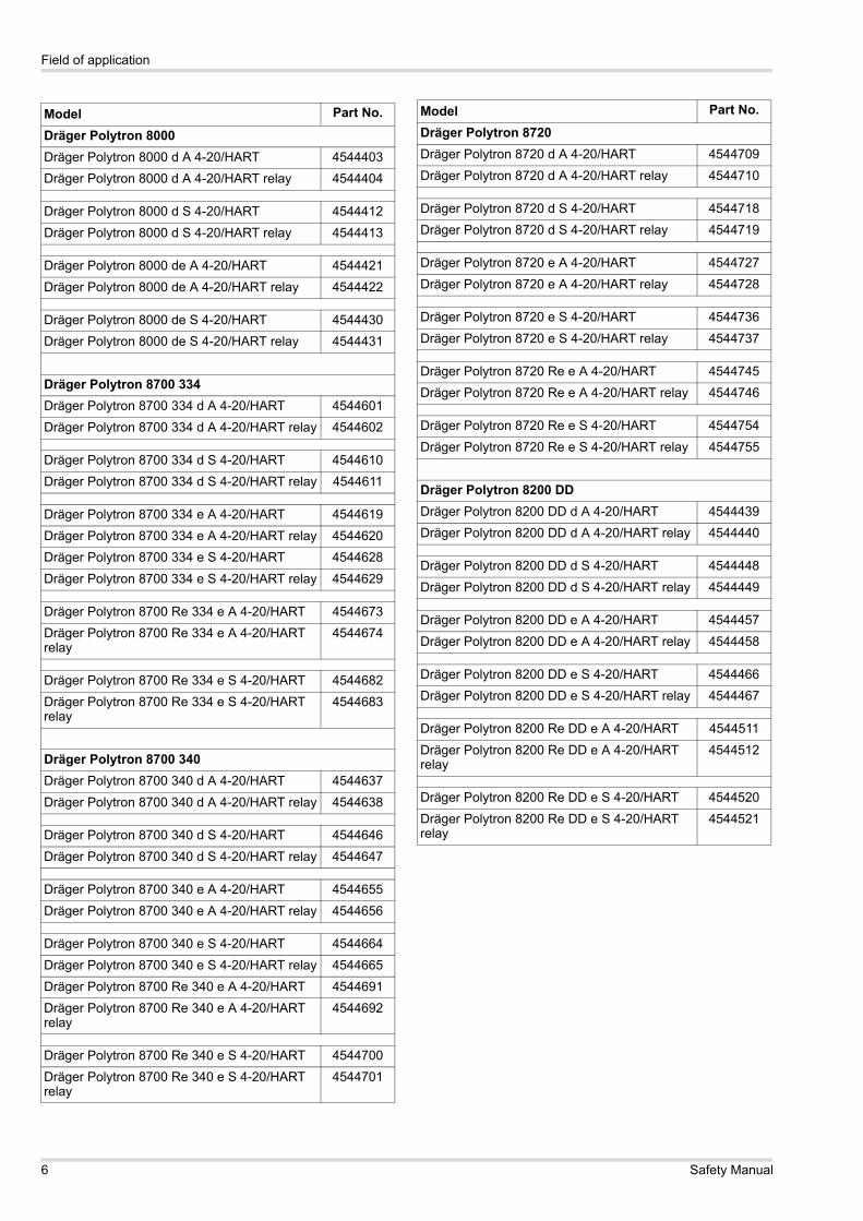
Model Part No.
Dräger Polytron 8000Dräger Polytron 8000 d A 4-20/HART 4544403Dräger Polytron 8000 d A 4-20/HART relay 4544404
Dräger Polytron 8000 d S 4-20/HART 4544412Dräger Polytron 8000 d S 4-20/HART relay 4544413
Dräger Polytron 8000 de A 4-20/HART 4544421Dräger Polytron 8000 de A 4-20/HART relay 4544422
Dräger Polytron 8000 de S 4-20/HART 4544430Dräger Polytron 8000 de S 4-20/HART relay 4544431
Dräger Polytron 8700 334Dräger Polytron 8700 334 d A 4-20/HART 4544601Dräger Polytron 8700 334 d A 4-20/HART relay 4544602
Dräger Polytron 8700 334 d S 4-20/HART 4544610Dräger Polytron 8700 334 d S 4-20/HART relay 4544611
Dräger Polytron 8700 334 e A 4-20/HART 4544619Dräger Polytron 8700 334 e A 4-20/HART relay 4544620Dräger Polytron 8700 334 e S 4-20/HART 4544628Dräger Polytron 8700 334 e S 4-20/HART relay 4544629
Dräger Polytron 8700 Re 334 e A 4-20/HART 4544673Dräger Polytron 8700 Re 334 e A 4-20/HART relay
4544674
Dräger Polytron 8700 Re 334 e S 4-20/HART 4544682Dräger Polytron 8700 Re 334 e S 4-20/HART relay
4544683
Dräger Polytron 8700 340Dräger Polytron 8700 340 d A 4-20/HART 4544637Dräger Polytron 8700 340 d A 4-20/HART relay 4544638
Dräger Polytron 8700 340 d S 4-20/HART 4544646Dräger Polytron 8700 340 d S 4-20/HART relay 4544647
Dräger Polytron 8700 340 e A 4-20/HART 4544655Dräger Polytron 8700 340 e A 4-20/HART relay 4544656
Dräger Polytron 8700 340 e S 4-20/HART 4544664Dräger Polytron 8700 340 e S 4-20/HART relay 4544665Dräger Polytron 8700 Re 340 e A 4-20/HART 4544691Dräger Polytron 8700 Re 340 e A 4-20/HART relay
4544692
Dräger Polytron 8700 Re 340 e S 4-20/HART 4544700Dräger Polytron 8700 Re 340 e S 4-20/HART relay
4544701
Dräger Polytron 8720Dräger Polytron 8720 d A 4-20/HART 4544709Dräger Polytron 8720 d A 4-20/HART relay 4544710
Dräger Polytron 8720 d S 4-20/HART 4544718Dräger Polytron 8720 d S 4-20/HART relay 4544719
Dräger Polytron 8720 e A 4-20/HART 4544727Dräger Polytron 8720 e A 4-20/HART relay 4544728
Dräger Polytron 8720 e S 4-20/HART 4544736Dräger Polytron 8720 e S 4-20/HART relay 4544737
Dräger Polytron 8720 Re e A 4-20/HART 4544745Dräger Polytron 8720 Re e A 4-20/HART relay 4544746
Dräger Polytron 8720 Re e S 4-20/HART 4544754Dräger Polytron 8720 Re e S 4-20/HART relay 4544755
Dräger Polytron 8200 DDDräger Polytron 8200 DD d A 4-20/HART 4544439Dräger Polytron 8200 DD d A 4-20/HART relay 4544440
Dräger Polytron 8200 DD d S 4-20/HART 4544448Dräger Polytron 8200 DD d S 4-20/HART relay 4544449
Dräger Polytron 8200 DD e A 4-20/HART 4544457Dräger Polytron 8200 DD e A 4-20/HART relay 4544458
Dräger Polytron 8200 DD e S 4-20/HART 4544466Dräger Polytron 8200 DD e S 4-20/HART relay 4544467
Dräger Polytron 8200 Re DD e A 4-20/HART 4544511Dräger Polytron 8200 Re DD e A 4-20/HART relay
4544512
Dräger Polytron 8200 Re DD e S 4-20/HART 4544520Dräger Polytron 8200 Re DD e S 4-20/HART relay
4544521
Model Part No.
6 Safety Manual
Assumptions and restrictions for usage of the gas transmitter
5 Assumptions and restrictions for usage of the gas transmitter
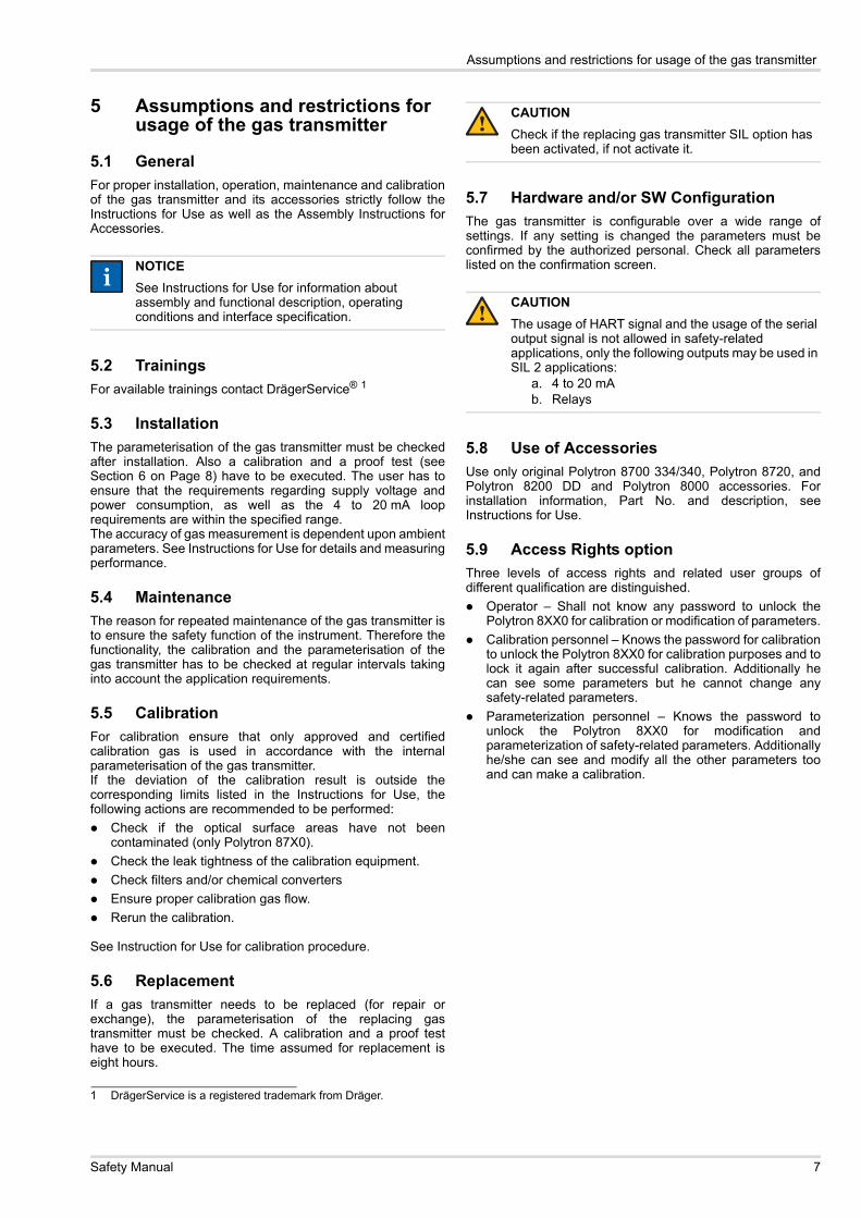
5.1 GeneralFor proper installation, operation, maintenance and calibrationof the gas transmitter and its accessories strictly follow theInstructions for Use as well as the Assembly Instructions forAccessories.
5.2 TrainingsFor available trainings contact DrägerService® 1
5.3 InstallationThe parameterisation of the gas transmitter must be checkedafter installation. Also a calibration and a proof test (seeSection 6 on Page 8) have to be executed. The user has toensure that the requirements regarding supply voltage andpower consumption, as well as the 4 to 20 mA looprequirements are within the specified range.The accuracy of gas measurement is dependent upon ambientparameters. See Instructions for Use for details and measuringperformance.
5.4 MaintenanceThe reason for repeated maintenance of the gas transmitter isto ensure the safety function of the instrument. Therefore thefunctionality, the calibration and the parameterisation of thegas transmitter has to be checked at regular intervals takinginto account the application requirements.
5.5 CalibrationFor calibration ensure that only approved and certifiedcalibration gas is used in accordance with the internalparameterisation of the gas transmitter.If the deviation of the calibration result is outside thecorresponding limits listed in the Instructions for Use, thefollowing actions are recommended to be performed:
Check if the optical surface areas have not beencontaminated (only Polytron 87X0).Check the leak tightness of the calibration equipment.Check filters and/or chemical convertersEnsure proper calibration gas flow.Rerun the calibration.
See Instruction for Use for calibration procedure.
5.6 ReplacementIf a gas transmitter needs to be replaced (for repair orexchange), the parameterisation of the replacing gastransmitter must be checked. A calibration and a proof testhave to be executed. The time assumed for replacement iseight hours.
5.7 Hardware and/or SW ConfigurationThe gas transmitter is configurable over a wide range ofsettings. If any setting is changed the parameters must beconfirmed by the authorized personal. Check all parameterslisted on the confirmation screen.
5.8 Use of AccessoriesUse only original Polytron 8700 334/340, Polytron 8720, andPolytron 8200 DD and Polytron 8000 accessories. Forinstallation information, Part No. and description, seeInstructions for Use.
5.9 Access Rights optionThree levels of access rights and related user groups ofdifferent qualification are distinguished.
Operator – Shall not know any password to unlock thePolytron 8XX0 for calibration or modification of parameters.Calibration personnel – Knows the password for calibrationto unlock the Polytron 8XX0 for calibration purposes and tolock it again after successful calibration. Additionally hecan see some parameters but he cannot change anysafety-related parameters.Parameterization personnel – Knows the password tounlock the Polytron 8XX0 for modification andparameterization of safety-related parameters. Additionallyhe/she can see and modify all the other parameters tooand can make a calibration.
NOTICESee Instructions for Use for information about assembly and functional description, operating conditions and interface specification.
1 DrägerService is a registered trademark from Dräger.
ii
CAUTIONCheck if the replacing gas transmitter SIL option has been activated, if not activate it.
CAUTIONThe usage of HART signal and the usage of the serial output signal is not allowed in safety-related applications, only the following outputs may be used in SIL 2 applications:
a. 4 to 20 mA b. Relays
!
!
Safety Manual 7
Proof test
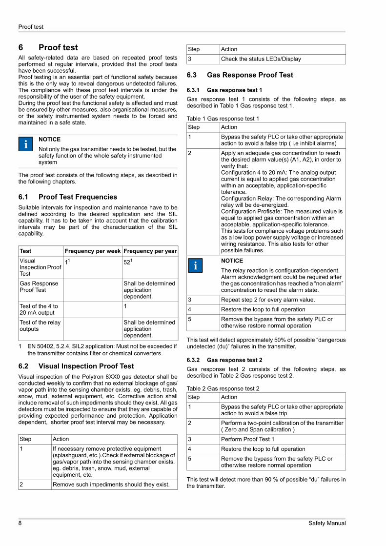
6 Proof testAll safety-related data are based on repeated proof testsperformed at regular intervals, provided that the proof testshave been successful.Proof testing is an essential part of functional safety becausethis is the only way to reveal dangerous undetected failures.The compliance with these proof test intervals is under theresponsibility of the user of the safety equipment.During the proof test the functional safety is affected and mustbe ensured by other measures, also organisational measures,or the safety instrumented system needs to be forced andmaintained in a safe state.
The proof test consists of the following steps, as described inthe following chapters.
6.1 Proof Test FrequenciesSuitable intervals for inspection and maintenance have to bedefined according to the desired application and the SILcapability. It has to be taken into account that the calibrationintervals may be part of the characterization of the SILcapability.
6.2 Visual Inspection Proof TestVisual inspection of the Polytron 8XX0 gas detector shall beconducted weekly to confirm that no external blockage of gas/vapor path into the sensing chamber exists, eg. debris, trash,snow, mud, external equipment, etc. Corrective action shallinclude removal of such impediments should they exist. All gasdetectors must be inspected to ensure that they are capable ofproviding expected performance and protection. Applicationdependent, shorter proof test interval may be necessary.
6.3 Gas Response Proof Test
6.3.1 Gas response test 1Gas response test 1 consists of the following steps, asdescribed in Table 1 Gas response test 1.
Table 1 Gas response test 1
This test will detect approximately 50% of possible “dangerousundetected (du)” failures in the transmitter.
6.3.2 Gas response test 2Gas response test 2 consists of the following steps, asdescribed in Table 2 Gas response test 2.
Table 2 Gas response test 2
This test will detect more than 90 % of possible “du” failures inthe transmitter.
NOTICENot only the gas transmitter needs to be tested, but the safety function of the whole safety instrumented system
Test Frequency per week Frequency per yearVisual Inspection Proof Test
11
1 EN 50402, 5.2.4, SIL2 application: Must not be exceeded if the transmitter contains filter or chemical converters.
521
Gas Response Proof Test
Shall be determined application dependent.
Test of the 4 to 20 mA output
1
Test of the relay outputs
Shall be determined application dependent.
Step Action
1 If necessary remove protective equipment (splashguard, etc.).Check if external blockage of gas/vapor path into the sensing chamber exists, eg. debris, trash, snow, mud, external equipment, etc.
2 Remove such impediments should they exist.
ii
3 Check the status LEDs/Display
Step Action
1 Bypass the safety PLC or take other appropriate action to avoid a false trip ( i.e inhibit alarms)
2 Apply an adequate gas concentration to reach the desired alarm value(s) (A1, A2), in order to verify that: Configuration 4 to 20 mA: The analog output current is equal to applied gas concentration within an acceptable, application-specific tolerance. Configuration Relay: The corresponding Alarm relay will be de-energized.Configuration Profisafe: The measured value is equal to applied gas concentration within an acceptable, application-specific tolerance.This tests for compliance voltage problems such as a low loop power supply voltage or increased wiring resistance. This also tests for other possible failures.
NOTICEThe relay reaction is configuration-dependent. Alarm acknowledgment could be required after the gas concentration has reached a “non alarm” concentration to reset the alarm state.
3 Repeat step 2 for every alarm value.
4 Restore the loop to full operation
5 Remove the bypass from the safety PLC or otherwise restore normal operation
Step Action
1 Bypass the safety PLC or take other appropriate action to avoid a false trip
2 Perform a two-point calibration of the transmitter ( Zero and Span calibration )
3 Perform Proof Test 1
4 Restore the loop to full operation
5 Remove the bypass from the safety PLC or otherwise restore normal operation
Step Action
ii
8 Safety Manual
Proof test
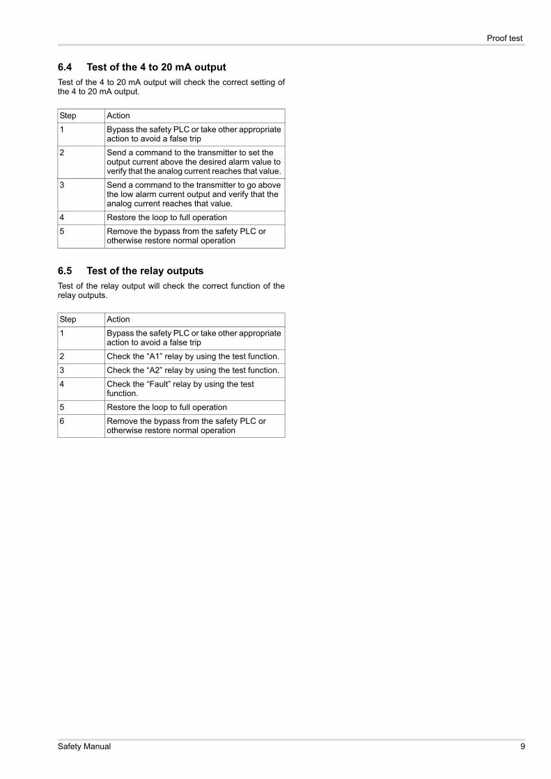
6.4 Test of the 4 to 20 mA outputTest of the 4 to 20 mA output will check the correct setting ofthe 4 to 20 mA output.
6.5 Test of the relay outputsTest of the relay output will check the correct function of therelay outputs.
Step Action
1 Bypass the safety PLC or take other appropriate action to avoid a false trip
2 Send a command to the transmitter to set the output current above the desired alarm value to verify that the analog current reaches that value.
3 Send a command to the transmitter to go above the low alarm current output and verify that the analog current reaches that value.
4 Restore the loop to full operation
5 Remove the bypass from the safety PLC or otherwise restore normal operation
Step Action
1 Bypass the safety PLC or take other appropriate action to avoid a false trip
2 Check the “A1” relay by using the test function.
3 Check the “A2” relay by using the test function.
4 Check the “Fault” relay by using the test function.
5 Restore the loop to full operation
6 Remove the bypass from the safety PLC or otherwise restore normal operation
Safety Manual 9
Safety relevant parameters
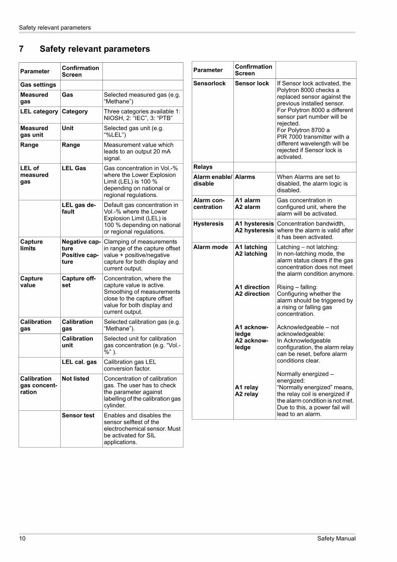
7 Safety relevant parameters
Parameter ConfirmationScreen
Gas settingsMeasured gas
Gas Selected measured gas (e.g. “Methane”)
LEL category Category Three categories available 1: NIOSH, 2: “IEC”, 3: “PTB”
Measured gas unit
Unit Selected gas unit (e.g. “%LEL”)
Range Range Measurement value which leads to an output 20 mA signal.
LEL of measured gas
LEL Gas Gas concentration in Vol.-% where the Lower Explosion Limit (LEL) is 100 % depending on national or regional regulations.
LEL gas de-fault
Default gas concentration in Vol.-% where the Lower Explosion Limit (LEL) is 100 % depending on national or regional regulations.
Capture limits
Negative cap-turePositive cap-ture
Clamping of measurements in range of the capture offset value + positive/negative capture for both display and current output.
Capture value
Capture off-set
Concentration, where the capture value is active. Smoothing of measurements close to the capture offset value for both display and current output.
Calibration gas
Calibration gas
Selected calibration gas (e.g. “Methane”).
Calibration unit
Selected unit for calibration gas concentration (e.g. “Vol.-%” ).
LEL cal. gas Calibration gas LEL conversion factor.
Calibration gas concent-ration
Not listed Concentration of calibration gas. The user has to check the parameter against labelling of the calibration gas cylinder.
Sensor test Enables and disables the sensor selftest of the electrochemical sensor. Must be activated for SIL applications.
Sensorlock Sensor lock If Sensor lock activated, the Polytron 8000 checks a replaced sensor against the previous installed sensor. For Polytron 8000 a different sensor part number will be rejected.For Polytron 8700 a PIR 7000 transmitter with a different wavelength will be rejected if Sensor lock is activated.
RelaysAlarm enable/disable
Alarms When Alarms are set to disabled, the alarm logic is disabled.
Alarm con-centration
A1 alarmA2 alarm
Gas concentration in configured unit, where the alarm will be activated.
Hysteresis A1 hysteresisA2 hysteresis
Concentration bandwidth, where the alarm is valid after it has been activated.
Alarm mode A1 latchingA2 latching
A1 directionA2 direction
A1 acknow-ledgeA2 acknow-ledge
A1 relayA2 relay
Latching – not latching: In non-latching mode, the alarm status clears if the gas concentration does not meet the alarm condition anymore.
Rising – falling: Configuring whether the alarm should be triggered by a rising or falling gas concentration.
Acknowledgeable – not acknowledgeable: In Acknowledgeable configuration, the alarm relay can be reset, before alarm conditions clear.
Normally energized – energized:“Normally energized” means, the relay coil is energized if the alarm condition is not met. Due to this, a power fail will lead to an alarm.
Parameter ConfirmationScreen
10 Safety Manual
Safety relevant parameters
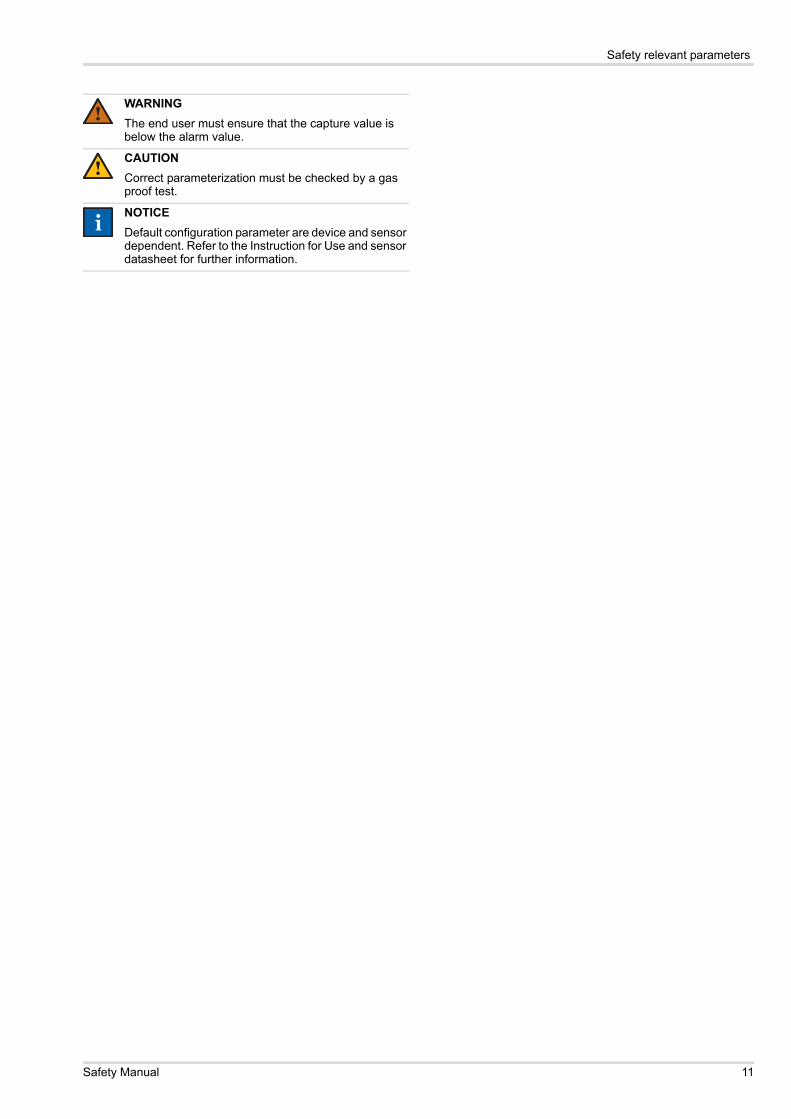
WARNINGThe end user must ensure that the capture value is below the alarm value.
CAUTIONCorrect parameterization must be checked by a gas proof test.
NOTICEDefault configuration parameter are device and sensor dependent. Refer to the Instruction for Use and sensor datasheet for further information.
!
!
ii
Safety Manual 11
Conditions of use
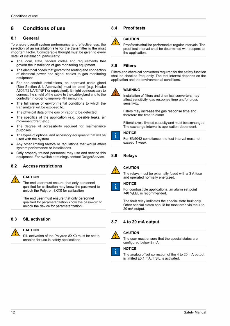
8 Conditions of use
8.1 GeneralTo ensure overall system performance and effectiveness, theselection of an installation site for the transmitter is the mostimportant factor. Considerable thought must be given to everydetail of installation, particularly:
The local, state, federal codes and requirements thatgovern the installation of gas monitoring equipment.The electrical codes that govern the routing and connectionof electrical power and signal cables to gas monitoringequipment.For non-conduit installations, an approved cable gland(See Section 8.1, Approvals) must be used (e.g. HawkeA501/421/A/¾”NPT or equivalent). It might be necessary toconnect the shield of the cable to the cable gland and to thecontroller in order to improve RFI immunity.The full range of environmental conditions to which thetransmitters will be exposed to.The physical data of the gas or vapor to be detected.The specifics of the application (e.g. possible leaks, airmovement/draft, etc.).The degree of accessibility required for maintenancepurposes.The types of optional and accessory equipment that will beused with the system.Any other limiting factors or regulations that would affectsystem performance or installations.Only properly trained personnel may use and service thisequipment. For available trainings contact DrägerService.
8.2 Access restrictions
8.3 SIL activation
8.4 Proof tests
8.5 FiltersFilters and chemical converters required for the safety functionshall be checked frequently. The test interval depends on theapplication and the environmental conditions.
8.6 Relays
8.7 4 to 20 mA output
CAUTIONThe end user must ensure, that only personnel qualified for calibration may know the password to unlock the Polytron 8XX0 for calibration
The end user must ensure that only personnel qualified for parameterization know the password to unlock the device for parameterization.
CAUTIONSIL activation of the Polytron 8XX0 must be set to enabled for use in safety applications.
!
!
CAUTIONProof tests shall be performed at regular intervals. The proof test interval shall be determined with respect to the application.
WARNINGInstallation of filters and chemical converters may affect sensitivity, gas response time and/or cross sensitivity.
Filters may increase the gas response time and therefore the time to alarm.
Filters have a limited capacity and must be exchanged. The exchange interval is application-dependent.
NOTICEFor EN5042 compliance, the test interval must not exceed 1 week
CAUTIONThe relays must be externally fused with a 3 A fuse and operated normally energized.
NOTICEFor combustible applications, an alarm set point ≤40 %LEL is recommended.
The fault relay indicates the special state fault only. Other special states should be monitored via the 4 to 20 mA output.
CAUTIONThe user must ensure that the special states are configured below 2 mA.
NOTICEThe analog offset correction of the 4 to 20 mA output is limited ±0.1 mA, if SIL is activated.
!
!
ii
!
ii
!
ii
12 Safety Manual
Conditions of use
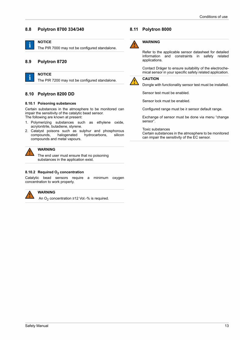
8.8 Polytron 8700 334/340
8.9 Polytron 8720
8.10 Polytron 8200 DD
8.10.1 Poisoning substancesCertain substances in the atmosphere to be monitored canimpair the sensitivity of the catalytic bead sensor.The following are known at present:1. Polymerizing substances such as ethylene oxide,
acrylonitrile, butadiene, styrene.2. Catalyst poisons such as sulphur and phosphorous
compounds, halogenated hydrocarbons, siliconcompounds and metal vapours.
8.10.2 Required O2 concentrationCatalytic bead sensors require a minimum oxygenconcentration to work properly.
8.11 Polytron 8000
NOTICEThe PIR 7000 may not be configured standalone.
NOTICEThe PIR 7200 may not be configured standalone.
WARNINGThe end user must ensure that no poisoning substances in the application exist.
WARNING An O2 concentration ≥12 Vol.-% is required.
ii
ii
!
!
WARNING
Refer to the applicable sensor datasheet for detailedinformation and constraints in safety relatedapplications.
Contact Dräger to ensure suitability of the electroche-mical sensor in your specific safety related application.
CAUTIONDongle with functionality sensor test must be installed.
Sensor test must be enabled.
Sensor lock must be enabled.
Configured range must be ≥ sensor default range.
Exchange of sensor must be done via menu “changesensor”.
Toxic substancesCertain substances in the atmosphere to be monitoredcan impair the sensitivity of the EC sensor.
!
!
Safety Manual 13
Safety functions
9 Safety functions
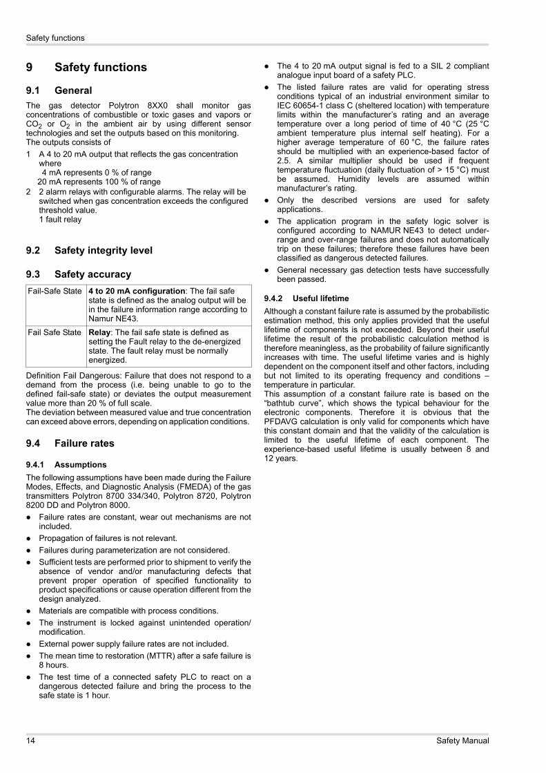
9.1 GeneralThe gas detector Polytron 8XX0 shall monitor gasconcentrations of combustible or toxic gases and vapors orCO2 or O2 in the ambient air by using different sensortechnologies and set the outputs based on this monitoring.The outputs consists of 1 A 4 to 20 mA output that reflects the gas concentration
where 4 mA represents 0 % of range 20 mA represents 100 % of range2 2 alarm relays with configurable alarms. The relay will be
switched when gas concentration exceeds the configured threshold value.1 fault relay
9.2 Safety integrity level
9.3 Safety accuracy
Definition Fail Dangerous: Failure that does not respond to ademand from the process (i.e. being unable to go to thedefined fail-safe state) or deviates the output measurementvalue more than 20 % of full scale.The deviation between measured value and true concentrationcan exceed above errors, depending on application conditions.
9.4 Failure rates
9.4.1 AssumptionsThe following assumptions have been made during the FailureModes, Effects, and Diagnostic Analysis (FMEDA) of the gastransmitters Polytron 8700 334/340, Polytron 8720, Polytron8200 DD and Polytron 8000.
Failure rates are constant, wear out mechanisms are notincluded.Propagation of failures is not relevant.Failures during parameterization are not considered.Sufficient tests are performed prior to shipment to verify theabsence of vendor and/or manufacturing defects thatprevent proper operation of specified functionality toproduct specifications or cause operation different from thedesign analyzed.Materials are compatible with process conditions.The instrument is locked against unintended operation/modification.External power supply failure rates are not included.The mean time to restoration (MTTR) after a safe failure is8 hours.The test time of a connected safety PLC to react on adangerous detected failure and bring the process to thesafe state is 1 hour.
The 4 to 20 mA output signal is fed to a SIL 2 compliantanalogue input board of a safety PLC.The listed failure rates are valid for operating stressconditions typical of an industrial environment similar toIEC 60654-1 class C (sheltered location) with temperaturelimits within the manufacturer’s rating and an averagetemperature over a long period of time of 40 °C (25 °Cambient temperature plus internal self heating). For ahigher average temperature of 60 °C, the failure ratesshould be multiplied with an experience-based factor of2.5. A similar multiplier should be used if frequenttemperature fluctuation (daily fluctuation of > 15 °C) mustbe assumed. Humidity levels are assumed withinmanufacturer’s rating.Only the described versions are used for safetyapplications.The application program in the safety logic solver isconfigured according to NAMUR NE43 to detect under-range and over-range failures and does not automaticallytrip on these failures; therefore these failures have beenclassified as dangerous detected failures.General necessary gas detection tests have successfullybeen passed.
9.4.2 Useful lifetimeAlthough a constant failure rate is assumed by the probabilisticestimation method, this only applies provided that the usefullifetime of components is not exceeded. Beyond their usefullifetime the result of the probabilistic calculation method istherefore meaningless, as the probability of failure significantlyincreases with time. The useful lifetime varies and is highlydependent on the component itself and other factors, includingbut not limited to its operating frequency and conditions –temperature in particular.This assumption of a constant failure rate is based on the“bathtub curve”, which shows the typical behaviour for theelectronic components. Therefore it is obvious that thePFDAVG calculation is only valid for components which havethis constant domain and that the validity of the calculation islimited to the useful lifetime of each component. Theexperience-based useful lifetime is usually between 8 and12 years.
Fail-Safe State 4 to 20 mA configuration: The fail safe state is defined as the analog output will be in the failure information range according to Namur NE43.
Fail Safe State Relay: The fail safe state is defined as setting the Fault relay to the de-energized state. The fault relay must be normally energized.
14 Safety Manual
Safety functions
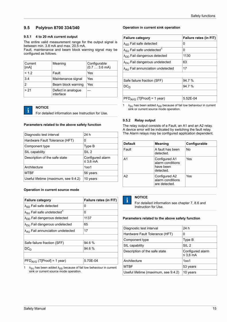
9.5 Polytron 8700 334/340
9.5.1 4 to 20 mA current outputThe entire valid measurement range for the output signal isbetween min. 3.8 mA and max. 20.5 mA. Fault, maintenance and beam block warning signal may beconfigured as follows.
Parameters related to the above safety function
Operation in current source mode
Operation in current sink operation
9.5.2 Relay outputThe relay output consists of a Fault, an A1 and an A2 relay.A device error will be indicated by switching the fault relay.The Alarm relays may be configured application dependent.
Parameters related to the above safety function
Current[mA]
Meaning Configurable(0.7 … 3.6 mA)
< 1.2 Fault Yes
3.4 Maintenance signal Yes
2 Beam block warning Yes
> 21 Defect in analogue interface
---
NOTICEFor detailed information see Instruction for Use.
Diagnostic test interval 24 h
Hardware Fault Tolerance (HFT) 0
Component type Type B
SIL capability SIL 2
Description of the safe state Configured alarm≤ 3,6 mA
Architecture 1oo1
MTBF 56 years
Useful lifetime (maximum, see 9.4.2) 10 years
Failure category Failure rates (in FIT)λSD Fail safe detected 0
λSU Fail safe undetected1
1 λSU has been added λDD because of fail low behaviour in current sink or current source mode operation.
0
λDD Fail dangerous detected 1137
λDU Fail dangerous undetected 65
λAU Fail annunciation undetected 17
Safe failure fraction (SFF) 94.6 %
DCD 94.6 %
PFDAVG (T[Proof] = 1 year) 5.70E-04
ii
Failure category Failure rates (in FIT)λSD Fail safe detected 0
λSU Fail safe undetected1
1 λSU has been added λDD because of fail low behaviour in current sink or current source mode operation.
0
λDD Fail dangerous detected 1130
λDU Fail dangerous undetected 63
λAU Fail annunciation undetected 17
Safe failure fraction (SFF) 94.7 %
DCD 94.7 %
PFDAVG (T[Proof] = 1 year) 5.52E-04
Default Meaning ConfigurableFault A fault has been
detected.No
A1 Configured A1 alarm conditions have been detected.
Yes
A2 Configured A2 alarm conditions are detected.
Yes
NOTICEFor detailed information see chapter 7, 8.6 and Instruction for Use.
Diagnostic test interval 24 h
Hardware Fault Tolerance (HFT) 0
Component type Type B
SIL capability SIL 2
Description of the safe state Configured alarm≤ 3,6 mA
Architecture 1oo1
MTBF 53 years
Useful lifetime (maximum, see 9.4.2) 10 years
ii
Safety Manual 15
Safety functions
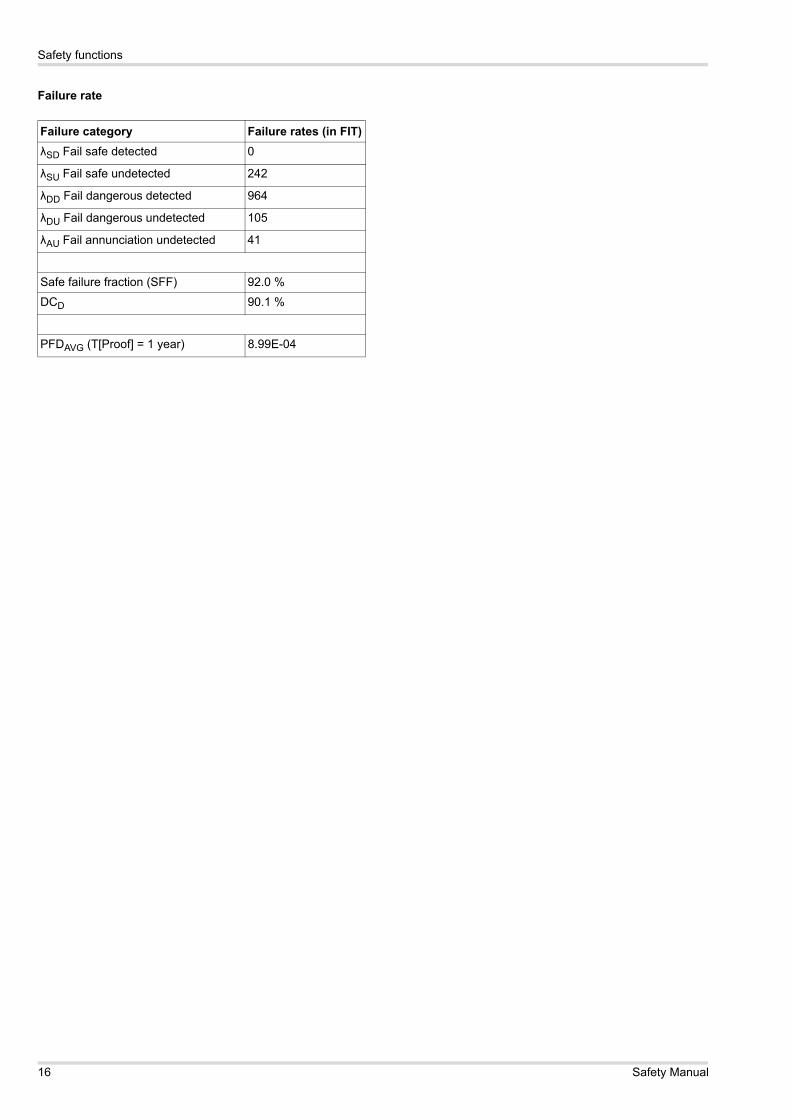
Failure rate
Failure category Failure rates (in FIT)λSD Fail safe detected 0
λSU Fail safe undetected 242
λDD Fail dangerous detected 964
λDU Fail dangerous undetected 105
λAU Fail annunciation undetected 41
Safe failure fraction (SFF) 92.0 %
DCD 90.1 %
PFDAVG (T[Proof] = 1 year) 8.99E-04
16 Safety Manual
Safety functions
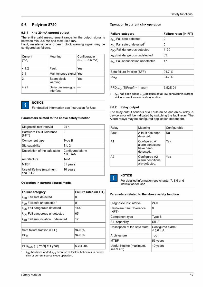
9.6 Polytron 8720
9.6.1 4 to 20 mA current outputThe entire valid measurement range for the output signal isbetween min. 3.8 mA and max. 20.5 mA. Fault, maintenance and beam block warning signal may beconfigured as follows.
Parameters related to the above safety function
Operation in current source mode
Operation in current sink operation
9.6.2 Relay outputThe relay output consists of a Fault, an A1 and an A2 relay. Adevice error will be indicated by switching the fault relay. TheAlarm relays may be configured application dependent.
Parameters related to the above safety function
Current[mA]
Meaning Configurable(0.7 … 3.6 mA)
< 1.2 Fault Yes
3.4 Maintenance signal Yes
2 Beam block warning
Yes
> 21 Defect in analogue interface
---
NOTICEFor detailed information see Instruction for Use.
Diagnostic test interval 24 h
Hardware Fault Tolerance (HFT)
0
Component type Type B
SIL capability SIL 2
Description of the safe state Configured alarm≤ 3,6 mA
Architecture 1oo1
MTBF 61 years
Useful lifetime (maximum, see 9.4.2
10 years
Failure category Failure rates (in FIT)λSD Fail safe detected 0
λSU Fail safe undetected1
1 λSU has been added λDD because of fail low behaviour in current sink or current source mode operation.
0
λDD Fail dangerous detected 1137
λDU Fail dangerous undetected 65
λAU Fail annunciation undetected 17
Safe failure fraction (SFF) 94.6 %
DCD 94.6 %
PFDAVG (T[Proof] = 1 year) 5.70E-04
ii
Failure category Failure rates (in FIT)λSD Fail safe detected 0
λSU Fail safe undetected1
1 λSU has been added λDD because of fail low behaviour in current sink or current source mode operation.
0
λDD Fail dangerous detected 1130
λDU Fail dangerous undetected 63
λAU Fail annunciation undetected 17
Safe failure fraction (SFF) 94.7 %
DCD 94.7 %
PFDAVG (T[Proof] = 1 year) 5.52E-04
Relay Meaning Configurable
Fault A fault has been detected.
No
A1 Configured A1 alarm conditions have been detected.
Yes
A2 Configured A2 alarm conditions are detected.
Yes
NOTICEFor detailed information see chapter 7, 8.6 and Instruction for Use.
Diagnostic test interval 24 h
Hardware Fault Tolerance (HFT)
0
Component type Type B
SIL capability SIL 2
Description of the safe state Configured alarm≤ 3,6 mA
Architecture 1oo1
MTBF 53 years
Useful lifetime (maximum, see 9.4.2)
10 years
ii
Safety Manual 17

Safety functions
Failure rate
Failure category Failure rates (in FIT)λSD Fail safe detected 0
λSU Fail safe undetected 242
λDD Fail dangerous detected 964
λDU Fail dangerous undetected 105
λAU Fail annunciation undetected 41
Safe failure fraction (SFF) 92.0 %
DCD 90.1 %
PFDAVG (T[Proof] = 1 year) 8.99E-04
18 Safety Manual
Safety functions
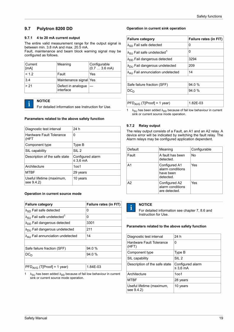
9.7 Polytron 8200 DD
9.7.1 4 to 20 mA current outputThe entire valid measurement range for the output signal isbetween min. 3.8 mA and max. 20.5 mA. Fault, maintenance and beam block warning signal may beconfigured as follows.
Parameters related to the above safety function
Operation in current source mode
Operation in current sink operation
9.7.2 Relay outputThe relay output consists of a Fault, an A1 and an A2 relay. Adevice error will be indicated by switching the fault relay. TheAlarm relays may be configured application dependent.
Parameters related to the above safety function
Current[mA]
Meaning Configurable(0.7 … 3.6 mA)
< 1.2 Fault Yes
3.4 Maintenance signal Yes
> 21 Defect in analogue interface
---
NOTICEFor detailed information see Instruction for Use.
Diagnostic test interval 24 h
Hardware Fault Tolerance (HFT
0
Component type Type B
SIL capability SIL 2
Description of the safe state Configured alarm≤ 3,6 mA
Architecture 1oo1
MTBF 29 years
Useful lifetime (maximum, see 9.4.2)
10 years
Failure category Failure rates (in FIT)λSD Fail safe detected 0
λSU Fail safe undetected1
1 λSU has been added λDD because of fail low behaviour in current sink or current source mode operation.
0
λDD Fail dangerous detected 3301
λDU Fail dangerous undetected 211
λAU Fail annunciation undetected 14
Safe failure fraction (SFF) 94.0 %
DCD 94.0 %
PFDAVG (T[Proof] = 1 year) 1.84E-03
ii
Failure category Failure rates (in FIT)λSD Fail safe detected 0
λSU Fail safe undetected1
1 λSU has been added λDD because of fail low behaviour in current sink or current source mode operation.
0
λDD Fail dangerous detected 3294
λDU Fail dangerous undetected 209
λAU Fail annunciation undetected 14
Safe failure fraction (SFF) 94.0 %
DCD 94.0 %
PFDAVG (T[Proof] = 1 year) 1.82E-03
Default Meaning Configurable
Fault A fault has been detected.
No
A1 Configured A1 alarm conditions have been detected.
Yes
A2 Configured A2 alarm conditions are detected.
Yes
NOTICEFor detailed information see chapter 7, 8.6 and Instruction for Use.
Diagnostic test interval 24 h
Hardware Fault Tolerance (HFT)
0
Component type Type B
SIL capability SIL 2
Description of the safe state Configured alarm≤ 3,6 mA
Architecture 1oo1
MTBF 28 years
Useful lifetime (maximum, see 9.4.2)
10 years
ii
Safety Manual 19

Safety functions
Failure rate
Failure category Failure rates (in FIT)λSD Fail safe detected 0
λSU Fail safe undetected 841
λDD Fail dangerous detected 2526
λDU Fail dangerous undetected 251
λAU Fail annunciation undetected 37
Safe failure fraction (SFF) 93.1 %
DCD 91.0 %
PFDAVG (T[Proof] = 1 year) 2.15E-03
20 Safety Manual
Safety functions
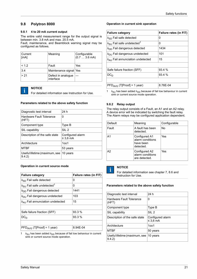
9.8 Polytron 8000
9.8.1 4 to 20 mA current outputThe entire valid measurement range for the output signal isbetween min. 3.8 mA and max. 20.5 mA. Fault, maintenance, and Beamblock warning signal may beconfigured as follows.
Parameters related to the above safety function
Operation in current source mode
Operation in current sink operation
9.8.2 Relay outputThe relay output consists of a Fault, an A1 and an A2 relay.A device error will be indicated by switching the fault relay.The Alarm relays may be configured application dependent.
Parameters related to the above safety function
Current[mA]
Meaning Configurable(0.7 … 3.6 mA)
< 1.2 Fault Yes
3.4 Maintenance signal Yes
> 21 Defect in analogue interface
---
NOTICEFor detailed information see Instruction for Use.
Diagnostic test interval 24 h
Hardware Fault Tolerance (HFT)
0
Component type Type B
SIL capability SIL 2
Description of the safe state Configured alarm≤ 3,6 mA
Architecture 1oo1
MTBF 53 years
Useful lifetime (maximum, see 9.4.2)
10 years
Failure category Failure rates (in FIT)λSD Fail safe detected 0
λSU Fail safe undetected1
1 λSU has been added λDD because of fail low behaviour in current sink or current source mode operation.
0
λDD Fail dangerous detected 1441
λDU Fail dangerous undetected 103
λAU Fail annunciation undetected 15
Safe failure fraction (SFF) 93.3 %
DCD 93.3 %
PFDAVG (T[Proof] = 1 year) 8.94E-04
ii
Failure category Failure rates (in FIT)λSD Fail safe detected 0
λSU Fail safe undetected1
1 λSU has been added λDD because of fail low behaviour in current sink or current source mode operation.
0
λDD Fail dangerous detected 1434
λDU Fail dangerous undetected 101
λAU Fail annunciation undetected 15
Safe failure fraction (SFF) 93.4 %
DCD 93.4 %
PFDAVG (T[Proof] = 1 year) 8.76E-04
Default Meaning Configurable
Fault A fault has been detected.
No
A1 Configured A1 alarm conditions have been detected.
Yes
A2 Configured A2 alarm conditions are detected.
Yes
NOTICEFor detailed information see chapter 7, 8.6 and Instruction for Use.
Diagnostic test interval 24 h
Hardware Fault Tolerance (HFT)
0
Component type Type B
SIL capability SIL 2
Description of the safe state Configured alarm≤ 3,6 mA
Architecture 1oo1
MTBF 50 years
Useful lifetime (maximum, see 9.4.2)
10 years
ii
Safety Manual 21
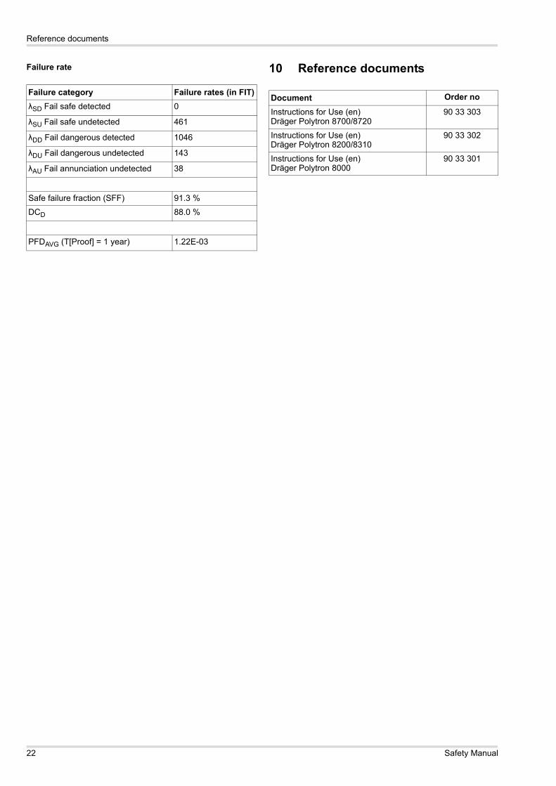
Reference documents
Failure rate 10 Reference documents
Failure category Failure rates (in FIT)λSD Fail safe detected 0
λSU Fail safe undetected 461
λDD Fail dangerous detected 1046
λDU Fail dangerous undetected 143
λAU Fail annunciation undetected 38
Safe failure fraction (SFF) 91.3 %
DCD 88.0 %
PFDAVG (T[Proof] = 1 year) 1.22E-03
Document Order no
Instructions for Use (en)Dräger Polytron 8700/8720
90 33 303
Instructions for Use (en)Dräger Polytron 8200/8310
90 33 302
Instructions for Use (en)Dräger Polytron 8000
90 33 301
22 Safety Manual
List of Abbreviations
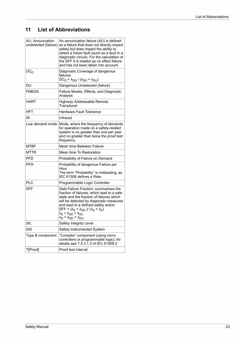
11 List of Abbreviations
AU, Annunciation undetected (failure)
An annunciation failure (AU) is defined as a failure that does not directly impact safety but does impact the ability to detect a future fault (such as a fault in a diagnostic circuit). For the calculation of the SFF it is treated as no effect failure and has not been taken into account.
DCD Diagnostic Coverage of dangerous failures DCD = λDD / (λDD + λDU)
DU Dangerous Undetected (failure)
FMEDA Failure Modes, Effects, and Diagnostic Analysis
HART Highway Addressable Remote Transducer
HFT Hardware Fault Tolerance
IR Infrared
Low demand mode Mode, where the frequency of demands for operation made on a safety-related system is no greater than one per year and no greater than twice the proof test frequency.
MTBF Mean time Between Failure
MTTR Mean time To Restoration
PFD Probability of Failure on Demand
PFH Probability of dangerous Failure per HourThe term “Probability” is misleading, as IEC 61508 defines a Rate.
PLC Programmable Logic Controller
SFF Safe Failure Fraction; summarises the fraction of failures, which lead to a safe state and the fraction of failures which will be detected by diagnostic measures and lead to a defined safety action. SFF = (λS + λDD )/ (λS + λD)λS = λSD + λSUλD = λDD + λDU
SIL Safety Integrity Level
SIS Safety Instrumented System
Type B component “Complex” component (using micro controllers or programmable logic); for details see 7.4.3.1.3 of IEC 61508-2
T[Proof] Proof test interval
Safety Manual 23

List of Abbreviations
24 Safety Manual

List of Abbreviations
Safety Manual 25

List of Abbreviations
26 Safety Manual

Dräger Safety AG & Co. KGaARevalstraße 123560 Lübeck, GermanyTel +49 451 882 0Fax +49 451 882 20 80www.draeger.com
Manufacturing Location:Draeger Safety, Inc.101 Technology DrivePittsburgh, PA 15275-1057, USAPhone +1 412 7 87 - 83 83Fax +1 412 7 87 - 22 07
90 33 307 - TM 4683.605© Dräger Safety AG & Co. KGaAEdition 02 - February 2012 (Edition 01 - September 2011) Subject to alteration
Related Documents