ERDC/CHL TR-11-4 Navigation Systems Research Program Lock Culvert Valves; Hydraulic Design Considerations Coastal and Hydralics Laboratory Richard L. Stockstill, E. Allen Hammack, and John E. Hite, Jr. June 2011 Approved for public release; distribution is unlimited.

Welcome message from author
This document is posted to help you gain knowledge. Please leave a comment to let me know what you think about it! Share it to your friends and learn new things together.
Transcript

ERD
C/CH
L TR
-11-
4
Navigation Systems Research Program
Lock Culvert Valves; Hydraulic Design Considerations
Coas
tal a
nd H
ydra
lics
Labo
rato
ry
Richard L. Stockstill, E. Allen Hammack, and John E. Hite, Jr. June 2011
Approved for public release; distribution is unlimited.

Report Documentation Page Form ApprovedOMB No. 0704-0188
Public reporting burden for the collection of information is estimated to average 1 hour per response, including the time for reviewing instructions, searching existing data sources, gathering andmaintaining the data needed, and completing and reviewing the collection of information. Send comments regarding this burden estimate or any other aspect of this collection of information,including suggestions for reducing this burden, to Washington Headquarters Services, Directorate for Information Operations and Reports, 1215 Jefferson Davis Highway, Suite 1204, ArlingtonVA 22202-4302. Respondents should be aware that notwithstanding any other provision of law, no person shall be subject to a penalty for failing to comply with a collection of information if itdoes not display a currently valid OMB control number.
1. REPORT DATE JUN 2011 2. REPORT TYPE
3. DATES COVERED 00-00-2011 to 00-00-2011
4. TITLE AND SUBTITLE Lock Culvert Valves; Hydraulic Design Considerations
5a. CONTRACT NUMBER
5b. GRANT NUMBER
5c. PROGRAM ELEMENT NUMBER
6. AUTHOR(S) 5d. PROJECT NUMBER
5e. TASK NUMBER
5f. WORK UNIT NUMBER
7. PERFORMING ORGANIZATION NAME(S) AND ADDRESS(ES) Coastal and Hydraulics Laboratory,U.S. Army Engineer Research andDevelopment Center,3909 Halls Ferry Road,Vicksburg,MS,39180
8. PERFORMING ORGANIZATIONREPORT NUMBER
9. SPONSORING/MONITORING AGENCY NAME(S) AND ADDRESS(ES) 10. SPONSOR/MONITOR’S ACRONYM(S)
11. SPONSOR/MONITOR’S REPORT NUMBER(S)
12. DISTRIBUTION/AVAILABILITY STATEMENT Approved for public release; distribution unlimited
13. SUPPLEMENTARY NOTES
14. ABSTRACT This report presents a review of design guidance and hydraulic parameters associated with lock culvertvalves. Many locks are beyond their design life, and the filling- and emptying-culvert valves are beingreplaced to keep the lock in service. Valve selection has begun for several new locks and lock extensionprojects. This report provides general information on three valve types: vertical lift, conventional tainter,and reverse tainter valves. The positive and negative aspects of each valve type as well as particularfeatures are discussed. This report focuses on reverse tainter valves as these are the most common valvedesign used in locks on United States waterways.
15. SUBJECT TERMS
16. SECURITY CLASSIFICATION OF: 17. LIMITATION OF ABSTRACT Same as
Report (SAR)
18. NUMBEROF PAGES
86
19a. NAME OFRESPONSIBLE PERSON
a. REPORT unclassified
b. ABSTRACT unclassified
c. THIS PAGE unclassified
Standard Form 298 (Rev. 8-98) Prescribed by ANSI Std Z39-18

Navigation Systems Research Program ERDC/CHL TR-11-4 June 2011
Lock Culvert Valves; Hydraulic Design Considerations
Richard L. Stockstill, E. Allen Hammack, and John E. Hite, Jr. Coastal and Hydraulics Laboratory U.S. Army Engineer Research and Development Center 3909 Halls Ferry Road Vicksburg, MS 39180-6199
Final report Approved for public release; distribution is unlimited.
Prepared for U.S. Army Corps of Engineers 441 G. Street, NW Washington, DC 20314-1000

ERDC/CHL TR-11-4 ii
Abstract: This report presents a review of design guidance and hydraulic parameters associated with lock culvert valves. Many locks are beyond their design life, and the filling- and emptying-culvert valves are being replaced to keep the lock in service. Valve selection has begun for several new locks and lock extension projects. This report provides general information on three valve types: vertical lift, conventional tainter, and reverse tainter valves. The positive and negative aspects of each valve type as well as particular features are discussed. This report focuses on reverse tainter valves as these are the most common valve design used in locks on United States waterways.
DISCLAIMER: The contents of this report are not to be used for advertising, publication, or promotional purposes. Citation of trade names does not constitute an official endorsement or approval of the use of such commercial products. All product names and trademarks cited are the property of their respective owners. The findings of this report are not to be construed as an official Department of the Army position unless so designated by other authorized documents. DESTROY THIS REPORT WHEN NO LONGER NEEDED. DO NOT RETURN IT TO THE ORIGINATOR.

ERDC/CHL TR-11-4 iii
Contents Figures and Tables ......................................................................................................................................... v
Preface ...........................................................................................................................................................vii
Unit Conversion Factors ........................................................................................................................... viii
1 Introduction ............................................................................................................................................ 1
1.1 Background .................................................................................................................... 1 1.2 Brief history .................................................................................................................... 2 1.3 Purpose .......................................................................................................................... 4
2 Vertical-lift valves .................................................................................................................................. 5
2.1 Hydraulic coefficients .................................................................................................... 7 2.2 Hydrodynamic loads ...................................................................................................... 8 2.3 Vibration considerations ............................................................................................... 9
3 Conventional tainter valves ............................................................................................................... 14
4 Reverse tainter valves ........................................................................................................................18
4.1 Hydraulic coefficients .................................................................................................. 18 4.2 Hydrodynamic loads .................................................................................................... 22 4.3 Vibration considerations ............................................................................................. 24 4.4 Hydraulic model studies .............................................................................................. 25
4.4.1 McNary Lock ................................................................................................................. 25 4.4.2 Lock No. 19 .................................................................................................................. 25 4.4.3 Holt Lock ....................................................................................................................... 26 4.4.4 John Day Lock .............................................................................................................. 36 4.4.5 Walter Bouldin Lock ..................................................................................................... 36 4.4.6 Watts Bar Lock ............................................................................................................. 39
4.5 Prototype studies ......................................................................................................... 50 4.5.1 McNary Lock ................................................................................................................. 50 4.5.2 Bankhead Lock ............................................................................................................ 51 4.5.3 John Day Lock .............................................................................................................. 54 4.5.4 Whitten (Bay Springs) Lock.......................................................................................... 56
4.6 Recommended design ................................................................................................ 57
5 Valve position ....................................................................................................................................... 60
5.1 Horizontal ..................................................................................................................... 60 5.2 Vertical ......................................................................................................................... 60
6 Prototype Experience ......................................................................................................................... 63
6.1 Chickamauga Lock ...................................................................................................... 63 6.2 Watts Bar Lock ............................................................................................................. 66
ERDC/CHL TR-11-4 iv
6.3 John Day Lock .............................................................................................................. 67 6.4 Holt Lock ...................................................................................................................... 69 6.5 Bankhead Lock ............................................................................................................ 70
7 Summary ............................................................................................................................................... 71
References ................................................................................................................................................... 73
Report Documentation Page
ERDC/CHL TR-11-4 v
Figures
Figures
Figure 1. Vertical-lift lock culvert valve. ....................................................................................................... 2
Figure 2. Conventional tainter lock culvert valve. ...................................................................................... 3
Figure 3. Reverse tainter lock culvert valve. ............................................................................................... 3
Figure 4. Discharge coefficient for vertical-lift gate having 45 degree lip. ............................................. 8
Figure 5. Loss coefficient for vertical-lift valve having a 45 degree lip. .................................................. 9
Figure 6. Definition sketch for vertical forces on vertical-lift gates ....................................................... 10
Figure 7. Uplift forces on vertical-lift gate .................................................................................................. 11
Figure 8. Flow under conventional tainter valves, Lower Monumental model study .......................... 15
Figure 9. Discharge coefficient for conventional tainter valve. .............................................................. 17
Figure 10. Basic types of reverse tainter valve design. ........................................................................... 19
Figure 11. Loss coefficient for reverse tainter valve ............................................................................... 20
Figure 12. Contraction coefficient for reverse tainter valve. .................................................................. 21
Figure 13. Typical hoist loads on reverse tainter valves. ........................................................................ 23
Figure 14. Flow patterns around reverse tainter valves. ......................................................................... 24
Figure 15. Lock 19 valve model study, types 2-6 and 8 valves. ............................................................ 27
Figure 16. Lock 19 valve model study, types 9 and 10 valves .............................................................. 28
Figure 17. Lock 19 valve model study, type 17 valve. ............................................................................. 28
Figure 18. Lock 19 valve model study, types 11-16 valves ................................................................... 29
Figure 19. Designs tested in Holt Lock study. .......................................................................................... 30
Figure 20. Designs tested in Holt Lock study ........................................................................................... 31
Figure 21. Designs tested in Holt Lock study ........................................................................................... 32
Figure 22. Vertically framed (recommended design) and double skin plate design, Holt Lock study ..................................................................................................................................................... 33
Figure 23. Recommended design, Holt Lock study ................................................................................ 34
Figure 24. Hoist loads with recommended design, Holt Lock study ..................................................... 35
Figure 25. Flow around a reverse tainter valve when nearly open. ....................................................... 37
Figure 26. Original design tainter valve, Walter Bouldin Lock ................................................................ 37
Figure 27. Hydraulic loads with original design valve, Walter Bouldin Lock ......................................... 38
Figure 28. Recommended design Walter Bouldin reverse tainter valve .............................................. 39
Figure 29. Hydraulic loads with recommended design Walter Bouldin valve ...................................... 40
Figure 30. Side view of Watts Bar Lock valve model............................................................................... 41
Figure 31. Watts Bar Lock valve model, hydraulic load vs. valve opening for varying lock chamber water-surface elevations (CWSEL). ........................................................................................... 42
Figure 32. Hoist load measured while lowering the Watts Bar Model lock valve from fully open position to a 7-ft valve opening. ....................................................................................................... 43

ERDC/CHL TR-11-4 vi
Figure 33. Watts Bar Lock valve top seal plate for holding adjustment bolts shown in prototype and model. ................................................................................................................................... 44
Figure 34. Watts Bar Lock valve model, hydraulic load vs. valve opening for varying lock chamber water-surface elevations (CWSEL) with top seal plate removed. .......................................... 45
Figure 35. Watts Bar Lock valve model, comparison of hydraulic load vs. valve opening for CWSEL 690 with and without top seal plate. ........................................................................................... 45
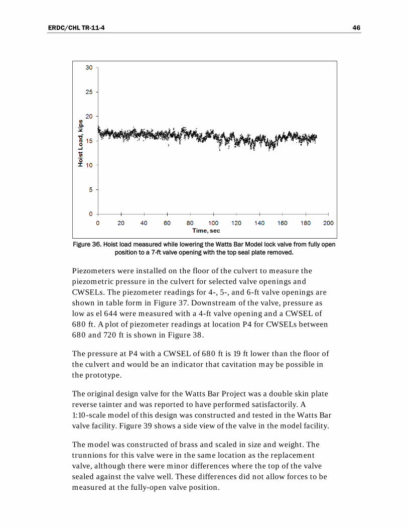
Figure 36. Hoist load measured while lowering the Watts Bar Model lock valve from fully open position to a 7-ft valve opening with the top seal plate removed. ............................................... 46
Figure 37. Watts Bar Lock valve model, piezometer locations and readings for 4-, 5-, and 6-ft valve openings with Upper Pool El of 740. ......................................................................................... 47
Figure 38. Watts Bar Lock valve model, piezometer readings at piezometer P4. .............................. 47
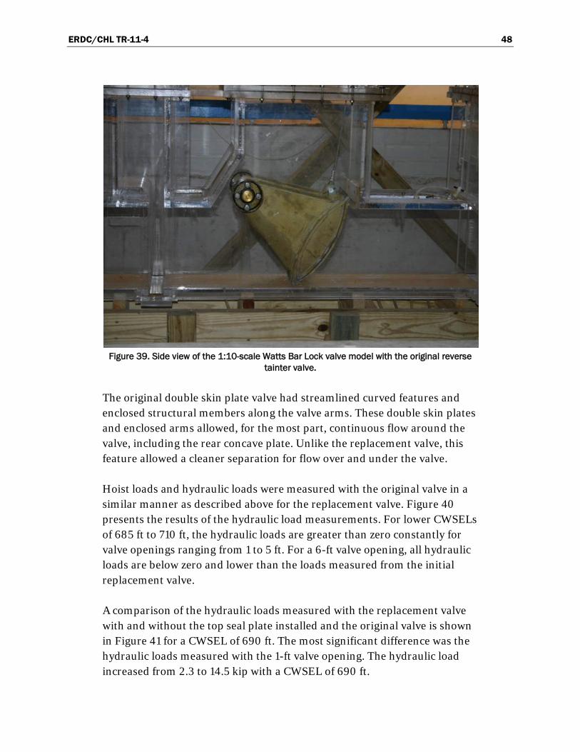
Figure 39. Side view of the 1:10-scale Watts Bar Lock valve model with the original reverse tainter valve. .................................................................................................................................... 48
Figure 40. Watts Bar Lock valve model, hydraulic load vs. valve opening for varying lock chamber water-surface elevations (CWSEL) with original design valve. .............................................. 49
Figure 41. Watts Bar Lock valve model, comparison of hydraulic load vs. valve opening for CWSEL 690 reverse tainter valve with and without top seal plate and with original double skin plate valve. ............................................................................................................................................ 49
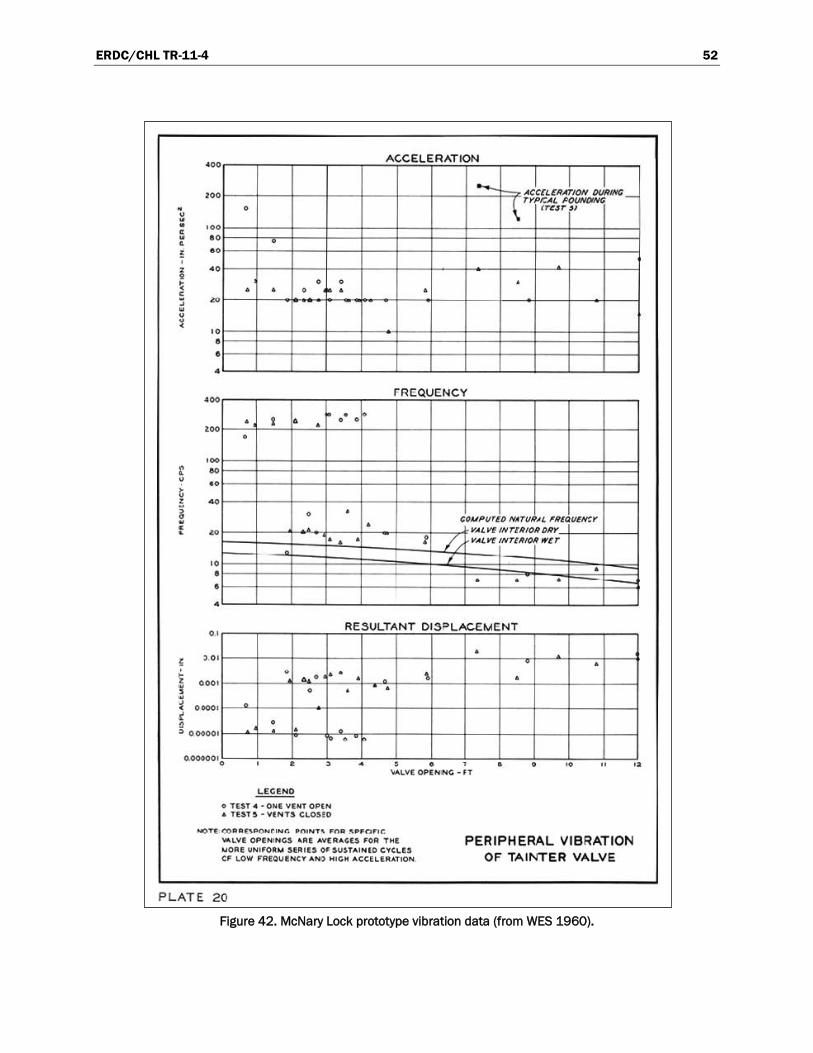
Figure 42. McNary Lock prototype vibration data ................................................................................... 52
Figure 43. McNary Lock prototype hoist loads......................................................................................... 53
Figure 44. Bankhead Lock reverse tainter valve. .................................................................................... 54
Figure 45. Bankhead Lock valve machinery. ........................................................................................... 55
Figure 46. Bankhead Lock hoist loads measured in prototype ............................................................. 56
Figure 47. Reverse tainter valve, Whiten Lock .......................................................................................... 58
Figure 48. Hydraulic loads on Whitten Lock filling valve, single-valve operation, 83.1-ft lift ............. 59
Figure 49. Old (double skin plate) reverse tainter valve, Chickamauga Lock, Tennessee River. .............................................................................................................................................................. 63
Figure 50. New (framed) reverse tainter valve, Chickamauga Lock, Tennessee River....................... 64
Figure 51. Modifications to new (framed) valve, Chickamauga Lock, Tennessee River..................... 65
Figure 52. Double skin plate reverse tainter valve waiting for repair, The Dalles Lock. ..................... 68
Figure 53. Holt Lock valve machinery. ...................................................................................................... 69

ERDC/CHL TR-11-4 vii
Preface
The investigation reported herein was sponsored by the U. S. Army Engineer District, Portland (NWP) and the Navigation Systems Research Program (NSRP). This work was conducted in the Coastal and Hydraulics Laboratory (CHL) of the U.S. Army Engineer Research and Development Center (ERDC). In 2007 NWP sponsored a review of previous field and laboratory investigations of lock culvert valves with particular emphasis on the hydraulic performance and hydrodynamic loadings on reverse tainter valves. Additional information pertaining to lock culvert valves was compiled during the period of July 2010 to September 2010 as part of the NSRP work unit “Hydrodynamic Design Guidance and Evaluation Tools for Inland Structures.”
This research was conducted under the general direction of Dr. William D. Martin, Director of the CHL; Jose E. Sanchez, Deputy Director, CHL; Dr. Rose Kress, Chief of the Navigation Division, CHL; and Dr. Richard B. Styles, Chief of the Navigation Branch, CHL. Dr. Laurie L. Ebner, NWP, and Brad Bird, NWD, reviewed the original document and guided the study as it pertained to the replacement of the valves on The Dalles and John Day Locks.
This investigation and subsequent report was completed by Dr. Richard L. Stockstill, E. Allen Hammack, and Dr. John E. Hite, Jr. of the Navigation Branch, CHL. Acknowledgments are made to Charles E. Wiggins, Navigation Systems Research Program Manager and Jeff Lillycrop, Technical Director for Navigation, ERDC.
At the time of this report, COL Kevin J. Wilson was Commander and Executive Director of ERDC. Dr. Jeffery P. Holland was Director.
ERDC/CHL TR-11-4 viii
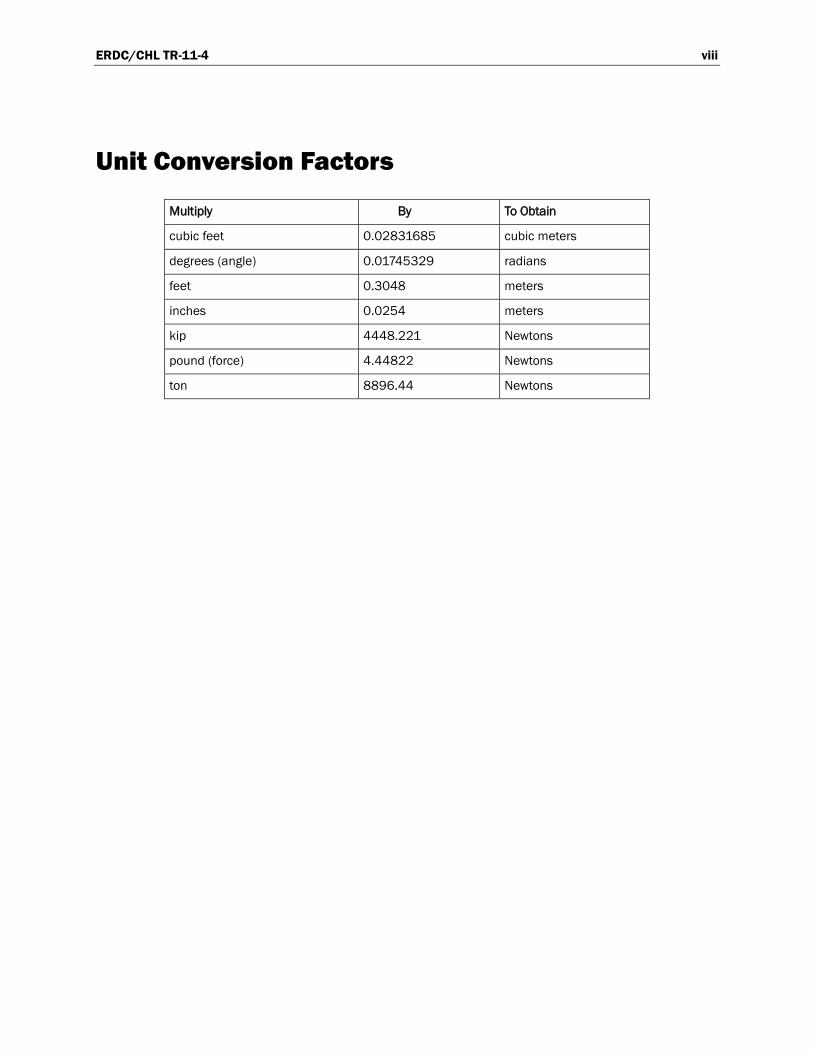
Unit Conversion Factors
Multiply By To Obtain
cubic feet 0.02831685 cubic meters
degrees (angle) 0.01745329 radians
feet 0.3048 meters
inches 0.0254 meters
kip 4448.221 Newtons
pound (force) 4.44822 Newtons
ton 8896.44 Newtons

ERDC/CHL TR-11-4 1
1 Introduction
1.1 Background
Many of the navigation locks maintained by the U.S. Army Corps of Engineers (Corps) have reached or exceeded their design life. Valves are an integral component to a lock’s filling and emptying system and dependable and repeated service is required to prevent costly project delays. Therefore, maintenance, rehabilitation, or replacement often requires engineering design. The control of flow, particularly at the early part of an operation cycle, can affect hawser forces in the chamber, vortex tendencies at the intake, and cavitation potential within the culverts.
The Corps’ design guidance pertaining specifically to the hydraulic design of lock culvert valves is documented in
• EM 1110-2-1604 “Hydraulic Design of Navigation Locks” (Headquarters, U.S. Army Corps of Engineers 2006)
• EM 1110-2-1610 “Hydraulic Design of Lock Culvert Valves” (Headquarters, U.S. Army Corps of Engineers 1975)
• a technical report authored by John Davis, formerly of Headquarters, U.S. Army Corps of Engineers (Davis 1989)
Mechanical design guidance for lock-operating equipment is provided in EM 1110-2-2610 “Engineering and Design – Lock and Dam Gate Operating and Control System” (Headquarters, U.S. Army Corps of Engineers 2003). A general discussion of valve selection, sizing, sealing, and maintenance is provided in EM 1110-2-2602 “Planning and Design of Navigation Locks” (Headquarters, U.S. Army Corps of Engineers 1995).
This report, which provides a review of the state of knowledge, was necessary because the lock culvert valve manual, EM 1110-2-1610, was last updated in 1975 and the corporate knowledge has grown substantially over the last 35 years. This report summarizes a review of previous investiga-tions, engineering manuals, textbooks, and technical papers on the general subject of lock culvert valves with particular emphasis on reverse tainter valves. Hydraulic coefficients, used to quantify energy losses at valves and the jet contraction downstream of a partially-opened valve, are provided for

ERDC/CHL TR-11-4 2
various valve configurations. These coefficients were obtained from field, laboratory, and computational studies.
1.2 Brief history
A research program to develop guidance for hydraulic design of navigation locks was initiated in 1930 in the U.S. Army Engineer District, St. Paul (Davis 1980). The same year the American Society of Civil Engineers (1930) published a manual on lock culvert valves. Early lock systems, which were all low-lift projects (heads of 30 ft1
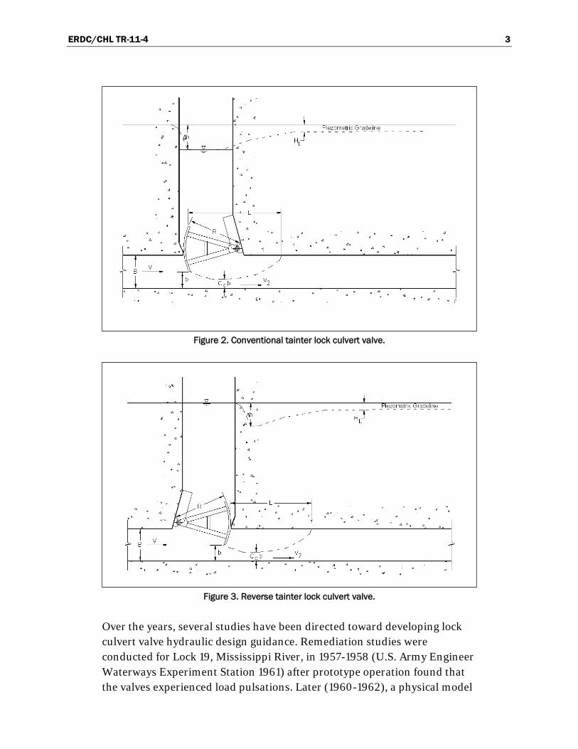
or less), almost exclusively used vertical-lift (e.g. stoney valve and wagon valve) and tainter (radial gate) valve designs. Engineer Manual 1110-2-1610 (Headquarters, U.S. Army Corps of Engineers 1975), states that Lock 2 on the Mississippi River, completed in 1930, was one of the first locks to use tainter valves. A vertical-lift valve design is illustrated on Figure 1. Tainter valves mounted in the conventional position and the reversed position are shown in Figures 2 and 3, respectively.
Figure 1. Vertical-lift lock culvert valve.
1 A table of factors for converting non-SI units of measurement to SI units is found on page viii.
ERDC/CHL TR-11-4 3
Figure 2. Conventional tainter lock culvert valve.
Figure 3. Reverse tainter lock culvert valve.
Over the years, several studies have been directed toward developing lock culvert valve hydraulic design guidance. Remediation studies were conducted for Lock 19, Mississippi River, in 1957-1958 (U.S. Army Engineer Waterways Experiment Station 1961) after prototype operation found that the valves experienced load pulsations. Later (1960-1962), a physical model

ERDC/CHL TR-11-4 4
study was conducted for the development of the Holt Lock culvert valve (Murphy and Ables 1965). The Holt Lock, Warrior River, study evaluated several reverse tainter valves including a series of tests on a double-skin plate configuration in support of Columbia/Snake River project develop-ments. The design for this double-skin plate valve was copied from the McNary Lock, Columbia River. George (1984) conducted a physical model study of a reverse tainter valve for the proposed Walter Bouldin Lock, Coosa River Waterway. The Walter Bouldin Lock was designed to be the highest lift lock in North America at 130 ft. Although Walter Bouldin Lock was never constructed, the model study provides hoist load data for very high heads.
1.3 Purpose
The purpose of this review is to provide engineers a synthesis of the knowledge available for the hydraulic design of lock culvert valves. Previously-published laboratory and field data for different valve configurations have been assembled to provide a source of design and evaluation information.
This report provides information on three valve designs commonly used to control culvert flow: vertical lift valves, conventional tainter valves, and reverse tainter valves. Items of interest to designers such as head loss, cavitation potential, and hydraulic loads are provided for these three valve configurations.

ERDC/CHL TR-11-4 5
2 Vertical-lift valves
Vertical-lift valves can be grouped by the way in which they are guided during operation. Valves designed to slide within their slots are commonly referred to as stoney valves. Wheeled vertical-lift valves are often called wagon valves. Also, the terms gate and valve have different connotations in various engineering communities. This report follows the literature wherein the terms are used interchangeably.
The primary advantages of the vertical-lift valve are that maintenance can be performed without taking the culvert out of service and that a large recess such as a valve well is not required as with tainter valves (EM 1110-2-1610). Having a spare vertical-lift valve at the lock is also much less expensive than for other valve types.
Even with all the previous hydraulic model studies and numerical model developments, the determination of downpull forces on vertical-lift valves is still a topic of research. Hydraulic model studies remain the most reliable means of obtaining hoist loads and vibration tendencies on high-head valves. Aydin et al. (2006) point out the importance of the lip geometry (lip angle, corner rounding, and the end plate) in hoist loads. Aydin et al. (2006) conducted experiments on a vertical-lift gate with four different gate lips. Pressure distributions on the gate bottom were measured for each gate lip at five gate openings. These data show that lip geometries producing unstable flow caused pressure fluctuations on the gate bottom. Vortex shedding was observed to cause intermittent pressure spikes. These unstable pressures on the gate bottom produce hoist load reversals, which might not be noticeable in the hoisting mechanism, but may induce fatigue.
A large portion of the literature associated with vertical-lift valves is concerned with gate vibrations (e.g. Bhargava and Narashimhan 1989 and Thang and Naudascher 1986), which suggests that vibrations are a leading problem of these gates. The shape of the lip is critical to vertical-lift valve performance (Naudascher and Rockwell 1994). Lewin (1995) presents a synthesis of studies on gate vibrations. He provides charts of variables needed for analysis such as the Strouhal number and added mass and suggests methods of estimating damping. He also points out that those pressure fluctuations, which induce flow fluctuations, exert a force on the
ERDC/CHL TR-11-4 6
lower edge of a gate and can initiate gate vibrations. High-velocity flow is more likely to induce vibrations, especially since vertical-lift valves are susceptible to pressure fluctuations. Therefore, extreme care must be given to the design of high-lift locks, particularly concerning small valve openings.
Another consideration is that vertical-lift valves require gate slots. The discontinuity in culvert sidewalls produced by gate slots can cause cavitation, especially in high-lift locks. Engineering Manual 1110-2-1602 (Headquarters, U.S. Army Corps of Engineers 1980) provides vertical-lift gate slot design details. EM 1110-2-1602 also gives incipient cavitation coefficients needed to determine the likelihood of cavitation formation.
The leaf gate is the most widely used high-head gate for flow regulation or emergency closure; however, the leaf gate causes the greatest problems with respect to hydrodynamic loading or downpull (Naudascher 1991). The variable hydrodynamic loading is the primary reason that current Corps navigation lock guidance suggests that if a vertical-lift valve is considered, then model tests should be conducted to develop an acceptable bottom shape for the valve and to determine valve hoist loads (EM 1110-2-1610). Furthermore, EM 1110-2-1610 states that the vertical-lift valve’s roller, wheels, or sliding surfaces might require considerably more servicing than the elements of a tainter valve. Modern (after 1960) lock design has rarely included vertical-lift valves, so there is little experience with the relative high frequency of operations.
Construction of a new lock having a chamber of 110 ft by 800 ft was recently completed at Marmet Locks and Dam, Kanawha River. The Marmet Lock has vertical-lift valves to control the filling and emptying flow. The hydraulic design was evaluated with a 1:25-scale physical model study (Hite 1999). A physical model study was completed to specifically evaluate vortex tenden-cies at the through-the-sill intake, determine filling and emptying times for various valve speeds at the design lift of 24 ft, measure pressures in the culverts, and to document lock chamber performance quantified by the measurement of hawser forces exerted on a moored tow. Culvert pressures downstream of the valve were measured during both filling and emptying operations. No undesirably-low pressures were recorded. The valves at this project will be monitored to assess their performance over time.
New locks having 1200-ft chambers are in the planning and design stage for Lock and Dam No. 22 and Lock and Dam No. 25 on the Upper Mississippi
ERDC/CHL TR-11-4 7
River (Hite and Maynord 2006). Vertical-lift valves are being considered to accommodate the limited space provided by the existing lock and dam. A physical model study of the lock filling and emptying system is being conducted to evaluate the hydraulic performance including the use of vertical-lift valves. The new Inner Harbor Navigation Canal Lock design also includes vertical-lift valves.
2.1 Hydraulic coefficients
The efficiency of valves can be quantified using a head-discharge relationship or in terms of head loss across the valve. The head-discharge relation is expressed empirically with a discharge coefficient, Cd, which is defined as
Δ
d
QC
bW g h
2 (1)
where
Q = discharge, b = culvert height, W = culvert width, g = acceleration due to gravity, and ∆h = differential piezometric head across the valve.
Discharge coefficients for vertical-lift valves having a 45-degree lip are provided on Figure 4.
The head loss across a valve, HL, is quantified in terms of the velocity head using a loss coefficient
L v
VH K
g
2
2 (2)
where
Kv = valve loss coefficient, and V = the average velocity at the valve.

ERDC/CHL TR-11-4 8
Figure 4. Discharge coefficient for vertical-lift gate having 45 degree lip.
Figure 5 is a plot illustrating the variation of loss coefficient with valve opening for vertical-lift valves. The data include physical model and proto-type data taken from the U.S. Army Corps of Engineers’ Hydraulic Design Criteria (HDC, U.S. Army Engineer Waterways Experiment Station 1988).
2.2 Hydrodynamic loads
Structural design of the gates follows the guidance and criteria given in EM 1110-2-2701 (Headquarters, U.S. Army Corps of Engineers 1997). This manual provides methods of calculating the magnitude and distribution of hydraulic forces acting on a vertical-lift valve. The vertical forces exerted by the water on the gate are a function of geometric parameters including gate opening, gate thickness, lip angle, and the lip seal extension (Naudascher 1991). Hoist loads are given in the HDC charts 320-2 to 320-2/1 (U.S. Army Engineer Waterways Experiment Station 1988). A sketch showing the variables is presented in Figure 6 and Figure 7 is a plot of the uplift forces. The data presented by Naudascher (1991) agrees with that presented on Figure 7 in that the minimum uplift occurs at valve openings slightly less that 50 percent.
0.0
0.2
0.4
0.6
0.8
1.0
1.2
1.4
0.0 0.1 0.2 0.3 0.4 0.5 0.6 0.7 0.8 0.9 1.0
Area of Valve Opening/Area of Culvert
Valv
e Di
scha
rge
Coef
ficie
nt, C
dPhysical Model CW 803Dorena Prototype

ERDC/CHL TR-11-4 9
Figure 5. Loss coefficient for vertical-lift valve having a 45 degree lip.
2.3 Vibration considerations
Neilson and Pickett (1980) give a summary report on flow-induced vibration problems at Corps projects. Their survey found that by far the most common flow-induced vibration problem is attributed to the J-seal. The problem can be the result of poor adjustment, material deterioration, or degradation due to damage. Bottom seals can be metal-to-metal which can reduce vibration induced by seals (Hart and Hite 1979 and Neilson and Pickett 1980), but sealing with such an arrangement is difficult. Lewin (1995) states “Under no circumstances should elastomeric seals project more than 5 mm below the faceplate of a gate.” Musical note shape seals are also not suitable as sill seals although they appear to be in use. Lewin (1995) also warns that particular locations of structural cross members can lead to vibration problems.
The Corps’ criteria for vertical-lift gate bottom shape design evolved during a study of the Ft. Randall Dam, Missouri River (U.S. Army Engineer Waterways Experiment Station 1959). A physical model study was conducted after the prototype gate experienced vibration problems. The original design was a flat bottom. Experiments led to an extension on
0.1
1
10
100
1000
0.0 0.1 0.2 0.3 0.4 0.5 0.6 0.7 0.8 0.9 1.0
Area of Valve Opening/Area of Culvert
Valv
e Lo
ss C
oeffi
cien
t, K
vPhysical Model CW 803Dorena Prototype
Suggested Design CurveHDC Chart 320-1
ERDC/CHL TR-11-4 10
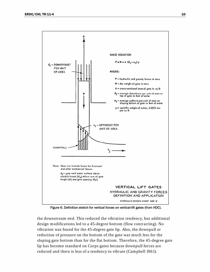
Figure 6. Definition sketch for vertical forces on vertical-lift gates (from HDC).
the downstream end. This reduced the vibration tendency, but additional design modifications led to a 45-degree bottom (flow contracting). No vibration was found for the 45-degree gate lip. Also, the downpull or reduction of pressure on the bottom of the gate was much less for the sloping gate bottom than for the flat bottom. Therefore, the 45-degree gate lip has become standard on Corps gates because downpull forces are reduced and there is less of a tendency to vibrate (Campbell 1961).
ERDC/CHL TR-11-4 11
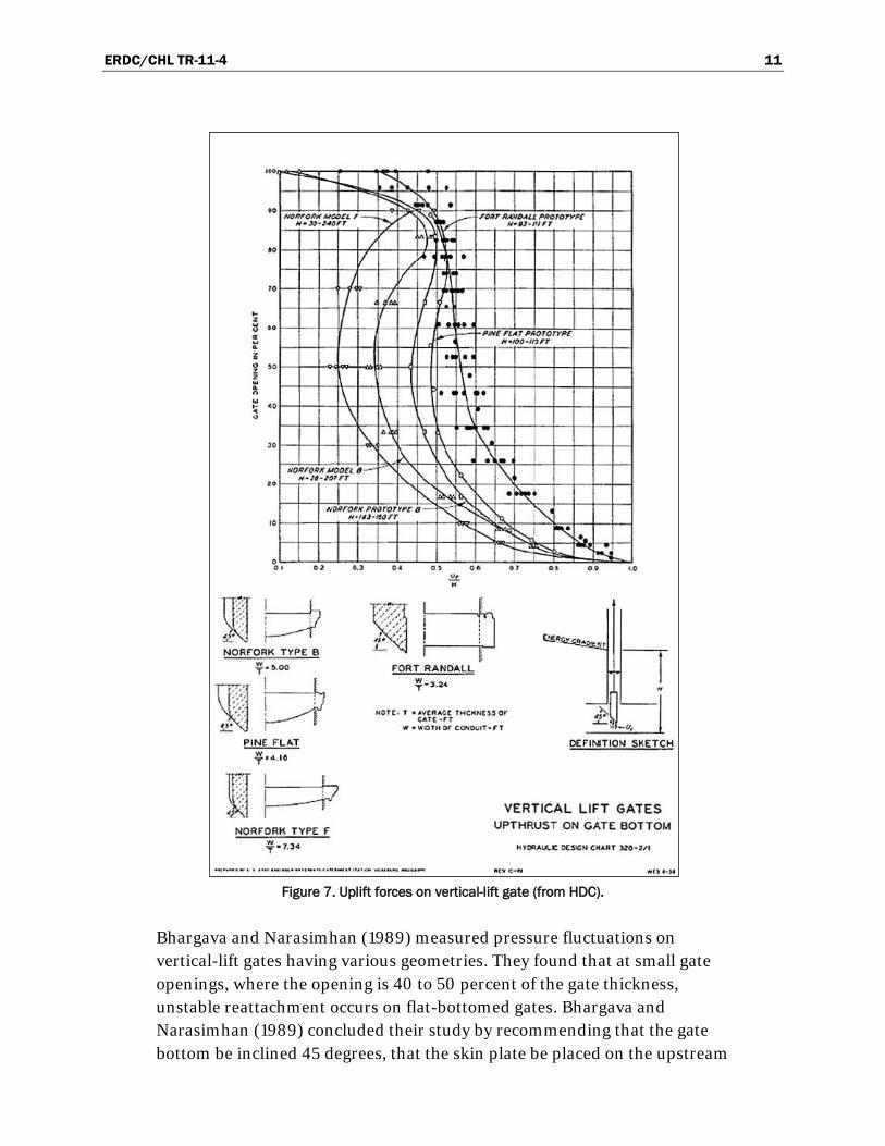
Figure 7. Uplift forces on vertical-lift gate (from HDC).
Bhargava and Narasimhan (1989) measured pressure fluctuations on vertical-lift gates having various geometries. They found that at small gate openings, where the opening is 40 to 50 percent of the gate thickness, unstable reattachment occurs on flat-bottomed gates. Bhargava and Narasimhan (1989) concluded their study by recommending that the gate bottom be inclined 45 degrees, that the skin plate be placed on the upstream

ERDC/CHL TR-11-4 12
side of the gate, and that the lip from the front skin plate to the bottom plate be rounded. The primary hydraulic design aspects of a vertical-lift gate are the shape of the bottom lip, the shape of the gate slots, and the determina-tion of the hydraulic capacity (EM 1110-2-1603, Headquarters, U.S. Army Corps of Engineers 1980).
The best-known solution to the possibility of gate vibration is that the gate bottom should be shaped at an angle of 45 degrees. However, even this 45-degree bottom is not immune to vibration because outside forces may excite the gate (Thang 1990). The vortex trail will spring from the upstream edge of a flat-bottomed gate causing pressure pulses at the bottom of the gate. Where the gate has a 45-degree or larger angle lip, the vortex trail springs from the downstream edge eliminating bottom pulses.
The standard 45-degree lip induces separation at the sharp downstream edge of the gate. The free shear layer has no chance to interact directly with the gate itself, as is the case with a flat-bottomed gate. The construction of flat-bottomed, high-head gates is poor design practice and should be avoided (Locher 1969)
Lewin (1995) recommends that no structural member upstream or downstream of the control point should protrude into a line at 45-degrees from the point of flow control. Arranging for a vortex tail to be shed from the extreme downstream edge of a gate in order to achieve flow conditions that are as steady as possible is a better option (Vrijer 1979). A sharp cut-off point should be provided at the lip (Schmidgall 1972).
. The obvious advantages in the structural framing of the flat-bottom are offset by the undesirable hydraulic characteristics.
Corps’ hydraulic design criteria and guidance for vertical-lift gates are given in EM 1110-2-1602 (Headquarters, U.S. Army Corps of Engineers 1980). Although EM 1110-2-1602 provides guidance for outlet works, discussion of control gates is applicable to vertical-lift lock culvert valves.
Gate performance has been found to improve when a curve is added to the upstream skin plate and the 45-degree angled bottom plate. The lip should have a 1-in vertical extension added to the end of the angled bottom plate and the upstream face should be flat to provide a more uniform flow distribution across the gate bottom.

ERDC/CHL TR-11-4 13
Vibration potential of cable-suspended gates is discussed in Paragraph 4-19 of EM 1110-2-1602. The structure can experience resonance when the forcing frequency is equal to the natural frequency. The resulting gate displacement is amplified and only limited by the damping in the system.
ERDC/CHL TR-11-4 14
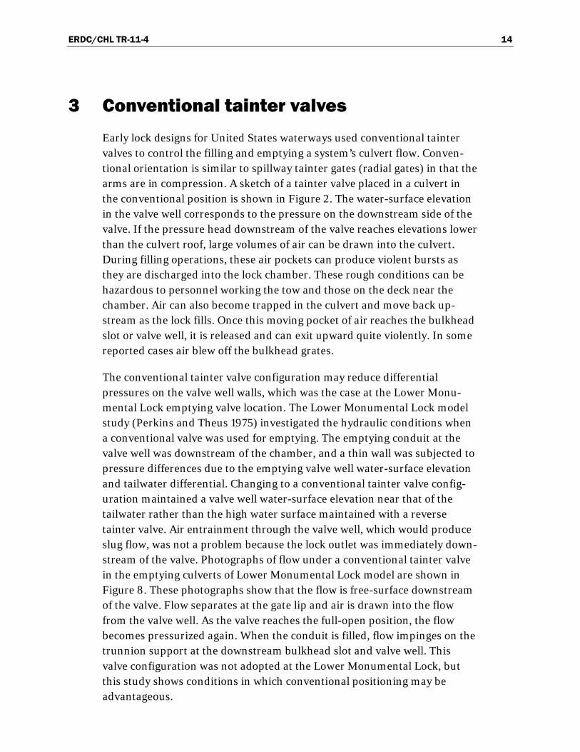
3 Conventional tainter valves Early lock designs for United States waterways used conventional tainter valves to control the filling and emptying a system’s culvert flow. Conven-tional orientation is similar to spillway tainter gates (radial gates) in that the arms are in compression. A sketch of a tainter valve placed in a culvert in the conventional position is shown in Figure 2. The water-surface elevation in the valve well corresponds to the pressure on the downstream side of the valve. If the pressure head downstream of the valve reaches elevations lower than the culvert roof, large volumes of air can be drawn into the culvert. During filling operations, these air pockets can produce violent bursts as they are discharged into the lock chamber. These rough conditions can be hazardous to personnel working the tow and those on the deck near the chamber. Air can also become trapped in the culvert and move back up-stream as the lock fills. Once this moving pocket of air reaches the bulkhead slot or valve well, it is released and can exit upward quite violently. In some reported cases air blew off the bulkhead grates.
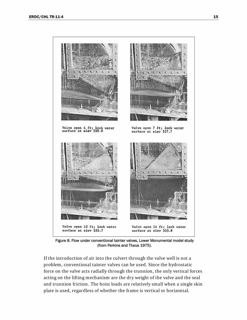
The conventional tainter valve configuration may reduce differential pressures on the valve well walls, which was the case at the Lower Monu-mental Lock emptying valve location. The Lower Monumental Lock model study (Perkins and Theus 1975) investigated the hydraulic conditions when a conventional valve was used for emptying. The emptying conduit at the valve well was downstream of the chamber, and a thin wall was subjected to pressure differences due to the emptying valve well water-surface elevation and tailwater differential. Changing to a conventional tainter valve config-uration maintained a valve well water-surface elevation near that of the tailwater rather than the high water surface maintained with a reverse tainter valve. Air entrainment through the valve well, which would produce slug flow, was not a problem because the lock outlet was immediately down-stream of the valve. Photographs of flow under a conventional tainter valve in the emptying culverts of Lower Monumental Lock model are shown in Figure 8. These photographs show that the flow is free-surface downstream of the valve. Flow separates at the gate lip and air is drawn into the flow from the valve well. As the valve reaches the full-open position, the flow becomes pressurized again. When the conduit is filled, flow impinges on the trunnion support at the downstream bulkhead slot and valve well. This valve configuration was not adopted at the Lower Monumental Lock, but this study shows conditions in which conventional positioning may be advantageous.
ERDC/CHL TR-11-4 15
Figure 8. Flow under conventional tainter valves, Lower Monumental model study
(from Perkins and Theus 1975).
If the introduction of air into the culvert through the valve well is not a problem, conventional tainter valves can be used. Since the hydrostatic force on the valve acts radially through the trunnion, the only vertical forces acting on the lifting mechanism are the dry weight of the valve and the seal and trunnion friction. The hoist loads are relatively small when a single skin plate is used, regardless of whether the frame is vertical or horizontal.
ERDC/CHL TR-11-4 16
Another structural advantage is that the trunnion anchorage is simpler than that of a reverse tainter valve.
The hydraulic performance of tainter valves used to control conduit flow is described in EM 1110-2-1602 (Headquarters, U.S. Army Corps of Engineers 1980). The relationship between discharge coefficient and gate opening for a partially-opened tainter valve varies with the valve’s lip angle, the angle between the culvert invert and the tangent to the valve at the lip, as the HDC chart provided on Figure 9 shows. This chart, which has a series of curves for various valve lip angles, is taken from EM 1110-2-1602. Note that the lip angle varies as the valve opens. So, for a given valve geometry, the discharge coefficient is dependent upon the relative gate opening and the lip angle at that gate opening. The cavitation potential is slightly less than that of a reverse tainter valve (next chapter) because of the shape of the contracted jet. The jet issuing beneath a conventional tainter valve is not contracted as much as one associated with a reverse tainter valve. Therefore, the head loss experienced with the conventional tainter valve is less than that attributed to the reverse tainter valve.

ERDC/CHL TR-11-4 17
Figure 9. Discharge coefficient for conventional tainter valve (from HDC).
ERDC/CHL TR-11-4 18
4 Reverse tainter valves
Reverse tainter valves are the most common valve type found on major locks constructed by the Corps (Pickett and Neilson 1988 and EM 1110-2-1610). The reverse tainter valve differs from radial gates found on spillways in that the trunnions are upstream of the skin plate with the convex surface of the skin plate facing downstream and sealing against the downstream end of the valve well. A typical reverse tainter valve layout is shown in Figure 9. This “reverse” orientation evolved to prevent large volumes of air from being drawn into the culvert at the valve well. Having pockets of air transported through the culvert system is undesirable because they are uncontrollably expelled through outlets such as ports, valve wells, and bulkhead slots. This surging and expulsion of volumes of air are hazardous to small vessels in the lock chamber.
According to Davis (1989), “with only two exceptions, all of the locks built in the United States since 1940 have had reverse tainter valves.” So, between the time reverse tainter valves were first used in about 1938 until the time of Davis’ report, virtually all lock culvert valves had the reverse tainter design. However, another exception is new Marmet Lock which began operations in 2008. As described previously, the filling and emptying system for the new Marmet Lock uses vertical-lift valves for flow control.
Engineering Manual 1110-2-1604 reports that there are three structurally different types of reverse tainter valves: horizontally-framed, vertically-framed, and double-skin plate. Each type is shown in Figure 10. All three valve types can be made sufficiently rigid, but the vertically-framed and double-skin plate valves are less susceptible to critical hydraulic loads and load variations during the opening cycle.
4.1 Hydraulic coefficients
The head loss as flow passes a partially-opened reverse tainter valve is a function of the gate shape and the gate opening. So, the head loss coefficient varies during a valve operation. The Hydraulic Design Chart 534-1, provided in Figure 11, is a plot of loss coefficients as a function of valve position. The sources of the data shown on the chart are Weisbach (Gibson 1930) and prototype and physical model studies of St. Anthony Falls Lower Lock, McNary Lock, and the Dalles Lock. These experiments were conducted in

ERDC/CHL TR-11-4 19
Figure 10. Basic types of reverse tainter valve design (from EM 1110-2-1610).
the 1950’s by the U.S. Army Engineer Waterways Experiment Station and U.S. Army Engineer Districts, St. Paul and Walla Walla. The prototype data suggest that the value of Kv for a fully-open (b/B of 1) reverse tainter valve is between 0.01 and 0.2.
Baines (1954) points out that the loss coefficient is greater for the reverse tainter valve than for a conventional tainter valve mounting. This difference is due to the lip, which points upstream on tainter valves in the reversed position.
The contraction coefficient, Cc, is the ratio of the minimum height of the jet downstream of the valve lip to the distance from the valve lip to the culvert invert, b. A schematic sketch describing the contraction coefficient is provided on Figure 12. Published data quantifying the contraction coefficient shows considerable scatter (Headquarters, U.S. Army Corps of Engineers 1975). This scatter exists partially because the coefficient cannot be directly measured but is determined from other observable quantities. The most difficult property to measure is the pressure at the station where the jet is at a minimum height, which varies with valve opening (Neilson 1975). Also, for a reverse tainter valve, Cc is very sensitive to the valve lip geometry and the angle of the gate bottom, which varies as the valve is opened. No universal description of Cc for reverse tainter valves has ever been formulated.

ERDC/CHL TR-11-4 20
Figure 11. Loss coefficient for reverse tainter valve (from HDC).
Contraction coefficients for several projects and the von Mises (1964) potential flow solutions for slot flow are provided on Figure 12. The von Mises solutions for lip angles of 45 and 90 degrees were taken from von Mises (1964), which is a translation of the original 1917 publication. The physical model data are from the general study reported by Pickering (1981). The prototype data are from reports of field experiments by McGee (1989) at Whitten Lock (formerly Bay Springs Lock), Neilson (1975) at

ERDC/CHL TR-11-4 21
Figure 12. Contraction coefficient for reverse tainter valve.
Barkley Lock, Neilson and Pickett (1986) at John Day Lock, and Pickett (U.S. Army Engineer Waterways Experiment Station 1960) at McNary Lock. The John Day Lock computational model results are from a Reynolds Averaged Navier-Stokes equation flow model (Hammack and Stockstill 2011).
ERDC/CHL TR-11-4 22
4.2 Hydrodynamic loads
The tainter shape provides a parabolic valve opening when using a linear hoist motion. The tainter gate (or radial gate) has the advantage of relatively small hydrodynamic hoisting forces if the trunnion is located at the gate’s radius point (Naudascher 1991). Vertical (lift) forces on reverse tainter valves are more stable than conventional tainter valves during operation because the resultant force is downward in the reversed position until the valve is nearly open. In the conventional configuration, the vertical force is upward until the valve is nearly open.
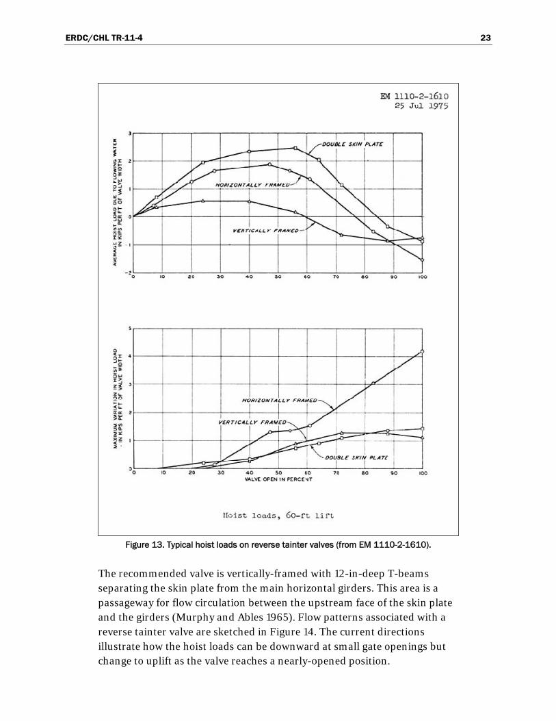
Hoist loads are described as downpull loads, which act to rotate the valve to the closed position, or uplift loads
Engineering Manual 1110-2-1610 states “for all three types of valves the two features that most affect loads on the valve hoist due to flowing water are the depth of the lower girder and the extension of the lower lip of the skin plate below the lower girder. A decrease in the depth of the lower girder results in a decrease in peak downpull and load variations and, also, a decrease in the range of valve positions at which uplift occurs. Data are not conclusive as to whether peak uplift is decreased. An increase in the extension of the lower lip of the valve below the lower girder decreases peak downpull and the range of valve positions at which downpull occurs but increases peak uplift and the range of valve positions at which uplift occurs. Load variations remain essentially unchanged.”
, which act to rotate the valve to the open position. Typical hoist loads for each type of reverse tainter valve are shown in Figure 13. The average load for the horizontally-framed valve is the most negative (uplift) at gate openings greater than 90 percent. However, the load variation is more important. The horizontally-framed valve experiences more than twice the variation of the double skin plate or vertically-framed valve designs at large gate openings. This hoist load variation is an indica-tion of valve vibration potential.
Davis (1989) concludes that “the single skin plate design developed for the Holt Lock has the best hydraulic characteristics of any developed so far.” The valve for the Holt Lock, which has a maximum lift of 63.6 ft, was developed for 12.5- by 12.5-ft culverts.
ERDC/CHL TR-11-4 23
Figure 13. Typical hoist loads on reverse tainter valves (from EM 1110-2-1610).
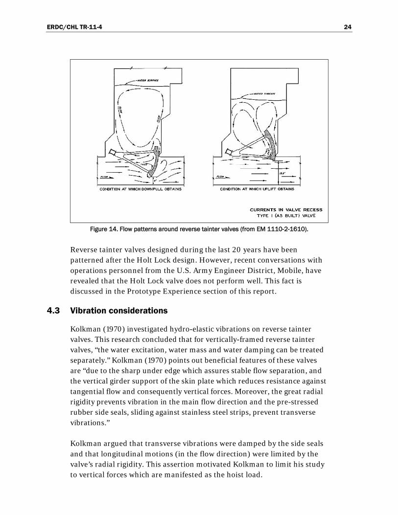
The recommended valve is vertically-framed with 12-in-deep T-beams separating the skin plate from the main horizontal girders. This area is a passageway for flow circulation between the upstream face of the skin plate and the girders (Murphy and Ables 1965). Flow patterns associated with a reverse tainter valve are sketched in Figure 14. The current directions illustrate how the hoist loads can be downward at small gate openings but change to uplift as the valve reaches a nearly-opened position.
ERDC/CHL TR-11-4 24
Figure 14. Flow patterns around reverse tainter valves (from EM 1110-2-1610).
Reverse tainter valves designed during the last 20 years have been patterned after the Holt Lock design. However, recent conversations with operations personnel from the U.S. Army Engineer District, Mobile, have revealed that the Holt Lock valve does not perform well. This fact is discussed in the Prototype Experience section of this report.
4.3 Vibration considerations
Kolkman (1970) investigated hydro-elastic vibrations on reverse tainter valves. This research concluded that for vertically-framed reverse tainter valves, “the water excitation, water mass and water damping can be treated separately.” Kolkman (1970) points out beneficial features of these valves are “due to the sharp under edge which assures stable flow separation, and the vertical girder support of the skin plate which reduces resistance against tangential flow and consequently vertical forces. Moreover, the great radial rigidity prevents vibration in the main flow direction and the pre-stressed rubber side seals, sliding against stainless steel strips, prevent transverse vibrations.”
Kolkman argued that transverse vibrations were damped by the side seals and that longitudinal motions (in the flow direction) were limited by the valve’s radial rigidity. This assertion motivated Kolkman to limit his study to vertical forces which are manifested as the hoist load.
ERDC/CHL TR-11-4 25
The bottom shape is the most sensitive position influencing the hoist loads during valve operation. The bottom shape greatly influences not only the maximum hoist loads, but also the pressure fluctuations. Generally, the loads and pressure fluctuations are low if the shape of the bottom is sharp (Luo et al. 2009)
The shape of the top of the valve is generally not important unless the valve is lowered while the water is flowing. Such is the case if the valve is closed during an opening or immediately after an opening operation. A sharp-edged top is better when a valve is lowered in flowing water because it reduces the uplift force that can be caused by low pressures forming aft of a blunt edge.
.
4.4 Hydraulic model studies
4.4.1 McNary Lock
McNary Lock, which has a maximum lift of 92 ft, has been extensively studied. Particular attention has been directed to design, performance evaluation, and development of operation guidance for the 11-ft-wide by 12-ft-high reverse tainter valves. Vacuum tank tests (U.S. Army Engineer Waterways Experiment Station 1949) and prototype tests (U.S. Army Engineer Waterways Experiment Station 1960 and U.S. Army Engineer Waterways Experiment Station 1961) have been conducted in addition to the traditional hydraulic model study of the filling and emptying system. Also, a memorandum discussing valve operations has been issued (U.S. Army Engineer District, Walla Walla 1955).
4.4.2 Lock No. 19
Lock 19 has a lift of 38.2 ft and flow is controlled with 14.5- by 14.5-ft horizontally-framed reverse tainter valves. The valves at the new Lock 19, Mississippi River, experienced load pulses. Load reversals on the valve hoist were so severe at large openings that the valve operation was limited to no greater than two-thirds open. A hydraulic model study of culvert tainter valves for Lock 19 was conducted at U.S. Army Waterways Experiment Station in 1957-1958 (U.S. Army Waterways Experiment Station 1961). The study concentrated on measuring load reversals on the hoist and developing valve modifications to eliminate intermittent reversals in machinery and permit normal operation of the valves.

ERDC/CHL TR-11-4 26
Horizontally-framed reverse tainter valves had been successfully used on low-lift locks, but load reversals produced clattering in the operation machinery at the medium-lift Lock 19. Laboratory experiments found that the major cause of load reversals was hydraulic forces tending to raise the valve. Seventeen designs with various valve modifications were tested in the physical model. Hoist loads at the full range of valve openings were documented for each design. The hydrodynamic loading and the pressure differentials across the webs of the lower girder and the trunnion arm were also measured for the as-built design.
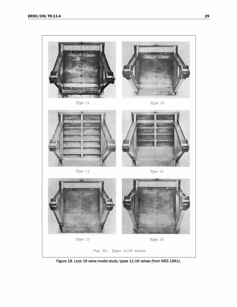
Photographs of the various designs tested are shown in Figures 15-19. The objective of the physical model study was to modify the valve to minimize the hydraulic load fluctuations. The magnitude of the time-averaged hoist load was not an issue. Rather, the deviations of the hoist load about the average (the load fluctuations) caused the prototype valve mechanism to clatter. Modifications included removing knee braces and adding plating to streamline the lower portion of the gate. These modifications were applied to the prototype valve and subsequent field tests found that hoist load reversals were eliminated.
The poorly performing valve at Lock 19 resulted in current design guidance recommending against the use of horizontally-framed reverse tainter valves (EM 1110-2-1610).
4.4.3 Holt Lock
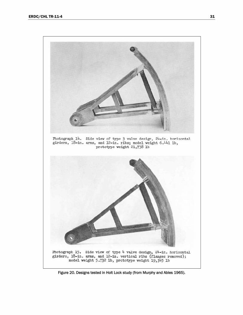
Two reverse tainter valve designs for Holt Lock, Warrior River, were evaluated in a physical model study (Murphy and Ables 1965). Hydraulic performance was judged on the hoist loads measured with each valve design. Six valve configurations were vertically-framed with T-beams separating the skin plate from the main horizontal girders. This framing provides space for flow to pass vertically between the ribs. The other design evaluated was a double skin plate valve. Pictures of the valve types tested are shown in Figures 20 and 21.
Hoist loads were measured with the valve held at particular openings. Discharges varied with the gate openings as determined by the physical model of the lock filling and emptying system. The discharges simulated a lock lift of 63.6 ft.

ERDC/CHL TR-11-4 27
Figure 15. Lock 19 valve model study, types 2-6 and 8 valves (from WES 1961).

ERDC/CHL TR-11-4 28
Figure 16. Lock 19 valve model study, types 9 and 10 valves (from WES 1961).
Figure 17. Lock 19 valve model study, type 17 valve (from WES 1961).
ERDC/CHL TR-11-4 29
Figure 18. Lock 19 valve model study, types 11-16 valves (from WES 1961).

ERDC/CHL TR-11-4 30
Figure 19. Designs tested in Holt Lock study (from Murphy and Ables 1965).
ERDC/CHL TR-11-4 31
Figure 20. Designs tested in Holt Lock study (from Murphy and Ables 1965).

ERDC/CHL TR-11-4 32
Figure 21. Designs tested in Holt Lock study (from Murphy and Ables 1965).
ERDC/CHL TR-11-4 33
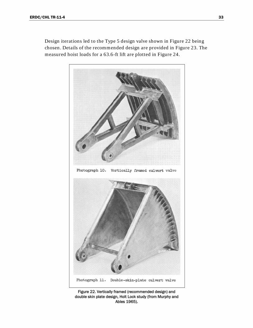
Design iterations led to the Type 5 design valve shown in Figure 22 being chosen. Details of the recommended design are provided in Figure 23. The measured hoist loads for a 63.6-ft lift are plotted in Figure 24.
Figure 22. Vertically framed (recommended design) and
double skin plate design, Holt Lock study (from Murphy and Ables 1965).

ERDC/CHL TR-11-4 34
Figure 23. Recommended design, Holt Lock study (from Murphy and Ables 1965).

ERDC/CHL TR-11-4 35
Figure 24. Hoist loads with recommended design, Holt Lock study (from Murphy and
Ables 1965).

ERDC/CHL TR-11-4 36
4.4.4 John Day Lock
Hydraulic forces on the valve lifting mechanism were measured on a hydraulic model of the John Day Lock filling and emptying system (Chanda and Perkins 1974). The 12-ft-wide by 14-ft-tall culvert valve is a double skin plate reverse tainter valve. Both dual- and single-valve operations of 4-min filling valves were tested. A maximum instantaneous load of 62.5 tons and an instantaneous variation of 22 tons were measured on the valve lifting rod during single-valve filling with maximum project head of 113 ft. Maximum load on the valve trunnion was 68 tons.
4.4.5 Walter Bouldin Lock
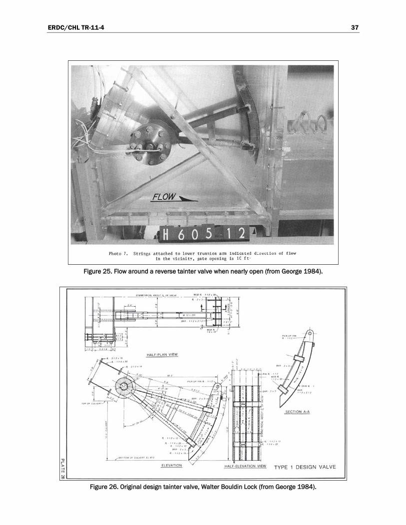
George (1984) is the most recently completed study that specifically addressed the loads and frequencies of reverse tainter valves in a high-head lock. The 1:15-scale model of the lock culvert valve was to be used on a series of five locks proposed for the Coosa River Waterway. The simulated lock lifts ranged from 43 to 130 ft. The average hydraulic forces reversed from downpull to uplift between gate openings of 55 and 65 percent for the different designs tested. Flow into the valve well when the gate is near the fully-opened position is illustrated in Figure 25. The strings on the photo-graph of Figure 25 are tied to the lower trunnion arm and show the flow direction. The string adjacent to the horizontal girder shows that flow is upward. This flow impacts the horizontal girder and produces uplift loads. Modifications to the valve did not reduce the dynamic loads on the hoist mechanism significantly.
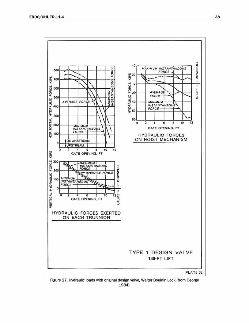
Although the 12- by 12-ft reverse tainter valve (Figure 26) was considered a vertically-framed valve, large horizontal box girders were located on the arms at the T-beams. These T-beams provided a passage for flow circulation between the upstream face of the skin plate and the girders. Hoist and trunnion loads were measured for steady flow under various gate openings at lifts up to 130 ft (Figure 27). The largest trunnion forces occurred at small gate openings, but the force fluctuation was small. The magnitude of forces acting on the trunnions decreased as the gate opening was increased, but force fluctuations increased significantly. The direction of the hoist load reversed from downward to upward at about 60 percent gate opening (7-ft gate opening with a 12-ft culvert height).
ERDC/CHL TR-11-4 37
Figure 25. Flow around a reverse tainter valve when nearly open (from George 1984).
Figure 26. Original design tainter valve, Walter Bouldin Lock (from George 1984).
ERDC/CHL TR-11-4 38
Figure 27. Hydraulic loads with original design valve, Walter Bouldin Lock (from George
1984).

ERDC/CHL TR-11-4 39
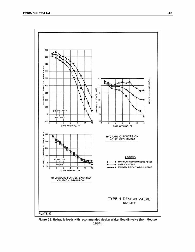
Various shapes were built to streamline the flow around the lower portion of the valve. Experiments with these designs showed that the trunnion forces were not affected, but the hoist loads were sensitive to the shape in this area of the valve, especially at higher valve openings. Not only were the average hoist loads larger, but the fluctuations also increased as “streamlining” plates were added to the cross girders. The flow was directed upward at large valve openings, as shown by the strings attached to the horizontal box member in Figure 25. Offsetting the cross member 36 in from the skin plate (Figure 28) reduced the uplift forces in the hoist while increasing the trunnion load (Figure 29). The hoist loads reversed from downward to upward at about 67 percent open with the box member offset 36 in.
4.4.6 Watts Bar Lock
A hydraulic model investigation was under way at the time this report was written. Project information for Watts Bar Lock is provided in Chapter 6. The purpose of the lock valve model study was to determine the following:
• Valve hoist loads during normal operations. • Valve hoist loads during emergency operations.
Figure 28. Recommended design Walter Bouldin reverse tainter valve (from George 1984).
ERDC/CHL TR-11-4 40
Figure 29. Hydraulic loads with recommended design Walter Bouldin valve (from George
1984).

ERDC/CHL TR-11-4 41
• Culvert pressures downstream from the valve and cavitation potential for various valve openings.
• Design modifications required to achieve desired performance. • Applicability of results to other Tennessee River locks.
The 1:10-scale model is shown in Figure 30. The model reproduced the lock culvert from the intake to the valve well, the upper and lower bulkheads, the valve well, the reverse tainter valve, and an approximately 150-ft length of culvert downstream from the lower bulkhead. The culvert, bulkhead slots, and valve well were constructed of transparent plastic to permit observation of flow. All lock culvert valve members were reproduced in detail with respect to size, shape, and weight and were constructed of brass. To avoid excessive friction between the valve and culvert wall, seals where not installed on the valve.
Figure 30. Side view of Watts Bar Lock valve model.
ERDC/CHL TR-11-4 42
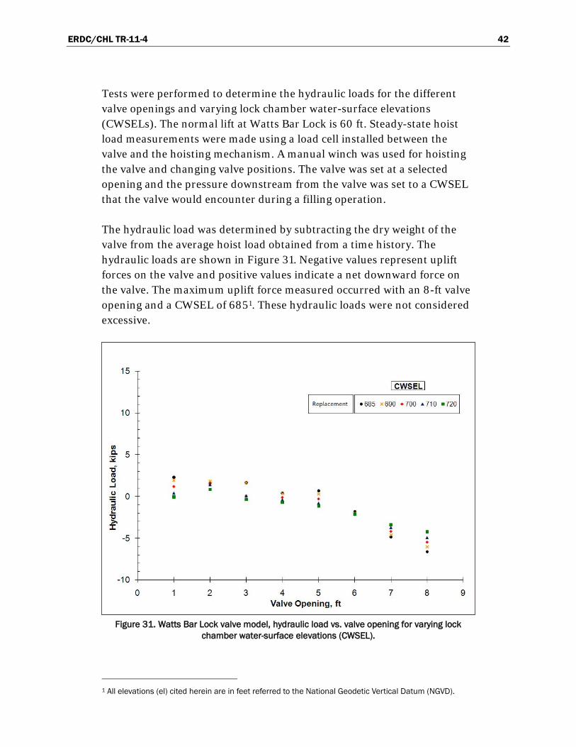
Tests were performed to determine the hydraulic loads for the different valve openings and varying lock chamber water-surface elevations (CWSELs). The normal lift at Watts Bar Lock is 60 ft. Steady-state hoist load measurements were made using a load cell installed between the valve and the hoisting mechanism. A manual winch was used for hoisting the valve and changing valve positions. The valve was set at a selected opening and the pressure downstream from the valve was set to a CWSEL that the valve would encounter during a filling operation.
The hydraulic load was determined by subtracting the dry weight of the valve from the average hoist load obtained from a time history. The hydraulic loads are shown in Figure 31. Negative values represent uplift forces on the valve and positive values indicate a net downward force on the valve. The maximum uplift force measured occurred with an 8-ft valve opening and a CWSEL of 6851
. These hydraulic loads were not considered excessive.
Figure 31. Watts Bar Lock valve model, hydraulic load vs. valve opening for varying lock chamber water-surface elevations (CWSEL).
1 All elevations (el) cited herein are in feet referred to the National Geodetic Vertical Datum (NGVD).

ERDC/CHL TR-11-4 43
Tests were also conducted to measure hoist loads while the valve was lowered from the fully-open position to a 7-ft valve opening. Since the test facility was not capable of maintaining constant head conditions, the head on the valve and the pressure downstream from the valve changed slightly during this test. The intent of the test was to observe any sudden uplift in the valve that might be the cause of the valve movement observed at the project.
Figure 32 shows a time history of the hoist load while the valve is lowered from an 8- (fully-open) to a 7-ft valve opening. The lowering took place between 80 and 140 sec on the time history. No significant change in the average hoist load occurred before and after the valve was lowered. Between 0 and 80 sec, the average hoist load was 14.5 kip and between 140 and 240 sec the average hoist load was 14.1 kip. An obvious reduction in hoist load occurred at 82.3 sec when a value of 7.6 kip was measured. This type of sudden change in hoist load could be responsible for the valve movement observed at the project.
Figure 32. Hoist load measured while lowering the Watts Bar Model lock valve from fully open
position to a 7-ft valve opening.

ERDC/CHL TR-11-4 44
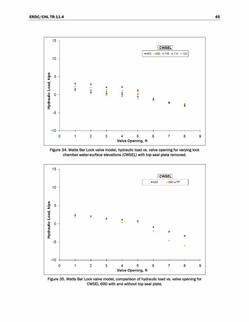
The Watts Bar Lock valve had a structural plate located as shown in Figure 33 that held the adjustment bolts for the valve top seal. The adjustment bolts for the top seal were mounted on the top downstream side of the plate. Tests were conducted without this top plate on the model valve. The hydraulic loads determined from these tests are shown in Figure 34. The maximum downward force was 3.1 kips and occurred with the normal upper pool el of 740, a CWSEL of 680 and a 1-ft valve opening. The maximum upward force was 3.4 kips and occurred with an upper pool elevation of 740 ft, a CWSEL of 690 ft, and an 8-ft valve opening.
A comparison of the hydraulic loads determined for a CWSEL of 690 ft with and without the top seal plate is shown in Figure 35. The uplift forces with the top seal plate removed were reduced from those measured with the top seal plate as seen with the 6-, 7-, and 8-ft valve openings.
Figure 36 shows a time history obtained while lowering the valve from 8- to 7-ft open. The valve was lowered from 8 to 7 ft between 100 and 160 sec at a speed of about 1 ft/min. No large load fluctuations were observed during the valve lowering. The loads measured while the valve was lowered without the top seal plate did not show any significant load fluctuations which would cause the sudden uplift that has been reported at the project.
Figure 33. Watts Bar Lock valve top seal plate for holding adjustment bolts shown in
prototype and model.
ERDC/CHL TR-11-4 45
Figure 34. Watts Bar Lock valve model, hydraulic load vs. valve opening for varying lock
chamber water-surface elevations (CWSEL) with top seal plate removed.
Figure 35. Watts Bar Lock valve model, comparison of hydraulic load vs. valve opening for
CWSEL 690 with and without top seal plate.
ERDC/CHL TR-11-4 46
Figure 36. Hoist load measured while lowering the Watts Bar Model lock valve from fully open
position to a 7-ft valve opening with the top seal plate removed.
Piezometers were installed on the floor of the culvert to measure the piezometric pressure in the culvert for selected valve openings and CWSELs. The piezometer readings for 4-, 5-, and 6-ft valve openings are shown in table form in Figure 37. Downstream of the valve, pressure as low as el 644 were measured with a 4-ft valve opening and a CWSEL of 680 ft. A plot of piezometer readings at location P4 for CWSELs between 680 and 720 ft is shown in Figure 38.
The pressure at P4 with a CWSEL of 680 ft is 19 ft lower than the floor of the culvert and would be an indicator that cavitation may be possible in the prototype.
The original design valve for the Watts Bar Project was a double skin plate reverse tainter and was reported to have performed satisfactorily. A 1:10-scale model of this design was constructed and tested in the Watts Bar valve facility. Figure 39 shows a side view of the valve in the model facility.
The model was constructed of brass and scaled in size and weight. The trunnions for this valve were in the same location as the replacement valve, although there were minor differences where the top of the valve sealed against the valve well. These differences did not allow forces to be measured at the fully-open valve position.

ERDC/CHL TR-11-4 47
Figure 37. Watts Bar Lock valve model, piezometer locations and readings for 4-, 5-, and 6-ft
valve openings with Upper Pool El of 740.
Figure 38. Watts Bar Lock valve model, piezometer readings at piezometer P4.
ERDC/CHL TR-11-4 48
Figure 39. Side view of the 1:10-scale Watts Bar Lock valve model with the original reverse
tainter valve.
The original double skin plate valve had streamlined curved features and enclosed structural members along the valve arms. These double skin plates and enclosed arms allowed, for the most part, continuous flow around the valve, including the rear concave plate. Unlike the replacement valve, this feature allowed a cleaner separation for flow over and under the valve.
Hoist loads and hydraulic loads were measured with the original valve in a similar manner as described above for the replacement valve. Figure 40 presents the results of the hydraulic load measurements. For lower CWSELs of 685 ft to 710 ft, the hydraulic loads are greater than zero constantly for valve openings ranging from 1 to 5 ft. For a 6-ft valve opening, all hydraulic loads are below zero and lower than the loads measured from the initial replacement valve.
A comparison of the hydraulic loads measured with the replacement valve with and without the top seal plate installed and the original valve is shown in Figure 41 for a CWSEL of 690 ft. The most significant difference was the hydraulic loads measured with the 1-ft valve opening. The hydraulic load increased from 2.3 to 14.5 kip with a CWSEL of 690 ft.

ERDC/CHL TR-11-4 49
Figure 40. Watts Bar Lock valve model, hydraulic load vs. valve opening for varying lock
chamber water-surface elevations (CWSEL) with original design valve.
Figure 41. Watts Bar Lock valve model, comparison of hydraulic load vs. valve opening for
CWSEL 690 reverse tainter valve with and without top seal plate and with original double skin plate valve.
ERDC/CHL TR-11-4 50
The hydraulic loads measured with the replacement valves and modifica-tions were not considered excessive. The best valve performance based on hydraulic loads was the replacement valve without the top seal plate. With the top seal plate installed uplift forces were higher and valve movement was observed when the valve was in the fully open position.
The valve lowering tests showed that with the top seal plate and bottom plate installed, the uplift forces were higher and the valve moved very noticeably in the fully-open position.
The hydraulic loads measured with the original valve were higher than those measured with the replacement valve. No movement was observed during steady-state tests.
The problems associated with the Watts Bar Lock replacement valves due to uplift appear to be caused by the top seal plate. A different seal plate adjust-ment design is recommended to eliminate or reduce the size of the top seal plate. The upward flow along the upstream side of the valve impacts the plate causing additional uplift forces.
4.5 Prototype studies
4.5.1 McNary Lock
McNary Lock, with a 92-ft maximum lift, experienced thundering noises when the filling valves were partially open (U.S. Army Engineer Waterways Experiment Station 1960). The filling and emptying system is an interlaced lateral system having 11-ft-wide by 12-ft-high reverse tainter valves. These valves were designed for 100 percent overload (184 ft head) “so that they could withstand additional stress of undetermined magnitude resulting from formation and collapse of vapor pockets on the downstream face of the valve.”
The effects of the pounding at the valve were transmitted to the operating machinery, so the hoist loads were measured. The pounding noise was caused by pockets of air being drawn into the flow through the downstream bulkhead slot, traveling upstream to the low pressure area immediately downstream of the partially-open valve and collapsing. The noise was eliminated when the air vent downstream of the valve was opened. Valve discharges during pounding were measured to be between 3,000 and 6,000 cfs. Velocities under the valve were estimated to have been between 55 and 70 fps.

ERDC/CHL TR-11-4 51
Prototype tests were conducted to determine the causes and effects of the pounding. This testing program was also part of a generalized research effort to obtain information about valving and air venting for high-head locks. Measurements were taken of pressures in the culverts, vibration of the valve and lock wall, presence of air or water at critical areas, valve openings, lock water-surface elevations, head-loss and contraction coefficients for the valve, and valve operating forces.
Natural frequencies were calculated for the valve system and compared to the frequency of measured vibrations in the hoist rod. Figure 42 shows that none of the computed or observed frequencies (6-40 Hz) were close to the frequency of the audible pounding (1 Hz). Therefore, resonance was not contributing to the pounding. Radial and transverse vibration of the valve was at a much higher frequency (above 200 Hz).
The oil pressures at the top and bottom of the valve-hoist hydraulic cylinder were measured, so the hoist loads could be calculated. The pounding at the valve was accompanied by concurrent hoist cylinder pressure and piston rod force fluctuations of considerable magnitude. Downpull (tension) and uplift (compression) forces in the hoist rod are summarized in Figure 43. Valve hoist loads varied between 95-kip tension and 30-kip compression. The venting reduced the force fluctuations significantly at the nearly-open position.
4.5.2 Bankhead Lock
The new Bankhead Lock has a design lift of 69 ft with 14- by 14-ft culverts with filling and emptying valves of the same size and a 110-ft by 600-ft chamber. Details of the reverse tainter valves are shown in Figure 44. Prototype tests were conducted on the new Bankhead Lock, Black Warrior River (Tool 1980). Hoist loads were measured indirectly by recording the hoist cylinder pressures. A construction drawing of the valve lifting machinery is provided on Figure 45. The Bankhead Lock reverse tainter valve has performed well and the valve design was recommended by operations personnel of the Mobile District.1
1 Personal communication with Anthony Perkins, Chief, Lock Operations and Repair, BWT/AL-Coosa
Project, U.S. Army Engineer District, Mobile.
ERDC/CHL TR-11-4 52
Figure 42. McNary Lock prototype vibration data (from WES 1960).

ERDC/CHL TR-11-4 53
Figure 43. McNary Lock prototype hoist loads (from WES 1960).
ERDC/CHL TR-11-4 54
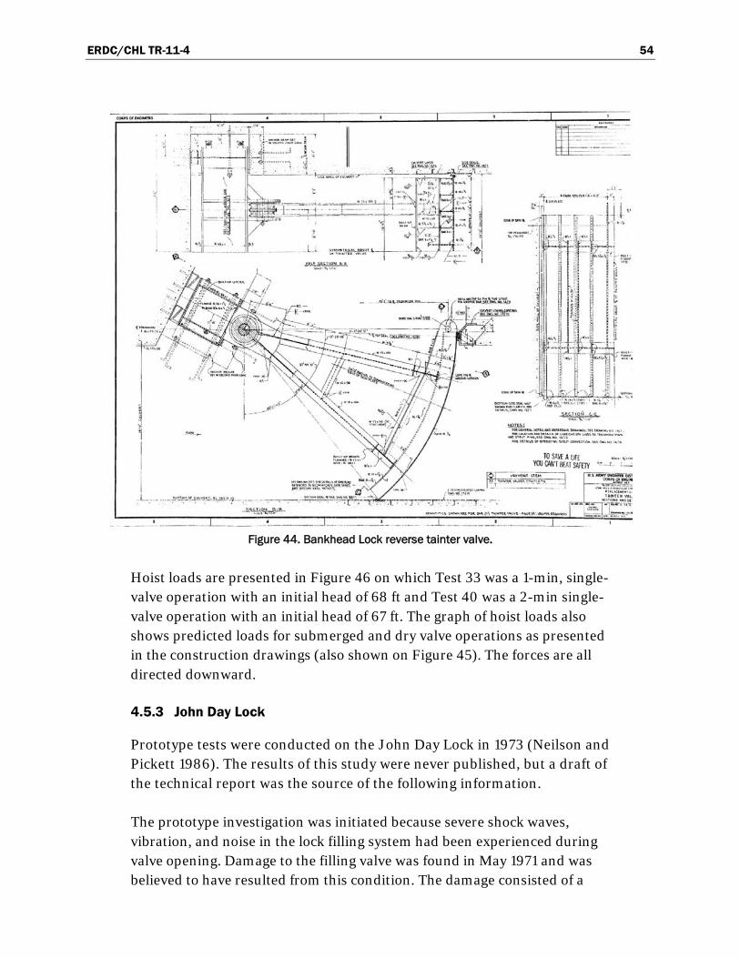
Figure 44. Bankhead Lock reverse tainter valve.
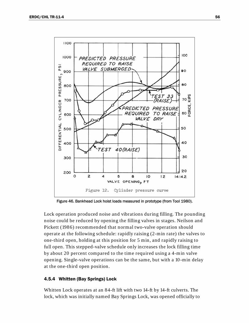
Hoist loads are presented in Figure 46 on which Test 33 was a 1-min, single-valve operation with an initial head of 68 ft and Test 40 was a 2-min single-valve operation with an initial head of 67 ft. The graph of hoist loads also shows predicted loads for submerged and dry valve operations as presented in the construction drawings (also shown on Figure 45). The forces are all directed downward.
4.5.3 John Day Lock
Prototype tests were conducted on the John Day Lock in 1973 (Neilson and Pickett 1986). The results of this study were never published, but a draft of the technical report was the source of the following information.
The prototype investigation was initiated because severe shock waves, vibration, and noise in the lock filling system had been experienced during valve opening. Damage to the filling valve was found in May 1971 and was believed to have resulted from this condition. The damage consisted of a

ERDC/CHL TR-11-4 55
Figure 45. Bankhead Lock valve machinery.
bent skin plate and broken welds in the radial arms and sheared bolts across the top of the valve skin plate. Chanda and Perkins (1974) reported that excessive structural vibration caused failure of monolith joint water stops, damage to valve trunnion arms, and movement of a monolith. “Workmen narrowly escaped death or serious injuries when water entered the right emptying valve shaft that was bulkheaded off for maintenance of the valve. Apparently, the bulkhead was moved by a shock wave that resulted when the right filling valve was opened.” Neilson and Pickett (1986) note that the shock waves are not unique at John Day since similar problems have also occurred at the McNary, Ice Harbor, and Lower Monumental locks. Information obtained at John Day was believed to be applicable to Ice Harbor and Lower Monumental since these locks have nearly identical filling systems and similar troubles during valve opening.
ERDC/CHL TR-11-4 56
Figure 46. Bankhead Lock hoist loads measured in prototype (from Tool 1980).
Lock operation produced noise and vibrations during filling. The pounding noise could be reduced by opening the filling valves in stages. Neilson and Pickett (1986) recommended that normal two-valve operation should operate at the following schedule: rapidly raising (2-min rate) the valves to one-third open, holding at this position for 5 min, and rapidly raising to full open. This stepped-valve schedule only increases the lock filling time by about 20 percent compared to the time required using a 4-min valve opening. Single-valve operations can be the same, but with a 10-min delay at the one-third open position.
4.5.4 Whitten (Bay Springs) Lock
Whitten Lock operates at an 84-ft lift with two 14-ft by 14-ft culverts. The lock, which was initially named Bay Springs Lock, was opened officially to

ERDC/CHL TR-11-4 57
navigation in May 1985. McGee (1989) conducted a field investigation to determine the operating characteristics and hydraulic efficiency of the lock. Particular attention was given to evaluating important design factors such as the cavitation parameter and the effects of venting and submergence of the valves.
The filling and emptying system is a bottom longitudinal floor culvert system commonly referred to as an “H” system. Reverse tainter valves are used to control both the filling and emptying flow in these main culverts. Dual 12-in diameter ducts introduce air downstream of each filling and emptying valve.
The reverse tainter valves have performed well, and the operating condi-tions are satisfactory. The problems at the project are limited to the concrete culverts. The reverse tainter valves are vertically-framed with a 20 ft radius (Figure 47). Hoist loads, measured during operation (Figure 48) were signi-ficantly larger than those predicted by the Corps’ guidance (EM 1110-2-1610). At no time were any uplift forces observed for the one filling valve that was instrumented.
4.6 Recommended design
Vertically-framed valves are preferable to horizontally-framed valves. Open spaces where water can circulate freely should be provided between the ribs and between the skin plate and horizontal girders. The actual trunnion and hoist loads will be directly affected by the valve geometry including structural members.

ERDC/CHL TR-11-4 58
Figure 47. Reverse tainter valve, Whiten Lock (from McGee 1989).
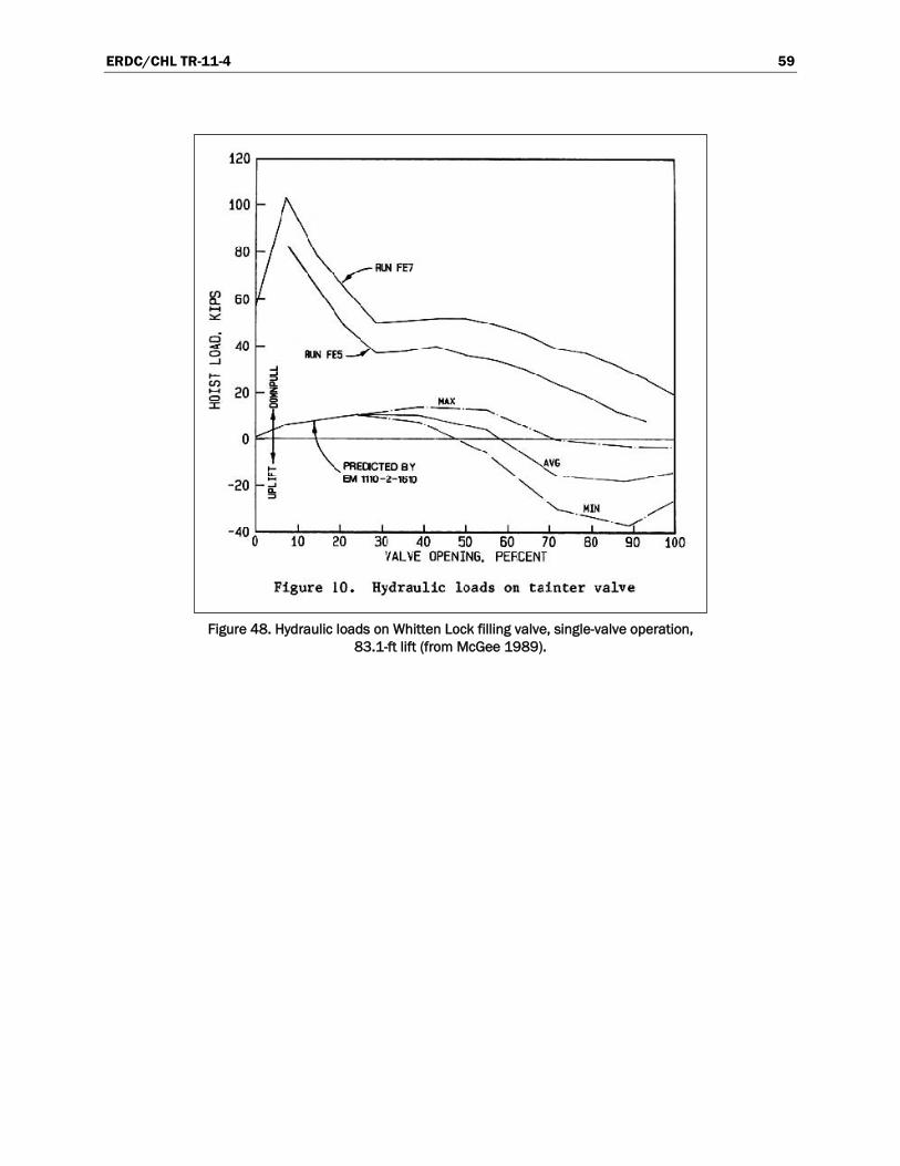
ERDC/CHL TR-11-4 59
Figure 48. Hydraulic loads on Whitten Lock filling valve, single-valve operation,
83.1-ft lift (from McGee 1989).
ERDC/CHL TR-11-4 60
5 Valve position
5.1 Horizontal
The distance between the valve and the manifold in a sidewall port filling system was tested for Newburgh Lock, Ohio River (Farrell and Ables 1968). This study, which employed a 1:25-scale physical model, found that the low pressure zone generated at the valve extended about 6.5 culvert heights downstream from the valve. One would think that sidewall ports located in this zone of lower pressure would disturb the manifold flow distribution. However, due to inertia, the upstream ports on a sidewall port system tend to discharge more than the average port flow rate at the early portion of the filling operation. So, the retardation of flow due to lower pressure did not have a measureable effect on the lock chamber performance. Farrell and Ables (1968) report that “with the port manifold placed in positions that resulted in the first two and the first four ports being within the low pressure zone downstream from the valve, no differences in filling time or hawser forces could be detected from those obtained with the manifold placed so that all ports were outside the low pressure zone.”
5.2 Vertical
Vertical position is determined by the piezometric head in the immediate vicinity of the valve. Several factors such as the project’s lift, the type of filling and emptying system, the type and design of the valve, and the valve operation schedule influence the pressures in the valve area. High-lift locks experience large pressure drops across partially-opened valves. These pressure drops can lead to excessively low pressures and the potential of cavitation downstream of the valve. Pickering (1981) shows that the culvert shape and size immediately downstream of reverse tainter valves have a large effect on the valve losses and therefore the maximum pressure drop across the valve.
The cavitation potential must be considered when determining the proper valve positioning. The lowest pressures downstream of a valve usually occur when the valve is between 50 and 70 percent open. These low pressures can lead to cavitation, the potential of which is quantified using a cavitation parameter

ERDC/CHL TR-11-4 61
( )a v
j
P P Pσ
Vg
2
2
(3)
where
P = gage pressure head at the top of the vena contracta of the jet emerging from the partially open valve,
Pa = atmospheric pressure head, Pv = vapor pressure head of water, and Vj = velocity in the vena contracta of the jet emerging from the
partially open valve.
A value of 33.0 ft is used for the term Pa – Pv for the cases reported in EM 1110-2-1610. The value of this parameter at which cavitation is incipient is termed the cavitation index, σi. There has been much discussion regarding the cavitation index value that is associated with incipient cavitation in unvented systems. A value of 0.61 has been used by many and this value has been substantiated by the prototype study of Whitten Lock (McGee 1989).
Alternatives to culvert roof expansion downstream of valves to avoid cavitation have been proposed by Qinghua and Guoxiang (1998). The experiments, conducted in a vacuum tank, investigated an abrupt culvert expansion downstream of a reverse tainter valve. The increased culvert area reduced the average velocity, which increased the pressure behind the valve and decreased the fluctuations. Cavitation from the valve lip was avoided because of these changes in the flow. However, the increase in pressure and decrease in fluctuations due to a sudden culvert expansion did increase the energy losses in the flow as the jet was dissipated. This additional head loss and associated increase in operation times must be considered in the lock design process.
The Corps’ design guidance calls for either placing the valve sufficiently deep or at an elevation that guarantees sufficiently negative pressures to draw air into the culvert just downstream of the valve. Deep valve submer-gence prevents negative pressures low enough to cause cavitation. This design is termed a positive head valve design; wherein, the pressures during valve operation never reach a level lower than about 15 ft below the culvert roof. An example of a positive head valve on a high-lift lock is the new Bonneville Lock on the Columbia River, which has a design lift of 69.5 ft. An example of a project designed to draw air is Whitten Lock on the Tennessee-

ERDC/CHL TR-11-4 62
Tombigbee Waterway. This lock, which has a design lift of 84 ft, draws air into the culvert immediately downstream of the valve. The air vent is located such that the air drawn into the culvert is entrained in the form of very small bubbles, avoiding large air pockets that may cause surging in the lock chamber.
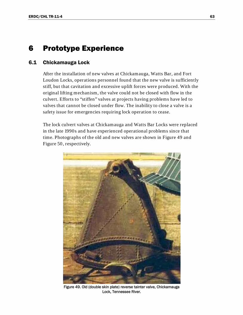
ERDC/CHL TR-11-4 63
6 Prototype Experience
6.1 Chickamauga Lock
After the installation of new valves at Chickamauga, Watts Bar, and Fort Loudon Locks, operations personnel found that the new valve is sufficiently stiff, but that cavitation and excessive uplift forces were produced. With the original lifting mechanism, the valve could not be closed with flow in the culvert. Efforts to “stiffen” valves at projects having problems have led to valves that cannot be closed under flow. The inability to close a valve is a safety issue for emergencies requiring lock operation to cease.
The lock culvert valves at Chickamauga and Watts Bar Locks were replaced in the late 1990s and have experienced operational problems since that time. Photographs of the old and new valves are shown in Figure 49 and Figure 50, respectively.
Figure 49. Old (double skin plate) reverse tainter valve, Chickamauga
Lock, Tennessee River.

ERDC/CHL TR-11-4 64
Figure 50. New (framed) reverse tainter valve, Chickamauga Lock,
Tennessee River.
Coastal and Hydraulics Laboratory personnel visited these locks during March 2007, and the information contained in the current report comes from a trip report of that visit (Hite and Waller 2007). The purpose of the visit was to inspect Chickamauga Lock valves and culvert while the project was dewatered and to observe valve operations at the Watts Bar project.
Chickamauga Lock is located on the Tennessee River near Chattanooga, TN. The lock is 60 ft wide by 360 ft long with a side-port filling and emptying system. The lift is nominally 50 ft, and the culverts are 8 ft wide by 8 ft high. Since the new valves were installed, problems have been experienced with uplift on the valves during normal operations and simulated emergency operations. During normal operations, the upper lock valve stems move up and down as the lock is being filled. This motion indicates that uplift forces large enough to move the valve are occurring during filling. During simulated emergency operations when the valve is opened fully and then immediately starts closing, the valve would lift enough to cause the lifting mechanism to stop. Three modifications have been made to the valve to

ERDC/CHL TR-11-4 65
reduce the uplift forces. Semi-circular pipes have been installed on the valve arms. Solid plates have been placed between the lower horizontal girder and vertical valve ribs and over the vertical ribs between the lower and upper horizontal girders. These modifications, shown in Figure 51, reduced the valve movement during lock filling. A larger spring was also added to the lifting mechanism to further reduce movement.
Figure 51. Modifications to new (framed) valve, Chickamauga Lock, Tennessee River.
The Chickamauga Lock valves are tapered and the side seals are in contact with the wall only at closure. Side seals might provide lateral support to deter torsion of the valve.
Lock designers are concerned with the problems experienced with valve uplift during lock operations as well as long term operation and mainten-ance issues at Chickamauga Lock. A field study was recommended to determine the cause of the valve uplift. Prototype measurements could determine the valve position, lock water surface, and magnitude of the movement. This information would be beneficial in determining if opera-tional changes could reduce valve stem movement and the resulting long-term effects on the operating machinery. A model study of the lock valve was proposed for the new lock at Chickamauga to provide information
ERDC/CHL TR-11-4 66
helpful in understanding the causes for the valve uplift. Either a field study or a model study was recommended to determine the cause of the valve uplift and hopefully determine how to avoid or eliminate the problem.
6.2 Watts Bar Lock
Watts Bar Lock and Dam is located about halfway between Chattanooga and Knoxville, TN on the Tennessee River. The lock is 60 ft wide by 360 ft long with a side-port filling and emptying system. The average lift is about 60 ft and the maximum lift is 70 ft. The culverts are 6 ft wide by 8 ft high.
These lock valves have also been replaced with newer valves, and the project personnel have had to alter lock operations from those used with the older valves. During lock operations with the older valves, the filling valves were opened in about 1-ft increments until sufficient water was in the chamber and then the valves were fully opened. This type of operation prevented excessive water surface slopes which would cause problems for vessels moored in the chamber. With the newer valves, the filling valves are held at a lower opening longer to get the water cushion in the chamber. Experience has shown that if the valves are left in the nearly half-opened position, loud and repeated noises occur in the culverts causing the building and lock machinery to vibrate. The upper land wall valve was modified the same way as those at Chickamauga Lock, but the noises still occurred when the filling valves were operated in the mid-range openings.
Operation of Watts Bar Lock was demonstrated with an initial head of 58.5 ft. The valves were opened to 4.5 ft in about 1 min and 45 sec. Several loud noises resulting from cavitation occurring in the culvert downstream of the filling valves were heard for a short time. The vapor cavities that form from the low pressure below the valve collapse or implode causing the booming sound. Often, the culverts in high-lift lock projects are designed to draw air into the low pressure zone below the valve and cushion the cavita-tion to avoid damages. The as-built drawings for Watts Bar Lock show 6-in. air vents in the valve well on both sides of the culvert. The purpose for these vents is unclear, but they are probably too close to the valve to help cushion the cavitation.
The lower bulkhead slots are open to the atmosphere, but the upper bulkhead slots are closed. The lower river wall valve was operated in the same manner as the upper valves in previous demonstrations, and the lower land valve was operated as it normally does during lock emptying. It was

ERDC/CHL TR-11-4 67
raised to 4.5 ft and held in that position to determine if any loud noises could be heard. No loud booming noises occurred during lock emptying. The flow passing through the downstream bulkhead slot from the lower river valve was observed as the lock was emptied. Initially, the flow was bulking up the slot from contact with the lower edge but eventually cleared the edge and passed though undisturbed. Apparently, more air was entrained in the riverside discharge outlet than the landside outlet during the emptying operation. Holding the river wall valve at 4.5 ft likely caused more air entrainment. The open bulkhead slots on the lower valves may have been the reason no booming was heard during the emptying operation.
An investigation of the hydraulic performance of the Watts Bar filling and emptying system was recommended. A physical model study could deter-mine if minor modifications to the existing port system could be made, so the filling valves could be opened faster. Improved valve opening operations could also be determined.
The bulkhead covers for the upper filling valves could be removed to determine if air was being drawn into the culvert during filling. If air is being drawn in, it might cushion the cavitation and improve the valve operation. A quick field test might be worthwhile to evaluate the valve operation and chamber performance with the upper bulkhead cover removed. As at Chickamauga Lock, a data acquisition system could monitor water levels, valve positions, and machinery and structural vibrations. During a field test, the noises heard during current valve operations could be recorded. Also, a video of lock chamber conditions during filling could be made for comparison to conditions without the bulkhead covers in place.
The existing Watts Bar Lock is required to operate for many more years. Additional studies to determine ways to speed up lock operations while providing safe conditions in the chamber are beneficial for the remaining life of the project.
6.3 John Day Lock
The double skin plate reverse tainter valve used on John Day and the Dalles Locks, Columbia River, have had cracks form in the steel wrapper plate of the valve members, and these cracks have been repaired numerous times. Operation and maintenance of the lock culvert valves on these locks has been hindered by problems essentially since completion of construction. A

ERDC/CHL TR-11-4 68
recommendation (North 2006) has been made to replace the tainter valves. Cracks in the double skin plate design suggest that a more rigid, framed design might provide better service.
The replacement valve selection will be made after consideration of various designs. Cracks in the double skin plate design suggest that a more rigid, framed design, similar to that of the new Bonneville Lock, might provide better service. However, alternative flow control devices such as vertical-lift valves are to be considered.
John Day Lock has the highest design lift of any lock in North America (113 ft) and a chamber that is 86 ft wide by 675 ft long. Its filling system has presented problems since operations began in 1968. The culverts are 12 ft wide by 14 ft high at each reverse tainter valve. A photograph of one of these valves that is waiting for repair, is shown on Figure 52. The valves have a nominal radius of 19.5 ft. The filling and emptying culverts form a split lateral system. Each 12-ft-wide by 20-ft-high wall culvert supplies water to a set of ten manifolds aligned laterally to the lock centerline. The left culvert laterals are located on the upper one-third end of the lock chamber, and the right culvert laterals are located in the lower one-third end of the chamber.
Figure 52. Double skin plate reverse tainter valve waiting for repair, The Dalles Lock.

ERDC/CHL TR-11-4 69
Valve operations have been changed from the design schedule to a stepped fashion to avoid cavitation damage. A two-valve filling operation was recommended by Neilson and Pickett (1986), wherein the valves are operated to one-third open in 40 sec, held at one-third open for a 5-min delay, and opened completely in 80 sec. Neilson and Pickett (1986) also recommended that a single valve could be operated in a similar schedule with a 10-min delay. While the valves are held at the one-third open position, the flow approaches an average velocity of 60 fps under the valve (EM 1110-2-1610). These high velocities combined with the structural inspections suggest that lateral-torsional loading occurs. Perhaps the loads are a result of vortex shedding at various rates across the valve lip. Not much can be done hydraulically to reduce these loads considering that optimum valve operation has been established.
6.4 Holt Lock
Holt Lock on the Black Warrior River has a design lift of 64 ft. The culvert flow is controlled with 12.5-ft-wide by 12.5-ft-high reverse tainter valves. The vertically-framed valves have a radius of 17.0 ft as shown in Figure 53. The construction drawings show that the tainter valves have an estimated weight of 26.3 kips each. These valves have been problematic for operations, and a redesign has been discussed in which weight and stiffness would be added to the valves.
Figure 53. Holt Lock valve machinery.

ERDC/CHL TR-11-4 70
Davis (1989) recommended that the Holt Lock valve design be used in all new valve construction. However, discussion with operation personnel at Holt Lock found the valve has been a maintenance problem since the lock began operations in the late 1960s. Holt Lock operations personnel believe that this valve design has performed poorly and describe the culvert valves as not being stiff enough. Apparently, the existing hydraulic design guidance does not reflect actual operational experiences and needs. The U. S. Army Engineer District, Mobile (SAM) is in the process of replacing the 4 lock culvert valves with new designs.
6.5 Bankhead Lock
Bankhead Lock on the Black Warrior River has a design lift of 69 ft. The culverts are 14 ft by 14 ft and flow is controlled with 20-ft radius reverse tainter valves (Figure 44). The Bankhead Lock valve design is much heavier than the valve design used at Holt Lock. The estimated weight shown on the construction drawing is 35.3 kips which is 34 percent heaver than the Holt Lock valve. Both the Holt and Bankhead valves are vertically-framed with virtually the same space between the skin plate and the horizontal beams between the arms.
The primary difference in the Bankhead Lock and Holt Lock valves is their performance. The SAM operations personnel have commented that the Bankhead Lock valves perform well and that only normal maintenance has been required.
Designers are challenged to explain the performance differences in the Bankhead and Holt valves. The lifts are not much different: actually, the Bankhead Lock’s design lift is 5 ft higher. Since the locks have comparable lifts, the culvert velocity during operation is probably similar. The Bankhead Lock valve is larger than the Holt Lock, not only because the culverts are larger, but also because the skin plate curvature is less. The Bankhead valve has a radius-to-culvert height ratio of 1.43, whereas the Holt valve’s radius is 1.36 times larger than the culvert height. Perhaps the size and weight of the Bankhead Lock valve provides some explanation as to why it performs better than the Holt Lock valve. Currently, the reason for valve performance differences is unknown.

ERDC/CHL TR-11-4 71
7 Summary
A review of the literature pertaining to lock culvert valves has been provided. Additional valve information has been gathered from recent numerical and physical project-specific model studies. Reverse tainter valves have been used in lock culverts since 1938. The U.S. Army Corps’ Engineering Manual “Hydraulic Design of Lock Culvert Valves” (EM 1110-2-1610) recommends incorporation of reverse tainter valves in the design of lock filling and emptying systems.
Although guidance recommends using reverse tainter valves, geometric constraints have forced the use of vertical-lift valves at the recently const-ructed Marmet Lock and are proposed for locks to be constructed on the Mississippi River and a new lock on the Inner Harbor Navigation Canal. The lip of the vertical-lift valve is important to the valve’s performance because they are subject to vibration tendencies. Also, EM 1110-2-1610 recommends reverse tainter valves due to increased maintenance requirements of vertical-lift valves. This engineering manual states that if a vertical-lift valve is used, the design should be tested in a hydraulic model
Vertically-framed reverse tainter valves are preferable to horizontally-framed valves because the uplift and load variations are larger on the latter. The Holt Lock valve has been recommended by Headquarters, U.S. Army Corps of Engineers (Davis 1989). However, operations personnel at the Holt Lock believe that this valve design has performed poorly. The existing hydraulic design guidance does not seem to reflect actual operational experiences and needs.
“to develop an optimum bottom shape for the gate and to determine valve hoist loads.”
Engineers and operators know several reverse tainter valve designs that do not perform well in the field. However, vertically-framed reverse tainter valves seem to be performing well at the new Bonneville Lock (69.5 ft lift) and the Bankhead Lock (69 ft lift). So, additional understanding of how the structural members interact with the flow, especially at the nearly-open valve position, is needed to help predict valve performance. Research using both numerical and physical models is recommended. General understanding could be developed with a three-dimensional numerical flow model of the valve, culvert, and valve well. Steady flow at particular

ERDC/CHL TR-11-4 72
valve openings, in a manner similar to previous physical model studies, could show whether horizontal girders are obstructing flow and thus inducing large uplift forces. A physical model of the valve could provide actual hoist loads and vibration tendencies and would provide the turbulence effects of eddies shedding from the valve lip.
ERDC/CHL TR-11-4 73
References American Society of Civil Engineers. 1930. Manual on lock valves. Manuals of
Engineering Practice No. 3, Committee on Lock Valves, Waterways Division, New York.
Aydin, I., I. T. Telci and O. Dundar. 2006. Prediction of downpull on closing high head gates, Journal of Hydraulic Research, Vol. 44, No. 6, pp. 822-831.
Baines, W. D. 1954. Flow through tainter valves. Ottawa, Canada: National Research Laboratories.
Bhargava, V. P. and S. Narasimhan. 1989. Pressure fluctuations on gates. Journal of Hydraulic Research, vol. 27, no. 2, pp. 215-231.
Campbell, F. B. 1961. Vibration problems in hydraulic structures, Proc. ASCE, Journal of Hydraulics Division, Vol. 67, HY2, pp. 61-77.
Chanda, A. J. and L. Z. Perkins. 1974. Filling and emptying system John Day Lock, Columbia River, Oregon and Washington; hydraulic model investigation. Technical Report No. 98-1, U.S. Army Engineer Division, North Pacific, Bonneville, Oregon.
Davis, J. P. 1980. Locks and Mechanical Lifts: State of the Art. National Waterways Roundtable: proceedings : history; regional development; technology; a look ahead: Norfolk ,VA. Pp. 419-441.
Davis, J. P. 1989. Hydraulic design of navigation locks. Miscellaneous Paper HL-89-5, Vicksburg, MS: U.S. Army Engineer Waterways Experiment Station.
Farrell, J. O. and J. H. Ables. 1968. Effect of valve position in a sidewall port filling system, Newburgh Lock, Ohio River; hydraulic model investigation. Technical Report H-68-4, Vicksburg, MS: U.S. Army Engineer Waterways Experiment Station.
George, J. F. 1984. Filling and emptying system, Walter Bouldin Lock, and lock culvert valve for Coosa River Waterway, Alabama, hydraulic model investigation. Technical Report HL-84-8, Vicksburg, MS: U.S. Army Engineer Waterways Experiment Station.
Gibson, A. H. 1930. Hydraulics and its applications, 4th edition, p. 249, New York, NY: Van Nostrand Co., Inc.
Hammack, E. A. and R. L. Stockstill. 2011. Computational flow model of a reverse tainter valve. ERDC/CHL CHETN-IX-In review. Vicksburg, MS: U.S. Army Engineer Research and Development Center.
Hart, E. D. and J. E. Hite, Jr. 1979. Prototype gate vibration tests, Barkley Dam, Cumberland River, Kentucky, Technical Report HL-79-8, Vicksburg, MS: U.S. Army Engineer Waterways Experiment Station.

ERDC/CHL TR-11-4 74
Headquarters, US Army Corps of Engineers. 1975. Hydraulic design of lock culvert valves. Engineer Manual No. 1110-2-1610, Washington, D.C.
Headquarters, US Army Corps of Engineers. 1980. Hydraulic design of reservoir outlet works. Engineer Manual No. 1110-2-1602, Washington, D.C.
Headquarters, US Army Corps of Engineers. 1980. Hydraulic design of spillways. Engineer Manual No. 1110-2-1603, Washington, D.C.
Headquarters, US Army Corps of Engineers. 1995. Planning and design of navigation locks. Engineer Manual No. 1110-2-2602, Washington, D.C.
Headquarters, US Army Corps of Engineers. 1997. Engineering and design – vertical lift gates. Engineer Manual No. 1110-2-2701, Washington, D.C.
Headquarters, US Army Corps of Engineers. 2003. Engineering and design – lock and dam gate operating and control systems. Engineer Manual No. 1110-2-2610, Washington, D.C.
Headquarters, US Army Corps of Engineers. 2006. Hydraulic design of navigation locks. Engineer Manual No. 1110-2-1604, Washington, D.C.
Hite, J. and T. Waller. 2007. Memorandum for DOTS Program Manager, Dr. Doug Clarke, Vicksburg, MS: U.S. Army Engineer Research and Development Center.
Hite, J. E., Jr. 1999. Model study of Marmet Lock filling and emptying system, Kanawha River, West Virginia. Technical Report CHL-99-8, Vicksburg, MS: U.S. Army Engineer Waterways Experiment Station.
Hite, J. and S. T. Maynord. 2006. Evaluation report, locks and dams 22 and 25; hydraulic evaluation of the preliminary lock design for the filling and emptying system and sill elevation. Vicksburg, MS: U.S. Army Engineer Research and Development Center.
Kolkman, P. A. 1970. Analysis of vibration and damping measurements on a reversed tainter valve. Publication No. 87, Reprint from Paper I.A.H.R. Symposium, Stockholm, Delft, Netherlands: Delft Hydraulics Laboratory.
Lewin, J. 1995. Hydraulic gates and valves in free surface flow and submerged outlets, London: Thomas Telford.
Locher, R. A. 1969. Some aspects of flow-induced vibrations of hydraulic control gates, Contract Report H-69-1, for U.S. Army Corps of Engineers Waterways Experiment Station, IIHR Report No. 116, Iowa Institute of Hydraulic Research, Iowa City, IA: The University of Iowa.
Luo, S., Y. Hu, B. Fan, and F. Sun. 2009. Study of flow-induced vibration of delivery valve of shiplocks. Advances in Water Resources and Hydraulic Engineering, Vol. VI, 2168-2173.
McGee, R. G. 1989. Prototype evaluation of Bay Springs Lock, Tennessee-Tombigbee Waterway, Mississippi. Technical Report HL-89-15, Vicksburg, MS: U.S. Army Engineer Waterways Experiment Station.

ERDC/CHL TR-11-4 75
Murphy, T. E. and J. H. Ables. 1965. Lock filling and emptying system, Holt Lock and Dam, Warrior River, Alabama, hydraulic model investigation. Technical Report No. 2-698, Vicksburg, MS: U.S. Army Engineer Waterways Experiment Station.
Naudascher, E. 1991. Hydrodynamic forces, International Association for Hydraulic Research, 3 Hydraulic structures design manual, Rotterdam, Netherlands: A.A. Balkema.
Naudascher, E. and D. Rockwell. 1994. Flow-induced vibrations, and engineering guide, Mineola, NY: Dover Publications.
Neilson, F. M. 1975. Barkley Lock prototype tests, Cumberland River, Kentucky. Technical Report H-75-11, Vicksburg, MS: U.S. Army Engineer Waterways Experiment Station.
Neilson, F. M. and E. B. Pickett. 1980. Corps of Engineers experiences with flow-induced vibrations. Miscellaneous Paper HL-80-2, Vicksburg, MS: US Army Engineer Waterways Experiment Station.
Neilson, F. M. and E. B. Pickett. 1986. John Day Lock hydraulic prototype tests, Columbia River, Washington. draft technical report, Vicksburg, MS: U.S. Army Engineer Waterways Experiment Station.
North, T. 2006. Inspection of the John Day Navigation Lock tainter valves. Memorandum of Design, U.S. Army Engineer Portland District.
Perkins, L. Z. and H. P. Theus. 1975. Intake manifold and emptying valves for Lower Monumental Lock, Snake River, Washington, hydraulic model investigation. Technical Report No. 105-1, Bonneville, OR: U.S. Army Engineer Division, North Pacific.
Pickering, G. A. 1981. Lock culvert valve loss coefficients; hydraulic model investigation. Technical Report HL-81-10, Vicksburg, MS: U.S. Army Engineer Waterways Experiment Station.
Pickett, E. B. and F. M. Neilson. 1988. Lock hydraulic system model and prototype study data. Miscellaneous Paper HL-88-1, Vicksburg, MS: U.S. Army Engineer Waterways Experiment Station.
Qinghua, X. and X. Guoxiang. 1998. The new methods for preventing cavitation of high-lift ship lock valves in hydro-power projects. Water Resources Engineering 98, Proceedings of the International Water Resources Engineering Conference, held in Memphis Tennessee, Reston, VA: American Society of Civil Engineers, pp. 1757-1762.
Schmidgall, T. 1972. Spillway gate vibrations on Arkansas River dams. Proceedings American Society of Civil Engineers, Journal of Hydraulics Division, Vol. 98, HY1, pp. 219-238.
Thang, N. D. and E. Naudascher. 1986. Vortex-excited vibrations of underflow gates. Journal of Hydraulic Research, vol. 24, no. 2, pp. 133-151.

ERDC/CHL TR-11-4 76
Thang, N. D. 1990. Gate vibrations due to unstable flow separation. Journal of Hydraulic Engineering, Vol. 116, No. 3, pp. 342-361.Tool, A. R. 1980. Prototype filling and emptying system measurements, New Bankhead Lock, Black Warrior River, Alabama. Technical Report HL-80-13, Vicksburg, MS: U.S. Army Engineer Waterways Experiment Station.
U.S. Army Engineer District, Walla Walla. 1955. Synchronization of lock filling valves, McNary Lock and Dam, Columbia River, Oregon and Washington. Design Memorandum No. 20, U.S. Army Engineer Walla Walla District.
U.S. Army Engineer Waterways Experiment Station. 1949. Vacuum tank tests of model tainter valve for McNary Dam. Technical Memorandum No. 2-282, Vicksburg, MS: U.S. Army Engineer Waterways Experiment Station.
U.S. Army Engineer Waterways Experiment Station. 1960. Hydraulic prototype tests of tainter valve, McNary Lock, Columbia River, Washington. Technical Report No. 2-552, Vicksburg, MS: U.S. Army Engineer Waterways Experiment Station, Vicksburg, Mississippi.
U.S. Army Engineer Waterways Experiment Station. 1961. Culvert tainter valves, New Lock No. 19, Mississippi River; hydraulic model investigation. Technical Report No. 2-537, Vicksburg, MS: U.S. Army Engineer Waterways Experiment Station.
U.S. Army Engineer Waterways Experiment Station. 1961. Hydraulic prototype tests of tainter valve, McNary Lock, Columbia River, Washington; Appendix A, tabulated test data. Technical Report No. 2-552, Vicksburg, MS: U.S. Army Engineer Waterways Experiment Station.
U.S. Army Engineer Waterways Experiment Station. 1988. Hydraulic design criteria. Eighteenth issue, Vicksburg, MS: U.S. Army Engineer Waterways Experiment Station.
von Mises, R. 1964. Computation of discharge and overfall coefficients, Translation No. 64-8, Vicksburg, MS: U.S. Army Engineer Waterways Experiment Station.
Vrijer, A. 1979. Stability of vertically movable gates, 19th IAHR Congress, Karlsruhe, paper C5.

REPORT DOCUMENTATION PAGE Form Approved
OMB No. 0704-0188 Public reporting burden for this collection of information is estimated to average 1 hour per response, including the time for reviewing instructions, searching existing data sources, gathering and maintaining the data needed, and completing and reviewing this collection of information. Send comments regarding this burden estimate or any other aspect of this collection of information, including suggestions for reducing this burden to Department of Defense, Washington Headquarters Services, Directorate for Information Operations and Reports (0704-0188), 1215 Jefferson Davis Highway, Suite 1204, Arlington, VA 22202-4302. Respondents should be aware that notwithstanding any other provision of law, no person shall be subject to any penalty for failing to comply with a collection of information if it does not display a currently valid OMB control number. PLEASE DO NOT RETURN YOUR FORM TO THE ABOVE ADDRESS.
1. REPORT DATE (DD-MM-YYYY) June 2011
2. REPORT TYPE Final report
3. DATES COVERED (From - To)
4. TITLE AND SUBTITLE
Lock Culvert Valves; Hydraulic Design Considerations
5a. CONTRACT NUMBER
5b. GRANT NUMBER
5c. PROGRAM ELEMENT NUMBER
6. AUTHOR(S)
Richard L. Stockstill, E. Allen Hammack, and John E. Hite, Jr.
5d. PROJECT NUMBER
5e. TASK NUMBER
5f. WORK UNIT NUMBER
7. PERFORMING ORGANIZATION NAME(S) AND ADDRESS(ES) 8. PERFORMING ORGANIZATION REPORT NUMBER
Coastal and Hydraulics Laboratory U.S. Army Engineer Research and Development Center 3909 Halls Ferry Road Vicksburg, MS 39180-6199
ERDC/CHL TR-11-4
9. SPONSORING / MONITORING AGENCY NAME(S) AND ADDRESS(ES) 10. SPONSOR/MONITOR’S ACRONYM(S) U.S. Army Corps of Engineers 441 G. Street, NW Washington, DC 20314-1000
11. SPONSOR/MONITOR’S REPORT NUMBER(S)
12. DISTRIBUTION / AVAILABILITY STATEMENT Approved for public release; distribution is unlimited.
13. SUPPLEMENTARY NOTES
14. ABSTRACT This report presents a review of design guidance and hydraulic parameters associated with lock culvert valves. Many locks are beyond their design life, and the filling- and emptying-culvert valves are being replaced to keep the lock in service. Valve selection has begun for several new locks and lock extension projects. This report provides general information on three valve types: vertical lift, conventional tainter, and reverse tainter valves. The positive and negative aspects of each valve type as well as particular features are discussed. This report focuses on reverse tainter valves as these are the most common valve design used in locks on United States waterways.
15. SUBJECT TERMS Filling and emptying system Hydraulics
Inland waterways Lock design Navigation
Tainter valve Radial valve Vertical lift valve
16. SECURITY CLASSIFICATION OF: 17. LIMITATION OF ABSTRACT
18. NUMBER OF PAGES
19a. NAME OF RESPONSIBLE PERSON
a. REPORT
UNCLASSIFIED
b. ABSTRACT
UNCLASSIFIED
c. THIS PAGE
UNCLASSIFIED 85 19b. TELEPHONE NUMBER (include area code)
Standard Form 298 (Rev. 8-98)
Prescribed by ANSI Std. 239.18
Related Documents