Welcome message from author
This document is posted to help you gain knowledge. Please leave a comment to let me know what you think about it! Share it to your friends and learn new things together.
Transcript

NASA Space Science Vision Missions Marc S. Allen, NASA Progress in Astronautics and Aeronautics Series, 224 Published by AIAA, © 2008, 260 pages, Hardback ISBN-10: 1-56347-934-6 ISBN-13: 978-1-56347-934-2

ix
Table of Contents
Foreword. . . . . . . . . . . . . . . . . . . . . . . . . . . . . . . . . . . . . . . . . . . . . . . . . . . . viiPreface. . . . . . . . . . . . . . . . . . . . . . . . . . . . . . . . . . . . . . . . . . . . . . . . . . . . . . xvAcknowledgments . . . . . . . . . . . . . . . . . . . . . . . . . . . . . . . . . . . . . . . . . . . . . xix
Chapter 1. Solar Polar Imager: Observing Solar Activity from a New Perspective . . . . . . . . . . . . . . . . . . . . . . . . . . . . . . . . . . . . . . . 1
P. C. Liewer and J. Ayon, Jet Propulsion Laboratory, California Institute of Technology, Pasadena, California; D. Alexander, Rice University, Houston, Texas; A. Kosovichev, Stanford University, Stanford, California; R. Mewaldt, California Institute of Technology, Pasadena, California; D. Socker and A. Vourlidas, US Naval Research Laboratory, Washington, District of Columbia
Introduction. . . . . . . . . . . . . . . . . . . . . . . . . . . . . . . . . . . . . . . . . . . . . . . . . . . . . . . . . . . 2Science Rationale . . . . . . . . . . . . . . . . . . . . . . . . . . . . . . . . . . . . . . . . . . . . . . . . . . . . . . 4Architecture and Implementation Approach. . . . . . . . . . . . . . . . . . . . . . . . . . . . . . . . . 16Technology . . . . . . . . . . . . . . . . . . . . . . . . . . . . . . . . . . . . . . . . . . . . . . . . . . . . . . . . . . 33Sail Deployment . . . . . . . . . . . . . . . . . . . . . . . . . . . . . . . . . . . . . . . . . . . . . . . . . . . . . . 35Operations . . . . . . . . . . . . . . . . . . . . . . . . . . . . . . . . . . . . . . . . . . . . . . . . . . . . . . . . . . . 36Safety . . . . . . . . . . . . . . . . . . . . . . . . . . . . . . . . . . . . . . . . . . . . . . . . . . . . . . . . . . . . . . 37Conclusions. . . . . . . . . . . . . . . . . . . . . . . . . . . . . . . . . . . . . . . . . . . . . . . . . . . . . . . . . . 37Acknowledgments. . . . . . . . . . . . . . . . . . . . . . . . . . . . . . . . . . . . . . . . . . . . . . . . . . . . . 37References. . . . . . . . . . . . . . . . . . . . . . . . . . . . . . . . . . . . . . . . . . . . . . . . . . . . . . . . . . . 38
Chapter 2. Titan Explorer: The Next Step in the Exploration of a Mysterious World . . . . . . . . . . . . . . . . . . . . . . . . . . . . . 41
Joel S. Levine and Henry S. Wright, NASA Langley Research Center, Hampton, Virginia
Introduction. . . . . . . . . . . . . . . . . . . . . . . . . . . . . . . . . . . . . . . . . . . . . . . . . . . . . . . . . . 41Science Rationale . . . . . . . . . . . . . . . . . . . . . . . . . . . . . . . . . . . . . . . . . . . . . . . . . . . . . 42Architecture and Implementation Approach. . . . . . . . . . . . . . . . . . . . . . . . . . . . . . . . . 51Technology . . . . . . . . . . . . . . . . . . . . . . . . . . . . . . . . . . . . . . . . . . . . . . . . . . . . . . . . . . 66Mission Design . . . . . . . . . . . . . . . . . . . . . . . . . . . . . . . . . . . . . . . . . . . . . . . . . . . . . . . 69Science Operations . . . . . . . . . . . . . . . . . . . . . . . . . . . . . . . . . . . . . . . . . . . . . . . . . . . . 74Operations Assurance . . . . . . . . . . . . . . . . . . . . . . . . . . . . . . . . . . . . . . . . . . . . . . . . . . 78Safety . . . . . . . . . . . . . . . . . . . . . . . . . . . . . . . . . . . . . . . . . . . . . . . . . . . . . . . . . . . . . . 78Acknowledgments. . . . . . . . . . . . . . . . . . . . . . . . . . . . . . . . . . . . . . . . . . . . . . . . . . . . . 79References. . . . . . . . . . . . . . . . . . . . . . . . . . . . . . . . . . . . . . . . . . . . . . . . . . . . . . . . . . . 79
FM8 AM

x
Chapter 3. A Neptune Orbiter with Probes Mission with Aerocapture Orbit Insertion . . . . . . . . . . . . . . . . . . . . . . . . . . . . . . . . . . 81
Andrew P. Ingersoll, California Institute of Technology, Pasadena, California; Thomas R. Spilker, Jet Propulsion Laboratory, Pasadena, California
Introduction. . . . . . . . . . . . . . . . . . . . . . . . . . . . . . . . . . . . . . . . . . . . . . . . . . . . . . . . . . 81Science Rationale . . . . . . . . . . . . . . . . . . . . . . . . . . . . . . . . . . . . . . . . . . . . . . . . . . . . . 82Architecture and Implementation Approach. . . . . . . . . . . . . . . . . . . . . . . . . . . . . . . . . 92Technology . . . . . . . . . . . . . . . . . . . . . . . . . . . . . . . . . . . . . . . . . . . . . . . . . . . . . . . . . 105Mission Design . . . . . . . . . . . . . . . . . . . . . . . . . . . . . . . . . . . . . . . . . . . . . . . . . . . . . . 106Operations . . . . . . . . . . . . . . . . . . . . . . . . . . . . . . . . . . . . . . . . . . . . . . . . . . . . . . . . . . 107Operations Assurance . . . . . . . . . . . . . . . . . . . . . . . . . . . . . . . . . . . . . . . . . . . . . . . . . 107Safety . . . . . . . . . . . . . . . . . . . . . . . . . . . . . . . . . . . . . . . . . . . . . . . . . . . . . . . . . . . . . 111References. . . . . . . . . . . . . . . . . . . . . . . . . . . . . . . . . . . . . . . . . . . . . . . . . . . . . . . . . . 111
Chapter 4. Neptune Orbiter, Probe, and Triton Lander Mission. . . . . 115Bernard Bienstock, Boeing Company, El Segundo, California; David Atkinson,
University of Idaho, Moscow, Idaho; Sushil Atreya, University of Michigan, Ann Arbor, Michigan; Kevin Baines, NASA Jet Propulsion Laboratory, Pasadena, California; Michael Wright, NASA Ames Research Center, Moffett Field, California; James Masciarelli, Ball Aerospace and Technologies Corporation, Boulder, Colorado
Introduction. . . . . . . . . . . . . . . . . . . . . . . . . . . . . . . . . . . . . . . . . . . . . . . . . . . . . . . . . 115Science Rationale . . . . . . . . . . . . . . . . . . . . . . . . . . . . . . . . . . . . . . . . . . . . . . . . . . . . 116Architecture and Implementation Approach. . . . . . . . . . . . . . . . . . . . . . . . . . . . . . . . 124Technology . . . . . . . . . . . . . . . . . . . . . . . . . . . . . . . . . . . . . . . . . . . . . . . . . . . . . . . . . 130Mission Design . . . . . . . . . . . . . . . . . . . . . . . . . . . . . . . . . . . . . . . . . . . . . . . . . . . . . . 145Conclusions. . . . . . . . . . . . . . . . . . . . . . . . . . . . . . . . . . . . . . . . . . . . . . . . . . . . . . . . . 149Acknowledgments. . . . . . . . . . . . . . . . . . . . . . . . . . . . . . . . . . . . . . . . . . . . . . . . . . . . 153References . . . . . . . . . . . . . . . . . . . . . . . . . . . . . . . . . . . . . . . . . . . . . . . . . . . . . . . . . 153
Chapter 5. Leaving the Heliosphere: A Nuclear-Powered Interstellar Probe . . . . . . . . . . . . . . . . . . . . . . . . . . . . . . . . . . . . . . . . . . 155
T. H. Zurbuchen, P. Patel, and L. A. Fisk, University of Michigan, Ann Arbor, Michigan; G. Zank, University of California, Riverside, California; R. Malhotra, University of Arizona, Tucson, Arizona; H. O. Funsten, Los Alamos National Laboratory, Los Alamos, New Mexico; R. A. Mewaldt, California Institute of Technology, Pasadena, California
Introduction. . . . . . . . . . . . . . . . . . . . . . . . . . . . . . . . . . . . . . . . . . . . . . . . . . . . . . . . . 156Science Rationale . . . . . . . . . . . . . . . . . . . . . . . . . . . . . . . . . . . . . . . . . . . . . . . . . . . . 156Architecture and Implementation Approach. . . . . . . . . . . . . . . . . . . . . . . . . . . . . . . . 169NEP Technology for ISP . . . . . . . . . . . . . . . . . . . . . . . . . . . . . . . . . . . . . . . . . . . . . . . 179Operations . . . . . . . . . . . . . . . . . . . . . . . . . . . . . . . . . . . . . . . . . . . . . . . . . . . . . . . . . . 182Risks and Safety . . . . . . . . . . . . . . . . . . . . . . . . . . . . . . . . . . . . . . . . . . . . . . . . . . . . . 184Conclusions. . . . . . . . . . . . . . . . . . . . . . . . . . . . . . . . . . . . . . . . . . . . . . . . . . . . . . . . . 184
FM.indd x
xi
Acknowledgments. . . . . . . . . . . . . . . . . . . . . . . . . . . . . . . . . . . . . . . . . . . . . . . . . . . . 185References. . . . . . . . . . . . . . . . . . . . . . . . . . . . . . . . . . . . . . . . . . . . . . . . . . . . . . . . . . 185
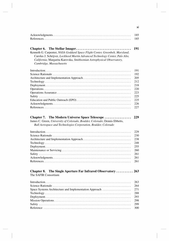
Chapter 6. The Stellar Imager . . . . . . . . . . . . . . . . . . . . . . . . . . . . . . . . . 191Kenneth G. Carpenter, NASA Goddard Space Flight Center, Greenbelt, Maryland;
Carolus J. Schrijver, Lockheed Martin Advanced Technology Center, Palo Alto, California; Margarita Karovska, Smithsonian Astrophysical Observatory, Cambridge, Massachusetts
Introduction. . . . . . . . . . . . . . . . . . . . . . . . . . . . . . . . . . . . . . . . . . . . . . . . . . . . . . . . . 191Science Rationale . . . . . . . . . . . . . . . . . . . . . . . . . . . . . . . . . . . . . . . . . . . . . . . . . . . . 192Architecture and Implementation Approach. . . . . . . . . . . . . . . . . . . . . . . . . . . . . . . . 205Technology . . . . . . . . . . . . . . . . . . . . . . . . . . . . . . . . . . . . . . . . . . . . . . . . . . . . . . . . . 212Deployment. . . . . . . . . . . . . . . . . . . . . . . . . . . . . . . . . . . . . . . . . . . . . . . . . . . . . . . . . 218Operations . . . . . . . . . . . . . . . . . . . . . . . . . . . . . . . . . . . . . . . . . . . . . . . . . . . . . . . . . . 220Operations Assurance . . . . . . . . . . . . . . . . . . . . . . . . . . . . . . . . . . . . . . . . . . . . . . . . . 223Safety . . . . . . . . . . . . . . . . . . . . . . . . . . . . . . . . . . . . . . . . . . . . . . . . . . . . . . . . . . . . . 225Education and Public Outreach (EPO) . . . . . . . . . . . . . . . . . . . . . . . . . . . . . . . . . . . . 225Acknowledgments. . . . . . . . . . . . . . . . . . . . . . . . . . . . . . . . . . . . . . . . . . . . . . . . . . . . 226References. . . . . . . . . . . . . . . . . . . . . . . . . . . . . . . . . . . . . . . . . . . . . . . . . . . . . . . . . . 227
Chapter 7. The Modern Universe Space Telescope . . . . . . . . . . . . . . . . 229James C. Green, University of Colorado, Boulder, Colorado; Dennis Ebbetts,
Ball Aerospace and Technologies Corporation, Boulder, Colorado
Introduction. . . . . . . . . . . . . . . . . . . . . . . . . . . . . . . . . . . . . . . . . . . . . . . . . . . . . . . . . 229Science Rationale . . . . . . . . . . . . . . . . . . . . . . . . . . . . . . . . . . . . . . . . . . . . . . . . . . . . 230Architecture and Implementation Approach. . . . . . . . . . . . . . . . . . . . . . . . . . . . . . . . 238Technology . . . . . . . . . . . . . . . . . . . . . . . . . . . . . . . . . . . . . . . . . . . . . . . . . . . . . . . . . 248Deployment. . . . . . . . . . . . . . . . . . . . . . . . . . . . . . . . . . . . . . . . . . . . . . . . . . . . . . . . . 255Maintenance or Servicing . . . . . . . . . . . . . . . . . . . . . . . . . . . . . . . . . . . . . . . . . . . . . . 260Safety . . . . . . . . . . . . . . . . . . . . . . . . . . . . . . . . . . . . . . . . . . . . . . . . . . . . . . . . . . . . . 261Acknowledgments. . . . . . . . . . . . . . . . . . . . . . . . . . . . . . . . . . . . . . . . . . . . . . . . . . . . 261References. . . . . . . . . . . . . . . . . . . . . . . . . . . . . . . . . . . . . . . . . . . . . . . . . . . . . . . . . . 261
Chapter 8. The Single Aperture Far Infrared Observatory . . . . . . . . . . 263The SAFIR Consortium
Introduction. . . . . . . . . . . . . . . . . . . . . . . . . . . . . . . . . . . . . . . . . . . . . . . . . . . . . . . . . 263Science Rationale . . . . . . . . . . . . . . . . . . . . . . . . . . . . . . . . . . . . . . . . . . . . . . . . . . . . 264Space Systems Architecture and Implementation Approach . . . . . . . . . . . . . . . . . . . 271Technology . . . . . . . . . . . . . . . . . . . . . . . . . . . . . . . . . . . . . . . . . . . . . . . . . . . . . . . . . 288Deployment. . . . . . . . . . . . . . . . . . . . . . . . . . . . . . . . . . . . . . . . . . . . . . . . . . . . . . . . . 293Mission Operations . . . . . . . . . . . . . . . . . . . . . . . . . . . . . . . . . . . . . . . . . . . . . . . . . . . 298Safety . . . . . . . . . . . . . . . . . . . . . . . . . . . . . . . . . . . . . . . . . . . . . . . . . . . . . . . . . . . . . 299Reference . . . . . . . . . . . . . . . . . . . . . . . . . . . . . . . . . . . . . . . . . . . . . . . . . . . . . . . . . . 300
FM.ind08 AM
xii
Chapter 9. A Kilometer-Baseline Far-Infrared/Submillimeter Interferometer in Space . . . . . . . . . . . . . . . . . . . . . . . . . . . . . . . . . . . . . 301
The SPECS Consortium
Introduction. . . . . . . . . . . . . . . . . . . . . . . . . . . . . . . . . . . . . . . . . . . . . . . . . . . . . . . . . 301Science Rationale . . . . . . . . . . . . . . . . . . . . . . . . . . . . . . . . . . . . . . . . . . . . . . . . . . . . 302Architecture and Implementation Approach. . . . . . . . . . . . . . . . . . . . . . . . . . . . . . . . 309Technology . . . . . . . . . . . . . . . . . . . . . . . . . . . . . . . . . . . . . . . . . . . . . . . . . . . . . . . . . 319Deployment. . . . . . . . . . . . . . . . . . . . . . . . . . . . . . . . . . . . . . . . . . . . . . . . . . . . . . . . . 321Operations . . . . . . . . . . . . . . . . . . . . . . . . . . . . . . . . . . . . . . . . . . . . . . . . . . . . . . . . . . 323Operations Assurance . . . . . . . . . . . . . . . . . . . . . . . . . . . . . . . . . . . . . . . . . . . . . . . . . 324Safety . . . . . . . . . . . . . . . . . . . . . . . . . . . . . . . . . . . . . . . . . . . . . . . . . . . . . . . . . . . . . 324References. . . . . . . . . . . . . . . . . . . . . . . . . . . . . . . . . . . . . . . . . . . . . . . . . . . . . . . . . . 325
Chapter 10. Generation-X Vision Mission . . . . . . . . . . . . . . . . . . . . . . . 327Roger J. Brissenden, Martin S. Elvis, Paul B. Reid, and Daniel A. Schwartz,
Harvard-Smithsonian Center for Astrophysics, Cambridge, MA; Enectali Figueroa-Feliciano and William W. Zhang, Goddard Space Flight Center, Greenbelt, MD; Mark W. Bautz, Massachusetts Institute of Technology
Introduction. . . . . . . . . . . . . . . . . . . . . . . . . . . . . . . . . . . . . . . . . . . . . . . . . . . . . . . . . 327Science Rationale . . . . . . . . . . . . . . . . . . . . . . . . . . . . . . . . . . . . . . . . . . . . . . . . . . . . 328Architecture. . . . . . . . . . . . . . . . . . . . . . . . . . . . . . . . . . . . . . . . . . . . . . . . . . . . . . . . . 342Technology . . . . . . . . . . . . . . . . . . . . . . . . . . . . . . . . . . . . . . . . . . . . . . . . . . . . . . . . . 349Deployment. . . . . . . . . . . . . . . . . . . . . . . . . . . . . . . . . . . . . . . . . . . . . . . . . . . . . . . . . 358Mission Operations . . . . . . . . . . . . . . . . . . . . . . . . . . . . . . . . . . . . . . . . . . . . . . . . . . . 361Mission Assurance . . . . . . . . . . . . . . . . . . . . . . . . . . . . . . . . . . . . . . . . . . . . . . . . . . . 364Safety . . . . . . . . . . . . . . . . . . . . . . . . . . . . . . . . . . . . . . . . . . . . . . . . . . . . . . . . . . . . . 364Acknowledgments. . . . . . . . . . . . . . . . . . . . . . . . . . . . . . . . . . . . . . . . . . . . . . . . . . . . 364References. . . . . . . . . . . . . . . . . . . . . . . . . . . . . . . . . . . . . . . . . . . . . . . . . . . . . . . . . . 364
Chapter 11. The Advanced Compton Telescope Mission . . . . . . . . . . . 369The ACT Consortium
Introduction. . . . . . . . . . . . . . . . . . . . . . . . . . . . . . . . . . . . . . . . . . . . . . . . . . . . . . . . . 369Architecture and Implementation . . . . . . . . . . . . . . . . . . . . . . . . . . . . . . . . . . . . . . . . 373Technology . . . . . . . . . . . . . . . . . . . . . . . . . . . . . . . . . . . . . . . . . . . . . . . . . . . . . . . . . 387Deployment. . . . . . . . . . . . . . . . . . . . . . . . . . . . . . . . . . . . . . . . . . . . . . . . . . . . . . . . . 395Operations . . . . . . . . . . . . . . . . . . . . . . . . . . . . . . . . . . . . . . . . . . . . . . . . . . . . . . . . . . 396Operations Assurance . . . . . . . . . . . . . . . . . . . . . . . . . . . . . . . . . . . . . . . . . . . . . . . . . 400Safety . . . . . . . . . . . . . . . . . . . . . . . . . . . . . . . . . . . . . . . . . . . . . . . . . . . . . . . . . . . . . 402References. . . . . . . . . . . . . . . . . . . . . . . . . . . . . . . . . . . . . . . . . . . . . . . . . . . . . . . . . . 402
FM.indd x
xiii
Chapter 12. Vision Mission Technology . . . . . . . . . . . . . . . . . . . . . . . . . 405Stephen L. Prusha, Jet Propulsion Laboratory, California Institute of Technology,
Pasadena, California
Introduction. . . . . . . . . . . . . . . . . . . . . . . . . . . . . . . . . . . . . . . . . . . . . . . . . . . . . . . . . 405Analytical Purpose . . . . . . . . . . . . . . . . . . . . . . . . . . . . . . . . . . . . . . . . . . . . . . . . . . . 406Ensuring Consistent Design Products. . . . . . . . . . . . . . . . . . . . . . . . . . . . . . . . . . . . . 406Representative Study Products . . . . . . . . . . . . . . . . . . . . . . . . . . . . . . . . . . . . . . . . . . 408Conclusion . . . . . . . . . . . . . . . . . . . . . . . . . . . . . . . . . . . . . . . . . . . . . . . . . . . . . . . . . 415Acknowledgments. . . . . . . . . . . . . . . . . . . . . . . . . . . . . . . . . . . . . . . . . . . . . . . . . . . . 415Appendix A: A Set of Design Attributes . . . . . . . . . . . . . . . . . . . . . . . . . . . . . . . . . . . 416References. . . . . . . . . . . . . . . . . . . . . . . . . . . . . . . . . . . . . . . . . . . . . . . . . . . . . . . . . . 418
Index . . . . . . . . . . . . . . . . . . . . . . . . . . . . . . . . . . . . . . . . . . . . . . . . . . . . . . . . 419Author Index . . . . . . . . . . . . . . . . . . . . . . . . . . . . . . . . . . . . . . . . . . . . . . . . . 433Supporting Materials . . . . . . . . . . . . . . . . . . . . . . . . . . . . . . . . . . . . . . . . . . 435
1:52:09 AM

FM.indd xiv52:09 AM
Chapter 4
Neptune Orbiter, Probe, and Triton Lander Mission
Bernard Bienstock*
Boeing Company, El Segundo, California
David Atkinsont
University ofIdaho, Moscow, Idaho
Sushi! Atreya+
University ofMichigan, Ann Arbor, Michigan
Kevin Baines§
NASA Jet Propulsion Laboratory, Pasadena, California
Michael Wright'l
NASA Ames Research Center, Moffett Field, California
and
James Masciarelli**
Ball Aerospace and Technologies Corporation, Boulder, Colorado
I" Introduction
I N 2004 our response to a NASA research announcement for Space Science Vision Missions resulted in the award of a NASA Vision Mission contract to
study a Neptune Orbiter with Probes Mission using nuclear electric propulsion
I "NASA Jet Propulsion Laboratory, Pasadena, California. Fonnerly with the Boeing Company, <""'II
El Segundo, California Project Manager. tProfessor, Department of Electrical and Computer Engineering. 'Professor of Atmospheric and Space Science. §Principle Scientist. 'Chief (Acting) Reacting Flow Environment Branch.
I
I II11
II I
""Principal Syestems Engineer. I <I
Copyright © 2008 by the American Institute ofAeronautics and Astronautics, Inc. All rights reserved. I I
115 II
1111~ill

116 117
B. BIENSTOCK ET AL.
(NEP). Our national team of engineers and scientists from aerospace, academia, NASA centers, and the Southwest Research Institute, with the assistance of the Jet Propulsion Laboratory's (JPL) Team X, developed a mission concept that satisfies the goals of our scientists. During the course of this study, we determined that the mission would benefit from the inclusion of a Triton lander to conduct a detailed surface mission on Triton, Neptune's most interesting moon. Our study also addresses the numerous engineering challenges that must be resolved to accomplish the ambitious Neptune Orbiter, Probe, and Triton Lander (NOPL) Mission.
II. Science Rationale
A. Key Objectives
The giant planets of the outer Solar System fall into two classes: the gas giants Jupiter and Saturn, consisting mainly of hydrogen and helium, and the ice giants Uranus and Neptune, presumably containing significantly higher fractions of the heavier elements carbon, nitrogen, oxygen, and sulfur. Although sharing a number of characteristics, each of the gas and ice giants is unique. Not only is each a miniature planetary system in its own right, with moons, rings, and dynamic atmospheres and magnetospheres, but also as a group the outer planets contain a physical and chemical record of conditions at the time of Solar System formation that is complementary to but different from the record encoded in the terrestrial planets.
Traditionally,.solar System exploration has been divided into three overlapping stages: reconnaissance, exploration, and in-depth study.l.2 Since the start of outer planetary exploration in the 1970s, a preliminary reconnaissance of the gas giants has been completed by the twin Pioneer 10 and 11 spacecraft in 1973 (Jupiter, Pioneer 10), 1974 (Jupiter, Pioneer 11), and 1979 (Saturn, Pioneer 11); the Voyager 1 and 2 spacecraft in 1979 (Jupiter, Voyagers 1 and 2),1980 (Saturn, Voyager 1), and 1981 (Saturn, Voyager 2); and the Ulysses and Cassini spacecraft flybys of Jupiter in 1992 and 2000, respectively. These early studies of planetary systems have focused on the cataloging and identification of physical and chemical processes underlying observed phenomena in the atmospheres, rings, satellites, and magnetospheres of the gas giants.3,4
At present, both the Jupiter and Saturn systems are in the early stages of exploration, initiated by the multiyear reconnaissances of Jupiter by the Galileo Orbiter and Probe Mission, and the Cassini-Huygens exploration of Saturn. However, the ice giants have only been briefly encountered when Voyager 2 flew past Uranus in 1986 and Neptune in 1989. As the initial exploration of the Solar System concludes, extensive Galileo- and Cassini-class exploration of the ice giants including detailed comparative studies of the atmospheres, satellites, rings, and magnetospheres of the gas and ice giants is the natural next step in the continuing progression of outer Solar System exploration. The extensive exploration of an ice giant will not only provide a basis for understanding this important class of planets, but it will also provide a comparative foundation for understanding the integrated dynamic, physical, and chemical origins and the formation, and evolution of the Solar System. In addition, it will help discriminate between competing theories of Solar System formation and planetary evolution.
NOPL MISSION
The outer Solar System, comprising the gas and ice giants, dust, magnetic fields and plasmas, and a multitude of smaller bodies including Kuiper Belt objects (KBOs), icy satellites, comets, and asteroids, represents a single complex, closely coupled, and mutually interdependent system. Intimately tied together through origin, evolution, and interaction, this family not only provides a laboratory for studying the Earth, including atmospheric chemistry, dynamics, and processes, surface geology, interiors, magnetic fields, and possibly even prebiotic chemistries, but also offers analogs for addressing astrophysical phenomena and processes that cannot be otherwise studied or easily modeled. In addition, the formative processes that have shaped and continue to shape the structure and chemistries of the outer Solar System can be considered representative of processes that are expected to govern the formation and evolution of other planetary systems, possibly giving rise to environments in which Earth-like planets and life can exist. Evidence of the chemical, thermal, and dynamical conditions at the time and location where the giant planets were created can be found in the remarkable similarities as well as the striking differences observed in the structure and composition of these bodies. The giant planets therefore represent time capsules of the Solar System at the epoch of formation, each reflecting the different local chemical and physical conditions existing at that location. Rings and apparent ring arcs embedded within planetary magnetic fields offer the closest available physical analogs to stellar nebular and circumstellar disks from which planetary systems are born. Planetary magnetic fields can help discern interior structure and processes, and each planet's system of moons and rings represents a miniature planetary system reflecting the local variation in chemistries and conditions at the time and location of giant planet formation. To begin understanding the conditions under which the Solar System was formed and the chemical and dynamical processes that occurred from the epoch of formation to the present, it is necessary to complete the initial inventory and reconnaissance of the outer Solar System and perform comparative studies of the objects comprising this region. To date, the ice giants and their systems of moons, rings, and magnetic environs remain largely unexplored.
1. Neptune Neptune's equatorial radius of 24,800 kIn, mass of approximately 17 Earth
masses, and rotation period of just over 16 h are all very similar to the bulk properties of Uranus. It is therefore thought that the interiors of Uranus and Neptune are likely similar, perhaps consisting of a large rocky core, a middle layer of water and ammonia, and an outer envelope of hydrogen and helium. However, unlike Uranus but similar to Jupiter and Saturn, Neptune possesses an internal source of heat, radiating about 3 times the energy it intercepts from the sun. The internal heat and rapid rotation give rise to some of the fastest winds in the Solar System, reaching upward of 500 mls. The atmosphere of Neptune is primarily composed of hydrogen and helium with traces of methane. The abundance of carbon (in the form of methane) found in the atmosphere by ground-based spectroscopy is about 2 vol %. Combined with Neptune's relatively high bulk density, this suggests that the atmosphere and core contain a much higher fraction of heavy elements than the gas giants contain.
118 119
I
NOPL MISSION B. BIENSTOCK ET AL.
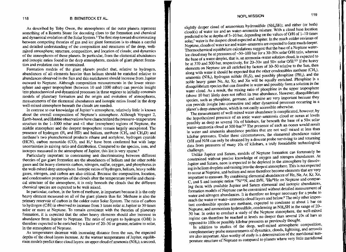
As described by Toby Owen, the atmospheres of the outer planets represent something of a Rosetta Stone for decoding clues to the formation and chemical and dynamical evolution of the Solar System.sThe first step toward discriminating between competing theories of gas and ice giant formation is to obtain a careful and detailed understanding of the composition and structures of the deep, wellmixed atmosphere; structure, composition, and location of clouds; and dynamics of the atmospheres of these planets. In particular, from the elemental abundances and isotopic ratios found in the deep atmospheres, models of giant planet formation and evolution can be constrained.
Formation models of the giant planets predict that, relative to hydrogen, abundances of all elements heavier than helium should be enriched relative to abundances observed in the Sun and this enrichment should increase from Jupiter outward to Neptune. Although composition measurements in the lower stratosphere and upper troposphere (between 10 and 1000 mbar) can provide insight into photochemical and dynamical processes in these regions to initially constrain models of planetary formation and the origin and evolution of atmospheres, measurements of the elemental abundances and isotopic ratios found in the deep well-mixed atmosphere beneath the clouds are needed.
In contrast to our knowledge of Jupiter's atmosphere, relatively little is known about the overall composition of Neptune's atmosphere. Although Voyager 2, Earth-based, and Hubble observations have characterized the pressure-temperature structure in the 1-1000 mbar and <1 nbar (exosphere) regions of Neptune, the middle atmosphere and the deepest troposphere remain largely unexplored. The presence of hydrogen (H2 and HD) and helium, methane (C~ and CH3D) and methane's two photochemical products ethane and acetylene, hydrogen cyanide (HCN), carbon monoxide (CO), and H3+ have been confirmed but with large uncertainties in mixing ratio and distribution. Compared to the species, ions, and isotopes measured in the atmosphere of Jupiter, this list is very sparse.6
Particularly important to constraining and discriminating between different theories of gas giant formation are the abundances of helium and the other noble gases and the heavy elements carbon, nitrogen, sulfur, oxygen, and phosphorus in the well-mixed deep atmosphere. Isotopic ratios of hydrogen, helium, heavy noble gases, nitrogen, and carbon are also critical. Because the composition, location, and condensation properties of the clouds alter the temperature profile and chemical structure of the atmosphere, it is only beneath the clouds that the different chemical species are expected to be well mixed.
In particular, carbon, in the form of methane, is important because it is the only heavy element measured on all of the giant planets thus far. Methane is also the primary reservoir of carbon in the colder outer Solar System. The ratio of carbon to hydrogen (CIH) is observed to increase from 3 times solar at Jupiter to 30 times solar or more at Neptune. To remain consistent with the theories of planetary formation, it is expected that the other heavy elements should also increase in abundance from Jupiter to Neptune. The ratio of oxygen to hydrogen (OIH) is therefore expected to be enriched by a factor of 2~30 or greater, relative to solar, in the atmosphere of Neptune.
As temperatures decrease with increasing distance from the sun, the expected depths of the cloud layers increase. At the warmer temperatures of Jupiter, equilibrium models predict three cloud layers: an upper cloud of ammonia (NH3); a second,
slightly deeper cloud of ammonium hydrosulfide (N~SH); and either (or both) cloud(s) of water ice and an water-ammonia mixture. With a cloud base location predicted to be at depths of 5-10 bar, depending on the values of OIH of 1-10 times solar,7 water is the deepest cloud expected at Jupiter. In the much colder environs of Neptune, clouds of water ice and water-ammonia are expected to form much deeper. Thermochemical equilibrium calculations suggest that the base of a Neptune waterice cloud may be at pressures of -5~100 bar for a 3~50x solar OIH ratio, whereas the base of a water droplet, that is, an ammonia-water solution cloud, is expected to
9be at 370 and 500 bar, respectively, for 2~30x and 50x solar OIH.8• If the heavy
elements on Neptune are all enriched by factors of 3~50 relative to the Sun, then along with water it should be expected that the other condensibles methane (C~), ammonia (NH3), hydrogen sulfide (H2S), and possibly phosphine (PH3), and the noble heavy gases Ne, Ar, Kr, and Xe will be equally enriched. Phosphine is a disequilibrium species that can dissolve in water and possibly form a solution in the water cloud. As a result, the mixing ratio of phosphine in the upper troposphere (above 10 bar) likely does not reflect its true abundance. However, disequilibrium species, such as phosphine, germane, and arsine are very important because they can provide insight into convective and other dynamical processes occurring in a planet's deep atmosphere, which is not easily accessible otherwise.
The measurement of well-mixed water abundance is complicated, however, by the hypothesized presence of an ionic water-ammonia cloud or ocean at levels possibly as deep as several lOs of kilobars, far beneath the base of a 50x solar water-ammonia cloud at 500 bar.8,9 The presence of such an ocean would result in water and ammonia abundance profiles that are not well mixed at less than kilobar pressures. Under these circumstances, the elemental abundance ratios OIH and NIH can only be obtained 1,Jy a descent probe surviving to and returning data from pressures of many lOs of kilobars, a truly formidable technological
challenge.Unlike Jupiter and Saturn, models of Neptune formation can fortunately be
constrained without precise knowledge of oxygen and nitrogen abundances. At Jupiter and Saturn, neon is expected to be depleted in the atmosphere by dissolving in helium droplets and raining into the deepest atmosphere. This is not expected to occur at Neptune, and helium and neon therefore become elements that are very important to measure. By combining elemental abundances of He, Ne, Ar, Kr, Xe, C, and S and isotopic ratios lsN/14N, and DIH, 3He/4He on Neptune and comparing them with available Jupiter and Saturn elemental and isotopic abundances, formation models of Neptune can be constrained without detailed measurement of water and nitrogen abundances. It is therefore no longer necessary for a probe to reach the water or water-ammonia cloud layers and below.8 The only other important condensible species are methane, expected to condense at about 1 bar on Neptune, and ammonium hydrosulfide, condensing as NH4SH in the range of 2~ 30 bar. In order to conduct a study of the Neptune atmosphere, the well-mixed regime can therefore be reached at levels no deeper than several lOs of bars as opposed to 100s or possibly kilobar pressures as previously thought.
In addition to studies of the deep, well-mixed atmospheric composition, complementary probe measurements of dynamics, clouds, lightning, and aerosols are also important. Also worthy of study is a determination of the meridional temperature structure of Neptune as compared to planets where very little meridional
: 111 ~ II II' lil!111
1[1
'I
II~I '111'
11
IIIIII),
121 120 B. BIENSTOCK ET AL.
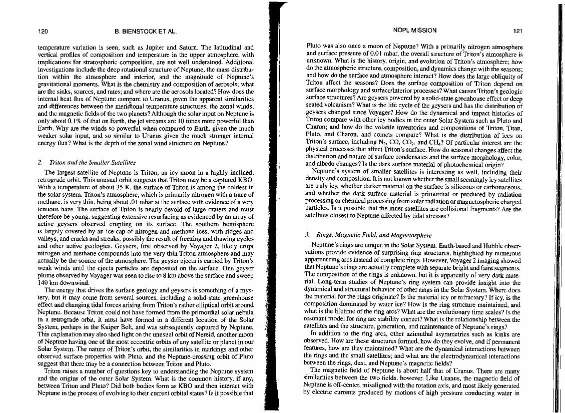
temperature variation is seen, such as Jupiter and Saturn. The latitudinal and vertical profiles of composition and temperature in the upper atmosphere, with implications for stratospheric composition, are not well understood. Additional investigations include the deep rotational structure of Neptune, the mass distribution within the atmosphere and interior, and the magnitude of Neptune's gravitational moments. What is the chemistry and composition of aerosols; what are the sinks, sources, and rates; and where are the aerosols located? How does the internal heat flux of Neptune compare to Uranus, given the apparent similarities and differences between the meridional temperature structures, the zonal winds, and the magnetic fields of the two planets? Although the solar input on Neptune is only about 0.1 % of that on Earth, the jet streams are 10 times more powerful than Earth. Why are the winds so powerful when compared to Earth, given the much weaker solar input, and so similar to Uranus given the much stronger internal energy flux? What is the depth of the zonal wind structure on Neptune?
2. Triton and the Smaller Satellites
The largest satellite of Neptune is Triton, an icy moon in a highly inclined, retrograde orbit. This unusual orbit suggests that Triton may be a captured KBO. With a temperature of about 35 K, the surface of Triton is among the coldest in the solar system. Triton's atmosphere, which is primarily nitrogen with a trace of methane, is very thin, being about .01 mbar at the surface with evidence of a very tenuous haze. The surface of Triton is nearly devoid of large craters and must therefore be young, suggesting extensive resurfacing as evidenced by an array of active geysers observed erupting on its surface. The southern hemisphere is largely covered by an ice cap of nitrogen and methane ices, with ridges and valleys, and cracks and streaks, possibly the result of freezing and thawing cycles and other active geologies. Geysers, first observed by Voyager 2, likely erupt nitrogen and methane compounds into the very thin Triton atmosphere and may actually be the source of the atmosphere. The geyser ejecta is carried by Triton's weak winds until the ejecta particles are deposited on the surface. One geyser plume observed by Voyager was seen to rise to 8 km above the surface and sweep 140 km downwind.
The energy that drives the surface geology and geysers is something of a mystery, but it may come from several sources, including a solid-state greenhouse effect and changing tidal forces arising from Triton's rather elliptical orbit around Neptune. Because Triton could not have formed from the primordial solar nebula in a retrograde orbit, it must have formed in a different location of the Solar System, perhaps in the Kuiper Belt, and was subsequently captured by Neptune. This explanation may also shed light on the unusual orbit of Nereid, another moon of Neptune having one of the most eccentric orbits of any satellite or planet in our Solar System. The nature of Triton's orbit, the similarities in markings and other observed surface properties with Pluto, and the Neptune-crossing orbit of Pluto suggest that there may be a connection between Triton and Pluto.
Triton raises a number of questions key to understanding the Neptune system and the origins of the outer Solar System. What is the common history, if any, between Triton and Pluto? Did both bodies form as KBO and then interact with Neptune in the process of evolving to their current orbital states? Is it possible that
NOPL MISSION
Pluto was also once a moon of Neptune? With a primarily nitrogen atmosphere and surface pressure of 0.01 mbar, the overall structure of Triton's atmosphere is unknown. What is the history, origin, and evolution of Triton's atmosphere; how do the atmospheric structure, composition, and dynamics change with the seasons; and how do the surface and atmosphere interact? How does the large obliquity of Triton affect the seasons? Does the surface composition of Triton depend on surface morphology and surface/interior processes? What causes Triton's geologic surface structures? Are geysers powered by a solid-state greenhouse effect or deep seated volcanism? What is the life cycle of the geysers and has the distribution of geysers changed since Voyager? How do the dynamical and impact histories of Triton compare with other icy bodies in the outer Solar System such as Pluto and Charon; and how do the volatile inventories and compositions of Triton, Titan, Pluto, and Charon, and comets compare? What is the distribution of ices on Triton's surface, including N2, CO, CO2, and C~? Of particular interest are the physical processes that affect Triton's surface. How do seasonal changes affect the distribution and nature of surface condensates and the surface morphology, color, and albedo changes? Is the dark surface material of photochemical origin?
Neptune's system of smaller satellites is interesting as well, including their density and composition. It is not known whether the small seemingly icy satellites are truly icy, whether darker material on the surface is siliceous or carbonaceous, and whether the dark surface material is primordial or produced by radiation processing or chemical processing from solar radiation or magnetospheric charged particles. Is it possible that the inner satellites are collisional fragments? Are the satellites closest to Neptune affected by tidal stresses?
3. Rings, Magnetic Field, and Magnetosphere
Neptune's rings are unique in the Solar System. Earth-based and Hubble observations provide evidence of surprising ring structures, highlighted by numerous apparent ring arcs instead of complete rings. However, Voyager 2 imaging showed that Neptune's rings are actually complete with separate bright and faint segments. The composition of the rings is unknown, but it is apparently of very dark material. Long-term studies of Neptune's ring system can provide insight into the dynamical and structural behavior of other rings in the Solar System. Where does the material for the rings originate? Is the material icy or refractory? If icy, is the composition dominated by water ice? How is the ring structure maintained, and what is the lifetime of the ring arcs? What are the evolutionary time scales? Is the resonant model for ring arc stability correct? What is the relationship between the satellites and the structure, generation, and maintenance of Neptune's rings?
In addition to the ring arcs, other azimuthal asymmetries such as kinks are observed. How are these structures formed, how do they evolve, and if permanent features, how are they maintained? What are the dynamical interactions between the rings and the small satellites; and what are the electrodynamical interactions between the rings, dust, and Neptune's magnetic fields?
The magnetic field of Neptune is about half that of Uranus. There are many similarities between the two fields, however. Like Uranus, the magnetic field of Neptune is off-center, misaligned with the rotation axis, and most likely generated by electric currents produced by motions of high pressure conducting water in

123 122 B. BIENSTOCK ET AL.
Neptune's middle layers. Neptune's field is tilted by 47 deg. to the rotation axis, is offset by about 0.5 radius from the center, and is significantly nondipolar with the largest magnetic field quadrupole moments in the Solar System. The large inclination of Neptune's magnetic field and the high obliquity of Neptune's rotation axis result in the magnetic pole facing into the solar wind once per Neptune day, causing an unusual and unique diurnal pumping of the magnetosphere. Of interest, although somewhat mysterious, the magnetosphere of Neptune is among the quietest in the Solar System, with very low observed emissions and fluxes of energetic particles. to
The Voyager 2 planetary radio astronomy measurement of modulated radio emissions originating within the magnetic field, thought to corotate with the deep interior of Neptune, found Neptune's rotation rate to be about 16 h and 7 min. The aurora of Neptune was also studied by Voyager 2 and provides a diagnostic not only of the deep magnetic field but also of the very complex interactions of the magnetic field, solar wind, and upper atmosphere of Neptune. The unique magnetic field of Neptune provides a laboratory for studying the properties of magnetospheres, magnetic field and solar wind interactions, as well as Neptune's deep interior.
A number of questions regarding the magnetosphere would be addressed by the Neptune Mission. How is Neptune's magnetic field generated? How can the strange orientation be explained, why is the magnetic field significantly nondipolar, and why is the magnetosphere apparently so quiescent? How do Triton, the rings, and the magnetosphere interact? What are the spatial and temporal properties of Neptune's magnetosphere? How does diurnal cycling affect the shape and structure of the magnetosphere? Why is the magnetic field at the cloud tops so asymmetrical in the ice giants as compared to gas giants? What is the composition of the ionosphere and how does Neptune's magnetic field affect interact with Triton? Do observed plasmas originate from the solar wind, from Neptune's atmosphere, or from Triton's upper atmosphere; and what are the sources of plasma energy input to the magnetosphere? Voyager detected very little magnetospheric activity. Was magnetospheric activity truly absent at the Voyage encounter and if so, why, how, and when does this occur? What are the processes responsible for auroral emissions from Neptune and Triton, and how do these compare to other planets and Titan? The magnetic field can be a tool for studying the deep interior of Neptune, and the polar distribution of the aurora can act as a diagnostic of cloud-top magnetic field structures and interactions of magnetic fields with solar winds and magnetic fields with the atmosphere on Neptune.
B. Summary of Scientific Goals and Objectives for Exploring the Neptune System
The complexity and scientific richness of the Neptune system drives a number of somewhat disparate but interrelated science goals and objectives. In priority order, the key measurements are summarized in Table 1.
C. Relation to NASA and Office of Space Science Strategic Plans
The primary motivation for a NOPL Mission derives from the need not only to inventory, catalog, and understand the detailed properties of an ice giant but
NOPL MISSION
Table 1 Neptune orbiter, probes, and Triton lander science and measurement objectives
No. Title Description
2
3
4
5
Origin and evolution of ice giants
Planetary processes
Triton
Rings
Magnetospheric and plasma
Neptune atmospheric elemental ratios relative to hydrogen (C, S, He, Ne, Ar, Kr, Xe) and key isotopic ratios (e.g., DIH, 15N/14N), gravity and magnetic fields [probes, orbiter]
Global circulation, dynamics, meteorology, and chemistry; winds (Doppler and cloud track), trace gas profiles (e.g., PH3, CO, ortho/para hydrogen); cloud structure, microphysics, and evolution; photochemistry and tracers of thermochemistry (e.g., disequilibrium species) [probes, orbiter]
Origin, plumes, atmospheric composition and structure, surface composition, internal structure, and geological processes [orbiter, lander]
Origin/evolution, structure (waves, microphysical, composition, etc.) [orbiter]
[orbiter]
6 processes
Icy satellites Origin, evolution, surface composition and geology [orbiter]
Notation in brackets indicates the mission vehicle(s) that will make the indicated measurements.
also to provide comparative studies between the gas and ice giants, between the inner and outer Solar System, and to help discriminate between competing theories of overall Solar System formation and evolution. The proposed mission to the Neptune system directly addresses many of the goals and themes documented in the National Academy of Science Decadal Survey,l1 the goals of NASA's Solar System Exploration theme, as well as the Solar System Exploration (SSE) Roadmap.12
1. National Academy ofSciences Decadal Survey
The 2003 National Academy of Science Decadal Survey for SSEl1 recommended that in-depth studies of the Neptune system be given high priority. In addition, the Primitive Bodies Panel lists a Neptuneffriton mission among its highest priorities for medium class missions and the Giant Planets Panel lists a Neptune orbiter with multiple entry probes as its highest priority in the next decade. The Decadal Survey emphasizes that it is only through a comparison of the composition and interior structure of the giant planets in our Solar System that we can advance our understanding of how our planetary system formed. Moreover, it is only through detailed study of the giant planets that we can confidently extrapolate to planetary systems around other stars. All three of the themes developed in the Decadal Survey Report (origin and evolution, interiors and atmospheres, and rings and plasmas) are addressed by a Neptune Orbiter with Probes Mission.
125 124 B. BIENSTOCK ET AL.
The primary probe science goal is the use of composition and temperature data in the Neptune atmosphere from the stratosphere to hundredlkilobar pressures to advance the understanding of solar system formation. Complementary probe measurements of winds, structure, composition and cloud particle size and lightning are also suggested. Critical measurements are CH4, NH3, H2S, H20, PH3, and the noble gases He, Ne, Ar, Kr, and Xe. Although the average atmospheric °abundance is not likely to be measured by 100 bar, C in methane and the noble gases will reveal the elemental abundance that can constrain models of Neptune's formation when analyzed in the context of data from other giant planets such as Jupiter and Saturn.
NASA's 2003 Strategic Plan and the more recent report of the President's Commission on Implementation of United States Exploration Policy provides the broad motivation for a Neptune mission. The Strategic Plan places the outer planet exploration program in the context of the study of the origin of the Solar System and the building blocks of life. The President's Commission Report describes the same themes in its National Science Research Agenda organized around the themes Origins, Evolution, and Fate. Neptune exploration is further motivated by subthemes described in the NASA Strategic Plan, including the formation of the Solar System, comparative planetology, and solar controls on climate.
2. 2003 SSE Roadmap
The SSE Roadmap, 2003 (Ref. 12) lists possible midterm and long-term flagship missions that should be selected to build on results of earlier investigations. One of the high priority missions listed is the NOPL Mission. Of the eight primary objectives enumerated in the Roadmap, the first two contain elements that are directly addressed by NOPL:
1) How did planets/minor bodies originate? Understand the initial stages of planet and satellite formation and study the processes that determined the original characteristics of the bodies in our Solar System.
2) How did the Solar System evolve to its current state? Determine how the processes that shape planetary bodies operate and interact, understand why the terrestrial planets are so different from one another, and learn what our Solar System can tell us about extrasolar planetary systems.
The SSE Roadmap also indicates that "comprehensive exploration of the ice giant Neptune will permit direct comparison with Jupiter and more complete modeling of giant planet formation and its effect on the inner solar system." The Roadmap offers the Neptune mission as an example of a high priority Flagship mission that would provide major scientific advances.
III. Architecture and Implementation Approach
A. Space Systems Architecture
In mid-2003, as we were writing our proposal for the NASA Vision Mission opportunity, the Jupiter Icy Moons Orbiter (HMO) Program, which used the
NOPL MISSION
Prometheus platform, offered an alternative method of implementing a mission to Neptune. Exploration of the giant planets is difficult because of the vast distances spacecraft must travel to reach the planets. This constraint translates to long travel periods. The mission also requires a significant velocity change (~V) so that the spacecraft arrives at the giant planets and then slows down in order to enter the planetary system.
Our mission concept utilized the Prometheus technology that was planned to be funded at the time we wrote our proposal. This technology, called nuclear electric power and propulsion (NEP), features a nuclear fission reactor power source that provides high power levels for electric propulsion and the other spacecraft systems. Because electric propulsion is extremely efficient relative to chemical propulsion, use of this technology allows a significant payload mass for conducting the science during transit to and at the Neptune system.
The basic parameters offered by the Prometheus technology that we assumed for implementing our NOPL Mission are provided in Table 2. In assessing a mission design, we did not focus our study on the orbiter vehicle, other than the orbiter's science related functions of providing mass and power allocations for the orbiter-mounted science instruments and the necessity for the orbiter to serve as a radio relay link for the science data returned from the probes and Triton lander.
The main focus of a mission to the Neptune system is Neptune itself. In order to analyze Neptune's atmosphere, our science team originally planned for three entry probes that were to be targeted to the upper, middle, and equatorial regions of the planet. In addition, our science team included a Triton lander as part of the deployable payload.
As we developed our concept through a Team X exercise, it became clear that the mass of the orbiter science instruments, three Neptune entry probes, and a Triton lander exceeded the allowable 1500 kg by a considerable amount. We thus eliminated one Neptune entry probe and targeted the remaining two probes to the equatorial and high latitude of Neptune. The mass allocations of the payload elements are summarized in Table 3.
1. Orbiter Design
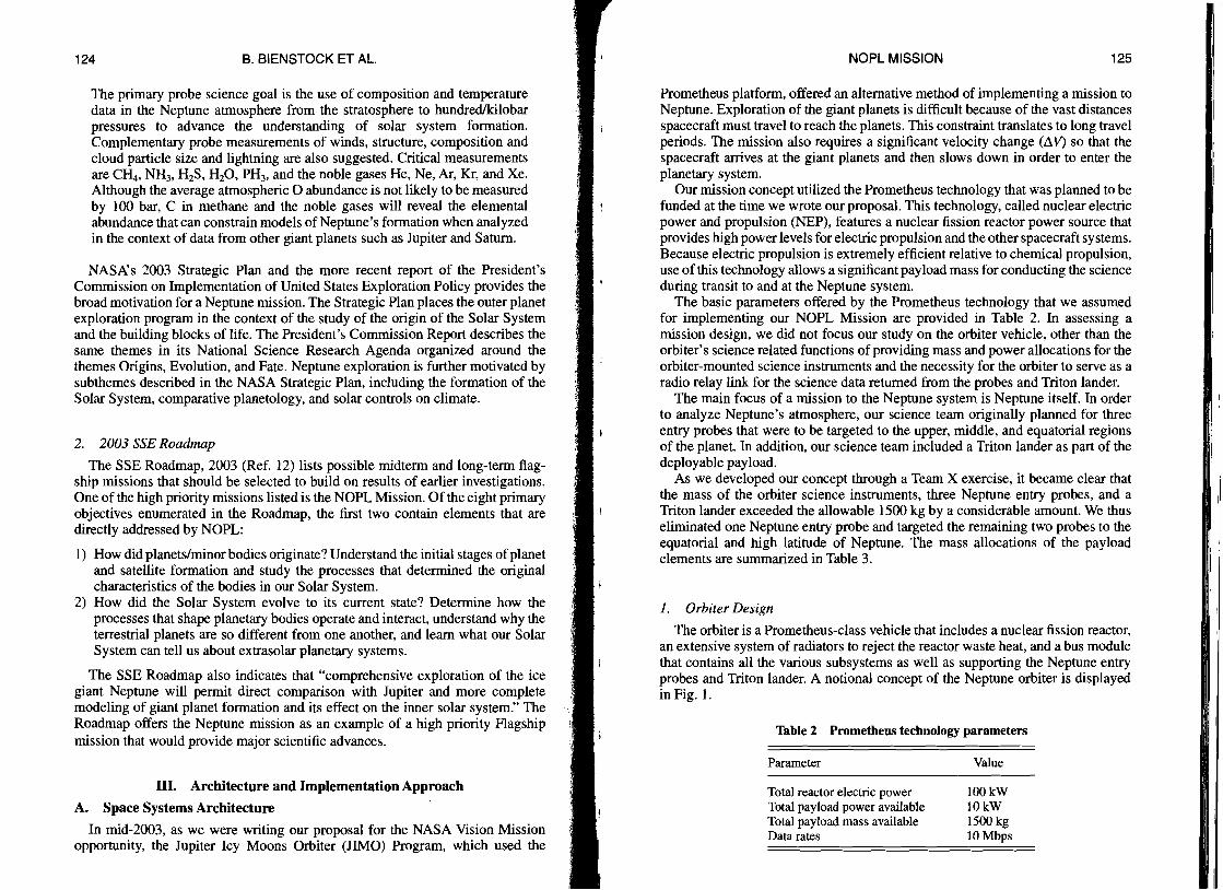
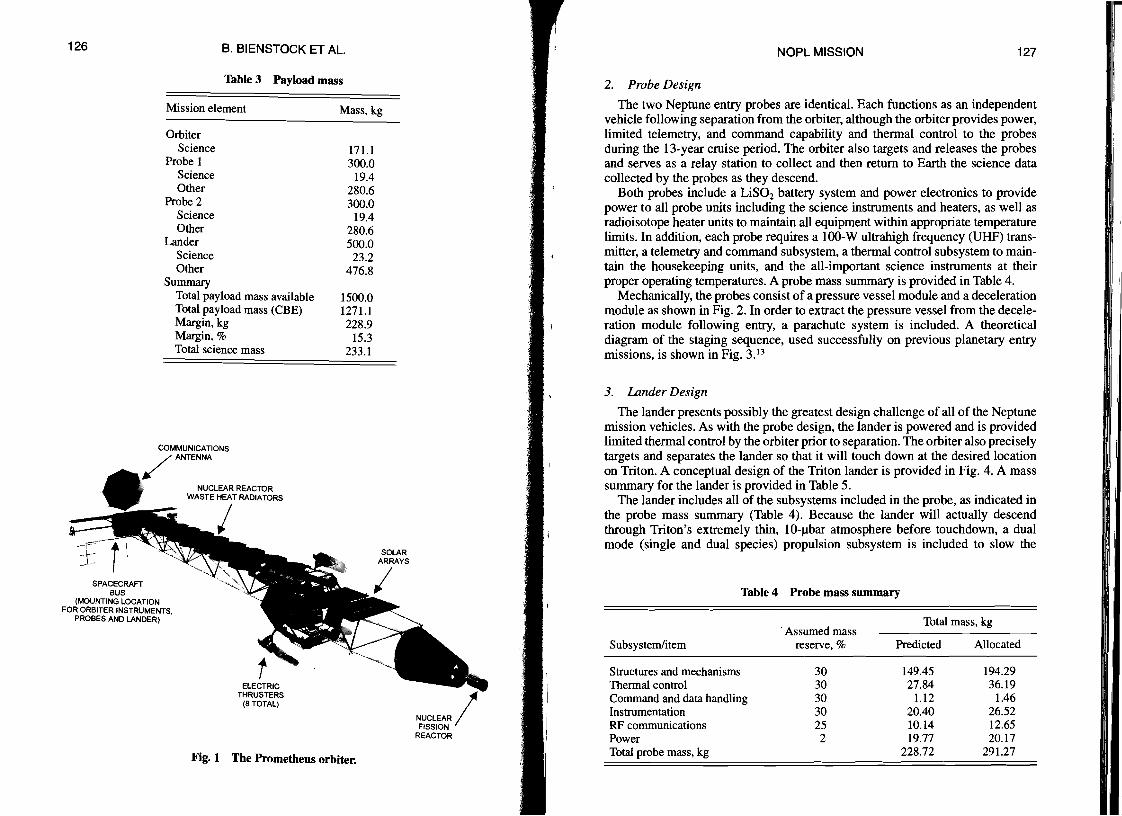
The orbiter is a Prometheus-class vehicle that includes a nuclear fission reactor, an extensive system of radiators to reject the reactor waste heat, and a bus module that contains all the various subsystems as well as supporting the Neptune entry probes and Triton lander. A notional concept of the Neptune orbiter is displayed in Fig. 1.
Table 2 Prometheus technology parameters
Parameter Value
Total reactor electric power 100kW Total payload power available IOkW Total payload mass available 1500 kg Data rates 10 Mbps
126 B. BIENSTOCK ET AL.
Table 3 Payload mass
Mission element Mass, kg
Orbiter Science 171.1
Probe I 300.0 Science 19.4 Other 280.6
Probe 2 300.0 Science 19.4 Other 280.6
Lander 500.0 Science 23.2 Other 476.8
Summary Total payload mass available 1500.0 Total payload mass (CBE) 1271.1 Margin, kg 228.9 Margin, % 15.3 Total science mass 233.1
COMMUNICATIONS
/ANTENNA
NUCLEAR REACTOR WASTE HEAT RADIATORS
I SPACECRAFT
BUS (MOUNTING LOCATION
FOR ORBITER INSTRUMENTS, PROBES AND LANDER)
ELECTRIC THRUSTERS
(8 TOTAL)
Fig. 1 The Prometheus orbiter.
rNOPL MISSION 127 I
II
2. Probe Design
The two Neptune entry probes are identical. Each functions as an independent vehicle following separation from the orbiter, although the orbiter provides power, limited telemetry, and command capability and thermal control to the probes during the I3-year cruise period. The orbiter also targets and releases the probes and serves as a relay station to collect and then return to Earth the science data collected by the probes as they descend.
Both probes include a LiSOz battery system and power electronics to provide power to all probe units including the science instruments and heaters, as well as radioisotope heater units to maintain all equipment within appropriate temperature limits. In addition, each probe requires a 100-W ultrahigh frequency (UHF) transmitter, a telemetry and command subsystem, a thermal control subsystem to maintain the housekeeping units, and the all-important science instruments at their proper operating temperatures. A probe mass summary is provided in Table 4.
Mechanically, the probes consist of a pressure vessel module and a deceleration module as shown in Fig. 2. In order to extract the pressure vessel from the deceleration module following entry, a parachute system is included. A theoretical diagram of the staging sequence, used successfully on previous planetary entry missions, is shown in Fig. 3. 13
3. Lander Design
The lander presents possibly the greatest design challenge of all of the Neptune mission vehicles. As with the probe design, the lander is powered and is provided limited thermal control by the orbiter prior to separation. The orbiter also precisely targets and separates the lander so that it will touch down at the desired location on Triton. A conceptual design of the Triton lander is provided in Fig. 4. A mass summary for the lander is provided in Table 5.
The lander includes all of the subsystems included in the probe, as indicated in the probe mass summary (Table 4). Because the lander will actually descend through Triton's extremely thin, IO-llbar atmosphere before touchdown, a dual mode (single and dual species) propulsion subsystem is included to slow the
Table 4 Probe mass summary
Total mass, kg .Assumed mass
Subsystem/item reserve, % Predicted Allocated
Structures and mechanisms 30 149.45 194.29 Thermal control 30 27.84 36.19 Command and data handling 30 1.12 1.46 Instrumentation 30 20.40 26.52 RF communications 25 10.14 12.65 Power 2 19.77 20.17 Total probe mass, kg 228.72 291.27

128 B. BIENSTOCK ET AL.
DECELERATION ~ ..,DULE (AFT COVER) ~
PRESSURE VESSEL MODULE
DECELERATION MODULE (HEAT SHIELD/AEROSHELL)
Fig. 2 The major components of the probe.
'"'~~ ~ ! t TFIRE MORTAR ,;.
DEPLOY PILOT PARACHUTE RELEASE AFT COVER 1 -e,
EXTRACT PARACHUTE BAG
DEPLOY MAIN PARACHUTE 'V DECELERATION MODULEI DESCENT MODULE ~ SEPARATION "'-..../
JEniSON PARACHUTE
Fig. 3 The typical entry descent sequence of the probe.
11 1 '1 '
INOPL MISSION 129
TELECOMMUNICATIONS ANTENNA I
/
I
IiPROPELLANT
TANKS I :1
'LANDING LEGS (3)
Fig. 4 The Triton lander configuration.
Table 5 Lander mass summary
Total mass, kgAssumed mass
Subsystem/item reserve, % Predicted Allocated
Structures and mechanisms 30 Thermal control 30 Command and data handling 30 Instrumentation 30 RF communications 26 Power 30 Attitude determination and control subsystem 30 Propulsion 17
Total lander mass, dry, kg Propellants and pressurant (for 500-kg lander) Total lander launch mass Lander allocation System margin 0.9
Propellant and presssurant mass fraction Propulsion subsystem mass fraction Total propulsion mass fraction
77.3 100.4 I
6.9 9.0 I2.0 2.6
23.2 30.2 7.6 9.6
23.0 29.9 1.2 1.6
45.5 53.3
186.7 236.6 259.0 495.6 500.0
4.4
52.3% 10.8% 63.0%
II

130 B. BIENSTOCK ET AL.
descending vehicle for a gentle landing on the Triton surface. The mass of the propulsion subsystem hardware plus the propellants accounts for nearly two-thirds of the lander mass. In addition, an attitude determination and control subsystem is included to maintain lander stability as it descends to the Triton surface.
The Triton lander design also includes a robust thermal control subsystem that will maintain the internal electronics and mechanisms within their operating limits, while also limiting the thermal leaks between the lander and the cold, frozen 35 K Triton surface. This is necessary because the Triton lander includes a surface sampling mechanism that will collect surface material for analysis by the instruments within the lander. Thus, the "hot" lander exterior could thermally contaminate the collected surface material.
B. Science Instrumentation
The complexity and scientific richness of the Neptune systems requires a welldefined complement of science and measurement goals and objectives and a highly integrated suite of remote sensing and in situ instruments.
Tables 6-8 contain the probe, orbiter, and lander instruments. The numbers in parentheses following each measurement refer to a science goal in Table 1. Estimated values for mass, power, and data rate were developed jointly with the Jet Propulsion Laboratory's (JPL) Team P (payload analysis).
The probe instrumentation listed in Table 6 is similar to that flown on the Galileo and Huygens probes, including a gas chromatograph/mass spectrometer (GeMS); sensors for measuring temperature, pressure, and acceleration; solar and infrared (IR) radiometers; and a nephelometer. As illustrated in Table 7, the orbiter is the core of the Neptune mission, providing a remote sensing platform and in situ instruments to study Neptune and Triton, as well as providing primary data links to directly return orbiter science data and relaying data from the probes and lander. A key element of the orbiter instrument payload is an integrated imaging package comprising multiwavelength imagers and spectrometers and a microwave radiometer. Space physics detectors include a magnetometer and a plasma wave detector. An ion and neutral mass spectrometer will obtain chemical and isotopic measurements from the upper atmosphere of Triton. Radio science investigations are enhanced by including an uplink capability enabled by ultrastable oscillators. The instrumentation for the Triton lander is described in Table 8.
IV. Technology
The technology development required to implement the ambitious mission described here is considerable. All aspects of the mission, from the launch and control of the combined vehicles during the 13-year cruise to the Neptune system, to the design, implementation, and testing of the three vehicles, require technology that has yet to be developed. Each of these various aspects of the NOPL Mission will be discussed in the following sections.
Unique requirements for the Neptune mission will be discussed in sec.V. Technology requirements for the orbiter were not included in this study because it was assumed that the Prometheus development was to have taken place as part of the JIMO mission.
'" E § 8
~ .~
~ ~ ·c
~ ::5
C = 1.5:= ~o~ o."'~~ .o=~ ~~~:::Sa) ~ ~U~J:l~ S-8 6.8"''l::0 .... <Ll '" <Ll ..c:",<t:oo£:::S"'v o l!J'" ·t",~i::Cll~I:: ~;i' 1ij'- • <Ll e "" Il.i8~ ..... o..~] 8 '" .~ :0 ·c ~ <Ll ~ ~ ~8 E :s Ba)=~<Ll .0."'1:: ",a ~ <t: <Ll.o § <Ll .5·- ""' ~ <Ll . .0 8·- £ <Ll "0 ;g '" ~<'j00.~=o£~"'8 ~ '8 ~ ~'s ;: ~ T~ ~ S "0 ~ l) <Ll '" I:: U = o.·c = IJ.;.<;:: Cll = <Ll ~ 'a ::e 0 "''''0.;;'''<Ll8N8'~U§~~~E6<Ll~'" O~O<Ll:::S"''''''.o ~ .,.... <D ~::I: = ... ... 0 <LlI: =:-= I Clj =';;J ..... I;/.l .....,
o 0 "Ol ='2 ;;.., ~ :::s 0. <Ll ed = 0 0 '<;j ·c "'" 8 :::s £ ,~ ~"'O"""<Ll<Ll"O
] .g .s ~ l3 '§.g E.2 a ~
... 0.0", I .,.,~.o <Ll N S -0<Ll
J ~ '" ~ 0.Cl '" '" I s-.o ..... 0.5 '" uCII
£ Ig~1 .,., <Ll
IC ::I: CII ~
~ 5::s 0 IJ...~
8~1 0..... E '" ..s
~ ~ Cll "'I:'l"lol ~u
~
~ ~
~ <Ll ~
i:: E ~ .s
00
.....""
Cll ""' a) • I:: c.OO • ~ "'0 ~ U b .- 0 ~
::l:.a:E.B a)1::::d3 ed . <Ii]'":::s E-o 0 8 0 ""u .a '" a) "0 ~ tb 'Su·6. 8~rd'" o.~u:::s .." s::= tUOO.,r;""" Q)-',p- ..s:::; ..... .9 tU -....., U c:a a U bl) tU ...:: '" 'C £ ~ 8 ~ I:: ~ = ~ 0..5 -¥ .= B ~ =E-oI::':;u;:."'<.I:: 0"" a) ..... "" a).9 "0 0 <Ii' '" a) -g '2 u .~ -goO '" ..; = ~ c: ....., bl).OO =' b.O v.i 0 >. V) tU·E
':::l '" = = ;:l N "0 .- a) a) ..... :a a) 5Cll = l:: • a) "" Oil ... !D '" .0 "0 U._ "0 a)~8"O' = "'a) 00"""':::S U
Q,) ~ ~ C'j ('1'j t'd >..D 1-4 .- 0 tf:l - <0'8 '0.. l:l ~ "0 ] :;a :::::::l 0. ~ = 8.. S£ :E 6.~.5 ~ ~] E'~ ~ g'~'§ ~.~ 8 8
~ ~'E ~ ~~.~ ~ ~ ~ ~ E8g~ 8a)""'0"'''''= o£"","O"''''''"'CllO'''="""'r:: 0."0 "'.B """ =.- :.a B"Iol "'. ,!;!<Ii'0.0i1 N ... 5u"'i:: a)'500. :::s "0 ~ '" ~ '" £ 0 ~ a) 1;l 8 N ""<;j~ = = a).:::S ... 8'- 0 a) "' _ ~ a) 0 '" E ~ 8 • a) .- '" ..... .= J:; =::> a) ~ ... ~ 0.;::1 a) .... "" a)'" U"O "'_~"":::Sl:l21.c: "08 9 ~';> e /:)J)C/i - =~ tI.l ~ fr~ B 1-4
= a) a) 0 8.;.§ <t: .~ 0 §.5 ~ = ~ ~ .B :; ~ £ 6. 8 '" a).<;:: ~ .~.o <Ll <Ll 0. 8 ~ £ .~ ~ B ~ ~ :t::: .8 ] S § ~ £ 1il §
;:J
.....
..... 0
0
'<t
'<t
cr.i N"-=£~~ ~ < ~ z Q) ~ _ .~ r--- <1f rE U '''ON &NZ o~::t~8"'; ~"';Q);:- ~~
"'::C (1) --.- r--- a ';"::t ";' (1) ~ N "'~ ~ ,.... 3 -= --.-:,:- 0 5 '8Z :i oJ:: ] --.-.t:: 0 ~ --.-'zj __ ~ ~
'Ou ~~ Z;§~ ~Q)e~<'j = ~ fO'tS 0 ;::;- ~'S to) bO><:.~ c~-6
..... ::I: ~ 8 ~-- 0" S ~ ,..; o.'<;j 0."0'§Z",<;j:t::Z~'O.o",,2=8= ~ :cs~a£~ ..§~~~
<'j 8 "i N
"0 0":: ~ ~ ~ ~ ~ u·- ........
e ~ .5 ~ 8 ~ "0 .gcncA~t)a~
° <t:
131
;:J Z
.,.,N .,.,\0 N0 00 0
.,., .....N 00 00
N 0
«") '<t
N
. '" ;;"'<Ll .~ .€
"0 58.="""00i:'jN ........ 1-4• <Ll 0.<Ll ..... N u --.-._ ~ a ~ ~.~ed <Ll ..... '" .o.c:,pE<Lledao..:= E 0. 8 ..... (1)""ou.;: 'S ::S':= ~ "'g .- ..9 t= --.
" U ""' ~Bt)a) 8
><§.8:::s._ .,'l::"O.c: t)~fr Z Z
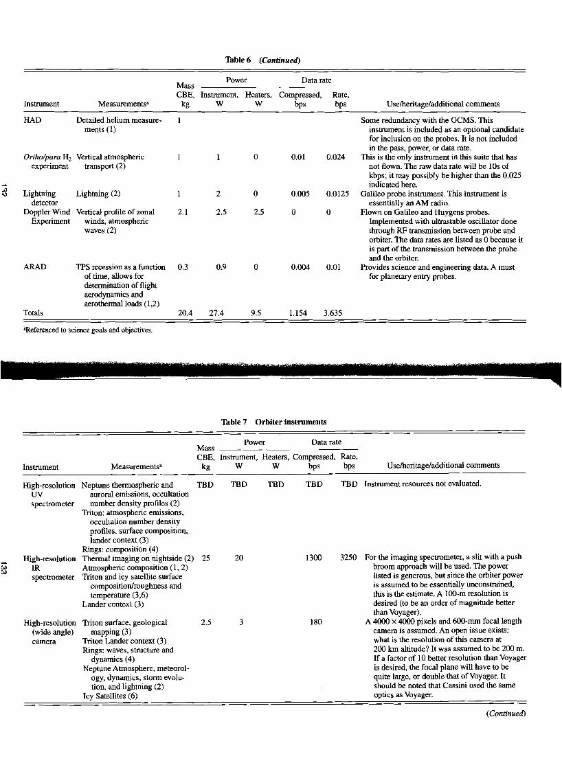
Table 6 (Continued)
Instrument Measurements"
Mass CBE,
kg
Power
Instrument, Heaters, W W
Data rate
Compressed, Rate, bps bps Uselheritage/additional comments
JJ
'"
HAD
Ortholpara Hz experiment
Lightning detector
Doppler Wind Experiment
ARAD
Totals
Detailed helium measurements (1)
Vertical atmospheric transport (2)
Lightning (2)
Vertical profile of zonal winds, atmospheric waves (2)
TPS recession as a function of time, allows for determination of flight aerodynamics and aerothermalloads (1,2)
I
I
I
2.1
0.3
20.4
I
2
2.5
0.9
27.4
0
0
2.5
0
9.5
om
0.005
0
0.004
1.154
0.024
0.0125
0
0.01
3.635
Some redundancy with the GeMS. This instrument is included as an optional candidate for inclusion on the probes. It is not included in the pass, power, or data rate.
This is the only instrument in this suite that has not flown. The raw data rate will be lOs of kbps; it may possibly be higher than the 0.025 indicated here.
Galileo probe instrument. This instrument is essentially an AM radio.
Flown on Galileo and Huygens probes. Implemented with ultrastable oscillator done through RF transmission between probe and orbiter. The data rates are listed as 0 because it is part of the transmission between the probe and the orbiter.
Provides science and engineering data. A must for planetary entry probes.
"Referenced to science goals and objectives.
Table 7 Orbiter instruments
Power Data rate Mass CBE, Instrument, Heaters, Compressed, Rate,
Instrument Measurements" kg W W bps bps Uselheritage/additional comments
High-resolution Neptune thermospheric and TBD TBD TBD TBD TBD Instrument resources not evaluated.
UV auroral emissions, occultation spectrometer number density profiles (2)
Triton: atmospheric emissions, occultation number density profiles, surface composition, lander context (3)
Rings: composition (4)
... I:..:l I:..:l
High-resolution IR spectrometer
Thermal imaging on nightside (2) Atmospheric composition (1, 2) Triton and icy satellite surface
25 20 1300 3250 For the imaging spectrometer, a slit with a push broom approach will be used. The power listed is generous, but since the orbiter power
composition/roughness and is assumed to be essentially unconstrained, temperature (3,6) this is the estimate. A loo-m resolution is
Lander context (3) desired (to be an order of magnitude better than Voyager).
High-resolution Triton surface, geological 2.5 3 180 A 4000 x 4000 pixels and 6oo-mm focal length (wide angle) mapping (3) camera is assumed. An open issue exists:
camera Triton Lander context (3) Rings: waves, structure and
dynamics (4)
what is the resolution of this camera at 200 km altitude? It was assumed to be 200 m. If a factor of 10 better resolution than Voyager
Neptune Atmosphere, meteorol is desired, the focal plane will have to be ogy, dynamics, storm evolu quite large, or double that of Voyager. It tion, and lightning (2) should be noted that Cassini used the same
Icy Satellites (6) optics as Voyager.
(Continued)

Table 7 (Continued)
Power Data rate Mass CBE, Instrument, Heaters, Compressed, Rate,
Instrument Measurements' kg W W bps bps Uselheritage/additional comments
Composite Neptune: detailed atmospheric The Cassini Orbiter CIRS weighed approxiinfrared composition, thermal mapping mately 39.25 kg and consumed 26.4 W. The spectrometer (3-D wind fields) (1,2) data rate is 6 kbps. No values have been (CIRS) Triton: surface thermal booked in this summary since there is
mapping (3) uncertainty in the state of development for Rings: particle size and this instrument in the 2015 time frame.
thickness (4) INMS Ion/neutral mass spectrometer 9.3 27.7 1.5
(3,5)
... Ka-IX-IS-band Atmospheric pressure, tempera 0 0 0 0 0 This instrument requires no orbiter resources 00)::.. radio science ture profile, density (2) because it is part of the communications
Gravitational field measurements system. (interior structure) (1,2)
Ring occultations for particle size and ring thickness (4)
Uplink radio Neptune and Triton atmospheric This instrument requires no orbiter resources science pressure, temperature profiles, because it is part of the communications
density (2) system. Bistatic radar Triton and possibly other satellite 5 50 200 Possible to fly the source on the orbiter and the
surface texture, mapping (3) receiver on the Triton lander. Plasma wave Plasma composition and electric 5 5 5
instrument fields (5) Magnetometer Magnetic fields (1,5) 25 3.1 4 The magnetometer is on a 15-m boom.
The 25-kg mass indicated here is for a 5-kg magnetometer and a 20-kg boom. It is assumed that the magnetometer is a flux-gate design.
Laser altimeter Triton topography (3) 12 25 100 The numbers used here were derived from Wayne Zimmerman's Lunar Precursor Study with Team X, although that spacecraft was assumed to fly at a 25-km altitude, not 2oo-km. The original values from the Neptune orbiter with Probes Team X study were 10kg and 20W.
Microwave Neptune deep atmosphere 35 25 80 This instrument must be further studied for a radiometer composition (1,2) refinement of the values indicated here. This
Triton composition (3) is a passive instrument that is composed of a Neptune, Triton, icy satellite detector on an antenna. The aperture is not
brightness temperatures affected by the illumination. It is assumed that (1,2,3,6) the gain is included in the 35-kg value.
Bolometer array Triton, icy satellite, and possibly This instrument was not discussed in the Team P ring surface temperature study or in the original Team X session, but was distribution (3,4,6) included on the desired instrument list.
Ground Triton subsurface mapping, 40 3000 1000 2500 The GPR is 25-30% efficient. When the radar is penetrating altimetry, surface emissivityl on, it is conceivable that no other instruments radar (GPR) roughness (3) will be operating. In comparing this instrument
Neptune deep atmosphere to other GPR instruments (on MRO composition (1,2) and MARSIS), it turns out that at roughly
Rings: particle size and 1-25 mHz, 40-60 We, it is projected that thickness (4) penetration depths will be on the order of
0.5-5 km with vertical resolutions in the 10-100 m range. Each of the instruments is on the order of 20 kg. These data were provided by Sam Kim (JPL), a GPR developer.
Cosmic dust Cosmic dust measurements during 12.3 13.8 0.52 1.31 These mass and power values are based on a analyzer transit from Earth to the ratio of 75% of the CDA flown on Cassini. (CDA) Neptune system The assumed data rate is the same as the
Cassini rate. Totals 171 3172.6 2921 5751
"Referenced to science goals and objectives.

Table 8 Lander instmments
Power Data rate Mass CBE, Instrument, Heaters, Compressed, Rate,
Instruments Measurements" kg W W bps bps Uselheritage!additional comments
Surface physical Density (3) 2.7 5 0 0.125 0.32 This instrument is essentially a weather properties Surface porosity (3) station at Triton. It will make meteorology instrument Surface thermal and electrical measurements, including wind speed, (SPPI) properties (3) etc. A boom is required to locate the
SPPI package away from the lander. The mass listed here includes the boom
... and the spring mechanisms to deploy it.
.J The indicated mass also includes two ., microseismometers at 100 g each, with one on the boom and one for redundancy. The data rate is based on the data rate of the ASI, but includes a 25-bps addition for the seismometers.
Surface science Sampling device + analysis, 2.5 5 0 0.1 1 Assumed to be similar to Huygens package GCMS (3) instrumentation. The objectives of the
Seismometer with active surface science package can be met sounding (3) with a Raman-type instrument as the
Panoramic imager with color (3) primary interest is geology. Surface near IR spectrometer (3)
Panoramic Required to return images from 3.5 27 2 Two cameras assumed for stereoimaging, camera the surface (scientific and PR redundancy, and range. The 3.5-kg mass
value) indicated here includes the 2 (0.25 kg) cameras, a I-m-high mast, and the actuators, cabling, etc.
~1_l.T._
Gas chromato- Atmospheric composition as a 9 10 5 1 2.5 Stand-alone GC and MS experiments have graph mass function of altitude (3) been flown on Venus probes. A mass spectrometer Measurement ofTriton spectrometer was flown on the Galileo (GCMS) atmosphere during descent Jupiter probe. A GCMS flew on the
Profiles of N2, HCN, H2S, NH3, Huygens probe as part of the Cassini-C~, H20, etc.: stratosphere Huygens mission. Similar to instrument to deep atmosphere (3) on Neptune probe except that Triton has
DIH (3) a very thin atmosphere, so it may need 15 N/14 N (3) to be compressed; the I-kg difference Disequilibrium species (3) between the lander and probe GCMS Hydrocarbons (3) instruments is for the compressor. The Noble gases (He, Ne, Ar, Kr, GCMS is used both during descent and
Xe) (3) on the surface, assuming the other Isotopic ratios (3) lander instrumentation can provide the
atmospheric samples. Atmospheric Atmospheric pressure! 4 4 0 0.1 1 Similar to instrument on Neptune probe;
:..>
'" structure temperature as a function of any difference is in the noise at this instrument altitude (3) stage of the lander design. (ASI)
Sampling Required to determine the 1.5 8 0 0.05 0.125 The ultrasonic drill/corer (USDC) mechanism composition of the Triton provides a low massllow reaction force
surface (3) solution to obtaining shallow ice samples. The design planned for the Europa probe (JIML), uses a 1.5-kg USDC housed in the instrument pod that can deliver a 1-1.5 cm sample to a sample chamber that is then heated to release the volatiles for analysis by a GCMS. Power required is 25 W. TRL is 4.
Totals 23.2 59 7 1.38 4.94
"Referenced to science goals and objectives.

138 B. BIENSTOCK ET AL.
A. Probe Technology Requirements
The probe technology issues are numerous. Highlighted in the following sections are discussions of the radiofrequency (RF) communications link design, the power subsystem design challenges, and the deceleration module thermal protection system (TPS) design, as well as the development of facilities to test the deceleration module.
1. Probe RF Communications Link Design
Telecommunication from the probe to the orbiter is extremely challenging mainly because of the large distance (up to 500,000 kIn) between the orbiter and probe when the probe enters Neptune's atmosphere. To conserve probe power, mass, and complexity, a downlink between the orbiter and probe was not considered. The probe descent sequence will be controlled by the probe; although turnaround ranging might be desirable, it is not included because of the mass and power restrictions.
The transmitter on the probe is constrained in power, mass, and volume. The baseline approach taken (and included in the probe mass summary, Table 4), is to use the next generation version of the Elektra UHF radio. However, link analysis shows that the link cannot be closed at ranges greater than approximately 100,000 kIn. The link margin goes to 0 dB at a distance of approximately 175,000 kIn. To extend the range, a much higher transmitter power, on the order of 1 kW, would be required. Even if this high level of electrical energy were available on the probe, a patch type antenna would not be able to handle this power level. A hom or dish antenna would be required, both of which present packaging problems within the confines of the probe aeroshell and severely constrain the orbiter dynamics for relaying the data to Earth. The use of the S-band frequency would improve the situation slightly, but it will not solve these problems. Therefore, if the mission design cannot be adjusted to maintain the distance between the orbiter and probe to approximately 100,000 kIn, a new telecom solution must be developed. Efficient, small transmitters need to be designed. Deployable, high temperature horns or dish antennas that could be packaged within the aeroshell and deployed before data collection begins are also needed.
2. Probe Power Subsystem Design
Electrical power for the probe is challenging for two main reasons. First, the probe must survive on its own for up to 62 days after release from the orbiter until entry. Second, power demands will be high, driven by the telecom subsystem that must communicate with the orbiter over very long distances. Both of these are a result of the mission design for the NOPL orbiter, which requires probe deployment to occur at a great distance from the Neptune system. Batteries are typically used for probe missions, although their use raises concerns. Throughout the l2-year cruise to Neptune, the battery system would be inactive, although occasional monitoring would be required. Following separation from the orbiter, the battery would provide a modest level of power for the 62-day coast period between orbiter separation and probe transmitter tum-on. That event would begin
ill
139NOPL MISSION
the period of high power usage for the several hour probe entry and descent into Neptune's atmosphere.
Thermal batteries are a good choice for applications where the battery must be stored for a long period of time before use, but their operational duration is typically short. Therefore, a hybrid system is feasible, in which traditional chemical batteries are used for the 62-day coast, followed by activation of the thermal battery just prior to entry to provide a higher level of power. The problem with this approach is the mass and volume required within the probe for such a system. This system would still need to be qualified for the long duration cruise, and heating from the thermal battery inside the probe would need to be addressed. Technology development is needed for a high power, lightweight probe electrical power system.
3. Probe Deceleration Module TPS Design
A series of parametric studies were used as a starting point to conduct more detailed aerodynamic and aerothermal analysis of the Neptune probes in order to size the probe TPS. We assumed that each entry probe would be a photographically scaled version of the Galileo probe, which entered Jupiter at a relative velocity of 47 km/s in 1995. Table 9 lists relevant parameters for the Galileo probe. 14
The heat flux and heat load reported in this table are the net values, including the cooling effects of ablation product blowing. The Galileo probe is the only previous giant planet entry attempted; it survived the most severe entry environment of any man-made object in terms of both peak heat flux and integrated heat load.
In the current analysis, the Neptune probe entry mass was fixed at 300 kg, with the diameter fixed at 1.65 m. The remainder of the probe dimensions were scaled from Galileo, resulting in a nose radius of 0.291 m.
The baseline mission scenario includes the release of the first probe on a (slightly) hyperbolic trajectory prior to orbit insertion. Given that the desired target orbit is retrograde to facilitate observations of Triton, the first probe will be on a retrograde entry trajectory to maximize the relay time between the probe and orbiter. This first probe will likely see the most severe aeroheating environment, and thus will determine the overall TPS material selection, thickness, and mass for the (assumed identical) second entry probe. The inertial entry velocity of the first probe is assumed to be about 29 km/s, although lower velocities are possible as a result of the mechanics of the orbit insertion maneuver. It should be noted that
Table 9 Galileo probe entry conditions
Relative entry angle -8.5 deg. Relative entry velocity 47km/s Cone half-angle 44.9deg. Diameter 1.26m Entry mass 335kg Peak heat flux 17,000 W/cm2
Heat load 2ookJ/cm2
TPS mass fraction 50.4%
II
i
i I
I I"
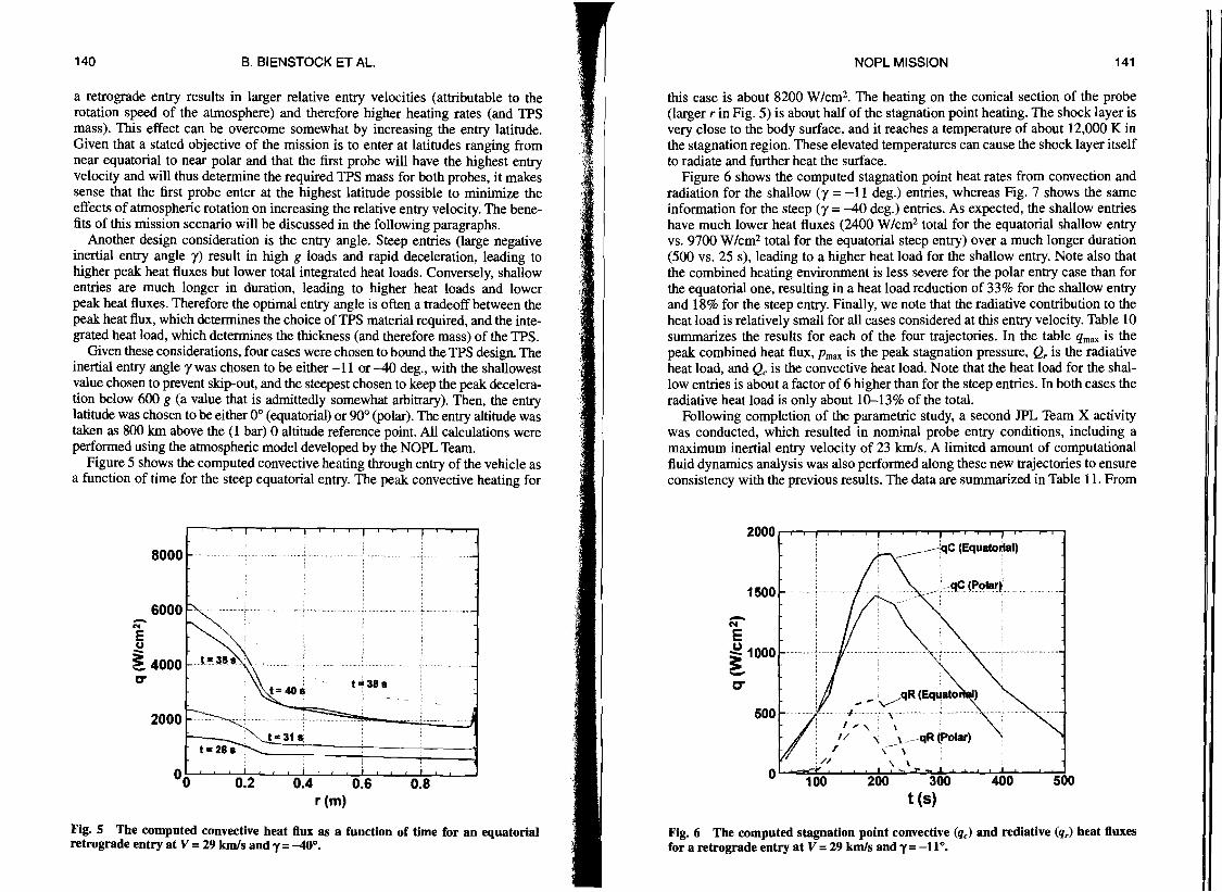
140 141 B. BIENSTOCK ET AL.
a retrograde entry results in larger relative entry velocities (attributable to the rotation speed of the atmosphere) and therefore higher heating rates (and TPS mass). This effect can be overcome somewhat by increasing the entry latitude. Given that a stated objective of the mission is to enter at latitudes ranging from .fir«,near equatorial to near polar and that the first probe will have the highest entry 'i,
I.ivelocity and will thus determine the required TPS mass for both probes, it makes t
sense that the first probe enter at the highest latitude possible to minimize the effects of atmospheric rotation on increasing the relative entry velocity. The benefits of this mission scenario will be discussed in the following paragraphs.
Another design consideration is the entry angle. Steep entries (large negative inertial entry angle y) result in high g loads and rapid deceleration, leading to higher peak heat fluxes but lower total integrated heat loads. Conversely, shallow entries are much longer in duration, leading to higher heat loads and lower peak heat fluxes. Therefore the optimal entry angle is often a tradeoff between the peak heat flux, which determines the choice of TPS material required, and the integrated heat load, which determines the thickness (and therefore mass) of the TPS.
Given these considerations, four cases were chosen to bound the TPS design. The inertial entry angle y was chosen to be either -11 or -40 deg., with the shallowest value chosen to prevent skip-out, and the steepest chosen to keep the peak deceleration below 600 g (a value that is admittedly somewhat arbitrary). Then, the entry latitude was chosen to be either 00 (equatorial) or 900 (polar). The entry altitude was taken as 800 km above the (1 bar) 0 altitude reference point. All calculations were performed using the atmospheric model developed by the NOPL Team.
Figure 5 shows the computed convective heating through entry of the vehicle as a function of time for the steep equatorial entry. The peak convective heating for
N E ~
C"
I I ! I I ! ! I If! , ! ! ! , (f
t", 388
8000
2000
~4000
0' I
o 0.2 0.4 0.6 0.8 r (m)
Fig. 5 The computed convective heat flux as a function of time for an equatorial retrograde entry at V =29 km/s and y =-40°.
NOPL MISSION
this case is about 8200 W/cm2. The heating on the conical section of the probe (larger r in Fig. 5) is about half of the stagnation point heating. The shock layer is very close to the body surface, and it reaches a temperature of about 12,000 K in the stagnation region. These elevated temperatures can cause the shock layer itself to radiate and further heat the surface.
Figure 6 shows the computed stagnation point heat rates from convection and radiation for the shallow (y = -11 deg.) entries, whereas Fig. 7 shows the same information for the steep (y= -40 deg.) entries. As expected, the shallow entries have much lower heat fluxes (2400 W/cm2 total for the equatorial shallow entry vs. 9700 W/cm2 total for the equatorial steep entry) over a much longer duration (500 vs. 25 s), leading to a higher heat load for the shallow entry. Note also that the combined heating environment is less severe for the polar entry case than for the equatorial one, resulting in a heat load reduction of 33% for the shallow entry and 18% for the steep entry. Finally, we note that the radiative contribution to the heat load is relatively small for all cases considered at this entry velocity. Table 10 summarizes the results for each of the four trajectories. In the table qrnax is the peak combined heat flux, Prnax is the peak stagnation pressure, Q, is the radiative heat load, and Qc is the convective heat load. Note that the heat load for the shallow entries is about a factor of 6 higher than for the steep entries. In both cases the radiative heat load is only about 10-13% of the total.
Following completion of the parametric study, a second JPL Team X activity was conducted, which resulted in nominal probe entry conditions, including a maximum inertial entry velocity of 23 kmIs. A limited amount of computational fluid dynamics analysis was also performed along these new trajectories to ensure consistency with the previous results. The data are summarized in Table 11. From
2000. Iii i I Iii I i I Iii I i I I
_------jqC (Equatorial)
1500
N E ~ 1000 J
-C"
500
0' w:e7! ! , I ''':t.r r: I ! 1 ! I ! I ! ! I
...ccq~ (j)ClIl1r~
.qRfolar)
) g "'+ '-............ . .-1
I
I I
100 200 300 400 500 t(S)
Fig. 6 The computed stagnation point convective (qJ and rediative (q,) heat fluxes for a retrograde entry at V = 29 km/s and y= _11°.
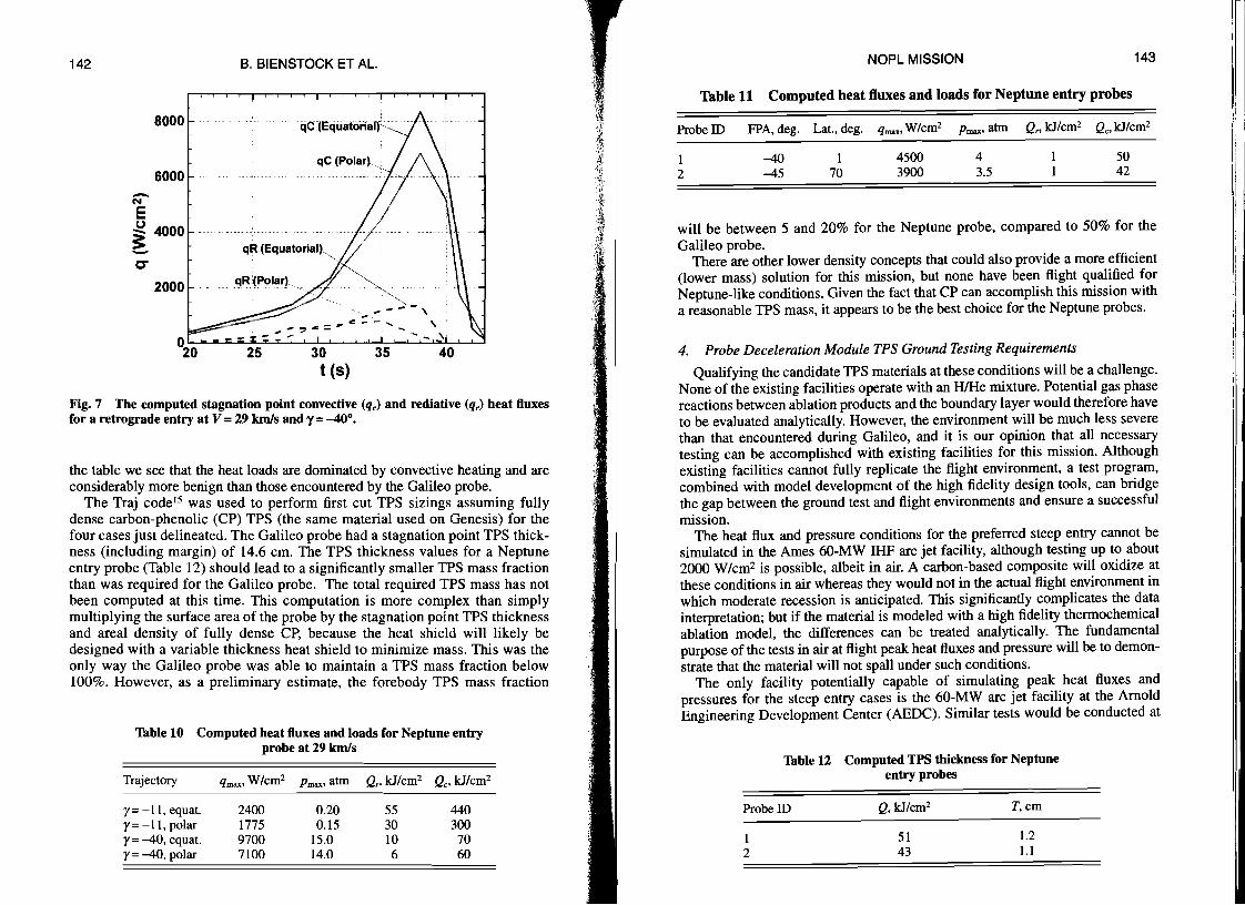
142
6000
8000
N E u ~ 4000f
-C" ",,- .~~"
2000 ~ ~-
"". .... -- " ..... :::,.= .. ~-- .......... ' - \
25 30 35 40
Fig. 7 The computed stagnation point convective (qc) and rediative (qr) heat fluxes for a retrograde entry at V = 29 km/s and r = -40°.
the table we see that the heat loads are dominated by convective heating and are considerably more benign than those encountered by the Galileo probe.
The Traj code IS was used to perform first cut TPS sizings assuming fully dense carbon-phenolic (CP) TPS (the same material used on Genesis) for the four cases just delineated. The Galileo probe had a stagnation point TPS thickness (including margin) of 14.6 cm. The TPS thickness values for a Neptune entry probe (Table 12) should lead to a significantly smaller TPS mass fraction than was required for the Galileo probe. The total required TPS mass has not been computed at this time. This computation is more complex than simply multiplying the surface area of the probe by the stagnation point TPS thickness and areal density of fully dense CP, because the heat shield will likely be designed with a variable thickness heat shield to minimize mass. This was the only way the Galileo probe was able to maintain a TPS mass fraction below 100%. However, as a preliminary estimate, the forebody TPS mass fraction
Table 10 Computed heat fluxes and loads for Neptune entry
qmax' W/cm2 Pmax' atm Q" kJ/cm2 Qo kJ/cm2
2400 1775 9700 7100
0.20 0.15
15.0 14.0
55 30 10 6
440 300 70 60
_.
II -
t(S)
143
50 42
4 3.5
4500 3900
NOPL MISSION
1 70
-40 -45
Table 11 Computed heat fluxes and loads for Neptune entry probes
1 2
Probe ID FPA, deg. Lat., deg. qrnax' W/cm2 Prnax' atm Q" kJ/cm2 Qc' kJ/cm2
I I
I'!:
II
I!
will be between 5 and 20% for the Neptune probe, compared to 50% for the Galileo probe.
There are other lower density concepts that could also provide a more efficient (lower mass) solution for this mission, but none have been flight qualified for Neptune-like conditions. Given the fact that CP can accomplish this mission with a reasonable TPS mass, it appears to be the best choice for the Neptune probes.
4. Probe Deceleration Module TPS Ground Testing Requirements
Qualifying the candidate TPS materials at these conditions will be a challenge. None ofthe existing facilities operate with an HlHe mixture. Potential gas phase reactions between ablation products and the boundary layer would therefore have to be evaluated analytically. However, the environment will be much less severe than that encountered during Galileo, and it is our opinion that all necessary testing can be accomplished with existing facilities for this mission. Although existing facilities cannot fully replicate the flight environment, a test program, combined with model development of the high fidelity design tools, can bridge the gap between the ground test and flight environments and ensure a successful mission.
The heat flux and pressure conditions for the preferred steep entry cannot be simulated in the Ames 60-MW IHF arc jet facility, although testing up to about 2000 W/cm2 is possible, albeit in air. A carbon-based composite will oxidize at these conditions in air whereas they would not in the actual flight environment in which moderate recession is anticipated. This significantly complicates the data interpretation; but if the material is modeled with a high fidelity thermochemical ablation model, the differences can be treated analytically. The fundamental purpose of the tests in air at flight peak heat fluxes and pressure will be to demonstrate that the material will not spall under such conditions.
The only facility potentially capable of simulating peak heat fluxes and pressures for the steep entry cases is the 60-MW arc jet facility at the Arnold Engineering Development Center (AEDC). Similar tests would be conducted at
Table 12
ProbelD
1 2
Computed TPS thickness for Neptune entry probes
Q, kJ/cm2 T,cm
51 1.2 43 1.1
Trajectory
Y= -11, equat. Y= -11, polar Y= -40, equat. Y= -40, polar
B. BIENSTOCK ET AL.
probe at 29 km/s
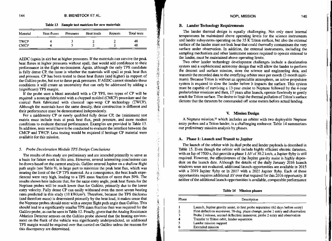
144 B. BIENSTOCK ET AL.
Table 13 Sample test matrices for new materials
Material Heat fluxes Pressures Heat loads Repeats
TWCP 4 3 2 2 CMCP 4 3 2 2
Total tests
48 48
AEDC (again in air) but at higher pressures. If the materials can survive the peak heat fluxes at higher pressures without spall, that would add confidence to their performance in the flight environment. Again, although the only TPS candidate is fully dense CP, the issue is whether the materials will spall at peak heat flux and pressure. CP has been tested to these heat fluxes (and higher) in support of the Galileo probe, but not to these peak pressures. IfAEDC cannot simulate these conditions it will create an uncertainty that can only be addressed by adding a (significant) TPS margin.
If the probe uses a blunt aeroshell with a CP TPS, two types of CP will be required: a nosecap fabricated with a chopped molded (CMCP) procedure and the conical flank fabricated with classical tape-wrap CP technology (TWCP). Although the materials have the same density, their construction is different and their performance must be demonstrated independently.
For a middensity CP or newly qualified fully dense CP, the (minimum) test matrix must include tests at peak heat flux, peak pressure, and more modest conditions to evaluate thermal performance. Examples are provided in Table 13. In addition, tests would have to be conducted to evaluate the interface between the CMCP and TWCP. Less testing would be required if heritage CP material were available for this mission.
5. Probe Deceleration Module TPS Design Conclusions
The results of this study are preliminary and are intended primarily to serve as a basis for future work in this area. However, several interesting conclusions can be drawn based on the current analysis. Galileo entered Jupiter on a shallow flight path angle (see Table 9), in large part to minimize the peak heat flux, which was nearing the limit of the CP TPS material. As a consequence, the heat loads experienced were very high, leading to a TPS mass fraction of more than 50%. The results shown here indicate that, for the same entry angle, peak heat fluxes for the Neptune probes will be much lower than for Galileo, primarily due to the lower entry velocity. Fully dense CP can easily withstand even the most severe heating rates predicted in this study (10 kW/cm2). Therefore, because the TPS thickness (and therefore mass) is determined primarily by the heat load, it makes sense that
~the Neptune probes should enter with a steeper flight path angle than Galileo. This should lead to a significantly smaller TPS mass fraction than was required for the Galileo probe, as can be seen in Table 12. Finally, given that the Analog Resistance ;~
.. ~.Ablation Detector sensors on the Galileo probe showed that the heating environment on the flank of the vehicle was significantly underpredicted, an additional TPS margin would be required over that carried on Galileo unless the reasons for this discrepancy are determined. l·.~·
:
NOPL MISSION 145
B. Lander Technology Requirements
The lander thermal design is equally challenging. Not only must internal temperatures be maintained above operating levels for the science instruments and lander subsystems operating on the 35 K Triton surface, but also the external surface of the lander must not leak heat that could thermally contaminate the very surface under observation. In addition, the external instruments, including the sampling mechanism and other instrument sensors required to operate external to the lander, must be maintained above operating limits.
1\vo other lander technology development challenges include a deceleration system and a sophisticated autonomy design that will allow the lander to perform the descent and surface mission, store the science and engineering data, and transmit the recorded data to the overflying orbiter once per month (2-month minimum). Because Triton is without an appreciable atmosphere, an active propulsion system is required to slow the lander before it impacts the surface. This system must be capable of surviving a 13-year cruise to Neptune followed by the 4-year probe/orbiter missions and then, 17 years after launch, operate flawlessly to gently reach the Triton surface. The desire to limit the thermal pollution ofTriton's surface dictates that the thrusters be commanded off some meters before actual landing.
V. Mission Design
A Neptune mission,16 which includes an orbiter with two deployable Neptune entry probes and a Triton lander, is a challenging endeavor. Table 14 summarizes our preliminary mission analysis by phases.
A. Phase 1: Launch and Transit to Jupiter
The launch of the orbiter with its dual probe and lander payloads is described in Table 15. Even though the orbiter will include highly efficient electric thrusters, with an Isp of 7500 s, that provide a phase 1 AV of 30.2 km/s, a Jupiter flyby is still required. However, the effectiveness of the Jupiter gravity assist is highly dependent on the launch date. Although the details of the daily January 2016 launch windows were not evaluated, additional launch opportunities are available in 2015 with a 2019 Jupiter flyby or in 2017 with a 2021 Jupiter flyby. Each of these opportunities requires additional AV over that required for this 2016 opportunity. If neither of the additional launch opportunities is available, comparable performance
Table 14 Mission phases
Phase Description
1 Launch, Jupiter gravity assist, to first probe separation (62 days before entry) 2 First deflection maneuver, 70-deg. plane change, probe I entry and observation 3 Probe 2 release, second deflection maneuver, probe 2 entry and observation 4 Transfer to Triton orbit, lander separation 5 Lander mission support 6 Extended mission
Ii I
I
I I
II
146 B. BIENSTOCK ET AL. NOPL MISSION 147
Table 15 NOPL Launch parameters Table 17 ProbesnUs~onsununary
Parameter Probe 1 Probe 2 ITrajectory type Jupiter gravity assist to Neptune capture Power 100kW Isp 7500 s .' Efficiency 75% Initial C3 lOkm2/s2
Initial mass 36,000kg Minimum Jupiter flyby radius 5 Rj
Launch date January 2016 Transit time to Neptune 12.88 years Jupiter flyby March 2020 First Probe separation December 2028 Phase I.!\V 30.2km1s
can be obtained either by waiting 12 years for the proper Jupiter phasing to occur again or via a single or double Earth gravity assist.
B. Reference Probe Entry Trajectories
Parametric probe entry trajectory analysis was used to support the overall mission design and select reference entry trajectories for the two Neptune probes that are compatible with the NEP orbiter's approach trajectory and propulsive capabilities. The probe characteristics shown in Table 16 were used to develop the reference trajectories.
The probe is released from the orbiter and travels to atmospheric entry, which for the mission study was assumed to occur at approximately l000-kIn altitude above a I-bar level. The probe aeroshell geometry is similar to that for the Galileo probe at Jupiter to take advantage of experience and existing aerothennal databases for that shape. After entry and deceleration to subsonic speeds, a parachute
Table 16 Neptune probe characteristics
Parameter Value
Mass at entry, kg 300 Aeroshell max diameter, m 1.65 Aeroshell nose radius, m 0.291 Aeroshell cone angle, deg. 45 Average hypersonic drag coefficient 1.05 Ballistic coefficient, kglm2 134 Parachute diameter, m 3.8 Parachute type Conical ribbon Parachute deployment Mach number 0.95 Mass after aeroshell separation, kg 195 Pressure vessel diameter, m 0.8
Altitude at entry l000km l000km Entry flight path angle -40 deg. -45 deg. Elevation angle at entry 10 deg. 32 deg. Elevation angle at entry + 5 h 17 deg. 35 deg. Maximum elevation angle 36 deg. 44 deg. Max range to orbiter 355,000km 500,OOOkm Latitude at entry 1.3 deg. 70 deg. Probe descent depth 200 bar 200 bar Data rate 1.2 kbps 1.2 kbps Data volume 21.6 Mbits 21.6 Mbits
is deployed. The parachute size, type, and deployment Mach number are the same as that used on the Galileo probe, again to take advantage of previous flight experience. As discussed earlier, the main function of the parachute is not for deceleration, but to extract the pressure vessel with science payload from the aeroshell. Once the aeroshell has been separated, science data will be collected and transmitted to the orbiter as the pressure vessel descends into the deeper atmosphere either under the parachute, or during a freefall descent after the parachute has been released. The basic mission profile just described is the same for both probes, as described in Table 17.
C. Phase 2: Probe 1 Entry and Orbiter Deflection Maneuver
The first phase of the trajectory ends with the separation of the first probe 62 days prior to probe entry at Neptune. At the separation point, both the orbiter and probe are on an impact course with Neptune.
The probe is targeted to the western limb of Neptune (from the orbiter's viewpoint). Once it enters the atmosphere, the probe will quickly lose its tangential velocity and begin rotating with Neptune as it descends vertically. The range to the orbiter at this time is 355,000 kIn and decreasing.
One issue with the initial probe entry as modeled in this study is that the elevation angles start out low (close to 10 deg.) and do not increase to greater than about 35 deg. (Note that the telecom angle from the probe to the orbiter will be 90 deg. minus the elevation angle, assuming that the probe is nadir pointed at all times during the descent.) There are a number of methods to solve this issue. One is to send the probe to a higher latitude. The probe is currently targeted to enter the Neptune atmosphere at about 10 latitude. Another solution would be to increase the time difference between periapsis of the orbiter and periapsis of the probe from 16 h to a larger value.
Immediately after separation, the orbiter begins thrusting to both raise periapsis and perfonn a 70-deg. plane change to prepare for communication with the first probe and, eventually, the second probe release. Orbiter periapsis, which occurs 16 h after the probe enters the Neptune atmosphere, is the event that initiates phase 3 of the mission. Phase 2 requires 63 days and 240 mls ~V.

148 149 B. BIENSTOCK ET AL.
D. Phase 3: Probe 2 Release and Entry
As phase 3 begins, the orbital period of the Neptune orbiter is roughly 100-200 days with a periapsis near 100,000 km and an inclination of about 70 deg. In order to release the second probe, the orbiter must perform a deflection maneuver that will decrease its periapsis to below the Neptune's cloud tops. At apoapsis, following release of the second probe, the orbiter is therefore on an impact trajectory with Neptune. The orbiter must then begin to raise periapsis back to some positive value in order to stay above the cloud tops (100,000 km was used for this analysis). This scenario could be performed on any integral number of orbit periods after the initial periapsis, but for this analysis we assume that the second deflection begins immediately (Le., during the first full orbit around Neptune).
The first halfofthe trajectory is spent reducing periapsis below Neptune's cloud tops and continuing to reduce the orbital period to exactly 100 days. Probe separation occurs at apoapsis approximately 50 days after the start of phase 3. The probe then travels on its own for an additional 50 days prior to entry at Neptune. Immediately after separation, orbiter thrusting occurs to raise periapsis. The total ~V for this phase is 461 mls.
The second probe entry is assumed to occur during the first full orbit around Neptune. At this time, the orbiter is in a 110°, 100-day orbit around Neptune. The reason for the higher inclination is to provide a high entry latitude for the probe. On the outbound leg of the orbit, the orbiter will perform a deflection maneuver that will lower periapsis to approximately -10,000 km (which will correspond to a flight path angle at probe entry of approximately --45 deg.). This very low periapsis and high flight path angle at entry is required to allow the probe to enter the atmosphere before it reaches its semilatus rectum in the orbit and thus be viewable by the orbiter (Le., so the probe will hit the atmosphere before passing behind the planet).
The probe is actually released from the orbiter at apoapsis (50 days before probe entry); the orbiter will continue its deflection maneuver to increase its own periapsis to 100,000 km and its periapsis time to occur 18 h after probe entry. Because the orbiter is in a retrograde orbit, the probe must enter the atmosphere on the western edge of Neptune (as viewed from the orbiter) at which point it will follow a similar path to the first probe and begin rotating with Neptune. Essentially, the probe enters the atmosphere in a direction that opposes Neptune's rotational velocity, loses its tangential velocity, and then begins rotating with Neptune and its atmosphere. Because the orbiter is still inbound at this point, it will be able to see the entire event at an elevation angle of greater than 30 deg. for a period of approximately 5-6 h. The range from the probe to the orbiter at entry is about 500,000 km and it does not decrease to values lower than -400,000 km during the event. As noted earlier, this range requires that a high power transmitter (power >1 kW) be flown on each probe. A lower latitude would result in higher elevation angles to the orbiter.
E. Phase 4: Transfer from Probe Observation Orbit to Triton Orbit
The final phase of the trajectory was analyzed using a control law algorithm known as the Q-Iaw developed at IPL by Anastassios Petropoulos. The Q-law is
NOPL MISSION
generally used for estimating the ~ V and flight time necessary to change orbital elements for orbit transfers with many revolutions about a central body. In this case, the Q-law was specifically used to calculate the ~V to transfer from the observing orbit to a rendezvous with Triton. The observation orbit has an eccentricity of 0.97, an orbital period of 100 days, and a low periapsis. Transferring to Triton's orbit requires an eccentricity reduction to 0, a raise in periapsis, a 20-deg. inclination change, and a rotation of the node by as much as 180 deg. The resulting transfer requires 4.31 years with a ~V of 9.43 kmls.
This trajectory is conservative. This transfer would likely benefit greatly from Triton gravity assists that have the potential to reduce both the ~V and flight time. The 180-deg. node change is also a worst-case scenario, although the node change required for the orbits assumed in this study would likely be substantial. Finally, because this transfer was generated by a control law, the performance could be somewhat improved by optimizing the trajectory. It would be reasonable to assume that 25-50% of the 9.43 kmls ~V could be reduced by using gravity assists and fully optimizing the trajectory for whatever launch date is eventually selected, although no work has been performed to substantiate this conclusion.
Following rendezvous with Triton, the orbiter will spiral down to the science orbit altitude. At a Triton science orbit altitude of 100 km, the ~V for the spiral-in is 0.89 kmls and the flight time to spiral-down is about 52 days. Prior to lander separation, the orbiter will perform detailed imaging of the Triton surface to establish the targeted landing site for the lander.
F. Phase 5: Lander Operations
Following separation of the lander and its low-velocity landing on the Triton surface at the targeted landing site, the orbiter again serves as a data relay, although the lander mission requirements differ significantly from the probe missions. The lander requires time to observe the surface and analyze its constituents. The mission design therefore includes two orbiter passes over the lander, with burst data transmissions at each pass. With an orbital period of approximately 26 days, the lander must be kept alive for nearly 60 days to complete two passes of data transmission. As discussed earlier, this is indeed a significant challenge for the lander design.
G. Phase 6: Extended Mission
Following mission support of both Neptune probes and the Triton lander, the orbiter will enter the extended mission phase. In this phase, the orbiter will continue detailed observations of Triton or, with additional ~V, be retargeted. A summary of the key parameters for the entire Neptune orbiter mission is provided in Table 18.
VI. Conclusions
Our NASA Vision Mission proposal specified that we would "develop science goals, perform conceptual mission planning, and identify enabling technologies for a probe-based scientific mission to the Neptune atmosphere." Our approach to
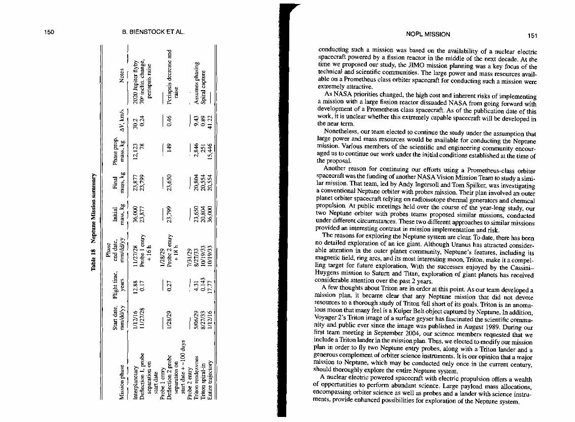
151 150 NOPL MISSION
conducting such a mission was based on the availability of a nuclear electric spacecraft powered by a fission reactor in the middle of the next decade. At the time we proposed our study, the JlMO mission planning was a key focus of the technical and scientific communities. The large power and mass resources available on a Prometheus class orbiter spacecraft for conducting such a mission were extremely attractive.
As NASA priorities changed, the high cost and inherent risks of implementing a mission with a large fission reactor dissuaded NASA from going forward with development of a Prometheus class spacecraft. As of the publication date of this work, it is unclear whether this extremely capable spacecraft will be developed in the near term.
Nonetheless, our team elected to continue the study under the assumption that large power and mass resources would be available for conducting the Neptune mission. Various members of the scientific and engineering community encouraged us to continue our work under the initial conditions established at the time of the proposal.
Another reason for continuing our efforts using a Prometheus-class orbiter spacecraft was the funding of another NASA Vision Mission Team to study a similar mission. That team, led by Andy Ingersoll and Tom Spilker, was investigating a conventional Neptune orbiter with probes mission. Their plan involved an outer planet orbiter spacecraft relying on radioisotope thermal generators and chemical propulsion. At public meetings held over the course of the year-long study, our two Neptune orbiter with probes teams proposed similar missions, conducted under different circumstances. These two different approaches to similar missions provided an interesting contrast in mission implementation and risk.
The reasons for exploring the Neptune system are clear. To date, there has been no detailed exploration of an ice giant. Although Uranus has attracted considerable attention in the outer planet community, Neptune's features, including its magnetic field, ring arcs, and its most interesting moon, Triton, make it a compelling target for future exploration. With the successes enjoyed by the CassiniHuygens mission to Saturn and Titan, exploration of giant planets has received considerable attention over the past 2 years.
A few thoughts about Triton are in order at this point. As our team developed a mission plan, it became clear that any Neptune mission that did not devote resources to a thorough study of Triton fell short of its goals. Triton is an anomalous moon that many feel is a Kuiper Belt object captured by Neptune. In addition, Voyager 2's Triton image of a surface geyser has fascinated the scientific community and public ever since the image was published in August 1989. During our first team meeting in September 2004, our science members requested that we include a Triton lander in the mission plan. Thus, we elected to modify our mission plan in order to fly two Neptune entry probes, along with a Triton lander and a generous complement of orbiter science instruments. It is our opinion that a major mission to Neptune, which may be conducted only once in the current century, should thoroughly explore the entire Neptune system.
A nuclear electric powered spacecraft with electric propulsion offers a wealth of opportunities to perform abundant science. Large payload mass allocations, encompassing orbiter science as well as probes and a lander with science instruments, provide enhanced possibilities for exploration of the Neptune system.
B. BIENSTOCK ET AL.
'" ~ Z
] ~ <l
~~ 0.. •
o:l o:l o'" '" '" if 8
bll
~
§ ;;..,~
..0 bll 0 ~ gp
.2 §.~ j .~ S... ..<:: ... o u. ,.... '" ..... c:: 00 "8.0.. §';.:::I ~ .;!l '" o:l
0..'" 8«1~.S '5 '" 0o
::3
u
...8 b 0.. ~'al"l r '~'§ I <CI)
<')O\l"ll"l~ ",,"00l"l00 I~ I 0\0""';<')
""" <') 00
l-a ...... -a
l"lr- ~ ...... ...... ~~~ C'i' C'i' ~ ......
r- 0\ o.,., 0.,.,.,.,r- 0\ """""""""oor- -a 00.,.,.,.,
<'i' 666 l"l l"l l"l l"ll"ll"l"'"''''"'
§E 0\ 0\ ~38 r- -a 00 0
0'<'i' <'i' ",",60'<') l"l l"l l"l l"l <')
i0
i 00 ..<:: 0..<:: <') <')
0\ <') <') <')~......t\O O\l"loo l"lo ...... (',1~ ........ - r- O ...... ........ ........ 0\0\
......t r- ......t '1""""1!::!"8+ 00"8+ ("f")(',1 ........ -......... ................ 00 ...... c. S~ r- 00 '1""""1 '1""""1
I......00 r r ~ r oo ...... l"l <') ...... r-MO o ..tor-: ......
-a~ 0\ <') -a
;::ii==: !::!~::::;~ -ar-l"l ............ ............ s .,., 00 ...... -- !::! Ol"l ......I I -- -- -
.g '"
] 0 8 '" o ..0......::3l5..15 8 15 , ~l::C
C ;»0.. + ;»N·... 0 .s-:-§Q)J:1C"l§t1)J:jQ)~t o l::';:j'" l:: l::'~'" l:: ~ ....0 l:: 0 o:l o:l 0 0 ~ o:l 0 l:: 'a ~ ~';:j ~ ~ .......;:j ~ ~ l"l ~ '" tl fr~o..~o~o..~Ol::l::O o q:: 0 ... ..0 q:: 0 ... ..0 0 o.z; ~ Q) ~ ~ 8 Q) ~ ~ e'E~ Q.so c.O c.f'-<f'-<~
i ~
g.1jJ
~ ~ 5' z
ClC... :a ~
«I~
l:: '" .~ '" I:l. o:l 8
bll «I~
';:j '" :.s ~ 8
. ;;.., o ;;..,
~.g ;g ..<::~]c. l::
o
.§ ~
'" :a~ ii:
i~.g;g ~]
o
.a '" 0..
.§'" '" ~

153 152 B. BIENSTOCK ET AL.
To be sure, exploration of the Neptune system presents enormous challenges in all aspects of the mission design, as well as the design of the orbiter, probes, and lander. Electric propulsion offers a highly efficient system for meeting the large AV requirements of our mission. However, the low thrust nature of electric propulsion requires that different tools be used in mission planning applications. In addition, development of the electric thrusters that require extremely long bum times, on the order of many months, presents technology challenges. The high radiation levels and enormous waste heat generated by the fission reactor will drive the design of the orbiter spacecraft. A final consideration for the orbiter design is the high total launch mass of the orbiter. In fact, current launch vehicles cannot launch the spacecraft; instead, in-orbit assembly or development of highcapability launch vehicles is required.
Neptune entry probe design presents additional challenges. Although the -25 km/s Neptune entry condition is only half the Jupiter value of 47 km/s, design of the Neptune thermal protection subsystem and the need to thoroughly test those hardware elements are required. A staging system to separate the probe pressure vessel from the deceleration module is also necessary. Although parachutes are normally used for this function, they are inherently unreliable; simpler, less risky systems should be developed.
Probe pressure vessel design also presents challenges. A probe, such as the one described here that descends to depths of 200 bar or more, requires a lightweight, hermetically sealed structure that can maintain the integrity of its seals during the 13-year cruise time, yet support the science instruments within by providing windows and inlets for in situ atmospheric measurements. Other probe considerations include the design of a highly efficient, high power transmitter to generate the RF signals capable of penetrating the dense Neptune atmosphere. Finally, the overall probe thermal design and batteries present challenges to the engineering community.
The Triton lander design is the most challenging of all. The 35 K surface temperature drives the thermal design, as well as the power subsystem within the lander. The lander also poses an additional, subtle thermal design challenge. Thermal contamination of the surface, attributable to the hot lander sitting on the cold surface, requires that special consideration be given to the spacecraft's external thermal environment. The science community's desire to "touch" the surface with mechanisms and instruments drives the need to limit surface melting. Another technology challenge is the safe storage of lander propellants over the 13-year cruise time. Moreover, the single heaviest element of the lander mass is the active propulsion system that is required to reach the surface, which means that the mass and power available for science instruments is extremely limited.
The scientific data generated by a Neptune orbiter with probes and a Triton lander, whether conducted using nuclear electric power and propulsion or conventional technologies, is of extremely high value. However, the mission design, as well as the development of the hardware elements, present significant challenges. Nonetheless, the rich scientific returns from civilization's first mission to the Neptune system should present an overwhelming case for further development and continued study of the mission described and analyzed here.
NOPL MISSION
Acknowledgments
The authors acknowledge the support of their entire Neptune team in completing this study. Additional team members include Paul Mahaffy, NASA Goddard Space Flight Center; Paul Steffes, Georgia Institute of Technology; Alan Stem, Southwest Research Institute; Harvey Willenberg, David Smith, Robert Frampton, Steve Sichi, and Leora Peltz, Boeing Company; and Jeffrey Van Cleve, Ball Aerospace and Technologies Corporation. In addition, JPL's Team X, led by Robert Kinsey, JPL's Team P, led by Wayne Zimmerman, and the JPL mission study, conducted by Daniel Parcher and Eugene Bonfiglio, made valuable contributions to our study.
References
INational Research Council, An Integrated Strategy for Planetary Sciences 1995-2010, National Academies Press, Washington, DC, 1994.
2Stern, S. A, Lunine, J. I., Friedlander, A L., and Cheng, A F. "Future Neptune and Triton Missions," Neptune and Triton, edited by D. Cruikshank, University of Arizona Press, Tucson, AZ, 1997.
3Harnmel, H. B., Porco, C. c., and Rages, K., "The Case for a Neptune Orbiter/ Multi-Probe Mission," Innovative Approaches to Outer Planetary Exploration 2001-2020, Lunar and Planetary Institute, Houston, TX, 2001.
4Harnmel, J. B., Baines, K. H., Cuzzi, J. D., de Pater, I., Grundy, W. M., Lockwood, G. w., Perry, 1., Rages, K. A, Spilker, T., and Stansberry, J. "Exploration of the Neptune System," The Future of Solar System Exploration (2003-2013), ASP Conference Proceedings, Vol. 272, Astronomical Society of the Pacific, San Francisco, CA, 2002, pp. 297-32.
50wen, T., "Atmospheric Probes: Needs and Prospects," Proceedings ofthe Intemational Workshop on Planetary Probe Atmospheric Entry and Descent Trajectory Analysis and Science, edited by A Wilson, Goddard Institute for Space Studies, New York, 2004, pp.7-12.
6Atreya, S. K., Mahaffy, P. R., Niemann, H. B., Wong, M. H., and Owen, T. C. "Composition and Origin of the Atmosphere of Jupiter-An Update, and Implications for the Extrasolar Giant Planets," Planetary Space Science, Vol. 51, No.2, 2003, pp.105-112.
7Atreya, S. K, Wong, M. H., Owen, T. c., Mahaffy, P. R., Niemann, H. B., de Pater, I., Drossart, P., and Encrenaz, T. "A Comparison of the Atmospheres of Jupiter and Saturn: Deep Atmospheric Composition, Cloud Structure, Vertical Mixing, and Origin," Planetary Space Science, Vol. 47, Nos 10-11, 1999, pp. 1243-1262.
8Atreya, S. K., Bolton, S., GUillot, T., and Owen, T. c., "Multiprobe Exploration of the Giant Planets-5hallow Probes," 3rd Intemational Planetary Probe Workshop Proceedings, NASAIEuropean Space Agency, Washington, DClMunich, 2006.
9Atreya, S. K., and Wong, A S., "Coupled Clouds and Chemistry of the Giant PlanetsA Case for Multiprobes," Outer Planets, edited by R. Kallenbach, Kluwer Academic, New York, 2004.
IORussell, C. T., and Luhmann, J. G., "Neptune: Magnetic Field and Magnetosphere," Encyclopedia ofPlanetary Sciences, edited by J. H. Shirley and R. W. Fainbridge, Vol. 532, Chapman & Hall, New York, 1997.
Related Documents