SLHC Machine Plans We acknowledge the support of the European Community-Research Infrastructure Activity under the FP6 "Structuring the European Research Area" programme (CARE, contract number RII3-CT-2003-506395) Frank Zimmermann on behalf of many people, ATLAS Upgrade Week, 27 February 2009 constraints from beam dynamics & collimation, parameter choices, upgrade scenarios, schedule

Name Event Date Name Event Date 1 SLHC Machine Plans We acknowledge the support of the European Community-Research Infrastructure Activity under the FP6.
Dec 19, 2015
Welcome message from author
This document is posted to help you gain knowledge. Please leave a comment to let me know what you think about it! Share it to your friends and learn new things together.
Transcript

Name Event Date1
SLHC Machine Plans
We acknowledge the support of the European Community-Research Infrastructure Activity under the FP6 "Structuring the European Research Area"
programme (CARE, contract number RII3-CT-2003-506395)
Frank Zimmermannon behalf of many people,
ATLAS Upgrade Week, 27 February 2009
constraints from beam dynamics & collimation,parameter choices, upgrade scenarios, schedule

Name Event Date2
key upgrade drivers:
• head-on beam-beam limit• detector pile up • long-range beam-beam effects• crossing angle• collimation & machine protection• beam from injectors• heat load (SR, impedance, e-cloud)
LHC Upgrade Beam Parameters, Frank Zimmermann PAF/POFPA Meeting 20 November 2006
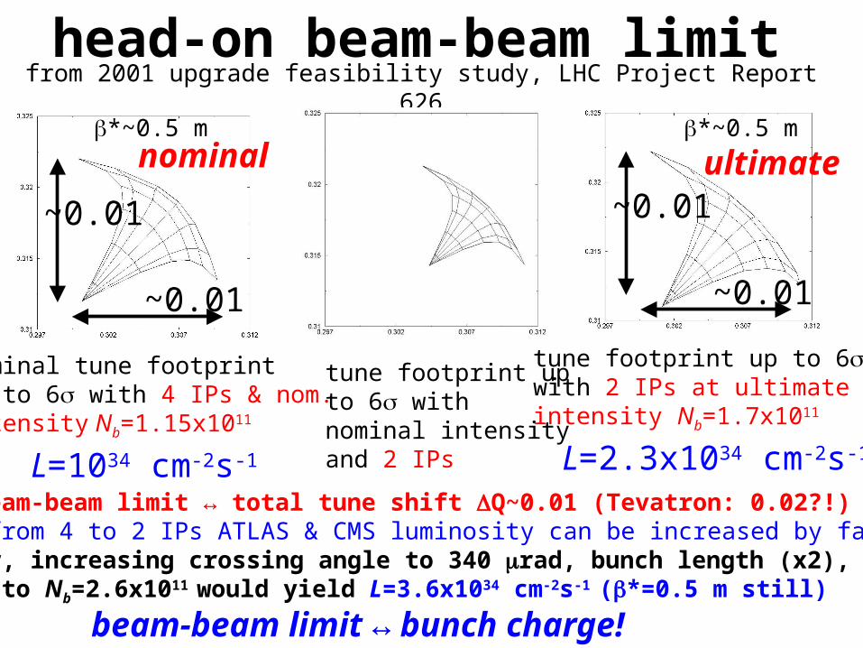
from 2001 upgrade feasibility study, LHC Project Report 626
nominal tune footprintup to 6s with 4 IPs & nom. intensity Nb=1.15x10¹¹
tune footprint up to 6s with nominal intensityand 2 IPs
tune footprint up to 6s with 2 IPs at ultimateintensity Nb=1.7x10¹¹
L=1034 cm-2s-1 L=2.3x1034 cm-2s-1
SPS: beam-beam limit ↔ total tune shift DQ~0.01 (Tevatron: 0.02?!)going from 4 to 2 IPs ATLAS & CMS luminosity can be increased by factor 2.3further, increasing crossing angle to 340 mrad, bunch length (x2), & bunch charge to Nb=2.6x10¹¹ would yield L=3.6x1034 cm-2s-1 (b*=0.5 m still)
~0.01
~0.01
~0.01
~0.01
b*~0.5 m b*~0.5 m
head-on beam-beam limit
beam-beam limit ↔ bunch charge!
nominal ultimate

LHC Upgrade Beam Parameters, Frank Zimmermann PAF/POFPA Meeting 20 November 2006
generated tracks per crossing, pt > 1 GeV/c cut, i.e. soft tracks removed!
1035cm-2s-1
I. Osborne
detector pile up < 200-300 events/#ing!?
↔ bunch spacing!
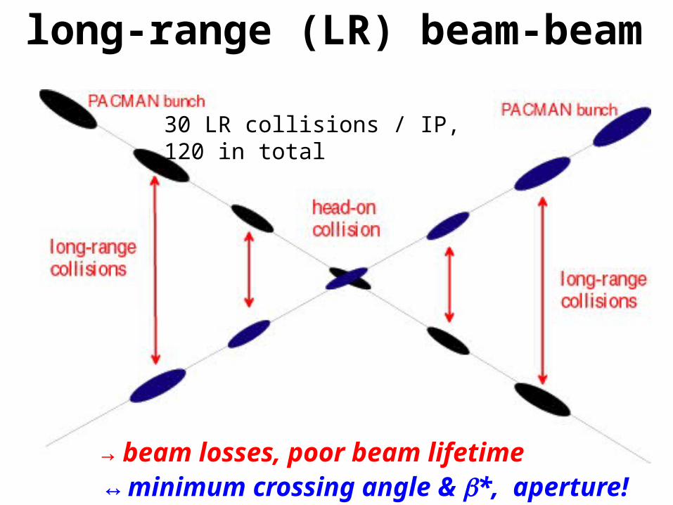
long-range (LR) beam-beam
30 LR collisions / IP, 120 in total
→ beam losses, poor beam lifetime↔ minimum crossing angle & b*, aperture!

x
zcR
2
;1
12
“Piwinski angle”luminosity reduction factor
nominal LHC
crossing angle
qc/2
effective beamsize s→s/Rf
→ luminosity loss, poor beam lifetime↔ bunch length, b*, crab cavities, emittance,
early separation scheme!

• main task: quench protection: 1% beam loss in 10 s
at 7 TeV ~ 500 kW energy ; quench limit = 8.5 W/m!
• simulated cleaning efficiency w. errors allows only
~5% of nominal intensity for assumed loss rate
• IR upgrade will not improve intensity limit
• “phase-II” collimation with (sacrificial or
consumable?) Cu & cryogenic collimators under
study ; predicted factor 30 improvement in cleaning
efficiency: 99.997 %/m → 99.99992 %/m ; ready for
nominal and higher intensity in 2012?!
collimation R. Assmann, HHH-2008

electron cloud
schematic of e- cloud build up in LHC beam pipe,due to photoemission and secondary emission
[F. Ruggiero]
→ heat load (→ quenches), instabilities, emittance growth, poor beam lifetime
↔ bunch spacing, bunch charge & bunch length!
also synchrotron radiation & beam image currents add to heat load

• nominal LHC beam ~ present performance limit
• ultimate LHC beam out of reach
• component aging & reliability problems
• important limiting mechanisms like space charge, &
aperture are common to all injectors and will “profit”
from an injection energy increase; in particular the
PSB will profit from new LINAC4
• TMCI is a major limitation for PS and SPS and an
increase in |h| is necessary (avoid transition crossing
and ginj>>gtr)
injector limitations
G. Arduini, BEAM’07
Name Event Date10
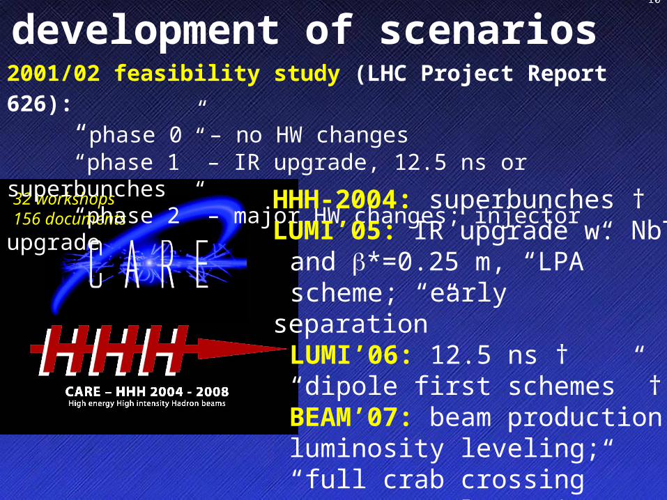
development of scenarios
32 workshops156 documents
2001/02 feasibility study (LHC Project Report 626): “phase 0” – no HW changes“phase 1” – IR upgrade, 12.5 ns or superbunches“phase 2” – major HW changes; injector upgrade
HHH-2004: superbunches †LUMI’05: IR upgrade w. NbTi
and b*=0.25 m, “LPA” scheme; “early separation”LUMI’06: 12.5 ns †“dipole first schemes” †BEAM’07: beam
production;luminosity leveling;“full crab crossing”HHH-2008: “low emittance”

LHC upgrade stages
“phase 1” ~2013, 2x1034 cm-2s-1:new NbTi triplets, D1, TAS, b*~0.25-0.3 m in IP1 & 5,beam from new Linac4
“phase 2” ~2017, ~1035 cm-2s-1 :possibly Nb3Sn triplet & b*~0.15 m
complementary measures 2010-2017: e.g. long-range beam-beam compensation, crab cavities, advanced collimators, crab waist?[, coherent e- cooling??, e- lenses??]
longer term (2020?): energy upgrade, LHeC,…
phase-2 might be just phase 1 plus complementary measures
+ injector upgrade

Name Event Date12
(LP)SPL: (Low Power) Superconducting Proton Linac (4-5 GeV)
PS2: High Energy PS(~ 5 to 50 GeV – 0.3 Hz)
SPS+: Superconducting SPS(50 to1000 GeV)
SLHC: “Superluminosity” LHC(up to 1035 cm-2s-1)
DLHC: “Double energy” LHC(1 to ~14 TeV)
Proton flux / Beam power
present and future injectors
PSB
SPSSPS+
Linac4
(LP)SPL
PS
LHC / SLHC DLHC
Ou
tpu
t en
ergy
160 MeV
1.4 GeV4 GeV
26 GeV50 GeV
450 GeV1 TeV
7 TeV~ 14 TeV
Linac250 MeV
PS2
Roland Garoby, LHCC 1July ‘08
Name Event Date13
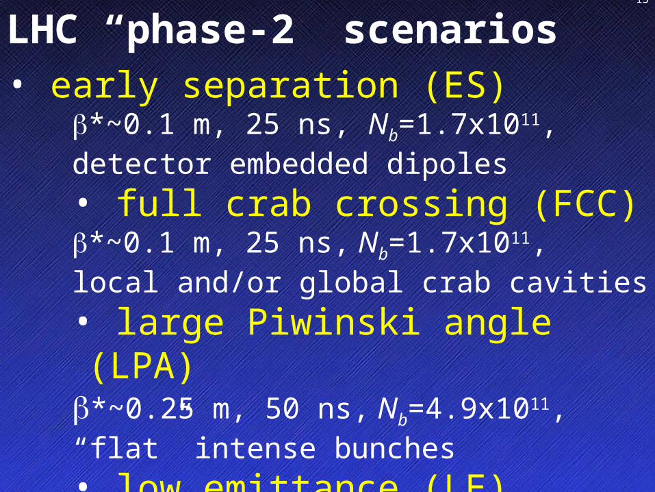
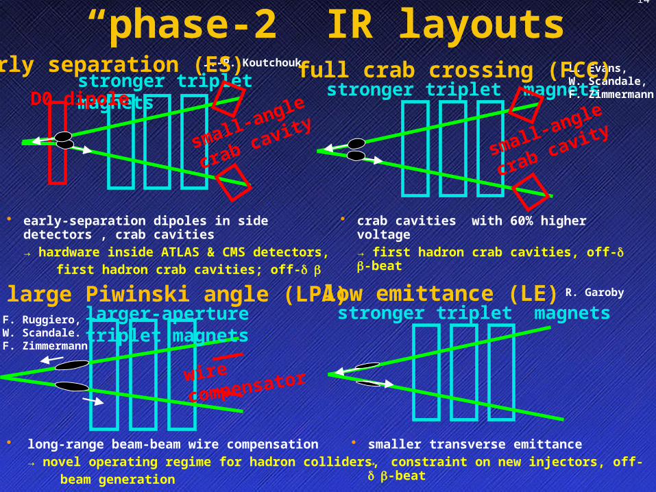
LHC “phase-2” scenarios
• early separation (ES)b*~0.1 m, 25 ns, Nb=1.7x10¹¹, detector embedded dipoles• full crab crossing (FCC) b*~0.1 m, 25 ns, Nb=1.7x10¹¹,local and/or global crab cavities • large Piwinski angle (LPA)b*~0.25 m, 50 ns, Nb=4.9x10¹¹,“flat” intense bunches • low emittance (LE)b*~0.1 m, 25 ns, ge~1-2 mm, Nb=1.7x10¹¹
Name Event Date14
“phase-2” IR layouts
• early-separation dipoles in side detectors , crab cavities → hardware inside ATLAS & CMS detectors,
first hadron crab cavities; off- d b
stronger triplet magnetsD0 dipole
small-angle
crab cavity
J.-P. Koutchoukearly separation (ES)stronger triplet magnets
small-angle
crab cavity
• crab cavities with 60% higher voltage → first hadron crab cavities, off- d b-beat
L. Evans,W. Scandale,F. Zimmermann
full crab crossing (FCC)
wire
compensator
larger-aperture triplet magnets
• long-range beam-beam wire compensation → novel operating regime for hadron colliders,
beam generation
F. Ruggiero,W. Scandale.F. Zimmermann
large Piwinski angle (LPA)stronger triplet magnets
• smaller transverse emittance → constraint on new injectors, off- d b-beat
R. Garobylow emittance (LE)
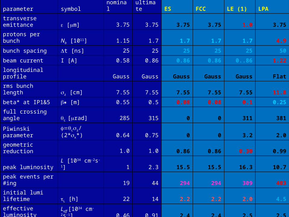
parameter symbol nominal ultimate ES FCC LE (1) LPA
transverse emittance e [mm] 3.75 3.75 3.75 3.75 1.0 3.75
protons per bunch Nb [1011] 1.15 1.7 1.7 1.7 1.7 4.9
bunch spacing Dt [ns] 25 25 25 25 25 50
beam current I [A] 0.58 0.86 0.86 0.86 0..86 1.22
longitudinal profile Gauss Gauss Gauss Gauss Gauss Flat
rms bunch length sz [cm] 7.55 7.55 7.55 7.55 7.55 11.8
beta* at IP1&5 *b [m] 0.55 0.5 0.08 0.08 0.1 0.25
full crossing angle qc [mrad] 285 315 0 0 311 381
Piwinski parameter =f qcsz/(2*sx*) 0.64 0.75 0 0 3.2 2.0
geometric reduction 1.0 1.0 0.86 0.86 0.30 0.99
peak luminosity L [1034 cm-2s-1] 1 2.3 15.5 15.5 16.3 10.7
peak events per #ing 19 44 294 294 309 403
initial lumi lifetime tL [h] 22 14 2.2 2.2 2.0 4.5
effective luminosity (Tturnaround=10 h)
Leff [1034 cm-2s-1] 0.46 0.91 2.4 2.4 2.5 2.5
Trun,opt [h] 21.2 17.0 6.6 6.6 6.4 9.5
effective luminosity (Tturnaround=5 h)
Leff [1034 cm-2s-1] 0.56 1.15 3.6 3.6 3.7 3.5
Trun,opt [h] 15.0 12.0 4.6 4.6 4.5 6.7
e-c heat SEY=1.4(1.3) P [W/m] 1.1 (0.4) 1.04(0.6) 1.0 (0.6) 1.0 (0.6) 1.0 (0.6) 0.4 (0.1)
SR heat load 4.6-20 K PSR [W/m] 0.17 0.25 0.25 0.25 0.25 0.36
image current heat PIC [W/m] 0.15 0.33 0.33 0.33 0.33 0.78
gas-s. 100 h (10 h) tb Pgas [W/m] 0.04 (0.4) 0.06 (0.6) 0.06 (0.56) 0.06 (0.56) 0.06 (0.56) 0.09 (0.9)
extent luminous region sl [cm] 4.5 4.3 3.7 3.7 1.6 5.3
comment nominal ultimate D0 + crab crab wire comp.
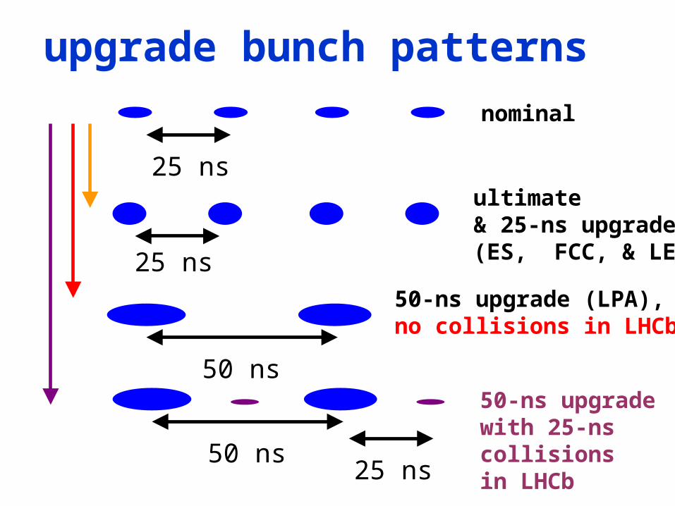
50-ns upgradewith 25-ns collisionsin LHCb
upgrade bunch patterns
25 ns
50 ns
nominal
25 ns
ultimate& 25-ns upgrade(ES, FCC, & LE)
50-ns upgrade (LPA),no collisions in LHCb!
50 ns25 ns
Name Event Date17
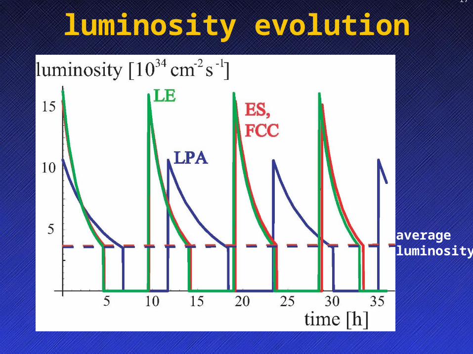
luminosity evolution
averageluminosity

Name Event Date18
event pile up

Name Event Date19
b.-b. DQ & peak luminosity
222*2
*
2
2*
1
1
2
11
11
4
1
piwhgprofilebbbrevp
hgprofilebbbbrevp
piw
hgbbrev
FFQnfr
FFQNnfr
FNnfL
profilepiw
pbbb F
rNQ
1
1
1
2 2 *
,2 yx
czpiw
total beam-beam tune shift at 2 IPs with alternating crossing;we increase charge Nb until limit DQbb is reached; to go furtherwe must increase fpiw, and/or e and/or Fprofile (~21/2 for flat bunches)
Piwinski angle
at the b-b limit, larger Piwinski angle &/or larger emittance increase luminosity
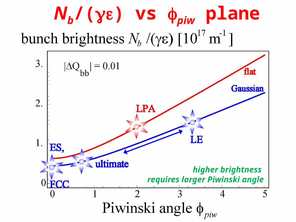
Nb/(ge) vs fpiw plane
higher brightness requires larger Piwinski angle

av. luminosity vs #p’s & b*
“linear” scale from 1033 to 2x1035 cm-2s-1
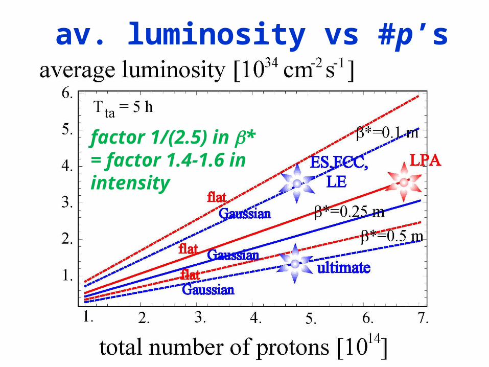
av. luminosity vs #p’s
factor 1/(2.5) in b* = factor 1.4-1.6 in intensity
Name Event Date23
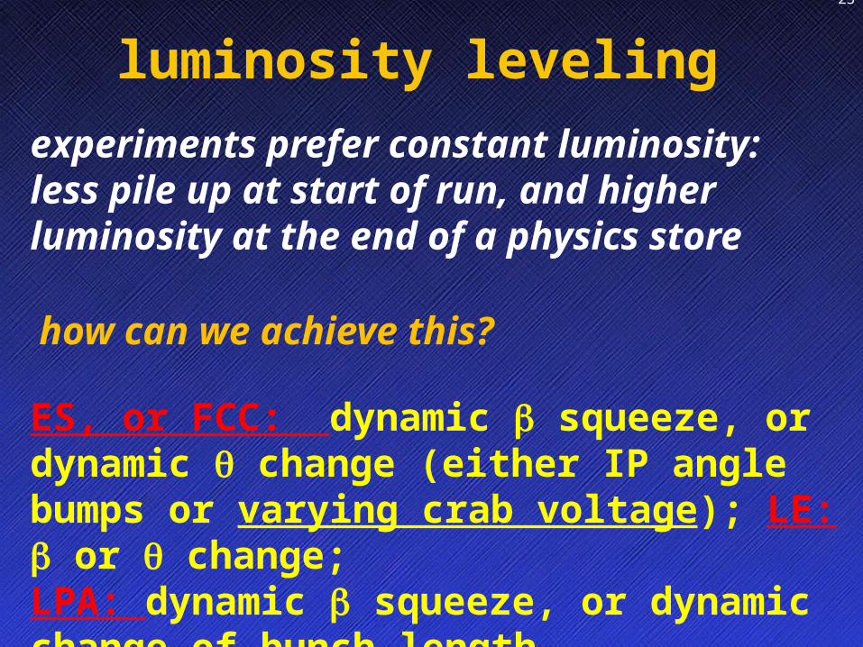
experiments prefer constant luminosity: less pile up at start of run, and higher luminosity at the end of a physics store
ES, or FCC: dynamic b squeeze, or dynamic q change (either IP angle bumps or varying crab voltage); LE: b or q change;LPA: dynamic b squeeze, or dynamic change of bunch length
how can we achieve this?
luminosity leveling
LHC Upgrade Beam Parameters, Frank Zimmermann PAF/POFPA Meeting 20 November 2006
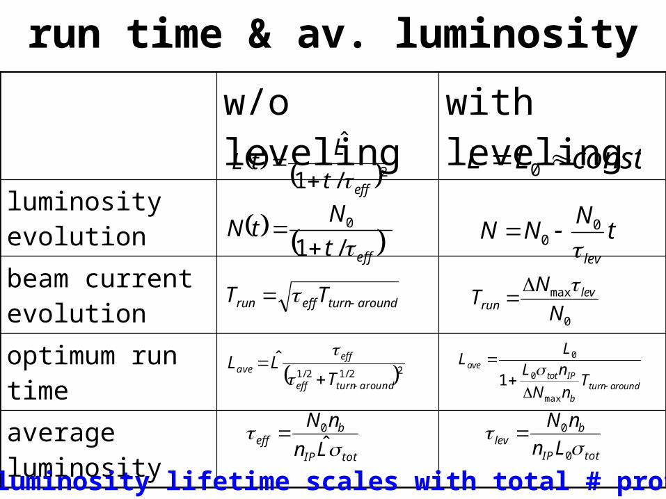
run time & av. luminosity
w/o leveling with levelingluminosity evolutionbeam current evolutionoptimum run timeaverage luminosity
constLL 0 2/1
ˆ
efft
LtL
tN
NNlev
00 efft
NtN
/10
0
max
N
NT lev
run
aroundturneffrun TT
aroundturnb
IPtotave
TnN
nLL
L
max
0
0
1 22/12/1
ˆ
aroundturneff
effave
TLL
totIP
beff
Ln
nN
ˆ0
totIP
blev Ln
nN
0
0
luminosity lifetime scales with total # protons!
LHC Upgrade Beam Parameters, Frank Zimmermann PAF/POFPA Meeting 20 November 2006
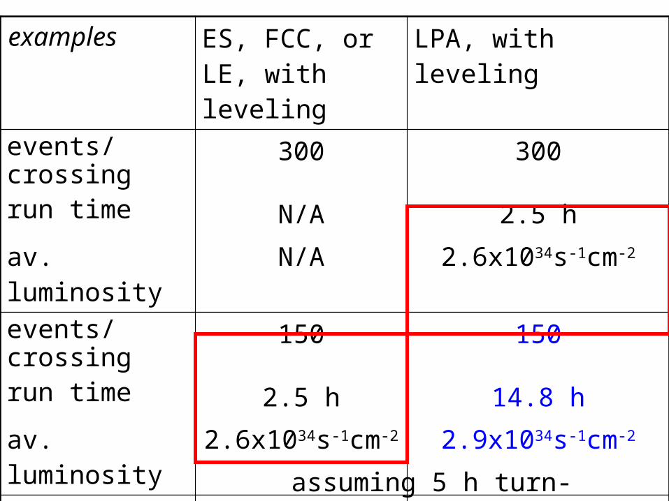
ES, FCC, or LE, with leveling
LPA, with leveling
events/crossing 300 300run time N/A 2.5 h
av. luminosity N/A 2.6x1034s-1cm-2
events/crossing 150 150
run time 2.5 h 14.8 h
av. luminosity 2.6x1034s-1cm-2 2.9x1034s-1cm-2
events/crossing 75 75
run time 9.9 h 26.4 h
av. luminosity 2.6x1034s-1cm-2 1.7x1034s-1cm-2
assuming 5 h turn-around time
examples
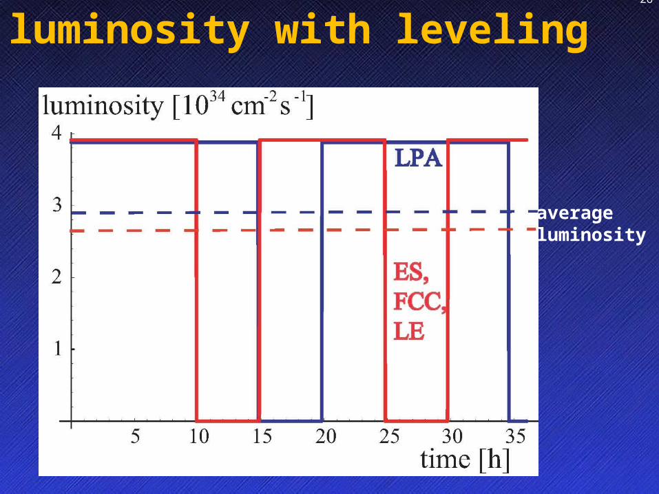
Name Event Date26
luminosity with leveling
averageluminosity
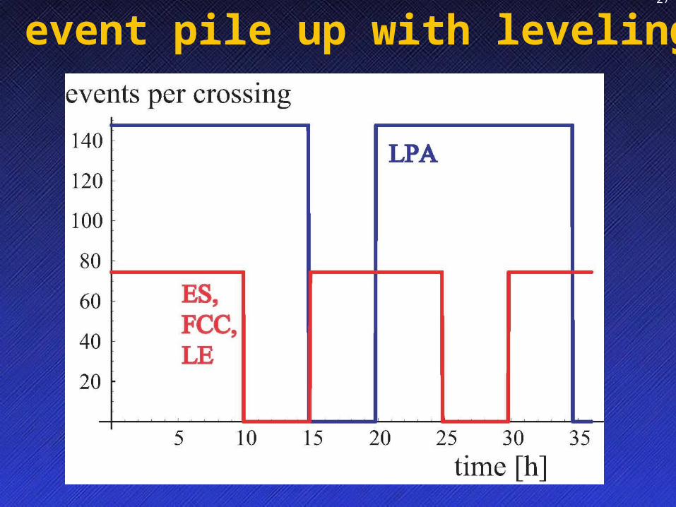
Name Event Date27
event pile up with leveling
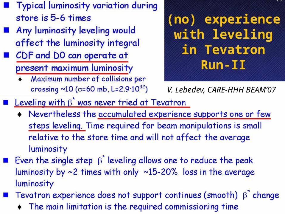
Name Event Date28
(no) experience with leveling in Tevatron Run-II
V. Lebedev, CARE-HHH BEAM’07

Name Event Date29
Chamonix’08 workshop → scenario for 2009/10 running
maximum resources engaged in certain technical domains, leaving little space for other work (e.g. magnet group’s involvement in repairing S3-4 and consolidating other sectors)→ 6-months delay in IR phase-1 magnet activities
delays in Linac4 civil works likely to shift start of Linac4 operation by one year
phase-I upgrade (experiments and accelerators) is postponed to shutdown of 2014, yielding effectively one year delay with respect to previous schedule
schedule after Chamonix’09
S. Fartoukh, R. Garoby, R. Ostojic

revised forecast peak & integrated luminosity evolution
Collimation phase 2
Linac4 + IR
upgrade
phase 1
New injectors + IR
upgrade
phase 2
ATLAS will need ~18 months
shutdown
goal for ATLAS Upgrade:3000 fb-1 recorded
cope with ~400 pile-up events each BC M. Nessi, CARE-HHH LHC crab-cavity validation mini-workshop August 2008, R. Garoby, LHCC July 08
202
6202
5202
4202
3202
2202
1202
0201
9201
8201
7201
6201
5201
4201
3201
2201
1201
0
202
6202
5202
4202
3202
2202
1202
0201
9201
8201
7201
6201
5201
4201
3201
2201
1201
0
shifted one year shifted one year

more commentson the four upgrade
schemes

Early Separation
magnets in front of calorimeters ruled out
D0 at ~14 m from IP retained as option (HHH-2008)
integrated field of ~13T-m required for D0 at 14 m
peak luminosity gain ~30-60% for b*=0.15 mdepending on minimum acceptable beam-beamseparation between the D0’s (7 or 5s)
heat load can be a problem (also effect of CMS solenoid, impact on background,…)
J.-P. Koutchouk, G. Sterbini et al.

Crab Cavities – Phases Phase I:
Test prototype – one cavity/beam (@IR4, 2013) Feasibility of crab crossing in hadron machine,
superconducting RF limits in deflecting mode, collimation,
impedance Operations - Cryogenics, operation at injection/ramp/top
energies, luminosity gain and leveling, emittance growth Phase II:
Complete IR redesign (IR1 & 5) with crab crossing optics
(2017/18?) Perhaps need for special compact cavities due to space
constraints
Phase I Phase II
R. Calaga

Crab Cavities: KEK-B Test Bed No serious instabilities at high currents (1.62/0.9 A) w.
crab cavities Similar luminosity as before at ~30% lower beam current Trip rate needs to improve for more reliable operation
Y. Morita et al (KEK-B)
KEK-B experiments will probe
many LHC related concerns
(Dec 08,
Spring 09):
KEK-CERN crab collaboration
R. Calaga
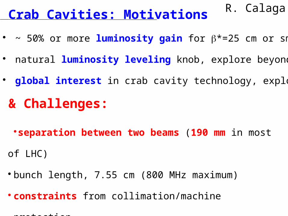
Crab Cavities: Motivations
& Challenges:
~ 50% or more luminosity gain for b*=25 cm or smaller
natural luminosity leveling knob, explore beyond the BB limit
global interest in crab cavity technology, exploit synergies
separation between two beams (190 mm in
most of LHC)
bunch length, 7.55 cm (800 MHz maximum)
constraints from collimation/machine protection
R. Calaga
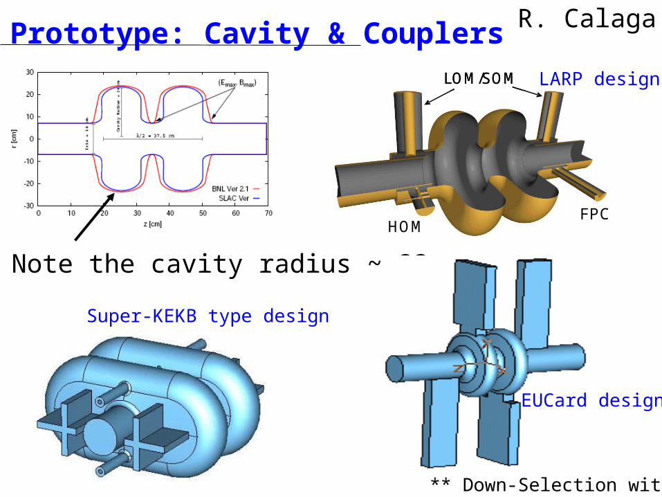
Prototype: Cavity & CouplersLARP designLOM/SOM
HOMFPC
LOM/SOM
HOMFPC
Super-KEKB type design
** Down-Selection within 1yr
Note the cavity radius ~ 23 cm
EUCard design
R. Calaga
cap tu re cav ities (A C N )
cap tu re cav ities
d am p er(A D T )
reserv e
d am p er
reserv e
d o g - leg
d o g - leg
su p erco n d u ctin g m o d u les (A S C )
su p erco n d u ctin g m o d u les
A P W
A P W
sid e v iew
sid e v iew
sid e v iew
to p v iew
to p v iew
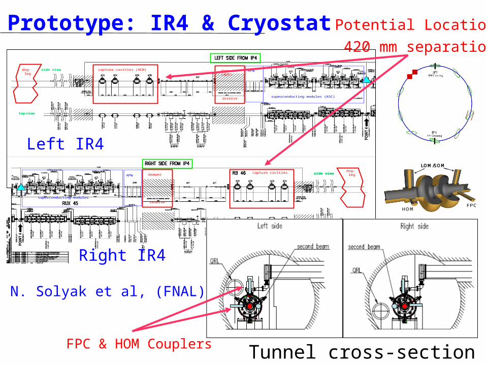
Tunnel cross-section
Prototype: IR4 & Cryostat Potential Locations
420 mm separation
Left IR4
Right IR4
FPC & HOM Couplers
N. Solyak et al, (FNAL)
LOM/SOM
HOMFPC
LOM/SOM
HOMFPC
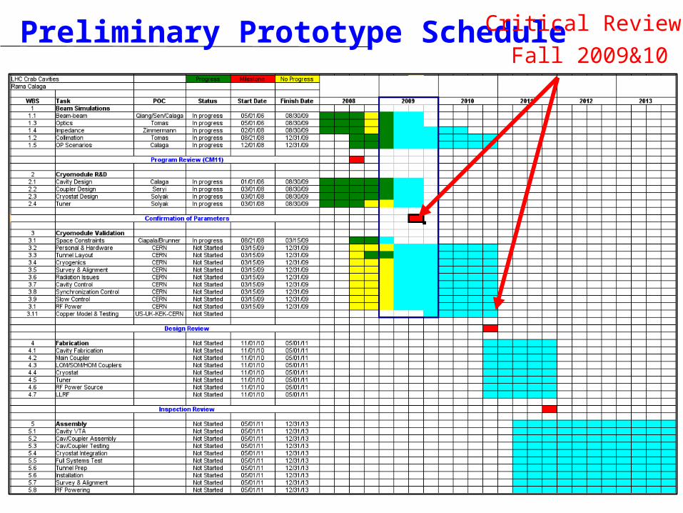
Preliminary Prototype ScheduleCritical Reviews
Fall 2009&10

Global Crab Cavity Contributions US-LARP
FY09 funding is good and expected to ramp up in the following years All proposed activities to continue, focus on cavity/coupler; mostly studies, little hardware
UK/CERN FP7 Budget sufficient for (670 k€ for 3 yrs, 1.5 FTE/yr):
Cavity/coupler studies, LLRF, warm model & testing (UK) Beam simulations, optics and installation issues (CERN)
Perhaps an increase in the following yrs. experimental contributions (?)
KEK Cavity/coupler simulations based on super KEK-B type structure Top level CERN-KEK agreement, funding request & approval by Japanese
government could allow major contributions
SBIRs (US-DOE) AES-BNL/FNAL/LBL/SLAC (cavity, couplers, cryostat, tuner); waiting for SBIR approval(s)
Other Collaborators Tsinghua University: Warm models & testing (in collaboration with UK work) Jlab: Very interested. Some activity ongoing on rod type compact structures
R. Calaga

“large Piwinski angle” (LPA)
If SPS can accelerate 6´1011 p/b (eL~0.7 eVs)
If SPS cannot accelerate 6´1011 p/b (eL~0.7 eVs)
“Best” choice Generate beam in PS2 at capture [PS2/1]
Slip stacking at high energy[SPS/4] ?
“Alternative” choice
Generate beam in PS2 by merging [PS2/2]
?
Other (new) ideas ? ?
generation & stability of 50-ns long flat intense bunchesR. GarobyCARE-HHH BEAM’07
h=21
h=21+4295 msec
35 msec
Experimental Data ESME Simulationstudies offlat-bunchgenerationin the CERN PS,C. Bhat (FNAL),2008
HHH-LARPcollaboration
SPS may be bottleneck!

low emittance (LE) schemesparameter symbol LE 1 LE 2
transverse emittance e [mm] 1.0 2.6
protons per bunch Nb [1011] 1.7 2.36
beam current I [A] 0.86 1.19
beta* at IP1&5 *b [m] 0.1 0.15
full crossing angle qc [mrad] 311 322
Piwinski parameter =f qcsz/(2*sx*) 3.2 1.7
geometric reduction 0.30 0.51
peak luminosity L [1034 cm-2s-1] 16.3 13.2
peak events per #ing 309 250
initial lumi lifetime tL [h] 2.0 2.5
effective luminosity (Tturnaround=10 h)
Leff [1034 cm-2s-1] 2.5 2.7
Trun,opt [h] 6.4 8.4
effective luminosity (Tturnaround=5 h)
Leff [1034 cm-2s-1] 3.7 3.9
Trun,opt [h] 4.5 5.9
e-c heat SEY=1.4(1.3) P [W/m] 1.0 (0.6) ~1.6 (1.1)
SR heat load 4.6-20 K PSR [W/m] 0.25 0.35
image current heat PIC [W/m] 0.33 0.64
gas-s. 100 h (10 h) tb Pgas [W/m] 0.06 (0.6) 0.08 (0.8)
extent luminous region sl [cm] 1.5 2.8
LE2
LE1
trade off intensity vs. emittance
smaller brightness is easier for injectors, but it comes together with higher bunch charge, higher heat load etc.

Name Event Date42
some conclusions nominal LHC is challenging upgrade of collimation system mandatory beam parameter sets evolved over past 8 years several scenarios exist on paper which can
reach 10x nominal luminosity with acceptable heat load & pile up; different merits and drawbacks (not in a corner)
if possible, raising beam intensity is preferred over reducing b* (better beam lifetime) ;
but intensity might be limited by collimation! needed: work on s.c. IR magnets for phase-2 and
on complementary measures (LR beam-beam compensation, crab cavities, etc. )
close coordination with detector upgrades
Name Event Date43
thank you!
Name Event Date44
appendix:
more details on collimation constraints

Maximum beam loss at 7 TeV: 1% of beam over 10 s 500 kW
Quench limit of SC LHC magnet:
8.5 W/m
R. Assmann - HHH 2008
collimation – quench prevention
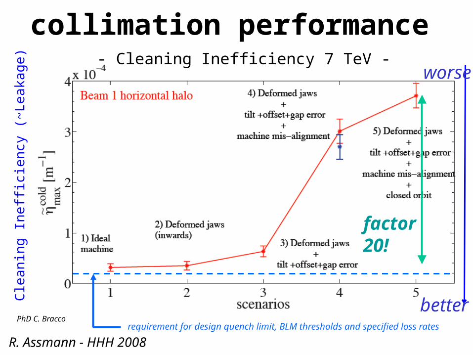
collimation performance - Cleaning Inefficiency 7 TeV -
better
worse
Cle
anin
g In
effi
cien
cy (
~Le
aka
ge
)
requirement for design quench limit, BLM thresholds and specified loss ratesPhD C. Bracco
R. Assmann - HHH 2008
factor20!
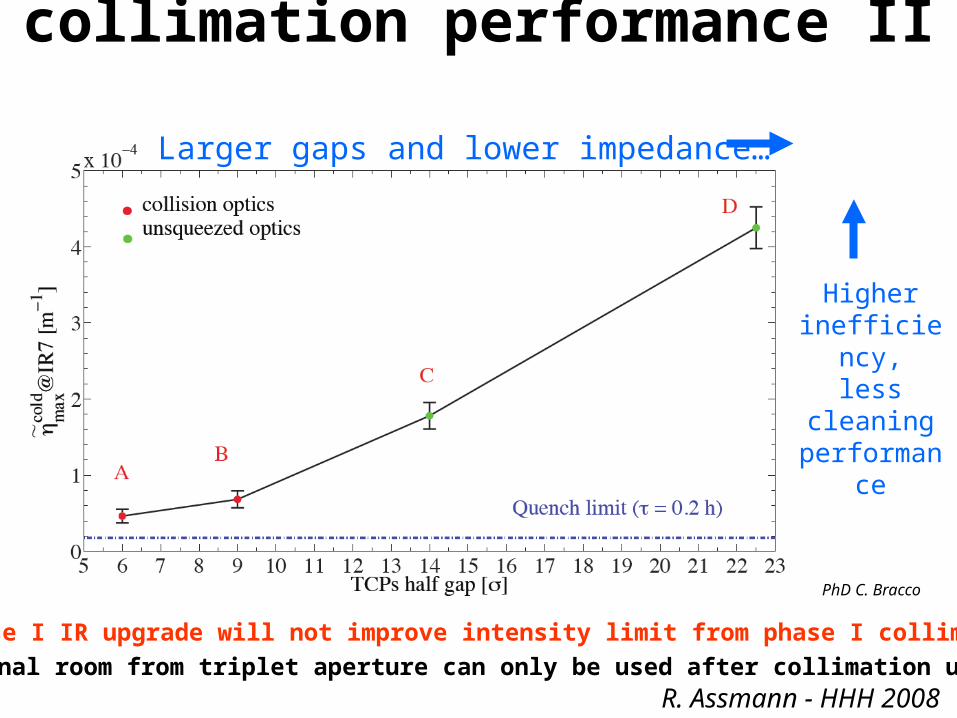
Larger gaps and lower impedance…
Higher inefficiency,
less cleaning performance
Phase I IR upgrade will not improve intensity limit from phase I collimation!
Additional room from triplet aperture can only be used after collimation upgrade
PhD C. Bracco
collimation performance II
R. Assmann - HHH 2008

p collimation efficiency w. “phase II” Cu & Cryogenic Collimators
inefficiency reduces by factor 30 (good for nominal intensity)
caution: further studies must show feasibility of this proposal
cryogenic collimators will be studied as part of FP7 with GSI in Germany
99.997 %/m 99.99992 %/m
T. Weiler & R. Assmann
R. Assmann - HHH 2008
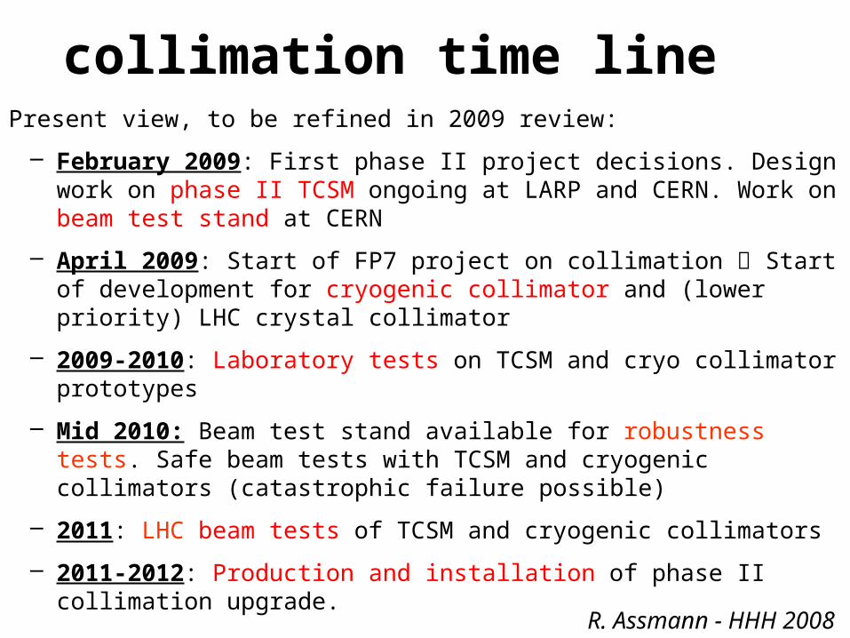
collimation time linePresent view, to be refined in 2009 review:
– February 2009: First phase II project decisions. Design work on phase II TCSM ongoing at LARP and CERN. Work on beam test stand at CERN
– April 2009: Start of FP7 project on collimation Start of development for cryogenic collimator and (lower priority) LHC crystal collimator
– 2009-2010: Laboratory tests on TCSM and cryo collimator prototypes
– Mid 2010: Beam test stand available for robustness tests. Safe beam tests with TCSM and cryogenic collimators (catastrophic failure possible)
– 2011: LHC beam tests of TCSM and cryogenic collimators
– 2011-2012: Production and installation of phase II collimation upgrade.
– Mid 2012: Readiness for nominal and higher intensities from collimation side
R. Assmann - HHH 2008
Related Documents


