, ..;: . ,..../ ....,_ ,.!: /:; /..!i!_: N95- 14682 CD RADIO S-Band Propagation Measurements Robert D. Briskman CD Radio Inc., Washington, D.C. INTRODUCTION A geosynchronous satellite system capable of providing many channels of Digital Audio Radio Service (DARS) to mobile platforms within the contiguous United States using S-band radio frequencies is being implemented. The system is designed uniquely to mitigate both multipath fading and outages from physical blockage in the transmission path by use of satellite spatial diversity in combination with radio frequency and time diversity. Figure 1 shows the generalized system configuration. The system also employs a satellite orbital geometry wherein all mobile platforms in the contiguous United States have elevation angles greater than 20 ° to both of the diversity satellites. Since implementation of the satellite system will require three years, an emulation has been performed using terrestrial facilities in order to allow evaluation of DARS capabilities in advance of satellite system operations. The major objective of the emulation was to prove the feasibility of broadcasting from satellites 30 channels of CD quality programming using S-band frequencies to an automobile equipped with a small disk antenna and to obtain quantitative performance data on S-band propagation in a satellite spatial diversity system. DARS SATELLITE SYSTEM The satellite system consists of two geosynchronous satellites, one located over the east coast of the United States at 80 ° West Longitude and the second over the west coast of the United States at 110 ° West Longitude. The satellites receive in the 6720 MHz band and transmit in two 8 MHz segments of the 2310-2360 MHz band. The satellites each receive the same transmission from the system's up-link/programming center essentially simultaneously and retransmit the signal through an antenna beam covering the contiguous United States. Figure 2 shows the block diagram of the satellite's transmission payload. The retransmission frequencies of the two satellites are separated by 20 MHz and the beam edge EIRP is 57 dBW. The high EIRP is required due to the low gain of the mobile platform antenna. The transmission consists of 30 stereo CD music channels, a 128 kb/s service channel and several information channels. The CD stereo music channels are compressed prior to transmission using a joint encoding algorithm based on perceptual audio coding so only a 128 kb/s output data rate is required for each. The channels are digitally multiplexed together (i.e., TDM-time division multiplex) with interleaving in time, resulting in a 4 Mb/s output signal. 211 CD Radro Inc 1001 22nd Street NW Washington DC 20037 Tel 202.296.6192 Fax 202.296.6265 https://ntrs.nasa.gov/search.jsp?R=19950008268 2018-05-15T12:37:53+00:00Z

Welcome message from author
This document is posted to help you gain knowledge. Please leave a comment to let me know what you think about it! Share it to your friends and learn new things together.
Transcript
, ..;: . ,..../ ....,_ ,.!: /:; /..!i!_:
N95- 14682
CD RADIO
S-Band Propagation Measurements
Robert D. Briskman
CD Radio Inc., Washington, D.C.
INTRODUCTION
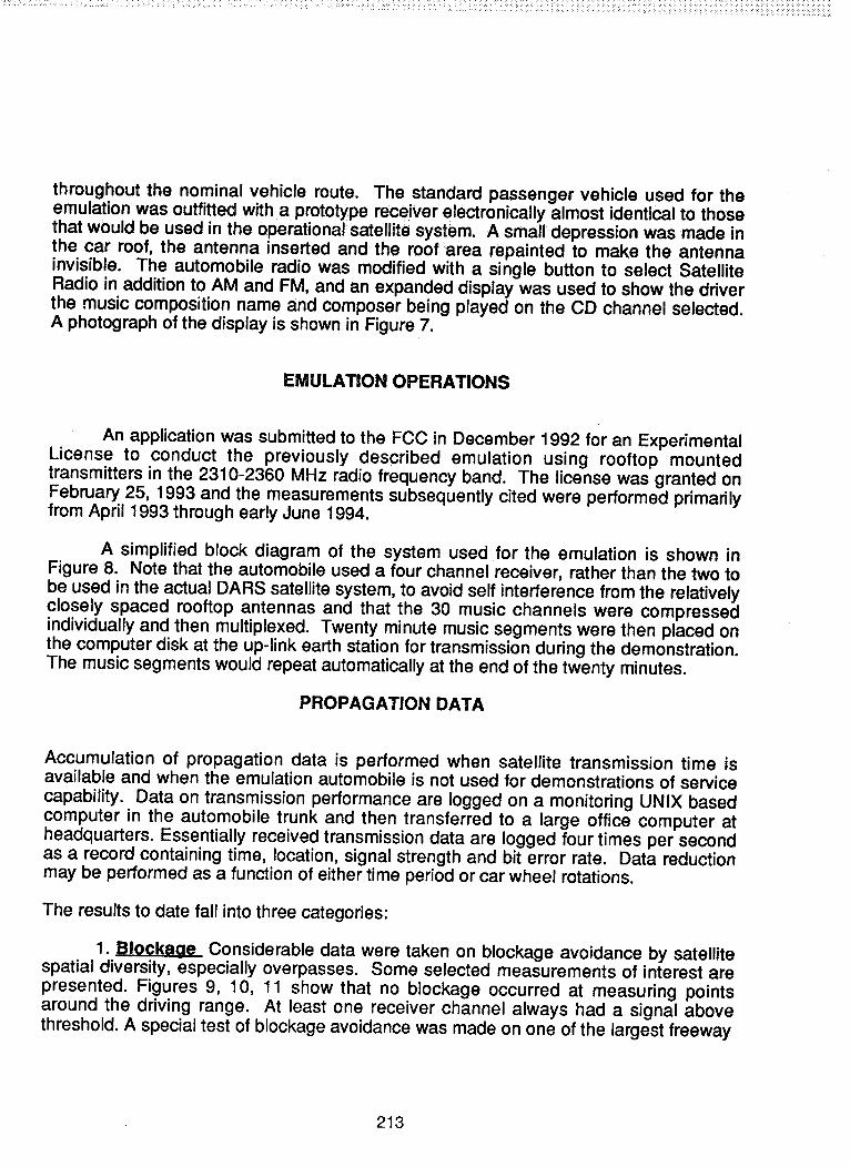
A geosynchronous satellite system capable of providing many channels of DigitalAudio Radio Service (DARS) to mobile platforms within the contiguous United Statesusing S-band radio frequencies is being implemented. The system is designed uniquelyto mitigate both multipath fading and outages from physical blockage in the transmissionpath by use of satellite spatial diversity in combination with radio frequency and timediversity. Figure 1 shows the generalized system configuration. The system alsoemploys a satellite orbital geometry wherein all mobile platforms in the contiguousUnited States have elevation angles greater than 20 ° to both of the diversity satellites.Since implementation of the satellite system will require three years, an emulation hasbeen performed using terrestrial facilities in order to allow evaluation of DARScapabilities in advance of satellite system operations. The major objective of theemulation was to prove the feasibility of broadcasting from satellites 30 channels of CDquality programming using S-band frequencies to an automobile equipped with a smalldisk antenna and to obtain quantitative performance data on S-band propagation in asatellite spatial diversity system.
DARS SATELLITE SYSTEM
The satellite system consists of two geosynchronous satellites, one located overthe east coast of the United States at 80 ° West Longitude and the second over the westcoast of the United States at 110 ° West Longitude. The satellites receive in the 6720MHz band and transmit in two 8 MHz segments of the 2310-2360 MHz band. Thesatellites each receive the same transmission from the system's up-link/programmingcenter essentially simultaneously and retransmit the signal through an antenna beamcovering the contiguous United States. Figure 2 shows the block diagram of thesatellite's transmission payload. The retransmission frequencies of the two satellites areseparated by 20 MHz and the beam edge EIRP is 57 dBW. The high EIRP is requireddue to the low gain of the mobile platform antenna. The transmission consists of 30stereo CD music channels, a 128 kb/s service channel and several information
channels. The CD stereo music channels are compressed prior to transmission using ajoint encoding algorithm based on perceptual audio coding so only a 128 kb/s outputdata rate is required for each. The channels are digitally multiplexed together (i.e.,TDM-time division multiplex) with interleaving in time, resulting in a 4 Mb/s output signal.
211
CD Radro Inc 1001 22nd Street NW Washington DC 20037 Tel 202.296.6192 Fax 202.296.6265
https://ntrs.nasa.gov/search.jsp?R=19950008268 2018-05-15T12:37:53+00:00Z

The output signal is convo!utionally encoded, a Reed-Solomon code added and then
transmitted to the satellites using offset quadraphase shift keying.
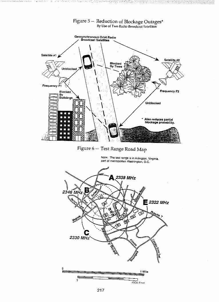
The satellite retransmissions are received by the mobile platforms, particularlypassenger automobiles. The mobile platform GEl"at worst operational aspect angle is-19 dB/K. The antenna is designed to provide 3 dBi gain within a 20°-60 ° elevationangle range at all azimuths. The antenna is physically 2.5 cm in radius and 0.4 cmthick, designed for embedment in automobile rooftops. A photograph of the antenna isshown in Figure 3. After radio frequency reception, amplification and down conversion,the transmission from each satellite is individually demodulated. The two signals aretime phased together using a maximal ratio combiner and then de-multiplexed. Theuser selects the specific music channel desired which is then routed to thedecompressor, the digital-to-analog converter and the audio amplifier-loud speakersubsystem. Figure 4 shows a block diagram of the mobile platform receiver. Themobile platform receiver just described enjoys great resistance to multipath fading andoutage from blockage since its mechanization takes advantage of satellite spatial,frequency and time diversity as depicted in Figure 5.
EMULATION IMPLEMENTATION
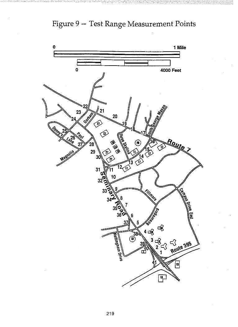
It is difficult to emulate the capabilities of the previously described DARS satellitesystem using terrestrial facilities to simulate the satellites. This is because achieving a20 ° elevation angle to the mobile platform from a terrestrial transmitter simulating thesatellite over a reasonably large area requires buildings or towers of great height. Also,the demonstration of spatial diversity requires two transmitters covering the samegeographical area resulting in the need for several transmitters. A satellite systememulation range was constructed in Northern Virginia close to Washington D.C. Figure6 is a roadmap of the range. Five high-rise building tops were used as transmitlocations to a vehicle driving a route through the area configured so that two transmitlocations are nominally at 10 ° or more elevation angle from the vehicle, and only onetransmit path at a time experiences physical blockage. The particular driving routeincluded areas representing both urban and suburban environments as well as areaswith trees and a roadway overpass.
The 30 CD music channels and service channel were generated at aprogramming/up-link earth station in Washington, D.C. using the compression,multiplexing and modulation described earlier. The uplink station transmitted the signalat Ku-band to the SBS-6 satellite which relayed the signal to standard VSATs on thehigh-rise building roofs. The VSAT received signal was translated by a stable frequencyconverter to the 2310-2360 MHz band and was then re-radiated using a small S-bandtransmitter and omni-directional antenna. The S-band EIRP of the transmitters was
adjusted to provide a signal strength equal to that which would have been received atthe mobile platforms from the previously described geosynchronous satellites
212
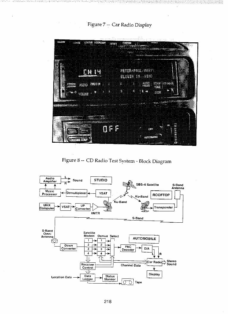
throughout the nominal vehicle route. The standard passenger vehicle used for theemulation was outfitted with a prototype receiver electronically almost identical to thosethat would be used in the operational satellite system. A small depression was made inthe car roof, the antenna inserted and the roof area repainted to make the antennainvisible. The automobile radio was modified with a single button to select SatelliteRadio in addition to AM and FM, and an expanded display was used to show the driverthe music composition name and composer being played on the CD channel selected.A photograph of the display is shown in Figure 7.
EMULATION OPERATIONS
An application was submitted to the FCC in December 1992 for an ExperimentalLicense to conduct the previously described emulation using rooftop mountedtransmitters in the 2310-2360 MHz radio frequency band. The license was granted onFebruary 25, 1993 and the measurements subsequently cited were performed primarilyfrom April 1993 through early June 1994.
A simplified block diagram of the system used for the emulation is shown inFigure 8. Note that the automobile used a four channel receiver, rather than the two tobe used in the actual DARS satellite system, to avoid self interference from the relativelyclosely spaced rooftop antennas and that the 30 music channels were compressedindividually and then multiplexed. Twenty minute music segments were then placed onthe computer disk at the up-link earth station for transmission during the demonstration.The music segments would repeat automatically at the end of the twenty minutes.
PROPAGATION DATA
Accumulation of propagation data is performed when satellite transmission time isavailable and when the emulation automobile is not used for demonstrations of service
capability. Data on transmission performance are logged on a monitoring UNIX basedcomputer in the automobile trunk and then transferred to a large office computer atheadquarters. Essentially received transmission data are logged four times per secondas a record containing time, location, signal strength and bit error rate. Data reductionmay be performed as a function of either time period or car wheel rotations.
The results to date fall into three categories:
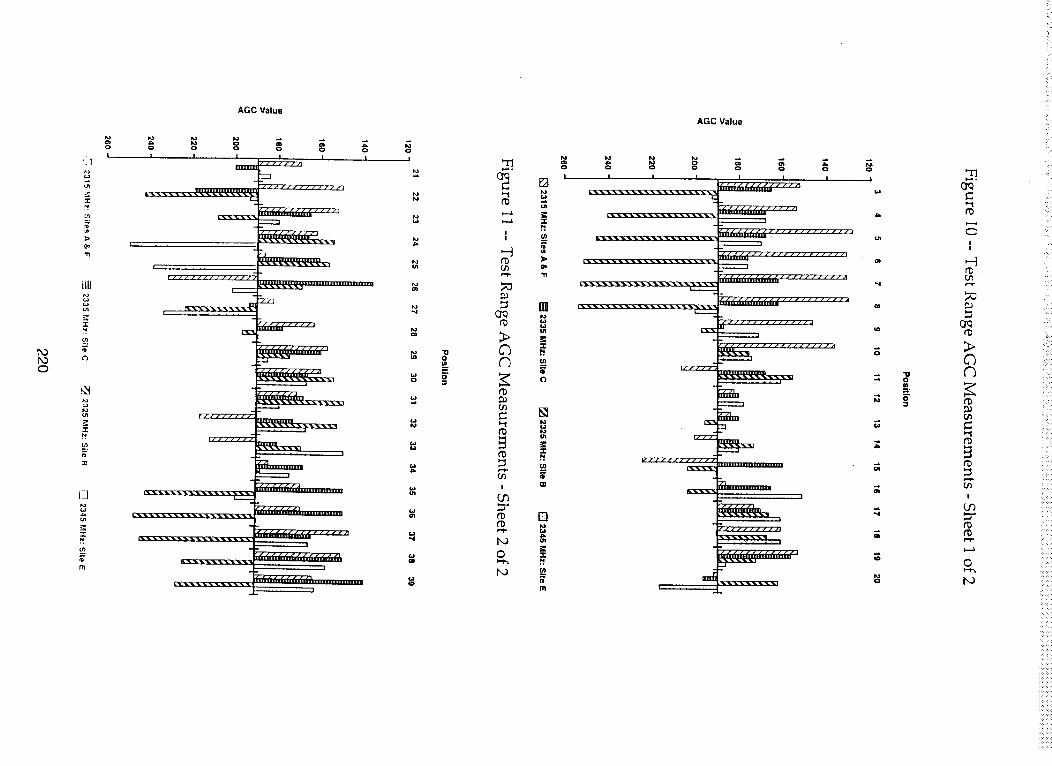
1. Blockage Considerable data were taken on blockage avoidance by satellitespatial diversity, especially overpasses. Some selected measurements of interest arepresented. Figures 9, 10, 11 show that no blockage occurred at measuring pointsaround the driving range. At least one receiver channel always had a signal abovethreshold. A special test of blockage avoidance was made on one of the largest freeway
213

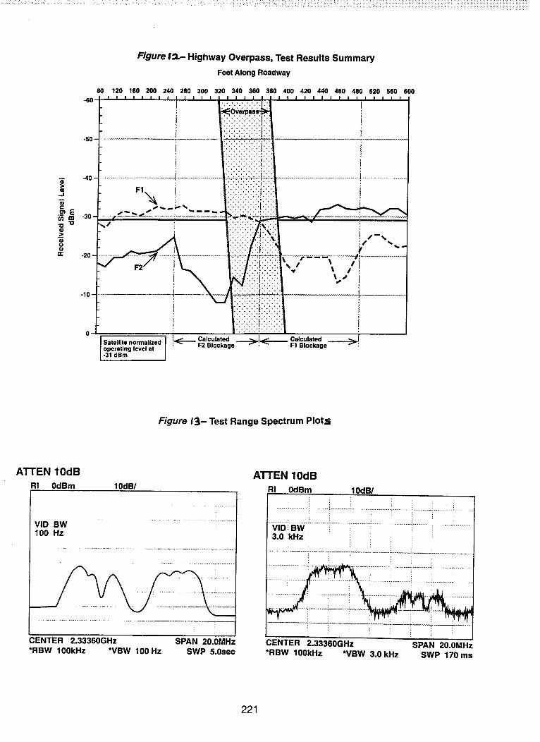
overpasses in the Washington, DC area, and the measurements are summarized inFigure 12. The measurements show that no blockage outage would occur in vehiclespassing under the overpass with the diversity satellite DARS system for the geometryutilized but would always occur for a single satellite DARS system.
2. MulUDath The nominal margin over threshold in the DARS satellite system foreach received transmission without divemity combining is 5dB. This required operationof the test range at increased transmitter power for statistical measurement of multipathfading up to 20dB. The data acquired to date indicate that greater than 12dBimprovement was almost always obtained from diversity but the statistical distributionabove 12dB awaits further data taking.
3. Freauency Selective Fadinq There was observed, on occasion,unanticipated high levels of frequency selective fading. Figure 13 shows two examplesof such fades; the left hand plot containing a narrowband (0.5MHz) fade of 15dB in thelower frequency transmission and the right hand plot containing a wideband (4MHz)fade of 20dB in the upper frequency transmission. In both cases, the satellite frequencydiversity scheme would have prevented a service outage.
SUMMARY
The propagation data obtained to date at S-band demonstrate the effectiveness ofsatellite spatial diversity in mitigating DARS service outages from blockage andmultipath. Further data will be accumulated for determining accurate multipathimprovement performance statistics.
214
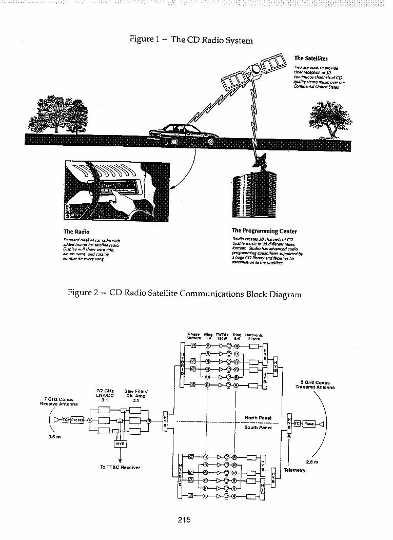
Figure 1 -- The CD Radio System
The Satellites
Two are used, to provideclear reception of 30continuous channels of CD
qualiq/ stereo music over theContinental United States.
The Radio
Standard AIvVFM car radio withadded burton _r satellite radio.
_sp_ay wdl show ams_ t_tie.album name, and ca_lognumber for every song.
The Programming Center
Studio creat_ 30 channels of CD_rmality music in 30 different music
ats. _tudio has advanced audlo
programming capabilities supported bya huge CD library and _acifities fortransmission to the satellites.
Figure 2 -- CD Radio Satellite Communications Block Diagram
Phale Ring TWTAs Ring HarmonicShlftem 6:4 160W 6:4 Filters
7/2 GHz Saw Filter/
LNA/DC Ch. Amp7 GHz Conus 3:1 3:1
Receive Antenna
TO "l-r&c Receiver
North Panel
South Panel
2 GHz ConusTransmit Antenna
2.8 m
Telemetry
215

..............................._:_:_,__:,_,___::4_._:_,_::,__:__:_:_,_::_._:_,__:_>__:_z_:_:::<:_v__:i_i_i_;:i,_i_i_:_i_i_i_i_i_i:!_i_i_!_i_!_!_i_:!_i_!i_:_:_;i!/_:i!!,iilii_!_;!;iii!_:iiil3!i!_:i!_i_;iii__/ii_!3_i!!iiii_i:iii_i!_ii!_ii!_i!!_ii!_ii!_i!!iii!ii;iiii!_ii!i!!iiiiiiiiiiii}iiiii!ii!iiiiiiiiiiiiiiiii!i;iliiiiiiiiiii_iiii!i_i!ii_ii__i_ii_iiiiiii}iiiii_iiiii__{iiiii__iiiii_iiiiiii_iiiii_iiii_i_ii_
Figure 3 -- CD Radio Antenna
Figure 4 -- Vehicle ReceiverAnalog AM & FM/Digital Satellite & Terrestrial
S-BandSatelliteAntenna
i
LNA !
i,.V_ i
iI i I I t I
Demodulatorsl _ I Demodulator II I i ...... j
i Comparator]_d r i _ ' MusicDemultiplexer _-_ Decompressor I__._._
I ! t l J I I -J L -L• I' A I
I l I
I i Front Panel
l ControlsServiceChannel
r iDisplay I
i
AM/FM
Antenna
l 'l -I Demodulator
FMRecelver j ; L _ J _UOIO
I
I Digital
I
R L
Amplifier _* LII1
..... Centrel
--_ Signal
I--_._.'_ Terrestrial DAB
F Satellite DAR
216
..... , • , ,, ,,, :: .: x.::+ ._:, ,:::::: :: :::::x:::: :!:i: ih!:i: ::'ii::::ii!!iiiiiii!i::i_!_i_::_:_:_!_!i!_:!ii::!:!:::_:!:ii!_!_i:_:_:_i:_:_:_:i_!_i_ii_i_i_:_:_:_i_:_i_i_
:: :,:,::.12.::::: :: ::i;i::i_ : :: :ic • !_i :i_: ':_- i¸: :
Figure 5 -- Reduction of Blockage Outages*By Use of Two Radio Broadcast Satellites
Geosynchronoua Orbit RadioBroadcast Satellites
Satellite 1 _=_ Satellite #2
,,_,_,,\XG/ _.,\_=_.t "-_. .C ByTrees ; _ "-_/ ,_7
Frequency F1 _ \.. _. " : "_ .... ,,,_d' __
B,oo.e \ If---"q By J. _' . " " "
" "t / Unblocked
__ " 'l_l " " " AlSO reduces partla,
_ blockage probability.
Figure 6 -- Test Range Road Map
Notre The test range is in Arlington, Virginia,
part of metropolitan Wast_ington. D.C.
2346
2338 MHz
2322 MHz
C233O
1 Mile
JO00 F-_t
217
...........:__ _-__:_:___..........._ _:__:__:_:_::______:::_:_:___:_:_____:__ _,i___:___:_:__i _!_i_i_i_i_i_ii_i:i_i_i_!_i_i_!_!_ii_i_!_i_!iiii:ii!ii:_:_i!ili!i!iiiiiiiiii!iiii_!ii!!iiiii!iiii!iiiiiiii!ii!ii!iiiiiiiiiiiii]ii!iii!iii!ii!iiiii!iiiiiii!iiiiiiil]i!i!iiiilililiiii!iiiiiiliiiliii!!ii!i!iliiiiiiiiiiiiiiii!_iiiiii__i_i_i!iii_iiiii_i_iiiiiii_iii_iii_i__i_iiiiiiiiii_iii_i__ii_iii]i_iiiii_i_iii_iiiii_iii__ii_ii_iiiiii
Figure 7-- Car Radio Display
Figure 8 -- CD Radio Test System - Block Diagram
Audio LI Amplifier _ Sound I STUDIO _-_
_ I R r I I _::_--_ SBS-6 Satellite S-Band
p__USiCJ__ _[---_Demutip!exer_ VSAT J _ _ - . I ROOFTOP An_.a
UP _1 "Ku-Band :=_
_[_ Converter_--_ _----__e_ _-_ I
XMTR /
•_ S-Band ./ f
S-BandOmni
Antenna
Down
Converter
Satellite
Mo:em Demux Select ]AUTOMOBILE]
__ Stereo
Rec Channel Data /_ SoundCo_
Location Data -_-_
-- _ Tape
218
................................<-_.___:::_:_:_:_:_<,__:_::____,_:_:_:_<__:_:_:_:_:_:_:_:_<_:_:_<__:__:_,_,:__ _:._<_<,<_i_i<_<i_i__<_!_!___!_!_i_!_:_ii_:ii_i_:_,!_!ii_ii!:_ii:!ii<:ii_ii<i_!_iii_!_i%i!_i_iiii_i!!i_ii_i_iii_iiiii_iii_<!!!!_!i_!_i_!i_i_i!_iii_iii!iiiii_iii_iii_ii_iii_iiiii_i_!ill_i_iii_ii_iiiiiiii!_!iiiii_ii_i_iiiiii_!i_iii_i_i_iiiii_iiiii!iiiiiiii_iiiiiii_ii_
Figure 9 -- Test Range Measurement Points
0 1 Mile
I II I I I I
0 4000 Feet
2120
29
®
31
8
35'
36'
7
6
®
219
f_0
_J_
-i-N
"11
ul
"r"
ul
",r
o0
I_]
u,i
-'r
r11
AGC Value
I
P_
CN
C3
I
0
AGC Value
[]
CJrl
=£-r
i9_
"fl
[]
z:-,rP.u_
[]
u_
W
[]
z:
nl
I I Ii
f_
0
=i
C_--"
i
c;
r_
I
0
I
i , ,
........:_::,::_:.:.:_:.,:_:_::_:__v:::_:::::__::_ ::_::_:. :::::_:::_::_:._:_::_..::::_:_:.:_:_ :::__:_ _ :_: _!_i__:__<_:i:::!:_i_i:i_!_i_ii!:_:i,i_!_i_::__!i_!_!i!!i_i_i_i_:i_!i_!i_:_!!_:_i!!_:_!!_:_i_i_!ii_!i:_:i!!_!_!i!_iii_ii_ii:!i:i:!_!_i_i_i!!_i_i!!:_ii!i:i_!!iiii_ii:iii_:i_i!i_!i:iii_ii_:i!_ii_!:!_ii_ii_!_ii_ii_!i_ii_i_iiiii_i_iiiiiiiii_ii_i_iii!iii_iiiii!i_Tiii
-40
_D..J
e-
N -3o.
U
Ilg
Figure 12.- Highway Overpass, Test Results Summary
Feet Along Roadway
80 120 160 200 240 280 300 320 340 360 380 400 420 440 460 480 520 560 600
l :.:.x<.:<.:b I
i ,i:i:!:i:i:i:!:!i!: I!
.......................................................................... i .........................................
..,...... ,,-_.
: __ i i:i:i:!:!:i:!!i:i:! i. --.,.,,_ , .X.X.X.I.:-:. _
_,_ " _.._ _ _ *" _ _ _ _ ,....-...,,.....
" _ ::::::::i/.:i:i_,ii,-,_ _ ::::::::l::i::-'_ _,' "" . ,, .'.'.':1:-'1:':':', _ ""
- .,..:::: . • ,:/:::1:-::: " ": ! \ _:l:--:i: - ,
1 ::::::::::::::::::: I
Satellltenormalized I !,_____Calculated ._._.__..._ Calculated ....__..._.!I operating level at ' F2 Blockage , FI Blockage ,I1-31 dBm
Figure I_- Test Range Spectrum Plots;
ATTEN lOdB
RI 0dBm 10dB!
VID BW100 Hz
CENTER 2.33360GHz SPAN 20.0MHz*RBW 100kHz *VBW 100 Hz SWP 5.0sec
ATTEN 10dB
RI 0dBm 10dBI
VIDI BW i3.0 kHz
:
CENTER 2.33360GHz SPAN 20.0MHz*RBW 100kHz *VBW 3.0 kHz SWP 170 ms
221

F=
FOFO
Satellite Fade Statistics and DiversityGain for Personal and Broadcast
Satellite Communications SystemsDerived from TDRS Observations
Wolfhard J. Vogel and Geoffrey W. Torrence
Electrical Engineering Research Laboratory
The University of Texas
Presented at NAPEX XVIII
Vancouver, BC CanadaJune 17, 1994
hOr_
EERL / Univ. of Texas
Background
• NASA Propagation Program has supportedmobile satellite propagation research since1983.
• Results have been used to support industry,government, and regulatory bodies.

r__ool
_EER_v.of Texas' ................................
Propagation Problems
• multipath fading (flat)
• shadowing by trees
• blockage by structures

POPO
User Scenarios
• mobile- vehicle-mounted antenna
- antenna hand-held inside vehicle
• ported- outdoors
- in building
, , ........ , .............................................. J

r_r_
Mobile Earth Station (MES)Environments
• rural
• suburban
• urban
• terrain
• vegetation

hOhOCo
Data
• DBS fade and performance prediction
• LEO satellite diversity gain prediction
• mobile fade prediction
• modeling of frequency scaling
r_r__o
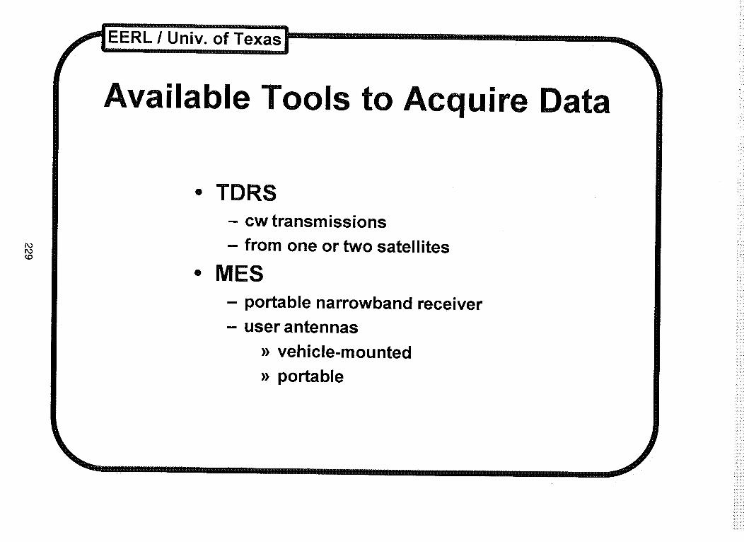
Available Tools to Acquire Data
• TDRS- cw transmissions
- from one or two satellites
• MES
portable narrowband receiveruser antennas
_ vehicle-mounted
_ portable
POCoo
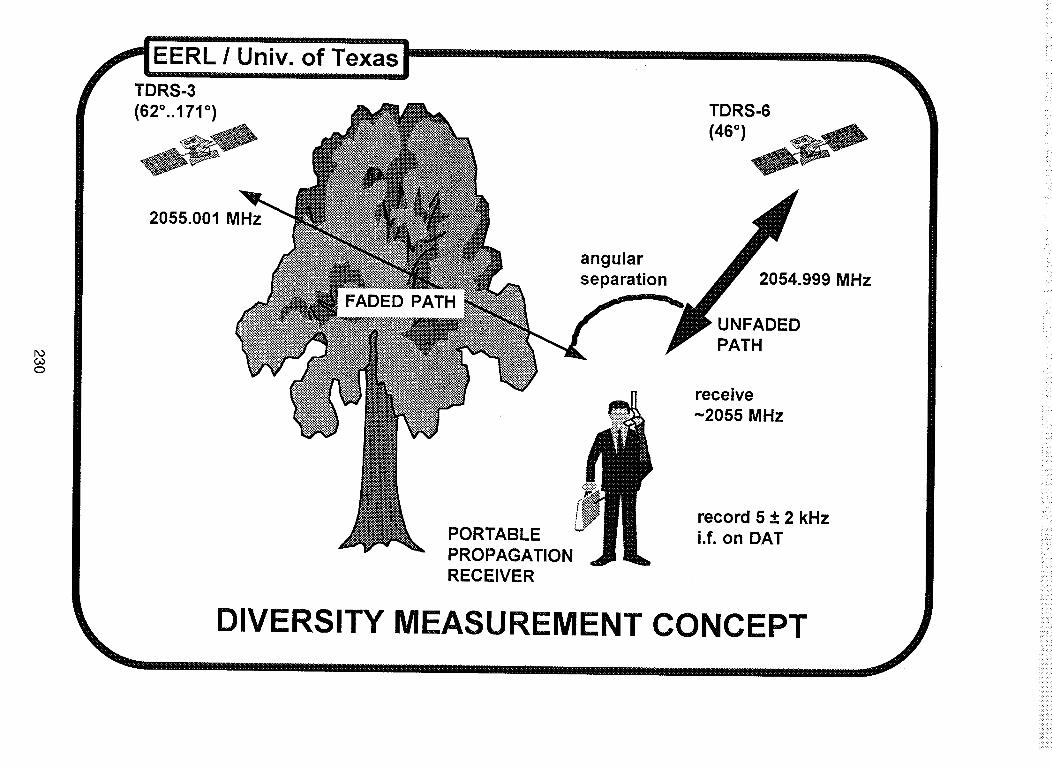
RS-3
(62°..171 °) TDRS-6 11
2055.001 MHz
FADED PATH
angular
separation 2054.999 MHz
UNFADED
PATH
PORTABLE
PROPAGATION
RECEIVER
receive
-2055 MHz
record 5 + 2 kHz
i.f. on DAT

r_oco
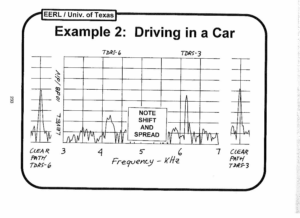
MEASUREMENT EXAMPLES
• TDRS-3 and TDRS-6 on 03/19/94 in Austin, TX
• abscissa: center frequency = 5 kHz, 1 kHz/div
• ordinate: 10dB/div

T_RI-G TbR_-3
I A^A
DOC_C.O
.J
<_E.4_ 3 4P_Tff
nnn'r....
NOTESHIFTAND
| Iw
5-
Fre guemcy
A
i JL
7 C_E4RPar_{T;@Y-3
...... ]........... Innlll....... I ................ , [[,[[......
r_oco
EERL / Univ. of Texas
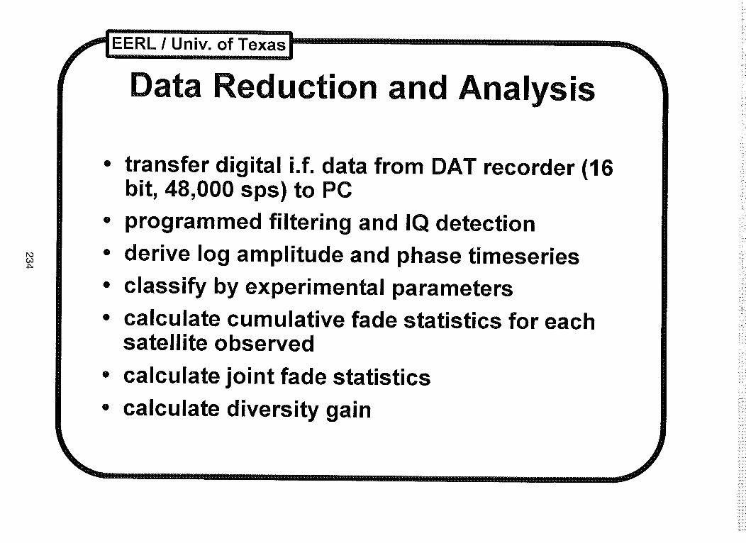
Data Reduction and Analysis
• transfer digital i.f. data from DAT recorder (16bit, 48,000 sps) to PC
• programmed filtering and IQ detection
• derive log amplitude and phase timeseries
• classify by experimental parameters
• calculate cumulative fade statistics for eachsatellite observed
• calculate joint fade statistics
• calculate diversity gain

FOCoU1
• observe TDRS-3 and -6 simultaneously
• in Austin, Texas
• every ~10 ° during move of TDRS-3
• with repeated MES scenarios- mobile with antenna on and in car
- ported with receiver at head
- in suburban and urban areas
- in a few buildings
• reduce and analyze as funds become available
I'FF'" 111...... I llr'F......................... I
i!ii


ACTS MINIWORKSHOP
A MINIWORKSHOP
ON
ADVANCED COMMUNICATIONSTECHNOLOGY SATELLITE (ACTS)
PROPAGATION STUDIES
PA_ _ _T FCMED 237

i,ii_
ACTS Opening Remarks
F. Davarian
Our ACTS propagation campaign has made considerable progress since thelast time we met in New Mexico. We have gathered here today to review thestatus of our campaign and discuss issues needing our attention.
As you recall, in our previous meetings we had the NASA headquartersrepresentative addressing us. He reviewed NASA's organization andobjectives. However now that our NASA contact, John Kiebler, has retired, I will
try to describe NASA's organization and its expectations of this campaign to thebest of my ability. Please see Chart 1.
Changes in national priorities combined with a slow economy have had theireffect on NASA. Headquarters has been going through transitions for the lasttwo or three years. NASA is seriously reevaluating its priorities and isreconsidering the way it conducts business. In this climate NASA managersare sometimes too preoccupied to pay close attention to some of the ongoingprograms such as ours. Fortunately for us and largely because of the goodwork of our community, the NASA Propagation Program is enjoying a good levelof visibility at NASA.
I am happy to announce that in a recent review of NASA's communications
projects, the NASA Propagation Program, and specifically the ACTS campaign,received positive feedback from the review committee. This committee
consisted of the members of the space communications industry. I am alsopleased to report that NASA funding of the ACTS campaign will continue.
NASA's requirement is that we help the satellite communications industry todevelop and introduce new applications and services. Our community shouldrely on its own resources for success. I am asking our experimenters tocontinue their work with the same enthusiasm and dedication as before.
Many of the terminal bugs have been resolved, but not all have been corrected.
! had to work hard to get renewed funding for Dave Westenhaver. Dave isfunded now, and he is dedicated to quickly resolving all the remaining terminalissues. I am hoping that with help from the experimenters, Dave will be able tosolve the remaining problems and, by the next time we gather, we will not haveto be concerned about the terminals anymore.
At this stage, we should focus on data processing and analysis. I expect BobCrane will continue his leadership role in this area. He has written a report onterminal calibration. We hope to be able to finalize our calibration scheme
soon. I also expect that Wolf Vogel will play a strong role in these areas since
F_R_II)UY_ PAGE _ NOT F_ME_ 239

he is a sophisticated experimenter with years of experience. In short, weshould be sending calibrated preprocessed data to Wolf every month and beable to conduct analysis and modeling efforts.
Bob Bauer is requesting a one-year extension for our campaign. If hesucceeds, we will have funding to continue our measurements for three years.He is also asking for a little more money after the measurements end to allowtime to finalize our analysis and modeling. He will elaborate on this issue inhis talk.
The evening plenary session jointly chaired by Bob Crane and Dave Rogerswill serve to capture the essence of this meeting. I expect a summary reportincluding a list of recommendations from them. This report will be published inthe proceedings of our meeting.
ISSUES FROM THE LAST MEETING:
A) REPORTING
. There is no longer a need for weekly reports. Please send a brief monthlystatus report to JPL. This report will indicate accomplished milestonesand problem areas. Its size should be about half a page. To allow otherexperimenters to see your progress, I encourage the use of the ACTSe-mail system for status reporting.
2. Quarterly reports required under contract will continue to be sent to NASALewis with a copy to JPL.
3. Monthly data will continue to be sent to Texas.
B)OTHERS
1. Capacitor rain gauge
2. Digital receiver post-detection filter
3. Antiwetting agent to coat the antenna
4. Beacon-level changes
5. Calibration
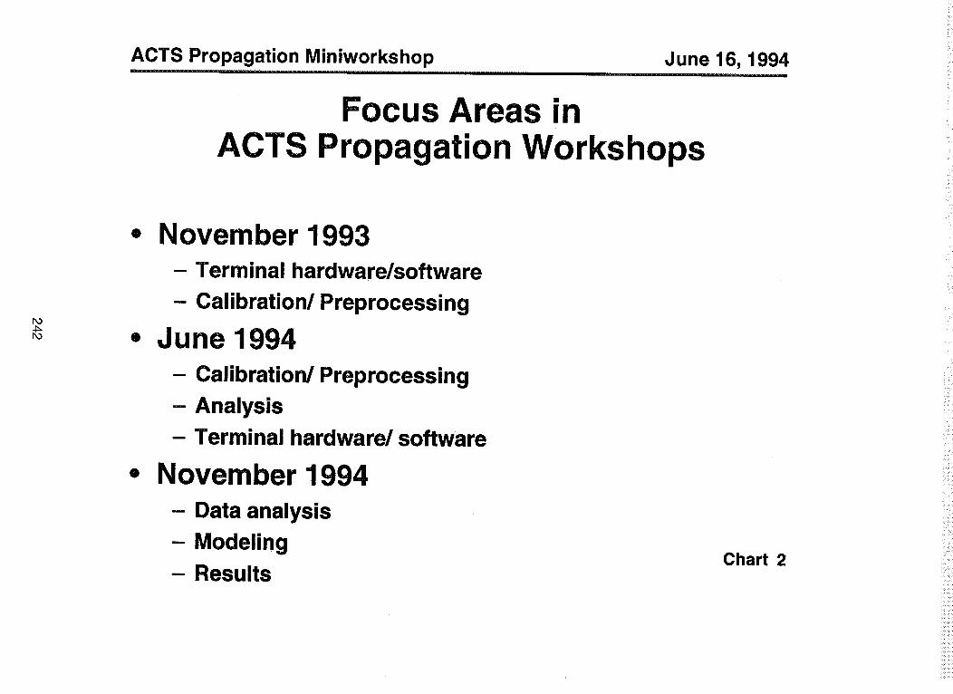
In this workshop, we will focus on calibration and preprocessing. In the nextone, we will focus on analysis and modeling. Please see Chart 2.
240
ACTS Propagation Miniworkshop June 16, 1994
r,o
--.L
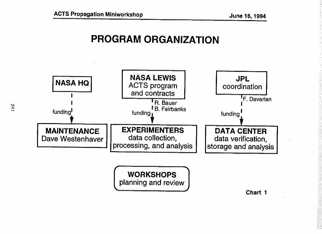
PROGRAM ORGANIZATION
NASA LEWISACTS programand contracts
t R. BauerI B. Fairbanks
JPL Jcoordination
tF. DavarianI
funding I funding_ funding_
_1 EXPERIMENTERS .... I DATA CENTERJ data collection, . I data verification,.processing, and analysts.... st[s[s[_storage...........and analysts
'lplanning and review
Chart 1
ACTS Propagation Miniworkshop June 16, 1994
PO
r_
Focus Areas inACTS Propagation Workshops
= November 1993- Terminal hardware/software
- Calibration/Preprocessing
= June 1994
- Calibration/Preprocessing
- Analysis
- Terminal hardware/software
• November 1994
- Data analysis
- Modeling
- ResultsChart 2

AdvancedCommunications
TechnologySatellite (ACTS) Program
C_
................... _r Ir111F .........................................................................................
iiii- NAsAROBERTLEwIsBAUERREsEARCHCENTER
"ACTS STATUS AND UPDATE"
1'1"
ACTS MINI WORKSHOP/NAPEX XVlli
VANCOUVER, BRITISH COLUMBIAJUNE 16, 1994
............. 1......... r....... r FrHII I HHHVH;.. ,,,,, 1.......
ACTS OPERATIONS STATUS
r,o
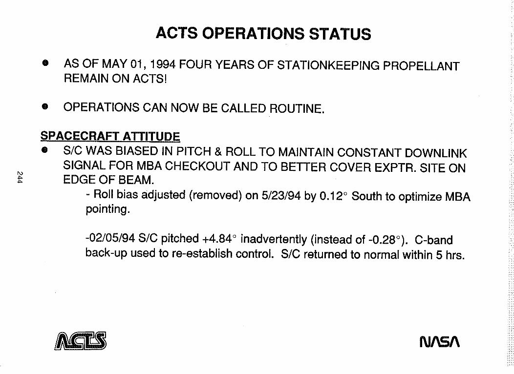
O AS OF MAY 01, 1994 FOUR YEARS OF STATIONKEEPING PROPELLANTREMAIN ON ACTS!
• OPERATIONS CAN NOW BE CALLED ROUTINE.
SPACECRAFT ATTITUDEO S/C WAS BIASED IN PITCH & ROLL TO MAINTAIN CONSTANT DOWNLINK
SIGNAL FOR MBA CHECKOUT AND TO BETTER COVER EXPTR. SITE ONEDGE OF BEAM.
- Roll bias adjusted (removed) on 5/23/94 by 0.12 ° South to optimize MBApointing.
-02/05/94 S/C pitched +4.84 ° inadvertently (instead of-0.28 °). C-bandback-up used to re-establish control. S/C returned to normal within 5 hrs.

r,o
ACTS OPERATIONS STATUS, cont.
O OPERATIONS CONTINUE UNDER EARTH SENSOR CONTROL INSTEAD OFAUTOTRACK. YAW ESTIMATOR USED SINCE JUNE 01 AND HAS BEENPERFORMING WELL.
- Algorithm estimates position of Sun when it's not in view of Sun sensors.
ECLIPSE• FIRST COMPLETE ECLIPSE CYCLE FROM 02/26-04/13/94.
O ANNULAR ECLIPSE ON 05/10/94.
- 78% obscuration of ACTS @ ~11:00PM EDT.- System shut-down as during a seasonal eclipse.
THERMAL EFFECTS• MBA CHECKOUT- VARIOUS TESTS PERFORMED TO MEASURE BEAM
CENTERS AND PATTERNS.
- Thermal effects mostly understood. Impact to spot beam users isnegligible.
fU/kSA
ACTS OPERATIONS STATUS, cont.
PO4:=Ob
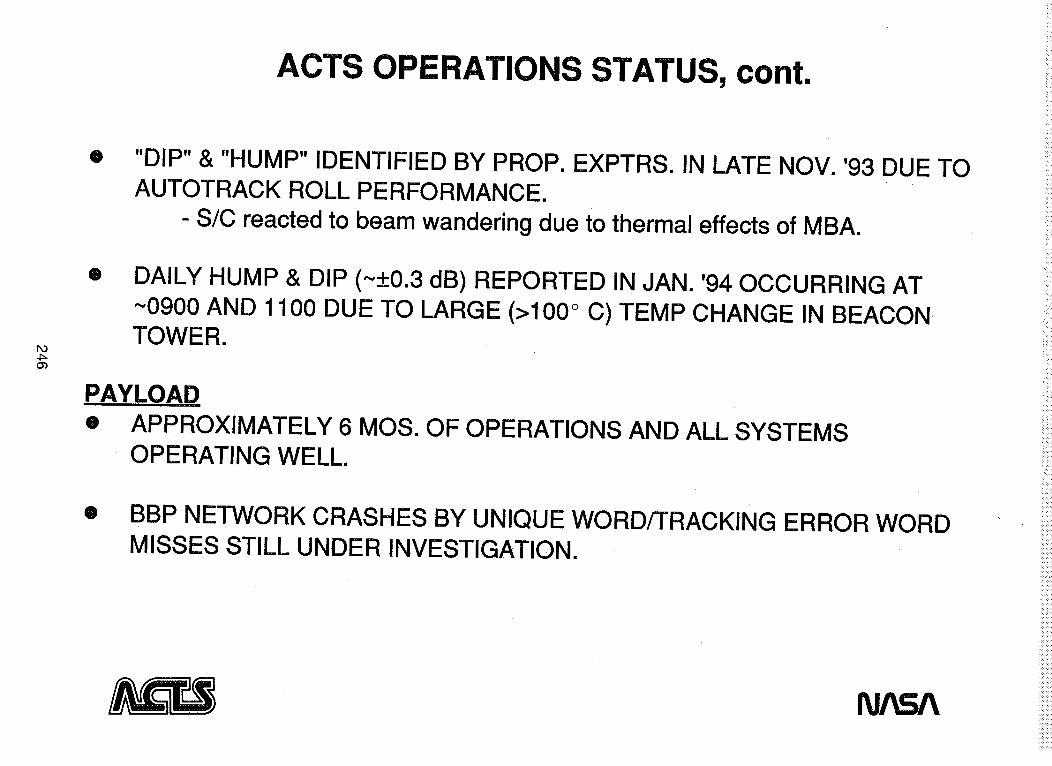
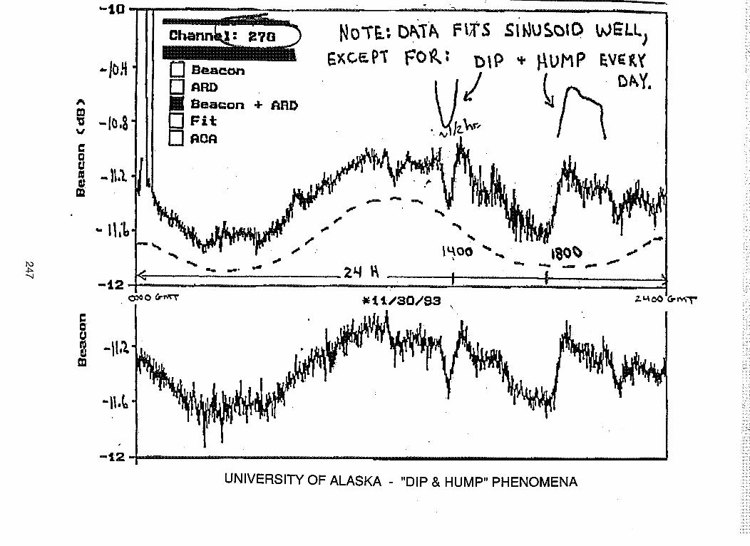
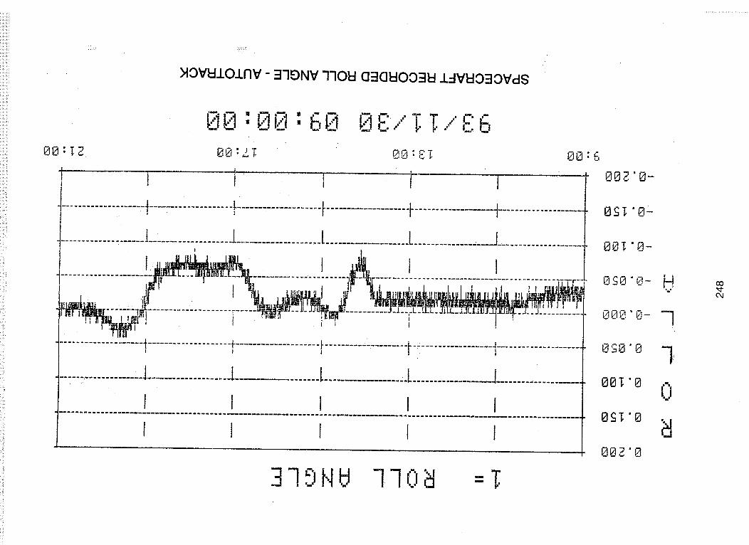
O "DIP" & "HUMP" IDENTIFIED BY PROP. EXPTRS. IN LATE NOV. '93 DUE TOAUTOTRACK ROLL PERFORMANCE.
- S/C reacted to beam wandering due to thermal effects of MBA.
O DALLY HUMP & DIP (~+0.3 dB) REPORTED IN JAN. '94 OCCURRING AT~0900 AND 1100 DUE TO LARGE (>100 ° C) TEMP CHANGE IN BEACONTOWER.
PAYLOADe APPROXIMATELY 6 MOS. OF OPERATIONS AND ALL SYSTEMS
OPERATING WELL.
O BBP NETWORK CRASHES BY UNIQUE WORD/TRACKING ERROR WORDMISSES STILL UNDER INVESTIGATION.
i"0
,.,q
-'i2 ..............
UNIVERSITY OF ALASKA - "DIP & HUMP" PHENOMENA
>lOVldlOlnV - =I'IONV 7"ION Cl':lOl::lOO'ql=l 1..-IVI=IO:JOV,:I8
00",7,0:60._-, 0 E:,,"T T,,"c6....00: TZ 00 =LT 0,0 =:_T. 8L-.-.4• 6
....................4....................!......-.............t....................I-............-_ t.....................
.................,_L.................._...........,.........t....................L...................J.....................
.................. -: ................ ................................................ -,';",....... ii/_...."_.......:i-%:_____:*_-_7-_ii!__.___:::",,_o_li,ol_l_,,_._,,_,_........__ ............ .......
....................i....................._...................._...................._-_.................1....................•
......................[....................I.................. [................J...................J.........:..........
I I i I I
I I I I I
37,9NU 770_] =T
80Z '0-
OST "8
80T "0-
OSO "0-
00T "0
0£T "0
OOZ "8
N
-7
7
0
oO,q,-04

ACTS OPERATIONS STATUS, cont.
PO
r,O
O
O
QUANTITY OF CRASHES HAS BEEN ON DECLINE.
- Were occurring daily, typically one crash per day.
- Occurrence now more erratic, sometimes none for weeks.
1 HZ ANOMALY BEING INVESTIGATED.
- A 0.015 ° p-p variation in beam results in ~1 dB change in S/C D/L signal(at -10 dB beam contour) observed at LET, HDR and T1 VSAT's.
- Theory is TX main reflector oscillates due to mechanical impulse bymomentum wheel system.
MGS OPERATIONS
• MGS STAFFED 24 H/D, 7 D/W; INCREASE TO 12 FULL TIME POSITIONS.
• SOME TWTA DIFFICULTIES (BBP UPLINK).
N/ $A

(J1C)
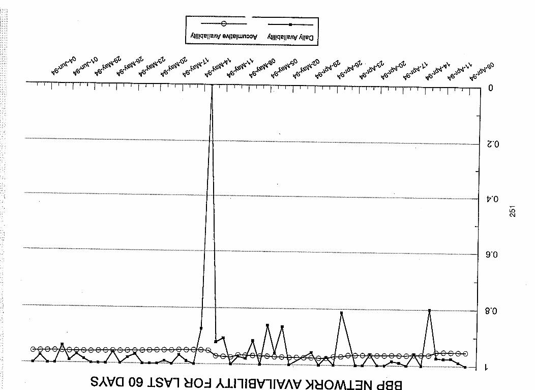
BBP MODE RELATED OUTAGES FOR LAST 60 DAYS
NORMAL OPS 95.9%
TOTAL OUTAGES 4.1%
BREAKDOWN OF OUTAGES
CONFIGURATION ERROR 4.4%
NETWORK SHUTDOWN 12.4%
WEATHER RELATED 1.2%
SPACECRAFT RELATED 3.2%
UW/TEW HITS 17.1%
UIPMENT FAILURE
MCS S/W ERRORS 5.6%OTHER/UNKNOWN 11.0%
45.1%
0 R .........
&!I!qel!e^Ve^l]elmnoov _lllqelle^v_l!eO
0
S,,kva 09 ISVl NO...4,J.I-li£VIlVAV >INOM.I.:iN d88
_'0
17"0
9"0
8"0
04


:_!___i_i_i_ili_:!_:!_:_i:_!_!_i_i__!__!!_i_i_ _: __i__i̧:__i!_i!_!i_!_izlliiiiiii!_illii!_!i!iiiii_i_i!i_i_i__!i_iilii_!_il!i_!_ii!il_ii!ii_ii_i_iii_i_i_i_ii_iii!iiiiiiiiiili_ii!ill'!_!i:_!iililiii_i!i!iii!iiii_i_ii!ii_iiii!_!_ili:iiiii!i!iii!ii!iii!!_ii!iiiiiii!i!i!ili!i!iiiiiiif!if!i!iiiiiiiiiiiiiliiiiiiiii!iiiiiii!i!iiiiiliiiiiii!iiiiiiiiiiiiiiiiiiIIIIIII!_!_iiiii_iii_iiiiiii_!ii_i_i_i_i_i!iiiiiiiiiiiiiiiiiiiii_iii_iii_iii_iiii_i_
I".
,,=,=o=o
o.=,
I-r_,II
252ORIGINAL PAGE
COLOR PHOTOGRAPH

e
$
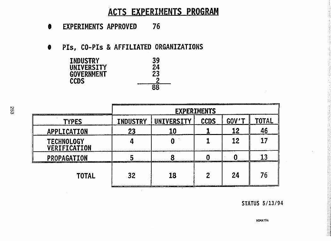
TA.C..!_S__F,_CP_EBIME_
EXPERIMENTS APPROVED 76
Pls, CO-Pls & AFFILIATED ORGANIZATIONS
INDUS.TRY 39UNIVERSITY 24GOVERNMENT 23CCDS 2,
88
DO0"ICO
TYPES
APPLICATION _ ,,
TECHNOLOGYVERIFICATION
PROPAGATION r'
TOTAL
,INDUSTRY ....
23,_n, , , 1,r ......
4
5
32
._m
EXPERIMENTS.
UNIVERSITY.....CC,D,,S
I0 ..........I.............10
8
18
' " '"' Ir ..... r"'r' I r,, • ,,,,
0
2
GOV'T TOTAL
12 ..........46 ....
12 17
0
24
13
76
STATUS 5/13/94
HQMAY94
FOO1
30
L-
e-
E|u
t_.
0,,XM.I
25
2O
15
10
0
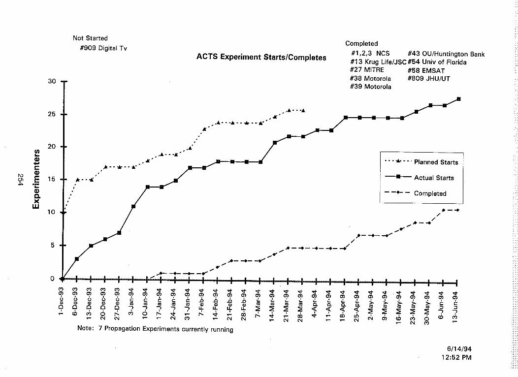
Not Started
#909 Digital TvACTS Experiment Starts/Completes
Completed
#1,2,3 NCS #43 OU/Huntington Bank#13 Krug Life/JSC #54 Univ of Florida#27 MITRE #58 EMSAT#38 Motorola #809 JHU/UT#39 Motorola
"""_ .... Planned Starts
-_ Actual Starts
Note: 7 Propagation Experiments currently running
6/14/9412:52 PM
Line
#
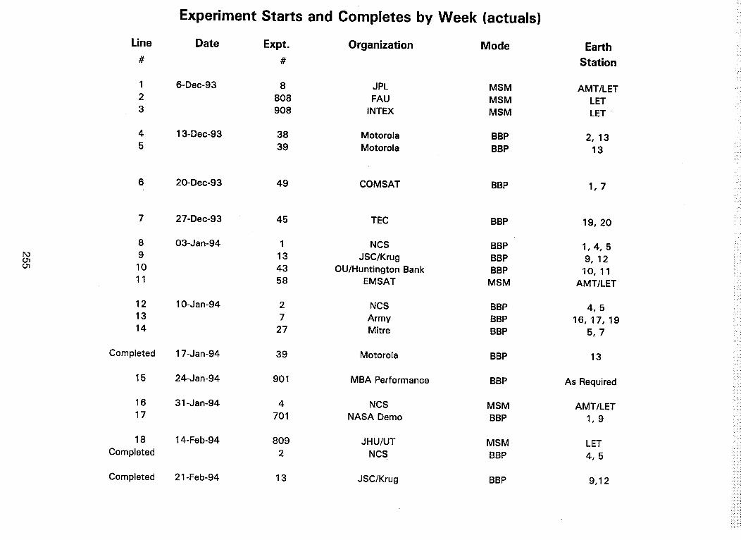
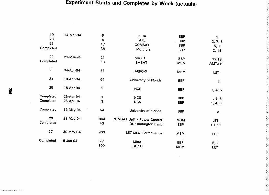
Experiment Starts and Completes by Week (actuals)
Date Expt. Organization Mode
#
6-Dec-93
4 13-Dec-93
5
Earth
Station
8 JPL MSM AMT/LET
808 FAU MSM LET
908 INTEX MSM LET
38 Motorola BBP
39 Motorola BBP2, 13
13
POO101
6 20-Dec-93
7
8
9
10
11
12
13
14
Completed
15
16
17
18
Completed
27-Dec-93
03-Jan-94
10-Jan-94
17-Jan-94
24-Jan-94
31-Jan-94
14-Feb-94
49 COMSAT BBP
45 TEC BBP
1 NCS BBP
13 JSC/Krug BBP
43 OU/Huntington Bank BBP
58 EMSAT MSM
2 NCS BBP
7 Army BBP
27 Mitre BBP
39 Motorola BBP
901 MBA Performance BBP
4 NCS MSM
701 NASA Demo BBP
809 JHU/UT MSM
2 NCS BBP
1,7
19, 20
1,4,5
9,12
10,11
AMT/LET
4,5
16, 17, 19
5,7
13
As Required
AMT/LET
1,9
LET
4,5
Completed 21-Feb-94 13 JSC/Krug BBP 9,12
h3O1(33
19
20
21
Completed
22
Completed
23
24
25
Completed
Completed
Completed
26
Completed
27
Completed
Experiment Starts and Completes by Week (actuals)
14-Mar-94 5 NTIA BBP
6 ARL BBP
17 COMSAT BBP
38 Motorola BBP
21 -Mar-94 21 MAYO BBP
58 EMSAT MSM
04-Apr-94 53 AERO-X MSM
18-Apr-94 54 University of Florida BBP
18-Apr-94 3 NCS BBP
25-Apr-94 1 NCS BBP
25-Apr-94 3 NCS BBP
16-May-94 54 University of Florida BBP
23-May-94 804 COMSAT Uplink Power Control MSM
43 OU/Huntington Bank BBP
30-May-94 903 LET MSM Performance MSM
6-Jun-94 27 Mitre BBP
809 JHU/UT MSM
9
2, 7, 8
5,7
2,13
12,13
AMT/LET
LET
3
1,4,5
1,4,5
1,4,5
3
LET
10, 11
LET
5,7
LET

1.Dec-93
6.Dec-93
13.Dec-93
20.Dec,-93
2"7-Dec'93
3_Jan-94
10 -Jan'94
1/ jan94
24.jan 94
31 jan94
7 .Feb 94
14 t:eb 94
m
O
tD
=_..
DO
CO
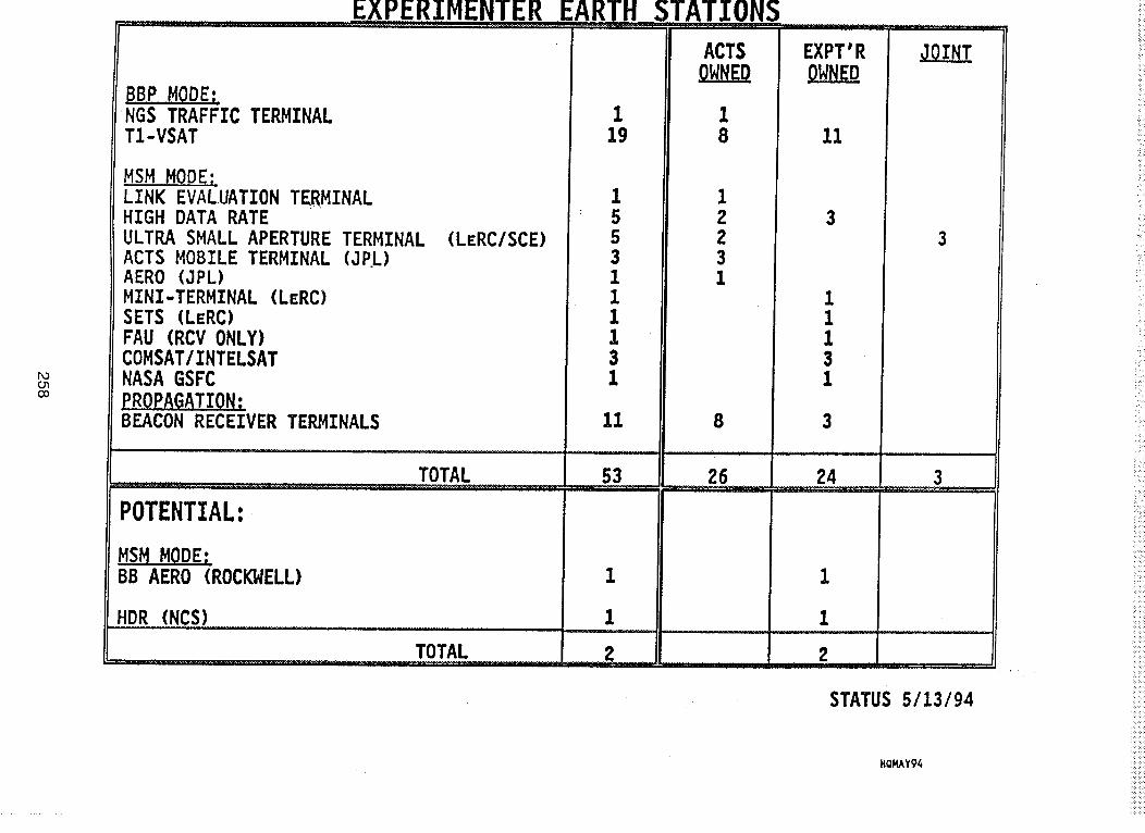
EXPERIMENTER
BBP MODE;jNGS TRAFFIC TERMINALT1-VSAT
MSM MODE;LINK EVALUATION TERMINALHIGH DATA RATEULTRA SMALL APERTURE TERMINALACTS MOBILE TERMINAL (JEL)AERO (JPL)MINI-TERMINAL (LERC)SETS (LERC)FAU (RCV ONLY)COMSAT/INTELSATNASA GSFCPROPAGATION:BEACON RECEIVER TERMINALS
(LERC/SCE)
............. i i, .....................
TOTAL
POTENTIAL:,
BB AERO (ROCKWELL)
_HDR (NCS)
TOTAL
119
STATIONS
ACTS
18
EXPT'R
11
1553111131
12Z31
3
11131
3
11 8 3
_r
26 24 3
1
2
1
1
2
STATUS 5/13/94
HQMAY94
O
0
e0
oo
0
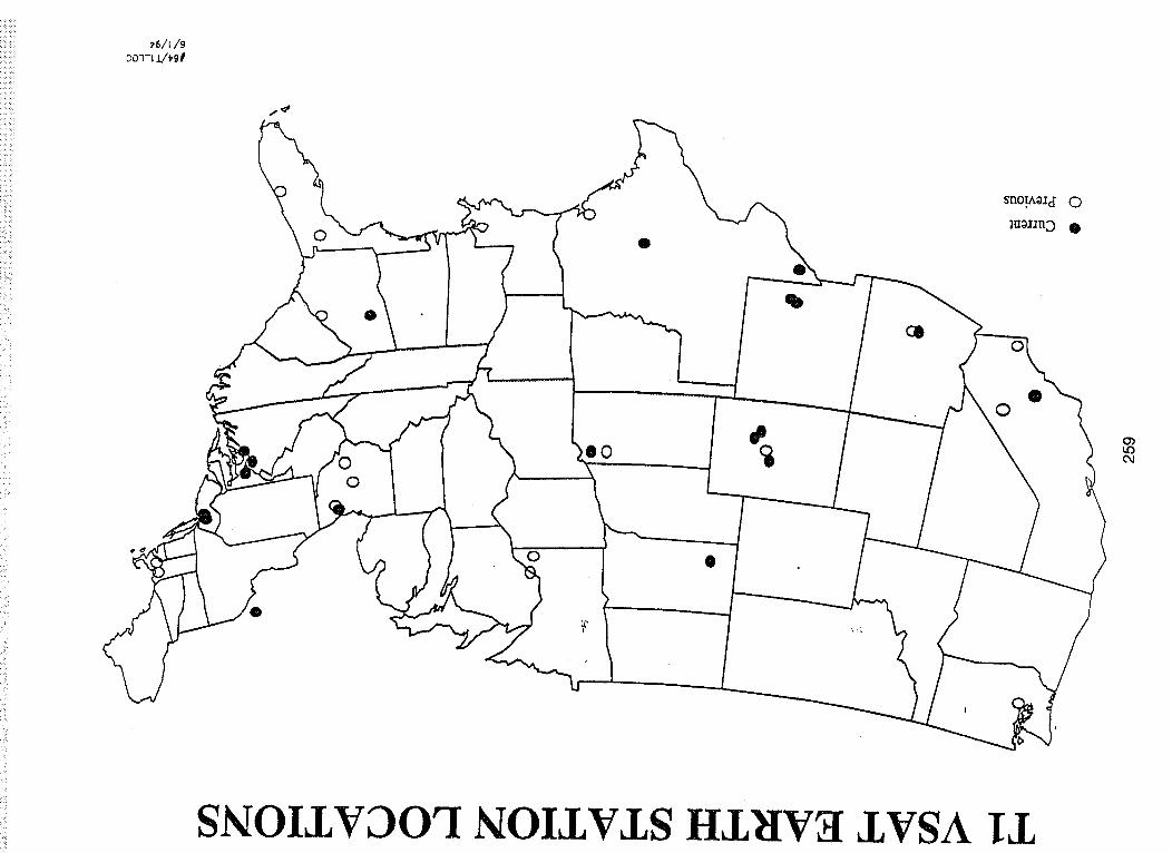
SNOIJNDOrI SOIJN_LS I-IJ_I¥_/ZVSA ILL
©
0
t_
t,61_0Gld3
_ :: i i ! j i _ i _ i i i i i i J!; J ; j i ii! i i j!il ii i!! ! !i ;ii i i!i !!!ili ii ; i!ii!i i ill; ii: : : : : : : : : : : : : : : : : : t : : : : : : i [ ! : : : : : : : : : : ; : : : : :
£ i i i i i _ ! ! i ! i _ i i i ! i i i i i i i i i: : : : : : : : : : : ! i i i _ _ i i : : : : , : ; : ; : : : ; : : : i : : ! i i i ! i i i :
i
: : : : f f i i i i i ] : : : : ; : : : : : : : : : : : : i i i i ] i : : : : : : : : : :e
: : _ _ _ _ i _ i i I i i ! i i i i i _ i i ' i i i i i i i i i i i_i iill iili i i _ii _iill i !!. III; I IIII
........... ; : ; : : : : ; : : :
, : : : : : : : : : : i : t : ; : : ; : : : : ...........
:_ !!il _iil _ ] ........... iiil !ill! i!i _ _ i i i i ! i i , i i i i i :: i i i :: i I i ! i i i ! i i i i i '
: : : : : : : : : : : ........... _ _ _ ! i i i i i ! i: : : : : : : : : : : _ i _ i i ! i i i _ _ : : : : : : : : : : :
_ _ ! _ _ _ _ i i ! _ ; i _ _ _ ! i i i i _ i i i i i i :: i i i i ::i i i i i i i i i i i i_li i i i i iii ! i i i i i i i i i i i i i
/
:: i i ! ! ! i i i i . A.........2_222T.- m _ _' ...... _ i J i J i i i ABa "lVNIINU3..L
i i i i i ! i ""'-"'P° i ! i ii i i i i-_-_-_ . , , : --_ ±vgn
ii iii! j_il i i! !ilil i _i iii _iii! ! i i ii!i i iili _i........... _t,P_ """-- ' -- ' _ : _ i • ; : : : ' i i i i :: ! i
_ _:i i ili i !i iiili l!ii/i iHbNI_V_I _e'ao ® .i i ! i i ! i i i ! i ! i ! ! i ! SU_4_dX_i_'i _ i i i _ _ i i i i i i i i_j:sv i i _ 8:::INOlS3711,N_IOPV_I
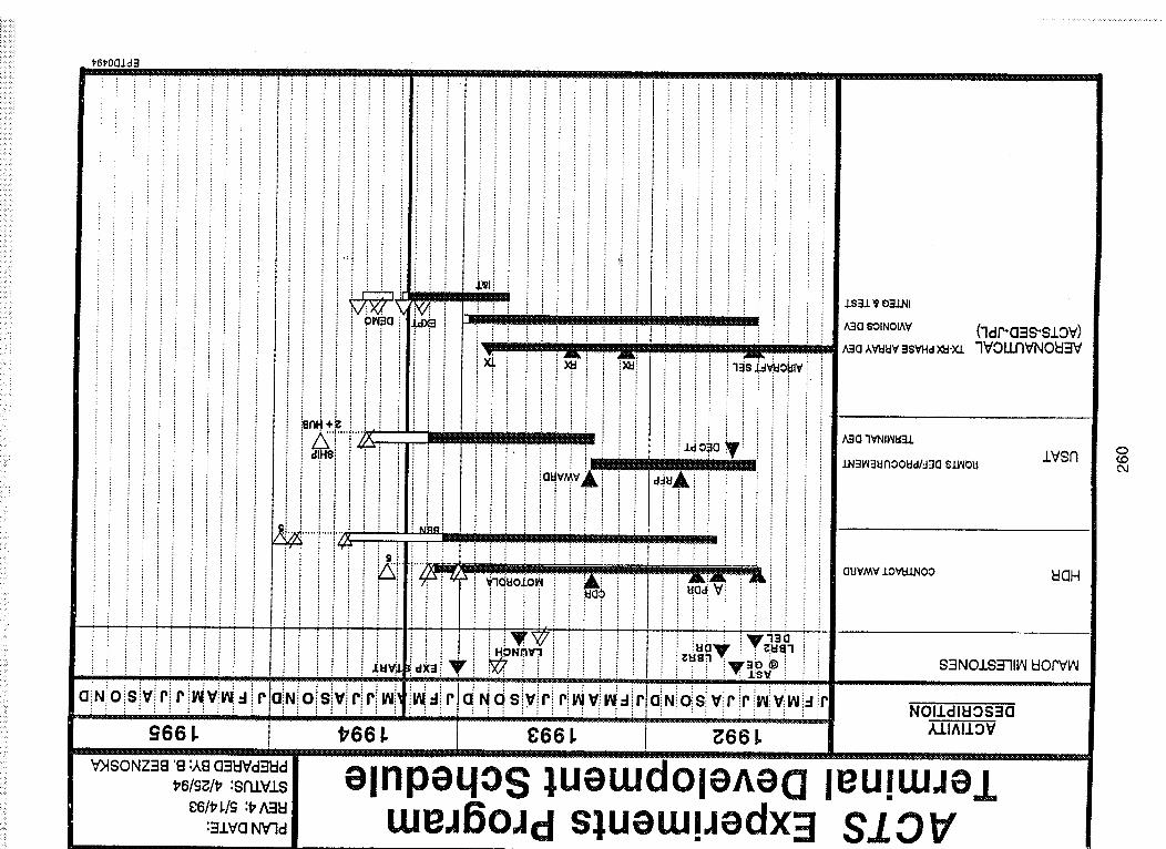
CliNiO8 virir *vv_lir'aiNiOlSlvlrlri,_ il_d r!dNdS v r ril_viv_ riaN _slv r r i.lvv_i_l r:, _ , , , ' i i • i i :_2__£/ ........... , : : . NOI£dlEIOS_]O
£66 I. t766 I. 8:66 I. ! ;_66 !. _l^l±ovr I I ' ! II I ,,,
V)ISONZ38 '8 :AS C]:IWVcFIWd
elnpeqo£ ueuJdoleAea leu!uJJeluJeJ6oJd s},ueuJiJedx:! SIOV
O{Do4

sdqlN ;_9 'uJ 1_'£:
ZV 'JelPueqo 'E)ISO eloJo),ol/_l le uop, m,S UQHX2ll.
0-0_jF-
z:c_cLc_
c_ oO_j
00
x--
CO
c_

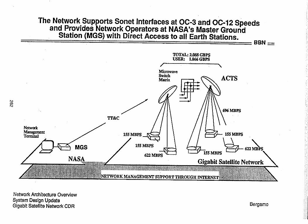
The Network Supports Sonet Interfaces at OC-3 and OC-12 Speedsand Provides Network Operators at NASA's Master Ground
Station (MGS) with Direct Access to all Earth Stations,'.................................. ......... BBN
O_
MGS
NASA
Network ArchitectureOverviewSystem DesignUpdateGigabit SatelliteNetworkCDR
TOTAL: 2.088 GBPSUSER: 1.866 GBPS
' \
Microwave
. ACTS
155 MBPS 155 MBPS
Satellite Network
MANAGEMENT
Bergamo
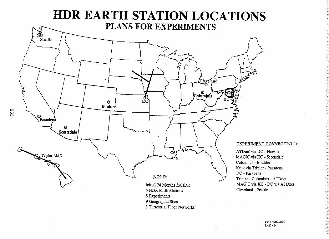
HDR EARTH STATION LOCATIONSPLANS FOR EXPERIMENTS
Seattle
bO03¢.0
0Scottsdale
0Bouh
NOTES
Initial 24 Months forHDR
5 HDR Earth Stations
8 Experiments
9 Geographic Sites
3 Terrestrial Fiber Networks
\EXTERIMENT CONNECTIVITY
ATDnet via DC - Hawaii
MAGIC via KC - Scottsdale
Columbus - Boulder
Keck via Tripler - PasadeI_aDC - Pasadena
Tripler Columbus - ATDnetMAGIC via KC - DC via ATDnet
Cleveland - Seattle
#64/HOR_LOC7
5/27/94

ACTS ULTRA SMALL APERTURE TERMINAL (USAT)
0.35 m diameter reflector; 4.8 kbps264

['o
Oa
AERONAUTICAL EXPERIMENT
(AERO-X)
SUCCESSFULLY TESTED THE AERONAUTICAL TERMINAL WITH THEACRYLIC WINDOW AND POSITIVE LINK MARGINS.
CONTINUOUS PILOT TONE MONITORING AS WELL AS VOICE
CONNECTIONS AT 9.6 AND 4.8 Kbps WERE ACHIEVED.
TUESDAY 26 APRIL 1994: MAIDEN VOYAGE
LEAR JET SPEED: 320 NAUTICAL MILES/HR
ALTITUDE: 41,000 FT
LOCATION: 150 MILES NW OF CLEVELAND
TIME OF 1ST CONVERSATION: 8:36 AM
CODEC RATE: 9.6 Kbps
LAST VERIFICATION FLIGHT:FIRST DEMO FLIGHT:
THURSDAY 12 MAY
MONDAY 11 JULY
Acts Propagation Terminal
Maintenance, Support andUpdates
David Westenhaver
Westenhaver Wizard Works,June 16,1 994
PAC_ _ f_OT F_MED267
oo
eq

WestenhaverWizard Works, Inc.
Status /Deficiencies and Known Problems
DACS / TSR Hardware / Software status:
DACS / TSR Software status:
Revised, Version 5
Revised, Version 7
Software Bugs Status:
Shipped
Shipped
Dec.14,1993
Jun. 2,1994
Commutation Protocol errors; Version 5.
Compiler warnings removed; Version 6.
ADC and DAC logic system review; Version 6.
Analog voltages can have overflow; Version 6.
Incorrect WWV time causes loss of data;Version 7
Setup takes too long and is dumb; To Be Addressed.
Radiometer calibration can occur during a fade; TBA.
DACS needs updated EPROMS; TBA.
Pressing Problems:
Problem: Crashes and Reboots.
Solution: Rework code to limit effect.
Save settings and download passed on reboot.
Keep searching for the hardware problem.
RF Temperature Controller:
Problems: Generates noise, FETs over
lack of regulation.
Solution: New design is in progress.
New units will be sent in exchange
units.
stressed,
for current
269
<_,_..........._<,_,<.......___ _: _,_,_: < _ _< _ _: << <: _____/:, ',:_ __:!<_< <_:__i_:¸_i_:i_<,_i<_i<i!__<_i!_i_ii!iiii!ili!i!i_!_i_i_!!_iiiii!_i!!i!_ii!i_!_!!_i_ii_ii_ii!i!i!!i!ii_!ii_iiiiii_!iii_iiiiii_!_ii<iiii_i_i_iiiii_iii_iiiii_iii_iii_i_iii_iiiii_i_ii_iiiiiiiiiiiiiiii_i_iiiiii_i_iiiiiiii_ii
Rec
Westenhaver Wizard Works, Inc.
eiver Enclosure temperature regulation:
Problem: The air temperature OK but IF's followoutside temperature.
Solution: Larger fan, Move thermostat, Air flowbaffles.
DRX Hardware / Software status:
DRX software status:
Revised, Version 12 Shipped Dec.
1Hz Filters Removed; Version
20 Samples / second data is limitedBe Addressed.
Missing synchronization command /
Pressing Problems:
Problem: 20 S/S
Solution:
Problem:
Solution:
14,1993
12.
to 2-3 Hz BW; To
responses; TBA.
Data Is Limited.
Rework Algorithm.
At least one unit fails
Replace Temperature
above 48 Degrees.
sensitive chip.
270
Westenhaver Wizard Works, inc.
Status of Software:
ActsView software status:
Revised, Version 2.1 Shipped Nov. 15,1993
System Crash at 23:59:59 if on status screen; TBA
Fails to "remember" last "custom" axis scaling; TBA.
Tape Backup Crashes system; TBA.
Data Problem with Daily Plots; TBA.
"Phase Noise" plot labels incorrect; TBA.
File Handles Need to be consistent; TBA.
Time axis not in integer minutes; TBA.
Unable to request "plot xx:xx:xx time"; TBA.
ActsEdit software status:
Version 1.2 Shipped Jan. 10,1994 (Gaff)
Flags errors for Bad data; Version 2.
Review Edit w/o removing work files; TBA.
Add Range Tones Correction;TBA.
271
Related Documents