Multicage Image Deformation On GPU Weiliang Meng 1∗ Xiaopeng Zhang 1† Weiming Dong 1‡ Jean-Claude Paul 2§ 1 LIAMA - NLPR, Institute of Automation, CAS, China 2 INRIA, France Figure 1: Image deformation based on the multicage using GPU in realtime. The multicage has 4 polygons with 68 vertices(ignoring the image bounding box), two of which are embedded in one. (a) is the original image, we set the ROI by the multicage in (b) and deform the image in (c). (d) is as the same as (c) with the multicage removed for better observation. Region 1 and 2 marked in blue in (b) are enclosed by polygons which will preserve the features when the peripheral polygons deformed. Region 3 and 4 marked in blue in (c) are the deformed results of region 1 and 2, with tiny automatical adjustments of the feature by our algorithm. The “ two lotus” image size is 1024 ∗ 768. Abstract As a linear blending method, cage-based deformation is widely used in various applications of image and geometry processing. In most cases especially in the interactive mode, deformation based on embedded cages does not work well as some of the coefficients are not continual and make the deformation discontinuous, which means existing “spring up” phenomenon. However, it’s common for us to deform the ROI(Region of Interest) while keeping local part untouched or with only small adjustments. In this paper, we design a scheme to solve the above problem. A multicage can be generated manually or automatically, and the image deformation can be adjusted intelligently according to the local cage shape to preserve important details. On the other hand, we don’t need to care about the pixels’ position relative to the multicage. All the pixels go through the same process, and this will save a lot of time. We also design a packing method for cage coordinates to pack all the necessary coefficents into one texture. A vertex shader can be used to accelerate the deformation process, leading to realtime de- formation even for large images. CR Categories: Numerical Analysis [G.1.1]: Interpolation— Interpolation formulas; Information Interfaces and Presentation [H.5.1]: Multimedia Information Systems—Animations; Computer Graphics [I.3.3]: Picture/Image Generation—Display algorithms; Computer Applications [J.6]: computer-aided engineering— Computer-aided design. ∗ e-mail:[email protected] † e-mail:[email protected] ‡ e-mail:[email protected] § email:[email protected] Keywords: image deformation, GPU, cage, coordinates 1 Introduction Image deformation has a lot of methods to be used, in which linear blending and corresponding variants are the most practical as the high speed deformation. For a typical linear blending method, the point on the object is transformed by a linear combination of affine transformations. The user only needs to construct a few handles and then manipulate them to control the shape. Free-form deforma- tion belongs to linear blending methods, but the regular structure restriction makes the control of concave objects complicated. Al- though skeleton-based deformations can provide natural control for object with rigid limbs, they are less convenient for flexible regions. Cage-based interactive space deformation is booming as it can de- form a significant portion of the object, leading to easy bulging and thinning of ROI(Region Of Interest). The cage can be constructed interactively or manually in advance, and the object vertices are represented as linearly combinations of cage vertices (may be also with edge or face normals). The weights of the combination can be computed before the deformation and associate with the object vertices, which can be called ‘binding’ process. During the pose time, i.e. the period that a user manipulates the cage vertices to de- form the object, the weights are fixed and using the cage vertices’ position to generate the deformed object. Unfortunately, most cage-based method doesn’t deal with the em- bedding cases very well, especially for the interactive deformation. Focusing on the situation in 2D case as shown in Fig.1, where the region is split by some embedded polygons(i.e. 2D cage) which we called ‘multicage’, when we move the cage vertices interactively,

Welcome message from author
This document is posted to help you gain knowledge. Please leave a comment to let me know what you think about it! Share it to your friends and learn new things together.
Transcript
Multicage Image Deformation On GPU
Weiliang Meng1∗ Xiaopeng Zhang1† Weiming Dong1‡ Jean-Claude Paul2§
1LIAMA - NLPR, Institute of Automation, CAS, China2INRIA, France
Figure 1: Image deformation based on the multicage using GPU in realtime. The multicage has 4 polygons with 68 vertices(ignoring theimage bounding box), two of which are embedded in one. (a) is the original image, we set the ROI by the multicage in (b) and deform theimage in (c). (d) is as the same as (c) with the multicage removed for better observation. Region 1 and 2 marked in blue in (b) are enclosedby polygons which will preserve the features when the peripheral polygons deformed. Region 3 and 4 marked in blue in (c) are the deformedresults of region 1 and 2, with tiny automatical adjustments of the feature by our algorithm. The “ two lotus” image size is 1024 ∗ 768.
Abstract
As a linear blending method, cage-based deformation is widelyused in various applications of image and geometry processing. Inmost cases especially in the interactive mode, deformation basedon embedded cages does not work well as some of the coefficientsare not continual and make the deformation discontinuous, whichmeans existing “spring up” phenomenon. However, it’s commonfor us to deform the ROI(Region of Interest) while keeping localpart untouched or with only small adjustments. In this paper, wedesign a scheme to solve the above problem. A multicage can begenerated manually or automatically, and the image deformationcan be adjusted intelligently according to the local cage shape topreserve important details. On the other hand, we don’t need tocare about the pixels’ position relative to the multicage. All thepixels go through the same process, and this will save a lot of time.We also design a packing method for cage coordinates to pack allthe necessary coefficents into one texture. A vertex shader can beused to accelerate the deformation process, leading to realtime de-formation even for large images.
CR Categories: Numerical Analysis [G.1.1]: Interpolation—Interpolation formulas; Information Interfaces and Presentation[H.5.1]: Multimedia Information Systems—Animations; ComputerGraphics [I.3.3]: Picture/Image Generation—Display algorithms;Computer Applications [J.6]: computer-aided engineering—Computer-aided design.
∗e-mail:[email protected]†e-mail:[email protected]‡e-mail:[email protected]§email:[email protected]
Keywords: image deformation, GPU, cage, coordinates
1 Introduction
Image deformation has a lot of methods to be used, in which linearblending and corresponding variants are the most practical as thehigh speed deformation. For a typical linear blending method, thepoint on the object is transformed by a linear combination of affinetransformations. The user only needs to construct a few handlesand then manipulate them to control the shape. Free-form deforma-tion belongs to linear blending methods, but the regular structurerestriction makes the control of concave objects complicated. Al-though skeleton-based deformations can provide natural control forobject with rigid limbs, they are less convenient for flexible regions.Cage-based interactive space deformation is booming as it can de-form a significant portion of the object, leading to easy bulging andthinning of ROI(Region Of Interest). The cage can be constructedinteractively or manually in advance, and the object vertices arerepresented as linearly combinations of cage vertices (may be alsowith edge or face normals). The weights of the combination canbe computed before the deformation and associate with the objectvertices, which can be called ‘binding’ process. During the posetime, i.e. the period that a user manipulates the cage vertices to de-form the object, the weights are fixed and using the cage vertices’position to generate the deformed object.
Unfortunately, most cage-based method doesn’t deal with the em-bedding cases very well, especially for the interactive deformation.Focusing on the situation in 2D case as shown in Fig.1, where theregion is split by some embedded polygons(i.e. 2D cage) which wecalled ‘multicage’, when we move the cage vertices interactively,
we hope all the region will deform smoothly as long as the movingis reasonable(no overmuch changes that leading to overlap or cageintersection). Every isolated part should not go beyond its bound-ary to make sure the deformations are cage-aware, or else the cagecan’t have a leading meaning for the deformation. For ideal state,the cage should also be generated interactively to satisfy the specialneeds of the users.
In this paper, we study the case and propose a method to keepeach isolated region details smoothly during the pose time. Wealso provide a packing method for the weights in order to warpingthe large image in realtime on GPU. Previous acceleration methodsdon’t pack the weights, leading to many textures to be set during thepreprocess. As the number of textures has limits for most displaycard, this confines the cage vertices’ numbers. Using our method,the weights are packed into a regular single texture and can be ad-dressed quickly during the rendering time. The multicage can havehundreds of vertices for medium sized images, and dozens of ver-tices for large images, which mainly depend on the memory.
Our contribution can be listed as follows:
• A novel scheme for warping images based on embeddedcages. The deformation is cage-aware conforming to the em-bedded cages. All the pixels will go through the same process,having no bearing on their positions to the multicage.
• A new packing method for cage coordinates to deform imageson GPU in real time.
Our technique can be applied to intelligent image warping and an-imation. The content of the image will be adjusted intuitively andautomatically. GPU is used for generating realtime intuitive cage-based deformation. Based on our method, any possible image warp-ing result can be easily achieved by using different multicages onthe deformed image repeatedly.
2 Related work
Plenty of methods can compute high-quality shape-preserving de-formations based on the selected handles, having the form of points[Bookstein 1989], lines [Beier and Neely 1992] or bones[Weberet al. 2007], and polygon grids [MacCracken and Joy 1996]. Usersmodify the positions and orientations of handles interactively toachieve an intuitive deformation. The handles can be on the surfaceof the targets [Igarashi et al. 2005; Botsch et al. 2006; Sorkine andAlexa 2007; Botsch and Sorkine 2008], or can be extended to otheroff-surface handles[Botsch et al. 2007]. The deformation is heav-ily rely on optimization at pose time, and most mentioned methodsabove are non-linear which recede the efficiency and make themtoo slow for deforming high-resolution images or objects.
Using a weighted blend of handle transformation, the computationcan be fast at pose time. Schaefer et al. [2006] use linear com-bination of Moving Least Squares (MLS) for image warping, andthe deformation time is linear proportional to the number of sam-ple grid vertices. Weng et al. [2008] deform images on GPU forreal-time performance based on the sketch, whose selection may betroublesome for users.
Cage-based methods can also be seen as a handle-deformation tech-nique, in which the handles are the cage vertices. This is essen-tially a kind of linear blend skinning methods[Magnenat-Thalmannet al. 1988], where the handle(cage vertex) transformations are re-stricted to be translations. The core for cage-based method is howto choose the weights in order to make the deformation smooth.Many feasible ways have been proposed including Mean Value Co-ordinates(MVC)[Floater 2003; Hormann and Floater 2006; Ju et al.
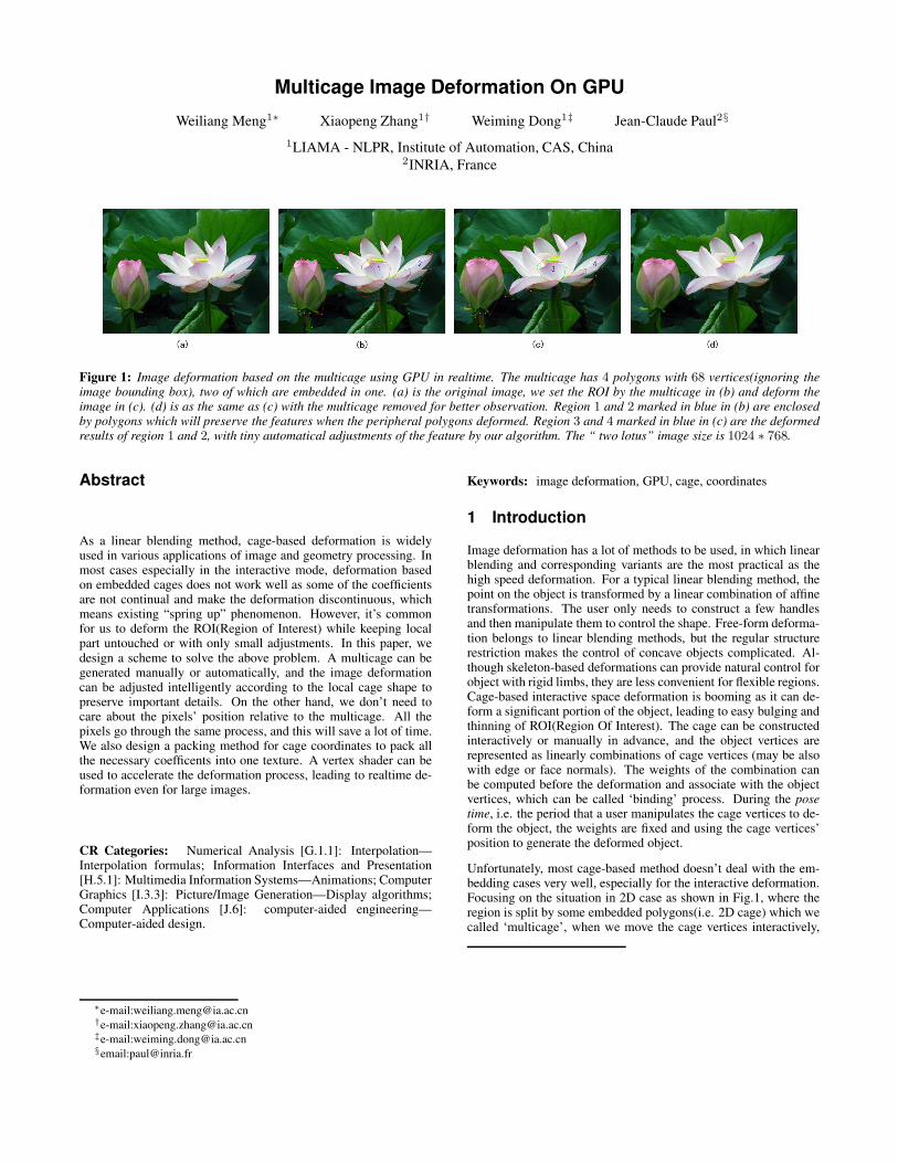
Figure 2: 2D Multicage demonstration. (a) a single polygon, (b)4 polygons with embedding and neighboring, (c) 2 polygons withintersect edges. (a) and (b) are multicages while (c) is not.
2005; Floater et al. 2005; Lipman et al. 2007], Harmonic Coor-dinates(HC) [Derose and Meyer 2006; Joshi et al. 2007], GreenCoordinates(GC) [Lipman et al. 2008], and complex barycentriccoordinates(CBC) and its variants [Weber et al. 2009; Ben-Chenet al. 2009]. Jacobson et al. [2011] develop linear blending weightsthat produce smooth and intuitive deformations using many kinds ofhandles including points, bones and cages. However, all the abovemethods don’t display interactive image deformation for the em-bedded cages case in their work, as this is a troublesome problem,which will be solved by this paper.
Once the weights for cages are obtained, they will keep fixedduring the whole deformation. Real time deformation can beachieved based on GPU, which is used for general purpose com-putation[Luebke et al. 2004; Goddeke 2005]. Meng et al.[2009]design a framework for the implementation of cage-based imagedeformation method on GPU. Their method are limited by the num-ber of cage vertices because of needing many unpacked textures.
Our work solves the embedded cages image deformation, and re-move the limited number for cage vertices on GPU. Section 3 givesthe concrete process for embedded cage image deformation, andsection 4 shows the packing algorithm.
3 Multicage Deformation
In this section, we first give the definition of ‘multicage’ for theimage, and then show the pipeline to compute the coefficients ofthe pixels relative to the multicage.
3.1 Definition of Multicage in 2D
A cage is a low polygon-count polyhedron that has a similar shapeto the enclosed object. The genus of the cage can be nonzero, mean-ing that the cage can have a “hole”. Multi-cage is a series of inde-pendent closed polygons in 2D with disjoint edges, i.e. the edges ofany two cages have no intersection. The polygons may be embed-ded each other, or be neighbors, and can be concave(Fig.2). Themain difference between the cage and the multicage is that manycages can construct a multicage, and we treat each closed poly-gons(not the cage) independently rather than as a whole entity.
Most cage-based image deformation use only one cage to deform.This is practical for the images with simple background. During thedeformation, contents in the cage are only affected by the enclosedcage. However, the following facts during the image deformationprocess can’t be ignored: all the pixels may have special meaningwith each other in the image especially for those with complicatedcontents, therefore deforming any region of the image will affectall the other pixels, some of which may have merely suffered unde-tectable changes as the distances from the ROI to the pixels are far.On the other hand, there are some special regions which we maywant to keep untouched or with only a little modification despite
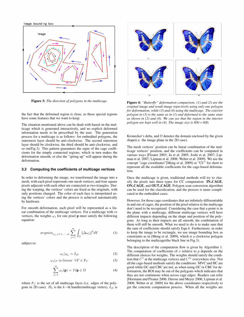
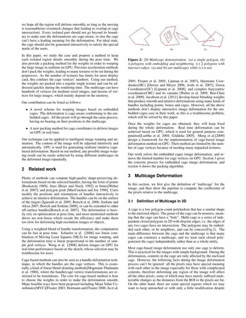
Figure 3: The direction of polygons in the multicage.
the fact that the deformed region is close, as these special regionshave some features that we want to keep.
The situation mentioned above can be dealt with based on the mul-ticage which is generated interactively, and no explicit deformedinformation needs to be prescribed by the user. The generationprocess for a multicage is as follows: for embedded polygons, theoutermost layer should be anti-clockwise. The second outermostlayer should be clockwise, the third should be anti-clockwise, andso on(Fig.3). This pattern guarantees the signs of the cage coeffi-cients for the simply connected regions, which in turn makes thedeformation smooth, or else the ”spring up” will appear during thedeformation.
3.2 Computing the coefficients of multicage vertices
In order to deforming the image, we transformed the image into amesh, with each pixel represents one mesh vertices, and four squarepixels adjacent with each other are connected as two triangles. Dur-ing the warping, the vertices’ colors are fixed as the originals, withonly positions changed. The color of each face is interpolated us-ing the vertices’ colors and the process is achieved automaticallyby hardware.
For smooth deformation, each pixel will be represented as a lin-ear combination of the multicage vertices. For a multicage with mvertices, the weights ωj for one pixel p must satisfy the followingequation:
argminωj ,j=1,··· ,m
m∑j=1
∫Ω
‖Δωj‖2dV (1)
subject to:
ωj |Hk = δjk (2)
ωj |F is linear ∀F ∈ FC (3)m∑
j=1
ωj(p) = 1∀p ∈ Ω (4)
where FC is the set of all multicage faces (i.e. edges of the poly-gons in 2D case). Hk is the k−th handle(multicage vertex), δjk is
Figure 4: “Butterfly” deformation comparison. (1) and (2) are theoriginal image and result image repectively using only one polygonfor deformation, while (3) and (4) using the multicage. The exteriorpolygon in (3) is the same as in (1) and deformed to the same stateas shown in (2) and (4). We can see that the region in the interiorpolygon are kept well in (4). The image size is 800 ∗ 600.
Kronecker’s delta, and Ω denotes the domain enclosed by the givenshape(i.e. the image plane in the 2D case).
The mesh vertices’ position can be linear combination of the mul-ticage vertices’ position, and the coefficients can be computed invarious ways [Floater 2003; Ju et al. 2005; Joshi et al. 2007; Lip-man et al. 2007; Lipman et al. 2008; Weber et al. 2009]. We use theconcept ”cage coordinates”[Meng et al. 2009] or ”CC” for short torepresent all the available coefficients for the cage-based deforma-tion.
Once the multicage is given, traditional methods will try to clas-sify the pixels into three types for CC computation: IN CAGE,ON CAGE, and OUT CAGE. Polygon scan conversion algorithmcan be used for the classification, and the process is more compli-cated in the embedded cases.
However, for those cage coordinates that are infinitely differentiablein and out of cages, the position of the pixel relative to the multicagedon’t need to be recognized. Considering the case that a point is inthe plane with a multicage, different multicage vertices will havedifferent impacts depending on the shape and position of the poly-gons. As long as their impacts are all smooth, the combination ofthem will still be smooth. What we need to do is to make sure thatthe sum of coefficients should satisfy Equ.4. Furthermore, in orderto keep the image to be rectangle, we use image bounding box asconstraints as in [Meng et al. 2009], which is a clockwise polygonbelonging to the multicage(the black line in Fig.3).
The description of the computation flow is given by Algorithm 1.The computation of coefficients of x relative to p depends on thedifferent choices for weights. The weights should satisfy the condi-tion that C1 at the multicage vertices and C∞ everywhere else. Notall the cage-based methods satisfy the conditions: MVC and HC aregood while GC and CBC are not, as when using GC or CBC for de-formation, the ROI may be out of the polygons which indicates thatthey are not continuous when across cage edges. Readers can refer[Hormann and Floater 2006; Derose and Meyer 2006; Lipman et al.2008; Weber et al. 2009] for the above coordinates respectively toget the concrete computation process. When all the weights are
Algorithm 1 Computing CC base on the multicageAssociate each pixel x in the image with an array CCx of lengthc./* c is the number of multicage vertices*/.base = 0;for all polygon p with i vertices in the multicage do
for all pixel x in the image doCompute the coefficients of x relative to p to fillCCx[base, base + i − 1].
end forbase = base + i;
end forfor all pixel x in the image do
Normalize CCx to make∑c
j=0 CCx[j] = 1.end for
obtained, we can use them for deformation.
Using the scheme we given above, the region in the closedcage(may be with non-zero genus) will not change out of the cagewhen only the peripheral polygons deformed, which in turn keepslocal details well(Fig.4), as long as the peripheral deformed poly-gons don’t suffer overlap warping which is unreasonable. More-over, most cage-based methods require the coefficients should benon-negative:
0 ≤ ωj(p) ≤ 1, j = 1, · · · , m,∀p ∈ Ω (5)
as negative weights lead to unintuitive handle influences. In ourcase, we found negative weights may lead to meaningful results.In Fig.5, the outer “big” polygon in Fig.5.(d) is the same as inFig.5.(a). In Fig.5.(b) and Fig.5.(e), the “big” polygon is deformedto the same position, mainly in the left part. The coefficients of thepixels in the “small” polygon is negative relative to the “big” poly-gon of the multicage in Fig.5.(d), and the deformation will movethe pixel to the opposite position of the “large” polygon, as shownin the blue circle. Fig.5.(c) and Fig.5.(f) are the deformed resultswhich have removed the deformed polygons for better observation.We can see that the petal in the “small” polygon are preserved betterin multicage in Fig.5.(f) as our expection than the ones in Fig.5.(c)which using only one cage for deformation.
4 Cage Coordinates Packing
The coefficients of the cage for each pixels keep fixed during thewhole deformation process once they are computed based on theinitial multicage. In order to accelerate the deformation, we cansend them to GPU as textures. Currently, float type are extendedlysupported and no special treat need to be made even though thecoefficients are less than 0. [Meng et al. 2009] gives a workflowfor acceleration on GPU, but need too many textures. If the numberof cage vertices is more than 64, then we need 16 or more textureswhich may not be supported by most display cards as this exceedsthe limit of the hardware.
Our deformation acceleration is based on the framework of [Menget al. 2009], with packing the CC into one texture to remove theconfine. In order to make the texture as square as possible to savethe graphic memory, the texture size is defined as follows:
For an image I with m × n(m > n) pixels, if the number of mul-ticage vertices is c, then the width w of the texture is:
w = �(√
�c/4� ∗ m/n)� ∗ m (6)
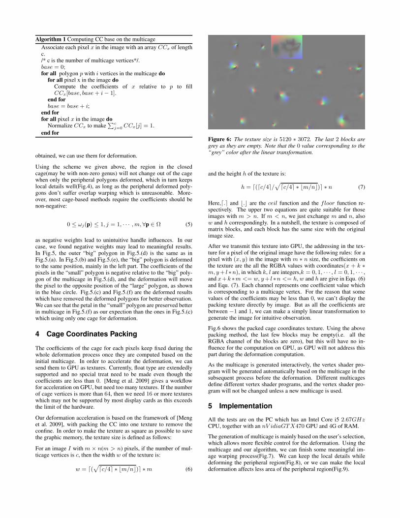
Figure 6: The texture size is 5120 ∗ 3072. The last 2 blocks aregrey as they are empty. Note that the 0 value corresponding to the“grey” color after the linear transformation.
and the height h of the texture is:
h = �(�c/4�/√
�c/4� ∗ m/n)� ∗ n (7)
Here,�.� and . are the ceil function and the floor function re-spectively. The upper two equations are quite suitable for thoseimages with m > n. If m < n, we just exchange m and n, alsow and h correspondingly. In a nutshell, the texture is composed ofmatrix blocks, and each block has the same size with the originalimage size.
After we transmit this texture into GPU, the addressing in the tex-ture for a pixel of the original image have the following rules: for apixel with (x, y) in the image with m ∗ n size, the coefficients onthe texture are the all the RGBA values with coordinates(x + k ∗m,y + l ∗n), in which k, l are integers,k = 0, 1, · · · , l = 0, 1, · · · ,and x+k ∗m <= w, y+ l ∗n <= h, w and h are give in Equ. (6)and Equ. (7). Each channel represents one coefficient value whichis corresponding to a multicage vertex. For the reason that somevalues of the coefficients may be less than 0, we can’t display thepacking texture directly by image. But as all the coefficients arebetween −1 and 1, we can make a simply linear transformation togenerate the image for intuitive observation.
Fig.6 shows the packed cage coordinates texture. Using the abovepacking method, the last few blocks may be empty(i.e. all theRGBA channel of the blocks are zero), but this will have no in-fluence for the computation on GPU, as GPU will not address thispart during the deformation computation.
As the multicage is generated interactively, the vertex shader pro-gram will be generated automatically based on the multicage in thesubsequent process before the deformation. Different multicagesdefine different vertex shader programs, and the vertex shader pro-gram will not be changed unless a new multicage is used.
5 Implementation
All the tests are on the PC which has an Intel Core i5 2.67GHzCPU, together with an nV idiaGTX470 GPU and 4G of RAM.
The generation of multicage is mainly based on the user’s selection,which allows more flexible control for the deformation. Using themulticage and our algorithm, we can finish some meaningful im-age warping process(Fig.7). We can keep the local details whiledeforming the peripheral region(Fig.8), or we can make the localdeformation affects less area of the peripheral region(Fig.9).

Figure 5: (a), (b) and (c) use one cage for deformation, while (d), (e) and (f) use a multicage for deformation. (a) and (d) are the initial state.The region in the blue circle is the mainly deformed part which can be detected. The petal in the blue circle are preserved better in (f) than in(c). The image size is 500 ∗ 333.
Figure 7: Rectified “Pisa” tower. The left is the original and the right one is the result. The middle two images show the selected multicageand its deformation respectively. Note that the lamp post before the tower is kept well, which is still as straight as the original. The imagesize is 701 ∗ 525.
Table 1: Statistics of our tests.
Image Image size Multicage vertex number Use GPUPreprocessing time Updating time
two lotus 1024 ∗ 768 68 9.034s less than 0.001sbutterfly 800 ∗ 600 44 3.478s less than 0.001s
lotus 500 ∗ 333 40 1.147s less than 0.001stower 375 ∗ 500 35 1.135s less than 0.001shead 701 ∗ 525 29 1.465s less than 0.001s
heart-reflector 1000 ∗ 701 41 3.864s less than 0.001s

Figure 8: Deform the “head” on a car. (a) is the original, (b) and (c) show a single cage position and its deformed result based on the cage.Here we don’t show the final cage for better observation. A new polygon is added in (d) to construct a multicage, compared to (b). Now wedeform the head by moving the ’big polygon’ to the same position as in (c), we get the result as (e). We can see that the face is kept betterafter we use the multicage. The image size is 701 ∗ 525.
Table 1 shows the statistics of our tests. As different cage coordi-nates will lead to the different computation time of CC, we don’tgive statistics time for CC computation. From the table, we can seethat the time for preprocessing on GPU is proportional to the ver-tices numbers of the multicage and the image size, but this will notexceed 10 seconds in our examples. The interactive deformation isreal time after the preprocessing.
For the packing method, we found that [Meng et al. 2009] methodcan’t work for the cases when the number of multicage vertices isover 60, which means the image ‘two lotus’ deformation can’t beexecuted as it has 68 multicage vertices. The limit number is de-pendent on the display card, and may be smaller for some low per-formance ones, while our GPU acceleration method doesn’t havesuch limit based on our packing pattern. We test the case with hun-dreds of multicage vertices for deforming the image ‘lotus’, and ourmethod can still work normally.
6 Conclusion and Future Work
Aiming to solve the embedded cage image deformation that can’tbe properly dealt with by the previous methods, we successfullyintroduce a new scheme that using multicage cage which is gener-ated interactively to deform images on GPU in real time. A newpacking method for cage coordinates is designed to allow moremulticage vertices to be used for image deformation on GPU. Theexperiments verify the effects of our algorithm, which means im-age deformation based on cages can generate more available resultsthan previous methods.
On the other hand, the cage generation is still a little bothering fordozens of clicking. We should generate the multicage based on im-age segmentation or edge detection, and automatically simplify therough boundaries as the multicage. We can simply adjust the mul-ticage according to our needs, and this will improve user experiencefor the image deformation.
We can set multicage vertices’ moving function to create anima-tion as in [Meng et al. 2009](see the accompany video), and in thefuture, we should seek for the technique that sets the multicage’smoving automatically according to the feature extracted from theimage or the positions of the embedded polygons, leading to morenaturally image deforming results and less setting work. We shouldalso look for how to use the multicage deformation as constraintsin image resizing or other image processing applications.
Acknowledgements
We thank the following Flickr (http://www.flickr.com/) membersand other websites for making their images available through cre-ative common rights:seri* (lotus), Hayley Grimes (head), Stuck
in Customs (heart-reflector), http://fdsysl.5d6d.com(two lotus),http://www.hncts.cn(tower) and http://www.sucai.com(butterfly).
This work is supported by National Natural Science Foundation ofChina(No.60872120, 60902078, 61172104), Beijing Natural Sci-ence Foundation(Content-Aware Image Synthesis and Its Appli-cations, No.4112061), French System@tic Paris-Region(CSDLProject) and ANR-NSFC(No.60911130368).
References
BEIER, T., AND NEELY, S. 1992. Feature-based image metamor-phosis. In SIGGRAPH ’92: Proceedings of the 19th annual con-ference on Computer graphics and interactive techniques, ACM,New York, NY, USA, 35–42.
BEN-CHEN, M., WEBER, O., AND GOTSMAN, C. 2009. Vari-ational harmonic maps for space deformation. ACM Trans.Graph. 28, 3, 1–11.
BOOKSTEIN, F. L. 1989. Principal warps: Thin-plate splines andthe decomposition of deformations. IEEE Trans. Pattern Anal.Mach. Intell. 11, 6, 567–585.
BOTSCH, M., AND SORKINE, O. 2008. On linear variational sur-face deformation methods. IEEE Transactions on Visualizationand Computer Graphics, 213–230.
BOTSCH, M., PAULY, M., GROSS, M., AND KOBBELT, L. 2006.Primo: coupled prisms for intuitive surface modeling. In Pro-ceedings of the fourth Eurographics symposium on Geometryprocessing, Eurographics Association, 11–20.
BOTSCH, M., PAULY, M., WICKE, M., AND GROSS, M. 2007.Adaptive space deformations based on rigid cells. In ComputerGraphics Forum, vol. 26, Wiley Online Library, 339–347.
DEROSE, T., AND MEYER, M. 2006. Harmonic coordinates. Tech.rep., Pixar Animation Studios.
FLOATER, M. S., KOS, G., AND REIMERS, M. 2005. Mean valuecoordinates in 3d. Comput. Aided Geom. Des. 22, 7, 623–631.
FLOATER, M. S. 2003. Mean value coordinates. Computer AidedGeometric Design 20, 1 (March), 19–27.
GODDEKE, D. 2005. Gpgpu–basic math tutorial. Tech. rep., Nov.
HORMANN, K., AND FLOATER, M. S. 2006. Mean value coordi-nates for arbitrary planar polygons. ACM Trans. Graph. 25, 4,1424–1441.
IGARASHI, T., MOSCOVICH, T., AND HUGHES, J. F. 2005. As-rigid-as-possible shape manipulation. In SIGGRAPH ’05: ACM
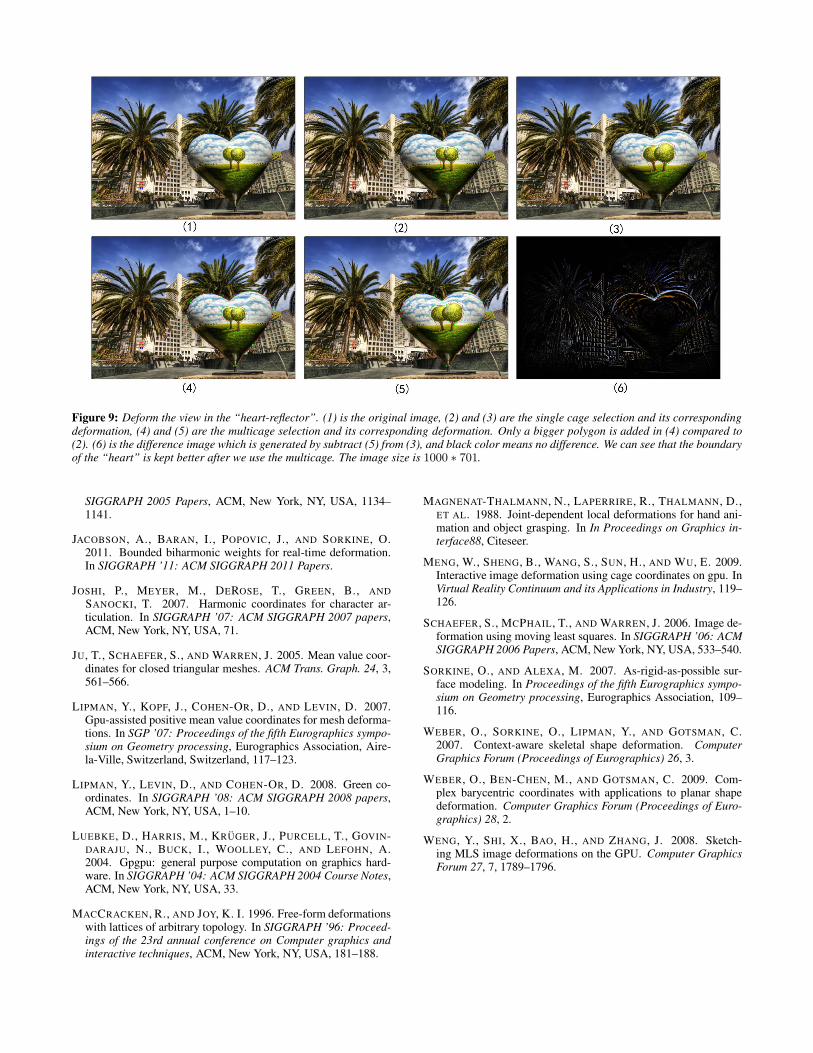
Figure 9: Deform the view in the “heart-reflector”. (1) is the original image, (2) and (3) are the single cage selection and its correspondingdeformation, (4) and (5) are the multicage selection and its corresponding deformation. Only a bigger polygon is added in (4) compared to(2). (6) is the difference image which is generated by subtract (5) from (3), and black color means no difference. We can see that the boundaryof the “heart” is kept better after we use the multicage. The image size is 1000 ∗ 701.
SIGGRAPH 2005 Papers, ACM, New York, NY, USA, 1134–1141.
JACOBSON, A., BARAN, I., POPOVIC, J., AND SORKINE, O.2011. Bounded biharmonic weights for real-time deformation.In SIGGRAPH ’11: ACM SIGGRAPH 2011 Papers.
JOSHI, P., MEYER, M., DEROSE, T., GREEN, B., ANDSANOCKI, T. 2007. Harmonic coordinates for character ar-ticulation. In SIGGRAPH ’07: ACM SIGGRAPH 2007 papers,ACM, New York, NY, USA, 71.
JU, T., SCHAEFER, S., AND WARREN, J. 2005. Mean value coor-dinates for closed triangular meshes. ACM Trans. Graph. 24, 3,561–566.
LIPMAN, Y., KOPF, J., COHEN-OR, D., AND LEVIN, D. 2007.Gpu-assisted positive mean value coordinates for mesh deforma-tions. In SGP ’07: Proceedings of the fifth Eurographics sympo-sium on Geometry processing, Eurographics Association, Aire-la-Ville, Switzerland, Switzerland, 117–123.
LIPMAN, Y., LEVIN, D., AND COHEN-OR, D. 2008. Green co-ordinates. In SIGGRAPH ’08: ACM SIGGRAPH 2008 papers,ACM, New York, NY, USA, 1–10.
LUEBKE, D., HARRIS, M., KRUGER, J., PURCELL, T., GOVIN-DARAJU, N., BUCK, I., WOOLLEY, C., AND LEFOHN, A.2004. Gpgpu: general purpose computation on graphics hard-ware. In SIGGRAPH ’04: ACM SIGGRAPH 2004 Course Notes,ACM, New York, NY, USA, 33.
MACCRACKEN, R., AND JOY, K. I. 1996. Free-form deformationswith lattices of arbitrary topology. In SIGGRAPH ’96: Proceed-ings of the 23rd annual conference on Computer graphics andinteractive techniques, ACM, New York, NY, USA, 181–188.
MAGNENAT-THALMANN, N., LAPERRIRE, R., THALMANN, D.,ET AL. 1988. Joint-dependent local deformations for hand ani-mation and object grasping. In In Proceedings on Graphics in-terface88, Citeseer.
MENG, W., SHENG, B., WANG, S., SUN, H., AND WU, E. 2009.Interactive image deformation using cage coordinates on gpu. InVirtual Reality Continuum and its Applications in Industry, 119–126.
SCHAEFER, S., MCPHAIL, T., AND WARREN, J. 2006. Image de-formation using moving least squares. In SIGGRAPH ’06: ACMSIGGRAPH 2006 Papers, ACM, New York, NY, USA, 533–540.
SORKINE, O., AND ALEXA, M. 2007. As-rigid-as-possible sur-face modeling. In Proceedings of the fifth Eurographics sympo-sium on Geometry processing, Eurographics Association, 109–116.
WEBER, O., SORKINE, O., LIPMAN, Y., AND GOTSMAN, C.2007. Context-aware skeletal shape deformation. ComputerGraphics Forum (Proceedings of Eurographics) 26, 3.
WEBER, O., BEN-CHEN, M., AND GOTSMAN, C. 2009. Com-plex barycentric coordinates with applications to planar shapedeformation. Computer Graphics Forum (Proceedings of Euro-graphics) 28, 2.
WENG, Y., SHI, X., BAO, H., AND ZHANG, J. 2008. Sketch-ing MLS image deformations on the GPU. Computer GraphicsForum 27, 7, 1789–1796.
Related Documents