HAL Id: tel-03327751 https://tel.archives-ouvertes.fr/tel-03327751 Submitted on 27 Aug 2021 HAL is a multi-disciplinary open access archive for the deposit and dissemination of sci- entific research documents, whether they are pub- lished or not. The documents may come from teaching and research institutions in France or abroad, or from public or private research centers. L’archive ouverte pluridisciplinaire HAL, est destinée au dépôt et à la diffusion de documents scientifiques de niveau recherche, publiés ou non, émanant des établissements d’enseignement et de recherche français ou étrangers, des laboratoires publics ou privés. Multi-Axis Instrumentation for Robotized Micro-assembly Bhawnath Tiwari To cite this version: Bhawnath Tiwari. Multi-Axis Instrumentation for Robotized Micro-assembly. Automatic. Université Bourgogne Franche-Comté, 2021. English. NNT: 2021UBFCD007. tel-03327751

Welcome message from author
This document is posted to help you gain knowledge. Please leave a comment to let me know what you think about it! Share it to your friends and learn new things together.
Transcript
HAL Id: tel-03327751https://tel.archives-ouvertes.fr/tel-03327751
Submitted on 27 Aug 2021
HAL is a multi-disciplinary open accessarchive for the deposit and dissemination of sci-entific research documents, whether they are pub-lished or not. The documents may come fromteaching and research institutions in France orabroad, or from public or private research centers.
L’archive ouverte pluridisciplinaire HAL, estdestinée au dépôt et à la diffusion de documentsscientifiques de niveau recherche, publiés ou non,émanant des établissements d’enseignement et derecherche français ou étrangers, des laboratoirespublics ou privés.
Multi-Axis Instrumentation for RobotizedMicro-assembly
Bhawnath Tiwari
To cite this version:Bhawnath Tiwari. Multi-Axis Instrumentation for Robotized Micro-assembly. Automatic. UniversitéBourgogne Franche-Comté, 2021. English. NNT : 2021UBFCD007. tel-03327751
Thèse de doctorat de l’établissementUniversité Bourgogne Franche-Comté
preparée à l’Université de Franche Comté
École doctorale no 37Sciences Physiques pour l’Ingénieur et
Microtechniques
Doctorat d’Automatique
Par
Bhawnath Tiwari
Instrumentation multi-axes pourmicro-assemblage robotisé
Soutenue publiquement le 14 Janvier 2021, à Besançondevant le jury composé de :
Franck CHOLLET Professeur, Univ. Bourgogne Franche-Comté, France PrésidentMicky RAKOTONDRABE Professeur, ENIT, Tarbes RapporteurFrédéric LAMARQUE Professeur, UTC, Compiègne RapporteurIrène FASSI Maître de Recherche, CNR, Italie ExaminateurDavid J. CAPPELLERI Maître de Conférences, Université Purdue, États Unis ExaminateurPhilippe LUTZ Professeur, UBFC, Besançon Co-encadrant de thèseCédric CLÉVY Maître de Conférences, HDR, UBFC, Besançon Directeur de thèse
Doctoral Thesis of the University ofBourgogne Franche-Comté prepared at
University of Franche-Comté
Doctoral School no 37Engineering Sciences and Microtechnologies
Doctorate in Automation
By
Bhawnath Tiwari
Multi-axis Instrumentation forRobotized Micro-assembly
Thesis defended publicly on 14 January 2021, at Besançoncomposition of jury :
Micky RAKOTONDRABE Professor, ENIT, Tarbes ReviewerFrédéric LAMARQUE Professor, UTC, Compiègne ReviewerIrène FASSI Senior Researcher, CNR, Italy ExaminerDavid J. CAPPELLERI Associate Prof., Purdue University, USA ExaminerFranck CHOLLET Professor, UBFC, Besançon ExaminerPhilippe LUTZ Professor, UBFC, Besançon Thesis Co-supervisorCédric CLÉVY Associate Prof., HDR, UBFC, Besançon Thesis Director

AcknowledgementsEnjoyment of any journey gets amplified when we have interesting people on
board. In the same way, thesis work also requires involvement of adequate people.I would like to thank every individual who directly or indirectly participated in thisexciting journey of my doctoral thesis. It is always said that crests and troughs,are part of any journey, but a proper guidance and support always expected for notonly its completion but for a healthy learning. Therefore, in this context I expressmy deepest thanks to my thesis director, Associate Prof. Cédric Clévy and co-supervisor Prof. Philippe Lutz, whose proper guidance and supports, significantlyhelped me to reach a meaningful completion of this thesis.
I would like to thank my thesis jury members, Pr. Franck Chollet, Pr. FrédéricLamarque, Pr. Micky Rakotondrabe, Dr. Irène Fassi, and Pr.(Assoc.) David J.Cappelleri, for their time and constructive participation in my soutenance. Yourremarks and suggestions are really encouraging and helpful for my research works,it was indeed an amazing learning experience.
As my thesis was in collaboration [COLAMIR 20] with academic-industrialpartners, I take this opportunity to say thanks to every members of this project.I would like to especially mention names of Dr. Joël Agnus, Mr. Patrick Rougeotfrom Femto-ST Institute and Stephane, Margot Billot, and Charlotte Quesnel fromPercipio Robotics, who helped me on technical sides throughout my thesis.
I also would like to express my sincere gratitude to every members of AS2MDepartment, must say that I was fortunate enough to be part of this happy andsupportive research family. I especially would like to mention here some of mycollegues, Jöel Bafumba Liseli, Marwa Haddad, Ning Liu, Jesus Toledo, BenjaminMauze, Amine Benouhiba, Yuning Lei, and Luc Petiet. I can proudly say, that Ilearned a lot from you guys.
I am immensely thankful to my family members for their continuous love,blessings, and supports. Finally, I express my deepest respect and honor for theultimate purest energy, my god, whose blessings helped me to complete this amaz-ing journey.
Bhawnath Tiwari
iii

Contents
Contents
Contents . . . . . . . . . . . . . . . . . . . . . . . . . . . . . . . . . . . . . . . . . . . . . . . . . . . . iv
List of Figures . . . . . . . . . . . . . . . . . . . . . . . . . . . . . . . . . . . . . . . . . . . . . vii
List of Tables. . . . . . . . . . . . . . . . . . . . . . . . . . . . . . . . . . . . . . . . . . . . . . . xi
Introduction . . . . . . . . . . . . . . . . . . . . . . . . . . . . . . . . . . . . . . . . . . . . . . . . 1
I Instrumentation and Robotics at the Micro-scale . . 3
I.1 Introduction . . . . . . . . . . . . . . . . . . . . . . . . . . . . . . . . . . . . . . . . . . . 4I.2 Microrobotics and its applications . . . . . . . . . . . . . . . . . . . . 4I.3 Thesis Context and Targeted Works . . . . . . . . . . . . . . . . . . 6
I.3.1 Challenges at the micro-scale . . . . . . . . . . . . . . . . . . . . . . 7I.3.2 Micro-assembly and the requirements. . . . . . . . . . . . . . . 7I.3.3 Micro-assembly with glue . . . . . . . . . . . . . . . . . . . . . . . . . 12
I.4 Instrumented system development . . . . . . . . . . . . . . . . . . . . 14I.5 Conclusions. . . . . . . . . . . . . . . . . . . . . . . . . . . . . . . . . . . . . . . . . . . . 19
II Analysis and robotics based precise gluing. . . . . . . . . . . 20
II.1 Introduction . . . . . . . . . . . . . . . . . . . . . . . . . . . . . . . . . . . . . . . . . . . 21II.2 Glue Curing in absence of External Load . . . . . . . . . . . . . 22II.3 Glue curing in the presence of external Load . . . . . . . . . 25II.4 Modeling of the Glue Shrinkage. . . . . . . . . . . . . . . . . . . . . . . 28II.5 Study of active control to achieve accurate gluing . . . . 31II.6 Towards an active control for precise gluing. . . . . . . . . . . 34
II.6.1 Working principle . . . . . . . . . . . . . . . . . . . . . . . . . . . . . . . . 34II.6.2 Controller Design. . . . . . . . . . . . . . . . . . . . . . . . . . . . . . . . . 35II.6.3 Experimental setup . . . . . . . . . . . . . . . . . . . . . . . . . . . . . . . 36II.6.4 Behavior in the absence of the proposed control scheme
36II.6.5 Behavior with proposed control strategy . . . . . . . . . . . . 39
iv

Contents
II.7 Conclusions. . . . . . . . . . . . . . . . . . . . . . . . . . . . . . . . . . . . . . . . . . . . 44
III A high range-to-resolution multi-axis µForce/torqueSensing Platform . . . . . . . . . . . . . . . . . . . . . . . . . . . . . . . . . . . . . . . . . 46
III.1 Introduction . . . . . . . . . . . . . . . . . . . . . . . . . . . . . . . . . . . . . . . . . . . 47III.2 Sensing Principle and Platform Design. . . . . . . . . . . . . . . . 50
III.2.1 Sensing Principle . . . . . . . . . . . . . . . . . . . . . . . . . . . . . . . . . 50III.2.2 System Design . . . . . . . . . . . . . . . . . . . . . . . . . . . . . . . . . . . 51III.2.3 Vision-based Position Measurement . . . . . . . . . . . . . . . . 52
III.3 System Modeling and Estimation . . . . . . . . . . . . . . . . . . . . . 54III.4 Fabrication Process. . . . . . . . . . . . . . . . . . . . . . . . . . . . . . . . . . . . 57III.5 Experimental Works for Identification . . . . . . . . . . . . . . . . 59
III.5.1 Principle and Setup. . . . . . . . . . . . . . . . . . . . . . . . . . . . . . . 59III.5.2 Experimental Results . . . . . . . . . . . . . . . . . . . . . . . . . . . . . 59III.5.3 Parameters Identification. . . . . . . . . . . . . . . . . . . . . . . . . . 59
III.6 Model Validation . . . . . . . . . . . . . . . . . . . . . . . . . . . . . . . . . . . . . . 62III.6.1 Estimation of Torque along Y and Force along X . . . . 62III.6.2 Sensing Resolution Validation . . . . . . . . . . . . . . . . . . . . . 64III.6.3 Performance Repeatability . . . . . . . . . . . . . . . . . . . . . . . . 65
III.7 Conclusions. . . . . . . . . . . . . . . . . . . . . . . . . . . . . . . . . . . . . . . . . . . . 66
IV A 2-Axis Piezoresistive Force Sensing Tool . . . . . . . . . . 67
IV.1 Introduction . . . . . . . . . . . . . . . . . . . . . . . . . . . . . . . . . . . . . . . . . . . 68IV.2 Sensing Principle and Design . . . . . . . . . . . . . . . . . . . . . . . . . 69
IV.2.1 Sensing Principle . . . . . . . . . . . . . . . . . . . . . . . . . . . . . . . . . 69IV.2.2 System Design . . . . . . . . . . . . . . . . . . . . . . . . . . . . . . . . . . . 71IV.2.3 System Working. . . . . . . . . . . . . . . . . . . . . . . . . . . . . . . . . . 71
IV.3 System analysis in COMSOL . . . . . . . . . . . . . . . . . . . . . . . . . . 75IV.3.1 Modeling of the system for Stress/Strain Estimation . 77IV.3.2 Electrical Connectivity and Gauge Factor Calcula-
tion . . . . . . . . . . . . . . . . . . . . . . . . . . . . . . . . . . . . . . . . . . . . . 79IV.4 Device Fabrication and Assembly process . . . . . . . . . . . . . 81
IV.4.1 Fabrication of the Passive Tool . . . . . . . . . . . . . . . . . . . . 81IV.4.2 Fabrication of the Cavalier . . . . . . . . . . . . . . . . . . . . . . . . 81
IV.5 Assembly Process . . . . . . . . . . . . . . . . . . . . . . . . . . . . . . . . . . . . . 83IV.6 Experimental Studies. . . . . . . . . . . . . . . . . . . . . . . . . . . . . . . . . . 85
IV.6.1 Experimental Setup . . . . . . . . . . . . . . . . . . . . . . . . . . . . . . 85
v

Contents
IV.6.2 Behavior under no load . . . . . . . . . . . . . . . . . . . . . . . . . . . 86IV.6.3 Characterization for load along Y axis . . . . . . . . . . . . . . 88IV.6.4 Characterization for load along Z axis . . . . . . . . . . . . . . 91IV.6.5 Gauge Factor and Sensitivity analysis . . . . . . . . . . . . . . 93
IV.7 Conclusions. . . . . . . . . . . . . . . . . . . . . . . . . . . . . . . . . . . . . . . . . . . . 96
V Development of an Instrumented microgripper andmicro-scale task handling . . . . . . . . . . . . . . . . . . . . . . . . . . . . . . . . 97
V.1 Introduction . . . . . . . . . . . . . . . . . . . . . . . . . . . . . . . . . . . . . . . . . . . 98V.2 Development of an instrumented microgripper. . . . . . . . 98
V.2.1 Modeling of the gripper’s actuation . . . . . . . . . . . . . . . . 100V.2.2 Task Handling with the proposed Gripper . . . . . . . . . . 104V.2.3 Grasping of micro-object without control . . . . . . . . . . . 104V.2.4 Force controlled Grasping of a micro-object . . . . . . . . . 105
V.3 Assembly using the developed instrumented micro-systems . . . . . . . . . . . . . . . . . . . . . . . . . . . . . . . . . . . . . . . . . . . . . . . . 108
V.4 Conclusions. . . . . . . . . . . . . . . . . . . . . . . . . . . . . . . . . . . . . . . . . . . . 111
Conclusions and perspectives . . . . . . . . . . . . . . . . . . . . . . . . . . . 113
Bibliography . . . . . . . . . . . . . . . . . . . . . . . . . . . . . . . . . . . . . . . . . . . . . . . 116
vi

List of Figures
List of Figures
I.1 Microrobot for cancer cells microsurgery [Vyskocil 20] . . . . . . . . . . . . . . 5I.2 Electrical characterization of a carbon nano-tube in contact with a
probe [Clévy 19]. . . . . . . . . . . . . . . . . . . . . . . . . . . . . . . . . . . . . . . . . . . . . . . . 6I.3 Comparison of forces at the micro-scale discussed in [Neugebauer 11] 8I.4 Gear assembly on 100 µm tungsten wire [Zyvex 20] . . . . . . . . . . . . . . . . 8I.5 Releasing strategy used in [Liu 20], (a)-(i) sequential images during
the release . . . . . . . . . . . . . . . . . . . . . . . . . . . . . . . . . . . . . . . . . . . . . . . . . . . . . 10I.6 Peg-in-Hole micro-assembly used in [Chang 16] . . . . . . . . . . . . . . . . . . . . 11I.7 Multi peg-in-hole used in [Ma 20], (a) Pin Header with pegs (b)Before
Insertion (c) During Insertion (d) Insertion Done . . . . . . . . . . . . . . . . . 11I.8 Capillary self-alignment in [Chang 17], (a1),(b1) and (c1) chip was
placed on a receptor site; (a2),(b2) and (c2) water mist induceddroplet introduces at the assembly site; (a3), (b3) and (c3) self-aligned chip at the receptor site . . . . . . . . . . . . . . . . . . . . . . . . . . . . . . . . . 13
I.9 Schematic of the Gluing system used in [Xie 18] . . . . . . . . . . . . . . . . . . . 13I.10 A comparison of different force sensing from the state-of-the-art. . . . . 18
II.1 Schematic for the Gluing in absence of external load . . . . . . . . . . . . . . . 22II.2 Experimental Setup for gluing in absence of external load: (a) Top
view (b) Side View . . . . . . . . . . . . . . . . . . . . . . . . . . . . . . . . . . . . . . . . . . . . . 23II.3 Study of the behavior of a component during its gluing. . . . . . . . . . . . . 23II.4 Spring model . . . . . . . . . . . . . . . . . . . . . . . . . . . . . . . . . . . . . . . . . . . . . . . . . . 24II.5 Calculated glue stiffness with 20 N/m passive beam. . . . . . . . . . . . . . . . 24II.6 Experimental setup for Glue behavior under external load . . . . . . . . . . 26II.7 System representation and behavior during gluing . . . . . . . . . . . . . . . . . 27II.8 Hysteresis and stiffness evolution during gluing . . . . . . . . . . . . . . . . . . . 28II.9 Modeling of the Glue shrinkage . . . . . . . . . . . . . . . . . . . . . . . . . . . . . . . . . . 30II.10 Negligible impact from the employed load; dA=0 correspond to no
displacement from Robot 1 (as shown in Fig. II.7a) . . . . . . . . . . . . . . . . 32II.11 A feedback control to insure a desired distance between the surfaces . 32
vii
List of Figures
II.12 The dependency of the controller gain on the extent of actuationand accuracy. . . . . . . . . . . . . . . . . . . . . . . . . . . . . . . . . . . . . . . . . . . . . . . . . . . 33
II.13 Proposed scheme for distance control between the Beams. . . . . . . . . . . 35II.14 Experimental Setup used for the analysis . . . . . . . . . . . . . . . . . . . . . . . . . 36II.15 Behavior in absence of control from interaction and curing. . . . . . . . . . 37II.16 Different Steps before use of control . . . . . . . . . . . . . . . . . . . . . . . . . . . . . . 41II.17 Actuation and obtained gluing with the proposed active control . . . . . 43
III.1 Comparison of different state-of-the-art Multi-axis Force Sensors . . . . 49III.2 Sensing platform design and working principle. . . . . . . . . . . . . . . . . . . . . 51III.3 Principle scheme of the force-torque sensing platform . . . . . . . . . . . . . . 52III.4 Encoded Central Rigid Body (CRB) with different Field of View . . . . 53III.5 System Behavior from COMSOL Simulation . . . . . . . . . . . . . . . . . . . . . . 54III.6 Summarized Fabrication Process . . . . . . . . . . . . . . . . . . . . . . . . . . . . . . . . . 58III.7 Fabricated Platform . . . . . . . . . . . . . . . . . . . . . . . . . . . . . . . . . . . . . . . . . . . . 58III.8 Experimental Setup . . . . . . . . . . . . . . . . . . . . . . . . . . . . . . . . . . . . . . . . . . . . 60III.9 Experimentation, input motion, reference force and according posi-
tion sensed by vision. . . . . . . . . . . . . . . . . . . . . . . . . . . . . . . . . . . . . . . . . . . . 60III.10Model fitting and parameters identification . . . . . . . . . . . . . . . . . . . . . . . 61III.11Force, Z: Model Validation with force at M and P . . . . . . . . . . . . . . . . . 62III.12Estimation error for the identification (Ident-(M) for force at M)
and validation (Val-(M) and Val-(P)), respectively for force at Mand P . . . . . . . . . . . . . . . . . . . . . . . . . . . . . . . . . . . . . . . . . . . . . . . . . . . . . . . . . 63
III.13Estimation of Force along X . . . . . . . . . . . . . . . . . . . . . . . . . . . . . . . . . . . . . 63III.14Estimation of Torque about Y . . . . . . . . . . . . . . . . . . . . . . . . . . . . . . . . . . . 64III.15Validation of Resolution. . . . . . . . . . . . . . . . . . . . . . . . . . . . . . . . . . . . . . . . . 65III.16Repeatbility of the proposed sensing platform . . . . . . . . . . . . . . . . . . . . . 66
IV.1 Resistance dependency on Geometry . . . . . . . . . . . . . . . . . . . . . . . . . . . . . 70IV.2 Sensing Principle . . . . . . . . . . . . . . . . . . . . . . . . . . . . . . . . . . . . . . . . . . . . . . . 71IV.3 Proposed design of the sensing tool. . . . . . . . . . . . . . . . . . . . . . . . . . . . . . . 73IV.4 Wheatstone Circuitry . . . . . . . . . . . . . . . . . . . . . . . . . . . . . . . . . . . . . . . . . . . 74IV.5 Force application in COMSOL, and the cross-section view of cavity . 76IV.6 Comparison of analytical model and COMSOL measurement . . . . . . . 78
viii
List of Figures
IV.7 Resistance change against the strain. . . . . . . . . . . . . . . . . . . . . . . . . . . . . . 80
IV.8 (a)-(i) Fabrication steps for the Passive Tool . . . . . . . . . . . . . . . . . . . . . 82
IV.9 Plane and direction representation for wafer and carriers . . . . . . . . . . . 82
IV.10Fabrication process of the cavalier. . . . . . . . . . . . . . . . . . . . . . . . . . . . . . . . 83
IV.11Fabricated devices . . . . . . . . . . . . . . . . . . . . . . . . . . . . . . . . . . . . . . . . . . . . . 84
IV.12Steps involved in the process of assembly and wiring . . . . . . . . . . . . . . 84
IV.13Experimental setup . . . . . . . . . . . . . . . . . . . . . . . . . . . . . . . . . . . . . . . . . . . . . 86
IV.14Signal acquisition under no load and the environmental conditions . . 87
IV.15Input displacement and sensed voltages from PRT against load alongY . . . . . . . . . . . . . . . . . . . . . . . . . . . . . . . . . . . . . . . . . . . . . . . . . . . . . . . . . . . . . 88
IV.16Voltage signal after coupling correction (resulting from Fig. IV.15) . . 89
IV.17Sensitivity identification of PRT along Y axis . . . . . . . . . . . . . . . . . . . . . 90
IV.18Spring equivalence. . . . . . . . . . . . . . . . . . . . . . . . . . . . . . . . . . . . . . . . . . . . . . 90
IV.19Resolution study along the Y axis. . . . . . . . . . . . . . . . . . . . . . . . . . . . . . . . 91
IV.20Characterization along the Z axis . . . . . . . . . . . . . . . . . . . . . . . . . . . . . . . 92
IV.21Relative resistance change against the strain . . . . . . . . . . . . . . . . . . . . . . 93
IV.22Absolute resistance change in the two wheatstone bridge against theload along Y and Z . . . . . . . . . . . . . . . . . . . . . . . . . . . . . . . . . . . . . . . . . . . . . 94
IV.23A completely flat tip used for the analysis in COMSOL . . . . . . . . . . . . 94
IV.24Resistance changes with load along Y axis . . . . . . . . . . . . . . . . . . . . . . . . 95
IV.25Resistance changes with load along Z axis . . . . . . . . . . . . . . . . . . . . . . . . 95
V.1 The instrumented microgripper after integration of the developedpiezoresistive tool (PRT) from Chapter IV with actuators . . . . . . . . . . 99
V.2 Block model of instrumented finger of the Gripper . . . . . . . . . . . . . . . . . 100
V.3 Experimental setup to study the characteristics of the gripper . . . . . . 101
V.4 Estimation and experimental results for actuation in free space . . . . . 102
V.5 Estimation and experimental results combining the constraint mo-tion . . . . . . . . . . . . . . . . . . . . . . . . . . . . . . . . . . . . . . . . . . . . . . . . . . . . . . . . . . . 103
V.6 Experimental setup and the Gripper-object view . . . . . . . . . . . . . . . . . . 105
V.7 Gripping of the micro-object without any feedback control. . . . . . . . . . 106
V.8 Force controlled grasping and Release of the micro-object . . . . . . . . . . 107
ix
List of Figures
V.9 Gluing with developed micro-systems; (a) CAD version of the gluingsystem; (b) Experimental Setup; (c) Sensing platform with Slab; (d)Force sensed by PRT along Y (P: glue-slab contact, Q: UV ON); (e)Force sensed by sensing platform along Z; (f) Force sensed by sensingplatform along Y . . . . . . . . . . . . . . . . . . . . . . . . . . . . . . . . . . . . . . . . . . . . . . 109
V.10 Gluing process in different steps: (a) A 500 µm × 500 µm object onthe support platform; (b) Gripper towards the object for grasping;(c) Grasped object; (d) Glue-Object contact for glue-deposition; (e)Deposited Glue at the base of the object; (f) Glue-deposited objecttowards the slab attached to sensing platform; (g) Object positionedon the slab, UV turned ON; (h) UV turned OFF, and object released(glued object on the slab) . . . . . . . . . . . . . . . . . . . . . . . . . . . . . . . . . . . . . . . 110
V.11 A variable stiffness used in [Memar 19] (a) gripper schematic (b)Fingers passive motion before grasp denoted by p1 (c) Fingers pas-sive motion after grasp denoted by ∆. Equilibrium points in theabsence of external forces are denoted by dotted lines in red (d)Different components of the gripper and mechanical design . . . . . . . . . 115
x

List of Tables
List of Tables
I.1 Comparison of major sensing approaches used for micro-scale appli-cations . . . . . . . . . . . . . . . . . . . . . . . . . . . . . . . . . . . . . . . . . . . . . . . . . . . . . . . . 16
I.2 State of the art References for Fig I.10 . . . . . . . . . . . . . . . . . . . . . . . . . . . 19
II.1 Evolution of Glue Stiffness . . . . . . . . . . . . . . . . . . . . . . . . . . . . . . . . . . . . . . 24II.2 Identified Parameters for shrinkage modeling with load. . . . . . . . . . . . . 30II.3 Obtained shrinkage from different experiments . . . . . . . . . . . . . . . . . . . . 38
III.1 State of the art References for Fig III.1 . . . . . . . . . . . . . . . . . . . . . . . . . . . 50III.2 The Identified Parameters . . . . . . . . . . . . . . . . . . . . . . . . . . . . . . . . . . . . . . . 61
IV.1 Load Impact with direction. . . . . . . . . . . . . . . . . . . . . . . . . . . . . . . . . . . . . . 72IV.2 Geometrical and mechanical parameters used in the COMSOL sim-
ulation . . . . . . . . . . . . . . . . . . . . . . . . . . . . . . . . . . . . . . . . . . . . . . . . . . . . . . . . 77IV.3 Measured resistance of gauges under no load . . . . . . . . . . . . . . . . . . . . . . 86IV.4 Identified parameters for characterization along Y and Z . . . . . . . . . . . 92
V.1 Identified parameters for the actuator . . . . . . . . . . . . . . . . . . . . . . . . . . . . 102V.2 Different steps during the gripping and release of micro-object . . . . . . 106
xi
Introduction
Introduction
Instrumentation of the structures allows their use as sensing devices. Micro-worldalso requires such instrumentation, mainly for tasks automation or local accuratecharacterization (interesting for human robot collaborative tasks). The micro-structures because of their fragility and high sensitivity to the uneven environmen-tal variation requires special care in the development of sensing and/or actuationmechanism. In the context of micro-robotics the force/torque sensing can bolsterthe decision making capability during the tasks. There are varieties of tasks wheresingle axis force sensing is not adequate enough to meet the objective, for examplemanipulation of the object against an unknown environment, or the rotation ofthe object, or the assembly of micro-components using a thick film of glue. Manythings are indeed coupled thus key things happen on several axis and measuringa single one induces key limitation in the analysis. A diverse and flexible decisionmaking capability during different task handling requires knowledge of the localstates along the multi-axis, which can be fulfilled by an instrumented multi-axisforce/torque sensor.
The thesis titled “Multi-Axis Instrumentation for Robotized Micro-assembly”covers the different key points in the context of micro-robotics. This thesis ispart of the ANR (National Research Agency) project “Collaborative Agile Minia-turized Robotics for ultra-precise assembly (COLAMIR) [COLAMIR 20]” and isfocused for the different requirements in the industrial scenario. To start with,a general study of different robotized works in micro-world, the requirement ofinstrumentation (specially in the context the COLAMIR project), and conclusionfrom different works (from the state of the art) is presented in Chapter I. Assemblyof micro-components is an important and frequent use in the industries. Gluingallows a fixed relative positioning of the two structures, but it brings additionalchallenges when it comes to positioning accuracy. This issue is addressed in theChapter II of this thesis where analysis of gluing and its use for precise position-ing is demonstrated. The corresponding studies were made along one axis, wherethe impact was maximum from the gluing. The studies made therefore suggestedthe requirement of multi-axis instrumentation. This thesis work then covers theinstrumentation requirement for the force-sensing along multi-axis. The instru-mentation of the structure may be done by instrumenting the platform used forthe task, and/or instrumenting the tool used for the manipulation of the micro-component. Both these possibilities are addressed in this thesis. Firstly, an in-strumented sensing platform is proposed with a sensing capability of forces alongthe two planar axes, and the torque about the plane. This work is detailed and isdiscussed in Chapter III. Following, the instrumentation requirements in the ma-nipulation, a piezoresistive force sensing tool was developed. This tool can sensethe force along the two axes, while it can be used for different applications where
1
Introduction
2 axis sensing are required but is designed to be used for gripping and assemblytasks. The development of this sensing tool from design, analysis, fabrication andexperimental validation of the performance is discussed in chapter IV. ChapterV constitutes, the use of demonstrated instrumented systems for the micro-scaletasks. In this direction, the sensing tool demonstrated in chapter IV was used todevelop a microgripper by integration of the tool with piezoelectric actuator. Thedeveloped system was then demonstrated with experimental validation followingthe actuation modeling and tasks covering the micro-grasping and release. Also,an extension of gluing study along multi-axis is presented with a combined use ofsensing platform (chapter III), and the microgripper developed.
2

Chapter IInstrumentation and Robotics at the
Micro-scale
I.1 Introduction . . . . . . . . . . . . . . . . . . . . . . . . . . . . . . . . . . . . . . . . . . . . 4I.2 Microrobotics and its applications . . . . . . . . . . . . . . . . . . . . . . . 4I.3 Thesis Context and Targeted Works . . . . . . . . . . . . . . . . . . . . . 6
I.3.1 Challenges at the micro-scale . . . . . . . . . . . . . . . . . . . . . . . . 7I.3.2 Micro-assembly and the requirements . . . . . . . . . . . . . . . . . 7I.3.3 Micro-assembly with glue . . . . . . . . . . . . . . . . . . . . . . . . . . . 12
I.4 Instrumented system development. . . . . . . . . . . . . . . . . . . . . . . 14I.5 Conclusions . . . . . . . . . . . . . . . . . . . . . . . . . . . . . . . . . . . . . . . . . . . . 19
3
Chapter I. Instrumentation and Robotics at the Micro-scale
I.1 Introduction
The excitement and motivation to explore more in the miniaturized world madethe researchers to investigate different sensing and actuation mechanisms. Fromthe development of microscope to a very high resolution camera is one of the dif-ferent advancements made towards the study of micro-world. In the recent years,microscopy development includes the work on range to resolution improvement[Perkel 19], use of artificial intelligence for real time medical diagnosis [Chen 19]to development of portable microscopes that can be used in freely behaving ani-mals [Senarathna 19]. Visualization of structures at micro/nano scale strengthenthe motivation to interact with them at such scales. But, unlike the macro-world,interaction with micro/nano structures require extra attention because of theirfragility and surface forces predominance at these scales. This lead to the require-ment of an intermediate system between the micro-structures and the end-user.Robotic systems can bring interesting results if they are used as intermediate sys-tems to interact with fragile micro-structures. This can be seen in these recentyears, where micro-robotic systems demonstrated their usefulness in varieties ofapplications (detailed in section I.2). But, the performances of any micro-roboticsystem may be limited by the complexity of the tasks. At the micro-scale, suchlimitations mainly occur from the lack of local state(s) knowledge and/or their ac-cording use in analysis or decision making. Modeling could be one way to provideinformation of such local state(s), but it’s not very obvious to model interactionforces which may differ depending on their nature (e.g. van-der-Waal’s, surfacetension etc.). Instrumentation, therefore appears as a key requirement. Choiceof the instrumented system may vary depending on the targeted works. Thisthesis work is a part of an academic-industrial project [COLAMIR 20]. The cor-responding instrumented micro-robotic system development was considered in theindustrial context with focus on manipulation and assembly at the micro-scale(detailed in Section I.3). Depending on the complexity of the task, multi-axisstate information can enrich the system capability for decision making during thetask or the post-experiment analysis. Therefore the multi-axis instrumentationdevelopment meeting the desired specifications of the task appears as a key lock.A discussion on the instrumented system development is presented in section I.4.Finally, the conclusion of this chapter is made in the section I.5.
I.2 Microrobotics and its applications
Robotic advancements lead to extend its application also for the miniaturizedworld. The medical domain witnessed several potential usefulness of the micro-robotics. This field needs dedicated, precise and repeatable task handling capabil-ities. Whether it deals with the navigation of a tool inside intestine [Wu 19], or theuse of biohybrid microrobots [Alapan 19] for in vivo imaging and cargo delivery;microrobotics is of an immense importance. The ultra sensitive tasks like perform-
4
I.2. Microrobotics and its applications
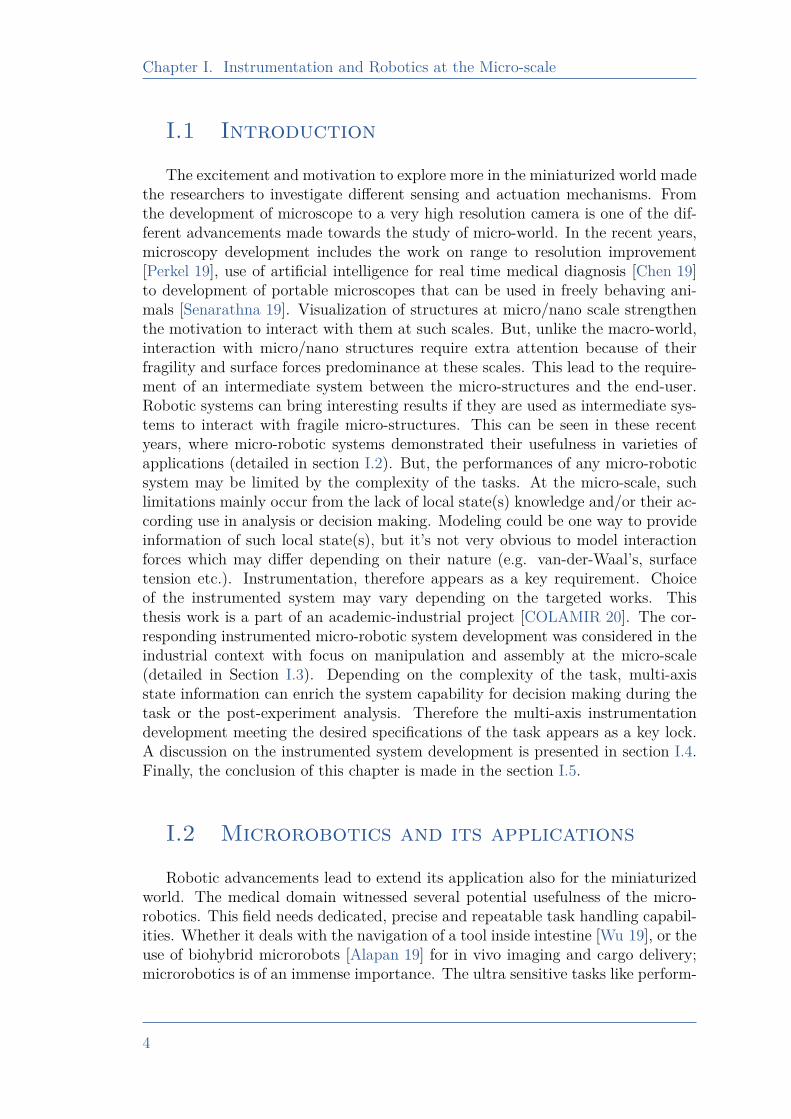
Figure I.1 – Microrobot for cancer cells microsurgery [Vyskocil 20]
ing surgical operations [Vyskocil 20] (Fig. I.1) and transport of cells [Yasa 19] ina confined environment, has also been effectively carried out using microrobots.Whereas the use of microrobotics is also found relevant in the fast detection oftoxin, especially in the infection such as clostridium difficile [Yang 20]. Micro-robotics demonstrated a potential interest in performing a precise and organizedway for varieties of medical tasks. There are still several advancement needed indifferent context of medical applications, which includes the multimodal sensingand tool development to achieve complex and dexterous tasks inside the body.
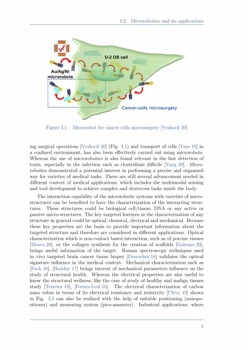
The interaction capability of the microrobotic systems with varieties of micro-structures can be benefited to have the characterization of the interacting struc-tures. These structures could be biological cell/tissue, DNA or any active orpassive micro-structures. The key targeted features in the characterization of anystructure in general could be optical, chemical, electrical and mechanical. Becausethese key properties are the basis to provide important information about thetargeted structure and therefore are considered in different applications. Opticalcharacterization which is non-contact based interaction, such as of porcine tissues[Mosca 20], or the collagen synthesis for the creation of scaffolds [Galeano 20],brings useful information of the target. Raman spectroscopy techniques usedin vivo targeted brain cancer tissue biopsy [Desroches 18] validates the opticalsignature influence in the medical context. Mechanical characterization such as[Park 18], [Budday 17] brings interest of mechanical parameters influence on thestudy of structural health. Whereas the electrical properties are also useful toknow the structural wellness, like the case of study of healthy and malign tissuesstudy [Teixeira 18], [Fornes-Leal 16]. The electrical characterization of carbonnano tubes in terms of its electrical resistance and resistivity [Clévy 19] shownin Fig. I.2 can also be realized with the help of suitable positioning (nanopo-sitioner) and measuring system (pico-ammeter). Industrial applications, where
5
Chapter I. Instrumentation and Robotics at the Micro-scale
Figure I.2 – Electrical characterization of a carbon nano-tube in contact with aprobe [Clévy 19]
manipulation of micro-structures and their assembly is needed, microrobotics issignificantly useful in such applications. The different works, constituent complex-ity and according analysis in the industrial scenario (targeted work of this thesis)are discussed in section I.3. Microrobotics therefore has demonstrated its useful-ness in wide range of applications and so, the trend towards miniaturization of thesystems is of great importance.
I.3 Thesis Context and Targeted Works
Microrobotic systems development and/or the different tools to interact withthe micro-world require their fabrication. Although different advanced processesmake it possible to fabricate the micro-structure needed, but still some complex-ity in structure may limit a direct fabrication (depending on time, accuracy orcost limitations). To fabricate such structures, fabrication into sub-componentsfollowed by their assembly is a key interesting solution, provided the process em-ployed able to meet the accuracy and assembly challenges.
This thesis is a part of the ANR COLAMIR [COLAMIR 20], which is anacademic-industrial collaboration project. The collaborated industrial partnerswere “Percipio Robotics” and “Aurea Technology”. As part of this project, thisthesis targeted precise micro-assembly and according system(s) development toaddress the industrial requirements. The assembly of two structures are very com-mon need in industries, where relative positioning of the two components can be
6
I.3. Thesis Context and Targeted Works
significantly important. To address the fast and large productivity in industrialscenario, the robotization of the assembly process is targeted. This minimizes therequirement of human assembler (can introduce the uncertainty in the positioningof the end product) and also can insure repeatable and cost effective manufac-turing. The primary requirement is to understand the complexity and challengesat micro-scale (subsection I.3.1), secondly to analyse the different existing micro-assembly and manipulation works (subsection I.3.2). It also becomes importantto study the potential and large demanding micro-assembly techniques. In thisdirection, use of glue for assembly is an important requirement. Gluing can allowto definitely hold the two surfaces and is a very common need in the industries.The use of glue for micro-assembly, and its corresponding challenges are discussedin subsection I.3.3.
I.3.1 Challenges at the micro-scale
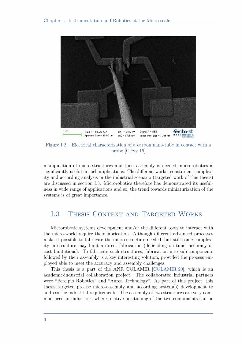
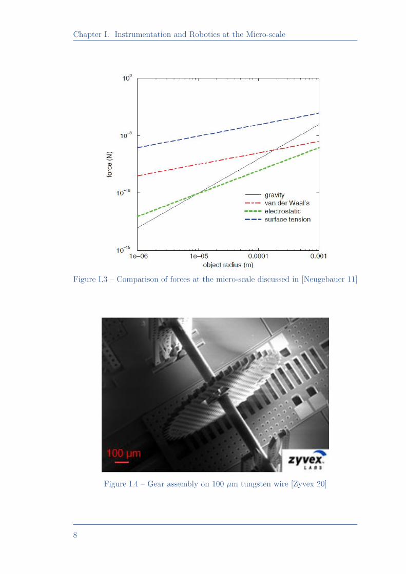
The micro-structure because of their fragility brings additional challenges, as itcan be easily broken if not handled carefully. At the micro-scale, surface forces alsoplay an important role, as the van der Waals forces may get dominated than therequired interaction force normally needed. For masses less than 10−6 kg, adhesiveforces becomes more significant than the gravity. A comparison of adhesive forcesat micro-level is discussed in [Neugebauer 11] from different state-of-the-art and isshown in Fig. I.3. It can be seen that the adhesive forces such as surface tension,electrostatic, van der Waal’s become dominant with the reduction in the objectsize. Among different adhesive forces, surface tension is significantly high withrespect to other forces, which therefore needs to be considered wherever there isan interaction between a micro-object with liquid.
The other challenge at micro-scale task handling is from the micro-system’s dy-namic. Depending on the compliance of the micro-structure, the dynamic influencemay bring additional inertial influence, which sometimes may lead to breakage ofthe micro-systems. Such happening may get more pronounced when there is fastprocessing needed. The disturbances from the environment, which could be in theform such as electromechanical or optical, may also impact the targeted behavior,for instance the actuation or actuation based on the sensed state(s). Therefore theaccording system design and/or the approach to interact with the micro-structuresneeds to be compatible with the mentioned challenges.
I.3.2 Micro-assembly and the requirements
In the context of assembly, the micro-building components may be assembledmanually, but it requires an adequate level of expertise depending on the targetedaccuracy of the assembled product. Not only the targeted accuracy is one re-quirement but the safety of the fragile structure during the assembly should alsobe a core consideration. In order to minimize a direct interaction of human beingwith micro-structure (which often results uncertainty in the interaction forces, and
7
Chapter I. Instrumentation and Robotics at the Micro-scale
Figure I.3 – Comparison of forces at the micro-scale discussed in [Neugebauer 11]
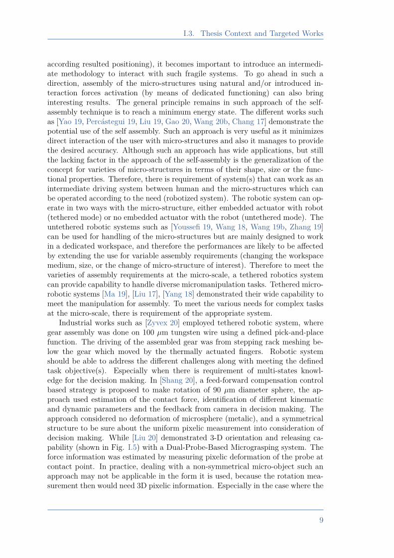
Figure I.4 – Gear assembly on 100 µm tungsten wire [Zyvex 20]
8
I.3. Thesis Context and Targeted Works
according resulted positioning), it becomes important to introduce an intermedi-ate methodology to interact with such fragile systems. To go ahead in such adirection, assembly of the micro-structures using natural and/or introduced in-teraction forces activation (by means of dedicated functioning) can also bringinteresting results. The general principle remains in such approach of the self-assembly technique is to reach a minimum energy state. The different works suchas [Yao 19, Percástegui 19, Liu 19, Gao 20, Wang 20b, Chang 17] demonstrate thepotential use of the self assembly. Such an approach is very useful as it minimizesdirect interaction of the user with micro-structures and also it manages to providethe desired accuracy. Although such an approach has wide applications, but stillthe lacking factor in the approach of the self-assembly is the generalization of theconcept for varieties of micro-structures in terms of their shape, size or the func-tional properties. Therefore, there is requirement of system(s) that can work as anintermediate driving system between human and the micro-structures which canbe operated according to the need (robotized system). The robotic system can op-erate in two ways with the micro-structure, either embedded actuator with robot(tethered mode) or no embedded actuator with the robot (untethered mode). Theuntethered robotic systems such as [Youssefi 19, Wang 18, Wang 19b, Zhang 19]can be used for handling of the micro-structures but are mainly designed to workin a dedicated workspace, and therefore the performances are likely to be affectedby extending the use for variable assembly requirements (changing the workspacemedium, size, or the change of micro-structure of interest). Therefore to meet thevarieties of assembly requirements at the micro-scale, a tethered robotics systemcan provide capability to handle diverse micromanipulation tasks. Tethered micro-robotic systems [Ma 19], [Liu 17], [Yang 18] demonstrated their wide capability tomeet the manipulation for assembly. To meet the various needs for complex tasksat the micro-scale, there is requirement of the appropriate system.
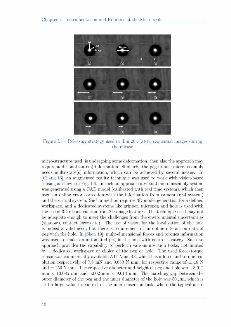
Industrial works such as [Zyvex 20] employed tethered robotic system, wheregear assembly was done on 100 µm tungsten wire using a defined pick-and-placefunction. The driving of the assembled gear was from stepping rack meshing be-low the gear which moved by the thermally actuated fingers. Robotic systemshould be able to address the different challenges along with meeting the definedtask objective(s). Especially when there is requirement of multi-states knowl-edge for the decision making. In [Shang 20], a feed-forward compensation controlbased strategy is proposed to make rotation of 90 µm diameter sphere, the ap-proach used estimation of the contact force, identification of different kinematicand dynamic parameters and the feedback from camera in decision making. Theapproach considered no deformation of microsphere (metalic), and a symmetricalstructure to be sure about the uniform pixelic measurement into consideration ofdecision making. While [Liu 20] demonstrated 3-D orientation and releasing ca-pability (shown in Fig. I.5) with a Dual-Probe-Based Micrograsping system. Theforce information was estimated by measuring pixelic deformation of the probe atcontact point. In practice, dealing with a non-symmetrical micro-object such anapproach may not be applicable in the form it is used, because the rotation mea-surement then would need 3D pixelic information. Especially in the case where the
9
Chapter I. Instrumentation and Robotics at the Micro-scale
Figure I.5 – Releasing strategy used in [Liu 20], (a)-(i) sequential images duringthe release
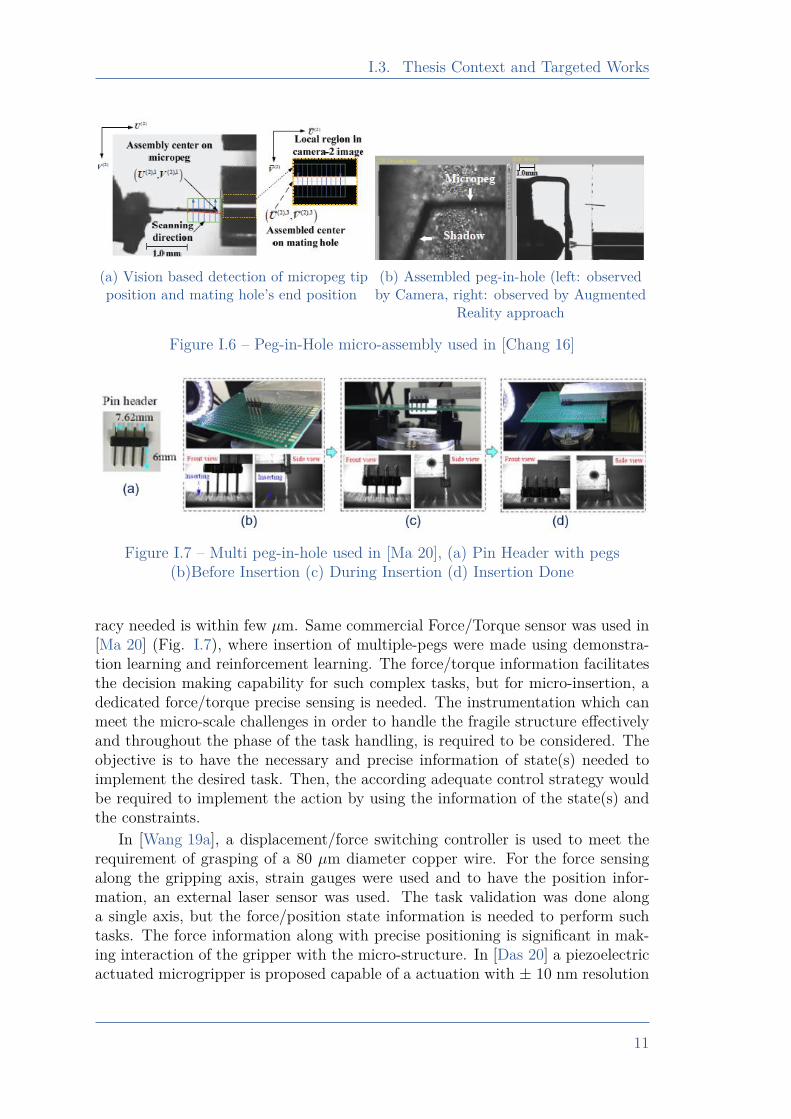
micro-structure used, is undergoing some deformation, then also the approach mayrequire additional state(s) information. Similarly, the peg-in-hole micro-assemblyneeds multi-state(s) information, which can be achieved by several means. In[Chang 16], an augmented reality technique was used to work with vision-basedsensing as shown in Fig. I.6. In such an approach a virtual micro-assembly systemwas generated using a CAD model (calibrated with real time system), which thenused an online error correction with the information from camera (real system)and the virtual system. Such a method requires 3D model generation for a definedworkspace, and a dedicated systems like gripper, micropeg and hole is used withthe use of 3D reconstruction from 2D image features. The technique used may notbe adequate enough to meet the challenges from the environmental uncertainties(shadows, contact forces etc). The use of vision for the localization of the holeis indeed a valid need, but there is requirement of an online interaction data ofpeg with the hole. In [Shen 19], multi-dimensional forces and torques informationwas used to make an automated peg in the hole with control strategy. Such anapproach provides the capability to perform various insertion tasks, not limitedby a dedicated workspace or choice of the peg or hole. The used force/torquesensor was commercially available ATI Nano-43, which has a force and torque res-olution respectively of 7.8 mN and 0.050 N mm, for respective range of ± 18 Nand ± 250 N mm. The respective diameter and height of peg and hole were, 8.012mm × 10.085 mm and 5.002 mm × 9.013 mm. The matching gap between theouter diameter of the peg and the inner diameter of the hole was 50 µm, which isstill a large value in context of the micro-insertion task, where the typical accu-
10
I.3. Thesis Context and Targeted Works
(a) Vision based detection of micropeg tipposition and mating hole’s end position
(b) Assembled peg-in-hole (left: observedby Camera, right: observed by Augmented
Reality approach
Figure I.6 – Peg-in-Hole micro-assembly used in [Chang 16]
Figure I.7 – Multi peg-in-hole used in [Ma 20], (a) Pin Header with pegs(b)Before Insertion (c) During Insertion (d) Insertion Done
racy needed is within few µm. Same commercial Force/Torque sensor was used in[Ma 20] (Fig. I.7), where insertion of multiple-pegs were made using demonstra-tion learning and reinforcement learning. The force/torque information facilitatesthe decision making capability for such complex tasks, but for micro-insertion, adedicated force/torque precise sensing is needed. The instrumentation which canmeet the micro-scale challenges in order to handle the fragile structure effectivelyand throughout the phase of the task handling, is required to be considered. Theobjective is to have the necessary and precise information of state(s) needed toimplement the desired task. Then, the according adequate control strategy wouldbe required to implement the action by using the information of the state(s) andthe constraints.
In [Wang 19a], a displacement/force switching controller is used to meet therequirement of grasping of a 80 µm diameter copper wire. For the force sensingalong the gripping axis, strain gauges were used and to have the position infor-mation, an external laser sensor was used. The task validation was done alonga single axis, but the force/position state information is needed to perform suchtasks. The force information along with precise positioning is significant in mak-ing interaction of the gripper with the micro-structure. In [Das 20] a piezoelectricactuated microgripper is proposed capable of a actuation with ± 10 nm resolution
11
Chapter I. Instrumentation and Robotics at the Micro-scale
but to perform grasping of 540 µm wire, an external strain gauge was attached tothe microgripper stationary jaw in order to have the grasping force information.In [Komati 16a], piezoelectric actuation was used but both the fingers were instru-mented to sense the force (piezoresistive sensing), which allowed the grasping ofmulti-stiffness object without need of any external sensor. Safe manipulation of afragile micro-object with unknown compliance requires the force and/or deforma-tion information during the phase of manipulation. The sensing capability thenneeds to be extended in order to tackle the complex tasks like rotation, insertionwithout dependency on modeling alone.
I.3.3 Micro-assembly with glueAssembly of the two surfaces can be made in several ways, like a dedicated
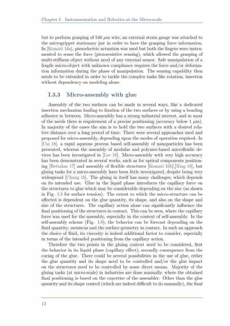
insertion mechanism leading to fixation of the two surfaces or by using a bondingadhesive in between. Micro-assembly has a strong industrial interest, and in mostof the needs there is requirement of a precise positioning (accuracy below 1 µm).In majority of the cases the aim is to hold the two surfaces with a desired rela-tive distance over a long period of time. There were several approaches used andproposed for micro-assembly, depending upon the modes of operation required. In[Cui 18], a rapid aqueous process based self-assembly of nanoparticles has beenpresented, whereas the assembly of modular and polymer-based microfluidic de-vices has been investigated in [Lee 18]. Micro-assembly with very high accuracyhas been demonstrated in several works, such as for optical components position-ing [Bettahar 17] and assembly of flexible structures [Komati 16b],[Xing 18], butgluing tasks for a micro-assembly have been little investigated, despite being verywidespread [Chang 10]. The gluing in itself has many challenges, which dependson its intended use. Glue in the liquid phase introduces the capillary force onthe structures to glue which may be considerable depending on the size (as shownin Fig. I.3 for surface tension). The extent to which the micro-structure can beaffected is dependent on the glue quantity, its shape, and also on the shape andsize of the structures. The capillary action alone can significantly influence thefinal positioning of the structures in contact. This can be seen, where the capillaryforce was used for the assembly, especially in the context of self-assembly. In theself-assembly scheme (Fig. I.8), the behavior can be forecast depending on thefluid quantity, meniscus and the surface geometry in contact. In such an approachthe choice of fluid, its viscosity is indeed additional factor to consider, especiallyin terms of the intended positioning from the capillary action.
Therefore the two points in the gluing context need to be considered, firstthe behavior in its liquid phase (capillary effect), secondly consequence from thecuring of the glue. There could be several possibilities in the use of glue, eitherthe glue quantity and its shape need to be controlled and/or the glue impacton the structures need to be controlled by some direct means. Majority of thegluing tasks (at micro-scale) in industries are done manually, where the obtainedfinal positioning is based on the expertise of the assembler. Other than the gluequantity and its shape control (which are indeed difficult to do manually), the final
12
I.3. Thesis Context and Targeted Works
Figure I.8 – Capillary self-alignment in [Chang 17], (a1),(b1) and (c1) chip wasplaced on a receptor site; (a2),(b2) and (c2) water mist induced droplet
introduces at the assembly site; (a3), (b3) and (c3) self-aligned chip at thereceptor site
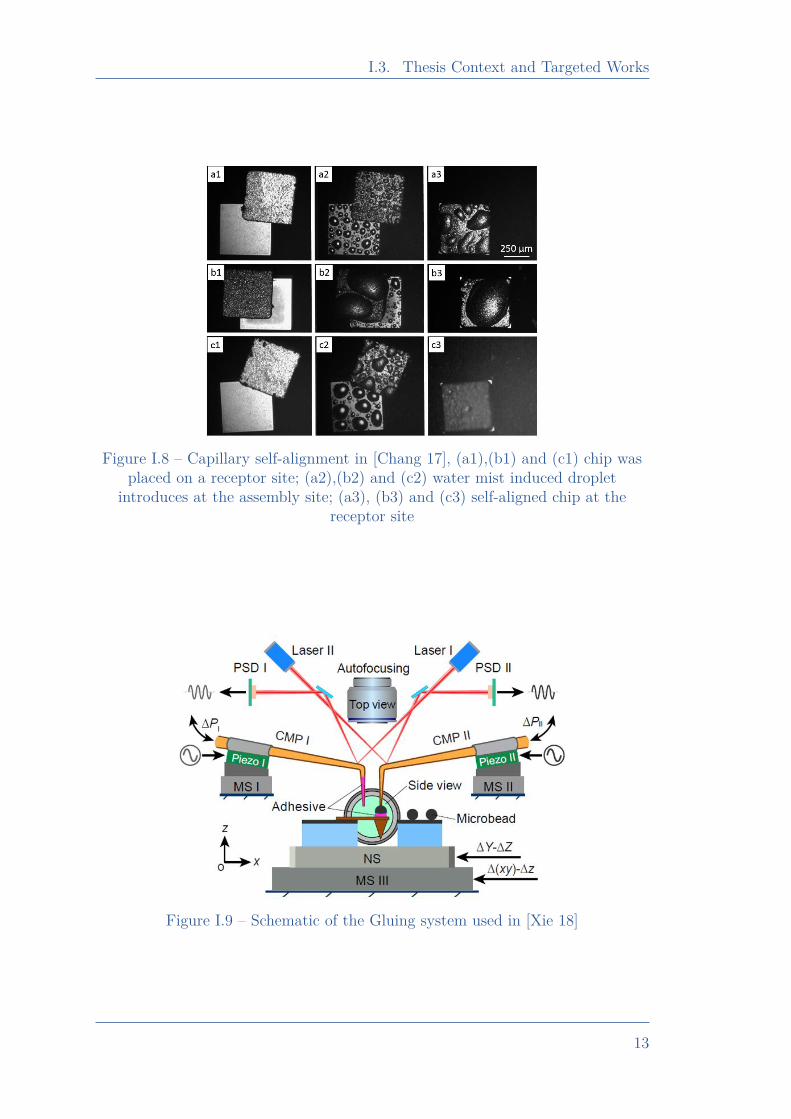
Figure I.9 – Schematic of the Gluing system used in [Xie 18]
13
Chapter I. Instrumentation and Robotics at the Micro-scale
positioning of the glued product is also dependent on the choice of the glue (thematerial properties), and the curing process. Therefore, it appears that there aremultiple potential parameters which can affect the positioning of the glued product,therefore an intermediate system is needed for a precise gluing. In [Xie 18], amicro-assembly system was used which included two cantilevered micropipetteprobe (CMP), each of them can be controlled to generate necessary vacuum. Oneof the CMP, named CMP I was used for adhesive deposition, while other (CMP II)was used for pick-and-place (schematic is shown in Fig. I.9). Also, to measure theinteraction force, an optical lever consisting of position sensitive detector (PSD)and a laser was used. Meaning which, the force measurement is external to theinteracting tool, and in such cases the two frames (of sensing and tool) must needto be relatively known and sometimes fixed (to be in the sensing range of theposition detector). The glue (adhesive) quantity was controlled with the help ofvacuum pressure control and typically the quantity of glue was much less (a thinlayer) compared to the micro-object used. Therefore positioning was not affectedconsiderably by the curing. The gluing quantity may affect the required holdingpressure of the micro-object during the curing, and this side can affect the finalrelative positioning of the structures.
In order to have a precise, flexible and robust micro-assembly capability, thedifferent key requirements can be listed as:
• Multi-axis and precise knowledge of assembly system’s state(s)
• Long range state(s) information for flexible tasks handling
• Compatibility over a high bandwidth
• Precise and multi-axis actuation
• Adequate control strategy to meet the desired speed and accuracy
• A compatible interaction tool/gripper for the desired taskPrecision, range, and choice of control, need to be considered in the design
based on the requirement of task of interest and therefore is not quantified. At themicro-scale, it can be said that the ideal situation would be when instrumentationof the robotic system allows the lowest change detection over a highest range pos-sible. These lowest and highest limits, need to be considered based on the targetedtask. The different possibilities of instrumentation, their merits, limitations, thetargeted specifications from the state-of-the-art works discussed is presented insection I.4.
I.4 Instrumented system development
As defined objectives in section I.3, the multi-axis instrumentation is an im-portant concern in the micro-assembly context, and therefore different possibilitiesneed to be studied for an adequate instrumented system development. Talking
14
I.4. Instrumented system development
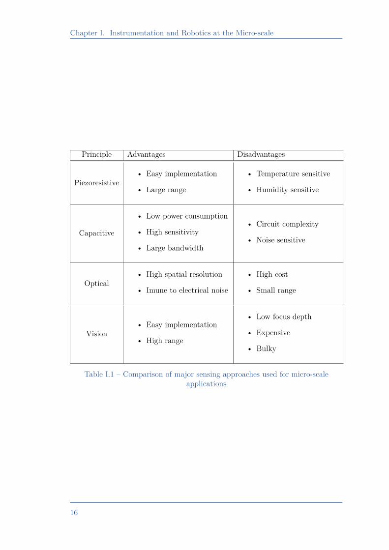
about the possibilities of instrumentation, there are several feasible principles pos-sible. A comparative study of different widely used sensing approach is listed inTable I.1, with their corresponding key advantages and disadvantages. All listedprinciples allow to have a sub µN resolution, and therefore the according systemdesign and signal processing feature needs to be analyzed to have adequate systemfor the desired task. In the context of force sensing, when an external load isapplied to the structure of interest (where force needs to be measured) undergoesstrain. This strain can be mapped to a force measurement, which can be done byuse of a reference force sensor.
fref = scal ×mstate (I.1)
Eq. I.1, defines a general equation of force sensing, where fref is the force sensedby a reference force sensor (calibrated), mstate is a measured state that needs to beused for force measurement and scal is a calculated scaling factor (called sensitivity)for mapping of mstate to fref . In this equation, there are two key assumptionsincluded, first in the linear dependency of mstate on fref , while second in the singlestatemstate dependency over force measurement along a given axis. It is possible tohave a non-linear relation between fref and mstate, and also to have a dependencyof fref on multiple states (case of coupling). A simplified version is used here toaddress the sensing principle, and therefore according changes can be included ifits relevant. An elastic beam when subjected to an external load (using a referenceforce sensor) at its tip end will undergo deformation, the extent will be dependenton the intensity of the load. If displacement of the tip is measured by an externalposition sensor, then displacement sensed (mstate here) can be transformed tomeasured force fref from the reference force sensor, which results into calculationscal, which is the stiffness of the beam (need to be calculated from the equivalentstiffness of beam and reference force sensor). The sensor development dependsmainly on two factors, first on the choice of mstate, second the principle used formeasurement of mstate. If displacement of the beam’s tip is mstate, then this couldbe done by use of an optical sensor or by use of vision based sensing. Elasticbehavior of structure allows to have calculated scaling factor scal unchanged, andtherefore the structure can be used as a force sensor with measurement of mstate
alone. Indeed, depending on the material and geometrical parameters, there willbe a life-cycle of any structure to withstand a constant elasticity and so the scal.Displacement is mstate also in case of vision based sensing [Adam 19]. It allowseasier experimental implementation with a reliable measurement over a long rangesensing capability. Use of an adequate camera makes the system expensive, andwith magnifying objectives the overall system may get bulkier. The limitation invision based sensing also is in its focus depth. But, indeed this approach is veryuseful for a precise and long range planar sensing.
Optical based sensing is not limited with its use of displacement as mstate butit can use some of the dedicated approaches such as Fabry-Perot Interferometers(FPI), Fiber-Bragg Gratings (FBG) or Light Intensity Modulation (LIM). Start-ing with LIM [Noh 16], this approach is based on the light intensity detection
15
Chapter I. Instrumentation and Robotics at the Micro-scale
Principle Advantages Disadvantages
Piezoresistive• Easy implementation
• Large range
• Temperature sensitive
• Humidity sensitive
Capacitive
• Low power consumption
• High sensitivity
• Large bandwidth
• Circuit complexity
• Noise sensitive
Optical• High spatial resolution
• Imune to electrical noise
• High cost
• Small range
Vision• Easy implementation
• High range
• Low focus depth
• Expensive
• Bulky
Table I.1 – Comparison of major sensing approaches used for micro-scaleapplications
16
I.4. Instrumented system development
in terms of voltage measurement, therefore mstate is voltage which is function oflight intensity. A rotating mirror (or a modulator in general) can be fixed at theend of an optical fiber which leads to the intensity variation detection under thepresence of external load. This optical method is costly and corresponding perfor-mance are likely to be affected in the presence of bending of fiber. Whereas FBG[Shi 19, Li 19, Li 20a], uses a diffraction grating formed in the optical fiber. Thisgrating selectively modulates the reflected light where the constituent spectrumchanges with external load. The other very prominent approach in optical forcesensing is FPI [Dash 19, Wei 19], where a dedicated MEMS is attached at theend of optical fiber, such system allows the detection of introduced load in termsof optical spectrum change where mstate is wavelength change measured. As awhole, optical sensors can provide high spatial resolution with high repeatability.The key advantage remains in its immunity against the electrical noise. Depend-ing on several possibilities of optical sensing, cost in general is still high with theemployment of suitable fiber. Electrical circuitry are often used in the sensors de-velopment, the main approach used is the voltage change detection as function ofthe application of external load, which means mstate as voltage. From the materialside, the question comes is about the choice of material which can allow a voltagechange detection against the applied load. One very common electrical circuitryused for voltage change detection is “Wheatstone Bridge” based circuitry, wherethe electrical resistance change can be transformed to voltage change detection.To go ahead in such direction the resistance property of structure need to be con-sidered. This resistance feature should not solely be dependent on the electricalresistance alone, but can be reflected in terms of the reactance. Also it is pos-sible to use directly, the resistance/reactance change as mstate against the forceapplied. It depends on which choice suits the specific signal processing require-ments. Charge storage capacity of the material, which can allow the measurementof capacitive reactance or capacitance, can be mapped to force. The correspondingstructure which exhibits the change of capacitance [Na 19] under the applied load,can therefore be used as a force sensor. The capacitive sensor design thereforeneed to consider the dependent parameters on capacitance, such as electrode area,size, or dielectric medium. Capacitive sensors can allow a high sensitivity over alarge bandwidth, but the according circuitry might need special design in order tominimize the noise influence on the performance which may result into complexityin the circuitry. Under the external load application a piezoelectric device under-goes change in the electric charge and so do the capacitance which then can bemeasured to map to the force. Piezoelectric device [Morales 18, Lee 20, Liseli 17]can be used as a force sensor, but the performance of device would be limitedby the minimum capacitive change detection. Depending on the choice of thematerial and geometry, the extent of change in capacitance against the externalload applied, may limits its use for micro-scale applications. The other featureswhich can be used for the reactance change can be inductive. An inductive reac-tance or inductance change can also be used to measure the force. This requires,the change of inductance [Yeh 19, Wang 20a] of the structure against the externalload. This choice is very limited because of additional complexity in the device
17
Chapter I. Instrumentation and Robotics at the Micro-scale
100 101 102 103 10410-2
100
102
104
106
(1)
(2)
(3)
(4)
(5)
(6)
(7)
Figure I.10 – A comparison of different force sensing from the state-of-the-art
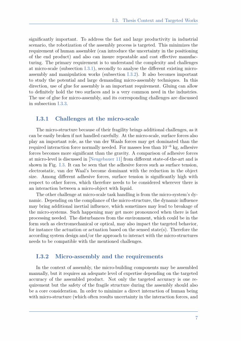
fabrication and large influence of noise in the signal processing. A piezoresistivedevice exhibits a direct change in electrical resistance under the applied externalforce, and this therefore can be used for force sensing. The resistance change canbe directly used as mstate or as said, it can be used to make voltage change asmstate using a dedicated wheatstone circuitry. Such devices are relatively easy toimplement as a force sensing device, also it can allow a high resolution measure-ment over a long range. Indeed, the sensitivity and according performances wouldbe dependent on the choice of the piezoresistive material, geometry and accordingsignal processing. The limitation of such a sensing approach is in environmentalconstraints, as resistance change is dependent on the temperature and humidity,therefore the environmental conditions must need to be in accordance with thematerial properties of the device. A state-of-the art survey is included in [Wei 15],which compared different force sensing techniques for micro-scale applications. Ev-ery sensing principle has some pros. and cons., the choices then need to be madebased on the candidate which closely meets the targeted performances under thedefined constraints.
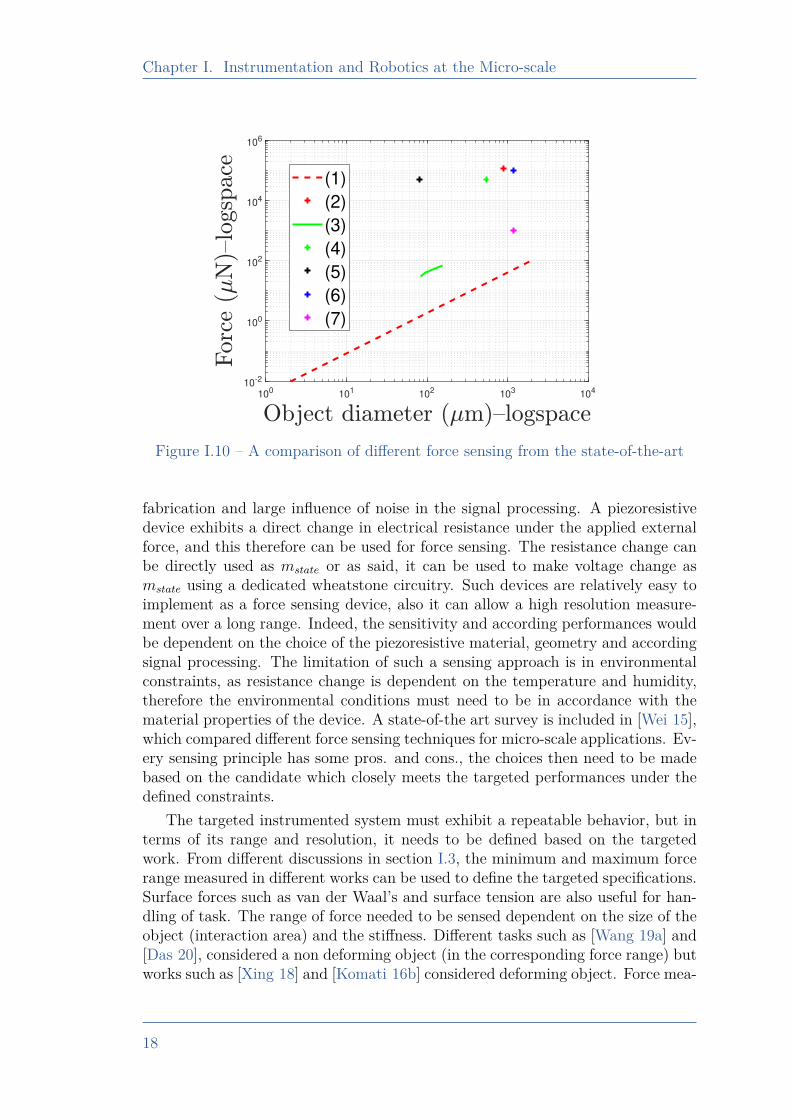
The targeted instrumented system must exhibit a repeatable behavior, but interms of its range and resolution, it needs to be defined based on the targetedwork. From different discussions in section I.3, the minimum and maximum forcerange measured in different works can be used to define the targeted specifications.Surface forces such as van der Waal’s and surface tension are also useful for han-dling of task. The range of force needed to be sensed dependent on the size of theobject (interaction area) and the stiffness. Different tasks such as [Wang 19a] and[Das 20], considered a non deforming object (in the corresponding force range) butworks such as [Xing 18] and [Komati 16b] considered deforming object. Force mea-
18
I.5. Conclusions
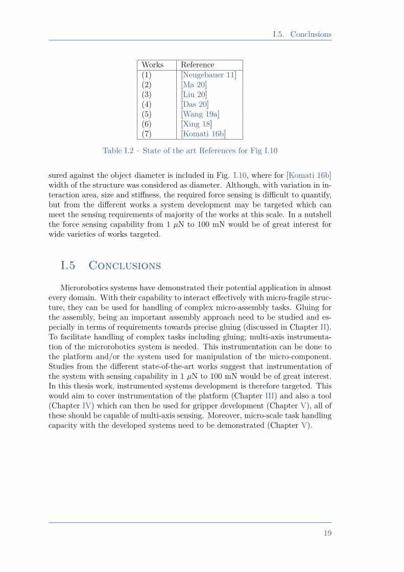
Works Reference(1) [Neugebauer 11](2) [Ma 20](3) [Liu 20](4) [Das 20](5) [Wang 19a](6) [Xing 18](7) [Komati 16b]
Table I.2 – State of the art References for Fig I.10
sured against the object diameter is included in Fig. I.10, where for [Komati 16b]width of the structure was considered as diameter. Although, with variation in in-teraction area, size and stiffness, the required force sensing is difficult to quantify,but from the different works a system development may be targeted which canmeet the sensing requirements of majority of the works at this scale. In a nutshellthe force sensing capability from 1 µN to 100 mN would be of great interest forwide varieties of works targeted.
I.5 Conclusions
Microrobotics systems have demonstrated their potential application in almostevery domain. With their capability to interact effectively with micro-fragile struc-ture, they can be used for handling of complex micro-assembly tasks. Gluing forthe assembly, being an important assembly approach need to be studied and es-pecially in terms of requirements towards precise gluing (discussed in Chapter II).To facilitate handling of complex tasks including gluing; multi-axis instrumenta-tion of the microrobotics system is needed. This instrumentation can be done tothe platform and/or the system used for manipulation of the micro-component.Studies from the different state-of-the-art works suggest that instrumentation ofthe system with sensing capability in 1 µN to 100 mN would be of great interest.In this thesis work, instrumented systems development is therefore targeted. Thiswould aim to cover instrumentation of the platform (Chapter III) and also a tool(Chapter IV) which can then be used for gripper development (Chapter V), all ofthese should be capable of multi-axis sensing. Moreover, micro-scale task handlingcapacity with the developed systems need to be demonstrated (Chapter V).
19
Chapter II. Analysis and robotics based precise gluing
Chapter IIAnalysis and robotics based precise gluing
II.1 Introduction . . . . . . . . . . . . . . . . . . . . . . . . . . . . . . . . . . . . . . . . . . . . 21II.2 Glue Curing in absence of External Load . . . . . . . . . . . . . . . . 22II.3 Glue curing in the presence of external Load . . . . . . . . . . . . 25II.4 Modeling of the Glue Shrinkage . . . . . . . . . . . . . . . . . . . . . . . . . 28II.5 Study of active control to achieve accurate gluing . . . . . . . . 31II.6 Towards an active control for precise gluing. . . . . . . . . . . . . . 34
II.6.1 Working principle . . . . . . . . . . . . . . . . . . . . . . . . . . . . . . . . . 34II.6.2 Controller Design. . . . . . . . . . . . . . . . . . . . . . . . . . . . . . . . . . 35II.6.3 Experimental setup . . . . . . . . . . . . . . . . . . . . . . . . . . . . . . . . 36II.6.4 Behavior in the absence of the proposed control scheme. . 36II.6.5 Behavior with proposed control strategy. . . . . . . . . . . . . . . 39
II.7 Conclusions . . . . . . . . . . . . . . . . . . . . . . . . . . . . . . . . . . . . . . . . . . . . 44
20
II.1. Introduction
II.1 Introduction
Gluing appears to be a key task of a micro-assembly process because it en-ables to definitely hold the relative position between two components. For mostapplications, the quality/positioning accuracy of the assembly directly impactsthe performances of the final product. Most of the existing gluing tasks requirevery dedicated approaches, especially to use thin films using surface referencingand conditioning [Tennico 10],[Xiong 14]. For gluing two objects, even using aconditioned glue layer of ∼ 20 µm can introduce significant error towards desiredassembly (the typical needs to reach a positioning accuracy below 1 µm). De-pending on the requirements, the thick glue layer can provide a wide range ofdesired distances between the two surfaces to be glued. In [Gakkestad 10], a 30µm thick layer of conductive glue was used to connect a MEMS structure directlyto a printed circuit board. Different applications of packaging, such as fiber fixa-tion with a chip, might be made using a thick glue instead of using fusion splicingbased dedicated approach, as used in [Nauriyal 18], but positioning accuracy thenneeds to be insured by some other flexible means.
Surfaces in contact with adhesive make huge contributions towards the behav-ior during gluing, especially their influence towards spreading coefficient and rateof spreading for the equilibrium stabilization [da Silva 11]. Moreover, the choiceand quantity of glue also play an important role in final positioning [R.D. 84,Cognard. 10]. Glue curing induces stress around the surfaces under glue-contact,which would introduce positional shrinkage (between the two gluing surfaces). As awhole, use of thick film of glue can introduce significant positional drifts, primarilyfrom capillary effects (surface-liquid glue interaction), followed by positional driftbecause of stress development during glue curing. The procedures needed to reachhigh positioning accuracy (below 1 µm) must account for these mentioned hap-penings. In order to have desired and repeatable behavior, there is requirement tohave similar choice, quantity, size and shape of glue, along with similar surfaces tobe glued (in terms of the size, roughness, shape). A small change in one or more ofthe mentioned parameters may result into different results than the targeted ver-sion. Therefore, there is a strong requirement of a flexible and versatile approachthat could solve the complexity with sub-micrometer accuracy. To address this, weaim to use an active robot control strategy which could allow online track of gluingstate and to make the necessary corrections so as to insure the desired positioningof the glued product. Indeed, this approach appears particularly generic, versatile,and flexible because it intends to adapt to all of the mentioned-above parameterschange. In order to meet this challenges, force-position sensing and its accordinglyuse in development of control strategy may bring an important role in the decisionmaking. Discussions in this chapter are focused on 3 studies, first the main effectof gluing on the surfaces in contact without any external load (applied force at thegluing end), second the impact of external load on the relative distance betweenthe two surfaces during the process of gluing and finally to extend the studies tocontrol the external load so as to reach a desired gluing of the two surfaces. The
21
Chapter II. Analysis and robotics based precise gluing
behavior resulted from gluing in absence of external load was primarily discussed(section II.2), then the limitation in analysis and the requirement to have an ex-ternal load based analysis is discussed (section II.3). The gluing behavior with itsdependency over the external load was analyzed followed by its use to estimate acontrol scenario in order to have a precise relative positioning of the gluing surfacesis also discussed (section II.4 and II.5). The continuation of the arguments pre-sented is further experimentally demonstrated with an active control strategy fora precise gluing (section II.6). The entire analysis and the work discussed in thischapter is made along a single axis, which consist of major influence on the gluingsurfaces (longitudinal component). It allows to make the key analysis, check thefeasibility of the approach towards solution to the key problems, without addingany complexity in the system.
II.2 Glue Curing in absence of External Load
The glue curing process in absence of any external load is discussed in thissection. The objective of this study is to be able to have understanding of theshrinkage amplitude, its introduced force on the surfaces, when there is no loadexternally applied to the gluing system. Moreover, analysis of the correspondingbehavior obtained in terms of the challenges towards a precise gluing is also studied.
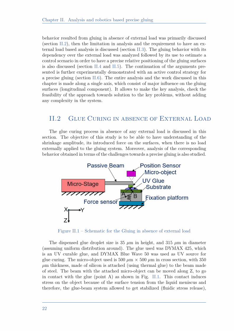
Figure II.1 – Schematic for the Gluing in absence of external load
The dispensed glue droplet size is 35 µm in height, and 315 µm in diameter(assuming uniform distribution around). The glue used was DYMAX 425, whichis an UV curable glue, and DYMAX Blue Wave 50 was used as UV source forglue curing. The micro-object used is 500 µm × 500 µm in cross section, with 350µm thickness, made of silicon is attached (using thermal glue) to the beam madeof steel. The beam with the attached micro-object can be moved along Z, to goin contact with the glue (point A) as shown in Fig. II.1. This contact inducesstress on the object because of the surface tension from the liquid meniscus andtherefore, the glue-beam system allowed to get stabilized (fluidic stress release),
22
II.2. Glue Curing in absence of External Load
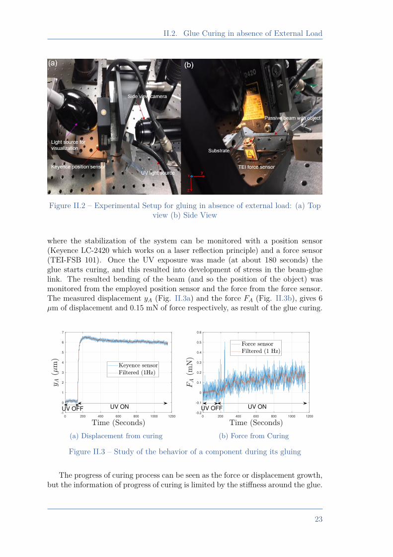
Figure II.2 – Experimental Setup for gluing in absence of external load: (a) Topview (b) Side View
where the stabilization of the system can be monitored with a position sensor(Keyence LC-2420 which works on a laser reflection principle) and a force sensor(TEI-FSB 101). Once the UV exposure was made (at about 180 seconds) theglue starts curing, and this resulted into development of stress in the beam-gluelink. The resulted bending of the beam (and so the position of the object) wasmonitored from the employed position sensor and the force from the force sensor.The measured displacement yA (Fig. II.3a) and the force FA (Fig. II.3b), gives 6µm of displacement and 0.15 mN of force respectively, as result of the glue curing.
0 200 400 600 800 1000 1200
-1
0
1
2
3
4
5
6
7
UV ONUV OFF
(a) Displacement from curing
0 200 400 600 800 1000 1200
-0.2
-0.1
0
0.1
0.2
0.3
0.4
0.5
0.6
UV OFF UV ON
(b) Force from Curing
Figure II.3 – Study of the behavior of a component during its gluing
The progress of curing process can be seen as the force or displacement growth,but the information of progress of curing is limited by the stiffness around the glue.
23
Chapter II. Analysis and robotics based precise gluing
Figure II.4 – Spring model
0 < kg ≤kb × kfkf + kb
(II.1)
kg >kb × kfkf − kb
(II.2)
Table II.1 – Evolution of Glue StiffnessA spring equivalence model considering the static scenario is shown in Fig. II.4,
0 200 400 600 800 1000 1200
-5
0
5
10
15
20
25
30
35
40
45
UV OFF UV ON
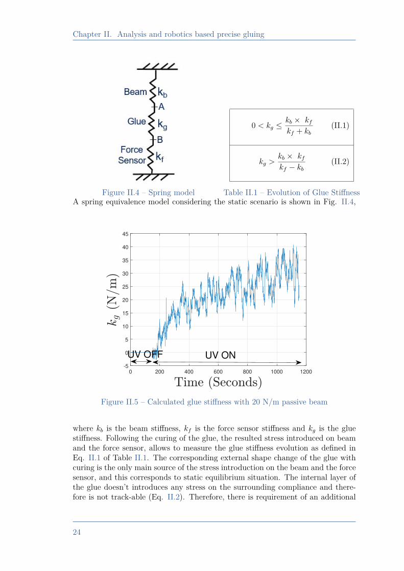
Figure II.5 – Calculated glue stiffness with 20 N/m passive beam
where kb is the beam stiffness, kf is the force sensor stiffness and kg is the gluestiffness. Following the curing of the glue, the resulted stress introduced on beamand the force sensor, allows to measure the glue stiffness evolution as defined inEq. II.1 of Table II.1. The corresponding external shape change of the glue withcuring is the only main source of the stress introduction on the beam and the forcesensor, and this corresponds to static equilibrium situation. The internal layer ofthe glue doesn’t introduces any stress on the surrounding compliance and there-fore is not track-able (Eq. II.2). Therefore, there is requirement of an additional
24
II.3. Glue curing in the presence of external Load
approach by which the glue curing extent can be monitored for the entire durationof gluing. One of the possible strategies could be the application of time-varyingbut known external load.
II.3 Glue curing in the presence of exter-nal Load
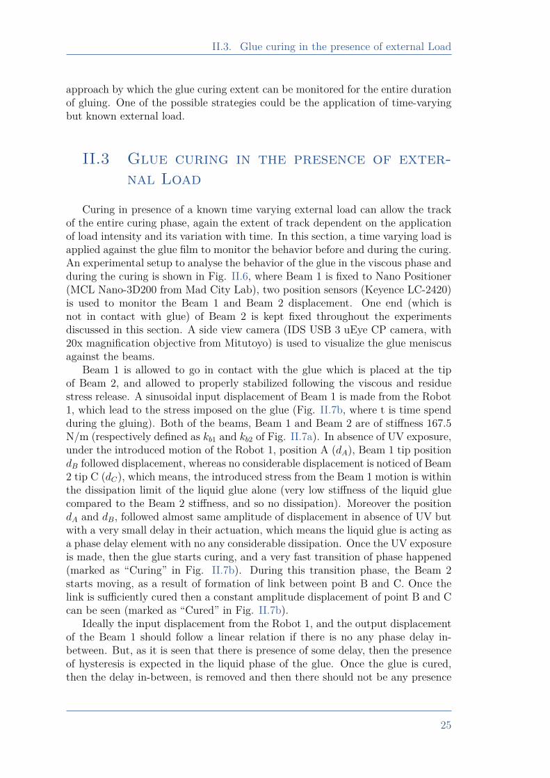
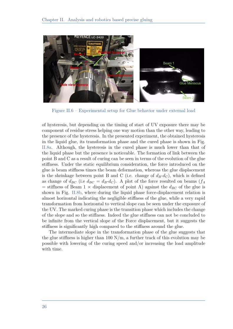
Curing in presence of a known time varying external load can allow the trackof the entire curing phase, again the extent of track dependent on the applicationof load intensity and its variation with time. In this section, a time varying load isapplied against the glue film to monitor the behavior before and during the curing.An experimental setup to analyse the behavior of the glue in the viscous phase andduring the curing is shown in Fig. II.6, where Beam 1 is fixed to Nano Positioner(MCL Nano-3D200 from Mad City Lab), two position sensors (Keyence LC-2420)is used to monitor the Beam 1 and Beam 2 displacement. One end (which isnot in contact with glue) of Beam 2 is kept fixed throughout the experimentsdiscussed in this section. A side view camera (IDS USB 3 uEye CP camera, with20x magnification objective from Mitutoyo) is used to visualize the glue meniscusagainst the beams.
Beam 1 is allowed to go in contact with the glue which is placed at the tipof Beam 2, and allowed to properly stabilized following the viscous and residuestress release. A sinusoidal input displacement of Beam 1 is made from the Robot1, which lead to the stress imposed on the glue (Fig. II.7b, where t is time spendduring the gluing). Both of the beams, Beam 1 and Beam 2 are of stiffness 167.5N/m (respectively defined as kb1 and kb2 of Fig. II.7a). In absence of UV exposure,under the introduced motion of the Robot 1, position A (dA), Beam 1 tip positiondB followed displacement, whereas no considerable displacement is noticed of Beam2 tip C (dC), which means, the introduced stress from the Beam 1 motion is withinthe dissipation limit of the liquid glue alone (very low stiffness of the liquid gluecompared to the Beam 2 stiffness, and so no dissipation). Moreover the positiondA and dB, followed almost same amplitude of displacement in absence of UV butwith a very small delay in their actuation, which means the liquid glue is acting asa phase delay element with no any considerable dissipation. Once the UV exposureis made, then the glue starts curing, and a very fast transition of phase happened(marked as “Curing” in Fig. II.7b). During this transition phase, the Beam 2starts moving, as a result of formation of link between point B and C. Once thelink is sufficiently cured then a constant amplitude displacement of point B and Ccan be seen (marked as “Cured” in Fig. II.7b).
Ideally the input displacement from the Robot 1, and the output displacementof the Beam 1 should follow a linear relation if there is no any phase delay in-between. But, as it is seen that there is presence of some delay, then the presenceof hysteresis is expected in the liquid phase of the glue. Once the glue is cured,then the delay in-between, is removed and then there should not be any presence
25
Chapter II. Analysis and robotics based precise gluing
Figure II.6 – Experimental setup for Glue behavior under external load
of hysteresis, but depending on the timing of start of UV exposure there may becomponent of residue stress helping one way motion than the other way, leading tothe presence of the hysteresis. In the presented experiment, the obtained hysteresisin the liquid glue, its transformation phase and the cured phase is shown in Fig.II.8a. Although, the hysteresis in the cured phase is much lower than that ofthe liquid phase but the presence is noticeable. The formation of link between thepoint B and C as a result of curing can be seen in terms of the evolution of the gluestiffness. Under the static equilibrium consideration, the force introduced on theglue is beam stiffness times the beam deformation, whereas the glue displacementis the shrinkage between point B and C (i.e. change of dB-dC), which is definedas change of dBC (i.e dBC = dB-dC). A plot of the force resulted on beams (fA= stiffness of Beam 1 × displacement of point A) against the dBC of the glue isshown in Fig. II.8b, where during the liquid phase force-displacement relation isalmost horizontal indicating the negligible stiffness of the glue, while a very rapidtransformation from horizontal to vertical slope can be seen under the exposure ofthe UV. The marked curing phase is the transition phase which includes the changeof the slope and so the stiffness. Indeed the glue stiffness can not be concluded tobe infinite from the vertical slope of the Force displacement, but it suggests thestiffness is significantly high compared to the stiffness around the glue.
The intermediate slope in the transformation phase of the glue suggests thatthe glue stiffness is higher than 100 N/m, a further track of this evolution may bepossible with lowering of the curing speed and/or increasing the load amplitudewith time.
26
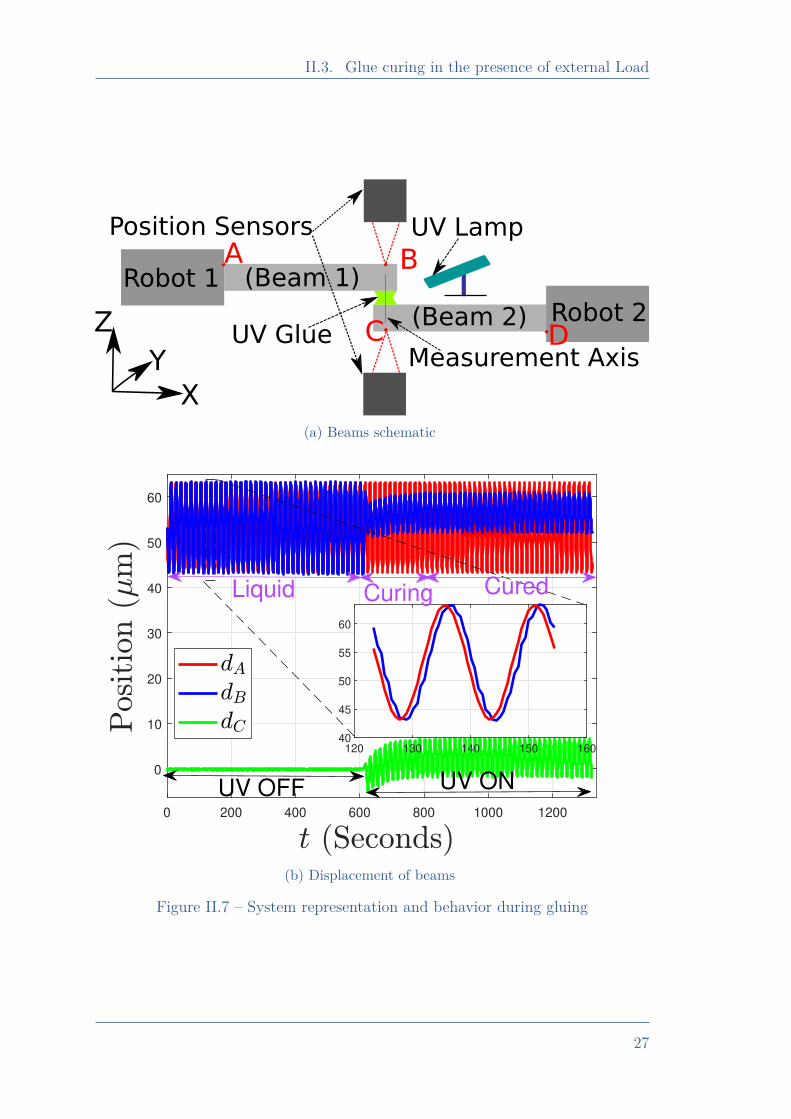
II.3. Glue curing in the presence of external Load
Robot 1
Robot 2
(Beam 1)
(Beam 2)
A B
C DUV Glue
UV LampPosition Sensors
X
Z
Y Measurement Axis
(a) Beams schematic
0 200 400 600 800 1000 1200
0
10
20
30
40
50
60
120 130 140 150 16040
45
50
55
60
UV ONUV OFF
Liquid CuredCuring
(b) Displacement of beams
Figure II.7 – System representation and behavior during gluing
27
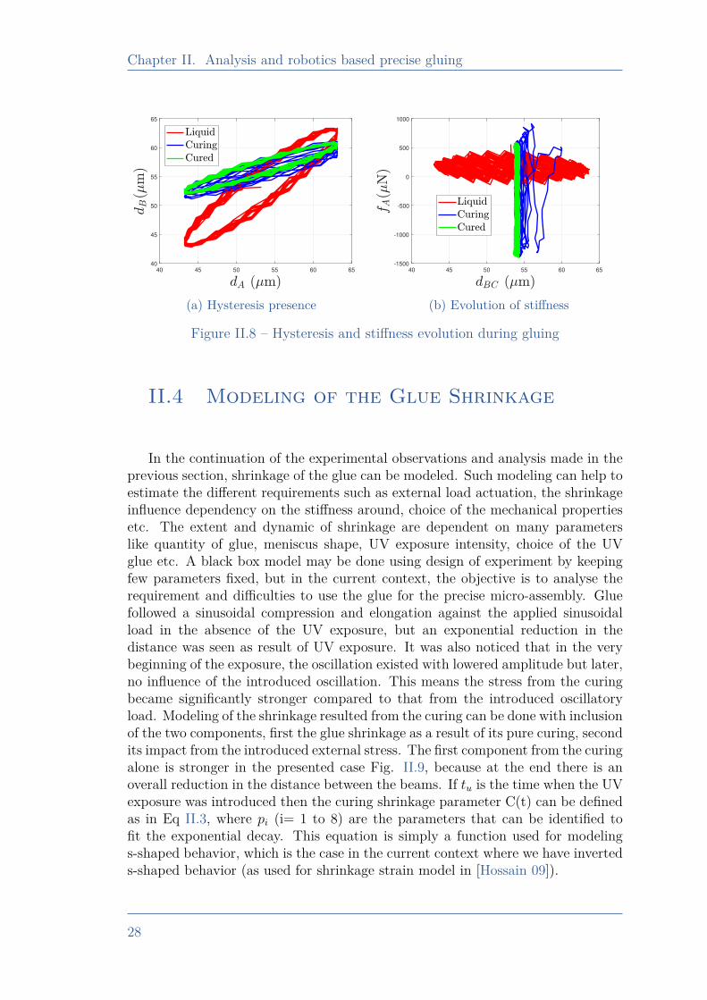
Chapter II. Analysis and robotics based precise gluing
40 45 50 55 60 65
40
45
50
55
60
65
(a) Hysteresis presence
40 45 50 55 60 65
-1500
-1000
-500
0
500
1000
(b) Evolution of stiffness
Figure II.8 – Hysteresis and stiffness evolution during gluing
II.4 Modeling of the Glue Shrinkage
In the continuation of the experimental observations and analysis made in theprevious section, shrinkage of the glue can be modeled. Such modeling can help toestimate the different requirements such as external load actuation, the shrinkageinfluence dependency on the stiffness around, choice of the mechanical propertiesetc. The extent and dynamic of shrinkage are dependent on many parameterslike quantity of glue, meniscus shape, UV exposure intensity, choice of the UVglue etc. A black box model may be done using design of experiment by keepingfew parameters fixed, but in the current context, the objective is to analyse therequirement and difficulties to use the glue for the precise micro-assembly. Gluefollowed a sinusoidal compression and elongation against the applied sinusoidalload in the absence of the UV exposure, but an exponential reduction in thedistance was seen as result of UV exposure. It was also noticed that in the verybeginning of the exposure, the oscillation existed with lowered amplitude but later,no influence of the introduced oscillation. This means the stress from the curingbecame significantly stronger compared to that from the introduced oscillatoryload. Modeling of the shrinkage resulted from the curing can be done with inclusionof the two components, first the glue shrinkage as a result of its pure curing, secondits impact from the introduced external stress. The first component from the curingalone is stronger in the presented case Fig. II.9, because at the end there is anoverall reduction in the distance between the beams. If tu is the time when the UVexposure was introduced then the curing shrinkage parameter C(t) can be definedas in Eq II.3, where pi (i= 1 to 8) are the parameters that can be identified tofit the exponential decay. This equation is simply a function used for modelings-shaped behavior, which is the case in the current context where we have inverteds-shaped behavior (as used for shrinkage strain model in [Hossain 09]).
28
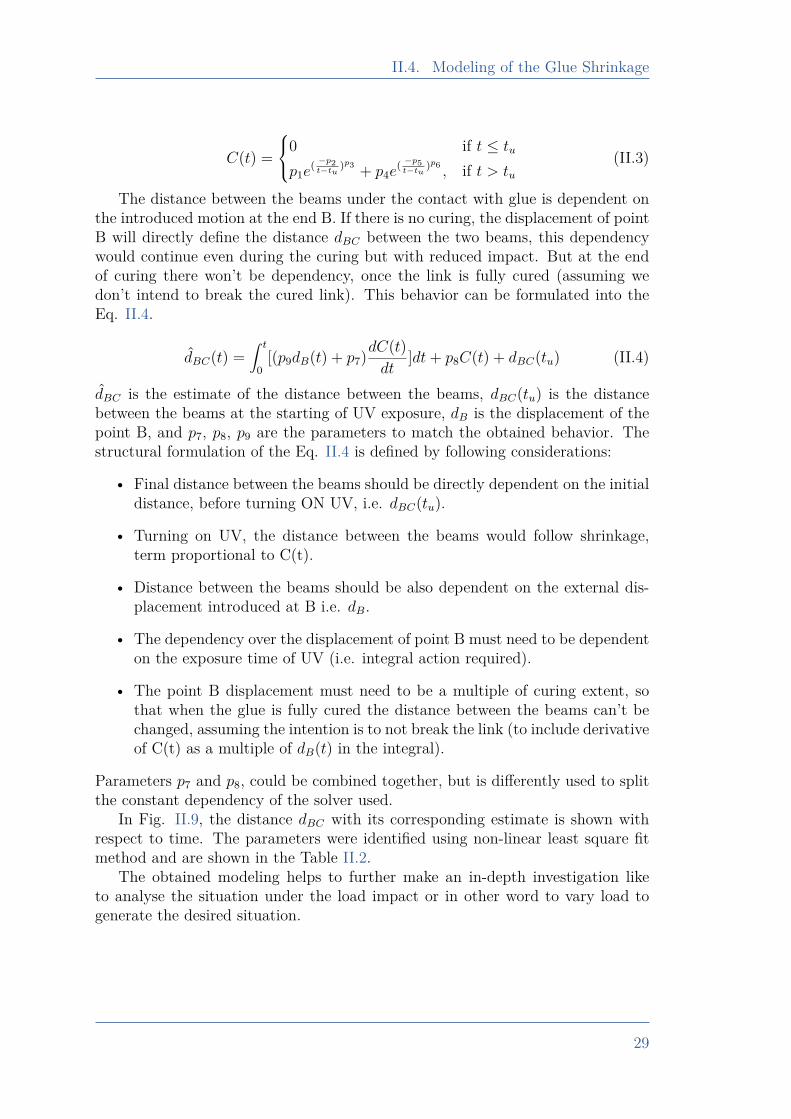
II.4. Modeling of the Glue Shrinkage
C(t) =0 if t ≤ tu
p1e( −p2
t−tu)p3 + p4e
( −p5t−tu
)p6, if t > tu
(II.3)
The distance between the beams under the contact with glue is dependent onthe introduced motion at the end B. If there is no curing, the displacement of pointB will directly define the distance dBC between the two beams, this dependencywould continue even during the curing but with reduced impact. But at the endof curing there won’t be dependency, once the link is fully cured (assuming wedon’t intend to break the cured link). This behavior can be formulated into theEq. II.4.
dBC(t) =∫ t
0[(p9dB(t) + p7)dC(t)
dt]dt+ p8C(t) + dBC(tu) (II.4)
dBC is the estimate of the distance between the beams, dBC(tu) is the distancebetween the beams at the starting of UV exposure, dB is the displacement of thepoint B, and p7, p8, p9 are the parameters to match the obtained behavior. Thestructural formulation of the Eq. II.4 is defined by following considerations:
• Final distance between the beams should be directly dependent on the initialdistance, before turning ON UV, i.e. dBC(tu).
• Turning on UV, the distance between the beams would follow shrinkage,term proportional to C(t).
• Distance between the beams should be also dependent on the external dis-placement introduced at B i.e. dB.
• The dependency over the displacement of point B must need to be dependenton the exposure time of UV (i.e. integral action required).
• The point B displacement must need to be a multiple of curing extent, sothat when the glue is fully cured the distance between the beams can’t bechanged, assuming the intention is to not break the link (to include derivativeof C(t) as a multiple of dB(t) in the integral).
Parameters p7 and p8, could be combined together, but is differently used to splitthe constant dependency of the solver used.
In Fig. II.9, the distance dBC with its corresponding estimate is shown withrespect to time. The parameters were identified using non-linear least square fitmethod and are shown in the Table II.2.
The obtained modeling helps to further make an in-depth investigation liketo analyse the situation under the load impact or in other word to vary load togenerate the desired situation.
29
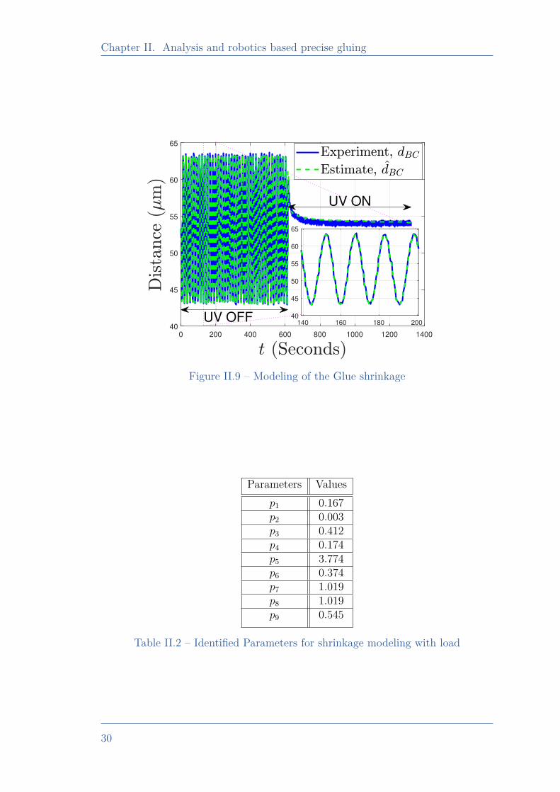
Chapter II. Analysis and robotics based precise gluing
0 200 400 600 800 1000 1200 1400
40
45
50
55
60
65
140 160 180 200
40
45
50
55
60
65
UV ON
UV OFF
Figure II.9 – Modeling of the Glue shrinkage
Parameters Valuesp1 0.167p2 0.003p3 0.412p4 0.174p5 3.774p6 0.374p7 1.019p8 1.019p9 0.545
Table II.2 – Identified Parameters for shrinkage modeling with load
30
II.5. Study of active control to achieve accurate gluing
II.5 Study of active control to achieve ac-curate gluing
As the glue curing process induces mechanical stress and so a drift, there is arequirement of an adequate action that can restrain this additional drift. Therecould be several approaches to solve this mismatch. In [Müller 15], shrinkagecompensation from UV-curing was addressed using identifying critical parametersof curing. This identification was made by numerical simulation with knowledge ofthe sensitivity of the isolated degree of freedom, and accordingly, bonding directionwas used. But this approach has its limitations: primarily from the choice of glue,and secondly from its convenient adaptability towards the micro-assembly process.Another possible approach could be to manage the viscosity variation to restrainthe possible reshaping of glue arising from the glue curing. In [Roca 12], oneapparatus is proposed with which viscosity adjustment of UV adhesive could bemade. But mapping up the viscosity adjustment with the micro-assembly mightfurther limit the workspace and the strategy towards assembly, as there mightbe other factors (such as choice of glue and cured strength) that complicate thechosen approach. With the knowledge of physical happening and its use in theapproach, it could be possible to further improve the flexibility of the approach(towards force/position-based control).
There are multiple ways to address this problem; one would be to go withthe approach of force/position control. To solve the problem of desired relativedistance resulting from positional drift, one approach could be to track positionalshrinkage, and accordingly generate sufficient force against the glue curing, therebyavoiding the drift introduced. This case is quite similar to that of grippers end-effector against the dynamic environment. An impedance control-based approachto estimate the unknown environment’s parameter using force tracking is presentedin [Komati 14b]; the approach was tested with different compliant structures. In[Wang 17], the force sensor was used to detect the penetration force against abiological cell, and a strain-based sensor to measure the relative position of themicropipette. With knowledge of force/position, an incremental PID controllerwas proposed to meet the suitable injection force. Another similar situation couldbe the case where the teleoperated task needs to be done against the dynamicenvironment, resulting in a requirement of force/position knowledge to developsuitable behavior. This case was addressed in [Lu 18], where a fuzzy-observerbased hybrid force/position control method was used for a bimanual teleoperationsystem in the presence of dynamic uncertainties.
Combining these several studies, in the context of glue curing, an active control-based strategy to control the distance between the beams appears promising. Beam1 would be allowed to find a suitable position to have sufficient force at the assemblyend, through which the desired distance between the beams can be obtained. Theemployed load in the presented experiment was not strong enough to fight againstthe shrinkage. Assuming the similar conditions in terms of the glue choice, shape,quantity and analysing the behavior in terms of load dependency, a zoomed section
31
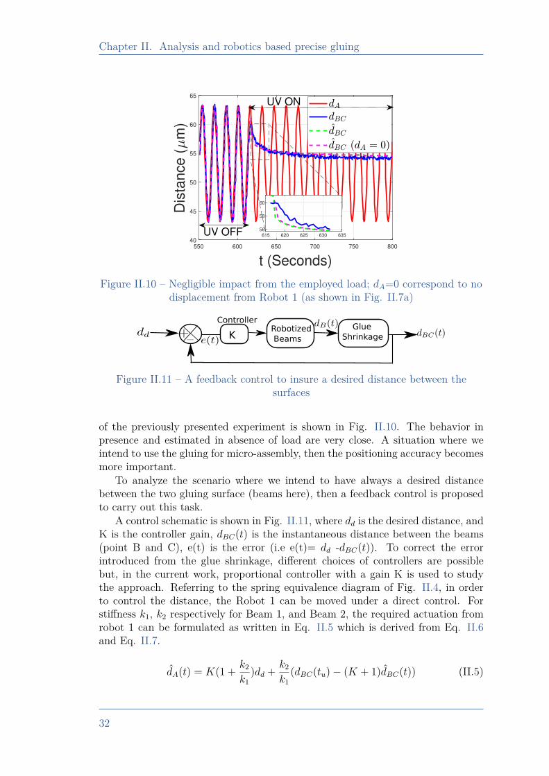
Chapter II. Analysis and robotics based precise gluing
550 600 650 700 750 800
t (Seconds)
40
45
50
55
60
65
Dis
tan
ce
(m
)
615 620 625 630 635
56
58
60
UV ON
UV OFF
Figure II.10 – Negligible impact from the employed load; dA=0 correspond to nodisplacement from Robot 1 (as shown in Fig. II.7a)
K Glue
Shrinkage
Controller Robotized
Beams
Figure II.11 – A feedback control to insure a desired distance between thesurfaces
of the previously presented experiment is shown in Fig. II.10. The behavior inpresence and estimated in absence of load are very close. A situation where weintend to use the gluing for micro-assembly, then the positioning accuracy becomesmore important.
To analyze the scenario where we intend to have always a desired distancebetween the two gluing surface (beams here), then a feedback control is proposedto carry out this task.
A control schematic is shown in Fig. II.11, where dd is the desired distance, andK is the controller gain, dBC(t) is the instantaneous distance between the beams(point B and C), e(t) is the error (i.e e(t)= dd -dBC(t)). To correct the errorintroduced from the glue shrinkage, different choices of controllers are possiblebut, in the current work, proportional controller with a gain K is used to studythe approach. Referring to the spring equivalence diagram of Fig. II.4, in orderto control the distance, the Robot 1 can be moved under a direct control. Forstiffness k1, k2 respectively for Beam 1, and Beam 2, the required actuation fromrobot 1 can be formulated as written in Eq. II.5 which is derived from Eq. II.6and Eq. II.7.
dA(t) = K(1 + k2
k1)dd + k2
k1(dBC(tu)− (K + 1)dBC(t)) (II.5)
32
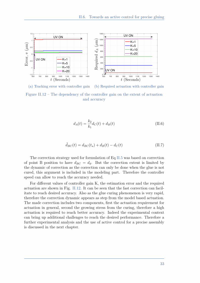
II.6. Towards an active control for precise gluing
600 700 800 900 1000 1100 1200 1300 1400
-1.5
-1
-0.5
0
0.5
1
1.5
K=1
K=5
K=10
K=20
UV ON
UV ON
(a) Tracking error with controller gain
600 700 800 900 1000 1100 1200 1300 1400
0
200
400
600
800
1000
1200
1400
K=1
K=5
K=10
K=20
UV ON
UV ON
(b) Required actuation with controller gain
Figure II.12 – The dependency of the controller gain on the extent of actuationand accuracy
dA(t) = k2
k1dC(t) + dB(t) (II.6)
dBC(t) = dBC(tu) + dB(t)− dC(t) (II.7)
The correction strategy used for formulation of Eq II.5 was based on correctionof point B position to have dBC = dd. But the correction extent is limited bythe dynamic of correction as the correction can only be done when the glue is notcured, this argument is included in the modeling part. Therefore the controllerspeed can allow to reach the accuracy needed.
For different values of controller gain K, the estimation error and the requiredactuation are shown in Fig. II.12. It can be seen that the fast correction can facil-itate to reach desired accuracy. Also as the glue curing phenomenon is very rapid,therefore the correction dynamic appears as step from the model based actuation.The made correction includes two components, first the actuation requirement foractuation in general, second the growing stress from the curing, therefore a highactuation is required to reach better accuracy. Indeed the experimental contextcan bring up additional challenges to reach the desired performance. Therefore afurther experimental analysis and the use of active control for a precise assemblyis discussed in the next chapter.
33
Chapter II. Analysis and robotics based precise gluing
II.6 Towards an active control for precisegluing
As discussed in previous sections, the glue shrinkage and its dependency onthe external load. In this part of the chapter, the experimental work dealing withthe control for precise gluing is presented. The control scheme as defined from themodel in section II.5, brings many information which is needed to consider for thecontroller design for a precise gluing.
II.6.1 Working principleThis part of work aims to address the problem of positioning accuracy resulting
from glue curing and to introduce a versatile solution to meet positioning require-ments. In the present work, gluing about the Z-axis (Fig. II.7a) is addressed usingthe presented beam-based system. There are many parameters that can influencethe assembly behavior, including glue quantity, relative contact area, and beamstiffness. The influence of the positional drift from glue curing about other planar(X and Y) axes can be considered negligible relative to the Z-axis, which was thecase in [Dai 19]. This can be seen in context of gluing plane which is XY (contactwith glue) in the presented configuration, so the orthogonal Z axis would includethe dominant shrinkage tensor, therefore the possibility of sliding in XY planeis negligible. The other problem is from a very intense UV exposure that mightintroduce small voids around the neutral axis of the beams [Norland 00]. This ismainly possible when using very fast curing of glue, so that neither the glue northe beam surfaces can equilibrate rapid enough to restrict the stress development.
In the literature, there are several works reporting the use of “depth curing”in place of “surface curing” using photoinitiators [Okamura 16]. With the suit-able concentration and choice of photoinitiator, it could be possible to avoid thecreation of void by facilitating the stress release. In the current work, the UVexposure intensity was minimized by placing the source suitably far (based on ex-perimental observation) from the glue, thereby resulting in a slow curing rate, andthe possibility of void creation could be minimized because of sufficient time forstress release. The other justification for negligible void creation can be explainedby the length to width ratio of the employed beams, which is more than 20 timesfor all chosen beams. So, overall, the major effect is considered to be along thelongitudinal Z-axis. The idea is to demonstrate the validity of the proposed ap-proach about the chosen axis, which can then be extended to another axis (withthe inclusion of an additional sensing mechanism).
The top beam can be, for instance, a microgripper holding a micro-object(part in contact with the glue) and the bottom beam as a substrate. Basically,the presented configuration and the opted approach was chosen in the context ofa tethered configuration for micro-assembly. The objective will be to control therelative distance [i.e., the distance between the two beams tips (denoted as pointsB and C of Fig. II.7a)].
34
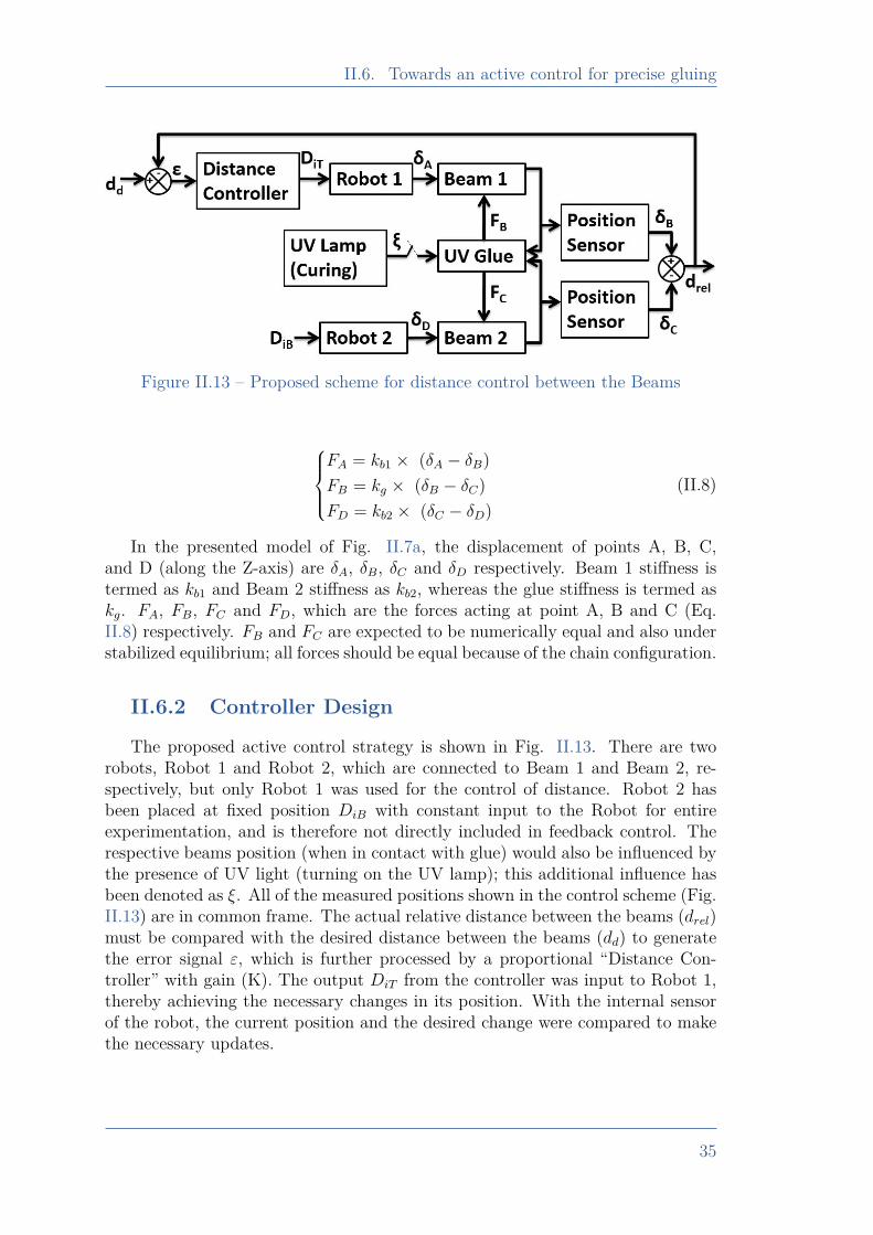
II.6. Towards an active control for precise gluing
Figure II.13 – Proposed scheme for distance control between the Beams
FA = kb1 × (δA − δB)FB = kg × (δB − δC)FD = kb2 × (δC − δD)
(II.8)
In the presented model of Fig. II.7a, the displacement of points A, B, C,and D (along the Z-axis) are δA, δB, δC and δD respectively. Beam 1 stiffness istermed as kb1 and Beam 2 stiffness as kb2, whereas the glue stiffness is termed askg. FA, FB, FC and FD, which are the forces acting at point A, B and C (Eq.II.8) respectively. FB and FC are expected to be numerically equal and also understabilized equilibrium; all forces should be equal because of the chain configuration.
II.6.2 Controller Design
The proposed active control strategy is shown in Fig. II.13. There are tworobots, Robot 1 and Robot 2, which are connected to Beam 1 and Beam 2, re-spectively, but only Robot 1 was used for the control of distance. Robot 2 hasbeen placed at fixed position DiB with constant input to the Robot for entireexperimentation, and is therefore not directly included in feedback control. Therespective beams position (when in contact with glue) would also be influenced bythe presence of UV light (turning on the UV lamp); this additional influence hasbeen denoted as ξ. All of the measured positions shown in the control scheme (Fig.II.13) are in common frame. The actual relative distance between the beams (drel)must be compared with the desired distance between the beams (dd) to generatethe error signal ε, which is further processed by a proportional “Distance Con-troller” with gain (K). The output DiT from the controller was input to Robot 1,thereby achieving the necessary changes in its position. With the internal sensorof the robot, the current position and the desired change were compared to makethe necessary updates.
35
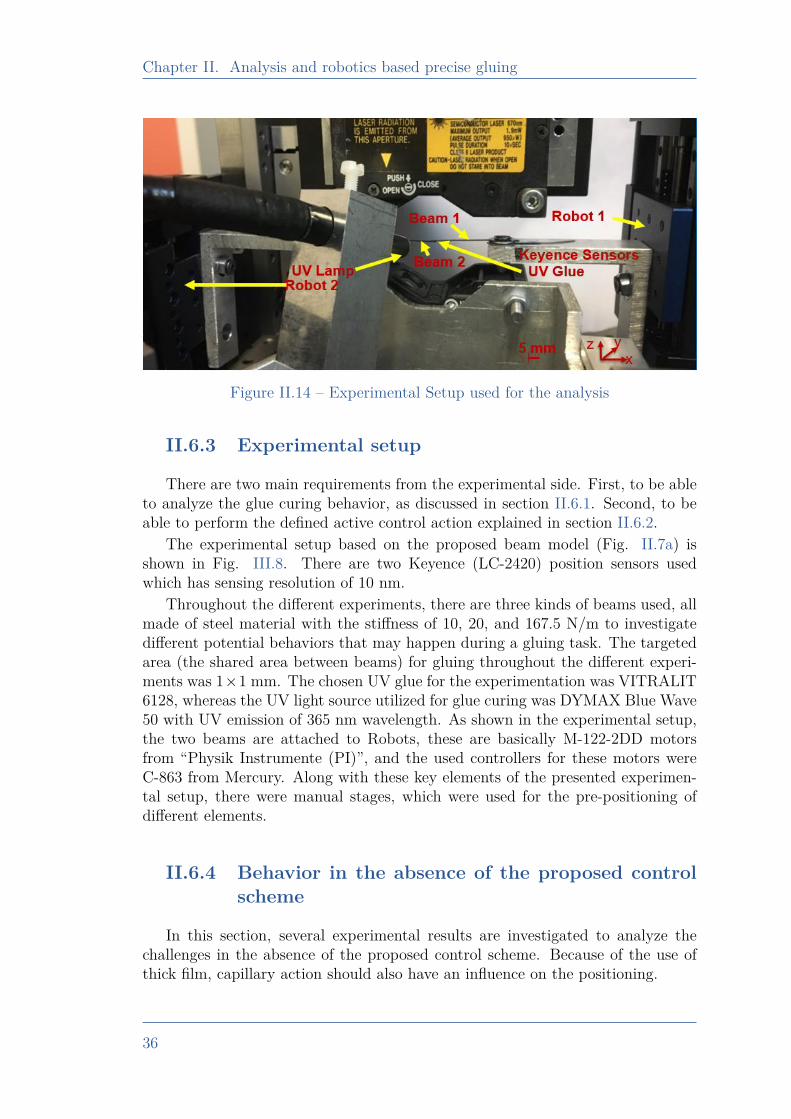
Chapter II. Analysis and robotics based precise gluing
Figure II.14 – Experimental Setup used for the analysis
II.6.3 Experimental setup
There are two main requirements from the experimental side. First, to be ableto analyze the glue curing behavior, as discussed in section II.6.1. Second, to beable to perform the defined active control action explained in section II.6.2.
The experimental setup based on the proposed beam model (Fig. II.7a) isshown in Fig. III.8. There are two Keyence (LC-2420) position sensors usedwhich has sensing resolution of 10 nm.
Throughout the different experiments, there are three kinds of beams used, allmade of steel material with the stiffness of 10, 20, and 167.5 N/m to investigatedifferent potential behaviors that may happen during a gluing task. The targetedarea (the shared area between beams) for gluing throughout the different experi-ments was 1×1 mm. The chosen UV glue for the experimentation was VITRALIT6128, whereas the UV light source utilized for glue curing was DYMAX Blue Wave50 with UV emission of 365 nm wavelength. As shown in the experimental setup,the two beams are attached to Robots, these are basically M-122-2DD motorsfrom “Physik Instrumente (PI)”, and the used controllers for these motors wereC-863 from Mercury. Along with these key elements of the presented experimen-tal setup, there were manual stages, which were used for the pre-positioning ofdifferent elements.
II.6.4 Behavior in the absence of the proposed controlscheme
In this section, several experimental results are investigated to analyze thechallenges in the absence of the proposed control scheme. Because of the use ofthick film, capillary action should also have an influence on the positioning.
36
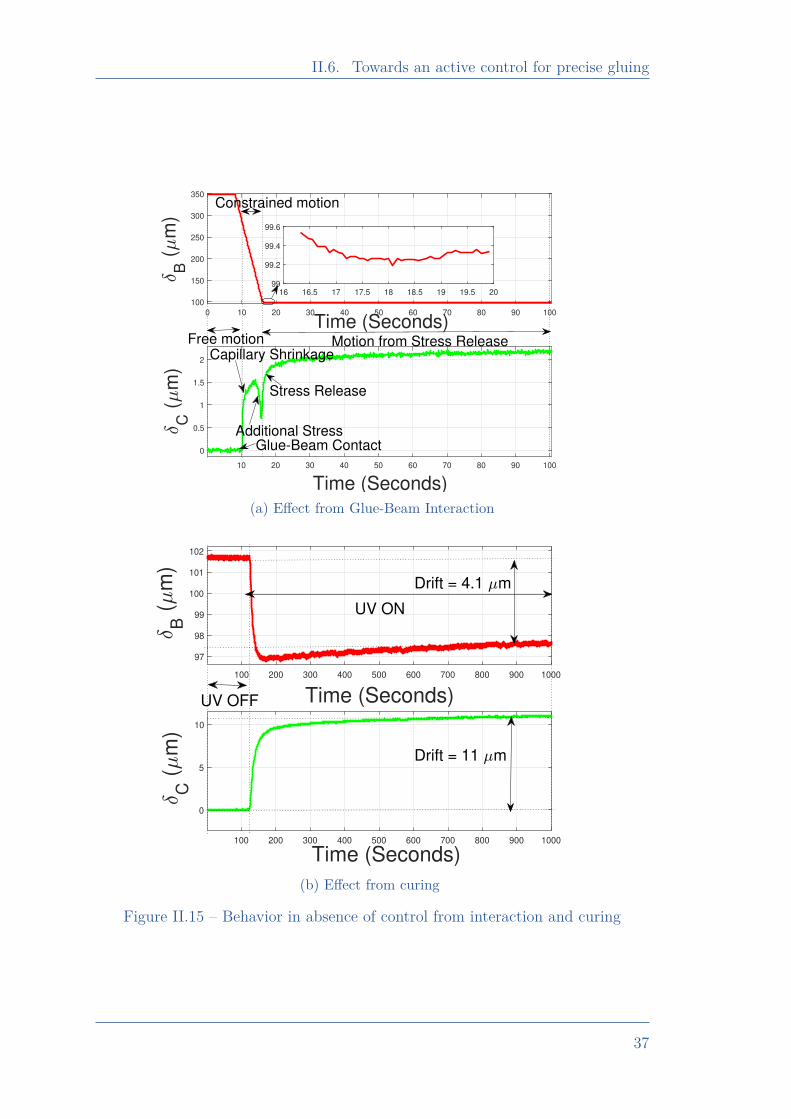
II.6. Towards an active control for precise gluing
0 10 20 30 40 50 60 70 80 90 100
Time (Seconds)100
150
200
250
300
350
B (
m)
10 20 30 40 50 60 70 80 90 100
Time (Seconds)
0
0.5
1
1.5
2
C (
m)
16 16.5 17 17.5 18 18.5 19 19.5 2099
99.2
99.4
99.6
Free motionCapillary Shrinkage
Additional StressGlue-Beam Contact
Stress Release
Constrained motion
Motion from Stress Release
(a) Effect from Glue-Beam Interaction
100 200 300 400 500 600 700 800 900 1000
Time (Seconds)
97
98
99
100
101
102
B
(m
)
100 200 300 400 500 600 700 800 900 1000
Time (Seconds)
0
5
10
C
(m
)
UV OFF
Drift = 11 m
Drift = 4.1 m
UV ON
(b) Effect from curing
Figure II.15 – Behavior in absence of control from interaction and curing
37
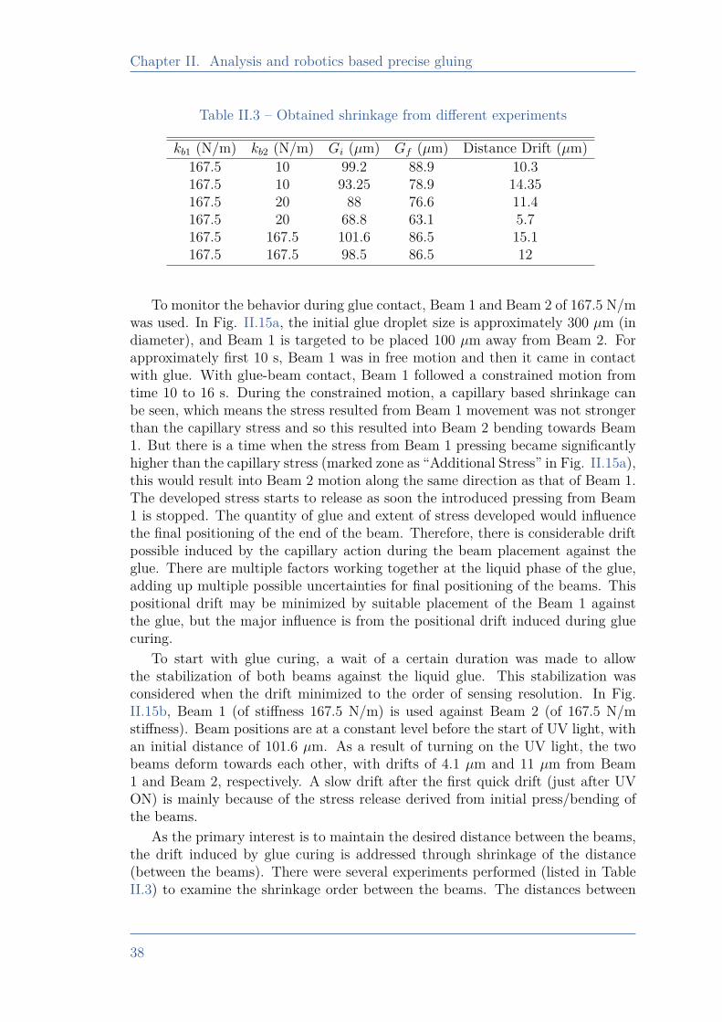
Chapter II. Analysis and robotics based precise gluing
Table II.3 – Obtained shrinkage from different experiments
kb1 (N/m) kb2 (N/m) Gi (µm) Gf (µm) Distance Drift (µm)167.5 10 99.2 88.9 10.3167.5 10 93.25 78.9 14.35167.5 20 88 76.6 11.4167.5 20 68.8 63.1 5.7167.5 167.5 101.6 86.5 15.1167.5 167.5 98.5 86.5 12
To monitor the behavior during glue contact, Beam 1 and Beam 2 of 167.5 N/mwas used. In Fig. II.15a, the initial glue droplet size is approximately 300 µm (indiameter), and Beam 1 is targeted to be placed 100 µm away from Beam 2. Forapproximately first 10 s, Beam 1 was in free motion and then it came in contactwith glue. With glue-beam contact, Beam 1 followed a constrained motion fromtime 10 to 16 s. During the constrained motion, a capillary based shrinkage canbe seen, which means the stress resulted from Beam 1 movement was not strongerthan the capillary stress and so this resulted into Beam 2 bending towards Beam1. But there is a time when the stress from Beam 1 pressing became significantlyhigher than the capillary stress (marked zone as “Additional Stress” in Fig. II.15a),this would result into Beam 2 motion along the same direction as that of Beam 1.The developed stress starts to release as soon the introduced pressing from Beam1 is stopped. The quantity of glue and extent of stress developed would influencethe final positioning of the end of the beam. Therefore, there is considerable driftpossible induced by the capillary action during the beam placement against theglue. There are multiple factors working together at the liquid phase of the glue,adding up multiple possible uncertainties for final positioning of the beams. Thispositional drift may be minimized by suitable placement of the Beam 1 againstthe glue, but the major influence is from the positional drift induced during gluecuring.
To start with glue curing, a wait of a certain duration was made to allowthe stabilization of both beams against the liquid glue. This stabilization wasconsidered when the drift minimized to the order of sensing resolution. In Fig.II.15b, Beam 1 (of stiffness 167.5 N/m) is used against Beam 2 (of 167.5 N/mstiffness). Beam positions are at a constant level before the start of UV light, withan initial distance of 101.6 µm. As a result of turning on the UV light, the twobeams deform towards each other, with drifts of 4.1 µm and 11 µm from Beam1 and Beam 2, respectively. A slow drift after the first quick drift (just after UVON) is mainly because of the stress release derived from initial press/bending ofthe beams.
As the primary interest is to maintain the desired distance between the beams,the drift induced by glue curing is addressed through shrinkage of the distance(between the beams). There were several experiments performed (listed in TableII.3) to examine the shrinkage order between the beams. The distances between
38
II.6. Towards an active control for precise gluing
the beams before the start of glue curing are listed as “Gi” in Table II.3, whereasthe distance as a result of glue curing is listed as “Gf”. Therefore, the shown“Distance Drift” (Difference of Gi and Gf ) in the table is mainly from the gluecuring, whereas we do have the shrinkage from the capillary action dependent onintroduced stress and glue quantity (as seen in Fig. II.15a). The big differencein distance drifts from 11.4 to 5.7 µm in two runs with 20 N/m for Beam 2 ismainly because of the different glue quantities between the beams. The amount ofdrift is directly dependent on the quantity of glue. The experimental results areshown in Table II.3, which differ mainly because glue quantity was not controlledin different parallel runs. This also demonstrates the behavior sensitivity overdifferent parameters. The shrinkage from capillary action (before the start ofcuring) ranged between 2 and 17 µm, throughout the different experiments listedin the Table II.3. Therefore, the overall shrinkage from the gluing process couldreach up to 30 µm, which is a serious concerned from an assembly accuracy pointof view. Therefore, the key objective of this work is to have a versatile approach formicro-assembly using UV glue, which could result in a repeatable sub-micrometeraccuracy positioning.
II.6.5 Behavior with proposed control strategy
The chosen control scheme (Fig. II.13) with a single robot allows the flexibilityfor micro-assembly operations, especially where the substrate is not robotized.The intention in the proposed work is to adapt a versatile approach that canalso work for a thick film (complex compared to thin films), and to avoid anyspecial treatment for gluing. Glue thickness > 50 µm is targeted to demonstratethe feasibility of the approach, but the approach aims at being independent ofthe choice of glue thickness. The limits in terms of glue quantity and the areato be glued can be defined from sensing and opted systems limitation. In thepresented case, Keyence sensors are used, for which, a relatively high stiffnessbeam (chosen 167.5 N/m) as compared to 10 or 20 N/m is used, so that thecorresponding displacements are scaled down. As with stiffer beam, a higher forcecan be generated at the assembly end with small movement of the beam whereasin case of low stiffness beam (10 or 20 N/m), it may requires to move out ofthe Keyence sensing range dependent on chosen glue size and area to be glued.Moreover, the chosen stiffness is closed to the stiffness of instrumented gripper (130N/m) used in [Komati 14a], therefore a comparative analysis in terms of limitationto tasks handling could also be done.
The main principle of the control strategy employed is to move Robot 1 withsufficient force at the assembly end (beams end) so that the desired distance be-tween the beams can be obtained. The passive beam’s position is an importantinformation which is required for processing of the control action. This positionwould be influenced depending on the beams’ interaction with glue and the move-ment from Robot 1. Therefore, the entire experiment has been divided into five
39
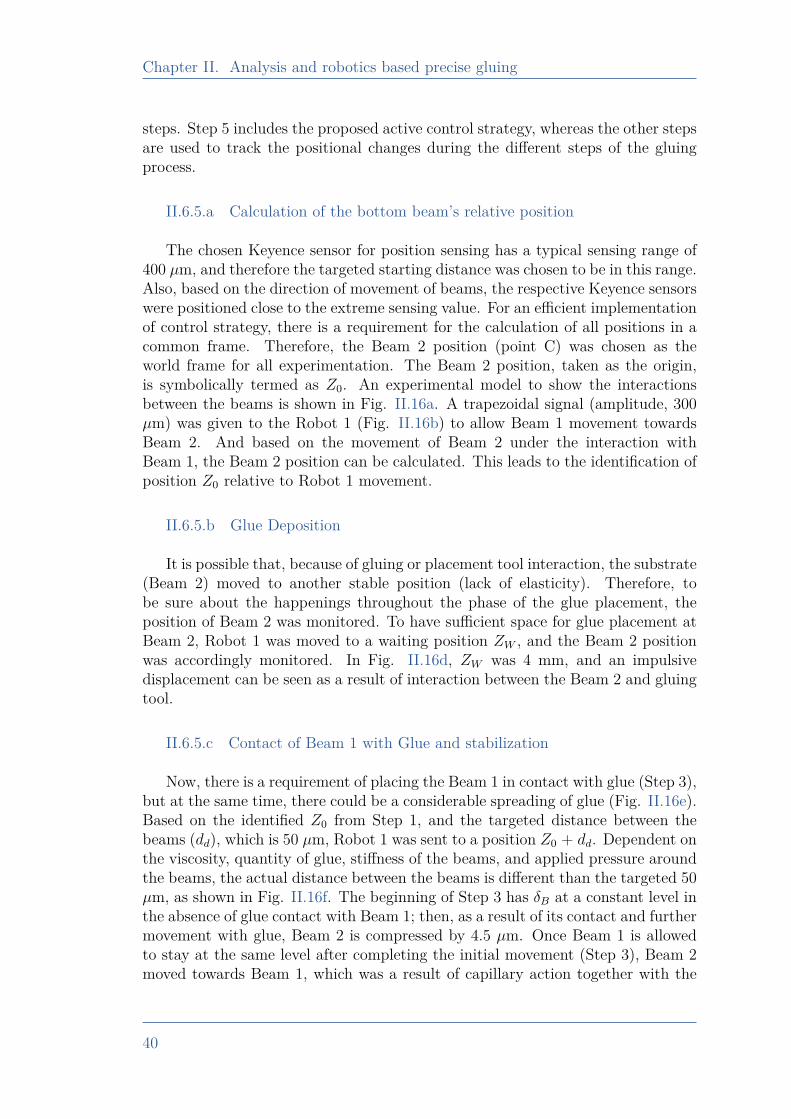
Chapter II. Analysis and robotics based precise gluing
steps. Step 5 includes the proposed active control strategy, whereas the other stepsare used to track the positional changes during the different steps of the gluingprocess.
II.6.5.a Calculation of the bottom beam’s relative position
The chosen Keyence sensor for position sensing has a typical sensing range of400 µm, and therefore the targeted starting distance was chosen to be in this range.Also, based on the direction of movement of beams, the respective Keyence sensorswere positioned close to the extreme sensing value. For an efficient implementationof control strategy, there is a requirement for the calculation of all positions in acommon frame. Therefore, the Beam 2 position (point C) was chosen as theworld frame for all experimentation. The Beam 2 position, taken as the origin,is symbolically termed as Z0. An experimental model to show the interactionsbetween the beams is shown in Fig. II.16a. A trapezoidal signal (amplitude, 300µm) was given to the Robot 1 (Fig. II.16b) to allow Beam 1 movement towardsBeam 2. And based on the movement of Beam 2 under the interaction withBeam 1, the Beam 2 position can be calculated. This leads to the identification ofposition Z0 relative to Robot 1 movement.
II.6.5.b Glue Deposition
It is possible that, because of gluing or placement tool interaction, the substrate(Beam 2) moved to another stable position (lack of elasticity). Therefore, tobe sure about the happenings throughout the phase of the glue placement, theposition of Beam 2 was monitored. To have sufficient space for glue placement atBeam 2, Robot 1 was moved to a waiting position ZW , and the Beam 2 positionwas accordingly monitored. In Fig. II.16d, ZW was 4 mm, and an impulsivedisplacement can be seen as a result of interaction between the Beam 2 and gluingtool.
II.6.5.c Contact of Beam 1 with Glue and stabilization
Now, there is a requirement of placing the Beam 1 in contact with glue (Step 3),but at the same time, there could be a considerable spreading of glue (Fig. II.16e).Based on the identified Z0 from Step 1, and the targeted distance between thebeams (dd), which is 50 µm, Robot 1 was sent to a position Z0 + dd. Dependent onthe viscosity, quantity of glue, stiffness of the beams, and applied pressure aroundthe beams, the actual distance between the beams is different than the targeted 50µm, as shown in Fig. II.16f. The beginning of Step 3 has δB at a constant level inthe absence of glue contact with Beam 1; then, as a result of its contact and furthermovement with glue, Beam 2 is compressed by 4.5 µm. Once Beam 1 is allowedto stay at the same level after completing the initial movement (Step 3), Beam 2moved towards Beam 1, which was a result of capillary action together with the
40
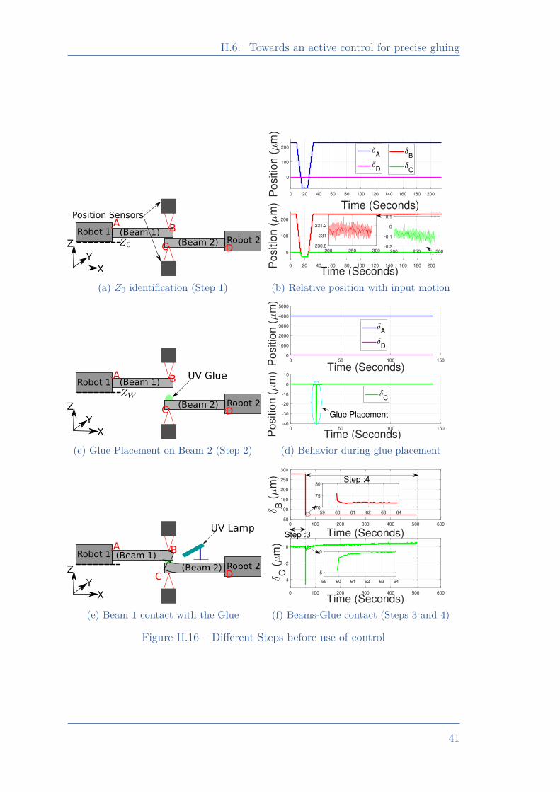
II.6. Towards an active control for precise gluing
Robot 1Robot 2
(Beam 1)(Beam 2)
AB
C D
Position Sensors
X
Z
Y
(a) Z0 identification (Step 1)
0 20 40 60 80 100 120 140 160 180 200
Time (Seconds)
0
100
200
Positio
n (
m)
A
D
0 20 40 60 80 100 120 140 160 180 200
Time (Seconds)
0
100
200
Positio
n (
m)
B
C
200 250 300230.8
231
231.2
200 250 300-0.2
-0.1
0
0.1
(b) Relative position with input motion
Robot 1
Robot 2
(Beam 1)
(Beam 2)
A B
C D
X
Z
Y
UV Glue
(c) Glue Placement on Beam 2 (Step 2)
0 50 100 150
Time (Seconds)
0
1000
2000
3000
4000
5000
Po
sitio
n (
m)
A
D
0 50 100 150
Time (Seconds)-40
-30
-20
-10
0
10
Po
sitio
n (
m)
C
Glue Placement
(d) Behavior during glue placement
Robot 1
Robot 2
(Beam 1)
(Beam 2)
A B
C D
X
Z
Y
UV Lamp
(e) Beam 1 contact with the Glue
0 100 200 300 400 500 600
Time (Seconds)
50
100
150
200
250
300
B (
m)
0 100 200 300 400 500 600
Time (Seconds)
-4
-2
0
C (
m)
59 60 61 62 63 6470
75
80
59 60 61 62 63 64
-5
0
Step :3
Step :4
(f) Beams-Glue contact (Steps 3 and 4)
Figure II.16 – Different Steps before use of control
41
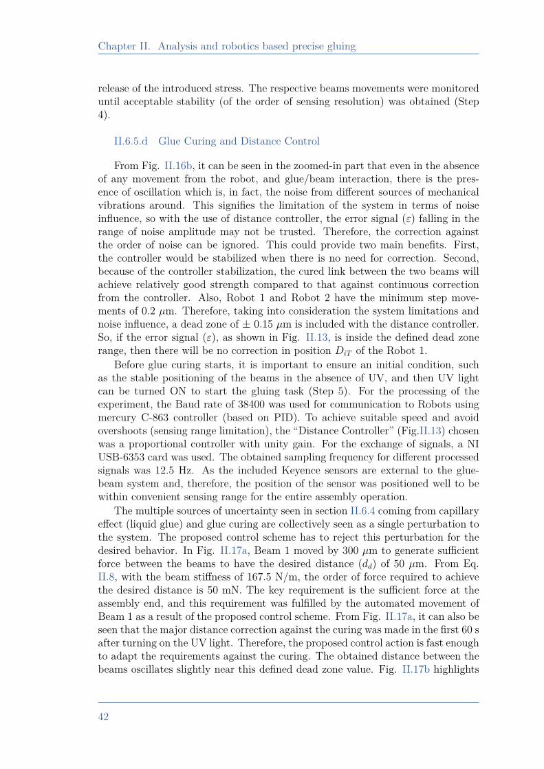
Chapter II. Analysis and robotics based precise gluing
release of the introduced stress. The respective beams movements were monitoreduntil acceptable stability (of the order of sensing resolution) was obtained (Step4).
II.6.5.d Glue Curing and Distance Control
From Fig. II.16b, it can be seen in the zoomed-in part that even in the absenceof any movement from the robot, and glue/beam interaction, there is the pres-ence of oscillation which is, in fact, the noise from different sources of mechanicalvibrations around. This signifies the limitation of the system in terms of noiseinfluence, so with the use of distance controller, the error signal (ε) falling in therange of noise amplitude may not be trusted. Therefore, the correction againstthe order of noise can be ignored. This could provide two main benefits. First,the controller would be stabilized when there is no need for correction. Second,because of the controller stabilization, the cured link between the two beams willachieve relatively good strength compared to that against continuous correctionfrom the controller. Also, Robot 1 and Robot 2 have the minimum step move-ments of 0.2 µm. Therefore, taking into consideration the system limitations andnoise influence, a dead zone of ± 0.15 µm is included with the distance controller.So, if the error signal (ε), as shown in Fig. II.13, is inside the defined dead zonerange, then there will be no correction in position DiT of the Robot 1.
Before glue curing starts, it is important to ensure an initial condition, suchas the stable positioning of the beams in the absence of UV, and then UV lightcan be turned ON to start the gluing task (Step 5). For the processing of theexperiment, the Baud rate of 38400 was used for communication to Robots usingmercury C-863 controller (based on PID). To achieve suitable speed and avoidovershoots (sensing range limitation), the “Distance Controller” (Fig.II.13) chosenwas a proportional controller with unity gain. For the exchange of signals, a NIUSB-6353 card was used. The obtained sampling frequency for different processedsignals was 12.5 Hz. As the included Keyence sensors are external to the glue-beam system and, therefore, the position of the sensor was positioned well to bewithin convenient sensing range for the entire assembly operation.
The multiple sources of uncertainty seen in section II.6.4 coming from capillaryeffect (liquid glue) and glue curing are collectively seen as a single perturbation tothe system. The proposed control scheme has to reject this perturbation for thedesired behavior. In Fig. II.17a, Beam 1 moved by 300 µm to generate sufficientforce between the beams to have the desired distance (dd) of 50 µm. From Eq.II.8, with the beam stiffness of 167.5 N/m, the order of force required to achievethe desired distance is 50 mN. The key requirement is the sufficient force at theassembly end, and this requirement was fulfilled by the automated movement ofBeam 1 as a result of the proposed control scheme. From Fig. II.17a, it can also beseen that the major distance correction against the curing was made in the first 60 safter turning on the UV light. Therefore, the proposed control action is fast enoughto adapt the requirements against the curing. The obtained distance between thebeams oscillates slightly near this defined dead zone value. Fig. II.17b highlights
42
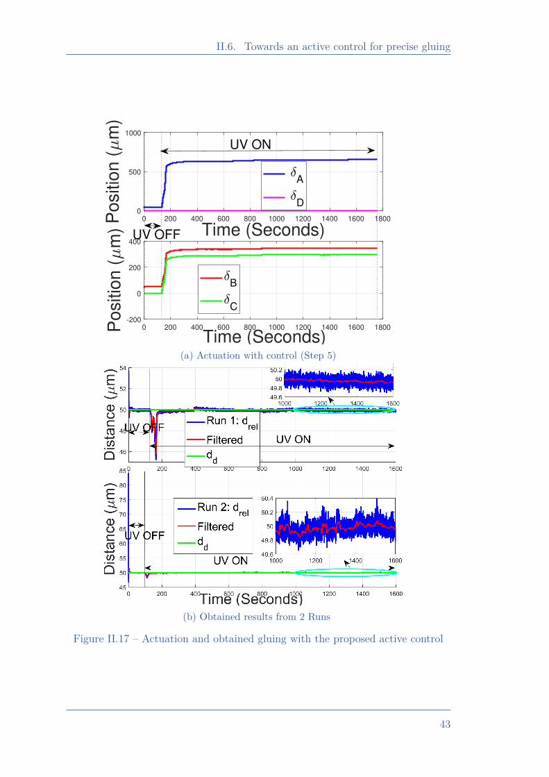
II.6. Towards an active control for precise gluing
0 200 400 600 800 1000 1200 1400 1600 1800
Time (Seconds)
0
500
1000
Po
sitio
n (
m)
A
D
0 200 400 600 800 1000 1200 1400 1600 1800
Time (Seconds)-200
0
200
400
Po
sitio
n (
m)
B
C
UV OFF
UV ON
(a) Actuation with control (Step 5)
(b) Obtained results from 2 Runs
Figure II.17 – Actuation and obtained gluing with the proposed active control
43
Chapter II. Analysis and robotics based precise gluing
the distance evolution over time during this gluing process. There were severalexperiments done to test the repeatability of the approach, and the experimentalresult from the two runs (Run 1 and Run 2) is shown in Fig. II.17b. Run 1corresponds to Fig. II.17a, whereas Run 2 corresponds to another experimentalresult. Before switching on the UV light (in Run 1 of Fig. II.17b), the initialdistance between the beams was controlled from 53.9 to 50 µm. The proposedcontrol action can maintain the desired distance with an error in the order of 200nm. By saying order 200 nm means, the obtained distance signal (drel) oscillates(with the exclusion of spikes) by 200 nm around the targeted distance. But itcan be seen that with the use of a moving average filter, the filtered signal is veryclose to the desired 50 µm (typically less than 20 nm positioning error). Thereare likely multiple sources of this noise; the main sources could be the mechanicalvibration resulting from the electrical devices around, the different vibrations fromthe movement around, and also the optical presence might have a contribution tothe obtained noise. In Run 2, the initial distance between the beams was 84.6 µm,but with the proposed approach, the final distance between the beams is of thesame order as that of Run 1, indicating the repeatability of the behavior. FromFig. II.17a, there is no movement of Robot 1 after ∼ 900 s, which means that thedifference in desired and the actual distance between the beams is well inside thedefined dead zone. Therefore, the noted dynamics after stopping the movementof Robot 1, as shown in the zoomed-in version of Fig. II.17b, mainly comes fromthe noise. Achieving accuracy around the opted dead zone and the resolution ofthe sensor also indicates that, if the chosen systems limitation can be removedor minimized, then it could be possible to further improve the accuracy with thesame approach for the distance control.
II.7 Conclusions
The chapter constitutes the behavior analysis of glue for its use in the contextof micro-assembly. The behavior of glue in absence and presence of external loadwas analyzed, which helped to build a modeling scheme with which the shrinkage-external load dependency can be further investigated. The modeling scheme helpedfurther to investigate the scenario desired from the external load in order to havea desired distance between the two gluing surfaces. Based on the observations,an active control scheme is presented which demonstrated the feasibility of theapproach in order to have a desired positioning. The obtained performance fromthe used approach is not dependent on several potential parameters discussed,which proven the versatility of the strategy used for a precise gluing. The approachused an indirect control of force by means of position control, which signifies theinterest of position control using the force information.
The influence of unsymmetrical bending of the beams (around the neutral axis)was also minimized by slowing the curing process. There is need of multi-DoFfast and precise gluing. It was also seen that glue quantity and shape affect the
44
II.7. Conclusions
behavior of the shrinkage. Moreover, dependency over external sensor also requiresframes re-positioning (the sensing frame and the beams frame) in order to be in thesensing range. This adds up additional complexity in the systems positioning. Theinstrumentation of the gluing platform along multi-axis (in the current case it wasBeam 2) with precise and long range sensing capability can definitely strengthento handle such tasks. Moreover, an instrumented gripper with a multi-axis sensingcapability will bolster the manipulation and decision making capability before andduring the process of gluing. Both these requirements are addressed in the comingchapters.
45
Chapter III. A high range-to-resolution multi-axis µForce/torque SensingPlatform
Chapter IIIA high range-to-resolution multi-axis
µForce/torque Sensing Platform
III.1 Introduction . . . . . . . . . . . . . . . . . . . . . . . . . . . . . . . . . . . . . . . . . . . . 47III.2 Sensing Principle and Platform Design . . . . . . . . . . . . . . . . . . 50
III.2.1 Sensing Principle . . . . . . . . . . . . . . . . . . . . . . . . . . . . . . . . . . 50III.2.2 System Design . . . . . . . . . . . . . . . . . . . . . . . . . . . . . . . . . . . . 51III.2.3 Vision-based Position Measurement . . . . . . . . . . . . . . . . . . 52
III.3 System Modeling and Estimation. . . . . . . . . . . . . . . . . . . . . . . . 54III.4 Fabrication Process . . . . . . . . . . . . . . . . . . . . . . . . . . . . . . . . . . . . . 57III.5 Experimental Works for Identification . . . . . . . . . . . . . . . . . . . 59
III.5.1 Principle and Setup . . . . . . . . . . . . . . . . . . . . . . . . . . . . . . . . 59III.5.2 Experimental Results . . . . . . . . . . . . . . . . . . . . . . . . . . . . . . 59III.5.3 Parameters Identification . . . . . . . . . . . . . . . . . . . . . . . . . . . 59
III.6 Model Validation . . . . . . . . . . . . . . . . . . . . . . . . . . . . . . . . . . . . . . . 62III.6.1 Estimation of Torque along Y and Force along X . . . . . . . 62III.6.2 Sensing Resolution Validation . . . . . . . . . . . . . . . . . . . . . . . 64III.6.3 Performance Repeatability . . . . . . . . . . . . . . . . . . . . . . . . . . 65
III.7 Conclusions . . . . . . . . . . . . . . . . . . . . . . . . . . . . . . . . . . . . . . . . . . . . 66
46
III.1. Introduction
III.1 Introduction
Micro-devices are often used for instrumentation in order to retrieve usefullocal state information. Such devices present high interests in robotics or me-chanical engineering as they enable to measure critical information in order tosucceed in doing the desired tasks in an appropriate way (like gripping, guidingas in [Komati 16a]). Instrumentation bringing the capability to measure at verylocal states with the required resolution (typically few µN) is of strategic interest(as discussed in Chapter I). A sensor capable of precise sensing over high rangecan allow to sense in the uneven terrain during the task handling, where requiredsensing range may constitutes high degree of uncertainty. Therefore high rangeto resolution ratio (RtR2) can bolster the tasks handling capability of the system.Moreover, most of the commercially available µForce sensors are single axis andare designed to operate against a relative environmental frame. A small misalign-ment of target relative to the sensing axis may lead to the inaccurate measurementwhich may be significant at any specific phase of the task. Small scale devices oftenhave coupling behavior with different mechanical axes. Therefore, it is importantto have a multi-axis force sensor which can decouple the different-axis force com-ponents. From a sensing system design point of view, the different sensors needto be optimally used depending on the available workspace. A multi-axis sensormay come handy as compared to differently oriented single axis sensors. More-over, one of the major requirement of the force sensing is in sensor’s developmentitself (calibration of the force sensor). For the development of a multi-axis forcesensor, a calibrated multi-axis force sensor may ease the characterization process.Therefore, it is a potential need to have a multi axis force/torque sensor with ahigh RtR2 capability.
Several multi-axis force sensors have been developed, depending on the require-ments of the targeted tasks. A graphical comparison of the existing state-of-the-artmulti-axis micro-force sensors (similar performance along the 2 axis) with the pro-posed work is proposed in Fig III.1. In all the cases presented in Fig III.1, the bestpossible sensing and range configurations are used (in case sensors have differentperformances under different modes of their proposed use). In [Adam 19] a visionbased force sensor was presented, the best possible resolution out of different ver-sions fabricated was 0.36 µN with the sensing range of 175 µN. Sensors developedin [Takahashi 14, Suzuki 19, He 14, Li 20b, Taghipour 20, Puangmali 12] works onoptical based sensing, where sensor in [Takahashi 14] can sense force along 2 axeswith ± 20 µN sensing range with a resolution of 1 µN which makes RtR2 ratio of20. Similarly, the sensor in [Suzuki 19], can sense higher range up to 1 mN but witha resolution of 10 µN scaling the RtR2 ratio to 100. Whereas the optical sensorin [He 14] has possibility to sense axial force with 41 µN, with configuration thatallow maximum range of 20 mN. In the same work the radial force can be sensedup to ± 20 mN but with resolution of 83 µN, making the RtR2 ratio vary between240 to 408. Work of [Li 20b], allows to sense force up to 2N, which is significantlyhigh compared to the other discussed works but the resolution demonstrated was
47
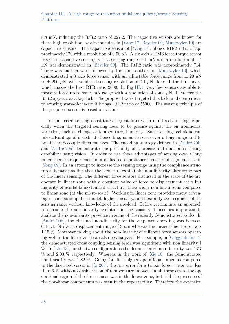
Chapter III. A high range-to-resolution multi-axis µForce/torque SensingPlatform
8.8 mN, inducing the RtR2 ratio of 227.2. The capacitive sensors are known forthere high resolution, works included in [Yang 17, Beyeler 09, Muntwyler 10] arecapacitive sensors. The capacitive sensor of [Yang 17], allows RtR2 ratio of ap-proximately 170 with a resolution of 0.58 µN. A six axis MEMS force-torque sensorbased on capacitive sensing with a sensing range of 1 mN and a resolution of 1.4µN was demonstrated in [Beyeler 09]. The RtR2 ratio was approximately 714.There was another work followed by the same authors in [Muntwyler 10], whichdemonstrated a 3 axis force sensor with an adjustable force range from ± 20 µNto ± 200 µN, with validated sensing resolution of 0.1 µN along all the three axes,which makes the best RTR ratio 2000. In Fig III.1, very few sensors are able tomeasure force up to some mN range with a resolution of some µN. Therefore theRtR2 appears as a key lock. The proposed work targeted this lock, and comparisonto existing state-of-the-art it brings RtR2 ratio of 55000. The sensing principle ofthe proposed sensor is based on vision.
Vision based sensing constitutes a great interest in multi-axis sensing, espe-cially when the targeted sensing need to be precise against the environmentalvariation, such as change of temperature, humidity. Such sensing technique cantake advantage of a dedicated encoding, so as to sense over a long range and tobe able to decouple different axes. The encoding strategy defined in [André 20b]and [André 20a] demonstrate the possibility of a precise and multi-axis sensingcapability using vision. In order to use these advantages of sensing over a longrange there is requirement of a dedicated compliance structure design, such as in[Yong 09]. In an attempt to increase the sensing range using the compliance struc-tures, it may possible that the structure exhibit the non-linearity after some partof the linear sensing. The different force sensors discussed in the state-of-the-art,operate in linear zone with a constant value of force to displacement ratio butmajority of available mechanical structures have wider non-linear zone comparedto linear zone (at the micro-scale). Working in linear zone provides many advan-tages, such as simplified model, higher linearity, and flexibility over segment of thesensing range without knowledge of the pre-load. Before getting into an approachto consider the non-linearity evolution in the sensing, it becomes important toanalyze the non-linearity presence in some of the recently demonstrated works. In[André 20b], the obtained non-linearity for the employed encoding was between0.4-1.15 % over a displacement range of 9 µm whereas the measurement error was1.15 %. Moreover talking about the non-linearity of different force sensors operat-ing well in the linear zone can also be analyzed. For example, in [Guggenheim 17]the demonstrated cross coupling sensing error was significant with non linearity 1%. In [Liu 13], for the two configurations the demonstrated non-linearity was 1.57% and 2.03 % respectively. Whereas in the work of [Xie 16], the demonstratednon-linearity was 1.82 %. Going for little higher operational range as comparedto the discussed cases, in [Li 20c], the rms error for a triaxis force sensor was lessthan 3 % without consideration of temperature impact. In all these cases, the op-erational region of the force sensor was in the linear zone, but still the presence ofthe non-linear components was seen in the repeatability. Therefore the extension
48
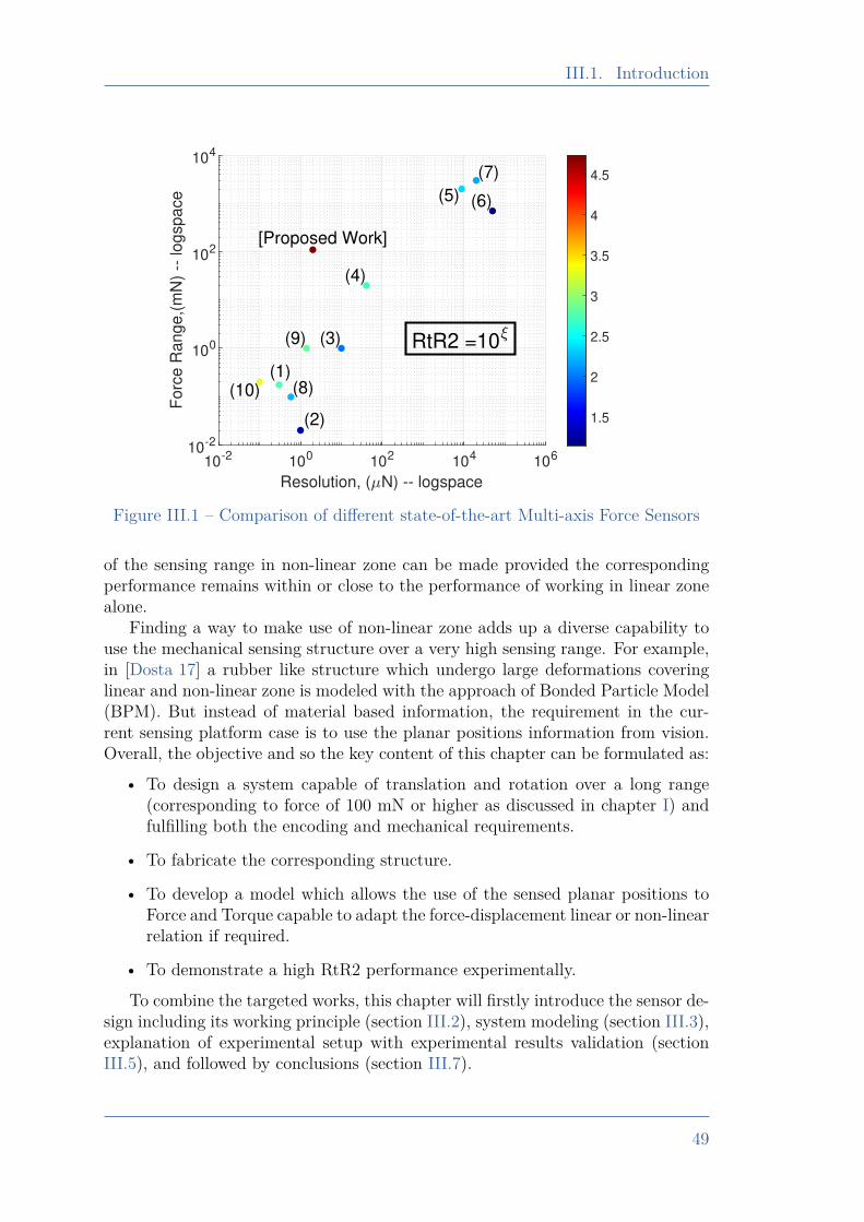
III.1. Introduction
10-2 100 102 104 106
Resolution, ( N) -- logspace
10-2
100
102
104
Fo
rce
Ra
ng
e,(
mN
) --
lo
gsp
ace
(1)
(2)
(3)
(4)
(5) (6)
(7)
(8)
(9)
(10)
[Proposed Work]
1.5
2
2.5
3
3.5
4
4.5
RtR2 =10
Figure III.1 – Comparison of different state-of-the-art Multi-axis Force Sensors
of the sensing range in non-linear zone can be made provided the correspondingperformance remains within or close to the performance of working in linear zonealone.
Finding a way to make use of non-linear zone adds up a diverse capability touse the mechanical sensing structure over a very high sensing range. For example,in [Dosta 17] a rubber like structure which undergo large deformations coveringlinear and non-linear zone is modeled with the approach of Bonded Particle Model(BPM). But instead of material based information, the requirement in the cur-rent sensing platform case is to use the planar positions information from vision.Overall, the objective and so the key content of this chapter can be formulated as:
• To design a system capable of translation and rotation over a long range(corresponding to force of 100 mN or higher as discussed in chapter I) andfulfilling both the encoding and mechanical requirements.
• To fabricate the corresponding structure.
• To develop a model which allows the use of the sensed planar positions toForce and Torque capable to adapt the force-displacement linear or non-linearrelation if required.
• To demonstrate a high RtR2 performance experimentally.
To combine the targeted works, this chapter will firstly introduce the sensor de-sign including its working principle (section III.2), system modeling (section III.3),explanation of experimental setup with experimental results validation (sectionIII.5), and followed by conclusions (section III.7).
49
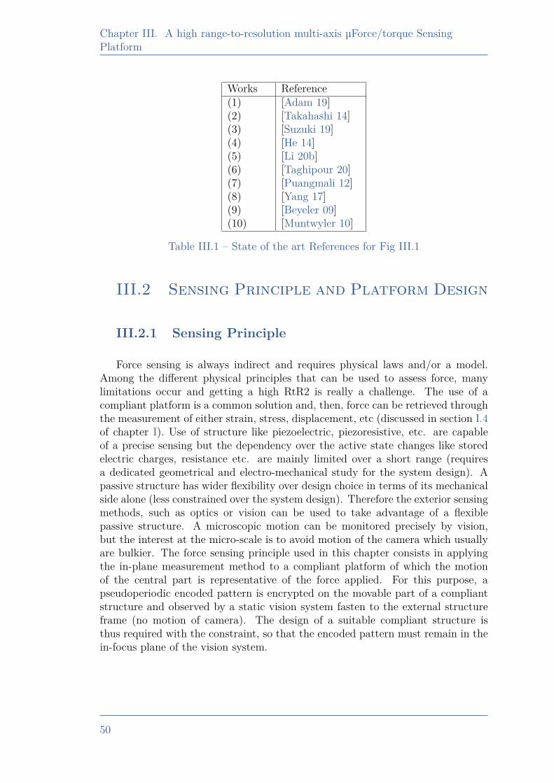
Chapter III. A high range-to-resolution multi-axis µForce/torque SensingPlatform
Works Reference(1) [Adam 19](2) [Takahashi 14](3) [Suzuki 19](4) [He 14](5) [Li 20b](6) [Taghipour 20](7) [Puangmali 12](8) [Yang 17](9) [Beyeler 09](10) [Muntwyler 10]
Table III.1 – State of the art References for Fig III.1
III.2 Sensing Principle and Platform Design
III.2.1 Sensing Principle
Force sensing is always indirect and requires physical laws and/or a model.Among the different physical principles that can be used to assess force, manylimitations occur and getting a high RtR2 is really a challenge. The use of acompliant platform is a common solution and, then, force can be retrieved throughthe measurement of either strain, stress, displacement, etc (discussed in section I.4of chapter I). Use of structure like piezoelectric, piezoresistive, etc. are capableof a precise sensing but the dependency over the active state changes like storedelectric charges, resistance etc. are mainly limited over a short range (requiresa dedicated geometrical and electro-mechanical study for the system design). Apassive structure has wider flexibility over design choice in terms of its mechanicalside alone (less constrained over the system design). Therefore the exterior sensingmethods, such as optics or vision can be used to take advantage of a flexiblepassive structure. A microscopic motion can be monitored precisely by vision,but the interest at the micro-scale is to avoid motion of the camera which usuallyare bulkier. The force sensing principle used in this chapter consists in applyingthe in-plane measurement method to a compliant platform of which the motionof the central part is representative of the force applied. For this purpose, apseudoperiodic encoded pattern is encrypted on the movable part of a compliantstructure and observed by a static vision system fasten to the external structureframe (no motion of camera). The design of a suitable compliant structure isthus required with the constraint, so that the encoded pattern must remain in thein-focus plane of the vision system.
50
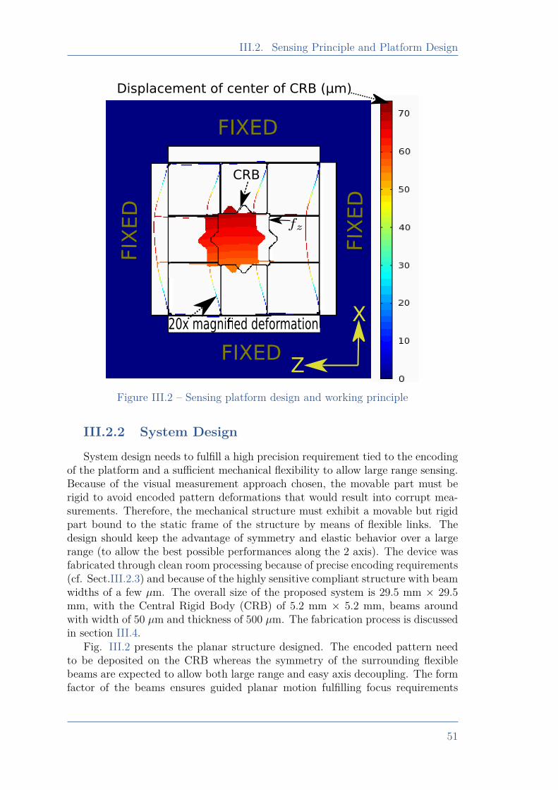
III.2. Sensing Principle and Platform Design
Z
X20x magni ed deformation
FIXED
Displacement of center of CRB (µm)
CRB
FIXEDFIX
ED
FIX
ED
Figure III.2 – Sensing platform design and working principle
III.2.2 System DesignSystem design needs to fulfill a high precision requirement tied to the encoding
of the platform and a sufficient mechanical flexibility to allow large range sensing.Because of the visual measurement approach chosen, the movable part must berigid to avoid encoded pattern deformations that would result into corrupt mea-surements. Therefore, the mechanical structure must exhibit a movable but rigidpart bound to the static frame of the structure by means of flexible links. Thedesign should keep the advantage of symmetry and elastic behavior over a largerange (to allow the best possible performances along the 2 axis). The device wasfabricated through clean room processing because of precise encoding requirements(cf. Sect.III.2.3) and because of the highly sensitive compliant structure with beamwidths of a few µm. The overall size of the proposed system is 29.5 mm × 29.5mm, with the Central Rigid Body (CRB) of 5.2 mm × 5.2 mm, beams aroundwith width of 50 µm and thickness of 500 µm. The fabrication process is discussedin section III.4.
Fig. III.2 presents the planar structure designed. The encoded pattern needto be deposited on the CRB whereas the symmetry of the surrounding flexiblebeams are expected to allow both large range and easy axis decoupling. The formfactor of the beams ensures guided planar motion fulfilling focus requirements
51
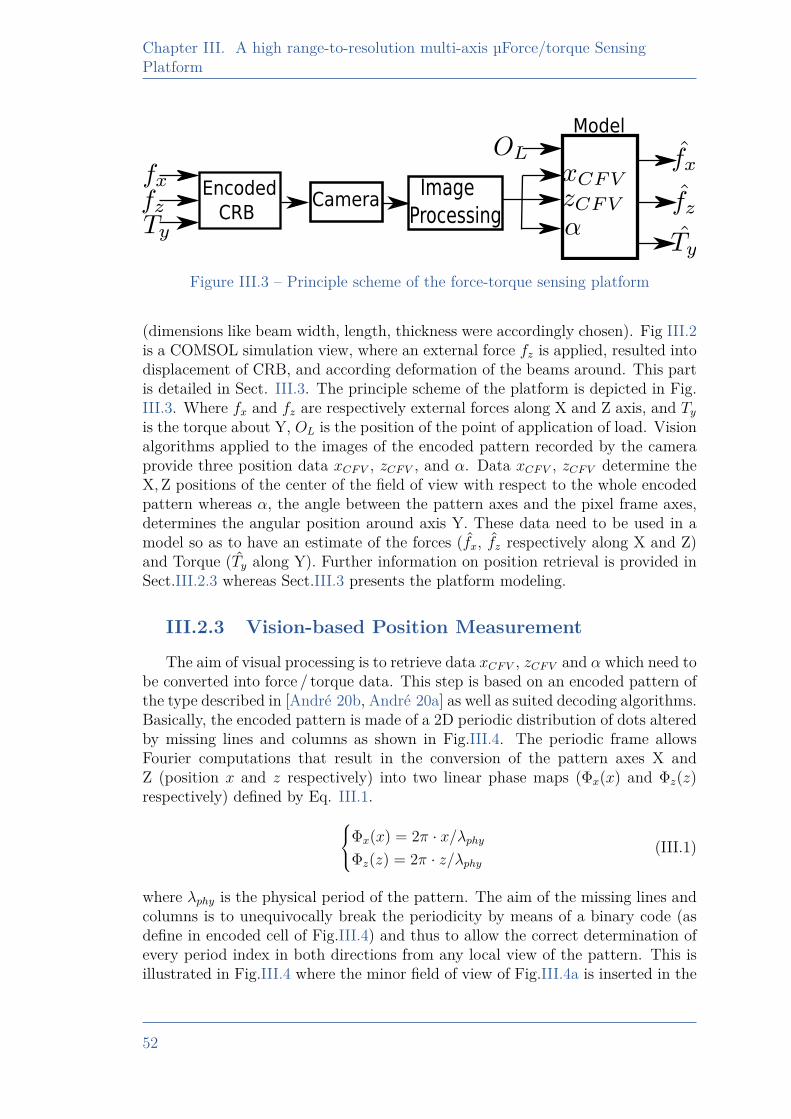
Chapter III. A high range-to-resolution multi-axis µForce/torque SensingPlatform
Encoded
CRBCamera
Image
Processing
Model
Figure III.3 – Principle scheme of the force-torque sensing platform
(dimensions like beam width, length, thickness were accordingly chosen). Fig III.2is a COMSOL simulation view, where an external force fz is applied, resulted intodisplacement of CRB, and according deformation of the beams around. This partis detailed in Sect. III.3. The principle scheme of the platform is depicted in Fig.III.3. Where fx and fz are respectively external forces along X and Z axis, and Tyis the torque about Y, OL is the position of the point of application of load. Visionalgorithms applied to the images of the encoded pattern recorded by the cameraprovide three position data xCFV , zCFV , and α. Data xCFV , zCFV determine theX, Z positions of the center of the field of view with respect to the whole encodedpattern whereas α, the angle between the pattern axes and the pixel frame axes,determines the angular position around axis Y. These data need to be used in amodel so as to have an estimate of the forces (fx, fz respectively along X and Z)and Torque (Ty along Y). Further information on position retrieval is provided inSect.III.2.3 whereas Sect.III.3 presents the platform modeling.
III.2.3 Vision-based Position MeasurementThe aim of visual processing is to retrieve data xCFV , zCFV and α which need to
be converted into force / torque data. This step is based on an encoded pattern ofthe type described in [André 20b, André 20a] as well as suited decoding algorithms.Basically, the encoded pattern is made of a 2D periodic distribution of dots alteredby missing lines and columns as shown in Fig.III.4. The periodic frame allowsFourier computations that result in the conversion of the pattern axes X andZ (position x and z respectively) into two linear phase maps (Φx(x) and Φz(z)respectively) defined by Eq. III.1.Φx(x) = 2π · x/λphy
Φz(z) = 2π · z/λphy(III.1)
where λphy is the physical period of the pattern. The aim of the missing lines andcolumns is to unequivocally break the periodicity by means of a binary code (asdefine in encoded cell of Fig.III.4) and thus to allow the correct determination ofevery period index in both directions from any local view of the pattern. This isillustrated in Fig.III.4 where the minor field of view of Fig.III.4a is inserted in the
52
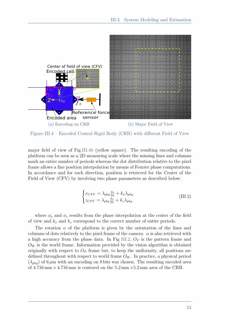
III.3. System Modeling and Estimation
X
Z
+
Reference force
sensorEncoded area
Encoded cell
Center of eld of view (CFV)
M
P
(a) Encoding on CRB (b) Major Field of View
Figure III.4 – Encoded Central Rigid Body (CRB) with different Field of View
major field of view of Fig.III.4b (yellow square). The resulting encoding of theplatform can be seen as a 2D measuring scale where the missing lines and columnsmark an entire number of periods whereas the dot distribution relative to the pixelframe allows a fine position interpolation by means of Fourier phase computations.In accordance and for each direction, position is retrieved for the Center of theField of View (CFV) by involving two phase parameters as described below:
xCFV = λphyφx
2π + kxλphy
zCFV = λphyφz
2π + kzλphy(III.2)
where φx and φz results from the phase interpolation at the center of the fieldof view and kx and kz correspond to the correct number of entire periods.
The rotation α of the platform is given by the orientation of the lines andcolumns of dots relatively to the pixel frame of the camera. α is also retrieved witha high accuracy from the phase data. In Fig III.2, OP is the pattern frame andOW is the world frame. Information provided by the vision algorithm is obtainedoriginally with respect to OP frame but, to keep the uniformity, all positions aredefined throughout with respect to world frame OW . In practice, a physical period(λphy) of 6µm with an encoding on 8 bits was chosen. The resulting encoded areaof 4.716mm× 4.716mm is centered on the 5.2mm×5.2mm area of the CRB.
53
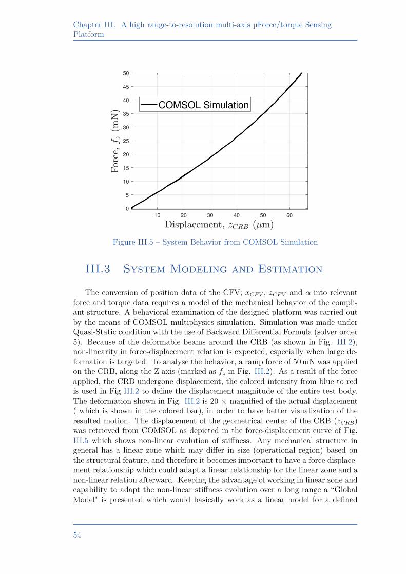
Chapter III. A high range-to-resolution multi-axis µForce/torque SensingPlatform
10 20 30 40 50 60
0
5
10
15
20
25
30
35
40
45
50
COMSOL Simulation
Figure III.5 – System Behavior from COMSOL Simulation
III.3 System Modeling and Estimation
The conversion of position data of the CFV; xCFV , zCFV and α into relevantforce and torque data requires a model of the mechanical behavior of the compli-ant structure. A behavioral examination of the designed platform was carried outby the means of COMSOL multiphysics simulation. Simulation was made underQuasi-Static condition with the use of Backward Differential Formula (solver order5). Because of the deformable beams around the CRB (as shown in Fig. III.2),non-linearity in force-displacement relation is expected, especially when large de-formation is targeted. To analyse the behavior, a ramp force of 50mN was appliedon the CRB, along the Z axis (marked as fz in Fig. III.2). As a result of the forceapplied, the CRB undergone displacement, the colored intensity from blue to redis used in Fig III.2 to define the displacement magnitude of the entire test body.The deformation shown in Fig. III.2 is 20 × magnified of the actual displacement( which is shown in the colored bar), in order to have better visualization of theresulted motion. The displacement of the geometrical center of the CRB (zCRB)was retrieved from COMSOL as depicted in the force-displacement curve of Fig.III.5 which shows non-linear evolution of stiffness. Any mechanical structure ingeneral has a linear zone which may differ in size (operational region) based onthe structural feature, and therefore it becomes important to have a force displace-ment relationship which could adapt a linear relationship for the linear zone and anon-linear relation afterward. Keeping the advantage of working in linear zone andcapability to adapt the non-linear stiffness evolution over a long range a “GlobalModel" is presented which would basically work as a linear model for a defined
54
III.3. System Modeling and Estimation
linear range and non-linear in non-linear zone of deformation. Extrapolation ofthe calculated stiffness from the linear zone is termed as a linear model and thedifference between linear and global model can then be analyzed.
The overall motion of the CFV results from a combined motion (translationand rotation). If the translations along the two axes are termed as dx and dz, alongX and Z axes respectively then the overall motions along the two axes is given byEq. III.3, where xI , zI are initial positions of the CFV along the respective axesand α is the rotation of the platform.xCFVzCFV
1
=
cosα − sinα dxsinα cosα dz
0 0 1
xIzI
1
(III.3)
As dx and dz, are pure translations, they directly depend on the forces fx and fzapplied along these two axes. The additional displacement component (resultedfrom rotation) is referred to as PI and is defined in Eq. III.5.
xCFVzCFV1
=
a1 cosα −a1 sinα 0a1 sinα a1 cosα 0
0 0 1
(fx
a2)rx
( fz
a2)rz
1
+ PI (III.4)
PI =
cosα − sinα 0sinα cosα 0
0 0 1
xIzI
1
(III.5)
The overall equation including forces fx, fz along the two axes and the ini-tial position component PI are shown in Eq. III.4. The variables rx and rz, arerepresentative of the linear or non-linear force-deformation relation. For instance,these variables should be unity for a linear relation and non-unity for a non-linearbehavior. Depending on the material properties of the deforming structure, thenon-linearity component needs to be adjusted in order to reflect the changing non-linear stiffness. The variables rx, and rz can be defined using Eq. III.6, where defis xCFV and zCFV respectively for defining r as rx and rz.
r = au(def)3 (III.6)
u(def) =0, if 0 ≤ def < d1
bi, if d1 ≤ def < di+1(III.7)
Function u(def) is defined in Eq. III.7 which facilitate the decision makingapproach by splitting the sensing range into sub-regions. di defines the boundariesbased on the displacements. In Eq. III.7, model is in linear region for def < d1,otherwise the system is in non-linear zone. i is the number of sub-regions in non-linear zone, for i = 1, system has only 1 region (between d1 and d2) in non-linear
55
Chapter III. A high range-to-resolution multi-axis µForce/torque SensingPlatform
zone. The force-displacement relation is defined linear for def < d1, therefore therespective algebraic powers (rx, and rz) for X and Z axis respectively must be 1in this region. When the system is in non-linear region then the rx, and rz shouldbe non-unity. But, there need to be a parameter independent of the respectivealgebraic powers (rx, and rz), so that an adequate scaling of stiffness can be realizedbetween linear and non-linear region. These parameters are respectively defined asa1 and a2. The parameter required to handle rx and rz throughout the operationalrange is a3, which is raised to zero algebraic power for linear region and non-zeropositive power for non-linear. Eq. III.7 defines the algebraic power of rx and rz,the respective intercept component in order to keep smooth computation is definedby Eq. III.8. If the non-linearity component is uniform, then only one value of bi,and ci with i = 1 is sufficient for a good force-displacement estimation. If not, thenon-linear region may be divided into several sub-regions to include the changesof the non-linearity component throughout the sensing range.
v(def) =0, if 0 ≤ def < d1
ci, if d1 ≤ def < di+1(III.8)
In the current case, the information available is the positions and orientationof the CFV, and the requirement is to estimate the forces and torque. ThereforeEq. III.4 can be inverted and written as Eq. III.9 for force estimate along X andZ, where tx, and tz are variables defined by Eq. III.10.fx = a2( tx−v(xCF V )
a1)( 1
rx)
fz = a2( tz−v(zCF V )a1
)( 1rz
) (III.9)
txtz1
=
cosα sinα −xI− sinα cosα −zI
0 0 1
xCFVzCFV
1
(III.10)
Considering the symmetry of the sensing platform, the mechanical parametersalong X and Z axes were considered equal. Therefore, the different mechanicalcoefficients formulated in terms of different parameters are considered same alongboth axes.
R =√x2L + z2
L (III.11)
T = feqRsinγ (III.12)
feq =√fx
2 + fz2 (III.13)
γ = tan−1 zLxL
+ tan−1 fz
fx(III.14)
56
III.4. Fabrication Process
The torque estimation (T can be defined as written in Eq. III.12) requires thedistance between the point of load application (xL, zL) and the center OW , this ismarked as R (Eq. III.11). Where, feq (Eq. III.13) is the overall force which makesan angle γ (Eq. III.14) with frame OW .
III.4 Fabrication Process
Silicon was chosen for the proposed sensing platform fabrication (Wafer size 5inch, thickness 500 µm). Because it is widespread, and enables to fabricate highaspect ratio beams. Also, its hookean nature with minimized energy dissipationand less fatigue behavior allows a high repeatability. The fabrication process wasstarted with a silicon-on-insulator (SOI) wafer with 1.2 µm SiO2 coating on bothside (Fig III.6). One side (along with side wall) of this coating was removed withBuffered Hydrofluoric Acid (BHF) etching by keeping the other side with a protec-tive resist. The negative resist was then deposited with a designed mask, followedby resist deposition for Deep Reaction Ion Etching (DRIE). This process was donefor the bottom and top side with deposition of Aluminium (electrode patterning)with the use of protective resist deposition in between. Finally, the etching ofaluminium was made followed by remaining residue cleaning with acetone andethanol respectively. As defined encoding in Fig III.4, each square was targeted tobe of 3 µm resulting into physical period of 6 µm. The fabrication result is shownin Fig III.7, the obtained encoded squares on the fabricated CRB was measured3.01 µm, resulting into less than 0.4 % fabrication error.
57
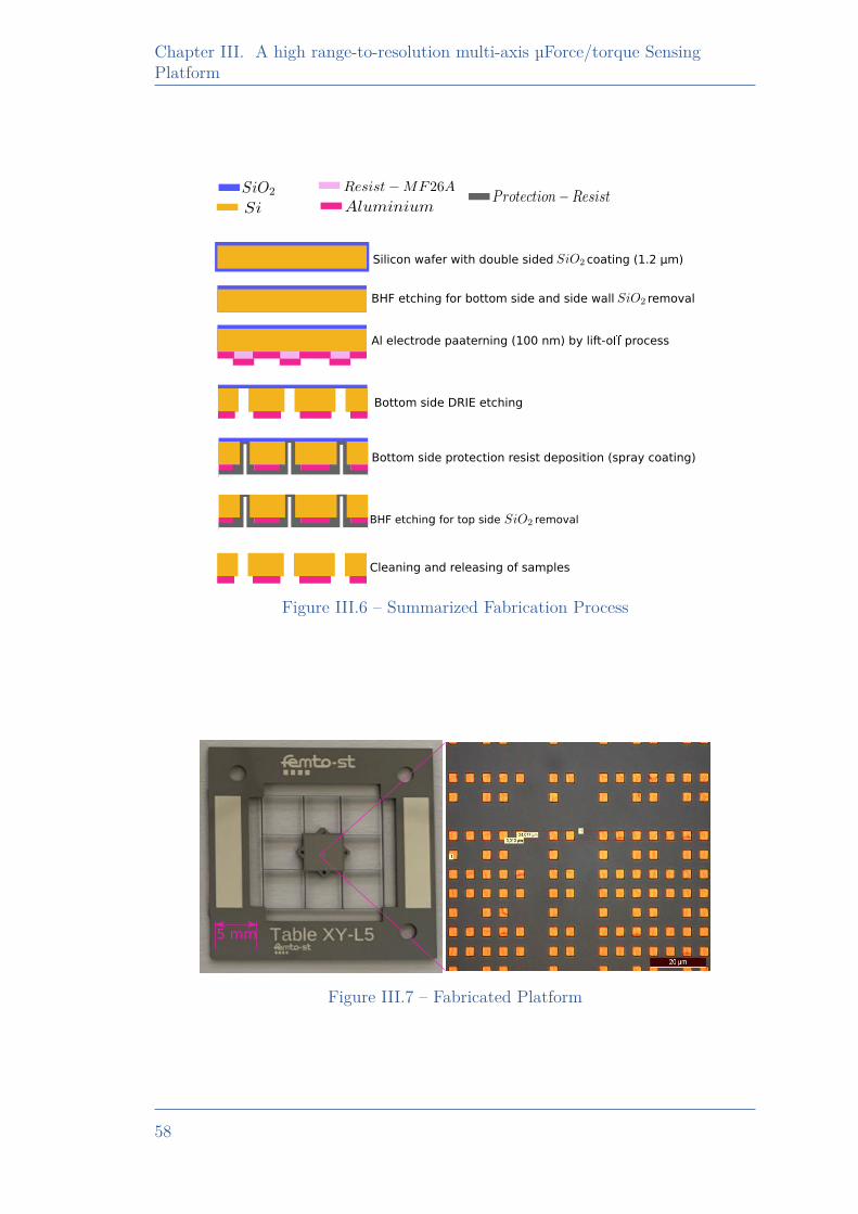
Chapter III. A high range-to-resolution multi-axis µForce/torque SensingPlatform
Silicon wafer with double sided coating (1.2 µm)
BHF etching for bottom side and side wall removal
Al electrode paaterning (100 nm) by lift-o process
Bottom side DRIE etching
Bottom side protection resist deposition (spray coating)
BHF etching for top side removal
Cleaning and releasing of samples
Figure III.6 – Summarized Fabrication Process
5 mm
Figure III.7 – Fabricated Platform
58
III.5. Experimental Works for Identification
III.5 Experimental Works for Identification
The experimental validation of the model requires the knowledge of the forceapplied. For this purpose, the force is applied along the Z axis of the CRB bymeans of a reference force sensor fastened to a 1D micro-positioner. The beamdeformations induced by micro-positioner displacements zPos result in displace-ments of the CRB which is measured by vision, and the force fz is synchronouslymeasured by the reference force sensor. In this way, force-displacement curves rep-resentative of the platform behavior can be recorded and used for the identificationof model’s parameters.
III.5.1 Principle and Setup
The experimental setup built includes 5 main components and is shown inFig. III.8. The platform is placed with its encoded plane facing a monitoringcamera. A reference force sensor; either a TEI FSB-101 with a 500 mN range ora FemtoTools FT-G102 sensing finger with a 250µN range is used, depending ona long range validation or resolution validation requirement. The reference forcesensor is attached with a M122.2DD micro-positioner from Physik Instrumente.The positioning of the reference sensor probe relatively to the platform is madewith the help of a side view camera. The cameras used are IDS USB 3 uEye CP,with a 20x magnification objective from Mitutoyo integrated with OPTEM ZOOM70 XL in the case of the pattern monitoring camera.
III.5.2 Experimental Results
Fig III.9a presents the load applied to the CRB of the platform where forcemeasured by the reference force sensor versus the displacement of the positioner isshown. zPos and fz are respectively the input displacement of the positioner andthe sensed force by the reference force sensor, which is used in the identificationprocess of the different parameters defined in the model (sampling rate of 0.408samples/sec). The resulting motions of the CRB are retrieved through the patternmonitoring camera and the vision algorithms. The results obtained are depictedin Fig III.9b, where the Z-X planar motion of CFV is shown, along with therotation of the platform. The obtained motion along X and the rotation is veryless compared to the force application direction (along Z).
III.5.3 Parameters Identification
The defined system parameters were identified using a non-linear least squaremethod to fit the reference force measured by the TEI force sensor. The functionsu(def) and v(def) for variables rx and rz (Eq. III.6 to Eq. III.8) define the non-linearregion behavior.
59
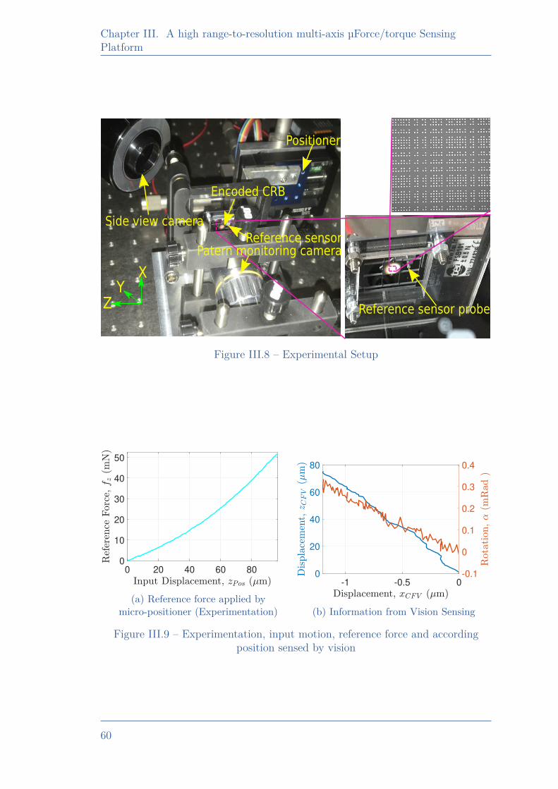
Chapter III. A high range-to-resolution multi-axis µForce/torque SensingPlatform
Encoded CRB
Positioner
Side view camera
Patern monitoring cameraReference sensor
Reference sensor probe
XY
Z
Figure III.8 – Experimental Setup
0 20 40 60 800
10
20
30
40
50
(a) Reference force applied bymicro-positioner (Experimentation)
-1 -0.5 00
20
40
60
80
-0.1
0
0.1
0.2
0.3
0.4
(b) Information from Vision Sensing
Figure III.9 – Experimentation, input motion, reference force and accordingposition sensed by vision
60
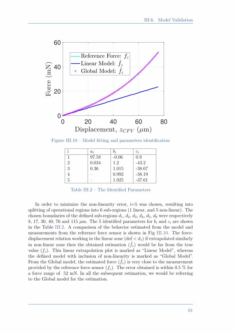
III.6. Model Validation
0 20 40 60 800
20
40
60
Figure III.10 – Model fitting and parameters identification
i ai bi ci1 97.58 -0.06 0.92 0.034 1.2 -43.23 0.36 1.015 -38.674 – 0.992 -38.195 – 1.025 -37.61
Table III.2 – The Identified Parameters
In order to minimize the non-linearity error, i=5 was chosen, resulting intosplitting of operational regions into 6 sub-regions (1 linear, and 5 non-linear). Thechosen boundaries of the defined sub-regions d1, d2, d3, d4, d5, d6 were respectively8, 17, 30, 40, 76 and 115 µm. The 5 identified parameters for bi and ci are shownin the Table III.2. A comparison of the behavior estimated from the model andmeasurements from the reference force sensor is shown in Fig III.10. The force-displacement relation working in the linear zone (def < d1) if extrapolated similarlyin non-linear zone then the obtained estimation (fz) would be far from the truevalue (fz). This linear extrapolation plot is marked as “Linear Model”, whereasthe defined model with inclusion of non-linearity is marked as “Global Model”.From the Global model, the estimated force (fz) is very close to the measurementprovided by the reference force sensor (fz). The error obtained is within 0.5 % fora force range of 52 mN. In all the subsequent estimation, we would be referringto the Global model for the estimation.
61
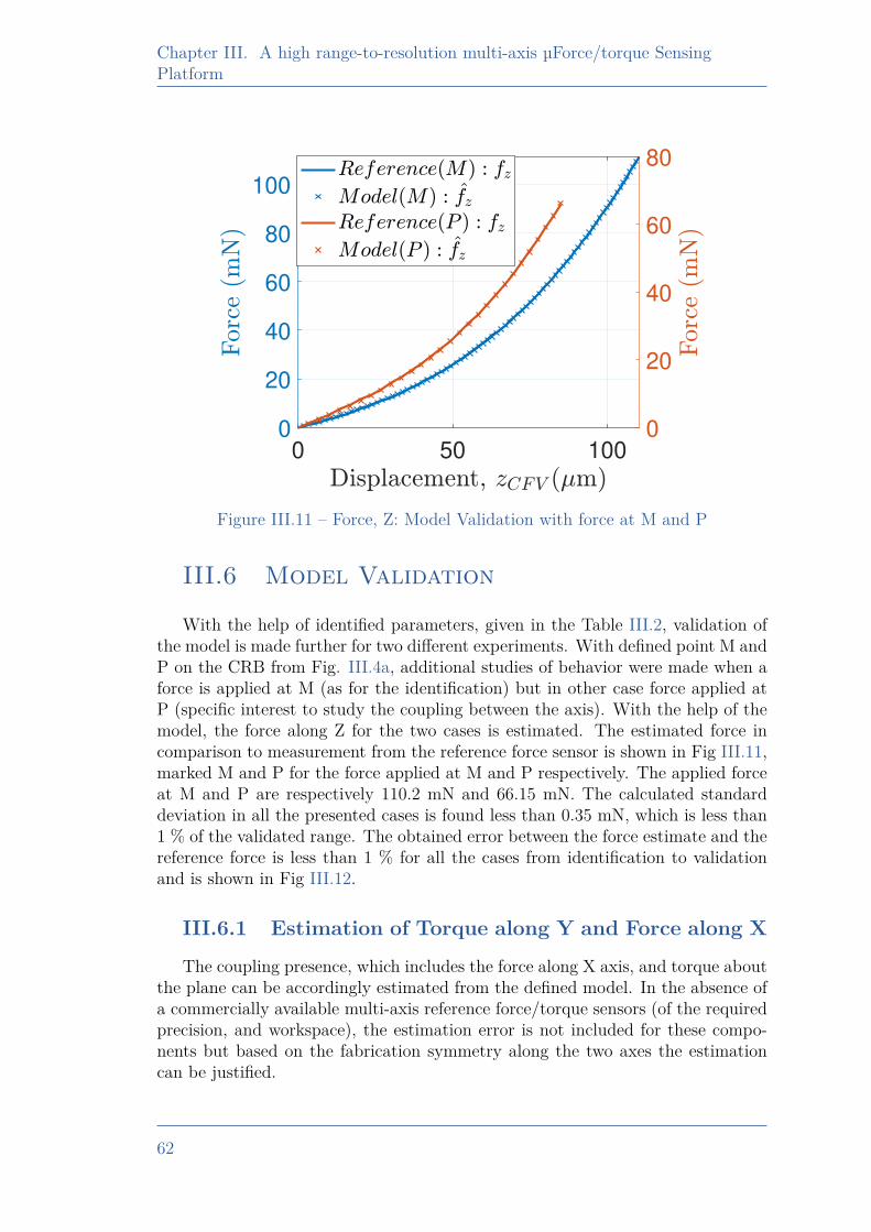
Chapter III. A high range-to-resolution multi-axis µForce/torque SensingPlatform
0 50 1000
20
40
60
80
100
0
20
40
60
80
Figure III.11 – Force, Z: Model Validation with force at M and P
III.6 Model Validation
With the help of identified parameters, given in the Table III.2, validation ofthe model is made further for two different experiments. With defined point M andP on the CRB from Fig. III.4a, additional studies of behavior were made when aforce is applied at M (as for the identification) but in other case force applied atP (specific interest to study the coupling between the axis). With the help of themodel, the force along Z for the two cases is estimated. The estimated force incomparison to measurement from the reference force sensor is shown in Fig III.11,marked M and P for the force applied at M and P respectively. The applied forceat M and P are respectively 110.2 mN and 66.15 mN. The calculated standarddeviation in all the presented cases is found less than 0.35 mN, which is less than1 % of the validated range. The obtained error between the force estimate and thereference force is less than 1 % for all the cases from identification to validationand is shown in Fig III.12.
III.6.1 Estimation of Torque along Y and Force along XThe coupling presence, which includes the force along X axis, and torque about
the plane can be accordingly estimated from the defined model. In the absence ofa commercially available multi-axis reference force/torque sensors (of the requiredprecision, and workspace), the estimation error is not included for these compo-nents but based on the fabrication symmetry along the two axes the estimationcan be justified.
62
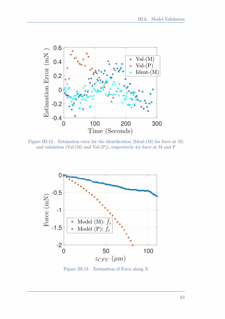
III.6. Model Validation
0 100 200 300-0.4
-0.2
0
0.2
0.4
0.6
Figure III.12 – Estimation error for the identification (Ident-(M) for force at M)and validation (Val-(M) and Val-(P)), respectively for force at M and P
0 50 100
-2
-1.5
-1
-0.5
0
Figure III.13 – Estimation of Force along X
63
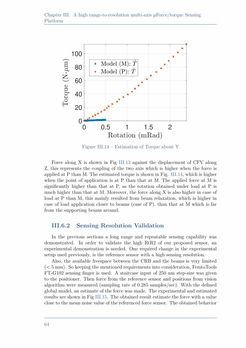
Chapter III. A high range-to-resolution multi-axis µForce/torque SensingPlatform
0 0.5 1 1.5 20
20
40
60
80
100
Figure III.14 – Estimation of Torque about Y
Force along X is shown in Fig III.13 against the displacement of CFV alongZ, this represents the coupling of the two axis which is higher when the force isapplied at P than M. The estimated torque is shown in Fig. III.14, which is higherwhen the point of application is at P than that at M. The applied force at M issignificantly higher than that at P, as the rotation obtained under load at P ismuch higher than that at M. Moreover, the force along X is also higher in case ofload at P than M, this mainly resulted from beam relaxation, which is higher incase of load application closer to beams (case of P), than that at M which is farfrom the supporting beams around.
III.6.2 Sensing Resolution Validation
In the previous sections a long range and repeatable sensing capability wasdemonstrated. In order to validate the high RtR2 of our proposed sensor, anexperimental demonstration is needed. One required change in the experimentalsetup used previously, is the reference sensor with a high sensing resolution.
Also, the available freespace between the CRB and the beams is very limited(< 5 mm). So keeping the mentioned requirements into consideration, FemtoToolsFT-G102 sensing finger is used. A staircase input of 250 nm step-size was givento the positioner. Then force from the reference sensor and positions from visionalgorithm were measured (sampling rate of 0.285 samples/sec). With the definedglobal model, an estimate of the force was made. The experimental and estimatedresults are shown in Fig III.15. The obtained result estimate the force with a valueclose to the mean noise value of the referenced force sensor. The obtained behavior
64
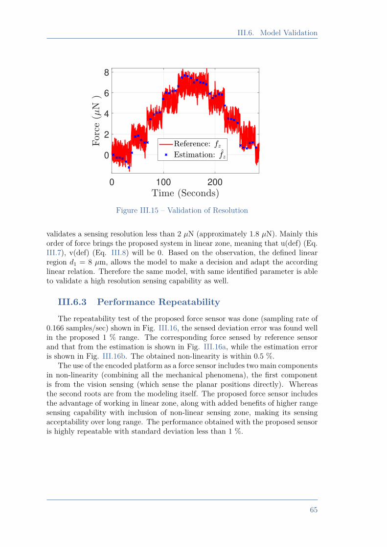
III.6. Model Validation
0 100 200
0
2
4
6
8
Figure III.15 – Validation of Resolution
validates a sensing resolution less than 2 µN (approximately 1.8 µN). Mainly thisorder of force brings the proposed system in linear zone, meaning that u(def) (Eq.III.7), v(def) (Eq. III.8) will be 0. Based on the observation, the defined linearregion d1 = 8 µm, allows the model to make a decision and adapt the accordinglinear relation. Therefore the same model, with same identified parameter is ableto validate a high resolution sensing capability as well.
III.6.3 Performance RepeatabilityThe repeatability test of the proposed force sensor was done (sampling rate of
0.166 samples/sec) shown in Fig. III.16, the sensed deviation error was found wellin the proposed 1 % range. The corresponding force sensed by reference sensorand that from the estimation is shown in Fig. III.16a, while the estimation erroris shown in Fig. III.16b. The obtained non-linearity is within 0.5 %.
The use of the encoded platform as a force sensor includes two main componentsin non-linearity (combining all the mechanical phenomena), the first componentis from the vision sensing (which sense the planar positions directly). Whereasthe second roots are from the modeling itself. The proposed force sensor includesthe advantage of working in linear zone, along with added benefits of higher rangesensing capability with inclusion of non-linear sensing zone, making its sensingacceptability over long range. The performance obtained with the proposed sensoris highly repeatable with standard deviation less than 1 %.
65
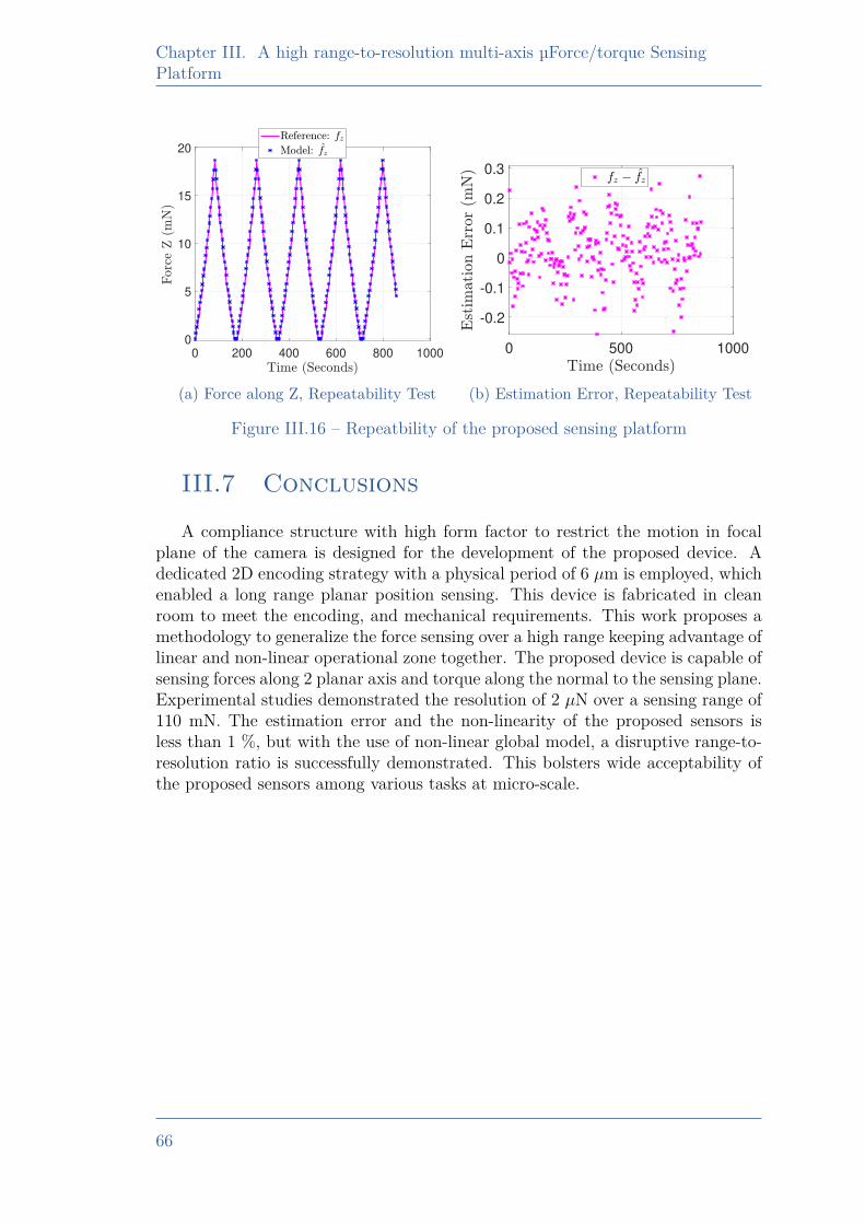
Chapter III. A high range-to-resolution multi-axis µForce/torque SensingPlatform
0 200 400 600 800 1000
0
5
10
15
20
(a) Force along Z, Repeatability Test
0 500 1000
-0.2
-0.1
0
0.1
0.2
0.3
(b) Estimation Error, Repeatability Test
Figure III.16 – Repeatbility of the proposed sensing platform
III.7 Conclusions
A compliance structure with high form factor to restrict the motion in focalplane of the camera is designed for the development of the proposed device. Adedicated 2D encoding strategy with a physical period of 6 µm is employed, whichenabled a long range planar position sensing. This device is fabricated in cleanroom to meet the encoding, and mechanical requirements. This work proposes amethodology to generalize the force sensing over a high range keeping advantage oflinear and non-linear operational zone together. The proposed device is capable ofsensing forces along 2 planar axis and torque along the normal to the sensing plane.Experimental studies demonstrated the resolution of 2 µN over a sensing range of110 mN. The estimation error and the non-linearity of the proposed sensors isless than 1 %, but with the use of non-linear global model, a disruptive range-to-resolution ratio is successfully demonstrated. This bolsters wide acceptability ofthe proposed sensors among various tasks at micro-scale.
66

Chapter IVA 2-Axis Piezoresistive Force Sensing
Tool
IV.1 Introduction . . . . . . . . . . . . . . . . . . . . . . . . . . . . . . . . . . . . . . . . . . . . 68IV.2 Sensing Principle and Design . . . . . . . . . . . . . . . . . . . . . . . . . . . 69
IV.2.1 Sensing Principle . . . . . . . . . . . . . . . . . . . . . . . . . . . . . . . . . . 69IV.2.2 System Design . . . . . . . . . . . . . . . . . . . . . . . . . . . . . . . . . . . . 71IV.2.3 System Working. . . . . . . . . . . . . . . . . . . . . . . . . . . . . . . . . . . 71
IV.3 System analysis in COMSOL . . . . . . . . . . . . . . . . . . . . . . . . . . . . 75IV.3.1 Modeling of the system for Stress/Strain Estimation . . . . 77IV.3.2 Electrical Connectivity and Gauge Factor Calculation . . . 79
IV.4 Device Fabrication and Assembly process . . . . . . . . . . . . . . . . 81IV.4.1 Fabrication of the Passive Tool . . . . . . . . . . . . . . . . . . . . . . 81IV.4.2 Fabrication of the Cavalier . . . . . . . . . . . . . . . . . . . . . . . . . . 81
IV.5 Assembly Process. . . . . . . . . . . . . . . . . . . . . . . . . . . . . . . . . . . . . . . 83IV.6 Experimental Studies . . . . . . . . . . . . . . . . . . . . . . . . . . . . . . . . . . . 85
IV.6.1 Experimental Setup. . . . . . . . . . . . . . . . . . . . . . . . . . . . . . . . 85IV.6.2 Behavior under no load. . . . . . . . . . . . . . . . . . . . . . . . . . . . . 86IV.6.3 Characterization for load along Y axis . . . . . . . . . . . . . . . . 88IV.6.4 Characterization for load along Z axis . . . . . . . . . . . . . . . . 91IV.6.5 Gauge Factor and Sensitivity analysis. . . . . . . . . . . . . . . . . 93
IV.7 Conclusions . . . . . . . . . . . . . . . . . . . . . . . . . . . . . . . . . . . . . . . . . . . . 96
67
Chapter IV. A 2-Axis Piezoresistive Force Sensing Tool
IV.1 Introduction
With a wide requirement of multi-axis local states knowledge in the differentmicro-scale tasks like rotation, gluing etc. (as discussed in Chapter I and II), thereis potential requirement of multi-axis instrumentation. Chapter III, presented amulti-axis sensing platform which demonstrated a high range to resolution sensingcapability. In this chapter, the instrumentation of a tool for multi-axis force sens-ing is targeted. The multi-DoF of force sensing can bring a diverse task handlingcapability, but in the case where sensor is external to the interacting tool, then thecorresponding frames (tool and sensor’s frame) must need to be suitably positionedso as to be in convenient sensing range. Also, such sensors require free-space be-tween the sensor and the tool of interest (e.g. laser or vision based sensor etc.). Toaddress this key issue, there is requirement of instrumented tools/grippers capableof multi-DoF force/position sensing. Instrumented tool allows the measurement(within its calibrated range) without its dependency over specific positioning as inthe case of external sensors, therefore strengthening an optimized use of work-spacefor varieties of tasks.
There are different possible approaches to measure the forces (as discussed inChapter I), and specific state can be used to define the sensing principle based onthe requirements. In this work, a 2-axis force sensing tool is presented which workson piezoresistive principle. The key interest to use the piezoresistive sensors is inprecise sensing capability that may be used over a long measurement range. Indeedthe disadvantage remains in its sensitivity to environmental changes such as fromtemperature and humidity. But, for the use where the temperature and humiditychanges are not significant (as defined with temperature coefficient of the mate-rial chosen), then the piezoresistive sensor becomes a preferable candidate. Theproposed tool can be integrated with the appropriate actuator to perform varietyof tasks at micro-scale (like characterization of tissues and fiber as discussed inChapter I), but can also be used for the development of microgripper (discussed inChapter V). The sensing tool development constitutes of assembly of a passive tooland two sensing devices (cavalier). The separate fabrication of the devices (pas-sive tool and sensing device) insures use of dedicated process individually, whichminimizes the fabrication complexity for the devices (sensing device in particular).Moreover, the sensing devices can be assembled with varieties of passive tools toperform different tasks, therefore giving its wide acceptability for different require-ments. This chapter starts with the discussions on sensing principle, system designand working (section IV.2), thereafter FEM analysis of the device is presented insection IV.3. Based on the proposed design, fabrication process of the devices,their assembly to develop the sensing tool is discussed in section IV.4. The devel-oped sensing tool performance especially when there is no any external forces, andwhen the force is applied along specific sensing axis is experimentally studied andthe corresponding characterization works are presented in section IV.6. Finally,conclusion of the presented works in this chapter is discussed in section IV.7.
68
IV.2. Sensing Principle and Design
IV.2 Sensing Principle and Design
In this section, the sensing principle and the design of the system is discussed.The key phenomenon includes, the physical change detection in terms of the re-sistance change and mapping of the detected change in terms of force change.This work was done in collaboration with CITHADEL [CITHADEL 19] projectwhich also targeted piezoresistive based force sensor development for mechanicalcharacterization of surfaces at the micro-scale.
IV.2.1 Sensing Principle
Any structure in general, which allows the passage of electric current exhibitssome finite resistance, or in other case it would be a pure insulator. The differentcategories possible in terms of the materials conductivity defines the material assemiconductor, conductor or a super-conductor (where electrical resistance van-ishes with the introduction to magnetic behavior).
R = ρL
A(IV.1)
Eq. IV.1 defines a general equation of resistance R, dependency over resistivityρ, length L and cross section area A of any conductive structure as shown in Fig.IV.1. So, the resistance of the structure is dependent on the geometry, and thematerial property. In order to use any conductive structure as a piezoresistivetransducer, the key factors needed are the mechanical reversability (more particu-larly elasticity), change of electrical resistance and the resistance change detectioncircuit such as a wheatstone bridge. The resistance change is not solely depen-dent on the geometry, or the resistivity, but also on the temperature. Based onthe choice of material there is a parameter called “temperature coefficient”, whichdefines the dependency of resistance on the temperature. This dependency couldbe constant, or linear in certain temperature range or non-linear. So, in order touse any conductive-mechanical structure as a piezoresistive transducer, the devicemust need to have stable behavior within the operating temperature. This ensuresthat the significant resistance change comes from the mechanical stress, not fromthe small fluctuation in the temperature (or humidity which is indirectly linked).Therefore the temperature dependent element is not included in the definition ofresistance in Eq. IV.1. The following discussions in this chapter will only con-sider the pure piezoresistive effect, which constitutes the impact of external forcetowards change in electrical resistance.
The change of resistance (∆R) can be written in relation with Poisson’s coef-ficient ν, strain ε, and resistivity change ∆ρ as in Eq. IV.2.
∆RR
= Gε where G = 1 + 2ν + ∆ρερ
(IV.2)
69

Chapter IV. A 2-Axis Piezoresistive Force Sensing Tool
V L
A
Figure IV.1 – Resistance dependency on Geometry
G written as in Eq. IV.2 defines the resistance change sensitivity and is calledGauge factor. In [Greaves 11], change of Poisson’s ratio (ν) under the strainfor different types of material is discussed. In context of macroscopic isotropicmaterials, for extremely compressible material like foam, ν can go negative up to-1, whereas for material like rubber it can reach maximum value of 0.5. Therefore,the dependency over the geometrical parameter to improve the sensitivity is verylimited in isotropic materials. For anisotropic materials, although there is nosuch limits but the possible variation of ν is not very significant [McCarthy 14]and so in defining the Gauge factor (G). Therefore the sensitivity needs to beseen on other dependent factor which is the resistivity of material. Conventionalmetal strain sensors typically enable a gauge factor of 2-5, but metal grid strainsensors based on all-solution process can exhibit also a high gauge factor (4685.9in [Oh 18]). A further higher gauge factor can be obtained with the approachof “crack propogation”. Cracks can be introduced in the transverse direction ofapplied stress, especially in the case of plasma treated polymers. The introducedcracks lower the conduction and so resulting into increase of electrical resistance.Such an approach based on crack depth is discussed in [Park 16], where a very highgauge factor of 16000 was demonstrated. The use of Pt and Au films in the “crackpropogation” approach lacks stretchability (typically < 2 %). In the context ofmicromanipulation tasks the factor like stretchability, linearity and repeatabilityare highly important. A high gauge factor may have a very poor stretchability,and therefore need to be considered before the sensor development. Semiconductorlike silicon can provide an interesting trade-off between the gauge factor (up to200) and stretchability (> 10 % possible) which can be tuned[Yang 13] based onthe substrate modulus. For these discussed reasons along with considerations interms of fabrication complexity and costs, the proposed work used p-type siliconfor the piezoresistive sensing tool fabrication.
70
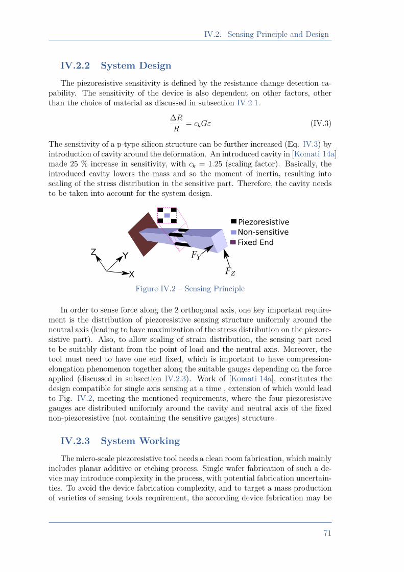
IV.2. Sensing Principle and Design
IV.2.2 System DesignThe piezoresistive sensitivity is defined by the resistance change detection ca-
pability. The sensitivity of the device is also dependent on other factors, otherthan the choice of material as discussed in subsection IV.2.1.
∆RR
= ckGε (IV.3)
The sensitivity of a p-type silicon structure can be further increased (Eq. IV.3) byintroduction of cavity around the deformation. An introduced cavity in [Komati 14a]made 25 % increase in sensitivity, with ck = 1.25 (scaling factor). Basically, theintroduced cavity lowers the mass and so the moment of inertia, resulting intoscaling of the stress distribution in the sensitive part. Therefore, the cavity needsto be taken into account for the system design.
X
YZ
Piezoresistive
Non-sensitive
Fixed End
Figure IV.2 – Sensing Principle
In order to sense force along the 2 orthogonal axis, one key important require-ment is the distribution of piezoresistive sensing structure uniformly around theneutral axis (leading to have maximization of the stress distribution on the piezore-sistive part). Also, to allow scaling of strain distribution, the sensing part needto be suitably distant from the point of load and the neutral axis. Moreover, thetool must need to have one end fixed, which is important to have compression-elongation phenomenon together along the suitable gauges depending on the forceapplied (discussed in subsection IV.2.3). Work of [Komati 14a], constitutes thedesign compatible for single axis sensing at a time , extension of which would leadto Fig. IV.2, meeting the mentioned requirements, where the four piezoresistivegauges are distributed uniformly around the cavity and neutral axis of the fixednon-piezoresistive (not containing the sensitive gauges) structure.
IV.2.3 System WorkingThe micro-scale piezoresistive tool needs a clean room fabrication, which mainly
includes planar additive or etching process. Single wafer fabrication of such a de-vice may introduce complexity in the process, with potential fabrication uncertain-ties. To avoid the device fabrication complexity, and to target a mass productionof varieties of sensing tools requirement, the according device fabrication may be
71
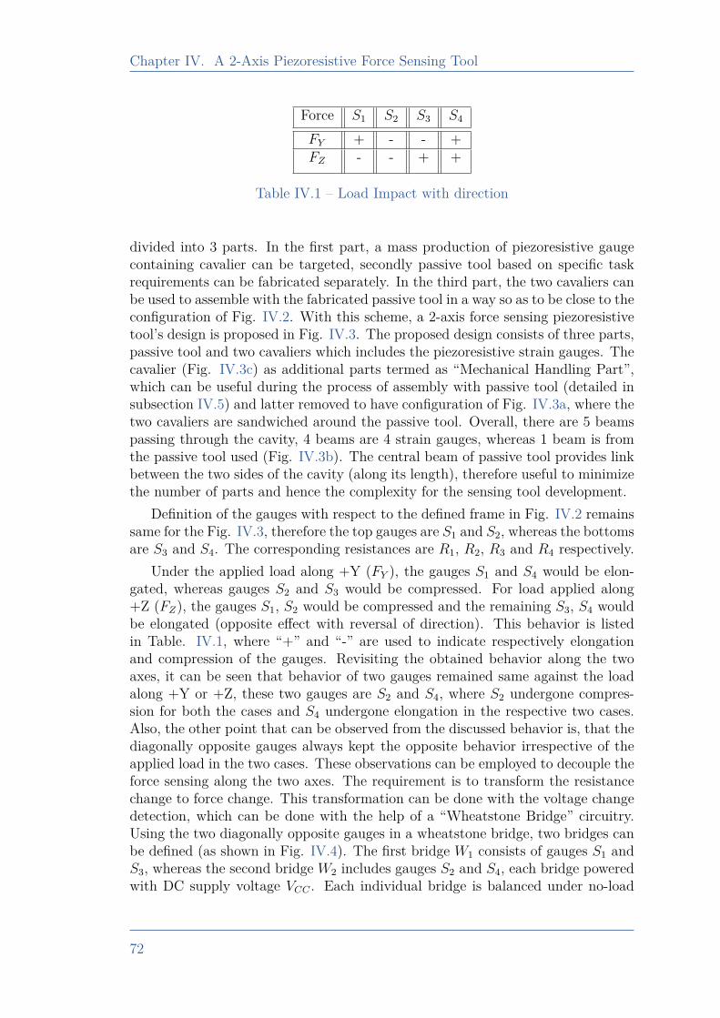
Chapter IV. A 2-Axis Piezoresistive Force Sensing Tool
Force S1 S2 S3 S4
FY + - - +FZ - - + +
Table IV.1 – Load Impact with direction
divided into 3 parts. In the first part, a mass production of piezoresistive gaugecontaining cavalier can be targeted, secondly passive tool based on specific taskrequirements can be fabricated separately. In the third part, the two cavaliers canbe used to assemble with the fabricated passive tool in a way so as to be close to theconfiguration of Fig. IV.2. With this scheme, a 2-axis force sensing piezoresistivetool’s design is proposed in Fig. IV.3. The proposed design consists of three parts,passive tool and two cavaliers which includes the piezoresistive strain gauges. Thecavalier (Fig. IV.3c) as additional parts termed as “Mechanical Handling Part”,which can be useful during the process of assembly with passive tool (detailed insubsection IV.5) and latter removed to have configuration of Fig. IV.3a, where thetwo cavaliers are sandwiched around the passive tool. Overall, there are 5 beamspassing through the cavity, 4 beams are 4 strain gauges, whereas 1 beam is fromthe passive tool used (Fig. IV.3b). The central beam of passive tool provides linkbetween the two sides of the cavity (along its length), therefore useful to minimizethe number of parts and hence the complexity for the sensing tool development.
Definition of the gauges with respect to the defined frame in Fig. IV.2 remainssame for the Fig. IV.3, therefore the top gauges are S1 and S2, whereas the bottomsare S3 and S4. The corresponding resistances are R1, R2, R3 and R4 respectively.
Under the applied load along +Y (FY ), the gauges S1 and S4 would be elon-gated, whereas gauges S2 and S3 would be compressed. For load applied along+Z (FZ), the gauges S1, S2 would be compressed and the remaining S3, S4 wouldbe elongated (opposite effect with reversal of direction). This behavior is listedin Table. IV.1, where “+” and “-” are used to indicate respectively elongationand compression of the gauges. Revisiting the obtained behavior along the twoaxes, it can be seen that behavior of two gauges remained same against the loadalong +Y or +Z, these two gauges are S2 and S4, where S2 undergone compres-sion for both the cases and S4 undergone elongation in the respective two cases.Also, the other point that can be observed from the discussed behavior is, that thediagonally opposite gauges always kept the opposite behavior irrespective of theapplied load in the two cases. These observations can be employed to decouple theforce sensing along the two axes. The requirement is to transform the resistancechange to force change. This transformation can be done with the voltage changedetection, which can be done with the help of a “Wheatstone Bridge” circuitry.Using the two diagonally opposite gauges in a wheatstone bridge, two bridges canbe defined (as shown in Fig. IV.4). The first bridge W1 consists of gauges S1 andS3, whereas the second bridge W2 includes gauges S2 and S4, each bridge poweredwith DC supply voltage VCC . Each individual bridge is balanced under no-load
72
IV.2. Sensing Principle and Design
XYZ
Cavalier
Passive ToolPCB
(a) Assembled sensing tool
(b) Exploded view of assembly
Electrodes
Piezoresistive gauges
Mechanical handling part
(to be removed)
Electrodes
1.7 mm
(c) Cavalier with electrodes and additionalhandling part
Figure IV.3 – Proposed design of the sensing tool
73
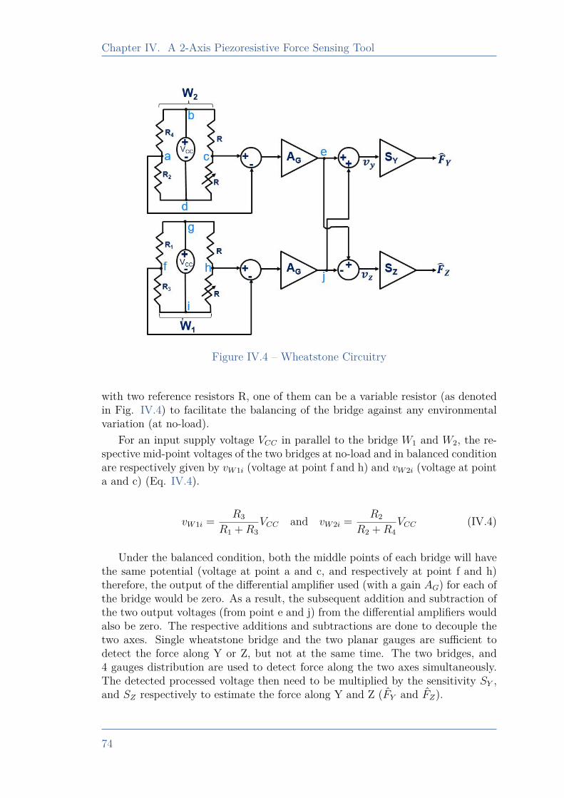
Chapter IV. A 2-Axis Piezoresistive Force Sensing Tool
Figure IV.4 – Wheatstone Circuitry
with two reference resistors R, one of them can be a variable resistor (as denotedin Fig. IV.4) to facilitate the balancing of the bridge against any environmentalvariation (at no-load).
For an input supply voltage VCC in parallel to the bridge W1 and W2, the re-spective mid-point voltages of the two bridges at no-load and in balanced conditionare respectively given by vW1i (voltage at point f and h) and vW2i (voltage at pointa and c) (Eq. IV.4).
vW1i = R3
R1 +R3VCC and vW2i = R2
R2 +R4VCC (IV.4)
Under the balanced condition, both the middle points of each bridge will havethe same potential (voltage at point a and c, and respectively at point f and h)therefore, the output of the differential amplifier used (with a gain AG) for each ofthe bridge would be zero. As a result, the subsequent addition and subtraction ofthe two output voltages (from point e and j) from the differential amplifiers wouldalso be zero. The respective additions and subtractions are done to decouple thetwo axes. Single wheatstone bridge and the two planar gauges are sufficient todetect the force along Y or Z, but not at the same time. The two bridges, and4 gauges distribution are used to detect force along the two axes simultaneously.The detected processed voltage then need to be multiplied by the sensitivity SY ,and SZ respectively to estimate the force along Y and Z (FY and FZ).
74
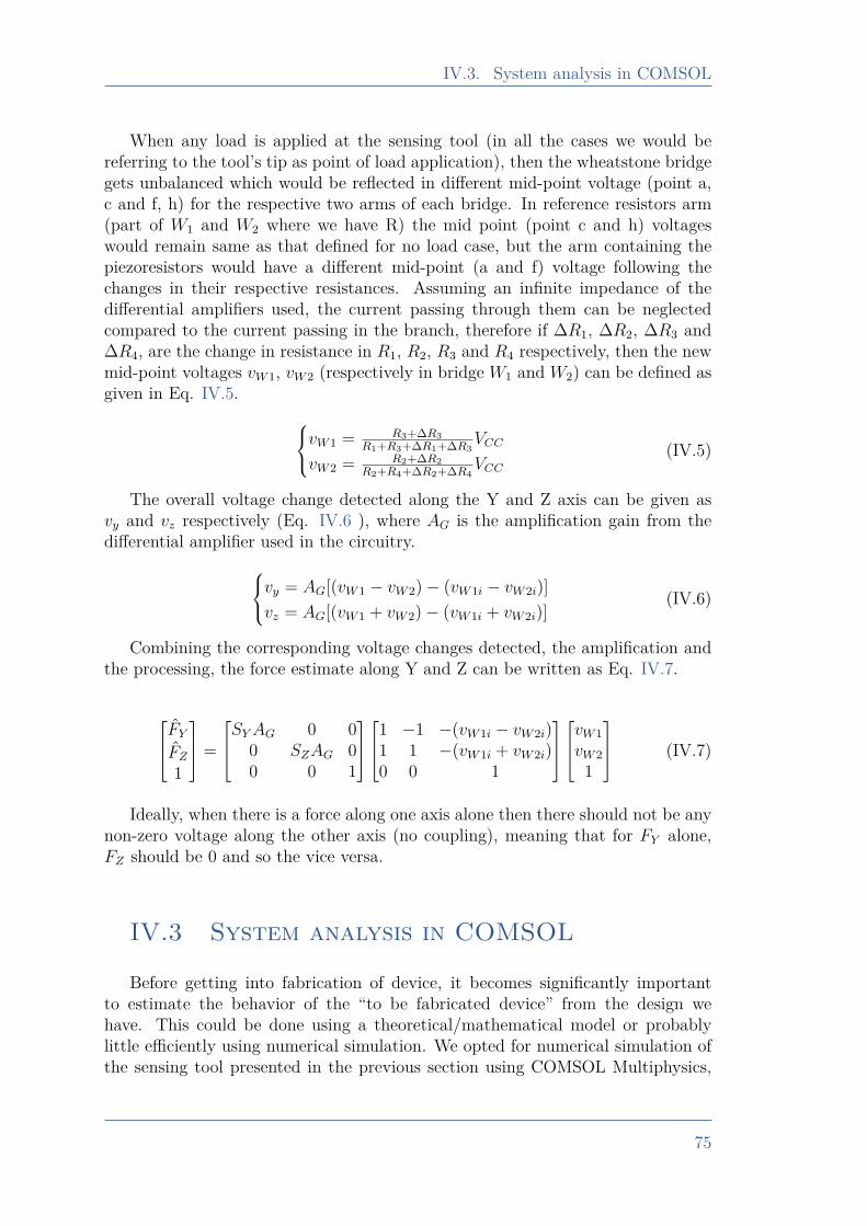
IV.3. System analysis in COMSOL
When any load is applied at the sensing tool (in all the cases we would bereferring to the tool’s tip as point of load application), then the wheatstone bridgegets unbalanced which would be reflected in different mid-point voltage (point a,c and f, h) for the respective two arms of each bridge. In reference resistors arm(part of W1 and W2 where we have R) the mid point (point c and h) voltageswould remain same as that defined for no load case, but the arm containing thepiezoresistors would have a different mid-point (a and f) voltage following thechanges in their respective resistances. Assuming an infinite impedance of thedifferential amplifiers used, the current passing through them can be neglectedcompared to the current passing in the branch, therefore if ∆R1, ∆R2, ∆R3 and∆R4, are the change in resistance in R1, R2, R3 and R4 respectively, then the newmid-point voltages vW1, vW2 (respectively in bridge W1 and W2) can be defined asgiven in Eq. IV.5. vW1 = R3+∆R3
R1+R3+∆R1+∆R3VCC
vW2 = R2+∆R2R2+R4+∆R2+∆R4
VCC(IV.5)
The overall voltage change detected along the Y and Z axis can be given asvy and vz respectively (Eq. IV.6 ), where AG is the amplification gain from thedifferential amplifier used in the circuitry.vy = AG[(vW1 − vW2)− (vW1i − vW2i)]
vz = AG[(vW1 + vW2)− (vW1i + vW2i)](IV.6)
Combining the corresponding voltage changes detected, the amplification andthe processing, the force estimate along Y and Z can be written as Eq. IV.7.
FYFZ1
=
SYAG 0 00 SZAG 00 0 1
1 −1 −(vW1i − vW2i)
1 1 −(vW1i + vW2i)0 0 1
vW1vW2
1
(IV.7)
Ideally, when there is a force along one axis alone then there should not be anynon-zero voltage along the other axis (no coupling), meaning that for FY alone,FZ should be 0 and so the vice versa.
IV.3 System analysis in COMSOL
Before getting into fabrication of device, it becomes significantly importantto estimate the behavior of the “to be fabricated device” from the design wehave. This could be done using a theoretical/mathematical model or probablylittle efficiently using numerical simulation. We opted for numerical simulation ofthe sensing tool presented in the previous section using COMSOL Multiphysics,
75
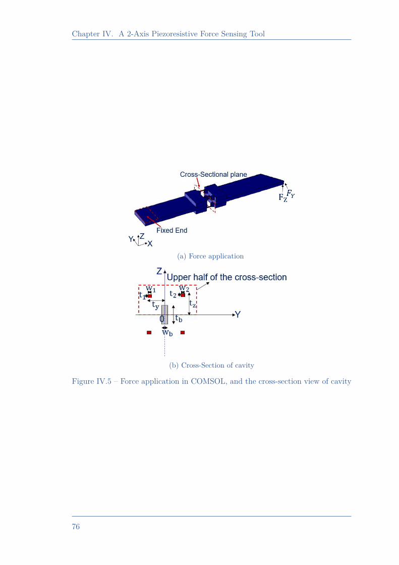
Chapter IV. A 2-Axis Piezoresistive Force Sensing Tool
(a) Force application
(b) Cross-Section of cavity
Figure IV.5 – Force application in COMSOL, and the cross-section view of cavity
76
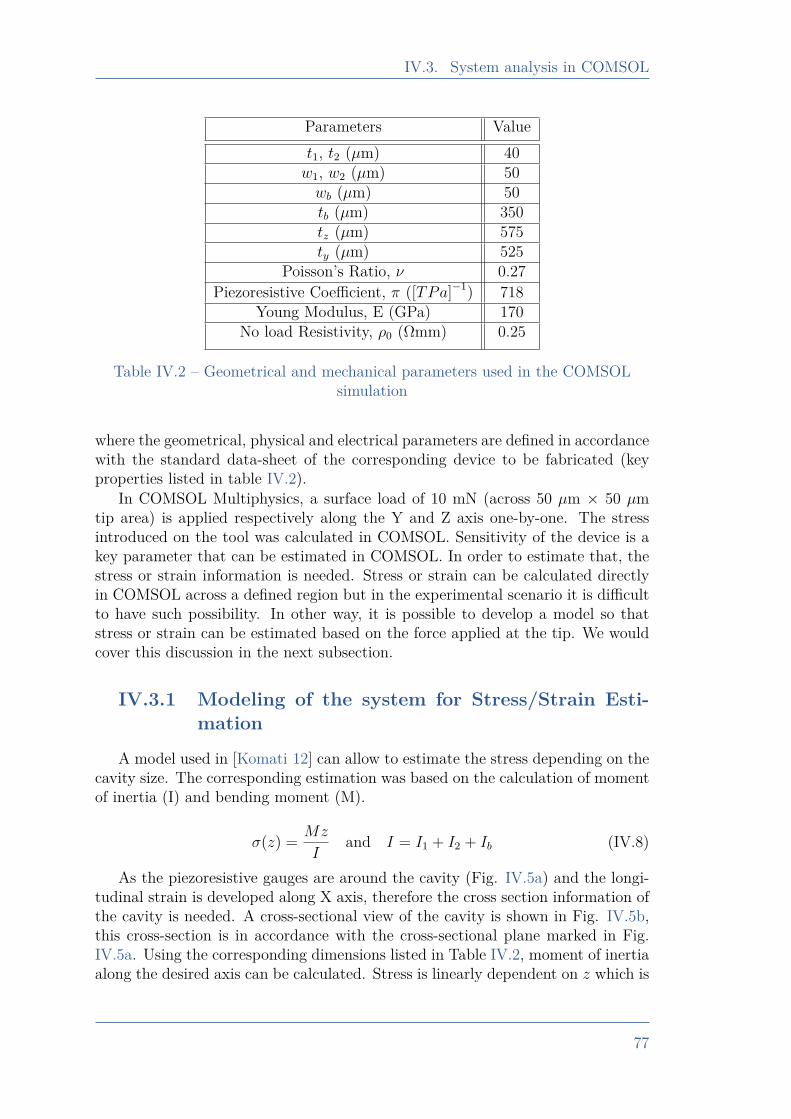
IV.3. System analysis in COMSOL
Parameters Valuet1, t2 (µm) 40w1, w2 (µm) 50wb (µm) 50tb (µm) 350tz (µm) 575ty (µm) 525
Poisson’s Ratio, ν 0.27Piezoresistive Coefficient, π ([TPa]−1) 718
Young Modulus, E (GPa) 170No load Resistivity, ρ0 (Ωmm) 0.25
Table IV.2 – Geometrical and mechanical parameters used in the COMSOLsimulation
where the geometrical, physical and electrical parameters are defined in accordancewith the standard data-sheet of the corresponding device to be fabricated (keyproperties listed in table IV.2).
In COMSOL Multiphysics, a surface load of 10 mN (across 50 µm × 50 µmtip area) is applied respectively along the Y and Z axis one-by-one. The stressintroduced on the tool was calculated in COMSOL. Sensitivity of the device is akey parameter that can be estimated in COMSOL. In order to estimate that, thestress or strain information is needed. Stress or strain can be calculated directlyin COMSOL across a defined region but in the experimental scenario it is difficultto have such possibility. In other way, it is possible to develop a model so thatstress or strain can be estimated based on the force applied at the tip. We wouldcover this discussion in the next subsection.
IV.3.1 Modeling of the system for Stress/Strain Esti-mation
A model used in [Komati 12] can allow to estimate the stress depending on thecavity size. The corresponding estimation was based on the calculation of momentof inertia (I) and bending moment (M).
σ(z) = Mz
Iand I = I1 + I2 + Ib (IV.8)
As the piezoresistive gauges are around the cavity (Fig. IV.5a) and the longi-tudinal strain is developed along X axis, therefore the cross section information ofthe cavity is needed. A cross-sectional view of the cavity is shown in Fig. IV.5b,this cross-section is in accordance with the cross-sectional plane marked in Fig.IV.5a. Using the corresponding dimensions listed in Table IV.2, moment of inertiaalong the desired axis can be calculated. Stress is linearly dependent on z which is
77
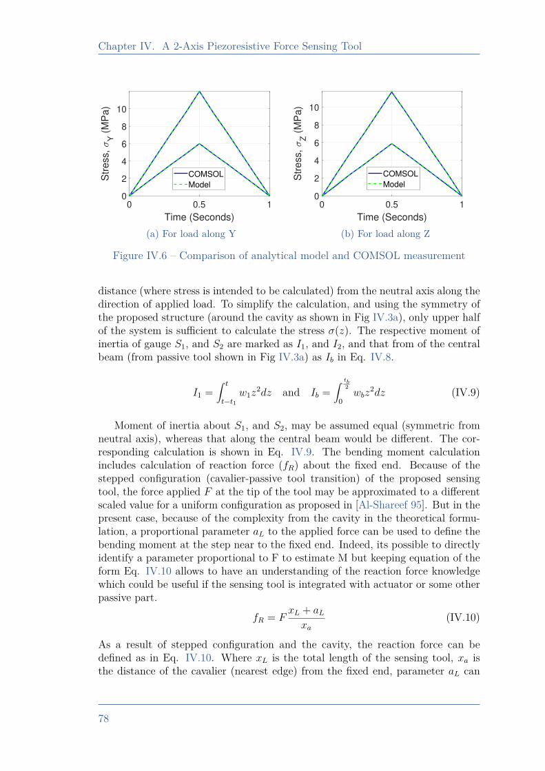
Chapter IV. A 2-Axis Piezoresistive Force Sensing Tool
0 0.5 1
Time (Seconds)
0
2
4
6
8
10S
tre
ss,
Y (
MP
a)
COMSOL
Model
(a) For load along Y
0 0.5 1
Time (Seconds)
0
2
4
6
8
10
Str
ess,
Z (
MP
a)
COMSOL
Model
(b) For load along Z
Figure IV.6 – Comparison of analytical model and COMSOL measurement
distance (where stress is intended to be calculated) from the neutral axis along thedirection of applied load. To simplify the calculation, and using the symmetry ofthe proposed structure (around the cavity as shown in Fig IV.3a), only upper halfof the system is sufficient to calculate the stress σ(z). The respective moment ofinertia of gauge S1, and S2 are marked as I1, and I2, and that from of the centralbeam (from passive tool shown in Fig IV.3a) as Ib in Eq. IV.8.
I1 =∫ t
t−t1w1z
2dz and Ib =∫ tb
2
0wbz
2dz (IV.9)
Moment of inertia about S1, and S2, may be assumed equal (symmetric fromneutral axis), whereas that along the central beam would be different. The cor-responding calculation is shown in Eq. IV.9. The bending moment calculationincludes calculation of reaction force (fR) about the fixed end. Because of thestepped configuration (cavalier-passive tool transition) of the proposed sensingtool, the force applied F at the tip of the tool may be approximated to a differentscaled value for a uniform configuration as proposed in [Al-Shareef 95]. But in thepresent case, because of the complexity from the cavity in the theoretical formu-lation, a proportional parameter aL to the applied force can be used to define thebending moment at the step near to the fixed end. Indeed, its possible to directlyidentify a parameter proportional to F to estimate M but keeping equation of theform Eq. IV.10 allows to have an understanding of the reaction force knowledgewhich could be useful if the sensing tool is integrated with actuator or some otherpassive part.
fR = FxL + aLxa
(IV.10)
As a result of stepped configuration and the cavity, the reaction force can bedefined as in Eq. IV.10. Where xL is the total length of the sensing tool, xa isthe distance of the cavalier (nearest edge) from the fixed end, parameter aL can
78
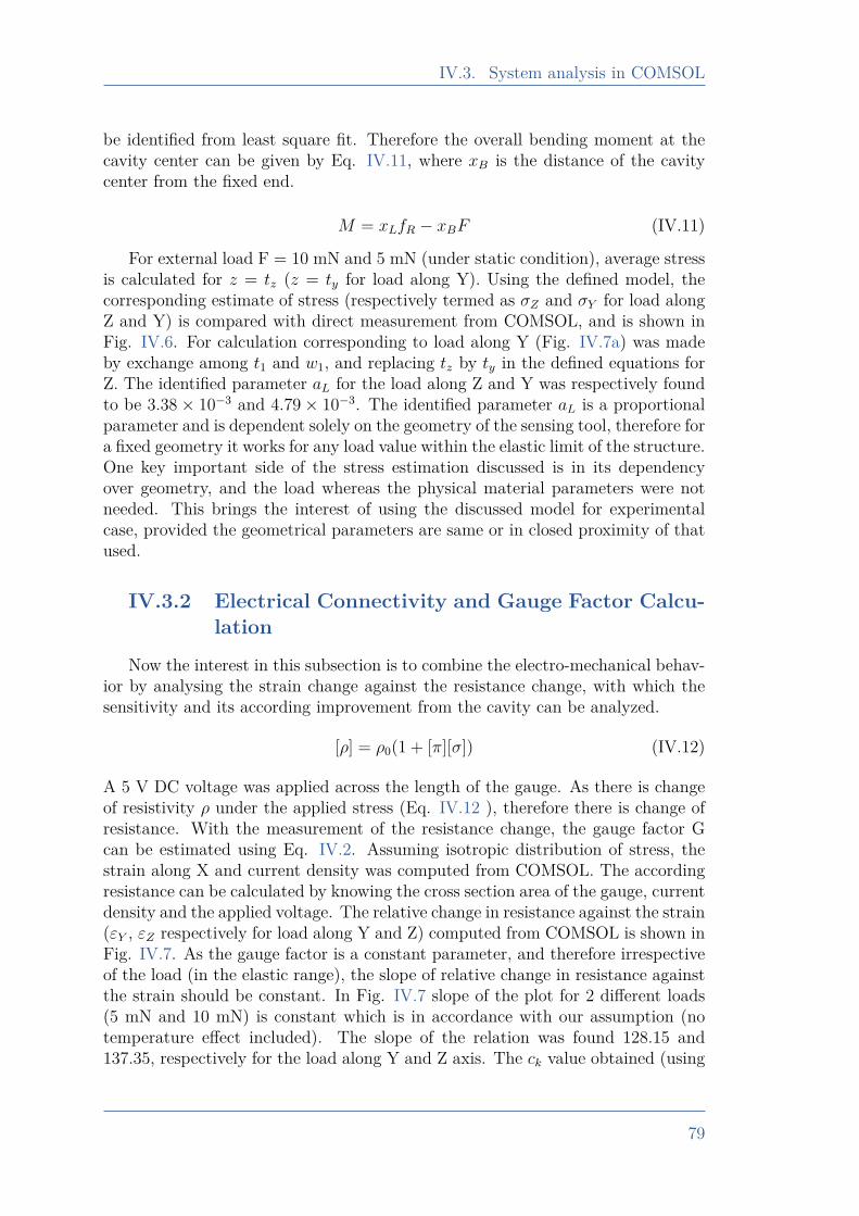
IV.3. System analysis in COMSOL
be identified from least square fit. Therefore the overall bending moment at thecavity center can be given by Eq. IV.11, where xB is the distance of the cavitycenter from the fixed end.
M = xLfR − xBF (IV.11)
For external load F = 10 mN and 5 mN (under static condition), average stressis calculated for z = tz (z = ty for load along Y). Using the defined model, thecorresponding estimate of stress (respectively termed as σZ and σY for load alongZ and Y) is compared with direct measurement from COMSOL, and is shown inFig. IV.6. For calculation corresponding to load along Y (Fig. IV.7a) was madeby exchange among t1 and w1, and replacing tz by ty in the defined equations forZ. The identified parameter aL for the load along Z and Y was respectively foundto be 3.38× 10⁻³ and 4.79× 10⁻³. The identified parameter aL is a proportionalparameter and is dependent solely on the geometry of the sensing tool, therefore fora fixed geometry it works for any load value within the elastic limit of the structure.One key important side of the stress estimation discussed is in its dependencyover geometry, and the load whereas the physical material parameters were notneeded. This brings the interest of using the discussed model for experimentalcase, provided the geometrical parameters are same or in closed proximity of thatused.
IV.3.2 Electrical Connectivity and Gauge Factor Calcu-lation
Now the interest in this subsection is to combine the electro-mechanical behav-ior by analysing the strain change against the resistance change, with which thesensitivity and its according improvement from the cavity can be analyzed.
[ρ] = ρ0(1 + [π][σ]) (IV.12)
A 5 V DC voltage was applied across the length of the gauge. As there is changeof resistivity ρ under the applied stress (Eq. IV.12 ), therefore there is change ofresistance. With the measurement of the resistance change, the gauge factor Gcan be estimated using Eq. IV.2. Assuming isotropic distribution of stress, thestrain along X and current density was computed from COMSOL. The accordingresistance can be calculated by knowing the cross section area of the gauge, currentdensity and the applied voltage. The relative change in resistance against the strain(εY , εZ respectively for load along Y and Z) computed from COMSOL is shown inFig. IV.7. As the gauge factor is a constant parameter, and therefore irrespectiveof the load (in the elastic range), the slope of relative change in resistance againstthe strain should be constant. In Fig. IV.7 slope of the plot for 2 different loads(5 mN and 10 mN) is constant which is in accordance with our assumption (notemperature effect included). The slope of the relation was found 128.15 and137.35, respectively for the load along Y and Z axis. The ck value obtained (using
79
Chapter IV. A 2-Axis Piezoresistive Force Sensing Tool
0 2 4 6 8
10-5
0
0.002
0.004
0.006
0.008
0.01
(R
/R) Y
10 mN
5 mN
(a) For load along Y
0 2 4 6 8
10-5
0
0.002
0.004
0.006
0.008
0.01
(R
/R) Z 10 mN
5 mN
(b) For load along Z
Figure IV.7 – Resistance change against the strain
Eq. IV.3) is respectively 1.05 and 1.125, along Y and Z axis, meaning 5 % and12.5 % of sensitivity improvement in device along the corresponding axes, underthe impact of introduced cavity.
80
IV.4. Device Fabrication and Assembly process
IV.4 Device Fabrication and Assembly pro-cess
In this section, fabrication and assembly process of different components of thesensing tool are discussed. The proposed sensing tool, consists of two types ofcomponent, one is the passive tool while second is the cavalier with piezoresistivegauges. These two type of components are fabricated separately with two differentprocesses. Their respective fabrication process and assembly is discussed in thefollowing subsections.
IV.4.1 Fabrication of the Passive ToolIn this section, the fabrication process of the passive tool is presented. The
fabrication starts with a silicon wafer of 350 µm thickness. The top and bottomsides of the wafer went through the lithography followed by the electrode deposition(which may be used for wiring if needed). The DRIE etching technique was usedfor the etching process. Finally, the samples were cleaned and were ready to beused for the assembly process. A summarized flow of the fabrication process isshown in Fig. IV.8.
IV.4.2 Fabrication of the CavalierIn our presented sensing configuration of Fig. IV.5a, the strain development
and the electric current passage for piezoresistive sensing are in the same direction.Therefore the piezoresistive effect targeted is longitudinal effect. As the intentionfor the sensing is to use the strain along the gauge length, which means tensilestrain in (100) silicon wafer should increase the mobility of electron in the <100>direction, while a compressive strain should increase the holes mobility in <110>direction (the miller indices representation is shown in Fig. IV.9).
Wafer orientation, type of doping, and the strain direction, can strongly influ-ence the system behavior as discussed in [Billot 15]. We chose (100) wafer and tohave <110> mobility direction, and therefore mask and wafer flat side were ac-cordingly chosen for the fabrication process. The targeted strain development forpiezoresistive effect is longitudinal, and the piezoresitive coefficient for the holesis 718 [TPa]−1 which is higher than that of electrons -316 [TPa]−1, which makessense to go ahead for p-doped piezoresistive effect. The n-type wafer can be usedto create p-n junction in reverse bias, so that there is no current leaking to thesubstrate. This approach of single crystal diffusion is a widely used method fordoping.
In our case we used a commercially available 5 layered wafer (5" with 350 µmthickness) constituted of 1 layer of p doped Si (100), 2 layers of SiO2, 1 layer of Si<111> and 1 layer of Si <100> (as shown in Fig. IV.10). The fabrication Process(Fig. IV.10) started from the top surface by performing the first lithographyfollowed by DRIE etching. Thereafter thermal oxidation of 300 nm was made on
81
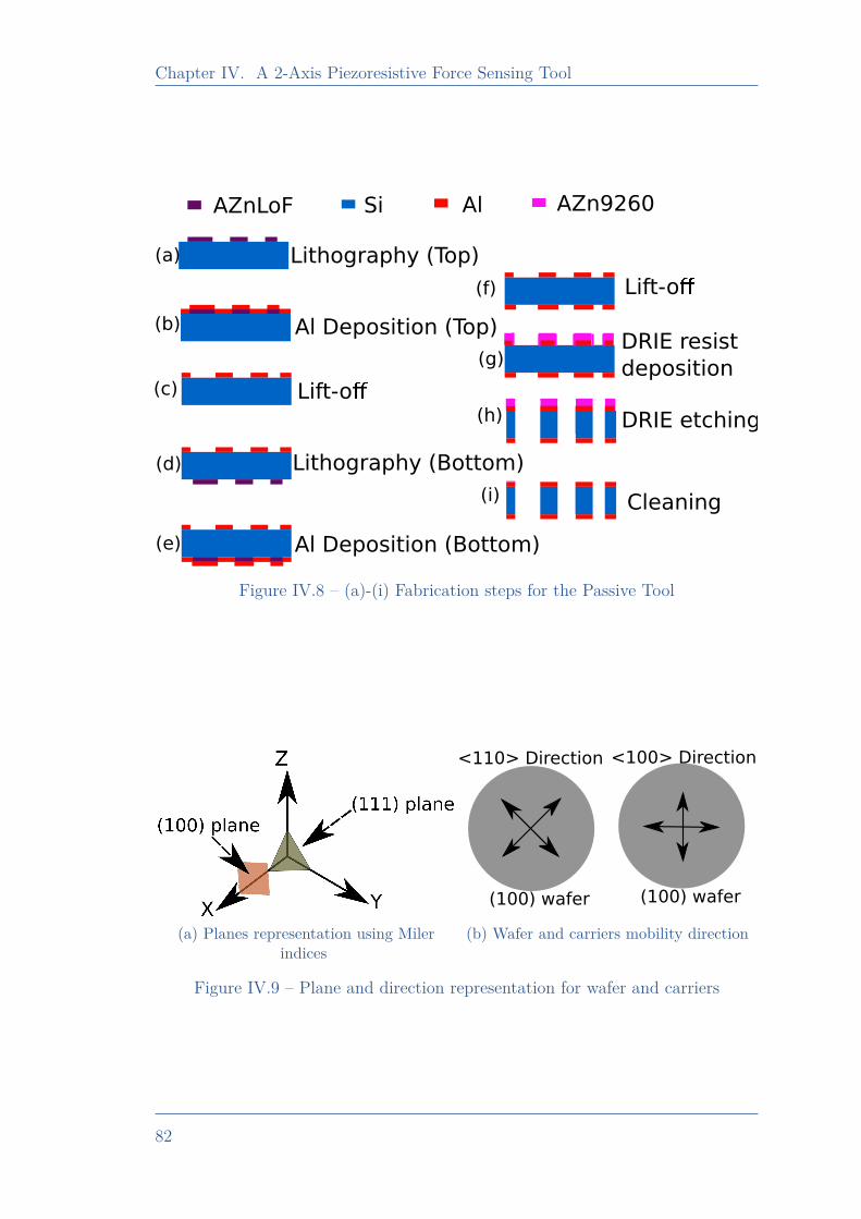
Chapter IV. A 2-Axis Piezoresistive Force Sensing Tool
Lithography (Top)
Al Deposition (Top)
Lithography (Bottom)
Al Deposition (Bottom)
Lift-o
(a)
(b)
(c)
(d)
(e)
(f)
(g)
(h)
(i)
Lift-o
Cleaning
DRIE etching
DRIE resist
deposition
AZnLoF Si AZn9260Al
Figure IV.8 – (a)-(i) Fabrication steps for the Passive Tool
X Y
Z
(a) Planes representation using Milerindices
<110> Direction <100> Direction
(100) wafer (100) wafer
(b) Wafer and carriers mobility direction
Figure IV.9 – Plane and direction representation for wafer and carriers
82
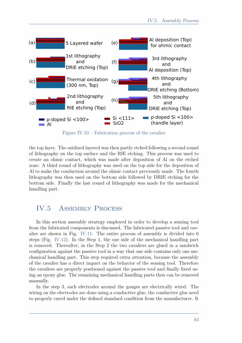
IV.5. Assembly Process
5 Layered wafer
1st lithography
and
DRIE etching (Top)
Thermal oxidation
(300 nm, Top)
2nd lithography
and
RIE etching (Top)
Al deposition (Top)
for ohmic contact
4th lithography
and
DRIE etching (Bottom)
3rd lithography
and
Al deposition (Top)
5th lithography
and
DRIE etching (Top)
p-doped Si <100>SiO2Si <111> p-doped Si <100>
(handle layer)Al
(a)
(b)
(c)
(d)
(e)
(f)
(g)
(h)
Figure IV.10 – Fabrication process of the cavalier
the top layer. The oxidized layered was then partly etched following a second roundof lithography on the top surface and the RIE etching. This process was used tocreate an ohmic contact, which was made after deposition of Al on the etchedzone. A third round of lithography was used on the top side for the deposition ofAl to make the conduction around the ohmic contact previously made. The fourthlithography was then used on the bottom side followed by DRIE etching for thebottom side. Finally the last round of lithography was made for the mechanicalhandling part.
IV.5 Assembly Process
In this section assembly strategy employed in order to develop a sensing toolfrom the fabricated components is discussed. The fabricated passive tool and cav-alier are shown in Fig. IV.11. The entire process of assembly is divided into 6steps (Fig. IV.12). In the Step 1, the one side of the mechanical handling partis removed. Thereafter, in the Step 2 the two cavaliers are glued in a sandwichconfiguration against the passive tool in a way that one side contains only one me-chanical handling part. This step required extra attention, because the assemblyof the cavalier has a direct impact on the behavior of the sensing tool. Thereforethe cavaliers are properly positioned against the passive tool and finally fixed us-ing an epoxy glue. The remaining mechanical handling parts then can be removedmanually.
In the step 3, each electrodes around the gauges are electrically wired. Thewiring on the electrodes are done using a conductive glue, the conductive glue needto properly cured under the defined standard condition from the manufacturer. It
83
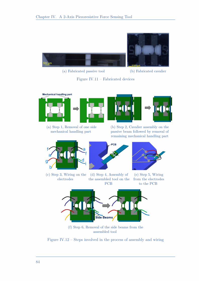
Chapter IV. A 2-Axis Piezoresistive Force Sensing Tool
(a) Fabricated passive tool (b) Fabricated cavalier
Figure IV.11 – Fabricated devices
(a) Step 1, Removal of one sidemechanical handling part
(b) Step 2, Cavalier assembly on thepassive beam followed by removal ofremaining mechanical handling part
(c) Step 3, Wiring on theelectrodes
(d) Step 4, Assembly ofthe assembled tool on the
PCB
(e) Step 5, Wiringfrom the electrodes
to the PCB
(f) Step 6, Removal of the side beams from theassembled tool
Figure IV.12 – Steps involved in the process of assembly and wiring
84
IV.6. Experimental Studies
is noticed that if the conductive glue is not cured well (timing and/or tempera-ture of curing not respected) then the corresponding gauges may have unwantedresistance. Therefore, the wiring on the electrodes required a careful attention.The corresponding wiring is made in accordance with the discussed wheatstonebridge in Fig. IV.4, where the common point of R2 and R4 is marked as “a”, andthat of R1 and R3 as “f”. The supply voltage VCC would be provided across point“b”,“d” and “g”, “i” respectively for the bridge W2, and W1. This assembled toolis then glued on a PCB using an epoxy glue in step 4. After this, the wiring fromthe electrodes are transferred to the PCB in step 5, which then can be electricallyconnected to wheatstone circuitry as discussed in Fig. IV.4. The two extra sidebeams of the passive tool in the cavity part, then removed using a laser cuttingprocess (step 6). The assembly of the cavalier with the passive tool, and the wiringinvolved on the electrodes of cavalier are done at the “Percipio Robotics”, who isan industrial partner in the COLAMIR project [COLAMIR 20].
IV.6 Experimental Studies
This section introduces the experimental setup, its working and discusses therealized tasks in terms of system performances. The constituent elements of theexperimental setup is defined in the subsection IV.6.1. System behavior under noload (subsection IV.6.2), and the characterization for the load along Y (subsectionIV.6.3) and Z axis (subsection IV.6.4), with a global discussion on the sensitivityand gauge factor is discussed (subsection IV.6.5).
IV.6.1 Experimental Setup
The experimental setup of the system is shown in Fig. IV.13. The experimen-tal setup consists of a MCL Nano 3D-200, which is capable of positioning along3 axes with nanometric resolution. The developed sensing tool is fixed on thepositoning stage and is positioned to move against a reference force sensor. Thereference force sensor employed for the tasks are Femtotools FT-S1000 and FT-S10000 respectively for resolution and long range validation (as in our knowledgethere was no any commercially available force sensor which can meet both theserequirements). Reference force sensor is fixed on a rotational axis, which is PIM116.DGH rotational axis from Physik Instrumente.
The experimental system configuration for the characterization along the twoaxes are shown in Fig. IV.13 as Configuration 1 and Configuration 2, respectivelyfor Y and Z axis. Throughout the characterization process the performance wascharacterized for the applied load within 50 µm from the tip end along the lengthof Piezoresistive Tool (PRT).
85
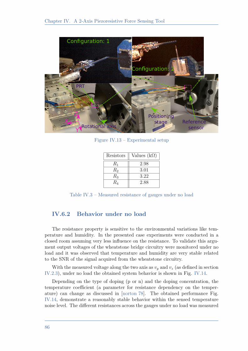
Chapter IV. A 2-Axis Piezoresistive Force Sensing Tool
X
Y
Z
Rotational axisReference
sensor
PRT
Positioning
stage
Con guration: 1
Con guration: 2
Figure IV.13 – Experimental setup
Resistors Values (kΩ)R1 2.98R2 3.01R3 3.22R4 2.88
Table IV.3 – Measured resistance of gauges under no load
IV.6.2 Behavior under no load
The resistance property is sensitive to the environmental variations like tem-perature and humidity. In the presented case experiments were conducted in aclosed room assuming very less influence on the resistance. To validate this argu-ment output voltages of the wheatstone bridge circuitry were monitored under noload and it was observed that temperature and humidity are very stable relatedto the SNR of the signal acquired from the wheatstone circuitry.
With the measured voltage along the two axis as vy and vz (as defined in sectionIV.2.3), under no load the obtained system behavior is shown in Fig. IV.14.
Depending on the type of doping (p or n) and the doping concentration, thetemperature coefficient (a parameter for resistance dependency on the temper-ature) can change as discussed in [norton 78]. The obtained performance Fig.IV.14, demonstrate a reasonably stable behavior within the sensed temperaturenoise level. The different resistances across the gauges under no load was measured
86
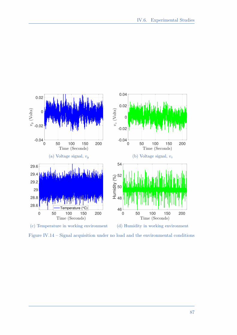
IV.6. Experimental Studies
0 50 100 150 200-0.04
-0.02
0
0.02
(a) Voltage signal, vy
0 50 100 150 200-0.04
-0.02
0
0.02
0.04
(b) Voltage signal, vz
0 50 100 150 200
28.6
28.8
29
29.2
29.4
29.6
Temperature (°C)
(c) Temperature in working environment
0 50 100 150 20046
48
50
52
54
Hu
mid
ity (
%)
(d) Humidity in working environment
Figure IV.14 – Signal acquisition under no load and the environmental conditions
87
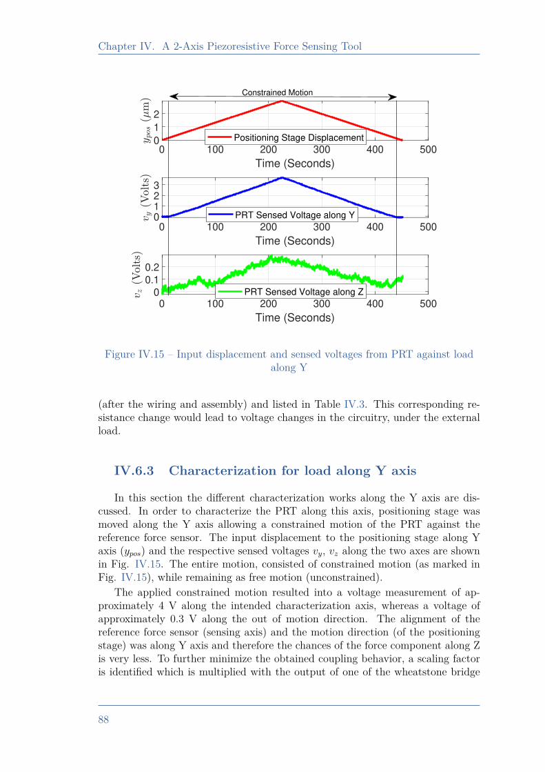
Chapter IV. A 2-Axis Piezoresistive Force Sensing Tool
0 100 200 300 400 500
Time (Seconds)
0
1
2
Positioning Stage Displacement
0 100 200 300 400 500
Time (Seconds)
0123
PRT Sensed Voltage along Y
0 100 200 300 400 500
Time (Seconds)
0
0.1
0.2
PRT Sensed Voltage along Z
Constrained Motion
Figure IV.15 – Input displacement and sensed voltages from PRT against loadalong Y
(after the wiring and assembly) and listed in Table IV.3. This corresponding re-sistance change would lead to voltage changes in the circuitry, under the externalload.
IV.6.3 Characterization for load along Y axis
In this section the different characterization works along the Y axis are dis-cussed. In order to characterize the PRT along this axis, positioning stage wasmoved along the Y axis allowing a constrained motion of the PRT against thereference force sensor. The input displacement to the positioning stage along Yaxis (ypos) and the respective sensed voltages vy, vz along the two axes are shownin Fig. IV.15. The entire motion, consisted of constrained motion (as marked inFig. IV.15), while remaining as free motion (unconstrained).
The applied constrained motion resulted into a voltage measurement of ap-proximately 4 V along the intended characterization axis, whereas a voltage ofapproximately 0.3 V along the out of motion direction. The alignment of thereference force sensor (sensing axis) and the motion direction (of the positioningstage) was along Y axis and therefore the chances of the force component along Zis very less. To further minimize the obtained coupling behavior, a scaling factoris identified which is multiplied with the output of one of the wheatstone bridge
88
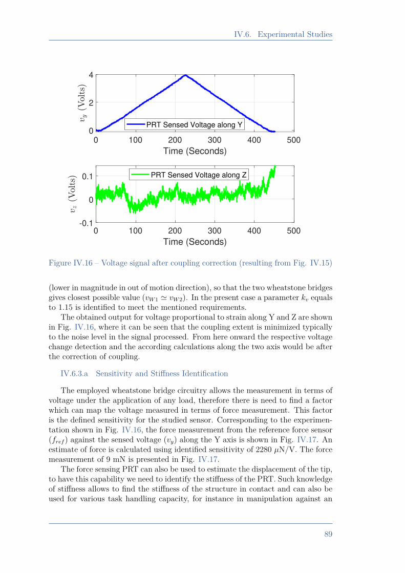
IV.6. Experimental Studies
0 100 200 300 400 500
Time (Seconds)
0
2
4
PRT Sensed Voltage along Y
0 100 200 300 400 500
Time (Seconds)
-0.1
0
0.1 PRT Sensed Voltage along Z
Figure IV.16 – Voltage signal after coupling correction (resulting from Fig. IV.15)
(lower in magnitude in out of motion direction), so that the two wheatstone bridgesgives closest possible value (vW1 ' vW2). In the present case a parameter kv equalsto 1.15 is identified to meet the mentioned requirements.
The obtained output for voltage proportional to strain along Y and Z are shownin Fig. IV.16, where it can be seen that the coupling extent is minimized typicallyto the noise level in the signal processed. From here onward the respective voltagechange detection and the according calculations along the two axis would be afterthe correction of coupling.
IV.6.3.a Sensitivity and Stiffness Identification
The employed wheatstone bridge circuitry allows the measurement in terms ofvoltage under the application of any load, therefore there is need to find a factorwhich can map the voltage measured in terms of force measurement. This factoris the defined sensitivity for the studied sensor. Corresponding to the experimen-tation shown in Fig. IV.16, the force measurement from the reference force sensor(fref ) against the sensed voltage (vy) along the Y axis is shown in Fig. IV.17. Anestimate of force is calculated using identified sensitivity of 2280 µN/V. The forcemeasurement of 9 mN is presented in Fig. IV.17.
The force sensing PRT can also be used to estimate the displacement of the tip,to have this capability we need to identify the stiffness of the PRT. Such knowledgeof stiffness allows to find the stiffness of the structure in contact and can also beused for various task handling capacity, for instance in manipulation against an
89
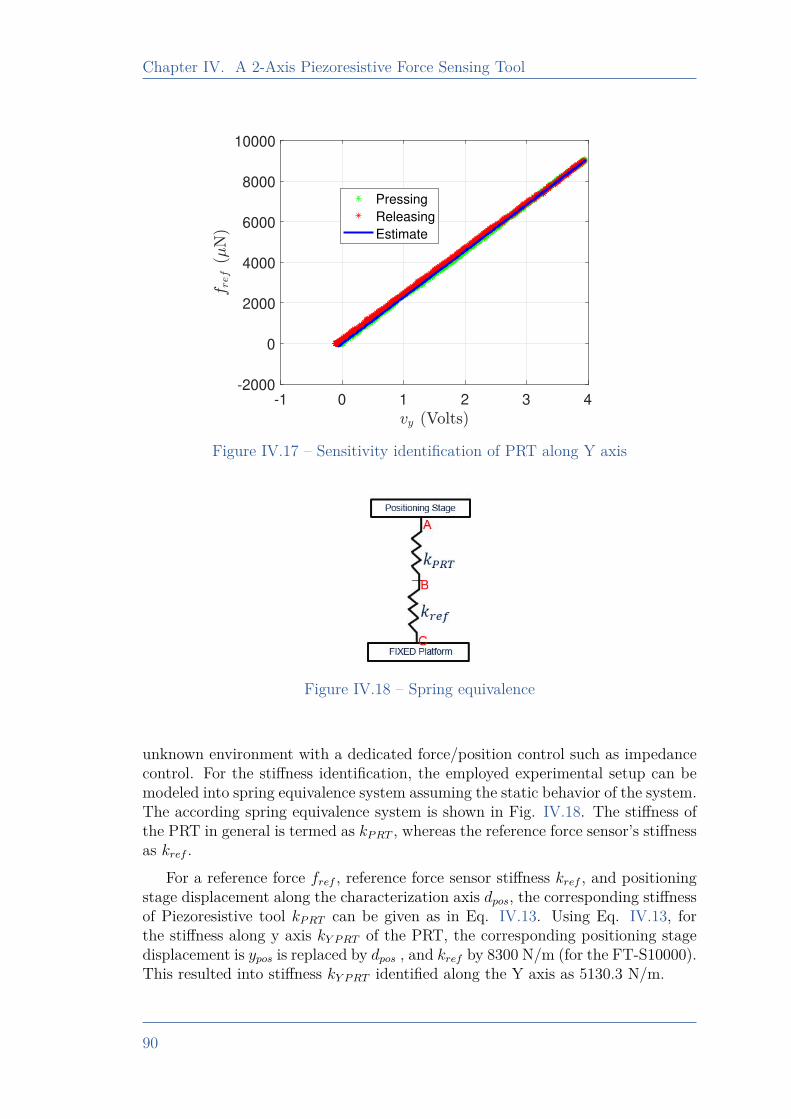
Chapter IV. A 2-Axis Piezoresistive Force Sensing Tool
-1 0 1 2 3 4-2000
0
2000
4000
6000
8000
10000
Pressing
Releasing
Estimate
Figure IV.17 – Sensitivity identification of PRT along Y axis
Figure IV.18 – Spring equivalence
unknown environment with a dedicated force/position control such as impedancecontrol. For the stiffness identification, the employed experimental setup can bemodeled into spring equivalence system assuming the static behavior of the system.The according spring equivalence system is shown in Fig. IV.18. The stiffness ofthe PRT in general is termed as kPRT , whereas the reference force sensor’s stiffnessas kref .
For a reference force fref , reference force sensor stiffness kref , and positioningstage displacement along the characterization axis dpos, the corresponding stiffnessof Piezoresistive tool kPRT can be given as in Eq. IV.13. Using Eq. IV.13, forthe stiffness along y axis kY PRT of the PRT, the corresponding positioning stagedisplacement is ypos is replaced by dpos , and kref by 8300 N/m (for the FT-S10000).This resulted into stiffness kY PRT identified along the Y axis as 5130.3 N/m.
90
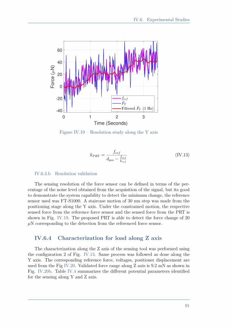
IV.6. Experimental Studies
0 1 2 3
Time (Seconds)
-40
-20
0
20
40
60F
orc
e (
N)
Figure IV.19 – Resolution study along the Y axis
kPRT = fref
dpos − fref
kref
(IV.13)
IV.6.3.b Resolution validation
The sensing resolution of the force sensor can be defined in terms of the per-centage of the noise level obtained from the acquisition of the signal, but its goodto demonstrate the system capability to detect the minimum change, the referencesensor used was FT-S1000. A staircase motion of 30 nm step was made from thepositioning stage along the Y axis. Under the constrained motion, the respectivesensed force from the reference force sensor and the sensed force from the PRT isshown in Fig. IV.19. The proposed PRT is able to detect the force change of 20µN corresponding to the detection from the referenced force sensor.
IV.6.4 Characterization for load along Z axis
The characterization along the Z axis of the sensing tool was performed usingthe configuration 2 of Fig. IV.13. Same process was followed as done along theY axis. The corresponding reference force, voltages, positioner displacement areused from the Fig IV.20. Validated force range along Z axis is 9.2 mN as shown inFig. IV.20b. Table IV.4 summarizes the different potential parameters identifiedfor the sensing along Y and Z axis.
91
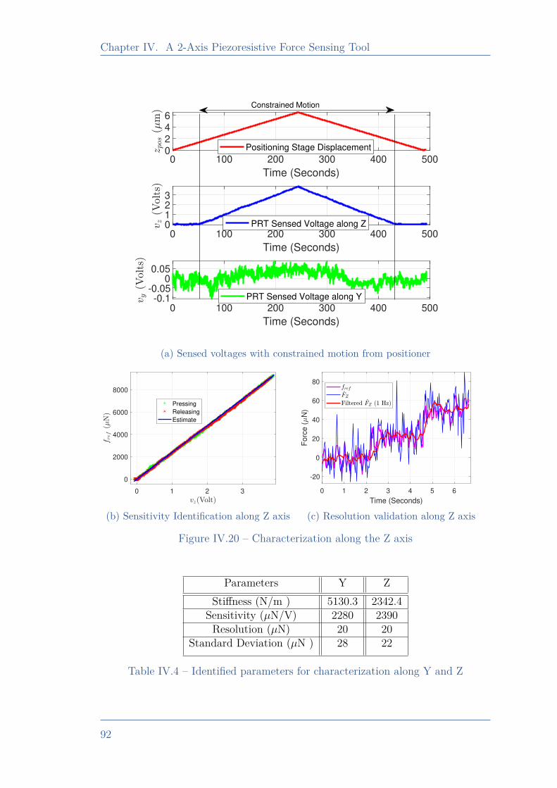
Chapter IV. A 2-Axis Piezoresistive Force Sensing Tool
0 100 200 300 400 500
Time (Seconds)
0246
Positioning Stage Displacement
0 100 200 300 400 500
Time (Seconds)
0123
PRT Sensed Voltage along Z
0 100 200 300 400 500
Time (Seconds)
-0.1-0.05
00.05
PRT Sensed Voltage along Y
Constrained Motion
(a) Sensed voltages with constrained motion from positioner
0 1 2 3
0
2000
4000
6000
8000
Pressing
Releasing
Estimate
(b) Sensitivity Identification along Z axis
0 1 2 3 4 5 6
Time (Seconds)
-20
0
20
40
60
80
Forc
e (
N)
(c) Resolution validation along Z axis
Figure IV.20 – Characterization along the Z axis
Parameters Y ZStiffness (N/m ) 5130.3 2342.4
Sensitivity (µN/V) 2280 2390Resolution (µN) 20 20
Standard Deviation (µN ) 28 22
Table IV.4 – Identified parameters for characterization along Y and Z
92
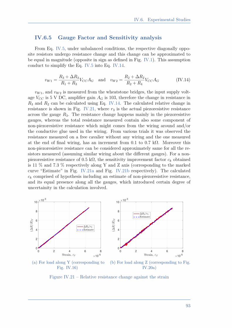
IV.6. Experimental Studies
IV.6.5 Gauge Factor and Sensitivity analysis
From Eq. IV.5, under unbalanced conditions, the respective diagonally oppo-site resistors undergo resistance change and this change can be approximated tobe equal in magnitude (opposite in sign as defined in Fig. IV.1). This assumptionconduct to simplify the Eq. IV.5 into Eq. IV.14.
vW1 = R3 + ∆R3
R1 +R3VCCAG and vW2 = R2 + ∆R2
R2 +R4VCCAG (IV.14)
vW1, and vW2 is measured from the wheatstone bridges, the input supply volt-age VCC is 5 V DC, amplifier gain AG is 103, therefore the change in resistance inR3 and R2 can be calculated using Eq. IV.14. The calculated relative change inresistance is shown in Fig. IV.21, where r3 is the actual piezoresistive resistanceacross the gauge R3. The resistance change happens mainly in the piezoresistivegauges, whereas the total resistance measured contain also some component ofnon-piezoresistive resistance which might comes from the wiring around and/orthe conductive glue used in the wiring. From various trials it was observed theresistance measured on a free cavalier without any wiring and the one measuredat the end of final wiring, has an increment from 0.1 to 0.7 kΩ. Moreover thisnon-piezoresistive resistance can be considered approximately same for all the re-sistors measured (assuming similar wiring about the different gauges). For a non-piezoresistive resistance of 0.5 kΩ, the sensitivity improvement factor ck obtainedis 11 % and 7.3 % respectively along Y and Z axis (corresponding to the markedcurve “Estimate” in Fig. IV.21a and Fig. IV.21b respectively). The calculatedck comprised of hypothesis including an estimate of non-piezoresistive resistance,and its equal presence along all the gauges, which introduced certain degree ofuncertainity in the calculation involved.
0 2 4 6 8
10-5
0
2
4
6
8
1010
-3
(a) For load along Y (corresponding toFig. IV.16)
0 2 4 6 8
10-5
0
2
4
6
8
1010
-3
(b) For load along Z (corresponding to Fig.IV.20a)
Figure IV.21 – Relative resistance change against the strain
93
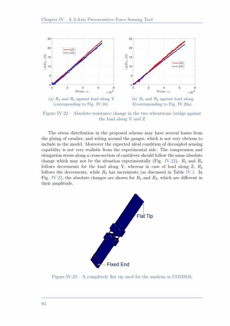
Chapter IV. A 2-Axis Piezoresistive Force Sensing Tool
0 2 4 6 8
10-5
0
5
10
15
20
25
(a) R3 and R2 against load along Y(corresponding to Fig. IV.16)
0 2 4 6 8
10-5
0
5
10
15
20
25
(b) R3 and R2 against load alongZ(corresponding to Fig. IV.20a)
Figure IV.22 – Absolute resistance change in the two wheatstone bridge againstthe load along Y and Z
The stress distribution in the proposed scheme may have several losses fromthe gluing of cavalier, and wiring around the gauges, which is not very obvious toinclude in the model. Moreover the expected ideal condition of decoupled sensingcapability is not very realistic from the experimental side. The compression andelongation stress along a cross-section of cantilever should follow the same absolutechange which may not be the situation experimentally (Fig. IV.22). R2 and R3follows decrements for the load along Y, whereas in case of load along Z, R2follows the decrements, while R3 has increments (as discussed in Table IV.1. InFig. IV.22, the absolute changes are shown for R2 and R3, which are different intheir amplitude.
Figure IV.23 – A completely flat tip used for the analysis in COMSOL
94
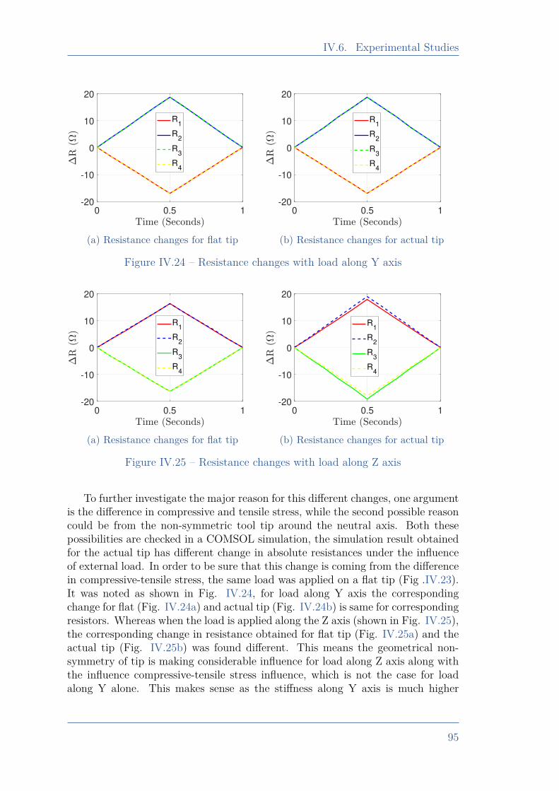
IV.6. Experimental Studies
0 0.5 1-20
-10
0
10
20
R1
R2
R3
R4
(a) Resistance changes for flat tip
0 0.5 1-20
-10
0
10
20
R1
R2
R3
R4
(b) Resistance changes for actual tip
Figure IV.24 – Resistance changes with load along Y axis
0 0.5 1-20
-10
0
10
20
R1
R2
R3
R4
(a) Resistance changes for flat tip
0 0.5 1-20
-10
0
10
20
R1
R2
R3
R4
(b) Resistance changes for actual tip
Figure IV.25 – Resistance changes with load along Z axis
To further investigate the major reason for this different changes, one argumentis the difference in compressive and tensile stress, while the second possible reasoncould be from the non-symmetric tool tip around the neutral axis. Both thesepossibilities are checked in a COMSOL simulation, the simulation result obtainedfor the actual tip has different change in absolute resistances under the influenceof external load. In order to be sure that this change is coming from the differencein compressive-tensile stress, the same load was applied on a flat tip (Fig .IV.23).It was noted as shown in Fig. IV.24, for load along Y axis the correspondingchange for flat (Fig. IV.24a) and actual tip (Fig. IV.24b) is same for correspondingresistors. Whereas when the load is applied along the Z axis (shown in Fig. IV.25),the corresponding change in resistance obtained for flat tip (Fig. IV.25a) and theactual tip (Fig. IV.25b) was found different. This means the geometrical non-symmetry of tip is making considerable influence for load along Z axis along withthe influence compressive-tensile stress influence, which is not the case for loadalong Y alone. This makes sense as the stiffness along Y axis is much higher
95
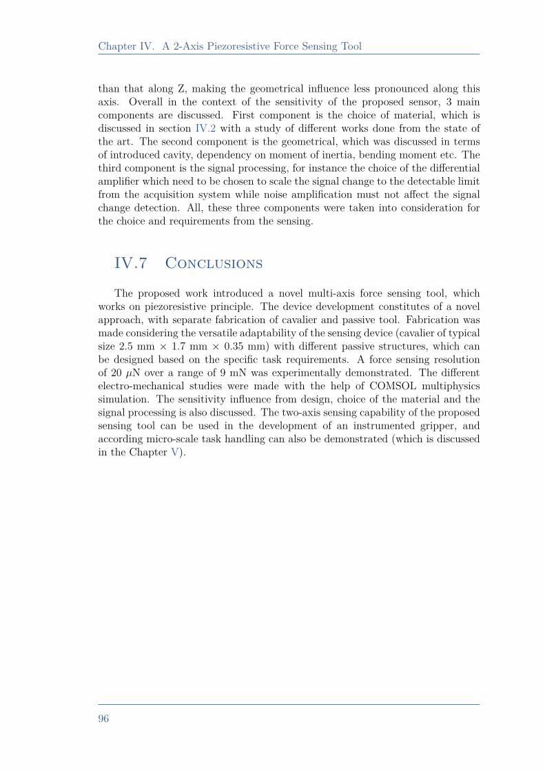
Chapter IV. A 2-Axis Piezoresistive Force Sensing Tool
than that along Z, making the geometrical influence less pronounced along thisaxis. Overall in the context of the sensitivity of the proposed sensor, 3 maincomponents are discussed. First component is the choice of material, which isdiscussed in section IV.2 with a study of different works done from the state ofthe art. The second component is the geometrical, which was discussed in termsof introduced cavity, dependency on moment of inertia, bending moment etc. Thethird component is the signal processing, for instance the choice of the differentialamplifier which need to be chosen to scale the signal change to the detectable limitfrom the acquisition system while noise amplification must not affect the signalchange detection. All, these three components were taken into consideration forthe choice and requirements from the sensing.
IV.7 Conclusions
The proposed work introduced a novel multi-axis force sensing tool, whichworks on piezoresistive principle. The device development constitutes of a novelapproach, with separate fabrication of cavalier and passive tool. Fabrication wasmade considering the versatile adaptability of the sensing device (cavalier of typicalsize 2.5 mm × 1.7 mm × 0.35 mm) with different passive structures, which canbe designed based on the specific task requirements. A force sensing resolutionof 20 µN over a range of 9 mN was experimentally demonstrated. The differentelectro-mechanical studies were made with the help of COMSOL multiphysicssimulation. The sensitivity influence from design, choice of the material and thesignal processing is also discussed. The two-axis sensing capability of the proposedsensing tool can be used in the development of an instrumented gripper, andaccording micro-scale task handling can also be demonstrated (which is discussedin the Chapter V).
96

Chapter VDevelopment of an Instrumented
microgripper and micro-scale taskhandling
V.1 Introduction . . . . . . . . . . . . . . . . . . . . . . . . . . . . . . . . . . . . . . . . . . . . 98V.2 Development of an instrumented microgripper . . . . . . . . . . . 98
V.2.1 Modeling of the gripper’s actuation. . . . . . . . . . . . . . . . . . . 100V.2.2 Task Handling with the proposed Gripper . . . . . . . . . . . . . 104V.2.3 Grasping of micro-object without control . . . . . . . . . . . . . . 104V.2.4 Force controlled Grasping of a micro-object . . . . . . . . . . . . 105
V.3 Assembly using the developed instrumented micro-systems108
V.4 Conclusions . . . . . . . . . . . . . . . . . . . . . . . . . . . . . . . . . . . . . . . . . . . . 111
97
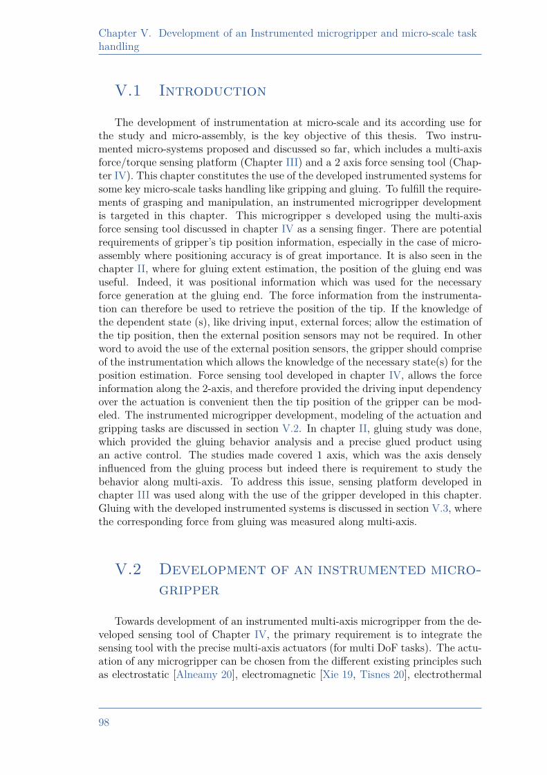
Chapter V. Development of an Instrumented microgripper and micro-scale taskhandling
V.1 Introduction
The development of instrumentation at micro-scale and its according use forthe study and micro-assembly, is the key objective of this thesis. Two instru-mented micro-systems proposed and discussed so far, which includes a multi-axisforce/torque sensing platform (Chapter III) and a 2 axis force sensing tool (Chap-ter IV). This chapter constitutes the use of the developed instrumented systems forsome key micro-scale tasks handling like gripping and gluing. To fulfill the require-ments of grasping and manipulation, an instrumented microgripper developmentis targeted in this chapter. This microgripper s developed using the multi-axisforce sensing tool discussed in chapter IV as a sensing finger. There are potentialrequirements of gripper’s tip position information, especially in the case of micro-assembly where positioning accuracy is of great importance. It is also seen in thechapter II, where for gluing extent estimation, the position of the gluing end wasuseful. Indeed, it was positional information which was used for the necessaryforce generation at the gluing end. The force information from the instrumenta-tion can therefore be used to retrieve the position of the tip. If the knowledge ofthe dependent state (s), like driving input, external forces; allow the estimation ofthe tip position, then the external position sensors may not be required. In otherword to avoid the use of the external position sensors, the gripper should compriseof the instrumentation which allows the knowledge of the necessary state(s) for theposition estimation. Force sensing tool developed in chapter IV, allows the forceinformation along the 2-axis, and therefore provided the driving input dependencyover the actuation is convenient then the tip position of the gripper can be mod-eled. The instrumented microgripper development, modeling of the actuation andgripping tasks are discussed in section V.2. In chapter II, gluing study was done,which provided the gluing behavior analysis and a precise glued product usingan active control. The studies made covered 1 axis, which was the axis denselyinfluenced from the gluing process but indeed there is requirement to study thebehavior along multi-axis. To address this issue, sensing platform developed inchapter III was used along with the use of the gripper developed in this chapter.Gluing with the developed instrumented systems is discussed in section V.3, wherethe corresponding force from gluing was measured along multi-axis.
V.2 Development of an instrumented micro-gripper
Towards development of an instrumented multi-axis microgripper from the de-veloped sensing tool of Chapter IV, the primary requirement is to integrate thesensing tool with the precise multi-axis actuators (for multi DoF tasks). The actu-ation of any microgripper can be chosen from the different existing principles suchas electrostatic [Alneamy 20], electromagnetic [Xie 19, Tisnes 20], electrothermal
98
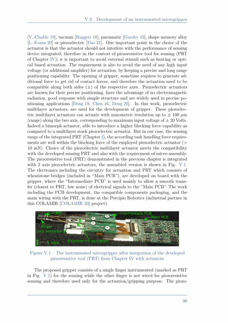
V.2. Development of an instrumented microgripper
[V.-Chable 19], vacuum [Ruggeri 18], pneumatic [Gursky 19], shape memory alloy[L.-Evans 20] or piezoelectric [Das 21]. One important point in the choice of theactuator is that the actuator should not interfere with the performance of sensingdevice integrated, therefore in the context of piezoresistive tool for sensing (PRTof Chapter IV); it is important to avoid external stimuli such as heating or opti-cal based actuation. The requirement is also to avoid the need of any high inputvoltage (or additional amplifier) for actuation, by keeping a precise and long rangepositioning capability. The opening of gripper, sometime requires to generate ad-ditional force to get rid of contact forces, and therefore the actuation need to becompatible along both sides (±) of the respective axes. Piezoelectric actuatorsare known for their precise positioning, have the advantage of no electromagneticradiation, good response with simple structure and are widely used in precise po-sitioning applications [Deng 19, Chen 16, Deng 20]. In this work, piezoelectricmultilayer actuators, are used for the development of gripper. These piezoelec-tric multilayer actuators can actuate with nanometric resolution up to ± 100 µm(range) along the two axis, corresponding to maximum input voltage of ± 20 Volts.Indeed a bimorph actuator, able to introduce a higher blocking force capability ascompared to a multilayer stack piezoelectric actuator. But in our case, the sensingrange of the integrated PRT (Chapter I), the according task handling force require-ments are well within the blocking force of the employed piezoelectric actuator (>10 mN). Choice of the piezoelectric multilayer actuator meets the compatibilitywith the developed sensing PRT and also with the requirement of micro-assembly.The piezoresistive tool (PRT) demonstrated in the previous chapter is integratedwith 2 axis piezoelectric actuators, the assembled version is shown in Fig. V.1.The electronics including the circuitry for actuation and PRT which consists ofwheatstone bridges (included in “Main PCB”), are developed on board with thegripper, where the “Intermediate PCB” is used mainly to allow a smooth trans-fer (closest to PRT, low noise) of electrical signals to the “Main PCB”. The workincluding the PCB development, the compatible components packaging, and themain wiring with the PRT, is done at the Percipio Robotics (industrial partner inthis COLAMIR [COLAMIR 20] project).
Figure V.1 – The instrumented microgripper after integration of the developedpiezoresistive tool (PRT) from Chapter IV with actuators
The proposed gripper consists of a single finger instrumented (marked as PRTin Fig. V.1) for the sensing while the other finger is not wired for piezoresistivesensing and therefore used only for the actuation/gripping purpose. The piezo-
99
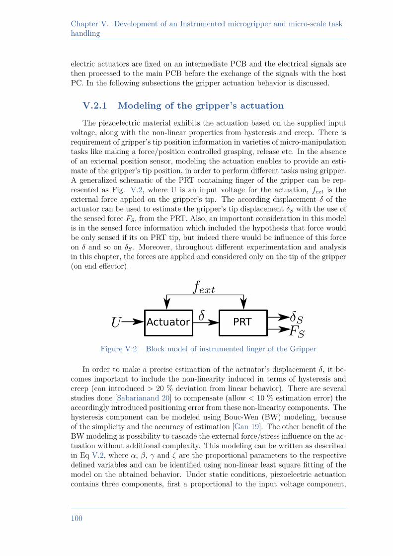
Chapter V. Development of an Instrumented microgripper and micro-scale taskhandling
electric actuators are fixed on an intermediate PCB and the electrical signals arethen processed to the main PCB before the exchange of the signals with the hostPC. In the following subsections the gripper actuation behavior is discussed.
V.2.1 Modeling of the gripper’s actuationThe piezoelectric material exhibits the actuation based on the supplied input
voltage, along with the non-linear properties from hysteresis and creep. There isrequirement of gripper’s tip position information in varieties of micro-manipulationtasks like making a force/position controlled grasping, release etc. In the absenceof an external position sensor, modeling the actuation enables to provide an esti-mate of the gripper’s tip position, in order to perform different tasks using gripper.A generalized schematic of the PRT containing finger of the gripper can be rep-resented as Fig. V.2, where U is an input voltage for the actuation, fext is theexternal force applied on the gripper’s tip. The according displacement δ of theactuator can be used to estimate the gripper’s tip displacement δS with the use ofthe sensed force FS, from the PRT. Also, an important consideration in this modelis in the sensed force information which included the hypothesis that force wouldbe only sensed if its on PRT tip, but indeed there would be influence of this forceon δ and so on δS. Moreover, throughout different experimentation and analysisin this chapter, the forces are applied and considered only on the tip of the gripper(on end effector).
Actuator PRT
Figure V.2 – Block model of instrumented finger of the Gripper
In order to make a precise estimation of the actuator’s displacement δ, it be-comes important to include the non-linearity induced in terms of hysteresis andcreep (can introduced > 20 % deviation from linear behavior). There are severalstudies done [Sabarianand 20] to compensate (allow < 10 % estimation error) theaccordingly introduced positioning error from these non-linearity components. Thehysteresis component can be modeled using Bouc-Wen (BW) modeling, becauseof the simplicity and the accuracy of estimation [Gan 19]. The other benefit of theBW modeling is possibility to cascade the external force/stress influence on the ac-tuation without additional complexity. This modeling can be written as describedin Eq V.2, where α, β, γ and ζ are the proportional parameters to the respectivedefined variables and can be identified using non-linear least square fitting of themodel on the obtained behavior. Under static conditions, piezoelectric actuationcontains three components, first a proportional to the input voltage component,
100
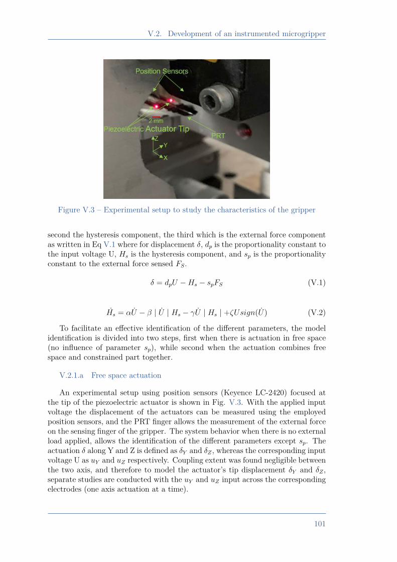
V.2. Development of an instrumented microgripper
Figure V.3 – Experimental setup to study the characteristics of the gripper
second the hysteresis component, the third which is the external force componentas written in Eq V.1 where for displacement δ, dp is the proportionality constant tothe input voltage U, Hs is the hysteresis component, and sp is the proportionalityconstant to the external force sensed FS.
δ = dpU −Hs − spFS (V.1)
Hs = αU − β | U | Hs − γU | Hs | +ζUsign(U) (V.2)
To facilitate an effective identification of the different parameters, the modelidentification is divided into two steps, first when there is actuation in free space(no influence of parameter sp), while second when the actuation combines freespace and constrained part together.
V.2.1.a Free space actuation
An experimental setup using position sensors (Keyence LC-2420) focused atthe tip of the piezoelectric actuator is shown in Fig. V.3. With the applied inputvoltage the displacement of the actuators can be measured using the employedposition sensors, and the PRT finger allows the measurement of the external forceon the sensing finger of the gripper. The system behavior when there is no externalload applied, allows the identification of the different parameters except sp. Theactuation δ along Y and Z is defined as δY and δZ , whereas the corresponding inputvoltage U as uY and uZ respectively. Coupling extent was found negligible betweenthe two axis, and therefore to model the actuator’s tip displacement δY and δZ ,separate studies are conducted with the uY and uZ input across the correspondingelectrodes (one axis actuation at a time).
101
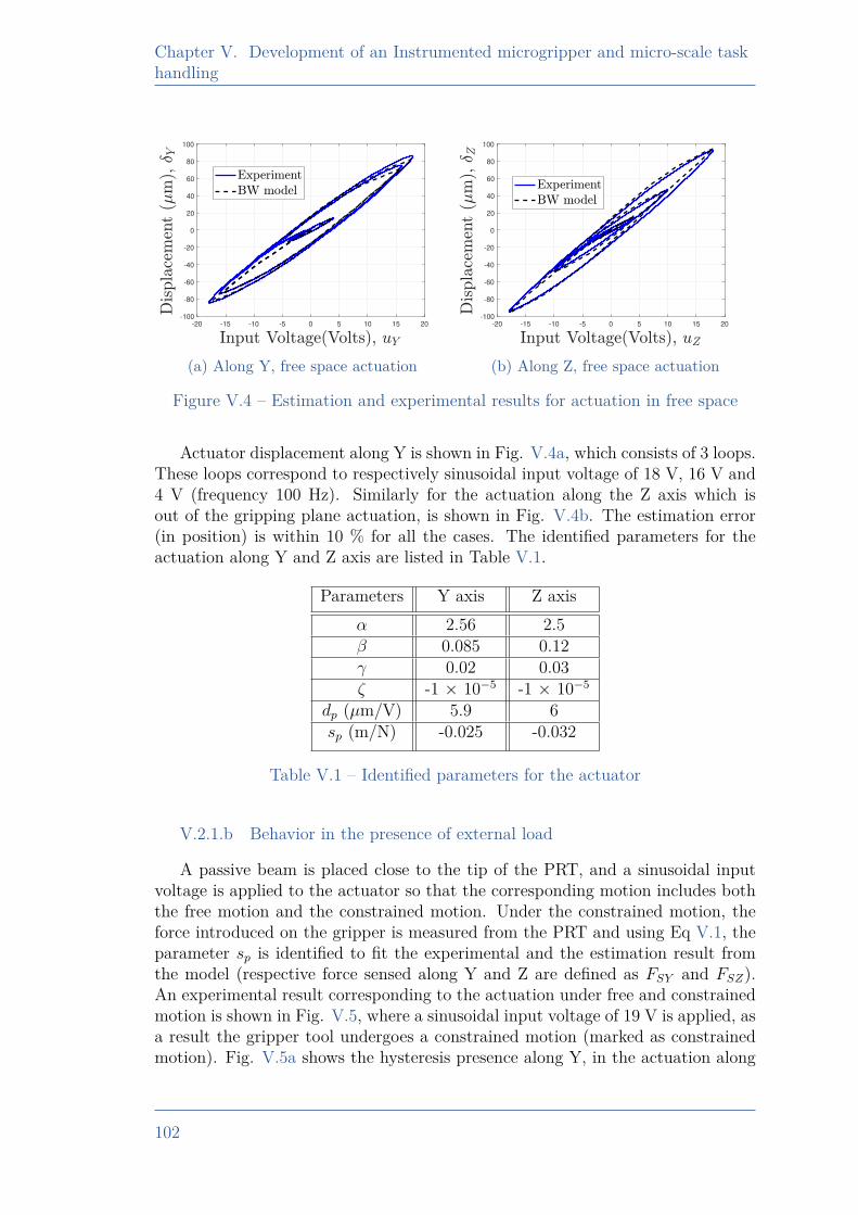
Chapter V. Development of an Instrumented microgripper and micro-scale taskhandling
-20 -15 -10 -5 0 5 10 15 20
-100
-80
-60
-40
-20
0
20
40
60
80
100
(a) Along Y, free space actuation
-20 -15 -10 -5 0 5 10 15 20
-100
-80
-60
-40
-20
0
20
40
60
80
100
(b) Along Z, free space actuation
Figure V.4 – Estimation and experimental results for actuation in free space
Actuator displacement along Y is shown in Fig. V.4a, which consists of 3 loops.These loops correspond to respectively sinusoidal input voltage of 18 V, 16 V and4 V (frequency 100 Hz). Similarly for the actuation along the Z axis which isout of the gripping plane actuation, is shown in Fig. V.4b. The estimation error(in position) is within 10 % for all the cases. The identified parameters for theactuation along Y and Z axis are listed in Table V.1.
Parameters Y axis Z axisα 2.56 2.5β 0.085 0.12γ 0.02 0.03ζ -1 × 10⁻⁵ -1 × 10⁻⁵
dp (µm/V) 5.9 6sp (m/N) -0.025 -0.032
Table V.1 – Identified parameters for the actuator
V.2.1.b Behavior in the presence of external load
A passive beam is placed close to the tip of the PRT, and a sinusoidal inputvoltage is applied to the actuator so that the corresponding motion includes boththe free motion and the constrained motion. Under the constrained motion, theforce introduced on the gripper is measured from the PRT and using Eq V.1, theparameter sp is identified to fit the experimental and the estimation result fromthe model (respective force sensed along Y and Z are defined as FSY and FSZ).An experimental result corresponding to the actuation under free and constrainedmotion is shown in Fig. V.5, where a sinusoidal input voltage of 19 V is applied, asa result the gripper tool undergoes a constrained motion (marked as constrainedmotion). Fig. V.5a shows the hysteresis presence along Y, in the actuation along
102
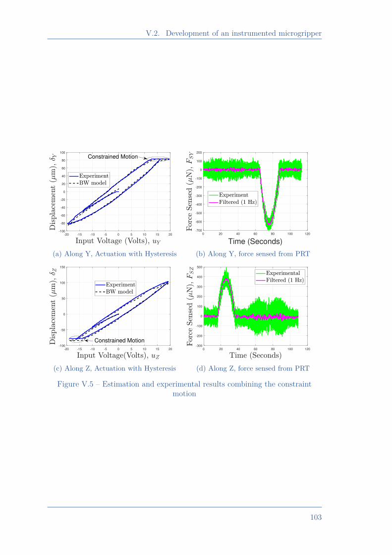
V.2. Development of an instrumented microgripper
-20 -15 -10 -5 0 5 10 15 20
-100
-80
-60
-40
-20
0
20
40
60
80
100
Constrained Motion
(a) Along Y, Actuation with Hysteresis
0 20 40 60 80 100 120
Time (Seconds)
-700
-600
-500
-400
-300
-200
-100
0
100
200
(b) Along Y, force sensed from PRT
-20 -15 -10 -5 0 5 10 15 20
-100
-50
0
50
100
150
Constrained Motion
(c) Along Z, Actuation with Hysteresis
0 20 40 60 80 100 120
-300
-200
-100
0
100
200
300
400
500
(d) Along Z, force sensed from PRT
Figure V.5 – Estimation and experimental results combining the constraintmotion
103
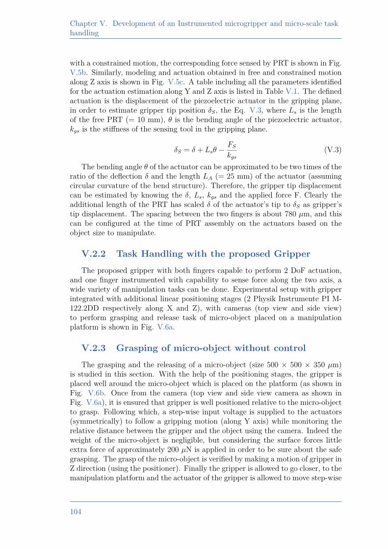
Chapter V. Development of an Instrumented microgripper and micro-scale taskhandling
with a constrained motion, the corresponding force sensed by PRT is shown in Fig.V.5b. Similarly, modeling and actuation obtained in free and constrained motionalong Z axis is shown in Fig. V.5c. A table including all the parameters identifiedfor the actuation estimation along Y and Z axis is listed in Table V.1. The definedactuation is the displacement of the piezoelectric actuator in the gripping plane,in order to estimate gripper tip position δS, the Eq. V.3, where Ls is the lengthof the free PRT (= 10 mm), θ is the bending angle of the piezoelectric actuator,kgs is the stiffness of the sensing tool in the gripping plane.
δS = δ + Lsθ −FSkgs
(V.3)
The bending angle θ of the actuator can be approximated to be two times of theratio of the deflection δ and the length LA (= 25 mm) of the actuator (assumingcircular curvature of the bend structure). Therefore, the gripper tip displacementcan be estimated by knowing the δ, Ls, kgs and the applied force F. Clearly theadditional length of the PRT has scaled δ of the actuator’s tip to δS as gripper’stip displacement. The spacing between the two fingers is about 780 µm, and thiscan be configured at the time of PRT assembly on the actuators based on theobject size to manipulate.
V.2.2 Task Handling with the proposed GripperThe proposed gripper with both fingers capable to perform 2 DoF actuation,
and one finger instrumented with capability to sense force along the two axis, awide variety of manipulation tasks can be done. Experimental setup with gripperintegrated with additional linear positioning stages (2 Physik Instrumente PI M-122.2DD respectively along X and Z), with cameras (top view and side view)to perform grasping and release task of micro-object placed on a manipulationplatform is shown in Fig. V.6a.
V.2.3 Grasping of micro-object without controlThe grasping and the releasing of a micro-object (size 500 × 500 × 350 µm)
is studied in this section. With the help of the positioning stages, the gripper isplaced well around the micro-object which is placed on the platform (as shown inFig. V.6b. Once from the camera (top view and side view camera as shown inFig. V.6a), it is ensured that gripper is well positioned relative to the micro-objectto grasp. Following which, a step-wise input voltage is supplied to the actuators(symmetrically) to follow a gripping motion (along Y axis) while monitoring therelative distance between the gripper and the object using the camera. Indeed theweight of the micro-object is negligible, but considering the surface forces littleextra force of approximately 200 µN is applied in order to be sure about the safegrasping. The grasp of the micro-object is verified by making a motion of gripper inZ direction (using the positioner). Finally the gripper is allowed to go closer, to themanipulation platform and the actuator of the gripper is allowed to move step-wise
104
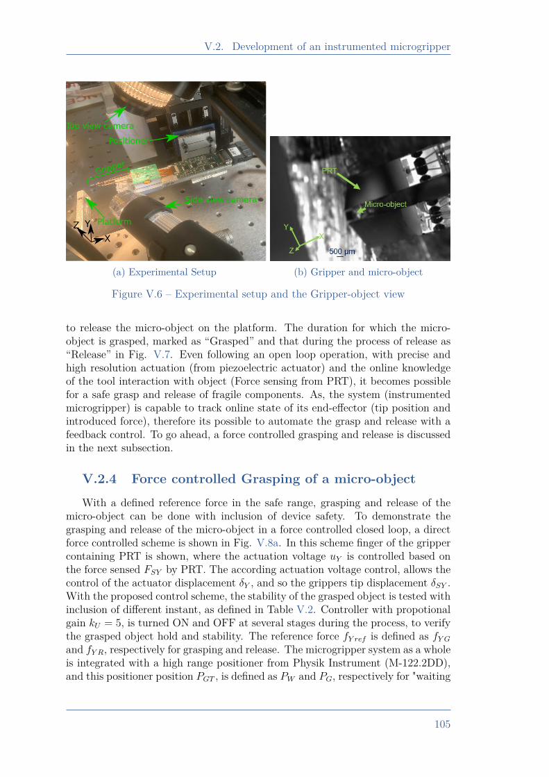
V.2. Development of an instrumented microgripper
Gripper
Platform
Side view camera
Top view camera
Positioner
X
YZ
(a) Experimental Setup (b) Gripper and micro-object
Figure V.6 – Experimental setup and the Gripper-object view
to release the micro-object on the platform. The duration for which the micro-object is grasped, marked as “Grasped” and that during the process of release as“Release” in Fig. V.7. Even following an open loop operation, with precise andhigh resolution actuation (from piezoelectric actuator) and the online knowledgeof the tool interaction with object (Force sensing from PRT), it becomes possiblefor a safe grasp and release of fragile components. As, the system (instrumentedmicrogripper) is capable to track online state of its end-effector (tip position andintroduced force), therefore its possible to automate the grasp and release with afeedback control. To go ahead, a force controlled grasping and release is discussedin the next subsection.
V.2.4 Force controlled Grasping of a micro-objectWith a defined reference force in the safe range, grasping and release of the
micro-object can be done with inclusion of device safety. To demonstrate thegrasping and release of the micro-object in a force controlled closed loop, a directforce controlled scheme is shown in Fig. V.8a. In this scheme finger of the grippercontaining PRT is shown, where the actuation voltage uY is controlled based onthe force sensed FSY by PRT. The according actuation voltage control, allows thecontrol of the actuator displacement δY , and so the grippers tip displacement δSY .With the proposed control scheme, the stability of the grasped object is tested withinclusion of different instant, as defined in Table V.2. Controller with propotionalgain kU = 5, is turned ON and OFF at several stages during the process, to verifythe grasped object hold and stability. The reference force fY ref is defined as fY Gand fY R, respectively for grasping and release. The microgripper system as a wholeis integrated with a high range positioner from Physik Instrument (M-122.2DD),and this positioner position PGT , is defined as PW and PG, respectively for "waiting
105
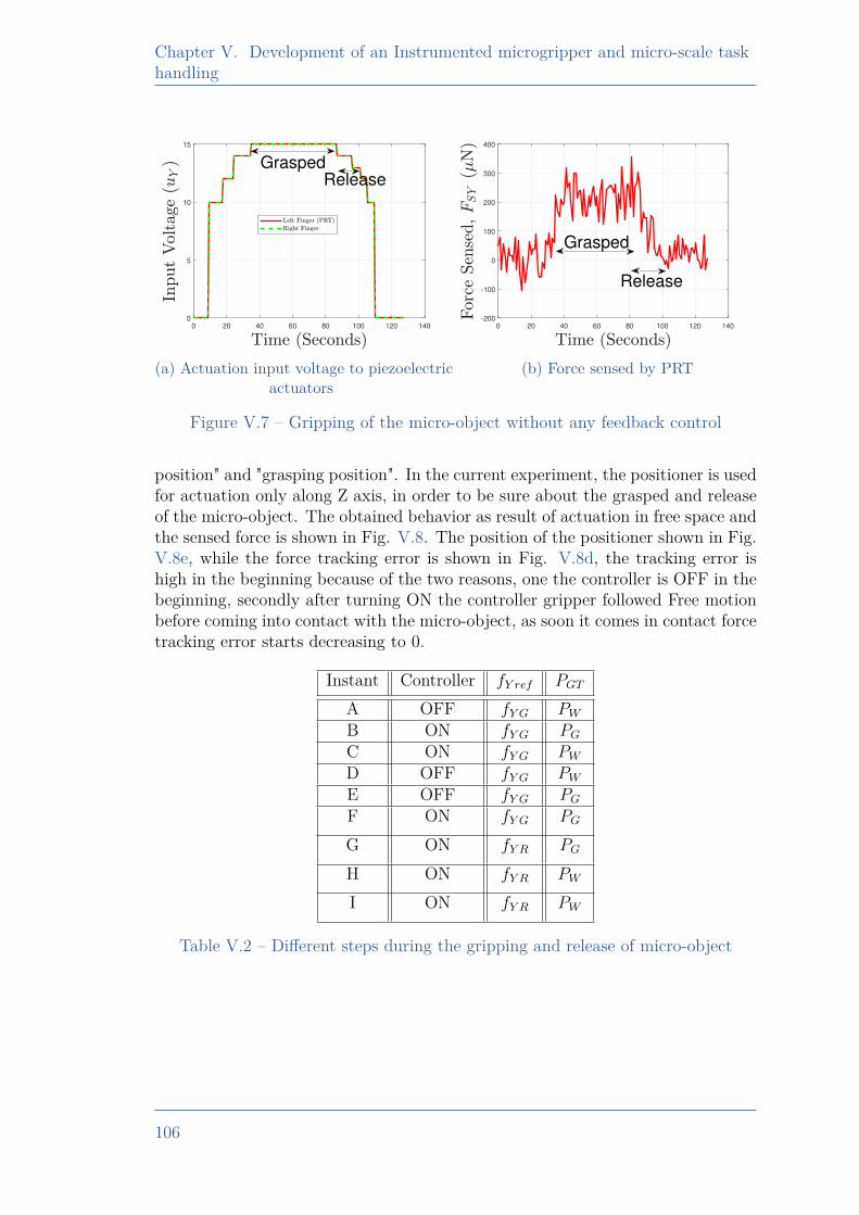
Chapter V. Development of an Instrumented microgripper and micro-scale taskhandling
0 20 40 60 80 100 120 1400
5
10
15
GraspedRelease
(a) Actuation input voltage to piezoelectricactuators
0 20 40 60 80 100 120 140-200
-100
0
100
200
300
400
Grasped
Release
(b) Force sensed by PRT
Figure V.7 – Gripping of the micro-object without any feedback control
position" and "grasping position". In the current experiment, the positioner is usedfor actuation only along Z axis, in order to be sure about the grasped and releaseof the micro-object. The obtained behavior as result of actuation in free space andthe sensed force is shown in Fig. V.8. The position of the positioner shown in Fig.V.8e, while the force tracking error is shown in Fig. V.8d, the tracking error ishigh in the beginning because of the two reasons, one the controller is OFF in thebeginning, secondly after turning ON the controller gripper followed Free motionbefore coming into contact with the micro-object, as soon it comes in contact forcetracking error starts decreasing to 0.
Instant Controller fY ref PGT
A OFF fY G PWB ON fY G PGC ON fY G PWD OFF fY G PWE OFF fY G PGF ON fY G PG
G ON fY R PG
H ON fY R PW
I ON fY R PW
Table V.2 – Different steps during the gripping and release of micro-object
106
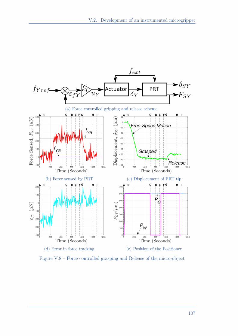
V.2. Development of an instrumented microgripper
Actuator PRT
(a) Force controlled gripping and release scheme
0 200 400 600 800 1000 1200
-100
0
100
200
300
400
500A B D E H IF GC
fYG
fYR
(b) Force sensed by PRT
0 200 400 600 800 1000 1200
-160
-140
-120
-100
-80
-60
-40
-20
0
20A B C D E F G H I
Free-Space Motion
Release
Grasped
(c) Displacement of PRT tip
0 200 400 600 800 1000 1200
-400
-300
-200
-100
0
100
200A B D E F G H IC
(d) Error in force tracking
0 200 400 600 800 1000 1200
0
100
200
300
400
500
600
700A B C D E F G H I
PG
PW
(e) Position of the Positioner
Figure V.8 – Force controlled grasping and Release of the micro-object
107
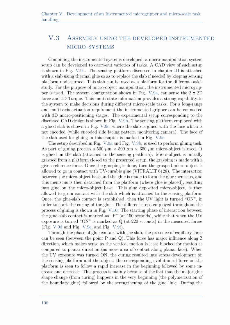
Chapter V. Development of an Instrumented microgripper and micro-scale taskhandling
V.3 Assembly using the developed instrumentedmicro-systems
Combining the instrumented systems developed, a micro-manipulation systemsetup can be developed to carry-out varieties of tasks. A CAD view of such setupis shown in Fig. V.9a. The sensing platform discussed in chapter III is attachedwith a slab using thermal glue so as to replace the slab if needed by keeping sensingplatform undisturbed. This slab can be used as a platform for the different task’sstudy. For the purpose of micro-object manipulation, the instrumented microgrip-per is used. The system configuration shown in Fig. V.9a, can sense the 2 x 2Dforce and 1D Torque. This multi-state information provides a strong capability tothe system to make decisions during different micro-scale tasks. For a long-rangeand multi-axis actuation requirement the instrumented gripper can be connectedwith 3D micro-positioning stages. The experimental setup corresponding to thediscussed CAD design is shown in Fig. V.9b. The sensing platform employed witha glued slab is shown in Fig. V.9c, where the slab is glued with the face which isnot encoded (while encoded side facing pattern monitoring camera). The face ofthe slab used for gluing in this chapter is marked in Fig. V.9c.
The setup described in Fig. V.9a and Fig. V.9b, is used to perform gluing task.As part of gluing process a 500 µm × 500 µm × 350 µm micro-object is used. Itis glued on the slab (attached to the sensing platform). Micro-object is initiallygrasped from a platform closed to the presented setup, the grasping is made with agiven reference force. Once the grasping is done, then the grasped micro-object isallowed to go in contact with UV-curable glue (VITRALIT 6128). The interactionbetween the micro-object base and the glue is made to form the glue meniscus, andthis meniscus is then detached from the platform (where glue is placed), resultinginto glue on the micro-object base. This glue deposited micro-object, is thenallowed to go in contact with the slab which is attached to the sensing platform.Once, the glue-slab contact is established, then the UV light is turned “ON”, inorder to start the curing of the glue. The different steps employed throughout theprocess of gluing is shown in Fig. V.10. The starting phase of interaction betweenthe glue-slab contact is marked as “P” (at 150 seconds), while that when the UVexposure is turned “ON” is marked as Q (at 220 seconds) in the measured forces(Fig. V.9d and Fig. V.9e, and Fig. V.9f).
Through the phase of glue contact with the slab, the presence of capillary forcecan be seen (between the point P and Q). This force has major influence along Zdirection, which makes sense as the vertical motion is least blocked for motion ascompared to planar direction (as more area of contact along planar face). Whenthe UV exposure was turned ON, the curing resulted into stress development onthe sensing platform and the object, the corresponding evolution of force on theplatform is seen to follow a rapid increase in the beginning followed by some in-crease and decrease. This process is mainly because of the fact that the major glueshape change (from curing) happens in the very beginning (the polymerization ofthe boundary glue) followed by the strengthening of the glue link. During the
108
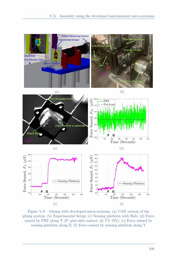
V.3. Assembly using the developed instrumented micro-systems
(a) (b)
(c)
0 100 200 300 400 500 600 700
500
550
600
650
700
750
800
P Q
(d)
0 100 200 300 400 500 600
-100
0
100
200
300
400
500
P Q
(e)
0 100 200 300 400 500 600
-20
0
20
40
60
80
100
120
140
160
180
P Q
(f)
Figure V.9 – Gluing with developed micro-systems; (a) CAD version of thegluing system; (b) Experimental Setup; (c) Sensing platform with Slab; (d) Forcesensed by PRT along Y (P: glue-slab contact, Q: UV ON); (e) Force sensed by
sensing platform along Z; (f) Force sensed by sensing platform along Y
109
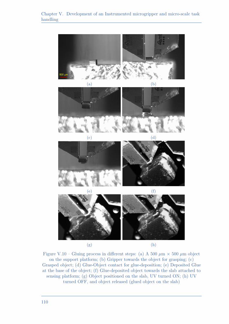
Chapter V. Development of an Instrumented microgripper and micro-scale taskhandling
(a) (b)
(c) (d)
(e) (f)
(g) (h)
Figure V.10 – Gluing process in different steps: (a) A 500 µm × 500 µm objecton the support platform; (b) Gripper towards the object for grasping; (c)
Grasped object; (d) Glue-Object contact for glue-deposition; (e) Deposited Glueat the base of the object; (f) Glue-deposited object towards the slab attached tosensing platform; (g) Object positioned on the slab, UV turned ON; (h) UV
turned OFF, and object released (glued object on the slab)
110
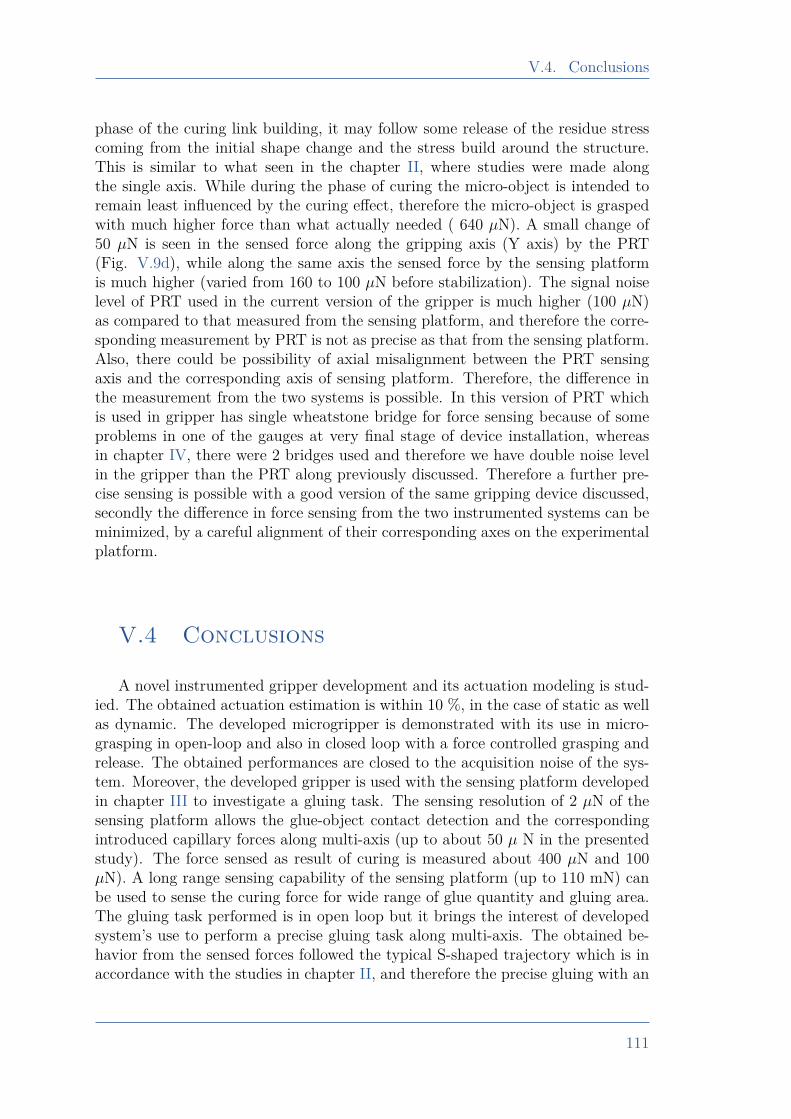
V.4. Conclusions
phase of the curing link building, it may follow some release of the residue stresscoming from the initial shape change and the stress build around the structure.This is similar to what seen in the chapter II, where studies were made alongthe single axis. While during the phase of curing the micro-object is intended toremain least influenced by the curing effect, therefore the micro-object is graspedwith much higher force than what actually needed ( 640 µN). A small change of50 µN is seen in the sensed force along the gripping axis (Y axis) by the PRT(Fig. V.9d), while along the same axis the sensed force by the sensing platformis much higher (varied from 160 to 100 µN before stabilization). The signal noiselevel of PRT used in the current version of the gripper is much higher (100 µN)as compared to that measured from the sensing platform, and therefore the corre-sponding measurement by PRT is not as precise as that from the sensing platform.Also, there could be possibility of axial misalignment between the PRT sensingaxis and the corresponding axis of sensing platform. Therefore, the difference inthe measurement from the two systems is possible. In this version of PRT whichis used in gripper has single wheatstone bridge for force sensing because of someproblems in one of the gauges at very final stage of device installation, whereasin chapter IV, there were 2 bridges used and therefore we have double noise levelin the gripper than the PRT along previously discussed. Therefore a further pre-cise sensing is possible with a good version of the same gripping device discussed,secondly the difference in force sensing from the two instrumented systems can beminimized, by a careful alignment of their corresponding axes on the experimentalplatform.
V.4 Conclusions
A novel instrumented gripper development and its actuation modeling is stud-ied. The obtained actuation estimation is within 10 %, in the case of static as wellas dynamic. The developed microgripper is demonstrated with its use in micro-grasping in open-loop and also in closed loop with a force controlled grasping andrelease. The obtained performances are closed to the acquisition noise of the sys-tem. Moreover, the developed gripper is used with the sensing platform developedin chapter III to investigate a gluing task. The sensing resolution of 2 µN of thesensing platform allows the glue-object contact detection and the correspondingintroduced capillary forces along multi-axis (up to about 50 µ N in the presentedstudy). The force sensed as result of curing is measured about 400 µN and 100µN). A long range sensing capability of the sensing platform (up to 110 mN) canbe used to sense the curing force for wide range of glue quantity and gluing area.The gluing task performed is in open loop but it brings the interest of developedsystem’s use to perform a precise gluing task along multi-axis. The obtained be-havior from the sensed forces followed the typical S-shaped trajectory which is inaccordance with the studies in chapter II, and therefore the precise gluing with an
111

Chapter V. Development of an Instrumented microgripper and micro-scale taskhandling
active control can be extended along multi-axis. As a future work, the proposedinstrumented gripper can be used to perform varieties of complex tasks in partiallyand/or fully automated mode.
112
Conclusions and perspectives
Conclusions and perspectives
This thesis presented a study of different micro-systems, their instrumentation andthe potential applications. As part of the COLAMIR project, this thesis targetedthe study and instrumented systems development for micro-assembly (in industrialcontext). The robotization of assembly process is an important need in the indus-try as it enables a cost effective mass production with repeatable performance.Gluing of the surfaces, is a very common approach of the assembly in the indus-try. But, being a widespread requirement, gluing is mostly done manually. Atthe micro-scale the gluing behavior is affected by several parameters, during thephase from liquid glue capillary influence to stress developed during curing. Thisbrings high uncertainty in the final positioning of the glued product. Therefore,in this thesis work gluing for micro-assembly is studied, the according challengesand approach towards precise gluing is discussed in Chapter II. It was found thatcuring alone can generate force of 200 µN across a gluing area of 500 µm × 500µm, but still this amplitude can’t be quantified because of its dependency overdifferent parameters such as glue quantity, choice of the glue and several others. Astudy of external load based dependency over the positioning enabled the use of anactive control for a precise gluing. With this use, positioning accuracy of ∼ 0.2 µmis demonstrated for the glued product. The studies in this chapter also suggestedthe requirement of multi-axis instrumentation to extend the approach adapted fora precise gluing along multi-axis. To follow up the assembly requirements, thereare several key challenges possible (in addition to the observation from gluing)such as; interaction with an unknown/variable environment, structural studiesetc. Modeling of the system alone is not sufficient to address these issues, andthere are potential requirements of multi-axis instrumentation with which localstate(s) information can be retrieved. To address these requirements, this thesistargeted the multi-axis instrumentation development and proposed 2 sensors andone instrumented microgripper. First sensor (sensing platform discussed in chap-ter III) is based on vision principle while the other using piezoresistive (piezore-sistive tool discussed in chapter IV). The proposed vision sensor of chapter IIIcan sense the forces along the two planar axis and torque about the normal axisto the force-sensing plane. This sensor employed a dedicated encoding strategywhich enabled planar position sensing over a long range. The vision sensor wasdemonstrated with a multi-axis force sensing with high range to resolution ratio of55000. This sensor demonstrated to sense the force from 2 µN to 110 mN along thetwo axis. The corresponding work included a novel methodology of modeling forforce–torque estimation along with non-linear force-displacement evolution. Tasklike gluing, where the extent of forces exerted (on the surfaces) is dependent on theseveral parameters (like glue quantity, size, shape with the gluing surfaces); in suchcases this sensor with high range to resolution enables the sensing from capillary
113
Conclusions and perspectives
interaction to the cured phase for a versatile choice over the gluing parameters.Moreover, this sensor is equally useful for multi-axis mechanical characterizationof a wide varieties of structures such as natural/artificial fibers, MEMS devices,etc. Also, the interest of this multi-axis instrumented system extends to the devel-opment of other instrumentation (calibration process). Therefore the developedinstrumentation is significantly useful for various applications. The second instru-mentation, which is piezoresistive sensing tool (chapter IV) demonstrated with asensing capability from 20 µN to 9 mN, along the two axis. This sensor can be eas-ily integrated with actuators to perform different studies, and are very useful whenthe sensing frame need to move in a very confined workspace. The demonstratedsensing tool was mainly designed for its use to develop an instrumented gripper,but one key advantage of this device development constitutes separate fabricationof the sensing part, and passive part. Therefore, different sizes and shapes ofpassive tool can be separately fabricated based on specific task requirements andcan be assembled with the proposed sensing part. This would lead to wide rangeof sensing possibilities, as the performance in terms of the range, resolution aredependent on the geometrical and mechanical parameters of the passive tool. Thiswork therefore, opens up the possibilities to tune up different parameters for anyspecific application.
The demonstrated piezoresistive sensing tool was further integrated with a2-axis piezoelectric actuators to develop an instrumented microgripper (chapterV). Modeling of the actuation of the instrumented gripper with inclusion of thehysteresis and external force is discussed with an estimation error less than 10 %.The developed gripper is demonstrated with grasping and release of a micro-object,making an open loop and a feedback controlled task. The obtained performanceswere within the signal noise level. The developed microgripper was also used forthe multi-axis gluing study with its combined use with the sensing platform. Thecorresponding study from multi-axis gluing brings the interest of using an activecontrol for a precise gluing along multi-axis. Moreover, the developed instrumenteddevices can be used to perform varieties of complex tasks, including 6-DoF precisegluing, insertion, rotation etc. Especially, for gluing and insertion (varying envi-ronment), use of impedance control can provide interesting results and thereforeneed to be demonstrated in the near future.
In terms of the device improvement for the microgripper developed, an adap-tation of the variable stiffness mechanism in the sensing tool can bring interestingflexibility. Indeed there are several works which demonstrated the possibility of theuse of the variable stiffness gripper such as using jamming technique [Yokouchif 20],[Jiang 19]. The gripper can also be tuned magnetically for variable stiffness suchas in [Memar 19] (Fig V.11) which enhanced manipulation safety and robustnessduring collisions. A variable stiffness capability of the gripper allows to play withdifferent sensing range and resolution without changing the tool. The MEMSdevices such as [Cailliez 18], demonstrated variable stiffness sensing for a nN res-olution over a measurement range of ± 2.45 µN. The interest of such sensing isin the characterization of mechanical structures, where for the distance (<20 nm)between the sensor and the structure, intramolecular force follows variable gradi-
114
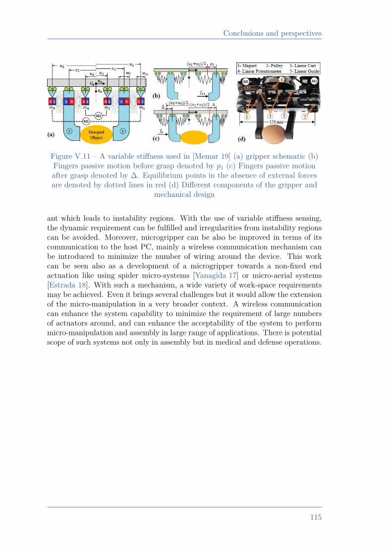
Conclusions and perspectives
Figure V.11 – A variable stiffness used in [Memar 19] (a) gripper schematic (b)Fingers passive motion before grasp denoted by p1 (c) Fingers passive motionafter grasp denoted by ∆. Equilibrium points in the absence of external forcesare denoted by dotted lines in red (d) Different components of the gripper and
mechanical design
ant which leads to instability regions. With the use of variable stiffness sensing,the dynamic requirement can be fulfilled and irregularities from instability regionscan be avoided. Moreover, microgripper can be also be improved in terms of itscommunication to the host PC, mainly a wireless communication mechanism canbe introduced to minimize the number of wiring around the device. This workcan be seen also as a development of a microgripper towards a non-fixed endactuation like using spider micro-systems [Yanagida 17] or micro-aerial systems[Estrada 18]. With such a mechanism, a wide variety of work-space requirementsmay be achieved. Even it brings several challenges but it would allow the extensionof the micro-manipulation in a very broader context. A wireless communicationcan enhance the system capability to minimize the requirement of large numbersof actuators around, and can enhance the acceptability of the system to performmicro-manipulation and assembly in large range of applications. There is potentialscope of such systems not only in assembly but in medical and defense operations.
115
Bibliography
Bibliography
[Adam 19] G. Adam & D. J. Cappelleri. Design of a 3d vision-based micro-force sensing probe. IEEE MARSS’ 19 proceeding, 2019.
[Al-Shareef 95] K. J. H. Al-Shareef, J. A. Brandon & A. J. Griffiths. A simplifiedtechnique for the analysis of multi-stepped beams. Proceedingsof the Institution of Mechanical Engineers, Part C: Journal ofMechanical Engineering Science, 1995.
[Alapan 19] Y. Alapan, O. Yasa, B. Yigit, I. C. Yasa, P. Erkoc & M. Sitti. Mi-crorobotics and Microorganisms: Biohybrid Autonomous CellularRobots. Annual Review of Control, Robotics, and AutonomousSystems, vol. 2, pages 205–230, 2019.
[Alneamy 20] A. M. Alneamy, M. E. Khater, A. K. A.-Aziz, G. R. Heppler &E. M. A.-Rahman. Electrostatic arch micro-tweezers. Elsevier,International Journal of Non-Linear Mechanics, vol. 118, 2020.
[André 20a] A. N. André, P. Sandoz, B. Mauzé, M. Jacquot & G. J. Laurent.Robust phase-based decoding of absolute (X, Y, θ) positioning byvision. IEEE Transactions on Instrumentation and Measurement,2020.
[André 20b] A. N. André, P. Sandoz, B. Mauzé, M. Jacquot & G. J. Laurent.Sensing One Nanometer over Ten Centimeters: A Micro-EncodedTarget for Visual In-Plane Position Measurement. IEEE/ASMETransactions on Mechatronics, vol. 25, no. 3, pages 1193–1201,2020.
[Bettahar 17] H. Bettahar, A. Caspar, C. Clévy, N. Courjal & P. Lutz. Photo-Robotic Positioning for Integrated Optics. IEEE Robotics andAutomation Letters, vol. 2, no. 1, page 217–222, 2017.
[Beyeler 09] F. Beyeler, S. Muntwyler & B. J. Nelson. A Six-AxisMEMS Force–Torque Sensor With Micro-Newton and Nano-Newtonmeter Resolution. Journal of Microelectromechanical Sys-tems, vol. 18, no. 2, 2009.
[Billot 15] M. Billot, X. Xu, J. Agnus, E. Piat & P. Stempflé. Multi-axisMEMS force sensor for measuring friction components involvedin dexterous micromanipulation: Design and optimization. In-derscience, International Journal of Nanomanufacturing, vol. 11,pages 161–184, 2015.
116
Bibliography
[Budday 17] S. Budday, G. Sommer, C. Birkl, C. Langkammer, J. Haybaeck,J. Kohnert, M. Bauer, F. Paulsen, P. Steinmann, E. Kuhl & G. A.Holzapfel. Mechanical characterization of human brain tissue.Elsevier, Acta Biomaterialia, vol. 48, pages 319–340, 2017.
[Cailliez 18] J. Cailliez, M. Boudaoud, A. M. Ousaid, A. W.-Duflos, S. Haliyo& S. Régnier. Modeling and Experimental Characterization of anActive MEMS Based Force Sensor. International Conference onManipulation, Automation and Robotics at Small Scales, Japan,2018.
[Chang 10] R. J. Chang & C. C. Chen. Using Microgripper in Development ofAutomatic Adhesive Glue Transferring and Binding Microassem-bly System. Engineering, vol. 2, no. 1, pages 1–11, 2010.
[Chang 16] R.-J. Chang & J.-C. Jau. Augmented Reality in Peg-in-HoleMicroassembly Operations. International Journal of AutomationTechnology, 2016.
[Chang 17] B. Chang, M. Koverola, Z. Ge & Q. Zhou. Hybrid Mi-croassembly combining Laser Die Transfer and Capillary Self-alignment. International Conference on Manipulation, Automa-tion and Robotics at Small Scales, 2017.
[Chen 16] X. Chen, C.-Y. Su, Z. Li & F. Yang. Design of ImplementableAdaptive Control for Micro/Nano Positioning System Driven byPiezoelectric Actuator. IEEE Transactions on Industrial Elec-tronics, vol. 63, no. 10, pages 6471–6481, 2016.
[Chen 19] P. C. Chen, K. Gadepalli, R. MacDonald, S. K. Y. Liu, K. Nag-pal, T. Kohlberger, J. Dean, G. S. Corrado, J. D. Hipp, C. H.Mermel & M. C. Stumpe. An augmented reality microscope withreal-time artificial intelligence integration for cancer diagnosis.Nature Medicine, vol. 25, no. 3, 2019.
[CITHADEL 19] CITHADEL. CITHADEL project. https://www.ens2m.fr/fr/projet-cithadel, 2019.
[Clévy 19] C. Clévy, B. Sauvet, J.-Y. Rauch, O. Lehmann, F. Marionnet,P. Lutz, L. Beccacece, S. Xavier, R. Aubry, A. Ziaei, C. Prévot& G. J. Laurent. In-situ Versatile Characterization of CarbonNanoTubes using Nanorobotics. IEEE, International Conferenceon Manipulation, Automation and Robotics at Small Scales, 2019.
[Cognard. 10] J. Y. Cognard., R. Creac’hcadec, L. Sohier & D. Leguillon. Influ-ence of adhesive thickness on the behaviour of bonded assembliesunder shear loadings using a modified TAST fixture. Springer,vol. 30, pages 257–266, 2010.
117
Bibliography
[COLAMIR 20] COLAMIR. COLAMIR ANR Project. https://projects.femto-st.fr/colamir/en/sample-page, 2020.
[Cui 18] S. Cui, X. N. Guan, E. Ghantous, J. J. Vajo, M. Lucas, M. S.Hsiao, L. F. Drummy, J. Collins, A. Juhl, C. S. Roper, & A. F.Gross. Aqueous Assembly of Oxide and Fluoride Nanoparticlesinto 3D Microassemblies. Langmuir, vol. 34, no. 27, pages 8075–8080, 2018.
[da Silva 11] L. F. M. da Silva, A. Ochsner & R. D. Adams. Fiber to chip fusionsplicing for robust, low loass photonic packaging. Handbook ofAdhesion Technology, Springer-Verlag Berlin Heidelberg, 2011.
[Dai 19] J. Dai, S. Xi & D. Li. Numerical Analysis of Curing ResidualStress and Deformation in Thermosetting Composite Laminateswith Comparison between Different Constitutive Models. Materi-als, 2019.
[Das 20] T. K. Das, B. Shirinzadeh, M. Ghafarian & A. Al-Jodah. Design,analysis, and experimental investigation of a single-stage and lowparasitic motion piezoelectric actuated microgripper. IOP, SmartMaterials and Structures, 2020.
[Das 21] T. K. Das, B. Shirirnzadeh, A. A.-Jodah, M. Ghafarian & J. Pin-skier. A novel compliant piezoelectric actuated symmetric micro-gripper for the parasitic motion compensation. Elsevier, Mecha-nism and Machine Theory, vol. 155, no. 1, 2021.
[Dash 19] J. N. Dash, Z. Liu, D. S. Gunawardena & H.-Y. Tam. Fabry–Perotcavity-based contact force sensor with high precision and a broadoperational range. OSA, Optics Letters, vol. 44, no. 14, page3546, 2019.
[Deng 19] J. Deng, W. Chen & H. Yu. A XY Transporting and Nanoposi-tioning Piezoelectric Robot Operated by Leg Rowing Mechanism.IEEE/ASME Transactions of Mechatronics, vol. 24, no. 1, pages207–217, 2019.
[Deng 20] J. Deng, Y. Liu, S. Zhang & J. Li. Development of a Nano-Positioning Platform with Large Travel Range Based on BionicQuadruped Piezoelectric Actuator. IEEE/ASME Transactions ofMechatronics, 2020.
[Desroches 18] J. Desroches, M. Jermyn, M. Pinto, F. Picot, M.-A. Tremblay,S. Obaid, E. Marple, K. Urmey, D. Trudel, G. Soulez, M.-C.Guiot, B. C. Wilson, K. Petrecca & F. Leblond. A new methodusing Raman spectroscopy for in vivo targeted brain cancer tissuebiopsy. Nature, Scientific Reports, 2018.
118
Bibliography
[Dosta 17] M. Dosta, C. Costa & H. A. Al-Qureshi. Numerical investigationof compaction of deformable particles with bonded-particle model.EPJ Web of Conferences 140, 15021, Powders & Grains, 2017.
[Estrada 18] M. A. Estrada, S. Mintchev, D. L. Christensen, M. R. Cutkosky& D. Floreano. Forceful manipulation with micro air vehicles.Science Robotics, 2018.
[Fornes-Leal 16] A. Fornes-Leal, C. Garcia-Pardo, M. Frasson, V. P. Beltran &N. Cardona. Dielectric characterization of healthy and malignantcolon tissues in the 0.5–18 GHz frequency band. IOP, Physics inMedicine & Biology, vol. 61, no. 20, 2016.
[Gakkestad 10] J. Gakkestad, P. Dalsjo, H. Kristiansen, R. Johannessen &M. M. V. Taklo. Use of conductive adhesive for MEMS in-terconnection in ammunition fuze applications. Journal of Mi-cro/Nanolithography, MEMS, and MOEMS, vol. 9, 2010.
[Galeano 20] J. Galeano, A. Zarzycki, J. G. Reyes & M. E. Moncada. Op-tical characterization of collagen scaffolds using multispectralim-ages and a light-scaffold interaction model. Elsevier, BiomedicalSignal Processing and Control, 2020.
[Gan 19] J. Gan & X. Zhang. Nonlinear Hysteresis Modeling of Piezo-electric Actuators Using a Generalized Bouc–Wen Model. MDPI,Micromachines, vol. 10, 2019.
[Gao 20] J. Gao, J. Zhan & Z. Yang. Enzyme-Instructed Self-Assembly(EISA) and Hydrogelation of Peptides. Advanced Materials, 2020.
[Greaves 11] G. N. Greaves, A. L. Greer, R. S. Lakes & T. Rouxel. Poisson’sratio and modern materials. Nature Materials, 2011.
[Guggenheim 17] J. W. Guggenheim, L. P. Jentoft, Y. Tenzer, & R. D. Howe. Ro-bust and Inexpensive 6-Axis Force-Torque Sensors using MEMSBarometers. IEEE/ASME Transactions on Mechatronics, vol. 22,no. 2, pages 838–844, 2017.
[Gursky 19] B. Gursky, S. Bütefisch, M. L.-Schädel, K. Li, B. Matheis & A. Di-etzel. A Disposable Pneumatic Microgripper for Cell Manipula-tion with Image-Based Force Sensing. MDPI, Micromachines,vol. 10, no. 10, 2019.
[He 14] X. He, J. Handa, P. Gehlbach, R. Taylor & I. Iordachita. ASubmillimetric 3-DOF Force Sensing Instrument With IntegratedFiber Bragg Grating for Retinal Microsurgery. IEEE Transactionson Biomedical Engineering, vol. 61, no. 2, pages 522–534, 2014.
119
Bibliography
[Hossain 09] M. Hossain, G. Possart & P. Steinmann. A small-strain modelto simulate the curing of thermosets. Computational Mechanics,vol. 43, pages 769–779, 2009.
[Jiang 19] P. Jiang, Y. Yang, M. Z. Q. Chen & Y. Chen. A variable stiff-ness gripper based on differential drive particle jamming. IOP,Bioinspiration & Biomimetics, vol. 14, no. 3, 2019.
[Komati 12] B. Komati, J. Agnus, C. Clévy & P. Lutz. Suspended submi-cron silicon-beam for high sensitivity piezoresistive force sensingcantilevers. Sensors and Actuators, 2012.
[Komati 14a] B. Komati, J. Agnus, C. Clévy & P. Lutz. Prototyping of ahighly performant and integrated piezoresistive force sensor formicroscale applications, Sensors. Journal of Micromechanics andMicroengineering, 2014.
[Komati 14b] B. Komati, C. Clévy & P. Lutz. Force tracking impedance controlwith unknown environment at the microscale. Proc. - IEEE Int.Conf. Robot. Autom., page 5203–5208, 2014.
[Komati 16a] B. Komati, C. Clévy & P. Lutz. High Bandwidth MicrogripperWith Integrated Force Sensors and Position Estimation for theGrasp of Multistiffness Microcomponents. IEEE/ASME Transac-tions on Mechatronics, 2016.
[Komati 16b] B. Komati, A. Kudryavtsev, C. Clévy, G. Laurent, B. Tamadazte,J. Agnus & P. Lutz. Automated robotic microassembly of flexibleoptical components. IEEE International Symposium on Assemblyand Manufacturing, 2016.
[L.-Evans 20] H. L.-Evans, C. A. Griffiths & A. A. Fahmy. An experimentalstudy into displacement of a shape memory alloy actuated roboticmicrogripper. IOP, Engineering Research Express, vol. 2, no. 1,2020.
[Lee 18] T. Y. Lee, K. Han, D. O. Barrett, S. Park, S. A. Soper & M. C.Murphy. Accurate, predictable, repeatable micro-assembly tech-nology for polymer, microfluidic modules. Sensors Actuators, BChem., vol. 254, pages 1249–1258, 2018.
[Lee 20] Y. R. Lee, J. Neubauer, K. J. Kim & Y. Cha. MultidirectionalCylindrical Piezoelectric Force Sensor: Design and ExperimentalValidation. MDPI, Sensors, vol. 20, no. 17, page 4840, 2020.
[Li 19] T. Li, N. K. K. King & H. Ren. Disposable FBG-Based Tridirec-tional Force/Torque Sensor for Aspiration Instruments in Neu-rosurgery. IEEE, Transactions on Industrial Electronics, vol. 67,no. 4, pages 3236–3247, 2019.
120
Bibliography
[Li 20a] T. Li, A.Pan & H. Ren. A High-Resolution Triaxial CatheterTip Force Sensor With Miniature Flexure and Suspended OpticalFibers. IEEE, Transactions on Industrial Electronics, vol. 67,no. 6, pages 5101–5111, 2020.
[Li 20b] T. Li, N. K. K. King & H. Ren. Disposable FBG-Based Tridirec-tional Force/Torque Sensor for Aspiration Instruments in Neu-rosurgery. IEEE Transactions on Industrial Electronics, vol. 67,no. 4, pages 3236–3247, 2020.
[Li 20c] T. Li, A. Pan & H. Ren. A High-Resolution Triaxial CatheterTip Force Sensor With Miniature Flexure and Suspended Opti-cal Fibers. IEEE Transactions on Industrial Electronics, vol. 67,no. 6, pages 5101–5111, 2020.
[Liseli 17] J. B. Liseli, J. Agnus, P. Lutz & M. Rakotondrabe. Self-Sensingmethod considering the dynamic impedance of piezoelectric basedactuators for ultra-low frequency. IEEE Robotics and AutomationLetters, vol. 3, no. 2, pages 1049–1055, 2017.
[Liu 13] H. Liu, S. Yang, Y. Zhao, Z. Jiang, Y. Liu, & B. Tian. A Micro-Force Sensor with Slotted-Quad-Beam Structure for Measuringthe Friction in MEMS Bearings. MDPI Sensors, vol. 13, pages13178–13191, 2013.
[Liu 17] Y. Liu, Y. Zhang & Q. Xu. Design and Control of a Novel Com-pliant Constant-Force Gripper Based on Buckled Fixed-GuidedBeams. IEEE/ASME Transactions on Mechatronics, 2017.
[Liu 19] Y. Liu, L. Wang, H. Feng, X. Ren, J. Ji, F. Bai & H. Fan.Microemulsion-Assisted Self-Assembly and Synthesis of Size-Controlled Porphyrin Nanocrystals with Enhanced PhotocatalyticHydrogen Evolution. ACS, Nano Letters, 2019.
[Liu 20] S. Liu, Y.-F. Li & X.-W. Wang. A Novel Dual-Probe-Based Mi-crograsping System Allowing Dexterous 3-D Orientation Adjust-ment. IEEE Transactions on Automation Science and Engineer-ing, 2020.
[Lu 18] Z. Lu, P. Huang, Z. Liu & H. Chen. Fuzzy Observer-based Hy-brid Force/Position Control Design for a Multiple-sampling-rateBimanual Teleoperation System. IEEE Trans. Fuzzy Syst., 2018.
[Ma 19] Y. Ma, K. Du, D. Zhou, J. Zhang, X. Liu & D. Xu. Automaticprecision robot assembly system with microscopic vision and forcesensor. International Journal of Advanced Robotic Systems, 2019.
121
Bibliography
[Ma 20] Y. Ma, D. Xu & F. Qin. Efficient Insertion Control for PrecisionAssembly Based on Demonstration Learning and ReinforcementLearning. IEEE Transactions on Industrial Informatics, 2020.
[McCarthy 14] E. K. McCarthy, A. T. Bellew, J. E. Sader & J. J. Boland. Pois-son’s ratio of individual metal nanowires. Nature Communica-tions, 2014.
[Memar 19] A. H. Memar & E. T. Esfahani. A Robot Gripper with VariableStiffness Actuation for Enhancing Collision Safety. IEEE Trans-actions on Industrial Electronics, 2019.
[Morales 18] A. R. R. Morales & M. E. Zaghloul. Highly Sensitive WearablePiezoelectric Force Sensor With Quasi-Static Load Testing. IEEE,Sensors Journal, vol. 18, no. 24, pages 9910–9918, 2018.
[Mosca 20] S. Mosca, P. Lanka, N. Stone, S. K. V. Sekar, P. Matousek,G. Valentini & A. Pifferi. Optical characterization of porcine tis-sues from various organs in the 650–1100 nm range using time-domain diffuse spectroscopy. Biomedical Optics Express, vol. 11,no. 3, 2020.
[Muntwyler 10] S. Muntwyler, F. Beyeler & B. J. Nelson. Three-axis micro-forcesensor with sub-micro-Newton measurement uncertainty and tun-able force range. Journal of Micromechanics and Microengineer-ing, 2010.
[Müller 15] T. Müller, V. K. Venu, S. Haag, D. Zontar, S. Sauer, C. Wenzel &C. Brecher. UV Curable Formulations for UV-C LEDs. Strategiesfor precision adhesive bonding of micro-optical systems, vol. 9346,2015.
[Na 19] C.-H. Na & K.-S. Yun. Capacitive Force Sensor with WideDynamic Range Using Wrinkled Micro Structures as DielectricLayer. ASP, Journal of Nanoscience and Nanotechnology, vol. 19,pages 6663–6667, 2019.
[Nauriyal 18] J. Nauriyal, M. Song, R. Yu & J. Cardenas. Fiber to ChipFusion Splicing for Robust, Low Loass Photonic Packaging.arXiv:1810.09531 [physics.app-ph], 2018.
[Neugebauer 11] R. Neugebauer, H.-J. Koriath, A. F. V. der Merwe, M. Müller &S. Matope. Study on applicability of adhesive forces for micro-material handling in production technology. ISEM Proceedings,2011.
122
Bibliography
[Noh 16] Y. Noh, S. Sareh, H. Würdemann, H. Liu, J. Back, J. Housden,K. Rhode & K. Althoefer. Three-Axis Fiber-Optic Body ForceSensor for Flexible Manipulators. IEEE, Sensors Journal, vol. 16,no. 6, 2016.
[Norland 00] E. A. Norland & F. S. Martin. Mechanisms Relating to Reduc-ing Stress in Curing Thick Sections of UV Adhesives. NorlandProducts Inc., 2000.
[norton 78] P. norton & J. Brandt. Temperature coefficient of Resistance forp- and n-type Silicon. Solid State Electronics, vol. 21, pages 969–974, 1978.
[Oh 18] S. Oh, J. Kim & S. T. Chang. Highly sensitive metal-grid strainsensors via water based solution processing. RSC Advances, 2018.
[Okamura 16] H. Okamura, S. Niizeki, T. Ochi & A. Matsumoto. UV CurableFormulations for UV-C LEDs. Journal of Photopolymer Scienceand Technology, vol. 29, pages 99–104, 2016.
[Park 16] B. Park, J. Kim, D. Kang, C. Jeong, K. S. Kim, J. U. Kim,P. J. Yoo & T. Kim. Dramatically Enhanced Mechanosensitiv-ity and Signal-to-Noise Ratio of Nanoscale Crack-Based Sensors.Advanced Materials, 2016.
[Park 18] S. Park, C. Lui, W.-H. Jung, D. Maity, C. S. Ong, J. Bush,V. Maruthamuthu, N. Hibino & Y. Chen. Mechanical Charac-terization of hiPSC-Derived Cardiac Tissues for Quality Control.Advanced Biosystems, vol. 2, no. 12, 2018.
[Percástegui 19] E. G. Percástegui, J. Mosquera, T. K. Ronson, A. J. Plajer,M. Kieffer & J. R. Nitschke. Waterproof architectures throughsubcomponent self-assembly. Royal Society of Chemistry, Chem-istry Science, 2019.
[Perkel 19] J. M. Perkel. Go big or go home. Nature, vol. 575, no. 3, 2019.
[Puangmali 12] P. Puangmali, H. Liu, L. D. Seneviratne, P. Dasgupta & K. Al-thoefer. Miniature 3-Axis Distal Force Sensor for Minimally In-vasive Surgical Palpation. IEEE/ASME Transactions on Mecha-tronics, vol. 17, no. 4, pages 646–656, 2012.
[R.D. 84] A. R.D. & W. W.C. Factors Influencing the Choice of Adhesive.In: Structural Adhesive Joints in Engineering. Springer, 1984.
[Roca 12] S. F. Roca & R. UV Adhesive viscocity adjustment apparatus andmethod. United States Patent, no. US 8.256.272 B1, 2012.
123
Bibliography
[Ruggeri 18] S. Ruggeri, G. Fontana, A. Ghidoni, A. Morelli, G. Legnani, A. M.Lezzi & I. Fassi. A Preliminary Fluid Dynamic Model of a Vac-uum Micro-Gripper With Integrated Release System. ASME, In-ternational Design Engineering Technical Conferences and Com-puters and Information In Engineering Conference, 2018.
[Sabarianand 20] D. V. Sabarianand, P. Karthikeyan & T. Muthuramalingam. Areview on control strategies for compensation of hysteresis andcreep on piezoelectric actuators based micro systems. Elsevier,Mechanical Systems and Signal Processing, vol. 140, 2020.
[Senarathna 19] J. Senarathna, H. Yu, C. Deng, A. L. Zou, J. B. Issa, D. H. Had-jiabadi, S. Gil, Q. Wang, B. M. Tyler, N. V. Thakor & A. P.Pathak. A miniature multi-contrast microscope for functionalimaging in freely behaving animals. Nature Communications,vol. 10, no. 3, 2019.
[Shang 20] W. Shang, H. Ren, M. Zhu, T. Xu & X. Wu. Dual RotatingMicrosphere Using Robotic Feedforward Compenstion Control ofCooperative Flexible Micropipettes. IEEE Transactions on Au-tomation Science and Engineering, 2020.
[Shen 19] F. Shen, Z. Zhang, D. Xu, J. Zhang & W. Wu. An AutomaticAssembly Control Method for Peg and Hole Based on Multidi-mensional Micro Forces and Torques. International Journal ofPrecision Engineering and Manufacturing, 2019.
[Shi 19] C. Shi, M. Li, C. Lv, J. Li & S. Wang. A High-SensitivityFiber Bragg Grating-Based Distal Force Sensor for LaparoscopicSurgery. IEEE, Sensors Journal, vol. 20, no. 5, pages 2467–2475,2019.
[Suzuki 19] M. Suzuki, T. Takahashi & S. Aoyagi. A Distributed 3D ForceSensor for Detecting Insect Motion by Optically Evaluating De-formation of Microscale Grid Pattern Inscribed on A Flexible Hy-drogel Sheet. IEEE, International Conference on Solid-State Sen-sors, Actuators and Microsystems & Eurosensors, 2019.
[Taghipour 20] A. Taghipour, A. N. Cheema, X. Gu, & F. J. Sharifi. Tempera-ture Independent Triaxial Force and Torque Sensor for MinimallyInvasive Interventions. IEEE/ASME Transactions on Mechatron-ics, vol. 25, no. 1, pages 449–459, 2020.
[Takahashi 14] H. Takahashi, N. Thanh-Vinh, U. G. Jung, K. Matsumoto &I. Shimoyama. MEMS two-axis force plate array used to measurethe ground reaction forces during the running motion of an ant.Journal of Micromechanics and Microengineering, vol. 24, no. 6,2014.
124
Bibliography
[Teixeira 18] V. S. Teixeira, W. Krautschneider & J. J. M. Rodriguez.Bioimpedance Spectroscopy for Characterization of Healthy andCancerous Tissues. IEEE, International Conference on ElectricalEngineering and Photonics, 2018.
[Tennico 10] Y. H. Tennico, M. T. Kosedjojo, S. Kondo, D. T. Mandrell &V. T. Remcho. Surface modification-assisted bonding of polymer-based microfluidic devices. Sensors and Actuators B: Chemical,vol. 143, no. 2, pages 799–804, 2010.
[Tisnes 20] S. D. Tisnes, L. Petit, C. Prelle & F. Lamarque. Modeling andexperimental validation of a planar micro conveyor based on a2 x 2 array of digital electromagnetic actuators. IEEE/ASMETransactions on Mechatronics, 2020.
[V.-Chable 19] P. V.-Chable, C. F.-Bello, J. O. S.-Reyes, M. T.-Torres &J. Varona. A novel electrothermal compliance microgripper. IEEE,International Conference on Mechatronics, Electronics and Auto-motive Engineering, Mexico, 2019.
[Vyskocil 20] J. Vyskocil, C. Mayorga-Martinez, E. Jablonska, F. Novotny,T. Ruml & M. Pumera. Cancer Cells Microsurgery via Asym-metric Bent Surface Au/Ag/Ni Microrobotic Scalpels Through aTransversal Rotating Magnetic Field. ACS Nano, vol. 14, no. 7,pages 8247–8256, 2020.
[Wang 17] G. Wang & Q. Xu. Design and Precision Position/Force Controlof a Piezo-Driven Microinjection System. IEEE/ASME Trans.Mechatronics, vol. 22, no. 4, pages 1744–1754, 2017.
[Wang 18] H. Wang, J. Li, J. Cui, Q. Shi, Z. Zheng, T. Sun, Q. Huang &T. Fukuda. Microrobotic Assembly of Shape-Customized Three-Dimensional Microtissues Based on Surface Tension Driven Self-Alignment. IEEE Transactions on Nanotechnology, vol. 17, no. 4,pages 684–687, 2018.
[Wang 19a] F. Wang, B. Shi, Z. Huo, Y. Tian, X. Zhao & D. Zhang. SmoothDisplacement/Force Switching Control of a Piezoelectric ActuatedMicrogripper for Micro Manipulation. IEEE International Con-ference on Manipulation, Manufacturing and Measurement on theNanoscale, 2019.
[Wang 19b] Y. Wang, Y. Hiratsuka, T. Nitta, K. Uesugi & K. Mor-ishima. Micro-Assembly Using Optically Patterned Molecular-Motor-Powered Artificial Muscles. International Conference onMicro Electro Mechanical Systems (MEMS), 2019.
125
Bibliography
[Wang 20a] L. Wang, D. Jones, G. J. Chapman, H. J. Siddle, D. A. Russell,A. Alazmani & P. Culmer. An Inductive Force Sensor for In-ShoePlantar Normal and Shear Load Measurement. IEEE, SensorsJournal, vol. 20, no. 22, pages 13318–13331, 2020.
[Wang 20b] Y. Wang, H. Huang, Y. Zhao, Z. Feng, H. Fan, T. Sun &Y. Xu. Self-assembly of ultralight and compressible inorganicsponges with hierarchical porosity by electrospinning. CeramicsInternational, 2020.
[Wei 15] Y. Wei & Q. Xu. An Overview of Micro-Force Sensing Techniques.Elsevier, Sensors and Actuators A, 2015.
[Wei 19] G. Wei, Q. Jiang & T. Zhang. A flexible force sensor based onspheroidal Fabry-Perot micro-cavity. Elsevier, Optik, vol. 181,pages 483–492, 2019.
[Wu 19] Z. Wu, L. Li, Y. Yang, P. Hu, Y. Li, S. Yang, L. V. Wang &W. Gao. A microrobotic system guided by photoacoustic computedtomography for targeted navigation in intestines in vivo. ScienceRobotics, vol. 4, no. 32, 2019.
[Xie 16] Y. Xie, Y. Zhou, Y. Lin, L. Wang, & W. Xi. Development of aMicroforce Sensor and Its Array Platform for Robotic Cell Mi-croinjection Force Measurement. MDPI Sensors, vol. 16, 2016.
[Xie 18] H. Xie, H. Z. nad J. Song, X. Meng, Y. Wen & L. Sun.High-Precision Automated Micromanipulation and Adhesive Mi-crobonding with Cantilevered Micropipette Probes in DynamicProbing Mode. IEEE/ASME Transactions on Mechatronics, 2018,2018.
[Xie 19] H. Xie, X. Meng, H. Zhang & L. Sun. Development of a Mag-netically Driven Microgripper for PicoNewton Force-ControlledMicroscale Manipulation and Characterization. IEEE Transac-tions on Industrial Electronics, vol. 67, no. 3, pages 2065–2075,2019.
[Xing 18] D. Xing, F. Liu, S. Liu & D. Xu. Efficient Insertion of PartiallyFlexible Objects in Precision Assembly. IEEE Transactions onAutomation Science and Engineering, 2018.
[Xiong 14] L. Xiong, P. Chen & Q. Zhou. Adhesion promotion between PDMSand glass by oxygen plasma pre-treatment. Journal of AdhesionScience and Technology, vol. 28, no. 11, page 1046–1054, 2014.
126
Bibliography
[Yanagida 17] T. Yanagida, R. E. Mohan, T. Pathmakumar, K. Elangovan& M. Iwase. Design and Implementation of a Shape ShiftingRolling–Crawling–Wall-Climbing Robot. MDPI, Applied Science,2017.
[Yang 13] S. Yang & N. Lu. Gauge Factor and Stretchability of Silicon-on-Polymer Strain Gauges, Sensors. MDPI Sensors, 2013.
[Yang 17] S. Yang, Q. Xu & Z. Nan. Design and Development of a Dual-Axis Force Sensing MEMS Microgripper. Journal of Mechanismand Robotics, vol. 9, no. 6, 2017.
[Yang 18] Y.-L. Yang, J.-Q. Lou, G.-H. Wu, Y.-D. Wei, & L. Fu. Design andposition/force control of an S-shaped MFC microgripper. Elsevier,Sensors and Actuators, vol. 282, pages 63–78, 2018.
[Yang 20] L. Yang, Y. Zhang, Q. Wang & L. Zhang. An Automated Mi-crorobotic Platform for Rapid Detection of C. diff Toxins. IEEETransactions on Biomedical Engineering, vol. 67, no. 5, pages1517–1527, 2020.
[Yao 19] Z.-F. Yao, Y.-Q. Zheng, Q.-Y. Li, T. Lei, S. Zhang, L. Zou, H.-Y.Liu, J.-H. Dou, Y. Lu, J.-Y. Wang, X. Gu & J. Pei. Wafer-Scale Fabrication of High-Performance n-Type Polymer Mono-layer Transistors Using a Multi-Level Self-Assembly Strategy. Ad-vanced Materials, 2019.
[Yasa 19] I. C. Yasa, A. F. Tabak, O. Yasa, H. Ceylan & M. Sitti. 3D-Printed Microrobotic Transporters with Recapitulated Stem CellNiche for Programmable and Active Cell Delivery. AdvancedFunctional Materials, vol. 29, no. 17, 2019.
[Yeh 19] S.-K. Yeh & W. Fang. Inductive Micro Tri-Axial Tactile SensorUsing a CMOS Chip With a Coil Array. IEEE, Electron DeviceLetters, vol. 40, no. 4, pages 620–623, 2019.
[Yokouchif 20] K. Yokouchif, T. Kamegawa, T. Matsuno, T. Hiraki, T. Yam-aguchi & A. Gofuku. Development of a Gripper with VariableStiffness for a CT-Guided Needle Insertion Robot. Journal ofRobotics and Mechatronics, 2020.
[Yong 09] Y. K. Yong, S. S. Aphale & S. O. R. Moheimani. Design, Iden-tification, and Control of a Flexure-Based XY Stage for FastNanoscale Positioning. IEEE Transactions on Nanotechnology,vol. 8, no. 1, 2009.
[Youssefi 19] O. Youssefi & E. Diller. Dry surface micromanipulation using anuntethered magnetic microrobot. Springer, Cham, 2019.
127

Bibliography
[Zhang 19] R. Zhang, A. Sherehiy, Z. Yang, D. Wei, C. K. Harnett & D. O.Popa. ChevBot – An Untethered Microrobot Powered by Laser forMicrofactory Applications. International Conference on Roboticsand Automation, 2019.
[Zyvex 20] Zyvex. Gear Assembly on 100 µm Tungsten wire. https://www.zyvexlabs.com/Technology/MicroAssembly.html, 2020.
128
Titre : Instrumentation multi-axes pour micro-assemblage robotisé
Mots clefs: Instrumentation, Micro-assemblage, Control
Résumé : L’instrumentation dans lesmicro-dispositifs a attiré l’attention de dif-férents domaines et a été récemment démon-trée avec un large éventail d’acceptabilitéde la médecine à la technologie spa-tiale. Les industries qui souhaitent ef-fectuer diverses tâches de micro-assemblageet robotiser ce processus nécessitent égale-ment une instrumentation dédiée. Cettethèse cible l’étude du micro-assemblage,analysant la complexité et le développe-ment de l’instrumentation. Avec les be-soins potentiels de collage pour le micro-assemblage dans les industries, le comporte-ment de collage est analysé. La complex-ité vers un assemblage précis est abordéeavec une approche microrobotique selon 1
axe (potentiellement affectée par le collage).L’approche démontrée avec 0.2 µm de pré-cision de positionnement du produit collé.L’extension de l’approche pour un collageprécis multi-axes nécessite une instrumen-tation multi-axes. Cette thèse a démontréle développement de 3 systèmes instrumen-tés. Cela constitue une plate-forme de dé-tection de force / couple multi-axes, un outilde détection de force à 2 axes, tandis que letroisième est un microgripper instrumentédéveloppé à partir de l’outil de détection deforce développé. La thèse couvre différentstravaux, de la conception, la modélisation,la fabrication et la validation expérimentaledes différents systèmes développés.
Title : Multi-axis Instrumentation for Robotized Micro-assembly
Keywords : Instrumentation, Micro-assembly, Control
Abstract : Instrumentation in the micro-devices has brought the attention of dif-ferent fields and are recently demonstratedwith a wide range of acceptability frommedicine to space technology. Industriesaiming to do various micro-assembly tasksand robotize this process, also require ded-icated instrumentation. This thesis targetsthe study of micro-assembly, analyzing thecomplexity and development of instrumen-tation. With potential needs of gluing formicro-assembly in the industries, the glu-ing behavior is analyzed. The complexitytowards precise assembly is addressed witha microrobotics approach along 1 axis (po-
tentially affected by gluing). The approachdemonstrated with 0.2 µm of positioning ac-curacy of the glued product. The exten-sion of the approach for a multi-axis precisegluing requires multi-axis instrumentation.This thesis demonstrated the developmentof 3 instrumented systems. This constitutesa multi-axis force/torque sensing platform,a 2 axis force sensing tool, while the thirdis an instrumented microgripper developedfrom the developed force sensing tool. The-sis covers different works, from design, mod-eling, fabrication and experimental valida-tion of the different systems developed.
Université Bourgogne Franche-Comté32, avenue de l’Observatoire25000 Besançon
Related Documents


