M/s. Ion Exchange (I) Ltd, Ankleshwar M/s. Jyoti Om Chemical Research Centre Pvt. Ltd., Ankleshwar. ANNEXURE- I PROPOSED TERMS OF REFERENCE Site description and plant layout. Project falls under B Category. List of finished products and production quantity. List of raw materials and consumption quantity. Process details with mass balance. Details of process emissions, waste water discharge & solid waste generation and disposal Complete water balance. Details of air pollution control systems. Base line data for soil, water, air and noise for one season. Environment impact assessment due to excavation and construction activities, manufacturing process and its operations etc. Details of Environmental Management Plan (EMP) and mitigation measures. Occupational health and safety program for the project.

Welcome message from author
This document is posted to help you gain knowledge. Please leave a comment to let me know what you think about it! Share it to your friends and learn new things together.
Transcript
M/s. Ion Exchange (I) Ltd, Ankleshwar
M/s. Jyoti Om Chemical Research Centre Pvt. Ltd., Ankleshwar.
ANNEXURE- I
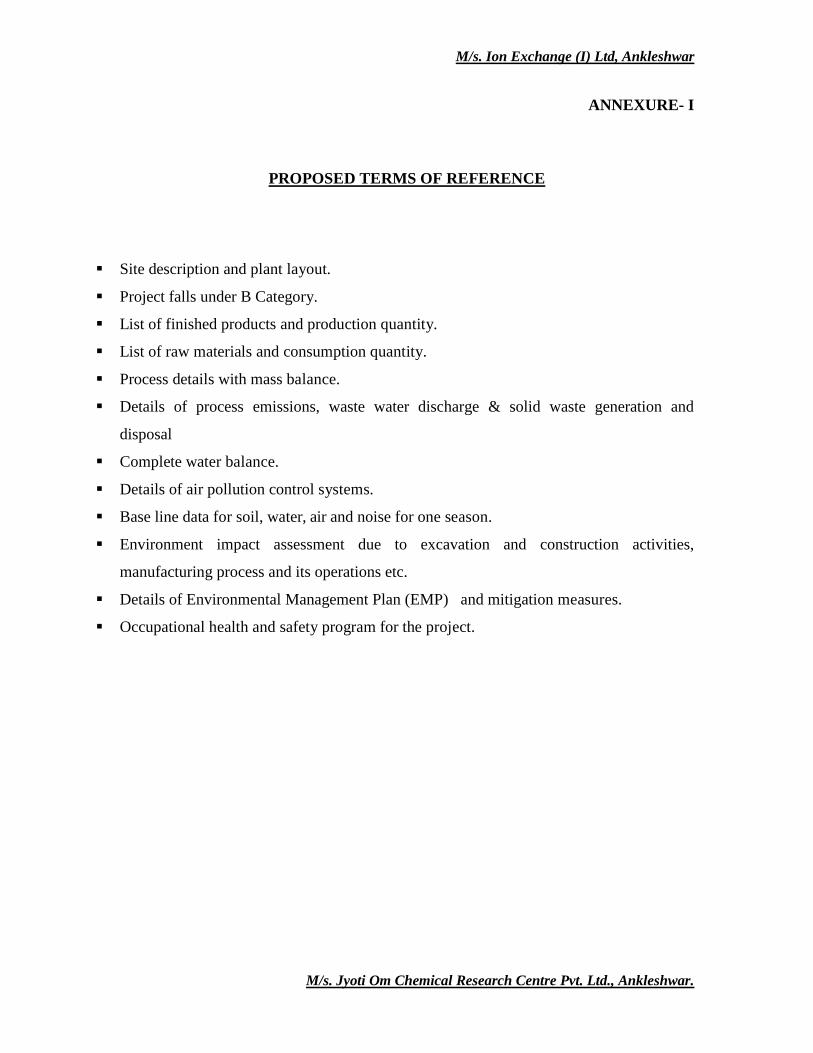
PROPOSED TERMS OF REFERENCE
Site description and plant layout.
Project falls under B Category.
List of finished products and production quantity.
List of raw materials and consumption quantity.
Process details with mass balance.
Details of process emissions, waste water discharge & solid waste generation and
disposal
Complete water balance.
Details of air pollution control systems.
Base line data for soil, water, air and noise for one season.
Environment impact assessment due to excavation and construction activities,
manufacturing process and its operations etc.
Details of Environmental Management Plan (EMP) and mitigation measures.
Occupational health and safety program for the project.
M/s. Ion Exchange (I) Ltd, Ankleshwar
M/s. Jyoti Om Chemical Research Centre Pvt. Ltd., Ankleshwar.
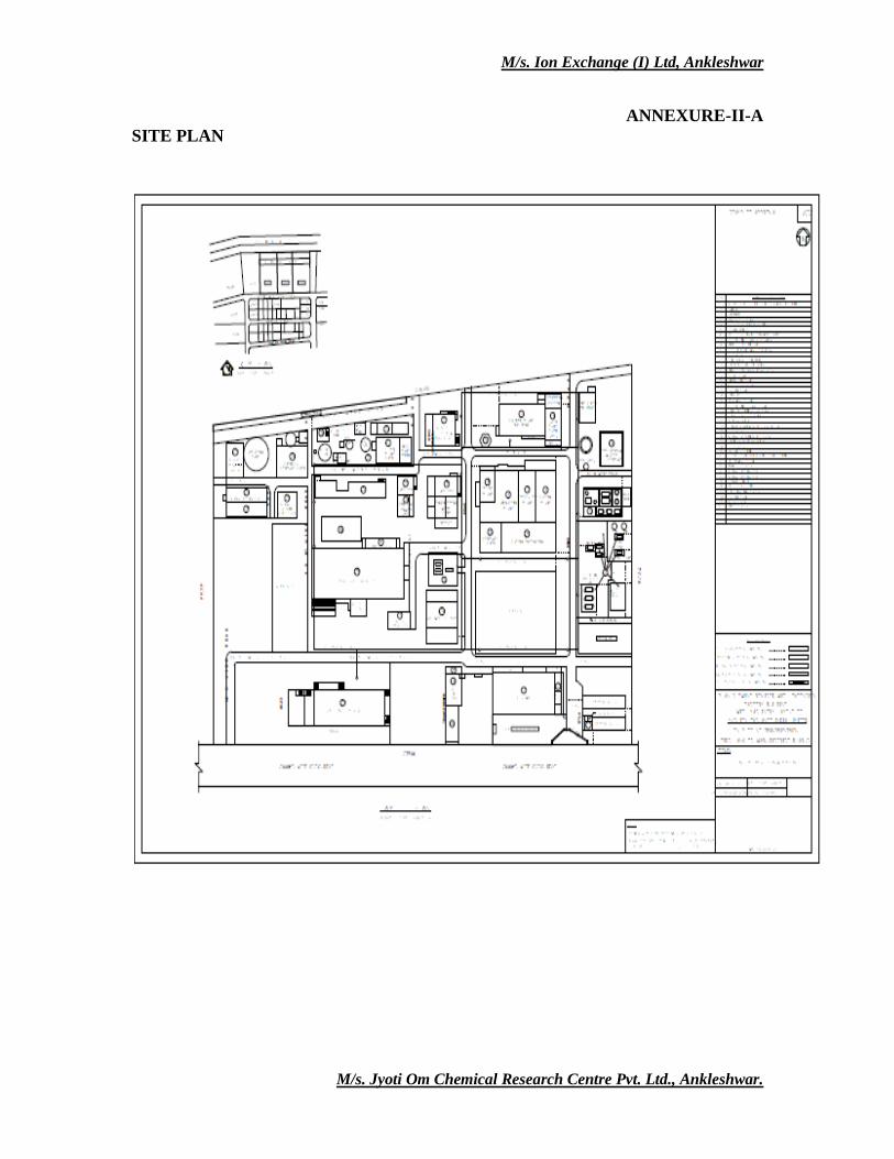
ANNEXURE-II-A
SITE PLAN
M/s. Ion Exchange (I) Ltd, Ankleshwar
M/s. Jyoti Om Chemical Research Centre Pvt. Ltd., Ankleshwar.
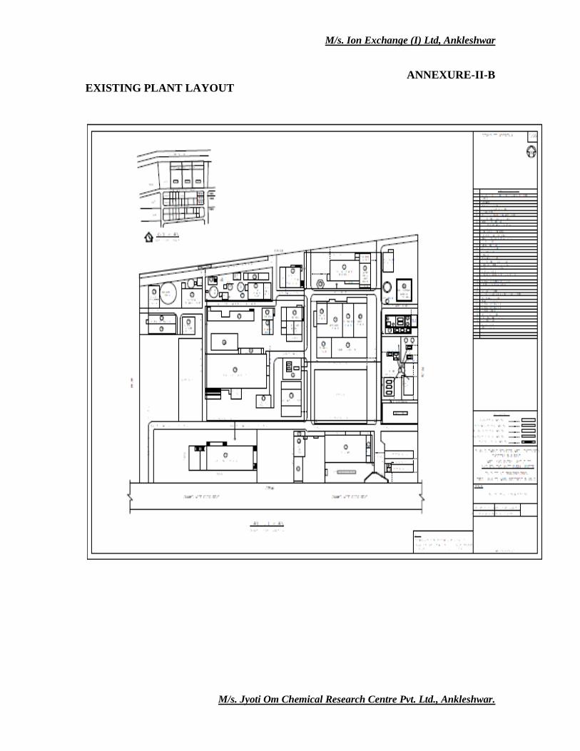
ANNEXURE-II-B
EXISTING PLANT LAYOUT
M/s. Ion Exchange (I) Ltd, Ankleshwar
M/s. Jyoti Om Chemical Research Centre Pvt. Ltd., Ankleshwar.
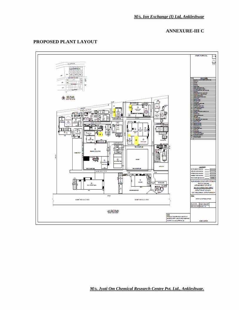
ANNEXURE-III C
PROPOSED PLANT LAYOUT
M/s. Ion Exchange (I) Ltd, Ankleshwar
M/s. Jyoti Om Chemical Research Centre Pvt. Ltd., Ankleshwar.
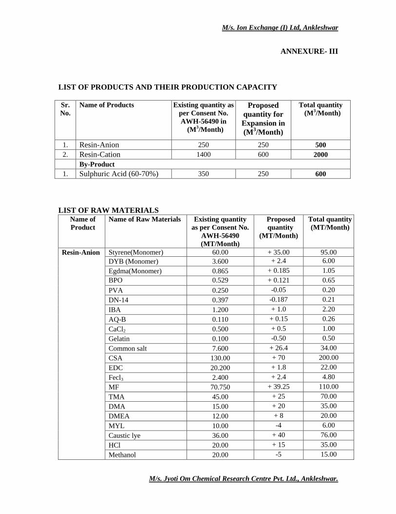
ANNEXURE- III
LIST OF PRODUCTS AND THEIR PRODUCTION CAPACITY Sr.
No.
Name of Products Existing quantity as
per Consent No.
AWH-56490 in
(M3/Month)
Proposed
quantity for
Expansion in
(M3/Month)
Total quantity
(M3/Month)
1. Resin-Anion 250 250 500
2. Resin-Cation 1400 600 2000
By-Product
1. Sulphuric Acid (60-70%) 350 250 600
LIST OF RAW MATERIALS
Name of
Product
Name of Raw Materials Existing quantity
as per Consent No.
AWH-56490
(MT/Month)
Proposed
quantity
(MT/Month)
Total quantity
(MT/Month)
Resin-Anion Styrene(Monomer) 60.00 + 35.00 95.00
DYB (Monomer) 3.600 + 2.4 6.00
Egdma(Monomer) 0.865 + 0.185 1.05
BPO 0.529 + 0.121 0.65
PVA 0.250 -0.05 0.20
DN-14 0.397 -0.187 0.21
IBA 1.200 + 1.0 2.20
AQ-B 0.110 + 0.15 0.26
CaCl2 0.500 + 0.5 1.00
Gelatin 0.100 -0.50 0.50
Common salt 7.600 + 26.4 34.00
CSA 130.00 + 70 200.00
EDC 20.200 + 1.8 22.00
Fecl3 2.400 + 2.4 4.80
MF 70.750 + 39.25 110.00
TMA 45.00 + 25 70.00
DMA 15.00 + 20 35.00
DMEA 12.00 + 8 20.00
MYL 10.00 -4 6.00
Caustic lye 36.00 + 40 76.00
HCl 20.00 + 15 35.00
Methanol 20.00 -5 15.00
M/s. Ion Exchange (I) Ltd, Ankleshwar
M/s. Jyoti Om Chemical Research Centre Pvt. Ltd., Ankleshwar.
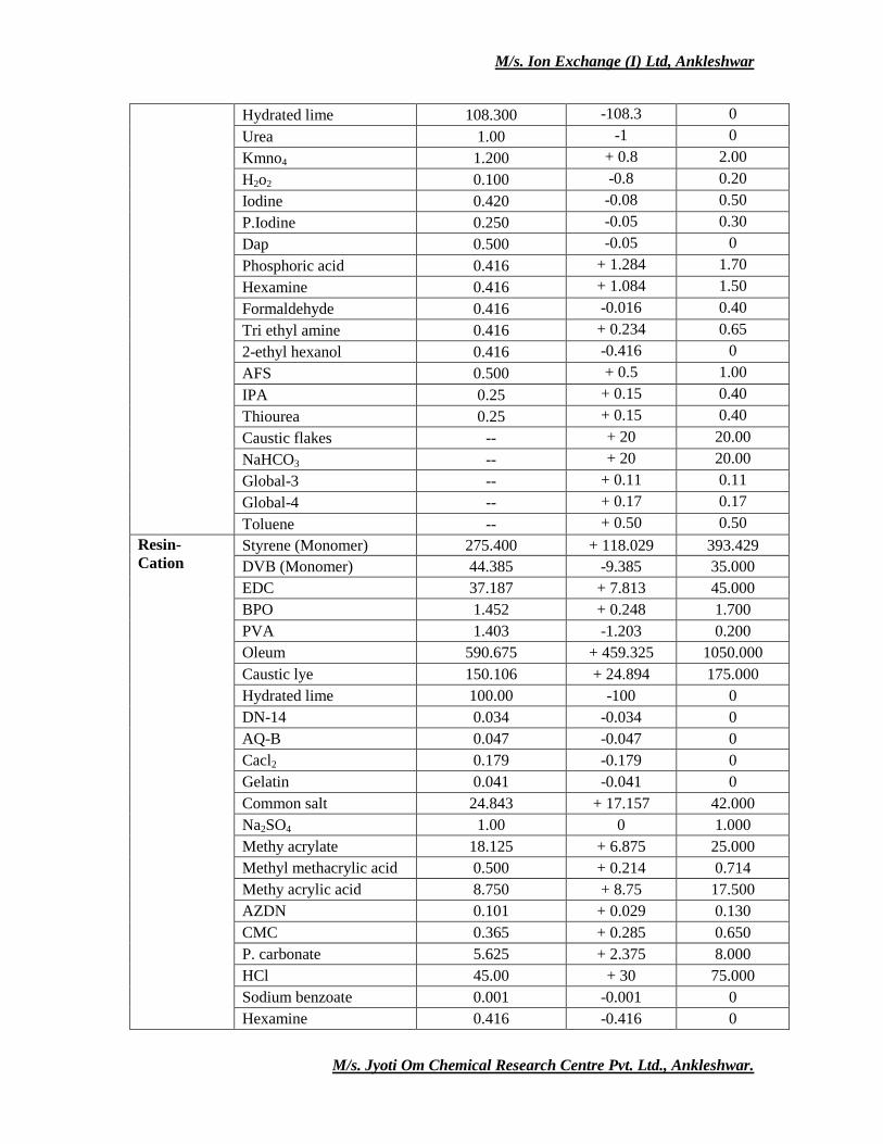
Hydrated lime 108.300 -108.3 0
Urea 1.00 -1 0
Kmno4 1.200 + 0.8 2.00
H2o2 0.100 -0.8 0.20
Iodine 0.420 -0.08 0.50
P.Iodine 0.250 -0.05 0.30
Dap 0.500 -0.05 0
Phosphoric acid 0.416 + 1.284 1.70
Hexamine 0.416 + 1.084 1.50
Formaldehyde 0.416 -0.016 0.40
Tri ethyl amine 0.416 + 0.234 0.65
2-ethyl hexanol 0.416 -0.416 0
AFS 0.500 + 0.5 1.00
IPA 0.25 + 0.15 0.40
Thiourea 0.25 + 0.15 0.40
Caustic flakes -- + 20 20.00
NaHCO3 -- + 20 20.00
Global-3 -- + 0.11 0.11
Global-4 -- + 0.17 0.17
Toluene -- + 0.50 0.50
Resin-
Cation Styrene (Monomer) 275.400 + 118.029 393.429
DVB (Monomer) 44.385 -9.385 35.000
EDC 37.187 + 7.813 45.000
BPO 1.452 + 0.248 1.700
PVA 1.403 -1.203 0.200
Oleum 590.675 + 459.325 1050.000
Caustic lye 150.106 + 24.894 175.000
Hydrated lime 100.00 -100 0
DN-14 0.034 -0.034 0
AQ-B 0.047 -0.047 0
Cacl2 0.179 -0.179 0
Gelatin 0.041 -0.041 0
Common salt 24.843 + 17.157 42.000
Na2SO4 1.00 0 1.000
Methy acrylate 18.125 + 6.875 25.000
Methyl methacrylic acid 0.500 + 0.214 0.714
Methy acrylic acid 8.750 + 8.75 17.500
AZDN 0.101 + 0.029 0.130
CMC 0.365 + 0.285 0.650
P. carbonate 5.625 + 2.375 8.000
HCl 45.00 + 30 75.000
Sodium benzoate 0.001 -0.001 0
Hexamine 0.416 -0.416 0
M/s. Ion Exchange (I) Ltd, Ankleshwar
M/s. Jyoti Om Chemical Research Centre Pvt. Ltd., Ankleshwar.
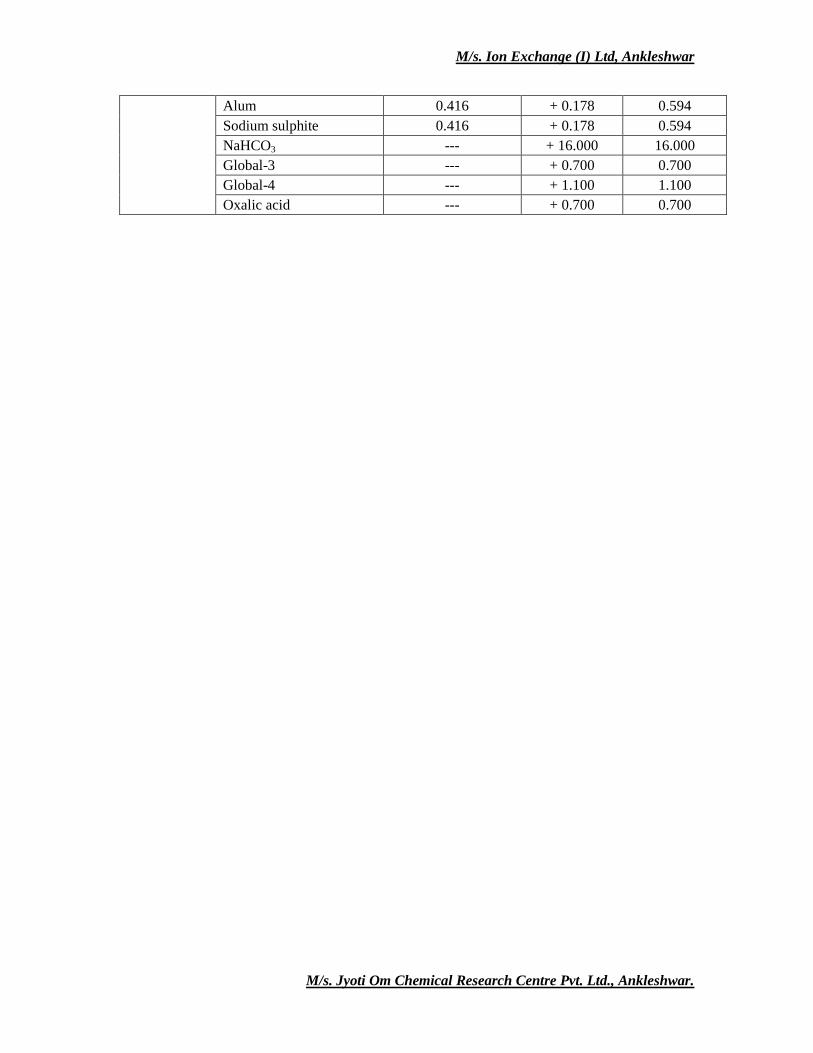
Alum 0.416 + 0.178 0.594
Sodium sulphite 0.416 + 0.178 0.594
NaHCO3 --- + 16.000 16.000
Global-3 --- + 0.700 0.700
Global-4 --- + 1.100 1.100
Oxalic acid --- + 0.700 0.700
M/s. Ion Exchange (I) Ltd, Ankleshwar
M/s. Jyoti Om Chemical Research Centre Pvt. Ltd., Ankleshwar.
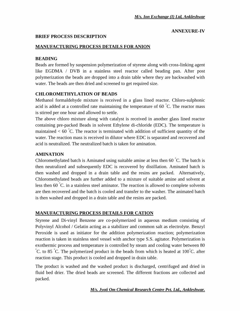
ANNEXURE-IV
BRIEF PROCESS DESCRIPTION
MANUFACTURING PROCESS DETAILS FOR ANION
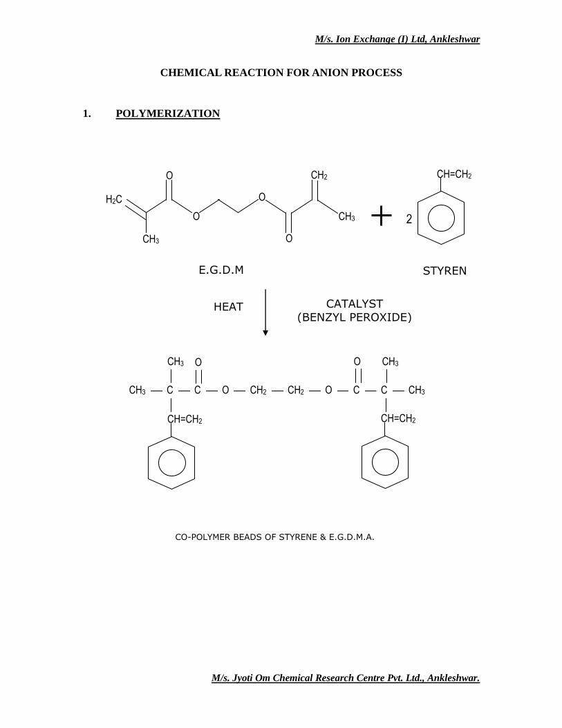
BEADING
Beads are formed by suspension polymerization of styrene along with cross-linking agent
like EGDMA / DVB in a stainless steel reactor called beading pan. After post
polymerization the beads are dropped into a drain table where they are backwashed with
water. The beads are then dried and screened to get required size.
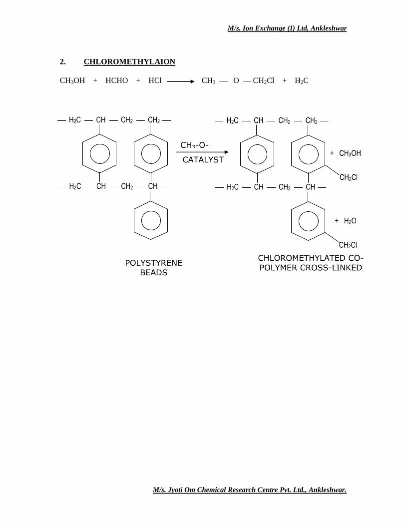
CHLOROMETHYLATION OF BEADS
Methanol formaldehyde mixture is received in a glass lined reactor. Chloro-sulphonic
acid is added at a controlled rate maintaining the temperature of 60 °C. The reactor mass
is stirred per one hour and allowed to settle.
The above chloro mixture along with catalyst is received in another glass lined reactor
containing pre-packed Beads in solvent Ethylene di-chloride (EDC). The temperature is
maintained < 60 °C. The reactor is terminated with addition of sufficient quantity of the
water. The reaction mass is received in dilutor where EDC is separated and recovered and
acid is neutralized. The neutralized batch is taken for amination.
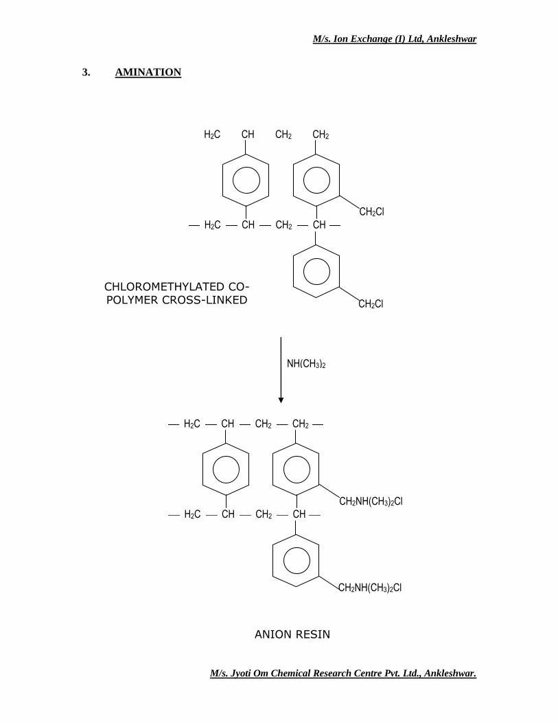
AMINATION
Chloromethylated batch is Aminated using suitable amine at less then 60 °C. The batch is
then neutralized and subsequently EDC is recovered by distillation. Aminated batch is
then washed and dropped in a drain table and the resins are packed. Alternatively,
Chloromethylated beads are further added to a mixture of suitable amine and solvent at
less then 60 °C. in a stainless steel aminator. The reaction is allowed to complete solvents
are then recovered and the batch is cooled and transfer to the washer. The animated batch
is then washed and dropped in a drain table and the resins are packed.
MANUFACTURING PROCESS DETAILS FOR CATION
Styrene and Di-vinyl Benzene are co-polymerized in aqueous medium consisting of
Polyvinyl Alcohol / Gelatin acting as a stabilizer and common salt as electrolyte. Benzyl
Peroxide is used as initiator for the addition polymerization reaction; polymerization
reaction is taken in stainless steel vessel with anchor type S.S. agitator. Polymerization is
exothermic process and temperature is controlled by steam and cooling water between 80
°C. to 85
°C. The polymerized product in the beads from which is heated at 100
°C. after
reaction stage. This product is cooled and dropped in drain table.
The product is washed and the washed product is discharged, centrifuged and dried in
fluid bed drier. The dried beads are screened. The different fractions are collected and
packed.
M/s. Ion Exchange (I) Ltd, Ankleshwar
M/s. Jyoti Om Chemical Research Centre Pvt. Ltd., Ankleshwar.
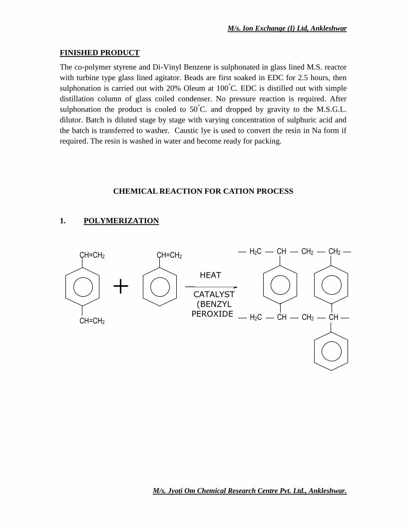
FINISHED PRODUCT
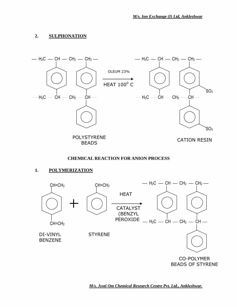
The co-polymer styrene and Di-Vinyl Benzene is sulphonated in glass lined M.S. reactor
with turbine type glass lined agitator. Beads are first soaked in EDC for 2.5 hours, then
sulphonation is carried out with 20% Oleum at 100°C. EDC is distilled out with simple
distillation column of glass coiled condenser. No pressure reaction is required. After
sulphonation the product is cooled to 50°C. and dropped by gravity to the M.S.G.L.
dilutor. Batch is diluted stage by stage with varying concentration of sulphuric acid and
the batch is transferred to washer. Caustic lye is used to convert the resin in Na form if
required. The resin is washed in water and become ready for packing.
CHEMICAL REACTION FOR CATION PROCESS
1. POLYMERIZATION
CATALYST
(BENZYL
PEROXIDE) CH=CH2
CH=CH2 CH=CH2 H2C CH CH2 CH2
H2C CH CH2 CH
HEAT
M/s. Ion Exchange (I) Ltd, Ankleshwar
M/s. Jyoti Om Chemical Research Centre Pvt. Ltd., Ankleshwar.
2. SULPHONATION
CHEMICAL REACTION FOR ANION PROCESS
1. POLYMERIZATION
POLYSTYRENE BEADS
CATION RESIN
OLEUM 23%
HEAT 1000 C
H2C CH CH2 CH2
H2C CH CH2 CH
SO3
SO3
H2C CH CH2 CH2
H2C CH CH2 CH
DI-VINYL BENZENE
STYRENE
CATALYST (BENZYL
PEROXIDE) CH=CH2
CH=CH2 CH=CH2 H2C CH CH2 CH2
H2C CH CH2 CH
HEAT
CO-POLYMER
BEADS OF STYRENE & D.V.B.
M/s. Ion Exchange (I) Ltd, Ankleshwar
M/s. Jyoti Om Chemical Research Centre Pvt. Ltd., Ankleshwar.
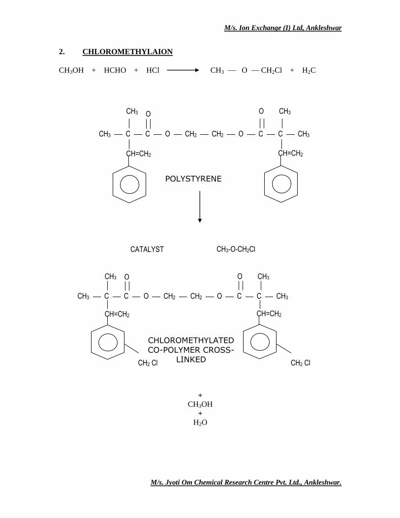
2. CHLOROMETHYLAION
CH3OH + HCHO + HCl CH3 O CH2Cl + H2C
CHLOROMETHYLATED CO-POLYMER CROSS-LINKED
BEADS
POLYSTYRENE BEADS
+ CH3OH
CH2Cl
CH2Cl
CATALYST
CH3-O-CH2Cl
H2C CH CH2 CH2
H2C CH CH2 CH
H2C CH CH2 CH2
H2C CH CH2 CH
+ H2O
M/s. Ion Exchange (I) Ltd, Ankleshwar
M/s. Jyoti Om Chemical Research Centre Pvt. Ltd., Ankleshwar.
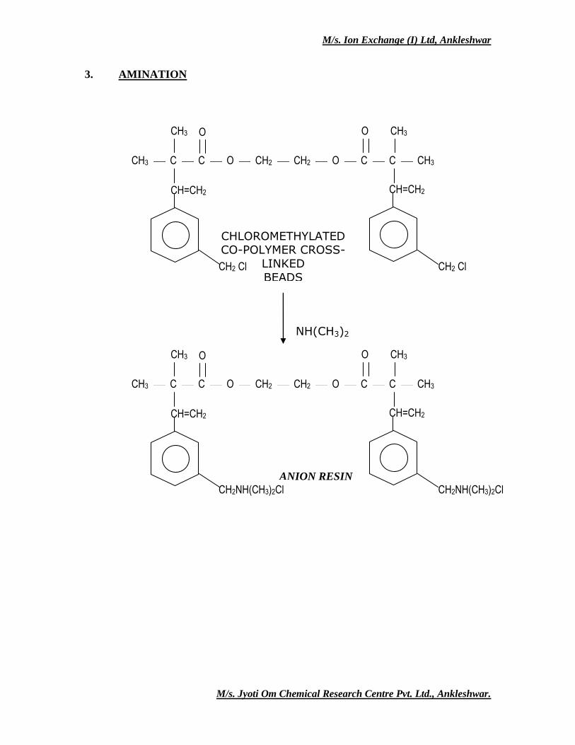
3. AMINATION
CH2Cl
CH2Cl
H2C CH CH2 CH2
H2C CH CH2 CH
NH(CH3)2
CH2NH(CH3)2Cl
CH2NH(CH3)2Cl
H2C CH CH2 CH2
H2C CH CH2 CH
ANION RESIN
CHLOROMETHYLATED CO-POLYMER CROSS-LINKED
BEADS
M/s. Ion Exchange (I) Ltd, Ankleshwar
M/s. Jyoti Om Chemical Research Centre Pvt. Ltd., Ankleshwar.
CHEMICAL REACTION FOR ANION PROCESS
1. POLYMERIZATION
STYRENE
E.G.D.M.A.
CO-POLYMER BEADS OF STYRENE & E.G.D.M.A.
CH2
CH3
CH3
O
H2C
O
O
O 2
CH=CH2
CH3 CH3 O O
CH3 C C O CH2 CH2 O C C CH3
CH=CH2 CH=CH2
CATALYST
(BENZYL PEROXIDE) HEAT
M/s. Ion Exchange (I) Ltd, Ankleshwar
M/s. Jyoti Om Chemical Research Centre Pvt. Ltd., Ankleshwar.
2. CHLOROMETHYLAION
CH3OH + HCHO + HCl CH3 O CH2Cl + H2C
+
CH3OH
+ H2O
POLYSTYRENE BEADS
CATALYST CH3-O-CH2Cl
CH3 CH3 O O
CH3 C C O CH2 CH2 O C C CH3
CH=CH2 CH=CH2
CHLOROMETHYLATED
CO-POLYMER CROSS-LINKED
BEADS CH2 Cl CH2 Cl
CH3 CH3 O O
CH3 C C O CH2 CH2 O C C CH3
CH=CH2 CH=CH2
M/s. Ion Exchange (I) Ltd, Ankleshwar
M/s. Jyoti Om Chemical Research Centre Pvt. Ltd., Ankleshwar.
3. AMINATION
ANION RESIN
CHLOROMETHYLATED CO-POLYMER CROSS-
LINKED
BEADS
NH(CH3)2
CH2 Cl CH2 Cl
CH3 CH3 O O
CH3 C C O CH2 CH2 O C C CH3
CH=CH2 CH=CH2
CH2NH(CH3)2Cl
CH2NH(CH3)2Cl
CH3 CH3 O O
CH3 C C O CH2 CH2 O C C CH3
CH=CH2 CH=CH2
M/s. Ion Exchange (I) Ltd, Ankleshwar
M/s. Jyoti Om Chemical Research Centre Pvt. Ltd., Ankleshwar.
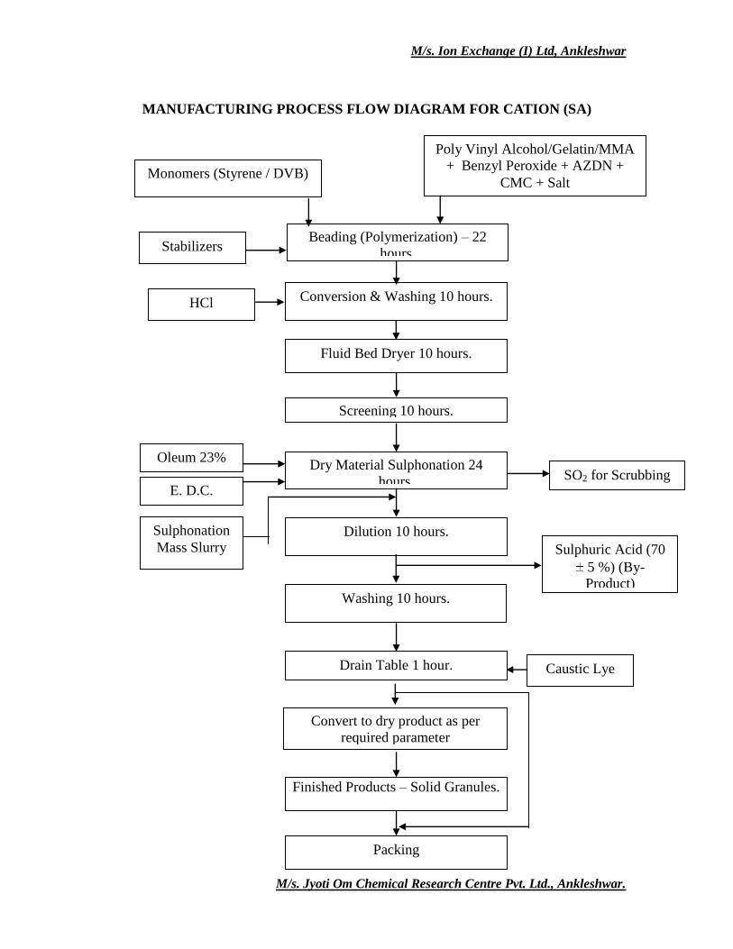
MANUFACTURING PROCESS FLOW DIAGRAM FOR CATION (SA)
Finished Products – Solid Granules.
Packing
Stabilizers
HCl
Convert to dry product as per
required parameter
Caustic Lye
Monomers (Styrene / DVB)
Poly Vinyl Alcohol/Gelatin/MMA
+ Benzyl Peroxide + AZDN +
CMC + Salt
Beading (Polymerization) – 22
hours.
Conversion & Washing 10 hours.
Fluid Bed Dryer 10 hours.
Screening 10 hours.
Dry Material Sulphonation 24
hours.
Dilution 10 hours.
Oleum 23%
E. D.C. SO2 for Scrubbing
Sulphonation
Mass Slurry
Washing 10 hours.
Drain Table 1 hour.
Sulphuric Acid (70
5 %) (By-
Product)
M/s. Ion Exchange (I) Ltd, Ankleshwar
M/s. Jyoti Om Chemical Research Centre Pvt. Ltd., Ankleshwar.
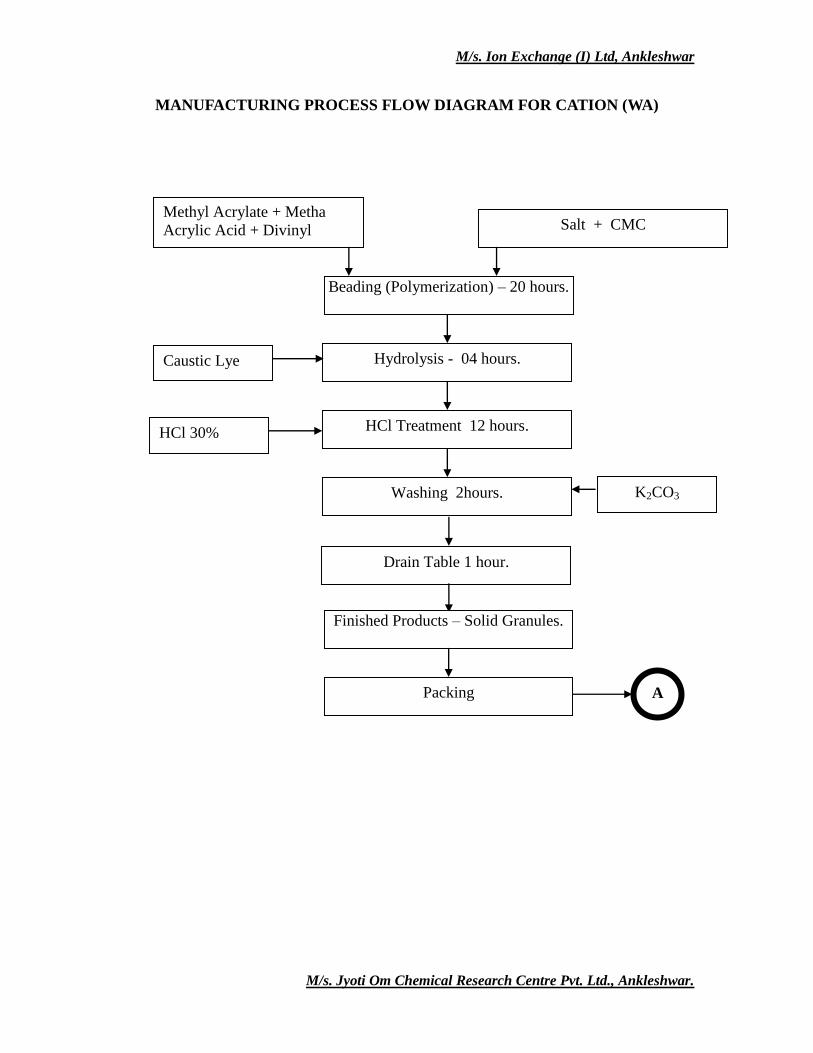
MANUFACTURING PROCESS FLOW DIAGRAM FOR CATION (WA)
K2CO3
HCl 30%
A
Drain Table 1 hour.
Finished Products – Solid Granules.
Packing
Washing 2hours.
Methyl Acrylate + Metha
Acrylic Acid + Divinyl
Benzene + AZDN
Salt + CMC
Beading (Polymerization) – 20 hours.
Hydrolysis - 04 hours.
HCl Treatment 12 hours.
Caustic Lye
M/s. Ion Exchange (I) Ltd, Ankleshwar
M/s. Jyoti Om Chemical Research Centre Pvt. Ltd., Ankleshwar.
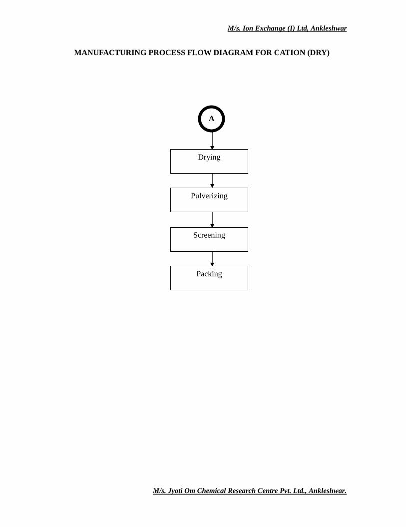
MANUFACTURING PROCESS FLOW DIAGRAM FOR CATION (DRY)
A
Drying
Packing
Pulverizing
Screening
M/s. Ion Exchange (I) Ltd, Ankleshwar
M/s. Jyoti Om Chemical Research Centre Pvt. Ltd., Ankleshwar.
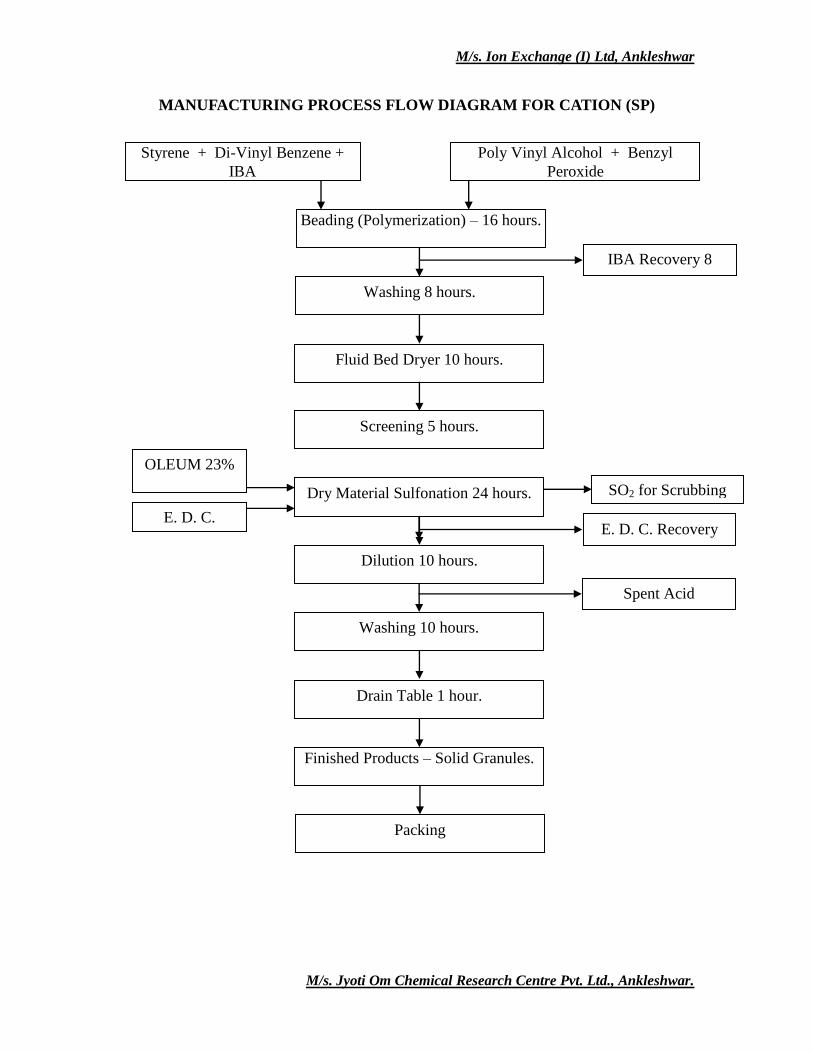
MANUFACTURING PROCESS FLOW DIAGRAM FOR CATION (SP)
Styrene + Di-Vinyl Benzene +
IBA
Poly Vinyl Alcohol + Benzyl
Peroxide
Beading (Polymerization) – 16 hours.
Washing 8 hours.
Fluid Bed Dryer 10 hours.
Screening 5 hours.
Dry Material Sulfonation 24 hours.
Dilution 10 hours.
OLEUM 23%
E. D. C.
SO2 for Scrubbing
Washing 10 hours.
Drain Table 1 hour.
Finished Products – Solid Granules.
E. D. C. Recovery
Packing
IBA Recovery 8
hours
Spent Acid
M/s. Ion Exchange (I) Ltd, Ankleshwar
M/s. Jyoti Om Chemical Research Centre Pvt. Ltd., Ankleshwar.
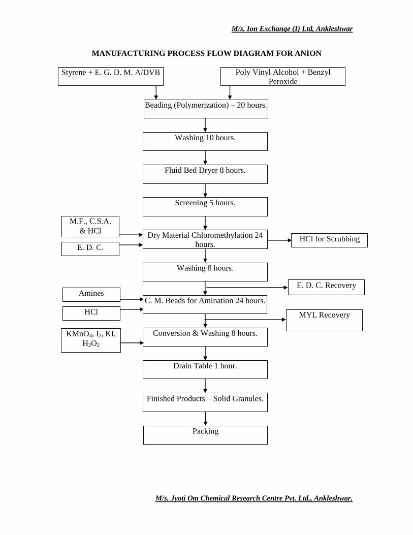
MANUFACTURING PROCESS FLOW DIAGRAM FOR ANION
Amines
HCl
Styrene + E. G. D. M. A/DVB Poly Vinyl Alcohol + Benzyl
Peroxide
Beading (Polymerization) – 20 hours.
Washing 10 hours.
Fluid Bed Dryer 8 hours.
Screening 5 hours.
Dry Material Chloromethylation 24
hours.
Washing 8 hours.
M.F., C.S.A.
& HCl
E. D. C. HCl for Scrubbing
C. M. Beads for Amination 24 hours.
Conversion & Washing 8 hours.
Drain Table 1 hour.
Finished Products – Solid Granules.
E. D. C. Recovery
MYL Recovery
Packing
KMnO4, I2, KI,
H2O2
M/s. Ion Exchange (I) Ltd, Ankleshwar
M/s. Jyoti Om Chemical Research Centre Pvt. Ltd., Ankleshwar.
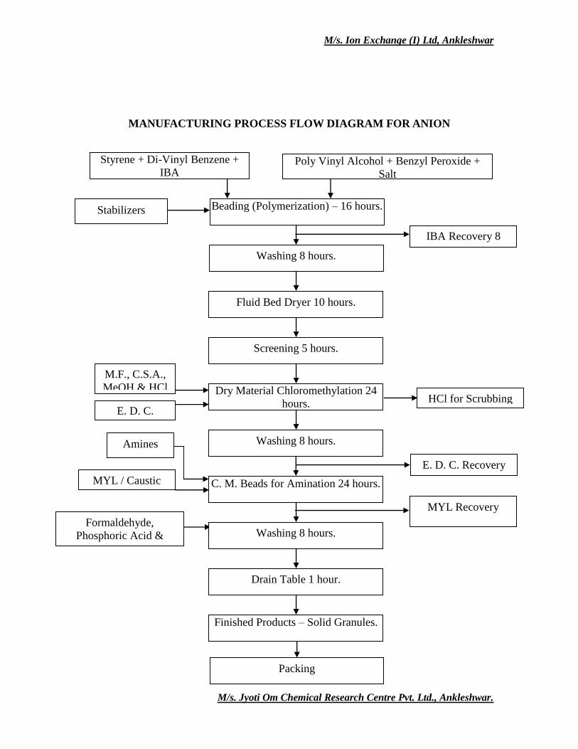
MANUFACTURING PROCESS FLOW DIAGRAM FOR ANION
Formaldehyde,
Phosphoric Acid &
Hexamine
IBA Recovery 8
hours
Stabilizers
Packing
MYL / Caustic
Amines
MYL Recovery
Styrene + Di-Vinyl Benzene +
IBA Poly Vinyl Alcohol + Benzyl Peroxide +
Salt
Beading (Polymerization) – 16 hours.
Washing 8 hours.
Fluid Bed Dryer 10 hours.
Screening 5 hours.
Dry Material Chloromethylation 24
hours.
Washing 8 hours.
M.F., C.S.A.,
MeOH & HCl
E. D. C. HCl for Scrubbing
C. M. Beads for Amination 24 hours.
Washing 8 hours.
Drain Table 1 hour.
Finished Products – Solid Granules.
E. D. C. Recovery
M/s. Ion Exchange (I) Ltd, Ankleshwar
M/s. Jyoti Om Chemical Research Centre Pvt. Ltd., Ankleshwar.
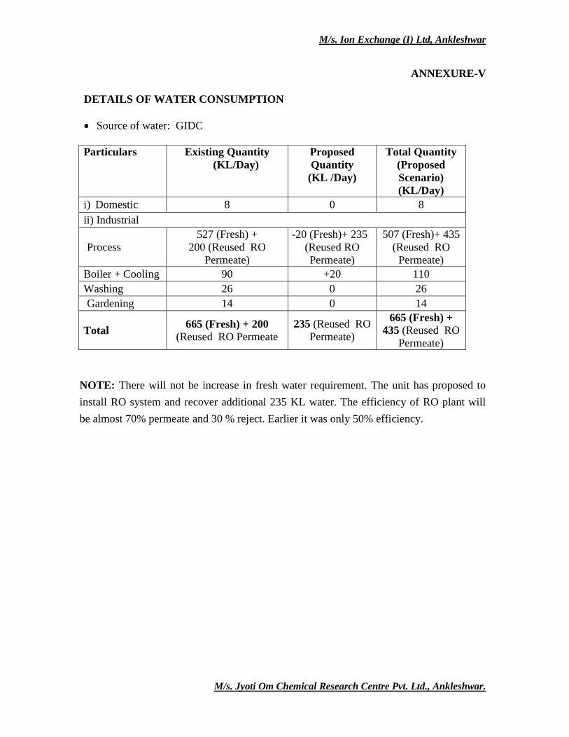
ANNEXURE-V
DETAILS OF WATER CONSUMPTION
Source of water: GIDC
NOTE: There will not be increase in fresh water requirement. The unit has proposed to
install RO system and recover additional 235 KL water. The efficiency of RO plant will
be almost 70% permeate and 30 % reject. Earlier it was only 50% efficiency.
Particulars Existing Quantity
(KL/Day)
Proposed
Quantity
(KL /Day)
Total Quantity
(Proposed
Scenario)
(KL/Day)
i) Domestic 8 0 8
ii) Industrial
Process
527 (Fresh) +
200 (Reused RO
Permeate)
-20 (Fresh)+ 235
(Reused RO
Permeate)
507 (Fresh)+ 435
(Reused RO
Permeate)
Boiler + Cooling 90 +20 110
Washing 26 0 26
Gardening 14 0 14
Total 665 (Fresh) + 200
(Reused RO Permeate
235 (Reused RO
Permeate)
665 (Fresh) +
435 (Reused RO
Permeate)
M/s. Ion Exchange (I) Ltd, Ankleshwar
M/s. Jyoti Om Chemical Research Centre Pvt. Ltd., Ankleshwar.
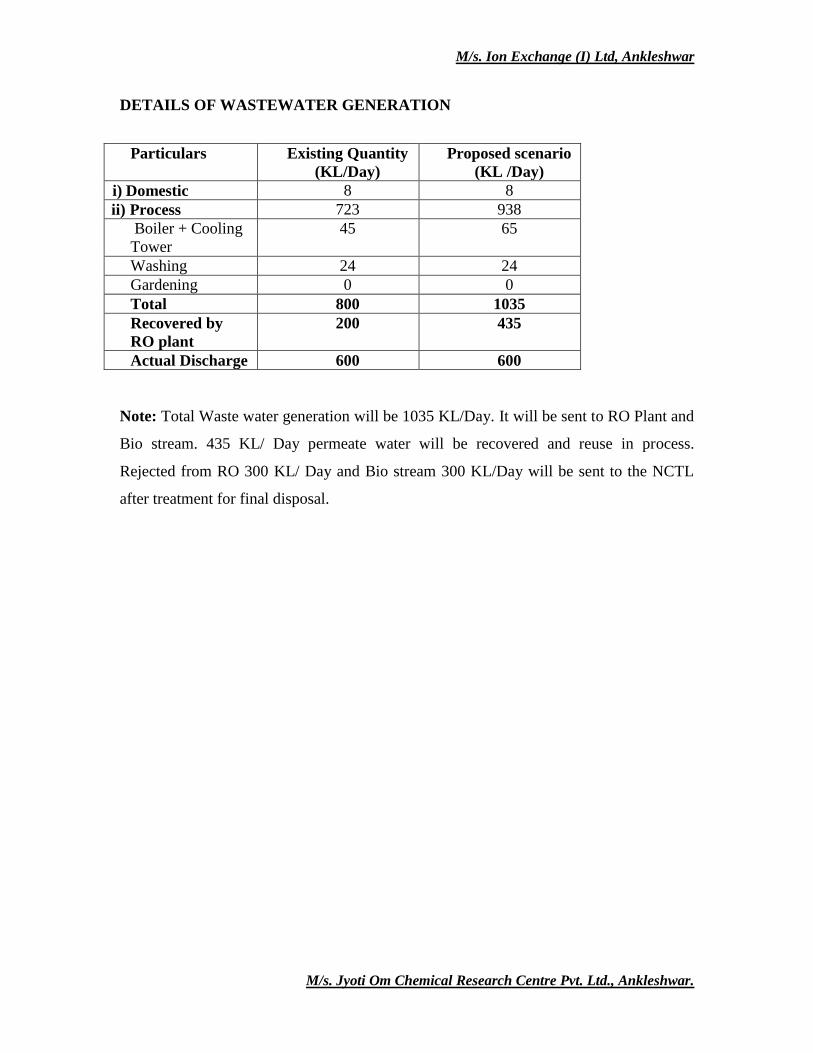
DETAILS OF WASTEWATER GENERATION
Particulars Existing Quantity
(KL/Day)
Proposed scenario
(KL /Day)
i) Domestic 8 8
ii) Process 723 938
Boiler + Cooling
Tower
45 65
Washing 24 24
Gardening 0 0
Total 800 1035
Recovered by
RO plant
200 435
Actual Discharge 600 600
Note: Total Waste water generation will be 1035 KL/Day. It will be sent to RO Plant and
Bio stream. 435 KL/ Day permeate water will be recovered and reuse in process.
Rejected from RO 300 KL/ Day and Bio stream 300 KL/Day will be sent to the NCTL
after treatment for final disposal.
M/s. Ion Exchange (I) Ltd, Ankleshwar
M/s. Jyoti Om Chemical Research Centre Pvt. Ltd., Ankleshwar.
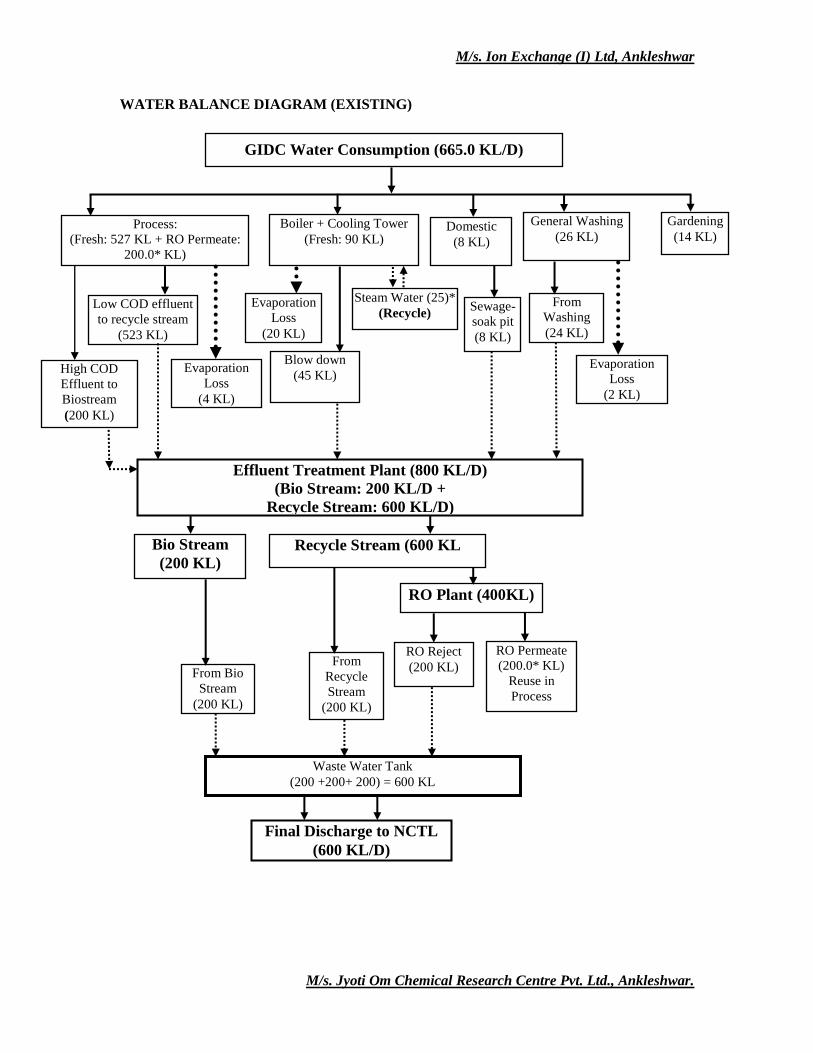
WATER BALANCE DIAGRAM (EXISTING)
Gardening
(14 KL) Process:
(Fresh: 527 KL + RO Permeate:
200.0* KL)
Boiler + Cooling Tower
(Fresh: 90 KL) Domestic
(8 KL)
General Washing
(26 KL)
Low COD effluent
to recycle stream
(523 KL)
Blow down
(45 KL)
Sewage-
soak pit
(8 KL)
From
Washing
(24 KL)
Effluent Treatment Plant (800 KL/D)
(Bio Stream: 200 KL/D +
Recycle Stream: 600 KL/D)
High COD
Effluent to
Biostream
(200 KL)
Evaporation
Loss
(20 KL)
RO Plant (400KL)
RO Reject
(200 KL)
Waste Water Tank
(200 +200+ 200) = 600 KL
Final Discharge to NCTL
(600 KL/D)
GIDC Water Consumption (665.0 KL/D)
Bio Stream
(200 KL)
RO Permeate
(200.0* KL)
Reuse in
Process
Evaporation
Loss
(2 KL)
Evaporation
Loss
(4 KL)
Steam Water (25)*
(Recycle)
Recycle Stream (600 KL
From Bio
Stream
(200 KL)
From
Recycle
Stream
(200 KL)
M/s. Ion Exchange (I) Ltd, Ankleshwar
M/s. Jyoti Om Chemical Research Centre Pvt. Ltd., Ankleshwar.
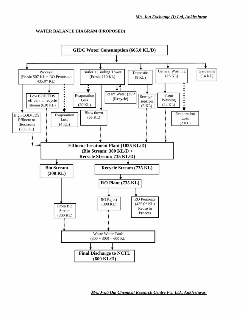
WATER BALANCE DIAGRAM (PROPOSED)
Process:
(Fresh: 507 KL + RO Permeate:
435.0* KL)
Boiler + Cooling Tower
(Fresh: 110 KL) Domestic
(8 KL)
General Washing
(26 KL)
Gardening
(14 KL)
Low COD/TDS
effluent to recycle
stream (638 KL)
Blow down
(65 KL)
Sewage-
soak pit
(8 KL)
From
Washing
(24 KL)
Effluent Treatment Plant (1035 KL/D)
(Bio Stream: 300 KL/D +
Recycle Stream: 735 KL/D)
High COD/TDS
Effluent to
Biostream
(300 KL)
Evaporation
Loss
(20 KL)
RO Plant (735 KL)
RO Reject
(300 KL)
Waste Water Tank
(300 + 300) = 600 KL
Final Discharge to NCTL
(600 KL/D)
GIDC Water Consumption (665.0 KL/D)
Bio Stream
(300 KL)
RO Permeate
(435.0* KL)
Reuse in
Process
Evaporation
Loss
(2 KL)
Evaporation
Loss
(4 KL)
Steam Water (25)*
(Recycle)
Recycle Stream (735 KL)
From Bio
Stream
(300 KL)
M/s. Ion Exchange (I) Ltd, Ankleshwar
M/s. Jyoti Om Chemical Research Centre Pvt. Ltd., Ankleshwar.
ANNEXURE-VI
DETAILS OF EFFLUENT TREATMENT PLANT
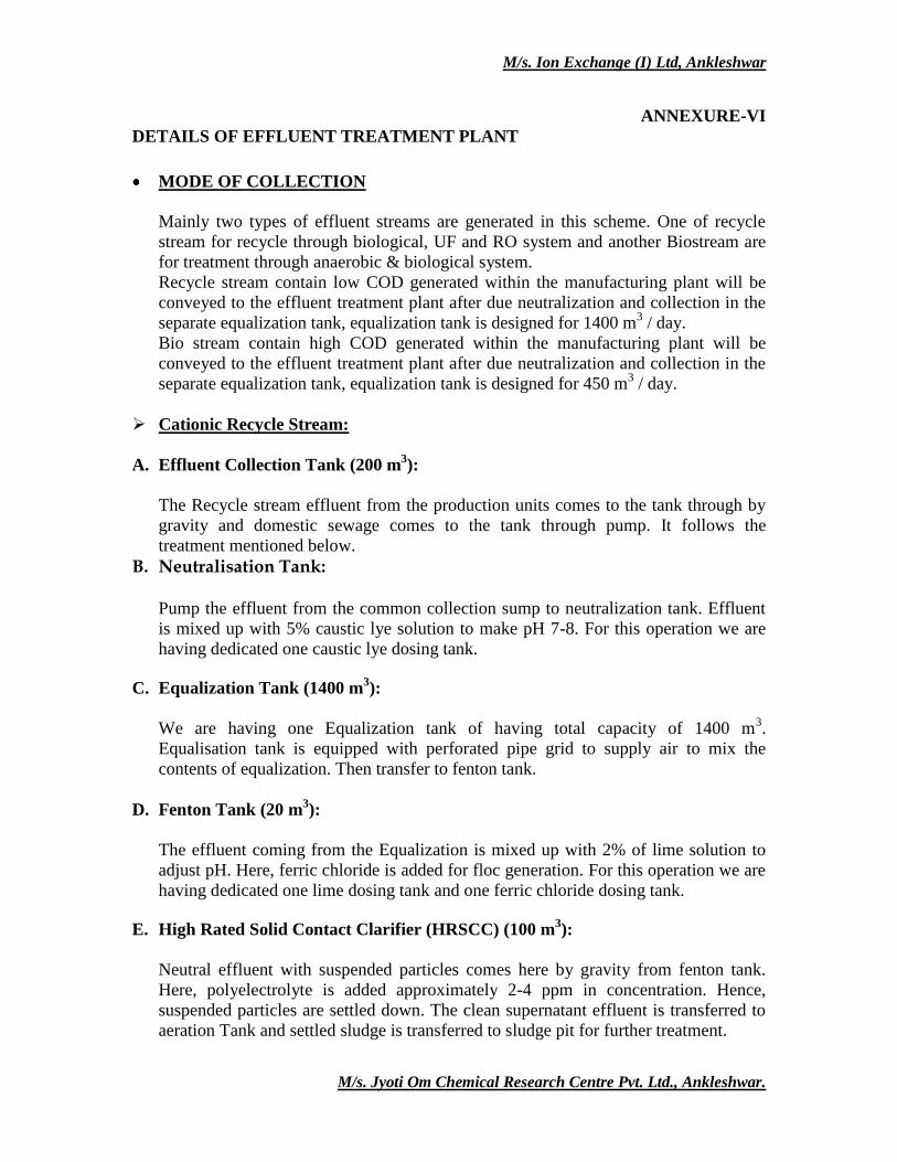
MODE OF COLLECTION
Mainly two types of effluent streams are generated in this scheme. One of recycle
stream for recycle through biological, UF and RO system and another Biostream are
for treatment through anaerobic & biological system.
Recycle stream contain low COD generated within the manufacturing plant will be
conveyed to the effluent treatment plant after due neutralization and collection in the
separate equalization tank, equalization tank is designed for 1400 m3 / day.
Bio stream contain high COD generated within the manufacturing plant will be
conveyed to the effluent treatment plant after due neutralization and collection in the
separate equalization tank, equalization tank is designed for 450 m3 / day.
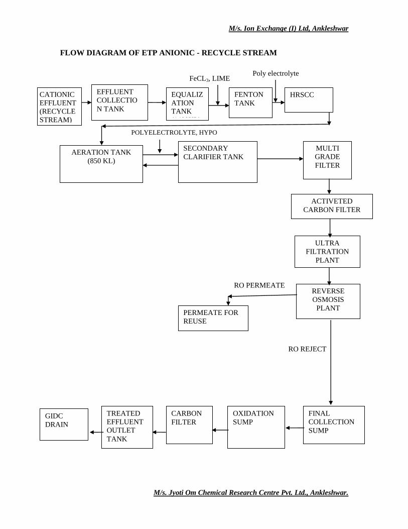
Cationic Recycle Stream:
A. Effluent Collection Tank (200 m3):
The Recycle stream effluent from the production units comes to the tank through by
gravity and domestic sewage comes to the tank through pump. It follows the
treatment mentioned below.
B. Neutralisation Tank: Pump the effluent from the common collection sump to neutralization tank. Effluent
is mixed up with 5% caustic lye solution to make pH 7-8. For this operation we are
having dedicated one caustic lye dosing tank.
C. Equalization Tank (1400 m3):
We are having one Equalization tank of having total capacity of 1400 m3.
Equalisation tank is equipped with perforated pipe grid to supply air to mix the
contents of equalization. Then transfer to fenton tank.
D. Fenton Tank (20 m3):
The effluent coming from the Equalization is mixed up with 2% of lime solution to
adjust pH. Here, ferric chloride is added for floc generation. For this operation we are
having dedicated one lime dosing tank and one ferric chloride dosing tank.
E. High Rated Solid Contact Clarifier (HRSCC) (100 m3):
Neutral effluent with suspended particles comes here by gravity from fenton tank.
Here, polyelectrolyte is added approximately 2-4 ppm in concentration. Hence,
suspended particles are settled down. The clean supernatant effluent is transferred to
aeration Tank and settled sludge is transferred to sludge pit for further treatment.
M/s. Ion Exchange (I) Ltd, Ankleshwar
M/s. Jyoti Om Chemical Research Centre Pvt. Ltd., Ankleshwar.
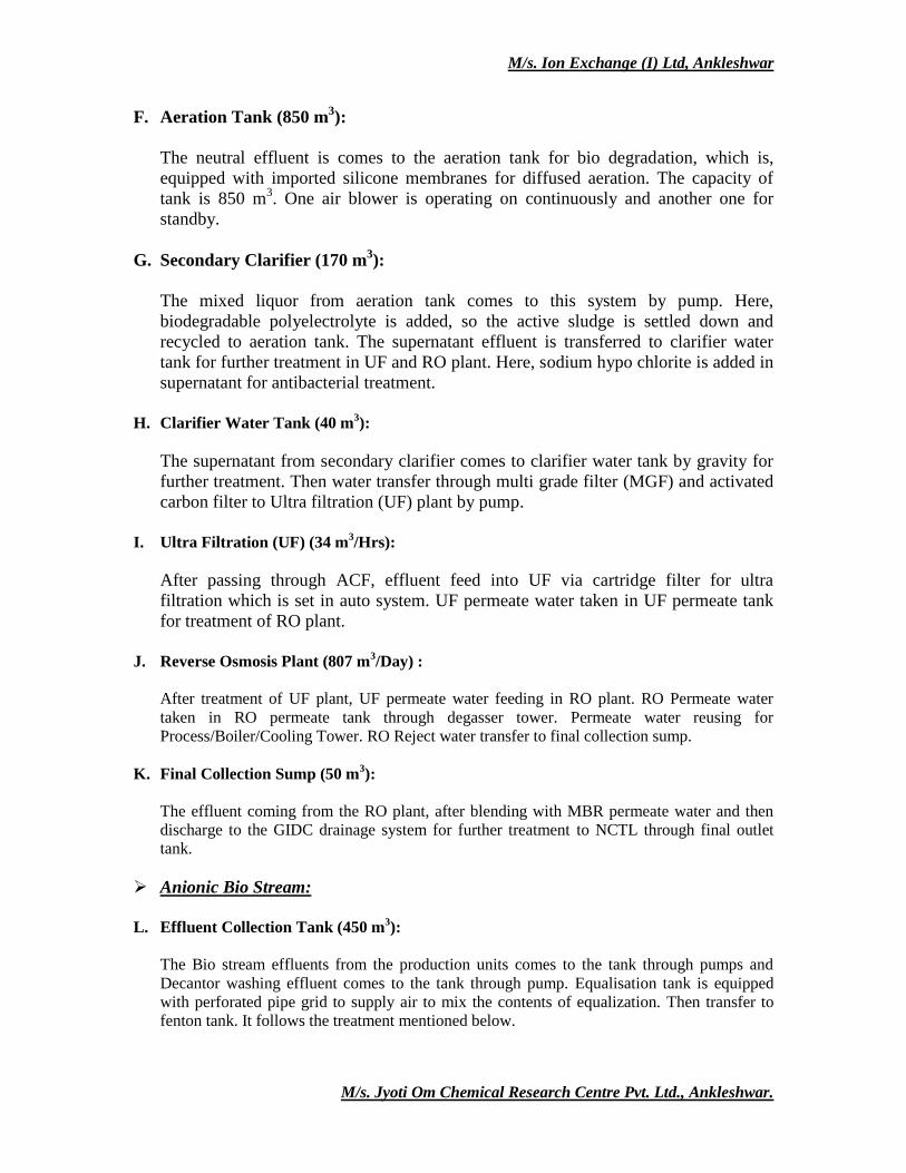
F. Aeration Tank (850 m3):
The neutral effluent is comes to the aeration tank for bio degradation, which is,
equipped with imported silicone membranes for diffused aeration. The capacity of
tank is 850 m3. One air blower is operating on continuously and another one for
standby.
G. Secondary Clarifier (170 m3):
The mixed liquor from aeration tank comes to this system by pump. Here,
biodegradable polyelectrolyte is added, so the active sludge is settled down and
recycled to aeration tank. The supernatant effluent is transferred to clarifier water
tank for further treatment in UF and RO plant. Here, sodium hypo chlorite is added in
supernatant for antibacterial treatment.
H. Clarifier Water Tank (40 m
3):
The supernatant from secondary clarifier comes to clarifier water tank by gravity for
further treatment. Then water transfer through multi grade filter (MGF) and activated
carbon filter to Ultra filtration (UF) plant by pump.
I. Ultra Filtration (UF) (34 m
3/Hrs):
After passing through ACF, effluent feed into UF via cartridge filter for ultra
filtration which is set in auto system. UF permeate water taken in UF permeate tank
for treatment of RO plant.
J. Reverse Osmosis Plant (807 m
3/Day) :
After treatment of UF plant, UF permeate water feeding in RO plant. RO Permeate water
taken in RO permeate tank through degasser tower. Permeate water reusing for
Process/Boiler/Cooling Tower. RO Reject water transfer to final collection sump.
K. Final Collection Sump (50 m3):
The effluent coming from the RO plant, after blending with MBR permeate water and then
discharge to the GIDC drainage system for further treatment to NCTL through final outlet
tank.
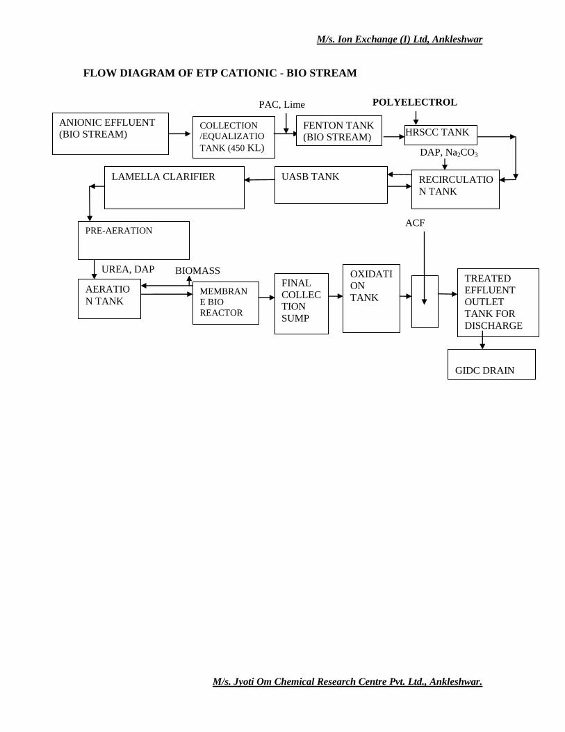
Anionic Bio Stream:
L. Effluent Collection Tank (450 m
3):
The Bio stream effluents from the production units comes to the tank through pumps and
Decantor washing effluent comes to the tank through pump. Equalisation tank is equipped
with perforated pipe grid to supply air to mix the contents of equalization. Then transfer to
fenton tank. It follows the treatment mentioned below.
M/s. Ion Exchange (I) Ltd, Ankleshwar
M/s. Jyoti Om Chemical Research Centre Pvt. Ltd., Ankleshwar.
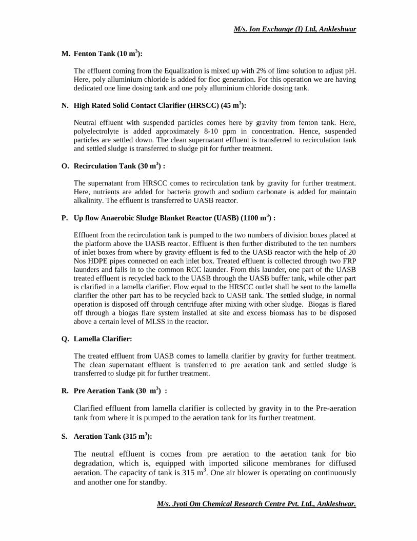
M. Fenton Tank (10 m3):
The effluent coming from the Equalization is mixed up with 2% of lime solution to adjust pH.
Here, poly alluminium chloride is added for floc generation. For this operation we are having
dedicated one lime dosing tank and one poly alluminium chloride dosing tank.
N. High Rated Solid Contact Clarifier (HRSCC) (45 m3):
Neutral effluent with suspended particles comes here by gravity from fenton tank. Here,
polyelectrolyte is added approximately 8-10 ppm in concentration. Hence, suspended
particles are settled down. The clean supernatant effluent is transferred to recirculation tank
and settled sludge is transferred to sludge pit for further treatment.
O. Recirculation Tank (30 m3) :
The supernatant from HRSCC comes to recirculation tank by gravity for further treatment.
Here, nutrients are added for bacteria growth and sodium carbonate is added for maintain
alkalinity. The effluent is transferred to UASB reactor.
P. Up flow Anaerobic Sludge Blanket Reactor (UASB) (1100 m3) :
Effluent from the recirculation tank is pumped to the two numbers of division boxes placed at
the platform above the UASB reactor. Effluent is then further distributed to the ten numbers
of inlet boxes from where by gravity effluent is fed to the UASB reactor with the help of 20
Nos HDPE pipes connected on each inlet box. Treated effluent is collected through two FRP
launders and falls in to the common RCC launder. From this launder, one part of the UASB
treated effluent is recycled back to the UASB through the UASB buffer tank, while other part
is clarified in a lamella clarifier. Flow equal to the HRSCC outlet shall be sent to the lamella
clarifier the other part has to be recycled back to UASB tank. The settled sludge, in normal
operation is disposed off through centrifuge after mixing with other sludge. Biogas is flared
off through a biogas flare system installed at site and excess biomass has to be disposed
above a certain level of MLSS in the reactor.
Q. Lamella Clarifier:
The treated effluent from UASB comes to lamella clarifier by gravity for further treatment.
The clean supernatant effluent is transferred to pre aeration tank and settled sludge is
transferred to sludge pit for further treatment.
R. Pre Aeration Tank (30 m3) :
Clarified effluent from lamella clarifier is collected by gravity in to the Pre-aeration
tank from where it is pumped to the aeration tank for its further treatment.
S. Aeration Tank (315 m
3):
The neutral effluent is comes from pre aeration to the aeration tank for bio
degradation, which is, equipped with imported silicone membranes for diffused
aeration. The capacity of tank is 315 m3. One air blower is operating on continuously
and another one for standby.
M/s. Ion Exchange (I) Ltd, Ankleshwar
M/s. Jyoti Om Chemical Research Centre Pvt. Ltd., Ankleshwar.
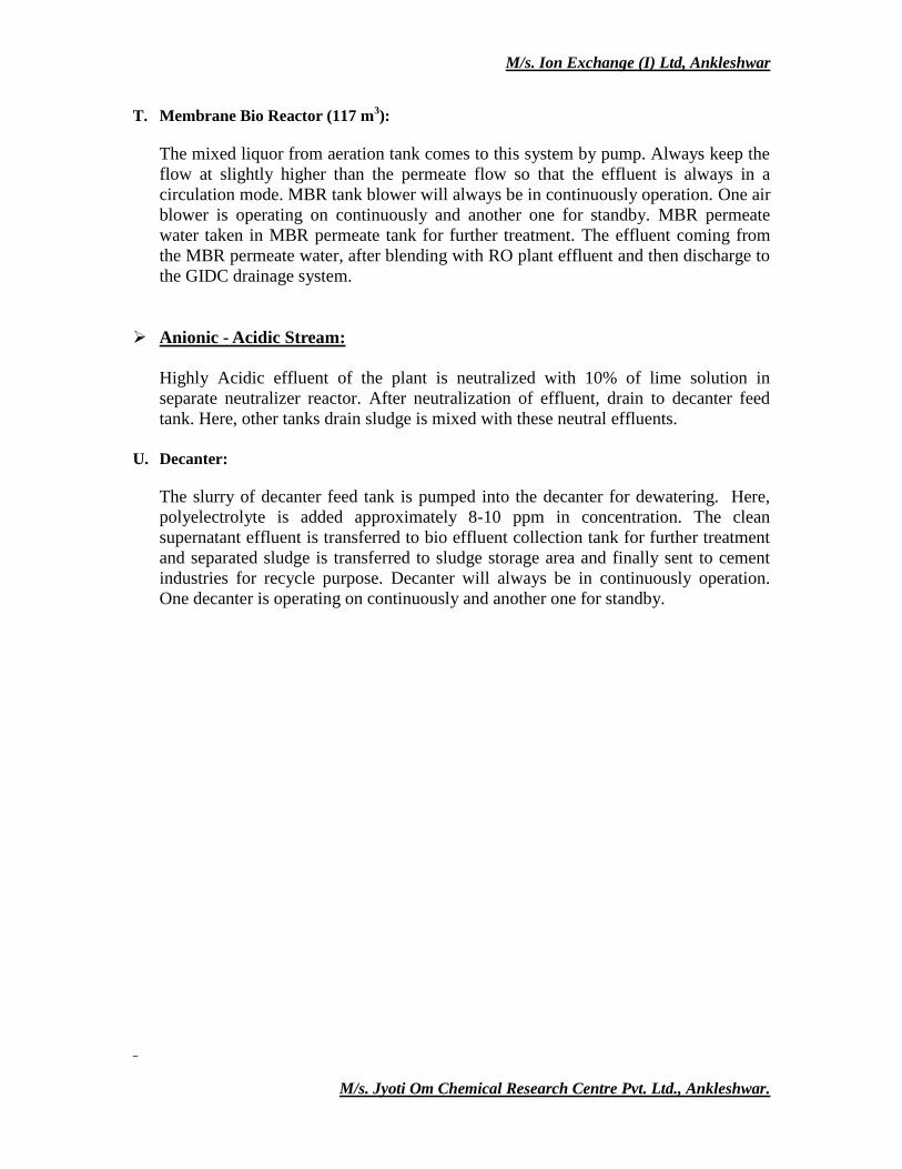
T. Membrane Bio Reactor (117 m3):
The mixed liquor from aeration tank comes to this system by pump. Always keep the
flow at slightly higher than the permeate flow so that the effluent is always in a
circulation mode. MBR tank blower will always be in continuously operation. One air
blower is operating on continuously and another one for standby. MBR permeate
water taken in MBR permeate tank for further treatment. The effluent coming from
the MBR permeate water, after blending with RO plant effluent and then discharge to
the GIDC drainage system.
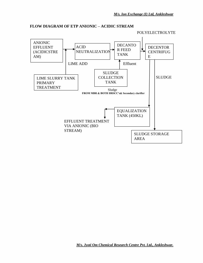
Anionic - Acidic Stream:
Highly Acidic effluent of the plant is neutralized with 10% of lime solution in
separate neutralizer reactor. After neutralization of effluent, drain to decanter feed
tank. Here, other tanks drain sludge is mixed with these neutral effluents.
U. Decanter:
The slurry of decanter feed tank is pumped into the decanter for dewatering. Here,
polyelectrolyte is added approximately 8-10 ppm in concentration. The clean
supernatant effluent is transferred to bio effluent collection tank for further treatment
and separated sludge is transferred to sludge storage area and finally sent to cement
industries for recycle purpose. Decanter will always be in continuously operation.
One decanter is operating on continuously and another one for standby.
M/s. Ion Exchange (I) Ltd, Ankleshwar
M/s. Jyoti Om Chemical Research Centre Pvt. Ltd., Ankleshwar.
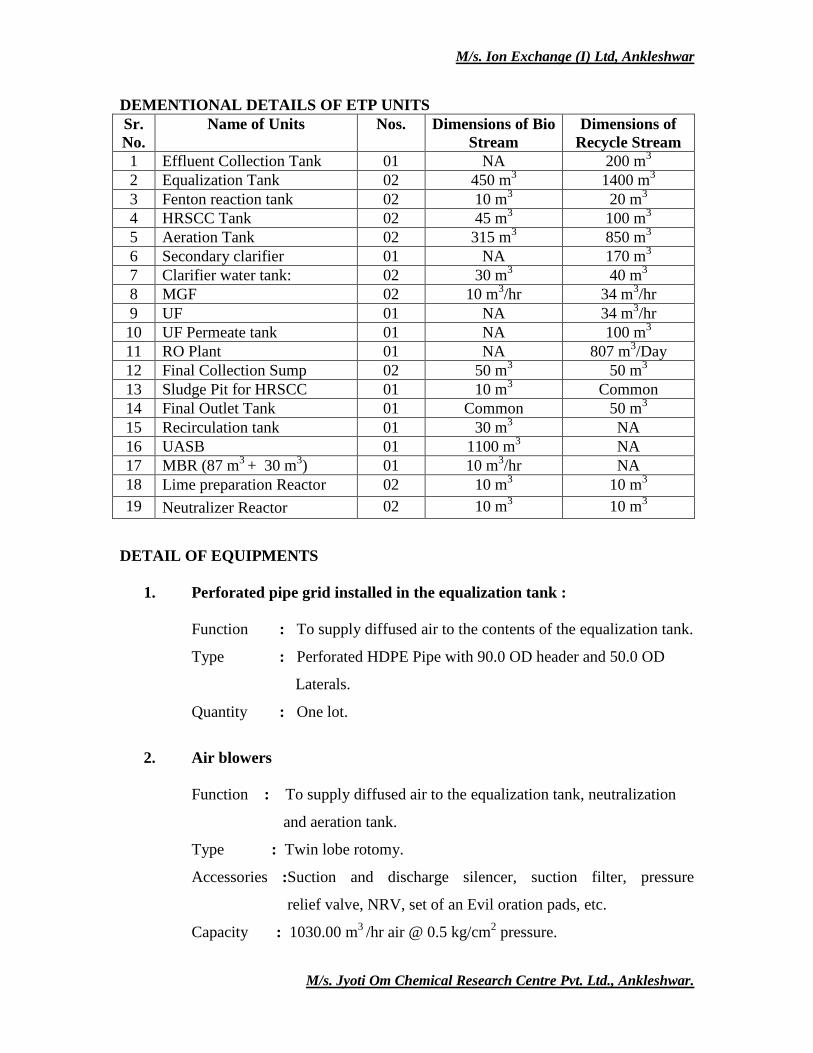
DEMENTIONAL DETAILS OF ETP UNITS
Sr.
No.
Name of Units Nos. Dimensions of Bio
Stream
Dimensions of
Recycle Stream
1 Effluent Collection Tank 01 NA 200 m3
2 Equalization Tank 02 450 m3 1400 m
3
3 Fenton reaction tank 02 10 m3 20 m
3
4 HRSCC Tank 02 45 m3 100 m
3
5 Aeration Tank 02 315 m3 850 m
3
6 Secondary clarifier 01 NA 170 m3
7 Clarifier water tank: 02 30 m3 40 m
3
8 MGF 02 10 m3/hr 34 m
3/hr
9 UF 01 NA 34 m3/hr
10 UF Permeate tank 01 NA 100 m3
11 RO Plant 01 NA 807 m3/Day
12 Final Collection Sump 02 50 m3 50 m
3
13 Sludge Pit for HRSCC 01 10 m3 Common
14 Final Outlet Tank 01 Common 50 m3
15 Recirculation tank 01 30 m3 NA
16 UASB 01 1100 m3 NA
17 MBR (87 m3
+ 30 m3) 01 10 m
3/hr NA
18 Lime preparation Reactor 02 10 m3 10 m
3
19 Neutralizer Reactor 02 10 m3 10 m
3
DETAIL OF EQUIPMENTS
1. Perforated pipe grid installed in the equalization tank :
Function : To supply diffused air to the contents of the equalization tank.
Type : Perforated HDPE Pipe with 90.0 OD header and 50.0 OD
Laterals.
Quantity : One lot.
2. Air blowers
Function : To supply diffused air to the equalization tank, neutralization
and aeration tank.
Type : Twin lobe rotomy.
Accessories :Suction and discharge silencer, suction filter, pressure
relief valve, NRV, set of an Evil oration pads, etc.
Capacity : 1030.00 m3
/hr air @ 0.5 kg/cm2 pressure.
M/s. Ion Exchange (I) Ltd, Ankleshwar
M/s. Jyoti Om Chemical Research Centre Pvt. Ltd., Ankleshwar.
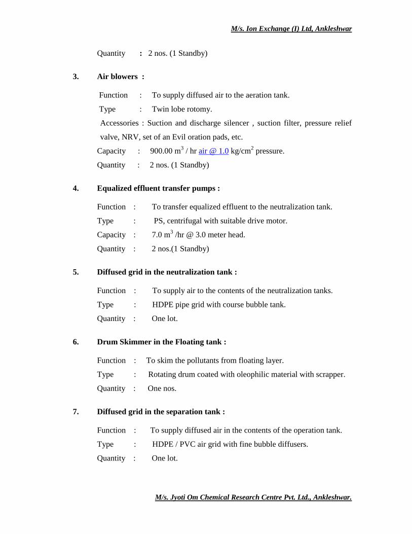
Quantity : 2 nos. (1 Standby)
3. Air blowers :
Function : To supply diffused air to the aeration tank.
Type : Twin lobe rotomy.
Accessories : Suction and discharge silencer , suction filter, pressure relief
valve, NRV, set of an Evil oration pads, etc.
Capacity : 900.00 m3 / hr air @ 1.0 kg/cm
2 pressure.
Quantity : 2 nos. (1 Standby)
4. Equalized effluent transfer pumps :
Function : To transfer equalized effluent to the neutralization tank.
Type : PS, centrifugal with suitable drive motor.
Capacity : 7.0 m3 /hr @ 3.0 meter head.
Quantity : 2 nos.(1 Standby)
5. Diffused grid in the neutralization tank :
Function : To supply air to the contents of the neutralization tanks.
Type : HDPE pipe grid with course bubble tank.
Quantity : One lot.
6. Drum Skimmer in the Floating tank :
Function : To skim the pollutants from floating layer.
Type : Rotating drum coated with oleophilic material with scrapper.
Quantity : One nos.
7. Diffused grid in the separation tank :
Function : To supply diffused air in the contents of the operation tank.
Type : HDPE / PVC air grid with fine bubble diffusers.
Quantity : One lot.
M/s. Ion Exchange (I) Ltd, Ankleshwar
M/s. Jyoti Om Chemical Research Centre Pvt. Ltd., Ankleshwar.
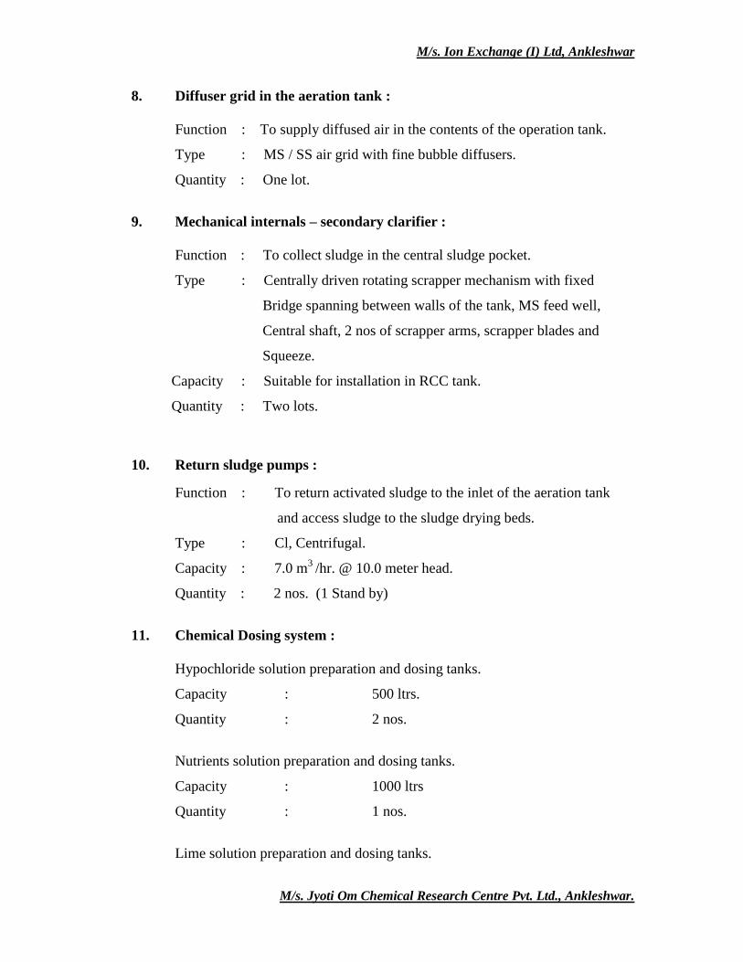
8. Diffuser grid in the aeration tank :
Function : To supply diffused air in the contents of the operation tank.
Type : MS / SS air grid with fine bubble diffusers.
Quantity : One lot.
9. Mechanical internals – secondary clarifier :
Function : To collect sludge in the central sludge pocket.
Type : Centrally driven rotating scrapper mechanism with fixed
Bridge spanning between walls of the tank, MS feed well,
Central shaft, 2 nos of scrapper arms, scrapper blades and
Squeeze.
Capacity : Suitable for installation in RCC tank.
Quantity : Two lots.
10. Return sludge pumps :
Function : To return activated sludge to the inlet of the aeration tank
and access sludge to the sludge drying beds.
Type : Cl, Centrifugal.
Capacity : 7.0 m3
/hr. @ 10.0 meter head.
Quantity : 2 nos. (1 Stand by)
11. Chemical Dosing system :
Hypochloride solution preparation and dosing tanks.
Capacity : 500 ltrs.
Quantity : 2 nos.
Nutrients solution preparation and dosing tanks.
Capacity : 1000 ltrs
Quantity : 1 nos.
Lime solution preparation and dosing tanks.
M/s. Ion Exchange (I) Ltd, Ankleshwar
M/s. Jyoti Om Chemical Research Centre Pvt. Ltd., Ankleshwar.
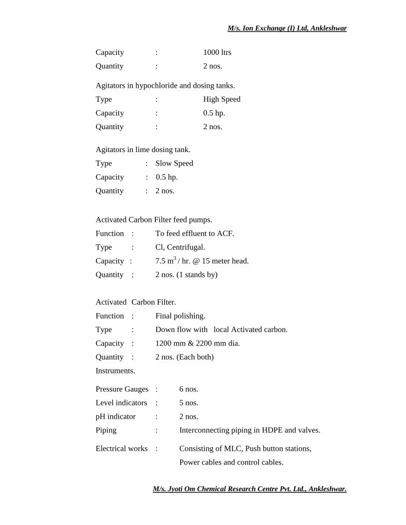
Capacity : 1000 ltrs
Quantity : 2 nos.
Agitators in hypochloride and dosing tanks.
Type : High Speed
Capacity : 0.5 hp.
Quantity : 2 nos.
Agitators in lime dosing tank.
Type : Slow Speed
Capacity : 0.5 hp.
Quantity : 2 nos.
Activated Carbon Filter feed pumps.
Function : To feed effluent to ACF.
Type : Cl, Centrifugal.
Capacity : 7.5 m3
/ hr. @ 15 meter head.
Quantity : 2 nos. (1 stands by)
Activated Carbon Filter.
Function : Final polishing.
Type : Down flow with local Activated carbon.
Capacity : 1200 mm & 2200 mm dia.
Quantity : 2 nos. (Each both)
Instruments.
Pressure Gauges : 6 nos.
Level indicators : 5 nos.
pH indicator : 2 nos.
Piping : Interconnecting piping in HDPE and valves.
Electrical works : Consisting of MLC, Push button stations,
Power cables and control cables.
M/s. Ion Exchange (I) Ltd, Ankleshwar
M/s. Jyoti Om Chemical Research Centre Pvt. Ltd., Ankleshwar.
FLOW DIAGRAM OF ETP ANIONIC – ACIDIC STREAM
ACID
NEUTRALIZATION
DECANTO
R FEED
TANK
ANIONIC
EFFLUENT
(ACIDICSTRE
AM)
DECENTOR
CENTRIFUG
E
SLUDGE
COLLECTION
TANK LIME SLURRY TANK
PRIMARY
TREATMENT
SLUDGE STORAGE
AREA
EQUALIZATION
TANK (450KL)
EFFLUENT TREATMENT
VIA ANIONIC (BIO
STREAM)
SLUDGE
POLYELECTROLYTE
Sludge FROM MBR & BOTH HRSCC’s& Secondary clarifier
Effluent LIME ADD
M/s. Ion Exchange (I) Ltd, Ankleshwar
M/s. Jyoti Om Chemical Research Centre Pvt. Ltd., Ankleshwar.
FLOW DIAGRAM OF ETP ANIONIC - RECYCLE STREAM
CATIONIC
EFFLUENT
(RECYCLE
STREAM)
EQUALIZ
ATION
TANK
(1400KL)
FENTON
TANK
HRSCC
MULTI
GRADE
FILTER
SECONDARY
CLARIFIER TANK AERATION TANK
(850 KL)
ULTRA
FILTRATION
PLANT
REVERSE
OSMOSIS
PLANT
FINAL
COLLECTION
SUMP
OXIDATION
SUMP
CARBON
FILTER
TREATED
EFFLUENT
OUTLET
TANK
GIDC
DRAIN
PERMEATE FOR
REUSE
ACTIVETED
CARBON FILTER
EFFLUENT
COLLECTIO
N TANK
RO REJECT
RO PERMEATE
POLYELECTROLYTE, HYPO
FeCL3, LIME Poly electrolyte
M/s. Ion Exchange (I) Ltd, Ankleshwar
M/s. Jyoti Om Chemical Research Centre Pvt. Ltd., Ankleshwar.
FLOW DIAGRAM OF ETP CATIONIC - BIO STREAM
TREATED
EFFLUENT
OUTLET
TANK FOR
DISCHARGE
PRE-AERATION
RECIRCULATIO
N TANK
HRSCC TANK ANIONIC EFFLUENT
(BIO STREAM)
UASB TANK
MEMBRAN
E BIO
REACTOR
FINAL
COLLEC
TION
SUMP
LAMELLA CLARIFIER
OXIDATI
ON
TANK
COLLECTION
/EQUALIZATIO
TANK (450 KL)
AERATIO
N TANK
FENTON TANK
(BIO STREAM)
GIDC DRAIN
PAC, Lime POLYELECTROL
YTE
ACF
TANK
DAP, Na2CO3
BIOMASS UREA, DAP
M/s. Ion Exchange (I) Ltd, Ankleshwar
M/s. Jyoti Om Chemical Research Centre Pvt. Ltd., Ankleshwar.
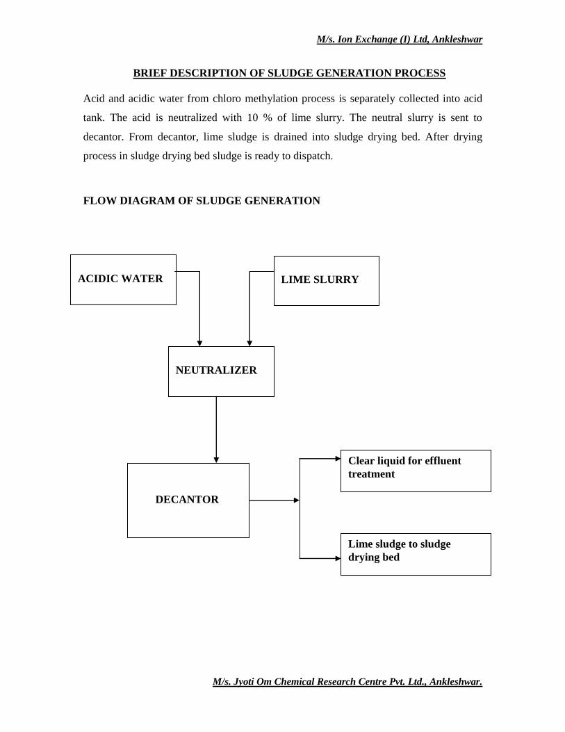
BRIEF DESCRIPTION OF SLUDGE GENERATION PROCESS
Acid and acidic water from chloro methylation process is separately collected into acid
tank. The acid is neutralized with 10 % of lime slurry. The neutral slurry is sent to
decantor. From decantor, lime sludge is drained into sludge drying bed. After drying
process in sludge drying bed sludge is ready to dispatch.
FLOW DIAGRAM OF SLUDGE GENERATION
ACIDIC WATER
LIME SLURRY
NEUTRALIZER
DECANTOR
Clear liquid for effluent
treatment
Lime sludge to sludge
drying bed
M/s. Ion Exchange (I) Ltd, Ankleshwar
M/s. Jyoti Om Chemical Research Centre Pvt. Ltd., Ankleshwar.
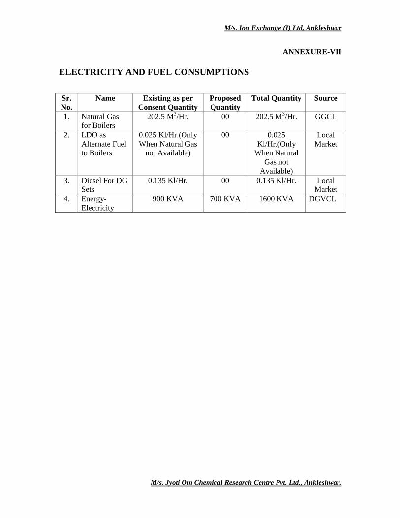
ANNEXURE-VII
ELECTRICITY AND FUEL CONSUMPTIONS
Sr.
No.
Name Existing as per
Consent Quantity
Proposed
Quantity
Total Quantity Source
1. Natural Gas
for Boilers
202.5 M3/Hr. 00 202.5 M
3/Hr. GGCL
2. LDO as
Alternate Fuel
to Boilers
0.025 Kl/Hr.(Only
When Natural Gas
not Available)
00 0.025
Kl/Hr.(Only
When Natural
Gas not
Available)
Local
Market
3. Diesel For DG
Sets
0.135 Kl/Hr. 00 0.135 Kl/Hr. Local
Market
4. Energy-
Electricity
900 KVA 700 KVA 1600 KVA DGVCL
M/s. Ion Exchange (I) Ltd, Ankleshwar
M/s. Jyoti Om Chemical Research Centre Pvt. Ltd., Ankleshwar.
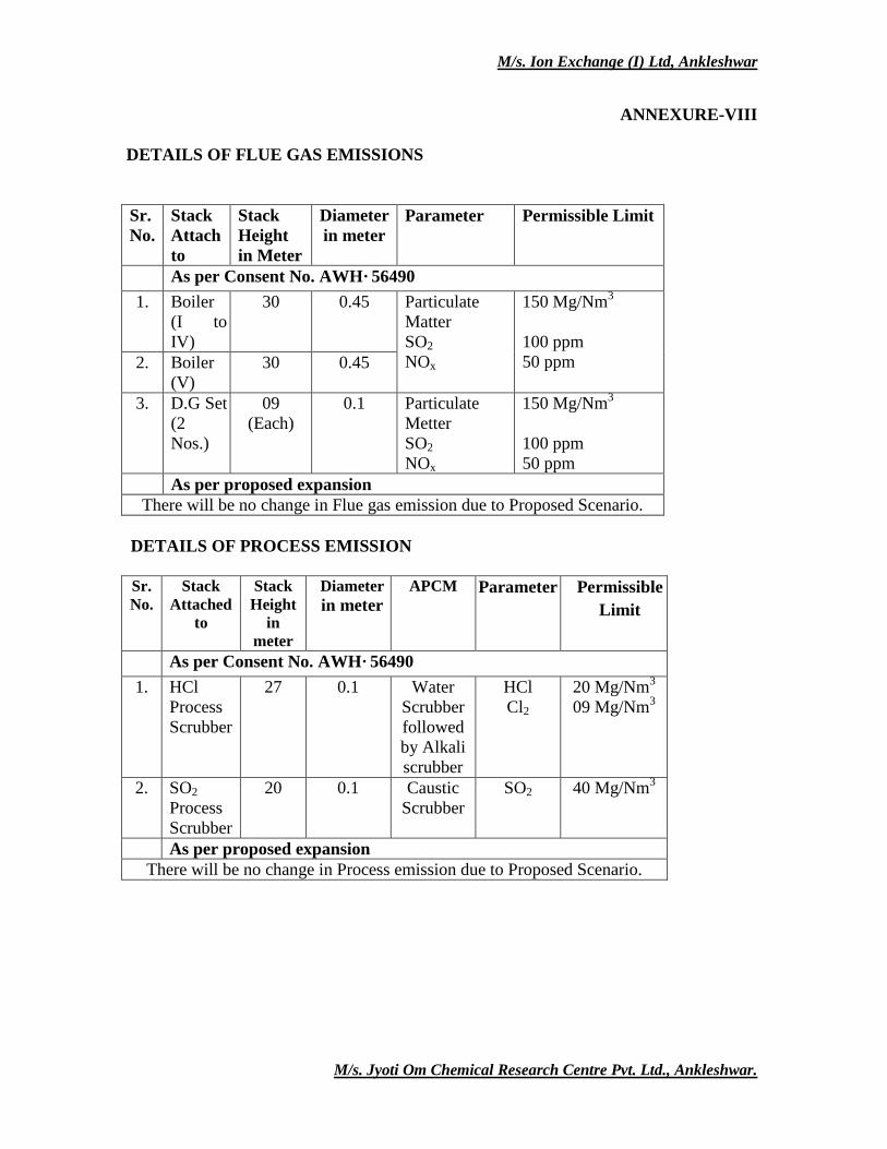
ANNEXURE-VIII
DETAILS OF FLUE GAS EMISSIONS
Sr.
No.
Stack
Attach
to
Stack
Height
in Meter
Diameter
in meter
Parameter Permissible Limit
As per Consent No. AWH· 56490
1. Boiler
(I to
IV)
30 0.45 Particulate
Matter
SO2
NOx
150 Mg/Nm3
100 ppm
50 ppm 2. Boiler
(V)
30 0.45
3. D.G Set
(2
Nos.)
09
(Each)
0.1 Particulate
Metter
SO2
NOx
150 Mg/Nm3
100 ppm
50 ppm
As per proposed expansion
There will be no change in Flue gas emission due to Proposed Scenario.
DETAILS OF PROCESS EMISSION
Sr.
No.
Stack
Attached
to
Stack
Height
in
meter
Diameter
in meter
APCM Parameter Permissible
Limit
As per Consent No. AWH· 56490
1. HCl
Process
Scrubber
27 0.1 Water
Scrubber
followed
by Alkali
scrubber
HCl
Cl2
20 Mg/Nm3
09 Mg/Nm3
2. SO2
Process
Scrubber
20 0.1 Caustic
Scrubber
SO2 40 Mg/Nm3
As per proposed expansion
There will be no change in Process emission due to Proposed Scenario.
M/s. Ion Exchange (I) Ltd, Ankleshwar
M/s. Jyoti Om Chemical Research Centre Pvt. Ltd., Ankleshwar.
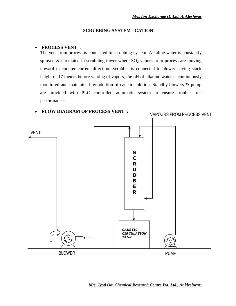
SCRUBBING SYSTEM - CATION
PROCESS VENT :
The vent from process is connected to scrubbing system. Alkaline water is constantly
sprayed & circulated in scrubbing tower where SO2 vapors from process are moving
upward in counter current direction. Scrubber is connected to blower having stack
height of 17 meters before venting of vapors, the pH of alkaline water is continuously
monitored and maintained by addition of caustic solution. Standby blowers & pump
are provided with PLC controlled automatic system to ensure trouble free
performance.
FLOW DIAGRAM OF PROCESS VENT :
VAPOURS FROM PROCESS VENT
BLOWER PUMP
CAUSTIC CIRCULATION TANK
S C
R U
B B
E
R
VENT
M/s. Ion Exchange (I) Ltd, Ankleshwar
M/s. Jyoti Om Chemical Research Centre Pvt. Ltd., Ankleshwar.
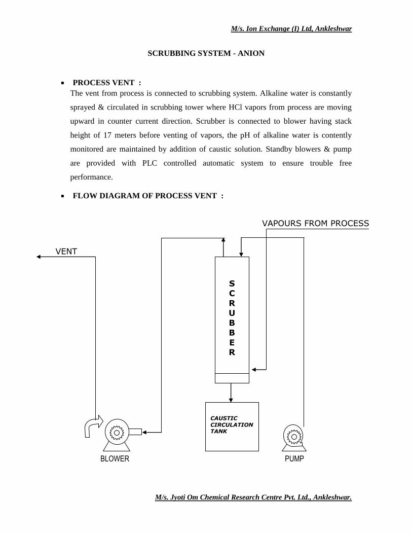
SCRUBBING SYSTEM - ANION
PROCESS VENT :
The vent from process is connected to scrubbing system. Alkaline water is constantly
sprayed & circulated in scrubbing tower where HCl vapors from process are moving
upward in counter current direction. Scrubber is connected to blower having stack
height of 17 meters before venting of vapors, the pH of alkaline water is contently
monitored are maintained by addition of caustic solution. Standby blowers & pump
are provided with PLC controlled automatic system to ensure trouble free
performance.
FLOW DIAGRAM OF PROCESS VENT :
VAPOURS FROM PROCESS
VENT
BLOWER PUMP
CAUSTIC CIRCULATION TANK
S C
R U
B B
E R
VENT
M/s. Ion Exchange (I) Ltd, Ankleshwar
M/s. Jyoti Om Chemical Research Centre Pvt. Ltd., Ankleshwar.
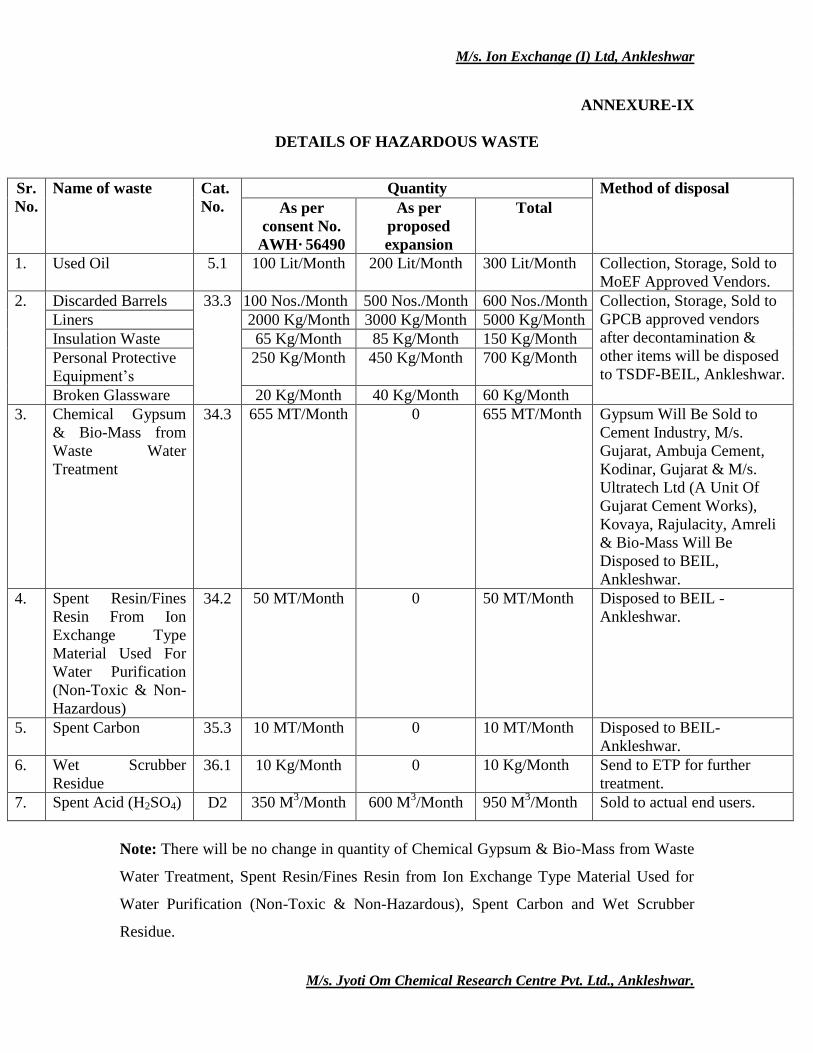
ANNEXURE-IX
DETAILS OF HAZARDOUS WASTE
Sr.
No.
Name of waste Cat.
No.
Quantity Method of disposal
As per
consent No.
AWH· 56490
As per
proposed
expansion
Total
1. Used Oil 5.1 100 Lit/Month 200 Lit/Month 300 Lit/Month Collection, Storage, Sold to
MoEF Approved Vendors.
2. Discarded Barrels 33.3 100 Nos./Month 500 Nos./Month 600 Nos./Month Collection, Storage, Sold to
GPCB approved vendors
after decontamination &
other items will be disposed
to TSDF-BEIL, Ankleshwar.
Liners 2000 Kg/Month 3000 Kg/Month 5000 Kg/Month
Insulation Waste 65 Kg/Month 85 Kg/Month 150 Kg/Month
Personal Protective
Equipment’s
250 Kg/Month 450 Kg/Month 700 Kg/Month
Broken Glassware 20 Kg/Month 40 Kg/Month 60 Kg/Month
3. Chemical Gypsum
& Bio-Mass from
Waste Water
Treatment
34.3 655 MT/Month 0 655 MT/Month Gypsum Will Be Sold to
Cement Industry, M/s.
Gujarat, Ambuja Cement,
Kodinar, Gujarat & M/s.
Ultratech Ltd (A Unit Of
Gujarat Cement Works),
Kovaya, Rajulacity, Amreli
& Bio-Mass Will Be
Disposed to BEIL,
Ankleshwar.
4. Spent Resin/Fines
Resin From Ion
Exchange Type
Material Used For
Water Purification
(Non-Toxic & Non-
Hazardous)
34.2 50 MT/Month 0 50 MT/Month Disposed to BEIL -
Ankleshwar.
5. Spent Carbon 35.3 10 MT/Month 0 10 MT/Month Disposed to BEIL-
Ankleshwar.
6. Wet Scrubber
Residue
36.1 10 Kg/Month 0 10 Kg/Month Send to ETP for further
treatment.
7. Spent Acid (H2SO4) D2 350 M3/Month 600 M
3/Month 950 M
3/Month Sold to actual end users.
Note: There will be no change in quantity of Chemical Gypsum & Bio-Mass from Waste
Water Treatment, Spent Resin/Fines Resin from Ion Exchange Type Material Used for
Water Purification (Non-Toxic & Non-Hazardous), Spent Carbon and Wet Scrubber
Residue.
Related Documents