MS 1553 : 2002 CODE OF PRACTICE ON WIND LOADING FOR BUILDING STRUCTURE ICS : 91.090 Descriptors : building structure, wind loading, wind action, wind speed, wind pressure, site exposure multipliers, shape factor MALAYSIAN STANDARD © Copyright DEPARTMENT OF STANDARDS MALAYSIA Licensed to T G Tan \& Partners Sdn Bhd / Downloaded on : 08-Nov-2010 07:52:04 PM / Single user license only, copying and networking prohibited

Welcome message from author
This document is posted to help you gain knowledge. Please leave a comment to let me know what you think about it! Share it to your friends and learn new things together.
Transcript

MS 1553 : 2002
CODE OF PRACTICE ON WIND LOADINGFOR BUILDING STRUCTURE
ICS : 91.090
Descriptors : building structure, wind loading, wind action, wind speed, wind pressure, siteexposure multipliers, shape factor
MALAYSIANSTANDARD
© Copyright
DEPARTMENT OF STANDARDS MALAYSIALice
nsed
to T
G T
an \&
Par
tner
s S
dn B
hd /
Dow
nloa
ded
on :
08-N
ov-2
010
07:5
2:04
PM
/ S
ingl
e us
er li
cens
e on
ly, c
opyi
ng a
nd n
etw
orki
ng p
rohi
bite
d

DEVELOPMENT OF MALAYSIAN STANDARDS
The Department of Standards Malaysia (DSM) is the national standardisation and
accreditation body.
The main function of the Department is to foster and promote standards,
standardisation and accreditation as a means of advancing the national economy,
promoting industrial efficiency and development, benefiting the health and safety of
the public, protecting the consumers, facilitating domestic and international trade and
furthering international cooperation in relation to standards and standardisation.
Malaysian Standards are developed through consensus by committees which
comprise of balanced representation of producers, users, consumers and others with
relevant interests, as may be appropriate to the subject in hand. To the greatest
extent possible, Malaysian Standards are aligned to or are adoption of international
standards. Approval of a standard as a Malaysian Standard is governed by the
Standards of Malaysia Act 1996 (Act 549). Malaysian Standards are reviewed
periodically. The use of Malaysian Standards is voluntary except in so far as they are
made mandatory by regulatory authorities by means of regulations, local by-laws or
any other similar ways.
The Department of Standards appoints SIRIM Berhad as the agent to develop
Malaysian Standards. The Department also appoints SIRIM Berhad as the agent for
distribution and sale of Malaysian Standards.
For further information on Malaysian Standards, please contact:
Department of Standards Malaysia OR SIRIM BerhadLevel 1 & 2, Block C4, Parcel C (Company No. 367474 - V)Federal Government Administrative Centre 1, Persiaran Dato’ Menteri62502 Putrajaya P.O. Box 7035, Section 2MALAYSIA 40911 Shah Alam
Selangor D.E.
Tel: 60 3 88858000 Tel: 60 3 5544 6000Fax: 60 3 88885060 Fax: 60 3 4410 8095
http://www.dsm.gov.my http://www.sirim.my
E-mail: [email protected]
Lice
nsed
to T
G T
an \&
Par
tner
s S
dn B
hd /
Dow
nloa
ded
on :
08-N
ov-2
010
07:5
2:04
PM
/ S
ingl
e us
er li
cens
e on
ly, c
opyi
ng a
nd n
etw
orki
ng p
rohi
bite
d
MS 1553 : 2002
i
CONTENTS
Page
Committee representation……………………………………………………………………... v
Foreword………………………………………………………………………………………... vi
SECTION 1 : GENERAL
1.1 Scope………………………………………………………………………….……….... 11.2 Application…………………………………………………………….……..…….…… 11.3 Referenced documents…………………………………………………….……….…. 11.4 Determination of wind actions…………………………………………..……………. 11.5 Units…………………………………………………………………………….….……. 21.6 Definitions……………………………………………………………………….……… 21.7 Notation………………………………………………………………………………… 6
SECTION 2 : CALCULATION OF WIND ACTIONS
2.1 General…………………………………………………..……………………..……… 142.2 Site wind speed………………………………………………………………..………. 142.3 Design wind speed…………………………………………………………………... 152.4 Design wind pressure………………………………………………………………... 152.5 Wind actions……………………………………………………………………..….... 162.6 Wind tunnel procedure………………………………………………….…..…..……. 172.7 Wind induced vibrations…………………………………………………….…..…… 18.SECTION 3 : WIND SPEEDS
3.1 General …………………………………………………………………………..…....… 193.2 Station wind speeds…………………………………………………………….…….. 19
SECTION 4 : SITE EXPOSURE MULTIPLIERS
4.1 General ………………………………………………………………….……..…….…. 224.2 Terrain/height multiplier, mz,cat…………………………………………………..…… 224.3 Shielding multiplier, ms…………………………………………………………….….. 254.4 Hill shape multiplier, mh………………………………………………………….……. 26
SECTION 5 : AERODYNAMIC SHAPE FACTOR
5.1 General……………………………………………………………………………..…. 295.2 Evaluation of aerodynamic shape factor……………………………………..……. 305.3 Internal pressure for enclosed buildings………………………………………..…. 315.4 External pressures for enclosed buildings…………………………..………..…… 335.5 Frictional drag forces for enclosed buildings………………………………….…… 41
Lice
nsed
to T
G T
an \&
Par
tner
s S
dn B
hd /
Dow
nloa
ded
on :
08-N
ov-2
010
07:5
2:04
PM
/ S
ingl
e us
er li
cens
e on
ly, c
opyi
ng a
nd n
etw
orki
ng p
rohi
bite
d
MS 1553 : 2002
ii
CONTENTS (continued)
Page
SECTION 6 : DYNAMIC RESPONSE FACTOR
6.1 Evaluation of dynamic response factor………………………….…………………… 436.2 Along-wind response of tall buildings and towers……………………………….…. 436.3 Cross wind response………………………………..…………………………….…… 476.4 Combination of along wind and crosswind response…………………………..…. 53
Tables
3.1 Wind speed for various return period…………………………………………..……. 193.2 Importance factor, I…………………………………………………………………..… 214.1 Terrain/height multipliers for gust wind speeds in fully developed terrain.
Serviceability limit state design and ultimate limit state……………………….…... 234.2 Roughness lengths for terrain categories………………………………………..….. 244.3 Shielding multiplier, Ms………………………………………………………………………………………………..…. 254.4 Hill-shape multiplier at crest ( |x| = 0), z = 0 (for gust wind speeds)…………….... 285.1 Internal pressure, coefficients, Cp,i, for buildings with open interior plan………... 325.2 Wall : External pressure coefficients, Cp,e for rectangular enclosed buildings … 355.3 Roofs : External pressure coefficients, Cp,e, for rectangular enclosed buildings ... 365.4 Area reduction factor, Ka………………………………………………………………………………………………….. 375.5 Action combination factors for wind pressure contributing from two
or more building surfaces to effects on major structural elements………………. 375.6 Local pressure factor, Kl………………………………………………………………. 395.7 Reduction factor, Kr, due to parapets……………………………………………….. 405.8 Porous cladding reduction factor, Kp………………………………………………… 415.9 Frictional drag coefficient for d/h > 4 or d/b > 4…………………………………….. 436.1 Turbulence intensity (Iz) ultimate limit state design and serviceability
limit state design – all regions ………………………………………………………. 456.2 Values of fraction critical damping of structures (ζ) ……………………………… 46A1 Terrain height multiplier, Mz,cat ……………………………………………………. 55A2 External pressure coefficients Cp,e, for leeward wall ……………………………. 57A3 External pressure coefficients Cp,e, for side walls ………………………………. 57A4 For up-wind slope, u and down-wind slope, d for α<10° and R for gable roofs .. 57A5 Up-wind slope, U, α ≥ 10° ……………………………………………………………. 58A6 Down-wind slope, D, α ≥ 10° and R for hip roofs ………………………………….. 58A7 Local pressure factor, Kl for claddings …………………………………………….. 58C1 External pressure coefficients (Cp,e) for multi-span buildings: pitch roofs ……… 64C2 External pressure coefficients (Cp,e) for multi-span buildings: saw-tooth roofs… 64C3 External pressure coefficients (Cp,e): curved roofs h/r ≤ 2 ……………………….. 65C4 External pressure for roofs of circular bins, silos and tanks ….………………….. 69D1 Local net pressure factors, Kl, for open structures ………………………………… 71D2 Net pressure coefficients for hoardings and free standing walls ………………… 72D3 Frictional drag coefficient …………………………………………………………… 73D4(a) Net pressure coefficients, Cp,n for monoslope free roofs( 0.25 ≤ hld ≤ 1) ………. 74D4(b) Net pressure coefficients, Cp,n for monoslope free roofs with α ≤ 5o
( 0.05 ≤ h/d ≤ 0.25 ) or for all α and θ = 90o and for long roofs ………………….. 75D5 Net pressures coefficients, Cp,n for pitched free roofs(0.25 ≤h/d ≤1) …………… 75
Lice
nsed
to T
G T
an \&
Par
tner
s S
dn B
hd /
Dow
nloa
ded
on :
08-N
ov-2
010
07:5
2:04
PM
/ S
ingl
e us
er li
cens
e on
ly, c
opyi
ng a
nd n
etw
orki
ng p
rohi
bite
d
MS 1553 : 2002
iii
CONTENTS (continued)
Page
D6 Net pressure coefficients, Cp,n for troughed free roofs(0.25 ≤ h/d ≤1) …………… 76D7 Net pressure coefficients, Cp,n for hypar free roofs (Empty under) ………………. 77D8 Net pressure coefficients, Cp,n, for canopies and awnings attached to
buildings (refer to Figure D6(a)) for θ = 0°…………………………………………. 79D9 Net pressure coefficients, Cp,n, for partially enclosed carports (hc/wc ≤ 0.5)…… 80E1 Aspect ratio correction factors, Kar …………………………………………………………………………… 82E2 Shielding factors, Ksh, for multiple frames …………………………………………. 84E3 Drag force coefficient (Cd) for rounded circular shapes ………………………….. 85E4 Drag force coefficient (Cd) for sharp-edge-prisms ………………………………… 86E5 Force coefficients (CF,x) and (CF,y ) for structural sections ………………………… 87E6 Drag force coefficients (Cd) for lattice towers ……………………………………… 90E7 Drag force coefficient (Cd) for UHF-antenna sections ……………………………. 91F1 Aerodynamic shape factor for circular shapes ……………………………………. 96
Figures
2.1 Reference to height of structure ……………………………………………………. 163.1 Peninsular Malaysia………………………………………………………………….. 204.1 Changes in terrain……………………………………………………………………. 254.2 Hills and ridges ……………………………………………………………………….. 274.3 Escarpments ………………………………………………………………………….. 284.4 Separation zone for slopes greater than 0.44 …………………………………….. 285.1 Sign conventions for Cfig …………………………………………………………….. 305.2 Parameters for rectangular enclosed buildings ……………………………………. 345.3 Local pressure factor, (Kl) ……………………………………………………………. 405.4 Notation for permeable surfaces ……………………………………………………. 416.1 Notation for heights ………………………………………………………………….. 436.2 Cross wind force spectrum coefficient for 3:1:1 square section ………………… 496.3 Cross wind force spectrum coefficient for 6:1:1 square section ………………... 506.4 Cross wind force spectrum coefficient for 6:2:1 rectanglar section ……………… 506.5 Cross wind force spectrum coefficient for 6:1:2 rectangular section …………… 51A1 Peninsula Malaysia ………………………………………………………………….. 56A2 Local pressure factors(Kl) ……………………………………………………….…. 59B1 Information in using this standard ……………………………………………….… 60B2 Determination of design wind speed ……………………………………………… 61B3 Determination of design wind pressure using simplified procedure ………….. 62C1. External pressure coefficients (Cp,e) for mult …………………………………….. 63C2 External pressure coefficient (Cp,e) for multi-span building : saw-tooth roofs …. 64C3 External pressure coefficients (Cp,e) : curved roofs……………………………….. 65C4 External pressure coefficients (Cp,e) for mansard roofs …………………………. 66C5 External pressure coefficients (Cp,b) on walls of circular bins,
silos and tanks (0.25 ≤ c/b ≤ 4.0)…………………………………………………….. 67C6 Plot of external pressure coefficient (Cp,l) on walls of circular bins,
silos and tanks (c/b = 1) ………………………………………………………………. 68C7 External pressure coefficients (Cp,e) on walls of circular bins,
silos and tanks (0.25 < c/b < 4.0) ……………………………………………………. 69D1 Free standing hoardings and walls ………………………………………………….. 72
Lice
nsed
to T
G T
an \&
Par
tner
s S
dn B
hd /
Dow
nloa
ded
on :
08-N
ov-2
010
07:5
2:04
PM
/ S
ingl
e us
er li
cens
e on
ly, c
opyi
ng a
nd n
etw
orki
ng p
rohi
bite
d

MS 1553 : 2002
iv
CONTENTS (continued)
Page
D2 Monoslope free roofs …………………………………………………………………. 75D3 Pitched free roofs ……………………………………………………………………. 76D4 Troughed free roofs ………………………………………………………………….. 76D5 Hyperbolic paraboloid (hypar) roofs ………………………………………………… 77D6 Net pressure coefficients, Cp,n, for canopies, awnings and carports
attached to buildings ………………………………………………………………… 79D7 Cantilevered roof and canopy …………………………………………………….. 80
E1 Notation for frame dimensions ……………………………………………………… 83E1(a) Along-wind coefficients for rectangular prisms …………………………………… 88E1(b) Cross-wind coefficients for rectangular prisms ………………………………….. 89E2 Drag force coefficients (Cd) for sections of UHF antenna ………………………. 92E3 Tower sections with ancillarie ……………………………………………………… 94F1 Reference area for flags ……………………………………………………………. 95
Appendices
A Simplified procedure…………………………………………………………………… 54B Flow chart…………………………………………………………….……………..…. 60C Additional pressure coefficients for enclosed buildings………………………..…. 63D Free standing walls, hoardings and canopies……………………………………... 70E Aerodynamic shape factors for exposed structural members………………….... 81F Flags and circular shapes…………………………………………………………..… 95
Lice
nsed
to T
G T
an \&
Par
tner
s S
dn B
hd /
Dow
nloa
ded
on :
08-N
ov-2
010
07:5
2:04
PM
/ S
ingl
e us
er li
cens
e on
ly, c
opyi
ng a
nd n
etw
orki
ng p
rohi
bite
d
MS 1553 : 2002
v
Committee representation
The Building and Civil Engineering Industry Standards Committee (ISC D) under whose supervision this MalaysianStandard was developed, comprises representatives from the following organisations:
Association of Consulting Engineers MalaysiaChartered Institute of Buildings MalaysiaConstruction Industry Development Board MalaysiaDepartment of Standards MalaysiaJabatan Bomba dan Penyelamat MalaysiaMalaysian Timber Indusry BoardMaster Builders Association MalaysiaNational Housing DepartmentPublic Works DepartmentPertubuhan Akitek MalaysiaSuruhanjaya TenagaThe Institution of Engineers, MalaysiaUniversiti Teknologi Malaysia
The Technical Committee on Structure Loading which supervised the development of this standard was managed bythe Construction Industry Development Board Malaysia (CIDB) in its capacity as an authorised Standard-WritingOrganisation and comprises the following organisations:
Association of Consulting Engineers Malaysia
Construction Industry Development Board Malaysia
Jabatan Kerja Raya
Jabatan Perkhidmatan Kajicuaca Malaysia
Pertubuhan Akitek Malaysia
SIRIM Berhad
The Institution of Engineers Malaysia
Universiti Kebangsaan Malaysia
Universiti Malaya
Universiti Sains Malaysia
Universiti Teknologi MARA
Lice
nsed
to T
G T
an \&
Par
tner
s S
dn B
hd /
Dow
nloa
ded
on :
08-N
ov-2
010
07:5
2:04
PM
/ S
ingl
e us
er li
cens
e on
ly, c
opyi
ng a
nd n
etw
orki
ng p
rohi
bite
d

MS 1553 : 2002
vi
Committee representation
The Working Group (CIDB/SWO-TC2/WG1) on Academic and Research of Code Of Practice On Wind LoadingFor Building Structure which developed this Malaysian Standard consists of representative from the followingorganisations:
Association of Consulting Engineers Malaysia
Construction Industry Development Board Malaysia
GR Associates
Jabatan Perkhidmatan Kajicuaca Malaysia
Monash University Malaysia
Universiti Kebangsaan Malaysia
Universiti Malaya
Universiti Sains Malaysia
Universiti Teknologi MARA
The Working Group (CIDB/SWO-TC2/WG2) on Development of Code of Practice on Wind Loading for BuildingStructure that developed this Malaysian Standard consists of representative from the following organisations:
Association of Consulting Engineers Malaysia
GR Associates
Jabatan Perkhidmatan Kajicuaca Malaysia
Construction Industry Development Board Malaysia
Monash University Malaysia
Universiti Kebangsaan Malaysia
Universiti Malaya
Universiti Sains Malaysia
Universiti Teknologi MARA
Lice
nsed
to T
G T
an \&
Par
tner
s S
dn B
hd /
Dow
nloa
ded
on :
08-N
ov-2
010
07:5
2:04
PM
/ S
ingl
e us
er li
cens
e on
ly, c
opyi
ng a
nd n
etw
orki
ng p
rohi
bite
d

MS 1553 : 2002
vii
FOREWORD
The Malaysian Standard was developed by the Working Group on Code of Practice on WindLoading for Building Structure supervised by the Technical Committee on Structure Loadingunder the authority of the Building and Civil Engineering Industry Standards Committee.Development of this Standard was carried out by the Construction Industry DevelopmentBoard Malaysia (CIDB) which is the Standards-Writing Organisation (SWO) appointed bySIRIM Berhad to develop standards for the construction industry.
During the development of this Malaysian Standard, reference was made to AS/NZS 1170.2Structural design – General requirements and design actions.
Compliance with a Malaysian Standard does not of itself confer immunity from legalobligations.
Lice
nsed
to T
G T
an \&
Par
tner
s S
dn B
hd /
Dow
nloa
ded
on :
08-N
ov-2
010
07:5
2:04
PM
/ S
ingl
e us
er li
cens
e on
ly, c
opyi
ng a
nd n
etw
orki
ng p
rohi
bite
d

Lice
nsed
to T
G T
an \&
Par
tner
s S
dn B
hd /
Dow
nloa
ded
on :
08-N
ov-2
010
07:5
2:04
PM
/ S
ingl
e us
er li
cens
e on
ly, c
opyi
ng a
nd n
etw
orki
ng p
rohi
bite
d

MS 1553 : 2002
1
CODE OF PRACTICE ON WIND LOADING FOR BUILDING STRUCTURE
SECTION 1 : GENERAL
1.1 Scope
This Malaysian Standard sets out procedures for determining wind speeds and resulting windactions to be used in the structural design for structures subjected to wind action other thanthose caused by tornadoes and typhoons.
The standard covers structures within the following criteria:
a) building less than 200 m high;
b) structures with roof spans less than 100 m; and
c) structures other than off-shore structures, bridges and transmission towers.
1.2 Application This Malaysian Standard applies to structures as described in 1.1 and designed to MalaysianStandards using limit states and permissible stresses. Appendix A may be used for structuresof limitations as stated there in.
1.3 Referenced document The following referenced documents contain provisions, which through references in this textconstitute provisions of this Malaysian Standard. For dated references, where there aresubsequent amendments to, or revisions of, any of these publications do not apply. However,parties to agreements based on this Malaysian Standard are encouraged to investigate thepossibility of applying the most recent editions of the referenced documents. For undatedreferences, the latest edition of publication referred to applies. ANSI/ASCE 7-95 Minimum design loads for buildings and other structures AS/NZS 1170.2 Structural design – General requirements and design actions ISO 4345 Wind action on structures MS ISO 1000 SI units and recommendations for the use of their multiples and of certainother units
1.4 Determination of wind actions Values of wind actions for use in design established shall be appropriate for the type ofstructure or structural element, its intended use, design working life and exposure to windactions. Wind actions on a structure or part of a structure shall be ascertain from using one ormore of the followings:
Lice
nsed
to T
G T
an \&
Par
tner
s S
dn B
hd /
Dow
nloa
ded
on :
08-N
ov-2
010
07:5
2:04
PM
/ S
ingl
e us
er li
cens
e on
ly, c
opyi
ng a
nd n
etw
orki
ng p
rohi
bite
d

MS 1553 : 2002
2
a) the applicable clauses of this Malaysian Standard;
b) reliable references used consistently with clauses of this Malaysian Standard;
c) data on wind speed and direction from reliable and recognised source; and
d) wind tunnel or similar fluid dynamic tests carried out for a specific structure.
This Malaysian Standard provides guidelines for wind tunnel testing of structures withirregular geometric shapes, response characteristics or site locations in which accurate windactions are desired (refer to 2.6). 1.5 Units
Except where specifically noted, this standard uses the SI units as specified in MS ISO 1000.
1.6 Definitions
1.6.1 Aerodynamic shape factor
Factor to account for the effects of the geometry of the structure on surface pressure due towind.
1.6.2 Awning
Roof-like structure, usually of limited extent, projecting from a wall of a building.
1.6.3 Canopy
Roof adjacent to or attached to a building, generally not enclosed by walls.
1.6.4 Cladding
Material which forms the external surface over the framing of an element of a building orstructure.
1.6.5 Design wind speed
Wind speed for use in design adjusted for wind direction, structure importance, design life,geographic position, surrounding countryside and height.
NOTE. For very tall structures, design wind speed may be expressed as a function of height.
1.6.6 Dominant opening
Opening in the external surface of an enclosed building which directly influences the averageinternal pressure in response to external pressures at that particular opening. Dominantopenings need not be large.
Lice
nsed
to T
G T
an \&
Par
tner
s S
dn B
hd /
Dow
nloa
ded
on :
08-N
ov-2
010
07:5
2:04
PM
/ S
ingl
e us
er li
cens
e on
ly, c
opyi
ng a
nd n
etw
orki
ng p
rohi
bite
d

MS 1553 : 2002
3
1.6.7 Drag
Force acting in the direction of the wind stream (see also Lift).
1.6.8 Dynamic response factor
Factor to account for the effects of correlation and resonant response.
1.6.9 Elevated building
Building with a clear, un-walled space underneath the first floor level with a height fromground to underside of the first floor of one third or more of the total height of the building.
1.6.10 Enclosed building
Building which has full perimeter walls (nominally sealed) from floor to roof level.
1.6.11 Escarpment
Long (steeply sloping) face between nominally level lower and upper plains where the plainshave average slopes of not greater than 5 %.
1.6.12 Exposure factor
Factor used in ISO 4354 to account for the variability of the wind speed at the site of thestructure due to terrain roughness and shape, height above ground, shielding and orographicenvironment.
1.6.13 First mode shape
Shape of a structure at its maximum amplitude under first mode natural vibration.
1.6.14 First mode natural frequency
Frequency of free oscillation corresponding to the lowest harmonic of vibration of a structure.
1.6.15 Force coefficient
Coefficient which when multiplied by the incident wind pressure and an appropriate area(defined in the text), gives the force in a specific direction.
1.6.16 Free roof
Roof (of any type) with no enclosing walls underneath, e.g. free-standing carport.
1.6.17 Free standing walls
Walls that are exposed to the wind on both sides, with no roof attached, e.g. fences.
1.6.18 Gable End
End of building without openings.
Lice
nsed
to T
G T
an \&
Par
tner
s S
dn B
hd /
Dow
nloa
ded
on :
08-N
ov-2
010
07:5
2:04
PM
/ S
ingl
e us
er li
cens
e on
ly, c
opyi
ng a
nd n
etw
orki
ng p
rohi
bite
d

MS 1553 : 2002
4
1.6.19 Hip roof
Traditional roof with sloping ridges rising up from external corners (valleys rise up from anyreturn corners).
1.6.20 Hoardings
Free standing (rectangular) signboards, etc, supported clear of the ground.
1.6.21 Immediate supports (cladding)
Those supporting members to which cladding is directly fixed (e.g. battens, purlins, girts,studs).
1.6.22 Importance factor
A factor that accounts for the degree of hazard to human life and damage to property.
1.6.23 Lag distance
Horizontal distance down wind, required for the effects of a change in terrain roughness onwind speed to reach the height being investigated. It increases with height above ground.
1.6.24 Lattice towers
Three-dimensional frameworks comprising three or more linear boundary membersinterconnected by linear bracing members jointed at common points (nodes), enclosing anopen area through which the wind may pass.
1.6.25 Lift
Force acting at 90° to the wind stream (see also Drag).
1.6.26 Mansard roof
A roof with two slopes on all four sides, the lower slope steeper than the upper slope.
Note. A mansard roof with the upper slopes less than 10 degrees any be assumed to be flat topped.
1.6.27 Monoslope roof
Planar roof with no ridge, which has a constant slope.
1.6.28 Obstructions
Natural or man-made objects, which generate turbulent wind flow, ranging from single trees toforests and from, isolated structures to closely spaced multi-storey buildings.
Lice
nsed
to T
G T
an \&
Par
tner
s S
dn B
hd /
Dow
nloa
ded
on :
08-N
ov-2
010
07:5
2:04
PM
/ S
ingl
e us
er li
cens
e on
ly, c
opyi
ng a
nd n
etw
orki
ng p
rohi
bite
d
MS 1553 : 2002
5
1.6.29 Permeable
Surface with an aggregation of small openings and cracks etc, which allows air to passthrough under the action of a pressure differential.
1.6.30 Pitched roof
Bi-fold, bi-planar roof with a ridge at its highest point.
1.6.31 Porosity (of cladding)
Ratio of the area openings divided by the total surface area.
1.6.32 Pressure
Air pressure referenced to ambient air pressure. In this Standard, negative values are lessthan ambient (suction), positive values exceed ambient. Net pressures act normal to asurface in the direction specified within the text.
1.6.33 Pressure coefficient
Ratio of the pressure acting at the point on a surface, to the free stream dynamic pressure ofthe incident wind.
1.6.34 Ridge (topographic feature)
Long crest or chain of hills which have a nearly linear apex, with sloping faces on either sideof the crest.
1.6.35 Roughness length
Theoretical quantification of the turbulence inducing nature of a particular type of terrain on airflow (wind).
1.6.36 Rectangular building
For the purpose of Section 5 of this standard, rectangular building includes buildings generallymade up of a rectangular shapes in plan.
1.6.37 Reynolds number
The ratio of the inertial forces to the viscous forces in the airflow.
1.6.38 Scruton number
A mass damping parameter.
1.6.39 Solidity (of cladding)
Ratio of solid area to the total area of the surface.
1.6.40 Structural elements, major
Structural elements whose tributary areas are greater than 10 m2.
Lice
nsed
to T
G T
an \&
Par
tner
s S
dn B
hd /
Dow
nloa
ded
on :
08-N
ov-2
010
07:5
2:04
PM
/ S
ingl
e us
er li
cens
e on
ly, c
opyi
ng a
nd n
etw
orki
ng p
rohi
bite
d

MS 1553 : 2002
6
1.6.41 Structural elements, minor
Structural elements whose tributary areas are less than or equal to 10 m2.
1.6.42 Terrain
Surface roughness condition when considering the side and arrangement of obstructions tothe wind.
1.6.43 Topography
Major land surface features comprising hills, valleys and plains, which strongly influence windflow patterns.
1.6.44 Tornado
Violently rotating column of air, pendant from the base of a convective cloud, and oftenobservable as a funnel cloud attached to the cloud base.
1.6.45 Tributary area
Area of building surface contributing to the force being considered.
1.6.46 Troughed roof
Bi-fold, bi-planar roof with a valley at its lowest point.
1.7 Notation
Unless stated otherwise, the notation used in this Standard shall have the following meaningswith respect to a structure, or member, or condition to which a Clause is applied.
A surface area of the element or the tributary area, which transmit wind forces tothe element, being:
i) when used in conjunction with the pressure coefficient (Cp), the area uponwhich the pressure acts, which may not always be normal to the wind stream;
ii) when used in conjunction with a drag force coefficient (Cd), the projected areanormal to the wind stream; and
iii) when used in conjunction with a force coefficient, (CF,x) or (CF,y ), the areas asdefined in applicable clauses.
Aa reference area of ancillaries on a tower.
Ar gross plan area of the roof including eaves, canopies, awning etc.
Aref reference area of flag.
Az,s total projected area of the tower section at height z.
Lice
nsed
to T
G T
an \&
Par
tner
s S
dn B
hd /
Dow
nloa
ded
on :
08-N
ov-2
010
07:5
2:04
PM
/ S
ingl
e us
er li
cens
e on
ly, c
opyi
ng a
nd n
etw
orki
ng p
rohi
bite
d

MS 1553 : 2002
7
Az area of a structure or a part of a structure, in meter's squared, at height z, upon whichthe pressure at that height (pz) acts.
a i) constant for ease of calculation (see E4.2.3); and
ii) dimension used in defining the extent of application of local pressure factors.
Bs background factor which is a measure of the slowly varying background componentof the fluctuating response, caused by low frequency wind speed variations.
b i) breadth of a structure or element, usually normal to the wind stream (seeFigures 5.1, C5, C7, D1, E1, E3 and Tables E3, E4 and E5);
ii) horizontal breadth of a vertical structure normal to the wind stream, oraverage breadth of a vertically tapered structure over the top half of thestructure; or nominal average breadth of a horizontal structure; and
iii) average diameter of a circular section.
bD diagonal breadth of UHF antennas.
b i average diameter or breadth of a section of a tower member.
bN normal breadth of UHF antennas.
b0 average breadth of the structure between 0 and h.
bs average breadth of the shielding buildings, normal to wind stream.
bsh average breadth of the structure between heights s and h.
br average breadth of top of the structure.
bz average breadth of the structure at the section at height z.
b/w ratio of the average diameter of an ancillary to the average width of structure.
Cd drag force coefficient for a structure or member in the direction of the wind stream.
Cda drag force coefficient of an isolated ancillary on a tower.
Cde effective drag force coefficient for a tower section with ancillaries.
Cd,f drag force coefficient for the first frame in the up-wind direction.
Cdyn dynamic response factor.
CF,x drag force coefficient for a structure or member, in the direction of the x-axis.
CF,y drag force coefficient for a structure or member, in the direction of the y-axis.
Cf frictional drag force coefficient.
Lice
nsed
to T
G T
an \&
Par
tner
s S
dn B
hd /
Dow
nloa
ded
on :
08-N
ov-2
010
07:5
2:04
PM
/ S
ingl
e us
er li
cens
e on
ly, c
opyi
ng a
nd n
etw
orki
ng p
rohi
bite
d

MS 1553 : 2002
8
Cfig aerodynamic shape factor.
Cfs cross-wind force spectrum coefficient generalised for a linear mode shape.
Cp,b external pressure coefficient for sides of bins, silos and tanks.
Cp,e external pressure coefficient.
Cp,i internal pressure coefficient
Cp,l net pressure coefficient for the leeward half of a free roof.
Cp,n net pressure coefficient acting normal to the surface for canopies, free standing roofs,walls etc.
Cp,w net pressure coefficient for the windward half of a free roof.
Cpl(θb) external pressure coefficient on walls of bins, silos or tanks of unit aspect ratio (c/b =1) as a function of θb.
c i) constant for ease of calculation (see E4.2.3);
ii) net height of a hoarding, bin, silo or tank (not including roof or lid height); and
iii) height between the highest and lowest points on a hyperbolic paraboloid roof.
d i) minimum roof plan dimension;
ii) depth or distance parallel to the wind stream to which the plan or crosssection of shape extends; and
iii) length of span of curved roof.
da along-wind depth of a porous wall or roof surface.
E the modulus of elasticity.
Et spectrum of turbulence in the approaching wind stream.
e i) the base of Napierian logarithms (≈ 2.71828); and
ii) horizontal eccentricity of net pressure.
F force on building element.
G ratio of peak to mean along-wind response, Ma,p/Ma,m (related to gust effects).
gR peak factor for resonant response (10 min period).
gv peak factor for up-wind velocity fluctuations.
H height of the hill, ridge or escarpment.
Hs height factor for the resonant response.
Lice
nsed
to T
G T
an \&
Par
tner
s S
dn B
hd /
Dow
nloa
ded
on :
08-N
ov-2
010
07:5
2:04
PM
/ S
ingl
e us
er li
cens
e on
ly, c
opyi
ng a
nd n
etw
orki
ng p
rohi
bite
d

MS 1553 : 2002
9
h average roof height of a structure above ground.
hc height from ground to the attached canopy, etc.
he eaves height from the ground to the eaves of the building.
hf flag height.
hi floor to floor height of the structure.
hr average height of surface roughness.
hp height of parapet above average roof level.
hs average height of shielding buildings.
ht height from the ground to the top of a structure.
I i) second moment of area; and
ii) Importance factor.
Ih turbulence intensity, obtained from Table 6.1 by setting z equal to h.
Iz turbulence intensity at height z given for the various terrain categories in Table 6.1.
K factor for maximum tip deflection.
Ka area reduction factor.
Kar aspect ratio correction factor for individual member forces.
Kc combination factor.
Ki factor to account for the angle of inclination of the axis of members to the winddirection.
Kin correction factor for interference.
Kl local pressure factor.
Km mode shape correction factor cross wind acceleration.
K’m mode shape correction factor cross wind base overturning moment.
Kp porous cladding reduction factor.
Kr parapet reduction factor.
Ksh shielding factor for shielded frames in multiple open framed structures reductionfactor.
k mode shape power exponent.
Lice
nsed
to T
G T
an \&
Par
tner
s S
dn B
hd /
Dow
nloa
ded
on :
08-N
ov-2
010
07:5
2:04
PM
/ S
ingl
e us
er li
cens
e on
ly, c
opyi
ng a
nd n
etw
orki
ng p
rohi
bite
d
MS 1553 : 2002
10
Kb factor for a circular bin.
Lh measure of effective turbulence length scale at height h.
Lu horizontal distance upwind from the crest of the hill. Ridge or escarpment to a levelhalf the height below the crest.
L1 length scale in meters to determine the vertical variation of Mh, to be taken as thegreater of 0.4H or 0.36Lu.
L2 length scale in meters to determine the horizontal variation of Mh, to be taken as L1upwind for all types, and downwind for hills and ridges, or 10L1 downwind forescarpments.
l i) length of member; and
ii) length of cantilevered roof beam.
lf flag length.
ls average spacing of shielding buildings.
Ma along-wind base overturning moment.
Ma,m mean base overturning moment for a structure in the along-wind direction.
Ma,p design peak base overturning moment for a structure in the along-wind direction.
Mc cross-wind base overturning moment.
Mc,m mean base overturning moment for a structure in the cross-wind direction.
Mc,p design peak base overturning moment for a structure in the cross-wind direction.
Md wind directional multiplier.
Mr resultant vector base overturning moment.
Mr,d design peak resultant vector base overturning moment.
Mh hill shape multiplier.
Ms shielding multiplier.
Mz,cat terrain/height multiplier.
m0 average mass per unit multiplier.
mf mass per unit of flag.
mt average mass per unit height over the top third of the structure.
m(z) mass per unit height as a function of height z.
Lice
nsed
to T
G T
an \&
Par
tner
s S
dn B
hd /
Dow
nloa
ded
on :
08-N
ov-2
010
07:5
2:04
PM
/ S
ingl
e us
er li
cens
e on
ly, c
opyi
ng a
nd n
etw
orki
ng p
rohi
bite
d

MS 1553 : 2002
11
n number of span of a multi-span roof.
n1 first mode natural frequency of vibration of structure in Hertz.
na first mode natural frequency of vibration of structure in the along-wind direction inHertz.
nc first mode natural frequency of vibration of structure in the cross-wind direction inHertz.
ns number of upwind shielding buildings within a 45° sector of radius 20ht and with h≥ht.
p design wind pressure.
pe external wind pressure.
pi internal wind pressure.
pn net wind pressure.
pz design wind pressure at height z.
Re Reynolds number.
r i) rise of curved roof; and
ii) corner radius of a structure shape.
S size reduction factor.
Sc Scruton number.
s i) shielding parameter; and
ii) height of the level at which action effects are calculated for a structure.
Vdes building design wind speeds.
Vdes,(z) building design wind speeds as a function of height z.
Vsit wind speed for a site.
Vs basic wind speed obtained from the Gringorten Method Analysis for 50 years returnperiod.
W wind actions.
Weq(z) equivalent static wind force per unit height as function of height z.
W i) width of tower;
ii) shortest horizontal dimension of the building; and
iii) factor to account for the second order effects of turbulence intensity.
Lice
nsed
to T
G T
an \&
Par
tner
s S
dn B
hd /
Dow
nloa
ded
on :
08-N
ov-2
010
07:5
2:04
PM
/ S
ingl
e us
er li
cens
e on
ly, c
opyi
ng a
nd n
etw
orki
ng p
rohi
bite
d

MS 1553 : 2002
12
Wc width of canopy, etc, from the face of the building.
X distance from the windward edge of a canopy or cantilevered roof.
X horizontal distance up-wind or down-wind of the structure to the crest of the hill, ridgeor escarpment.
xi distance down-wind from the start of a new terrain roughness to the developed heightof the inner layer, z at the structure (lag distance).
..x max peak acceleration at the top of a structure in the along-wind direction...y max peak acceleration at the top of a structure in the cross-wind direction.
ymax maximum amplitude of tip deflection in cross-wind vibration at the critical wind speed.
z height on the structure above the local ground level.
z effective height of the hill, ridge or escarpment.
z0,r larger of two roughness at a boundary between roughness.
α i) angle of slope of a roof; and
ii) direction of a resultant vector base overturning moment with respect to thealong- wind direction.
αmax angle from the along-wind direction to the plane of the maximum resultant vectorbase overturning moment.
β angle of compass wind direction, measured clockwise from North, for determining sitewind velocities.
∆Cd additional drag coefficient due to an ancillary attached to one face or located insidethe tower section.
∆z height of the section of the structure upon which the wind pressure acts.
δ solidity ratio of the structure (surface or open frame) which is the ratio of solid area tototal area of the structure.
δe effective solidity ratio for an open frame.
εa,m action effect derived from the mean along-wind response, and proportional to themean base overturning moment, Ma,m.
εc,m action effect derived from the mean cross-wind response, and proportional to themean base overturning moment, Mc,m.
Lice
nsed
to T
G T
an \&
Par
tner
s S
dn B
hd /
Dow
nloa
ded
on :
08-N
ov-2
010
07:5
2:04
PM
/ S
ingl
e us
er li
cens
e on
ly, c
opyi
ng a
nd n
etw
orki
ng p
rohi
bite
d
MS 1553 : 2002
13
εa,p action effect derived from the mean cross-wind response, and proportional to thedesign peak base overturning moment, Mc,p.
ζ ratio of structural damping to critical damping capacity of a structure.
θ angle of the up-wind direction to the orthogonal axes of a structure.
θa angle of deviation of the wind stream from the normal of the ancillary.
θb angle from the wind direction to a point on the wall of a circular bin, silo or tank.
θm angle between the wind direction and the longitudinal axis of the member.
λ spacing ratio for parallel open frames, equal to the frame spacing center-to-center onthe projected frame width normal to the wind direction.
ρair density of air which can be taken as 1.225 kg/m3.
NOTE. This value is based on standard atmosphere conditions and typical ground level atmospheric pressure andvariation may be necessary for very high altitudes or cold environments.
φl(z) first mode shape as a function of height z, normalised to unity at z=h (in the absenceof more accurate shape, assume that φl(z) = (z/h)2.
Lice
nsed
to T
G T
an \&
Par
tner
s S
dn B
hd /
Dow
nloa
ded
on :
08-N
ov-2
010
07:5
2:04
PM
/ S
ingl
e us
er li
cens
e on
ly, c
opyi
ng a
nd n
etw
orki
ng p
rohi
bite
d

MS 1553 : 2002
14
SECTION 2 : CALCULATION OF WIND ACTIONS
2.1 General
This Section gives the procedure for determining wind actions, W, on structures and elementsof structures or buildings as follows:
a) determine site wind speeds (see 2.2);
b) determine design wind speed from the site wind speeds (see 2.3);
c) determine design wind pressures and distributed forces (see 2.4); and
d) calculate wind actions (see 2.5).
2.2 Site wind speed
The site wind speeds, Vsit, is defined at the level of the average roof height above ground (seeFigure 2.1) by the expression:
Vsit = VS (Md) (Mz,cat ) ( Ms) ( Mh) (1)
where,
Vs 33.5 m/s zone I and 32.5 m/s zone II respectively, see Figure 3.1;
Md 1;
Mz,cat terrain/height multiplier as given in Section 4;
Mh hill shape multiplier as given in Section 4; and
Ms shielding multiplier as given in Section 4.
NOTES:
1. For buildings higher than 25 m and for frames, design wind speeds for other levels up to roof height may needto be considered.
2. The wind speeds given in Section 3 are established for each particular region and are related to standardexposure (i.e. 10 m height in Terrain Category 2), peak gust, annual probability of exceedence (or return period)and wind direction.
3. The site exposure multipliers given in Section 4 correct the gust wind speeds for conditions around the site ofthe structure due to:
a) the height above ground level;
b) the roughness of the terrain;
c) the shape and slope of the ground contours in undulating terrain; and
d) the shielding effect of surrounding structures.
Lice
nsed
to T
G T
an \&
Par
tner
s S
dn B
hd /
Dow
nloa
ded
on :
08-N
ov-2
010
07:5
2:04
PM
/ S
ingl
e us
er li
cens
e on
ly, c
opyi
ng a
nd n
etw
orki
ng p
rohi
bite
d
MS 1553 : 2002
15
4. VS reference is based on 50 years return period and has been recommended for Zone I and Zone II. For specificlocation/station or for other return period (20 and 100 years) the designer may refer to Table 3.1
2.3 Design wind speed
The building design wind speeds, Vdes shall be taken as the maximum site wind speed, Vsitmultiplied by the importance factor, I, which can be obtained from Table 3.2.
2.4 Design wind pressure
2.4.1 General
The design wind pressures, in Pascals, shall be determined for structures and parts ofstructures using the following equation:
p = (0.5 ρair) [Vdes ]2Cfig Cdyn Pa (2)
where,
ρair density of air which can be taken as 1.225 kg/m3 ; and
0.5 ρair 0.613 (This value is based on standard air conditions and typical ground levelatmospheric pressure).
Vdes = Vsit × I (3)
I Importance factor given in Table 3.2
Cfig aerodynamic shape factor as given in Section 5; and
Cdyn dynamic response factor which shall be taken as 1.0 unless the structure is windsensitive (see Section 6), when the values shall be as defined in Section 6
NOTE. ISO 4354 gives the values for the effects of the site as Cexp which effectively equals the square of the factorscovered in Sections 4, (Mz,cat Ms Mh)2. It also assumes an all direction wind effect represented as qref which effectivelyequals (0.5ρair) [VS]2. Therefore this standard relates to ISO 4354 as follows (see also Equation 2):
qref Cexp = (0.5ρair) [Vdes]2
The notation used for pressure is p instead of w.
2.4.2 Minimum design wind load
The wind load in the design of main wind force resisting system shall not be less than 0.65kN/m2 multiplied by the area of the building or structure projected on a vertical plane normalto the wind direction.
In the case of components and cladding for buildings, the algebraic sum of the pressureacting on opposite faces shall be taken into account and shall not be less than 0.65 kN/m2
acting in either direction normal to the surface.
Lice
nsed
to T
G T
an \&
Par
tner
s S
dn B
hd /
Dow
nloa
ded
on :
08-N
ov-2
010
07:5
2:04
PM
/ S
ingl
e us
er li
cens
e on
ly, c
opyi
ng a
nd n
etw
orki
ng p
rohi
bite
d

MS 1553 : 2002
16
The design force for open buildings and other structures shall not be less than 0.65 kN/m2
multiplied by the area A.
z
h h
z z
h
h
h
Figure 2.1 Reference to height of structure
2.5 Wind actions
2.5.1 Directions to be considered
Structures shall be designed to withstand wind forces derived by considering wind actionsfrom no fewer than four critical orthogonal directions aligned to the structure.
2.5.2 Forces on building elements
To determine the action effects, W, the forces, F, in Newton, on a building element, such as awall or a roof, shall be calculated from the pressures applicable to the assumed areas asfollows:
F = ΣpzAz (4)
where,
pz the design wind pressure at height z, in Pascals
(pe – pi) for enclosed buildings or (pn) where net pressure is applicable. Given pe, pi,pn are the external, internal and net pressures respectively as determined in 2.4;
Az area of a structure or a part of a structure, in meters squared, at height z, upon whichthe pressure at that height (pz) acts.
Lice
nsed
to T
G T
an \&
Par
tner
s S
dn B
hd /
Dow
nloa
ded
on :
08-N
ov-2
010
07:5
2:04
PM
/ S
ingl
e us
er li
cens
e on
ly, c
opyi
ng a
nd n
etw
orki
ng p
rohi
bite
d
MS 1553 : 2002
17
For enclosed buildings, internal pressures shall be taken to act simultaneously with externalpressures including the effects of local pressure factors, Kl (see 5.4.4). The most severecombinations of internal and external pressures shall be selected for design.
NOTES:
1. Clause 5.4.3 provides a factor for use when calculating action effects on major structural elements that resultfrom adding wind pressures on more than one surface of the building;
2. Where variations in the surface pressure with height are considered, the area may be subdivided so that thespecified pressures are taken over appropriate areas (see 4.2 for variation of wind speed with height); and
3. The wind pressure acts in a direction normal to the surface of the structure or element. Tangential frictionaleffects such as those in 5.5 act parallel to the wind direction.
2.5.3 Forces and moments on complete structures
The total resultant forces and overturning moments on a complete structure shall be taken to be the summation of theeffects of the external pressures on all surfaces of the building.
For rectangular enclosed buildings where the ratio d/h or d/b (see 5.4) is greater than 4 thetotal resultant force on a complete structure shall include the frictional drag calculated inaccordance with 5.5.
For dynamic effects the combination of along-wind and crosswind responses shall becalculated in accordance with Section 6.
2.6 Wind tunnel procedure
Wind-tunnel tests or similar test employing fluids dynamic principles other than air shall be used for the determinationof design wind loads in accordance to 2.6.1.
2.6.1 Test conditions
Test for the mean and fluctuating forces and pressures are considered adequate only if all ofthe following conditions are satisfied:
a) the natural atmospheric boundary layer where applicable has been modeled toaccount for the variation of wind speed with height;
b) the relevant macro (integral) length and micro length scales of the longitudinalcomponent of atmospheric turbulence are modeled to approximately the same scaleas that used to model the building or other structure;
c) the modeled building or other structure and surrounding structures and topographyare geometrically similar to their full scale counterparts;
d) the projected area of the modeled building or other structure and surroundings is lessthan 8 % of the test section cross-sectional area unless correction is made forblockage;
e) the longitudinal pressure gradient in the wind tunnel test section is accounted for;
Lice
nsed
to T
G T
an \&
Par
tner
s S
dn B
hd /
Dow
nloa
ded
on :
08-N
ov-2
010
07:5
2:04
PM
/ S
ingl
e us
er li
cens
e on
ly, c
opyi
ng a
nd n
etw
orki
ng p
rohi
bite
d
MS 1553 : 2002
18
f) Reynolds number effects on pressure forces are minimized; and
g) Response characteristics of the wind-tunnel instrumentation are consistent with therequired measurements.
2.7 Wind induced vibrations
2.7.1 Building acceleration
The acceleration of a building due to wind-induced motion shall not exceed 1.0 % forresidential structures and 1.5 % for other structures, of the acceleration due to gravity.
2.7.2 Drift
The total drift and inter-story drift of wind force resisting system shall not exceed h/500 andhi/750 respectively, where h is the overall height of the structure and hi is the floor to floorheight of the structure.
Lice
nsed
to T
G T
an \&
Par
tner
s S
dn B
hd /
Dow
nloa
ded
on :
08-N
ov-2
010
07:5
2:04
PM
/ S
ingl
e us
er li
cens
e on
ly, c
opyi
ng a
nd n
etw
orki
ng p
rohi
bite
d
MS 1553 : 2002
19
SECTION 3 : WIND SPEEDS
3.1 General
This Section provides methods for determining gust wind speeds appropriate to the region inwhich a structure is to be constructed.
3.2 Station wind speeds
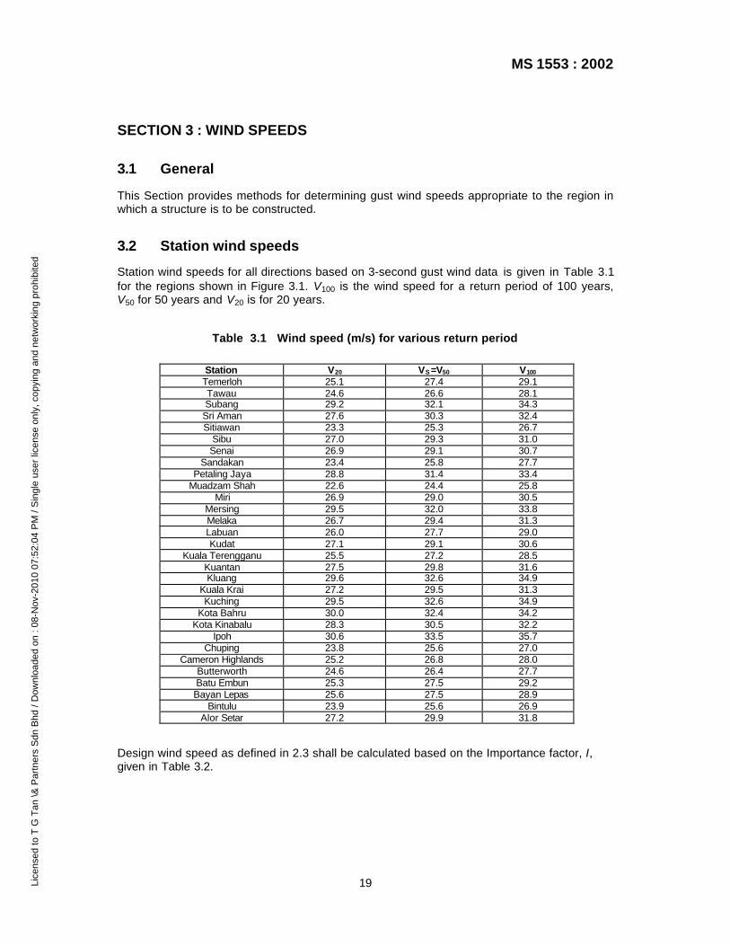
Station wind speeds for all directions based on 3-second gust wind data is given in Table 3.1for the regions shown in Figure 3.1. V100 is the wind speed for a return period of 100 years,V50 for 50 years and V20 is for 20 years.
Table 3.1 Wind speed (m/s) for various return period
Station V20 VS =V50 V100
Temerloh 25.1 27.4 29.1Tawau 24.6 26.6 28.1Subang 29.2 32.1 34.3Sri Aman 27.6 30.3 32.4Sitiawan 23.3 25.3 26.7
Sibu 27.0 29.3 31.0Senai 26.9 29.1 30.7
Sandakan 23.4 25.8 27.7Petaling Jaya 28.8 31.4 33.4
Muadzam Shah 22.6 24.4 25.8Miri 26.9 29.0 30.5
Mersing 29.5 32.0 33.8Melaka 26.7 29.4 31.3Labuan 26.0 27.7 29.0Kudat 27.1 29.1 30.6
Kuala Terengganu 25.5 27.2 28.5Kuantan 27.5 29.8 31.6Kluang 29.6 32.6 34.9
Kuala Krai 27.2 29.5 31.3Kuching 29.5 32.6 34.9
Kota Bahru 30.0 32.4 34.2Kota Kinabalu 28.3 30.5 32.2
Ipoh 30.6 33.5 35.7Chuping 23.8 25.6 27.0
Cameron Highlands 25.2 26.8 28.0Butterworth 24.6 26.4 27.7Batu Embun 25.3 27.5 29.2Bayan Lepas 25.6 27.5 28.9
Bintulu 23.9 25.6 26.9Alor Setar 27.2 29.9 31.8
Design wind speed as defined in 2.3 shall be calculated based on the Importance factor, I,given in Table 3.2.
Lice
nsed
to T
G T
an \&
Par
tner
s S
dn B
hd /
Dow
nloa
ded
on :
08-N
ov-2
010
07:5
2:04
PM
/ S
ingl
e us
er li
cens
e on
ly, c
opyi
ng a
nd n
etw
orki
ng p
rohi
bite
d

MS 1553 : 2002
20
Figure 3.1 Peninsular Malaysia
NOTE. Zone map for East Malaysia has not been provided due to on going research.
Zone IIZone I
Basic Wind Speed
Zone I, VS = 33.5 m/sZone II, VS = 32.5 m/s
Lice
nsed
to T
G T
an \&
Par
tner
s S
dn B
hd /
Dow
nloa
ded
on :
08-N
ov-2
010
07:5
2:04
PM
/ S
ingl
e us
er li
cens
e on
ly, c
opyi
ng a
nd n
etw
orki
ng p
rohi
bite
d
MS 1553 : 2002
21
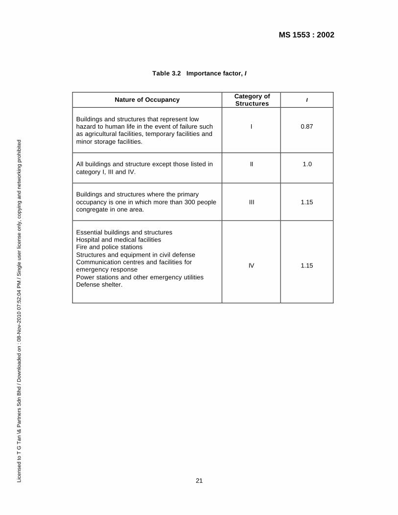
Table 3.2 Importance factor, I
Nature of Occupancy Category ofStructures
I
Buildings and structures that represent lowhazard to human life in the event of failure suchas agricultural facilities, temporary facilities andminor storage facilities.
I 0.87
All buildings and structure except those listed incategory I, III and IV.
II 1.0
Buildings and structures where the primaryoccupancy is one in which more than 300 peoplecongregate in one area.
III 1.15
Essential buildings and structuresHospital and medical facilitiesFire and police stationsStructures and equipment in civil defenseCommunication centres and facilities foremergency responsePower stations and other emergency utilitiesDefense shelter.
IV 1.15
Lice
nsed
to T
G T
an \&
Par
tner
s S
dn B
hd /
Dow
nloa
ded
on :
08-N
ov-2
010
07:5
2:04
PM
/ S
ingl
e us
er li
cens
e on
ly, c
opyi
ng a
nd n
etw
orki
ng p
rohi
bite
d
MS 1553 : 2002
22
SECTION 4 : SITE EXPOSURE MULTIPLIERS
4.1 General
This Section provides methods for evaluating the exposure multipliers relating to siteterrain/height, Mz,cat , shielding, Ms and hill shape, Mh.
The design shall take account of known future changes to terrain roughness when assessingterrain category and to buildings providing shielding when assessing shielding.
4.2 Terrain/height multiplier, Mz,cat
4.2.1 Terrain category definitions
Terrain, over which the approach wind flows towards a structure, shall be assessed on thebasis of the following category descriptions:
a) Category 1 : Exposed open terrain with few or no obstructions.
NOTE. For serviceability considerations, water surfaces are included in this category.
b) Category 2 : Water surfaces, open terrain, grassland with few well scatteredobstructions having height generally from 1.5 m to 10.0 m.
c) Category 3 : Terrain with numerous closely spaced obstructions 3.0 m to 5.0 m highsuch as areas of suburban housing.
d) Category 4 : Terrain with numerous large, high (10.0.m to 30.0 m high) and closelyspaced obstructions such as large city centers and well-developed industrialcomplexes.
Selection of terrain category shall be made with due regard to the permanence of theobstructions which constitute the surface roughness, in particular some vegetation andbuildings in tropical regions shall not be relied upon to maintain surface roughness duringwind events.
4.2.2 Determination of terrain/height multiplier, Mz,cat
The variation with height, z, of the effect of terrain roughness on wind speed (terrain/heightmultiplier), Mz,cat, shall be taken from the values for fully developed profiles given in Table 4.1.
Designers shall take account of known future changes to terrain roughness in assessment ofterrain category.
Lice
nsed
to T
G T
an \&
Par
tner
s S
dn B
hd /
Dow
nloa
ded
on :
08-N
ov-2
010
07:5
2:04
PM
/ S
ingl
e us
er li
cens
e on
ly, c
opyi
ng a
nd n
etw
orki
ng p
rohi
bite
d

MS 1553 : 2002
23
Table 4.1. Terrain/height multipliers for gust wind speeds in fully developedterrain. Serviceability limit state design and ultimate limit state
Multiplier (Mz,cat)Height (z)
mTerrain
Category 1Terrain
Category 2Terrain
Category 3Terrain
Category 4
≤3510
152030
405075
100150200
250300400
500
0.991.051.12
1.161.191.22
1.241.251.27
1.291.311.32
1.341.351.37
1.38
0.850.911.00
1.051.081.12
1.161.181.22
1.241.271.29
1.311.321.35
1.37
0.750.750.83
0.890.941.00
1.041.071.12
1.161.211.24
1.271.291.32
1.35
0.750.750.75
0.750.750.80
0.850.900.98
1.031.111.16
1.201.231.28
1.31
NOTE. For intermediate values of height z and terrain category, use linear interpolation.
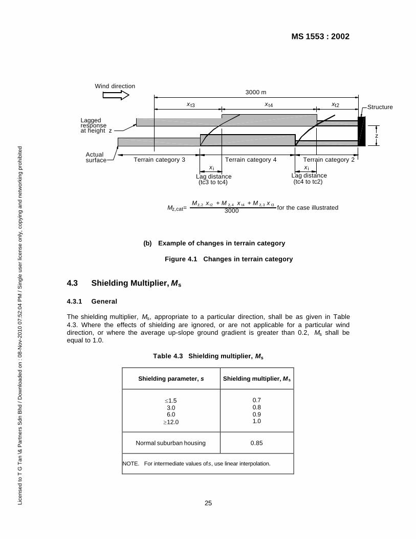
4.2.3 Changes in terrain category
Where, for the direction under consideration, the wind approaches across ground withchanges in terrain category that lie within 3000 m of the structure, Mz,cat shall be taken as theweighted average terrain and structure height multiplier over the 3000 m upwind of thestructure at height z above ground level.
For evaluation at height z, a change in terrain incorporates a lag distance, xi given as follows:25.1
r,or,oi z3.0
zzx
= (5)
where,
xi distance down-wind from the start of a new terrain roughness to the developed heightof the inner layer, z at the structure (lag distance);
Lice
nsed
to T
G T
an \&
Par
tner
s S
dn B
hd /
Dow
nloa
ded
on :
08-N
ov-2
010
07:5
2:04
PM
/ S
ingl
e us
er li
cens
e on
ly, c
opyi
ng a
nd n
etw
orki
ng p
rohi
bite
d

MS 1553 : 2002
24
z0, r larger of the two roughness lengths at a boundary between roughness, as given inTable 4.2; and
z height on the structure above the local ground level.
NOTE. Lag distance is not a significant effect for heights less than 15 m.
Table 4.2 Roughness Lengths for terrain categories
Terrain category Roughness length
Terrain category 1Terrain category 2Terrain category 3Terrain category 4
0.0020.020.22.0
The weighted average of Mz,cat is weighted by the length of each terrain upwind of thestructure allowing for the lag distance at each terrain category change for a distance of 3000m. An example is given in Figure 4.1(b).
h = zi
x i
x
x - x i
New terrain categoryx
Upstream terrain category
zDeveloped heightof inner layer
Wind direction
terrain roughnessStart of new
(a) Notation for changes in terrain category
Lice
nsed
to T
G T
an \&
Par
tner
s S
dn B
hd /
Dow
nloa
ded
on :
08-N
ov-2
010
07:5
2:04
PM
/ S
ingl
e us
er li
cens
e on
ly, c
opyi
ng a
nd n
etw
orki
ng p
rohi
bite
d
MS 1553 : 2002
25
Terrain category 2Terrain category 4Terrain category 3
t3
(tc3 to tc4)
x x t4
3000 m
t2x Structure
x i
Lag distance
z
(tc4 to tc2)Lag distance
Laggedresponseat height z
z,catM = M x + M x + M x
3000 for the case illustrated
surfaceActual
Wind direction
x i
z,2 t2 z,4 z,3t4 t3
(b) Example of changes in terrain category
Figure 4.1 Changes in terrain category
4.3 Shielding Multiplier, Ms
4.3.1 General
The shielding multiplier, Ms, appropriate to a particular direction, shall be as given in Table4.3. Where the effects of shielding are ignored, or are not applicable for a particular winddirection, or where the average up-slope ground gradient is greater than 0.2, Ms shall beequal to 1.0.
Table 4.3 Shielding multiplier, Ms
Shielding parameter, s Shielding multiplier, Ms
≤1.53.06.0
≥12.0
0.70.80.91.0
Normal suburban housing 0.85
NOTE. For intermediate values of s, use linear interpolation.
Lice
nsed
to T
G T
an \&
Par
tner
s S
dn B
hd /
Dow
nloa
ded
on :
08-N
ov-2
010
07:5
2:04
PM
/ S
ingl
e us
er li
cens
e on
ly, c
opyi
ng a
nd n
etw
orki
ng p
rohi
bite
d
Related Documents