450 – 1 Street SW Calgary, Alberta T2P 5H1 Tel: (403) 920-5214 Fax: (403) 920-2347 Email: [email protected] November 3, 2021 Filed Electronically Canada Energy Regulator Suite 210, 517 Tenth Avenue SW Calgary, AB T2R 0A8 Attention: Mr. Jean-Denis Charlebois, Secretary of the Commission Dear Mr. Charlebois: Re: NOVA Gas Transmission Ltd. (NGTL) 2021 NGTL System Expansion Project (Project) Certificate GC-129, (Certificate) and Order XG-001-2020 (Order), as amended Hydrostatic Testing Plans – Karr Mainline Test Sections 4 and 5 File No.: File OF-Fac-Gas-N081-2018-03 02 In its application NGTL committed to submitting hydrostatic test plans prior to hydrotesting the Project’s pipeline sections. 1 As such, NGTL submits the hydrostatic testing plan (the Plan) for Karr Section – mainline test sections 4 and 5. 2 On November 1, 2021, the Commission of the Canada Energy Regulator (Commission) issued a letter to NGTL acknowledging its receipt of other Project-related hydrostatic test plans and confirming that it does not require personal information or unredacted plans, and that publicly filed redacted plans are sufficient. 3 In accordance with this direction, while the Plan for the Karr Section contains personal information that has been redacted by NGTL, no corresponding unredacted version of the Plan has or will be provided to the Commission. Going forward, NGTL intends to implement the Commission’s direction for additional Project-related hydrostatic test plans that it may file per its commitment. 1 NEB Filing ID: A92619, Section 8.8.5. 2 NGTL previously submitted the hydrostatic test plan for Karr Section mainline test section 1 on September 15, 2021, (C14941). 3 CER Filing ID: C15855.

Welcome message from author
This document is posted to help you gain knowledge. Please leave a comment to let me know what you think about it! Share it to your friends and learn new things together.
Transcript

450 – 1 Street SW Calgary, Alberta T2P 5H1
Tel: (403) 920-5214 Fax: (403) 920-2347 Email: [email protected]
November 3, 2021
Filed Electronically Canada Energy Regulator Suite 210, 517 Tenth Avenue SW Calgary, AB T2R 0A8
Attention: Mr. Jean-Denis Charlebois, Secretary of the Commission
Dear Mr. Charlebois:
Re: NOVA Gas Transmission Ltd. (NGTL) 2021 NGTL System Expansion Project (Project) Certificate GC-129, (Certificate) and Order XG-001-2020 (Order), as amended Hydrostatic Testing Plans – Karr Mainline Test Sections 4 and 5 File No.: File OF-Fac-Gas-N081-2018-03 02
In its application NGTL committed to submitting hydrostatic test plans prior to hydrotesting the Project’s pipeline sections.1 As such, NGTL submits the hydrostatic testing plan (the Plan) for Karr Section – mainline test sections 4 and 5.2
On November 1, 2021, the Commission of the Canada Energy Regulator (Commission) issued a letter to NGTL acknowledging its receipt of other Project-related hydrostatic test plans and confirming that it does not require personal information or unredacted plans, and that publicly filed redacted plans are sufficient.3
In accordance with this direction, while the Plan for the Karr Section contains personal information that has been redacted by NGTL, no corresponding unredacted version of the Plan has or will be provided to the Commission.
Going forward, NGTL intends to implement the Commission’s direction for additional Project-related hydrostatic test plans that it may file per its commitment.
1 NEB Filing ID: A92619, Section 8.8.5. 2 NGTL previously submitted the hydrostatic test plan for Karr Section mainline test section 1 on
September 15, 2021, (C14941). 3 CER Filing ID: C15855.
November 3, 2021 Mr. Charlebois Page 2 of 2
Any questions with respect to this filing should be directed to Jaron Dyble at (403) 920-5214 or by email at [email protected].
Yours truly, NOVA Gas Transmission Ltd.
Original signed by
Jaron Dyble Regulatory Project Manager Canadian Natural Gas Pipelines
Attachments
cc: Heather Dodds, Canada Energy Regulator

UNCONTROLLED IF PRINTED
Client TC Energy
Project Name Grande Prairie Mainline Karr Section
Project ID GPMK
Hydrostatic Test Plan – Test Section 4
Print Name Position Signature
Document Owner Project Engineer (EIT)
Reviewer Lead Project Engineer
Approver Project Director
02 2021-10-30 Issued for Use
01 2021-10-22 Issued for Use
00 2021-10-19 Issued for Use
Revision Date (yyyy-mm-dd) Status / Change Description
Document Number and Revision 00796-SMJV-CM-PLN-0016 Rev 02
HYDROSTATIC TEST PLAN – TEST SECTION 4
00796-SMJV-CM-PLN-0016 Rev 02 2
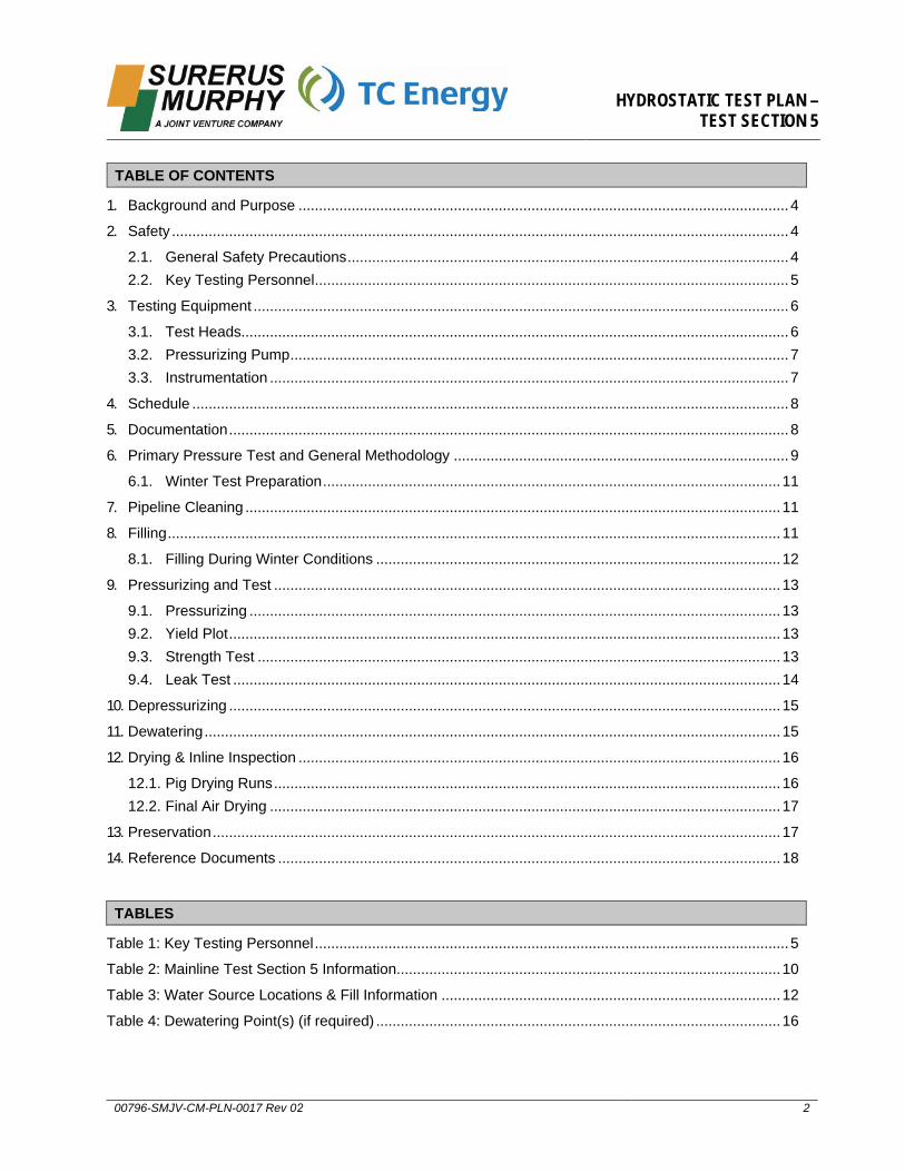
1. Background and Purpose ........................................................................................................................ 4
2. Safety ....................................................................................................................................................... 4
2.1. General Safety Precautions ............................................................................................................ 4 2.2. Key Testing Personnel .................................................................................................................... 5
3. Testing Equipment ................................................................................................................................... 6
3.1. Test Heads...................................................................................................................................... 6 3.2. Pressurizing Pump .......................................................................................................................... 7 3.3. Instrumentation ............................................................................................................................... 7
4. Schedule .................................................................................................................................................. 8
5. Documentation ......................................................................................................................................... 8
6. Primary Pressure Test and General Methodology .................................................................................. 9
6.1. Winter Test Preparation ................................................................................................................ 11
7. Pipeline Cleaning ................................................................................................................................... 11
8. Filling ...................................................................................................................................................... 11
8.1. Filling During Winter Conditions ................................................................................................... 12
9. Pressurizing and Test ............................................................................................................................ 13
9.1. Pressurizing .................................................................................................................................. 13 9.2. Yield Plot ....................................................................................................................................... 13 9.3. Strength Test ................................................................................................................................ 14 9.4. Leak Test ...................................................................................................................................... 14
10. Depressurizing ....................................................................................................................................... 15
11. Dewatering ............................................................................................................................................. 15
12. Drying & Inline Inspection ...................................................................................................................... 16
12.1. Pig Drying Runs ............................................................................................................................ 16 12.2. Final Air Drying ............................................................................................................................. 17
13. Preservation ........................................................................................................................................... 17
14. Reference Documents ........................................................................................................................... 18
TABLES
Table 1: Key Testing Personnel .................................................................................................................... 5
Table 2: Mainline Test Section 4 Information .............................................................................................. 10
Table 3: Water Source Locations & Fill Information ................................................................................... 12
Table 4: Dewatering Point(s)....................................................................................................................... 16
TABLE OF CONTENTS
HYDROSTATIC TEST PLAN – TEST SECTION 4
00796-SMJV-CM-PLN-0016 Rev 02 3
APPENDICES
Appendix A: SMJV Hydrotest Checklists & Forms ..................................................................................... 19
Appendix B: Alignment Sheets ................................................................................................................... 24
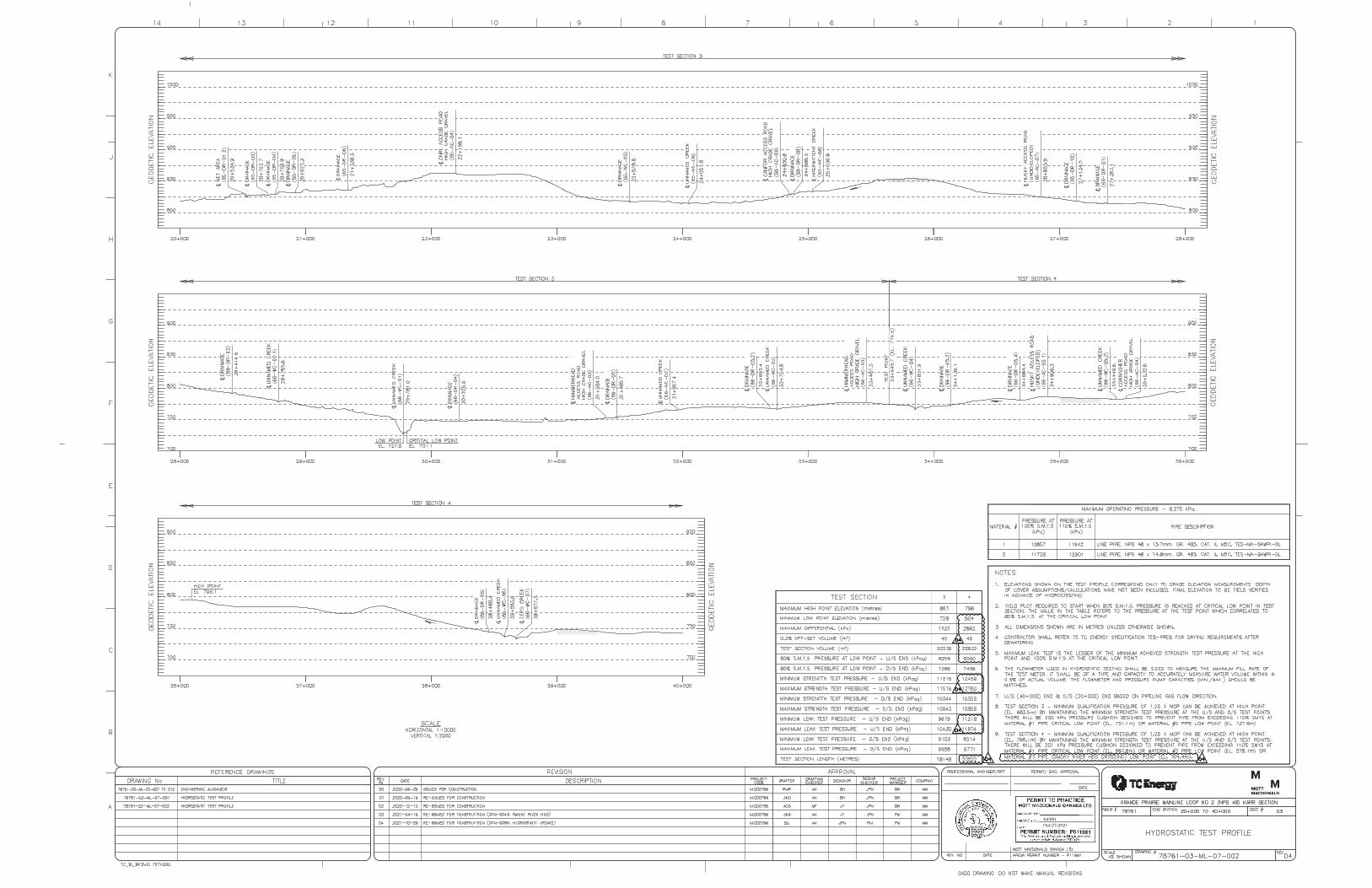
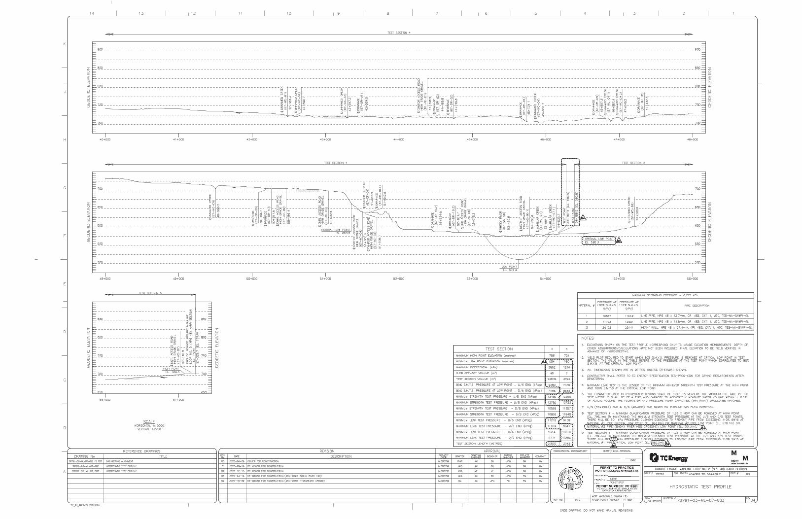
Appendix C: Hydrostatic Test Profile .......................................................................................................... 31
Appendix D: Example Typical Filling, Test, & Dewater Sketches ............................................................... 34
Appendix E: New Road 31 Test Point Drawing .......................................................................................... 39
Appendix F: TC Energy Test Calculation Sheet & As-Built Data ................................................................ 41
Appendix G: Water Source Map ................................................................................................................. 43

HYDROSTATIC TEST PLAN – TEST SECTION 4
00796-SMJV-CM-PLN-0016 Rev 02 4
1. Background and PurposeNova Gas Transmission Ltd. (“Company”), a wholly owned subsidiary of TC Energy, proposes to construct and operate new pipeline Facilities in the Grande Prairie area of the province of Alberta.
The Grande Prairie Mainline Loop No. 2 (NPS 48) Karr Section (the “Project”) includes the construction of approximately 57 km of NPS 48 (1219 mm) diameter pipeline and associated facilities. The line begins at the GPM 60 valve site located at Latornell Compressor Station within NW-28-63-01-W6M, approximately 90 km south of Grande Prairie, AB. The line proceeds north-west to the GPM 80 valve site at Gold Creek Compressor Station within NW-26-67-05-W6M, approximately 40 km south of Grande Prairie, AB. The Project route is located on 100% Crown land and parallels existing disturbances for the majority of the route.
This Hydrostatic Test Plan – Test Section 4 (Plan) was prepared for the hydrostatic pressure testing of the NPS 48 pipeline following installation as part of the Project. This Plan details Surerus Murphy Joint Venture’s (SMJV) plan for testing Section 4 (KP 33+656.7 to 54+166.1) of the pipeline and should be read in conjunction with CSA Z662-19, TCPL specification TES-PRES Pipeline and Facility Piping Pressure Testing Specification, and TEP-PRES Pipeline and Facility Piping Pressure Testing Procedure. The hydrostatic test consists of a minimum four-hour strength test followed by a minimum four-hour leak test to verify the integrity of the pipeline.
The overall design requirements of the Project are regulated by the Canada Energy Regulator (CER).
Please note that wherever this Plan (00796-SMJV-CM-PLN-0016) may conflict with Preliminary Hydrostatic Test Plan (00796-SMJV-CM-PLN-0004) that the contents of this Plan shall govern.
2. Safety
2.1. General Safety Precautions
Project hazard assessments will be carried out to identify any specific hazards that may not be addressed in this plan, and control measures will be established to mitigate any risks identified.
All personnel shall review and follow the Emergency Response Plan (ERP) developed specifically for this project along with the activity specific Job Safety Analysis (JSA). A copy of the ERP will be available in each vehicle used on the project. Additionally, an ERP shall be posted in the test shack for the duration of testing activities.
Test crews shall complete pre-job meetings and hazard identification at the start of each work shift and before every major task.
SMJV will install warning signs and barricades to prevent access to the vicinity of the test area prior to pressurization. Warning signs shall indicate “DANGER - High Pressure Pipeline Test” and “Restricted Access” as per Section 6.2 of specification TEP-PRES.
All SMJV personnel involved in testing activities shall be a minimum of 30 m away from any exposed pipe while the pipeline section is undergoing the strength test. Visual inspection while the section is being pressurized for testing will only take place if instrument readings suggest a leak is occurring. Visual inspection of the test section shall not be conducted during the strength test or while the test pressure is producing a hoop stress of 100% SMYS or more.

HYDROSTATIC TEST PLAN – TEST SECTION 4
00796-SMJV-CM-PLN-0016 Rev 02 5
SMJV employees shall inspect all hoses, lines, and connections for faults prior to pressurizing the lines. The SMJV Quality Control team will complete the Hydro Pre-Test Checklist (SSMJV-QC-FOR-067) on site to ensure that all components meet the required ratings.
SMJV personnel shall ensure pressuring hoses/unions are rated to a minimum of 2.5 times the maximum expected hydrotest pressures, all safety lines are firmly attached, and all hoses are secured with whip checks at each connection. No hose greater than NPS 2 shall be used for pressuring the section.
A TC Energy Test Inspector will be on site for the duration of test activities.
All test heads will be welded to heavy wall pipe such that the 20 m adjacent to the test head experiences a hoop stress of less than 90% over the duration of the test.
All fuel tanks shall be double lined or be placed within adequate containment to prevent the migration of fuel in the event of a spill. All site vehicles will be equipped with absorbent pads in the event of a small release outside of contained areas.
Fire extinguishers will be kept in all site vehicles.
To ensure over pressurisation of the pipeline does not occur, the test section shall be filled using pumps with a maximum capacity of 4,500 kPa and the squeeze pump shall be equipped with a pressure relief valve (PRV) stationed between the pump and test head. The PRV shall be pre-set to 110% of the target test pressure or the maximum test pressure. All valves between the PRV and test assembly will be in the fully open position during testing.
2.2. Key Testing Personnel
SMJV has identified personnel that will be vital to ensure a safe, successful hydrotesting of the entire mainline section. The key personnel are as follows:
Table 1: Key Testing Personnel
Name Position Company
Superintendent SMJV
Assistant Superintendent SMJV
Hydrotest Consultant SMJV
Hydrotest Foreman SMJV
Hydrotest Foreman (Nights) SMJV
Lead Project Engineer SMJV
Quality Control Manager SMJV
Quality Control Lead SMJV
Project Engineer (EIT) SMJV
In addition to the above, TC Energy will nominate representatives who will be present during hydrostatic testing (as per responsibility matrix Table 4-1 TEP-PRES & TES-PRES).
HYDROSTATIC TEST PLAN – TEST SECTION 4
00796-SMJV-CM-PLN-0016 Rev 02 6
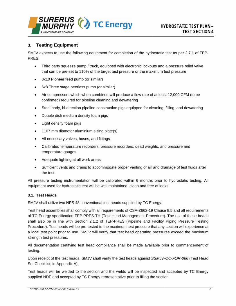
3. Testing EquipmentSMJV expects to use the following equipment for completion of the hydrostatic test as per 2.7.1 of TEP-PRES:
• Third party squeeze pump / truck, equipped with electronic lockouts and a pressure relief valvethat can be pre-set to 110% of the target test pressure or the maximum test pressure
• 8x10 Pioneer feed pump (or similar)
• 6x8 Three stage peerless pump (or similar)
• Air compressors which when combined will produce a flow rate of at least 12,000 CFM (to beconfirmed) required for pipeline cleaning and dewatering
• Steel body, bi-direction pipeline construction pigs equipped for cleaning, filling, and dewatering
• Double dish medium density foam pigs
• Light density foam pigs
• 1107 mm diameter aluminium sizing plate(s)
• All necessary valves, hoses, and fittings
• Calibrated temperature recorders, pressure recorders, dead weights, and pressure andtemperature gauges
• Adequate lighting at all work areas
• Sufficient vents and drains to accommodate proper venting of air and drainage of test fluids afterthe test
All pressure testing instrumentation will be calibrated within 6 months prior to hydrostatic testing. All equipment used for hydrostatic test will be well maintained, clean and free of leaks.
3.1. Test Heads
SMJV shall utilize two NPS 48 conventional test heads supplied by TC Energy.
Test head assemblies shall comply with all requirements of CSA-Z662-19 Clause 8.5 and all requirements of TC Energy specification TEP-PRES-TH (Test Head Management Procedure). The use of these heads shall also be in line with Section 2.1.2 of TEP-PRES (Pipeline and Facility Piping Pressure Testing Procedure). Test heads will be pre-tested to the maximum test pressure that any section will experience at a local test point prior to use. SMJV will verify that test head operating pressures exceed the maximum strength test pressures.
All documentation certifying test head compliance shall be made available prior to commencement of testing.
Upon receipt of the test heads, SMJV shall verify the test heads against SSMJV-QC-FOR-066 (Test Head Set Checklist; in Appendix A).
Test heads will be welded to the section and the welds will be inspected and accepted by TC Energy supplied NDE and accepted by TC Energy representative prior to filling the section.
HYDROSTATIC TEST PLAN – TEST SECTION 4
00796-SMJV-CM-PLN-0016 Rev 02 7
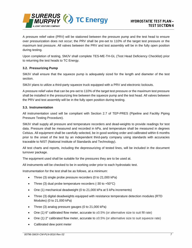
A pressure relief valve (PRV) will be stationed between the pressure pump and the test head to ensure over pressurization does not occur; the PRV shall be pre-set to 110% of the target test pressure or the maximum test pressure. All valves between the PRV and test assembly will be in the fully open position during testing.
Upon completion of testing, SMJV shall complete TES-ME-TH-GL (Test Head Deficiency Checklist) prior to returning the test heads to TC Energy.
3.2. Pressurizing Pump
SMJV shall ensure that the squeeze pump is adequately sized for the length and diameter of the test section.
SMJV plans to utilize a third-party squeeze truck equipped with a PRV and electronic lockouts.
A pressure relief valve that can be pre-set to 110% of the target test pressure or the maximum test pressure shall be installed in the pressurizing line between the squeeze pump and the test head. All valves between the PRV and test assembly will be in the fully open position during testing.
3.3. Instrumentation
All instrumentation used will be compliant with Section 2.7 of TEP-PRES (Pipeline and Facility Piping Pressure Testing Procedure).
SMJV shall supply all pressure and temperature recorders and dead-weights to provide readings for test data. Pressure shall be measured and recorded in kPa, and temperature shall be measured in degrees Celsius. All equipment shall be carefully selected, be in good working order and calibrated within 6 months prior to the onset of the test by an independent third-party company using standards with accuracies traceable to NIST (National Institute of Standards and Technology).
All test charts and reports, including the depressurizing of tested lines, will be included in the document turnover package.
The equipment used shall be suitable for the pressures they are to be used at.
All instruments will be checked to be in working order prior to each hydrostatic test.
Instrumentation for the test shall be as follows, at a minimum:
• Three (3) single probe pressure recorders (0 to 21,000 kPa)
• Three (3) dual probe temperature recorders (-30 to +50°C)
• One (1) mechanical deadweight (0 to 21,000 kPa at 5 kPa increments)
• Three (3) digital deadweights equipped with resistance temperature detection modules (RTDModules) (0 to 21,000 kPa)
• Three (3) analog pressure gauges (0 to 21,000 kPa)
• One (1) 6” calibrated flow meter, accurate to ±0.5% (or alternative size to suit fill rate)
• One (1) 2” calibrated flow meter, accurate to ±0.5% (or alternative size to suit squeeze rate)
• Calibrated dew point meter
HYDROSTATIC TEST PLAN – TEST SECTION 4
00796-SMJV-CM-PLN-0016 Rev 02 8
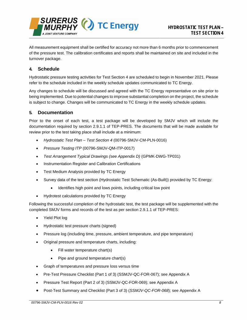
All measurement equipment shall be certified for accuracy not more than 6 months prior to commencement of the pressure test. The calibration certificates and reports shall be maintained on site and included in the turnover package.
4. ScheduleHydrostatic pressure testing activities for Test Section 4 are scheduled to begin in November 2021. Please refer to the schedule included in the weekly schedule updates communicated to TC Energy.
Any changes to schedule will be discussed and agreed with the TC Energy representative on site prior to being implemented. Due to potential changes to improve substantial completion on the project, the schedule is subject to change. Changes will be communicated to TC Energy in the weekly schedule updates.
5. DocumentationPrior to the onset of each test, a test package will be developed by SMJV which will include the documentation required by section 2.9.1.1 of TEP-PRES. The documents that will be made available for review prior to the test taking place shall include at a minimum:
• Hydrostatic Test Plan – Test Section 4 (00796-SMJV-CM-PLN-0016)
• Pressure Testing ITP (00796-SMJV-QM-ITP-0017)
• Test Arrangement Typical Drawings (see Appendix D) (GPMK-DWG-TP031)
• Instrumentation Register and Calibration Certifications
• Test Medium Analysis provided by TC Energy
• Survey data of the test section (Hydrostatic Test Schematic (As-Built)) provided by TC Energy:
• Identifies high point and lows points, including critical low point
• Hydrotest calculations provided by TC Energy
Following the successful completion of the hydrostatic test, the test package will be supplemented with the completed SMJV forms and records of the test as per section 2.9.1.1 of TEP-PRES:
• Yield Plot log
• Hydrostatic test pressure charts (signed)
• Pressure log (including time, pressure, ambient temperature, and pipe temperature)
• Original pressure and temperature charts, including:
• Fill water temperature chart(s)
• Pipe and ground temperature chart(s)
• Graph of temperatures and pressure loss versus time
• Pre-Test Pressure Checklist (Part 1 of 3) (SSMJV-QC-FOR-067); see Appendix A
• Pressure Test Report (Part 2 of 3) (SSMJV-QC-FOR-069); see Appendix A
• Post-Test Summary and Checklist (Part 3 of 3) (SSMJV-QC-FOR-068); see Appendix A
HYDROSTATIC TEST PLAN – TEST SECTION 4
00796-SMJV-CM-PLN-0016 Rev 02 9
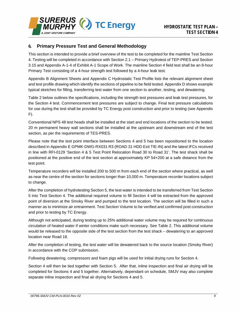
6. Primary Pressure Test and General MethodologyThis section is intended to provide a brief overview of the test to be completed for the mainline Test Section4. Testing will be completed in accordance with Section 2.1 – Primary Hydrotest of TEP-PRES and Section3.15 and Appendix A-1-4 of Exhibit A-1 Scope of Work. The mainline Section 4 field test shall be an 8-hourPrimary Test consisting of a 4-hour strength test followed by a 4-hour leak test.
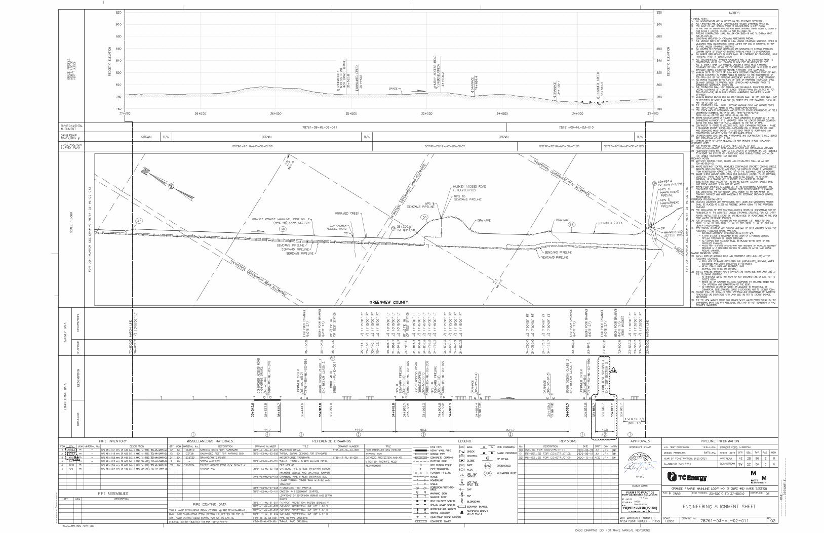
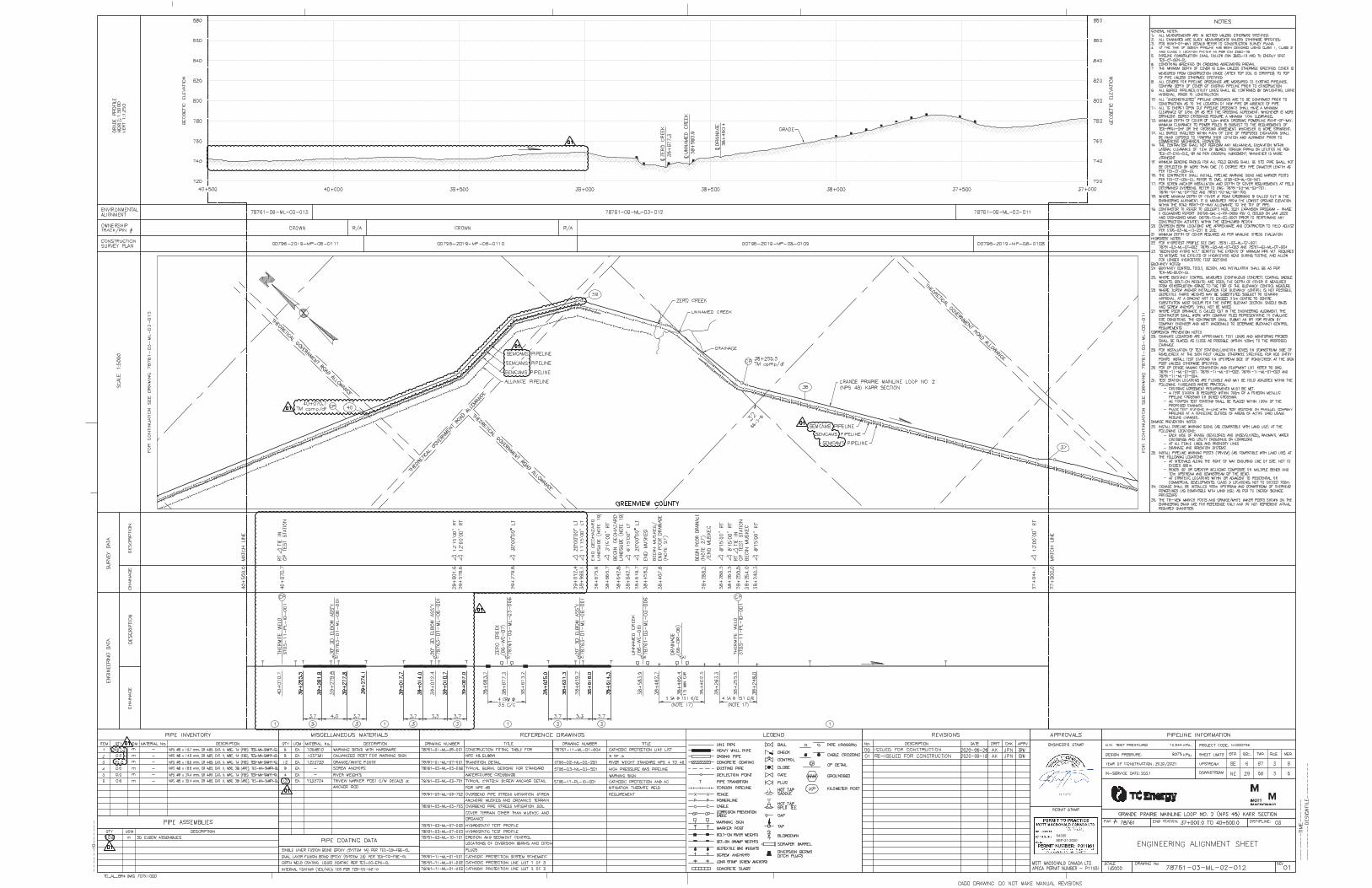
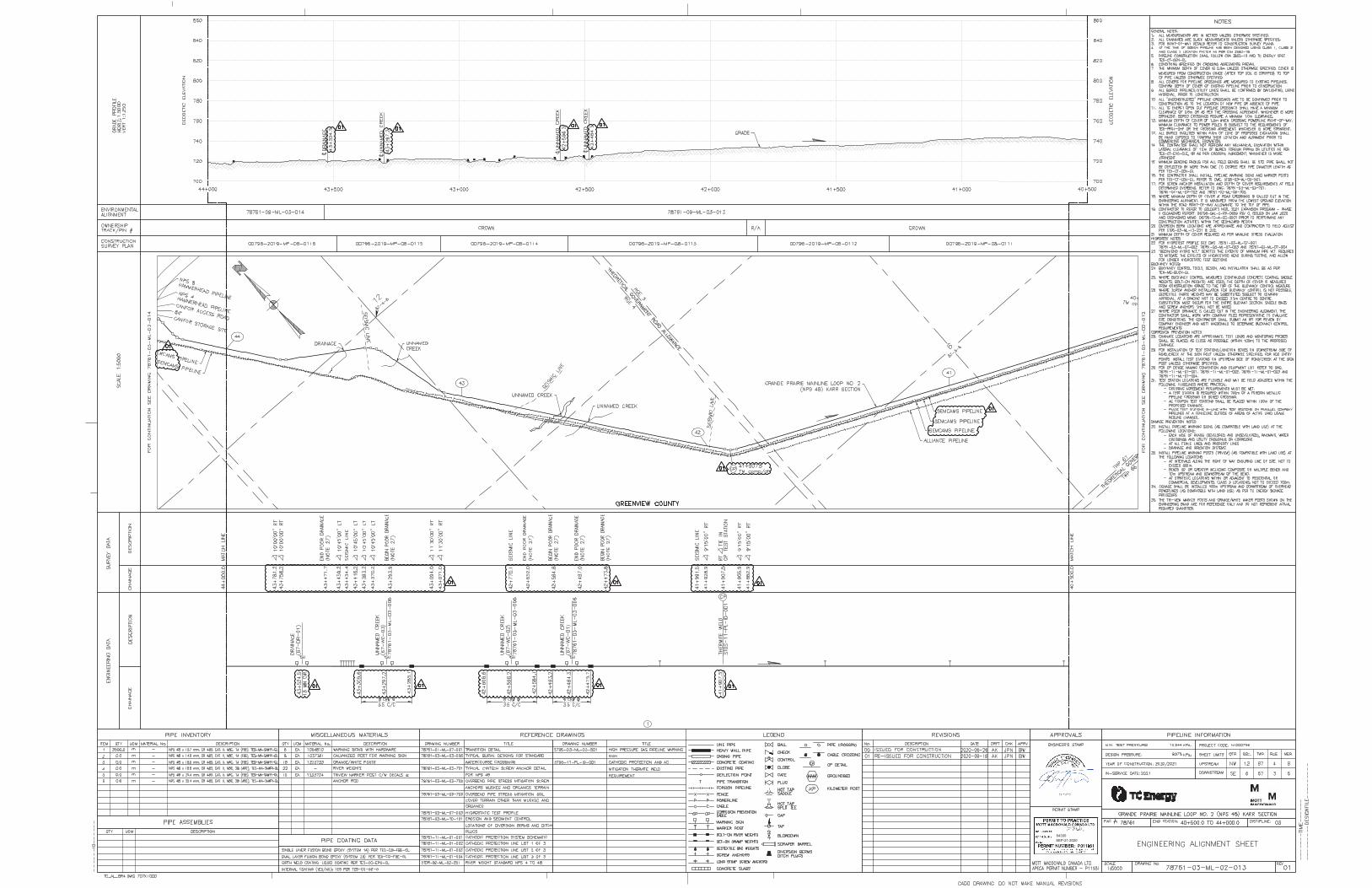
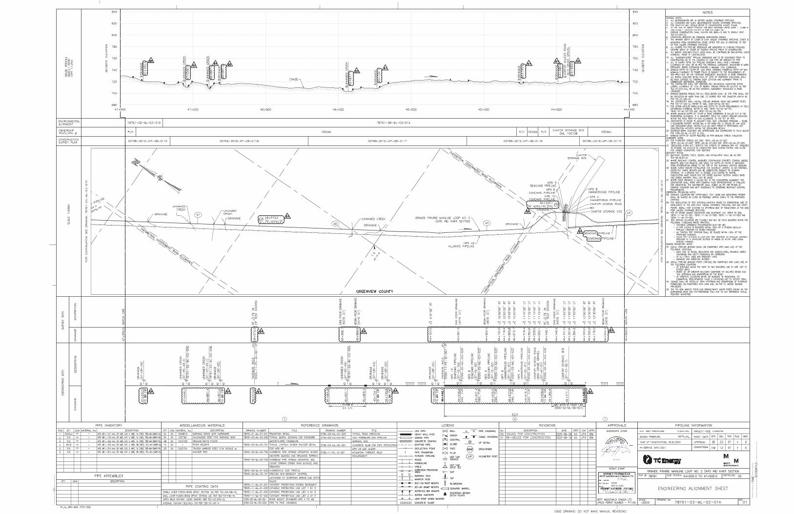
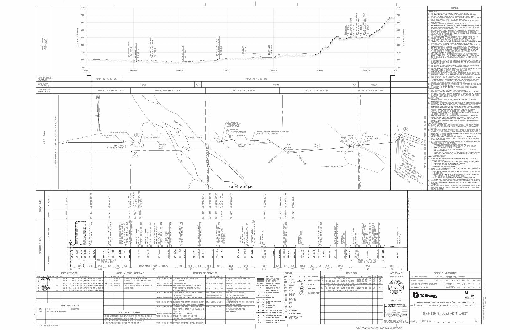
Appendix B Alignment Sheets and Appendix C Hydrostatic Test Profile lists the relevant alignment sheet and test profile drawing which identify the sections of pipeline to be field tested. Appendix D shows example typical sketches for filling, transferring test water from one section to another, testing, and dewatering.
Table 2 below outlines the specifications, including the strength test pressures and leak test pressures, for the Section 4 test. Commencement test pressures are subject to change. Final test pressure calculations for use during the test shall be provided by TC Energy post construction and prior to testing (see Appendix F).
Conventional NPS 48 test heads shall be installed at the start and end locations of the section to be tested. 20 m permanent heavy wall sections shall be installed at the upstream and downstream end of the test section, as per the requirements of TES-PRES.
Please note that the test point interface between Sections 4 and 5 has been repositioned to the location described in Appendix E GPMK-DWG-RX031 R3 (ROAD 31 HDD Exit TIE-IN) and the latest IFCs received in line with RFI-0129 ‘Section 4 & 5 Test Point Relocation Road 30 to Road 31’. The test shack shall be positioned at the positive end of the test section at approximately KP 54+200 at a safe distance from the test point.
Temperature recorders will be installed 200 to 500 m from each end of the section where practical, as well as near the centre of the section for sections longer than 10,000 m. Temperature recorder locations subject to change.
After the completion of hydrotesting Section 5, the test water is intended to be transferred from Test Section 5 into Test Section 4. The additional required volume to fill Section 4 will be extracted from the approved point of diversion at the Smoky River and pumped to the test location. The section will be filled in such a manner as to minimize air entrainment. Test Section Volume to be verified and confirmed post construction and prior to testing by TC Energy.
Although not anticipated, during testing up to 25% additional water volume may be required for continuous circulation of heated water if winter conditions make such necessary. See Table 2. This additional volume would be released to the opposite side of the test section from the test shack – dewatering to an approved location near Road 18.
After the completion of testing, the test water will be dewatered back to the source location (Smoky River) in accordance with the COP submission.
Following dewatering, compressors and foam pigs will be used for initial drying runs for Section 4.
Section 4 will then be tied together with Section 5. After that, inline inspection and final air drying will be completed for Sections 4 and 5 together. Alternatively, dependant on schedule, SMJV may also complete separate inline inspection and final air drying for Sections 4 and 5.
HYDROSTATIC TEST PLAN – TEST SECTION 4
00796-SMJV-CM-PLN-0016 Rev 02 10
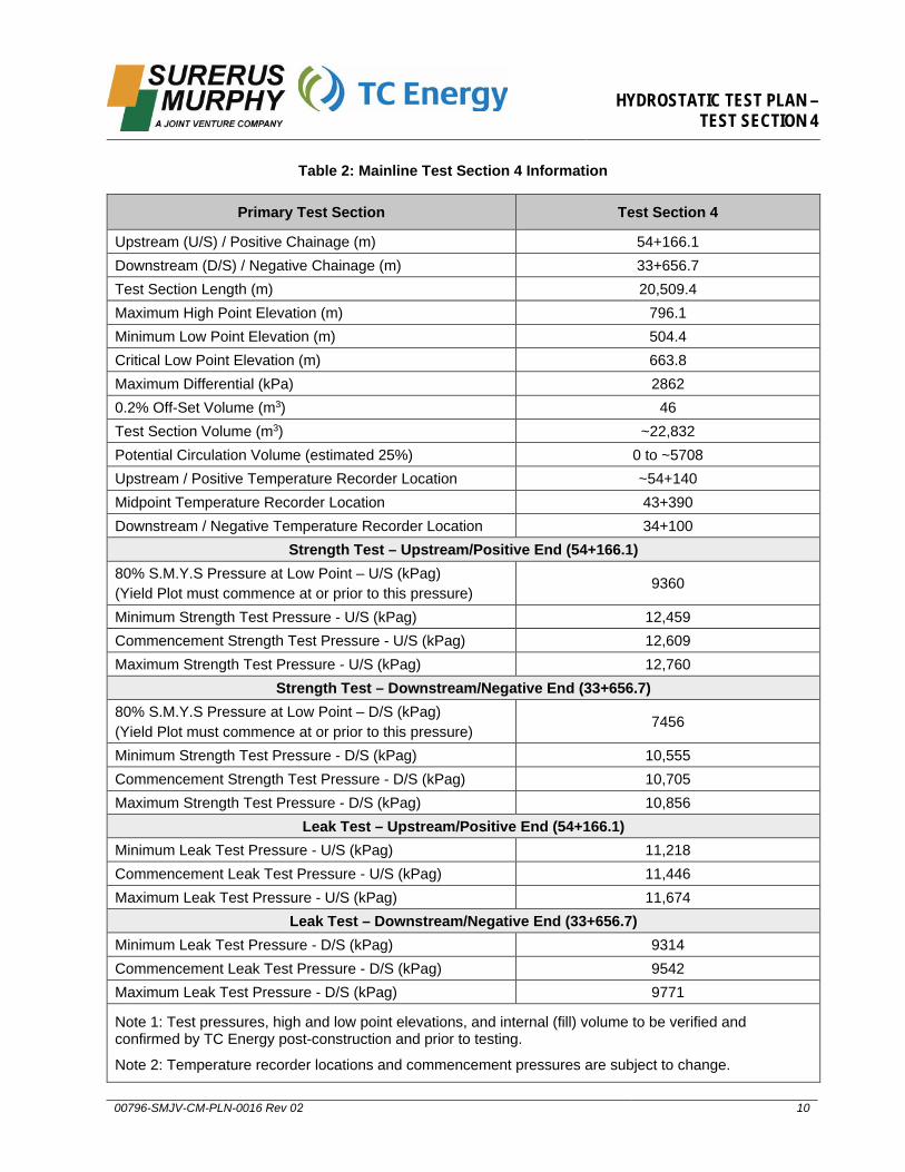
Table 2: Mainline Test Section 4 Information
Primary Test Section Test Section 4
Upstream (U/S) / Positive Chainage (m) 54+166.1 Downstream (D/S) / Negative Chainage (m) 33+656.7 Test Section Length (m) 20,509.4 Maximum High Point Elevation (m) 796.1 Minimum Low Point Elevation (m) 504.4 Critical Low Point Elevation (m) 663.8 Maximum Differential (kPa) 2862 0.2% Off-Set Volume (m3) 46 Test Section Volume (m3) ~22,832 Potential Circulation Volume (estimated 25%) 0 to ~5708 Upstream / Positive Temperature Recorder Location ~54+140 Midpoint Temperature Recorder Location 43+390 Downstream / Negative Temperature Recorder Location 34+100
Strength Test – Upstream/Positive End (54+166.1) 80% S.M.Y.S Pressure at Low Point – U/S (kPag) (Yield Plot must commence at or prior to this pressure) 9360
Minimum Strength Test Pressure - U/S (kPag) 12,459 Commencement Strength Test Pressure - U/S (kPag) 12,609 Maximum Strength Test Pressure - U/S (kPag) 12,760
Strength Test – Downstream/Negative End (33+656.7) 80% S.M.Y.S Pressure at Low Point – D/S (kPag) (Yield Plot must commence at or prior to this pressure) 7456
Minimum Strength Test Pressure - D/S (kPag) 10,555 Commencement Strength Test Pressure - D/S (kPag) 10,705 Maximum Strength Test Pressure - D/S (kPag) 10,856
Leak Test – Upstream/Positive End (54+166.1) Minimum Leak Test Pressure - U/S (kPag) 11,218 Commencement Leak Test Pressure - U/S (kPag) 11,446 Maximum Leak Test Pressure - U/S (kPag) 11,674
Leak Test – Downstream/Negative End (33+656.7) Minimum Leak Test Pressure - D/S (kPag) 9314 Commencement Leak Test Pressure - D/S (kPag) 9542 Maximum Leak Test Pressure - D/S (kPag) 9771
Note 1: Test pressures, high and low point elevations, and internal (fill) volume to be verified and confirmed by TC Energy post-construction and prior to testing.
Note 2: Temperature recorder locations and commencement pressures are subject to change.
HYDROSTATIC TEST PLAN – TEST SECTION 4
00796-SMJV-CM-PLN-0016 Rev 02 11
6.1. Winter Test Preparation
Depending on the weather at the time of execution, winter test preparations may be required and will be jointly decided on between SMJV and TC Energy field representatives and may differ from the below.
Test layout and equipment will be in line with the requirements of Section 2.6 of TEP-PRES Pipeline and Facility Piping Pressure Testing Procedure.
Potential mitigations for winter tests (to be agreed upon between SMJV and TC Energy at time of test):
• Exposed pipework planned to be minimized to only test head and immediate adjacent pipework.This will be heated and hoarded
• A water heater will be used to heat an initial hot slug to pass into the pipe at approximately 45 to50 degrees Celsius (maximum of 50 degrees per 2.6.1.1.1 of TES-PRES)
• A second hot slug heated to approximately 25 degrees Celsius may also be passed into the pipe
• Remainder of test water will be pumped into the section at approximately 4 to 5 degrees Celsius
• A minimum of two drying runs will be made as soon as reasonable after dewatering
7. Pipeline CleaningPrior to filling the pipeline with water, the test section will be fitted with multipurpose test heads (pigging heads) to accommodate cleaning pig runs.
The pipeline will be internally cleaned by propelling pigs equipped with nylon bristle brushes through the entire length to remove any debris left in the pipeline during construction.
The cleaning pig will be propelled using compressed air against a closed discharge and backpressure in front of the pig will be allowed to build to 100 kPa (15 psi) to act as a cushion in the event of the pig breaking out of a bend, valve, or heavy wall pipe section.
Should the pig get stuck in the line, resulting in an unexpected increase in pressure, SMJV will follow the guidance within TEP-PRES Section 2.1.4.
Following cleaning runs, a sizing pig will be sent through the section to identify major anomalies. The aluminium sizing plate will have a diameter of 1107 mm which is equivalent to 95% of the smallest internal diameter pipe in the section (25.4mm WT elbows). Provided that no major issues are identified at the conclusion of the sizing run, filling may commence.
8. FillingThe test medium to be used will be fresh water that is compliant with the Alberta Code of Practice forHydrotesting of Petroleum Liquid and Gas Pipelines.
SMJV will use the water sources prescribed in Appendix A-1-5 of Exhibit A-1 Scope of Work (and Exhibit E-14 Proposed Water Sources) and as described below.
All source water will be compliant with the DFO Interim Code of Practice: End-of-pipe Fish Protection Screens for Small Water Intakes in Freshwater, Alberta Code of Practice for the Temporary Diversion of Water for Hydrostatic Testing of Pipelines, the Environmental Protection Plan (EPP) and fall within the bounds set out in the short-term water use permits procured by TC Energy.
HYDROSTATIC TEST PLAN – TEST SECTION 4
00796-SMJV-CM-PLN-0016 Rev 02 12
Prior to filling, TC Energy will sample the proposed source water and complete analytical testing to ensure SAR and EC values are within the regulated threshold limits. A baseline TSS analysis will be recorded and quantified in the event dewatering will occur directly to water.
Daily water withdrawals, including volumes, will be submitted to TC Energy weekly.
Prior to filling, the section will be prepped for test including setting up flow meters and temperature recorders which will continue to run for the duration of the test. Any fill line between the test head and the fill pump will be tested to 3,500 kPa for 5 minutes with a visual inspection performed.
The water will be pumped from the source location(s) to a clean collection tank, inspected by TC Energy’s EIs, where the water will then be pumped into the pipe section at a rate of approximately 3 to 8 m3/min using a series of pumps to produce enough pressure to overcome the head pressure present in the section. A flow meter will be used to monitor the rate of fill as well as track the total volume of water used for the section. Note that a flow meter capable of measuring low fill rates of 150 litres per minute should be used.
A bi-directional pig will be used to ensure that all air is removed from the section prior to testing. The rate of travel, and head pressure for the pig will be dictated by the elevation changes through the section. The head pressure required is approximately 2900 kPa (to be confirmed once survey data is received).
SMJV intends to transfer the water in Test Section 5 into Test Section 4. Please refer to the typical drawing in Appendix D.
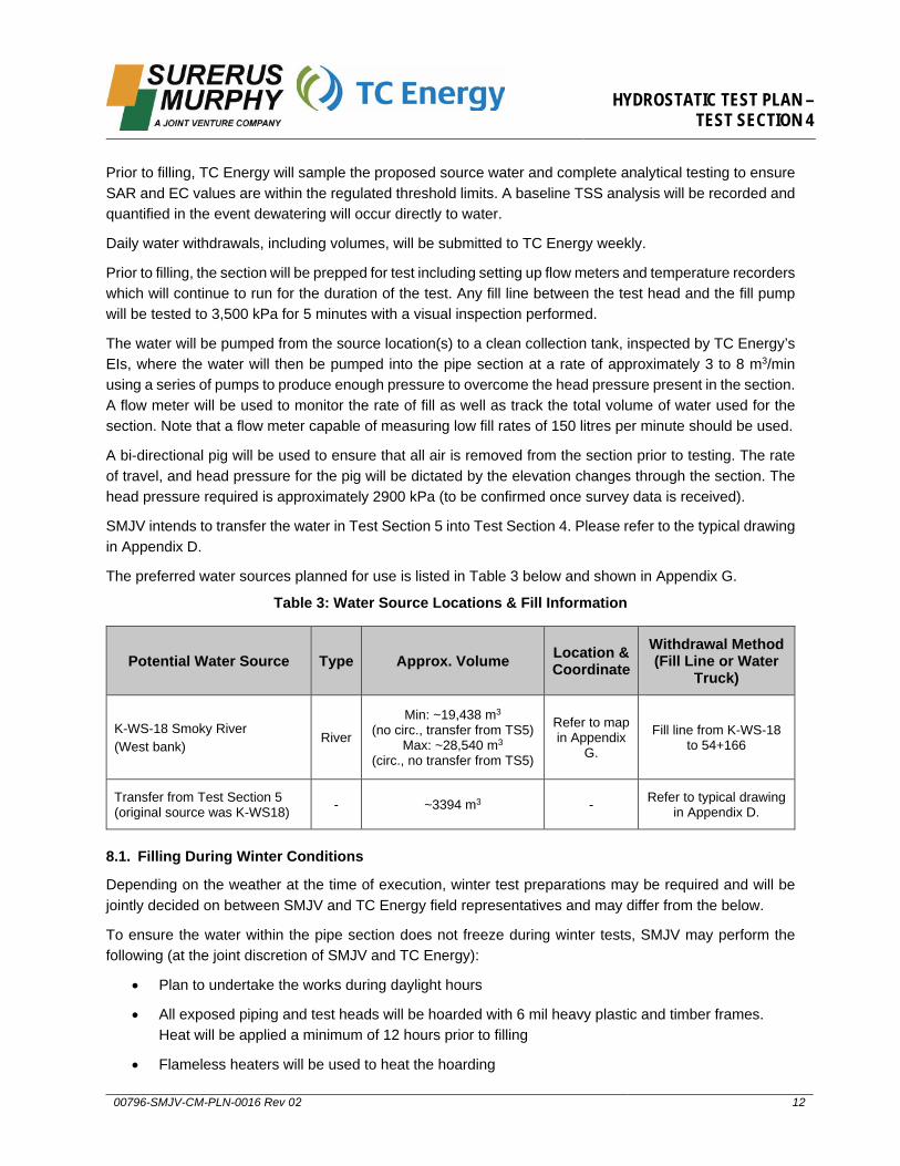
The preferred water sources planned for use is listed in Table 3 below and shown in Appendix G.
Table 3: Water Source Locations & Fill Information
Potential Water Source Type Approx. Volume Location & Coordinate
Withdrawal Method (Fill Line or Water
Truck)
K-WS-18 Smoky River(West bank)
River
Min: ~19,438 m3 (no circ., transfer from TS5)
Max: ~28,540 m3 (circ., no transfer from TS5)
Refer to map in Appendix
G.
Fill line from K-WS-18 to 54+166
Transfer from Test Section 5 (original source was K-WS18) - ~3394 m3 - Refer to typical drawing
in Appendix D.
8.1. Filling During Winter Conditions
Depending on the weather at the time of execution, winter test preparations may be required and will be jointly decided on between SMJV and TC Energy field representatives and may differ from the below.
To ensure the water within the pipe section does not freeze during winter tests, SMJV may perform the following (at the joint discretion of SMJV and TC Energy):
• Plan to undertake the works during daylight hours
• All exposed piping and test heads will be hoarded with 6 mil heavy plastic and timber frames.Heat will be applied a minimum of 12 hours prior to filling
• Flameless heaters will be used to heat the hoarding
HYDROSTATIC TEST PLAN – TEST SECTION 4
00796-SMJV-CM-PLN-0016 Rev 02 13
• SMJV shall promptly drain all fill lines following water transfer to protect fill pipe and pumps fromfreezing
• Use of propylene glycol in the deadweight hose connection at the test head
• Use of propylene glycol oil at the pressure recorder and deadweight
• Continuous fill of direct heated water – in general this will be heated water at 4 to 48 degreesCelsius filled into the pipe (or as agreed upon in the field). At the opposite end of the test sectionwater will be discharged for 2 hours at a minimum temperature of 2 degrees Celsius to provesatisfactory heating has been applied
9. Pressurizing and Test
9.1. Pressurizing
Prior to connecting the squeeze pump to the test head, all valves and instrumentation shall be visually examined to ensure that they are in good working condition and that all valves are in the proper position.
Once filling is complete, the pressure of the section will be taken to 3,000 kPa. The pressure shall be increased at a rate not exceeding 300 kPa per minute. Once 3,000 kPa is reached, pressurization will cease to allow for a leak check of the exposed areas of the section and test heads. The leak check pressure shall be held for a minimum of 15 minutes.
Following the leak check, the temperature of the test section will be allowed to stabilize prior to the commencement of strength and leak tests. The section is considered stable when the temperature of the test water is at or near the temperature of the ground along the test section. The TC Energy Test Inspector shall determine and declare when the temperature is sufficiently stabilized to begin the test.
Once the leak check is complete and the temperature has been declared sufficiently stable the pressure will be increased at 300 kPa per minute until 60% of the target test pressure is achieved. A second 15-minute leak check will be completed prior to continuing to pressure the section.
The final stage from 60% to 100% will be pressured at a rate of approximately 100 kPa per minute, and not to exceed 300 kPa/min, to allow for a yield plot to be recorded.
9.2. Yield Plot
The yield plot is a pressure versus volume plot where the pressure is plotted against the total volume of water added after filling.
The pressure of the pipe will be increased at rate of 100 kPa per minute and will run uninterrupted and at a constant rate of 100 kPa per minute until the target test pressure is met. If at any point the pressure increase is interrupted, the yield plot shall be redrawn.
The baseline for the yield plot will be set between 60% of the target test pressure, and the pressure relating to 80% of the SMYS of the section at the critical low point. At 80% of the SMYS the yield plot will begin. The volume input will be monitored using a calibrated flow meter and will be tracked against the pressure. If at any point in the yield plot the volume input deviates from the theoretical expansion of the pipe by 0.2%, the pressurizing will cease. If the 0.2% relative expansion is met, the strength test will begin at the achieved pressure.

HYDROSTATIC TEST PLAN – TEST SECTION 4
00796-SMJV-CM-PLN-0016 Rev 02 14
9.3. Strength Test
When the target strength test pressure is achieved and the pressure has stabilized, the section will be isolated from the squeeze pump.
The pressure will be held for a minimum of 4 hours within the maximum and minimum strength test pressures with no unexplained pressure loss to be considered successful, in compliance with TEP-PRES 2.1.9.
The finalized minimum, maximum, and target strength test pressures will be determined by TC Energy and communicated to SMJV via an engineered and stamped calculation sheet.
Measurements of the pressure from the deadweight during the strength test will be recorded every 5 minutes from the onset of the test for the first 30 minutes, every 10 minutes from 30 minutes to 1-hour, and every 15 minutes for the remainder of the duration of the test.
If the pressure rises to near the Maximum Strength Test Pressure due to an increase in ambient temperature, then test water may be carefully bled off. Any test water that is bled off will be collected in a container and the time, volume of water, and initial and final pressures shall be recorded.
If the pressure falls but is still above the Minimum Strength Test Pressure due to a decrease in ambient temperature and not a leak, then the pressure may be increased back up to the target strength test pressure without restarting the strength test.
If the pressure falls below the Minimum Strength Test Pressure within the test period due to changes in ambient temperature and not a leak, then the pressure must be increased back up to the target strength test pressure and the test must be restarted and held for the full required duration of the strength test.
A temperature stabilization period between the strength and leak test will be held if it is deemed the ambient conditions or changing ambient conditions may pose a risk to the ability to maintaining the required pressure cushion.
9.4. Leak Test
The pressure will be held for a minimum of 4 hours within the maximum and minimum leak test pressures.
The minimum, maximum, and target leak test pressures will be determined by TC Energy and communicated to SMJV via an engineered and stamped calculation sheet.
Measurements of the pressure from the deadweight during the leak test will be recorded every 5 minutes from the onset of the test for the first 30 minutes, every 10 minutes from 30 minutes to 1-hour, and every 15 minutes for the remainder of the duration of the test.
The achieved minimum and maximum pressures during the leak test must be maintained within 15 kPa of each other for 4 consecutive hours to be considered successful. If a pressure change of greater than 15 kPa is observed within 4 hours and the pressure change can be correlated with temperature deviations, the leak test will continue until 4 consecutive hours within the 15 kPa acceptance band is achieved.
If the pressure continues to change outside of the 15 kPa acceptance band and instrumentation indicates that a leak may be occurring, then a visual leak investigation may commence. If a leak is found the TC Energy Test Inspector will be notified.
HYDROSTATIC TEST PLAN – TEST SECTION 4
00796-SMJV-CM-PLN-0016 Rev 02 15
If the pressure continues to change outside of the 15 kPa acceptance band and the pressure deviation is explainable due to temperature changes, then SMJV shall consult with TC Energy to determine if this is acceptable. If TC Energy determines they are satisfactorily correlated using TEF-HYDRO-TEMP (Effects of Temperature Pressure - Hydrotest (CDN)) then test may be ended.
10. DepressurizingAt the conclusion of a successful test, the section will be depressurized in a controlled manner with a depressurization rate that should not exceed 300 kPa/min. The TC Energy Test Inspector shall witness the depressurizing of the test section and ensure the depressurization is conducted with extreme caution and minimal vibration. Depressurization shall use the bleed-off assembly on the test head, which shall be opened and closed slowly to protect the assembly from shock loading. Under no circumstances will valves be set to the fully open position to initiate depressurizing.
11. DewateringDewatering activities shall be in accordance with Alberta Code of Practice for the Release of Hydrostatic Test Water from Hydrostatic Testing of Petroleum Liquid and Gas Pipelines to an approved location in accordance with Section 8.7 of the Environmental Protection Plan.
Prior to dewatering, a land sample will be completed by TC Energy at the proposed dewatering location(s) to ensure that SAR & EC values are under the allowable limit. TC Energy may also sample the release water once testing is complete to determine if the water may be discharged into a receiving waterbody or watercourse. If the test water and receiving water is determined to be within allowable tolerances, then it will be discharged in accordance with Section 8.7 of the Environmental Protection Plan (EPP) and the COP for Release of Hydrostatic Test Water.
Water will be driven out of the pipe using a bi-directional pig pushed by compressed air at an approximate driving pressure of approximately 700 kPa (100 psi) plus the static head (or as otherwise decided upon in the field once survey data is received). A minimum 100 kPa (15 psi) backpressure will be maintained on dewatering pigs. SMJV expects to dewater the section at up to 10 m3/min.
Suitable dewatering locations near the hydrotest location have been determined by TC Energy and SMJV’s environmental teams. The dewatering point locations have been approved by TC Energy EIs. For Section 4, the potential dewatering locations are described in the Table 4. Dewatering is only expected at one of these locations.

HYDROSTATIC TEST PLAN – TEST SECTION 4
00796-SMJV-CM-PLN-0016 Rev 02 16
Table 4: Dewatering Point(s)
Dewater Point Location Discharge Volume
Land Description Coordinates (UTM)
Anticipated: Release to source location at K-WS-18
Smoky River (West bank) 22,832 m3 NE 30-67-04-W6 11 N 397547 m E 6077270 m N
Contingency for circulation water: Release to land on parallel ROW west of footprint at KP 33+675 by Road 18
0 to 5708 m3 SE 21-66-03-W6 11 N 411111 m E 6064752 m N
Contingency: Release to land to the north side of the ROW into the grazing lease near KP
54+200 by Road 31
0 to 22,832 m3 NW 30-67-04-W6 11 N 397196 m E 6077147 m N
Water shall be discharged into a diffuser and into surrounding vegetated area to reduce the risk of erosion at the dewatering location as per section 8.7 Hydrostatic Testing (EPP) Mitigation Measure items 6 through 11.
All lines and hoses used for dewatering will arrive to site clean.
Dewatering lines shall be securely supported and tied down at the discharge end to prevent sudden releases of energy (whipping) during dewatering.
During winter conditions, dewatering will be as soon as reasonably possible following the successful completion of the hydrostatic test.
12. Drying & Inline InspectionFollowing dewatering, SMJV plans to use air compressors and foam pigs for initial drying runs.
Section 4 will then be tied together with Section 5 upon successful hydrotest of both sections.
After that, inline inspection and final air drying will be completed for Sections 4 and 5 together.
Alternatively, dependant on schedule, SMJV may also complete separate inline inspection and final air drying for Sections 4 and 5.
12.1. Pig Drying Runs
Air compressors with a combined capacity of 12,000 CFM (to be confirmed) will be supplied to propel the drying pigs.
Compressed air will be used to push a combination of one bi-direction steel body pig and two light density foam pigs for the first run.
Subsequent runs will be one double dish medium density foam pig and one light density foam pig until the section is confirmed to be free of any residual water.
The section will be considered free of standing water when there is less than 6 mm of water on the bottom half of the foam pig as confirmed by the on-site Company representative.
HYDROSTATIC TEST PLAN – TEST SECTION 4
00796-SMJV-CM-PLN-0016 Rev 02 17
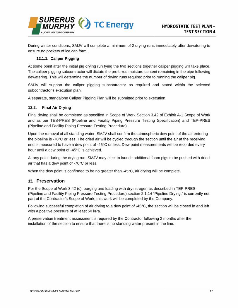
During winter conditions, SMJV will complete a minimum of 2 drying runs immediately after dewatering to ensure no pockets of ice can form.
12.1.1. Caliper Pigging
At some point after the initial pig drying run tying the two sections together caliper pigging will take place. The caliper pigging subcontractor will dictate the preferred moisture content remaining in the pipe following dewatering. This will determine the number of drying runs required prior to running the caliper pig.
SMJV will support the caliper pigging subcontractor as required and stated within the selected subcontractor’s execution plan.
A separate, standalone Caliper Pigging Plan will be submitted prior to execution.
12.2. Final Air Drying
Final drying shall be completed as specified in Scope of Work Section 3.42 of Exhibit A-1 Scope of Work and as per TES-PRES (Pipeline and Facility Piping Pressure Testing Specification) and TEP-PRES (Pipeline and Facility Piping Pressure Testing Procedure).
Upon the removal of all standing water, SMJV shall confirm the atmospheric dew point of the air entering the pipeline is -70°C or less. The dried air will be cycled through the section until the air at the receiving end is measured to have a dew point of -45°C or less. Dew point measurements will be recorded every hour until a dew point of -45°C is achieved.
At any point during the drying run, SMJV may elect to launch additional foam pigs to be pushed with dried air that has a dew point of -70°C or less.
When the dew point is confirmed to be no greater than -45°C, air drying will be complete.
13. PreservationPer the Scope of Work 3.42 (c), purging and loading with dry nitrogen as described in TEP-PRES (Pipeline and Facility Piping Pressure Testing Procedure) section 2.1.14 “Pipeline Drying,” is currently not part of the Contractor’s Scope of Work, this work will be completed by the Company.
Following successful completion of air drying to a dew point of -45°C, the section will be closed in and left with a positive pressure of at least 50 kPa.
A preservation treatment assessment is required by the Contractor following 2 months after the installation of the section to ensure that there is no standing water present in the line.
HYDROSTATIC TEST PLAN – TEST SECTION 4
00796-SMJV-CM-PLN-0016 Rev 02 18
14. Reference Documents• CSA Z662-19 Oil and Gas Pipeline Systems
• TES-CT-GEN-GL Pipeline Construction Specification (CAN)
• TES-PRES Pipeline and Facility Piping Pressure Testing Specification (CDN)
• TEP-PRES Pipeline and Facility Piping Pressure Testing Procedure (CDN)
• TEF-ME-PRIM-GL Pipeline and Facility Primary Pressure Testing Form (CAN)
• TEF-ME-SEC-GL Pipeline and Facility Secondary Pressure Testing Form (CAN)
• TES-PRES-TH Design of Test Head Assemblies Specification
• TES-ME-TH-GL Test Head Deficiency Checklist (CDN)

HYDROSTATIC TEST PLAN – TEST SECTION 4
00796-SMJV-CM-PLN-0016 Rev 02 19
Appendix A: SMJV Hydrotest Checklists & Forms

SSMJV-QC-FOR-066 Rev 0 Page 1 of 1
TEST HEAD SET CHECKLIST
PROJECT NAME Grande Prairie Mainline – Karr Section DATE
CLIENT TRANSCANADA PROJECT NO. 2010
TEST HEAD SET ASSEMBLY #’s
1. OWNER OF TEST HEADS
2.
TEST HEAD DETAILS (MAIN BODY ASSEMBLIES ONLY)
DIAMETER (mm)
WALL THICKNESS (mm)
GRADE (mPa)
MAXIMUM OPERATING PRESSURE (kPa)
TEST HEAD DOCUMENTATION
MATERIAL CERTIFICATES ARE AVAILABLE FOR REVIEW FOR PIPE, FITTINGS AND VALVES YES NO
NDT REPORTS FOR ALL WELDS ARE AVAILABLE FOR REVEIW YES NO
PRESSURE TEST LOG HISTORY AND PRESSURE CHARTS ARE AVAILABLE FOR REVEIW YES NO
VISUAL INSPECTION
TEST HEADS IDENTIFICATION IS CLEARLY MARKED YES NO
ALL TEST HEAD WELD ARE FREE FROM VISABLE CRACKS AND ARE NOT COMPROMISED FOR TESTING PURPOSES YES NO
VISIBLE MECHANICAL DAMAGE IS EVIDENT TO TEST HEADER AND ASSOCIATED FITTINGS TO PREVENT USE OF TEST HEADS YES NO
ALL VALVES AND FITTING RATINGS ARE ASSOCIATED WITH TEST HEAD AS BUILT TURNOVER PACKAGE YES NO
ALL VALVES AND VALVE HANDLES ARE MECHANICALLY SOUND AND ARE OPERATIONAL YES NO
THE INTERNAL BORE IS FREE AND CLEAN OF DEBRIS THAT COULD DAMAGE FILL OR DEWATERING PIGS YES NO
ALL PREVIOUS PIPELINE PIGS HAVE BEEN REMOVED YES NO
EXCESSIVE CORROSION HAS BEEN IDENTIFIED TO PREVENT USE OF TEST HEADS YES NO
LIFTING EYES / BRACKETS HAVE NO MECHANICAL DAMAGE THAT REQUIRES WELDS TO BE MT INSPECTED YES NO
COMMENTS:
SSMJV REPRESENTATIVE CLIENT REPRESENTATIVE (IF REQUIRED)
PRINT NAME
SIGNATURE

SSMJV-QC-FOR-067 Rev 0 Page 1 of 1
PRE-TEST PRESSURE CHECKLIST PART 1 OF 3
PROJECT NAME Grande Prairie Mainline – Karr Section DATE
CLIENT TC ENERGY PROJECT NO. 2010
TEST NUMBER TEST STATION LOCATION
FOREMAN TEST LIMIT US CHAINAGE
TEST SUBCONTRACTOR TEST LIMIT DS CHAINAGE
PRESSURE TEST ACTIVITY CHECKLIST – PRE-TEST DOCUMENTATION
1 Hydrotest Plan is submitted and approved for use ☐ YES ☐ NO ☐ N/A
2 Notify owner of test schedule ☐ YES ☐ NO ☐ N/A
3 Permits obtained and available for review (Water withdrawal / Discharge) ☐ YES ☐ NO ☐ N/A
4 Test limits are identified on P&ID, isometric or other supporting drawing ☐ YES ☐ NO ☐ N/A Dwg. No.
5 Test configuration drawing identifying test instrumentation used and location in test ☐ YES ☐ NO ☐ N/A Dwg. No.
6 Test section supporting documentation is complete and meets Project specifications ☐ YES ☐ NO ☐ N/A
7 All permanent welds within test section are NDE examined and acceptable ☐ YES ☐ NO ☐ N/A
PRE-TEST WALKDOWN INSPECTION
1 Test system is isolated from other systems ☐ YES ☐ NO ☐ N/A
2 Ensure all valves are not in fully closed position ☐ YES ☐ NO ☐ N/A
3 All pressure sensitive instrumentation removed from test section ☐ YES ☐ NO ☐ N/A
4 Valves, vents and drains installed as per IFC drawings ☐ YES ☐ NO ☐ N/A
5 Gaskets correctly seated and meet Project specifications ☐ YES ☐ NO ☐ N/A
6 Bolts correct length and torqued to Project specification ☐ YES ☐ NO ☐ N/A
HYDRO-TEST EQUIPMENT
1 Hydro testing equipment is calibrated, and in good working condition ☐ YES ☐ NO ☐ N/A
2 Hydrotest equipment has proper range and ratings for maximum test pressure ☐ YES ☐ NO ☐ N/A
3 Safety valves properly installed and checked for correct relief pressure ☐ YES ☐ NO ☐ N/A
4 Quantity and location of test instrumentation equipment is as per Hydrotest Plan ☐ YES ☐ NO ☐ N/A
5 Test section environmental measures and controls meet Project EPP requirements ☐ YES ☐ NO ☐ N/A
SAFETY
1 Check that the required safety barriers, signage, are in place ☐ YES ☐ NO ☐ N/A
2 Ensure only test personnel are permitted within the designated test areas ☐ YES ☐ NO ☐ N/A
TEST EQUIPMENT
Upstream Test head No. Downstream Test head No.
Pressure testing Instrumentation Serial No. Date Calibrated Pressure testing Instrumentation Serial No. Date Calibrated
SSMJV REPRESENTATIVE CLIENT REPRESENTATIVE (IF REQUIRED) PRINT NAME
SIGNATURE

SSMJV-QC-FOR-069 Rev 0
PRESSURE TEST REPORT PART 2 OF 3
PROJECT NAME Grande Prairie Mainline – Karr Section DATE
CLIENT TC ENERGY PROJECT NO. 2010
TEST NUMBER PAGE OF
TEST DESCRIPTION TEST STATION LOCATION
FOREMAN TEST LIMIT US CHAINAGE
TEST SUBCONTRACTOR TEST LIMIT DS CHAINAGE
TEST CHART TIME INTERVALS DURATION OF TEST
Time Deadweight Pressure Ambient (°C) Pipe (°C) Volume (m3) Comments
SSMJV REPRESENTATIVE CLIENT REPRESENTATIVE (IF REQUIRED) PRINT NAME SIGNATURE
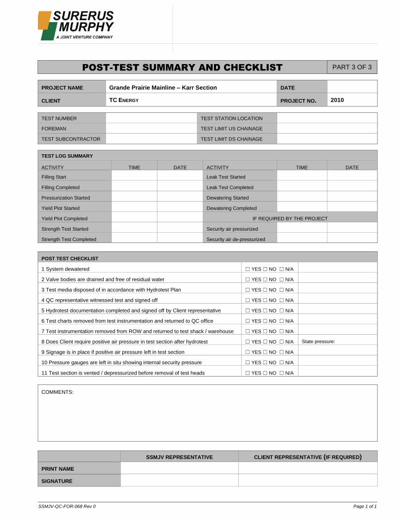
SSMJV-QC-FOR-068 Rev 0 Page 1 of 1
POST-TEST SUMMARY AND CHECKLIST PART 3 OF 3
PROJECT NAME Grande Prairie Mainline – Karr Section DATE
CLIENT TC ENERGY PROJECT NO. 2010
TEST NUMBER TEST STATION LOCATION
FOREMAN TEST LIMIT US CHAINAGE
TEST SUBCONTRACTOR TEST LIMIT DS CHAINAGE
TEST LOG SUMMARY
ACTIVITY TIME DATE ACTIVITY TIME DATE
Filling Start Leak Test Started
Filling Completed Leak Test Completed
Pressurization Started Dewatering Started
Yield Plot Started Dewatering Completed
Yield Plot Completed IF REQUIRED BY THE PROJECT
Strength Test Started Security air pressurized
Strength Test Completed Security air de-pressurized
POST TEST CHECKLIST
1 System dewatered ☐ YES ☐ NO ☐ N/A
2 Valve bodies are drained and free of residual water ☐ YES ☐ NO ☐ N/A
3 Test media disposed of in accordance with Hydrotest Plan ☐ YES ☐ NO ☐ N/A
4 QC representative witnessed test and signed off ☐ YES ☐ NO ☐ N/A
5 Hydrotest documentation completed and signed off by Client representative ☐ YES ☐ NO ☐ N/A
6 Test charts removed from test instrumentation and returned to QC office ☐ YES ☐ NO ☐ N/A
7 Test instrumentation removed from ROW and returned to test shack / warehouse ☐ YES ☐ NO ☐ N/A
8 Does Client require positive air pressure in test section after hydrotest ☐ YES ☐ NO ☐ N/A State pressure:
9 Signage is in place if positive air pressure left in test section ☐ YES ☐ NO ☐ N/A
10 Pressure gauges are left in situ showing internal security pressure ☐ YES ☐ NO ☐ N/A
11 Test section is vented / depressurized before removal of test heads ☐ YES ☐ NO ☐ N/A
COMMENTS:
SSMJV REPRESENTATIVE CLIENT REPRESENTATIVE (IF REQUIRED)
PRINT NAME
SIGNATURE

HYDROSTATIC TEST PLAN – TEST SECTION 4
00796-SMJV-CM-PLN-0016 Rev 02 24
Appendix B: Alignment Sheets
64300Dec-15-2020
64300SEP-21-2020
64300SEP-21-2020
64300SEP-21-2020

64300SEP-21-2020
64300Oct-27-2021

HYDROSTATIC TEST PLAN – TEST SECTION 4
00796-SMJV-CM-PLN-0016 Rev 02 31
Appendix C: Hydrostatic Test Profile
³
³
64300Oct-27-2021
³
³
64300Oct-27-2021

HYDROSTATIC TEST PLAN – TEST SECTION 4
00796-SMJV-CM-PLN-0016 Rev 02 34
Appendix D: Example Typical Filling, Test, & Dewater Sketches

WATER SOURCE
VELOCITY BOXFLOW METER HIGH VOLUME
PUMP
HIGH VOLUME PUMP
TEST HEAD
TEST SECTION
SPILL CONTAINMENTSPILL CONTAINMENT
TANK
HIGH PRESSURE(3,000kpa) PUMPS
FLOW METER
WATER TRUCK
FILL BUFFER TANK USING FILLLINE OR WATER TRUCKS
TYPICAL FILL FROM WATER SOURCE
Dra
win
g N
oR
evis
ion
Drawing Title:
Scale:
Drawing Number:
Project:
File Path:
Rev:
0G
PMK-
DW
G-T
P031
GPMK-DWG-TP031
HYDROTEST SET-UP SHEET 1
0
GPMK 1219mmØ STEEL GAS PIPELINE
NTS
SURERUS PIPELINE INC. &SURERUS MURPHY JOINT VENTURESuite 2200, 605 - 5th Avenue SWCalgary, Alberta. CanadaTel: (403) 930.1358 Fax: (587) 353.5369
REV DESCRIPTION APP BYCHK BYREV BYDATESTATUS
REVISIONS LEGEND
A ISSUED FOR INFORMATION MJBIFI VMD18/06/21 BOS0 ISSUED FOR INFORMATION VMDIFI MJB23/08/21 BOS

TANK FLOW METER
HIGH VOLUME PUMP
HIGH PRESSURE(3,000kpa) PUMPS
TYPICAL FILL THROUGH SECTION
Dra
win
g N
oR
evis
ion
Drawing Title:
Scale:
Drawing Number:
Project:
File Path:
Rev:
0G
PMK-
DW
G-T
P031
GPMK-DWG-TP031
HYDROTEST SET-UP SHEET 2
0
GPMK 1219mmØ STEEL GAS PIPELINE
NTS
SURERUS PIPELINE INC. &SURERUS MURPHY JOINT VENTURESuite 2200, 605 - 5th Avenue SWCalgary, Alberta. CanadaTel: (403) 930.1358 Fax: (587) 353.5369
REV DESCRIPTION APP BYCHK BYREV BYDATESTATUS
REVISIONS LEGEND
A ISSUED FOR INFORMATION MJBIFI VMD18/06/21 BOS0 ISSUED FOR INFORMATION VMDIFI MJB23/08/21 BOS

HIGH VOLUME PUMP
DIGITAL PRESSUREGAUGE
PRESSURE RECORDERTEMPERATURE RECORDER TEST SHACK
FLOW METER
SQUEEZE TRUCK
TEST DIAGRAM
Dra
win
g N
oR
evis
ion
Drawing Title:
Scale:
Drawing Number:
Project:
File Path:
Rev:
0G
PMK-
DW
G-T
P031
GPMK-DWG-TP031
HYDROTEST SET-UP SHEET 3
0
GPMK 1219mmØ STEEL GAS PIPELINE
NTS
SURERUS PIPELINE INC. &SURERUS MURPHY JOINT VENTURESuite 2200, 605 - 5th Avenue SWCalgary, Alberta. CanadaTel: (403) 930.1358 Fax: (587) 353.5369
REV DESCRIPTION APP BYCHK BYREV BYDATESTATUS
REVISIONS LEGEND
A ISSUED FOR INFORMATION MJBIFI VMD18/06/21 BOS0 ISSUED FOR INFORMATION VMDIFI MJB23/08/21 BOS

TANK VEGETATION
HIGH VOLUME PUMP
DIFFUSER
FILTER CLOTH
CONTAINMENT
DEWATERING
Dra
win
g N
oR
evis
ion
Drawing Title:
Scale:
Drawing Number:
Project:
File Path:
Rev:
0G
PMK-
DW
G-T
P031
GPMK-DWG-TP031
HYDROTEST SET-UP SHEET 4
0
GPMK 1219mmØ STEEL GAS PIPELINE
NTS
SURERUS PIPELINE INC. &SURERUS MURPHY JOINT VENTURESuite 2200, 605 - 5th Avenue SWCalgary, Alberta. CanadaTel: (403) 930.1358 Fax: (587) 353.5369
REV DESCRIPTION APP BYCHK BYREV BYDATESTATUS
REVISIONS LEGEND
A ISSUED FOR INFORMATION MJBIFI VMD18/06/21 BOS0 ISSUED FOR INFORMATION VMDIFI MJB23/08/21 BOS

HYDROSTATIC TEST PLAN – TEST SECTION 4
00796-SMJV-CM-PLN-0016 Rev 02 39
Appendix E: New Road 31 Test Point Drawing
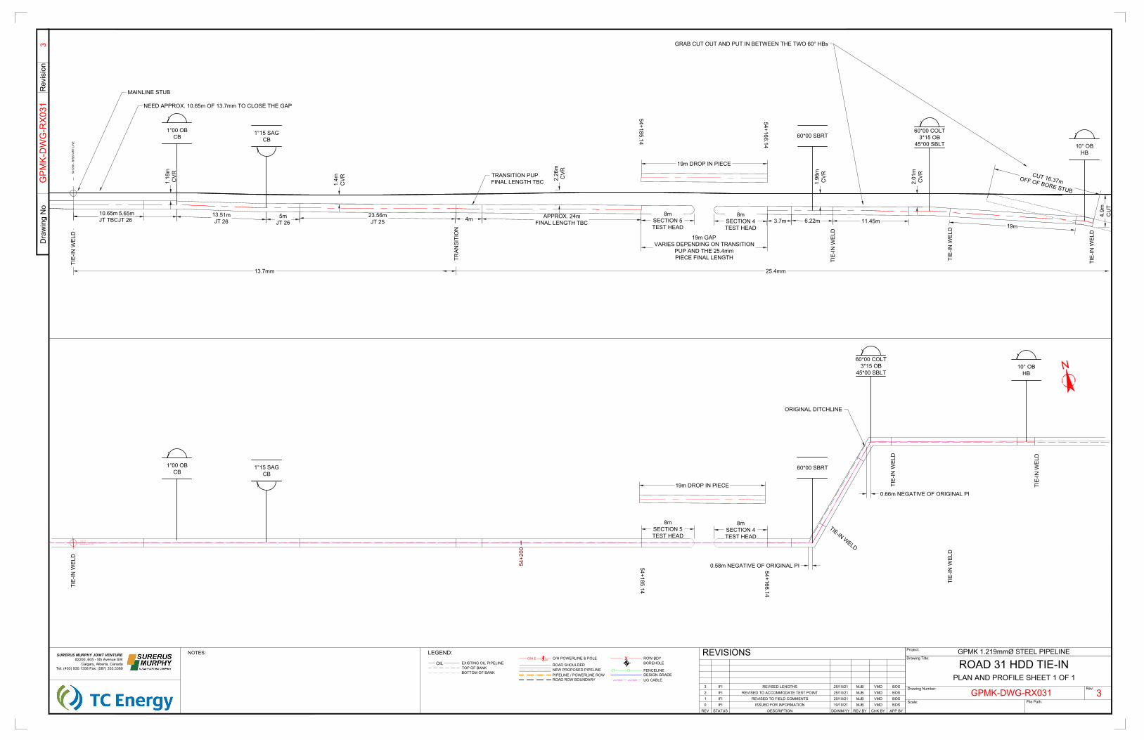
CUT 16.37mOFF OF BORE STUB
54+2
68 -
BH|S
TAR
T LI
NE
60*00 COLT3*15 OB
45*00 SBLT60*00 SBRT
10° OBHB
13.7mm 25.4mm
GRAB CUT OUT AND PUT IN BETWEEN THE TWO 60° HBs
1°00 OBCB
1°15 SAGCB
MAINLINE STUB
NEED APPROX. 10.65m OF 13.7mm TO CLOSE THE GAP
11.45m6.22m23.56mJT 25
5mJT 26
13.51mJT 26
15.65mJT 26
10.65mJT TBC
TRAN
SITI
ON 19m
TIE-
IN W
ELD
TIE-
IN W
ELD
TIE-
IN W
ELD
4.9m
CU
T
2.01
mC
VR
1.96
mC
VR2.26
mC
VR
1.4m
CVR1.18
mC
VR
TIE-
IN W
ELD
3.7m
TRANSITION PUPFINAL LENGTH TBC
4m APPROX. 24mFINAL LENGTH TBC
8mSECTION 4TEST HEAD
8mSECTION 5TEST HEAD
19m DROP IN PIECE
19m GAPVARIES DEPENDING ON TRANSITION
PUP AND THE 25.4mmPIECE FINAL LENGTH
54+166.14
54+185.14
54+2
00
BH|START LINE
100317579.86
0.66m NEGATIVE OF ORIGINAL PI
0.58m NEGATIVE OF ORIGINAL PI
19m DROP IN PIECE
8mSECTION 5TEST HEAD
8mSECTION 4TEST HEAD
54+166.14
54+185.14
PLAN AND PROFILE SHEET 1 OF 1
N
Dra
win
g N
oR
evis
ion
Drawing Title:
Scale:
Drawing Number:
Project:
File Path:
Rev:
3
3
GPMK 1.219mmØ STEEL PIPELINESURERUS MURPHY JOINT VENTURE#2200, 605 - 5th Avenue SW
Calgary, Alberta. CanadaTel: (403) 930.1358 Fax: (587) 353.5369
GPMK-DWG-RX031
GPM
K-D
WG
-RX0
31
REV DESCRIPTION APP BYCHK BYREV BYDD/MM/YYSTATUS
REVISIONSROAD 31 HDD TIE-IN
LEGEND:
0 ISSUED FOR INFORMATION VMDMJB19/10/21IFI
ROW BDYO/H POWERLINE & POLEOIL ROAD SHOULDER
O/H.E
TOP OF BANKBOTTOM OF BANK
EXISTING OIL PIPELINE
NEW PROPOSED PIPELINE
XPP
BOREHOLE
FENCELINEDESIGN GRADEUG CABLEU/G.FIBRE U/G.FIBRE
PIPELINE / POWERLINE ROWROAD ROW BOUNDARY
NOTES:
BOS
1°00 OBCB
1°15 SAGCB
60*00 COLT3*15 OB
45*00 SBLT
60*00 SBRT
10° OBHB
TIE-
IN W
ELD
TIE-IN WELD
TIE-
IN W
ELD
TIE-
IN W
ELD
TIE-
IN W
ELD
1 REVISED TO FIELD COMMENTS VMDMJB20/10/21IFI BOS
ORIGINAL DITCHLINE
2 REVISED TO ACCOMMODATE TEST POINT VMDMJB25/10/21IFI BOS3 REVISED LENGTHS VMDMJB25/10/21IFI BOS
HYDROSTATIC TEST PLAN – TEST SECTION 4
00796-SMJV-CM-PLN-0016 Rev 02 41
Appendix F: TC Energy Test Calculation Sheet & As-Built Data

HYDROSTATIC TEST PLAN – TEST SECTION 4
00796-SMJV-CM-PLN-0016 Rev 02 42
Test calculation sheet to be supplied by TC Energy.
Page left intentionally blank.

HYDROSTATIC TEST PLAN – TEST SECTION 4
00796-SMJV-CM-PLN-0016 Rev 02 43
Appendix G: Water Source Map
065-05-W6
066-05-W6
064-05-W6
063-05-W6
068-05-W6
067-05-W6
063-03-W6
064-01-W6
063-01-W6
064-02-W6
066-01-W6
064-04-W6
065-04-W6
068-02-W6
066-04-W6
065-01-W6065-03-W6
067-04-W6
068-04-W6
065-02-W6
068-01-W6
063-02-W6
064-03-W6
063-04-W6
066-03-W6
1 6 1 61 61 6
36 31 36 3136 3136 31
1 6 1 61 61 6
36 3136 3136 3136 31
1 61 61 61 6
36 3136 3136 3136 31
1 6 1 61 61 6
36 31 36 3136 3136 31
1 616
1 61 6
3631 36 31 36 31 36 31
1 6 1 6 1 6 1 6
Economy Creek
Moose
Karr Cree k
Lig niteCre e k
Moose River
Smuland Creek
McMillar Creek
Lato
rnell
Rive
r
Karr Lake
Musreau Lake
LittleMusreau Lake
K a kwa
Rive
r
S m o ky River
Smoky R
iver
Simonet teRiver
Lato rnell
Cutb
ank Rive
r
B igM
o unta
inCr
eek
Latornell River
LATORNELLRIVER
UNNAMED TRIBUTARYTO PATTERSON CREEK
SMOKY RIVERMcMILLARCREEK
GPM80
GPM75
GPM70
GPM60 0+000
57+068
50+000
40+000
30+000
20+000
10+000
LOCKED GATEGRAZING LEASE KARR SUMP SITE NO. 3
KARR SUMP SITE NO. 2
KARR SUMP SITE NO. 4
PL-9PL-8
PL-7PL-6
PL-5
PL-53
PL-52
PL-51PL-50
PL-49 PL-48PL-47
PL-46PL-45
PL-43
PL-42PL-41
PL-40PL-39
PL-37PL-36
PL-35
PL-34PL-33
PL-31PL-30
PL-29
PL-28
PL-27
PL-26PL-25PL-24PL-23PL-22
PL-18PL-17
PL-16
PL-15
PL-10
PL-14
PL-13
PL-12
PL-4 PL-1PL-2
PL-44
PL-38
PL-32
PL-21PL-20PL-19
PL-11
K-WS9
K-WS7
K-WS8
K-WS4
K-WS2
K-WS5
K-WS3
K-WS11
K-WS-20
K-WS-21
K-WS-13
K-WS-14
K-WS-16
K-WS-15
K-WS-17
I
E
J
G
G2
H
AF3AB
Z
Y
V
D1
F2
O
L8
K1J1
Q2
S1
X1
L3
L
P
AE
AF1AF AE1
AG1AG
AG2
L7
AH
AG4
L5
N
AG5
AC
AC1AG9
AA
X
T
S
I1
K
F
AG3
AG6
AG7 AG8
AE2AC3
W
V1
U
R
Q
D3
F4
G6
G5
G1
I3
J4
J3
D2
G4
F1
AD
I2
L4
L2
L6
J2
H1
G3
L1
F3
N1
P1
R1
T1
W1
Y1
Z1
AA1
AB1
AC2
F5
G7
J5
J6
J7
AC4
AG10
AA2
AB2
AB3
AG11
F6
AG12
AH2
N1
N2
V2
D4
AG15
V3
N3
PL-66
PL-68
PL-69
PL-71
± 69
.1 k
m T
O H
WY
43
UV734
GOLD ROAD
TOWER ROAD
FORE
STRY
TRU
NK R
OAD
FOR
ESTR
Y TR
UN
K R
OA
D
FOR
ESTRY TRU
NK
RO
AD
CANFOR
4000 ROAD
D ROAD
CANFOR2000 ROAD
CANFOR 2000 ROAD
CANFOR
2000 ROAD
ÄÆ
40
ÄÆ
40
ÄÆ
40
RCCC LATOR LODGE
35 4
812
18 1416
24 2322
2930 2826
3534
4 53
9117
181515
19 2019 2324 20 22
28292527
812 107 8
13 18 161413 1616
19 20222323
2630 282728
3233
3423
118 912
131413
2322 2124 22
262725 272726
32 3335
534
11 12810 7 11
1416
2421 20 2422
25 30 25 28
35 35
5 3
12 10 7 8 12 7
18 14 18
2323
433
7 10109
18 1714
24 192324 19 2221
2525 3026
32 3335
55323
9 88 1012 98 109
1613 18 16
2322
29272525 30272928
333333
3 4242
8119
1713
21
3025 27
32 34353534
5343
810111189 10
1715161717
20 2020202322
292629
3234333235
3 5
12 7 11109 8 10 9
17 1515 16 15 16
23 19
30 2927 30
32
4 2 5
8 11 12109
13 18 17 17 15
24 20 2421 20 21 21
5 222
811
13 1814
2419 2020
28292727
3434
2
12 712 711
13 18 1718 14
21 2120 22
26
3535
255 43
7810
18151715
22 2124 1922
2725 3026
333433
24
7 12 97 99
13 181417
24 19 24 192421
25 30 25 2825 30 2828 27
3333
22 45 44 3
9 7 8
18 13 1317 16 14 13 17
23 2421 23
2627 29
34 34 33
523 4 4
11
1415 1316 18 14
2221 22 24 19 20
523
712
151314
20 2220
30 2627
333233
3 4245 4
78
17 1617 161414
2419 2121
2630 2829 2830
34323534323433
523534
97 912
131418 1514
242019
25 28262930 262927
35 323333
5 424
7812 10
1618141614
212319
30 29
3534353434
23
7810 129
18 1815 18
19 20 1922 20 21
2528 2627 29
33 32
5 3
710 119 8 9
1317 15 13 17 16
19 2420 1922 23 2322
Twp.
62Tw
p.63
Twp.
64Tw
p.65
Twp.
66Tw
p.67
Twp.
68
Twp.
62Tw
p.63
Twp.
64Tw
p.65
Twp.
66Tw
p.67
Twp.
68
Rge.1Rge.2Rge.3Rge.4Rge.5
Ü
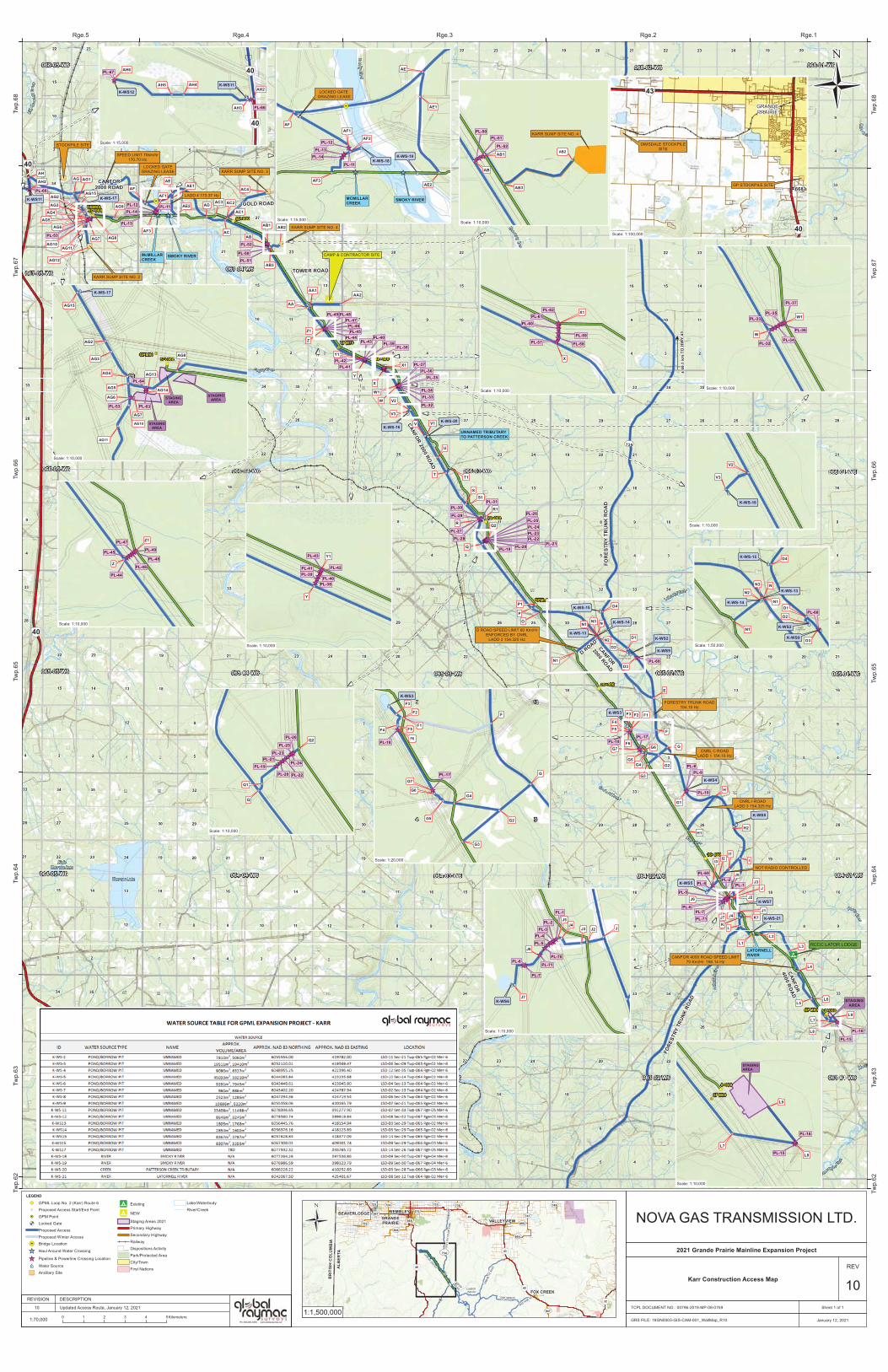
LEGEND
!( GPML Loop No. 2 (Karr) Route 6!( Proposed Access Start/End Point!H GPM Point
! ( Locked GateProposed AccessProposed Winter Access
!(à Bridge Location
_̂ Haul Around Water Crossing
_̂ Pipeline & Powerline Crossing Location
po Water Source
") Ancillary Site
!9 Existing
!9 NEW
Staging Areas 2021Primary HighwaySecondary HighwayRailwayDispositions ActivityPark/Protected AreaCity/TownFirst Nations
Lake/WaterbodyRiver/Creek
!(L
!(M
ÄÆ
43
UV734
CANFOR
4000 RD CANFOR7000 RD
BIGSTONE RD
FORE
STRY
TRU
NK R
OAD
CANFOR 2000 RD
TONY MAIN RD
SIMO
NETT
E RO
AD
!(D
!(E
!(A
!(B!(C
ÄÆ
43
ÄÆ
43
ÄÆ
40
ÄÆ
32
UV668
UV667
UV733 UV736 UV749UV723
UV947
UV724
UV669
UV670
UV671
UV665
UV722
UV666
UV747
BR
ITIS
H C
OLU
MB
IA
ALB
ERTA
VALLEYVIEW
FOX CREEK
WEMBLEYBEAVERLODGEGRANDEPRAIRIEÜ NOVA GAS TRANSMISSION LTD.
1:1,500,000
Karr Construction Access Map
REV
10TCPL DOCUMENT NO.: 00796-2019-MP-08-0759 Sheet 1 of 1
1:70,000
10
REVISION DESCRIPTION
0 1 2 3 4 5Kilometers
2021 Grande Prairie Mainline Expansion Project
Updated Access Route, January 12, 2021
January 12, 2021GRS FILE: 18GN0003-GIS-CAM-001_WallMap_R10
!(
!(
!(
_̂̂_̂_̂_̂_̂_̂_̂_PL-24
PL-26
Q
Q2
PL-19
PL-20
PL-21
PL-22
PL-23
PL-25
!(
!(
!(
!(
!(
!(
!(!(
!(
!(
!(
!(
!(!(
_̂
_̂
po
F5
G7
F6
K-WS3
F
G
G2
F4
F2
G6
G5
G4
F1
G3
F3
PL-17
PL-18
34
109
!(
!H
!(
!(
!(
!(
!( !(
!(
!(
!(
!(
!(
!(po
_̂_̂̂_
STAGINGAREA
STAGINGAREA
STAGINGAREA
PL-64
AG2
AG4
AG5
AG3
AG6
AG7
AG8
26
57+068
PL-53
GPM80
!(
!H
!(
!(_̂̂_
STAGINGAREA
GPM60
L7
L8
0+000
PL-15
PL-16
Scale: 1:10,000
Scale: 1:20,000
Scale: 1:10,000
STOCKPILE SITE
CAMP & CONTRACTOR SITE
STAGINGAREA
_̂_̂
!(à
!(
!(
!(
!(
!( !(
!(
po
po
_̂_̂̂_̂_
! (
AE
AF
AF3AE2
AF1
AE1
AF2
SMOKY RIVERMCMILLARCREEK
PL-11
PL-12
PL-13PL-14
K-WS-18K-WS-19
Smoky River
Scale: 1:15,000
!(!(
!( !(
!(
!(
!(
!(
po
_̂̂_̂_̂_̂_
_̂̂_
_̂_̂
PL-3
PL-1
JJ4
J3 J2
J5
J6
J7
PL-2
PL-4
PL-5
PL-7
K-WS6
PL-6
Scale: 1:10,000
!(
!(
!(
!(
_̂̂_̂_
AB
AB1
PL-50PL-51
PL-52
Scale: 1:10,000
!(
!(
_̂̂_̂_̂_̂_̂_
Z
Z1
PL-44
PL-45
PL-46
PL-47
PL-48
PL-49
Scale: 1:10,000
Scale: 1:10,000
!(
!(
_̂̂_̂_̂_̂_̂_
PL-38
PL-39PL-40
PL-41 PL-42
PL-43
Y
Y1
Scale: 1:10,000
!(
!(
_̂̂_̂_̂_̂_̂_
PL-32
PL-33
PL-34
PL-35
PL-36
PL-37
W
W1
Scale: 1:10,000
AB2
KARR SUMP SITE NO. 4
SPEED LIMIT 70km/hr170.70 Hz
LADD 4 173.37 Hz
D ROAD SPEED LIMIT 60 Km/HrENFORCED BY CNRL
LADD 3 154.325 Hz
FORESTRY TRUNK ROAD154.10 Hz
CNRL C ROADLADD 1 154.10 Hz
CNRL I ROADLADD 3 154.325 Hz
NOT RADIO CONTROLLED
CANFOR 4000 ROAD SPEED LIMIT70 Km/Hr 166.14 Hz
LOCKED GATE GRAZING LEASE
!(
!(
_̂̂__̂_̂̂_̂_
X
X1PL-62PL-61
PL-60
PL-59
PL-58PL-57
Scale: 1:10,000
AG10
AG11
PL-63
AG13
AG14
GP STOCKPILE SITE
DIMSDALE STOCKPILESITE
ÄÆ
43
ÄÆ
40
UV668
GRANDEPRAIRIE
Scale: 1:100,000
K-WS12K-WS11
AH6
AH5 AH4
AH3
AH2
PL-67
PL-66
ÄÆ
40
ÄÆ
40
Scale: 1:15,000
H2
PL-70
PL-71
L9
L9
AG15
K-WS-17
V3
V2
K-WS-16
N
D4
N2
N1
D3
N1
D2
D1
K-WS-15
K-WS2
K-WS9
K-WS-13
K-WS-14
PL-68
Scale: 1:50,000
Scale: 1:10,000
Q1
N3
AB3

UNCONTROLLED IF PRINTED
Client TC Energy
Project Name Grande Prairie Mainline Karr Section
Project ID GPMK
Hydrostatic Test Plan – Test Section 5
Print Name Position Signature
Document Owner Project Engineer (EIT)
Reviewer Lead Project Engineer
Approver Project Director
02 2021-10-30 Issued for Use
01 2021-10-22 Issued for Use
00 2021-10-19 Issued for Use
Revision Date (yyyy-mm-dd) Status / Change Description
Document Number and Revision 00796-SMJV-CM-PLN-0017 Rev 02
HYDROSTATIC TEST PLAN – TEST SECTION 5
00796-SMJV-CM-PLN-0017 Rev 02 2
1. Background and Purpose ........................................................................................................................ 4
2. Safety ....................................................................................................................................................... 4
2.1. General Safety Precautions ............................................................................................................ 4 2.2. Key Testing Personnel .................................................................................................................... 5
3. Testing Equipment ................................................................................................................................... 6
3.1. Test Heads...................................................................................................................................... 6 3.2. Pressurizing Pump .......................................................................................................................... 7 3.3. Instrumentation ............................................................................................................................... 7
4. Schedule .................................................................................................................................................. 8
5. Documentation ......................................................................................................................................... 8
6. Primary Pressure Test and General Methodology .................................................................................. 9
6.1. Winter Test Preparation ................................................................................................................ 11
7. Pipeline Cleaning ................................................................................................................................... 11
8. Filling ...................................................................................................................................................... 11
8.1. Filling During Winter Conditions ................................................................................................... 12
9. Pressurizing and Test ............................................................................................................................ 13
9.1. Pressurizing .................................................................................................................................. 13 9.2. Yield Plot ....................................................................................................................................... 13 9.3. Strength Test ................................................................................................................................ 13 9.4. Leak Test ...................................................................................................................................... 14
10. Depressurizing ....................................................................................................................................... 15
11. Dewatering ............................................................................................................................................. 15
12. Drying & Inline Inspection ...................................................................................................................... 16
12.1. Pig Drying Runs ............................................................................................................................ 16 12.2. Final Air Drying ............................................................................................................................. 17
13. Preservation ........................................................................................................................................... 17
14. Reference Documents ........................................................................................................................... 18
TABLES
Table 1: Key Testing Personnel .................................................................................................................... 5
Table 2: Mainline Test Section 5 Information .............................................................................................. 10
Table 3: Water Source Locations & Fill Information ................................................................................... 12
Table 4: Dewatering Point(s) (if required) ................................................................................................... 16
TABLE OF CONTENTS
HYDROSTATIC TEST PLAN – TEST SECTION 5
00796-SMJV-CM-PLN-0017 Rev 02 3
APPENDICES
Appendix A: SMJV Hydrotest Checklists & Forms ..................................................................................... 19
Appendix B: Alignment Sheets ................................................................................................................... 24
Appendix C: Hydrostatic Test Profile .......................................................................................................... 26
Appendix D: Example Typical Filling, Test, & Dewater Sketches ............................................................... 28
Appendix E: New Road 31 Test Point Drawing .......................................................................................... 33
Appendix F: TCE Test Calculation Sheet & As-Built Data .......................................................................... 35
Appendix G: Water Source Map ................................................................................................................. 37
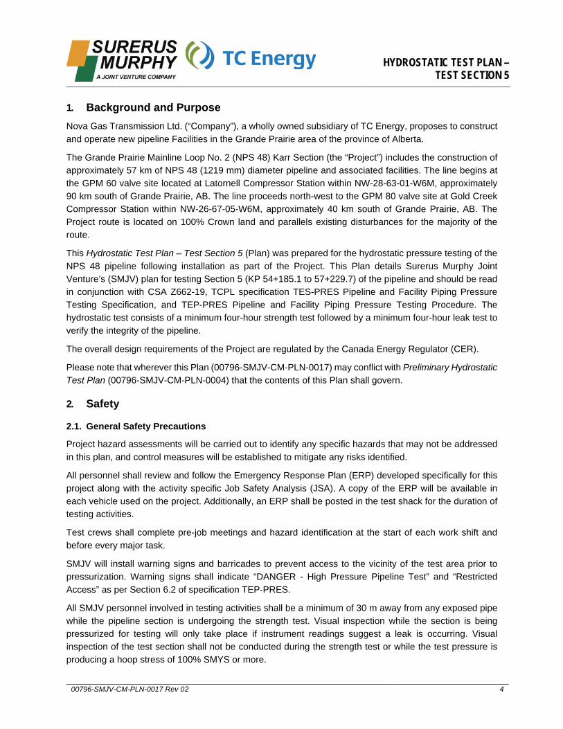
HYDROSTATIC TEST PLAN – TEST SECTION 5
00796-SMJV-CM-PLN-0017 Rev 02 4
1. Background and PurposeNova Gas Transmission Ltd. (“Company”), a wholly owned subsidiary of TC Energy, proposes to construct and operate new pipeline Facilities in the Grande Prairie area of the province of Alberta.
The Grande Prairie Mainline Loop No. 2 (NPS 48) Karr Section (the “Project”) includes the construction of approximately 57 km of NPS 48 (1219 mm) diameter pipeline and associated facilities. The line begins at the GPM 60 valve site located at Latornell Compressor Station within NW-28-63-01-W6M, approximately 90 km south of Grande Prairie, AB. The line proceeds north-west to the GPM 80 valve site at Gold Creek Compressor Station within NW-26-67-05-W6M, approximately 40 km south of Grande Prairie, AB. The Project route is located on 100% Crown land and parallels existing disturbances for the majority of the route.
This Hydrostatic Test Plan – Test Section 5 (Plan) was prepared for the hydrostatic pressure testing of the NPS 48 pipeline following installation as part of the Project. This Plan details Surerus Murphy Joint Venture’s (SMJV) plan for testing Section 5 (KP 54+185.1 to 57+229.7) of the pipeline and should be read in conjunction with CSA Z662-19, TCPL specification TES-PRES Pipeline and Facility Piping Pressure Testing Specification, and TEP-PRES Pipeline and Facility Piping Pressure Testing Procedure. The hydrostatic test consists of a minimum four-hour strength test followed by a minimum four-hour leak test to verify the integrity of the pipeline.
The overall design requirements of the Project are regulated by the Canada Energy Regulator (CER).
Please note that wherever this Plan (00796-SMJV-CM-PLN-0017) may conflict with Preliminary Hydrostatic Test Plan (00796-SMJV-CM-PLN-0004) that the contents of this Plan shall govern.
2. Safety
2.1. General Safety Precautions
Project hazard assessments will be carried out to identify any specific hazards that may not be addressed in this plan, and control measures will be established to mitigate any risks identified.
All personnel shall review and follow the Emergency Response Plan (ERP) developed specifically for this project along with the activity specific Job Safety Analysis (JSA). A copy of the ERP will be available in each vehicle used on the project. Additionally, an ERP shall be posted in the test shack for the duration of testing activities.
Test crews shall complete pre-job meetings and hazard identification at the start of each work shift and before every major task.
SMJV will install warning signs and barricades to prevent access to the vicinity of the test area prior to pressurization. Warning signs shall indicate “DANGER - High Pressure Pipeline Test” and “Restricted Access” as per Section 6.2 of specification TEP-PRES.
All SMJV personnel involved in testing activities shall be a minimum of 30 m away from any exposed pipe while the pipeline section is undergoing the strength test. Visual inspection while the section is being pressurized for testing will only take place if instrument readings suggest a leak is occurring. Visual inspection of the test section shall not be conducted during the strength test or while the test pressure is producing a hoop stress of 100% SMYS or more.
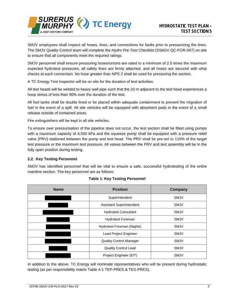
HYDROSTATIC TEST PLAN – TEST SECTION 5
00796-SMJV-CM-PLN-0017 Rev 02 5
SMJV employees shall inspect all hoses, lines, and connections for faults prior to pressurizing the lines. The SMJV Quality Control team will complete the Hydro Pre-Test Checklist (SSMJV-QC-FOR-067) on site to ensure that all components meet the required ratings.
SMJV personnel shall ensure pressuring hoses/unions are rated to a minimum of 2.5 times the maximum expected hydrotest pressures, all safety lines are firmly attached, and all hoses are secured with whip checks at each connection. No hose greater than NPS 2 shall be used for pressuring the section.
A TC Energy Test Inspector will be on site for the duration of test activities.
All test heads will be welded to heavy wall pipe such that the 20 m adjacent to the test head experiences a hoop stress of less than 90% over the duration of the test.
All fuel tanks shall be double lined or be placed within adequate containment to prevent the migration of fuel in the event of a spill. All site vehicles will be equipped with absorbent pads in the event of a small release outside of contained areas.
Fire extinguishers will be kept in all site vehicles.
To ensure over pressurisation of the pipeline does not occur, the test section shall be filled using pumps with a maximum capacity of 4,500 kPa and the squeeze pump shall be equipped with a pressure relief valve (PRV) stationed between the pump and test head. The PRV shall be pre-set to 110% of the target test pressure or the maximum test pressure. All valves between the PRV and test assembly will be in the fully open position during testing.
2.2. Key Testing Personnel
SMJV has identified personnel that will be vital to ensure a safe, successful hydrotesting of the entire mainline section. The key personnel are as follows:
Table 1: Key Testing Personnel
Name Position Company
Superintendent SMJV
Assistant Superintendent SMJV
Hydrotest Consultant SMJV
Hydrotest Foreman SMJV
Hydrotest Foreman (Nights) SMJV
Lead Project Engineer SMJV
Quality Control Manager SMJV
Quality Control Lead SMJV
Project Engineer (EIT) SMJV
In addition to the above, TC Energy will nominate representatives who will be present during hydrostatic testing (as per responsibility matrix Table 4-1 TEP-PRES & TES-PRES).

HYDROSTATIC TEST PLAN – TEST SECTION 5
00796-SMJV-CM-PLN-0017 Rev 02 6
3. Testing EquipmentSMJV expects to use the following equipment for completion of the hydrostatic test as per 2.7.1 of TEP-PRES:
• Third party squeeze pump / truck, equipped with electronic lockouts and a pressure relief valve thatcan be pre-set to 110% of the target test pressure or the maximum test pressure
• 8x10 Pioneer feed pump (or similar)
• 6x8 Three stage peerless pump (or similar)
• Air compressors which when combined will produce a flow rate of at least 12,000 CFM (to beconfirmed) required for pipeline cleaning and dewatering
• Steel body, bi-direction pipeline construction pigs equipped for cleaning, filling, and dewatering
• Double dish medium density foam pigs
• Light density foam pigs
• 1107 mm diameter aluminium sizing plate(s)
• All necessary valves, hoses, and fittings
• Calibrated temperature recorders, pressure recorders, dead weights, and pressure andtemperature gauges
• Adequate lighting at all work areas
• Sufficient vents and drains to accommodate proper venting of air and drainage of test fluids afterthe test
All pressure testing instrumentation will be calibrated within 6 months prior to hydrostatic testing. All equipment used for hydrostatic test will be well maintained, clean and free of leaks.
3.1. Test Heads
SMJV shall utilize two NPS 48 conventional test heads supplied by TC Energy.
Test head assemblies shall comply with all requirements of CSA-Z662-19 Clause 8.5 and all requirements of TC Energy specification TEP-PRES-TH (Test Head Management Procedure). The use of these heads shall also be in line with Section 2.1.2 of TEP-PRES (Pipeline and Facility Piping Pressure Testing Procedure). Test heads will be pre-tested to the maximum test pressure that any section will experience at a local test point prior to use. SMJV will verify that test head operating pressures exceed the maximum strength test pressures.
All documentation certifying test head compliance shall be made available prior to commencement of testing.
Upon receipt of the test heads, SMJV shall verify the test heads against SSMJV-QC-FOR-066 (Test Head Set Checklist; in Appendix A).
Test heads will be welded to the section and the welds will be inspected and accepted by TC Energy supplied NDE and accepted by TC Energy representative prior to filling the section.

HYDROSTATIC TEST PLAN – TEST SECTION 5
00796-SMJV-CM-PLN-0017 Rev 02 7
A pressure relief valve (PRV) will be stationed between the pressure pump and the test head to ensure over pressurization does not occur; the PRV shall be pre-set to 110% of the target test pressure or the maximum test pressure. All valves between the PRV and test assembly will be in the fully open position during testing.
Upon completion of testing, SMJV shall complete TES-ME-TH-GL (Test Head Deficiency Checklist) prior to returning the test heads to TC Energy.
3.2. Pressurizing Pump
SMJV shall ensure that the squeeze pump is adequately sized for the length and diameter of the test section.
SMJV plans to utilize a third-party squeeze truck equipped with a PRV and electronic lockouts.
A pressure relief valve that can be pre-set to 110% of the target test pressure or the maximum test pressure shall be installed in the pressurizing line between the squeeze pump and the test head. All valves between the PRV and test assembly will be in the fully open position during testing.
3.3. Instrumentation
All instrumentation used will be compliant with Section 2.7 of TEP-PRES (Pipeline and Facility Piping Pressure Testing Procedure).
SMJV shall supply all pressure and temperature recorders and dead-weights to provide readings for test data. Pressure shall be measured and recorded in kPa, and temperature shall be measured in degrees Celsius. All equipment shall be carefully selected, be in good working order and calibrated within 6 months prior to the onset of the test by an independent third-party company using standards with accuracies traceable to NIST (National Institute of Standards and Technology).
All test charts and reports, including the depressurizing of tested lines, will be included in the document turnover package.
The equipment used shall be suitable for the pressures they are to be used at.
All instruments will be checked to be in working order prior to each hydrostatic test.
Instrumentation for the test shall be as follows, at a minimum:
• Three (3) single probe pressure recorder (0 to 21,000 kPa)
• Two (2) dual probe temperature recorder (-30 to +50°C)
• One (1) mechanical deadweight (0 to 21,000 kPa at 5 kPa increments)
• Three (3) digital deadweights equipped with resistance temperature detection modules (RTDModules) (0 to 21,000 kPa)
• Three (3) analog pressure gauges (0 to 21,000 kPa)
• One (1) 6” calibrated flow meter, accurate to ±0.5% (or alternative size to suit fill rate)
• One (1) 2” calibrated flow meter, accurate to ±0.5% (or alternative size to suit squeeze rate)
• Calibrated dew point meter

HYDROSTATIC TEST PLAN – TEST SECTION 5
00796-SMJV-CM-PLN-0017 Rev 02 8
All measurement equipment shall be certified for accuracy not more than 6 months prior to commencement of the pressure test. The calibration certificates and reports shall be maintained on site and included in the turnover package.
4. ScheduleHydrostatic pressure testing activities for Test Section 5 are scheduled to begin in November 2021. Please refer to the schedule included in the weekly schedule updates communicated to TC Energy.
Any changes to schedule will be discussed and agreed with the TC Energy representative on site prior to being implemented. Due to potential changes to improve substantial completion on the project, the schedule is subject to change. Changes will be communicated to TC Energy in the weekly schedule updates.
5. DocumentationPrior to the onset of each test, a test package will be developed by SMJV which will include the documentation required by section 2.9.1.1 of TEP-PRES. The documents that will be made available for review prior to the test taking place shall include at a minimum:
• Hydrostatic Test Plan – Test Section 5 (00796-SMJV-CM-PLN-0017)
• Pressure Testing ITP (00796-SMJV-QM-ITP-0017)
• Test Arrangement Typical Drawings (see Appendix D) (GPMK-DWG-TP031)
• Instrumentation Register and Calibration Certifications
• Test Medium Analysis provided by TC Energy
• Survey data of the test section (Hydrostatic Test Schematic (As-Built)) provided by TC Energy:
• Identifies high point and lows points, including critical low point
• Hydrotest calculations provided by TC Energy
Following the successful completion of the hydrostatic test, the test package will be supplemented with the completed SMJV forms and records of the test as per section 2.9.1.1 of TEP-PRES:
• Yield Plot log
• Hydrostatic test pressure charts (signed)
• Pressure log (including time, pressure, ambient temperature, and pipe temperature)
• Original pressure and temperature charts, including:
• Fill water temperature chart(s)
• Pipe and ground temperature chart(s)
• Graph of temperatures and pressure loss versus time
• Pre-Test Pressure Checklist (Part 1 of 3) (SSMJV-QC-FOR-067); see Appendix A
• Pressure Test Report (Part 2 of 3) (SSMJV-QC-FOR-069); see Appendix A
• Post-Test Summary and Checklist (Part 3 of 3) (SSMJV-QC-FOR-068); see Appendix A
HYDROSTATIC TEST PLAN – TEST SECTION 5
00796-SMJV-CM-PLN-0017 Rev 02 9
6. Primary Pressure Test and General MethodologyThis section is intended to provide a brief overview of the test to be completed for the mainline Test Section5. Testing will be completed in accordance with Section 2.1 – Primary Hydrotest of TEP-PRES and Section3.15 and Appendix A-1-4 of Exhibit A-1 Scope of Work. The mainline Section 5 field test shall be an 8-hourPrimary Test consisting of a 4-hour strength test followed by a 4-hour leak test.
Appendix B Alignment Sheets and Appendix C Hydrostatic Test Profile lists the relevant alignment sheet and test profile drawing which identify the sections of pipeline to be field tested. Appendix D shows example typical sketches for filling, transferring test water from one section to another, testing, and dewatering.
Table 2 below outlines the specifications, including the strength test pressures and leak test pressures, for the Section 5 test. Commencement test pressures are subject to change. Final test pressure calculations for use during the test shall be provided by TC Energy post construction and prior to testing (see Appendix F).
Conventional NPS 48 test heads shall be installed at the start and end locations of the section to be tested. 20 m permanent heavy wall sections shall be installed at the upstream and downstream end of the test section, as per the requirements of TES-PRES.
Please note that the test point interface between Sections 4 and 5 has been repositioned to the location described in Appendix E GPMK-DWG-RX031 R3 (ROAD 31 HDD Exit TIE-IN) and the latest IFCs received in line with RFI-0129 ‘Section 4 & 5 Test Point Relocation Road 30 to Road 31’. The test shack shall be positioned at the negative end of the test section at approximately KP 54+200 at a safe distance from the test point.
Temperature recorders will be installed 200 to 500 m from each end of the section where practical. No mid-point recorder will be installed due to the short length of Section 5. Temperature recorder locations subject to change.
Test water will be extracted from the approved point of diversion at the Smoky River and pumped to the test location. The section will be filled in such a manner as to minimize air entrainment. Test Section Volume to be verified and confirmed post construction and prior to testing by TC Energy.
Although not anticipated, during testing up to 25% additional water volume may be required for continuous circulation of heated water if winter conditions make such necessary. See Table 2. This additional volume would be released to the opposite side of the test section from the test shack – dewatering to an approved location near Road 32.
After the completion of hydrotesting Section 5, the test water is intended to be transferred from Test Section 5 into Test Section 4. Although not anticipated, some test water may be dewatered and released to land or to the source location (Smoky River) in accordance with the COP submission.
Following dewatering, compressors and foam pigs will be used for initial drying runs for Section 5.
Section 5 will later be tied together with Section 4 upon successful hydrotest of that section. After that, inline inspection and final air drying will be completed for Sections 4 and 5 together. Alternatively, dependant on schedule, SMJV may also complete separate inline inspection and final air drying for Sections 4 and 5.

HYDROSTATIC TEST PLAN – TEST SECTION 5
00796-SMJV-CM-PLN-0017 Rev 02 10
Table 2: Mainline Test Section 5 Information
Primary Test Section Test Section 5
Upstream (U/S) / Positive Chainage (m) 57+229.7 Downstream (D/S) / Negative Chainage (m) 54+185.1 Test Section Length (m) 3044.6 Maximum High Point Elevation (m) 704.3 Minimum Low Point Elevation (m) 580.3 Critical Low Point Elevation (m) 580.3 Maximum Differential (kPa) 1216 0.2% Off-Set Volume (m3) 7 Test Section Volume (m3) ~3394 Potential Circulation Volume (estimated 25%) 0 to ~849 Upstream / Positive Temperature Recorder Location 56+750 Midpoint Temperature Recorder Location N/A Downstream / Negative Temperature Recorder Location 54+575
Strength Test – Upstream/Positive End (57+229.7) 80% S.M.Y.S Pressure at Low Point – U/S (kPag) (Yield Plot must commence at or prior to this pressure) 7476
Minimum Strength Test Pressure - U/S (kPag) 10,350 Commencement Strength Test Pressure - U/S (kPag) 10,541 Maximum Strength Test Pressure - U/S (kPag) 10,733
Strength Test – Downstream/Negative End (54+185.1) 80% S.M.Y.S Pressure at Low Point – D/S (kPag) (Yield Plot must commence at or prior to this pressure) 8683
Minimum Strength Test Pressure - D/S (kPag) 11,557 Commencement Strength Test Pressure - D/S (kPag) 11,748 Maximum Strength Test Pressure - D/S (kPag) 11,940
Leak Test – Upstream/Positive End (57+229.7) Minimum Leak Test Pressure - U/S (kPag) 9109 Commencement Leak Test Pressure - U/S (kPag) 9378 Maximum Leak Test Pressure - U/S (kPag) 9647
Leak Test – Downstream/Negative End (54+185.1) Minimum Leak Test Pressure - D/S (kPag) 10,316 Commencement Leak Test Pressure - D/S (kPag) 10,585 Maximum Leak Test Pressure - D/S (kPag) 10,854
Note 1: Test pressures, high and low point elevations, and internal (fill) volume to be verified and confirmed by TC Energy post-construction and prior to testing.
Note 2: Temperature recorder locations and commencement pressures are subject to change.

HYDROSTATIC TEST PLAN – TEST SECTION 5
00796-SMJV-CM-PLN-0017 Rev 02 11
6.1. Winter Test Preparation
Depending on the weather at the time of execution, winter test preparations may be required and will be jointly decided on between SMJV and TC Energy field representatives and may differ from the below.
Test layout and equipment will be in line with the requirements of Section 2.6 of TEP-PRES Pipeline and Facility Piping Pressure Testing Procedure.
Potential mitigations for winter tests (to be agreed upon between SMJV and TC Energy at time of test):
• Exposed pipework planned to be minimized to only test head and immediate adjacent pipework.This will be heated and hoarded
• A water heater will be used to heat an initial hot slug to pass into the pipe at approximately 45 to50 degrees Celsius (maximum of 50 degrees per 2.6.1.1.1 of TES-PRES)
• A second hot slug heated to approximately 25 degrees Celsius may also be passed into the pipe
• Remainder of test water will be pumped into the section at approximately 4 to 5 degrees Celsius
• A minimum of two drying runs will be made as soon as reasonable after dewatering
7. Pipeline CleaningPrior to filling the pipeline with water, the test section will be fitted with multipurpose test heads (pigging heads) to accommodate cleaning pig runs.
The pipeline will be internally cleaned by propelling pigs equipped with nylon bristle brushes through the entire length to remove any debris left in the pipeline during construction.
The cleaning pig will be propelled using compressed air against a closed discharge and backpressure in front of the pig will be allowed to build to 100 kPa (15 psi) to act as a cushion in the event of the pig breaking out of a bend, valve, or heavy wall pipe section. Should the pig get stuck in the line, resulting in an unexpected increase in pressure, SMJV will follow the guidance within TEP-PRES Section 2.1.4.
Following cleaning runs, a sizing pig will be sent through the section to identify major anomalies. The aluminium sizing plate will have a diameter of 1107 mm which is equivalent to 95% of the smallest internal diameter pipe in the section (25.4mm WT elbows). Provided that no major issues are identified at the conclusion of the sizing run, filling may commence.
8. FillingThe test medium to be used will be fresh water that is compliant with the Alberta Code of Practice forHydrotesting of Petroleum Liquid and Gas Pipelines.
SMJV will use the water sources prescribed in Appendix A-1-5 of Exhibit A-1 Scope of Work (and Exhibit E-14 Proposed Water Sources) and as described below.
All source water will be compliant with the DFO Interim Code of Practice: End-of-pipe Fish Protection Screens for Small Water Intakes in Freshwater, Alberta Code of Practice for the Temporary Diversion of Water for Hydrostatic Testing of Pipelines, the Environmental Protection Plan (EPP) and fall within the bounds set out in the short-term water use permits procured by TC Energy.
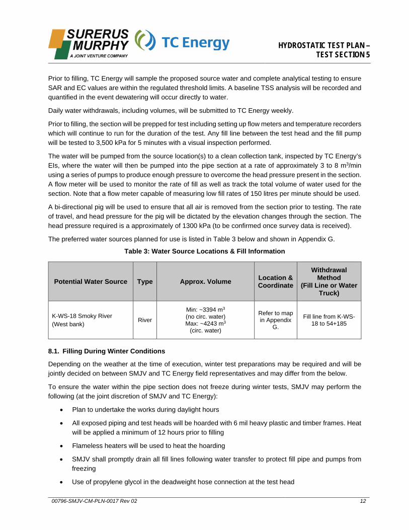
HYDROSTATIC TEST PLAN – TEST SECTION 5
00796-SMJV-CM-PLN-0017 Rev 02 12
Prior to filling, TC Energy will sample the proposed source water and complete analytical testing to ensure SAR and EC values are within the regulated threshold limits. A baseline TSS analysis will be recorded and quantified in the event dewatering will occur directly to water.
Daily water withdrawals, including volumes, will be submitted to TC Energy weekly.
Prior to filling, the section will be prepped for test including setting up flow meters and temperature recorders which will continue to run for the duration of the test. Any fill line between the test head and the fill pump will be tested to 3,500 kPa for 5 minutes with a visual inspection performed.
The water will be pumped from the source location(s) to a clean collection tank, inspected by TC Energy’s EIs, where the water will then be pumped into the pipe section at a rate of approximately 3 to 8 m3/min using a series of pumps to produce enough pressure to overcome the head pressure present in the section. A flow meter will be used to monitor the rate of fill as well as track the total volume of water used for the section. Note that a flow meter capable of measuring low fill rates of 150 litres per minute should be used.
A bi-directional pig will be used to ensure that all air is removed from the section prior to testing. The rate of travel, and head pressure for the pig will be dictated by the elevation changes through the section. The head pressure required is a approximately of 1300 kPa (to be confirmed once survey data is received).
The preferred water sources planned for use is listed in Table 3 below and shown in Appendix G.
Table 3: Water Source Locations & Fill Information
Potential Water Source Type Approx. Volume Location & Coordinate
Withdrawal Method
(Fill Line or Water Truck)
K-WS-18 Smoky River(West bank)
River
Min: ~3394 m3
(no circ. water) Max: ~4243 m3
(circ. water)
Refer to map in Appendix
G.
Fill line from K-WS-18 to 54+185
8.1. Filling During Winter Conditions
Depending on the weather at the time of execution, winter test preparations may be required and will be jointly decided on between SMJV and TC Energy field representatives and may differ from the below.
To ensure the water within the pipe section does not freeze during winter tests, SMJV may perform the following (at the joint discretion of SMJV and TC Energy):
• Plan to undertake the works during daylight hours
• All exposed piping and test heads will be hoarded with 6 mil heavy plastic and timber frames. Heatwill be applied a minimum of 12 hours prior to filling
• Flameless heaters will be used to heat the hoarding
• SMJV shall promptly drain all fill lines following water transfer to protect fill pipe and pumps fromfreezing
• Use of propylene glycol in the deadweight hose connection at the test head
HYDROSTATIC TEST PLAN – TEST SECTION 5
00796-SMJV-CM-PLN-0017 Rev 02 13
• Use of propylene glycol at the pressure recorder and deadweight
• Continuous fill of direct heated water – in general this will be heated water at 4 to 48 degreesCelsius filled into the pipe (or as agreed upon in the field). At the opposite end of the test sectionwater will be discharged for 2 hours at a minimum temperature of 2 degrees Celsius to provesatisfactory heating has been applied
9. Pressurizing and Test
9.1. Pressurizing
Prior to connecting the squeeze pump to the test head, all valves and instrumentation shall be visually examined to ensure that they are in good working condition and that all valves are in the proper position.
Once filling is complete, the pressure of the section will be taken to 3,000 kPa. The pressure shall be increased at a rate not exceeding 300 kPa per minute. Once 3,000 kPa is reached, pressurization will cease to allow for a leak check of the exposed areas of the section and test heads. The leak check pressure shall be held for a minimum of 15 minutes.
Following the leak check, the temperature of the test section will be allowed to stabilize prior to the commencement of strength and leak tests. The section is considered stable when the temperature of the test water is at or near the temperature of the ground along the test section. The TC Energy Test Inspector shall determine and declare when the temperature is sufficiently stabilized to begin the test.
Once the leak check is complete and the temperature has been declared sufficiently stable the pressure will be increased at 300 kPa per minute until 60% of the target test pressure is achieved. A second 15-minute leak check will be completed prior to continuing to pressure the section.
The final stage from 60% to 100% will be pressured at a rate of approximately 100 kPa per minute, and not to exceed 300 kPa/min, to allow for a yield plot to be recorded.
9.2. Yield Plot
The yield plot is a pressure versus volume plot where the pressure is plotted against the total volume of water added after filling.
The pressure of the pipe will be increased at rate of 100 kPa per minute and will run uninterrupted and at a constant rate of 100 kPa per minute until the target test pressure is met. If at any point the pressure increase is interrupted, the yield plot shall be redrawn.
The baseline for the yield plot will be set between 60% of the target test pressure, and the pressure relating to 80% of the SMYS of the section at the critical low point. At 80% of the SMYS the yield plot will begin. The volume input will be monitored using a calibrated flow meter and will be tracked against the pressure. If at any point in the yield plot the volume input deviates from the theoretical expansion of the pipe by 0.2%, the pressurizing will cease. If the 0.2% relative expansion is met, the strength test will begin at the achieved pressure.
9.3. Strength Test
When the target strength test pressure is achieved and the pressure has stabilized, the section will be isolated from the squeeze pump.
HYDROSTATIC TEST PLAN – TEST SECTION 5
00796-SMJV-CM-PLN-0017 Rev 02 14
The pressure will be held for a minimum of 4 hours within the maximum and minimum strength test pressures with no unexplained pressure loss to be considered successful, in compliance with TEP-PRES 2.1.9.
The finalized minimum, maximum, and target strength test pressures will be determined by TC Energy and communicated to SMJV via an engineered and stamped calculation sheet.
Measurements of the pressure from the deadweight during the strength test will be recorded every 5 minutes from the onset of the test for the first 30 minutes, every 10 minutes from 30 minutes to 1-hour, and every 15 minutes for the remainder of the duration of the test.
If the pressure rises to near the Maximum Strength Test Pressure due to an increase in ambient temperature, then test water may be carefully bled off. Any test water that is bled off will be collected in a container and the time, volume of water, and initial and final pressures shall be recorded.
If the pressure falls but is still above the Minimum Strength Test Pressure due to a decrease in ambient temperature and not a leak, then the pressure may be increased back up to the target strength test pressure without restarting the strength test.
If the pressure falls below the Minimum Strength Test Pressure within the test period due to changes in ambient temperature and not a leak, then the pressure must be increased back up to the target strength test pressure and the test must be restarted and held for the full required duration of the strength test.
A temperature stabilization period between the strength and leak test will be held if it is deemed the ambient conditions or changing ambient conditions may pose a risk to the ability to maintaining the required pressure cushion.
9.4. Leak Test
The pressure will be held for a minimum of 4 hours within the maximum and minimum leak test pressures.
The minimum, maximum, and target leak test pressures will be determined by TC Energy and communicated to SMJV via an engineered and stamped calculation sheet.
Measurements of the pressure from the deadweight during the leak test will be recorded every 5 minutes from the onset of the test for the first 30 minutes, every 10 minutes from 30 minutes to 1-hour, and every 15 minutes for the remainder of the duration of the test.
The achieved minimum and maximum pressures during the leak test must be maintained within 15 kPa of each other for 4 consecutive hours to be considered successful. If a pressure change of greater than 15 kPa is observed within 4 hours and the pressure change can be correlated with temperature deviations, the leak test will continue until 4 consecutive hours within the 15 kPa acceptance band is achieved.
If the pressure continues to change outside of the 15 kPa acceptance band and instrumentation indicates that a leak may be occurring, then a visual leak investigation may commence. If a leak is found the TC Energy Test Inspector will be notified.
If the pressure continues to change outside of the 15 kPa acceptance band and the pressure deviation is explainable due to temperature changes, then SMJV shall consult with TC Energy to determine if this is acceptable. If TC Energy determines they are satisfactorily correlated using TEF-HYDRO-TEMP (Effects of Temperature Pressure - Hydrotest (CDN)) then test may be ended.
HYDROSTATIC TEST PLAN – TEST SECTION 5
00796-SMJV-CM-PLN-0017 Rev 02 15
10. DepressurizingAt the conclusion of a successful test, the section will be depressurized in a controlled manner with a depressurization rate that should not exceed 300 kPa/min. The TC Energy Test Inspector shall witness the depressurizing of the test section and ensure the depressurization is conducted with extreme caution and minimal vibration. Depressurization shall use the bleed-off assembly on the test head, which shall be opened and closed slowly to protect the assembly from shock loading. Under no circumstances will valves be set to the fully open position to initiate depressurizing.
11. DewateringDewatering activities shall be in accordance with Alberta Code of Practice for the Release of Hydrostatic Test Water from Hydrostatic Testing of Petroleum Liquid and Gas Pipelines to an approved location in accordance with Section 8.7 of the Environmental Protection Plan.
Prior to dewatering, a land sample will be completed by TC Energy at the proposed dewatering location(s) to ensure that SAR & EC values are under the allowable limit. TC Energy may also sample the release water once testing is complete to determine if the water may be discharged into a receiving waterbody or watercourse. If the test water and receiving water is determined to be within allowable tolerances, then it will be discharged in accordance with Section 8.7 of the Environmental Protection Plan (EPP) and the COP for Release of Hydrostatic Test Water.
Water will be driven out of the pipe using a bi-directional pig pushed by compressed air at an approximate driving pressure of approximately 700 kPa (100 psi) plus the static head (or as otherwise decided upon in the field once survey data is received). A minimum 100 kPa (15 psi) backpressure will be maintained on dewatering pigs. SMJV expects to dewater the section at up to 10 m3/min.
SMJV intends to transfer the water in Test Section 5 into Test Section 4. Please refer to the typical drawing in Appendix D.
Suitable dewatering locations near the hydrotest location has been determined by TC Energy and SMJV’s environmental teams have been determined in the contingency event the water in section cannot be transferred over to Test Section 4 and must be dewatered. In the event any dewatering is required, the location of dewatering point(s) that may be used is listed in Table 4 below. These locations have been approved by TC EIs. SMJV and TC Energy will jointly determine the final dewatering point location on site at time of test.
HYDROSTATIC TEST PLAN – TEST SECTION 5
00796-SMJV-CM-PLN-0017 Rev 02 16
Table 4: Dewatering Point(s) (if required)
Dewater Point Location Discharge Volume
Land Description Coordinates (UTM)
Anticipated: Transfer entire volume to Test Section 4 N/A N/A N/A
Contingency for circulation water: Release to land at bar ditch adjacent to
Road 32 0 to 849 m3 NE 26-67-05-W6 11 N 394390 m E 6077022 m N
Contingency: Release to land to the north side of the
RoW into the grazing lease near KP 54+200 by Road 31
0 to 3394 m3 NW 30-67-04-W6 11 N 397196 m E 6077147 m N
Contingency: Release to source location at K-WS-18
Smoky River (West bank) 0 to 3394 m3 NE 30-67-04-W6 11 N 397547 m E 6077270 m N
Water shall be discharged into a diffuser and into surrounding vegetated area to reduce the risk of erosion at the dewatering location as per section 8.7 Hydrostatic Testing (EPP) Mitigation Measure items 6 through 11.
All lines and hoses used for dewatering will arrive to site clean.
Dewatering lines shall be securely supported and tied down at the discharge end to prevent sudden releases of energy (whipping) during dewatering.
During winter conditions, dewatering will be as soon as reasonably possible following the successful completion of the hydrostatic test.
12. Drying & Inline InspectionFollowing dewatering, SMJV plans to use air compressors and foam pigs for initial drying runs.
Section 5 will then be tied together with Section 4 upon successful hydrotest of both sections.
After that, inline inspection and final air drying will be completed for Sections 4 and 5 together.
Alternatively, dependant on schedule, SMJV may also complete separate inline inspection and final air drying for Sections 4 and 5.
12.1. Pig Drying Runs
Air compressors with a combined capacity of 12,000 CFM (to be confirmed) will be supplied to propel the drying pigs.
Compressed air will be used to push a combination of one bi-direction steel body pig and two light density foam pigs for the first run.
Subsequent runs will be one double dish medium density foam pig and one light density foam pig until the section is confirmed to be free of any residual water.
HYDROSTATIC TEST PLAN – TEST SECTION 5
00796-SMJV-CM-PLN-0017 Rev 02 17
The section will be considered free of standing water when there is less than 6 mm of water on the bottom half of the foam pig as confirmed by the on-site Company representative.
During winter conditions, SMJV will complete a minimum of 2 drying runs immediately after dewatering to ensure no pockets of ice can form.
12.1.1. Caliper Pigging
At some point after the initial pig drying run tying the two sections together caliper pigging will take place. The caliper pigging subcontractor will dictate the preferred moisture content remaining in the pipe following dewatering. This will determine the number of drying runs required prior to running the caliper pig.
SMJV will support the caliper pigging subcontractor as required and stated within the selected subcontractor’s execution plan.
A separate, standalone Caliper Pigging Plan will be submitted prior to execution.
12.2. Final Air Drying
Final drying shall be completed as specified in Scope of Work Section 3.42 of Exhibit A-1 Scope of Work and as per TES-PRES (Pipeline and Facility Piping Pressure Testing Specification) and TEP-PRES (Pipeline and Facility Piping Pressure Testing Procedure).
Upon the removal of all standing water, SMJV shall confirm the atmospheric dew point of the air entering the pipeline is -70°C or less. The dried air will be cycled through the section until the air at the receiving end is measured to have a dew point of -45°C or less. Dew point measurements will be recorded every hour until a dew point of -45°C is achieved.
At any point during the drying run, SMJV may elect to launch additional foam pigs to be pushed with dried air that has a dew point of -70°C or less.
When the dew point is confirmed to be no greater than -45°C, air drying will be complete.
13. PreservationPer the Scope of Work 3.42 (c), purging and loading with dry nitrogen as described in TEP-PRES (Pipeline and Facility Piping Pressure Testing Procedure) section 2.1.14 “Pipeline Drying,” is currently not part of the Contractor’s Scope of Work, this work will be completed by the Company.
Following successful completion of air drying to a dew point of -45°C, the section will be closed in a left with a positive pressure of at least 50 kPa.
A preservation treatment assessment is required by the Contractor following 2 months after the installation of the section to ensure that there is no standing water present in the line.

HYDROSTATIC TEST PLAN – TEST SECTION 5
00796-SMJV-CM-PLN-0017 Rev 02 18
14. Reference Documents• CSA Z662-19 Oil and Gas Pipeline Systems
• TES-CT-GEN-GL Pipeline Construction Specification (CAN)
• TES-PRES Pipeline and Facility Piping Pressure Testing Specification (CDN)
• TEP-PRES Pipeline and Facility Piping Pressure Testing Procedure (CDN)
• TEF-ME-PRIM-GL Pipeline and Facility Primary Pressure Testing Form (CAN)
• TEF-ME-SEC-GL Pipeline and Facility Secondary Pressure Testing Form (CAN)
• TES-PRES-TH Design of Test Head Assemblies Specification
• TES-ME-TH-GL Test Head Deficiency Checklist (CDN)

HYDROSTATIC TEST PLAN – TEST SECTION 5
00796-SMJV-CM-PLN-0017 Rev 02 19
Appendix A: SMJV Hydrotest Checklists & Forms
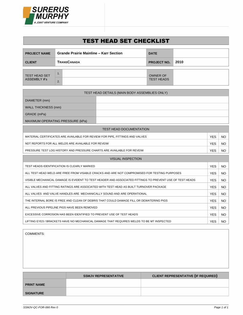
SSMJV-QC-FOR-066 Rev 0 Page 1 of 1
TEST HEAD SET CHECKLIST
PROJECT NAME Grande Prairie Mainline – Karr Section DATE
CLIENT TRANSCANADA PROJECT NO. 2010
TEST HEAD SET ASSEMBLY #’s
1. OWNER OF TEST HEADS
2.
TEST HEAD DETAILS (MAIN BODY ASSEMBLIES ONLY)
DIAMETER (mm)
WALL THICKNESS (mm)
GRADE (mPa)
MAXIMUM OPERATING PRESSURE (kPa)
TEST HEAD DOCUMENTATION
MATERIAL CERTIFICATES ARE AVAILABLE FOR REVIEW FOR PIPE, FITTINGS AND VALVES YES NO
NDT REPORTS FOR ALL WELDS ARE AVAILABLE FOR REVEIW YES NO
PRESSURE TEST LOG HISTORY AND PRESSURE CHARTS ARE AVAILABLE FOR REVEIW YES NO
VISUAL INSPECTION
TEST HEADS IDENTIFICATION IS CLEARLY MARKED YES NO
ALL TEST HEAD WELD ARE FREE FROM VISABLE CRACKS AND ARE NOT COMPROMISED FOR TESTING PURPOSES YES NO
VISIBLE MECHANICAL DAMAGE IS EVIDENT TO TEST HEADER AND ASSOCIATED FITTINGS TO PREVENT USE OF TEST HEADS YES NO
ALL VALVES AND FITTING RATINGS ARE ASSOCIATED WITH TEST HEAD AS BUILT TURNOVER PACKAGE YES NO
ALL VALVES AND VALVE HANDLES ARE MECHANICALLY SOUND AND ARE OPERATIONAL YES NO
THE INTERNAL BORE IS FREE AND CLEAN OF DEBRIS THAT COULD DAMAGE FILL OR DEWATERING PIGS YES NO
ALL PREVIOUS PIPELINE PIGS HAVE BEEN REMOVED YES NO
EXCESSIVE CORROSION HAS BEEN IDENTIFIED TO PREVENT USE OF TEST HEADS YES NO
LIFTING EYES / BRACKETS HAVE NO MECHANICAL DAMAGE THAT REQUIRES WELDS TO BE MT INSPECTED YES NO
COMMENTS:
SSMJV REPRESENTATIVE CLIENT REPRESENTATIVE (IF REQUIRED)
PRINT NAME
SIGNATURE
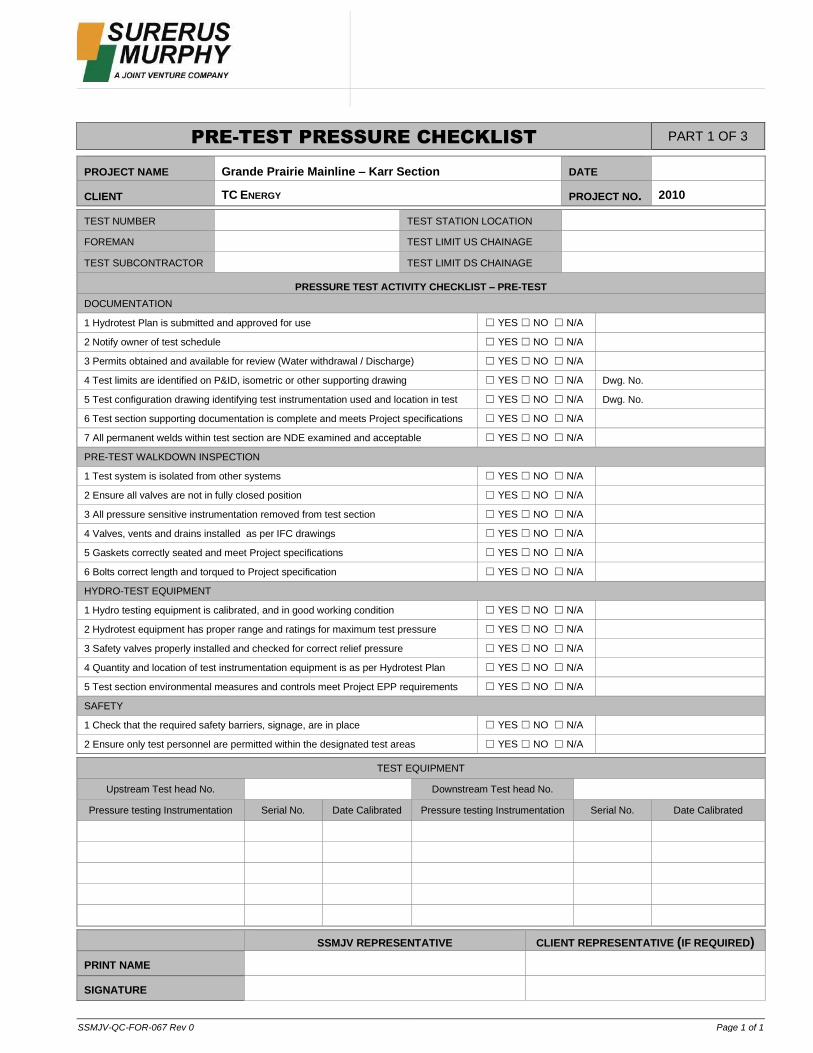
SSMJV-QC-FOR-067 Rev 0 Page 1 of 1
PRE-TEST PRESSURE CHECKLIST PART 1 OF 3
PROJECT NAME Grande Prairie Mainline – Karr Section
DATE
CLIENT TC ENERGY PROJECT NO. 2010
TEST NUMBER TEST STATION LOCATION
FOREMAN TEST LIMIT US CHAINAGE
TEST SUBCONTRACTOR TEST LIMIT DS CHAINAGE
PRESSURE TEST ACTIVITY CHECKLIST – PRE-TEST DOCUMENTATION
1 Hydrotest Plan is submitted and approved for use ☐ YES ☐ NO ☐ N/A
2 Notify owner of test schedule ☐ YES ☐ NO ☐ N/A
3 Permits obtained and available for review (Water withdrawal / Discharge) ☐ YES ☐ NO ☐ N/A
4 Test limits are identified on P&ID, isometric or other supporting drawing ☐ YES ☐ NO ☐ N/A Dwg. No.
5 Test configuration drawing identifying test instrumentation used and location in test ☐ YES ☐ NO ☐ N/A Dwg. No.
6 Test section supporting documentation is complete and meets Project specifications ☐ YES ☐ NO ☐ N/A
7 All permanent welds within test section are NDE examined and acceptable ☐ YES ☐ NO ☐ N/A
PRE-TEST WALKDOWN INSPECTION
1 Test system is isolated from other systems ☐ YES ☐ NO ☐ N/A
2 Ensure all valves are not in fully closed position ☐ YES ☐ NO ☐ N/A
3 All pressure sensitive instrumentation removed from test section ☐ YES ☐ NO ☐ N/A
4 Valves, vents and drains installed as per IFC drawings ☐ YES ☐ NO ☐ N/A
5 Gaskets correctly seated and meet Project specifications ☐ YES ☐ NO ☐ N/A
6 Bolts correct length and torqued to Project specification ☐ YES ☐ NO ☐ N/A
HYDRO-TEST EQUIPMENT
1 Hydro testing equipment is calibrated, and in good working condition ☐ YES ☐ NO ☐ N/A
2 Hydrotest equipment has proper range and ratings for maximum test pressure ☐ YES ☐ NO ☐ N/A
3 Safety valves properly installed and checked for correct relief pressure ☐ YES ☐ NO ☐ N/A
4 Quantity and location of test instrumentation equipment is as per Hydrotest Plan ☐ YES ☐ NO ☐ N/A
5 Test section environmental measures and controls meet Project EPP requirements ☐ YES ☐ NO ☐ N/A
SAFETY
1 Check that the required safety barriers, signage, are in place ☐ YES ☐ NO ☐ N/A
2 Ensure only test personnel are permitted within the designated test areas ☐ YES ☐ NO ☐ N/A
TEST EQUIPMENT
Upstream Test head No. Downstream Test head No.
Pressure testing Instrumentation Serial No. Date Calibrated Pressure testing Instrumentation Serial No. Date Calibrated
SSMJV REPRESENTATIVE CLIENT REPRESENTATIVE (IF REQUIRED) PRINT NAME
SIGNATURE

SSMJV-QC-FOR-069 Rev 0
PRESSURE TEST REPORT PART 2 OF 3
PROJECT NAME Grande Prairie Mainline – Karr Section
DATE
CLIENT TC ENERGY PROJECT NO. 2010
TEST NUMBER PAGE OF
TEST DESCRIPTION TEST STATION LOCATION
FOREMAN TEST LIMIT US CHAINAGE
TEST SUBCONTRACTOR TEST LIMIT DS CHAINAGE
TEST CHART TIME INTERVALS DURATION OF TEST
Time Deadweight Pressure Ambient (°C) Pipe (°C) Volume (m3) Comments
SSMJV REPRESENTATIVE CLIENT REPRESENTATIVE (IF REQUIRED) PRINT NAME
SIGNATURE

SSMJV-QC-FOR-068 Rev 0 Page 1 of 1
POST-TEST SUMMARY AND CHECKLIST PART 3 OF 3
PROJECT NAME Grande Prairie Mainline – Karr Section
DATE
CLIENT TC ENERGY PROJECT NO. 2010
TEST NUMBER TEST STATION LOCATION
FOREMAN TEST LIMIT US CHAINAGE
TEST SUBCONTRACTOR TEST LIMIT DS CHAINAGE
TEST LOG SUMMARY
ACTIVITY TIME DATE ACTIVITY TIME DATE
Filling Start Leak Test Started
Filling Completed Leak Test Completed
Pressurization Started Dewatering Started
Yield Plot Started Dewatering Completed
Yield Plot Completed IF REQUIRED BY THE PROJECT
Strength Test Started Security air pressurized
Strength Test Completed Security air de-pressurized
POST TEST CHECKLIST
1 System dewatered ☐ YES ☐ NO ☐ N/A
2 Valve bodies are drained and free of residual water ☐ YES ☐ NO ☐ N/A
3 Test media disposed of in accordance with Hydrotest Plan ☐ YES ☐ NO ☐ N/A
4 QC representative witnessed test and signed off ☐ YES ☐ NO ☐ N/A
5 Hydrotest documentation completed and signed off by Client representative ☐ YES ☐ NO ☐ N/A
6 Test charts removed from test instrumentation and returned to QC office ☐ YES ☐ NO ☐ N/A
7 Test instrumentation removed from ROW and returned to test shack / warehouse ☐ YES ☐ NO ☐ N/A
8 Does Client require positive air pressure in test section after hydrotest ☐ YES ☐ NO ☐ N/A State pressure:
9 Signage is in place if positive air pressure left in test section ☐ YES ☐ NO ☐ N/A
10 Pressure gauges are left in situ showing internal security pressure ☐ YES ☐ NO ☐ N/A
11 Test section is vented / depressurized before removal of test heads ☐ YES ☐ NO ☐ N/A
COMMENTS:
SSMJV REPRESENTATIVE CLIENT REPRESENTATIVE (IF REQUIRED)
PRINT NAME
SIGNATURE

HYDROSTATIC TEST PLAN – TEST SECTION 5
00796-SMJV-CM-PLN-0017 Rev 02 24
Appendix B: Alignment Sheets
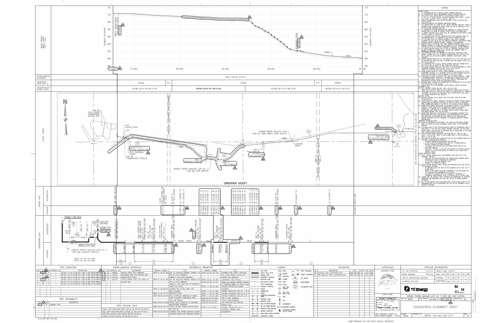
64300SEP-21-2020

HYDROSTATIC TEST PLAN – TEST SECTION 5
00796-SMJV-CM-PLN-0017 Rev 02 26
Appendix C: Hydrostatic Test Profile

³
³
64300Oct-27-2021

HYDROSTATIC TEST PLAN – TEST SECTION 5
00796-SMJV-CM-PLN-0017 Rev 02 28
Appendix D: Example Typical Filling, Test, & Dewater Sketches
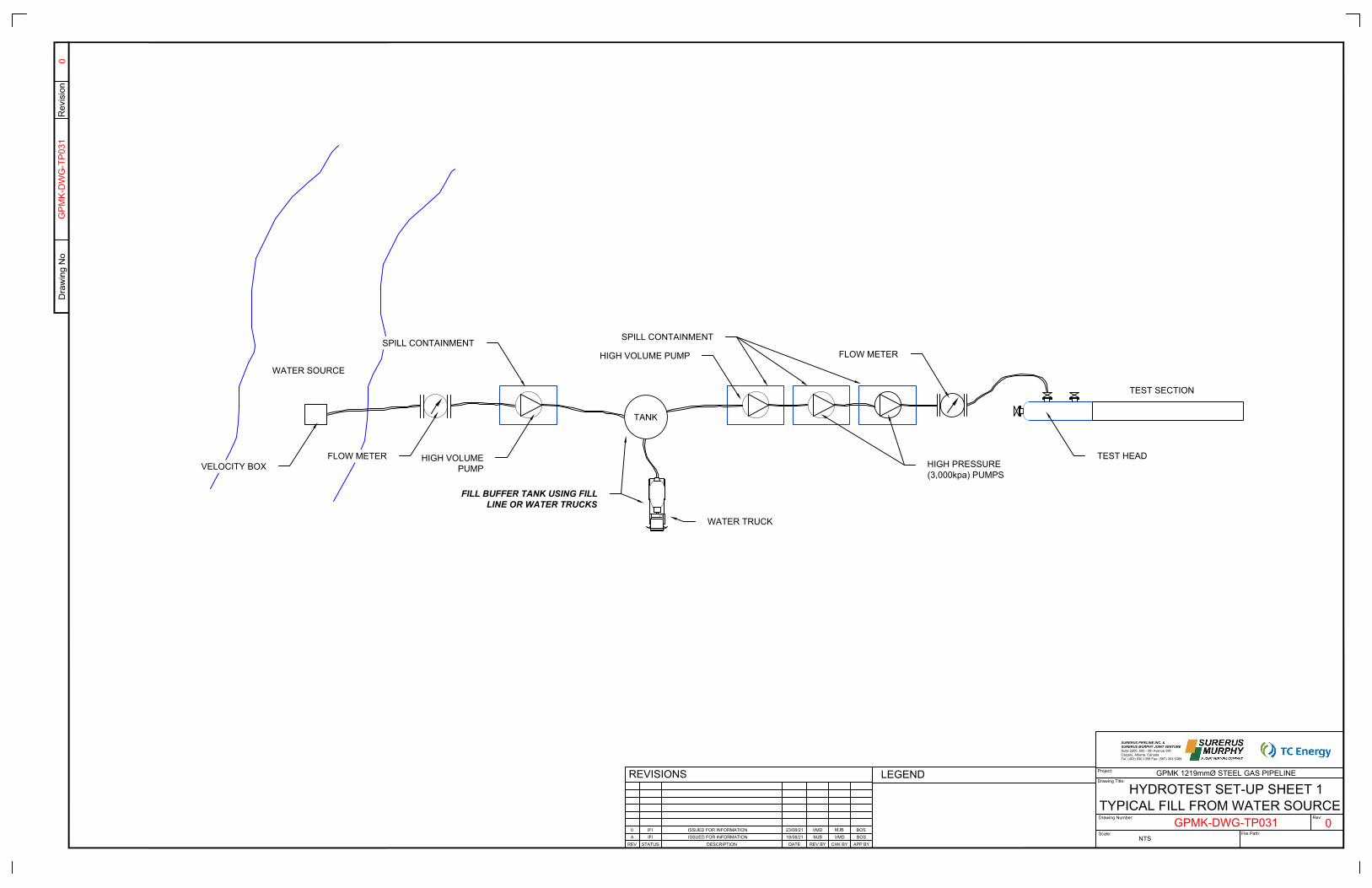
WATER SOURCE
VELOCITY BOXFLOW METER HIGH VOLUME
PUMP
HIGH VOLUME PUMP
TEST HEAD
TEST SECTION
SPILL CONTAINMENTSPILL CONTAINMENT
TANK
HIGH PRESSURE(3,000kpa) PUMPS
FLOW METER
WATER TRUCK
FILL BUFFER TANK USING FILLLINE OR WATER TRUCKS
TYPICAL FILL FROM WATER SOURCE
Dra
win
g N
oR
evis
ion
Drawing Title:
Scale:
Drawing Number:
Project:
File Path:
Rev:
0G
PMK-
DW
G-T
P031
GPMK-DWG-TP031
HYDROTEST SET-UP SHEET 1
0
GPMK 1219mmØ STEEL GAS PIPELINE
NTS
SURERUS PIPELINE INC. &SURERUS MURPHY JOINT VENTURESuite 2200, 605 - 5th Avenue SWCalgary, Alberta. CanadaTel: (403) 930.1358 Fax: (587) 353.5369
REV DESCRIPTION APP BYCHK BYREV BYDATESTATUS
REVISIONS LEGEND
A ISSUED FOR INFORMATION MJBIFI VMD18/06/21 BOS0 ISSUED FOR INFORMATION VMDIFI MJB23/08/21 BOS
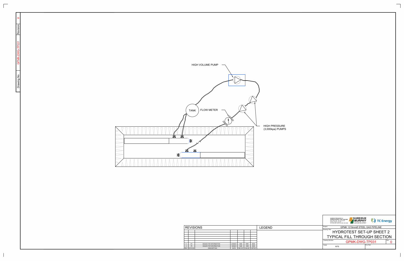
TANK FLOW METER
HIGH VOLUME PUMP
HIGH PRESSURE(3,000kpa) PUMPS
TYPICAL FILL THROUGH SECTION
Dra
win
g N
oR
evis
ion
Drawing Title:
Scale:
Drawing Number:
Project:
File Path:
Rev:
0G
PMK-
DW
G-T
P031
GPMK-DWG-TP031
HYDROTEST SET-UP SHEET 2
0
GPMK 1219mmØ STEEL GAS PIPELINE
NTS
SURERUS PIPELINE INC. &SURERUS MURPHY JOINT VENTURESuite 2200, 605 - 5th Avenue SWCalgary, Alberta. CanadaTel: (403) 930.1358 Fax: (587) 353.5369
REV DESCRIPTION APP BYCHK BYREV BYDATESTATUS
REVISIONS LEGEND
A ISSUED FOR INFORMATION MJBIFI VMD18/06/21 BOS0 ISSUED FOR INFORMATION VMDIFI MJB23/08/21 BOS

HIGH VOLUME PUMP
DIGITAL PRESSUREGAUGE
PRESSURE RECORDERTEMPERATURE RECORDER TEST SHACK
FLOW METER
SQUEEZE TRUCK
TEST DIAGRAM
Dra
win
g N
oR
evis
ion
Drawing Title:
Scale:
Drawing Number:
Project:
File Path:
Rev:
0G
PMK-
DW
G-T
P031
GPMK-DWG-TP031
HYDROTEST SET-UP SHEET 3
0
GPMK 1219mmØ STEEL GAS PIPELINE
NTS
SURERUS PIPELINE INC. &SURERUS MURPHY JOINT VENTURESuite 2200, 605 - 5th Avenue SWCalgary, Alberta. CanadaTel: (403) 930.1358 Fax: (587) 353.5369
REV DESCRIPTION APP BYCHK BYREV BYDATESTATUS
REVISIONS LEGEND
A ISSUED FOR INFORMATION MJBIFI VMD18/06/21 BOS0 ISSUED FOR INFORMATION VMDIFI MJB23/08/21 BOS
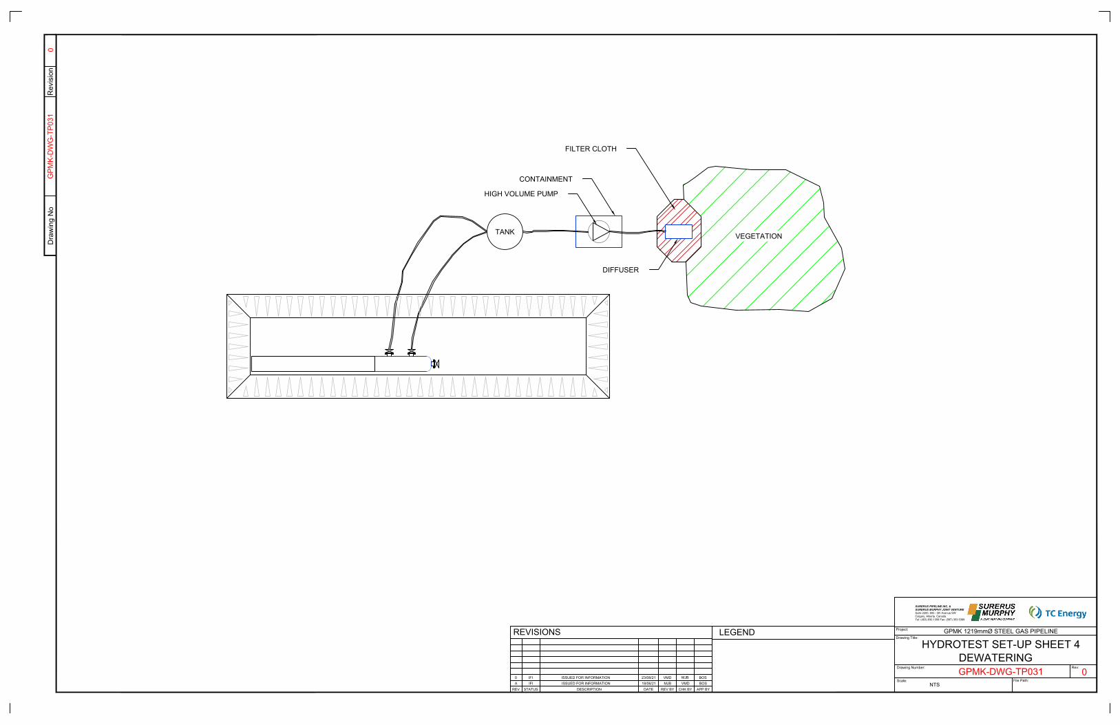
TANK VEGETATION
HIGH VOLUME PUMP
DIFFUSER
FILTER CLOTH
CONTAINMENT
DEWATERING
Dra
win
g N
oR
evis
ion
Drawing Title:
Scale:
Drawing Number:
Project:
File Path:
Rev:
0G
PMK-
DW
G-T
P031
GPMK-DWG-TP031
HYDROTEST SET-UP SHEET 4
0
GPMK 1219mmØ STEEL GAS PIPELINE
NTS
SURERUS PIPELINE INC. &SURERUS MURPHY JOINT VENTURESuite 2200, 605 - 5th Avenue SWCalgary, Alberta. CanadaTel: (403) 930.1358 Fax: (587) 353.5369
REV DESCRIPTION APP BYCHK BYREV BYDATESTATUS
REVISIONS LEGEND
A ISSUED FOR INFORMATION MJBIFI VMD18/06/21 BOS0 ISSUED FOR INFORMATION VMDIFI MJB23/08/21 BOS

HYDROSTATIC TEST PLAN – TEST SECTION 5
00796-SMJV-CM-PLN-0017 Rev 02 33
Appendix E: New Road 31 Test Point Drawing

CUT 16.37mOFF OF BORE STUB
54+2
68 -
BH|S
TAR
T LI
NE
60*00 COLT3*15 OB
45*00 SBLT60*00 SBRT
10° OBHB
13.7mm 25.4mm
GRAB CUT OUT AND PUT IN BETWEEN THE TWO 60° HBs
1°00 OBCB
1°15 SAGCB
MAINLINE STUB
NEED APPROX. 10.65m OF 13.7mm TO CLOSE THE GAP
11.45m6.22m23.56mJT 25
5mJT 26
13.51mJT 26
15.65mJT 26
10.65mJT TBC
TRAN
SITI
ON 19m
TIE-
IN W
ELD
TIE-
IN W
ELD
TIE-
IN W
ELD
4.9m
CU
T
2.01
mC
VR
1.96
mC
VR2.26
mC
VR
1.4m
CVR1.18
mC
VR
TIE-
IN W
ELD
3.7m
TRANSITION PUPFINAL LENGTH TBC
4m APPROX. 24mFINAL LENGTH TBC
8mSECTION 4TEST HEAD
8mSECTION 5TEST HEAD
19m DROP IN PIECE
19m GAPVARIES DEPENDING ON TRANSITION
PUP AND THE 25.4mmPIECE FINAL LENGTH
54+166.14
54+185.14
54+2
00
BH|START LINE
100317579.86
0.66m NEGATIVE OF ORIGINAL PI
0.58m NEGATIVE OF ORIGINAL PI
19m DROP IN PIECE
8mSECTION 5TEST HEAD
8mSECTION 4TEST HEAD
54+166.14
54+185.14
PLAN AND PROFILE SHEET 1 OF 1
N
Dra
win
g N
oR
evis
ion
Drawing Title:
Scale:
Drawing Number:
Project:
File Path:
Rev:
3
3
GPMK 1.219mmØ STEEL PIPELINESURERUS MURPHY JOINT VENTURE#2200, 605 - 5th Avenue SW
Calgary, Alberta. CanadaTel: (403) 930.1358 Fax: (587) 353.5369
GPMK-DWG-RX031
GPM
K-D
WG
-RX0
31
REV DESCRIPTION APP BYCHK BYREV BYDD/MM/YYSTATUS
REVISIONSROAD 31 HDD TIE-IN
LEGEND:
0 ISSUED FOR INFORMATION VMDMJB19/10/21IFI
ROW BDYO/H POWERLINE & POLEOIL ROAD SHOULDER
O/H.E
TOP OF BANKBOTTOM OF BANK
EXISTING OIL PIPELINE
NEW PROPOSED PIPELINE
XPP
BOREHOLE
FENCELINEDESIGN GRADEUG CABLEU/G.FIBRE U/G.FIBRE
PIPELINE / POWERLINE ROWROAD ROW BOUNDARY
NOTES:
BOS
1°00 OBCB
1°15 SAGCB
60*00 COLT3*15 OB
45*00 SBLT
60*00 SBRT
10° OBHB
TIE-
IN W
ELD
TIE-IN WELD
TIE-
IN W
ELD
TIE-
IN W
ELD
TIE-
IN W
ELD
1 REVISED TO FIELD COMMENTS VMDMJB20/10/21IFI BOS
ORIGINAL DITCHLINE
2 REVISED TO ACCOMMODATE TEST POINT VMDMJB25/10/21IFI BOS3 REVISED LENGTHS VMDMJB25/10/21IFI BOS

HYDROSTATIC TEST PLAN – TEST SECTION 5
00796-SMJV-CM-PLN-0017 Rev 02 35
Appendix F: TCE Test Calculation Sheet & As-Built Data

HYDROSTATIC TEST PLAN – TEST SECTION 5
00796-SMJV-CM-PLN-0017 Rev 02 36
Test calculation sheet to be supplied by TC Energy.
Page left intentionally blank.

HYDROSTATIC TEST PLAN – TEST SECTION 5
00796-SMJV-CM-PLN-0017 Rev 02 37
Appendix G: Water Source Map

065-05-W6
066-05-W6
064-05-W6
063-05-W6
068-05-W6
067-05-W6
063-03-W6
064-01-W6
063-01-W6
064-02-W6
066-01-W6
064-04-W6
065-04-W6
068-02-W6
066-04-W6
065-01-W6065-03-W6
067-04-W6
068-04-W6
065-02-W6
068-01-W6
063-02-W6
064-03-W6
063-04-W6
066-03-W6
1 6 1 61 61 6
36 31 36 3136 3136 31
1 6 1 61 61 6
36 3136 3136 3136 31
1 61 61 61 6
36 3136 3136 3136 31
1 6 1 61 61 6
36 31 36 3136 3136 31
1 616
1 61 6
3631 36 31 36 31 36 31
1 6 1 6 1 6 1 6
Economy Creek
Moose
Karr Cree k
Lig niteCre e k
Moose River
Smuland Creek
McMillar Creek
Lato
rnell
Rive
r
Karr Lake
Musreau Lake
LittleMusreau Lake
K a kwa
Rive
r
S m o ky River
Smoky R
iver
Simonet teRiver
Lato rnell
Cutb
ank Rive
r
B igM
o unta
inCr
eek
Latornell River
LATORNELLRIVER
UNNAMED TRIBUTARYTO PATTERSON CREEK
SMOKY RIVERMcMILLARCREEK
GPM80
GPM75
GPM70
GPM60 0+000
57+068
50+000
40+000
30+000
20+000
10+000
LOCKED GATEGRAZING LEASE KARR SUMP SITE NO. 3
KARR SUMP SITE NO. 2
KARR SUMP SITE NO. 4
PL-9PL-8
PL-7PL-6
PL-5
PL-53
PL-52
PL-51PL-50
PL-49 PL-48PL-47
PL-46PL-45
PL-43
PL-42PL-41
PL-40PL-39
PL-37PL-36
PL-35
PL-34PL-33
PL-31PL-30
PL-29
PL-28
PL-27
PL-26PL-25PL-24PL-23PL-22
PL-18PL-17
PL-16
PL-15
PL-10
PL-14
PL-13
PL-12
PL-4 PL-1PL-2
PL-44
PL-38
PL-32
PL-21PL-20PL-19
PL-11
K-WS9
K-WS7
K-WS8
K-WS4
K-WS2
K-WS5
K-WS3
K-WS11
K-WS-20
K-WS-21
K-WS-13
K-WS-14
K-WS-16
K-WS-15
K-WS-17
I
E
J
G
G2
H
AF3AB
Z
Y
V
D1
F2
O
L8
K1J1
Q2
S1
X1
L3
L
P
AE
AF1AF AE1
AG1AG
AG2
L7
AH
AG4
L5
N
AG5
AC
AC1AG9
AA
X
T
S
I1
K
F
AG3
AG6
AG7 AG8
AE2AC3
W
V1
U
R
Q
D3
F4
G6
G5
G1
I3
J4
J3
D2
G4
F1
AD
I2
L4
L2
L6
J2
H1
G3
L1
F3
N1
P1
R1
T1
W1
Y1
Z1
AA1
AB1
AC2
F5
G7
J5
J6
J7
AC4
AG10
AA2
AB2
AB3
AG11
F6
AG12
AH2
N1
N2
V2
D4
AG15
V3
N3
PL-66
PL-68
PL-69
PL-71
± 69
.1 k
m T
O H
WY
43
UV734
GOLD ROAD
TOWER ROAD
FORE
STRY
TRU
NK R
OAD
FOR
ESTR
Y TR
UN
K R
OA
D
FOR
ESTRY TRU
NK
RO
AD
CANFOR
4000 ROAD
D ROAD
CANFOR2000 ROAD
CANFOR 2000 ROAD
CANFOR
2000 ROAD
ÄÆ
40
ÄÆ
40
ÄÆ
40
RCCC LATOR LODGE
35 4
812
18 1416
24 2322
2930 2826
3534
4 53
9117
181515
19 2019 2324 20 22
28292527
812 107 8
13 18 161413 1616
19 20222323
2630 282728
3233
3423
118 912
131413
2322 2124 22
262725 272726
32 3335
534
11 12810 7 11
1416
2421 20 2422
25 30 25 28
35 35
5 3
12 10 7 8 12 7
18 14 18
2323
433
7 10109
18 1714
24 192324 19 2221
2525 3026
32 3335
55323
9 88 1012 98 109
1613 18 16
2322
29272525 30272928
333333
3 4242
8119
1713
21
3025 27
32 34353534
5343
810111189 10
1715161717
20 2020202322
292629
3234333235
3 5
12 7 11109 8 10 9
17 1515 16 15 16
23 19
30 2927 30
32
4 2 5
8 11 12109
13 18 17 17 15
24 20 2421 20 21 21
5 222
811
13 1814
2419 2020
28292727
3434
2
12 712 711
13 18 1718 14
21 2120 22
26
3535
255 43
7810
18151715
22 2124 1922
2725 3026
333433
24
7 12 97 99
13 181417
24 19 24 192421
25 30 25 2825 30 2828 27
3333
22 45 44 3
9 7 8
18 13 1317 16 14 13 17
23 2421 23
2627 29
34 34 33
523 4 4
11
1415 1316 18 14
2221 22 24 19 20
523
712
151314
20 2220
30 2627
333233
3 4245 4
78
17 1617 161414
2419 2121
2630 2829 2830
34323534323433
523534
97 912
131418 1514
242019
25 28262930 262927
35 323333
5 424
7812 10
1618141614
212319
30 29
3534353434
23
7810 129
18 1815 18
19 20 1922 20 21
2528 2627 29
33 32
5 3
710 119 8 9
1317 15 13 17 16
19 2420 1922 23 2322
Twp.
62Tw
p.63
Twp.
64Tw
p.65
Twp.
66Tw
p.67
Twp.
68
Twp.
62Tw
p.63
Twp.
64Tw
p.65
Twp.
66Tw
p.67
Twp.
68
Rge.1Rge.2Rge.3Rge.4Rge.5
Ü
LEGEND
!( GPML Loop No. 2 (Karr) Route 6!( Proposed Access Start/End Point!H GPM Point
! ( Locked GateProposed AccessProposed Winter Access
!(à Bridge Location
_̂ Haul Around Water Crossing
_̂ Pipeline & Powerline Crossing Location
po Water Source
") Ancillary Site
!9 Existing
!9 NEW
Staging Areas 2021Primary HighwaySecondary HighwayRailwayDispositions ActivityPark/Protected AreaCity/TownFirst Nations
Lake/WaterbodyRiver/Creek
!(L
!(M
ÄÆ
43
UV734
CANFOR
4000 RD CANFOR7000 RD
BIGSTONE RD
FORE
STRY
TRU
NK R
OAD
CANFOR 2000 RD
TONY MAIN RD
SIMO
NETT
E RO
AD
!(D
!(E
!(A
!(B!(C
ÄÆ
43
ÄÆ
43
ÄÆ
40
ÄÆ
32
UV668
UV667
UV733 UV736 UV749UV723
UV947
UV724
UV669
UV670
UV671
UV665
UV722
UV666
UV747
BR
ITIS
H C
OLU
MB
IA
ALB
ERTA
VALLEYVIEW
FOX CREEK
WEMBLEYBEAVERLODGEGRANDEPRAIRIEÜ NOVA GAS TRANSMISSION LTD.
1:1,500,000
Karr Construction Access Map
REV
10TCPL DOCUMENT NO.: 00796-2019-MP-08-0759 Sheet 1 of 1
1:70,000
10
REVISION DESCRIPTION
0 1 2 3 4 5Kilometers
2021 Grande Prairie Mainline Expansion Project
Updated Access Route, January 12, 2021
January 12, 2021GRS FILE: 18GN0003-GIS-CAM-001_WallMap_R10
!(
!(
!(
_̂̂_̂_̂_̂_̂_̂_̂_PL-24
PL-26
Q
Q2
PL-19
PL-20
PL-21
PL-22
PL-23
PL-25
!(
!(
!(
!(
!(
!(
!(!(
!(
!(
!(
!(
!(!(
_̂
_̂
po
F5
G7
F6
K-WS3
F
G
G2
F4
F2
G6
G5
G4
F1
G3
F3
PL-17
PL-18
34
109
!(
!H
!(
!(
!(
!(
!( !(
!(
!(
!(
!(
!(
!(po
_̂_̂̂_
STAGINGAREA
STAGINGAREA
STAGINGAREA
PL-64
AG2
AG4
AG5
AG3
AG6
AG7
AG8
26
57+068
PL-53
GPM80
!(
!H
!(
!(_̂̂_
STAGINGAREA
GPM60
L7
L8
0+000
PL-15
PL-16
Scale: 1:10,000
Scale: 1:20,000
Scale: 1:10,000
STOCKPILE SITE
CAMP & CONTRACTOR SITE
STAGINGAREA
_̂_̂
!(à
!(
!(
!(
!(
!( !(
!(
po
po
_̂_̂̂_̂_
! (
AE
AF
AF3AE2
AF1
AE1
AF2
SMOKY RIVERMCMILLARCREEK
PL-11
PL-12
PL-13PL-14
K-WS-18K-WS-19
Smoky River
Scale: 1:15,000
!(!(
!( !(
!(
!(
!(
!(
po
_̂̂_̂_̂_̂_
_̂̂_
_̂_̂
PL-3
PL-1
JJ4
J3 J2
J5
J6
J7
PL-2
PL-4
PL-5
PL-7
K-WS6
PL-6
Scale: 1:10,000
!(
!(
!(
!(
_̂̂_̂_
AB
AB1
PL-50PL-51
PL-52
Scale: 1:10,000
!(
!(
_̂̂_̂_̂_̂_̂_
Z
Z1
PL-44
PL-45
PL-46
PL-47
PL-48
PL-49
Scale: 1:10,000
Scale: 1:10,000
!(
!(
_̂̂_̂_̂_̂_̂_
PL-38
PL-39PL-40
PL-41 PL-42
PL-43
Y
Y1
Scale: 1:10,000
!(
!(
_̂̂_̂_̂_̂_̂_
PL-32
PL-33
PL-34
PL-35
PL-36
PL-37
W
W1
Scale: 1:10,000
AB2
KARR SUMP SITE NO. 4
SPEED LIMIT 70km/hr170.70 Hz
LADD 4 173.37 Hz
D ROAD SPEED LIMIT 60 Km/HrENFORCED BY CNRL
LADD 3 154.325 Hz
FORESTRY TRUNK ROAD154.10 Hz
CNRL C ROADLADD 1 154.10 Hz
CNRL I ROADLADD 3 154.325 Hz
NOT RADIO CONTROLLED
CANFOR 4000 ROAD SPEED LIMIT70 Km/Hr 166.14 Hz
LOCKED GATE GRAZING LEASE
!(
!(
_̂̂__̂_̂̂_̂_
X
X1PL-62PL-61
PL-60
PL-59
PL-58PL-57
Scale: 1:10,000
AG10
AG11
PL-63
AG13
AG14
GP STOCKPILE SITE
DIMSDALE STOCKPILESITE
ÄÆ
43
ÄÆ
40
UV668
GRANDEPRAIRIE
Scale: 1:100,000
K-WS12K-WS11
AH6
AH5 AH4
AH3
AH2
PL-67
PL-66
ÄÆ
40
ÄÆ
40
Scale: 1:15,000
H2
PL-70
PL-71
L9
L9
AG15
K-WS-17
V3
V2
K-WS-16
N
D4
N2
N1
D3
N1
D2
D1
K-WS-15
K-WS2
K-WS9
K-WS-13
K-WS-14
PL-68
Scale: 1:50,000
Scale: 1:10,000
Q1
N3
AB3
Related Documents


