MPMI: Model-based product manufacturing information Tom Rando Heidi Preston Electric Boat Corp. April 4, 2017

Welcome message from author
This document is posted to help you gain knowledge. Please leave a comment to let me know what you think about it! Share it to your friends and learn new things together.
Transcript

MPMI: Model-based product manufacturing information
Tom RandoHeidi Preston
Electric Boat Corp.April 4, 2017

Mechanical CAD vs. Shipbuilding/AEC CAD
• Most CAD platforms are designed to support mechanical CAD– Single product with components in part-of relationships– Assembly is primary data structure– One goal is to maximize part re-use
• Shipbuilding/AEC CAD– The end product is a container of loosely-related member
components– Occurrence is the primary entity– One to two million occurrences per ship– Low production rate– More general approach to tolerances
MCAD supports a small number of parts with complex geometry; shipbuilding is comprised of a large number of parts with simple geometry.

Design authority/Build authority
• Design authority– Describes what to make– 3D model fully describes form and fit– DA deliverables may be devoid of PMI
• Build authority describes how to make it– Describes the critical dimensions which are the
instructions for fabricators, installers, inspectors
Design authority and build authority should be loosely coupled.

MPMI defined• A popular misconception is that the 3D model
is what defines model-based enterprise.• Model-based enterprise is actually defined by
a digital model in which significant components have globally-unique, persistent identifiers.
• Model-based PMI (MPMI) is a methodology in which PMI objects have enterprise identifiers.
MBE is defined not by 3D, but by ID.

Lean work instruction• Replaces multiple pages of text and engineering
drawings– Planner consumes drawing sheets in work
instruction• Derived from the product model• Reflects a detailed build plan
– Possibly to the shift level• Shows only the data and 3D graphics needed to
accomplish a single operation
The lean work package reduces construction costs but may add significant planning labor.
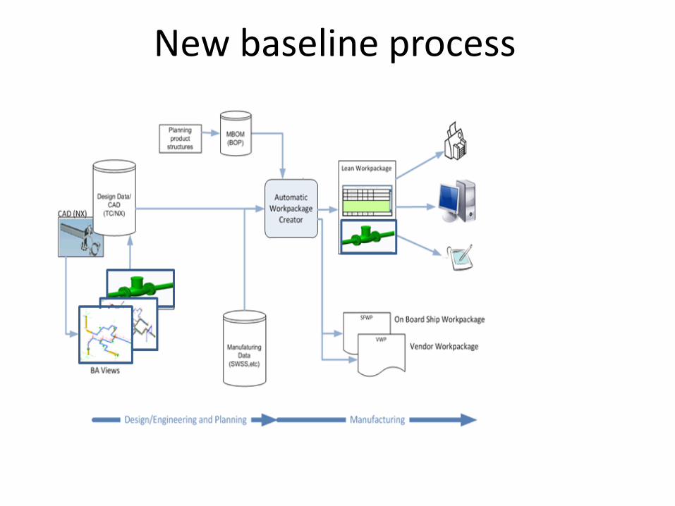
New baseline process

BA autoviews• Identifies critical dimensions
– Rules-based (rather than consumption-based)– Divide and conquer
• BA/TA :: fab/install :: piping/structures/electrical/HVAC
• Manages PMI presentation– Requirement for printed WP persists– Determines location of labels/dimensions– Finds the minimal set of views
• The new work instruction is still ‘paper-based’ with respect to PMI.

Tablet work instruction
• Enables more flexible presentation of PMI• 2D vs 3D presentation of PMI
– Draggable labels– 3D dimensions
• 3D datums
• Interactive– Signoffs, etc.

Lean tablet work instruction
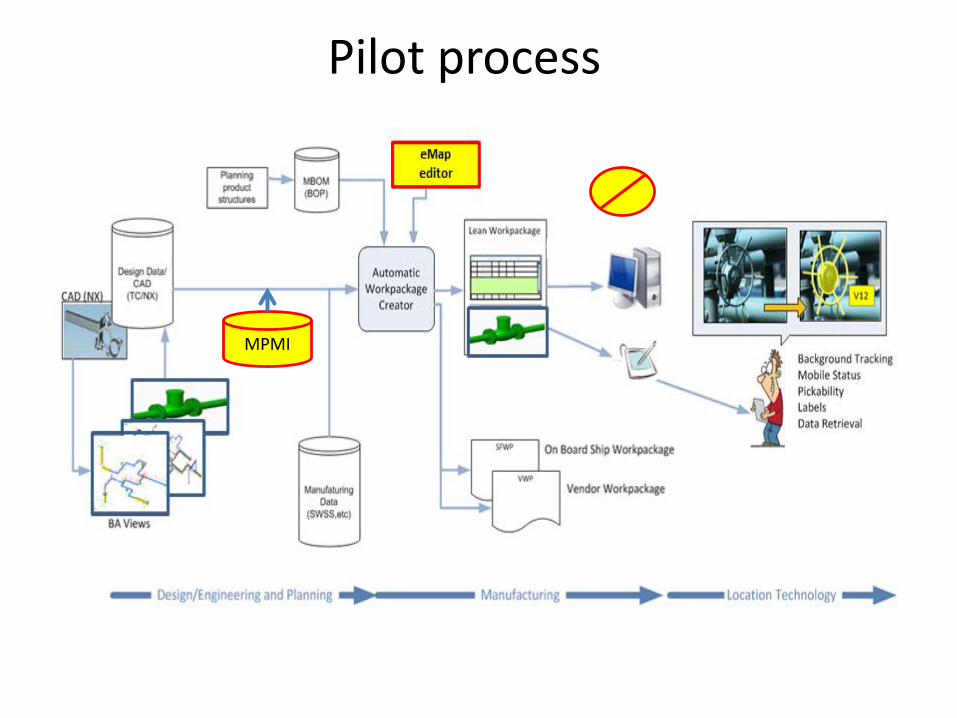
Pilot process
MPMI

eMap Editor Interface
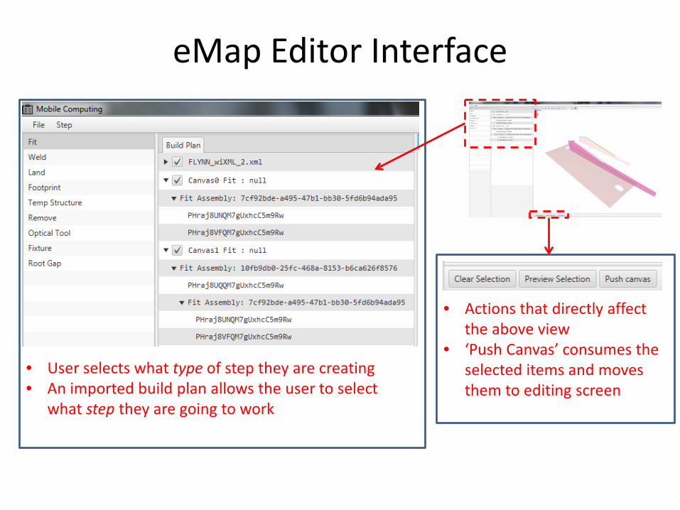
eMap Editor Interface
• Actions that directly affect the above view
• ‘Push Canvas’ consumes the selected items and moves them to editing screen
• User selects what type of step they are creating• An imported build plan allows the user to select
what step they are going to work

eMap Editor Interface
• List of Parts and Joints associated with the selected model
• Each part or joint can be turned on or off
• User names the step and adds any addition information
• User captures the view displayed
• Displays all previously created steps and canvas’s

eMapon
tablet

Authoring MPMI
• New paradigm– Rules-based rather than consumption-based
• At design release:– Autoviews creates MPMI and stores in DB– Manual views are scanned for MPMI to be stored
in DB.• Automates much of the planning process to
make it viable– Consumption step is replaced by DB query.

MPMI data architecture
Occurrence Hull
Build occurrence
InstallationBuild occurrence
Assembly Build occurrenceparent
parent
parent
MPMIrelated
rela
ted
New planning process• Planner constructs the build plan by selecting
occurrences and joints.– This reflects the traditional planning process.
• eMap editor creates visualization of the operation.– System brings in the relevant MPMI from the
database.• Result : less work for the planner than the fat
work instruction process.The new process depends upon enterprise identifiers for
MPMI objects.
Related Documents