Multimedia Systems, Standards, and Networks. A. Puri, T. Chen (Eds.) - Marcel Dekker ISBN: 082479303X , chapter 9, March 2000. MPEG-4 Natural Video Coding – Part II T. Ebrahimi α , F. Dufaux β , and Y. Nakaya γ α EPFL β Compaq γ Hitachi Ltd. CH-1015 Lausanne Cambridge, MA 02139 Tokyo 181 Switzerland USA Japan 1. Introduction Multimedia commands the growing attention of the telecommunications and consumer electronics industry. In a broad sense, multimedia is assumed to be a general framework for interaction with information available from different sources, including video information. Multimedia is expected to support a large number of applications. These applications translate into specific sets of requirements which may be very different from each other. One theme common to most applications is the need for supporting interactivity with different kinds of data. Applications related to visual information can be grouped together on the basis of several features: • type of data (still images, stereo images, video,…); • type of source (natural images, computer generated images, text/graphics, medical images, …); • type of communication (ranging from point-to-point to multipoint-to-multipoint); • type of desired functionalities (object manipulation, on-line editing, progressive transmission, error resilience, …). Video compression standards, MPEG-1[2] and MPEG-2[3], although perfectly well suited in environments for which they were designed for, are not necessarily flexible enough to efficiently address the requirements of multimedia applications. Hence, MPEG (Motion Pictures Experts Group) committed itself to the development of the MPEG-4 standard, providing a common platform for a wide range of multimedia applications[1]. MPEG has been working on the development of the MPEG-4 standard since 1993, and finally after about 6 years of efforts, an International Standard covering the first version of MPEG-4 has been adopted recently [5]. MPEG-4 has been designed to support several classes of functionalities[4,5]. Chief among them are the following: Compression efficiency: This class consists of functionalities for improved coding efficiency and coding of multiple concurrent data streams. These functionalities are required by all applications relying on efficient storage or transmission of video data. One example of such applications is video transmission over IP.

Welcome message from author
This document is posted to help you gain knowledge. Please leave a comment to let me know what you think about it! Share it to your friends and learn new things together.
Transcript

Multimedia Systems, Standards, and Networks. A. Puri, T. Chen (Eds.) - Marcel Dekker ISBN: 082479303X , chapter 9, March 2000.
MPEG-4 Natural Video Coding – Part II
T. Ebrahimiα, F. Dufauxβ, and Y. Nakayaγ
α EPFL β Compaq γ Hitachi Ltd. CH-1015 Lausanne Cambridge, MA 02139 Tokyo 181 Switzerland USA Japan
1. Introduction Multimedia commands the growing attention of the telecommunications and consumer electronics industry. In a broad sense, multimedia is assumed to be a general framework for interaction with information available from different sources, including video information. Multimedia is expected to support a large number of applications. These applications translate into specific sets of requirements which may be very different from each other. One theme common to most applications is the need for supporting interactivity with different kinds of data. Applications related to visual information can be grouped together on the basis of several features: • type of data (still images, stereo images, video,…); • type of source (natural images, computer generated images, text/graphics, medical images, …); • type of communication (ranging from point-to-point to multipoint-to-multipoint); • type of desired functionalities (object manipulation, on-line editing, progressive transmission,
error resilience, …). Video compression standards, MPEG-1[2] and MPEG-2[3], although perfectly well suited in environments for which they were designed for, are not necessarily flexible enough to efficiently address the requirements of multimedia applications. Hence, MPEG (Motion Pictures Experts Group) committed itself to the development of the MPEG-4 standard, providing a common platform for a wide range of multimedia applications[1]. MPEG has been working on the development of the MPEG-4 standard since 1993, and finally after about 6 years of efforts, an International Standard covering the first version of MPEG-4 has been adopted recently [5]. MPEG-4 has been designed to support several classes of functionalities[4,5]. Chief among them are the following: Compression efficiency: This class consists of functionalities for improved coding efficiency and coding of multiple concurrent data streams. These functionalities are required by all applications relying on efficient storage or transmission of video data. One example of such applications is video transmission over IP.
2
Content-based interactivity: These are functionalities to allow for content-based access and manipulation of data, editing bitstreams, coding hybrid (natural and synthetic) data, and improved random access. These functionalities will target applications such as digital libraries, electronic shopping, and movie production. Universal access: Such functionalities include robustness in error-prone environments and content-based scalability. These functionalities allow MPEG-4 encoded data to be accessible over a wide range of media, with various qualities in terms of temporal and spatial resolutions for specific objects. These different resolutions could be decoded by a range of decoders with different complexities. Applications benefiting from them are mobile communications, database browsing, and access at different content levels, scales, resolutions, and qualities. This chapter will concentrate on those tools and functionalities in MPEG-4 natural video that go beyond a pixel-based representation of video. Other tools have been covered in the previous chapter.
1.2 Motivations and background
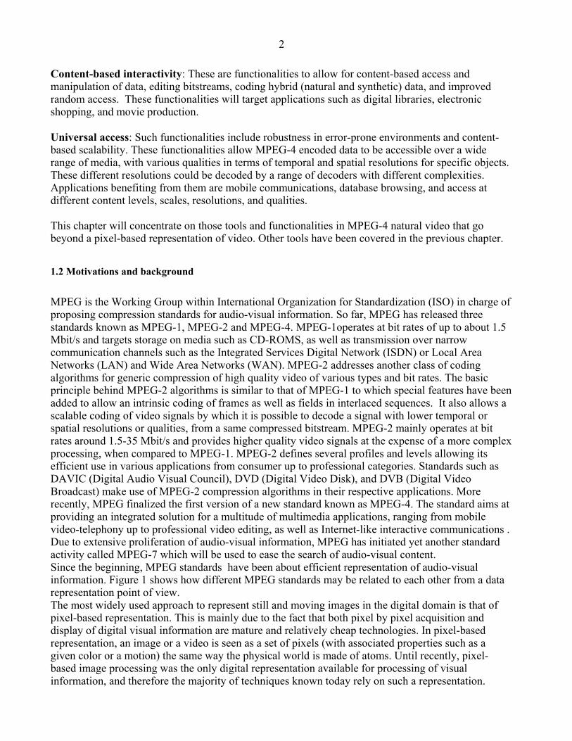
MPEG is the Working Group within International Organization for Standardization (ISO) in charge of proposing compression standards for audio-visual information. So far, MPEG has released three standards known as MPEG-1, MPEG-2 and MPEG-4. MPEG-1operates at bit rates of up to about 1.5 Mbit/s and targets storage on media such as CD-ROMS, as well as transmission over narrow communication channels such as the Integrated Services Digital Network (ISDN) or Local Area Networks (LAN) and Wide Area Networks (WAN). MPEG-2 addresses another class of coding algorithms for generic compression of high quality video of various types and bit rates. The basic principle behind MPEG-2 algorithms is similar to that of MPEG-1 to which special features have been added to allow an intrinsic coding of frames as well as fields in interlaced sequences. It also allows a scalable coding of video signals by which it is possible to decode a signal with lower temporal or spatial resolutions or qualities, from a same compressed bitstream. MPEG-2 mainly operates at bit rates around 1.5-35 Mbit/s and provides higher quality video signals at the expense of a more complex processing, when compared to MPEG-1. MPEG-2 defines several profiles and levels allowing its efficient use in various applications from consumer up to professional categories. Standards such as DAVIC (Digital Audio Visual Council), DVD (Digital Video Disk), and DVB (Digital Video Broadcast) make use of MPEG-2 compression algorithms in their respective applications. More recently, MPEG finalized the first version of a new standard known as MPEG-4. The standard aims at providing an integrated solution for a multitude of multimedia applications, ranging from mobile video-telephony up to professional video editing, as well as Internet-like interactive communications . Due to extensive proliferation of audio-visual information, MPEG has initiated yet another standard activity called MPEG-7 which will be used to ease the search of audio-visual content. Since the beginning, MPEG standards have been about efficient representation of audio-visual information. Figure 1 shows how different MPEG standards may be related to each other from a data representation point of view. The most widely used approach to represent still and moving images in the digital domain is that of pixel-based representation. This is mainly due to the fact that both pixel by pixel acquisition and display of digital visual information are mature and relatively cheap technologies. In pixel-based representation, an image or a video is seen as a set of pixels (with associated properties such as a given color or a motion) the same way the physical world is made of atoms. Until recently, pixel-based image processing was the only digital representation available for processing of visual information, and therefore the majority of techniques known today rely on such a representation.
3
Pixel-based representation
Object based representation
Semantics basedrepresentation
MPEG-7
MPEG-4
MPEG-1MPEG-2
ObjectsFormationandtracking
Objectsfeaturesextraction
2D/3Dsyntheticmodels
Figure 1: Relationship between MPEG standards
It was in the mid 80's that for the first time, motivated by studies of the mechanism of human visual system, other representation techniques started appearing. The main idea behind this effort was that as humans are in the majority of cases the final stage in the image processing chain, then a representation similar to that of human visual system will be more efficient in the design of image processing and coding systems. Non-pixel based representation techniques for coding (also called second generation coding) showed that at very high compression ratios, these techniques are superior to pixel-based representation methods. However, it is a fact that transform-based and (motion compensated) predictive coding have shown outstanding results in compression efficiency for coding of still images and video. One reason is that digital images and video are intrinsically pixel-based in all digital sensors and display devices and provide a projection of the read 4D world, as this is the only way we know today to acquire and to display them. In order to use a non-pixel based approach, pixel-based data has to be converted somehow to a non-pixel based representation, which brings additional complexity, but also other inefficiencies. Among non-pixel based representation techniques, 'object-based' visual data representation exhibits a very important class. In object based representation, objects replace pixels and an image or a video is seen as a set of objects that cannot be broken into smaller elements. In addition to texture (color) and motion properties, a shape information is also needed in order to define the object completely. The shape in this case can be seen as a force field keeping together the elements of an image or video object in a similar fashion that atoms of a physical object are kept together because of atomic force field. It is because of the force field keeping atoms of a physical object together that one can move them easily. Once you grab a corner of an object, the rest comes with it because a force field has glued all atoms of the object together. Same is true in an object-based visual information representation, where the role of the force field is played by that of shape as said earlier.

4
Thanks to this property object-based representation brings a very important feature at no cost called interactivity. Interactivity is defined by some as the element that defines multimedia, and this is one of the main reasons for which an object-based representation was adopted in MPEG-4 standard. It is obvious that because of the fact that the majority of digital visual information is still in pixel-based representation, converters are needed in order to go from one representation to another. The passage from a pixel-based representation to an object based representation can be performed using manual, semi-automatic or automatic segmentation techniques. The inverse operation is achieved by rendering, blending, or composition. At this point it is important to note that since the input information is pixel-based, all tools used in MPEG-4 still operate in a pixel-based approach where care has been taken to extend their operation to arbitrary shaped objects. This is not necessarily a disadvantage as such an approach allows an easy backward/forward compatibility and easy transcoding between MPEG-4 and other standards. An exception to the above statement is when synthetic objects (2D or 3D) are also added in the scene. Such objects are intrinsically non-pixel based as they are not built from a set of pixels. Continuing the same philosophy, one could think of yet another representation in which visual information is represented by describing its content. An example would be when you describe to someone a person he/she has never seen: She is tall, thin, has long black hair, blue eyes, etc. As this kind of representation would require some degree of semantic understanding one could call it a 'semantics based representation'. We will not cover this representation here, as it goes beyond the scope of this chapter. It is worth mentioning that MPEG-7 could benefit from this type of representation.
2. Video Objects and Video Object Planes extraction and coding The previous standards (MPEG-1[2] and MPEG-2[3]) were designed mainly for the purpose of audiovisual-data compression, and accomplish this task very well[1] The MPEG-4 standard[4,5], while providing good compression performance, is being designed with other image-based applications in mind. Most of these applications expect certain basic functionalities to be supported by the underlying standard. Therefore, MPEG-4 incorporates tools, or algorithms, that enable functionalities such as scalability, error resilience or interactivity with content, in addition to compression. MPEG-4 relies on an object-based representation of the video data, in order to achieve its goals. The central concept in MPEG-4 is that of the Video Object (VO). Each VO is characterized by intrinsic properties such as shape, texture, and motion. MPEG-4 considers a scene to be composed of several VOs. Such a representation of the scene is more amenable to interactivity with the scene content than pixel-based (block-based) representations[2,3]. It is important to mention that the standard will not prescribe the method for creating VOs. Depending on the application, VOs may be created in a variety of ways, such as spatio-temporal segmentation of natural scenes [6-9] or from parametric descriptions used in computer graphics[10]. Indeed, for video sequences where compression is the only goal, a set of rectangular image frames may be considered as a VO. MPEG-4 will simply provide a standard convention for describing VOs, such that all compliant decoders will be able to extract VOs of any shape from the encoded bitstream, as necessary. The decoded VOs may then be subjected to further manipulation as appropriate for the application at hand.

5
Figure 2: Structure of an MPEG-4 encoder.
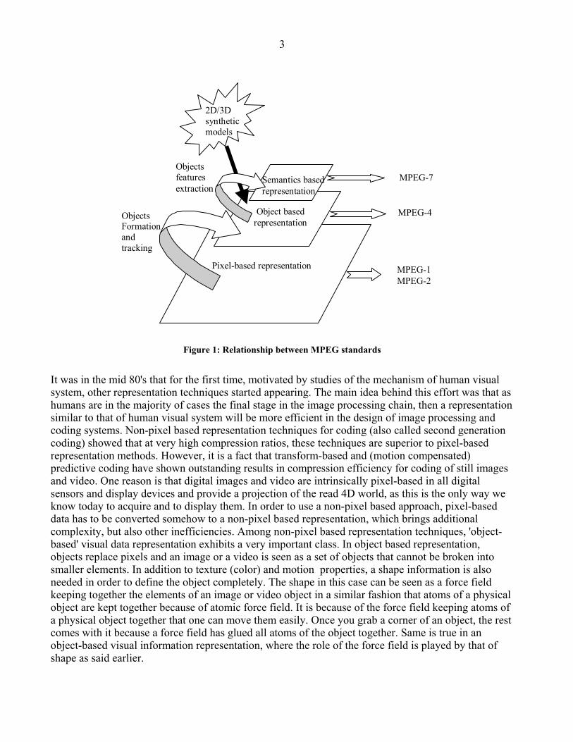
Figure 2 gives the general block diagram of an MPEG-4 video encoder. First the video information is split into VOs as required by the application. The coding control unit decides, possibly based on requirements of the user or the capabilities of the decoder, which VOs are to be transmitted, the number of layers and the level of scalability suited to the current video session. Each VO is encoded independently of the others. The multiplexer then merges the bitstreams representing the different VOs into a video bitstream. Figure 3 shows the block diagram of an MPEG-4 decoder. The incoming bitstream is first decomposed into its individual VO bitstreams. Each VO is then decoded, and the result is composited. The composition handles the way the information is presented to the user. For a natural video, composition is simply the layering of 2D VOs in the scene. The VO based structure has certain specific characteristics. In order to be able to process data available in a pixel-based digital representation, the texture information for a VO (in the uncompressed form) is represented in YUV color coordinates. Up to 12 bits may be used to represent a pixel component value. Additional information regarding the shape of the VO is also available. Both shape and texture information are assumed to be available for specific snapshots of VOs called Video Object Planes (VOP).
6
Figure 3: Structure of an MPEG-4 decoder.
Although the snapshots from conventional digital sources occur at predefined temporal intervals, the encoded VOPs of a VO need not be at the same, or even constant, temporal intervals. Also, the decoder may choose to decode a VO at a temporal rate lower than that used while encoding. MPEG-4 video also supports sprite based coding. The concept of sprites is based on the notion that there is more to an object (a VO, in our case) than meets the eye. A VOP may be thought of as just the portion of the sprite that is visible at a given instant of time. If we can encode the entire information about a sprite, then VOPs may be derived from this encoded representation as necessary. Sprite based encoding is particularly well suited for representing synthetically generated scenes. We will discuss sprites in more detail, further in this chapter.
2.1 VOP Based coding
For reasons of efficiency and backward compatibility, VOs are compressed by coding their corresponding VOPs in a hybrid coding scheme somewhat similar to previous MPEG standards. The VOP coding technique, as shown in Fig. 4 is implemented in terms of macroblocks (blocks of 16 x 16 pixels). This is a design decision which leads to low complexity algorithms and also provides a certain level of compatibility with other standards. Grouping the encoded information in small entities, here macroblocks, facilitates resynchronization in case of transmission errors. A VOP has two basic types of information associated with it: shape information and texture information. The shape information needs to be specified explicitly, since VOPs are, in general, expected to have arbitrary shapes. Thus, the VOP encoder essentially consists of two encoding schemes: one for shape, and one for texture. Of course, in applications where shape information is not explicitly required, such as when each VOP is a rectangular frame, the shape coding scheme may be disabled. The same coding schemes is used for all VOPs in a given VO.

7
The shape information for a VOP, also referred to as alpha-plane, is specified in two components. A simple array of binary labels, arranged in a rectangle corresponding to the bounding box of the VOP, specifies whether an input pixel belongs to the VOP. In addition, a transparency value is available for each pixel of the VOP. This set of transparency values forms what is referred to as the gray scale shape. Gray scale shape values typically range from 0 (completely transparent) to 255 (opaque As mentioned before, the texture information for a VOP is available in the form of a luminance (Y) and two chrominance (U,V) components. We discuss only the encoding process for the luminance (Y) component. The other two components are treated in a similar fashion. The most important tools used for encoding VOPs are discussed further.
Figure 4: Block diagram of a VOP encoder .

8
3. Shape coding In this section we discuss the tools offered by MPEG-4 video standard for explicit coding of shape information in arbitrarily shaped VOPs. Beside the shape information available for the VOP in question, the shape coding scheme also relies on motion estimation to compress the shape information even further. A general description of shape coding literature would be out of the scope of this chapter. Therefore, we will only describe the scheme adopted by MPEG-4 natural video standard for shape coding. Interested readers are referred to [11] for information on other shape coding techniques. In MPEG-4 video standard, two kinds of shape information are considered as inherent characteristics of a video object. These are referred to as binary and grey scale shape information. By binary shape information one means a label information that defines which portions (pixels) of the support of the object belong to the video object at a given time. The binary shape information is most commonly represented as a matrix with the same size as that of the bounding box of a VOP. Every element of the matrix can take one of the two possible values depending on whether the pixel is inside or outside the video object. Gray scale shape is a generalization of the concept of binary shape providing a possibility to represent transparent objects.
3.1 Binary shape coding
In the past, the problem of shape representation and coding has been thoroughly investigated in the fields of computer vision, image understanding, image compression and computer graphics. However, this is the first time that a video standardization effort has adopted a shape representation and coding technique within its scope. In its canonical form, a binary shape is represented as a matrix of binary values called a bitmap. However, for the purpose of compression, manipulation, or a more semantic description, one may choose to represent the shape in other forms such as using geometric representations or by means of its contour. Since its beginning, MPEG adopted a bitmap based compression technique for the shape information. This is mainly due to the relative simplicity and higher maturity of such techniques. Experiments have shown that bitmap based techniques offer good compression efficiency with relatively low computational complexity. This section describes the coding methods for binary shape information. Binary shape information is encoded by a motion compensated block based technique allowing both lossless and lossy coding of such data. In MPEG-4 video compression algorithm, the shape of every VOP is coded along with its other properties (texture and motion). To this end, the shape of a VOP is bounded by a rectangular window with a size of multiples of 16 pixels in horizontal and vertical directions. The position of the bounding rectangle is chosen such that it contains the minimum number of blocks of size 16x16 with non transparent pixels. The samples in the bounding box and outside of the VOP are set to 0 (transparent). The rectangular bounding box is then partitioned into blocks of 16x16 samples (hereafter referred to as shape blocks) and the encoding/decoding process is performed block by block.
9
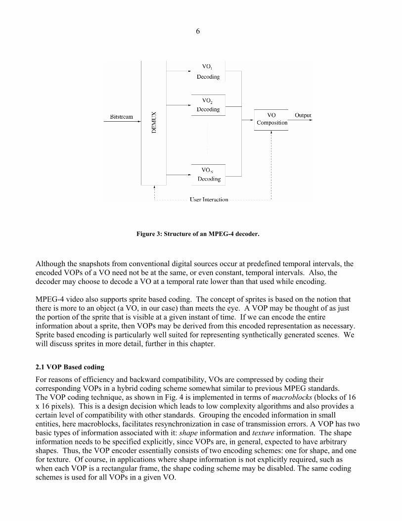
Figure 5: Context selected for InterCAE (a) and IntraCAE (b) shape coding. In each case, the pixel to be encoded is marked by a circle, and the context pixels are marked with crosses. In the InterCAE, part of the context pixels are taken from the co-located block in the previous frame.
The binary matrix representing the shape of a VOP is referred to as binary mask . In this mask every pixel belonging to the VOP is set to 255, and all other pixels are set to 0. It is then partitioned into binary alpha blocks (BAB) of size 16x16. Each BAB is encoded separately. Starting from rectangular frames, it is common to have BABs which have all pixels of the same color, either 0 (in which case the BAB is called an All-0 block) or 255 (in which case the block is said to be an All-255 block). The shape compression algorithm provides several modes for coding a BAB. The basic tools for encoding BABs are the CAE algorithm[12] and motion compensation. InterCAE and IntraCAE are the variants of the CAE algorithm used with and without motion compensation, respectively. Each shape coding mode supported by standard is a combination of these basic tools. Motion vectors can be computed by first predicting a value based on those of neighboring blocks that have been previously encoded, and then searching for a best match position (given by minimum sum of absolute difference). The motion vectors themselves are differentially coded (the result being the MVD). Every BAB can be coded in one of the following modes: 1. The block is flagged All-0. In this case no coding is necessary. Texture information is not coded
for such blocks either. 2. The block is flagged All-255. Again, shape-coding is not necessary for such blocks, but texture
information needs to be coded (since they belong to the VOP). 3. Motion vector difference (MVD) is zero but the block is not updated. 4. MVD is zero but the block is updated. IntraCAE is used for the block. 5. MVD is zero, and InterCAE is to be used for the block. 6. MVD is non-zero, and InterCAE is to be used. The CAE algorithm is used to code pixels in BABs. The arithmetic encoder is initialized at the beginning of the process. Each pixel is encoded as follows[4,5]: 1. compute a context number; 2. index a probability table using this context number; 3. use the retrieved probability to drive the arithmetic encoder for codeword assignment.
10
3.2 Grey scale shape coding
The grey scale shape information has a similar corresponding structure to that of binary shape with the difference that every pixel (element of the matrix) can take on a range of values (usually 0 to 255) representing the degree of the transparency of that pixel. The grey scale shape corresponds to the notion of alpha plane used in computer graphics, in which 0 corresponds to a completely transparent pixel and 255 to a completely opaque pixel. Intermediate values of the pixel correspond to intermediate degrees of transparencies of that pixel. By convention, a binary shape information corresponds to a grey scale shape information with values of 0 and 255. Grey scale shape information is encoded using a block based motion compensated DCT similar to that of texture coding, allowing lossy coding only. The grey scale shape coding also makes use of binary shape coding for coding of its support.
4. Texture coding In the case of I-VOPs, the term texture refers to the information present in the gray- or chroma-values of the pixels forming the VOP. In the case of predicted VOPs (B-VOPs and P-VOPs), the residual error after motion compensation is considered as the texture information. The MPEG-4 video standard uses techniques very similar to other existing standards, for coding of the VOP texture information. The block based Discrete Cosine Transform (DCT) method is adapted to the needs of an arbitrarily shaped VOP oriented approach. The VOP texture is split into macroblocks of size 16 x 16. Of course, this implies that the blocks along the boundary of the VOP may not fall completely on the VOP, that is, some pixels in a boundary block may not belong to the VOP. Such boundary blocks, are treated differently from the non-boundary blocks. 4.1 Coding of Internal Blocks The blocks that lie completely within the VOP are encoded using a conventional two-dimensional (2D) 8 x 8 block DCT. The luminance and chrominance blocks are treated separately. Thus, six blocks of DCT coefficients are generated for each macroblock. The DCT coefficients are quantized, in order to compress the information. The DC coefficient is quantized using a step size of 8. MPEG-4 video algorithm offers two alternatives for determining the quantization step to be used for the AC coefficients. One is to follow an approach similar to the recommendation H.263. Here, a quantization parameter determines how the coefficients will be quantized. The same value applies to all coefficients in a macroblock, but may change from one macroblock to another, depending on the desired image quality or target bitrate. The other option is a quantization scheme similar to that used in MPEG-2, where the quantization step may vary depending on the position of the coefficient. After appropriate quantization, the DCT coefficients in a block are scanned in zig-zag fashion in order to create a string of coefficients from the 2D block. The string is compressed using run-length coding and entropy coding. A detailed description of these operations is given in the previous chapter.
11
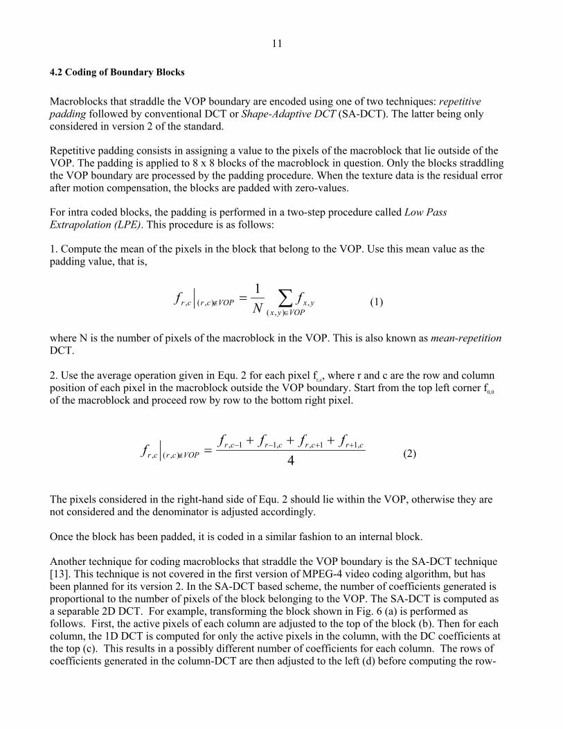
4.2 Coding of Boundary Blocks Macroblocks that straddle the VOP boundary are encoded using one of two techniques: repetitive padding followed by conventional DCT or Shape-Adaptive DCT (SA-DCT). The latter being only considered in version 2 of the standard. Repetitive padding consists in assigning a value to the pixels of the macroblock that lie outside of the VOP. The padding is applied to 8 x 8 blocks of the macroblock in question. Only the blocks straddling the VOP boundary are processed by the padding procedure. When the texture data is the residual error after motion compensation, the blocks are padded with zero-values. For intra coded blocks, the padding is performed in a two-step procedure called Low Pass Extrapolation (LPE). This procedure is as follows: 1. Compute the mean of the pixels in the block that belong to the VOP. Use this mean value as the padding value, that is,
∑∈
∉ =VOPyx
yxVOPcrcr fN
f),(
,),(,1
(1)
where N is the number of pixels of the macroblock in the VOP. This is also known as mean-repetition DCT. 2. Use the average operation given in Equ. 2 for each pixel fr,c, where r and c are the row and column position of each pixel in the macroblock outside the VOP boundary. Start from the top left corner f0,0 of the macroblock and proceed row by row to the bottom right pixel.
4,11,,11,
),(,crcrcrcr
VOPcrcr
fffff ++−−
∉
+++= (2)
The pixels considered in the right-hand side of Equ. 2 should lie within the VOP, otherwise they are not considered and the denominator is adjusted accordingly. Once the block has been padded, it is coded in a similar fashion to an internal block. Another technique for coding macroblocks that straddle the VOP boundary is the SA-DCT technique [13]. This technique is not covered in the first version of MPEG-4 video coding algorithm, but has been planned for its version 2. In the SA-DCT based scheme, the number of coefficients generated is proportional to the number of pixels of the block belonging to the VOP. The SA-DCT is computed as a separable 2D DCT. For example, transforming the block shown in Fig. 6 (a) is performed as follows. First, the active pixels of each column are adjusted to the top of the block (b). Then for each column, the 1D DCT is computed for only the active pixels in the column, with the DC coefficients at the top (c). This results in a possibly different number of coefficients for each column. The rows of coefficients generated in the column-DCT are then adjusted to the left (d) before computing the row-

12
DCT. The 2D SA-DCT coefficients are laid out as shown in (e), with the DC coefficient at the top left corner. The binary mask of the shape and the DCT coefficients are both required in order to decode the block correctly. Coefficients of the SA-DCT are then quantized and entropy coded in a similar way to that explained in the previous section.
Figure 6: Steps for computing Shape-Adaptive DCT for an arbitrarily shaped 2D region. (a) Region to be transformed, with shaded blocks representing the active pixels, (b) top-adjusted columns, (c) column-DCT coefficients with DC coefficients marked with black spots, (d) left-adjusted rows of coefficients, (e) final 2D SA-DCT with DC coefficient marked with a black spot.
4.3 Static texture coding
MPEG-4 also supports a mode for encoding texture of static objects of arbitrary shapes, or texture information to be mapped on 3D surfaces. This mode is called static texture coding mode, and utilizes a discrete wavelet transform (DWT) to efficiently compress the texture information[14,15]. In particular, it offers a high degree of scalability, both spatial, and in terms of image quality. The input texture components (luminance and chrominances) are treated separately. Each component is decomposed into bands by a bank of analysis filters. Another filter bank, the synthesis filters, later recombine the bands to decode and to reconstruct the texture information. The analysis and synthesis filters must satisfy certain constraints to yield perfect reconstruction. Extensive wavelet theory has been developed for designing filters which satisfy these constraints. It has been shown that the filters play an important role in the performance of the decomposition for compression purpose[16,17].

13
Figure 7: Illustration of a wavelet decomposition of depth 2, and the corresponding subband layout.
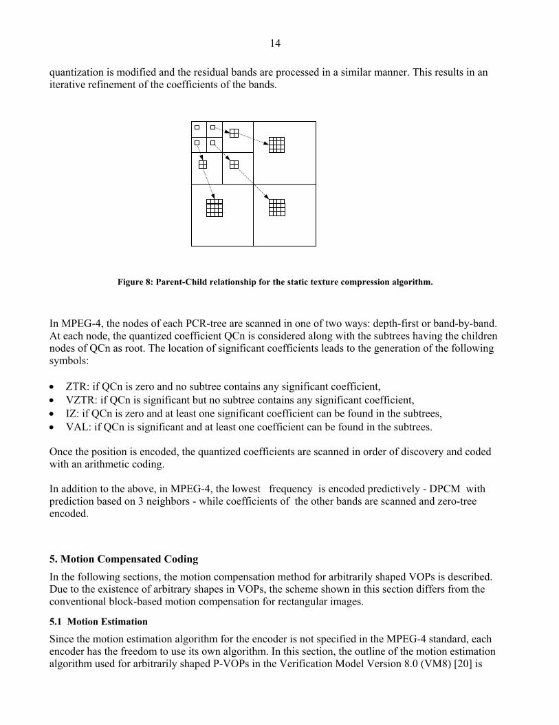
The decomposition explained above can be applied recursively on the obtained bands, yielding a decomposition-tree (D-tree) of so-called subbands. A decomposition of depth 2 is shown in Fig. 7, where the square static texture image is decomposed into 4 bands, and the lowest frequency band (shown on the left) is further decomposed into 4 subbands (1,2,3,4). Therefore, subband 1 represents the lowest spectral band of the texture. At each step, the spectral domain is split into n parts, n being the number of filters in the filter bank. The number of coefficients to represent each band can therefore also be reduced by a factor of n, assuming that filters have the same bandwidth. The different bands can then be laid out as shown in Fig. 7 (right hand side); they contain the same number of coefficients than pixels in the original texture. It is important to note that, even though the subbands represent a portion of the signal which is well localized in the spectral domain, the subband coefficients also remain in the spatial domain. Therefore, co-located coefficients in the subbands represent the original texture at that location but at different spectral locations. The correlation between the bands, up to a scale factor, can then be exploited for compression purposes. Shapiro[18] originally proposed a scheme for coding the coefficients by predicting the position of insignificant coefficient across bands. MPEG-4 is based on a modified zero-tree wavelet coding as described in [19]. For any given coefficient in the lower frequency band, a parent-child relation tree (PCR-tree) of coefficients in the subbands is built with a parent-child relationship (Fig. 8). There is one PCR-tree for each coefficient in the lowest frequency subband. Every coefficient in the decomposition can thus be located by indicating its root coefficient and the position in the PCR-tree from that root. The problem then is to encode both the location and the value of the coefficients. This is done in two passes: the first pass locates coefficients, and the second encodes their values. As compression is lossy, the most significant coefficients should be transmitted first, and the less significant transmitted later, or not at all. A coefficient is considered significant if its magnitude is nonzero after quantization. The difference between the quantized and non-quantized coefficients results in so-called residual subbands. Selection and encoding of significant coefficients is achieved by iterative quantization of residual subbands. In each iteration, significant coefficients are selected, and their locations and quantized values are encoded by means of an arithmetic encoder. In subsequent iterations, the
1
3
2
4
6
5
7
Static texture
1 2 3 4
5 6 7
14
quantization is modified and the residual bands are processed in a similar manner. This results in an iterative refinement of the coefficients of the bands.
Figure 8: Parent-Child relationship for the static texture compression algorithm.
In MPEG-4, the nodes of each PCR-tree are scanned in one of two ways: depth-first or band-by-band. At each node, the quantized coefficient QCn is considered along with the subtrees having the children nodes of QCn as root. The location of significant coefficients leads to the generation of the following symbols: • ZTR: if QCn is zero and no subtree contains any significant coefficient, • VZTR: if QCn is significant but no subtree contains any significant coefficient, • IZ: if QCn is zero and at least one significant coefficient can be found in the subtrees, • VAL: if QCn is significant and at least one coefficient can be found in the subtrees. Once the position is encoded, the quantized coefficients are scanned in order of discovery and coded with an arithmetic coding. In addition to the above, in MPEG-4, the lowest frequency is encoded predictively - DPCM with prediction based on 3 neighbors - while coefficients of the other bands are scanned and zero-tree encoded.
5. Motion Compensated Coding In the following sections, the motion compensation method for arbitrarily shaped VOPs is described. Due to the existence of arbitrary shapes in VOPs, the scheme shown in this section differs from the conventional block-based motion compensation for rectangular images.
5.1 Motion Estimation
Since the motion estimation algorithm for the encoder is not specified in the MPEG-4 standard, each encoder has the freedom to use its own algorithm. In this section, the outline of the motion estimation algorithm used for arbitrarily shaped P-VOPs in the Verification Model Version 8.0 (VM8) [20] is
15
shown as a reference algorithm. For simplification, it is assumed that the one motion vector is transmitted at most for a macroblock.
5.1.1 Motion estimation for texture and gray scale shape Motion estimation for the texture and gray scale shape is performed using the luminance values. The algorithm consists of the following three steps. (1) Padding of the reference VOP: This step is applied only to arbitrarily shaped VOPs. The details of this step is described in section 4.1. (2) Full-search polygon matching with single-pel accuracy: The search range in this step is –2 fcode + 3 ≤ MVx, MVy < 2 fcode + 3 , where MVx and MVy denote the horizontal and vertical components of the motion vector in single pel unit, and 1 ≤ fcode ≤ 7. The value of fcode is defined independently for each VOP. The error measure, SAD (MVx, MVy), is defined as
),()12/(
),(),(),(),(15
0
15
0000000
yx
i jyxyx
MVMVNB
jyixBAMVjyMVixRjyixIMVMVSAD
δ•+−
++•++++−++= ∑∑= = , (3)
where (x0, y0) denotes the left top coordinate of the macroblock, I(x, y) denotes the luminance sample value at (x, y) in the input VOP, R(x, y) denotes the luminance sample value at (x, y) in the reference VOP, BA(x, y) is 0 when the pixel at (x, y) is transparent and 1 when the pixel is opaque , NB denotes the number of non-transparent pixels in the macroblock, δ (MVx, MVy) is 1 when (MVx, MVy) = (0, 0) and 0 otherwise, and “/” denotes integer division with truncation towards zero. (3) Polygon matching with half-pel accuracy: Starting from the motion vector estimated in step (2), half sample search in a ±0.5 × ±0.5 pel window is performed using SAD(MVx, MVy) as the error measure. The estimated motion vector, (x, y), shall stay within the range of –2 fcode + 3 ≤ x, y < 2 fcode + 3. The interpolation scheme for obtaining the interpolated sample values is described in section 5.2.
5.1.2 Motion estimation for binary shape In MPEG-4 video, the motion estimation algorithm applied to the binary shape macroblocks is different from the algorithm applied to the texture planes. This algorithm consists of the following three steps. (1) Calculation of the predictor: In this step, the sum of absolute difference for the motion vector predictor is calculated. The method for obtaining the predictor is described in section 5.3. If the calculated sum of absolute difference for any 4×4 sub-block (there are 16 sub-blocks in each shape macroblock) is smaller than 16 × AlphaTH (AlphaTH is a parameter that specifies the target quality of the reconstructed binary shape), the predictor becomes the estimated motion vector. Otherwise, the algorithm proceeds to (2).

16
(2) Full search block matching: Full search block matching with single-pel accuracy is performed within the ±16 × ±16 pel window around the predictor. The sum of absolute difference without favoring the zero motion vector is used as the error measure. If multiple motion vectors minimize the sum of absolute difference, the following rule is applied for selecting the estimated motion vector from these motion vectors: • The motion vector that minimizes parameter Q is selected as the estimated motion vector. Q is
defined as Q = 2( |MVDsx | + |MVDsy | + 1) – δ (MVDsx), (4)
where (MVDsx , MVDsy) denotes the differential vector between the motion vector of the shape macroblock and the predictor, and the value of δ (MVDsx ) is 1 when MVDsx = 0 and 0 otherwise.
• If multiple motion vectors minimize the sum of absolute difference and Q, the motion vector with the smallest absolute value for the vertical component is selected from these motion vectors. If multiple motion vectors minimize the absolute value for the vertical component, the motion vector with the smallest absolute value for the horizontal component is selected.
5.2 Motion Compensation
The motion compensation algorithm for reconstructing the predicted VOP is normative and is strictly defined in the MPEG-4 standard. The motion compensation algorithm for the texture, gray scale, and binary shapes consists of the following steps: (1) Padding of the texture in the reference VOP: The repetitive padding method described in section 4 is applied to the texture of the reference VOP. This process is skipped for rectangular VOPs. (2) Synthesis of the predicted VOP: The predicted VOP is synthesized using the decoded motion vectors for the texture and the binary shape. The unrestricted motion vector mode, four motion vector mode, and overlapped block motion compensation can be used for texture macroblocks in arbitrarily shaped VOPs, as well as for rectangular VOPs. For the texture, the interpolation of pixel values is performed as shown in Fig. 9.
Integer pixel position
Half pixel position
A B
C
a b
c d
D
a = Ab = (A + B + 1 – rounding_control) / 2c = (A + C + 1 – rounding_control) / 2d = (A + B + C + D + 2 – rounding_contrlol) / 4
Figure 9: Pixel value interpolation.

17
The parameter rounding_control can have the value of 0 or 1, and is defined explicitly for each P-VOP. Usually, the encoder controls rounding_control so that the current P-VOP and the reference VOP have different values. By having such control mechanism, the accumulation of round-off errors, which causes degradation in the quality of the decoded VOPs, is avoided [21].
5.3 Motion Coding
As in rectangular VOPs, the motion vectors are coded differentially in arbitrarily shaped VOPs. However, the method for obtaining the predictor differs between texture or gray scale shape and binary shape. This is discussed in detail in the following.
5.3.1 Motion coding for the texture The difference between the motion coding methods for the texture in rectangular VOPs and arbitrarily shaped VOPs is that arbitrarily shaped VOPs may include transparent macroblocks. When the current macroblock is transparent, motion vector information is not transmitted for this macroblock. The decoder can correctly decode the coded data for this macroblock, since the shape information is transmitted before the motion information for each macroblock. When the decoded shape information indicates that the current macroblock is transparent, the decoder knows at this point that the coded data of that macroblock does not include motion vector information. The same rule applies to each 8×8 pixel block in a macroblock with four motion vectors: The motion vector information for a transparent 8×8 pixel block is not transmitted. When the candidate predictor for motion vector prediction (see Figure 7 of Chapter 8) is included in a transparent block (i.e. a macroblock or an 8×8 pixel block), this candidate predictor is regarded as not valid. Before applying median filtering to the three candidate predictors, the values of the candidate predictors that are not valid are defined according to the following rule: • When one and only one candidate predictor is not valid, the value of this candidate predictor is set
to zero. • When two and only two candidate predictors are not valid, the values of these candidate predictors
are set to value of the other valid candidate predictor. • When three candidate predictors are not valid, the values of these candidate predictors are set to
zero.
5.3.2 Motion coding for the binary shape Both the shape motion vectors, MVs1, MVs2, and MVs3, and texture motion vectors, MV1, MV2, and MV3, of the adjacent macroblocks shown in Fig. 10 are used as the candidate predictors for the motion vector of a shape macroblock. Since only single pel accuracy motion vectors are allowed for shape macroblocks, the candidate predictors of the texture macroblocks are truncated towards 0 to an integer value. It is assumed in Fig. 10 that macroblocks with one motion vector have four identical motion vectors for each of the 8x8 block included in it.
MVs1
MVs2 MVs3
currentshapemacroblock
correspondingtexturemacroblock
MV3
MV1
MV2
(a) motion vectors for shape (b) motion vectors for texture

18
Figure 10: Candidate predictors for a shape macroblock.
The predictor is obtained by traversing MVs1, MVs2, MVs3, MV1, MV2, and MV3 in this order, and taking the first valid motion vector as the estimated motion vector. The motion vector of a texture macroblock is not valid when the macroblock is transparent or outside the current VOP. The motion vector of a shape macroblock is valid only when this shape macroblock is coded as an inter shape macroblock.
6. Sprite Coding and Global Motion Compensation Efficient representation of temporal information is a key component in any video coding system. In video imagery, pixels are indeed most correlated in the direction of motion. The widely used model of blocks of pixels undergoing a translation is the basis of most motion compensated techniques such as the one used in MPEG-1, -2 and -4. However, while it has achieved significant performance [22], this simple model has its limitations. In order to reach higher coding efficiency, a more sophisticated model is needed. For this purpose, a novel technique referred to as sprite coding [23] was adopted in the MPEG-4 standard. MPEG is also considering another technique referred to as Global Motion Compensation (GMC) [24,25] for possible adoption in the MPEG-4 Version 2 standard (the latter is scheduled to reach the CD stage in March 1999 [26]). In computer graphics, a sprite is a graphic image that can be individually animated or moved around within a larger graphic image or set of images. In the context of MPEG-4, a sprite is more generally a video object modeled by a coherent motion. In the case of natural video, a sprite is typically a large composite image resulting from the blending of pixels belonging to various temporal instances of the video object. In the case of synthetic video, it is simply a graphic object. Temporal instances of the video object can subsequently be reconstructed from the sprite by warping the corresponding portion of the sprite content. As far as video coding is concerned, a sprite captures spatio-temporal information in a very compact way. Indeed, a video sequence can be represented by a sprite and warping parameters [23]. This concept is similar to the mosaicking techniques proposed in [27, 28] and to the layered representation introduced in [29]. Therefore, sprite coding achieves a high coding efficiency. In addition, it empowers the media consumer by enabling content-based interaction at the receiver end. Sprite coding is most useful to encode synthetic graphics objects (e.g. a flying logo). However, it is also well suited to encode any video object which can be modeled by a rigid 2-D motion (e.g. this assumption very often holds true for the background of a video scene). When the sprite is not directly available, such as when processing natural video, it should be constructed prior to coding. In this situation, the technique is not suitable for real-time applications due to the off-line nature of the sprite generation process. GMC [24, 25] is a technique that compensates for this limitation of sprite coding. Instead of warping the sprite, GMC warps the reference VOP using the estimated warping parameters to obtain the predicted VOP used for interframe coding. GMC is most useful to encode a video sequence with significant camera motion (e.g. pan, zoom). Since GMC does not require a priori knowledge about the scene to be encoded, it is applicable to on-line real-time applications. In summary, sprite coding consists of the following steps [23]. First, a sprite is build by means of image registration and blending. The sprite and warping parameters are subsequently transmitted to the decoder side. Finally, the decoder reconstructs the video imagery by warping the sprite. On the other hand, GMC coding, which fits well in the conventional interframe coding framework, consists of interframe prediction and prediction error coding. The details of these techniques are discussed in more details hereafter.

19
6.1 Sprite generation
When processing natural video, the sprite is generally not known a priori. In this case, it has to be generated off-line prior to starting the encoding process. Note that the sprite generation process is not specified by the MPEG-4 standard. This section presents a technique based on the MPEG-4 Verification Model [30]. This technique is not normative. In the following, we assume a video object which can be modeled by a rigid 2-D motion, along with its corresponding segmentation mask, obtained for instance by means of chroma keying or automatic/supervised segmentation techniques (see section 2). Figure 11 illustrates the process of sprite generation. It basically consists of three steps: global motion is first estimated between an input image and the sprite, using this motion information the image is then aligned, i.e. warped, with the sprite, and finally the image is blend into the sprite. These steps are more thoroughly described below.
globalmotionestimation
warping blendinginputvideo
sprite
Figure 11: Sprite generation block diagram (successive images are highlighted in white for illustrative purpose)
6.1.1 Global motion estimation In order to estimate the motion of the current image with respect to the sprite, global motion estimation is performed. The technique is based on a hierarchical iterative gradient descent [31]. More formally, it minimizes the sum of squared differences between the sprite S and the motion-compensated image I’,
∑=
=N
iieE
1
2 , with ),(),( iiiii yxIyxSe ′′′−= , (5)
where (xi,yi) denotes the spatial coordinates of the ith pixel in the sprite, (xi’,yi’) denotes the coordinates of the corresponding pixel in the image, and the summation is carried out over N pairs of pixels (xi,yi) and (xi’,yi’) within image boundaries. Alternatively, motion estimation may be carried out between consecutive images. Since the problem of motion estimation is under-constrained [22], an additional constrained is required. In our case, an implicit constraint is added, namely the motion over the whole image is parameterized by a perspective motion model (8 parameters) defined as follows

20
)1()()1()(
76543
76210
++++=′++++=′
iiiii
iiiii
yaxayaxaayyaxayaxaax
, (6)
where (a0,…,a7) are the motion parameters. This model is suitable when the scene can be approximated by a planar surface, or when the scene is static and the camera motion is a pure rotation around its optical center. Simpler models such as affine (6 parameters: a6=a7=0), translation - isotropic magnification - rotation (4 parameters: a1=a5, a2=-a4, a6=a7=0), and translation (2 parameters: a1=a5=1, a2=a4=a6=a7=0) are particular cases of the perspective model and can be easily derived from it. The motion parameters a=(a0,…,a7) are computed by minimizing E in Equ. (5). Since the dependence of E on a is nonlinear, the following iterative gradient descent method is used
bHaa 1)()1( −+ += tt , (7)
where a(t) and a(t+1) denote a at iteration t and t +1 respectively, H is an n x n matrix and b is an n-element vector whose coefficients are given by
∑∑== ∂
∂∂∂
≅∂∂
∂=
N
i l
i
k
iN
i lk
ikl a
eae
aae
H11
22
21
, and ∑∑== ∂
∂−=
∂∂
−=N
i k
ii
N
i k
ik a
ee
ae
b11
2
21
, (8)
and n is the number of parameters of the model. In order to improve convergence and to reduce computational complexity, a low-pass image pyramid is introduced. The gradient descent is applied at the top of the pyramid and then iterated at each level until convergence is achieved. To assure convergence in the presence of large displacements, an initial coarse estimate of the translation component of the displacement is computed by applying an n-step search matching algorithm at the top level of the pyramid prior to the gradient descent. Finally, in order to limit the influence of outliers which would otherwise bias the estimation, a robust estimator is used. For this purpose, the quadratic measure in Equ. (5) is replaced by a truncated quadratic error function defined as
∑=
=N
iieE
1)(ρ , with
>≤
=TeifTeifee
i
iii ||0
||)(2
ρ (9)
where T is a threshold. In other words, only those pixels for which the absolute value of the error term is below T are taken into account in the estimation process. Typically, T is computed from the data such as to exclude the samples resulting in the largest error terms |ei|, for instance eliminating the top p percents of the distribution of |ei|. Note that the above iterative procedure remains unchanged while using this robust estimator. 6.1.2 Warping and blending Once motion is known, the image is aligned with respect to the sprite. This procedure is referred to as warping [31]. More precisely, coordinates (xi,yi) in the sprite are scanned, and the warped coordinates (xi’,yi’) in the image are simply computed using Equ. (6). Generally, (xi’,yi’) will not coincide with the integer-pixel grid. Therefore, I’(xi’,yi’) is evaluated by interpolating surrounding pixels. Bilinear interpolation is most commonly used. The last step to complete the sprite generation is to blend the warped image into the current sprite to produce the new sprite. A simple average can be used. Furthermore, a weighting function decreasing near the edges may be introduced to produce a more seamless sprite. However, the averaging operator may results in blurring in case of misregistration. As the sprite generation is an off-line and non-causal process, memory buffer permitting it is possible to store the whole sequence of warped images.
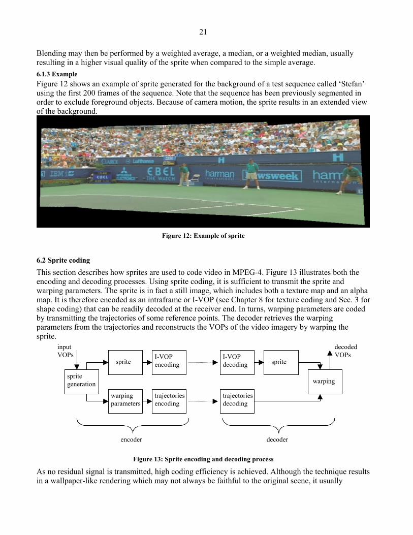
21
Blending may then be performed by a weighted average, a median, or a weighted median, usually resulting in a higher visual quality of the sprite when compared to the simple average. 6.1.3 Example Figure 12 shows an example of sprite generated for the background of a test sequence called ‘Stefan’ using the first 200 frames of the sequence. Note that the sequence has been previously segmented in order to exclude foreground objects. Because of camera motion, the sprite results in an extended view of the background.
Figure 12: Example of sprite
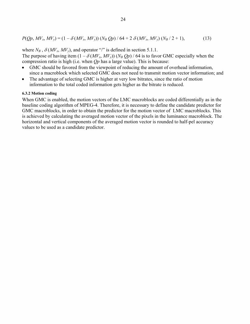
6.2 Sprite coding
This section describes how sprites are used to code video in MPEG-4. Figure 13 illustrates both the encoding and decoding processes. Using sprite coding, it is sufficient to transmit the sprite and warping parameters. The sprite is in fact a still image, which includes both a texture map and an alpha map. It is therefore encoded as an intraframe or I-VOP (see Chapter 8 for texture coding and Sec. 3 for shape coding) that can be readily decoded at the receiver end. In turns, warping parameters are coded by transmitting the trajectories of some reference points. The decoder retrieves the warping parameters from the trajectories and reconstructs the VOPs of the video imagery by warping the sprite.
I-VOPencoding
spritegeneration
sprite
trajectoriesencoding
warpingparameters
spriteI-VOPdecoding
trajectoriesdecoding
warping
decodedVOPs
decoderencoder
inputVOPs
Figure 13: Sprite encoding and decoding process
As no residual signal is transmitted, high coding efficiency is achieved. Although the technique results in a wallpaper-like rendering which may not always be faithful to the original scene, it usually

22
provides with a high visual quality. Finally, because local block matching motion estimation and residual encoding/decoding are avoided, the technique has a low complexity. 6.2.1 Trajectories coding Instead of directly transmitting the parameters a=(a0,…,a7) of the motion model (see Equ. (6)), displacement of reference points are encoded. More precisely, for each VOP to be encoded, reference points (in, jn), n=1,…,N, are positioned at the corners of the VOP bounding box, and the corresponding points (i’n, j’n) in the sprite are computed, as illustrated in Fig. 14. The points (i’n, j’n) are quantized to half-pel precision. Finally, the displacement vectors (un, vn)=(in-i’n, jn-j’n) are computed and transmitted as differential motion vectors. MPEG-4 supports four motion models: N=4 points are required for a perspective model, N=3 points for affine, N=2 points for translation - isotropic magnification - rotation, and N=1 point for translation.
(i0,j0) (i1,j1)
(i2,j2)(i3,j3)
(i’0,j’0)sprite
VOP
(i’1,j’1)
(i’3,j’3)
(i’2,j’2)
Figure 14: Reference points and trajectories coding
At the receiver end, the decoder reconstructs the N pairs of reference points (in, jn) and (i’n, j’n), which are then used in the warping procedure. 6.2.2 Warping and VOP reconstruction In the decoder, VOPs are reconstructed by warping the content of the sprite. Note that this warping is different from the one described in section 6.1.2 in several aspects. First this warping is part of the decoding process and is thus normative. Second, the sprite is now warped towards the VOP. Furthermore, the warping is expressed in terms of the N pairs of reference points (in, jn) and (i’n, j’n) instead of the warping parameters a=(a0,…,a7). Finally, in order to precisely specify the accuracy of the warping procedure, (i’n, j’n) are expressed as integers in 1/s pel accuracy, where the sprite warping accuracy s takes the values {2, 4, 8, 16}. For instance in the case of a perspective model, for each VOP luminance pixel (i,j), the corresponding sprite location (i’,j’) is determined as follow
)()(
)()(DWHhjgifjeidj
DWHhjgicjbiai++++=′
++++=′, (19)
where W and H are the width and height of the VOP respectively, and HWiDa 0′= , 101 )( igHiiDb ′+′−′= , 202 )( ihWiiDc ′+′−′= ,
HWjDd 0′= , 101 )( jgHjjDe ′+′−′= , 202 )( jhWjjDf ′+′−′= ,
Hjjjjiijjiiiig )))(())((( 321032323210 ′+′−′−′′−′−′−′′+′−′−′= , (11)
Wjjiiiijjjjiih )))(())((( 313210321031 ′−′′+′−′−′−′+′−′−′′−′= ,

23
))(())(( 31323231 jjiijjiiD ′−′′−′−′−′′−′= .
The reconstructed value of the VOP pixel (i,j) is finally interpolated from the four sprite pixels surrounding the location (i’,j’). 6.2.3 Low-latency sprite As shown in Fig. 12, a sprite is typically much larger than a single frame of video. If the decoder should wait for the whole sprite to be transmitted before being able to decode and display the first VOP, a high latency is introduced. In order to alleviate this limitation, MPEG-4 supports two low-latency sprite coding methods. The first method consists in transmitting the sprite piece by piece. The portion of the sprite needed to reconstruct the beginning of the video sequence is first transmitted. Remaining pieces of the sprite are subsequently sent according to the decoding requirements and available bandwidth. In the second method, the quality of the transmitted sprite is progressively upgraded. A coarsely quantized version of the sprite is first transmitted. Bandwidth permitting, finely quantized residuals are later sent to improve upon the quality of the sprite. These two methods may be utilized separately or in combination, and allow to significantly reduce the latency intrinsic to sprite coding.
6.3 Global Motion Compensation
Panning and zooming is a common motion pattern observed in natural video scenes. However, the existence of such motion patterns in the input scene usually causes degradation of coding efficiency to an encoder which uses conventional block matching for motion compensation. This is because a moving background leads to a large number of transmitted motion vectors, and translational motion of blocks is not the appropriate motion model for a scene with non-translational motion (i.e. zooming, rotation, etc.). Global Motion Compensation (GMC) [24,25] is a motion compensation tool that solves this problem. Instead of applying warping to a sprite VOP, GMC applies warping to the reference VOP for obtaining the predicted VOP. The main technical elements of the GMC technique are global motion estimation, warping, motion trajectory coding, LMC/GMC decision, and motion coding. Since the first three elements have already been covered, LMC/GMC decision and motion coding are discussed in the following subsections.
6.3.1 LMC/GMC decision In the GMC method adopted in the MPEG-4 Version 2 Working Draft [26], each inter macroblock is allowed to select either GMC or LMC (Local Motion Compensation, which is identical with the block matching method used in the baseline coding algorithm of MPEG-4) as its motion compensation method. A common strategy for deciding whether to use LMC or GMC for a macroblock is to apply GMC to the moving background, and LMC to the foreground. For this purpose, the following LMC/GMC decision criteria is adopted in the MPEG-4 Video VM Version 12.1 [32] (for simplicity, it is assumed that one motion vector is transmitted at most for a macroblock using LMC): If SADGMC – P(Qp, MVx, MVy) < SAD(MVx, MVy), then use GMC, otherwise use LMC, (12) where SAD(MVx, MVy) is defined in section 5.1.1, (MVx, MVy) is the estimated motion vector of LMC, Qp is the quantization parameter for DCT coefficients, and SADGMC is the sum of absolute difference between the original macroblock and the macroblock predicted by GMC. Parameter P(Qp, MVx, MVy) is defined as:
24
P(Qp, MVx, MVy) = (1 – δ (MVx, MVy)) (NB Qp) / 64 + 2 δ (MVx, MVy) (NB / 2 + 1), (13) where NB , δ (MVx, MVy), and operator “/” is defined in section 5.1.1. The purpose of having item (1 – δ (MVx, MVy)) (NB Qp) / 64 is to favor GMC especially when the compression ratio is high (i.e. when Qp has a large value). This is because: • GMC should be favored from the viewpoint of reducing the amount of overhead information,
since a macroblock which selected GMC does not need to transmit motion vector information; and • The advantage of selecting GMC is higher at very low bitrates, since the ratio of motion
information to the total coded information gets higher as the bitrate is reduced.
6.3.2 Motion coding When GMC is enabled, the motion vectors of the LMC macroblocks are coded differentially as in the baseline coding algorithm of MPEG-4. Therefore, it is necessary to define the candidate predictor for GMC macroblocks, in order to obtain the predictor for the motion vector of LMC macroblocks. This is achieved by calculating the averaged motion vector of the pixels in the luminance macroblock. The horizontal and vertical components of the averaged motion vector is rounded to half-pel accuracy values to be used as a candidate predictor.

25
7. Concluding remarks and perspectives MPEG-4 is being developed to support a wide range of multimedia applications. Past standards have concentrated mainly on deriving as compact a representation as possible, of the video (and associated audio) data. In order to support the various applications envisaged, MPEG-4 enables functionalities that are required by many such applications MPEG-4 video standard uses an object-based representation of the video sequence at hand. This allows easy access and manipulation of arbitrarily shaped regions in frames of the video. The structure based on Video Objects (VOs) directly supports one highly desirable functionality: object scalability. Spatial scalability and temporal scalability are also supported in MPEG-4. Scalability is implemented in terms of layers of information, where the minimum needed to decode is the base-layer. Any additional enhancement-layer will improve the resulting image quality either in temporal or in spatial resolution. Sprite and image texture coding are two new features supported by MPEG-4. To accommodate universal access, transmission oriented functionalities have also been considered in MPEG-4. Functionalities for error robustness and error resilience handle transmission errors, and the rate control functionality adapts the encoder to the available channel bandwidth. New tools are still being added to the MPEG-4 version 2 coding algorithm. Extensive tests show that this new standard achieve better or similar image qualities at all bitrates targeted, with the bonus of added functionalities.
References [1] L. Chariglione, “MPEG and Multimedia Communications”, IEEE Transactions on Circuits and Systems for Video Technology, Vol. 7, No. 1, pp. 5-18, Feb. 1997. [2] MPEG-1 Video Group, "Information Technology - Coding of Moving Pictures and Associated Audio for Digital Storage Media up to about 1.5 Mbit/s: Part 2 - Video," ISO/IEC 11172-2, International Standard, 1993. [3] MPEG-2 Video Group, "Information Technology - Generic Coding of Moving Pictures and Associated Audio: Part 2 - Video," ISO/IEC 13818-2, International Standard, 1995. [4] MPEG-4 Video Verification Model Editing Committee, “The MPEG-4 Video Verification Model 8.0,” ISO/IEC JTC1/SC29/WG11 N1796, Stockholm, July 1997. [5] MPEG-4 Video Group, “Generic Coding of Audio-Visual Objects: Part 2 - Visual,” ISO/IEC JTC1/SC29/WG11 N1902, FDIS of ISO/IEC 14496-2, Atlantic City, Nov. 1998 [6] C. Horne, « Unsupervised image segmentation », Ph. D. thesis, EPF-Lausanne, Lausanne, Switzerland, 1990.

26
[7] C. Gu, « Multivalued morphology and segmentation-based coding», Ph.D. thesis (1452), EPFL, Lausanne, Switzerland, 1995. [8] F. Moscheni, « Spatio-temporal segmentation and object tracking: An application to second generation video coding», Ph.D. thesis (1618), EPFL, Lausanne, Switzerland, 1997. [9] R. Castagno, « Video segmentation based on multiple features for interactive and automatic multimedia applications», Ph.D. thesis (1894), EPFL, Lausanne, Switzerland, 1998. [10] J. Foley, A. Van Dam, S. Feiner and J. Hughes, « Computer graphics: Principle and Practise », Addison-Wesley Publishing Company, 1987. [11] C. Le Buhan, F. Bossen, S. Bhattacharjee, F. Jordan, T. Ebrahimi, “Shape representation and coding of visual objects in multimedia applications - An Overview”, (invited paper), in Annales des Telecommunications 53, No 5-6, pp. 164-178, May 1998. [12] F. Bossen, T. Ebrahimi, "A simple and efficient binary shape coding technique based on bitmap representation" in Proc. of the International Conference on Acoustics, Speech, and Signal Processing (ICASSP'97), vol. 4, pp. 3129-3132, Munich, Germany, April 20-24, 1997. [13] T. Sikora, “Low Complexity Shape-Adaptive DCT for Coding of Arbitrarily Shaped Image Segments”, Signal Processing: Image Communication, No. 7, Nov. 1995. [14] C. K. Chui, “An introduction to Wavelets”, Academic Press, 1992. [15] G. Strang and T. Nguyen, “Wavelets and Filter Banks”, Wellesley-Cambridge Press, 1996. [16] H. Caglar, Y. Liu, and A. N. Akansu, “Optimal PR-QMF design for subband image coding”, Journal of Visual Communications and Image Representation, Vol. 4, No. 4, pp. 242-253, Sept. 1993. [17] O. Egger, W. Li, “Subband coding of images using asymmetrical filter banks”, IEEE Transactions on Image Processing, Vol. 4, No. 4, pp. 478-485, Apr. 1995. [18] J. M. Shapiro, “Embedded Image Coding using Zerotrees of Wavelet Coefficients”, IEEE Trans. On Signal Processing, Vol. 41, No. 12, pp.3445-3462, Dec. 1993. [19] S. A. Martucci, I. Sodagar, T. Chiang, Y-Q Zhang, “A Zerotree Wavelet Video Coder”, Trans. On Circuit and Systems for Video Technology”, Vol. 7, No. 1, pp. 109-118, Feb. 1997. [20] MPEG-4 Video Verification Model Editing Committee, “The MPEG-4 Video Verification Model 8.0”, ISO/IEC JTC1/SC29/WG11 N1796, Stockholm, July 1997. [21] Y. Nakaya, S. Misaka, and Y. Suzuki, “Avoidance of error accumulation caused by motion compensation” ISO/IEC JTC1/SC29/WG11 MPEG97/2491, Stockholm, July 1997. [22] F. Dufaux and F. Moscheni, “Motion Estimation Techniques for Digital TV: A Review and a New Contribution”, Proc. IEEE, vol. 83, pp. 858-879, June 1995.

27
[23] M.C. Lee, W. Chen, C.B. Lin, C. Gu, T. Markoc, S.I. Zabinsky, R. Szeliski, “A Layered Video Object Coding System Using Sprite and Affine Motion Model”, IEEE Trans. on Circ. and Syst. for Video Tech., vol. 7, no. 1, pp. 130-145, February 1997. [24] M. Hötter, “Differential estimation of the global motion parameters zoom and pan”, Signal Processing, vol. 16, no. 3, pp. 249-265, March 1989. [25] H. Jozawa, K. Kamikura, A. Sagata, H. Kotera, and H. Watanabe, “Two-Stage Motion Compensation Using Adaptive Global MC and Local Affine MC”, IEEE Trans. on Circ. and Syst. for Video Tech., vol. 7, no. 1, pp. 75-85, February 1997. [26] MPEG-4 Video Group, “Generic Coding of Audio-Visual Objects: Part 2 – Visual”, ISO/IEC JTC1/SC29/WG11 N2553, WD Revision 6.0 of ISO/IEC 14496-2/AMD1, Rome, December 1998. [27] M. Irani, S. Hsu, and P. Anandan, “Mosaic-based Video Compression”, in SPIE Proc. Digital Video Compression: Algorithms and Technologies, vol. 2419, San Jose, CA, February 1995. [28] F. Dufaux and F. Moscheni, “Background Mosaicking for Low Bit Rate Coding”, In IEEE Proc. ICIP’96, pp. 673-676, Lausanne, Switzerland, September 1996. [29] J. Wang, E. Adelson, “Representing Moving Images with Layers”, IEEE Trans. on Image Proc., vol. 3, no. 5, pp. 625-638, September 1994. [30] MPEG-4 Video Group, “MPEG-4 Video Verification Model Version 10.0,” ISO/IEC JTC1/SC29/WG11 N1992, San Jose, February 1998. [31] G. Wolberg, Digital Image Warping, IEEE Computer Society Press, Los Alamitos, CA, 1990. [32] MPEG-4 Video Verification Model Editing Committee, “The MPEG-4 Video Verification Model 12.1”, ISO/IEC JTC1/SC29/WG11 N2552, Rome, December 1998.
Related Documents


![Chapter 12 MPEG Video Coding II.ppt [相容模式]brahms.emu.edu.tr/babagil/9-comp306-Video coding MPEG4.pdf · Overview of MPEG-4 (Cont4 (Contd) 'd) yMPEG-4 (Fig 122(b)) is an entirely](https://static.cupdf.com/doc/110x72/5f998543b99f9524ef5f1f49/chapter-12-mpeg-video-coding-iippt-c-coding-mpeg4pdf-overview-of.jpg)