Sixteenth Edition Read this manual before using the equipment. Keep this manual with the equipment. MP1764A Error Detector Operation Manual ANRITSU CORPORATION Document No.: M-W0887AE-16.0

Welcome message from author
This document is posted to help you gain knowledge. Please leave a comment to let me know what you think about it! Share it to your friends and learn new things together.
Transcript
Sixteenth Edition
Read this manual before using the equipment.
Keep this manual with the equipment.
MP1764A
Error Detector
Operation Manual
ANRITSU CORPORATION
Document No.: M-W0887AE-16.0
ii
MP1764AError DetectorOperation Manual
10 November 1994 (First Edition)30 August 2002 (Sixteenth Edition)
Copyright © 1994-2002, ANRITSU CORPORATION.All rights reserved. No part of this manual may be reproduced without the prior written permission of thepublisher.The contents of this manual may be changed without prior notice.Printed in Japan
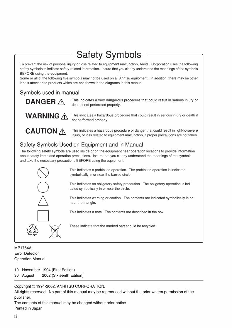
To prevent the risk of personal injury or loss related to equipment malfunction, Anritsu Corporation uses the followingsafety symbols to indicate safety-related information. Insure that you clearly understand the meanings of the symbolsBEFORE using the equipment.Some or all of the following five symbols may not be used on all Anritsu equipment. In addition, there may be otherlabels attached to products which are not shown in the diagrams in this manual.
Symbols used in manual
DANGER
WARNING
CAUTION
Safety Symbols Used on Equipment and in ManualThe following safety symbols are used inside or on the equipment near operation locations to provide informationabout safety items and operation precautions. Insure that you clearly understand the meanings of the symbolsand take the necessary precautions BEFORE using the equipment.
This indicates a prohibited operation. The prohibited operation is indicatedsymbolically in or near the barred circle.
This indicates an obligatory safety precaution. The obligatory operation is indi-cated symbolically in or near the circle.
This indicates warning or caution. The contents are indicated symbolically in ornear the triangle.
This indicates a note. The contents are described in the box.
These indicate that the marked part should be recycled.
This indicates a very dangerous procedure that could result in serious injury ordeath if not performed properly.
This indicates a hazardous procedure that could result in serious injury or death ifnot performed properly.
This indicates a hazardous procedure or danger that could result in light-to-severeinjury, or loss related to equipment malfunction, if proper precautions are not taken.
Safety Symbols
iii
WARNING
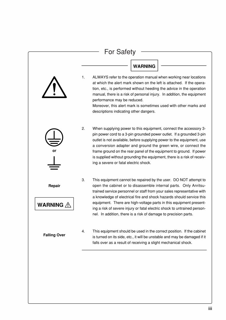
1. ALWAYS refer to the operation manual when working near locations
at which the alert mark shown on the left is attached. If the opera-
tion, etc., is performed without heeding the advice in the operation
manual, there is a risk of personal injury. In addition, the equipment
performance may be reduced.
Moreover, this alert mark is sometimes used with other marks and
descriptions indicating other dangers.
2. When supplying power to this equipment, connect the accessory 3-
pin power cord to a 3-pin grounded power outlet. If a grounded 3-pin
outlet is not available, before supplying power to the equipment, use
a conversion adapter and ground the green wire, or connect the
frame ground on the rear panel of the equipment to ground. If power
is supplied without grounding the equipment, there is a risk of receiv-
ing a severe or fatal electric shock.
3. This equipment cannot be repaired by the user. DO NOT attempt to
open the cabinet or to disassemble internal parts. Only Anritsu-
trained service personnel or staff from your sales representative with
a knowledge of electrical fire and shock hazards should service this
equipment. There are high-voltage parts in this equipment present-
ing a risk of severe injury or fatal electric shock to untrained person-
nel. In addition, there is a risk of damage to precision parts.
4. This equipment should be used in the correct position. If the cabinet
is turned on its side, etc., it will be unstable and may be damaged if it
falls over as a result of receiving a slight mechanical shock.
or
Repair
WARNING
Falling Over
For Safety
iv
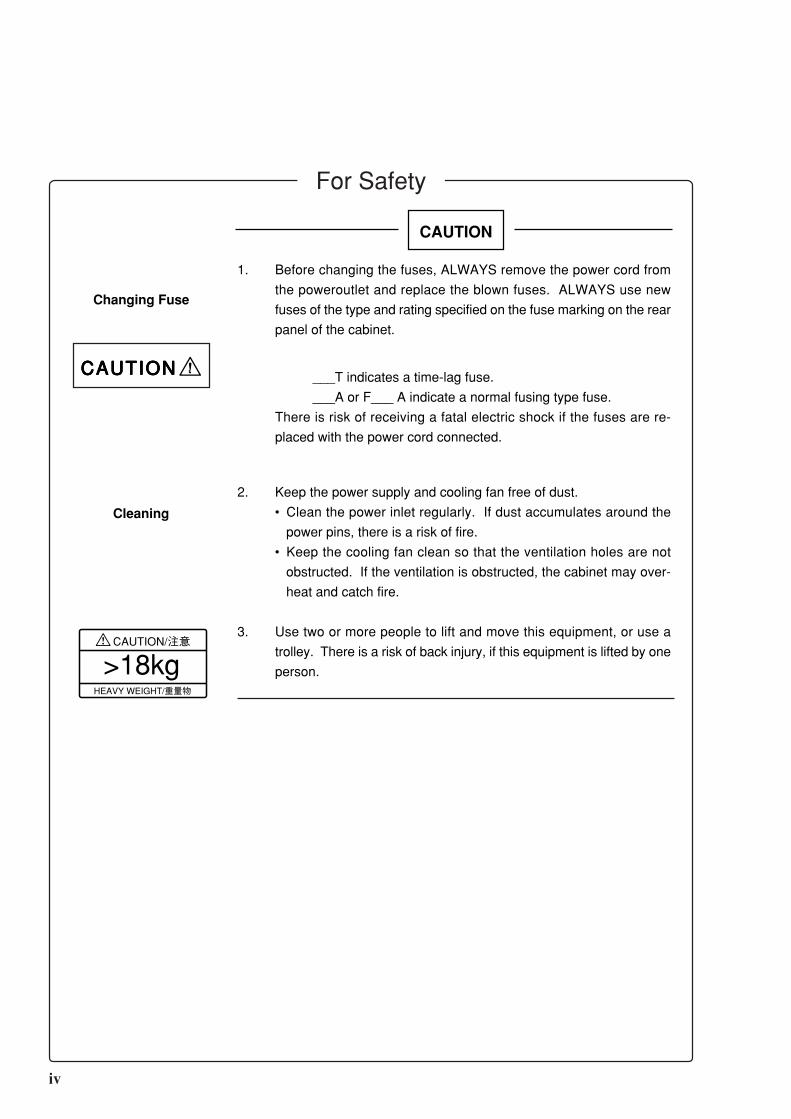
CAUTION
1. Before changing the fuses, ALWAYS remove the power cord from
the poweroutlet and replace the blown fuses. ALWAYS use new
fuses of the type and rating specified on the fuse marking on the rear
panel of the cabinet.
___T indicates a time-lag fuse.
___A or F___ A indicate a normal fusing type fuse.
There is risk of receiving a fatal electric shock if the fuses are re-
placed with the power cord connected.
2. Keep the power supply and cooling fan free of dust.
• Clean the power inlet regularly. If dust accumulates around the
power pins, there is a risk of fire.
• Keep the cooling fan clean so that the ventilation holes are not
obstructed. If the ventilation is obstructed, the cabinet may over-
heat and catch fire.
3. Use two or more people to lift and move this equipment, or use a
trolley. There is a risk of back injury, if this equipment is lifted by one
person.
Changing Fuse
CAUTIONCAUTIONCAUTIONCAUTIONCAUTION
Cleaning
HEAVY WEIGHT/重量物
CAUTION/注意
>18kg
For Safety

v
For Safety
CAUTION
This instrument uses floppy disks for storing data and programs.
Incorrect use of the floppy disks or errors can cause the data stored on the
medium to be erased. Back up the floppy disk as a precaution.
Anritsu will not compensate for loss of the stored data.
Note the following points when using this instrument. Especially, do not
remove the floppy disk from the drive during disk access. For details, see
the main text of this manual.
• Satisfy the specified environmental conditions. Do not use this instru-
ment in places subject to dirt.
• Clean head of floppy disk drive with 3.5 inch head cleaning disk set regu-
larly.
• Keep floppy disks away from magnetized products. Do not bend the
floppy disk.
The MP1764A uses chemical compound semiconductor including arsenic
and manganese dioxide Lithium Battery and timer including mercury. At
the end of it's life, the MP1764A should be recycled or disposed properly.
Storage media
Disposing of
the product

vi
(Blank)

vii
Equipment CertificateAnritsu Corporation certifies that this equipment was tested before shipment using
calibrated measuring instruments with direct traceability to public testing organiza-
tions recognized by national research laboratories including the Electrotechnical Labo-
ratory, the National Research Laboratory of Metrology and the Communications Re-
search Laboratory, and was found to meet the published specifications.
Anritsu WarrantyAnritsu Corporation will repair this equipment free-of-charge if a malfunction occurs
within 1 year after shipment due to a manufacturing fault, provided that this warranty is
rendered void under any or all of the following conditions.
• The fault is outside the scope of the warranty conditions described in the operation
manual.
• The fault is due to mishandling, misuse, or unauthorized modification or repair of
the equipment by the customer.
• The fault is due to severe usage clearly exceeding normal usage.
• The fault is due to improper or insufficient maintenance by the customer.
• The fault is due to natural disaster including fire, flooding, earthquake, etc.
• The fault is due to use of non-specified peripheral equipment, peripheral parts,
consumables, etc.
• The fault is due to use of a non-specified power supply or in a non-specified instal-
lation location.
In addition, this warranty is valid only for the original equipment purchaser. It is not
transferable if the equipment is resold.
Anritsu Corporation will not accept liability for equipment faults due to unforeseen and
unusual circumstances, nor for faults due to mishandling by the customer.
Anritsu Corporation ContactIf this equipment develops a fault, contact Anritsu Corporation or its representatives at
the address in this manual.

viii
CE MarkingAnritsu affix the CE Conformity Marking on the following product(s) in
accordance with the Council Directive 93/68/EEC to indicate that they
conform with the EMC directive of the European Union (EU).
CE Conformity Marking
1. Product Name/Model Name
Product Name: Error Detector
Model Name: MP1764A
2. Applied Directive
EMC: Council Directive 89/336/EEC
Safety: Council Directive 73/23/EEC
3. Applied Standards
EMC :
Electromagnetic radiation:
EN55011(ISM, Group 1, Class A equipment)
Immunity:
EN50082-1
Performance Criteria*
IEC801-2 (ESD) 4 kVCD, 8 kVAD B
IEC801-3 (Rad.) 3 V/m A
IEC801-4 (EFT) 1 kV B
*: Performance Criteria
A: No performance degradation or function loss
B: Self-recovered temporary degradation of performance or tempo-
rary loss of function
Harmonic current emissions:
EN61000-3-2 (Class A equipment)
Safety: EN61010-1 (Installation Category II, Pollution Degree 2 )

ix
Power Line Fuse ProtectionFor safety, Anritsu products have either one or two fuses in the AC power lines as
requested by the customer when ordering.
Single fuse: A fuse is inserted in one of the AC power lines.
Double fuse: A fuse is inserted in each of the AC power lines.
Example 1: An example of the single fuse is shown below:
Fuse Holder
FU
S E
Example 2: An example of the double fuse is shown below:
Fuse Holders
FU
S E
FU
S E

x

I
Title of Contents
For Safety ....................................................................................................................... iii
SECTION 1 GENERAL ................................................................................................... 1-1
1.1 Features ......................................................................................................................... 1-1
1.2 Functions ...................................................................................................................... 1-2
1.3 Options ......................................................................................................................... 1-9
1.4 Composition ................................................................................................................. 1-9
SECTION 2 PREPARATIONS ....................................................................................... 2-1
2.1 Installation Site Environment ....................................................................................... 2-1
2.2 Safety Measures ............................................................................................................ 2-1
2.3 Power Supply Voltage .................................................................................................. 2-1
2.4 Internal Battery Life ..................................................................................................... 2-1
2.5 Destruction Prevention Measures ................................................................................. 2-2
SECTION 3 DESCRIPTION OF PANELS AND CONNECTORS ............................. 3-1
3.1 FRONT PANEL ........................................................................................................... 3-2
3.2 REAR PANEL.............................................................................................................. 3-4
SECTION 4 OPERATION............................................................................................... 4-1
4.1 Setup ............................................................................................................................. 4-1
4.1.1 Measurement ................................................................................................... 4-2
4.2 Internal Memory Initialization ..................................................................................... 4-2
4.3 Input Conditions Setting ............................................................................................... 4-5
4.3.1 When both DATA and CLOCK are GND termination ................................... 4-6
4.3.2 When DATA and CLOCK are both ECL termination .................................... 4-8
4.3.3 Auto search ...................................................................................................... 4-8
4.3.4 EYE MARGIN Measurement ......................................................................... 4-9
4.4 Pattern Setting .............................................................................................................. 4-10
4.4.1 Logic ................................................................................................................ 4-12
4.4.2 Alternate pattern setting .................................................................................. 4-12
4.4.3 Data pattern setting .......................................................................................... 4-14
4.4.4 Zero substitution pattern setting ...................................................................... 4-15
4.4.5 Pseudo random pattern setting ........................................................................ 4-16
4.4.6 Bit window setting .......................................................................................... 4-17
4.4.7 Block window setting ...................................................................................... 4-18
II
4.4.8 Sync detection mode ....................................................................................... 4-19
4.4.9 Tracking .......................................................................................................... 4-21
4.4.10 Error analysis (Option 01) ............................................................................... 4-22
4.5 Error Measurement ....................................................................................................... 4-23
4.5.1 ERROR RATIO measurement ........................................................................ 4-25
4.5.2 ERROR COUNT ............................................................................................. 4-26
4.5.3 ERROR INTERVAL....................................................................................... 4-27
4.5.4 ERROR FREE INTERVAL ............................................................................ 4-28
4.5.5 CLOCK FREQUENCY .................................................................................. 4-29
4.5.6 DISPLAY display ........................................................................................... 4-30
4.5.7 Measurement mode selection .......................................................................... 4-31
4.5.8 Measurement start/stop ................................................................................... 4-31
4.5.9 Current data function ....................................................................................... 4-32
4.5.10 AUTO SYNC function .................................................................................... 4-33
4.5.11 Measurement time setting ............................................................................... 4-36
4.5.12 Real time setting .............................................................................................. 4-36
4.5.13 Error lamp and alarm lamps ............................................................................ 4-37
4.5.14 Error detection mode setting ........................................................................... 4-38
4.6 Memory (Floppy Disk) ................................................................................................. 4-39
4.6.1 File save........................................................................................................... 4-40
4.6.2 File recall ......................................................................................................... 4-41
4.6.3 Disk formatting ............................................................................................... 4-41
4.6.4 File delete ........................................................................................................ 4-42
4.6.5 Error messages ................................................................................................ 4-42
4.6.6 Floppy disk ...................................................................................................... 4-43
4.6.7 Floppy disk precautions .................................................................................. 4-43
4.7 Printer output ................................................................................................................ 4-44
4.7.1 Printing Format ............................................................................................... 4-47
4.8 Definition of Terms ...................................................................................................... 4-51
4.8.1 Measurement items ......................................................................................... 4-51
4.8.2 Alarm intervals ................................................................................................ 4-51
4.8.3 Threshold EI and EFI data .............................................................................. 4-51
4.8.4 Error performance data .................................................................................... 4-52
4.9 Processing of Measurement Data At Alarm Generation .............................................. 4-54
4.10 FUNCTION Switch Setting ......................................................................................... 4-56
SECTION 5 PRINCIPLES OF OPERATION ............................................................... 5-1
5.1 Pseudorandom Pattern (PRBS Pattern) ....................................................................... 5-1
5.2 Pattern Synchronized Output Synchronization ........................................................... 5-3
5.2.1 Pseudorandom pattern ..................................................................................... 5-3
5.2.2 Programmable pattern ..................................................................................... 5-3

III
5.3 Frame Sync Output ...................................................................................................... 5-4
5.4 Error Output ................................................................................................................ 5-5
SECTION 6 MEASUREMENT ....................................................................................... 6-1
6.1 Set-up ............................................................................................................................ 6-1
6.2 Measurement ................................................................................................................ 6-1
6.3 Burst Measurement ....................................................................................................... 6-2
SECTION 7 PERFORMANCE CHECK........................................................................ 7-1
7.1 When Performance Check Necessary .......................................................................... 7-1
7.2 Test Equipment ............................................................................................................. 7-1
7.3 Check Method .............................................................................................................. 7-2
7.3.1 Operating frequency ........................................................................................ 7-2
7.3.2 Input data level ................................................................................................ 7-3
7.3.3 Input clock level .............................................................................................. 7-4
7.3.4 Pattern .............................................................................................................. 7-5
7.3.5 Measurement items ......................................................................................... 7-6
SECTION 8 MAINTENANCE ........................................................................................ 8-1
8.1 Daily Maintenance ........................................................................................................ 8-1
8.2 Preparation for Shipment .............................................................................................. 8-1
SECTION 9 TROUBLESHOOTING AND REPAIR ................................................... 9-1
9.1 Before Considering Trouble ......................................................................................... 9-1
9.2 Fuse Replacement ........................................................................................................ 9-1

IV.

1-1
SECTION 1
GENERAL
1.1 FeaturesThe MP1764A is an error detector that operates over the 50 MHz to 12.5 GHz frequency range, and is used in conjunction
with an MP1763B Pulse Pattern Generator to test high-speed digital communication systems and high-speed semiconduc-
tors.
The input threshold voltage (–3 V to +1.875 V) of MP1764A can be set in 1 mV steps and the input clock phase (–500 ps
to +500 ps) can be set in 1 ps steps. The measurement patterns are pseudorandom (PRBS) pattern (1 period 2N–1; N=7, 9,
11, 15, 20, 21, 31), programmable (PRGM) pattern (maximum 8M bits), alternate pattern, and zero substitution pattern.
Since the 8M bits memory can program six STM-64 (OC192) frames, STM frame tests can be carried out by combining the
MP1764A with an MP1763B Pulse Pattern Generator. The MP1764A has three error detection modes of total error, inser-
tion error, and omission error. Its measurement items are error ratio, error count, error intervals (EI), error free intervals
(EFI) and clock frequency. The measured result can be displayed on a display. A printer can printout the threshold EI/EFI
data and performance data, as well as the measured result (error ratio, error count, EI/EFI, alarm time).
The MP1764A has an automatic search function that can automatically set the input data threshold voltage and input clock
phase and a pattern tracking function that can send to and set the MP1764A pattern data to the MP1763B. The pattern
tracking function can also send the MP1763B pattern data to the MP1764A. Data EYE Margin measurement is also pos-
sible. The MP1764A also has a memory function that can store the set patterns and pattern data to 3.5 inch floppy disk and
read and set the stored data.
The MP1764A is equipped with an IEEE Std 488-1987 GPIB as standard so that it can be remotely controlled. It also has
a DMA receive function that can receive pattern data transferred by DMA from the controller.

1-2
SECTION 1 GENERAL
1.2 Functions
0.05 to 12.5 GHz
2N–1 (N=7, 9, 11, 15, 20, 23, 31)
1/2, 1/4, 1/8, 0/8
(1/2, 3/4, 7/8, 8/8 possible by logic inversion)
1 bit or 3 bits
(switchable by rear panel DIP switch)
Consecutive 0 pattern can be inserted up to pattern length–1.
Pattern at zero substitution: 2N (N=7, 9, 11, 15)
2 to 8388608 bits
2 to 65536 bits : step
65536 to 131072 bits : step
131072 to 262144 bits : step
262144 to 524288 bits : step
524288 to 1048576 bits : step
1048576 to 2097152 bits : step
2097152 to 4194304 bits : step
4194304 to 8388608 bits : step
All 0 / all 1 / page 0 / page 1
128 to 4194304 bits / Step 128 bits (A/B same length)
Controlled by external signal
All 0 / all 1 / page 0 / page 1
PRBS
Zero substitution
DATA
Alternate
pattern
Logic
inversion
1 bit
2 bits
4 bits
8 bits
16 bits
32 bits
64 bits
128 bits
Pattern length
Mark ratio
Number of AND bit
shifts at mark ratio
DATA length
Editing function
DATA length
Number of loops
Editing function
Operating frequency
Measurement
pattern
Positive/Negative switching possible
[PRBS]
[PRGM]
PositiveH
L "1"
"0"Negative
Positive Negative
L
H "1"
"0"
H
L "1"
"0" H
L "1"
"0"
1-3
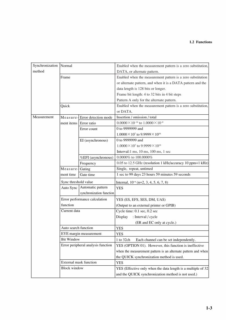
Synchronization
method
Measurement
Normal
Frame
Quick
M e a s u r e -
ment items
M e a s u r e -
ment time
1.2 Functions
Enabled when the measurement pattern is a zero substitution,
DATA, or alternate pattern.
Enabled when the measurement pattern is a zero substitution
or alternate pattern, and when it is a DATA pattern and the
data length is 128 bits or longer.
Frame bit length: 4 to 32 bits in 4 bit steps
Pattern A only for the alternate pattern.
Enabled when the measurement pattern is a zero substitution,
or DATA.
Insertion / omission / total
0.0000×10⁻¹⁶ to 1.0000×10–0
0 to 9999999 and
1.0000×10⁷ to 9.9999×10¹⁶
0 to 9999999 and
1.0000×10⁷ to 9.9999×10¹⁶
Interval:1 ms, 10 ms, 100 ms, 1 sec
0.0000% to 100.0000%
0.05 to 12.5 GHz (resolution 1 kHz/accuracy 10 ppm+1 kHz)
Single, repeat, untimed
1 sec to 99 days 23 hours 59 minutes 59 seconds
Error detection mode
Error ratio
Error count
EI (asynchronous)
%EFI (asynchronous)
Frequency
Gating
Gate time
Automatic pattern
synchronization function
Sync threshold value
Auto Sync
Error performance calculation
function
Current data
Auto search function
EYE margin measurement
Bit Window
Error peripheral analysis function
External mask function
Block window
Internal, 10–n (n=2, 3, 4, 5, 6, 7, 8)
YES
YES (ES, EFS, SES, DM, UAS)
(Output to an external printer or GPIB)
Cycle time: 0.1 sec, 0.2 sec
Display : Interval / cycle
(ER and EC only at cycle.)
YES
YES
1 to 32ch Each channel can be set independently.
YES (OPTION 01). However, this function is ineffective
when the measurement pattern is an alternate pattern and when
the QUICK synchronization method is used.
YES
YES (Effective only when the data length is a multiple of 32
and the QUICK synchronization method is not used.)

1-4
SECTION 1 GENERAL
Input waveform
Input amplitude
Threshold voltage
Termination voltage
Input impedance
Connector
Input waveform
Input amplitude
Clock delay
Polarity switching
Termination voltage
Input impedance
Connector
Output level
Connector
Output level
Connector
Input/output
connectorData input
Clock input
Sync signal
output
Error output
(DIRECT)
NRZ
0.25 to 2.0 Vp-p
–3.000 to 1.875 V (1mV steps)
GND / –2 V
50ΩAPC-3.5
Up to 0.5 GHz: Square wave only (Duty 50%)
Others : Sine wave or square wave (Duty 50%)
0.25 to 2.0 Vp-p
±500 ps (1ps step)
CLOCK / CLOCK
GND/–2 V
50ΩAPC-3.5
1/32 Clock / Pattern sync (FIX) / Pattern sync (VARIABLE)
VOH: 0 ±0.2 V Amplitude: 1 Vp-p±20%
SMA
0 / –1 V±0.1 V (LOW level at error)
SMA

1-5
Input/output
connector
Clock
Error output
(STRETCHED)
Alarm output
Frame sync
output
Internal sync
judgment output
External
mask input
Resync input
Pattern
switching input
Output level
Pulse width
Connector
Output condition
Output level
Connector
Output level
Connector
Output level
Connector
Input level
Connector
Input level
Connector
Input level
Connector
TTL (LOW level at error)
350 ns±100 ns
BNC
Clock loss, sync loss
TTL (LOW level at alarm)
BNC
0 /–1 V±0.1 V(*1)
SMA
HIGH level output when synchronization established.
0 /–1 V±0.1 V
SMA
Masked when LOW level.
0 /–1 V±0.1 V
SMA
Synchronization released when LOW level.
0 /–1 V±0.1 V
SMA
Alternate pattern A/B switching signal (A when LOW level)
ECL (H: –0.9±0.2 V, L: –1.75±0.2 V)
SMA
Date and time display
1.2 Functions
(*1) Frame sync output is output under the following conditions only:
(1) When SYNC MODE is frame
(2) When data length exceeds 128 bits
In short, it is not output for the PRBS pattern, when the data length is 128 bits, etc.
1-6
SECTION 1 GENERAL
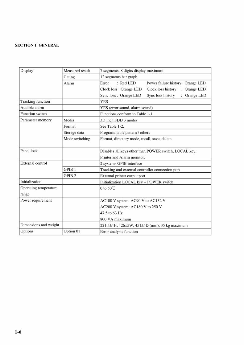
Display
Tracking function
Audible alarm
Function switch
Parameter memory
Panel lock
External control
Initialization
Operating temperature
range
Power requirement
Dimensions and weight
Options
Measured result
Gating
Alarm
Media
Format
Storage data
Mode switching
GPIB 1
GPIB 2
Option 01
7 segments, 8 digits display maximum
12 segments bar graph
Error : Red LED Power failure history: Orange LED
Clock loss: Orange LED Clock loss history : Orange LED
Sync loss : Orange LED Sync loss history : Orange LED
YES
YES (error sound, alarm sound)
Functions conform to Table 1-1.
3.5 inch FDD 3 modes
See Table 1-2.
Programmable pattern / others
Format, directory mode, recall, save, delete
Disables all keys other than POWER switch, LOCAL key,
Printer and Alarm monitor.
2 systems GPIB interface
Tracking and external controller connection port
External printer output port
Initialization LOCAL key + POWER switch
0 to 50
AC100 V system: AC90 V to AC132 V
AC200 V system: AC180 V to 250 V
47.5 to 63 Hz
800 VA maximum
221.5±4H, 426±5W, 451±5D (mm), 35 kg maximum
Error analysis function
1-7
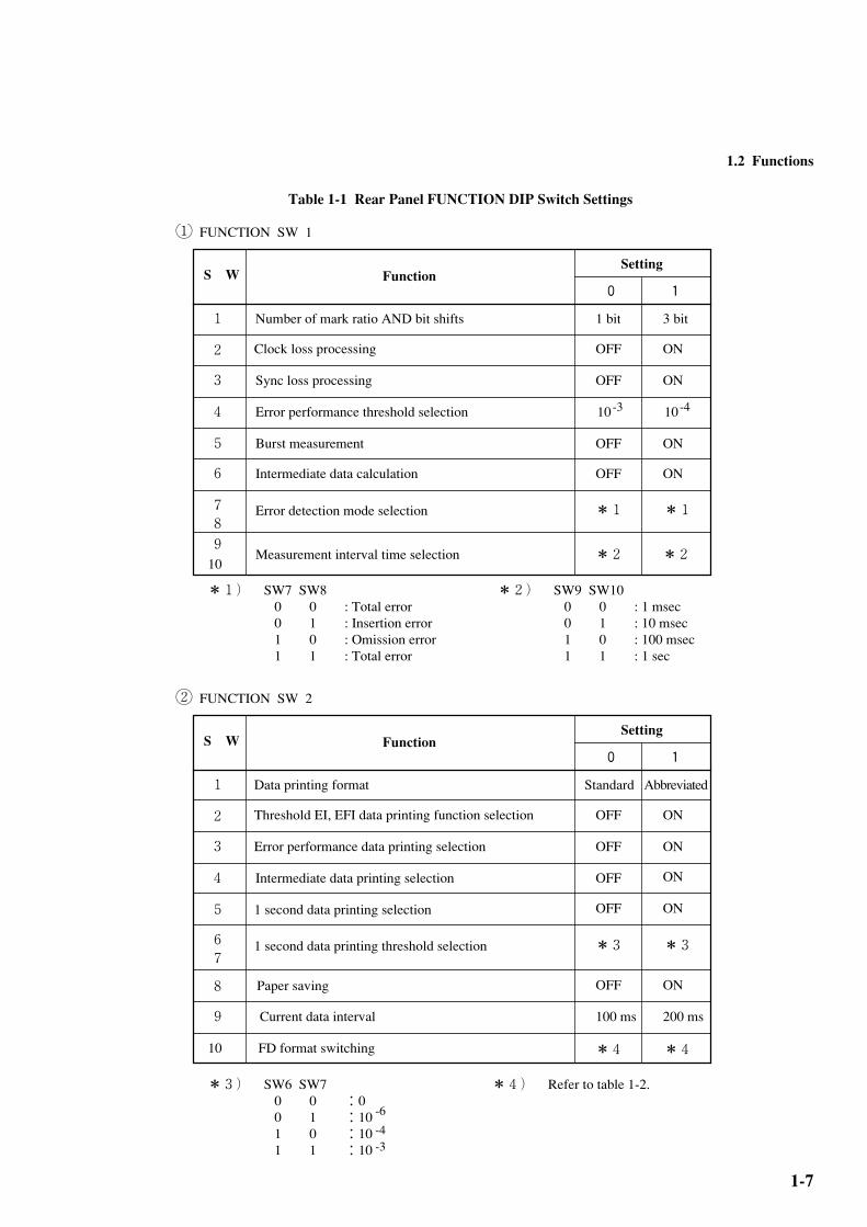
Table 1-1 Rear Panel FUNCTION DIP Switch Settings
S W FunctionSetting
1 Number of mark ratio AND bit shifts
Clock loss processing
Sync loss processing
Error performance threshold selection
Burst measurement
Intermediate data calculation
Measurement interval time selection
Error detection mode selection
2
3
4
5
6
78
1 bit
OFF
10-3
OFF
*1
OFF
OFF
*2
0 1
3 bit
ON
10-4
ON
*1
ON
ON
*2
FUNCTION SW 1
910
*1) SW7 SW8 0 0 : Total error 0 1 : Insertion error 1 0 : Omission error 1 1 : Total error
*2) SW9 SW10 0 0 : 1 msec 0 1 : 10 msec 1 0 : 100 msec 1 1 : 1 sec
S W FunctionSetting
1 Data printing format
Threshold EI, EFI data printing function selection
Error performance data printing selection
1 second data printing selection
2
3
4
5
67
8
Standard
OFF
*3
OFF
OFF
100 ms
0 1
Abbreviated
ON
*3
ON
ON
200 ms
FUNCTION SW 2
9
10
*3) SW6 SW7 0 0 :0 0 1 :10 1 0 :10 1 1 :10
Intermediate data printing selection
1 second data printing threshold selection
Paper saving
Current data interval
FD format switching
OFF ON
OFF ON
-6
-4-3
②
①
*4 *4
*4) Refer to table 1-2.
1.2 Functions

1-8
SECTION 1 GENERAL
Table 1-22HD
TypeSector length [bytes/sector]
Number of sectors [sectors/track]
Number of tracks [tracks/side]
Number of sides
1232KB
1440KB
1024
512
8
18
77
80
2
2
2DD
TypeSector length [bytes/sector]
Number of sectors [sectors/track]
Number of tracks [tracks/side]
Number of sides
640KB
720KB
512
512
8
9
80
80
2
2
SW2BIT 10
1
0
SW2BIT 10
1
0
1
2

1-9
1.3 OptionThe following option is available with the MP1764A Error Detector.
OPTION 01 Error analysis function
1.4 CompositionThe standard composition of the MP1764A Error Detector is shown in Table 1-3.
Table 1-3 MP1764A Standard Composition
Item
Main Unit
Accessory
Application
parts
No.
MP1764A
J0500A
J0496
J0515J
J0491
J0008
F0079
Z0168
M-W0887AE
Z0481
MB24B
B0163
B0171
B0044
Z0416
Name
MP1764A Error Detector
Semirigid cable (50 cm)
Conversion connector
SMA cable (1 m)
Power cord w/shield
GPIB cable (2 m)
Fuse
3.5 inch floppy disk (2HD)
Operation manual
12.5G/3.2G BERTS APPLICATION
SOFTWARE DEMO
Dolly
Transport quilting
Protective carrying case
Rack mounting kit 1MW.5U use
3.5 inch head cleaning disk
Qty
1
2
2
3
1
2
2
2
1
1
APC • 3.5J-APC • 3.5J
13A (2.6 m)
408JE-102
MF51NR10A
Formatted *1
20A power cord/plug
2 pcs/set
*1: The two 3.5 inch floppy disks are already formatted (1,440 kB). Patterns equivalent to PRBS210–1 (mark ratios 1/2,
1/4, and 1/8) that can be generated by the MP1601A or MP1604A Pulse Pattern Generator from Anritsu Corporation
are stored on one of these disks.
1.4 Composition

1-10
SECTION 1 GENERAL
.
(Blank)

2-1
SECTION 2
PREPARATIONS
2.1 Installation Site Environment
Do not use the instrument in locations:
• Where vibrations are severe.
• Where it is damp or dusty.
• Where there is exposure to direct sunlight.
• Where there is exposure to active gases.
Long-term storage at high temperatures will shorten the life of the internal battery. Store the instrument at normal room
temperature.
Operating temperature and humidity conditions 0 to 50 (However, 5 to 40 for floppy disks),
Relative humidity ≤95%.
Storage temperature and humidity conditions – 40 to 70, Relative humidity ≤95%.
2.2 Safety Measures
• Use the power cord to connect the ac power supply. Ground the ground terminal of the power cord or the frame ground
terminal on the rear panel of the instrument.
• When changing the fuse, always use a fuse of the same rating. (See the fuse replacement section.)
• If the instrument is operated at room temperature after being used or stored for a long time at low temperature, conden-
sation may occur and cause short-circuiting. To prevent this, do not turn the power on until the instrument is completely
dry.
2.3 Power Supply Voltage
The power supply voltage for this instrument is shown on the rear panel. Use a voltage within the rated voltage range.
Excessive voltage may damage the circuits.
2.4 Internal Battery Life
The MP1764A uses a lithium primary battery as the timer and memory back-up power supply. The life of this battery is 7
years or more when the instrument is stored at normal room temperature. However, since the battery life largely depends on
the storage temperature, storage at high temperatures for long periods will shorten the period given above.
Since battery replacement can only be made by Anritsu, contact the nearest Anritsu representative when replacement is
required.
2-2
SECTION 2 PREPARATIONS
.
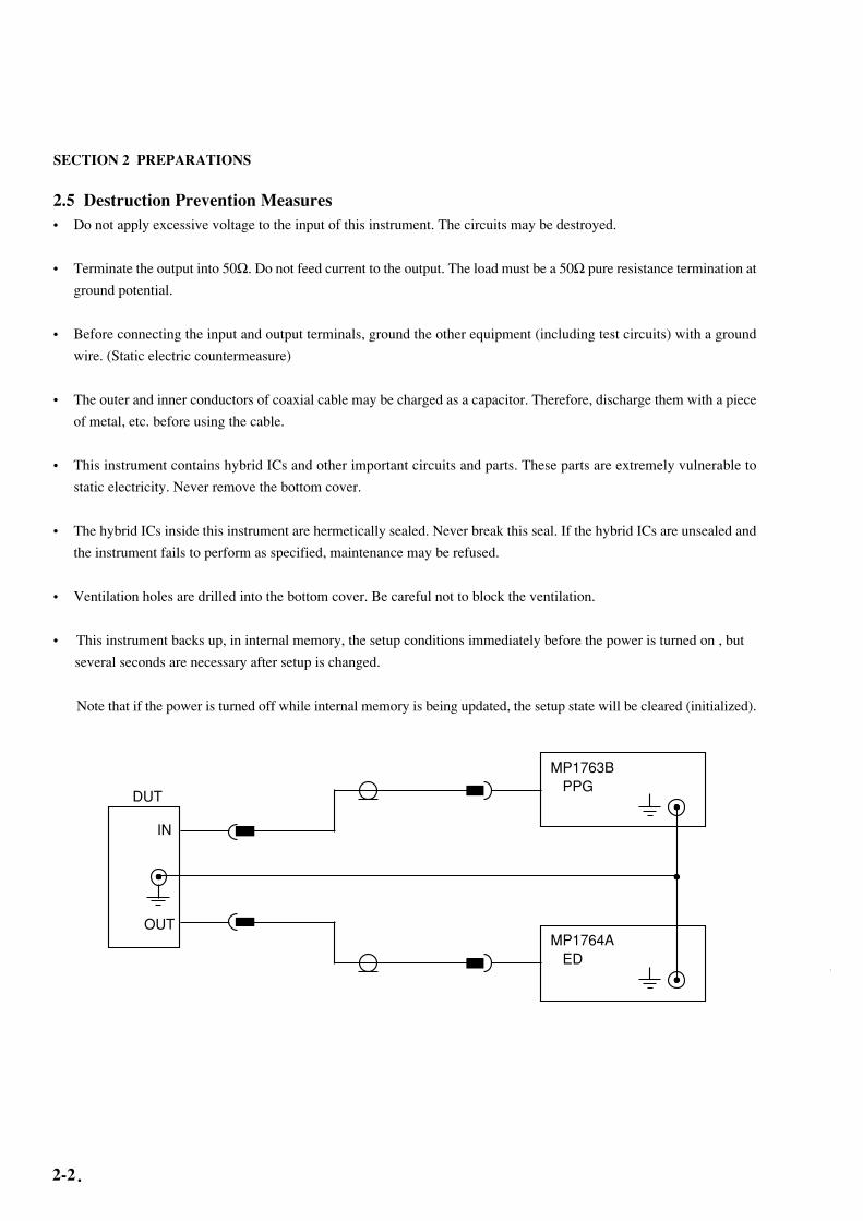
2.5 Destruction Prevention Measures
• Do not apply excessive voltage to the input of this instrument. The circuits may be destroyed.
• Terminate the output into 50Ω. Do not feed current to the output. The load must be a 50Ω pure resistance termination at
ground potential.
• Before connecting the input and output terminals, ground the other equipment (including test circuits) with a ground
wire. (Static electric countermeasure)
• The outer and inner conductors of coaxial cable may be charged as a capacitor. Therefore, discharge them with a piece
of metal, etc. before using the cable.
• This instrument contains hybrid ICs and other important circuits and parts. These parts are extremely vulnerable to
static electricity. Never remove the bottom cover.
• The hybrid ICs inside this instrument are hermetically sealed. Never break this seal. If the hybrid ICs are unsealed and
the instrument fails to perform as specified, maintenance may be refused.
• Ventilation holes are drilled into the bottom cover. Be careful not to block the ventilation.
• This instrument backs up, in internal memory, the setup conditions immediately before the power is turned on , but
several seconds are necessary after setup is changed.
Note that if the power is turned off while internal memory is being updated, the setup state will be cleared (initialized).
MP1763B PPG
MP1764A ED
DUT
IN
OUT

3-1
SECTION 3
DESCRIPTION OF PANELS AND CONNECTORS
3-2
SEC
TIO
N 3 D
ESC
RIP
TIO
N O
F P
AN
EL
S AN
D C
ON
NE
CT
OR
S
3.1F
ront PanelERROR DETECTOR MP1764A 0.05 - 12.5GHz
PATTERN
MEMORY
THRESHOLD / MARGIN DELAY TIME / MARGIN
MEASUREMENT
EXIST DIRFILE No.
RECALLDELETE
SAVERESAVE SHIFT PATT OTHERS
MODE
LOGIC PATTERN PRBS / ZERO SUBST PRBS MARK RATIO
2 - 1N
2 N
POS
NEG
ALTNDATA Z.S PRBS 7 9 11 15 20 23 31 0/8 1/8 1/4 1/2
8/8 7/8 3/4 1/2
!
PANEL LOCK
GPIBREMOTE
LOCAL
POWER
OFF ON
INPUTDATA CLOCK
VVp-p
psps p-p
TERMGND
-2V
GUARD
TERMGND
-2V
GUARD
BUSY
-3V to 1.875V -500ps to 500ps
AUTO SEARCH(MARK RATIO 1/8 to 7/8)
POLARITYCLK
CLK
EYE MARGINERROR RATIO (10 )
2 3 4 5 6 7 8 9- N
ON START
SYNC MODENORMAL FRAME QUICK A B
ALTNDISPLAY SELECT
PATT BIT BLOCK ERROR
CURRENT HISTORY
POWER FAILCLOCK LOSS SYNC LOSS
ERRORS GATING
%MHz
REPEATSINGLEUNTIMED
ERROR RATIO
DISPLAYERROR COUNT
ERRORINTERVAL
ERROR FREE INTERVAL
CLOCKFREQUENCY
MODECURRENT DATA
2 3 4 5 6 7 8 INTAUTO SYNC
SYNC THRESHOLD(10 )-NSTART STOP
REAL TIME / MEAS TIME
DAY YEAR / HOUR MONTH / MINUTE DAY / SECOND
DISPLAY / MODIFY
REAL TIME MEAS TIMEY.M.D H.M.S PERIOD TIMED ELAPSED
MODIFY
BURST MODE
ON MANUAL PRINT
ALARM
ERRORS
PRINTER ALARM MONITOR
1 / 32 CLOCKFIXED POSN VAR POSN
PATTERN SYNC
0 / -1V 50Ω
SYNC OUTPUT
0.25-2.0Vp-p / 50Ω
CLOCK
GND-2V
TERM
INPUT
!
0.25-2.0Vp-p / 50Ω
GND-2V
TERM DATA
WINDOW WINDOW ANALYSIS
DATA LENGTH/ZERO SUBST LENGTHDATA LENGTHZERO SUBST LENGTH
PAGE/PATTERN SYNC POSITION
9 10 11 12 13 14 15 16
ALL PAGEPRESET
PATTERNLOADING
TRACKINGGUARD 0 1 0 1
FRAME LENGTH
ON
ERROR ANALYSIS TRIGGER
BLOCK WINDOW
BIT
1 2 3 4 5 6 7 8 BIT WINDOW
PATTERN SYNC POSITIONPAGEDISPLAY
1 2 3 4 5 6 7 8 9 10
11
12
13141516

3-3
3.1 Front P
anel
1
2
3
4
5
ON
MANUALPRINT
6
7
8
9
Small Large
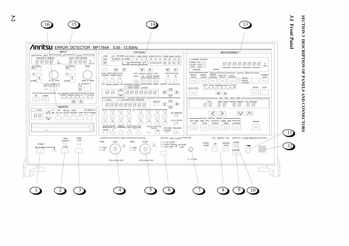
POWER switch When the power is turned on and the LED lights.When the power is turned off.
LOCAL key Switches from GPIB REMOTE state (LED lit) to LOCAL key enabled state.In the GPIB REMOTE state, all the keys other than the POWER switch and LOCAL key are disabled.
Panel lock key At panel lock (LED lit), all the keys other than the following keys are disabled.POWER, PANEL LOCK, PRINTER, ALARM MONITOR
DATA INPUT DATA signal input connector. Impedance 50Ω, GND or –2 V termination can be selected.
CLOCK INPUT CLOCK signal input connector. Impedance 50Ω, GND or –2 V can be termination can be selected.
Sync output selector key Selects the type of sync output.1/32 CLOCK: Output CLOCK divided by 32.FIXED POSITION: Output sync pulse at fixed position relative to output pattern.VARIABLE POSITION: Shift sync output pulse output position in 16-bit units.
Sync output connector Impedance 50Ω, output level 0/–1 V
Printer output Turns the printer output on and off. When the switch is on, the lamp blinks at end of paper and when on-line.
Press when printing intermediate measurement data. Enabled only when the printer switch is on.
ERROR key When the audible alarm sounds at error detection, the key is turned on. When the key is on, the LED inside the key lights.
ALARM key When the audible alarm sounds at alarm detection, the key is turned on. When the key is on, the LED inside the key lights.
Variable resistor Adjust the volume of the audible alarm.
Speaker Audible alarm speaker.
Measurement unit
Pattern setting unit
Input setting unit
Floppy disk drive16
15
14
13
12
11
10

3-4
SECTION 3 DESCRIPTION OF PANELS AND CONNECTORS
AC 100V
10A
GPIB 1
ADDRESS
SYSTEM
CONTROL 5 4 3 2 1
ON
OFF
1 0
0:1BIT
0:10 1:10
-3-4
ERROR
7.8
INTERVAL TIME
(EI.%EFI)
9.10
FUMCTION 2 DATA OUTPUT.DISPLAY
FUNCTION 1 MEASUREMENT
ITEMS SW
BIT SHIFT NUMBER
FOR MARK RATIO VARIED
CLOCK LOSS EVALUATION
SYNC LOSS EVALUATION
ERROR PERFORMANCE
THRESHOLD
BURST MODE
CURRENT DATA CALCULATION
0:EXCLUDE
SPECIFICATION
0:EXCLUDE
0:OFF
0:PROGRESSIVE
00:TOTAL ERROR
01:INSERTION ERROR
10:OMISSION ERROR
11:TOTAL ERROR
00:1 ms
01:10 ms
10:100 ms
11:1 s
1:3BITS
1:INCLUDE
1 2 3 4 5 6
1:INCLUDE
1:ON
1:IMMEDIATE
SPECIFICATION
SHORT FORM OUTPUT
THRESHOLD EI.EFI.DATA
ERROR PERFORMANCE DATA
INTERMEDIATE DATA
OUTPUT
THRESHOLD
ONE
SECOND
DATA
PAPER SAVING
CURRENT DATA INTERVAL
FD FORMATTING TYPE
ITEMS
SW
0:OFF
1:ON
00:> 0
01:>10
10:>10
11:>10
0:OFF
0:100 ms
0:1440 k/720 k
1:1232 k/640 k
1:ON
1:200 ms
0:OFF
0:OFF
0:OFF
0:OFF
1:ON
1:ON
1:ON
1:ON
-6 -4 -3
OUTPUT
1 0
5 4 3 2 1
ADDRESS
SH1 AH1 T6 L4 SR1 RL1 PP0
DC1 DT1 C1 C2 C3 C7
SH1 AH1 T6 L4 SR0 RL0 PP0
DC0 DT0 C1 C2 C3 C4 C28
GPIB 2
(PRINTER)
24-Pin
24-Pin
Nameplate
FUNCTION 1
FUNCTION 2
10 9 8 7 6 5 4 3 2 1 10 9 8 7 6 5 4 3 2 1
1 01 0
ALTN A/B
INPUT
RESYNC
INPUT
EXT MEAS
GATE INPUTFRAME SYNC
OUTPUT
SYNC GAIN
OUTPUT
TTL
TTL
0/-1V 50Ω
ALARM
OUTPUT
ORED ERROR OUTPUT
(STRETCHED) (DIRECT)
ECL 50Ω
0/-1v 50Ω
~LINE INPUT
47.5-63Hz.800VA MAX
WARNING
CAUTION
0/-1v 50Ω
0/-1v 50Ω
0/-1v 50Ω
!
1 2 3 4 5 6.7 8 9 10
12
34
56
79
810
1112
1314
1516
3.2 Rear Panel

3-5
3.2 Rear P
anel
DIP switch Sets system control ON/OFF and the GPIB 1 address.
DIP SWITCH Sets the GPIB 2 address.
GPIB 1 GPIB 1 connector.
GPIB 2 GPIB 2 connector. (for printer)
Nameplate Displays the serial number and oiption.
DIP SWITCH FUNCTION 1/FUNCTION 2 setting DIP SWITCH.
ALT A/B INPUT ECL level. Inputs the pattern A/pattern B switching timing in the ALTN mode.
RESYNC INPUT 0/–1 V 50Ω. When LOW level is input, sync loss is generated.
ALARM OUTPUT TTL level. Outputs LOW level when an alarm is generated.
EXT MEAS GATE INPUT 0/–1 V 50Ω. Mask when LOW level.
ORED ERROR OUTPUT STRETCHED: TTL level. Outputs low level when an error is generated.
DIRECT: 0/–1 V 50Ω
FRAME SYNC OUTPUT 0/–1 V 50Ω
SYNC. GAIN OUTPUT 0/–1 V 50Ω. Synchronization established when HIGH level.
FUSE holder
Power inlet
Ground terminal Connects to the ground terminal of the instrument connected to this instrument.
1
2
3
4
5
6
7
8
9
10
11
12
13
14
15
16

3-6
SECTION 3 DESCRIPTION OF PANELS AND CONNECTORS
.
(Blank)

4-1
SECTION 4
OPERATION
4.1 SetupBe careful of static electricity when handling the MP1764A. Connection to an MP1763B Pulse Pattern Generator is de-
scribed here as an example. Refer to the following figure and make the connections in the following order.
1. Connect the MP1764A and MP1763B ground terminals with ground wire.
2. Connect the power cord to an ac outlet. At this time, use a 3-prong plug with ground. If a 2-prong plug must be used,
connect the MP1764A and MP1763B ground terminals before connecting the plug to the socket.
3. While pressing the LOCAL key, turn on the power and initialize the MP1764A and MP1763B. When initialization is
performed, all the settings are set to the factory settings. (See Table 4-1.) When setting a pattern, etc. that you do not
want to clear, save it to FD. (See 4.6.1.) Initialization makes the MP1764A and MP1763B settings the same. Turn off
the power.
NOTEIf a high voltage is applied to the input connector, the protection circuit may be damaged. Never
apply an input exceeding the rating. If the rating may be exceeded, check the input signal before
making any connections.
ERROR DETECTOR MP1764A 0.05 - 12.5GHzPATTERN
MEMORY
THRESHOLD / MARGIN DELAY TIME / MARGIN
MEASUREMENT
EXIST DIRFILE No.
RECALLDELETE
SAVERESAVE SHIFT PATT OTHERS
MODE
LOGIC PATTERN PRBS / ZERO SUBST PRBS MARK RATIO
2 - 1N
2 N
POS
NEG
ALTNDATA Z.S PRBS 7 9 11 15 20 23 31 0/8 1/8 1/4 1/2
8/8 7/8 3/4 1/2
DATA LENGTH/ZERO SUBST LENGTHDATA LENGTHZERO SUBST LENGTH
!
PANEL LOCK
GPIBREMOTE
LOCAL
POWER
OFF ON
INPUTDATA CLOCK
VVp-p
psps p-p
TERMGND
-2V
GUARD
TERMGND
-2V
GUARD
BUSY
-3V to 1.875V -500ps to 500ps
AUTO SEARCH(MARJ RATIO 1/8 to 7/8)
POLARITYCLK
CLK
EYE MARGINERROR RATIO (10 )
2 3 4 5 6 7 8 9- N
ON START
FRAME LENGTH
SYNC MODENORMAL FRAME QUICK A B
ALTNDISPLAY SELECT
PATT BIT BLOCK ERROR
CURRENT HISTORY
POWER FAILCLOCK LOSS SYNC LOSS
ERRORS GATING
%MHz
REPEATSINGLEUNTIMED
ERROR RATIO
DISPLAYERROR COUNT
ERRORINTERVAL
ERROR FREE INTERVAL
CLOCKFREQUENCY
MODECURRENT DATA
2 3 4 5 6 7 8 9 INTAUTO SYNC
SYNC THRESHOLD(10 )-N
START STOP
REAL TIME / MEAS TIME
DAY YEAR / HOUR MONTH / MINUTE DAY / SECOND
DISPLAY / MODIFY
REAL TIME MEAS TIMEY.M.D H.M.S PERIOD TIMED ELAPSED
MODIFY
BURST MODE
ON MANUAL PRINT
ALARM
ERRORS
PRINTER ALARM MONITOR
1 / 32 CLOCKFIXED POSN VAR POSN
PATTERN SYNC
0 / -1V 50Ω
SYNC OUTPUT
0.25-2.0Vp-p / 50Ω
CLOCK
GND-2V
TERM
INPUT
!
0.25-2.0Vp-p / 50Ω
GND-2V
TERM DATA
WINDOW WINDOW ANALYSIS
PAGE/PATTERN SYNC POSITION
9 10 11 12 13 14 15 16
ALL PAGEPRESET
PATTERNLOADING
TRACKINGGUARD 0 1 0 1
ON
ERROR ANALYSIS TRIGGER
BLOCK WINDOW
BIT
1 2 3 4 5 6 7 8 BIT WINDOW
PATTERN SYNC POSITIONPAGEDISPLAY
Don't forget level check!
Be careful of excessive input !
PULSE PATTERN GENERATOR MP1763B 0.05 - 12.5GHzINTERNAL CLOCK (OPTION.01) PATTERN
MEMORY
TUNING RESOLUTION
FREQUENCYMHz kMz
OUTPUT
EXIST DIRFILE No.
RECALLDELETE
SAVERESAVE SHIFT PATT OTHERS
MODE
LOGIC PATTERN PRBS / ZERO SUBST PRBS MARK RATIO
2 - 1N2 N
POS
NEG
ALTNDATA Z.S PRBS 7 9 11 15 20 23 31 0/8 1/8 1/4 1/2
8/8 7/8 3/4 1/2
ALTN ERROR ADDITION(1×10 )- N
SINGLEA B ON 4 5 6 7 8 9
DATA LENGTH/ZERO SUBST LENGTHDATA LENGTHZERO SUBST LENGTH
A / B LOOP TIME
PAGE/PATTERN SYNC POSITION
BIT
1 2 3 4 5 6 7 8
9 10 11 12 13 14 15 16
ALL PAGEPRESET
PATTERNLOADING
TRACKINGGUARD 0 1 0 1
DATA
50Ω GND
ECL
AMPLITUDE
Vp - p
OFFSET
V
ECL
ps
DELAY TIME
BUSY
CLOCK 1
50Ω GND
ECL
AMPLITUDE
Vp - p
OFFSET
V
ECL
GUARD
GUARD
OFFSET
VOHVTHVOL
OUTPUT
DATA DUMMY DATA CLOCK 1 DUMMY CLOCK 1 CLOCK 2
! ! ! !
50Ω
CAUTION CONNECT THE UNUSEOUTPUT TO THE DUMMY 50Ω 50Ω
CAUTION CONNECT THE UNUSEOUTPUT TO THE DUMMY 50Ω 0 / - 1V 50Ω
1 / 32 CLOCKFIXED POSNVAR POSN
PATTERN SYNC
PANEL LOCK
GPIBREMOTE
LOCAL
POWER
OFF ON
SYNC OUTPUT
0 / - 1V 50Ω
! !
ERROR DETECTOR MP1764A 0.05 - 12.5GHzPATTERN
MEMORY
THRESHOLD / MARGIN DELAY TIME / MARGIN
MEASUREMENT
EXIST DIRFILE No.
RECALLDELETE
SAVERESAVE SHIFT PATT OTHERS
MODE
LOGIC PATTERN PRBS / ZERO SUBST PRBS MARK RATIO
2 - 1N
2 N
POS
NEG
ALTNDATA Z.S PRBS 7 9 11 15 20 23 31 0/8 1/8 1/4 1/2
8/8 7/8 3/4 1/2
DATA LENGTH/ZERO SUBST LENGTHDATA LENGTHZERO SUBST LENGTH
!
PANEL LOCK
GPIBREMOTE
LOCAL
POWER
OFF ON
INPUTDATA CLOCK
VVp-p
psps p-p
TERMGND
-2V
GUARD
TERMGND
-2V
GUARD
BUSY
-3V to 1.875V -500ps to 500ps
AUTO SEARCH(MARJ RATIO 1/8 to 7/8)
POLARITYCLK
CLK
EYE MARGINERROR RATIO (10 )
2 3 4 5 6 7 8 9- N
ON START
FRAME LENGTH
SYNC MODENORMAL FRAME QUICK A B
ALTNDISPLAY SELECT
PATT BIT BLOCK ERROR
CURRENT HISTORY
POWER FAILCLOCK LOSS SYNC LOSS
ERRORS GATING
%MHz
REPEATSINGLEUNTIMED
ERROR RATIO
DISPLAYERROR COUNT
ERRORINTERVAL
ERROR FREE INTERVAL
CLOCKFREQUENCY
MODECURRENT DATA
2 3 4 5 6 7 8 9 INTAUTO SYNC
SYNC THRESHOLD(10 )-N
START STOP
REAL TIME / MEAS TIME
DAY YEAR / HOUR MONTH / MINUTE DAY / SECOND
DISPLAY / MODIFY
REAL TIME MEAS TIMEY.M.D H.M.S PERIOD TIMED ELAPSED
MODIFY
BURST MODE
ON MANUAL PRINT
ALARM
ERRORS
PRINTER ALARM MONITOR
1 / 32 CLOCKFIXED POSN VAR POSN
PATTERN SYNC
0 / -1V 50Ω
SYNC OUTPUT
0.25-2.0Vp-p / 50Ω
CLOCK
GND-2V
TERM
INPUT
!
0.25-2.0Vp-p / 50Ω
GND-2V
TERM DATA
WINDOW WINDOW ANALYSIS
MP1764A MP1763B
PAGE/PATTERN SYNC POSITION
9 10 11 12 13 14 15 16
ALL PAGEPRESET
PATTERNLOADING
TRACKINGGUARD 0 1 0 1
ON
ERROR ANALYSIS TRIGGER
BLOCK WINDOW
BIT
1 2 3 4 5 6 7 8 BIT WINDOW
PATTERN SYNC POSITIONPAGEDISPLAY
Ground wire
Semiriged cable supplied

SECTION 4 OPERATION
4-2
4.1.1 Measurement1. Check that the MP1764A Error Detector and MP1763B Pulse Pattern Generator settings are the same. Since the
instruments were initialized in Paragraph 4.1, the settings should be the same. If the settings are different, initialize the
instruments again. Then, set the MP1763B OUTPUT and the MP1764A AUTO SYNC to ON.
2. Press the MP1764A AUTO SEARCH key. The input data threshold voltage and input clock delay time are automati-
cally set.
After the AUTO SEARCH lamp goes off, check that the CLOCK LOSS, SYNC LOSS, and ERRORS real time lamps
are not lit. If the lamps are lit, check that signaling cables are connected correctly.
3. Change the DISPLAY display item and check if the following measured result is obtained:
ERROR RATIO : Error ratio displayed
ERROR COUNT : Error count displayed
ERROR INTERVAL : Number of error intervals (See 4.8.1.)
ERROR FREE INTERVAL: Number of error free intervals ratio (See 4.8.1.)
4. Add an error and check if it is correctly detected.
Set MP1763B ERROR ADDITION to ON and select 1×10⁻⁶.
Select ERROR RATIO at MP1764A DISPLAY and check if 1×10⁻⁶ is displayed at DISPLAY.
4.2 Internal Memory InitializationTo set the MP1764A to the initial state (factory setting state), set the POWER switch to ON while pressing the LOCAL key.
When the MP1764A is set to the initial state, the previously set contents are all cleared and are preset as shown in
Table 4-1. Verify which patterns, etc. must not be cleared with the user.
THRESHOLD / MARGIN DELAY TIME / MARGIN
INPUTDATA CLOCK
VVp-p
psps p-p
TERMGND
-2V
GUARD
TERMGND
-2V
GUARD
BUSY
-3V to 1.875V -500ps to 500ps
AUTO SEARCH(MARK RATIO 1/8 to 7/8)
POLARITYCLK
CLK
EYE MARGINERROR RATIO (10 )
2 3 4 5 6 7 8 9- N
ON START
MEASUREMENT
CURRENT HISTORY
POWER FAILCLOCK LOSS SYNC LOSS
ERRORS GATING
%MHz
REPEATSINGLEUNTIMED
ERROR RATIO
DISPLAYERROR COUNT
ERRORINTERVAL
ERROR FREE INTERVAL
CLOCKFREQUENCY
MODECURRENT DATA
2 3 4 5 6 7 8 INTAUTO SYNC
SYNC THRESHOLD(10 )-N
START STOP
REAL TIME / MEAS TIME
DAY YEAR / HOUR MONTH / MINUTE DAY / SECOND
DISPLAY / MODIFY
REAL TIME MEAS TIMEY.M.D H.M.S PERIOD TIMED ELAPSED
MODIFY
AUTO SEARCH key

4-3
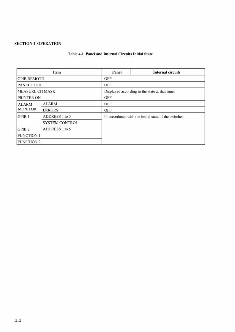
Table 4-1 Panel and Internal Circuits Initial State
4.1 Setup
INPUT
PATTERN
MEASURE-
MENT
SYNC OUTPUT
REAL TIME
/
MEAS TIME
DATA
CLOCK
AUTO SEARCH
LOGIC
PATTERN mode
MARK RATIO
TRACKING
SYNC MODE
ALTN
DATA
Z.S.
DISPLAY
CURRENT DATA
MODE
START
AUTO
Display
DISPLAY/MODIFY
MODIFY
TERM
THRESHOLD value
TERM
DELAY TIME value
BUSY
POLARITY
Pattern
A/B selection
DATA LENGTH
PAGE
Pattern
DATA LENGTH
PAGE
Pattern
PAGE
GND
–0.500
GND
0
OFF
CLK
OFF
POS
PRBS 2 –1
1/2
OFF
NORMAL
All 0
A
128
1
All 0
2
1
Pseudo PRBS 2
1
1
ERROR RATIO (All digits "-" displayed on display)
OFF
REPEAT
OFF
OFF
1/32 CLOCK
PERIOD (MEAS TIME)
OFF
(1) REAL TIME• Y. M. D:
• H. M. S :
(2) MEAS TIME
• PERIOD :• TIMED :• ELAPSED:
Item Panel Internal circuit
Current date (year, month, day)Current time (hour, minute, second)
00 day 00 hour 00 minute 00 second
All digits '-'
All digits '-'
15
ZERO SUB LENGTH
7
Measurement period is displayed.
SECTION 4 OPERATION
4-4
Table 4-1 Panel and Internal Circuits Initial State
GPIB REMOTE
PANEL LOCK
MEASURE CH MASK
PRINTER ON
GPIB 1
GPIB 2
FUNCTION 1
FUNCTION 2
ALARM
ERRORS
ADDRESS 1 to 5
SYSTEM CONTROL
ADDRESS 1 to 5
OFF
OFF
Displayed according to the state at that time.
OFF
OFF
OFF
In accordance with the initial state of the switches.
Item Panel Internal circuits
ALARM MONITOR

4-5
THRESHOLD / MARGIN DELAY TIME / MARGIN
INPUTDATA CLOCK
VVp-p
psps p-p
TERMGND
-2V
GUARD
TERMGND
-2V
GUARD
BUSY
-3V to 1.875V -500ps to 500ps
AUTO SEARCH(MARK RATIO 1/8 to 7/8)
POLARITYCLK
CLK
EYE MARGINERROR RATIO (10 )
2 3 4 5 6 7 8 9- N
ON START
12
3
4 5
6
7
89
1
2
3
4
6
5
7
8
9
4.3 Input Conditions Setting
4.3 Input Conditions Setting
Rotary encoder (DATA) Sets the DATA THRESHOLD.
TERM key Selects the DATA termination condition. To select –2 V termination,
press this key while pressing the GUARD key.
AUTO SEARCH key Performs AUTO SEARCH. To repeat AUTO SEARCH, press this key
again.
EYE MARGIN ON Sets the EYE margin measurement mode.
EYE MARGIN START Starts EYE margin measurement.
EYE MARGIN keys Select the EYE margin threshold value.
POLARITY Inverts the CLOCK polarity.
Rotary encoder (CLOCK) Adjusts the CLOCK input phase within a ±500 ps range.
TERM key Selects the CLOCK termination conditions. To select –2 V termination,
press this key while pressing the GUARD key.
SECTION 4 OPERATION
4-6
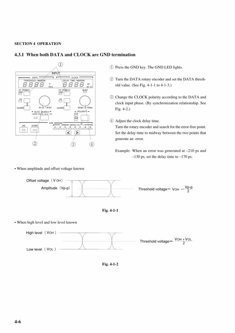
4.3.1 When both DATA and CLOCK are GND termination
① Press the GND key. The GND LED lights.
② Turn the DATA rotary encoder and set the DATA thresh-
old value. (See Fig. 4-1-1 to 4-1-3.)
③ Change the CLOCK polarity according to the DATA and
clock input phase. (By synchronization relationship. See
Fig. 4-2.)
④ Adjust the clock delay time.
Turn the rotary encoder and search for the error-free point.
Set the delay time to midway between the two points that
generate an error.
Example: When an error was generated at –210 ps and
–130 ps, set the delay time to –170 ps.
• When amplitude and offset voltage known
Fig. 4-1-1
• When high level and low level known
Fig. 4-1-2
V OHOffset voltage( )
Amplitude(Vp-p)Threshold voltage=VOH -2
Vp-p
VOHHigh level( )
Threshold voltage=
VLow level( )OL
2VOH +VOL
THRESHOLD / MARGIN DELAY TIME / MARGIN
INPUTDATA CLOCK
VVp-p
psps p-p
TERMGND
-2V
GUARD
TERMGND
-2V
GUARD
BUSY
-3V to 1.875V -500ps to 500ps
AUTO SEARCH(MARK RATIO 1/8 to 7/8)
POLARITYCLK
CLK
EYE MARGINERROR RATIO (10 )
2 3 4 5 6 7 8 9- N
ON START
①
② ④③

4-7
Setting the optimum value
In the error free state, lower the DATA threshold voltage and measure the voltage that generates an error (V1). Then raise
the threshold voltage and measure the voltage that generates an error (V2). Set the threshold voltage to midway between
these two voltages.
Fig. 4-1-3
Next, move CLOCK Delay in the minus direction and measure the phase (D1) that generates an error. Then move CLOCK
Delay in the plus direction and measure the phase (D2) that generates an error. Set the CLOCK Delay to midway between
these two values.
Fig. 4-2
V1 + V2( )2
V1
V2
2V1+V2
D1 D2
4.3 Input Conditions Setting
D1 + D2
2( )

SECTION 4 OPERATION
4-8
4.3.2 When DATA and CLOCK are both ECL termination
① While pressing the GUARD key, press the –2 V key. The
–2 V LED lights.
② Set the DATA threshold voltage to –1.3 V (ECL standard
voltage).
③ Set the CLOCK phase, etc. as described in Paragraph
4.3.1.
NOTEIncorrect setting of the termination voltage
may damage the device under test. Be very
careful when changing the setting.
4.3.3 Auto search
① When the AUTO SEARCH key is pressed, the DATA
threshold voltage and CLOCK Delay are automatically
set. If AUTO SEARCH does not end within three seconds,
AUTO SEARCH stops and the AUTO SEARCH lamp
begins to blink. At this time, return the data threshold volt-
age and CLOCK delay time to the set value before AUTO
SEARCH.
If AUTO SEARCH does not end normally, check the cable connections and termination conditions. It they are normal,
check the input waveform with a sampling oscilloscope.
THRESHOLD / MARGIN DELAY TIME / MARGIN
INPUTDATA CLOCK
VVp-p
psps p-p
TERMGND
-2V
GUARD
TERMGND
-2V
GUARD
BUSY
-3V to 1.875V -500ps to 500ps
AUTO SEARCH(MARK RATIO 1/8 to 7/8)
POLARITYCLK
CLK
EYE MARGINERROR RATIO (10 )
2 3 4 5 6 7 8 9- N
ON START
①
THRESHOLD / MARGIN DELAY TIME / MARGIN
INPUTDATA CLOCK
VVp-p
psps p-p
TERMGND
-2V
GUARD
TERMGND
-2V
GUARD
BUSY
-3V to 1.875V -500ps to 500ps
AUTO SEARCH(MARK RATIO 1/8 to 7/8)
POLARITYCLK
CLK
EYE MARGINERROR RATIO (10 )
2 3 4 5 6 7 8 9- N
ON START
①
②

4-9
4.3.4 EYE MARGIN Measurement
① Press the ON key. The LED inside the key lights. At this
time,
is displayed.
② Set the threshold value error rate.
③ Start measurement by pressing the START key. At the
end of measurement, the measured result is displayed on
the display.
EYE MARGIN starts measurement from the point (point A) obtained by AUTO SEARCH. Therefore, measurements are
made within the range shown below.
Point B is the position (10–2 to 10–9) delayed by the threshold
value set ERROR RATIO.
Vp-p
ps p-p
THRESHOLD / MARGIN DELAY TIME / MARGIN
INPUTDATA CLOCK
VVp-p
psps p-p
TERMGND
-2V
GUARD
TERMGND
-2V
GUARD
BUSY
-3V to 1.875V -500ps to 500ps
AUTO SEARCH(MARK RATIO 1/8 to 7/8)
POLARITYCLK
CLK
EYE MARGINERROR RATIO (10 )
2 3 4 5 6 7 8 9- N
ON START
③①
Phase margin(PSp-p)
B
B B
B
A Bias margin(Vp-p)
4.3 Input Conditions Setting
②
SECTION 4 OPERATION
4-10
4.4 Pattern Setting
PATTERNLOGIC PATTERN PRBS / ZERO SUBST PRBS MARK RATIO
2 - 1N
2 N
POS
NEG
ALTNDATA Z.S PRBS 7 9 11 15 20 23 31 0/8 1/8 1/4 1/2
8/8 7/8 3/4 1/2
DATA LENGTH/ZERO SUBST LENGTHDATA LENGTHZERO SUBST LENGTH
FRAME LENGTH
SYNC MODENORMAL FRAME QUICK A B
ALTNDISPLAY SELECT
PATT BIT BLOCK ERROR WINDOW WINDOW ANALYSIS
PAGE/PATTERN SYNC POSITION
9 10 11 12 13 14 15 16
ALL PAGEPRESET
PATTERNLOADING
TRACKINGGUARD 0 1 0 1
ON
ERROR ANALYSIS TRIGGER
BLOCK WINDOW
BIT
1 2 3 4 5 6 7 8 BIT WINDOW
PATTERN SYNC POSITIONPAGEDISPLAY
1
2
3
4
5 6 7 8
9
10
12
1314
151617
18 11

4-11
1
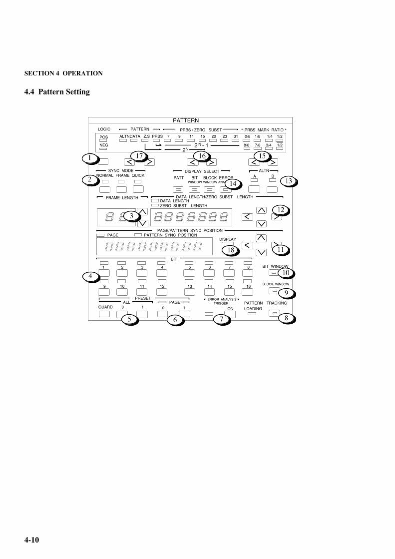
4.4 Pattern Setting
2
LOGIC Inverts the DATA/DATA output logic. The DATA output logic isshown by lighting of the POS or NEG lamp.
SYNC MODE Selects the sync pull-in mode. One of the following three modes can beselected:
NORMAL : Turn on normal sync pull-in.FRAME : Turn on the frame sync function.QUICK : Turn on the quick sync function.
FRAME LENGTH Sets the frame pattern bit length at FRAME SYNC .
BIT setting keys Set the logic of each bit for each Page. When LOGIC is POS, lighting ofthe lamp above each key indicates logic '1'.
ALL edit keys Set all the bits of the selected pattern to logic '0' or '1'. Press the 0 or 1 keywhile pressing the GUARD key.
PAGE edit keys Set all bits of the displayed page to logic '0' or '1'.
ERROR ANALYSIS Turns the error analysis function on and off. Lighting of the lamp shows(OPTION 01) that the error analysis function is 'ON'. This function is enabled only
when OPTION 01 is built-in.
TRACKING Turns the tracking function on and off. Lighting of the lamp inside thekey shows that the tracking function is 'ON'.
BLOCK WINDOW Turned on when error measurement in block units (32 bits) is masked.
BIT WINDOW Turned on when error measurement in channel units (1 bit) is masked.(All 32 channels)
keys Set the page and the pattern sync output position.
keys Set the data length and number of consecutive zeros in Z.S.
ALTN keys Select the A/B pattern at ALTN pattern setting.
DISPLAY SELECT Select the item displayed on the display. When PATT, BIT WINDOW,and BLOCK WINDOW are set, that item is selected and is set at thepanel. (It is possible to select ERROR ANALYSIS, When OPTION 01is built-in.)
MARK ratio selection keys Set the receive pattern mark ratio for PRBS.
PRBS/ZERO SUBST keys Set the PRBS or pseudo PRBS period.
PATTERN selection keys Select the type of receive pattern.
DISPLAY key Toggles the display between PAGE and PATTERN SYNC POSITION.
Selected display mode is displayed by the indicator.
3
4
7
5
6
8
9
10
11
12
13
14
15
16
17
18
SECTION 4 OPERATION
4-12
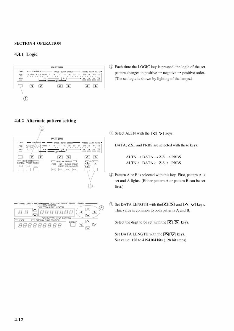
4.4.1 Logic
① Each time the LOGIC key is pressed, the logic of the set
pattern changes in positive → negative → positive order.
(The set logic is shown by lighting of the lamps.)
4.4.2 Alternate pattern setting
① Select ALTN with the keys.
DATA, Z.S., and PRBS are selected with these keys.
ALTN → DATA → Z.S. → PRBS
ALTN ← DATA ← Z.S. ← PRBS
② Pattern A or B is selected with this key. First, pattern A is
set and A lights. (Either pattern A or pattern B can be set
first.)
③ Set DATA LENGTH with the and keys.
This value is common to both patterns A and B.
Select the digit to be set with the keys.
Set DATA LENGTH with the keys.
Set value: 128 to 4194304 bits (128 bit steps)
①
PATTERNLOGIC PATTERN PRBS / ZERO SUBST PRBS MARK RATIO
2 - 1N
2 N
POS
NEG
ALTNDATA Z.S PRBS 7 9 11 15 20 23 31 0/8 1/8 1/4 1/2
8/8 7/8 3/4 1/2
PATTERNLOGIC PATTERN PRBS / ZERO SUBST PRBS MARK RATIO
2 - 1N
2 N
POS
NEG
ALTNDATA Z.S PRBS 7 9 11 15 20 23 31 0/8 1/8 1/4 1/2
8/8 7/8 3/4 1/2
SYNC MODENORMAL FRAME QUICK A B
ALTNDISPLAY SELECT
PATT BIT BLOCK ERROR WINDOW WINDOW ANALYSIS
②
③
①
DATA LENGTH/ZERO SUBST LENGTHDATA LENGTHZERO SUBST LENGTH
PAGE/PATTERN SYNC POSITION
FRAME LENGTH
PATTERN SYNC POSITIONPAGEDISPLAY
4-13
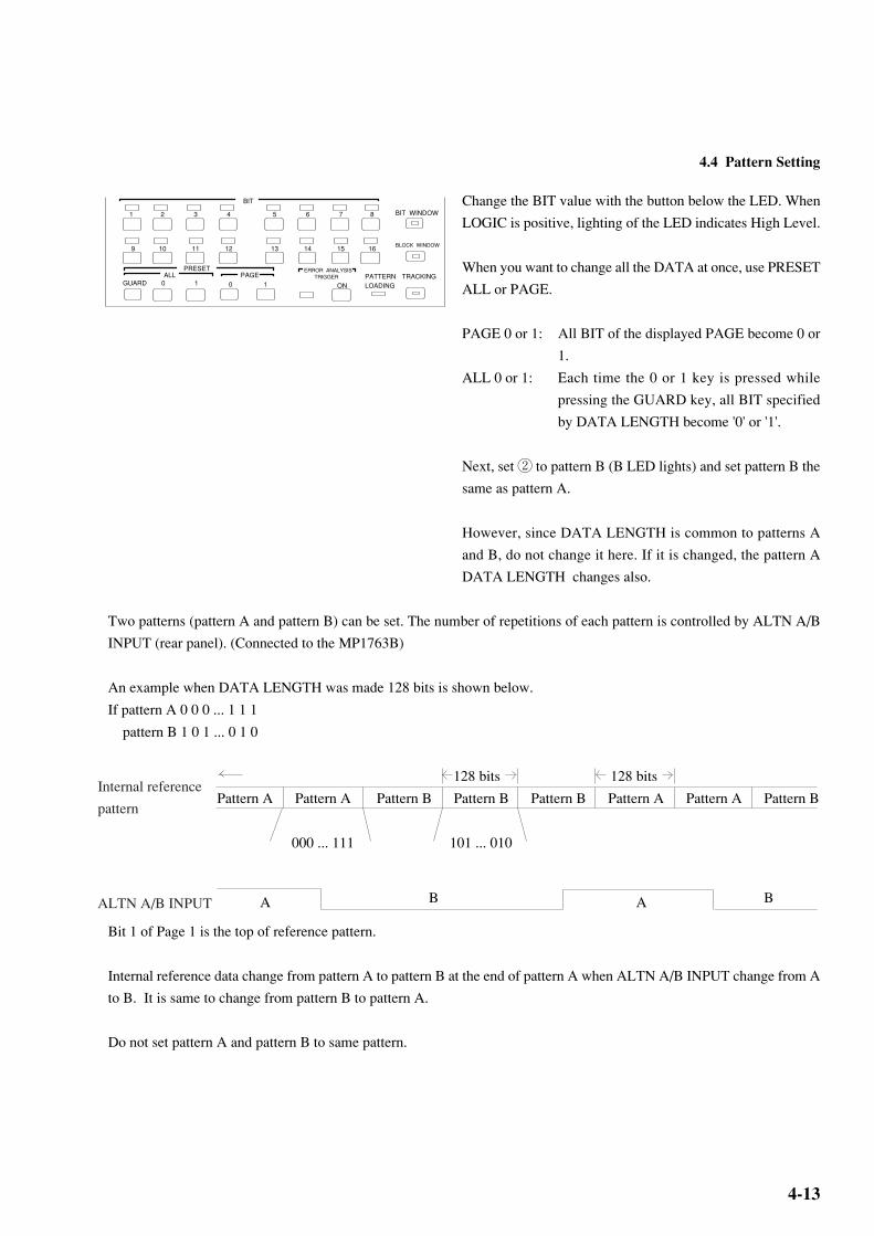
Change the BIT value with the button below the LED. When
LOGIC is positive, lighting of the LED indicates High Level.
When you want to change all the DATA at once, use PRESET
ALL or PAGE.
PAGE 0 or 1: All BIT of the displayed PAGE become 0 or
1.
ALL 0 or 1: Each time the 0 or 1 key is pressed while
pressing the GUARD key, all BIT specified
by DATA LENGTH become '0' or '1'.
Next, set ② to pattern B (B LED lights) and set pattern B the
same as pattern A.
However, since DATA LENGTH is common to patterns A
and B, do not change it here. If it is changed, the pattern A
DATA LENGTH changes also.
Two patterns (pattern A and pattern B) can be set. The number of repetitions of each pattern is controlled by ALTN A/B
INPUT (rear panel). (Connected to the MP1763B)
An example when DATA LENGTH was made 128 bits is shown below.
If pattern A 0 0 0 ... 1 1 1
pattern B 1 0 1 ... 0 1 0
128 bits 128 bits
Pattern A Pattern A Pattern B Pattern B Pattern B Pattern A Pattern A Pattern B
000 ... 111 101 ... 010
Bit 1 of Page 1 is the top of reference pattern.
Internal reference data change from pattern A to pattern B at the end of pattern A when ALTN A/B INPUT change from A
to B. It is same to change from pattern B to pattern A.
Do not set pattern A and pattern B to same pattern.
4.4 Pattern Setting
Internal reference
pattern
A AB B
BIT
1 2 3 4 5 6 7 8
9 10 11 12 13 14 15 16
ALL PAGEPRESET
PATTERNLOADING
TRACKINGGUARD 0 1 0 1
ON
ERROR ANALYSIS TRIGGER
BIT WINDOW
BLOCK WINDOW
ALTN A/B INPUT
SECTION 4 OPERATION
4-14
①
PATTERNLOGIC PATTERN PRBS / ZERO SUBST PRBS MARK RATIO
2 - 1N
2 N
POS
NEG
ALTNDATA Z.S PRBS 7 9 11 15 20 23 31 0/8 1/8 1/4 1/2
8/8 7/8 3/4 1/2
DATA LENGTH/ZERO SUBST LENGTHDATA LENGTHZERO SUBST LENGTH
PAGE/PATTERN SYNC POSITION
FRAME LENGTH
PATTERN SYNC POSITIONPAGEDISPLAY
BIT
1 2 3 4 5 6 7 8
9 10 11 12 13 14 15 16
ALL PAGEPRESET
PATTERNLOADING
TRACKINGGUARD 0 1 0 1
ON
ERROR ANALYSIS TRIGGER
BIT WINDOW
BLOCK WINDOW
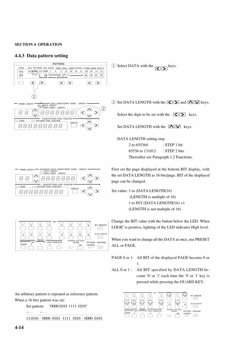
4.4.3 Data pattern setting
① Select DATA with the keys.
② Set DATA LENGTH with the and keys.
Select the digit to be set with the keys.
Set DATA LENGTH with the keys.
DATA LENGTH setting step
2 to 655364 : STEP 1 bit
65536 to 131012 : STEP 2 bits
Thereafter see Paragraph 1.2 Functions.
First set the page displayed at the bottom BIT display, with
the set DATA LENGTH as 16 bits/page. BIT of the displayed
page can be changed.
Set value: 1 to (DATA LENGTH/16)
(LENGTH is multiple of 16)
1 to INT (DATA LENGTH/16) +1
(LENGTH is not multiple of 16)
Change the BIT value with the button below the LED. When
LOGIC is positive, lighting of the LED indicates High level.
When you want to change all the DATA at once, use PRESET
ALL or PAGE.
PAGE 0 or 1: All BIT of the displayed PAGE become 0 or
1.
ALL 0 or 1 : All BIT specified by DATA LENGTH be-
come '0' or '1' each time the '0' or '1' key is
pressed while pressing the GUARD KEY.
An arbitrary pattern is repeated as reference pattern.
When a 16 bits pattern was set:
Set pattern "0000 0101 1111 1010"
111010 0000 0101 1111 1010 0000 0101
BIT
1 2 3 4 5 6 7 8
9 10 11 12 13 14 15 16
ALL PAGEPRESET
PATTERNLOADING
TRACKINGGUARD 0 1 0 1
ON
ERROR ANALYSIS TRIGGER
BIT WINDOW
BLOCK WINDOW
②
DATA LENGTH/ZERO SUBST LENGTHDATA LENGTHZERO SUBST LENGTH
PAGE/PATTERN SYNC POSITION
FRAME LENGTH
PATTERN SYNC POSITIONPAGEDISPLAY

4-15
4.4.4 Zero substitution pattern setting
① Select Z.S. with the keys.
② Set 2N pattern with the keys. (This pattern is
pseudo PRBS with a 2N period.)
③ Set ZERO SUBSTITUTION BIT LENGTH.
Here, the pattern is substituted by a set number of bits
logic '0' pattern. For a description of the substitution
method, see the following.
Setting: 1 to 2N (N=7, 9, 11, 15)
Pattern with the number of set bits substituted by a logic '0' pattern immediately after the maximum length of consecutive
0 bits of a pseudo PRBS (period 2N bits: N=7, 9, 11, 15) with a one bit pattern of logic '1' at the end of PRBS stages 7 ,9, 11,
and 15. However, when the bit directly after substitution by '0' is '0', it is inverted and made '1'.
Example: Pseudo PRBS frame 7
Since the maximum length of consecutive 0 is 7–1 = 6 bits, 0 substitution begins from the position shown
below.
1 0 0 0 0 0 0 1 0 0 0 0 0 1 1 0 0 0 0 1 0 1 0 .....
1 bit 1 0 0 0 0 0 0 0 1 0
5 bits 1 0 0 0 0 0 0 0 0 0 0 0 1 1
7 bits 1 0 0 0 0 0 0 0 0 0 0 0 0 0 1 0
①
PATTERNLOGIC PATTERN PRBS / ZERO SUBST PRBS MARK RATIO
2 - 1N
2 N
POS
NEG
ALTNDATA Z.S PRBS 7 9 11 15 20 23 31 0/8 1/8 1/4 1/2
8/8 7/8 3/4 1/2
PATTERNLOGIC PATTERN PRBS / ZERO SUBST PRBS MARK RATIO
2 - 1N
2 N
POS
NEG
ALTNDATA Z.S PRBS 7 9 11 15 20 23 31 0/8 1/8 1/4 1/2
8/8 7/8 3/4 1/2
②
DATA LENGTH/ZERO SUBST LENGTHDATA LENGTHZERO SUBST LENGTH
PAGE/PATTERN SYNC POSITION
FRAME LENGTH
PATTERN SYNC POSITIONPAGEDISPLAY
Pseudo PRBS frame 7
Since the bit immediately after '0' substitution is '0', it is inverted and
made '1'.
4.4 Pattern Setting
③

SECTION 4 OPERATION
4-16
4.4.5 Pseudo random pattern setting
① Select PRBS with the keys.
② Set the number of PRBS frames with the keys.
③ Set the PRBS mark ratio with the keys.
When LOGIC is positive, make your selection from the
top row (0/8, 1/8, 1/4, 1/2).
When LOGIC is negative, make your selection from the
bottom row (8/8, 7/8, 3/4, 1/2).
When LOGIC is changed from positive to negative when
mark ratio is 1/4, the mark ratio changes to 3/4.
Pattern generated by the principle described in Paragraph 5.1 Pseudo random Pattern. When arbitrary consecutive N bits
was selected in the bit array of a PRBS pattern having a period of 2N–1, the same bit array does not exist in one period. That
is, all bit arrays can be considered other than '0' in one period.
Note: When setting pseudo random pattern, the BIT LEDs light according to the set pattern.
PATTERNLOGIC PATTERN PRBS / ZERO SUBST PRBS MARK RATIO
2 - 1N
2 N
POS
NEG
ALTNDATA Z.S PRBS 7 9 11 15 20 23 31 0/8 1/8 1/4 1/2
8/8 7/8 3/4 1/2
①
PATTERNLOGIC PATTERN PRBS / ZERO SUBST PRBS MARK RATIO
2 - 1N
2 N
POS
NEG
ALTNDATA Z.S PRBS 7 9 11 15 20 23 31 0/8 1/8 1/4 1/2
8/8 7/8 3/4 1/2
② ③
4-17
4.4 Pattern Setting
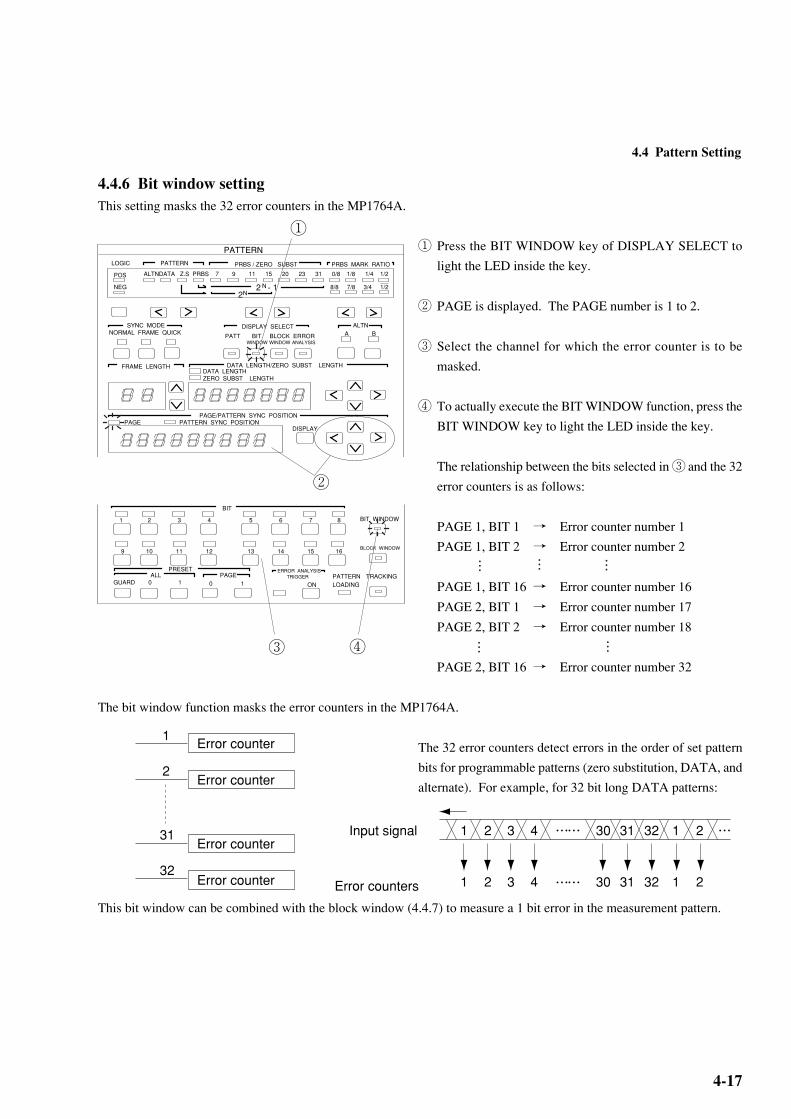
4.4.6 Bit window settingThis setting masks the 32 error counters in the MP1764A.
① Press the BIT WINDOW key of DISPLAY SELECT to
light the LED inside the key.
② PAGE is displayed. The PAGE number is 1 to 2.
③ Select the channel for which the error counter is to be
masked.
④ To actually execute the BIT WINDOW function, press the
BIT WINDOW key to light the LED inside the key.
The relationship between the bits selected in ③ and the 32
error counters is as follows:
PAGE 1, BIT 1 → Error counter number 1
PAGE 1, BIT 2 → Error counter number 2
PAGE 1, BIT 16 → Error counter number 16
PAGE 2, BIT 1 → Error counter number 17
PAGE 2, BIT 2 → Error counter number 18
PAGE 2, BIT 16 → Error counter number 32
The bit window function masks the error counters in the MP1764A.
The 32 error counters detect errors in the order of set pattern
bits for programmable patterns (zero substitution, DATA, and
alternate). For example, for 32 bit long DATA patterns:
This bit window can be combined with the block window (4.4.7) to measure a 1 bit error in the measurement pattern.
PATTERNLOGIC PATTERN PRBS / ZERO SUBST PRBS MARK RATIO
2 - 1N
2 N
POS
NEG
ALTNDATA Z.S PRBS 7 9 11 15 20 23 31 0/8 1/8 1/4 1/2
8/8 7/8 3/4 1/2
SYNC MODENORMAL FRAME QUICK A B
ALTNDISPLAY SELECT
PATT BIT BLOCK ERROR WINDOW WINDOW ANALYSIS
DATA LENGTH/ZERO SUBST LENGTHDATA LENGTHZERO SUBST LENGTH
PAGE/PATTERN SYNC POSITION
FRAME LENGTH
PATTERN SYNC POSITIONPAGEDISPLAY
①
BIT
1 2 3 4 5 6 7 8
9 10 11 12 13 14 15 16
ALL PAGEPRESET
PATTERNLOADING
TRACKINGGUARD 0 1 0 1
ON
ERROR ANALYSIS TRIGGER
BIT WINDOW
BLOCK WINDOW
③
②…
…
……
…
④
Input signal
Error counters
1 2 1 23 4 30 31 32
1 2 1 23 4 30 31 32
………
……
Error counter
Error counter
Error counter
1
2
31
32Error counter

SECTION 4 OPERATION
4-18
PATTERNLOGIC PATTERN PRBS / ZERO SUBST PRBS MARK RATIO
2 - 1N
2 N
POS
NEG
ALTNDATA Z.S PRBS 7 9 11 15 20 23 31 0/8 1/8 1/4 1/2
8/8 7/8 3/4 1/2
SYNC MODENORMAL FRAME QUICK A B
ALTNDISPLAY SELECT
PATT BIT BLOCK ERROR WINDOW WINDOW ANALYSIS
DATA LENGTH/ZERO SUBST LENGTHDATA LENGTHZERO SUBST LENGTH
PAGE/PATTERN SYNC POSITION
FRAME LENGTH
PATTERN SYNC POSITIONPAGEDISPLAY
①
②
BIT
1 2 3 4 5 6 7 8
9 10 11 12 13 14 15 16
ALL PAGEPRESET
PATTERNLOADING
TRACKINGGUARD 0 1 0 1
ON
ERROR ANALYSIS TRIGGER
BIT WINDOW
BLOCK WINDOW
③ ④
4.4.7 Block window settingThis setting masks the bits for 32 bit based pattern error measurement.
① Press the BLOCK WINDOW key of DISPLAY SELECT
to light the LED inside the key.
The block window is enabled for programmable patterns
(zero substitution, DATA, and alternate). For DATA, the
DATA length must be a multiple of 32 and the synchroni-
zation mode must not be QUICK.
② Move PAGE to the pattern position where measurement
masking is to be performed. The PAGE operation is the
same as when PATT is selected for DISPLAY SELECT.
(See Paragraphs 4.4.2 to 4.4.4)
③ Select a pattern mask on the BIT indicator.
When a LED is on, the bit is masked.
One LED of the BIT indicator indicates one bit in the pat-
tern setting. When one key of the BIT indicator is pressed,
the LEDs for all 32 bits go on or off together because the
block window is turned on or off for each of the 32 bits.
④ To actually execute the block window function, press the
BLOCK WINDOW key to light the LED inside the key.
The block window function can be used with the bit window function to measure errors on one-bit basis. Measurement can
be masked by OR operation of the bit and block windows.
Only the high-order bit of a pattern can be measured as shown above.
32 bits 32 bits 32 bits 32 bits 32 bits 32 bits Input pattern
Block window
Bit window
One cycle
………………
1 bit
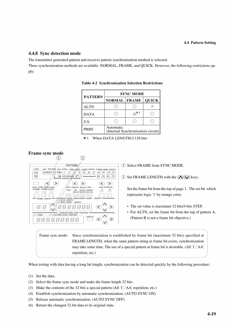
4-19
PATTERNSYNC MODE
NORMAL FRAME QUICK
ALTN
DATA
Z.S.
PRBS
×
*1 When DATA LENGTH≧128 bits
*1
Automatic (Internal Synchronization circuit)
PATTERNLOGIC PATTERN PRBS / ZERO SUBST PRBS MARK RATIO
2 - 1N
2 N
POS
NEG
ALTNDATA Z.S PRBS 7 9 11 15 20 23 31 0/8 1/8 1/4 1/2
8/8 7/8 3/4 1/2
SYNC MODENORMAL FRAME QUICK A B
ALTNDISPLAY SELECT
PATT BIT BLOCK ERROR WINDOW WINDOW ANALYSIS
DATA LENGTH/ZERO SUBST LENGTHDATA LENGTHZERO SUBST LENGTH
PAGE/PATTERN SYNC POSITION
FRAME LENGTH
PATTERN SYNC POSITIONPAGEDISPLAY
① ②
4.4 Pattern Setting
4.4.8 Sync detection modeThe transmitter generated pattern and receiver pattern synchronization method is selected.
Three synchronization methods are available: NORMAL, FRAME, and QUICK. However, the following restrictions ap-
ply:
Table 4-2 Synchronization Selection Restrictions
Frame sync mode
① Select FRAME from SYNC MODE.
② Set FRAME LENGTH with the keys.
Set the frame bit from the top of page 1. The set bit which
represents logic '1' by orange color.
• The set value is maximum 32 bits/4 bits STEP.
• For ALTN, set the frame bit from the top of pattern A.
(Pattern B is not a frame bit objective.)
Frame sync mode: Since synchronization is established by frame bit (maximum 32 bits) specified at
FRAME LENGTH, when the same pattern string as frame bit exists, synchronization
may take some time. The use of a special pattern at frame bit is desirable. (All '1', 'AA'
repetition, etc.)
When testing with data having a long bit length, synchronization can be detected quickly by the following procedure:
(1) Set the data.
(2) Select the frame sync mode and make the frame length 32 bits.
(3) Make the contents of the 32 bits a special pattern (All '1', 'AA' repetition, etc.)
(4) Establish synchronization by automatic synchronization. (AUTO SYNC ON)
(5) Release automatic synchronization. (AUTO SYNC OFF)
(6) Return the changed 32-bit data to its original state.

SECTION 4 OPERATION
4-20
QUICK sync mode
① Select QUICK from SYNC MODE.
QUICK sync mode: Method that makes error measurements by fetching data of the bit length set by DATA
LENGTH to internal memory and uses the fetched pattern as the standard pattern. In
this case, the pattern BIT setting is invalid.
①
PATTERNLOGIC PATTERN PRBS / ZERO SUBST PRBS MARK RATIO
2 - 1N
2 N
POS
NEG
ALTNDATA Z.S PRBS 7 9 11 15 20 23 31 0/8 1/8 1/4 1/2
8/8 7/8 3/4 1/2
SYNC MODENORMAL FRAME QUICK A B
ALTNDISPLAY SELECT
PATT BIT BLOCK ERROR WINDOW WINDOW ANALYSIS
DATA LENGTH/ZERO SUBST LENGTHDATA LENGTHZERO SUBST LENGTH
PAGE/PATTERN SYNC POSITION
FRAME LENGTH
PATTERN SYNC POSITIONPAGEDISPLAY

4-21
BIT
1 2 3 4 5 6 7 8
9 10 11 12 13 14 15 16
ALL PAGEPRESET
PATTERNLOADING
TRACKINGGUARD 0 1 0 1
ON
ERROR ANALYSIS TRIGGER
BIT WINDOW
BLOCK WINDOW
①
GPIBADDRESSSYSTEM
CONTROL 5 4 3 2 1 ONOFF
10
・・・・・
4.4.9 Tracking
① Press the TRACKING key. The LED inside the key lights
and the MP1764A enters the tracking mode.
* When tracking is performed, the MP1763B must be con-
nected by GPIB.
When the PATTERN LOADING lamp lights, data is be-
ing read and the keys cannot be operated.
Tracking can be performed from both the receiver and the transmitter. However, one of them must be set as the master.
Therefore, tracking cannot be performed simultaneously from both the receiver and the transmitter.
When performing tracking, set 'SYSTEM CONTROL' of the DIP switch on the rear panel of the master unit to 'ON'. (Set
'SYSTEM CONTROL' of the controlled unit to 'OFF'.)
Set GPIB ADDRESS of the controlled unit to master unit GPIB ADDRESS + 2.
Each time the settings of the master unit (receiver or transmitter) are changed in the tracking ON state, the settings of the
transmitter (or receiver) are changed. Therefore, each time a master key is operated, an unavailable state is generated.
(Especially, when the program bit length is long, an unavailable state of several tens of seconds is generated.) To prevent
this, when changing the master unit settings, set tracking to OFF.
4.4 Pattern Setting

SECTION 4 OPERATION
4-22
4.4.10 Error analysis (Option 01)At error detection, 256 bits of data are memorized and the error and the data before and after it can be checked.
① Press the ERROR ANALYSIS key. The LED inside the
key lights.
② Change the display page for the ERROR ANALYSIS
DATA.
Sixteen pages, including the pattern that generated an er-
ror, can be set.
Pages 9 and 10 display the BIT that generated an error and
became the trigger.
③ Set ERROR ANALYSIS TRIGGER to ON.
Result Display
④ The display page is shown.
Page position shows the pattern setting and display page
position.
⑤ The error is indicated by a red or orange LED.
(See Table 4-3.)
* When performing error analysis using the PRBS 231-1 pattern, a few seconds after synchronization is established before
starting analysis.
PATTERNLOGIC PATTERN PRBS / ZERO SUBST PRBS MARK RATIO
2 - 1N
2 N
POS
NEG
ALTNDATA Z.S PRBS 7 9 11 15 20 23 31 0/8 1/8 1/4 1/2
8/8 7/8 3/4 1/2
SYNC MODENORMAL FRAME QUICK A B
ALTNDISPLAY SELECT
PATT BIT BLOCK ERROR WINDOW WINDOW ANALYSIS
DATA LENGTH/ZERO SUBST LENGTHDATA LENGTHZERO SUBST LENGTH
PAGE/PATTERN SYNC POSITION
FRAME LENGTH
PATTERN SYNC POSITIONPAGEDISPLAY
①
②
BIT
1 2 3 4 5 6 7 8
9 10 11 12 13 14 15 16
ALL PAGEPRESET
PATTERNLOADING
TRACKINGGUARD 0 1 0 1
ON
ERROR ANALYSIS TRIGGER
BIT WINDOW
BLOCK WINDOW
③
④
⑤
Receive data Reference LED
0101
0110
OFFGreenRedOrange
NormalNormalInsertion errorOmission error
Table 4-3
DATA LENGTH/ZERO SUBST LENGTHDATA LENGTHZERO SUBST LENGTH
PAGE/PATTERN SYNC POSITION
9 10 11 12 13 14 15 16
ALL PAGEPRESET
PATTERNLOADING
TRACKINGGUARD 0 1 0 1
FRAME LENGTH
ON
ERROR ANALYSIS TRIGGER
BLOCK WINDOW
BIT
1 2 3 4 5 6 7 8 BIT WINDOW
PATTERN SYNC POSITIONPAGEDISPLAY

4-23
4.5 Error Measurement
DISPLAY/MODIFY key REAL TIME
Y.H.D. Press to set or display the date. When the lamp inside the
key lights, the date is displayed on the display.
H.M.S. Press to set or display the time., When the lamp inside the
key lights, the time is displayed on the display.
MEAS TIME
PERIOD Press to set or display the measurement time (gating time).
When the LED inside the key lights, the measurement
time (gating time) is displayed on the display.
TIME Press to display the remaining measurement time. When
the LED inside the key lights, the remaining time is dis-
played on the display. Cannot be selected when the mea-
surement mode is UNTIMED.
ELAPSED Press to display the elapsed measurement time. When the
LED inside the key lights, the elapsed time is displayed on
the display.
MEASUREMENT
CURRENT HISTORY
POWER FAILCLOCK LOSS SYNC LOSS
ERRORS GATING
%MHz
REPEATSINGLEUNTIMED
ERROR RATIO
DISPLAYERROR COUNT
ERRORINTERVAL
ERROR FREE INTERVAL
CLOCKFREQUENCY
MODECURRENT DATA
2 3 4 5 6 7 8 INTAUTO SYNC
SYNC THRESHOLD(10 )-N
START STOP
REAL TIME / MEAS TIME
DAY YEAR / HOUR MONTH / MINUTE DAY / SECOND
DISPLAY / MODIFY
REAL TIME MEAS TIMEY.M.D H.M.S PERIOD TIMED ELAPSED
MODIFY
1
2
3
4
56
7
89
11
10
1
4.5 Error Measurement

SECTION 4 OPERATION
4-24
keys keys Select the item to be set when setting REAL TIME. The
selected item blinks.
keys Used when raising and lowering the set value.
MODIFY key Pressed when changing the REAL TIME or MEAS TIME setting. When
the LED inside the key lights, the set value can be changed.
START / STOP keys Start and stop measurement. During measurement, the LED inside the
START key remains lit.
CURRENT DATA key Turns the data display on and off during measurement. When the LED
inside the key is lit, the current measurement data is displayed.
Measurement mode selection keys Select the measurement mode from among REPEAT, SINGLE, and
UNTIMED.
REPEAT : Repeated measurement
SINGLE : One measurement
UNTIMED : Manual measurement (accumulative measurement)
Display Displays the measured result. The display contents are selected with
.
HISTORY key Displays the past state. (Displays the result of the last measurement.)
POWER FAIL : Lamp that shows that the power dipped or failed.
(History lamp only)
CLOCK LOSS : Display and lamp that show that the clock pulses
were lost.
SYNC LOSS : Display and lamp that show that synchronization
was lost.
CURRENT lamp Displays the current measurement state.
DISPLAY display switching keys Select the item displayed on the display. The item at which the internal
LED is lit is displayed.
ERROR RATIO : Displays the error ratio.
ERROR COUNT : Displays the number of errors.
ERROR INTERVAL : Displays the number of error intervals
(EI).
ERROR FREE INTERVAL : Displays the number of error free inter-
vals ratio(EFI).
CLOCK FREQUENCY : Displays the clock frequency.
AUTO SYNC key Turns the pattern automatic synchronization function on and off.
2
3
4
5
6
7
8
10
9
10
11

4-25
4.5.1 ERROR RATIO measurement
① Press the ERROR RATIO key. The LED inside the key
lights and the ERROR RATIO measured result is dis-
played at DISPLAY.
② Press the MODE key and select REPEAT. (See 4.5.7.)
When REPEAT is selected, the DISPLAY display value
is updated at each MEAS TIME set value.
③ Set AUTO SYNC to ON. (Internal LED lights) During
normalmeasurement, the AUTO SYNC key is usually left
in the ON position. (See 4.5.10.).
④ When you want to display the result during measurement,
press the CURRENT DATA key. The LED inside the key
lights. When CURRENT DATA is ON, the current mea-
sured result is displayed at eachmeasurement time.
(See 4.5.11.)
MEASUREMENT
CURRENT HISTORY
POWER FAILCLOCK LOSS SYNC LOSS
ERRORS GATING
%MHz
REPEATSINGLEUNTIMED
ERROR RATIO
DISPLAYERROR COUNT
ERRORINTERVAL
ERROR FREE INTERVAL
CLOCKFREQUENCY
MODECURRENT DATA
N
②
MEASUREMENT
CURRENT HISTORY
POWER FAILCLOCK LOSS SYNC LOSS
ERRORS GATING
%MHz
REPEATSINGLEUNTIMED
ERROR RATIO
DISPLAYERROR COUNT
ERRORINTERVAL
ERROR FREE INTERVAL
CLOCKFREQUENCY
MODECURRENT DATA
N
①
③
MEASUREMENT
CURRENT HISTORY
POWER FAILCLOCK LOSS SYNC LOSS
ERRORS GATING
%MHz
REPEATSINGLEUNTIMED
ERROR RATIO
DISPLAYERROR COUNT
ERRORINTERVAL
ERROR FREE INTERVAL
CLOCKFREQUENCY
MODECURRENT DATA
2 3 4 5 6 7 8 INTAUTO SYNC
SYNC THRESHOLD(10 )-N
START STOP
MEASUREMENT
CURRENT HISTORY
POWER FAILCLOCK LOSS SYNC LOSS
ERRORS GATING
%MHz
REPEATSINGLEUNTIMED
ERROR RATIO
DISPLAYERROR COUNT
ERRORINTERVAL
ERROR FREE INTERVAL
CLOCKFREQUENCY
MODECURRENT DATA
2 3 4 5 6 7 8 INTAUTO SYNC
SYNC THRESHOLD(10 )-N
START STOP
④
4.5 Error Measurement

SECTION 4 OPERATION
4-26
4.5.2 ERROR COUNT
① Press the ERROR COUNT key. The LED inside the key
lights and the ERROR COUNT measured result is dis-
played at DISPLAY.
② Set MODE (Paragraph 4.5.2) and MEAS TIME (Para-
graph 4.5.11) and start measurement by pressing the
START key.
In the AUTO SYNC OFF state, synchronization is not es-
tablished. Therefore, always leave the AUTO SYNC key
in the ON position.
MEASUREMENT
CURRENT HISTORY
POWER FAILCLOCK LOSS SYNC LOSS
ERRORS GATING
%MHz
REPEATSINGLEUNTIMED
ERROR RATIO
DISPLAYERROR COUNT
ERRORINTERVAL
ERROR FREE INTERVAL
CLOCKFREQUENCY
MODECURRENT DATA
2 3 4 5 6 7 8 INTAUTO SYNC
SYNC THRESHOLD(10 )-N
START STOP
REAL TIME / MEAS TIME
DAY YEAR / HOUR MONTH / MINUTE DAY / SECOND
DISPLAY / MODIFY
REAL TIME MEAS TIMEY.M.D H.M.S PERIOD TIMED ELAPSED
MODIFY
①
②

4-27
4.5.3 ERROR INTERVAL
① Press the ERROR INTERVAL key. The LED inside the
key lights.
② Select the measurement mode. (See 4.5.1.)
③ Set MEAS TIME. (See 4.5.11.)
④ When an intermediate measured result is necessary, press
the CURRENT DATA key. The LED inside the key
lights. (See 4.5.9.)
⑤ Start measurement by pressing the START key.
* During measurement, always leave the AUTO SYNC key
in the ON position. (See 4.5.10.)
MEASUREMENT
CURRENT HISTORY
POWER FAILCLOCK LOSS SYNC LOSS
ERRORS GATING
%MHz
REPEATSINGLEUNTIMED
ERROR RATIO
DISPLAYERROR COUNT
ERRORINTERVAL
ERROR FREE INTERVAL
CLOCKFREQUENCY
MODECURRENT DATA
AUTO SYNC START STOP
REAL TIME / MEAS TIME
DAY YEAR / HOUR MONTH / MINUTE DAY / SECOND
DISPLAY / MODIFY
REAL TIME MEAS TIMEY.M.D H.M.S PERIOD TIMED ELAPSED
MODIFY
2 3 4 5 6 7 8 INTSYNC THRESHOLD(10 )-N
①
MEASUREMENT
CURRENT HISTORY
POWER FAILCLOCK LOSS SYNC LOSS
ERRORS GATING
%MHz
REPEATSINGLEUNTIMED
ERROR RATIO
DISPLAYERROR COUNT
ERRORINTERVAL
ERROR FREE INTERVAL
CLOCKFREQUENCY
MODECURRENT DATA
AUTO SYNC START STOP
REAL TIME / MEAS TIME
DAY YEAR / HOUR MONTH / MINUTE DAY / SECOND
DISPLAY / MODIFY
REAL TIME MEAS TIMEY.M.D H.M.S PERIOD TIMED ELAPSED
MODIFY
2 3 4 5 6 7 8 INTSYNC THRESHOLD(10 )-N
④⑤
4.5 Error Measurement

SECTION 4 OPERATION
4-28
4.5.4 ERROR FREE INTERVAL
① Press the ERROR FREE INTERVAL key. The LED in-
side the key lights.
② Select the measurement mode. (See 4.5.1.)
③ Set MEAS TIME. (See 4.5.11.)
④ When an intermediate measured result is necessary, press
the CURRENT DATA key. The LED inside the key
lights. (See 4.5.9.)
⑤ Start measurement by pressing the START key.
* During measurement, always leave the AUTO SYNC key
in the ON position. (See 4.5.10.)
MEASUREMENT
CURRENT HISTORY
POWER FAILCLOCK LOSS SYNC LOSS
ERRORS GATING
%MHz
REPEATSINGLEUNTIMED
ERROR RATIO
DISPLAYERROR COUNT
ERRORINTERVAL
ERROR FREE INTERVAL
CLOCKFREQUENCY
MODECURRENT DATA
AUTO SYNC START STOP
REAL TIME / MEAS TIME
DAY YEAR / HOUR MONTH / MINUTE DAY / SECOND
DISPLAY / MODIFY
REAL TIME MEAS TIMEY.M.D H.M.S PERIOD TIMED ELAPSED
MODIFY
2 3 4 5 6 7 8 INTSYNC THRESHOLD(10 )-N
①
MEASUREMENT
CURRENT HISTORY
POWER FAILCLOCK LOSS SYNC LOSS
ERRORS GATING
%MHz
REPEATSINGLEUNTIMED
ERROR RATIO
DISPLAYERROR COUNT
ERRORINTERVAL
ERROR FREE INTERVAL
CLOCKFREQUENCY
MODECURRENT DATA
AUTO SYNC START STOP
REAL TIME / MEAS TIME
DAY YEAR / HOUR MONTH / MINUTE DAY / SECOND
DISPLAY / MODIFY
REAL TIME MEAS TIMEY.M.D H.M.S PERIOD TIMED ELAPSED
MODIFY
2 3 4 5 6 7 8 INTSYNC THRESHOLD(10 )-N
④⑤

4-29
4.5.5 CLOCK FREQUENCY
① Press the CLOCK FREQUENCY key. The LED inside
the key lights.
② For SYNC LOSS, CLOCK FREQUENCY is not dis-
played. In this case, make measurements with the AUTO
SYNC key set to OFF. If the clock pulse is input nor-
mally, CLOCK FREQ. is correctly displayed.
MEASUREMENT
CURRENT HISTORY
POWER FAILCLOCK LOSS SYNC LOSS
ERRORS GATING
%MHz
REPEATSINGLEUNTIMED
ERROR RATIO
DISPLAYERROR COUNT
ERRORINTERVAL
ERROR FREE INTERVAL
CLOCKFREQUENCY
MODECURRENT DATA
AUTO SYNC START STOP
REAL TIME / MEAS TIME
DAY YEAR / HOUR MONTH / MINUTE DAY / SECOND
DISPLAY / MODIFY
REAL TIME MEAS TIMEY.M.D H.M.S PERIOD TIMED ELAPSED
MODIFY
2 3 4 5 6 7 8 INTSYNC THRESHOLD(10 )-N
①
4.5 Error Measurement
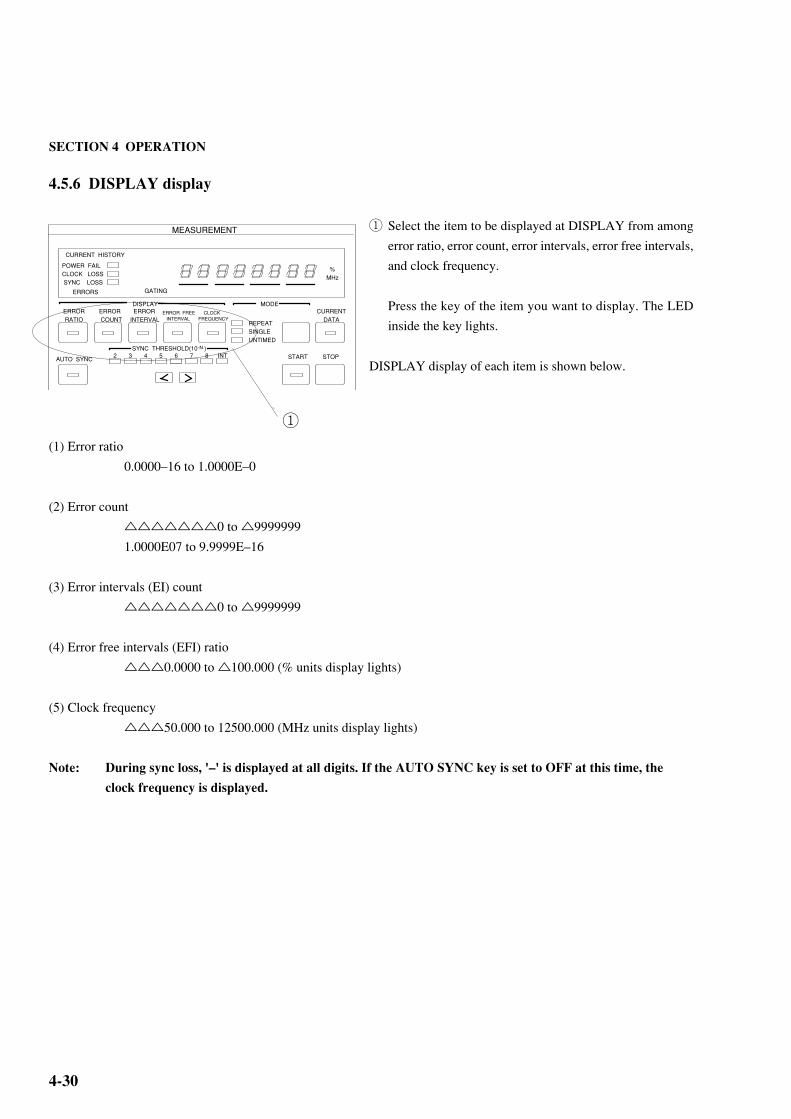
SECTION 4 OPERATION
4-30
4.5.6 DISPLAY display
① Select the item to be displayed at DISPLAY from among
error ratio, error count, error intervals, error free intervals,
and clock frequency.
Press the key of the item you want to display. The LED
inside the key lights.
DISPLAY display of each item is shown below.
(1) Error ratio
0.0000–16 to 1.0000E–0
(2) Error count
0 to 9999999
1.0000E07 to 9.9999E–16
(3) Error intervals (EI) count
0 to 9999999
(4) Error free intervals (EFI) ratio
0.0000 to 100.000 (% units display lights)
(5) Clock frequency
50.000 to 12500.000 (MHz units display lights)
Note: During sync loss, '–' is displayed at all digits. If the AUTO SYNC key is set to OFF at this time, the
clock frequency is displayed.
MEASUREMENT
CURRENT HISTORY
POWER FAILCLOCK LOSS SYNC LOSS
ERRORS GATING
%MHz
REPEATSINGLEUNTIMED
ERROR RATIO
DISPLAYERROR COUNT
ERRORINTERVAL
ERROR FREE INTERVAL
CLOCKFREQUENCY
MODECURRENT DATA
2 3 4 5 6 7 8 INTAUTO SYNC
SYNC THRESHOLD(10 )-N
START STOP
①

4-31
4.5.7 Measurement mode selection
① Press the MODE key and select the measurement mode.
The measurement mode changes in REPEAT → SINGLE
→ UNTIMED → REPEAT... order and the LED of the
selected item lights.
When selecting REPEAT or SINGLE, set the measure-
ment time in accordance with Paragraph 4.5.11.
The measurement modes are defined below.
(1) REPEAT mode
Unit measurement is repeated continuously during the set measurement time.
(2) SINGLE mode
Unit measurement is performed once during the set measuring time.
(3) UNTIMED mode
After the START key is pressed, measurement is performed continuously until the STOP key is pressed.
4.5.8 Measurement start/stop
When the START key is pressed, the start lamp lights and
measurement starts in accordance with the measurement
mode.
When the STOP key is pressed, the START lamp goes off and
measurement stops. When the START key is pressed during
measurement, measurement is restarted.
In the SINGLE mode, when the measurement time ends be-
fore the STOP key is pressed, the START lamp goes off auto-
matically and measurement stops.
MEASUREMENT
CURRENT HISTORY
POWER FAILCLOCK LOSS SYNC LOSS
ERRORS GATING
%MHz
REPEATSINGLEUNTIMED
ERROR RATIO
DISPLAYERROR COUNT
ERRORINTERVAL
ERROR FREE INTERVAL
CLOCKFREQUENCY
MODECURRENT DATA
2 3 4 5 6 7 8 INTAUTO SYNC
SYNC THRESHOLD(10 )-N
START STOP
①
MEASUREMENT
CURRENT HISTORY
POWER FAILCLOCK LOSS SYNC LOSS
ERRORS GATING
%MHz
REPEATSINGLEUNTIMED
ERROR RATIO
DISPLAYERROR COUNT
ERRORINTERVAL
ERROR FREE INTERVAL
CLOCKFREQUENCY
MODECURRENT DATA
2 3 4 5 6 7 8 INTAUTO SYNC
SYNC THRESHOLD(10 )-N
START STOP
4.5 Error Measurement

SECTION 4 OPERATION
4-32
4.5.9 Current data functionThe current data function can display intermediate measured results at the specified cycle time (0.1, 0.2 secs). There are
two intermediate measured result calculation modes: PROGRESSIVE mode and IMMEDIATE mode. In the PROGRES-SIVE mode, the result accumulated from the start of measurement is displayed. In the IMMEDIATE mode, the instanta-
neous result of each cycle time is displayed. An example of display of the measured result for 2 seconds measurement time
and 0.2 second cycle time is shown in Fig. 4-3.
① Press the CURRENT DATA key. The LED inside the keylights.
② Set rear panel FUNCTION1 SW6. (Calculation mode set-ting)
SW6 0: PROGRESSIVE mode
1: IMMEDIATE mode
③ Set rear panel FUNCTION2 SW9. (Cycle time setting)
SW9 Cycle time 0 0.1 sec 1 0.2 sec
The measurement time and calculation mode have the following relationship:
Fig. 4-3
MEASUREMENT
CURRENT HISTORY
POWER FAILCLOCK LOSS SYNC LOSS
ERRORS GATING
%MHz
REPEATSINGLEUNTIMED
ERROR RATIO
DISPLAYERROR COUNT
ERRORINTERVAL
ERROR FREE INTERVAL
CLOCKFREQUENCY
MODECURRENT DATA
AUTO SYNC START STOP2 3 4 5 6 7 8 INTSYNC THRESHOLD(10 )-N
①
E E E E E E
0.2 s 0.2 s 0.2 s 0.2 s 0.2 s 0.2 s
1 2 3 4 5 6
1s
Measured value
All digits`-´
E 1 ∑2
n=1E n ∑
3
n=1E n ∑
4
n=1E n E 6
Current data ON:PROGRESSIVE mode
Current data ON:IMMEDIATE mode
E E E E E 1 2 3 4 5
Current data OFF
∑5
n=1E n
Displayed value All digits`-´
All digits`-´
E 7
∑5
n=1E n
E 6

4-33
4.5.10 AUTO SYNC function
① In normal measurement, the AUTO SYNC function isturned on and input pattern and comparison pattern syn-chronization is established automatically. To turn on theAUTO SYNC function, press the AUTO SYNC key. Thelamp inside the key lights.
The AUTO SYNC function has a normal mode, a framemode and a quick mode. The monitor pattern during syncloss is different in the normal mode and the frame mode.Whereas the monitor pattern in the normal mode is all pat-terns, the monitor pattern in the frame mode is only a spe-cific pattern of from 4 to 32 bits (hereinafter referred to as"frame bits").
The frame mode can be set only when one period is a pro-grammable pattern of at least 128 bits. The synchroniza-tion pull-in time can be made shorter than the normal pat-tern by monitoring only the frame bits.
② To set the AUTO SYNC function to the frame mode, se-lect frame at SYNC MODE. The lamp lights and theframe sync function is turned on. For a description offrame bit length and frame bit setting, see 5.2.4 Framesync function setting.
When number of errors is largeOrdinary, the AUTO SYNC function is left on during measurement. However, when the number of errors extremely large(larger than the sync pull-in value) and synchronization cannot be established, the pull-in value can be set manually.Moreover, once synchronization has been established by AUTO SYNC function, error measurements can be made, even ifthe number of errors is extremely large, by tuning off the AUTO SYNC function. However, when the frequency ischanged, measurement may become impossible.
When SYNC THRESHOLD is INTSync pull-in state or sync loss state judgment is performed by sync threshold value. In the sync pull-in state, when the errorratio exceeds the sync loss threshold value, the sync loss state is judged. In the sync loss state, when the error ratio dropsbelow the sync recovery threshold value, the sync pull-in state is judged. When the error ratio always exceeds the sync lossthreshold value, pattern synchronization is not established and measurements cannot be made. However, when the errorratio is smaller than the sync loss threshold value, pattern synchronization is established by setting the AUTO SYNC toON. Thereafter, if the AUTO SYNC key is set to OFF and the pattern sync circuit is locked, measurements can be madeeven if the error ratio exceeds the sync loss threshold value.
As SYNC THRESHOLD, INT or either of 10–2 to 10–8 can be selected. Refer to Fig. 4-4-1 for INT, and refer to Fig. 4-4-
2 for either of 10–2 to 10–8.
Example: PRBS threshold value when SYNC THRESHOLD made 10–5 (See Table 4-4-2.)Sync pull-in threshold value
1.56×10⁻⁵
Sync loss threshold value5×10–5
MEASUREMENT
CURRENT HISTORY
POWER FAILCLOCK LOSS SYNC LOSS
ERRORS GATING
%MHz
REPEATSINGLEUNTIMED
ERROR RATIO
DISPLAYERROR COUNT
ERRORINTERVAL
ERROR FREE INTERVAL
CLOCKFREQUENCY
MODECURRENT DATA
AUTO SYNC START STOP2 3 4 5 6 7 8 INTSYNC THRESHOLD(10 )-N
①
4.5 Error Measurement
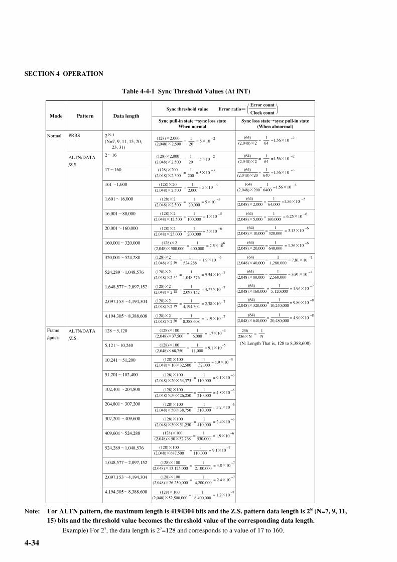
SECTION 4 OPERATION
4-34
Table 4-4-1 Sync Threshold Values (At INT)
Note: For ALTN pattern, the maximum length is 4194304 bits and the Z.S. pattern data length is 2N (N=7, 9, 11,15) bits and the threshold value becomes the threshold value of the corresponding data length.
Example) For 27, the data length is 27=128 and corresponds to a value of 17 to 160.
Mode Pattern Data lengthSync threshold value Error ratio=
Error count
Clock count
Sync pull-in state→sync loss stateWhen normal
Sync loss state→sync pull-in state(When abnormal)
2(N=7, 9, 11, 15, 20, 23, 31)
2~16
17~160
161~1,600
1,601~16,000
16,001~80,000
20,001~160,000
160,001~320,000
320,001~524,288
524,289~1,048,576
1,648,577~2,097,152
2,097,153~4,194,304
4,194,305~8,388,608
128~5,120
5,121~10,240
10,241~51,200
51,201~102,400
102,401~204,800
204,801~307,200
307,201~409,600
409,601~524,288
524,289~1,048,576
1,048,577~2,097,152
2,097,153~4,194,304
4,194,305~8,388,608
Normal
Frame
/quick
PRBS
ALTN/DATA
/Z.S.
ALTN/DATA
/Z.S.
N–1(128)×2,000(2,048)×2,500
=120= 5×10
–2 164
(64)(2,048)×2
= =1.56×10⁻²
(128)×2,000(2,048)×2,500
=120= 5×10
–2
(128)×200(2,048)×2,500
=1200= 5×10
–3
(128)×20(2,048)×2,500
=12,000
= 5×10⁻⁴
(128)×2(2,048)×2,500
=1
20,000= 5×10
–5
(128)×2(2,048)×12,500
=1
100,000= 1×10
–5
(128)×2(2,048)×25,000
=1
200,000= 5×10
–6
(128)×2(2,048)×500,000
=1
400,000= 2.5×10
–6
(128)×2(2,048)×2
=1
524,288= 1.9×10
–616
(128)×100(2,048)×37.500
=16,000
= 1.7×10⁻⁴
(128)×100(2,048)×68,750
=1
11,000= 9.1×10
–5
(128)×100(2,048)×10×32,500
=1
52,000= 1.9×10
–5
(128)×100(2,048)×20×34,375
=1
110,000= 9.1×10
–6
(128)×100(2,048)×50×26,250
=1
210,000= 4.8×10
–6
(128)×100(2,048)×50×38,750
=1
310,000= 3.2×10
–6
(128)×100(2,048)×50×51,250
=1
410,000= 2.4×10
–6
(128)×100(2,048)×50×32,768
=1
530,000= 1.9×10
–6
164
(64)(2,048)×2
= =1.56×10⁻²
1640
(64)(2,048)×20
= =1.56×10⁻³
16400
(64)(2,048)×200
= =1.56×10⁻⁴
164,000
(64)(2,048)×2,000
= =1.56×10⁻⁵
1160,000
(64)(2,048)×5,000
= = 6.25×10⁻⁶
(64)(2,048)×10,000
1320,000= = 3.13×10
–6
(64)(2,048)×20,000
1640,000= = 1.56×10
–6
(64)(2,048)×40,000
11,280,000
= = 7.81×10⁻⁷
1N
256256×N
=
(N: Length That is, 128 to 8,388,608)
(128)×2(2,048)×2
=1
1,048,576= 9.54×10 –7
17
(128)×2(2,048)×2
=1
2,097,152= 4.77×10 –7
18
(128)×2(2,048)×2
=1
4,194,304= 2.38×10 –7
19
(128)×2(2,048)×2
=1
8,388,608= 1.19×10 –7
20
(64)(2,048)×80,000
12,560,000
= = 3.91×10⁻⁷
(64)(2,048)×160,000
15,120,000
= = 1.96×10⁻⁷
(64)(2,048)×320,000
110,240,000= = 9.80×10
–8
(64)(2,048)×640,000
120,480,000= = 4.90×10
–8
(128)×100(2,048)×687,500
=1
110,000= 9.1×10
–7
(128)×100(2,048)×13.125.000
=1
2.100.000= 4.8×10
–7
(128)×100(2,048)×26,250,000
=1
4,200,000= 2.4×10
–7
(128)×100(2,048)×52,500,000
=1
8,400,000= 1.2×10
–7

4-35
Table 4-4-2 Sync Threshold Values (At 10–2 to 10–8)
The Sync Threshold values are independent from the Pattern and Data Length.
SYNCTHRESHOLD
(128)×2,000(2,048)×2,500
= 5×10⁻² (64)
(2,048)×2=1.56×10
–2
(128)×2,000(2,048)×25,000
= 5×10⁻³
(128)×2,000(2,048)×250,000
(128)×2,000(2,048)×2,500,000
(128)×2,000(2,048)×25,000,000
(128)×200(2,048)×25,000,000
(128)×20(2,048)×25,000,000
(64)(2,048)×20
=1.56×10⁻³
(64)(2,048)×200
(64)(2,048)×2,000
(64)(2,048)×20,000
(64)(2,048)×200,000
(64)(2,048)×2,000,000
10–3
10–4
10–5
10–6
10–7
10–8
10–2
= 5×10–4
= 5×10–5
= 5×10–6
= 5×10–7
= 5×10–8
=1.56×10–4
=1.56×10–5
=1.56×10–6
=1.56×10–7
=1.56×10⁻⁸
Sync threshold value Error ratio=Error count
Clock count
Sync pull-in state→sync loss stateWhen normal
Sync loss state→sync pull-in state(When abnormal)
4.5 Error Measurement
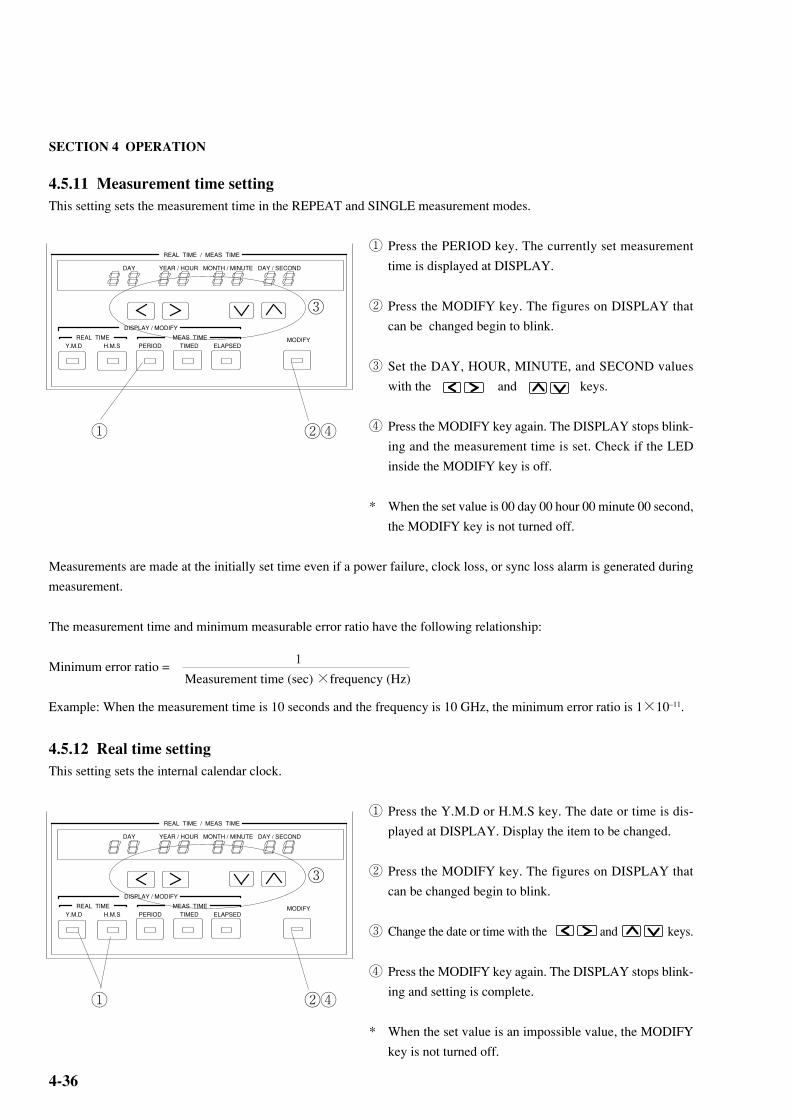
SECTION 4 OPERATION
4-36
4.5.11 Measurement time settingThis setting sets the measurement time in the REPEAT and SINGLE measurement modes.
① Press the PERIOD key. The currently set measurement
time is displayed at DISPLAY.
② Press the MODIFY key. The figures on DISPLAY that
can be changed begin to blink.
③ Set the DAY, HOUR, MINUTE, and SECOND values
with the and keys.
④ Press the MODIFY key again. The DISPLAY stops blink-
ing and the measurement time is set. Check if the LED
inside the MODIFY key is off.
* When the set value is 00 day 00 hour 00 minute 00 second,
the MODIFY key is not turned off.
Measurements are made at the initially set time even if a power failure, clock loss, or sync loss alarm is generated during
measurement.
The measurement time and minimum measurable error ratio have the following relationship:
Minimum error ratio =
Example: When the measurement time is 10 seconds and the frequency is 10 GHz, the minimum error ratio is 1×10–11.
4.5.12 Real time settingThis setting sets the internal calendar clock.
① Press the Y.M.D or H.M.S key. The date or time is dis-
played at DISPLAY. Display the item to be changed.
② Press the MODIFY key. The figures on DISPLAY that
can be changed begin to blink.
③ Change the date or time with the and keys.
④ Press the MODIFY key again. The DISPLAY stops blink-
ing and setting is complete.
* When the set value is an impossible value, the MODIFY
key is not turned off.
REAL TIME / MEAS TIME
DAY YEAR / HOUR MONTH / MINUTE DAY / SECOND
DISPLAY / MODIFY
REAL TIME MEAS TIMEY.M.D H.M.S PERIOD TIMED ELAPSED
MODIFY
① ②④
③
REAL TIME / MEAS TIME
DAY YEAR / HOUR MONTH / MINUTE DAY / SECOND
DISPLAY / MODIFY
REAL TIME MEAS TIMEY.M.D H.M.S PERIOD TIMED ELAPSED
MODIFY
① ②④
③
Measurement time (sec) ×frequency (Hz)
1

4-37
MEASUREMENT
CURRENT HISTORY
POWER FAILCLOCK LOSS SYNC LOSS
ERRORS GATING
%MHz
REPEATSINGLEUNTIMED
ERROR RATIO
DISPLAYERROR COUNT
ERRORINTERVAL
ERROR FREE INTERVAL
CLOCKFREQUENCY
MODECURRENT DATA
AUTO SYNC START STOP
REAL TIME / MEAS TIME
DAY YEAR / HOUR MONTH / MINUTE DAY / SECOND
DISPLAY / MODIFY
REAL TIME MEAS TIMEY.M.D H.M.S PERIOD TIMED ELAPSED
MODIFY
BURST MODE
ON MANUAL PRINT
ALARM
ERRORS
PRINTER ALARM MONITOR
0 / -1V 50Ω
2 3 4 5 6 7 8 INTSYNC THRESHOLD(10 )-N
4.5.13 Error lamp and alarm lamps
(1) Error lamp
This lamp indicates that an error was generated.
• ON condition: When error generated
• OFF condition: When there are no errors and at clock loss and sync loss
(2) Alarm lamps
The alarm lamps are made up of a HISTORY lamp (orange, small) that displays the past state and a realtime lamp
(orange, large) that displays the current state.
(a) POWER FAIL lamp (HISTORY lamp only)
This lamp indicates generation of a power dip or power failure alarm.
• ON condition HISTORY lamp: After power is recovered when a power dip or power failure occurred duringmeasurement.
• OFF condition HISTORY lamp: At the start of measurement.
(b) CLOCK LOSS lamps
These lamps indicate that a clock loss alarm was generated.
• ON condition HISTORY lamp: When clock loss alarm generated during measurement.
Realtime lamp : When clock loss alarm generated.
• OFF condition HISTORY lamp: At start of measurement.
Realtime lamp : When clock signal recovered.
(c) SYNC LOSS lamps
These lamps indicate that a sync loss alarm was generated.
• ON condition HISTORY lamp: When sync loss alarm generatedduring measurement.
Realtime lamp : When sync loss alarm generated.
• OFF condition HISTORY lamp: At start of measurement.
Realtime lamp : When synchronization recovered and when clock loss alarm generated and
when the AUTO SYNC key is OFF.
4.5 Error Measurement

SECTION 4 OPERATION
4-38
(a) Input pattern(b) Internal pattern(c) Total error(d) Insertion error(e) Omission error
4.5.14 Error detection mode settingErrors are detected by comparing each bit of the input pattern to an internally generated pattern. The error detection mode
has three kinds of errors: total error, insertion error, and omission error. The kind of error is selected by rear panel FUNC-
TION1 SW7 and SW8 as shown below.
SW7 SW8 Error
0 0 Total error
0 1 Insertion error
1 0 Omission error
1 1 Total error
In the insertion error mode, the pattern is detected only as an error of BIT that changed from "0" to "1". In the omission error
mode, the pattern is detected as an error of only BIT that changed from "1" to "0". In the total error mode, all errors are
detected.
In Fig. 4-4, the pattern logic was set to positive logic. When the pattern logic was set to negative logic, (d) becomes an
omission error and (e) becomes an insertion error.
Fig. 4-4 Error Detection Mode

4-39
4.6 Memory (Floppy Disk)
File No. selection
File control
Mode selection
Eject
MEMORYEXIST DIR
FILE No.RECALLDELETE
SAVERESAVE SHIFT PATT OTHERS
MODE
1 23
4
1
2
3
4
4.6 Memory (Floppy Disk)

SECTION 4 OPERATION
4-40
4.6.1 File save
① Insert a formatted disk (2HD, 2DD) into the floppy disk
drive. (For a description of the formatting method, see
Paragraph 4.6.3 Disk formatting.)
② Select the PATT mode or OTHERS mode.
PATT mode : Stores the contents set at Paragraph 4.4.
OTHERS mode : Stores the contents other than PATT.
③ Press the DIR/File No. key. The File No. LED lights.
④ Set the file name (00 to 99) with the keys.
⑤ Press the SAVE key and save the file.
* If another file was previously saved under the same file
name, the current file cannot be saved with the SAVE key.
If the old file is unnecessary, a new file can be saved by
pressing the SHIFT key, then pressing the SAVE key. If
the old file is necessary, save the new file by changing its
file name.
Note: When there is not enough vacant space on the FD to
resave files, files cannot be resaved. In this case, to
try to resave files, "DELETE" files from the FD.
Files larger than 720 k cannot be resaved to an FD
formatted at 1.44 M.
MEMORYEXIST DIR
FILE No.RECALLDELETE
SAVERESAVE SHIFT PATT OTHERS
MODE
①
②③④
⑤
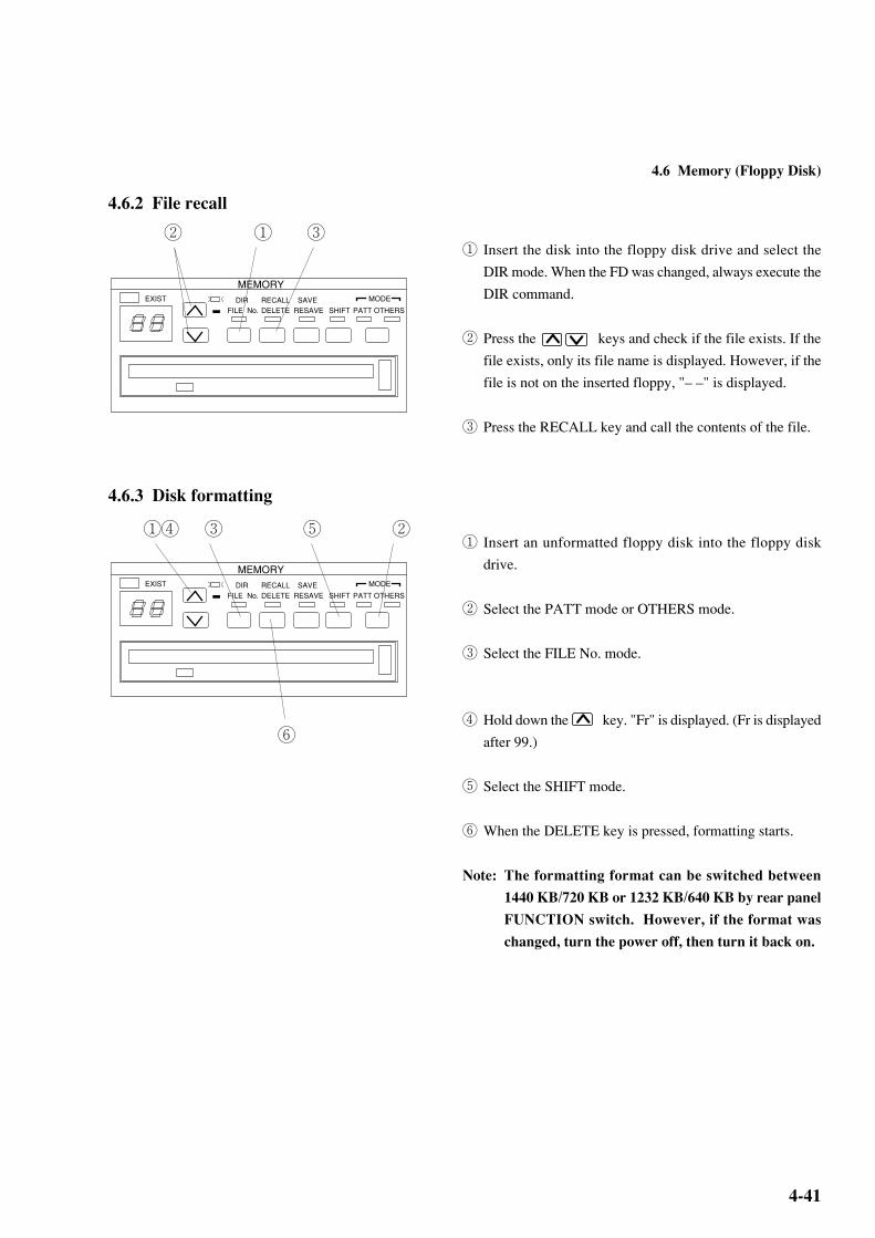
4-41
4.6.2 File recall
① Insert the disk into the floppy disk drive and select the
DIR mode. When the FD was changed, always execute the
DIR command.
② Press the keys and check if the file exists. If the
file exists, only its file name is displayed. However, if the
file is not on the inserted floppy, "– –" is displayed.
③ Press the RECALL key and call the contents of the file.
4.6.3 Disk formatting
① Insert an unformatted floppy disk into the floppy disk
drive.
② Select the PATT mode or OTHERS mode.
③ Select the FILE No. mode.
④ Hold down the key. "Fr" is displayed. (Fr is displayed
after 99.)
⑤ Select the SHIFT mode.
⑥ When the DELETE key is pressed, formatting starts.
Note: The formatting format can be switched between
1440 KB/720 KB or 1232 KB/640 KB by rear panel
FUNCTION switch. However, if the format was
changed, turn the power off, then turn it back on.
MEMORYEXIST DIR
FILE No.RECALLDELETE
SAVERESAVE SHIFT PATT OTHERS
MODE
① ③②
MEMORYEXIST DIR
FILE No.RECALLDELETE
SAVERESAVE SHIFT PATT OTHERS
MODE
①④ ③ ②⑤
⑥
4.6 Memory (Floppy Disk)

SECTION 4 OPERATION
4-42
4.6.4 File delete
① Insert the floppy disk into the floppy disk drive and select
the name of the file you want to delete.
② Press the SHIFT key.
③ Press the DELETE key. The file with the displayed file
name is deleted.
④ (Confirmation)
Execute the DIR command.
⑤ Press the keys and check that the deleted file
name is not displayed.
4.6.5 Error messagesWhen a floppy disk error was generated, an error code of from E0 to E9 is displayed on the file name display. For the error
display, see Table 4-5 Error Messages. The error messages are cleared each time the keys are pressed.
Table 4-5 Error Messages
MEMORYEXIST DIR
FILE No.RECALLDELETE
SAVERESAVE SHIFT PATT OTHERS
MODE
①⑤ ④ ③ ②
Error item
E0
E1
E2
E3
E4
E5
E6
E7
E8
E9
Error contents
Media error (Formatting, media error)
Write protection error (Protection error when writing)
File full (Write area too small)
File not found (Specified file could not be found when reading.)
File exists error (An attempt was made to save the same file)
Write error (Write obstruction error)
Read error (Read obstruction error)
File type, File error (File type or file contents error)
FD error (Other error)
Hardware error (Hardware trouble error)

4-43
4.6.6 Floppy disk(a) Disk type
Floppy disks are formatted in the standard MS-DOS format provided by the MS-DOS handler. The type of formatted
floppy disk is data disk. This is because the MS-DOS file handler does not copy the MS-DOS system. A system disk
containing the MS-DOS system can also be used to store data.
(b) Volume label
A volume label is added when the floppy disk is formatted.
Volume label: MP1764A
This volume label is provided to identify the floppy disk.
(c) File structure
• Directory structure
Route directory only.
• File name, extension
The file name and extension have the following format:
File name RR××00 to 99 (file name)
Extension PTN: Pattern file
OTH: Parameter file other than pattern
Examples: RR99. PTN
RR01. OTH
(d) Data format
The format of the data stored on floppy disk is, as a rule, not made public. Therefore, when data creation, updating, etc.
are performed using a personal computer that runs under MS-DOS, operation is not guaranteed. However, there is no
problem in checking the file directory or copying files.
(e) Compatibility
The MP1764A Error Detector 'PTN' file mode can be used with the MP1763B Pulse Pattern Generator. The 'OTH' file
cannot be used with the MP1763B Pulse Pattern Generator.
The MP1764A cannot read the files of the old MP1702A, MP1609A, and MP1651A Error Detectors.
4.6.7 Floppy disk precautions• Do not remove a floppy disk from the floppy disk drive while it is being accessed.
• Observe the specified environmental conditions, and do not use the floppy disk in dusty places.
• Clean head of floppy disk drive with 3.5 inch head cleaning disk set regularly.
• Do not place a magnetized object near the floppy disk and do not bend the floppy disk.
4.6 Memory (Floppy Disk)
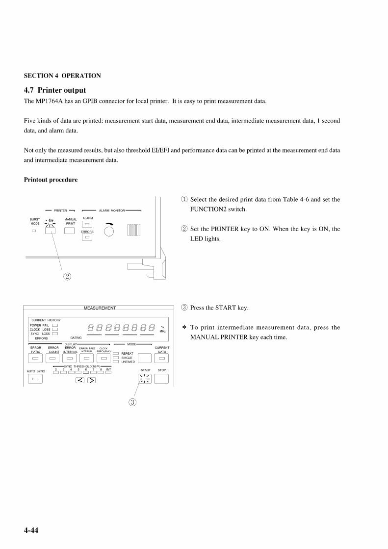
SECTION 4 OPERATION
4-44
4.7 Printer outputThe MP1764A has an GPIB connector for local printer. It is easy to print measurement data.
Five kinds of data are printed: measurement start data, measurement end data, intermediate measurement data, 1 second
data, and alarm data.
Not only the measured results, but also threshold EI/EFI and performance data can be printed at the measurement end data
and intermediate measurement data.
Printout procedure
① Select the desired print data from Table 4-6 and set the
FUNCTION2 switch.
② Set the PRINTER key to ON. When the key is ON, the
LED lights.
③ Press the START key.
* To print intermediate measurement data, press the
MANUAL PRINTER key each time.
BURST MODE
ON MANUAL PRINT
ALARM
ERRORS
PRINTER ALARM MONITOR
②
MEASUREMENT
CURRENT HISTORY
POWER FAILCLOCK LOSS SYNC LOSS
ERRORS GATING
%MHz
REPEATSINGLEUNTIMED
ERROR RATIO
DISPLAYERROR COUNT
ERRORINTERVAL
ERROR FREE INTERVAL
CLOCKFREQUENCY
MODECURRENT DATA
AUTO SYNC START STOP2 3 4 5 6 7 8 INTSYNC THRESHOLD(10 )-N
③

4-45
The print data contents are shown below.
Table 4-6 Print Data Contents
Print data contents Print timing Printing restriction
Measurement start data
Measurement end data
Intermediate measurement data
・Measurement start time
・Measurement start time・Measurement end time・Measurement elapsed time・Measured result
・Threshold EI and EFI data・Error performance data
・Same as measurement end data. However, the measurement end time is replaced by the intermediate measurement time.
Measurement value
Alarm intervals
・At the start of measurement.
・At the end of measurement
・When MANUAL PRINT key pressed.・When intermediate data printing is selected:1. When measurement time is less than 2 days, every 2 hours.2. when measurement time is 2 days or more, every day.3. In UNTIMED mode, every day.
None
・The following can be selected with FUNCTION2 SW1, SW2, and SW3.
SW10: Print all measured result1: Print only error ratio and error count of measured resultSW20: Do not print threshold EI and EFI data.1: Print threshold EI and EFI data.SW30: Do not print error performance data.1: Print error performance data.
・The following can be selected with FUNCTION2 SW4.
0: Do not print intermediate data.1: Print intermediate data.
・Except for the above, the same as measurement end data.
Error ratioError countEI countEFI ratio
Power failureClock lossSync loss
4.7 Printer output
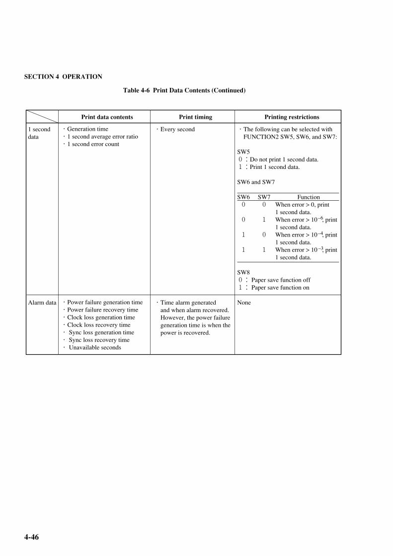
SECTION 4 OPERATION
4-46
Table 4-6 Print Data Contents (Continued)
Print data contents Print timing Printing restrictions
1 second dataAlarm data
・Generation time・1 second average error ratio・1 second error count・Power failure generation time・Power failure recovery time・Clock loss generation time・Clock loss recovery time・ Sync loss generation time・ Sync loss recovery time・ Unavailable seconds
・Every second・Time alarm generated and when alarm recovered. However, the power failure generation time is when the power is recovered.
・The following can be selected with FUNCTION2 SW5, SW6, and SW7:
SW50:Do not print 1 second data.1:Print 1 second data.
SW6 and SW7
SW6 SW7 Function 0 0 When error > 0, print 1 second data. 0 1 When error > 10 , print 1 second data. 1 0 When error > 10 , print 1 second data. 1 1 When error > 10 , print 1 second data.
SW80: Paper save function off1: Paper save function on
None
–6
–4
–3

4-47
<< POWER FAILURE
<< POWER RECOVERY
94-03-01 21:20:07 >>
94-03-01 21:20:08 >>
• Clock loss/clock recovery
<< CLOCK LOSS
<< CLOCK RECOVERY
Power recovery time
Year-day-time Hour: minute: second
Power failure generation time
Year-day-time Hour: minute: second
Clock loss generation time
Year-day-time Hour: minute: second
Clock recovery time
Year-day-time Hour: minute: second
94-03-01 21:20:09 >>
94-03-01 21:20:10 >>
4.7.1 Printing Format Note: Print data (Differs with the setting state and measurement state)
(1) Measurement start data
<<START 94-03-01 21: 20: 05 REPEAT 99-01: 59: 59 >>
Measurement start time Measurement mode Measurement time
Year-day-time Hour:minute:second
(2) 1 second data
(3) Alarm data
• Power failure/power recovery
REPEAT
SINGLE
UNTIMED
Day-hour:minute:second
(Not printed for UNTIMED.)
TIME 94-03-01 21:20:06
ERROR RATIO 1.0000E-11 ERROR COUNT 15
1SEC DATA
Number of errors in 1 second1 second average error ratio measurement
1 second data generation time
Year-day-time Hour: minute: second
4.7 Printer output

SECTION 4 OPERATION
4-48
<< PATTERN SYNC LOSS
<< PATTERN SYNC RECOVERY
• Sync loss/sync recovery
(4) Measurement end data and intermediate measurement data
There are two output formats, standard format and abbreviated format. These formats are described below in the
order: (a) Standard format and (b) abbreviated format.
(a) Standard format
Line 1
Line 2
Line 3
Line 4
Line 5
Line 6
Line 7
Line 8
Line 9
*********************************************************************************
Measurement end time or
intermediate measurement
time
Measurement end data
INT for intermediate
measurement data
Measurement start time
Year-day-time
Hour: minute: second
ERROR RATIO 1.0000E-11 ERROR COUNT 25
ERROR INTVL 1 %ERROR FREE INTVL 0
ERROR MEASUREMENT
POWER FAIL INTVL 0 CLOCK LOSS INTVL 0
SYNC LOSS INTVL 0
Number of power fail intervals Number of clock loss intervals
Error free intervals ratio
Number of errors
Number of error intervals
Number of sync loss intervals
*********************************************************************************
Average error ratio
Sync loss generation time
Year-day-time Hour: minute: second
Sync recovery time
Year-day-time Hour: minute: second
94-03-01 21: 20:11 >>
94-03-01 21: 20:12 >>
START 94-03-01 21: 20:13 END 94-03-01 21: 20:14

4-49
When there is threshold EI/EFI data to be printed, the following data is printed between lines 8 and 9.
Line 9
Line 10
Line 11
Line 12
Line 13
Line 14
Line 15
Line 16
Line 17
Line 18
Number of threshold EI Threshold EFI ratio
Number of threshold EI Threshold EFI ratio
Number of threshold EI Threshold EFI ratio
Number of threshold EI Threshold EFI ratio
Number of threshold EI Threshold EFI ratio
Number of threshold EI Threshold EFI ratio
Number of threshold EI Threshold EFI ratio
>1.0E-3 0 100.0000%
>1.0E-4 0 100.0000%
>1.0E-5 0 100.0000%
>1.0E-6 0 100.0000%
>1.0E-7 0 100.0000%
>1.0E-8 0 100.0000%
=<1.0E-8 1 0.0000%
ERROR RATIO ERROR INTVL %ERROR FREE INTVL
THRESHOLD EI. EFI
4.7 Printer output

SECTION 4 OPERATION
4-50
%SES (1.0E-3) 0.0000% %DM (1.0E-3) 0.0000%
ERROR RATIO 1.0000E-11 ERROR COUNT 25
When there is error performance data to be printed, the following data is printed after line 19 (between lines 8 and 9
when threshold EI/EFI data is not printed).
Line 19
(Line 9)
Line 20
(Line 10)
Line 21
(Line 11)
Line 22
(Line 12)
Line 23
(Line 13)
%ERRORED SECOND 100.0000% %ERROR FREE SECOND 0.0000%
%UNAVAIL SECOND 0.0000%
Error free seconds ratio
Severely errored seconds ratio
Error seconds ratio
Unavailable seconds ratio
(b) Abbreviated format
Line 1
Line 2
Line 3
Line 4
Line 5
Line 6
Number of errors
Measurement end time or
intermediate measurement
time
Measurement end data
INT for intermediate
measurement data
Measurement start time
Year-day-time
Hour:minute:second
*********************************************************************************
ERROR MEASUREMENT
Average error ratio
ERROR PERFORMANCE
Degraded minutes ratio
START 94-03-01 21: 20:13 END 94-03-01 21: 20:14
*********************************************************************************
Note: The threshold EI/EFI data and error performance data printing format is the same as the standard
output format. The data is printed from line 4.

4-51
( )number of measurement intervals – EINumber of measurement intervals
( )Number of measurement intervals
4.8 Definition of Terms
4.8.1 Measurement items(1) Error ratio
Number of error pulses in measurement time
Number of clock pulses in measurement time
(2) Error count
Number of error pulses in measurement time.
(3) Error intervals (EI) count
Number of intervals (1 second) containing one or more error pulses in measurement time.
(4) Error free intervals (EFI) ratio
Ratio of total number of intervals with number of intervals (1 second) containing one or more error pulses to total
number of intervals in measurement time. It is calculated from EI with the following equation:
EFI = × 100%
(5) Clock frequency
One second clock frequency.
4.8.2 Alarm intervals(1) Power failure alarm intervals
Number of intervals (1 second) at which a power failure occurred.
(2) Clock loss intervals
Number of intervals (1 second) at which a clock loss alarm was generated.
(3) Sync loss intervals
Number of intervals (1 second) at which a sync loss alarm was generated.
4.8.3 Threshold EI and EFI data(1) Threshold EI
Number of intervals (1 second) that the 1 second average error ratio satisfies each of the following thresholds in the
measurement time.
1 second average error ratio > 10–3, >10–4, >10–5, >10–6, >10–7, >10–8, ≦10–8
(2) Threshold EFI
Ratio of the number of intervals at which the 1 second average error ratio does not satisfy each threshold condition of
item (1) to the total number of intervals.
The threshold EFI is calculated from EI with the following equation:
Threshold EFI = × 100%Number of measurement intervals – threshold EI
4.8 Definition of Terms

SECTION 4 OPERATION
4-52
4.8.4 Error performance dataThe interval from the start of measurement to the end of measurements is divided into available periods and unavailable
periods, with 1 second interval as the unit. Each item is calculated for the available periods.
(1) Definition of unavailable period and available period
When an interval at which the 1 second average error ratio exceeds the unavailable threshold (unavailable period)
continues for 10 seconds, the unavailable period starts and this 10 seconds is included in the unavailable seconds.
When an interval at which the 1 second average error ratio does not exceed the unavailable threshold (available inter-
val) continues for 10 seconds in an unavailable period, the unavailable period ends and this 10 seconds is included in the
available seconds.
Each is subdivided into two states, with the periods that are not unavailable periods as available periods.
• Unavailable period (after confirmation)
This is the state after the last interval was calculated in the unavailable seconds. When an interval is an unavailable
interval, it is calculated in the unavailable seconds and the state does not change.
When an interval is an available interval, the unavailable seconds and available seconds do not change and the state
changes to unavailable seconds (during judgment).
• Unavailable period (during judgment)
This is the state during which whether the last interval was included in unavailable seconds or available seconds during
an unavailable interval is judged.
When the interval is an unavailable interval, the continuation seconds of this state is calculated in the unavailable
seconds and the state changes to unavailable period (after confirmation).
When the interval is an available interval, and the number of consecutive available intervals reached 10, the continua-
tion time of this state (=10 seconds) is calculated in the available seconds and the state changes to available period (after
confirmation). When the number of consecutive available intervals is less than 10, the unavailable seconds and avail-
able seconds do not change and this state continues.
• Available period (after confirmation)
This is the state after the last interval was calculated in the available seconds.
When the interval is an available interval, it is calculated in the available seconds and the state does not change.
When the interval is an unavailable interval, the available seconds and unavailable seconds do not change and the state
changes to available seconds (during judgment).

4-53
• Available seconds (during judgment)
This is the state during which whether the last interval is included in the available seconds in an available period.
When the interval is an available interval, the continuation time of that state is calculated in the available seconds and
the state changes to available period (after confirmation).
When the interval is an unavailable interval, and the number of consecutive unavailable intervals reached 10, the
continuation time (=10 seconds) of this state is calculated in the unavailable seconds and the state changes to unavail-
able period (after confirmation). When the number of consecutive unavailable intervals is less than 10, the available
seconds and unavailable seconds do not change and this state is continued.
The initial state is available period (after confirmation).
(2) Unavailable threshold, DM threshold
The following can be selected with FUNCTION1 SW4:
0: Unavailable threshold = 10–3, DM threshold = 10–6
1: Unavailable threshold = 10–4, DM threshold = 10–8
(3) Measurement items
• Unavailable Seconds
Ratio of unavailable seconds to measurement time.
• Error Seconds
Ratio of error intervals calculated in available seconds to all intervals calculated in available seconds.
• Error Free Seconds
Ratio of error free intervals calculated in available seconds to all intervals calculated in available seconds.
• Severely Errored Seconds (SES)
Ratio of unavailable intervals calculated in available seconds to all intervals calculated in available seconds.
• Degraded Minutes
The error ratio is calculated for every 60 packets, excluding the SES above at the available interval calculated in the
available seconds. The error ratio is the ratio of the number of packets exceeding the DM threshold to the total number
of packets.
4.8 Definition of Terms

SECTION 4 OPERATION
4-54
4.9 Processing of Measurement Data At Alarm Generation(1) Power failure
When a power failure alarm is generated during measurement, the measurement data up to the interval before the
interval that generated the power failure alarm is saved during the power failure.
If the measurement data was correctly saved, measurement is continued after the power recovers.
(a) Error measurement
The number of error pulses and the number of clock pulses counted in the interval that generated the power failure
alarm are removed from calculation.
(b) Interval measurement, threshold interval measurement
The interval that generated the power failure alarm and the interval during continuation of the power failure are in-
cluded only in the power failure intervals calculation and are included in other calculations.
(c) Error performance
The interval being judged when a power failure alarm was generated is not included in neither unavailable seconds nor
available seconds calculation.
After the power recovers, measurement restarts from the initial state.
(2) Clock loss
When a clock loss alarm is generated during measurement, one of the following two processings can be selected:
(a) Removal of clock loss processing from calculation (FUNCTION1 SW2 set to 0.)
(i) Error measurement
The number of error pulses and number of clock pulses counted in the interval that generated the clock loss alarm are
removed from calculation.
(ii) Interval measurement, threshold interval measurement
Intervals whose interval status is clock loss are included in clock loss intervals calculation only. They are not included
in other calculations.
(iii) Error performance
Intervals whose interval status is clock loss are not included in neither unavailable seconds or available seconds calcu-
lation. The interval being judged is not included in unavailable seconds or available seconds calculation either.
When the interval status is no longer clock off, measurement is continued from the initial state.

4-55
(b) Inclusion of clock loss processing in calculation (FUNCTION1 SW2 set to 1.)
(i) Error measurement
The number of error pulses and number of clock pulses counted in the interval that generated the clock loss alarm are
removed from calculation.
(ii) Interval measurement, threshold interval measurement
Intervals whose interval status is clock loss are included in clock loss intervals and total intervals calculation, but are not
included in threshold EI calculation.
(iii) Error performance
Intervals whose interval status is clock loss become unavailable intervals and when they were included in available
seconds calculation, they are also included in error seconds calculation.
(3) Sync loss
When a sync loss alarm is generated during measurement, one of the following two processings can be selected:
(a) Removal of sync loss processing from calculation (FUNCTION1 SW3 set to 0)
(i) Error measurement
The number of error pulses and number of clock pulses counted in the interval that generated the sync loss alarm are
removed from calculation.
(ii) Interval measurement, threshold interval measurement
Intervals whose interval status is sync loss are included only in sync loss intervals calculation. They are not included in
other calculations.
(iii) Error performance
Intervals whose interval status is sync loss are not included in neither unavailable seconds nor available seconds calcu-
lation. The interval being judged is not included in unavailable seconds and available seconds calculations either.
When the interval status is not longer sync loss, measurement is continued from the initial state.
(b) Inclusion of sync loss processing in calculations (FUNCTION1 SW3 set to 1.)
(i) Error measurement
The number of error pulses and the number of clock pulses counted in the interval that generated the sync loss alarm are
removed from all calculations.
(ii) Interval measurement, threshold interval measurement
Intervals whose interval status is sync loss are included in sync loss intervals and total intervals calculations, but are not
included in threshold EI calculation.
(iii) Error performance
Intervals whose interval status is sync loss become unavailable intervals and when they were included in available
seconds calculation, they are also included in error seconds calculation.
4.9 Processing of Measurement Data At Alarm Generation

SECTION 4 OPERATION
4-56
4.10 FUNCTION Switch SettingThe setting contents of the FUNCTION1 and 2 switches on the rear panel of the mainframe show below.
When the FUNCTION2 SW10 setting was changed, turn on the mainframe power again.
* When the setting of the other FUNCTION switches was changed, the power does not have to be turned on again.
Note: When the system control setting was changed, turn on the power again.

4-57
1
Marking Function
BIT SHIFTNUMBER FORMARK RATIOVARIED
Number of AND shift bits at mark ratio setting switch0:1 bit1:3 bits
CLOCK LOSSEVALUATION
Clock loss processing function selector switch0:Do not measure and evaluate clock loss1:Measure and evaluate clock loss
SYNC LOSSEVALUATION
Sync loss processing function selector switch0:Do not measure and evaluate sync loss1:Measure and evaluate sync loss
FUNCTION 1
ERRORPERFORMANCETHRESHOLD
Error performance threshold selector switch0:101:10
-3
-4
BURST MODE Burst mode switch0:OFF1:ON
CURRENTDATACALCULATION
Calculation mode of intermediate measurement data displayed when CURRENT DATA key ON selector switch0:Progressive mode1:Immediate mode
7,8 ERROR
INTERVAL TIME
Error detection mode selector switch
SW7 SW8 0 0 0 1 1 0 1 1
Error modeTotal errorInsertion errorOmission errorTotal error
INTERVAL TIME selector switch (at the EI or %EFI measurement)
SW9 SW10 0 0 0 1 1 0 1 1
Cycle time 1 ms 10 ms 100 ms 1 s
9,10
2
3
4
5
6
4.10 FUNCTION Switch Setting

SECTION 4 OPERATION
4-58
1
Marking Function
SHORT FORMOUTPUT
Measurement data printing format selector switch0:Standard format1:Abbreviated format
THRESHOLDEI, EFI DATA
Switch that selects whether or not threshold EI and EFI data are printed.0:Do not print1:Print
FUNCTION 2
ERRORPERFORMANCEDATA
Switch that selects whether or not error performance data is printed.0:Do not print1:Print
OUTPUT
8
CURRENT DATA INTERVAL
1 second data printing threshold selector switch
SW6 SW7 0 0 0 1 1 0 1 1
Error threshold > 0 > 10 > 10 > 10
9
2
3
4
5
INTERMEDIATEDATA
Switch that selects whether or not intermediate data is printed.0:Do not print1:Print
Switch that selects whether or not 1 second data is printed.0:Do not print1:Print
OUTPUTTHRESHOLD
-6
-4
-3
6,7
10
PAPERSAVING
Switch that selects whether or not printer paper is saved.0:Do not save1:Save
ONESECONDDATA
Switch that selects the current data measurement time.0:100 ms1:200 ms
FD FORMATTING TYPE
Switch that selects the floppy disk format.0:1440 K / 720 KB1:1232 K / 640 KB
.....
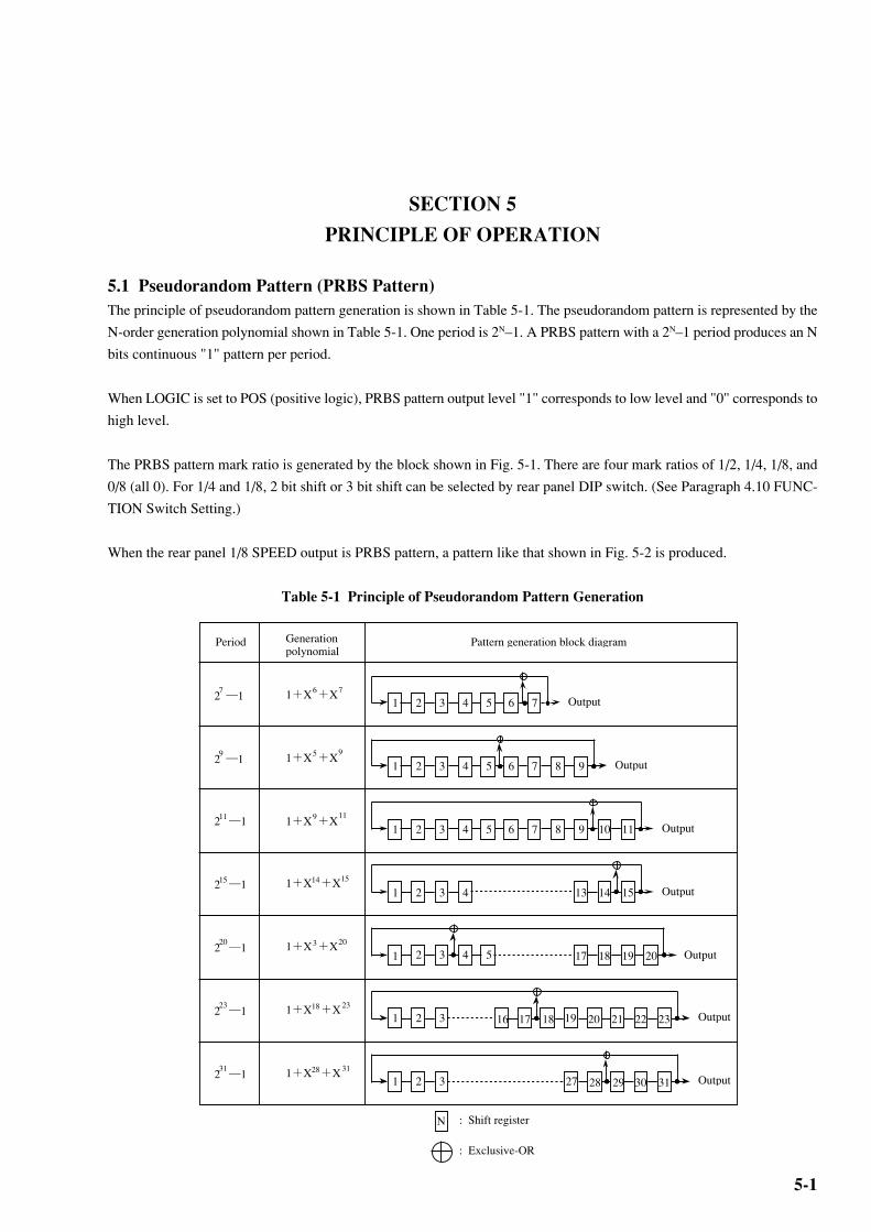
5-1
SECTION 5
PRINCIPLE OF OPERATION
5.1 Pseudorandom Pattern (PRBS Pattern)The principle of pseudorandom pattern generation is shown in Table 5-1. The pseudorandom pattern is represented by the
N-order generation polynomial shown in Table 5-1. One period is 2N–1. A PRBS pattern with a 2N–1 period produces an N
bits continuous "1" pattern per period.
When LOGIC is set to POS (positive logic), PRBS pattern output level "1" corresponds to low level and "0" corresponds to
high level.
The PRBS pattern mark ratio is generated by the block shown in Fig. 5-1. There are four mark ratios of 1/2, 1/4, 1/8, and
0/8 (all 0). For 1/4 and 1/8, 2 bit shift or 3 bit shift can be selected by rear panel DIP switch. (See Paragraph 4.10 FUNC-
TION Switch Setting.)
When the rear panel 1/8 SPEED output is PRBS pattern, a pattern like that shown in Fig. 5-2 is produced.
Table 5-1 Principle of Pseudorandom Pattern Generation
Period Generation polynomial
Pattern generation block diagram
2 ―17 1+X +X76
1 2 3 4 5 6 7 Output
2 ―19 1+X +X95
1 2 3 4 5 6 7 Output8 9
2 ―111 1+X +X119
1 2 3 4 5 6 7 Output8 9 10 11
2 ―115 1+X +X1514
1 2 3 4 Output13 14 15
52 ―120 1+X +X203
1 2 3 4 Output17 18 2019
162 ―123 1+X +X2318
1 2 3 Output19 20 22211817 23
2 ―131 1+X +X3128
1 2 3 Output27 28 3029 31
N : Shift register
: Exclusive-OR
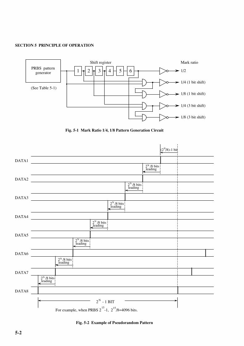
SECTION 5 PRINCIPLE OF OPERATION
5-2
Fig. 5-1 Mark Ratio 1/4, 1/8 Pattern Generation Circuit
Fig. 5-2 Example of Pseudorandom Pattern
1 2 3 4 5 6 1/2
Mark ratio
1/4 (1 bit shift)
1/8 (1 bit shift)
1/4 (3 bit shift)
1/8 (3 bit shift)
Shift register
PRBS pattern generator
(See Table 5-1)
DATA1
DATA2
DATA3
DATA4
DATA5
DATA6
DATA7
DATA8
(2 /8)-1 bitN
2 - 1 BITN
For example, when PRBS 2 -1, 2 /8=4096 bits.15 15
2 /8 bits N
leading
2 /8 bits N
leading
2 /8 bits N
leading
2 /8 bits N
leading
2 /8 bits N
leading
2 /8 bits N
leading
2 /8 bits N
leading

5-3
5.2 Pattern Synchronized Output Synchronization
5.2 Pattern Synchronized Output Synchronization
5.2.1 Pseudorandom pattern
Period = × (2N–1) × 32
N=7, 9, 11, 15, 20, 23, 31
(Where pulse width = × 32 plus pulses)
5.2.2 Programmable pattern(1) Data pattern, alternate pattern
(a) Data length = 65536 or less
Period = × (128 and lowest common denominator of data length)
(Example 1) Data = 8
Period = ×128
(Example 2) Data = 10
Period = × 640
(b) Data length > 65536
Period = × (data length)
(2) Zero Sub pattern
Period = ×2N N=7, 9, 11, 15
(3) Pulse width
For any of the programmable patterns above, the pulse width is pulse width = × 32. The output signal
polarity is plus pulse.
Note: For alternate pattern, the sync pulse is output in basic data length units. When the data output is ob-
served with a sampling oscilloscope, pattern A and pattern B appear to be superimposed.
When you want to observe the data output pattern A or pattern B without being superimposed, input the
rear panel A/B TIMING OUTPUT of MP1763B to a sampling oscilloscope trigger via an ECL termina-
tor.
1
(Set frequency)
1
(Set frequency)
1
(Set frequency)
1
(Set frequency)
1
(Set frequency)
1
(Set frequency)
1
(Set frequency)
1
(Set frequency)

SECTION 5 PRINCIPLE OF OPERATION
5-4
5.3 Frame Sync OutputThe frame sync pulse is output when the frame sync function is on. Its period and pulse width are shown in Fig. 5-3.
• Pulse width = ×32
• The period is the same as the pattern sync output period. See Paragraph 5.2.
• Not output when the bit length is 128 bits.
Fig. 5-3 Frame Sync Output
1
(Set frequency)
Period
Pulse width
Frame Sync Output 0 V
–1 V

5-5
5.4 Error OutputThe error output can be of two types, direct error and stretched error. The error detection block diagram is shown in Fig. 5-
4 and the error output pulse is illustrated in Fig. 5-5.
Fig. 5-4 Error Output Block Diagram
Fig. 5-5 Error Output Pulse
Input data
1/32data
Error detection circuit
Direct error
Stretched error
1/32data
1/32 error1
2
31
32
1/32OR error
1/32 clock
(RZ)
1/32 DEMUXcircuit
Standard pattern generator
Pulse width stretcher circuit
Direct error(0/-1 V)
Stretched error(TTL)
1/32 OR error
1/32 clock
T
Approx. 350 ns
0 V
-1 V
H
L
T=16f
Example: When f=10 GHz T=1.6 ns
Note:
Indicates an ERROR.
5.4 Error Output

SECTION 5 PRINCIPLE OF OPERATION
5-6 .....
(Blank)
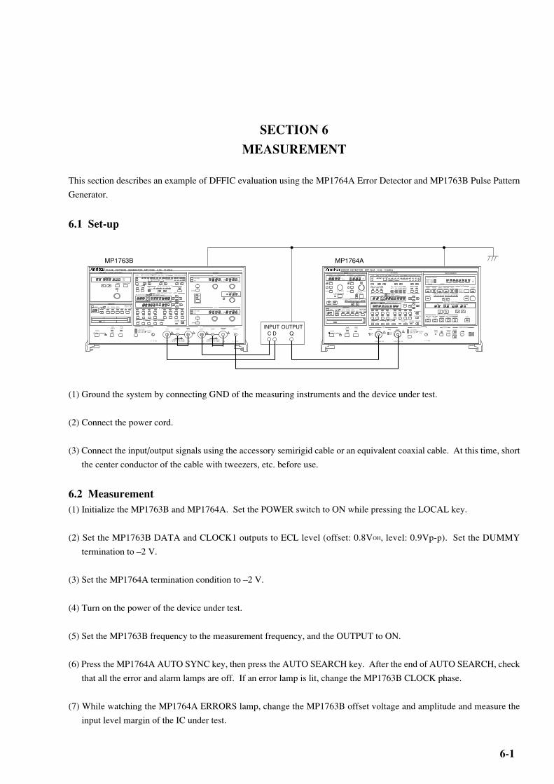
6-1
SECTION 6
MEASUREMENT
This section describes an example of DFFIC evaluation using the MP1764A Error Detector and MP1763B Pulse Pattern
Generator.
6.1 Set-up
(1) Ground the system by connecting GND of the measuring instruments and the device under test.
(2) Connect the power cord.
(3) Connect the input/output signals using the accessory semirigid cable or an equivalent coaxial cable. At this time, short
the center conductor of the cable with tweezers, etc. before use.
6.2 Measurement(1) Initialize the MP1763B and MP1764A. Set the POWER switch to ON while pressing the LOCAL key.
(2) Set the MP1763B DATA and CLOCK1 outputs to ECL level (offset: 0.8VOH, level: 0.9Vp-p). Set the DUMMY
termination to –2 V.
(3) Set the MP1764A termination condition to –2 V.
(4) Turn on the power of the device under test.
(5) Set the MP1763B frequency to the measurement frequency, and the OUTPUT to ON.
(6) Press the MP1764A AUTO SYNC key, then press the AUTO SEARCH key. After the end of AUTO SEARCH, check
that all the error and alarm lamps are off. If an error lamp is lit, change the MP1763B CLOCK phase.
(7) While watching the MP1764A ERRORS lamp, change the MP1763B offset voltage and amplitude and measure the
input level margin of the IC under test.
ERROR DETECTOR MP1764A 0.05 - 12.5GHzPATTERN
MEMORY
THRESHOLD / MARGIN DELAY TIME / MARGIN
MEASUREMENT
EXIST DIRFILE No.
RECALLDELETE
SAVERESAVE SHIFT PATT OTHERS
MODE
LOGIC PATTERN PRBS / ZERO SUBST PRBS MARK RATIO
2 - 1N
2 N
POS
NEG
ALTNDATA Z.S PRBS 7 9 11 15 20 23 31 0/8 1/8 1/4 1/2
8/8 7/8 3/4 1/2
!
PANEL LOCK
GPIBREMOTE
LOCAL
POWER
OFF ON
INPUTDATA CLOCK
VVp-p
psps p-p
TERMGND
-2V
GUARD
TERMGND
-2V
GUARD
BUSY
-3V to 1.875V -500ps to 500ps
AUTO SEARCH(MARJ RATIO 1/8 to 7/8)
POLARITYCLK
CLK
EYE MARGINERROR RATIO (10 )
2 3 4 5 6 7 8 9- N
ON START
SYNC MODENORMAL FRAME QUICK A B
ALTNDISPLAY SELECT
PATT BIT BLOCK ERROR
CURRENT HISTORY
POWER FAILCLOCK LOSS SYNC LOSS
ERRORS GATING
%MHz
REPEATSINGLEUNTIMED
ERROR RATIO
DISPLAYERROR COUNT
ERRORINTERVAL
ERROR FREE INTERVAL
CLOCKFREQUENCY
MODECURRENT DATA
2 3 4 5 6 7 8 9 INTAUTO SYNC
SYNC THRESHOLD(10 )-N
START STOP
REAL TIME / MEAS TIME
DAY YEAR / HOUR MONTH / MINUTE DAY / SECOND
DISPLAY / MODIFY
REAL TIME MEAS TIMEY.M.D H.M.S PERIOD TIMED ELAPSED
MODIFY
BURST MODE
ON MANUAL PRINT
ALARM
ERRORS
PRINTER ALARM MONITOR
1 / 32 CLOCKFIXED POSN VAR POSN
PATTERN SYNC
0 / -1V 50Ω
SYNC OUTPUT
0.25-2.0Vp-p / 50Ω
CLOCK
GND-2V
TERM
INPUT
!
0.25-2.0Vp-p / 50Ω
GND-2V
TERM DATA
WINDOW WINDOW ANALYSIS
MP1764APULSE PATTERN GENERATOR MP1763B 0.05 - 12.5GHz
INTERNAL CLOCK (OPTION.01) PATTERN
MEMORY
TUNING RESOLUTION
FREQUENCYMHz kMz
OUTPUT
EXIST DIRFILE No.
RECALLDELETE
SAVERESAVE SHIFT PATT OTHERS
MODE
LOGIC PATTERN PRBS / ZERO SUBST PRBS MARK RATIO
2 - 1N2 N
POS
NEG
ALTNDATA Z.S PRBS 7 9 11 15 20 23 31 0/8 1/8 1/4 1/2
8/8 7/8 3/4 1/2
ALTN ERROR ADDITION(1×10 )- N
SINGLEA B ON 4 5 6 7 8 9
DATA LENGTH/ZERO SUBST LENGTHDATA LENGTHZERO SUBST LENGTH
A / B LOOP TIME
PAGE/PATTERN SYNC POSITION
BIT
1 2 3 4 5 6 7 8
9 10 11 12 13 14 15 16
ALL PAGEPRESET
PATTERNLOADING
TRACKINGGUARD 0 1 0 1
DATA
50Ω GND
ECL
AMPLITUDE
Vp - p
OFFSET
V
ECL
ps
DELAY TIME
BUSY
CLOCK 1
50Ω GND
ECL
AMPLITUDE
Vp - p
OFFSET
V
ECL
GUARD
GUARD
OFFSET
VOHVTHVOL
OUTPUT
DATA DUMMY DATA CLOCK 1 DUMMY CLOCK 1 CLOCK 2
! ! ! !
50Ω
CAUTION CONNECT THE UNUSEOUTPUT TO THE DUMMY 50Ω 50Ω
CAUTION CONNECT THE UNUSEOUTPUT TO THE DUMMY 50Ω 0 / - 1V 50Ω
1 / 32 CLOCKFIXED POSNVAR POSN
PATTERN SYNC
PANEL LOCK
GPIBREMOTE
LOCAL
POWER
OFF ON
SYNC OUTPUT
0 / - 1V 50Ω
! !
MP1763B
INPUT OUTPUTC D Q
DATA LENGTH/ZERO SUBST LENGTHDATA LENGTHZERO SUBST LENGTH
PAGE/PATTERN SYNC POSITION
9 10 11 12 13 14 15 16
ALL PAGEPRESET
PATTERNLOADING
TRACKINGGUARD 0 1 0 1
FRAME LENGTH
ON
ERROR ANALYSIS TRIGGER
BLOCK WINDOW
BIT
1 2 3 4 5 6 7 8 BIT WINDOW
PATTERN SYNC POSITIONPAGEDISPLAY

SECTION 6 MEASUREMENT
6-2.....
6.3 Burst Measurement
To perform the burst measurement, set the function sw5 (BURST MODE) on the MP1764A rear panel to ON and connect
the MP1764A to the MP1763B and DUT as shown below:
Burst measurement
Restart the burst measurement after termination of the burst timing and completion of pull in. In other words, the measure-
ment inhibiting time is the time of burst timing added by the pull-in time.
ERROR DETECTOR MP1764A 0.05 - 12.5GHzPATTERN
MEMORY
THRESHOLD / MARGIN DELAY TIME / MARGIN
MEASUREMENT
EXIST DIRFILE No.
RECALLDELETE
SAVERESAVE SHIFT PATT OTHERS
MODE
LOGIC PATTERN PRBS / ZERO SUBST PRBS MARK RATIO
2 - 1N
2 N
POS
NEG
ALTNDATA Z.S PRBS 7 9 11 15 20 23 31 0/8 1/8 1/4 1/2
8/8 7/8 3/4 1/2
!
PANEL LOCK
GPIBREMOTE
LOCAL
POWER
OFF ON
INPUTDATA CLOCK
VVp-p
psps p-p
TERMGND
-2V
GUARD
TERMGND
-2V
GUARD
BUSY
-3V to 1.875V -500ps to 500ps
AUTO SEARCH(MARJ RATIO 1/8 to 7/8)
POLARITYCLK
CLK
EYE MARGINERROR RATIO (10 )
2 3 4 5 6 7 8 9- N
ON START
SYNC MODENORMAL FRAME QUICK A B
ALTNDISPLAY SELECT
PATT BIT BLOCK ERROR
CURRENT HISTORY
POWER FAILCLOCK LOSS SYNC LOSS
ERRORS GATING
%MHz
REPEATSINGLEUNTIMED
ERROR RATIO
DISPLAYERROR COUNT
ERRORINTERVAL
ERROR FREE INTERVAL
CLOCKFREQUENCY
MODECURRENT DATA
2 3 4 5 6 7 8 9 INTAUTO SYNC
SYNC THRESHOLD(10 )-N
START STOP
REAL TIME / MEAS TIME
DAY YEAR / HOUR MONTH / MINUTE DAY / SECOND
DISPLAY / MODIFY
REAL TIME MEAS TIMEY.M.D H.M.S PERIOD TIMED ELAPSED
MODIFY
BURST MODE
ON MANUAL PRINT
ALARM
ERRORS
PRINTER ALARM MONITOR
1 / 32 CLOCKFIXED POSN VAR POSN
PATTERN SYNC
0 / -1V 50Ω
SYNC OUTPUT
0.25-2.0Vp-p / 50Ω
CLOCK
GND-2V
TERM
INPUT
!
0.25-2.0Vp-p / 50Ω
GND-2V
TERM DATA
WINDOW WINDOW ANALYSIS
MP1764APULSE PATTERN GENERATOR MP1763B 0.05 - 12.5GHz
INTERNAL CLOCK (OPTION.01) PATTERN
MEMORY
TUNING RESOLUTION
FREQUENCYMHz kMz
OUTPUT
EXIST DIRFILE No.
RECALLDELETE
SAVERESAVE SHIFT PATT OTHERS
MODE
LOGIC PATTERN PRBS / ZERO SUBST PRBS MARK RATIO
2 - 1N2 N
POS
NEG
ALTNDATA Z.S PRBS 7 9 11 15 20 23 31 0/8 1/8 1/4 1/2
8/8 7/8 3/4 1/2
ALTN ERROR ADDITION(1×10 )- N
SINGLEA B ON 4 5 6 7 8 9
DATA LENGTH/ZERO SUBST LENGTHDATA LENGTHZERO SUBST LENGTH
A / B LOOP TIME
PAGE/PATTERN SYNC POSITION
BIT
1 2 3 4 5 6 7 8
9 10 11 12 13 14 15 16
ALL PAGEPRESET
PATTERNLOADING
TRACKINGGUARD 0 1 0 1
DATA
50Ω GND
ECL
AMPLITUDE
Vp - p
OFFSET
V
ECL
ps
DELAY TIME
BUSY
CLOCK 1
50Ω GND
ECL
AMPLITUDE
Vp - p
OFFSET
V
ECL
GUARD
GUARD
OFFSET
VOHVTHVOL
OUTPUT
DATA DUMMY DATA CLOCK 1 DUMMY CLOCK 1 CLOCK 2
! ! ! !
50Ω
CAUTION CONNECT THE UNUSEOUTPUT TO THE DUMMY 50Ω 50Ω
CAUTION CONNECT THE UNUSEOUTPUT TO THE DUMMY 50Ω 0 / - 1V 50Ω
1 / 32 CLOCKFIXED POSNVAR POSN
PATTERN SYNC
PANEL LOCK
GPIBREMOTE
LOCAL
POWER
OFF ON
SYNC OUTPUT
0 / - 1V 50Ω
! !
MP1763B
RESYNCINPUT
C
DD
DUT
DATA LENGTH/ZERO SUBST LENGTHDATA LENGTHZERO SUBST LENGTH
PAGE/PATTERN SYNC POSITION
9 10 11 12 13 14 15 16
ALL PAGEPRESET
PATTERNLOADING
TRACKINGGUARD 0 1 0 1
FRAME LENGTH
ON
ERROR ANALYSIS TRIGGER
BLOCK WINDOW
BIT
1 2 3 4 5 6 7 8 BIT WINDOW
PATTERN SYNC POSITIONPAGEDISPLAY
Burst timing
* Ground the grounding terminal before
wiring the MP1763B, MP1764A, and
DUT.
DATA OUTPUT(MP1763B)
BURST DATA(DUT)
BURST TIMING(DUT)
ERROR MEASUREMENT RANGE
Pull in
Completion of pull in(Measurement restart)
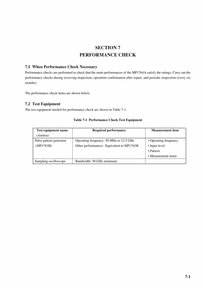
7-1
SECTION 7
PERFORMANCE CHECK
7.1 When Performance Check NecessaryPerformance checks are performed to check that the main performances of the MP1764A satisfy the ratings. Carry out the
performance checks during receiving inspection, operation confirmation after repair, and periodic inspection (every six
months).
The performance check items are shown below.
7.2 Test EquipmentThe test equipment needed for performance check are shown in Table 7-1.
Table 7-1 Performance Check Test Equipment
Test equipment name Required performance Measurement item
(Anritsu)
Pulse pattern generator Operating frequency: 50 MHz to 12.5 GHz • Operating frequency
(MP1763B) Other performances: Equivalent to MP1763B • Input level
• Pattern
• Measurement items
Sampling oscilloscope Bandwidth: 50 GHz minimum
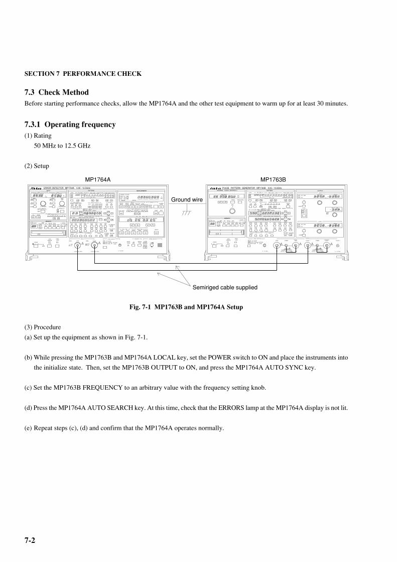
7-2
SECTION 7 PERFORMANCE CHECK
7.3 Check MethodBefore starting performance checks, allow the MP1764A and the other test equipment to warm up for at least 30 minutes.
7.3.1 Operating frequency(1) Rating
50 MHz to 12.5 GHz
(2) Setup
Fig. 7-1 MP1763B and MP1764A Setup
(3) Procedure
(a) Set up the equipment as shown in Fig. 7-1.
(b) While pressing the MP1763B and MP1764A LOCAL key, set the POWER switch to ON and place the instruments into
the initialize state. Then, set the MP1763B OUTPUT to ON, and press the MP1764A AUTO SYNC key.
(c) Set the MP1763B FREQUENCY to an arbitrary value with the frequency setting knob.
(d) Press the MP1764A AUTO SEARCH key. At this time, check that the ERRORS lamp at the MP1764A display is not lit.
(e) Repeat steps (c), (d) and confirm that the MP1764A operates normally.
PULSE PATTERN GENERATOR MP1763B 0.05 - 12.5GHzINTERNAL CLOCK (OPTION.01) PATTERN
MEMORY
TUNING RESOLUTION
FREQUENCYMHz kMz
OUTPUT
EXIST DIRFILE No.
RECALLDELETE
SAVERESAVE SHIFT PATT OTHERS
MODE
LOGIC PATTERN PRBS / ZERO SUBST PRBS MARK RATIO
2 - 1N2 N
POS
NEG
ALTNDATA Z.S PRBS 7 9 11 15 20 23 31 0/8 1/8 1/4 1/2
8/8 7/8 3/4 1/2
ALTN ERROR ADDITION(1×10 )- N
SINGLEA B ON 4 5 6 7 8 9
DATA LENGTH/ZERO SUBST LENGTHDATA LENGTHZERO SUBST LENGTH
A / B LOOP TIME
PAGE/PATTERN SYNC POSITION
BIT
1 2 3 4 5 6 7 8
9 10 11 12 13 14 15 16
ALL PAGEPRESET
PATTERNLOADING
TRACKINGGUARD 0 1 0 1
DATA
50Ω GND
ECL
AMPLITUDE
Vp - p
OFFSET
V
ECL
ps
DELAY TIME
BUSY
CLOCK 1
50Ω GND
ECL
AMPLITUDE
Vp - p
OFFSET
V
ECL
GUARD
GUARD
OFFSET
VOHVTHVOL
OUTPUT
DATA DUMMY DATA CLOCK 1 DUMMY CLOCK 1 CLOCK 2
! ! ! !
50Ω
CAUTION CONNECT THE UNUSEOUTPUT TO THE DUMMY 50Ω 50Ω
CAUTION CONNECT THE UNUSEOUTPUT TO THE DUMMY 50Ω 0 / - 1V 50Ω
1 / 32 CLOCKFIXED POSNVAR POSN
PATTERN SYNC
PANEL LOCK
GPIBREMOTE
LOCAL
POWER
OFF ON
SYNC OUTPUT
0 / - 1V 50Ω
! !
ERROR DETECTOR MP1764A 0.05 - 12.5GHzPATTERN
MEMORY
THRESHOLD / MARGIN DELAY TIME / MARGIN
MEASUREMENT
EXIST DIRFILE No.
RECALLDELETE
SAVERESAVE SHIFT PATT OTHERS
MODE
LOGIC PATTERN PRBS / ZERO SUBST PRBS MARK RATIO
2 - 1N
2 N
POS
NEG
ALTNDATA Z.S PRBS 7 9 11 15 20 23 31 0/8 1/8 1/4 1/2
8/8 7/8 3/4 1/2
DATA LENGTH/ZERO SUBST LENGTHDATA LENGTHZERO SUBST LENGTH
!
PANEL LOCK
GPIBREMOTE
LOCAL
POWER
OFF ON
INPUTDATA CLOCK
VVp-p
psps p-p
TERMGND
-2V
GUARD
TERMGND
-2V
GUARD
BUSY
-3V to 1.875V -500ps to 500ps
AUTO SEARCH(MARJ RATIO 1/8 to 7/8)
POLARITYCLK
CLK
EYE MARGINERROR RATIO (10 )
2 3 4 5 6 7 8 9- N
ON START
FRAME LENGTH
SYNC MODENORMAL FRAME QUICK A B
ALTNDISPLAY SELECT
PATT BIT BLOCK ERROR
CURRENT HISTORY
POWER FAILCLOCK LOSS SYNC LOSS
ERRORS GATING
%MHz
REPEATSINGLEUNTIMED
ERROR RATIO
DISPLAYERROR COUNT
ERRORINTERVAL
ERROR FREE INTERVAL
CLOCKFREQUENCY
MODECURRENT DATA
2 3 4 5 6 7 8 9 INTAUTO SYNC
SYNC THRESHOLD(10 )-N
START STOP
REAL TIME / MEAS TIME
DAY YEAR / HOUR MONTH / MINUTE DAY / SECOND
DISPLAY / MODIFY
REAL TIME MEAS TIMEY.M.D H.M.S PERIOD TIMED ELAPSED
MODIFY
BURST MODE
ON MANUAL PRINT
ALARM
ERRORS
PRINTER ALARM MONITOR
1 / 32 CLOCKFIXED POSN VAR POSN
PATTERN SYNC
0 / -1V 50Ω
SYNC OUTPUT
0.25-2.0Vp-p / 50Ω
CLOCK
GND-2V
TERM
INPUT
!
0.25-2.0Vp-p / 50Ω
GND-2V
TERM DATA
WINDOW WINDOW ANALYSIS
MP1764A MP1763B
PAGE/PATTERN SYNC POSITION
9 10 11 12 13 14 15 16
ALL PAGEPRESET
PATTERNLOADING
TRACKINGGUARD 0 1 0 1
ON
ERROR ANALYSIS TRIGGER
BLOCK WINDOW
BIT
1 2 3 4 5 6 7 8 BIT WINDOW
PATTERN SYNC POSITIONPAGEDISPLAY
Ground wire
Semiriged cable supplied

7-3
7.3.2 Input data level(1) Rating
Amplitude : 0.25 to 2 Vp-p
Offset (VOH) : –2 to +2 V
Threshold voltage : –3 to +1.875 V
(2) Setup
The setup method is the same as Paragraph 7.3.1(2) and is shown in Fig. 7-1.
(3) Procedure
(a) Set up the equipment as shown in Fig. 7-1.
(b) While pressing the MP1763B and MP1764A LOCAL key, set the POWER switch to ON and set the instruments to the
initialize state. Then, set the MP1763B OUTPUT and the MP1764A AUTO SYNC to ON.
(c) When the following was effected, check that the ERRORS lamp is not lit. However, set the input clock and input data
phase suitably with the DELAY TIME value setting knob.
Note: Since the MP1764A THRESHOLD value shown below is the logic value, measure the MP1763B data
output level in advance with a calibrated sampling oscilloscope, then set the MP1764A THRESHOLD
value to the correct value.
Item
Setting
order
MP1763B MP1764A
DATA DATA
AMPLITUDE OFFSET (V ) TERM THRESHOLD
①
②
③
④
⑤
2.000 Vp-p
0.250 Vp-p
2.000 Vp-p
0.250 Vp-p
0.800 Vp-p
–2.000 V
–2.000 V
2.000 V
2.000 V
–0.900 V
GND
GND
GND
GND
–2 V
–3.000 V
–2.125 V
1.000 V
1.875 V
–1.300 V
OH
7.3 Check Method

7-4
SECTION 7 PERFORMANCE CHECK
7.3.3 Input clock level(1) Rating
Amplitude : 0.25 to 2 Vp-p
Offset (VOH) : –2 to +2 V
(2) Setup
The setup method is the same as Paragraph 7.3.1(2) and is shown in Fig. 7-1.
(3) Procedure
(a) Set up the equipment as shown in Fig. 7-1.
(b) While pressing the MP1763B and MP1764A LOCAL key, set the POWER switch to ON and set the instruments to the
initialize state. Then, set the MP1763B OUTPUT and the MP1764A AUTO SYNC to ON.
(c) When the following was effected, confirm that the ERRORS lamp did not light. However set the input clock and input
data phases suitably with the DELAY TIME setting knob.
Note: Since the MP1764A THRESHOLD value below is the logic value, measure the MP1763B data output
level in advance with a calibrated sampling oscilloscope, then set the MP1764A THRESHOLD value to
the correct value.
Item
Setting
order
MP1763B MP1764A
CLOCK 1
AMPLITUDE OFFSET (V )
①
②
③
④
⑤
2.000 Vp-p
0.250 Vp-p
2.000 Vp-p
0.250 Vp-p
0.800 Vp-p
–2.000 V
–2.000 V
2.000 V
2.000 V
–0.900 V
GND
GND
GND
GND
–2 V
OH
CLOCK TERM

7-5
7.3.4 Pattern(1) Rating
Pseudorandom (PRBS) pattern
Programmable (PRGM) pattern
Data mode Data length: 2 to 8388608 bits
(2) Setup
The setup method is the same as Paragraph 7.3.1(2) and is shown in Fig. 7-1.
(3) Procedure
(a) Set up the equipment as shown in Fig. 7-1.
(b) While pressing the MP1763B and MP1764A LOCAL key, set the POWER switch to ON and set the instruments to the
initialize state. Then, set the MP1763B OUTPUT and the MP1764A AUTO SYNC to ON.
(c) Press the MP1764A AUTO SEARCH key.
(d) Set the MP1763B and MP1764A pattern mode to programmable data pattern and make the settings shown below. At
this time, confirm that the ERRORS lamp does not light.
(e) Change the MP1763B and MP1764A pattern mode to PRBS 27–1, PRBS 29–1, PRBS 211–1, PRBS 215–1, PRBS 220–1,
PRBS 223–1, and PRBS 231–1 and check that the ERRORS lamp does not light at each mode.
(f) Fix the MP1763B and MP1764A pattern mode at PRBS 231–1 and change the mark ratio 0/8, 1/8, 1/4, 1/2, 8/8, 7/8, 3/
2, and 1/2 and check that the ERRORS lamp does not light at each mark ratio.
Setting order Item Setting
DATA LENGTH value 8
2 to 8 OFF (LED off)
BIT key 1 ON (LED lit) ②
①
7.3 Check Method
7-6
SECTION 7 PERFORMANCE CHECK
7.3.5 Measurement items(1) Rating
Error rate : 0.0000×10–16=1.0000×10⁻⁵
Error count : 0 to 9.9999×10¹⁶
Error intervals I(EI) : 0 to 9999999
Error free intervals (EFI) : 0.0000 to 100.0000%
Clock frequency : 50 MHz to 12.5 GHz
Accuracy: ±(10 ppm+1 kHz)
(2) Setup
The setup method is the same as Paragraph 7.3.1(2) and is shown in Fig. 7-1.
(3) Procedure
(a) Set up the equipment as shown in Fig. 7-1.
(b) While pressing the MP1763B and MP1764A LOCAL key, set the POWER switch to ON and set the instruments to the
initialize state. Set the MP1763B OUTPUT to ON, and the frequency to 10 GHz.
(c) Set the MP1764A AUTO SYNC to ON, and press the AUTO SEARCH key.
(d) Turn on the MP1763B error addition function. (Error addition: Single)
(e) Set the MP1764A measurement mode to SINGLE and set the measurement time to 10 seconds.
(f) Press the MP1764A START key. After the GATING lamp lights, press the MP1763B ERROR ADDITION SINGLE
key once.
After the end of measurement (after 10 seconds), switch the DISPLAY key and check if each value shown below is
displayed.
Error ratio : 1.0000E–11
Error count : 1
Error intervals : 1
Error free intervals : 99.9900%
Clock frequency : 9999.899 to 10000.101 MHz
.
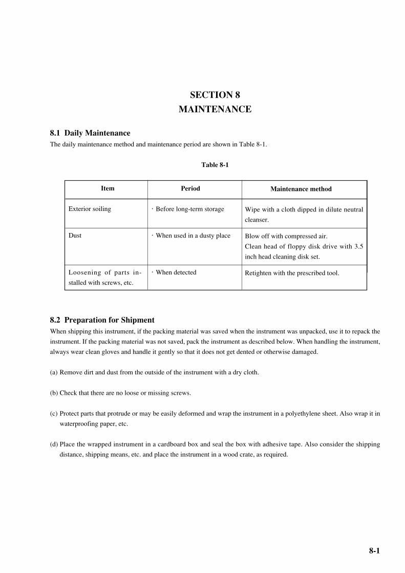
8-1
SECTION 8
MAINTENANCE
8.1 Daily Maintenance
The daily maintenance method and maintenance period are shown in Table 8-1.
Table 8-1
8.2 Preparation for Shipment
When shipping this instrument, if the packing material was saved when the instrument was unpacked, use it to repack the
instrument. If the packing material was not saved, pack the instrument as described below. When handling the instrument,
always wear clean gloves and handle it gently so that it does not get dented or otherwise damaged.
(a) Remove dirt and dust from the outside of the instrument with a dry cloth.
(b) Check that there are no loose or missing screws.
(c) Protect parts that protrude or may be easily deformed and wrap the instrument in a polyethylene sheet. Also wrap it in
waterproofing paper, etc.
(d) Place the wrapped instrument in a cardboard box and seal the box with adhesive tape. Also consider the shipping
distance, shipping means, etc. and place the instrument in a wood crate, as required.
Item
Exterior soiling
Dust
Loosening of parts in-
stalled with screws, etc.
Period
・ Before long-term storage
・ When used in a dusty place
・ When detected
Maintenance method
Wipe with a cloth dipped in dilute neutral
cleanser.
Blow off with compressed air.
Clean head of floppy disk drive with 3.5
inch head cleaning disk set.
Retighten with the prescribed tool.

8-2
SECTION 8 MAINTENANCE
.....
(Blank)

9-1
SECTION 9
TROUBLESHOOTING AND REPAIR
9.1 Before Considering Trouble
If the instrument is not operating properly for some reason, check it as follows:
• Power is not turned on
Is the power cord loose? → Plug in firmly.
↓Is the fuse blown? → Replace the fuse.
• Synchronization is not established.
Are the transmit and receive interfaces the same? → Check the set values and set them to the correct values.
(Termination conditions, output level, offset, etc.)
↓Is the connection cable normal? → Change the cable.
↓ Initialize the instrument. (Transmitter and receiver)
Set the receiver the same as the transmitter.
• Error added
Is the cable loose? → Retighten the connector.
↓Is Error addition OFF? → Set Error addition to OFF.
↓Are the phase margin and bias margin sufficient? → Adjust so that the phase and offset are suitably cut.
• Floppy disk drive is not used.
Is the floppy disk normal ? → Use the normal floppy disk.
↓Is the head of floppy disk drive dusty ? → Clean head of floppy disk drive with 3.5 inch head
cleaning disk set.
If the problem cannot be found from the above check items, contact the service section of Anritsu.
9.2 Fuse Replacement
Turn off the power switch, then disconnect the power cable plugged into the AC power inlet. Next, open the AC power
fuse holder cover and replace the fuse with a spare.

9-2
SECTION 9 TROUBLESHOOTING AND REPAIR
.
(Blank)
Related Documents