Rowan University Rowan University Rowan Digital Works Rowan Digital Works Theses and Dissertations 11-20-2020 Moving target network steganography Moving target network steganography Tapan Soni Rowan University Follow this and additional works at: https://rdw.rowan.edu/etd Part of the Information Security Commons Recommended Citation Recommended Citation Soni, Tapan, "Moving target network steganography" (2020). Theses and Dissertations. 2850. https://rdw.rowan.edu/etd/2850 This Thesis is brought to you for free and open access by Rowan Digital Works. It has been accepted for inclusion in Theses and Dissertations by an authorized administrator of Rowan Digital Works. For more information, please contact [email protected].

Welcome message from author
This document is posted to help you gain knowledge. Please leave a comment to let me know what you think about it! Share it to your friends and learn new things together.
Transcript

Rowan University Rowan University
Rowan Digital Works Rowan Digital Works
Theses and Dissertations
11-20-2020
Moving target network steganography Moving target network steganography
Tapan Soni Rowan University
Follow this and additional works at: https://rdw.rowan.edu/etd
Part of the Information Security Commons
Recommended Citation Recommended Citation Soni, Tapan, "Moving target network steganography" (2020). Theses and Dissertations. 2850. https://rdw.rowan.edu/etd/2850
This Thesis is brought to you for free and open access by Rowan Digital Works. It has been accepted for inclusion in Theses and Dissertations by an authorized administrator of Rowan Digital Works. For more information, please contact [email protected].

MOVING TARGET NETWORK STEGANOGRAPHY
by
Tapan Soni
A Thesis
Submitted to the
Department of Computer Science
College of Science and Mathematics
In partial fulfillment of the requirement
For the degree of
Master of Science in Computer Science
at
Rowan University
November 18, 2020
Thesis Chair: Vahid Heydari, Ph.D.

© 2020 Tapan Soni
Dedications
To my family and friends. Without you, this would not have been possible.

iv
Acknowledgments
A special thanks to my committee chair Dr. Vahid Heydari, who first hired me to
be a student researcher in his lab, back in 2018, and who I’ve worked with throughout my
undergraduate and graduate school tenure. Special thanks to my committee members
Professor Patrick McKee, Dr. Chenxi Qiu, and Jacob Carpenter for helping me finish my
thesis.
Special thanks to Professor Christopher Simber from Rowan College at
Burlington County who I worked with during my first research project when I was a
freshman in college. His guidance, motivation, and knowledge has helped me
tremendously.
I would also like to thank my friends who were constantly supporting me through
this journey. Without their patience and understanding, this would not have been
possible.
Finally, I would like to thank my parents. They have helped me more than anyone
and without them, none of this would have been possible.

v
Abstract
Tapan Soni MOVING TARGET NETWORK STEGANOGRAPHY
2019-2020
Vahid Heydari, Ph.D.
Master of Science in Computer Science
A branch of information hiding that has gained traction in recent years is network
steganography. Network steganography uses network protocols are carriers to hide and
transmit data. Storage channel network steganography manipulates values in protocol
header and data fields and stores covert data inside them. The timing channel modulates
the timing of events in the protocol to transfer covert information. Many current storage
channel network steganography methods have low bandwidths and they hide covert data
directly into the protocol which allows discoverers of the channel to read the confidential
information. A new type of storage channel network steganography method is proposed
and implemented which abstracts the idea of hiding data inside the network protocol. The
addition of a moving target mechanism rotates the locations of data to be evaluated
preventing brute force attacks. The bandwidth of the algorithm can also be controlled by
increasing or decreasing the rate of packet transmission. A proof of concept is developed
to implement the algorithm. Experimental run times are compared with their theoretical
equivalents to compare the accuracy of the proof of concept. Detailed probability and
data transfer analysis is performed on the algorithm to see how the algorithm functions in
terms of security and bandwidth. Finally, a detection and mitigation analysis is performed
to highlight the flaws with the algorithm and how they can be improved.

vi
Table of Contents
Abstract ............................................................................................................................v
List of Figures ..................................................................................................................viii
List of Tables ...................................................................................................................x
Chapter 1: Covert Channels and Network Steganography ..............................................1
Covert Channels .........................................................................................................1
The Prisoner’s Problem..............................................................................................3
Overview of TCP/IP ..................................................................................................5
Network Steganography.............................................................................................13
Chapter 2: Related Network Steganography Approaches ...............................................15
Chapter 3: Algorithm, Implementation, and Results .......................................................21
Background ................................................................................................................21
Hash Functions.....................................................................................................21
Permutations ........................................................................................................23
Algorithm ...................................................................................................................24
Sender Side ..........................................................................................................28
Receiver Side .......................................................................................................32
Proof of Concept ........................................................................................................35
Results ........................................................................................................................41
Chapter 4: Analysis ..........................................................................................................45
Probability ..................................................................................................................45
Performance ...............................................................................................................48
Theoretical Performance ......................................................................................49
vii
Table of Contents (Continued)
Experimental Performance...................................................................................50
Detectability and Mitigation ......................................................................................60
Chapter 5: Conclusion and Future Work .........................................................................62
Conclusion .................................................................................................................60
Future Work ...............................................................................................................60
References ........................................................................................................................65
viii
List of Figures
Figure Page
Figure 1. Information hiding hierarchy ............................................................................1
Figure 2. The Prisoner’s Problem ....................................................................................4
Figure 3. Layers of the TCP/IP Protocol Suite ................................................................6
Figure 4. TCP three-way handshake ................................................................................8
Figure 5. TCP/IP encapsulation process ..........................................................................12
Figure 6. Hash function input and output ........................................................................21
Figure 7. MTNS algorithm, sender side...........................................................................26
Figure 8. Evaluating the packet hash to see if it can hold covert data .............................31
Figure 9. MTNS algorithm, receiver side ........................................................................33
Figure 10. Extracting data from marked packets .............................................................34
Figure 11. Proof of Concept network architecture...........................................................37
Figure 12. Sending data from Alice’s side.......................................................................42
Figure 13. Receiving data from Bob’s side .....................................................................42
Figure 14. Wireshark packet capture ...............................................................................43
Figure 15. Contents of a marked packet ..........................................................................44
Figure 16. Theoretical vs. experimental run times for n = 8, and p = 75 p/s ...................52
Figure 17. Theoretical vs. experimental run times for n = 8, and p = 100 p/s .................53
Figure 18. Theoretical vs. experimental run times for n = 8, and p = variable p/s ..........54
Figure 19. Average packet transfer rates for p = 75 p/s ...................................................56
Figure 20. Average packet transfer rates for p = 100 p/s .................................................57
Figure 21. Average packet transfer rates for p = variable p/s ..........................................58
ix
List of Figures (Continued)
Figure Page
Figure 22. Times for transmitting 208 bits of data ..........................................................59

x
List of Tables
Table Page
Table 1. Hash function input and output examples ..........................................................22
Table 2. Probability and data transfer equation parameters .............................................47

1
Chapter 1
Covert Channels and Network Steganography
Covert Channels
The term “covert channel” originally coined by Butler Lampson [1], is defined by
the United States Department of Defense as “any communication channel that can be
exploited by a process to transfer information in a manner that violates the system’s
security policy” [2]. In plain terms, a covert channel is an information hiding technique in
which the user takes advantage of the design and availability of a standard
communication channel to transfer covert data between two processes or entities without
a third party knowing of its existence. It is important to note that the term “covert
channel” is used to describe a category of information hiding techniques and not a
singular entity by itself. Figure 1 describes the information hiding hierarchy.
Figure 1. Information hiding hierarchy

2
One of the most widely known and used covert channels is steganography.
Steganography is the practice of hiding a message inside a carrier and comes from the
Greek word “steganos” which means “covered” or “protected” and “kryptos”, meaning
hidden (secret) [3] [4]. A point to note is that steganography is not the same as
cryptography. Although both prominent techniques of information hiding, steganography
aims to hide the existence of a message while cryptography aims to hide the content of a
message [5].
The most popular form of steganography is image steganography where data is
hidden inside images. Software such as BPStegno [6], StegHide [7], and OpenStego [8]
use different encoding techniques to hide data inside of the image pixels, the most
common being Least-Significant Bit (LSB) but there are many more techniques. The
LSB data encoding technique encodes data inside the least-significant bit of the image
pixel’s red, green, and blue values. By using LSB encoding, the sender can hide up to 3
bits of data inside every pixel without significantly impact the visual quality of the
images.
While image steganography is the most widely used and recognizable forms of
steganography, a new type of steganography, using network protocols as carriers, has
gained traction in recent years. The term “network steganography” was first introduced
by Krzysztof Szczypiorski in 2003 [9]. Network steganography is a subset of
steganography where network protocols are used as carriers to hide and transmit secret
messages. For a simple example of network steganography imagine a communication
protocol which is used by two parties to exchange messages. The communication

3
protocol assumes that the response from either side should come within a specific amount
of time after the initial message was sent, otherwise the response will be treated as a
delayed message and discarded. The two parties want to communicate in secret, agree
that responses carrying the secret messages will be purposely delayed and not be
discarded by the recipient but instead read to extract the secret message. This becomes
their shared secret. The manipulation of the communication protocol happens in the
intentional delaying of responses containing the secret messages. Third parties who
observe the network traffic between our two parties do not become suspicious of the
existence of a hidden communication channel if the frequency of delayed responses does
not appear to be out of the ordinary, e.g., under a certain threshold. This example of
network steganography is categorized as a timing channel approach which is discussed
later in this chapter [4].
The Prisoner’s Problem
A classic problem used to define the need for a covert channel is the Prisoners
Problem [10]–[12]. The prisoners problem was introduced by Gustavus J. Simmons in
1983 [10] and is used to describe a scenario in which covert channels are needed to
communicate. Figure 2 (adapted from [11]) shows the prisoners problem. There are two
prisoners, Alice and Bob, and they want to communicate with each other to plan their
escape. Both Alice and Bob are confined to their prison cell and can only communicate
using the provided computer terminals. The network used for communication is insecure
and monitored by the Warden, Walter. He is monitoring the network for evidence of any
malicious activity by Alice or Bob. The use of cryptography would immediately be
noticed by the Warden causing him to throw Alice and Bob into solitary confinement

4
where they would not be able to communicate with each other. Therefore, cryptography
cannot be used to secure their exchange of secret messages. Alice and Bob must
communicate in such a way over the unsecure network that the warden does not find out
their plan to escape the prison. A point to note is that Alice and Bob have a shared secret
between them. Without the shared secret, the receiver might as well be the warden
because there is no way to differentiate normal traffic from the covert traffic. How the
shared secret is established is beyond the scope of this research, but they could have met
in private to share the secret. There are two types of wardens in the prisoners problem, an
active warden and a passive warden. The active warden can modify the contents of the
network traffic in any way he wants and can be more aggressive. The passive warden is
like a network sniffer and can only spy on the network traffic, he cannot alter the
messages in any way.
The goal of network steganography is to send covert data through regular network
channels which cannot be detected by the warden or any other third party for that matter.
Many classical schemes can be easily detected by the warden because they manipulate
Figure 2. The Prisoner's Problem

5
the protocol in an un-natural or predictable way which does not conform to the standards
set in place.
Overview of TCP/IP
Network steganography exists partly because of the adaption of an open system
architecture of the Internet and the standardization of communication protocols. The
Internet, the largest network on the planet, is made up of millions of servers, routers,
switches, and end-users. These devices communicate with each other using standardized
communication protocols to form the Internet. These protocols, designed in the 1970s,
1980s, and 1990s, form the backbone of the communication architecture of the Internet as
we know it today. One of those protocol suites, the TCP/IP Protocol Suite (Transmission
Control Protocol and Internet Protocol) [13], is widely used on the Internet today.
Created by the United States Department of Defense in collaboration with several
academic institutions [14], the TCP/IP protocol was created to meet the demands of an
increasingly connected world. Since the creation and adoption of the TCP/IP protocol, the
Internet has grown exponentially in size and far beyond its original scope [14]. The
Internet has evolved from a simple network between a small number of federal and
academic organizations to a global network connecting millions of people, thanks in part
to the TCP/IP protocol suite.
The popularity of TCP/IP is due in part to its robustness and its open, free, and
broad protocol standard. TCP/IP can operate on different types of physical transmission
mediums such as Ethernet, optical, and dial-up which allows it to integrate into many
different kinds of networks [14]. Because it was so widely supported by different
6
organizations, TCP/IP is designed to work independently from specific types of hardware
or operating systems, allowing it to be used in many different communication scenarios
[14].
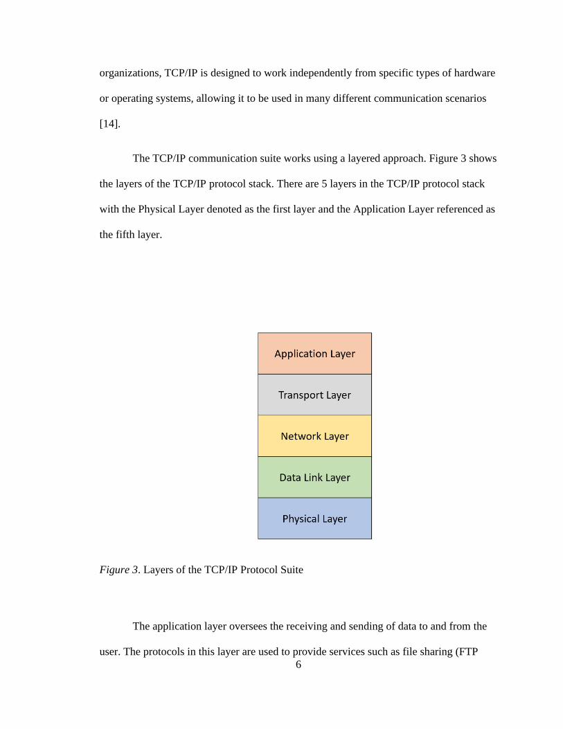
The TCP/IP communication suite works using a layered approach. Figure 3 shows
the layers of the TCP/IP protocol stack. There are 5 layers in the TCP/IP protocol stack
with the Physical Layer denoted as the first layer and the Application Layer referenced as
the fifth layer.
Figure 3. Layers of the TCP/IP Protocol Suite
The application layer oversees the receiving and sending of data to and from the
user. The protocols in this layer are used to provide services such as file sharing (FTP

7
[15], SFTP [16]), remote login capability (TELNET [17], SSH [18]), mail transfer
(SMTP [19], IMAP [20], POP3 [21]), and web page delivery (HTTP [22], HTTPS [23])
to name a few [14]. New protocols are constantly added to this layer to extend the
functionality of this layer.
The transport layer is one of the most important layers of the TCP/IP stack and
the fourth layer. It controls the delivery of data between two processes on different hosts.
Two of the most popular transport layer protocols are the Transmission Control Protocol
(TCP) [24] and User Datagram Protocol (UDP) [25].
TCP is a reliable connection-oriented protocol, which means that it will try to
send data in a reliable manner and has mechanisms to prevent data (called packets) from
being lost or dropped between the source and destination [14]. TCP has an
acknowledgement mechanism which allows the sender to send data again if an
acknowledgement that the data has arrived has not been sent by the receiver does not
arrive. TCP also provides checksums or data hashes which are used to verify the integrity
of the data. If the data is received undamaged and unaltered, the receiver sends a positive
acknowledgement to the sender. If the data is damaged or altered, the receiver sends a
negative acknowledgement to the sender and the sender can resend the data [14].
Being a connection-oriented protocol, TCP establishes a logical end-to-end
connection between two hosts [14] before sending data. The establishment of this logical
connection is called a “three-way handshake”. Figure 4 shows a simple implementation
of the three-way handshake.

8
Figure 4. TCP three-way handshake
The first step in the three-way handshake is the SYN step. The client initiates a
connection by sending a “SYN” packet to the server. SYN is a flag in the TCP protocol
which means synchronize and is used to initiate connections. This means that the client
wants to start a connection with the server. The second step is the SYN+ACK step
performed by the server. The server sends the client a SYN+ACK packet. The packet sent
by the server has two flags set, the SYN flag and the ACK flag. The ACK flag stands for
acknowledge. The server acknowledges to the client that it received the connection
initiation request sent by the client (the SYN packet) and it also wants to open a
connection from the server’s side, which is marked by the SYN flag sent alongside the
ACK flag. The third step is the ACK step sent by the client to the server. The client
receives the SYN+ACK packet from the server in step two and proceeds to acknowledge
that the server wants to initiate a connection as well. The client also acknowledges that

9
the server acknowledged the client wanting to open a connection. After the third step is
complete, both the client and server have established a connection which is
acknowledged by the other party creating a reliable and connection-oriented path to
exchange data. The termination of the logical connection happens in the same format.
The flag used to terminate the connection is FIN which signals the end of data
transmission from the sender.
UDP is the second most popular transport layer protocol in the TCP/IP stack. It is
an unreliable connectionless protocol, where “unreliable” means that UDP does not have
any way to verify that the data has reached the receiver [14]. UDP delivers data correctly
by using the IP address of the destination machine and the port number of the process.
Since UDP does not have a data received verification mechanism, it is a more efficient
choice as a transport layer protocol because there is no overhead of creating and
maintaining a reliable connection [14]. Media applications and services may prefer using
UDP over TCP because of its speed in transferring information.
The network layer is the third layer in the TCP/IP protocol suite. The most
popular and widely used network protocol is the Internet Protocol (IP) version 4 (IPv4)
[26]. The IP protocol creates data fragments called datagrams which are the basic unit of
transmission for the Internet, defines a common addressing scheme for devices connected
to the Internet, controls the routing of datagrams between hosts, and performs
fragmentation and de-fragmentation of datagrams [14]. The IP protocol uses IP addresses
as a common addressing scheme for devices connected to a network. An IP address is
like a house address. Every house has a different address and in the same way, each host
has a different IP address. The IP address is used to deliver the data of the previous layers

10
to the correct destination machine. The IP protocol also handles the fragmentation and
de-fragmentation of datagrams if needed. Fragmentation breaks datagrams into smaller
pieces and may be needed if the datagram is too large to be sent as a single unit [14].
Another important protocol in the network layer is the Internet Control Message
Protocol (ICMP) [27]. ICMP is used to send messages which perform flow control and
error reporting by sending messages between hosts through the network layer [14]. The
ICMP protocol can notify the sender to stop sending datagrams temporarily to control the
flow of traffic and about unreachable hosts among other notifications.
The second layer is the data link layer. Data at this layer is encapsulated inside
frames. The function of the data link layer is to transfer frames between hops in the
network. A hop or network node is every intermediate stop the frame makes between the
source and destination, e.g., a router or a switch. The data link layer, like the transport
and network layer, adds a header to the data frame with the source and destination
physical addresses. The data link layer can also add a trailer. A trailer is another header
that is added to the end of the frame instead of the front. The trailer contains data for
error detection [28]. Some of the protocols supported by the data link layer include the
IEEE 802.3 Ethernet standard [29] and the IEEE 802.11 Wireless LAN (WLAN)
standard [30]. The IEEE 802.3 Ethernet standard defines the physical layer of a wired
connection within a network. The IEEE 802.11 WLAN standard defines the physical
layer of a wireless physical layer also known as Wi-Fi.
The first layer is the physical layer. The physical layer takes care of sending and
receiving the data between hops. The data is sent a bit at a time and the protocol defined

11
by the connection link is used, e.g., if two hops are connected by an ethernet link, the
ethernet protocol is used to send the data. The physical layer is also tasked with
controlling the direction of transmission between two devices: simplex, half-duplex, or
full-duplex [31]. Simplex mode means only one device can send, and one can receive, in
half-duplex mode, two devices can send and receive but not at the same time, and in full-
duplex mode, two devices can send and receive at the same time [31].
Each layer is abstracted from the others to divide the functionality and prevent a
single layer from performing too many tasks which can create a single point of failure.
This allows the protocol to be modular and robust because each layer is its own system
that receives and passes data to and from other layers and does not have to worry about
the functionality of other layers. Each layer adds a header to the front of the data that it
receives from the previous layer. The addition of each layer header is called
encapsulation. Figure 5 [31] shows the encapsulation process.

12
Figure 5. TCP/IP encapsulation process
There are many moving parts in the TCP/IP protocol suite. Each layer has a
specific job which requires many unique protocols to accomplish. The variety of
protocols and the availability of the TCP/IP protocol suite in today’s Internet make it an
increasingly attractive carrier for steganographic activity. Network steganography relies
on three characteristics of current implementations of network protocols to transfer covert
information [32]. The communication channels are not perfect. Data loss, corruption, and
reordering happen in a real-world environment and thus it is possible to embed data by
mimicking those behaviors [32]. Most network protocols define header fields or
messages that are not used in all situations allowing users to hide data inside these extra
fields [32]. Finally, not every protocol is completely defined and “semantic overloading”
is possible [32], allowing a certain degree of freedom in the implementation. This
freedom can be used for steganographic purposes to hide data.

13
Network Steganography
There are two types of network steganography, storage channel and timing
channel. A storage channel is a class of network steganography that modifies values in
the carrier to create a storage covert channel [32]. Typically, these techniques hide
information by modifying protocol header fields, such as unused bits of a header, or the
data field of a packet [32]. A majority of network steganography comprises of storage
channel network steganography since each layer adds some type of header to the data it
receives and not every field in the header is used.
A timing channel is a class of network steganography that modifies the timing of
“events” in a carrier to create a timing covert channel [32]. The goal of a timing covert
channel is to store information in the timing of the protocol messages or packets [32].
Timing channels are less prevalent in network steganography due to the increased
complexity and limited user control over how the protocol and operating system handles
the timing of the events. Much of the protocol timing is out of the users’ control,
therefore, making timing channel steganography harder to implement and develop.
Two major drawbacks of current storage channel network steganography
techniques are that they transmit actual covert data inside the channels and their
transmission rate is low. Current network steganography channels embed the actual
covert data inside the protocol allowing a third party to read the data if the covert channel
is ever found. Additionally, since the confidentiality of the channel must be preserved,
the transmission rate of the channel suffers because there are not many modifications that
can be made to the protocol.

14
A new type of storage channel network steganography, moving target network
steganography, is proposed and implemented to address these drawbacks. The new
technique abstracts the transmission of data to each host by evaluating a data packet using
hashing algorithms. Hashing data packets at the host level and comparing bits of the hash
to covert data at the client level prevents covert data from being embedded inside a
packet. Furthermore, by moving the locations and order of data that is evaluated to places
known only by the hosts, it is virtually impossible to extract data from a packet if the
scheme is detected. The scheme also has a higher average transmission rate than the 1 bit
per second defined by the United States Department of Defense [2].
The rest of the thesis is organized as follows, Chapter 2 reviews current
approaches in storage channel network steganography and touches on timing channel
network steganography. Chapter 3 provides an in-depth explanation of the
steganographic algorithm, the proof of concept, and reviews the results of the
implementation. Chapter 4 contains a probability and data transfer analysis alongside
mitigation techniques. Chapter 5 concludes the research.

15
Chapter 2
Related Network Steganography Approaches
In this chapter, related storage channel network steganography approaches are
discussed and explained.
Kadhim et al. [33] proposed a network steganography technique based on crafting
custom TCP/IP sequence numbers. Their algorithm performs the XOR operation on the
binary representation of the secret data with the binary representation of the source port
and destination port numbers. This number, converted to a decimal, is used as the
sequence number. The receiver reads the data by performing the XOR operation with the
received packet’s sequence number, source port and destination port.
Kundur et al. [34] proposed a network steganography method based on
manipulating the Do not Fragment (DF) IP header field which marks the packet as “don’t
fragment” [4]. The DF field which can hold either a “0” or a “1” and can be exploited by
knowing the Maximum Transmission Unit (MTU) size which is the maximum size of a
datagram that can be sent through a network [4]. Any datagram whose size is below the
MTU value is not fragmented, thus rendering the DF field useless if set to “1”. Therefore,
by crafting datagrams whose size is less than the MTU value, the DF field value can be
used to transmit one bit of covert data per packet.
Biswas et al. [35] proposed a network steganography technique which fills the
TCP data portion with encrypted RSA data. The decryption key is then encoded inside
the sequence number of the data packet and sent along with the encrypted data. The

16
receiver sniffs TCP traffic from the sender, extracts the encrypted data from the TCP data
field, and decrypts it using the key inside the sequence number field.
Stødle [36] proposed a network steganography technique using ICMP echo
request and reply packets. In this scheme, the client communicates with a remote proxy
using ICMP echo requests. The remote proxy communicates with the client using ICMP
reply packets. The remote proxy then establishes a TCP connection with a remote server
e.g. a website server. In a communication scenario, the proxy converts incoming TCP
data from the remote server into ICMP reply packets and sends them to the client. The
client does the same except their packets are in the form of ICMP request packets when
communicating with the proxy.
Handel et al. [37] proposed several network steganography techniques for the OSI
model [38]. The first method proposed hides covert data inside unused portions of the
data link layer frame. The covert data is stored inside the buffer, beginning at the end of
the buffer and working towards the valid data. When the frame is transmitted, the entire
buffer is sent which includes the valid data and the covert data. The second method
described is hiding data inside the network layer. Inside the IP header, there is an 8-bit
Type of Service (ToS) field. The two least-significant bits are unused and can store two
bits of covert data per packet. The last method uses the 6-bit Reserved header field
between the Header Length and the TCP Flags to store six bits of information. Combined
with the IP ToS field’s two bits and the six bits of the Reserved field, the sender can send
one byte of covert information per packet.

17
Jankowski et al. [39] proposed a network steganography technique called PadSteg
which uses inter-protocol network steganography and the EtherLeak [40] frame padding
vulnerability to send covert data. Inter-protocol steganography exploits the relationship
between two or more protocols from the TCP/IP stack to transmit covert information. The
EtherLeak vulnerability is a flaw in the padding mechanism of many Network Interface
Cards (NIC) where the physical layer (hardware implementation) or the data link layer
(software implementation) do not properly zero out the padded bits of an ethernet frame.
This allows arbitrary bits to be placed into the padding buffer thus allowing the storage of
covert bits. PadSteg uses the ARP [41] protocol to search for hidden nodes on a LAN that
can communicate secretly. Once a hidden node is found, both nodes take TCP data
transmitted between each other and hide secret data inside the ethernet frame padding
bits.
Melo et al. [42] described a network steganography technique using TCP
sequence numbers. The method can transmit 3 bits of data inside the Initial Sequence
Number (ISN) of a TCP connection. The covert data is converted into its binary
representation and concatenated into a 24-bit binary string. The first byte of the 32-bit
TCP ISN is an identifier. Together, they make up a 32-bit binary string. The sum of the
high values (locations where the bit is 1) is taken and that generates the 10-digit ISN
which contains the data.
Giffin et al. [43] developed a network steganography method based on rewriting
the least significant bits of a TCP packet’s timestamp field. By purposely delaying the
processing of TCP packets by the kernel, the least significant bit of the TCP timestamp
can be modified to hold a covert bit. Since TCP timestamps are based on internal timings

18
of the host machine, on a slower connection, the least significant bits are effectively
random.
Rowland [44] proposed three network steganography techniques that manipulated
TCP/IP header fields to encode ASCII values for transmission. The first method replaces
the IP identification field with the ASCII representation of the character to be encoded.
The second method encodes ASCII values inside the TCP sequence number of the packet
by converting the ASCII representation of the character into a 32-bit sequence number.
The third method uses a “bounce” server to send data to a remote server anonymously.
The data is hidden inside the TCP sequence number and the source IP address of the
packet is the remote server’s IP address. When the bounce server replies to an initial SYN
packet, the response is sent to the remote server. The remote server takes the incoming
packet and decodes the information by transforming the sequence number minus one
back into the ASCII equivalent.
Trabelsi et al. [45] described a network steganography technique which uses the
IP Record Route option [26] to hide data inside the IP header. The IP Record Route
option is an option which, when set in the IP header, allows routers that handle the packet
to log their own IP address into allocated space inside the packet’s IP header. The IP
Record Route option has three fields, the code field, the length field, and the pointer field.
The code field tells the host what type of option it is. The length field specifies the total
length of the option as it appears inside the IP datagram. The pointer field specifies the
offset to the next available slot inside the option data. This is used to determine where the
next location is for writing the hosts’ IP address. Every time a host logs their IP address
inside the record route option, the pointer field is incremented by 4 (4 bytes). When the
19
pointer field’s value is greater than the length field, no more hosts can log their IP
address inside the IP datagram and the hosts send the packet to its destination. The
authors exploit this functionality by setting the initial pointer value to be larger than the
length value. This prevents any logging of IP addresses and allows up to 36 bytes of
secret data to be hidden inside the option. They also proposed the Covert File Transfer
Protocol (CFTP) which is a client/server application that exploits the IP record route
hiding method to tunnel the ICMP protocol inside the IP options allowing for a two-way
communication channel between the client and the server.
Szczypiorski [9] presented HICCUPS (HIdden Communication system for
CorrUPted networkS), a new type of network steganography which utilized the IEEE
802.11 WLAN protocol. HICCUPS created data frames with bad checksums as a method
of creating additional on-demand steganographic bandwidth. The data frames with bad
checksums would be discarded by hosts who did not know about the steganographic
scheme. Hosts that knew about the scheme would not discard the data frames and extract
the covert data from those frames.
Rios et al. [46] presented network steganography techniques in the Dynamic Host
Control Protocol (DHCP) [47]. The first technique uses the XID field in the DHCP
header. The XID field is the transaction ID which is a random number generated by the
client and used by both the client and server to associate the messages and responses
between a client and a server [47]. The XID field is 4 bytes long. Since the field uses
randomly generated fields by the client, the client can store covert data inside the field
and send it to the server. The server stores the data locally until the client signals the end
of the covert data transmission. Once the end of transmission is received, the server can

20
read the covert data from the XID field. The second technique uses the sname and file
fields inside the DHCP header which are together 190 bytes in length. Both the sname
and file fields consist of null-terminated (‘\0’) strings. Anything after the null termination
is marked as garbage data. The strategy sends “empty” fields by setting the first byte to a
null character allowing for a maximum of 190 bytes of covert data to be sent per packet
including the null characters.
Patuck et al. [48] introduced several covert channels inside the Extensible
Messaging and Presence Protocol (XMPP) [49]. XMPP relies on XML streams as a base
for transferring data. The first covert channel exploits the type channel by alternating
between the “normal” and “chat” values. The attribute is not used by the server and is
passed as-is to the receiver. The second covert channel uses the ID element which is a
unique alphanumeric string for use in tagging messages (like TCP sequence numbers).
The covert data is encoded inside the least-significant bit of the ID element and sent to
the receiver, similar to [43]. The third covert channel manipulates the xml:lang attribute.
The xml:lang attribute is used to determine the language used in writing the message. By
using language codes that represent roughly the same language (en-GB, en-US, etc.),
covert data can be transmitted. The final covert channel modifies the contents of the body
element. The body element is where the actual content of the message is stored. The
methods of modifying the body element include leading and trailing spaces around the
body text encoding up to 2 bits of information, replacing words with synonyms (likely to
suffer from many false positives and low accuracy), and intentional spelling mistakes.
21
Chapter 3
Algorithm, Implementation, and Results
Background
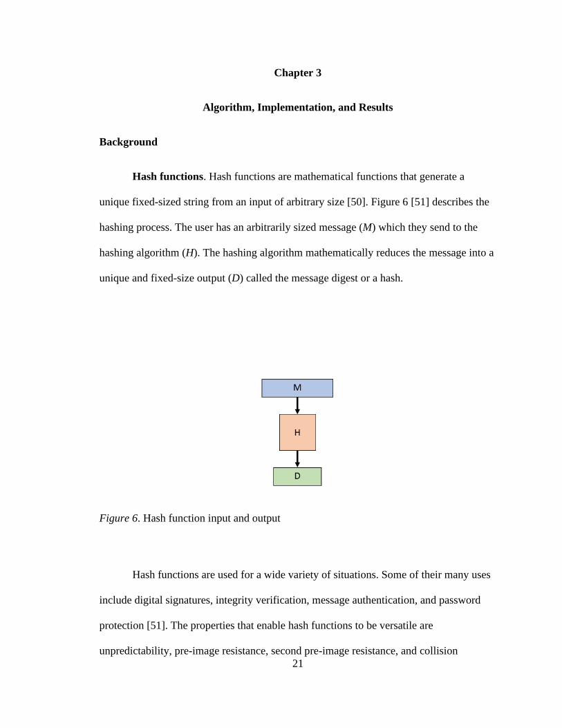
Hash functions. Hash functions are mathematical functions that generate a
unique fixed-sized string from an input of arbitrary size [50]. Figure 6 [51] describes the
hashing process. The user has an arbitrarily sized message (M) which they send to the
hashing algorithm (H). The hashing algorithm mathematically reduces the message into a
unique and fixed-size output (D) called the message digest or a hash.
Figure 6. Hash function input and output
Hash functions are used for a wide variety of situations. Some of their many uses
include digital signatures, integrity verification, message authentication, and password
protection [51]. The properties that enable hash functions to be versatile are
unpredictability, pre-image resistance, second pre-image resistance, and collision

22
resistance [51]. Unpredictability is the property of a hash function that makes a hash
function return a random unique string each time it receives an input [51]. Table 1 [51]
shows an example of the unpredictability property. Three different inputs (numerals 1, 2,
and 3) are hashed by the SHA-256 [52] hashing function and their output is shown. Even
though 1, 2, and 3 are off only by one or two bits (0001, 0010, 0011), the output of the
hash function is completely different for every input [51]. A point to note is that hash
functions are always deterministic meaning they will always produce the same output for
the same input.
Table 1
Hash function input and output examples
Pre-image resistance describes the guarantee that given a random hash value, an
attacker will never find a preimage of that hash value. A preimage of a given hash value,
D, is any message, M, such that 𝐻(𝑀) = 𝐷 . Hash functions are also called one-way
functions because a user can generate a hash from a message, but not a message from a
hash, i.e. one-way. Pre-image resistance describes cases where it is practically (but not
completely) impossible to find a message that hashes to a given hash value. Second pre-

23
image resistance on the other hand, describes the cases that when given a message, M and
its hash value D, it is practically impossible (but not completely) to find another message,
N, that hashes to the same hash that M does. Pre-image resistance focuses on the hash
functions ability to be irreversible, whereas second pre-image resistance focuses on the
hash functions output being sufficiently random [51].
Collision resistance is the property that prevents two different input messages, M
and N, from having the same hash, D [53] [51]. Collision resistance is related to second
pre-image resistance in that if an attacker can find a second pre-image using a given
message and its hash value, the attacker can also find collisions [51]. The reality of
collisions is that they will always occur no matter what hashing algorithm is being used.
This is due to the pigeonhole principle. The idea of the pigeonhole principle is that you
have K holes and R pigeons to put into those holes, and if R is greater and K, at least one
hole must contain more than one pigeon [51]. Hash functions produce a hash whose size
is always the same, but they can take in a message that can of any length. This will
always result in some messages having the same hash as other messages because the
input can be, theoretically, any length. The goal is to make such a discovery practically
impossible to detect and that is collision resistance.
Hash functions are an integral part of the proposed method because they provide a
unique representation of data which allows the method to evaluate data packets and hide
secret data inside of them without having to manipulate the packets directly.
Permutations. In mathematics, arranging objects in a certain order is called a
permutation [54]. In contrast, a combination is a way of arranging objects where order

24
doesn’t matter. The numbers in the permutation do not have to increase linearly or
consecutively. Each number can be greater or smaller than the previous number in the
permutation. The sequence of numbers can also be described as a permutation array.
Another example of a permutation is choosing an ordered subset from a set of
objects. How many ways can first place, second place, and third place be assigned to
three people from a group of twenty people. In this example, order matters because there
can only be one first-place winner, one second-place winner who cannot be either the
first-place or the third-place winner, and one third-place who cannot be either the first-
place or the second-place winner. Selecting an ordered subset out of a set is a selective
permutation [55]. By leveraging selective permutations in the proposed method, a
moving target feature is added. Selecting a random permutation array that is of a certain
size out of a larger list of values allows the method to change the locations of where the
secret data is hidden. Additionally, by seeding a random permutation array generator with
a secret pre-shared key, the method prevents third parties from re-creating the same
permutation arrays.
Algorithm
While traditional storage channel network steganography methods hide data
directly into the fields of a packet, the proposed algorithm analyzes a packet in a holistic
manner to hide and extract secret data. This allows the algorithm to stray away from
hiding covert data inside the data packet. Since covert data is never hidden directly inside
the data packet, any attempt to extract data from the packet without knowing the
algorithm first will not work.

25
The algorithm is designed to use a stream of packets originating from the sender
and going to the receiver as a covert channel. If a packet stream is not available, the
algorithm generates one which acts as a covert channel. Each packet in the stream is
evaluated to see if a specific number of bits from target locations of its hash match the
same number of bits of secret data. If they do match, the packet is marked and sent over
the wire. The receiver sniffs traffic coming from the sender’s machine and looks for the
marked packets. Once they see the marked packet, the receiver creates the same hash of
the marked packet and extracts the secret data bits from that packet and reassembles the
covert data. The algorithm security is augmented by the addition of a moving target
mechanism. The location of the bits that are evaluated in packet hash bits which are
compared for every marked packet change. By moving the location of the bits that are
evaluated, an attacker simply cannot guess the correct location and extract the covert
data. They need to know the order of the bits that need to be evaluated from the packet
hash and their specific location which renders a brute force attack useless. Additionally,
since the packet is analyzed as a whole entity, statistical analysis does not yield anything
because the packet is useless and doesn’t convey any special meaning, except to the
receiver. Figure 7 shows the steps the sender takes to hide data and send it to the receiver
using the general algorithm.

26
Figure 7. MTNS algorithm, sender side

27
The algorithm requires the sender and receiver to have pre-shared parameters.
These parameters are the number of evaluation bits, a secret key, and a retry count. The
number of evaluation bits identifies how many bits are intended to be hidden inside of a
packet. It is the number of bits which are compared from the packet hash against the
same number of covert bits. The value of the evaluation bits can range between 1 and up
to including the size of the hash digest e.g. 256 for the SHA-256 hashing algorithm. The
retry count specifies how many times the sender should send the message again if the
receiver did not receive all the secret data or cannot verify the integrity of the secret data.
The retry count is also used by the receiver to determine how many times they will keep
sniffing for secret data from the sender if all the secret data was not received or the data
integrity could not be verified.
The number of evaluation bits dictates the total time it takes to transfer the data
and the number of bits that are transferred per packet. The higher the number of
evaluation bits, the more data can be transferred per packet. On the other hand, as the
number of evaluation bits increases, the total transmission time also increases because the
algorithm needs to match a greater number of bits from the packet hash against the secret
data. A larger amount of evaluation bits also provides more security from brute force
attacks since an attacker would have to find the exact order of the permutation used when
evaluating the packet hash. A smaller amount of evaluation bits allows the user to
transfer data at a higher rate than if they used more evaluation bits because the algorithm
is evaluating a smaller amount of positions from the packet hash against the secret data.
The overall data transmission time is reduced when using a smaller amount of evaluation

28
bits. By using a smaller amount of evaluation bits, the amount of data transferred is also
smaller.
A smaller amount of evaluation bits provides less security than many evaluation
bits because the number of positions from the packet hash that need to match the secret
data are less. Nevertheless, smaller amounts of evaluation bits have their advantages.
They are much faster in transferring data since the algorithm
The key is a shared secret between the sender and the receiver. The secret key
allows the sender and receiver to prevent any third party from extracting secret data from
the packets by acting as the seed for a random permutation generator which generates an
array of values whose size is the same as the number of evaluation bits. Since both the
sender and receiver have the same secret key, they generate the same sequence of
permutation arrays.
Sender side. The first step of the general algorithm is taking in the secret data as
input from the user. The secret data is then sent to the data formatter which generates the
formatted message. The format of the message is the following: +<MSG> | <MSGCTR>
|<First 4 chars and last 4 chars of SHA256(MSG+MSGCTR)>-. The formatted message
begins with a + sign to indicate the start of a new message. Next, the actual plain text
message is concatenated. The pipe (|) acts as a separator between each component of the
formatted message. After the message, the message counter is attached. The message
counter is used to keep track or of the order of messages that are sent by the sender to the
receiver. The message counter will also be used in the reply the receiver sends to the
sender acknowledging whether all the data was received, and if the integrity was verified

29
or not. Preceded by another separator are the first four and the last four hexadecimal
characters of the SHA256 hash of the message and the message counter. The sender
sends over the first four and last four characters of the hash digest as an integrity
verification mechanism. The receiver will compute the SHA256 hash of the on their end
and compare the first four and last four hexadecimal characters to the provided
characters. This is used to verify the message integrity by the receiver. After the message
hash, a dash (-) is attached to signal the end of a message. This will let the receiver know
that the sender has finished sending their message. Once the plaintext secret message has
been formatted, the newly formatted message is then converted into binary for
transmission.
The second step generates a random permutation array that is the same size as the
number of evaluation bits. The values of the permutation array are limited to a range
between 0 and the maximum size of the hash digest minus one (1), e.g., if the hash digest
is 256 bits long, then the values in the permutation array will be between 0 and 255
inclusive. The permutation generator is seeded with the pre-shared secret key which
allows the sender and receiver to generate the same permutation array for every marked
packet. The values in the permutation array act as index locations of the binary packet
hash that are to be checked against bits of secret data, n bits at a time, where n is the
number of evaluation bits. For every marked packet, Alice and Bob generate a new
permutation array, effectively moving or changing the target indexes to be evaluated
against the next set of bits. By moving the locations of the evaluation bits, we make a
brute force attack practically impossible for an attacker because they would have to find
the correct location of the evaluation bits and process the evaluation in the correct order.
30
A point to note is that the permutation array need not be in increasing order. The values
can be both in an increasing and decreasing order as determined by the permutation
generator e.g. if the number of evaluation bits is equal to 8, the permutation array may
look like this: [84, 22, 52, 12, 156, 194, 73, 2]. The non-linear order of the permutation
array allows the algorithm to enforce order when comparing the binary packet hash bits
against the covert data. In other words, the bits that are being checked aren’t simply from
left to right, their location can be all over the binary hash adding another layer of security.
The third step determines whether network traffic exists and can be used as a
covert channel or not. If an existing channel doesn’t exist, the sender generates a TCP/IP
packet stream that can be used as a covert channel. If the TCP/IP packet stream is
generated, the packet contains a randomly generated data which has no semantic
meaning. The packet doesn’t hold any semantic value and contains no secret information
embedded inside either the TCP header, IP header, or data fields.
The fourth step generates the hash of the TCP/IP packet. The elements that are
used as parameters for the hashing function are packet specific dynamic and non-dynamic
values such as the source IP address, the destination IP address, source port number, the
destination port number, the sequence number, and the data. This hash is then converted
into its binary representation for step five.
The fifth step uses the permutation array values as indexes locations to compare
the bits at those index locations in the binary packet hash with the first set of n bits of the
secret data, where n is the number of evaluation bits. Figure 8 shows an example of step
five. The number of evaluation bits is selected to be 8 and the range of the permutation

31
values is between 0 and 255 (since SHA256 outputs a 256-bit hash value). The values of
the packet hash in binary at the index positions, defined by the permutation array, are
evaluated to see if they match the secret data in binary. If all the values match exactly
with the secret binary data, then the algorithm marks the packet as defined in the next
step. If the bits do not match exactly, then the algorithm skips the marking step and
moves onto the next one after that.
Step six is about marking the packet. The marking of the packets tells the receiver
that the packet “contains” n bits of secret data that need to be extracted. The marking
includes the setting of the TCP push (PSH) flag in the TCP flag field. The aim is to use
the traditional push flag to mark not the transmission of regular data, but also covert data.
If the algorithm uses a stream of packets instead of generating one, the marking of the
packets is not done by setting the push flag because packets in the stream might already
Figure 8. Evaluating the packet hash to see if it can hold covert data

32
have the push flag set. Therefore, finding a more covert way to mark packets is a part of
the future work.
Step seven sends the packet with secret data to the receiver. Regardless of
whether the packet is marked or not, it is sent to the receiver. After the packet is sent, the
algorithm evaluates whether all the secret data has been sent. If all the data has been sent,
the sender waits for an acknowledgement from the receiver. The acknowledgement from
the receiver confirms that they received all the data and that it was unmodified by any
third party. The data of the acknowledgement packet is the message counter which is
used to keep track of the message order. If the receiver sends back a negative number as
the acknowledgement data instead of the message counter, that means that the message
wasn’t properly received or verified by the receiver and that the sender should re-send the
data. The sender will keep generating new permutations and sending the data and wait for
the right acknowledgement response until the retry count threshold has been met or the
receiver has received the data, whichever comes first. If the acknowledgement contains
the message counter, the sender knows that all the data was received, and the integrity
was verified therefore the process has finished.
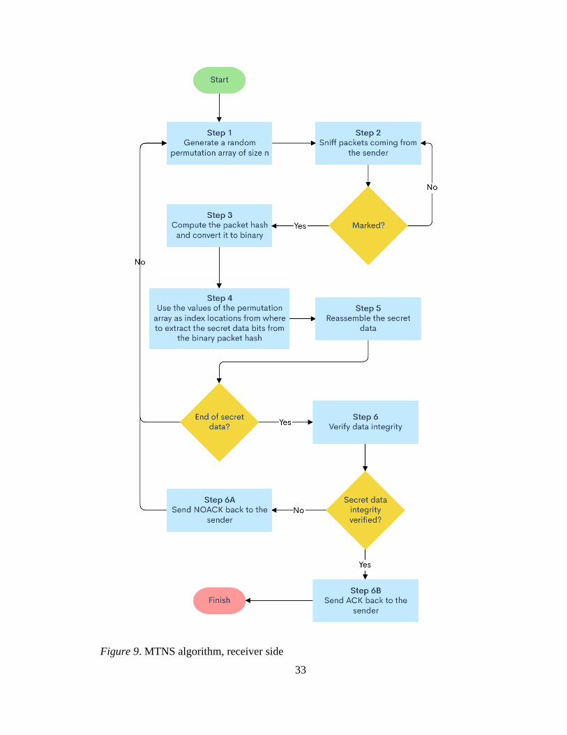
Receiver side. Figure 9 shows the steps in the general algorithm from the receiver’s
side. The first step is to generate the same permutation array used by the sender which will
be used to find the covert data in the following steps. Since both the sender and receiver
know the scheme, and have the same secret key, the receiver uses it to seed the random
permutation generator and creates a permutation array which is the size of the evaluation
bits.
33
Figure 9. MTNS algorithm, receiver side

34
The second step is to monitor the traffic coming to receiver from the sender. The
receiver is constantly monitoring the traffic for marked packets. If the receiver finds a
marked packet, they move onto step three otherwise they keep monitoring the traffic until
one is found.
In the third step, the receiver computes the hash of the packet using the same
parameters that the sender used. The hash is then converted into binary which is where the
covert data is stored. The fourth step extracts the secret data from the binary packet hash.
This is done by reading the bits of the binary packet hash located at the indexes in the
permutation array. Figure 10 shows how this is achieved.
Figure 10. Extracting data from marked packets

35
Step five is the final step of the data extraction process. After the receiver has read
the secret data from the packet, they reassemble the data into the complete binary string
which contains all the secret data. When the receiver encounters the dash (-) as the covert
data, they know that they sender has finished sending the data. If the receiver has not
encountered the dash (-), they generate the next permutation array and keep sniffing for
traffic.
Step six verifies the integrity of the data. The receiver calculates the SHA256
hash of the received message and then compares the first four and the last four
hexadecimal characters of the hash to the provided hash. If they match exactly, then the
receiver knows that the message was received completely and without alterations. If the
message was received without any modifications, the receiver sends back an
acknowledgement packet with the message counter as the data. If the message was
altered in any way such that the computed hash did not match the provided hash, the
receiver sends back a negative number to the sender indicating that the message was not
received correctly and then proceeds to repeat the permutation array generation and the
monitoring of traffic.
Proof of Concept
In the previous section, the general algorithm was outlined in detail and presented
from both the sender and receiver’s sides. In this section, a simplified version of the
general algorithm is implemented as a proof of concept. The proof of concept does not
contain the permutation mechanism, or the acknowledgement reply by the receiver but

36
those can be easily added in future versions. For this section, the sender will be called
Alice and the receiver will be called Bob.
The proof of concept is designed using two virtual machines. One virtual machine
is the Alice computer and the other virtual machine is the Bob computer. Although a full
duplex communication system is not implemented in the proof of concept, it is
completely possible to create by letting Bob be the sender and Alice be the receiver. In
that case, Bob would execute Alice’s sender steps and Alice would execute Bob’s
receiver steps.
The virtual machines are deployed using Oracle VM VirtualBox [56], a free to
use hypervisor designed to emulate many different types of operating systems. The
operating systems on these two virtual machines are Ubuntu 18.04 LTS (Bionic Beaver)
[57]. The proof of concept itself is developed using Python 3.8 [52] and uses the Scapy
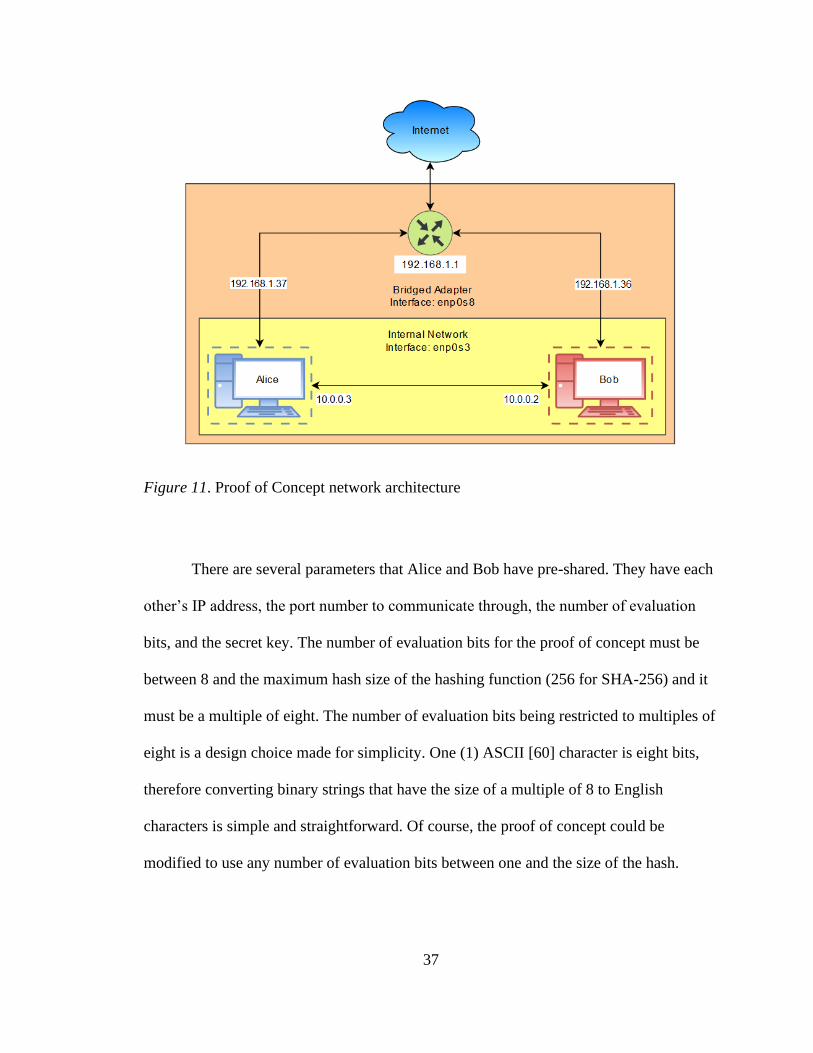
[59] packet crafting library. Figure 11 shows the network implementation of the proof of
concept. Both virtual machines have two network interfaces enabled. The first interface,
enp0s3, is enabled and used for an internal network. The internal network allows both
virtual machines to communicate with each other in an isolated environment. This is the
interface that is used for sending and receiving a packet stream generated by the
algorithm that is used as a covert channel. The second interface, enp0s8, is enabled and
used as a bridged adapter which allows the virtual machines to communicate directly
with the Internet through the host machine. The enp0s8 interface is enabled for updating
the software on the virtual machines and downloading new software packages.
37
Figure 11. Proof of Concept network architecture
There are several parameters that Alice and Bob have pre-shared. They have each
other’s IP address, the port number to communicate through, the number of evaluation
bits, and the secret key. The number of evaluation bits for the proof of concept must be
between 8 and the maximum hash size of the hashing function (256 for SHA-256) and it
must be a multiple of eight. The number of evaluation bits being restricted to multiples of
eight is a design choice made for simplicity. One (1) ASCII [60] character is eight bits,
therefore converting binary strings that have the size of a multiple of 8 to English
characters is simple and straightforward. Of course, the proof of concept could be
modified to use any number of evaluation bits between one and the size of the hash.

38
The following pseudo-code describes the proof of concept from the Alice’s side:
1. Take input from the user
a. Create binary representation
2. Establish TCP connection with Bob on given IP address and port number
3. Create the TCP/IP packet with Scapy
a. The PSH flag is set initially – marking the packet as containing data
4. Create the hash of the packet and convert it into binary
a. Use the source IP address, destination IP address, source port number,
destination port number, sequence number, and the data as parameters for the
hashing function
b. Convert the hash into binary
5. Compare the last 8 bits of the binary packet hash with 8 bits of the secret data
a. Match?
i. Send it to Bob
b. No match?
i. Remove the PSH flag and send it to Bob
6. Repeat steps 3-5 until the entire message is sent.
7. Ask user if they want to send more data
a. Yes?
i. Go to step 1
b. No?
i. Terminate TCP connection and exit

39
Alice begins by taking input from the user. In this case, it is a string. She converts
the string into its binary representation. Next, Alice creates a TCP session with Bob using
the pre-shared port number and Bob’s IP address. Alice then creates a TCP packet using
Scapy. She initially sets the push flag, marking the packet as containing covert data. She
will remove it later if the packet does not contain covert data. Next, she creates the hash
of the packet using the SHA-256 hashing algorithm. The parameters of the packet that are
used for the hash computation are the source IP address, destination IP address, source
port number, destination port number, sequence number, and the data. These values are
session and packet specific resulting in unique hashes for every packet created. Once the
hash has been converted into its binary form, the last 8 bits (one ASCII character) of the
binary packet hash are compared with 8 bits of the input from the user. If the binary
packet bits match the bits of the input, then the packet is sent over the wire to Bob,
already having the push flag set. If the bits do not match, then the push flag is removed
and then the packet is sent over the wire to Bob. Alice repeats the steps of creating
packets, generating the hashes, and comparing the bits until all the covert data is sent to
Bob. If Alice wants to send more data, she has that option once all the previous data has
been sent.

40
The following pseudo code describes the proof of concept from the receiver (Bob) side:
1. Establish TCP session with Alice on given IP address and port number
2. Sniff traffic coming from Alice’s machine
3. When marked PSH flag is found
a. Create the packet hash and convert it to binary
i. Use the source IP address, destination IP address, source port
number, destination port number, sequence number, and the data
as parameters for the hashing function
b. Extract the secret data bits which are the last 8 bits of the binary packet
hash
c. Re-assemble the data
4. Repeat until Alice stops sending data
Bob’s steps are much simpler than Alice’s steps since he is simply reading the
covert data in the marked packets. He begins by establishing a TCP connection with
Alice’s machine using her IP address and the mutual port number used to communicate.
Next, he continuously sniffs for traffic coming from her machine on the specific port.
When he sees a packet with the push flag set, he generates the same hash using the source
IP address, destination IP address, source port number, destination port number, sequence
number, and the data as parameters for the hashing function. After converting the hash
into its binary representation, Bob reads the last 8 bits of data and reassembles the covert
message. Bob repeats the steps of sniffing for marked packets, generating the binary
packet hash, and reading the last 8 bits until Alice stops sending him data.

41
It is important to note that the goal of the proof of concept was to determine if the
algorithm could be implemented. Therefore, a version of the general algorithm was
implemented which contained the core functionality of the algorithm by abstracting the
embedding of data inside the data packets using hashing. Future versions of the proof of
concept could include the moving target functionality of the permutation array and a
mechanism for determining if Bob received the message completely and without any
alterations. Another feature that could be included in future versions of the proof of
concept is a duplex communication system where both Alice and Bob can send messages
instead of only Alice being able to send messages. This two-way communication would
make the proof of concept more robust.
Results
Figure 12 shows the proof of concept in action from Alice’s side. Figure 13 shows
the proof of concept from Bob’s side. Alice is sending the secret message “hello” to Bob
by evaluating the last eight bits of the packet binary hash. Bob is sniffing for marked
packets, extracting the last eight bits of the marked packet binary hash, and rebuilding the
secret message letter by letter.

42
Figure 12. Sending data from Alice's side
Figure 13. Receiving data from Bob's side

43
Wireshark [61], a network sniffer, is used to monitor the data transfer between
Alice and Bob’s virtual machines. Figure 14 shows the Wireshark output of the data
transfer between Alice and Bob. A push flag packet is highlighted. By correlating the
sequence number from the Wireshark packet capture with figure 13, the packet contains
the second “l” in “hello”. Figure 15 shows the contents of the packet highlighted in figure
14. Wireshark allows the user to view each layer of the packet, the data, and provides
additional analysis information about the packet. A point to note is that the data is
random data. It is a random number generated by the proof of concept. It doesn’t convey
any special meaning. Another point to note is that the proof of concept supplied the
source IP address, destination IP address, source port number, destination port number,
the sequence number, the push flag, and the data. The rest of the fields for the packet
were filled automatically by Scapy.
Figure 14. Wireshark packet capture

44
Figure 15. Contents of a marked packet

45
Chapter 4
Analysis
Probability
In this section the section, the algorithm is analyzed for the probability of an
attacker managing to uncover the secret data. A sample scenario is defined where the
number of evaluation bits, denoted as n, is 8 bits. Both the sender and receiver have
secret keys which they are using to generate permutation arrays. The secret data is
“Hello”, and the packet transmission rate is 100 packets per second, and the general
algorithm is known to the attacker.
The algorithm keeps creating new packets and calculates their hashes until the bits
located at the indexes defined by the permutation array match n bits of covert data. The
maximum number of possible n-bit binary strings that can be created is 2𝑛 since each
position can have two possible values, like the following: 21 × 22 × ⋯ 2𝑛 = 2𝑛. Since n
is 8 in this scenario, the maximum number of possible 8-bit binary strings that can be
created is 28 or 256. That means, in the worst case, the algorithm must calculate 256
hashes before finding a match to 8 bits of secret data (assuming that the 8-bit strings are
unique for every consecutive calculation and do not repeat). The probability of matching
one unique string out of the maximum calculated hashes is 1
2𝑛 which, for this scenario, is
1
256 . That means that Alice has the probability of
1
256 of matching 8 bits of the packet
hash to 8 bits of the secret data. If the attacker knew the implementation of the algorithm,

46
all they must do is read the eight bits of the marked packet hash to extract the secret data.
The burden of probability falls on the sender.
Therefore, using static bit locations e.g. the last eight locations of the packet hash,
is a bad idea. The solution to this problem is moving the locations, i.e. moving the target.
This is where the permutation array comes into effect. The permutation array, as
discussed before, is a randomly generated array of values of size n in which the order of
the values is enforced. The order property of a permutation is important in adding
security to the algorithm because the algorithm must compare and read values in a
specified order determined by the array preventing a right to left data extraction event,
adding more security. Since the range of values is between 0 and the size of the hash - 1,
in this scenario, the random permutation generator creates a permutation array of size n
with values ranging between 0 and 255 inclusive (256 total possibilities). Selecting a
permutation of 8 values from 256 values yields 16,517,640,193,528,320,000 possible
combinations. If the n is increased, the possible number of permutations increases
exponentially, e.g., if n is 16, the possible number of 16 permutations out of 256 is
210,875,602,102,456,269,086,537,616,669,081,600,000 and if n is 24, the possible
number of 24 permutations out of 256 increases to
2,063,062,690,012,022,711,962,604,920,118,953,278,227,813,467,422,720,000,000.
The Summit supercomputer [62], the fastest supercomputer in the United States,
can perform a maximum of two hundred quadrillion calculations per second [63]. It
would take the Summit supercomputer 82.58 seconds running at maximum capacity to
calculate all the 16,517,640,193,528,320,000 different permutations. If the number of
evaluation bits is increased to the next multiple of eight, 16 bits, then it will take the

47
Summit supercomputer 1.05 × 10²¹ seconds to make its way through
210,875,602,102,456,269,086,537,616,669,081,600,000 permutations. Since the
permutations are generated via a random number generator which is seeded with the
shared secret key, even if the attacker knows every single detail about the implementation
and the algorithm, they cannot recreate the specific permutation used to evaluate n bits of
secret data without the key. Also, since the permutation changes for every n bits of data,
the attacker has a very short time to guess the create the permutation array before it
changes.
Parameters used in the probability analysis and later in the data transfer analysis
are show in Table 2.
Table 2
Probability and data transfer equation parameters
Variable Value
w Size of the hash
s Size of the permutation
n Number of evaluation bits
p Transmission rate in packets per second
y Data transfer rate in bits per second
q Data to transfer in bits
48
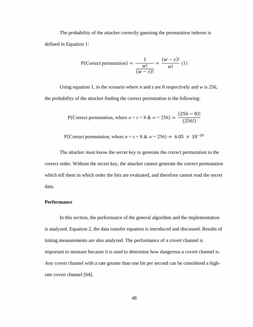
The probability of the attacker correctly guessing the permutation indexes is
defined in Equation 1:
P(Correct permutation) = 1
𝑤!(𝑤 − 𝑠)!
= (𝑤 − 𝑠)!
𝑤! (1)
Using equation 1, in the scenario where n and s are 8 respectively and w is 256,
the probability of the attacker finding the correct permutation is the following:
P(Correct permutation, where n = s = 8 & w = 256) = (256 − 8)!
(256!)
P(Correct permutation, where n = s = 8 & w = 256) = 6.05 × 10⁻²⁰
The attacker must know the secret key to generate the correct permutation in the
correct order. Without the secret key, the attacker cannot generate the correct permutation
which tell them in which order the bits are evaluated, and therefore cannot read the secret
data.
Performance
In this section, the performance of the general algorithm and the implementation
is analyzed. Equation 2, the data transfer equation is introduced and discussed. Results of
timing measurements are also analyzed. The performance of a covert channel is
important to measure because it is used to determine how dangerous a covert channel is.
Any covert channel with a rate greater than one bit per second can be considered a high-
rate covert channel [64].
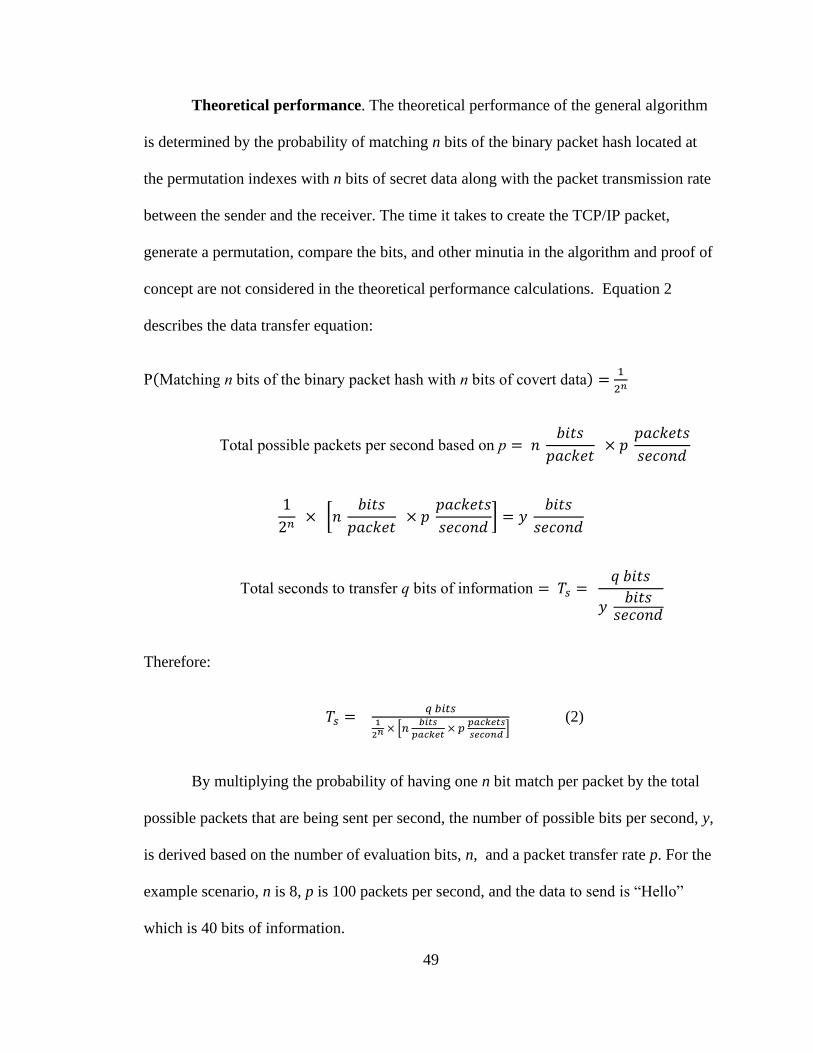
49
Theoretical performance. The theoretical performance of the general algorithm
is determined by the probability of matching n bits of the binary packet hash located at
the permutation indexes with n bits of secret data along with the packet transmission rate
between the sender and the receiver. The time it takes to create the TCP/IP packet,
generate a permutation, compare the bits, and other minutia in the algorithm and proof of
concept are not considered in the theoretical performance calculations. Equation 2
describes the data transfer equation:
P(Matching n bits of the binary packet hash with n bits of covert data) = 1
2𝑛
Total possible packets per second based on p = 𝑛 𝑏𝑖𝑡𝑠
𝑝𝑎𝑐𝑘𝑒𝑡 × 𝑝
𝑝𝑎𝑐𝑘𝑒𝑡𝑠
𝑠𝑒𝑐𝑜𝑛𝑑
1
2𝑛 × [𝑛
𝑏𝑖𝑡𝑠
𝑝𝑎𝑐𝑘𝑒𝑡 × 𝑝
𝑝𝑎𝑐𝑘𝑒𝑡𝑠
𝑠𝑒𝑐𝑜𝑛𝑑] = 𝑦
𝑏𝑖𝑡𝑠
𝑠𝑒𝑐𝑜𝑛𝑑
Total seconds to transfer q bits of information = 𝑇𝑠 = 𝑞 𝑏𝑖𝑡𝑠
𝑦 𝑏𝑖𝑡𝑠
𝑠𝑒𝑐𝑜𝑛𝑑
Therefore:
𝑇𝑠 = 𝑞 𝑏𝑖𝑡𝑠
1
2𝑛 × [𝑛 𝑏𝑖𝑡𝑠
𝑝𝑎𝑐𝑘𝑒𝑡 × 𝑝
𝑝𝑎𝑐𝑘𝑒𝑡𝑠
𝑠𝑒𝑐𝑜𝑛𝑑] (2)
By multiplying the probability of having one n bit match per packet by the total
possible packets that are being sent per second, the number of possible bits per second, y,
is derived based on the number of evaluation bits, n, and a packet transfer rate p. For the
example scenario, n is 8, p is 100 packets per second, and the data to send is “Hello”
which is 40 bits of information.

50
First, the bits per second rate must be calculated:
1
28 × [8
𝑏𝑖𝑡𝑠
𝑝𝑎𝑐𝑘𝑒𝑡 × 100
𝑝𝑎𝑐𝑘𝑒𝑡𝑠
𝑠𝑒𝑐𝑜𝑛𝑑] = 3.125
𝑏𝑖𝑡𝑠
𝑠𝑒𝑐𝑜𝑛𝑑
Based on the denominator of equation 2, the algorithm evaluating 8 bits of data
per packet transferring packets at 100 packets per second can transfer 3.125 bits per
second which is about three times greater than the 1 bit per second high covert channel
benchmark [2].
𝑇𝑠 = 40 𝑏𝑖𝑡𝑠
3.125 𝑏𝑖𝑡𝑠
𝑠𝑒𝑐𝑜𝑛𝑑
= 12.8 𝑠𝑒𝑐𝑜𝑛𝑑𝑠
Using equation 2, transferring 40 bits of data at a rate of 3.125 bits per second will
take 12.8 seconds.
Experimental performance. To get an accurate representation of how the proof
of concept’s run times compared with the theoretical calculations, 26 trials were
conducted, each trial running 100 times resulting in a total of 2600 total proof of concept
runs. The amount of data for every consecutive trial was increased by 8 bits, starting with
the letter “a” (8 bits) and ending with the entire alphabet “abcdefghijklmnopqrstuvwxyz”
(208 bits). Two sets of 26 trials were ran with a controlled packet transmission rate, 75
packets per second and 100 packets per second respectively. The third set of 26 trials
were ran with transmission rates controlled by the operating system, i.e., no packet rate
limitations were applied, the system determined how fast the packets were transmitted
between the virtual machines.
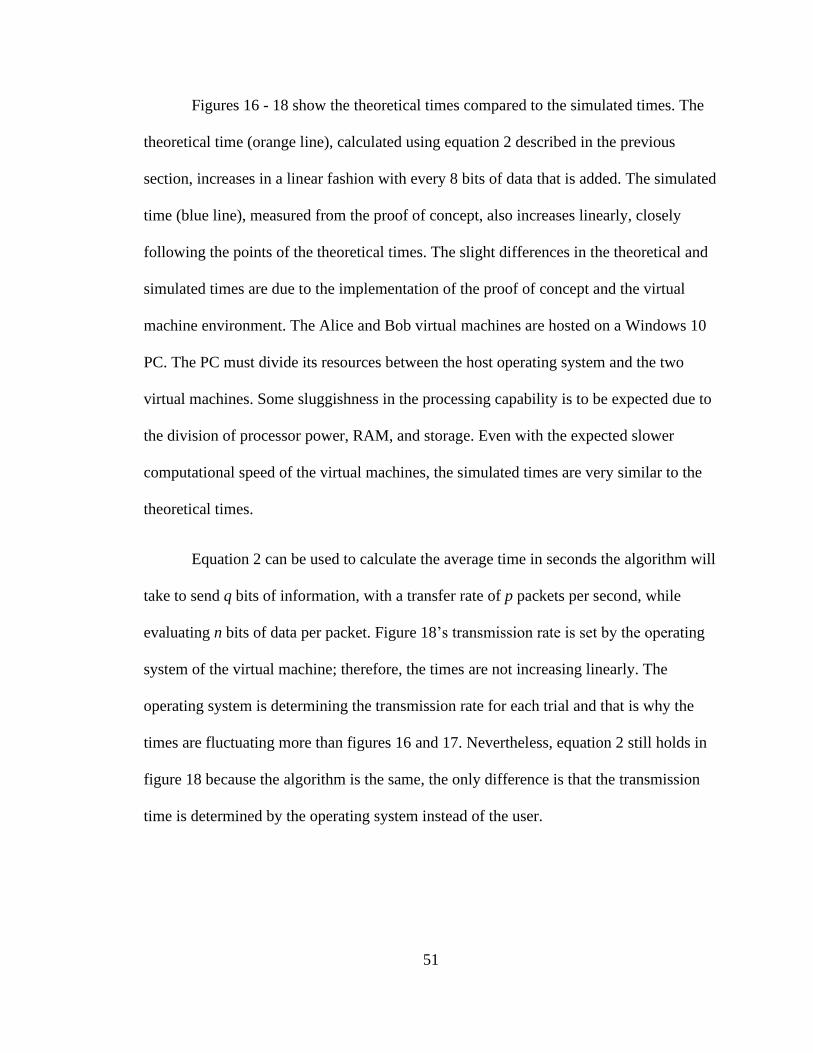
51
Figures 16 - 18 show the theoretical times compared to the simulated times. The
theoretical time (orange line), calculated using equation 2 described in the previous
section, increases in a linear fashion with every 8 bits of data that is added. The simulated
time (blue line), measured from the proof of concept, also increases linearly, closely
following the points of the theoretical times. The slight differences in the theoretical and
simulated times are due to the implementation of the proof of concept and the virtual
machine environment. The Alice and Bob virtual machines are hosted on a Windows 10
PC. The PC must divide its resources between the host operating system and the two
virtual machines. Some sluggishness in the processing capability is to be expected due to
the division of processor power, RAM, and storage. Even with the expected slower
computational speed of the virtual machines, the simulated times are very similar to the
theoretical times.
Equation 2 can be used to calculate the average time in seconds the algorithm will
take to send q bits of information, with a transfer rate of p packets per second, while
evaluating n bits of data per packet. Figure 18’s transmission rate is set by the operating
system of the virtual machine; therefore, the times are not increasing linearly. The
operating system is determining the transmission rate for each trial and that is why the
times are fluctuating more than figures 16 and 17. Nevertheless, equation 2 still holds in
figure 18 because the algorithm is the same, the only difference is that the transmission
time is determined by the operating system instead of the user.

52
Figure 16. Theoretical vs. experimental run times for n = 8, and p = 75 p/s
0
5
10
15
20
25
30
35
40
45
50
55
60
65
70
75
80
85
90
95TI
ME
(SEC
ON
DS)
DATA (BITS)
THEORETICAL VS. EXPERIMENTAL TIMES FOR N=8, P = 75 P/S
EXPERIMENTAL THEORETICAL
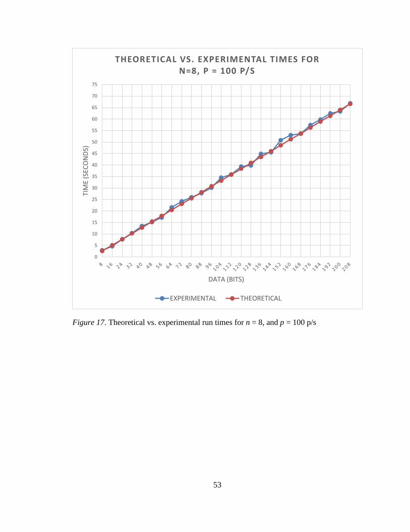
53
Figure 17. Theoretical vs. experimental run times for n = 8, and p = 100 p/s
0
5
10
15
20
25
30
35
40
45
50
55
60
65
70
75TI
ME
(SEC
ON
DS)
DATA (BITS)
THEORETICAL VS. EXPERIMENTAL TIMES FOR N=8, P = 100 P/S
EXPERIMENTAL THEORETICAL

54
Figure 18. Theoretical vs. experimental run times for n = 8, and p = variable p/s
0
2
4
6
8
10
12
14
16
18
20TI
ME
(SEC
ON
DS)
DATA (BITS)
THEORETICAL VS. EXPERIMENTAL TIMES FOR N=8, P = OS DETERMINED
EXPERIMENTAL THEORETICAL

55
Figures 19 - 21 show the average packet transfer rates. The packet transfer rates
for each run are collected by taking the average of the 100 runs’ individual packet
transfer rates. Controlling the packet transfer rate is done by implementing a slight delay
between sending packets. An automatic transmission rate correction feature was
implemented in the proof of concept which would increase or decrease the interval of
time between the packets based on the transmission rate of each run in the trial. The
simulated packet transfer rates are very close to packet transfer rates used for the
theoretical time calculations. The minor fluctuations are due to numerous mechanisms
such as internal program delays, operating system delays, and transmission delays. Figure
21 shows the average packet transfer rate of the trial where the transfer rate is handled by
the system. There is a large variance in transfer rates from 290 packets per second to 375
packet per second because the virtual machine operating systems determined the
transmission speed for each trial. Additionally, there are many variables that the
operating systems decides on that contributes to the fluctuations in the packet
transmission speed. Equation 2, the data transfer equation, still holds in this scenario
because each run’s transfer time is calculated with its specific transmission rate instead of
a set transmission rate.

56
Figure 19. Average packet transfer rates for p = 75 p/s
25
30
35
40
45
50
55
60
65
70
75
80
85
90
95
100
105
110
115
120
125A
VER
AG
E P
AC
KET
RA
TE (
PA
CK
ETS/
SEC
ON
D)
DATA (BITS)
EXPERIMENTAL AVERAGE PACKET TRANSFER RATE FOR P = 75 P/S

57
Figure 20. Average packet transfer rates for p = 100 p/s
50
55
60
65
70
75
80
85
90
95
100
105
110
115
120
125
130
135
140
145
150A
VER
AG
E P
AC
KET
RA
TE (
PA
CK
ETS/
SEC
ON
D)
DATA (BITS)
EXPERIMENTAL AVERAGE PACKET TRANSFER RATE FOR P = 100 P/S

58
Figure 21. Average packet transfer rates for p = variable p/s
250
270
290
310
330
350
370
390A
VER
AG
E P
AC
KET
RA
TE (
PA
CK
ETS/
SEC
ON
D)
DATA (BITS)
EXPERIMENTAL AVERAGE P/S FOR P = OS DETERMINED

59
Figure 22 shows an interesting relationship between the packet transfer rate and
the time it takes to transfer 208 bits of information at those packet transfer rates. The time
to complete the transmission is logarithmically decreasing the higher the packet rate is.
The fastest average packet rate for the proof of concept was 379 packets per second using
virtual network interfaces. Business and enterprise grade routers and networking
equipment can send many more packets per second than 379 thus increasing the
bandwidth of the scheme and allowing the sender to increase the amount of data sent
while reducing the transmission time. Equation 2 will still hold in these cases regardless
of the transmission speeds because the algorithm being used is still the same and relies on
the probability of the packet hash matching n bits of the secret data and the transmission
speed of the data packets.
Figure 22. Times for transmitting 208 bits of data
0
10
20
30
40
50
60
70
TIM
E (S
)
PACKET RATE (PACKETS/SECOND)
TIME FOR TRANSMIT TING 208 BITS OF INFORMATION AT VARIABLE PACKET TRANSMISSION RATES
60
Detectability and Mitigation
No network steganography method is completely secure. The following is a
detectability and mitigation analysis of the general algorithm. Steganalysis is the process
of detecting the presence of and ultimately extracting covert data from a carrier [65] [66].
There is one way that the scheme could be exposed. It is important to note that since the
“embedding” of covert data happens by comparing indexes of the packet hash with covert
data, the covert data is never stored inside a packet. The packet represents covert data and
without the appropriate key and the correct permutation, it is nearly impossible to extract
the covert information so even if the scheme is discovered, the warden is not able to read
the data.
The way to detect if a covert channel is being used is by the marking of the
packet. The mark tells the receiver which packets have hidden information. The general
algorithm describes that the marking of the packets is was done with the TCP push flag,
if it generates a custom packet stream, which is used to push data from the user to the
receiver [24]. If the general algorithm uses an already available packet stream, the
marking scheme is left for future research. If the warden realizes that the push flag is
used to send data other than what’s in the data portion, i.e. covert data, he can shut down
the channel. But since the push flag is described by the TCP standard to be used when
sending data, the warden cannot differentiate whether covert data is also being sent in
addition to the plaintext data.
If the warden is an active warden, he can manipulate the fields of the packet and
change the values. A point to note is that an active warden is akin to a man in the middle
who has total control over the network channel. The only way to stop an active warden is

61
to prevent them from detecting the covert channel in the first place. Since no covert data
is hidden inside the protocol, the two ways to mitigate this covert channel are to change
the values that are used to calculate the hash (source IP address, destination IP address
etc.) or to stop the communication channel entirely. Doing both will result in
performance loss between the sender and the receiver and may not be worth it for
network administrators since closing the communication channel is the same as shutting
off the Internet for that process, and changing the contents of packet may have negative
effects on legitimate processes.

62
Chapter 5
Conclusion and Future Work
Conclusion
The field of information hiding is a broad field with many different techniques used daily
to keep information hidden and away from prying eyes. One of those techniques is
network steganography. Network steganography is a branch of information hiding that
uses network protocols as information carriers to hide and transmit covert information.
The widespread adoption of the Internet, and its open system architecture make it an
attractive candidate for information hiding. Two types of network steganography exist,
storage channel and timing channel. Storage channel network steganography is a class of
network steganography where the field values of protocol are manipulated to transmit
secret data. Timing channel network steganography is a class of network steganography
that modifies the timing of the events in a carrier to transmit secret data. Storage channel
network steganography is more prevalent because it is easier to implement, allows for
more control over the protocol, and there are many different protocols in the TCP/IP
protocol suite.
Many of the current approaches to storage channel network steganography suffer
from a low transmission rate and the vulnerability of hiding covert data inside the
protocol header and data fields. If the covert channel is discovered, the covert data can be
read which is the ultimate breach of confidentiality. A new type of storage channel
network steganography is introduced. It allows packets to represent the covert data
instead of hiding it directly inside the packet. This new approach does not hide data

63
inside the packet but instead allows the receiver to re-create data out of data packets
using a holistic packet evaluation algorithm. The algorithm utilizes hashing to create a
unique signature of the packet and compares values from the hash to values of the secret
data. If they match, then the packet is marked and sent to the receiver. The receiver
creates the same signature of the marked packet and extracts the data from the packet
hash. Additional security is added to the algorithm in the form of a moving target
mechanism which changes the locations from which the data in the packet hash is
evaluated. By implementing the moving target functionality, brute forcing the algorithm
is impossible since the location is changing for every marked packet and the permutations
are generated via a random permutation generator that is seeded with the shared secret
key. Controlling the transmission rate of the packets and increasing the number of
evaluation bits allows for increased transfer bandwidth.
A proof of concept is developed to test the algorithm. Built using Python 3.8 and
implemented on two virtual machines, the proof of concept implements a simplified
version of the general algorithm. It creates a direct communication channel between the
sender and receiver that is used as a covert channel. Different packet transmission speeds
are tested to evaluate the accuracy of the simulated times against the theoretical times.
The simulated times are identical to the theoretical times. A probability analysis is
performed to determine the probability of an attacker being able to brute force the
algorithm and how the moving target mechanism mitigates it. A data transfer equation is
developed to calculate how long in seconds the algorithm would take to transfer q bits of
information with a transfer rate of p packets per second while evaluating n bits of data per
packet. Finally, a mitigation and detection analysis is performed on the algorithm.

64
Future Work
The most important part of the future work is to establish a more covert marking
technique for the general algorithm and to improve the proof of concept. The general
algorithm is robust enough to provide security against brute forcing because of the
rotating permutations but if the marking mechanism is found by a third party who is
monitoring the traffic, then the covert channel is discovered. Although the third party
cannot read the data, they can shut down the channel which prevents covert
communication. Another important part of the future work is to perform a through and in-
depth steganalysis by performing experiments on how an active or passive warden would
behave in a scenario where this network steganography technique is applied.
The proof of concept ignored the fact that most of the time, the users will not be
in the same localized private network. Part of the future work should focus on
augmenting the capabilities of the proof of concept. The proof of concept should be
upgraded to have the ability to allow for communication between hosts outside of local
networks. Additionally, the permutation and simulated ack features for mitigating
dropped or altered data packets were not implemented. Adding those features would
enhance the security of the proof of concept. Finally, allowing the proof of concept to use
a packet that was not generated by the program, i.e. one that is already present between
the two hosts, would increase the covertness of the program.

65
References
[1] B. W. Lampson, “A note on the confinement problem,” Commun. ACM, vol. 16, no.
10, pp. 613–615, Oct. 1973, doi: 10.1145/362375.362389.
[2] US Department of Defense, “Department of Defense Trusted Computer System
Evaluation Criteria,” in The ‘Orange Book’ Series, US Department of Defense, Ed.
London: Palgrave Macmillan UK, 1985, pp. 1–129.
[3] “Definition of STEGANOGRAPHY.” https://www.merriam-
webster.com/dictionary/steganography (accessed Aug. 11, 2020).
[4] J. Lubacz, W. Mazurczyk, and K. Szczypiorski, “Principles and overview of
network steganography,” IEEE Communications Magazine, vol. 52, no. 5, pp. 225–
229, May 2014, doi: 10.1109/MCOM.2014.6815916.
[5] S. Wendzel, W. Mazurczyk, L. Caviglione, and M. Meier, “Hidden and
Uncontrolled - On the Emergence of Network Steganographic Threats,”
arXiv:1407.2029 [cs], Jul. 2014, Accessed: Aug. 11, 2020. [Online]. Available:
http://arxiv.org/abs/1407.2029.
[6] T. Soni, TapanSoni/BPStegano. 2020.
[7] S. D. Vuono, StefanoDeVuono/steghide. 2020.
[8] “OpenStego.” https://www.openstego.com/ (accessed Aug. 11, 2020).
[9] K. Szczypiorski, “HICCUPS : Hidden Communication System for Corrupted
Networks,” 2003.
[10] G. J. Simmons, “The Prisoners’ Problem and the Subliminal Channel,” in Advances
in Cryptology: Proceedings of Crypto 83, D. Chaum, Ed. Boston, MA: Springer US,
1984, pp. 51–67.

66
[11] S. Zander, G. J. Armitage, and P. Branch, “Covert channels in the IP Time To Live
Field,” undefined, 2006. https://www.semanticscholar.org/paper/Covert-channels-
in-the-IP-Time-To-Live-Field-Zander-
Armitage/d1a0fab4a6b629d47dbf0854904b3c010c4f7915 (accessed Aug. 11,
2020).
[12] S. J. Murdoch and S. Lewis, “Embedding Covert Channels into TCP/IP,” in
Information Hiding, Berlin, Heidelberg, 2005, pp. 247–261, doi:
10.1007/11558859_19.
[13] R. Braden, “Requirements for Internet Hosts - Communication Layers.”
https://tools.ietf.org/html/rfc1122 (accessed Aug. 11, 2020).
[14] “1. Overview of TCP/IP - TCP/IP Network Administration, 3rd Edition [Book].”
https://www.oreilly.com/library/view/tcpip-network-
administration/0596002971/ch01.html (accessed Aug. 11, 2020).
[15] J. Postel and J. Reynolds, “File Transfer Protocol.” https://tools.ietf.org/html/rfc959
(accessed Aug. 11, 2020).
[16] M. Lottor, “Simple File Transfer Protocol.” https://tools.ietf.org/html/rfc913
(accessed Aug. 11, 2020).
[17] J. Postel and J. K. Reynolds, “Telnet Protocol Specification.”
https://tools.ietf.org/html/rfc854 (accessed Aug. 11, 2020).
[18] T. Ylonen and C. Lonvick, “The Secure Shell (SSH) Transport Layer Protocol.”
https://tools.ietf.org/html/rfc4253 (accessed Aug. 11, 2020).
[19] J. C. Klensin <[email protected]>, “Simple Mail Transfer Protocol.”
https://tools.ietf.org/html/rfc5321 (accessed Aug. 11, 2020).
[20] M. R. Crispin <[email protected]>, “INTERNET MESSAGE ACCESS
PROTOCOL - VERSION 4rev1.” https://tools.ietf.org/html/rfc3501 (accessed Aug.
11, 2020).
[21] J. Myers and M. Rose, “Post Office Protocol - Version 3.”
https://www.ietf.org/rfc/rfc1939.txt (accessed Aug. 11, 2020).

67
[22] P. J. Leach, T. Berners-Lee, J. C. Mogul, L. Masinter, R. T. Fielding, and J. Gettys,
“Hypertext Transfer Protocol -- HTTP/1.1.” https://tools.ietf.org/html/rfc2616
(accessed Aug. 11, 2020).
[23] E. Rescorla, “HTTP Over TLS.” https://tools.ietf.org/html/rfc2818 (accessed Aug.
11, 2020).
[24] “Transmission Control Protocol. DARPA Internet Program Protocol Specification.”
https://www.ietf.org/rfc/rfc793.txt (accessed Aug. 11, 2020).
[25] J. Postel, “User Datagram Protocol.” https://tools.ietf.org/html/rfc768 (accessed
Aug. 11, 2020).
[26] J. Postel, “Internet Protocol.” https://tools.ietf.org/html/rfc791 (accessed Aug. 11,
2020).
[27] J. Postel, “Internet Control Message Protocol.” https://tools.ietf.org/html/rfc792
(accessed Aug. 11, 2020).
[28] “Datalink layer ISO OSI.”
http://www.highteck.net/EN/DataLink/Data_Link_Layer.html (accessed Sep. 20,
2020).
[29] “802.3-2018 - IEEE Standard for Ethernet - IEEE Standard.”
https://ieeexplore.ieee.org/document/8457469 (accessed Aug. 11, 2020).
[30] “IEEE Standard for Information technology—Telecommunications and information
exchange between systems Local and metropolitan area networks—Specific
requirements - Part 11: Wireless LAN Medium Access Control (MAC) and Physical
Layer (PHY) Specifications,” IEEE Std 802.11-2016 (Revision of IEEE Std 802.11-
2012), pp. 1–3534, Dec. 2016, doi: 10.1109/IEEESTD.2016.7786995.
[31] B. Forouzan, TCP/IP Protocol Suite, 4th ed. USA: McGraw-Hill, Inc., 2009.
[32] W. Mazurczyk, S. Wendzel, S. Zander, A. Houmansadr, and K. Szczypiorski,
Information Hiding in Communication Networks: Fundamentals, Mechanisms,
Applications, and Countermeasures, 1st ed. Wiley-IEEE Press, 2016.
[33] J. M. Kadhim and A. E. Abed, “Steganography Using TCP / IP’s Sequence
Number,” 2017, doi: 10.22401/jnus.20.4.16.

68
[34] D. Kundur and K. Ashan, “Practical Internet Steganography : Data Hiding in IP,”
2003. https://www.semanticscholar.org/paper/Practical-Internet-Steganography-
%3A-Data-Hiding-in-Kundur-
Texas./cd5ef9cdc9d8e1bb8fc985158e462ab9d53a1d79 (accessed Aug. 11, 2020).
[35] R. Biswas and S. K. Bandhyapadhyay, “TCP Packet Steganography using SDA
Algorithm,” 2016. /paper/TCP-Packet-Steganography-using-SDA-Algorithm-
Biswas-Bandhyapadhyay/6fca16dbe70253df513395f9b585ba519bc8ac95 (accessed
Aug. 11, 2020).
[36] “Ping Tunnel - Send TCP traffic over ICMP.”
https://www.mit.edu/afs.new/sipb/user/golem/tmp/ptunnel-0.61.orig/web/ (accessed
Feb. 22, 2020).
[37] T. G. Handel and M. T. Sandford, “Hiding data in the OSI network model,” in
Information Hiding, Berlin, Heidelberg, 1996, pp. 23–38, doi: 10.1007/3-540-
61996-8_29.
[38] R. Miller, “The OSI Model: An Overview,” p. 10, 2001.
[39] B. Jankowski, W. Mazurczyk, and K. Szczypiorski, “Information Hiding Using
Improper Frame Padding,” arXiv:1005.1925 [cs], Jul. 2010, Accessed: Aug. 11,
2020. [Online]. Available: http://arxiv.org/abs/1005.1925.
[40] O. Arkin and J. W. Anderson, “EtherLeak: Ethernet frame padding information
leakage,” undefined, 2003. /paper/EtherLeak%3A-Ethernet-frame-padding-
information-Arkin-Anderson/1b69f5c3c889da506313e40757f38703f673c212
(accessed Aug. 11, 2020).
[41] D. Plummer, “An Ethernet Address Resolution Protocol: Or Converting Network
Protocol Addresses to 48.bit Ethernet Address for Transmission on Ethernet
Hardware.” https://tools.ietf.org/html/rfc826 (accessed Aug. 11, 2020).
[42] P. M. B. Melo, A. M. Sison, and R. P. Medina, “Enhanced TCP Sequence Number
Steganography using Dynamic Identifier,” in 2019 IEEE Eurasia Conference on
IOT, Communication and Engineering (ECICE), Oct. 2019, pp. 482–485, doi:
10.1109/ECICE47484.2019.8942661.

69
[43] J. Giffin, R. Greenstadt, P. Litwack, and R. Tibbetts, “Covert Messaging through
TCP Timestamps,” in Privacy Enhancing Technologies, Berlin, Heidelberg, 2003,
pp. 194–208, doi: 10.1007/3-540-36467-6_15.
[44] C. Rowland, “Covert Channels in the TCP/IP Protocol Suite,” May 05, 1995.
https://firstmonday.org/ojs/index.php/fm/article/view/528/449 (accessed Aug. 11,
2020).
[45] Z. Trabelsi and I. Jawhar, “Covert File Transfer Protocol Based on the IP Record
Route Option,” p. 10.
[46] R. Rios, J. A. Onieva, and J. Lopez, “HIDE_DHCP: Covert Communications
through Network Configuration Messages,” in Information Security and Privacy
Research, Berlin, Heidelberg, 2012, pp. 162–173, doi: 10.1007/978-3-642-30436-
1_14.
[47] R. Droms, “Dynamic Host Configuration Protocol.”
https://tools.ietf.org/html/rfc2131 (accessed Aug. 11, 2020).
[48] R. Patuck and J. Hernandez-Castro, “Steganography using the Extensible Messaging
and Presence Protocol (XMPP),” arXiv:1310.0524 [cs], Sep. 2013, Accessed: Aug.
11, 2020. [Online]. Available: http://arxiv.org/abs/1310.0524.
[49] P. Saint-Andre <[email protected]>, “Extensible Messaging and Presence
Protocol (XMPP): Core.” https://tools.ietf.org/html/rfc6120 (accessed Aug. 11,
2020).
[50] R. Sobti and G. Ganesan, “Cryptographic Hash Functions: A Review,”
ResearchGate, vol. 9, no. 2, pp. 461–479, Mar. 2012.
[51] J.-P. Aumasson, Serious Cryptography. No Starch Press, 2017.
[52] Q. H. Dang, “Secure Hash Standard,” National Institute of Standards and
Technology, NIST FIPS 180-4, Jul. 2015. doi: 10.6028/NIST.FIPS.180-4.
[53] A. A. Alkandari, I. F. Al-Shaikhli, and M. A. Alahmad, “Cryptographic Hash
Function: A High Level View,” in 2013 International Conference on Informatics
and Creative Multimedia, Sep. 2013, pp. 128–134, doi: 10.1109/ICICM.2013.29.

70
[54] B. Holliday et al., Algebra 2. Glencoe McGraw Hill, 2008.
[55] E. Gregersen, G. Lotha, A. Augustyn, Y. Chauhan, and D. Promeet, “Permutations
and combinations,” Encyclopedia Britannica.
https://www.britannica.com/science/permutation (accessed Sep. 28, 2020).
[56] “Oracle VM VirtualBox.” https://www.virtualbox.org/ (accessed Aug. 11, 2020).
[57] “Ubuntu 18.04.4 LTS (Bionic Beaver).” https://releases.ubuntu.com/18.04/
(accessed Aug. 11, 2020).
[58] “Python Release Python 3.8.0,” Python.org.
https://www.python.org/downloads/release/python-380/ (accessed Aug. 11, 2020).
[59] P. B. and the S. community, “Scapy.” https://secdev.github.io/ (accessed Feb. 22,
2020).
[60] “INCITS 4-1986[R2012] - Information Systems - Coded Character Sets - 7-Bit
American National Standard Code for Information Interchange (7-Bit ASCII).”
https://webstore.ansi.org/standards/incits/incits1986r2012 (accessed Aug. 11, 2020).
[61] “Wireshark · Go Deep.” https://www.wireshark.org/ (accessed Nov. 28, 2019).
[62] “Summit,” Oak Ridge Leadership Computing Facility.
https://www.olcf.ornl.gov/summit/ (accessed Aug. 11, 2020).
[63] “IBM – See the story behind Summit, the world’s most powerful supercomputer,”
Jun. 06, 2018. https://www.ibm.com/thought-leadership/summit-supercomputer/
(accessed Aug. 11, 2020).
[64] S. Zander, “Performance of selected noisy covert channels and their
countermeasures in IP networks,” p. 294.
[65] A. Sur, A. S. Nair, A. Kumar, A. Jain, and S. Nandi, “Steganalysis of Network
Packet Length Based Data Hiding,” Circuits Syst Signal Process, vol. 32, no. 3, pp.
1239–1256, Jun. 2013, doi: 10.1007/s00034-012-9497-8.

71
[66] A. S. Nair, A. Sur, and S. Nandi, “Detection of Packet Length Based Network
Steganography,” in 2010 International Conference on Multimedia Information
Networking and Security, Nov. 2010, pp. 574–578, doi: 10.1109/MINES.2010.126.
Related Documents