Moving object detection, tracking and following using an omnidirectional camera on a mobile robot* Ivan Markovi´ c 1 , Franc ¸ois Chaumette 2 and Ivan Petrovi´ c 1 Abstract— Equipping mobile robots with an omnidirectional camera is very advantageous in numerous applications as all information about the surrounding scene is stored in a single image frame. In the given context, the present paper is concerned with detection, tracking and following of a moving object with an omnidirectional camera. The camera calibration and image formation is based on the spherical unified projection model thus yielding a representation of the omnidirectional image on the unit sphere. Detection of moving objects is performed by calculating a sparse optical flow in the image and then lifting the flow vectors on the unit sphere where they are discriminated as dynamic or static by analytically calculating the distance of the terminal vector point to a great circle arc. The flow vectors are then clustered and the center of gravity is calculated to form the sensor measurement. Furthermore, the tracking is posed as a Bayesian estimation problem on the unit sphere and the solution based on the von Mises-Fisher distribution is utilized. Visual servoing is performed for the object following task where the control law calculation is based on the projection of a point on the unit sphere. Experimental results obtained by a camera with a fish-eye lens mounted on a differential drive mobile robot are presented and discussed. I. INTRODUCTION Omnidirectional cameras by their definition provide a 360 ◦ view of the surrounding scene and as such pose themselves as a powerful tool in robot’s vision system. The enhanced field of view can be obtained by using several synchronized panoramic cameras, a combination of a camera and a mirror, or a camera with a wide-angle lens. The amount of infor- mation in such a single image reinforces robot’s abilities in interpreting and adequately acting and reacting in the environment. The sensor has been utilized in mobile robotics in a variety of applications: visual odometry, navigation, structure-from-motion, visual servoing, and moving object tracking to name but a few. Detection and tracking of moving objects with a camera mounted on a mobile robot is a task inconvenienced by the simultaneous ego-motion of the robot and the motion of the objects. With perspective cameras the problem is approached in [1] by calculating the optical flow and optimizing the *This work has been supported by European Community’s Seventh Framework Programme under grant agreement no. 285939 (ACROSS). The research related to object following by visual servoing was supported by the University of Zagreb as a short term financial support under the contract number 2013-ZUID-19. 1 Ivan Markovi´ c and Ivan Petrovi´ c are with University of Zagreb, Faculty of Electrical Engineering and Computing, Department of Con- trol and Computer Engineering, 10000 Zagreb, Croatia (e-mail: ivan.markovic, [email protected]) 2 Franc ¸ois Chaumette is with Inria Rennes-Bretagne Atlantique, Campus de Beaulieu, Rennes, Cedex 35042, France (e-mail: [email protected]) bilinear transformation to warp the image between the con- secutive frames, after which the images are differentiated and motion is detected. Then the particle filter is used to track the moving objects in the image and a laser range finder is used to infer about the location in 3D. In [2] the detection was based on monocular scene reconstruction and affine transformation of a triangle mesh in order to perform the image warping. The tracking of the moving object and the scene reconstruction was performed using the extended Kalman filter. Compared to perspective cameras, omnidirectional cameras offers the advantage of being able to address objects in the 360 ◦ surrounding scene of the mobile robot, thus, for example, removing the possibility that the followed object will escape the camera’s field-of-view. In [3] and [4] an omnidirectional image was first un- wrapped to a panoramic image using a cylindrical projection, where the optical flow is calculated. In the former a synthetic optical flow is generated by estimating the position of the focii of expansion and contraction and the calculated flow is compared to the generated one, while the latter estimates an affine transform on square subsegments to warp the image and perform the differentiation. In [5] the omnidirectional image is segmented in a set of perspective images and detection is done in the vein of [1], while the tracking is based on the particle filter. To perform the following a control law based on a minimization of an ad hoc following error is calculated. Compared to cylindrical projection geometry, working on the unit sphere offers the advantage of mitigating wrapping issues at the edges of the projection caused by cutting and unwrapping the cylinder. In the present paper, excepting the optical flow calculation, we propose a method for moving object detection, tracking and following based on processing on the unit sphere thus taking into account the specific sensor geometry and mak- ing it as general as possible for calibrated omnidirectional systems, since any such image can be represented on the unit sphere. The novel moving object detection is based on analytically calculating the distance of a point on the unit sphere to a great circle arc on the unit sphere. The tracking is performed in a Bayesian prediction-correction manner where the underlying distribution is a distribution on the unit sphere, namely the von Mises-Fisher distribution [6]. In the end, the object following is based on visual servoing [7] where the control law is calculated from an interaction matrix derived for a projection of a point on the unit sphere. In our previous work [8] a mixture of von Mises distributions (distribution on the unit circle) was proposed as a Bayesian method for speaker azimuth estimation with a microphone array.

Welcome message from author
This document is posted to help you gain knowledge. Please leave a comment to let me know what you think about it! Share it to your friends and learn new things together.
Transcript

Moving object detection, tracking and following using anomnidirectional camera on a mobile robot*
Ivan Markovic1, Francois Chaumette2 and Ivan Petrovic1
Abstract— Equipping mobile robots with an omnidirectionalcamera is very advantageous in numerous applications asall information about the surrounding scene is stored in asingle image frame. In the given context, the present paper isconcerned with detection, tracking and following of a movingobject with an omnidirectional camera. The camera calibrationand image formation is based on the spherical unified projectionmodel thus yielding a representation of the omnidirectionalimage on the unit sphere. Detection of moving objects isperformed by calculating a sparse optical flow in the image andthen lifting the flow vectors on the unit sphere where they arediscriminated as dynamic or static by analytically calculatingthe distance of the terminal vector point to a great circle arc.The flow vectors are then clustered and the center of gravityis calculated to form the sensor measurement. Furthermore,the tracking is posed as a Bayesian estimation problem on theunit sphere and the solution based on the von Mises-Fisherdistribution is utilized. Visual servoing is performed for theobject following task where the control law calculation is basedon the projection of a point on the unit sphere. Experimentalresults obtained by a camera with a fish-eye lens mounted ona differential drive mobile robot are presented and discussed.
I. INTRODUCTION
Omnidirectional cameras by their definition provide a 360◦
view of the surrounding scene and as such pose themselvesas a powerful tool in robot’s vision system. The enhancedfield of view can be obtained by using several synchronizedpanoramic cameras, a combination of a camera and a mirror,or a camera with a wide-angle lens. The amount of infor-mation in such a single image reinforces robot’s abilitiesin interpreting and adequately acting and reacting in theenvironment. The sensor has been utilized in mobile roboticsin a variety of applications: visual odometry, navigation,structure-from-motion, visual servoing, and moving objecttracking to name but a few.
Detection and tracking of moving objects with a cameramounted on a mobile robot is a task inconvenienced by thesimultaneous ego-motion of the robot and the motion of theobjects. With perspective cameras the problem is approachedin [1] by calculating the optical flow and optimizing the
*This work has been supported by European Community’s SeventhFramework Programme under grant agreement no. 285939 (ACROSS). Theresearch related to object following by visual servoing was supported by theUniversity of Zagreb as a short term financial support under the contractnumber 2013-ZUID-19.
1Ivan Markovic and Ivan Petrovic are with University of Zagreb,Faculty of Electrical Engineering and Computing, Department of Con-trol and Computer Engineering, 10000 Zagreb, Croatia (e-mail:ivan.markovic, [email protected])
2Francois Chaumette is with Inria Rennes-Bretagne Atlantique,Campus de Beaulieu, Rennes, Cedex 35042, France (e-mail:[email protected])
bilinear transformation to warp the image between the con-secutive frames, after which the images are differentiatedand motion is detected. Then the particle filter is used totrack the moving objects in the image and a laser rangefinder is used to infer about the location in 3D. In [2]the detection was based on monocular scene reconstructionand affine transformation of a triangle mesh in order toperform the image warping. The tracking of the movingobject and the scene reconstruction was performed using theextended Kalman filter. Compared to perspective cameras,omnidirectional cameras offers the advantage of being able toaddress objects in the 360◦ surrounding scene of the mobilerobot, thus, for example, removing the possibility that thefollowed object will escape the camera’s field-of-view.
In [3] and [4] an omnidirectional image was first un-wrapped to a panoramic image using a cylindrical projection,where the optical flow is calculated. In the former a syntheticoptical flow is generated by estimating the position of thefocii of expansion and contraction and the calculated flow iscompared to the generated one, while the latter estimates anaffine transform on square subsegments to warp the imageand perform the differentiation. In [5] the omnidirectionalimage is segmented in a set of perspective images anddetection is done in the vein of [1], while the tracking isbased on the particle filter. To perform the following a controllaw based on a minimization of an ad hoc following erroris calculated. Compared to cylindrical projection geometry,working on the unit sphere offers the advantage of mitigatingwrapping issues at the edges of the projection caused bycutting and unwrapping the cylinder.
In the present paper, excepting the optical flow calculation,we propose a method for moving object detection, trackingand following based on processing on the unit sphere thustaking into account the specific sensor geometry and mak-ing it as general as possible for calibrated omnidirectionalsystems, since any such image can be represented on theunit sphere. The novel moving object detection is based onanalytically calculating the distance of a point on the unitsphere to a great circle arc on the unit sphere. The tracking isperformed in a Bayesian prediction-correction manner wherethe underlying distribution is a distribution on the unit sphere,namely the von Mises-Fisher distribution [6]. In the end, theobject following is based on visual servoing [7] where thecontrol law is calculated from an interaction matrix derivedfor a projection of a point on the unit sphere. In our previouswork [8] a mixture of von Mises distributions (distributionon the unit circle) was proposed as a Bayesian method forspeaker azimuth estimation with a microphone array.

II. CAMERA CALIBRATION
The unified projection model describes the image forma-tion in catadioptric systems with a unique effective view-point, which includes combinations of the mirror—parabolic,hyperbolic, elliptic, planar—and the lens—orthographic orperspective. Theoretical derivation of complete single-lenssingle-mirror catadioptric sensors characterized by a uniqueeffective viewpoint was introduced in [9], while the unifiedprojection model was introduced and studied in [10], [11].In the present paper we have chosen to use the calibrationmethod based on planar grids proposed in [12]. Althoughthe model and the calibration methods were developed forsystems with a unique effective viewpoint, in practice theyhave been shown to be valid for dioptric systems with afish-eye lens [13].
Consider a point in space P and a frame Fo : (xo, yo, zo)as shown in Fig. 2. First, P is projected to the surface ofthe sphere. Then, the normalized point Pn is perspectivelyprojected from the coordinate system Fm : (xm, ym, zm) tothe point m = (x, y, 1) on the normalized plane. The point inthe image p is obtained by calculating p = Km, where K isa 3×3 matrix containing the camera intrinsic parameters. Thematrix K and ξ are obtained by the calibration procedure.In the present paper we used a standard perspective camerawith a fish-eye lens, and the best calibration results wereobtained by utilizing just the K and ξ, i.e. without distortionmodeling. In the sequel we assume that our omnidirectionalcamera is calibrated, which consequently enables us to applythe inverse projection (lifting) of the point in the image to apoint on the unit sphere [12]
m = K−1p, Pn =
ξ+√
1+(1−ξ2)(x2+y2)
x2+y2+1 xξ+√
1+(1−ξ2)(x2+y2)
x2+y2+1 yξ+√
1+(1−ξ2)(x2+y2)
x2+y2+1 − ξ
. (1)
III. MOVING OBJECT DETECTION
The main goal of our vision system is to detect movingobjects in the omnidirectional image while the robot itselfmoves. However, this proves to be a daunting task since wehave motion in the image induced both by the moving objectsand the ego-motion of the robot. We have approached thisproblem in one of our previous works [14] by estimating thesparse optical flow in the image and by using the robot’sodometry to discriminate between the flow vectors inducedby the ego-motion (static features) from those induced by themoving objects (dynamic features). The detection part in thepresent paper continues in the similar vein, but with severalimportant distinctions—after the optical flow is calculatedin the image, the higher-level processing is done on thesphere and vector discrimination is performed analyticallyas opposed to by iteratively projecting points from differentheights.
More concretely, we calculate the optical flow directlyin the camera image coordinates using the sparse iterativeversion of the Lucas-Kanade algorithm in pyramids [15]implemented in the OpenCV library [16]. Furthermore, both
Foxo
yo
zo
Fmxm
ym
zm
P
Pn
m
p
ξ
1
K
Fig. 2. Illustration of the unified image formation
the initial point (feature position in the previous frame) andthe terminal point (feature position in the current frame) ofthe optical flow vector are lifted to the unit sphere for furtherprocessing. An extension and improvement would be tocalculate the optical flow and the low-level image processingon the unit sphere/Riemannian manifolds [17] since it hasbeen shown that operators based on the spherical image yieldbetter results than operators derived for perspective images[18], [19], [17].
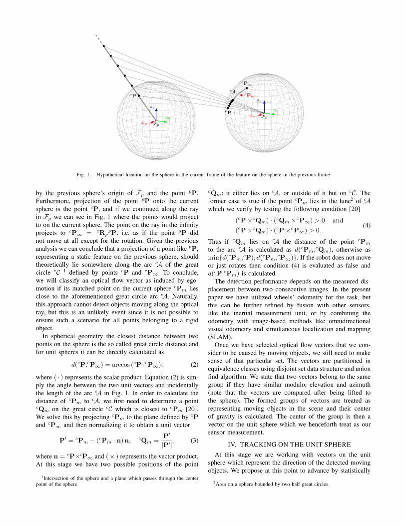
With the optical flow calculated, we need to devise aprocedure for finding the optical flow vectors caused by themoving objects. Consider Fig. 1 where we have depicteda sphere with Fp : (xp, yp, zp) coordinate system in theorigin—representing the image in the previous frame, hence-forth referred to as the previous sphere—and a second spherewith Fc : (xc, yc, zc) coordinate system in the origin—representing the image in the current frame, henceforthreferred to as the current sphere. We assume that the dis-placement between the previous and the current sphere, i.e.Fp and Fc, is known (in practice calculated from odometrymeasurements) and described by cRp and ctp accounting forthe rotation and the translation, respectively. Furthermore,the point pP in Fp represents a lifted point detected in theprevious image whose matched point in the current image,the lifted point cPm in Fc, has been determined by theoptical flow algorithm. To determine whether this opticalflow vector was induced by the moving object or the ego-motion, we will first hypothesize that the flow was due toego-motion, and then if the condition is not met we willclassify it as being caused by the moving object.
In order to achieve this task, we need to know where toexpect a static feature from the previous sphere, like pP,on the current sphere (of course without any informationabout the depth of the feature). By looking at Fig. 1 wecan assert that the point pP is projection of a feature inthe environment somewhere along the optical ray defined
Fp
Fc
xp
yp
zp
xc
yc
zc
pP
cP
cP∞
cPm
cA
Fig. 1. Hypothetical location on the sphere in the current frame of the feature on the sphere in the previous frame
by the previous sphere’s origin of Fp and the point pP.Furthermore, projection of the point pP onto the currentsphere is the point cP, and if we continued along the rayin Fp we can see in Fig. 1 where the points would projectto on the current sphere. The point on the ray in the infinityprojects to cP∞ = cRp
pP, i.e. as if the point pP didnot move at all except for the rotation. Given the previousanalysis we can conclude that a projection of a point like pP,representing a static feature on the previous sphere, shouldtheoretically lie somewhere along the arc cA of the greatcircle cC 1 defined by points cP and cP∞. To conclude,we will classify an optical flow vector as induced by ego-motion if its matched point on the current sphere cPm liesclose to the aforementioned great circle arc cA. Naturally,this approach cannot detect objects moving along the opticalray, but this is an unlikely event since it is not possible toensure such a scenario for all points belonging to a rigidobject.
In spherical geometry the closest distance between twopoints on the sphere is the so called great circle distance andfor unit spheres it can be directly calculated as
d(cP,cP∞) = arccos (cP ·cP∞), (2)
where ( · ) represents the scalar product. Equation (2) is sim-ply the angle between the two unit vectors and incidentallythe length of the arc cA in Fig. 1. In order to calculate thedistance of cPm to cA, we first need to determine a pointcQm on the great circle cC which is closest to cPm [20].We solve this by projecting cPm to the plane defined by cPand cP∞ and then normalizing it to obtain a unit vector
P′ = cPm − (cPm · n)n, cQm =P′
|P′|, (3)
where n = cP×cP∞ and (× ) represents the vector product.At this stage we have two possible positions of the point
1Intersection of the sphere and a plane which passes through the centerpoint of the sphere
cQm: it either lies on cA, or outside of it but on cC. Theformer case is true if the point cPm lies in the lune2 of cAwhich we verify by testing the following condition [20]
(cP×cQm) · (cQm ×cP∞) > 0 and
(cP×cQm) · (cP×cP∞) > 0.(4)
Thus if cQm lies on cA the distance of the point cPmto the arc cA is calculated as d(cPm,cQm), otherwise asmin{d(cPm,cP), d(cPm,
cP∞)}. If the robot does not moveor just rotates then condition (4) is evaluated as false andd(cP,cPm) is calculated.
The detection performance depends on the measured dis-placement between two consecutive images. In the presentpaper we have utilized wheels’ odometry for the task, butthis can be further refined by fusion with other sensors,like the inertial measurement unit, or by combining theodometry with image-based methods like omnidirectionalvisual odometry and simultaneous localization and mapping(SLAM).
Once we have selected optical flow vectors that we con-sider to be caused by moving objects, we still need to makesense of that particular set. The vectors are partitioned inequivalence classes using disjoint set data structure and unionfind algorithm. We state that two vectors belong to the samegroup if they have similar modulo, elevation and azimuth(note that the vectors are compared after being lifted tothe sphere). The formed groups of vectors are treated asrepresenting moving objects in the scene and their centerof gravity is calculated. The center of the group is then avector on the unit sphere which we henceforth treat as oursensor measurement.
IV. TRACKING ON THE UNIT SPHERE
At this stage we are working with vectors on the unitsphere which represent the direction of the detected movingobjects. We propose at this point to advance by statistically
2Area on a sphere bounded by two half great circles.
modeling the measured direction, i.e. to pose a probabilisticmodel of the sensor measurement, by using a directionalstatistics distribution on the unit sphere, namely the vonMises-Fisher (VMF) distribution.
In general the VMF is a distribution on a (p − 1)-dimensional sphere in Rp. In our case p = 3 and thedistribution has the following form [21]
p(x;κ,µ) =κ
4π sinhκexp
(κµTx
), (5)
where µ is the mean direction and κ is the concentrationparameter. Because (5) is symmetrical about µ, the meandirection of x is µ. For κ > 0, the distribution has a modeat the mean direction µ, whereas when κ = 0 the distributionis uniform. The larger the κ the greater the clusteringaround the mean direction. Since (5) depends on x solelythrough µTx, the VMF is rotationally symmetric about µ.Historically, the VMF first appeared in statistical mechanicsin the context of weakly interacting dipoles subjected to anexternal electric field, whose directions tend to have a VMFdistribution [21].
Furthermore, we pose the problem as an estimation ona sphere thus devising a Bayesian state estimator (tracker)based on the VMF distribution [6]. This consists of con-structing the a posteriori probability density function (pdf)of the state based on all available information. A Bayesianestimation procedure of the a posteriori pdf consists of twosteps: prediction and update [22], which in our case entailsrepresenting the state to be estimated xk at time k as theVMF distribution and successively predicting and updatingthis distribution. The prediction step involves calculating thepdf via the total probability theorem
p(xk|z1:k−1) =∫p(xk|xk−1)p(xk−1|z1:k−1) dxk−1, (6)
where p(xk|xk−1) is the probabilistic model of the stateevolution, p(xk−1|z1:k−1) is the posterior at time k− 1, andz1:k−1 are all measurements up to and including time k− 1.In our case we choose to add process noise governed by acentered VMF in the prediction stage which amounts to con-volving our posterior at time k−1 with the VMF distributionrepresenting the process noise. Given two VMF distributions,p(x;κi,µ) and p(x;κj ,µ), the result of the convolution doesnot produce another VMF distribution. However, the resultof this operation can be well approximated by a VMF withunchanged mean direction and a suitably chosen value of theresulting κ [21]
κij = A−1(A(κi)A(κj)), A(κ) =1
tanhκ− 1
κ. (7)
In the update step, the posterior at time k is calculated viathe Bayes theorem
p(xk|z1:k) =p(zk|xk)p(xk|z1:k−1)
p(zk|z1:k−1), (8)
where p(zk|xk) is the sensor model and p(zk|z1:k−1) is thenormalizer. In our case the sensor model p(zk|xk) will berepresented by a VMF where the measurement zk is the
0 5 10 15 20 25 30 35−200
−100
0
100
200
time [s]
azim
uth
[◦]
0 5 10 15 20 25 30 3550
60
70
80
90
time [s]
elev
atio
n[◦
]
measuredestimated
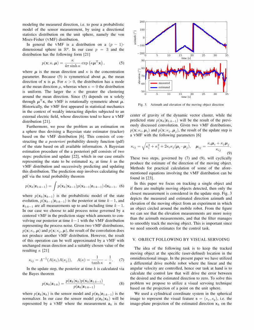
Fig. 3. Azimuth and elevation of the moving object direction
center of gravity of the dynamic vector cluster, while thepredicted state p(xk|z1:k−1) will be the result of the previ-ously discussed convolution. Given two VMF distributions,p(x;κi,µi) and p(x;κj ,µj), the result of the update step isa VMF with the following parameters [6]
κij =√κ2i + κ2j + 2κiκj(µi · µj), µij =
κiµi + κjµjκij
.
(9)These two steps, governed by (7) and (9), will cyclicallyproduce the estimate of the direction of the moving object.Methods for practical calculation of some of the afore-mentioned equations involving the VMF distribution can befound in [23].
In this paper we focus on tracking a single object andif there are multiple moving objects detected, then only theclosest measurement is considered in the update step. Fig. 3depicts the measured and estimated direction azimuth andelevation of the moving object from an experiment in whichan object circled around the mobile robot. From the figurewe can see that the elevation measurements are more noisythan the azimuth measurements, and that the filter managesto smoothly track the moving object. This is important sincewe need smooth estimates for the control task.
V. OBJECT FOLLOWING BY VISUAL SERVOING
The idea of the following task is to keep the trackedmoving object at the specific (user-defined) location in theomnidirectional image. In the present paper we have utilizeda differential drive mobile robot where the linear and theangular velocity are controlled, hence our task at hand is tocalculate the control law that will drive the error betweenthe desired and the estimated direction to zero. To solve thisproblem we propose to utilize a visual servoing techniquebased on the projection of a point on the unit sphere.
We used a cylindrical coordinate system in the sphericalimage to represent the visual feature s = (sx, sy), i.e. theimage-plane projection of the estimated direction xk on the
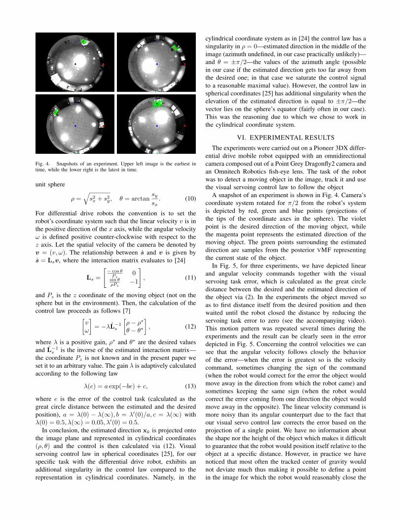
Fig. 4. Snapshots of an experiment. Upper left image is the earliest intime, while the lower right is the latest in time.
unit sphere
ρ =√s2x + s2y, θ = arctan
sysx. (10)
For differential drive robots the convention is to set therobot’s coordinate system such that the linear velocity v is inthe positive direction of the x axis, while the angular velocityω is defined positive counter-clockwise with respect to thez axis. Let the spatial velocity of the camera be denoted byv = (v, ω). The relationship between s and v is given bys = Lsv, where the interaction matrix evaluates to [24]
Ls =
[− cos θPz
0sin θρPz
−1
], (11)
and Pz is the z coordinate of the moving object (not on thesphere but in the environment). Then, the calculation of thecontrol law proceeds as follows [7][
vω
]= −λL−1s
[ρ− ρ∗θ − θ∗
], (12)
where λ is a positive gain, ρ∗ and θ∗ are the desired valuesand L−1s is the inverse of the estimated interaction matrix—the coordinate Pz is not known and in the present paper weset it to an arbitrary value. The gain λ is adaptively calculatedaccording to the following law
λ(e) = a exp(−be) + c, (13)
where e is the error of the control task (calculated as thegreat circle distance between the estimated and the desiredposition), a = λ(0) − λ(∞), b = λ′(0)/a, c = λ(∞) withλ(0) = 0.5, λ(∞) = 0.05, λ′(0) = 0.5.
In conclusion, the estimated direction xk is projected ontothe image plane and represented in cylindrical coordinates(ρ, θ) and the control is then calculated via (12). Visualservoing control law in spherical coordinates [25], for ourspecific task with the differential drive robot, exhibits anadditional singularity in the control law compared to therepresentation in cylindrical coordinates. Namely, in the
cylindrical coordinate system as in [24] the control law has asingularity in ρ = 0—estimated direction in the middle of theimage (azimuth undefined, in our case practically unlikely)—and θ = ±π/2—the values of the azimuth angle (possiblein our case if the estimated direction gets too far away fromthe desired one; in that case we saturate the control signalto a reasonable maximal value). However, the control law inspherical coordinates [25] has additional singularity when theelevation of the estimated direction is equal to ±π/2—thevector lies on the sphere’s equator (fairly often in our case).This was the reasoning due to which we chose to work inthe cylindrical coordinate system.
VI. EXPERIMENTAL RESULTS
The experiments were carried out on a Pioneer 3DX differ-ential drive mobile robot equipped with an omnidirectionalcamera composed out of a Point Grey Dragonfly2 camera andan Omnitech Robotics fish-eye lens. The task of the robotwas to detect a moving object in the image, track it and usethe visual servoing control law to follow the object
A snapshot of an experiment is shown in Fig. 4. Camera’scoordinate system rotated for π/2 from the robot’s systemis depicted by red, green and blue points (projections ofthe tips of the coordinate axes in the sphere). The violetpoint is the desired direction of the moving object, whilethe magenta point represents the estimated direction of themoving object. The green points surrounding the estimateddirection are samples from the posterior VMF representingthe current state of the object.
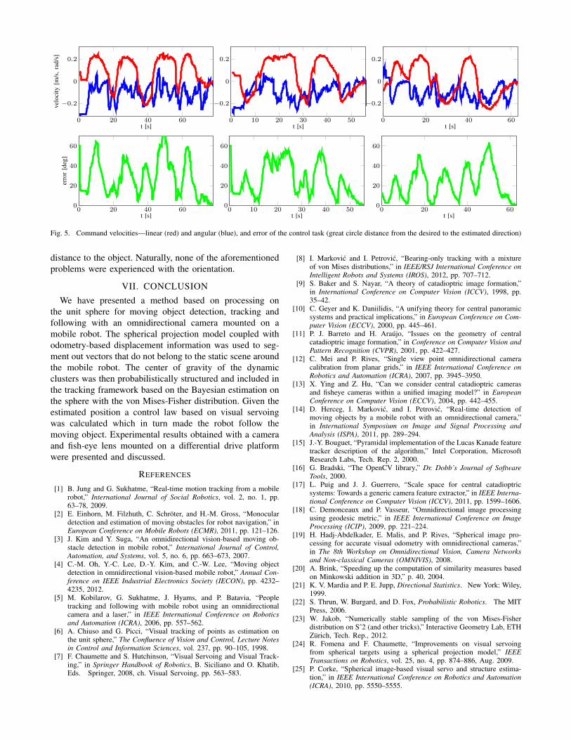
In Fig. 5, for three experiments, we have depicted linearand angular velocity commands together with the visualservoing task error, which is calculated as the great circledistance between the desired and the estimated direction ofthe object via (2). In the experiments the object moved soas to first distance itself from the desired position and thenwaited until the robot closed the distance by reducing theservoing task error to zero (see the accompanying video).This motion pattern was repeated several times during theexperiments and the result can be clearly seen in the errordepicted in Fig. 5. Concerning the control velocities we cansee that the angular velocity follows closely the behaviorof the error—when the error is greatest so is the velocitycommand, sometimes changing the sign of the command(when the robot would correct for the error the object wouldmove away in the direction from which the robot came) andsometimes keeping the same sign (when the robot wouldcorrect the error coming from one direction the object wouldmove away in the opposite). The linear velocity command ismore noisy than its angular counterpart due to the fact thatour visual servo control law corrects the error based on theprojection of a single point. We have no information aboutthe shape nor the height of the object which makes it difficultto guarantee that the robot would position itself relative to theobject at a specific distance. However, in practice we havenoticed that most often the tracked center of gravity wouldnot deviate much thus making it possible to define a pointin the image for which the robot would reasonably close the
0 10 20 30 40 50
−0.2
0
0.2
t [s]0 20 40 60
−0.2
0
0.2
t [s]
velo
city
[m/s
,rad
/s]
0 20 40 600
20
40
60
t [s]
erro
r[d
eg]
0 10 20 30 40 500
20
40
60
t [s]0 20 40 60
0
20
40
60
t [s]
0 20 40 60
−0.2
0
0.2
t [s]
Fig. 5. Command velocities—linear (red) and angular (blue), and error of the control task (great circle distance from the desired to the estimated direction)
distance to the object. Naturally, none of the aforementionedproblems were experienced with the orientation.
VII. CONCLUSION
We have presented a method based on processing onthe unit sphere for moving object detection, tracking andfollowing with an omnidirectional camera mounted on amobile robot. The spherical projection model coupled withodometry-based displacement information was used to seg-ment out vectors that do not belong to the static scene aroundthe mobile robot. The center of gravity of the dynamicclusters was then probabilistically structured and included inthe tracking framework based on the Bayesian estimation onthe sphere with the von Mises-Fisher distribution. Given theestimated position a control law based on visual servoingwas calculated which in turn made the robot follow themoving object. Experimental results obtained with a cameraand fish-eye lens mounted on a differential drive platformwere presented and discussed.
REFERENCES
[1] B. Jung and G. Sukhatme, “Real-time motion tracking from a mobilerobot,” International Journal of Social Robotics, vol. 2, no. 1, pp.63–78, 2009.
[2] E. Einhorn, M. Filzhuth, C. Schroter, and H.-M. Gross, “Monoculardetection and estimation of moving obstacles for robot navigation,” inEuropean Conference on Mobile Robots (ECMR), 2011, pp. 121–126.
[3] J. Kim and Y. Suga, “An omnidirectional vision-based moving ob-stacle detection in mobile robot,” International Journal of Control,Automation, and Systems, vol. 5, no. 6, pp. 663–673, 2007.
[4] C.-M. Oh, Y.-C. Lee, D.-Y. Kim, and C.-W. Lee, “Moving objectdetection in omnidirectional vision-based mobile robot,” Annual Con-ference on IEEE Industrial Electronics Society (IECON), pp. 4232–4235, 2012.
[5] M. Kobilarov, G. Sukhatme, J. Hyams, and P. Batavia, “Peopletracking and following with mobile robot using an omnidirectionalcamera and a laser,” in IEEE International Conference on Roboticsand Automation (ICRA), 2006, pp. 557–562.
[6] A. Chiuso and G. Picci, “Visual tracking of points as estimation onthe unit sphere,” The Confluence of Vision and Control, Lecture Notesin Control and Information Sciences, vol. 237, pp. 90–105, 1998.
[7] F. Chaumette and S. Hutchinson, “Visual Servoing and Visual Track-ing,” in Springer Handbook of Robotics, B. Siciliano and O. Khatib,Eds. Springer, 2008, ch. Visual Servoing, pp. 563–583.
[8] I. Markovic and I. Petrovic, “Bearing-only tracking with a mixtureof von Mises distributions,” in IEEE/RSJ International Conference onIntelligent Robots and Systems (IROS), 2012, pp. 707–712.
[9] S. Baker and S. Nayar, “A theory of catadioptric image formation,”in International Conference on Computer Vision (ICCV), 1998, pp.35–42.
[10] C. Geyer and K. Daniilidis, “A unifying theory for central panoramicsystems and practical implications,” in European Conference on Com-puter Vision (ECCV), 2000, pp. 445–461.
[11] P. J. Barreto and H. Araujo, “Issues on the geometry of centralcatadioptric image formation,” in Conference on Computer Vision andPattern Recognition (CVPR), 2001, pp. 422–427.
[12] C. Mei and P. Rives, “Single view point omnidirectional cameracalibration from planar grids,” in IEEE International Conference onRobotics and Automation (ICRA), 2007, pp. 3945–3950.
[13] X. Ying and Z. Hu, “Can we consider central catadioptric camerasand fisheye cameras within a unified imaging model?” in EuropeanConference on Computer Vision (ECCV), 2004, pp. 442–455.
[14] D. Herceg, I. Markovic, and I. Petrovic, “Real-time detection ofmoving objects by a mobile robot with an omnidirectional camera,”in International Symposium on Image and Signal Processing andAnalysis (ISPA), 2011, pp. 289–294.
[15] J.-Y. Bouguet, “Pyramidal implementation of the Lucas Kanade featuretracker description of the algorithm,” Intel Corporation, MicrosoftResearch Labs, Tech. Rep. 2, 2000.
[16] G. Bradski, “The OpenCV library,” Dr. Dobb’s Journal of SoftwareTools, 2000.
[17] L. Puig and J. J. Guerrero, “Scale space for central catadioptricsystems: Towards a generic camera feature extractor,” in IEEE Interna-tional Conference on Computer Vision (ICCV), 2011, pp. 1599–1606.
[18] C. Demonceaux and P. Vasseur, “Omnidirectional image processingusing geodesic metric,” in IEEE International Conference on ImageProcessing (ICIP), 2009, pp. 221–224.
[19] H. Hadj-Abdelkader, E. Malis, and P. Rives, “Spherical image pro-cessing for accurate visual odometry with omnidirectional cameras,”in The 8th Workshop on Omnidirectional Vision, Camera Networksand Non-classical Cameras (OMNIVIS), 2008.
[20] A. Brink, “Speeding up the computation of similarity measures basedon Minkowski addition in 3D,” p. 40, 2004.
[21] K. V. Mardia and P. E. Jupp, Directional Statistics. New York: Wiley,1999.
[22] S. Thrun, W. Burgard, and D. Fox, Probabilistic Robotics. The MITPress, 2006.
[23] W. Jakob, “Numerically stable sampling of the von Mises-Fisherdistribution on Sˆ2 (and other tricks),” Interactive Geometry Lab, ETHZurich, Tech. Rep., 2012.
[24] R. Fomena and F. Chaumette, “Improvements on visual servoingfrom spherical targets using a spherical projection model,” IEEETransactions on Robotics, vol. 25, no. 4, pp. 874–886, Aug. 2009.
[25] P. Corke, “Spherical image-based visual servo and structure estima-tion,” in IEEE International Conference on Robotics and Automation(ICRA), 2010, pp. 5550–5555.
Related Documents
