Louisiana State University LSU Digital Commons LSU Master's eses Graduate School 2015 Motion Analysis of Biotin Carboxylase-Driven Robotic Nano-swimmers Sima Hannani Louisiana State University and Agricultural and Mechanical College, [email protected] Follow this and additional works at: hps://digitalcommons.lsu.edu/gradschool_theses Part of the Civil and Environmental Engineering Commons is esis is brought to you for free and open access by the Graduate School at LSU Digital Commons. It has been accepted for inclusion in LSU Master's eses by an authorized graduate school editor of LSU Digital Commons. For more information, please contact [email protected]. Recommended Citation Hannani, Sima, "Motion Analysis of Biotin Carboxylase-Driven Robotic Nano-swimmers" (2015). LSU Master's eses. 2803. hps://digitalcommons.lsu.edu/gradschool_theses/2803

Welcome message from author
This document is posted to help you gain knowledge. Please leave a comment to let me know what you think about it! Share it to your friends and learn new things together.
Transcript

Louisiana State UniversityLSU Digital Commons
LSU Master's Theses Graduate School
2015
Motion Analysis of Biotin Carboxylase-DrivenRobotic Nano-swimmersSima HannaniLouisiana State University and Agricultural and Mechanical College, [email protected]
Follow this and additional works at: https://digitalcommons.lsu.edu/gradschool_theses
Part of the Civil and Environmental Engineering Commons
This Thesis is brought to you for free and open access by the Graduate School at LSU Digital Commons. It has been accepted for inclusion in LSUMaster's Theses by an authorized graduate school editor of LSU Digital Commons. For more information, please contact [email protected].
Recommended CitationHannani, Sima, "Motion Analysis of Biotin Carboxylase-Driven Robotic Nano-swimmers" (2015). LSU Master's Theses. 2803.https://digitalcommons.lsu.edu/gradschool_theses/2803
MOTION ANALYSIS OF BIOTIN CARBOXYLASE-DRIVEN ROBOTIC NANO-
SWIMMERS
A Thesis
Submitted to the Graduate Faculty of the
Louisiana State University and
Agricultural and Mechanical College
in partial fulfillment of the
requirements for the degree of
Master of Science in Civil Engineering
in
The Department of Civil Engineering
by
Sima Hannani
B.S., Islamic Azad University-North Branch of Tehran, 2009
May 2015

ii
ACKNOWLEDGEMENTS
First of all I want to thank Dr. Marcio de Queiroz for his support and guidance and for
giving me the opportunity to work on the presented project which I truly enjoyed and learned a
lot from it.
I would truly like to thank Dr. Ronald Malone for his vast support and encouragement
during the last three years. Thank you so much for everything you have done for me, I could not
achieve this degree without your support.
I also want to thank Dr. Dorel Moldovan, Dr. Hongliang Zhang, and Dr. Grover Waldrop
for their help and support during the last one and half years.
I specifically want to thank Dr. Varshni Singh, this work could not be done without your
assistance. Also thanks to Dr. Amar Kumbhar at CHANL facility of UNC Chapel Hill, NC.
Thanks to all my friends, Alexandra Evans, Ram Prasad, Anoosha Forghani, Maryam
Foroozani, Aryan Geraili Nejadfomeshi, and Daniel Alt for their support.
Thanks to Ms. Sandy Malone who has always encouraged me and supported me during
the rough times.
Thanks to my amazing mom Mitra Meftahi, and my wonderful dad, Mohammad Hannani
and thanks to my lovely sister Sara Hannani. I cannot live a day without your love.
Finally thanks to the most amazing husband in the world, Amir Shadkam, for his
unconditional love and support and for being with me through my ups and downs. I am blessed
to have you in my life.
At the end I would like to acknowledge the support of Center for Advanced
Microstructures and Devices at Louisiana State University.
iii
TABLE OF CONTENTS
ACKNOWLEDGEMENTS……………………………………….……….……………..ii
ABSTRACT ……………….……………………………………………….…………….v
CHAPTER 1 INTRODUCTION ...................................................................................... 1
1.1 Motivation ............................................................................................................. 1
1.2 Statement of Work and Thesis Organization ........................................................ 2
1.3 Background Information ....................................................................................... 3
1.3.1 Biotin Carboxylase .......................................................................................... 3
1.3.2 The Theory of Brownian Motion .................................................................... 5
1.4 Literature Review .................................................................................................. 8
1.4.1 Janus Particles ................................................................................................. 8
1.4.2 Biomolecular Motors..................................................................................... 10
CHAPTER 2 NANO-SWIMMER FABRICATION ..................................................... 13
2.1 Materials and Main Equipment ........................................................................... 13
2.2 Janus Particle Preparation ................................................................................... 15
2.2.1 Particle Cleaning Procedure .......................................................................... 15
2.2.2 Wafer Preparation ......................................................................................... 20
2.2.3 Coating the Nano-Particles............................................................................ 23
2.3 Addition of BC to Nanoparticles ......................................................................... 28
CHAPTER 3 NANO-SWIMMER EXPERIMENTATION .......................................... 32
3.1 Experimental Setup ............................................................................................. 32
3.2 Experimental Controls......................................................................................... 33
3.3 Experimental Protocol ......................................................................................... 34
3.4 Analysis and Results ........................................................................................... 34
3.4.1 Translational Diffusion Analysis .................................................................. 36
3.4.2 Directional Diffusion Analysis...................................................................... 41
CHAPTER 4 CONCLUSIONS AND RECOMMENDATIONS FOR FUTURE
WORK…………………………………...……………………………...46
4.1 Conclusions ......................................................................................................... 46
4.2 Recommendations for Future Work .................................................................... 46

iv
REFERENCES……………………………………………………………………….…48
VITA……………………………………….……………………………………………51

v
ABSTRACT
The purpose of this study is to experimentally validate the hypothesis that the enzyme
biotin carboxylase (BC) can behave as a bimolecular motor and propel nano-scale particles in
fluidic environments. This hypothesis was proposed in the M.S. thesis “Toward the Development
of Biotin Carboxylase Driven Robotic Nano-swimmer” by Rachel Yates (Yates, 2012). In
(Yates, 2012), the nano-particle (called a nano-swimmer) is a Janus particle with BC molecules
attached to one hemisphere. The idea is that in the presence of its substrates (i.e., fuel) BC will
cause individual nano-particles to undergo non-Brownian motion by virtue of its conformational
change.
In order to validate the stated hypothesis, the first step of the present study was to
reproduce the nano-swimmer fabrication process introduced in (Yates, 2012) and make
necessary improvements. The second step was to analyze the motion of the nano-swimmer in
comparison with the control experiments. This step involved developing an experimental setup
for tracking individual nano-particles and recording their motion, followed by analyzing the
motion of the particles to determine if they are Brownian or not.
Translational and directional diffusion methods were used to analyze the motion of the
controls and nano-swimmer. In the translational diffusion method, the experimental mean square
displacement versus time data was plotted. The slope of the linear fit of the plot for the nano-
swimmers was approximately 1.5, which is an indication of non-Brownian motion. The slope for
controls was approximately 1, which is expected for Brownian motion. In the directional
diffusion method, the histogram of the directional diffusion angle was generated for both nano-
swimmer and controls. The histograms showed that the nano-swimmers were more likely to have
small directional diffusion (i.e., difference between the current and previous heading angles was

vi
small) when compared to controls. The overall results of both analyses provide strong indications
that the nano-swimmers have non-Brownian motion.
1
CHAPTER 1 INTRODUCTION
1.1 Motivation
The development of nano-machines has become an important topic of research in recent
years because they can be used in broad areas of science and technology. The term “nano-
machine” refers to the integration of biological molecules with chemical, mechanical, electrical,
magnetic, and/or optical components to form a nano-scale system that converts chemical energy
to mechanical work and then harnesses this mechanical work for a particular purpose (Yates,
2012). For instance, nano-machines can potentially be used in drug delivery systems for cancer
treatment. In particular, they can transport the drug to defeat a tumor in a specific location in the
body without harming other parts of the body and with fewer side effects (Ghalanbor, Marashi,
& Rangbar, 2005). Cleaning out clogged arteries, destroying toxic pollutants, and acting as ultra-
sensitive disease markers are some other potential applications for nano-machines (Wang, 2009).
“The development of this technology would enable a new generation of devices with several
advantages over micro-scale systems in terms of performance, size, power consumption,
efficiency, and ease of fabrication” (Yates, 2012).
Biomolecular motors are the key component of nano-machines since they serve as
actuators, converting chemical energy to mechanical work. In nature, many living organisms use
molecular motors for functions such as cell division and cell shape maintenance (Keller, 2000).
The discovery and engineering of biomolecular motors is of great interest to biotechnology
researches (Hiratsuka, 2006). A literature review of biomolecular motors is provided in Section
1.4.

2
1.2 Statement of Work and Thesis Organization
The goal of this study is to test the hypothesis that a nano-scale, Janus-like particle that
uses the enzyme biotin carboxylase (BC) as biomolecular motor will undergo non-Brownian
motion in a fluidic environment. The biomolecular machine, which is referred to as a nano-
swimmer (Yates, 2012), is schematically illustrated in Figure 1-1. The idea is that the nano-
swimmer will be propelled in the direction perpendicular to the plane of its hemisphere by the
conformational change of the BC molecules. BC is a nano-scale enzyme involved in the
metabolism of carbohydrates, fatty acids, and amino acids in all organisms such as animals,
plants, fungi, and bacteria (Tong, 2013).
This work involved the following three steps:
1. Fabrication of the nano-swimmers according to the method proposed in (Yates, 2012).
2. Development of an experimental set up and protocol for testing the hypothesis.
3. Analyses of the experimental data to this discern if the motion is Brownian or non-
Brownian.
Figure 1-1. Schematic depiction of the nano-swimmer (Yates, 2012).

3
The thesis is organized as follows. The reminder of Chapter 1 contains background
information about the enzyme BC and the theory of Brownian motion, followed by a literature
review of biomolecular motors.
Chapter 1 contains background information about the enzyme BC and the theory of Brownian
motion, followed by a literature review of biomolecular motors. Chapter 2 explains the nano-
swimmer fabrication process. Chapter 3 describes the nano-swimmer experimental set up and
presents the results of the motion analysis. Finally, conclusions and suggestions for future works
are provided in Chapter 4.
1.3 Background Information
1.3.1 Biotin Carboxylase
Biotin Carboxylase (BC) is one of the components of Acetyl CoA Carboxylase (ACC).
ACC is highly involved in fatty acid synthesis, and can be found in animals, plants, bacteria,
fungi, etc. ACC utilizes the reaction in two steps:
BC enzyme-biotin + Mg-ATP +
↔ enzyme-biotin- + MgADP + Pi (1)
enzyme-biotin- + acetyl-coA ↔ malonyl-CoA +enzyme-biotin (2)
Reaction (1), which is catalyzed by BC, is ATP dependent carboxylation of the vitamin biotin.
BC substrates are bicarbonate, ATP, and biotin. In reaction (2) the carboxyl group is transferred
to acetyl coenzyme A (acetyl-CoA) to make malonyl-CoA (Broussard, 2013) (Blanchard, Lee,
Frantom, & Waldrop, 1999). BC utilizes three substrates: ATP, biotin, and bicarbonate.
Availability of the structural information of Escherichia coli (E-coli) makes it an ideal
model to demonstrate the 3 dimensional (3D) structure of ACC (Cronan & Waldrop, 2002). In E-

4
coli, ACC is made of three polypeptide chains which are referred to as Biotin Carboxylase (BC),
Biotin Carboxyl Carrier Protein (BCCP) and Carboxyltransferase (CT) (Thoden, 2000). When
isolated from other components, BC from E-coli can retain its enzymatic activity. This
characteristic of BC makes it a great model for mechanistic studies. BC can also use free biotin
as substrate (Broussard, 2013). The crystallographic of BC confirmed that BC is a homodimer
which means it consists of two identical subunits; see Figure 1-2 (a). Each subunit (monomer) of
BC is approximately 6.7 nm × 5.2 nm × 4.8 nm and is consisted of 3 domains: A, B and C as
shown in Figure 1-2 (b). (Broussard, 2013) (Thoden, 2000) (Thoden J. B., et al., 1969) (Yates,
2012).
Figure 1-2. BC structure: (a) dimer and (b) detailed view of monomer (Yates, 2012).
One of the characteristics of BC which makes it a candidate to serve as biomolecular motor is
that when ATP binds with BC, it goes through a large conformational change, which means a
hinge-like rotation of one domain (B domain) relative to other domains (A and C domains)
with frequency of 2 Hz (Thoden, Blanchard, Holden, & Waldrop, 2000) (Yates, 2012).
Other than large conformational change of BC, there are some other characteristics that make
BC a proper candidate for biomolecular machine fabrication. Gene coding and overexpression of
BC enzyme has been done before which means BC can be produced in large quantities
Active site
Active site
B domain
A domain
C domain
Hinge axis
45o
(a)
5
(Broussard, 2013) (Blanchard, Lee, Frantom, & Waldrop, 1999). Previously, to separate the wild
type of BC from the mutant form, Blanchard et al., used poly-histidine tag (Blanchard, Lee,
Frantom, & Waldrop, 1999). Poly-histidine tag consists of at least six histidine residues fused to
N- or C-terminal ends of the enzyme BC (Hayworth). Histidine tag can interact with nickel.
Therefore, the histidine tag connects the BC to the nickel. Histidine tagged wild type BC has the
potential to be used as the motor for the nano-swimmer which consists of a Janus particle half-
coated with nickel with BC enzyme attached to the nickel.
1.3.2 The Theory of Brownian Motion
Brownian motion is the name given to the random movement of small objects in a fluidic
environment. It is caused when molecules of water (or any other solution) randomly collide with
the objects (Radenovic). The discovery of this phenomenon is credited to Robert Brown as a
result of his observations of how pollen behaves in water in 1827 (Powles, 1827). In 1905 Albert
Einstein quantitatively analyzed the Brownian motion phenomenon (Einstein, 1905). Einstein
proved that the mean square displacement (MSD) of a spherical particle is proportional to time
(with the proportionality constant being related to the diffusion coefficient) when Brownian
motion is present (Gora, 2006).
A conceptual explanation of Brownian motion can be found in (Bhalerao, 2004). There
are a number of important characteristics in Brownian motion (Perrin & Fredrick, 1910):
1. The motion is rotational and irregular.
2. Particles move independently.
3. As the particle size decreases, the motion becomes more active.
4. Density and composition of the particles have no effect on the motion.
5. As the viscosity of the fluid decreases, the motion becomes more active.

6
6. As temperature increases, motion becomes more active.
7. The motion never stops.
In this thesis, two different methods used to analyze Brownian motion from experimental
data. These methods are introduced next.
Method One: Translational Diffusion
This method is based directly on Einstein’s theory (Einstein, 1905). Let the discretized,
two dimensional (2D) position of particle i at time t be given by
( ) [ ( ) ( )
] 1–1
where are the time samples and is the sampling period. The particle displacement
relative to its position at some initial time is given by
( ) ( ) ( ) 1–2
Consider that N spherical particles are being tracked. The MSD of all particles is defined as
( )
∑ ( )
1–3
where |.| is the Euclidean norm. Einstein showed that if the 2D motion of particles is Brownian,
then the following relationship holds (Einstein, 1905)
( ) (
) 1–4
where K is the Boltzmann’s constant, T is the absolute temperature of the fluid, is the viscosity
of the liquid, r is the particle radius, and
is the translational diffusion coefficient for a

7
spherical particle. That is, a plot of MSD calculated from measured data, versus time is linear if
the motion is Brownian.
Method Two: Directional Diffusion
In this method, the 2D directional diffusion of the particle motion is analyzed rather than
its translation. To this end, let the displacement of particle i between two consecutive time
samples be defined as
( ) [ ( ) ( )
] [ ( ) (( ) )
( ) (( ) )] 1–5
for k = 1, 2,… and i = 1,2,…,N. Figure 1-2 illustrates the displacement vector in Equation 1-6
along with two angles related to the change in the particle’s direction at each time sample. The
angle ( ) is measured relative to the positive x-axis and is defined by
( ) ( ( ) ( )) 1–6
The angle ( ) is measured relative to the directional axis at (i.e., the direction of the
displacement vector ( )) and is defined as follows
( ) ( ) ( ). 1–7
When ( ) , the particle does not change direction. When ( ) ( , resp.), the
particle moves to the left (right, resp.) of the directional axis. When ( ) , the particle
moves backwards along the directional axis. Thus, the angle should be in the interval (-π, π]. To
this end, the following adjustment was made to the values calculated from Equation 1-7
If ( ) then ( ) ( )
If ( ) then ( ) ( ) 1–8

8
Otherwise, leave angle value as is.
In this method, the directional angel ( ) for each particle i = 1,…,N are calculated for
k = 1, 2,…, and a histogram of all the angle values is created. If the angle
distribution is approximately flat, showing no directional preference, the motion is Brownian. If
the distribution shows preference for small angles, the motion is non-Brownian.
Figure 1-2. Displacement vectors and directional angles. Blue dot indicates the particles
position at different time samples.
1.4 Literature Review
1.4.1 Janus Particles
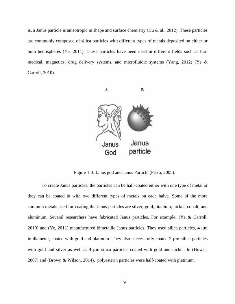
P. G. de Gennes, winner of the Nobel Prize in 1991, was the first to use the name
“Janus”, meaning two back-to-back heads in Roman gods (Figure 1-3). This terminology
gradually became more common in colloidal particle research. Specifically, Janus is used to
describe particles whose hemisphere surfaces are chemically different (Perro, et al., 2005). That
9
is, a Janus particle is anisotropic in shape and surface chemistry (Hu & al., 2012). These particles
are commonly composed of silica particles with different types of metals deposited on either or
both hemispheres (Ye, 2011). These particles have been used in different fields such as bio-
medical, magnetics, drug delivery systems, and microfluidic systems (Yang, 2012) (Ye &
Carroll, 2010).
Figure 1-3. Janus god and Janus Particle (Perro, 2005).
To create Janus particles, the particles can be half-coated either with one type of metal or
they can be coated in with two different types of metals on each halve. Some of the more
common metals used for coating the Janus particles are silver, gold, titanium, nickel, cobalt, and
aluminum. Several researchers have fabricated Janus particles. For example, (Ye & Carroll,
2010) and (Ye, 2011) manufactured bimetallic Janus particles. They used silica particles, 4
in diameter, coated with gold and platinum. They also successfully coated 2 silica particles
with gold and silver as well as 4 silica particles coated with gold and nickel. In (Howse,
2007) and (Brown & Wilson, 2014), polyesterin particles were half-coated with platinum.

10
1.4.2 Biomolecular Motors
Different types of proteins such as ATP synthase, myosin, kinesin, and dynin have been
widely used as bimolecular motors to produce motion (Yates, 2012). ATP synthase is a
ubiquitous protein machine which produces energy in all living cells. ATP synthase is composed
of two sectors: and . These sectors act as rotary stepper motors (Borsch, 2013) (Lu, Lill, &
Bald, 2014). These bimolecular motors have been into the interest not only due to their
micro/nano-scale size, but also because of their efficiency in converting the chemical energy to
mechanical motion (Behkam & Metin, 2007). The high energy is created due to the hydrolyzing
of the phosphate bond in ATP, which yields ADP and phosphate (Schmidt & Montemagno,
2004). Ricky Soong and Carlo D. Montemagno have successfully fabricated an organic-
inorganic nano-machine which is powered by -ATP synthase (Soong & Montemagno, 2005).
Other protein motors such as myosin, kinesin and dynein are also commonly used as nano-
motors. Conventional kinesin and muscle myosin are often used in nano-machine fabrication due
to their ability of generating force (Agarwal & Hess, 2010). Another interesting bimolecular
motor is bacteria flagella. Different types of bacteria use flagella to swim. Flagella can function
as a rotary machine which makes it a proper candidate as bimolecular motors (Terashima & al.,
2006). In their study Bahareh Behkam and Metin Sittia, used flagella motors inside bacteria
named Serratia marcescens as their swimming robot (Behkam & Metin, 2007).
An alternative to biomolecular motors is chemical motors which can be used in nano-
machine fabrication. Chemical motors generate force based on chemical reactions to propel
small devices. In other words, chemical motors convert chemical energy to useful mechanical
work. One of the common examples is the use of half-coated particles with platinum in hydrogen
peroxide solution (Howse, 2007). Walter F. Paxton, et al. used 1 micrometer long, 370 nm in

11
diameter, gold and platinum rad shape particles. The particles move in anon-Brownian manner in
2% and 3% hydrogen peroxide solution by catalyzing the formation of in platinum side of the
particles (Paxton, 2004).
Exceptional properties of BC have overcome using other types of motors for the
proposed nano-swimmer in this study. Among all bimolecular motors, -ATPase has been the
most studied. -ATPase is similar to BC in biochemical aspect but its structure is more
complicated than BC which means -ATPase needs three subunits to function properly but BC
requires only one subunit to be active. Besides, addition of histidine tag to -ATPase affects its
enzyme activity. But with BC, adding the histidine tag does not affect the enzymes activity
(Ekuni, 1998). Although biomolecules such as myosin and kinesin are commonly used in nano-
machine fabrication, they require large protein complexes to function properly. Therefore, the
size of the protein would be larger than the nano-machine which is not in interest of nano-scale
applications (Yates, 2012) (Schmidt & Montemagno, 2004). Bacteria flagella can be used as
bimolecular motor, but there are some limitations that need to be considered. The size of the
flagella is in micro scales; therefore it cannot be used in nano-scale machines. Besides, Flagella
motors cannot function out of the bacteria cell which is a disadvantage. Hence, flagella motors
are not qualified to be used as motors for the purpose of this study (Yates, 2012).
Although chemically propelled motors are commonly used as biomotors, these
chemically propelled motors can only operate in synthetic environments. Therefore, they are not
a proper choice for some specific purposes such as biomedical applications (Wang, 2009).
A method for fabricating BC-driven nano-swimmers was proposed in (Yates, 2012). BC
was successfully attached to the nickel-coated hemisphere of 500 nm silica particles. The
location and orientation of the enzymes on the coated half of the particles were statistically

12
modeled. The theoretical study predicted that BC would be able to convert chemical energy into
non-Brownian motion of the nano-swimmers.

13
CHAPTER 2 NANO-SWIMMER FABRICATION
This chapter describes the two-step process for fabricating the nano-swimmers. The first
step involved coating half of the nanoparticles with nickel to create an asymmetry (i.e., a Janus
particle). The second step involved attaching the BC molecules to the nickel-coated hemisphere
of the particle.
Fabrication of the nano-particles was done at the LSU Center for Advanced
Manufacturing (CAMD) and at Chapel Hill Analytical and Nanofabrication Laboratory
(CHANL) facility of the University of North Carolina (UNC). All the preparatory procedures
were done in a clean room to reduce the risk of contamination.
2.1 Materials and Main Equipment
The nano-particles used in this study were 492 nm Fluorescent-Green SiO2 silica nano-
spheres (product line C-SIO-G0.5) (Microspheres-Nanospheres, 2003-2011). The density of the
silica particles is 1.96 g/ . The particles are embedded with fluorescein isothiocyanate dye
with excitation wavelength of 495 nm. The emission wavelength is 510 nm. The purpose of
purchasing the fluorescent particles was to enable tracking of the nanoparticles with a micro-
particle image velocimetry system. However, a Nikon microscope, which does not require the
fluorescent dye, was eventually used to track the nano-particles. Figure 2-1 shows a sample
image of the plain 492 nm silica nano-particles.

14
Figure 2-1. SEM image of 492 nm plain silica particles deposited on a silicon wafer.
Scanning Electron Microscopy (SEM) was used to capture images of the nano-particles.
CAMD’s SEM is a Hitachi S-4500 II cold field emission SEM with EDAX. The SEM uses high-
energy electrons to scan the particle’s surface.
Transmission Electron Microscopy (TEM) was also used to take high resolution images
of the nano-particles. The TEM that was used is a JEOL 2010 F-FasTEM which is a High-
Resolution Transmission Electron Microscopy (HRTEM) with a zirconated tungsten thermal
field emission tip, and is located at the UNC CHANL facility. The TEM is also equipped with a
2k x 2k Gatan CCD bottom mount camera. All the measurements were performed at an
accelerating voltage of 200kV and in bright field mode.
The sputter deposition technique which is a type of vapor deposition (PVD) was used to
coat the nano-particles with nickel. In sputtering, the target material (in this case, nickel) is
ejected onto a substrate (silicon wafer) in a vacuum chamber. In this technique, the target is
bombarded by high energy particles. The momentum transferred from high energy particles to
target surface would cause the surface atoms to escape. These atoms can then travel to substrate
15
creating a thin layer of metal coating (Kurt J. Lesker Company, 1954). The PVD 75 Sputter
System at the UNC CHANL facility was used.
2.2 Janus Particle Preparation
2.2.1 Particle Cleaning Procedure
10 ml bottle of 492 nm particles solution was used for this experiment. The particles were
suspended in distilled water with concentration of 25 mg/ml. In (Yates, 2012), it was suggested
to wash the nano-particles with hydrochloric acid (HCl) before coating them specifically, 1 ml of
the nano-particle solution was suspended in 200 ml of 2 N HCl and sonicated for 1 hour. The
next step was to let the beaker sit until the particles settled to the bottom of the beaker. Then,
HCl was decanted and the beaker was refilled with distilled water. The particles were settled
again. The pH level of the particle solution was then measured with a probe. This process was
repeated until the pH level was equal to that of distilled water. Finally, the excess water was
taken out and the concentrated particle solution was stored in a glass container to be later coated.
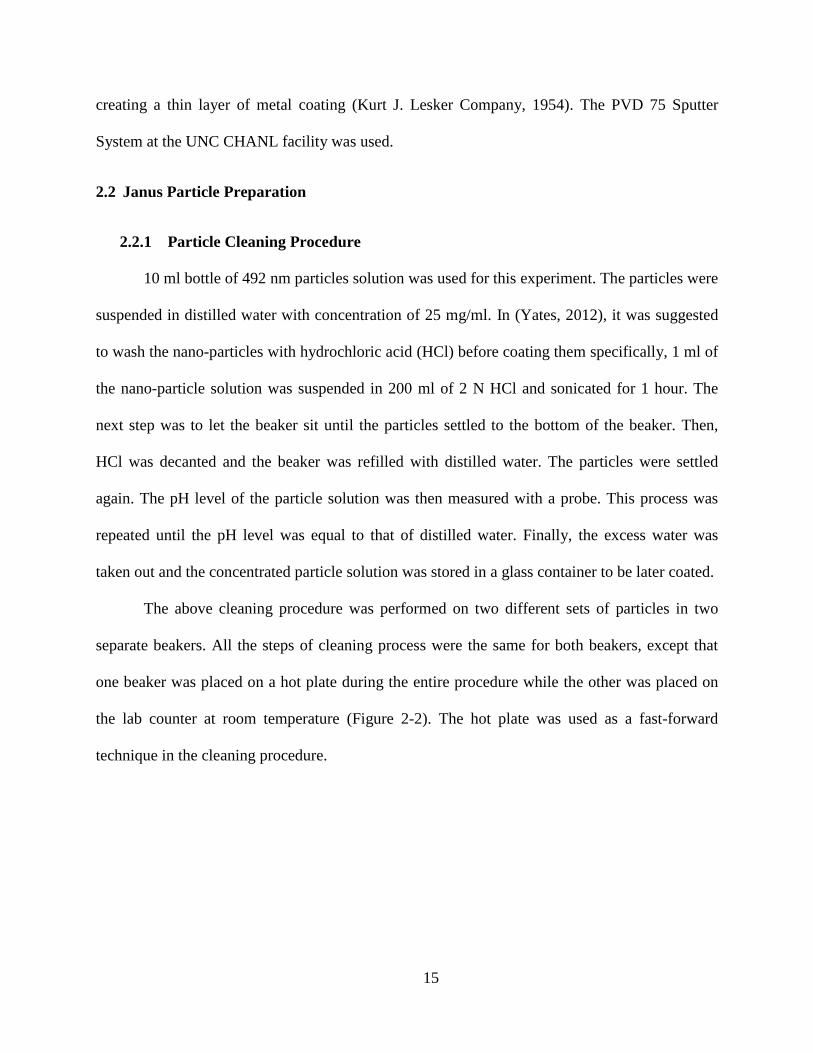
The above cleaning procedure was performed on two different sets of particles in two
separate beakers. All the steps of cleaning process were the same for both beakers, except that
one beaker was placed on a hot plate during the entire procedure while the other was placed on
the lab counter at room temperature (Figure 2-2). The hot plate was used as a fast-forward
technique in the cleaning procedure.
16
Figure 2-2. Cleaning procedure of two sets of particles with and without hot plate (hot
plate was used to increse the cleaning process speed, but the effect was unknown).
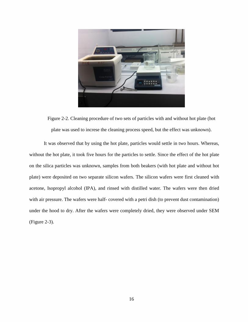
It was observed that by using the hot plate, particles would settle in two hours. Whereas,
without the hot plate, it took five hours for the particles to settle. Since the effect of the hot plate
on the silica particles was unknown, samples from both beakers (with hot plate and without hot
plate) were deposited on two separate silicon wafers. The silicon wafers were first cleaned with
acetone, Isopropyl alcohol (IPA), and rinsed with distilled water. The wafers were then dried
with air pressure. The wafers were half- covered with a petri dish (to prevent dust contamination)
under the hood to dry. After the wafers were completely dried, they were observed under SEM
(Figure 2-3).

17
Figure 2-3. Particles deposited on silicon wafer to be observed under SEM.
Figure 2-4 and Figure 2-5 show the SEM images from the hot plate and room
temperature processes, respectively. It was observed that when the particles are exposed to the
hot plate, they tend to cluster. On the other hand, the particles that were dried at room
temperature are more evenly distributed on the wafer.
Based on this experiment, the use of the hot plate in particle cleaning and drying process
was not recommended.

18
Figure 2-4. SEM image of particles cleaned on the hot plate showing particle clustering.
Figure 2-5. SEM image of particles cleaned without the hot plate showing a more evenly
distribution of particles.
Clusters
19
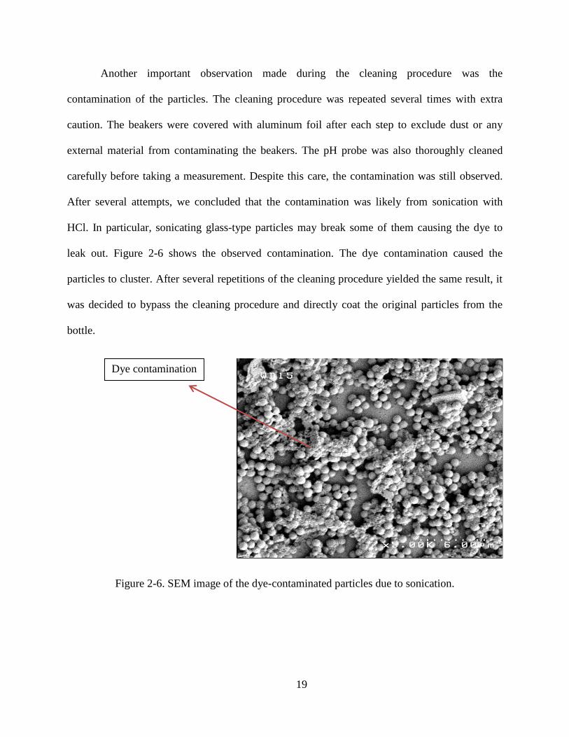
Another important observation made during the cleaning procedure was the
contamination of the particles. The cleaning procedure was repeated several times with extra
caution. The beakers were covered with aluminum foil after each step to exclude dust or any
external material from contaminating the beakers. The pH probe was also thoroughly cleaned
carefully before taking a measurement. Despite this care, the contamination was still observed.
After several attempts, we concluded that the contamination was likely from sonication with
HCl. In particular, sonicating glass-type particles may break some of them causing the dye to
leak out. Figure 2-6 shows the observed contamination. The dye contamination caused the
particles to cluster. After several repetitions of the cleaning procedure yielded the same result, it
was decided to bypass the cleaning procedure and directly coat the original particles from the
bottle.
Figure 2-6. SEM image of the dye-contaminated particles due to sonication.
Dye contamination

20
2.2.2 Wafer Preparation
In order to coat the particles with PVD, a single layer of particles has to be formed on the
wafer. To this end, 25% and 16% diluted particle solutions were prepared and deposited on the
silicon wafer. Right after deposition, the solution was spread evenly with the tip of a pipet. The
samples were then examined under SEM. It was observed that even with high dilutions, the
particles tend to form multi-layers instead of a single layer. If multiple layers of particles were
deposited on the wafer, only the top layer would be coated. Figure 2-7 (a) and (b) show 25% and
16% diluted particles deposited on the silicon wafer, respectively. After several attempts the
results showed that the dilution technique did not work for our purpose.
(a)

21
(b)
Figure 2-7. SEM images of (a) 25% and (b) 16% diluted particles deposited on a silicon
wafer.
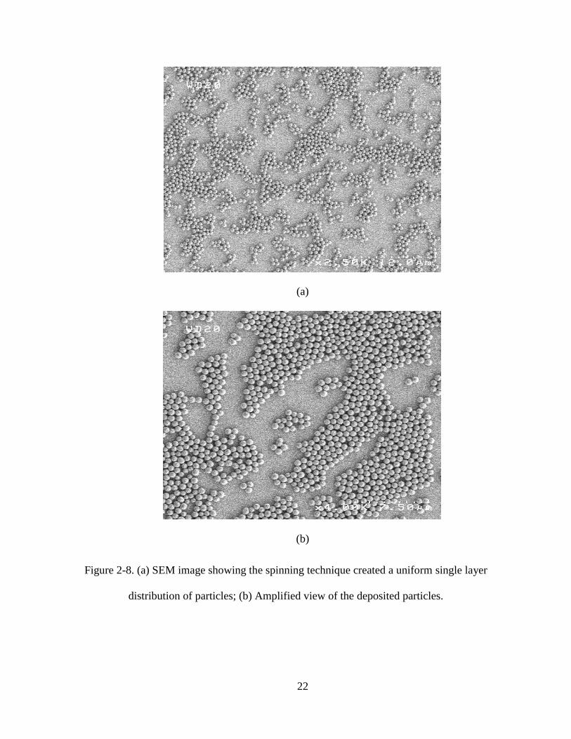
The next strategy to create a single layer of particles was to use a spinner to spin the
wafer after depositing the particles. 100 l of the nanoparticles from the original bottle was
deposited on the wafer. Then, the wafer was spun for 15 seconds at 500 revolutions per minute
(rpm). The dried sample was observed under SEM. Based on SEM results, the spinning
technique gave us a single layer of particles on silicon the wafer. Figure 2-8 shows the result
after spinning the wafer.
The spinning technique was repeated several times to make sure it gives us the same
result every time. This technique was used for depositing the nanoparticles on the wafer in the
remainder of the experiments conducted.
Multi-layers
22
(a)
(b)
Figure 2-8. (a) SEM image showing the spinning technique created a uniform single layer
distribution of particles; (b) Amplified view of the deposited particles.

23
2.2.3 Coating the Nano-Particles
The silica nano-particles were half-coated with nickel at the UNC CHANL facility using
the sputtering deposition technique described in section 2.1. After the coating procedure was
completed, the wafers were brought back to CAMD for SEM examination. Figure 2-9 shows the
top view of the coated particles.
Figure 2-9. Top view of the nickel coated side of the particles.
In order to have a better view of the half-coated particles, a small area was scraped off
with a sharp small knife to randomly change the orientation of the half-coated particles on the
wafer. The particles were then observed under SEM. Based on the observations; the coating
process was successfully done on 492 nm particles. Figure 2-10 (a) shows the side view of
the half-coated particle, where the brighter side shows the nickel. Figure 2-10 (b) shows a
broader view of half-coated particles after scraping them off the wafer.

24
(a)
(b)
Figure 2-10. (a) Side view of a single half-coated particle; (b) SEM image of scrapped half-
coated particles on the wafer.
Further experiments were done with three coating thicknesses to obtain the optimum
thickness.
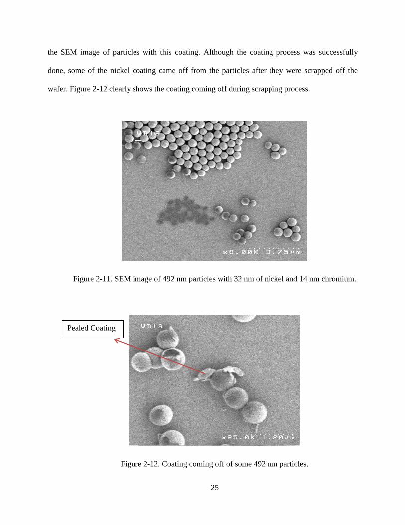
After each deposition, the particles were scraped off and observed under SEM. The first
coating was 32 nm of nickel with 14 nm of chromium as the adhesive layer. Figure 2-11 shows
Coated side of
the particle
25
the SEM image of particles with this coating. Although the coating process was successfully
done, some of the nickel coating came off from the particles after they were scrapped off the
wafer. Figure 2-12 clearly shows the coating coming off during scrapping process.
Figure 2-11. SEM image of 492 nm particles with 32 nm of nickel and 14 nm chromium.
Figure 2-12. Coating coming off of some 492 nm particles.
Pealed Coating

26
The second coating thickness was 20 nm nickel with 9 nm chromium. The image of the
particles that were successfully coated is shown in Figure 2-13. Also in this case, it was observed
that the coating came off during the scraping process (Figure 2-14).
Figure 2-13. SEM image of particles with 20 nm of nickel and 9 nm chromium.
Figure 2-14. SEM image showing the coating coming off from particles with 20 nm
nickel and 9 nm chromium.
Pealed Coating

27
The third coating thickness was 10 nm nickel with 5 nm chromium. A small area was
scraped off and then the sample was observed under SEM. Figure 2-15 is the SEM image from
492 nm particles with thinnest metal coating. Higher quality images of the half-coated
nanoparticles were obtained using transmission electron microscopy (TEM). Figure 2-16 shows
the TEM image of the particles, where the darker shades indicate the nickel coating.
Figure 2-15. SEM image of 492 nm particles with 10 nm of nickel and 5 nm chromium.
Figure 2-16. TEM image of the particles half-coated with nickel.
Coated side of
the particle
28
Based on the SEM and TEM images, the thinnest the coating (10 nm nickel with 5 nm
chromium) was least likely to peel off from the silica particles and therefore, was selected for
coating the particles prior to the enzyme attachment.
2.3 Addition of BC to Nanoparticles
Enzymes attachment was done at the Biochemistry Lab of the LSU Department of
Biological Sciences. The coated particles were transferred into two separate micro-tubes: one for
experimental control and one for the nano-swimmers. The particles in both micro-tubes were
washed by adding 1.5 ml of a second dialysis solution. Second dialysis is a buffer that keeps the
protein at its proper pH of 8, so it can function properly. Second dialysis consists of 10 mM
hepes and 150 mM KCl. Next, the micro-tubes were vortexed for 2 minutes to re-suspend the
particles. The micro-tubes were then placed in a micro-centrifuge and centrifuged for 15 minutes
at 2200 relative centrifugal force (rcf), causing the particles to settle at the bottom of the micro-
tubes. The supernatant (the excess liquid after centrifugation) was then removed from the tubes.
Then, 1.5 ml of BC was added to one of the micro-tubes to create the nano-swimmer tube. In the
control micro-tube, 1.5 ml of second dialysis was added. Both micro-tubes were vortexed again
to re-suspend the particles. Next, the tubes were incubated for 5 minutes at room temperature.
The micro-tubes were then centrifuged again for 15 minutes with 2200 rcf. The supernatant was
taken out from both micro-tubes, and 1.5 ml of second dialysis was added again to each micro
tube to wash the particles. The tubes were vortexed again and spun in micro centrifuge for
another 15 minutes with 2200 rcf. After 15 minutes, the particles were settled at the bottom of
the tubes. The supernatant were then removed from the tubes. 50 of second dialysis were then
added to each tube. The micro-tubes were vortexed one more time to re-suspend the particles.
29
The purpose of vortexing in enzyme attachment process was to mix the particles and liquid each
time.
At the end of this process, control micro-tube contained half-coated particles without any
enzyme attached to them. The nano-swimmer micro-tube contained the half-coated particles with
enzyme attach to them.
The enzyme substrates were prepared separately. The substrates consisted of 1 ml of 800
mM biotin, 1 ml of 2 M magnesium chloride, 1 ml of 492 mM bicarbonate, and 600 of 0.2
mM ATP. Although magnesium chloride is not a direct substrate for BC, it binds with ATP. ATP
was kept in a separate micro-tube and was added to the samples when needed. After the enzyme
attachment, a sodium dodecyl sulfate polyacrylamide gel electrophoresis (SDS-PAGE) test was
run. Sodium dodecyl sulfate (SDS) is a detergent that denatures the protein so the protein retains
its primary structure. SDS also creates a negative charge on the protein. The sample was also
heated to 60 for further denaturation. To separate different protein sizes with different moving
rates, discontinuous polyacrylamide gel was used. An electric field was applied on the gel so the
negatively-charged proteins were attracted toward the anode. When the current was turned off,
the gel was suspended in a dye solution so the proteins become visible. In presence of the
enzyme, a blue band appears on the gel. The band corresponds to the standard ladder which is a
guide for the test (Caprette, 1996) (SDS-PAGE (PolyAcrylamide Gel Electrophoresis), 2001).
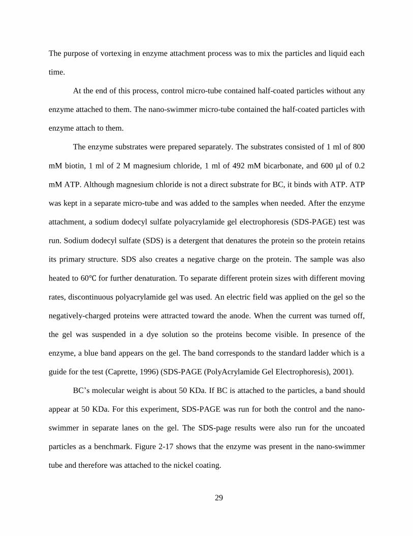
BC’s molecular weight is about 50 KDa. If BC is attached to the particles, a band should
appear at 50 KDa. For this experiment, SDS-PAGE was run for both the control and the nano-
swimmer in separate lanes on the gel. The SDS-page results were also run for the uncoated
particles as a benchmark. Figure 2-17 shows that the enzyme was present in the nano-swimmer
tube and therefore was attached to the nickel coating.
30
Figure 2-17. SDS-PAGE results showing successful enzyme attachment to the nano-
particles.
To make sure the enzyme was active after attachment; an assay was run on the uncoated
particles, coated particles without enzyme, and nano-swimmers in the presence of enzyme
substrates. The assay shows the enzyme activity per minute. The activity of the enzyme is
determined by measuring the rate of ATP that is hydrolyzed. Table 1 shows the enzyme activity
for two analyses. A bar chart of the results is shown in Figure 2-18. The enzyme activity for the
uncoated and half-coated particles were similar and in the same range. The slight difference was
due to instability of ATP. The enzyme activity for the half-coated with enzyme (nano-swimmer)
was more than double than that of the control particles, indicating the BC was active while
attached to the nano-swimmer.

31
Table 1: Comparison of Enzyme Activity
Controls First Measurement
(Activity/min)
Second Measurement
(Activity/min)
Average
(Activity/min)
Uncoated 0.008098296 0.008848296 0.008473296
Half-Coated 0.008829454 0.0121049 0.010467177
Half-Coated+Enzyme 0.01677103 0.02633346 0.021552245
Figure 2-18 Enzyme activity measurements.
Uncoated Half-Coated Half-Coated
+Enzyme
0
0.005
0.01
0.015
0.02
0.025
Chan
ge
of
Enzy
me
Act
ivit
y /
min

32
CHAPTER 3 NANO-SWIMMER EXPERIMENTATION
This chapter describes the experimental procedure used to test the hypothesis that the
nano-swimmer undergoes non-Brownian motion in the presence of the enzyme substrates. The
following experiments were conducted immediately after the enzyme attachment procedure was
completed to ensure the BC molecules on the nano-swimmers were still alive.
3.1 Experimental Setup
A Nikon Microscope with 100x lens was used to observe the movement of the nano-
swimmers and the controls. A TUCSEN TrueChrome II camera was attached to the microscope
to capture and save the videos at 30 frames per second on a SD card.
In order to observe the nano-particles under the microscope, a viewing chamber was
fabricated (Yates, 2012). Its purpose is to enclose the observation area and avoid any external
factors from biasing the motion of the nano-particles.
The viewing chamber was made of two 18 18 mm micro-glasses (catalog number 48366
045) (VWR International-Chemicals and Labratory Scientific Supplies). A 9 mm diameter, 0.12
mm deep secure-seal spacer (Invitrogen, S24737) (Secure-Seal™ Spacer) was used in between
the micro-glasses where the sample drop was placed. A schematic of the viewing chamber is
given in Figure 3-1 (Yates, 2012).
The Video Spot Tracker v08.01 software (CISMM, 2013) was used to track and record
the 2D position of the nano-particles over time. Specifically, the software outputs the x(t) and
y(t) coordinates of the particles in a CSV file for post-analysis.

33
Figure 3-1. Schematic representation of the viewing chamber for observing the particles under
the microscope (Yates, 2012).
3.2 Experimental Controls
The nano-swimmers consisted of particles half-coated with nickel with BC molecules
attach to the nickel surface. In order to activate the enzyme, the fluidic environment contained
the enzyme substrates (biotin, bicarbonate, and ATP). The following three controls were also
used in the experiments.
1. Uncoated particles.
2. Particles half-coated with nickel but without BC attached to the nickel surface.
Henceforth, this control is referred to as half-coated particles.
3. Particles half-coated with nickel with BC attached to the nickel surface but not
exposed to all the enzyme substrates. Specifically, ATP was not present in the
solution, making the enzyme inactive. Henceforth, this control is referred to as
inactive nano-swimmers.
Micro-glass
Secure-SealTM
Spacer
Sample 9
mm
18 m
m
0.12 mm

34
3.3 Experimental Protocol
The protocol followed for observing the uncoated particles, was the following. One drop
of the uncoated particles and one drop of the BC substrates were added to a separate micro tube
and were mixed by using a pipet tip. Then one drop of the mixture was placed at the center of the
secure seal which was stuck on a micro-glass. Immediately after adding the drop, a second
micro-glass was placed over the drop such that the drop was stuck in the viewing chamber. The
viewing chamber was placed under the microscope to observe and record the movement of the
particles. In order to prevent any transient bias from the addition of the particles and substrate
mixture to the micro-slide, a 40 second gap was given to the sample before initiating the video
capture. The motion of the particles was then captured with the camera and was saved on a SD
card for further analysis. The captured video for each particle had 360 frames ( )
with time increments of 1/30 s. Therefore, each particle was tracked for 12 s. Since the particles
drop out of the focus of the lens after 12 seconds, this was the maximum time that a single
particle could be tracked.
The same protocol was followed for the half-coated particles, inactive nano-swimmers,
and nano-swimmers, except that for the inactive nano-swimmer, ATP was not added to the
particle mixture.
3.4 Analysis and Results
Figure 3-2 shows the trajectory of the particles for the three controls and nano-swimmer
from the video spot tracker software. The yellow line represents the trajectory of the particles in
the time interval [0,12] s. Two distinct particles are shown for each case. The trajectories in
Figure 3-2 (A,B,C,D,E,F) suggest that the motions of the controls are likely Brownian since the
particle displacements appear random and confined to the neighborhood of their position at t=0.

35
This is in sharp contrast to the trajectories of the nano-swimmer, which are more directed and
move away from the initial position. That is, the nano-swimmer motility appears to be non-
Brownian.
In order to corroborate the visual, qualitative results from the videos, a quantitative
analysis was performed on the ( ( ) ( )) data of each particle. To this end, the two methods
describe in section 1.3.2 were applied to the experimental data to compare the translational and
directional diffusion of the recorded particle motions.
Figure 3-2 : Single particle trajectory. A and B: Uncoated particles, C and D: Half-coated
particles, E and F: Inactive nano-swimmers, G and H: Nano-swimmer
(each tick mark interval equals 500 nm).

36
Figure 3-2 : continued.
3.4.1 Translational Diffusion Analysis
Recall the translational diffusion equation for Brownian motion given by Equation 1-4.
This equation indicates that the MSD of Brownian motion is linear in time. To facilitate the
evaluation of this relationship, the experimental MSD versus time was plotted in log-log scale.
Notice that in a log-log scale, Equation 1-4 would result in a line with slope of one since
( ) ( ) ( ) ( ) 3–1
That is, the line fit to the log-log plot of the experimental data will have slope of approximately
one if the motion is Brownian and slope greater than one if the motion is non-Brownian.
For this analysis, 15 particles were tracked for each control and the nano-swimmer. The
particles were tracked for 12 seconds (360 frames). The displacement in Equation 1-2 was

37
calculated for each particle by varying and averaging over several equal values of
[ (
) ] where . For example, to compute ( ), we calculated the
displacement vector from time samples 0 to 1, time samples 1 and 2, and so on, and took their
average. To compute ( ), we averaged over the displacement vectors from time
samples 0 to 180, time samples 1 and 181, and so on. A second average was then taken over all
particles (N = 15) to compute the MSD in Equation 1-3 for each control and the nano-swimmer.
Figure 3-3 to Figure 3-6 show the log-log plots of the MSD versus time for the uncoated
particle, half-coated particles, inactive nano-swimmers, and nano-swimmers. A linear fit,
, was applied to each data set using the “polyfit” function in MATLAB.
The slopes for the resulting linear fits are summarized in Table 2. The 95% confidence
intervals ( ) on slopes are calculated as , where is the standard error of
the slope (Equation 3-3) and equals 1.96 (Freund, 2003).
Table 2: Comparison of slopes of MSD linear fit.
Case Slope
Uncoated Particles 0.956 0.028
Half-Coated Particles 0.920 0.113
Inactive Nano-Swimmers 0.975 0.039
Nano-Swimmers 1.472 0.047

38
Figure 3-3. Log-log plot of MSD versus time for uncoated particles.
Figure 3-4. Log-log plot of MSD versus time for half-coated particles.
100
101
102
103
101
102
103
104
y = 0.956 x + 1.442
time ( 33 ms)
MS
D
( 1
62 n
m2)
Uncoated Particles
100
101
102
103
101
102
103
104
y = 0.920 x + 1.608
time (33 ms)
MS
D
( 16
2 n
m2)
Half-coated Particles

39
Figure 3-5. Log-log plot of MSD versus time for inactive nano-swimmers.
Figure 3-6. Log-log plot of MSD versus time for nano-swimmer.
100
101
102
103
101
102
103
104
y = 0.975 x + 1.373
time (33 ms)
MS
D
( 16
2 n
m2)
Inactive Nano-swimmers
100
101
102
103
101
102
103
104
105
y = 1.472 x + 0.972
time (33 ms)
MS
D
( 16
2 n
m2)
Nano-swimmers
40
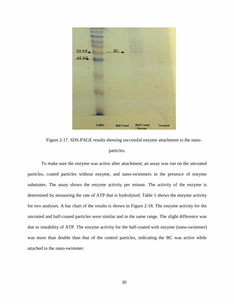
In order to check the statistical significance ( ) of the difference between the
calculated slope values against 1, t-test has been applied to the Table 2 results. The null
hypothesis ( ) is that the slope of the fitted line equals 1, and the alternative hypothesis ( ) is
that the slope of the fitted line is different from 1. The t-value for one sample t-test is calculated
as:
3–2
where is the slope of the fitted line, is 1, and is the standard error of the slope of the
fitted line. To calculate , the following formula was used
√
( )∑ ( ̅)
3–3
where
∑ ( )
3–4
Here, ( ) , log(MSD( )), and , where 160 corresponds to
the number of fitted data points in Figure 3-3 to Figure 3-6 and 15 corresponds to the number of
particles.
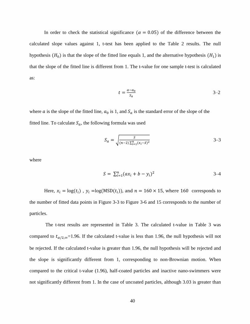
The t-test results are represented in Table 3. The calculated t-value in Table 3 was
compared to =1.96. If the calculated t-value is less than 1.96, the null hypothesis will not
be rejected. If the calculated t-value is greater than 1.96, the null hypothesis will be rejected and
the slope is significantly different from 1, corresponding to non-Brownian motion. When
compared to the critical t-value (1.96), half-coated particles and inactive nano-swimmers were
not significantly different from 1. In the case of uncoated particles, although 3.03 is greater than
41
1.96, the difference is not strong. The t-value of the nano-swimmers is 38.69 which is
significantly different from 1.
Table 3: t-values for three controls and nano-swimmer.
Case t-value
Uncoated Particles 3.03
Half-Coated Particles 1.36
Inactive Nano-Swimmers 1.25
Nano-Swimmers 38.69
The slope values for the experimental controls indicate that their motion was Brownian as
expected. The slope for the nano-swimmer was significantly higher than the controls which is
indicative of non-Brownian behavior.
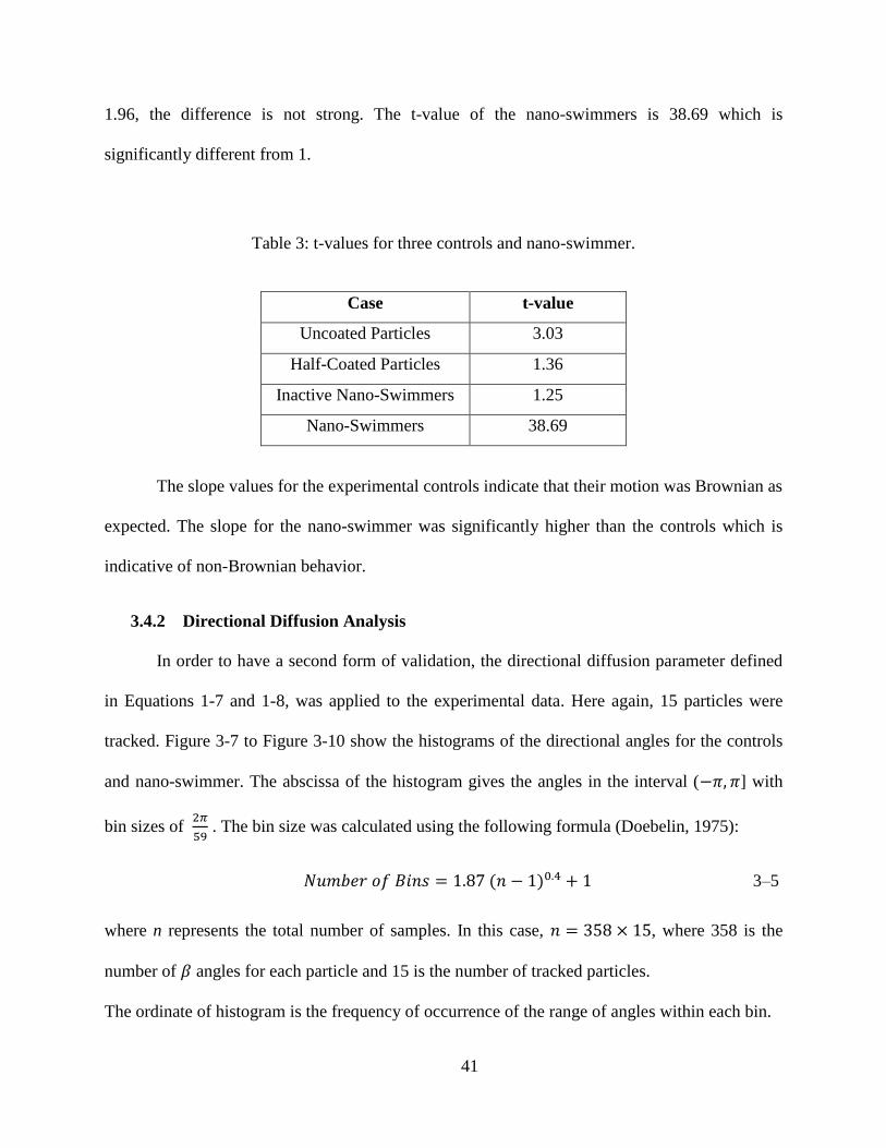
3.4.2 Directional Diffusion Analysis
In order to have a second form of validation, the directional diffusion parameter defined
in Equations 1-7 and 1-8, was applied to the experimental data. Here again, 15 particles were
tracked. Figure 3-7 to Figure 3-10 show the histograms of the directional angles for the controls
and nano-swimmer. The abscissa of the histogram gives the angles in the interval ( ] with
bin sizes of
. The bin size was calculated using the following formula (Doebelin, 1975):
( ) 3–5
where n represents the total number of samples. In this case, , where 358 is the
number of angles for each particle and 15 is the number of tracked particles.
The ordinate of histogram is the frequency of occurrence of the range of angles within each bin.

42
Notice from Figure 3-7 to Figure 3-9 that the angle frequency distribution for the controls
shows no strong directional preference, which is consistent with Brownian motion. On the other
hand, the angle frequency distribution for the nano-swimmer in Figure 3-10 has two larger peaks
in the neighborhood of . This indicates that the nano-swimmers have less of a tendency to
change their direction while moving in the fluid and are more likely to move in the direction that
the BC “motors” are propelling them (perpendicular to the plain of the Janus particle
hemisphere). Thus, their motion is non-Brownian.
Figure 3-7. Directional diffusion histogram for uncoated particles.
Uncoated Particles
Pro
babili
ty

43
Figure 3-8. Directional diffusion histogram for half-coated particles.
Figure 3-9. Directional diffusion histogram for inactive nano-swimmer.

44
Figure 3-10. Directional diffusion histogram for nano-swimmers.
The histograms of the directional angles for the controls and nano-swimmer was also
plotted for ( ) ( ) ( ) and ( ) ( ) ( ) but the nature of the
histograms remained the same.
In order to test the equality of two probability distributions, Kolmogorov-Smirnov (K-S)
test was applied to all histogram pairs (Pollard, 1979). The K-S test was applied to
the ] region of the histograms because the ] and ]
regions in the histograms are similar. The null hypothesis here is that the two compared
histograms are statistically indifferent. If the p-value from K-S test was less than 0.05, the null
hypothesis will be rejected and the histograms are significantly different. Otherwise, the p-value
from K-S test was greater than 0.05, the histograms are not significantly different. The results of
the K-S tests are summarized in Table 4. Based on the K-S test P-values ( ), the controls
are not significantly different from each other as expected. The nano-swimmers are significantly

45
different from uncoated particles and half-coated particles. The test did not show a significant
difference between inactive nano-swimmers and nano-swimmers which may be due to not
having enough data points.
Table 4: K-S Test Results
Case P-value of K-S Test
Uncoated vs. Inactive Nano-swimmers 0.154
Uncoated vs. Half-Coated Nano-swimmers 0.304
Half-Coated vs. Inactive Nano-swimmers 0.154
Uncoated Particles vs. Nano-swimmers 0.029
Half-Coated Particles vs. Nano-swimmers 0.004
Inactive Nano-Swimmers vs. Nano-Swimmers 0.154

46
CHAPTER 4 CONCLUSIONS AND RECOMMENDATIONS FOR
FUTURE WORK
4.1 Conclusions
This thesis presented results that strongly suggest that the enzyme biotin carboxylase
(BC) can serve as a biomolecular motor, converting chemical energy into useful mechanical
work. This was demonstrated by covering the nickel-coated hemisphere of a Janus-like, 492 nm
particle with BC molecules. Nickel was used because BC can be attached to it via a histidine tag.
It was shown that BC can propel the nano-particles in a non-Brownian manner in comparison to
three control experiments when the particles are immersed in a fluidic environment with the
enzyme substrates. For this demonstration, videos of the nano-swimmers and controls were
recorded, and the motion of 15 individual particles was tracked via a free software.
Videos showed the nano-swimmers moving in directed manner and away from their
initial position, whereas motion of the controls was random and in the proximity of their initial
position. Translational and directional diffusion analyses were performed on the experimental
data of the nano-swimmer and controls. The slope of the linear fit for the mean square
displacement versus time plot of the nano-swimmers was approximately 1.5, indicating non-
Brownian motion according to Einstein’s theory (the slope of the controls was approximately
one, which is indicative of Brownian motion). Further, the histogram of the directional diffusion
angle of the nano-swimmers was less flat than those of the controls and showed higher
probability for small angles. This means the nano-swimmer are more likely to move in the
direction in which they are propelled by the BC motors.
4.2 Recommendations for Future Work
In order to produce better nickel-coated particles, it is recommended that a more efficient
way to remove the half-coated particles from silicon be developed. The method used in this work

47
involved scraping the particles off the wafer, which can damage some of them. An alternative
method is to use a wafer with a layer of salt on it. To remove the half-coated particles safely, the
wafer can be submerged in the salt solution so the particles would come off the wafer. A nano-
size mesh can be used to remove the particles from the solution. Other than using the wafer with
a layer of salt, using surfactants and adding charge are also other options to optimize the
removing procedure of the half-coated particles from the wafer.
It is also recommended to reduce the size of the nano- particles to 300 nm or 100 nm
when fabricating and testing the nano-swimmers. The non-Brownian motion of the nano-
swimmers will likely be more noticeable as the particles size decreases.
Preliminary step toward this recommendation was taken by half-coating 300 nm particles
using the procedure described in this thesis. The 300 nm particles were observed under SEM,
showing that the coating successfully adhered to the particle. Enzyme attachment and testing of
the 300 nm nano-swimmers was not performed though. Coating of the 100 nm particles might
require a different procedure that the one used here.

48
REFERENCES
Agarwal,Ashutosh, and Henry Hess. "Biomolecular Motors at the Intersection of
Nanotechnology and Polymer Science." Progress in Polymer Science 35.Special Issue
on Stimuli-Responsive Materials (2010): 252-277.
Behkam, Bahareh, and Metin Sitti. "Bacterial Flagella-Based Propulsion and On/Off Motion
Control of Microscale Objects." Applied Physics Letters 90.2 (2007): 023902-N.PAG.
Academic Search Complete.
Behkam, Bahareh, and Metin Sitti. "Effect of Quantity and Configuration of Attached Bacteria
on Bacterial Propulsion of Microbeads." Applied Physics Letters 93.22 (2008): 223901.
Academic Search Complete.
Bhalerao, R.S. Brownian Motion for the School-Going Child, arXiv: physics/0412132y1
[physics. ed-ph], Dec.2004.
Blanchard, Carol Z., et al. "Mutations at Four Active Site Residues of Biotin Carboxylase
Abolish Substrate-Induced Synergism by Biotin." Biochemistry 38.11 (n.d.): 3393-3400.
Biological Abstracts 1969 - Present.
Borsch, Michael. "Microscopy of Single Fof1-ATP Synthases- the Unraveling of Motors,
Gears, and Controls." IUBMB Life 65.3 (2013): 227-237. Science & Technology
Collection.
Broussard, Tyler C., et al. "The Three-Dimensional Structure of the Biotin Carboxylase-Biotin
Carboxyl Carrier Protein Complex of E. Coli Acetyl-CoA Carboxylase." Structure
(Cambridge) 21.4 (n.d.): 650-657. Biological Abstracts 1969 - Present.
Brown, Aidan, and Wilson Poon. "Ionic Effects in Self-Propelled Pt-Coated Janus Swimmers."
Soft Matter 10.22 (2014): 4016-4027. MEDLINE.
Caprette, David R. "Introduction to SDS-PAGE." Rice University, 14 Aug. 1996.
CISMM. CISMM RSS. N.p., (2013). Web. 14 Mar. 2015. <http://www.cismm.org/downloads/>.
Cronan, Jr., John E, and Grover L Waldrop. "Review: Multi-Subunit Acetyl-CoA Carboxylases."
Progress In Lipid Research 41.(2002): 407-435. ScienceDirect.
Doebelin, Ernest O. Measurement Systems: Application and Design. n.p.: New York, McGraw-
(Doebelin, 1975)Hill [1975], 1975. Louisiana State University.
Einstein, Albert. "On the Movement of Small Particles Suspended in Stationary Liquids
Required by Molecular-Kinetics Theory of Heat." Annalen Der Physik (Leipzig) 17
(1905).549-560 (1905). Print.
Ekuni, A., et al. "Reconstitution of FI-ATPase activity from Escherichia coli subunits u, v
and subunit tagged with six histidine residues at the C-terminus." Federation of
European Biochemical Societies Letters, 427, 64-68 (1998).
Freund, Rudolf J., and William J. Wilson. Statistical Methods. San Diego, CA: Academic, 2003.
Print.
49
Ghalanbor, Zahra, Sayed-Amir Marashi, and Bijan Ranjbar. "Nanotechnology Helps Medicine:
Nanoscale Swimmers and Their Future Applications." Medical Hypotheses 65.1 (2005):
198-199. MEDLINE.
Gora, Powel F. "The Theory of Brownian Motion: A Hundred Years Anniversary." (2006): 52-
57.
Hiratsuka, Yuichi, et al. "A Microrotary Motor Powered by Bacteria." Proceedings of the
National Academy of Sciences of the United States of America 2006: 13618. JSTOR
Journals.
"His-tagged Proteins – Production and Purification." Life Technoogies, n.d.
Howse, Jonathan R., et al. "Self-Motile Colloidal Particles: From Directed Propulsion to
Random Walk." (2007): arXiv.
Hu, Jing, et al. "Fabrication, Properties and Applications of Janus Particles." Chemical Society
Reviews 41.11 (2012): 4356-4378. MEDLINE.
Ke, Hua, et al. "Motion Analysis of Self-Propelled Pt-Silica Particles in Hydrogen Peroxide
Solutions." The Journal of Physical Chemistry. A 114.17 (2010): 5462-5467. MEDLINE.
Keller, David, and Carlos Bustamante. "The Mechanochemistry of Molecular Motors."
Biophysical Journal 78.(2000): 541-556. ScienceDirect.
Kurt J. Lesker Company. N.p., n.d. Web. 14 Mar. 2015. <http://www.lesker.com>.
Lu, Ping, Holger Lill, and Dirk Bald. "ATP Synthase in Mycobacteria: Special Features and
Implications for A Function As Drug Target." Biochimica Et Biophysica Acta 1837.7,
Sp. Iss. SI (n.d.): 1208-1218. Biological Abstracts 1969 - Present.
Microspheres and Nanospheres. www.microspheres-nanospheres.com.
Montemagno, C. D. (2001). Nanomachines: A roadmap for realizing the vision. Journal of
Nanoparticle Research, 1-3.
Paxton, Walter F., et al. "Catalytic Nanomotors: Autonomous Movement of Striped Nanorods."
Journal of the American Chemical Society 126.41 (2004): 13424-13431. Science &
Technology Collection.
Perrin, Jean, and Frederick Soddy. Brownian Movement and Molecular Reality. n.p.: London :
Taylor and Francis, 1910., 1910. Louisiana State University.
Perro, Adeline, et al. "Design And Synthesis Of Janus Micro- And Nanoparticles." Journal Of
Materials Chemistry 15.35-36 (2005): 3745. Supplemental Index.
Pollard, J. H. "A Handbook of Numerical and Statistical Techniques." Cambridge University
Press, 30 Nov. 1979.
Powles, J. G. "Brownian Motion-June 1827 (For Teachers)." Physics Education 13.5 (1978): 1.
Publisher Provided Full Text Searching File. Web.
Radenovic, Aleksandra. "Brownian Motion and Single Particles Tracking."
Schmidt, Jacob J., and Carlo D. Montemagno. "Bionanomechanical Systems." Annual Review of
Materials Research 34.1 (2004): 315-C-2. Business Source Complete.
50
"SDS-PAGE." SDS-PAGE. Davidson College, 2001.
"Secure-Seal™ Spacer, 8 Wells, 9 Mm Diameter, 0.12 Mm Deep." Life Technology. N.p., n.d.
<https://www.lifetechnologies.com/order/catalog/product/S24737>.
Soong, Ricky, and Carlo D. Montemagno. "Engineering Hybrid Nano-Devices Powered by the
F1-Atpase Biomolecular Motor." International Journal of Nanotechnology 2.4 (2005):
N.PAG. Supplemental Index.
Terashima, Hiroyuki, et al. "The Vibrio Motor Proteins, Motx and Moty, Are Associated With
the Basal Body of Na-Driven Flagella and Required for Stator Formation." Molecular
Microbiology 62.4 (2006): 1170-1180. MEDLINE.
Thoden, James B., et al. "Molecular Structure Of Escherichia Coli Purt-Encoded Glycinamide
Ribonucleotide Transformylase." Biochemistry 39.30 (n.d.): 8791-8802. Biological
Abstracts 1969 - Present.
Thoden, James B., et al. "Movement of the Biotin Carboxylase B-Domain As A Result of ATP
Binding." Journal of Biological Chemistry 275.21 (n.d.): 16183-16190. Biological
Abstracts 1969 - Present.
Tong, Liang. "Structure and Function of Biotin-Dependent Carboxylases." Cellular & Molecular
Life Sciences 70.5 (2013): 863-891. Academic Search Complete.
"VWR International - Chemicals and Laboratory Scientific Supplies." VWR. N.p., n.d.
https://us.vwr.com/store/catalog/product.jsp?product_id=4645789.
Wang, Joseph. "Can Man-Made Nanomachines Compete With Nature Biomotors?." ACS Nano
3.1 (2009): 4-9. MEDLINE.
Yang, Shikuan, et al. "Microfluidic Synthesis of Multifunctional Janus Particles for Biomedical
Applications." Lab on a Chip 12.12 (2012): 2097-2102. MEDLINE.
Yates, Rachel Allison. Towards the Development of Biotin Carboxylase Driven Robotic
Nanoswimmers, M.S. Thesis, Louisiana State University, 2012.
Ye, Shengrong. Anisotropic Particles Preparation and Study. PhD Dissertation, West Virginia
University, 2011.
Ye, Shengrong, and R Lloyd Carroll. "Design and Fabrication of Bimetallic Colloidal "Janus"
Particles." ACS Applied Materials & Interfaces 2.3 (2010): 616-620. MEDLINE.

51
VITA
Sima Hannani was born in 1987 in Sari, Iran. She graduated from Islamic Azad University
North-Branch of Tehran with a Bachelor in Science in Natural Resources Engineering in July
2009. She came to the United States in August 2010 and attended a Master’s degree program in
Civil Engineering department at Louisiana State University in August 2012. She is a candidate
for a Master of Science in Civil Engineering to be awarded in May 2015.
Related Documents