HEADQUARTERS DEPARTMENTS OF THE ARMY AND THE AIR FORCE FIELD MANUAL 23-90 TECHNICAL ORDER 11W2-5-13-21 LIBRARY 06A CGgr FT LEAVENIORTN. KAN. APR 2 7 2000 ACCESSION NO PO REGISTER MORTARS DISTRIBUTION RESTRICTION: Approved for public release; distribution is unlimited.

Welcome message from author
This document is posted to help you gain knowledge. Please leave a comment to let me know what you think about it! Share it to your friends and learn new things together.
Transcript
HEADQUARTERSDEPARTMENTS OF THE ARMYAND THE AIR FORCE
FIELD MANUAL 23-90TECHNICAL ORDER 11W2-5-13-21
LIBRARY06A CGgr FT LEAVENIORTN. KAN.
APR 2 7 2000ACCESSION NO
PO REGISTER
MORTARS
DISTRIBUTION RESTRICTION: Approved for public release; distribution isunlimited.

This publication is available on theGeneral Dennis J. Reimer Training
And Doctrine Digital Library atwww.adtdl.army.mil
FM 23-90C1
Change 1 HeadquartersDepartment of the Army
Washington, DC, 9 December 2002
Mortars
This change updates misfire procedures for ground- and carrier-mounted 120-mmmortars (paragraphs 7-13 and 7-22, pages 7-11 and 7-23, respectively). The title ofSection III, Chapter 7 changes to reflect its focus on only ground-mounted mortars(Section V focuses on carrier-mounted mortars). The Table of Contents changes only toshow a changed Chapter 7. The changed Preface updates contact information.
1. Change FM 23-90, 1 March 2000, as follows:
Remove old pages: Insert new pages:
Contents and Preface (pages i thru ix)...... Contents and Preface (pages i thru ix)
Chapter 7 (pages 7-1 through 7-39).......... Chapter 7 (pages 7-1 through 7-38)
2. A star (*) marks new or changed material.
3. File this transmittal sheet in front of the publication.
DISTRIBUTION RESTRICTION:
Approved for public release; distribution is unlimited.
By Order of the Secretary of the Army:Official:
ERIC K. SHINSEKIGeneral, United States Army
JOEL B. HUDSONAdministrative Assistant to the
Secretary of the Army
0229006
DISTRIBUTION:
Active Army, USAR, and ARNG: To be distributed in accordance with the requirementsfor initial distribution number 110209, requirements for FM 23-90.
This publication is available on theGeneral Dennis J. Reimer Training
and Doctrine Digital Library atwww.adtdl.army.mil
FM 23-90/TO 11W2-5-13-21FIELD MANUAL HEADQUARTERSNO. 23-90 DEPARTMENTS OF THE ARMYTECHNICAL ORDER AND THE AIR FORCENO. 11W2-5-13-21 WASHINGTON, DC, 1 March 2000
MORTARS
CONTENTS
PageP R E F A C E ......................................................................................................................... ix
CHAPTER 1. INTRODUCTIONSection I. General Doctrine ................................................................................... 1-1
1-1. Effective Mortar Fire ..................................... 1-11-2. M ortar Positions..................................................................... 1-2
Section II. Indirect Fire Team.................................... 1-21-3. Applications .................................... ......... 1-21-4. Team M ission ............................................................... ......... 1-3
Section III. Safety Procedures........................................................... 1-31-5. Duties of the Safety Officer and Supervisory Personnel ....... 1-31-6. Ammunition Care and Handling................................... ......... 1-91-7. Field Storage of Ammunition ..................................... 1-10
CHAPTER 2. SIGHTING AND FIRE CONTROL EQUIPMENTSection I. Compass, M2 ....................................... 2-1
2-1. C haracteristics........................................................................ 2-12-2. D escription............................. 2-22-3. U se ........................................ 2-2
Section II. Aiming Circles, M2 and M2A2 ..................................... 2-52-4. Characteristics......................... 2-52-5. D escription............................. 2-52-6. U se ........................................ 2-52-7. Accessory Equipment ..................................... 2-82-8. Setup and Leveling of Aiming Circle .................................... 2-92-9. D eclination Constant............................................................ 2-112-10. Orienting of the Instrument on Grid North to Measure
Grid Azimuth to Objects.............................. 2-142-11. Measurement of Horizontal Angle Between Two Points ....... 2-14
DISTRIBUTION RESTRICTION: Approved for public release, distribution is unlimited.
C1, FM 23-90/TO 11W2-5-13-21
Page2-12. Orienting of the 0-3200 Line on a Given Grid Azimuth ........ 2-152-13. Orienting of the 0-3200 Line on a Given
Magnetic Azimuth ........................................ 2-162-14. Verifying the Lay of the Platoon ........................................ 2-162-15. Orienting by Orienting Angle ........................................ 2-172-16. Disassembly of Aiming Circle............................... 2-182-17. Care and Maintenance ..................................... 2-18
Section III. Sightunits ........................................ 2-192-18. Sightunit, M53-Series ..................................... 2-192-19. Operation of M53 Sightunit............................ 2-212-20. Care and Maintenance of M53 Sightunit............................... 2-222-21. Sightunit, M64-Series ..................................... 2-232-22. Sightunit, M67 ........................................ 2-26
Section IV . B oresights ........................................................................................... 2-272-23. Boresight, M45-Series ........................................ 2-272-24. Boresight, M115 ........................................ 2-282-25. Principles of Operation ........................................ 2-292-26. Installation ........................................ 2-292-27. Sight Calibration ..................................... 2-302-28. Boresight Method of Calibration ........................................ 2-302-29. Calibration for Deflection Using the M2 Aiming Circle........ 2-32
Section V. Other Equipment............................... 2-342-30. Instrument Light, M53E1 ..................................... 2-342-31. Aiming Posts, M14 and M1A2 ..................................... 2-362-32. Aiming Post Lights, M58 and M59 ..................................... 2-37
Section VI. Laying the Section ........................................ 2-382-33. Reciprocal Laying.......... .... ............... 2-392-34. Reciprocal Laying on a Grid Azimuth.............................. 2-402-35. Reciprocal Laying on a Magnetic Azimuth......................... 2-432-36. Reciprocal Laying Using the Orienting Angle .................... 2-432-37. Reciprocal Laying Using the Mortar Sights ........................ 2-432-38. Reciprocal Laying Using the M2 Compass ......................... 2-452-39. Placing Out Aiming Posts................................ 2-452-40. Alternate Method of Placing Out Aiming Posts .................. 2-462-41. Correction for Displacement of Sight................................ 2-48
Section VII. Loading and Firing .................................... ............ 2-492-42. Firing the Mortar.............................. 2-492-43. Target Engagement ......................................... 2-502-44. Execution of Fire Commands ..................................... 2-502-45. Arm-and-Hand Signals ........................................ 2-522-46. Subsequent Fire Commands ..................................... 2-532-47. Repeating and Correcting of Fire Commands ..................... 2-542-48. Reporting of Errors in Firing .............................................. 2-542-49. Night Firing ........................................ 2-54

C1, FM 23-90/TO 11W2-5-13-21
PageCHAPTER 3. 60-mm MORTAR, M224Section I. Squad and Section Organization and Duties ..................................... 3-1
3-1. O rganization .......................................................................... 3-13-2. D uties ................................................................................ 3-1
Section II. Com ponents .................................................................................. 3-13-3. Tabulated D ata ....................................................................... 3-23-4. Cannon Assembly, M225 ..................................... 3-43-5. Baseplate, M7 ....................... ................ 3-43-6. B aseplate, M 8 ........................................................................ 3-53-7. Bipod Assembly, M170 ..................................... 3-6
Section III. O peration ............................................................................................. 3-73-8. Prem ount Checks ................................................................... 3-73-9. Mounting of the Mortar ......................................................... 3-73-10. Safety Checks Before Firing.................................................. 3-83-11. Small Deflection and Elevation Changes .............................. 3-93-12. Large Deflection and Elevation Changes .............................. 3-93-13. Referring of the Sight and Realignment of Aiming Posts ...... 3-103-14. M alfunctions ........................................................................ 3-123-15. Removal ofa Misfire ............. ........................... 3-123-16. Dismounting and Carrying of the Mortar ............................... 3-16
Section IV. Ammunition .............................................................................. 3-173-17. Classification ........................................ 3-173-18. C olor C odes ......................................................................... 3-183-19. Preparation of Ammunition .................................................. 3-193-20. Types of Fuzes ..................................................................... 3-193-21. Standard B Ammunition ...................................................... 3-213-22. Care and Handling .............................................................. 3-22
CHAPTER 4. 81-mm MORTAR, M252Section I. Squad and Section Organization and Duties ..................................... 4-1
4-1. O rganization ............................................................................. 4-14-2 . D uties .................................................................................... . 4-1
Section II. C om ponents ....................................................................................... 4-34-3. Tabulated D ata................................................................ 4-44-4. Cannon Assembly, M253 ..................................... 4-54-5. M ount, M 177 ......................................................................... 4-54-6. Baseplate, M 3A 1 .................................................................. 4-6
Section III. O peration ............................................................................................ 4-74-7. Premount Checks ..................................... 4-74-8. Mounting of the Mortar ......................................................... 4-84-9. Safety Checks Before Firing............................... 4-94-10. Small Deflection and Elevation Changes .............................. 4-104-11. Large Deflection and Elevation Changes ............................ 4-11
iii
Cl, FM 23-90/TO 11W2-5-13-21
Page4-12. Referring of the Sight and Realignment of
Aiming Posts Using M64 Sight ...................................... 4-114-13. M alfunctions ......................................................... 4-124-14. Removal of a Misfire ............................................................. 4-124-15. Dismounting of the Mortar ...................................... 4-13
Section IV . Am m unition ..................................................... ............................. 4-144-16. Classification ...... ............................ 4-144-17. Function ..................................... 4-164-18. High-Explosive Ammunition.............................. 4-164-19. Red/White Phosphorus Ammunition ................................. 4-174-20. Illuminating Ammunition .................................................... 4-184-21. Types of Fuzes ..................................... 4-184-22. Characteristics of Proximity Fuzes ................................... 4-204-23. Fuze Wrench and Fuze Setter ................................................ 4-214-24. Preparation of Ammunition ........................................ 4-214-25. Care and Handling ........................................ 4-22
CHAPTER 5. 81-mm MORTAR, M29A1Section I. Squad and Section Organization and Duties ..................................... 5-1
5-1. Organization .................................... 5-15-2. Duties ............................................ .............. ................ 5-1
Section II. C om ponents .......................................................................................... 5-25-3. Tabulated Data ................................. 5-35-4. Cannon Assembly, M29A1 ............. ............... 5-45-5. Bipod Assembly, M23A1 ........................................ 5-45-6. Baseplate, M3 .................................... 5-5
Section III. O peration ................................................. 5-65-7. Premount Checks ..................................... 5-65-8. Mounting of the Mortar ........................................ 5-75-9. Safety Checks Before Firing.................................. 5-195-10. Small Deflection and Elevation Changes ............................ 5-105-11. Large Deflection and Elevation Changes ............................ 5-105-12. Referring of the Sight and Realignment of
Aiming Posts Using M53 Sight ........................................ 5-125-13. Malfunctions ..................................... 5-125-14. Removal of a Misfire ..................................... 5-125-15. Dismounting of the Mortar ........................................ 5-13
Section IV . A m m unition ........................................................................................ 5-145-16. Function ................................................................................ 5-145-17. High-Explosive Ammunition........................... 5-155-18. White Phosphorus Ammunition......................... 5-155-19. Illuminating Ammunition ........................................ 5-165-20. Types of Fuzes ..................................... 5-165-21. Characteristics of Proximity Fuzes ..................................... 5-16
iv
C1, FM 23-90/TO 11W2-5-13-21
Page5-22. Fuze Wrench and Fuze Setter ........................................ 5-165-23. Preparation of Ammunition .............................. 5-165-24. Care and Handling ............................................................. 5-16
CHAPTER 6. 4.2-INCH MORTAR, M30Section I. Squad and Section Organization and Duties ..................................... 6-1
6-1. O rganization .......................................................................... 6-16-2. D uties ................................................................................... 6-16-3. Section Drill and Section Leader Duties ............................... 6-2
Section II. Components ..................................................................................... 6-36-4. Tabulated D ata ....................................................................... 6-46-5. Mortar Cannon, M30 ............................................................ 6-46-6. Mortar Mount, M24A1 .......................................................... 6-5
Section III. Operation of Ground-Mounted Mortar............................... 6-96-7. Mounting of the Mortar ......................................................... 6-96-8. Safety Checks Before Firing ........... ...................... 6-146-9. Small Deflection Change .................................................... 6-156-10. Large Deflection and Elevation Changes ............................. 6-156-11. Loading and Firing of M329A2 Round ............................... 6-166-12. M alfunctions ........................................................................ 6-166-13. Removal of a Misfire .......................................................... 6-176-14. Dismounting of the Mortar ........................................ 6-22
Section IV. Mortar Carriers, M106, M106A1, and M106A2 ................................ 6-226-15. D escription.............................................................................. 6-226-16. Tabulated D ata ..................................................................... 6-24
Section V. Operation of Carrier-Mounted Mortar.............................. 6-256-17. Mortar and Vehicular Mount ..................................... 6-256-18. M aintenance......................................................................... 6-276-19. Placement of Mortar Into Firing Position on Carrier........... 6-276-20. Laying for Deflection and Elevation ................................... 6-296-21. Removal of a Misfire (Carrier-Mounted) ............................ 6-316-22. Mounting of Mortar on Carrier From
Ground-Mounted Position ......................................... .......... 6-336-23. Dismounting of Mortar From Carrier .................................. 6-346-24. Preparation for a March Order From
Ground-Mounted Position ..................................... 6-346-25. Safety Checks ...................................................................... 6-366-26. Measurement of Minimum and Maximum Elevations ........... 6-376-27. Squad Form ations ............................... .............................. 6-376-28. Dismounted Mortar Squad............................. 6-386-29. Reciprocally Laying the Mortar Carrier Section ................. 6-39
Section V I. A m m unition..................................................................................... 6-406-30. C lassification ...................................................................... 6-406-31. Types of Fuzes ........................ ..................... 6-43

C1, FM 23-90/TO 11W2-5-13-21
Page6-32. Preparation of Ammunition ........................................ 6-446-33. Care and Handling ........................................ 6-49
* CHAPTER 7. 120-mm MORTAR, M120Section I. Squad and Section Organization and Duties.................................. 7-1
7-1. Organization.................................. 7-17-2. Duties ................ ......... ...................... ..... 7-1
Section II. Components ........................................ 7-27-3. Tabulated Data for the 120-mm Mortar, M120 ........................ 7-47-4. Barrel Assembly, M298........................... 7-47-5. Bipod Assembly, M191 (Carrier-/Ground-Mounted) ............. 7-57-6. Bipod Assembly, M190 (Ground-Mounted)........................ 7-67-7. Baseplate, M9 ........................................ 7-7
Section III. Operation of a Ground-Mounted 120-mm Mortar ............................... 7-87-8. Placing a Ground-Mounted 120-mm Mortar
Into Action ........................................ 7-87-9. Performing Safety Checks on a Ground-Mounted
120-mm Mortar ................................. 7-107-10. Performing Small Deflection and Elevation Changes
on a Ground-Mounted 120-mm Mortar ...................... 7-107-11. Performing Large Deflection and Elevation Changes
on a Ground-Mounted 120-mm Mortar .................. 7-117-12. Clearing Malfunctions on a Ground-Mounted
120-mm Mortar.................................. 7-127-13. Performing Misfire Procedures on a Ground-Mounted
120-mm Mortar During Combat.................................. 7-127-14. Loading and Firing the Ground-Mounted 120-mm Mortar.... 7-157-15. Taking the 120-mm Mortar Out of Action ............................. 7-16
Section IV. Mortar Carrier, M1064A3............................. 7-177-16. Description..................................7-177-17. Tabulated Data for the M1064A3 Carrier................ 7-19
Section V. Operation of a Carrier-Mounted 120-mm Mortar............................... 7-207-18. Mortar and Vehicular Mount...... ................. 7-207-19. Maintenance.................................. 7-217-20. Placing Carrier-Mounted 120-mm Mortar Into Action........... 7-217-21. Lay for Deflection and Elevation on a
Carrier-Mounted 120-mm Mortar.................................. 7-227-22. Performing Misfire Procedures on a
Carrier-Mounted 120-mm Mortar During Combat .......... 7-237-23. Mounting of the Mortar From a Carrier to a
Ground-Mounted Position ........................................ 7-267-24. Taking the Mortar Out of Action (Ground-Mounted
to M1064A3 Carrier-Mounted) ....................................... 7-27
C1, FM 23-90/TO 11W42-5-13-21
Page7-25. Performing Safety Checks on a Carrier-Mounted
120-mm Mortar.................................. 7-287-26. Reciprocally Laying the Mortar Carrier Section......... 7-29
Section VI. Ammunition ................................................................................ 7-307-27. Classification ........................................ 7-307-28. Authorized Cartridges.............................. 7-307-29. Preparation for Firing ........................................ 7-347-30. Loading and Firing ........................................ 7-357-31. Unfired Cartridges ........................................ 7-357-32. Care and Handling of Cartridges.................... 7-367-33. Fuzes ..................... ................. ...................................... 7-367-34. Setting Fuzes............................................................. 7-377-35. Resetting Fuzes ........................................................ 7-39
CHAPTER 8. FIRE WITHOUT A FIRE DIRECTION CENTERSection I. Fire Procedures ........................................ 8-1
8-1. Advantages and Disadvantages ........................................ 8-18-2. Firing Data ........................................ ................................... 8-18-3. Observer Corrections............................. 8-18-4. Initial Fire Commands ........................................ 8-38-5. Fire Commands ......................................... ............................. 8-38-6. Fire Control................................... 8-58-7. Movement to Alternate and Supplementary Positions ......... 8-58-8. Squad Conduct of Fire ........................................ 8-58-9. Reference Line ...................... .......................................... 8-58-10. Fire Adjustment ........................................ 8-58-11. Squad Use of Illumination and Smoke ..................................... 8-68-12. Attack of Wide Targets............................... 8-68-13. Attack of Deep Targets ........................................ 8-8
Section II. Direct-Lay Method ........................................ 8-98-14. Step 1: Initial Firing Data ........................................ 8-98-15. Step 2: Referring the Sight ........................................ 8-108-16. Step 3: Bracketing the Target ........................................ 8-108-17. Step 4: Fire for Effect ........................................ 8-10
Section III. Direct-Alignment Method ........................................ 8-118-18. Mortar Dismounted.............................. 8-118-19. Mortar Mounted.................................................................... 8-118-20. Natural Object Method ........................................ 8-11
Section IV. Adjustment of Range ........................................ 8-118-21. Range Spottings ....................................... ..... 8-118-22. Miscellaneous Spottings ........................................ 8-128-23. Bracketing Method ........................................................ 8-128-24. Creeping Method of Adjustment.................... 8-138-25. Normal Fire Commands................................ 8-14
vii
C1, FM 23-90/TO 11W2-5-13-21
Page8-26. Modified Fire Commands ....................................................... 8-148-27. Fire Control ............................................................................. 8-148-28. Establishment of a Reference Line and
Shifting From That Line ........................................ 8-158-29. Ladder Method of Adjustment.............................. 8-17
CHAPTER 9. GUNNER'S EXAMINATIONSection I. Preparatory Instruction ........................................ 9-1
9-i. Methods of Instruction.................................. 9-19-2. Prior Training................................. 9-19-3. Preparatory Exercises ........................................ 9-19-4. Examining Board.............................................................. 9-19-5. Location and Date ......... . . . ................................ 9-29-6. Eligible Personnel ........................................ 9-29-7. Qualification Scores.................................. 9-39-8. General Rules................................... 9-3
Section II. Gunner's Examination With Ground-Mounted Mortar........... 9-49-9. Subjects and Credits ........................................ 9-49-10. Equipment ........................................ 9-49-11. Organization ........................................ 9-49-12. Procedure .............................................................................. 9-49-13. Mounting of the Mortar ........................................ 9-59-14. Small Deflection Change ........................................ 9-129-15. Referring of the Sight and Realignment of Aiming Posts ...... 9-139-16. Large Deflection and Elevation Changes ............................... 9-159-17. Reciprocal Laying..................................... 9-16
Section III. Gunner's Examination With the Track-Mounted Mortar ......... 9-189-18. Subjects and Credits ........................................ 9-189-19. Equipment................................... 9-189-20. Organization ........................................ 9-199-21. Procedure.................................... 9-199-22. Placement of Mortar Into a Firing Position
From Traveling Position ........................................ 9-199-23. Small Deflection Change ........................................................ 9-219-24. Referring of the Sight and Realignment of Aiming Posts ...... 9-229-25. Large Deflection and Elevation Changes ............................... 9-249-26. Reciprocal Laying...................................... 9-269-27. Support Squad................................... 9-27
APPENDIX A. TRAINING DEVICES ........................................ A-iAPPENDIX B. MORTAR TRAINING STRATEGY............................... ...... B-iGLOSSARY..................................................... Glossary-iREFERENCES........................................... References-iINDEX..................................................................................................................... Index-i
viii
Cl, FM 23-90/TO 11W2-5-13-21
* PREFACE
This publication prescribes guidance for leaders and crewmen of mortar squads andplatoons. It is concerned with the problems of mortar crew training. It presents practicalsolutions to assist in the timely delivery of accurate mortar fires but does not discuss allpossible situations. Local requirements may dictate minor variations from the methodsand techniques described herein. However, principles should not be violated bymodification of techniques and methods.
The scope of this publication includes mortar crew training at squad and section levels.The 60-mm mortar, M224; 81-mm mortar, M29A1; 81-mm mortar, M252; 4.2-inch(107-mm) mortar, M30; and 120-mm mortar, M120, are discussed herein to includenomenclature, sighting, equipment, characteristics, capabilities, ammunition, andmaintenance.
Note: For clarity and simplicity, the artwork in this manual shows soldiers in plainBDUs. Showing camouflage would obscure required artistic and technicaldetails that the user of this manual needs to see.
This publication prescribes DA Form 5964-R and implements the following internationalagreements:
QSTAG 900 Characteristics of a Multirole Mortar Fuze (Edition One)
STANAG 2321 NATO Code of Colors for the Identification of Ammunition(Except Ammunition of a Caliber Below 22 millimeters)
The proponent of this manual is HQ TRADOC. Submit changes for improving thispublication on DA Form 2028 (Recommended Changes to Publications and BlankForms) by US Mail to Commandant, US Army Infantry School, ATTN: ATSH-INB-O,Fort Benning, GA 31905-5594 or by e-mail to lusanohbenning.army.mil.
Unless otherwise stated, whenever the masculine gender is used, both men and womenare included.
FM 23-90/TO 11W2-5-13-21
CHAPTER 1
INTRODUCTION
The mission of the mortar platoon is to provide close and immediate indirectfire support for the maneuver battalions and companies.
Section I. GENERAL DOCTRINEDoctrine demands the timely and accurate delivery of indirect fire to meet the needs ofsupported units. All members of the indirect fire team must be trained to quickly execute aneffective fire mission.
1-1. EFFECTIVE MORTAR FIREFor mortar fire to be effective, it must be dense enough and must hit the target at the righttime with the right projectile and fuze. Good observation is necessary for effective mortarfire. Limited observation results in a greater expenditure of ammunition and less effective fire.Some type of observation is desirable for every target to ensure that fire is placed on thetarget. Observation of close battle areas is usually visual. When targets are hidden by terrainfeatures or when great distance or limited visibility is involved, observation can be by radaror sound. When observation is possible, corrections can be made to place mortar fire on thetarget by adjustment procedures; however, lack of observation must not preclude firing ontargets that can be located by other means.
a. Mortar fire must be delivered by the most accurate means that time and the tacticalsituation permit. When possible, survey data are used to accurately locate the mortar positionand target. Under some conditions, only a rapid estimate of the location of weapons andtargets maybe possible. To achieve the most effective massed fires, a survey using accuratemaps should be made of each mortar position, registration points, and targets.
b. The immediate objective is to deliver a large volume of accurate and timely fire toinflict as many casualties as possible on the enemy. The number of casualties inflicted in atarget area can usually be increased by surprise fire. If surprise massed fires cannot beachieved, the time required to bring effective fires on the target should be kept to a minimum.The greatest demoralizing effect on the enemy can be achieved by delivery of a maximumnumber of effective rounds from all the mortars in the shortest possible time.
c. Mortar units must be prepared to accomplish multiple fire missions. They can providean immediate, heavy volume of accurate fire for sustained periods. Mortars are suppressiveindirect fire (high-angle-of-fire) weapons. They can be employed to neutralize or destroy areaor point targets, screen large areas with smoke, and to provide illumination or coordinatedHE/illumination.
d. In the armor and mechanized infantry battalions, mortars are normally fired frommortar carriers; however, they maintain their capability to be ground-mounted. Firing fromthe carrier permits rapid displacement and quick reaction.
FM 23-90/TO 11W2-5-13-21
1-2. MORTAR POSITIONSMortars should be employed in defilade to protect them from enemy direct fire andobservation, and to take the greatest advantage of their indirect fire role. Although the useof defilade precludes sighting the weapons directly at the target (direct lay), it is necessary forsurvivability. Because mortars are indirect fire weapons, special procedures ensure that theweapon and ammunition settings used will cause the projectile to burst on or above the target.A coordinated effort by the indirect fire team ensures the timely and accurate engagement oftargets.
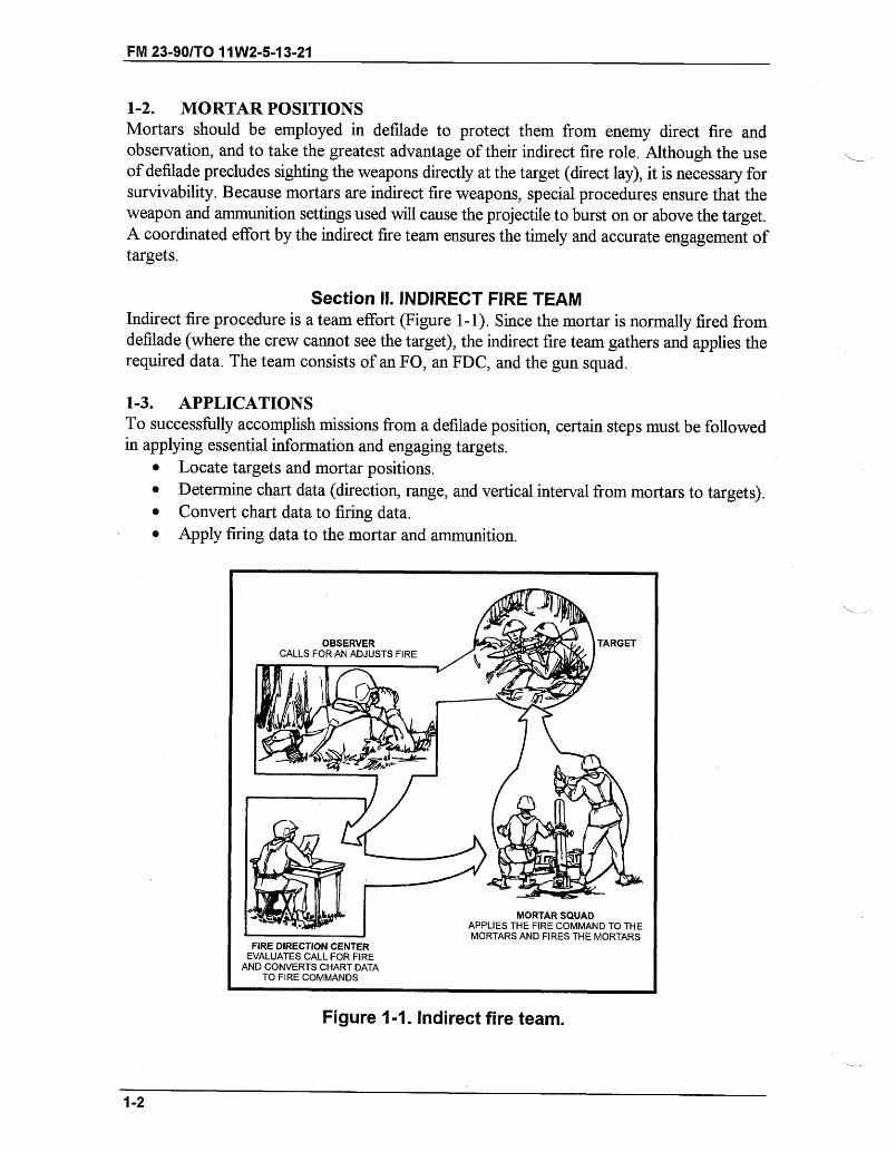
Section II. INDIRECT FIRE TEAMIndirect fire procedure is a team effort (Figure 1-1). Since the mortar is normally fired fromdefilade (where the crew cannot see the target), the indirect fire team gathers and applies therequired data. The team consists of an FO, an FDC, and the gun squad.
1-3. APPLICATIONSTo successfully accomplish missions from a defilade position, certain steps must be followedin applying essential information and engaging targets.
* Locate targets and mortar positions.* Determine chart data (direction, range, and vertical interval from mortars to targets).* Convert chart data to firing data.* Apply firing data to the mortar and ammunition.
Figure 1-1. Indirect fire team.
1-2
MORTAR SQUADAPPLIES THE FIRE COMMAND TO THEMORTARS AND FIRES THE MORTARS
FIRE DIRECTION CENTEREVALUATES CALL FOR FIRE
AND CONVERTS CHART DATATO FIRE COMMANDS
- _~ __ _ _~ _ ~_ _ _
FM 23-90/TO 11W2-5-13-21
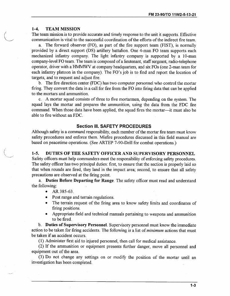
1-4. TEAM MISSIONThe team mission is to provide accurate and timely response to the unit it supports. Effectivecommunication is vital to the successful coordination of the efforts of the indirect fire team.
a. The forward observer (FO), as part of the fire support team (FIST), is normallyprovided by a direct support (DS) artillery battalion. One 4-man FO team supports eachmechanized infantry company. The light infantry company is supported by a 10-mancompany-level FO team. The team is composed of a lieutenant, staff sergeant, radio-telephoneoperator, driver with a HMMWV at company headquarters, and six FOs (one 2-man team foreach infantry platoon in the company). The FO's job is to find and report the location oftargets, and to request and adjust fire.
b. The fire direction center (FDC) has two computer personnel who control the mortarfiring. They convert the data in a call for fire from the FO into firing data that can be appliedto the mortars and ammunition.
c. A mortar squad consists of three to five mortarmen, depending on the system. Thesquad lays the mortar and prepares the ammunition, using the data from the FDC firecommand. When those data have been applied, the squad fires the mortar-it must also beable to fire without an FDC.
Section ill. SAFETY PROCEDURESAlthough safety is a command responsibility, each member of the mortar fire team must knowsafety procedures and enforce them. Misfire procedures discussed in this field manual arebased on peacetime operations. (See ARTEP 7-90-Drill for combat operations.)
1-5. DUTIES OF THE SAFETY OFFICER AND SUPERVISORY PERSONNELSafety officers must help commanders meet the responsibility of enforcing safety procedures.The safety officer has two principal duties: first, to ensure that the section is properly laid sothat when rounds are fired, they land in the impact area; second, to ensure that all safetyprecautions are observed at the firing point.
a. Duties Before Departing for Range. The safety officer must read and understandthe following:
" AR 385-63." Post range and terrain regulations." The terrain request of the firing area to know safety limits and coordinates of
firing positions." Appropriate field and technical manuals pertaining to weapons and ammunition
to be fired.b. Duties of Supervisory Personnel. Supervisory personnel must know the immediate
action to be taken for firing accidents. The following is a list of minimum actions that mustbe taken if an accident occurs.
(1) Administer first aid to injured personnel, then call for medical assistance.(2) If the ammunition or equipment presents further danger, move all personnel and
equipment out of the area.(3) Do not change any settings on or modify the position of the mortar until an
investigation has been completed.
1-3

FM 23-90/TO 11W2-5-13-21
(4) Record the ammunition lot number involved in the accident or malfunction and reportit to the battalion ammunition officer. If a certain lot number is suspected, its use should besuspended by the platoon leader.
c. Mortar Range Safety Checklist. A mortar range safety checklist can be written forlocal use. The following is a suggested checklist, which can also include three columns on theright titled "Yes," "No," and "Remarks."
(1) Items to check before firing.(a) Is a range log or journal maintained by the officer in charge?(b) Is radio or telephone communication maintained with-
* Range control?* Unit S3?® Firing crews?* Forward observers?* Road or barrier guards?
(c) Are the required emergency personnel and equipment present on the range?* Properly briefed and qualified medical personnel.* A wheeled or tracked ambulance.* Fire-fighting equipment.
(d) Are the following range controls and warning devices available, readily visible, andin use during the firing exercise?
* Barrier/road guards briefed and in position.* Road barriers in position.* Red range flag in position.* Blinking red lights for night firing.* Signs warning trespassers to beware of explosive hazards and not to remove duds
or ammunition components from ranges.* Noise hazard warning signs.
(e) Are current copies of the following documents available and complied with?* AR 385-63.* Technical and field manuals pertinent to the mortar in use.* Appropriate firing tables.* Installation range regulations.
(f) Are the following personal safety devices and equipment available and in use?* Helmets.* Protective earplugs.* Protective earmuffs.
(g) Is the ammunition the correct caliber, type, and quantity required for the day's firing?Are the rounds, fuzes, and charges-
* Stored in a location to minimize possible ignition or detonation?* Covered to protect them from moisture and direct sunlight?* Stacked on dunnage to keep them clear of the ground?* Strictly accounted for by lot number?* Exposed only immediately before firing?* Stored separately from ammunition and protected from ignition?
1-4
FM 23-90/T0 11W2-5-13-21
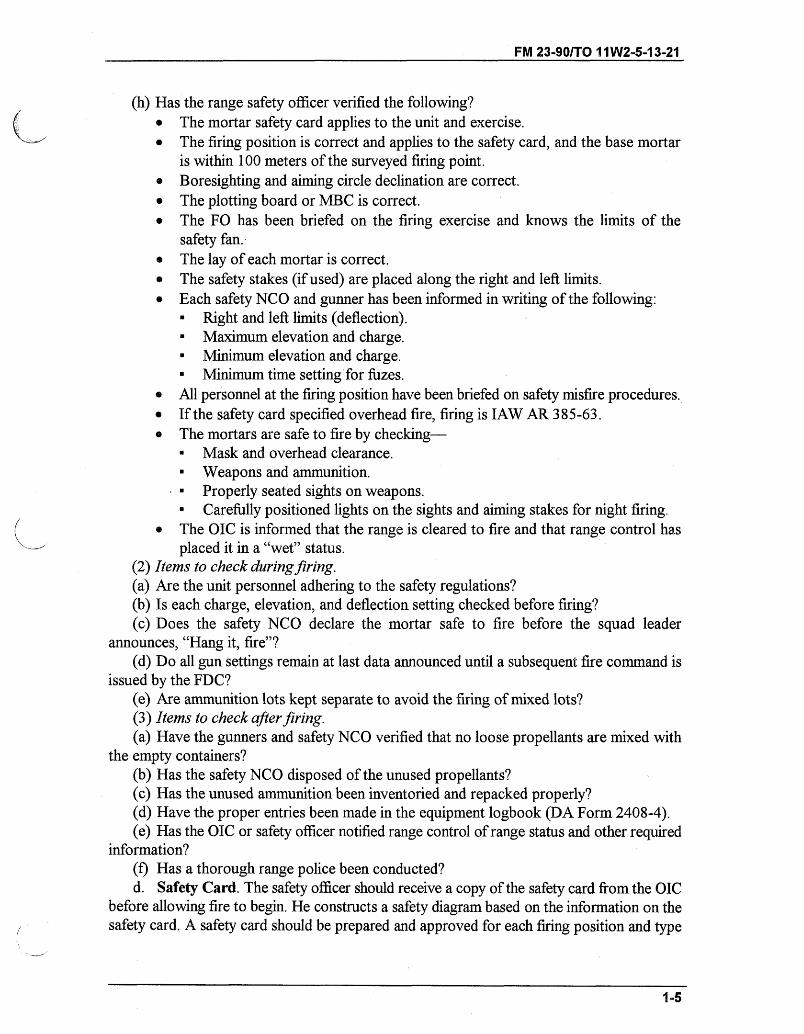
(h) Has the range safety officer verified the following?" The mortar safety card applies to the unit and exercise." The firing position is correct and applies to the safety card, and the base mortar
is within 100 meters of the surveyed firing point." Boresighting and aiming circle declination are correct." The plotting board or MBC is correct." The FO has been briefed on the firing exercise and knows the limits of the
safety fan." The lay of each mortar is correct." The safety stakes (if used) are placed along the right and left limits." Each safety NCO and gunner has been informed in writing of the following:
" Right and left limits (deflection).SMaximum elevation and charge.
" Minimum elevation and charge.- Minimum time setting for fuzes.
" All personnel at the firing position have been briefed on safety misfire procedures.* If the safety card specified overhead fire, firing is IAW AR 385-63." The mortars are safe to fire by checking-
" Mask and overhead clearance." Weapons and ammunition." Properly seated sights on weapons." Carefully positioned lights on the sights and aiming stakes for night firing.
" The OIC is informed that the range is cleared to fire and that range control hasplaced it in a "wet" status.
(2) Items to check during firing.(a) Are the unit personnel adhering to the safety regulations?(b) Is each charge, elevation, and deflection setting checked before firing?(c) Does the safety NCO declare the mortar safe to fire before the squad leader
announces, "Hang it, fire"?(d) Do all gun settings remain at last data announced until a subsequent fire command is
issued by the FDC?(e) Are ammunition lots kept separate to avoid the firing of mixed lots?(3) Items to check after firing.(a) Have the gunners and safety NCO verified that no loose propellants are mixed with
the empty containers?(b) Has the safety NCO disposed of the unused propellants?(c) Has the unused ammunition been inventoried and repacked properly?(d) Have the proper entries been made in the equipment logbook (DA Form 2408-4).(e) Has the OIC or safety officer notified range control of range status and other required
information?(f) Has a thorough range police been conducted?d. Safety Card. The safety officer should receive a copy of the safety card from the OIC
before allowing fire to begin. He constructs a safety diagram based on the information on thesafety card. A safety card should be prepared and approved for each firing position and type
1-5
FM 23-90/TO 11W2-5-13-21
of ammunition used. The form of the card depends upon local regulations (training list,overlay, range bulletin). Even without a prescribed format, it should contain the following:
* Unit firing or problem number.* Type of weapon and fire.* Authorized projectile, fuze, and charge zone.* Grid of the platoon center.* Azimuth of left and right limits.* Minimum and maximum ranges and elevations.* Any special instructions to allow for varying limits on special ammunition or
situations.e. Safety Diagram. The safety officer, on receipt of the safety card, constructs a safety
diagram. The safety diagram is a graphic portrayal of the data on the safety card, which neednot be drawn to scale but must accurately list the sight settings that delineate the impact area.The diagram serves as a convenient means of checking the commands announced to the guncrews against those commands that represent the safety limits.
(1) The diagram shows the right and left limits, expressed in deflections correspondingto those limits; the maximum and minimum elevations; and the minimum fuze settings (whenapplicable) for each charge to be fired. The diagram also shows the minimum and maximumrange lines, the left and right azimuth limits, the deflections corresponding to the azimuthlimits, and the direction on which the guns are laid. The safety diagram must show onlynecessary information.
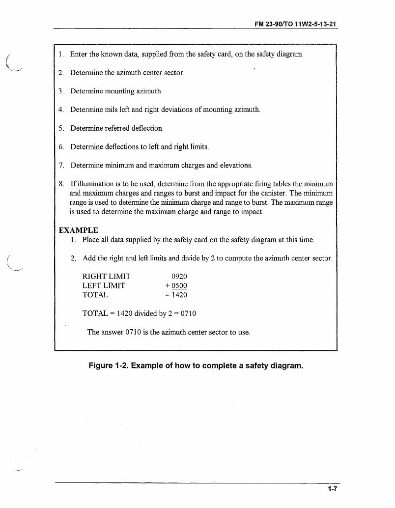
(2) To accurately complete a safety diagram, the safety officer must use the informationsupplied by range control or, in the example in Figure 1-2, the safety card.
1-6
FM 23-90/TO 11W2-5-13-21
1. Enter the known data, supplied from the safety card, on the safety diagram.
2. Determine the azimuth center sector.
3. Determine mounting azimuth.
4. Determine mils left and right deviations of mounting azimuth.
5. Determine referred deflection.
6. Determine deflections to left and right limits.
7. Determine minimum and maximum charges and elevations.
8. If illumination is to be used, determine from the appropriate firing tables the minimumand maximum charges and ranges to burst and impact for the canister. The minimumrange is used to determine the minimum charge and range to burst. The maximum rangeis used to determine the maximum charge and range to impact.
EXAMPLE1. Place all data supplied by the safety card on the safety diagram at this time.
2. Add the right and left limits and divide by 2 to compute the azimuth center sector.
RIGHT LIMIT 0920LEFT LIMIT + 0500TOTAL = 1420
TOTAL = 1420 divided by 2 = 0710
The answer 0710 is the azimuth center sector to use.
Figure 1-2. Example of how to complete a safety diagram.
1-7
FM 23-90/TO 11W2-5-13-21
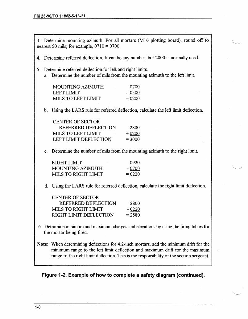
3. Determine mounting azimuth. For all mortars (M16 plotting board), round off tonearest 50 mils; for example, 0710 = 0700.
4. Determine referred deflection. It can be any number, but 2800 is normally used.
5. Determine referred deflection for left and right limits.a. Determine the number of mils from the mounting azimuth to the left limit.
MOUNTING AZIMUTH 0700LEFT LIMIT - 0500MILS TO LEFT LIMIT = 0200
b. Using the LARS rule for referred deflection, calculate the left limit deflection.
CENTER OF SECTORREFERRED DEFLECTION 2800
MILS TO LEFT LIMIT + 0200LEFT LIMIT DEFLECTION = 3000
c. Determine the number of mils from the mounting azimuth to the right limit.
RIGHT LIMIT 0920MOUNTING AZIMUTH - 0700MILS TO RIGHT LIMIT = 0220
d. Using the LARS rule for referred deflection, calculate the right limit deflection.
CENTER OF SECTORREFERRED DEFLECTION 2800
MILS TO RIGHT LIMIT - 0220RIGHT LIMIT DEFLECTION = 2580
6. Determine minimum and maximum charges and elevations by using the firing tables forthe mortar being fired.
Note: When determining deflections for 4.2-inch mortars, add the minimum drift for theminimum range to the left limit deflection and maximum drift for the maximumrange to the right limit deflection. This is the responsibility of the section sergeant.
Figure 1-2. Example of how to complete a safety diagram (continued).
1-8
FM 23-90/TO 11W2-5-13-21
1-6. AMMUNITION CARE AND HANDLINGA complete round of mortar ammunition contains all the components needed to get the roundout of the tube and to burst it at the desired place and time. The key to proper ammunitionfunctioning is protection. Rounds prepared but not fired should be placed back in theircontainers, fin end first. Safety is always a matter of concern for all section personnel, and itrequires special attention where ammunition is concerned. Supervision is critical, becauseimproper care and handling can cause serious accidents as well as inaccurate fire. Followingare some of the principles of proper ammunition handling.
* Never tumble, drag, throw, or drop individual cartridges or boxes of cartridges.* Do not allow smoking, open flames, or other fire hazards around ammunition storage
areas.* Inspect each cartridge before it is loaded for firing. Dirty ammunition can damage the
weapon or affect the accuracy of the round.* Keep the ammunition dry and cool.* Never make unauthorized alterations or mix components of one lot with another.
Note: For care and handling of specific mortar rounds, see corresponding chapter in thismanual.
a. Projectiles/Cartridges. Each projectile must be inspected to ensure that there is noleakage of the contents, and that the projectile is correctly assembled. The HE 4.2-inch mortarprojectiles are issued without a fuze. Each is issued with a removable supplementary chargeso that it can be used with an impact, mechanical, or VT (proximity) fuze.
b. Burning of Unused Propelling Charges. Mortar increments and propelling chargesare highly flammable, and they must be handled with extreme care to preclude exposure toheat, flame, or any spark-producing source. This includes exposure to the hot residue fromburning increments or propelling charges that float downward after a cartridge leaves thebarrel. Like other types of ammunition, increments and propelling charges must be kept cooland dry. Storing these items inside the ammunition boxes until needed is an effective way toprevent premature combustion.
(1) Unused charges must not be saved but should be removed to a storage area until theycan be burned or otherwise disposed of.
(2) Burning increments create a large flash and a lot of smoke. In a tactical environment,the platoon leader must ensure that burning increments do not compromise camouflage andconcealment. The burning of increments in a dummy position, if established, can aid in thedeception effort. The safety officer, in a range environment, supervises the disposal of unusedpropellant increments.
c. Fuzes. Never fire a round with a fuze that is not authorized for that round. Specificfuzes available for each weapon system are discussed in this manual.
(1) Fuzes are sensitive to shock and must be handled with care. Before fuzing a round,inspect the threads of the fuze and fuze well for cleanliness and crossed threads. The fuzeshould be screwed into the fuze well slowly until resistance is met and then firmly seated witha sharp twist of the M25 or M18 fuze wrench, as appropriate.
FM 23-90/TO 11W2-5-13-21
(2) To prevent accidental functioning of the point-detonating elements of fuzes of theM524 series, the fuzes must not be dropped, rolled, or struck under any circumstances. Anymechanical-time fuze that is set and modified must be reset to SAFE, and the safety wires (if
applicable) must be replaced before the fuze is repacked in the original carton.(3) All primers must be inspected before use for signs of corrosion. If a seal has been
broken, it is likely that the primer has been affected by moisture and should be turned in.
d. Segregation of Ammunition Lots. Different lots of propellant burn at different ratesand give slightly different effects in the target area. Therefore, the registration correctionsderived from one lot do not always apply to another. Ammunition MUST be segregated bylot and weight zone (square weight [4.2-inch mortar only]). In the field storage area, onvehicles or in a dump, ammunition lots should be roped off with communications wire ortwine and conspicuously marked with a cardboard sign or other marker.
1-7. FIELD STORAGE OF AMMUNITIONMost ammunition components can be stored at temperatures as low as -80 degrees F for notlonger than three days and as high as 160 degrees F for not longer than four hours.
a. The greatest hazards to ammunition in the storage area are weather, enemy fire, NBCcontamination, improper handling, and accidental fires. Regardless of the method of storage,those hazards must be considered. Some general considerations that apply to storage are asfollows:
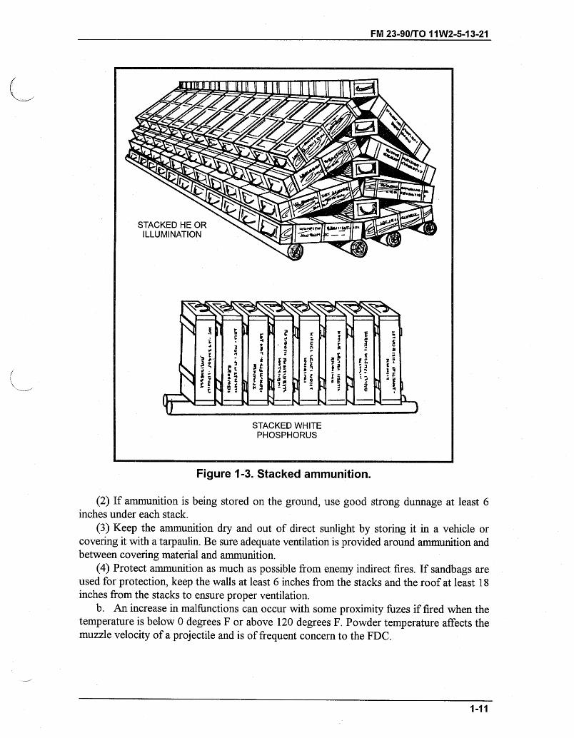
(1) Stack ammunition by type, lot number, and weight zone (Figure 1-3).
Note: WP ammunition must be stacked fuze-end up.
1-10
FM 23-90/TO 11W2-5-13-21
Figure 1-3. Stacked ammunition.
(2) If ammunition is being stored on the ground, use good strong dunnage at least 6inches under each stack.
(3) Keep the ammunition dry and out of direct sunlight by storing it in a vehicle orcovering it with a tarpaulin. Be sure adequate ventilation is provided around ammunition andbetween covering material and ammunition.
(4) Protect ammunition as much as possible from enemy indirect fires. If sandbags areused for protection, keep the walls at least 6 inches from the stacks and the roof at least 18inches from the stacks to ensure proper ventilation.
b. An increase in malfunctions can occur with some proximity fuzes if fired when thetemperature is below 0 degrees F or above 120 degrees F. Powder temperature affects themuzzle velocity of a projectile and is of frequent concern to the FDC.
1-11
STACKED WHITEPHOSPHORUS
- --- -~-~LIP- ~- -D-L
FM 23-90/TO 11W2-5-13-21
CHAPTER 2
SIGHTING AND FIRE CONTROL EQUIPMENT
Proper employment of sighting and fire control equipment ensures effectivefire against the enemy. This chapter describes this equipment and itsapplications.
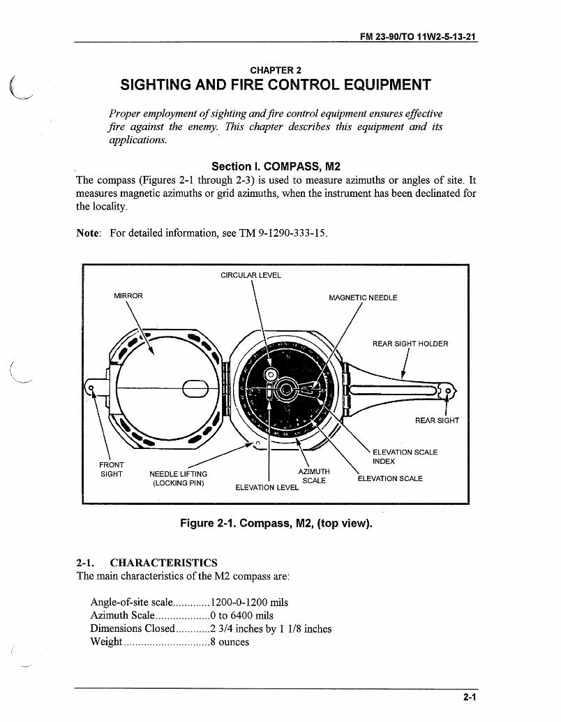
Section I. COMPASS, M2The compass (Figures 2-1 through 2-3) is used to measure azimuths or angles of site. Itmeasures magnetic azimuths or grid azimuths, when the instrument has been declinated forthe locality.
Note: For detailed information, see TM 9-1290-333-15.
Figure 2-1. Compass, M2, (top view).
2-1. CHARACTERISTICSThe main characteristics of the M2 compass are:
Angle-of-site scale.............1200-0-1200 milsAzimuth Scale ................... to 6400 milsDimensions Closed.........2 3/4 inches by 1 1/8 inchesW eight ........................... 8 ounces
-- ----- - ---- -I - I
FM 23-90/TO 11W2-5-13-21
2-2. DESCRIPTIONThe principal parts of the compass are described herein.
a. Compass Body Assembly. This assembly consists of a circular glass window thatcovers the instrument, and keeps dust and moisture from its interior, protecting the compassneedle and angle-of-site mechanism. A hinge assembly holds the compass cover in theposition in which it is placed. A hole in the cover coincides with a small oval window in themirror on the inside of the cover. A sighting line is etched across the face of the mirror.
b. Angle-of-Site Mechanism. The angle-of-site mechanism is attached to the bottomof the compass body. It consists of an actuating (leveling) lever located on the back of thecompass, a leveling assembly with a tubular elevation level, and a circular level. Theinstrument is leveled with the circular level to read azimuths and with the elevation level toread angle of site. The elevation (angle-of-site) scale and the four points of the compass,represented by three letters and a star, are engraved on the inside bottom of the compassbody. The elevation scale is graduated in two directions; in each direction it is graduated from0 to 1200 mils in 20-mil increments and numbered every 200 mils.
c. Magnetic Needle and Lifting Mechanism. The magnetic needle assembly consistsof a magnetized needle and a jewel housing that serves as a pivot. The north-seeking end ofthe needle is white. (The newer compasses have the north and south ends of the needlemarked "N" and "S" in raised, white lettering.) On some compasses a thin piece of copperwire is wrapped around the needle for counterbalance. A lifting pin projects above the top rimof the compass body. The lower end of the pin engages the needle-lifting lever. When thecover is closed, the magnetic needle is automatically lifted from its pivot and-held firmlyagainst the window of the compass.
d. Azimuth Scale and Adjuster. The azimuth scale is a circular dial geared to theazimuth scale adjuster. This permits rotation of the azimuth scale about 900 mils in eitherdirection. The azimuth index provides a means of orienting the azimuth scale at 0 or thedeclination constant of the locality. The azimuth scale is graduated from 0 to 6400 in 20-milincrements and numbered at 200-mil intervals.
e. Front and Rear Sight. The front sight is hinged to the compass cover. It can befolded across the compass body, and the cover is closed. The rear sight is made in twoparts-a rear sight and holder. When the compass is not being used, the rear sight and holderare folded across the compass body and the cover is closed.
2-3. USEThe compass should be held as steadily as possible to obtain accurate readings. The use of asitting or prone position, a rest for the hand or elbows, or a solid nonmetallic support helpseliminate unintentional movement of the instrument. When being used to measure azimuths,the compass must not be near metallic objects.
a. To measure a magnetic azimuth-(1) Zero the azimuth scale by turning the scale adjuster.(2) Place the cover at an angle of about 45 degrees to the face of the compass so that the
scale reflection is viewed in the mirror.(3) Adjust the front and rear sights to the desired position. Sight the compass by any of
these methods:
2-2
FM 23-90/TO 11W2-5-13-21
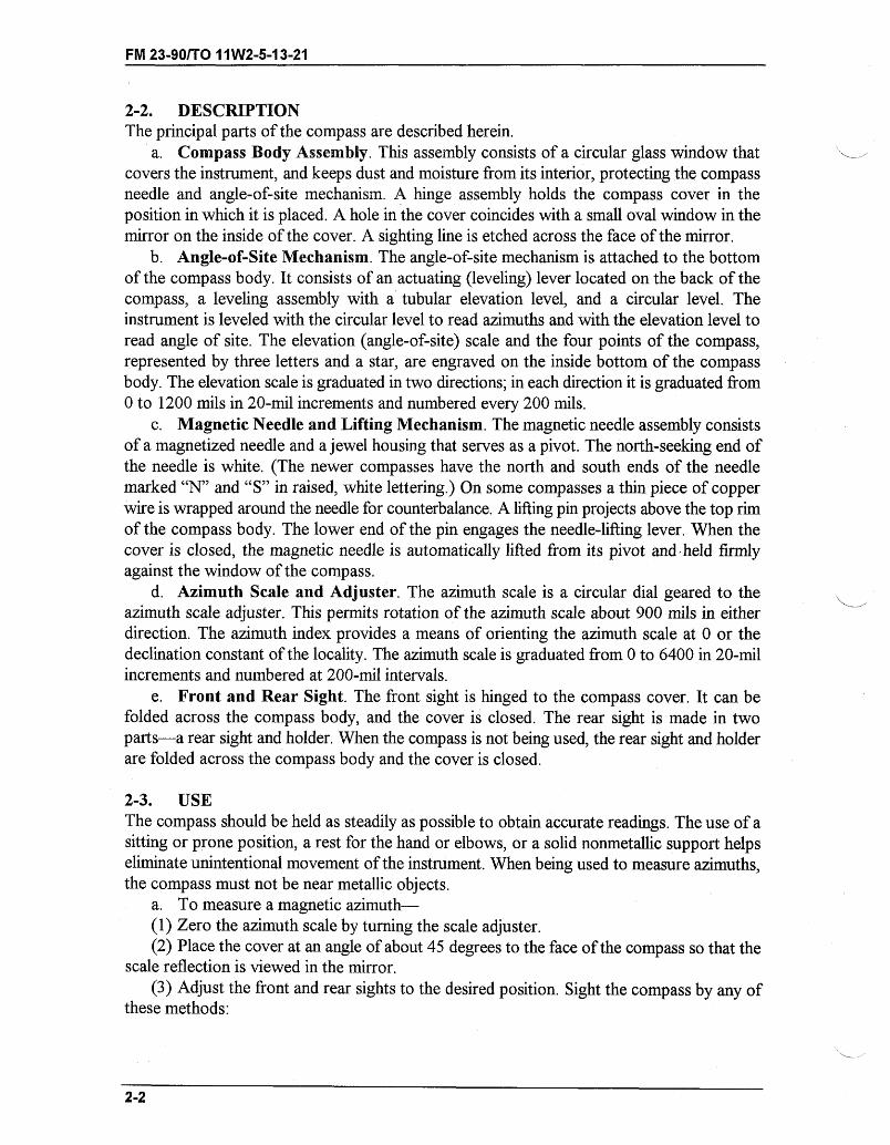
(a) Fold the rear sight holder out parallel with the rear sight of the compass faceperpendicular to its holder. Sight through the window in the cover. If the object sighted is ata lower elevation than the compass, raise the rear sight holder as needed. The compass iscorrectly sighted when it is level and the black centerline of the window, rear sight, and objectare aligned.
(b) Raise the front and rear sights perpendicular to the face of the compass (Figure 2-2and Figure 2-3, page 2-4). Sight over the tips of the rear and front sights. The compass iscorrectly sighted when it is level and the tips of the sights and object are aligned.
Figure 2-2. Compass, M2 (side view)
2-3
FM 23-90/TO 11W2-5-13-21
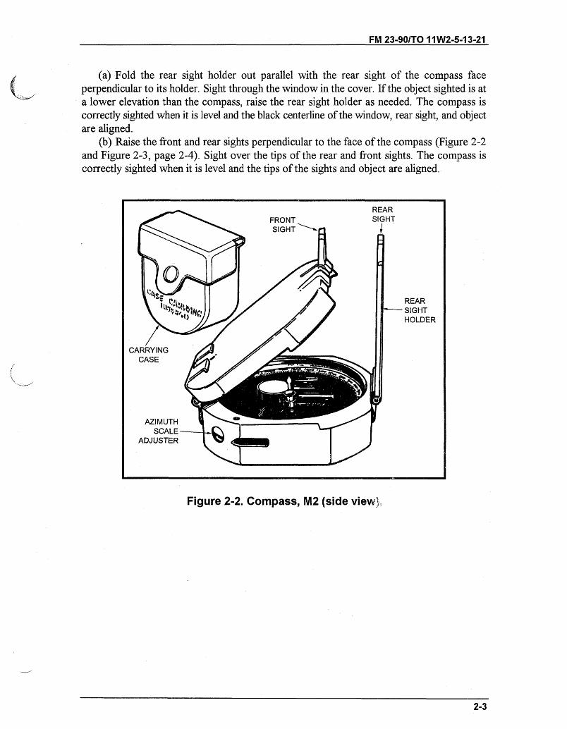
Figure 2-3. Compass, M2 (user's view).
(4) Hold the compass in both hands, at eye level, with the arms braced against the bodyand the rear sight near the eyes. For precise measurements, rest the compass on a nonmetallicstake or object.
(5) Level the instrument by viewing the circular level in the mirror and moving thecompass until the bubble is centered. Sight on the object, look in the mirror, and read theazimuth indicated by the black (south) end of the magnetic needle.
b. To measure a grid azimuth-(1) Index the known declination constant on the azimuth scale by turning the azimuth
scale adjuster. Be sure to loosen the locking screw on the bottom of the compass. (The newlightweight [plastic] M2 compass has no locking screw.)
(2) Measure the azimuth as described above. The azimuth measured is a grid azimuth.c. To measure an angle of site or vertical angle from the horizontal-(1) Hold the compass with the left side down (cover to the left) and fold the rear sight
holder out parallel to the face of the compass, with the rear sight perpendicular to the holder.Position the cover so that, when looking through the rear sight and the aperture in the cover,the elevation vial is reflected in the mirror.
(2) Sight on the point to be measured.(3) Center the bubble in the elevation level vial (reflected in the mirror) with the level
lever.(4) Read the angle on the elevation scale opposite the index mark. The section of the scale
graduated counterclockwise from 0 to 1200 mils measures plus angles of site. The section ofthe scale graduated clockwise from 0 to 1200 mils measures minus angles of site.
2-4
REAR SIGHT
FRONT SIGHT
REAR SIGHTHOLDER
REFLECTEDSCALEIMAGE
___slP_1OBI~_______I1____1______ ~ ~1~
FM 23-90/TO 11W2-5-13-21
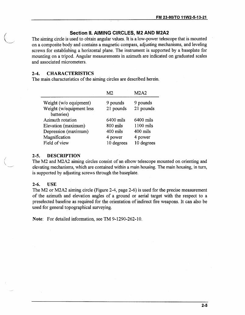
Section II. AIMING CIRCLES, M2 AND M2A2The aiming circle is used to obtain angular values. It is a low-power telescope that is mountedon a composite body and contains a magnetic compass, adjusting mechanisms, and levelingscrews for establishing a horizontal plane. The instrument is supported by a baseplate formounting on a tripod. Angular measurements in azimuth are indicated on graduated scalesand associated micrometers.
2-4. CHARACTERISTICSThe main characteristics of the aiming circles are described herein.
M2 M2A2
Weight (w/o equipment) 9 pounds 9 poundsWeight (w/equipment less 21 pounds 21 pounds
batteries)Azimuth rotation 6400 mils 6400 milsElevation (maximum) 800 mils 1100 milsDepression (maximum) 400 mils 400 milsMagnification 4 power 4 powerField of view 10 degrees 10 degrees
2-5. DESCRIPTIONThe M2 and M2A2 aiming circles consist of an elbow telescope mounted on orienting andelevating mechanisms, which are contained within a main housing. The main housing, in turn,is supported by adjusting screws through the baseplate.
2-6. USEThe M2 or M2A2 aiming circle (Figure 2-4, page 2-6) is used for the precise measurementof the azimuth and elevation angles of a ground or aerial target with the respect to apreselected baseline as required for the orientation of indirect fire weapons. It can also beused for general topographical surveying.
Note: For detailed information, see TM 9-1290-262-10.
2-5
FM 23-90/TO 11W2-5-13-21
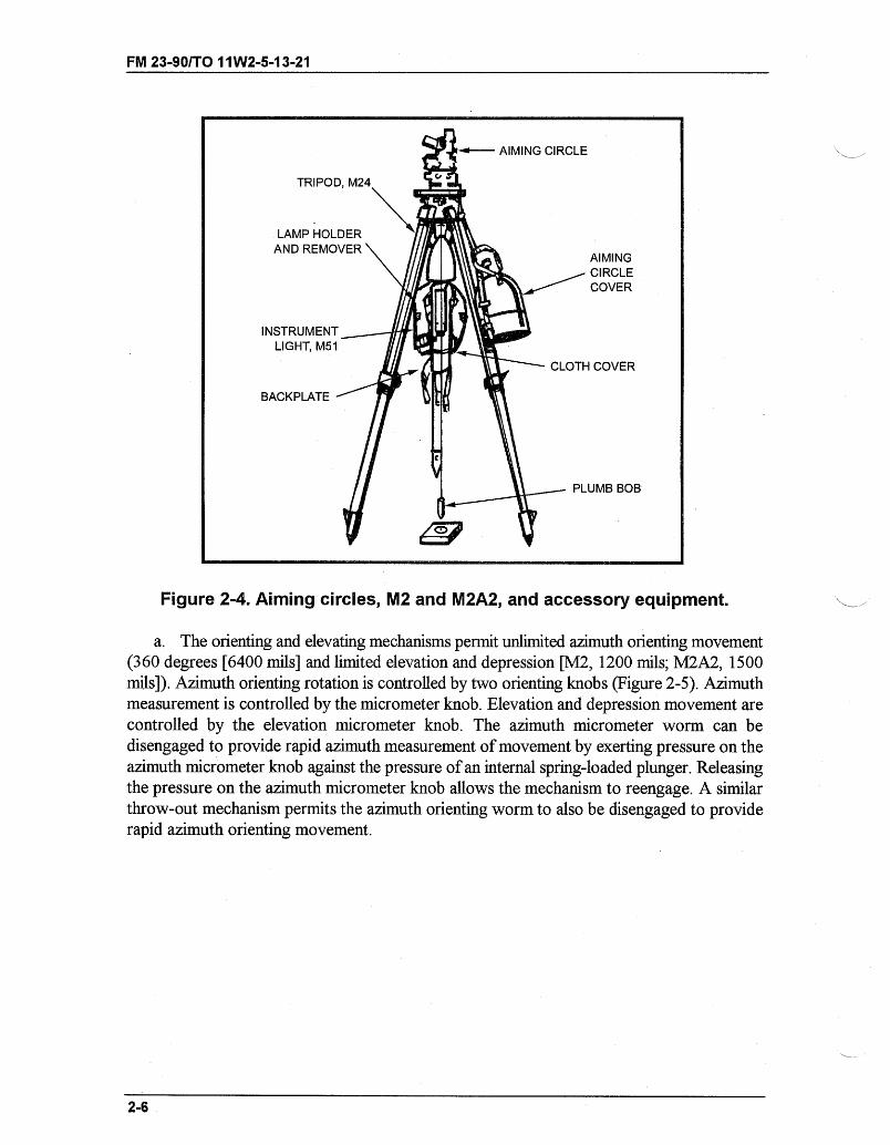
Figure 2-4. Aiming circles, M2 and M2A2, and accessory equipment.
a. The orienting and elevating mechanisms permit unlimited azimuth orienting movement(360 degrees [6400 mils] and limited elevation and depression [M2, 1200 mils; M2A2, 1500mils]). Azimuth orienting rotation is controlled by two orienting knobs (Figure 2-5). Azimuthmeasurement is controlled by the micrometer knob. Elevation and depression movement arecontrolled by the elevation micrometer knob. The azimuth micrometer worm can bedisengaged to provide rapid azimuth measurement of movement by exerting pressure on theazimuth micrometer knob against the pressure of an internal spring-loaded plunger. Releasingthe pressure on the azimuth micrometer knob allows the mechanism to reengage. A similarthrow-out mechanism permits the azimuth orienting worm to also be disengaged to providerapid azimuth orienting movement.
2-6
AIMINGCIRCLECOVER
CLOTH COVER
_ PLUMB BOB
- -~-~--~- -~~ - -- - --
ELEVATION MICROMETER
ELEVATIONMICROMETERSCALE
MAIN HOUSING
LOCKINGKNOB
AZIMUTH- ORIENTING
KNOB
LEFT-SIDE VIEW
SLOTTEDBRACKET
TELESCOPICBODY "
TUBULAR KLEVELS
ELEVATIONSCALE
AZIMUTHi MICROMETER
KNOB
AZIMUTHORIENTINGKNOB
AZIMUTHSCALE
BASEPLATE
RIGHT-SIDE VIEW
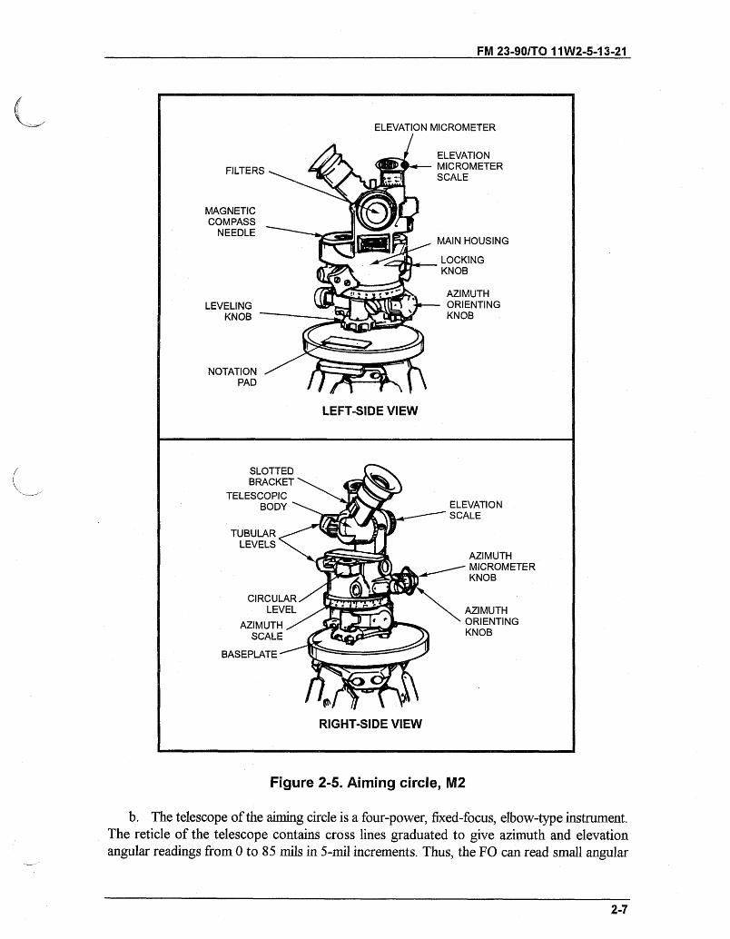
Figure 2-5. Aiming circle, M2
b. The telescope of the aiming circle is a four-power, fixed-focus, elbow-type instrument.The reticle of the telescope contains cross lines graduated to give azimuth and elevationangular readings from 0 to 85 mils in 5-mil increments. Thus, the FO can read small angular
2-7
FM 23-90/TO 11W2-5-13-21
FILTERS
MAGNETICCOMPASS
NEEDLE
LEVELINGKNOB -
NOTATION .PAD
-- -~~ II -~
- -- I'- -II -'
' I- -e ' ---- --~---~c~- II-~ - -- - c -
FM 23-90/TO 11W2-5-13-21
values directly from the reticle without referring to the azimuth and elevation micrometerscales. An externally stowed filter is provided for protection against the rays of the sun. Aslotted bracket provides the means of securing the lamp bracket on one lead wire of the M51instrument light so that illumination of the reticle during night operation can be accomplished.The reflector can be illuminated and used in conjunction with the sightunits on the mortarsduring night operations to backlight the vertical centerline of the aiming circle.
c. Three levels are contained within the telescope body and main housing of the aimingcircle. One tubular level, held between two bosses on the telescope body, is used to establisha true horizontal line-of-sight. The two bosses supporting this level are machined to form anopen sight for approximate alignment of the telescope and target, and for quick or emergencysighting. One circular level and one tubular level are held within bosses on the main housing.The circular level is used for rough leveling of the aiming circle, and the tubular level is usedfor fine leveling adjustments. The three leveling screws on the baseplate are used to level theinstrument and each is controlled by a leveling screw knob.
d. A magnetic compass needle is located in a recess in the top of the housing. Amagnifier and rectangular reticle located at one end of the recess enable the FO to observethe end of the compass needle and to align the line of sight of the telescope with the needle.The compass needle can be locked in position by actuating the locking lever on the side of thehousing.
e. Azimuth scales and elevation scales are employed to measure accurate azimuth orelevation angles. The scales provide coarse readings and the micrometer provides finereading. The two readings added together give the angle. Graduation intervals and numeralscales are graduated into relatively large round number intervals for convenience in reading.The scale intervals are in graduations of 100 mils.
(1) The azimuth scale is graduated from 0 to 6400 mils (zero equals 6400). The upperseries forms the main azimuth scale, colored black and numbered at 200-mil intervals. Thelower series, colored red, is numbered from 0 to 3200 mils (the large zero in the main scaleequals 3200). The red scale should only be used when verifying the lay of the aiming circlewith another aiming circle.
(2) The azimuth micrometer scale is graduated at 1-mil intervals and numbered from 0 to100 at ten 10-mil intervals.
(3) The elevation scale is graduated and numbered on both sides of 0. Minus (red)readings represent depression and plus (black) readings represent elevations at 100-milintervals from minus 400 to 800 mils.
(4) The elevation micrometer scale is graduated at 1-mil intervals from 0 to 99 mils-large zero is designated 0 and 100. Red numerals represent depression and black numeralsrepresent elevation.
f. A notation strip is provided on the baseplate. This strip is a raised and machinedsurface on which scale readings, settings, or other data can be recorded for reference.
2-7. ACCESSORY EQUIPMENTThe accessory equipment for the M2 aiming circle includes the aiming circle cover, M24tripod, and the accessory kit which includes the M51 instrument light, backplate, cloth cover,plumb bob, and a lamp holder and remover. This equipment is mounted on the M24 tripodwhen the instrument is set up for use.
2-8
FM 23-90/T0 11W2-5-13-21
a. The aiming circle cover is a metal cover that protects and houses the aiming circlewhen not in use. It attaches to the baseplate of the aiming circle and can be carried by meansof its strap. When the aiming circle is in use, the cover is placed on the tripod head cover.
b. The M24 tripod comprises three telescoping wooden legs hinged to a metal head,which contains a captive screw for attaching the aiming circle. When not in use, the tripodcover should be fitted on the head to protect the head and captive screw from damage, andthe legs are held retracted by a strap. Attachments are provided so that the aiming circle coverand cloth cover with attached accessory equipment can be mounted on its legs when theaiming circle is set up for use. A hook is also provided from which the plumb bob can besuspended by means of its attaching thread when in use.
c. The M51 instrument light is a lighting device for use with the M2 aiming circle duringnight operations and for certain test and adjustment procedures. The light is flashlight battery-powered and contains two attaching lead wires. A lamp bracket attached to one lead wire canbe inserted into the slotted bracket of the aiming circle telescope for illumination of thetelescope reticle. A hand light, attached to the other lead wire, can be used for general-purpose illumination (scales, level vials, reflector, compass needle, and so forth). Rotation ofthe rheostat knob turns the two lamps on and off and increases or decreases the intensity ofillumination.
d. The backplate provides the necessary clips and attachments for securing andprotecting the instrument light and lamp bracket, hand light, and lead wires of the light. Theplate with the attached instrument light is stored within the cloth cover.
e. The cloth cover is used to store the backplate and attached M51 instrument light. Itis also used to store the plumb bob and a lamp holder and remover. When the aiming circleis set up for use, the cloth cover with attached equipment is mounted on one of the legs ofthe M24 tripod. When not in use, attached snap fasteners keep the cover in a closed position.
f. The plumb bob is used to aid in orienting the aiming circle over a certain grid point.It composes a pointed weight attached to a nylon thread that can be suspended from the hookunder the tripod head when in use. The effective length of the thread can be adjusted bymeans of the slide. When not in use, the plumb bob is stored within the cloth cover.
g. A lamp holder and remover are used to hold spare incandescent lamps for the M51instrument light. They also facilitate the removal and replacement of unserviceable lamps inthe light.
2-8. SETUP AND LEVELING OF AIMING CIRCLEThe aiming circle must always be level during operation.
a. Unstrap the tripod legs, loosen the leg clamp thumbscrews, extend the legs so that thetripod is about chest high, and tighten the leg clamp thumbscrews. Spread the legs about18 inches apart, adjust the legs so the tripod head is about level, and plant the feet firmly inthe ground.
b. Remove the tripod head cover. Open the baseplate cover of the aiming circle head.Keeping the baseplate cover pointed toward you, thread the tripod guide screw assembly intothe aiming circle until it is firmly seated. The base of the aiming circle should not protrudeover the machine surface of the tripod head. Pull out and down on the strap latch assembly.Remove the cover and hang it on the tripod head cover.
2-9
FM 23-90/TO 1W2-5-13-21
c. If the instrument is to be set up over an orienting point, attach the plumb bob to thehook. Adjust the tripod legs and aiming circle head until it is over the point.
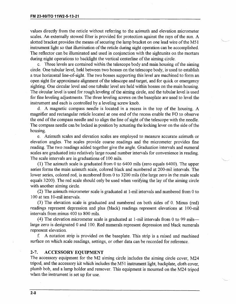
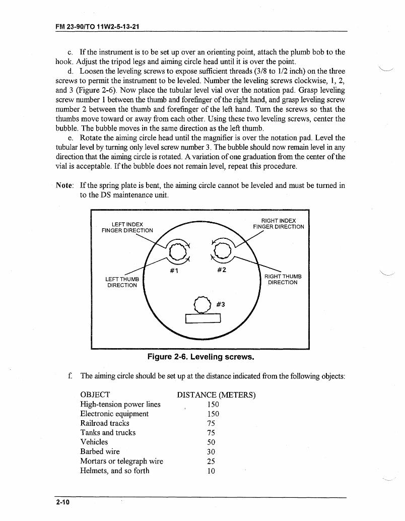
d. Loosen the leveling screws to expose sufficient threads (3/8 to 1/2 inch) on the threescrews to permit the instrument to be leveled. Number the leveling screws clockwise, 1, 2,and 3 (Figure 2-6). Now place the tubular level vial over the notation pad. Grasp levelingscrew number 1 between the thumb and forefinger of the right hand, and grasp leveling screwnumber 2 between the thumb and forefinger of the left hand. Turn the screws so that thethumbs move toward or away from each other. Using these two leveling screws, center thebubble. The bubble moves in the same direction as the left thumb.
e. Rotate the aiming circle head until the magnifier is over the notation pad. Level thetubular level by turning only level screw number 3. The bubble should now remain level in anydirection that the aiming circle is rotated. A variation of one graduation from the center of thevial is acceptable. If the bubble does not remain level, repeat this procedure.
Note: If the spring plate is bent, the aiming circle cannot be leveled and must be turned into the DS maintenance unit.
Figure 2-6. Leveling screws.
f. The aiming circle should be set up at the distance indicated from the following objects:
OBJECTHigh-tension power linesElectronic equipmentRailroad tracksTanks and trucksVehiclesBarbed wireMortars or telegraph wireHelmets, and so forth
DISTANCE (METERS)150150757550302510
2-10
FM 23-90/TO 11 W2-5-13-21
2-9. DECLINATION CONSTANTSince the magnetic needle of an aiming circle does not point to the grid north determinedfrom a map, it is necessary to correct for this difference by using the declination constant. Thedeclination constant of an instrument is the clockwise angle between grid north and magneticnorth; that is, the grid azimuth of magnetic north. This constant differs slightly for differentinstruments and must be recorded on each instrument. The constant also varies for the sameinstrument in different localities. To determine the declination constant, proceed as follows:
a. Declination Station. Declination stations are established by corps artillery, divisionartillery, and artillery battalion survey teams to determine the declination constants ofinstruments and to correct for local attractions, annual variations, and instrument errors.When a unit moves from one locality to another, a station should be established where allinstruments are declinated. If the declination constants for all instruments of a unit aredetermined at the same station, grid azimuths measured with each instrument will agree withthe map grid, and all instruments will agree with each other. The point chosen for thedeclination station must have a view of at least two distant, well-defined points with a knowngrid azimuth. Two additional points are desirable, one in each quadrant, as a check.
b. Procedure for Declinating Aiming Circle at a Declination Station. Where adeclination station is available, the procedure for declinating the aiming circle is as follows:
STEP 1. Set up and fine-level the aiming circle directly over the declination stationmarker using the plumb bob.
STEP 2. Place the grid azimuth of the first azimuth marker on the scales using therecording motion. Place the vertical cross line of the telescope on the azimuthmarker using the nonrecording (orienting) motion. The aiming circle is noworiented on grid north.
STEP 3. With the recording motion, rotate the instrument to zero. Release the magneticneedle and look through the magnifier. Center the north-seeking needle usingthe recording motion, then relock the magnetic needle.
STEP 4. Notice the new azimuth on the scale, which is the declination constant-record it.
STEP 5. Recheck the aiming circle level and repeat steps 2 through 4 using theremaining azimuth markers until three readings have been taken. If there isonly one marker, repeat the entire procedure twice using the same marker.
2-11
FM 23-90/TO 11W2-5-13-21
STEP 6. Find the average declination constant using these three readings.
EXAMPLE 11st point reading = 6399 mils2d point reading = 6398 mils3d point reading = 6398 mils
Total = 19195 mils
19195 + 3 = 6398.3 (rounded off to the nearest whole number) = 6398 mils(average declination constant)
EXAMPLE 21st point reading = 0030 mils2d point reading = 0031 mils3d point reading = 0029 mils
Total = 0090 mils
0090 + 3 = 0030 mils (average declination constant)
STEP 7. Record the average declination constant in pencil on the notation (strip) padof the aiming circle as its declination constant. All readings should be within2 mils of each other; if not, repeat steps 2 through 4. Ensure the aiming circleis directly over the station marker to obtain the 2-mil tolerance. If the desired2-mil accuracy is not gained after two tries, the aiming circle is defective andshould be turned in for repair.
c. Use of the Grid-Magnetic Angle. If an aiming circle is used in a new area withouta declination station, a declination constant can be determined by using the grid-magnetic(GM) angle from a map. When the GM angle (converted to mils) is westerly, it is subtractedfrom 6400 mils. The remainder is the declination constant. When the GM angle is easterly,the angle (in mils) is the declination constant.
d. Redeclination of an Aiming Circle. An aiming circle is redeclinated when movedover 25 miles (40 kilometers) from the last declination station. It is also redeclinated uponinitial issue, when returned from repair (if 30 days since last declinated), or if severely jolted.
e. Procedure for Declinating an Aiming Circle When a Declination Station is NotAvailable. This procedure is the least desirable and should be used only when no other meansare available. It does not compensate for the error that could be inherent in the aiming circle.
(1) Determine the GM angle from the map of the area in which the aiming circle is to beused. This GM angle is used as indicated below.
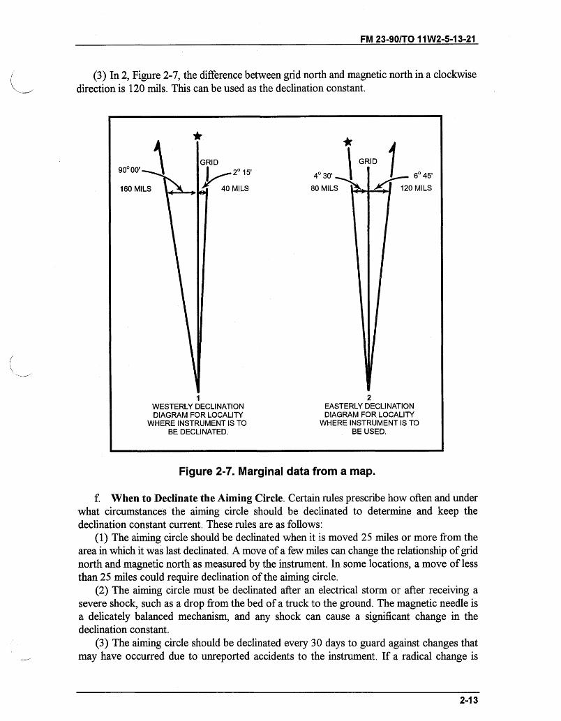
(2) In 1, Figure 2-7, the difference between grid north and magnetic north is 200 mils(westerly). This total is then subtracted from 6400 mils. The declination constant that can beused is 6200 mils.
2-12
FM 23-90/TO 11W2-5-13-21
(3) In 2, Figure 2-7, the difference between grid north and magnetic north in a clockwisedirection is 120 mils. This can be used as the declination constant.
''' -~''I
,20 15'
40 MILS
1WESTERLY DECLINATIONDIAGRAM FOR LOCALITY
WHERE INSTRUMENT IS TOBE DECLINATED.
40 30'
80 MILS
6045'
120 MILS
2EASTERLY DECLINATIONDIAGRAM FOR LOCALITY
WHERE INSTRUMENT IS TOBE USED.
U U-
Figure 2-7. Marginal data from a map.
f. When to Declinate the Aiming Circle. Certain rules prescribe how often and underwhat circumstances the aiming circle should be declinated to determine and keep thedeclination constant current. These rules are as follows:
(1) The aiming circle should be declinated when it is moved 25 miles or more from thearea in which it was last declinated. A move of a few miles can change the relationship of gridnorth and magnetic north as measured by the instrument. In some locations, a move of lessthan 25 miles could require declination of the aiming circle.
(2) The aiming circle must be declinated after an electrical storm or after receiving asevere shock, such as a drop from the bed of a truck to the ground. The magnetic needle isa delicately balanced mechanism, and any shock can cause a significant change in thedeclination constant.
(3) The aiming circle should be declinated every 30 days to guard against changes thatmay have occurred due to unreported accidents to the instrument. If a radical change is
2-13
90000'
160 MILS
FM 23-90/TO 11W2-5-13-21
observed, the instrument should be declinated again within a few days to determine if theobserved change was due to a magnetic storm or is a real change in the characteristics of theinstrument.
(4) The aiming circle should be declinated when it is initially received and when it isreturned from support maintenance repair. Variations in the declination constant due to thetime of day are not significant enough to warrant declinating again.
2-10. ORIENTING OF THE INSTRUMENT ON GRID NORTH TO MEASUREGRID AZIMUTH TO OBJECTSThe procedure to orient the aiming circle on grid north to measure grid azimuth to objects isas follows:
a. Level the instrument.b. Set the azimuth micrometer and the azimuth scale on the declination constant of the
instrument.c. Release the magnetic needle.d. With the orienting knob, align the south end of the needle accurately with the center
etched line by using the magnetic needle magnifier.e. Lock the magnetic needle and close the orienting knob covers.f. Using the throw-out mechanism (azimuth knob), turn the telescope until the vertical
line of the reticle is about on the object.g. By rotating the azimuth knob, bring the vertical line exactly on the object.h. Read the azimuth to the object on the azimuth and micrometer scales.
2-11. MEASUREMENT OF HORIZONTAL ANGLE BETWEEN TWO POINTSTo measure the horizontal angle between two points, at least two measurements should bemade.
a. Set the azimuth micrometer and the azimuth scale at zero.b. Rotate the instrument using the orienting knob throw-out mechanism until the vertical
line of the telescope is about on the left edge of the left-hand object.c. Lay the vertical line exactly on the right edge of the left-hand object by rotating the
orienting knob.d. Using the throw-out mechanism (azimuth knob), turn the telescope clockwise until
the vertical line is about on the left edge of the right-hand object.e. Lay the vertical line exactly on the left edge of the right-hand object by turning the
azimuth knob.f. Read the horizontal angle on the scales and record the value to the nearest 0.5 mil.
This completes the first repetition.g. Rotate the aiming circle, using the lower motion, until the vertical cross line is again
on the rear station.
Note: The value obtained from the first repetition is still on the scales.
h. Rotate the aiming circle body, using the upper motion, until the vertical cross line isagain on the forward station.
2-14
FM 23-90/TO 11W2-5-13-21
i. Read and record the accumulated value of the two measurements of the angle to thenearest 0.5 mil. This completes the second repetition.
j. Divide the second reading by 2 to obtain the mean angle to the nearest 0.1 mil. Thismean angle must be within 0.5 mil of the first reading; if it is not, the measurement is void andthe angle is measured again.
2-12. ORIENTING OF THE 0-3200 LINE ON A GIVEN GRID AZIMUTHThe procedure for orienting the 0-3200 line of the aiming circle on a given grid azimuth isillustrated below. In this example, the mounting azimuth is 5550 mils and the aiming circle isassumed to have a declination constant of 6380 mils.
a. Set up and level the aiming circle.b. Subtract the announced mounting azimuth from the declination constant of the aiming
circle (adding 6400 to the declination constant of the aiming circle if the mounting azimuthis larger). In this case, subtract the mounting azimuth 5550 from the declination constant6380.
Solution:Declination constant 6380 milsAnnounced mounting azimuth- 5550 milsRemainder 830 mils
c. Set the remainder on the azimuth and micrometer scales of the aiming circle. In thiscase, the remainder is 830 mils (recording motion).
d. Release the compass needle. Look through the window in the cover housing androtate the instrument until the needle floats freely using the orienting knob throw-outmechanism. For fine adjustments, use orienting knobs until the magnetic needle is exactlycentered on the etched marks on the magnifier. Relock the compass needle to orient the0-3200 line of the aiming circle on the mounting azimuth; in this case, grid azimuth of 5550mils (Figure 2-8, page 2-16).
2-15
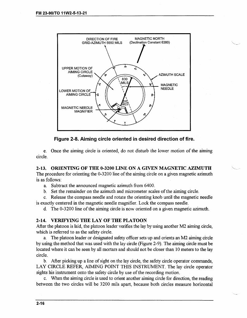
FM 23-90/TO 11 W2-5-13-21
DIRECTION OF FIRE MAGNETIC NORTHGRID-AZIMUTH 5550 MILS (Declination Constant 6380)
UPPER MOTION OF 35
AIMING CIRCLE(Cutaway) /AZIMUTH SCALE
\ 830
+. ;iMILS 5 MAGNETIC
LOWER MOTION OF NEEDLE
AIMING CIRCLE 8
MAGNETIC NEEDLEMAGNIFIER
Figure 2-8. Aiming circle oriented in desired direction of fire.
e. Once the aiming circle is oriented, do not disturb the lower motion of the aimingcircle.
2-13. ORIENTING OF THE 0-3200 LINE ON A GIVEN MAGNETIC AZIMUTHThe procedure for orienting the 0-3200 line of the aiming circle on a given magnetic azimuthis as follows:
a. Subtract the announced magnetic azimuth from 6400.b. Set the remainder on the azimuth and micrometer scales of the aiming circle.c. Release the compass needle and rotate the orienting knob until the magnetic needle
is exactly centered in the magnetic needle magnifier. Lock the compass needle.d. The 0-3200 line of the aiming circle is now oriented on a given magnetic azimuth.
2-14. VERIFYING THE LAY OF THE PLATOONAfter the platoon is laid, the platoon leader verifies the lay by using another M2 aiming circle,which is referred to as the safety circle.
a. The platoon leader or designated safety officer sets up and orients an M2 aiming circleby using the method that was used with the lay circle (Figure 2-9). The aiming circle must belocated where it can be seen by all mortars and should not be closer than 10 meters to the laycircle.
b. After picking up a line of sight on the lay circle, the safety circle operator commands,LAY CIRCLE REFER, AIMING POINT THIS INSTRUMENT. The lay circle operatorsights his instrument onto the safety circle by use of the recording motion.
c. When the aiming circle is used to orient another aiming circle for direction, the readingbetween the two circles will be 3200 mils apart, because both circles measure horizontal
2-16
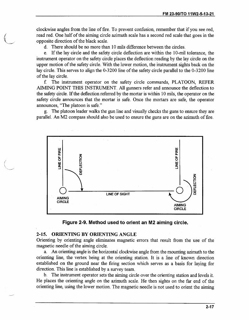
FM 23-90/TO 11W2-5-13-21
clockwise angles from the line of fire. To prevent confusion, remember that if you see red,read red. One half of the aiming circle azimuth scale has a second red scale that goes in theopposite direction of the black scale.
d. There should be no more than 10 mils difference between the circles.e. If the lay circle and the safety circle deflection are within the 10-mil tolerance, the
instrument operator on the safety circle places the deflection reading by the lay circle on theupper motion of the safety circle. With the lower motion, the instrument sights back on thelay circle. This serves to align the 0-3200 line of the safety circle parallel to the 0-3200 lineof the lay circle.
f. The instrument operator on the safety circle commands, PLATOON, REFERAIMING POINT THIS INSTRUMENT. All gunners refer and announce the deflection tothe safety circle. If the deflection referred by the mortar is within 10 mils, the operator on thesafety circle announces that the mortar is safe. Once the mortars are safe, the operatorannounces, "The platoon is safe."
g. The platoon leader walks the gun line and visually checks the guns to ensure they areparallel. An M2 compass should also be used to ensure the guns are on the azimuth of fire.
O F o
0 z
o
LINE OF SIGHTAIMINGCIRCLE
AIMINGCIRCLE
Figure 2-9. Method used to orient an M2 aiming circle.
2-15. ORIENTING BY ORIENTING ANGLEOrienting by orienting angle eliminates magnetic errors that result from the use of themagnetic needle of the aiming circle.
a. An orienting angle is the horizontal clockwise angle from the mounting azimuth to theorienting line, the vertex being at the orienting station. It is a line of known directionestablished on the ground near the firing section which serves as a basis for laying fordirection. This line is established by a survey team.
b. The instrument operator sets the aiming circle over the orienting station and levels it.He places the orienting angle on the azimuth scale. He then sights on the far end of theorienting line, using the lower motion. The magnetic needle is not used to orient the aiming
2-17
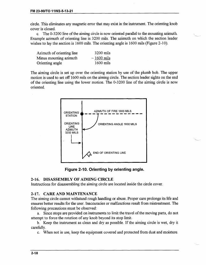
FM 23-90/TO 11W2-5-13-21
circle. This eliminates any magnetic error that may exist in the instrument. The orienting knobcover is closed.
c. The 0-3200 line of the aiming circle is now oriented parallel to the mounting azimuth.Example azimuth of orienting line is 3200 mils. The azimuth on which the section leaderwishes to lay the section is 1600 mils. The orienting angle is 1600 mils (Figure 2-10).
Azimuth of orienting lineMinus mounting azimuthOrienting angle
3200 mils- 1600 mils
1600 mils
The aiming circle is set up over the orienting station by use of the plumb bob. The uppermotion is used to set off 1600 mils on the aiming circle. The section leader sights on the endof the orienting line using the lower motion. The 0-3200 line of the aiming circle is noworiented.
Figure 2-10. Orienting by orienting angle.
2-16. DISASSEMBLY OF AIMING CIRCLEInstructions for disassembling the aiming circle are located inside the circle cover.
2-17. CARE AND MAINTENANCEThe aiming circle cannot withstand rough handling or abuse. Proper care prolongs its life andensures better results for the user. Inaccuracies or malfunctions result from mistreatment. Thefollowing precautions must be observed:
a. Since stops are provided on instruments to limit the travel of the moving parts, do notattempt to force the rotation of any knob beyond its stop limit.
b. Keep the instrument as clean and dry as possible. If the aiming circle is wet, dry itcarefully.
c. When not in use, keep the equipment covered and protected from dust and moisture.
2-18
ORIENTING AZIMUTH OF FIRE 1600 MILS
STATION
ORIENTING ORIENTING ANGLE 1600 MILSLINE
AZIMUTH3200 MILS
END OF ORIENTING LINE
END OF ORIENTING LINE
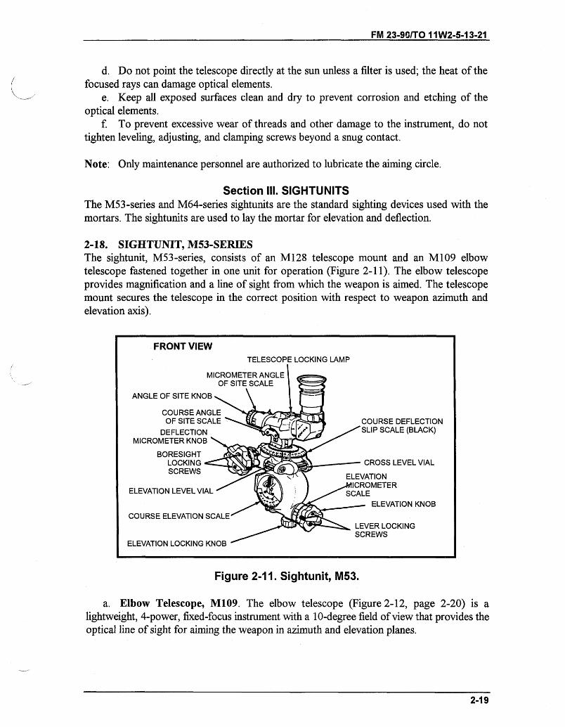
FM 23-90/TO 11W2-5-13-21
d. Do not point the telescope directly at the sun unless a filter is used; the heat of thefocused rays can damage optical elements.
e. Keep all exposed surfaces clean and dry to prevent corrosion and etching of theoptical elements.
f. To prevent excessive wear of threads and other damage to the instrument, do nottighten leveling, adjusting, and clamping screws beyond a snug contact.
Note: Only maintenance personnel are authorized to lubricate the aiming circle.
Section III. SIGHTUNITSThe M53-series and M64-series sightunits are the standard sighting devices used with themortars. The sightunits are used to lay the mortar for elevation and deflection.
2-18. SIGHTUNIT, M53-SERIESThe sightunit, M53-series, consists of an M128 telescope mount and an M109 elbowtelescope fastened together in one unit for operation (Figure 2-11). The elbow telescopeprovides magnification and a line of sight from which the weapon is aimed. The telescopemount secures the telescope in the correct position with respect to weapon azimuth andelevation axis).
Figure 2-11. Sightunit, M53.
a. Elbow Telescope, M109. The elbow telescope (Figure 2-12, page 2-20) is alightweight, 4-power, fixed-focus instrument with a 10-degree field of view that provides theoptical line of sight for aiming the weapon in azimuth and elevation planes.
2-19
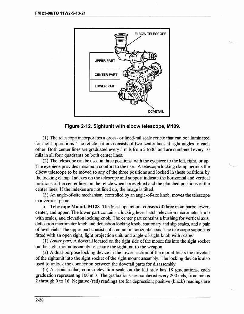
FM 23-90/1TO 11W2-5-13-21
Figure 2-12. Sightunit with elbow telescope, M109.
(1) The telescope incorporates a cross- or lined-mil scale reticle that can be illuminatedfor night operations. The reticle pattern consists of two center lines at right angles to eachother. Both center lines are graduated every 5 mils from 5 to 85 and are numbered every 10mils in all four quadrants on both center lines.
(2) The telescope can be used in three positions: with the eyepiece to the left, right, or up.The eyepiece provides maximum comfort to the user. A telescope locking clamp permits theelbow telescope to be moved to any of the three positions and locked in these positions bythe locking clamp. Indexes on the telescope and support indicate the horizontal and verticalpositions of the center lines on the reticle when boresighted and the plumbed positions of thecenter lines. If the indexes are not lined up, the image is tilted.
(3) An angle-of-site mechanism, controlled by an angle-of-site knob, moves the telescopein a vertical plane.
b. Telescope Mount, M128. The telescope mount consists of three main parts: lower,center, and upper. The lower part contains a locking lever hatch, elevation micrometer knobwith scales, and elevation locking knob. The center part contains a bushing for vertical axis,deflection micrometer knob and deflection locking knob, stationary and slip scales, and a pairof level vials. The upper part consists of a common horizontal axis. The telescope support isfitted with an open sight, light projection unit, and angle-of-sight knob with scales.
(1) Lower part. A dovetail located on the right side of the mount fits into the sight socketon the sight mount assembly to secure the sightunit to the weapon.
(a) A dual-purpose locking device in the lower section of the mount locks the dovetailof the sightunit into the sight socket of the sight mount assembly. The locking device is alsoused to unlock the connection between the dovetail parts for disassembly.
(b) A semicircular, course elevation scale on the left side has 18 graduations, eachgraduation representing 100 mils. The graduations are numbered every 200 mils, from minus2 through 0 to 16. Negative (red) readings are for depression; positive (black) readings are
2-20
ELBOW TELESCOPE
UPPER PART
CENTER PART Mc "'
LOWER PART
0
DOVETAIL
FM 23-90/TO 11W2-5-13-21
for elevation settings. A reference index is inscribed on the lower part of the casting. Thescale settings can be adjusted by loosening the two attaching screws, slipping the scale, andtightening the screws.
(c) The elevation knob elevates or depresses the line of sight and is fitted with a crankhandle for large changes. Secured to the elevation knob is an adjustable micrometer scaleconsisting of positive and negative readings, numbered in black for elevation and red fordepression. The scale has 100 graduations, each representing 1 mil, and is numbered every10 mils from 0 to 90. A reference index is inscribed on the main casting. To release the scalefor slipping, two screws at the front of the elevation knob must be loosened. A devicecontrolled by a locking knob prevents the elevation knob from rotating during firing.
(2) Center part. The fixed deflection scale is a nonslip scale of 64 red graduations, witheach 400 mils numbered in red from 0 to 60. The scale rotates with the upper part of thetelescope mount when the deflection knob is turned.
(a) The deflection knob is fitted with a crank for large changes. The index for the scaleis on a stationary bracket which is bolted to the main casting. The deflection micrometer scaleconsists of 100 red graduations numbered from 0 to 90 in increments of 10 mils. This scaleis fastened to the deflection knob. To slip the micrometer scale, two screws at the front of thedeflection knob must be loosened. The scale is pushed toward the sightunit and rotated to thedesired setting.
(b) The coarse deflection slip scale is a large circular scale retained in place by friction andlocated adjacent to the fixed deflection scale. The slip scale has 64 black graduationsnumbered every 200 mils. The index for the scale is engraved on the main casting. The coarsedeflection setting can be changed by depressing the scale and turning.
(c) The adjustable micrometer deflection slip scale, also located on the deflection knob,has 100 black graduations numbered from 0 to 90 in increments of 10 mils. The scale isretained in place by friction. The scale is fitted with an index attached to the main housing.
(d) Two level vials, located 90 degrees apart on the main housing, are used for levelingthe sightunit. Both vials have rotating metal covers to protect them from damage.
(3) Upper part. The telescope support is equipped with an open sight, clampingmechanism, and mechanism for adjusting the angle-of-sight reading change.
2-19. OPERATION OF M53 SIGHTUNITOperation of the M53 sightunit is described herein.
a. Attaching the Sightunit. Insert the dovetail of the telescope mount into the sightsocket. Press the locking lever inward, seat the mount firmly, and release the locking lever.
Note: Until the baseplate is firmly seated, remove the sight from the mortar before firingeach round.
b. Placing Sightunit Into Operation. Place the sightunit into operation as follows:(1) Setting for deflection.(a) To place a deflection setting on the sight, turn the deflection knob. This turns the
elbow telescope, the coarse deflection scales, and the deflection micrometer scales. Beforeattempting to place a deflection setting on the sightunit, ensure that the deflection locking
2-21
FM 23-90/TO 11W2-5-13-21
knob is released. After placing a setting on the sight, lock the locking knob to lock the dataonto the sight and to ensure that the scale does not slip during firing.
(b) When setting the deflection, it is necessary to use the red fixed coarse scale and thered fixed micrometer scale to obtain the desired setting. Set the first two digits of thedeflection on the coarse scale and the last two on the micrometer scale.
Note: The black coarse scale and the black micrometer scale are slip scales.
(c) Setting a deflection on the deflection scale does not change the direction in which thebarrel is pointing (the lay of the mortar). It only moves the vertical line off (to the left or right)the aiming line. The deflection placed on the sight is the deflection announced in the firecommand. Place a deflection on the sight before elevation.
(2) Setting the elevation.(a) To set for elevation, turn the elevation knob. This operates both the elevation
micrometer and coarse elevation scales. Both scales must be set properly to obtain the desiredelevation. For example, to place elevation 1065 mils on the M53 sightunit, turn the elevationknob until the fixed index opposite the moving coarse elevation scale is between the black1000- and 1100-mil graduations on the scale (the graduations are numbered every 200 mils,from minus 2 through 0 to 16), and the 65-mil mark on the elevation micrometer is oppositethe fixed index. When making elevation settings, remember that the black numbers are forelevation and the red numbers are for depression.
(b) Setting an elevation on the elevation scale does not change the elevation of the mortarbarrel. The elevation to be placed on the sight is announced in the fire command.
(c) Before setting elevations on the sight, unlock the elevation locking knob. Once theelevation is placed on the sight, lock the elevation locking knob. This ensures the data placedon the sight do not accidentally change.
c. Replacing the sightunit in the carrying case. Before returning the sightunit to thecarrying case, close the covers on the level vials and set an elevation of 800 mils anddeflection of 3800 mils on the scales. Place the elbow telescope in the left horizontal position.All crank handles should be folded into the inoperative position. The M53 instrument lightis stored in the same case with the rheostat knob down.
2-20. CARE AND MAINTENANCE OF M53 SIGHTUNITAlthough the M53-series sightunits are rugged, if abused or handled roughly, the unit couldbe inaccurate or malfunction.
a. Avoid striking or otherwise damaging any part of the sight. Be particularly careful notto burr or dent the dovetail bracket. Avoid bumping the micrometer knobs, telescope adapter,and level vials. Except when using the sight, keep the metal vial covers closed.
b. Keep the sight in the carrying case when not in use. Keep it as dry as possible, and donot place it in the carrying case while it is damp.
c. When the sight fails to function correctly, return it to the DS maintenance unit forrepair. Members of the mortar crew are not authorized to disassemble the sight.
d. Keep the optical parts of the telescope clean and dry. Remove dust from the lens witha clean camel's-hair brush. Use only lens cleaning tissue to wipe these parts. Do not use
2-22
FM 23-90/TO 1 1W2-5-13-21
ordinary polishing liquids, pastes, or abrasives on optical parts. Use only authorized lenscleaning compound for removing grease or oil from the lens.
e. Occasionally oil only the sight locking devices by using a small quantity of lightpreservative lubricating oil. To prevent accumulation of dust and grit, wipe off excesslubricant that seeps from moving parts. Ensure that no oil gets on the deflection and elevationscales. (Oil removes the paint from the deflection scale.) No maintenance is authorized.
2-21. SIGHTUNIT, M64-SERIESThe sightunit (Figure 2-13, page 2-24) is the device on which the gunner sets deflection andelevation to hit targets by using the elevation level vial and the cross-level vial. After the sighthas been set for deflection and elevation, the mortar is elevated or depressed until theelevation bubble on the sight is level. The mortar is then traversed until a proper sight pictureis seen (using the aiming posts as the aiming point) and cross-level bubble is level. The mortaris laid for deflection and elevation when all bubbles are level. After the ammunition has beenprepared, it is ready to be fired.
a. Major Components. The two major components are the elbow telescope and sightmount. The elbow telescope has an illuminated cross line. The sight mount has a dovetail,locking knobs, control knobs, scales, cranks, and locking latch.
(1) Dovetail. The dovetail is compatible with standard US mortars. When the dovetail isproperly seated in the dovetail slot, the locking latch clicks. The locking latch is pushedtoward the barrel to release the sight from the dovetail slot for removal.
(2) Locking knobs. The red locking knobs lock the deflection and elevation mechanismsof the sight during firing.
(3) Micrometer knobs. The elevation and deflection micrometer knobs are large for easyhandling. Each knob has a crank for large deflection and elevation changes.
(4) Scales. All scales can be adjusted to any position. Micrometer scales are white. Theelevation micrometer scale and fixed boresight references (red lines) above the coarsedeflection scale and adjacent to the micrometer deflection scale are slipped by loosening slot-headed screws. Coarse deflection scales and micrometer deflection scales are slipped bydepressing and rotating. The coarse elevation scale is factory set and should not be adjustedat crew level. (If the index does not align with the coarse elevation scale within +20 mils whenboresighting at 800 mils, DS-level maintenance should be notified.) The screws that maintainthe coarse elevation scale are held in place with locking compound. If the screws are loosenedand then tightened without reapplying the locking compound, the coarse elevation scale canshift during firing.
2-23

FM 23-90/TO 11W2-5-13-21
COARSE ELEVATION SCALE100-MIL INCREMENTS, 0 TO 6400 MILS
DEFLECTIONLOCKING KNOB /-
FINE DEFLECTION SCALE,1-MIL INCREMENTS,
0 TO 100 MILS
FIXED BORESIGHTREFERENCE MARK
(RED)
DEFLECTION KNOB -
- EYESHIELD
- ELBOW TELESCOPE
FIXED BORESIGHTREFERENCE
-MARK (RED)
COARSE ELEVATION SCALE,-1 00-MIL INCREMENTS,100 TO 1600 MILS
COARSE ELEVATIONINDEX ARROW
* CROSSLEVEL VIAL
FINE ELEVATION SCALE,- 1-MIL INCREMENTS,OTO 100 MILS
ELEVATION KNOB
ELEVATIONLOCKING KNOB
Figure 2-13. Sightunit, M64-series.
b. Illumination. Instrument lights are not needed when using the sightunit at night. Nineparts of the sight are illuminated by tritium gas.
" Telescope." Coarse elevation scale." Coarse elevation index arrow." Elevation vial." Fine elevation scale." Coarse deflection index arrow." Cross-leveling vial." Fine deflection scale." Coarse deflection scale.
2-24
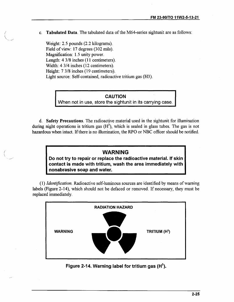
FM 23-90/TO 11W2-5-13-21
c. Tabulated Data. The tabulated data of the M64-series sightunit are as follows:
Weight: 2.5 pounds (2.2 kilograms).Field of view: 17 degrees (302 mils).Magnification: 1.5 unity power.Length: 4 3/8 inches (11 centimeters).Width: 4 3/4 inches (12 centimeters).Height: 7 3/8 inches (19 centimeters).Light source: Self-contained, radioactive tritium gas (H3).
CAUTIONWhen not in use, store the sightunit in its carrying case.
d. Safety Precautions. The radioactive material used in the sightunit for illuminationduring night operations is tritium gas (H3), which is sealed in glass tubes. The gas is nothazardous when intact. If there is no illumination, the RPO or NBC officer should be notified.
WARNINGDo not try to repair or replace the radioactive material. If skincontact is made with tritium, wash the area immediately withnonabrasive soap and water.
(1) Identification. Radioactive self-luminous sources are identified by means of warninglabels (Figure 2-14), which should not be defaced or removed. If necessary, they must bereplaced immediately.
RADIATION HAZARD
Figure 2-14. Warning label for tritium gas (H3).
2-25
TRITIUM (H3)WARNING
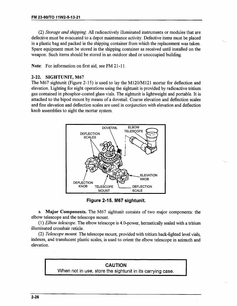
FM 23-90/TO '11W2-5-13-21
(2) Storage and shipping. All radioactively illuminated instruments or modules that aredefective must be evacuated to a depot maintenance activity. Defective items must be placedin a plastic bag and packed in the shipping container from which the replacement was taken.Spare equipment must be stored in the shipping container as received until installed on theweapon. Such items should be stored in an outdoor shed or unoccupied building.
Note: For information on first aid, see FM 21-11.
2-22. SIGHTUNIT, M67The M67 sightunit (Figure 2-15) is used to lay the M120/M121 mortar for deflection andelevation. Lighting for night operations using the sightunit is provided by radioactive tritiumgas contained in phosphor-coated glass vials. The sightunit is lightweight and portable. It isattached to the bipod mount by means of a dovetail. Coarse elevation and deflection scalesand fine elevation and deflection scales are used in conjunction with elevation and deflectionknob assemblies to sight the mortar system.
DEFLECTION /KNOB TELESCOPE
MOUNT
ELEVATIONKNOB
. DEFLECTIONSCALE
Figure 2-15. M67 sightunit.
a. Major Components. The M67 sightunit consists of two major components: theelbow telescope and the telescope mount.
(1) Elbow telescope. The elbow telescope is 4.0-power, hermetically sealed with a tritiumilluminated crosshair reticle.
(2) Telescope mount. The telescope mount, provided with tritium back-lighted level vials,indexes, and translucent plastic scales, is used to orient the elbow telescope in azimuth andelevation.
Sn CAUTIONWhen not in use, store the sightunit in its carrying case.
2-26
--- ,,
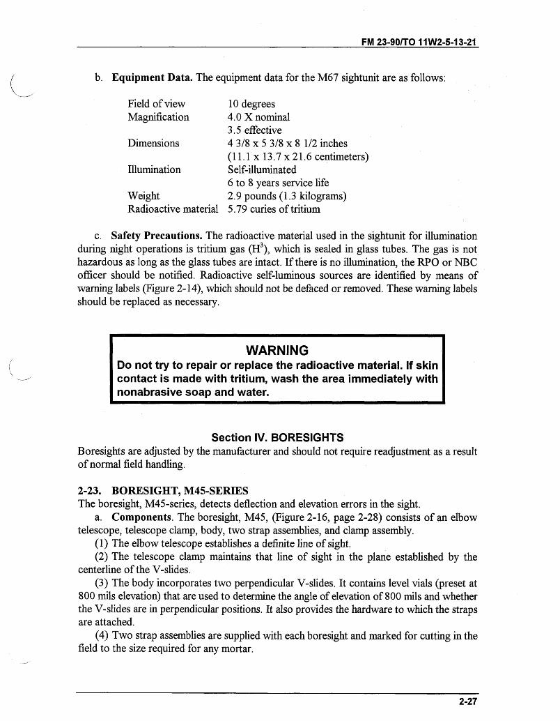
FM 23-90/TO 11W2-5-13-21
b. Equipment Data. The equipment data for the M67 sightunit are as follows:
Field of view 10 degreesMagnification 4.0 X nominal
3.5 effectiveDimensions 4 3/8 x 5 3/8 x 8 1/2 inches
(11.1 x 13.7 x 21.6 centimeters)Illumination Self-illuminated
6 to 8 years service lifeWeight 2.9 pounds (1.3 kilograms)Radioactive material 5.79 curies of tritium
c. Safety Precautions. The radioactive material used in the sightunit for illuminationduring night operations is tritium gas (H3), which is sealed in glass tubes. The gas is nothazardous as long as the glass tubes are intact. If there is no illumination, the RPO or NBCofficer should be notified. Radioactive self-luminous sources are identified by means ofwarning labels (Figure 2-14), which should not be defaced or removed. These warning labelsshould be replaced as necessary.
WARNINGDo not try to repair or replace the radioactive material. If skincontact is made with tritium, wash the area immediately withnonabrasive soap and water.
Section IV. BORESIGHTSBoresights are adjusted by the manufacturer and should not require readjustment as a resultof normal field handling.
2-23. BORESIGHT, M45-SERIESThe boresight, M45-series, detects deflection and elevation errors in the sight.
a. Components. The boresight, M45, (Figure 2-16, page 2-28) consists of an elbowtelescope, telescope clamp, body, two strap assemblies, and clamp assembly.
(1) The elbow telescope establishes a definite line of sight.(2) The telescope clamp maintains that line of sight in the plane established by the
centerline of the V-slides.(3) The body incorporates two perpendicular V-slides. It contains level vials (preset at
800 mils elevation) that are used to determine the angle of elevation of 800 mils and whetherthe V-slides are in perpendicular positions. It also provides the hardware to which the strapsare attached.
(4) Two strap assemblies are supplied with each boresight and marked for cutting in thefield to the size required for any mortar.
2-27
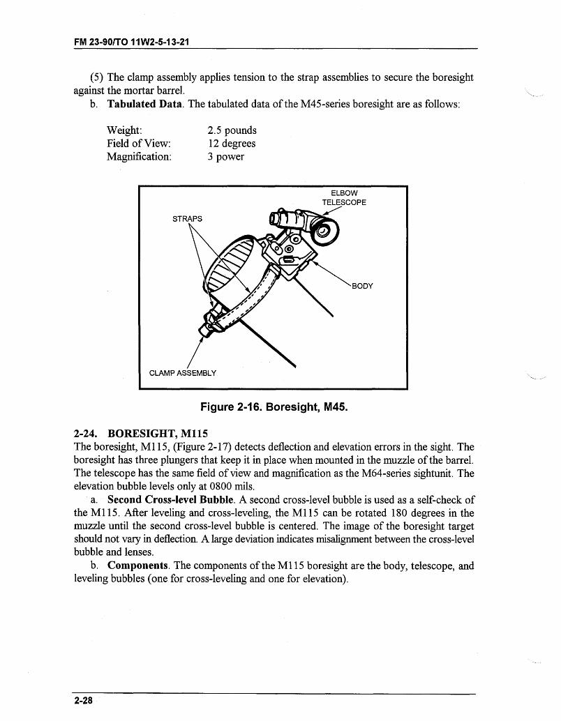
FM 23-90/TO 11W2-5-13-21
(5) The clamp assembly applies tension to the strap assemblies to secure the boresightagainst the mortar barrel.
b. Tabulated Data. The tabulated data of the M45-series boresight are as follows:
Weight:Field of View:Magnification:
2.5 pounds12 degrees3 power
Figure 2-16. Boresight, M45.
2-24. BORESIGHT, M115The boresight, M115, (Figure 2-17) detects deflection and elevation errors in the sight. Theboresight has three plungers that keep it in place when mounted in the muzzle of the barrel.The telescope has the same field of view and magnification as the M64-series sightunit. Theelevation bubble levels only at 0800 mils.
a. Second Cross-level Bubble. A second cross-level bubble is used as a self-check ofthe M115. After leveling and cross-leveling, the M115 can be rotated 180 degrees in themuzzle until the second cross-level bubble is centered. The image of the boresight targetshould not vary in deflection. A large deviation indicates misalignment between the cross-levelbubble and lenses.
b. Components. The components of the M115 boresight are the body, telescope, andleveling bubbles (one for cross-leveling and one for elevation).
2-28
ELBOW
CLAMP
- - - , c
FM 23-90/TO 11W2-5-13-21
CROSSLEVEL BUBBLE
MUZZLE
ELEVATION-LEVELBUBBLE
SECONDLENS
SECOND CROSSLEVELBUBBLE FOR SELF-CHECK
Figure 2-17. Boresight, M115.
c. Tabulated Data. The tabulated data of the M1 15 boresight are as follows:
Weight: 5 ouncesField of view: 17 degreesMagnification: 1.5 power
2-25. PRINCIPLES OF OPERATIONThe boresight is constructed so that the telescope line of sight lies in the plane established bythe center lines of the V-slides. When properly secured to a mortar barrel, the centerline ofthe contacting V-slide is parallel to the centerline of the barrel. Further, the cross-level vial,when centered, indicates that the center lines of both slides, the elbow telescope, and thebarrel lie in the same vertical plane. Therefore, the line of sight of the telescope coincides withthe axis of the barrel, regardless of which V-slide of the boresight is contacting the barrel. Theelevation vial is constructed with a fixed elevation of 800 mils.
2-26. INSTALLATIONInstallation procedures for the M45 boresight are described herein.
a. Remove the boresight, clamp assembly, and straps from the carrying case. Grasp theboresight by the body to prevent damaging the telescope.
b. Place the ring over the hook and attach the strap snap to the eye provided on the strapshaft.
2-29
- -- --
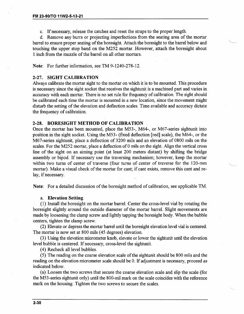
FM 23-90/TO 11W2-5-13-21
c. If necessary, release the catches and reset the straps to the proper length.d. Remove any burrs or projecting imperfections from the seating area of the mortar
barrel to ensure proper seating of the boresight. Attach the boresight to the barrel below andtouching the upper stop band on the M252 mortar. However, attach the boresight about1 inch from the muzzle of the barrel on all other mortars.
Note: For further information, see TM 9-1240-278-12.
2-27. SIGHT CALIBRATIONAlways calibrate the mortar sight to the mortar on which it is to be mounted. This procedureis necessary since the sight socket that receives the sightunit is a machined part and varies inaccuracy with each mortar. There is no set rule for frequency of calibration. The sight shouldbe calibrated each time the mortar is mounted in a new location, since the movement mightdisturb the setting of the elevation and deflection scales. Time available and accuracy dictatethe frequency of calibration.
2-28. BORESIGHT METHOD OF CALIBRATIONOnce the mortar has been mounted, place the M53-, M64-, or M67-series sightunit intoposition in the sight socket. Using the M53- (fixed deflection [red] scale), the M64-, or theM67-series sightunit, place a deflection of 3200 mils and an elevation of 0800 mils on thescales. For the M252 mortar, place a deflection of 0 mils on the sight. Align the vertical crossline of the sight on an aiming point (at least 200 meters distant) by shifting the bridgeassembly or bipod. If necessary use the traversing mechanism; however, keep the mortarwithin two turns of center of traverse (four turns of center of traverse for the 120-mmmortar). Make a visual check of the mortar for cant; if cant exists, remove this cant and re-lay, if necessary.
Note: For a detailed discussion of the boresight method of calibration, see applicable TM.
a. Elevation Setting.(1) Install the boresight on the mortar barrel. Center the cross-level vial by rotating the
boresight slightly around the outside diameter of the mortar barrel. Slight movements aremade by loosening the clamp screw and lightly tapping the boresight body. When the bubblecenters, tighten the clamp screw.
(2) Elevate or depress the mortar barrel until the boresight elevation level vial is centered.The mortar is now set at 800 mils (45 degrees) elevation.
(3) Using the elevation micrometer knob, elevate or lower the sightunit until the elevationlevel bubble is centered. If necessary, cross-level the sightunit.
(4) Recheck all level bubbles.(5) The reading on the coarse elevation scale of the sightunit should be 800 mils and the
reading on the elevation micrometer scale should be 0. If adjustment is necessary, proceed asindicated below.
(a) Loosen the two screws that secure the coarse elevation scale and slip the scale (forthe M53-series sightunit only) until the 800-mil mark on the scale coincides with the referencemark on the housing. Tighten the two screws to secure the scales.
2-30
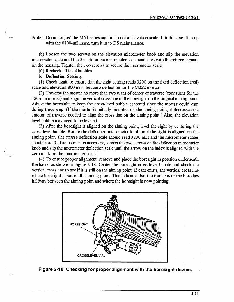
FM 23-90/TO 11W2-5-13-21
Note: Do not adjust the M64-series sightunit coarse elevation scale. If it does not line upwith the 0800-mil mark, turn it in to DS maintenance.
(b) Loosen the two screws on the elevation micrometer knob and slip the elevationmicrometer scale until the 0 mark on the micrometer scale coincides with the reference markon the housing. Tighten the two screws to secure the micrometer scale.
(6) Recheck all level bubbles.b. Deflection Setting.(1) Check againto ensure that the sight setting reads 3200 on the fixed deflection (red)
scale and elevation 800 mils. Set zero deflection for the M252 mortar.(2) Traverse the mortar no more than two turns of center of traverse (four turns for the
120-mm mortar) and align the vertical cross line of the boresight on the original aiming point.Adjust the boresight to keep the cross-level bubble centered since the mortar could cantduring traversing. (If the mortar is initially mounted on the aiming point, it decreases theamount of traverse needed to align the cross line on the aiming point.) Also, the elevationlevel bubble may need to be leveled.
(3) After the boresight is aligned on the aiming point, level the sight by centering thecross-level bubble. Rotate the deflection micrometer knob until the sight is aligned on theaiming point. The coarse deflection scale should read 3200 mils and the micrometer scalesshould read 0. If adjustment is necessary, loosen the two screws on the deflection micrometerknob and slip the micrometer deflection scale until the arrow on the index is aligned with thezero mark on the micrometer scale.
(4) To ensure proper alignment, remove and place the boresight in position underneaththe barrel as shown in Figure 2-18. Center the boresight cross-level bubble and check thevertical cross line to see if it is still on the aiming point. If cant exists, the vertical cross lineof the boresight is not on the aiming point. This indicates that the true axis of the bore lieshalfway between the aiming point and where the boresight is now pointing.
Figure 2-18. Checking for proper alignment with the boresight device.
2-31
BORESIGHT L
CROSSLEVEL VIAL
-"- -
- - - -- ''~- =
FM 23-901T0 11W2-5-13-21
(5) To correct this error, look through the boresight, traverse the mortar onto the aimingpoint. If bubbles are level, use the deflection micrometer knob and place the vertical cross lineof the sight back onto the aiming point. With the sight in this position, index one-half of themil variation between the sight and boresight. Slip zero on the micrometer scale to the indexmark-for example, the mil variation is 10 mils and one-half of this value is 5 mils. Loosenthe two screws on the deflection micrometer and index zero.
(6) Check all level bubbles, sightunit, and boresight.(7) With a deflection on the micrometer scale of half the value of the original mil
variation, both the sightunit and boresight are on the aiming point. If an error exists, repeatthe procedure outlined above.
(8) Using the M64-series sightunit, adjust the deflection scale and micrometer scale of thesightunit to zero. To do this, loosen the deflection knob screws and slip the scale to zero.Adjust the deflection micrometer scale to zero by pushing in on the micrometer knob retainingbutton and slipping the scale to zero.
(9) Check again all level bubbles, and the lay of the sightunit and the boresight on theaiming point.
Note: The M53-series sightunit should be received from the manufacturer with the reddeflection scale calibrated on 3200. If it is not, turn the sightunit in to DS maintenancefor calibration.
c. Removal.(1) Loosen the clamp screw, releasing the boresight from the barrel.(2) Swing the elbow telescope until it is about parallel with the elevation level bubble.(3) Release the clamp assembly and straps by removing the ring from the hook and strap
shaft.(4) Stow the clamp assembly and straps in the corner compartment. Put the boresight in
the center compartment of the carrying case.
2-29. CALIBRATION FOR DEFLECTION USING THE M2 AIMING CIRCLETwo methods can be used to calibrate the sight for deflection using the M2 aiming circle: theangle method (Figure 2-19) and the distant aiming point method (Figure 2-20, page 2-34).
a. Calibration for Deflection Using the Angle Method.(1) Set up the aiming circle 25 meters to the rear of the mounted mortar. (The mortar is
mounted at 800 mils elevation.)(2) With the aiming circle fine leveled, index 0 on the azimuth scale and azimuth
micrometer scale. Using the orienting motion (nonrecording motion) align the vertical line ofthe reticle of the telescope so that it bisects the baseplate.
(3) Traverse and cross-level the mortar until the center axis of the barrel from thebaseplate to the muzzle is aligned with the vertical line of the aiming circle telescope reticle.
2-32
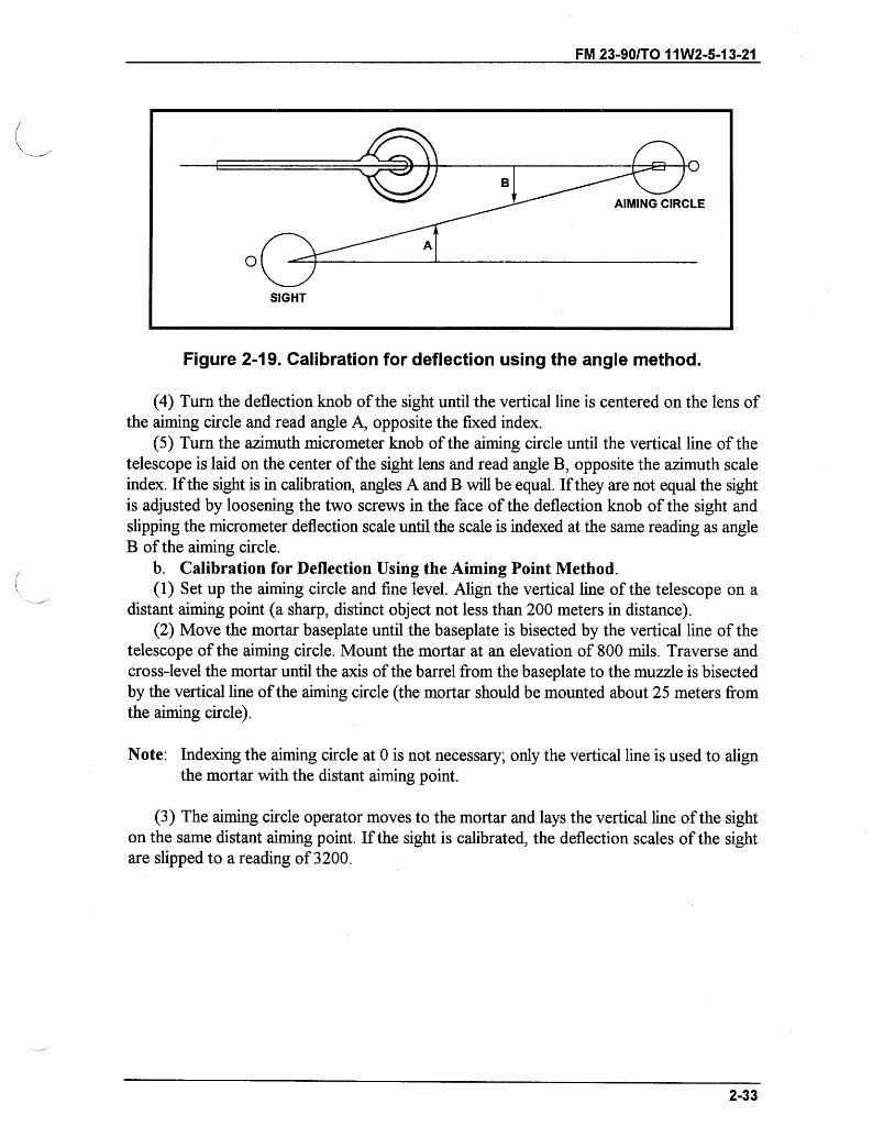
FM 23-90/TO 11W2-5-13-21
Figure 2-19. Calibration for deflection using the angle method.
(4) Turn the deflection knob of the sight until the vertical line is centered on the lens ofthe aiming circle and read angle A, opposite the fixed index.
(5) Turn the azimuth micrometer knob of the aiming circle until the vertical line of thetelescope is laid on the center of the sight lens and read angle B, opposite the azimuth scaleindex. If the sight is in calibration, angles A and B will be equal. If they are not equal the sightis adjusted by loosening the two screws in the face of the deflection knob of the sight andslipping the micrometer deflection scale until the scale is indexed at the same reading as angleB of the aiming circle.
b. Calibration for Deflection Using the Aiming Point Method.(1) Set up the aiming circle and fine level. Align the vertical line of the telescope on a
distant aiming point (a sharp, distinct object not less than 200 meters in distance).(2) Move the mortar baseplate until the baseplate is bisected by the vertical line of the
telescope of the aiming circle. Mount the mortar at an elevation of 800 mils. Traverse andcross-level the mortar until the axis of the barrel from the baseplate to the muzzle is bisectedby the vertical line of the aiming circle (the mortar should be mounted about 25 meters fromthe aiming circle).
Note: Indexing the aiming circle at 0 is not necessary; only the vertical line is used to alignthe mortar with the distant aiming point.
(3) The aiming circle operator moves to the mortar and lays the vertical line of the sighton the same distant aiming point. If the sight is calibrated, the deflection scales of the sightare slipped to a reading of 3200.
2-33
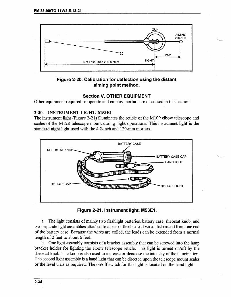
FM 23-90/TO 11W2-5-13-21
GUN
AIMINGCIRCLE
25M
Not Less Than 200 Meters SIGHT
Figure 2-20. Calibration for deflection using the distantaiming point method.
Section V. OTHER EQUIPMENTOther equipment required to operate and employ mortars are discussed in this section.
2-30. INSTRUMENT LIGHT, M53E1The instrument light (Figure 2-21) illuminates the reticle of the M109 elbow telescope andscales of the M128 telescope mount during night operations. This instrument light is thestandard night light used with the 4.2-inch and 120-mm mortars.
RHEOSTAT KNOB
RETICLE CAP -
BATTERY CASE CAP
- HANDLIGHT
'- RETICLE LIGHT
Figure 2-21. Instrument light, M53E1.
a. The light consists of mainly two flashlight batteries, battery case, rheostat knob, andtwo separate light assemblies attached to a pair of flexible lead wires that extend from one endof the battery case. Because the wires are coiled, the leads can be extended from a normallength of 2 feet to about 6 feet.
b. One light assembly consists of a bracket assembly that can be screwed into the lampbracket holder for lighting the elbow telescope reticle. This light is turned on/off by therheostat knob. The knob is also used to increase or decrease the intensity of the illumination.The second light assembly is a hand light that can be directed upon the telescope mount scalesor the level vials as required. The on/off switch for this light is located on the hand light.
2-34
----- -- c
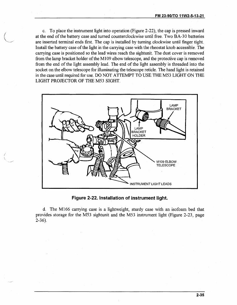
FM 23-90/TO 11W2-5-13-21
c. To place the instrument light into operation (Figure 2-22), the cap is pressed inwardat the end of the battery case and turned counterclockwise until free. Two BA-30 batteriesare inserted terminal ends first. The cap is installed by turning clockwise until finger tight.Install the battery case of the light in the carrying case with the rheostat knob accessible. Thecarrying case is positioned so the lead wires reach the sightunit. The dust cover is removedfrom the lamp bracket holder of the M109 elbow telescope, and the protective cap is removedfrom the end of the light assembly lead. The end of the light assembly is threaded into thesocket on the elbow telescope for illuminating the telescope reticle. The hand light is retainedin the case until required for use. DO NOT ATTEMPT TO USE THE M53 LIGHT ON THELIGHT PROJECTOR OF THE M53 SIGHT.
Figure 2-22. Installation of instrument light.
d. The M166 carrying case is a lightweight, sturdy case with an isofoam bed thatprovides storage for the M53 sightunit and the M53 instrument light (Figure 2-23, page2-36).
2-35
INSTRUMENT LIGHT LEADS
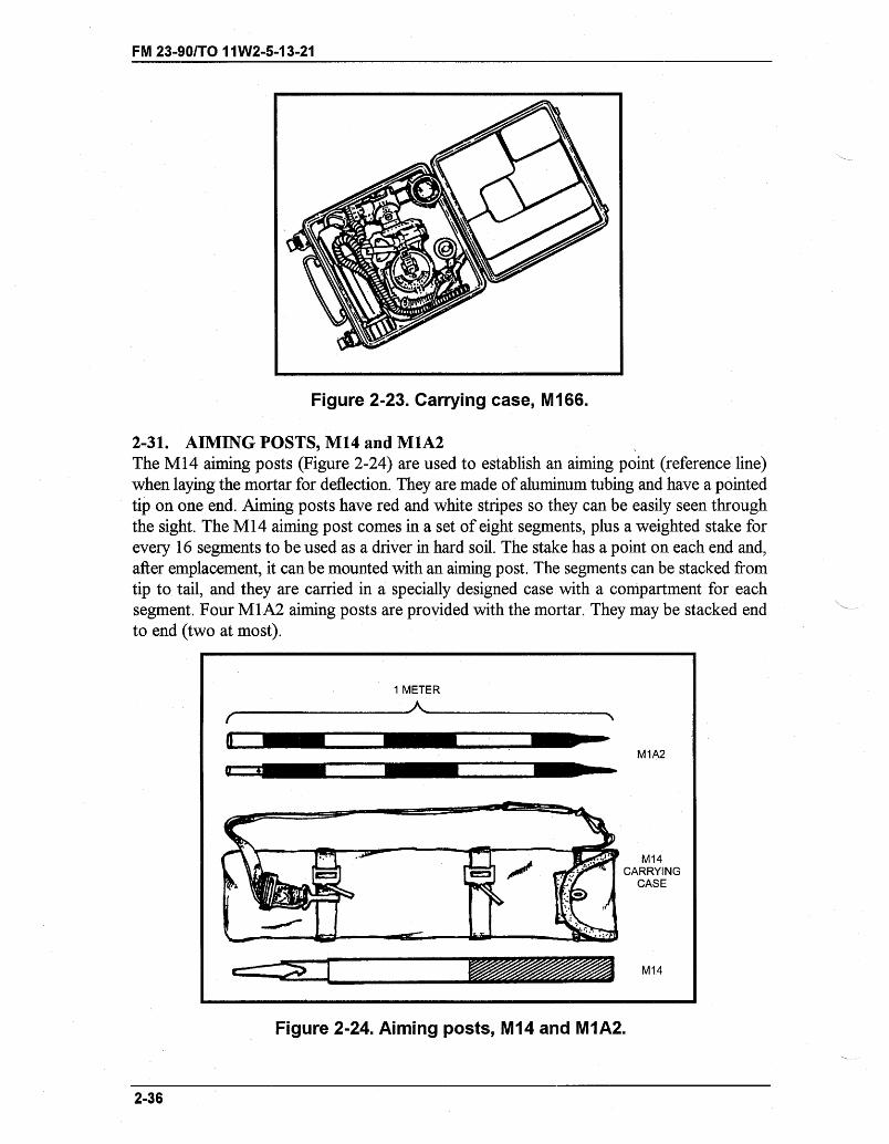
FM 23-90/TO 11 W2-5-13-21
Figure 2-23. Carrying case, M166.
2-31. AIMING POSTS, M14 and M1A2The M14 aiming posts (Figure 2-24) are used to establish an aiming point (reference line)when laying the mortar for deflection. They are made of aluminum tubing and have a pointedtip on one end. Aiming posts have red and white stripes so they can be easily seen throughthe sight. The M14 aiming post comes in a set of eight segments, plus a weighted stake forevery 16 segments to be used as a driver in hard soil. The stake has a point on each end and,after emplacement, it can be mounted with an aiming post. The segments can be stacked fromtip to tail, and they are carried in a specially designed case with a compartment for eachsegment. Four M1A2 aiming posts are provided with the mortar. They may be stacked endto end (two at most).
Figure 2-24. Aiming posts, M14 and M1A2.
2-36
1 METERA
I1 -
M1A2
M14CARRYING
CASE
M14
_ -- , -I-I-.I
I -- - ---- I - - I
i fi
CI _ ,- II I L I- - - - r
O I ii,
~5-~----
II
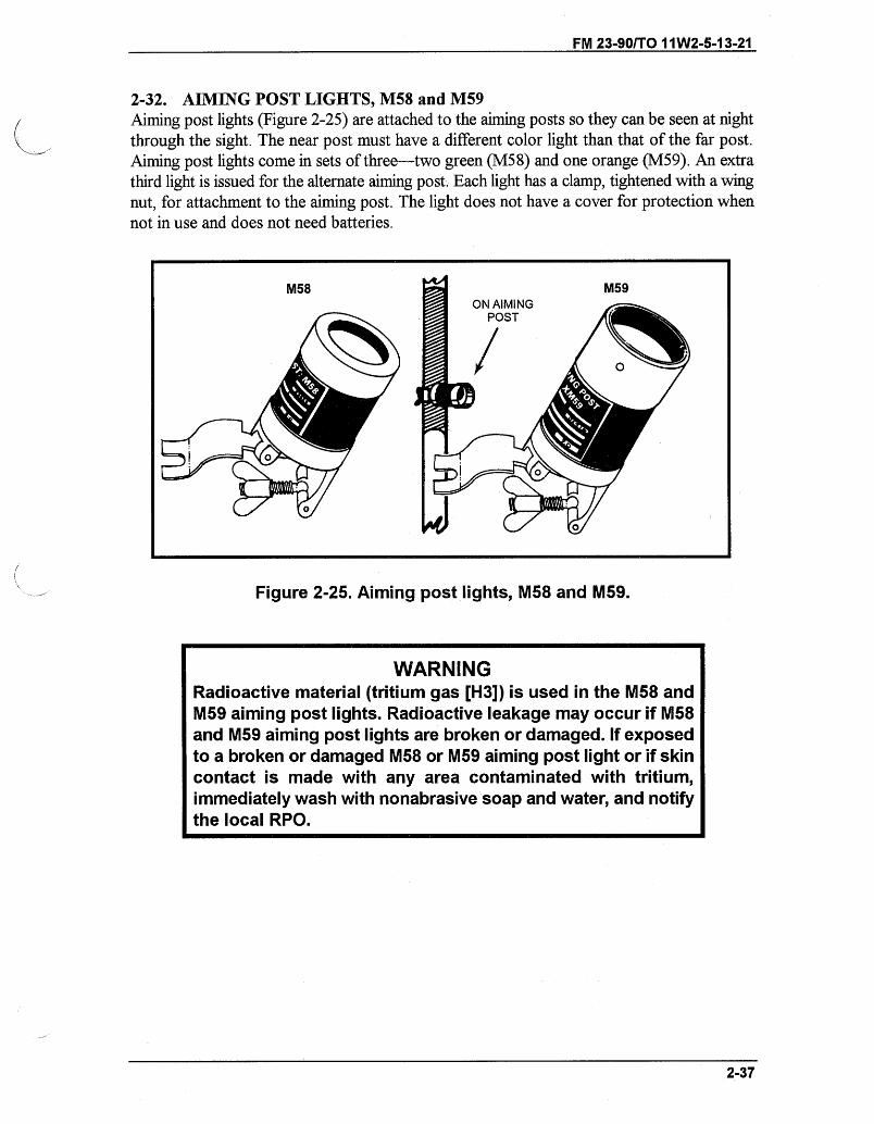
FM 23-90/TO 11W2-5-13-21
2-32. AIMING POST LIGHTS, M58 and M59Aiming post lights (Figure 2-25) are attached to the aiming posts so they can be seen at nightthrough the sight. The near post must have a different color light than that of the far post.Aiming post lights come in sets of three-two green (M58) and one orange (M59). An extrathird light is issued for the alternate aiming post. Each light has a clamp, tightened with a wingnut, for attachment to the aiming post. The light does not have a cover for protection whennot in use and does not need batteries.
U -- -- - I
Figure 2-25. Aiming post lights, M58 and M59.
2-37
M58
WARNINGRadioactive material (tritium gas [H3]) is used in the M58 andM59 aiming post lights. Radioactive leakage may occur if M58and M59 aiming post lights are broken or damaged. If exposedto a broken or damaged M58 or M59 aiming post light or if skincontact is made with any area contaminated with tritium,immediately wash with nonabrasive soap and water, and notifythe local RPO.
- -- ------ --- - -- ---
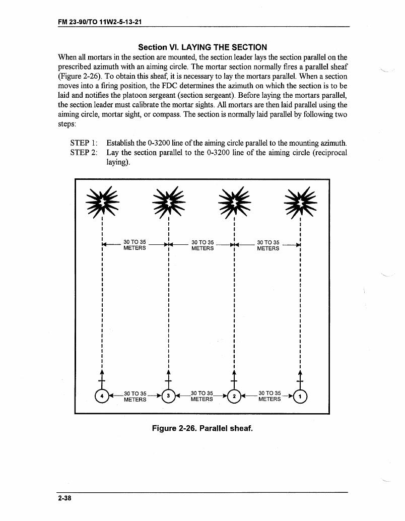
FM 23-90/TO 11W2-5-13-21
Section VI. LAYING THE SECTIONWhen all mortars in the section are mounted, the section leader lays the section parallel on theprescribed azimuth with an aiming circle. The mortar section normally fires a parallel sheaf(Figure 2-26). To obtain this sheaf, it is necessary to lay the mortars parallel. When a sectionmoves into a firing position, the FDC determines the azimuth on which the section is to belaid and notifies the platoon sergeant (section sergeant). Before laying the mortars parallel,the section leader must calibrate the mortar sights. All mortars are then laid parallel using theaiming circle, mortar sight, or compass. The section is normally laid parallel by following twosteps:
STEP 1:STEP 2:
Establish the 0-3200 line of the aiming circle parallel to the mounting azimuth.Lay the section parallel to the 0-3200 line of the aiming circle (reciprocallaying).
Figure 2-26. Parallel sheaf.
2-38
I I I II I I II I I I
30 TO 35 - 30 TO 35 30 TO 35i METERS I METERS I METERS 1I I I II I I II I I II I I II I I II I I II I I II I I II I I II I I II I I II I I II I I II I I II I I II I I II I I II I I II I I II I I II I I II I I II I I I
4 30 TO 35 3 30 TO 35 Z 30 TO 35 tETERS METERS METERS
,,
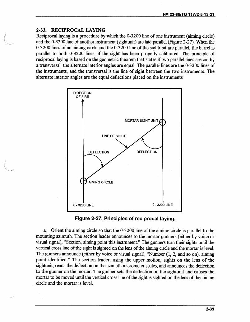
FM 23-90/TO 11W2-5-13-21
2-33. RECIPROCAL LAYINGReciprocal laying is a procedure by which the 0-3200 line of one instrument (aiming circle)and the 0-3200 line of another instrument (sightunit) are laid parallel (Figure 2-27). When the0-3200 lines of an aiming circle and the 0-3200 line of the sightunit are parallel, the barrel isparallel to both 0-3200 lines, if the sight has been properly calibrated. The principle ofreciprocal laying is based on the geometric theorem that states if two parallel lines are cut bya transversal, the alternate interior angles are equal. The parallel lines are the 0-3200 lines ofthe instruments, and the transversal is the line of sight between the two instruments. Thealternate interior angles are the equal deflections placed on the instruments
Figure 2-27. Principles of reciprocal laying.
a. Orient the aiming circle so that the 0-3200 line of the aiming circle is parallel to themounting azimuth. The section leader announces to the mortar gunners (either by voice orvisual signal), "Section, aiming point this instrument." The gunners turn their sights until thevertical cross line of the sight is sighted on the lens of the aiming circle and the mortar is level.The gunners announce (either by voice or visual signal), "Number (1, 2, and so on), aimingpoint identified." The section leader, using the upper motion, sights on the lens of thesightunit, reads the deflection on the azimuth micrometer scales, and announces the deflectionto the gunner on the mortar. The gunner sets the deflection on the sightunit and causes themortar to be moved until the vertical cross line of the sight is sighted on the lens of the aimingcircle and the mortar is level.
2-39
FM 23-90/TO 11 W2-5-13-21
b. When the sight has been sighted on the aiming circle, the gunner reports, "Ready forrecheck." The platoon sergeant (section sergeant) again sights on the lens of the sightunit, andreads and announces the deflection. This procedure is repeated until the gunner reports adifference of ZERO (or ONE) MIL between successive deflections. The mortar has then beenlaid.
2-34. RECIPROCAL LAYING ON A GRID AZIMUTHThis paragraph discusses the commands and procedures used in reciprocal laying of themortar section on a given grid azimuth.
a. The FDC normally directs the section to lay the mortar parallel on a mounting (grid)azimuth.
b. The platoon sergeant (section sergeant) receives the command MOUNTINGAZIMUTH FIVE FIVE FIVE ZERO (5550 mils) from the FDC.
(1) The mounting azimuth is 5550 mils, and the aiming circle has a declination constantof 450 mils.
Declination constant 450 mils+ 6400 mils
6850 milsMinus the mounting (grid) azimuth - 5550 milsRemainder to set on aiming circle 1300 mils
(2) The platoon sergeant (section sergeant) mounts and levels the aiming circle at a' pointfrom which he can observe the sights of all the mortars in the section (normally the left frontor left rear of the section).
(3) He places 1300 mils on the azimuth and micrometer scales of the aiming circle(recording motion).
(4) Using the orienting knob, he centers the magnetic needle in the magnetic needlemagnifier. This orients the 0-3200 line of the aiming circle in the desired direction (mountingazimuth 5550 mils).
(5) The platoon sergeant (section sergeant) announces, "Section, aiming point thisinstrument."
(6) All gunners refer their sights to the aiming circle with the vertical cross line laid on thecenter of the aiming circle. The gunner then announces, "Number two (one or three), aimingpoint identified."
(7) To lay the mortar barrel parallel to the 0-3200 line of the aiming circle (Figure 2-28),the platoon sergeant (section sergeant) turns the upper motion of the aiming circle until thevertical cross line is laid on the center of the lens of the mortar sight. He reads the azimuthand micrometer scales and announces the deflectionXfor example, "Number two, deflectionone nine nine eight (1998)."
Note: When the M53 sightunit is used, it is calibrated at 3200 mils on the red deflection andmicrometer scales. All readings from the aiming circle to the sight are placed on thered deflection scale and the mortar is laid on the aiming circle using this scale.
2-40
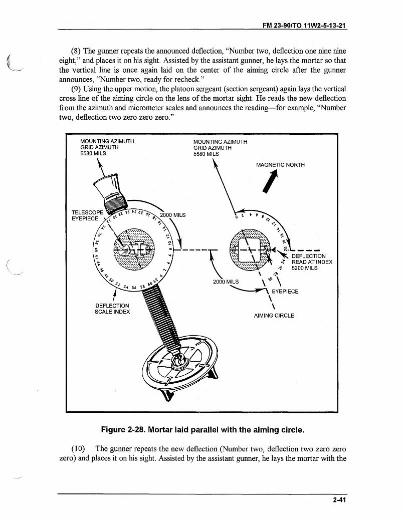
FM 23-901TO 11W2-5-13-21
(8) The gunner repeats the announced deflection, "Number two, deflection one nine nineeight," and places it on his sight. Assisted by the assistant gunner, he lays the mortar so thatthe vertical line is once again laid on the center of the aiming circle after the gunnerannounces, "Number two, ready for recheck."
(9) Using the upper motion, the platoon sergeant (section sergeant) again lays the verticalcross line of the aiming circle on the lens of the mortar sight. He reads the new deflectionfrom the azimuth and micrometer scales and announces the reading-for example, "Numbertwo, deflection two zero zero zero."
MOUNTING AZIMUTHGRID AZIMUTH5580 MILS
MOUNTING AZIMUTHGRID AZIMUTH5580 MILS
MILS
MAGNETIC NORTH
9 ]
SDEFLECTION
)0 MILS
DEFLECTIONSCALE INDEX
AIMING CIRCLE
Figure 2-28. Mortar laid parallel with the aiming circle.
(10) The gunner repeats the new deflection (Number two, deflection two zero zerozero) and places it on his sight. Assisted by the assistant gunner, he lays the mortar with the
2-41
\ :" 4 ' RE
2000 MILS
EYEPIECE
s -- sr
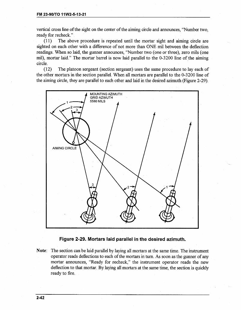
FM 23-90/TO 11W2-5-13-21
vertical cross line of the sight on the center of the aiming circle and announces, "Number two,ready for recheck."
(11) The above procedure is repeated until the mortar sight and aiming circle aresighted on each other with a difference of not more than ONE mil between the deflectionreadings. When so laid, the gunner announces, "Number two (one or three), zero mils (onemil), mortar laid." The mortar barrel is now laid parallel to the 0-3200 line of the aimingcircle.
(12) The platoon sergeant (section sergeant) uses the same procedure to lay each ofthe other mortars in the section parallel. When all mortars are parallel to the 0-3200 line ofthe aiming circle, they are parallel to each other and laid in the desired azimuth (Figure 2-29).
MOUNTING AZIMUTHGRID AZIMUTH5580 MILS
Figure 2-29. Mortars laid parallel in the desired azimuth.
Note: The section can be laid parallel by laying all mortars at the same time. The instrumentoperator reads deflections to each of the mortars in turn. As soon as the gunner of anymortar announces, "Ready for recheck," the instrument operator reads the newdeflection to that mortar. By laying all mortars at the same time, the section is quicklyready to fire.
2-42
AIMING CIRCLE
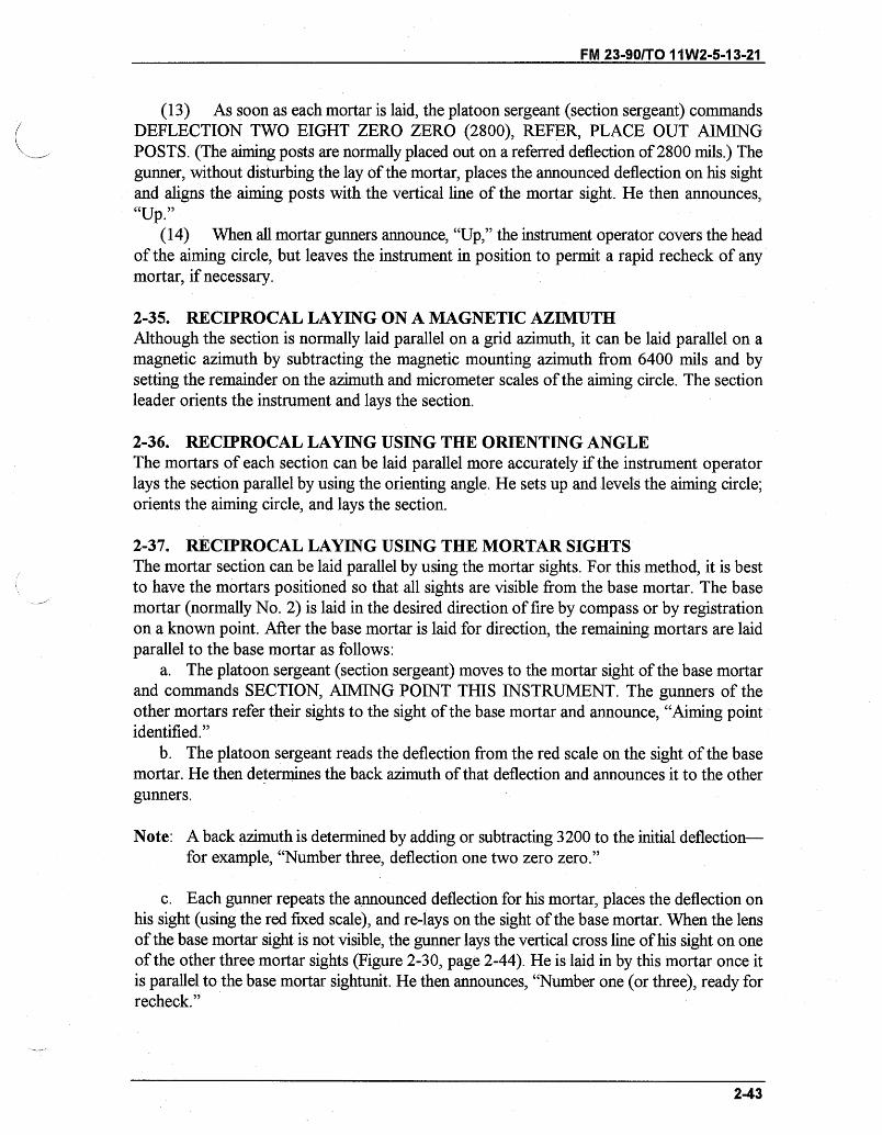
FM 23-90/T0 11W2-5-13-21
(13) As soon as each mortar is laid, the platoon sergeant (section sergeant) commandsDEFLECTION TWO EIGHT ZERO ZERO (2800), REFER, PLACE OUT AIMINGPOSTS. (The aiming posts are normally placed out on a referred deflection of 2800 mils.) Thegunner, without disturbing the lay of the mortar, places the announced deflection on his sightand aligns the aiming posts with the vertical line of the mortar sight. He then announces,"Up."
(14) When all mortar gunners announce, "Up," the instrument operator covers the headof the aiming circle, but leaves the instrument in position to permit a rapid recheck of anymortar, if necessary.
2-35. RECIPROCAL LAYING ON A MAGNETIC AZIMUTHAlthough the section is normally laid parallel on a grid azimuth, it can be laid parallel on amagnetic azimuth by subtracting the magnetic mounting azimuth from 6400 mils and bysetting the remainder on the azimuth and micrometer scales of the aiming circle. The sectionleader orients the instrument and lays the section.
2-36. RECIPROCAL LAYING USING THE ORIENTING ANGLEThe mortars of each section can be laid parallel more accurately if the instrument operatorlays the section parallel by using the orienting angle. He sets up and levels the aiming circle;orients the aiming circle, and lays the section.
2-37. RECIPROCAL LAYING USING THE MORTAR SIGHTSThe mortar section can be laid parallel by using the mortar sights. For this method, it is bestto have the mortars positioned so that all sights are visible from the base mortar. The basemortar (normally No. 2) is laid in the desired direction of fire by compass or by registrationon a known point. After the base mortar is laid for direction, the remaining mortars are laidparallel to the base mortar as follows:
a. The platoon sergeant (section sergeant) moves to the mortar sight of the base mortarand commands SECTION, AIMING POINT THIS INSTRUMENT. The gunners of theother mortars refer their sights to the sight of the base mortar and announce, "Aiming pointidentified."
b. The platoon sergeant reads the deflection from the red scale on the sight of the basemortar. He then determines the back azimuth of that deflection and announces it to the othergunners.
Note: A back azimuth is determined by adding or subtracting 3200 to the initial deflection-for example, "Number three, deflection one two zero zero."
c. Each gunner repeats the announced deflection for his mortar, places the deflection onhis sight (using the red fixed scale), and re-lays on the sight of the base mortar. When the lensof the base mortar sight is not visible, the gunner lays the vertical cross line of his sight on oneof the other three mortar sights (Figure 2-30, page 2-44). He is laid in by this mortar once itis parallel to the base mortar sightunit. He then announces, "Number one (or three), ready forrecheck."
2-43
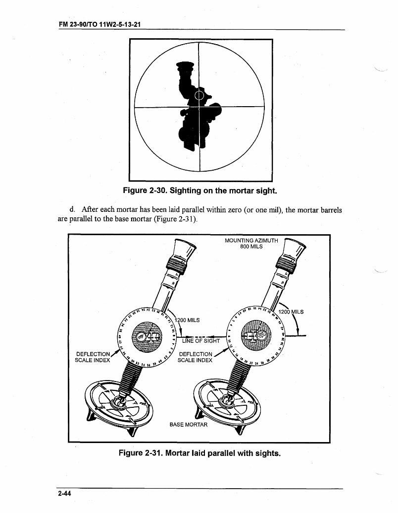
FM 23-90/TO 11W2-5-13-21
Figure 2-30. Sighting on the mortar sight.
d. After each mortar has been laid parallel within zero (or one mil), the mortar barrelsare parallel to the base mortar (Figure 2-31).
Figure 2-31. Mortar laid parallel with sights.
2-44
I ,, _
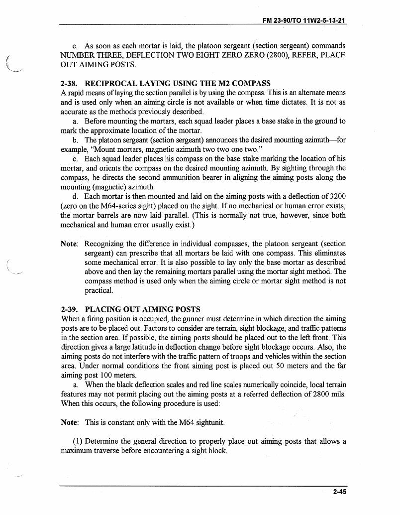
FM 23-90/TO 11 W2-5-13-21
e. As soon as each mortar is laid, the platoon sergeant (section sergeant) commandsNUMBER THREE, DEFLECTION TWO EIGHT ZERO ZERO (2800), REFER, PLACEOUT AIMING POSTS.
2-38. RECIPROCAL LAYING USING THE M2 COMPASSA rapid means of laying the section parallel is by using the compass. This is an alternate meansand is used only when an aiming circle is not available or when time dictates. It is not asaccurate as the methods previously described.
a. Before mounting the mortars, each squad leader places a base stake in the ground tomark the approximate location of the mortar.
b. The platoon sergeant (section sergeant) announces the desired mounting azimuth-forexample, "Mount mortars, magnetic azimuth two two one two."
c. Each squad leader places his compass on the base stake marking the location of hismortar, and orients the compass on the desired mounting azimuth. By sighting through thecompass, he directs the second ammunition bearer in aligning the aiming posts along themounting (magnetic) azimuth.
d. Each mortar is then mounted and laid on the aiming posts with a deflection of 3200(zero on the M64-series sight) placed on the sight. If no mechanical or human error exists,the mortar barrels are now laid parallel. (This is normally not true, however, since bothmechanical and human error usually exist.)
Note: Recognizing the difference in individual compasses, the platoon sergeant (sectionsergeant) can prescribe that all mortars be laid with one compass. This eliminatessome mechanical error. It is also possible to lay only the base mortar as describedabove and then lay the remaining mortars parallel using the mortar sight method. Thecompass method is used only when the aiming circle or mortar sight method is notpractical.
2-39. PLACING OUT AIMING POSTSWhen a firing position is occupied, the gunner must determine in which direction the aimingposts are to be placed out. Factors to consider are terrain, sight blockage, and traffic patternsin the section area. If possible, the aiming posts should be placed out to the left front. Thisdirection gives a large latitude in deflection change before sight blockage occurs. Also, theaiming posts do not interfere with the traffic pattern of troops and vehicles within the sectionarea. Under normal conditions the front aiming post is placed out 50 meters and the faraiming post 100 meters.
a. When the black deflection scales and red line scales numerically coincide, local terrainfeatures may not permit placing out the aiming posts at a referred deflection of 2800 mils.When this occurs, the following procedure is used:
Note: This is constant only with the M64 sightunit.
(1) Determine the general direction to properly place out aiming posts that allows amaximum traverse before encountering a sight block.
2-45
FM 23-90/TO 11W2-5-13-21
(2) Refer the sight to that general direction and index any deflection to the nearest 100mils.
(3) Place out the aiming posts.(4) Record the deflection reading on the red scales.b. The black deflection scale of the M64 sightunit must be slipped when the mortar
section is being used in a 6400-mil capability.(1) After the mortar is initially laid for direction, rotate the deflection micrometer knob
until the deflection scale is set on 2800 mils. Place out two aiming posts to the left front.(2) Using the deflection course scale, index a deflection of 700 mils and place out two
more aiming posts to the right rear.(3) Be sure to use ONLY the aiming posts placed out at 2800 mils for the front reference
points. Use the aiming posts placed out at 700 mils for the rear reference points.
Note: To ensure that the gunners are on the appropriate aiming posts, the section leader maydirect that each mortar squad place out cardinal direction stakes around its mortarposition. He should also announce the general direction of fire before giving the initialfire command.
c. When the M64 sightunit is used within the same firing section that is being used in a6400-mil capability, the gunner must slip the black deflection scale of the sightunit so that 0mils on the black deflection scale coincides with the red 3200-mil line.
d. When the section is laid parallel, the rounds usually land in the impact area the samedistance apart as the mortars are mounted (25 to 30 meters). When they do not, the FO mustadjust the sheaf
(1) Sheaf adjustment is normally accomplished after the base mortar is adjusted on theregistration point. The section leader has the section fire a section right (left) with the samecharge and deflection setting as the base mortar (No. 2). The FO adjusts mortar No. 1 untilit is in its proper position in the sheaf Any adjustment of either mortar results in that mortarhaving a different deflection. This makes it necessary to announce a different deflection foreach mortar to fire two mortars as a section. To avoid that complication, the sights arereferred so that each sight has the same deflection reading.
(2) At the completion of the adjustment, the FDC commands SECTION, REFERDEFLECTION, (FDC gives the deflection of the base No. 2 mortar), REALIGN AIMINGPOSTS. The gunner refers his sight to the deflection setting and, without disturbing the layof the mortar, directs the ammunition bearer in moving the aiming posts until they are alignedwith the vertical cross line of the sight. The barrels of the mortars are parallel, and eachmortar has the same deflection reading.
2-40. ALTERNATE METHOD OF PLACING OUT AIMING POSTSAfter the section leader has laid the section for direction, he commands SECTION, REFERDEFLECTION (normally, TWO EIGHT ZERO ZERO), PLACE OUT AIMING POSTS.The gunner determines which general direction will enable him to place out his aiming postsand still allow a maximum traverse before encountering a sight block. He refers the sight tothat direction and indexes any deflection to the nearest 100 mils. He then places out the
2-46
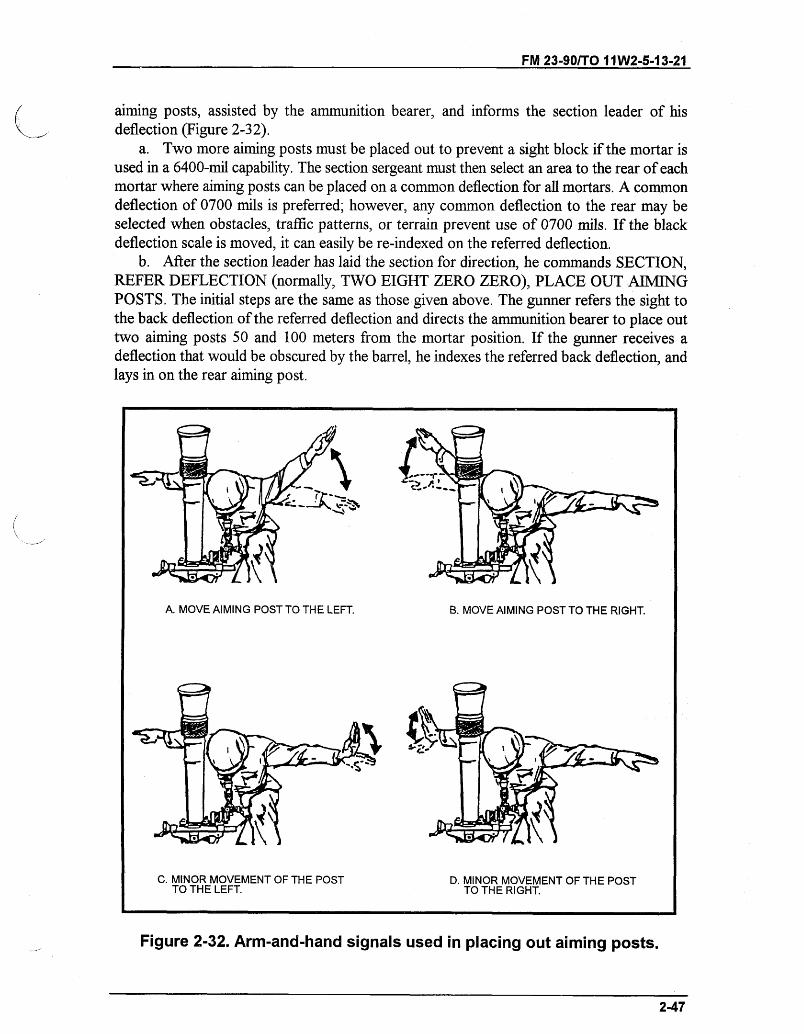
FM 23-90/TO 1 1W2-5-13-21
aiming posts, assisted by the ammunition bearer, and informs the section leader of hisdeflection (Figure 2-32).
a. Two more aiming posts must be placed out to prevent a sight block if the mortar isused in a 6400-mil capability. The section sergeant must then select an area to the rear of eachmortar where aiming posts can be placed on a common deflection for all mortars. A commondeflection of 0700 mils is preferred; however, any common deflection to the rear may beselected when obstacles, traffic patterns, or terrain prevent use of 0700 mils. If the blackdeflection scale is moved, it can easily be re-indexed on the referred deflection.
b. After the section leader has laid the section for direction, he commands SECTION,REFER DEFLECTION (normally, TWO EIGHT ZERO ZERO), PLACE OUT AIMINGPOSTS. The initial steps are the same as those given above. The gunner refers the sight tothe back deflection of the referred deflection and directs the ammunition bearer to place outtwo aiming posts 50 and 100 meters from the mortar position. If the gunner receives adeflection that would be obscured by the barrel, he indexes the referred back deflection, andlays in on the rear aiming post.
Figure 2-32. Arm-and-hand signals used in placing out aiming posts.
2-47
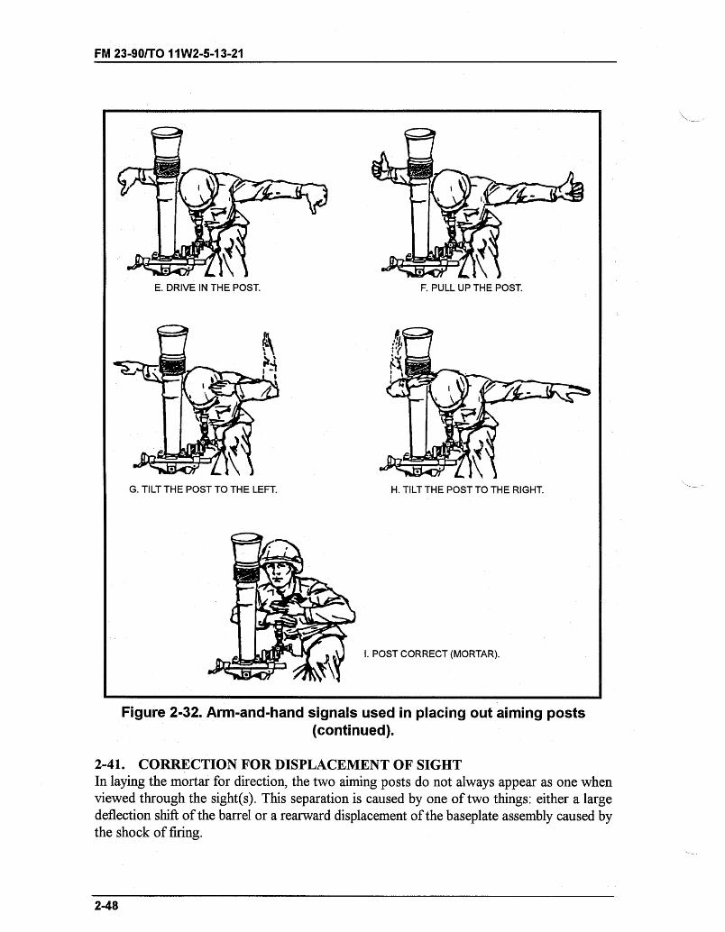
FM 23-90/TO 11W2-5-13-21
E. DRIVE IN THE POST.
G. TILT THE POST TO THE LEFT.
F. PULL UP THE POST.
H. TILT THE POST TO THE RIGHT.
I. POST CORRECT (MORTAR).
Figure 2-32. Arm-and-hand signals used in placing out aiming posts(continued).
2-41. CORRECTION FOR DISPLACEMENT OF SIGHTIn laying the mortar for direction, the two aiming posts do not always appear as one whenviewed through the sight(s). This separation is caused by one of two things: either a largedeflection shift of the barrel or a rearward displacement of the baseplate assembly caused bythe shock of firing.
2-48
_ ___I __I_ I ___

FM 23-90/TO 11W2-5-13-21
a. When the aiming posts appear separated, the gunner cannot use either one as hisaiming point. To lay the mortar correctly, he takes a compensated sight picture. Then, hetraverses the mortar until the sight picture appears with the left edge of the far aiming postplaced exactly midway between the left edge of the near aiming post and the vertical line ofthe sight. This corrects for the displacement. A memory trick for correcting displacement is:Hey diddle diddle, far post in the middle.
b. The gunner determines if the displacement is caused by traversing the mortar or bydisplacement of the baseplate assembly. To do so, he places the referred deflection on thesight and lays on the aiming posts. If both aiming posts appear as one, the separation is causedby traversing. Therefore, the gunner continues to lay the mortar as described and does notrealign the aiming posts. When the posts appear separated, the separation is caused bydisplacement of the baseplate assembly. The gunner notifies his squad leader, who requestspermission from the section/platoon leader to realign the aiming posts. (For more information,see Chapter 3, paragraph 3-14.)
Section VII. LOADING AND FIRINGUpon receiving a fire command from the section leader, the gunner repeats each element ofit. He places the firing data on the sight and, assisted by the assistant gunner, lays the mortar.The first ammunition bearer repeats the charge element when announced by the gunner andprepares the round with that charge. (If a fuze setting is announced, the first ammunitionbearer also repeats the setting and places it on the fuze.) He completes his preparation of thecartridge to include safety checks. The squad leader spot-checks the data on the sight and thelay of the mortar. He then commands FIRE.
2-42. FIRING THE MORTARThe crew fires the mortar as follows:
a. The gunner removes the sight, being careful not to disturb the lay of the mortar. Hecontinues to remove the sight until the baseplate assembly is settled and there is no danger ofthe sight becoming damaged from the recoil of the mortar. The bipod assembly can slide upthe barrel when the gunner fires the 81-mm mortar, M252 or the 120-mm mortar, M120. Thegunner must not try to place the mortar back into position until the baseplate is settled.
b. The first ammunition bearer passes a round to the assistant gunner. He holds theround with the palms of both hands up and near each end of the round so that the fuze ispointing in the general direction of the mortar.
c. The assistant gunner takes the round from the first ammunition bearer with his righthand, palm up, and his left hand, palm down. He grasps the body of the round near the center,guides it into the barrel to a point beyond the narrow portion of the body of the shell, andreleases the round. He cuts both hands sharply away and down along the barrel. At the sametime, he pivots to the left and bends toward the first ammunition bearer, extending his handsto receive the next round. He is careful not to disturb the lay of the mortar as he loads theround (the round can bind as the base end enters the barrel). This can cause considerabledispersion in the target area and can create unsafe conditions due to erratic fire.
Note: See Chapter 6 for loading and firing the M329A2 round.
2-49
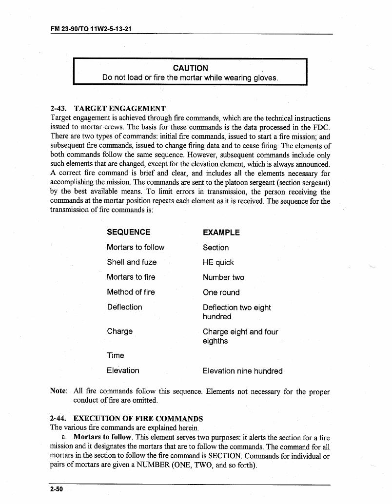
FM 23-90/TO 11 W2-5-13-21
CAUTIONDo not load or fire the mortar while wearing gloves.
2-43. TARGET ENGAGEMENTTarget engagement is achieved through fire commands, which are the technical instructionsissued to mortar crews. The basis for these commands is the data processed in the FDC.There are two types of commands: initial fire commands, issued to start a fire mission; andsubsequent fire commands, issued to change firing data and to cease firing. The elements ofboth commands follow the same sequence. However, subsequent commands include onlysuch elements that are changed, except for the elevation element, which is always announced.A correct fire command is brief and clear, and includes all the elements necessary foraccomplishing the mission. The commands are sent to the platoon sergeant (section sergeant)by the best available means. To limit errors in transmission, the person receiving thecommands at the mortar position repeats each element as it is received. The sequence for thetransmission of fire commands is:
SEQUENCE EXAMPLE
Mortars to follow Section
Shell and fuze HE quick
Mortars to fire Number two
Method of fire One round
Deflection Deflection two eighthundred
Charge Charge eight and foureighths
Time
Elevation Elevation nine hundred
Note: All fire commands follow this sequence. Elements not necessary for the properconduct of fire are omitted.
2-44. EXECUTION OF FIRE COMMANDSThe various fire commands are explained herein.
a. Mortars to follow. This element serves two purposes: it alerts the section for a firemission and it designates the mortars that are to follow the commands. The command for allmortars in the section to follow the fire command is SECTION. Commands for individual orpairs of mortars are given a NUMBER (ONE, TWO, and so forth).
2-50
FM 23-90/TO 11W2-5-13-21
b. Shell and fuze. This element alerts the ammunition bearers as to what type ofammunition and fuze action to prepare for firing-for example, HE QUICK; HE DELAY;HE PROXIMITY; and so forth.
c. Mortar(s) to fire. This element designates the specific mortar(s) to fire. If the mortarsto fire are the same as the mortars to follow, this element is omitted. The command to fire anindividual mortar or any combination of mortars if NUMBER(s) (ONE, THREE, and soforth).
d. Method of fire. In this element, the mortar(s) designated to fire in the precedingelement is told how many rounds to fire, how to engage the target, and any special controldesired. Also included are the number and type ammunition to be used in the fire-for-effectphase.
(1) Volley fire. A volley can be fired by one or more mortars. The command for volleyfire is (so many) ROUNDS. Once all mortars are reported up, they fire on the platoonsergeant's (section sergeant's) command. If more than one round is being fired by eachmortar, the squads fire the first round on command and the remaining as rapidly as possibleconsistent with accuracy and safety, and without regard to other mortars. If a specific timeinterval is desired, the command is (so many) ROUNDS AT (so many) SECONDSINTERVAL, or (so many) ROUNDS PER MINUTE. In this case, a single round for eachmortar, at the time interval indicated, is fired at the platoon sergeant's (section sergeant's)command.
(2) Section right (left). This is a method of fire in which mortars are discharged from theright (left) one after the other, normally at 10-second intervals. The command for section firefrom the right (left) flank at intervals of 10 seconds is SECTION RIGHT (LEFT), ONEROUND. Once all mortars are reported up, the platoon sergeant (section sergeant) gives the
command FIREXfor example, SECTION RIGHT, ONE ROUND; the platoon sergeant(section sergeant) commands FIRE ONE; 10 seconds later FIRE TWO, and so forth.
(a) If the section is firing a section left, the fire begins with No. 3 and works to the right.The command LEFT (RIGHT) designates the flank from which the fire begins. The platoonsergeant (section sergeant) fires a section right (left) at 10-second intervals unless he is tolddifferently by the FDC-for example, SECTION LEFT, ONE ROUND, TWENTY-SECOND INTERVALS.
(b) When it is desired to fire continuously at a target, the command is CONTINUOUSFIRE. When it is desired to maintain a smoke screen, it may be necessary to fire a series ofsections right (left). In this case, the command is CONTINUOUS FIRE FROM THE RIGHT(LEFT). The platoon sergeant (section sergeant) then fires the designated mortarsconsecutively at 10-second intervals unless a different time interval is specified in thecommand.
(c) Changes in firing data (deflections and elevations) are applied to the mortars in turnsof traverse or elevation so as not to stop or break the continuity of fire-for example,NUMBER ONE, RIGHT THREE TURNS; NUMBER TWO, UP ONE TURN. Whencontinuous fire is given in the fire command, the platoon sergeant (section sergeant) continuesto fire the section until the FDC changes the method of fire or until the command END OFMISSION is given.
(3) Traversing fire. In traversing fire, rounds are fired with a designated number of turnsof traverse between each round. The command for traversing fire is (so many) ROUNDS,
2-51
FM 23-90/TO 11W2-5-13-21
TRAVERSE RIGHT (LEFT) (so many) TURNS. At the platoon sergeant's (sectionsergeant's) command FIRE, all mortars fire one round, traverse the specified number of turns,fire another round, and continue this procedure until the number of rounds specified in thecommand have been fired.
(4) Searching fire. Searching fire is fired the same as volley fire except that each roundnormally has a different range. No specific order is followed in firing the rounds. For example,the assistant gunner does not start at the shortest range and progress to the highest charge orvice versa, unless instructed to do so. Firing the rounds in a definite sequence (high to lowor low to high) establishes a pattern of fire that can be detected by the enemy.
(5) At my command. If the FDC wants to control the fire, the command AT MYCOMMAND is placed in the method of fire element of the fire command. Once all mortarsare reported up, the platoon sergeant (section sergeant) reports to the FDC: SECTIONREADY. The FDC then gives the command FIRE.
(6) Do not fire. The FDC can command DO NOT FIRE immediately following themethod of fire. DO NOT FIRE then becomes a part of the method of fire. This command isrepeated by the platoon sergeant (section sergeant). As soon as the weapons are laid theplatoon sergeant (section sergeant) reports to FDC that the section is laid. The command forthe section of fire is the command for a new method of fire not followed by DO NOT FIRE.
(7) Deflection. This element gives the exact deflection setting to be placed on the mortarsight. It is always announced in four digits, and the word DEFLECTION always precedes thesight setting-for example, DEFLECTION, TWO EIGHT FOUR SEVEN (2847). When themortars are to be fired with different deflections, the number of the mortar is given and thenthe deflection for that mortar-for example, NUMBER THREE, DEFLECTION TWOFOUR ZERO ONE (2401).
(8) Charge. This element gives the charge consistent with elevation and range asdetermined from the firing tables-for example, CHARGE FOUR (4). The word CHARGEalways precedes the amountXfor example, ONE ROUND, CHARGE FOUR (4).
(9) Time. The computer tells the ammunition bearer the exact time setting to place on theproximity, MTSQ, and the MT fuze. The command for time setting is TIME (so much)- forexample, TIME TWO SEVEN. The command for a change in time setting is a new commandfor time.
(10) Elevation. This element serves two purposes: first, it gives the exact elevationsetting that is to be placed on the mortar sight; second, it serves as the command to fire, if norestrictions are placed on method of fire. When no restrictions are announced in the methodof fire, the section, when laid, fires at the platoon sergeant's (section sergeant's) commandFIRE. The platoon sergeant (section sergeant) may allow the mortar(s) to fire when ready.The elevation element is always given in a fire command. It is announced as, "Elevation (somany mils)."
2-45. ARM-AND-HAND SIGNALSWhen giving the commands FIRE or CEASE FIRING, the section leader or squad leader usesboth arm-and-hand signals and voice commands (Figure 2-33).
a. Ready. The signal for "I am ready" or "Are you ready?" is to extend the arm towardthe person being signaled. Then, the arm is raised slightly above the horizontal, palm outward.
2-52
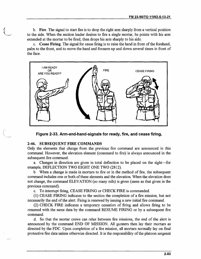
FM 23-90/TO 11W2-5-13-21
b. Fire. The signal to start fire is to drop the right arm sharply from a vertical positionto the side. When the section leader desires to fire a single mortar, he points with his armextended at the mortar to be fired, then drops his arm sharply to his side.
c. Cease Firing. The signal for cease firing is to raise the hand in front of the forehead,palm to the front, and to move the hand and forearm up and down several times in front ofthe face.
I AM READYOR FIRE CEASE FIRING
ARE YOU READY?
ci
Figure 2-33. Arm-and-hand-signals for ready, fire, and cease firing.
2-46. SUBSEQUENT FIRE COMMANDSOnly the elements that change from the previous fire command are announced in thiscommand. However, the elevation element (command to fire) is always announced in thesubsequent fire command.
a. Changes in direction are given in total deflection to be placed on the sight-forexample, DEFLECTION TWO EIGHT ONE TWO (2812).
b. When a change is made in mortars to fire or in the method of fire, the subsequentcommand includes one or both of these elements and the elevation. When the elevation doesnot change, the command ELEVATION (so many mils) is given (same as that given in theprevious command).
c. To interrupt firing, CEASE FIRING or CHECK FIRE is commanded.(1) CEASE FIRING indicates to the section the completion of a fire mission, but not
necessarily the end of the alert. Firing is renewed by issuing a new initial fire command.(2) CHECK FIRE indicates a temporary cessation of firing and allows firing to be
resumed with the same data by the command RESUME FIRING or by a subsequent firecommand.
d. So that the mortar crews can relax between fire missions, the end of the alert isannounced by the command END OF MISSION. All gunners then lay their mortars asdirected by the FDC. Upon completion of a fire mission, all mortars normally lay on finalprotective fire data unless otherwise directed. It is the responsibility of the platoon sergeant
2-53
FM 23-90/TO0 11W2-5-13-21
(section sergeant) to ensure that the mortars are laid on final protective fire data and that theprescribed amount of ammunition for the final protective fire is prepared and on position.
2-47. REPEATING AND CORRECTING OF FIRE COMMANDSIf the platoon sergeant (section sergeant) or squad member fails to understand any elementsof the fire command, he can request that element be repeated by starting-for example, "Sayagain deflection, elevation," and so forth. Misunderstanding is avoided when the repeatedelement is prefaced with "I say again deflection (repeats mils)."
a. In an initial fire command, an incorrect element is corrected by stating, "Correction,"and giving only the corrected element.
b. In a subsequent command, an incorrect element is corrected by stating, "Correction,"and then by repeating all of the subsequent commands. (The term "correction" cancels theentire command.)
2-48. REPORTING OF ERRORS IN FIRINGWhen any squad member discovers that an error has been made in firing, he immediatelynotifies his squad leader, who in turn notifies the FDC. Such errors include, but are notlimited to, incorrect deflection or elevation settings, incorrect laying of the mortar, orammunition improperly prepared for firing. Misfires are also reported this way. Errors shouldbe promptly reported to the FDC to prevent loss of time in determining the cause andrequired corrective action.
2-49. NIGHT FIRINGWhen firing the mortar at night, the mission dictates whether noise and light discipline are tobe sacrificed for speed. To counteract the loss of speed for night firing, the gunner mustconsider presetting both fuze and charge for illumination rounds with the presetting ofcharges for other rounds. The procedure for manipulating the mortar at night is the same asduring daylight operations. To assist the gunner in these manipulations, the sight reticle isilluminated, and the aiming posts are provided with lights.
a. The instrument lights illuminate the reticle of the sights and make the vertical crosslines visible. The hand light on the flexible cord is used to illuminate the scales and bubbles.
b. An aiming post light is placed on each aiming post to enable the gunner to see theaiming posts. Aiming posts are placed out at night similar to the daylight procedure. Thelights must be attached to the posts before they can be seen and positioned by the gunner. Thegunner must issue commands such as NUMBER ONE, MOVE RIGHT, LEFT, HOLD,DRIVE IN, POST CORRECT. Tilt in the posts is corrected at daybreak. Some of thedistance to the far post can be sacrificed if it cannot be easily seen at 100 meters. However,the near post should still be positioned about half the distance to the far post from the mortar.The far post light should be a different color from the one on the near post and be positionedso it appears slightly higher. Adjacent squads should alternate post lights to avoid laying onthe wrong posts-for example, 1ST SQUAD, NEAR POST-GREEN LIGHT, FARPOST-RED LIGHT; 2D SQUAD, NEAR POST-RED LIGHT, FAR POST-GREENLIGHT. (The M58 light is green and the M59 light is orange.)
2-54
FM 23-90/TO 11W2-5-13-21
c. The mortar is laid for deflection by placing the vertical cross line of the sight in thecorrect relation to the center of the lights attached to the aiming posts. The procedure forlaying the mortar is the same as discussed in Section VI.
d. The night lights can be used to align the aiming posts without using voice commands.(1) The gunner directs the ammunition bearer to place out the aiming posts. The
ammunition bearer moves out 100 meters and turns on the night light of the far aiming post.The gunner holds the instrument night light in his right (left) hand and, by moving the lightto the right (left), directs the ammunition bearer to move to the right (left). To ensure that theammunition bearer sees the light moving only in the desired direction, the gunner places histhumb over the light when returning it to the starting position. The gunner continues to directthe ammunition bearer to move the aiming post until it is properly aligned.
(2) The gunner moves the instrument light a shorter distance from the starting positionwhen he desires the ammunition bearer to move the aiming post a short distance.
(3) The gunner holds the light over his head (starting position) and moves the light towaist level when he desires to have the ammunition bearer place the aiming post into theground. In returning the instrument light to the starting position, the gunner covers the lightwith his thumb to ensure that the ammunition bearer sees the light move only in the desireddirection.
(4) The gunner uses the same procedure described above when he wants the ammunitionbearer to move the aiming post light to a position corresponding to the vertical hairline in thesight after the aiming post has been placed into the ground.
(5) The gunner reverses the procedure described above when he wants the ammunitionbearer to take the aiming post out of the ground. The gunner places the uncovered light atwaist level and moves it to a position directly above his head. He then directs alignment asrequired.
(6) When the gunner is satisfied with the alignment of the aiming posts, he signals theammunition bearer to return to the mortar positions by making a circular motion with theinstrument light.
Note: When the night light is used to signal, the gunner directs the light toward theammunition bearer.
2-55
FM 23-90/TO 11W2-5-13-21
CHAPTER 3
60-mm MORTAR, M224
The 60-mm mortar, M224, reacts quickly to support infantrymen by engagingthe target first. This allows infantrymen to confront the enemy whilesupporting the battle plan. The mortar can be fired accurately with orwithout afire direction center.
Section I. SQUAD AND SECTION ORGANIZATION AND DUTIESThis section discusses the organization and duties of the 60-mm mortar squad and section.
3-1. ORGANIZATIONIf the mortar section is to operate quickly and effectively in accomplishing its mission, mortarsquad members must be proficient in individually assigned duties. Correctly applying andperforming these duties enables the mortar section to perform as an effective fighting team.The section leader commands the section and supervises the training of the elements. He usesthe chain of command to assist him in effecting his command and supervising duties.
3-2. DUTIESThe mortar squad consists of three soldiers. Each squad member is cross-trained to performall duties involved in firing the mortar. The positions and principal duties are as follows:
a. The squad leader is in position to best control the mortar squad. He is positioned tothe right of the mortar, facing the barrel. He is also the FDC.
b. The gunner is on the left side of the mortar where he can manipulate the sight,elevating gear handle, and traversing assembly wheel. He places firing data on the sight andlays the mortar for deflection and elevation. Assisted by the squad leader (or ammunitionbearer), he makes large deflection shifts by shifting the bipod assembly.
c. The ammunition bearer is to the right rear of the mortar. He prepares the ammunitionand assists the gunner in shifting and loading the mortar. He swabs the barrel every 10 roundsor after each end of mission.
Section II. COMPONENTSThe 60-mm mortar, M224, can be fired in the conventional mode or handheld mode (Figure3-1, page 3-2). The mortar is a muzzle-loaded, smooth-bore, high-angle-of-fire weapon. Itcan be drop-fired or trigger-fired and has five major components.
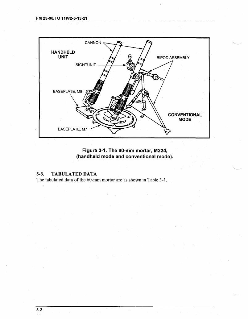
FM 23-901T0 11W2-5-13-21
Figure 3-1. The 60-mm mortar, M224,(handheld mode and conventional mode).
3-3. TABULATED DATAThe tabulated data of the 60-mm mortar are as shown in Table 3-1.
3-2
BIPOD ASSEMBLY
CONVENTIONAL\ MODE
- I_ ,,
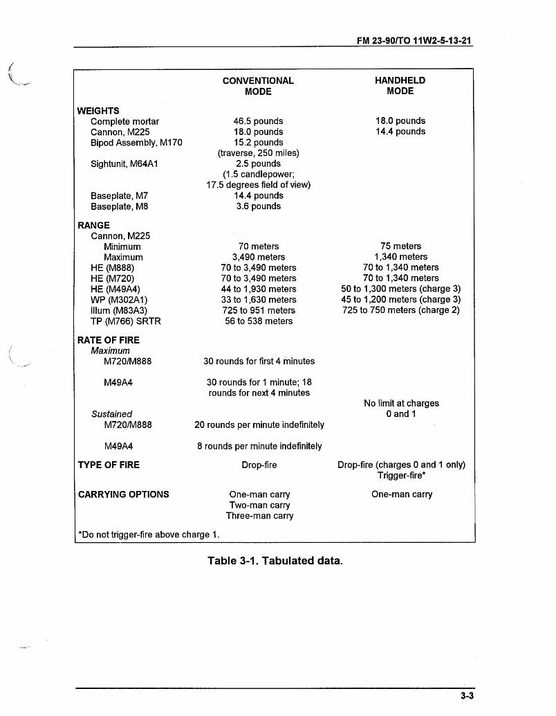
FM 23-90/TO 11W2-5-13-21
CONVENTIONALMODE
WEIGHTSComplete mortarCannon, M225Bipod Assembly, M170
Sightunit, M64A1
Baseplate, M7Baseplate, M8
RANGECannon, M225
MinimumMaximum
HE (M888)HE (M720)HE (M49A4)WP (M302A1)Illum (M83A3)TP (M766) SRTR
RATE OF FIREMaximum
M720/M888
M49A4
SustainedM720/M888
M49A4
46.5 pounds18.0 pounds15.2 pounds
(traverse, 250 miles)2.5 pounds
(1.5 candlepower;17.5 degrees field of view)
14.4 pounds3.6 pounds
70 meters3,490 meters
70 to 3,490 meters70 to 3,490 meters44 to 1,930 meters33 to 1,630 meters725 to 951 meters56 to 538 meters
30 rounds for first 4 minutes
30 rounds for 1 minute; 18rounds for next 4 minutes
20 rounds per minute indefinitely
8 rounds per minute indefinitely
18.0 pounds14.4 pounds
75 meters1,340 meters
70 to 1,340 meters70 to 1,340 meters
50 to 1,300 meters (charge 3)45 to 1,200 meters (charge 3)725 to 750 meters (charge 2)
No limit at charges0 and 1
TYPE OF FIRE Drop-fire Drop-fire (charges 0 and 1 only)Trigger-fire*
CARRYING OPTIONS One-man carryTwo-man carry
Three-man carry
One-man carry
*Do not trigger-fire above charge 1.
Table 3-1. Tabulated data.
3-3
HANDHELDMODE
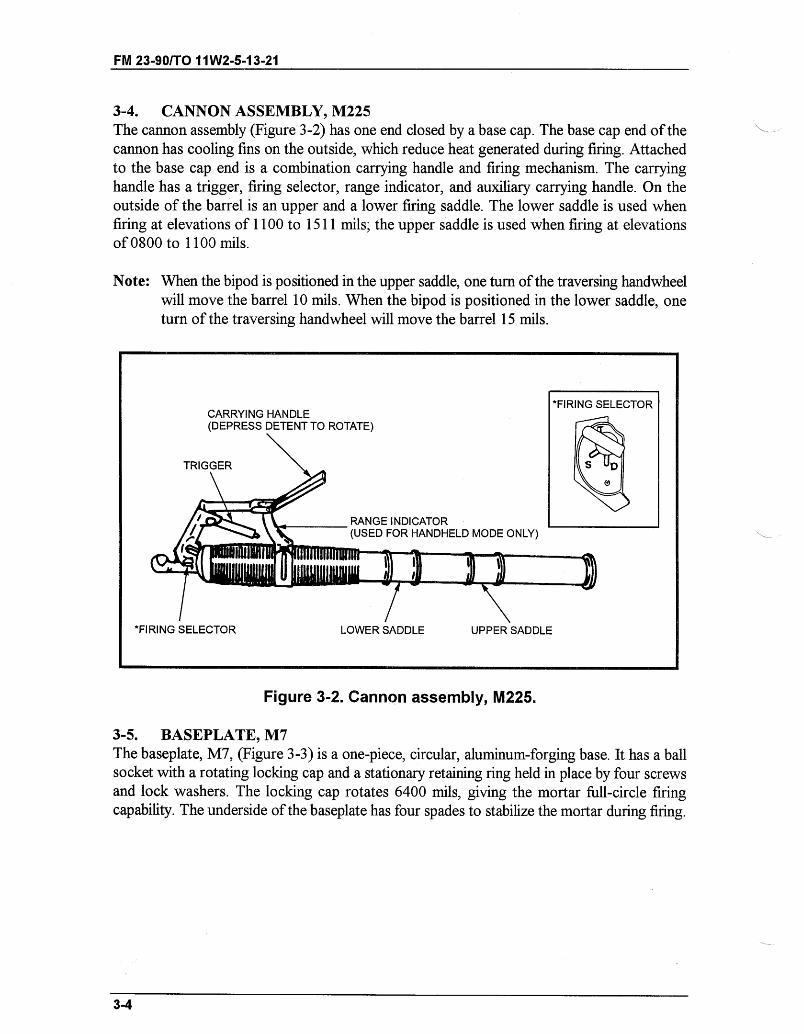
FM 23-90/TO 11W2-5-13-21
3-4. CANNON ASSEMBLY, M225The cannon assembly (Figure 3-2) has one end closed by a base cap. The base cap end of thecannon has cooling fins on the outside, which reduce heat generated during firing. Attachedto the base cap end is a combination carrying handle and firing mechanism. The carryinghandle has a trigger, firing selector, range indicator, and auxiliary carrying handle. On theoutside of the barrel is an upper and a lower firing saddle. The lower saddle is used whenfiring at elevations of 1100 to 1511 mils; the upper saddle is used when firing at elevationsof 0800 to 1100 mils.
Note: When the bipod is positioned in the upper saddle, one turn of the traversing handwheelwill move the barrel 10 mils. When the bipod is positioned in the lower saddle, oneturn of the traversing handwheel will move the barrel 15 mils.
V I ----- I I --- -------
Figure 3-2. Cannon assembly, M225.
3-5. BASEPLATE, M7The baseplate, M7, (Figure 3-3) is a one-piece, circular, aluminum-forging base. It has a ballsocket with a rotating locking cap and a stationary retaining ring held in place by four screwsand lock washers. The locking cap rotates 6400 mils, giving the mortar full-circle firingcapability. The underside of the baseplate has four spades to stabilize the mortar during firing.
3-4
*FIRING SELECTORCARRYING HANDLE(DEPRESS DETENT TO ROTATE)
TRIGGER
RANGE INDICATOR(USED FOR HANDHELD MODE ONLY)
*FIRING SELECTOR LOWER SADDLE UPPER SADDLE

FM 23-90/TO 11W2-5-13-21
Figure 3-3. Baseplate, M7.
3-6. BASEPLATE, M8The baseplate, M8, (Figure 3-4) is a one-piece, rectangular, aluminum-forging base. It shouldbe used when the mortar is fired in the handheld mode. The baseplate allows the mortar tobe fired 0800 mils left and 0800 mils right of the center of sector for a total sector coverageof 1600 mils. It has a socket in which the barrel can be locked to the baseplate by securingthe locking arm. The underside of the baseplate has four spades to strengthen and stabilizethe mortar during firing. Two spring-loaded plungers lock the baseplate to the barrel in itscarry position.
Figure 3-4. Baseplate, M8.
3-5
-- ----- --- ,,
---- -- L - c I -- -- -
- ,, __
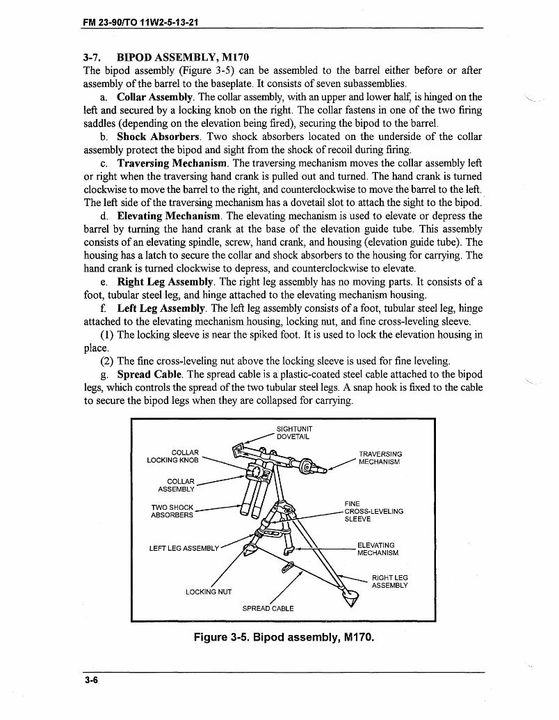
FM 23-90/T011W2-5-13-21
3-7. BIPOD ASSEMBLY, M170The bipod assembly (Figure 3-5) can be assembled to the barrel either before or afterassembly of the barrel to the baseplate. It consists of seven subassemblies.
a. Collar Assembly. The collar assembly, with an upper and lower half, is hinged on theleft and secured by a locking knob on the right. The collar fastens in one of the two firingsaddles (depending on the elevation being fired), securing the bipod to the barrel.
b. Shock Absorbers. Two shock absorbers located on the underside of the collarassembly protect the bipod and sight from the shock of recoil during firing.
c. Traversing Mechanism. The traversing mechanism moves the collar assembly leftor right when the traversing hand crank is pulled out and turned. The hand crank is turnedclockwise to move the barrel to the right, and counterclockwise to move the barrel to the left.The left side of the traversing mechanism has a dovetail slot to attach the sight to the bipod.
d. Elevating Mechanism. The elevating mechanism is used to elevate or depress thebarrel by turning the hand crank at the base of the elevation guide tube. This assemblyconsists of an elevating spindle, screw, hand crank, and housing (elevation guide tube). Thehousing has a latch to secure the collar and shock absorbers to the housing for carrying. Thehand crank is turned clockwise to depress, and counterclockwise to elevate.
e. Right Leg Assembly. The right leg assembly has no moving parts. It consists of afoot, tubular steel leg, and hinge attached to the elevating mechanism housing.
f. Left Leg Assembly. The left leg assembly consists of a foot, tubular steel leg, hingeattached to the elevating mechanism housing, locking nut, and fine cross-leveling sleeve.
(1) The locking sleeve is near the spiked foot. It is used to lock the elevation housing inplace.
(2) The fine cross-leveling nut above the locking sleeve is used for fine leveling.g. Spread Cable. The spread cable is a plastic-coated steel cable attached to the bipod
legs, which controls the spread of the two tubular steel legs. A snap hook is fixed to the cableto secure the bipod legs when they are collapsed for carrying.
Figure 3-5. Bipod assembly, M170.
3-6
SIGHTUNITDOVETAIL
COLLAR . TRAVERSINGLOCKING KNOB / MECHANISM
COLLARASSEMBLY
TWO SHOCK FINEABSORBERS tCROSS-LEVELING
SLEEVE
LEFT LEG ASSEMBLY ELEVATINGMECHANISM
RIGHT LEG
LOCKING NUT/ ASSEMBLY
SPREAD CABLE
FM 23-90/TO 11W2-5-13-21
Section III. OPERATIONSafe operation of the 60-mm mortar requires that training include drill practice on tasks forsafe manipulation and effective employment. Crew training achieves the speed, precision, andteamwork needed to deliver responsive and effective fire on target.
3-8. PREMOUNT CHECKSBefore the mortar is mounted, the squad must perform premount checks. Each squad membershould be capable of performing all the premount checks.
a. The gunner performs the premount checks on the mount so that-* The spreader cable is fixed to both legs and taut.* The clearance on the left leg above the adjusting nut is two fingers in width.* The locking sleeve is neither too loose nor too tight.* The traversing bearing is centered.
b. The squad leader performs the premount checks on the barrel so that-* The barrel is clean both inside and outside.* The firing pin is visible.* The spherical projection is clean, and the firing pin is firmly seated.* The selector switch is on drop-fire mode.
c. The ammunition bearer is responsible for the premount checks on the baseplateensuring that-
* The rotatable socket cap moves freely and has a light coat of oil.* The ribs and braces are checked for breaks and dents, and the inner ring is secured
to the outer ring.d. When all pieces of equipment are checked, the gunner notifies the section leader by
announcing, "All correct."
3-9. MOUNTING OF THE MORTARThe squad leader picks up and places the sight case and two aiming posts at the exact positionwhere the mortar is to be mounted.
a. The ammunition bearer places the outer edge of the baseplate against the baseplatestake. He aligns the left edge of the cutout portion of the baseplate with the right edge of thebaseplate stake. He then rotates the socket cap so that the open end points in the directionof fire.
b. The gunner picks up the bipod with his left hand on the traversing hand crank and hisright hand on the dovetail slot. He moves forward of the baseplate about 12 to 15 inches andfaces the baseplate on line with the left edge (gunner's viewpoint) of the baseplate. Droppingdown on one knee in front of the bipod, the gunner supports the bipod with his left hand onthe gear case. He then detaches the hook and unwraps the cable assembly. The gunner placeshis left hand on the midsection of the traversing slide and his right hand on the mechanical leg,and he extends the bipod legs the length of the cable assembly. He then aligns the center ofthe bipod assembly with the center of the baseplate. He ensures that the elevation guide barrelis vertical and the locking nut is hand tight. The gunner moves to the mechanical leg side andsupports the bipod with his left hand on the shock absorber. He unscrews the collar lockingknob to open the collar.
3-7
FM 23-90/TO 11W2-5-13-21
c. The ammunition bearer picks up the barrel and inserts the spherical projection of thebase plug into the socket. He rotates the barrel 90 degrees to lock it to the baseplate. Ifperformed properly, the carrying handle is on the upper side of the barrel, facing skyward.
d. The gunner pushes down on the shock absorber and raises the collar assembly. Theammunition bearer lowers the barrel and places the lower saddle on the lower part of thecollar. The gunner closes the upper part of the collar over the barrel. He replaces the lockingknob to its original position and makes it hand tight. The ammunition bearer cranks theelevation hand crank up 15 to 17 turns.
e. The gunner takes the sight out of the case and sets a deflection of 3200 mils and anelevation of 1100 mils. He mounts the sight to the mortar by pushing the lock latch on thesight inward. He slides the dovetail on the sight into the dovetail slot on the bipod until firmlyseated. The gunner releases the latch. He should tap up on the bottom of the sight to ensureproper seating. He then levels the mortar first for elevation 1100 mils, and then cross-levels.The gunner announces, "(gun number) up," to his squad leader.
3-10. SAFETY CHECKS BEFORE FIRINGSafety checks are performed by the entire squad.
a. The gunner ensures that-(1) There is mask and overhead clearance.(a) Since the mortar is normally mounted in defilade, there could be a mask such as a hill,
trees, buildings, or a rise in the ground. Roofs or overhanging tree branches can causeoverhead interference. The gunner must be sure the round does not strike any obstruction.
(b) When selecting the exact mortar position, the squad leader checks quickly for maskand overhead clearance. After the mortar is mounted, the gunner checks it thoroughly. Hedetermines mask and overhead clearance by sighting along the top of the barrel with his eyeplaced near the base plug. If the line of sight clears the mask, it is safe to fire. If not, he maystill fire at the desired range by selecting a charge zone having a higher elevation for thatparticular range. When firing under the control of an FDC, the gunner reports to the FDC thatmask clearance cannot be obtained at a certain elevation.
(c) Firing is slowed if mask clearance is checked before each firing. Therefore, if the maskis not regular throughout the sector of fire, the minimum mask clearance is determined toeliminate the need for checking on each mission. To do this, the gunner depresses the barreluntil the top of the mask is sighted. He then levels the elevation bubble and reads the settingon the elevation scale and elevation micrometer. That setting is the minimum mask clearance.The gunner notifies the squad leader of the minimum mask clearance elevation. Any targetthat requires that elevation or lower cannot be engaged from that position.
(d) Placing the mortar in position at night does not relieve the gunner of the responsibilityfor checking for mask and overhead clearance.
(2) The barrel is locked to the baseplate and the open end of the socket cap points in thedirection of fire. The bipod should be connected to either the upper or lower saddle of thebarrel.
(3) The barrel is locked on the collar by the locking knob.(4) The locking nut is wrist tight.(5) The cable is taut.(6) The selector switch on the barrel is on drop-fire.
3-8
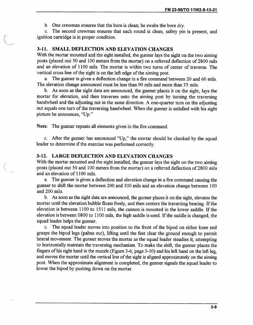
FM 23-90/TO 11W2-5-13-21
b. One crewman ensures that the bore is clean; he swabs the bore dry.c. The second crewman ensures that each round is clean, safety pin is present, and
ignition cartridge is in proper condition.
3-11. SMALL DEFLECTION AND ELEVATION CHANGESWith the mortar mounted and the sight installed, the gunner lays the sight on the two aimingposts (placed out 50 and 100 meters from the mortar) on a referred deflection of 2800 milsand an elevation of 1100 mils. The mortar is within two turns of center of traverse. Thevertical cross line of the sight is on the left edge of the aiming post.
a. The gunner is given a deflection change in a fire command between 20 and 60 mils.The elevation change announced must be less than 90 mils and more than 35 mils.
b. As soon as the sight data are announced, the gunner places it on the sight, lays themortar for elevation, and then traverses onto the aiming post by turning the traversinghandwheel and the adjusting nut in the same direction. A one-quarter turn on the adjustingnut equals one turn of the traversing handwheel. When the gunner is satisfied with his sightpicture he announces, "Up."
Note: The gunner repeats all elements given in the fire command.
c. After the gunner has announced "Up," the mortar should be checked by the squadleader to determine if the exercise was performed correctly.
3-12. LARGE DEFLECTION AND ELEVATION CHANGESWith the mortar mounted and the sight installed, the gunner lays the sight on the two aimingposts (placed out 50 and 100 meters from the mortar) on a referred deflection of 2800 milsand an elevation of 1100 mils.
a. The gunner is given a deflection and elevation change in a fire command causing thegunner to shift the mortar between 200 and 300 mils and an elevation change between 100and 200 mils.
b. As soon as the sight data are announced, the gunner places it on the sight, elevates themortar until the elevation bubble floats freely, and then centers the traversing bearing. If theelevation is between 1100 to 1511 mils, the cannon is mounted in the lower saddle. If theelevation is between 0800 to 1100 mils, the high saddle is used. If the saddle is changed, thesquad leader helps the gunner.
c. The squad leader moves into position to the front of the bipod on either knee andgrasps the bipod legs (palms out), lifting until the feet clear the ground enough to permitlateral movement. The gunner moves the mortar as the squad leader steadies it, attemptingto horizontally maintain the traversing mechanism. To make the shift, the gunner places thefingers of his right hand in the muzzle (Figure 3-6, page 3-10) and his left hand on the left leg,and moves the mortar until the vertical line of the sight is aligned approximately on the aimingpost. When the approximate alignment is completed, the gunner signals the squad leader tolower the bipod by pushing down on the mortar.
3-9
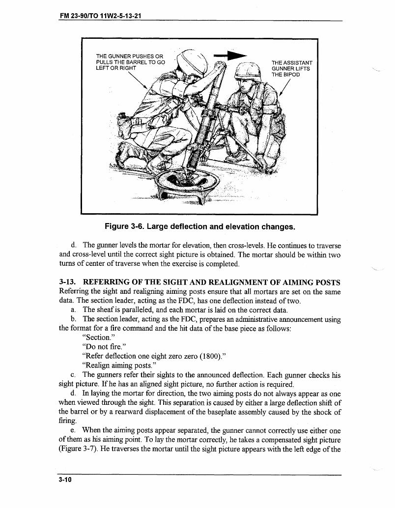
FM 23-90/TO 11W2-5-13-21
* II -- ,,_
Figure 3-6. Large deflection and elevation changes.
d. The gunner levels the mortar for elevation, then cross-levels. He continues to traverseand cross-level until the correct sight picture is obtained. The mortar should be within twoturns of center of traverse when the exercise is completed.
3-13. REFERRING OF THE SIGHT AND REALIGNMENT OF AIMING POSTSReferring the sight and realigning aiming posts ensure that all mortars are set on the samedata. The section leader, acting as the FDC, has one deflection instead of two.
a. The sheaf is paralleled, and each mortar is laid on the correct data.b. The section leader, acting as the FDC, prepares an administrative announcement using
the format for a fire command and the hit data of the base piece as follows:"Section.""Do not fire.""Refer deflection one eight zero zero (1800).""Realign aiming posts."
c. The gunners refer their sights to the announced deflection. Each gunner checks hissight picture. If he has an aligned sight picture, no further action is required.
d. In laying the mortar for direction, the two aiming posts do not always appear as onewhen viewed through the sight. This separation is caused by either a large deflection shift ofthe barrel or by a rearward displacement of the baseplate assembly caused by the shock offiring.
e. When the aiming posts appear separated, the gunner cannot correctly use either oneof them as his aiming point. To lay the mortar correctly, he takes a compensated sight picture(Figure 3-7). He traverses the mortar until the sight picture appears with the left edge of the
3-10
THE GUNNER PUSHES ORTHE ASSISTANTGUNNER LIFTSTHE BIPOD
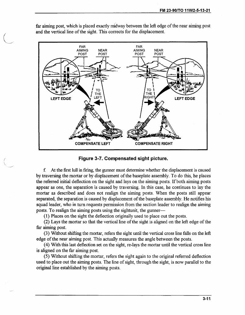
FM 23-90/TO 11W2-5-13-21
far aiming post, which is placed exactly midway between the left edge of the near aiming postand the vertical line of the sight. This corrects for the displacement.
FAR FARAIMING NEAR AIMING NEARPOST POST POST POST
Figure 3-7. Compensated sight picture.
f. At the first lull in firing, the gunner must determine whether the displacement is causedby traversing the mortar or by displacement of the baseplate assembly. To do this, he placesthe referred initial deflection on the sight and lays on the aiming posts. If both aiming postsappear as one, the separation is caused by traversing. In this case, he continues to lay themortar as described and does not realign the aiming posts. When the posts still appearseparated, the separation is caused by displacement of the baseplate assembly. He notifies hissquad leader, who in turn requests permission from the section leader to realign the aimingposts. To realign the aiming posts using the sightunit, the gunner-
(1) Places on the sight the deflection originally used to place out the posts.(2) Lays the mortar so that the vertical line of the sight is aligned on the left edge of the
far aiming post.(3) Without shifting the mortar, refers the sight until the vertical cross line falls on the left
edge of the near aiming post. This actually measures the angle between the posts.(4) With this last deflection set on the sight, re-lays the mortar until the vertical cross line
is aligned on the far aiming post.(5) Without shifting the mortar, refers the sight again to the original referred deflection
used to place out the aiming posts. The line of sight, through the sight, is now parallel to theoriginal line established by the aiming posts.
3-11
COMPENSATE RIGHTV- IW
COMPENSATE LEFT
FM 23-90/T0 11W2-5-13-21
(6) Looking through the sight, directs the ammunition bearer to move the aiming postsso that they are realigned with the sight's vertical line. The posts are now realigned to correctthe displacement.
Note: This procedure is used only when displacement is so great that it is difficult to obtaina compensated sight picture.
3-14. MALFUNCTIONSMortarmen must be aware of the following malfunctions.
a. Misfire. A misfire is a complete failure to fire. It can be caused by a faulty firingmechanism or faulty element in the propelling charge explosive train. A misfire cannot beimmediately distinguished from a delay in functioning of the firing mechanism or from ahangfire; therefore, it must be handled with care. All firing malfunctions should be considereda misfire. Mechanical malfunctions can be caused by a faulty wiring pin or by rounds lodgedin the barrel because of burrs, excess paint, oversized rounds, or foreign matter in the barrel.Procedures for removing a misfire are discussed in paragraph 3-15.
b. Hangfire. A hangfire is a delay in the functioning of a propelling charge explosivetrain at the time of firing. In most cases, the delay ranges from a split second to severalminutes. Thus, a hangfire cannot be distinguished immediately from a misfire.
c. Cookoff. A cookoffis a functioning of one or more of the explosive components ofa round chambered in a hot weapon, initiated by the heat of the weapon.
3-15. REMOVAL OF A MISFIREThe procedures for removing a misfire are different for handheld and conventional modes.The propelling charge may not function for the following reasons:
" Defective ignition cartridge." Defective, damaged, or loose firing pin." Fouled firing pin or firing pin obstructed by extraneous material." Fouled bore.* Excess oil or water in the bore." Misaligned stabilizing fin." Foreign matter or excess paint on round." Selector switch on SAFE or TRIGGER.a. Conventional Mode.(1) When a misfire occurs, any member of the squad immediately announces, "Misfire."
The entire squad stays with the mortar. If it is obvious to the squad leader that the round hasreached the bottom of the barrel and it has failed to ignite, the gunner places the selectorswitch on trigger fire and squeezes the trigger several times to try to clear the round.
WARNINGDuring peacetime live-fire training, the ammunition bearermoves at least 50 meters to the rear of the mortar.
3-12
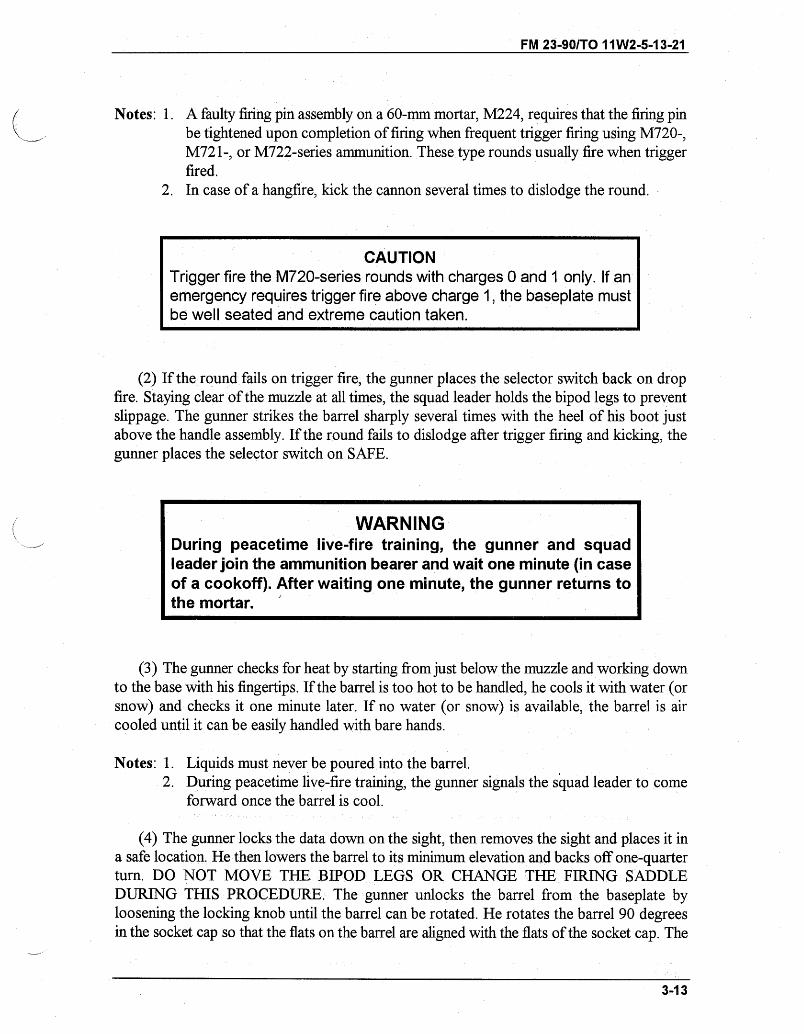
FM 23-90/TO 11W2-5-13-21
Notes: 1. A faulty firing pin assembly on a 60-mm mortar, M224, requires that the firing pinbe tightened upon completion of firing when frequent trigger firing using M720-,M721-, or M722-series ammunition. These type rounds usually fire when triggerfired.
2. In case of a hangfire, kick the cannon several times to dislodge the round.
CAUTIONTrigger fire the M720-series rounds with charges 0 and 1 only. If anemergency requires trigger fire above charge 1, the baseplate mustbe well seated and extreme caution taken.
(2) If the round fails on trigger fire, the gunner places the selector switch back on dropfire. Staying clear of the muzzle at all times, the squad leader holds the bipod legs to preventslippage. The gunner strikes the barrel sharply several times with the heel of his boot justabove the handle assembly. If the round fails to dislodge after trigger firing and kicking, thegunner places the selector switch on SAFE.
WARNINGDuring peacetime live-fire training, the gunner and squadleader join the ammunition bearer and wait one minute (in caseof a cookoff). After waiting one minute, the gunner returns tothe mortar.
(3) The gunner checks for heat by starting from just below the muzzle and working downto the base with his fingertips. If the barrel is too hot to be handled, he cools it with water (orsnow) and checks it one minute later. If no water (or snow) is available, the barrel is aircooled until it can be easily handled with bare hands.
Notes: 1. Liquids must never be poured into the barrel.2. During peacetime live-fire training, the gunner signals the squad leader to come
forward once the barrel is cool.
(4) The gunner locks the data down on the sight, then removes the sight and places it ina safe location. He then lowers the barrel to its minimum elevation and backs off one-quarterturn. DO NOT MOVE THE BIPOD LEGS OR CHANGE THE FIRING SADDLEDURING THIS PROCEDURE. The gunner unlocks the barrel from the baseplate byloosening the locking knob until the barrel can be rotated. He rotates the barrel 90 degreesin the socket cap so that the flats on the barrel are aligned with the flats of the socket cap. The
3-13
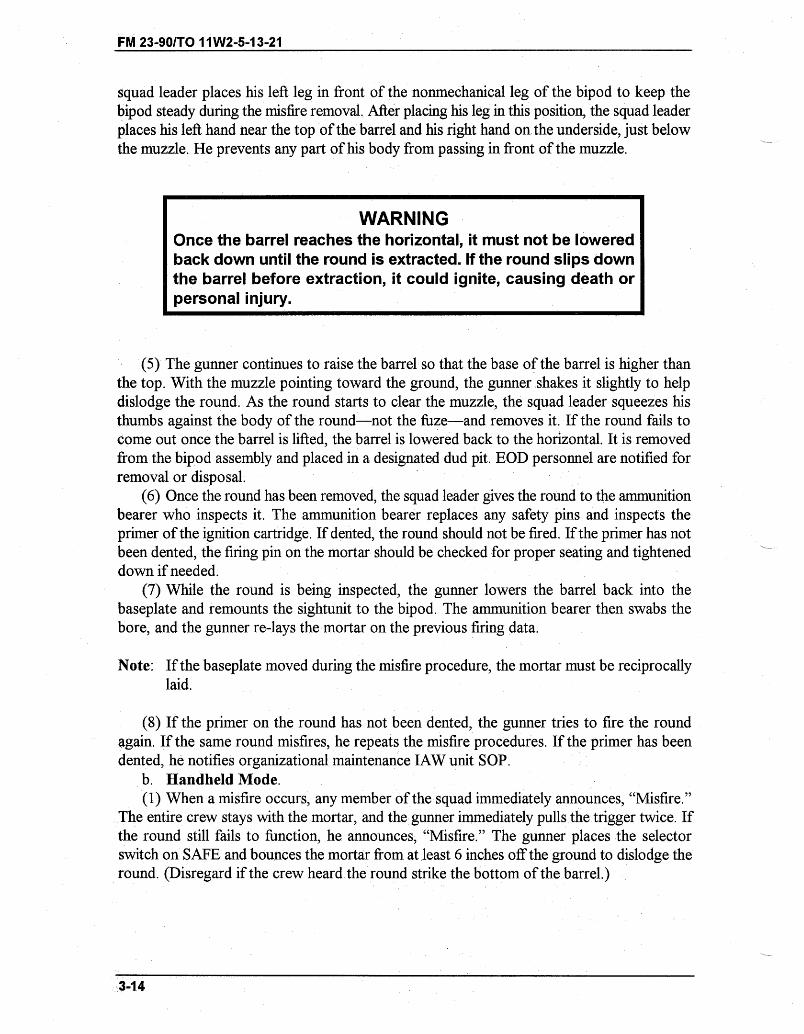
FM 23-90/TO 11W2-5-13-21
squad leader places his left leg in front of the nonmechanical leg of the bipod to keep thebipod steady during the misfire removal. After placing his leg in this position, the squad leaderplaces his left hand near the top of the barrel and his right hand on the underside, just belowthe muzzle. He prevents any part of his body from passing in front of the muzzle.
WARNINGOnce the barrel reaches the horizontal, it must not be loweredback down until the round is extracted. If the round slips downthe barrel before extraction, it could ignite, causing death orpersonal injury.
(5) The gunner continues to raise the barrel so that the base of the barrel is higher thanthe top. With the muzzle pointing toward the ground, the gunner shakes it slightly to helpdislodge the round. As the round starts to clear the muzzle, the squad leader squeezes histhumbs against the body of the round-not the fuze-and removes it. If the round fails tocome out once the barrel is lifted, the barrel is lowered back to the horizontal. It is removedfrom the bipod assembly and placed in a designated dud pit. EOD personnel are notified forremoval or disposal.
(6) Once the round has been removed, the squad leader gives the round to the ammunitionbearer who inspects it. The ammunition bearer replaces any safety pins and inspects theprimer of the ignition cartridge. If dented, the round should not be fired. If the primer has notbeen dented, the firing pin on the mortar should be checked for proper seating and tighteneddown if needed.
(7) While the round is being inspected, the gunner lowers the barrel back into thebaseplate and remounts the sightunit to the bipod. The ammunition bearer then swabs thebore, and the gunner re-lays the mortar on the previous firing data.
Note: If the baseplate moved during the misfire procedure, the mortar must be reciprocallylaid.
(8) If the primer on the round has not been dented, the gunner tries to fire the roundagain. If the same round misfires, he repeats the misfire procedures. If the primer has beendented, he notifies organizational maintenance IAW unit SOP.
b. Handheld Mode.(1) When a misfire occurs, any member of the squad immediately announces, "Misfire."
The entire crew stays with the mortar, and the gunner immediately pulls the trigger twice. Ifthe round still fails to function, he announces, "Misfire." The gunner places the selectorswitch on SAFE and bounces the mortar from at least 6 inches off the ground to dislodge theround. (Disregard if the crew heard the round strike the bottom of the barrel.)
3-14
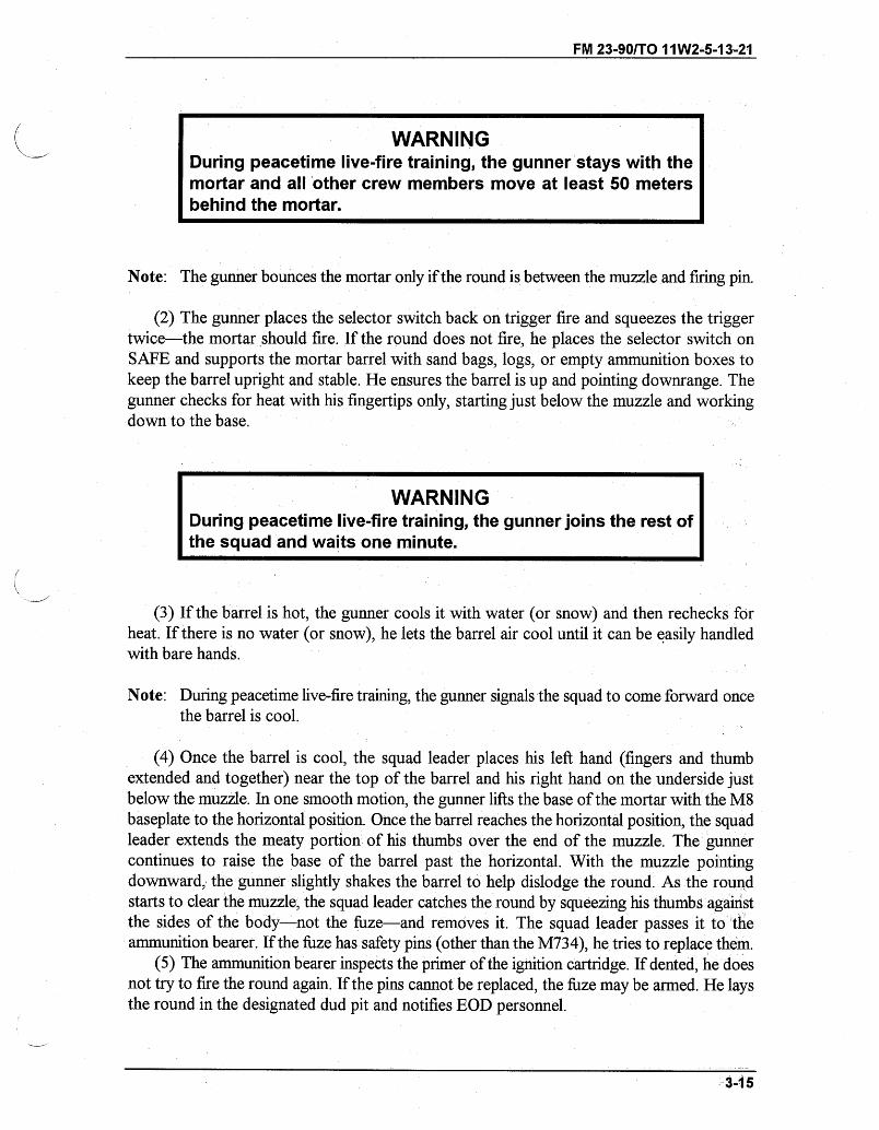
FM 23-90/TO 11W2-5-13-21
WARNINGDuring peacetime live-fire training, the gunner stays with themortar and all other crew members move at least 50 metersbehind the mortar.
Note: The gunner bounces the mortar only if the round is between the muzzle and firing pin.
(2) The gunner places the selector switch back on trigger fire and squeezes the triggertwice-the mortar should fire. If the round does not fire, he places the selector switch onSAFE and supports the mortar barrel with sand bags, logs, or empty ammunition boxes tokeep the barrel upright and stable. He ensures the barrel is up and pointing downrange. Thegunner checks for heat with his fingertips only, starting just below the muzzle and workingdown to the base.
WARNINGDuring peacetime live-fire training, the gunner joins the rest ofthe squad and waits one minute.
(3) If the barrel is hot, the gunner cools it with water (or snow) and then rechecks forheat. If there is no water (or snow), he lets the barrel air cool until it can be easily handledwith bare hands.
Note: During peacetime live-fire training, the gunner signals the squad to come forward oncethe barrel is cool.
(4) Once the barrel is cool, the squad leader places his left hand (fingers and thumbextended and together) near the top of the barrel and his right hand on the underside justbelow the muzzle. In one smooth motion, the gunner lifts the base of the mortar with the M8baseplate to the horizontal position. Once the barrel reaches the horizontal position, the squadleader extends the meaty portion of his thumbs over the end of the muzzle. The gunnercontinues to raise the base of the barrel past the horizontal. With the muzzle pointingdownward, the gunner slightly shakes the barrel to help dislodge the round. As the roundstarts to clear the muzzle, the squad leader catches the round by squeezing his thumbs againstthe sides of the body--not the fuze-and removes it. The squad leader passes it to theammunition bearer. If the fuze has safety pins (other than the M734), he tries to replace them.
(5) The ammunition bearer inspects the primer of the ignition cartridge. If dented, he doesnot try to fire the round again. If the pins cannot be replaced, the fuze may be armed. He laysthe round in the designated dud pit and notifies EOD personnel.
3-15
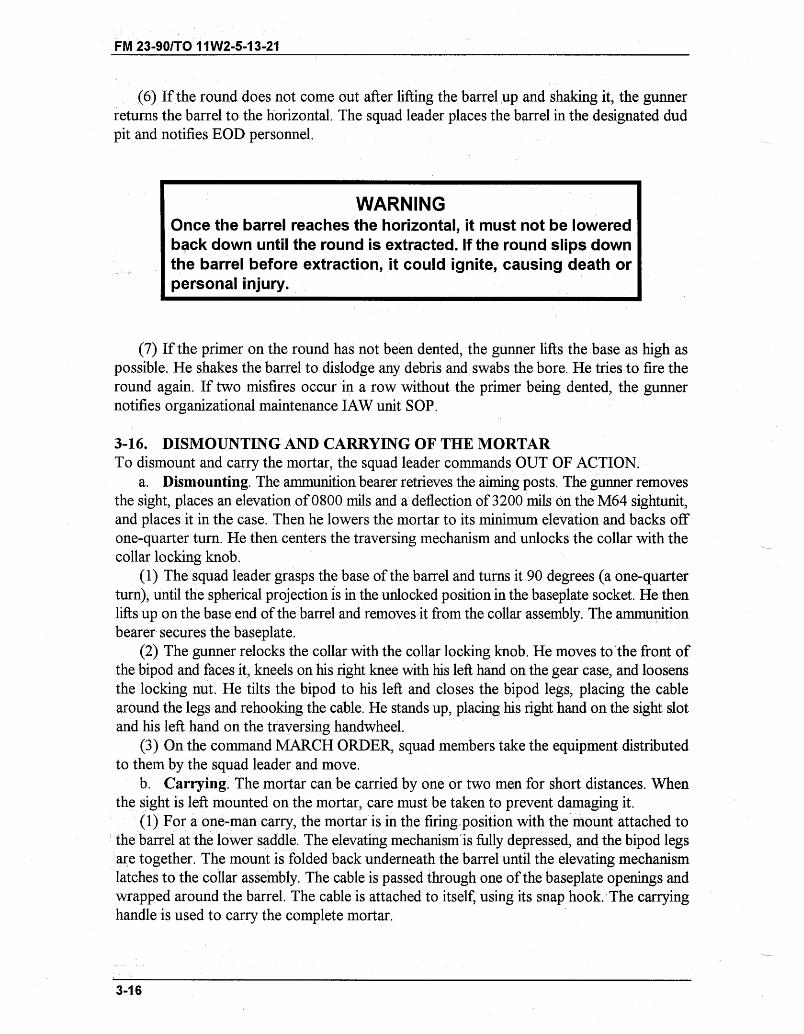
FM 23-90/TO 11W2-5-13-21
(6) If the round does not come out after lifting the barrel up and shaking it, the gunnerreturns the barrel to the horizontal. The squad leader places the barrel in the designated dudpit and notifies EOD personnel.
WARNINGOnce the barrel reaches the horizontal, it must not be loweredback down until the round is extracted. If the round slips downthe barrel before extraction, it could ignite, causing death orpersonal injury.
(7) If the primer on the round has not been dented, the gunner lifts the base as high aspossible. He shakes the barrel to dislodge any debris and swabs the bore. He tries to fire theround again. If two misfires occur in a row without the primer being dented, the gunnernotifies organizational maintenance IAW unit SOP.
3-16. DISMOUNTING AND CARRYING OF THE MORTARTo dismount and carry the mortar, the squad leader commands OUT OF ACTION.
a. Dismounting. The ammunition bearer retrieves the aiming posts. The gunner removesthe sight, places an elevation of 0800 mils and a deflection of 3200 mils on the M64 sightunit,and places it in the case. Then he lowers the mortar to its minimum elevation and backs offone-quarter turn. He then centers the traversing mechanism and unlocks the collar with thecollar locking knob.
(1) The squad leader grasps the base of the barrel and turns it 90 degrees (a one-quarterturn), until the spherical projection is in the unlocked position in the baseplate socket. He thenlifts up on the base end of the barrel and removes it from the collar assembly. The ammunitionbearer secures the baseplate.
(2) The gunner relocks the collar with the collar locking knob. He moves to the front ofthe bipod and faces it, kneels on his right knee with his left hand on the gear case, and loosensthe locking nut. He tilts the bipod to his left and closes the bipod legs, placing the cablearound the legs and rehooking the cable. He stands up, placing his right hand on the sight slotand his left hand on the traversing handwheel.
(3) On the command MARCH ORDER, squad members take the equipment distributedto them by the squad leader and move.
b. Carrying. The mortar can be carried by one or two men for short distances. Whenthe sight is left mounted on the mortar, care must be taken to prevent damaging it.
(1) For a one-man carry, the mortar is in the firing position with the mount attached tothe barrel at the lower saddle. The elevating mechanism is fully depressed, and the bipod legsare together. The mount is folded back underneath the barrel until the elevating mechanismlatches to the collar assembly. The cable is passed through one of the baseplate openings andwrapped around the barrel. The cable is attached to itself, using its snap hook. The carryinghandle is used to carry the complete mortar.
3-16
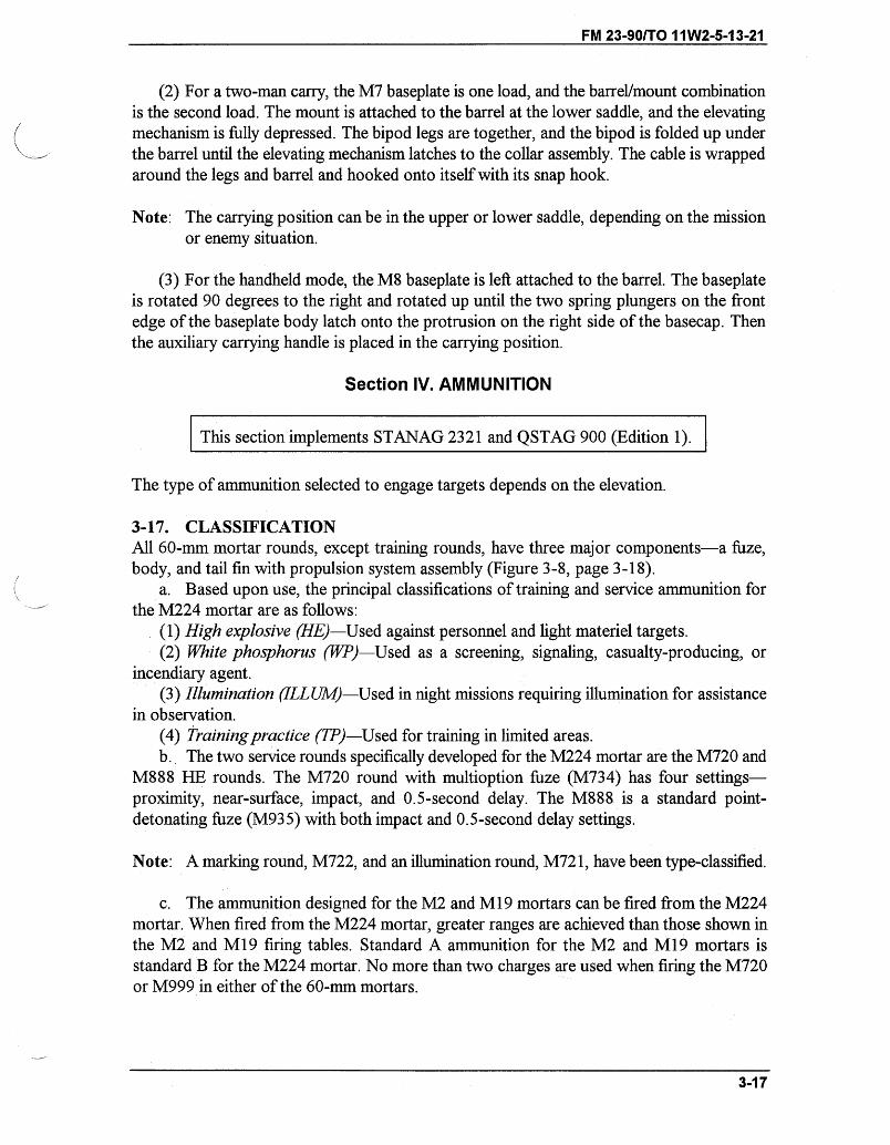
FM 23-90/TO 11W2-5-13-21
(2) For a two-man carry, the M7 baseplate is one load, and the barrel/mount combinationis the second load. The mount is attached to the barrel at the lower saddle, and the elevatingmechanism is fully depressed. The bipod legs are together, and the bipod is folded up underthe barrel until the elevating mechanism latches to the collar assembly. The cable is wrappedaround the legs and barrel and hooked onto itself with its snap hook.
Note: The carrying position can be in the upper or lower saddle, depending on the missionor enemy situation.
(3) For the handheld mode, the M8 baseplate is left attached to the barrel. The baseplateis rotated 90 degrees to the right and rotated up until the two spring plungers on the frontedge of the baseplate body latch onto the protrusion on the right side of the basecap. Thenthe auxiliary carrying handle is placed in the carrying position.
Section IV. AMMUNITION
This section implements STANAG 2321 and QSTAG 900 (Edition 1).
The type of ammunition selected to engage targets depends on the elevation.
3-17. CLASSIFICATIONAll 60-mm mortar rounds, except training rounds, have three major components-a fuze,body, and tail fin with propulsion system assembly (Figure 3-8, page 3-18).
a. Based upon use, the principal classifications of training and service ammunition forthe M224 mortar are as follows:
(1) High explosive (HE)-Used against personnel and light materiel targets.(2) White phosphorus (WP)-Used as a screening, signaling, casualty-producing, or
incendiary agent.(3) Illumination (ILL UM)-Used in night missions requiring illumination for assistance
in observation.(4) Training practice (TP)-Used for training in limited areas.b. The two service rounds specifically developed for the M224 mortar are the M720 and
M888 HE rounds. The M720 round with multioption fuze (M734) has four settings-proximity, near-surface, impact, and 0.5-second delay. The M888 is a standard point-detonating fuze (M935) with both impact and 0.5-second delay settings.
Note: A marking round, M722, and an illumination round, M721, have been type-classified.
c. The ammunition designed for the M2 and M19 mortars can be fired from the M224mortar. When fired from the M224 mortar, greater ranges are achieved than those shown inthe M2 and M19 firing tables. Standard A ammunition for the M2 and M19 mortars isstandard B for the M224 mortar. No more than two charges are used when firing the M720or M999 in either of the 60-mm mortars.
3-17
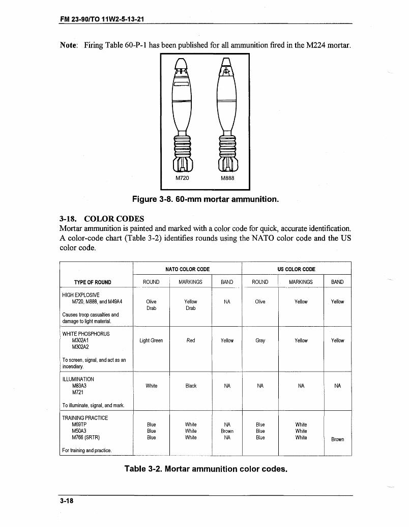
FM 23-90/TO 11W2-5-13-21
Note: Firing Table 60-P-1 has been published for all ammunition fired in the M224 mortar.
M720 M888
Figure 3-8. 60-mm mortar ammunition.
3-18. COLOR CODESMortar ammunition is painted and marked with a color code for quick, accurate identification.A color-code chart (Table 3-2) identifies rounds using the NATO color code and the UScolor code.
NATO COLOR CODE US COLOR CODE
TYPE OF ROUND ROUND MARKINGS BAND ROUND MARKINGS BAND
HIGH EXPLOSIVEM720, M888, and M49A4 Olive Yellow NA Olive Yellow Yellow
Drab DrabCauses troop casualties anddamage to light material.
WHITE PHOSPHORUSM302A1 Light Green Red Yellow Gray Yellow YellowM302A2
To screen, signal, and act as anincendiary.
ILLUMINATIONM83A3 White Black NA NA NA NAM721
To illuminate, signal, and mark.
TRAINING PRACTICEM69TP Blue White NA Blue WhiteM50A3 Blue White Brown Blue WhiteM766 (SRTR) Blue White NA Blue White Brown
For training and practice.
Table 3-2. Mortar ammunition color codes.
3-18
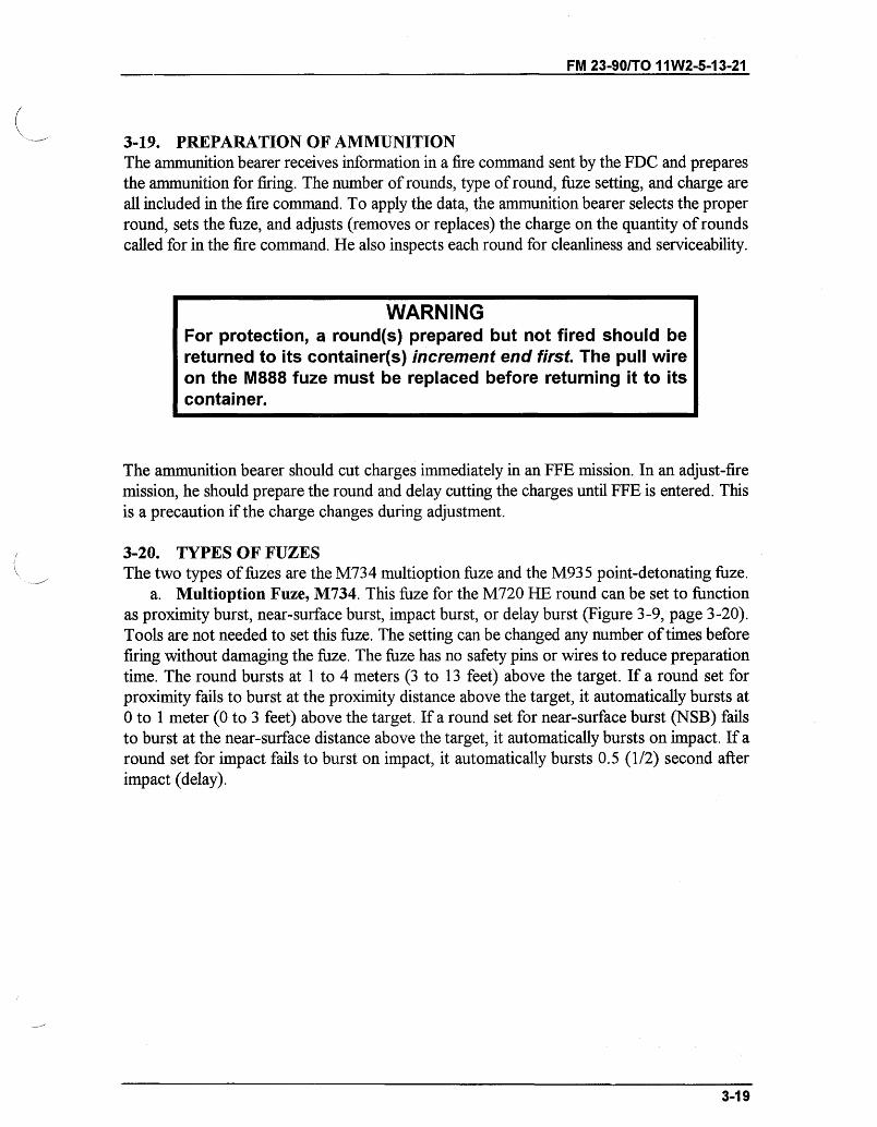
FM 23-90/TO 11W2-5-13-21
3-19. PREPARATION OF AMMUNITIONThe ammunition bearer receives information in a fire command sent by the FDC and preparesthe ammunition for firing. The number of rounds, type of round, fuze setting, and charge areall included in the fire command. To apply the data, the ammunition bearer selects the properround, sets the fuze, and adjusts (removes or replaces) the charge on the quantity of roundscalled for in the fire command. He also inspects each round for cleanliness and serviceability.
WARNINGFor protection, a round(s) prepared but not fired should bereturned to its container(s) increment end first. The pull wireon the M888 fuze must be replaced before returning it to itscontainer.
The ammunition bearer should cut charges immediately in an FFE mission. In an adjust-firemission, he should prepare the round and delay cutting the charges until FFE is entered. Thisis a precaution if the charge changes during adjustment.
3-20. TYPES OF FUZESThe two types of fuzes are the M734 multioption fuze and the M935 point-detonating fuze.
a. Multioption Fuze, M734. This fuze for the M720 HE round can be set to functionas proximity burst, near-surface burst, impact burst, or delay burst (Figure 3-9, page 3-20).Tools are not needed to set this fuze. The setting can be changed any number of times beforefiring without damaging the fuze. The fuze has no safety pins or wires to reduce preparationtime. The round bursts at 1 to 4 meters (3 to 13 feet) above the target. If a round set forproximity fails to burst at the proximity distance above the target, it automatically bursts at0 to 1 meter (0 to 3 feet) above the target. If a round set for near-surface burst (NSB) failsto burst at the near-surface distance above the target, it automatically bursts on impact. If around set for impact fails to burst on impact, it automatically bursts 0.5 (1/2) second afterimpact (delay).
3-19
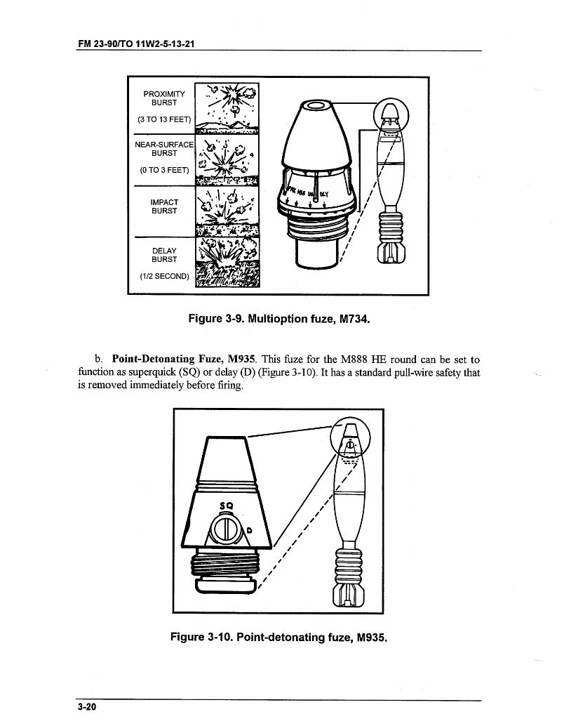
FM 23-90/TO I 1W2-5-1 3-21
PROXIMITY ~L9'
PROXIMITY
BURST
(3 TO 13 FEET)
NEAR-SURFACEBURST q
(0 TO 3 FEET)
IMPACT moo'BURST I
* 4,~C,3
,, r I .
Figure 3-9. Multioption fuze, M734.
b. Point-Detonating Fuze, M935. This fuze for the M888 HE round can be set tofunction as superquick (SQ) or delay (D) (Figure 3-10). It has a standard pull-wire safety thatis removed immediately before firing.
Figure 3-10. Point-detonating fuze, M935.
3-20
DELAYBURST
(1/2 SECOND)
-- '= ''
" Y Y9
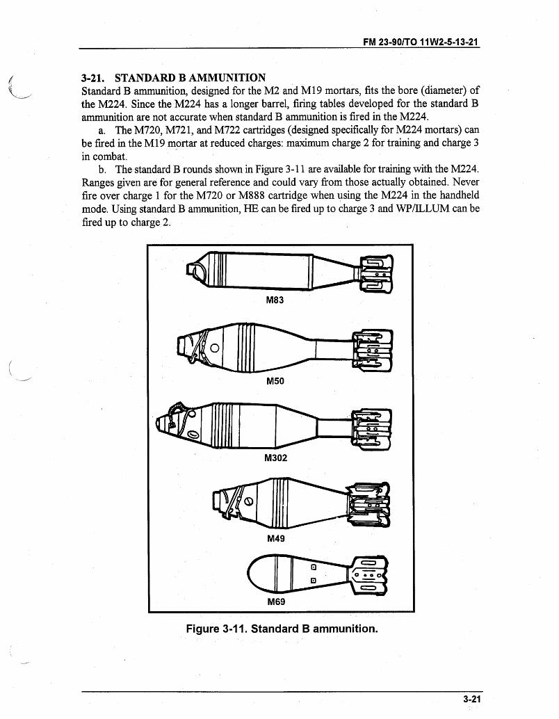
FM 23-90/TO 11W2-5-13-21
3-21. STANDARD B AMMUNITIONStandard B ammunition, designed for the M2 and M19 mortars, fits the bore (diameter) ofthe M224. Since the M224 has a longer barrel, firing tables developed for the standard Bammunition are not accurate when standard B ammunition is fired in the M224.
a. The M720, M721, and M722 cartridges (designed specifically for M224 mortars) canbe fired in the M19 mortar at reduced charges: maximum charge 2 for training and charge 3in combat.
b. The standard B rounds shown in Figure 3-11 are available for training with the M224.Ranges given are for general reference and could vary from those actually obtained. Neverfire over charge 1 for the M720 or M888 cartridge when using the M224 in the handheldmode. Using standard B ammunition, HE can be fired up to charge 3 and WP/ILLUM can befired up to charge 2.
Figure 3-11. Standard B ammunition.
3-21
M83
M50
M302
M49
M6o
M69
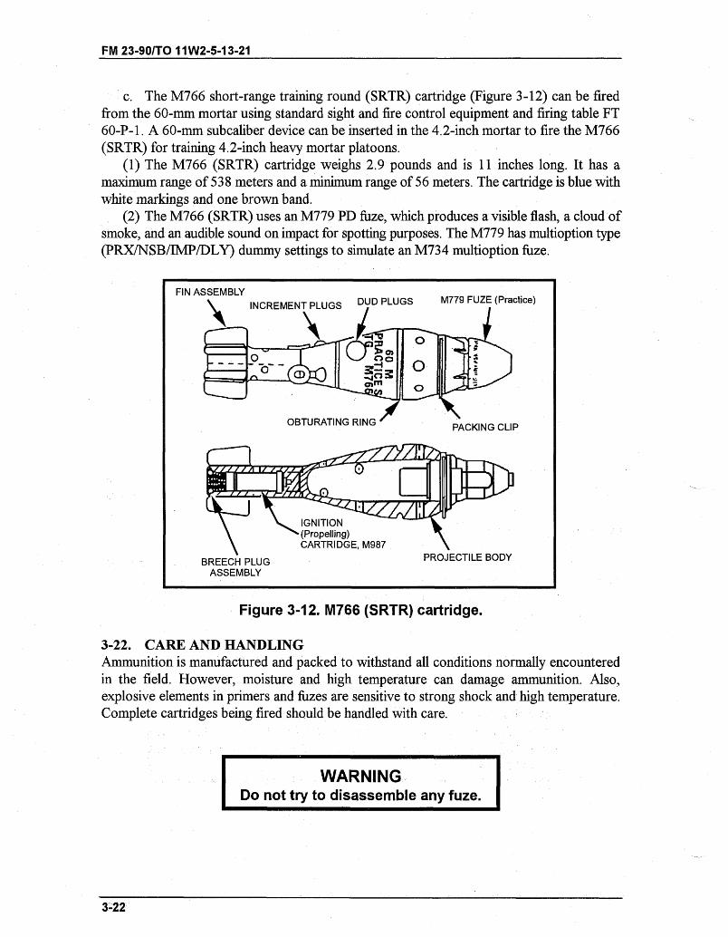
FM 23-90/TO 11W2-5-13-21
c. The M766 short-range training round (SRTR) cartridge (Figure 3-12) can be firedfrom the 60-mm mortar using standard sight and fire control equipment and firing table FT60-P-1. A 60-mm subcaliber device can be inserted in the 4.2-inch mortar to fire the M766(SRTR) for training 4.2-inch heavy mortar platoons.
(1) The M766 (SRTR) cartridge weighs 2.9 pounds and is 11 inches long. It has amaximum range of 538 meters and a minimum range of 56 meters. The cartridge is blue withwhite markings and one brown band.
(2) The M766 (SRTR) uses an M779 PD fuze, which produces a visible flash, a cloud ofsmoke, and an audible sound on impact for spotting purposes. The M779 has multioption type(PRX/NSB/IMP/DLY) dummy settings to simulate an M734 multioption fuze.
Figure 3-12. M766 (SRTR) cartridge.
3-22. CARE AND HANDLINGAmmunition is manufactured and packed to withstand all conditions normally encounteredin the field. However, moisture and high temperature can damage ammunition. Also,explosive elements in primers and fuzes are sensitive to strong shock and high temperature.Complete cartridges being fired should be handled with care.
WARNINGDo not try to disassemble any fuze.D onot try WARNIN
3-22
FIN ASSEMBLY\ CeRac -rT D ,I ~e DUD PLUGS M779 FUZE (Practice)
PROJECTILE BODYBREECH PLUGASSEMBLY
-- I
FM 23-90/TO 11W2-5-13-21
a. The moisture-resistant seal of the shipping container should not be broken until theammunition is to be used. When a large number of cartridges (15 or more for each squad) areprepared before a combat mission, the cartridges may be removed from the shipping containerand the propellant increments adjusted. Then the fin assemblies should be reinserted into thecontainer to protect the propelling charges.
b. Ammunition should be protected from mud, dirt, sand, water, and direct sunlight.Cartridges must be free of such foreign matter before firing. Ammunition that is wet or dirtyshould be wiped off at once.
c. Before firing, the gunner must remove the safety wire of the M888. Safety wiresshould be reinserted into all cartridges that have been prepared for firing but not used.Powder increments that have been removed should be replaced. Cartridges should be returnedto their original packing and marked accordingly. (These cartridges should be used first insubsequent firings.)
WARNINGDuds are cartridges that have been fired but have notexploded. Duds are dangerous and should not be handled byanyone other than a member of the EOD team.
d. Ammunition should always be stored under cover. When this is not possible, it israised at least 6 inches (15 centimeters) off the ground and covered with a double thicknessof tarpaulin. Trenches are dug around the ammunition pile for drainage. WP cartridges mustbe stored with the fuze end up.
(1) In combat, store ammunition underground such as in bunkers.(2) In the field, use waterproof bags, ponchos, ground cloths, and dunnage to prevent
deterioration of ammunition. Ensure that ammunition does not become water-soaked.(3) In arctic weather, store the ammunition in wooden boxes or crates. Place the boxes
or crates on pallets and cover them with a double thickness of tarpaulin.
WARNINGDo not walk on, tumble, drag, throw, roll, or drop ammunition.Ensure that ammunition is kept in original container until readyfor use. Do not combine WP and HE in storage. Maintaincompatibility and quantity of ammunition, as outlined inTM 9-1300-206.
3-23
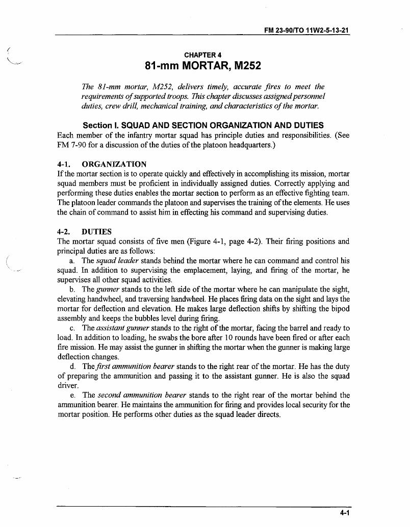
FM 23-90/TO 11W2-5-13-21
CHAPTER 4
81-mm MORTAR, M252
The 81-mm mortar, M252, delivers timely, accurate fires to meet therequirements of supported troops. This chapter discusses assigned personnelduties, crew drill, mechanical training, and characteristics of the mortar.
Section I. SQUAD AND SECTION ORGANIZATION AND DUTIESEach member of the infantry mortar squad has principle duties and responsibilities. (SeeFM 7-90 for a discussion of the duties of the platoon headquarters.)
4-1. ORGANIZATIONIf the mortar section is to operate quickly and effectively in accomplishing its mission, mortarsquad members must be proficient in individually assigned duties. Correctly applying andperforming these duties enables the mortar section to perform as an effective fighting team.The platoon leader commands the platoon and supervises the training of the elements. He usesthe chain of command to assist him in effecting his command and supervising duties.
4-2. DUTIESThe mortar squad consists of five men (Figure 4-1, page 4-2). Their firing positions andprincipal duties are as follows:
a. The squad leader stands behind the mortar where he can command and control hissquad. In addition to supervising the emplacement, laying, and firing of the mortar, hesupervises all other squad activities.
b. The gunner stands to the left side of the mortar where he can manipulate the sight,elevating handwheel, and traversing handwheel. He places firing data on the sight and lays themortar for deflection and elevation. He makes large deflection shifts by shifting the bipodassembly and keeps the bubbles level during firing.
c. The assistant gunner stands to the right of the mortar, facing the barrel and ready toload. In addition to loading, he swabs the bore after 10 rounds have been fired or after eachfire mission. He may assist the gunner in shifting the mortar when the gunner is making largedeflection changes.
d. The first ammunition bearer stands to the right rear of the mortar. He has the dutyof preparing the ammunition and passing it to the assistant gunner. He is also the squaddriver.
e. The second ammunition bearer stands to the right rear of the mortar behind theammunition bearer. He maintains the ammunition for firing and provides local security for themortar position. He performs other duties as the squad leader directs.
4-1
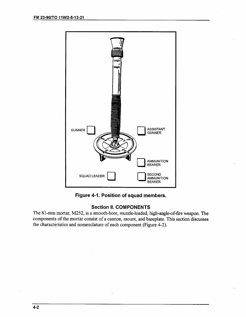
II
TII
GUNNER L1 ASSISTANTGUNNER
SIJ AMMUNITIONBEARER
SQUAD LEADER SECONDAMMUNITIONBEARER
Figure 4-1. Position of squad members.
Section II. COMPONENTSThe 81-mm mortar, M252, is a smooth-bore, muzzle-loaded, high-angle-of-fire weapon. Thecomponents of the mortar consist of a cannon, mount, and baseplate. This section discussesthe characteristics and nomenclature of each component (Figure 4-2).
4-2
FM 23-90/TO 11W2-5-13-21
-
'
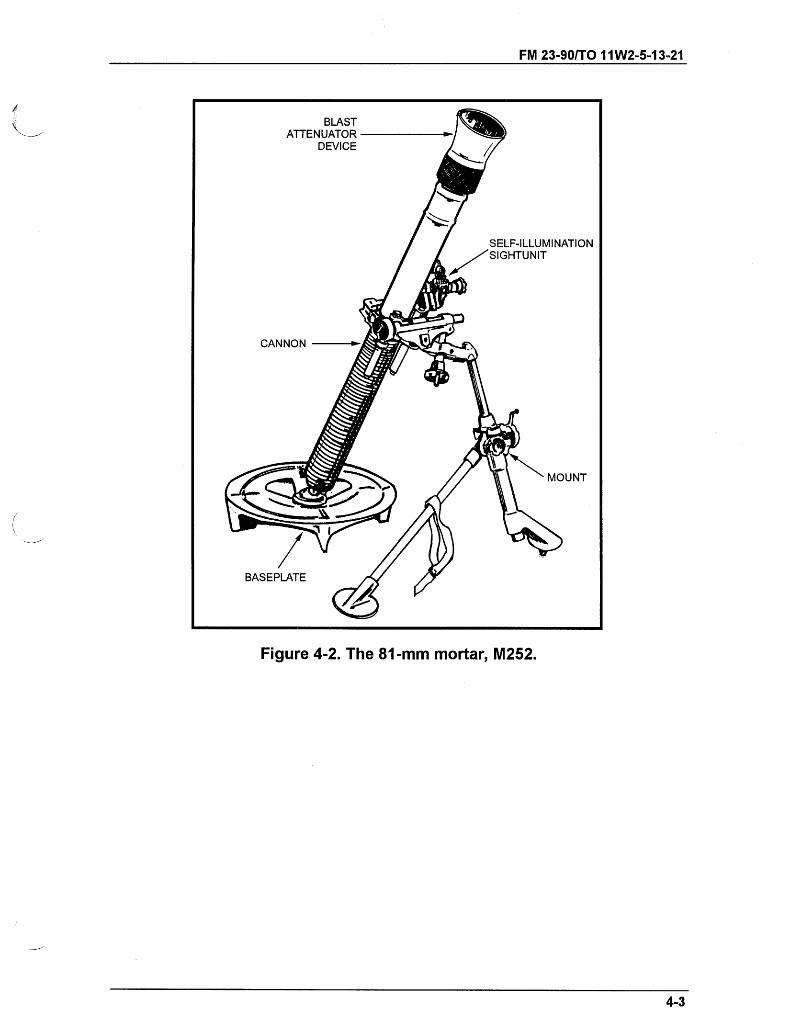
FM 23-90/TO 11 W2-5-13-21
Figure 4-2. The 81-mm mortar, M252.
4-3
ATTENUATOR
SELF-ILLUMINATION
MOUNT
BASEPLATE
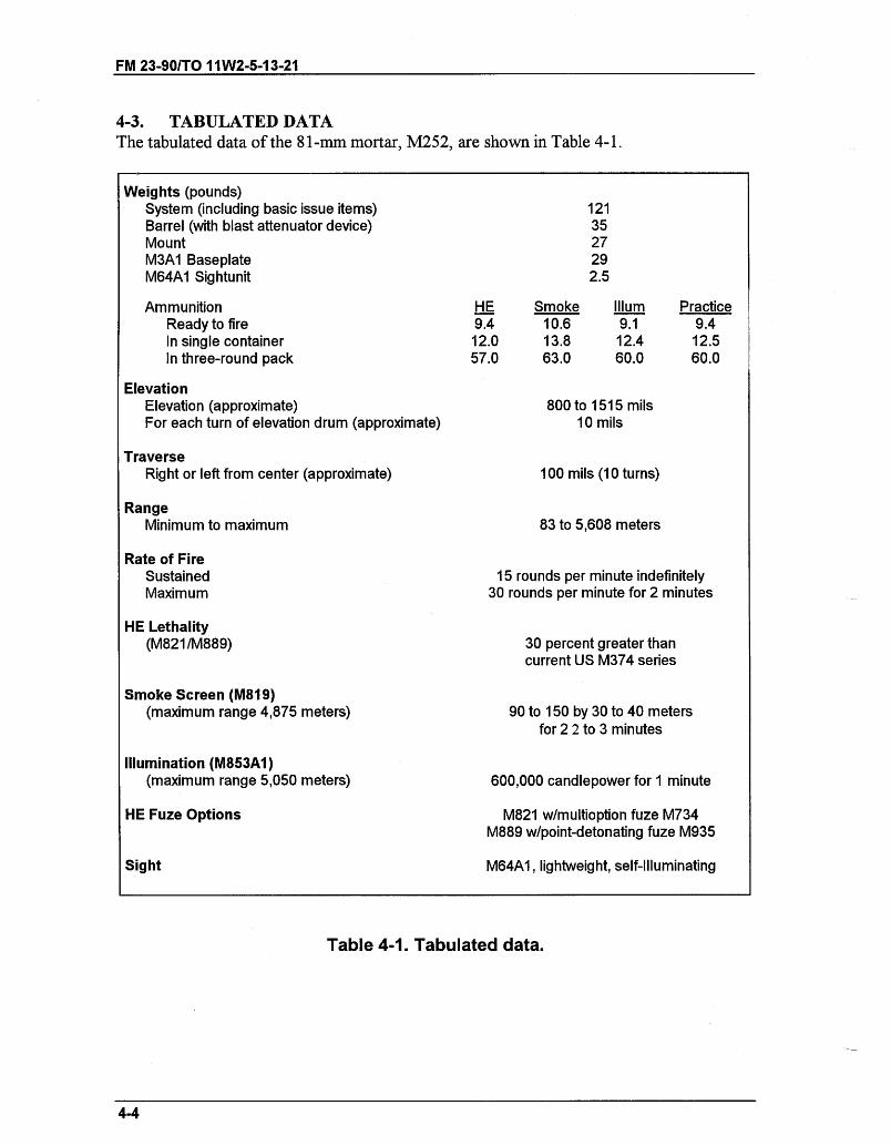
FM 23-90/TO 11W2-5-13-21
4-3. TABULATED DATAThe tabulated data of the 81-mm mortar, M252, are shown in Table 4-1.
Weights (pounds)System (including basic issue items)Barrel (with blast attenuator device)MountM3A1 BaseplateM64A1 Sightunit
1213527292.5
AmmunitionReady to fireIn single containerIn three-round pack
ElevationElevation (approximate)For each turn of elevation drum (approximate)
TraverseRight or left from center (approximate)
RangeMinimum to maximum
Rate of FireSustainedMaximum
HE Lethality(M821/M889)
HE9.412.057.0
Smoke10.613.863.0
Illum9.1
12.460.0
800 to 1515 mils10 mils
100 mils (10 turns)
83 to 5,608 meters
Practice9.412.560.0
15 rounds per minute indefinitely30 rounds per minute for 2 minutes
30 percent greater thancurrent US M374 series
Smoke Screen (M819)(maximum range 4,875 meters)
Illumination (M853A1)(maximum range 5,050 meters)
HE Fuze Options
Sight
90 to 150 by 30 to 40 metersfor 2 2 to 3 minutes
600,000 candlepower for 1 minute
M821 w/multioption fuze M734M889 w/point-detonating fuze M935
M64A1, lightweight, self-Illuminating
Table 4-1. Tabulated data.
4-4
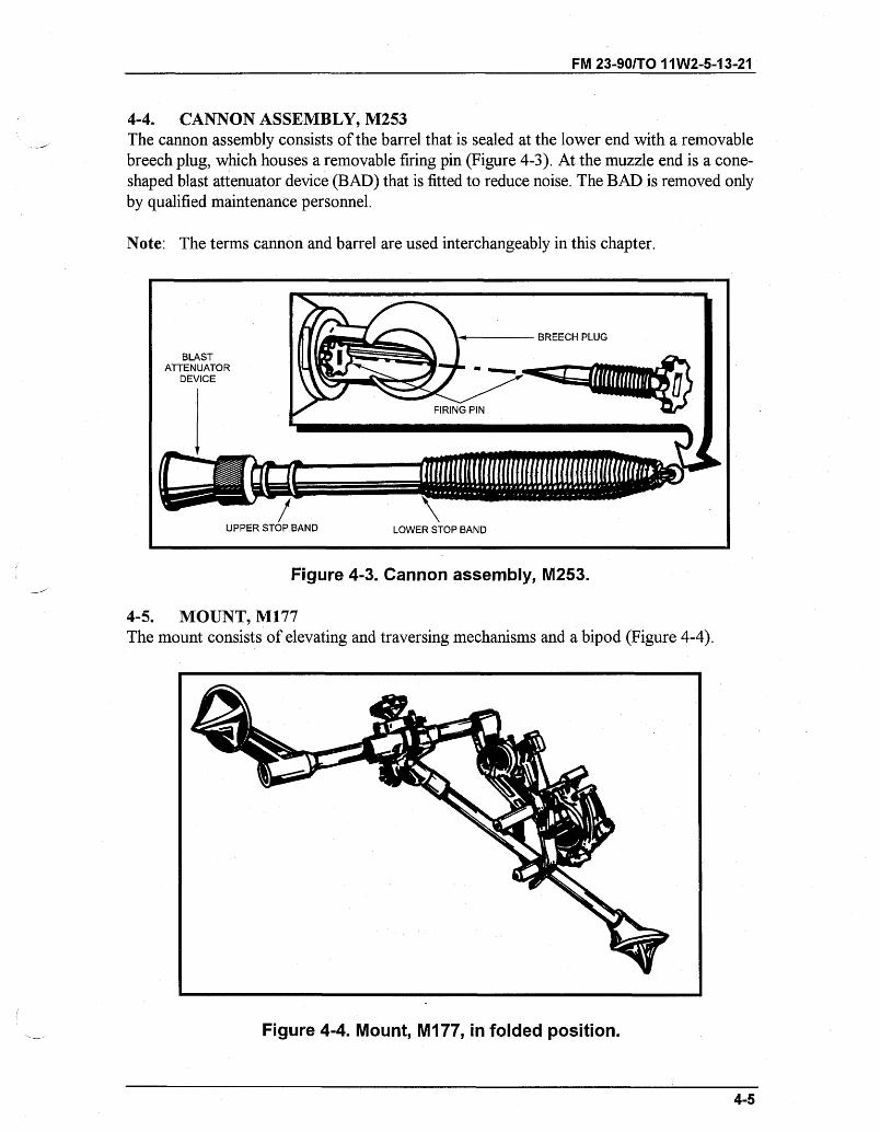
FM 23-90/TO 11W2-5-13-21
4-4. CANNON ASSEMBLY, M253The cannon assembly consists of the barrel that is sealed at the lower end with a removablebreech plug, which houses a removable firing pin (Figure 4-3). At the muzzle end is a cone-shaped blast attenuator device (BAD) that is fitted to reduce noise. The BAD is removed onlyby qualified maintenance personnel.
Note: The terms cannon and barrel are used interchangeably in this chapter.
BREECH PLUG
BLASTATTENUATOR
DEVICE
FIRING PIN
Figure 4-3. Cannon assembly, M253.
4-5. MOUNT, M177The mount consists of elevating and traversing mechanisms and a bipod (Figure 4-4).
Figure 4-4. Mount, M177, in folded position.
4-5
- = ''
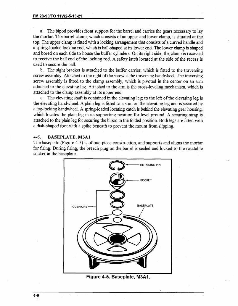
FM 23-90/TO 11W2-5-13-21
a. The bipod provides front support for the barrel and carries the gears necessary to laythe mortar. The barrel clamp, which consists of an upper and lower clamp, is situated at thetop. The upper clamp is fitted with a locking arrangement that consists of a curved handle anda spring-loaded locking rod, which is ball-shaped at its lower end. The lower clamp is shapedand bored on each side to house the buffer cylinders. On its right side, the clamp is recessedto receive the ball end of the locking rod. A safety latch located at the side of the recess isused to secure the ball.
b. The sight bracket is attached to the buffer carrier, which is fitted to the traversingscrew assembly. Attached to the right of the screw is the traversing handwheel. The traversingscrew assembly is fitted to the clamp assembly, which is pivoted in the center on an armattached to the elevating leg. Attached to the arm is the cross-leveling mechanism, which isattached to the clamp assembly at its upper end.
c. The elevating shaft is contained in the elevating leg; to the left of the elevating leg isthe elevating handwheel. A plain leg is fitted to a stud on the elevating leg and is secured bya leg-locking handwheel. A spring-loaded locating catch is behind the elevating gear housing,which locates the plain leg in its supporting position for level ground. A securing strap isattached to the plain leg for securing the bipod in the folded position. Both legs are fitted witha disk-shaped foot with a spike beneath to prevent the mount from slipping.
4-6. BASEPLATE, M3A1The baseplate (Figure 4-5) is of one-piece construction, and supports and aligns the mortarfor firing. During firing, the breech plug on the barrel is sealed and locked to the rotatablesocket in the baseplate.
S RETAINING PIN
Figure 4-5. Baseplate, M3A1.
4-6
CUSHIONS
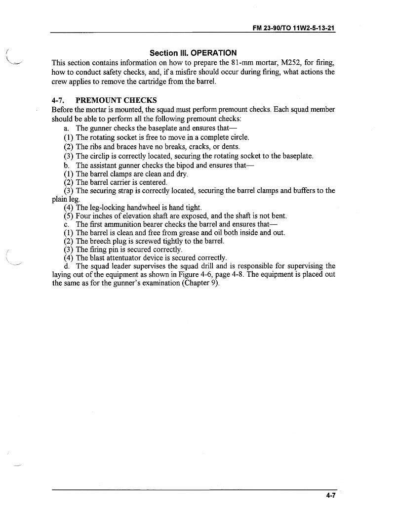
FM 23-90/TO 11W2-5-13-21
Section III. OPERATIONThis section contains information on how to prepare the 81-mm mortar, M252, for firing,how to conduct safety checks, and, if a misfire should occur during firing, what actions thecrew applies to remove the cartridge from the barrel.
4-7. PREMOUNT CHECKSBefore the mortar is mounted, the squad must perform premount checks. Each squad membershould be able to perform all the following premount checks:
a. The gunner checks the baseplate and ensures that-(1) The rotating socket is free to move in a complete circle.(2) The ribs and braces have no breaks, cracks, or dents.(3) The circlip is correctly located, securing the rotating socket to the baseplate.b. The assistant gunner checks the bipod and ensures that-(1) The barrel clamps are clean and dry.(2) The barrel carrier is centered.(3) The securing strap is correctly located, securing the barrel clamps and buffers to the
plain leg.(4) The leg-locking handwheel is hand tight.(5) Four inches of elevation shaft are exposed, and the shaft is not bent.c. The first ammunition bearer checks the barrel and ensures that-(1) The barrel is clean and free from grease and oil both inside and out.(2) The breech plug is screwed tightly to the barrel.(3) The firing pin is secured correctly.(4) The blast attentuator device is secured correctly.d. The squad leader supervises the squad drill and is responsible for supervising the
laying out of the equipment as shown in Figure 4-6, page 4-8. The equipment is placed outthe same as for the gunner's examination (Chapter 9).
4-7
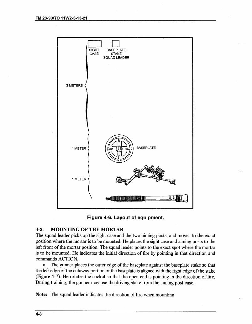
FM 23-90/TO 11W2-5-13-21
SIGHT BASEPLATECASE STAKE
SQUAD LEADER
3 METERS
1 METER BASEPLATE
1 METER ~EENE--IlL
Figure 4-6. Layout of equipment.
4-8. MOUNTING OF THE MORTARThe squad leader picks up the sight case and the two aiming posts, and moves to the exactposition where the mortar is to be mounted. He places the sight case and aiming posts to theleft front of the mortar position. The squad leader points to the exact spot where the mortaris to be mounted. He indicates the initial direction of fire by pointing in that direction andcommands ACTION.
a. The gunner places the outer edge of the baseplate against the baseplate stake so thatthe left edge of the cutaway portion of the baseplate is aligned with the right edge of the stake(Figure 4-7). He rotates the socket so that the open end is pointing in the direction of fire.During training, the gunner may use the driving stake from the aiming post case.
Note: The squad leader indicates the direction of fire when mounting.
4-8
FM 23-90/TO 11W2-5-13-21
Figure 4-7. Baseplate placed against baseplate stake.
b. When the baseplate is in position, the first ammunition bearer lowers the breech pluginto the rotating socket and rotates the barrel a quarter of a turn to lock it. He ensures thatthe firing pin recess is facing upwards. He stands to the rear of the baseplate and supports thebarrel until the bipod is fitted.
c. The assistant gunner lifts the bipod and stands it on its elevating leg so that theelevating handwheel is to the rear and the plain leg is to the front. He releases the securingstrap, loosens the leg-locking handwheel, and lowers the plain leg until the locating catchengages in the recess. The leg-locking handwheel must then be tightened by hand, ensuringthe teeth on either side are correctly meshed. The assistant gunner exposes 8 inches (200millimeters) of elevation shaft, leaving the elevation handwheel unfolded. He opens the cross-level handwheel, traversing handwheel, and barrel clamp. The assistant gunner carries thebipod to the front of the barrel and places the bipod feet on the ground 12 to 15 inches infront of the baseplate and astride the line of fire. He positions the lower barrel clamp againstthe lower stop band on the barrel and secures the upper barrel clamp. He must ensure that theball-shaped end of the locking rod is secured in its recess by the locking latch.
d. The gunner removes the sight from its case, mounts it on the mortar, and sets adeflection of 3200 mils and an elevation of 1100 mils. He levels all bubbles.
4-9. SAFETY CHECKS BEFORE FIRINGThe following safety checks must be enforced before firing the mortar.
a. The gunner ensures that-(1) Mask clearance and overhead clearance are sufficient.(a) Since the mortar is normally mounted in defilade, there could be a mask such as a hill,
tree, building, or rise in the ground. Overhead interference can be branches of trees or roofsof buildings. In any case, the gunner must ensure that the cartridge does not strike anobstacle.
(b) In selecting the exact mortar position, the leader looks quickly for mask clearance andoverhead interference. After the mortar is mounted, the gunner makes a thorough check.
4-9
FM 23-90/TO 11W2-5-13-21
(c) The gunner determines mask and overhead clearance by sighting along the barrel withhis eye near the breech plug. If the line of sight clears the mask, it is safe to fire. If not, he maystill fire at the desired range by selecting a charge zone having a higher elevation. When firingunder the control of an FDC, he reports to the FDC that mask clearance cannot be obtainedat a certain elevation.
(d) Firing is slowed if mask clearance must be checked before each firing but this can beeliminated if minimum mask clearance is determined. This is accomplished by depressing thebarrel until the top of the mask is clear. The gunner levels the elevation bubble by turning theelevation micrometer knob and reading the setting on the elevation scale and elevationmicrometer-this setting is the minimum mask clearance. The squad leader notifies the FDCof the minimum mask clearance elevation. Any target that requires that elevation, or a lowerone, cannot be engaged from that position.
(e) If the mask is not regular throughout the sector of fire, the gunner determines theminimum mask clearance as described above. Placing the mortar in position at night does notrelieve the gunner of the responsibility of checking for mask clearance and overheadinterference.
(2) The barrel is locked to the baseplate, and the open end of the socket points in thedirection of fire.
(3) The firing pin recess faces upwards.(4) The bipod locking latch is locked, securing the barrel clamps.
Note: See TM 9-1015-200-10 for more on loading and firing.
(5) The leg-locking handwheel is tight.b. The assistant gunner cleans the bore and swabs it dry.c. The first ammunition bearer ensures that each cartridge is clean, the safety pin is
present, and the ignition cartridge is in good condition.
4-10. SMALL DEFLECTION AND ELEVATION CHANGESWith the mortar mounted and the sight installed, the gunner lays the sight on the two aimingposts (placed out 50 and 100 meters from the mortar) on a referred deflection of 2800 milsand an elevation of 1100 mils. The mortar is within two turns of center of traverse. Thevertical cross line of the sight is on the left edge of the aiming point.
a. The gunner is given a deflection change in a fire command between 20 and 60 milsinclusive. The elevation change announced must be less than 90 mils and more than 35 mils.
b. As soon as the sight data are announced, the gunner places it on the sight, lays themortar for elevation, and traverses onto the aiming post by turning the traversing handwheeland adjusting nut in the same direction. One-quarter turn on the adjusting nut equals one turnof the traversing handwheel. When the gunner is satisfied with his sight picture he announces,"Up."
Note: All elements given in the fire command are repeated by the squad.
c. After the gunner has announced, "Up," the squad leader should check the mortar todetermine if the exercise was performed correctly.
4-10
FM 23-90/TO 11W2-5-13-21
4-11. LARGE DEFLECTION AND ELEVATION CHANGESWith the mortar mounted and the sight installed, the gunner lays the sight on the two aimingposts (placed out 50 and 100 meters from the mortar) on a referred deflection of 2800 milsand an elevation of 1100 mils.
a. The gunner is given a deflection and elevation change in a fire command causing thegunner to shift the mortar between 200 and 300 mils for deflection and between 100 and 200for elevation.
b. As soon as the sight data are announced, the gunner places it on the sight. The gunnershould expose 6 inches (150 millimeters) of elevation shaft and center the buffer carrier. Thisensures a maximum traversing and elevating capability after making the movement.
c. The assistant gunner moves into position to the front of the bipod on his right kneeand grasps the bipod legs (palms up), lifting until they clear the ground enough to permitlateral movement. The gunner moves the mortar as the assistant gunner steadies it. Theassistant gunner attempts to maintain the traversing mechanism on a horizontal plane. Tomake the shift, the gunner places the fingers of his right hand in the muzzle and his left handon the left leg. He moves the mortar until the vertical line of the sight is aligned approximatelyon the aiming post. When the approximate alignment is completed, the gunner signals theassistant gunner to lower the bipod by pushing down on the mortar.
d. The gunner rough levels the cross-level bubble by making the bubble bounce from oneside to the other. He then checks the sight picture to ensure he is within 20 mils of a propersight picture. If he is not within 20 mils, the gunner and assistant gunner must make anotherlarge shift before moving on.
e. The gunner centers the elevation bubble. He lays for deflection, taking the proper sightpicture. The mortar should be within two turns of center of traverse when the task is compete.
f. The open end of the socket must continue to point in the direction of fire. Normally,it can be moved by hand, although this may be difficult to do if the mortar is moved througha large arc. If required, the gunner/assistant gunner lowers the barrel so that the breech plugengages with the open end of the socket, and he uses the barrel as a lever to move the socket.
g. The barrel clamps can be moved along the barrel to counter large changes in elevation.This may preclude moving the bipod. It is especially useful if the baseplate sinks deep into theground during prolonged firing. Upon completion of any bipod movement on the barrel, thegunner ensures that the firing pin recess is facing upward.
h. Where the ground is uneven and there is no level surface for the bipod, the gunner canadjust the plain leg. While the assistant gunner supports the barrel, the gunner slackens theleg-locking handwheel, releases the locating catch, and positions the plain leg. The leg-lockinghandwheel must then be tightened, ensuring the teeth are correctly meshed.
4-12. REFERRING OF THE SIGHT AND REALIGNMENT OF AIMING POSTSUSING M64 SIGHTReferring and realigning aiming posts ensure that all mortars are set on the same data. Thesection leader, acting as FDC, has one deflection instead of two or more.
a. The mortar is mounted and the sight is installed. The sight is laid on two aiming posts(placed out 50 and 100 meters from the mortar) on a referred deflection of 2800 mils and anelevation of 1100 mils. The mortar is within two turns of center of traverse. The gunner is
4-11
FM 23-90/TO 11W2-5-13-21
given an administrative command to lay the mortar on a deflection of 2860 or 2740 mils. Themortar is then re-laid on the aiming posts using the traversing crank.
b. The gunner is given a deflection change between 5 and 25 mils, either increasing ordecreasing from the last stated deflection, and the command to refer and realign aiming posts.
EXAMPLE
REFER DEFLECTION TWO EIGHT SEVEN FIVE (2875), REALIGNAIMING POSTS.
c. Upon receiving the command REFER, REALIGN AIMING POST, two actions takeplace at the same time in the mortar squad. The gunner places the announced deflection onthe sight (without disturbing the lay of the weapon) and looks through the sightunit. At thesame time, the first ammunition bearer moves out on the double to realign the aiming posts.He knocks down the near aiming post and proceeds to the far aiming post. Following the arm-and-hand signals of the gunner (who is looking through the sight unit), he moves the faraiming post so that the gunner obtains an aligned sight picture. The same procedure foraligning the far aiming post is used to align the near aiming post.
4-13. MALFUNCTIONSSee Chapter 3, paragraph 3-14 for a detailed discussion of malfunctions.
4-14. REMOVAL OF A MISFIREWhen a misfire occurs, any member of the squad immediately announces, "Misfire." Theentire squad stays with the mortar. The gunner then kicks the barrel several times with hisheel in an attempt to dislodge the round. If the round fires, the mortar is re-laid on the aimingpoint and firing is continued.
WARNINGDuring peacetime live-fire training, all personnel, except thegunner, move 50 meters or farther to the rear of the mortar.
a. If the round does not fire, the gunner tests the barrel for heat. If the barrel is coolenough to handle, the crew removes the round as described below. If the barrel is hot, thegunner may then apply water to the outside of the barrel until it is cool. If water is notavailable, the gunner must stand clear of the mortar until the barrel is cool.
4-12
FM 23-90/TO 11W2-5-13-21
WARNINGDuring peacetime live-fire training, if the round does not fire,the gunner joins the crew and waits one minute to avoid apossible personal injury due to a cookoff. After waiting oneminute, the gunner returns to the mortar and tests the barrelfor heat. When the barrel is cool enough to handle, the gunnersignals for the rest of the crew to come forward.
b. After the barrel cools, the gunner removes the sight and firing pin. This ensures thatthe mortar does not fire should the round slip down the barrel during the subsequent drills.The gunner can depress the barrel, if necessary, to provide easier access to the firing pin. Thegunner unlocks the barrel clamp and rotates the barrel, unlocking the breech plug from therotating socket of the baseplate. Then he relocks the barrel clamp.
c. The gunner grasps both ends of the traverse screw assembly and supports the mortarduring the subsequent drill. The assistant gunner places his right hand palm up (1 inch fromthe muzzle end) under the BAD and his left hand palm down (1 inch from the muzzle end)on top. He places his thumbs alongside the forefingers, being careful to keep both hands awayfrom the muzzle. The first ammunition bearer puts both hands on the cooling fins under thebarrel and slowly lifts the barrel until it is horizontal. He must not stand directly behind themortar.
d. When the barrel reaches the horizontal position, and not before, the assistant gunnermoves the thumb of each hand over the muzzle. When the fuze of the misfired round reachesthe BAD, the assistant gunner stops the round with his thumbs (he does not touch the fuze)and carefully removes it from the barrel. The first ammunition bearer shakes the barrel todislodge any remnants from the last round fired, and he lowers the barrel into the rotatingsocket of the baseplate.
e. The assistant gunner passes the round to the first ammunition bearer who inspects itfor the cause of the misfire. If the primer of the ignition cartridge is dented, the firstammunition bearer attempts to replace the safety wire and places the round in a marked, safelocation for disposal by ordnance personnel. If the primer is not dented, the round may beused again. The firing pin must be replaced and the bore swabbed.
f. If the above procedure fails to remove the misfire, the barrel must be kept horizontal.Then it is removed from the bipod and laid horizontally on the ground at the dud pit until itcan be turned over to ordnance personnel.
4-15. DISMOUNTING OF THE MORTARTo dismount the mortar, the squad leader commands, OUT OF ACTION. At this command,the squad proceeds as follows:
a. The gunner removes the sight and places it in the case with 3200 deflection and 0800elevation indexed.
b. The first ammunition bearer holds the barrel until the assistant gunner has removedthe mount. The barrel is then rotated a quarter turn to unlock it from the socket, and it is
4-13
FM 23-90/TO 11W2-5-13-21
placed in an area designated by the squad leader. The second ammunition bearer retrieves theaiming posts.
c. The assistant gunner disengages the barrel clamps and moves the bipod from theimmediate area of the mortar position. The barrel clamps are then closed. With the clampsfacing away from him, the assistant gunner traverses the buffer carrier to the traversinghandwheel and folds the handle. He exposes 1 inch (25 millimeters) of cross-level shaft andfolds the handle. He exposes 4 inches (100 millimeters) of elevation shaft and folds the handle.Finally, the assistant gunner loosens the leg-locking handwheel, presses the spring-loadedlocating catch, and raises the plain leg behind the buffer cylinders until it touches thetraversing handwheel. He tightens the leg-locking handwheel (ensuring the teeth are correctlymeshed) and fastens the securing strap over the arm and around the buffers.
d. The gunner recovers the baseplate to the area designated by the squad leader.e. The squad leader picks up the aiming posts and sight. At the command, MARCH
ORDER, the squad places the mortar, equipment, and ammunition in the squad vehicle andtrailer.
Section IV. AMMUNITION
This section implements STANAG 2321 and QSTAG 900 (Edition 1).
The ammunition that can be fired by the 81-mm mortar, M252, is identified and describedherein.
4-16. CLASSIFICATIONAmmunition is typed according to use (Table 4-2). High explosive is used for bothfragmentation and blast effect against personnel and light-skinned vehicles. Redphosphorus/white phosphorus is used for screening, producing casualties, creating incendiaryeffects, and signaling. Illuminating is used for battlefield illumination and signaling. Trainingpractice is used only for training.
Note: Standard A ammunition for the M29A1 mortar is Standard B for the M252 mortar(Table 4-3, page 4-16). Standard B ammunition for the M29A1 mortar is StandardC for the M252 mortar.
a. Identification. All mortar cartridges are painted to prevent rust and to identify theirtype.
(1) Marking on container. The contents of ammunition containers are shown bymarkings. Additional information is included on an ammunition data card inside eachcontainer.
(2) Color code. All rounds are colored according to their type.(3) Markings on rounds. Each round is stenciled with the ammunition lot number, type
of round, type of filler, and caliber.
4-14
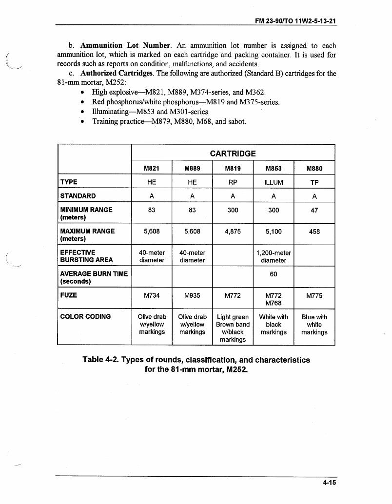
FM 23-90/TO 11W2-5-1 3-21
b. Ammunition Lot Number. An ammunition lot number is assigned to eachammunition lot, which is marked on each cartridge and packing container. It is used forrecords such as reports on condition, malfunctions, and accidents.
c. Authorized Cartridges. The following are authorized (Standard B) cartridges for the81-mm mortar, M252:
" High explosive-M821, M889, M374-series, and M362." Red phosphorus/white phosphorus-M819 and M375-series.* Illuminating-M853 and M301-series." Training practice-M879, M880, M68, and sabot.
CARTRIDGE
M821 M889 M819 M853 M880
TYPE HE HE RP ILLUM TP
STANDARD A A A A A
MINIMUM RANGE 83 83 300 300 47(meters)
MAXIMUM RANGE 5,608 5,608 4,875 5,100 458(meters)
EFFECTIVE 40-meter 40-meter 1,200-meterBURSTING AREA diameter diameter diameter
AVERAGE BURN TIME 60(seconds)
FUZE M734 M935 M772 M772 M775M768
COLOR CODING Olive drab Olive drab Light green White with Blue withw/yellow w/yellow Brown band black whitemarkings markings w/black markings markings
markings
Table 4-2. Types of rounds, classification, and characteristicsfor the 81-mm mortar, M252.
4-15
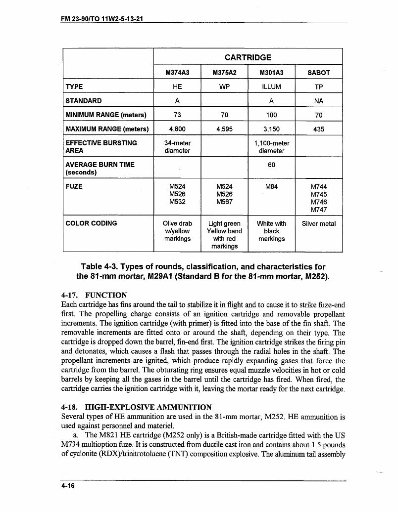
FM 23-90/TO 11W2-5-13-21
CARTRIDGE
M374A3 M375A2 M301A3 SABOT
TYPE HE WP ILLUM TP
STANDARD A A NA
MINIMUM RANGE (meters) 73 70 100 70
MAXIMUM RANGE (meters) 4,800 4,595 3,150 435
EFFECTIVE BURSTING 34-meter 1,100-meterAREA diameter diameter
AVERAGE BURN TIME 60(seconds)
FUZE M524 M524 M84 M744M526 M526 M745M532 M567 M746
M747
COLOR CODING Olive drab Light green White with Silver metalw/yellow Yellow band blackmarkings with red markings
markings
Table 4-3. Types of rounds, classification, and characteristics forthe 81-mm mortar, M29A1 (Standard B for the 81-mm mortar, M252).
4-17. FUNCTIONEach cartridge has fins around the tail to stabilize it in flight and to cause it to strike fuze-endfirst. The propelling charge consists of an ignition cartridge and removable propellantincrements. The ignition cartridge (with primer) is fitted into the base of the fin shaft. Theremovable increments are fitted onto or around the shaft, depending on their type. Thecartridge is dropped down the barrel, fin-end first. The ignition cartridge strikes the firing pinand detonates, which causes a flash that passes through the radial holes in the shaft. Thepropellant increments are ignited, which produce rapidly expanding gases that force thecartridge from the barrel. The obturating ring ensures equal muzzle velocities in hot or coldbarrels by keeping all the gases in the barrel until the cartridge has fired. When fired, thecartridge carries the ignition cartridge with it, leaving the mortar ready for the next cartridge.
4-18. HIGH-EXPLOSIVE AMMUNITIONSeveral types of HE ammunition are used in the 81-mm mortar, M252. HE ammunition isused against personnel and materiel.
a. The M821 HE cartridge (M252 only) is a British-made cartridge fitted with the USM734 multioption fuze. It is constructed from ductile cast iron and contains about 1.5 poundsof cyclonite (RDX)/trinitrotoluene (TNT) composition explosive. The aluminum tail assembly
4-16
FM 23-90/TO 11W2-5-13-21
has six integral fins equally spaced around the rear, which stabilize the round in flight. Thecartridge is painted olive drab with yellow markings. Each cartridge weighs about 10 poundsand is provided with the M223 propelling charge, consisting of four horseshoe-shapedincrements fitted around the tail.
b. The M889 HE cartridge (M252 onlyXUS Marine Corps) is of the same constructionas the M821 cartridge in every detail except the fuze, which is the M935.
c. The M374A3 HE cartridge is constructed from pearlitic malleable cast iron andcontains about 2.10 pounds of composition B explosive. It uses the M205 propelling charge,consisting of four horseshoe-shaped increments fitted around the tail. The cartridge is paintedolive drab with yellow markings and weighs about 9.05 pounds. It can be fitted with eitherthe M567, M524, or M532-series fuzes.
d. The M374A2, M374A, and M374 HE cartridges are painted olive drab with yellowmarkings and are constructed from pearlitic malleable cast iron. They contain about 2.10pounds of composition B explosive. The M374 cartridge is fitted with the M90 propellingcharge. The M374A2 and M374A1 cartridges are fitted with the M90A1 propelling charge.Both the M90 and M90A1 propellants are in nine wax-tested, cotton cloth, bag incrementsassembled to the tail unit. The cartridge can be fitted with the M524-series, M526-series,M567, or M532 fuzes. Those cartridges assembled with the M524 (Al, A2, A3, or A4) fuzeare for-use by the US Marine Corps and US Navy only. Cartridges assembled with the M532fuze must be fired above charge 0. Short cartridges can be expected when firing below charge4. The cartridge weighs about 9.12 pounds.
e. The M362A1 and M362 HE cartridges are of steel forge construction and containabout 2.10 pounds of composition B explosive. They use the M5 propelling charge thatconsists of eight cloth bags attached to the tail unit. The cartridges are painted olive drab withyellow markings. They are fuzed with the M524-series, M256-series, or M532. Cartridgesassembled with the M524 (Al, A2, A3, or A4) fuze are for use by the U.S. Marine Corps andU.S. Navy only. Cartridges assembled with the M532 fuze must be fired above charge 0. Thecartridge weighs about 9.4 pounds.
4-19. RED/WHITE PHOSPHORUS AMMUNITIONSeveral types of RP/WP ammunition are described herein.
a. The M819 cartridge (M252 only) has a cylindrical body and contains red phosphorusthat produces white smoke on contact with air. The cartridge uses the M218 propellingcharge, which consists of four horseshoe-shaped increments fitted around the tail. Thecartridge is painted light green with black markings and one narrow brown band. It uses theM772 mechanical time fuze and weighs about 10.6 pounds.
Note: Red phosphorus rounds can be fired from the M29/M29A1 at a reduced charge(maximum charge = charge 2). This round may be stored in a horizontal position.
b. The M375A3 cartridge is ballistically similar to the M374A3 (HE) cartridge. Itcontains white phosphorus that produces white smoke on contact with air. The cartridge ispainted light green and has red markings and one narrow yellow band. The cartridge uses theM205 propelling charge and is assembled with the M567 or M524-series fuze. It weighsabout 9.05 pounds. This round must be stored in a vertical position.
4-17
FM 23-90/TO 11W2-5-13-21
c. The M375A2, M375A1, and M375 cartridges may also be used. They are paintedlight green with red markings and one narrow yellow band. They are assembled with eitheran M524-series, M526-series, or M567 fuze. The M375 cartridge uses the M90 propellingcharge while the M375A2 and M375A1 cartridges use the M90A1 propelling charge.Cartridges assembled with the M524 (Al, A2, A3, or A4) fuze are for use by the US MarineCorps and US Navy only. Short cartridges can be expected when firing below charge 4. Thiscartridge is ballistically matched to the M374A2, M374A1, and M375 HE cartridges, andweighs about 9.12 pounds.
4-20. ILLUMINATING AMMUNITIONThe M853 and M301A3 illuminating ammunition are described herein.
a. The M853 cartridge (M252 only) has a cylindrical body that contains an illuminatingcandle and parachute assembly. It provides illumination for about 60 seconds with 600,000candlepower illumination. It is assembled with the M772A1 MTSQ. It uses the M219propelling charge and weighs about 9.1 pounds.
b. The M301A3 cartridge has a cylindrical body that contains an illuminating candle andparachute assembly. The round has a burst height of 600 meters and provides illumination forabout 60 seconds for an area of about 1,200 meters. It is painted white with black markings.It uses the M185 propelling charge that consists of eight increments fitted into the spacesbetween the fins and held by a propellant holder. The increments are individually wrappedwith waterproof bags that are not removed. The cartridge must not be fired below charge 3.
4-21. TYPES OF FUZESThe types of fuzes described in this paragraph are point detonating, proximity, mechanicaltime, multioption, and dummy.
a. Point-Detonating. All PD fuzes are superquick-detonate on impact.(1) The M93 5 fuze has two function settings: impact and delay. It is set using the bladed
end of the M18 fuze wrench. It is fitted with a standard pull wire and safety pin that areremoved immediately before firing.
(2) The M524-series fuze has two function settings: superquick/impact (SQ/IMP) anddelay. When set at delay, the fuze train causes a 0.05-second delay before functioning. Whenset at SQ, the fuze functions on point impact or graze contact. The fuze contains a delayedarming feature that ensures the fuze remains unarmed and detonator safe for a minimum of1.25 seconds of flight. It arms within a maximum of 2.50 seconds. To prepare for firing, theslot is aligned in the striker with SQ or delay using the M18 fuze wrench. The safety pull wireis removed just before inserting the cartridge into the mortar.
Note: If, upon removal of the safety wire, a buzzing sound in the fuze is heard, the roundshould not be used. The round is still safe to handle and transport if the safety wireis reinserted.
4-18
FM 23-90/TO 11W2-5-13-21
WARNINGIf the plunger safety pin (upper pin) cannot be reinserted, thefuze may be armed. An armed fuze must not be fired since itwill be premature. It should be handled with extreme care, andEOD personnel notified immediately. If it is necessary tohandle a round with a suspected armed fuze, personnel musthold the round vertically with the fuze striker assembly up.
(3) The M256-series fuze has an SQ/IMP function only. It is fitted with a safety wire andpin that are removed immediately before firing.
(4) The M567 fuze is an impact fuze that has a SQ/IMP or D function. It comes presetto function on SQ/IMP, and the selector slot should align with the SQ mark on the ogive. Toset for delay, the selector slot should be rotated clockwise until it is aligned with the "D"mark on the ogive. An M18 fuze wrench is used to change settings. The fuze has a safety wirethat must be removed before firing.
b. Proximity (VT). The M532 fuze is a radio doppler fuze that has a proximity (PROX)or SQ/IMP function. An internal clock mechanism provides nine seconds of safe air travel(610 to 2,340 meters along trajectory for charge 0 through 9, respectively). Once set to actas an impact fuze, the mechanism cannot be reset for PROX. The fuze arms and functionsnormally when fired at any angle of elevation between 0800 and 1406 mils at charges 1through 9. The fuze is not intended to function at charge 0. However, at temperatures above32 degrees Fahrenheit and at angles greater than 1068 mils, the flight time is sufficient topermit arming. To convert the fuze from PROX to SQ/IMP, the top of the fuze must berotated 120 degrees (one-third turn) in either direction. This action breaks an internal sheetpin and internal wire, thereby disabling the proximity function.
c. Mechanical Time. These fuzes use a clockwork mechanism to delay functioning fora specific time.
(1) The M772A1 fuze is a MTSQ. It can be set from 3 to 55 seconds at half-secondintervals. The settings are obtained from the range tables and are applied using a wrench(number 9239539) or a 1 3/4-turn open-end wrench. The safety wire must be removed beforefiring.
(2) The M84 fuze is a single-purpose, powder-train, mechanical-time fuze used with the81-mm M301A1 and M301A2 illuminating cartridges. It has a time setting of up to25 seconds. The fuze consists of a brass head, body assembly, and expelling charge. The fuzebody is graduated from 0 to 25 seconds in 1-second intervals; 5-second intervals are indicatedby bosses. The 0-second boss is wider and differs in shape from the other body bosses; thesafe setting position is indicated by the letter "S" on the fuze body. The adjustment ring hassix raised ribs for use in conjunction with fuze setter, M25, and a setting indicator rib (markedSET) about half the height and width of the other six ribs. Safety before firing is provided bya safety wire, which must be removed just before firing.
(3) The M84A1 fuze is a single-purpose, tungsten-ring, mechanical-time fuze used withthe 81-mm M301A3 illumination cartridge. It has a time setting of up to 50 seconds. The fuze
4-19
FM 23-90/TO 11W2-5-13-21
consists of a brass head, body assembly, and expelling charge. The fuze body is graduatedfrom 0 to 50 seconds in 2-second intervals; 10-second intervals are indicated by bosses. The0-second boss is wider and differs in shape from the other body bosses; the safe settingposition is indicated by the letter "S" on the fuze body. The adjustment ring has six raised ribsfor use in conjunction with fuze setter, M25, and a setting indicator rib (marked SET) abouthalf the height and width of the other six ribs. Safety before firing is provided by a safety wire,which must be removed just before firing.
d. Multioption. The M734 multioption fuze is the only one used with the 81-mmmortar. It has four function settings: PRX (proximity) causes the cartridge to explodebetween 3 and 13 feet above the ground; NSB (near-surface burst) causes the cartridge toexplode up to 3 feet above the ground; IM (impact) causes the cartridge to explode oncontact; and DLY (delay) incorporates a 0.05-second delay in the fuze train before explodingthe cartridge. No tools are needed to set the fuze, and the setting can be changed severaltimes without damaging the fuze. It has no safety pins or wires to reduce preparation time.If the fuze does not function as set, it automatically functions at the next lower setting.
e. Dummy. The M751 fuze is the only dummy fuze used with the 81-mm mortar. It hastwo types: type 1 resembles the M734 fuze, and type 2 resembles the M935 fuze. The M751is fitted with a smoke charge that operates on impact. The safety/packing clip should beremoved when the cartridge is unpacked.
4-22. CHARACTERISTICS OF PROXIMITY FUZESA proximity fuze is an electronic device that detonates a projectile by means of radio wavessent out from a small radio set in the nose of the projectile.
a. Disposal Precautions. Proximity-fuzed short cartridges, which are duds, contain acomplete explosive train and impact element. They should not be approached for 5 minutesor disturbed for at least 30 minutes after firing. After the 30-minute waiting period, the dudis still dangerous but can be approached and removed carefully or destroyed in place byqualified disposal personnel. If the situation allows for a longer waiting period, the dud canbe considered safe for handling after 40 hours.
b. Burst Height. The principal factors affecting height of burst are the angle of approachto the target and the reflectivity of the target terrain. The air burst over average types of soilranges from 1 to 6 meters, depending on the angle of approach. High angles of approach(near vertical) give the lowest burst heights. Light tree foliage and light vegetation affect theheight of burst only slightly, but dense tree foliage and dense vegetation increase the heightof burst. Target terrain, such as ice and dry sand, gives lowest burst heights, whereas waterand wet ground give highest burst heights.
c. Crest Clearance. Close approach to crests, trees, towers, large buildings, parkedaircraft, mechanized equipment, and similar irregularities causes functioning at heights greaterthan average level. When targets are beyond such irregularities, a clearance of at least 30meters should be allowed to ensure maximum effect over the target area.
d. Climatic Effects. The fuzes may be used for day or night operations. They functionnormally in light rain; however, heavy rain, sleet, or snow can cause an increase in the numberof early bursts. At extreme temperatures (below -40 degrees Fahrenheit and above 125degrees Fahrenheit), it is not unusual to experience an increase in malfunctions proportionateto the severity of conditions.
4-20
FM 23-901"TO 11W2-5-13-21
e. Care, Handling, and Preservation. Proximity fuzes withstand normal handlingwithout danger of detonation or damage when in their original packing containers or whenassembled to projectiles in their packing containers.
WARNINGThe explosive elements in primers and fuzes are sensitive toshock and high temperatures. Boxes containing ammunitionshould not be dropped, thrown, tumbled, or dragged.
f. Installation. The fuze should already be fitted to the cartridge. If not, the cartridgeis placed on its side, and the closing plug is removed using an M18 fuze wrench. (The handleof the wrench is turned counterclockwise.) The fuze threads and fuze well threads areinspected for damage. The fuze is screwed into the cartridge body, and it is seated andsecured using an M18 wrench. There must not be a visible gap between the fuze and cartridgebody.
WARNINGDo not use the fuze if the thread(s) is damaged. Do not use thecartridge if the fuze well is damaged or if the explosive isvisible on the thread.
4-23. FUZE WRENCH AND FUZE SETTERThe fuze wrench, M18, assembles the fuze to the cartridge, and the bladed tip on the end setsPD-type fuzes. The wrench (P/N 9349539) sets M772 MT and M768 time fuzes. It engagesthe 1 3/4-inch flats on the setting ring or the fuze head. The fuze setter, M25, sets M84-seriestime fuzes. Notches in the setter engage ribs in the setting ring of the fuze.
4-24. PREPARATION OF AMMUNITIONThe propellant train (except the training cartridge) consists of an ignition cartridge andpropellant charges. The ignition cartridge has a percussion primer and is assembled to the endof the fin assembly. The propelling charge is contained in four horseshoe-shaped, felt-fibercontainers or nine wax-tested, cotton cloth, bag increments. The propelling charges areassembled around the fin assembly shaft.
a. Cartridges are shipped with a complete propelling charge, an ignition cartridge, andprimer. Firing tables are used to determine the correct charge for firing. Remaining incrementsare repositioned towards the rear of the tail fin assembly when firing the cartridge withhorseshoe-shaped increments at less than full charge.
4-21
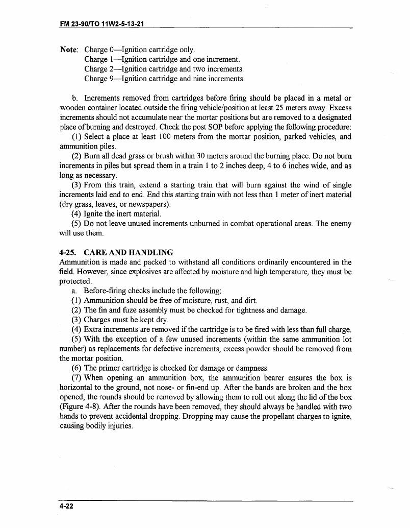
FM 23-90/TO 11W2-5-13-21
Note: Charge 0-Ignition cartridge only.Charge 1-Ignition cartridge and one increment.Charge 2-Ignition cartridge and two increments.Charge 9-Ignition cartridge and nine increments.
b. Increments removed from cartridges before firing should be placed in a metal orwooden container located outside the firing vehicle/position at least 25 meters away. Excessincrements should not accumulate near the mortar positions but are removed to a designatedplace of burning and destroyed. Check the post SOP before applying the following procedure:
(1) Select a place at least 100 meters from the mortar position, parked vehicles, andammunition piles.
(2) Bumrn all dead grass or brush within 30 meters around the burning place. Do not burnincrements in piles but spread them in a train 1 to 2 inches deep, 4 to 6 inches wide, and aslong as necessary.
(3) From this train, extend a starting train that will burn against the wind of singleincrements laid end to end. End this starting train with not less than 1 meter of inert material(dry grass, leaves, or newspapers).
(4) Ignite the inert material.(5) Do not leave unused increments unburned in combat operational areas. The enemy
will use them.
4-25. CARE AND HANDLINGAmmunition is made and packed to withstand all conditions ordinarily encountered in thefield. However, since explosives are affected by moisture and high temperature, they must beprotected.
a. Before-firing checks include the following:(1) Ammunition should be free of moisture, rust, and dirt.(2) The fin and fuze assembly must be checked for tightness and damage.(3) Charges must be kept dry.(4) Extra increments are removed if the cartridge is to be fired with less than full charge.(5) With the exception of a few unused increments (within the same ammunition lot
number) as replacements for defective increments, excess powder should be removed fromthe mortar position.
(6) The primer cartridge is checked for damage or dampness.(7) When opening an ammunition box, the ammunition bearer ensures the box is
horizontal to the ground, not nose- or fin-end up. After the bands are broken and the boxopened, the rounds should be removed by allowing them to roll out along the lid of the box(Figure 4-8). After the rounds have been removed, they should always be handled with twohands to prevent accidental dropping. Dropping may cause the propellant charges to ignite,causing bodily injuries.
4-22
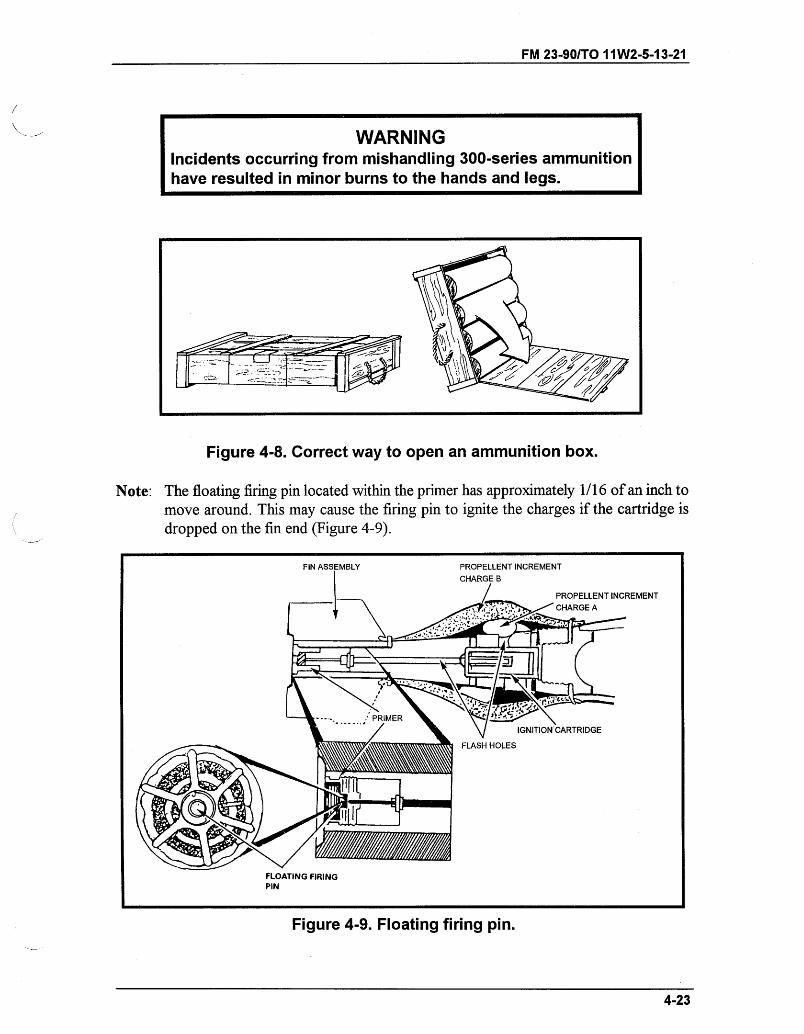
FM 23-90/TO 11W2-5-13-21
WARNINGIncidents occurring from mishandling 300-series ammunitionhave resulted in minor burns to the hands and legs.
U M -I
Figure 4-8. Correct way to open an ammunition box.
Note: The floating firing pin located within the primer has approximately 1/16 of an inch tomove around. This may cause the firing pin to ignite the charges if the cartridge isdropped on the fin end (Figure 4-9).
Figure 4-9. Floating firing pin.
4-23
C; C-
PROPELLENT INCREMENTCHARGE A
FLOATING FIRINGPIN
FM 23-90/TO 11W2-5-13-21
(8) To help minimize the occurrence of short rounds and or duds, unpackagedammunition that has been dropped should not be fired. It should be destroyed in accordancewith standard procedures.
DANGERM800-SERIES CARTRIDGES (HE, TP, SMOKE, ANDILLUMINATION) ARE AUTHORIZED FOR FIRING IN THE 81-mm,M29-SERIES MORTARS ONLY AT CHARGE 3 OR BELOW.FIRING THE M800-SERIES CARTRIDGES ABOVE CHARGE 3CAN CAUSE CATASTROPHIC FAILURE OF THE MORTARTUBE RESULTING IN PERSONNEL INJURY OR DEATH.
b. Complete cartridges are always handled with care. The explosive elements in primersand fuzes are sensitive to shock and high temperature. Fuzes are not disassembled.
c. The moisture-resistant seal of the container is broken when the ammunition is to beused. When a large number of cartridges are needed for a mission, they may be removed fromthe containers and prepared. Propelling charges are covered or protected from dampness orheat.
d. The ammunition is protected from mud, sand, dirt, and water. If it gets wet or dirty,it must be wiped off at once. The powder increments, mainly, should not be exposed to directsunlight. More uniform firing is obtained if ammunition is kept at the same temperature.
e. The pull wire and safety wire are removed from the fuze just before firing. Whencartridges have been prepared for firing, but are not used, all powder increments and safetywires are replaced. The cartridges are returned to their original containers. These cartridgesare used first in subsequent firing so that once-opened stocks can be kept to a minimum.
WARNINGDo not handle duds; the fuzes could be armed. Duds areextremely dangerous. Do not move or turn them. To disposeof duds, immediately call the nearest EOD unit.
f. Ammunition should be stored under cover. If it is necessary to leave the ammunitionuncovered, it should be raised on dunnage at least 6 inches above the ground. The pile iscovered with a double thickness of tarpaulin. Trenches are dug to prevent water from flowingunder the pile. WP cartridges are stored with the fuze end up. Since phosphorus liquefies atabout 100 degrees Fahrenheit, the ammunition is protected against an uneven rehardening ofthe filler. An air cavity can form on one side of a cartridge to unbalance it, causing instabilityin flight. Red phosphorus cartridges (M252 only) are stored the same as HE cartridges.
4-24

FM 23-90/TO 11W2-5-13-21
WARNINGWhen firing HE ammunition less than 400 meters, personnelmust have adequate cover for protection from fragments.
DANGERM800-SERIES AMMUNITION IS NOT AUTHORIZED FOR FIRINGIN THE 81-mm MORTAR, M1.
4-25
FM 23-90/TO 1 W2-5-13-21
CHAPTER 5
81-mm MORTAR, M29A1
The 81-mm mortar, M29A], delivers timely, accurate fires to meet therequirements of supported troops. This chapter discusses personnel duties,mechanical training, and the characteristics of the mortar.
Section I. SQUAD AND SECTION ORGANIZATION AND DUTIESEach member of the infantry mortar squad has principle duties and responsibilities. (SeeFM 7-90 for platoon drills.)
5-1. ORGANIZATIONFor the 81-mm mortar section to operate effectively, each mortar squad member must beproficient in his individual duties. By performing those duties as a team member, he enablesthe mortar squad and section to perform as a fighting team. The platoon leader commands theplatoon and supervises the training of the elements. He uses the chain of command to assisthim in effecting his command and supervising duties.
5-2. DUTIESThe mortar squad consists of five men (Figure 5-1, page 5-2). Their firing positions andprincipal duties are as follows:
a. The squad leader stands behind the mortar where he can command and control hissquad. In addition to supervising the emplacement, laying, and firing of the mortar, hesupervises all other squad activities.
b. The gunner stands on the left side of the mortar where he can manipulate the sight,elevating gear handle, and traversing assembly wheel. He places firing data on the sight andlays the mortar for deflection and elevation. He and assistant gunner make large deflectionshifts by shifting the bipod assembly.
c. The assistant gunner stands on the right of the mortar, facing the barrel and ready toload. In addition to loading, he is responsible for swabbing the bore after every 10 roundshave been fired or after each fire mission. He assists the gunner in shifting the mortar whenmaking large deflection changes.
d. The first ammunition bearer stands to the right rear of the mortar. He prepares theammunition and passes it to the assistant gunner.
e. The second ammunition bearer is normally behind the mortar, maintaining theammunition for firing, providing local security for the mortar position, filling sandbags, andperforming other duties as the squad leader directs. He normally places out and retrieves theaiming post. The second ammunition bearer is also the squad truck driver. When his dutiesdo not require him to be with the vehicle, he is used as an ammunition bearer (performing thesame duties as the first ammunition bearer).
_ __
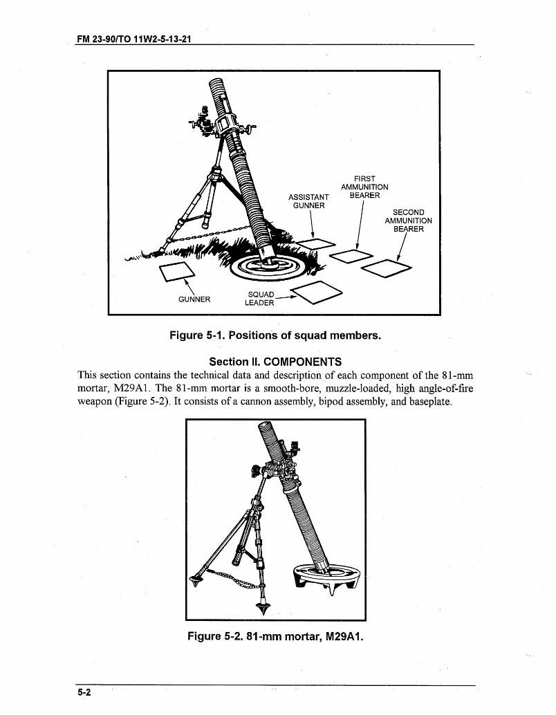
GUNNER
FIRSTAMMUNITION
ASSISTANT BEARERGUNNER
SECONDAMMUNITION
I BEARER
SQUADLEADER
Figure 5-1. Positions of squad members.
Section II. COMPONENTSThis section contains the technical data and description of each component of the 81-mmmortar, M29A1. The 81-mm mortar is a smooth-bore, muzzle-loaded, high angle-of-fireweapon (Figure 5-2). It consists of a cannon assembly, bipod assembly, and baseplate.
Figure 5-2. 81-mm mortar, M29A1.
5-2
FM 23-90/TO 11W2-5-13-21
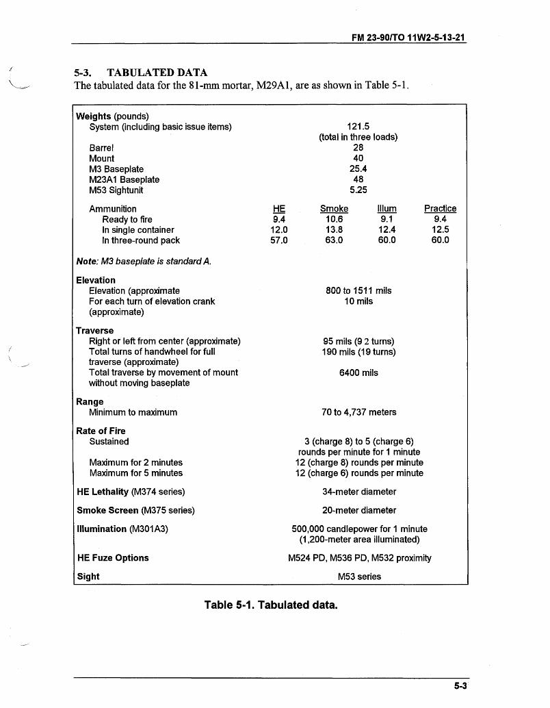
FM 23-90/TO 11W2-5-13-21
5-3. TABULATED DATAThe tabulated data for the 81-mm mortar, M29A1, are as shown in Table 5-1.
Weights (pounds)System (including basic issue items)
BarrelMountM3 BaseplateM23A1 BaseplateM53 Sightunit
AmmunitionReady to fireIn single containerIn three-round pack
HE9.412.057.0
Note: M3 baseplate is standard A.
ElevationElevation (approximateFor each turn of elevation crank(approximate)
TraverseRight or left from center (approximate)Total turns of handwheel for fulltraverse (approximate)Total traverse by movement of mountwithout moving baseplate
RangeMinimum to maximum
121.5(total in three loads)
2840
25.448
5.25
Smoke10.613.863.0
IlIum9.112.460.0
800 to 1511 mils10 mils
95 mils (9 2 turns)190 mils (19 turns)
6400 mils
70 to 4,737 meters
Rate of FireSustained
Maximum for 2 minutesMaximum for 5 minutes
HE Lethality (M374 series)
Smoke Screen (M375 series)
Illumination (M301A3)
HE Fuze Options
3 (charge 8) to 5 (charge 6)rounds per minute for 1 minute
12 (charge 8) rounds per minute12 (charge 6) rounds per minute
34-meter diameter
20-meter diameter
500,000 candlepower for 1 minute(1,200-meter area illuminated)
M524 PD, M536 PD, M532 proximity
Sight M53 series
Table 5-1. Tabulated data.
5-3
Practice9.4
12.560.0
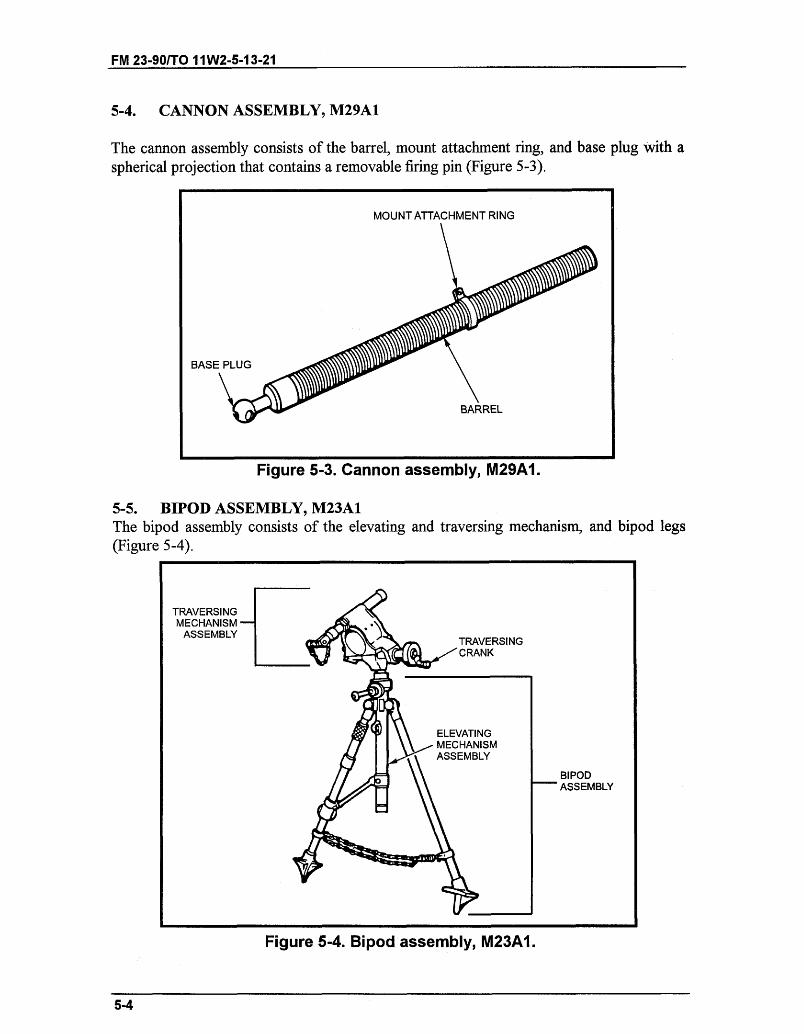
FM 23-90/T0 11 W2-5-13-21
5-4. CANNON ASSEMBLY, M29A1
The cannon assembly consists of the barrel, mount attachment ring, and base plug with aspherical projection that contains a removable firing pin (Figure 5-3).
Figure 5-3. Cannon assembly, M29A1.
5-5. BIPOD ASSEMBLY, M23A1The bipod assembly consists of the elevating and traversing mechanism, and bipod legs(Figure 5-4).
Figure 5-4. Bipod assembly, M23A1.
5-4
MOUNT ATTACHMENT RING
BASE PLUG
BARREL
TRAVERSINGMECHANISM
ASSEMBLYTRAVERSINGCRANK
ELEVATINGMECHANISMASSEMBLY
BIPODASSEMBLY
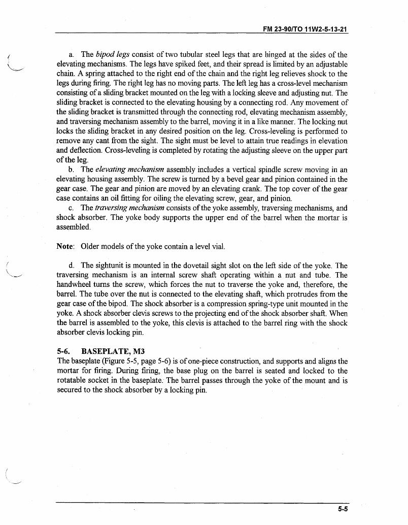
FM 23-90/T0 11 W2-5-13-21
a. The bipod legs consist of two tubular steel legs that are hinged at the sides of theelevating mechanisms. The legs have spiked feet, and their spread is limited by an adjustablechain. A spring attached to the right end of the chain and the right leg relieves shock to thelegs during firing. The right leg has no moving parts. The left leg has a cross-level mechanismconsisting of a sliding bracket mounted on the leg with a locking sleeve and adjusting nut. Thesliding bracket is connected to the elevating housing by a connecting rod. Any movement ofthe sliding bracket is transmitted through the connecting rod, elevating mechanism assembly,and traversing mechanism assembly to the barrel, moving it in a like manner. The locking nutlocks the sliding bracket in any desired position on the leg. Cross-leveling is performed toremove any cant from the sight. The sight must be level to attain true readings in elevationand deflection. Cross-leveling is completed by rotating the adjusting sleeve on the upper partof the leg.
b. The elevating mechanism assembly includes a vertical spindle screw moving in anelevating housing assembly. The screw is turned by a bevel gear and pinion contained in thegear case. The gear and pinion are moved by an elevating crank. The top cover of the gearcase contains an oil fitting for oiling the elevating screw, gear, and pinion.
c. The traversing mechanism consists of the yoke assembly, traversing mechanisms, andshock absorber. The yoke body supports the upper end of the barrel when the mortar isassembled.
Note: Older models of the yoke contain a level vial.
d. The sightunit is mounted in the dovetail sight slot on the left side of the yoke. Thetraversing mechanism is an internal screw shaft operating within a nut and tube. Thehandwheel turns the screw, which forces the nut to traverse the yoke and, therefore, thebarrel. The tube over the nut is connected to the elevating shaft, which protrudes from thegear case of the bipod. The shock absorber is a compression spring-type unit mounted in theyoke. A shock absorber clevis screws to the projecting end of the shock absorber shaft. Whenthe barrel is assembled to the yoke, this clevis is attached to the barrel ring with the shockabsorber clevis locking pin.
5-6. BASEPLATE, M3The baseplate (Figure 5-5, page 5-6) is of one-piece construction, and supports and aligns themortar for firing. During firing, the base plug on the barrel is seated and locked to therotatable socket in the baseplate. The barrel passes through the yoke of the mount and issecured to the shock absorber by a locking pin.
5-5
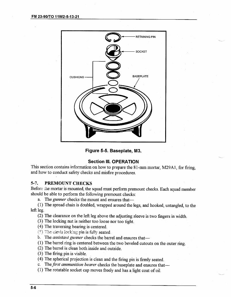
FM 23-90/TO 11W2-5-13-21
Figure 5-5. Baseplate, M3.
Section III. OPERATIONThis section contains information on how to prepare the 81-mm mortar, M29A1, for firing,and how to conduct safety checks and misfire procedures.
5-7. PREMOUNT CHECKSBefore the mortar is mounted, the squad must perform premount checks. Each squad membershould be able to perform the following premount checks:
a. The gunner checks the mount and ensures that-(1) The spread chain is doubled, wrapped around the legs, and hooked, untangled, to the
left leg.(2) The clearance on the left leg above the adjusting sleeve is two fingers in width.(3) The locking nut is neither too loose nor too tight.(4) The traversing bearing is centered.( ,) .~.he clevis lock :n pin is fully seated.b. The assistant gunner checks the barrel and ensures that-(1) The barrel ring is centered between the two beveled cutouts on the outer ring.(2) The barrel is clean both inside and outside.(3) The firing pin is visible.(4) The spherical projection is clean and the firing pin is firmly seated.c. The first ammunition bearer checks the baseplate and ensures that-(1) The rotatable socket cap moves freely and has a light coat of oil.
5-6
Q RETAINING PIN
CUSHIONS
---- - ~I"
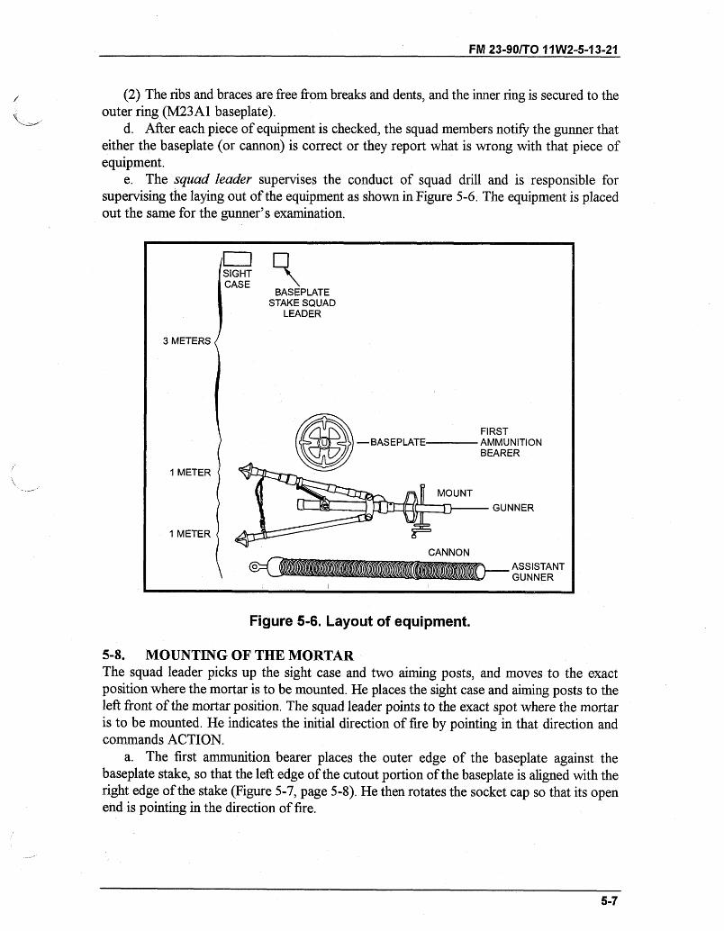
FM 23-90/TO 11W2-5-13-21
(2) The ribs and braces are free from breaks and dents, and the inner ring is secured to theouter ring (M23A1 baseplate).
d. After each piece of equipment is checked, the squad members notify the gunner thateither the baseplate (or cannon) is correct or they report what is wrong with that piece ofequipment.
e. The squad leader supervises the conduct of squad drill and is responsible forsupervising the laying out of the equipment as shown in Figure 5-6. The equipment is placedout the same for the gunner's examination.
I, U,
SIGHTCASE
3 METERS
1 METER
1 METER
BASEPLATESTAKE SQUAD
LEADER
FIRST- BASEPLATE AMMUNITION
BEARER
MOUNT
GUNNER
CANNON
o ASSISTANTGUNNER
Figure 5-6. Layout of equipment.
5-8. MOUNTING OF THE MORTARThe squad leader picks up the sight case and two aiming posts, and moves to the exactposition where the mortar is to be mounted. He places the sight case and aiming posts to theleft front of the mortar position. The squad leader points to the exact spot where the mortaris to be mounted. He indicates the initial direction of fire by pointing in that direction andcommands ACTION.
a. The first ammunition bearer places the outer edge of the baseplate against thebaseplate stake, so that the left edge of the cutout portion of the baseplate is aligned with theright edge of the stake (Figure 5-7, page 5-8). He then rotates the socket cap so that its openend is pointing in the direction of fire.
5-7
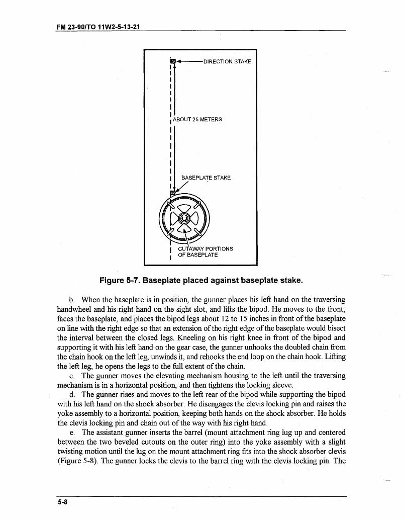
FM 23-901T0 11W2-5-13-21
Figure 5-7. Baseplate placed against baseplate stake.
b. When the baseplate is in position, the gunner places his left hand on the traversinghandwheel and his right hand on the sight slot, and lifts the bipod. He moves to the front,faces the baseplate, and places the bipod legs about 12 to 15 inches in front of the baseplate.on line with the right edge so that an extension of the right edge of the baseplate would bisectthe interval between the closed legs. Kneeling on his right knee in front of the bipod andsupporting it with his left hand on the gear case, the gunner unhooks the doubled chain fromthe chain hook on the left leg, unwinds it, and rehooks the end loop on the chain hook. Liftingthe left leg, he opens the legs to the full extent of the chain.
c. The gunner moves the elevating mechanism housing to the left until the traversingmechanism is in a horizontal position, and then tightens the locking sleeve.
d. The gunner rises and moves to the left rear of the bipod while supporting the bipodwith his left hand on the shock absorber. He disengages the clevis locking pin and raises theyoke assembly to a horizontal position, keeping both hands on the shock absorber. He holdsthe clevis locking pin and chain out of the way with his right hand.
e. The assistant gunner inserts the barrel (mount attachment ring lug up and centeredbetween the two beveled cutouts on the outer ring) into the yoke assembly with a slighttwisting motion until the lug on the mount attachment ring fits into the shock absorber clevis(Figure 5-8). The gunner locks the clevis to the barrel ring with the clevis locking pin. The
5-8
* .- DIRECTION STAKE
ABOUT 25 METERS
I
I BASEPLATE STAKE
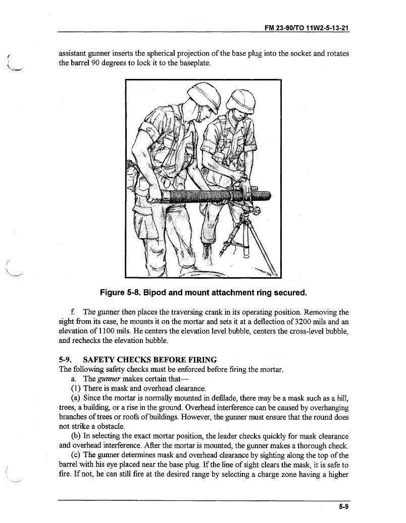
FM 23-90/TO 11 W2-5-13-21
assistant gunner inserts the spherical projection of the base plug into the socket and rotatesthe barrel 90 degrees to lock it to the baseplate.
Figure 5-8. Bipod and mount attachment ring secured.
f. The gunner then places the traversing crank in its operating position. Removing thesight from its case, he mounts it on the mortar and sets it at a deflection of 3200 mils and anelevation of 1100 mils. He centers the elevation level bubble, centers the cross-level bubble,and rechecks the elevation bubble.
5-9. SAFETY CHECKS BEFORE FIRINGThe following safety checks must be enforced before firing the mortar.
a. The gunner makes certain that-(1) There is mask and overhead clearance.(a) Since the mortar is normally mounted in defilade, there may be a mask such as a hill,
trees, a building, or a rise in the ground. Overhead interference can be caused by overhangingbranches of trees or roofs of buildings. However, the gunner must ensure that the round doesnot strike a obstacle.
(b) In selecting the exact mortar position, the leader checks quickly for mask clearanceand overhead interference. After the mortar is mounted, the gunner makes a thorough check.
(c) The gunner determines mask and overhead clearance by sighting along the top of thebarrel with his eye placed near the base plug. If the line of sight clears the mask, it is safe tofire. If not, he can still fire at the desired range by selecting a charge zone having a higher
5-9
FM 23-90/TO 11W2-5-13-21
elevation. When firing under the control of an FDC, he reports to the FDC that maskclearance cannot be obtained at a certain elevation.
(d) Firing would be slowed if mask clearance had to be checked before each firing but thiscan be eliminated if minimum mask clearance is determined. This is accomplished bydepressing the barrel until the top of the mask is sighted. The gunner levels the elevationbubble and reads the setting on the elevation scale and elevation micrometer-this setting isthe minimum mask clearance. The squad leader notifies the FDC of the minimum maskclearance elevation. Any target that requires that elevation, or a lower one, cannot be engagedfrom that position.
(e) If the mask is not regular throughout the sector of fire, the gunner determines theminimum mask clearance as described above. Placing the mortar in position at night does notrelieve the gunner of the responsibility of checking for mask clearance and overheadinterference.
(2) The barrel is locked to the baseplate with the open end of the socket cap pointing inthe direction of fire. The barrel ring should be positioned between the etched markings on thebarrel.
(3) The shock absorber clevis locking pin is secure.(4) The locking sleeve is wrist tight.(5) The chain is taut and is hooked to the left leg.b. The assistant gunner ensures that the bore is clean, and he swabs the bore dry.c. The ammunition bearer ensures that each round is clean, the safety pin is present, and
the ignition cartridge is in good condition.
5-10. SMALL DEFLECTION AND ELEVATION CHANGESWith the mortar mounted and the sight installed, the gunner lays the sight on the two aimingposts (placed out 50 and 100 meters from the mortar) on a referred deflection of 2800 milsand an elevation of 1100 mils. The mortar is within two turns of center of traverse. Thevertical cross line of the sight is on the left edge of the aiming post.
a. The gunner is given a deflection change in a fire command between 20 and 60 mils.The elevation change announced must be less than 90 mils and more than 35 mils.
b. As soon as the sight data are announced, the gunner places it on the sight, lays themortar for elevation, and then traverses onto the aiming post by turning the traversinghandwheel and the adjusting nut in the same direction. A one-quarter turn on the adjustingnut equals one turn of the traversing handwheel. When the gunner is satisfied with his sightpicture, he announces, "Up."
Note: All elements given in the fire command are repeated by the gunner.
c. After the gunner has announced, "Up," the mortar should be checked by the squadleader to determine if the exercise was performed correctly.
5-11. LARGE DEFLECTION AND ELEVATION CHANGESWith the mortar mounted and the sight installed, the gunner lays the sight on the two aimingposts (placed out 50 and 100 meters from the mortar) on a referred deflection of 2800 milsand an elevation of 1100 mils.
5-10
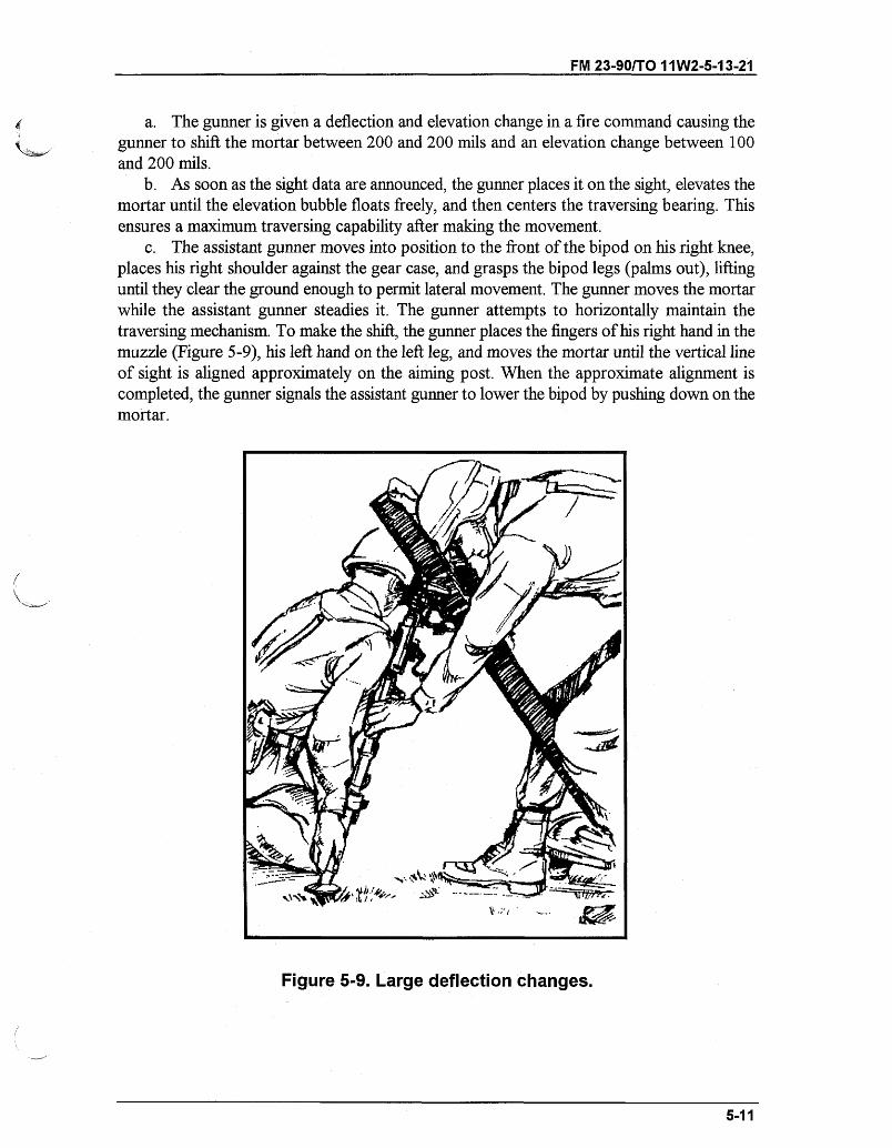
FM 23-90/T0 11W2-5-13-21
a. The gunner is given a deflection and elevation change in a fire command causing thegunner to shift the mortar between 200 and 200 mils and an elevation change between 100and 200 mils.
b. As soon as the sight data are announced, the gunner places it on the sight, elevates themortar until the elevation bubble floats freely, and then centers the traversing bearing. Thisensures a maximum traversing capability after making the movement.
c. The assistant gunner moves into position to the front of the bipod on his right knee,places his right shoulder against the gear case, and grasps the bipod legs (palms out), liftinguntil they clear the ground enough to permit lateral movement. The gunner moves the mortarwhile the assistant gunner steadies it. The gunner attempts to horizontally maintain thetraversing mechanism. To make the shift, the gunner places the fingers of his right hand in themuzzle (Figure 5-9), his left hand on the left leg, and moves the mortar until the vertical lineof sight is aligned approximately on the aiming post. When the approximate alignment iscompleted, the gunner signals the assistant gunner to lower the bipod by pushing down on themortar.
Figure 5-9. Large deflection changes.
5-11
FM 23-90/TO 11W2-5-13-21
5-12. REFERRING OF THE SIGHT AND REALIGNMENT OF AIMING POSTSUSING M53 SIGHTReferring and realigning aiming posts ensure that all mortars are set on the same data. Thesection leader, acting as FDC, has one deflection instead of two.
a. The mortar is mounted and the sight is installed. The sight is laid on two aiming posts(placed out 50 and 100 meters from the mortar) on a referred deflection of 2800 mils and anelevation of 1100 mils. The mortar is within two turns of center of traverse. The gunner isgiven an administrative command to lay the mortar on a deflection of 2860 or 2740 mils. Themortar is then re-laid on the aiming posts using the traversing crank.
b. The gunner is given a deflection change between 5 and 25 mils, either increasing ordecreasing from the last stated deflection, and the command to refer and realign aiming posts.
EXAMPLE: REFER DEFLECTION TWO EIGHT SEVEN FIVE (2875),REALIGN AIMING POST.
c. Upon receiving the command REFER, REALIGN AIMING POST, two actions takeplace at the same time in the mortar squad. The gunner places the announced deflection onthe sight (without disturbing the lay of the weapon) and looks through the sightunit. Also, thefirst ammunition bearer moves out to realign the aiming posts. He knocks down the nearaiming post and proceeds to the far aiming post. Following the arm-and-hand signals of thegunner (who is looking' through the sightunit), he moves the far aiming post so that thegunner obtains an aligned sight picture. The same procedure for aligning the far aiming postis used to align the near aiming post.
5-13. MALFUNCTIONSSee Chapter 3, paragraph 3-14 for a detailed discussion of malfunctions.
5-14. REMOVAL OF A MISFIREWhen a misfire occurs, any member of the squad immediately announces, "Misfire." Theentire squad stays with the mortar. The gunner then kicks the barrel several times with hisheel in an attempt to dislodge the round. If the round fires, the mortar is re-laid on the aimingpoint and firing is continued.
WARNINGDuring peacetime live-fire training, all personnel, except thegunner, move at least 50 meters to the rear of the mortar.
a. If the round does not fire, the gunner tests the barrel for heat. After one minute, if thebarrel is cool enough to handle, the crew removes the round as described below. If the barrelis hot, the gunner may then apply water to the outside of the barrel until it is cool. If no wateris available, the gunner stands clear of the mortar until the barrel is cool.
5-12
FM 23-90/TO 11W2-5-13-21
WARNINGDuring peacetime live-fire training, if the round does not fire,the gunner joins the crew and waits one minute to avoidpersonal injury due to a cookoff. After waiting one minute, thegunner returns to the mortar and tests the barrel for heat.When the barrel is cool enough to handle, the gunner signalsfor the rest of the crew to come forward.
b. After the barrel cools, the gunner removes the sight and depresses the barrel to theminimum elevation. The assistant gunner braces the right leg of the bipod by placing his leftleg in front of it. The gunner rotates the barrel while ensuring that he is positioned beside notbehind, the weapon, until it is unlocked from the baseplate. The assistant gunner then placeshis right hand, palm up, under the barrel near the muzzle, and his left hand, palm down, ontop of the barrel. He places the thumbs of both hands alongside the forefingers, being carefulto keep both hands hand away from the muzzle.
c. The gunner lifts the base of the barrel until it is horizontal. He never lowers the baseof the barrel below a horizontal position before the round has been removed. As soon as thebarrel is in the horizontal position, and not before, the assistant gunner places the meatyportion of the thumb of each hand over the muzzle. When the fuze reaches the muzzle, theassistant gunner stops the round with his thumbs (avoiding the fuzes). He then carefullyremoves the round and passes it to the first ammunition bearer who inspects it to determinethe cause of the misfire. If the primer of the ignition cartridge is dented, the ammunitionbearer replaces the safety wire (if applicable) and places the round in a marked, safe locationfor disposition by ordnance personnel. If the primer is not dented, the round can be usedagain. The gunner shakes the barrel to dislodge any remnants from the last round fired, thenlocks the barrel.
d. If the procedure above fails to remove the misfire, the barrel must be kept horizontal.Then it is removed from the bipod and laid horizontally on the ground at the dud pit or safearea until it can be turned over to ordnance for disposal.
5-15. DISMOUNTING OF THE MORTARTo dismount the mortar, the squad leader commands, OUT OF ACTION. At this command,the squad proceeds as follows:
a. The second ammunition bearer retrieves the aiming posts. The gunner removes thesight and places it in the sight box. He places an elevation of 800 mils and a deflection of3800 mils on the M53 sightunit. Then he lowers the mortars to its minimum elevation.
b. The assistant gunner turns the barrel 90 degrees, lifts up on the base end of the barreland removes the barrel from the yoke assembly. He then turns to his left and places the barrelin the area designated by the squad leader.
c. The gunner disengages the clevis locking pin. He moves to the front of the bipod andfaces it, kneels on his right knee with his left hand on the gear case, loosens the locking nut,and unhooks the chain from the left leg. He tilts the bipod to his left and closes the bipod legs,
5-13
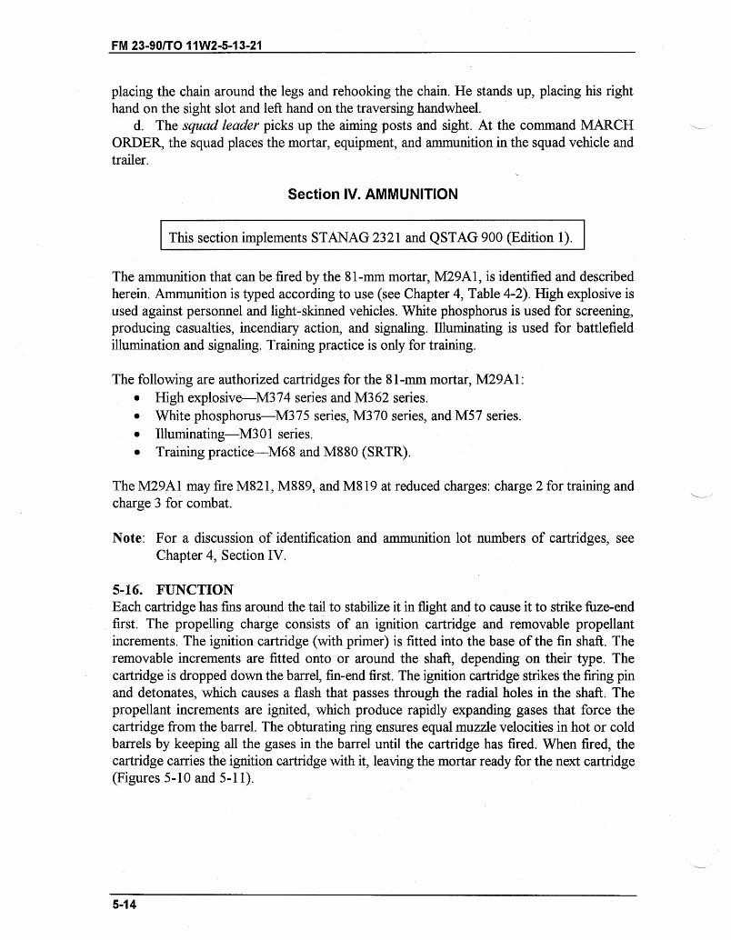
FM 23-901TO 11W2-5-13-21
placing the chain around the legs and rehooking the chain. He stands up, placing his righthand on the sight slot and left hand on the traversing handwheel.
d. The squad leader picks up the aiming posts and sight. At the command MARCHORDER, the squad places the mortar, equipment, and ammunition in the squad vehicle andtrailer.
Section IV. AMMUNITION
This section implements STANAG 2321 and QSTAG 900 (Edition 1).
The ammunition that can be fired by the 81-mm mortar, M29A1, is identified and describedherein. Ammunition is typed according to use (see Chapter 4, Table 4-2). High explosive isused against personnel and light-skinned vehicles. White phosphorus is used for screening,producing casualties, incendiary action, and signaling. Illuminating is used for battlefieldillumination and signaling. Training practice is only for training.
The following are authorized cartridges for the 81-mm mortar, M29A1:* High explosive-M374 series and M362 series.* White phosphorus-M375 series, M370 series, and M57 series.* Illuminating-M301 series.* Training practice-M68 and M880 (SRTR).
The M29A1 may fire M821, M889, and M819 at reduced charges: charge 2 for training andcharge 3 for combat.
Note: For a discussion of identification and ammunition lot numbers of cartridges, seeChapter 4, Section IV.
5-16. FUNCTIONEach cartridge has fins around the tail to stabilize it in flight and to cause it to strike fuze-endfirst. The propelling charge consists of an ignition cartridge and removable propellantincrements. The ignition cartridge (with primer) is fitted into the base of the fin shaft. Theremovable increments are fitted onto or around the shaft, depending on their type. Thecartridge is dropped down the barrel, fin-end first. The ignition cartridge strikes the firing pinand detonates, which causes a flash that passes through the radial holes in the shaft. Thepropellant increments are ignited, which produce rapidly expanding gases that force thecartridge from the barrel. The obturating ring ensures equal muzzle velocities in hot or coldbarrels by keeping all the gases in the barrel until the cartridge has fired. When fired, thecartridge carries the ignition cartridge with it, leaving the mortar ready for the next cartridge(Figures 5-10 and 5-11).
5-14
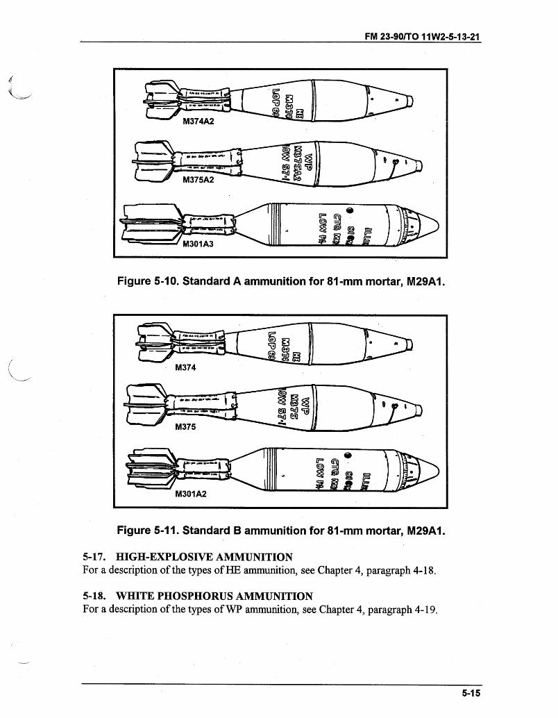
FM 23-90/TO 11W2-5-13-21
Figure 5-10. Standard A ammunition for 81-mm mortar, M29A1.
M301 A2
Figure 5-11. Standard B ammunition for 81-mm mortar, M29A1.
5-17. HIGH-EXPLOSIVE AMMUNITIONFor a description of the types of HE ammunition, see Chapter 4, paragraph 4-18.
5-18. WHITE PHOSPHORUS AMMUNITIONFor a description of the types of WP ammunition, see Chapter 4, paragraph 4-19.
5-15
I
FM 23-90/TO 11W2-5-13-21
5-19. ILLUMINATING AMMUNITIONFor a description of the types of illuminating ammunition, see Chapter 4, paragraph 4-20.
5-20. TYPES OF FUZESFor a description of the types of fuzes, see Chapter 4, paragraph 4-21.
5-21. CHARACTERISTICS OF PROXIMITY FUZESFor an explanation of the characteristics of proximity fuzes, see Chapter 4, paragraph 4-22.
5-22. FUZE WRENCH AND FUZE SETTERFor details on the use of the fuze wrench and fuze setter, see Chapter 4, paragraph 4-23.
5-23. PREPARATION OF AMMUNITIONFor an explanation of preparation of ammunition, see Chapter 4, paragraph 4-24.
5-24. CARE AND HANDLINGFor proper care and handling of ammunition, see Chapter 4, paragraph 4-25.
5-16
Related Documents