INSTALLATION INSTRUCTION - 1 - 1. INTRODUCTION 2. BASIC PLASTIC MATERIALS 2.1 COMPARISON OF THE PLASTIC AND STEEL PIPELINES 2.2 DIVISION OF POLYOLEFINS AND VINYL CHLORIDES 2.3 USING OF MATERIAL AND WELDABILITY 2.4 PROPERTIES OF MATERIALS USED TO THE PIPES PRODUCTION 2.5 ROW BY PRESSURE DIMENSION 2.6 DIMENSIONS AND MARKING OF PLASTIC PIPES 2.7 SYSTEM OF ADAPTING PIPES 2.8 OPERATING PARAMETERS 2.9 STORAGE AND HANDLING 3. WELDING 3.1 TOOLS AND INSTRUMENTS 3.2 TECHNIQUE OF THE POLYFUSION WELDING 3.2.1 ADMEASUREMENT AND CUTTING OF PIPES 3.2.2 PREPARING OF PIPES AND ADAPTING PIPES TO THE WELDING 3.2.3 WELDING 3.2.4 WELDING TEMPERATURES 3.2.5 WELDABILITY 4. ASSEMBLY OF PLASTIC PIPING 4.1 DOCUMENTATION 4.2. MATERIAL CHECKING 4.3 PRINCIPLES OF THE LEADING, SETTING AND FIXING OF THE PIPING 4.3.1 LEADING OF THE PIPING 4.3.2 CONNECTING PIPING 4.3.3 RISING MAIN 4.3.4 LYING PIPING 4.3.5 DECLINE OF THE PIPING 4.3.6 ISOLATION OF THE PIPING 4.3.7 DISTANCE BETWEEN RESTS 4.4 ALTERATION OF THE TUBE MATERIAL 4.5 COMPENSATION OF THE PIPELINE 4.6 PROTECTIVE CONNECTING 4.7 FIRE WATER MAIN 4.8 PRESSURE TEST 4.9 SAFETY AND HEALTH PROTECTION IN THE COURSE OF THE WORK 4.10 REVISAL OF WELDING APPARATUSES 4.11 DIMENSIONING 5 CENTRAL HEATING AND FLOOR HEATING 5.1 EXAMPLE OF THE APPRECIATION OF PROPOSED PIPING APPLICABILITY 6 CHEMICAL RESISTANCE OF THE MATERIAL

Welcome message from author
This document is posted to help you gain knowledge. Please leave a comment to let me know what you think about it! Share it to your friends and learn new things together.
Transcript

INSTALLATION INSTRUCTION
- 1 -
1. INTRODUCTION2. BASIC PLASTIC MATERIALS2.1 COMPARISON OF THE PLASTIC AND STEEL PIPELINES2.2 DIVISION OF POLYOLEFINS AND VINYL CHLORIDES2.3 USING OF MATERIAL AND WELDABILITY2.4 PROPERTIES OF MATERIALS USED TO THE PIPES PRODUCTION2.5 ROW BY PRESSURE DIMENSION2.6 DIMENSIONS AND MARKING OF PLASTIC PIPES2.7 SYSTEM OF ADAPTING PIPES2.8 OPERATING PARAMETERS2.9 STORAGE AND HANDLING3. WELDING3.1 TOOLS AND INSTRUMENTS3.2 TECHNIQUE OF THE POLYFUSION WELDING3.2.1 ADMEASUREMENT AND CUTTING OF PIPES3.2.2 PREPARING OF PIPES AND ADAPTING PIPES TO THE WELDING3.2.3 WELDING3.2.4 WELDING TEMPERATURES3.2.5 WELDABILITY4. ASSEMBLY OF PLASTIC PIPING4.1 DOCUMENTATION4.2. MATERIAL CHECKING4.3 PRINCIPLES OF THE LEADING, SETTING AND FIXING OF THE PIPING4.3.1 LEADING OF THE PIPING4.3.2 CONNECTING PIPING4.3.3 RISING MAIN4.3.4 LYING PIPING4.3.5 DECLINE OF THE PIPING4.3.6 ISOLATION OF THE PIPING4.3.7 DISTANCE BETWEEN RESTS4.4 ALTERATION OF THE TUBE MATERIAL4.5 COMPENSATION OF THE PIPELINE4.6 PROTECTIVE CONNECTING4.7 FIRE WATER MAIN4.8 PRESSURE TEST4.9 SAFETY AND HEALTH PROTECTION IN THE COURSE OF THE WORK4.10 REVISAL OF WELDING APPARATUSES4.11 DIMENSIONING5 CENTRAL HEATING AND FLOOR HEATING5.1 EXAMPLE OF THE APPRECIATION OF PROPOSED PIPING APPLICABILITY6 CHEMICAL RESISTANCE OF THE MATERIAL

INSTALLATION INSTRUCTION
- 2 -
1. INTRODUCTION
There are constantly growing demands to systems of water piping thanks to constantly growing demands on thehabitation amenities.
Because the consumption of water is perpetual higher and higher, there is necessary to use water with lower levelof pH on the score of the food supply. Even thought this water isn't unhealthy, her reaction with the still usedpipelines from the metallic materials to the higher value of metallic ions ( e.g. ions of lead, zinc, copper ).
Said pipes do create the main cause of their corrosion, nowise improving the quality of carried water. Todrinking water with lower value of pH factor does not resist nor yet semi-noble metal, e.g. copper.
The following problem can create the incrusting of pipes, engendered by the higher hardness of used watercomprising a larger mass of calcium. Internal diameter of said pipes will be continuously minor thanks to regularsedimenting, guiding to its absolute clogging and following potential disruption.
There is unavoidable to solve this problem immediate, because the corrosion and incrusting of pipes do more andmore damages inside of pipelines.
Using healthy non-exceptionable sorts of plastics brings a new non-traditional materials for producing waterpiping systems.
There are beginnings of first use one type of plastics - polyethylene - during the 60's, before now so calledbranch-chained polyethylene. There were banished not only the disadvantages of metallic pipelines, but it waschanged whole method of pipeline’s assemblage through the replacement of prime materials by the saidpolyethylene. Former arduous pipes and thread cutting was compensate by the new and simply method oflinking - polyfusion welding. The drawback of the branch-chained polyethylene was not-comprising appropriatestabilisation which could have prevent to excessive punishment of pipeline leading hot water. Therefore thebranch-chained polyethylene was usable only to internal cold-water pipelines.
The beginnings of this method were attaced with a great number of problems and break-downs as a result of anunqualified work. Causes of said unqualified work were not only in an unskilled labour of workers and not-acquaintance of a proper assembling technique, but these ones have had some their reasons in an deficiency ofgood tools and welding machines, too. Described drawbacks led up customers and fitters to the opinion this newtechnology has no future in practical area.
Only in the 1989 were reached a certain break-through in this technique. There came up a new, till this timeunused plastic material - polypropylene type I and after following year came the polypropylene type III into themarket. This type of polypropylene can be used safely to the produce a pipes for cold water and for warm watertoo, thanks to its appropriate stabilisation. New types of welders from the same year did the following stepforward in this branch. The using of thermostat for keeping in the appointed temperature was the main goal of it.Disbelief and apprehension were over.
The problems of plastic piping came sometimes more and more demanding. The formerly used materials werepurchase out by the new and more superior materials, usually produced abroad. Some improvements werereached in effete polyfuse welders, step by step substituting by the professional welders of world-wide level.

INSTALLATION INSTRUCTION
- 3 -
2. BASIC PLASTIC MATERIALS
The plastic pipings has a big number of advantages in comparison with the classical, metallic one. In this day isthe plastic piping more used than the metallic thanks to said advantages. Described advantages are not only inthe more simply and effective production of individual pipes, but in their practical using too. The big virtuecreates the processing technology, allowing arbitrary shaping of piping deals.
Because there are not usable all types of plastics ( and offering of these ones is till this day very large ), it’slogical to do a careful assortment of advisable type of plastic, warranting acquirement of high-level attributes.
There were stepwise chosen a number of advisable types to producing of water-piping from this largeassortment. These selected plastics were after it delivered on the market. There were plastic based onpolyolefins, e.g. polyethylene, polypropylene, co-polymers of propylene, filet-polyethylene, polybutene, orbased on vinyl chloride, e.g. PVC, C-PVC. In Europe were used especially above all polyethylene for cold-waterpipings and statistical copolymer of propylene for warm-water piping.
2.1 Comparison of plastic and metallic piping
Advantages:
• lower purchase costs• suitable for health reasons• rust resistance• incrustation resistance• electrical non-conductibility• higher flow-rate• low temperature resistance• lower consumption of energy• low weight• simply and fast assemblage (lower quantity of invested work in range of 30% )• a several times higher operating life• chemical stability• thermal and acoustic isolation• simply and guaranteed weldability• possibility of recycling
Disadvantages:
• lower thermal stability• higher thermal expansivity: for steel: 0,012mm/°C.m for plastics: 0,15mm/°C.m• low resistance to UV radiation• low mechanical resistance

INSTALLATION INSTRUCTION
- 4 -
2.2 Division of polyolefins and vinyl chlorides
a) polyethylens - PE
Name Identification mark
low-solid polyethylene ( branched ) PE-LD (rPE)
middle-solid polyethylene PE-MD
high-solid polyethylene ( straight chain ) PE-HD (1PE)
filet polyethylene VPE, PEX
b) polypropylens PP
PP-type I - propylene homopolymere PP-H, PP
PP-type II - propylene block co-polymer PP-B; kP
PP-type 3 - propylene statistic co-polymer PP-R; PPC; PP-RC
c) polybutylens
polybutylene PB
d) polyvinyl chlorides PVC
polyvinyl chloride PVC
chlorinated polyvinyl chloride CPVC

INSTALLATION INSTRUCTION
- 5 -
2.3 Using of material and weldability
PE-LD • internal water pipings
• water-conduit connections
• irrigation systems
weldable
PE-MD • gas distribution systems weldable
PE-HD • internal water distribution systems
• gas distribution systems
• waste piping systems
weldable
PEX • internal water distribution systems
• floor heating distribution systems
• connections to the heaters
• long-distance heating systems
unweldable
PP-type 1 • internal water distribution systems weldable
PP-type 2 • industrial water distribution systems weldable
PP-type 3 • internal water distribution systems
• floor heating distribution systems
• connections to the heaters ( limited )
weldable
PB • internal water distribution systems
• long-distance heating systems
• floor heating distribution systems
• connections to the heaters
• gas distribution systems
weldable

INSTALLATION INSTRUCTION
- 6 -
• industrial distribution systems
• irrigation systems
• distribution systems with high qualitypiping
PVC • internal waste piping systems
• internal water distribution systems
connecting bythe adhesive
C-PVC • internal distribution systems of warm water connecting bythe adhesive
2.4 Properties of materials used to the pipes production
Attribute Unit PE-LD PE-HP PP
Density kg.m3 920 950 910
Tensile strength MPa 11 30 35
Bending strength MPa 20 32 46
Modulus of elasticity MPa 120 900 1300
Notch toughness J.cm2 6,0 2,9 1,9
Extensibility % 500 250 200
Linear expansion mm/°C.m 0,25 0,18 0,15
Thermal conductivity W/K.m 0,27 0,34 0,27
Absorptivity %/7 days 0 0 0,03
2.5 Row by pressure dimension
There are distincted a number of rows by the pressure dimension signed with letters „PN“ on produced pipes.Individual pressure row for every pipe is further characterised by the numbers determining its admeasurement.
Pressure rows PN 16, PN 20 are more often used for or internal water distribution systems. Some producers fromabroad are using the pressure row PN 25, too. Size of pressure row indicates the maximal operating overpressurein „bar“ at the temperature 30°C and at the life cycle min. 50 years ( 1 Mpa = 10 bar = 10 Atm ).

INSTALLATION INSTRUCTION
- 7 -
The size of pressure row doesn’t indicate the maximal operating overpressure at the higher temperature ( over30°C ), but it is only a marking. Values of real overpressures are for these occasions included in charts.
2.6 Dimensions and marking of plastic pipes
There are produced pipes in dimensions 10 to 125 mm for internal distribution.
The more often used dimensions are: 16. 20, 25, 32, 40, 50, 63 and 75 mm.
Dimension gives the inner diameter of the pipe in mm. The pressure row determines thickness of the pipe wallfor every pressure row.
PE-LD PP-type 3
D (in mm) PN 6 PN 10 D (in mm) PN 10 PN 16 PN 20
thickness of wall in mm thickness of wall in mm
16 2,0 2,5 16 2,0 2,3 2,7
20 2,0 2,8 20 2,2 2,8 3,4
25 2,3 3,5 25 2,5 3,5 4,2
32 2,9 4,4 32 3,2 4,5 5,4
40 3,7 5,5 40 3,7 5,6 6,7
50 4,6 6,9 50 4,6 6,9 8,4
63 5,8 8,6 63 5,8 8,7 10,5
75 6,9 10,4 12,5
Marking of plastic piping should be realised in following order:
Mark of theproducer
dimension x thickness of thewall
pressure row material norm
IDEAL TRADE 20 x 3,4 PN 20 PPR type-3 DIN 8077-78

INSTALLATION INSTRUCTION
- 8 -
2.7 System of adapting pipes
Every system of plastic piping comprises exclusive of pipes also the corresponding system of plastic adaptingpipes. Dimensions of said adapting pipes agree with dimension rows of pipes. and for the most part they aren’tproduced in different pressure rows. The row PN 20 (eventually PN 16) is the most produced pressure row ofadapting pipes.
The construction of the adapting pipes produced to use in individual systems is in some individual events alittle bit different. There is possible to divide these adapting pipes system from the user’s point of view:
1. Basic adapting pipes2. Additional pipes3. Special reducing pieces
Between basic adapting pieces are belonging above all T-piece (single valued), the elbow 90° and 45°, socketcoupling, socket and piping reduction, plastic reducing sleeve (DG). There is possible to realise a routineassemblage ( only for cold water - CW ) with the help of these basic adapting pipes but in plenty of events ismore advantageous to use an additional pipe with construction allowing a few of basic adapting pipes.This groupcomprise reduced T-pieces, elbow with a spigot, elbows 3 x 90°, corner four-branch, crossing, alternative routes,stopples, blinding, plastic screw-thread connectors, straight-way valve, non-concentric valve, etc.For theconnecting of plastic piping to the metallic piping are subserving a special reducing pieces. These parts aredifferent in different systems, but largely they are made like a reducing sleeves with the injected windings ( foruse to leading of warm water ).With a number of pieces is this group the most big one and comprises reducingsleeves with the external and/or internal threads, reducing sleeves in combination with T-pieces and elbows,elbow with a spigot, a lot of screw-thread connectors and -as a matter of course - wall catches for attachment ofthe leaving fittings.
The course of isothermal curve of pipes from the PP type-3

INSTALLATION INSTRUCTION
- 9 -
2.8 Operating parameters
Operational parameters of plastic parts ( pipes and adapting pieces ) are defined through three following values:
operational pressureoperational temperatureoperating life
There are compiled tables from results of measurings and tests ( first of all from long-term stress tests by internaloverpressure ), indicating dependency of operational parameters. Values mentioned in said tables take a respectto safety coefficient k = 1,5 by the norm DIN 8077; this coefficient do derogate the maximum value of internaloverpressure upon approximately 33%.
There is possible to elicit by extrapolation an operating life of the piping from the dependency of the shearingstress in the pipe’s wall upon time and temperature ( see diagram - PP type 3 ). It is possible to re-count theshearing stress to operational overpressure. Dimension of the operational overpressure depends on thepressure-row of piping ( that’s on the size of the pipe ).
Re-counting of the shearing stress to operational overpressure:
p = σ . 2.s(D - s) . k
where
σ shearing stress N/mm2
s thickness of the pipe’s wall ( by the pressure row ) mm
p operational overpressure N/mm2
D diameter of the pipe mm

INSTALLATION INSTRUCTION
- 10 -
Table of operational over pressures in dependency on the temperature of the medium and supposedoperation life for the material PP TYPE-3 with cold and warm water specification from norm DIN 8077
Pressure row
Temperat
ure
°C
Operation life
( years )
PN 10 PN 16 PN 20
acceptable operation pressure (bar)
1 16,4 26,2 32,6
5 16,0 25,6 32,0
10 15,7 25,2 31,5
25 15,0 24,1 30,0
10
50 14,7 23,5 29,3
1 15,1 24,1 30,1
5 14,0 22,4 28,0
10 13,5 21,7 27,1
25 13,2 21,1 26,4
20
50 12,9 20,7 25,9
1 12,8 20,5 25,6
5 12,0 19,2 24,0
10 11,7 18,8 23,05
25 11,3 18,1 22,7
30
50 11,1 17,7 22,1

INSTALLATION INSTRUCTION
- 11 -
1 11,1 17,7 22,1
5 10,4 16,6 20,8
10 10,1 16,2 20,3
25 9,7 15,6 19,5
40
50 9,2 14,7 18,4
1 9,5 15,1 18,9
5 8,9 14,3 17,9
10 8,7 13,9 17,3
25 8,0 12,8 16,0
50
50 7,3 11,7 14,7
1 8,3 13,2 16,5
5 7,6 12,2 15,2
10 7,2 11,5 14,4
25 6,1 9,8 12,3
60
50 5,5 8,7 10,9
1 6,7 10,7 13,3
5 6,0 9,6 12,0
10 5,3 8,5 10,7
25 4,5 7,3 9,1
70
50 4,4 7,0 8,8
1 5,8 8,7 10,9
80 5 4,3 6,9 8,7

INSTALLATION INSTRUCTION
- 12 -
10 3,9 6,3 7,9
15 3,7 5,9 7,3
1 4,6 7,3 9,0
5 3,2 5,1 6,3
10 2,7 4,3 5,4
90
15 2,5 3,9 4,8
1 3,8 6,1 7,695
5 2,9 4,6 5,7

INSTALLATION INSTRUCTION
- 13 -
2.9 Storage and handling
The ČSN 64 0090 (Czech industrial norm) is general in the force for storage of pipes and adapting pipes.Separate producers do more specify further particulars for storage of their products and conditions of providedguarantees.
The following belongs between said general conditions:
It is necessary to store pipes in a covered room. Pipes and adapting pipes will be resolved by single dimensionsan pressure rows.
The direct pipes will collocate into stacks in horizontal layers and the lower layer must lie on a flat backgroundin whole length. The lower margin of pipes must lie minimum 10 cm over the soil. Height of stack is max. 1,2 mand stack must be secured against the displacement.
Coils of pipes can be stored horizontal or standing. The stack from coils can compose only three ones. There’snecessary to store the coils at the outdoor storing so that’s impossible collection of water inside of pipes.
Pipes cannot to come into contact with an abrupt matter at a transport. There’s prohibited a tug of pipes or coilsof pipes by land. Transport in the winter denotes enhanced risk of damage by a bump for embrittlement of theplastic material.
The material cannot be insulate and in temperature higher than 60°C.
The material cannot be leave open to impingement of petrol, crude-oil, oil, lubricants, sulphur and toimpingement of other substances against them it isn’t resistant. These substances do attack polyolefines, do theirswelling and a persistent damage. These ones cannot be stored in rooms with fuel oil, petrol and gases in respectof diffusion mentioned substances.
We advise to keep all material in the original wrappage during of storage and transport; this wrappage ensuresprotecting against mechanical and/or chemical contaminations and against damage by action of UV radiation.
3. WELDING
3.1 Tools and instruments
There are necessary following instruments out of common fitter’s tools:
• Lever shears for plastic pipes with dividing shear moment into the number of clasps. It is possible use thespecial circular cutter or metal saw or wood saw with smooth teeth.
• Welding apparatus - polyfuse welder with electronic regulation of temperature in range of 190 to 280°C.• Polyfuse adapters - special exchangeable adapters with the protective teflon film, obstructing to sticking of
plastic on melting extents of adapters.• The knife - the knife with short blade to clearing of frays and adaptation edge of pipe before the welding• Clout form a non-synthetic material for clearing of melted faces of polyfusion adapters and for clearing of
pipes and adapting pipes in the position of weld.• Marker - to the marking of length of insertion of pipe into the polyfusion adapter.• Denatured alcohol (isopropyl alcohol) to the clearing of pipes and adapting pipes of mechanical and
chemical contaminations

INSTALLATION INSTRUCTION
- 14 -
3.2 Technique of the polyfusion welding
There is possible to divide this operatic sequence to following parts:
1. Admeasurement and cutting of pipes2. Preparing of pipes and adapting pipes to the welding3. Welding
3.2.1 Admeasurement and cutting of pipes
Ends of the pipes instant to the welding must be circular. Pipes winding off from the coils have elastic memoryafter the unrolling; they can revert into the oval shape after the said unrolling.
It is necessary to add to the length of admeasured figure a length which will be intromit into the adapting pipe.This intromit-length depends on type of the polyfusion adapter ( see table on page 12 ).
Said admeasuring is realised by meter. The shear or the cut must be perpendicular. It is necessary to abridgeclipped ends from frays.
3.2.2 Preparing of pipes and adapting pipes to the welding
Since there is danger of intake of pipe in the weld position, especially at the welding of pipes with a smallerdimensions of pipes ( 16, 20, 25 mm ), incurred by movements of fused material, we do recommend to realisebefore this welding the following conversion: to cut down the inner edge of pipe’s edge under the angle of 45°and into the deep of 1/3 of pipe’s wall thickness before the welding. It’s the best to make this cutting down withthe keen knife. Faces intended to welding must be dried by the clout from non-synthetic material and deliveredfrom mechanical contaminations. The welded face must not be unctuous or moist. It is possible to use denaturedalcohol or isopropyl alcohol to clarify the said welded faces.
3.2.3 Welding
The both of axes of the pipe and the adapting pipe must be identical with the axe of polyfusion adapter duringthe fusion of inner surface and external surface of the pipe. It is possible to soak both welded parties ( the pipeand the adapting pipe ) for the „warming-through time“ T1 after the insertion of the pipe and adapting pipe intothe polyfusion adapter. The both parties are careful dismantled from the polyfusion adapter after expiration ofthe warming-through time and the end of pipe is directly telescoped into the end of the adapting pipe. Theinsertion should be realised by the axial movement without moving round a slight amount. The so called„remelting time“ T2 is the time between the dismantling both of the pipe and the adapting pipe from thepolyfusion adapter and the mutual association of them. There is necessary to develop the mild axial pressure tothe pipe with connected adapting pipe after said dismantling to prevent their mutual spontaneous and backwardstir. This time is so called „time of connection“ T3. This is important to realise the mutual connection in thismanner that we can adhere the length of warming-through l and the mutual position of the pipe and the adaptingpipe.
The weld consistency time T4 defines the period in which this weld must not be stressed. There is possible tomanipulate with this weld after the expiration of mentioned time, but the weld cannot be commit to permanentmechanical stress.
The warming-through time into the polyfusion adapters can be affected by a different agents ( e.g. dimensions,type of material, temperature of neighbourhood ).

INSTALLATION INSTRUCTION
- 15 -
1. Fitting-on of pipe and adapting pipe into
the warming-up polyfusion adapter
2. Warming-through of welded faces
3. Completed weld - the not-removable joint
Remark: The accelerating of cooling areas is inadmissible ( it erodes the mechanical stronghold of the weld ).
The finished weld can be commit to permit mechanical stress after 60 to 120 minutes in accordance with thedimension of the piping and with the material. The filling of piping with water is allowed to be said permitmechanical stress.
3.2.4 Welding temperatures
Diameter
(mm)
Length of thewarming-
through (mm)
Time of thewarming-
through T1 (sec)
Remelting timeT2 (sec)
Time ofconnection T3
(sec)
Weldconsistency time
T4 (sec)
16 11 5 3 5 2
20 13 5 3 5 2
25 17 7 3 7 2
32 22 8 6 8 4
40 25 12 6 12 4
50 30 18 6 18 4
63 37 24 8 24 6
INSTALLATION INSTRUCTION
- 16 -
The water main cannot be imbedded into the circumferential walls or ceilings over the outdoor areas of buildingobjects or under the one-casing roof ( into the carrying construction nor yet into the casing of the roof ).
The water main cannot lead through the chimney vent.
The water piping cannot through the spaces with the increased concentration of fumes of crude oil products( e.g. fuel and heating oil stores ).
The piping of interior water-supply can be deposed into the soil under the flooring of the building object onlyunder the condition, that it conducts in the protective construction with possibility of the supervision (in theprotective pipe, in the installation canal, etc. ).
Each from the plastic materials has its own welding temperature which must bee unconditional adhered.Therewill be cold links the lower temperatures; contrawise at the higher temperatures will give the degradation of thewelded material. Temperatures of faces of polyfusion adaptors for the pipes welding must be adhere in the range:
PE-LD 195 ± 5°C
PP Type-1 and Type-3 from 225 to 28°C ± °C
The temperature of 280°C is designate above all for higher dimensions ( 32 mm and more ) and for the higherpressure rows ( PN 16 and higher ).
Besides of welding temperatures there has an influence on the quality of the resulting weld the temperature ofthe neighbourhood. The low temperatures of surroundings brings the accute cooling of the welds and as a resulttheir brittleness.
The minimum temperature of surroundings without a negative influences of said welds is +5°C.
There is recomended temperature of +10°C in demand of doing a larger number of welds eventually for thedoing of the prafabricated elements.
3.2.5 Weldability
The mutual weldability or not-weldability of individual plastics ( PP type-1, PP type-2, PE-LD, DD ) will berewied by the weldability classes. Said classes are designated by values from the test of liquid alloy flux index( ITT ) which is e.g. for polypropylenes 0,3; 0,6; 0,9; or for polyethylens 0,5; 1,0; 1,5.
There is generally valid the high quality and dependability of the whole system is ensurable only with the mutualwelding of the same materials ( PP Type-1 and PP type-1; PP Type-3 and PP Type-3; etc. ) The mutual weldingof materials from the different groups is unpossible ( i.e. polyethylene with polypropylene ).

INSTALLATION INSTRUCTION
- 17 -
4. Assembly of plastic piping
4.1 Documentation
There must be finished the documentation in the needful extent. The assemblage of the piping can be realisedonly by virtue of the said documentation. In the case that there are necessary some changes in regard of theproject, it is needful the projector’s acceptance. The change must be enlisted in the build diary and must beassigned in the documentation.
4.2. Material checking
The essential is to realize the visual control of the material with the respect to the eventuality of its damage inprocess of the stocking and transit. The necessary is to check the kind of the material in regard of the possibilityof interchange of similar materials.
4.3 Principles of the leading, setting and fixing of the piping
4.3.1 Fundamentals for leading, depositng and fixing of the piping
The manner of the piping leading and its protection must be proposed in order that the press transfer from thebuildings constructions to said piping is impossible.
The piping must be possibly shortest and directest.
There is impossible to lead the drinking water conduit along with the central heating conduit in the non-manholable channel.
The water conduit cannot be deposit in the circumferential walls of building objects or into the ceilings and one-level covering of the roof ( into the carrying construction or into the roof cover ).
The water piping cannot pass through the chimney vents.
The drinking water conduit cannot pass through spaces with the enhanced concentration of petroleum-productsvapours ( power fuel stocks, stocks of lubricants, etc. ).
The inner conduit pipes can be deposit into the soil under the floor of the building object only in the protectingconstruction with the possibility of the inspection ( into the protecting pipe, in the installation canal, etc. )
4.3.2 Connecting piping
There is necessary to orienting the connecting piping in the localities without assumption of a mechanicaldamage by the drilling or by a cutting through in the fastening of supports, consoles, mirrors, hand-rail, etc.
Every outfall armature must be fastened good either by the wall-grip on the classic brick wall or by the fastenedpart on the wall of the housing core.

INSTALLATION INSTRUCTION
- 18 -
It is possible to realise the fastening of the piping similarly as the fastening of cables with the help of specialclamps. It’s necessary to embed a special separation inlet from underfelt, foamy polystyrene, PVC, etc., betweenpiping and clamps. Described lodgement protects piping before its mechanical damage in the fastening positionsby the perforation at the dilatation movements. It isn’t necessary to use said separation inlet with plastic clamps.
There is not recommended to use metallic coupling hooks to eliminate failures during their embarrassing into thewall.
In the wall grooves we are recommending to use pipes produced in a shape of equal bars, because the pipe hasthe elastic memory. The adhering is maintained by plastering over the thermal insulation.
The lay-out of the position to the lodgement of piping is realised by the drawing documentation with thecompliance of specified gradients of said piping. If the gradient is not specified said piping can be mounted withthe minimal gradient 0,3% to the outfall or discharge armatures.
The example of constant points and sliding points lodgement
Comment: KU - sliding lodgement
PB - constant point
SK - dilatation loop
4.3.3 Rising main
A branch from the rising main leading to the connecting piping should be realised undirect by the elbow wherethe minimal distance between the branch and elbow is 8 cm. There is reached efficient compensation of theplastic piping dilatation by through this adjustment.

INSTALLATION INSTRUCTION
- 19 -
• The rising main have to be equipped with the compensation members.
• The rising main have to be equipped with system of sliding and constant points locating in dependence toused compensators ( see project documentation ).
• There is necessary to equip the fastening of the raising main and every ceiling passage with the advisableplastic bushing ( the pipe from PVC, polyethylene, etc.) so, the plastic piping cannot come into the directcontact with the build construction.
• There is essential to fill the area between the raising main and the bushing with the non-combustible lute asa part of fire-protection.
• The rising main must be ensured with the individual lock-out armature.
The raising main have to be connected to the horizontal piping hereby it eliminates effects evocated by itsweight and effects evocated by thermal changes. The raising main could be to the horizontal piping with apossibility of dilatation ( the congenial one is a connection to the horizontal piping with the minimal length 1/8of the raising main length to the nearest constant point ).
Number of
attached armatures
used diameter ofpiping responding tothe number ofconnected armatures

INSTALLATION INSTRUCTION
- 20 -
4.3.4 Lying piping
• There is possible to deposit lying plastic piping on bridges under the ceiling, into grooves in the masonry,into canals in the floor, into the grooves in the soil or into the plastic or sheet manger. We do notrecommend to fasten the plastic piping to the prime metallic piping.
• The horizontal piping as well the raising main must be equipped with the compensation members withsystem of constant and sliding points, guaranteeing the proper functioning of compensators.
It’s necessary to locate stop-valves for individual raising mains ( sections ) in available positions for occasion oftheir needful conclusion.
4.3.5 Decline of the piping
• Horizontal pipings must have a minimal declination of 0,3% to the lowest position for eventual dewateringand to the highest position to the venting.
• There’s recommended to deposit cold water piping with the declination to the water distributory ( to thewater-measuring set with the emitting armature ). For warm water horizontal pipings and for circulation wedo recommend a declination to the warm water tank.
• The unventable parts of the horizontal piping must be in the highest position provided with an individualventing valve. The parts of piping, underwaterable by common outfalls, must be equipped with individualoutfall armature.
4.3.6 Isolation of the piping
• Horizontal pipings cannot lead through the spaces with the temperature decline under the 5°C in the usualoperation, if these pipings are not ensured contrary to the depression of temperature ( e.g. by the thermalinsulation )
• Cold water piping ( deposited loose, located in grooves of installation canals, etc. ) must be ensured againstthe dew
• Loose located piping of cold water in a warm or heated space and leaded parallel with the heating pipingmust be ensured against the warming ( e.g. by the thermal insulation ).
• Warm water piping and piping with compulsory circulation must have a thermal insulation by reasons of athermal dissipation and linear extensibility by claims of ( Czech industrial norm ) ČSN 72 7006.
• There is possibility of use of different materials, e.g. foamed polystyrene, polystyrene, mineral wool,eventually insulation based on the PE, PP or PUR foams. Minimal thickness of insulation sections are 5 mmfor cold water and from 9 to 14 mm for warm utilitarian water.
INSTALLATION INSTRUCTION
- 21 -
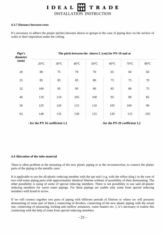
4.3.7 Distance between rests
It’s necessary to adhere the proper pitches between shores or groups in the case of piping duct on the surface ofwalls or their imposition under the ceiling.
The pitch between the shores L (cm) for PN 10 and atPipe’sdiameter
(mm)20°C 30°C 40°C 50°C 60°C 70°C 80°C
20 80 75 70 70 65 60 60
25 85 85 85 80 75 75 70
32 100 95 95 90 85 80 75
40 110 110 105 100 95 90 85
50 125 120 115 110 105 100 90
63 140 135 130 125 120 115 105
- for the PN 16 coefficient 1,1 - for the PN 20 coefficient 1,2
4.4 Alteration of the tube material
There is often problem at the mounting of the new plastic piping or in the reconstruction, to connect the plasticparts of the piping to the metallic ones.
It is applicable to use the all-plastic reducing member with the apt seal ( e.g. with the teflon sling ) in the case oftwo cold water piping parts with approximately identical lifetime without of possibility of their demounting. Theother possibility is using of some of special reducing members. There is not possibility to use said all-plasticreducing members for warm water pipings. For these pipings are usable only some from special reducingmembers with fused-in screw.
If we will connect together two parts of piping with different periods of lifetime or where we will presumedemounting of some part of them ( connecting of dividers, connecting of the new plastic piping with the actualone, connecting of measuring, locking and outflow armatures, water heaters etc. ), it’s necessary to realise thisconnecting with the help of some from special reducing members.

INSTALLATION INSTRUCTION
- 22 -
4.5 Compensation of the pipeline
There happens to the extension ( abbreviation ) of plastic pipeline thanks to impingements of temperaturedifferences at the mounting of he piping and in the actual operation it will to pass. Dimension of said extensionwill be depending on the length of said piping, coefficient of the linear extensibility and on the temperaturedifference.
It’s possible to realise the longitudinal compensation of piping with the dilatation arc or by the change ofleading course ( L - compensator; U - compensator ), see Technological instruction to mounting of internal waterpipings. But it is necessary to let this piping lax movable in its axial course.
The proper functioning of the compensator depends on advisable locating of sliding and fixed points.
It’s essential to calculate for connecting pipings with the thermal dilatation of pipings. Into the rising pits isimportant to enable the proper dilatation of rising mains with connected branches, too
Maximal value of ∆l, whichgives the compensation arc
Diameter (mm) Max. ∆l (mm)16 85-9020 75-80
25 65-70
32 50-55
40 40-45
5063
Diagram for compensation projectFacing ( unsupported length ) of the compensator Ls (mm)Table of maximum values ∆ltransmitting by the compensation arc

INSTALLATION INSTRUCTION
- 23 -
4.6 Protective connecting
It is indispensable to realise out of basic degree of shock protection a protecting connection of all conductibleobjects with possible user’s contact in bathrooms and in shower-baths ( see ČSN 34 1010 ). It will not be connectenough remote objects and enough insulated ones. There is allowed to be enough the distance of conductibleobject or part of object, when its bottom edge is at least 3 meter from the floor ( event. from the bottom of thebath or the shower-bath.
In the event of incidence of the connected electrical socket must be protection connecting with the protectionwire at least in one position (see ČSN 33 1235 Part 1 ).
4.7 Fire water main
Polyethylene and polypropylene piping is usable only to the water distribution from the filled fire water-conduct,when“
• the opened conducting of piping is possible in spaces with no higher temperature in the time of fire than the70°C;
• in other cases ( in spaces with fire load ) piping has got to locate in a fire pit of canal with the double firerobustness in regard of installation pits.
The pass through the fire dividing construction must be the pass wafered with the mass with the maximuminflammability degree C1 ( by the ČSN 73 0862 , respective ČSN 73 0823 ). The sealing construction has to
∆l = α1 x L x ∆t in millimetres
α1 coefficient of thermal expansivity, for polypropylene 0,15
L calculating length; the distance between two points
∆t temperature difference between the temperature at the mounting process and the temperature in the supreme functional operation in °C
prolongation ∆l is demonstrated in the diagram

INSTALLATION INSTRUCTION
- 24 -
have the same inflammability degree through which the pipings are passed. But there is not asked the higherinflammability than 60 minutes. There isn’t required following equipment at the pass for piping with net passingsection to 400 cm2.
4.8 Pressure test
Before the connecting of pipeline to the public water-conduit or to the proper source of water must be thefinished internal conduit reviewed and testing under the pressure ( see ČSN 73 6660 ). It must be elaborated aprotocol by the appropriate instructions appertaining to said review and testing.
Pressure testing of internal water-conduit is realised altogether or in parts by the size of piping in followinggrades:
a) pressure test of pipeline
b) final pressure test of internal piping
The pressure test can begin after the 12 hours of piping’s stabilisation with a frequent operating overpressure andminimum 1 hour after the venting and adjustment of the pressure.
The test of piping will audit its entirety, resistance against the internal overpressure and the tightness.
It’s important to flush all parts of the tested internal piping with the hygienic unexceptionable water. Currentlyis necessary to dislime said piping in a lower position ( see ČSN 83 0611 and ČSN 83 0616 ).
There are tested only the distribution pipings during the overpressure testing ( without thermal insulation,outfalling and securing armatures, PO rim, equipment objects, etc. ).
The distribution piping will be tested with the hygienic unexceptionable water ( see ČSN 83 0611 and 83 0616 )under 1,5 multiple of the functional overpressure, at least under the overpressure of 0,7 Mpa.
Testing overpressure may not fall off during 900 seconds more than rather 0,005 Mpa.
It is necessary to do a record on a continuance of the overpressure test.
4.9 Safety and health protection in the course of the work
More of work sites conducting in praxis the welding of pipes and adapting pipes by the polyfusion welders ischaracterised by the ČSN 34 1010 like dangerous space, sometimes like a extra dangerous space.
The dangerous space is the space with the constant or momentarily danger of harm by the electric current. Thereare especially the spaces with hot or humid ( with momentarily humid space too ) neighbourhood, withconductible or dusty neighbourhood, with the conductible dust ( combustible and non-combustible one ), withthe caustic neighbourhood ( with chemical derrogative environment.
Like the extra dangerous space is qualified space with some anomalous circumstances or effects or environmentadvance danger of a harm.

INSTALLATION INSTRUCTION
- 25 -
The claims pertinent to the security of the working are more rigorous especially at the work with electricalapparatuses. It is necessary to provide against a harm by the dangerous contact voltage.
Polyfusion welders are produced with supply voltage 220 V, 50 Hz and they discharge the conditions ofelectrical matter of class I. It involves they have all about operational insulation or protectional contact. Theirconstruction is adapted to connect to the supply net either direct by the disconnectable plug, or by the flexiblelengthening supply.
The lengthening supply must be manufactured by the person skilled in the art and discharge condition of thenorm ČSN 34 0350; particularly they must comprise an plug and a female connector with the preservativecontact for connecting of the neutral conductor. The male and the female connector must be dimensioned for thesame nominal supply and nominal current.
The length of lengthening supplies for electric tools is maximum 12 m; if it is necessary to made anomaly someflexible lengthening supply, there is essential to assure the shock protection. The best one is a lengthening supplywith the current protection, realised by the person skilled in this art.
The electric shock hazard can come into existence on the metallic mould of the polyfusion welder by the failureof its internal insulation, by the incorrect connected supply. The earthing pin isn’t often connected by course ofinstructions; it is sometimes connected with a phase ( in an old estate ) or by the accidental fetch of electricalvoltage on a metallic matter and construction by the incorrect connected earthing pin.
4.10 Revisal of welding apparatuses
There is obligate to execute regular revisions of polyfusion welders whereas they are incorporated into the group„electrical handy tools of class 1“.
The revision of the polyfusion welder must be realised every three moths. These revisions can do only theworkers qualified to this doing ( revision technicians ) with technical education by the supplements 1 and 2 ( seedecree Nr. 50/1978 Col. of Laws of Czech Republic ) and experience by the supplement 1, after the passing of anexam at the proper controls.
INSTALLATION INSTRUCTION
- 26 -
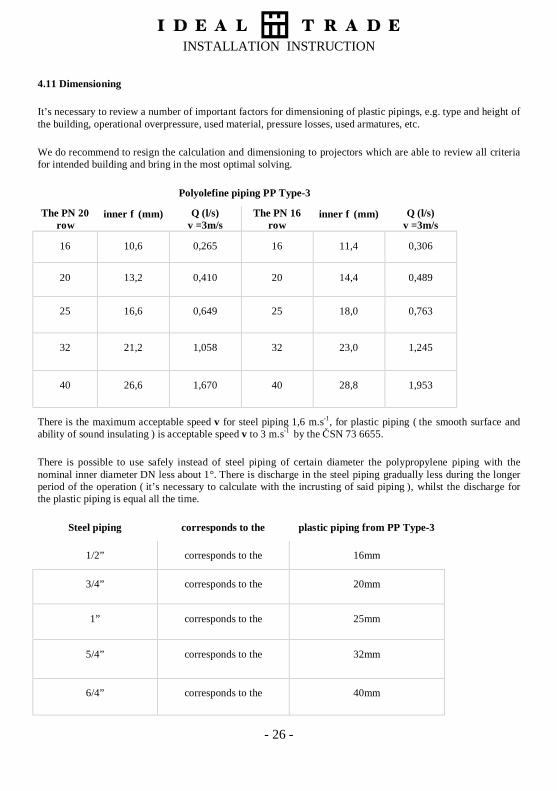
4.11 Dimensioning
It’s necessary to review a number of important factors for dimensioning of plastic pipings, e.g. type and height ofthe building, operational overpressure, used material, pressure losses, used armatures, etc.
We do recommend to resign the calculation and dimensioning to projectors which are able to review all criteriafor intended building and bring in the most optimal solving.
Polyolefine piping PP Type-3
The PN 20row
inner φ (mm) Q (l/s)v =3m/s
The PN 16row
inner φ (mm) Q (l/s)v =3m/s
16 10,6 0,265 16 11,4 0,306
20 13,2 0,410 20 14,4 0,489
25 16,6 0,649 25 18,0 0,763
32 21,2 1,058 32 23,0 1,245
40 26,6 1,670 40 28,8 1,953
There is the maximum acceptable speed v for steel piping 1,6 m.s-1, for plastic piping ( the smooth surface andability of sound insulating ) is acceptable speed v to 3 m.s-1 by the ČSN 73 6655.
There is possible to use safely instead of steel piping of certain diameter the polypropylene piping with thenominal inner diameter DN less about 1°. There is discharge in the steel piping gradually less during the longerperiod of the operation ( it’s necessary to calculate with the incrusting of said piping ), whilst the discharge forthe plastic piping is equal all the time.
Steel piping corresponds to the plastic piping from PP Type-3
1/2” corresponds to the 16mm
3/4” corresponds to the 20mm
1” corresponds to the 25mm
5/4” corresponds to the 32mm
6/4” corresponds to the 40mm

INSTALLATION INSTRUCTION
- 27 -
5 Central heating and floor heating
There is allowed to use for pipings of central and floor heating exclusively the pipes and adapting pipes from thematerial PP Type-3. Used pipes are judged from the point of view of the operational life with respect to thedimension and to maximum value of temperature, pressure and to the proper safety coefficient.
To dimensioning of the operation lifetime we must calculate like the first tenseness in the pipe wall reached bythe maximum operational pressure by the following formula:
σ =−p D ss
S.( ).
.2
1
where
σ - calculated tenseness
D - external diameter of the pipe
s - thickness if the pipe wall
p - maximum pressure
s1 - security coefficient ( for the central heating min. 2,5 )
After this calculation we can the value of the resulting tenseness into the diagram (
In this diagram we will do determine the cross of the resulting tenseness with the isothermal curve of themaximum temperature in the heating system ( see „The course of isothermal curve of pipes from the PP type-3“ -page 8 ). From this cross we do lead the normal to the horizontal axe which indicate the expectant minimumoperational life at the consecutive heating.
The consequential value, expressing the final expectant minimum operational life we will get after the divisionof value of the expectant minimum operational life at the consecutive heating by the proportion of calendar yeardivided by the length of heating period in the year.
5.1 Example of the appreciation of proposed piping applicability
Used pipes 25 x 4,2 mm, PN 20
Max. temperature of water in the system 95°C
Max. operational pressure 0,23 MPa
Security coefficient 2,5
Length of the heating period 7 months

INSTALLATION INSTRUCTION
- 28 -
σ =−p.(D s)
2..
ss
In the diagram ( see „The course of isothermal curve of pipes from the PP type-3“ - page 8 ) we will dodetermine the cross of the resulting tenseness with the isothermal curve of 95°C. From this cross we do lead thenormal to the horizontal axe which indicate the expectant minimum operational life at the consecutive heating.
175000 127
300000 34 25hrs hrs years. ,= =
The final expectant minimum operational life of the piping is 34,25 years

INSTALLATION INSTRUCTION
- 29 -
6 Chemical resistance of the material
The chemical resistance of the polypropylene PP Type-3 in the face of media, usable into the pipes and adaptingpipes of the HP-system in the dependency to the strength and temperature.
The used material is from the original, appreciated by the producer of polypropylene PP Type-3
CHEMICALS OR PRODUCTS STRENGTH TEMPERATURE 20° 60° 100°
Acetic acid do 40 % S S -Acetic acid 50% S S -Acetic acid, glacial více než 96 % S L NSAcetic anhydride 100% S - -Acetone 100% S S -Aceptophenone 100% S L -Acrylonitrite 100% S - -Air S S SAlmond oil S - -Alum Sol S - -Ammonia, aqueous do 30 % S - -Ammonia, dry gas 100% S - -Ammonia, liquid 100% S - -Ammonium acetate Sat. sol S S -Ammonium chloride Sat. sol S - -Ammonium fluoride Sol S S -Ammonium hydrogen carbonate Sat. sol S S -Ammonium hydroxide Sat. sol S - -Ammonium etaphosphate Sat. sol S S -Ammonium nitrate Sat. sol S S SAmmonium phosphate Sat. sol S - -Ammonium sulphate Sat. sol S S SAmyl acetate 100% L - -Amyl alcohol 100% S S SAniline 100% S S -Apple juice S - -Aqua regia HCl/HNO3 = 3/1 NS NS NSBarium carbonate Sat. sol S S SBarium chloride Sat. sol S S SBarium hydroxide Sat. sol S S SBarium sulphate Sat. sol S S SBenzene 100% L NS NSBenzoic acid Sat. sol S - -Benzyl alcohol 100% S L -Borax Sol S S -Boric acid Sat. sol S - -Bromine, gas L NS NSBromine, liquid 100% NS NS NSButane 100% S - -

INSTALLATION INSTRUCTION
- 30 -
Butanol 100% S L LButyl acetate 100% S L LButyl glocol 100% S - -Butyl phenol Cold sat.sol S - -Butyl phthalate 100% S L LCalcium carbonate Sat. sol S S SCalcium chloride Sat. sol S S SCalcium hydroxide Sat. sol S S -Calcium hypochlorite Sol S - -Calcium nitrate Sat. sol S S -Camphor oil NS NS NSCarbon dioxide, dry gas 100% S S -Carbon dioxide, wet S S -Carbon disulphide 100% S NS NSCarbon tetrachloride 100% NS NS NSCastor oil 100% S S -Caustic soda do 50 % S L LChlorine, aqueous Sat. sol S L -Chlorine, dry gas 100% NS NS NSChlorine, liquid 100% NS NS NSChloroacetic acid Sol S - -Chloroethanol 100% S - -Chloroform 100% L NS NSChlorosulphonic acid 100% NS NS NSChrome alum Sol S S -Chromic acid do 40 % S L NSCitric acid 10% S S SCoconut oil S - -Corn oil S L -Cottonseed oil S S -Cresol více než 90 % S - -Copper (II) chloride Sat. sol S S -Copper (II) nitrate 30% S S SCopper(II) sulphate Sat. sol S S -Cyclohexane 100% S - -Cyclohexanol 100% S L -Cyclohexanone 100% L NS NSDekalin(decahydronaphthalene) 100% NS NS NSDextrin Sol S S -Dextrose Sol S S -Dibutyl phthalate 100% S L NSDichloroacetic acid 100% L - -Dichloroethylene (A a B) 100% L - -Diethanolamine 100% S - -Diethyl ether 100% S L -Diethylone glycol 100% S S -Diglycolic acid Sat. sol S - -Disoctyl phthalate 100% S L -Dimethyl amine 100% S - -

INSTALLATION INSTRUCTION
- 31 -
Dimethyl formamine 100% S S -Dioctyl phthalate 100% L L -Dioxane 100% L L -Distilert water 100% S S SEthanolamine 100% S - -Ethyl acatate 100% L NS NSEthyl alcohol do 95 % S S SEthyl chloride 100% NS NS NSEthylene chloride 100% L L -Ethylene glycol 100% S S SFormaldehyde 40% S - -Formic acid 10% S S LFormic acid 85% S NS NSFormic acid, anhydrous 100% S L LFructose Sol S S SFruit juice S S SGasoline, petrol (aliphatic hydrocerbons) NS NS NSGelatine S S -Glucose 20% S S SGlycerine 100% S S SGlycolic acid 30% S - -Heptane 100% L NS NSHexane 100% S L -Hydrobromic acid do 48 % S - NSHydrochloric acid od 2 do 7 % S S SHydrochloric acid od 10 do 20 % S S -Hydrochloric acid 30% S L LHydrochloric acid od 35 do 36 % S - -Hydrofluoric acid Dil.sol S - -Hydrofluoric acid 40% S - -Hydrogen 100% S - -Hydrogen chloride, dry gas 100% S S -Hydrogen peroxide do 10 % S - -Hydrogen peroxide do 30 % S L -Hydrogen sulphide, dry gas 100% S S -Iodine in alcohol S - -Isopropyl alcohol 100% S S SIsopropyl ether 100% L - -Isoctane 100% L NS NSLactic acid do 90 % S S -Lanoline S L -Linseed oil S S SMagnesium carbonate Sat. sol S S SMagnesium chloride Sat. sol S S -Magnesium sulphate Sat. sol S S -Mercury (II) chloride Sat. sol S S -Mercury (II) cyanide Sat. sol S S -Mercury (I) nitrate Sol S S -Mercury 100% S S -

INSTALLATION INSTRUCTION
- 32 -
Methyl acetate 100% S S -
Methyl alcohol 5% S L LMethyl amine do 32% S - -Methyl bromide 100% NS NS NSMethyl ether ketone 100% S - -Methylene chloride 100% L NS NSMilk S S SMonochloroacetic acid více než 85 % S S -Naphtha S NS NSNickel chloride Sat. sol S S -Nickel nitrate Sat. sol S S -Nickel sulphate Sat. sol S S -Nitric acid 10% S NS NSNitric acid 30% S - -Nitric acid od 40 do 50 % L NS NSNitrobenzene 100% S L -Oleic acid 100% S L -Olive oil S S LOxalic acid Sat. sol S L NSOxygen 100% S - -Parafin oil (FL 65) S L NSPoanut oil S S -Peppermint oil S - -Perchloric acid 2N S - -Petroleum ether (ligroine) L L -Phenol 5% S S -Phenol 90% S - -Phosporic acid 25% S S SPhosporic acid od 25 do 85 % S S SPicric acid Sat. sol S - -Potassium bicarbonate Sat. sol S S -Potassium borate Sat. sol S S -Potassium bromate do 10 % S S -Potassium bromide Sat. sol S S -Potassium carbonate Sat. sol S - -Potassium chlorate Sat. sol S S -Potassium chloride Sat. sol S - -Potassium chromate Sat. sol S S -Potassium cyanide Sol S - -Potassium fluoride Sat. sol S S -Potassium hydroxide do 50 % S S SPotassium iodide Sat. sol S - -Potassium nitrate Sat. sol S S -otassium perchlorate 10% S S -Potassium permanganate 2 N S - -Potassium sulphate Sat. sol S - -Propane 100% S - -Propionic acid více než 50 % S - -Silver nitrate Sat. sol S S L

INSTALLATION INSTRUCTION
- 33 -
Sodium acetate Sat. sol S S SSodium benzoate 35% S - -Sodium carbonate do 50 % S S LSodium chlorate Sat. sol S - -Sodium chlorite 2% S L NSSodium chlorite 20% S L NSSodium dichromate Sat. sol S S SSodium hydrogen carbonate Sat. sol S S SSodium hydrogen sulphate Sat. sol S S -Sodium hydrogen sulphite Sol S - -Sodium hydroxide od 10 do 30 % S S SSodium hypochlorite 5% S S -Sodium hypochlorite 10% S - -Sodium hypochlorite 20% S L -Sodium metaphosphate Sol S - -Sodium nitrate Sat. sol S S -Sodium perborate Sat. sol S - -Sodium silicate Sol S S -Sodium sulphate Sat. sol S S -Sodium sulphide Sat. sol S - -Sodium thilosulphate (hypo) Sat. sol S - -Soybean oil S L -Succinic acid Sat. sol S S -Sulphur dioxide, dry or wet 100% S S -Sulphur acid od 10 do 30 % S S -Sulphuric acid 50% S L LSulphuric acid 96% S L NSSulphuric acid 98% L NS NSSulphurous acid Sol S - -Tartaric acid 10% S S -Tetrahydrofuran 100% L NS NSTetralin 100% NS NS NSThiophene 100% S L -Tin (IV) chloride Sat. sol S S -Tin (II) chloride Sat. sol S S -Toluene 100% L NS NSTrichloracetic acid do 50 % S S -
Explanation: S – suitable L – uncommendable NS – unsatisfactory - - not mentioned
Related Documents