8.1.2015 Monitoring technology/Visileak VSL Subject to technical changes Table of Contents 8.0 Table of Contents 8.1 System description 8.100 General system description 8.110 Principle of operation 8.120 Measurement principle 8.2 Planning, inspection plans 8.200 Planning, sensor loop plan 8.210 Inspection plans, weld seam plans 8.3 LMS 120 monitoring device 8.300 Description of device, technical data 8.310 Description of device, sheet 2 8.320 Description of device, sheet 3 8.0

Welcome message from author
This document is posted to help you gain knowledge. Please leave a comment to let me know what you think about it! Share it to your friends and learn new things together.
Transcript

8.1.2015
Monitoring technology/Visileak VSL
Subject to technical changes
Table of Contents
8.0 Table of Contents
8.1 System description 8.100 General system description8.110 Principle of operation8.120 Measurement principle
8.2 Planning, inspection plans 8.200 Planning, sensor loop plan8.210 Inspection plans, weld seam plans
8.3 LMS 120 monitoring device 8.300 Description of device, technical data8.310 Description of device, sheet 28.320 Description of device, sheet 3
8.0

8.1.2015
Monitoring technology/Visileak VSL
Subject to technical changes
General system description
In the majority of cases, district heat pipes laid underground are now equipped with operational monitoring systems. The benefits are that damage can be detected at an early stage and easily located. Together with the appropriate monitoring devices, monitoring wires foamed into the heat insulation at the factory perform a wide variety of tasks. Operational re-liability and safety are increased, and costs of damage are limited.
The following BRUGG pipe systems are factory-equipped for monitoring with the resistance reference measuring method (WIREM) as standard: FLEXWELL district heating cables, PREMANT district heating pipe and CASAFLEX district heating pipe; BRUGG STEEL CASING PIPE can also be equipped for this purpose on request. (On request, PREMANT district hea-ting pipe can be supplied with different monitoring wires).
WIREM and BRANDES are compatible systems.
The WIREM technology makes it possible to carry out a large number of functions with the help of the monitoring wires and devices:
• Monitoring heat insulation for moisture - already possible when the pipe is being installed. Supply of informative measurement data on the condition of the heat insulation.
• Contact between monitoring wires and inner pipe, break-offs or interruptions anywhere in the circuit are differentiated and displayed.
• During operation, the entry of moisture - for example through weld seam faults, non-tight joints or external damage - can be measured, signalled and located, not only in the area of the joint but continuously throughout the entire length of the pipe.
• Short circuit detection
• Alarm signals are passed on via outputs for external alarm devices.
Depending on the requirements for network size and data availability, a suitable system can be selected from the range of measurement, monitoring and locating equipment based on the modular principle.
Device combinations range from manual entry of measurement data about the status of the heat insulation and manual fault location (device LMS 120) through to fully automated monitoring and fault location (devices available on the market) with remote signalling, test inquiries via dialog electronics, storage of measurement data and electronic data transmitters to computers and printers in central management systems.
8.100

8.1.2015
Monitoring technology/Visileak VSL
Subject to technical changes
Principle of operation
Monitoring wires
The monitoring wires (sensor wire and feedback wire) are positioned continuously in the heat insulation of the pipe, between the outer and inner pipes. On PREMANT and CASAFLEX, the wires are positioned parallel to the inner pipe, ap-proximately in the middle of the heat insulation, but in FLEXWELL district heating cable, they are positioned parallel and next to one another in a helical configuration, at a defined distance from and around the inner pipe.
Structure of sensor wires
1. Perforations at
regular intervals
for moisture contact
2. PTFE insulation, colour: red
3. NiCr wire
Structure of feedback wires
1. Copper wire
2. FEP insulation, colour:
green
Measuring principle for monitoring
The technical basis for measurement, both for monitoring and location, is the resistance reference measuring system (WIREM) which operates according to the principle of the unloaded voltage distributor.A defined voltage is applied between the sensor wire positioned paral-lel with the pipe in the heat insulation, and the pipe (see picture). If the insulation resistance that is present there drops due to the entry of moisture, an increase in voltage is measured on the comparator resist-ance in the upstream monitoring device, thereby triggering a signal.
The comparator resistance defines the signalling threshold at the same time.
Monitoring of the heat insulation is handled by a special sensor wire (see the picture). This wire is protected against direct metallic contact by a temperature-resistant PTFE insulation. The moisture contact with the NiCr wire is established through perforations in the PTFE insulation, thereby enabling continuous monitoring of the entire pipe section.
In addition, the perforations allow a differentiated evaluation of the in-tensity of moisture faults, across the entire monitorable spectrum from 'dry' at over 50 MΩ to 'wet' at less than 10 kΩ insulation resistance.
In addition to the sensor wire, another FEP-insulated copper wire known as the 'feedback wire' is used for the actual monitoring.
The two wires make up a sensor loop (see the picture) which can be a maximum of 1000 meters in length, enabling 1000 meters of pipe to be monitored. Branch lines starting from the sensor wire in the main pipe are 'looped in', i.e. sensor wires 'in' and feedback wires 'back' (see picture).
For monitored pipe networks with a pipe length of over 1000 meters, the network is subdivided (for example, using the wire model) into monitoring sections of a maximum of 1000 meters, and individual sen-sor loops are formed from them. An appropriate monitoring device can be assigned to each monitoring section.
Monitoring principleSensor wire [red]
Feedback wire [green]
Monitoring deviceInsulation
LoopS
I
Structure of sensor loop
Feedback wire [green]
Sensor wire [red]
Pipe axis
Sensor loop including branch
1 2 3
2 1
8.110
8.1.2015
Monitoring technology/Visileak VSL
Subject to technical changes
Measurement principle
Measurement principle for location
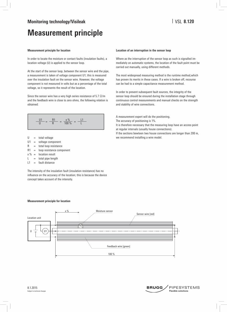
In order to locate the moisture or contact faults (insulation faults), a location voltage (U) is applied to the sensor loop.
At the start of the sensor loop, between the sensor wire and the pipe, a measurement is taken of voltage component U1; this is measured over the insulation fault on the sensor wire. However, the voltage component is not measured in volts but as a percentage of the total voltage, so it represents the result of the location.
Since the sensor wire has a very high series resistance of 5.7 Ω/m and the feedback wire is close to zero ohms, the following relation is obtained:
U = total voltageU1 = voltage componentR = total loop resistanceR1 = loop resistance componentx % = location resultL = total pipe lengthL1 = fault distance
The intensity of the insulation fault (insulation resistance) has no influence on the accuracy of the location; this is because the device concept takes account of the intensity.
Location of an interruption in the sensor loop
Where as the interruption of the sensor loop as such is signalled im-mediately on automatic systems, the location of the fault point must be carried out manually, using different methods.
The most widespread measuring method is the runtime method,which has proven its merits in these cases. If a wire is broken off, recourse can be had to a simple capacitance measurement method.
In order to prevent subsequent fault sources, the integrity of the sensor loop should be ensured during the installation stage through continuous control measurements and manual checks on the strength and stability of wire connections.
U1 R1 x % L1 = = =U R 100 % L
Measurement principle for location
100 %
x %
U1 U
Moisture sensorSensor wire [red]
Feedback wire [green]
Location unit
8.120
A measurement expert will do the positioning.The accuracy of positioning is 1%.It is therefore necessary that the measuring loop have an access point at regular intervals (usually house connections).If the sections bewteen two house connections are longer than 200 m, we recommend installing a wire model.
8.1.2015
Monitoring technology/Visileak VSL
Subject to technical changes
PlanningSensor loop plan
8.200
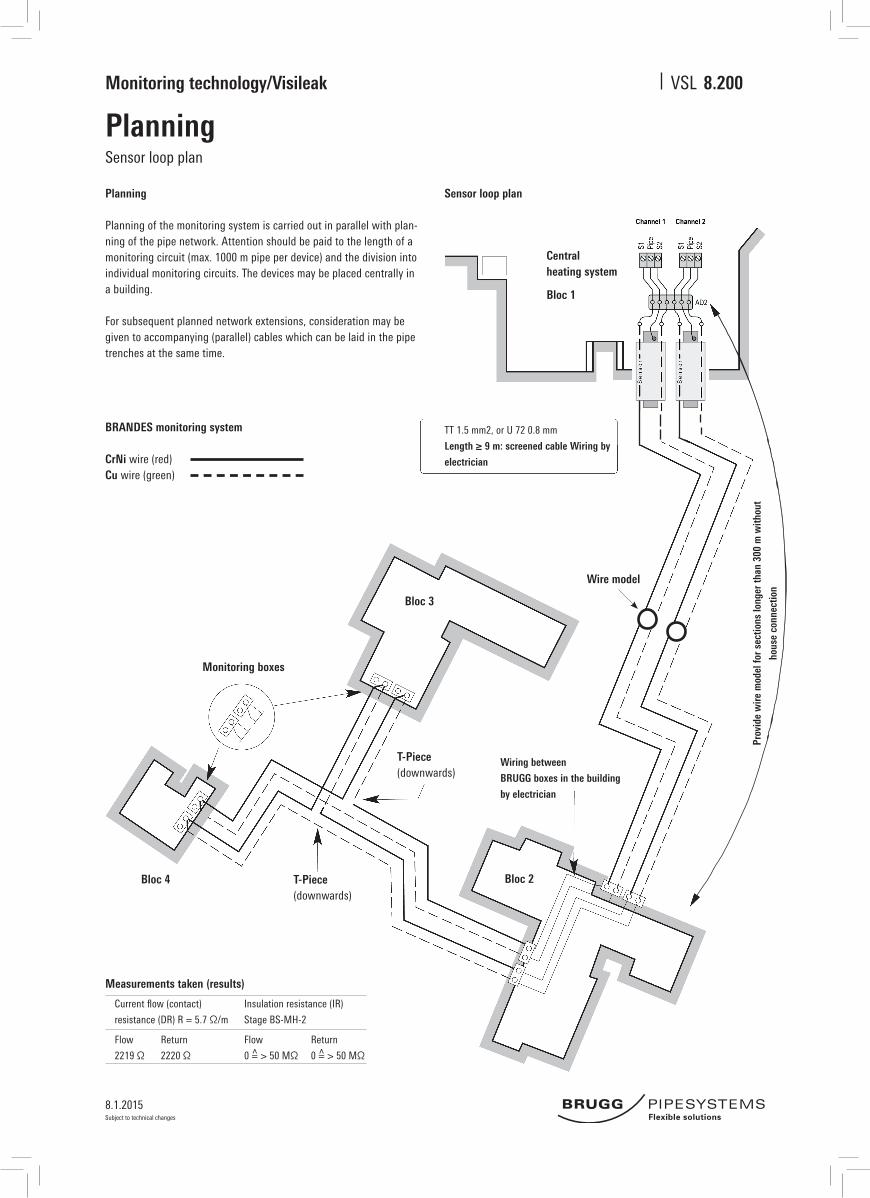
Planning
Planning of the monitoring system is carried out in parallel with plan-ning of the pipe network. Attention should be paid to the length of a monitoring circuit (max. 1000 m pipe per device) and the division into individual monitoring circuits. The devices may be placed centrally in a building.
For subsequent planned network extensions, consideration may be given to accompanying (parallel) cables which can be laid in the pipe trenches at the same time.
Sensor loop plan
Measurements taken (results)
Current flow (contact)
resistance (DR) R = 5.7 Ω/m
Insulation resistance (IR)
Stage BS-MH-2
Flow
2219 Ω
Return
2220 Ω
Flow
0 = > 50 MΩ
Return
0 = > 50 MΩ
TT 1.5 mm2, or U 72 0.8 mm
Length ≥ 9 m: screened cable Wiring by
electrician
BRANDES monitoring system
CrNi wire (red)Cu wire (green)
Wiring between
BRUGG boxes in the building
by electrician
Wire model
Prov
ide
wire
mod
el fo
r sec
tions
long
er th
an 3
00 m
with
out
hous
e co
nnec
tion
Central heating system
T-Piece(downwards)
T-Piece(downwards)
Bloc 1
Bloc 3
Bloc 2Bloc 4
Monitoring boxes

8.1.2015
Monitoring technology/Visileak VSL
Subject to technical changes
Inspection plans, weld seam plans
Inspection plans are required so that faults can also be measured above ground after location. Accurate plans make it easier to locate and diagnose the error message. Weld seam plans have proven to be best for this purpose.
Inspection planWeld seam plan
Measurements taken (results)
Pipe Standard L Bend [m]
PRE 60.3-140 6 m 0.5 x 0.5
PRE 76.1-160 6 m 0.65 x 0.65
PRE 88.9-180 12 m 0.65 x 0.65
8.210
T-Piece(downwards)
Central heating system
View A
Drainage, DN 32
Bloc 3
Bloc 4
Bloc 2
Bloc 1
Venting

8.1.2015
Monitoring technology/Visileak VSL
Subject to technical changes
Device description LMS 120Technical data
Device description
General
The monitoring device is suitable for controlling sensor wires in district heating pipelines.The system is based on measuring resistances between the connecting contacts.
With the LMS 120, it is possible to control various monitoring systems permanently. The measurement interval can be set. An error memory is also installed in the device.
The technical design allows monitoring of two different system types at the same time. As such, it is possible to connect one line with the NORDIC system on measurement channel 1 and one line with the BRANDES system on measurement channel 2, for instance.The system is based on measuring resistances between monitoring conductors and the metal medium pipe or the resistances of measurement loops. All measured values can be read from the display.
Technical data
Info display and LEDFree parameter settingOperating voltage 110....230 V ACMonitoring cycles 2 channelsLength of pipeline per channel:Brandes ( 1 x Cu, 1 x CrNi) 1.000 mEMS (nordic, 2 x Cu blank) 2.500 mSwiss ( each 1 x Cu blank/isolated) 2.500 mFault (pot.-free converter) 2 A/30 VDimensions 182 x 180 x 90 mmPermissible ambient temperature 0...50 °CProtection category IP 65
System design
The LMS 120 has measurement channels operating free of potential to increase measurement precision and minimise the influence of parasitic current measurements in the pipe.
Fig. 1 (System design)
Volta
ge 1
Volta
ge 2
Sens
or
Retur
n
Sens
or
Retur
n Ext. a
larm
Relay Display Keys CPU
Measurement module
1
Measurement module
2
Pipe
Pipe
8.300
8.1.2015
Monitoring technology/Visileak VSL
Subject to technical changes
Device description LMS 120
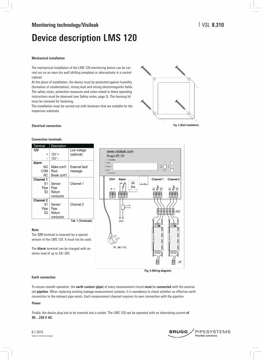
Mechanical installation
The mechanical installation of the LMS 120 monitoring device can be car-ried out on an even dry wall (drilling template) or alternatively in a control cabinet. At the place of installation, the device must be protected against humidity (formation of condensation), strong dust and strong electromagnetic fields. The safety notes, protection measures and notes stated in these operating instructions must be observed (see Safety notes; page 3). The housing lid must be removed for fastening.The installation must be carried out with fasteners that are suitable for the respective substrate.
Fig. 3 (Wall installation) Electrical connection
Note: The 12V terminal is reserved for a special version of the LMS 120. It must not be used.
The Alarm terminal can be charged with an ohmic load of up to 2A/ 30V.
Earth connection
To ensure smooth operation, the earth contact (pipe) of every measurement circuit must be connected with the associa-ted pipeline. When replacing existing leakage measurement systems, it is mandatory to check whether an effective earth connection to the relevant pipe exists. Each measurement channel requires its own connection with the pipeline.
Power
Finally, the device plug has to be inserted into a socket. The LMS 120 can be operated with an alternating current of 90…240 V AC.
3.2. Electrical connection 3.2.1. Connection terminals Terminal Description 12V
+ -
12V + 12V -
Low voltage (optional)
Alarm NO
COM NC
Make cont’t Root Break cont’t
External fault message
Channel 1 S1
Pipe S2
Sensor Pipe Return conductor
Channel 1
Channel 2 S1
Pipe S2
Sensor Pipe Return conductor
Channel 2
Tab. 1 (Terminals)
Fig. 4 (Wiring diagram)
Connection terminals
8.310

8.1.2015
Monitoring technology/Visileak VSL
Subject to technical changes
Device description LMS 120
7. AccessoriesItem name Item number Description LMS 120 DE 21000076 LMS 120 with mains plug for Germany LMS 120 CH LMS 120 with mains plug for Switzerland Socket AD2 21000083 Socket for LMS 120 Monitoring end piece 21000081 Loop end plug
Tab. 6 (Accessories)
8. Technical dataRequirements for voltage supply Voltage 100 – 240 VAC Power consumption max. 100 mA Max. power consumption on activation 6 A
Output 6 W
Housing specification: Dimensions (width x height x depth) 182 x 180 x 90 mm Installation Wall instillation, control cabinet installation, screws Materials and colour Housing: Polystyrene, grey (similar to RAL 7035)
Lid: Polycarbonate, transparent Protection category IP 65 in accordance with EN 60529 Weight (excl. packaging) 1.1 kg
Measurement inputs specification: Wire standards / measurement wires
Nordic, 2 copper blank Brandes, NiCr 5,7 Ω/m copper isolated Swiss, copper blank – copper isolated
Potential separation Yes
Alarm output specification Type of the alarm output: Relay Max. contact voltage: 24 VDC Max. switching current: 2 A Min. switching current: 1 mA (at 10 mVDC)
Ambient conditions Ambient temperature 0 to + 50° C Transport and storage temperature -20 to + 60° C Humidity: < 90 %, not condensing
Tests and certificates EC Declaration of Conformity Yes Conformity standards EN 61000-6-2 (2006-05-01)
EN 61000-6-4 (01/11/2007)
8.320
Technical data
Related Documents