MONITORING - T2S ETH with Catena User Manual V2.0 THE NEW GENERATION OF MONITORING • EXTENDED LOG CAPABILITIES • WEB-BASED USER INTERFACE • COMPATIBLE WITH CATENA Copyright © 2013. Construction electroniques & telecommunications S.A. All rights reserved. The contents in document are subject to change without notice. The products presented are protected by several international patents and trademarks. Address: CE+T S.a, Rue du Charbonnage 12, B 4020 Wandre, Belgium www.cet-power.com - [email protected] www.cet-power.com Belgium, China, India, Luxembourg, Malaysia, Russia, Turkey, United Kingdom, United States, Australia & Germany

Welcome message from author
This document is posted to help you gain knowledge. Please leave a comment to let me know what you think about it! Share it to your friends and learn new things together.
Transcript

MONITORING - T2S ETH with CatenaUser Manual V2.0
THE NEW GENERATION OF MONITORING• EXTENDED LOG CAPABILITIES
• WEB-BASED USER INTERFACE
• COMPATIBLE WITH CATENA
Copyright © 2013. Construction electroniques & telecommunications S.A. All rights reserved. The contents in document are subject to change without notice.The products presented are protected by several international patents and trademarks.Address: CE+T S.a, Rue du Charbonnage 12, B 4020 Wandre, Belgiumwww.cet-power.com - [email protected]
www.cet-power.com Belgium, China, India, Luxembourg, Malaysia, Russia, Turkey, United Kingdom, United States, Australia & Germany
2 - Monitoring - T2S ETH - User Manual - v2.0
Table of content1. CE+T at a glance ................................................................................................................................... 6
2. Abbreviations ........................................................................................................................................ 7
3. Warranty and Safety Conditions ............................................................................................................. 83.1 Disclaimer ................................................................................................................................... 83.2 Technical care ............................................................................................................................. 83.3 Installation .................................................................................................................................. 9
3.3.1 Handling ......................................................................................................................... 93.3.2 Surge and transients ...................................................................................................... 93.3.3 Other .............................................................................................................................. 9
3.4 Pre-cautions before maintenance ............................................................................................... 103.5 Replacement and Dismantling ..................................................................................................... 10
4. Product Code and Identification .............................................................................................................. 114.1 Identification labels for T2S-ETH .................................................................................................. 11
5. Introduction ........................................................................................................................................... 12
6. Hardware ............................................................................................................................................... 136.1 LEDs code during operations ....................................................................................................... 14
6.1.1 LEDs code during normal operation ................................................................................ 146.1.2 LED Error Code - upgrade or system start up .................................................................. 14
6.2 Signaling Information .................................................................................................................. 156.2.1 Alarm relay ..................................................................................................................... 166.2.2 Digital Inputs .................................................................................................................. 166.2.3 Communication .............................................................................................................. 16
6.3 Monitoring - Candis ..................................................................................................................... 186.3.1 Display and Buttons ....................................................................................................... 186.3.2 Configuration .................................................................................................................. 18
6.4 Graphical User Interface - Catena ................................................................................................ 196.4.1 Description ..................................................................................................................... 196.4.2 Wiring ............................................................................................................................ 20
7. Graphical User Interface ......................................................................................................................... 217.1 Hierarchy .................................................................................................................................... 217.2 Login ........................................................................................................................................... 227.3 Interface Areas ............................................................................................................................ 22
7.3.1 Banner ........................................................................................................................... 237.3.2 Main Area ....................................................................................................................... 237.3.3 Toolbar ........................................................................................................................... 24
7.4 Pages and Feature....................................................................................................................... 257.4.1 AC IN .............................................................................................................................. 257.4.2 DC IN ............................................................................................................................. 257.4.3 AC Out ............................................................................................................................ 26

3 - Monitoring - T2S ETH - User Manual - v2.0
7.4.4 System ........................................................................................................................... 267.4.5 Module ........................................................................................................................... 277.4.6 Events ............................................................................................................................ 287.4.7 Log ................................................................................................................................ 287.4.8 Connections ................................................................................................................... 297.4.9 Files ............................................................................................................................... 297.4.10 Parameters..................................................................................................................... 30
8. Catena ................................................................................................................................................... 398.1 Introduction ................................................................................................................................. 398.2 User interface .............................................................................................................................. 398.3 Ethernet connections ................................................................................................................... 39
8.3.1 Rear connections............................................................................................................ 398.3.2 Front connection ............................................................................................................ 398.3.3 Troubleshooting .............................................................................................................. 40
8.4 Configuration ............................................................................................................................... 408.4.1 Network architecture ...................................................................................................... 40
8.5 Protocols ..................................................................................................................................... 418.5.1 SNMP v2c ...................................................................................................................... 418.5.2 SNMP v3 ........................................................................................................................ 41
9. SNMP .................................................................................................................................................... 429.1 SNMP Configuration .................................................................................................................... 42
9.1.1 Introduction .................................................................................................................... 429.1.2 General NMS, SNMP Agent and MIB Role ........................................................................ 429.1.3 MIB General Design ........................................................................................................ 429.1.4 SNMP V1 Configuration .................................................................................................. 439.1.5 SNMP V2C Configuration ................................................................................................ 459.1.6 SNMP V3 Configuration .................................................................................................. 47
9.2 Advanced IP Scanner ................................................................................................................... 529.3 SNMP V1 Testing ......................................................................................................................... 539.4 SNMP V1 Traps ............................................................................................................................ 559.5 SNMP V3 Testing ......................................................................................................................... 55
9.5.1 Steps to Load CET MIB ................................................................................................... 559.5.2 Steps to Discover Device ................................................................................................ 579.5.3 Steps to Get / Walk OID .................................................................................................. 589.5.4 Steps to add SNMP V3 User ............................................................................................ 58
10. FAQ ....................................................................................................................................................... 60
11. Trouble Shooting and Defective Situations Fixing .................................................................................... 6211.1 Defective T2S ETH ....................................................................................................................... 62
11.1.1 Return defective T2S interface ....................................................................................... 6211.1.2 Return defective T2S ETH ............................................................................................... 62
4 - Monitoring - T2S ETH - User Manual - v2.0
12. Service ................................................................................................................................................. 63
13. Maintenance Task ................................................................................................................................. 64
14. Annex 1: Supervisor alarms - T2S ETH .................................................................................................. 65
15. Annex 2: Module alarms - T2S ETH ....................................................................................................... 67
16. Annex 3: Configuration parameters - T2S ETH ....................................................................................... 7116.1 Montioring ................................................................................................................................... 7116.2 Inputs/Relays .............................................................................................................................. 7316.3 SNMP .......................................................................................................................................... 7616.4 Modbus ....................................................................................................................................... 7716.5 Power.......................................................................................................................................... 78
17. Annex 4: Modbus .................................................................................................................................. 8317.1 Hardware Requirements .............................................................................................................. 83
17.1.1 Cabling: .......................................................................................................................... 8317.1.2 Baud rate, parity and mode ............................................................................................ 83
17.2 Database Description ................................................................................................................. 8417.2.1 Typographic convention: ................................................................................................. 8417.2.2 Data types: ..................................................................................................................... 8417.2.3 Supported function: ........................................................................................................ 84
17.3 Status and Constants Description ................................................................................................ 8917.3.1 Module status explanation (A1): ...................................................................................... 8917.3.2 Alarm types: ................................................................................................................... 9017.3.3 Alarm sources: ............................................................................................................... 9017.3.4 Validity and Unit description (A2):.................................................................................... 91
17.4 Modbus over RTU ........................................................................................................................ 9117.4.1 Introduction .................................................................................................................... 9117.4.2 Modbus RTU - Testing .................................................................................................... 95
17.5 Modbus over TCP/IP .................................................................................................................... 10117.5.1 Introduction .................................................................................................................... 10117.5.2 Modbus TCP - Testing ..................................................................................................... 104
17.6 Migrating from T2S USB to T2S ETH ............................................................................................ 10917.6.1 T2S ETH and USB Alarm ID list ....................................................................................... 11017.6.2 wIdentifier field in Modbus configuration table (4160(0x1040)) ....................................... 115
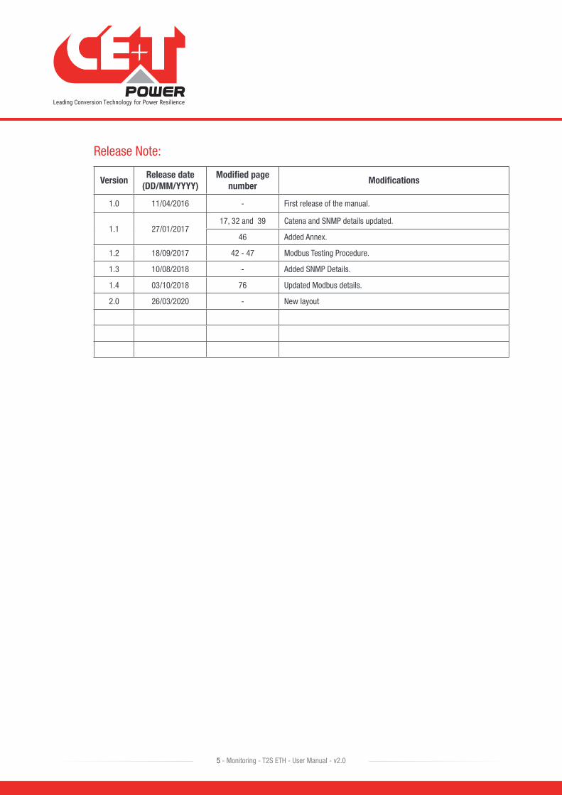
Release Note:
VersionRelease date
(DD/MM/YYYY)Modified page
numberModifications
1.0 11/04/2016 - First release of the manual.
1.1 27/01/201717, 32 and 39 Catena and SNMP details updated.
46 Added Annex.
1.2 18/09/2017 42 - 47 Modbus Testing Procedure.
1.3 10/08/2018 - Added SNMP Details.
1.4 03/10/2018 76 Updated Modbus details.
2.0 26/03/2020 - New layout
5 - Monitoring - T2S ETH - User Manual - v2.0

1. CE+T at a glanceCE+T Power designs, manufactures, and markets a range of products for industrial operators with mission critical applications, who are not satisfied with existing AC backup system performances and related maintenance costs.
Our product is an innovative AC backup solution that unlike most UPS’s available.
• Maximizes the operator’s applications uptime;
• Operates with lowest OPEX;
• Provides best protection to disturbances;
• Optimizes footprint.
Our systems are:
• Modular
• Truly redundant
• Highly efficient
• Maintenance free
• Battery friendly
CE+T power puts 60+ years expertise in power conversion together with worldwide presence to provide customized solutions and extended service 24/7 - 365 days per year.
CE+T at a glance
6 - Monitoring - T2S ETH - User Manual - v2.0

2. Abbreviations TSI Twin Sine Innovation
EPC Enhanced Power Conversion
REG Regular
DSP Digital Signal Processor
AC Alternating current
DC Direct current
PE Protective Earth (also called Main Protective Conductor)
N Neutral
PCB Printed Circuit Board
TRS True Redundant Structure
PWR Power
ESD Electro Static Discharge
MET Main Earth Terminal
MBP Manual By-pass
TCP/IP Transmission Control Protocol/Internet Protocol
USB Universal Serial Bus
LAN Local Access Network
ETH Ethernet
SNMP Simple Network Management Protocol
HTTP HyperText Transfer Protocol
HTTPS Secure HyperText Transfer Protocol
NTP Network Time Protocol
MIB Management Information Base
DHCP Dynamic Host Configuration Protocol
Abbreviations
7 - Monitoring - T2S ETH - User Manual - v2.0

3. Warranty and Safety Conditions*
The electronics in the power supply system are designed for an indoor, clean environment.
When installed in a dusty and/or corrosive environment, outdoor or indoor, it is important to:
• Install an appropriate filter on the enclosure door or on the room’s air conditioning system. Installation of filters may result in de-rating of module.
• Keep the enclosure door closed during operation.
• Replace the filters on a regular basis.
Important Safety Instructions, Save These Instructions.
3.1 Disclaimer • The manufacturer declines all responsibilities if equipment is not installed, used, or operated according to the
instructions herein by factory certified technicians according to local regulations.
• Warranty does not apply if the product is not installed, used, and handled according to the instructions in the manuals.
3.2 Technical care • This electronic equipment can only be repaired or maintained by a “qualified employee” with adequate training.
Even personnel who are in charge of simple repairs or maintenance are required to have knowledge or experience related to product maintenance.
• Please follow the procedures contained in this Manual, and note all the “DANGER”, “WARNING” AND “NOTICE” marks contained in this Manual. Warning labels must not be removed.
• Qualified employees are trained to recognize and avoid any dangers that might be present when working on or near exposed electrical parts.
• Qualified employees understand how to lock out and tag out machines so the machines will not accidentally be turned on and injure employees working on them.
• Qualified employees also understand safety related work practices, including those by OSHA and NFPA, as well as knowing what personal protective equipment should be worn.
• All operators are to be trained to perform the emergency shut-down procedure.
• Never wear metallic objects such as rings, watches, or bracelets during installation, service and maintenance of the product.
• Insulated tools must be used at all times when working with live systems.
• When handling the system/units pay attention to sharp edges.
* These instructions are valid for most CE+T Products/Systems. Some points might however not be valid for the product described in this manual.
Warranty and Safety Conditions
8 - Monitoring - T2S ETH - User Manual - v2.0

3.3 Installation • This product is intended to be installed only in restricted access areas.
• The user must observe the recommended upstream and downstream circuit breaker requirements as per the local regulations.
• Please use extreme caution when accessing circuits that may be at hazardous voltages or energy levels.
• The modular inverter rack is a dual input power supply. The complete system shall be wired in a way that both input and output leads can be made power free.
• In REG systems, to comply with local and international safety standards the N (output) and PE shall be bonded. The bonded connection between N (output) and PE must be removed once the AC input is connected.
• AC and DC circuits shall be terminated with no voltage / power applied.
• The safety standard IEC/EN62040-1-1 requires that, in the event of an output short circuit, the inverter must disconnect in 5 seconds maximum. The parameter can be adjusted on T2S ETH monitoring; however, if the parameter is set at a value > 5 seconds, an external protection must be provided so that the short circuit protection operates within 5 seconds. Default setting is 60 seconds.
• The system is designed for installation within an IP20 or IP21 environment. When installed in a dusty or humid environment, appropriate measures (air filtering) must be taken. Installation of filters may result in de-rating of module.
• All illustrations in the manual are for general reference, refer to the technical drawing which is received along with the system for exact information.
3.3.1 Handling
• The cabinet shall not be lifted using lifting eyes.
• Remove weight from the cabinet by unplugging the inverters. Mark inverters clearly with shelf and position for correct rebuild. This is especially important in dual or three phase configurations.
• Empty T2S positions should not be left open. Replace either with a T2S or dummy cover.
3.3.2 Surge and transients
The mains (AC) supply of the modular inverter system shall be fitted with Lightning surge suppression and Transient voltage surge suppression suitable for the application at hand. Manufacturer’s recommendations of installation shall be adhered to. Selecting a device with an alarm relay for function failure is advised.
Indoor sites are considered to have a working lightning surge suppression device in service.
• Indoor sites Min Class II.
• Outdoor sites Min Class I + Class II or combined Class I+II. The modular inverter system/rack can reach hazardous leakage currents. Earthing must be carried out prior to energizing the system. Earthing shall be made according to local regulations.
3.3.3 Other • Isolation test (Hi-Pot) must not be performed without instructions from the manufacturer.
Warranty and Safety Conditions
9 - Monitoring - T2S ETH - User Manual - v2.0

3.4 Pre-cautions before maintenance • The modular inverter system/rack can reach hazardous leakage currents. Earthing must be carried out prior to
energizing the system. Earthing shall be made according to local regulations.
• Prior to any work conducted on a system/unit make sure that AC input voltage and DC input voltage are disconnected.
• Inverter modules and shelves contain capacitors for filtering and energy storage. Prior to accessing the system/modules after power down, wait at least 5 minutes to allow capacitors to discharge.
• Some components and terminals carry high voltage during operation. Contact may result in fatal injury.
3.5 Replacement and Dismantling • ESD Strap must be worn when handling PCBs and open units.
• CE+T cannot be held responsible for disposal of the Inverter system and therefore the customer must segregate and dispose of the materials which are potentially harmful to the environment, in accordance with the local regulations in force in the country of installation.
• If the equipment is dismantled, to dispose of its component products, you must comply with the local regulations in force in the country of destination and in any case avoid causing any kind of pollution.
To download the latest:
• Documents - www.cet-power.com
• Softwares - my.cet-power.com
Warranty and Safety Conditions
10 - Monitoring - T2S ETH - User Manual - v2.0
Product Code and Identification
11 - Monitoring - T2S ETH - User Manual - v2.0
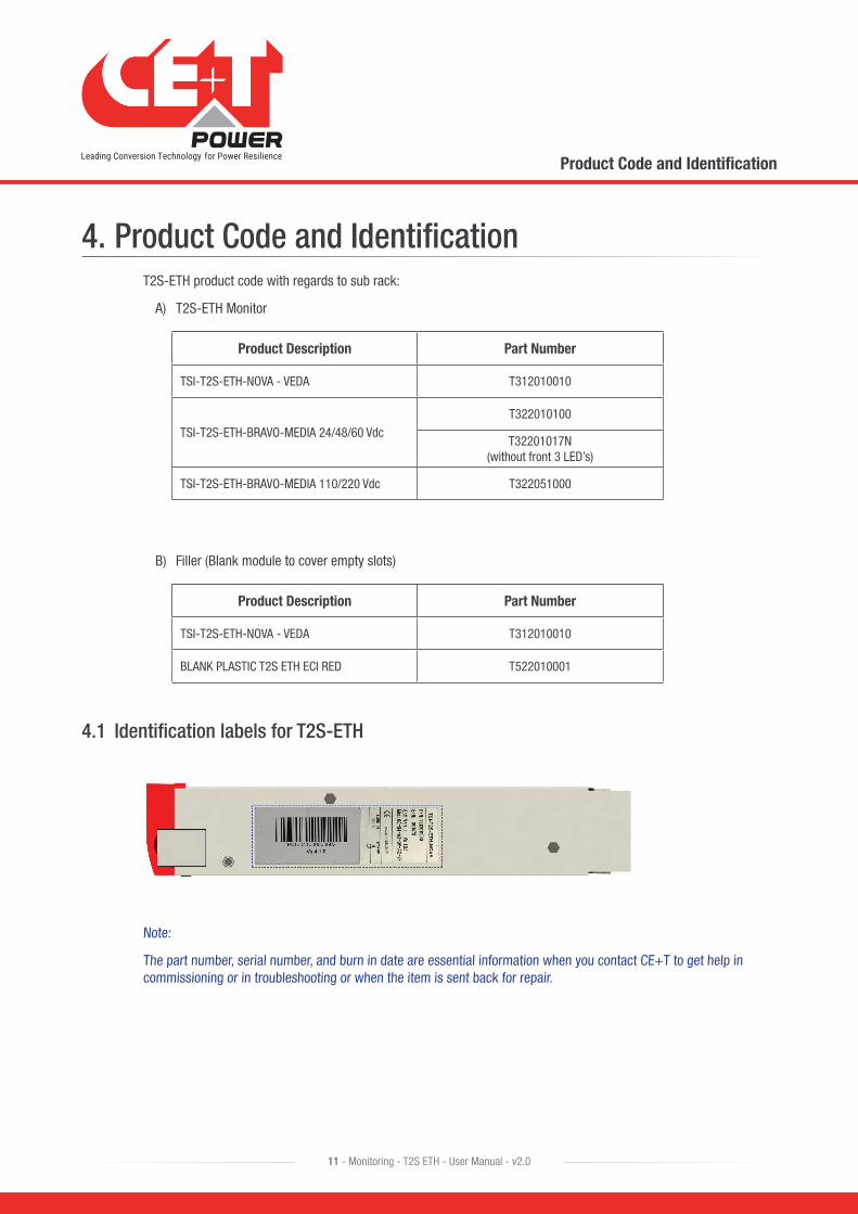
4. Product Code and IdentificationT2S-ETH product code with regards to sub rack:
A) T2S-ETH Monitor
Product Description Part Number
TSI-T2S-ETH-NOVA - VEDA T312010010
TSI-T2S-ETH-BRAVO-MEDIA 24/48/60 VdcT322010100
T32201017N (without front 3 LED’s)
TSI-T2S-ETH-BRAVO-MEDIA 110/220 Vdc T322051000
B) Filler (Blank module to cover empty slots)
Product Description Part Number
TSI-T2S-ETH-NOVA - VEDA T312010010
BLANK PLASTIC T2S ETH ECI RED T522010001
4.1 Identification labels for T2S-ETH
Note:
The part number, serial number, and burn in date are essential information when you contact CE+T to get help in commissioning or in troubleshooting or when the item is sent back for repair.

Introduction
12 - Monitoring - T2S ETH - User Manual - v2.0
5. IntroductionThe T2S ETH stands for T2S Ethernet. It replaces the former T2S with the same form factor but with a front Ethernet connector replacing the former USB one. Like his predecessor, T2S ETH is a monitoring solution for the full TSI inverter range and is able to monitor up to 32 inverters through a friendly web-based interface and it consumes power of 2W. T2S also supports Modbus Serial communication (RTU) and SNMP v1 Communication.
This new monitoring device provides a graphical user interface, embeds an SNMPv2c/SNMP v3 agent, and Modbus TCP support with Catena. If one needs a touch screen display, Catena can be connected to T2S ETH and is compatible. It also allows the user to change the configuration of the system via the touchscreen.

Hardware
13 - Monitoring - T2S ETH - User Manual - v2.0
6. HardwareThe T2S ETH provides 3 LED’s: Red for major alarm signaling, orange led for minor alarm signaling, and green led for power and network connection status.
The RJ45 is a standard ETH connector that could be connected to any IPv4 network.
T2S ETH software can be upgraded using the Micro SD card. The latest device softwares are available in my.cet-power.com
Hardware
14 - Monitoring - T2S ETH - User Manual - v2.0
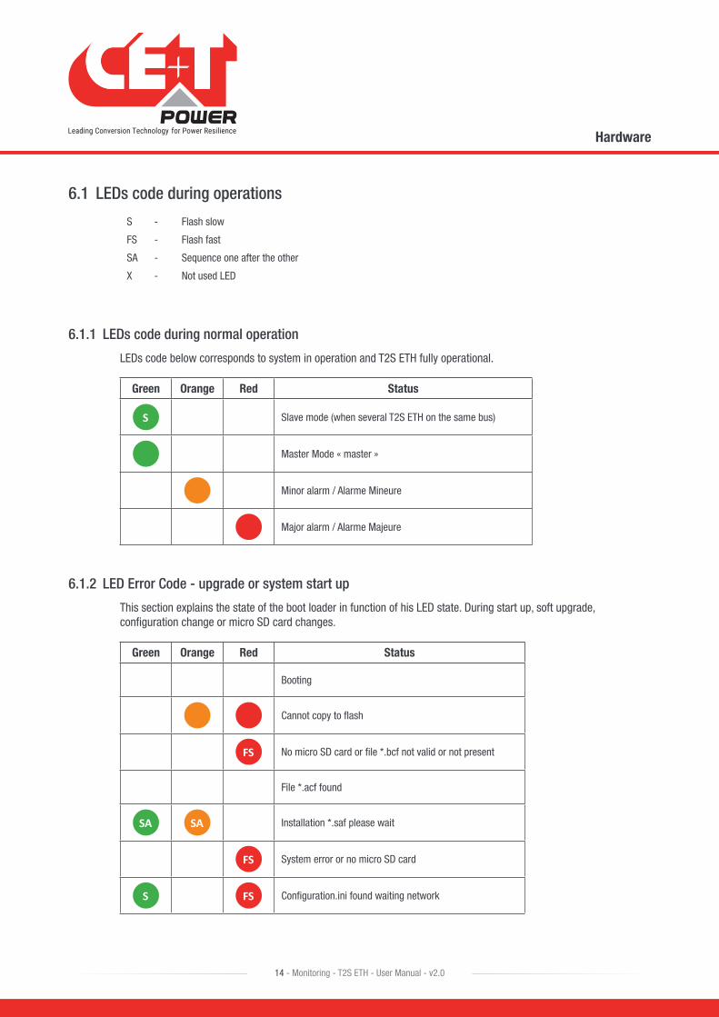
6.1 LEDs code during operations
S - Flash slow
FS - Flash fast
SA - Sequence one after the other
X - Not used LED
6.1.1 LEDs code during normal operation
LEDs code below corresponds to system in operation and T2S ETH fully operational.
Green Orange Red Status
S Slave mode (when several T2S ETH on the same bus)
Master Mode « master »
Minor alarm / Alarme Mineure
Major alarm / Alarme Majeure
6.1.2 LED Error Code - upgrade or system start up
This section explains the state of the boot loader in function of his LED state. During start up, soft upgrade, configuration change or micro SD card changes.
Green Orange Red Status
Booting
Cannot copy to flash
FS No micro SD card or file *.bcf not valid or not present
File *.acf found
SA SA Installation *.saf please wait
FS System error or no micro SD card
S FS Configuration.ini found waiting network
Hardware
15 - Monitoring - T2S ETH - User Manual - v2.0
Green Orange Red Status
FS Boot loader Web interface ON and in operation
S FS System file OK but no config file *.ini
S S S Error SD Card / File
S S Error no configuration.ini
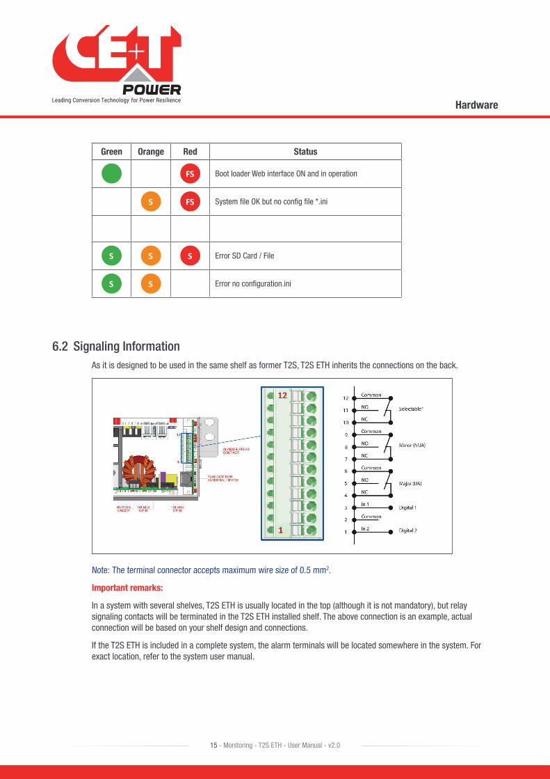
6.2 Signaling InformationAs it is designed to be used in the same shelf as former T2S, T2S ETH inherits the connections on the back.
Note: The terminal connector accepts maximum wire size of 0.5 mm2.
Important remarks:
In a system with several shelves, T2S ETH is usually located in the top (although it is not mandatory), but relay signaling contacts will be terminated in the T2S ETH installed shelf. The above connection is an example, actual connection will be based on your shelf design and connections.
If the T2S ETH is included in a complete system, the alarm terminals will be located somewhere in the system. For exact location, refer to the system user manual.
Hardware
16 - Monitoring - T2S ETH - User Manual - v2.0
6.2.1 Alarm relay
There are 3 alarm contacts:
• Major
• Minor
• User selectable
As one can see in the picture: contacts 5 and 6 are closed when no major alarm is present, contact 8 and 9 are closed when no minor alarm is present.
Remark: Default mapping and level of each available alarm of the monitoring unit is available in “Annex 1: Supervisor alarms - T2S ETH”, page 65.
NB: Alarm relay are active (energized) when no alarm are present.
• Alarms relay features
� Max current: 2 A @ 30 VDC or 1A @ 60 VDC
� Max Power: 60 W
� Max Voltage: 60 VDC SELV
Note that for higher voltages, it is mandatory to install an additional relay with appropriate characteristics – especially for 60/110/220 VDC.
6.2.2 Digital Inputs
Two potential free Digital inputs are reserved for optional equipment.
• Digital Input 1 is assigned for MBP operation if used.
• Digital Input 2 is assigned for Surge Arrester if used.
The voltage present on terminal 1 and 3 is +5 V (galvanic insulation). Care should be taken to avoid connecting any external voltage on terminal 1 to 3. External signals should be applied to these terminals via Volt-free contacts. The function is activated when the two terminals concerned are short-circuited (i.e., when the external Volt-free contact is closed).
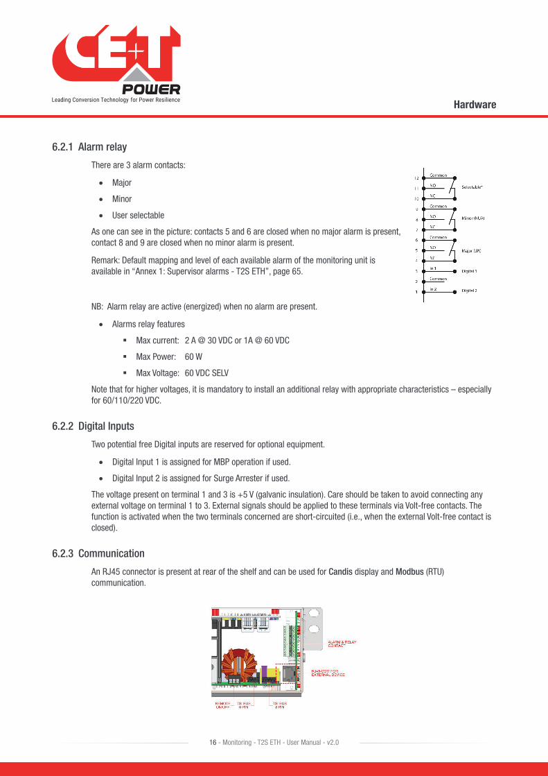
6.2.3 Communication
An RJ45 connector is present at rear of the shelf and can be used for Candis display and Modbus (RTU) communication.
Hardware
17 - Monitoring - T2S ETH - User Manual - v2.0
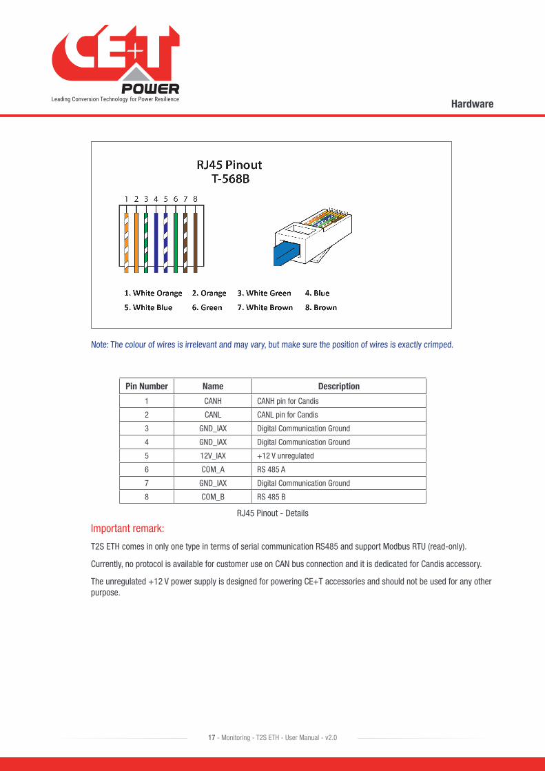
Note: The colour of wires is irrelevant and may vary, but make sure the position of wires is exactly crimped.
Pin Number Name Description
1 CANH CANH pin for Candis
2 CANL CANL pin for Candis
3 GND_IAX Digital Communication Ground
4 GND_IAX Digital Communication Ground
5 12V_IAX +12 V unregulated
6 COM_A RS 485 A
7 GND_IAX Digital Communication Ground
8 COM_B RS 485 B
RJ45 Pinout - Details
Important remark:
T2S ETH comes in only one type in terms of serial communication RS485 and support Modbus RTU (read-only).
Currently, no protocol is available for customer use on CAN bus connection and it is dedicated for Candis accessory.
The unregulated +12 V power supply is designed for powering CE+T accessories and should not be used for any other purpose.
Hardware
18 - Monitoring - T2S ETH - User Manual - v2.0
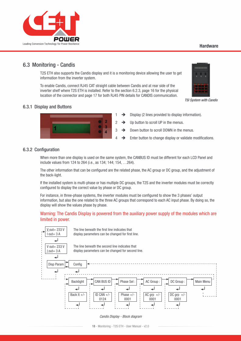
6.3 Monitoring - CandisT2S ETH also supports the Candis display and it is a monitoring device allowing the user to get information from the inverter system.
To enable Candis, connect RJ45 CAT straight cable between Candis and at rear side of the inverter shelf where T2S ETH is installed. Refer to the section 6.2.3, page 16 for the physical location of the connector and page 17 for both RJ45 PIN details for CANDIS communication.
6.3.1 Display and Buttons
1 Display (2 lines provided to display information).
2 Up button to scroll UP in the menus.
3 Down button to scroll DOWN in the menus.
4 Enter button to change display or validate modifications.
6.3.2 Configuration
When more than one display is used on the same system, the CANBUS ID must be different for each LCD Panel and include values from 124 to 264 (i.e., as 134; 144; 154, …264).
The other information that can be configured are the related phase, the AC group or DC group, and the adjustment of the back-light.
If the installed system is multi-phase or has multiple DC groups, the T2S and the inverter modules must be correctly configured to display the correct value by phase or DC group.
For instance, in three-phase systems, the inverter modules must be configured to show the 3 phases’ output information, but also the one related to the three AC groups that correspond to each AC input phase. By doing so, the display will show the values phase by phase.
Warning: The Candis Display is powered from the auxiliary power supply of the modules which are limited in power.
V out= 233 V I out= 3 A
V out= 233 V I out= 3 A
Main Menu
Disp Param Config
DC Group :AC Group :Phase Sel :
Back lt +/- ID CAN +/-0124
Phase +/-0001
AC grp +/-0001
DC grp +/-0001
CAN BUS IDBacklight
The line beneath the first line indicates that display parameters can be changed for first line.
The line beneath the second line indicates that display parameters can be changed for second line.
Candis Display - Block diagram
TSI System with Candis
Hardware
19 - Monitoring - T2S ETH - User Manual - v2.0
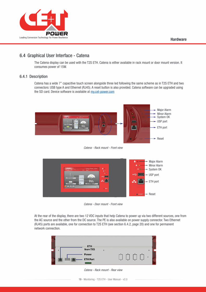
6.4 Graphical User Interface - CatenaThe Catena display can be used with the T2S ETH. Catena is either available in rack mount or door mount version. It consumes power of 15W.
6.4.1 Description
Catena has a wide 7’’ capacitive touch screen alongside three led following the same scheme as in T2S ETH and two connectors: USB type A and Ethernet (RJ45). A reset button is also provided. Catena software can be upgraded using the SD card. Device software is available at my.cet-power.com
Major AlarmMinor AlarmSystem OKUSP port
ETH port
Reset
Catena - Rack mount - Front view
Major AlarmMinor AlarmSystem OK
USP port
ETH port
Reset
Catena - Door mount - Front view
At the rear of the display, there are two 12 VDC inputs that help Catena to power up via two different sources, one from the AC source and the other from the DC source. The PE is also available on power supply connector. Two Ethernet (RJ45) ports are available, one for connection to T2S ETH (see section 6.4.2, page 20) and one for permanent network connection.
Catena - Rack mount - Rear view

Hardware
20 - Monitoring - T2S ETH - User Manual - v2.0
ETH from TXS
12V Power
ETH Port
Catena - Door mount - Rear view
To establish the communication in Catena, connect RJ45 Straight CAT6e cable between rear side of the Catena (Named as ETH from TXS) and front side of the T2S-ETH connector.
Note: Catena has different versions. So, refer the system manual to identify the version of catena which you received.
6.4.2 Wiring
Catena configuration has to be selected in the T2S ETH under monitoring, network, connection mode, hardware setup should be “With Catena”. Refer to section “Network”, page 32 and this option has to be selected even before wiring.
Graphical User Interface
21 - Monitoring - T2S ETH - User Manual - v2.0
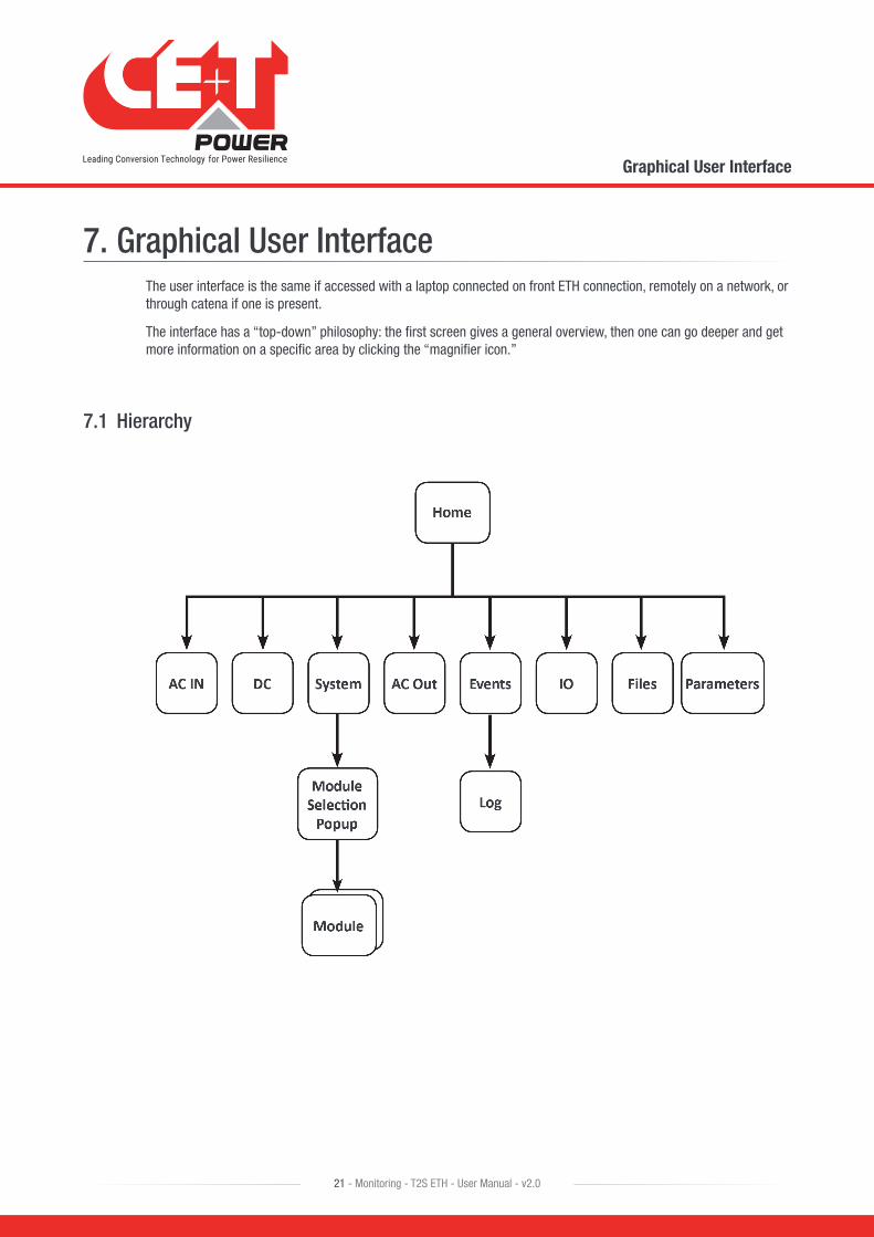
7. Graphical User InterfaceThe user interface is the same if accessed with a laptop connected on front ETH connection, remotely on a network, or through catena if one is present.
The interface has a “top-down” philosophy: the first screen gives a general overview, then one can go deeper and get more information on a specific area by clicking the “magnifier icon.”
7.1 Hierarchy
Graphical User Interface
22 - Monitoring - T2S ETH - User Manual - v2.0
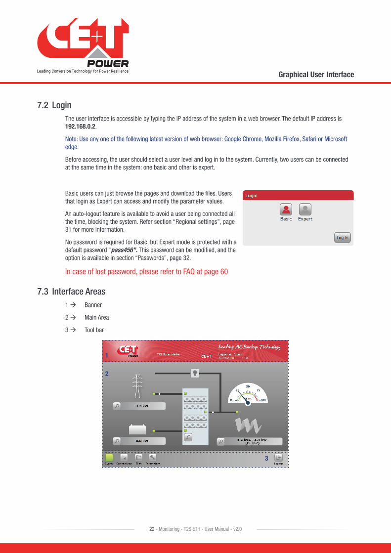
7.2 LoginThe user interface is accessible by typing the IP address of the system in a web browser. The default IP address is 192.168.0.2.
Note: Use any one of the following latest version of web browser: Google Chrome, Mozilla Firefox, Safari or Microsoft edge.
Before accessing, the user should select a user level and log in to the system. Currently, two users can be connected at the same time in the system: one basic and other is expert.
Basic users can just browse the pages and download the files. Users that login as Expert can access and modify the parameter values.
An auto-logout feature is available to avoid a user being connected all the time, blocking the system. Refer section “Regional settings”, page 31 for more information.
No password is required for Basic, but Expert mode is protected with a default password “pass456”. This password can be modified, and the option is available in section “Passwords”, page 32.
In case of lost password, please refer to FAQ at page 60
7.3 Interface Areas1 Banner
2 Main Area
3 Tool bar
1
2
3
Graphical User Interface
23 - Monitoring - T2S ETH - User Manual - v2.0
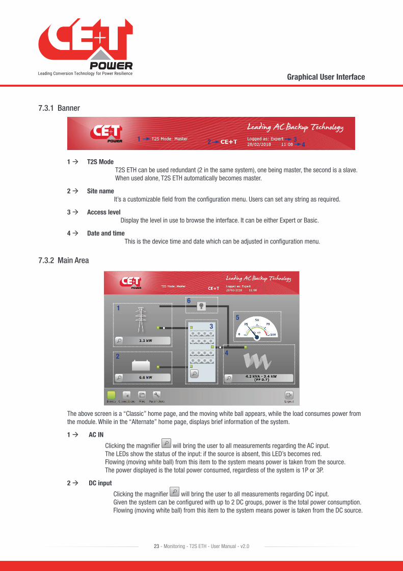
7.3.1 Banner
1 2 34
1 T2S Mode T2S ETH can be used redundant (2 in the same system), one being master, the second is a slave. When used alone, T2S ETH automatically becomes master.
2 Site name It’s a customizable field from the configuration menu. Users can set any string as required.
3 Access level Display the level in use to browse the interface. It can be either Expert or Basic.
4 Date and time This is the device time and date which can be adjusted in configuration menu.
7.3.2 Main Area
1
2
3
4
5
6
The above screen is a “Classic” home page, and the moving white ball appears, while the load consumes power from the module. While in the “Alternate” home page, displays brief information of the system.
1 AC IN
Clicking the magnifier will bring the user to all measurements regarding the AC input. The LEDs show the status of the input: if the source is absent, this LED’s becomes red. Flowing (moving white ball) from this item to the system means power is taken from the source. The power displayed is the total power consumed, regardless of the system is 1P or 3P.
2 DC input
Clicking the magnifier will bring the user to all measurements regarding DC input. Given the system can be configured with up to 2 DC groups, power is the total power consumption. Flowing (moving white ball) from this item to the system means power is taken from the DC source.
Graphical User Interface
24 - Monitoring - T2S ETH - User Manual - v2.0
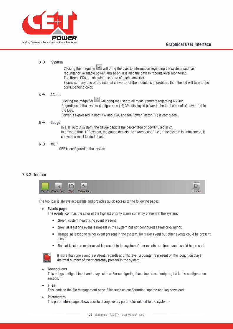
3 System
Clicking the magnifier will bring the user to information regarding the system, such as redundancy, available power, and so on. It is also the path to module level monitoring. The three LEDs are showing the state of each converter. Example: if any one of the internal converter of the module is in problem, then the led will turn to the corresponding color.
4 AC out
Clicking the magnifier will bring the user to all measurements regarding AC Out. Regardless of the system configuration (1P, 3P), displayed power is the total amount of power fed to the load. Power is expressed in both KW and KVA, and the Power Factor (PF) is computed.
5 Gauge In a 1P output system, the gauge depicts the percentage of power used in VA. In a “more than 1P” system, the gauge depicts the “worst case,” i.e., if the system is unbalanced, it shows the most loaded phase.
6 MBP MBP is configured in the system.
7.3.3 Toolbar
The tool bar is always accessible and provides quick access to the following pages:
• Events page The events icon has the color of the highest priority alarm currently present in the system:
� Green: system healthy, no event present.
� Grey: at least one event is present in the system but not configured as major or minor.
� Orange: at least one minor event present in the system. No major event but other events could be present also.
� Red: at least one major event is present in the system. Other events or minor events could be present.
If more than one event is present, regardless of its level, a counter is present on the icon. It displays the total number of event currently present in the system.
• Connections This brings to digital input and relays status. For configuring these inputs and outputs, it’s in the configuration section.
• Files This leads to the file management page. Files such as configuration, update and log download.
• Parameters The parameters page allows user to change every parameter related to the system.
Graphical User Interface
25 - Monitoring - T2S ETH - User Manual - v2.0
Throughout the browsing, the user can see the following icons:
When accessing a page of depth of two or more (such as module or log page), the user can go back to previous page by clicking “back” icon
Clicking on “Home” icon goes to the home page from any page you are accessing in the interface.
Clicking on “Logout” icon goes to the login page
7.4 Pages and Feature
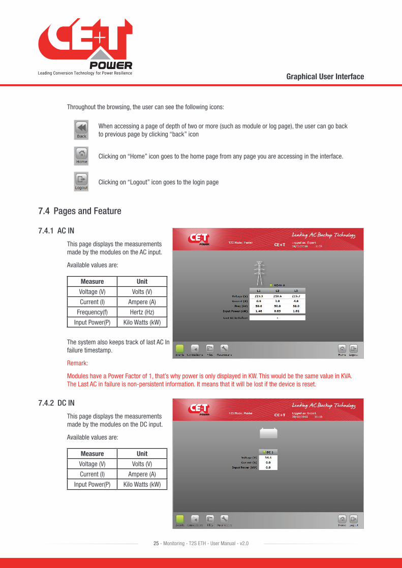
7.4.1 AC IN
This page displays the measurements made by the modules on the AC input.
Available values are:
Measure Unit
Voltage (V) Volts (V)
Current (I) Ampere (A)
Frequency(f) Hertz (Hz)
Input Power(P) Kilo Watts (kW)
The system also keeps track of last AC In failure timestamp.
Remark:
Modules have a Power Factor of 1, that’s why power is only displayed in KW. This would be the same value in KVA. The Last AC in failure is non-persistent information. It means that it will be lost if the device is reset.
7.4.2 DC IN
This page displays the measurements made by the modules on the DC input.
Available values are:
Measure Unit
Voltage (V) Volts (V)
Current (I) Ampere (A)
Input Power(P) Kilo Watts (kW)
Graphical User Interface
26 - Monitoring - T2S ETH - User Manual - v2.0
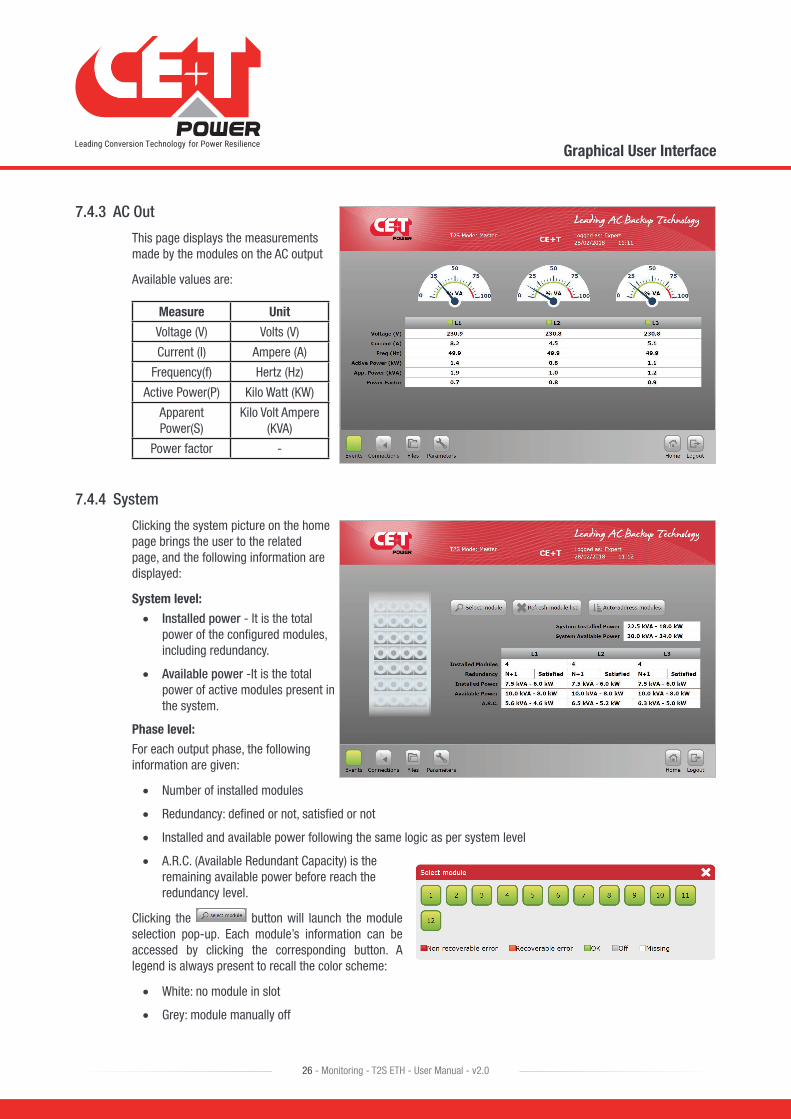
7.4.3 AC Out
This page displays the measurements made by the modules on the AC output
Available values are:
Measure Unit
Voltage (V) Volts (V)
Current (I) Ampere (A)
Frequency(f) Hertz (Hz)
Active Power(P) Kilo Watt (KW)
Apparent Power(S)
Kilo Volt Ampere (KVA)
Power factor -
7.4.4 System
Clicking the system picture on the home page brings the user to the related page, and the following information are displayed:
System level:
• Installed power - It is the total power of the configured modules, including redundancy.
• Available power -It is the total power of active modules present in the system.
Phase level:
For each output phase, the following information are given:
• Number of installed modules
• Redundancy: defined or not, satisfied or not
• Installed and available power following the same logic as per system level
• A.R.C. (Available Redundant Capacity) is the remaining available power before reach the redundancy level.
Clicking the button will launch the module selection pop-up. Each module’s information can be accessed by clicking the corresponding button. A legend is always present to recall the color scheme:
• White: no module in slot
• Grey: module manually off
Graphical User Interface
27 - Monitoring - T2S ETH - User Manual - v2.0
• Green: module OK
• Orange: module in recoverable error
• Red: module with unrecoverable error
For last two, refer to module manual for troubleshooting.
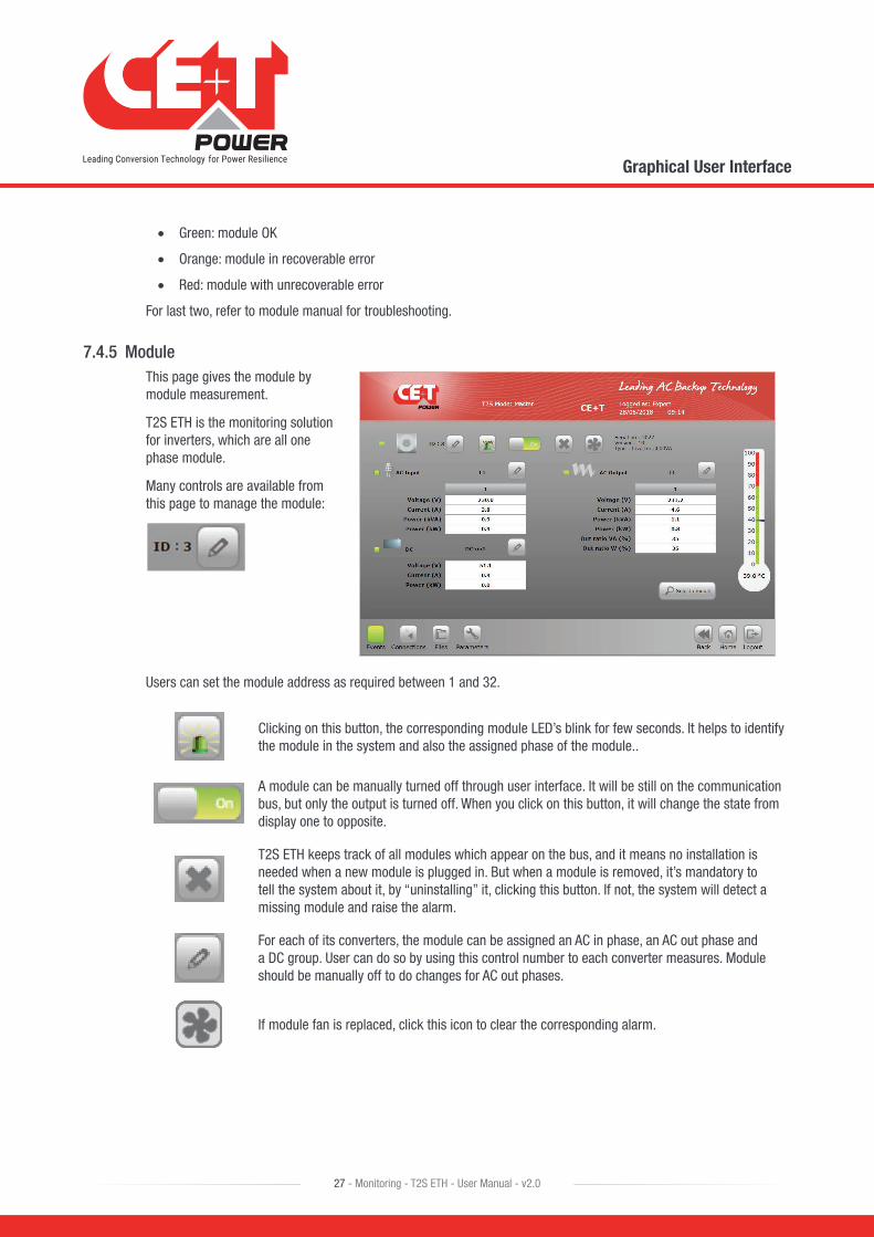
7.4.5 ModuleThis page gives the module by module measurement.
T2S ETH is the monitoring solution for inverters, which are all one phase module.
Many controls are available from this page to manage the module:
Users can set the module address as required between 1 and 32.
Clicking on this button, the corresponding module LED’s blink for few seconds. It helps to identify the module in the system and also the assigned phase of the module..
A module can be manually turned off through user interface. It will be still on the communication bus, but only the output is turned off. When you click on this button, it will change the state from display one to opposite.
T2S ETH keeps track of all modules which appear on the bus, and it means no installation is needed when a new module is plugged in. But when a module is removed, it’s mandatory to tell the system about it, by “uninstalling” it, clicking this button. If not, the system will detect a missing module and raise the alarm.
For each of its converters, the module can be assigned an AC in phase, an AC out phase and a DC group. User can do so by using this control number to each converter measures. Module should be manually off to do changes for AC out phases.
If module fan is replaced, click this icon to clear the corresponding alarm.
Graphical User Interface
28 - Monitoring - T2S ETH - User Manual - v2.0
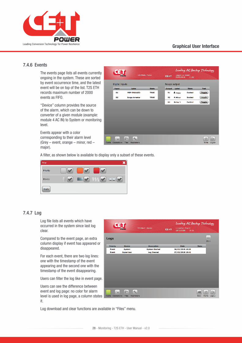
7.4.6 Events
The events page lists all events currently ongoing in the system. These are sorted by event occurrence time, and the latest event will be on top of the list. T2S ETH records maximum number of 2000 events as FIFO.
“Device” column provides the source of the alarm, which can be down to converter of a given module (example: module 4 AC IN) to System or monitoring level.
Events appear with a color corresponding to their alarm level (Grey – event, orange – minor, red – major).
A filter, as shown below is available to display only a subset of these events.
7.4.7 Log
Log file lists all events which have occurred in the system since last log clear.
Compared to the event page, an extra column display if event has appeared or disappeared.
For each event, there are two log lines: one with the timestamp of the event appearing and the second one with the timestamp of the event disappearing.
Users can filter the log like in event page.
Users can see the difference between event and log page: no color for alarm level is used in log page, a column states it.
Log download and clear functions are available in “Files” menu.

Graphical User Interface
29 - Monitoring - T2S ETH - User Manual - v2.0
7.4.8 Connections
As described before, T2S ETH has two digital inputs and three alarm relays.
State of each of these connections can be read through the “connections” page.
An extra “toggle” allows the user to test each relay manually, toggling it for a few seconds to detect a mechanically failing device over time.
7.4.9 Files
The Files page has three tabs.
The Transfer tab allows the user to download the log file and configuration files.
Users have the option to clear the log file by clicking “Clear” icon.
The Update tab allows the user to install the latest software version and get the latest features. Software is available through the CE+T customer area on the website (my.cet-power.com).
Software are provided in a proprietary format called “*.saf” file. Once uploaded, the system will restart, installing the new application after verifications.
The dedicated procedure will be provided at the same location if needed.

Graphical User Interface
30 - Monitoring - T2S ETH - User Manual - v2.0
The Language tab helps the user to upload a language file and translate the whole interface to the corresponding language. These files are available for certain languages in my.cet-power.com.
If the required language is not available, get in touch with sales representative to request the interface translation.
The first line Install language file allows uploading any language file while other lists are installed language. English is the default installed language. Apart from English, the user can install up to two different languages. Contact my.cet-power.com to find supported Language packs.
7.4.10 Parameters
The Parameters page is divided into multiple tabs, which are compound of sub menus. As shown below, the whole list of parameters, organized as in the interface with remarks and comments about their use. Monitoring, Input relays, SNMP, Modbus, Power, and Info are the sub menus.
Note: The following parameter sections provide brief information, to know more about each field, its function and values refer to section “16. Annex 3: Configuration parameters - T2S ETH”, page 71.
Disclaimer: The configuration file should be manually edited only by CE+T crew or any especially trained operator. All modifiable values contained here are easily accessible through the T2S ETH web interface which allow you to change the configuration carefully. Any mistake done in this file could lead to system malfunction and CE+T shall not guarantee the behavior of the whole system once this file has been corrupted.
7.4.10.1 Monitoring Tab
• Time
Time and date information of the T2S ETH system can be configured
Note: If the system has no power, the Real-Time Clock in T2S ETH can run up to 24 hours. After that, the clock will reset the date to 01/10/2013 and time to 8.00.

Graphical User Interface
31 - Monitoring - T2S ETH - User Manual - v2.0
• Regional settings
� Language: users can select a language from the list. Refer the “Files” menu for installing the language pack.
� Sitename: it’s a standard string that is displayed in the banner.
� Location is the place where the system is installed.
� Auto logout delay: number of seconds after which any user will have to login again. When set to 0, auto-logout is disabled. A maximum value of 6000 seconds can be configured for the Auto-logout option.
� Keyboard layout: useful when using a Catena with the T2S ETH for in-display keyboard. It has two options AZERTY and QWERTY
� New module identifier: Always Ask, Always replace and Never Replace are the options available for New Module Identifier.
� Home page: Two different home page layouts are available and they are “Classic” and “Alternate” home page.
� Display format: DD/MM/YYYY, YYYY/MM/DD, MM/DD/YYYY are the different display format available
� Time format: 24 Hours and 12 Hours options are available.
� Temperature format: Celsius and Fahrenheit options are available.
• NTP Server
NTP Server: System date and time can be synchronized with NTP server. NTP configuration parameters.
� IP Address of NTP server
� Port Number
� Time zone offset
� Auto-refresh
� Synchronization interval (days)
� Force Synchronization.

Graphical User Interface
32 - Monitoring - T2S ETH - User Manual - v2.0
• Passwords
Expert password: default is “pass456” but it’s strongly recommended to change it.
Software update do not change your password.
In case of lost password, please refer to FAQ at page 60
• Network
In Connection mode, Select Hardware setup as
� Standalone - System with T2S ETH or
� With Catena - System with T2S ETH and display unit - Catena
Network address is configuration of the T2S ETH
� DHCP status: DHCP Disable allows configuring static IP to T2S ETH card. When DHCP is enabled, IP to T2S will be assigned by the DHCP server or the Router to which T2S ETH is connected. To find the IP address of T2S ETH card IP Scanner tools can be used. For more information refer section 9.2, page 52.
� IP address
� Subnet mask
� Default gateway
� Primary DNS
� Secondary DNS
DNS has to be configured where server has host name.
Graphical User Interface
33 - Monitoring - T2S ETH - User Manual - v2.0
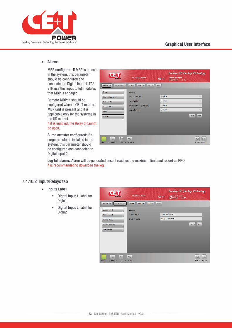
• Alarms
MBP configured: If MBP is present in the system, this parameter should be configured and connected to Digital input 1. T2S ETH use this input to tell modules that MBP is engaged.
Remote MBP: It should be configured when a CE+T external MBP unit is present and it is applicable only for the systems in the US market. If it is enabled, the Relay 3 cannot be used.
Surge arrester configured: If a surge arrester is installed in the system, this parameter should be configured and connected to Digital input 2.
Log full alarms: Alarm will be generated once it reaches the maximum limit and record as FIFO. It is recommended to download the log.
7.4.10.2 Input/Relays tab
• Inputs Label
� Digital Input 1: label for DigIn1
� Digital Input 2: label for DigIn2

Graphical User Interface
34 - Monitoring - T2S ETH - User Manual - v2.0
• Relays Label
� Major Relay Name: dedicated to major relay – not possible to change
� Minor Relay Name: dedicated to minor relay – not possible to change
� Relay 3 name: It is a programmable relay, and the user can select a particular alarm. Relay 3 cannot be used if remote MBP is enabled
• Relays Delay
� Major Relay delay: delay in seconds before toggling when the condition is met (major alarm present)
� Minor Relay delay: delay in seconds before toggling when the condition is met (minor alarm present)
� Relay 3 delay: delay in seconds before toggling when the condition is met.
• Relays Mapping
� Relay mapping page is a matrix: all events can be mapped on one relay, all relays can be mapped on one event, or any other combination the customer would like. Note: While selecting an alarm type for a relay, choose either Major or Minor. If both selected, only the major alarm will be enabled during that relay energized.
Graphical User Interface
35 - Monitoring - T2S ETH - User Manual - v2.0
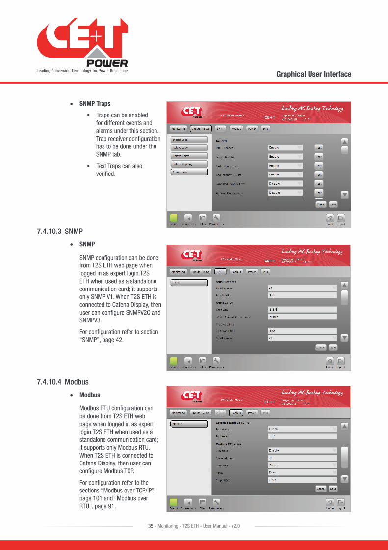
• SNMP Traps
� Traps can be enabled for different events and alarms under this section. Trap receiver configuration has to be done under the SNMP tab.
� Test Traps can also verified.
7.4.10.3 SNMP
• SNMP
SNMP configuration can be done from T2S ETH web page when logged in as expert login.T2S ETH when used as a standalone communication card; it supports only SNMP V1. When T2S ETH is connected to Catena Display, then user can configure SNMPV2C and SNMPV3.
For configuration refer to section “SNMP”, page 42.
7.4.10.4 Modbus
• Modbus
Modbus RTU configuration can be done from T2S ETH web page when logged in as expert login.T2S ETH when used as a standalone communication card; it supports only Modbus RTU. When T2S ETH is connected to Catena Display, then user can configure Modbus TCP.
For configuration refer to the sections “Modbus over TCP/IP”, page 101 and “Modbus over RTU”, page 91.
Graphical User Interface
36 - Monitoring - T2S ETH - User Manual - v2.0
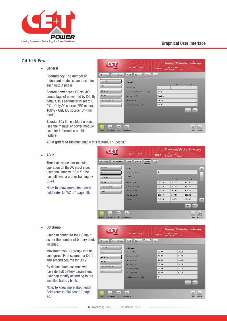
7.4.10.5 Power
• General
Redundancy: The number of redundant modules can be set for each output phase.
Source power ratio DC vs. AC: percentage of power fed by DC. By default, this parameter is set to 0. 0% - Only AC source (EPC mode), 100% - Only DC source (On-line mode).
Booster 10x Iin: enable the boost (see the manual of power module used for information on this feature).
AC In grid feed Disable: enable this feature, if “Booster.”
• AC In
Threshold values for module operation on the AC input side. User shall modify it ONLY if he has followed a proper training by CE+T.
Note: To know more about each field, refer to “AC In”, page 79.
• DC Group
User can configure the DC input as per the number of battery bank installed.
Maximum two DC groups can be configured. First column for DC 1 and second column for DC 2.
By default, both columns will have default battery parameters. User can modify according to the installed battery bank.
Note: To know more about each field, refer to “DC Group”, page 80.
Graphical User Interface
37 - Monitoring - T2S ETH - User Manual - v2.0
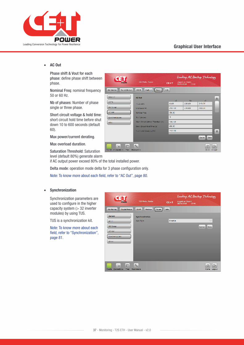
• AC Out
Phase shift & Vout for each phase: define phase shift between phase.
Nominal Freq: nominal frequency 50 or 60 Hz.
Nb of phases: Number of phase single or three phase.
Short circuit voltage & hold time: short circuit hold time before shut down 10 to 600 seconds (default 60).
Max power/current derating.
Max overload duration.
Saturation Threshold: Saturation level (default 80%) generate alarm if AC output power exceed 80% of the total installed power.
Delta mode: operation mode delta for 3 phase configuration only.
Note: To know more about each field, refer to “AC Out”, page 80.
• Synchronization
Synchronization parameters are used to configure in the higher capacity system (> 32 inverter modules) by using TUS.
TUS is a synchronization kit.
Note: To know more about each field, refer to “Synchronization”, page 81.

Graphical User Interface
38 - Monitoring - T2S ETH - User Manual - v2.0
• Other
� Remote OFF disable AC power.
� Walk in mode time.
� Airco mode.
� Force start without T2S.
� No power from AC IN phase 1
� No power from AC IN phase 2
� No power from AC IN phase 3
Note: To know more about each field, refer to “Other”, page 82
7.4.10.6 Info
• T2S-ETH
This tab provides information about the T2S ETH:
� Serial Number
� Software version
� Interface version
� Bootloader version
� MAC Address: In case of required support, it’s mandatory to provide information listed in this page or a screenshot of it.
Catena
39 - Monitoring - T2S ETH - User Manual - v2.0
8. Catena
8.1 IntroductionCatena is the display solution for T2S ETH. Using it, you get access on a 7’’ display directly in the system, providing the same graphical user interface as the T2S ETH when accessed remotely.
8.2 User interfaceAs described before, the user interface is the same if the system is accessed remotely or directly on the 7’’ display.
The only limitation is the relay testing button, which is not available in Catena.
8.3 Ethernet connectionsCatena has 3 ETH connections, two at rear and one at front.
8.3.1 Rear connections
One is dedicated to connection with T2S ETH while the second one is for permanent network connection. On this one, Catena offers extra protocols: SNMP v2c, v3 and Modbus over TCPIP. See following section “Protocols” about these.
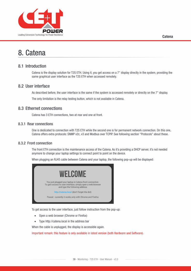
8.3.2 Front connection
The front ETH connection is the maintenance access of the Catena. As it’s providing a DHCP server, it’s not needed anymore to change your laptop settings to connect point to point on the device.
When plugging an RJ45 cable between Catena and your laptop, the following pop-up will be displayed:
To get access to the user interface, just follow instruction from the pop-up:
• Open a web browser (Chrome or Firefox)
• Type http://catena.local in the address bar
When the cable is unplugged, the display is accessible again.
Important remark: this feature is only available in latest version (both Hardware and Software).
Catena
40 - Monitoring - T2S ETH - User Manual - v2.0
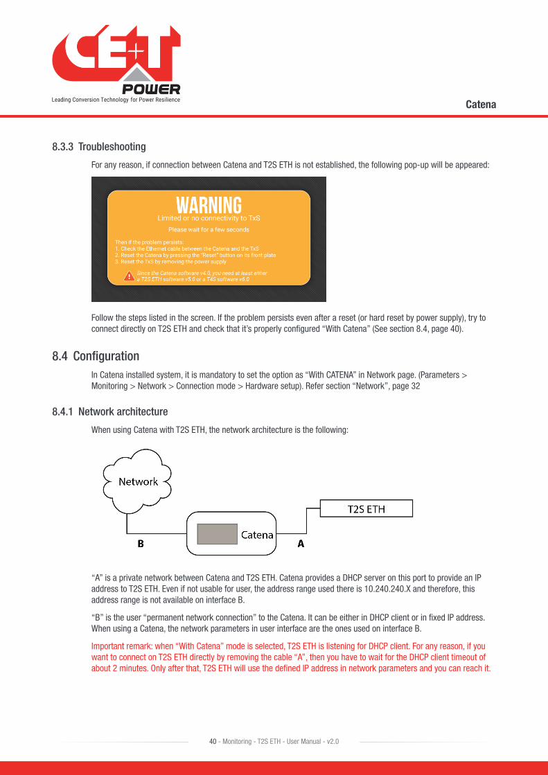
8.3.3 Troubleshooting
For any reason, if connection between Catena and T2S ETH is not established, the following pop-up will be appeared:
Follow the steps listed in the screen. If the problem persists even after a reset (or hard reset by power supply), try to connect directly on T2S ETH and check that it’s properly configured “With Catena” (See section 8.4, page 40).
8.4 ConfigurationIn Catena installed system, it is mandatory to set the option as “With CATENA” in Network page. (Parameters > Monitoring > Network > Connection mode > Hardware setup). Refer section “Network”, page 32
8.4.1 Network architecture
When using Catena with T2S ETH, the network architecture is the following:
“A” is a private network between Catena and T2S ETH. Catena provides a DHCP server on this port to provide an IP address to T2S ETH. Even if not usable for user, the address range used there is 10.240.240.X and therefore, this address range is not available on interface B.
“B” is the user “permanent network connection” to the Catena. It can be either in DHCP client or in fixed IP address. When using a Catena, the network parameters in user interface are the ones used on interface B.
Important remark: when “With Catena” mode is selected, T2S ETH is listening for DHCP client. For any reason, if you want to connect on T2S ETH directly by removing the cable “A”, then you have to wait for the DHCP client timeout of about 2 minutes. Only after that, T2S ETH will use the defined IP address in network parameters and you can reach it.

Catena
41 - Monitoring - T2S ETH - User Manual - v2.0
8.5 ProtocolsUsing Catena SNMP V2C, SNMP V3 and Modbus TCP support is enhanced to monitor the system.
8.5.1 SNMP v2c
Implemented MIB file is CET-MIB.
For configuration refer to section “SNMP”, page 42.
8.5.2 SNMP v3
Implemented MIB file is CET-MIB. Three different modes are available in SNMP v3 with subsequent parameters:
• No Auth/No Priv
• Auth/No Priv
• Auth/Priv

9. SNMP
9.1 SNMP Configuration
9.1.1 Introduction
This document describes the Management Information Base (MIB) schema design for standalone T2S ETH for SNMPv1 configuration and T2S ETH with Catena for SNMP V2C and V3 configuration. A MIB schema describes the structure of information served by a Simple Network Management Protocol Subsystem (SNMP) agent.
9.1.2 General NMS, SNMP Agent and MIB Role
This section describes the Management Information Base’s (MIB’s) and SNMP Agent’s roles.
9.1.2.1 NMS Role
SNMP’s purpose is to report operational status information about networked computing devices to a centralized Network Management System (NMS) endpoint. The status information is typically polled from an SNMP Agent on regular intervals by a Network Management System (NMS) Endpoint. The SNMP Agent can also check internal status at regular intervals, and when status of certain metrics falls outside pre-defined acceptable tolerances, an asynchronous Notification is transmitted to the NMS. This notification is termed as a Trap.
9.1.2.2 MIB Role
The MIB file describes the specific format of data provided by the SNMP agent running within the subsystem. The data is grouped in terms of high-level objects and therefore models a top-down hierarchical design. There exist a high-level object defined in a TOP LEVEL MIB file; they are CET-TSI-MIB and CET-TSI-SMI
9.1.2.3 SNMP Agent Role
An agent is a network-management software module that resides on a managed device. An agent has local knowledge of management information and translates that information to or from an SNMP-specific form. A network management station (NMS) executes applications that monitor and control managed devices. As mentioned above, the SNMP agent’s purpose is reporting data elements to a Network Management System tool, such as MG Soft, I reasoning on a periodic basis. Also, if the system is exhibiting non-ideal behavior, Notifications can be distributed to the NMS on a per incident basis called the Traps. After Notifications that denote non-conforming or malfunctioning behavior are triggered, the system may further distribute Notifications indicating the system is back to its normal state.
9.1.3 MIB General Design
This section describes the general design for the T2S ETH and Catena products
9.1.3.1 Industry Identification
The private CET MIB shall be represented by the object identifier 1.3.6.1.4.1.12551, or iso.org.dod.internet.private.enterprise.cetMIB.
The TSI MIB shall be named cetTSI and will be located as a child object of the cetMIB, using object identifier 1.3.6.1.4.1.12551.4, taking the next available spot at the top level of the cet MIB’s Products node.
SNMP
42 - Monitoring - T2S ETH - User Manual - v2.0

9.1.3.2 MIB Design in the T2S ETH and Catena Products
Each component in the system or device shall be monitored, and therefore will be described by its own Management Information Base (MIB) structure file, which describes the data provided by that MIB. The data elements in a MIB are grouped in objects, and each object may hold any number of child objects specified as either scalar values or tabular values.
In CET-TSI MIB Device objects are grouped to a high level table tsiObjects, a Table is effectively specified as a group of scalar values each scalar is a column in the table. Tables are used to provide multiple groups of information (multiple rows).The first child of tsiObjects are tsiModules,tsiPhases, tsiACGroups, tsiDcGroups, tsiAlarms, tsiTraps, tsiEventDescription, tsiT2SInfo, tsiConfiguration
For example, tsiModules is the table which holds all module information; if there are multiple Module components on a given system, the tsiModuleseen MIB table will provide an instance (row) for each module like tsiModuleSeen.1 (.1) is the instance referring to the first module.
9.1.4 SNMP V1 Configuration
SNMP version 1: the oldest flavor. Easy to set up - only requires a plaintext community. A community string sent in plaintext, possibly from a restricted range of allowed IP addresses, is as good as the security gets.
9.1.4.1 T2S ETH web
SNMP configuration can be done from T2S ETH web page when logged in as expert login.T2S ETH when used as a standalone communication card; it only supports SNMP V1. When T2S ETH is connected to Catena Display, then the user can configure SNMPV2C and SNMPV3.
9.1.4.2 Network Configurations for T2S ETH Standalone
1. Login to T2S web link http://192.168.0.2/index.html as Expert login.
2. Click “Parameters” button in the toolbar.
3. Go to “Monitoring” tab and click “Network”.
4. In Connection mode the “Hardware setup” should be Standalone.
5. If you are on a network with DHCP, you can enable the DHCP inside the Network submenu of the “Monitoring” menu.
6. Turn DHCP to “Enable”.
7. Click “Save”.
SNMP
43 - Monitoring - T2S ETH - User Manual - v2.0
8. When DHCP is enabled IP to T2S will be assigned by the DHCP server or the Router to which T2S ETH is connected.
9. To find the IP address of T2S ETH card IP Scanner tools can be used.
10. Refer section 9.2, page 52 for more information.
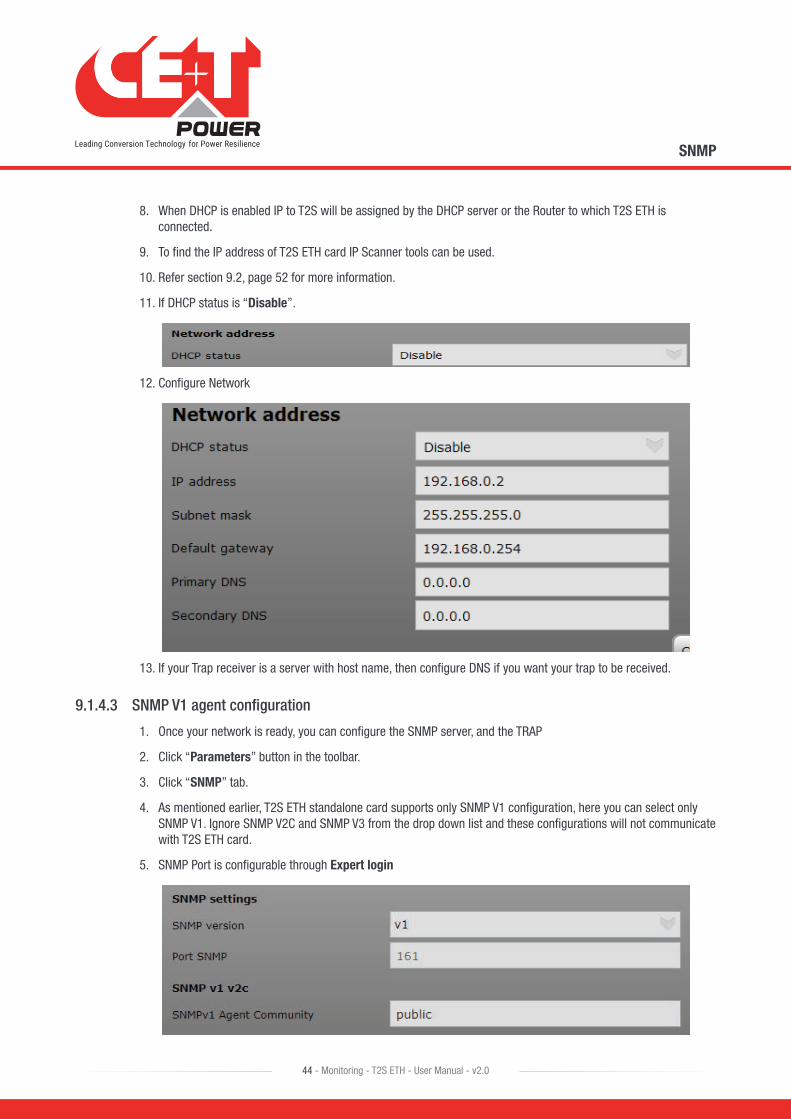
11. If DHCP status is “Disable”.
12. Configure Network
13. If your Trap receiver is a server with host name, then configure DNS if you want your trap to be received.
9.1.4.3 SNMP V1 agent configuration
1. Once your network is ready, you can configure the SNMP server, and the TRAP
2. Click “Parameters” button in the toolbar.
3. Click “SNMP” tab.
4. As mentioned earlier, T2S ETH standalone card supports only SNMP V1 configuration, here you can select only SNMP V1. Ignore SNMP V2C and SNMP V3 from the drop down list and these configurations will not communicate with T2S ETH card.
5. SNMP Port is configurable through Expert login
SNMP
44 - Monitoring - T2S ETH - User Manual - v2.0
6. SNMP Port number is standard port 161 for V1 communication
7. SNMP V1 will not communicate when port number is changed from default port number even if the same port number is configured at the NMS end.
8. SNMP Agent Community is configurable, the same agent community name has to be used in NMS SNMP V1 profile.
9. Community name accepts a maximum of 15 ASCII characters.
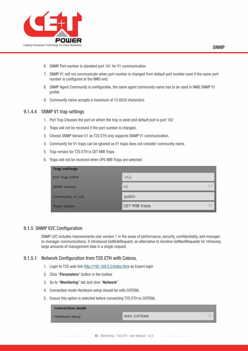
9.1.4.4 SNMP V1 trap settings
1. Port Trap Chooses the port on which the trap is send and default port is port 162
2. Traps will not be received if the port number is changed.
3. Choose SNMP Version V1 as T2S ETH only supports SNMP V1 communication.
4. Community for V1 traps can be ignored as V1 traps does not consider community name.
5. Trap version for T2S ETH is CET MIB Traps
6. Traps will not be received when UPS MIB Traps are selected.
9.1.5 SNMP V2C Configuration
SNMP v2C includes improvements over version 1 in the areas of performance, security, confidentiality, and manager-to-manager communications. It introduced GetBulkRequest, an alternative to iterative GetNextRequests for retrieving large amounts of management data in a single request.
9.1.5.1 Network Configuration from T2S ETH with Catena.
1. Login to T2S web link http://192.168.0.2/index.html as Expert login
2. Click “Parameters” button in the toolbar.
3. Go to “Monitoring” tab and click “Network”.
4. Connection mode Hardware setup should be with CATENA.
5. Ensure this option is selected before connecting T2S ETH to CATENA.
SNMP
45 - Monitoring - T2S ETH - User Manual - v2.0
9.1.5.2 SNMP V2C agent configuration
1. SNMP V2C can be configured when T2S ETH is connected to Catena
2. Login to T2S web page in Expert login
3. Click “Parameters” button in the toolbar.
4. Click “SNMP” tab.
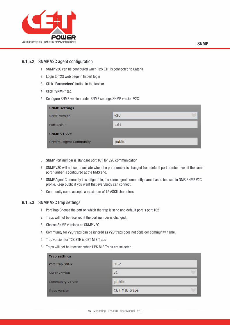
5. Configure SNMP version under SNMP settings SNMP version V2C
6. SNMP Port number is standard port 161 for V2C communication
7. SNMP V2C will not communicate when the port number is changed from default port number even if the same port number is configured at the NMS end.
8. SNMP Agent Community is configurable, the same agent community name has to be used in NMS SNMP V2C profile. Keep public if you want that everybody can connect.
9. Community name accepts a maximum of 15 ASCII characters.
9.1.5.3 SNMP V2C trap settings
1. Port Trap Choose the port on which the trap is send and default port is port 162
2. Traps will not be received if the port number is changed.
3. Choose SNMP versions as SNMP V2C
4. Community for V2C traps can be ignored as V2C traps does not consider community name.
5. Trap version for T2S ETH is CET MIB Traps
6. Traps will not be received when UPS MIB Traps are selected.
SNMP
46 - Monitoring - T2S ETH - User Manual - v2.0

9.1.6 SNMP V3 Configuration
SNMPv3 defines a secure version of SNMP and also facilitates the remote configuration of the SNMP entities. SNMP V3 configuration is possible only if you have a catena.
Network Configuration is the same as SNMP V2C.
The three possible configuration options are
• No Auth + No Encrypt: no authentication required, so anybody on the network can access or know what you’re doing.
• Auth + No Encrypt: To have access one must be logged (authenticate). But anybody on the network knows what he is doing by reading the network packets.
• Auth + Encrypt: must be authenticate AND all the network packets send are encrypted and thus, nobody know what the user is doing except the user himself of course.
9.1.6.1 SNMP V3 Configuration No Auth + No Encrypt.
1. SNMP V3 can be configured when T2S ETH is connected to Catena
2. Login to T2S web page in Expert login
3. Click “Parameters” button in the toolbar.
4. Click “SNMP” tab.
5. Configure SNMP version under SNMP settings select “v3 No Auth. + No Encrypt”.
6. SNMP Port number is standard port 161 for V3 communication
7. SNMP V3 will not communicate when port number is changed from default port number even if the same port number is configured at the NMS end.
8. Context name has to match the name used in NMS, context name accepts a maximum of 15 ASCII characters.
9. SNMP NoAuth user is configurable, the same user name has to be used in NMS SNMP V3 profile.
10. User name accepts a maximum of 15 ASCII characters.
9.1.6.2 SNMP V3 No Auth + No Encrypt trap settings.
1. Port Trap choose the port on which the trap is send and default port is port 162
2. Traps will not be received if the port number is changed.
3. Choose SNMP versions as SNMP V3 No Auth. + No Encrypt.
SNMP
47 - Monitoring - T2S ETH - User Manual - v2.0
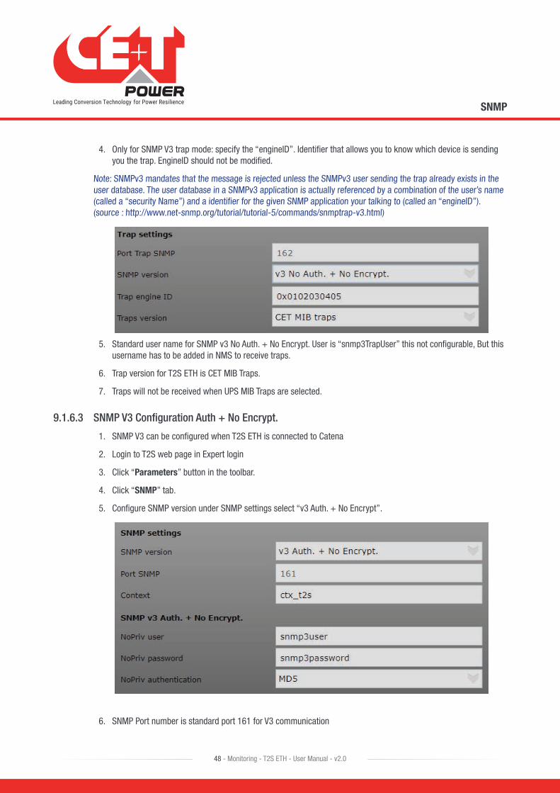
4. Only for SNMP V3 trap mode: specify the “engineID”. Identifier that allows you to know which device is sending you the trap. EngineID should not be modified.
Note: SNMPv3 mandates that the message is rejected unless the SNMPv3 user sending the trap already exists in the user database. The user database in a SNMPv3 application is actually referenced by a combination of the user’s name (called a “security Name”) and a identifier for the given SNMP application your talking to (called an “engineID”). (source : http://www.net-snmp.org/tutorial/tutorial-5/commands/snmptrap-v3.html)
5. Standard user name for SNMP v3 No Auth. + No Encrypt. User is “snmp3TrapUser” this not configurable, But this username has to be added in NMS to receive traps.
6. Trap version for T2S ETH is CET MIB Traps.
7. Traps will not be received when UPS MIB Traps are selected.
9.1.6.3 SNMP V3 Configuration Auth + No Encrypt.
1. SNMP V3 can be configured when T2S ETH is connected to Catena
2. Login to T2S web page in Expert login
3. Click “Parameters” button in the toolbar.
4. Click “SNMP” tab.
5. Configure SNMP version under SNMP settings select “v3 Auth. + No Encrypt”.
6. SNMP Port number is standard port 161 for V3 communication
SNMP
48 - Monitoring - T2S ETH - User Manual - v2.0
7. SNMP V3 will not communicate when port number is changed from default port number even if the same port number is configured at the NMS end.
8. Context name has to match the name used in NMS, Context name accepts a maximum of 15 ASCII characters.
9. NoPriv user name has to match the name used in V3 profile in NMS, user name accepts a maximum of 15 ASCII characters.
10. When No Auth same user name used for NoPriv user Error (109) will be displayed. Try creating new user name.
11. NoPriv password has to match the password used in V3 profile in NMS, Password accepts a maximum of 15 ASCII characters.
12. NoPriv authentication is the hash method used to login (take care that MD5 is the weakest of the list. SHA recommended).
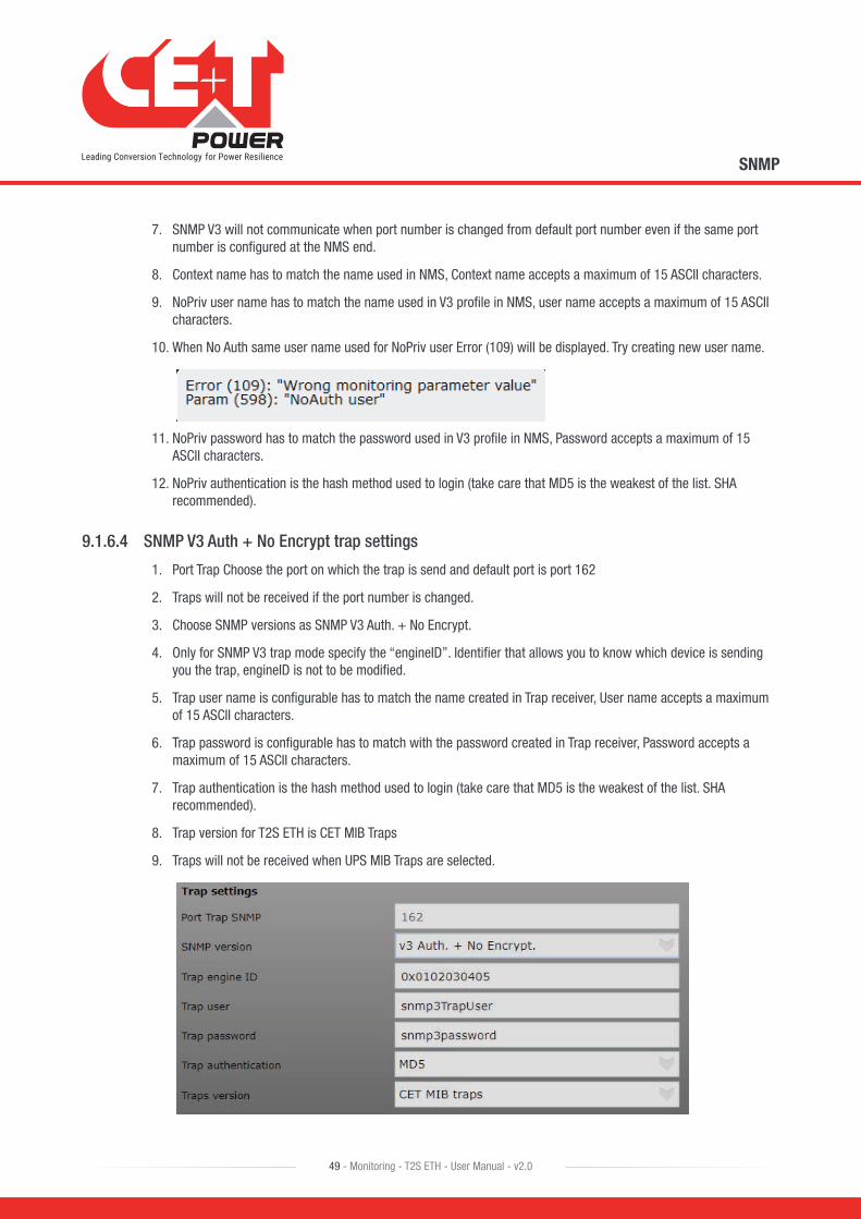
9.1.6.4 SNMP V3 Auth + No Encrypt trap settings
1. Port Trap Choose the port on which the trap is send and default port is port 162
2. Traps will not be received if the port number is changed.
3. Choose SNMP versions as SNMP V3 Auth. + No Encrypt.
4. Only for SNMP V3 trap mode specify the “engineID”. Identifier that allows you to know which device is sending you the trap, engineID is not to be modified.
5. Trap user name is configurable has to match the name created in Trap receiver, User name accepts a maximum of 15 ASCII characters.
6. Trap password is configurable has to match with the password created in Trap receiver, Password accepts a maximum of 15 ASCII characters.
7. Trap authentication is the hash method used to login (take care that MD5 is the weakest of the list. SHA recommended).
8. Trap version for T2S ETH is CET MIB Traps
9. Traps will not be received when UPS MIB Traps are selected.
SNMP
49 - Monitoring - T2S ETH - User Manual - v2.0
9.1.6.5 SNMP configuration Auth + Encrypt
1. SNMP V3 can be configured when T2S ETH is connected to Catena
2. Login to T2S web page in Expert login
3. Click “Parameters” button in the toolbar.
4. Click “SNMP” tab.
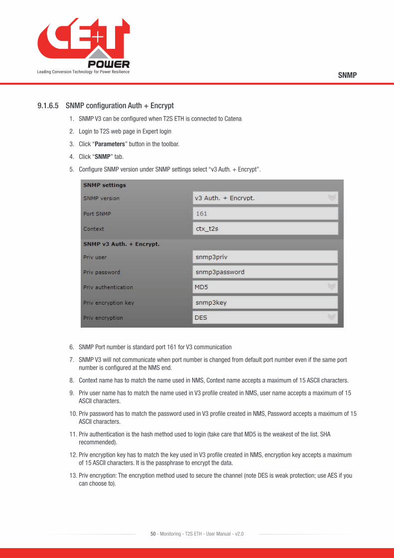
5. Configure SNMP version under SNMP settings select “v3 Auth. + Encrypt”.
6. SNMP Port number is standard port 161 for V3 communication
7. SNMP V3 will not communicate when port number is changed from default port number even if the same port number is configured at the NMS end.
8. Context name has to match the name used in NMS, Context name accepts a maximum of 15 ASCII characters.
9. Priv user name has to match the name used in V3 profile created in NMS, user name accepts a maximum of 15 ASCII characters.
10. Priv password has to match the password used in V3 profile created in NMS, Password accepts a maximum of 15 ASCII characters.
11. Priv authentication is the hash method used to login (take care that MD5 is the weakest of the list. SHA recommended).
12. Priv encryption key has to match the key used in V3 profile created in NMS, encryption key accepts a maximum of 15 ASCII characters. It is the passphrase to encrypt the data.
13. Priv encryption: The encryption method used to secure the channel (note DES is weak protection; use AES if you can choose to).
SNMP
50 - Monitoring - T2S ETH - User Manual - v2.0
9.1.6.6 SNMP V3 Auth + Encrypt trap settings.
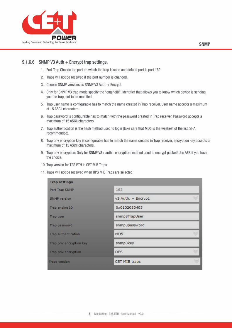
1. Port Trap Choose the port on which the trap is send and default port is port 162
2. Traps will not be received if the port number is changed.
3. Choose SNMP versions as SNMP V3 Auth. + Encrypt.
4. Only for SNMP V3 trap mode specify the “engineID”. Identifier that allows you to know which device is sending you the trap, not to be modified.
5. Trap user name is configurable has to match the name created in Trap receiver, User name accepts a maximum of 15 ASCII characters.
6. Trap password is configurable has to match with the password created in Trap receiver, Password accepts a maximum of 15 ASCII characters.
7. Trap authentication is the hash method used to login (take care that MD5 is the weakest of the list. SHA recommended).
8. Trap priv encryption key is configurable has to match the name created in Trap receiver, encryption key accepts a maximum of 15 ASCII characters.
9. Trap priv encryption: Only for SNMP V3+ auth+ encryption: method used to encrypt packet! Use AES if you have the choice.
10. Trap version for T2S ETH is CET MIB Traps
11. Traps will not be received when UPS MIB Traps are selected.
SNMP
51 - Monitoring - T2S ETH - User Manual - v2.0
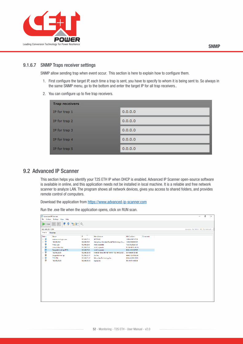
9.1.6.7 SNMP Traps receiver settings
SNMP allow sending trap when event occur. This section is here to explain how to configure them.
1. First configure the target IP, each time a trap is sent, you have to specify to whom it is being sent to. So always in the same SNMP menu, go to the bottom and enter the target IP for all trap receivers..
2. You can configure up to five trap receivers.
9.2 Advanced IP ScannerThis section helps you identify your T2S ETH IP when DHCP is enabled. Advanced IP Scanner open-source software is available in online, and this application needs not be installed in local machine. It is a reliable and free network scanner to analyze LAN. The program shows all network devices, gives you access to shared folders, and provides remote control of computers.
Download the application from https://www.advanced-ip-scanner.com
Run the .exe file when the application opens, click on RUN scan.
SNMP
52 - Monitoring - T2S ETH - User Manual - v2.0

9.3 SNMP V1 TestingThis section helps you to test the SNMP of your T2S ETH unit. There are several different software programs (some are free) is available online to download. Current example is given using “iReasoning MIB Browser”.
Here are the steps to follow:
1. Click File > Load MIBs and browse to locate on your hard drive, where the files downloaded on my.cet-power.com portal (CET-TSI-MIB.mib & CET-TSI-SMI.mib).
2. Once it is done, you can browse the MIB content under MIB Tree > iso.org.dod.internet > private > enterprises > cetMIB > cetTSIMIB
3. Fill the address field with your unit IP address.
SNMP
53 - Monitoring - T2S ETH - User Manual - v2.0
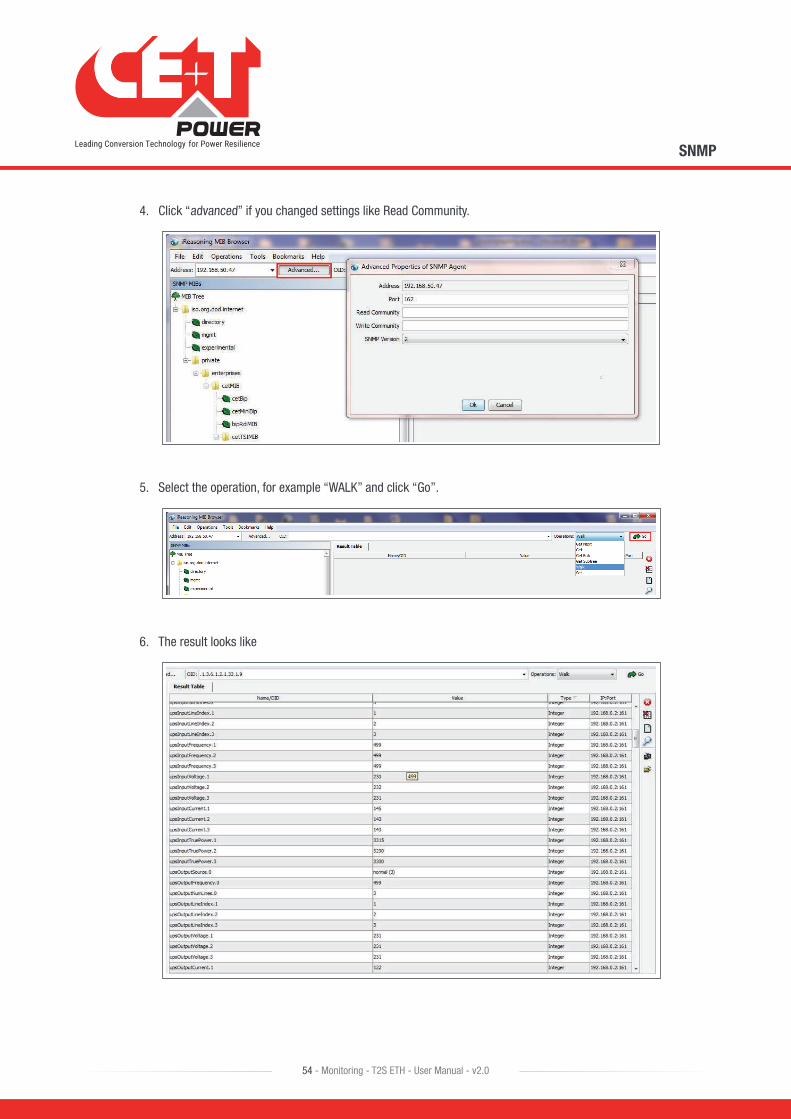
4. Click “advanced” if you changed settings like Read Community.
5. Select the operation, for example “WALK” and click “Go”.
6. The result looks like
SNMP
54 - Monitoring - T2S ETH - User Manual - v2.0

9.4 SNMP V1 TrapsTo check the SNMP V1 traps,
1. Click Tools > Trap Receiver on the menu bar.
2. You should have defined the IP address of the laptop running MIB Browser in the T2S ETH configuration in order to retrieve trap.
9.5 SNMP V3 TestingSnmpb-0.8.exe is the latest version of snmp tool. Download the file from this URL https://sourceforge.net/projects/snmpb/ and run the exe to install the application.
9.5.1 Steps to Load CET MIB
1. Open the application and navigate to editor.
2. Open CET-TSI-MIB and paste it in the editor.
3. Press Ctrl + S to save the file with the same file name.
4. Open CET-TSI-SIM and paste it in the editor.
SNMP
55 - Monitoring - T2S ETH - User Manual - v2.0

5. Press Ctrl + S to save the file with the same file name.
6. Navigate to Modules Tab.
7. Check CET-TSI-MIB and CET-TSI-SIM are listed under available MIB Modules.
8. Select the above files and Press right arrow to move the files to Loaded MIB Module.
9. By doing this CET MIB files are loaded to SNMPB MIB tree.
10. Navigate to tree tab and check for CET MIB under iso-org-dod-internet-private-enterprises-cetMIB.
SNMP
56 - Monitoring - T2S ETH - User Manual - v2.0

9.5.2 Steps to Discover Device
1. Navigate to Discovery tab.
2. Select IP option and enter From and To IP addresses, this would be the IP address range of T2S ETH IP.
3. SNMP Agent profile to be selected based on the type of SNMP communication.
4. Click on discover device.
5. T2S device will be discovered.
6. Right click on the device and add device to agent profile list.
SNMP
57 - Monitoring - T2S ETH - User Manual - v2.0

9.5.3 Steps to Get / Walk OID
1. Select the SNMP Agent under remote SNMP agent.
2. The Added SNMP Agent has to be listed in the list.
3. Right click on the OID to perform walk or Get.
9.5.4 Steps to add SNMP V3 User
1. Navigate to Options – manage Agent Profile.
2. Select the Agent Profile and select the supported SNMP Version.
3. Select Manage SNMP3 USM User.
4. Right click on User profile and add new user profile.
5. Security username should be the Priv user name given in T2S ETH web page.
6. Authentication protocol, Authentication password, Privacy Protocol and Privacy password should also match with the values given in T2S ETH web page.
7. Click OK.
8. Navigate to Options – manage Agent Profile.
9. Select SNMP agent and select SNMP v3, under SNMP properties security name drop down list select the USM user created.
10. Select Security level NoAuth/NoPriv or Auth/NoPriv or AuthPriv as the once configured in T2S ETH web page.
11. Enter SNMP content text same as in T2S ETH web page.
SNMP
58 - Monitoring - T2S ETH - User Manual - v2.0

SNMP
59 - Monitoring - T2S ETH - User Manual - v2.0
10. FAQ1. I am unable to change the output phase of a module?
� Check that the number of phases is correctly configured in Configuration > Power > AC OUT > Nb of phase.
� Module should be manually turned off (module page).
� Don’t forget to turn the module back on when the phase is changed.
2. I have a system properly running with T2S USB, can I replace it with T2S ETH?
Of course, T2S ETH and T2S are 100% compatible. Once the load is fed, monitoring cannot cause any issue to it. Feel free to replace your old T2S with a new T2S ETH.
� T2S ETH is compatible with Candis.
� T2S ETH featured with SNMP and SNMP supports only V1. So, the TCP IP section is not required. (SNMP V2c and V3 are available through Catena.)
Pay attention to:
� MBP monitoring is a T2S configuration parameter that should be reconfigured in your new T2S ETH once it’s up and running.
� Operating parameter need to be cross check, and IP setting must reconfigured.
3. I want to replace a power module in my system. What should I do?
� Remove the module
� Browse to module selection pop-up.
� The removed module appears in red. Click on it.
� This brings you to module page. Uninstall the module by clicking the uninstall button.
� Insert the new module.
� Module will appears on module selection pop-up.
� Its address can be changed by browsing to module page.
4. How can I reset my admin password if I have unfortunately forgotten it?
In case of password lost, a new temporary password (valid 24 hrs after creation) can be issued by CE+T Power. To receive a temporary password, send an email with your T2S ETH serial Number and the date at which you expect to go back on site to change the password to [email protected] specifically requesting a new temporary password. The serial number can be found on the sticker on the T2S ETH, or on screen in “Parameters” then “Info”.
FAQ
60 - Monitoring - T2S ETH - User Manual - v2.0

5. What is the purpose of the SNMP trap community?
T2S ETH device features the ability to send SNMP Trap events to a configured SNMP trap receiver. This could be Test Traps and Traps sent when there is an alarm.
These traps receivers can be configured in T2S ETH web page under parameters -> SNMP -> Trap receiver in Expert Login.
A maximum of 5 Trap receivers can be configured in T2S ETH.
The purpose of SNMP trap community string:
• This is an added measure of security, operators may configure a trap community string which is used by the trap receiver to determine which traps are to be accepted from a device.
• This parameter is useful to avoid unwanted floods of Traps from a malicious source, by configuring Trap community string only relevant traps are processed by the trap receiver.
• Filtering on Trap Community string is used to process relevant Traps.
6. After migrating from T2S USB to T2S ETH, what changes can you expect in Modbus?
There are more changes between USB and ETH versions, to know about the changes, refer to section 17.6, page 109.
FAQ
61 - Monitoring - T2S ETH - User Manual - v2.0
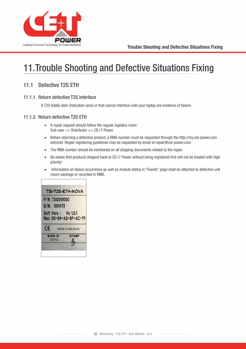
11. Trouble Shooting and Defective Situations Fixing
11.1 Defective T2S ETH
11.1.1 Return defective T2S interface
A T2S totally dark (indication area) or that cannot interface with your laptop are evidence of failure.
11.1.2 Return defective T2S ETH
• A repair request should follow the regular logistics chain: End-user => Distributor => CE+T Power.
• Before returning a defective product, a RMA number must be requested through the http://my.cet-power.com extranet. Repair registering guidelines may be requested by email at [email protected].
• The RMA number should be mentioned on all shipping documents related to the repair.
• Be aware that products shipped back to CE+T Power without being registered first will not be treated with high priority!
• Information on failure occurrence as well as module status in “Events” page shall be attached to defective unit return package or recorded in RMA.
Trouble Shooting and Defective Situations Fixing
62 - Monitoring - T2S ETH - User Manual - v2.0

12. ServiceFor Service
• Check Service Level Agreement (SLA) of your vendor. Most of the time they provide assistance on call with integrated service. If such SLA is in place, you must call their assistance first.
• If your vendor doesn’t provide such assistance (*) you may call CE+T directly. Toll free Number 1(855) 669 - 4627(**)
Service is available from 8:00 A.M. to 10:00 P.M. EST, Monday through Friday, except closing periods for holidays or inclement weather.
Major Incidents and Emergency conditions can be invoked for immediate handling of same number or by dropping a mail on [email protected] (***)
(*) CE+T will redirect your call to your vendor if he has such SLA in place.
(**) Valid in USA and Canada only.
(***) Messages that are not Major Incident or Emergency will be served at the next scheduled working a day.
Service
63 - Monitoring - T2S ETH - User Manual - v2.0

13. Maintenance TaskAs maintenance will perform on live system, all task should perform only by trained people with sufficient knowledge on TSI and ECI product.
Tasks:
• Identify the site, customer, responsible, cabinet number, product type.
• Download and save configuration file for back up.
• Check configuration file to be in accordance with operational site conditions.
• Read and save log file for back up.
• Check and analyze log file, and if alarm are present.
• Replace dust filter if present. Filter is mandatory in dusty environment.
• Check module temperature and log value. If the internal temperature is higher than the previous year, determine if this is due to increased load, accumulated dust or reduced airflow. It is common to have a delta of 15°C by 30% of the load between the ambient and the internal temperature. If temperature increases due to internal dust built up, clean the module by air suction blower or vacuum cleaner.
• Clean cabinet (vacuum cleaner or dry cloth)
• Control the inverter mapping (AC Group, DC Group, Address)
• Check load level and record the rate value (print in word document the 4 screen modules information for the 32 modules, the 3 screen for the phases value and the 2 screens for the group AC and DC value)
• Change the configuration file for AC and DC mix mode to check that all TSI work on both power supply
• Check alarm operation (e.g., redundancy lost, mains failure, DC failure) on dry contact and through SNMP system or web interface.
• Switch OFF AC IN and check alarms.
• Check temperature terminal and temperature wiring. If possible use an infrared camera.
• Read and record value as wave form, power factor, Crest factor, THD I from power analyzer.
• Take cabinet picture
• Keep track of report and provide end user with a copy.
• Perform a MBP procedure. This task is not really recommended*, but could be demanded by site manager.
* It is not recommended because when you perform a By-pass procedure, generally there is no back up on AC input line, and the load shutdown if mains disappear.
Maintenance Task
64 - Monitoring - T2S ETH - User Manual - v2.0
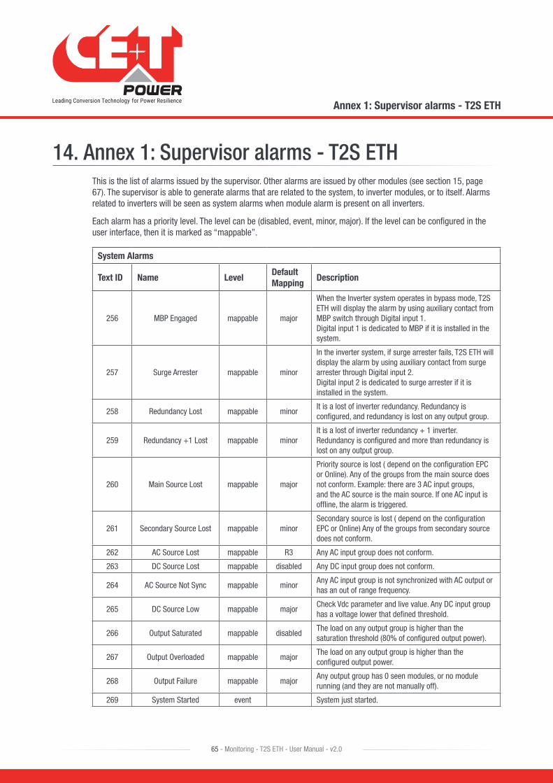
14. Annex 1: Supervisor alarms - T2S ETHThis is the list of alarms issued by the supervisor. Other alarms are issued by other modules (see section 15, page 67). The supervisor is able to generate alarms that are related to the system, to inverter modules, or to itself. Alarms related to inverters will be seen as system alarms when module alarm is present on all inverters.
Each alarm has a priority level. The level can be (disabled, event, minor, major). If the level can be configured in the user interface, then it is marked as “mappable”.
System Alarms
Text ID Name LevelDefault Mapping
Description
256 MBP Engaged mappable major
When the Inverter system operates in bypass mode, T2S ETH will display the alarm by using auxiliary contact from MBP switch through Digital input 1. Digital input 1 is dedicated to MBP if it is installed in the system.
257 Surge Arrester mappable minor
In the inverter system, if surge arrester fails, T2S ETH will display the alarm by using auxiliary contact from surge arrester through Digital input 2. Digital input 2 is dedicated to surge arrester if it is installed in the system.
258 Redundancy Lost mappable minorIt is a lost of inverter redundancy. Redundancy is configured, and redundancy is lost on any output group.
259 Redundancy +1 Lost mappable minorIt is a lost of inverter redundancy + 1 inverter. Redundancy is configured and more than redundancy is lost on any output group.
260 Main Source Lost mappable major
Priority source is lost ( depend on the configuration EPC or Online). Any of the groups from the main source does not conform. Example: there are 3 AC input groups, and the AC source is the main source. If one AC input is offline, the alarm is triggered.
261 Secondary Source Lost mappable minorSecondary source is lost ( depend on the configuration EPC or Online) Any of the groups from secondary source does not conform.
262 AC Source Lost mappable R3 Any AC input group does not conform.
263 DC Source Lost mappable disabled Any DC input group does not conform.
264 AC Source Not Sync mappable minorAny AC input group is not synchronized with AC output or has an out of range frequency.
265 DC Source Low mappable majorCheck Vdc parameter and live value. Any DC input group has a voltage lower that defined threshold.
266 Output Saturated mappable disabledThe load on any output group is higher than the saturation threshold (80% of configured output power).
267 Output Overloaded mappable majorThe load on any output group is higher than the configured output power.
268 Output Failure mappable majorAny output group has 0 seen modules, or no module running (and they are not manually off).
269 System Started event System just started.
Annex 1: Supervisor alarms - T2S ETH
65 - Monitoring - T2S ETH - User Manual - v2.0

System Alarms
Text ID Name LevelDefault Mapping
Description
272 Missing Module eventModule is removed or defect. No module is detected on system bus.
273 New Module event All modules have just been detected on system bus.
274 Manually OFF mappable disabledInverter are switched OFF by the OFF function in hyper terminal. All modules outputs are manually turned off.
275 Output Fault event All modules outputs are turned off because of a fault.
276 Brownout Derating eventAC in below threshold - reduce power from the AC input and pulls power form the DC input. All modules AC inputs are derated because of a brown-out.
278 Temperature Derating eventHeat sink temperature is over rating. All modules outputs are derated because of an over temperature.
279 Overtemperature eventTemperature is too high in the room or bad cooling, or component defective inside inverter. All modules outputs are turned off because of an over temperature.
Supervisor T2S ETH Alarms
Text ID Name Level Def. Map Description
512 Digital Input 1 mappable disabledDigital input 1 is in low state and digital input 1 is NOT used for MBP signaling.
513 Digital Input 2 mappable disabledDigital input 2 is in low state and digital input 2 is NOT used for surge arrester signaling.
514 Log Nearly Full mappable disabled Log file is nearly full.
515 Log Full mappable disabled Log file is full (with information loss).
516 Log Cleared event Log file has just been cleared.
517 Config modified event Configuration has just been modified.
Annex 1: Supervisor alarms - T2S ETH
66 - Monitoring - T2S ETH - User Manual - v2.0
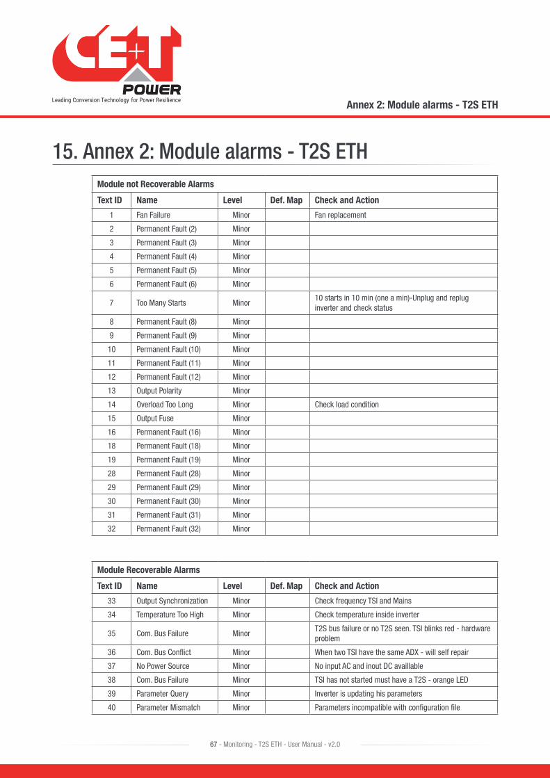
15. Annex 2: Module alarms - T2S ETHModule not Recoverable Alarms
Text ID Name Level Def. Map Check and Action
1 Fan Failure Minor Fan replacement
2 Permanent Fault (2) Minor
3 Permanent Fault (3) Minor
4 Permanent Fault (4) Minor
5 Permanent Fault (5) Minor
6 Permanent Fault (6) Minor
7 Too Many Starts Minor10 starts in 10 min (one a min)-Unplug and replug inverter and check status
8 Permanent Fault (8) Minor
9 Permanent Fault (9) Minor
10 Permanent Fault (10) Minor
11 Permanent Fault (11) Minor
12 Permanent Fault (12) Minor
13 Output Polarity Minor
14 Overload Too Long Minor Check load condition
15 Output Fuse Minor
16 Permanent Fault (16) Minor
18 Permanent Fault (18) Minor
19 Permanent Fault (19) Minor
28 Permanent Fault (28) Minor
29 Permanent Fault (29) Minor
30 Permanent Fault (30) Minor
31 Permanent Fault (31) Minor
32 Permanent Fault (32) Minor
Module Recoverable Alarms
Text ID Name Level Def. Map Check and Action
33 Output Synchronization Minor Check frequency TSI and Mains
34 Temperature Too High Minor Check temperature inside inverter
35 Com. Bus Failure MinorT2S bus failure or no T2S seen. TSI blinks red - hardware problem
36 Com. Bus Conflict Minor When two TSI have the same ADX - will self repair
37 No Power Source Minor No input AC and inout DC availlable
38 Com. Bus Failure Minor TSI has not started must have a T2S - orange LED
39 Parameter Query Minor Inverter is updating his parameters
40 Parameter Mismatch Minor Parameters incompatible with configuration file
Annex 2: Module alarms - T2S ETH
67 - Monitoring - T2S ETH - User Manual - v2.0
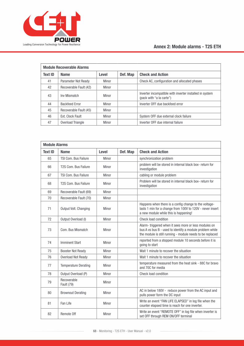
Module Recoverable Alarms
Text ID Name Level Def. Map Check and Action
41 Parameter Not Ready Minor Check AC, configuration and allocated phases
42 Recoverable Fault (42) Minor
43 Inv Mismatch MinorInverter incompatible with inverter installed in system (pack with “a la carte”)
44 Backfeed Error Minor Inverter OFF due backfeed error
45 Recoverable Fault (45) Minor
46 Ext. Clock Fault Minor System OFF due external clock failure
47 Overload Triangle Minor Inverter OFF due internal failure
Module Alarms
Text ID Name Level Def. Map Check and Action
65 TSI Com. Bus Failure Minor synchronization problem
66 T2S Com. Bus Failure Minorproblem will be stored in internal black box- return for investigation
67 TSI Com. Bus Failure Minor cabling or module problem
68 T2S Com. Bus Failure MinorProblem will be stored in internal black box- return for investigation
69 Recoverable Fault (69) Minor
70 Recoverable Fault (70) Minor
71 Output Volt. Changing MinorHappens when there is a config change to the voltage- lasts 1 min for a change from 100V to 120V - never insert a new module while this is happening!
72 Output Overload (I) Minor Check load condition
73 Com. Bus Mismatch MinorAlarm- triggered when it sees more or less modules on bus A vs bus B - used to identify a module problem while the module is still running - module needs to be replaced
74 Imminent Start Minorreported from a stopped module 10 seconds before it is going to start
75 Booster Not Ready Minor Wait 1 minute to recover the situation
76 Overload Not Ready Minor Wait 1 minute to recover the situation
77 Temperature Derating Minortemperature measured from the heat sink - 88C for bravo and 70C for media
78 Output Overload (P) Minor Check load condition
79Recoverable Fault (79)
Minor
80 Brownout Derating MinorAC in below 180V - reduce power from the AC input and pulls power form the DC input
81 Fan Life MinorWrite an event “FAN LIFE ELAPSED” in log file when the counter elapsed time is reach for one inverter.
82 Remote Off MinorWrite an event “REMOTE OFF” in log file when inverter is set OFF through REM ON/OFF terminal
Annex 2: Module alarms - T2S ETH
68 - Monitoring - T2S ETH - User Manual - v2.0

Module Alarms
Text ID Name Level Def. Map Check and Action
83 Manual Off MinorWrite an event “MANUALLY OFF” in log file when module is set OFF through hyperterminal
84 Triangle Off Minor Inverter in OFF position due triangle mode failure
85Recoverable Fault (85)
Minor
86Recoverable Fault (86)
Minor
88Recoverable Fault (88)
Minor
Module AC Input Alarms
Text ID Name Level Def. Map Check and Action
160 Ok No error on AC IN
161Source V Too Low Transfert
Minor Check AC IN configuration and live value
162Source V Too High Transfert
Minor Check AC IN configuration and live value
163 Error (163) Minor
164 Error (164) Minor
165Source V Too Low Transfert
Minor Check AC IN configuration and live value
166Source V Too High Transfert
Minor Check AC IN configuration and live value
167 Source Not conform Minor Check AC IN configuration and live value
168 Source Not conform Minor Check AC IN configuration and live value
169 Source Not conform Minor Check AC IN configuration and live value
170 Power Disabled Minor AC input converter is only use for synchronization
171 Source Not conform Minor Check AC IN configuration and live value
172 THD Too High Minor Check AC IN configuration and live value
173 Output Synchronization Minor Check AC IN configuration and live value
174 Error (174) Minor
175 Output Synchronization Minor Check synchronization between AC IN and AC OUT
176 Inv. Synchronization Minor Check synchronization between AC IN and AC OUT
177 Synchronization failure Minor Check synchronization between AC IN and AC OUT
179 Source V Too Low Stop Minor Check AC IN configuration and live value
180 Source V Too High Stop Minor Check AC IN configuration and live value
181 Source Frequ. Too Low Minor Check AC IN configuration and live value
182 Source Frequ. Too High Minor Check AC IN configuration and live value
183 Phase Not Ready Minor Check AC IN configuration and live value
184 Backfeed Error Minor Inverter in backfeed protection
Annex 2: Module alarms - T2S ETH
69 - Monitoring - T2S ETH - User Manual - v2.0
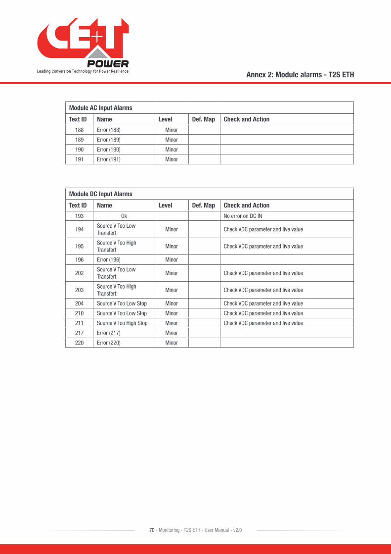
Module AC Input Alarms
Text ID Name Level Def. Map Check and Action
188 Error (188) Minor
189 Error (189) Minor
190 Error (190) Minor
191 Error (191) Minor
Module DC Input Alarms
Text ID Name Level Def. Map Check and Action
193 Ok No error on DC IN
194Source V Too Low Transfert
Minor Check VDC parameter and live value
195Source V Too High Transfert
Minor Check VDC parameter and live value
196 Error (196) Minor
202Source V Too Low Transfert
Minor Check VDC parameter and live value
203Source V Too High Transfert
Minor Check VDC parameter and live value
204 Source V Too Low Stop Minor Check VDC parameter and live value
210 Source V Too Low Stop Minor Check VDC parameter and live value
211 Source V Too High Stop Minor Check VDC parameter and live value
217 Error (217) Minor
220 Error (220) Minor
Annex 2: Module alarms - T2S ETH
70 - Monitoring - T2S ETH - User Manual - v2.0

16. Annex 3: Configuration parameters - T2S ETH
16.1 MontioringDisclaimer: The configuration file should be manually edited only by CE+T crew or any especially trained operator. All modifiable values contained here are easily accessible through the T2S ETH web interface which allow you to change the configuration carefully. Any mistake done in this file could lead to system malfunction and CE+T shall not guarantee the behavior of the whole system once this file has been corrupted.
• Time
Text ID Name Values Description
Time HH : MN : SS Set the Time in Hours : Minutes : Seconds
Date DD : MM : YY Set the Date in Day : Month : Year
• Regional settings
Text ID Name Values Description
Regional settings
525 Language
English
Select a language for User interfaceFrench
German
523 Sitename CE+T Enter the site name which will appear in user interface banner
524 Location Belgium Enter the location of the system installed.
562 Auto logout delay 1 - 6000 seconds The auto logout time for Expert login
561 Keyboard layoutazerty
Keyboard layout for Catena touch screenqwerty
631New module
identifier
Always ask Select a function to perform while inserting a new module.
• Always ask - System will ask to assign the address of every newly inserted module.
• Always replace - System will assign the address of the replaced module automatically.
• Never replace - System will assign the module address randomly.
Always replace
Never replace
634 Home page
Classic homepage User interface display for home page.
• Classic home page - Displays information of AC IN, DC IN, and AC OUT parameters, for more information user has to click Magnifier button.
• Alternate homepage - Displays brief information of parameters in single page without clicking Magnifier button.
Alternate homepage
Display format
620 Date format
DD/MM/YYYY
Date format for user interface and user logYYYY/MM/DD
MM/DD/YYYY
621 Time format24H
Time format for user interface and user log12H
Annex 3: Configuration parameters - T2S ETH
71 - Monitoring - T2S ETH - User Manual - v2.0
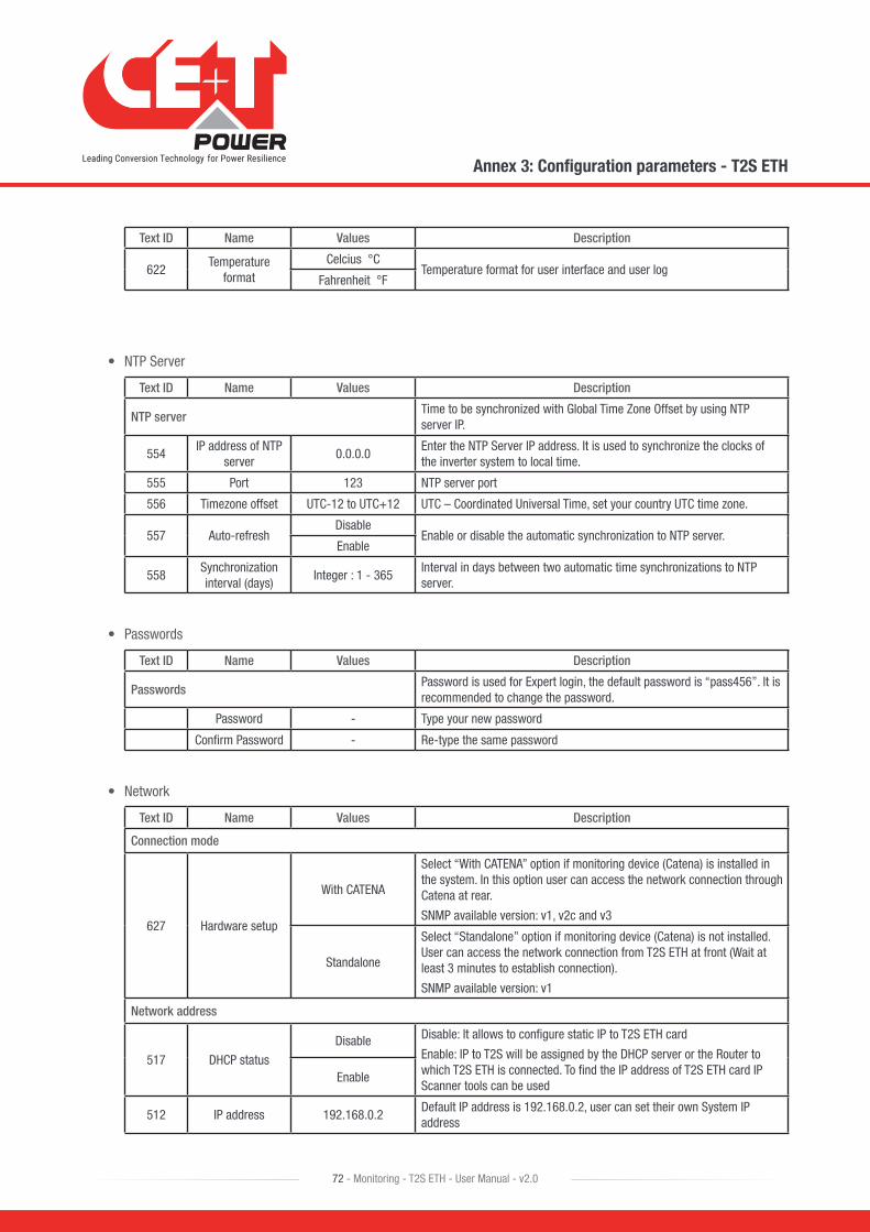
Text ID Name Values Description
622Temperature
formatCelcius °C
Temperature format for user interface and user logFahrenheit °F
• NTP Server
Text ID Name Values Description
NTP serverTime to be synchronized with Global Time Zone Offset by using NTP server IP.
554IP address of NTP
server0.0.0.0
Enter the NTP Server IP address. It is used to synchronize the clocks of the inverter system to local time.
555 Port 123 NTP server port
556 Timezone offset UTC-12 to UTC+12 UTC – Coordinated Universal Time, set your country UTC time zone.
557 Auto-refreshDisable
Enable or disable the automatic synchronization to NTP server.Enable
558Synchronization interval (days)
Integer : 1 - 365Interval in days between two automatic time synchronizations to NTP server.
• Passwords
Text ID Name Values Description
PasswordsPassword is used for Expert login, the default password is “pass456”. It is recommended to change the password.
Password - Type your new password
Confirm Password - Re-type the same password
• Network
Text ID Name Values Description
Connection mode
627 Hardware setup
With CATENA
Select “With CATENA” option if monitoring device (Catena) is installed in the system. In this option user can access the network connection through Catena at rear.
SNMP available version: v1, v2c and v3
Standalone
Select “Standalone” option if monitoring device (Catena) is not installed. User can access the network connection from T2S ETH at front (Wait at least 3 minutes to establish connection).
SNMP available version: v1
Network address
517 DHCP status
Disable Disable: It allows to configure static IP to T2S ETH card
Enable: IP to T2S will be assigned by the DHCP server or the Router to which T2S ETH is connected. To find the IP address of T2S ETH card IP Scanner tools can be used
Enable
512 IP address 192.168.0.2Default IP address is 192.168.0.2, user can set their own System IP address
Annex 3: Configuration parameters - T2S ETH
72 - Monitoring - T2S ETH - User Manual - v2.0
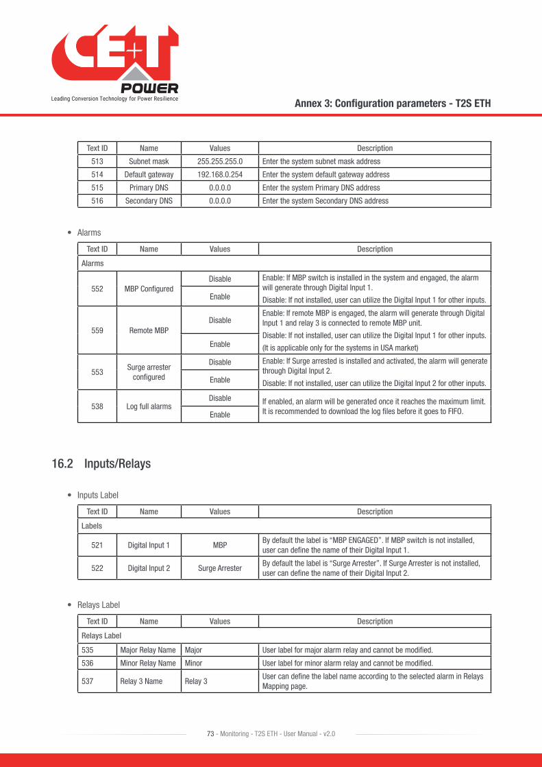
Text ID Name Values Description
513 Subnet mask 255.255.255.0 Enter the system subnet mask address
514 Default gateway 192.168.0.254 Enter the system default gateway address
515 Primary DNS 0.0.0.0 Enter the system Primary DNS address
516 Secondary DNS 0.0.0.0 Enter the system Secondary DNS address
• Alarms
Text ID Name Values Description
Alarms
552 MBP ConfiguredDisable Enable: If MBP switch is installed in the system and engaged, the alarm
will generate through Digital Input 1.
Disable: If not installed, user can utilize the Digital Input 1 for other inputs.Enable
559 Remote MBPDisable
Enable: If remote MBP is engaged, the alarm will generate through Digital Input 1 and relay 3 is connected to remote MBP unit.
Disable: If not installed, user can utilize the Digital Input 1 for other inputs.
(It is applicable only for the systems in USA market)Enable
553Surge arrester
configured
Disable Enable: If Surge arrested is installed and activated, the alarm will generate through Digital Input 2.
Disable: If not installed, user can utilize the Digital Input 2 for other inputs.Enable
538 Log full alarmsDisable If enabled, an alarm will be generated once it reaches the maximum limit.
It is recommended to download the log files before it goes to FIFO.Enable
16.2 Inputs/Relays
• Inputs Label
Text ID Name Values Description
Labels
521 Digital Input 1 MBPBy default the label is “MBP ENGAGED”. If MBP switch is not installed, user can define the name of their Digital Input 1.
522 Digital Input 2 Surge ArresterBy default the label is “Surge Arrester”. If Surge Arrester is not installed, user can define the name of their Digital Input 2.
• Relays Label
Text ID Name Values Description
Relays Label
535 Major Relay Name Major User label for major alarm relay and cannot be modified.
536 Minor Relay Name Minor User label for minor alarm relay and cannot be modified.
537 Relay 3 Name Relay 3User can define the label name according to the selected alarm in Relays Mapping page.
Annex 3: Configuration parameters - T2S ETH
73 - Monitoring - T2S ETH - User Manual - v2.0

• Relays Delay
Text ID Name Values Description
Relays Delay
532 Major Relay delay
2 to 60 secondsUser can set the time (2 to 60s) for Relay to get energize after the alarm is generated.
533 Minor Relay delay
534 Relay 3 delay
• Relays Mapping
Text ID Name Values Description
Relays Mapping
543 MBP Engaged
Major
Minor
Relay 3
In this page, all the alarms from the modules and systems will be listed. User can set these alarms as major or minor.
T2S ETH has one user selectable Alarm – Relay 3. It can be assigned any one alarm from the list.
549 Surge Arrester
545 Redundancy Lost
550 Redundancy +1 lost
563 Sync Redundancy Lost
564 All Sync Modules Lost
580 Main Source Lost
581 Secondary Source Lost
539 AC Source Lost
585 DC Source Lost
546 AC Source Not Sync
586 DC Source Low
551 Output Saturated
544 Output Overload
540 Output Failure
590 System Manual Off
582 Missing Module
583 Module Manual Off
584 Module Output fault
589Module Brownout
Derating
591Module Temperature
Derating
548Module Over Temperature
541 Dig Input 1
542 Dig Input 2
587 Log Nearly Full
588 Log Full
Annex 3: Configuration parameters - T2S ETH
74 - Monitoring - T2S ETH - User Manual - v2.0

• Snmp traps
Text ID Name Values Description
General
543 MBP Engaged
Disable
EnableIf enabled, by using SNMP protocol these alarms can be used for TRAP receivers. ( number of TRAP receivers can set in SNMP page)
549 Surge Arrester
545 Redundancy
550Redundancy +1
lost
563Sync Redundancy
Lost
564All Sync Modules
Lost
580 Main Source Lost
581Secondary Source
Lost
539 AC Source Lost
585 DC Source Lost
546AC Source Not
Sync
Disable
Enable
If enabled, by using SNMP protocol these alarms can be used for TRAP receivers. (number of TRAP receivers can set in SNMP page)
586 DC Source Low
551 Output Saturated
544 Output Overload
540 Output Failure
590System Manual
Off
582 Missing Module
583 Module Manual Off
584Module Output
fault
589Module Brownout
Derating
591Module
Temperature Derating
548Module Over Temperature
541 Dig Input 1
542 Dig Input 2
587 Log Nearly Full
588 Log Full
633 Other alarms
Annex 3: Configuration parameters - T2S ETH
75 - Monitoring - T2S ETH - User Manual - v2.0
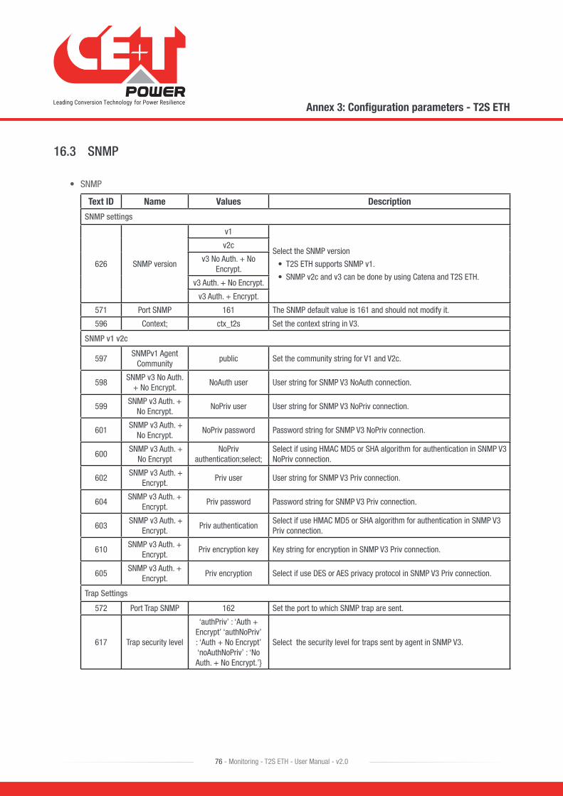
16.3 SNMP
• SNMP
Text ID Name Values Description
SNMP settings
626 SNMP version
v1
Select the SNMP version
• T2S ETH supports SNMP v1.
• SNMP v2c and v3 can be done by using Catena and T2S ETH.
v2c
v3 No Auth. + No Encrypt.
v3 Auth. + No Encrypt.
v3 Auth. + Encrypt.
571 Port SNMP 161 The SNMP default value is 161 and should not modify it.
596 Context; ctx_t2s Set the context string in V3.
SNMP v1 v2c
597SNMPv1 Agent
Communitypublic Set the community string for V1 and V2c.
598SNMP v3 No Auth.
+ No Encrypt.NoAuth user User string for SNMP V3 NoAuth connection.
599SNMP v3 Auth. +
No Encrypt.NoPriv user User string for SNMP V3 NoPriv connection.
601 SNMP v3 Auth. +
No Encrypt.NoPriv password Password string for SNMP V3 NoPriv connection.
600 SNMP v3 Auth. +
No EncryptNoPriv
authentication;select;Select if using HMAC MD5 or SHA algorithm for authentication in SNMP V3 NoPriv connection.
602 SNMP v3 Auth. +
Encrypt.Priv user User string for SNMP V3 Priv connection.
604SNMP v3 Auth. +
Encrypt.Priv password Password string for SNMP V3 Priv connection.
603 SNMP v3 Auth. +
Encrypt.Priv authentication
Select if use HMAC MD5 or SHA algorithm for authentication in SNMP V3 Priv connection.
610SNMP v3 Auth. +
Encrypt.Priv encryption key Key string for encryption in SNMP V3 Priv connection.
605SNMP v3 Auth. +
Encrypt.Priv encryption Select if use DES or AES privacy protocol in SNMP V3 Priv connection.
Trap Settings
572 Port Trap SNMP 162 Set the port to which SNMP trap are sent.
617 Trap security level
‘authPriv’ : ‘Auth + Encrypt’ ‘authNoPriv’ : ‘Auth + No Encrypt’ ‘noAuthNoPriv’ : ‘No Auth. + No Encrypt.’}
Select the security level for traps sent by agent in SNMP V3.
Annex 3: Configuration parameters - T2S ETH
76 - Monitoring - T2S ETH - User Manual - v2.0
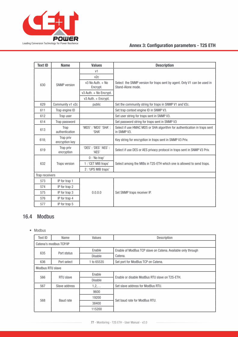
Text ID Name Values Description
630 SNMP version
v1
Select the SNMP version for traps sent by agent. Only V1 can be used in Stand-Alone mode.
v2c
v3 No Auth. + No Encrypt.
v3 Auth. + No Encrypt.
v3 Auth. + Encrypt.
629 Community v1 v2c public Set the community string for traps in SNMP V1 and V2c.
611 Trap engine ID Set trap context engine ID in SNMP V3.
612 Trap user Set user string for traps sent in SNMP V3.
614 Trap password Set password string for traps sent in SNMP V3
613Trap
authentication‘MD5’ : ‘MD5’ ‘SHA’ :
‘SHA’Select if use HMAC MD5 or SHA algorithm for authentication in traps sent in SNMP V3.
618;Trap priv
encryption keyKey string for encryption in traps sent in SNMP V3 Priv.
619Trap priv
encryption‘DES’ : ‘DES’ ‘AES’ :
‘AES’Select if use DES or AES privacy protocol in traps sent in SNMP V3 Priv.
632 Traps version
0 : ‘No trap’
Select among the MIBs in T2S-ETH which one is allowed to send traps.1 : ‘CET MIB traps’
2 : ‘UPS MIB traps’
Trap receivers
573 IP for trap 1
0.0.0.0 Set SNMP traps receiver IP.
574 IP for trap 2
575 IP for trap 3
576 IP for trap 4
577 IP for trap 5
16.4 Modbus
• Modbus
Text ID Name Values Description
Catena’s modbus TCP/IP
635 Port statusEnable Enable of ModBus TCP slave on Catena. Available only through
Catena.Disable
636 Port select 1 to 65535 Set port for ModBus TCP on Catena.
Modbus RTU slave
566 RTU slaveEnable
Enable or disable ModBus RTU slave on T2S-ETH.Disable
567 Slave address 1,2,… Set slave address for ModBus RTU.
568 Baud rate
9600
Set baud rate for ModBus RTU.19200
38400
115200
Annex 3: Configuration parameters - T2S ETH
77 - Monitoring - T2S ETH - User Manual - v2.0
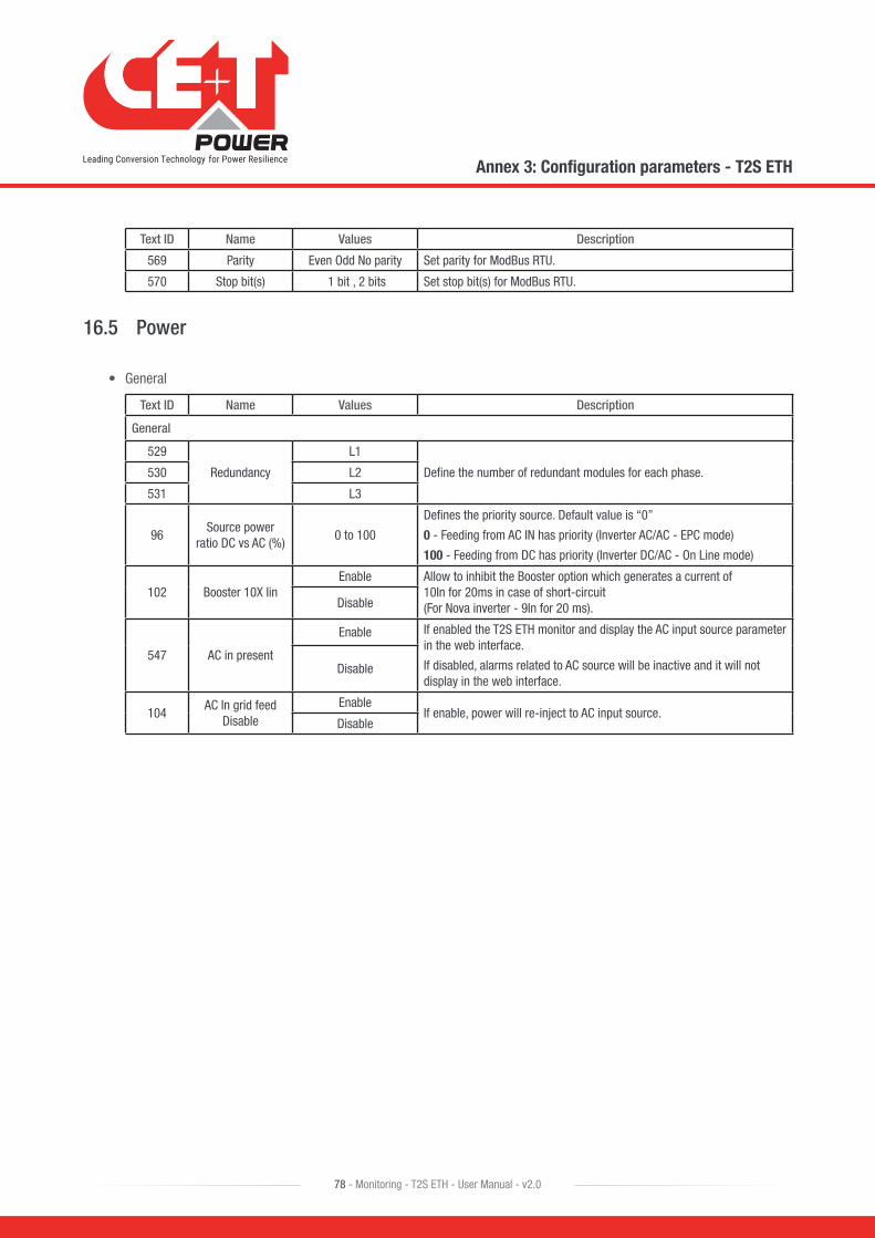
Text ID Name Values Description
569 Parity Even Odd No parity Set parity for ModBus RTU.
570 Stop bit(s) 1 bit , 2 bits Set stop bit(s) for ModBus RTU.
16.5 Power
• General
Text ID Name Values Description
General
529
Redundancy
L1
Define the number of redundant modules for each phase.530 L2
531 L3
96Source power
ratio DC vs AC (%)0 to 100
Defines the priority source. Default value is “0”
0 - Feeding from AC IN has priority (Inverter AC/AC - EPC mode)
100 - Feeding from DC has priority (Inverter DC/AC - On Line mode)
102 Booster 10X IinEnable Allow to inhibit the Booster option which generates a current of
10In for 20ms in case of short-circuit (For Nova inverter - 9In for 20 ms).Disable
547 AC in present
Enable If enabled the T2S ETH monitor and display the AC input source parameter in the web interface.
If disabled, alarms related to AC source will be inactive and it will not display in the web interface.
Disable
104AC In grid feed
DisableEnable
If enable, power will re-inject to AC input source.Disable
Annex 3: Configuration parameters - T2S ETH
78 - Monitoring - T2S ETH - User Manual - v2.0
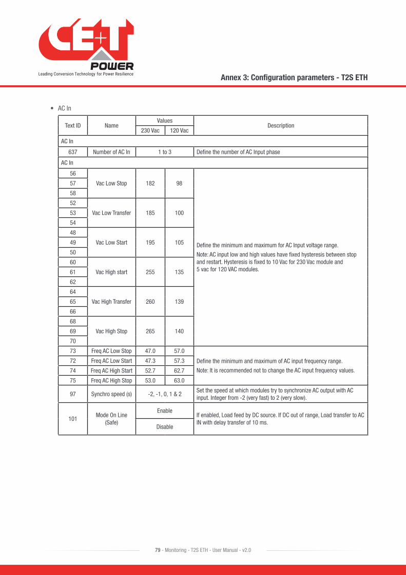
• AC In
Text ID NameValues
Description230 Vac 120 Vac
AC In
637 Number of AC In 1 to 3 Define the number of AC Input phase
AC In
56
Vac Low Stop 182 98
Define the minimum and maximum for AC Input voltage range.
Note: AC input low and high values have fixed hysteresis between stop and restart. Hysteresis is fixed to 10 Vac for 230 Vac module and 5 vac for 120 VAC modules.
57
58
52
Vac Low Transfer 185 10053
54
48
Vac Low Start 195 10549
50
60
Vac High start 255 13561
62
64
Vac High Transfer 260 13965
66
68
Vac High Stop 265 14069
70
73 Freq AC Low Stop 47.0 57.0
Define the minimum and maximum of AC input frequency range.
Note: It is recommended not to change the AC input frequency values.
72 Freq AC Low Start 47.3 57.3
74 Freq AC High Start 52.7 62.7
75 Freq AC High Stop 53.0 63.0
97 Synchro speed (s) -2, -1, 0, 1 & 2Set the speed at which modules try to synchronize AC output with AC input. Integer from -2 (very fast) to 2 (very slow).
101Mode On Line
(Safe)
EnableIf enabled, Load feed by DC source. If DC out of range, Load transfer to AC IN with delay transfer of 10 ms.
Disable
Annex 3: Configuration parameters - T2S ETH
79 - Monitoring - T2S ETH - User Manual - v2.0

• DC Group
Text ID NameValues
Description24 Vdc 48 Vdc 60 Vdc 110 Vdc 220 Vdc
DC Group
16Vdc Low Stop 19.0 39.0 49.0 90.0 165.0
Define the minimum and maximum of DC input voltage range.
Note: It is recommended not to change the DC input values.
17
8Vdc Low Transfer 19.5 40.0 50.0 92.0 169.0
9
0Vdc Low Start 23.0 45.0 56.0 100.0 18.0
1
24Vdc High Start 31.0 57.0 71.0 150.0 280.0
25
32Vdc High Transfer 34.5 60.0 74.0 158.0 296.0
33
40Vdc High Stop 35.0 61.0 75.0 160.0 300.0
41
593DC Source Low
Threshold0 to 300
Set DC source low threshold voltage in volts. If DC source voltage drops under this threshold a “DC source low” alarm is raised.”
• AC Out
Text ID Name Values Description
230 Vac 120 Vac
AC out
78
Phase shift
L1 - 0.00 Phase shift between AC input phase 1 and AC output phase 1.
79 L2 - 120.00 Phase shift between AC input phase 1 and AC output phase 2.
80 L3 - 240.00 Phase shift between AC input phase 1 and AC output phase 3.
86
Vout nominal
L1 - 230 L1 - 120 Define AC output voltage for AC output phase 1, 2 and 3.
Output voltage per phase can be selectable
(N-L : 200 V,220 V, 230 V & 240 V)
87 L2 - 230 L2 - 120
88 L3 - 230 L3 - 120
76 Nominal Freq 50 60 Free running AC output frequency when AC input is not available.
77 Nb of phases 1 to 3Define the number of system output phase.
It should be same as number of AC input phase.
94Short Circuit
Voltage Threshold (V)
80 60Minimum AC output voltage under which module considers output as in short-circuit.
95Short Circuit Hold
Time (s)1 to 60
Default value is 60 seconds. Time duration during which module tries to eliminate the short-circuit existing on output. If the voltage remains under the “Short Circuit Voltage Threshold” for this duration the module stops.
98Max Power
Derating (%)150% (TSI)
125% (ECI)
Maximum power that module can supply.
99Max Current Derating (%)
Maximum current that module can supply.
Annex 3: Configuration parameters - T2S ETH
80 - Monitoring - T2S ETH - User Manual - v2.0
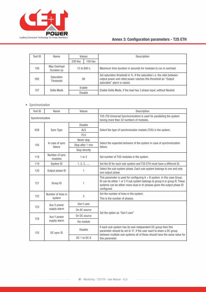
Text ID Name Values Description
230 Vac 120 Vac
100Max Overload Duration (s)
15 to 600 s Maximum time duration in seconds for modules to run in overload.
592Saturation Threshold
80Set saturation threshold in %. If the saturation i.e. the ratio between output power and rated power reaches this threshold an “Output saturated” alarm is raised.
107 Delta ModeEnable
Enable Delta Mode, if the load has 3 phase input, without Neutral.Disable
• Synchronization
Text ID Name Values Description
SynchronizationTUS (TSI Universal Synchronization) is used for paralleling the system having more than 32 numbers of modules.
638 Sync Type
Disable
Select the type of synchronizator module (TUS) in the system.ALS
PLS
105In case of sync
failure
Never stopSelect the expected behavior of the system in case of synchronization failure.
Stop after 1 min
Stop directly
118Number of sync
modules1 or 2 Set number of TUS modules in the system.
119 System ID 1, 2, 3, ..... Set the ID for each sub-system and T2S ETH must have a different ID.
120 Output phase ID 1Select the sub-system phase. Each sub-system belongs to one and only one output phase.
121 Group ID 1
This parameter is used for configuring A + B system. In this case Group ID can be either 1 or 2 if sub system belongs to group A or group B. These systems can be either mono dual or tri-phases given the output phase ID configured.
122Number of lines in
system3
Set the number of lines in the system.
This is the number of phases.
123Aux X power supply alarm
Don’t care
Set the option as “Don’t care”On AC source
124Aux Y power supply alarm
On DC source
Via module
125 DC sync IDDisable
If each sub-system has its own independent DC group then this parameter should be set to ‘0’. If the user want to share a DC group between multiple sub-systems all of these should have the same value for this parameter.DC 1 to DC 8
Annex 3: Configuration parameters - T2S ETH
81 - Monitoring - T2S ETH - User Manual - v2.0

• Other
Text ID Name Values Description
103Remote Off
Disable AC PowerEnable Enable special mode in which “remote off” disables only AC input stage.
AC input source is still used for synchronization.Disable
106 Other;Walk In
Mode Time (x10 s.)
Integer The Walk-in mode allow at the TSI to comeback progressively on
the AC priority source after an outage. Friendly use on Genset.
108 Airco ModeEnable Enable airco mode. It allows to start load with high inrush current and it is
applicable only for TSI modules.Disable
109Force Start Without T2S
EnableEnable modules start without T2S
Disable
110 Pdc Max (W) 0.000000
Maximum power allowed on DC even during overload.
0 means no limit.
111No power from ACin phase 1
Enable
Not Applicable for EPC mode operation.
It is recommended to set in “Disable”
Disable
112No power from ACin phase 2
Enable
Disable
113No power from ACin phase 3
Enable
Disable
Annex 3: Configuration parameters - T2S ETH
82 - Monitoring - T2S ETH - User Manual - v2.0
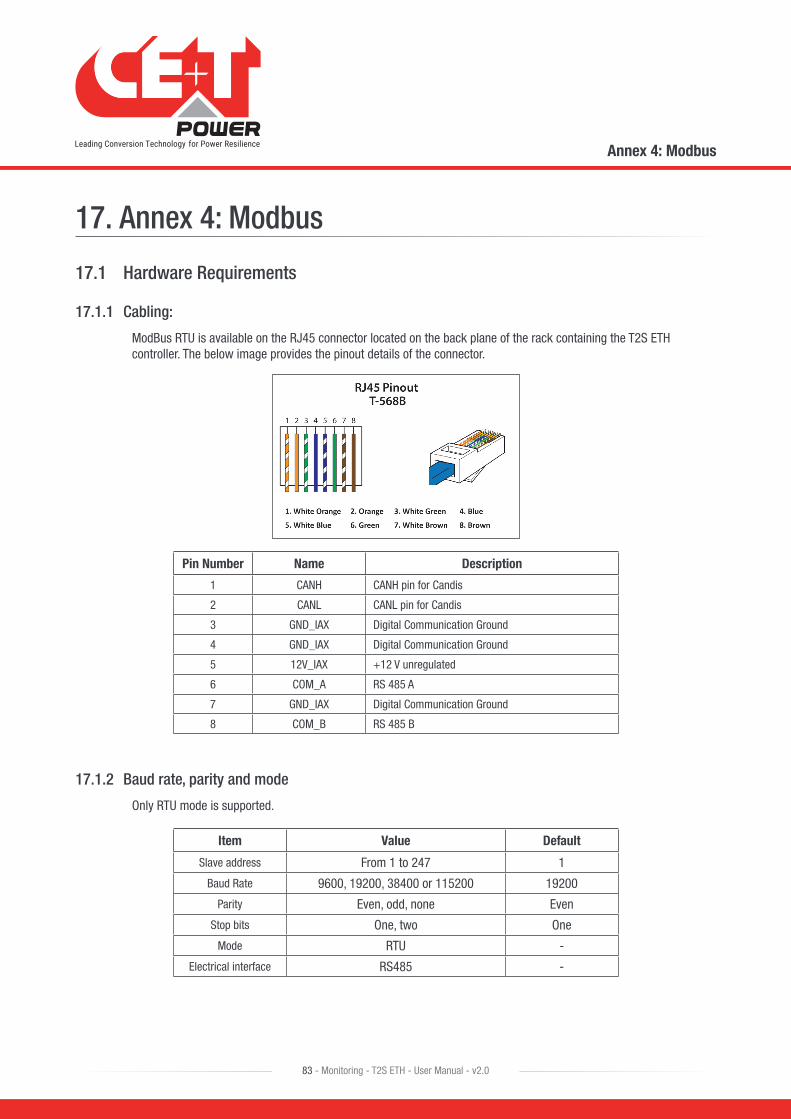
17. Annex 4: Modbus
17.1 Hardware Requirements
17.1.1 Cabling:
ModBus RTU is available on the RJ45 connector located on the back plane of the rack containing the T2S ETH controller. The below image provides the pinout details of the connector.
Pin Number Name Description
1 CANH CANH pin for Candis
2 CANL CANL pin for Candis
3 GND_IAX Digital Communication Ground
4 GND_IAX Digital Communication Ground
5 12V_IAX +12 V unregulated
6 COM_A RS 485 A
7 GND_IAX Digital Communication Ground
8 COM_B RS 485 B
17.1.2 Baud rate, parity and mode
Only RTU mode is supported.
Item Value Default
Slave address From 1 to 247 1
Baud Rate 9600, 19200, 38400 or 115200 19200
Parity Even, odd, none Even
Stop bits One, two One
Mode RTU -
Electrical interface RS485 -
Annex 4: Modbus
83 - Monitoring - T2S ETH - User Manual - v2.0
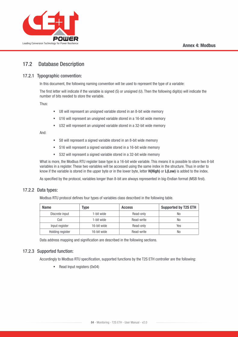
17.2 Database Description
17.2.1 Typographic convention:
In this document, the following naming convention will be used to represent the type of a variable:
The first letter will indicate if the variable is signed (S) or unsigned (U). Then the following digit(s) will indicate the number of bits needed to store the variable.
Thus:
� U8 will represent an unsigned variable stored in an 8-bit wide memory
� U16 will represent an unsigned variable stored in a 16-bit wide memory
� U32 will represent an unsigned variable stored in a 32-bit wide memory
And:
� S8 will represent a signed variable stored in an 8-bit wide memory
� S16 will represent a signed variable stored in a 16-bit wide memory
� S32 will represent a signed variable stored in a 32-bit wide memory
What is more, the Modbus RTU register base type is a 16-bit wide variable. This means it is possible to store two 8-bit variables in a register. These two variables will be accessed using the same index in the structure. Thus in order to know if the variable is stored in the upper byte or in the lower byte, letter H(High) or L(Low) is added to the index.
As specified by the protocol, variables longer than 8-bit are always represented in big-Endian format (MSB first).
17.2.2 Data types:
Modbus RTU protocol defines four types of variables class described in the following table.
Name Type Access Supported by T2S ETH
Discrete input 1-bit wide Read-only No
Coil 1-bit wide Read-write No
Input register 16-bit wide Read-only Yes
Holding register 16-bit wide Read-write No
Data address mapping and signification are described in the following sections.
17.2.3 Supported function:
Accordingly to Modbus RTU specification, supported functions by the T2S ETH controller are the following:
� Read Input registers (0x04)
Annex 4: Modbus
84 - Monitoring - T2S ETH - User Manual - v2.0

17.2.3.1 INPUT REGISTERS ELEMENTS (Read-Only 16-bit wide)
Module table (0x0000)
The table described below represents the information that can be retrieved regarding a particular module. The Maximum amount of the module is set to 32. Each of them is identified by an address ranging from 1 to 32.
BASE ADDRESS: 0(0x0000) + 31*(Module address – 1).
Index Name Description Type
0H eStatusACOut AC output status number (see 17.3.1.1, page 89) U8
0L eStatusACIn AC input status number (see 17.3.1.2, page 90) U8
1H eStatusDCIn DC Input status number (see 17.3.1.3, page 90) U8
1L bAddress Configured address U8
2H bLoadPositionPosition of the load regarding input power sources (0:AC, 100:DC, 50:mixed, 101:unknown)
U8
2L bLoadRatioW Loading ratio regarding power in watts (%) U8
3H bLoadRatioVA Loading ratio regarding power in VA (%) U8
3L bPhaseNumber Number of the phase module is belonging to U8
4 wVout Output voltage value (0.1V) U16
5 wIout Output current value (0.1A) U16
6 wPoutW Output power value (W) U16
7 wPoutVA Output power value (VA) U16
8 wVinAC AC input voltage value (0.1V) U16
9 wIinAC AC input current value (0.1A) U16
10 wPinACW AC input power value (W) U16
11 wPinACVA AC input power value (VA) U16
12 wACInFreq AC input frequency value (0.1Hz) U16
13 wVinDC DC input voltage value (0.1V) U16
14 wIinDC DC input current value (0.1A) U16
15 wPinDC DC input power value (W) U16
16 wTemperature Temperature value (K) U16
17 wSoftVersion Software version number U16
18 lSerialNumber Serial number U32
22H bStatusModEvent number of the status related to the output stage and the module internal status
U8
22L bStatusAC Event number of the status related to the AC input stage U8
23H bStatusDC Event number of the status related to the DC input stage U8
23L bPresent Flag (true or false) that indicates if module is seen by T2S ETH or not U8
24H bGroupAC AC input group number module is belonging to U8
24L bGroupDC DC input group number module is belonging to U8
25H bRestrainedFlag (true or false)that indicates if module cannot cope with more than five other module or not
U8
25L bNoEPC Flag (true or false) that indicates if module has an AC input (EPC) or not U8
26 wPoutNominalW Nominal output power (W) U16
Annex 4: Modbus
85 - Monitoring - T2S ETH - User Manual - v2.0
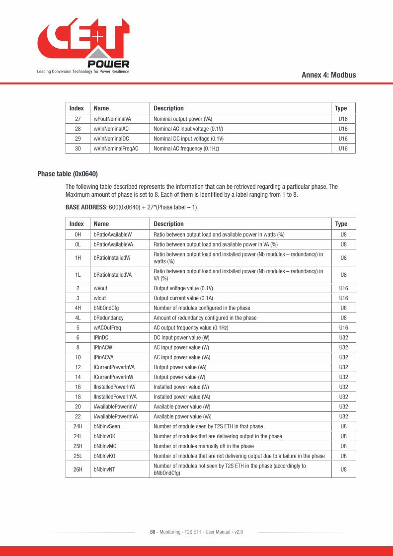
Index Name Description Type
27 wPoutNominalVA Nominal output power (VA) U16
28 wVinNominalAC Nominal AC input voltage (0.1V) U16
29 wVinNominalDC Nominal DC input voltage (0.1V) U16
30 wVinNominalFreqAC Nominal AC frequency (0.1Hz) U16
Phase table (0x0640)
The following table described represents the information that can be retrieved regarding a particular phase. The Maximum amount of phase is set to 8. Each of them is identified by a label ranging from 1 to 8.
BASE ADDRESS: 600(0x0640) + 27*(Phase label – 1).
Index Name Description Type
0H bRatioAvailableW Ratio between output load and available power in watts (%) U8
0L bRatioAvailableVA Ratio between output load and available power in VA (%) U8
1H bRatioInstalledWRatio between output load and installed power (Nb modules – redundancy) in watts (%)
U8
1L bRatioInstalledVARatio between output load and installed power (Nb modules – redundancy) in VA (%)
U8
2 wVout Output voltage value (0.1V) U16
3 wIout Output current value (0.1A) U16
4H bNbOndCfg Number of modules configured in the phase U8
4L bRedundancy Amount of redundancy configured in the phase U8
5 wACOutFreq AC output frequency value (0.1Hz) U16
6 lPinDC DC input power value (W) U32
8 lPinACW AC input power value (W) U32
10 lPinACVA AC input power value (VA) U32
12 lCurrentPowerInVA Output power value (VA) U32
14 lCurrentPowerInW Output power value (W) U32
16 lInstalledPowerInW Installed power value (W) U32
18 lInstalledPowerInVA Installed power value (VA) U32
20 lAvailablePowerInW Available power value (W) U32
22 lAvailablePowerInVA Available power value (VA) U32
24H bNbInvSeen Number of module seen by T2S ETH in that phase U8
24L bNbInvOK Number of modules that are delivering output in the phase U8
25H bNbInvMO Number of modules manually off in the phase U8
25L bNbInvKO Number of modules that are not delivering output due to a failure in the phase U8
26H bNbInvNTNumber of modules not seen by T2S ETH in the phase (accordingly to bNbOndCfg)
U8
Annex 4: Modbus
86 - Monitoring - T2S ETH - User Manual - v2.0
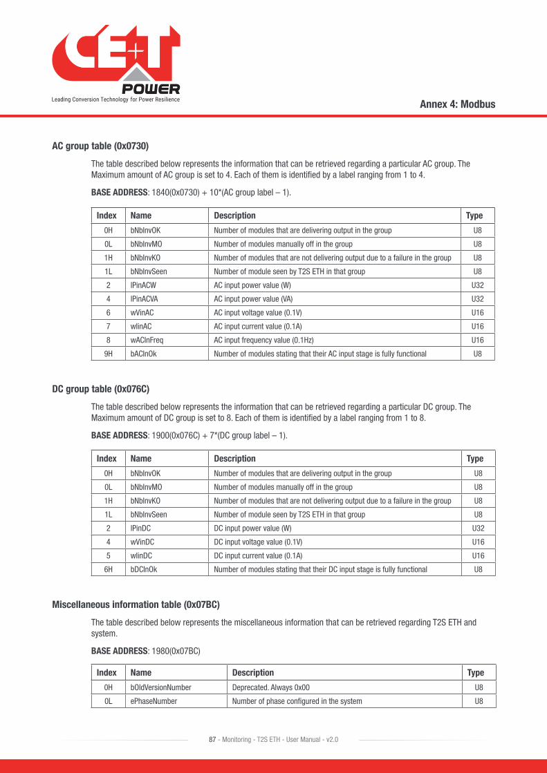
AC group table (0x0730)
The table described below represents the information that can be retrieved regarding a particular AC group. The Maximum amount of AC group is set to 4. Each of them is identified by a label ranging from 1 to 4.
BASE ADDRESS: 1840(0x0730) + 10*(AC group label – 1).
Index Name Description Type
0H bNbInvOK Number of modules that are delivering output in the group U8
0L bNbInvMO Number of modules manually off in the group U8
1H bNbInvKO Number of modules that are not delivering output due to a failure in the group U8
1L bNbInvSeen Number of module seen by T2S ETH in that group U8
2 lPinACW AC input power value (W) U32
4 lPinACVA AC input power value (VA) U32
6 wVinAC AC input voltage value (0.1V) U16
7 wIinAC AC input current value (0.1A) U16
8 wACInFreq AC input frequency value (0.1Hz) U16
9H bACInOk Number of modules stating that their AC input stage is fully functional U8
DC group table (0x076C)
The table described below represents the information that can be retrieved regarding a particular DC group. The Maximum amount of DC group is set to 8. Each of them is identified by a label ranging from 1 to 8.
BASE ADDRESS: 1900(0x076C) + 7*(DC group label – 1).
Index Name Description Type
0H bNbInvOK Number of modules that are delivering output in the group U8
0L bNbInvMO Number of modules manually off in the group U8
1H bNbInvKO Number of modules that are not delivering output due to a failure in the group U8
1L bNbInvSeen Number of module seen by T2S ETH in that group U8
2 lPinDC DC input power value (W) U32
4 wVinDC DC input voltage value (0.1V) U16
5 wIinDC DC input current value (0.1A) U16
6H bDCInOk Number of modules stating that their DC input stage is fully functional U8
Miscellaneous information table (0x07BC)
The table described below represents the miscellaneous information that can be retrieved regarding T2S ETH and system.
BASE ADDRESS: 1980(0x07BC)
Index Name Description Type
0H bOldVersionNumber Deprecated. Always 0x00 U8
0L ePhaseNumber Number of phase configured in the system U8
Annex 4: Modbus
87 - Monitoring - T2S ETH - User Manual - v2.0
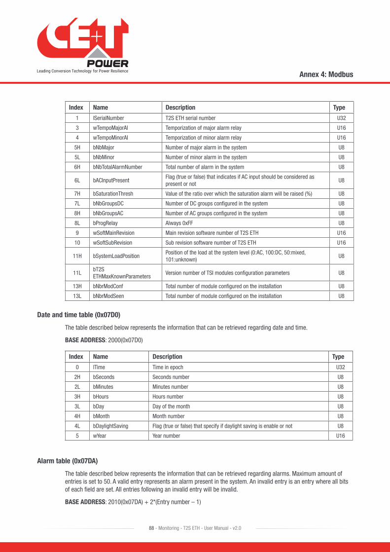
Index Name Description Type
1 lSerialNumber T2S ETH serial number U32
3 wTempoMajorAl Temporization of major alarm relay U16
4 wTempoMinorAl Temporization of minor alarm relay U16
5H bNbMajor Number of major alarm in the system U8
5L bNbMinor Number of minor alarm in the system U8
6H bNbTotalAlarmNumber Total number of alarm in the system U8
6L bACInputPresentFlag (true or false) that indicates if AC input should be considered as present or not
U8
7H bSaturationThresh Value of the ratio over which the saturation alarm will be raised (%) U8
7L bNbGroupsDC Number of DC groups configured in the system U8
8H bNbGroupsAC Number of AC groups configured in the system U8
8L bProgRelay Always 0xFF U8
9 wSoftMainRevision Main revision software number of T2S ETH U16
10 wSoftSubRevision Sub revision software number of T2S ETH U16
11H bSystemLoadPositionPosition of the load at the system level (0:AC, 100:DC, 50:mixed, 101:unknown)
U8
11LbT2S ETHMaxKnownParameters
Version number of TSI modules configuration parameters U8
13H bNbrModConf Total number of module configured on the installation U8
13L bNbrModSeen Total number of module configured on the installation U8
Date and time table (0x07D0)
The table described below represents the information that can be retrieved regarding date and time.
BASE ADDRESS: 2000(0x07D0)
Index Name Description Type
0 lTime Time in epoch U32
2H bSeconds Seconds number U8
2L bMinutes Minutes number U8
3H bHours Hours number U8
3L bDay Day of the month U8
4H bMonth Month number U8
4L bDaylightSaving Flag (true or false) that specify if daylight saving is enable or not U8
5 wYear Year number U16
Alarm table (0x07DA)
The table described below represents the information that can be retrieved regarding alarms. Maximum amount of entries is set to 50. A valid entry represents an alarm present in the system. An invalid entry is an entry where all bits of each field are set. All entries following an invalid entry will be invalid.
BASE ADDRESS: 2010(0x07DA) + 2*(Entry number – 1)
Annex 4: Modbus
88 - Monitoring - T2S ETH - User Manual - v2.0

Index Name Description Type
0H bDeviceNumberIdentifier that specifies which device is responsible of this alarm (see 17.3.1, page 89)
U8
0L bEventType Type of the alarm (Major or minor) (see 17.3.1, page 89) U8
1 wEventNumber Alarm number identifier U16
Rem: See alarm types in the annexes for bEventType description.
Configuration table (0x1040)
The table described below represents the information that can be retrieved regarding parameters that can be configured in the T2S ETH controller. Maximum amount of entries is set to 500. Not all entries are valid. An invalid entry is an entry where all bits of each field are set. Invalid entries might be interleaved with valid entries.
BASE ADDRESS: 4160(0x1040) + 20*(Entry number – 1)
Index Name Description Type
0 swParameter Configured value of the parameter S16
1 wValidityValue indicating if last configured parameter value is valid (see 17.3.4, page 91)
U16
2 wIdentifier Unique value identifying the parameter U16
3 wUnitValue indicating in which units the parameter is expressed (see 17.3.4, page 91)
U16
4 strParamDescription Textual description of the parameter 32*U8
Event string table (0x4114)
The table described below represents the information that can be retrieved regarding event textual description. Maximum amount of entries is set to 300. Each event is identified by an unique number (Event 0 exists!).
BASE ADDRESS: 16660(0x4114) + 8*Event number
Index Name Description Type
0 strEventTxt Textual description of event 16*U8
17.3 Status and Constants Description
17.3.1 Module status explanation (A1):
17.3.1.1 eStatusACOut:
Name Description Value
SBR Standby running. This means that the module is delivering output 0
SB Standby. This mean that the module is manually OFF 1
SBWEStandby with error. This means that the module is not delivering output due to an unrecoverable error
2
Annex 4: Modbus
89 - Monitoring - T2S ETH - User Manual - v2.0
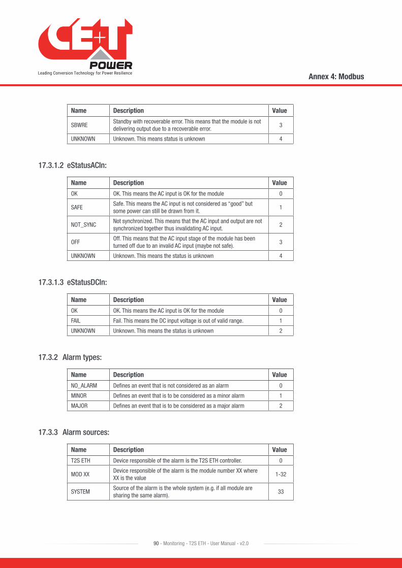
Name Description Value
SBWREStandby with recoverable error. This means that the module is not delivering output due to a recoverable error.
3
UNKNOWN Unknown. This means status is unknown 4
17.3.1.2 eStatusACIn:
Name Description Value
OK OK. This means the AC input is OK for the module 0
SAFESafe. This means the AC input is not considered as “good” but some power can still be drawn from it.
1
NOT_SYNCNot synchronized. This means that the AC input and output are not synchronized together thus invalidating AC input.
2
OFFOff. This means that the AC input stage of the module has been turned off due to an invalid AC input (maybe not safe).
3
UNKNOWN Unknown. This means the status is unknown 4
17.3.1.3 eStatusDCIn:
Name Description Value
OK OK. This means the AC input is OK for the module 0
FAIL Fail. This means the DC input voltage is out of valid range. 1
UNKNOWN Unknown. This means the status is unknown 2
17.3.2 Alarm types:
Name Description Value
NO_ALARM Defines an event that is not considered as an alarm 0
MINOR Defines an event that is to be considered as a minor alarm 1
MAJOR Defines an event that is to be considered as a major alarm 2
17.3.3 Alarm sources:
Name Description Value
T2S ETH Device responsible of the alarm is the T2S ETH controller. 0
MOD XXDevice responsible of the alarm is the module number XX where XX is the value
1-32
SYSTEMSource of the alarm is the whole system (e.g. if all module are sharing the same alarm).
33
Annex 4: Modbus
90 - Monitoring - T2S ETH - User Manual - v2.0
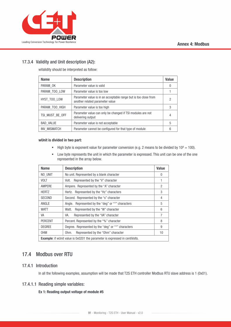
17.3.4 Validity and Unit description (A2):
wValidity should be interpreted as follow:
Name Description Value
PARAM_OK Parameter value is valid 0
PARAM_TOO_LOW Parameter value is too low 1
HYST_TOO_LOWParameter value is in an acceptable range but is too close from another related parameter value
2
PARAM_TOO_HIGH Parameter value is too high 3
TSI_MUST_BE_OFFParameter value can only be changed if TSI modules are not delivering output
4
BAD_VALUE Parameter value is not acceptable 5
INV_MISMATCH Parameter cannot be configured for that type of module 6
wUnit is divided in two part:
� High byte is exponent value for parameter conversion (e.g. 2 means to be divided by 10² = 100).
� Low byte represents the unit in which the parameter is expressed. This unit can be one of the one represented in the array below.
Name Description Value
NO_UNIT No unit. Represented by a blank character 0
VOLT Volt. Represented by the “V” character 1
AMPERE Ampere. Represented by the “A” character 2
HERTZ Hertz. Represented by the “Hz” characters 3
SECOND Second. Represented by the “s” character 4
ANGLE Angle. Represented by the “deg” or “°” characters 5
WATT Watt. Represented by the “W” character 6
VA VA. Represented by the “VA” character 7
PERCENT Percent. Represented by the “%” character 8
DEGREE Degree. Represented by the “deg” or “°” characters 9
OHM Ohm. Represented by the “Ohm” character 10
Example: if wUnit value is 0x0201 the parameter is expressed in centiVolts.
17.4 Modbus over RTU
17.4.1 Introduction
In all the following examples, assumption will be made that T2S ETH controller Modbus RTU slave address is 1 (0x01).
17.4.1.1 Reading simple variables:
Ex 1: Reading output voltage of module #5
Annex 4: Modbus
91 - Monitoring - T2S ETH - User Manual - v2.0

Field Value Description
Function 4 (0x04) Read input register
Address 128 (0x0080) 31*(5-1) + 4 = 128 (see module table, page 85)
Number of registers 1 (0x01) Vout value is 16-bit wide
Master frame: 0x01 0x04 0x00 0x80 0x00 0x01 0x71 0xE3
T2S ETH frame: 0x01 0x04 0x02 0x09 0x1B 0xFF 0x6B
Received value: 0x091B = 2331 Output voltage is 233.1V (see module table, page 85)
Ex 2: Reading T2S ETH serial number
Field Value Description
Function 4 (0x04) Read input register
Address 128 (0x0080) 31*(5-1) + 4 = 128 (see module table, page 85)
Number of registers 1 (0x01) Vout value is 16-bit wide
Master frame: 0x01 0x04 0x07 0xC5 0x00 0x02 0x60 0x82
T2S ETH frame: 0x01 0x04 0x04 0x00 0x01 0x00 0x07 0xEB 0x86
Received value: 0x0001 and 0x0007 T2S ETH revision is Vs1.7
17.4.1.2 Reading alarm and history log:
Reading entry #1
Field Value Description
Function 4 (0x04) Read input register
Address 2010 (0x07D4) 2010 + 2*(1-1) = 2010 (see alarm table, page 88)
Number of registers 2 (0x02) Alarm entry is 2 registers wide
Master frame: 0x01 0x04 0x07 0xDA 0x00 0x02 0x51 0x44
T2S ETH frame: 0x01 0x04 0x04 0x21 0x01 0x00 0xB3 0xE1 0xCD
Alarm entry #1 is a minor (0x01) alarm generated by the system (0x21) and this alarm has the ID 179 (0x00B3)
Reading an invalid entry
Let’s assume that there are only 2 alarms present in the system. Then reading alarm entry #3 should return an invalid entry
Field Value Description
Function 4 (0x04) Read input register
Address 2014 (0x07DE) 2010 + 2*(3-1) = 2014 (see alarm table, page 88)
Number of registers 2 (0x02) Alarm entry is 2 registers wide
Annex 4: Modbus
92 - Monitoring - T2S ETH - User Manual - v2.0
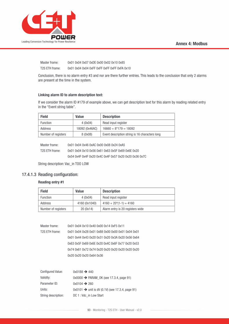
Master frame: 0x01 0x04 0x07 0xDE 0x00 0x02 0x10 0x85
T2S ETH frame: 0x01 0x04 0x04 0xFF 0xFF 0xFF 0xFF 0xFA 0x10
Conclusion, there is no alarm entry #3 and nor are there further entries. This leads to the conclusion that only 2 alarms are present at the time in the system.
Linking alarm ID to alarm description text:
If we consider the alarm ID #179 of example above, we can get description text for this alarm by reading related entry in the “Event string table”.
Field Value Description
Function 4 (0x04) Read input register
Address 18092 (0x46AC) 16660 + 8*179 = 18092
Number of registers 8 (0x08) Event description string is 16 characters long
Master frame: 0x01 0x04 0x46 0xAC 0x00 0x08 0x24 0xA5
T2S ETH frame: 0x01 0x04 0x10 0x56 0x61 0x63 0x5F 0x69 0x6E 0x20
0x54 0x4F 0x4F 0x20 0x4C 0x4F 0x57 0x20 0x20 0x36 0x7C
String description: Vac_in TOO LOW
17.4.1.3 Reading configuration:
Reading entry #1
Field Value Description
Function 4 (0x04) Read input register
Address 4160 (0x1040) 4160 + 20*(1-1) = 4160
Number of registers 20 (0x14) Alarm entry is 20 registers wide
Master frame: 0x01 0x04 0x10 0x40 0x00 0x14 0xF5 0x11
T2S ETH frame: 0x01 0x04 0x28 0x01 0xB8 0x00 0x00 0x01 0x04 0x01
0x01 0x44 0x43 0x20 0x31 0x20 0x3A 0x20 0x56 0x64
0x63 0x5F 0x69 0x6E 0x20 0x4C 0x6F 0x77 0x20 0x53
0x74 0x61 0x72 0x74 0x20 0x20 0x20 0x20 0x20 0x20
0x20 0x20 0x20 0x64 0x36
Configured Value: 0x01B8 440
Validity: 0x0000 PARAM_OK (see 17.3.4, page 91)
Parameter ID: 0x0104 260
Units: 0x0101 unit is dV (0.1V) (see 17.3.4, page 91)
String description: DC 1 : Vdc_in Low Start
Annex 4: Modbus
93 - Monitoring - T2S ETH - User Manual - v2.0

Reading an invalid entry
Let’s assume that entry #189 is invalid
Field Value Description
Function 4 (0x04) Read input register
Address 7920 (0x1EF0) 4160 + 20*(189-1) = 7920
Number of registers 20 (0x14) Alarm entry is 20 registers wide
Master frame: 0x01 0x04 0x1E 0xF0 0x00 0x14 0xF6 0x1E
T2S ETH frame: 0x01 0x04 0x28 0xFF 0xFF 0xFF 0xFF 0xFF 0xFF 0xFF
0xFF 0xFF 0xFF 0xFF 0xFF 0xFF 0xFF 0xFF 0xFF 0xFF
0xFF 0xFF 0xFF 0xFF 0xFF 0xFF 0xFF 0xFF 0xFF 0xFF
0xFF 0xFF 0xFF 0xFF 0xFF 0xFF 0xFF 0xFF 0xFF 0xFF
0xFF 0xFF 0xFF 0xF0 0x04
Due to internal memory organization, the configuration might have valid entries interleaved with invalid ones. Thus, in order to read all configurations, one should read all entries to determine which ones are valid and which ones are not.
Exceptions: Textual parameter
The configured value field is 16 bit wide. Consequently, only integer values can be read (or further configured) using this way. There are 3 parameters that are not integer values but strings. Thus, the values returned in the “Configured value” field of the configuration table for those 3 IDs are dummy values that have no meaning.
Those IDs are the following
ID Description Remark
901 Digital input 1 labelCan be read in the digital inputs table in the holding registers (0x0686)
902 Digital input 2 labelCan be read in the digital inputs table in the holding registers (0x0686)
Note 1:
Caution should be taken while changing the module address because it will affect the addresses where to retrieve information regarding this module. What is more, there can be a delay between the moment where the change address order is received and the moment where the module address has been physically changed. Moreover, a module address can be changed to a new address that is already assigned to another module! In this case, the modules will swap their addresses.
For all those reasons, the best and secure way to change a module address is the following one:
1. Get module serial number using “Module information table” using the current address to calculate the index.
2. Send to the new address for this module using the “Module action table” using the current address to calculate the index.
3. Poll the serial number using “Module information table” using the new address as index until there is a match with the serial number collected at point 1.
Annex 4: Modbus
94 - Monitoring - T2S ETH - User Manual - v2.0

17.4.2 Modbus RTU - Testing
In order to test the Modbus communication functionalities, please install the program “Radzio ! Master Modbus Simulator” on your computer.
• Website: http://en.radzio.dxp.pl/modbus-master-simulator/
• Direct download: http://en.radzio.dxp.pl/modbus-master-simulator/RMMS.zip
17.4.2.1 Requirement
• USB to RS485 interface cable (For example USB-RS485-WE cable, FTDI chip), Fig 1
Fig 1: FTDI cable
• RJ45-TERM (Gravitech.us) Fig 2
Fig 2: Adapter for RJ45
Annex 4: Modbus
95 - Monitoring - T2S ETH - User Manual - v2.0
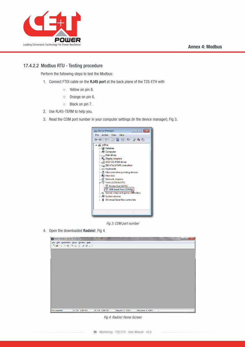
17.4.2.2 Modbus RTU - Testing procedure
Perform the following steps to test the Modbus:
1. Connect FTDI cable on the RJ45 port at the back plane of the T2S-ETH with
○ Yellow on pin 8.
○ Orange on pin 6.
○ Black on pin 7.
2. Use RJ45-TERM to help you.
3. Read the COM port number in your computer settings (In the device manager), Fig 3.
Fig 3: COM port number
4. Open the downloaded Radzio!, Fig 4
Fig 4: Radzio! Home Screen
Annex 4: Modbus
96 - Monitoring - T2S ETH - User Manual - v2.0

5. Click on the Connection settings icon in the tool bar.
Fig 5: Connection settings icon
6. Select Modbus RTU in the Connections settings window
Fig 6: Connection settings window
Annex 4: Modbus
97 - Monitoring - T2S ETH - User Manual - v2.0
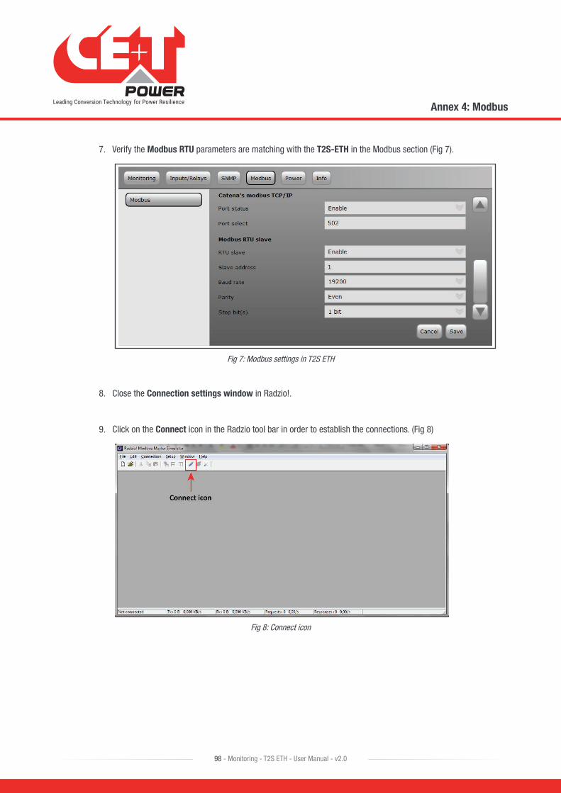
7. Verify the Modbus RTU parameters are matching with the T2S-ETH in the Modbus section (Fig 7).
Fig 7: Modbus settings in T2S ETH
8. Close the Connection settings window in Radzio!.
9. Click on the Connect icon in the Radzio tool bar in order to establish the connections. (Fig 8)
Fig 8: Connect icon
Annex 4: Modbus
98 - Monitoring - T2S ETH - User Manual - v2.0

10. Click New Modbus sheet icon, to open the new Modbus sheet. (Fig 9)
Fig 9: New Modbus sheet icon
11. Modify the Device Settings in the new modbus sheet. (Fig 10)
○ Set the Device ID (Default value is 1)
○ Set the entity of Device ID as Input Register (Default value is Coil status)
Fig 10: Default Radzio settings to Modify
Annex 4: Modbus
99 - Monitoring - T2S ETH - User Manual - v2.0
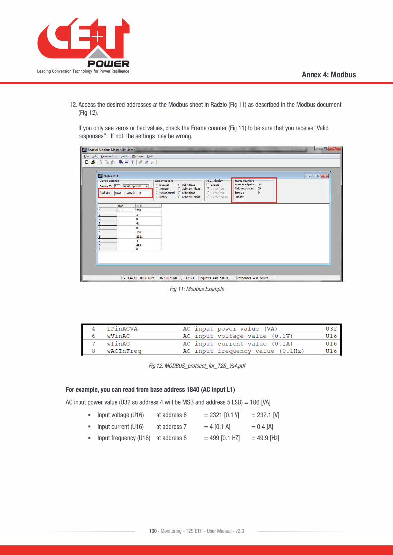
12. Access the desired addresses at the Modbus sheet in Radzio (Fig 11) as described in the Modbus document (Fig 12). If you only see zeros or bad values, check the Frame counter (Fig 11) to be sure that you receive “Valid responses”. If not, the settings may be wrong.
Fig 11: Modbus Example
Fig 12: MODBUS_protocol_for_T2S_Vs4.pdf
For example, you can read from base address 1840 (AC input L1)
AC input power value (U32 so address 4 will be MSB and address 5 LSB) = 106 [VA]
� Input voltage (U16) at address 6 = 2321 [0.1 V] = 232.1 [V]
� Input current (U16) at address 7 = 4 [0.1 A] = 0.4 [A]
� Input frequency (U16) at address 8 = 499 [0.1 HZ] = 49.9 [Hz]
Annex 4: Modbus
100 - Monitoring - T2S ETH - User Manual - v2.0
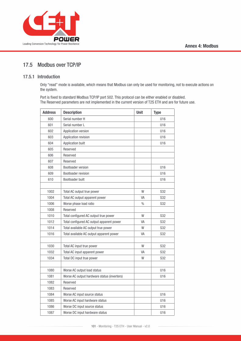
17.5 Modbus over TCP/IP
17.5.1 Introduction
Only “read” mode is available, which means that Modbus can only be used for monitoring, not to execute actions on the system.
Port is fixed to standard Modbus TCP/IP port 502. This protocol can be either enabled or disabled. The Reserved parameters are not implemented in the current version of T2S ETH and are for future use.
Address Description Unit Type
600 Serial number H U16
601 Serial number L U16
602 Application version U16
603 Application revision U16
604 Application built U16
605 Reserved
606 Reserved
607 Reserved
608 Bootloader version U16
609 Bootloader revision U16
610 Bootloader built U16
1002 Total AC output true power W S32
1004 Total AC output apparent power VA S32
1006 Worse phase load ratio % S32
1008 Reserved
1010 Total configured AC output true power W S32
1012 Total configured AC output apparent power VA S32
1014 Total available AC output true power W S32
1016 Total available AC output apparent power VA S32
1030 Total AC input true power W S32
1032 Total AC input apparent power VA S32
1034 Total DC input true power W S32
1080 Worse AC output load status U16
1081 Worse AC output hardware status (inverters) U16
1082 Reserved
1083 Reserved
1084 Worse AC input source status U16
1085 Worse AC input hardware status U16
1086 Worse DC input source status U16
1087 Worse DC input hardware status U16
Annex 4: Modbus
101 - Monitoring - T2S ETH - User Manual - v2.0

Address Description Unit Type
1088 Redundancy lost U16
1089 On DC U16
1090 Reserved U16
1091 MBP engaged U16
1096 Number of events (all alarms types) U16
1097 Number of major alarms U16
1098 Number of minor alarms U16
Output phase 1
2050 Phase 1 true power W S32/float
2052 Phase 1 apparent power VA S32/float
2054 Phase 1 voltage V/10 S32/float
2056 Phase 1 current A/10 S32/float
2058 Phase 1 frequency Hz/100 S32/float
2060 Reserved
2062 Phase 1 worse power factor % S32/float
2064 Phase 1 worse temperature °C/10 S32/float
2066 Phase 1 load ratio (W) % S32/float
2068 Phase 1 load ratio (VA) % S32/float
2070 Phase 1 available true power W S32/float
2072 Phase 1 available apparent power VA S32/float
Output phase 2
2100 Phase 2 true power W S32/float
2102 Phase 2 apparent power VA S32/float
2104 Phase 2 voltage V/10 S32/float
2106 Phase 2 current A/10 S32/float
2108 Phase 2 frequency Hz/100 S32/float
2110 Reserved
2112 Phase 2 worse power factor % S32/float
2114 Phase 2 worse temperature °C/10 S32/float
2116 Phase 2 load ratio (W) % S32/float
2118 Phase 2 load ratio (VA) % S32/float
2120 Phase 2 available true power W S32/float
2122 Phase 2 available apparent power VA S32/float
Output phase 3
2150 Phase 3 true power W S32/float
2152 Phase 3 apparent power VA S32/float
2154 Phase 3 voltage V/10 S32/float
2156 Phase 3 current A/10 S32/float
2158 Phase 3 frequency Hz/100 S32/float
Annex 4: Modbus
102 - Monitoring - T2S ETH - User Manual - v2.0
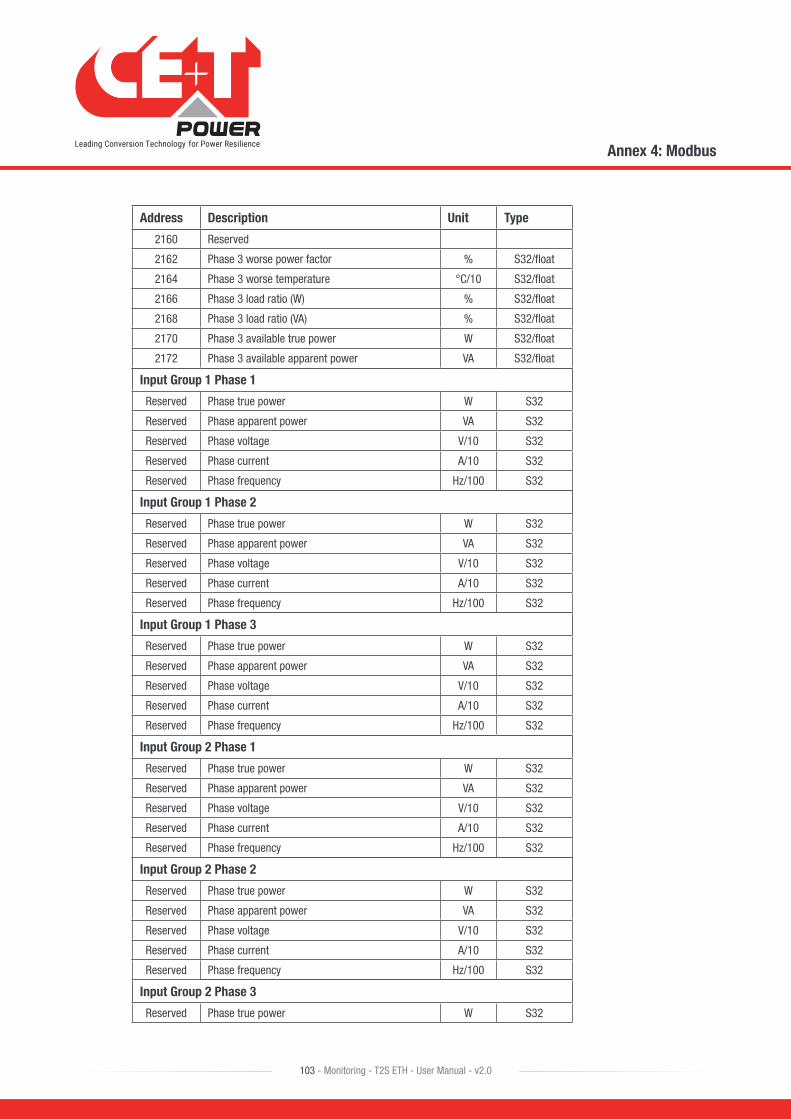
Address Description Unit Type
2160 Reserved
2162 Phase 3 worse power factor % S32/float
2164 Phase 3 worse temperature °C/10 S32/float
2166 Phase 3 load ratio (W) % S32/float
2168 Phase 3 load ratio (VA) % S32/float
2170 Phase 3 available true power W S32/float
2172 Phase 3 available apparent power VA S32/float
Input Group 1 Phase 1
Reserved Phase true power W S32
Reserved Phase apparent power VA S32
Reserved Phase voltage V/10 S32
Reserved Phase current A/10 S32
Reserved Phase frequency Hz/100 S32
Input Group 1 Phase 2
Reserved Phase true power W S32
Reserved Phase apparent power VA S32
Reserved Phase voltage V/10 S32
Reserved Phase current A/10 S32
Reserved Phase frequency Hz/100 S32
Input Group 1 Phase 3
Reserved Phase true power W S32
Reserved Phase apparent power VA S32
Reserved Phase voltage V/10 S32
Reserved Phase current A/10 S32
Reserved Phase frequency Hz/100 S32
Input Group 2 Phase 1
Reserved Phase true power W S32
Reserved Phase apparent power VA S32
Reserved Phase voltage V/10 S32
Reserved Phase current A/10 S32
Reserved Phase frequency Hz/100 S32
Input Group 2 Phase 2
Reserved Phase true power W S32
Reserved Phase apparent power VA S32
Reserved Phase voltage V/10 S32
Reserved Phase current A/10 S32
Reserved Phase frequency Hz/100 S32
Input Group 2 Phase 3
Reserved Phase true power W S32
Annex 4: Modbus
103 - Monitoring - T2S ETH - User Manual - v2.0
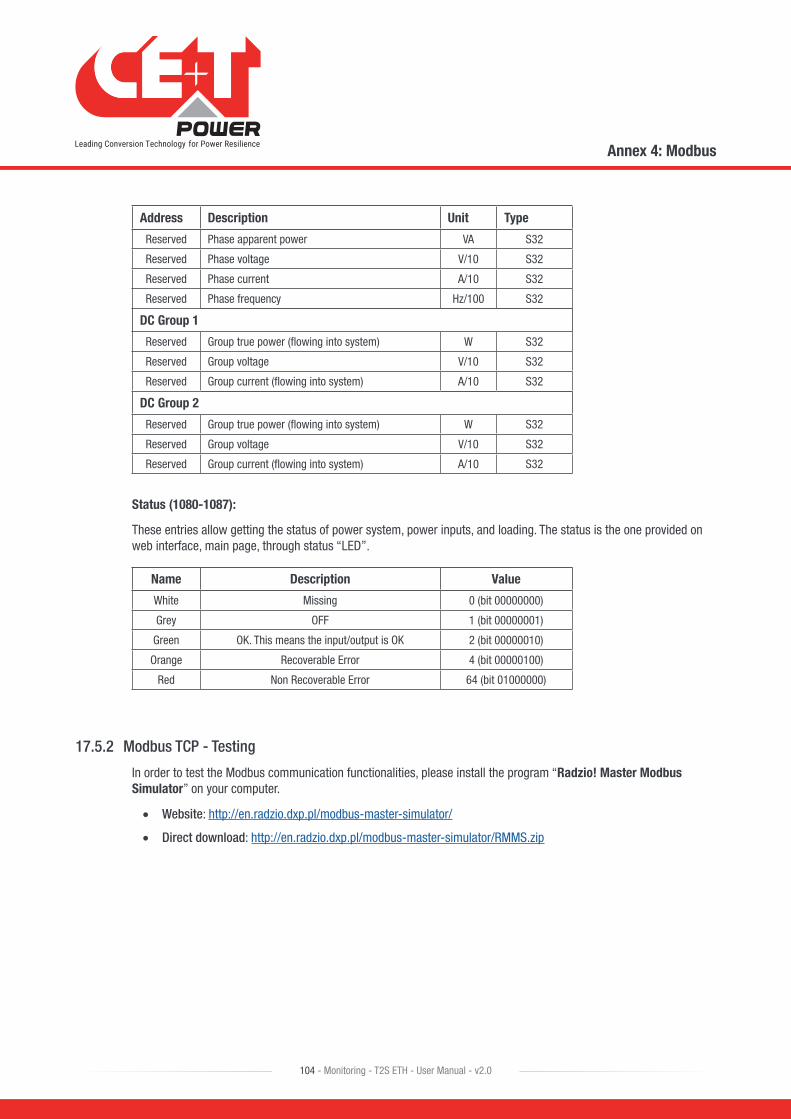
Address Description Unit Type
Reserved Phase apparent power VA S32
Reserved Phase voltage V/10 S32
Reserved Phase current A/10 S32
Reserved Phase frequency Hz/100 S32
DC Group 1
Reserved Group true power (flowing into system) W S32
Reserved Group voltage V/10 S32
Reserved Group current (flowing into system) A/10 S32
DC Group 2
Reserved Group true power (flowing into system) W S32
Reserved Group voltage V/10 S32
Reserved Group current (flowing into system) A/10 S32
Status (1080-1087):
These entries allow getting the status of power system, power inputs, and loading. The status is the one provided on web interface, main page, through status “LED”.
Name Description Value
White Missing 0 (bit 00000000)
Grey OFF 1 (bit 00000001)
Green OK. This means the input/output is OK 2 (bit 00000010)
Orange Recoverable Error 4 (bit 00000100)
Red Non Recoverable Error 64 (bit 01000000)
17.5.2 Modbus TCP - Testing
In order to test the Modbus communication functionalities, please install the program “Radzio! Master Modbus Simulator” on your computer.
• Website: http://en.radzio.dxp.pl/modbus-master-simulator/
• Direct download: http://en.radzio.dxp.pl/modbus-master-simulator/RMMS.zip
Annex 4: Modbus
104 - Monitoring - T2S ETH - User Manual - v2.0
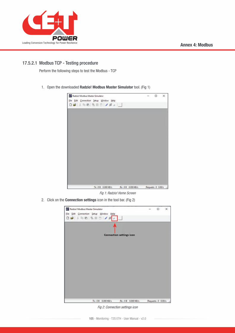
17.5.2.1 Modbus TCP - Testing procedure
Perform the following steps to test the Modbus - TCP
1. Open the downloaded Radzio! Modbus Master Simulator tool. (Fig 1)
Fig 1: Radzio! Home Screen
2. Click on the Connection settings icon in the tool bar. (Fig 2)
Fig 2: Connection settings icon
Annex 4: Modbus
105 - Monitoring - T2S ETH - User Manual - v2.0
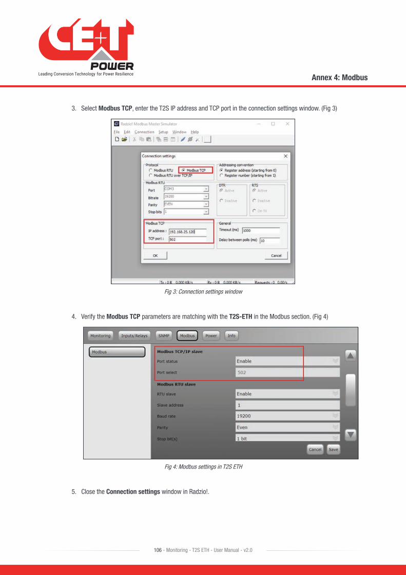
3. Select Modbus TCP, enter the T2S IP address and TCP port in the connection settings window. (Fig 3)
Fig 3: Connection settings window
4. Verify the Modbus TCP parameters are matching with the T2S-ETH in the Modbus section. (Fig 4)
Fig 4: Modbus settings in T2S ETH
5. Close the Connection settings window in Radzio!.
Annex 4: Modbus
106 - Monitoring - T2S ETH - User Manual - v2.0
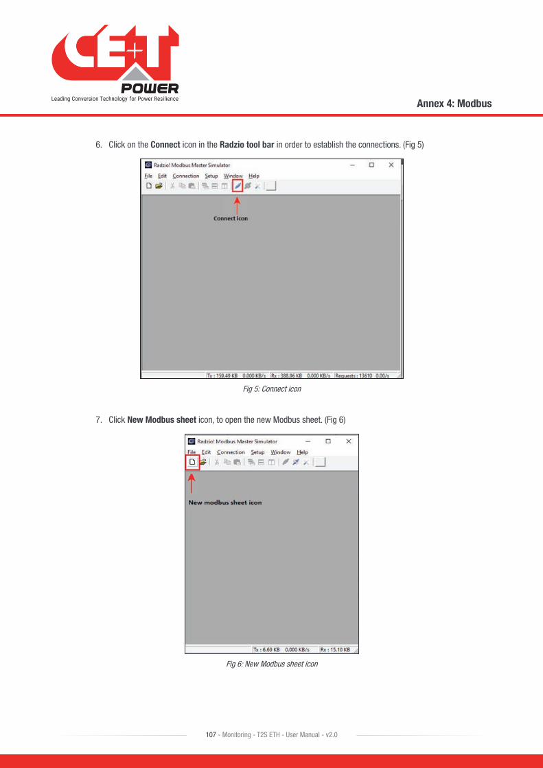
6. Click on the Connect icon in the Radzio tool bar in order to establish the connections. (Fig 5)
Fig 5: Connect icon
7. Click New Modbus sheet icon, to open the new Modbus sheet. (Fig 6)
Fig 6: New Modbus sheet icon
Annex 4: Modbus
107 - Monitoring - T2S ETH - User Manual - v2.0
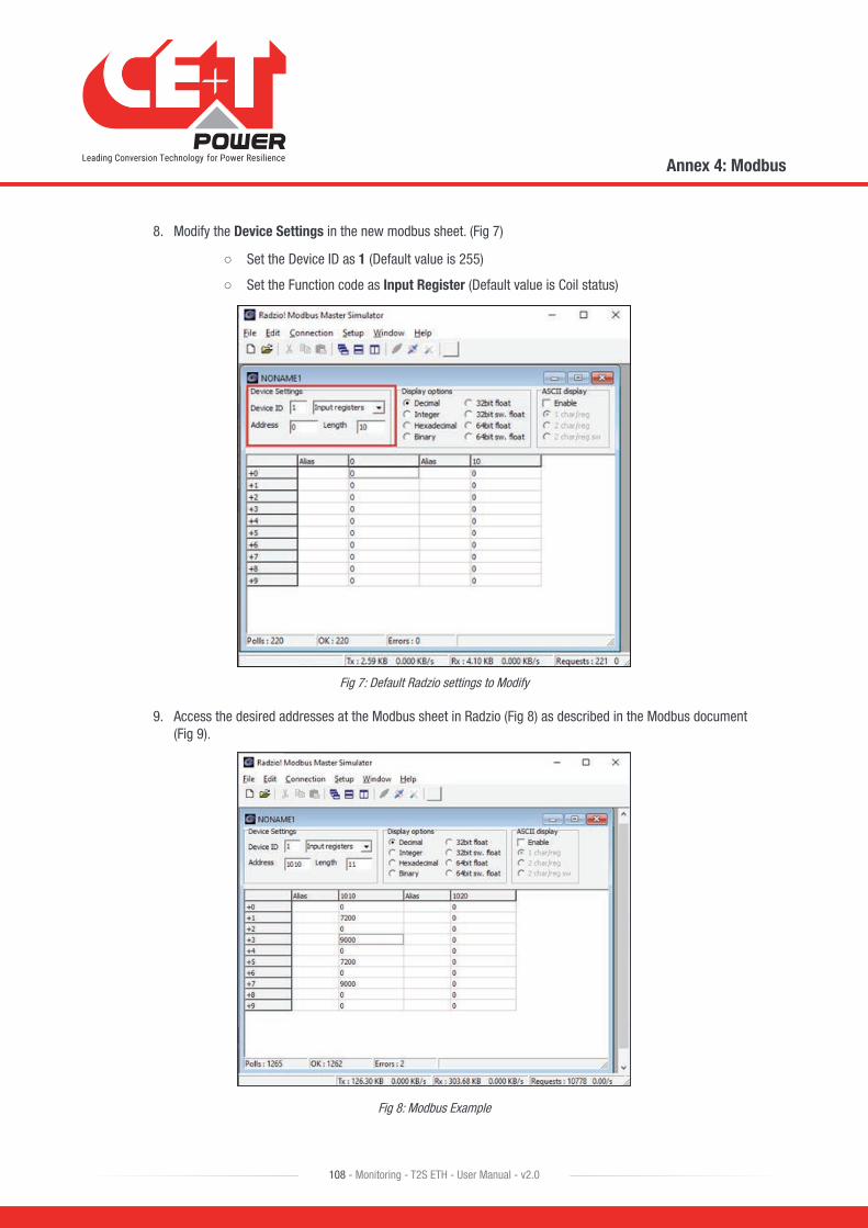
8. Modify the Device Settings in the new modbus sheet. (Fig 7)
○ Set the Device ID as 1 (Default value is 255)
○ Set the Function code as Input Register (Default value is Coil status)
Fig 7: Default Radzio settings to Modify
9. Access the desired addresses at the Modbus sheet in Radzio (Fig 8) as described in the Modbus document (Fig 9).
Fig 8: Modbus Example
Annex 4: Modbus
108 - Monitoring - T2S ETH - User Manual - v2.0
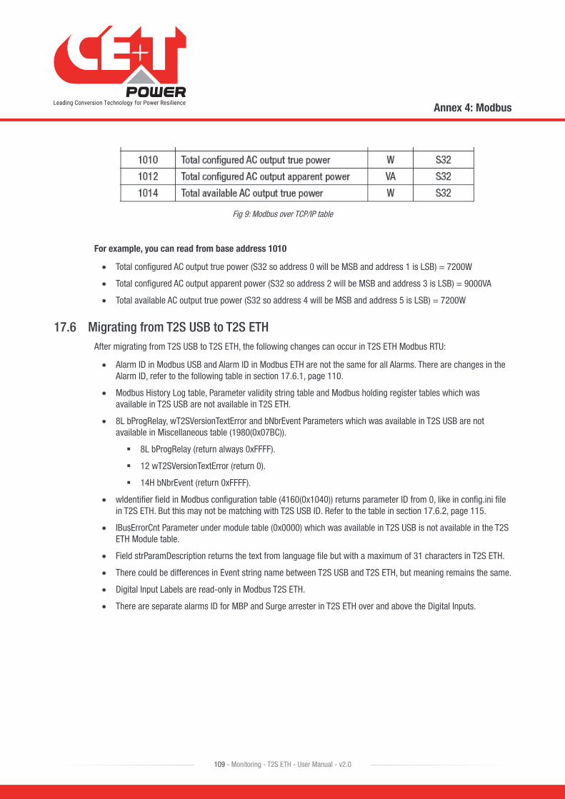
Fig 9: Modbus over TCP/IP table
For example, you can read from base address 1010
• Total configured AC output true power (S32 so address 0 will be MSB and address 1 is LSB) = 7200W
• Total configured AC output apparent power (S32 so address 2 will be MSB and address 3 is LSB) = 9000VA
• Total available AC output true power (S32 so address 4 will be MSB and address 5 is LSB) = 7200W
17.6 Migrating from T2S USB to T2S ETHAfter migrating from T2S USB to T2S ETH, the following changes can occur in T2S ETH Modbus RTU:
• Alarm ID in Modbus USB and Alarm ID in Modbus ETH are not the same for all Alarms. There are changes in the Alarm ID, refer to the following table in section 17.6.1, page 110.
• Modbus History Log table, Parameter validity string table and Modbus holding register tables which was available in T2S USB are not available in T2S ETH.
• 8L bProgRelay, wT2SVersionTextError and bNbrEvent Parameters which was available in T2S USB are not available in Miscellaneous table (1980(0x07BC)).
� 8L bProgRelay (return always 0xFFFF).
� 12 wT2SVersionTextError (return 0).
� 14H bNbrEvent (return 0xFFFF).
• wIdentifier field in Modbus configuration table (4160(0x1040)) returns parameter ID from 0, like in config.ini file in T2S ETH. But this may not be matching with T2S USB ID. Refer to the table in section 17.6.2, page 115.
• lBusErrorCnt Parameter under module table (0x0000) which was available in T2S USB is not available in the T2S ETH Module table.
• Field strParamDescription returns the text from language file but with a maximum of 31 characters in T2S ETH.
• There could be differences in Event string name between T2S USB and T2S ETH, but meaning remains the same.
• Digital Input Labels are read-only in Modbus T2S ETH.
• There are separate alarms ID for MBP and Surge arrester in T2S ETH over and above the Digital Inputs.
Annex 4: Modbus
109 - Monitoring - T2S ETH - User Manual - v2.0
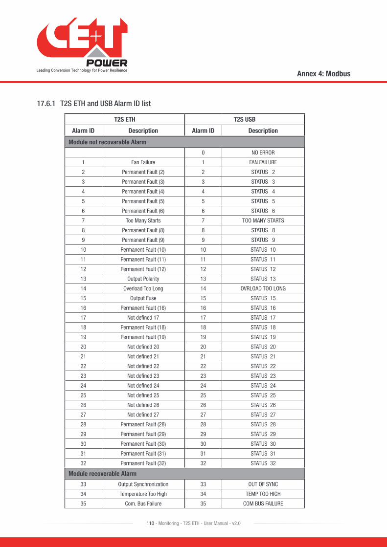
17.6.1 T2S ETH and USB Alarm ID list
T2S ETH T2S USB
Alarm ID Description Alarm ID Description
Module not recovarable Alarm
0 NO ERROR
1 Fan Failure 1 FAN FAILURE
2 Permanent Fault (2) 2 STATUS 2
3 Permanent Fault (3) 3 STATUS 3
4 Permanent Fault (4) 4 STATUS 4
5 Permanent Fault (5) 5 STATUS 5
6 Permanent Fault (6) 6 STATUS 6
7 Too Many Starts 7 TOO MANY STARTS
8 Permanent Fault (8) 8 STATUS 8
9 Permanent Fault (9) 9 STATUS 9
10 Permanent Fault (10) 10 STATUS 10
11 Permanent Fault (11) 11 STATUS 11
12 Permanent Fault (12) 12 STATUS 12
13 Output Polarity 13 STATUS 13
14 Overload Too Long 14 OVRLOAD TOO LONG
15 Output Fuse 15 STATUS 15
16 Permanent Fault (16) 16 STATUS 16
17 Not defined 17 17 STATUS 17
18 Permanent Fault (18) 18 STATUS 18
19 Permanent Fault (19) 19 STATUS 19
20 Not defined 20 20 STATUS 20
21 Not defined 21 21 STATUS 21
22 Not defined 22 22 STATUS 22
23 Not defined 23 23 STATUS 23
24 Not defined 24 24 STATUS 24
25 Not defined 25 25 STATUS 25
26 Not defined 26 26 STATUS 26
27 Not defined 27 27 STATUS 27
28 Permanent Fault (28) 28 STATUS 28
29 Permanent Fault (29) 29 STATUS 29
30 Permanent Fault (30) 30 STATUS 30
31 Permanent Fault (31) 31 STATUS 31
32 Permanent Fault (32) 32 STATUS 32
Module recoverable Alarm
33 Output Synchronization 33 OUT OF SYNC
34 Temperature Too High 34 TEMP TOO HIGH
35 Com. Bus Failure 35 COM BUS FAILURE
Annex 4: Modbus
110 - Monitoring - T2S ETH - User Manual - v2.0
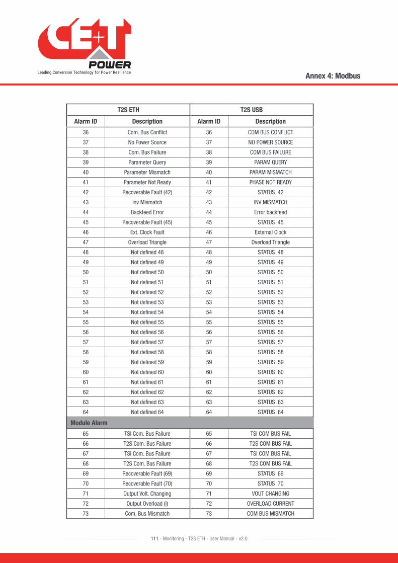
T2S ETH T2S USB
Alarm ID Description Alarm ID Description
36 Com. Bus Conflict 36 COM BUS CONFLICT
37 No Power Source 37 NO POWER SOURCE
38 Com. Bus Failure 38 COM BUS FAILURE
39 Parameter Query 39 PARAM QUERY
40 Parameter Mismatch 40 PARAM MISMATCH
41 Parameter Not Ready 41 PHASE NOT READY
42 Recoverable Fault (42) 42 STATUS 42
43 Inv Mismatch 43 INV MISMATCH
44 Backfeed Error 44 Error backfeed
45 Recoverable Fault (45) 45 STATUS 45
46 Ext. Clock Fault 46 External Clock
47 Overload Triangle 47 Overload Triangle
48 Not defined 48 48 STATUS 48
49 Not defined 49 49 STATUS 49
50 Not defined 50 50 STATUS 50
51 Not defined 51 51 STATUS 51
52 Not defined 52 52 STATUS 52
53 Not defined 53 53 STATUS 53
54 Not defined 54 54 STATUS 54
55 Not defined 55 55 STATUS 55
56 Not defined 56 56 STATUS 56
57 Not defined 57 57 STATUS 57
58 Not defined 58 58 STATUS 58
59 Not defined 59 59 STATUS 59
60 Not defined 60 60 STATUS 60
61 Not defined 61 61 STATUS 61
62 Not defined 62 62 STATUS 62
63 Not defined 63 63 STATUS 63
64 Not defined 64 64 STATUS 64
Module Alarm
65 TSI Com. Bus Failure 65 TSI COM BUS FAIL
66 T2S Com. Bus Failure 66 T2S COM BUS FAIL
67 TSI Com. Bus Failure 67 TSI COM BUS FAIL
68 T2S Com. Bus Failure 68 T2S COM BUS FAIL
69 Recoverable Fault (69) 69 STATUS 69
70 Recoverable Fault (70) 70 STATUS 70
71 Output Volt. Changing 71 VOUT CHANGING
72 Output Overload (I) 72 OVERLOAD CURRENT
73 Com. Bus Mismatch 73 COM BUS MISMATCH
Annex 4: Modbus
111 - Monitoring - T2S ETH - User Manual - v2.0
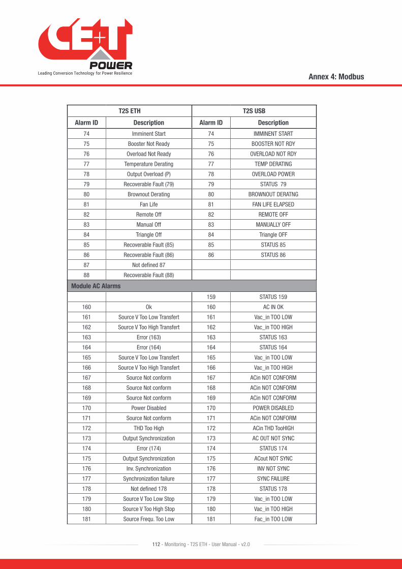
T2S ETH T2S USB
Alarm ID Description Alarm ID Description
74 Imminent Start 74 IMMINENT START
75 Booster Not Ready 75 BOOSTER NOT RDY
76 Overload Not Ready 76 OVERLOAD NOT RDY
77 Temperature Derating 77 TEMP DERATING
78 Output Overload (P) 78 OVERLOAD POWER
79 Recoverable Fault (79) 79 STATUS 79
80 Brownout Derating 80 BROWNOUT DERATNG
81 Fan Life 81 FAN LIFE ELAPSED
82 Remote Off 82 REMOTE OFF
83 Manual Off 83 MANUALLY OFF
84 Triangle Off 84 Triangle OFF
85 Recoverable Fault (85) 85 STATUS 85
86 Recoverable Fault (86) 86 STATUS 86
87 Not defined 87
88 Recoverable Fault (88)
Module AC Alarms
159 STATUS 159
160 Ok 160 AC IN OK
161 Source V Too Low Transfert 161 Vac_in TOO LOW
162 Source V Too High Transfert 162 Vac_in TOO HIGH
163 Error (163) 163 STATUS 163
164 Error (164) 164 STATUS 164
165 Source V Too Low Transfert 165 Vac_in TOO LOW
166 Source V Too High Transfert 166 Vac_in TOO HIGH
167 Source Not conform 167 ACin NOT CONFORM
168 Source Not conform 168 ACin NOT CONFORM
169 Source Not conform 169 ACin NOT CONFORM
170 Power Disabled 170 POWER DISABLED
171 Source Not conform 171 ACin NOT CONFORM
172 THD Too High 172 ACin THD TooHIGH
173 Output Synchronization 173 AC OUT NOT SYNC
174 Error (174) 174 STATUS 174
175 Output Synchronization 175 ACout NOT SYNC
176 Inv. Synchronization 176 INV NOT SYNC
177 Synchronization failure 177 SYNC FAILURE
178 Not defined 178 178 STATUS 178
179 Source V Too Low Stop 179 Vac_in TOO LOW
180 Source V Too High Stop 180 Vac_in TOO HIGH
181 Source Frequ. Too Low 181 Fac_in TOO LOW
Annex 4: Modbus
112 - Monitoring - T2S ETH - User Manual - v2.0
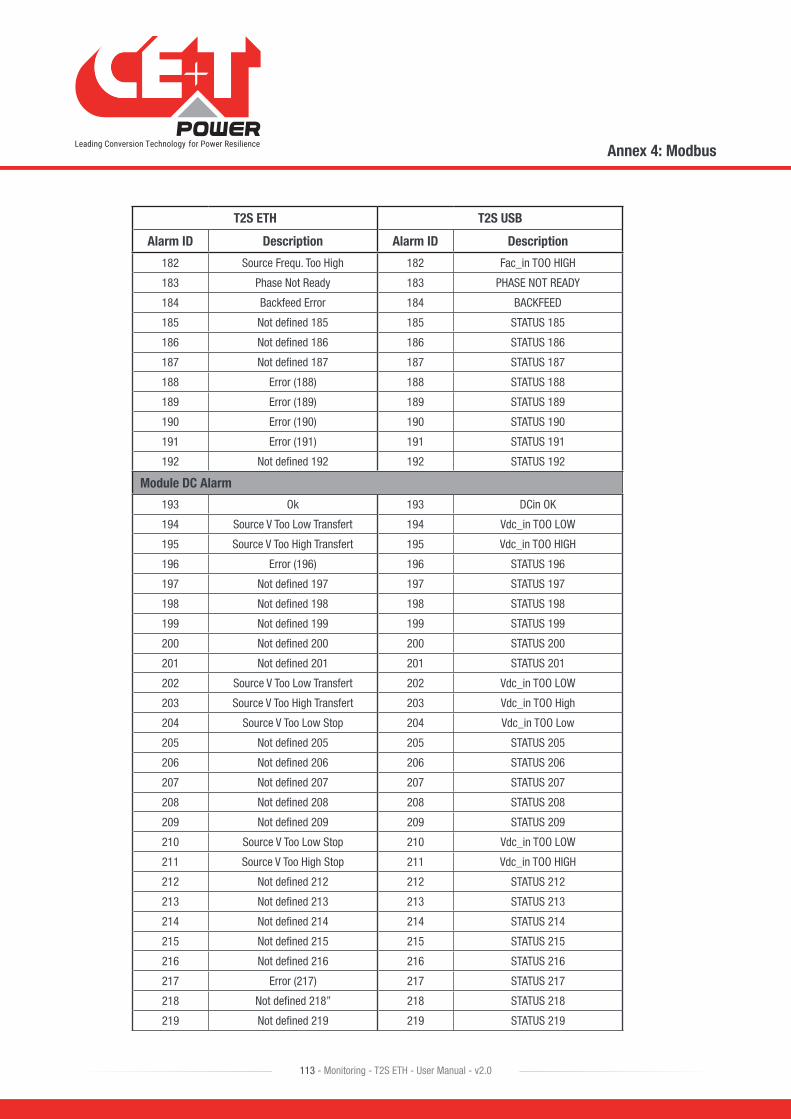
T2S ETH T2S USB
Alarm ID Description Alarm ID Description
182 Source Frequ. Too High 182 Fac_in TOO HIGH
183 Phase Not Ready 183 PHASE NOT READY
184 Backfeed Error 184 BACKFEED
185 Not defined 185 185 STATUS 185
186 Not defined 186 186 STATUS 186
187 Not defined 187 187 STATUS 187
188 Error (188) 188 STATUS 188
189 Error (189) 189 STATUS 189
190 Error (190) 190 STATUS 190
191 Error (191) 191 STATUS 191
192 Not defined 192 192 STATUS 192
Module DC Alarm
193 Ok 193 DCin OK
194 Source V Too Low Transfert 194 Vdc_in TOO LOW
195 Source V Too High Transfert 195 Vdc_in TOO HIGH
196 Error (196) 196 STATUS 196
197 Not defined 197 197 STATUS 197
198 Not defined 198 198 STATUS 198
199 Not defined 199 199 STATUS 199
200 Not defined 200 200 STATUS 200
201 Not defined 201 201 STATUS 201
202 Source V Too Low Transfert 202 Vdc_in TOO LOW
203 Source V Too High Transfert 203 Vdc_in TOO High
204 Source V Too Low Stop 204 Vdc_in TOO Low
205 Not defined 205 205 STATUS 205
206 Not defined 206 206 STATUS 206
207 Not defined 207 207 STATUS 207
208 Not defined 208 208 STATUS 208
209 Not defined 209 209 STATUS 209
210 Source V Too Low Stop 210 Vdc_in TOO LOW
211 Source V Too High Stop 211 Vdc_in TOO HIGH
212 Not defined 212 212 STATUS 212
213 Not defined 213 213 STATUS 213
214 Not defined 214 214 STATUS 214
215 Not defined 215 215 STATUS 215
216 Not defined 216 216 STATUS 216
217 Error (217) 217 STATUS 217
218 Not defined 218” 218 STATUS 218
219 Not defined 219 219 STATUS 219
Annex 4: Modbus
113 - Monitoring - T2S ETH - User Manual - v2.0

T2S ETH T2S USB
Alarm ID Description Alarm ID Description
226 NO TRANSMISSION
227 DIG INP1 FAILURE
228 DIG INP2 FAILURE
229 REDUNDANCY LOST
230 REDUND + 1 LOST
231 SYS SATURATED
232 MAIN SOURCE LOST
233 SEC SOURCE LOST
234 TS BUS FAIL
235 TS FAILURE
236 TS STARTED
237 LOG CLEARED
238 CONFIG MODIFIED
239 NEW MOD DETECTED
240 DATE & TIME MOD
241 CFG READ IN MOD
242 LOG NEARLY FULL
243 TS FLASH ERROR
244 CHECK LOG FILE
245 DC 1
246 DC 2 - DC 8
247 MISSING MODULE
248 STATUS 248
249 STATUS 249
250 STATUS 250
Module Monitoring Alarm
256 MBP Engaged
257 Surge Arrester
258 Redundancy Lost
259 Redundancy +1 Lost
260 Main Source Lost
261 Secondary Source Lost
262 AC Source Lost
263 DC Source Lost
264 AC Source Not Sync
265 DC Source Low
266 Output Saturation
267 Output Overload
268 Output Failure
Annex 4: Modbus
114 - Monitoring - T2S ETH - User Manual - v2.0
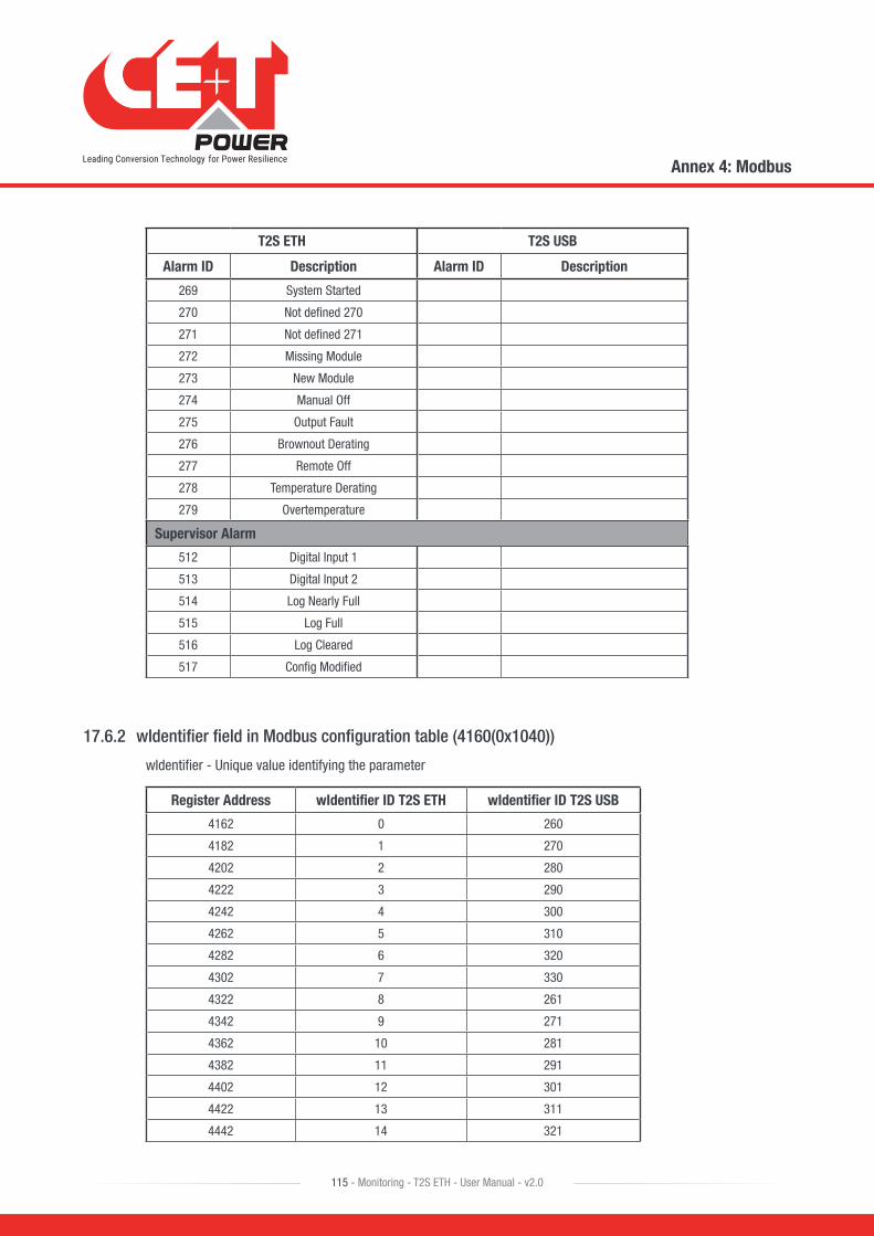
T2S ETH T2S USB
Alarm ID Description Alarm ID Description
269 System Started
270 Not defined 270
271 Not defined 271
272 Missing Module
273 New Module
274 Manual Off
275 Output Fault
276 Brownout Derating
277 Remote Off
278 Temperature Derating
279 Overtemperature
Supervisor Alarm
512 Digital Input 1
513 Digital Input 2
514 Log Nearly Full
515 Log Full
516 Log Cleared
517 Config Modified
17.6.2 wIdentifier field in Modbus configuration table (4160(0x1040))
wIdentifier - Unique value identifying the parameter
Register Address wIdentifier ID T2S ETH wIdentifier ID T2S USB
4162 0 260
4182 1 270
4202 2 280
4222 3 290
4242 4 300
4262 5 310
4282 6 320
4302 7 330
4322 8 261
4342 9 271
4362 10 281
4382 11 291
4402 12 301
4422 13 311
4442 14 321
Annex 4: Modbus
115 - Monitoring - T2S ETH - User Manual - v2.0
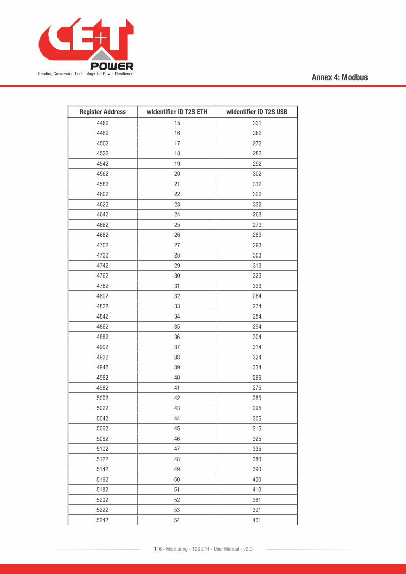
Register Address wIdentifier ID T2S ETH wIdentifier ID T2S USB
4462 15 331
4482 16 262
4502 17 272
4522 18 282
4542 19 292
4562 20 302
4582 21 312
4602 22 322
4622 23 332
4642 24 263
4662 25 273
4682 26 283
4702 27 293
4722 28 303
4742 29 313
4762 30 323
4782 31 333
4802 32 264
4822 33 274
4842 34 284
4862 35 294
4882 36 304
4902 37 314
4922 38 324
4942 39 334
4962 40 265
4982 41 275
5002 42 285
5022 43 295
5042 44 305
5062 45 315
5082 46 325
5102 47 335
5122 48 380
5142 49 390
5162 50 400
5182 51 410
5202 52 381
5222 53 391
5242 54 401
Annex 4: Modbus
116 - Monitoring - T2S ETH - User Manual - v2.0

Register Address wIdentifier ID T2S ETH wIdentifier ID T2S USB
5262 55 411
5282 56 382
5302 57 392
5322 58 402
5342 59 412
5362 60 383
5382 61 393
5402 62 403
5422 63 413
5442 64 384
5462 65 394
5482 66 404
5502 67 414
5522 68 385
5542 69 395
5562 70 405
5582 71 415
5602 72 370
5622 73 371
5642 74 372
5662 75 373
5682 76 75
5702 77 70
5722 78 160
5742 79 170
5762 80 180
5782 81 190
5802 82 200
5822 83 210
5842 84 220
5862 85 230
5882 86 161
5902 87 171
5922 88 181
5942 89 191
5962 90 201
5982 91 211
6002 92 221
6022 93 231
6042 94 80
Annex 4: Modbus
117 - Monitoring - T2S ETH - User Manual - v2.0
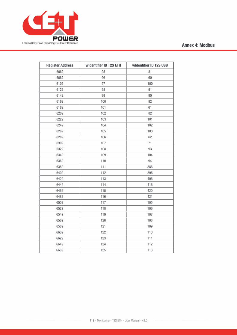
Register Address wIdentifier ID T2S ETH wIdentifier ID T2S USB
6062 95 81
6082 96 60
6102 97 100
6122 98 91
6142 99 90
6162 100 92
6182 101 61
6202 102 82
6222 103 101
6242 104 102
6262 105 103
6282 106 62
6302 107 71
6322 108 93
6342 109 104
6362 110 94
6382 111 386
6402 112 396
6422 113 406
6442 114 416
6462 115 420
6482 116 421
6502 117 105
6522 118 106
6542 119 107
6562 120 108
6582 121 109
6602 122 110
6622 123 111
6642 124 112
6662 125 113
Annex 4: Modbus
118 - Monitoring - T2S ETH - User Manual - v2.0

Related Documents