Module 109 Design Hydrology

Welcome message from author
This document is posted to help you gain knowledge. Please leave a comment to let me know what you think about it! Share it to your friends and learn new things together.
Transcript

Module 109
Design Hydrology

Engineering Hydrology Training Series
Module 109 Design Hydrology

Table of Contents Module Description ................................................................................. vii Introduction ................................................................................................. 1 520.00 General. ..................................................................................... 1 530.10 General. ..................................................................................... 2 530.11 Hydrologic Procedures. ............................................................. 2 530.12 Hydrologic Criteria. .................................................................. 3 Background ................................................................................................. 4 NHCP .................................................................................................... 4 Dam, Diversion (348) ................................................................................. 6 Dam, Floodwater Retarding (402) .............................................................. 7 Dam, Multipurpose (349)......................................................................... ...8 Dike (356) ................................................................................................... 9 Diversion (362) ......................................................................................... 12 Floodwater Diversion (400) ...................................................................... 13 Floodway (404) ......................................................................................... 14 Grade Stabilization Structure (410) .......................................................... 16 Embankment Dams ............................................................................. 17 Pond Size Dams .................................................................................. 17 Full-flow Open Structures................................................................... 18 Island-type Structures ......................................................................... 19 Side-inlet Drainage Structures ............................................................ 19 Grassed Waterway (412)........................................................................... 21 Irrigation Pit-Regulating Reservoir (552) ................................................. 21 Lined Waterway (468) .............................................................................. 22 Open Channel (582) .................................................................................. 22 Pond (378) ................................................................................................. 23 Waterspreading (640) ................................................................................ 24 Irrigation Storage Reservoir (436) ............................................................ 24 Water and Sediment Control Basin (638) ................................................. 25 Surface Drainage, Field Ditch (607) ......................................................... 26 Underground Outlet (620) ......................................................................... 26 Waste Management System (312) ............................................................ 27 Engineering Job Classes ........................................................................... 28 Activity 1 .................................................................................................. 33 Structure Classification ............................................................................. 34 Summary ................................................................................................... 37 Activity Solutions ..................................................................................... 39 Appendix A ............................................................................................... 41 Appendix B ............................................................................................... 45 Appendix C ............................................................................................... 53 Certificate of Completion ......................................................................... 63

Module Description Objectives
• Upon completion of this module, the participant will be able to: • Use hydraulic criteria to design conservation practices. • Select Engineering Job Classes using the National Engineering Manual (NEM). • Determine the classification of a structure. • Perform at ASK Level 3 (perform with supervision).
Prerequisites Modules 101-Introduction to Hydrology, 102-Precipitation, 104-Runoff Curve Number Computations, 105-Runoff Computations, 106-Peak Discharge, and l07-Hydrography. Length Participant should take as long as necessary to complete module. Training time for this module is approximately three hours. Who May Take the Module This module is intended for all NRCS personnel who plan or design conservation practices. Method of Completion This module is self-paced, but the state should select a resource person to answer any questions that the participant's supervisor cannot handle. Content This module presents information field office people need to know about NRCS policy and criteria to design conservation practices. The module discusses the NRCS structure classification system and engineering job classes.

Introduction The policy for NRCS hydrology investigations, technology, and procedures is contained in National Engineering Manual (NEM) subchapters C and D. Subchapter C, paragraph 520.00 of the NEM gives the overall NRCS policy for erosion and sediment control and is quoted below. 520.00 General.
• Effective erosion and sediment control requires a comprehensive system of engineering and cultural practices applied to the land for the specific purpose of controlling erosion and preventing excessive sediment accumulation. Federal and State laws, regulations, and executive orders have emphasized the need to conserve natural resources and improve the quality of the environment. Erosion and sediment control systems address this need.
• Erosion occurs in many areas other than cropland. Construction sites, parks, playgrounds,
roads, and urban areas are major sources of erosion. NRCS is often asked for assistance in the planning, design, and construction of erosion and sediment control systems.
This establishes the intent and purpose of conservation practices by national policy or "what we are trying to accomplish". Subchapter D, paragraphs 530.10-12 define the hydrologic procedures and where we can find the hydrologic criteria to use for designing conservation practices. These paragraphs are quoted below. 530.10 General. Hydrologic procedures have been developed within NRCS to assist in the planning and design of on-farm conservation practices including water control structures and to solve hydrologic problems encountered in developing plans and designs for project activities. Because structure or project costs may range from several hundred to several million dollars, it is important that the most suitable hydrologic procedure be used for a particular problem. The procedure selected must provide the desired level of accuracy and complement other design procedures to insure that the structure or project meets its functional objective. Hydrologic Criteria for designing conservation practices and water Control structures have been developed largely from field experience and represent minimum acceptable standards consistent with the objectives of the practice or structure. 530.11 Hydrologic Procedures.
• Procedures in the Engineering Field Manual for Conservation Practices, Chapter 2, are the preferred method for hydrologic analysis for on-farm conservation practices. They are to be used unless specifically expected by the approving engineer.

• Procedures in NEH-4, Section 4, and those contained in Technical Releases, Hydrology
Notes, and designated references are to be used for hydrologic analysis of soil and water conservation practices to the maximum extent practicable.
• Procedures outside the scope of the NEH and other designated references may be used
providing prior approval is obtained from the approving engineer. 530.12 Hydrologic Criteria. Hydrologic criteria established in standards and directives are to be used for designing conservation practices and water control structures. Exceptions to use of national criteria are to be obtained from the Director of Engineering. The "standards” noted in paragraph 530.12 refers to the National Handbook of Conservation Practices (NHCP). The criteria in the NHCP defines the minimum capacities or capabilities of the conservation practice. The criteria is a combination of common practices in the construction field, industry standards, field trials, research and knowledge of what is needed for the conservation practice to accomplish its intended purpose. Each state can develop additional criteria for each practice standard to give guidance on minimum criteria to be used on projects within that state's boundaries. These additional criteria may be necessary to establish standards compatible with state and/or county laws and guidelines, requirements to meet environmental conditions, or common accepted practice within the area. Often supplemental criteria is developed within the states to define design limits and provide information. Background The criteria as defined in the NHCP has evolved over the history of the NRCS. As new products or practices are developed, industry sources, universities, research institutes, and professional societies are queried for information. The national specialists and other interested specialists develop a consensus of opinion, and then develop a written standard for review. The Institutes, State Engineering Staffs, and others, including industry representatives, review and comment on the proposed standards before they become final. An occasional interim standard is prepared for one project use or temporary use, while a standard is being prepared and reviewed in the regular manner. The terminology used in the standard is accepted practice in the industry or is taken from that used by the many standards committees or professional society publications. NHCP The NHCP provides the minimum design criteria that must be used nationally. The states can supplement these criteria to add details. The state additions must be equally or more restrictive than the national standard. Hydrology aspects and design criteria are just one of the many design

elements included in the standards. Our interest here is to develop the peak discharges and/or hydrographs required to design the various projects. Standards that require hydrologic criteria which we will discuss are listed below.
• Dam Diversion (348) • Dam Floodwater Retarding (402) • Dam Multi-Purpose (349)
• Dike (356)
-Class I
-Class II
-Class III
• Diversion (362)
• Floodwater Diversion (400)
• Floodway (404)
-Class I
-Class II
-Class III
• Grade Stabilization Structures (410)
• Grassed Waterway (412)
• Irrigation Pit-Regulating Reservoir (552)
• Lined Waterway (468)
• Open Channel (582)
• Pond (378)
• Waterspreading (640)
• Irrigation Storage Reservoir (436)

• Water and Sediment Control (638)
• Surface Drainages Field Ditch (607)
• Underground Outlet (620)
• Waste Management System (312) Dam, Diversion (348) Dam, Diversion-Standard 348 is defined as "a structure built to divert part or all of the water from a waterway or stream into a different watercourse, an irrigation canal or ditch, or a water spreading system". Standard 348 doesn't give much guidance for hydrologic criteria to size the hydraulic parts of the diversion dam. This is a case where the state has the option to declare minimum return interval for the peak flow both to be bypassed through the site, as well as that portion diverted for beneficial use. Many states refer to the requirements as specified in Table 4 of Standard 378-Pond to size the bypass works. That standard specifies that drainage areas up to 20 acres with storage less than 50 acre ft. use the peak discharge from the 10 yr.-24 hr storm. For drainage areas greater than 20 acres with storage less than 50 acre ft. and less than 20 feet of effective height of the dam, use the 25 yr.-24 hr storm for design. Refer to Appendix A for a list of applicable precipitation data references. The outlet works for the diverted water must meet the flow requirements for which it is intended. For the case where limited detention storage is provided upstream of the diversion dam, the peak discharge should be used for design. In cases where appreciable storage is available and the designer wants to take advantage of that storage to reduce the bypass discharge, a hydrograph is necessary for flood routing the runoff through the available temporary storage. Dam, Floodwater Retarding (402) Dam, floodwater Retarding-Standard 402, is defined as "A single-purpose dam designed for temporary storage of floodwater and its controlled release". This standard refers to the standard for Ponds (378) or TR-60 as appropriate. Hydrologic criteria is included in each of the references. The standard for Ponds (378) applies where the effective height of the dam is less than 35 feet, the failure of which would not cause loss of life and the storage height product is less than 3000. The storage is the volume, in acre feet, in the reservoir below the crest of the emergency spillway. The effective height of the dam is the difference in elevation, in feet, between the emergency spillway crest and the lowest point in the cross section taken along the centerline of the dam. Dams that exceed the above limits are controlled by criteria outlined in TR-60. The hydrologic criteria between the two references is quite different. For dams where the standard for Pond (378) applies, use the hydrologic criteria stated in Table 4 of standard 378.

Minimum design storm.
Drainage area Effective height of dam Storage Frequency Minimum duration
acre ft acre-ft yr hr 20 or less 20 or less Less than 50 10 24 20 or less More than 20 Less than 50 25 24
More than 20 20 or less Less than 50 25 24 All others 50 24
Table 4. Minimum Spillway Capacity. *Select rain distribution based on climatological region. **As defined under "Scope". Refer to Appendix A for precipitation data references. On small structures meeting Pond (378) criteria, spillways are sized to pass the peak of the applicable hydrograph rather than by routing the hydrograph. This saves design time. Often small structures are such that the minimum pipe size or spillway bottom width are adequate to pass the required peak flow without flood routing computations. For all situations where site conditions exceed those allowed for design using Standard 378, TR-60 criteria applies. The precipitation data references, Minimum Principal Spillway Hydrologic Criteria and Minimum Emergency Spillway Hydrologic Criteria as specified in TR-60 are shown in Appendix A. Floodwater Retarding Dams by definition and purpose are designed to temporarily store floodwater for release at a slower rate. A hydrograph is required for flood routing these structures. Dam, Multipurpose (349) Dam, Multi-Purpose-Standard 349, is defined as "a dam constructed across a stream or natural watercourse that has a designed reservoir storage capacity for two or more purposes, such as floodwater retardation and irrigation water supply, municipal water supply, and recreation. The hydrologic criteria is referenced to NRCS standard for Ponds (378) or TR-60 as appropriate. Once site conditions have been determined, the selection of hydrologic criteria can be established. Since by definition a multi-purpose dam stores water for beneficial use, a hydrograph is required for routing purposes to size the principal spillway and emergency spillway. On small structures meeting Pond (378) criteria, spillways are sized to pass the peak of the applicable hydrograph rather than route the hydrograph to save time during design. Often small structures are such that minimum pipe size or spillway bottom width is adequate to pass the required peak flow without flood routing computations. Where TR-60 criteria is applicable, flood routing the applicable hydrograph is important since the structures are generally on larger streams and the criteria is more stringent. The flood routing of the hydrographs in this case can reduce the spillway sizes appreciably. Dike (356)

Dike-Standard 356 is defined as “An embankment constructed of earth or other suitable materials to protect land against overflow or to regulate water". Dikes are further classified as Class I, II, or III. Their definition as specified in standard 356 is as follows: Class I dikes are those constructed on sites where:
• Failure may cause loss of life or serious damage to homes, industrial and commercial buildings, important public utilities, main highways or railroads, and high value land, crops, or other improvements.
• Unusual or complex site conditions require special construction procedures to ensure
satisfactory installations.
• Protection is needed to withstand more than 12 ft. (3.7 m) of water above normal ground surface, exclusive of crossings of sloughs, old channels, or low areas.
Class II dikes are those constructed in highly developed and productive agricultural areas where:
• Failure may damage isolated homes, highways or minor railroads, or cause interruption in service of relatively important public utilities.
• The maximum design water stage against the dike is 12 ft. (3.7 m).
Class III dikes are those constructed in rural or agricultural areas where:
• Damage likely to occur from dike failure is minimal. • The maximum design water stage against the dike is 6 ft (1.8 m) for mineral soils and 4 ft
(1.2m) for organic soils. (Exclude channels, sloughs, swales, and gullies in determining the design water stage.)
Each dike class has specific hydrologic design criteria. The criteria as specified in standard 356 is as follows: For Class I Dikes Design elevation of high water shall be determined as follows:
• If dike failure is likely to cause loss of life or extensive high value crop or property damage, the elevation of design high water shall be that associated with the stage of the 100-year frequency flood or of the maximum flood of record, whichever is greater.
• If dike failure is unlikely to result in loss of life or extensive high-value crop or property
damage, the elevation of design high water shall be that associated with the peak flow from the storm that will insure the desired level of protection or the 50-year frequency flood, whichever is greater.

• If the dike will be subject to stages from more than one stream or source, the criteria indicated shall be met for the combination that causes the highest stage.
• If the dike will be subject to tidal influence as well as stream flow, the stream flow peak
shall be assumed to occur in conjunction with the mean high tide to determine the design high water depth.
For Class II Dikes If the design water depth against dikes, based on the required level of protection, exceeds 4 ft. (1.2 m), the design shall be based on at least a 25-year frequency flood. If this degree of protection is not feasible, the design shall approach the 25-year flood level as nearly as possible and planned fuse plug sections and other relief measures shall be installed where appropriate. For Class III Dikes The national standard does not give specific hydrologic criteria for Class m dikes. Many states have supplemented the national standard to provide guidance. Use the most restrictive hydrologic criteria if a state supplement is provided. Since dikes are used in many situations, a hydrograph mayor may not be required to determine maximum water level. Almost always, a water surface profile computation must be made for Class I and Class II dikes. Diversion (362) Diversion-Standard 362 is defined as "a channel constructed across the slope with a supporting ridge on the lower side". Its purpose is "to divert excess water from one area for use or safe disposal in other areas". The hydrologic criteria specified in the national standard are as follows: Capacity Diversions as temporary measures, with a life span of less than 2 years, shall carry as a minimum the 2-year, 24-hour-duration storm. Diversions that protect agricultural land and those that are part of a pollution abatement system must have the capacity to carry the peak runoff from a 10-year frequency, 24-hour-duration storm as a minimum. Diversions designed to protect areas such as urban development, buildings, and roads, shall have enough capacity to carry the peak runoff expected from a storm frequency consistent with the hazard involved, but not less than a 25-year frequency, 24-hour duration storm with a freeboard not less than 0.3 ft. Diversion channels are sized based on passing the peak discharge for the specified return period. A hydrograph is usually not necessary.
Floodwater Diversion (400) Floodwater Diversion-Standard 400 is defined as "a graded channel with a supporting embankment or dike on the lower side constructed on lowland subject to flood damage". The purpose of a floodwater diversion is "to divert floodwater from lowlands by the construction of a graded channel on the lowlands". The hydrologic criteria specified in the national standard are as follows: Capacity Floodwater diversions that are to protect agricultural land shall have the capacity to carry the peak runoff expected from a 10-year frequency storm. If farmsteads, public roads, or other improvements are within the area to be protected, the design capacity shall be consistent with the hazard involved but shall not be less than the peak flow from a 25-year-frequency storm. The diversion channel is sized based on passing the peak discharge for the specified return period. A hydrograph is usually not necessary. Floodway (404) Floodway-Standard 404 is defined as "a channel, usually bounded by dikes, used to carry flood flows". A floodway is used to carry floodwater; from a side drainage across a flood plain into the channel of a main stream. Floodway classification is referenced to Standard 356-Dike. In as much as a large percentage of floodways includes dikes as a major feature of the floodway, the same classification used for dikes is used for floodways. The classes are defined in the standard for dikes (356). Class I Floodways
• Include Class I dikes as a feature of the floodway, or;
• Are constructed to protect areas where either of the following conditions apply:
-There is a possibility of loss of life should dike failure occur.
-High-value land or improvements are to be protected. Class II Floodways
• Include Class n dikes as a feature of the floodway, or;
• Are constructed to protect agricultural lands of medium to high capability; improvements are generally limited to farmsteads and allied farm facilities.
Class III Floodways
• Include Class III dikes as a feature of the floodway, or; • Are constructed to protect agricultural lands of relatively low capability or improvements
of relatively low value. The hydrologic criteria for Class I, II, and III floodways are similar to those for Class I, II, and III Dikes with some allowance for lower criteria in some instances. The design criteria, as taken from Floodway-Standard 404 is below. Class I Floodways Class I floodways shall be designed to provide maximum feasible protection. If urban protection is one of the primary objectives of a project or segment thereof, the project shall be planned to keep water out of the main part of the urban area if the largest flood of record was repeated. Such protection shall rarely be less than the l00-year frequency level. Dikes used or constructed as a part of Class I floodways shall meet NRCS criteria established for Class I dikes. Class II Floodways If dikes are included as a feature of Class II floodways, they shall meet NRCS standards for Class II dikes, and the design criteria established thereby shall also apply to the floodway. If dikes are not included in Class II floodways, the floodway shall have the capacity to carry the peak runoff from a l0-year frequency storm as a minimum. Class III Floodways If dikes are included as a feature of Class III floodways, they shall meet NRCS standards for Class III dikes, and the design criteria established thereby shall also apply to the floodway. If dikes are not included in Class III floodways, the floodway shall have the capacity to carry the design flow selected on the basis of a study of site conditions. The floodway channel is sized based on passing the peak discharge for the specified return period. A hydrograph is usually not necessary. Computation of a water surface profile is usually necessary for design of Class I and Class II floodways. Grade Stabilization Structure (410) Grade Stabilization Structure-Standard 410 is defined as "a structure used to control the grade and head-cutting in natural or artificial channels". Grade stabilization structures"... stabilize the grade and control erosion in natural or artificial channels, to prevent the formation or advance of

gullies, and to enhance environmental quality and reduce pollution hazards". The hydrologic criteria established in the national standard 410 have ties to many other standards depending upon the purpose of the structure. Standard 410 has five separate categories which are: (1) embankment dams, (2) pond size dams, (3) full-flow structures, (4) island-type structures, and (5) side-inlet drainage structures. The hydrologic criteria taken from national standard 410 are as follows: Embankment Dams Class (a) dams that have a product of storage times the effective height of the dam of 3,000 or more, those more than 35 ft in effective height, and all class (b) and class (c) dams shall meet or exceed the requirements specified in Technical Release No. 60 (TR-60) Class (a) dams that have a product of storage times the effective height of the dam of less than 3,000 and an effective height of 35 ft. or less shall meet or exceed the requirements specified for Ponds (378). Pond Size Dams If mechanical spillways are required, the minimum capacity of the principal spillway shall be that required to pass the peak flow expected from a 24-hour duration design storm of the frequency shown in Table 1, less any reduction because of detention storage. If the effective height of the dam is less than 20 ft and the emergency spillway has a stable grade throughout its length with no overfalls and has good vegetation along its reentry into the downstream channel, the principal spillway capacity may be reduced but can be no less than 80 percent of the 2-year frequency, 24-hour duration storm. If criteria values exceed those shown in Table 1 or the storage capacity is more than 50 acre-ft, the 10-year frequency, 24-hour duration storm must be used as the minimum design storm. Grade stabilization structures with a settled fill height of less than 15 ft and 10-year frequency, 24-hour storm runoff volume less than 10 acre-ft. shall be designed to control the 10-year frequency storm without overtopping. The mechanical spillway, regardless of size, may be considered in design and an emergency spillway is not required if the combination of storage and mechanical spillway discharge will handle the design storm. The embankment can be designed to meet the requirements for Water and Sediment Control Basins (638) rather than the requirements for Ponds (378). Full-flow Open Structures Drop, chute, and box inlet drop spillways shall be designed according to the principles set forth in the Engineering Field Manual for Conservation Practices, the National Engineering Handbook, and other applicable NRCS publications and reports. The minimum capacity shall be
that required to pass the peak flow expected from a design storm of the frequency and duration shown in Table 2, less any reduction because of detention storage. If site conditions exceed those shown in Table 2, the minimum design 24-hour storm frequency is 25 years for the principal spillway and 100 years for the total capacity. Structures must not create unstable conditions upstream or downstream. Provisions must be made to insure reentry of bypassed storm flows. Toe wall drop structures can be used if the vertical drop is 4 ft or less, flows are intermittent, downstream grades are stable, and tailwater depth at design flow is equal to or greater than one-third of the height of the overfall. The ratio of the capacity of drop boxes to road culverts shall be as required by the responsible road authority or as specified in Table 2 or 3, as applicable, less any reduction because of detention storage, whichever is greater. The drop box capacity (attached to a new or existing culvert) must equal or exceed the culvert capacity at design flow. Island-type Structures If the mechanical spillway is designed as an island-type structure, its minimum capacity shall equal the capacity of the downstream channel. For channels with very small drainage areas, the mechanical spillway should carry at least the 2-year, 24-hour storm or the design drainage curve runoff. The minimum emergency spillway capacity shall be that required to pass the peak flow expected from a design storm of the frequency and duration shown in Table 2 for total capacity without overtopping the headwall extensions of the mechanical spillway. Provisions must be made for safe reentry of bypassed flow as necessary. Side-inlet Drainage Structures The design criteria for minimum capacity of open-weir or pipe structures used to lower surface water from field elevations or lateral channels into deeper open channels are shown in Table 3. The minimum principal spillway capacity shall equal the design drainage curve runoff for all conditions. If site condition values exceed those shown in Table 3, the 50-year frequency storm shall be used for minimum design of total capacity.

Maximum drainage area for indicated
rainfall.
0-3 in 3-5 in 5+ in Effective height of dam
Frequency of minimum design, 24-hour duration storm
Acres ft yr. 200 100 50 35 or less 2 400 200 100 20 or less 2 400 200 100 20-35 5 600 400 200 20 or less 5
Table 1. Design criteria for establishing minimum capacity of the principal spillway for dams with storage capacity of less than 50 acre-feet. *In a 5-year frequency, 24-hour duration storm.
Maximum drainage area Frequency of minimum design for indicated rainfall* 24-hour duration storm
0-3 in 3-5 in 5+ in Vertical Drop
Principal spillway capacity Total Capacity
Acres ft yr. yr. 1,200 450 250 5 or less 5 10 2,200 900 500 10 or less 10 25
Table 2. Design criteria for establishing minimum capacity of full-flow open structures. *In a 5-year frequency, 24-hour duration storm.
Maximum drainage areafor indicated rainfall.
Frequency of minimum design 24-hour duration storm
0-3 in 3-5 in 5+ in Vertical drop
Receiving channel depth Total Capacity
Acres ft ft yr. 1,200 450 250 0-5 0-10 - 1,200 450 250 5-10 10-20 10 2,200 900 500 0-10 0-20 25
Table 3. Design criteria for establishing minimum capacity of side-inlet, open. *In a 5-year frequency, 24-hour duration storm. For these situations where temporary storage will be used to reduce required spillway size and/or capacity, a hydrograph must be developed and routed through the structure. All other full flow conditions will only require the peak discharge for design of the spillways.

Grassed Waterway (412) Standard 412 is defined as "a natural or constructed channel that is shaped or graded to required dimensions and established in suitable vegetation for the stable conveyance of runoff. Grassed waterways"….convey runoff from terraces, diversions, or other water concentrations without causing erosion or flooding and to improve water quality." The hydrologic criteria in national standard 412 for channel capacity is "... the peak runoff expected from a storm of 10-year frequency, 24-hour duration." A hydrograph for design of a grassed waterway is not required. Irrigation Pit-Regulating Reservoir (552) Standard 552 is defined as "a small storage reservoir constructed to regulate or store a supply of water for irrigation". The purpose of an irrigation pit or regulating reservoir is "to collect and store water until it can be used beneficially to satisfy crop irrigation requirements”. The hydrologic criteria for irrigation pit or regulating reservoir in the national standard is referred to the excavated ponds section of Standard 378, Pond. In essence, if the pit can be excluded from any surface runoff, then spillways are not necessary, otherwise spillways must pass minimum return frequency flow as specified in Table 4 of Standard 378. Lined Waterway (468) Standard 468 is defined as "a waterway or outlet having an erosion-resistant lining of concrete, stone, or other permanent material. The lined section extends up the side slopes to a design depth. The earth above the permanent lining may be vegetated or otherwise protected". A lined waterway may be used to provide a stable outlet for other conservation structures or from natural concentrations of flow, without damage by erosion or flooding, where unlined or grassed waterways would be inadequate. The hydrologic criteria established in the national standard is the minimum capacity that shall be adequate to carry the peak rate of runoff from a 10-year frequency storm. The maximum peak discharge for which a lined waterway or outlet can be used is 200 cubic feet per second. Since the channel is sized by peak rate of flow, a hydrograph is not necessary. Open Channel (582) Standard 582 is defined as "constructing or improving a channel, either natural or artificial, in which water flows with a free surface". An open channel is used "to provide discharge capacity required for flood prevention, drainage, or other authorized water management purposes or any combination of these purposes". The hydrologic criteria established in the national standard refers to the "...purposes to be served and according to related engineering standards and guidelines in handbooks". Also, the standard

further specifies "the required capacity may be established by considering volume-duration removal rates, peak flow, or a combination of the two, as determined by the topography, purpose of the channel, desired level of protection, and economic feasibility". Pond (378) Standard 378 is defined as "a water impoundment made by constructing a dam or embankment or by excavating a pit or dugout". The national standard further defines Pond as follows: "In this standard ponds constructed by the first method are referred to as embankment ponds, and those constructed by the second method are referred to as excavated ponds. Ponds constructed by both the excavation and the embankment methods are classified as embankment ponds if the depth of water impounded against the embankment at spillway elevation is 3 ft. or more." The hydrologic criteria for embankment ponds are specified in Table 4 shown below.
Minimum design storm*
Drainage area Effective height of dam** Storage Frequency Minimum
duration acre ft acre-ft yr hr
20 or less 20 or less Less than 50 10 24 20 or less More than 20 Less than 50 25 24
More than 20 20 or less Less than 50 25 24 All others 50 24
Table 4. Minimum Spillway Capacity. *Select rain distribution based on climatological region. **As defined under "Scope". For those structures that use the temporary storage to reduce the spillway size by flood routing, a hydrograph will be required. For structures with full flow type outlets, only the peak discharge is required for design. The hydrologic criteria for excavated ponds will require similar data if surface runoff is able to run into the pond. For those excavated ponds isolated from surface runoff, no spillway is required. Waterspreading (640) Standard 640 is defined as "Diverting or collecting runoff from natural channels, gullies, or streams with a system of dams, dikes, ditches, or other means, and spreading it over relatively flat areas". The purpose is to supplement natural precipitation in areas where plants can effectively use additional moisture. The national standard is not specific for hydrologic criteria for the diversion works. The standard requires that the diversion works must be capable of safely bypassing the peak flood flow without a return frequency specified.

The section covering outlet works in the standard has more specific hydrologic criteria requiring the outlet works to pass the maximum diverted rate of flow, or the 10-year, 24-hour peak flow from the contributing area, whichever is less. Design requirements are for peak discharge where a hydrograph for flood routing is not required. Irrigation Storage Reservoir (436) Standard 436 is defined as "an irrigation water storage structure made by constructing a dam". Its stated purpose is "to conserve water by holding it in storage until it can be beneficially used to meet crop irrigation requirements". The hydrologic criteria set forth for irrigation storage reservoir standard refers to standard 378 for Ponds or TR-60 as appropriate. Water and Sediment Control Basin (638) Standard 638 is defined as "an earth embankment or a combination ridge and channel generally constructed across the slope and minor watercourses to form a sediment trap and a water detention basin". The purpose of a water and sediment basin is "to improve farmability of sloping land, reduce watercourse and gully erosion, trap sediment, reduce and manage onsite and downstream runoff, and improve downstream water quality”. The hydrologic criteria set forth in the national standard requires a basin capacity large enough to control the runoff from a 10-year, 24-hour-frequency storm without overtopping. If the basin is to provide flood protection or function with other structures, it may be larger and shall be adequate to control the runoff from a storm of a frequency consistent with the potential hazard. The 10-year sediment accumulation must also be provided for unless provisions are made for periodic sediment removal from the basin to maintain the design capacity. Surface Drainage, Field Ditch (607) Standard 607 is defined as "a graded ditch for collecting excess water in afield". The purpose for a surface drainage field ditch is "to drain surface depressions; collect or intercept excess surface water, such as sheet flow, from natural or graded land surfaces or channel flow from furrows and carry it to an outlet; and collect or intercept excess subsurface water and carry it to an outlet". The hydrologic criteria set forth in the national standard require size, depth, side slopes, and cross-section area adequate to provide the required drainage for the site. Some states have additional criteria specific to their states that the minimum capacity shall be adequate to pass the 10-year, 24-hour storm without damage or erosion or for irrigated fields, a percent of the available irrigation stream.

Underground Outlet (620) Standard 620 is defined as "a conduit installed beneath the surface of the ground to collect surface water and convey it to a suitable outlet". The purpose of an underground outlet is "to dispose of excess water from terraces, diversions, subsurface drains, surface drains, trickle tubes or principal spillways from dams (outside the dam area only), or other concentrations without causing damage by erosion or flooding". The hydrologic criteria specified in the national standard is "the underground outlet shall be designed, alone or in combination with other practices, with adequate capacity to insure that the terrace diversion or other practices function according to the standard for the specific practice. The capacity of the underground outlet for natural basins shall be adequate for the intended purpose without causing excessive damage to crops, vegetation, or improvements". The underground outlet must remove the trapped volume before the standing water damages the vegetation in the pool area. Waste Management System (312) Standard 312 is defined as "a planned system in which all necessary components are installed for managing liquid and solid waste, including runoff from concentrated waste areas, in a manner that does not degrade air, soil, or water resources". The purpose of a waste management system is: "To manage waste in rural areas in a manner that prevents or minimizes degradation of air, soil, and water resources and protects public health and safety. Such systems are planned to preclude discharge of pollutants to surface or ground water and to recycle waste through soil and plants to the fullest extent practicable." Since a waste management system may include many components necessary to properly manage waste and prevent degradation of air, water, soil, and plant resources, design standards for individual components shall be according to standards in the NHCP. Engineering Job Classes Classes I-V Review and approval authority is delegated from the National Headquarters to each State Engineer. Appendix B is part 501.08 of the NEM and lists the approval delegated to all State Engineers. Jobs of this complexity are Class V. As an example, Appendix C, Engineering Job Approval Authority, ID-ENG-126, sets the limits of approval authority by Classes I through V for the state of Idaho. Class V is the upper limit that can be approved by the State Conservation Engineer. State Engineers can be delegated higher approval authority for certain practices (Class VI). These cannot be re-delegated and consequently are not shown. All other practices that exceed the approval limits shown in Class V must be approved by the Director, Conservation Engineering Division and the State

Conservation Engineer (Class VII). Individuals are to have engineering job approval only for those practices in which they have training, experience, demonstrated competence, and a defined workload. It is not the intent of this policy to limit the activity of any individual with respect to gathering basic data or preparing engineering plans that may be beyond their approval authority. However, such plans and all significant revisions thereof must be reviewed and signed by a person authorized to approve the plan prior to layout or installation of the practice. The signature approval on plans constitutes approval of both drawings and specifications and is taken as assurance that NRCS standards are met and that appropriate investigations, accuracy, and precision have been incorporated in the design and quantity computations. Even on those jobs where the designer has approval authority, a review of the plan by another person is encouraged. This review should be in accordance with NEM Section 511.05 Design Checking and Review. Plans and reports requiring the approval of a state agency and/or another federal agency automatically are Class V and must be forwarded to the state office. After review and approval by the State Conservation Engineer, the state office will transmit plans to the appropriate agency. All preliminary investigation reports for RC&D and PL-566 projects, including drafts of measure plans and work plans, are classified as Class V and must be approved by the State Conservation Engineer. When more than one engineering practice is involved in a project and they are interdependent on each other, the approval authority class for that project shall be based on the highest practice job class. All practices for the project shall then be approved by a person having review and approval authority for the higher job class practice. Class VI Authority to approve jobs exceeding the scope of NEM 501.08 may be delegated to states if they have demonstrated competence and if they have a sustained workload to maintain that proficiency. When a State Conservation Engineer or other key individual responsible for inventory and evaluation, design, or construction is replaced, or when other conditions warrant, the approval authority is to be reviewed. The Director, Conservation Engineering Division, will initiate the review. The Director, Conservation Engineering Division, will establish the level of approval authority delegated to the State Conservation Engineer and will notify the State Conservationist by memorandum. Class VII Jobs not listed in NEM 501.08, or jobs that are larger or more complex (except those specifically delegated to a state by the Director, Conservation Engineering Division) are to be approved by both the Director, Conservation Engineering Division and the State Conservation Engineer. This is referred to as joint approval. Joint approval encompasses the job design documentation, drawings, specifications, design report, inspection plan along with any specific construction inspection requirements identified during the design process and, when applicable, the

instrumentation plan. Joint approval also applies to all significant changes required during construction. Class VIII Jobs requiring the concurrence of the Director, Conservation Engineering Division, are listed in NEM 501.08.

Example 1 A farmer wants to divert floodwaters away from a machinery storage shed and cropland. The 10-year peak discharge of 35 cfs can be diverted with a small dike and channel with water 1.5 feet deep. A 25-year peak discharge of 60 cfs will require water depth of 2.3 feet in the same channel. Use hydrologic criteria for floodwater diversion-Standard 400 and Appendix "C" to determine job class. Given Data
a. 10-year peak discharge = 35 cfs, 25-year peak discharge = 60 cfs
b. Floodwater diversion protects cropland and a machine storage shed improvement. Solution From hydrologic criteria in Standard 400, 25-year frequency storm is the minimum hydrologic condition for design since improvements are to be protected. From Appendix C, page 3, the job class for water depth of 2.3 feet for the 25-year flood is less than the maximum of 3 feet for Job. (Refer to page 56 in Module 109 for hydrologic criteria for floodwater diversion under Standard 400) Class II. The 25-year peak discharge is between 50 and 100 cfs, therefore based on peak discharge the job class is Class N. For the above floodwater diversion, it would be Job Class IV in the state of Idaho.

Example 2 A drainage district needs to realign an open channel for future road construction. The design flow for the channel is 120 cfs. The realignment will steepen the grade so that erosive velocities will be generated. To control velocities, a grade stabilization structure will be required with a drop of six feet and a sidewall height of approximately ten feet. What job class approval is required? Given Data
a. Design discharge = 120 cfs
b. Drop structure - standard design discharge = 120 cfs sidewall height = 10 feet Solution From Appendix "C", page 7, under Standard 582, Open Channel, note that all discharges less than 250 cfs is Job Class IV. For open channel criteria, the Job Class is IV. (Refer to page 60 in Module 109 for hydrologic criteria for open channel under Standard 582) Also from Appendix "C", page 2, under Standard 410, Grade Stabilization Structure, that design discharge, as well as height of drop, determine the job class. Design discharge is less than 150 cfs which is the maximum for Job Class II. The height of drop required of six feet will put the job class up to V (State Engineer approval) since it exceeds the five feet allowed for Job Class IV. The job class for design approval is V.

Structure Classification Some dams have greater significance than others because of their potential for affecting public safety. The public concern for safety of dams is often identified with the size of dam and reservoir. Because dams, even though small, initially may present no hazard in terms of loss of human life, their degree of hazard can change as a result of downstream development. With this in mind, dams are classified according to the potential hazard to life and property if the dam should suddenly breach or fail. Existing and future downstream development, including controls for future development must be considered when classifying the dam. The classification of a dam is determined only by the potential hazard from failure. Class (a) Dams in rural or agricultural areas where failure may damage farm buildings, agricultural land, or township and country roads. Class (b) Dams in predominantly rural or agricultural areas where failure may damage isolated homes, main highways, or minor railroads or interrupt service of relatively important public utilities. Class (c) Dams where failure may cause loss of life or serious damage to homes, industrial and commercial buildings, important public utilities, main highways, or railroads.

Example 1 Given Data A drainage district wants to build a dam to temporarily store storm runoff so that it can be released at a slower rate that will match the performance curves of their pumping plant. The dam will be above primarily agricultural land with farm roads, county roads and power lines within the flood path and possible inundated area. The power lines provide power to the pumping plant and isolated machine sheds. Solution The damage area will be agricultural land, isolated farm buildings, county roads, and may interrupt power to the pumping plant or farm buildings. There are no homes in the damage area and no main highways or railroads. The power lines in this case are not considered "relatively important public utilities". This dam should be classed as an "a" hazard dam.

Example 2 Given Data A flood control structure on the outskirts of Ottumwa, Iowa outlets into a flood channel to the Des Moines River. Along the flood channel are business districts and housing developments as well as U.S. Highway 34 and a major railroad. What is the dam hazard class? Solution This dam has the potential for loss of life during sudden failure. Serious damage would result to homes, commercial buildings, main highways, and railroads. In accordance with National Engineering Manual policy, this is a class "c" hazard dam.

Summary Conservation practices are defined in the National Handbook of Conservation Practices (NHCP) which provides minimum design criteria. Each state may add detailed criteria specific to projects within that state to meet state laws or industry practice as long as the criteria is more restrictive than the national standard. Refer to the NHCP for definitions and details so that the proper practice standard is used. Once the applicable practice standard is selected, refer to the job classification chart provided by your state. Appendix "C" is a job classification chart taken from the state of Idaho. Your state has something similar that covers Job Classes I through V. Job Class VI through VIII are approved by the State Engineer and/or concurrently with NHQ. When embankments store 50 acre ft. or more and have a height of 6 feet or more, or store more than 15 acre ft with an embankment height of 25 feet or more, these are considered dams by NEM policy. Dams must be classified according to their potential hazard to life and property. Refer to the NEM section 520.20 for dam hazard criteria for class "a", "b", and "c" dams.

Module 109 Design Hydrology Activity Question Activity 1 A water and sediment control basin is being designed with an underground outlet. The watershed is 29 acres and there is adequate storage at the site to limit the outflow to 1.71 cfs. What job class approval is required for this design? Given Data
a. Basin drainage area = 29 acres.
b. Underground outlet discharge = 1.71 cfs. Solution (Refer to page 40 in Module 109 for Activity 1 Solution)

Generated by a Trial Version of NetCentric Technologies’ CommonLook® Acrobat® Plug-in. www.net-centric.com
Module 109 Design Hydrology Activity Solutions
Activity 1 A water and sediment control basin is being designed with an underground outlet. The watershed is 29 acres and there is adequate storage at the site to limit the outflow to 1.71 cfs. What job class approval is required for this design? Given Data
a. Basin drainage area = 29 acres.
b. Underground outlet discharge = 1.71 cfs. Solution From Appendix "C", page 7, under Standard 638, Water and Sediment Control Basin, the job class is specified by contributing area. In this case, the drainage area is 29 acres or Job Class II. (Refer to page 60 in Module 109 for hydrologic criteria for a water and sediment control basin under Standard 582) Also from Appendix "C", page 7, under Standard 620, Underground Outlet, the job class is based on design capacity. In this case, the discharge in the pipe is 1.71 cfs or Job Class III in the chart. Answer: The underground outlet controls the design job class which is Class III in Idaho.

Module 109 Design Hydrology Appendix A
Table 2-1 National Weather Service References*-Precipitation Data
A. Durations to 1 day and return periods to 100 years Technical Memorandum HYDRO-35. Durations 5 to 60 minutes for the eastern and central States (1977)
Technical Paper 40. 48 contiguous States (1961) (Use for 37 contiguous States east of the 105th meridian)
Technical Paper 42. Puerto Rico and Virgin Islands (1961) Technical Paper 43. Hawaii (1962) Technical Paper 47. Alaska (1963) NOAA Atlas 2. Precipitation Atlas of the Western United States (1973).
Vol. I, Montana Vol. II, Wyoming Vol. III, Colorado Vol. IV, New Mexico Vol. V, Idaho Vol. VI, Utah Vol. VII, Nevada Vol. VIII, Arizona Vol. IX, Washington
Vol. X, Oregon Vol. XI, California B. Durations from 2 to 10 days and return periods to 100 years
Technical Paper 49. 48 contiguous States (1964) (Use NRCS West Technical Service Center Technical Note Hydrology-PO-6 Rev. 1973, for States
covered by NOAA Atlas 2). Technical Paper 5l. Hawaii (1965) Technical Paper 52. Alaska (1965) Technical Paper 53. Puerto Rico and Virgin Islands (1965)
c. Probable maximum precipitation (See Figure 2-5) Hydrometeorological Report 36. California (1961) Hydrometeorological Report 39. Hawaii (1963) (PMP maps in TP-43**are based on HM Report 39) Hydrometeorological Report 43. Northwest States (Rev. 1981) Hydrometeorological Report 49. Colorado River and Great Basin Drainages (1977) Hydrometeorological Report 5l. For 37 contiguous States east of the 105th meridian (1978) Hydrometeorological Report 52. Application of PMP estimates for 37 contiguous States east of the
105th meridian (1981-2) Technical Paper 38. States west of the 105th meridian (1960) Technical Paper 42 .** Puerto Rico and Virgin Islands (1961) Technical Paper 47 .** Alaska (1963) Unpublished Reports: Upper Rio Grande Basin, New Mexico, Colorado (1967). New
studies are in progress in S.E. Alaska and parts of Colorado, Montana, New Mexico and Wyoming between the continental divide and the 105th meridian.
*National Weather Service (NWS), National Oceanic and Atmospheric Administration (NOM), U.S. Department of Commerce; formerly U.S. Weather Bureau . **Technical papers listed in both A and C.
(T.R. Notice 60-B, May 1982)

Table 2-2 Minimum Principal Spillway Hydrologic Criteria
Class of Dam
Purpose of Dam
Product of Storage x
Effective Height
Existing or Planned
Upstream Dams
Precipitation Data for Maximum Frequency1 of Use of
Emergency Spillway Types:
Earth Vegetated
(a)
single2 irrigation
less than 30,000 none
1/2 design life 1/2 design lifegreater than 30,000 3/4 design life 3/4 design life
single or multiple4
less than 30,000 none
P50 P253
greater than 30,000 1/2 (P50 + P100) 1/2 (P25 + P50)all any5 P100 P50
(b) single or multiple all none or any P100 P50
(c) single or multiple all none or any P100 P100
1Precipitation amounts return periods in years. In some areas direct runoff amounts determined by figure 2-1 and 2-2 or procedures in Chapter 21, NSH-4 should be used in lieu of precipitation data. 2Applies to irrigation dams on ephemeral streams in areas where the annual rainfall is less than 25 inches. 3The minimum criteria are to be increased from P25 to P100 for a ramp spillway. 4C1ass (a) dams involving industrial or municipal water are to be designed with a minimum criteria equivalent to that of class (b). 5Applles when the upstream dam is located so that its failure could endanger the lower dam.

Table 2-5 Minimum Emergency Spillway Hydrologic Criteria
Class of
Dam
Product of Storage x
Effective Height
Existing or Planned
Upstream Dams
Precipitation Data forl Emergency Spillway
Hydrograph Freeboard Hydrograph
(a)2
less than 30,000 none P100 P100 + 0.12 (PMP - P100)greater than
30,000 none P100 + 0.06 (PMP - P100) P100 + 0.26 (PMP - P100)
all any3 P100 + 0.12 (PMP - P100) P100 + 0.40 (PMP - P100)(b) all none or any P100 + 0.12 (PMP - P100) P100 + 0.40 (PMP - P100)(c) all none or any P100 + 0.26 (PMP - P100) PMP
1 P100 = Precipitation for 100-year return period. PMP = Probable maximum precipitation. 2Dams involving industrial or municipal water are to use minimum criteria equivalent to that of class (b). 3Applies when the upstream dam is located so that its failure could endanger the lower dam.

Module 109 Design Hydrology Appendix B
Part 501-Authorizations
501.08
State approval authority for design of engineering practices. (Maximum that may be approved in a state except under delegated authority.) Practice standard
code
Practice or element Limiting factor Units Quantity
560 Access road Culvert Pipe, inside diameter (includes storm-water conduits not associated with access road)
ft 6
Monolithic concrete opening ft2 25
Bridge span (standard designs) ft 24
Dams and structures-All with relatively impervious cutoff, simple foundation needs and standard or proven designs for practice standards: Dam, floodwater retarding (402); Dam, multiple purpose (349); Grade stabilization structure (410); Irrigation pit or regulating reservoir (552); Irrigation storage reservoir (436); Pond (378); Sediment basin (350); and Structure for water control (587). Dam classification is treated the same as other features for approval purposes.
Hazard class a Effective height ft 35 Open channel spillways drainage area mi2 20
Prefabricated conduits (single) inside diameter in. 48
Box culvert, area of opening (standard) design ft2 16
Storage X height ac ft2 3,000 501-6
(2 10-V-NEM, Amend. 14, June 1989)

Subpart A-Review And Approval
Practice standard
code
Practice or element Limiting factor Units Quantity
Dams and Structures continued
Straight drop spillways -Net drop ft 8 -Weir depth ft 4 -Weir capacity ft3/s 500 Box inlet drop spillways, -open or to conduit -Net drop ft 6 -Weir capacity ft3/s 500 Toe walls -Net drop ft 4 -Weir capacity ft3/s 300 Chutes -Net drop ft 12 -Weir depth ft 3 -Weir capacity ft3/s 300 Slide gate -Head 10 feet or more ft3/s 200 -Head less than 10 feet ft3/s 500 Radial or tainter gates none Siphon -Head ft 10 -Capacity ft3/s 100 -Minimum headloss across siphon per 100 ft ft 0.5
Long span supported pipe -Capacity ft3/s 10
348 Dam, diversion Streamflow (25 yr. freq.) ft3/s 2,000 Flow diverted ft3/s 200 Height of drop ft 8
356 Dike Water height ft 12 Hazard class II & III
400 Floodwater diversion
Design capacity ft3/s 500 Water height ft 6
(210-V-NEM, Amend. 5, August 1983 501-7

Part 50l-Authorizations
Practice standard
code Practice or element Limiting factor Units Quantity
404 Floodway Design capacity ft3/s 1,000 Hazard class II&III
320 Irrigation Design capacity ft3/s 500 canal or lateral
428 Irrigation Canal lining water Design capacity ft3/s 200 conveyance
430 Irrigation Pipeline capacity water -Greater than 50 psi gym 3,500 conveyance -Less than 50 psi gym 5,000
Land Reclamation 451 Fire each None
Control 452 Shaft and
Adit Closing Shafts (vertical)
-Complete filling maximum depth ft 50
-Capping, maximum clear span ft 16
-Plugs None -Adits (horizontal) -Barriers, permeable All -Barriers, impermeable (dams) None
453 Landslides Hazard to public safety None. Slide area acres 1.0 Maximum depth to failure ft 10.0 Surface slope of slide percent 50 Moderate to high (similar None to classes band c duos)
501-8
(210-V-NEM, Amend. 5, August 1983)

Subpart A-Review And Approval
Practice standard code
Practice or element Limiting factor Units Quantity
454 Subsidence Treatment
Rural areas -Surface reconstruction -Area acres All -Maximum fill ft 20 Subsurface injection & support None Non-rural areas None
455 Toxic Discharge Control
Relocation and protection (day lighting) -Depth of excavation, maximum ft 50 -Area of excavation, maximum acre 20 Drainage control -Sealing openings to underground mines None -Infiltration control sealing of waste, surface area blanketing or impervious membrane acre 20 -Waste material modification by processing and/or addition of amendments, surface area treated
acre 20
Water treatment -One time treatment and disposal of surface waters
All
Continuous discharge requiring continuous treatment, flow rate
None
456 Highwall Treatment
Hazard to public safety None, maximum height of unsupported cut face No seepage ft 50 Seepage ft 35 Moderate to high (similar to classes band c dams)
None
501-9
(210-V-(NEM), Amend. 3, May 1982)
Part 501-Authorizations
Practice standard code
Practice or element Limiting factor Units Quantity
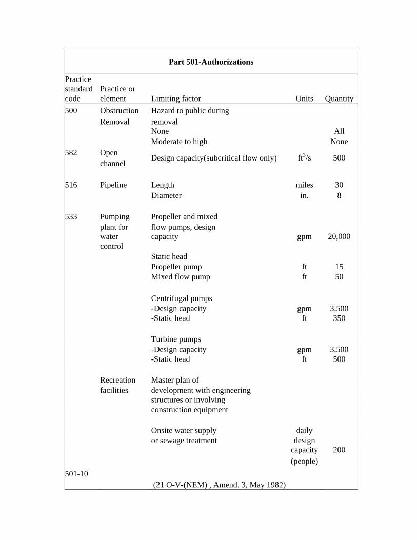
500 Obstruction Hazard to public during removal Removal None All Moderate to high None
582 Open channel
Design capacity(subcritical flow only) ft3/s 500
516 Pipeline Length miles 30 Diameter in. 8
533 Pumping plant for water control
Propeller and mixed flow pumps, design capacity gpm 20,000
Static head Propeller pump ft 15 Mixed flow pump ft 50
Centrifugal pumps -Design capacity gpm 3,500 -Static head ft 350
Turbine pumps -Design capacity gpm 3,500 -Static head ft 500
Recreation facilities
Master plan of development with engineering structures or involving construction equipment
Onsite water supply or sewage treatment
daily design
capacity (people)
200
501-10 (21 O-V-(NEM) , Amend. 3, May 1982)

Subpart A-Review and Approval
Practice standard code
Practice or element Limiting factor Units Quantity
Offsite public water daily supply and sewage treatment
design capacity (people) 400
No potable water or sewerage included in master plan all
580 Stream bank and shoreline protection
Beaches and shorelines Revetments, bulkheads, and groins. Height above mean high tide or mean high water ft 3 Stream banks Vegetative all Mechanical protection Capacity (bank full) ft3/s 2,000 Drainage area mi2 100 Channel depth, low bank ft 10
584 Stream channel stabilization
Design capacity ft3/s 500
608 Surface drainage, main or lateral
Design capacity ft3/s 500
425 Waste storage
pond
Effective height of dam ft 35
313 Waste storage structure
Wall height Above ground ft 16 Below ground ft 8 Tank span Above ground all Below ground ft 16
359 Waste treatment lagoon
Aerobic-surface area acres 10 Anaerobic-volume ft3 2,000,000 Effective height of dam ft 35
501-l0a (2l0-V-NEM, Amend. 5, August 1983)

Part 501-Authorizations
Practice standard code
Practice or element Limiting factor Units Quantity Any practice Alters the visual resources
of beaches and shorelines on oceans and the Great Lakes none
Other Practices all
Bedding (310), Clearing and snagging (326), Commercial fishponds (397), Diversion (362), Filter strip (393), Fish raceway or tank (398), Grassed waterway or outlet (4 12), Heavy use area protection (561), Hillside ditch (423), Irrigation field ditch (388), Irrigation land leveling (464), Irrigation system, trickle (441), Sprinkler (442), Surface and subsurface (443), Irriga- tion system, tailwater recovery (447), Irrigation water management (449), Land clearing (460), Land smoothing (466), Lined waterway or outlet (468), Mole drain (482), Pond sealing or lining (521), Precision land forming (462), Pumped well drain (532), Recreation land grading and shaping (566), Recreation trail and walkway (568), Regulating water in drainage systems (554), Rock barrier (555), Roof runoff management (558), Row arrange- ment (557), Runoff management system (570), Spoil spreading (572), Spring development (574), Subsurface drain (606), Surface drainage, field ditch (607), Terrace (600), Trough or tank (614), Underground outlet (620), Vertical drain (630), Waste management system (312), Water harvesting catchment (636), Water and sediment control basin (638), Water spreading (640), Well (642) All jobs not listed or more complex than those above (except for those specifically delegated to a State or those covered by interim standards, with approval specified in approval letter) will require co approval by the Head, NTC Engineering Staff and the state conservation engineer. The following complex jobs are to be approved only after concurrence by the Director, Engineering Division.
Class "C" dam and those with permanent
than sediment) storage (other
Embankment over an active fault all
Dams-(See page 501-6) Pumping plant for water control
Drainage area mi2 50 Design capacity ft3/s 1,000
50 1-10b (2 10-V-NEM, Amend. 5, August 1983)

Module 109 Design Hydrology Appendix C
Idaho Engineering Job Approval AuthorityName Title Grade Location Technical Determination by (Responsible Engineer) Title Date Approved by (Line Supervisor) Title Date
Job Class Maximum Approval Unit
Practice or System Practice
Code Controlling Factors Units I II III IV V Plan- ning Design Const.
Bedding 310 - - - - - - AllWaste Management System 312 Design capacity 1,000 lbs.
animal live weight No. 50 100 150 300 All
Waste Storage Structure 313 Design capacity 1,000 lbs. animal live weight
No. - - 100 300 All
Wall Height - Abov re g ound Ft. - - - 12* 16 Below ground Ft. - - 6* 8* 8
Tank Span - Above ground Ft. - - - - All Below ground Ft. - - 10* 16* 16
Irrigation Canal or Lateral 320 Design capacity cfs - 25 50 100 500Clearing and Snagging 326 Obstruction removal except
sediment bars - - - All -
Dam, Diversion 348 Stream flow (25 yr. frequency) cfs - 150 250 500 2,000
Flow diverted - - 10 25 100 200Height of drop Ft. - 2 4 5 8
Dam Multiple Purpose 349 Hazard class - a a a a aSediment Basin 350 Effective height. Ft. 6t 10t 15t 19t 35Pond 378 Open channel spillways Dam Floodwater Retarding 402 drainage area Mi2 3 5 10 15 20Irrigation Storage Reservoir 436 Conduit spillway (single) Irrigation Pit or Regulating Inside diameter In. 6 8 12 18 48Reservoir 552 Box culvert area of opening
(Standard design) Ft.2 - - - - 16Storage x Height Ac-Ft.2 30 150 375 1,000 3,000Storage Ac-Ft 10 30 50 100 All
*Standard designs only. Refer to Idaho Supplement, NHCP Code 378 for dam height definition

Idaho Engineering Job Approval Authority
Job Class Maximum Approval limit
Practice or System Practice
Code Controlling Factors Units I II III IV VPlan- ning Design Const.
Grade Stabilization Structure 410 Flow cfs - - 150 250 500 -
Height drop - - 2 4 5 AllStructures for Water Control 587 Design capacity cfs 3t 5 10 100 All
Sidewall height. Ft. t 4 4 8 AllNet drop Ft. 1 2 4 5 AllReinforced concrete structural Ft. - - - 12* 16
spillways standard design e 8Net drop Ft. - - - 6 8Weir depth Ft. - - - 3 4Weir capacity cfs - - - 50 500Box inlet drop spillways - All - -
open or to conduit Net drop Ft. - - - - 6Weir capacity cfs - - - - 500Reinforced concrete & formless Ft. - 2 4 5 8
chutes standard design a a a a aNet drop Ft. - - - 10 12Weir depth Ft. - - - 3 3Weir capacity cfs - - - 50 300Slide gate Head 10 feet or more cfs - 2 4 20 200Head less than 10 feet cfs 2* 3 5 50 500Radial or tainter gates - - - - - -Siphon - Head"" Ft. - - - 10 10- Capacity cfs - - - 20 100Long span supported pipe cfs - - - - 10
capacity Ac-Ft. 10 30 50 100 All
*Standard Designs only. Standard Idaho drawings only Maximum working head on pipe.

Idaho Engineering Job Approval Authority
Job Class Maximum Approval Limit
Practice or System Practice
Code Controlling Factors Units I II III IV V Plan- ning Design Const.
Dike 356 Water height Ft. - 3 4 6 12
Hazard Class - III II&III II&III II&III Waste Treatment Lagoon 359 Aerobic - Surface area Ac. - - - 3 10
Anaerobic - Volume Ft.3 - - - 600,000 2,000,000Effective height of dam* Ft. - - - 19 35
Diversion 362 Design capacity cfs 3 5 10 50 All
Irrigation Field Ditch 388 Design capacity cfs 2 5 10 15 All
Filter Strip 393 Drainage area Ac. 40 80 160 All -
Fish Raceway or Tank 398 Side wall height Ft. - - 4** 5 All
Floodwater Diversion 400 Design capacity cfs 5 10 50 100 500
Water height Ft. 2 3 4 5 6
Floodway 404 Design capacity cfs 5 10 100 250 1,000
Hazard Class III III II&III II&III II&III
Grassed Waterway or Design flow - 10% Outlet 412 frequency cfs 25 50 150 250 All
- Hillside Ditch 423 Design flow cfs 5 10 100 250 AllWaste Storage Pond 425 Design capacity 1,000 lbs. - a a a a a
Animal live weight No. - - 200 500 AllEffective height of dam* Ft. - - 10 19 35
Irrigation Water Canal lining (design Conveyance 428 capacity) cfs 5 10 20 50 200(Ditch & Canal Lining) Velocity fps 4 6 9 15 All
Hazard class, spillway criteria, etc., as shown on pages 1 and 2 also apply to this practice. **Standard Designs only.

Idaho Engineering Job Approval Authority
Job Class Maximum Approval Limit
Practice or System Practice
Code Controlling Factors Units I II III IV V Plan- ning Design Const.
Irrigation Water Conveyance 430 Pipeline capacity> 50 psi gpm 900 1,800 2,250 3,000 3,500
< 50 psi gpm 900 2,700 3,600 4,500 5,000Irrigation Water Conveyance 430.DD-A Pipeline capacity> 50 psi gpm - - - - 3,500
(lnterim) 430-EE-A < 50 psi gpm - - - - 5000
Plastic pipe size> 50 psi In. - - - - 201027< 50 psi In. - - - - 20
Irrigation System, Trickle 441 Area benefited Ac. - - 20 40 AD
Irrigation System, Sprinkler 442 Area served Ac. 40 80 160 360 AllNumber of farm units served No. 1 1 2 4 AD
Irrigation System, Surface
and Subsurface
443 Area benefited Ac. 40 80 160 340 All
Water height Ft. 2 3 4 5 6
Irrigation System 447 Area benefited Ac. 40 80 160 320 All
Tailwater Recovery Hazard Class III III II&III II&III II&III Irrigation Water Management 449 Area
benefited Ac. 40 80 All - -
Land Clearing 460 Area cleared* Ac. - 10 40 160 All
Precision Land Forming 462 Area benefited Ac. 80 160 240 320 All
Irrigation Land Leveling 464 Area benefited Ac. 20 80 160 240 All
Land Smoothing 466 Area benefited Ac. 20 80 160 240 All
Lined Waterway or Outlet 468 Design flow cfs 3 5 25 50 All
Hole Drain 482 - - All - - - -
*Must have interdisciplinary review and total plan.

Idaho Engineering Job Approval Authority
Job Class Maximum Approval Limit
Practice or System Practice
Code Controlling Factors Units I II III IV V Plan- ning Design Const.
Obstruction Removal 500 Hazard to public during - - - AD -- removal - none gpm - - - -3,500
Pipeline 516 Length Mi. 1 2 4 530 Diameter In. 2 3 3 38
Pond sealing or Lining 521 Area treated Ac. - 1 2 5All
Height of embankment Ft. - 10 15 19All
Pumped Well Drain 532 - - - - - -All
Pumping Plant for Propeller & mixed
Water Control 533 flow pumps gpm 900 1,800 5,000 10,00020,000
design capacity Ac. 40 80 160 340All Static head Ft. 2 3 4 56
Propeller pump Ft. 5 5 5 1015 Mixed flow pump Ft. 5 10 15 3050
Centrifugal pump Ac. 40 80 All -- Design capacity gpm 900 1,800 2,250 3,0003,500 Static head. Ft. 5 20 40 50350
Turbine pump Ac. 20 80 160 240All Design capacity gpm 900 1,800 2,250 3,0003,500 Static head Ft. 5 20 40 50500
Regulating Water In Drainage 554 - Ac. - - - 20All
Systems
Rock Barrier 555 - - All - - --
Row Arrangement 557 - - All - - -- *Defined as the sum of the static suction left and the static discharge head (NEH 15, Chapter 8). *Defined as static discharge head (NEH15, Chapter 8).

Idaho Engineering Job Approval Authority
Job Class Maximum Approval Limit
Practice or System Practice
Code Controlling Factors Units I II III IV V Plan- Ning Design Const.
Root Runoff Management Facility 558 Root surface area Ft.2 - - 1,000 2,500 All
Access Road 560 Length Mi. - 1 2 4 AllSurface Type - Natural Gravel Gravel AllCulvert - Pipe Inside diameter Ft. - 2 3 4 6
(Includes storm water Ac. - 1 2 5 Allconduits not associated Ft. - 10 15 19 Allwith access roods) - - - - - All
Monolithic concrete opening Ft.2 - - 15 20 25
Bridge-span (standard design) Ft. - - - - 24
Heavy Use Area Protection 561 Gravel, cinders, bark Ac. 1 2 5 All -sawdust only Ft. 5 5 5 10 15
Recreation Land 566 - Ac. - 10 All - -Grading and Shaping Centrifugal pump Ac. 40 80 All - -Recreation Trail and Walkway 568 - Ft. - All - - -
Runoff Management System 570 Area Ac. - - - 40 All
Spoilbank Spreading 572 - - All - - - -
Spring Development 574 Stock water only No. - All - - -Stream bank Protection 580 Beaches and shorelines Ft. 5 20 40 50 500
Revetments bulkheads & Ac. - - - 20 Allgroins - Height above mean
high tide or mean high water Ft. - - - - 3
Stream banks - vegetative - - - - - AllMechanical protection
capacity (bank full) cfs - - - - 2,000
Drainage area Mi. - - - - 100Channel depth - low bank Ft. - - - - 10

Idaho Engineering Job Approval Authority
Job Class Maximum Approval Limit
Practice or System Practice
Code Controlling Factors Units I II III IV V Plan-ning Design Const.
Open Channel 582 Design capacity cfs - - - 250 500
(Subcritical flow only) Mi. - 1 2 4 All
Stream Channel Stabilization 584 Design capacity cfs - - - - 500
Terrace 600 Area in system Ac. 240 360 640 All -
Subsurface Drain 606 Area benefited Ac. 40 80 120 240 All
Surface Drain - Field Ditch 607 Drainage area Ac. 40 80 120 240 All
Surface Drain - Main or Lateral 608 Design capacity cfs 5 15 25 50 500
Trough or Tank 614 - No. . All - - -
Underground Outlet 620 Design capacity cfs 0.5 1 2 3 All
Vertical Drain 630 - - - - - - All
Water & Sediment Control Basin 638 Contributing area Ac. 20 40 80 160 All
Waterspreading 640 - - All - - - -
Well 642 Depth Ft. - 25 50 100 All
*Standard Designs only.

Idaho Engineering Job Approval Authority
Job Class Maximum Approval Limit
Practice or System Practice
Code Controlling Factors Units I II III IV V Plan- ning Design Const.
Recreation Facilities Master plan of development withengineering structures or Involving construction equipment.
On-site water supply or sewage treatment
Daily design
capacity (people)
- - - - 200
Off-site public water supply and sewage treatment
Daily design
capacity (people) - - - - 400
Related Documents