Modes of integrated collaborative ship design R.I. Whitfield, A.H.B. Duffy Department of Design, Manufacture and Engineering Management, University of Strathclyde, UK SUMMARY The authors have developed a number of integrated collaborative design platforms within the shipbuilding industry. The platforms have addressed a range of integration and collaboration challenges from product data sharing and exchange, consistency management, change propagation, version management and design guidance. Solutions to these challenges are necessary when the design process is fragmented and distributed, to ensure that the right information gets to the right person at the right time to do the right work, i.e. the design process is co-ordinated. The platforms were developed within European Commission (EC) funded projects: VRShips, VIRTUE and SAFEDOR over eight years and demonstrated an evolution and refinement of the ideas, requirements and solutions to a point where the latest version of the platform is being used by industry and developed by an industrial user group. One of the factors contributing towards success was the development of approaches that visualise the solutions to these collaboration challenges. This paper discusses these solutions from a collaboration perspective. 1 INTRODUCTION The design of complex products is inherently disparate, distributed and collaborative regardless of whether the design process is being enacted within a single building, across a geographically distributed organisation, or globally across a number of (potentially competing) organisations. The expertise in order to design a complex artefact such as a ship needs to be co-ordinated to achieve the desired outcome in an efficient (in terms of resource utilisation) and effective (in terms of goal satisfaction) manner. Co-ordination within this context concerns timeliness and appropriateness, where co-ordination is required at the information level (right information, right person, right time) as well as at the task level (right task, right person, right time) [1, 2]. If co-ordination is provided at both levels, the objective of getting the right information to the right person to do the right task at the right time will be achieved. Tasks within the design process are commonly associated with computational tools that are either used to develop the design, or used to simulate performance such as manoeuvring, sea-keeping or fire propagation. Within any one organisation, these tools can consist of a combination of commercial, in-house and legacy applications and can place individual demands in terms of: the expertise required to operate; the computational demands; as well as the type, format and structure of the information being used and generated. The authors have developed a number of integration platforms within EC funded projects within the shipbuilding industry for distributed collaborative design. VRShips-ROPAX was funded within FP5 and developed a platform to support distributed through-life design of a ROPAX ferry [3, 4]. VIRTUE was an FP6 funded project that integrated distributed virtual basins to allow a holistic Computational Fluid Dynamics (CFD) analysis of a ship to be undertaken [5-7]. SAFEDOR was an FP6 funded project that supported designers in performing distributed Risk-Based Design (RBD) and simulation of different types of vessels [8, 9]. These projects had a number of commonalities: the designers involved were distributed; the design and analysis effort required the use of computers, and the designers were expected to collaborate. In each case a Virtual Integration Platform (VIP) was developed, building on and sharing ideas between the projects with the aim of providing collaborative support for distributed design. Bakis et al. provide a discussion of the progress and challenges associated with distributed product data sharing environments [10]. They discuss the sharing of product data at three different levels: conceptual; physical and data management. The conceptual level addresses the issues relating to the format and structure of the data to be exchanged between tools and covers data models such as STEP (Standard for the Exchange of Product Model Data) and representations such as XML (eXtensible Markup Language). The physical level discusses approaches for translating and transferring the data, as well as distributed data sharing architectures. The data management level addresses issues relating to transaction management, access control mechanisms, change notification and propagation, as well as version management mechanisms. Each of the VIPs developed by the authors addressed different aspects of these levels identified, and the solutions are discussed here. The paper is organised as follows: Section 2 covers the approaches for distributed data management at the three levels discussed by Bakis et al., Section 3 details the platform architectures; and Section 4 illustrates how these approaches can be visualised graphically to support collaboration. Section 5 concludes.

Welcome message from author
This document is posted to help you gain knowledge. Please leave a comment to let me know what you think about it! Share it to your friends and learn new things together.
Transcript
Modes of integrated collaborative ship design
R.I. Whitfield, A.H.B. Duffy Department of Design, Manufacture and Engineering Management, University of Strathclyde, UK SUMMARY The authors have developed a number of integrated collaborative design platforms within the shipbuilding industry. The platforms have addressed a range of integration and collaboration challenges from product data sharing and exchange, consistency management, change propagation, version management and design guidance. Solutions to these challenges are necessary when the design process is fragmented and distributed, to ensure that the right information gets to the right person at the right time to do the right work, i.e. the design process is co-ordinated. The platforms were developed within European Commission (EC) funded projects: VRShips, VIRTUE and SAFEDOR over eight years and demonstrated an evolution and refinement of the ideas, requirements and solutions to a point where the latest version of the platform is being used by industry and developed by an industrial user group. One of the factors contributing towards success was the development of approaches that visualise the solutions to these collaboration challenges. This paper discusses these solutions from a collaboration perspective.
1 INTRODUCTION
The design of complex products is inherently disparate, distributed and collaborative regardless of whether the design process is being enacted within a single building, across a geographically distributed organisation, or globally across a number of (potentially competing) organisations. The expertise in order to design a complex artefact such as a ship needs to be co-ordinated to achieve the desired outcome in an efficient (in terms of resource utilisation) and effective (in terms of goal satisfaction) manner. Co-ordination within this context concerns timeliness and appropriateness, where co-ordination is required at the information level (right information, right person, right time) as well as at the task level (right task, right person, right time) [1, 2]. If co-ordination is provided at both levels, the objective of getting the right information to the right person to do the right task at the right time will be achieved.
Tasks within the design process are commonly associated with computational tools that are either used to develop the design, or used to simulate performance such as manoeuvring, sea-keeping or fire propagation. Within any one organisation, these tools can consist of a combination of commercial, in-house and legacy applications and can place individual demands in terms of: the expertise required to operate; the computational demands; as well as the type, format and structure of the information being used and generated.
The authors have developed a number of integration platforms within EC funded projects within the shipbuilding industry for distributed collaborative design. VRShips-ROPAX was funded within FP5 and developed a platform to support distributed through-life design of a ROPAX ferry [3, 4]. VIRTUE was an FP6 funded project that integrated distributed virtual basins to allow a holistic Computational Fluid Dynamics (CFD) analysis of a ship
to be undertaken [5-7]. SAFEDOR was an FP6 funded project that supported designers in performing distributed Risk-Based Design (RBD) and simulation of different types of vessels [8, 9].
These projects had a number of commonalities: the designers involved were distributed; the design and analysis effort required the use of computers, and the designers were expected to collaborate. In each case a Virtual Integration Platform (VIP) was developed, building on and sharing ideas between the projects with the aim of providing collaborative support for distributed design.
Bakis et al. provide a discussion of the progress and challenges associated with distributed product data sharing environments [10]. They discuss the sharing of product data at three different levels: conceptual; physical and data management. The conceptual level addresses the issues relating to the format and structure of the data to be exchanged between tools and covers data models such as STEP (Standard for the Exchange of Product Model Data) and representations such as XML (eXtensible Markup Language). The physical level discusses approaches for translating and transferring the data, as well as distributed data sharing architectures. The data management level addresses issues relating to transaction management, access control mechanisms, change notification and propagation, as well as version management mechanisms. Each of the VIPs developed by the authors addressed different aspects of these levels identified, and the solutions are discussed here. The paper is organised as follows: Section 2 covers the approaches for distributed data management at the three levels discussed by Bakis et al., Section 3 details the platform architectures; and Section 4 illustrates how these approaches can be visualised graphically to support collaboration. Section 5 concludes.
2 DISTRIBUTED DATA MANAGEMENT
When designing a data management solution to support distributed design, three issues require consideration: storage (how to store the data), structure (how to format the data), and coverage (what data to store) which correspond to the levels identified by Bakis et al.
These issues are however related since the selection of the storage mechanism depends upon the structure of the data to be stored (binary, XML, object-oriented). In addition, the data structure is influenced by the requirements of the tools to be integrated as well as the requirements of the users of the platform, and therefore influences and is influenced by the coverage.
One of the focal points of facilitating collaboration within VRShips was through the exchange of product data via a common model. Despite some success by others in using the Standard for the Exchange of Product Model Data (STEP) and its underlying language EXPRESS [11], the number of design and simulation tools supporting STEP within VRShips were limited hence an alternative had to be found. This was in addition to pressure from commercial software providers within the project to an alternative to STEP. In order to solve the problem relating to structure, it was therefore necessary to consider the data requirements (coverage) of the platform from two perspectives: the data that the tools would be using; and the data that would be required for through-life design.
A series of workshops were conducted within the VRShips project that combined the partners responsible for integrating tools with those responsible for conducting through-life design to establish a schema for the common model data. An additional consideration in creating the schema was in the selection of a data structure that would be neutral to all of the tools being integrated, but which facilitated conversion between neutral and native formats. The philosophy when defining the schema was in identifying the minimum set of data that would allow tool integration and the exchange of data between these tools, whilst supporting through life design. Any data that was not common according to this philosophy was managed within the local data models of the tools and merged with the common neutral data when needed. This approach had the benefit that the size of the common model schema would be kept to a minimum; it would simplify the data conversion; and if sufficient tools were considered during the creation of the schema (making the schema information rich), it should allow additional tools to be integrated with little or no modification. The schema was used to develop a product data model contained within an XML database (the centralised common model). This product data model was contained within a single XML file structured in accordance with the schema.
Choosing to manage the data within the common model using XML, facilitated the selection of a storage mechanism. The XML:DB initiative provides standardisation for the development of specifications for the querying, manipulation and management of data stored within XML databases. This initiative enabled the database to be de-coupled from the rest of the VRShips platform, allowing alternative XML databases to be used without impacting any of the software that communicates with the database.
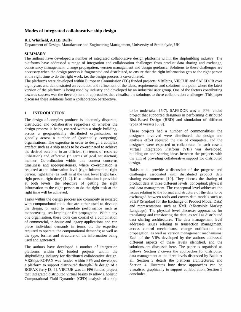
With the schema for the common model in place, integrating a tool into the platform involved identifying and downloading the data from the schema that would be used as input, converting this data from the neutral format into the tool native format whilst merging any additional local data, then loading the data into the tool. Any output data to be uploaded would be converted from the tool native format into the neutral format and inserted back into the schema - Figure 1. The choice of XML as the language for storage of the data facilitated the conversion process and allowed conversion algorithms to be shared amongst tool integrators where the native formats were similar. The development of at least one conversion algorithm (for either input or output) was the minimum requirement in order to integrate a tool into VRShips. Using the approach illustrated within Figure 1 allowed the sharing of data between all of the tools integrated whilst minimising the number of data conversion algorithms.
Con
vert
Con
vert
Tool Tool
Neutral
Convert Convert
Convert Convert Convert
Convert
Figure 1. VRShips data management.
The approach within the VIP-V (VIRTUE) and VIP-S (SAFEDOR) had a number of conceptual differences with VRShips, and chiefly amongst these was in the development of the common model. It was established within the VIRTUE project that some of the file-based results from a single CFD analysis would be of the order 100MB, which would present difficulties for the VRShips
common model. Through the use of the VRShips configuration it was established that there was a limitation in the size of an XML element that could be inserted into the common model. The computation and memory demands to insert an element greater than 10MB into the common model became excessive, occasionally resulting with failure.
A consideration of the data coverage was made both within VIRTUE and SAFEDOR. For VIRTUE three main types of data required support to perform CFD: geometrical data representing a hullform or propeller; a meshed representation of this geometrical data; and 3D or 4D results from the CFD. The process was relatively sequential – modify the geometry, mesh the geometry, perform CFD, analyse results, reiterate and modify the geometry in accordance with the results and objectives. Large volumes of (generally file-based) data could be created at various stages within this process. Synergies were drawn with SAFEDOR having generally a single design tool as the starting point from which the required data would be generated in order to undertake Performance, Earnings, Risk, and Cost (PERC) analyses. The need to fill the gaps in conversion from one tool to the next were not as great within VIRTUE and SAFEDOR, hence the storage of file-based data was taken from the common model to the local models via FTP servers.
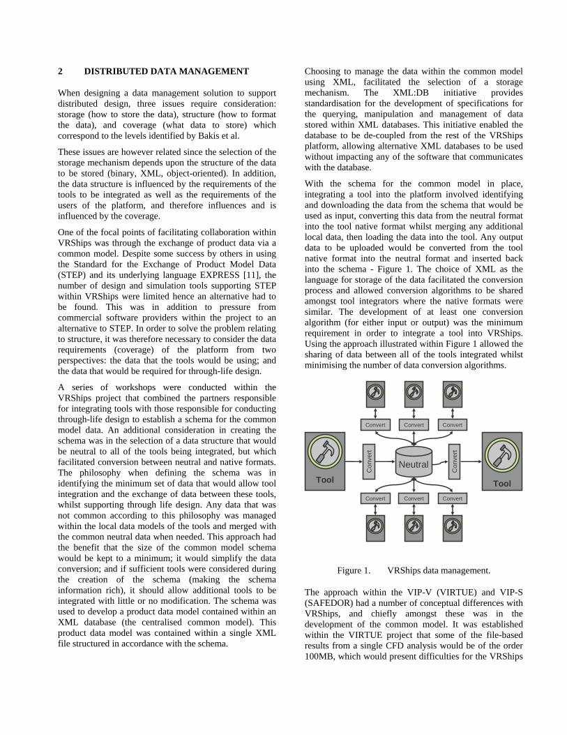
The concept of a centralised database holding common data with local models holding all other data was modified to an architecture where the centralised database contained Uniform Resource Locators (URLs) to the data stored within distributed FTP servers as shown within Figure 2.
FTPServer
FTPServer
Tool A
Wra
pper
Output A
URL…
OutputA
Tool B
Wra
pper
Tool C
Wra
pper
OutputA
Tool D
Wra
pper
OutputC
URL…
OutputC
FileLocationRequest
FileTransfer
FileLocation
Response
FTPServer
FTPServer
Tool ATool A
Wra
pper
Output A
URL…
OutputA
OutputA
Tool B
Wra
pper
Tool BTool B
Wra
pper
Tool C
Wra
pper
Tool CTool C
Wra
pper
OutputA
OutputA
Tool D
Wra
pper
Tool DTool D
Wra
pper
OutputC
OutputC
URL…
OutputC
FileLocationRequest
FileTransfer
FileLocation
Response
Figure 2. VIRTUE and SAFEDOR data management
A generic wrapper was still used to integrate the design and analysis tools into the VIP-S and VIP-V. However when the generic wrapper attempted to download data in enactment mode, it would firstly communicate with the
common model to establish where within the network the required data was. Once this had been established, the generic wrapper would communicate with the FTP server located at that URL and request the file to be downloaded. A similar sequence of operations would be performed to upload output data with the common model being updated to indicate that a new version had been created. A common model schema was created within the VIP-S and VIP-V providing a structure for storing meta-data relating to the physical files. The architecture allowed the centralised database to store meta-data relating to the physical file data, and a number of FTP servers to control
o be developed within VIRTUE and
n offered, as well as facilitating parametric
order to develop import and export functionality.
access to the file data for the distributed users.
Since the VIP-S and VIP-V had no neutral data format the responsibility of converting the data would be that of the integrated tools, and not something that was explicitly managed by the platform. This would either involve the export of data from the output tool, or the import of data into the input tool. It was established however that this requirement did not limit the way in which tools could be integrated and exchange information. In contrast, recent results from the use of these platforms has identified that this requirement has had the side-effect of further enhancing the capabilities of the integrated tools [7]. One of the shortcomings of using this approach however was in the number of conversion algorithms to be developed. Referring to Figure 1, the VRShips approach required the development of 16 algorithms to allow data to be shared between all of the tools, however to achieve the same level of integration would require 56 conversion algorithms tSAFEDOR.
Not all of the data within SAFEDOR or VIRTUE was file-based; hence the schema was further developed to allow the storage of parametric data. The inclusion of any type of parametric data within the common model provided additional flexibility that the VRShips implementatiooptimisation.
The approaches developed within each of the projects for distributed data management provide individual strengths and weaknesses. The VRShips approach provides flexibility to easily extend the range of tools to be integrated whilst minimising the volume of data held within the common model and minimising the number of convertors that were required. This was at the expense of limiting the size of elements that the database could manage. By contrast, the VIRTUE and SAFEDOR implementation provided no limitation to the volume of data that could be managed and efficiently transferred the data between users, but necessitated access to the tool source code in
3 PLATFORM ARCHITECTURES
It was established early within the VRShips project that: the design and analysis activity would be distributed; the activity would be performed using computers with different operating systems; the integrated tools may be developed using different programming languages, and the tools may use data within different formats and structures. Flexibility was required in order to develop an architecture that addressed these challenges and was sufficiently accessible to allow new design and analysis tools to be integrated into the platform with the minimum of effort. Two of the underlying technologies that provided this flexibility were Java (for platform independence) and XML (for communication of information). The same choice of technologies was used within the VIRTUE and SAFEDOR projects.
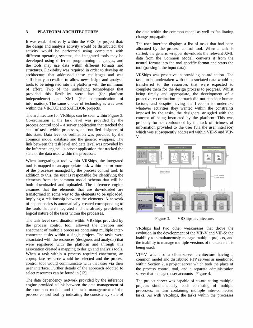
The architecture for VRShips can be seen within Figure 3. Co-ordination at the task level was provided by the process control tool – a server application that tracked the state of tasks within processes, and notified designers of this state. Data level co-ordination was provided by the common model database and the generic wrappers. The link between the task level and data level was provided by the inference engine – a server application that tracked the state of the data used within the processes.
When integrating a tool within VRShips, the integrated tool is mapped to an appropriate task within one or more of the processes managed by the process control tool. In addition to this, the user is responsible for identifying the elements from the common model schema that will be both downloaded and uploaded. The inference engine assumes that the elements that are downloaded are transformed in some way to the elements to be uploaded, implying a relationship between the elements. A network of dependencies is automatically created corresponding to the tools that are integrated and the already pre-defined logical nature of the tasks within the processes.
The task level co-ordination within VRShips provided by the process control tool, allowed the creation and enactment of multiple processes containing multiple inter-connected tasks within a single project. The tasks were associated with the resources (designers and analysts) that were registered with the platform and through this association created a mapping to design and analysis tools. When a task within a process required enactment, an appropriate resource would be selected and the process control tool would communicate with that user via their user interface. Further details of the approach adopted to select resources can be found in [12].
The data dependency network provided by the inference engine provided a link between the data management of the common model, and the task management of the process control tool by indicating the consistency state of
the data within the common model as well as facilitating change propagation.
The user interface displays a list of tasks that had been allocated by the process control tool. When a task is started, the generic wrapper downloads the relevant XML data from the Common Model, converts it from the neutral format into the tool specific format and starts the tool (passing it the input data).
VRShips was proactive in providing co-ordination. The tasks to be undertaken with the associated data would be transferred to the resources that were expected to complete them for the design process to progress. Whilst being timely and appropriate, the development of a proactive co-ordination approach did not consider human factors, and despite having the freedom to undertake whatever activities they wanted within the constraints imposed by the tasks, the designers struggled with the concept of being instructed by the platform. This was probably further confounded by the lack of richness of information provided to the user (via the user interface) which was subsequently addressed within VIP-S and VIP-V.
User Interface
Common Model
Generic Wrapper
Simulation Tool
AVPro
Local ModelIn
put C
onve
rter
Out
put C
onve
rter
SSL Com
Generic Wrapper
Design Tool
Tribon
Local Model In
put C
onve
rter
Out
put C
onve
rter
SSL Com
Generic Wrapper
Design Tool
AVPro
Local Model In
put C
onve
rter
Out
put C
onve
rter
SSL Com
Process Control Tool
Resources
Requirements
Processes
SSL
Com
SSL Com
Inference Engine
Dependency Maps
SSL
Com
Performance Analysis
Performance Models
SSL
Com
Common Model Communication
Virtual Platform Communication
Figure 3. VRShips architecture.
VRShips had two other weaknesses that drove the evolution in the development of the VIP-V and VIP-S: the inability to simultaneously manage multiple projects, and the inability to manage multiple versions of the data that is being used.
VIP-V was also a client-server architecture having a common model and distributed FTP servers as mentioned within Section 2, a project server which took the place of the process control tool, and a separate administration server that managed user accounts - Figure 4.
The project server was capable of co-ordinating multiple projects simultaneously, each consisting of multiple processes, in turn containing multiple inter-connected tasks. As with VRShips, the tasks within the processes
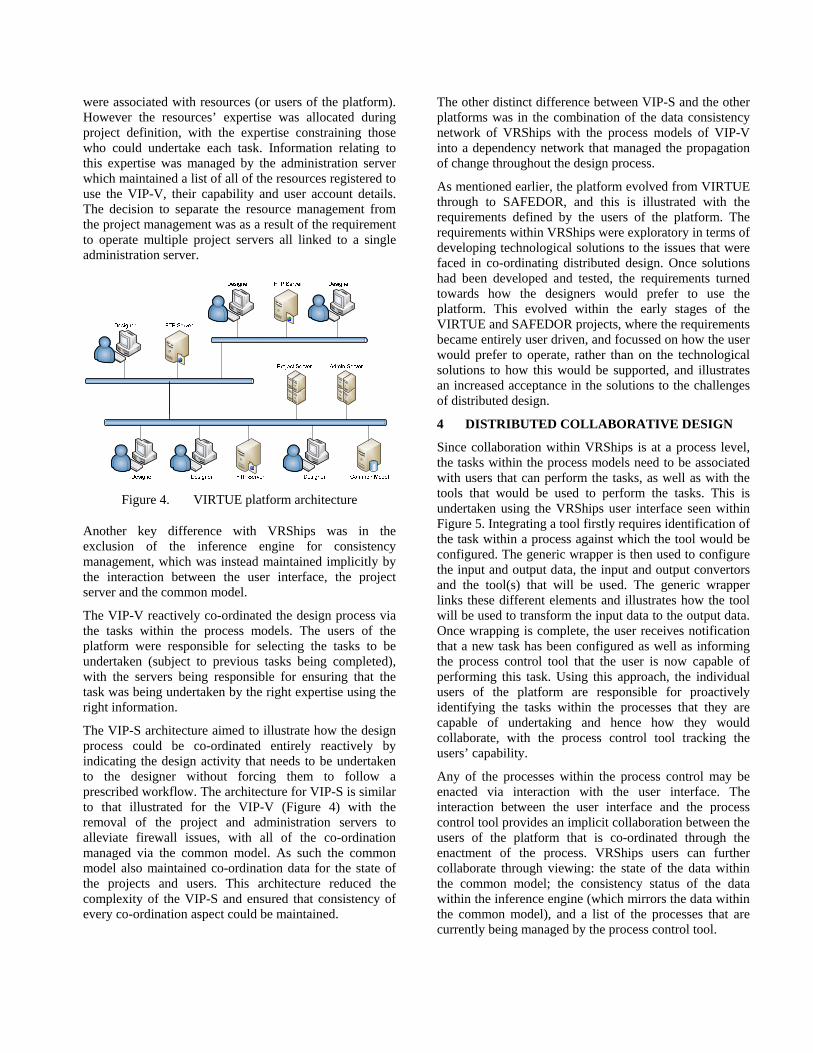
were associated with resources (or users of the platform). However the resources’ expertise was allocated during project definition, with the expertise constraining those who could undertake each task. Information relating to this expertise was managed by the administration server which maintained a list of all of the resources registered to use the VIP-V, their capability and user account details. The decision to separate the resource management from the project management was as a result of the requirement to operate multiple project servers all linked to a single administration server.
Figure 4. VIRTUE platform architecture
Another key difference with VRShips was in the exclusion of the inference engine for consistency management, which was instead maintained implicitly by the interaction between the user interface, the project server and the common model.
The VIP-V reactively co-ordinated the design process via the tasks within the process models. The users of the platform were responsible for selecting the tasks to be undertaken (subject to previous tasks being completed), with the servers being responsible for ensuring that the task was being undertaken by the right expertise using the right information.
The VIP-S architecture aimed to illustrate how the design process could be co-ordinated entirely reactively by indicating the design activity that needs to be undertaken to the designer without forcing them to follow a prescribed workflow. The architecture for VIP-S is similar to that illustrated for the VIP-V (Figure 4) with the removal of the project and administration servers to alleviate firewall issues, with all of the co-ordination managed via the common model. As such the common model also maintained co-ordination data for the state of the projects and users. This architecture reduced the complexity of the VIP-S and ensured that consistency of every co-ordination aspect could be maintained.
The other distinct difference between VIP-S and the other platforms was in the combination of the data consistency network of VRShips with the process models of VIP-V into a dependency network that managed the propagation of change throughout the design process.
As mentioned earlier, the platform evolved from VIRTUE through to SAFEDOR, and this is illustrated with the requirements defined by the users of the platform. The requirements within VRShips were exploratory in terms of developing technological solutions to the issues that were faced in co-ordinating distributed design. Once solutions had been developed and tested, the requirements turned towards how the designers would prefer to use the platform. This evolved within the early stages of the VIRTUE and SAFEDOR projects, where the requirements became entirely user driven, and focussed on how the user would prefer to operate, rather than on the technological solutions to how this would be supported, and illustrates an increased acceptance in the solutions to the challenges of distributed design.
4 DISTRIBUTED COLLABORATIVE DESIGN
Since collaboration within VRShips is at a process level, the tasks within the process models need to be associated with users that can perform the tasks, as well as with the tools that would be used to perform the tasks. This is undertaken using the VRShips user interface seen within Figure 5. Integrating a tool firstly requires identification of the task within a process against which the tool would be configured. The generic wrapper is then used to configure the input and output data, the input and output convertors and the tool(s) that will be used. The generic wrapper links these different elements and illustrates how the tool will be used to transform the input data to the output data. Once wrapping is complete, the user receives notification that a new task has been configured as well as informing the process control tool that the user is now capable of performing this task. Using this approach, the individual users of the platform are responsible for proactively identifying the tasks within the processes that they are capable of undertaking and hence how they would collaborate, with the process control tool tracking the users’ capability.
Any of the processes within the process control may be enacted via interaction with the user interface. The interaction between the user interface and the process control tool provides an implicit collaboration between the users of the platform that is co-ordinated through the enactment of the process. VRShips users can further collaborate through viewing: the state of the data within the common model; the consistency status of the data within the inference engine (which mirrors the data within the common model), and a list of the processes that are currently being managed by the process control tool.
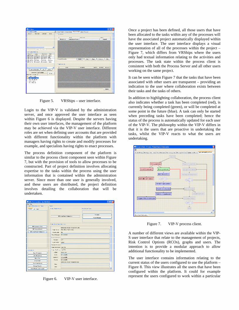
Figure 5. VRShips – user interface.
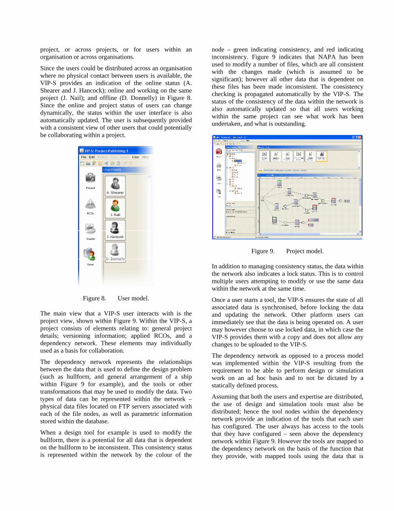
Login to the VIP-V is validated by the administration server, and once approved the user interface as seen within Figure 6 is displayed. Despite the servers having their own user interfaces, the management of the platform may be achieved via the VIP-V user interface. Different roles are set when defining user accounts that are provided with different functionality within the platform with managers having rights to create and modify processes for example, and specialists having rights to enact processes.
The process definition component of the platform is similar to the process client component seen within Figure 7, but with the provision of tools to allow processes to be constructed. Part of project definition involves allocating expertise to the tasks within the process using the user information that is contained within the administration server. Since more than one user is generally involved, and these users are distributed, the project definition involves detailing the collaboration that will be undertaken.
Figure 6. VIP-V user interface.
Once a project has been defined, all those users that have been allocated to the tasks within any of the processes will have the associated project automatically displayed within the user interface. The user interface displays a visual representation of all of the processes within the project – Figure 7, which differs from VRShips where the users only had textual information relating to the activities and processes. The task state within the process client is consistent with both the Process Server and all other users working on the same project.
It can be seen within Figure 7 that the tasks that have been associated with other users are transparent – providing an indication to the user where collaboration exists between their tasks and the tasks of others.
In addition to highlighting collaboration, the process client also indicates whether a task has been completed (red), is currently being completed (green), or will be completed at some point in the future (blue). A task can only be started when preceding tasks have been completed; hence the status of the process is automatically updated for each user of the VIP-V. The philosophy within the VIP-V differs in that it is the users that are proactive in undertaking the tasks, whilst the VIP-V reacts to what the users are undertaking.
Figure 7. VIP-V process client.
A number of different views are available within the VIP-S user interface that relate to the management of projects, Risk Control Options (RCOs), graphs and users. The intention is to provide a modular approach to allow additional functionality to be implemented.
The user interface contains information relating to the current status of the users configured to use the platform – Figure 8. This view illustrates all the users that have been configured within the platform. It could for example represent the users configured to work within a particular
project, or across projects, or for users within an organisation or across organisations.
Since the users could be distributed across an organisation where no physical contact between users is available, the VIP-S provides an indication of the online status (A. Shearer and J. Hancock); online and working on the same project (J. Nail); and offline (D. Donnelly) in Figure 8. Since the online and project status of users can change dynamically, the status within the user interface is also automatically updated. The user is subsequently provided with a consistent view of other users that could potentially be collaborating within a project.
Figure 8. User model.
The main view that a VIP-S user interacts with is the project view, shown within Figure 9. Within the VIP-S, a project consists of elements relating to: general project details; versioning information; applied RCOs, and a dependency network. These elements may individually used as a basis for collaboration.
The dependency network represents the relationships between the data that is used to define the design problem (such as hullform, and general arrangement of a ship within Figure 9 for example), and the tools or other transformations that may be used to modify the data. Two types of data can be represented within the network – physical data files located on FTP servers associated with each of the file nodes, as well as parametric information stored within the database.
When a design tool for example is used to modify the hullform, there is a potential for all data that is dependent on the hullform to be inconsistent. This consistency status is represented within the network by the colour of the
node – green indicating consistency, and red indicating inconsistency. Figure 9 indicates that NAPA has been used to modify a number of files, which are all consistent with the changes made (which is assumed to be significant); however all other data that is dependent on these files has been made inconsistent. The consistency checking is propagated automatically by the VIP-S. The status of the consistency of the data within the network is also automatically updated so that all users working within the same project can see what work has been undertaken, and what is outstanding.
Figure 9. Project model.
In addition to managing consistency status, the data within the network also indicates a lock status. This is to control multiple users attempting to modify or use the same data within the network at the same time.
Once a user starts a tool, the VIP-S ensures the state of all associated data is synchronised, before locking the data and updating the network. Other platform users can immediately see that the data is being operated on. A user may however choose to use locked data, in which case the VIP-S provides them with a copy and does not allow any changes to be uploaded to the VIP-S.
The dependency network as opposed to a process model was implemented within the VIP-S resulting from the requirement to be able to perform design or simulation work on an ad hoc basis and to not be dictated by a statically defined process.
Assuming that both the users and expertise are distributed, the use of design and simulation tools must also be distributed; hence the tool nodes within the dependency network provide an indication of the tools that each user has configured. The user always has access to the tools that they have configured – seen above the dependency network within Figure 9. However the tools are mapped to the dependency network on the basis of the function that they provide, with mapped tools using the data that is
represented within the network and accessed from the common model, whereas unmapped tools only use local data.
The dependency network represents the consistency status of one version of the entire data set. Like the VIP-V, the VIP-S manages multiple versions of the data – with the different versions being represented within the version tree of Figure 9. Whereas the VIP-V manages individual versions for each piece of data, the VIP-S has an entire dataset within each version, with the consistency and lock status of the dataset potentially being different across each of the versions. Different versions and variants can be created, modified and deleted within the VIP-S either copying datasets from existing versions or using completely new datasets.
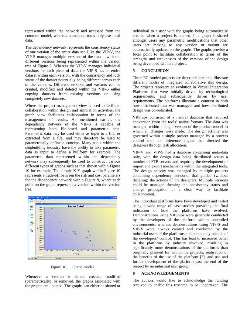
Where the project management view is used to facilitate collaboration within design and simulation activities, the graph view facilitates collaboration in terms of the management of results. As mentioned earlier, the dependency network of the VIP-S is capable of representing both file-based and parametric data. Parametric data may be used either as input to a file, or extracted from a file, and may therefore be used to parametrically define a concept. Many tools within the shipbuilding industry have the ability to take parametric data as input to define a hullform for example. The parametric data represented within the dependency network may subsequently be used to construct various different types of graphs such as that shown within Figure 10 for example. The simple X-Y graph within Figure 10 represents a trade-off between the risk and cost parameters for the dependency network within Figure 9, where each point on the graph represents a version within the version tree.
Figure 10. Graph model.
Whenever a version is either: created; modified (parametrically), or removed, the graphs associated with the project are updated. The graphs can either be shared or
individual to a user with the graphs being automatically created when a project is opened. If a graph is shared amongst users any parametric modifications that other users are making to any version or variant are automatically updated on the graphs. The graphs provide a focal point to facilitate collaboration in terms of the strengths and weaknesses of the versions of the design being developed within a project.
5 CONCLUSION
Three EC funded projects are described here that illustrate different modes of integrated collaborative ship design. The projects represent an evolution in Virtual Integration Platforms that were initially driven by technological requirements, and subsequently driven by user requirements. The platforms illustrate a contrast in both how distributed data was managed, and how distributed design was co-ordinated.
VRShips consisted of a neutral database that required conversion from the tools’ native formats. The data was managed within a single version of the product model to which all changes were made. The design activity was governed within a single project managed by a process control tool and inference engine that directed the designers through task allocation.
VIP-V and VIP-S had a database containing meta-data only, with the design data being distributed across a number of FTP servers and requiring the development of import and export mechanisms within the integrated tools. The design activity was managed by multiple projects containing dependency networks that guided (without dictating) the actions of the designers. Multiple versions could be managed showing the consistency status and change propagation in a clear way to facilitate collaboration.
The individual platforms have been developed and tested using a wide range of case studies providing the final indication of how the platforms have evolved. Demonstrations using VRShips were generally conducted by the developers of the platform within controlled environments, whereas demonstrations using VIP-S and VIP-V were always created and conducted by the industrial users of the platforms and completely outside of the developers’ control. This has lead to increased belief in the platforms by industry involved, resulting in significantly more demonstrations of the platforms than originally planned for within the projects; realisation of the benefits of the use of the platform [7]; and use and further development of the platform past the end of the project by an industrial user group.
6 ACKNOWLEDGEMENTS
The authors would like to acknowledge the funding received to enable this research to be undertaken. The
VRShips-ROPAX project was funded by the European Commission (grant number G3RD-CT-2001-00506), which was part of the Fifth Framework Programme for “Research, technological development and demonstration”. The SAFEDOR project was funded by the European Commission (contract number FP6-516278), within the Sixth Framework Programme for “Sustainable surface transport”. The VIRTUE project was funded by the European Commission (contract number FP6-516201) within the Sixth Framework Programme for “Sustainable development, global change and ecosystems”. The opinions are those of the authors and should not be construed to represent the views of the SAFEDOR, VIRTUE or VRShips-ROPAX partnerships.
7 REFERENCES
1. Whitfield, R.I., et al., Coordination approaches and systems - Part 1: A strategic perspective. Research in Engineering Design, 2000. 12(1): p. 48-60.
2. Coates, G., et al., Coordination approaches and systems – Part II: An operational perspective. Research in Engineering Design, 2000. 12(2): p. 73-89.
3. Duffy, A.H.B. Life cycle virtual reality ships systems. Available from: http://www.vrsproject.com/index.phtml.
4. Whitfield, R.I., et al. An overview of the VRS virtual platform. in 15th International Conference on Engineering Design. 2005. Melbourne Australia: Design Society.
5. Marzi, J. The virtual tank utility in Europe. Available from: http://www.virtual-basin.org/.
6. Wu, Z., et al. VIRTUE integrated platform: holistic support for distributed ship hydrodynamic design. in International Conference on Engineering Design. 2007. Paris, France: Design Society.
7. Wang, W., et al., Virtual Integration Plaform for Computational Fluid Dynamics, in 14th International Conference on Computer Applications in Shipbuilding. 2009, Royal Institution of Naval Architects: Shanghai, China.
8. Baumgart, A. Design, operation and regulation for safety. Available from: http://www.safedor.org/.
9. Whitfield, R.I. and A.H.B. Duffy, Collaborative support for distributed design, in Realising Network Enabled Capability. 2008: Leeds, UK.
10. Bakis, N., G. Aouad, and M. Kagioglou, Towards distributed product data sharing environments - Progress so far and future challenges. Automation in Construction, 2007. 16: p. 286-292.
11. Whitfield, R.I., et al., Ship product modelling. Journal of Ship Production, 2003. 19(4): p. 230-245.
12. Whitfield, R.I., A.H.B. Duffy, and G. Coates. Real time resource scheduling within a distributed collaborative design environment. in International
Conference of Engineering Design. 2007. Paris, France: Design Society.
8 AUTHORS BIOGRAPHY
Dr Ian Whitfield is a lecturer in the Department of Design Manufacture and Engineering Management at the University of Strathclyde. He has been involved in the management and conducting of research within a number of large FP5 and FP6 integrated projects within the shipbuilding industry, and has garnered significant knowledge in how to achieve collaboration between a large number of partners for successful project completion. These projects have each focussed upon the development of collaborative tools and techniques for the integration of distributed design expertise across Europe. His research background subsequently covers issues relating to: co-ordination, collaboration, integration, resource management, process modelling and optimisation and modular design.
Prof. Alex Duffy is Vice Dean of Research in the Engineering Faculty at the University of Strathclyde. He is a Chartered Engineer, Chartered IT Professional, Fellow of the British Computer Society, Fellow of the Institute of Engineering Designers, and is currently the Vice President, and prior to this the President, of the Design Society, an international body encompassing all aspects and disciplines of design. He has published over 200 articles, is the editor of the Journal of Engineering Design and is on the editorial boards of the journals of Research in Engineering Design, Design Computing, and Artificial Intelligence in Engineering Design Analysis and Manufacture.
Related Documents