Modern Optics Lab Lab 4: First Experiments with the Advanced Optics Set Imaging with a single lens Aperture and its effect on depth of field Measuring the focal length with the “auto- collimation” method Spherical Aberration and the Foucault knife test Total internal reflection: Determining the index of refraction of a liquid with “Abbes Method”. Building a beam expander. Topics

Welcome message from author
This document is posted to help you gain knowledge. Please leave a comment to let me know what you think about it! Share it to your friends and learn new things together.
Transcript

Modern Optics LabLab 4: First Experiments with the Advanced Optics Set
Imaging with a single lens
Aperture and its effect on depth of field
Measuring the focal length with the “auto-collimation” method
Spherical Aberration and the Foucault knife test
Total internal reflection: Determining the index of refraction of a liquid with “Abbes Method”.
Building a beam expander.
Topics

Modern Optics LabLab 4: First Experiments with the Advanced Optics Set
Quantity Sign
+ -so Real object Virtual objectsi Real image Virtual imagef Converging lens Diverging lensyo Erect object Inverted objectyi Erect image Inverted image
Fo Fi
fxo
so
f
si
xi
yo
yi
Thin Lens
fss i
111
:formula Lens
0
o
i
o
iT y
y
s
sM
:ion Magnificat Transverse

Modern Optics LabLab 4: First Experiments with the Advanced Optics Set
IV.A Imaging by a single lens
Lens Screen
os is
Lens Screen
os is
Figure out the exact position of the filament!

Modern Optics LabLab 4: First Experiments with the Advanced Optics Set
IV.B Depth of Field
Depth of field in photograph:
The range of distances over which the image is sharp.
Can be controlled with aperture.
Depth of field is a trade-off for time of exposure in photography: Smaller aperture = greater depth of field but requires longer exposure
time. Larger aperture = less depth of field but requires less exposure time.

Modern Optics LabLab 4: First Experiments with the Advanced Optics Set
Screen placed away from image plane: Blurry image
Fo Fi
fxo
so
f
si
xi
yo
yi

Modern Optics LabLab 4: First Experiments with the Advanced Optics Set
Screen placed away from image plane but using an aperture…..
Fo Fi
fxo
so
f
si
xi
yo
yi
Aperture
Modern Optics LabLab 4: First Experiments with the Advanced Optics Set
IV.C Auto-collimation method
Lens Mirror
f
Aperture
Make sure the image appearing here is a sharp image of the aperture, NOT an image of the filament!
Modern Optics LabLab 4: First Experiments with the Advanced Optics Set
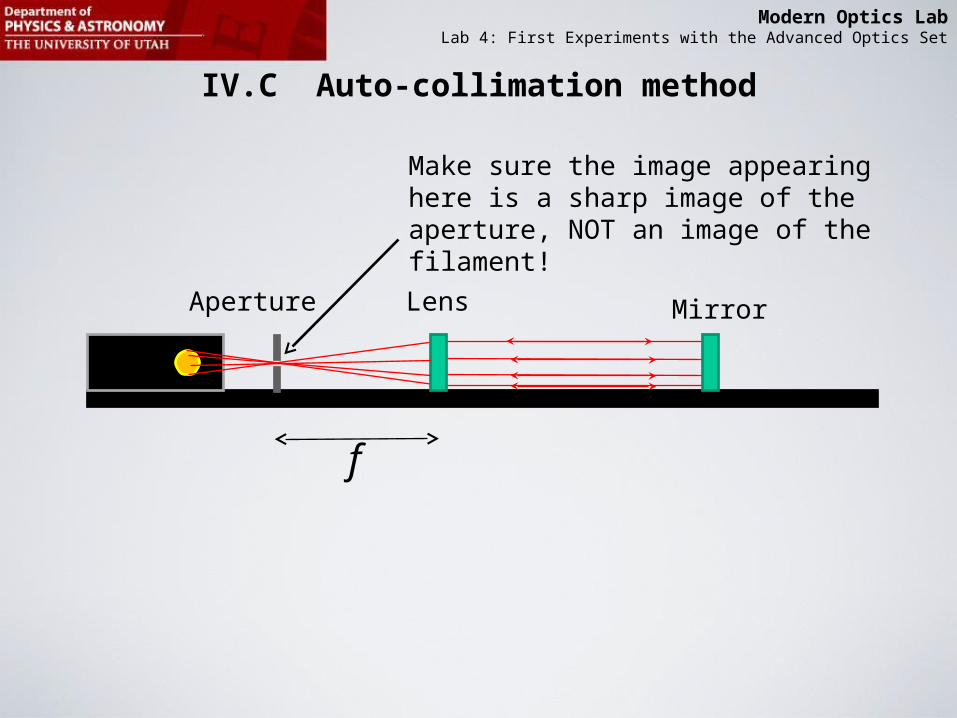
IV.D Spherical aberration

Modern Optics LabLab 4: First Experiments with the Advanced Optics Set
IV.D Foucault knife test explainedNote: The different colors used are just for the purpose of easier visual tracking. They do not represent different colors. Assume all rays have the same color.
1
1
2
2
3
3
4
5
6
456
Perfect Lens

Modern Optics LabLab 4: First Experiments with the Advanced Optics Set
IV.D Foucault knife test explainedFoucault “knife” at position 1 (in front of focus)
1
1
2
2
3
3
4
5
6
456
Perfect Lens
Screen
Screen

Modern Optics LabLab 4: First Experiments with the Advanced Optics Set
IV.D Foucault knife test explainedFoucault “knife” at position 2 (at focus)
1
1
2
2
3
3
4
5
6
456
Perfect Lens
Screen
Screen

Modern Optics LabLab 4: First Experiments with the Advanced Optics Set
IV.D Foucault knife test explainedFoucault “knife” at position 3 (behind the focus)
1
1
2
2
3
3
4
5
6
456
Perfect Lens
Screen
Screen

Modern Optics LabLab 4: First Experiments with the Advanced Optics Set
IV.D Foucault knife test explainedIn this example of a lens with spherical aberration, we assume for simplicity two different focal points: One for “outer rays” (1,6) and one for “inner rays” (2,3,4,5)
1
1
2
2
3
3
4
5
6
456
Lens with spherical aberration

Modern Optics LabLab 4: First Experiments with the Advanced Optics Set
IV.D Foucault knife test explained
123
456
Lens with spherical aberration
Foucault “knife” at position 1 (in front of “inner” focus)
Screen
Screen

Modern Optics LabLab 4: First Experiments with the Advanced Optics Set
IV.D Foucault knife test explained
123
456
Lens with spherical aberration
Foucault “knife” at position 2 (in front of “inner” focus)
Screen
Screen
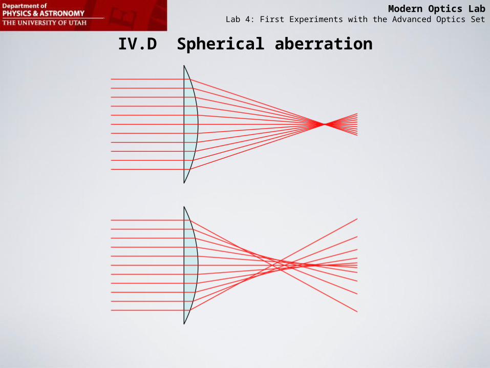
Modern Optics LabLab 4: First Experiments with the Advanced Optics Set
IV.D Foucault knife test explained
123
456
Lens with spherical aberration
Foucault “knife” at position 3 (between “inner” and “outer” focus)
Screen
Screen This should be enough instruction for you to complete!

Modern Optics LabLab 4: First Experiments with the Advanced Optics Set
IV.D Setting up your Foucault knife test
Light Source
Short ends towards each other
18mm lens Razor bladeScreen
Razor blade
View from the front

Modern Optics LabLab 4: First Experiments with the Advanced Optics Set
IV.E Total internal reflection
critical1n
12 nn
1n
12 nn
criticalnnnn sin90sinsinsin :Law sSnell' 212211
2
1sinn
ncritical

Modern Optics LabLab 4: First Experiments with the Advanced Optics Set
IV.E Determine the refractive index of prism by measuring the critical angle
prismn1n
45
Modern Optics LabLab 4: First Experiments with the Advanced Optics Set
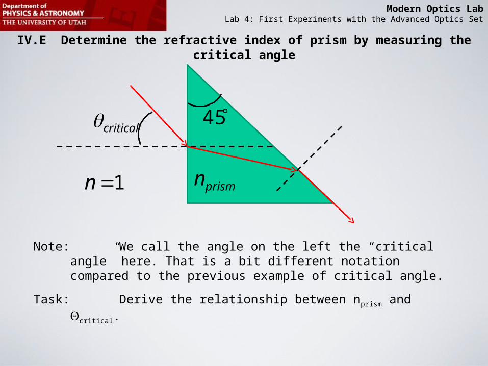
IV.E Determine the refractive index of prism by measuring the critical angle
critical
prismn1n
Note: We call the angle on the left the “critical angle” here. That is a bit different notation compared to the previous example of critical angle.
Task: Derive the relationship between nprism and critical.
45

Modern Optics LabLab 4: First Experiments with the Advanced Optics Set
IV.E Careful when deriving nprism (critical): There are two possibilities requiring you to count the critical angle positive or negative
critical
prismn
Case A
criticalprismn
Case B

Modern Optics LabLab 4: First Experiments with the Advanced Optics Set
IV.E The result will be (please derive):
A casefor 0 and
B casefor 0where2
critical
criticalcriticalprismn

Modern Optics LabLab 4: First Experiments with the Advanced Optics Set
IV.E Measuring the critical angle
Use the angular translator and position prism such that the laser hits the prism exactly at the rotational axis of the rotation stage.
Reorient prism such that when the rotation stage is at 0 degrees the laser light is back-reflected (make sure back-reflection goes back into laser).
Use the screen on the arm of the rotation stage to vie outgoing light ray.
Top view
Screen
Laser

Modern Optics LabLab 4: First Experiments with the Advanced Optics Set
IV.E Measuring the critical angle
Use the screen on the arm of the rotation stage to vie outgoing light ray.
Top view
Screen
Laser

Modern Optics LabLab 4: First Experiments with the Advanced Optics Set
IV.E Measuring the index of refraction of a liquid using two prisms
criticalprismn
Before adding the liquid

Modern Optics LabLab 4: First Experiments with the Advanced Optics Set
IV.E Measuring the index of refraction of a liquid using two prisms
criticalprismn
After adding the liquid

Modern Optics LabLab 4: First Experiments with the Advanced Optics Set
newcriticaprismn
Reorient to find the new critical angle. Determine nliquid from the new critical angle. Do not assume that the critical angle is “small”. Use numerical value of nprism from the previous result. Derive in “steps”:
• Knowing nprism and the new critical angle, calculate using Snell’s law.• Calculate from trigonometric relationship.• Calculate nliquid from nprism and using Snell’s law.
liquidn

Modern Optics LabLab 4: First Experiments with the Advanced Optics Set
IV.E Beam expansion/contraction using a Kepler style telescope
Objective LensEyepiece Lens
Parallel Light:Diameter Din
Parallel Light:Diameter Dout
How are Dout , Din , fo , and fe related? Use trigonometry!
ef of

Modern Optics LabLab 4: First Experiments with the Advanced Optics Set
IV.E Beam expansion/contraction using a Galileo style telescope
Objective LensEyepiece Lens
Parallel Light:Diameter Din
Parallel Light:Diameter Dout
of.)(negfe
eo ff

Modern Optics LabLab 4: First Experiments with the Advanced Optics Set
Advanced Optics Set Components
In the manual called “Advanced Optics Set” on page 3 there is a list of components. Check to make sure all of them are in your set. Note that most sets only have one prism. You will need to borrow a second prism from the TA as needed.
On page 4 of that manual at the bottom, there is a list of “offsets” for each component. Example: Lenses have an offset of 6.5mm. Keep that in mind when reading out the location using the marker on the component holder.
6.5 mm
Related Documents