Accepted Manuscript Not Copyedited 1 Journal of Engineering Mechanics, Yiatros et al. (2012) Modelling of interactive buckling in sandwich struts with functionally graded cores Stylianos Yiatros 1 , M. Ahmer Wadee 2 and Christina Völlmecke 3 Abstract: An analytical pilot model for interactive buckling in sandwich struts with cores made from a Functionally Graded Material (FGM) based on total potential energy principles is presented. Using a Timoshenko beam approach, a system of nonlinear differential and integral equations is derived that predicts critical and secondary instabilities. These are validated against numerical simulations performed within the commercial finite element package ABAQUS. Good agreement is found and this offers encouragement for more elaborate models to be devised that can account for face–core delamination – a feature where FGMs are known to offer distinct advantages. CE Database subject Headings: Structural stability, Interactive buckling, Post-buckling, Functionally Graded Materials, Sandwich structures 1. Introduction Sandwich construction comprising two stiff plates separated by a core of softer material boasts its advantage over homogeneous construction methods due to its optimized configuration which assigns material and stiffness where it is most effective, thus reducing the cost and weight of the structural element. Owing to their merits, sandwich structures can be found in a wide range of engineering applications ranging from astronautics to civil engineering (Zenkert, 1995). A problem with optimized structural forms, such as sandwich struts, is that since these are tuned for a specific objective they can become prone to more than one instability mode being triggered simultaneously. Specifically for the case of a sandwich strut under uniaxial compression, 1 Lecturer, Department of Civil Engineering & Geomatics, Cyprus University of Technology, Limassol, Cyprus. Email: [email protected] 2 Reader in Nonlinear Mechanics, Department of Civil & Environmental Engineering, Imperial College London, London, UK. Email: [email protected] 3 Lecturer, LKM, Institut für Mechanik, Technische Universität Berlin, Germany. Email: [email protected] Journal of Engineering Mechanics. Submitted January 31, 2012; accepted July 27, 2012; posted ahead of print August 2, 2012. doi:10.1061/(ASCE)EM.1943-7889.0000470 Copyright 2012 by the American Society of Civil Engineers J. Eng. Mech. Downloaded from ascelibrary.org by IMPERIAL COLLEGE LONDON on 01/09/13. Copyright ASCE. For personal use only; all rights reserved.

Welcome message from author
This document is posted to help you gain knowledge. Please leave a comment to let me know what you think about it! Share it to your friends and learn new things together.
Transcript

Accep
ted M
anus
cript
Not Cop
yedit
ed
1
Journal of Engineering Mechanics, Yiatros et al. (2012)
Modelling of interactive buckling in sandwich struts with functionally graded cores
Stylianos Yiatros1, M. Ahmer Wadee2 and Christina Völlmecke3
Abstract:
An analytical pilot model for interactive buckling in sandwich struts with cores made from a Functionally
Graded Material (FGM) based on total potential energy principles is presented. Using a Timoshenko beam
approach, a system of nonlinear differential and integral equations is derived that predicts critical and secondary
instabilities. These are validated against numerical simulations performed within the commercial finite element
package ABAQUS. Good agreement is found and this offers encouragement for more elaborate models to be
devised that can account for face–core delamination – a feature where FGMs are known to offer distinct
advantages.
CE Database subject Headings: Structural stability, Interactive buckling, Post-buckling, Functionally Graded
Materials, Sandwich structures
1. Introduction
Sandwich construction comprising two stiff plates separated by a core of softer material boasts its
advantage over homogeneous construction methods due to its optimized configuration which assigns material
and stiffness where it is most effective, thus reducing the cost and weight of the structural element. Owing to
their merits, sandwich structures can be found in a wide range of engineering applications ranging from
astronautics to civil engineering (Zenkert, 1995). A problem with optimized structural forms, such as sandwich
struts, is that since these are tuned for a specific objective they can become prone to more than one instability
mode being triggered simultaneously. Specifically for the case of a sandwich strut under uniaxial compression,
1Lecturer, Department of Civil Engineering & Geomatics, Cyprus University of Technology, Limassol, Cyprus.Email: [email protected] Reader in Nonlinear Mechanics, Department of Civil & Environmental Engineering, Imperial College London, London, UK. Email: [email protected], LKM, Institut für Mechanik, Technische Universität Berlin, Germany. Email: [email protected]
Journal of Engineering Mechanics. Submitted January 31, 2012; accepted July 27, 2012; posted ahead of print August 2, 2012. doi:10.1061/(ASCE)EM.1943-7889.0000470
Copyright 2012 by the American Society of Civil Engineers
J. Eng. Mech.
Dow
nloa
ded
from
asc
elib
rary
.org
by
IMPE
RIA
L C
OL
LE
GE
LO
ND
ON
on
01/0
9/13
. Cop
yrig
ht A
SCE
. For
per
sona
l use
onl
y; a
ll ri
ghts
res
erve
d.

Accep
ted M
anus
cript
Not Cop
yedit
ed
2
after the mode with the lowest critical buckling load is triggered, the resulting deformations give rise to
increasing stresses that may trigger additional buckling modes through a secondary bifurcation point. Known as
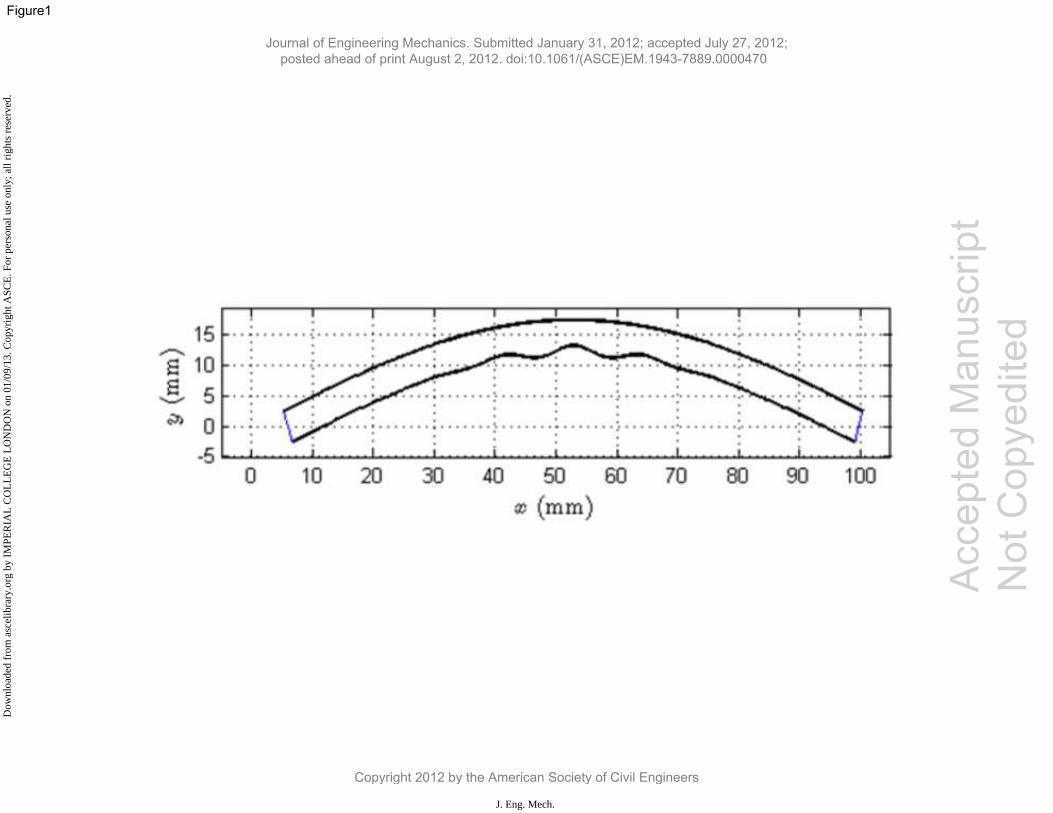
interactive buckling (Fig. 1) this can lead to an unstable post-buckling response since the least stiff equilibrium
path is followed. Consequently, this can have significantly negative effects on the sandwich strut, causing it to
lose a considerable proportion of its load carrying capacity (Atankovic, 1997; Hunt & Wadee, 1998; Huang &
Kardomateas, 2002), while in the presence of imperfections the proximity of the critical and the secondary
bifurcations may even cause premature failure (Wadee, 2000; Beghini et al., 2006). Another major issue
affecting the load carrying capacity and structural integrity of sandwich structures is delamination or debonding
at the face plate-core interface and its propagation due to buckling (Østergaard, 2008). Delamination, usually
induced by impact or buckling, can be characterized as a great challenge in composites since it prevents the
composite action between the face plate and the core locally, while its propagation magnifies the problem with
detrimental consequences.
A promising development for the engineering industry is the use of Functionally Graded Materials
(FGMs) in sandwich construction. These materials have gained importance in astronautical technology where
significant reductions in cost can be achieved by utilizing materials that combine two or more functions safely,
resulting in a reduction of the payload (Zhu & Sankar, 2007). Sandwich construction with FGMs is mainly seen
in sandwiched FGM plates and sandwich struts with FGM face plates where the core is usually homogeneous.
This is the case in aerospace applications, where structural elements are subjected simultaneously to thermal
and mechanical loads; the sandwich struts are expected to perform well at elevated temperatures caused by
friction in the atmosphere during hypersonic flight. The thermo-elastic properties of the sandwich struts
therefore need to be controlled by gradually varying the ceramic and metallic composition of the face plates.
The metallic component, other than the strength, is expected to contribute to the toughness while the ceramic
component would also contribute to corrosion resistance (Zenkour, 2005). More related to the scope of work
herein are the applications of sandwich struts with functionally graded cores where the stiffness varies in the
transverse direction by gradually changing the density of the foam material. Grading the material properties of
the core can provide further advantages to sandwich construction, such as the increase of critical loads, but it
can also address specific localized phenomena such as delamination and fracture due to impact (Anderson,
2003).
In terms of the structural analysis of functionally graded sandwich struts, there is great focus on the
application of mechanical and thermal loads (Samsam Shariat et al., 2005; Zenkour, 2005; Zhu & Sankar,
Journal of Engineering Mechanics. Submitted January 31, 2012; accepted July 27, 2012; posted ahead of print August 2, 2012. doi:10.1061/(ASCE)EM.1943-7889.0000470
Copyright 2012 by the American Society of Civil Engineers
J. Eng. Mech.
Dow
nloa
ded
from
asc
elib
rary
.org
by
IMPE
RIA
L C
OL
LE
GE
LO
ND
ON
on
01/0
9/13
. Cop
yrig
ht A
SCE
. For
per
sona
l use
onl
y; a
ll ri
ghts
res
erve
d.
Accep
ted M
anus
cript
Not Cop
yedit
ed
3
2007), with special attention to the change in the response brought by the gradation. It has been shown that the
risk of delamination due to high interfacial shear stresses is minimized if the stiffness of the weaker part is
locally increased (Venkataraman & Sankar, 2003; Anderson, 2003). The higher stiffness near the interface also
results in an increase of the wrinkling, or local buckling, critical load (Ávila, 2007) as well as helping to reduce
electric displacement intensity factors in piezoelectric FGM (Li & Weng, 2002). The accurate modelling of the
kinematics of sandwich FGMs has been of great interest to many researchers leading to the proposal of several
approaches from simpler Equivalent Single Layer (Reissner, 1945; Reddy, 1984) to Layer-wise (Cho et al.,
1991) and Carrera’s unified formulation (Carrera et al., 2008); these approaches listed here in order of
increasing complexity and computational cost. Recently, Apetre et al. (2008) compared two Equivalent Single
Layer approaches with a Higher Order theory (Frostig et al., 1992) and a Fourier–Galerkin theory (Zhu &
Sankar, 2007) showing that the latter two approaches correlate much better with an FE simulation used for
validation, at the expense of increased computational cost. The reason lies in the fact that both approaches rely
on the solution of the elasticity equations without making any assumptions about the through-depth in-plane
displacements, unlike the Equivalent Single Layer approaches which are based on the same assumptions as the
analytical model presented herein. On similar grounds, Brischetto (2009) also suggests the use of higher order
theories in the cases of thick plates or large gradients.
The stability of FGM has also been investigated in terms of compression (Feldman & Abudi, 1997)
and thermal buckling (Samsam Shariat & Eslami, 2007; Javaheri & Eslami, 2002) including some post-
buckling (Shen & Li, 2008; Ke et al., 2009) and vibration analysis (Yang et al., 2006; Park & Kim, 2006).
Since these have been mostly on the stability of FGM plates, post-buckling work is yet to be seen on the onset
of interactive buckling and localization of sandwich struts with FGM cores. These secondary instabilities have
been shown to destabilize the approximately neutrally stable post-buckling response of sandwich struts and its
effects are magnified in the presence of eccentric loads (Yiatros & Wadee, 2011), geometrical imperfections
(Wadee, 2000) or buckling-driven delaminations (Wadee & Blackmore, 2001; Wadee 2002).
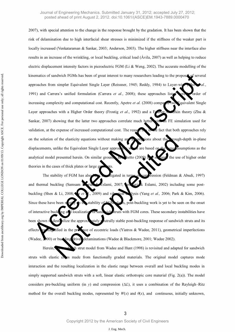
Herein, the sandwich strut model from Wadee and Hunt (1998) is revisited and adapted for sandwich
struts with elastic cores made from functionally graded materials. The original model captures mode
interaction and the resulting localization in the elastic range between overall and local buckling modes in
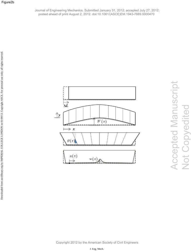
simply supported sandwich struts with a soft, linear elastic orthotropic core material (Fig. 2(a)). The model
considers pre-buckling uniform (in y) end compression (ΔL), it uses a combination of the Rayleigh–Ritz
method for the overall buckling modes, represented by W(x) and θ(x), and continuous, initially unknown,
Journal of Engineering Mechanics. Submitted January 31, 2012; accepted July 27, 2012; posted ahead of print August 2, 2012. doi:10.1061/(ASCE)EM.1943-7889.0000470
Copyright 2012 by the American Society of Civil Engineers
J. Eng. Mech.
Dow
nloa
ded
from
asc
elib
rary
.org
by
IMPE
RIA
L C
OL
LE
GE
LO
ND
ON
on
01/0
9/13
. Cop
yrig
ht A
SCE
. For
per
sona
l use
onl
y; a
ll ri
ghts
res
erve
d.

Accep
ted M
anus
cript
Not Cop
yedit
ed
4
functions, w(x) and u(x), for the interactive mode (Fig. 2(b)). It is based on Timoshenko beam theory (TBT)
and nonlinear stability theory (Hunt & Wadee, 1998). Other variations of this model were also developed,
including models using the Reddy-Bickford Theory (RBT) (Reddy, 1984), which is a well-known higher order
shear deformation bending theory. These were employed to examine interactive buckling in sandwich panels
for different geometric and loading configurations, attaching particular importance to the onset of the
instabilities. The RBT and TBT models were first compared for sandwich struts in Wadee et al. (2010), while
sub-models for beam-columns were presented in Yiatros & Wadee (2011), for the case of axial loads being
applied offset to the neutral axis. The present work on modelling interactive buckling in sandwich panels with
an FGM core material represents the principal novel contribution. Section 2 presents the development of the
nonlinear variational model, with numerical results and validation being presented in Section 3. Finally,
Section 4 concludes by discussing possible future model enhancements, in particular accounting for the effects
of face–core delamination.
2. Model development
2.1 Geometry and kinematics
Consider a simply supported sandwich strut of length L and breadth c comprising two identical
isotropic stiff face plates of thickness t, Young’s modulus E and Poisson's ratio ν, that are separated by a weak
orthotropic core material of thickness b that potentially has different Young’s moduli in the axial direction Ex,
the transverse direction Ey and an associated shear modulus Gc; the Poisson’s ratios in x and y directions are νx
and νy respectively. A stiff, thick end-plate is attached for load application and support purposes as shown in
Fig. 2(a). Uniform end shortening prior to buckling is represented by ΔL, while the overall (Euler) buckling
mode is modelled using discrete generalized coordinates that are associated with predetermined functions with
respect to x for the lateral displacement and section rotation as shown in Eq. (1):
, (1)
where qs and qt denote the amplitudes of sway and tilt respectively; different values for these allow for the
development of shear strains in the core (Hunt& Wadee, 1998) in Eq. (2) and represent a Timoshenko beam
(TBT) model for bending. Shear strains have been found to be vital for the interaction of the two buckling
modes:
sin , coss t
x xW q L q
L L
Journal of Engineering Mechanics. Submitted January 31, 2012; accepted July 27, 2012; posted ahead of print August 2, 2012. doi:10.1061/(ASCE)EM.1943-7889.0000470
Copyright 2012 by the American Society of Civil Engineers
J. Eng. Mech.
Dow
nloa
ded
from
asc
elib
rary
.org
by
IMPE
RIA
L C
OL
LE
GE
LO
ND
ON
on
01/0
9/13
. Cop
yrig
ht A
SCE
. For
per
sona
l use
onl
y; a
ll ri
ghts
res
erve
d.

Accep
ted M
anus
cript
Not Cop
yedit
ed
5
(2)
Local plate buckling is only considered for one of the two face plates since it is assumed that the overall mode is
triggered first. During initial post-buckling, the subsequent stress at mid-span reaches the critical compressive
stress for local plate buckling in the most compressed face plate and the localized interactive mode is triggered,
see Fig. 2(b).
Unlike the overall mode that is described by predetermined displacement functions, the interactive mode
has initially unknown displacement components for the more compressed face plate with w(x) and u(x) being the
lateral and in-plane components respectively. The interactive mode is assumed to vary in x and linearly in y,
thus:
(3)
Finally, the relative compressive strain defining the non-trivial fundamental path is modelled by Δ.
2.2 Formulation
As indicated earlier, the core is made from an FGM where the stiffness varies from the neutral axis of
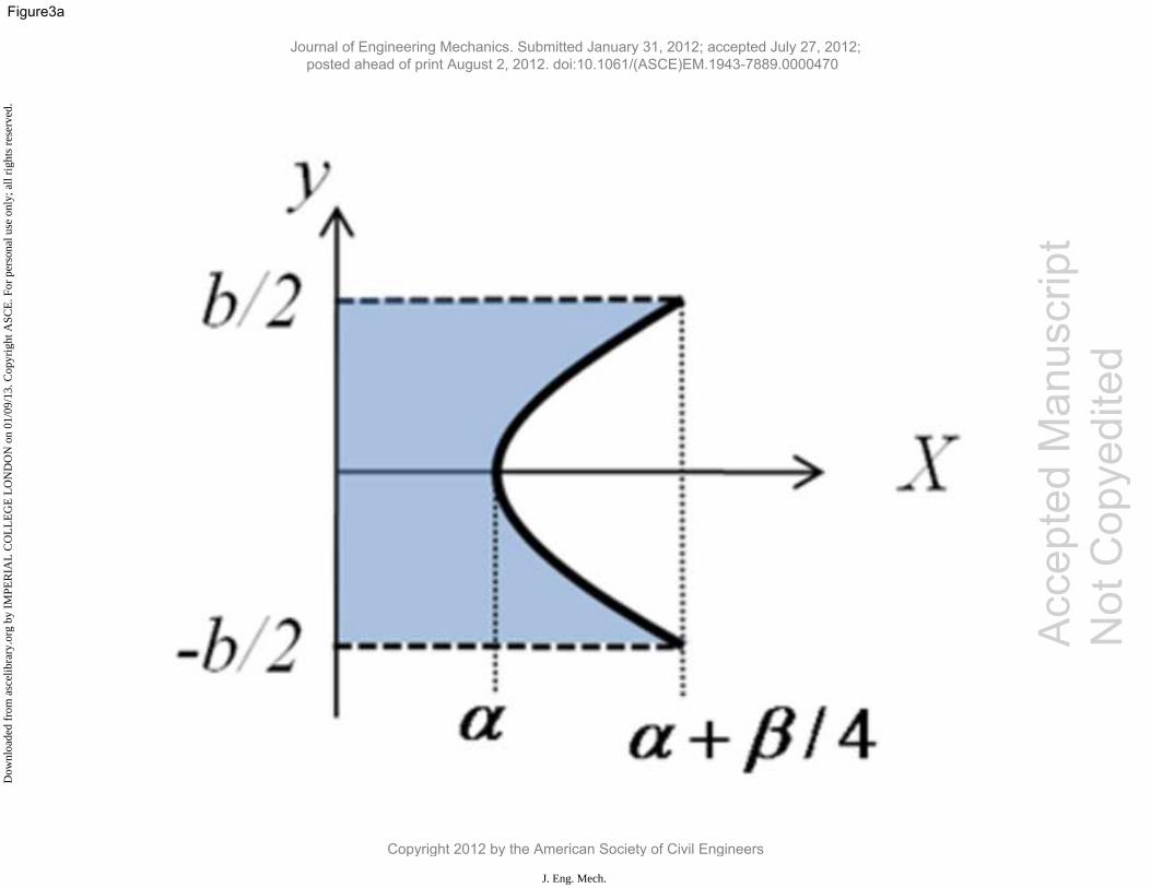
bending outwards. Currently, a quadratic stiffness distribution is assumed such that:
(4)
where X is the base material property such as the Young’s or shear moduli (Ex, Ey or Gc), while XFGM gives the
variation of the property in the transverse direction y. The above function is quadratic in y ensuring that the
variation of properties is symmetric in the transverse direction to avoid any bias in the direction of overall
buckling. The reason for selecting a quadratic gradation is that it provides the simplest nonlinear continuous and
symmetric property variation, hence keeping the complexity of the pilot model to a minimum. The two
parameters, α and β, determine the nature of the gradation. As seen in Fig. 3(a), increasing , increases the rate
of the gradation quadratically, thus reducing the step change in shear stiffness at the face plate–core interface.
Setting to zero leads to uniform properties across the section. The Poisson’s ratio of the material is assumed
to remain constant, i.e. it is assumed to be unaffected by the stiffness gradient.
2.3. Energy formulation
TBT cos .s t
xq q
L
2 2, ( ); , ( ).
2 2
b y b yw x y w x u x y u xc c
b b
2
2 ,( )FGM
yb
X y X
Journal of Engineering Mechanics. Submitted January 31, 2012; accepted July 27, 2012; posted ahead of print August 2, 2012. doi:10.1061/(ASCE)EM.1943-7889.0000470
Copyright 2012 by the American Society of Civil Engineers
J. Eng. Mech.
Dow
nloa
ded
from
asc
elib
rary
.org
by
IMPE
RIA
L C
OL
LE
GE
LO
ND
ON
on
01/0
9/13
. Cop
yrig
ht A
SCE
. For
per
sona
l use
onl
y; a
ll ri
ghts
res
erve
d.
Accep
ted M
anus
cript
Not Cop
yedit
ed
6
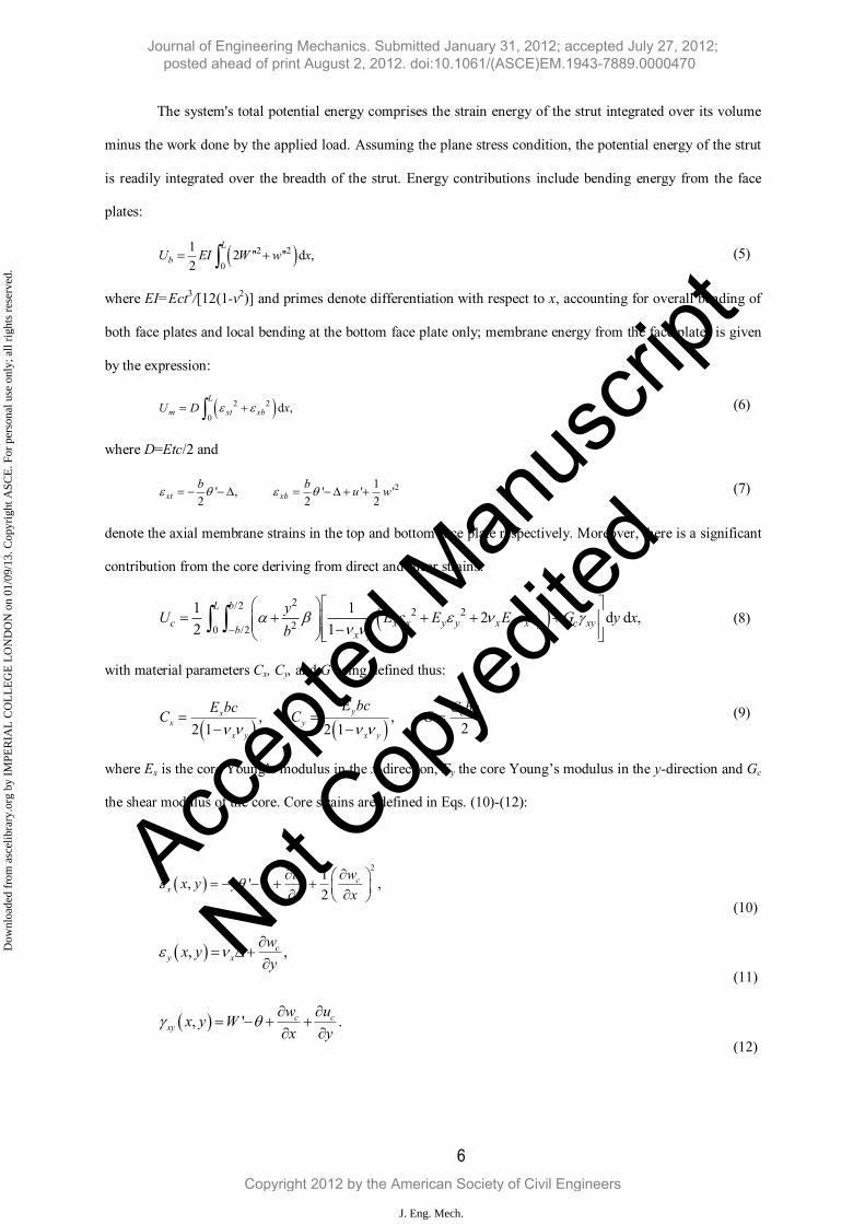
The system's total potential energy comprises the strain energy of the strut integrated over its volume
minus the work done by the applied load. Assuming the plane stress condition, the potential energy of the strut
is readily integrated over the breadth of the strut. Energy contributions include bending energy from the face
plates:
(5)
where EI=Ect3/[12(1-ν2)] and primes denote differentiation with respect to x, accounting for overall bending of
both face plates and local bending at the bottom face plate only; membrane energy from the face plates is given
by the expression:
(6)
where D=Etc/2 and
(7)
denote the axial membrane strains in the top and bottom face plate respectively. Moreover, there is a significant
contribution from the core deriving from direct and shear strains:
(8)
with material parameters Cx, Cy, and G being defined thus:
(9)
where Ex is the core Young’s modulus in the x-direction, Ey the core Young’s modulus in the y-direction and Gc
the shear modulus of the core. Core strains are defined in Eqs. (10)-(12):
(10)
(11)
(12)
2 2
0
1'' ' d ,
22 '
L
b EI W w xU
2 2
0d ,
L
m xt xb xU D
21' , ' ' '
2 2 2xt xbb b
u w
2/22 2
20 /2
1d d ,
21
21
L b
c x x y y x y x y c xyb x y
U E E E Gy
y xb
, , ,
22 1 2 1yx c
xx y x y
y
E bcE bC C
cG
G bc
212
, ,' c cx
u wx
x y yx
, ,xy
cx ywy
', .c c
xy
w uW
xx y
y
Journal of Engineering Mechanics. Submitted January 31, 2012; accepted July 27, 2012; posted ahead of print August 2, 2012. doi:10.1061/(ASCE)EM.1943-7889.0000470
Copyright 2012 by the American Society of Civil Engineers
J. Eng. Mech.
Dow
nloa
ded
from
asc
elib
rary
.org
by
IMPE
RIA
L C
OL
LE
GE
LO
ND
ON
on
01/0
9/13
. Cop
yrig
ht A
SCE
. For
per
sona
l use
onl
y; a
ll ri
ghts
res
erve
d.

Accep
ted M
anus
cript
Not Cop
yedit
ed
7
The work done is the product of the applied load multiplied by the displacement at the point of application, in
the direction of the load, thus:
(13)
where the first term Δ is purely a uniform (in y) compressive strain, defined as a generalized coordinate, which
gives the non-trivial fundamental (pre-buckling) equilibrium path. The second term comprises the contribution
purely from the overall buckling lateral displacement W if the strut was inextensional. The third term comprises
an additional in-plane displacement at the point of load application, where y=0, due to the incremental local
buckling in-plane displacement u. Since u is assumed to be linear in y, the in-plane displacement contribution
from local buckling at the centroid is u/2, see Fig. 4. Moreover, since the final end-shortening contribution is
equal to [u(0)-u(L)]/2, and hence it can be written as the final term in Eq. (13) within an integral expression.
Assembling all the energy terms and integrating over the depth, the total potential energy is given as an integral
over the length of the strut:
(14)
The difference between the current model and the benchmark model in Wadee & Hunt (1998) lies in the fact
that the material parameters (core Young’s and shear moduli) are not constant, but are functions of y. Setting all
the interactive buckling terms, w(x) and u(x), and their derivatives to zero, the critical overall buckling load can
be found through linear eigenvalue analysis:
(15)
where . As expected, when and , the critical buckling load returns to the homogeneous core
sandwich strut critical load presented in Wadee & Hunt (1998). Having determined the critical load, it is then
necessary to minimize the entire expression of V to determine the governing equilibrium equations to obtain the
2
0
1 1' ' d ,
2 2
LP P W u x
0
LPP
0
LL
42 2 2 2 2 2 4 2
20
2 42 2 2 4 2 2
2
2
2
1 1 1'' sin 2 ' ' '
2 4 2
1 1 11 1sin sin ' ' ' ' '
2 2 20 84 3 10
1 7' '
4 60
2 ' ' ' 2L
s
t t x
xEI w D w w u
L L
b x b x bq q u w w
V q u u w
u wL L L L
u w
C
2 4 22 2
2
2 2 2
22 2 2
2
1 3 1' sin ' ' sin
12 12 20 2
1 1 '' ' '
2 2
2
cos
c 2o 's
10 3
t t
s y x x y x x
s t
b xq
C C
G q
b xu q u w
L L L L
x w w wP q u kw u u
L b b
x u uqq
bw
L b2
2
1cos '
2 12
'd .
10 3
s t
x uw
L b
x
q
wG
2 22C
2 2 2
/ 3 / 2 /122,
3
40 28 240 / 2
20 / 20 3 /1260 /
c x
x c
bc C EtcGEIL Etc
PG cC
/b L 1 0
Journal of Engineering Mechanics. Submitted January 31, 2012; accepted July 27, 2012; posted ahead of print August 2, 2012. doi:10.1061/(ASCE)EM.1943-7889.0000470
Copyright 2012 by the American Society of Civil Engineers
J. Eng. Mech.
Dow
nloa
ded
from
asc
elib
rary
.org
by
IMPE
RIA
L C
OL
LE
GE
LO
ND
ON
on
01/0
9/13
. Cop
yrig
ht A
SCE
. For
per
sona
l use
onl
y; a
ll ri
ghts
res
erve
d.

Accep
ted M
anus
cript
Not Cop
yedit
ed
8
post-buckling response. Thus is achieved through the application of the calculus of variations (Fox, 1987),
which yields two coupled, nonlinear and non-autonomous ordinary differential equations for w(x) and u(x),
respectively. Moreover, by minimizing V with respect to each generalized coordinate, an equivalent number of
equilibrium equations in the form of integral constraints are also derived. The complete system of equations is
given thus:
(16)
(17)
(18)
(19)
and
(20)
The system of equations is solved within the numerical continuation software AUTO (Doedel & Oldeman, 2007),
which is well known for its capability of pinpointing bifurcations in the solution space and trace subsequent
equilibrium paths. Since the model considers geometric configurations where the overall buckling mode is
triggered first, the solution process is initiated from the primary bifurcation PC at the overall buckling critical
load. The secondary bifurcation PS can be found by increasing qs from the critical state; when located, the
2 32
2 2
22
3
2
3 1'''' 2 '' sin ' ' ' sin '' ' '' cos
2 2 2 2 6
3 1 2 11 7 1'' ' ' sin ' '' ' '' '' ' ''
5 2 3 6 140 120 15
t t x t
t
t
b x b x b xw D w q u w w q u C w u q
L L L L L L
b xw w u q w w u w u w w
L
E
L
I
q2 2
2
' 1 '''sin ' cos 2 ''
40 12 3 10
' 2sin 0,
12 3 10
y x y x x
s t
b x x u w ww w kw C C w
L L L L b b b
x uqG q G
L L b
3
2
7 3'' ' '' 2 cos
3 10 2 60 6 20
1 '2 co
2
s ' 0,2 12
x x xt
s t y x
C C Cb xu D w w D q D
L L
G x u wq w
b Lq C
b b
2 22 2
0
3 1 3sin ' '
2 6 20 12 2 6 20
1cos ' d 02 ,
2 12
Lx x
t s tqC Cb b x
D GL u w DL L L
x
q
ux
L
q
wGb
42
0
1' 2 d 0,
2 12
L
s s s t
EI uq PL q L q q w x
L bG
2
2 2
0
212
1 '' ' '
2 12
2
2 03 0
.1
x y x
L
x y xD
L D C C PL
wu w uC C
Journal of Engineering Mechanics. Submitted January 31, 2012; accepted July 27, 2012; posted ahead of print August 2, 2012. doi:10.1061/(ASCE)EM.1943-7889.0000470
Copyright 2012 by the American Society of Civil Engineers
J. Eng. Mech.
Dow
nloa
ded
from
asc
elib
rary
.org
by
IMPE
RIA
L C
OL
LE
GE
LO
ND
ON
on
01/0
9/13
. Cop
yrig
ht A
SCE
. For
per
sona
l use
onl
y; a
ll ri
ghts
res
erve
d.
Accep
ted M
anus
cript
Not Cop
yedit
ed
9
applied load becomes the principal parameter and the post-buckling path is evaluated; see Fig. 3(b) for a
schematic representation of the response.
3. Numerical study, validation and discussion
In the pilot study herein, a sandwich strut with L = 100 mm and b = 5.1 mm is examined. The face
plates of thickness 0.5 mm are made from aluminium alloy (E = 68.9 kN/mm2 and = 0.3). The base Young's
modulus in both x and y directions in the core (when α = 1 and β = 0) is 199 N/mm2 and the shear modulus 83
N/mm2. The Poisson's ratio for the core is taken as 0.2 in both directions regardless of the value of the two
parameters (α, β) that define the functional gradation of the core material, as shown in Eq. (4).
The analytical model is validated using numerical simulations developed with ABAQUS. The core
material is discretized with the 2-dimensional solid element CPS4R, which is a 4-noded bilinear element with
reduced integration, hourglass control and an aspect ratio close to unity. The core is discretized vertically in
horizontal strips, each one element wide similarly to the model presented in Apetre et al. (2008) (see Fig. 5(a)).
The gradation in the material properties in cross-section is approximated by having a sufficiently large number
of strips of homogeneous yet different properties. For the range of values used in this study it was found that
20 strips across the depth of the strut were sufficient to provide a reasonably smooth transition in the properties
and more importantly avoid unwanted numerical errors caused by shear locking (Belytschko et al., 2000). The
key property of each strip is the value of the property at its mid-height, which is derived from the gradation
function given in Eq. (4). The face plates are modelled as stringers bonded to the edges of the existing core
while specifying suitable engineering properties. The 2-dimensional linear Timoshenko beam element B22 is
used to discretize the stringers. Owing to the small thickness of a face plate (t = 0.5 mm), in conjunction with
the large length and the need to maintain a reasonable element aspect ratio, this approach is less computationally
demanding, since only one beam element through the thickness of the face plate is used without compromising
accuracy (Zenkert, 1995; Léotoing et al., 2002), especially in the cases of thin face plates and has therefore been
implemented for all the tested struts.
To capture the overall buckling mode and the corresponding critical load, a linear perturbation analysis
was performed; Fig. 6(a) shows the increase of the critical load from the linear perturbation analysis, which
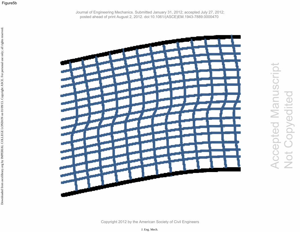
correlates very well with the analytical model. Qualitatively, regarding the mode shape, for the FE simulation
where >0, which implies a higher stiffness further away from the neutral axis, the shear strain is seen to be
maximum with a localized peak at the neutral axis and approximately constant further from it, see Fig. 5(b). The
Journal of Engineering Mechanics. Submitted January 31, 2012; accepted July 27, 2012; posted ahead of print August 2, 2012. doi:10.1061/(ASCE)EM.1943-7889.0000470
Copyright 2012 by the American Society of Civil Engineers
J. Eng. Mech.
Dow
nloa
ded
from
asc
elib
rary
.org
by
IMPE
RIA
L C
OL
LE
GE
LO
ND
ON
on
01/0
9/13
. Cop
yrig
ht A
SCE
. For
per
sona
l use
onl
y; a
ll ri
ghts
res
erve
d.

Accep
ted M
anus
cript
Not Cop
yedit
ed
10
first buckling mode was then used as an initial perturbation (imperfection) in the model geometry in the
subsequent nonlinear analysis, by employing the modified Riks method (ABAQUS, 2006). An imperfection
amplitude of L/10000 was selected since it is sufficient to trigger the instability, yet small enough to give results
close to the perfect case. It should be noted that although no local imperfection is explicitly incorporated in the
model, a secondary instability and buckle pattern localization is subsequently observed from a self-generated
local imperfection that evolves during the post-critical (Riks) analysis.
When the parameter α is set to unity, while β is increased from zero (i.e. a homogeneous core) to 12,
the critical loads predicted by the model increase with an increasing value of β. This is expected since β
increases the stiffness of the core, thereby contributing to the buckling resistance of the strut. For the position of
the secondary bifurcation which triggers interactive buckling, the gap between the critical and secondary
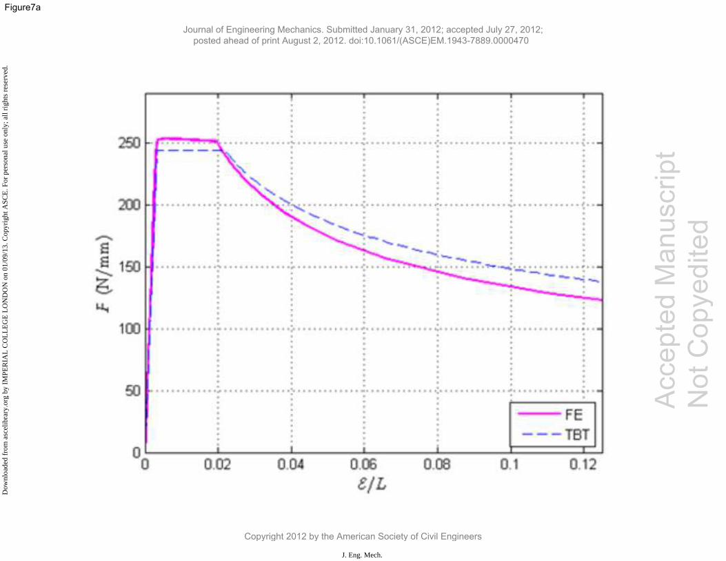
bifurcations decreases with increasing β, as seen in Fig. 6(b). Although for smaller values of β this compares
very well with the finite element model (Fig. 7), for larger values of β the comparison becomes divergent. This
is attributed to the fact that the analytical model does not fully account for the shear stiffness energy near the
neutral axis of bending as a result of the “plane sections remain plane” assumption of TBT. This leads to an
underestimation of the total potential energy of the strut which is reflected by the two bifurcations coming closer
together as the critical load increases, a feature that is not replicated in the finite element model. However,
beyond the secondary bifurcation the post-buckling path becomes unstable owing to the presence of the
localized mode being confined only to one face plate; this is, however, observed clearly in both the analytical
and finite element models with the unloading shown to match reasonably well, as shown in Fig. 7.
4. Concluding remarks
An analytical model based on Timoshenko beam theory, has been adapted to investigate interactive buckling in
sandwich struts with functionally graded cores. The merits of a functionally graded core can be realized by
assigning a certain material property where it is most needed, without creating steep changes. This gradual
change in the properties across the depth of the strut can minimize the risk of delamination in composite
components, such as sandwich structures, where there is a large interlaminar shear stress between the two
laminates in the cases where the required adhesive is not so strong. If the stiffness of the softer laminate
gradually increases towards the interface, the danger of shear discontinuities appearing is significantly reduced.
On the other hand, the reduction of the stiffness at places where it is not necessarily required could be utilized in
an optimization strategy in systems with weight constraints. The model has been tested with struts where the
Journal of Engineering Mechanics. Submitted January 31, 2012; accepted July 27, 2012; posted ahead of print August 2, 2012. doi:10.1061/(ASCE)EM.1943-7889.0000470
Copyright 2012 by the American Society of Civil Engineers
J. Eng. Mech.
Dow
nloa
ded
from
asc
elib
rary
.org
by
IMPE
RIA
L C
OL
LE
GE
LO
ND
ON
on
01/0
9/13
. Cop
yrig
ht A
SCE
. For
per
sona
l use
onl
y; a
ll ri
ghts
res
erve
d.
Accep
ted M
anus
cript
Not Cop
yedit
ed
11
shear stiffness in the core is graded quadratically and symmetrically about the neutral axis, increasing at the face
plate–core interface. Increasing the degree of gradation results in an increase in the overall buckling load, but
shows a reduction in the gap between the critical and secondary bifurcations due to the underestimation of the
shear stiffness since a fundamental assumption of TBT is that plane sections remain plane.
The analytical model has been validated using a finite element model implemented in ABAQUS that
exhibited good correlation in terms of the position of secondary bifurcation points and the subsequent post-
buckling paths. The reason for this can be attributed to the in-plane displacement field being approximately
linear except very locally near the neutral axis. Further work would be necessary to generalize the models for
different gradation functions and more loading cases, but this study has provided a useful baseline for
determining which models best suit the simplest gradations. This class of model is envisaged to be able to
validate an enhanced model of a previously developed approach (Abali et al., 2012) that has been implemented
with the aid of the open source finite element software FEniCS (Logg et al., 2011) based on continuum
mechanics formulations. The major advantage of this numerical approach is that the gradient properties can be
readily implemented as a function over the thickness of the core rather than modelling the variation with several
layers, thus leading to a more accurate representation whilst having greater numerical efficiency. Furthermore,
by using Green–Lagrange strains, being conjugated to the second Piola–Kirchhoff stresses, when deriving the
weak formulation of equilibrium, geometric nonlinearities are already intrinsically part of the formulation.
Hence, the post-buckling paths can be traced without any stepwise iteration or need for initial imperfections.
Additionally, by solving the problem using continuum mechanics principles interlaminar stresses at the interface
between the core material and the face plates can be determined, subsequently interfacial damage may be
predicted and its progression may be traced. This approach would provide an excellent way of assessing the
advantages of using FGMs and allow tailoring to optimize the performance of such sandwich structures.
Figure 1
Journal of Engineering Mechanics. Submitted January 31, 2012; accepted July 27, 2012; posted ahead of print August 2, 2012. doi:10.1061/(ASCE)EM.1943-7889.0000470
Copyright 2012 by the American Society of Civil Engineers
J. Eng. Mech.
Dow
nloa
ded
from
asc
elib
rary
.org
by
IMPE
RIA
L C
OL
LE
GE
LO
ND
ON
on
01/0
9/13
. Cop
yrig
ht A
SCE
. For
per
sona
l use
onl
y; a
ll ri
ghts
res
erve
d.

Accep
ted M
anus
cript
Not Cop
yedit
ed
12
Fig. 1: Interactive buckling between the overall (Euler-type) and local (plate) buckling on a sandwich strut
100mm long and 5.1mm deep.
Figure 2a Figure2b
(a)
(b)
Fig.2: (a) The simply supported sandwich strut in elevation and cross-section. (b) Modal descriptions. From the
top: uniform (pre-buckling) end shortening due to pure compression represented by ΔL, sway mode represented
the overall buckling deflection W(x), tilt mode represented by θ(x) and the local modes, w(x) and u(x) becoming
non-trivial beyond the secondary bifurcation.
Figure 3a Figure3b
(a)
(b)
Fig. 3 (a) Variation in material properties X through the core depth. (b) A graphical representation of the
equilibrium response: (1) fundamental path; (2) overall buckling; (3) interactive buckling. The critical load is
PC and the quantity is the end shortening at the critical load. Similarly and qsS refer to the values of end
shortening and the sway amplitude at the secondary bifurcation, respectively.
Figure 4
Fig. 4 The total end shortening contributions for work done. Top: pre-buckling end shortening, Middle: end-
shortening from lateral displacement W from overall buckling, considering the strut as inextensional and
Bottom: in-plane displacement u(x,0) from the interactive mode.
Figure 5a Figure5b
CC SS
Journal of Engineering Mechanics. Submitted January 31, 2012; accepted July 27, 2012; posted ahead of print August 2, 2012. doi:10.1061/(ASCE)EM.1943-7889.0000470
Copyright 2012 by the American Society of Civil Engineers
J. Eng. Mech.
Dow
nloa
ded
from
asc
elib
rary
.org
by
IMPE
RIA
L C
OL
LE
GE
LO
ND
ON
on
01/0
9/13
. Cop
yrig
ht A
SCE
. For
per
sona
l use
onl
y; a
ll ri
ghts
res
erve
d.

Accep
ted M
anus
cript
Not Cop
yedit
ed
13
(a)
(b)
Fig. 5: (a) The variation ( ) in the core shear modulus modelled for FE simulations in ABAQUS. The
same applies for core Young’s modulus in both directions. The analytical model is represented by the
continuous function and the numerical model with a step gradation. (b) A schematic of the in-plane
displacement due to overall buckling as this was seen in the finite element simulations somewhere along the
length of the strut.
Figure 6a Figure 6b
(a)
(b)
Fig. 6: (a) Comparison of the critical loads from the analytical model and FE simulation for different values of β
from 0 to 12. The analytical model results are represented by “○” and the numerical model results by “∆”. (b)
The equilibrium paths from the analytical model: load versus end shortening per unit length, for a strut 5.1 mm
deep, α =1 and different values of β from 0 to 12.
Figure 7a Figure7b
(a)
(b)
Fig. 7: The comparison of the equilibrium paths for the analytical model and the FE simulation for struts with
different degrees of stiffness of gradation (a) = 3, (b) = 6.
References
1; 4
Journal of Engineering Mechanics. Submitted January 31, 2012; accepted July 27, 2012; posted ahead of print August 2, 2012. doi:10.1061/(ASCE)EM.1943-7889.0000470
Copyright 2012 by the American Society of Civil Engineers
J. Eng. Mech.
Dow
nloa
ded
from
asc
elib
rary
.org
by
IMPE
RIA
L C
OL
LE
GE
LO
ND
ON
on
01/0
9/13
. Cop
yrig
ht A
SCE
. For
per
sona
l use
onl
y; a
ll ri
ghts
res
erve
d.

Accep
ted M
anus
cript
Not Cop
yedit
ed
14
Abali, B. E., Völlmecke, C., Woodward, B., Kashtalyan, M., Guz, I. & Müller, W.H., 2012. Numerical
modeling of functionally graded materials using a variational formulation. Continuum Mech. Therm. accepted
manuscript.
ABAQUS, 2006.Abaqus/standard: User's manual version 6.6. Pawtucket, USA: Hibbitt, Karlsson & Sorensen,
Inc.
Anderson, T. A., 2003. A 3-d elasticity solution for a sandwich composite with functionally graded core
subjected to transverse loading by a rigid sphere. Compos. Struct., 60(3), 265–274.
Apetre, N. A., Sankar, A. V., & Ambur, D. R., 2008. Analytical modeling of sandwich beams with a
functionally graded core. J. Sandw. Struct. Mater.,10(53), 53–74.
Atanackovic, T. M., 1997. Stability theory of elastic rods, Series on Elastic stability, Vibration and Control of
Systems, Series A.
Ávila, A. F., 2007. Failure mode investigation of sandwich beams with functionally graded core. Compos.
Struct., 81(3), 323–330.
Beghini A., Bažant, Z.P., Waas A.M.& Basu S., 2006. Postcritical imperfection sensitivity of sandwich or
homogeneized orthotropic columns soft in shear and in transverse deformation, Int. J. Solids Structures, 43,
5501-5524.Belytschko, T., Liu, W. K. & Moran, B. 2000.Nonlinear finite elements for continua and structures.
Chichester: Wiley.
Brischetto, S., 2009. Classical and mixed advanced models for sandwich plates embedding functionally graded
cores. J. Mech. Mater. Struct., 4(1), 13–33.
Carrera, S., Brichetto, S., & Robaldo, A., 2008. Variable kinematic model for the analysis of functionally graded
material plates. AIAA J., 46(1), 194–203.
Cho, K. N., Bert, C. W.& Striz, A. G., 1991. Free vibrations of laminated rectangular plates analyzed by higher
order individual-layer theory. J. Sound Vibr., 145(3), 429–442.
Doedel, E. J. & Oldeman, B. E., 2009. AUTO-07p: Continuation and bifurcation software for ordinary
differential equations. Tech. rept. Department of Computer Science, Concordia University, Montreal, Canada.
Available from http://indy.cs.concordia.ca/auto.
Feldman, E. & Abudi, J., 1997. Buckling analysis of functionally graded plates subjected to uniaxial loading.
Compos. Struct., 38(1–4), 29–36.
Fox, C., 1987. An introduction to the calculus of variations. New York: Dover.
Journal of Engineering Mechanics. Submitted January 31, 2012; accepted July 27, 2012; posted ahead of print August 2, 2012. doi:10.1061/(ASCE)EM.1943-7889.0000470
Copyright 2012 by the American Society of Civil Engineers
J. Eng. Mech.
Dow
nloa
ded
from
asc
elib
rary
.org
by
IMPE
RIA
L C
OL
LE
GE
LO
ND
ON
on
01/0
9/13
. Cop
yrig
ht A
SCE
. For
per
sona
l use
onl
y; a
ll ri
ghts
res
erve
d.

Accep
ted M
anus
cript
Not Cop
yedit
ed
15
Frostig, Y., Baruch, M., Vilnay, O.&Sheinman, I., 1992. A high order theory for the bending of sandwich beams
with flexible core. ASCE J. Eng.Mech., 118(5), 1026–1043.
Huang H.Y. & Kardomateas G.A., 2002. Buckling and initial post-buckling behavior of sandwich beams
including transverse shear, AIAA J., 40(11), 2331-2335.
Hunt, G. W. & Wadee, M. A., 1998. Localization and mode interaction in sandwich structures. Proc. R. Soc. A,
454(1972), 1197–1216.
Javaheri, R., & Eslami, M. R., 2002. Thermal buckling of functionally gradedplates. AIAA J., 40(1), 162–169.
Ke, L. L., Yang, J., & Kitipornchai, S., 2009. Postbuckling analysis of edgecracked functionally graded
Timoshenko beams under end shortening. Compos .Struct., 90, 152–160.
Logg, A. Mardal, K.-A. & Wells, G. N., 2011. Automated solution of differential equations by the finite element
method. Springer.
Léotoing, L., Drapier, S., & Vautrin, A., 2002. Nonlinear interaction of geometricaland material properties in
sandwich beam instabilities. Int. J. Solids Struct., 39(13–14), 3717–3739.
Østergaard, R. C., 2008. Buckling driven debonding in sandwich columns. Int. J. Solids Struct., 45, 1264–1282.
Park, J. S., & Kim, J. H., 2006. Thermal postbuckling and vibration analyses of functionally graded plates.J.
Sound Vibr., 289(1–2), 77–93.
Reddy, J. N., 1984. A simple higher order theory for laminated composite plates. ASME J. Appl. Mech., 51,
745–752.
Reissner, E., 1945. The effects of transverse shear deformation on the bending of elastic plates. ASME J. Appl.
Mech., 67, 69–77.
Samsam Shariat, B. A. & Eslami, M. R., 2007. Buckling of thick functionally graded plates under mechanical
and thermal loads. Compos. Struct., 78(3), 433–439.
Samsam Shariat, B. A., Javaheri, R.& Eslami, M. R., 2005. Buckling of imperfect functionally graded plates
under in-plane compressive loading. Thin-walled Struct., 43, 1020-1036.
Shen, H. S., & Li, S. R., 2008. Postbuckling of sandwich plates with FGM face sheets and temperature-
dependent properties. Compos. Pt. B – Eng., 39, 332–344.
Venkataraman, S. & Sankar, B. V., 2003. Elasticity solution for stresses in a sandwich beam with functionally
graded core. AIAA J., 41(12), 2501–2505.
Wadee, M. A., 2000. Effects of periodic and localized imperfections on struts on nonlinear foundations and
compression sandwich panels. Int. J. Solids Struct., 37(8), 1191–1209.
Journal of Engineering Mechanics. Submitted January 31, 2012; accepted July 27, 2012; posted ahead of print August 2, 2012. doi:10.1061/(ASCE)EM.1943-7889.0000470
Copyright 2012 by the American Society of Civil Engineers
J. Eng. Mech.
Dow
nloa
ded
from
asc
elib
rary
.org
by
IMPE
RIA
L C
OL
LE
GE
LO
ND
ON
on
01/0
9/13
. Cop
yrig
ht A
SCE
. For
per
sona
l use
onl
y; a
ll ri
ghts
res
erve
d.
Accep
ted M
anus
cript
Not Cop
yedit
ed
16
Wadee, M. A., 2002. Localized buckling in sandwich struts with pre-existing delaminations and geometrical
imperfections. J. Mech. Phys. Solids, 50(8), 1767-1787.
Wadee, M. A. & Blackmore, A., 2001. Delamination from localized instabilities in compression sandwich
panels. J. Mech. Phys. Solids, 49(6), 1281-1299.
Wadee, M. A. & Hunt, G. W., 1998. Interactively induced localized buckling in sandwich structures with core
orthotropy. ASME J. Appl. Mech., 65(2), 523–528.
Wadee, M. A., Yiatros, S. & Theofanous, M., 2010. Comparative studies of localized buckling in sandwich
struts with different core bending models. Int. J. Non-Linear Mech., 45(2), 111–120.
Yang, J., Liew, K. M. & Kitipornchai, S., 2006. Imperfection sensitivity of the post-buckling behavior of high
order shear deformable functionally graded plates. Int. J. Solids Struct., 43, 5247–5266.
Yiatros, S. & Wadee, M. A., 2011. Interactive buckling in sandwich beam-columns. IMA J. Appl. Math., 76(1),
146-168.
Zenkert, D., 1995. An introduction to sandwich construction. London: Engineering Materials Advisory Services
Ltd.
Zenkour, A. M., 2005. A comprehensive analysis of functionally graded sandwich plates: Part 1–Deflection and
stresses. Int. J. Solids Struct., 42(18–19), 5224–5242.
Zhu, H., & Sankar, B. V., 2007. Analysis of sandwich TPS panel with functionally graded foam core by
Galerkin method. Compos.Struct., 77(3), 280–287.
Journal of Engineering Mechanics. Submitted January 31, 2012; accepted July 27, 2012; posted ahead of print August 2, 2012. doi:10.1061/(ASCE)EM.1943-7889.0000470
Copyright 2012 by the American Society of Civil Engineers
J. Eng. Mech.
Dow
nloa
ded
from
asc
elib
rary
.org
by
IMPE
RIA
L C
OL
LE
GE
LO
ND
ON
on
01/0
9/13
. Cop
yrig
ht A
SCE
. For
per
sona
l use
onl
y; a
ll ri
ghts
res
erve
d.
Acc
epte
d M
anus
crip
t N
ot C
opye
dite
d
Journal of Engineering Mechanics. Submitted January 31, 2012; accepted July 27, 2012; posted ahead of print August 2, 2012. doi:10.1061/(ASCE)EM.1943-7889.0000470
Copyright 2012 by the American Society of Civil Engineers
J. Eng. Mech.
Dow
nloa
ded
from
asc
elib
rary
.org
by
IMPE
RIA
L C
OL
LE
GE
LO
ND
ON
on
01/0
9/13
. Cop
yrig
ht A
SCE
. For
per
sona
l use
onl
y; a
ll ri
ghts
res
erve
d.
Related Documents