Modeling Actions in Dynamic Engineering Design Processes Vadim Ermolayev 1 , Natalya Keberle 1 , Eyck Jentzsch 2 , Richard Sohnius 2 , Wolf-Ekkehard Matzke 2 1 Department of IT, Zaporozhye National University, Zhukovskogo 66, 69063, Zaporozhye, Ukraine [email protected], [email protected] 2 Cadence Design Systems, GmbH, Mozartstr. 2 D-85622 Feldkirchen, Germany [email protected], [email protected], [email protected] Abstract: The paper presents the approach for modeling actions in the dynamic processes of engineering design in Microelectronics and Integrated Circuits domain. It elaborates the formal framework for representing processes, the states of these processes and process environments, the actions being the constituents of the processes. Presented framework is implemented as the part of PSI Suite of Ontologies and is evaluated using three different methods: user evaluation, formal evaluation, and commonsense evaluation following PSI shaker modeling methodology. The Suite of PSI ontologies is used for representing Dynamic Engineering Design Processes in Cadence Project Planning Expert System software prototype. 1 Introduction As many experts in microelectronic and integrated circuits design point out (e.g., [1]), one of the main industrial challenges is the gap between the capability of design technology and the productivity of design systems. For example, the capability of the design technology to accommodate digital gates on a chip is growing much faster than the capability of design teams using this technology and corresponding design environments to produce these gates in their designs. The consequence is that the effort required to be spent for designing a typical microelectronic device is growing substantially. Therefore, tools and methodologies for improving the performance of design systems are very highly demanded by industry. PSI project 1 aims at developing models, methodologies, and software tools providing for rigorous engineering treatment of performance and performance management. PSI performance modeling and management approach focuses on performance as a pro-active action. A fine-grained dynamic model of an engineering design process, comprising a semantically rich action model, and a design system is 1 Performance Simulation Initiative (PSI) is the R&D project of Cadence Design Systems GmbH.

Welcome message from author
This document is posted to help you gain knowledge. Please leave a comment to let me know what you think about it! Share it to your friends and learn new things together.
Transcript
Modeling Actions in Dynamic Engineering Design Processes
Vadim Ermolayev1, Natalya Keberle1, Eyck Jentzsch2, Richard Sohnius2, Wolf-Ekkehard Matzke2
1Department of IT, Zaporozhye National University, Zhukovskogo 66, 69063, Zaporozhye, Ukraine
[email protected], [email protected] 2Cadence Design Systems, GmbH, Mozartstr. 2 D-85622 Feldkirchen, Germany
[email protected], [email protected], [email protected]
Abstract: The paper presents the approach for modeling actions in the dynamic processes of engineering design in Microelectronics and Integrated Circuits domain. It elaborates the formal framework for representing processes, the states of these processes and process environments, the actions being the constituents of the processes. Presented framework is implemented as the part of PSI Suite of Ontologies and is evaluated using three different methods: user evaluation, formal evaluation, and commonsense evaluation following PSI shaker modeling methodology. The Suite of PSI ontologies is used for representing Dynamic Engineering Design Processes in Cadence Project Planning Expert System software prototype.
1 Introduction
As many experts in microelectronic and integrated circuits design point out (e.g., [1]), one of the main industrial challenges is the gap between the capability of design technology and the productivity of design systems. For example, the capability of the design technology to accommodate digital gates on a chip is growing much faster than the capability of design teams using this technology and corresponding design environments to produce these gates in their designs. The consequence is that the effort required to be spent for designing a typical microelectronic device is growing substantially. Therefore, tools and methodologies for improving the performance of design systems are very highly demanded by industry.
PSI project1 aims at developing models, methodologies, and software tools providing for rigorous engineering treatment of performance and performance management. PSI performance modeling and management approach focuses on performance as a pro-active action. A fine-grained dynamic model of an engineering design process, comprising a semantically rich action model, and a design system is
1 Performance Simulation Initiative (PSI) is the R&D project of Cadence Design Systems
GmbH.
2
therefore developed. PSI approach considers that performance is embodied in its environment and is controlled by the associated performance management process.
An engineering design process is a goal-directed process of transforming the representations of a design artifact in stateful nested environments. An environment comprises design artifact representations, resources, tools, and actors who perform actions to transform design artifacts using tools, consume resources. Actions are admissible in particular environment states and may be atomic or compound, state-transitive or iterative, dependent or independent on other actions. The components of an environment may generate internal events or may be influenced by external events. Events may have causal dependencies. An engineering design process is a problem solving process which goals, partial goals, and environments may change dynamically. A decision taking procedure is associated with each state to allow environments adjust the process taking these changes into account. Decisions are taken by actors modeled by software agents.
PSI software tools are developed [2] for assisting project managers to make robust planning, monitoring, and management of their design projects aiming at reaching best possible performance. Grounded decisions in planning are based on the knowledge base of project logs accomplished in the past. These logs provide vast and finely grained records of the performance of accomplished projects and may be used for simulating the behavior of the design system in response to different influences. At project execution phase PSI software may be used for predicting the behavior of the design system in the future based on the record of the partially accomplished Dynamic Engineering Design Process (DEDP), the knowledge about its environment(s), and performance simulations.
The focus of this paper is the framework for modeling actions. The rest of the paper is structured as follows. Section 2 analyses the related work in process modeling emphasizing the ways to model dynamic processes and pointing out the advancement of the presented modeling approach. Section 3 presents the action modeling framework of PSI. Section 4 reports how the framework has been implemented as the part of PSI Suite of Ontologies, evaluated, and used in PSI Project Planning Expert System. Finally, concluding remarks are given and our plans for future work are outlined in Section 5.
2 Related Work
The framework presented in this paper is for modeling change and adequately accounting for dynamics in the processes of engineering design. Fundamentally, research in representing, reasoning, and capturing knowledge about change and dynamics produced the plethora of premium quality results which can’t be even listed here due to space limit. Instead, we point to [3] as an excellent reference source. We also mention several related sources for analyzing our contribution.
McCarthy and Hayes [4] were the pioneers in introducing a logical formalism which became a mainstream for commonsense reasoning and reasoning about change in particular – the Situation Calculus (SC). Several authors have further developed this approach resulting in several Event Calculi (EC) [5, 6]. Most of them use linear
3
time instead of branching time characteristic to the SC. A topical representative of a branching time logic approach is [7]. Our approach is particularly close to DEC [8] because DEC uses discrete linear time representation. In difference to the mentioned EC our framework uses discrete linear time and time intervals with fuzzy beginnings and endings [9]. This enhancement makes our representation of events [10] and actions more flexible and expressive. For all other desired representational capabilities like causality, event triggering, context sensitivity, delays in effects, concurrency, release from the law of inertia [11] we rely on [8]. Some of these have already been accounted for: causality, triggering, delays. Elaboration of the rest is planned for the future work. The mainstream of formal business process modeling and engineering today is using PSL [12], PDL [13] or their extensions. Unfortunately, these formal process modeling frameworks do not fully allow breaking down the diversity of the processes encountered in real life. This diversity may be characterized for example by Sandewall’s taxonomy [11] of the basic features of the processes. This classification embraces highly predictable, normal, manufacturing processes at one side and stochastic (“surprising”2), structurally ramified, time-bound processes characteristic for design domain, on the other side of the spectrum.
Presented modeling framework and the PSI Suite of Ontologies are the follow-up of our results published in [14]. The DEDP modeling framework in its part of process modeling bases its approach on [15-17]. The advancements of PSI approach are: (i) a rich typology of actions; (ii) environmentalistic approach to model processes, actions, their dependencies comprising concurrency; (iii) a state model refined using decision making mechanism and requirement sensitivity; (iv) an explicit difference between events and actions.
To the best of our knowledge, existing frameworks do not specify the difference between events and actions, except stating that actions are a kind of events: “the most important events are actions, and for a program to plan intelligently, it must be able to determine the effects of its own actions…” [cf. 18]. Such a view underestimates the role of events which occur without the involvement of an actor and the influence of those events on the environments of actions. Indeed, if we consider a person accidentally falling out from a window, this event can hardly be qualified as an action – the person had no purpose for or intention of falling out. He did not desire reaching this uncomfortable situation. The refinement proposed in PSI [19, 20] is that processes (compound actions) subsume to events, while atomic actions do that not. Atomic actions are a specific kind of an instrument for agents to pro-actively apply changes to their environment(s). In that sense a happening is an atomic action and is not an event because it is an instrument for an observer to perceive the changes in observer’s environment. An observer will perceive the event only if he intends to. However, an event occurs irrespectively to somebody’s perception or intent.
Our analysis of the variety of foundational ontologies [21] has revealed that the best matching ontological foundation for DEDP modeling is DOLCE [22] and the most appropriate referential commonsense theory is SUMO [23] extended by WordNet [24]. The semantics of our representation of actions, events, and
2 A process is considered “surprising” if it is allowed that a surprising or exogenous event may cause a
change that is not anticipated by the process script [11].
4
environments is aligned with DOLCE through the PSI Upper-Level Ontology [21]. The concepts of PSI Process Ontology are mapped to SUMO through PSI Upper-Level Ontology and WordNet using subsumptions.
3 Action Modeling Framework of PSI
A DEDP is the process of goal-directed (pro-active) transformation of a Design Artifact. A DEDP usually begins with collecting the initial available inputs (like the requirements, the high-level specification), continues in a sequence of stages normally defined by the Design System, and ends up with the Design Artifact in a form which meets the goal of the design. These stages are the Actions applied to a Design Artifact. Actions are distinct because they affect a Design Artifact differently by applying different changes (transformations) or causing no tangible change at all. Actions may be grouped in different combinations like sequences, branching structures, alternative or concurrent paths.
3.1 Preliminaries
A Design Artifact (DA) is a tangible product that is being designed in a DEDP. A DA may be a single indivisible design object or a hierarchical composition of design objects having the same or different types. A DA, and every design object in a DA, is incrementally elaborated as the emerging set of its Representations. A DA Representation is the implementation of a DA in a particular form, format, or notation in which the DA is used for a distinctive purpose.
There exists only a partial order among DA Representation Types and respective DA Representations. The semantics of this partial order is that a Representation Rm which precedes another Representation Rn is more abstract, while Rn is more elaborated. The distance between two Representations Rm and Rn may also be of interest. Indeed, a question about how MUCH is Rn more elaborated (or more abstract) than Rm is important because the answer characterizes the Difficulty of the transformation of a DA between those Representations. Difficulty is understood as the amount of abstraction crossed by a transformation. As transformations are applied by Actions, Difficulty (and distance) is somehow reflected by the effort to be spent for an Action.
In any combination, Actions lead processes to particular States. The simplest possible DEDP may be described by specifying its initial (triggering) influence, its initial State, its Action, its target State, and the change in the Design Artifact caused by the specified Action and reached in the target State. A more complex DEDP may comprise both atomic and compound Actions. Hence, in a general case, a DEDP description should also contain the specification of its intermediate States. A DEDP State is a State S of DEDP environment which is characterized by the set of the pre-requisites for the associated Actions. These pre-requisites are either the Events [10] which, if perceived as happenings [10], trigger influences that change the course of Action, the DA Representations which are required for an Action, or their
5
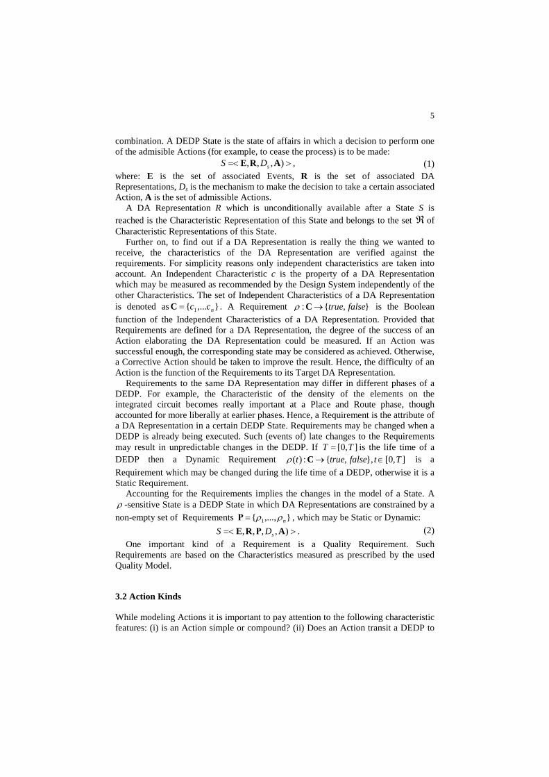
combination. A DEDP State is the state of affairs in which a decision to perform one of the admisible Actions (for example, to cease the process) is to be made:
>=< ),,, ARE sDS , (1) where: E is the set of associated Events, R is the set of associated DA Representations, Ds is the mechanism to make the decision to take a certain associated Action, A is the set of admissible Actions.
A DA Representation R which is unconditionally available after a State S is reached is the Characteristic Representation of this State and belongs to the set ℜ of Characteristic Representations of this State.
Further on, to find out if a DA Representation is really the thing we wanted to receive, the characteristics of the DA Representation are verified against the requirements. For simplicity reasons only independent characteristics are taken into account. An Independent Characteristic c is the property of a DA Representation which may be measured as recommended by the Design System independently of the other Characteristics. The set of Independent Characteristics of a DA Representation is denoted as },...{ 1 ncc=C . A Requirement },{: falsetrue→Cρ is the Boolean
function of the Independent Characteristics of a DA Representation. Provided that Requirements are defined for a DA Representation, the degree of the success of an Action elaborating the DA Representation could be measured. If an Action was successful enough, the corresponding state may be considered as achieved. Otherwise, a Corrective Action should be taken to improve the result. Hence, the difficulty of an Action is the function of the Requirements to its Target DA Representation.
Requirements to the same DA Representation may differ in different phases of a DEDP. For example, the Characteristic of the density of the elements on the integrated circuit becomes really important at a Place and Route phase, though accounted for more liberally at earlier phases. Hence, a Requirement is the attribute of a DA Representation in a certain DEDP State. Requirements may be changed when a DEDP is already being executed. Such (events of) late changes to the Requirements may result in unpredictable changes in the DEDP. If ],0[ TT = is the life time of a DEDP then a Dynamic Requirement ],0[},,{:)( Ttfalsetruet ∈→Cρ is a
Requirement which may be changed during the life time of a DEDP, otherwise it is a Static Requirement.
Accounting for the Requirements implies the changes in the model of a State. A ρ -sensitive State is a DEDP State in which DA Representations are constrained by a
non-empty set of Requirements },...,{ 1 nρρ=Ρ , which may be Static or Dynamic:
>=< ),,,, AΡRE sDS . (2)
One important kind of a Requirement is a Quality Requirement. Such Requirements are based on the Characteristics measured as prescribed by the used Quality Model.
3.2 Action Kinds
While modeling Actions it is important to pay attention to the following characteristic features: (i) is an Action simple or compound? (ii) Does an Action transit a DEDP to
6
a different State? (iii) What are the changes applied to the Design Artifact? (iv) What are the dependencies among certain Actions?
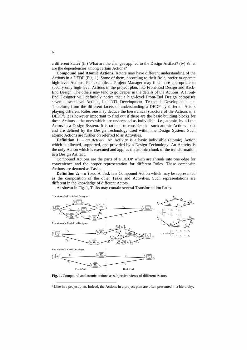
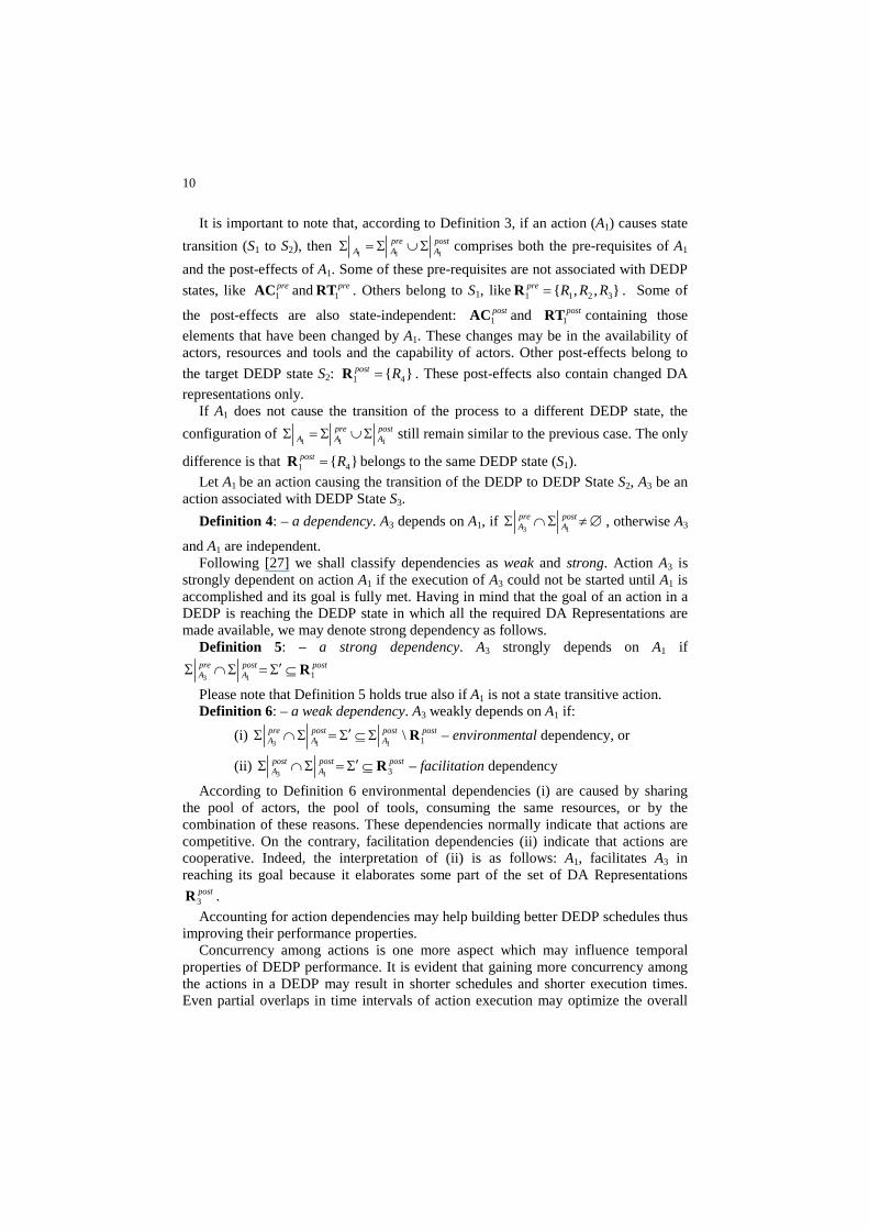
Compound and Atomic Actions. Actors may have different understanding of the Actions in a DEDP (Fig. 1). Some of them, according to their Role, prefer to operate high-level Actions. For example, a Project Manager may find more appropriate to specify only high-level Actions in the project plan, like Front-End Design and Back-End Design. The others may tend to go deeper in the details of the Actions. A Front-End Designer will definitely notice that a high-level Front-End Design comprises several lower-level Actions, like RTL Development, Testbench Development, etc. Therefore, from the different facets of understanding a DEDP by different Actors playing different Roles one may deduce the hierarchical structure of the Actions in a DEDP3. It is however important to find out if there are the basic building blocks for these Actions – the ones which are understood as indivisible, i.e., atomic, by all the Actors in a Design System. It is rational to consider that such atomic Actions exist and are defined by the Design Technology used within the Design System. Such atomic Actions are further on referred to as Activities.
Definition 1: – an Activity. An Activity is a basic indivisible (atomic) Action which is allowed, supported, and provided by a Design Technology. An Activity is the only Action which is executed and applies the atomic chunk of the transformation to a Design Artifact.
Compound Actions are the parts of a DEDP which are shrunk into one edge for convenience and the proper representation for different Roles. These composite Actions are denoted as Tasks.
Definition 2: – a Task. A Task is a Compound Action which may be represented as the composition of the other Tasks and Activities. Such representations are different in the knowledge of different Actors.
As shown in Fig. 1, Tasks may contain several Transformation Paths.
Si
S2
Ri
A1
The view of a Front-End Designer
The view of a Back-End Designer
R2
S6 R6 S3 R3
S4 R4 S5 R5
A3
St Rt A2
A4
A5
A7
A6
A8
T3
T4
S8 R8
St Rt
S6 R6
S5 R5
Si Ri
T1
T2
The view of a Project Manager
St Rt
S6 R6
S5 R5
Si Ri T1
T2
T3
T4
S7 R7
S9 R9
S10 R10
A9
A10
A13
A12
A11
A14
A15
A16
Si
S2
A1 S6
A2 A7
A6
S3
⎪⎩
⎪⎨
⎧
⎯→⎯⎯→⎯
⎯→⎯⎯→⎯
63
62
1
72
61
OR:
SSS
SSS
TAA
i
AAi
Si S6 S3
S4 S5 A3
A4
A5
A7
A8
⎪⎩
⎪⎨
⎧
⎯→⎯⎯→⎯
⎯→⎯⎯→⎯⎯→⎯
654
634
2
85
74
3 OR:
SSS
SSS
STAA
AA
Ai
Front-End Back-End
Fig. 1. Compound and atomic actions as subjective views of different Actors.
3 Like in a project plan. Indeed, the Actions in a project plan are often presented in a hierarchy.
7
State-Transitive Actions. A DEDP transits to a new state when the pre-requisites for such a transition are met. These pre-requisites are: (i) events which indirectly trigger an Action or (ii) the availability of Characteristic DA Representations for the target DEDP State. For clarity we shall consider the Events occurring outside of DEDP environment and the Events generated within the Environment of a DEDP as separate kinds of Events –external and internal ones.
An Action will transit a DEDP to a new state S if DA Representations produced by this Action “complete” the set ℜ of the Characteristic Representations of S. According to the classification of the results of Actions, the following types of Actions may result in DEDP State transition because they produce new DA Representations: Productive Actions, Decomposition and Integration Actions.
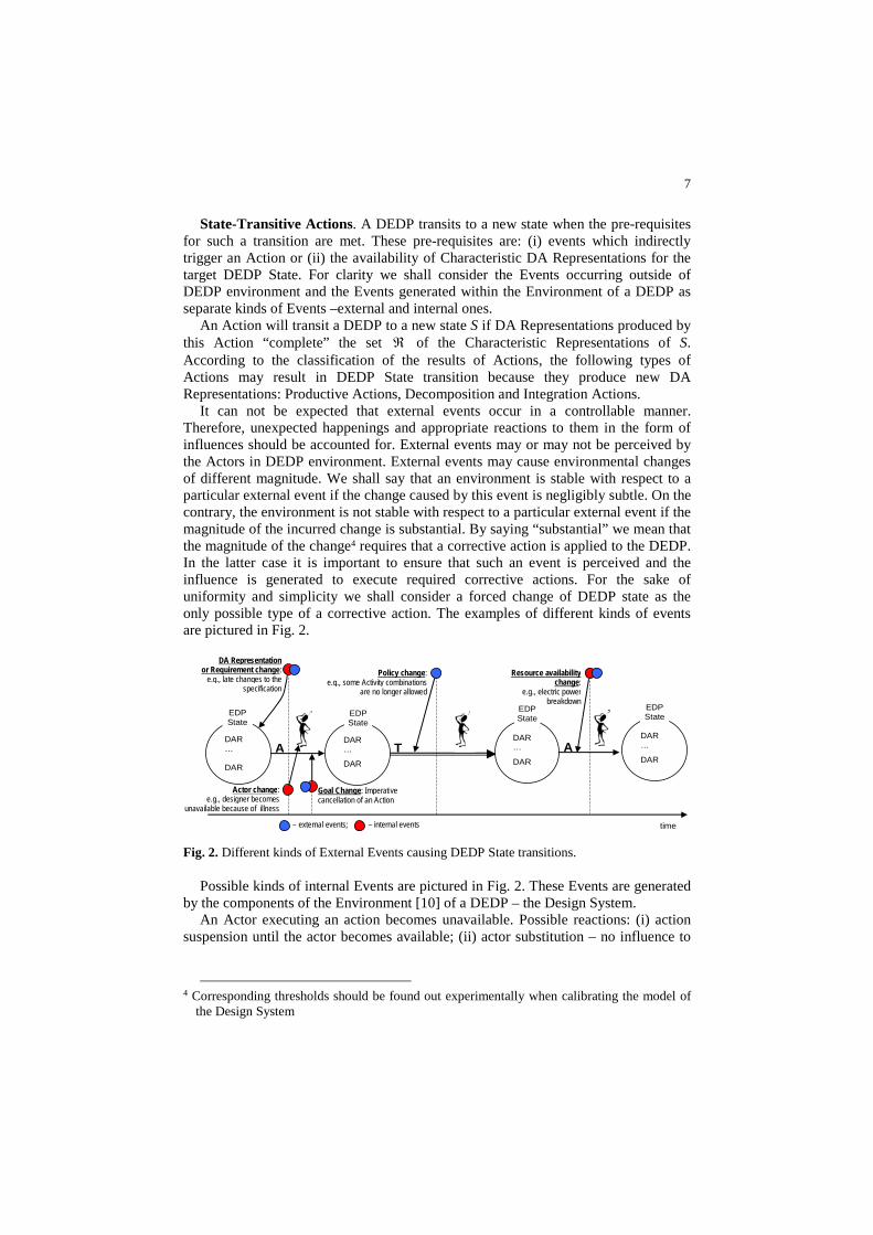
It can not be expected that external events occur in a controllable manner. Therefore, unexpected happenings and appropriate reactions to them in the form of influences should be accounted for. External events may or may not be perceived by the Actors in DEDP environment. External events may cause environmental changes of different magnitude. We shall say that an environment is stable with respect to a particular external event if the change caused by this event is negligibly subtle. On the contrary, the environment is not stable with respect to a particular external event if the magnitude of the incurred change is substantial. By saying “substantial” we mean that the magnitude of the change4 requires that a corrective action is applied to the DEDP. In the latter case it is important to ensure that such an event is perceived and the influence is generated to execute required corrective actions. For the sake of uniformity and simplicity we shall consider a forced change of DEDP state as the only possible type of a corrective action. The examples of different kinds of events are pictured in Fig. 2.
DAR … DAR
EDP State
DAR …
DAR
DAR …
DAR
DAR …
DAR
time
DA Representation or Requirement change:
e.g., late changes to the specification
Actor change: e.g., designer becomes
unavailable because of illness
Goal Change: Imperative cancellation of an Action
A T A
Policy change: e.g., some Activity combinations
are no longer allowed
Resource availability change:
e.g., electric power breakdown
EDP State
EDP State
EDP State
– external events; – internal events
Fig. 2. Different kinds of External Events causing DEDP State transitions.
Possible kinds of internal Events are pictured in Fig. 2. These Events are generated by the components of the Environment [10] of a DEDP – the Design System.
An Actor executing an action becomes unavailable. Possible reactions: (i) action suspension until the actor becomes available; (ii) actor substitution – no influence to
4 Corresponding thresholds should be found out experimentally when calibrating the model of
the Design System
8
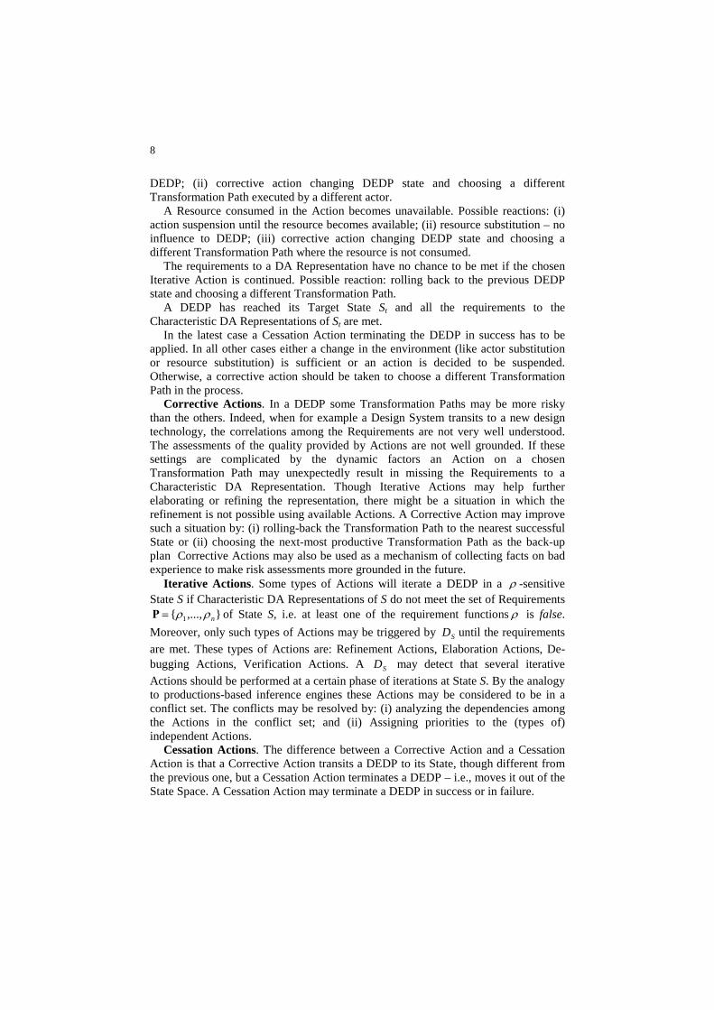
DEDP; (ii) corrective action changing DEDP state and choosing a different Transformation Path executed by a different actor.
A Resource consumed in the Action becomes unavailable. Possible reactions: (i) action suspension until the resource becomes available; (ii) resource substitution – no influence to DEDP; (iii) corrective action changing DEDP state and choosing a different Transformation Path where the resource is not consumed.
The requirements to a DA Representation have no chance to be met if the chosen Iterative Action is continued. Possible reaction: rolling back to the previous DEDP state and choosing a different Transformation Path.
A DEDP has reached its Target State St and all the requirements to the Characteristic DA Representations of St are met.
In the latest case a Cessation Action terminating the DEDP in success has to be applied. In all other cases either a change in the environment (like actor substitution or resource substitution) is sufficient or an action is decided to be suspended. Otherwise, a corrective action should be taken to choose a different Transformation Path in the process.
Corrective Actions. In a DEDP some Transformation Paths may be more risky than the others. Indeed, when for example a Design System transits to a new design technology, the correlations among the Requirements are not very well understood. The assessments of the quality provided by Actions are not well grounded. If these settings are complicated by the dynamic factors an Action on a chosen Transformation Path may unexpectedly result in missing the Requirements to a Characteristic DA Representation. Though Iterative Actions may help further elaborating or refining the representation, there might be a situation in which the refinement is not possible using available Actions. A Corrective Action may improve such a situation by: (i) rolling-back the Transformation Path to the nearest successful State or (ii) choosing the next-most productive Transformation Path as the back-up plan Corrective Actions may also be used as a mechanism of collecting facts on bad experience to make risk assessments more grounded in the future.
Iterative Actions. Some types of Actions will iterate a DEDP in a ρ -sensitive State S if Characteristic DA Representations of S do not meet the set of Requirements
},...,{ 1 nρρ=Ρ of State S, i.e. at least one of the requirement functions ρ is false.
Moreover, only such types of Actions may be triggered by SD until the requirements
are met. These types of Actions are: Refinement Actions, Elaboration Actions, De-bugging Actions, Verification Actions. A SD may detect that several iterative
Actions should be performed at a certain phase of iterations at State S. By the analogy to productions-based inference engines these Actions may be considered to be in a conflict set. The conflicts may be resolved by: (i) analyzing the dependencies among the Actions in the conflict set; and (ii) Assigning priorities to the (types of) independent Actions.
Cessation Actions. The difference between a Corrective Action and a Cessation Action is that a Corrective Action transits a DEDP to its State, though different from the previous one, but a Cessation Action terminates a DEDP – i.e., moves it out of the State Space. A Cessation Action may terminate a DEDP in success or in failure.
9
3.3 Dependencies and Concurrency
As emphasized by many authors, for example [25], best performance is achieved when the best achievable degree of coherence among the actions within a process is granted. Coherence among actions means several important things: (i) coherence in individual goals of different actors performing different actions in one process; (ii) proper distribution of the consumption of available resources in different actions; (iii) balance in the capacities of the tools used in different actions; (iv) appropriateness of the skills of the Actors to the requirements of the actions assigned to these Actors; (v) proper scheduling of the actions which use the results produced by other actions. All these aspects represent dependencies among actions. Hence, achieving coherence among these actions can be reached by coordination, which is the routine of “managing the interdependencies between activities” (cf. [26]). Therefore, a model of inter-action dependencies should account not only for the direct dependencies of actions on the results of other actions (the latter case (v)), but for a broader variety of indirect dependencies (at least cases (i)–(iv)) revealed through the process environment. Generally speaking, action A3 depends on another action A1 when the post-effects of A1 change the pre-requisites of A3. This dependency may be denoted in the terms of a DEDP State, an event, a happening, and an influence.
Let S1, S2 be ρ -sensitive States (2).
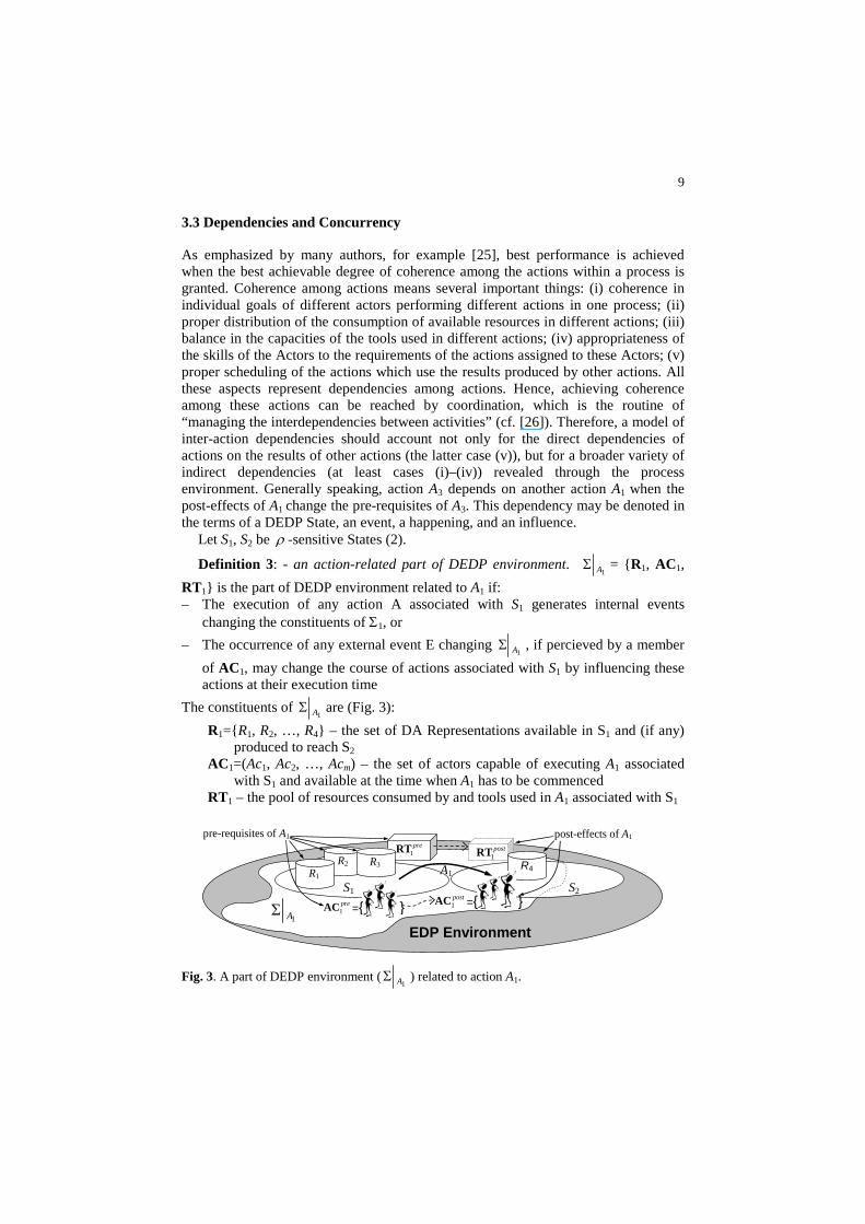
Definition 3: - an action-related part of DEDP environment. 1AΣ = {R1, AC1,
RT1} is the part of DEDP environment related to A1 if: – The execution of any action A associated with S1 generates internal events
changing the constituents of Σ1, or
– The occurrence of any external event E changing 1AΣ , if percieved by a member
of AC1, may change the course of actions associated with S1 by influencing these actions at their execution time
The constituents of 1AΣ are (Fig. 3):
R1={R1, R2, …, R4} – the set of DA Representations available in S1 and (if any) produced to reach S2
AC1=(Ac1, Ac2, …, Acm) – the set of actors capable of executing A1 associated with S1 and available at the time when A1 has to be commenced
RT1 – the pool of resources consumed by and tools used in A1 associated with S1
EDP Environment
R2
R1
pre1RT
S1
1AΣS2
pre1AC ={ }
A1
post1RT
R4R3
post1AC ={ }
post-effects of A1 pre-requisites of A1
Fig. 3. A part of DEDP environment (1AΣ ) related to action A1.
10
It is important to note that, according to Definition 3, if an action (A1) causes state
transition (S1 to S2), then postA
preAA 111
Σ∪Σ=Σ comprises both the pre-requisites of A1
and the post-effects of A1. Some of these pre-requisites are not associated with DEDP
states, like pre1AC and pre
1RT . Others belong to S1, like },,{ 3211 RRRpre =R . Some of
the post-effects are also state-independent: post1AC and post
1RT containing those
elements that have been changed by A1. These changes may be in the availability of actors, resources and tools and the capability of actors. Other post-effects belong to
the target DEDP state S2: }{ 41 Rpost =R . These post-effects also contain changed DA
representations only. If A1 does not cause the transition of the process to a different DEDP state, the
configuration of postA
preAA 111
Σ∪Σ=Σ still remain similar to the previous case. The only
difference is that }{ 41 Rpost =R belongs to the same DEDP state (S1).
Let A1 be an action causing the transition of the DEDP to DEDP State S2, A3 be an action associated with DEDP State S3.
Definition 4: – a dependency. A3 depends on A1, if ∅≠Σ∩Σ postA
preA 13
, otherwise A3
and A1 are independent. Following [27] we shall classify dependencies as weak and strong. Action A3 is
strongly dependent on action A1 if the execution of A3 could not be started until A1 is accomplished and its goal is fully met. Having in mind that the goal of an action in a DEDP is reaching the DEDP state in which all the required DA Representations are made available, we may denote strong dependency as follows.
Definition 5: – a strong dependency. A3 strongly depends on A1 if postpost
ApreA 113
R⊆Σ′=Σ∩Σ
Please note that Definition 5 holds true also if A1 is not a state transitive action. Definition 6: – a weak dependency. A3 weakly depends on A1 if:
(i) postpostA
postA
preA 1\
113RΣ⊆Σ′=Σ∩Σ – environmental dependency, or
(ii) postpostA
postA 313
R⊆Σ′=Σ∩Σ – facilitation dependency
According to Definition 6 environmental dependencies (i) are caused by sharing the pool of actors, the pool of tools, consuming the same resources, or by the combination of these reasons. These dependencies normally indicate that actions are competitive. On the contrary, facilitation dependencies (ii) indicate that actions are cooperative. Indeed, the interpretation of (ii) is as follows: A1, facilitates A3 in reaching its goal because it elaborates some part of the set of DA Representations
post3R .
Accounting for action dependencies may help building better DEDP schedules thus improving their performance properties.
Concurrency among actions is one more aspect which may influence temporal properties of DEDP performance. It is evident that gaining more concurrency among the actions in a DEDP may result in shorter schedules and shorter execution times. Even partial overlaps in time intervals of action execution may optimize the overall
11
performance. Unfortunately, it is not possible to execute all the actions in a DEDP in parallel or partly in parallel because of their dependencies.
Let, according to [9], 1AI be the fuzzy time interval of the execution of A1 and
3AI be
the fuzzy time interval of the execution of A3. Then the following definitions of full and partial concurrency among two different actions hold true.
Definition 7: – full concurrency. Action A1 is fully concurrent to action A3 if ),(),(
3131 AAAA IIWithinIISame ∨ .
Definition 8: – partial concurrency. Action A1 is partially concurrent to action A3 if ),(
31 AA IIOverlaps .
In terms of action dependencies we may rightfully state that if action A1 is independent to action A3 then we may schedule and execute them fully concurrently. Granting concurrency to dependent actions is not that straightforward. The case of a strong dependency is simpler.
Corollary 1: – concurrency of strongly dependent actions. If action A3 is strongly dependent on action A1 then they can not be executed concurrently.
The case of a weak dependency is more complex. Corollary 2: – concurrency of environmentally dependent actions. If action A3 is
environmentally dependent of action A1, then their concurrent execution, while being possible, may make the overall performance less optimal.
Corollary 3: – concurrency of actions with facilitation dependency. If action A1 facilitates the execution of action A1, then their concurrent execution while result in better overall performance.
4 Implementation and Evaluation
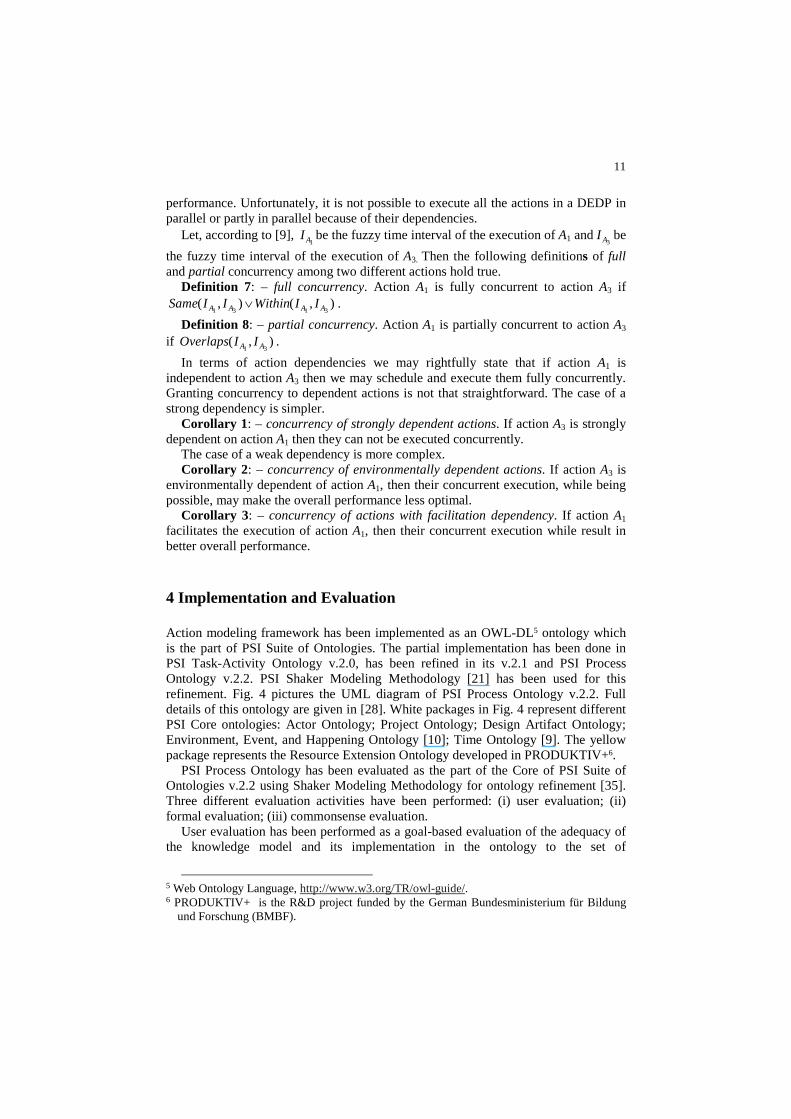
Action modeling framework has been implemented as an OWL-DL5 ontology which is the part of PSI Suite of Ontologies. The partial implementation has been done in PSI Task-Activity Ontology v.2.0, has been refined in its v.2.1 and PSI Process Ontology v.2.2. PSI Shaker Modeling Methodology [21] has been used for this refinement. Fig. 4 pictures the UML diagram of PSI Process Ontology v.2.2. Full details of this ontology are given in [28]. White packages in Fig. 4 represent different PSI Core ontologies: Actor Ontology; Project Ontology; Design Artifact Ontology; Environment, Event, and Happening Ontology [10]; Time Ontology [9]. The yellow package represents the Resource Extension Ontology developed in PRODUKTIV+6.
PSI Process Ontology has been evaluated as the part of the Core of PSI Suite of Ontologies v.2.2 using Shaker Modeling Methodology for ontology refinement [35]. Three different evaluation activities have been performed: (i) user evaluation; (ii) formal evaluation; (iii) commonsense evaluation.
User evaluation has been performed as a goal-based evaluation of the adequacy of the knowledge model and its implementation in the ontology to the set of
5 Web Ontology Language, http://www.w3.org/TR/owl-guide/. 6 PRODUKTIV+ is the R&D project funded by the German Bundesministerium für Bildung
und Forschung (BMBF).
12
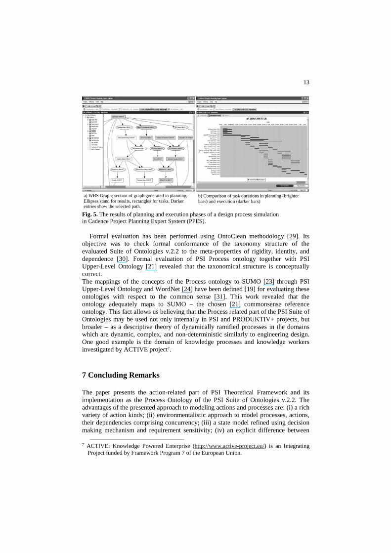
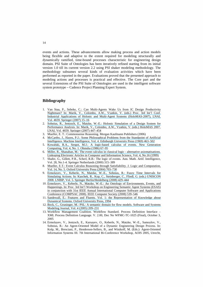
requirements by the group of subject experts in microelectronic engineering design. It found out that the ontology adequately answers the competency questions formulated using the requirements by subject experts. Several test cases have been developed for evaluating the suite of ontologies using simulation. A testcase is a real or a fictive project for which at least all the initial data instances required for design system modeling are available. Acquiring a testcase allows to verify that the ontology is capable of storing all initial data and to start simulation using the multi-agent system (MAS). Ideally, a testcase also provides a complete project execution record which is required for the calibration step and for the verification of the simulation results. Amongst the set of testcases are very simple and fictive ones describing tiny digital and tiny analog designs. These have been used to verify and refine the model and the ontologies. Others are based on real world projects of digital chip design. These are fictive ones as well designed for demonstration purposes because real world projects usually may not be disclosed to public. For calibration the Project Planning Expert System MAS [2] was fed with the project definition and the knowledge base. Using these, it created a new Work Breakdown Structure (Fig. 5a). The result was then compared to the original structure, differences were analyzed, and corrections were made until the both roughly matched. At subsequent stages the MAS simulated project executions (Fig. 5b) and again the results were compared to the original project course. Project log replay simulations and calibration experiments proved that the approach is effective and practical.
Fig. 4. UML diagram of the main concepts in the PSI Process Ontology v.2.2.
13
a) WBS Graph; section of graph generated in planning. Ellipses stand for results, rectangles for tasks. Darker entries show the selected path.
b) Comparison of task durations in planning (brighter bars) and execution (darker bars)
Fig. 5. The results of planning and execution phases of a design process simulation in Cadence Project Planning Expert System (PPES).
Formal evaluation has been performed using OntoClean methodology [29]. Its objective was to check formal conformance of the taxonomy structure of the evaluated Suite of Ontologies v.2.2 to the meta-properties of rigidity, identity, and dependence [30]. Formal evaluation of PSI Process ontology together with PSI Upper-Level Ontology [21] revealed that the taxonomical structure is conceptually correct. The mappings of the concepts of the Process ontology to SUMO [23] through PSI Upper-Level Ontology and WordNet [24] have been defined [19] for evaluating these ontologies with respect to the common sense [31]. This work revealed that the ontology adequately maps to SUMO – the chosen [21] commonsense reference ontology. This fact allows us believing that the Process related part of the PSI Suite of Ontologies may be used not only internally in PSI and PRODUKTIV+ projects, but broader – as a descriptive theory of dynamically ramified processes in the domains which are dynamic, complex, and non-deterministic similarly to engineering design. One good example is the domain of knowledge processes and knowledge workers investigated by ACTIVE project7.
7 Concluding Remarks
The paper presents the action-related part of PSI Theoretical Framework and its implementation as the Process Ontology of the PSI Suite of Ontologies v.2.2. The advantages of the presented approach to modeling actions and processes are: (i) a rich variety of action kinds; (ii) environmentalistic approach to model processes, actions, their dependencies comprising concurrency; (iii) a state model refined using decision making mechanism and requirement sensitivity; (iv) an explicit difference between
7 ACTIVE: Knowledge Powered Enterprise (http://www.active-project.eu/) is an Integrating
Project funded by Framework Program 7 of the European Union.
14
events and actions. These advancements allow making process and action models being flexible and adaptive to the extent required for modeling structurally and dynamically ramified, time-bound processes characteristic for engineering design domain. PSI Suite of Ontologies has been iteratively refined starting from its initial version 1.0 till its current version 2.2 using PSI shaker modeling methodology. The methodology subsumes several kinds of evaluation activities which have been performed as reported in the paper. Evaluations proved that the presented approach to modeling actions and processes is practical and effective. The Core part and the several Extensions of the PSI Suite of Ontologies are used in the intelligent software system prototype – Cadence Project Planning Expert System.
Bibliography
1. Van Staa, P., Sebeke, C.: Can Multi-Agents Wake Us from IC Design Productivity Nightmare? In: Marik, V., Colombo, A.W., Vyatkin, V. (eds.) Proc. 3rd Int’l Conf. Industrial Applications of Holonic and Multi-Agent Systems (HoloMAS-2007), LNAI, Vol. 4659. Springer (2007) 15–16
2. Sohnius, R., Jentzsch, E., Matzke, W.-E.: Holonic Simulation of a Design System for Performance Analysis. In: Marik, V., Colombo, A.W., Vyatkin, V. (eds.) HoloMAS 2007. LNAI, Vol. 4659. Springer (2007) 447–454
3. Mueller, E. T.: Commonsense Reasoning. Morgan Kaufmann Publishers (2006) 4. McCarthy, J., Hayes, P.J.: Some Philosophical Problems from the Standpoint of Artificial
Intelligence. Machine Intelligence, Vol. 4. Edinburgh University Press (1969) 463–502 5. Kowalski, R.A., Sergot, M.J.: A logic-based calculus of events. New Generation
Computing, Vol. 4, No. 1. Ohmsha (1986) 67–95 6. Miller, R., Shanahan, M.: The event calculus in classical logic - alternative axiomatisations.
Linkoping Electronic Articles in Computer and Information Science, Vol. 4, No.16 (1999) 7. Shafer, G., Gillett, P.R., Scherl, R.B.: The logic of events. Ann. Math. Artif. Intelligence,
Vol. 28, No.1-4. Springer Netherlands (2000) 315–389 8. Mueller, E.T.: Event Calculus Reasoning through Satisfiability. J. Logic and Computation,
Vol. 14, No. 5. Oxford University Press (2004) 703–730 9. Ermolayev, V., Keberle, N., Matzke, W.-E., Sohnius, R.: Fuzzy Time Intervals for
Simulating Actions. In: Kaschek, R., Kop, C., Steinberger, C., Fliedl, G. (eds.) UNISCON 2008. LNBIP, Vol. 5. Springer Berlin/Heidelberg (2008) 429–444
10. Ermolayev, V., Keberle, N., Matzke, W.-E.: An Ontology of Environments, Events, and Happenings. In: Proc. 3rd Int’l Workshop on Engineering Semantic Agent Systems (ESAS) in conjunction with 31st IEEE Annual International Computer Software and Applications Conference (COMPSAC 2008). IEEE Computer Society (2008) 539–546
11. Sandewall, E.: Features and Fluents. Vol. 1: the Representation of Knowledge about Dynamical Systems. Oxford University Press, 1994
12. Bock, C., Gruninger, M.: PSL: A semantic domain for flow models. Software and Systems Modeling Journal, Vol. 4 (2005) 209–231
13. Workflow Management Coalition. Workflow Standard. Process Definition Interface – XML Process Definition Language. V. 2.00, Doc No WFMC-TC-1025 (Final), October 3, 2005
14. Ermolayev, V., Jentzsch, E., Karsayev, O., Keberle, N., Matzke, W.-E., Samoylov, V., Sohnius, R.: An Agent-Oriented Model of a Dynamic Engineering Design Process. In: Kolp, M., Bresciani, P., Henderson-Sellers, B., and Winikoff, M. (Eds.): Agent-Oriented Information Systems III. 7th International Bi-Conference Workshop, AOIS 2005, Utrecht,
15
Netherlands, July 26, 2005, and Klagenfurt, Austria, October 27, 2005. Revised Selected Papers, LNCS, Vol. 3529. Springer (2006) 168–183
15. Buhler, P., Vidal, J.M.: Enacting BPEL4WS specified workflows with multiagent systems. In: Proc. of the Workshop on Web Services and Agent-Based Engineering (2004)
16. Ermolayev, V., et al: Towards a framework for agent-enabled semantic web service composition. Int. J. of Web Services Research, Vol. 1, No.3 (2004) 63–87
17. Fensel, D., Bussler, C.: The Web Service Modeling Framework WSMF. Electronic Commerce Research and Applications, Vol.1, No.2 (2002) 113–137
18. McCarthy, J.: Some expert systems need common sense. In: Pagels, H. R. (ed.) Proc. Symp. on Computer Culture: the Scientific, Intellectual, and Social Impact of the Computer. New York Academy of Sciences (1984) 129–137
19. Ermolayev, V., et al.: Performance Simulation Initiative. Meta-Ontology v.2.2. Reference Specification, tech. report PSI-ONTO-TR-2007-4, VCAD EMEA Cadence Design Systems GmbH (2008)
20. Ermolayev, V., et al.: Performance Simulation Initiative. Theoretical Framework v.2.0, tech. report PSI-TF-TR-2007-1, VCAD EMEA Cadence Design Systems GmbH (2007)
21. Ermolayev, V., Keberle, N., Matzke, W.-E.: An Upper-Level Ontological Model for Engineering Design Performance Domain. In: Li, Q., Spaccapietra, S., and Yu, E. (eds.) Proc 27 th Int. Conference on Conceptual Modeling (ER 2008). LNCS, Vol. 5231. Springer Berlin/Heidelberg (2008) 98–113
22. Masolo, C., Borgo, S., Gangemi, A., Guarino, N., Oltramari, A.: WonderWeb Deliverable D18 Ontology Library (final), ICT Project 2001-33052 WonderWeb: Ontology Infrastructure for the Semantic Web (2003)
23. Niles, I., Pease, A.: Towards a Standard Upper Ontology. In: Guarino, N., Smith, B., Welty, C. (eds.): Int. Conf. on Formal Ontologies in Inf. Systems, Vol. 2001. ACM Press, New York, NY, USA (2001) 2–9
24. Fellbaum, C. (ed.): WordNet: An Electronic Lexical Database. MIT Press, Cambridge, MA, USA (1998)
25. O’Donnel, F. J., Duffy, A. H. B.: Design Performance. Springer-Verlag London (2005) 26. Malone, T., Crowston, K.: Toward an interdisciplinary theory of coordination. Center for
Coordination Science, Technical Report 120, MIT Sloan School of Management (1991) 27. Nagendra Prasad, M. V., Lesser, V. R.: Learning situation-specific coordination in
cooperative multi-agent systems. Autonomous Agents and Multi-Agent Systems, Vol. 2, No. 2. Springer US(1999) 173–207
28. Ermolayev, V., Jentzsch, E., Keberle, N., Sohnius, R.: Performance Simulation Initiative. The Suite of Ontologies v.2.2. Reference Specification. Technical report PSI-ONTO-TR-2007-5, VCAD EMEA Cadence Design Systems, GmbH (2007)
29. Guarino, N., Welty, C.: Supporting Ontological Analysis of Taxonomic Relationships. Data and Knowledge Engineering, Vol. 39, No.1. Elsevier (2001) 51–74
30. Guarino, N., Welty, C. A.: A Formal Ontology of Properties. In: Dieng, R., Corby, O. (eds.) EKAW 2000. LNCS, Vol. 1937. Springer-Verlag (2000) 97–112
31. Keberle, N., Ermolayev, V., Matzke, W.-E.: Evaluating PSI Ontologies by Mapping to the Common Sense. In: Mayr, H. C, Karagiannis, D. (eds.): Proc. 6th Int’l Conf. Information Systems Technology and its Applications (ISTA 2007), GI LNI, Vol. 107. GI Bonn (2007) 91–104
Related Documents


