DO-ALL SERIES I PRESSURE REDUCING REGULATOR Spring Operated: 1/2" – 4" (DN15 - 100) The Model DA1 is a high performance, spring operated, flow-to-open, pressure reducing regulator with internal pressure balancing piston-cylinder that provides high flow capacity and high pressure drop capability. Internal trim design allows the same basic unit to cover a broad range of pressure settings. Performance approaches that of competitive pilot-operated designs in the basic construction. Applied primarily in clean gaseous or liquid services. Truly a “DO-ALL” pressure regulator. FEATURES Versatile: Five basic materials and multiple trim material combinations to select from. Tight Shutoff: Multiple composition materials provide Class IV or VI inboard leakage rates. Designed as a soft-seated valve. Capacity: Highest in the industry. Allows smaller body sizes than competitors in a majority of applications. Pressure Drop: Highest in the industry when coupled with high flow capacity. Trim Design: “DO-ALL” trim design provides FTO and pressure balancing for higher inlet pressure. Results in unmatched sensitivity and stability. Internals are cage-contained within easily removable quick change trim. Rangeability: Basic valve gives outstanding rangeability due to close tolerances, balanced trim, and a broad range of elastomeric diaphragms and soft seats. Can be as high as 1000:1. Heavy-Duty Both top and bottom guided to maintain stability and increased diaphragm life. Failure Position: Fails open on loss of P 1 or P 2 pressures. TECHNICAL BULLETIN DA1-TB 03-16 APPLICATIONS The “DO-ALL” design allows application of all types of clean fluids. Designed primarily for gaseous and liquid service applications where excessive cavitation is absent. Excellent for atmospheric industrial gases – GN 2 , GOX, Ar, He, H 2 , CO 2 – as well as a natural gas regulator. Used as a utilities – air, oil, water, steam – regulator. Corrosive and non-corrosive chemical services – gas or liquid – are possible with broad materials range. Special variations available for cryogenic gas; consult factory. MODEL DA1 MODEL DA1 Guiding: ISO Registered Company

Welcome message from author
This document is posted to help you gain knowledge. Please leave a comment to let me know what you think about it! Share it to your friends and learn new things together.
Transcript

DO-ALL SERIES IPRESSURE REDUCING REGULATOR
Spring Operated: 1/2" – 4" (DN15 - 100)
The Model DA1 is a high performance, spring operated, flow-to-open, pres sure reducing regulator with internal pres sure bal anc ing piston-cylinder that provides high flow ca pac i ty and high pressure drop ca pa bil i ty. Internal trim design allows the same basic unit to cover a broad range of pressure settings. Per for mance approaches that of com pet i tive pi lot-op er at ed designs in the basic con struc tion. Ap plied primarily in clean gaseous or liquid services. Truly a “DO-ALL” pres sure reg u la tor.
FEATURES
Versatile: Five basic materials and multiple trim ma te ri al combinations to select from.
Tight Shutoff: Multiple composition materials pro vide Class IV or VI inboard leak age rates. Designed as a soft-seat ed valve.
Capacity: Highest in the industry. Allows small er body sizes than competitors in a ma jor i ty of applications.
Pressure Drop: Highest in the industry when cou pled with high flow capacity.
Trim Design: “DO-ALL” trim design provides FTO and pressure balancing for higher in let pres sure. Results in unmatched sensitivity and stability. Internals are cage-contained within easily re mov able quick change trim.
Rangeability: Basic valve gives outstanding rangeability due to close tolerances, balanced trim, and a broad range of elastomeric diaphragms and soft seats. Can be as high as 1000:1.
Heavy-Duty Both top and bottom guided to maintain stability and increased di a phragm life.
Failure Position: Fails open on loss of P1 or P2
pres sures.
TECHNICAL BULLETIN DA1-TB03-16
APPLICATIONS
The “DO-ALL” design allows application of all types of clean fluids. Designed primarily for gaseous and liquid ser vice applications where ex ces sive cavitation is absent. Ex cel lent for at mo spher ic in dus tri al gases – GN2, GOX, Ar, He, H2, CO2 – as well as a natural gas regulator. Used as a utilities – air, oil, water, steam – regulator. Corrosive and non-corrosive chemical services – gas or liquid – are possible with broad materials range. Special variations avail able for cryogenic gas; consult factory.
MODEL DA1
MODEL DA1
Guiding:
ISO Registered Company

2 DA1-TB
DI/DI BRZ/CS SST/CS CS/DI BRZ/SST SST/SST CS/CS HC/CS * Dup SST/CS BRZ/BRZ * HC/SST * Dup SST/SST BRZ/DI SST/DI Dup SST/Dup SST * Through 2" (DN50) body size only.DI = Ductile Iron CS = Carbon Steel BRZ = BronzeSST = Stainless Steel HC = Hastelloy "C"Dup SST = Super Duplex SST
1/2"–1" (DN15–25): 1–450 psig (.07–34.5 Barg) 1-1/4"–1-1/2" (DN32–DN40): 1–400 psig (.07–27.6 Barg)2" (DN50): 1–275 psig (.07–20.7 Barg)2-1/2"–4" (DN65–100): 1–225 psig (.07–15.5 Barg)
NOTE: Ranges may be limited by diaphragm se lec tion. See Table 5.
Opt-5: Cryogenic Const. Opt-40: NACE Const.Opt-9: *TFE Diaph. Cover Opt-41: Ext. Tube EndsOpt-25: 1/4" (DN8) NPT Tap Opt-55: Oxygen Cleaned Spring Chmb. Opt-56: Special CleanedOpt-25S: Vent Screen Opt-57: Chlorine CleanedOpt-30: RF Flanges Opt-80: High Outlet Press.Opt-31: BSP End Conns. Opt-85: Extra Set PressureOpt-32: Ext. Pipe Nipples TapsOpt-34: 14" F to F Flange. Opt-95: Epoxy Paint Opt-36: Cryogenic Const. Opt-95OS: Epoxy Paint* Available with Composition Diaphragm ONLY.
STANDARD / GENERAL SPECIFICATIONS
Body / Spring Chamber Materials
Body Sizes
End Connections
Recommended Max. Useable Cv
Inlet Pressure Range
1/2", 3/4", 1", 1-1/4", 1-1/2", 2", 2-1/2", 3", 4"(DN15, 20, 25, 32, 40, 50, 65, 80, 100)
Standard: Female NPT (screwed). ASME Flanged:125#, 150#, 250#, 300#,600#DIN Flanged: PN16, PN25, PN40;Opt-31: British Standard Pipe Threads.Opt-32: Schedule 80 Extended Pipe Nipples.Opt-34: 14" Face to Face Flange Dimension.Opt-41: Extension Tube Ends.
Body Size Diaphragm Body Size Diaphragm
Comp.
Cv
Metal
Cv
Comp.
Cv
Metal
Cvin (DN) in (DN)
1/2" (15) 3.6 3.5 2" (50) 54 12
3/4" (20) 7.2 3.5 2-1/2" (65) 81 N/A
1" (25) 13.5 3.5 3" (80) 108 N/A
1-1/4" (32) 20.7 6.0 4" (100) 198 N/A
1-1/2" (40) 27.0 6.0 – – –
See Table DAG-6 for Wide Open Cv Limits.See Tables 3A through 3D and 4A through 4C for Cv vs. Droop vs. Range Spring tables.
METRIC CONVERSION FACTOR: Cv / 1.16 = kv
Operating: 10–1480 psig (.69-102.1 Barg).See Tables DAG-1A – 1H for design P vs. T limits.
Outlet Pressure Range
Pressure Drop Limits
Temperature Range
Inboard Leakage Rates
Optional Constructions
5–1480 psid (.34-102.1 Bard)Function of service fluid, base trim material, diaphragm and dynamic seal design. See Table 5 and Table DAG-2, DAG-3 & DAG-4.
-425° to +400°F (-254° to +204° C) Limited by body/sp.ch. material combinations, and by elas to mer ic – diaphragm, seat, static seal, dynamicseal – materials. See Tables DAG-1A through 1H and Table DAG-5.Alternate "CS" Mat'l - Steel - ASTM A352 Gr. LCC - Minimum temperature -50 °F (-46 °C).Cryogenic Application see Opt -5 or -36.
ABBREVIATIONS
FK = Fluorosilicone NBR = Buna-N PTFE = Polytetrafluoroethylene
FKM = Fluorocarbon RTFE = Brz-fill TFE V-TFE = Virgin TFE
EPR = Ethylene Propylene GF-TFE = Glass-fill TFE CTFE = Chlorotrifluoroethylene
BC = Neoprene PA = PolyAll 3-ply (PTFE+FKM+PTFE)
See Table DAG-10

DA1-TB 3
Composition Di a phragm
DI – ASTM A395 CS – ASTM A216, Grade WCB Alternate ASTM A352 Gr. LCC BRZ – ASTM B62, Alloy 83600, SST – ASTM A351, Grade CF3M. Alternate ASTM A995/A995M7 Gr. 6A HC – ASTM A494, Gr. CW-12 MW.
See DAG-1A through DAG-1H for material specs.
Metal Di a phragm
This construction RE QUIRES a Low er Pis ton Spring to be sup plied.
MATERIAL SPECIFICATIONS
Body
Spring Chamber
Diaphragm *
Metallic Trim *
DI – ASTM A395 CS – Sizes 1/2" - 4" ASTM A216, Gr. WCB; Alternate ASTM A352 Gr. LCC Opt-80 - Sizes 1/2"-1-1/2" ASTM A516, Gr. 55, ASTM A106, Gr. B; Size 2" ASTM A216, Gr. WCB BRZ – ASTM B62, Alloy 83600. SST – Size 1/2" - 4 " ASTM A351 Gr. CF3M; Opt-80 - Size 1/2" - 1-1/2" ASTM A312, Gr. 316L, ASTM A479, Gr. 316L; Size 2" is ASTM A351 Gr. CF3M Alternate ASTM A995/A995M7 Gr. 6A
Elastomeric – BC, EPR, FKM, FK, NBR, FKM+TFE, 3-ply (PTFE+FKM+PTFE).Metallic – Be-Cu. (only 1/2" - 2" sizes)
17-4PH SST, 316L SST, Nickel-Copper Alloy (Monel†), See Ta ble 2.
Seat *
Static Seals (See Fig. DAG-F1) *
Dynamic Seals (See Fig. DAG-F1) *
Painting
PolyAll, V-TFE, GF-TFE, CTFE, BC, NBR, FKM
RTFE, NBR, FKM, FK, EPR, - o-ringSST/TFE (1/2"–2") (DN15-50) sizes, V-TFE (2-1/2"–4") (DN65-100) sizes.
Type OR – NBR, FKM, FK, EPR - o-ring seal.Type UC – V-TFE u-cup seal w/ 316L SST energizer – V-TFE u-cup seal w/ Elgiloy energizer – V-TFE u-cup seal w/ Hast C energizerType CW – TFE cap seal with o-ring energizer (o-ring material same as static seal) and GF-TFE wiper backup seal.Type PW – GF-TFE piston ring assembly seal with 17-7PH SST energizer and GF-TFE wiper backup seal.
Standard: All non-corrosion resistant portions to be painted with corrosion resistant epoxy paint per Cashco Spec #S-1606.Alternate: See Opt-95 or Opt-95OS.
* See Product Coder for acceptable combinations.† Hastelloy®, MonelTM, and Inconel® are registered trade names: Hastelloy® is a mark owned by Stelite Div., Cabot Corp. MonelTM is a mark owned by International Nickel Co. Inconel® is a mark owned by International Nickel Co.See Fig. DAG-1
Dynamic & Stat ic Seals
FIGURE 1 – Model DA1 Flow To Open
4 DA1-TB
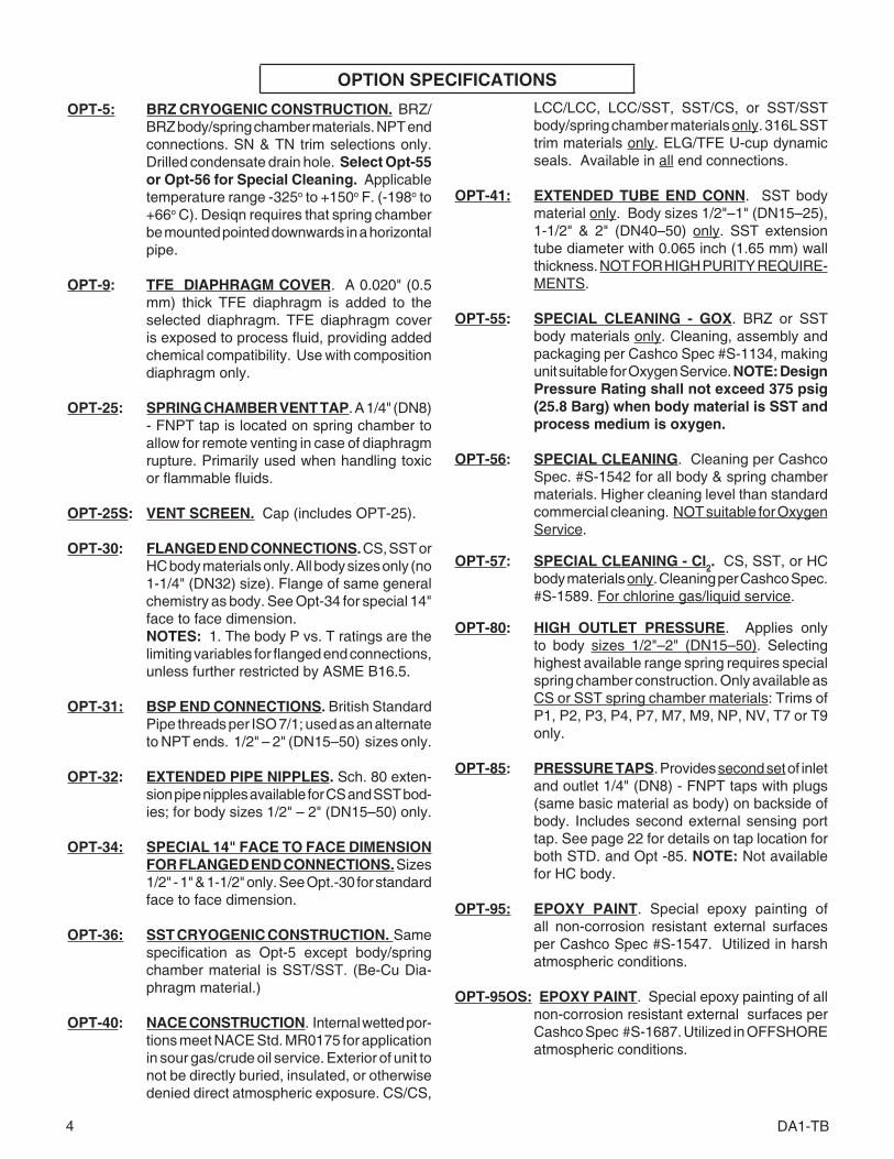
LCC/LCC, LCC/SST, SST/CS, or SST/SST body/spring chamber materials only. 316L SST trim materials only. ELG/TFE U-cup dynamic seals. Available in all end con nec tions.
OPT-41: EXTENDED TUBE END CONN. SST body material only. Body sizes 1/2"–1" (DN15–25), 1-1/2" & 2" (DN40–50) only. SST ex ten sion tube di am e ter with 0.065 inch (1.65 mm) wall thick ness. NOT FOR HIGH PU RI TY REQUIRE-MENTS.
OPT-55: SPE CIAL CLEAN ING - GOX. BRZ or SST body ma te ri als only. Cleaning, assembly and pack ag ing per Cashco Spec #S-1134, making unit suitable for Oxygen Service. NOTE: Design Pressure Rating shall not ex ceed 375 psig (25.8 Barg) when body material is SST and process medium is oxygen.
OPT-56: SPECIAL CLEAN ING. Cleaning per Cashco Spec. #S-1542 for all body & spring chamber materials. Higher cleaning level than standard commercial cleaning. NOT suitable for Oxygen Service.
OPT-57: SPECIAL CLEAN ING - Cl2. CS, SST, or HC body materials only. Cleaning per Cashco Spec. #S-1589. For chlorine gas/liq uid ser vice.
OPT-80: HIGH OUTLET PRESSURE. Applies only to body sizes 1/2"–2" (DN15–50). Selecting high est avail able range spring re quires special spring cham ber construction. Only available as CS or SST spring chamber materials: Trims of P1, P2, P3, P4, P7, M7, M9, NP, NV, T7 or T9 only.
OPT-85: PRESSURE TAPS. Provides second set of inlet and outlet 1/4" (DN8) - FNPT taps with plugs (same ba sic ma te ri al as body) on back side of body. In cludes second external sensing port tap. See page 22 for details on tap location for both STD. and Opt -85. NOTE: Not available for HC body.
OPT-95: EPOXY PAINT . Special epoxy painting of all non-corrosion resistant external surfaces per Cashco Spec #S-1547. Utilized in harsh atmospheric conditions.
OPT-95OS: EPOXY PAINT . Special epoxy painting of all non-corrosion resistant external surfaces per Cashco Spec #S-1687. Utilized in OFFSHORE atmospheric conditions.
OPT-5: BRZ CRYOGENIC CONSTRUCTION. BRZ/BRZ body/spring chamber materials. NPT end connections. SN & TN trim selections only. Drilled condensate drain hole. Select Opt-55 or Opt-56 for Special Cleaning. Applicable temperature range -325o to +150o F. (-198o to +66o C). Desiqn requires that spring chamber be mounted pointed downwards in a horizontal pipe.
OPT-9: TFE DIAPHRAGM COVER. A 0.020" (0.5 mm) thick TFE diaphragm is added to the selected diaphragm. TFE diaphragm cover is ex posed to process fluid, providing added chemical com pat i bil i ty. Use with composition diaphragm only.
OPT-25: SPRING CHAMBER VENT TAP. A 1/4" (DN8) - FNPT tap is located on spring chamber to allow for remote venting in case of diaphragm rup ture. Primarily used when handling toxic or flammable fluids.
OPT-25S: VENT SCREEN. Cap (includes OPT-25).
OPT-30: FLANGED END CONNECTIONS. CS, SST or HC body materials only. All body sizes only (no 1-1/4" (DN32) size). Flange of same gen er al chem is try as body. See Opt-34 for special 14" face to face dimension.
NOTES: 1. The body P vs. T ratings are the limiting variables for flanged end connections, unless fur ther restricted by ASME B16.5.
OPT-31: BSP END CONNECTIONS. British Stan dard Pipe threads per ISO 7/1; used as an al ter nate to NPT ends. 1/2" – 2" (DN15–50) sizes only.
OPT-32: EXTENDED PIPE NIPPLES. Sch. 80 ex ten- sion pipe nipples available for CS and SST bod-ies; for body sizes 1/2" – 2" (DN15–50) only.
OPT-34: SPECIAL 14" FACE TO FACE DIMENSION FOR FLANGED END CON NEC TIONS. Sizes 1/2" - 1" & 1-1/2" only. See Opt.-30 for standard face to face dimension.
OPT-36: SST CRYOGENIC CONSTRUCTION. Same specification as Opt-5 except body/spring chamber material is SST/SST. (Be-Cu Dia-phragm material.)
OPT-40: NACE CONSTRUCTION. In ter nal wetted por- tions meet NACE Std. MR0175 for application in sour gas/crude oil service. Exterior of unit to not be directly buried, in su lat ed, or otherwise denied direct atmospheric exposure. CS/CS,
OPTION SPECIFICATIONS

DA1-TB 5
Body Sizein. (DN)
Spring Rangepsig
Body Sizein. (DN)
Spring Rangepsig
1/2" (15),3/4" (20)1" (25)
1–5 *1–10 **
2" (50)
1–5 *1 –10 **
5–20 10–35 20–80
30–15070–200100–300
5–15 10–3015–5030–9050–150
80–22580-275
(Opt-80)√200–450(Opt-80) √
2-1/2" (65),3" (80),4" (100)
1–10
1-1/4" (32)1-1/2" (40)
1–5 *1–10 **
5–20 10–4010–7040–12550–225
5–2015–4510–70
40–17570–200
100–350100-400
(Opt-80) √
TABLE 1RANGE SPRINGS
* Composition diaphragm construction ONLY.** Metal diaphragm for set point pressures ≥ 5 psig (.34 Barg).√ OPT-80 requires selection of a CS or SST spring chamber.METRIC CONVERSION: psig / 14.5 = Barg.
TECHNICAL SPECIFICATIONS
6 DA1-TB
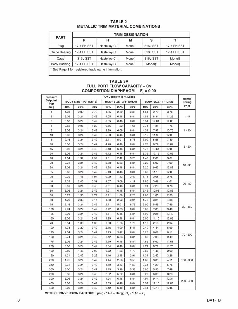
TABLE 3AFULL PORT FLOW CAPACITY – Cv
COMPOSITION DIAPHRAGM FL = 0.90
PressureSetpoint
Psp psig
Cv Capacity @ % DroopRange Springpsig
BODY SIZE - 1/2" (DN15) BODY SIZE - 3/4" (DN20) BODY SIZE - 1" (DN25)
10% 20% 30% 10% 20% 30% 10% 20% 30%
1 1.08 2.00 2.70 1.35 2.50 3.38 1.51 2.79 3.76
1 - 5 3 3.06 3.24 3.42 4.05 6.48 6.84 4.51 8.34 11.25
5 3.06 3.24 3.42 5.85 6.48 6.84 6.51 12.04 12.83
1 0.52 0.96 1.29 0.66 1.22 1.65 0.71 1.31 1.76
1 - 105 3.06 3.24 3.42 3.29 6.09 6.84 4.31 7.97 10.75
10 3.06 3.24 3.42 5.60 6.48 6.84 6.15 11.38 12.83
5 2.16 3.24 3.42 2.71 5.01 6.76 3.00 5.55 7.49
5 - 2010 3.06 3.24 3.42 4.28 6.48 6.84 4.75 8.79 11.87
15 3.06 3.24 3.42 5.18 6.48 6.84 5.75 10.64 12.83
20 3.06 3.24 3.42 6.12 6.48 6.84 8.35 12.15 12.83
10 1.04 1.92 2.59 1.31 2.42 3.26 1.45 2.68 3.61
10 - 3520 2.31 3.24 3.42 2.88 5.33 6.84 3.20 5.92 7.99
30 3.06 3.24 3.42 4.68 6.48 6.84 5.20 9.62 12.83
35 3.06 3.24 3.42 5.40 6.48 6.84 6.00 11.10 12.83
20 0.79 1.46 1.97 0.99 1.83 2.47 1.11 2.05 2.76
20 - 8040 1.33 2.46 3.32 1.67 3.09 4.17 1.85 3.42 4.61
60 2.81 3.24 3.42 3.51 6.48 6.84 3.91 7.23 9.76
80 3.06 3.24 3.42 4.91 6.48 6.84 5.45 10.08 12.83
30 0.72 1.33 1.79 0.91 1.68 2.26 1.00 1.85 2.50
30 - 150
50 1.26 2.33 3.14 1.58 2.92 3.94 1.75 3.24 4.38
75 2.16 3.24 3.42 2.71 5.01 6.76 3.00 5.55 7.49
100 2.74 3.24 3.42 3.42 6.33 6.84 3.80 7.03 9.49
125 3.06 3.24 3.42 4.51 6.48 6.84 5.00 9.25 12.49
150 3.06 3.24 3.42 4.95 6.48 6.84 6.00 11.10 12.83
70 0.54 1.00 1.35 0.68 1.26 1.70 1.18 2.18 2.94
70 - 200
100 1.73 3.20 3.42 2.16 4.00 5.41 2.40 4.44 5.99
125 2.34 3.24 3.42 2.93 5.42 6.84 3.25 6.01 8.11
150 2.74 3.24 3.42 3.42 6.33 6.84 3.80 7.03 9.49
175 3.06 3.24 3.42 4.19 6.48 6.84 4.65 8.60 11.61
200 3.06 3.24 3.42 5.04 6.48 6.84 4.71 8.71 11.75
100 0.80 1.48 2.00 0.72 1.33 1.79 0.80 1.48 2.00
100 - 300
150 1.31 2.42 3.26 1.16 2.15 2.91 1.31 2.42 3.26
200 1.75 3.24 3.42 1.44 2.66 3.58 1.65 3.05 4.11
250 2.31 3.24 3.42 1.80 3.33 4.50 2.31 4.27 5.76
300 3.00 3.24 3.42 2.15 3.98 5.38 3.00 5.55 7.49
200 2.35 3.24 3.42 2.82 5.22 6.84 3.29 6.09 8.23
200 - 450300 3.06 3.24 3.42 4.24 6.48 6.84 4.94 9.14 12.34
400 3.06 3.24 3.42 5.65 6.48 6.84 6.59 12.15 12.83
450 3.06 3.24 3.42 6.12 6.48 6.84 7.41 12.15 12.83
METRIC CONVERSION FACTORS: psig / 14.5 = Barg; Cv / 1.16 = kv
TABLE 2METALLIC TRIM MATERIAL COMBINATIONS
PARTTRIM DESIGNATION
P H M S T
Plug 17-4 PH SST Hastelloy-C Monel† 316L SST 17-4 PH SST
Guide Bearing 17-4 PH SST Hastelloy-C Monel† 316L SST 17-4 PH SST
Cage 316L SST Hastelloy-C Monel† 316L SST Monel†
Body Bushing 17-4 PH SST Hastelloy-C Monel† Monel† Monel†† See Page 3 for registered trade name information.
DA1-TB 7
PressureSetpoint
Psppsig
Cv Capacity @ % DroopRangeSpringpsig
BODY SIZE1-1/4" (DN32)
BODY SIZE1-1/2" (DN40)
10% 20% 30% 10% 20% 30%
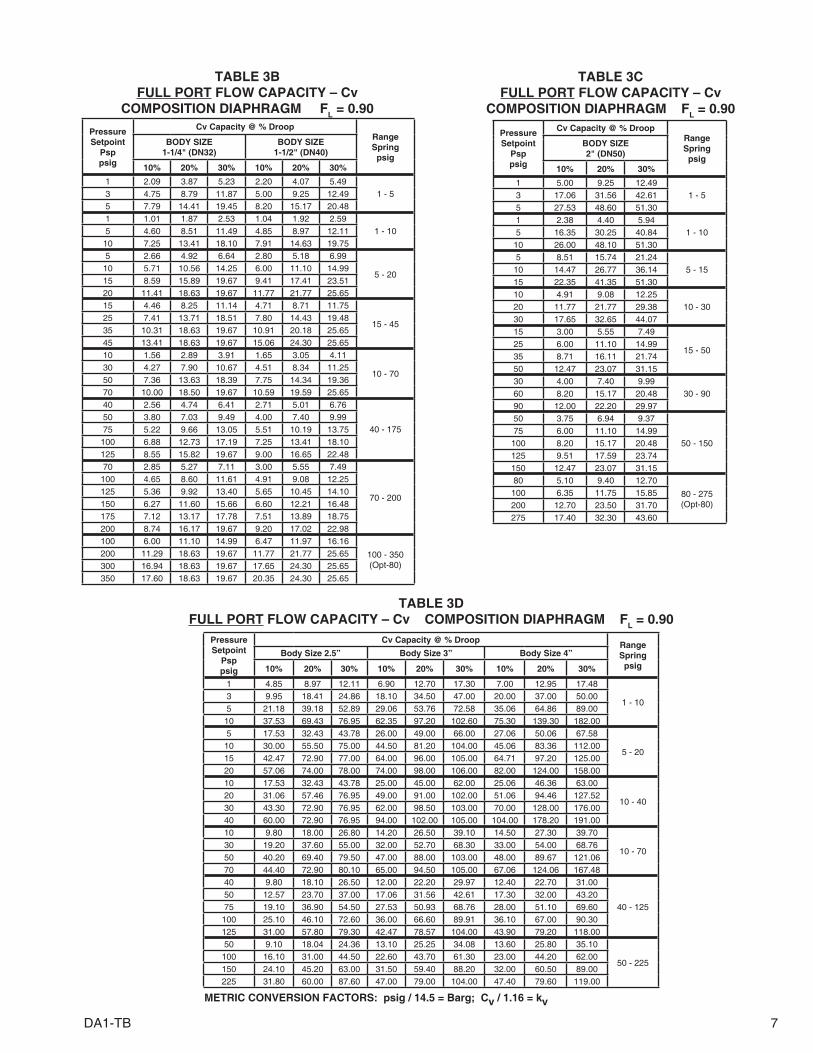
1 2.09 3.87 5.23 2.20 4.07 5.491 - 53 4.75 8.79 11.87 5.00 9.25 12.49
5 7.79 14.41 19.45 8.20 15.17 20.481 1.01 1.87 2.53 1.04 1.92 2.59
1 - 105 4.60 8.51 11.49 4.85 8.97 12.1110 7.25 13.41 18.10 7.91 14.63 19.755 2.66 4.92 6.64 2.80 5.18 6.99
5 - 2010 5.71 10.56 14.25 6.00 11.10 14.9915 8.59 15.89 19.67 9.41 17.41 23.5120 11.41 18.63 19.67 11.77 21.77 25.6515 4.46 8.25 11.14 4.71 8.71 11.75
15 - 4525 7.41 13.71 18.51 7.80 14.43 19.4835 10.31 18.63 19.67 10.91 20.18 25.6545 13.41 18.63 19.67 15.06 24.30 25.6510 1.56 2.89 3.91 1.65 3.05 4.11
10 - 7030 4.27 7.90 10.67 4.51 8.34 11.2550 7.36 13.63 18.39 7.75 14.34 19.3670 10.00 18.50 19.67 10.59 19.59 25.6540 2.56 4.74 6.41 2.71 5.01 6.76
40 - 17550 3.80 7.03 9.49 4.00 7.40 9.9975 5.22 9.66 13.05 5.51 10.19 13.75
100 6.88 12.73 17.19 7.25 13.41 18.10125 8.55 15.82 19.67 9.00 16.65 22.4870 2.85 5.27 7.11 3.00 5.55 7.49
70 - 200
100 4.65 8.60 11.61 4.91 9.08 12.25125 5.36 9.92 13.40 5.65 10.45 14.10150 6.27 11.60 15.66 6.60 12.21 16.48175 7.12 13.17 17.78 7.51 13.89 18.75200 8.74 16.17 19.67 9.20 17.02 22.98100 6.00 11.10 14.99 6.47 11.97 16.16
100 - 350(Opt-80)
200 11.29 18.63 19.67 11.77 21.77 25.65300 16.94 18.63 19.67 17.65 24.30 25.65350 17.60 18.63 19.67 20.35 24.30 25.65
TABLE 3DFULL PORT FLOW CAPACITY – Cv COMPOSITION DIAPHRAGM FL = 0.90
TABLE 3BFULL PORT FLOW CAPACITY – Cv
COMPOSITION DIAPHRAGM FL = 0.90
PressureSetpoint
Psppsig
Cv Capacity @ % DroopRangeSpringpsig
BODY SIZE2" (DN50)
10% 20% 30%
1 5.00 9.25 12.491 - 53 17.06 31.56 42.61
5 27.53 48.60 51.301 2.38 4.40 5.94
1 - 105 16.35 30.25 40.8410 26.00 48.10 51.305 8.51 15.74 21.24
5 - 1510 14.47 26.77 36.1415 22.35 41.35 51.3010 4.91 9.08 12.25
10 - 3020 11.77 21.77 29.3830 17.65 32.65 44.0715 3.00 5.55 7.49
15 - 5025 6.00 11.10 14.9935 8.71 16.11 21.7450 12.47 23.07 31.1530 4.00 7.40 9.99
30 - 9060 8.20 15.17 20.4890 12.00 22.20 29.9750 3.75 6.94 9.37
50 - 15075 6.00 11.10 14.99
100 8.20 15.17 20.48125 9.51 17.59 23.74150 12.47 23.07 31.1580 5.10 9.40 12.70
80 - 275(Opt-80)
100 6.35 11.75 15.85200 12.70 23.50 31.70275 17.40 32.30 43.60
TABLE 3CFULL PORT FLOW CAPACITY – Cv
COMPOSITION DIAPHRAGM FL = 0.90
METRIC CONVERSION FACTORS: psig / 14.5 = Barg; Cv / 1.16 = kv
Pressure Setpoint
Psppsig
Cv Capacity @ % DroopRange Springpsig
Body Size 2.5” Body Size 3” Body Size 4”
10% 20% 30% 10% 20% 30% 10% 20% 30%
1 4.85 8.97 12.11 6.90 12.70 17.30 7.00 12.95 17.48
1 - 103 9.95 18.41 24.86 18.10 34.50 47.00 20.00 37.00 50.005 21.18 39.18 52.89 29.06 53.76 72.58 35.06 64.86 89.00
10 37.53 69.43 76.95 62.35 97.20 102.60 75.30 139.30 182.005 17.53 32.43 43.78 26.00 49.00 66.00 27.06 50.06 67.58
5 - 2010 30.00 55.50 75.00 44.50 81.20 104.00 45.06 83.36 112.0015 42.47 72.90 77.00 64.00 96.00 105.00 64.71 97.20 125.0020 57.06 74.00 78.00 74.00 98.00 106.00 82.00 124.00 158.0010 17.53 32.43 43.78 25.00 45.00 62.00 25.06 46.36 63.00
10 - 4020 31.06 57.46 76.95 49.00 91.00 102.00 51.06 94.46 127.5230 43.30 72.90 76.95 62.00 98.50 103.00 70.00 128.00 176.0040 60.00 72.90 76.95 94.00 102.00 105.00 104.00 178.20 191.0010 9.80 18.00 26.80 14.20 26.50 39.10 14.50 27.30 39.70
10 - 7030 19.20 37.60 55.00 32.00 52.70 68.30 33.00 54.00 68.7650 40.20 69.40 79.50 47.00 88.00 103.00 48.00 89.67 121.0670 44.40 72.90 80.10 65.00 94.50 105.00 67.06 124.06 167.4840 9.80 18.10 26.50 12.00 22.20 29.97 12.40 22.70 31.00
40 - 12550 12.57 23.70 37.00 17.06 31.56 42.61 17.30 32.00 43.2075 19.10 36.90 54.50 27.53 50.93 68.76 28.00 51.10 69.60
100 25.10 46.10 72.60 36.00 66.60 89.91 36.10 67.00 90.30125 31.00 57.80 79.30 42.47 78.57 104.00 43.90 79.20 118.0050 9.10 18.04 24.36 13.10 25.25 34.08 13.60 25.80 35.10
50 - 225100 16.10 31.00 44.50 22.60 43.70 61.30 23.00 44.20 62.00150 24.10 45.20 63.00 31.50 59.40 88.20 32.00 60.50 89.00225 31.80 60.00 87.60 47.00 79.00 104.00 47.40 79.60 119.00
8 DA1-TB
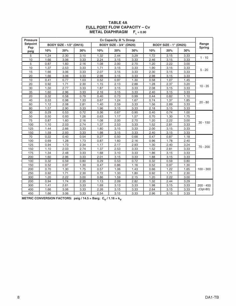
Pressure Setpoint
Psp psig
Cv Capacity @ % DroopRange Spring
BODY SIZE - 1/2" (DN15) BODY SIZE - 3/4" (DN20) BODY SIZE - 1" (DN25)
10% 20% 30% 10% 20% 30% 10% 20% 30%
5 1.24 2.30 3.10 1.32 2.44 3.29 1.72 3.15 3.331 - 10
10 1.66 3.06 3.33 2.24 3.15 3.33 2.46 3.15 3.335 0.87 1.60 2.16 1.08 2.00 2.70 1.20 2.22 3.00
5 - 2010 1.37 2.53 3.33 1.71 3.15 3.33 1.90 3.15 3.3315 1.66 3.06 3.33 2.07 3.15 3.33 2.30 3.15 3.3320 1.66 3.06 3.33 2.98 3.15 3.33 2.98 3.15 3.3310 0.41 0.77 1.03 0.52 0.97 1.30 0.58 1.07 1.45
10 - 3520 0.92 1.71 2.30 1.15 2.13 2.88 1.28 2.37 3.2030 1.50 2.77 3.33 1.87 3.15 3.33 2.08 3.15 3.3335 1.60 2.96 3.33 2.16 3.15 3.33 2.40 3.15 3.3320 0.32 0.58 0.79 0.40 0.73 0.99 0.44 0.82 1.10
20 - 8040 0.53 0.98 1.33 0.67 1.24 1.67 0.74 1.37 1.8560 1.12 2.08 2.81 1.40 2.59 3.33 1.56 2.89 3.3380 1.57 2.90 3.33 1.96 3.15 3.33 2.18 3.15 3.3330 0.29 0.53 0.72 0.36 0.67 0.90 0.40 0.74 1.00
30 - 150
50 0.50 0.93 1.26 0.63 1.17 1.57 0.70 1.30 1.7575 0.87 1.60 2.16 1.08 2.00 2.70 1.20 2.22 3.00
100 1.10 2.03 2.74 1.37 2.53 3.33 1.52 2.81 3.33125 1.44 2.66 3.33 1.80 3.15 3.33 2.00 3.15 3.33150 1.59 2.93 3.33 1.98 3.15 3.33 2.40 3.15 3.3370 0.22 0.40 0.54 0.27 0.50 0.68 0.47 0.87 1.18
70 - 200
100 0.69 1.28 1.73 0.87 1.60 2.16 0.96 1.78 2.40125 0.94 1.73 2.34 1.17 2.17 2.93 1.30 2.40 3.24150 1.10 2.03 2.74 1.37 2.53 3.33 1.52 2.81 3.33175 1.34 2.48 3.33 1.68 3.10 3.33 1.86 3.15 3.33200 1.60 2.96 3.33 2.01 3.15 3.33 1.88 3.15 3.33100 0.32 0.59 0.80 0.29 0.53 0.72 0.32 0.59 0.80
100 - 300150 0.52 0.97 1.30 0.47 0.86 1.16 0.52 0.97 1.30200 0.70 1.30 1.75 0.57 1.06 1.43 0.66 1.22 1.65250 0.92 1.71 2.30 0.72 1.33 1.80 0.92 1.71 2.30300 1.20 2.22 3.00 0.86 1.59 2.15 1.20 2.22 3.00200 0.94 1.74 2.35 1.13 2.09 2.82 1.32 2.44 3.29
200 - 450(Opt-80)
300 1.41 2.61 3.33 1.69 3.13 3.33 1.98 3.15 3.33400 1.66 3.06 3.33 2.26 3.15 3.33 2.64 3.15 3.33450 1.66 3.06 3.33 2.54 3.15 3.33 2.96 3.15 3.33
METRIC CONVERSION FACTORS: psig / 14.5 = Barg; Cv / 1.16 = kv
TABLE 4AFULL PORT FLOW CAPACITY – Cv
METAL DIAPHRAGM FL = 0.90

DA1-TB 9
DiaphragmMaterial
Standard Diaphragm Construction psig (Barg) *
Body Sizein (DN)
1/2" – 2" (15–50) 2-1/2" – 4" (65–100)
BC, EPR 1250 (86.1) 800 (55.1)
NBR 450 (31.0) 300 (20.6)
FKM, FKM+TFE, FK 700 (48.2) 550 (37.9)
3-ply (PTFE+FKM+PTFE) ** 125 (8.6) 125 (8.6)
Metal (Be-Cu) 1500 (103) N/A
* Maximum setting of pressure safety device – safety relief valve or rupture disc.** For Steam applications.NA = Not Available
TABLE 5 MAXIMUM DIAPHRAGM RATING
Pressure Setpoint
Psp psig
Cv Capacity @ % Droop RangeSpringpsig
BODY SIZE 2" (DN50)
10% 20% 30%5 6.54 10.80 11.40
1 - 1010 10.20 10.80 11.405 3.40 6.29 8.50
5 - 1510 5.79 10.71 11.4015 8.94 10.80 11.4010 1.96 3.63 4.90
10 - 3020 4.71 8.71 11.4030 7.06 10.80 11.4015 1.20 2.22 3.00
15 - 5025 2.40 4.44 5.9935 3.48 6.44 8.7050 4.99 9.23 11.4030 1.60 2.96 4.00
30 - 9060 3.28 6.07 8.1990 4.80 8.88 11.4050 1.50 2.78 3.75
50 - 15075 2.40 4.44 5.99
100 3.28 6.07 8.19125 3.80 7.03 9.50150 4.99 9.23 11.4080 2.10 3.80 5.00
80 - 275(Opt-80)
100 2.60 4.75 6.25200 5.25 9.50 11.40275 7.20 11.30 11.40
TABLE 4BFULL PORT FLOW CAPACITY – Cv
METAL DIAPHRAGM FL = 0.90
TABLE 4CFULL PORT FLOW CAPACITY – Cv
METAL DIAPHRAGM FL = 0.90
METRIC CONVERSION FACTORS: psig / 14.5 = Barg; Cv / 1.16 = kv
Pressure Setpoint
Psp psig
Cv Capacity @ % Droop RangeSpringpsig
BODY SIZE 1-1/4" (DN32)
BODY SIZE 1-1/2" (DN40)
10% 20% 30% 10% 20% 30%5 1.84 3.40 4.60 1.94 3.59 4.84
1 - 1010 2.90 5.36 5.70 3.16 5.40 5.705 1.06 1.97 2.66 1.12 2.07 2.80
5-2010 2.28 4.22 5.70 2.40 4.44 5.7015 3.44 5.40 5.70 3.76 5.40 5.7020 4.56 5.40 5.70 4.71 5.40 5.7015 1.78 3.30 4.45 1.88 3.48 4.70
15 - 4525 2.96 5.40 5.70 3.12 5.40 5.7035 4.12 5.40 5.70 4.36 5.40 5.7045 5.10 5.40 5.70 5.10 5.40 5.7010 0.63 1.16 1.56 0.66 1.22 1.65
10 - 7030 1.71 3.16 4.27 1.80 3.33 4.5050 2.95 5.40 5.70 3.10 5.40 5.7070 4.00 5.40 5.70 4.24 5.40 5.7040 1.03 1.90 2.56 1.08 2.00 2.70
40 - 17550 1.52 2.81 3.80 1.60 2.96 4.0075 2.09 3.87 5.22 2.20 4.07 5.50
100 2.75 5.09 5.70 2.90 5.36 5.70125 3.42 5.40 5.70 3.60 5.40 5.7070 1.14 2.11 2.84 1.20 2.22 3.00
70 - 200
100 1.86 3.44 4.64 1.96 3.63 4.90125 2.15 3.97 5.36 2.26 4.18 5.64150 2.51 4.64 5.70 2.64 4.88 5.70175 2.85 5.27 5.70 3.00 5.40 5.70200 3.50 5.40 5.70 3.68 5.40 5.70100 2.40 4.44 5.70 2.59 4.79 5.70
100 - 350(Opt-80)
200 4.52 5.40 5.70 4.71 5.40 5.70300 5.10 5.40 5.70 5.10 5.40 5.70350 5.10 5.40 5.70 5.10 5.40 5.70
NOTE: The below ratings may be further "derated" by limitations through the Pressure Equipment Directive (2014/68/EU).

10 DA1-TB
Material Specifi cations(Body / Topworks)
End Connection – Inlet & Outlet
Temperature °F
Working Pressure – psig
Description(Abbr.)
ASTMNo.
End Connection – Pressure Class
NPT 125# FF 250# RF
DI/DI(Note 1)
A395/A395
-20° to +150° 400 200 500
200° 370 190 460
225° 355 180 440
250° 340 175 415
300° 310 165 375
350° 300 150 335
400° 250 140 290
406° 250 140 290
400 WOG, 250 S 225 WOG, 125 S 400 WOG, 250 S
Temperature °C
Working Pressure – Barg
End Connection – Pressure Class
NPT 125# FF 250# RF
-29° to +65° 27.6 13.8 34 .5
107 24.5 12.5 30.2
120° 23.4 12.1 28.7
150° 21.2 11.2 25.7
177° 19.2 10.6 23.8
204° 17.5 9.6 20.3
TABLE DAG-1ADI – DUCTILE IRON
BODY / TOPWORKS MATERIAL SPECIFICATIONSDESIGN PRESSURE vs. TEMPERATURE vs. END CONNECTION RATINGS(To ASME B16.1 for Flanged and B16.4 for NPT Connections per Cast Iron Rating)
NOTE 1: Whenever body and topworks materials are mixed, the P vs. T ratings that should be applied are those which are lowest of the two materials.Example: CS body, DI topworks; NPT end connections, 200°F temperature. Because the topworks is not “end flanged”, use the DI limits of "400 PSIG CWP 370/200F" from above to com-
pare to CS limits from DAG-1C values. The DI limits are lower, so ratings from DAG-1A MUST be used as the limits.
NOTE 2: Unless stated otherwise, design pressure is Maximum Allowable Working Pressure (MAWP) for Inlet and Outlet.
TABLE TITLE PAGE DAG-1A ......... DI – Press vs Temp vs End Conn Ratings ......................................10 DAG-1B ..........BRZ – Press vs Temp vs End Conn Ratings ..................................11 DAG-1C ..........CS – Press vs Temp vs End Conn Ratings - Design Inlet .............12 DAG-1D ................Design Outlet - DA1 ................................................................12 DAG-1E..........SST – Press vs Temp vs End Conn Ratings – Design Inlet ............13 DAG-1F..................Design Outlet - DA1.................................................................13 DAG-1G..........HC – Press vs Temp vs End Conn Ratings – Design Inlet .............14 DAG-1H.................. Design Outlet - DA1................................................................14 DAG-2 .....................Max Pressure Drop - Comp Seat ............................................15 DAG-3 .....................Max Pressure Drop - Dynamic Seal Design ............................15 DAG-4 .....................Max Pressure Drop - Basic Trim Mat'ls ...................................15 DAG-5 .....................Temperature Limits – Elastomer Mat'ls. ..................................16 DAG-6 .....................Reducer Max Capacity - Plug Wide Open...............................17 DAG-9 .....................Reducer Lower Piston Spring range .......................................17 DAG-10 ...................Inboard Leakage Ratings ........................................................18 DAG-11 ...................Reducer Recommended Velocity Limits .................................18 DAG-13 ...................Max Recommended Noise Limits............................................18 DAG-14 ...................Recommended Internal Materials - Liquids .............................19 DAG-14 ...................Recommended Internal Materials - Gases ..............................19 DAG-14 ...................Supplement - Chemical Resistance ........................................20 DAG-15 ...................ISR Effect ................................................................................20 FIGURE DAG-F1 ...................Dynamic/Static Seals ..............................................................21 DAG-F2 ...................Location of Body/Spring Chamber Taps .................................22
DAG TECHNICAL APPENDIX INDEX

DA1-TB 11
Material Specifi cations(Body / Topworks)
End Connection – Inlet & Outlet (Note 2)
Description (Abbr.) ASTM No. Temperature °F
Working Pressure –psig
End Connection – Pressure Class
NPT 150# FF 300# FF
BRZ/BRZ(Note 1)
B62,Alloy C83600/B62,
Alloy C83600
-325° to +150° * 700 † / 500 225 500
175° 390 220 480
200° 385 210 465
225° 375 205 445
250° 365 195 425
300° 335 180 390
350° 300 165 350
400° 250 150 315
406° 250 150 315
Temperature °C
Working Pressure – Barg
End Connection – Pressure Class
NPT 150# FF 300# FF
-198° to +65° * 48.3 † / 34.5 15.5 34.5
107° 25.8 14.0 30.8
120° 25.1 13.5 29.5
150° 23.0 12.4 26.8
177° 20.4 11.3 24.0
204° 17.8 10.3 21.4
TABLE DAG-1BBRZ – BRONZE
BODY / TOPWORKS MATERIAL SPECIFICATIONS
DESIGN PRESSURE vs. TEMPERATURE vs. END CONNECTION RATINGS(Per ASME B16.24 for Flanged and B16.15 for NPT Connections)
NOTE 1: Whenever body and topworks materials are mixed, the P vs. T ratings that should be applied are those which are lowest of the two materials.
Example: BRZ body, DI topworks; NPT end connections, ambient temperature. Because the topworks is not “end flanged”, use the DI limits of "400 PSIG CWP 370/200F" from DAG-1A to
compare to above DAG-1B values. The DI limits are lower, so ratings from DAG-1A MUST be used as the limits.
NOTE 2: Unless stated otherwise, design pressure is Maximum Allowable Working Pressure (MAWP) for Inlet and Outlet.
† For Pressure Reducing Regulator DA1 use 700 psig (48.2 Barg) inlet / 500 psig (34.4 Barg) outlet at 150°F as maximum limits.
* See Minimum Temperature Ratings Table below.
Regulator FunctionMaterial Specifi cations
(Body / Topworks - Connections)Description (Abbr.)
Pressure at Min. Temperature
Pressure Reducing
BRZ/BRZ - NPTInlet - 700 psig CWP to -325°F (-198°C)
Outlet - 500 psig CWP to -325°F (-198°C)
SST/SST - NPT, BSP, Ext. Nipples,Tube Ends and 600# Flgs
Inlet - 1440 psig CWP to -425°F (-254°C)
Outlet - 625 psig CWP to -425°F (-254°C)
DESIGN PRESSURE RATINGAT MIN. TEMPERATURE

12 DA1-TB
TABLE DAG-1DDESIGN OUTLET PRESSURE FOR DA1
in PSIG (BARG)
CONSTRUCTIONEND CONNECTIONS
DESIGN TEMP. RANGE: Deg F
(Deg C) **
NPT, BSP, 600#,EXTD NIPP
150# 300#
-20 to +100(-29 to +38)
750(51.7)
285(19.6)
740(51.1)
-20 to +200(-29 to +93)
680(47.1)
260(17.9)
680(47.1)
-20 to +300(-29 to +149)
655(45.1)
230(15.8)
655(45.1)
-20 to +400(-29 to +204)
635(43.6)
200(13.7)
635(43.8)
** Alternate Mat'l: ASTM 352 Gr. LCC Minimum Temperature -50 °F (-46 °C).
TABLE DAG-1CDESIGN INLET PRESSURE FOR DA1
in PSIG (BARG)
CONSTRUCTIONEND CONNECTIONS
DESIGN TEMP. RANGE: Deg F
(Deg C) **NPT, BSP
600#,EXTD NIPP
150# 300#
-20 to +100(-29 to +38)
1480(102.1)
1480(102.1)
285(19.6)
740(51.1)
-20 to +200(-29 to +93)
1360(94.2)
1360(94.2)
260(17.9)
680(47.1)
-20 to +300(-29 to +149)
1310(90.3)
1310(90.3)
230(15.8)
655(45.1)
-20 to +400(-29 to +204)
1265(87.3)
1265(87.3)
200(13.7)
635(43.6)
** Alternate Mat'l: ASTM 352 Gr. LCC Minimum Temperature -50 °F (-46 °C).
Body Material Specifications Cast Steel A216 Gr.WCB or Steel Weldment A216 Gr. WCB w/ forged flanges A105
Alternate Material: Cast Steel A352 Gr. LCC or Steel Weldment A352 Gr. LCC w/ forged flanges A350 Gr. LF6 Class 2Topworks Material Specifications
Cast Steel A216 Gr. WCB. (For Option-80 Sizes 1/2"-1-1/2" Steel Weldment A516 Gr. 55 & A106; Size 2" ASTM A216, Gr. WCB)
Alternate Material: Cast Steel A352 Gr. LCCDESIGN PRESSURE vs. TEMPERATURE vs. END CONNECTION RATINGS
(Per ASME B16.5 and B16.34) See NOTE 1
NOTE 1: These pressure ratings may be further derated by limitations through the Pressure Equipment Directive (2014/68/EU).Whenever body and topworks are mixed, the P vs. T ratings that should be applied are those which are lowest for the two materials.
Example: 600 lb. RF flanged steel body at 200 deg F maximum temp would have a preliminary inlet to 1360 psig and outlet to 680 psig, but if fitted with a ductile iron topworks pressure rating is only 370 psig. Must derate both the inlet and outlet to 370 psig. (Note: Topworks pressure rating, same as NPT design outlet pressure rating for the selected topworks material and diaphragm type.

DA1-TB 13
TABLE DAG-1EDESIGN INLET PRESSURE FOR DA1
in PSIG (BARG) CONSTRUCTION
*END CONNECTIONS
DESIGN TEMP. RANGE: Deg F
(Deg C) **NPT, BSP
600#, EXTD NIPP, TUBE
150# 300#
-425 to +100(-254 to +38)
1440(99.3)
1440(99.3)
275(19.0)
720(49.6)
-20 to +200(-29 to +93)
1240(86.1)
1240(86.1)
235(16.5)
620(43.0)
-20 to +300(-29 to +149)
1120(77.1)
1120(77.1)
215(14.8)
560(38.6)
-20 to +400(-29 to +204)
1025(70.9)
1025(70.9)
195(13.6)
515(35.5)
** Alternate Mat'l: ASTM 995 / 995M Gr. 6A Super Duplex SST Minimum Temperature -60 ˚F (-51 ˚C).
Body Material SpecificationsCast Stainless Steel A351 Gr.CF3M or Stainless Steel Weldment A315 Gr. CF3M w/ forged flanges A182 Gr. F 316L
Alternate Material: Super Duplex SST A995/A995M Gr. 6ATopworks Material SpecificationsCast Stainless Steel A351 Gr.CF3M.
(For Option-80 Sizes 1/2"-1-1/2" Stainless Steel Weldment A312 Gr. 316/316L, A479 Gr. 316/316L, Size 2" is ASTM A351 Gr. CF3M)Alternate Material: Super Duplex SST A995/A995M Gr. 6A
DESIGN PRESSURE vs. TEMPERATURE vs END CONNECTION RATINGS(Per ASME B16.5 and B16.34) See NOTE 1
TABLE DAG-1FDESIGN OUTLET PRESSURE FOR DA1
in PSIG (BARG) CONSTRUCTION
*END CONNECTIONS
DESIGN TEMP. RANGE: Deg F
(Deg C) **
NPT, BSP, 600#, EXTD NIPP, TUBE
150# 300#
-425 to +100(-254 to +38)
625(43.0)
275(19.0)
625(43.0)
-20 to +200(-29 to +93)
620(42.3)
235(16.5)
620(42.3)
-20 to +300(-29 to +149)
560(38.6)
215(14.8)
560(38.6)
-20 to +400(-29 to +204)
515(35.5)
195(13.6)
515(35.5)
** Alternate Mat'l: ASTM 995 / 995M Gr. 6A Super Duplex SST Minimum Temperature -60 ˚F (-51 ˚C).
NOTE 1: These pressure ratings may be further derated by limitations through the Pressure Equipment Directive (2014/68/EU).Whenever body and topworks are mixed, the P vs. T ratings that should be applied are those which are lowest for the two materials. Example: 300 lb. RF flanged SST body at 200 deg F maximum temp would have a preliminary inlet and outlet to 620 psig, but if fitted with a ductile iron topworks pressure rating is only 400 psig. Must derate both the inlet and outlet to 400 psig. (Note: Topworks pressure rating, same as NPT design outlet pressure rating for the selected topworks material and diaphragm type.The ratings are the same as above, if substitute steel topwork material.Maximum Design Pressure Rating for 2" Opt -41 limited by 0.065" wall thickness to 1200 psig.300# Flanges are derated due to the bolting for these products.
* For Temperatures below -20oF - refer to page 11 for Design Pressure Rating at Min. Temperature.

14 DA1-TB
TABLE DAG-1HDESIGN OUTLET PRESSURE FOR DA1
in PSIG (BARG)
CONSTRUCTIONEND CONNECTIONS
DESIGN TEMP. RANGE: Deg F
(Deg C)NPT, BSP 150# 300#
-325 to +100(-198 to +38)
625(43.0)
230(15.9)
600(41.4)
-20 to +200(-29 to +93)
550(38.2)
210(14.7)
550(38.2)
-20 to +300(-29 to +149)
520(35.9)
200(13.7)
520(35.9)
-20 to +400(-29 to +204)
490(33.8)
190(12.9)
490(33.8)
TABLE DAG-1GDESIGN INLET PRESSURE FOR DA1
in PSIG (BARG)
CONSTRUCTIONEND CONNECTIONS
DESIGN TEMP. RANGE: Deg F
(Deg C)NPT, BSP 150# 300#
-325 to +100(-198 to +38)
1200(82.7)
230(15.9)
600(41.4)
-20 to +200(-29 to +93)
1105(76.4)
210(14.7)
550(38.2)
-29 to +300(-29 to +149)
1040(71.8)
200(13.7)
520(35.9)
-20 to +400(-29 to +204)
980(67.6)
190(12.9)
490(33.8)
Body Material SpecificationsCast Hastelloy A494 Gr.CW-12MW or Hastelloy Weldment A494 Gr. CW-12MW w/ forged flanges B462 Gr. N10276
Topworks Material SpecificationsCast Steel A216 Gr. WCB. (For Option-80 Steel Weldment A516 Gr. 55 & A106)
DESIGN PRESSURE vs. TEMPERATURE vs END CONNECTION RATINGS(Per ASME B16.5 and B16.34) See NOTE 1
NOTE 1: These pressure ratings may be further derated by limitations through the Pressure Equipment Directive (2014/68/EU).

DA1-TB 15
TABLE DAG-2MAXIMUM PRESSURE DROP FOR
COMPOSITION SEATS
Body SizeMax. Pressure Drop - psid (Bard)
Seat Material
in (DN)BC, NBR, POLYALL *, FKM GF-TFE
Liquid * Gas Steam Liquid * Gas Steam √
1/2" – 1" (15-25) 600 (41.3) 750 (51.7) DNA 450 (31.0) 1000 (68.9) 150/125 (10.3/8.6)
1-1/4" – 1-1/2"
(32-40) 600 (41.3) 600 (41.3) DNA 450 (31.0) 900 (62.0) 150/125 (10.3/8.6)
2" (50) 600 (41.3) 600 (41.3) DNA 450 (31.0) 750 (51.7) 150/125 (10.3/8.6)
2-1/2" – 4" (65-100) 500 (34.4) 600 (41.3) DNA 450 (31.0) 750 (51.7) 125 (8.6)
V-TFE CTFE
1/2" – 1" (15-25) 300 (20.7) 600 (41.3) 125 (8.6) 600 (41.3) 3000 (206.9) DNA
1-1/4" – 1-1/2"
(32-40) 300 (20.7) 600 (41.3) 125 (8.6) 600 (41.3) 3000 (206.9) DNA
2" (50) 300 (20.7) 600 (41.3) 125 (8.6) 600 (41.3) 2000 (137.9) DNA
2-1/2" – 4" (65-100) 300 (20.7) 450 (31.0) 125 (8.6) 500 (34.4) 1500 (103.4) DNA
* Only seat material to be applied in liquid “partially cavitating” service is PolyAll.√ Steam Service: metal diaphragm/composition diaphragm.N/A = Not AvailableDNA = Do Not Apply
Body SizeMax. Pressure Drop - psid (Bard)
Dynamic Seal Design
in (DN)"OR" – O-RING * "CP" – TFE CAP "CW" – TFE CAP w/WIPER
Liquid * Gas * Steam Liquid Gas Steam Liquid Gas Steam
1/2" – 1"
(15-25)
600 (41.3) 750 (51.7) DNA 600 (41.3) 600 (41.3) DNA 450 (31.0) 600 (41.3) DNA
1-1/4" –
1-1/2"
(32-40)
600 (41.3) 750 (51.7) DNA 600 (41.3) 600 (41.3) DNA 450 (31.0) 600 (41.3) DNA
2" (50) 600 (41.3) 750 (51.7) DNA 600 (41.3) 600 (41.3) DNA 450 (31.0) 600 (41.3) DNA
2-1/2" – 4"
(65-100)
600 (41.3) 750 (51.7) DNA 600 (41.3) 600 (41.3) DNA 450 (31.0) 600 (41.3) DNA
"PR" – PISTON RING ASSY."PW" – PISTON RING ASSY.
w/WIPER"UC" – U-CUP
1/2" – 1"
(15-25)
DNA DNA√
150/125(10.3/8.6) DNA DNA
√ 150/125
(10.3/8.6) 600 (41.3) 3000 (206.9) DNA
1-1/4" –
1-1/2"
(32-40)
DNA DNA√
150/125(10.3/8.6) DNA DNA
√ 150/125
(10.3/8.6) 600 (41.3) 3000 (206.9) DNA
2" (50) DNA DNA√
150/125(10.3/8.6) DNA DNA
√ 150/125
(10.3/8.6) 600 (41.3) 3000 (206.9) DNA
2-1/2" – 4"
(65-100)
DNA DNA 125 (8.6) DNA DNA 125 (8.6) 600 (41.3) 3000 (206.9) DNA
* Only seat material to be applied in liquid “partially cavitating” or “flashing” service is PolyAll.√ Steam Service: metal diaphragm/composition diaphragm.N/A = Not Available DNA = Do Not Apply wo/ = without w/ = with
TABLE DAG-3MAXIMUM PRESSURE DROP FOR
DYNAMIC SEAL DESIGNS
Body Size Max Pressure Drop - psid (Bard)
Basic Trim Materialin (DN) "P" – 17-4PH SST "S" – 316L SST "M" – Monel "T" – Hybrid *
1/2" – 2" (15-50) 3000 (206.9) 800 (55.1) 1500 (103.4) 3000 (206.9)
2-1/2" – 4" (65-100) 3000 (206.9) 800 (55.1) 1500 (103.4) 3000 (206.9)
* 17-4PH SST plug & piston, Monel cage.
TABLE DAG-4MAXIMUM PRESSURE DROP FOR
BASIC TRIM MATERIAL

16 DA1-TB
Elastomer T Maximum T MinimumS
eats
ID Description °F (°C) °F (°C)PolyAll Proprietary Polyurethane Derivative 225° (107°) -60° (-51°)
GF-TFE Glass-filled Polytetrafluorethylene 425° (218°) -325° (-198°)
V-TFE Virgin TFE 400° (205°) -325° (-198°)
CTFE Chlorotrifluoroethylene TFE 300° (148°) -325° (-198°)
BC Neoprene 225° (107°) -35° (-37°)
NBR Buna-N 320° (160°) -40° (-40°)
FKM Fluorocarbon Elastomer 400° (205°) 0° (-17°)
Di a
ph
rag
ms
3-Ply 3-Ply TFE/FKM/TFE 400° (205°) 0° (-17°)
BC Neoprene (Polychloroprene) 250° (121°) -65° (-53°)
EPR Ethylene Propylene 300° (148°) -40° (-40°)
FK Fluorosilicone 350° (177°) -65° (-54°)
FKM Fluorocarbon Elastomer 400° (205°) 0° (-17°)
NBR Buna-N (Nitrile) 250° (121°) -70° (-56°)
FKM+TFE Fluorocarbon Elastomer + TFE 400° (205°) 0° (-17°)
Sta
tic
Sea
ls
RTFE Bronze-filled TFE 425° (218°) 70° (21°)
V-TFE Virgin TFE 400° (205°) -325° (-198°)
EPR Ethylene Propylene 300° (148°) -40° (-40°)
FK Fluorosilicone 350° (177°) -65° (-54°)
FKM Fluorocarbon Elastomer 400° (205°) -20° (-28°)
NBR Buna-N 212° (100°) -40° (-40°)
SST/TFE 301/302 SST U-cup / TFE 400° (205°) -325° (-198°)
HC/TFE Hastelloy C U-cup / TFE 400° (205°) -325° (-198°)
Dyn
amic
Sea
ls
"PR" Piston Ring Assy, GF-TFE / SST 425° (218°) -40° (-40°)
"PW" PRA* w/Wiper, GF-TFE / SST / GF-TFE 425° (218°) 70° (21°)
"CW" – EPR/TFE TFE Cap Seal, EPR O-ring, GF-TFE Wiper 300° (148°) -40° (-40°)
"CW" – NBR/TFE TFE Cap Seal, NBR O-ring, GF-TFE Wiper 212° (100°) -40° (-40°)
"CW" – FK/TFE TFE Cap Seal, FK O-ring, GF-TFE Wiper 350° (177°) -40° (-40°)
"CW" – FKM/TFE TFE Cap Seal, FKM O-ring, GF-TFE Wiper 400° (205°) -20° (-28°)
"CP" – EPR/TFE TFE Cap Seal, EPR O-ring 300° (148°) -40° (-40°)
"CP" – NBR/TFE TFE Cap Seal, NBR O-ring 212° (100°) -40° (-40°)
"CP" – FK/TFE TFE Cap Seal, FK O-ring 350° (177°) -10° (-23°)
"CP" – FKM/TFE TFE Cap Seal, FKM O-ring 400° (205°) -20° (-28°)
SST/TFE 301/302 SST U-cup / TFE 400° (205°) -325° (-198°)
HC/TFE Hastelloy C U-cup / TFE 400° (205°) -325° (-198°)
ELG/TFE Elgiloy / TFE U-cup 400° (205°) -325° (-198°)
* PRA - Piston Ring Assembly
TABLE DAG-5TEMPERATURE LIMITS
FOR ELASTOMERIC MATERIALS
ABBREVIATIONS
FK = Fluorosilicone NBR = Buna-N PTFE = Polytetrafluoroethylene PRA = GF-TFE/SST
FKM = Fluorocarbon Elastomer RTFE = Brz-fill TFE V-TFE = Virgin TFE BC = Neoprene
EPR = Ethylene Propylene GF-TFE = Glass-fill TFE CTFE = Chlorotrifluoroethylene TFE ELG = Elgiloy
Metal Diaphragm T Maximum T MinimumID Description °F (°C) °F (°C)
BE-CU Beryllium Copper 400° (205°) -325° (-198°)

DA1-TB 17
Body Size Full PortMax Capacity
Full PortMax Capacity
in (DN) Cv Kv Cv Kv
1/2" (15) 4.0 3.4 3.5 3.0
3/4" (20) 8.0 6.9 3.5 3.0
1" (25) 15 13 3.5 3.0
1-1/4" (32) 23 20 6.0 5.2
1-1/2" (40) 30 26 6.0 5.2
2" (50) 60 52 12 10.4
2-1/2" (65) 90 78
3" (80) 120 104
4" (100) 220 190
Diaphragm Composition Metal
NOTE: The above Cv factors may be used for sizing of safety relief valves or rupture discs.
TABLE DAG-6REDUCER MAXIMUM CAPACITY WITH PLUG WIDE-OPEN
TABLE DAG-9REDUCER – LOWER PISTON SPRING RANGES
NOTES: 1. All metallic diaphragm constructions MUST include a lower piston spring. 2. The 1–2 psig lower piston spring should only be used with low pressure setpoints. (Psp ≤ 10 psig) and with composition diaphragms. 3. Lower spring material matches main metallic trim in corrosion resistance.
Basic Unit Lower PistonSpring Range
psig
ApplicationNotesModel Diaphragm
DA1 Comp 1-21-5 and 1-10 range
spring only
DA1 Metal 4–10 –

18 DA1-TB
TABLE DAG-10INBOARD LEAKAGE RATINGS *
Per ANSI/FCI 70-2
Seat Material
Dynamic Seal
O-RingDynamic Seals Except
O-Ring
CTFE, GF-TFE, and V-TFE
IV IV
BC, NBR, PolyAll, FKM VI IV
*Inboard leak rates are the composite leakage of the seat leakage + dynamic seal leakage, considered as a single inboard leakage value.
ApplicationFluid
Valve Valve BodyOutlet Downstream Pipe
UnitsType
SizeRange
Recommend Max. Recommend Max.
LiquidPRV
1/2"–4" 15 20 5-8 16
Ft/Sec6" 15 25 7–12 20
8"–12" – – 9–14 24
GasPRV
1/2"–1"1-1/4"–2"
0.200.25
0.400.45
0.150.20
0.300.30
Mach #2-1/2"–6" 0.30 0.50 0.25 0.35
8"–12" – – 0.25 0.40
SteamPRV
1/2"–1"1-1/4"–2"2-1/2"–6"
0.200.220.25
0.300.320.35
0.100.120.20 0.30 Mach #
8"–12" – – 0.22
NOTES: 1. Liquids experiencing no 2-phase flow at valve outlet will have same valve body outlet velocity as inlet velocity. 2. Liquids experiencing 2-phase flow at valve outlet should have average velocity less than 150-200 ft/sec. 3. Liquids experiencing 2-phase flow at outlet pipe should have average velocity less than 20-50 ft/sec. 4. If valve outlet exceeds recommended limits, then can use external sensing to reach maximum limits. 5. On gas service, a pilot operated prv can work with a outlet Mach = 0.75.
TABLE DAG-11REDUCER RECOMMENDED VELOCITY LIMITS
CriteriaBody Sizes
Noise Level - dBAin (DN)
Per OSHA Regs. w/noiseattenuation methodsincorporated.
All All 85-95
Sch. 80 pipe, no insulation. 1/2"–2" (15-50) 95
Std. wt. pipe, no insulation. 2-1/2"–4" (65-100) 98
* Consult Factory for ALL applications exceeding 97 dBA noise prediction.
TABLE DAG 13MAXIMUM RECOMMENDED NOISE LIMITS *
Schemes To Reduce High Noise –• Staging – using two separate throttling valves in series.• dB Plates – using 1, 2 or 3-stage dB Plate car tridg es
downstream of a throttling valve.• Paralleling – using two separate throttling valves in
parallel.• Combinations – using multiple methods of above three
possibilities.

DA1-TB 19
LIQUIDS
LIQ
UID
S
LIQ
UID
S
L
IQU
IDS
FluidTmax
°FTmin
°FMetalTrim
Industrial Water –Cold
180° 32° P1
Hot 225° 32° P4
DI, DM225° 32° PJ
250° 32° PL
Seawater 180° -20° MQ , MW
Fuel Oils –Diesel, #1,#2‡
180° -30° P5
Bunker C,#3 - #6‡
180° -30° P5
400° 0° PC
Jet Fuel JP3, JP4, JP5, JP6‡ 400° 0° PC
Kerosene‡ 400° 0° PC
Crude Oils –Sweet‡
225° 0° PA
400° 0° PC
Sour‡ 225° 0° NS
Heat Transfer Oils –Dowtherm, Therminol,
Mobil-Therm, Silvatherm400° 0° PC
Misc. Oils –Lube Oil‡
180° -30° P5
Naptha‡ 400° 0° PC
Turbine Oil‡ 225° 0° PA
Edible Oils –Vegetable Oil‡
180° -30° PH
Animal Fats‡ 180° -30° PH
Seed Oils‡ 180° -30° PH
Inorganic Acids –Acetic - 5%
100° 0° SL
Acetic - 30% 100° 0° SL
Sulfuric - conc. 100° 0° CF *
Sulfuric - dilute 100° 0° CF *
Nitric - conc. 140° 0° SL
Nitric - dilute 140° 0° SL
Hydrofluoric(air free) -
dilute, concentrate100° 0° CF *
Hydrobromic 140° 0° CF *
Phosphoric - dilute, concentrate
150° 0° SL
Misc. Liquids –Gasoline‡
150° -30° P5
Benzene (C6H6)‡ 150° 0° SL
Chlorine (Cl2) 150° 0° ML
Bromine (Br2) 150° 0° CF *
Ammonia (NH3) 140° 0° SL
Hydrogen Peroxide (H2O2) 125° 0° SL
Hydrogen Chloride (HCl) 125° 0° ML
Hydrogen Bromide (HBr) 125° 0° SL
Cane Sugar Liquor 180° 0° PH
‡ In accordance with ASME B31.3 "Process Piping", do not use Ductile Iron Body for hydrocarbon or flammable service with inlet pressures greater than 150 psig (10.3 Barg) or temperatures greater than 300 deg F (149 deg C).* CF = Consult Factory
TABLE DAG-14RECOMMENDED INTERNAL MATERIALS
For Pmax, Reference Individual Technical Bulletins
GASES
Atm
osp
her
ic G
ases
FluidTmax
°FTmin
°FTrim
Atmospheric Gases – O2 (GOX)
225° -60° M7
350° -65° M9
350° -325° TN
N2 (GN2),Air, Argon
180° -60° P2
350° -65° P8
CO2 (dry) 180° -40° P6
CO2 (wet) 180° -40° P5
Pro
cess
Gas
es
Process Gases –Nat. Gas (Sweet)
180° -65° P9
Nat. Gas (Sour) 180° -40° NR
LPG (propane) 180° -40° PH
Ammonia 120° -40° CF *
Hydrogen 180° -325° SN
Helium 180° -325° SN
Chlorine (dry) 200° 0° ME
Hydrogen Chloride (dry) 120° -40° SJ
Hydrogen Bromide (dry) 120° 0° PE
Hydrogen Fluoride (dry) 120° 0° PE
Hydrogen Sulfide (dry) 140° 0° NS
Hydrogen Sulfide (wet) 140° 0° NS
Sulfur Dioxide (dry) 120° 0° PES
TE
AM
P1≤ 125 psig 350° — PG

20 DA1-TB
General Statement: Statements located within this tech ni cal bulletin concerning suitability of fluids with TFE ma te ri als are general statements, and should not be construed as rec om men da tions. Any statements of suita bil ity are the result of a com pi la tion of various sources of information based on experience, tests, and published technical literature. No guarantee or warranty is in anyway implied for a given particular service or application.Additional Reference: For an inclusive listing cov er ing a broad er range of service application fluids, reference “Handbook of Corrosion Resistant Piping”, P.A. Schweitzer, Industrial Press or “Compass Corrosion Guide”, 2nd Edition, K.M. Pruett, Compass Publications. This pub li ca tion will include in for ma tion based on the fol low ing fluid variables:
1. Solution concentration 2. Pressure 3. Temperature
DAG-14 SUPPLEMENTCHEMICAL RESISTANCE
DAG-15 Inverse Sympathetic Ratio (ISR) - effect on regulator performance.
DA1 regulators utilize a top and bottom guide, "flow to open" trim design. The top guide also acts as a "balancing" piston to oppose the forces generated by the inlet pressure acting on the valve plug. A small residual imbalance between the piston and the valve plug helps to reduce seat leakage at high differential pressures across the seat joint. This same imbalance produces and Inverse Sympathetic Ratio, ISR effect, as the delta pressure across the seat (DP) changes. The magnitude of the ISR effect is given in Table DAG-15 for both the pressure reducing and back pressure designs.
TABLE DAG-15Body Size
PRV - DA1/DA2/DA4/DAPin (DN)
1/2", 3/4", 1"
(15,20,25) 0.03
1-1/4", 1-1/2"
(32,40) 0.04
2" (50) 0.02
2-1/2", 3", 4"
(65,80,100)
0.054
A typical example of the ISR effect is the rise in outlet setpoint as the inlet pressure decays from a pressure vessel or compressed gas bottle. A 1" DA1 connected to a nitrogen bottle at 3000 psig can be adjusted to deliver downstream pressure, P2, of 100 psig. The P2 will rise to 181.48 psig as the compressed gas bottle pressure decays to 284 psig, because of the ISR effect. The calcula-tion follows below:
Psp = P2 + (ISR x DELTA P1)
DELTA P1 = INITIAL INLET - FINAL INLET. (3000 - 284) = 2716
P2 = 100
ISR = 0.03 (1.0" DA1)
Psp = 100 + (0.03 x 2716)
Psp = 181.48NOTE: For a rising DP across the seat, the ISR effect would cause a downward shift or offset in the setpoint.
If the ISR effect is unacceptable, then two regulators installed in series will greatly reduce the overall ISR effect. Overall ISR effect = ISR (first stage regulator) x ISR (second stage regulator). For example, in the same application of a N2 bottle source using two 1" DA1 regulators, the setpoint offset - 0.03 x 0.03 x 2716 = 2.44. In summary, the outlet pressure will rise from 100 psig to 102.44 psig as the inlet pressure decays from 3000 psig to 200 psig.
In a similar manner the ISR effect will produce an offset between the loading pressure, PL, and the pressure setpoint of a dome loaded regulator. For example, a 4" DA4 with an inlet pressure, P1 of 300 psig and an outlet pressure, P2 of 50 psig would require a loading pressure, PL = (P1 - P2) x ISR +P2) = (300-50) x 0.054 + 50 = 63.5 psig. In addition, if the DP changes, then a setpoint offset would be observed with a constant loading pressure.

DA1-TB 21
O-RING DYNAMIC SEAL TFE CAP DYNAMIC SEAL TFE CAP DYNAMIC SEAL + WIPER
PRA DYNAMIC SEAL
PRA DYNAMIC SEAL + WIPER
U-CUPDYNAMIC SEAL
22 DA1-TB
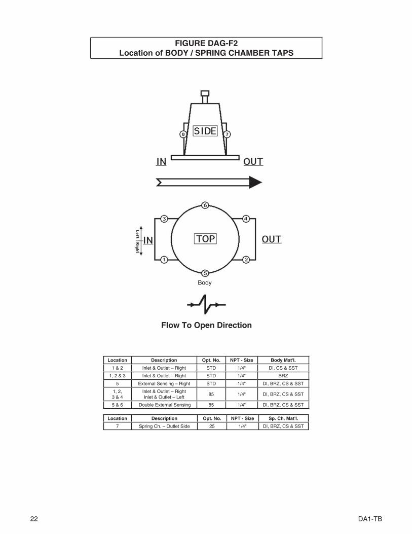
Location Description Opt. No. NPT - Size Sp. Ch. Mat'l.
7 Spring Ch. – Outlet Side 25 1/4" DI, BRZ, CS & SST
FIGURE DAG-F2Location of BODY / SPRING CHAMBER TAPS
Location Description Opt. No. NPT - Size Body Mat'l.
1 & 2 Inlet & Outlet – Right STD 1/4" DI, CS & SST
1, 2 & 3 Inlet & Outlet – Right STD 1/4" BRZ
5 External Sensing – Right STD 1/4" DI, BRZ, CS & SST
1, 2,3 & 4
Inlet & Outlet – RightInlet & Outlet – Left
85 1/4" DI, BRZ, CS & SST
5 & 6 Double External Sensing 85 1/4" DI, BRZ, CS & SST
Flow To Open Direction
Body

DA1-TB 23
End Conn.
Body Size
DN15, DN20
& DN25
DN32&
DN40DN50 DN65 DN80 DN100
NPT 152 251 251209 251 248
125# FF 276 298 352250# RF 292 318 368150# FF 246 292 √ 292 276 298 352300# FF 246 292 √ 292 292 309 368
150# RF 273 314 √254 276 298 352349 — — —
150# RF ‡ 356 356 √ 356 — — —
300# RF 273 314 √267 292 318 368362 — — —
300# RF ‡ 356 356 √ 356 — — —600# RF 273 314 √ 286 311 336 394
600# RF ‡ 356 356 356 — — —Opt-32
EXT NIPS356 400 400
OPT-41 279 387 394All 72 94 102 133 146 178All 152 178 203 254 279 283All 314 362 406 673 692 705All
432 444 483 — — —
wo/Flanges
13 20 24 — — —
w/Flanges 16 25 31 45 79 86
ENGLISH UNITS (in) (lbs) METRIC UNITS (mm) (kg)
* HC body material available in sizes 1", 1-1/2", & 2" ONLY.** Flanged BRZ bodies available in sizes 1", 1-1/2", 2", 2-1/2", 3", & 4" ONLY.√ Flange Connections not available for 1-1/4" size.‡ Opt-34: Special 14" F to F Flange dimensions, CS and SST body material only.Consult Factory for dimensions of ISO DIN Flanged units. (PN16, PN25, PN40)
Dimen. End
Conn. Body Mat’l.
Body Size
1/2", 3/4" & 1"
1-1/4" &
1-1/2"2" 2-1/2" 3" 4"
A NPT DI, BRZ 6.00 9.88 9.88
CS, SST, HC 8.25 9.88 9.75
B
125# FF DI 10.88 11.75 13.88250# RF DI 11.50 12.50 14.50
150# FF BRZ ** 9.63 11.50 √ 11.50 10.88 11.75 13.88
300# FF BRZ ** 9.63 11.50 √ 11.50 11.50 12.15 14.50
150# RF CS, SST
10.75 12.38 √10.00 10.88 11.75 13.88
HC * 13.75 — — —150# RF ‡ CS, SST 14.00 14.00 √ 14.00 — — —
300# RFCS,SST
10.75 12.38 √10.50 11.50 12.50 14.50
HC * 14.25 — — —300# RF ‡ CS, SST 14.00 14.00 √ 14.00 — — —600# RF CS, SST 10.75 12.38 √ 11.25 12.25 13.25 15.50
600# RF ‡ CS, SST 14.00 14.00 14.00 — — —
COpt-32
EXT NIPSCS, SST 14.00 15.75 15.75
OPT-41 SST 11.00 15.25 15.50E All All 2.84 3.69 4.00 5.25 5.75 7.00G All All 6.00 7.00 8.00 10.00 11.00 11.13J All All 12.38 14.25 16.00 26.50 27.25 27.75
J w/Opt-80
All All 17.00 17.50 19.00 — — —
WEIGHTwo/
FlangesAll 28 43 52 — — —
w/Flanges All 35 55 68 100 175 190
DIMENSION and WEIGHTS
The contents of this publication are presented for informational purposes only, and while every effort has been made to ensure their accuracy, they are not to be con-strued as warranties or guarantees, express or implied, regarding the products or services described herein or their use or applicability. We reserve the right to modify or improve the designs or specifications of such product at any time without notice.Cashco, Inc. does not assume responsibility for the selection, use or maintenance of any product. Responsibility for proper selection, use and maintenance of any Cashco, Inc. product remains solely with the purchaser.

24 DA1-TB
D1MODEL DA1 PRODUCT CODER 03/11/16
POSITION 6 & 7 - DIAPHRAGM, SEAL & SEAT MATERIALSTrim Seat (#) Diaphragm Static Seal Dynamic Seal CODE
17-4PHSST"P"
PA BC NBR O-ring ^ P1PA / (BC) BC NBR SST/TFE u-cup ^ P2 / (PU)
CTFE BC NBR SST/TFE u-cup ^ P3PA EPR EPR O-ring ^ P4PA NBR NBR O-ring P5
PA/ (NBR) NBR NBR SST/TFE u-cup P6 / (PW)PA FK FK SST/TFE u-cup ^ P7 ‡
GF-TFE FK FK SST/TFE u-cup P8 ‡V-TFE FK FK SST/TFE u-cup P9 ‡
PA FKM FKM O-ring PAPA FKM FKM SST/TFE u-cup PB
GF-TFE FKM FKM O-ring PCGF-TFE FKM FKM SST/TFE u-cup PDV-TFE FKM + TFE SST/TFE u-cup √ SST/TFE u-cup PE
GF-TFE 3-ply RTFE SST/TFE u-cup $ PFGF-TFE 3-ply RTFE PRA + W $ PG
PA / (NBR) NBR NBR TFE+NBR GFTFE CW PH / (PY)PA EPR EPR TFE+EPR GFTFE CW PJPA FK FK TFE+FK GFTFE CW PK
GF-TFE FKM FKM TFE+FKM GFTFE CW PLFKM FKM FKM SST/TFE u-cup PZ
Hastelloy"H"
PA FK FK Hast-C/TFE u-cup H7V-TFE FK FK Hast-C/TFE u-cup H9
GF-TFE FKM FKM Hast-C/TFE u-cup HD
Monel"M"
PA FK FK SST/TFE u-cup ‡‡ ^ M7 ‡V-TFE FK FK SST/TFE u-cup ^ M9 ‡V-TFE FKM-TFE SST/TFE u-cup √ SST/TFE u-cup ME
PA / (NBR) NBR NBR TFE+NBR GFTFE CW MH / (MY)PA EPR EPR TFE+EPR GFTFE CW MJPA FK FK TFE+FK GFTFE CW MK
GF-TFE FKM FKM TFE+FKM GFTFE CW MLV-TFE FKM FKM O-ring MQNBR NBR NBR O-ring MWFKM FKM FKM SST/TFE u-cup MZ
316L SST"S"
NACEOPT-40
PA FK FK SST/TFE u-cup S7 ‡V-TFE FK FK SST/TFE u-cup S9 ‡
PA BE-CU * SST/TFE u-cup SST/TFE u-cup SMV-TFE BE-CU * SST/TFE u-cup SST/TFE u-cup ** SN
PA / (NBR) NBR NBR TFE+NBR GFTFE CW SH / (SY)PA EPR EPR TFE+EPR GFTFE CW SJPA FK FK TFE+FK GFTFE CW SK
GF-TFE FKM FKM TFE+FKM GFTFE CW SLPA BC V-TFE ELG/TFE u-cup ^ NP ‡PA NBR NBR ELG/TFE u-cup NRPA FKM FKM ELG/TFE u-cup NS
FKM FKM FKM ELG/TFE u-cup NFCTFE NBR V-TFE ELG/TFE u-cup NT ‡V-TFE BC VTFE ELG/TFE u-cup ^ NV ‡
17-4PH/Monel/17-4PH
"T"
PA FK FK SST/TFE u-cup ‡‡ ^ T7 ‡V-TFE FK FK SST/TFE u-cup ^ T9 ‡
PA BE-CU * SST/TFE u-cup SST/TFE u-cup TMV-TFE BE-CU* SST/TFE u-cup SST/TFE u-cup ** TN
PA FK FK TFE+FK GFTFE CW TK
‡‡ For GOX service, PA seats allowed in BRZ Bodies w/ trim materials "M" or "T" only.^ Only trims that may be used with Opt. -80.
* 2-1/2" - 4" sizes are not available with metal diaphragm. ** Use for Opt-5 or -36. ‡ For Low Ambient Temperatures (See DAG-5 & -14 for Min. Temperatures).√ Sizes 2-1/2"-4" use V-TFE static seal. $ For Steam Applications Max Press < 125 psig. (#) BC and NBR Seat material not available for 2-1/2" size.
EPOSITION 3 -
SIZESize
CODEin (DN)
1/2" (15) 43/4" (20) 51" (25) 6
1-1/4" (32) 71-1/2" (40) 8
2" (50) 92-1/2" * (65) A
3" * (80) B4" * (100) C
* Not available with metal diaphragms.
POSITION 5 - BODY & SPRING CHAMBER MATERIALS
Materials CODE Materials CODEDI/DI 1 SST/DI 7
BRZ/DI 2 SST/CS * 9BRZ/BRZ *** ‡‡ B SST/SST * / **** A
BRZ/CS * J Dup SST/CS * / ***** FBRZ/SST * D Dup SST/SST * / ***** L
CS/DI 4 Dup SST/Dup SST ***** MCS/CS * 5 HC/CS ‡‡ GLCC/LCC 6 HC/SST ‡‡ H
LCC/SST * 8
* For Opt-80 Select CS or SST Spring Chamber Material except in
Canada, use SST. See Position 11.
*** Select for Opt-5 **** Select for Opt-36
***** Select for Sea water ‡‡ Sizes 1/2" - 2" Except No 1-1/4"
POSITION 10 - END CONNECTIONS / ASME
Size Material Option End Conn CODE End Conn CODE End
Conn CODE
1/2" - 2" ALL – NPT 1 – – – –2-1/2" - 4" DI – 125#FF 2 250#RF 3 – –
1", 1-1/2" - 4" BRZ – 150#FF 6 300#FF 7 – –1/2" - 4" CS,SST -30 *
150#RF 4 300#RF 5 600# RF** 8
1" - 2" HC -30 *1/2" - 2" ALL -31 BSP P – – – –1/2" - 2" CS, SST -32 Extended Nipples E
1/2" - 2" (14" F to F) CS, SST -34 * 150#RF V 300#RF W 600#RF Y1/2" - 1", 1-1/2" - 2" SST -41 Non-High Purity Tube Ends T – –
END CONNECTIONS FOR ISO DIN FLANGESDN15-25, 40, 50
BRZ –PN40 FF - will mate with PN16, 25 and 40 J
DN65-100 PN16 FF K PN25 FF L PN40 FF M
DN15-25, 40, 50 HC -30 PN40 RF - will mate with PN16, 25 and 40 DDN15-100 CS, SST -30 PN16 RF A PN25 RF C PN40 RF G
* Flanges Not Available for 1-1/4" (DN32) size.** Not available in HC material)
POSITION 11 - RANGE SPRINGS
Body Size
Pressure RangeCODE
Body Size
Pessure RangeCODE
psig barg psig barg
1/2", 3/4"& 1"
(DN15,20
& 25)
1-5 ^ .07-.34 1
2"(DN50)
1-5 ^ .07-.34 11-10 ^ .07-.68 S 1-10 ^ .07-.68 S5-20 .34-1.3 A 5-15 .34-1.0 M10-35 .68-2.4 B 10-30 .68-2.0 N20-80 1.3-5.5 C 15-50 1.0-3.4 P
30-150 2.0-10.3 D 30-90 2.0-6.2 Q70-200 4.8-13.7 E 50-150 3.4-10.3 R
100-300 6.8-20.6 F 80-225 * 5.5-15.5 Z200-450 * 13.7-31.0 G 80-275 * 5.5-18.9 4
1-1/14"&
1-1/2"(DN32
&40)
1-5 ^ .07-.34 1 2-1/2", 3"
& 4"(DN65,
80& 100)
1-10 .07-.68 S1-10 ^ .07-.68 S 5-20 .34-1.3 A5-20 .34-1.3 A 10-40 .68-2.7 T
15-45 1.0-3.1 H 10-70 .68-4.8 J10-70 .68-4.8 J 40-125 2.7-8.6 K
40-175 2.7-12.0 2 50-225 3.4-15.5 370-200 4.8-13.7 E
100-350 * 6.8-24.1 Y100-400 * 6.8-27.5 6
* Opt-80 - High Outlet Pressure requires CS or SST Sp.Ch. only. See Position 5.^ Comp diaphragm only.
POSITION 12 - SENSING FLOW DIRECTION
OptionFlow To
OpenCODE
Internal 1External 2
Large Internal 4
For Special Construction
Contact Cashco for Special Code
X
POSITION 13 - FEATURE OPTIONS Option CODENo Option – 0
TFE Diaphragm Cover. -9 2Cryogenic Construction (Select Cleaning Spec.
Opt.-55 or -56 from Position 16.-5 or -36 C
POSITION 14 - SPRING CHAMBER OPTIONS Option CODENo Option – 0
1/4" (DN8) NPT Vent Tap. -25 EVent Screen (Includes Opt.-25) -25S H
POSITION 16 - CERTIFICATE OPTIONS Option CODENo Option – 0
NACE CONST: CS/CS, LCC/LCC, LCC/SST, SST/CS or SST/SST All Sizes Except 1-1/4" per MR0175 -40 J
SPECIAL CLEANING: Per Spec #S-1134. W/ properly selected mat'ls. Suitable for Oxygen Service.
BRZ or SST body material.-55 M
SPECIAL CLEANING: Per Cashco Spec.#S-1542. -56 N
SPECIAL CLEANING: Per Cashco Spec #S-1589 Cl2 Service. -57 P
POSITION 15 - BODY OPTIONS Option CODENo Option – 0
Second "Set" of 1/4" (DN8) FNPT Pressure Taps & Plugs -85 T
POSITION 17 - PAINT OPTIONS Option CODENo Option – 0
Epoxy Painted Per Cashco Spec #S-1547. -95 W
Epoxy Painted Per Cashco Spec #S-1687 OFFSHORE Applic. -95OS Y
POS3
POS5
POS6 & 7
POS8
POS10
POS11
POS13
POS14
POS15
POS16
POS17
POS12
POSITION 8 - Product ClassificationUnder European"Pressure Equipment Directive"
PRODUCT DESTINATION HAZARD CATEGORY CODE
Anywhere except Europe N/A 7
EuropeanCountries * (CE Mark does not apply
to DN25 and below)
Sound Engineering Practice (SEP)
S
CE Marked Hazard Cat I or II E
ATEX A
* For products to be placed in service in Europe - Ref to Directive 2014/68/EU. Forward Completed "EU" Application Recorder prior to quotation. (Without Recorder- Processing of Purchase Order will be delayed). Contact Cashco for Assistance.
An “X” in POS 12 followed by a 5-digit control num ber over rides remaining selections.

Cashco, Inc.P.O. Box 6 Ellsworth, KS 67439-0006PH (785) 472-4461Fax. # (785) 472-3539www.cashco.comemail: [email protected] in U.S.A. DA1-TB
Cashco do Brasil, Ltda.Al.Venus, 340Indaiatuba - Sao Paulo, BrazilPH +55 11 99677 7177Fax. No. www.cashco.comemail: [email protected]
Cashco GmbHHandwerkerstrasse 1515366 Hoppegarten, GermanyPH +49 3342 30968 0Fax. No. +49 3342 30968 29www.cashco.comemail: [email protected]
Related Documents