i MODAL ANALYSIS OF AN AIRCRAFT LANDING GEAR By Muhammad Amsyar Bin Zulkifly Dissertation submitted in partial fulfillment of the requirements for the Bachelor of Engineering (Hons) (Mechanical Engineering) SEPTEMBER 2012 Universiti Teknologi PETRONAS, Bandar Seri Iskandar, 31750 Tronoh, Perak Darul Ridzuan.

Welcome message from author
This document is posted to help you gain knowledge. Please leave a comment to let me know what you think about it! Share it to your friends and learn new things together.
Transcript
i
MODAL ANALYSIS OF AN AIRCRAFT LANDING GEAR
By
Muhammad Amsyar Bin Zulkifly
Dissertation submitted in partial fulfillment of
the requirements for the
Bachelor of Engineering (Hons)
(Mechanical Engineering)
SEPTEMBER 2012
Universiti Teknologi PETRONAS,
Bandar Seri Iskandar,
31750 Tronoh,
Perak Darul Ridzuan.

i
CERTIFICATION OF APPROVAL
Modal Analysis of An Aircraft Landing Gear
by
Muhammad Amsyar Bin Zulkify
A project dissertation submitted to the
Mechanical Engineering Programme
Universiti Teknologi PETRONAS
in partial fulfilment of the requirement for the
BACHELOR OF ENGINEERING (Hons)
(MECHANICAL ENGINEERING)
Approved by,
_____________________
(Ir Idris Bin Ibrahim)
UNIVERSITI TEKNOLOGI PETRONAS
TRONOH, PERAK
September 2012

ii
CERTIFICATION OF ORIGINALITY
This is to certify that I am responsible for the work submitted in this project, that the
original work is my own except as specified in the references and
acknowledgements, and that the original work contained herein have not been
undertaken or done by unspecified sources or persons.
___________________________________________
MUHAMMAD AMSYAR BIN ZULKIFLY

iii
ABSTRACT
During the course of an aircraft landing and take-off, the landing gear is subjected to
a very massive force that needs to be diverted so that it will not affect the aircraft.
Some of the dynamic characteristics that are caused by the force that is subjected to
the landing gear are gear walk, shimmy, and brake-induced vibration. Stiffness and
dampers are two most important elements of the landing gear to provide smooth
motion of the aircraft. However, the data is not available to the public for research
purpose. This project is undertaken to establish design data of an aircraft landing
gear and study its dynamic characteristics using modal analysis method where the
project is carried out using ANSYS software. Modal analysis is basically the study
of the dynamic characteristic of a structure when subjected to a vibrating excitation
where in this case, the structure to be analysed is the landing gear of the aircraft. In
this project, a specific landing gear of an aircraft from Embraer is used as the model
for the analysis. After the modelling is done, all the boundary conditions such as the
mechanical properties and the connections are properly defined. Modal analysis is
then performed in order to obtain the deformations, mode shapes, and the natural
frequencies of the landing gear. From the result, five different mode shapes are taken
into account and natural frequencies of the mode shapes are in the range of 129 –
379 Hz. The obtained result is discussed and compared to the closest possible
research for its validity and it can be concluded that the project is successful where
the mode shapes and natural frequencies that are obtained have the same pattern as
the result in other researches.

iv
ACKNOWLEDGEMENT
First and foremost, all praises to The Almighty as for His blessing and guidance and
also giving opportunity and strength to the author to get through and completing the
research and study about this project.
In this opportunity, author would like to take this opportunity to express his utmost
gratitude to his supervisor; Ir Idris bin Ibrahim for his helpful advice, guidance, and
constant encouragement throughout the execution of this project. With the help and
guidance given by him from time to time, it really helps the author to get a thorough
understanding of how to execute and complete the project.
The author also wants to take this opportunity to thank everybody that is involved in
completing this project directly or indirectly. This project might not be completed
without their full devotion in helping and supporting the author.
Lastly, the author would like to thank his parents for their love, wholehearted moral
supports and encouragement. Although they are not directly involved in the
completion of this project, it is their presence that gives the author strength and
motivation to finish the project until the end.
v
TABLE OF CONTENTS
CERTIFICATION OF APPROVAL ........................................................................................ i
CERTIFICATION OF ORIGINALITY .................................................................................. ii
ABSTRACT ............................................................................................................................ iii
ACKNOWLEDGEMENT ...................................................................................................... iv
TABLE OF CONTENTS ......................................................................................................... v
LIST OF FIGURES ................................................................................................................ vi
LIST OF TABLES ................................................................................................................. vii
CHAPTER 1: INTRODUCTION ............................................................................................ 1
1.1 Background .................................................................................................................... 1
1.2 Problem statement .......................................................................................................... 2
1.3 Objectives ...................................................................................................................... 2
1.4 Scope of study ................................................................................................................ 3
CHAPTER 2: LITERATURE REVIEW ................................................................................. 4
2.1 Review of previous work ............................................................................................... 4
2.2 Theoretical background ................................................................................................. 6
CHAPTER 3: METHODOLOGY ........................................................................................... 7
3.1 Research Methodology .................................................................................................. 7
3.2 Project Flow Chart ......................................................................................................... 8
3.3 Modelling ....................................................................................................................... 9
3.3.1 Landing Gear Model ............................................................................................... 9
3.3.2 Landing Gear Data ................................................................................................ 14
3.4 Gantt Chart ................................................................................................................... 15
CHAPTER 4: RESULTS AND DISCUSSION ..................................................................... 16
4.1 Results and Discussion ................................................................................................ 16
CHAPTER 5: CONCLUSION AND RECOMMENDATION .............................................. 22
5.1 Conclusion ................................................................................................................... 22
5.2 Recommendation ......................................................................................................... 22
REFERENCES ...................................................................................................................... 23
APPENDICES ....................................................................................................................... 24
vi
LIST OF FIGURES
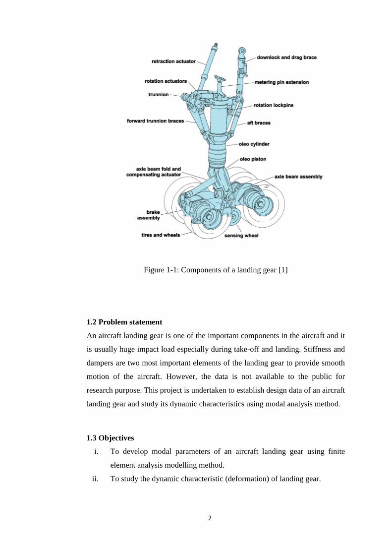
Figure 1-1: Components of a landing gear [1]
Figure 2-1: Landing gear in the form of beam model [4]
Figure 2-2: Proper landing gear model for the modal analysis [4]
Figure 3-1: Flow chart of the project
Figure 3-2: Schematic diagram of the landing gear [7]
Figure 3-3: Landing gear model reference [7]
Figure 3-4: Simplified model of the landing gear
Figure 3-5: Simplified model with separated bodies
Figure 3-6: Modified model of the landing gear
Figure 4-1: Mode Shape 1
Figure 4-2: Mode Shape 2
Figure 4-3: Mode Shape 3
Figure 4-4: Mode Shape 4
Figure 4-5: Mode Shape 5
Figure 4-6: Plotted natural frequencies
Figure 4-7: Mode shape of a landing gear [7]
Figure A-1
Figure A-2
Figure B-1
Figure B-2

vii
LIST OF TABLES
Table 3-1: Dimensions of the landing gear [7]
Table 3-2: Mass and moment of inertia used for the landing gear [7]
Table 3-3: Gantt chart for FYP I & II
Table 4-1: Natural frequencies of the mode shapes
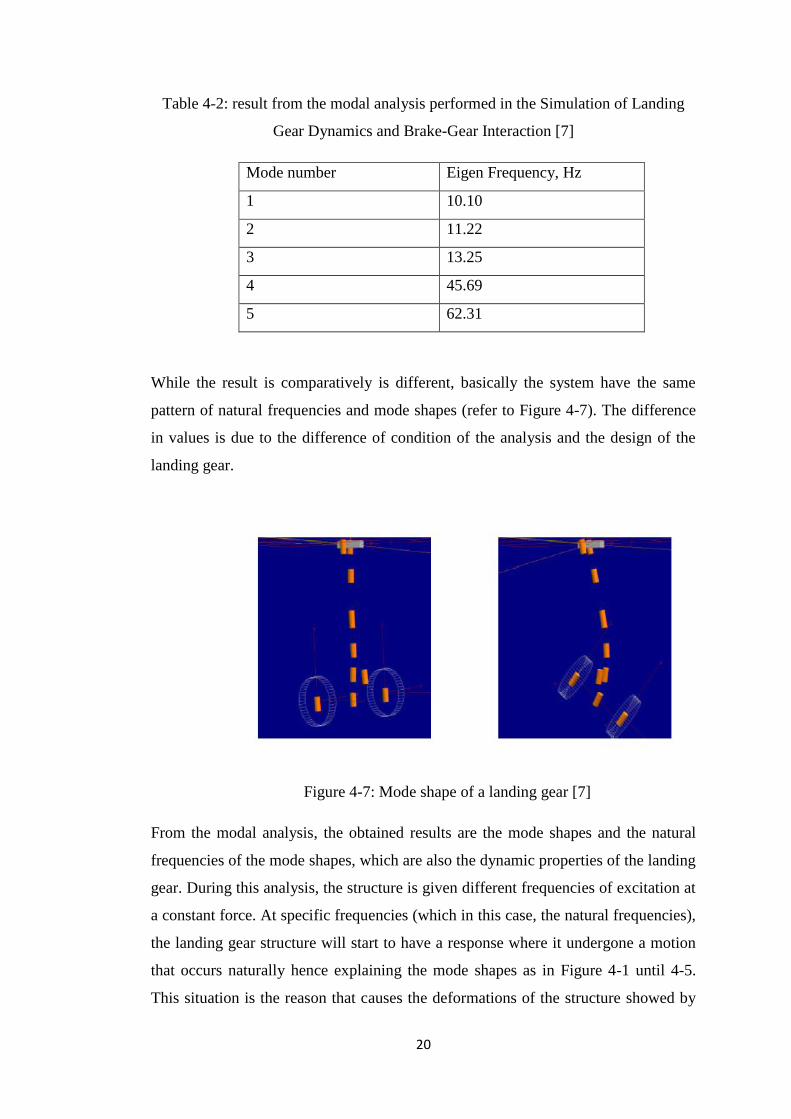
Table 4-2: result from the modal analysis performed in the Simulation of Landing
Gear Dynamics and Brake-Gear Interaction [7]
1
CHAPTER 1: INTRODUCTION
1.1 Background
In an aircraft, the typical main components are the fuselage, wings, powerplant,
empennage, and landing gear. The fuselage is the body of the aircraft where the
controls, cabin and storage space are located. The wings are the parts that help
the lifting of the aircraft. Powerplant provides the thrust and it is consisted of
engine and propeller. Landing gear, which is the main focus in this paper, helps
the movement of the aircraft itself on land.
In manoeuvring the aircraft on the land, the landing gear (sometimes called as
aircraft undercarriage) plays a very important role so that it runs smoothly where
it absorbs energy during landing. Even though the landing gear mentions the
word „landing‟, it also has important function during taxiing and takeoff while
helping movement and provides support at the same time. There are three types
of landing gear that are commonly used and they are; conventional, tricycle and
tandem.
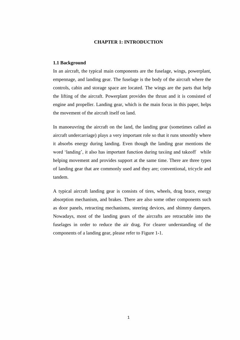
A typical aircraft landing gear is consists of tires, wheels, drag brace, energy
absorption mechanism, and brakes. There are also some other components such
as door panels, retracting mechanisms, steering devices, and shimmy dampers.
Nowadays, most of the landing gears of the aircrafts are retractable into the
fuselages in order to reduce the air drag. For clearer understanding of the
components of a landing gear, please refer to Figure 1-1.
2
Figure 1-1: Components of a landing gear [1]
1.2 Problem statement
An aircraft landing gear is one of the important components in the aircraft and it
is usually huge impact load especially during take-off and landing. Stiffness and
dampers are two most important elements of the landing gear to provide smooth
motion of the aircraft. However, the data is not available to the public for
research purpose. This project is undertaken to establish design data of an aircraft
landing gear and study its dynamic characteristics using modal analysis method.
1.3 Objectives
i. To develop modal parameters of an aircraft landing gear using finite
element analysis modelling method.
ii. To study the dynamic characteristic (deformation) of landing gear.

3
1.4 Scope of study
This project examines the dynamic characteristics of an aircraft landing gear at
two operating conditions which is when the aircraft is landing and taking off.
i. The aircraft landing gear for the selected aircraft model will be studied
and design data will be collected.
ii. Develop finite element analysis model for the design.
iii. Study the dynamic characteristic especially on the deformations of the
landing gear at different frequencies of excitation.
4
CHAPTER 2: LITERATURE REVIEW
2.1 Review of previous work
In a presentation of Experimental Modal Analysis of Landing Gears by Alvin
Fong P. Eng, it was said that during rapid landing, the load of the landing gear
can be influenced by the landing gear modal characteristics. It also affects one of
the concerns in landing gear dynamics which is called as shimmy. Shimmy of a
landing gear system is a violent self-excited oscillation driven by the interaction
between tire and the ground and this motion interacts with the landing gear
structure. Shimmy can occur during taxiing, take-off, and landing and the effect
could be detrimental to the landing gear structure or the aircraft [2].
In Simulation of Aircraft Landing Gear Dynamics Using Flexible Multibody
Dynamics Methods in SIMPACK by Prashant Dilip Khapane. The oscillations of
the landing gear is simulated using SIMPACK software. The multibody of the
landing gear is then represented by simple body elements such as main fitting,
the shock tube, and two/four wheels respectively [3]. Using FEA tool in the
SIMPACK, an elastic body is set up and it is transferred into the software using
modal approach. Two types of modal simulations were done; braking and
reduced friction-induced vibration. In braking simulation, it was compared
between two types of brakes; ABS and dynamic braking. It was found that ABS
is better in providing passenger comfort and reduced friction-induced vibration.
While for the second simulation, flexible landing gear is used at the attachment
point and deflection were reduced to almost zero.
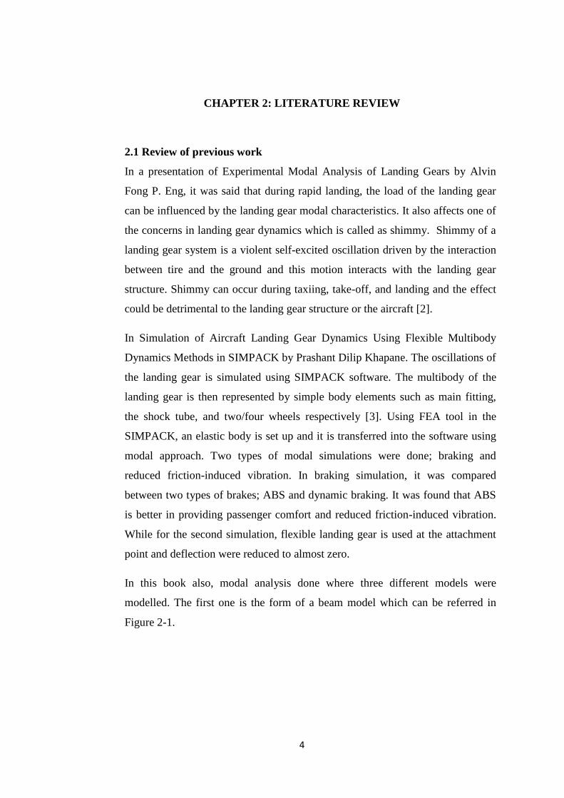
In this book also, modal analysis done where three different models were
modelled. The first one is the form of a beam model which can be referred in
Figure 2-1.
5
Figure 2-1: Landing gear in the form of beam model [4]
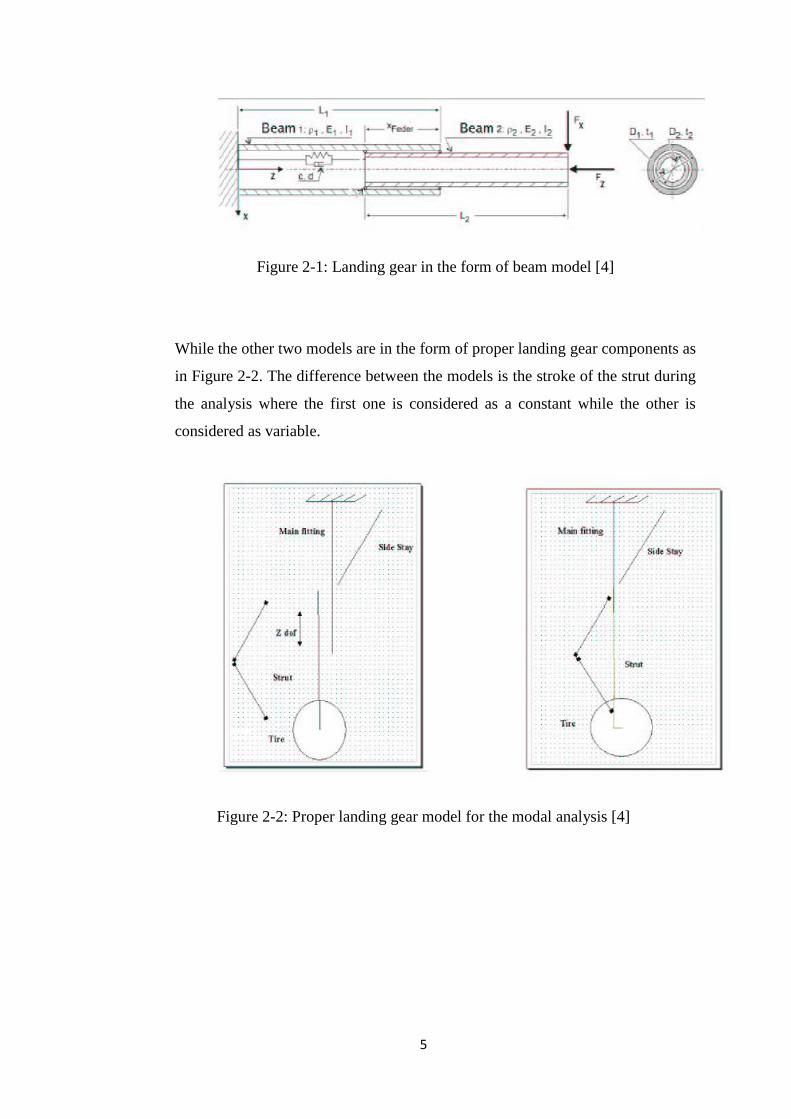
While the other two models are in the form of proper landing gear components as
in Figure 2-2. The difference between the models is the stroke of the strut during
the analysis where the first one is considered as a constant while the other is
considered as variable.
Figure 2-2: Proper landing gear model for the modal analysis [4]
6
2.2 Theoretical background
The modal analysis in this project will be focused during landing and takeoff of
the aircraft.
Modal analysis is the study of dynamic characteristics of structures. It is used to
determine the natural frequencies and mode shapes of a structure where the
results are used to help design the structural system of the structure for vibrations
applications [5]. The analysis is usually used using Finite Element Method
(FEM) and can be performed using ANSYS.
Modes are inherent properties of a structure, and are determined by the material
properties (mass, damping, and stiffness), and boundary conditions of the
structure [6]. Each of the modes differs from the other through modal damping,
mode shape and resonant frequency.
Basic equation for Multi DOF system:
[M ]{ü}+ [C ]{ů}+ [K ]{u}= {F }
• The mass, damping and stiffness matrices are constant with time
• The unknown nodal displacements vary with time
A continuous structure has an infinite number of degrees of freedom. The finite
element method approximates the real structure with a finite number of DOFs. In
this project, the result from the analysis is compared to the closest analysis that
had been done by other study.

7
CHAPTER 3: METHODOLOGY
3.1 Research Methodology
As mentioned before, the project is undertaken to establish design data of an aircraft
landing gear and study its dynamic characteristics using modal analysis method. The
research will be made available to the public for further research. For the project to
start, literature review is first done for thorough understanding of landing gear and
modal analysis. The dimension of a landing gear from a specific aircraft is taken as
the reference for modelling purpose. The properties of the parts of the landing gear
such as the Young‟s modulus and Poisson‟s ratio will be used from the literature
resource as reference. If the required properties are not provided, the most common
material and properties used in landing gears is applied in the modal analysis.
After literature review is done, modelling phase is performed using CATIA and the
model is transferred into ANSYS for simulation in two conditions: landing and take-
off. The design data for the landing gear is taken from an aircraft of Embraer.
Simulation is done on the effect of deformation on the landing gear. Among the
modal parameter to be studied are the mode shapes, deformation, and natural
frequencies of the mode shapes.
After the simulation is performed, the results are compared to other researches that
are similar in term of the study area. The results that will be compared are the mode
shapes and the natural frequencies of the landing gear. If the results differ too much
from the other researches, the project will start again from the modelling phase.
After satisfying results are obtained, the project will be completed with a report for
submission.

8
3.2 Project Flow Chart
Figure 3-1: Flow chart of the project
Literature Research
Done based on previous researches about Aircraft Landing Gear
Data Gathering
Design data: Gathering the dimensions of the landing gear.
Simulation data: Gathering the data of properties of the landing
gear such as the Young‟s modulus and Poisson‟s ratio.
Modelling
Modelling the landing gear based on the dimensions gathered
using CATIA software.
Simulation
Performed using ANSYS software. All of the boundary conditions
of the landing gear such as the mass, connections, mechanical
properties are defined.
Report
Full report about the project is done for submission
Compare result with the results
from existing researches for the
same pattern.
Is the pattern is the same?
NO
YES
END
START
9
3.3 Modelling
3.3.1 Landing Gear Model
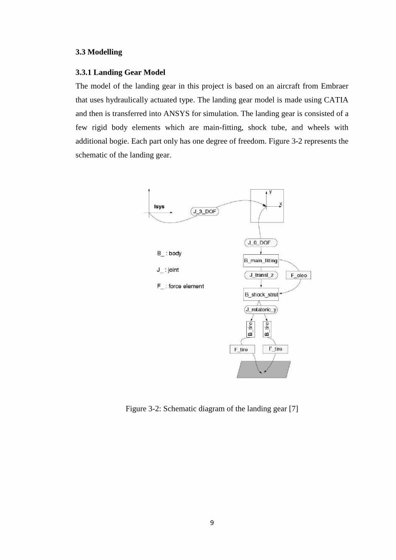
The model of the landing gear in this project is based on an aircraft from Embraer
that uses hydraulically actuated type. The landing gear model is made using CATIA
and then is transferred into ANSYS for simulation. The landing gear is consisted of a
few rigid body elements which are main-fitting, shock tube, and wheels with
additional bogie. Each part only has one degree of freedom. Figure 3-2 represents the
schematic of the landing gear.
Figure 3-2: Schematic diagram of the landing gear [7]

10
The model of the landing gear produced using CATIA basically is basically based on
the Figure 3-3 where the parts that should be taken into account are the main fitting,
shock strut and the tire.
Figure 3-3: Landing gear model reference [7]
The modelling of the aircraft landing gear is based on the design taken from
Simulation of Aircraft Landing Gear which is based on the Embraer regional aircraft.
The design is combined into simpler design in order to ease the process of analysis
using ANSYS as the usual analysis in this software involves only the critical part of
a structure without including the details of a structure. If the design is too
complicated, it will consume more time thus affecting the process of getting proper
result and also the process of analysing the result.
In performing the modal analysis, the design needs to be defined properly such as for
the connections and physical and material properties. The connections can be either
between body to body or body to ground. There is also contact option between the

11
bodies. As for the material properties, there are preset materials to be chosen from. If
the material needed is not available, it can be added to the database. As for this
analysis, based on the provided Young‟s modulus and Poisson‟s ratio, the material of
the landing gear can be concluded that it is made from stainless steel. After a few try
and error, it was found that the process is complicated and everything is
interconnected with each other. If there is one mistake occur at one part, the whole
result will be affected.
After further discussion, it was decided that the design of the landing gear needed to
be simplified into a single body as the time frame to perform the analysis is short.
Below is the first model of the simplified landing gear.
Figure 3-4: Simplified model of the landing gear
However, after a few times of analysis, it was found that the required result could be
obtained. This was because for a single body, only a limited constraints can be
defined thus making the option not feasible. It was then remodelled into separated
bodies as in Figure 3-5.
12
\
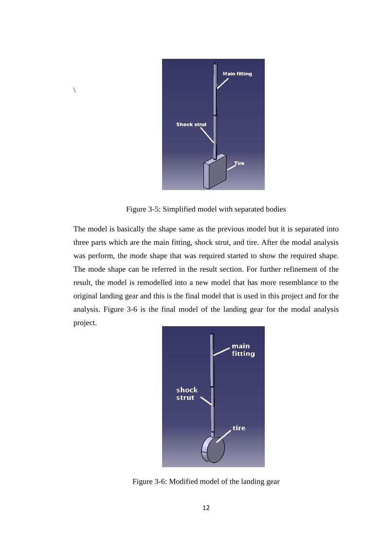
Figure 3-5: Simplified model with separated bodies
The model is basically the shape same as the previous model but it is separated into
three parts which are the main fitting, shock strut, and tire. After the modal analysis
was perform, the mode shape that was required started to show the required shape.
The mode shape can be referred in the result section. For further refinement of the
result, the model is remodelled into a new model that has more resemblance to the
original landing gear and this is the final model that is used in this project and for the
analysis. Figure 3-6 is the final model of the landing gear for the modal analysis
project.
Figure 3-6: Modified model of the landing gear
13
After modelling in CATIA, the model is then transferred in ANSYS for the modal
analysis. The model is combined and defined according to its joints, contacts and
support. All of the constraints needed to be defined properly in order to avoid error
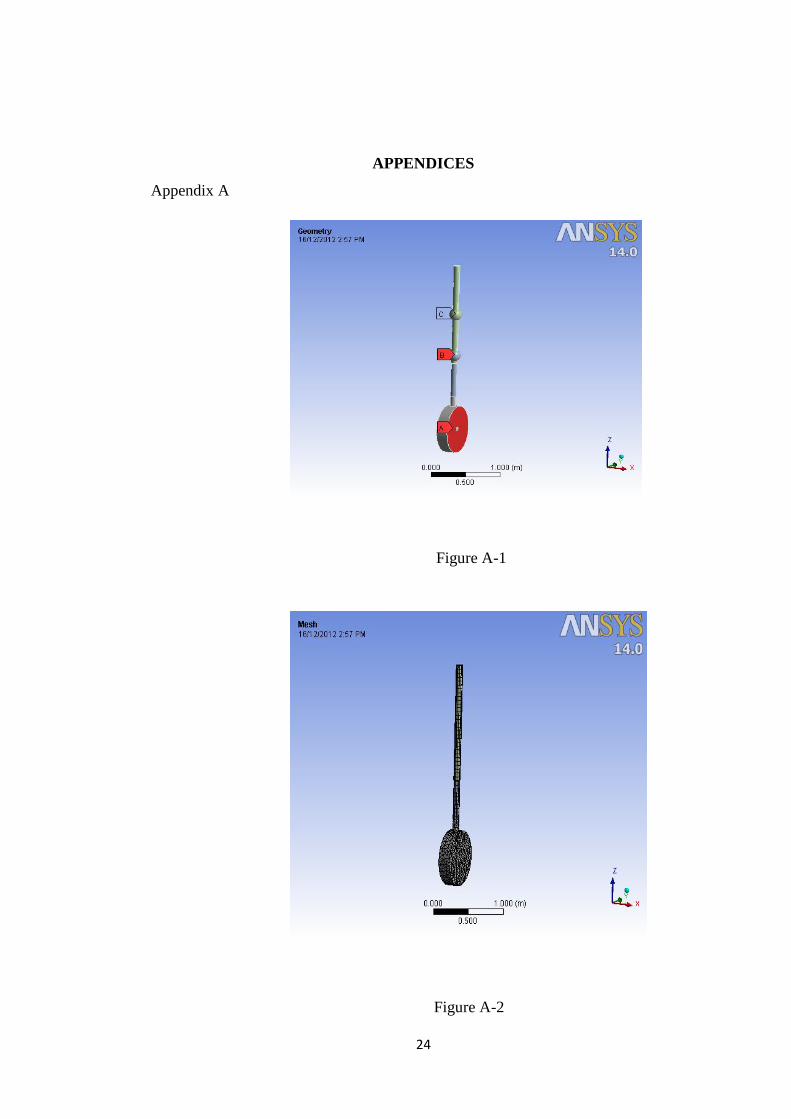
thus affecting the results obtained. The figure A-1 in Appendix A is the model of the
landing gear after assembled according to its joints. At this point, all of the properties
of the landing gear such as the materials and mass are defined. The letter A, B and C
are the point masses of the bodies of the landing gear.
The model is then meshed in separate elements (this is the part where the finite
element analysis come into the picture) before solved by the software. Refer to figure
A-2 in Appendix A for the meshed model of the landing gear.
As mentioned before, the first aim was to perform the analysis as a single body
landing gear. However, due to the limitations of the single body analysis such as the
redundancy of the constraints, the analysis needed to be altered into multi-body
analysis. It needed to be given attention that in modal analysis, the forces and the
damping that act on the bodies are to be ignored. This is because modal analysis is a
vibration analysis where the aim is to find the natural frequencies and mode shapes
of a structure (in this case, the landing gear) when given some frequencies of
excitation. This will be explained later in this section.
The basic working principle of the landing gear in this modal analysis is basically the
same as a beam where both of the ends are fixed. One end is fixed to the aircraft
fuselage and the other end is fixed to the ground. The other end is fixed to the ground
to mimic the situation during landing and when the aircraft is about take-off for
flight.
The basic parameters that are needed in this analysis are mass, moment inertia of the
axle, Poisson‟s ratio, Young‟s modulus and the frictional coefficient. The frictional
coefficient is used as the replacement of the damping effect for the landing gear.
14
3.3.2 Landing Gear Data
The data for the modelling of the landing gear is taken from Simulation of Landing
Gear Dynamics and Brake-Gear Interaction and below is the data used for the
analysis:
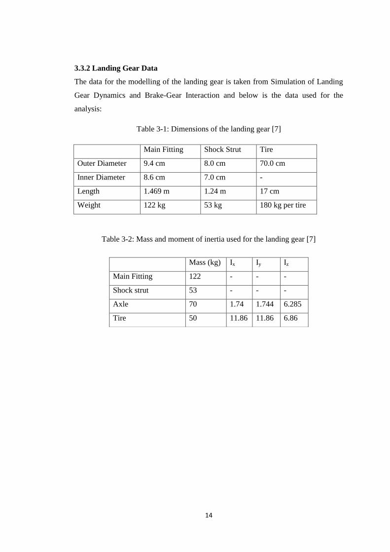
Table 3-1: Dimensions of the landing gear [7]
Main Fitting Shock Strut Tire
Outer Diameter 9.4 cm 8.0 cm 70.0 cm
Inner Diameter 8.6 cm 7.0 cm -
Length 1.469 m 1.24 m 17 cm
Weight 122 kg 53 kg 180 kg per tire
Table 3-2: Mass and moment of inertia used for the landing gear [7]
Mass (kg) Ix Iy Iz
Main Fitting 122 - - -
Shock strut 53 - - -
Axle 70 1.74 1.744 6.285
Tire 50 11.86 11.86 6.86

15
3.4 Gantt Chart
Table 3-3: Gantt chart for FYP I & I
Legends:
Project Activity
Key Milestone

16
CHAPTER 4: RESULTS AND DISCUSSION
4.1 Results and Discussion
These are the results for the modal analysis of the landing gear. Five mode shapes of
total deformation are taken into record from Figure 4-1 until Figure 4-5. For Figure
4-1 which is mode shape 1, the shape of the deformation is in torsion and lateral
shape. Mode shape 2 shows fore-aft pattern and mode shape 3 also shows
deformation in torsion shape. As for mode shape 4, the deformation is in second
lateral shape and for mode shape 5; the deformation is in the vertical motion of the
wheels. From Figure 4-1, the deformation is focused at the shock strut where the
deformation is approximately 0.11m when the frequency of excitation is equal to the
natural frequency of the mode shape 1 which is at 129.5 Hz. For Figure 4-2, the
deformation is focused at both main fitting and shock strut in Y-direction with
deformation of 0.1m with natural frequency of 135.86Hz. The deformation for
Figure 4-3 and 4-4 are 0.19m and 0.2m with natural frequencies of 205.31 Hz and
210.79 Hz respectively in X-direction. Finally, the deformation for Figure 4-5 is in
Z-direction where it is focused at the main fitting at the value of 0.09m at the natural
frequency of 378.01 Hz.
Figure 4-1: Mode Shape 1

17
Figure 4-2: Mode Shape 2
Figure 4-3: Mode Shape 3

18
Figure 4-4: Mode Shape 4
Figure 4-5: Mode Shape 5

19
The difference between the mode shapes is due to the difference between the
frequencies of excitation to the landing gear. In the results, there are 5 different mode
shapes. Mode shape 1 is the motion of the landing gear when the structure vibrated
in half of sine curve shape. While mode shape 2 is the motion of the landing gear
when it vibrated at full of the sine curve. The other mode shapes are also explained
based on the same principle. Table 4-1 are the natural frequencies of the mode
shapes analysed during the analysis.
Table 4-1: Natural frequencies of the mode shapes
Mode Frequency (Hz)
1 129.5
2 135.86
3 205.31
4 210.79
5 378.01
Figure 4-6: Plotted natural frequencies
The followings are the result from the modal analysis performed in the Simulation of
Landing Gear Dynamics and Brake-Gear Interaction book using their model.
20
Table 4-2: result from the modal analysis performed in the Simulation of Landing
Gear Dynamics and Brake-Gear Interaction [7]
Mode number Eigen Frequency, Hz
1 10.10
2 11.22
3 13.25
4 45.69
5 62.31
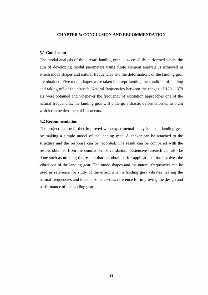
While the result is comparatively is different, basically the system have the same
pattern of natural frequencies and mode shapes (refer to Figure 4-7). The difference
in values is due to the difference of condition of the analysis and the design of the
landing gear.
Figure 4-7: Mode shape of a landing gear [7]
From the modal analysis, the obtained results are the mode shapes and the natural
frequencies of the mode shapes, which are also the dynamic properties of the landing
gear. During this analysis, the structure is given different frequencies of excitation at
a constant force. At specific frequencies (which in this case, the natural frequencies),
the landing gear structure will start to have a response where it undergone a motion
that occurs naturally hence explaining the mode shapes as in Figure 4-1 until 4-5.
This situation is the reason that causes the deformations of the structure showed by

21
the mode shapes. These frequencies are really important as they might cause
damage to the structure such as fatigue or permanent failure.
In order to prevent the structure from vibrating at its natural frequencies, damping
system is introduced as an alternative dispersion mean for the energy that is
produced without compromising the structure itself.
Modal analysis can also be done experimentally where the landing gear can be give
frequencies of excitation using shaker at a constant force. The response is then
recorded by an accelerometer that is attached at the other end of the landing gear.
Modal analysis is a preferable analysis for a vibration study of a structure since it
helps to find the problems that are caused by vibrations. Moreover, it tackles the
problems before it happens during the real working condition and it helps to
optimize the landing gear design and improves its performance.
22
CHAPTER 5: CONCLUSION AND RECOMMENDATION
5.1 Conclusion
The modal analysis of the aircraft landing gear is successfully performed where the
aim of developing modal parameters using finite element analysis is achieved in
which mode shapes and natural frequencies and the deformations of the landing gear
are obtained. Five mode shapes were taken into representing the condition of landing
and taking off of the aircraft. Natural frequencies between the ranges of 129 – 379
Hz were obtained and whenever the frequency of excitation approaches one of the
natural frequencies, the landing gear will undergo a drastic deformation up to 0.2m
which can be detrimental if it occurs.
5.2 Recommendation
The project can be further improved with experimental analysis of the landing gear
by making a simple model of the landing gear. A shaker can be attached to the
structure and the response can be recorded. The result can be compared with the
results obtained from the simulation for validation. Extensive research can also be
done such as utilising the results that are obtained for applications that involves the
vibrations of the landing gear. The mode shapes and the natural frequencies can be
used as reference for study of the effect when a landing gear vibrates nearing the
natural frequencies and it can also be used as reference for improving the design and
performance of the landing gear.
23
REFERENCES
[1] After S. Pace, 1984, “North American Valkyrie XB-70A”, Aero Series vol. 30,
Tab Books
[2] A. Fong P. Eng., “Shimmy Analysis of A Landing Gear System”, Menasco
Aerospace Ltd, Coltec Industries, pp. 1
[3] Prashant Dilip Khapane, “Simulation of Aircraft Landing Gear Dynamics Using
Flexible Multibody Dynamics Methods In SIMPACK”, DLR – German Aerospace
Center, pp. 3
[4] Prashant Khapane, “Simulation of Landing Gear Dynamics and Brake-Gear
Interaction”, Technischen Universität Carolo-Wilhelmina zu Braunschweig, pp 52-
53
[5] Pete Avitabile, “Modal Space Back to Basics”, pp. 3
[6] Patrick Guillaume, “Modal Analysis”, Vrije Universiteit Brussel, pp. 3
[7]Prashant Khapane, “Simulation of Landing Gear Dynamics and Brake-Gear
Interaction”, Technischen Universität Carolo-Wilhelmina zu Braunschweig, pp 44-
74
[8] Alvin Fong P. Eng., 2007, “Experimental Modal Analysis of Landing Gears”,
LMS Conference
[9] Airplane Parts – Major Components, retrieved on 29 July 2012,
<http://www.flightlearnings.com/2008/10/23/airplane-parts-major-components/>,
24
APPENDICES
Appendix A
Figure A-1
Figure A-2

25
Appendix B
Figure B-1

26
Figure B-2
Related Documents


![arXiv:1407.0927v1 [cs.SE] 3 Jul 2014Landing-Gear Extended Landing-Gear Retracted Landing-Gear Box Landing Wheel Door Figure 1: Landing Gear System such as airport runways [11]. Three](https://static.cupdf.com/doc/110x72/5e9397289f16a23cdf089611/arxiv14070927v1-csse-3-jul-2014-landing-gear-extended-landing-gear-retracted.jpg)


