Miniature Electronic Pressure Scanners ESP-16HD/32HD/64HD FEATURES ● Unparalleled Long Term Stability ● Advanced Digital Temperature Compensation (DTC) ● Individual Offset and Thermal Zero Compensation ● Automatically Switched Reference Pressures ● Optional Isolated Purge Capability ● Optional Temperature Sense Output APPLICATIONS ● ● ● In-Model Windtunnel Testing Aircraft Flight Testing Automotive Track Testing ESP Pressure Scanners are miniature electronic differential pressure measurement units consisting of an array of silicon piezoresistive pressure sensors, one for each pressure port. The sensors are mounted on a common hybrid glass substrate using a proprietary technique which maximizes long term stability. The outputs of the sensors are electronically multiplexed through a single onboard instrumentation amplifier at rates up to 70,000 Hz using binary addressing. The multiplexed amplified analog output is capable of driving long lengths of cable to a remote A/D converter. The ESP scanners also incorporate a two position calibration manifold actuated by momentary pulses of control pressures. When placed in the calibrate position, all sensors are connected to a common calibration pressure port. A series of accurately measured pressures can be applied through this port to characterize the sensors, in place, at the condition to which they are being subjected. Proper and periodic on-line calibration maintains static errors within +/-0.03% or better of the full scale (FS) pressure range. The calibration manifold automatically switches between two common reference pressures to ensure a stable reference is applied during calibration. The calibration manifold incorporates a visual position indicator and utilizes a dynamic o-ring seal design for high reliability and easy servicing in the field. Options include purge capability, isolated from the pressure sensors, to clear measurement lines of moisture and contamination as well as to prevent closure of model pressure taps during application of pressure sensitive paint. Other options include a nickel foil RTD output to monitor internal scanner temperature and Digital Temperature Compensation technology now incorporating PSI’s Gen-2 amplifier technology. The Digital Temperature Compensation (DTC) option incorporates the latest PSI innovations in ESP technology including temperature signal outputs from each silicon pressure sensor, embedded EEPROM retaining factory calibration information including temperature characteristics, programmable dual gain amplifier with optional dual range calibration, calibration manifold position sensing, and internal sensor excitation regulation with sense output. DTC Series ESP scanners are supported by PSI’s DTC Initium System and the SDI configuration of the System 8400 to dramatically reduce calibration requirements. The ESP scanners are also supported bya variety of third party compatible systems. 34 Research Drive Hampton, VA 23666 USA www.PressureSystems.com ISO-9001:2000 Certified Phone: 757-865-1243 Toll Free: 800-328-3665 Fax: 757-865-8744 E-mail: [email protected] © Copyright Pressure Systems, Inc., 2009

Welcome message from author
This document is posted to help you gain knowledge. Please leave a comment to let me know what you think about it! Share it to your friends and learn new things together.
Transcript

Miniature Electronic Pressure Scanners
ESP-16HD/32HD/64HD
FEATURES ● Unparalleled Long Term Stability
● Advanced Digital Temperature Compensation (DTC)
● Individual Offset and Thermal Zero Compensation
● Automatically Switched Reference Pressures
● Optional Isolated Purge Capability
● Optional Temperature Sense Output
APPLICATIONS
● ● ●
In-Model Windtunnel Testing Aircraft Flight Testing Automotive Track Testing
ESP Pressure Scanners are miniature electronic differential pressure measurement units consisting of an array of silicon piezoresistive pressure sensors, one for each pressure port. The sensors are mounted on a common hybrid glass substrate using a proprietary technique which maximizes long term stability. The outputs of the sensors are electronically multiplexed through a single onboard instrumentation amplifier at rates up to 70,000 Hz using binary addressing. The multiplexed amplified analog output is capable of driving long lengths of cable to a remote A/D converter. The ESP scanners also incorporate a two position calibration manifold actuated by momentary pulses of control pressures. When placed in the calibrate position, all sensors are connected to a common calibration pressure port. A series of accurately measured pressures can be applied through this port to characterize the sensors, in place, at the condition to which they are being subjected. Proper and periodic on-line calibration maintains static errors within +/-0.03% or better of the full scale (FS) pressure range. The calibration manifold automatically switches between two common reference pressures to ensure a stable reference is applied during calibration. The calibration manifold incorporates a visual position indicator and utilizes a dynamic o-ring seal design for high reliability and easy servicing in the field. Options include purge capability, isolated from the pressure sensors, to clear measurement lines of moisture and contamination as well as to prevent closure of model pressure taps during application of pressure sensitive paint. Other options include a nickel foil RTD output to monitor internal scanner temperature and Digital Temperature Compensation technology now incorporating PSI’s Gen-2 amplifier technology. The Digital Temperature Compensation (DTC) option incorporates the latest PSI innovations in ESP technology including temperature signal outputs from each silicon pressure sensor, embedded EEPROM retaining factory calibration information including temperature characteristics, programmable dual gain amplifier with optional dual range calibration, calibration manifold position sensing, and internal sensor excitation regulation with sense output. DTC Series ESP scanners are supported by PSI’s DTC Initium System and the SDI configuration of the System 8400 to dramatically reduce calibration requirements. The ESP scanners are also supported bya variety of third party compatible systems. 34 Research Drive Hampton, VA 23666 USA
www.PressureSystems.com
ISO-9001:2000 Certified
Phone: 757-865-1243 Toll Free: 800-328-3665 Fax: 757-865-8744 E-mail: [email protected]
© Copyright Pressure Systems, Inc., 2009

- 2 -
ESP Specifications Specifications subject to change without notice.
After 1 hour warmup @ 250C with atmospheric reference pressure unless otherwise stated.
DTC CONVENTIONAL Parameter
32HD 64HD 16HD 32HD 64HD Units Comments
PNEUMATICS
Number of Pressure Inputs
32 64 16 32 64 ports
Pressure Range1 ±4 (1.0), ±10 (2.5), ±20 (5.0)
±1 (7), ±2.5 (17), ±5 (34), ±10 (69) , ±15 (103), ±30 (207), ±45 (310), ±50 (345), +100 (689)
in WC (kPa)psid (kPa) psid (kPa)
Proof Pressure 2 400 150
% FS % FS
range ≤ 30 psid range > 30 psid
Max Reference Pressure (Line Pressure)
50 (345) 15 (103)
psid (kPa) psid (kPa)
range ≥ 2.5 psid range < 2.5 psid
Manifold Control Pressure 100 (689) 125 (862)
psig (kPa) psig (kPa)
min max
Optional Purge Pressure greater than max input pressure
150 (1050) psig (kPa) psig (kPa)
min max
Media: Measurement Ports Reference Ports
non-corrosive gases up to 100% non-condensing humidity
dry, non-corrosive gases
Pneumatic Connection 0.040 or
0.063 0.040
0.040 or 0.063
0.040 or 0.063
0.040 inches OD SS bulged tubulation
PERFORMANCE
Static Accuracy 3 @100% range 4 @33% range 7 2nd order correction 5 4th order correction 6
±0.03 ±0.06 ±0.15
±0.05
N/A N/A
N/A N/A
N/A N/A N/A
N/A
±0.15 ±0.20
±0.05 ±0.10
% FS % FS % FS
% FS
% FS % FS
% FS % FS
range ≥ 5 psid range ≥ 10 in WC to < 5 psid range < 10 in WC range ≥5 psid range > 2.5 psid range≤2.5 psid range > 2.5 psid range≤ 2.5 psid
Thermal Zero Error N/A ±0.06 ±0.20
% FS/ºC % FS/ºC
range > 2.5 psid range≤ 2.5 psid
Thermal Span Error N/A ±0.02 ±0.03
% FS/ºC % FS/ºC
range > 2.5 psid range≤2.5 psid
Total Thermal Stability @100% range @33% range 7
±0.002 ±0.004 ±0.01
±0.003
N/A N/A N/A
N/A
% FS/ºC % FS/ºC %FS/ºC
% FS/ºC
range ≥ 5 psid range ≥ 10 in WC to < 5 psid range < 10 in WC range ≥ 5 psid
Line Pressure Effect ±0.001 ±0.002
% FS/psi % FS/psi
range > 2.5 psid range≤2.5 psid
NOTES: 1 Consult factory for pressure ranges not listed 2 Maximum applied pressure without reducing sensor performance 3 Static accuracy includes combined errors due to non-linearity, hysteresis, and non-repeatability 4 Achievable static accuracy after span calibration. Consult applicable datasheets for DTC Series ESP specifications when used with PSI’s System 8400 SDI configuration or DTC Initium system. 5 Typical performance using 2nd order equation of the form Px = C0 + C1 (Vx) + C2 (Vx)
2 6 Typical performance using 4th order equation of the form Px = C0 + C1 (Vx) + C2 (Vx)
2 + C3 (Vx)3 + C4 (Vx)
4 7 Accuracy is expressed as a percent of the deranged Full Scale when dual range calibration is specified. Applicable when Dual Range Calibration is specified.

- 3 -
ESP Specifications Specifications subject to change without notice.
DTC CONVENTIONAL Parameter
32HD 64HD 16HD 32HD 64HD Units Comments
ELECTRICAL
Power Supply +5 VDC +12 VDC -12 VDC
0
75 25
0
110 25
25 5 3
55 5 3
75 5 3
mA mA mA
max max max
Full Scale Output ±3.5 – 4.5 VDC optional output available
Port Selection 5 6 4 5 6 bit 0-12 VDC, CMOS Logic
Scan Rate 70,000 20,000 chs/sec
Electrical Connection 15 pin subminiature D-shell 8 ITT Cannon (PN: MDM 15SSB)
ENVIRONMENTAL/PHYSICAL
Comp Temp Range 0 to 80 ºC
Operating Temp Range -25 to 80 ºC
Storage Temp -25 to 100 ºC
Weight 3.9
(112) 5.1
(143) 1.6 (46)
3.7 (106)
4.9 (140)
oz. (g)
HEATER CHAMBERS
Setpoint Adjustability ±3 ºC
Thermal Compensation N/A 9 10:1 reduction in the effects of temperature to the scanner
Ambient Temperature -55 ºC min
Power Requirements 28 VDC @ 1.5A max
Electrical Connection Two leads unterminated Red: +28 VDC Black: GND
Temperature Overload 90 ºC with Auto Reset
Weight 6.8
(192) 6.8
(192) 5.6
(157) 6.8
(192) 6.8
(192) oz. (g)
NOTES: 8 ESP-16HD supplied with intermediate cable terminating with 15-pin subminiature D-shell 9 Heater chambers for DTC Series scanners are only required to maintain minimum operating temperature.
PIN FUNCTION PIN FUNCTION 1 Digital Address A0 9 -VS, Sensor Suply Voltage Return 2 Digital Address A1 10 GND 3 Digital Address A2 11 Voltage Output V0 4 Digital Address A3 12 Digital Address A5 5 Digital Address A4 13 GND Sense 6 +12 VDC 14 +VS Sense (opt.) 7 -12 VDC 15 Vt, Temperature Sense Output (opt.) 8 +VS, Sensor Supply Voltage (+5)

- 4 -
ESP Pneumatic/Electrical Interface
Interfacing to the ESP-HD Series scanners consist of both electrical and pneumatic considerations. The DTC Initium, System 8400 and S8256 Flight System provide turnkey pre-engineered solutions to these interfacing requirements. Custom data acquisition systems will require these interfaces to be developed.

- 5 -
ESP Options
Digital Temperature Compensation (DTC)
The DTC option of the ESP pressure scanners incorporates many advanced features including the Gen-2 amplifier technology to increase the utility of the scanners while providing digital temperature compensation of the silicon sensors.
An onboard EEPROM stores the thermal calibration data for each channel. Also stored in the EEPROM is information identifying the range of the scanner, the number of channels, the model number, the serial number, the date of manufacturer, the date of calibration, and the model and serial number of the calibration unit used to calibrate the scanner. This data is serially transmitted to a data acquisition system such as the DTC Initium or to the Scanner Digitizer Interface (SDI) of the System 8400 using the ESP address lines and then transferred to the 8400 System Processor via fiber optic cable.
Using a proprietary PSI-developed method, the temperature of each sensor within the scanner is measured and transmitted along with the raw pressure measurements to the data acquisition system. Utilizing the calibration data within the EEPROM, the data acquisition system compensates for temperature changes to the sensors in real time. This reduces thermal errors by a factor of 20 thereby reducing on-line calibration requirements by up to 90%.
The ESP scanners also incorporate a hall effect sensor which is used to indicate the position of the calibration manifold. This position information can be transferred to the system upon command.
Another advanced feature is the ability to derange the ESP scanner upon command. This alters the gain on the amplifier to derange the scanner by a factor of three, enabling additional windtunnel tests to be conducted without reinstrumenting the model with lower range ESP scanners. To optimize the accuarcy of the DTC scanner at the highest gain, the optional dual range calibration is recommended. Temperature Sense Output Option for Conventional ESP Scanners The temperature sense output option involves embedding a nickel foil RTD within the scanner to indicate internal scanner temperature. The analog signal from the RTD is output on one of the pins of the electrical connector. Silicon sensors are repeatable with temperature and, once characterized, can be compensated for thermal errors using algorithmic techniques. Scanners with this option are factory calibrated at temperature intervals throughout the operational temperature span of the scanner and a curve fit established for each sensor. A fourth order polynomial equation is generated for each sensor at standard temperature points of -25, 0, 25, 50 and 75ºC. These equations as well as the corresponding RTD voltages are provided to customers in a calibration report along with the scanner. The temperature sense option can be ordered with the scanner or existing scanners can be retrofitted by returning the scanner to the factory for upgrade. (See page 12 for order information.) Pneumatic Connections Pneumatic connections to the ESP scanners are made via user-specified 0.040” or 0.063” OD bulged stainless steel tubulations installed on the scanner tubing plate. Tubulations of 0.040” OD can optionally be installed at a 60º angle to minimize the overall height of the scanner. Scanners specified with Purge option must be installed at the standard 90º angle unless the Quick-Disconnect option is also specified. Flexible tubing is installed over the bulged tubulation and secured using retaining springs. Pressure Systems offers nylon tubing, retaining springs and tubing pliers to facilitate the installation of the tubing and springs. (See page 12 for ordering information).
- 6 -
ESP Options
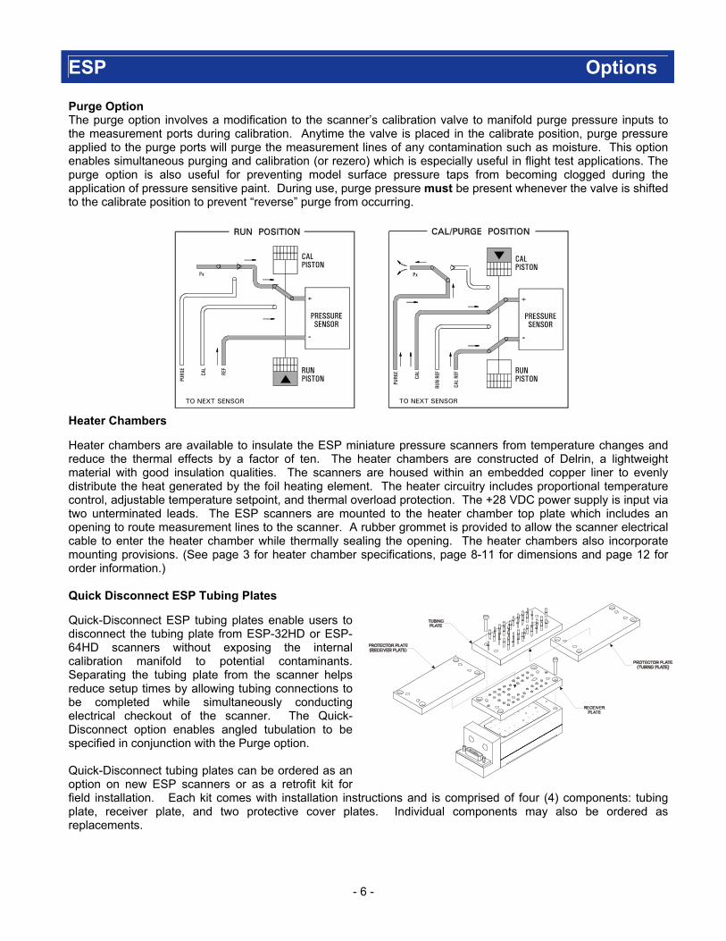
Purge Option The purge option involves a modification to the scanner’s calibration valve to manifold purge pressure inputs to the measurement ports during calibration. Anytime the valve is placed in the calibrate position, purge pressure applied to the purge ports will purge the measurement lines of any contamination such as moisture. This option enables simultaneous purging and calibration (or rezero) which is especially useful in flight test applications. The purge option is also useful for preventing model surface pressure taps from becoming clogged during the application of pressure sensitive paint. During use, purge pressure must be present whenever the valve is shifted to the calibrate position to prevent “reverse” purge from occurring. Heater Chambers Heater chambers are available to insulate the ESP miniature pressure scanners from temperature changes and reduce the thermal effects by a factor of ten. The heater chambers are constructed of Delrin, a lightweight material with good insulation qualities. The scanners are housed within an embedded copper liner to evenly distribute the heat generated by the foil heating element. The heater circuitry includes proportional temperature control, adjustable temperature setpoint, and thermal overload protection. The +28 VDC power supply is input via two unterminated leads. The ESP scanners are mounted to the heater chamber top plate which includes an opening to route measurement lines to the scanner. A rubber grommet is provided to allow the scanner electrical cable to enter the heater chamber while thermally sealing the opening. The heater chambers also incorporate mounting provisions. (See page 3 for heater chamber specifications, page 8-11 for dimensions and page 12 for order information.) Quick Disconnect ESP Tubing Plates Quick-Disconnect ESP tubing plates enable users to disconnect the tubing plate from ESP-32HD or ESP-64HD scanners without exposing the internal calibration manifold to potential contaminants. Separating the tubing plate from the scanner helps reduce setup times by allowing tubing connections to be completed while simultaneously conducting electrical checkout of the scanner. The Quick-Disconnect option enables angled tubulation to be specified in conjunction with the Purge option. Quick-Disconnect tubing plates can be ordered as an option on new ESP scanners or as a retrofit kit for field installation. Each kit comes with installation instructions and is comprised of four (4) components: tubing plate, receiver plate, and two protective cover plates. Individual components may also be ordered as replacements.
- 7 -
ESP Accessories and Spec Diagrams
Maintenance Kits and Spare Tubing Plates
To supplement the on-site ability to replace the transducer carriers and the amplifier assembly, maintenance kits are offered to service the calibration valve and tubing plate. These kits are available for each of the scanner models.
The maintenance kits consist of spare bulged tubulations, a drill bit to clean the tubulation bore in the tubing plate, and the sealant to secure the tubulation to the plate. Also included are spare “O” rings for the calibration manifold and the pistons along with a generous supply of lubricant. Additional “O” rings can be purchased separately. Spare tubing plate screws are also provided.
Spare tubing plates can be used to replace damaged tubing plates or to alter the pneumatic connections of the scanner. When ordering spare tubing plates, the manifold configuration (standard or purge) as well as the ESP model must be indicated along with the pneumatic connection.
Instructions for servicing the ESP scanners using these maintenance kits are provided in the ESP Miniature Scanners User’s Manual. (See page 12 of this datasheet for order information.)
Cables
Pressure Systems offers a variety of cables including a mating connector with wiring harness to facilitate electrical connection to the system. These cables are custom designed to maximize noise immunity and flexibility. These cables can be used to interface the ESP miniature scanners to the DTC Initium, System 8400, and S8256 Flight System Scanner Interfaces or to custom data acquisition systems. Both PVC and PTFE jacketed cables are available.
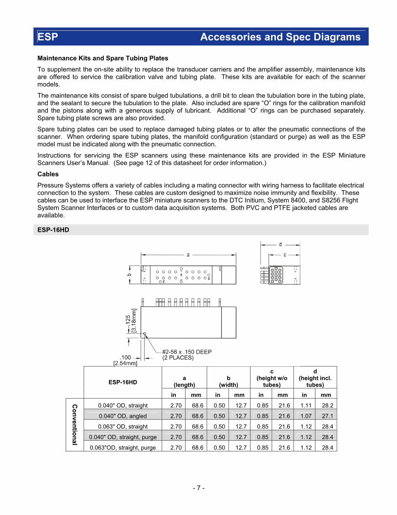
ESP-16HD
a
(length) b
(width)
c (height w/o
tubes)
d (height incl.
tubes)
ESP-16HD
in mm in mm in mm in mm
0.040" OD, straight 2.70 68.6 0.50 12.7 0.85 21.6 1.11 28.2
0.040" OD, angled 2.70 68.6 0.50 12.7 0.85 21.6 1.07 27.1
0.063" OD, straight 2.70 68.6 0.50 12.7 0.85 21.6 1.12 28.4
0.040" OD, straight, purge 2.70 68.6 0.50 12.7 0.85 21.6 1.12 28.4
Co
nven
tion
al
0.063"OD, straight, purge 2.70 68.6 0.50 12.7 0.85 21.6 1.12 28.4

- 8 -
ESP Spec Diagrams
ESP-32HD
a
(length) b
(width)
c (height w/o
tubes)
d (height incl.
tubes)
ESP-32HD
in mm in mm in mm in mm
0.040" OD, straight 2.80 71.1 1.00 25.4 0.93 23.7 1.17 29.8
0.040" OD, angled 2.80 71.1 1.00 25.4 0.93 23.7 1.17 29.6
0.063" OD, straight 2.80 71.1 1.00 25.4 0.93 23.7 1.18 30.0
0.040" OD, straight, purge 2.80 71.1 1.00 25.4 0.93 23.7 1.36 34.5
0.063"OD, straight, purge 2.80 71.1 1.00 25.4 0.93 23.7 1.36 34.5
0.040" OD, straight, QDC 2.80 71.1 1.00 25.4 1.12 28.4 1.36 34.6
0.040" OD, angled, QDC 2.80 71.1 1.00 25.4 1.12 28.4 1.35 34.3
0.063" OD, straight, QDC 2.80 71.1 1.00 25.4 1.12 28.4 1.37 34.7
0.040" OD, straight, QDC, purge 2.80 71.1 1.00 25.4 1.12 28.4 1.54 39.2
0.040" OD, angled, QDC, purge 2.80 71.1 1.00 25.4 1.12 28.4 1.53 39.0 C
on
ventio
nal
0.063" OD, straight, QDC, purge 2.80 71.1 1.00 25.4 1.12 28.4 1.54 39.2
0.040" OD, straight 3.10 78.7 1.00 25.4 0.93 23.7 1.17 29.8
0.040" OD, angled 3.10 78.7 1.00 25.4 0.93 23.7 1.17 29.6
0.063" OD, straight 3.10 78.7 1.00 25.4 0.93 23.7 1.18 30.0
0.040" OD, straight, purge 3.10 78.7 1.00 25.4 0.93 23.7 1.36 34.5
0.063"OD, straight, purge 3.10 78.7 1.00 25.4 0.93 23.7 1.36 34.5
0.040" OD, straight, QDC 3.10 78.7 1.00 25.4 1.12 28.4 1.36 34.6
0.040" OD, angled, QDC 3.10 78.7 1.00 25.4 1.12 28.4 1.35 34.3
0.063" OD, straight, QDC 3.10 78.7 1.00 25.4 1.12 28.4 1.37 34.7
0.040" OD, straight, QDC, purge 3.10 78.7 1.00 25.4 1.12 28.4 1.54 39.2
0.040" OD, angled, QDC, purge 3.10 78.7 1.00 25.4 1.12 28.4 1.53 39.0
DT
C S
eries
0.063" OD, straight, QDC, purge 3.10 78.7 1.00 25.4 1.12 28.4 1.54 39.2

- 9 -
ESP Conventional Spec Diagrams
ESP-64HD
a
(length) b
(width)
c (height w/o
tubes)
d (height incl.
tubes)
ESP-64HD
in mm in mm in mm in mm
0.040" OD, straight 2.80 71.1 1.30 33.0 1.00 25.4 1.23 31.3
0.040" OD, angled 2.80 71.1 1.30 33.0 1.00 25.4 1.19 30.1
0.040" OD, straight, purge 2.80 71.1 1.30 33.0 1.13 28.6 1.55 39.4
0.040" OD, straight, QDC 2.80 71.1 1.30 33.0 1.31 33.3 1.55 39.2
0.040" OD, angled, QDC 2.80 71.1 1.30 33.0 1.31 33.3 1.50 38.1
0.040" OD, straight, QDC, purge 2.80 71.1 1.30 33.0 1.31 33.3 1.74 44.1
Co
nven
tion
al
0.040" OD, angled, QDC, purge 2.80 71.1 1.30 33.0 1.31 33.3 1.55 39.5
0.040" OD, straight 3.15 80.0 1.30 33.0 1.00 25.4 1.23 31.3
0.040" OD, angled 3.15 80.0 1.30 33.0 1.00 25.4 1.19 30.1
0.040" OD, straight, purge 3.15 80.0 1.30 33.0 1.13 28.6 1.55 39.4
0.040" OD, straight, QDC 3.15 80.0 1.30 33.0 1.31 33.3 1.55 39.2
0.040" OD, angled, QDC 3.15 80.0 1.30 33.0 1.31 33.3 1.50 38.1
0.040" OD, straight, QDC, purge 3.15 80.0 1.30 33.0 1.31 33.3 1.74 44.1
DT
C S
eries
0.040" OD, angled, QDC, purge 3.15 80.0 1.30 33.0 1.31 33.3 1.55 39.5

- 10 -
ESP Conventional Heater Chambers
ESP-16HD
ESP-32HD
ESP-64HD

- 11 -
ESP DTC Series Heater Chamber
ESP-32HD
ESP-64HD

- 12 -
ESP Ordering Information Pressure Scanner:
PN: 16HD-AABBCCDDEE ESP-16HD Scanner, 16 channels PN: 32HD-AABBCCDDFF ESP-32HD Scanner, 32 channels PN: 64HD-AABBCCDDFF ESP-64HD Scanner, 64 channels
AA = Pressure Range (Consult Factory for pressure ranges not listed) 19, ±4”WC (1.0 kPa) 04, ±2.5 psid (17 kPa) 08, ±30 psid (207 kPa) 01, ±10"WC (2.5 kPa) 05, ±5 psid (34 kPa) 09, ±45 psid (310 kPa) 02, ±20"WC (5.0 kPa) 06, ±10 psid (69 kPa) 10, +100 psid (689 kPa) 03, ±1 psid (7 kPa) 07, ±15 psid (103 kPa) BB = Pneumatic Connection (OD, angle) CC = Manifold Options 01, 0.040", 90º 00, Standard 02, 0.040", 60º (not available with Purge option) 02, Purge option 03, 0.063", 90º (16HD/32HD only) 11, 0.040", 90º, quick disconnect (32HD/64HD only) 12, 0.040", 60º, quick disconnect (32HD/64HD only) EE = Intermediate Cable Length (16HD only) 13, 0.063", 90º, quick disconnect (32HD only) 01, 1 foot 02, 2 feet 03, 3 feet DD = Temperature Sense 04, 4 feet 00, Standard 05, 5 feet 01, Temperature Sense with PROM
(for use with S8256)
03, Temperature Sense with Calibration
11, Digital Temperature Compensation (DTC) with single
range calilbration (FF must = 20)
12, Digital Temperature Compensation (DTC) with dual range calibration (FF must = 20)
FF =
06, 6 feet
For requirements in excess of 6 feet, use ESCB scanner extension cable
Amplifier Generation 32HD & 64HD only)
00, Conventional 20, Gen-2 DTC (DD must = 11 or 12)
Spare Quick-Disconnect: 32QD-AABBCC0000 64QD-AABBCC0000
Quick-Disconnect ESP Tubing Plate Kit, 32 ports Quick-Disconnect ESP Tubing Plate Kit, 64 ports
AA = Kit Configuration 00, Complete 4-piece kit 01, Receiver plate only 02, Tubing plate only 03, Protective plate only \ BB = Pneumatic Configuration (OD, angle) CC = Manifold Options 00, N/A 00, Standard 11, 0.040", 90º (32HD/64HD only) 02, Purge 12, 0.040", 60º (32HD/64HD only) 13, 0.063", 90º (32QD only)
Notes:
32QD with purge option uses 0.125" OD purge tubes on all pneumatic configurations 64QD with purge option uses 0.090" OD purge tubes on 90º pneumatic configurations and 0.063" OD purge tubes on 60º pneumatic configurations Not available with heater chamber option
Heater Chamber:
PN: 16HC-AA00000000 ESP-16HD Heater Chamber PN: 32HC-AA00000000 ESP-32HD Heater Chamber PN: 64HC-AA00000000 ESP-64HD Heater Chamber
AA = Type of Scanner 01, Conventional 02, DTC
Order Example: 32HD-0103021120 ESP-32HD Scanner, ±10"WC, .063", 90º, purge, digital temperature compensation with single range calibration
No. 1009
Related Documents