DIGITAL 300 SERIES INSTRUCTION MANUAL ISO 9001 C E R T I F I E D www.teledyne-hi.com

Welcome message from author
This document is posted to help you gain knowledge. Please leave a comment to let me know what you think about it! Share it to your friends and learn new things together.
Transcript
DIGITAL 300 SERIES
INSTRUCTION MANUAL
I S O 9 0 0 1C E R T I F I E D
www.teledyne-hi.com
Digital 300 Series Instruction Manual Page 2 of 44
Manual Print History The print history shown below lists the printing dates of all revisions created for this manual. The revision level letter increases alphabetically as the manual undergoes subsequent updates. Each new revision includes a revised copy of this print history page.
Revision A (Document Number 176-082015) ................................................................ August 2015
Visit www.teledyne-hi.com for WEEE disposal guidance.
Description of Symbols and Messages used in this manual
WARNING: indicates a hazardous situation, which, if not avoided, could result in death or serious injury. Do not proceed beyond a WARNING notice until the indicated conditions are fully understood.
CAUTION: indicates a hazardous situation, which if not avoided, could result in minor or moderate injury. Do not proceed beyond a CAUTION notice until the indicated conditions are fully understood and met.
NOTICE: calls attention to a procedure or practice that if not correctly performed or adhered to, could result in equipment damage, loss of data, or inaccurate data.
NOTE: is used for tips and other digressions.
Hastings Instruments reserves the right to change or modify the design of its equipment without any obligation to provide notification of change or intent to change.
Digital 300 Series Instruction Manual Page 3 of 44
Table of Contents 1. GENERAL INFORMATION .................................................................................................. 5
FEATURES ................................................................................................................ 6 1.1.
SPECIFICATIONS .......................................................................................................... 7 1.2.
ACCESSORIES ............................................................................................................. 8 1.3.
1.3.1. Power Supplies ................................................................................................. 8
1.3.2. Cables ........................................................................................................... 8
2. INSTALLATION AND SETUP ............................................................................................... 9
RECEIVING INSPECTION ................................................................................................... 9 2.1.
MECHANICAL CONNECTIONS .............................................................................................. 9 2.2.
2.2.1. Filtering ......................................................................................................... 9
2.2.2. Mounting ........................................................................................................ 9
2.2.3. Plumbing ........................................................................................................ 9
ELECTRICAL CONNECTIONS .............................................................................................. 10 2.3.
2.3.1. Connector ...................................................................................................... 10
2.3.2. Power Input ................................................................................................... 10
2.3.3. Analog Output ................................................................................................ 10
2.3.4. Analog Inputs ................................................................................................. 11
2.3.5. Digital Connection ........................................................................................... 12
SWITCH OPERATION ..................................................................................................... 12 2.4.
LED OPERATION ........................................................................................................ 13 2.5.
QUICK START ........................................................................................................... 13 2.6.
3. GENERAL OPERATION .................................................................................................... 14
OPERATING CONDITIONS ................................................................................................ 14 3.1.
ZERO CHECK ............................................................................................................ 14 3.2.
HIGH PRESSURE OPERATION ............................................................................................. 14 3.3.
VERTICAL MOUNTING ................................................................................................... 17 3.4.
TEMPERATURE COEFFICIENT ............................................................................................. 17 3.5.
BLENDING OF GASES .................................................................................................... 18 3.6.
CONTROLLING OTHER PROCESS VARIABLES .............................................................................. 18 3.7.
COMMAND INPUT ........................................................................................................ 18 3.8.
VALVE OVERRIDE CONTROL ............................................................................................. 18 3.9.
4. DIGITAL OPERATION ...................................................................................................... 19
INSTRUMENT STATES .................................................................................................... 19 4.1.
4.1.1. Initialization .................................................................................................. 19
4.1.2. Operation ...................................................................................................... 19
4.1.3. Failure ......................................................................................................... 19
4.1.4. Calibration .................................................................................................... 20
Digital 300 Series Instruction Manual Page 4 of 44
SERIAL COMMUNICATIONS ............................................................................................... 20 4.2.
4.2.1. General ........................................................................................................ 20
4.2.2. Serial Communication Software ........................................................................... 20
4.2.3. The Lists ....................................................................................................... 20
4.2.4. Command Prompt ............................................................................................ 21
4.2.5. Command Format ............................................................................................ 21
4.2.6. RS-232 / RS-485 Mode ....................................................................................... 21
4.2.7. Response Format ............................................................................................. 21
4.2.7.1. Response Line Termination .......................................................................................... 22
4.2.7.2. RS-485 Mode Responses ............................................................................................... 22
4.2.8. Commands ..................................................................................................... 22
4.2.8.1. Flow Reporting Commands ........................................................................................... 22
4.2.8.2. System Status Commands ............................................................................................ 22
4.2.8.3. Sensor List Commands ................................................................................................ 24
4.2.8.4. Gas List Commands .................................................................................................... 29
4.2.8.5. Valve List Commands ................................................................................................. 31
ALARM LIMITS ........................................................................................................... 33 4.3.
FLOW AND FLOWING TIME INTEGRATION ................................................................................. 33 4.4.
MFC OPERATION ........................................................................................................ 34 4.5.
1% SHUTOFF THRESHOLD ............................................................................................... 34 4.6.
SOFTSTART ............................................................................................................. 35 4.7.
READING AVERAGING .................................................................................................... 35 4.8.
5. FLOW CALCULATION ..................................................................................................... 36
6. TROUBLESHOOTING ...................................................................................................... 38
AUTHORIZED MAINTENANCE ............................................................................................. 38 6.1.
TROUBLESHOOTING ..................................................................................................... 38 6.2.
6.2.1. Instrument Lists and Codes ................................................................................. 38
6.2.2. Possible Problems and Solutions ........................................................................... 38
7. WARRANTY ................................................................................................................. 40
WARRANTY POLICY ..................................................................................................... 40 7.1.
RETURN POLICY ......................................................................................................... 40 7.2.
8. DRAWINGS .................................................................................................................. 41
Digital 300 Series Instruction Manual Page 5 of 44
1. General Information The Digital 300 Series is an all-digital line of instruments that is based on the 300 series flow meters and controllers. This digital version uses the same base, flow shunting arrangement, and patented sensor as the analog 300 series. The sensor is operated in the “constant temperature above ambient” manner similar to the analog 300 series. Mechanically, the Digital 300 series has the same foot print and mounting-hole arrangement as the analog 300 series and, with consideration given for its additional height, could be a drop in replacement.
The Digital 300 series instruments have a modular PCB design that allows for flexible connections for OEM applications. The standard configuration has the same 15 pin D connector as an analog 300 Series along with 2 parallel connectors (6P6C) for digital communication. The Digital 300 series will, normally, be setup at the factory to emulate an analog 300 unit. It will accept the same command signals and generate the same analog output signals.
Because the sensors and shunts are the same as those used in the analog version of these instruments, the digital version exhibits excellent linearity and stability. It then uses a precision A/D converter to supply digital readings. The product of the converted sensor current and voltage signals produces a digital power signal. A measure of the power signal at a known zero flow condition is stored in non-volatile storage and subtracted from the instantaneous power measurement to produce a signal proportional to the molar gas flow.
During initial calibration, the residual non-linearity is measured and a polynomial is fitted to the error signal. This polynomial is stored in non-volatile RAM on the flow controller. The polynomial is applied to the instantaneous power measurement to convert the power signal to a flow signal. This flow signal is then converted to the desired engineering units and to the % of full-scale flow. These flow signals are made available on the digital port. The % of full-scale signal is converted to the desired analog signal (0-5 VDC, 0-10 VDC, 0-20mA or 4-20 mA). This signal is presented to the D connector at the same pins as the analog 300 Series.
In analog control mode, the analog signal present on the command input pin is converted to a % of full-scale value. This % of full-scale command value is compared to the % of full-scale flow signal and a difference signal is generated. The difference signal is used to adjust the power supplied to the valve coil to adjust the actual gas flow to match the desired flow. This measurement/control loop is performed approximately 200 times a second to maintain real time control of the flow stream.
The digital mass flow meters (HFM-D-300/301/305/306) and controllers (HFC-D-302/303/307/308) are intrinsically linear and are designed to accurately measure and control mass flow over the range of 5 SCCM to 10,000 SLM. Hastings mass flow instruments do not require any periodic maintenance under normal operating conditions with clean gases. No damage will occur from the use of moderate overpressures (< 500 PSI/3.45 MPa) or overflows. Instruments are normally calibrated with the appropriate standard calibration gas (nitrogen or air), and then a conversion factor is used to adjust the output for the intended gas. Calibrations for other gases, such as oxygen, hydrogen, helium and argon, are available through special order.
The following sections contain the steps needed to get a new flow meter/controller operating as quickly and easily as possible. Please read the following thoroughly before attempting to install the instrument.
NOTICE: The instruments described in this manual are available with multiple pin-outs. Ensure that all electrical connections are correct.
NOTICE: The instruments described in this manual are designed for INDOOR use only.
NOTICE: The instruments described in this manual are designed for Class 2 installations in accordance with IPC standards.
Digital 300 Series Instruction Manual Page 6 of 44
Features 1.1.
LINEAR BY DESIGN. The 300 Series is intrinsically linear. The output of the sensor has a non-linearity less than 1% typically before the curve fit. This minimizes the density driven errors that occur when gases other than the calibration gas are measured.
CURVE FIT CORRECTION. The Digital 300 Series uses a curve fitting technique to remove any residual non-linearity from the system to improve the overall accuracy. This significantly improves the % of reading errors when flow rates are at a small fraction of the controller’s full scale flow.
FLEXIBLE POWER REQUIREMENTS. The Digital 300 Series can operate with any power supply capable of providing 11 – 36 VDC between the high and low supply pins. Bipolar ±12 VDC, ±15 VDC or unipolar 24 VDC are all acceptable.
DIGITAL COMMUNICATIONS. The Digital 300 Series can communicate or be controlled via an RS232 port or a RS485 bus. Baud rates of 9600 and 19.2k baud are supported.
ANALOG EMULATION. The Digital 300 Series instrument can be set up to mimic an analog instrument. In this configuration the flow output is available as an analog signal and flow controllers will respond to analog commands.
AUTO-ZERO. The Digital 300 Series of flow controllers can re-zero automatically. This feature is enabled by default at the factory. Auto-zeroing will occur whenever the command signal is set to zero for 1 minute after flowing for 10 ten minutes. Ambient temperature changes of more than 5 degrees will also cause the auto-zero to occur. This feature removes most temperature driven zero shifts.
CURRENT LOOP. The 0-20 mA or 4-20 mA option gives the user the advantages of a current loop output to minimize environmental noise pickup and signal loss over long cable runs.
NO FOLDOVER. The output signal is linear for very large over flows and is monotonically increasing thereafter. The output signal will not come back on scale when flows an order of magnitude over the full scale flow rate are measured. This means no false acceptable readings during leak testing.
LARGE DIAMETER SENSOR TUBE. The Hastings 300 sensor is less likely to be clogged than other mass flow sensors due to its large internal diameter (0.026”/ 0.66mm).
LOW dP. The HFM-300 sensor requires a pressure of approximately 0.25 inches of water (62 Pa) at a flow rate of 10 sccm. The low pressure drop across this instrument is ideal for leak detection applications since the pneumatic settling times are proportional to the differential pressure.
METAL SEALS. The HFM-300 and HFC-302 are constructed of stainless steel. All seals (except the valve seat) are made with Ni gaskets standard, eliminating the permeation, degradation and outgassing problems of elastomer O-rings.
LOW SURFACE AREA. The HFM-300 and HFC-302 shunt is designed to have minimal wetted surface area and no un-swept volumes. This will minimize particle generation, trapping and retention.
Digital 300 Series Instruction Manual Page 7 of 44
Specifications 1.2.
WARNING: Do not operate instruments in excess of the specifications listed below. Failure to heed this warning could result in serious personal injury and/or damage to the equipment.
Accuracy: ±(0.2% full scale + 0.5% of reading) Repeatability: ±0.15% of full scale Maximum Pressure: 300 psi [2.07 MPa] (Models 306/308)
500 psi [3.45 MPa] (Other models) Optional 1000 psi [6.9 MPa] (Models 300/301/302/303 only) Pressure Coefficient: (Span) 0.026%/psi (N2) (0-50 psig)
See pressure section for pressure error correction
Operating Temperature: -20°C to 70°C in non-condensing environment Temperature Coefficient of Zero: N/A for controller with Auto-zero
< 0.2%/°C of full scale max (over -20 to 70°C)
Temperature Coefficient of Span: < 0.1%/°C max (over -20 to 70°C) Leak Integrity: <1x10⁻⁹ std. cc/s
<1x10⁻⁸ std. cc/s (Models 306/308)
Standard Output: 0-5 VDC Optional 0-10 VDC, 0-20 mA, 4-20 mA Power Requirements: 11-36 VDC @ 3.1 watts max (meter) @ 6.7 watts max (controller)
±12, ±15 VDC acceptable Class 2 power 150 VA max
NOTICE: Use of an underpowered or under-voltage supply could result in equipment damage.
Wetted Materials (Standard): stainless steel, nickel, Viton®
PTFE (Models 303/305/306/307/308) Kalrez® (Models 302/303/307/308)
Wetted Materials (Optional Seals): Buna-N, Neoprene, Kalrez®, PTFE Attitude Sensitivity of Zero: <1.4% of full scale before auto-zero
with N2 at 50 psig (345 KPa)
Weight (approx.): HFM-D-300A: 2.1 lb (0.9 kg) HFM-D-301A: 3.6 lb (1.6 kg) HFC-D-302A: 2.6 lb (1.2 kg) HFC-D-303A: 5.4 lb (2.5 kg) HFM-D-305A: 8.4 lb (3.8 kg) HFM-D-306A: 28.9 lbs (13.1 kg) HFC-D-307A: 15.5 lb (7.0 kg) HFC-D-308A: 37.0 lbs (16.8 kg)
Connectors: 15 pin subminiature “D”, 6P6C modular jack
Digital 300 Series Instruction Manual Page 8 of 44
Accessories 1.3.
1.3.1. Power Supplies
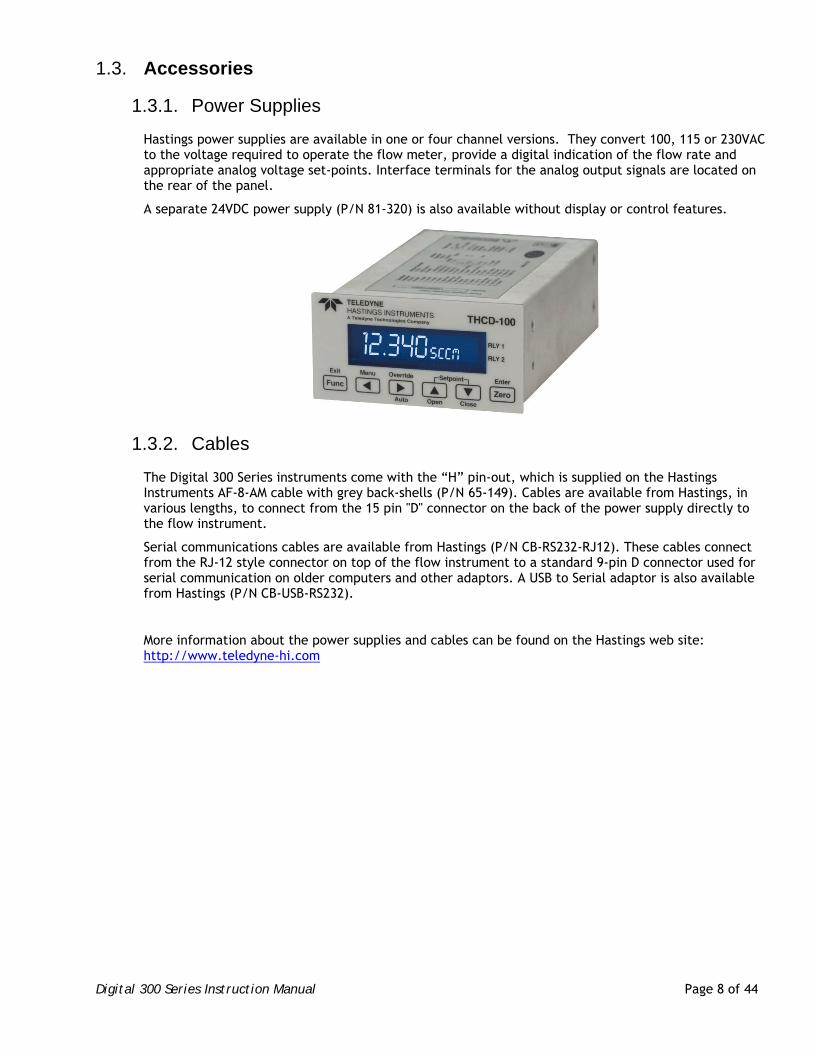
Hastings power supplies are available in one or four channel versions. They convert 100, 115 or 230VAC to the voltage required to operate the flow meter, provide a digital indication of the flow rate and appropriate analog voltage set-points. Interface terminals for the analog output signals are located on the rear of the panel.
A separate 24VDC power supply (P/N 81-320) is also available without display or control features.
1.3.2. Cables
The Digital 300 Series instruments come with the “H” pin-out, which is supplied on the Hastings Instruments AF-8-AM cable with grey back-shells (P/N 65-149). Cables are available from Hastings, in various lengths, to connect from the 15 pin "D" connector on the back of the power supply directly to the flow instrument.
Serial communications cables are available from Hastings (P/N CB-RS232-RJ12). These cables connect from the RJ-12 style connector on top of the flow instrument to a standard 9-pin D connector used for serial communication on older computers and other adaptors. A USB to Serial adaptor is also available from Hastings (P/N CB-USB-RS232).
More information about the power supplies and cables can be found on the Hastings web site: http://www.teledyne-hi.com
Digital 300 Series Instruction Manual Page 9 of 44
2. Installation and Setup This section contains the necessary steps to assist in getting a new flow meter/controller into operation as quickly and easily as possible. Please read the following thoroughly before attempting to install the instrument.
Receiving Inspection 2.1.
Prior to opening, inspect for obvious signs of damage to the shipment. Immediately advise the carrier who delivered the shipment if any damage is suspected. If the shipment has arrived intact, carefully unpack the meter/controller and any accessories that have been ordered. Check each component shipped with the packing list. Ensure that all parts are present (i.e. flow meter, power supply, cables, etc.). Optional equipment or accessories will be listed separately on the packing list. There may also be one or more options on the packing list. These normally refer to special ranges or special gas calibrations. They may also refer to special helium leak tests or high pressure tests. In most cases, these are not separate parts, but special options or modifications built into the flow meter.
Mechanical Connections 2.2.
2.2.1. Filtering
One of the smallest of the internal passageways in the 300 Series is the diameter of the sensor tube, which can be 0.026” (0.66 mm), 0.017” (0.43 mm), or 0.014” (0.36 mm). Flow element passageways can be 0.010” in size or less. If the gas supply contains particulates or condensates, the instrument will require adequate filtering of the gas supply to prevent blockage or clogging.
2.2.2. Mounting
The flow meter may usually be mounted in any position as long as the direction of gas flow through the instrument follows the arrow marked on the bottom of the flow meter case label. The preferred orientation is with the inlet and outlet fittings in a horizontal plane. When mounted in a different orientation the instrument should be re-zeroed at zero flow with the system pressurized to the expected operating pressure. If operating with a dense gas (e.g. sulfur hexafluoride) or at high pressures (> 250 psig) the instrument must be installed horizontally.
There are threaded holes located on the bottom of the base that can be used to secure it to a mounting bracket, if desired.
CAUTION: Some Digital 300 Series models are very heavy. Take care and use appropriate personal protection equipment when moving and mounting the instruments.
2.2.3. Plumbing
The pressure regulator and the plumbing upstream must be of sufficient size to minimize changes in the upstream pressure. When switching from full flow to zero flow, the inlet pressure of instrument should rise to no more that 30% above the inlet pressure at full flow. In general, high capacity regulators and large internal diameter plumbing help to make the system more stable. The pressure drop between the regulator and the instrument due to line resistance should be minimized.
For very low flows (< 100 sccm) it is important to minimize volume in the system, so use small diameter tubing over short distances when possible. As the room temperature changes, the expansion of the gas in the tubing can force flow through the flow meter. Also, any extra volume can introduce lags in system response time.
Digital 300 Series Instruction Manual Page 10 of 44
The standard inlet and outlet fittings for the 300 series are swage compression fittings. Larger fittings may require a hydraulic swage tool. It is suggested that all connections be checked for leaks after installation. This can be done by pressurizing the instrument and applying a diluted soap solution to the flow connections.
WARNING: Do not exceed the pressure rating of the instrument. Different models have different ratings. If operating near the maximum operating pressure ensure there is a pressure relief valve in the system.
Electrical Connections 2.3.
WARNING: Care must be taken to avoid any high voltages that may be present when dealing with power supplies.
2.3.1. Connector
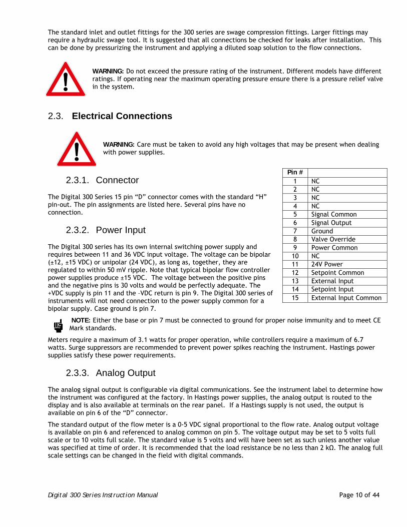
The Digital 300 Series 15 pin “D” connector comes with the standard “H” pin-out. The pin assignments are listed here. Several pins have no connection.
2.3.2. Power Input
The Digital 300 series has its own internal switching power supply and requires between 11 and 36 VDC input voltage. The voltage can be bipolar (±12, ±15 VDC) or unipolar (24 VDC), as long as, together, they are regulated to within 50 mV ripple. Note that typical bipolar flow controller power supplies produce ±15 VDC. The voltage between the positive pins and the negative pins is 30 volts and would be perfectly adequate. The +VDC supply is pin 11 and the –VDC return is pin 9. The Digital 300 series of instruments will not need connection to the power supply common for a bipolar supply. Case ground is pin 7.
NOTE: Either the base or pin 7 must be connected to ground for proper noise immunity and to meet CE Mark standards.
Meters require a maximum of 3.1 watts for proper operation, while controllers require a maximum of 6.7 watts. Surge suppressors are recommended to prevent power spikes reaching the instrument. Hastings power supplies satisfy these power requirements.
2.3.3. Analog Output
The analog signal output is configurable via digital communications. See the instrument label to determine how the instrument was configured at the factory. In Hastings power supplies, the analog output is routed to the display and is also available at terminals on the rear panel. If a Hastings supply is not used, the output is available on pin 6 of the “D” connector.
The standard output of the flow meter is a 0-5 VDC signal proportional to the flow rate. Analog output voltage is available on pin 6 and referenced to analog common on pin 5. The voltage output may be set to 5 volts full scale or to 10 volts full scale. The standard value is 5 volts and will have been set as such unless another value was specified at time of order. It is recommended that the load resistance be no less than 2 kΩ. The analog full scale settings can be changed in the field with digital commands.
Pin # 1 NC 2 NC 3 NC 4 NC 5 Signal Common 6 Signal Output 7 Ground 8 Valve Override 9 Power Common 10 NC 11 24V Power 12 Setpoint Common 13 External Input 14 Setpoint Input 15 External Input Common
Digital 300 Series Instruction Manual Page 11 of 44
Optional to the standard voltage output is the 0-20 mA or 4-20 mA current output that is proportional to flow. The current loop output is useful for remote applications where pickup noise could substantially affect the stability of the voltage output. The current loop signal replaces the voltage output on pin 6 of the “D” connector and is returned on pin 5.
NOTICE: The loop load must be less than 600 Ω. Failure to meet this condition will cause failure of the loop transmitter. Wiring diagrams for two types of power supplies and 4-20mA signals are shown below.
NOTE: 0-20mA output cannot indicate a reverse flow through the instrument or a negative offset.
2.3.4. Analog Inputs
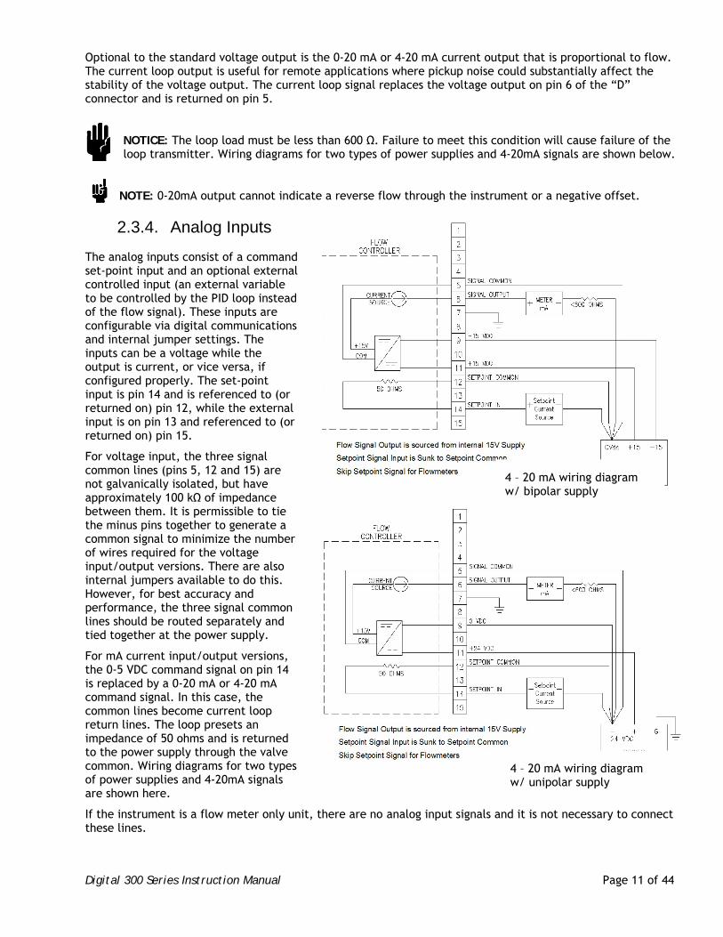
The analog inputs consist of a command set-point input and an optional external controlled input (an external variable to be controlled by the PID loop instead of the flow signal). These inputs are configurable via digital communications and internal jumper settings. The inputs can be a voltage while the output is current, or vice versa, if configured properly. The set-point input is pin 14 and is referenced to (or returned on) pin 12, while the external input is on pin 13 and referenced to (or returned on) pin 15.
For voltage input, the three signal common lines (pins 5, 12 and 15) are not galvanically isolated, but have approximately 100 kΩ of impedance between them. It is permissible to tie the minus pins together to generate a common signal to minimize the number of wires required for the voltage input/output versions. There are also internal jumpers available to do this. However, for best accuracy and performance, the three signal common lines should be routed separately and tied together at the power supply.
For mA current input/output versions, the 0-5 VDC command signal on pin 14 is replaced by a 0-20 mA or 4-20 mA command signal. In this case, the common lines become current loop return lines. The loop presets an impedance of 50 ohms and is returned to the power supply through the valve common. Wiring diagrams for two types of power supplies and 4-20mA signals are shown here.
If the instrument is a flow meter only unit, there are no analog input signals and it is not necessary to connect these lines.
4 – 20 mA wiring diagram w/ bipolar supply
4 – 20 mA wiring diagram w/ unipolar supply
Digital 300 Series Instruction Manual Page 12 of 44
Besides the standard input lines, controller versions have a valve override input available on pin 8 referenced to pin 5. If pin 8 is allowed to float, the valve is controlled internally. If a voltage above 2.4 VDC is placed on pin 8 with respect to pin 5, the valve will open fully. If a voltage below 0.4 VDC is placed on pin 8, the valve will close. Care should be taken to ensure this voltage remains between -16 and +16 VDC.
2.3.5. Digital Connection
The Digital 300 series has two, 6-pin, RJ style ports on the top of the instrument for digital communication. These ports are wired in parallel. They may be used interchangeably. Two are provided to allow the daisy chaining between multiple instruments when using the RS485 bus. The Digital 300 series can be configured to operate with RS232 or RS485 signals using switch 2 on top of the unit.
Hastings has chosen a cable configuration for our instruments and the instrument will be shipped with this configuration. Hastings uses a full duplex configuration with center two pins tied to ground and the outer pins being the communication lines to provide protection if the cable is inadvertently reversed. See the table below for the standard pin-out.
The pins are numbered looking into the female connector with the pins on the bottom from right to left. Note that the first two pins are signals coming from the Digital 300 to the bus master while the last two pins are signals coming to the Digital 300 from the bus master.
If making up a cable to interface from the RJ12 style connector to a standard PC 9-pin serial port (RS-232), use the connections as listed here.
The Digital 300 series uses RS485 receivers that are protected from bus over-voltages and will not be damaged if connected to a bus without a driver or pull up resistors. Switch 4 on top of the unit selects 120-ohm termination resistors if this particular instrument is the last one in a long cable length (prevents miscommunications due to reflections). This is not normally necessary for short cables. Do not have more than one instrument with these resistors enabled on any one cable run as this will load down the cable. Hastings ships RS485 instruments without the resistors enabled.
The default port set-up is 19.2K baud, 8 data bits, 1 stop bit, no parity and no flow control. The baud rate is selectable (9600 or 19.2k baud) with switch 1 on top of the unit. A “carriage return” signals the end of command input. The end of a response message from the Digital 300 is signaled by a “>” character. See Serial Communications section later in this manual for more information.
Switch Operation 2.4.
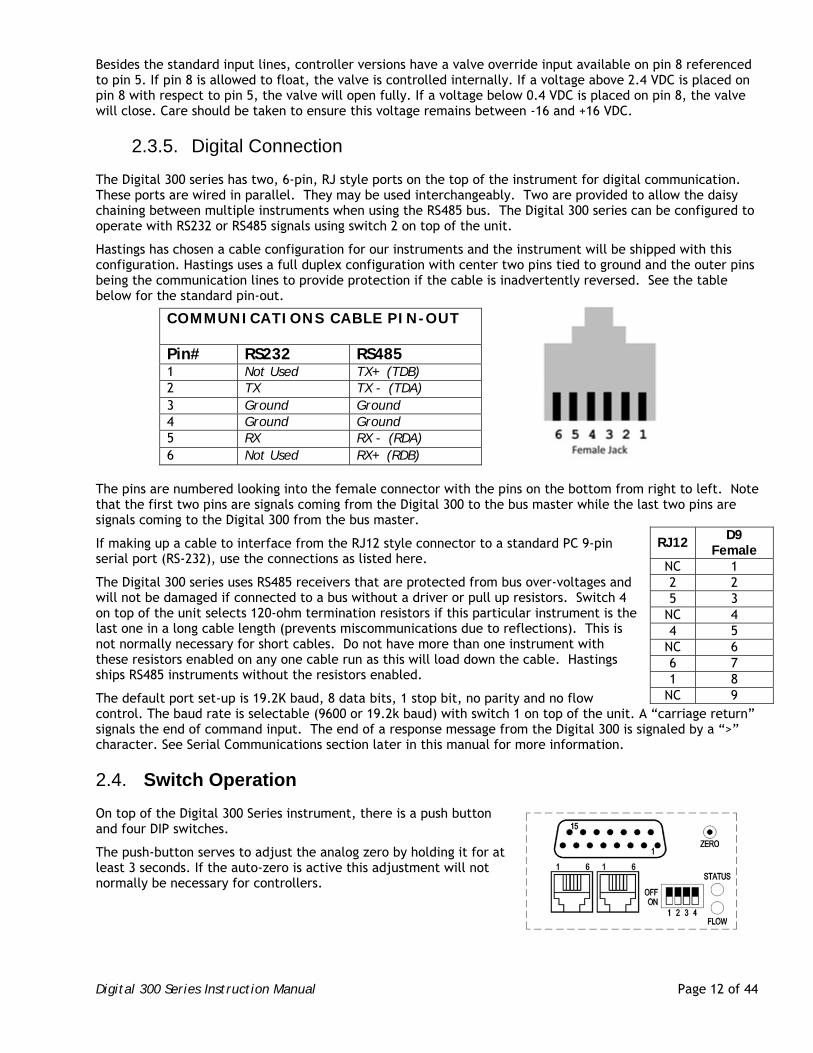
On top of the Digital 300 Series instrument, there is a push button and four DIP switches.
The push-button serves to adjust the analog zero by holding it for at least 3 seconds. If the auto-zero is active this adjustment will not normally be necessary for controllers.
COMMUNICATIONS CABLE PIN-OUT
Pin# RS232 RS485 1 Not Used TX+ (TDB) 2 TX TX - (TDA) 3 Ground Ground 4 Ground Ground 5 RX RX - (RDA) 6 Not Used RX+ (RDB)
RJ12 D9
Female NC 1 2 2 5 3
NC 4 4 5
NC 6 6 7 1 8
NC 9
Digital 300 Series Instruction Manual Page 13 of 44
On Off Switch 1 19.2K Baud 9600 Baud
Switch 2 RS232 RS485
Switch 3 Digital Control Analog Control
Switch 4 No Termination 120 Ω Termination
The four DIP switches control digital setup of the instruments.
If switch position 2 is changed, power to the unit must be cycled in order to have the change take effect.
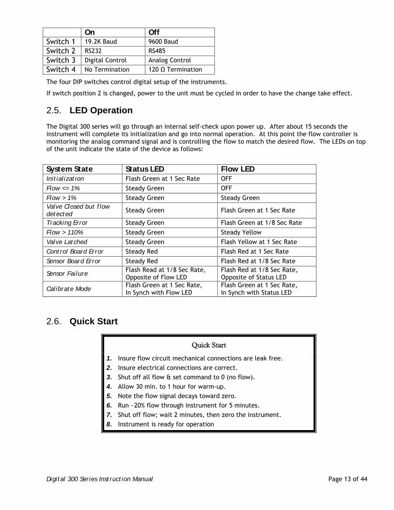
LED Operation 2.5.
The Digital 300 series will go through an internal self-check upon power up. After about 15 seconds the instrument will complete its initialization and go into normal operation. At this point the flow controller is monitoring the analog command signal and is controlling the flow to match the desired flow. The LEDs on top of the unit indicate the state of the device as follows:
System State Status LED Flow LED Initialization Flash Green at 1 Sec Rate OFF
Flow <= 1% Steady Green OFF
Flow > 1% Steady Green Steady Green Valve Closed but flow detected Steady Green Flash Green at 1 Sec Rate
Tracking Error Steady Green Flash Green at 1/8 Sec Rate
Flow > 110% Steady Green Steady Yellow
Valve Latched Steady Green Flash Yellow at 1 Sec Rate
Control Board Error Steady Red Flash Red at 1 Sec Rate
Sensor Board Error Steady Red Flash Red at 1/8 Sec Rate
Sensor Failure Flash Read at 1/8 Sec Rate, Opposite of Flow LED
Flash Red at 1/8 Sec Rate, Opposite of Status LED
Calibrate Mode Flash Green at 1 Sec Rate, In Synch with Flow LED
Flash Green at 1 Sec Rate, In Synch with Status LED
Quick Start 2.6.
Quick Start
1. Insure flow circuit mechanical connections are leak free.
2. Insure electrical connections are correct.
3. Shut off all flow & set command to 0 (no flow).
4. Allow 30 min. to 1 hour for warm-up.
5. Note the flow signal decays toward zero.
6. Run ~20% flow through instrument for 5 minutes.
7. Shut off flow; wait 2 minutes, then zero the instrument.
8. Instrument is ready for operation
Digital 300 Series Instruction Manual Page 14 of 44
3. General Operation
Operating Conditions 3.1.
NOTICE: For proper operation, the combination of ambient temperature and gas temperature must be such that the flow meter temperature remains between -20 and 70°C. The most accurate measurement of flow will be obtained if the flow meter is zeroed at the operating temperature as temperature shifts result in some zero offset.
NOTICE: The 300 Series is intended for use in non-condensing environments only. Condensate or any other liquids which enter the flow meter may destroy its electronic components.
Zero Check 3.2.
Turn the power supply on if not already energized. Typically allow at least 15 minutes for warm-up to be within rated accuracy. Typically allow at least 30 minutes warm-up when adjusting the zero. Stop all flow through the instrument and wait 2 minutes.
NOTE: Do not assume that all metering valves completely shut the flow off. Even a slight leakage will cause an indication on the meter and an apparent zero-shift.
Reset the zero using the ZRO command, by allowing the auto-zero to activate or by pressing the zero-button for 3 seconds. This zero should be checked periodically during normal operation. Zero adjustment is required if there is a change in ambient temperature or vertical orientation of the flow meter/controller.
High Pressure Operation 3.3.
WARNING: The 305,306,307 and 308 models do not have a high pressure option and are only rated for a maximum working pressure of 300 psig (306/308) or 500 psig (305/307). Do not use an instrument above its rated maximum pressure.
Thermal mass flow meters measure the heat transfer caused by gas flow. This heat transfer is a function of the constant pressure specific heat (Cp) of the gas. For monatomic gases, the specific heat is essentially a constant for all normal pressure/temperature conditions. As the gas structure becomes more complex and as the molecular weight of the gas increases, the specific heat increases as the pressure inside of the sensing tube increases. This is compensated somewhat by the effect of the hoop strain of the tube wall caused by the internal pressure on the resistance heaters wrapped around the sensing tube.
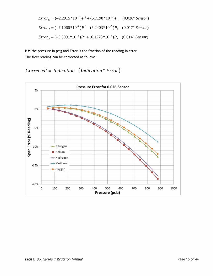
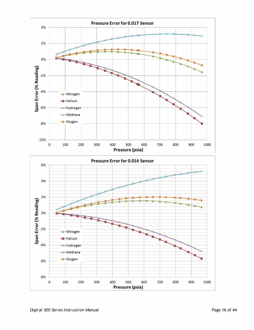
Larger tubing will have more strain than the smaller tubing and a larger associated pressure effect. Charts of the effects of various gases on the span of the flow instruments as a function of pressure are shown below for each of the available sensor diameters. The sensor tubing diameter is written on a label mounted on the side of the sensor and is listed in the options in the order acknowledgement.
If the system pressure is higher than 250 psig (1.7 MPa) the pressure induced error in the span reading becomes significant. This error will approach 16% for nitrogen at 1000 psig. For accurate high pressure measurements this error must be corrected.
The formulas for predicting the nitrogen mean error expressed as a fraction of the reading are shown below.
Digital 300 Series Instruction Manual Page 15 of 44
)"026.0(,)10*7198.5()10*2915.2( 52726 SensorPPError
)"017.0(,)10*2403.5()10*1066.7( 52817 SensorPPError
)"014.0(,)10*1278.6()10*3091.5( 52814 SensorPPError
P is the pressure in psig and Error is the fraction of the reading in error.
The flow reading can be corrected as follows:
ErrorIndicationIndicationCorrected *
Digital 300 Series Instruction Manual Page 16 of 44
Digital 300 Series Instruction Manual Page 17 of 44
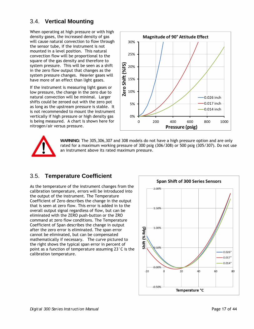
Vertical Mounting 3.4.
When operating at high pressure or with high density gases, the increased density of gas will cause natural convection to flow through the sensor tube, if the instrument is not mounted in a level position. This natural convection flow will be proportional to the square of the gas density and therefore to system pressure. This will be seen as a shift in the zero flow output that changes as the system pressure changes. Heavier gases will have more of an effect than light gases.
If the instrument is measuring light gases or low pressure, the change in the zero due to natural convection will be minimal. Larger shifts could be zeroed out with the zero pot as long as the upstream pressure is stable. It is not recommended to mount the instrument vertically if high pressure or high density gas is being measured. A chart is shown here for nitrogen/air versus pressure.
WARNING: The 305,306,307 and 308 models do not have a high pressure option and are only rated for a maximum working pressure of 300 psig (306/308) or 500 psig (305/307). Do not use an instrument above its rated maximum pressure.
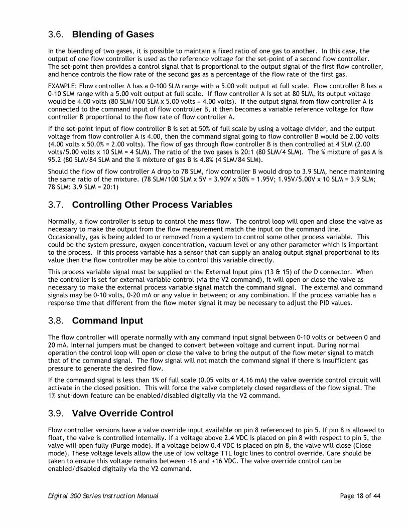
Temperature Coefficient 3.5.
As the temperature of the instrument changes from the calibration temperature, errors will be introduced into the output of the instrument. The Temperature Coefficient of Zero describes the change in the output that is seen at zero flow. This error is added in to the overall output signal regardless of flow, but can be eliminated with the ZERO push-button or the ZRO command at zero flow conditions. The Temperature Coefficient of Span describes the change in output after the zero error is eliminated. The span error cannot be eliminated, but can be compensated mathematically if necessary. The curve pictured to the right shows the typical span error in percent of point as a function of temperature assuming 23°C is the calibration temperature.
Digital 300 Series Instruction Manual Page 18 of 44
Blending of Gases 3.6.
In the blending of two gases, it is possible to maintain a fixed ratio of one gas to another. In this case, the output of one flow controller is used as the reference voltage for the set-point of a second flow controller. The set-point then provides a control signal that is proportional to the output signal of the first flow controller, and hence controls the flow rate of the second gas as a percentage of the flow rate of the first gas.
EXAMPLE: Flow controller A has a 0-100 SLM range with a 5.00 volt output at full scale. Flow controller B has a 0-10 SLM range with a 5.00 volt output at full scale. If flow controller A is set at 80 SLM, its output voltage would be 4.00 volts (80 SLM/100 SLM x 5.00 volts = 4.00 volts). If the output signal from flow controller A is connected to the command input of flow controller B, it then becomes a variable reference voltage for flow controller B proportional to the flow rate of flow controller A.
If the set-point input of flow controller B is set at 50% of full scale by using a voltage divider, and the output voltage from flow controller A is 4.00, then the command signal going to flow controller B would be 2.00 volts (4.00 volts x 50.0% = 2.00 volts). The flow of gas through flow controller B is then controlled at 4 SLM (2.00 volts/5.00 volts x 10 SLM = 4 SLM). The ratio of the two gases is 20:1 (80 SLM/4 SLM). The % mixture of gas A is 95.2 (80 SLM/84 SLM and the % mixture of gas B is 4.8% (4 SLM/84 SLM).
Should the flow of flow controller A drop to 78 SLM, flow controller B would drop to 3.9 SLM, hence maintaining the same ratio of the mixture. (78 SLM/100 SLM x 5V = 3.90V x 50% = 1.95V; 1.95V/5.00V x 10 SLM = 3.9 SLM; 78 SLM: 3.9 SLM = 20:1)
Controlling Other Process Variables 3.7.
Normally, a flow controller is setup to control the mass flow. The control loop will open and close the valve as necessary to make the output from the flow measurement match the input on the command line. Occasionally, gas is being added to or removed from a system to control some other process variable. This could be the system pressure, oxygen concentration, vacuum level or any other parameter which is important to the process. If this process variable has a sensor that can supply an analog output signal proportional to its value then the flow controller may be able to control this variable directly.
This process variable signal must be supplied on the External Input pins (13 & 15) of the D connector. When the controller is set for external variable control (via the V2 command), it will open or close the valve as necessary to make the external process variable signal match the command signal. The external and command signals may be 0-10 volts, 0-20 mA or any value in between; or any combination. If the process variable has a response time that different from the flow meter signal it may be necessary to adjust the PID values.
Command Input 3.8.
The flow controller will operate normally with any command input signal between 0-10 volts or between 0 and 20 mA. Internal jumpers must be changed to convert between voltage and current input. During normal operation the control loop will open or close the valve to bring the output of the flow meter signal to match that of the command signal. The flow signal will not match the command signal if there is insufficient gas pressure to generate the desired flow.
If the command signal is less than 1% of full scale (0.05 volts or 4.16 mA) the valve override control circuit will activate in the closed position. This will force the valve completely closed regardless of the flow signal. The 1% shut-down feature can be enabled/disabled digitally via the V2 command.
Valve Override Control 3.9.
Flow controller versions have a valve override input available on pin 8 referenced to pin 5. If pin 8 is allowed to float, the valve is controlled internally. If a voltage above 2.4 VDC is placed on pin 8 with respect to pin 5, the valve will open fully (Purge mode). If a voltage below 0.4 VDC is placed on pin 8, the valve will close (Close mode). These voltage levels allow the use of low voltage TTL logic lines to control override. Care should be taken to ensure this voltage remains between -16 and +16 VDC. The valve override control can be enabled/disabled digitally via the V2 command.
Digital 300 Series Instruction Manual Page 19 of 44
4. Digital Operation
Instrument States 4.1.
The Digital 300 will be in one of the following states as reported by the SS command:
State 1 Initialization
State 4 Operation
State 6 Failure
State 8 Calibration
4.1.1. Initialization
Upon application of input power, the flow instrument will enter the Initialization state (1); this is indicated by the Status LED blinking green at ½ second intervals. The Flow LED will be off. During this state, the following actions are performed:
The Serial Port Baud Rate is set to either 9600 or 19200 according to switch #1
The Serial Port is configured for either RS-232 or RS-485 operation according to switch #2
The flow set point source is set to either External Analog Command or Digital Command according to switch #3
Communication with the Control and Sensors Boards is verified
The Analog Output port is set up to operate as configured in S64
The gas record for the currently-selected gas (S6) is loaded
The flow calculation parameters are downloaded to the Sensor Board
If configured as a controller via S64, the valve is set to the Default state (Open or Closed) as configured in V2
During the Initialization state, flow readings are available but inaccurate. It takes from 10 to 30 seconds for the flow sensor hardware to stabilize and generate accurate readings.
If a flow command is entered via V4 or V5 during the Initialization state, it will be enacted when the controller transitions to the Operation state.
4.1.2. Operation
After 10 seconds, the instrument will enter the Operation state (4); this is indicated by the Status LED being solid green
In the Operation state, the Zero button and Flow totalizers are active; Flow alarms (G10/G12) are active if enabled via S2.
For controllers, automatic flow control operation begins with the Initial Flow Command contained in V30 as the Set Point. Tracking Alarms, Auto-Zero and Valve Override are active if enabled.
4.1.3. Failure
If a system error occurs the flow instrument will go into the Failure state (6). In this state, automatic flow control is disabled and the valve is set to the Default Position as specified in the MFC Configuration Word (V2). If the failure condition goes away, the instrument will attempt to return to the Operate state.
Digital 300 Series Instruction Manual Page 20 of 44
A network command (SS1) can move the flow instrument from the Fail state to the Initialization state (1), which may solve the problem.
The best way to recover is by turning the power off then back on.
The cause of the failure can be determined by observing the LEDs or by the sending the FAIL CODES command. The LEDs will be set as follows:
If there is an error communicating with the Control Board, the Status LED will be solid red and the Flow LED will blink Red once every second.
If there is an error communicating with the Sensor Board, the Status LED will be solid red and the Flow LED will blink Red four times per second .
If there is an error with the Sensor Bridge levels, the Status and Flow LEDs will alternately blink Red four times per second.
4.1.4. Calibration
The Calibration state is used to adjust the Analog Input and Output hardware using the TOFF, TDAO, TDAS, and TDAZ commands. This state is entered by sending the SS8 command.
Serial Communications 4.2.
4.2.1. General
The Digital 300 uses either RS-232 or RS-485 Serial Port communications. The position of switch #2 at startup determines the active mode.
4.2.2. Serial Communication Software
Serial Communication Software running on a host computer is required to access the serial port. All such programs need to be configured to communicate with the instrument; the required parameters are Baud Rate (Bits Per Second) which needs to match the selection of Switch #1 (either 9600 or 19200), the number of data bits (8), Parity (None), Number of Stop Bits (1), and Flow Control (None).
4.2.3. The Lists
Most of the Digital 300 operational parameters are grouped into lists. Each list can be read in its entirety or each item within the list can be read individually. For example, to read the entire Sensor List, send the command SL. To read an individual item from the Sensor List (e.g. item #5 Device Address) send the first letter of the list followed by the item number e.g. S5 reads the Device Address.
The Sensor List (SL) contains general information about the instrument as a whole, as well as sensor-specific information
The Valve List (VL) contains information on the flow control process. Valve List (VL) commands will return an error message if the device is not configured as a flow controller. Bit 0 of the Product Configuration Word (S64) will be 1 if the flow control function is enabled.
The Gas List (GL) allows access to the currently active gas instance/record (specified by S6). The instrument allows for up to 10 gas records numbered 0 to 9; these may be accessed using the alternative form of the GL command GIL. For instance, to list gas record 3, send the command GIL3.
Digital 300 Series Instruction Manual Page 21 of 44
4.2.4. Command Prompt
The prompt character is a greater than symbol ‘>’ (x3E); when this symbol is received, the Digital 300 is ready to accept a new command. Software can use the prompt as an end of response indicator as long as this symbol is not used in any text fields e.g. S54 Comment.
4.2.5. Command Format
The Digital 300 expects a Carriage Return (0x0D) at the end of each command; Line Feeds (0x0A) are ignored. Commands can be aborted by sending the Escape character (0x1B) before the Carriage Return has been sent; the device will ignore all characters. A Backspace (0x08) erases the previous character, but some Serial Communication Software needs to be configured to erase from the display.
Spaces are ignored unless they are part of a text field, e.g. “S 5 4 = t e s t” will set the Comment field to “t e s t”, not “test”. Note that the leading spaces before the first t are ignored; the command is equivalent to S54=t e s t.
Commands can be entered in upper case, lower case, or mixed case, so s54 = S54 and sTaTuS = STATUS.
Some items can be changed by the user -- for example, G10 High Alarm Limit. To change an item, enter the item to be changed followed by the equals sign ‘=’ followed by the new value, e.g. G10=60.
Some items which affect calibration cannot be changed by the user; “ACCESS DENIED” will be returned when trying to change these values.
Text Strings are limited to 63 characters.
4.2.6. RS-232 / RS-485 Mode
The position of switch #2 at startup determines the active mode. RS-232 mode does not support addressing, so commands are entered as described in the command description.
In RS-485 mode, multiple devices can be on the same bus; an address is required to select the device to which commands are directed. The Digital 300 device address is stored in S5. The address is a two-digit hexadecimal value which can be in the range 0x01 to 0x98 and 0x9A to 0xFF; the factory default is x01.
The address is required at the beginning of every command and is entered in the format *AA where AA is the two-digit hex address stored in S5 of the target device. As an example, if you want to read the Sensor List from the device with address 0x02, send the command *02 SL. The Digital 300 will accept a one-digit address, but this could cause problems; *2 SL will work the same as *02 SL, but *2 F will be interpreted as *2F which is addressing device 2F, not 2. (F returns the current flow.) In this case, you must enter *02 F because F is a valid hex digit. Note that *02F works the same as *02 F as discussed above.
Address 0x99 is used for broadcasting – all devices will process the command. For example, the command *99 V5=60 will command all attached Digital 300 controllers to flow 60% of full scale.
NOTE: The *99 address should not be used with commands that result in a response on the RS-485 bus, because multiple instruments will try to respond simultaneously.
See the Digital Connection section earlier in this manual for more information
4.2.7. Response Format
Responses may be set to either Cryptic or Verbose; this is controlled by bit 7 of the MFM Configuration Word (S2) or by using the S112 command (S112=1 for Verbose, S112=0 for Cryptic).
Cryptic responses include only the requested item’s value.
Verbose responses include descriptive text along with the item’s value. If units are associated with the item, the units will also be displayed. The SL, GL and VL commands are always verbose.
Digital 300 Series Instruction Manual Page 22 of 44
4.2.7.1. Response Line Termination
The Response Line Termination character(s) is (are) appended to each line returned from the Digital 300; the default is a Carriage Return, but this can be changed via S65 to one of the following:
For carriage-return (default), enter “S65=x0D”. For line feed, enter “S65=x0A”. For carriage-return linefeed, enter “S65 =x0D0A”.
4.2.7.2. RS‐485 Mode Responses
In RS-485 mode, all responses and error messages from commands sent using the broadcast address (0x99) will be suppressed. The S5 command is an exception to this rule; when the device is the only Digital 300 on the bus, the command *99 S5 can be used to get the device’s address.
Other than the above behavior, responses will be no different than responses in RS-232 mode. There will be no address in responses.
4.2.8. Commands
4.2.8.1. Flow Reporting Commands
F Flow
Returns the current flow in the units specified in G7.
FS % Full Scale Flow
Returns the current flow as a percent of full scale.
FR Flow Power
Returns the current bridge power differential reading.
F1 Start Flow Streaming
Causes flow readings to be output every 1/2 second.
F0 Stop Flow Streaming
Stops the 1/2 second flow reading output.
ZERO Set Flow Zero
Sets S15 UB Zero and S16 DB Zero to the current bridge power readings. The effect of this is the current flow reading becomes the zero flow point.
ZRO Alias for ZERO
For backward compatibility.
4.2.8.2. System Status Commands
FLOK Enable/Disable Factory‐Level Access
Resets the Factory Access Code, allows only customer-level changes.
Enables Factory-Level Access if the correct code entered, allows changes to everything.
Digital 300 Series Instruction Manual Page 23 of 44
LOCK Disable Expert‐User‐Level access
Disables Expert-User-Level Access (Unlock in command descriptions)
UNLOCK Enable Expert‐User‐Level access
Enables Expert-User-Level Access (Unlock in command descriptions)
TEMP Current System Temperature
Returns the current system temperature in degrees C.
SS System State
Returns the current system state which can be one of the following: 1 = Initializing 4 = Normal Operation 6 = System Failure Mode Active, send STATUS command for reason 8 = Calibration Mode
SS1 Enter Initialize mode
Resets the system, simulates power-on, returns to the Initializing state.
SS4 Enter Normal Operation mode
Returns the system from Calibration Mode (SS8) to Normal Operations (SS4).
SS8 Enter Calibrate mode
Sets system state to Calibrate, allows calibration of the Analog I/O.
SFL System Full List
Returns all system variables for use in problem determination.
STATUS Current system error status
Returns the current System Status word; if in Verbose Output mode (S112=1), returns descriptions of the presently active errors.
The System Status word contains the following:
0x8000 CONTROL_BOARD_COMM_ERROR 0x4000 SENSOR_BOARD_COMM_ERROR 0x0080 UB_CURRENT_ERROR 0x0040 DB_CURRENT_ERROR 0x0008 VALVE_LATCH_ERROR 0x0004 TRACKING_ERROR 0x0002 GAS_HIGH_ALARM_ERROR 0x0001 GAS_LOW_ALARM_ERROR
ML Status Alias
This is an alias for the STATUS command for backward compatibility.
HISTORY System Error Status History
Returns any Status errors that have occurred since system reset
Digital 300 Series Instruction Manual Page 24 of 44
CLEAR HISTORY
Clears the Status History
FAIL CODES System Fail codes
Returns all System Status Failure codes which have occurred since the device left the factory or since the last time the CLEAR FAIL CODES command was sent
The Fail Codes contain the following: 0x8000 CONTROL_BOARD_COMM_ERROR 0x4000 SENSOR_BOARD_COMM_ERROR 0x0080 UB_CURRENT_ERROR 0x0040 DB_CURRENT_ERROR
CLEAR FAIL CODES (Factory Function)
Clears the Fail Codes
4.2.8.3. Sensor List Commands
SL Sensor List (Read Only)
Returns all items in the Sensor List
S1 Model (Read Only)
Returns the Model and Software Version of the device.
S2 MFM Config (Read/Write)
Mass Flow Meter Configuration Word. This is a hex value which configures the overall operation of the device. The possible settings are as follows:
Bit 15 (Mask 0x8000) Flow Rate Alarms:
If this bit is set, the GAS_HIGH_ALARM_ERROR bit in the System Status word will be set if the flow exceeds the value set in G10 and the GAS_LOW_ALARM_ERROR bit in the System Status word will be set if the flow falls below the value set in G12.
Bit 13 (Mask 0x2000) Auto Zero:
Valid only for Flow Controllers. If set, the system will reset the flow zero point after the sensor has stabilized and the set-point is zero.
Bit 11 (Mask 0x0800) Tracking Alarms:
Valid only for Flow Controllers. Reflects the setting of V18. If enabled, the TRACKING_ERROR bit in the System Status word will be set and the Flow LED will blink green at 1/2 second intervals if the flow varies from the set-point by the percent of full-scale flow specified by V17 for more than 2 seconds.
Bit 7 (Mask 0x0080) Verbose Replies:
If set, all commands will return descriptive information. If not set, only the List commands (SL, GL, VL) will return descriptive information.
Bit 0-2 (Mask 0x0007) Decimal Places:
Reflects the setting of S14. This is the number of digits following the decimal point in floating point number.
In addition to changing S2 directly, these fields can also be changed using the following methods:
Digital 300 Series Instruction Manual Page 25 of 44
The Decimal Places field can be changed via S14.
There are 4 items which can be Enabled or Disabled. In verbose mode, the S2 command returns the current settings with explanatory text. These four items have the main function capitalized - RATE, VERBOSE, AUTOZERO, and TRACKING. Each of these can be enabled or disabled by entering ENABLE or DISABLE followed by the capitalized word.
For example, to disable Auto-Zero, enter DISABLE AUTOZERO - case does not matter.
Verbose Replies can also be Enabled/Disabled via the S112 command.
S5 Device Address (Read/Write)
Address used for RS-485 mode addressing. This is a hex number which accepts values from 0x01 to 0x98 and 0x9A to 0xFF; 0x99 is the BROADCAST ADDRESS - all devices process this message, but do not respond unless the command is S5.
NOTE: The command *99S5 should be used only with a single device attached to the RS-485 bus. The purpose of this command is to get the current address of a device when it is not known.
S6 Active Gas Instance (Read/Write)
The Gas Instance/Record currently being used for flow calculations. Valid values are 0 to 9.
S12 Total Flow Hours (Read/Factory Write)
The number of hours the device has been flowing 1% of Full-Scale or greater.
S14 Num Decimal Places (Read/Write)
The number of decimal places displayed for floating point values. Valid values are 0 to 7. This setting is reflected in the lower 3 bits of S2.
S15 UB Zero (Read/Factory Write)
The Upstream Bridge Zero value in watts
S16 DB Zero (Read/Factory Write)
The Downstream Bridge Zero value in watts
S17 Auto‐Zero Temperature (Read Only)
The sensor board temperature at the last zero event
S18 Current Sensor Temperature (Read Only)
The current sensor board temperature
S19 Low‐Pass Filter Decay Time (Factory Read/Factory Write)
Sensor response decay time in seconds, usually 0.05, which is 50 ms of averaging the raw sensor flow readings. If changed, the PID may need to be recalibrated.
S20 Mid‐Term Filter Gain (Factory Read/Factory Write)
Sensor response gain value. If changed, the PID may need to be recalibrated.
Digital 300 Series Instruction Manual Page 26 of 44
S21 Mid‐Term Filter Decay Time (Factory Read/Factory Write)
Sensor response mid-term filter decay time in seconds
S22 Short‐Term Filter Gain (Factory Read/Factory Write)
Sensor short-term response gain value. If changed, the PID may need to be recalibrated.
S23 Short‐Term Filter Decay Time (Factory Read/Factory Write)
Sensor response short-term filter decay time in seconds
S24 SetPoint A/D FS Code (Unlock Read/Unlock Write)
The Set Point A/D Full-Scale Code. Range is -32768 to 32767. If in CALIBRATE state (SS8), writes value to RAM only; otherwise, writes the value to RAM and FLASH.
S25 External In A/D FS Code (Unlock Read/Unlock Write)
The External Input A/D Full-Scale Code. Range is -32768 to 32767. If in CALIBRATE state (SS8), writes value to RAM only; otherwise, writes the value to RAM and FLASH.
S26 SetPoint A/D (Read Only)
The current Set Point A/D voltage or current.
S27 External In A/D (Read Only)
The current External Input A/D voltage or current.
S28 Sensor Span (Unlock Read)
The Sensor Span value in watts (should be around 0.017). Determined by S29 Sensor Type.
S29 Sensor Type (Read/Factory Write)
The Sensor Type, either 14, 17, or 26. Value also found on customer order and internal label.
S30 Num Avg Samples (Read/Write)
The number of samples used in calculating the flow average used for serial-port display and analog output. The system gets a new flow reading every 10 milliseconds; these raw flow readings are noisy because they have not been averaged. This number allows end-user adjustment of the noisiness of the output. Range is 1 to 100 which translates to 10 to 1000 ms of averaging. The factory default is 20 which is an average of 1/5th second of readings.
S35 Shunt Factor (Read/Factory Write)
This is the nominal range of the flow shunt in SLM.
S36 Analog Output (Zero Flow) (Read Only)
The Analog Output voltage or current value which is output when the flow is at 0% of full scale. This is controlled by S64 Product Config.
Digital 300 Series Instruction Manual Page 27 of 44
S37 Analog Output (FS Flow) (Read Only)
The Analog Output voltage or current value which is output when the flow is at 100% of full scale. This is controlled by S64 Product Config.
S40 UB Current (Factory Read Only)
The Sensor Upstream Bridge Current reading.
S41 UB Voltage (Factory Read Only)
The Sensor Upstream Bridge Voltage reading.
S42 DB Current (Factory Read Only)
The Sensor Downstream Bridge Current reading.
S43 DB Voltage (Factory Read Only)
The Sensor Downstream Bridge Voltage reading.
S46 UB Power (Factory Read Only)
The Sensor Upstream Bridge Power level.
S47 DB Power (Factory Read Only)
The Sensor Downstream Bridge Power level.
S51 DAC Zero Code (Unlock Read/Unlock Write)
The Analog Output D/A value used to represent 0% flow. If in CALIBRATE state (SS8), writes value to RAM and Sets the Analog Output to the level representing 0% flow; otherwise, writes value to RAM and FLASH
Range is 0 to 65535. Defaults are as follows:
0 to 5 V, 0 to 10V 32764 1 to 5 V 35742 0 to 20 mA 0 4 to 20 mA 10950
S52 DAC Full Scale Code (Unlock Read/Unlock Write)
The Analog Output D/A value used to represent 100% flow. If in CALIBRATE state (SS8), writes value to RAM and Sets the Analog Output to the level representing 100% flow; otherwise, writes value to RAM and FLASH
Range is 0 to 65535. Defaults are as follows:
0 to 5 V, 1 to 5V 47654 0 to 10 V 62545 0 to 20 mA, 4 to 20mA 54670
S54 Comment (Read/Write)
The Comment field. This allows the end user to add up to 63 characters of free-format text for their own use. WARNING, do not use the greater-than sign '>' in any text field because it could affect automated command response processing since it is used as the end-of-response character.
Digital 300 Series Instruction Manual Page 28 of 44
S62 Cal Date (Read/Factory Write)
The date the device was calibrated at the factory. This is a text field which accepts a maximum of 63 characters.
S63 Cal Temp (Read/Factory Write)
The temperature at which the device was calibrated at the factory. This is a text field which accepts a maximum of 63 characters.
S64 Product Config (Read/Factory Write)
The product configuration word. Valid settings are as follows:
0x00 = 0 to 5 Volt Flow Meter 0x02 = 0 to 10 Volt Flow Meter 0x08 = 1 to 5 Volt Flow Meter 0x14 = 0 to 20 milliamp Flow Meter 0x1C = 4 to 20 milliamp Flow Meter 0x01 = 0 to 5 Volt Flow Controller 0x03 = 0 to 10 Volt Flow Controller 0x09 = 1 to 5 Volt Flow Controller 0x15 = 0 to 20 milliamp Flow Controller 0x1D = 4 to 20 milliamp Flow Controller When this command is executed, the system will automatically re-start.
S65 NextLine (Read/Write)
The Response Line Termination character(s) sent at the end of each line of a response.
For carriage-return (default), enter "S65=x0D". For line feed, enter "S65=x0A". For carriage-return linefeed, enter "S65 =x0D0A".
S68 Instrument ID (Read/Factory Write)
The Instrument's ID string. This is a text field which accepts a maximum of 63 characters.
S69 SetPoint A/D Offset (Unlock Read/Unlock Write)
The Set Point A/D Zero code. Range is -32768 to 32767. If in CALIBRATE state (SS8), writes value to RAM only; otherwise, writes the value to RAM and FLASH.
S70 External In A/D Offset (Unlock Read/Unlock Write)
The External In A/D Zero code. Range is -32768 to 32767. If in CALIBRATE state (SS8), writes value to RAM only; otherwise, writes the value to RAM and FLASH.
S75 Control Board Id (Factory Read Only)
The Hex ID and Software Version of the Control Board.
S76 Sensor Board Id (Factory Read Only)
The Hex ID and Software Version of the Sensor Board.
S112 Verbose Replies (Write Only)
Enables (Non-Zero value) or disables (0) Verbose Replies. This setting is reflected in bit 7 of S2.
Digital 300 Series Instruction Manual Page 29 of 44
4.2.8.4. Gas List Commands
GL Gas List (Read Only)
Returns all items in the Active Gas List (S6 specifies Active Gas).
GILx Gas List x (Read Only)
Returns all items in the Gas List for the Gas Record x. The valid values for x are 0 to 9.
GIxy Gas Item (Read/Factory Write Record 0, Unlock Write Records 1 ‐ 9)
The current setting for item #y in Gas Record #x.
Used for viewing/changing any Gas Record item, especially those which are not the Active Gas (S6) Record.
e.g. GI410 returns the Gas High Alarm Limit for Gas Record 4. GI410=85 sets the Gas High Alarm Limit for Gas Record 4 to 85%.
GICxy: (Factory Function)
Copies Gas Record x to Gas Record y. Does not copy to Gas Record #0.
G1 Gas Instance (Read Only)
The Gas Record/instance number being displayed.
G4 Gas Symbol (Read/Factory Write Record 0, Unlock Write 1 ‐ 9)
The Gas Symbol, e.g. N2, is a text field which accepts a maximum of 63 characters.
G7 Units Symbol (Read/Factory Write Record 0, Unlock Write 1 ‐ 9)
The Gas Units Symbol, e.g. SLM, is a text field which accepts a maximum of 63 characters.
G10 High Alarm Limit (Read/Write)
The High Alarm Limit in % of Full-Scale Flow. If Flow Rate Alarms are enabled in S2, the GAS_HIGH_ALARM_ERROR in the STATUS word will be set if the flow is greater than this value for more than 2 seconds. The alarm will be de-activated if the flow is 2% below this value for at least 2 seconds. The HISTORY command will report if the alarm has occurred at any time since reset.
G12 Low Alarm Limit (Read/Write)
The Low Alarm Limit in % of Full-Scale Flow. If Flow Rate Alarms are enabled in S2, the GAS_LOW_ALARM_ERROR in the STATUS word will be set if the flow is less than this value for more than 2 seconds. The alarm will be de-activated if the flow is 2% above this value for at least 2 seconds. The HISTORY command will report if the alarm has occurred at any time since reset.
G15 Volumetric Unit Select (Read/Factory Wr. Record 0, Unlock Wr. 1 ‐ 9)
If the customer units are volumetric in nature (e.g. SLM, SCCM, SCFH), this is set to 1. In this case, reference temperature (G22) and pressure (G23) are considered in the flow calculation. If mass units are desired (e.g. k/s, g/s, lb/hour), this is set to 0 and temperature and pressure are not considered.
Digital 300 Series Instruction Manual Page 30 of 44
G16 Gas Conversion Factor (Read/Factory Wr. Record 0, Unlock Wr. 1 ‐ 9)
The gas conversion factor (GCF) is the ratio of nitrogen sensor output to customer gas sensor output. Consult the factory website for gas conversion factors for various gases.
G17 Span Correction Factor (Read/Factory Wr. Record 0, Unlock Wr. 1 ‐ 9)
This is used to make small adjustments to the instrument span. Value is usually close to 1.0
G18 Full Scale Flow (Read/Factory Write Record 0, Unlock Wr. 1 ‐ 9)
This is the full scale value in the final customer units as reported digitally.
G19 Time Factor (Read/Factory Write Record 0, Unlock Wr. 1 ‐ 9)
Factor used to convert from minutes to customer time units in time units per minute (e.g. 0.01667 hr/min).
G20 Volume Factor (Read/Factory Write GI 0, Unlock Wr. GI 1 ‐ 9)
Factor used to convert from minutes to customer volume units in volume units per liter (e.g. 0.0353 ft3/L). In the case of a mass unit, this is the density in g/L and is used with G21 to get kilograms or pounds.
G21 Mass Factor (Read/Factory Write GI 0, Unlock Write GI 1 ‐ 9)
Factor used to convert from grams to customer mass units in grams per mass unit (e.g. 1000 g/kg or 453.59237 g/lb). Used with G20 when it is a density.
G22 Reference Temperature (°C) (Read/Factory Wr. GI 0, Unlock Wr. GI 1 ‐ 9)
This is the reference temperature of the customer standardized volumetric unit. It is used to convert from a standard temperature of 0 °C to the customer unit standard temperature. Used if G15 is 1.
G23 Reference Pressure (Torr) (Read/Factory Wr. Record 0, Unlock Wr. 1 ‐ 9)
This is the reference pressure of the customer standardized volumetric unit. It is used to convert from a standard pressure of 760 Torr to the customer unit standard pressure. Used if G15 is 1.
G24 Linearization Coeff #1 (Read/Factory Wr. Record 0, Unlock Wr. 1 ‐ 9)
This is the linear term of the equation used to fit the calibration data in order to improve accuracy. If no curve fit was required, this term will be 1 and the others 0.
G25 Linearization Coeff #2 (Read/Factory Wr. Record 0, Unlock Wr. 1 ‐ 9)
This is the quadratic term of the equation used to fit the calibration data in order to improve accuracy.
G26 Linearization Coeff #3 (Read/Factory Wr. Record 0, Unlock Wr. 1 ‐ 9)
This is the third-order term of the equation used to fit the calibration data in order to improve accuracy.
Digital 300 Series Instruction Manual Page 31 of 44
G27 Linearization Coeff #4 (Read/Factory Wr. Record 0, Unlock Wr. 1 ‐ 9)
This is the fourth-order term of the equation used to fit the calibration data in order to improve accuracy.
G29 Full‐Scale Power (Read Only)
This is the calculated full-scale sensor power value for this gas instance.
G31 Total Accumulated Flow (Read/Write)
This is the total amount of gas that has flowed through the device since the last time this total was set to zero. It is useful for tracking the total amount of gas that has flowed using this gas record.
4.2.8.5. Valve List Commands
VL Valve List (Read Only)
Returns all items in the Valve List.
V1 MFC Mode (Read/Write)
The Mass Flow Controller Mode Word - the current state of the Valve Control System.
0 = DEFAULT Open or Closed According to V2 Bit 1 1 = AUTO Flow Automatically Maintained at Rate Specified by V4/V5 2 = HOLD Valve Drive Held at Current Voltage, must be in AUTO to switch to HOLD. 3 = SHUT Valve is Forced Closed 4 = PURGE Valve is Forced Fully Open 5 = VARIABLE Valve Drive Controlled by V28 6 = ERROR System Failure Active, Valve at DEFAULT Position. Only the System
can enter this state, command not allowed.
V2 MFC Config (Read/Write)
The Mass Flow Controller Configuration Word - controls valve operation using bit flags, with the following interpretation:
Bit 0 (Mask 0x0001) DERIVATIVE ON ERROR (Always 1, Enabled) Bit 1 (Mask 0x0002) DEFAULT VALVE POSITION (0 = SHUT, 1 = PURGE) Bit 2 (Mask 0x0004) VALVE OVERRIDE (0 = Disabled, 1 = Enabled) Bit 4 (Mask 0x0010) CONTROLLED VARIABLE (0 = Flow, 1 = A/D Input) Bit 7, 6 (Mask 0x00C0) SETPOINT SOURCE Switch 3 (10 = A/D Input, 01 = V4/V5) Bit 8 (Mask 0x0100) ONE PERCENT SHUTDOWN (0 = Disabled, 1 = Enabled)
In addition to changing the value directly, these bits can also be set/cleared using the following method:
The four configurable items are the default valve position, valve override, controlled variable and 1% shutdown.
In verbose mode, the V2 command returns the current settings with explanatory text. The four configurable items have the main configurable function capitalized = PURGE, OVERRIDE, EXTERNAL, and SHUTDOWN. Each of these can be enabled or disabled by entering ENABLE or DISABLE followed by the capitalized word.
For example, to disable valve override, enter DISABLE OVERRIDE – case does not matter.
Digital 300 Series Instruction Manual Page 32 of 44
V3 Valve Position (Read Only)
The current Valve Position as a hex value with the following interpretation:
0x10 CLOSED Valve drive is set to minimum, the valve is closed 0x20 PURGE Valve drive is set to maximum, the valve is fully open 0x30 HOLD Valve drive is held at a constant value. 0x40 VARIABLE Valve drive is manually controlled by the value in V28 0x50 AUTO Valve drive is being automatically adjusted
The above may be OR'd with the following modifiers. If any of these are active, the text (in Verbose mode) will show only these conditions.
0x01 OVERRIDE_SHUT Valve Override is enabled in V2 bit 2 and the analog override input is below 0.4 VDC 0x02 1PERCENT_SHUTDOWN The one percent shutdown is enabled in V2 bit 8 and the setpoint is less than 1%. 0x04 OVERRIDE_PURGE Valve Override is enabled in V2 bit 2 and the analog override input is above 2.4 VDC
V4 SetPoint (in Units) (Read/Write)
The Flow Setpoint in Flow Units, e.g. SLM
V5 SetPoint (in % Full‐Scale) (Read/Write)
The Flow Setpoint in % Full Scale.
V8 Implemented SetPoint (in Units) (Read Only)
The current Setpoint in Flow Units. Normally this will be the same as V4, but if SoftStart is active, it will be the Setpoint at the time the command is processed.
V9 Implemented SetPoint (in % Full‐Scale) (Read Only)
The current Setpoint in % Full Scale. Normally this will be the same as V5, but if SoftStart is active, it will be the Setpoint at the time the command is processed.
V10 Controlled Variable (Read Only)
The Controlled Variable in % Full Scale. This is normally the Flow, but if bit 4 of V2 is set to 1, it will be the A/D input.
V12 SoftStart Enabled (Read/Write)
If non-zero, SoftStart is enabled. Softstart is enabled by default.
V13 SoftStart Rate (Read/Write)
The rate at which the implemented Setpoint will be ramped up or down in % of Full Scale per second.
V17 Tracking Alarm Limit (Read/Write)
The Tracking Alarm Limit in % of Full Scale. The default is 2%.
Digital 300 Series Instruction Manual Page 33 of 44
V18 Tracking Alarm Enabled (Read/Write)
If non-zero, enables Tracking Alarm, if zero, disables Tracking Alarm. If enabled, the TRACKING_ERROR bit in the System Status word will be set and the Flow LED will blink green at 1/8 second intervals if the flow varies from the Setpoint by the percent of full-scale flow specified by V17 for more than 2 seconds.
V24 PID Proportional (Read/Unlock Write)
The Valve-Control Proportional.
V25 PID Derivative (Read/Unlock Write)
The Valve-Control Derivative.
V26 PID Integral (Read/Unlock Write)
The Valve-Control Integral.
V27 Valve Drive (Read Only)
The current Valve Drive D/A value.
V28 Manual Valve Set (Read/Write)
The Valve Drive value used in V1=5, VARIABLE mode. Allows manual control of the Valve.
V29 Valve Cracking (Read/Unlock Write)
The Valve drive circuit's Control Bias (Cracking) value.
V30 Initial Setpoint (Read/Write)
When the device enters the OPERATE state, the MFC mode (V1) is set to AUTO and the valve control system will attempt to maintain the flow (or External Process Variable) at some setpoint. If dip switch #3 is in the ON position (Digital Flow Command enabled), this item defines that setpoint; otherwise, the analog setpoint will be used.
If OPERATE mode is entered from the DEFAULT or ERROR mode, the valve position will be either OPEN or CLOSED according to the Default Valve Position specified in V2 bit 1. If V30 has not been changed, the default Initial setpoint will be 1000% if the Default Valve Position is OPEN and 0% if CLOSED
Alarm Limits 4.3.
Gas instances/records keep upper and lower flow rate alarm limits. Limits are checked at 10 ms intervals against linearized, normalized and filtered flow measurements that have been converted to FS units. Alarms will be reported/cleared if the alarm condition is active/inactive for at least 2 seconds.
Flow and Flowing Time Integration 4.4.
Values for integrated flow (total flow) and flowing hours are stored internally as the integral of %full-scale hours, accumulated every 10 seconds for the integrated flow (6 minutes for flowing hours) when flow rate is above 1% of present user full-scale.
Total flow is stored per gas instance. Values are reported based on the present flow rate units (e.g. if flow units are presently L/min, total flow will be reported/entered as nnn.nnn L). Since flow
Digital 300 Series Instruction Manual Page 34 of 44
accumulation is kept in raw sensor units, it is not affected by changes to engineering unit type or range scaling.
Total flow is queried for gas instances using G31 or GI [d] 31 (for engineering units).
Flowing hours are maintained for the instrument (as opposed to per-gas-instance) and is queried using command S12.
Network commands to change the totals are unrestricted so users can change to other values. “Resetting” is done by changing to 0.0 (examples: GI 4 31=0.0 or S12=0.0).
Gas units, full-scale engineering units and full scale power difference values can be changed without destroying flow totalizer scaling. This is because flow totalizers are maintained in internal units of power difference. However, changing the fundamental scaling of the sensor will affect total flow values as they are not automatically rescaled for sensor data modifications (must be done manually).
MFC Operation 4.5.
Flow control is activated by setting MFC mode to “1” (AUTO, use V1=1) and instrument state to OPERATE (SS4).
Flow control action is modifiable by adjustment of PID coefficients and adjustment of drive values for valve shut, valve cracking and valve upper limit.
Typical values for single-stage valve PID coefficients are around: P = 2000, I = 0.24, D = 0.037. The P value has the greatest effect. The I and D values will likely not vary too much for other pressures and orifice sizes. For two-stage valves, the I and D values may change more. The I value could be over 1.
Note that the “valve cracking” drive value serves as the “output bias” amount that is added to the controller valve drive output.
Network commands related to MFC flow control and data items will return an error message if the MFC option is not configured. See bit 1 in S64 Product Config. This bit should be zero if the flow control feature is not installed.
Valve control operates in accordance with the MFM “state” data item and also per the “MFC mode”. Refer to MFC Mode Word (V1).
Network commands exist to directly control valve working (set to default position - purge or shut, force shut, force open (purge), set into automatic closed loop mode, set to “hold” mode (valve stays where was in auto mode), set valve drive “manually” per command).
1% Shutoff Threshold 4.6.
When the flow control setpoint (V5) is less than 1% of full scale flow rate for the active gas record G18 then: the implemented setpoint value V8 is forced to zero and the valve is forced shut.
Bit x02 in V3 (valve mode) is set to indicate this.
The action can be disabled. See MFC configuration word (V2).
Flow loop tracking error alarm & warning remain active (if user enabled) in HOLD mode as well as when setpoint is below the 1% FS threshold.
Note that tracking error is the difference between the implemented and the measured flow. Therefore the tracking alarm should not be active when 1% shutoff is active, except possibly as a transient condition.
There is a small amount of hysteresis in the 1% shutoff limit. If the command setpoint is < 1% of FS, the implemented setpoint is zeroed and the valve is placed in the shut mode.

Digital 300 Series Instruction Manual Page 35 of 44
Softstart 4.7.
If enabled (V12), softstart operates for both network commanded setpoint as well as for analog command setpoint. The value in V13 determines the ramp rate at which the setpoint will be approached and applied to the control loop. This will slow down response time and reduce overshoot.
Reading Averaging 4.8.
The value in S30 determines the number of samples used in calculating the flow average for display and for analog output. Range is 1 to 100 which translates to 10 to 1000 ms of averaging. This will result in quieter output readings and slower response time.
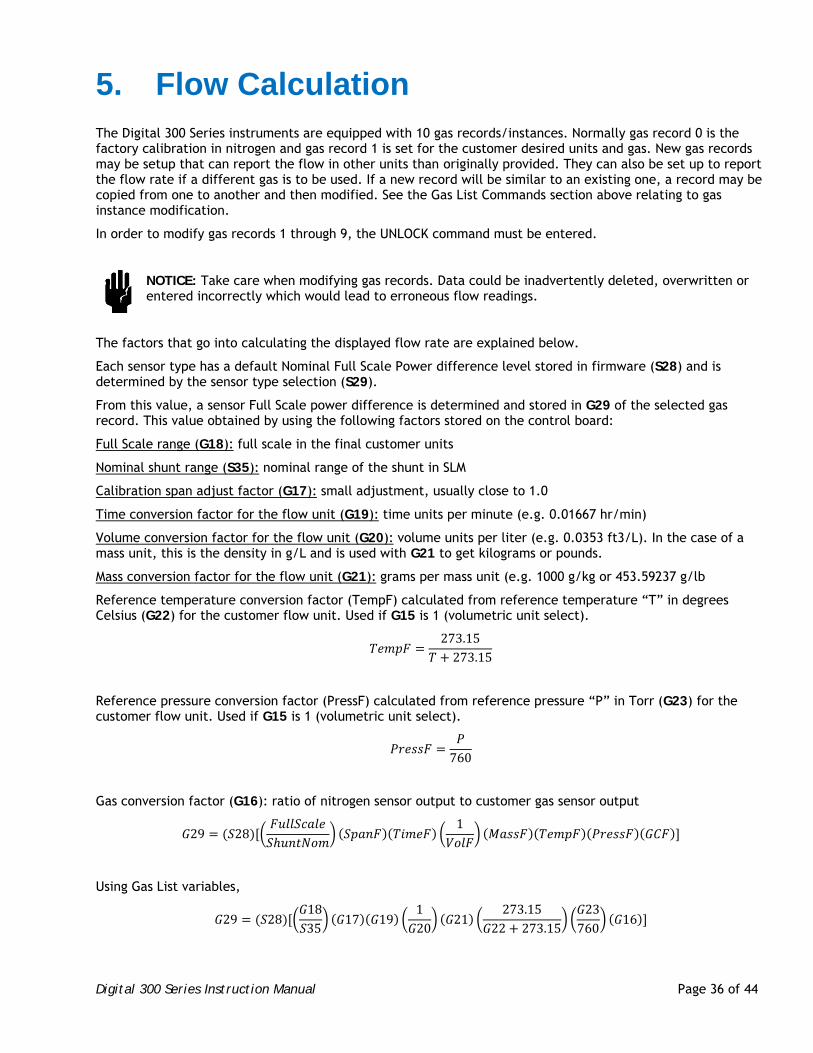
Digital 300 Series Instruction Manual Page 36 of 44
5. Flow Calculation The Digital 300 Series instruments are equipped with 10 gas records/instances. Normally gas record 0 is the factory calibration in nitrogen and gas record 1 is set for the customer desired units and gas. New gas records may be setup that can report the flow in other units than originally provided. They can also be set up to report the flow rate if a different gas is to be used. If a new record will be similar to an existing one, a record may be copied from one to another and then modified. See the Gas List Commands section above relating to gas instance modification.
In order to modify gas records 1 through 9, the UNLOCK command must be entered.
NOTICE: Take care when modifying gas records. Data could be inadvertently deleted, overwritten or entered incorrectly which would lead to erroneous flow readings.
The factors that go into calculating the displayed flow rate are explained below.
Each sensor type has a default Nominal Full Scale Power difference level stored in firmware (S28) and is determined by the sensor type selection (S29).
From this value, a sensor Full Scale power difference is determined and stored in G29 of the selected gas record. This value obtained by using the following factors stored on the control board:
Full Scale range (G18): full scale in the final customer units
Nominal shunt range (S35): nominal range of the shunt in SLM
Calibration span adjust factor (G17): small adjustment, usually close to 1.0
Time conversion factor for the flow unit (G19): time units per minute (e.g. 0.01667 hr/min)
Volume conversion factor for the flow unit (G20): volume units per liter (e.g. 0.0353 ft3/L). In the case of a mass unit, this is the density in g/L and is used with G21 to get kilograms or pounds.
Mass conversion factor for the flow unit (G21): grams per mass unit (e.g. 1000 g/kg or 453.59237 g/lb
Reference temperature conversion factor (TempF) calculated from reference temperature “T” in degrees Celsius (G22) for the customer flow unit. Used if G15 is 1 (volumetric unit select).
273.15273.15
Reference pressure conversion factor (PressF) calculated from reference pressure “P” in Torr (G23) for the customer flow unit. Used if G15 is 1 (volumetric unit select).
760
Gas conversion factor (G16): ratio of nitrogen sensor output to customer gas sensor output
29 281
Using Gas List variables,
29 281835
17 19120
21273.15
22 273.1523760
16
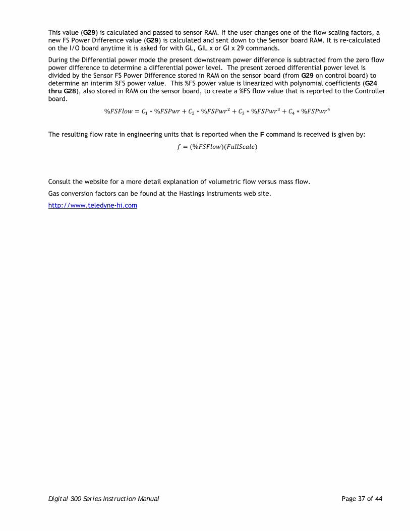
Digital 300 Series Instruction Manual Page 37 of 44
This value (G29) is calculated and passed to sensor RAM. If the user changes one of the flow scaling factors, a new FS Power Difference value (G29) is calculated and sent down to the Sensor board RAM. It is re-calculated on the I/O board anytime it is asked for with GL, GIL x or GI x 29 commands.
During the Differential power mode the present downstream power difference is subtracted from the zero flow power difference to determine a differential power level. The present zeroed differential power level is divided by the Sensor FS Power Difference stored in RAM on the sensor board (from G29 on control board) to determine an interim %FS power value. This %FS power value is linearized with polynomial coefficients (G24 thru G28), also stored in RAM on the sensor board, to create a %FS flow value that is reported to the Controller board.
% ∗% ∗% ∗% ∗%
The resulting flow rate in engineering units that is reported when the F command is received is given by:
%
Consult the website for a more detail explanation of volumetric flow versus mass flow.
Gas conversion factors can be found at the Hastings Instruments web site.
http://www.teledyne-hi.com
Digital 300 Series Instruction Manual Page 38 of 44
6. Troubleshooting
Authorized Maintenance 6.1.
With proper care in installation and use, the flow instrument will require little or no maintenance. If maintenance does become necessary, it is best to consult the factory before doing so, since some procedures may require recalibration. Entry into the sensor or tampering with the printed circuit board will void the warranty.
NOTICE: Do not perform repairs on these assemblies while the unit is still under warranty. If there is a problem, check the listing below to rule out some of the straight-forward solutions that may exist.
Troubleshooting 6.2.
6.2.1. Instrument Lists and Codes
If a problem occurs and obvious solutions are not apparent, the internal instrument values can be accessed digitally. Using a terminal emulation program, type SFL. This command will return a long list of values. These values can then be sent to the factory to better determine what the problem may be.
Also, issues that may have occurred are recorded in memory and may be accessed using the commands STATUS, HISTORY and FAIL CODES. See Commands section above.
6.2.2. Possible Problems and Solutions
Symptom: Not able to communicate digitally.
Action: Check settings as found in Serial Communications section above. Make certain switches corresponding to baud rate and 232/485 operation are correct. If 485 with a long cable run, make certain termination switch of last instrument on the bus is set OFF.
Symptom: Flow meter is out of calibration and non-linear.
Action: Check all fittings for leaks by placing soap solution on all fittings between gas supply and final destination of gas. Check flow meter for leaks.
Symptom: The output is non-repeatable at zero or span (unit drifts).
Action: Make certain the instrument is properly warmed up. Pass flow through the instrument for several minutes. Stop all flow, wait for the reading to stabilize and zero the instrument.
Symptom: Intermittent, “jumpy” or “noisy” output from instrument.
Action: Determine if the actual flow is fluctuating. For low flow instruments, temperature changes can cause flow due to gas expansion. Ensure that the supply pressure is stable. Ensure that the instrument is well grounded.
Symptom: Little or no output with flow.
Action: Ensure there are no leaks. Ensure electrical connections are secure including common and ground lines.
Digital 300 Series Instruction Manual Page 39 of 44
Symptom: Little or no flow, even when the valve is OPEN.
Action: Verify that the pressure drop originally specified on the instrument is across the instrument.
Symptom: Full flow cannot be reached
Action: Ensure command or set-point input is correct. Make certain the pressure is correct at the flow controller. Restrictions and undersized lines can introduce additional pressure drops.
Symptom: The valve does not open.
Action: Ensure that the switch is set for the mode of operation desired (analog/digital). Ensure valve is not overridden shut. Check the valve coil leads for nicks and cuts and verify that the coil is properly plugged into the controller card. Check that the valve coil resistance is around 320 to 370 ohms.
Symptom: The controller is not stable.
Action: Make certain the upstream and downstream pressures are as specified on the label. Make certain the regulator size and line sizes are adequate. It can be helpful to introduce volume between the regulator and the controller and between the controller and restrictions. Adjustments to the PID values, soft-start or averaging may need to be made.
Symptom: Slight errors are observed in flow vs. command when analog inputs are in use.
Action: Ensure connections are secure. Ensure command voltage/current is as expected at the instrument. Adjust analog input factor S24 until S26 matches the command input.
Symptom: LED indication is red.
Action: Cycle power. If symptom persists, check FAIL CODES and consult the factory.
Digital 300 Series Instruction Manual Page 40 of 44
7. Warranty
Warranty Policy 7.1.
See the company website for warranty information at:
http://www.teledyne-hi.com/terms&conditions.htm
Return Policy 7.2.
See the company website for return information at:
http://www.teledyne-hi.com/terms&conditions.htm
Any product returned for either warranty or non-warranty repair must have been issued a Return Material Authorization (RMA) form.
RMA Forms may be obtained from the Information section of the Hastings Instruments website:
http://www.teledyne-hi.com/inforeq.htm
WARNING: Contaminated parts can be detrimental to health and environment. Ensure instruments are free of hazardous contamination prior to shipment.
Company contact information
TELEDYNE HASTINGS INSTRUMENTS
804 NEWCOMBE AVENUE
HAMPTON, VIRGINIA 23669 U.S.A.
ATTENTION: REPAIR DEPARTMENT
TELEPHONE (757) 723-6531 1-800-950-2468
FAX (757) 723-3925
E MAIL mailto:[email protected]
INTERNET ADDRESS http://www.teledyne-hi.com
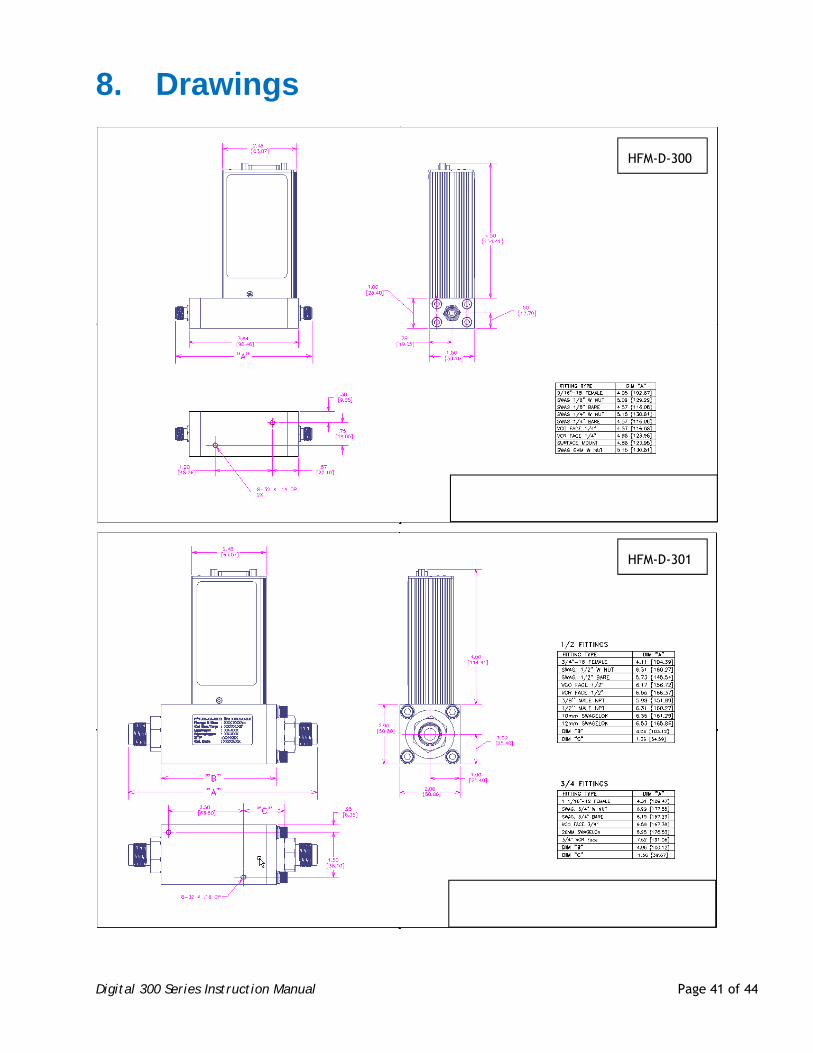
Digital 300 Series Instruction Manual Page 41 of 44
8. Drawings
HFM-D-300
HFM-D-301
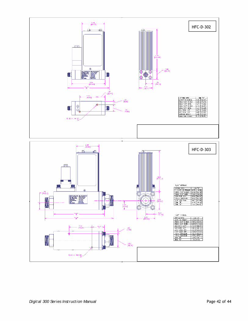
Digital 300 Series Instruction Manual Page 42 of 44
HFC-D-302
HFC-D-303
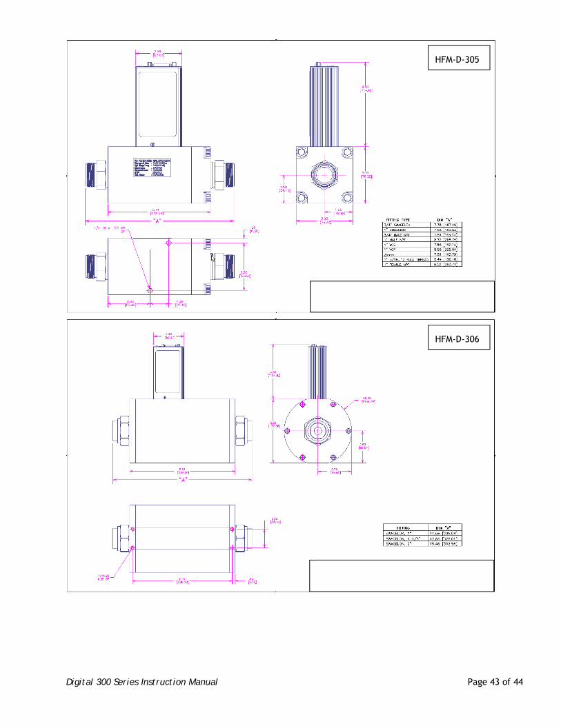
Digital 300 Series Instruction Manual Page 43 of 44
HFM-D-305
HFM-D-306
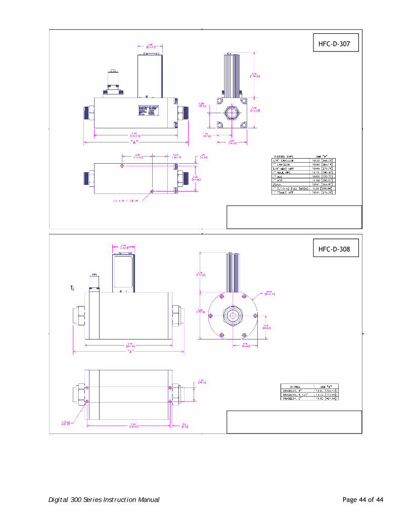
Digital 300 Series Instruction Manual Page 44 of 44
HFC-D-308
HFC-D-307
Related Documents