Series Editors: Damià Barceló · Andrey G. Kostianoy The Handbook of Environmental Chemistry 61 Minghua Zhou Mehmet A. Oturan Ignasi Sirés Editors Electro- Fenton Process New Trends and Scale-Up

Welcome message from author
This document is posted to help you gain knowledge. Please leave a comment to let me know what you think about it! Share it to your friends and learn new things together.
Transcript

Series Editors: Damià Barceló · Andrey G. KostianoyThe Handbook of Environmental Chemistry 61
Minghua ZhouMehmet A. OturanIgnasi Sirés Editors
Electro-Fenton ProcessNew Trends and Scale-Up
The Handbook of Environmental Chemistry
Founded by Otto Hutzinger
Editors-in-Chief: Dami�a Barcelo • Andrey G. Kostianoy
Volume 61
Advisory Board:
Jacob de Boer, Philippe Garrigues, Ji-Dong Gu,
Kevin C. Jones, Thomas P. Knepper, Alice Newton,
Donald L. Sparks

More information about this series at http://www.springer.com/series/698
Electro-Fenton Process
New Trends and Scale-Up
Volume Editors: Minghua Zhou � Mehmet A. Oturan �Ignasi Sirés
With contributions by
A.A. Alvarez-Gallegos � M. Bechelany � E. Brillas � M. Cretin �A. Hasanzadeh � A.J. Karabelas � A. Khataee � T.X.H. Le � L. Liang �H. Lin � L. Ma � E. Mousset � J.L. Nava � P.V. Nidheesh �H. Olvera-Vargas � M.A. Oturan � N. Oturan � M. Panizza �K.V. Plakas � C. Ponce de Leon � G. Ren � M.A. Rodrigo �O. Scialdone � S. Silva-Martınez � I. Sires � C. Trellu � Y. Wang �J. Wu � W. Yang � F. Yu � H. Zhang � Y. Zhang � L. Zhou �M. Zhou � S. Zuo

EditorsMinghua ZhouCollege of Environmental Science & Eng.Nankai UniversityTianjin, China
Mehmet A. OturanLaboratoire Geomaeriaux et EnvironnementUniversite Paris-EstChamps sur Marne, France
Ignasi SiresDepartament de Quımica FısicaUniversitat de BarcelonaBarcelona, Spain
ISSN 1867-979X ISSN 1616-864X (electronic)The Handbook of Environmental ChemistryISBN 978-981-10-6405-0 ISBN 978-981-10-6406-7 (eBook)https://doi.org/10.1007/978-981-10-6406-7
Library of Congress Control Number: 2017959330
© Springer Nature Singapore Pte Ltd. 2018This work is subject to copyright. All rights are reserved by the Publisher, whether the whole or part ofthe material is concerned, specifically the rights of translation, reprinting, reuse of illustrations,recitation, broadcasting, reproduction on microfilms or in any other physical way, and transmissionor information storage and retrieval, electronic adaptation, computer software, or by similar ordissimilar methodology now known or hereafter developed.The use of general descriptive names, registered names, trademarks, service marks, etc. in thispublication does not imply, even in the absence of a specific statement, that such names are exemptfrom the relevant protective laws and regulations and therefore free for general use.The publisher, the authors and the editors are safe to assume that the advice and information in thisbook are believed to be true and accurate at the date of publication. Neither the publisher nor theauthors or the editors give a warranty, express or implied, with respect to the material containedherein or for any errors or omissions that may have been made. The publisher remains neutral withregard to jurisdictional claims in published maps and institutional affiliations.
Printed on acid-free paper
This Springer imprint is published by Springer NatureThe registered company is Springer Nature Singapore Pte Ltd.The registered company address is: 152 Beach Road, #21-01/04 Gateway East, Singapore 189721,Singapore

Editors-in-Chief
Prof. Dr. Dami�a Barcelo
Department of Environmental Chemistry
IDAEA-CSIC
C/Jordi Girona 18–26
08034 Barcelona, Spain
and
Catalan Institute for Water Research (ICRA)
H20 Building
Scientific and Technological Park of the
University of Girona
Emili Grahit, 101
17003 Girona, Spain
Prof. Dr. Andrey G. Kostianoy
P.P. Shirshov Institute of Oceanology
Russian Academy of Sciences
36, Nakhimovsky Pr.
117997 Moscow, Russia
Advisory Board
Prof. Dr. Jacob de Boer
IVM, Vrije Universiteit Amsterdam, The Netherlands
Prof. Dr. Philippe Garrigues
University of Bordeaux, France
Prof. Dr. Ji-Dong Gu
The University of Hong Kong, China
Prof. Dr. Kevin C. Jones
University of Lancaster, United Kingdom
Prof. Dr. Thomas P. Knepper
University of Applied Science, Fresenius, Idstein, Germany
Prof. Dr. Alice Newton
University of Algarve, Faro, Portugal
Prof. Dr. Donald L. Sparks
Plant and Soil Sciences, University of Delaware, USA
The Handbook of Environmental Chemistry
Also Available Electronically
The Handbook of Environmental Chemistry is included in Springer’s eBook
package Earth and Environmental Science. If a library does not opt for the whole
package, the book series may be bought on a subscription basis.
For all customers who have a standing order to the print version of The Handbookof Environmental Chemistry, we offer free access to the electronic volumes of the
Series published in the current year via SpringerLink. If you do not have access, you
can still view the table of contents of each volume and the abstract of each article on
SpringerLink (www.springerlink.com/content/110354/).
You will find information about the
– Editorial Board
– Aims and Scope
– Instructions for Authors
– Sample Contribution
at springer.com (www.springer.com/series/698).
All figures submitted in color are published in full color in the electronic version on
SpringerLink.
Aims and Scope
Since 1980, The Handbook of Environmental Chemistry has provided sound
and solid knowledge about environmental topics from a chemical perspective.
Presenting a wide spectrum of viewpoints and approaches, the series now covers
topics such as local and global changes of natural environment and climate;
anthropogenic impact on the environment; water, air and soil pollution; remediation
and waste characterization; environmental contaminants; biogeochemistry; geo-
ecology; chemical reactions and processes; chemical and biological transformations
as well as physical transport of chemicals in the environment; or environmental
modeling. A particular focus of the series lies on methodological advances in
environmental analytical chemistry.
vii
Series Preface
With remarkable vision, Prof. Otto Hutzinger initiated The Handbook of Environ-mental Chemistry in 1980 and became the founding Editor-in-Chief. At that time,
environmental chemistry was an emerging field, aiming at a complete description
of the Earth’s environment, encompassing the physical, chemical, biological, and
geological transformations of chemical substances occurring on a local as well as a
global scale. Environmental chemistry was intended to provide an account of the
impact of man’s activities on the natural environment by describing observed
changes.
While a considerable amount of knowledge has been accumulated over the last
three decades, as reflected in the more than 70 volumes of The Handbook ofEnvironmental Chemistry, there are still many scientific and policy challenges
ahead due to the complexity and interdisciplinary nature of the field. The series
will therefore continue to provide compilations of current knowledge. Contribu-
tions are written by leading experts with practical experience in their fields. TheHandbook of Environmental Chemistry grows with the increases in our scientific
understanding, and provides a valuable source not only for scientists but also for
environmental managers and decision-makers. Today, the series covers a broad
range of environmental topics from a chemical perspective, including methodolog-
ical advances in environmental analytical chemistry.
In recent years, there has been a growing tendency to include subject matter of
societal relevance in the broad view of environmental chemistry. Topics include
life cycle analysis, environmental management, sustainable development, and
socio-economic, legal and even political problems, among others. While these
topics are of great importance for the development and acceptance of The Hand-book of Environmental Chemistry, the publisher and Editors-in-Chief have decidedto keep the handbook essentially a source of information on “hard sciences” with a
particular emphasis on chemistry, but also covering biology, geology, hydrology
and engineering as applied to environmental sciences.
The volumes of the series are written at an advanced level, addressing the needs
of both researchers and graduate students, as well as of people outside the field of
ix

“pure” chemistry, including those in industry, business, government, research
establishments, and public interest groups. It would be very satisfying to see
these volumes used as a basis for graduate courses in environmental chemistry.
With its high standards of scientific quality and clarity, The Handbook of Envi-ronmental Chemistry provides a solid basis from which scientists can share their
knowledge on the different aspects of environmental problems, presenting a wide
spectrum of viewpoints and approaches.
The Handbook of Environmental Chemistry is available both in print and online
via www.springerlink.com/content/110354/. Articles are published online as soon
as they have been approved for publication. Authors, Volume Editors and Editors-
in-Chief are rewarded by the broad acceptance of The Handbook of EnvironmentalChemistry by the scientific community, from whom suggestions for new topics to
the Editors-in-Chief are always very welcome.
Dami�a BarceloAndrey G. Kostianoy
Editors-in-Chief
x Series Preface
Preface
Even though the existence and performance appraisal of Fenton’s reaction dates
back to almost 150 years, the feasibility of full-scale environmental applications
has become nowadays a very hot topic. Among the large variety of existing
processes whose reactivity is pre-eminently determined by the metal-catalyzed
transformation of a mild oxidizing reagent like H2O2 into the second strongest
oxidant known (•OH), electro-Fenton (EF) process has become one of the most
successful, especially for destroying organic pollutants. The origins of EF can be
found in organic electrosynthesis in the 1970s, but soon it was adopted as a
promising system in the environmental electrochemistry field. EF combines sim-
plicity with outstanding performance in terms of degradation rate and decontami-
nation percentage, overcoming the major drawbacks of conventional Fenton
process such as significant sludge generation and need of continuous H2O2 addition.
The main feature of EF, that is to say, the one that allows making the difference
between this and other Fenton-based processes for water decontamination and
disinfection, is the electrogeneration of H2O2 on site from the two-electron reduc-
tion of oxygen, thus avoiding the cost and risks associated with production,
mobilization, storage, and use of industrially synthesized H2O2. In addition, the
continuous regeneration of Fe(II) catalyst from cathodic reduction of Fe(III)
ensures a permanent catalytic activity and minimizes sludge management.
This book is dedicated to the EF process, embracing from its first steps to the
newest trends and scale-up, in 15 chapters. Despite the lack of a strict division
between the various aspects that are presented, the chapters could be considered as
grouped into four different parts: the first four chapters list and describe the
alternative EF setups, from conventional to the most recent ones; then, there appear
three chapters on advances in cathode materials; reactor engineering and modeling
are explained in the subsequent four chapters; the book concludes with four
chapters that deal with applications in soil and water treatment.
In the first chapter, Profs. Sires and Brillas make a very thorough description of
EF fundamentals and reactivity, including up to 50 reactions to unravel the com-
plexity of such systems. Then, Dr. Olvera-Vargas and coworkers give all details on
xi
a new combined process called bio-electro-Fenton. Prof. Wang focuses on the so-
called electro-peroxone technology, which combines cathodic H2O2 production
with conventional ozonation to upgrade the latter process thanks to •OH generation.
Dr. Nidheesh and coworkers describe the fundamentals of heterogeneous EF
process, which relies on the use of insoluble solid catalysts to promote the removal
of organic pollutants from water with the possibility to recover the catalyst.
The three chapters devoted to cathode modification for enhancing the H2O2
electrogeneration are presented by Profs. A. Khataee and A. Hasanzadeh (use of
carbon-based nanomaterials like carbon nanotubes, graphene, and mesoporous
carbon), Dr. Le and coworkers (use of carbon felt), and Prof. Zhou and coworkers
(use of modified graphite felt and composites with carbon black or graphene).
These chapters include characterization of modified materials as well as perfor-
mance assessment regarding pollutant destruction.
Reactor engineering and modeling is first addressed in the chapter of Profs.
Scialdone and Panizza, experts in either microreactors or conventional reactors.
The flow-through reactor for EF treatment is described by Prof. Zhou and
coworkers, who explain the enhanced mass transport and electron transfer upon
use of such configuration. Profs. Nava and Ponce de Leon introduce in a detailed
manner the principles of reactor design and comment on the modeling of a solar
photoelectro-Fenton flow plant. To sum up with this part, Profs. Alvarez Gallegos
and Silva Martınez focus on the elucidation of a semiempirical chemical model to
predict the time course of organic pollutants in EF treatments.
The last chapters contain different applications of EF and related processes.
First, Prof. Brillas shows the great performance of solar photoelectro-Fenton
process for wastewater treatment. Then, Drs. Plakas and Karabelas summarize
the state of the art of pilot, demonstration, and full-scale EF systems, including a
patent survey. Dr. Lin and coworkers show the results of EF treatment of artificial
sweeteners (aspartame, sucralose, saccharin, and acesulfame) in aqueous medium.
And finally, Dr. Mousset and coworkers discuss the feasibility of soil remediation
by EF.
We believe that this book, which has been written by world leading experts,
constitutes a timely milestone for scientists and engineers alike. It constitutes a
platform for addressing the most challenging issues and future prospects of EF
process. From the excellent results that have been obtained so far, we aim to foster
the gradual scale-up and implementation of this electrochemical technology in the
public and private sector. We would like to acknowledge very warmly all the
authors, who are kindly involved in this project and committed to clearly explain
the pros and cons of EF technology. We are also thankful to Springer for their
support in publishing this book.
Nankai, China M. Zhou
Champs-sur-Marne, France M.A. Oturan
Barcelona, Spain I. Sires
xii Preface
Contents
Electro-Fenton Process: Fundamentals and Reactivity . . . . . . . . . . . . . 1
Ignasi Sires and Enric Brillas
Bio-electro-Fenton: A New Combined Process – Principles
and Applications . . . . . . . . . . . . . . . . . . . . . . . . . . . . . . . . . . . . . . . . . . 29
Hugo Olvera-Vargas, Clement Trellu, Nihal Oturan,
and Mehmet A. Oturan
The Electro-peroxone Technology as a Promising Advanced
Oxidation Process for Water and Wastewater Treatment . . . . . . . . . . 57
Yujue Wang
Heterogeneous Electro-Fenton Process: Principles and Applications . . . 85
P.V. Nidheesh, H. Olvera-Vargas, N. Oturan, and M.A. Oturan
Modified Cathodes with Carbon-Based Nanomaterials
for Electro-Fenton Process . . . . . . . . . . . . . . . . . . . . . . . . . . . . . . . . . . 111
Alireza Khataee and Aliyeh Hasanzadeh
Advances in Carbon Felt Material for Electro-Fenton Process . . . . . . . 145
Thi Xuan Huong Le, Mikhael Bechelany, and Marc Cretin
Cathode Modification to Improve Electro-Fenton Performance . . . . . . 175
Minghua Zhou, Lei Zhou, Liang Liang, Fangke Yu, and Weilu Yang
Conventional Reactors and Microreactors in Electro-Fenton . . . . . . . . 205
Marco Panizza and Onofrio Scialdone
Cost-Effective Flow-Through Reactor in Electro-Fenton . . . . . . . . . . . 241
Minghua Zhou, Gengbo Ren, Liang Ma, Yinqiao Zhang, and Sijin Zuo
Reactor Design for Advanced Oxidation Processes . . . . . . . . . . . . . . . . 263
Jose L. Nava and Carlos Ponce de Leon
xiii

Modeling of Electro-Fenton Process . . . . . . . . . . . . . . . . . . . . . . . . . . . 287
A.A. Alvarez-Gallegos and S. Silva-Martınez
Solar-Assisted Electro-Fenton Systems for Wastewater Treatment . . . 313
Enric Brillas
Electro-Fenton Applications in the Water Industry . . . . . . . . . . . . . . . 343
Konstantinos V. Plakas and Anastasios J. Karabelas
The Application of Electro-Fenton Process for the Treatment
of Artificial Sweeteners . . . . . . . . . . . . . . . . . . . . . . . . . . . . . . . . . . . . . 379
Heng Lin, Nihal Oturan, Jie Wu, Mehmet A. Oturan, and Hui Zhang
Soil Remediation by Electro-Fenton Process . . . . . . . . . . . . . . . . . . . . . 399
Emmanuel Mousset, Clement Trellu, Nihal Oturan, Manuel A. Rodrigo,
and Mehmet A. Oturan
Index . . . . . . . . . . . . . . . . . . . . . . . . . . . . . . . . . . . . . . . . . . . . . . . . . . . 425
xiv Contents
Electro-Fenton Process: Fundamentals
and Reactivity
Ignasi Sires and Enric Brillas
Abstract This chapter is conceived as the gateway to more specific sections in the
book. Its main aim is to introduce all the reactions of interest for fully understanding
further development and applications of the EF process. The 50 reactions provided
condense all the phenomena occurring in such a complex system and serve as the
platform to justify the need of different devices and setups when treating water
matrices of very different nature. In addition, all the key operation parameters for
H2O2 electrogeneration and water decontamination are discussed. Subsections
devoted to explaining the effect of the electrolyte composition, cell design, cathode
and anode nature, catalyst source, hydrodynamic conditions, solution pH, and
operation mode (potentiostatic or galvanostatic) are set out in summarized form,
in order to present all the crucial information without intending to duplicate ideas
that will be already given in subsequent chapters.
Keywords Catalyst source for electro-Fenton, Cathode and anode nature in
electro-Fenton treatment, Electrolytic cells for electro-Fenton, Influence of
electrolyte composition on degradation kinetics in electro-Fenton, Operation
modes in electro-Fenton, Reactions occurring in electro-Fenton process
Contents
1 Introduction . . . . . . . . . . . . . . . . . . . . . . . . . . . . . . . . . . . . . . . . . . . . . . . . . . . . . . . . . . . . . . . . . . . . . . . . . . . . . . . . . . . 2
2 Conventional Fenton Process . . . . . . . . . . . . . . . . . . . . . . . . . . . . . . . . . . . . . . . . . . . . . . . . . . . . . . . . . . . . . . . . 3
3 Hydrogen Peroxide Electrogeneration . . . . . . . . . . . . . . . . . . . . . . . . . . . . . . . . . . . . . . . . . . . . . . . . . . . . . . . 6
3.1 Cathode Materials . . . . . . . . . . . . . . . . . . . . . . . . . . . . . . . . . . . . . . . . . . . . . . . . . . . . . . . . . . . . . . . . . . . . . . 7
3.2 Divided Cells . . . . . . . . . . . . . . . . . . . . . . . . . . . . . . . . . . . . . . . . . . . . . . . . . . . . . . . . . . . . . . . . . . . . . . . . . . . 8
I. Sires (*) and E. Brillas
Laboratori d’Electroquımica dels Materials i del Medi Ambient, Departament de Quımica
Fısica, Facultat de Quımica, Universitat de Barcelona, Martı i Franques 1-11, 08028
Barcelona, Spain
e-mail: [email protected]; [email protected]
M. Zhou et al. (eds.), Electro-Fenton Process: New Trends and Scale-Up,Hdb Env Chem (2018) 61: 1–28, DOI 10.1007/698_2017_40,© Springer Nature Singapore Pte Ltd. 2017, Published online: 31 May 2017
1
3.3 Undivided Cells . . . . . . . . . . . . . . . . . . . . . . . . . . . . . . . . . . . . . . . . . . . . . . . . . . . . . . . . . . . . . . . . . . . . . . . . 13
4 Electro-Fenton Process . . . . . . . . . . . . . . . . . . . . . . . . . . . . . . . . . . . . . . . . . . . . . . . . . . . . . . . . . . . . . . . . . . . . . . . 15
4.1 Cell Configuration . . . . . . . . . . . . . . . . . . . . . . . . . . . . . . . . . . . . . . . . . . . . . . . . . . . . . . . . . . . . . . . . . . . . . . 17
4.2 Iron Catalysts . . . . . . . . . . . . . . . . . . . . . . . . . . . . . . . . . . . . . . . . . . . . . . . . . . . . . . . . . . . . . . . . . . . . . . . . . . . 18
4.3 Anode Behavior and Electrolyte Composition . . . . . . . . . . . . . . . . . . . . . . . . . . . . . . . . . . . . . . . . 20
4.4 Operation Variables . . . . . . . . . . . . . . . . . . . . . . . . . . . . . . . . . . . . . . . . . . . . . . . . . . . . . . . . . . . . . . . . . . . . 22
5 Conclusions . . . . . . . . . . . . . . . . . . . . . . . . . . . . . . . . . . . . . . . . . . . . . . . . . . . . . . . . . . . . . . . . . . . . . . . . . . . . . . . . . . . 25
References . . . . . . . . . . . . . . . . . . . . . . . . . . . . . . . . . . . . . . . . . . . . . . . . . . . . . . . . . . . . . . . . . . . . . . . . . . . . . . . . . . . . . . . . 25
1 Introduction
In 1876, the destruction of tartaric acid using a mixture of H2O2 and Fe2+ signaled
the dawn of Fenton process and all the related Fenton’s reaction chemistry [1]. Now-
adays, after more than a century of thorough investigation, several issues are still
subjected to vivid discussion: do the pure aquacomplex models explain in a correct
manner the reactivity between iron ions and H2O2 [2]? Is hydroxyl radical (•OH) or
a high-valent oxoiron (i.e., ferryl) species the main oxidant [3]? Despite these
mechanistic controversies, much progress has been gained regarding the optimiza-
tion, scale-up, and implementation of the classical (i.e., conventional or dark)
Fenton process, with multiple existing alternatives born from its combination
with physical, (photo)(electro)chemical, and biological treatments. Currently, the
Fenton process has an extraordinary impact in many research fields. For example,
Fenton-based •OH can be used to activate methane bond scission to form methanol,
being useful for energy storage/conversion [4]. The occurrence of Fenton’s reactionis also very relevant in medicine, since free radicals have a negative impact on cells
and organs as they trigger the lipid peroxidation [5]. In humans, mitochondria are
the main source of H2O2, inducing oxidative damage of macromolecules in the
presence of iron and copper ions. Conversely, •OH can also serve as a therapeutic
agent to remove malignant tumors [6]. Fenton’s reaction is also useful in the
development of new materials such as Zn-doped carbon dots employed as bio-
sensors for detecting H2O2 by fluorescence [7]. Nonetheless, the flagship applica-
tions are found in environmental chemistry, where the great oxidization power of•OH (and/or ferryl and other concomitant reactive species) can be used to
inactivate microorganisms, degrade organic contaminants, and transform metal
ions in water, sludge, or soil [8, 9].
The electro-Fenton (EF) process finds its origins in the 1970s within the field of
organic electrosynthesis, when several pioneer studies reported the oxidative trans-
formation of benzene and other molecules with electrogenerated Fenton’s reagent[10]. At that time, Hg cathode was the material of choice. Later, in the mid-1970s,
carbonaceous cathodes were introduced to overcome the limitations due to the
toxicity of Hg. However, their first use in EF systems for wastewater treatment did
not appear until the mid-1980s [11]. This work, reporting the degradation of phenol
solutions in a Pt/graphite electrolytic cell, fired the starting gun on a vast plethora of
2 I. Sires and E. Brillas
successive applications of EF and combined EF processes, which include (photo)
peroxi-coagulation, heterogeneous EF, photoelectro-Fenton with UVA light or
sunlight (PEF and SPEF, respectively), sonoelectro-Fenton, and bioelectro-Fenton.
Forthcoming chapters of this book focus their attention on some of these upgraded
EF systems, which favor process intensification.
The most characteristic feature of all the mentioned Fenton-based electrochem-
ical processes is the in situ electrogeneration of H2O2 from the two-electron
reduction of O2, either sparged into the solution or pumped into a gas diffusion
device, at a carbonaceous cathode. Thus, the industrial production, transportation,
storage, and handling of synthetic H2O2 can be avoided, eventually minimizing the
costs and risks. This key feature does not exist in processes like Fered-Fenton,
electrochemical peroxidation, or anodic Fenton treatment, where H2O2 is added to
the solution as a chemical reagent [1]. As a collateral but crucial effect, in EF-based
systems that incorporate large surface area cathodes, the simultaneous regeneration
of Fe2+ can occur continuously, which clearly enhances the performance of the
processes because of the longer availability of •OH in the bulk.
2 Conventional Fenton Process
The Fenton process is based on the use of H2O2 and Fe2+, so-called Fenton’sreagent, with notorious application to the removal of organic pollutants from
water. H2O2 is a green chemical since it gives rise to oxygen gas and water as
by-products. It is a weak oxidant with E�(H2O2/H2O) ¼ 1.763 V/SHE in acidic
solution and E�(H2O2/OH�) ¼ 0.88 V/SHE in alkaline medium. H2O2 can only
attack reduced sulfur compounds, cyanides, and certain organics such as aldehydes,
formic acid, and some nitro-organic and sulfo-organic compounds [1]. Its reaction
with Fe2+ originates the very oxidizing and unstable species hydroxyl radical (•OH)
as predominant oxidant, thereby being the Fenton process considered as an
advanced oxidation process (AOP). As a result of its short mean lifetime, estimated
in the range of few nanoseconds in water, it has to be generated in situ in the
reaction medium to nonselectively oxidize organic compounds. It is the second
strongest oxidizing agent known, with a standard reduction potential E�(•OH/H2O) ¼ 2.8 V/SHE, which allows the overall mineralization of organic and
organometallic pollutants, i.e., transformation into CO2, water, and inorganic ions.
There are three possible attack modes of •OH onto organic molecules:
1. Dehydrogenation or abstraction of a hydrogen atom to form water, as occurs for
alkanes and alcohols, with absolute rate constants (k2) in the range 107–109M�1 s�1
2. Hydroxylation or electrophilic addition to a double bond or aromatic ring, with
higher k2-values of 108–1010 M�1 s�1 [12]
3. Electron transfer or redox reactions
Table 1 collects the main reactions and their k2-values for Fenton’s chemistry
reported in the literature [1, 13]. The generally accepted mechanism of the Fenton
Electro-Fenton Process: Fundamentals and Reactivity 3
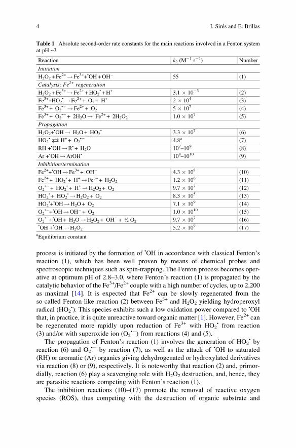
process is initiated by the formation of •OH in accordance with classical Fenton’sreaction (1), which has been well proven by means of chemical probes and
spectroscopic techniques such as spin-trapping. The Fenton process becomes oper-
ative at optimum pH of 2.8–3.0, where Fenton’s reaction (1) is propagated by the
catalytic behavior of the Fe3+/Fe2+ couple with a high number of cycles, up to 2,200
as maximal [14]. It is expected that Fe2+ can be slowly regenerated from the
so-called Fenton-like reaction (2) between Fe3+ and H2O2 yielding hydroperoxyl
radical (HO2•). This species exhibits such a low oxidation power compared to •OH
that, in practice, it is quite unreactive toward organic matter [1]. However, Fe2+ can
be regenerated more rapidly upon reduction of Fe3+ with HO2• from reaction
(3) and/or with superoxide ion (O2•�) from reactions (4) and (5).
The propagation of Fenton’s reaction (1) involves the generation of HO2• by
reaction (6) and O2•� by reaction (7), as well as the attack of •OH to saturated
(RH) or aromatic (Ar) organics giving dehydrogenated or hydroxylated derivatives
via reaction (8) or (9), respectively. It is noteworthy that reaction (2) and, primor-
dially, reaction (6) play a scavenging role with H2O2 destruction, and, hence, they
are parasitic reactions competing with Fenton’s reaction (1).
The inhibition reactions (10)–(17) promote the removal of reactive oxygen
species (ROS), thus competing with the destruction of organic substrate and
Table 1 Absolute second-order rate constants for the main reactions involved in a Fenton system
at pH ~3
Reaction k2 (M�1 s�1) Number
Initiation
H2O2 + Fe2+!Fe3++•OH+OH� 55 (1)
Catalysis: Fe2+ regeneration
H2O2 + Fe3+!Fe2+ +HO2
• +H+ 3.1 � 10�3 (2)
Fe3++HO2•!Fe2+ + O2 + H+ 2 � 104 (3)
Fe3+ + O2•�! Fe2+ + O2 5 � 107 (4)
Fe3+ + O2•�+ 2H2O! Fe2+ + 2H2O2 1.0 � 107 (5)
Propagation
H2O2+•OH! H2O+ HO2
• 3.3 � 107 (6)
HO2• � H++ O2
•� 4.8a (7)
RH +•OH!R• + H2O 107–109 (8)
Ar +•OH!ArOH• 108–1010 (9)
Inhibition/termination
Fe2++•OH!Fe3+ + OH� 4.3 � 108 (10)
Fe2+ + HO2• + H+!Fe3+ + H2O2 1.2 � 106 (11)
O2•�+ HO2
• + H+!H2O2 + O2 9.7 � 107 (12)
HO2• + HO2
•!H2O2 + O2 8.3 � 105 (13)
HO2•+•OH!H2O+ O2 7.1 � 109 (14)
O2•�+•OH!OH�+ O2 1.0 � 1010 (15)
O2•�+•OH+ H2O!H2O2 + OH�+ ½ O2 9.7 � 107 (16)
•OH +•OH!H2O2 5.2 � 109 (17)aEquilibrium constant
4 I. Sires and E. Brillas
eventually restricting the range of several experimental parameters. The existence
of reaction (10), for example, has huge importance since it determines the optimum
Fe2+ content in the medium in order to minimize the consumption of •OH. It should
also be stated that reactions (12)–(17) play a relatively minor role despite their quite
high k2-values, because of the low concentration of radical ROS in the bulk. This
limits their occurrence compared to that of other reactions involving the participa-
tion of some non-radical species, like reactions (10) and (11).
It has been described that the rate of Fenton’s reaction (1) depends strongly
on the presence of inorganic ions like chloride, sulfate, nitrate, carbonate, and
hydrogencarbonate [15], which is mainly due to their scavenging role. On the
other hand, the experimental tests in favor of the free radical theory are not always
satisfactory and convincing, and, in fact, some experimental evidence has been
found by means of electron paramagnetic resonance measurements for the presence
of hypervalent iron complexes such as ferryl or Fe(IV) ions. From this, Kremer [16]
proposed the formation of a mononuclear Fe(IV) oxo complex as follows:
Fe2þ þ H2O2 ! Fe OHð Þ2� �2þ ! Fe3þ þ • OHþ OH� ð18Þ
Unlike •OH, the ferryl ion [Fe(OH)2]2+ is only able to oxidize organic molecules
by electron transfer. Several researchers have proposed that both the “classical”
(based on hydroxyl radicals) and the “nonclassical” (based on ferryl ion) mecha-
nisms coexist, with predominance of one or another depending on the operation
conditions [8, 17]. Pignatello et al. [18] demonstrated the cogeneration of both, •OH
and a high-valent oxoiron complex, by time-resolved laser flash photolysis
spectroscopy:
FeIII-OOH� �2þ∗ ! FeIII-O • $ FeIV ¼ O
� �þ • OH ð19Þ
where [FeIII-OOH]2+* denotes an excited state and reaction (19) can be interpreted
as an intraligand reaction. These results suggested to the authors that secondary
ferryl formation under classical Fenton conditions cannot be ruled out.
The regeneration of Fe2+ from Fe3+ produced during the Fenton process is a key
factor with high impact on the treatment efficiency. An accurate control of exper-
imental variables like pH, temperature, and H2O2 and catalyst concentrations is
crucial [1]. The catalytic activity of iron species is mainly determined by the solution
pH, which is optimal at pH 2.8 since it allows the maximum available Fe2+ concen-
tration and, consequently, yields the highest rate of Fenton’s reaction (1). Conversely,the use of pH<2 enhances the formation of the inert protonated formH3O2
+, whereas
at pH>5 Fe(III) species precipitate as Fe(OH)3, and hence, the quantity of catalyst in
solution diminishes and H2O2 is split into O2 and H2O. The temperature is also a
relevant parameter, whose influence needs to be ascertained for each case study. In
general, the reaction kinetics is upgraded upon heating, although this accelerates the
chemical H2O2 decomposition to O2 and H2O. As for the concentration of both
Electro-Fenton Process: Fundamentals and Reactivity 5
Fenton’s reagents, it has to be optimized on the basis of the [Fe2+]/[H2O2] ratio
utilized, instead of treating them independently.
The main advantages of Fenton process for wastewater treatment are [8] (1) sim-
ple and flexible operation with easy implementation in industrial plants, (2) easy-to-
handle chemicals, and (3) no need for energy input. The following disadvantages
have been reported:
1. Relatively high cost and risks related to the storage, transportation, and handling
of H2O2.
2. High quantities of chemicals for acidifying effluents to pH 2–4 and for neutral-
izing treated solutions before disposal.
3. Accumulation of iron sludge that needs to be managed at the end of the
treatment.
4. Overall mineralization is not feasible because of the formation of Fe(III) com-
plexes with generated carboxylic acids that cannot be destroyed with •OH.
Minimum amounts of H2O2 may be utilized if its concentration is optimized,
whereas the massive formation iron sludge may be prevented by using heteroge-
neous catalysis, with solid iron-containing supports like zeolites, alumina, clays,
mesoporous molecular sieves, natural oxides, ion-exchange resins, and ion-
exchange Nafion membranes that can be easily separated from treated solutions.
The intensification of the Fenton process is also feasible by combination or inte-
gration with other technologies, as reviewed by Pliego et al. [19]. With this aim, the
EF process represents a major milestone in the course of Fenton process develop-
ment, using the electrochemical technology for its significant upgrade.
3 Hydrogen Peroxide Electrogeneration
The main difference between the EF process and the classical Fenton one is the
on-site electrogeneration of H2O2 in an electrochemical reactor in EF, which entails
a reduction of costs and drawbacks related to its production, transportation, storage,
and handling. The pioneer work of Traube in 1882 described the cathodic reduction
of dissolved O2 in aqueous NaOH to generate H2O2 [1]. In the mid-1970s, Dow
Chemical along with Huron Technologies Inc. developed a system for the reduction
of O2 at a carbon-polytetrafluoroethylene (PTFE) gas diffusion electrode (GDE)
using a trickle bed reactor, being employed in the pulp and paper industry. Cur-
rently, the leading procedure for industrial H2O2 production consists in the catalytic
oxidation of anthraquinone, so-called anthraquinone cyclic process, developed by
Riedl and Pfleiderer (BASF) between 1935 and 1945.
In the EF process, H2O2 is continuously supplied to an acidic contaminated
aqueous solution, typically at pH ~3, contained in an electrolytic cell from the
two-electron reduction of oxygen gas, directly injected as pure gas or bubbled air,
by reaction (20) with E� ¼ 0.695 V/SHE. This transformation is easier than its four-
electron reduction towater from reaction (21) withE� ¼ 1.23V/SHE [20, 21]. Several
6 I. Sires and E. Brillas
parasitic reactions at the cathode surface slow down its accumulation in solution,
preeminently its reduction to water and that of protons to hydrogen gas from
reactions (22) and (23), respectively. On the other hand, H2O2 disproportionation in
the bulk by reaction (24) can also occur to much lesser extent:
O2 gð Þ þ 2Hþ þ 2e� ! H2O2 ð20ÞO2 gð Þ þ 4Hþ þ 4e� ! 2H2O ð21ÞH2O2 þ 2Hþ þ 2e� ! 2H2O ð22Þ
2Hþ þ 2e� ! H2 gð Þ ð23Þ2H2O2 ! O2 gð Þþ2H2O ð24Þ
The current efficiency for H2O2 accumulation, determined from Faraday’s law,mainly depends on the cell configuration, which includes the use of divided and
undivided cells with two or three electrodes. The cathode material and operation
conditions also affect largely the H2O2 generation for each setup.
3.1 Cathode Materials
H2O2 can be electrosynthesized by dissolving O2 or air in the solution, thereby
being reduced under galvanostatic or potentiostatic conditions at suitable cathode
materials, or by directly injecting the gas into GDEs. Smooth carbonaceous elec-
trodes like planar graphite and boron-doped diamond (BDD) thin film produce low
amounts of H2O2 because of the low solubility of O2 in water (about 40 or 8 mg L�1
upon saturation with pure O2 or air, respectively, at 1 atm and 25�C). To obtain highrates for reaction (20), 3D carbonaceous electrodes such as carbon felt, activated
carbon fiber (ACF), reticulated vitreous carbon (RVC), carbon sponge and carbon
nanotubes (NTs), as well as carbon-PTFE GDEs or beds of graphite particles have
been used. Note that carbon is a nontoxic material with large overvoltage for H2
evolution, low catalytic activity for H2O2 decomposition and relatively high stability,
conductivity, and chemical resistance.
3D electrodes present a high surface/volume ratio and porosity that counteracts
the limitations of the low space-time yield and low normalized space velocity that
are typically encountered in electrochemical processes with two-dimensional elec-
trodes. Fluidized bed, packed bed, rolling tube, and porous materials can also be
used for water treatment. These 3D electrodes possess large specific areas and
enhance mass transfer of dissolved O2. GDEs have a thin and porous structure
allowing the percolation of the injected gas across its pores to contact with the
solution at the carbon surface. The large number of active surface sites in GDEs
leads to a very fast O2 reduction with large accumulation of H2O2 using high
currents. These cathodes commonly incorporate PTFE to bind the carbon particles
into a cohesive layer and to give some hydrophobicity to the electrode [1, 21].
Electro-Fenton Process: Fundamentals and Reactivity 7
A large number of chemically modified cathodes have been prepared for the
electrocatalytic enhancement of O2 reduction with the consequent shift of the
reduction potential to more positive values and the acceleration of H2O2 formation.
For example, the modification of graphite/PTFE with 2-ethylanthraquinone allowed
a higher H2O2 production. GDEs have been successfully modified with Co and Cu
phthalocyanines, metal oxide nanoparticles, and noble metal like Ag, which
increases the extent of reaction (21) but enlarges the lifetime of the cathode. The
use of NTs has also received attention for H2O2 electrogeneration in EF, because of
their closed topology, tubular structure, and ability to be functionalized with long-
term stability. Chemically modified multiwalled carbon NTs (MWCNTs) with
metal oxide and sulfide have been prepared for the same purpose [22, 23].
3.2 Divided Cells
These systems are composed of two solutions called anolyte and catholyte, which
are usually separated by a cationic Nafion® membrane that only allows the crossing
of protons to maintain the electroneutrality of both solutions. In the catholyte, H2O2
is generated from O2 reduction via reaction (20) and the EF process can then be run
to destroy organic pollutants. Only the anode is immersed in the anolyte, whereas
the catholyte can contain the cathode alone or a reference electrode as well, giving
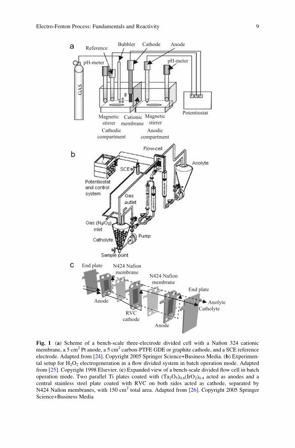
rise to two- and three-electrode cells, respectively. Figure 1a shows a sketch of a
typical cylindrical three-electrode cell with two tank reactors as the anodic and
cathodic compartments [24], whereas Fig. 1b presents a scheme of a three-electrode
flow system operating in batch mode [25]. In contrast, Fig. 1c [26] shows the
components of a two-electrode flow cell. In fact, all these systems can operate
with two or three electrodes depending on the use or not of a reference electrode.
The three-electrode systems tend to operate under potentiostatic conditions by
providing a constant potential to the cathode (Ecath) against the reference electrode,
usually SCE or Ag/AgCl, with a resulting current flow between the anode and
cathode. The two-electrode systems work under galvanostatic conditions by
directly supplying a constant current (I) or current density ( j) to the electrodes.
Table 2 collects selected results for H2O2 accumulation in the above systems
using different arrangements and electrode materials. As can be seen, high current
efficiencies, up to ~100%, were obtained in most cases operating up to�1.6 V/SCE
or 3 A with 100 cm2 electrodes under potentiostatic and galvanostatic conditions.
An interesting comparative study on the ability of graphite and GDE cathodes to
electrogenerate H2O2 has been reported by Da Pozzo et al. [24]. They utilized the
three-electrode cell of Fig. 1a equipped with a Nafion 324 cationic membrane for
the electrolysis of 100 mL of 0.04 M Na2SO4 + 0.05 M NaHSO4 as the catholyte. A
continuous H2O2 accumulation over time was obtained at Ecath ¼ �0.9 V/SCE,
although with much greater performance, near the ideal behavior, for the
O2-diffusion cathode compared to graphite. Several electrogeneration trials were
made with graphite cathode applying from �0.6 to �1.1 V/SCE, and a maximum
8 I. Sires and E. Brillas
pH-meter
AnodeCathode BubblerReference
pH-meter
Magnetic
stirrer
Magnetic
stirrer Cationic
membrane
Cathodic
compartment
Anodic
compartment
Potentiostat
GA
S
End plate
End plate
Anode
Anode
Anolyte
CatholyteRVC
cathode
N424 Nafion
membrane N424 Nafion
membrane
a
c
b
Fig. 1 (a) Scheme of a bench-scale three-electrode divided cell with a Nafion 324 cationic
membrane, a 5 cm2 Pt anode, a 5 cm2 carbon-PTFE GDE or graphite cathode, and a SCE reference
electrode. Adapted from [24]. Copyright 2005 Springer Science+Business Media. (b) Experimen-
tal setup for H2O2 electrogeneration in a flow divided system in batch operation mode. Adapted
from [25]. Copyright 1998 Elsevier. (c) Expanded view of a bench-scale divided flow cell in batch
operation mode. Two parallel Ti plates coated with (Ta2O5)0.6(IrO2)0.4 acted as anodes and a
central stainless steel plate coated with RVC on both sides acted as cathode, separated by
N424 Nafion membranes, with 150 cm2 total area. Adapted from [26]. Copyright 2005 Springer
Science+Business Media
Electro-Fenton Process: Fundamentals and Reactivity 9
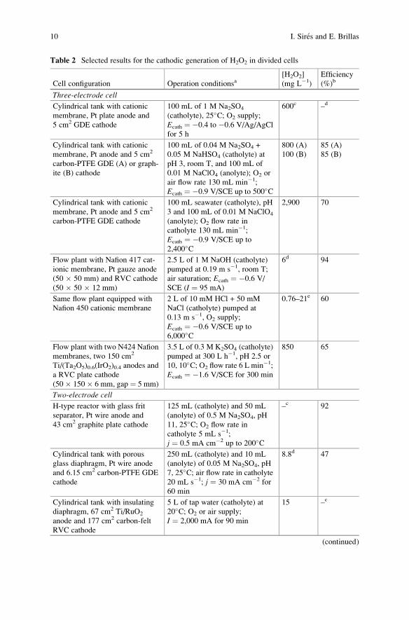
Table 2 Selected results for the cathodic generation of H2O2 in divided cells
Cell configuration Operation conditionsa[H2O2]
(mg L�1)
Efficiency
(%)b
Three-electrode cell
Cylindrical tank with cationic
membrane, Pt plate anode and
5 cm2 GDE cathode
100 mL of 1 M Na2SO4
(catholyte), 25�C; O2 supply;
Ecath ¼ �0.4 to �0.6 V/Ag/AgCl
for 5 h
600c –d
Cylindrical tank with cationic
membrane, Pt anode and 5 cm2
carbon-PTFE GDE (A) or graph-
ite (B) cathode
100 mL of 0.04 M Na2SO4 +
0.05 M NaHSO4 (catholyte) at
pH 3, room T, and 100 mL of
0.01 M NaClO4 (anolyte); O2 or
air flow rate 130 mL min�1;
Ecath ¼ �0.9 V/SCE up to 500�C
800 (A)
100 (B)
85 (A)
85 (B)
Cylindrical tank with cationic
membrane, Pt anode and 5 cm2
carbon-PTFE GDE cathode
100 mL seawater (catholyte), pH
3 and 100 mL of 0.01 M NaClO4
(anolyte); O2 flow rate in
catholyte 130 mL min�1;
Ecath ¼ �0.9 V/SCE up to
2,400�C
2,900 70
Flow plant with Nafion 417 cat-
ionic membrane, Pt gauze anode
(50 � 50 mm) and RVC cathode
(50 � 50 � 12 mm)
2.5 L of 1 M NaOH (catholyte)
pumped at 0.19 m s�1, room T;
air saturation; Ecath ¼ �0.6 V/
SCE (I ¼ 95 mA)
6d 94
Same flow plant equipped with
Nafion 450 cationic membrane
2 L of 10 mM HCl + 50 mM
NaCl (catholyte) pumped at
0.13 m s�1, O2 supply;
Ecath ¼ �0.6 V/SCE up to
6,000�C
0.76–21e 60
Flow plant with two N424 Nafion
membranes, two 150 cm2
Ti/(Ta2O5)0.6(IrO2)0.4 anodes and
a RVC plate cathode
(50 � 150 � 6 mm, gap ¼ 5 mm)
3.5 L of 0.3 M K2SO4 (catholyte)
pumped at 300 L h�1, pH 2.5 or
10, 10�C; O2 flow rate 6 L min�1;
Ecath ¼ �1.6 V/SCE for 300 min
850 65
Two-electrode cell
H-type reactor with glass frit
separator, Pt wire anode and
43 cm2 graphite plate cathode
125 mL (catholyte) and 50 mL
(anolyte) of 0.5 M Na2SO4, pH
11, 25�C; O2 flow rate in
catholyte 5 mL s�1;
j ¼ 0.5 mA cm�2 up to 200�C
–c 92
Cylindrical tank with porous
glass diaphragm, Pt wire anode
and 6.15 cm2 carbon-PTFE GDE
cathode
250 mL (catholyte) and 10 mL
(anolyte) of 0.05 M Na2SO4, pH
7, 25�C; air flow rate in catholyte
20 mL s�1; j ¼ 30 mA cm�2 for
60 min
8.8d 47
Cylindrical tank with insulating
diaphragm, 67 cm2 Ti/RuO2
anode and 177 cm2 carbon-felt
RVC cathode
5 L of tap water (catholyte) at
20�C; O2 or air supply;
I ¼ 2,000 mA for 90 min
15 –c
(continued)
10 I. Sires and E. Brillas
current efficiency of 85% was found at optimum Ecath ¼ �0.9 V/SCE. The same
efficiency was obtained for the GDE electrode, practically independent of applied
charge operating between �0.6 and �0.9 V/SCE. These results demonstrate that
GDEs exhibit a higher selectivity for H2O2 production, thanks to the direct supply
of O2 to the electrode surface that minimizes the extent of side reactions. In fact, the
limited solubility and slow mass transport of O2 in water impede the production of
great concentrations of H2O2, whereas the use of GDEs allows overcoming these
drawbacks thanks to their porous structure and the coexistence of a triple phase
boundary (TPB) [27]. More recently, in 2015, Barazesh et al. [28] also showed the
excellent performance of GDEs for H2O2 electrogeneration in a three-electrode cell
similar to that of Fig. 1a equipped with a DSA® anode. Current efficiencies as high
as 95% were obtained by these authors by electrolyzing 120 mL of synthetic
groundwater, surface water, or urban wastewater with electrodes of 60 cm2 area
at 3.0 mA cm�2.
Excellent H2O2 electrogeneration has also been obtained using an RVC cathode.
Alvarez-Gallegos and Pletcher [25] used it in a three-electrode flow cell in the
divided flow system of Fig. 1b to obtain maximum current efficiencies of 56–68%
using 10 mMHCl and 10 mMH2SO4 (pH ~2) as catholytes at Ecath ranging between
�0.4 and�0.7 V/SCE, which slightly increased upon addition of NaCl and Na2SO4
as background electrolytes, respectively. By adding 1 mM Fe2+, a fast disappear-
ance of H2O2 due to the action of Fenton’s reaction was observed. On the other hand,Badellino et al. [26] utilized a similar flow circuit equipped with the two-electrode
cell of Fig. 1c, also with an RVC cathode to electrolyze 3.5 L of 0.3 M K2SO4 at
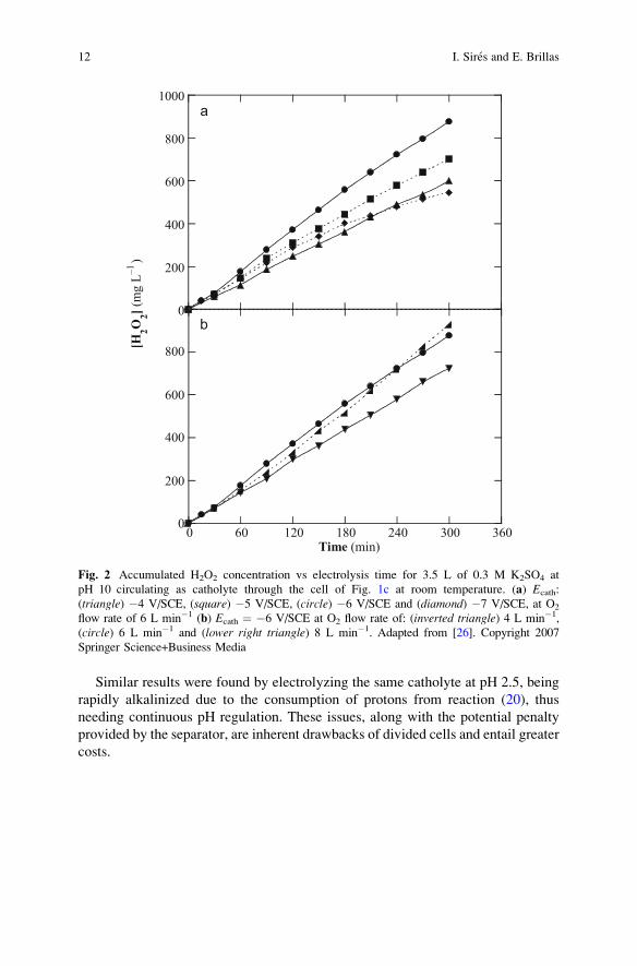
pH 10 and liquid flow rate of 300 L h�1. Figure 2a, b highlights that optimum
conditions were attained at Ecath ¼ �1.6 V/SCE and O2 flow rate of 6 L min�1 by
saturating the solution with 25 mg L�1 of the gas. However, only a 65% current
efficiency was obtained because of the large extent of reactions (21), (22), and (24).
Table 2 (continued)
Cell configuration Operation conditionsa[H2O2]
(mg L�1)
Efficiency
(%)b
Cylindrical tank with cotton dia-
phragm, 14 cm2 Ti/IrO2/RuO2
anode and carbon-PTFE GDE
cathode
100 mL of 0.02 M Na2SO4
(catholyte), pH 7; air flow rate in
the catholyte 25 mL s�1;
j ¼ 39 mA cm�2 for 100 min
8.3 –c
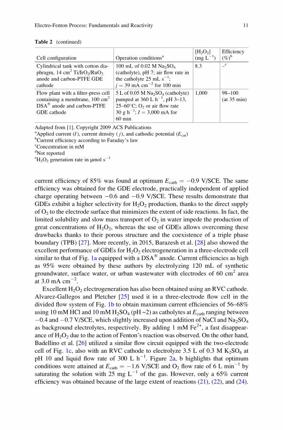
Flow plant with a filter-press cell
containing a membrane, 100 cm2
DSA® anode and carbon-PTFE
GDE cathode
5 L of 0.05 M Na2SO4 (catholyte)
pumped at 360 L h�1, pH 3–13,
25–60�C; O2 or air flow rate
30 g h�1; I ¼ 3,000 mA for
60 min
1,000 98–100
(at 35 min)
Adapted from [1]. Copyright 2009 ACS PublicationsaApplied current (I ), current density ( j), and cathodic potential (Ecat)bCurrent efficiency according to Faraday’s lawcConcentration in mMdNot reportedeH2O2 generation rate in μmol s�1
Electro-Fenton Process: Fundamentals and Reactivity 11
Similar results were found by electrolyzing the same catholyte at pH 2.5, being
rapidly alkalinized due to the consumption of protons from reaction (20), thus
needing continuous pH regulation. These issues, along with the potential penalty
provided by the separator, are inherent drawbacks of divided cells and entail greater
costs.
0
200
400
600
800
1000
[H2O
2] (m
g L
–1)
0
200
400
600
800
0 60 120 180 240 300 360Time (min)
a
b
Fig. 2 Accumulated H2O2 concentration vs electrolysis time for 3.5 L of 0.3 M K2SO4 at
pH 10 circulating as catholyte through the cell of Fig. 1c at room temperature. (a) Ecath:
(triangle) �4 V/SCE, (square) �5 V/SCE, (circle) �6 V/SCE and (diamond) �7 V/SCE, at O2
flow rate of 6 L min�1 (b) Ecath ¼ �6 V/SCE at O2 flow rate of: (inverted triangle) 4 L min�1,
(circle) 6 L min�1 and (lower right triangle) 8 L min�1. Adapted from [26]. Copyright 2007
Springer Science+Business Media
12 I. Sires and E. Brillas
3.3 Undivided Cells
Despite the stable pH solution and lower energy requirements of undivided cells
compared with divided ones for H2O2 electrogeneration, the former kind of systems
is not suitable to obtain large amounts of H2O2 since this species is oxidized to O2 at
the anode via HO2• as intermediate as follows:
H2O2 ! HO2• þ Hþ þ e� ð25Þ
HO2• ! O2 gð Þ þ Hþ þ e� ð26Þ
The concomitant anodic oxidation of cathodically generated H2O2 in three- and
two-electrode undivided cells via reactions (25) and (26) then leads to a remarkably
lower steady-state concentration of this compound. Moreover, other weaker oxi-
dants can also be produced at the anode, thus complicating the degradation process
of organic pollutants in EF, as will be discussed below.
Figure 3a and 3b show typical bench-scale stirred-tank reactors with GDE [29]
and carbon-felt [30] cathodes, respectively, utilized as undivided cells for
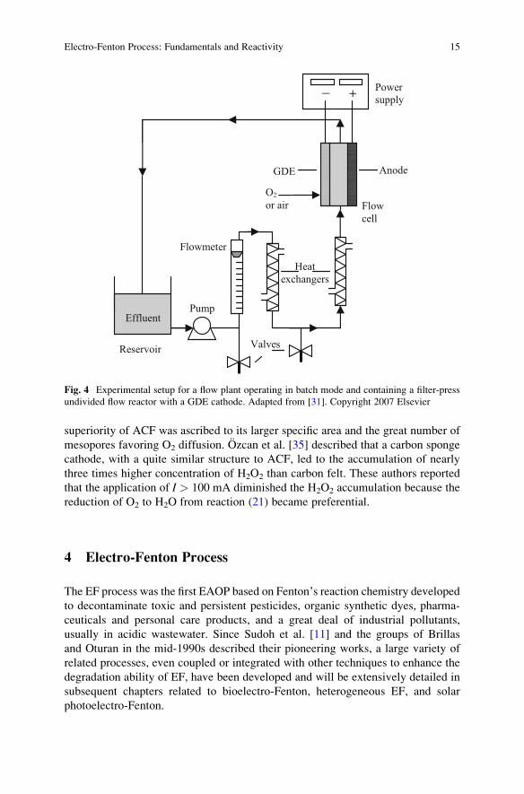
EF. Figure 4 depicts the experimental setup for a flow plant with a typical filter-
press flow cell equipped with a GDE cathode [31]. An example for the profiles for
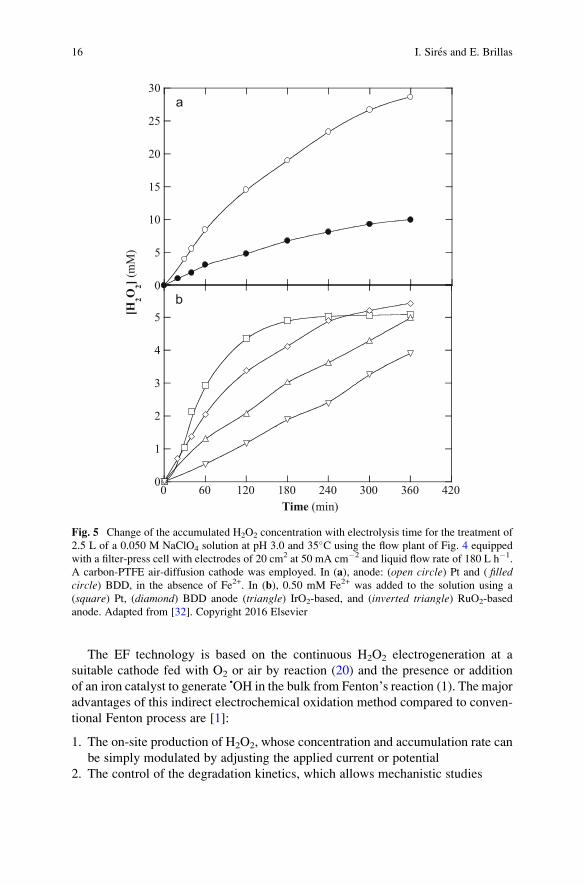
H2O2 accumulation in all these systems is given in Fig. 5a and 5b [32], which
correspond to the electrolysis of 2.5 L of 0.050 M NaClO4 at pH 3.0 and 35�C using
the flow plant of Fig. 4 with a filter-press cell with 20 cm2 electrodes at
j ¼ 50 mA cm�2 in the absence and presence of 0.50 mM Fe2+, respectively. As
can be seen, the concentration of H2O2 always rose with time tending to a quasi-
steady value, which is achieved exactly when its generation rate at the air-diffusion
cathode from reaction (20) equates its decomposition rate, mainly at the anode
surface from reaction (25). The influence of the latter process can be clearly
observed in Fig. 5a, where H2O2 is destroyed much more rapidly at BDD compared
to Pt. In the presence of 0.50 mM Fe2+, Fig. 5b highlights the existence of a much
smaller accumulation of H2O2 because of its removal via Fenton’s reaction. It canalso be seen that H2O2 destruction at the anode was upgraded in the order:
Pt < BDD < DSA®-O2 (IrO2-based) < DSA®-Cl2 (RuO2-based). On the other
hand, Reis et al. [20] studied the effect of liquid flow rate on H2O2 accumulation
using a three-electrode undivided flow cell with a DSA®-Cl2 anode and a GDE as
cathode fed with O2 under circulation of 5 L of 0.1 M K2SO4 at pH.
Under laminar flow conditions (50 L h�1), H2O2 was accumulated up to
414 mg L�1 at Ecath ¼ �2.25 V/Ag|AgCl for 2 h, whereas under turbulent flow
(300 L h�1) this species was more rapidly decomposed at the anode, and a maximal
yield of 294 mg L�1 was reached at Ecath ¼ �1.75 V/Ag|AgCl.
Lower H2O2 electrogeneration ability has been obtained for other cathodes. For
example, Badellino et al. [33] reported a poor current efficiency of 7.8% for H2O2
accumulation at 240 min using a cylindrical tank reactor with a Pt anode and a
rotating RVC cathode to electrolyze 130 mL of 0.3 M K2SO4 solutions at pH 3.5
or 10, 10�C, and Ecath ¼ �1.6 V/SCE. They also found a drop in H2O2 production
Electro-Fenton Process: Fundamentals and Reactivity 13
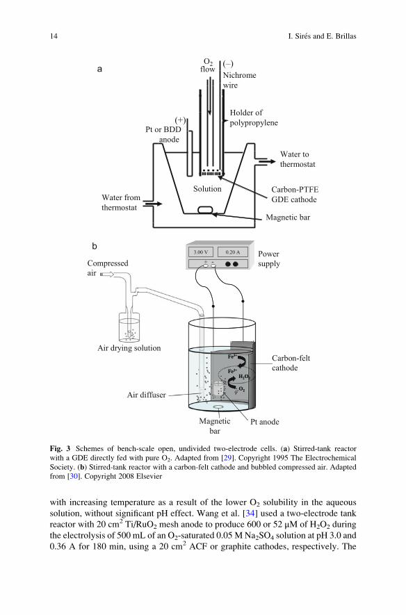
with increasing temperature as a result of the lower O2 solubility in the aqueous
solution, without significant pH effect. Wang et al. [34] used a two-electrode tank
reactor with 20 cm2 Ti/RuO2 mesh anode to produce 600 or 52 μM of H2O2 during
the electrolysis of 500 mL of an O2-saturated 0.05 M Na2SO4 solution at pH 3.0 and
0.36 A for 180 min, using a 20 cm2 ACF or graphite cathodes, respectively. The
Pt or BDD
anode
(–)
Nichrome
wire
flow
Solution
(+)
Water from
thermostat
O2
Carbon-PTFE
GDE cathode
Magnetic bar
Holder of
polypropylene
Water to
thermostat
Compressed
air
Power
supply
3.00 V 0.20 A
+ -
Fe3+
Fe2+
H2O2
O2
3.00 V 0.20 A
+ -
Fe3+
Fe2+
H2O2
O2
Air drying solution
Magnetic
barPt anode
Carbon-felt
cathode
Air diffuser
a
b
Fig. 3 Schemes of bench-scale open, undivided two-electrode cells. (a) Stirred-tank reactor
with a GDE directly fed with pure O2. Adapted from [29]. Copyright 1995 The Electrochemical
Society. (b) Stirred-tank reactor with a carbon-felt cathode and bubbled compressed air. Adapted
from [30]. Copyright 2008 Elsevier
14 I. Sires and E. Brillas
superiority of ACF was ascribed to its larger specific area and the great number of
mesopores favoring O2 diffusion. Ozcan et al. [35] described that a carbon sponge
cathode, with a quite similar structure to ACF, led to the accumulation of nearly
three times higher concentration of H2O2 than carbon felt. These authors reported
that the application of I > 100 mA diminished the H2O2 accumulation because the
reduction of O2 to H2O from reaction (21) became preferential.
4 Electro-Fenton Process
The EF process was the first EAOP based on Fenton’s reaction chemistry developed
to decontaminate toxic and persistent pesticides, organic synthetic dyes, pharma-
ceuticals and personal care products, and a great deal of industrial pollutants,
usually in acidic wastewater. Since Sudoh et al. [11] and the groups of Brillas
and Oturan in the mid-1990s described their pioneering works, a large variety of
related processes, even coupled or integrated with other techniques to enhance the
degradation ability of EF, have been developed and will be extensively detailed in
subsequent chapters related to bioelectro-Fenton, heterogeneous EF, and solar
photoelectro-Fenton.
−
GDE
Pump
+
O2
or air
Anode
Power
supply
Flow
cell
Flowmeter
Heat
exchangers
Valves
Effluent
Reservoir
Fig. 4 Experimental setup for a flow plant operating in batch mode and containing a filter-press
undivided flow reactor with a GDE cathode. Adapted from [31]. Copyright 2007 Elsevier
Electro-Fenton Process: Fundamentals and Reactivity 15
The EF technology is based on the continuous H2O2 electrogeneration at a
suitable cathode fed with O2 or air by reaction (20) and the presence or addition
of an iron catalyst to generate •OH in the bulk from Fenton’s reaction (1). The major
advantages of this indirect electrochemical oxidation method compared to conven-
tional Fenton process are [1]:
1. The on-site production of H2O2, whose concentration and accumulation rate can
be simply modulated by adjusting the applied current or potential
2. The control of the degradation kinetics, which allows mechanistic studies
0
5
10
15
20
25
30
[H2O
2] (m
M)
0
1
2
3
4
5
0 60 120 180 240 300 360 420
Time (min)
a
b
Fig. 5 Change of the accumulated H2O2 concentration with electrolysis time for the treatment of
2.5 L of a 0.050 M NaClO4 solution at pH 3.0 and 35�C using the flow plant of Fig. 4 equipped
with a filter-press cell with electrodes of 20 cm2 at 50 mA cm�2 and liquid flow rate of 180 L h�1.
A carbon-PTFE air-diffusion cathode was employed. In (a), anode: (open circle) Pt and ( filledcircle) BDD, in the absence of Fe2+. In (b), 0.50 mM Fe2+ was added to the solution using a
(square) Pt, (diamond) BDD anode (triangle) IrO2-based, and (inverted triangle) RuO2-based
anode. Adapted from [32]. Copyright 2016 Elsevier
16 I. Sires and E. Brillas
3. The higher degradation rate of organic pollutants because of the continuous
regeneration of Fe2+ from cathodic Fe3+ reduction via reaction (27), with the
concomitant minimization of sludge production
4. The feasibility of total mineralization at relatively low cost when operation
parameters are optimized, being the costs largely reduced when the electrical
supply comes from renewable energy sources
Fe3þ þ e � ! Fe2þ ð27Þ
It is noteworthy that the fast regeneration of Fe2+ by reaction (27) with
E� ¼ 0.77 V/SHE accelerates the production of •OH from Fenton’s reaction,
upgrading the decontamination of organic solutions compared to single conven-
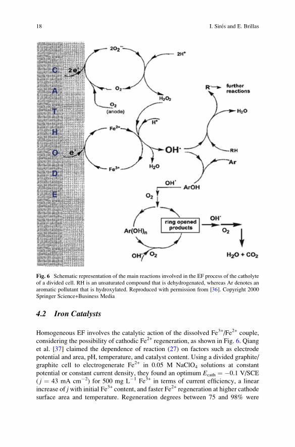
tional Fenton and electrooxidation with electrogenerated H2O2 (EO-H2O2). Figure 6
highlights the main reactions occurring in the catholyte of a divided cell in EF. This
catalytic cycle includes the cathodic H2O2 generation, the cathodic Fe2+ regenera-
tion, and the attack of •OH formed from Fenton’s reaction onto an unsaturated
compound RH and an aromatic pollutant Ar, reaching their conversion into CO2
[36]. In an undivided cell, the process is much more complex and involves the
simultaneous destruction of pollutants with oxidizing species formed at the anode,
as will be discussed below.
4.1 Cell Configuration
The EF technology utilizes three- and two-electrode divided and undivided elec-
trolytic cells in which H2O2 is continuously electrogenerated at the cathode from
reaction (20) using O2 or air as explained above, usually in batch operation mode.
Some examples of divided cells with GDE or RVC cathodes for the EF treatment of
organics are shown in Fig. 1. Figure 3a depicts an undivided stirred two-electrode
cell, and Fig. 4 presents a recirculation flow plant with an undivided two-electrode
filter-press cell, both equipped with a GDE cathode. This setup is commonly
employed for research on EF in our group. On the other hand, Fig. 3b shows the
typical undivided two-electrode cell with a large surface carbon-felt cathode used in
Oturan’s group for studies on EF. Anodes such as Pt, BDD, and DSA® are the most
widely employed in this method. A large number of raw and modified carbonaceous
materials are used as cathodes. Detailed information on different electrochemical
cells and reactors devised for this technique, as well as the use of modified cathodes
with carbon-based materials and other advanced cathodes useful for electro-Fenton,
will be described in further chapters of this book.
Electro-Fenton Process: Fundamentals and Reactivity 17
4.2 Iron Catalysts
Homogeneous EF involves the catalytic action of the dissolved Fe3+/Fe2+ couple,
considering the possibility of cathodic Fe2+ regeneration, as shown in Fig. 6. Qiang
et al. [37] claimed the dependence of reaction (27) on factors such as electrode
potential and area, pH, temperature, and catalyst content. Using a divided graphite/
graphite cell to electrogenerate Fe2+ in 0.05 M NaClO4 solutions at constant
potential or constant current density, they found an optimum Ecath ¼ �0.1 V/SCE
( j ¼ 43 mA cm�2) for 500 mg L�1 Fe3+ in terms of current efficiency, a linear
increase of jwith initial Fe3+ content, and faster Fe2+ regeneration at higher cathodesurface area and temperature. Regeneration degrees between 75 and 98% were
Fig. 6 Schematic representation of the main reactions involved in the EF process of the catholyte
of a divided cell. RH is an unsaturated compound that is dehydrogenated, whereas Ar denotes an
aromatic pollutant that is hydroxylated. Reproduced with permission from [36]. Copyright 2000
Springer Science+Business Media
18 I. Sires and E. Brillas
obtained within the pH range 0–2.5, quickly dropping at greater pH values due to
Fe(OH)3 precipitation. They also observed that Fe2+ regeneration was feasible up to
Ecath ¼ �0.8 V/SCE since higher potentials favored the H2 evolution from reaction
(28) with E� ¼ �0.83 V/SHE:
2H2Oþ 2e� ! H2 gð Þ þ 2OH� ð28Þ
The selection of the iron source strongly relies on the cathode nature in homo-
geneous EF. This was clearly revealed in a work by Sires et al. [38], where the
authors found that, using a GDE cathode in an undivided cell with a BDD or Pt
anode, a concentration of 4.0 mM Fe3+ in 0.050 M Na2SO4 at pH 3.0 was kept
practically constant during the electrolysis. This suggests a very rapid transforma-
tion of the low quantity of Fe2+, produced at the GDE from reaction (27), into Fe3+
by Fenton’s reaction. Conversely, a concentration of 0.2 mM Fe3+ in the same
medium was completely reduced to Fe2+ at a 3D carbon-felt cathode, using the
same undivided cell with BDD or Pt, with only a slow anodic oxidation of Fe2+ to
Fe3+ as follows:
Fe2þ ! Fe3þ þ e� ð29Þ
The above findings allow concluding that in systems with a GDE, the use of Fe2+
as catalyst is mandatory in order to accelerate the production of •OH within the
early stages of EF, since this ion is gradually removed from the solution. In contrast,
either Fe3+ or Fe2+ ions can be used as iron sources in systems with 3D carbona-
ceous materials owing to the fast Fe2+ regeneration, producing continuously •OH by
reaction with electrogenerated H2O2. Oturan et al. [30] confirmed this behavior
when they found that the dye malachite green underwent the same decay using
either 0.2 mM Fe2+ or 0.2 mM Fe3+ as catalyst in an undivided Pt/carbon-felt cell.
The most recent work has been devoted to heterogeneous EF aiming to use
natural sources of iron ions, cocatalysts with ability for promoting Fenton-like
reaction and modified cathodes that not only electrogenerate H2O2 but also yield
surface-catalyzed reactions to produce •OH. For example, excellent degradation of
organics, even quicker than in homogeneous EF under comparable conditions, has
been reported using pyrite [39], alginate gel beads with Mn and Fe [40], and Fe2O3-
kaolin [41] as catalysts, which are able to leach iron ions that are subsequently used
for Fenton’s reaction. Other articles described the good performance of EF systems
equipped with cathodes such as composite graphite felt modified with transition
metals like Co [42] and hierarchical CoFe-layered double hydroxide modified
carbon felt [43]. In the latter case, Acid Orange II was rapidly destroyed at
pH 2–7, and this was ascribed to:
1. The surface-catalyzed reaction occurring at the cathode, which expands the
working pH window, avoiding the precipitation of iron sludge as pH increases
2. The enhanced generation of H2O2 due to the enhanced electroactive surface area
Electro-Fenton Process: Fundamentals and Reactivity 19
3. The cocatalyst effect of the Co2+ ion that can promote regeneration and addi-
tional production of Fe2+ and •OH, respectively
This is explained from the Fenton-like reaction (30) with leached Co2+ and the
reaction of this ion with leached Fe3+ according to reaction (31) in the bulk:
Co2þ þ H2O2 þ Hþ ! Co3þ þ • OH þ H2O ð30ÞFe3þ þ Co2þ ! Fe2þ þ Co3þ ð31Þ
Moreover, at the cathode surface (�), the hydroxylated Fe(III) can be reduced to
hydroxylated Fe(II) by reaction (32). Other catalytic reactions involve the hetero-
geneous formation of hydroxylated Fe(II) and Co(III) from reaction (33), the
heterogeneous Fenton-like reaction (34) to produce HO2•, and reaction (35) gener-
ating •OH:
� Fe III-OHþ e� !� FeII-OH ð32Þ� FeIII-OHþ � CoII-OH !� FeII-OHþ � CoIII-OH ð33Þ
� FeIII=CoIII-OHþ H2O2 !� FeII =CoII-OHþ HO2• þ Hþ ð34Þ
� FeII=CoII-OHþ H2O2 !� FeIII=CoIII-OHþ • OH ð35Þ
4.3 Anode Behavior and Electrolyte Composition
When an undivided cell is used in EF, organic pollutants are simultaneously
destroyed by: (1) oxidants generated at the anode and (2) ROS produced from
cathodic reactions, schematized in Fig. 6. The whole process is so-called “paired”
or “coupled” electrocatalysis, because of the formation of oxidizing agents from
both anode and cathode reactions. The kind and relative proportions of oxidants
formed at the anode depend on its nature and the electrolyte composition.
At a large O2 overvoltage anode, heterogeneous hydroxyl radical (M(•OH)) is
produced from water oxidation by reaction (36) regardless of the medium [1, 21]:
Mþ H2O ! M •OHð Þ þ Hþ þ e� ð36Þ
The requirement of a large O2 overvoltage is needed to minimize the extent of
O2 discharge from reaction (37):
2M •OHð Þ ! 2Mþ O2 gð Þ þ 2Hþ þ 2e� ð37Þ
The oxidative action of M(•OH) is very low for classical active electrodes such
as Pt- and IrO2-based or RuO2-based DSA®, being much more efficient for BDD
20 I. Sires and E. Brillas
[44]. Operating at high current within the water discharge region, large amounts of
reactive BDD(•OH) are generated, and these radicals can mineralize to great extent
aromatics and carboxylic acids in free-chlorine media [21]. Note that the low
adsorption of •OH on BDD favors its dimerization to H2O2 by reaction (38),
whereas the high oxidation power of this anode facilitates ozone generation from
water oxidation by reaction (39) with E� ¼ 1.51 V/SHE. In inert electrolytes such as
perchlorate and nitrate, reactions (36)–(39) along with H2O2 and Fe2+ oxidation via
reactions (25) and (27), respectively, predominate at the anode [45]. In contrast,
peroxodisulfate (S2O82�) ion can be obtained from oxidation of SO4
2� and HSO4�
ions from reactions (40) and (41), respectively, using sulfate medium [1]. It has
been proposed that a very strong oxidizing species like SO4•� radical with
E� ¼ 2.6 V/SCE is originated as intermediate of S2O82� formation, and then, this
radical can attack the organic matter as well:
2BDD •OHð Þ ! 2BDD þ H2O2 ð38Þ3H2O ! O3 gð Þ þ 6Hþ þ 6e� ð39Þ2SO4
2� ! S2O82� þ 2e� ð40Þ
2HSO4� ! S2O8
2� þ 2Hþ þ 2e� ð41Þ
The situation is very different when chlorinated pollutants or chloride-
containing medium is employed, since the oxidant Cl2 is also originated in the
bulk from the anodic oxidation of chloride ion by reaction (42). Hydrolysis of this
species produces hypochlorous acid (HClO) by reaction (43), which is dissociated
to hypochlorite (ClO�) ion by reaction (44) with pKa ¼ 7.56 [45, 46]. They act as
active chlorine species oxidizing organics. Cl2, HClO, and ClO� predominate at
pH <3.0, 3.0–8.0, and >8.0, respectively. Consequently, under the best EF condi-
tions of pH ~3, organics are preeminently attacked by HClO, which is the most
oxidizing active chlorine species:
2Cl� ! Cl2 aqð Þ þ 2e � ð42ÞCl2 aqð Þ þ H2O ! HClOþ Cl� þ Hþ ð43Þ
HClO�ClO� þ Hþ ð44Þ
While acting as an oxidant, electrogenerated HClO can be removed by different
processes. Cathodic reduction to Cl� ion via reaction (45) [47] and its consecutive
anodic oxidation to ClO2�, ClO3
� and ClO4� ions by reactions (46)–(48), respec-
tively, occur regardless of the electrode tested [45, 48]:
HClOþ Hþ þ 2e� ! Cl� þ H2O ð45ÞHClOþ H2O ! ClO�
2 þ 3Hþ þ 2e� ð46Þ
Electro-Fenton Process: Fundamentals and Reactivity 21

ClO�2 þ H2O ! ClO�
3 þ 2Hþþ2e� ð47ÞClO�
3 þ H2O ! ClO�4 þ 2Hþ þ 2e� ð48Þ
Very interestingly, under EF conditions HClO can also attack Fenton’s reagentvia reactions (49) and (50) [49], causing a loss of treatment efficiency:
HClOþ H2O2 ! Cl�þO2 gð Þ þ H2Oþ Hþ ð49ÞHClOþ Fe2þ ! Fe3þ þ • OH þ Cl� ð50Þ
A recent work by Thiam et al. [48] reported the degradation of 130 mL of
0.42 mM Ponceau 4R dye in 0.050 M of several electrolytes with 0.50 mM Fe2+ by
means of EF with a BDD or Pt anode and an air-diffusion cathode. They found
much greater decolorization rate using Cl� ion than ClO4�, NO3
�, and SO42� ions,
as expected if active chlorine attacks more rapidly the dye than M(•OH) and •OH.
Moreover, the use of BDD instead of Pt accelerated the loss of color, indicating the
parallel oxidation of the dye by BDD(•OH). For the mineralization of 100 mL of
158 mg L�1 methylparaben in 0.025MNa2SO4 + 0.035MNaCl with 0.50 mM Fe2+
at pH 3.0 by EF using different anodes and an air-diffusion cathode, Steter et al.
[46] showed the enhancement of total organic carbon (TOC) reduction in the
anode sequence: Pt < RuO2-based < IrO2-based < BDD. Again, the combination
of BDD(•OH) and active chlorine yielded the best performance regarding organic
removal. However, this depends critically on the by-products formed. Figure 7a
shows that H2O2 is accumulated at similar rate in 2.5 L of either 0.050 M Na2SO4 or
LiClO4 at pH 3.0, being much faster than using 0.050 M NaCl, using the flow plant
of Fig. 4 with a BDD/air-diffusion cell [45]. The lower H2O2 accumulation in NaCl
is due to its destruction by reaction (49). In contrast, the attack of active chlorine on
209.3 mg L�1 Carmoisine with 0.50 mM Fe2+ at pH 3.0 in chloride medium which
was much faster than that of BDD(•OH) and •OH in perchlorate and sulfate media,
as can be seen in Fig. 7b. As for TOC removal, Fig. 7c depicts a slower mineral-
ization in chloride medium, which can be related to the formation of highly
recalcitrant chloroderivatives that are more hardly removed than by-products orig-
inated by BDD(•OH) and •OH in perchlorate and sulfate media.
4.4 Operation Variables
The EF degradation of organics in the catholyte of a divided cell involves the attack
by ROS, preeminently •OH formed from Fenton’s reaction (1). As explained above,the process becomes much more complicated in an undivided cell using a free-
chlorine medium, where organic oxidation can be mainly related to the action of
both, •OH in the bulk and M(•OH) at the anode surface, along with parallel destruc-
tion with weaker oxidizing species such as ROS (HO2•, H2O2, O3), S2O8
2� ion, etc. In
22 I. Sires and E. Brillas
0
20
40
60
80
100
120
0 15 30 45 60 75
% C
olor
rem
oval
Time (min)
0
20
40
60
80
100
120
0 60 120 180 240 300 360 420 480 540
TO
C (
mg
L–1)
Time (min)
0
5
10
15
20
25
0 60 120 180 240 300 360 420 480 540
Time (min)
[H2O
2] (m
M)
a
b
c
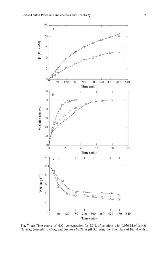
Fig. 7 (a) Time course of H2O2 concentration for 2.5 L of solutions with 0.050 M of (circle)Na2SO4, (triangle) LiClO4, and (square) NaCl, at pH 3.0 using the flow plant of Fig. 4 with a
Electro-Fenton Process: Fundamentals and Reactivity 23
chloride medium, the process is even more complex due to the electrogeneration of
active chlorine species, other chlorinated ions, and chlorinated by-products. In all
cases, the reactivity of the oxidizing species in a given arrangement (i.e., cell
configuration, anode, cathode, and electrolyte) is a function of operation variables
like temperature, pH, liquid flow rate, j or Ecath and catalyst, and pollutant concen-
trations. The specific assessment of these variables is needed to find the best perfor-
mance of the process.
Some variables can be easily optimized [1, 21]. Although the EF process is
accelerated with raising temperature, values >35�C are not recommended in order
to avoid water evaporation that can provoke analytical errors in mineralization
measurements. It has been well established that the optimum pH for homogeneous
EF is about 3, optimal for Fenton’s reaction. Recent efforts in heterogeneous
EF allowed the use of catalyst and cathodes that can operate up to neutral or
circumneutral pH (see Sect. 4.2), thus expanding the applicability. The stirring
rate in tank reactors or the liquid flow rate in recirculation or continuous flow plants
is another important variable to ensure the homogenization of solutions and
enhance the transport of reactants toward/from the electrodes. The effect of the
latter variable on different flow reactors will be discussed in subsequent chapters of
this book. The optimum iron catalyst concentration for homogeneous EF is low,
usually 0.50 mM Fe2+ using GDE as cathode and 0.10–0.20 mM Fe2+ using 3D
cathodes like carbon felt. In three-electrode cells, the optimization of Ecath is closely
related to the maximum production of H2O2, which is assumed to control the
degradation process. In contrast, in two-electrode cells, the applied current can be
increased up to a maximum value whereupon no higher mineralization is attained.
Higher j accelerates slightly the degradation process, but with loss of current
efficiency and a strong growth of energy consumption due the larger enhancement
of O2 and/or H2 evolution and parasitic reactions that cause the destruction
of electrogenerated oxidants. Consequently, the optimum j has to be chosen by
keeping well balanced the treatment time, the current efficiency, and the energy
consumption. Finally, it is well known that the presence of higher organic pollutant
concentration upgrades the current efficiency in EF because a relatively greater
proportion of oxidants is employed to attack organic molecules instead of being lost
in wasting reactions. However, longer times are required to attain a significant
mineralization degree, reason for which it is recommended to study the degradation
behavior of model pollutants for concentrations <500 mg L�1. Note also that too
concentrated solutions have to be avoided because of their highly exothermic
degradation, which leads to a poor control of the treatment and safety concerns.
This problem becomes crucial for industrial wastewater, where the EF process can
Fig. 7 (continued) BDD/air-diffusion cell at 100 mA cm�2 and 35�C. (b) Percentage of color
removal at 514 nm and (c) TOC decay vs electrolysis time during the EF process of 209.3 mg L�1
Carmoisine with 0.50 mM Fe2+ under the same conditions. Adapted from [45]. Copyright 2015
Elsevier
24 I. Sires and E. Brillas
be very inefficient if they contain very high organic load, thus needing (1) their
dilution before electrolysis or (2) sequential treatments that allow a preliminary
reduction of the TOC content, as we have recently proposed by combining EF with
electrocoagulation [50].
5 Conclusions
EF process and all the methods that have derived from it in recent years are
experiencing considerable progress, which can be mainly explained by two reasons:
1. The new awakening of electrochemical technology as a highly versatile, clean
and adaptable tool to multiple purposes, from nanoscience to industrial engi-
neering, and
2. The serious concerns related to water scarcity and environmental contamination,
which constitutes a major challenge within the framework of an ever-increasing
population and a more industrialized society.
EF process is thus a perfect alternative for the electrochemical decontamination
of water and soil. A large plethora of devices and setups has appeared since the first
application of EF, aiming at both, gradually enhancing the treatment efficiency and
offer new solutions to the management of more complex polluted matrices. EF and
related technologies can then be considered a hot topic nowadays, as deduced by the
important advances that are being reported in all topics of interest: novel modified
cathodes with larger selectivity to electrogenerate H2O2 and regenerate Fe2+,
anodes with higher oxidation power, new reactors with innovative arrangements,
and process intensification by combination of EF with other physicochemical and
electrochemical technologies. The present is bright for EF, but the future is chal-
lenging and further work will be needed.
References
1. Brillas E, Sires I, Oturan MA (2009) Electro-Fenton process and related electrochemical
technologies based on Fenton’s reaction chemistry. Chem Rev 109:6570–6663
2. Zakharov II, Kudjukov KY, Bondar VV, Tyupalo NF, Minaev BF (2011) DFT-based thermo-
dynamics of Fenton reactions rejects the ‘pure’ aquacomplex models. Comput Theoret Chem
964:94–99
3. Yamamoto N, Koga N, Nagaoka M (2012) Ferryl-oxo species produced from Fenton’s reagentvia a two-step pathway: minimum free-energy path analysis. J Phys Chem B 116:14178–14182
4. Ayodele OB (2016) Structure and reactivity of ZSM-5 supported oxalate ligand functionalized
nano-Fe catalyst for low temperature direct methane conversion to methanol. Energy Conv
Manage 126:537–547
5. Saporito-Magri~na C, Musacco-Sebio R, Acosta JM, Bajicoff S, Paredes-Fleitas P, Boveris A,
Repetto MG (2017) Rat liver mitochondrial dysfunction by addition of copper(II) or iron(III)
ions. J Inorg Biochem 166:5–1
Electro-Fenton Process: Fundamentals and Reactivity 25
6. Li WP, Su CH, Chang YC, Lin YJ, Yeh CS (2016) Ultrasound-induced reactive oxygen
species mediated therapy and imaging using a Fenton reaction activable polymersome. ACS
Nano 10:2017–2027
7. Xu Q, Liu Y, Su R, Cai L, Li B, Zhang Y, Zhang L, Wang Y, Wang Y, Li N, Gong X, Gu Z,
Chen Y, Tan Y, Dong C, Sreeprasad TS (2016) Highly fluorescent Zn-doped carbon dots as
Fenton reaction-based bio-sensors: an integrative experimental–theoretical consideration.
Nanoscale 8:17919–17927
8. Pignatello JJ, Oliveros E, MacKay A (2006) Advanced oxidation processes for organic
contaminant destruction based on the Fenton reaction and related chemistry. Environ Sci
Technol 36:1–84
9. Oturan MA, Aaron JJ (2014) Advanced oxidation processes in water/wastewater treatment:
principles and applications. A review. Crit Rev Environ Sci Technol 44:257–264
10. Tomat R, Vecchi E (1971) Electrocatalytic production of OH radicals and their oxidative
addition to benzene. J Appl Electrochem 1:185–188
11. Sudoh M, Kodera T, Sakai K, Zhang JQ, Koide K (1986) Oxidative degradation of aqueous
phenol effluent with electrogenerated Fenton’s reagent. J Chem Eng Jpn 19:513–518
12. Buxton GU, Greenstock CL, Helman WP, Ross AB (1988) critical review of rate constants for
reactions of hydrated electrons, hydrogen atoms and hydroxyl radicals (•OH/•O�) in aqueous
solution. J Phys Chem Ref Data 17:513–886
13. Oturan MA, Oturan N, Aaron JJ (2004) Traitement des micropolluants organiques dans l’eau
par des procedes d’oxydation avancee. Actual Chimique 277–278:57–63
14. Burns J, Craig P, Shaw T, Ferry A (2010) Multivariate examination of Fe(II)/Fe(III) cycling
and consequent hydroxyl radical generation. Env Sci Technol 44:7226–7723
15. Bossmann SH, Oliveros E, G€ob S, Siegwart S, Dahlen EP, Payawan J, Straub M, W€orner M,
Braun AM (1998) New evidence against hydroxyl radicals as reactive intermediates in the
thermal and photochemically enhanced Fenton reactions. J Phys Chem A 102:5542–5550
16. Kremer ML (1999) Mechanism of the Fenton reaction. Evidence for a new intermediate. Phys
Chem Chem Phys 1:3595–3605
17. Pang SY, Jiang J, Ma J (2011) Oxidation of sulfoxides and arsenic(III) in corrosion of
nanoscale zero valent iron by oxygen: evidence against ferryl ions (Fe(IV)) as active interme-
diates in Fenton reaction. Environ Sci Technol 45:307–312
18. Pignatello JJ, Liu D, Huston P (1999) Evidence for an additional oxidant in the photoassisted
Fenton reaction. Environ Sci Technol 33:1832–1839
19. Pliego G, Zazo JA, Garcia-Mu~noz P, Mu~noz M, Casas JA, Rodrıguez JJ (2015) Trends in the
intensification of Fenton process by wastewater treatment: an overview. Crit Rev Environ Sci
Technol 45:2611–2692
20. Reis RM, Beati AAGF, Rocha RS, Assumpc~ao MHMT, Santos MC, Bertazzoli R, Lanza MRV
(2012) Use of gas diffusion electrode for the in situ generation of hydrogen peroxide in an
electrochemical flow-by reactor. Ind Eng Chem Res 51:649–654
21. Martınez-Huitle CA, Rodrigo MA, Sires I, Scialdone O (2015) Single and coupled electro-
chemical processes and reactors for the abatement of organic water pollutants: a critical
review. Chem Rev 115:13362–13407
22. Liang Y, Li Y, Wang H, Dai H (2013) Strongly coupled inorganic/nanocarbon hybrid
materials for advanced electrocatalysis. J Amer Chem Soc 135:2013–2036
23. Faber MS, Dziedzic R, Lukowski MA, Kaiser NS, Ding Q, Jin S (2014) High-performance
electrocatalysis using metallic cobalt pyrite (CoS2) micro- and nanostructures. J Amer Chem
Soc 136:10053–11006
24. Da Pozzo A, Di Palma L, Merli C, Petrucci E (2005) An experimental comparison of a graphite
electrode and a gas diffusion electrode for the cathodic production of hydrogen peroxide.
J Appl Electrochem 35:413–419
25. Alvarez-Gallegos A, Pletcher D (1998) The removal of low level organics via hydrogen
peroxide formed in a reticulated vitreous carbon cathode cell, Part 1. The electrosynthesis of
hydrogen peroxide in acidic aqueous solutions. Electrochim Acta 44:853–886
26 I. Sires and E. Brillas
26. Badellino C, Rodrigues CA, Bertazzoli R (2007) Oxidation of herbicides by in situ synthesized
hydrogen peroxide and Fenton’s reagent in an electrochemical flow reactor: study of the
degradation of 2,4-dichlorophenoxyacetic acid. J Appl Electrochem 37:451–459
27. Yu X, Zhou M, Ren G, Ma L (2015) A novel dual gas diffusion electrodes system for efficient
hydrogen peroxide generation used in electro-Fenton. Chem Eng J 263:92–100
28. Barazesh JM, Hennebel T, Jasper JT, Sedlak DL (2015) Modular advanced oxidation process
enabled by cathodic hydrogen peroxide production. Env Sci Tech 49:7391–7399
29. Brillas E, Bastida RM, Llosa E, Casado J (1995) Electrochemical destruction of aniline and
4-chloroaniline for waste water treatment using a carbon-PTFE O2-fed cathode. J Electrochem
Soc 142:1733–1174
30. Oturan MA, Guivarch E, Oturan N, Sires I (2008) Oxidation pathways of malachite green by
Fe3+-catalyzed electro-Fenton process. Appl Catal B: Environ 82:244–254
31. Flox C, Garrido JA, Rodrıguez RM, Cabot PL, Centellas F, Arias C, Brillas E (2007)
Mineralization of herbicide mecoprop by photoelectro-Fenton with UVA and solar light.
Catal Today 129:29–36
32. Coria G, Sires I, Brillas E, Nava JL (2016) Influence of the anode material on the degradation
of naproxen by Fenton-based electrochemical processes. Chem Eng J 304:817–825
33. Badellino C, Rodrigues CA, Bertazzoli R (2006) Oxidation of pesticides by in situ
electrogenerated hydrogen peroxide: study for the degradation of 2,4-dichlorophenoxyacetic
acid. J Hazard Mater 137:856–872
34. Wang A, Qu J, Ru J, Liu H, Ge J (2005) Mineralization of an azo dye Acid Red 14 by electro-
Fenton’s reagent using an activated carbon fiber cathode. Dyes Pigments 65:227–233
35. Ozcan A, Sahin Y, Savas Koparal A, Oturan MA (2008) Carbon sponge as a new cathode
material for the electro-Fenton process: comparison with carbon felt cathode and application to
degradation of synthetic dye basic blue 3 in aqueous medium. J Electroanal Chem 616:71–78
36. Oturan MA (2000) An ecologically effective water treatment technique using electrochemi-
cally generated hydroxyl radicals for in situ destruction of organic pollutants: application to
herbicide 2,4-D. J Appl Electrochem 30:475–482
37. Qiang Z, Chang J-H, Huang C-P (2003) Electrochemical regeneration of Fe2+ in Fenton
oxidation processes. Water Res 37:1308–1319
38. Sires I, Garrido JA, Rodrıguez RM, Brillas E, Oturan N, Oturan MA (2007) Catalytic behavior
of the Fe3+/Fe2+ system in the electro-Fenton degradation of the antimicrobial chlorophene.
Appl Catal B: Environ. 72:382–394
39. Ammar S, Oturan MA, Labiadh L, Guersalli A, Abdelhedi R, Oturan N, Brillas E (2015)
Degradation of tyrosol by a novel electro-Fenton process using pyrite as heterogeneous source
of iron catalyst. Water Res 74:77–87
40. Iglesias O, Meijide J, Bocos E, Sanroman MA, Pazos M (2015) New approaches on hetero-
geneous electro-Fenton treatment of winery wastewater. Electrochim Acta 169:134–114
41. Ozcan A, Atilir Ozcan A, Demirci Y, Sener E (2017) Preparation of Fe2O3 modified kaolin and
application in heterogeneous electro-catalytic oxidation of enoxacin. Appl Catal B: Environ
200:361–337
42. Liang L, Yu F, An Y, Liu M, Zhou M (2017) Preparation of transition metal composite
graphite felt cathode for efficient heterogeneous electro-Fenton process. Environ Sci Pollut
Res 24:1122–1132
43. Ganiyu SO, Le TXH, Bechelany M, Esposito G, van Hullebusch ED, Oturan MA, Cretin M
(2017) A hierarchical CoFe-layered double hydroxide modified carbon-felt cathode for het-
erogeneous electro-Fenton process. J Mater Chem A 5:3655–3666
44. Thiam A, Brillas E, Garrido JA, Rodrıguez RM, Sires I (2016) Routes for the electrochemical
degradation of the artificial food azo-colour Ponceau 4R by advanced oxidation processes.
Appl Catal B: Environ 180:227–236
45. Thiam A, Sires I, Garrido JA, Rodrıguez RM, Brillas E (2015) Effect of anions on electro-
chemical degradation of azo dye Carmoisine (Acid Red 14) using a BDD anode and
air-diffusion cathode. Sep Purif Technol 140:43–52
Electro-Fenton Process: Fundamentals and Reactivity 27

46. Steter JR, Brillas E, Sires I (2016) On the selection of the anode material for the electrochem-
ical removal of methylparaben from different aqueous media. Electrochim Acta
222:1464–1474
47. Kodera F, Umeda M, Yamada A (2005) Detection of hypochlorous acid using reduction wave
during anodic cyclic voltammetry. Jpn J Appl Phys 44:L718–L719
48. Thiam A, Brillas E, Centellas F, Cabot PL, Sires I (2015) Electrochemical reactivity of
Ponceau 4R (food additive E124) in different electrolytes and batch cells. Electrochim Acta
173:523–533
49. Aguilar ZA, Brillas E, Salazar M, Nava JL, Sires I (2017) Evidence of Fenton-like reaction
with active chlorine during the electrocatalytic oxidation of Acid Yellow 36 azo dye with Ir-
Sn-Sb oxide anode in the presence of iron ion. Appl Catal B: Environ 206:44–52
50. Thiam A, Zhou M, Brillas E, Sires I (2014) Two-step mineralization of Tartrazine solutions:
Study of parameters and by-products during the coupling of electrocoagulation with electro-
chemical advanced oxidation processes. Appl Catal B: Environ 150–151:116–125
28 I. Sires and E. Brillas
Bio-electro-Fenton: A New Combined
Process – Principles and Applications
Hugo Olvera-Vargas, Clement Trellu, Nihal Oturan,
and Mehmet A. Oturan
Abstract Biological treatments show insufficient removal efficiency in the case of
recalcitrant organic compounds. Therefore, the necessity of upgrading wastewater
treatment plants (WWTPs) with advanced treatment steps is unequivocal.
Advanced oxidation processes (AOPs) are the most effective technologies for the
removal of a large range of organic pollutants from water due to the generation of
strong oxidizing species like hydroxyl radicals (•OH). However, AOPs often
involve high energy and/or reagent consumption and are considered as less cost-
effective than biological processes. Hence, the combination of AOPs and biological
treatments has been implemented aiming at maximizing efficient removal of recal-
citrant organic pollutants while minimizing treatment costs. Among AOPs, elec-
trochemical advanced oxidation processes (EAOPs) have been widely explored
during coupled processes, since they possess remarkable advantages, such as high
efficiencies, operability at mild conditions, economic feasibility, ease of automa-
tion, as well as eco-friendly character. The electro-Fenton process (EF) stands out
as one of the most applied EAOPs and the present chapter is devoted to the
advances and applications of EF process as a treatment step coupled with biological
methods: the so-called bio-electro-Fenton (Bio-EF) process, which brings together
the high oxidation power of EF and cost-effectiveness of biological methods.
Keywords Biodegradability, Bio-electro-Fenton, Biological treatment, By-
products, Combined process, Electro-Fenton, Hydroxyl radicals, Mineralization,
Toxicity, Water treatment
H. Olvera-Vargas, C. Trellu, N. Oturan, and M.A. Oturan (*)
Laboratoire Geomateriaux et Environnement (LGE), EA 4508, Universite Paris-Est, UPEM, 5
bd Descartes, Marne-la-Vallee, Cedex 2 77454, France
e-mail: [email protected]
M. Zhou et al. (eds.), Electro-Fenton Process: New Trends and Scale-Up,Hdb Env Chem (2018) 61: 29–56, DOI 10.1007/698_2017_53,© Springer Nature Singapore Pte Ltd. 2017, Published online: 14 June 2017
29
Contents
1 Introduction . . . . . . . . . . . . . . . . . . . . . . . . . . . . . . . . . . . . . . . . . . . . . . . . . . . . . . . . . . . . . . . . . . . . . . . . . . . . . . . . . . . 30
2 Biological Methods for the Degradation of Organic Emerging Contaminants . . . . . . . . . . . . . 31
3 The Coupling of Biological Processes with AOPs . . . . . . . . . . . . . . . . . . . . . . . . . . . . . . . . . . . . . . . . . . 32
3.1 AOPS as Pre- or Post-treatment for Biological Processes . . . . . . . . . . . . . . . . . . . . . . . . . . . . 32
3.2 Biodegradability Indicators . . . . . . . . . . . . . . . . . . . . . . . . . . . . . . . . . . . . . . . . . . . . . . . . . . . . . . . . . . . . 33
4 The Electro-Fenton Process . . . . . . . . . . . . . . . . . . . . . . . . . . . . . . . . . . . . . . . . . . . . . . . . . . . . . . . . . . . . . . . . . . 34
5 Bio-electro-Fenton Process . . . . . . . . . . . . . . . . . . . . . . . . . . . . . . . . . . . . . . . . . . . . . . . . . . . . . . . . . . . . . . . . . . . 36
5.1 Fundamentals of Bio-EF Process . . . . . . . . . . . . . . . . . . . . . . . . . . . . . . . . . . . . . . . . . . . . . . . . . . . . . . 36
5.2 Degradation Pathways During the Bio-EF Process . . . . . . . . . . . . . . . . . . . . . . . . . . . . . . . . . . . 44
5.3 Experimental Features and Operating Conditions . . . . . . . . . . . . . . . . . . . . . . . . . . . . . . . . . . . . . 46
5.4 Economic Aspects . . . . . . . . . . . . . . . . . . . . . . . . . . . . . . . . . . . . . . . . . . . . . . . . . . . . . . . . . . . . . . . . . . . . . . 51
6 Concluding Remarks and Perspectives . . . . . . . . . . . . . . . . . . . . . . . . . . . . . . . . . . . . . . . . . . . . . . . . . . . . . . 52
References . . . . . . . . . . . . . . . . . . . . . . . . . . . . . . . . . . . . . . . . . . . . . . . . . . . . . . . . . . . . . . . . . . . . . . . . . . . . . . . . . . . . . . . . 53
1 Introduction
The worldwide water problem has boosted research in the field of wastewater
treatment technologies (WWTT) during last decades since environmentally com-
patible technological solutions are imperative for providing clean water to the fast-
growing population on one hand, and to protect natural water resources on the
other.
Traditionally, municipal wastewater treatment plants (WWTP) have been
designed for removing different contaminants, which include particles, organic
and inorganic compounds, pathogens, and so on. However, they are generally not
suitable for the control of the so-called emerging contaminants or micropollutants
(pharmaceuticals, pesticides, dyestuff, personal care products, and industrial
chemicals), due to their recalcitrance and low biodegradability [1, 2]. The presence
of these potentially persistent and harmful substances in different environmental
water sources has been extensively documented and they are reported to come from
industrial wastewater, agriculture, livestock and aquaculture activity, landfill leach-
ates, as well as domestic and hospital effluents, being the release of contaminated
WWTP effluents (especially for pharmaceuticals and personal care products) the
main responsible for the discharge of these pollutants in surface water [3]. The
noxious effects associated with these contaminants are principally short-term and
long-term toxicity, endocrine disrupting effects (even at very low concentration),
and antibiotic resistance of microorganisms [4].
In conventional WWTP, wastewater treatment goes through primary, secondary,
and sometimes tertiary treatment processes. The aim of primary treatment is the
removal of suspended solids by physical methods and it is ineffective in removing
dissolved chemicals such as organic micropollutants. Secondary processes com-
prise mainly biological methods, the most widespread conventional processes.
Their cost-effectiveness and well-established operating conditions arise as their
most relevant advantages. Biological technologies include activated sludge (AS),
30 H. Olvera-Vargas et al.
constructed wetland (CW), membrane bioreactor (MBR), sequential batch reactor
(SBR), microalgae and fungal bioreactor, trickling filter, nitrification and denitrifi-
cation, enzyme treatment, and biosorption. Among them, AS and MBR are the most
utilized processes for the treatment of refractory contaminants, which are predom-
inately removed via sorption, biodegradation, and/or chemical conversion
[5, 6]. Tertiary treatment aims at increasing water quality with defined objectives
generally related to public health and environmental purposes. They are normally
accompanied by high treatment costs [1].
2 Biological Methods for the Degradation of Organic
Emerging Contaminants
When it comes to the degradation of emerging organic contaminants, biological
processes present several limitations since these refractory substances are hardly
biodegradable due to their toxicity and/or resistance tomicrobial activities. Themain
mechanisms through which organic micropollutants are degraded during biological
oxidation are: (1) metabolism, in which organics are directly assimilated as a source
of carbon through enzymatic reactions for cellular growth and (2) co-metabolism, in
which a different substrate is needed as a source of energy to maintain biomass
growth, while organic contaminants are degraded by the enzymes or cofactors
produced duringmetabolism of that substrate [7]. Removal efficiencies are governed
by physicochemical properties of pollutants under study and the different operating
treatment conditions [6]. Several discrepancies exist between the reports on the
biological degradation of emerging pollutants and the removal rates are generally
low. Luo et al. exhaustively reviewed the fate of some of the most assessed
micropollutants in different countries during diverse WWTT, evidencing the large
range in the variation of removal efficiencies when applying biological methods. For
example, nonsteroidal anti-inflammatory drugs (NSAIDs) like ibuprofen, naproxen,
and ketoprofen have moderate to high removal efficiencies (between 52 and 90%),
while antibiotics, lipid regulators, and β-blockers present low to moderate degrada-
tion rates (between 37 and 73%). The drug carbamazepine and various pesticides
have been reported to be highly persistent with insufficient removal rates [4]. Fur-
thermore, removal efficiencies are generally related to the disappearance of starting
pollutants, referred only to degradation of parent molecules, while the formation and
removal of different intermediates is not taken into consideration, even though
numerous studies have stated the generation of toxic by-products as a result of partial
degradation [8, 9]. Some other thorough reviews have been focused on the state of
the art and perspectives of biological wastewater treatment processes [6, 10, 11].
Bio-electro-Fenton: A New Combined Process – Principles and Applications 31
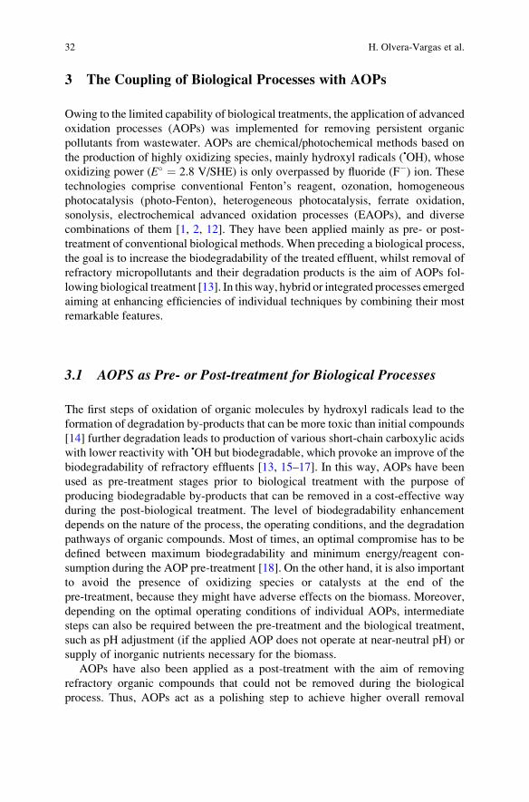
3 The Coupling of Biological Processes with AOPs
Owing to the limited capability of biological treatments, the application of advanced
oxidation processes (AOPs) was implemented for removing persistent organic
pollutants from wastewater. AOPs are chemical/photochemical methods based on
the production of highly oxidizing species, mainly hydroxyl radicals (•OH), whose
oxidizing power (E� ¼ 2.8 V/SHE) is only overpassed by fluoride (F�) ion. Thesetechnologies comprise conventional Fenton’s reagent, ozonation, homogeneous
photocatalysis (photo-Fenton), heterogeneous photocatalysis, ferrate oxidation,
sonolysis, electrochemical advanced oxidation processes (EAOPs), and diverse
combinations of them [1, 2, 12]. They have been applied mainly as pre- or post-
treatment of conventional biological methods. When preceding a biological process,
the goal is to increase the biodegradability of the treated effluent, whilst removal of
refractory micropollutants and their degradation products is the aim of AOPs fol-
lowing biological treatment [13]. In this way, hybrid or integrated processes emerged
aiming at enhancing efficiencies of individual techniques by combining their most
remarkable features.
3.1 AOPS as Pre- or Post-treatment for Biological Processes
The first steps of oxidation of organic molecules by hydroxyl radicals lead to the
formation of degradation by-products that can be more toxic than initial compounds
[14] further degradation leads to production of various short-chain carboxylic acids
with lower reactivity with •OH but biodegradable, which provoke an improve of the
biodegradability of refractory effluents [13, 15–17]. In this way, AOPs have been
used as pre-treatment stages prior to biological treatment with the purpose of
producing biodegradable by-products that can be removed in a cost-effective way
during the post-biological treatment. The level of biodegradability enhancement
depends on the nature of the process, the operating conditions, and the degradation
pathways of organic compounds. Most of times, an optimal compromise has to be
defined between maximum biodegradability and minimum energy/reagent con-
sumption during the AOP pre-treatment [18]. On the other hand, it is also important
to avoid the presence of oxidizing species or catalysts at the end of the
pre-treatment, because they might have adverse effects on the biomass. Moreover,
depending on the optimal operating conditions of individual AOPs, intermediate
steps can also be required between the pre-treatment and the biological treatment,
such as pH adjustment (if the applied AOP does not operate at near-neutral pH) or
supply of inorganic nutrients necessary for the biomass.
AOPs have also been applied as a post-treatment with the aim of removing
refractory organic compounds that could not be removed during the biological
process. Thus, AOPs act as a polishing step to achieve higher overall removal
32 H. Olvera-Vargas et al.
rates [13, 19]. The advantage is that hydroxyl radicals are not wasted for the
oxidation of initial easily biodegradable compounds.
Different applications of such combined approaches have been investigated on
various industrial effluents and synthetic solutions containing diverse emerging
contaminants [2, 13]. The choice of the treatment strategy strongly depends on the
nature of the effluent.
3.2 Biodegradability Indicators
When combining AOPs with biological methods, the assessment and monitoring of
the biodegradability becomes a crucial parameter. It is performed by measurement
of the general parameters: biological oxygen demand after x days (BODx), chemical
oxygen demand (COD), dissolved organic carbon (DOC), and total organic carbon
(TOC), as well as the calculation of the generalized indexes: BOD5/COD ratio
and/or the average oxidation state (AOS). These ratios give an approximation of the
proportion of biodegradable substances under aerobic conditions during a deter-
mined period of time; 5 days for the BOD5, or 28 days for the Zahn-Wellens assays,
in which the portion of removed DOC is expressed as the percentage of biodegra-
dation (Dt(%)). In the latter method, biodegradability is considered for biodegra-
dation values above 70%. Quick respirometric measurements based on the amount
of oxygen used by bacteria in 20 min-contact are also used for determining the
biodegradability. The readily biodegradable fraction of the COD (CODrb) is mea-
sured during the tests and the ratio R ¼ CODrb/COD indicates the biodegradability
of the sample (R > 0.1: biodegradable, 0.1 < R < 0.05: low biodegradability, and
R < 0.05: non-biodegradable) [13, 20]. It is important to mention that the nature of
the inoculum used for these methods can strongly influence the results. In the case
of the AOS, this ratio is related to the mean oxidation state of organic carbon, which
ranges from �4 for the most reduced form of carbon (CH4) to +4 for the most
oxidized form (CO2). Positive AOS values evidence the presence of compounds
with more oxidized forms of carbon, such as formic acid (+2) or oxalic acid (+3),
which are more biocompatible [21].
Alternatively, the use of a real biological reactor, which can mimic the operating
conditions of a real biological treatment, can be a more reliable method for
assessing the feasibility of a biological treatment.
Another crucial aspect when applying AOPs as pre-treatment stage preceding
bio-treatment is the evolution of toxicity, as biodegradability is strongly linked with
the presence of toxic compounds. A lack of toxicity is hence another important hint
of the suitability of the effluents for biological treatment [13]. Among the most
utilized methods for ecotoxicological water quality assessment, in vitro essays
based on the determination of luminescence inhibition of bioluminescent bacteria
(such as Vibrio fischeri and Aliivibrio fischeri) stand out because of their simplicity.
Bio-electro-Fenton: A New Combined Process – Principles and Applications 33
They are good indicators of potential toxicity and are proper starting tools for the
analysis of ecotoxicological effects. However, a vast number of approaches for
toxicological assessment can be found, and their choice relies on the objectives of
the study [5].
4 The Electro-Fenton Process
The EF process has shown notable advantages among EAOPs and its application
for the degradation of persistent/toxic organic contaminants and the remediation of
diverse kinds of wastewaters has been exhaustively studied. The process is based on
the electrochemical generation of the “Fenton’s reagent”: H2O2 by 2-electron
reduction of dissolved O2 (Eq. 1) and Fe2+ (catalyst) from 1-electron reduction of
externally added Fe3+ (Eq. 2) at a “suitable cathode” leading to the continuous
formation of •OH via the Fenton’s reaction (Eq. 3). In this way, organics are
efficiently oxidized by the powerful attack of generated •OH, which promote their
mineralization to CO2, water, and inorganic ions [12, 22, 23]. Furthermore, by
using a suitable anode with a high O2 evolution overpotential (such as boron-doped
diamond (BDD), Ti4O7 ceramic materials, and PbO2), additional•OH can also be
produced at the surface of the anode from water discharge (anodic oxidation, AO),
Eq. 4, thus enhancing the mineralization rates [24]. The remarkable efficiency and
sustainability of the EF process has boosted the development of more effective
advanced carbon-based cathode materials [25, 26], as well as catalysts [27, 28] for
enhancement of the process. Furthermore, EF has also found a great number of
applications in integrated or hybrid systems, in which its outstanding oxidative
power is combined with other wastewater treatment technologies during “step-by-
step” or “one-step” methodologies [16, 29, 30]. Thorough details on the mecha-
nisms, operating conditions, experimental setups, and advances of the EF process,
as well as a wide range of applications, are exhaustively described through the
different chapters of the present book.
O2 þ 2Hþ þ 2e� ! H2O2 ð1ÞFe3þ þ e� ! Fe2þ ð2Þ
H2O2 þ Fe2þ ! Fe3þ þ OH�þ • OH ð3ÞMþ H2O ! M •OHð Þ þ Hþ þ e� ð4Þ
On the other hand, although the EF process presents numerous advantages when
it comes to the degradation of persistent and refractory organic pollutants, there are
still some shortcomings that require further development. One of them is related to
energetic needs. In fact, the mineralization of organics during electrochemical
treatment is generally energy-consuming since the degradation by-products gener-
ated throughout the electro-oxidation process tend to be more and more recalcitrant
34 H. Olvera-Vargas et al.
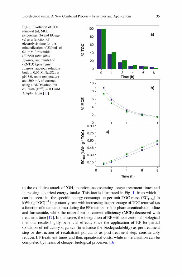
to the oxidative attack of •OH, therefore necessitating longer treatment times and
increasing electrical energy intake. This fact is illustrated in Fig. 1, from which it
can be seen that the specific energy consumption per unit TOC mass (ECTOC) in
kWh (g TOC)�1 importantly rose with increasing the percentage of TOC removal (as
a function of treatment time) during the EF treatment of the pharmaceuticals ranitidine
and furosemide, while the mineralization current efficiency (MCE) decreased with
treatment time [17]. In this sense, the integration of EF with conventional biological
methods results highly beneficial effects, since the application of EF for partial
oxidation of refractory organics (to enhance the biodegradability) as pre-treatment
step or destruction of recalcitrant pollutants as post-treatment step, considerably
reduces EF treatment times and thus operational costs, while mineralization can be
completed by means of cheaper biological processes [16].
0
2
4
6
8
10
0 2 4 6 8
0.15
0.30
0.45
0.60
0.75
0.90
0 1 2 4 6 80
20
40
60
80
100
c)
b)%
TO
CTime (h)
a)
% M
CE
ECTO
C(k
Wh
g-1 T
OC
)
Time (h)
Fig. 1 Evolution of TOC
removal (a), MCE
percentage (b) and ECTOC
(c) as a function of
electrolysis time for the
mineralization of 230 mL of
0.1 mM furosemide
(FRSM) (blue filledsquares) and ranitidine
(RNTD) (green filledsquares) aqueous solutions,both in 0.05 M Na2SO4 at
pH 3.0, room temperature
and 500 mA of current,
using a BDD/carbon-felt
cell with [Fe2+] ¼ 0.1 mM.
Adapted from [17]
Bio-electro-Fenton: A New Combined Process – Principles and Applications 35
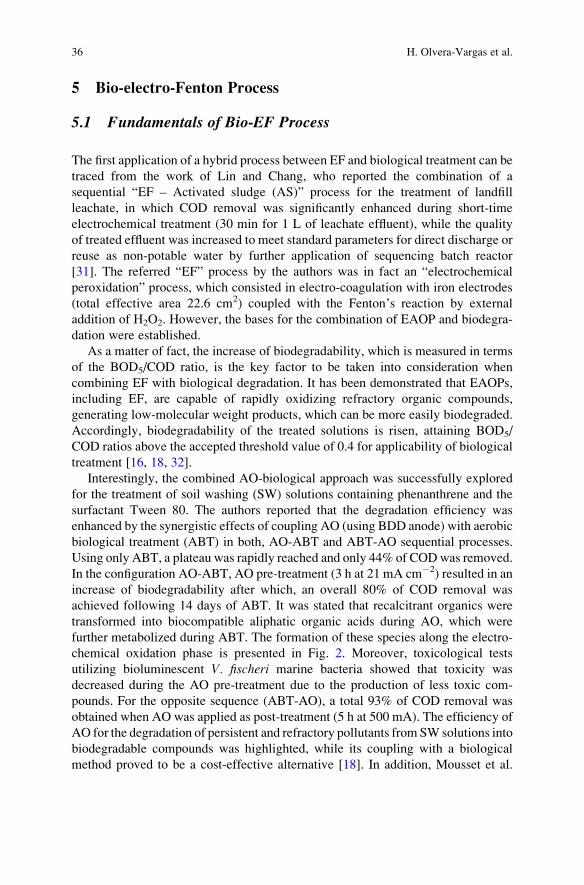
5 Bio-electro-Fenton Process
5.1 Fundamentals of Bio-EF Process
The first application of a hybrid process between EF and biological treatment can be
traced from the work of Lin and Chang, who reported the combination of a
sequential “EF – Activated sludge (AS)” process for the treatment of landfill
leachate, in which COD removal was significantly enhanced during short-time
electrochemical treatment (30 min for 1 L of leachate effluent), while the quality
of treated effluent was increased to meet standard parameters for direct discharge or
reuse as non-potable water by further application of sequencing batch reactor
[31]. The referred “EF” process by the authors was in fact an “electrochemical
peroxidation” process, which consisted in electro-coagulation with iron electrodes
(total effective area 22.6 cm2) coupled with the Fenton’s reaction by external
addition of H2O2. However, the bases for the combination of EAOP and biodegra-
dation were established.
As a matter of fact, the increase of biodegradability, which is measured in terms
of the BOD5/COD ratio, is the key factor to be taken into consideration when
combining EF with biological degradation. It has been demonstrated that EAOPs,
including EF, are capable of rapidly oxidizing refractory organic compounds,
generating low-molecular weight products, which can be more easily biodegraded.
Accordingly, biodegradability of the treated solutions is risen, attaining BOD5/
COD ratios above the accepted threshold value of 0.4 for applicability of biological
treatment [16, 18, 32].
Interestingly, the combined AO-biological approach was successfully explored
for the treatment of soil washing (SW) solutions containing phenanthrene and the
surfactant Tween 80. The authors reported that the degradation efficiency was
enhanced by the synergistic effects of coupling AO (using BDD anode) with aerobic
biological treatment (ABT) in both, AO-ABT and ABT-AO sequential processes.
Using only ABT, a plateau was rapidly reached and only 44% of CODwas removed.
In the configuration AO-ABT, AO pre-treatment (3 h at 21 mA cm�2) resulted in an
increase of biodegradability after which, an overall 80% of COD removal was
achieved following 14 days of ABT. It was stated that recalcitrant organics were
transformed into biocompatible aliphatic organic acids during AO, which were
further metabolized during ABT. The formation of these species along the electro-
chemical oxidation phase is presented in Fig. 2. Moreover, toxicological tests
utilizing bioluminescent V. fischeri marine bacteria showed that toxicity was
decreased during the AO pre-treatment due to the production of less toxic com-
pounds. For the opposite sequence (ABT-AO), a total 93% of COD removal was
obtained when AO was applied as post-treatment (5 h at 500 mA). The efficiency of
AO for the degradation of persistent and refractory pollutants from SW solutions into
biodegradable compounds was highlighted, while its coupling with a biological
method proved to be a cost-effective alternative [18]. In addition, Mousset et al.
36 H. Olvera-Vargas et al.
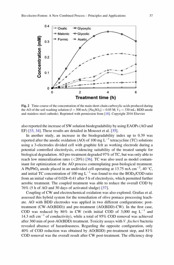
also reported the increase of SW solution biodegradability by using EAOPs (AO and
EF) [33, 34]. These results are detailed in Mousset et al. [35].
In another study, an increase in the biodegradability index up to 0.39 was
reported after the anodic oxidation (AO) of 100 mg L�1 tetracycline (TC) solutions
using a 3-electrodes divided cell with graphite felt as working electrode during a
potential controlled electrolysis, evidencing suitability of the treated sample for
biological degradation. AO pre-treatment degraded 97% of TC, but was only able to
reach low mineralization rates (<20%) [36]. TC was also used as model contam-
inant for optimization of the AO process contemplating post-biological treatment.
A Pb/PbO2 anode placed in an undivided cell operating at 13.75 mA cm�2, 40 �C,and initial TC concentration of 100 mg L�1 was found to rise the BOD5/COD ratio
from an initial value of 0.028–0.41 after 5 h of electrolysis, which permitted further
aerobic treatment. The coupled treatment was able to reduce the overall COD by
76% (5 h of AO and 30 days of activated sludge) [37].
Coupling of CW and electrochemical oxidation was also explored. Grafias et al.
assessed this hybrid system for the remediation of olive pomace processing leach-
ate. AO with BDD electrodes was applied in two different configurations: post-
treatment (CW-AO(BDD)) and pre-treatment (AO(BDD)-CW). In the first case,
COD was reduced by 86% in CW (with initial COD of 3,000 mg L�1 and
14.3 mS cm�1 of conductivity), while a total of 95% COD removal was achieved
after 360 min of post-AO(BDD) treatment. Toxicity assays with V. fischeri bacteriarevealed absence of hazardousness. Regarding the opposite configuration, only
40% of COD reduction was obtained by AO(BDD) pre-treatment step, and 81%
COD removal was the overall result after CW post-treatment. The efficiency drop
Fig. 2 Time-course of the concentration of the main short-chain carboxylic acids produced during
the AO of the soil washing solution (I ¼ 500 mA; [Na2SO4]¼ 0.05 M; VT ¼ 330 mL; BDD anode
and stainless steel cathode). Reprinted with permission from [18]. Copyright 2016 Elsevier
Bio-electro-Fenton: A New Combined Process – Principles and Applications 37
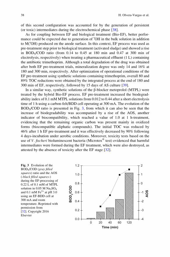
of this second configuration was accounted for by the generation of persistent
(or toxic) intermediates during the electrochemical phase [38].
As for coupling between EF and biological treatment (Bio-EF), better perfor-
mance could be expected due to generation of •OH in the bulk solution in addition
to M(•OH) produced on the anode surface. In this context, EF process was used as
pre-treatment step prior to biological treatment (activated sludge) and showed a rise
in BOD5/COD ratio (from 0.14 to 0.45 at 180 min and 0.47 at 300 min of
electrolysis, respectively) when treating a pharmaceutical effluent (1 L) containing
the antibiotic trimethoprim. Although a total degradation of the drug was obtained
after both EF pre-treatment trials, mineralization degree was only 14 and 16% at
180 and 300 min, respectively. After optimization of operational conditions of the
EF pre-treatment using synthetic solutions containing trimethoprim, overall 80 and
89% TOC reductions were obtained by the integrated process at the end of 180 and
300 min of EF, respectively, followed by 15 days of AS culture [39].
In a similar way, synthetic solutions of the β-blocker metoprolol (MTPL) were
treated by the hybrid Bio-EF process. EF pre-treatment increased the biodegrad-
ability index of 0.1 mMMTPL solutions from 0.012 to 0.44 after a short electrolysis
time of 1 h using a carbon-felt/BDD cell operating at 300 mA. The evolution of the
BOD5/COD ratio is presented in Fig. 3, from which it can also be seen that the
increase of biodegradability was accompanied by a rise of the AOS, another
indicator of biocompatibility, which reached a value of 1.0 at 1 h-treatment,
evidencing that the remaining organic carbon was present mainly in oxidized
forms (biocompatible aliphatic compounds). The initial TOC was reduced by
46% after 1 h EF pre-treatment and it was effectively decreased by 90% following
4 days-incubation under aerobic conditions. Moreover, toxicity tests based on the
use of V. fischeri bioluminescent bacteria (Microtox® test) evidenced that harmful
intermediates were formed during the EF treatment, which were also destroyed, as
attested by the absence of toxicity after the EF stage [32].
0 20 40 60 1200.0
0.2
0.4
0.6
0.8
1.0
1.2
BO
D5/C
OD
Time (min)
-4
-3
-2
-1
0
1
2
AO
S
Fig. 3 Evolution of the
BOD5/COD (gray filledsquares) ratio and the AOS
(-black filled squares-)during the EF-processing of
0.22 L of 0.1 mM of MTPL
solution in 0.05 M Na2SO4
and 0.1 mM Fe2+ at pH 3.0
using an EF-BDD cell at
300 mA and room
temperature. Reprinted with
permission from
[32]. Copyright 2016
Elsevier
38 H. Olvera-Vargas et al.

Table
1RelevantstudiesontheapplicationofthehybridBio-EFprocess
System
setup/
reference
Operatingconditions
Effluent
BOD5/
CODratio
increase
Efficiency
EF
Biological
process
EF
Biological
process
Overall
EF-SBR/
SBR-EF
[17]
Carbon-feltcath-
ode/BDD
anode,
1.4
Lin
undivided
cell
0.2
mM
Fe2
+,
500mA(pre-treat-
ment)and200mA
(post-treatment),
pH3,0.05M
Na 2SO4
0.5
h–pre-treat-
ment
4h–post-
treatm
ent
Activated
sludge
from
WWTP,
sequencingbatch
reactor(SBR),1-L
sample
forpost-
treatm
entand1.5
L
sample
forpre-
treatm
ent
24h–pre-treatment
48h–post-
treatm
ent
Pharmaceutical
wastewater
spiked
withcaf-
feineand5-
fluorouracil
<0.05–0.33
(in0.5
hof
EFpre-
treatm
ent)
Pre-treatment:60%
CODremoval
Post-treatment:
48%
CODremoval
Post-treatment:
30%
CODremoval
Pre-treatment:52%
COD
removal
90%
TotalCOD
removal
EF-A
S[39]
Carbon-feltcath-
ode/Ptanode,1L-
undivided
cell
0.69mM
Fe2
+,
466mA,pH3,
0.05M
Na 2SO4
30and60min
electrolysis(syn-
thetic
solutions)
180and300min
(industrialeffluent)
Activated
sludge
from
WWTP
20days-treatm
ent
(forsynthetic
sam-
ples)
15days-treatm
ent
(forindustrial)
Synthetic
and
industrial
phar-
maceuticalwaste-
water
containing
trim
ethoprim
(0.2
mM)
Forsyn-
thetic
solu-
tion:
0.11–0.32
(in30min)
0.11–0.52
(in50min)
Forindus-
trialefflu-
ent:
0.4–0.45(in
180min)
0.4–0.47(in
300min)
Totaldegradation,
12%
and21%
TOC
removal
at30and
60min,respectively
(synthetic
sample)
98%
degradation,
14and18%
TOC
removal
at180and
300min,respec-
tively(industrial
effluent)
47and59%
TOC
removal
after30
and60min
pre-
treatm
ent,respec-
tively(synthetic
sample)
76%
and87%
TOC
removal
after180
and300min
pre-
treatm
ent,respec-
tively(industrial
effluent)
61and80%
TOC
removal
80and89%
TOC
removal
(continued)
Bio-electro-Fenton: A New Combined Process – Principles and Applications 39
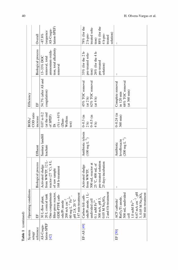
Table
1(continued)
System
setup/
reference
Operatingconditions
Effluent
BOD5/
CODratio
increase
Efficiency
EF
Biological
process
EF
Biological
process
Overall
AS-Coagu-
lation-SPEF
[42]
30L-flow
plant,
20Lconical
tank
One-compartm
ent-
filter-press
reactor,
GDE-PTFEcath-
ode/Ptanode
200mAcm
−2,
60mgL−1Fe2
+,
pH2.8,20˚C
147min-treatment
Activated
sludge
from
WWTP,12L-
reactor(27˚C),8L
ofraw
sample
168h-treatment
Sanitarylandfill
leachate
0.07to
0.2
(attheend
ofSPEF)
Dt
(%)=61%
(Zhan-
Wellens
test)
54.7%
(afterASand
coagulation)
13–33%
DOC
removal,total
ammonium
oxida-
tion,totalalkalinity
removal
~87.8%
(sequence
AS-Coagu-
lation-SPEF)
EF-A
S[49]
Carbon-feltcath-
ode/Ptanode,1L-
undivided
cell
0.1
mM
Fe2
+,
300mA,pH3,
0.05M
Na 2SO4
2and4h-treatment
Activated
sludge
from
WWTP,
500mL-reactorat
25˚C,400mLof
pre-treated
solution
25days-incubation
Antibiotictylosin
(100mgL−1)
0–0.3
(in
2h)
0–0.5
(in
4h)
45%
TOCremoval
(at2h)
62%
TOCremoval
(at4h)
33%
(forthe2h-
pre-treated
solu-
tion)
26%
(forthe4h-
pre-treated
solution)
78%
(forthe
2h-pre-
treatedsolu-
tion)
88%
(forthe
4h-pre-
treated
solution)
EF[50]
ACFcathode/
RuO2/Tianode,
500mL-undivided
cell
1.0
mM
Fe2
+,
6.67mAcm
−2,pH
3,0.05M
Na 2SO4
360min-treatment
–Antibiotic
levofloxacin
(200mgL−1)
0–0.24(in
360min)
Complete
removal
in120min
68%
TOCremoval
(at360min)
––
40 H. Olvera-Vargas et al.
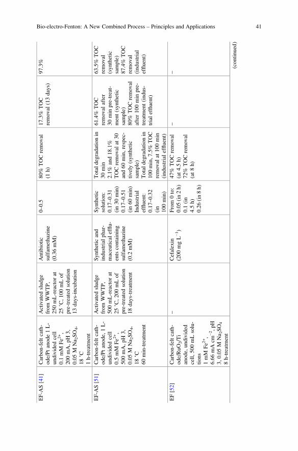
EF-A
S[41]
Carbon-feltcath-
ode/Ptanode1L-
undivided
cell
0.1
mM
Fe2
+,
200mA,pH3,
0.05M
Na 2SO4,
18˚C
1h-treatment
Activated
sludge
from
WWTP,
250mL-reactorat
25˚C,100mLof
pre-treated
solution
13days-incubation
Antibiotic
sulfam
ethazine
(0.36mM)
0–0.5
80%
TOCremoval
(1h)
17.3%
TOC
removal
(13days)
97.3%
EF-A
S[51]
Carbon-feltcath-
ode/Ptanode,1L-
undivided
cell
0.5
mM
Fe2
+,
500mA,pH3,
0.05M
Na 2SO4,
18˚C
60min-treatment
Activated
sludge
from
WWTP,
500mL-reactorat
25˚C,200mLof
pre-treated
solution
18days-treatm
ent
Synthetic
and
industrial
phar-
maceuticalefflu-
entscontaining
sulfam
ethazine
(0.2
mM)
Synthetic
solution:
0.17–0.31
(in30min)
0.17–0.51
(in60min)
Industrial
effluent:
0.17–0.32
(in
100min)
Totaldegradationin
30min
2.1%
and18.1%
TOCremoval
at30
and60min,respec-
tively(synthetic
sample)
Totaldegradationin
100min,7.5%
TOC
removal
at100min
(industrial
effluent)
61.4%
TOC
removal
after
30min
pre-treat-
ment(synthetic
sample)
80%
TOCremoval
after100min
pre-
treatm
ent(indus-
trialeffluent)
63.5%
TOC
removal
(synthetic
sample)
87.4%
TOC
removal
(industrial
effluent)
EF[52]
Carbon-feltcath-
ode/RuO2/Ti
anode,undivided
cell,500mLsolu-
tions
1mM
Fe2
+,
6.66mAcm
−2,pH
3,0.05M
Na 2SO4
8h-treatment
–Cefalexin
(200mgL−1)
From
0to:
0.05(in2h)
0.1
(in
4.5
h)
0.26(in8h)
47%
TOCremoval
(at4.5
h)
72%
TOCremoval
(at8h)
––
(continued)
Bio-electro-Fenton: A New Combined Process – Principles and Applications 41

Table
1(continued)
System
setup/
reference
Operatingconditions
Effluent
BOD5/
CODratio
increase
Efficiency
EF
Biological
process
EF
Biological
process
Overall
EC-A
S[53]
Feplateelectrodes,
undivided
cell,
200mLsolutions
8.5
mAcm
−2,pH
10,10mM
H2O2
min
−1
6min-treatment
Activated
sludge
from
WWTP(accli-
matized
biomass),
bench-scale
biore-
actor,150mLpre-
treatedsam-
ple
+50mLbio-
masssuspension
16days-incubation
Form
aldehyde
(7.5
gL−1)
–51%
CODremoval
(at6min
pre-
treatm
ent)
48%
CODremoval
(16days)
99%
COD
removal
EF-A
erobic
[32]
Carbon-feltcath-
ode/BDD
anode
undivided
cell,
230mLsolutions
0.1
mM
Fe2
+,
300mA,pH3,
0.05M
Na 2SO4
1h-treatment
Pure
culturesunder
aerobic
conditions,
0.5L-capacitybatch
reactor,200mL
pre-treated
sample
4days-incubation
β-Blocker
meto-
prolol(0.1
mM)
0.02–0.44
(in1h-pre-
treatm
ent)
47%
TOCremoval
(at1h-pre-
treatm
ent)
43%
TOCremoval
(at4days-
treatm
ent)
90%
TOC
removal
Anaerobic-
SPEF[54]
GDE-PTFEcath-
ode/BDD
anode
undivided
cell,
100mLpre-treated
solutions
1mM
Fe2
+,
30mAcm
−2,pH3,
0.05M
Na 2SO4,
35˚C
180min-treatment
Anaerobic
digestion
sludge,500mL-
capacityreactor,
320mLsam-
ple+80mLsludge,
35˚C
30days-incubation
Slaughterhouse
wastewater
–95%
CODremoval
oftheinitialCOD
afterpre-treatment
(7%
CODremoval
oftheraw
sample)
90%
CODremoval
(at30days-
treatm
ent)
97%
COD
removal
42 H. Olvera-Vargas et al.
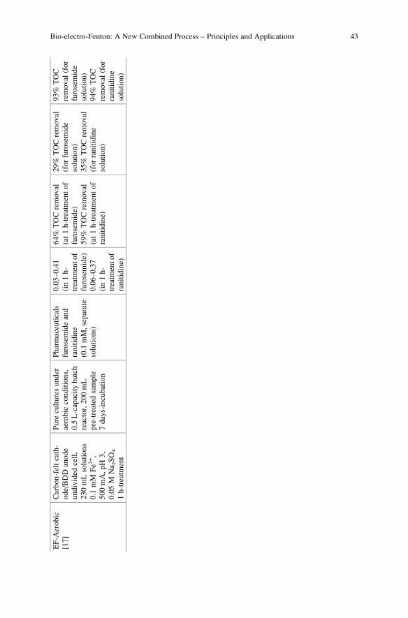
EF-A
erobic
[17]
Carbon-feltcath-
ode/BDD
anode
undivided
cell,
230mLsolutions
0.1
mM
Fe2
+,
500mA,pH3,
0.05M
Na 2SO4
1h-treatment
Pure
culturesunder
aerobic
conditions,
0.5L-capacitybatch
reactor,200mL
pre-treated
sample
7days-incubation
Pharmaceuticals
furosemideand
ranitidine
(0.1
mM,separate
solutions)
0.03–0.41
(in1h-
treatm
entof
furosemide)
0.06–0.37
(in1h-
treatm
entof
ranitidine)
64%
TOCremoval
(at1h-treatmentof
furosemide)
59%
TOCremoval
(at1h-treatmentof
ranitidine)
29%
TOCremoval
(forfurosemide
solution)
35%
TOCremoval
(forranitidine
solution)
93%
TOC
removal
(for
furosemide
solution)
94%
TOC
removal
(for
ranitidine
solution)
Bio-electro-Fenton: A New Combined Process – Principles and Applications 43
Bio-EF process was also applied for the treatment of pharmaceutical wastewater
spiked with the drugs caffeine and 5-fluorouracil. Two sequential systems were
investigated: EF as pre- or post-treatment coupled with a biological process
(sequencing batch reactor, SBR); EF-SBR and SBR-EF, respectively (referred to
Table 1 for the experimental details). For the first configuration, EF was capable of
completely removing both drugs in 2 h using 200 mA, while only 60% of COD
removal was achieved (1.4 L was the volume treated). The post-SBR treatment
removed 30% more of COD in 2 days-incubation, giving an overall 90% of COD
removal. It was found that higher EF pre-treatment times at lower current values
resulted in higher biodegradability increase, thus highlighting that operating condi-
tions must be optimized for achieving the best compromise in terms of efficiency,
biodegradability enhancement, and minimal energy consumption. Regarding the
SBR-EF sequence, caffeine and COD were only degraded by 43% and 52%, respec-
tively, after 24 h-treatment using acclimated biomass, while 5-fluorouracil was
almost totally removed. Subsequent application of EF (applying 500 mA of current)
yielded total degradation of caffeine and COD at 30 min and 4 h, respectively [40].
Form the above mentioned, it can be seen that starting target pollutants are
quickly degraded during the first stages of electrochemical treatment, and even if
the mineralization rates are generally low, an increase in the biodegradability of the
treated influent is highly relevant since the biodegradable by-products formed in the
EF pre-treatment can be eliminated by microbial cultures during biological pro-
cesses. Indeed, it is desirable to have a moderate mineralization rate, since a good
fraction of organic matter is needed for sustaining the energy needs of microorgan-
isms during biological treatment.
5.2 Degradation Pathways During the Bio-EF Process
As mentioned in the previous sections, the main goal of combining EF with biolog-
ical methods is the destruction of refractory contaminants by •OH produced during
the electrochemical process, either in a pre-treatment or a post-treatment stage.
When EF precedes biological oxidation, organic pollutants are transformed into
smaller molecules as a result of the oxidative attack of •OH. These low-molecular
weight species can be then metabolized by the microbial cultures during biological
degradation. On the other hand, when EF is applied after biologic oxidation, initial
biodegradable organic compounds are bio-transformed by the microbial consortia
and the resulting refractory by-products (as well as those refractory pollutants
initially present) can be oxidized during post-electrochemical process. These two
strategies are depicted in Fig. 4, showing the sequence of the Bio-EF units according
to the characteristics of the target effluent.
The oxidation of organics with •OH occurs through well-known pathways,
principally H atom abstraction (mainly from aliphatics) and addition to C ¼ C
bonds (mainly with aromatics leading to the formation of hydroxylated aromatic
derivatives) [12, 40]. In the latter case, consecutive oxidation reactions lead to ring
44 H. Olvera-Vargas et al.
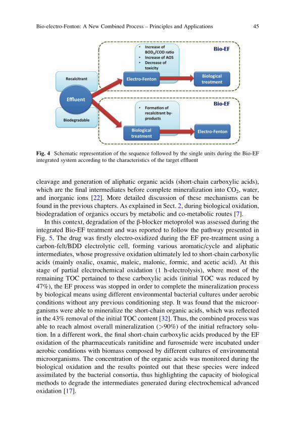
cleavage and generation of aliphatic organic acids (short-chain carboxylic acids),
which are the final intermediates before complete mineralization into CO2, water,
and inorganic ions [22]. More detailed discussion of these mechanisms can be
found in the previous chapters. As explained in Sect. 2, during biological oxidation,
biodegradation of organics occurs by metabolic and co-metabolic routes [7].
In this context, degradation of the β-blocker metoprolol was assessed during the
integrated Bio-EF treatment and was reported to follow the pathway presented in
Fig. 5. The drug was firstly electro-oxidized during the EF pre-treatment using a
carbon-felt/BDD electrolytic cell, forming various aromatic/cycle and aliphatic
intermediates, whose progressive oxidation ultimately led to short-chain carboxylic
acids (mainly oxalic, oxamic, maleic, malonic, formic, and acetic acid). At this
stage of partial electrochemical oxidation (1 h-electrolysis), where most of the
remaining TOC pertained to these carboxylic acids (initial TOC was reduced by
47%), the EF process was stopped in order to complete the mineralization process
by biological means using different environmental bacterial cultures under aerobic
conditions without any previous conditioning step. It was found that the microor-
ganisms were able to mineralize the short-chain organic acids, which was reflected
in the 43% removal of the initial TOC content [32]. Thus, the combined process was
able to reach almost overall mineralization (>90%) of the initial refractory solu-
tion. In a different work, the final short-chain carboxylic acids produced by the EF
oxidation of the pharmaceuticals ranitidine and furosemide were incubated under
aerobic conditions with biomass composed by different cultures of environmental
microorganisms. The concentration of the organic acids was monitored during the
biological oxidation and the results pointed out that these species were indeed
assimilated by the bacterial consortia, thus highlighting the capacity of biological
methods to degrade the intermediates generated during electrochemical advanced
oxidation [17].
Biodegradable
Recalcitrant
Effluent
• Increase of BOD5/COD ra�o
• Increase of AOS• Decrease of
toxicity
Electro-Fenton
• Forma�on of recalcitrant by-products
Biological treatment
Biological treatment
Electro-Fenton
Bio-EF
Bio-EF
Fig. 4 Schematic representation of the sequence followed by the single units during the Bio-EF
integrated system according to the characteristics of the target effluent
Bio-electro-Fenton: A New Combined Process – Principles and Applications 45
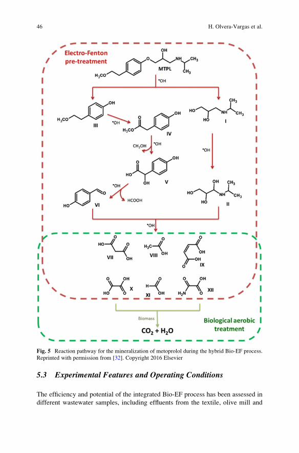
5.3 Experimental Features and Operating Conditions
The efficiency and potential of the integrated Bio-EF process has been assessed in
different wastewater samples, including effluents from the textile, olive mill and
Fig. 5 Reaction pathway for the mineralization of metoprolol during the hybrid Bio-EF process.
Reprinted with permission from [32]. Copyright 2016 Elsevier
46 H. Olvera-Vargas et al.
pharmaceutical industries, landfill leachates, as well as synthetic and industrial
wastewaters containing dyes, pesticides, pharmaceuticals, and other emerging
organic pollutants. The most relevant works on Bio-EF have been summarized in
Table 1, in which the system configuration, the operating conditions, as well as the
main results are included.
Generally, the efficacy of the EF process for the degradation or organic contam-
inants is investigated in terms of target pollutant removal, degradation mechanisms,
and mineralization degree, with concomitant optimization prior to (or after) bio-
logical oxidation (mainly in terms of percentage of mineralization, increase of the
BOD5/COD ratio, and sometimes toxicity assays). Optimization is done taking into
consideration both, the rise in biodegradability (strongly linked with the degrada-
tion pathways of organics) and the minimum energy consumption. In this sense, EF
is remarkably advantageous, since its operating conditions are easily adjustable,
which allows for a convenient manipulation of the degradation and mineralization
kinetic rates. For example, Olvera-Vargas et al. reported that 500 mA was the
optimal current value for an efficient EF treatment of the pharmaceutical metopro-
lol, with which the best degradation and mineralization rates were achieved.
Nonetheless, a lower current value of 300 mA was chosen when EF was used as
pre-treatment stage before biological aerobic oxidation, because the lower miner-
alization rates obtained at 300 mA were preferable for maintaining a good fraction
of organic matter as source of carbon for the microorganisms. Moreover, a dimi-
nution of the consumed energy was also favored by reduction of the applied current
[32]. Likewise, Ganzenko et al. highlighted the importance of optimizing opera-
tional conditions of EF so the minimum energy is consumed for the production of a
biodegradable effluent. It was found that even if the biodegradability enhancement
was higher at increasing current values and longer treatment times, the BOD5/COD
threshold for biodegradability was rapidly reached for all the tested current values
(Fig. 6), showing that the use of elevated high-consuming currents can be avoided
[19]. In a similar way, Mansour et al. reported that changes in the operating
conditions of the pre-EF stage lead to notable changes in the overall results gotten
after the activated sludge (AS) process. They reported that under optimal conditions
of catalyst and pollutant concentration, applied current, and treatment time, the
biodegradability can be importantly increased during EF pre-treatment, therefore
entailing higher mineralization rates after the biological stage [41].
Most of the studies on Bio-EF have been conducted applying EF as
pre-treatment method. However, EF has also been used to follow the degradation
process initiated by a biological approach. Indeed, the establishment of the best
sequence strategy relies mostly on the characteristics of the effluent. Just as in the
case of the integration of AOPs and biological methods, EF pre-treatment will be
preferred when the effluent is charged with high amounts of bio-recalcitrant or toxic
compounds, while an EF post-treatment phase will be most adapted for effluents
containing biodegradable compounds in large extent (refer to Fig. 4). For example,
during a multistage treatment system for remediation of sanitary landfill leachate,
the EF, photoelectro-Fenton (PEF), and solar photoelectro-Fenton (SPEF) pro-
cesses were integrated as post-treatment stage following a first AS treatment and
Bio-electro-Fenton: A New Combined Process – Principles and Applications 47
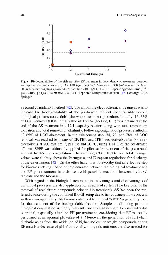
a second coagulation method [42]. The aim of the electrochemical treatment was to
increase the biodegradability of the pre-treated effluent so a possible second
biological process could finish the whole treatment procedure. Initially, 13–33%
of DOC removal (DOC initial value of 1,222–1,460 mg L�1) was obtained at the
end of the AS treatment in a 12 L-capacity reactor, along with total ammonium
oxidation and total removal of alkalinity. Following coagulation process resulted in
63–65% of DOC abatement. In the subsequent step, 34, 72, and 78% of DOC
removal was reached by means of EF, PEF, and SPEF, respectively, after 300 min-
electrolysis at 200 mA cm�2, pH 2.8 and 20 �C, using 1.18 L of the pre-treated
effluent. SPEF was ultimately applied for pilot scale treatment of the pre-treated
effluent by AS and coagulation. The resulting COD, BOD5, and total nitrogen
values were slightly above the Portuguese and European regulations for discharge
in the environment [42]. On the other hand, it is noteworthy that an effective step
for biomass settling had to be implemented between the biological treatment and
the EF post-treatment in order to avoid parasitic reactions between hydroxyl
radicals and the biomass.
With regard to the biological treatment, the advantages and disadvantages of
individual processes are also applicable for integrated systems (the key point is the
removal of recalcitrant compounds prior to bio-treatment). AS has been the pre-
ferred choice during the combined Bio-EF setup due to its robustness, low cost, and
well-known operability. AS biomass obtained from local WWTP is generally used
for the treatment of the biodegradable fraction. Sample conditioning prior to
biological degradation is highly relevant, since pH adjustment to a neutral value
is crucial, especially after the EF pre-treatment, considering that EF is usually
performed at an optimal pH value of 3. Moreover, the generation of short-chain
aliphatic acids from the oxidation of higher molecular weight compounds during
EF entails a decrease of pH. Additionally, inorganic nutrients are also needed for
Fig. 6 Biodegradability of the effluent after EF treatment in dependence on treatment duration
and applied current intensity (mA): 100 (-purple filled diamonds-); 500 (-blue open circles-);800 mA (-dark red filled squares-).Dashed line – BOD5/COD¼ 0.33. Operating conditions: [Fe2+
]¼ 0.2 mM, [Na2SO4]¼ 50 mM, V¼ 1.4 L. Reprinted with permission from [19]. Copyright 2016
Springer
48 H. Olvera-Vargas et al.
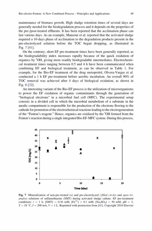
maintenance of biomass growth. High sludge retention times of several days are
generally needed for the biodegradation process and it depends on the properties of
the pre-/post-treated effluents. It has been reported that the acclimation phase can
last various days. As an example, Mansour et al. reported that the activated sludge
required a 10-days phase of acclimation to the degradation products present in the
pre-electrolyzed solution before the TOC began dropping, as illustrated in
Fig. 7 [41].
On the contrary, short EF pre-treatment times have been generally reported, as
the biodegradability index increases rapidly because of the quick oxidation of
organics by •OH, giving more readily biodegradable intermediates. Electrochemi-
cal treatment times ranging between 0.5 and 4 h have been communicated when
combining EF and biological treatment, as can be observed in Table 1. For
example, for the Bio-EF treatment of the drug metoprolol, Olvera-Vargas et al.
conducted a 1 h EF pre-treatment before aerobic incubation. An overall 90% of
TOC removal was achieved after 4 days of biological oxidation, as shown in
Fig. 8 [32].
An interesting variant of the Bio-EF process is the utilization of microorganisms
to power the EF oxidation of organic contaminants through the generation of
“biological electrons” in a microbial fuel cell (MFC). The experimental setup
consists in a divided cell in which the microbial metabolism of a substrate in the
anodic compartment is responsible for the production of the electrons flowing to the
cathode for promotion of the electrochemical reactions leading to the electrogeneration
of the “Fenton’s reagent.” Hence, organics are oxidized by the •OH formed from the
Fenton’s reaction during a single integrated Bio-EF-MFC system. During this process,
Fig. 7 Mineralization of non-pre-treated (x) and pre-electrolyzed ( filled circles and open tri-angles) solutions of sulfamethazine (SMT) during activated sludge culture. EF pre-treatment
conditions: t ¼ 1 h, [SMT] ¼ 0.36 mM, [Fe2+] ¼ 0.1 mM, [Na2SO4] ¼ 50 mM, pH ¼ 3,
T ¼ 18 �C, I ¼ 200 mA, V ¼ 1 L. Reprinted with permission from [41]. Copyright 2016 Elsevier
Bio-electro-Fenton: A New Combined Process – Principles and Applications 49
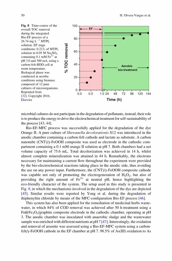
microbial cultures do not participate in the degradation of pollutants, instead, their role
is to produce the energy to drive the electrochemical treatment for self-sustainability of
the process [43, 44].
Bio-EF-MFC process was successfully applied for the degradation of the dye
Orange II. A pure culture of Shewanella decolorationis S12 was introduced in the
anodic chamber containing a carbon-felt cathode and lactate as substrate. A carbon
nanotube (CNT)/γ-FeOOH composite was used as electrode in the cathodic com-
partment containing a 0.1 mM orange II solution at pH 7. Both chambers had a net
volume capacity of 75.6 mL. Total decolorization was achieved in 14 h, whilst
almost complete mineralization was attained in 44 h. Remarkably, the electrons
necessary for maintaining a current flow throughout the experiment were provided
by the bio-electrochemical reactions taking place in the anodic side, thus avoiding
the use on any power input. Furthermore, the (CNT)/γ-FeOOH composite cathode
was capable not only of promoting the electrogeneration of H2O2, but also of
providing the right amount of Fe2+ at neutral pH, hence highlighting the
eco-friendly character of the system. The setup used in this study is presented in
Fig. 9, in which the mechanisms involved in the degradation of the dye are depicted
[45]. Similar results were reported by Yong et al. during the degradation of
thiphenyltin chloride by means of the MFC-configuration Bio-EF process [46].
This system has also been applied for the remediation of medicinal herbs waste-
water, in which 84% of COD removal was achieved after 50 h-treatment using a
Fe@Fe2O3/graphite composite electrode in the cathodic chamber, operating at pH
3. The anodic chamber was inoculated with anaerobic sludge and the wastewater
samplewas enrichedwith different nutrients at pH 7 [47]. Interestingly, the oxidation
and removal of arsenite was assessed using a Bio-EF-MFC system using a carbon-
felt/γ-FeOOH cathode in the EF chamber at pH 7. 98.5% of As(III) oxidation to As
0.0 0.5 1.0 24 48 72 96 120 1440
20
40
60
80
100
% T
OC
rem
oval
Time (h)
EF
Aerobicbio-treatment
Fig. 8 Time-course of the
overall TOC removal
during the integrated
Bio-EF process of a
26.74 mg L�1 MTPL
solution. EF stage
conditions: 0.22 L of MTPL
solution in 0.05 M Na2SO4
containing 0.1 mM Fe2+ at
pH 3.0 and 300 mA, using a
carbon-felt-BDD cell at
room temperature.
Biological phase was
conducted at aerobic
conditions using biomass
composed of 12 pure
cultures of microorganisms.
Reprinted from
[32]. Copyright 2016,
Elsevier
50 H. Olvera-Vargas et al.
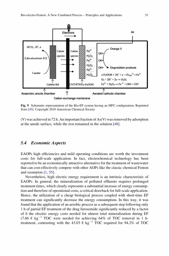
(V) was achieved in 72 h. An important fraction of As(V) was removed by adsorption
at the anode surface, while the rest remained in the solution [48].
5.4 Economic Aspects
EAOPs high efficiencies and mild operating conditions are worth the investment
costs for full-scale application. In fact, electrochemical technology has been
reported to be an economically attractive alternative for the treatment of wastewater
that can cost-effectively compete with other AOPs like the classic chemical Fenton
and ozonation [1, 55].
Nevertheless, high electric energy requirement is an intrinsic characteristic of
EAOPs. In general, the mineralization of polluted effluents requires prolonged
treatment times, which clearly represents a substantial increase of energy consump-
tion and therefore of operational costs, a critical drawback for full-scale application.
Hence, the utilization of a cheap biological process coupled with short-time EF
treatment can significantly decrease the energy consumption. In this way, it was
found that the application of an aerobic process as a subsequent step following only
1 h of partial EF treatment of the drug furosemide significantly reduced by a factor
of 6 the electric energy costs needed for almost total mineralization during EF
(7.66 € kg�1 TOC were needed for achieving 64% of TOC removal in 1 h-
treatment, contrasting with the 43.03 € kg�1 TOC required for 94.2% of TOC
Fig. 9 Schematic representation of the Bio-EF system having an MFC configuration. Reprinted
from [45]. Copyright 2010 Amerrican Chemical Society
Bio-electro-Fenton: A New Combined Process – Principles and Applications 51
removal in 8-h), while the remaining organic matter was removed by cheap
biological aerobic oxidation [17].
6 Concluding Remarks and Perspectives
Electrochemical technologies for wastewater treatment, including the EF process,
have reached a state of development in which their industrial application for the
degradation of refractory organic pollutants is greatly encouraged. Nevertheless, on
account of the shortcomings intrinsic to these processes, as well as the unequivocal
need for upgrading WWTPs with advanced and sustainable steps, their integration
as a part of a multistage treatment systems is more advantageous, inasmuch as the
most remarkable features of the individual methods are capitalized into a compre-
hensive and synergistic one. Accordingly, the main advantages emerging from the
hybrid Bio-EF system include:
• Since biological methods are much more cost-effective wastewater treatment
technologies, their utilization is always preferred in an economic point of view,
as well as in terms of feasibility. Consequently, integration of a biological
method in a system where a refractory and/or toxic effluent containing emerging
organic pollutants can be pre-treated for biodegradability increase, or post-
treated for degradation of the non-biodegradable fraction, always brings eco-
nomic benefits and it’s the only way to reach sufficient removal rates and meet
effluent discharge requirements. In this case, the outstanding characteristics of
the EF process highlight its advantages as part of an integrated process.
• Reduction of energy consumption related to the EF process. Indeed, as the
biodegradability is increased due to the oxidation of recalcitrant organics to
biodegradable ones during the EF pre-treatment, electrochemical treatment
times can be importantly reduced, which results in a significant depletion of
the amount of energy necessitated for higher mineralization degrees. Lower
energy consumption is evidently accompanied by an important fall of the overall
operating costs. In the opposite sense, when EF is used as post-treatment
method, persistent compounds to biodegradation can also be destroyed during
short EF treatment times because of the absence of competitive reactions with
biodegradable compounds.
• Shorter EF treatment times are also beneficial in terms of the stability of the
electrode materials used for electrolysis. In fact, reduced treatment times could
increase the lifetime of electrodes, an important benefice in the electrochemical
point of view.
• Since only partial mineralization is required during the EF phase, different
operating conditions and reactor configurations can be applied with the aim of
finding the most advantageous energy-consumption/biodegradability-increase
compromise according to the objectives to be attained. For example, the utili-
zation of advanced and expensive electrode materials can be avoided by
52 H. Olvera-Vargas et al.
augmenting treatment times or on the contrary, they can be used only for short-
duration electrolysis.
Despite the advantages presented by this coupled method, there are still some
gaps to be filled. The use of electricity to power EF and EAOPs in general, remains
a drawback. In this matter, great progress has been done by utilizing solar radiation
(photovoltaic technology) as a source of energy for electrochemical technology
[56, 57]. However, further exploration in the use of renewable energies as driven
forces for electrochemical methods, as well as self-sufficient technologies, needs
the attention of researchers and engineers.
On the other hand, the optimal pH value (3.0) for the EF process stands as well
an important limitation, since pH adjustment before or after biological oxidation is
imperative, thus representing extra operational cost. A potential alternative has
been the use of chelating agents that allow Fenton’s reaction to take place at
circumneutral pH values by the complexation of iron ions, such as tripolyphosphate
(TPP) [58]. The use of heterogeneous catalysts increasing the interval of working-
pH has also been proposed as an interesting alternative [59]. Other options include
the utilization of graphene-based cathodes [60] or hierarchical CoFe-layered double
hydroxide modified carbon-felt cathode [26]. These topics are subject of additional
research.
Further research is also needed on scaling up and optimization for industrial
application. The design of sequential integrated systems in which a comprehensive
control of the different parameters affecting the performance of each single unit and
that of the whole system is an intricate task demanding the unceasing efforts of the
scientific community.
References
1. Ribeiro AR, Nunes OC, Pereira MFR, Silva AMT (2015) An overview on the advanced
oxidation processes applied for the treatment of water pollutants defined in the recently
launched directive 2013/39/EU. Environ Int 75:33–51
2. Uribe IO, Mosquera-Corral A, Rodicio JL, Esplugas S (2015) Advanced technologies for
water treatment and reuse. AICHE J 61:3146–3158
3. Barbosa MO, Moreira NFF, Ribeiro AR et al (2016) Occurrence and removal of organic
micropollutants: an overview of the watch list of EU decision 2015/495.Water Res 94:257–279
4. Luo Y, Guo W, Ngo HH et al (2014) A review on the occurrence of micropollutants in the
aquatic environment and their fate and removal during wastewater treatment. Sci Total
Environ 473–474:619–641
5. Prasse C, Stalter D, Schulte-Oehlmann U et al (2015) Spoilt for choice: a critical review on the
chemical and biological assessment of current wastewater treatment technologies. Water Res
87:237–270
6. Ahmed MB, Zhou JL, Ngo HH et al (2016) Progress in the biological and chemical treatment
technologies for emerging contaminant removal from wastewater: a critical review. J Hazard
Mater 323:274–298
Bio-electro-Fenton: A New Combined Process – Principles and Applications 53
7. Tran NH, Urase T, Ngo HH et al (2013) Insight into metabolic and cometabolic activities of
autotrophic and heterotrophic microorganisms in the biodegradation of emerging trace organic
contaminants. Bioresour Technol 146:721–731
8. Fatta-Kassinos D, Kalavrouziotis IK, Koukoulakis PH, Vasquez MI (2011) The risks associ-
ated with wastewater reuse and xenobiotics in the agroecological environment. Sci Total
Environ 409:3555–3563
9. Pico Y, Barcelo D (2015) Transformation products of emerging contaminants in the environ-
ment and high-resolution mass spectrometry: a new horizon. Anal Bioanal Chem
407:6257–6273
10. Garcia-Rodrıguez A, Matamoros V, Font�as C, Salvado V (2013) The ability of biologically
based wastewater treatment systems to remove emerging organic contaminants – a review.
Environ Sci Pollut Res 21:11708–11728
11. Pomies M, Choubert J-M, Wisniewski C, Coquery M (2013) Modelling of micropollutant
removal in biological wastewater treatments: a review. Sci Total Environ 443:733–748
12. Oturan MA, Aaron J-J (2014) Advanced oxidation processes in water/wastewater treatment:
principles and applications. A review. Crit Rev Environ Sci Technol 44:2577–2641
13. Oller I, Malato S, Sanchez-Perez JA (2011) Combination of advanced oxidation processes and
biological treatments for wastewater decontamination – a review. Sci Total Environ
409:4141–4166
14. Dirany A, Sires I, Oturan N et al (2012) Electrochemical treatment of the antibiotic
sulfachloropyridazine: kinetics, reaction pathways, and toxicity evolution. Environ Sci
Technol 46:4074–4082
15. Oturan MA, Pimentel M, Oturan N, Sires I (2008) Reaction sequence for the mineralization of
the short-chain carboxylic acids usually formed upon cleavage of aromatics during electro-
chemical Fenton treatment. Electrochim Acta 54:173–182
16. Ganzenko O, Huguenot D, van Hullebusch ED et al (2014) Electrochemical advanced oxida-
tion and biological processes for wastewater treatment: a review of the combined approaches.
Environ Sci Pollut Res 21:8493–8524
17. Olvera-Vargas H, Oturan N, Buisson D, Oturan MA (2016) A coupled bio-EF process for
mineralization of the pharmaceuticals furosemide and ranitidine: feasibility assessment.
Chemosphere 155:606–613
18. Trellu C, Ganzenko O, Papirio S et al (2016) Combination of anodic oxidation and biological
treatment for the removal of phenanthrene and tween 80 from soil washing solution. Chem Eng
J 306:588–596
19. Ganzenko O, Trellu C, Papirio S et al (2017) Bio-electro-Fenton: evaluation of a combined
biological-advanced oxidation treatment for pharmaceutical wastewater. Environ Sci Pollut
Res. doi:10.1007/s11356-017-8450-6
20. Pulgarin C, Invernizzi M, Parra S et al (1999) Strategy for the coupling of photochemical and
biological flow reactors useful in mineralization of biorecalcitrant industrial pollutants. Catal
Today 54:341–352
21. Contreras S, Rodrı guez M, Momani FA et al (2003) Contribution of the ozonation
pre-treatment to the biodegradation of aqueous solutions of 2,4-dichlorophenol. Water Res
37:3164–3171
22. Brillas E, Sires I, Oturan MA (2009) Electro-Fenton process and related electrochemical
technologies based on Fenton’s reaction chemistry. Chem Rev 109:6570–6631
23. Moreira FC, Boaventura RAR, Brillas E, Vilar VJP (2017) Electrochemical advanced oxida-
tion processes: a review on their application to synthetic and real wastewaters. Appl Catal
Environ 202:217–261
24. Sopaj F, Oturan N, Pinson J et al (2016) Effect of the anode materials on the efficiency of the
electro-Fenton process for the mineralization of the antibiotic sulfamethazine. Appl Catal
Environ 199:331–341
25. Mousset E, Ko ZT, Syafiq M et al (2016) Electrocatalytic activity enhancement of a graphene
ink-coated carbon cloth cathode for oxidative treatment. Electrochim Acta 222:1628–1641
54 H. Olvera-Vargas et al.
26. Ganiyu SO, Le TXH, Bechelany M et al (2017) Hierarchical CoFe-layered double hydroxide
modified carbon-felt cathode: synthesis, characterization and application in heterogeneous
electro-Fenton degradation of organic pollutants at circumneutral pH. J Mater Chem A
4:17686–17693
27. He Z, Gao C, Qian M et al (2014) Electro-Fenton process catalyzed by Fe3O4 magnetic
nanoparticles for degradation of C.I. Reactive blue 19 in aqueous solution: operating condi-
tions, influence, and mechanism. Ind Eng Chem Res 53:3435–3447
28. Khataee A, Sajjadi S, Hasanzadeh A et al (2017) One-step preparation of nanostructured
martite catalyst and graphite electrode by glow discharge plasma for heterogeneous electro-
Fenton like process. J Environ Manage 199:31–45
29. Ganiyu SO, van Hullebusch ED, Cretin M et al (2015) Coupling of membrane filtration and
advanced oxidation processes for removal of pharmaceutical residues: a critical review. Sep
Purif Technol 156:891–914
30. Martınez-Huitle CA, Rodrigo MA, Sires I, Scialdone O (2015) Single and coupled electro-
chemical processes and reactors for the abatement of organic water pollutants: a critical
review. Chem Rev 115:13362–13407
31. Lin SH, Chang CC (2000) Treatment of landfill leachate by combined electro-Fenton oxida-
tion and sequencing batch reactor method. Water Res 34:4243–4249
32. Olvera-Vargas H, Cocerva T, Oturan N et al (2016) Bioelectro-Fenton: a sustainable integrated
process for removal of organic pollutants from water: application to mineralization of meto-
prolol. J Hazard Mater 319:13–23
33. Mousset E, Oturan N, van Hullebusch ED et al (2014) Treatment of synthetic soil washing
solutions containing phenanthrene and cyclodextrin by electro-oxidation. Influence of anode
materials on toxicity removal and biodegradability enhancement. Appl Catal Environ
160–161:666–675
34. Mousset E, Oturan N, van Hullebusch ED et al (2014) Influence of solubilizing agents
(cyclodextrin or surfactant) on phenanthrene degradation by electro-Fenton process – study
of soil washing recycling possibilities and environmental impact. Water Res 48:306–316
35. Mousset E et al. (2017) Soil remediation by electro-Fenton process. Handb Environ Chem.
doi:10.1007/698_2017_38
36. Belkheiri D, Fourcade F, Geneste F et al (2011) Feasibility of an electrochemical pre-treatment
prior to a biological treatment for tetracycline removal. Sep Purif Technol 83:151–156
37. Yahiaoui I, Aissani-Benissad F, Fourcade F, Amrane A (2013) Removal of tetracycline
hydrochloride from water based on direct anodic oxidation (Pb/PbO2 electrode) coupled to
activated sludge culture. Chem Eng J 221:418–425
38. Grafias P, Xekoukoulotakis NP, Mantzavinos D, Diamadopoulos E (2010) Pilot treatment of
olive pomace leachate by vertical-flow constructed wetland and electrochemical oxidation: an
efficient hybrid process. Water Res 44:2773–2780
39. Mansour D, Fourcade F, Soutrel I et al (2015) Mineralization of synthetic and industrial
pharmaceutical effluent containing trimethoprim by combining electro-Fenton and activated
sludge treatment. J Taiwan Inst Chem Eng 53:58–67
40. Pignatello JJ, Oliveros E, MacKay A (2006) Advanced oxidation processes for organic
contaminant destruction based on the Fenton reaction and related chemistry. Crit Rev Environ
Sci Technol 36:1–84
41. Mansour D, Fourcade F, Huguet S et al (2014) Improvement of the activated sludge treatment
by its combination with electro Fenton for the mineralization of sulfamethazine. Int Biodeter
Biodegr 88:29–36
42. Moreira FC, Soler J, Fonseca A et al (2015) Incorporation of electrochemical advanced
oxidation processes in a multistage treatment system for sanitary landfill leachate. Water
Res 81:375–387
43. Zhu X, Ni J (2009) Simultaneous processes of electricity generation and p-nitrophenol
degradation in a microbial fuel cell. Electrochem Commun 11:274–277
Bio-electro-Fenton: A New Combined Process – Principles and Applications 55
44. Huong Le TX, Esmilaire R, Drobek M et al (2016) Design of a novel fuel cell-Fenton system: a
smart approach to zero energy depollution. J Mater Chem A 4:17686–17693
45. Feng C-H, Li F-B, Mai H-J, Li X-Z (2010) Bio-electro-Fenton process driven by microbial fuel
cell for wastewater treatment. Environ Sci Technol 44:1875–1880
46. Yong X-Y, Gu D-Y, Wu Y-D et al (2017) Bio-electron-Fenton (BEF) process driven by
microbial fuel cells for triphenyltin chloride (TPTC) degradation. J Hazard Mater
324:178–183
47. Birjandi N, Younesi H, Ghoreyshi AA, Rahimnejad M (2016) Electricity generation through
degradation of organic matters in medicinal herbs wastewater using bio-electro-Fenton sys-
tem. J Environ Manage 180:390–400
48. Wang X-Q, Liu C-P, Yuan Y, Li F (2014) Arsenite oxidation and removal driven by a bio-
electro-Fenton process under neutral pH conditions. J Hazard Mater 275:200–209
49. Ferrag-Siagh F, Fourcade F, Soutrel I et al (2014) Electro-Fenton pretreatment for the
improvement of tylosin biodegradability. Environ Sci Pollut Res 21:8534–8542
50. Gong Y, Li J, Zhang Y et al (2016) Partial degradation of levofloxacin for biodegradability
improvement by electro-Fenton process using an activated carbon fiber felt cathode. J Hazard
Mater 304:320–328
51. Mansour D, Fourcade F, Soutrel I et al (2015) Relevance of a combined process coupling
electro-Fenton and biological treatment for the remediation of sulfamethazine solutions –
application to an industrial pharmaceutical effluent. Comptes Rendus Chim 18:39–44
52. Ledezma Estrada A, Li Y-Y, Wang A (2012) Biodegradability enhancement of wastewater
containing cefalexin by means of the electro-Fenton oxidation process. J Hazard Mater
227:41–48
53. Moussavi G, Bagheri A, Khavanin A (2012) The investigation of degradation and minerali-
zation of high concentrations of formaldehyde in an electro-Fenton process combined with the
biodegradation. J Hazard Mater 237:147–152
54. Vidal J, Huili~nir C, Salazar R (2016) Removal of organic matter contained in slaughterhouse
wastewater using a combination of anaerobic digestion and solar photoelectro-Fenton pro-
cesses. Electrochim Acta 210:163–170
55. Ca~nizares P, Paz R, Saez C, Rodrigo MA (2009) Costs of the electrochemical oxidation of
wastewaters: a comparison with ozonation and Fenton oxidation processes. J Environ Manage
90:410–420
56. Garcia-Segura S, Brillas E (2014) Advances in solar photoelectro-Fenton: decolorization and
mineralization of the direct yellow 4 diazo dye using an autonomous solar pre-pilot plant.
Electrochim Acta 140:384–395
57. Mook WT, Aroua MK, Issabayeva G (2014) Prospective applications of renewable energy
based electrochemical systems in wastewater treatment: a review. Renew Sustain Energy Rev
38:36–46
58. Wang L, Cao M, Ai Z, Zhang L (2015) Design of a highly efficient and wide pH electro-Fenton
oxidation system with molecular oxygen activated by ferrous-tetrapolyphosphate complex.
Environ Sci Technol 49:3032–3039
59. Zhang C, Zhou M, Yu X et al (2015) Modified iron-carbon as heterogeneous electro-Fenton
catalyst for organic pollutant degradation in near neutral pH condition: characterization,
degradation activity and stability. Electrochim Acta 160:254–262
60. Le TXH, Bechelany M, Lacour S, Oturan N, Oturan MA, Cretin M (2015) High removal
efficiency of dye pollutants by electron-Fenton process using a graphene based cathode.
Carbon 94:1003–1011
56 H. Olvera-Vargas et al.
The Electro-peroxone Technology
as a Promising Advanced Oxidation Process
for Water and Wastewater Treatment
Yujue Wang
Abstract The electro-peroxone (E-peroxone) process is a novel electrochemical ad-
vanced oxidation process (EAOP) that is enabled by in situ generation of hydrogen
peroxide (H2O2) from cathodic oxygen (O2) reduction during conventional ozonation.
The electro-generated H2O2 can considerably enhance ozone (O3) transformation to
hydroxyl radicals (�OH), thus greatly enhancing pollutant degradation and total org-
anic carbon (TOC) mineralization by the E-peroxone process than by conventional
ozonation. Due to its higher kinetics of pollutant degradation, the E-peroxone process
can also reduce reaction time and energy consumption required for water and waste-
water treatment. In addition, the in situ generated H2O2 can effectively reduce bromate
formation during the E-peroxone treatment of bromide-containing water compared to
conventional ozonation. All oxidants (O3, H2O2, and �OH) are produced on site at con-trollable rates during the E-peroxone process using only clean oxygen and electricity.
No chemicals or catalysts are added in the E-peroxone process nor does it produce
secondary pollutants. By simply installing low-cost carbon-based cathodes in ozone
contactors, conventional ozonation systems that are commonly used inwater andwaste-
water utilities can be easily retrofitted to the E-peroxone process with minimal upgrade
work and costs. Therefore, the E-peroxone process can provide a convenient and eco-
nomical way to significantly improve the performance of existing ozonation systems
in many aspects and has thus emerged as a promising EAOP for practical water and
wastewater treatment.
Keywords Electrochemical advanced oxidation process, Electro-peroxone,
Hydrogen peroxide, Micropollutant, Ozone, Wastewater treatment, Water
treatment
Y. Wang (*)
School of Environment, Tsinghua University, Beijing 100084, China
e-mail: [email protected]
M. Zhou et al. (eds.), Electro-Fenton Process: New Trends and Scale-Up,Hdb Env Chem (2018) 61: 57–84, DOI 10.1007/698_2017_57,© Springer Nature Singapore Pte Ltd. 2017, Published online: 9 July 2017
57
Contents
1 Introduction . . . . . . . . . . . . . . . . . . . . . . . . . . . . . . . . . . . . . . . . . . . . . . . . . . . . . . . . . . . . . . . . . . . . . . . . . . . . . . . . . . . 58
2 Principles and Advantages of the Electro-peroxone Process . . . . . . . . . . . . . . . . . . . . . . . . . . . . . . . 61
2.1 Cathodic Reaction Mechanisms During the Electro-peroxone Process . . . . . . . . . . . . . . 62
2.2 Bulk Reaction Mechanism During the Electro-peroxone Process . . . . . . . . . . . . . . . . . . . . 65
2.3 Photoelectro-peroxone Process . . . . . . . . . . . . . . . . . . . . . . . . . . . . . . . . . . . . . . . . . . . . . . . . . . . . . . . . 67
3 Applications of the Electro-peroxone Process for Water and Wastewater Treatment . . . . . 69
3.1 Electro-peroxone for Wastewater Treatment . . . . . . . . . . . . . . . . . . . . . . . . . . . . . . . . . . . . . . . . . . 69
3.2 Electro-peroxone for Advanced Wastewater Treatment . . . . . . . . . . . . . . . . . . . . . . . . . . . . . . 71
3.3 Electro-peroxone for Drinking Water Treatment . . . . . . . . . . . . . . . . . . . . . . . . . . . . . . . . . . . . . 75
3.4 Electro-peroxone Regeneration of Spent Activated Carbon . . . . . . . . . . . . . . . . . . . . . . . . . . 76
4 Concluding Remarks . . . . . . . . . . . . . . . . . . . . . . . . . . . . . . . . . . . . . . . . . . . . . . . . . . . . . . . . . . . . . . . . . . . . . . . . . 77
4.1 Potentials of the Electro-peroxone Process for Water and Wastewater Treatment . . 77
4.2 Future Research Directions . . . . . . . . . . . . . . . . . . . . . . . . . . . . . . . . . . . . . . . . . . . . . . . . . . . . . . . . . . . . 78
References . . . . . . . . . . . . . . . . . . . . . . . . . . . . . . . . . . . . . . . . . . . . . . . . . . . . . . . . . . . . . . . . . . . . . . . . . . . . . . . . . . . . . . . . 81
1 Introduction
Advanced oxidation processes (AOPs) are of great interest in water and wastewater
treatment [1–5]. AOPs have been broadly defined as those aqueous phase oxidation
processes that are driven by highly reactive oxidants, especially hydroxyl radicals
(�OH) [6]. �OH is just about the strongest oxidant (E0 ¼ 2.8 V [7]) that can be safely
applied in water treatment and can nonselectively oxidize most organic pollutants at
diffusion-controlled rates (~108–1010 M�1 s�1) [8]. Therefore, �OH-based AOPs havebeen increasingly used in water and wastewater treatment to degrade refractory organic
pollutants that are difficult to remove by other conventional treatment technologies.
Due to its extremely high reactiveness and short lifetime, �OH has to be produced in
situ during AOP treatment of water and wastewater. Hydrogen peroxide (H2O2) is one
of the most common chemicals used to produce �OH in a variety of AOPs [9]. H2O2 is
relatively stable in pure water. However, it can react actively with many chemicals
(e.g., ozone (O3) and ferrous iron (Fe2+)) and catalysts (e.g., titanium dioxide and transi-
tion metal oxides) or undergo ultraviolet-induced photolysis to produce �OH (Eqs. 1–4)
[1, 7, 10]. Therefore, H2O2 has been considered a versatile reagent for �OH produc-
tion in many AOPs, for example, the peroxone (O3/H2O2), Fenton (Fe2+/H2O2), and
UV/H2O2 processes. In addition, H2O2 is also an environmentally friendly oxidant
because the only decomposition products of H2O2 are water (H2O) and oxygen
(O2) [9].
2H2O2 þ 2O3 ! H2Oþ 3O2 þ HO2 � þ � OH ð1ÞFe2þ þ H2O2 þ Hþ ! Fe3þ þ H2Oþ �OH ð2Þ
58 Y. Wang
H2O2 þ TiO2 e�CB� � ! TiO2 þ OH� þ �OH ð3Þ
H2O2 þ hv ! 2 � OH ð4Þ
Currently, H2O2 is manufactured almost exclusively by the anthraquinone oxidation
process on an industrial scale, and commercially available as aqueous solutions at con-
centrations of usually 30, 50, and 70 wt.% [9]. The market price for industrial grade
H2O2 (30wt.% solution) is about 0.39–0.5 USD kg�1, equivalent to ~1.2–1.5 USD kg�1
on a 100 wt.% basis [11, 12]. Therefore, H2O2 is generally considered a costly chemical
for water and wastewater treatment [12–14]. Moreover, H2O2 stock solutions may
decay during storage, leading to a decline in the efficiency of water and wastewater
treatment. Furthermore, due to its high reactiveness and strong oxidizing properties
(E0 ¼ 1.78 V), the transportation, storage, and handling of bulk H2O2 solutions in-
volve safety hazards, which has considerably limited the use of H2O2 in some water
and wastewater utilities [9, 10, 12].
To overcome the drawbacks associated with the use of bulk H2O2 solutions, the in
situ generation of H2O2 from cathodic O2 reduction (Eq. 5) during water and waste-
water treatment has gained increasing interest in recent years [2, 10, 12, 15–17].
Results show that by bubbling air or pure oxygen into an electrolysis reactor that has a
carbon-based cathode (e.g., carbon-polytetrafluorethylene (carbon-PTFE), carbon felt,
and reticulated vitreous carbon (RVC)), H2O2 can be electrochemically produced
from cathodic O2 reduction at controllable rates with high current efficiencies (up to
~100%) [18, 19]. This provides a convenient and flexible way to supply H2O2 on
demand for water and wastewater treatment. In addition, economic analyses indicate
that depending on reaction conditions (e.g., solution conductivities and O2 sources),
H2O2 can be produced from cathodic O2 reduction at comparable or even much lower
costs (e.g., 0.1–0.3 USD kg�1) compared to H2O2 stocks (e.g., 1.2–1.5 USD kg�1)
[12, 20]. Therefore, cathodic O2 reduction to H2O2 can not only eliminate the risks
and decay problems associated with the use and storage of bulk H2O2 solutions but
also reduce the operation costs of AOPs. These promising results indicate that the in
situ generation of H2O2 from cathodic O2 reduction can provide an attractive ap-
proach to providing the H2O2 necessary for the implementation of more traditional
AOPs and considerably improve the performance of water and wastewater treatment
in many aspects.
O2 þ 2Hþ þ 2e� ! H2O2 ð5Þ
Over the past two decades, a variety of electrochemically driven AOPs (EAOPs)
have been developed on the basis of the electro-generation of H2O2 from cathodic
O2 reduction [10, 12, 15–18, 21]. Among this kind of EAOPs, the electro-Fenton
(E-Fenton) process, which was developed in the 1990s by Brillas’ and Oturan’s groups[18, 22], is probably the most known and popular one. Since its appearance, the
E-Fenton process has been extensively investigated and successfully applied to treat a
wide range of wastewaters that are polluted by toxic and/or refractory organic
The Electro-peroxone Technology as a Promising Advanced Oxidation Process. . . 59
pollutants, such as industrial effluents, landfill leachates, and concentrates from
membrane processes (see [4, 5, 10] and references therein).
However, the applications of the E-Fenton process in drinking water treatment
have been largely limited because of several reasons. For example, Fenton-related
processes usually need to be operated under acidic conditions (e.g., pH of ~3), where-
as the typical pH values encountered in drinking water treatment are circumneutral
(e.g., ~7–8) [1, 23]. pH adjustment is uneconomical or impractical for large-scale drink-
ing water treatment [1]. Moreover, the addition of Fe2+ catalysts and the ensuing form-
ation of iron sludge during Fenton-related processes are problematic for drinking water
treatment. Therefore, Fenton-related processes have rarely been applied in drinking
water treatment.
To exploit the benefits of in situ H2O2 generation in drinking water treatment, we
have recently developed a novel EAOP, named as the electro-peroxone (E-peroxone)
process, by combining conventional ozonation with cathodic H2O2 production from
O2 reduction [16]. Unlike the Fenton process, ozonation is a well-established tech-
nology in drinking water treatment with numerous successful experiences of large-
scale applications [1]. In addition, ozonation has also been increasingly applied in
wastewater treatment in recent years, for example, as pretreatment to improve the bio-
degradability of wastewater for biological treatment, or as posttreatment to abate
refractory organic residuals in biologically treated effluents [1]. Ozone is a strong
oxidant (E0 ¼ 2.07 V) and can oxidize a wide range of inorganic and organic
pollutants, especially compounds with activated double bonds (e.g., activated aromatic
systems, deprotonated amines, and reduced sulfur groups) [1]. In addition, O3 is also an
excellent disinfectant and capable of inactivating a broad variety of waterborne path-
ogens such as viruses, bacteria, and protozoa [24]. Therefore, O3 has been commonly
used in both water and wastewater treatment as an oxidant and disinfectant.
While ozonation has been working well and applied successfully in full-scale op-
erations, it still has some room for improvement. For example, O3 is a very selective
oxidant. Therefore, ozonation is often inefficient at degrading O3-resistant pollutants
(such as atrazine, 1,4-dioxane, and ibuprofen) and mineralizing total organic carbon
(TOC) [1, 25, 26]. Moreover, while O3-reactive pollutants can be readily degraded by
ozonation, they may generate some O3-resistant transformation products that can
accumulate in ozonation effluents and thus still pose threat to the ecosystem and
human health [1, 26, 27]. Furthermore, ozonation of bromide (Br�)-containing watercan produce bromate (BrO3
�) [1, 24], which is a potential human carcinogen and
therefore strictly regulated in drinking water with a maximum contaminant level
(MCL) of 10 μg L�1 in many countries [28–30].
Interestingly, our recent studies have shown that the major limitations of con-
ventional ozonation can be successfully overcome by electrochemically producing
H2O2 in situ from cathodic O2 reduction during the E-peroxone process [16, 20, 31–
34]. The E-peroxone process has a simple reactor configuration and can be easily
60 Y. Wang
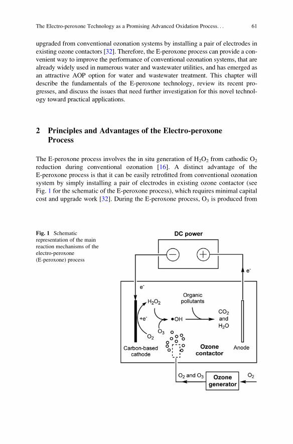
upgraded from conventional ozonation systems by installing a pair of electrodes in
existing ozone contactors [32]. Therefore, the E-peroxone process can provide a con-
venient way to improve the performance of conventional ozonation systems, that are
already widely used in numerous water and wastewater utilities, and has emerged as
an attractive AOP option for water and wastewater treatment. This chapter will
describe the fundamentals of the E-peroxone technology, review its recent pro-
gresses, and discuss the issues that need further investigation for this novel technol-
ogy toward practical applications.
2 Principles and Advantages of the Electro-peroxone
Process
The E-peroxone process involves the in situ generation of H2O2 from cathodic O2
reduction during conventional ozonation [16]. A distinct advantage of the
E-peroxone process is that it can be easily retrofitted from conventional ozonation
system by simply installing a pair of electrodes in existing ozone contactor (see
Fig. 1 for the schematic of the E-peroxone process), which requires minimal capital
cost and upgrade work [32]. During the E-peroxone process, O3 is produced from
Fig. 1 Schematic
representation of the main
reaction mechanisms of the
electro-peroxone
(E-peroxone) process
The Electro-peroxone Technology as a Promising Advanced Oxidation Process. . . 61
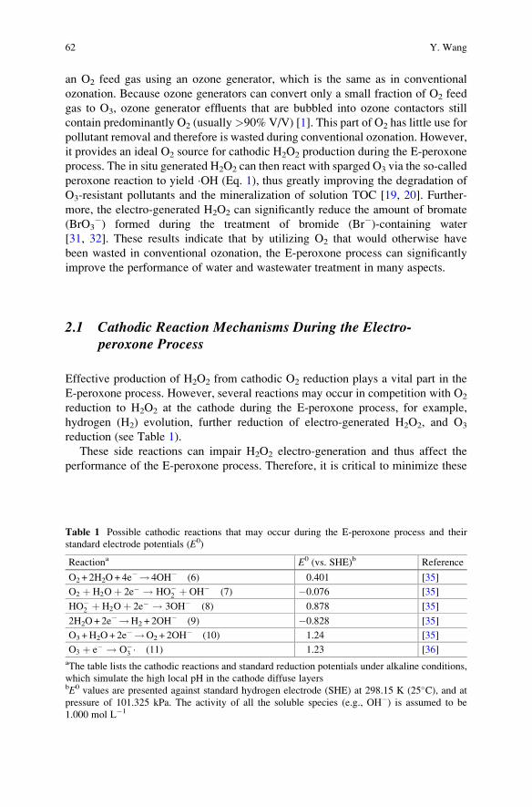
an O2 feed gas using an ozone generator, which is the same as in conventional
ozonation. Because ozone generators can convert only a small fraction of O2 feed
gas to O3, ozone generator effluents that are bubbled into ozone contactors still
contain predominantly O2 (usually>90% V/V) [1]. This part of O2 has little use for
pollutant removal and therefore is wasted during conventional ozonation. However,
it provides an ideal O2 source for cathodic H2O2 production during the E-peroxone
process. The in situ generated H2O2 can then react with sparged O3 via the so-called
peroxone reaction to yield �OH (Eq. 1), thus greatly improving the degradation of
O3-resistant pollutants and the mineralization of solution TOC [19, 20]. Further-
more, the electro-generated H2O2 can significantly reduce the amount of bromate
(BrO3�) formed during the treatment of bromide (Br�)-containing water
[31, 32]. These results indicate that by utilizing O2 that would otherwise have
been wasted in conventional ozonation, the E-peroxone process can significantly
improve the performance of water and wastewater treatment in many aspects.
2.1 Cathodic Reaction Mechanisms During the Electro-peroxone Process
Effective production of H2O2 from cathodic O2 reduction plays a vital part in the
E-peroxone process. However, several reactions may occur in competition with O2
reduction to H2O2 at the cathode during the E-peroxone process, for example,
hydrogen (H2) evolution, further reduction of electro-generated H2O2, and O3
reduction (see Table 1).
These side reactions can impair H2O2 electro-generation and thus affect the
performance of the E-peroxone process. Therefore, it is critical to minimize these
Table 1 Possible cathodic reactions that may occur during the E-peroxone process and their
standard electrode potentials (E0)
Reactiona E0 (vs. SHE)b Reference
O2 + 2H2O+ 4e�! 4OH� (6) 0.401 [35]
O2 þ H2Oþ 2e� ! HO�2 þ OH� (7) �0.076 [35]
HO�2 þ H2Oþ 2e� ! 3OH� (8) 0.878 [35]
2H2O+ 2e�!H2 + 2OH� (9) �0.828 [35]
O3 +H2O+ 2e�!O2 + 2OH� (10) 1.24 [35]
O3 þ e� ! O�3 � (11) 1.23 [36]
aThe table lists the cathodic reactions and standard reduction potentials under alkaline conditions,
which simulate the high local pH in the cathode diffuse layersbE0 values are presented against standard hydrogen electrode (SHE) at 298.15 K (25�C), and at
pressure of 101.325 kPa. The activity of all the soluble species (e.g., OH�) is assumed to be
1.000 mol L�1
62 Y. Wang

side reactions during the E-peroxone process by selecting proper electrodes and
optimizing the reaction conditions [37].
Due to their high overpotential for H2 evolution and low catalytic activity for H2O2
decomposition, carbon-based electrodes have been commonly used to produce H2O2
from cathodic O2 reduction [10, 38]. Many carbon electrodes can be used for H2O2
production, such as graphite, carbon-PTFE, carbon felt, RVC, carbon nanotube, and
graphene electrodes [10]. Figure 2 shows that when a pure O2 gas was sparged into a
background electrolyte (0.05 MNa2SO4) during electrolysis with a carbon-PTFE cath-
ode, H2O2 could be produced with high apparent current efficiencies (~87–96%, cal-
culated according to Eq. 12) over a wide range of current density (5–25 mA cm�2)
[19]. Considering that some cathodically generated H2O2 could be decomposed at the
anode (Eq. 13) or undergo self-decomposition (Eq. 14) in the bulk solution during the
process, the actual current efficiencies of cathodic H2O2 production are expected to be
even higher. The high current efficiencies for cathodic H2O2 production suggest that
when carbon-PTFE cathodes are used in the E-peroxone process, the four-electron
reduction of O2 to OH� (Eq. 6), H2 evolution (Eq. 9), and H2O2 reduction (Eq. 8) are
generally negligible cathodic reactions compared to the two-electron reduction of O2 to
H2O2 (Eq. 7) [19, 37].
CE %ð Þ ¼ nFCH2O2V
R t0I dt
� 100 ð12Þ
where n is the number of electrons consumed for converting O2 to H2O2 (two elec-
trons), F is the Faraday constant (96,486 C mol�1), CH2O2is the concentration of
H2O2 (mol L�1), V is the solution volume (L), I is the current (A), and t is the
electrolysis time (s).
H2O2 ! 2Hþ þ O2 þ 2e� ð13Þ2H2O2 ! 2H2Oþ O2 ð14Þ
However, it should be noted that during the E-peroxone process, an O2/O3 mix-
ture (rather than pure O2) is sparged into the system to electrochemically drive the
peroxone reaction for �OH production. Thermodynamically, O3 can be preferen-
tially reduced at much more positive potentials than O2 at the cathodes (see
Table 1). Therefore, cathodic O2 reduction to H2O2 would be inhibited if sufficient
quantity of O3 is available in the cathode diffuse layer to accept all the electrons
transferred at the cathode, i.e., cathodic O3 reduction is limited by the applied
currents [37]. Under such current limited conditions, the desired electrochemically
driven peroxone process (i.e., cathodic O2 reduction to H2O2 and the ensuing
peroxone reaction of H2O2 with O3 to �OH) actually cannot occur during the
E-peroxone process [37]. Fortunately, because O3 accounts for only small fractions
of the sparged O2/O3 gas mixture (<10% V/V [1]) and can be rapidly consumed in
bulk reactions with O3-reactive water matrix (e.g., natural organic matter (NOM)
and compounds with activated double bonds) as well as electro-generated H2O2 in the
The Electro-peroxone Technology as a Promising Advanced Oxidation Process. . . 63
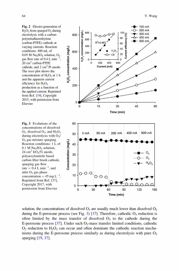
solution, the concentrations of dissolved O3 are usually much lower than dissolved O2
during the E-peroxone process (see Fig. 3) [37]. Therefore, cathodic O3 reduction is
often limited by the mass transfer of dissolved O3 to the cathode during the
E-peroxone process [37]. Under such O3-mass transfer limited conditions, cathodic
O2 reduction to H2O2 can occur and often dominate the cathodic reaction mecha-
nisms during the E-peroxone process similarly as during electrolysis with pure O2
sparging [19, 37].
Fig. 2 Electro-generation of
H2O2 from spargedO2 during
electrolysis with a carbon-
polytetrafluorethylene
(carbon-PTFE) cathode at
varying currents. Reaction
conditions: 400 mL of
0.05 M Na2SO4 solution, O2
gas flow rate of 0.4 L min�1,
20 cm2 carbon-PTFE
cathode, and 2 cm2 Pt anode.
The inset plot shows theconcentration of H2O2 at 1 h
and the apparent current
efficiency for H2O2
production as a function of
the applied current. Reprinted
from Ref. [19], Copyright
2015, with permission from
Elsevier
Fig. 3 Evolutions of the
concentrations of dissolved
O2, dissolved O3, and H2O2
during electrolysis with O2/
O3 gas mixture sparging.
Reaction conditions: 1 L of
0.1 M Na2SO4 solution,
24 cm2 IrO2/Ti anode,
polyacrylonitrile based
carbon fiber brush cathode,
sparging gas flow
rate ¼ 0.4 L min�1, and
inlet O3 gas phase
concentration ¼ 45 mg L�1.
Reprinted from Ref. [37],
Copyright 2017, with
permission from Elsevier
64 Y. Wang
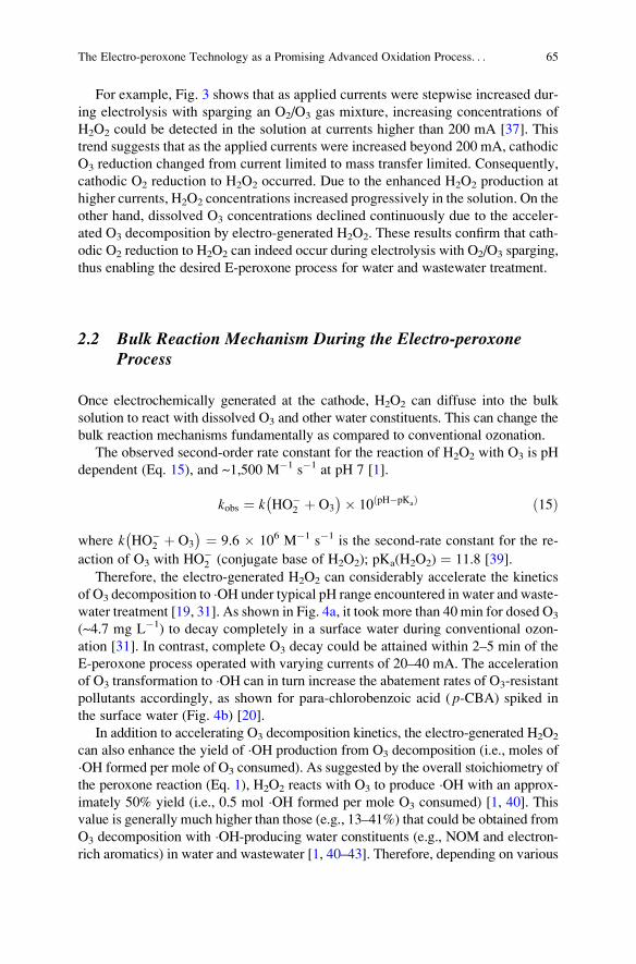
For example, Fig. 3 shows that as applied currents were stepwise increased dur-
ing electrolysis with sparging an O2/O3 gas mixture, increasing concentrations of
H2O2 could be detected in the solution at currents higher than 200 mA [37]. This
trend suggests that as the applied currents were increased beyond 200 mA, cathodic
O3 reduction changed from current limited to mass transfer limited. Consequently,
cathodic O2 reduction to H2O2 occurred. Due to the enhanced H2O2 production at
higher currents, H2O2 concentrations increased progressively in the solution. On the
other hand, dissolved O3 concentrations declined continuously due to the acceler-
ated O3 decomposition by electro-generated H2O2. These results confirm that cath-
odic O2 reduction to H2O2 can indeed occur during electrolysis with O2/O3 sparging,
thus enabling the desired E-peroxone process for water and wastewater treatment.
2.2 Bulk Reaction Mechanism During the Electro-peroxoneProcess
Once electrochemically generated at the cathode, H2O2 can diffuse into the bulk
solution to react with dissolved O3 and other water constituents. This can change the
bulk reaction mechanisms fundamentally as compared to conventional ozonation.
The observed second-order rate constant for the reaction of H2O2 with O3 is pH
dependent (Eq. 15), and ~1,500 M�1 s�1 at pH 7 [1].
kobs ¼ k HO�2 þ O3
� �� 10 pH�pKað Þ ð15Þ
where k HO�2 þ O3
� � ¼ 9.6 � 106 M�1 s�1 is the second-rate constant for the re-
action of O3 with HO�2 (conjugate base of H2O2); pKa(H2O2) ¼ 11.8 [39].
Therefore, the electro-generated H2O2 can considerably accelerate the kinetics
of O3 decomposition to �OH under typical pH range encountered in water and waste-
water treatment [19, 31]. As shown in Fig. 4a, it took more than 40 min for dosed O3
(~4.7 mg L�1) to decay completely in a surface water during conventional ozon-
ation [31]. In contrast, complete O3 decay could be attained within 2–5 min of the
E-peroxone process operated with varying currents of 20–40 mA. The acceleration
of O3 transformation to �OH can in turn increase the abatement rates of O3-resistant
pollutants accordingly, as shown for para-chlorobenzoic acid ( p-CBA) spiked in
the surface water (Fig. 4b) [20].
In addition to accelerating O3 decomposition kinetics, the electro-generated H2O2
can also enhance the yield of �OH production from O3 decomposition (i.e., moles of
�OH formed per mole of O3 consumed). As suggested by the overall stoichiometry of
the peroxone reaction (Eq. 1), H2O2 reacts with O3 to produce �OH with an approx-
imately 50% yield (i.e., 0.5 mol �OH formed per mole O3 consumed) [1, 40]. This
value is generally much higher than those (e.g., 13–41%) that could be obtained from
O3 decomposition with �OH-producing water constituents (e.g., NOM and electron-
rich aromatics) in water and wastewater [1, 40–43]. Therefore, depending on various
The Electro-peroxone Technology as a Promising Advanced Oxidation Process. . . 65
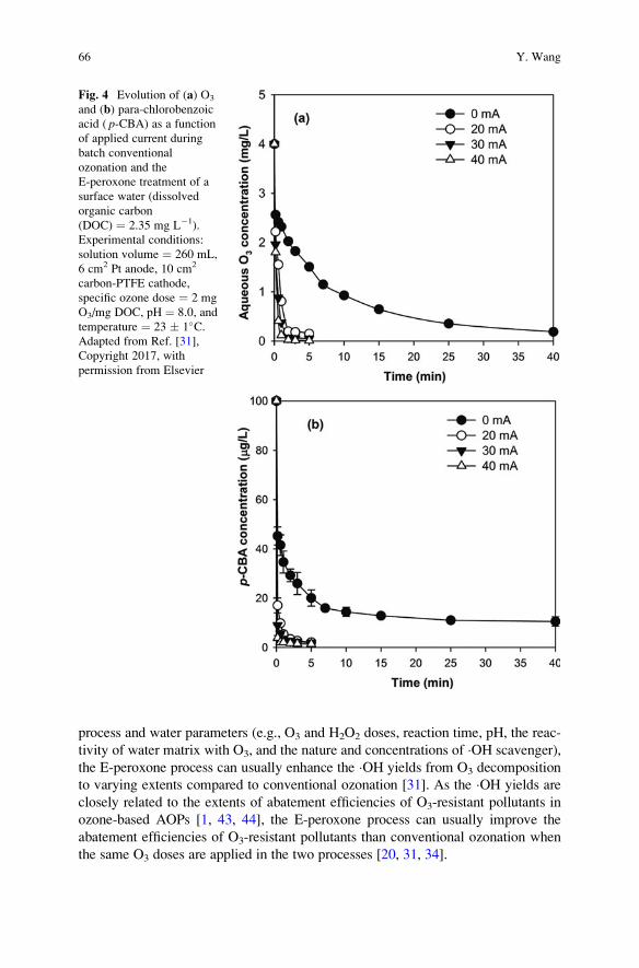
process and water parameters (e.g., O3 and H2O2 doses, reaction time, pH, the reac-
tivity of water matrix with O3, and the nature and concentrations of �OH scavenger),
the E-peroxone process can usually enhance the �OH yields from O3 decomposition
to varying extents compared to conventional ozonation [31]. As the �OH yields are
closely related to the extents of abatement efficiencies of O3-resistant pollutants in
ozone-based AOPs [1, 43, 44], the E-peroxone process can usually improve the
abatement efficiencies of O3-resistant pollutants than conventional ozonation when
the same O3 doses are applied in the two processes [20, 31, 34].
Fig. 4 Evolution of (a) O3
and (b) para-chlorobenzoic
acid ( p-CBA) as a functionof applied current during
batch conventional
ozonation and the
E-peroxone treatment of a
surface water (dissolved
organic carbon
(DOC) ¼ 2.35 mg L�1).
Experimental conditions:
solution volume ¼ 260 mL,
6 cm2 Pt anode, 10 cm2
carbon-PTFE cathode,
specific ozone dose ¼ 2 mg
O3/mg DOC, pH ¼ 8.0, and
temperature ¼ 23 � 1�C.Adapted from Ref. [31],
Copyright 2017, with
permission from Elsevier
66 Y. Wang
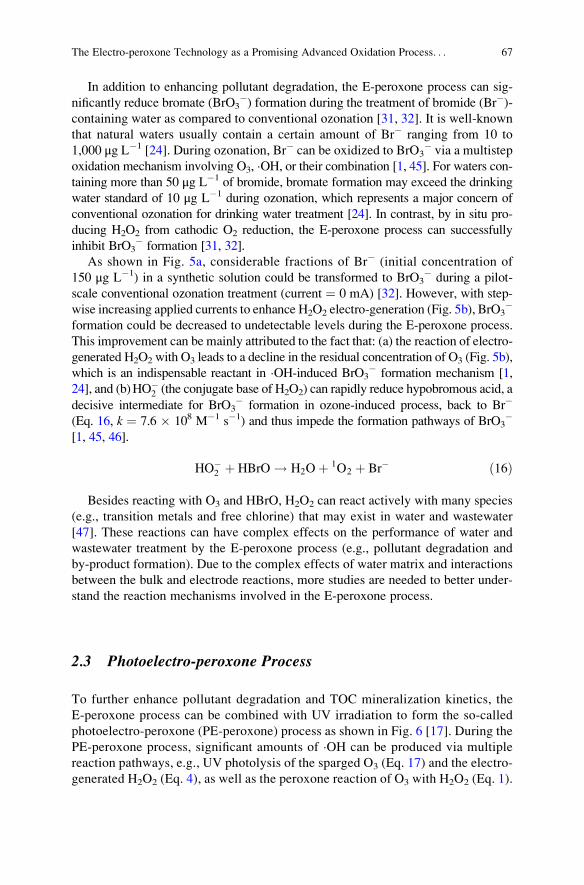
In addition to enhancing pollutant degradation, the E-peroxone process can sig-
nificantly reduce bromate (BrO3�) formation during the treatment of bromide (Br�)-
containing water as compared to conventional ozonation [31, 32]. It is well-known
that natural waters usually contain a certain amount of Br� ranging from 10 to
1,000 μg L�1 [24]. During ozonation, Br� can be oxidized to BrO3� via a multistep
oxidation mechanism involving O3, �OH, or their combination [1, 45]. For waters con-
taining more than 50 μg L�1 of bromide, bromate formation may exceed the drinking
water standard of 10 μg L�1 during ozonation, which represents a major concern of
conventional ozonation for drinking water treatment [24]. In contrast, by in situ pro-
ducing H2O2 from cathodic O2 reduction, the E-peroxone process can successfully
inhibit BrO3� formation [31, 32].
As shown in Fig. 5a, considerable fractions of Br� (initial concentration of
150 μg L�1) in a synthetic solution could be transformed to BrO3� during a pilot-
scale conventional ozonation treatment (current ¼ 0 mA) [32]. However, with step-
wise increasing applied currents to enhance H2O2 electro-generation (Fig. 5b), BrO3�
formation could be decreased to undetectable levels during the E-peroxone process.
This improvement can be mainly attributed to the fact that: (a) the reaction of electro-
generated H2O2 with O3 leads to a decline in the residual concentration of O3 (Fig. 5b),
which is an indispensable reactant in �OH-induced BrO3� formation mechanism [1,
24], and (b)HO�2 (the conjugate base of H2O2) can rapidly reduce hypobromous acid, a
decisive intermediate for BrO3� formation in ozone-induced process, back to Br�
(Eq. 16, k ¼ 7.6 � 108 M�1 s�1) and thus impede the formation pathways of BrO3�
[1, 45, 46].
HO�2 þ HBrO ! H2Oþ 1O2 þ Br� ð16Þ
Besides reacting with O3 and HBrO, H2O2 can react actively with many species
(e.g., transition metals and free chlorine) that may exist in water and wastewater
[47]. These reactions can have complex effects on the performance of water and
wastewater treatment by the E-peroxone process (e.g., pollutant degradation and
by-product formation). Due to the complex effects of water matrix and interactions
between the bulk and electrode reactions, more studies are needed to better under-
stand the reaction mechanisms involved in the E-peroxone process.
2.3 Photoelectro-peroxone Process
To further enhance pollutant degradation and TOC mineralization kinetics, the
E-peroxone process can be combined with UV irradiation to form the so-called
photoelectro-peroxone (PE-peroxone) process as shown in Fig. 6 [17]. During the
PE-peroxone process, significant amounts of �OH can be produced via multiple
reaction pathways, e.g., UV photolysis of the sparged O3 (Eq. 17) and the electro-
generated H2O2 (Eq. 4), as well as the peroxone reaction of O3 with H2O2 (Eq. 1).
The Electro-peroxone Technology as a Promising Advanced Oxidation Process. . . 67
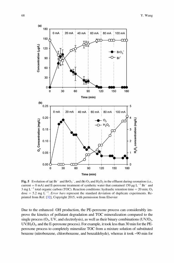
Due to the enhanced �OH production, the PE-peroxone process can considerably im-
prove the kinetics of pollutant degradation and TOC mineralization compared to the
single process (O3, UV, and electrolysis), as well as their binary combinations (UV/O3,
UV/H2O2, and the E-peroxone process). For example, it took less than 30min for the PE-
peroxone process to completely mineralize TOC from a mixture solution of substituted
benzene (nitrobenzene, chlorobenzene, and benzaldehyde), whereas it took ~90 min for
Fig. 5 Evolution of (a) Br� and BrO3�, and (b) O3 and H2O2 in the effluent during ozonation (i.e.,
current ¼ 0 mA) and E-peroxone treatment of synthetic water that contained 150 μg L�1 Br� and
3 mg L�1 total organic carbon (TOC). Reaction conditions: hydraulic retention time ¼ 20 min; O3
dose ¼ 5.2 mg L�1. Error bars represent the standard deviation of duplicate experiments. Re-
printed from Ref. [32], Copyright 2015, with permission from Elsevier
68 Y. Wang
the E-peroxone and UV/O3 processes to achieve the similar extents of TOC mineraliza-
tion. In addition, due to the multiple ways of �OH generation and pollutant degradation
(e.g., oxidationwithO3 and �OH, anodic oxidation, andUV photolysis), the PE-peroxone
process can maintain high kinetics and energy efficiencies for pollutant degradation
under a variety of reaction conditions that may be unfavorable for other AOPs (e.g., low
pH for O3/H2O2 and high color and turbidity for UV/H2O2 processes) [17, 48–50].
Therefore, although the PE-peroxone process would require a more complex system
design and higher capital investment than the more traditional AOPs such as O3/H2O2,
UV/O3, and UV/H2O2, it may serve as a robust and effective option to treat wastewaters
(e.g., landfill leachate and industrial effluents) that are problematic to treat by other
AOPs.
O3 þ H2Oþ hv ! 2 � OHþ O2 ð17Þ
3 Applications of the Electro-peroxone Process for Water
and Wastewater Treatment
3.1 Electro-peroxone for Wastewater Treatment
O3 is a highly selective oxidant and reacts preferentially with conjugated double
bonds (e.g., N ¼ N, C ¼ O, and C ¼ C) that are often the chromophores of dye
molecules. Therefore, O3 has been commonly used in dye wastewater treatment for
decolorization purpose [1, 34]. As an ozone-based EAOP, the E-peroxone process
Fig. 6 Schematic representation of the main reaction mechanisms of the photoelectro-peroxone
process and TOC mineralization from substituted benzene mixture solution by ozonation, UV,
electrolysis, UV/O3, E-peroxone, and photoelectro-peroxone (PE-peroxone) processes. Reaction
conditions: initial concentration of nitrobenzene, chlorobenzene, and benzaldehyde ¼ 10 mg L�1,
solution volume ¼ 700 mL, sparging gas flow rate ¼ 0.25 L min�1, inlet O3 gas phase concen-
tration ¼ 110 mg L�1, current ¼ 400 mA, UV fluence rate ¼ 0.87 mW cm�2. Reprinted from Ref.
[17], Copyright 2016, with permission from Elsevier
The Electro-peroxone Technology as a Promising Advanced Oxidation Process. . . 69
is also very effective at color removal. Figure 7a shows that similar to conventional
ozonation, the E-peroxone process is capable of completely removing the color of a
synthetic Orange II dye wastewater in a short reaction time (4 min) [34].
Due to the selective oxidation characteristics of O3, conventional ozonation is
usually ineffective at TOC mineralization and can generate a variety of O3-resistant
transformation products from the oxidative degradation of parent pollutants [1]. On
the other hand, electrolysis usually needs long reaction time to completely miner-
alize pollutants from wastewater because the rate of pollutant degradation can be
limited by the mass transfer of pollutants to the electrodes, and this limitation
becomes increasingly severe as the pollutant concentrations decrease [3]. In con-
trast, by electrochemically producing H2O2 to enhance O3 transformation to aqueous
�OH, which can then nonselectively and rapidly oxidize most organic pollutants in the
bulk solution, the E-peroxone process can greatly enhance TOC mineralization as
compared to conventional ozonation and electrolysis [19]. As Fig. 7b shows, only
~15% and ~56% TOC could be removed from the Orange II wastewater after 90 min
of electrolysis and conventional ozonation treatment, respectively. In contrast, more
than 95% TOC was removed after only 45 min of the E-peroxone process [34]. These
results indicate that the E-peroxone process is very effective at both decolorization
and TOC mineralization and can therefore provide a suitable technology for dye
wastewater treatment.
Similar enhancement in TOC mineralization has also been observed during the
E-peroxone treatment of a wide variety of wastewaters, such as landfill leachate [33],
and wastewaters containing pharmaceuticals [26, 27, 47, 51], 1,4-dioxane [25, 48],
aromatics [17, 52], and phenols [53, 54]. These results highlight that the E-peroxone
process can successfully overcome the inherent limitations of conventional ozonation
and electrolysis for pollutant degradation, i.e., the selective oxidation with O3 and the
limitation of pollutant mass transfer on their electrode degradation kinetics, and thus
greatly improve the performance of wastewater treatment for pollutant degradation
and TOC mineralization (Table 2).
Due to its high kinetics of pollutant degradation, the E-peroxone process can often
reduce the energy consumption for water and wastewater treatment compared to con-
ventional ozonation and electrolysis [20, 25, 55]. Figure 8 shows that after 2 h treat-
ment, conventional ozonation and electrolysis with a boron-doped diamond (BDD)
anode removed ~6% and 27% TOC from 1,4-dioxane solutions with a specific energy
consumption (SEC) of 2.43 and 0.558 kWh g�1 TOCremoved, respectively. It is note
that because O3 is essentially unreactive with saturated carboxylic acids formed from
1,4-dioxane degradation, the SEC for ozonation increased sharply after 60 min. In
contrast, the E-peroxone process almost completely removed the solution TOC (~97%)
with a lower SEC of 0.376 kWh g�1 TOCremoved [25]. In addition, because pollutants
can be effectively oxidized by aqueous �OH generated primarily from the cathodically
induced peroxone reaction, the E-peroxone process does not require potent but expen-
sive anodes (e.g., BDD) to enhance pollutant degradation by anodic oxidation [19].
Therefore, cheap anode materials such as dimensionally stable anode (DSA) can be
used to reduce the capital cost for the E-peroxone process [25, 47].
70 Y. Wang
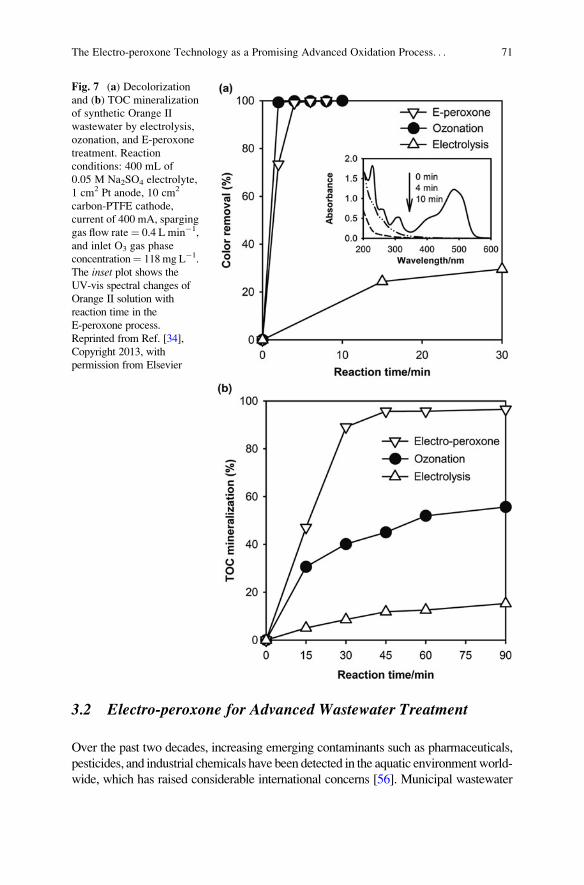
3.2 Electro-peroxone for Advanced Wastewater Treatment
Over the past two decades, increasing emerging contaminants such as pharmaceuticals,
pesticides, and industrial chemicals have been detected in the aquatic environmentworld-
wide, which has raised considerable international concerns [56]. Municipal wastewater
Fig. 7 (a) Decolorization
and (b) TOC mineralization
of synthetic Orange II
wastewater by electrolysis,
ozonation, and E-peroxone
treatment. Reaction
conditions: 400 mL of
0.05 M Na2SO4 electrolyte,
1 cm2 Pt anode, 10 cm2
carbon-PTFE cathode,
current of 400 mA, sparging
gas flow rate¼ 0.4 L min�1,
and inlet O3 gas phase
concentration¼ 118mg L�1.
The inset plot shows theUV-vis spectral changes of
Orange II solution with
reaction time in the
E-peroxone process.
Reprinted from Ref. [34],
Copyright 2013, with
permission from Elsevier
The Electro-peroxone Technology as a Promising Advanced Oxidation Process. . . 71
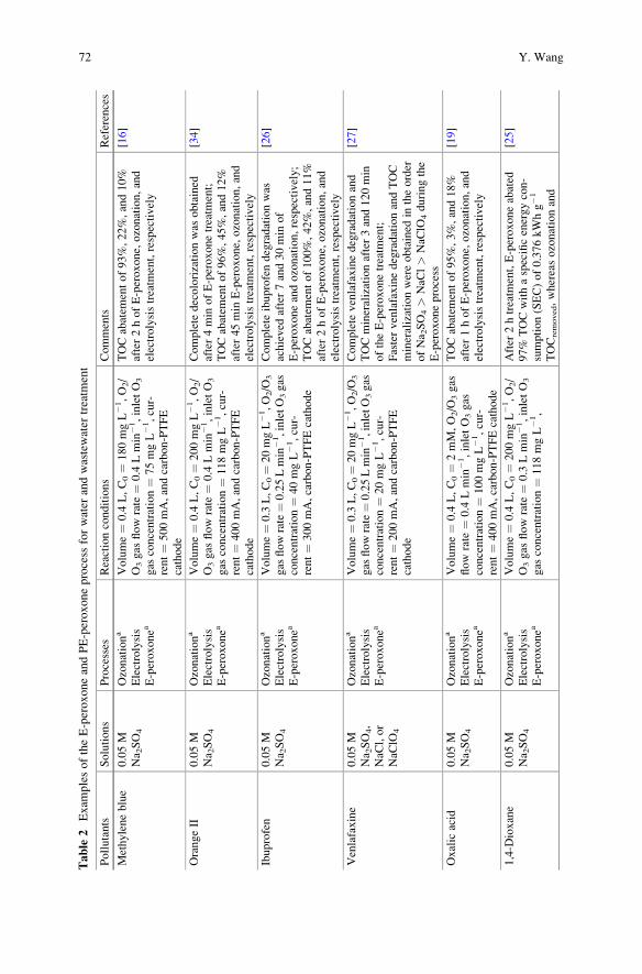
Table
2Exam
plesoftheE-peroxoneandPE-peroxoneprocess
forwater
andwastewater
treatm
ent
Pollutants
Solutions
Processes
Reactionconditions
Comments
References
Methyleneblue
0.05M
Na 2SO4
Ozonationa
Electrolysis
E-peroxonea
Volume¼
0.4
L,C0¼
180mgL�1,O2/
O3gas
flowrate
¼0.4
Lmin
�1,inletO3
gas
concentration¼
75mgL�1,cur-
rent¼
500mA,andcarbon-PTFE
cathode
TOCabatem
entof93%,22%,and10%
after2hofE-peroxone,ozonation,and
electrolysistreatm
ent,respectively
[16]
OrangeII
0.05M
Na 2SO4
Ozonationa
Electrolysis
E-peroxonea
Volume¼
0.4
L,C0¼
200mgL�1,O2/
O3gas
flowrate
¼0.4
Lmin
�1,inletO3
gas
concentration¼
118mgL�1,cur-
rent¼
400mA,andcarbon-PTFE
cathode
Complete
decolorizationwas
obtained
after4min
ofE-peroxonetreatm
ent;
TOCabatem
entof96%,45%,and12%
after45min
E-peroxone,ozonation,and
electrolysistreatm
ent,respectively
[34]
Ibuprofen
0.05M
Na 2SO4
Ozonationa
Electrolysis
E-peroxonea
Volume¼
0.3
L,C0¼
20mgL�1,O2/O
3
gas
flowrate¼0.25Lmin
�1,inletO3gas
concentration¼
40mgL�1,cur-
rent¼
300mA,carbon-PTFEcathode
Complete
ibuprofendegradationwas
achieved
after7and30min
of
E-peroxoneandozonation,respectively;
TOCabatem
entof100%,42%,and11%
after2hofE-peroxone,ozonation,and
electrolysistreatm
ent,respectively
[26]
Venlafaxine
0.05M
Na 2SO4,
NaC
l,or
NaC
lO4
Ozonationa
Electrolysis
E-peroxonea
Volume¼
0.3
L,C0¼
20mgL�1,O2/O
3
gas
flowrate¼0.25Lmin
�1,inletO3gas
concentration¼
20mgL�1,cur-
rent¼
200mA,andcarbon-PTFE
cathode
Complete
venlafaxinedegradationand
TOCmineralizationafter3and120min
oftheE-peroxonetreatm
ent;
FastervenlafaxinedegradationandTOC
mineralizationwereobtained
intheorder
ofNa 2SO4>
NaC
l>
NaC
lO4duringthe
E-peroxoneprocess
[27]
Oxalic
acid
0.05M
Na 2SO4
Ozonationa
Electrolysis
E-peroxonea
Volume¼
0.4
L,C0¼
2mM,O2/O
3gas
flow
rate
¼0.4
Lmin
�1,inletO3gas
concentration¼
100mgL�1,cur-
rent¼
400mA,carbon-PTFEcathode
TOCabatem
entof95%,3%,and18%
after1hofE-peroxone,ozonation,and
electrolysistreatm
ent,respectively
[19]
1,4-D
ioxane
0.05M
Na 2SO4
Ozonationa
Electrolysis
E-peroxonea
Volume¼
0.4
L,C0¼
200mgL�1,O2/
O3gas
flowrate
¼0.3
Lmin
�1,inletO3
gas
concentration¼
118mgL�1,
After
2htreatm
ent,E-peroxoneabated
97%
TOCwithaspecificenergycon-
sumption(SEC)of0.376kWhg�1
TOCremoved,whereasozonationand
[25]
72 Y. Wang
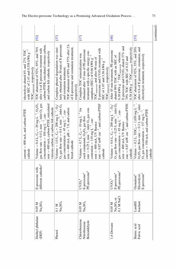
current¼
400mA,andcarbon-PTFE
cathode
electrolysisabated
6%
and27%
TOC
withSECof2.43and0.558kWhg�1
TOCremoved,respectively
Diethylphthalate
(DEP)
0.05M
Na 2SO4
E-peroxonewith
differentcathodes
aVolume¼
0.4
L,C0¼
20mgL�1,O2/O
3
gas
flowrate
¼0.4
Lmin
�1,inletO3gas
concentration¼
104mgL�1,cur-
rent¼
400mA,carbon-PTFE,reticulated
vitreouscarbon,orcarbonfeltcathode
TOCabatem
entof92%,85%,and76%
after1hofE-peroxonetreatm
entwith
carbon-PTFE,reticulatedvitreouscarbon,
andcarbonfeltcathode,respectively
[52]
Phenol
0.1
MNa 2SO4
Volume¼
1.0
L,C0¼
200mgL�1,O2/
O3gas
flowrate
¼0.4
Lmin
�1,inletO3
gas
concentration¼
45mgL�1,cur-
rent¼
400mA,pH¼
7.8,andcarbon
brush
cathode
Complete
phenoldegradationwas
simi-
larlyobtained
after30min
ofE-peroxone
andozonationtreatm
ent;
TOCabatem
entof89%
and57%
after2h
ofE-peroxoneandozonationtreatm
ent,
respectively
[37]
Chlorobenzene
Nitrobenzene
Benzaldehyde
0.05M
Na 2SO4
UV/O
3a
E-peroxonea
PE-peroxonea
Volume¼
0.7
L,C0¼
10mgL�1for
each
compound,O2/O
3gas
flow
rate
¼0.25Lmin
�1,inletO3gas
con-
centration¼
110mgL�1,cur-
rent¼
400mA,UV
fluence
rate
¼0.87mW
cm�2,andcarbon-PTEF
cathode
Complete
TOCmineralizationwas
obtained
after15min
ofPE-peroxone
treatm
entwithaspecificenergycon-
sumption(SEC)of0.66kWhg�1
TOCremoved,andafter90min
of
E-peroxoneandUV/O
3treatm
entwith
SECof1.07and3.56kWhg�1
TOCremoved,respectively
[17]
1,4-D
ioxane
0.05M
Na 2SO4or
0.1
MNaC
l
UV/O
3a
E-peroxonea
PE-peroxonea
Volume¼
0.6
L,C0¼
200mgL�1,O2/
O3gas
flowrate¼
0.25Lmin
�1,inletO3
gas
concentration¼
85mgL�1,cur-
rent¼
400mA,UV
fluence
rate
¼0.87mW
cm�2,andcarbon-PTFE
cathode
After
45min
treatm
ent,PE-peroxone
abated
98%
TOCwithan
SECof
0.30kWhg�1TOCremoved,whereas
E-peroxoneandUV/O
3abated
37%
and
70%
TOCwithSECof0.22and
0.38kWhg�1TOCremoved,respectively
[48]
Humic
acid
Fulvic
acid
Landfill
leachate
Ozonationa
Electrolysis
E-peroxonea
Volume¼
0.2
L,TOC0¼
1,650mgL�1,
O2/O
3gas
flowrate
¼0.3
Lmin
�1,inlet
O3gas
concentration¼
157mgL�1,
current¼
350mA,andcarbon-PTFE
cathode
TOCabatem
entof92%,55%,and20%
after6hofE-peroxone,ozonation,and
electrolysistreatm
ent,respectively
[33]
(continued)
The Electro-peroxone Technology as a Promising Advanced Oxidation Process. . . 73
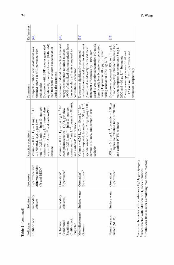
Table
2(continued)
Pollutants
Solutions
Processes
Reactionconditions
Comments
References
Clofibricacid
Secondary
effluent
E-peroxonewith
differentanodes
(PtandBDD)a
Volume¼
0.4
L,C0¼
1mgL�1,Cl�
¼1.90mM,O2/O
3gas
flow
rate
¼0.25Lmin
�1,inletO3gas
con-
centration¼
38mgL�1,currentden-
sity
¼32mA
cm�2,andcarbon-PTFE
cathode
Complete
clofibricacid
abatem
entwas
obtained
after1hofE-peroxonewith
both
anodes;
E-peroxonewithBDDanodes
generated
significantlymore
perchlorate
(0.46mM)
than
that
withPtanodes
(undetectable)
duringthetreatm
ent
[47]
Diclofenac
Gem
fibrozil
Bezafibrate
Clofibricacid
Ibuprofen
Secondary
effluents
Ozonationa
E-peroxonea
Volume¼
0.4
L,C0¼
0.4
mgL�1for
each
pharmaceutical,O2/O
3gas
flow
rate
¼0.25Lmin
�1,inletO3gas
con-
centration¼
6mgL�1,current¼
80mA,
andcarbon-PTFEcathode
E-peroxonereducedthereactiontimeand
energyconsumptionrequired
toabate
>90%
ofallspiked
pharmaceuticalsfrom
foursecondaryeffluentscompared
toconventional
ozonation
[20]
Methylisoborneol
Geosm
inSurfacewater
Ozonationb
E-peroxoneb
Volume¼
0.26L,C0¼
10μg
L�1for
each
compound,bromide¼
150μg
L�1,
specificozonedose
¼2mgO3/m
gDOC,
current¼
40mA,andcarbon-PTFE
cathode
E-peroxonesignificantlyaccelerated
methylisoborneolandgeosm
inabatem
ent
(5min)andmoderatelyincreasedtheir
abatem
entefficiencies
by~10%
com-
pared
toconventionalozonation(40min);
Significantlyless
bromatewas
generated
duringE-peroxone(8.2
μgL�1)than
duringozonation(76.1
μgL�1)
[31]
Naturalorganic
matter(N
OM)
Surfacewater
Ozonationc
E-peroxonec
DOC0¼
6.1
mgL�1,bromide¼
150μg
L�1,hydraulicretentiontimeof20min,
andcarbon-PTFEcathode
E-peroxonedecreased
DOCto
3.1
mgL
�1andcompletely
inhibited
bromatefor-
mationcompared
toozonation(5
mgL�1
DOCand~60μg
L�1bromate);
Energyconsumptionwas
0.190and
0.117kWhm
�3forE-peroxoneand
ozonation,respectively
[32]
aSem
i-batch
reactorwithcontinuousO2/O
3gas
sparging
bBatch
reactorwithadditionofO3stock
solutions
cContinuousflowreactor(sim
ulatingreal
ozonereactor)
74 Y. Wang
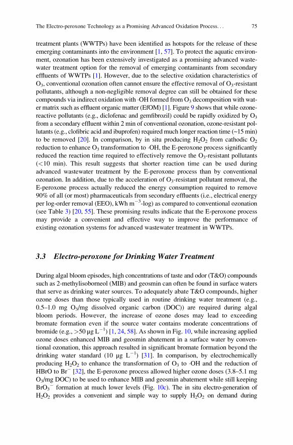
treatment plants (WWTPs) have been identified as hotspots for the release of these
emerging contaminants into the environment [1, 57]. To protect the aquatic environ-
ment, ozonation has been extensively investigated as a promising advanced waste-
water treatment option for the removal of emerging contaminants from secondary
effluents of WWTPs [1]. However, due to the selective oxidation characteristics of
O3, conventional ozonation often cannot ensure the effective removal of O3-resistant
pollutants, although a non-negligible removal degree can still be obtained for these
compounds via indirect oxidation with �OH formed fromO3 decomposition with wat-
er matrix such as effluent organic matter (EfOM) [1]. Figure 9 shows that while ozone-
reactive pollutants (e.g., diclofenac and gemfibrozil) could be rapidly oxidized by O3
from a secondary effluent within 2 min of conventional ozonation, ozone-resistant pol-
lutants (e.g., clofibric acid and ibuprofen) required much longer reaction time (~15min)
to be removed [20]. In comparison, by in situ producing H2O2 from cathodic O2
reduction to enhance O3 transformation to �OH, the E-peroxone process significantlyreduced the reaction time required to effectively remove the O3-resistant pollutants
(<10 min). This result suggests that shorter reaction time can be used during
advanced wastewater treatment by the E-peroxone process than by conventional
ozonation. In addition, due to the acceleration of O3-resistant pollutant removal, the
E-peroxone process actually reduced the energy consumption required to remove
90% of all (or most) pharmaceuticals from secondary effluents (i.e., electrical energy
per log-order removal (EEO), kWh m�3-log) as compared to conventional ozonation
(see Table 3) [20, 55]. These promising results indicate that the E-peroxone process
may provide a convenient and effective way to improve the performance of
existing ozonation systems for advanced wastewater treatment in WWTPs.
3.3 Electro-peroxone for Drinking Water Treatment
During algal bloom episodes, high concentrations of taste and odor (T&O) compounds
such as 2-methylisoborneol (MIB) and geosmin can often be found in surface waters
that serve as drinking water sources. To adequately abate T&O compounds, higher
ozone doses than those typically used in routine drinking water treatment (e.g.,
0.5–1.0 mg O3/mg dissolved organic carbon (DOC)) are required during algal
bloom periods. However, the increase of ozone doses may lead to exceeding
bromate formation even if the source water contains moderate concentrations of
bromide (e.g.,>50 μg L�1) [1, 24, 58]. As shown in Fig. 10, while increasing applied
ozone doses enhanced MIB and geosmin abatement in a surface water by conven-
tional ozonation, this approach resulted in significant bromate formation beyond the
drinking water standard (10 μg L�1) [31]. In comparison, by electrochemically
producing H2O2 to enhance the transformation of O3 to �OH and the reduction of
HBrO to Br� [32], the E-peroxone process allowed higher ozone doses (3.8–5.1 mg
O3/mg DOC) to be used to enhance MIB and geosmin abatement while still keeping
BrO3� formation at much lower levels (Fig. 10c). The in situ electro-generation of
H2O2 provides a convenient and simple way to supply H2O2 on demand during
The Electro-peroxone Technology as a Promising Advanced Oxidation Process. . . 75
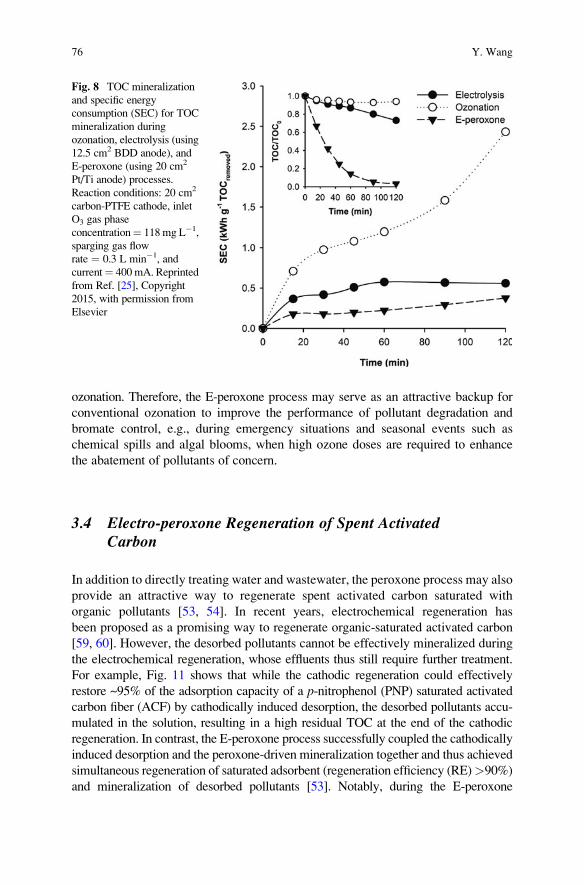
ozonation. Therefore, the E-peroxone process may serve as an attractive backup for
conventional ozonation to improve the performance of pollutant degradation and
bromate control, e.g., during emergency situations and seasonal events such as
chemical spills and algal blooms, when high ozone doses are required to enhance
the abatement of pollutants of concern.
3.4 Electro-peroxone Regeneration of Spent ActivatedCarbon
In addition to directly treating water and wastewater, the peroxone process may also
provide an attractive way to regenerate spent activated carbon saturated with
organic pollutants [53, 54]. In recent years, electrochemical regeneration has
been proposed as a promising way to regenerate organic-saturated activated carbon
[59, 60]. However, the desorbed pollutants cannot be effectively mineralized during
the electrochemical regeneration, whose effluents thus still require further treatment.
For example, Fig. 11 shows that while the cathodic regeneration could effectively
restore ~95% of the adsorption capacity of a p-nitrophenol (PNP) saturated activated
carbon fiber (ACF) by cathodically induced desorption, the desorbed pollutants accu-
mulated in the solution, resulting in a high residual TOC at the end of the cathodic
regeneration. In contrast, the E-peroxone process successfully coupled the cathodically
induced desorption and the peroxone-driven mineralization together and thus achieved
simultaneous regeneration of saturated adsorbent (regeneration efficiency (RE)>90%)
and mineralization of desorbed pollutants [53]. Notably, during the E-peroxone
Fig. 8 TOC mineralization
and specific energy
consumption (SEC) for TOC
mineralization during
ozonation, electrolysis (using
12.5 cm2 BDD anode), and
E-peroxone (using 20 cm2
Pt/Ti anode) processes.
Reaction conditions: 20 cm2
carbon-PTFE cathode, inlet
O3 gas phase
concentration¼ 118mg L�1,
sparging gas flow
rate ¼ 0.3 L min�1, and
current¼ 400 mA. Reprinted
from Ref. [25], Copyright
2015, with permission from
Elsevier
76 Y. Wang
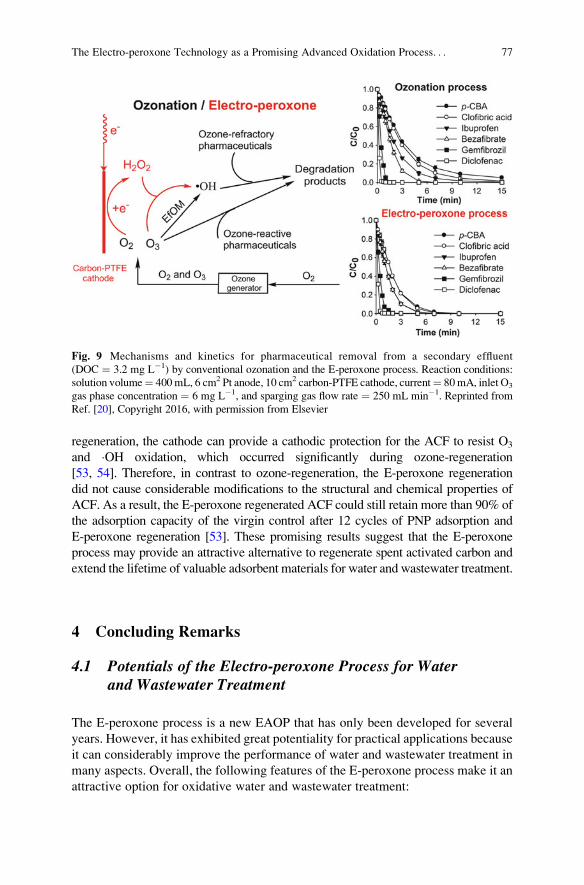
regeneration, the cathode can provide a cathodic protection for the ACF to resist O3
and �OH oxidation, which occurred significantly during ozone-regeneration
[53, 54]. Therefore, in contrast to ozone-regeneration, the E-peroxone regeneration
did not cause considerable modifications to the structural and chemical properties of
ACF. As a result, the E-peroxone regenerated ACF could still retain more than 90% of
the adsorption capacity of the virgin control after 12 cycles of PNP adsorption and
E-peroxone regeneration [53]. These promising results suggest that the E-peroxone
process may provide an attractive alternative to regenerate spent activated carbon and
extend the lifetime of valuable adsorbent materials for water and wastewater treatment.
4 Concluding Remarks
4.1 Potentials of the Electro-peroxone Process for Waterand Wastewater Treatment
The E-peroxone process is a new EAOP that has only been developed for several
years. However, it has exhibited great potentiality for practical applications because
it can considerably improve the performance of water and wastewater treatment in
many aspects. Overall, the following features of the E-peroxone process make it an
attractive option for oxidative water and wastewater treatment:
Fig. 9 Mechanisms and kinetics for pharmaceutical removal from a secondary effluent
(DOC ¼ 3.2 mg L�1) by conventional ozonation and the E-peroxone process. Reaction conditions:
solution volume¼ 400mL, 6 cm2 Pt anode, 10 cm2 carbon-PTFE cathode, current¼ 80mA, inlet O3
gas phase concentration ¼ 6 mg L�1, and sparging gas flow rate ¼ 250 mL min�1. Reprinted from
Ref. [20], Copyright 2016, with permission from Elsevier
The Electro-peroxone Technology as a Promising Advanced Oxidation Process. . . 77
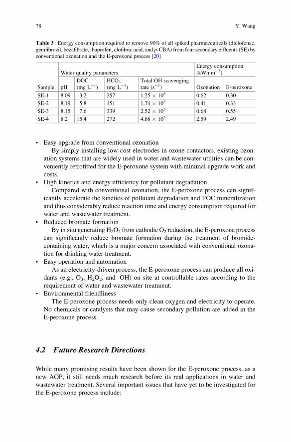
• Easy upgrade from conventional ozonation
By simply installing low-cost electrodes in ozone contactors, existing ozon-
ation systems that are widely used in water and wastewater utilities can be con-
veniently retrofitted for the E-peroxone system with minimal upgrade work and
costs.
• High kinetics and energy efficiency for pollutant degradation
Compared with conventional ozonation, the E-peroxone process can signif-
icantly accelerate the kinetics of pollutant degradation and TOC mineralization
and thus considerably reduce reaction time and energy consumption required for
water and wastewater treatment.
• Reduced bromate formation
By in situ generating H2O2 from cathodic O2 reduction, the E-peroxone process
can significantly reduce bromate formation during the treatment of bromide-
containing water, which is a major concern associated with conventional ozona-
tion for drinking water treatment.
• Easy operation and automation
As an electricity-driven process, the E-peroxone process can produce all oxi-
dants (e.g., O3, H2O2, and �OH) on site at controllable rates according to the
requirement of water and wastewater treatment.
• Environmental friendliness
The E-peroxone process needs only clean oxygen and electricity to operate.
No chemicals or catalysts that may cause secondary pollution are added in the
E-peroxone process.
4.2 Future Research Directions
While many promising results have been shown for the E-peroxone process, as a
new AOP, it still needs much research before its real applications in water and
wastewater treatment. Several important issues that have yet to be investigated for
the E-peroxone process include:
Table 3 Energy consumption required to remove 90% of all spiked pharmaceuticals (diclofenac,
gemfibrozil, bezafibrate, ibuprofen, clofibric acid, and p-CBA) from four secondary effluents (SE) by
conventional ozonation and the E-peroxone process [20]
Sample
Water quality parameters
Energy consumption
(kWh m�3)
pH
DOC
(mg L�1)
HCO3�
(mg L�1)
Total OH scavenging
rate (s�1) Ozonation E-peroxone
SE-1 8.09 3.2 257 1.25 � 105 0.62 0.30
SE-2 8.19 5.8 151 1.74 � 105 0.41 0.33
SE-3 8.15 7.6 339 2.52 � 105 0.68 0.55
SE-4 8.2 15.4 272 4.68 � 105 2.59 2.49
78 Y. Wang
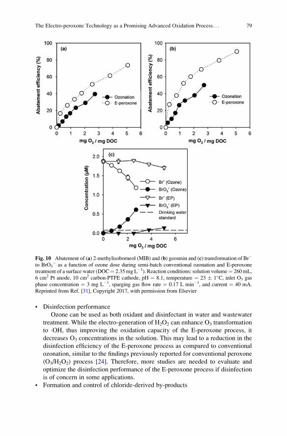
• Disinfection performance
Ozone can be used as both oxidant and disinfectant in water and wastewater
treatment. While the electro-generation of H2O2 can enhance O3 transformation
to �OH, thus improving the oxidation capacity of the E-peroxone process, it
decreases O3 concentrations in the solution. This may lead to a reduction in the
disinfection efficiency of the E-peroxone process as compared to conventional
ozonation, similar to the findings previously reported for conventional peroxone
(O3/H2O2) process [24]. Therefore, more studies are needed to evaluate and
optimize the disinfection performance of the E-peroxone process if disinfection
is of concern in some applications.
• Formation and control of chloride-derived by-products
Fig. 10 Abatement of (a) 2-methylisoborneol (MIB) and (b) geosmin and (c) transformation of Br�
to BrO3� as a function of ozone dose during semi-batch conventional ozonation and E-peroxone
treatment of a surface water (DOC¼ 2.35mg L�1). Reaction conditions: solution volume¼ 260mL,
6 cm2 Pt anode, 10 cm2 carbon-PTFE cathode, pH ¼ 8.1, temperature ¼ 23 � 1�C, inlet O3 gas
phase concentration ¼ 3 mg L�1, sparging gas flow rate ¼ 0.17 L min�1, and current ¼ 40 mA.
Reprinted from Ref. [31], Copyright 2017, with permission from Elsevier
The Electro-peroxone Technology as a Promising Advanced Oxidation Process. . . 79
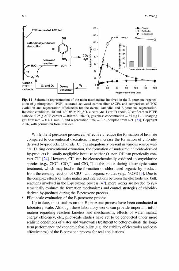
While the E-peroxone process can effectively reduce the formation of bromate
compared to conventional ozonation, it may increase the formation of chloride-
derived by-products. Chloride (Cl�) is ubiquitously present in various source wat-ers. During conventional ozonation, the formation of undesired chloride-derived
by-products is usually negligible because neither O3 nor �OH can practically con-
vert Cl� [24]. However, Cl� can be electrochemically oxidized to oxychlorine
species (e.g., ClO�, ClO2�, and ClO3
�) at the anode during electrolytic water
treatment, which may lead to the formation of chlorinated organic by-products
from the ensuing reaction of ClO� with organic solutes (e.g., NOM) [3]. Due to
the complex effects of water matrix and interactions between the electrode and bulk
reactions involved in the E-peroxone process [47], more works are needed to sys-
tematically evaluate the formation mechanisms and control strategies of chloride-
derived by-products during the E-peroxone process.
• Pilot-scale evaluation of the E-peroxone process
Up to date, most studies on the E-peroxone process have been conducted at
laboratory scale. Although these laboratory works can provide important infor-
mation regarding reaction kinetics and mechanisms, effects of water matrix,
energy efficiency, etc., pilot-scale studies have yet to be conducted under more
realistic conditions of water and wastewater treatment to better evaluate the long-
term performance and economic feasibility (e.g., the stability of electrodes and cost-
effectiveness) of the E-peroxone process for real applications.
Fig. 11 Schematic representation of the main mechanisms involved in the E-peroxone regener-
ation of p-nitrophenol (PNP) saturated activated carbon fiber (ACF), and comparison of TOC
evolution and regeneration efficiencies for the ozone, cathodic, and E-peroxone regeneration.
Reaction conditions: 400 mL of 0.05 M Na2SO4 electrolyte, 4 cm2 Pt anode, 20 cm2 carbon-PTFE
cathode, 0.25 g ACF, current ¼ 400 mA, inlet O3 gas phase concentration ¼ 65 mg L�1, sparging
gas flow rate ¼ 0.4 L min�1, and regeneration time ¼ 3 h. Adapted from Ref. [53], Copyright
2016, with permission from Elsevier
80 Y. Wang
References
1. von Sonntag C, von Gunten U (2012) Chemistry of ozone in water and wastewater treatment.
From basic principles to applications, vol EPFL-BOOK-181142. IWA Publishing, London
2. Brillas E, Martınez-Huitle CA (2015) Decontamination of wastewaters containing synthetic
organic dyes by electrochemical methods. An updated review. Appl Catal Environ 166–167
(0):603–643. doi:10.1016/j.apcatb.2014.11.016
3. Panizza M, Cerisola G (2009) Direct and mediated anodic oxidation of organic pollutants.
Chem Rev 109(12):6541–6569. doi:10.1021/Cr9001319
4. Oturan MA, Aaron JJ (2014) Advanced oxidation processes in water/wastewater treatment:
principles and applications. A review. Crit Rev Environ Sci Technol 44(23):2577–2641.
doi:10.1080/10643389.2013.829765
5. Sires I, Brillas E, Oturan MA, Rodrigo MA, Panizza M (2014) Electrochemical advanced
oxidation processes: today and tomorrow. A review. Environ Sci Pollut R 21(14):8336–8367.
doi:10.1007/s11356-014-2783-1
6. Glaze WH (1987) Drinking-water treatment with ozone. Environ Sci Technol 21(3):224–230.
doi:10.1021/es00157a001
7. Legrini O, Oliveros E, Braun AM (1993) Photochemical processes for water-treatment. Chem
Rev 93(2):671–698. doi:10.1021/cr00018a003
8. Buxton GV, Greenstock CL, HelmanWP, Ross AB (1988) Critical review of rate constants for
reactions of hydrated electrons, hydrogen atoms and hydroxyl radicals (�OH/�O�) in aqueous
solution. J Phys Chem Ref Data Monogr 17(2):513–886. doi:10.1063/1.555805
9. Campos-Martin JM, Blanco-Brieva G, Fierro JLG (2006) Hydrogen peroxide synthesis: an
outlook beyond the anthraquinone process. Angew Chem Int Ed 45(42):6962–6984. doi:10.
1002/anie.200503779
10. Brillas E, Sires I, Oturan MA (2009) Electro-Fenton process and related electrochemical tech-
nologies based on Fenton’s reaction chemistry. Chem Rev 109(12):6570–6631. doi:10.1021/
Cr900136g
11. Zhu X, Logan BE (2013) Using single-chamber microbial fuel cells as renewable power sources
of electro-Fenton reactors for organic pollutant treatment. J Hazard Mater 252–253:198–203.
doi:10.1016/j.jhazmat.2013.02.051
12. Barazesh JM, Hennebel T, Jasper JT, Sedlak DL (2015) Modular advanced oxidation process
enabled by cathodic hydrogen peroxide production. Environ Sci Technol 49(12):7391–7399.
doi:10.1021/acs.est.5b01254
13. Rosenfeldt EJ, Linden KG, Canonica S, von Gunten U (2006) Comparison of the efficiency of
OH radical formation during ozonation and the advanced oxidation processes O3/H2O2 and
UV/H2O2. Water Res 40(20):3695–3704. doi:10.1016/j.watres.2006.09.008
14. Katsoyiannis IA, Canonica S, von Gunten U (2011) Efficiency and energy requirements for the
transformation of organic micropollutants by ozone, O3/H2O2 and UV/H2O2. Water Res 45
(13):3811–3822. doi:10.1016/j.watres.2011.04.038
15. Frangos P, Shen WH, Wang HJ, Li X, Yu G, Deng SB, Huang J, Wang B, Wang YJ (2016)
Improvement of the degradation of pesticide deethylatrazine by combining UV photolysis with
electrochemical generation of hydrogen peroxide. Chem Eng J 291:215–224. doi:10.1016/j.
cej.2016.01.089
16. Yuan S, Li ZX, Wang YJ (2013) Effective degradation of methylene blue by a novel electro-
chemically driven process. Electrochem Commun 29:48–51. doi:10.1016/j.elecom.2013.01.012
17. Frangos P, Wang HJ, Shen WH, Yu G, Deng SB, Huang J, Wang B, Wang YJ (2016) A novel
photoelectro-peroxone process for the degradation and mineralization of substituted benzenes
in water. Chem Eng J 286:239–248. doi:10.1016/j.cej.2015.10.096
18. Brillas E, Mur E, Casado J (1996) Iron(II) catalysis of the mineralization of aniline using a
carbon-PTFE O2-fed cathode. J Electrochem Soc 143(3):L49–L53
The Electro-peroxone Technology as a Promising Advanced Oxidation Process. . . 81
19. Wang HJ, Yuan S, Zhan JH, Wang YJ, Yu G, Deng SB, Huang J, Wang B (2015) Mechanisms
of enhanced total organic carbon elimination from oxalic acid solutions by electro-peroxone
process. Water Res 80:20–29. doi:10.1016/j.watres.2015.05.024
20. Yao WK, Wang XF, Yang HW, Yu G, Deng SB, Huang J, Wang B, Wang YJ (2016) Removal
of pharmaceuticals from secondary effluents by an electro-peroxone process. Water Res
88:826–835. doi:10.1016/j.watres.2015.11.024
21. Li XZ, Liu HS (2005) Development of an E-H2O2/TiO2 photoelectrocatalytic oxidation system
for water and wastewater treatment. Environ Sci Technol 39(12):4614–4620. doi:10.1021/
es048276k
22. Oturan MA, Peiroten J, Chartrin P, Acher AJ (2000) Complete destruction of p-nitrophenol in
aqueous medium by electro-Fenton method. Environ Sci Technol 34(16):3474–3479
23. von Gunten U (2003) Ozonation of drinking water: part I. Oxidation kinetics and product
formation. Water Res 37(7):1443–1467. doi:10.1016/S0043-1354(02)00457-8
24. von Gunten U (2003) Ozonation of drinking water: part II. Disinfection and by-product formation
in presence of bromide, iodide or chlorine.Water Res 37(7):1469–1487. doi:10.1016/S0043-1354
(02)00458-X
25. Wang HJ, Bakheet B, Yuan S, Li X, Yu G, Murayama S, Wang YJ (2015) Kinetics and energy
efficiency for the degradation of 1,4-dioxane by electro-peroxone process. J Hazard Mater
294:90–98. doi:10.1016/j.jhazmat.2015.03.058
26. Li X, Wang YJ, Yuan S, Li ZX, Wang B, Huang J, Deng SB, Yu G (2014) Degradation of the
anti-inflammatory drug ibuprofen by electro-peroxone process. Water Res 63:81–93. doi:10.
1016/j.watres.2014.06.009
27. Li X, Wang YJ, Zhao J, Wang HJ, Wang B, Huang J, Deng SB, Yu G (2015) Electro-peroxone
treatment of the antidepressant venlafaxine: operational parameters and mechanism. J Hazard
Mater 300:298–306. doi:10.1016/j.jhazmat.2015.07.004
28. WHO G (2011) Guidelines for drinking water quality. World Health Organization, Geneva
29. USEPA (1998) National primary drinking water regulations: disinfectants and disinfection
byproducts – final rule. Federal Register, vol 63
30. European Union (1998) Council directive 98/83/EC of 3 November 1998 on the quality of
water intended for human consumption. European Union, Brussels
31. YaoW, Qu Q, von Gunten U, Chen C, Yu G, Wang Y (2017) Comparison of methylisoborneol
and geosmin abatement in surface water by conventional ozonation and an electro-peroxone
process. Water Res 108:373–382. doi:10.1016/j.watres.2016.11.014
32. Li YK, Shen WH, SJ F, Yang HW, Yu G, Wang YJ (2015) Inhibition of bromate formation
during drinking water treatment by adapting ozonation to electro-peroxone process. Chem Eng
J 264:322–328. doi:10.1016/j.cej.2014.11.120
33. Li ZX, Yuan S, Qiu CC, Wang YJ, Pan XJ, Wang JL, Wang CW, Zuo JA (2013) Effective
degradation of refractory organic pollutants in landfill leachate by electro-peroxone treatment.
Electrochim Acta 102:174–182. doi:10.1016/j.electacta.2013.04.034
34. Bakheet B, Yuan S, Li ZX, Wang HJ, Zuo JN, Komarneni S, Wang YJ (2013) Electro-peroxone
treatment of Orange II dye wastewater. Water Res 47(16):6234–6243. doi:10.1016/j.watres.
2013.07.042
35. Haynes WM (2014) CRC handbook of chemistry and physics, 95th edn. CRC Press, Boca
Raton, FL
36. Kishimoto N, Morita Y, Tsuno H, Oomura T, Mizutani H (2005) Advanced oxidation effect of
ozonation combined with electrolysis. Water Res 39(19):4661–4672. doi:10.1016/j.watres.
2005.09.001
37. Xia G, Wang Y, Wang B, Huang J, Deng S, Yu G (2017) The competition between cathodic
oxygen and ozone reduction and its role in dictating the reaction mechanisms of an electro-
peroxone process. Water Res 118:26–38. doi:10.1016/j.watres.2017.04.005
38. Sljukic B, Banks C, Compton R (2005) An overview of the electrochemical reduction of
oxygen at carbon-based modified electrodes. J Iran Chem Soc 2(1):1–25
82 Y. Wang
39. Sein MM, Golloch A, Schmidt TC, von Sonntag C (2007) No marked kinetic isotope effect in
the peroxone (H2O2/D2O2+O3) reaction: mechanistic consequences. ChemPhysChem 8
(14):2065–2067. doi:10.1002/cphc.200700493
40. Fischbacher A, von Sonntag J, von Sonntag C, Schmidt TC (2013) The �OH radical yield in the
H2O2+O3 (peroxone) reaction. Environ Sci Technol 47(17):9959–9964. doi:10.1021/es402305r
41. N€othe T, Fahlenkamp H, CV S (2009) Ozonation of wastewater: rate of ozone consumption
and hydroxyl radical yield. Environ Sci Technol 43(15):5990–5995. doi:10.1021/es900825f
42. Flyunt R, Leitzke A, Mark G, Mvula E, Reisz E, Schick R, von Sonntag C (2003) Determi-
nation of �OH, O2��, and hydroperoxide yields in ozone reactions in aqueous solution. J Phys
Chem B 107(30):7242–7253. doi:10.1021/jp022455b
43. Lee Y, Kovalova L, McArdell CS, von Gunten U (2014) Prediction of micropollutant eli-
mination during ozonation of a hospital wastewater effluent. Water Res 64(0):134–148. doi:10.
1016/j.watres.2014.06.027
44. Pocostales JP, Sein MM, Knolle W, von Sonntag C, Schmidt TC (2010) Degradation of ozone-
refractory organic phosphates in wastewater by ozone and ozone/hydrogen peroxide (perox-
one): the role of ozone consumption by dissolved organic matter. Environ Sci Technol 44
(21):8248–8253. doi:10.1021/es1018288
45. von Gunten U, Hoigne J (1994) Bromate formation during ozonization of bromide-containing
waters: interaction of ozone and hydroxyl radical reactions. Environ Sci Technol 28(7):1234–1242.
doi:10.1021/es00056a009
46. von Gunten U, Oliveras Y (1997) Kinetics of the reaction between hydrogen peroxide and
hypobromous acid: implication on water treatment and natural systems. Water Res 31
(4):900–906. doi:10.1016/s0043-1354(96)00368-5
47. Lin ZR, Yao WK, Wang YJ, Yu G, Deng SB, Huang J, Wang B (2016) Perchlorate formation
during the electro-peroxone treatment of chloride-containing water: effects of operational
parameters and control strategies. Water Res 88:691–702. doi:10.1016/j.watres.2015.11.005
48. Shen W, Wang Y, Zhan J, Wang B, Huang J, Deng S, Yu G (2017) Kinetics and operational
parameters for 1,4-dioxane degradation by the photoelectro-peroxone process. Chem Eng J
310(Part 1):249–258. doi:10.1016/j.cej.2016.10.111
49. Bessegato GG, Cardoso JC, da Silva BF, Zanoni MVB (2016) Combination of photoelec-
trocatalysis and ozonation: a novel and powerful approach applied in acid yellow 1 minerali-
zation. Appl Catal Environ 180:161–168. doi:10.1016/j.apcatb.2015.06.013
50. Mena E, Rey A, Acedo B, Beltran FJ, Malato S (2012) On ozone-photocatalysis synergism in
black-light induced reactions: oxidizing species production in photocatalytic ozonation versus
heterogeneous photocatalysis. Chem Eng J 204:131–140. doi:10.1016/j.cej.2012.07.076
51. Guo WQ, QL W, Zhou XJ, Cao HO, JS D, Yin RL, Ren NQ (2015) Enhanced amoxicillin
treatment using the electro-peroxone process: key factors and degradation mechanism. RSC
Adv 5(65):52695–52702. doi:10.1039/c5ra07951a
52. Hou MF, Chu YF, Li X, Wang HJ, Yao WK, Yu G, Murayama S, Wang YJ (2016) Electro-
peroxone degradation of diethyl phthalate: cathode selection, operational parameters, and
degradation mechanisms. J Hazard Mater 319:61–68. doi:10.1016/j.jhazmat.2015.12.054
53. Zhan JH, Wang HJ, Pan XJ, Wang JL, Yu G, Deng SB, Huang J, Wang B, Wang YJ (2016)
Simultaneous regeneration of p-nitrophenol-saturated activated carbon fiber and mineraliza-
tion of desorbed pollutants by electro-peroxone process. Carbon 101:399–408. doi:10.1016/j.
carbon.2016.02.023
54. Zhan JH, Wang YJ, Wang HJ, Shen WH, Pan XJ, Wang JL, Yu G (2016) Electro-peroxone
regeneration of phenol-saturated activated carbon fiber: the effects of irreversible adsorption
and operational parameters. Carbon 109:321–330. doi:10.1016/j.carbon.2016.08.034
55. Yao W, Lin Z, von Gunten U, Yang H, Yu G, Wang Y. Pilot-scale evaluation of an electro-
peroxone process for pharmaceutical abatements (in preparation)
56. Schwarzenbach RP, Escher BI, Fenner K, Hofstetter TB, Johnson CA, von Gunten U,Wehrli B
(2006) The challenge of micropollutants in aquatic systems. Science 313(5790):1072–1077.
doi:10.1126/science.1127291
The Electro-peroxone Technology as a Promising Advanced Oxidation Process. . . 83

57. Michael I, Rizzo L, McArdell CS, Manaia CM,Merlin C, Schwartz T, Dagot C, Fatta-Kassinos
D (2013) Urban wastewater treatment plants as hotspots for the release of antibiotics in the
environment: a review. Water Res 47(3):957–995. doi:10.1016/j.watres.2012.11.027
58. Mizuno T, Ohara S, Nishimura F, Tsuno H (2011) O3/H2O2 process for both removal of
odorous algal-derived compounds and control of bromate ion formation. Ozone Sci Eng 33
(2):121–135. doi:10.1080/01919512.2011.548200
59. Narbaitz RM, Cen JQ (1994) Electrochemical regeneration of granular activated carbon.
Water Res 28(8):1771–1778. doi:10.1016/0043-1354(94)90250-X
60. Berenguer R, Marco-Lozar JP, Quijada C, Cazorla-Amoros D, Morallon E (2010) Electro-
chemical regeneration and porosity recovery of phenol-saturated granular activated carbon in
an alkaline medium. Carbon 48(10):2734–2745. doi:10.1016/j.carbon.2010.03.071
84 Y. Wang
Heterogeneous Electro-Fenton Process:
Principles and Applications
P.V. Nidheesh, H. Olvera-Vargas, N. Oturan, and M.A. Oturan
Abstract Electro-Fenton (EF) process has received much attention among the
various advanced oxidation process, due to its higher contaminant removal and
mineralization efficiencies, simplicity in operation, in situ generation of hydrogen
peroxide, etc. Heterogeneous EF process rectifies some of the drawbacks of con-
ventional EF process by using solid catalyst for the generation of reactive hydroxyl
radicals in water medium. The efficiency of various heterogeneous EF catalysts
such as iron oxides, pyrite, iron supported on zeolite, carbon, alginate beads, etc.
was tested by various researchers. All of these catalysts are insoluble in water; and
most of them are stable and reusable in nature. Depending on the iron leaching
characteristics, hydroxyl radicals are generated either in the solution or over the
catalyst surface. Catalysts with higher leaching characteristics exhibit the first
radical generation mechanism, while the stable catalyst with insignificant leaching
exhibits the second radical generation mechanism. Adsorption of the pollutant over
the surface of the catalyst also enhances the pollutant degradation. Overall, hetero-
geneous EF process is very potent, powerful, and useful for the pollutant decon-
tamination from the water medium.
Keywords Advanced oxidation process, Electro-Fenton, Heterogeneous EF,
Hydroxyl radicals, Solid catalyst, Water treatment
P.V. Nidheesh (*)
CSIR-National Environmental Engineering Research Institute, Nagpur, Maharastra, India
e-mail: [email protected]
H. Olvera-Vargas, N. Oturan, and M.A. Oturan
Laboratoire Geomateriaux et Environnement, Universite Paris-Est, UPEMLV 77454, Marne-
la-Vallee EA 4508, France
M. Zhou et al. (eds.), Electro-Fenton Process: New Trends and Scale-Up,Hdb Env Chem (2018) 61: 85–110, DOI 10.1007/698_2017_72,© Springer Nature Singapore Pte Ltd. 2017, Published online: 16 Aug 2017
85
Contents
1 Introduction . . . . . . . . . . . . . . . . . . . . . . . . . . . . . . . . . . . . . . . . . . . . . . . . . . . . . . . . . . . . . . . . . . . . . . . . . . . . . . . . . . 86
2 Importance of Heterogeneous EF Process . . . . . . . . . . . . . . . . . . . . . . . . . . . . . . . . . . . . . . . . . . . . . . . . . . 87
3 Heterogeneous Electro-Fenton Catalysts . . . . . . . . . . . . . . . . . . . . . . . . . . . . . . . . . . . . . . . . . . . . . . . . . . . 88
3.1 Magnetite (Fe3O4) . . . . . . . . . . . . . . . . . . . . . . . . . . . . . . . . . . . . . . . . . . . . . . . . . . . . . . . . . . . . . . . . . . . . . 89
3.2 Zero-Valent Iron . . . . . . . . . . . . . . . . . . . . . . . . . . . . . . . . . . . . . . . . . . . . . . . . . . . . . . . . . . . . . . . . . . . . . . 90
3.3 Pyrite . . . . . . . . . . . . . . . . . . . . . . . . . . . . . . . . . . . . . . . . . . . . . . . . . . . . . . . . . . . . . . . . . . . . . . . . . . . . . . . . . . . 92
3.4 Sludge Containing Iron . . . . . . . . . . . . . . . . . . . . . . . . . . . . . . . . . . . . . . . . . . . . . . . . . . . . . . . . . . . . . . . 99
3.5 Iron-Loaded Alginate Beads . . . . . . . . . . . . . . . . . . . . . . . . . . . . . . . . . . . . . . . . . . . . . . . . . . . . . . . . . . 99
3.6 Iron-Loaded Carbon . . . . . . . . . . . . . . . . . . . . . . . . . . . . . . . . . . . . . . . . . . . . . . . . . . . . . . . . . . . . . . . . . . . 101
3.7 Iron-Loaded Zeolite . . . . . . . . . . . . . . . . . . . . . . . . . . . . . . . . . . . . . . . . . . . . . . . . . . . . . . . . . . . . . . . . . . . 102
3.8 Iron-Loaded Sepiolite . . . . . . . . . . . . . . . . . . . . . . . . . . . . . . . . . . . . . . . . . . . . . . . . . . . . . . . . . . . . . . . . . 103
4 Pollutant Degradation Mechanism . . . . . . . . . . . . . . . . . . . . . . . . . . . . . . . . . . . . . . . . . . . . . . . . . . . . . . . . . . 104
5 Conclusions and Perspectives . . . . . . . . . . . . . . . . . . . . . . . . . . . . . . . . . . . . . . . . . . . . . . . . . . . . . . . . . . . . . . . 107
References . . . . . . . . . . . . . . . . . . . . . . . . . . . . . . . . . . . . . . . . . . . . . . . . . . . . . . . . . . . . . . . . . . . . . . . . . . . . . . . . . . . . . . . 108
1 Introduction
Electro-Fenton (EF) process is an indirect electrochemical advanced oxidation
process, initially explained by Brillas and Oturan groups [1–5]. EF process utilizes
in situ generated hydrogen peroxide by the two-electron reduction of oxygen
molecules over the cathodic surface in acidic medium as in Eq. (1) [2, 3, 6]. The
electrolytically generated hydrogen peroxide reacts with ferrous ions, which are
added externally in the electrolytic cell, resulting in Fenton’s reactions and in the
subsequent generation of highly reactive hydroxyl radicals as in Eq. (2). The ferric
ions generated from the Fenton’s reactions undergo cathodic reduction (Eq. 3) and
regenerate ferrous ions, apart from conventional Fenton’s chain reactions [2, 3, 6–
8]. Increase in solution pH with increase in reaction time is the main operating
problem of conventional Fenton’s process. This is mainly due to the generation of
hydroxyl ions in water during the Fenton’s reactions [9]. This increase in solution
pH during the Fenton’s reactions counterbalanced in EF process by the generation
of protons by the water oxidation at anode (Eq. 4) and by the generation of
carboxylic acids by the degradation of pollutants [10, 11].
O2 þ 2Hþ þ 2e�⟶H2O2 ð1ÞFe2þ þ H2O2⟶Fe3þ þ OH� þ HO• ð2Þ
Fe3þ þ e�⟶Fe2þ ð3Þ2H2O ! O2 þ 4Hþ þ 4e� ð4Þ
EF process is a world widely accepted process, due to its higher efficiency, in situ
generation of hydrogen peroxide, negligible or absence of sludge production, higher
ferrous ion regeneration rate, etc. [7, 9, 12]. Based on the physical nature of catalyst,
EF process can divide into two: homogeneous EF process and heterogeneous EF
86 P.V. Nidheesh et al.
process. In homogeneous EF process, the soluble forms of iron are used as the source
of catalyst. The most commonly used homogeneous Fenton catalysts are the salts of
iron such as ferrous sulfate, ferric chloride, etc. These salts generate ferrous or ferric
ions in water medium and undergo Fenton’s reaction with in situ generated hydrogenperoxide.
Heterogeneous EF process uses heterogeneous catalysts, which are generally
very slightly soluble or insoluble in water. That is, in heterogeneous EF process,
solid catalysts are used as the source of iron. The solid catalysts contain iron,
generally in its stable form. The most commonly used heterogeneous Fenton
catalysts are the oxides of iron.
2 Importance of Heterogeneous EF Process
Even though, there are several advantages for homogeneous EF process, some of its
drawbacks retard its industrial-level applications. One of the main drawbacks of
homogeneous EF is its narrow optimal operating pH interval. The optimal pH
condition for the effective Fenton’s reaction is near to 3. Iron exhibits in various
hydroxide forms in solution, and the concentration of these hydroxides also
depends on the solution pH. In water medium, these compounds form hexa-
coordinated complexes. For example, ferric ions exist in aqueous solution as Fe
(H2O)63+ [13]. Six molecules of water have a covalent bond with the iron species
located at the center. For the formation of bond, water molecule uses one of the lone
electron pairs of oxygen. This ferric complex undergoes further hydrolysis as in
Eqs. 5 and 6 [14]. Similarly, ferrous ions also undergo complex formation. Among
the various hexa-aqua complex species of iron, Fe2+ (i.e., Fe(H2O)62+) and Fe3+
(i.e., Fe(H2O)63+) are the predominant forms of iron at solution pH less than 3 [15–
17]. With increase in solution pH from 3, these complexes convert into insoluble
complexes like [Fe(H2O)8(OH)2]4+, [Fe2(H2O)7(OH)3]
3+, [Fe2(H2O)7(OH)4]5+, etc.
[14]. At these conditions, pollutant removal by coagulation predominates the
degradation. It has been experimentally proved that the electrocoagulation of
organic pollutants using iron anode has the optimal values at pH between 6 and
8. Also, in the presence of oxygen, oxidation of ferrous ions to ferric ions occurs at
pH greater than 4 as in Eq. 7 [13, 18]. This retards the rate of Fenton’s reaction at
pH values higher than 4. Therefore, the Fenton’s reaction occurs in higher rates
at pH 3, due to the predominant concentrations of ferrous and ferric ions. This pH is
maintained near to the initial condition in EF process by the anodic oxidation of
water.
Fe H2Oð Þ6� �3þ þ H2O⟶ Fe H2Oð Þ5OH
� �2þ þ H3Oþ ð5Þ
Fe H2Oð Þ5OH� �2þ þ H2O⟶ Fe H2Oð Þ4 OHð Þ2
� �þ þ H3Oþ ð6Þ
Heterogeneous Electro-Fenton Process: Principles and Applications 87
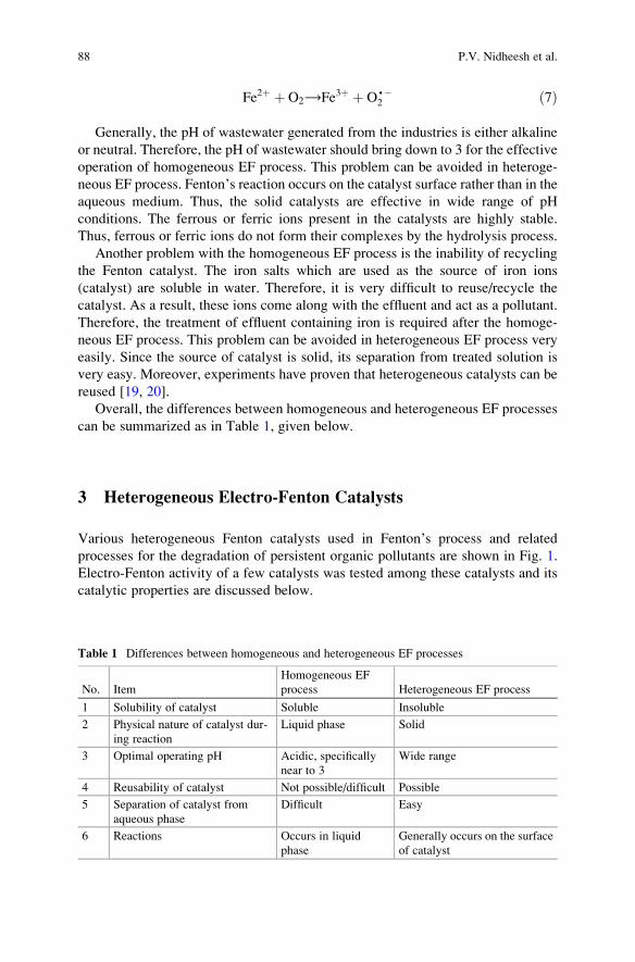
Fe2þ þ O2⟶Fe3þ þ O•�2 ð7Þ
Generally, the pH of wastewater generated from the industries is either alkaline
or neutral. Therefore, the pH of wastewater should bring down to 3 for the effective
operation of homogeneous EF process. This problem can be avoided in heteroge-
neous EF process. Fenton’s reaction occurs on the catalyst surface rather than in the
aqueous medium. Thus, the solid catalysts are effective in wide range of pH
conditions. The ferrous or ferric ions present in the catalysts are highly stable.
Thus, ferrous or ferric ions do not form their complexes by the hydrolysis process.
Another problem with the homogeneous EF process is the inability of recycling
the Fenton catalyst. The iron salts which are used as the source of iron ions
(catalyst) are soluble in water. Therefore, it is very difficult to reuse/recycle the
catalyst. As a result, these ions come along with the effluent and act as a pollutant.
Therefore, the treatment of effluent containing iron is required after the homoge-
neous EF process. This problem can be avoided in heterogeneous EF process very
easily. Since the source of catalyst is solid, its separation from treated solution is
very easy. Moreover, experiments have proven that heterogeneous catalysts can be
reused [19, 20].
Overall, the differences between homogeneous and heterogeneous EF processes
can be summarized as in Table 1, given below.
3 Heterogeneous Electro-Fenton Catalysts
Various heterogeneous Fenton catalysts used in Fenton’s process and related
processes for the degradation of persistent organic pollutants are shown in Fig. 1.
Electro-Fenton activity of a few catalysts was tested among these catalysts and its
catalytic properties are discussed below.
Table 1 Differences between homogeneous and heterogeneous EF processes
No. Item
Homogeneous EF
process Heterogeneous EF process
1 Solubility of catalyst Soluble Insoluble
2 Physical nature of catalyst dur-
ing reaction
Liquid phase Solid
3 Optimal operating pH Acidic, specifically
near to 3
Wide range
4 Reusability of catalyst Not possible/difficult Possible
5 Separation of catalyst from
aqueous phase
Difficult Easy
6 Reactions Occurs in liquid
phase
Generally occurs on the surface
of catalyst
88 P.V. Nidheesh et al.
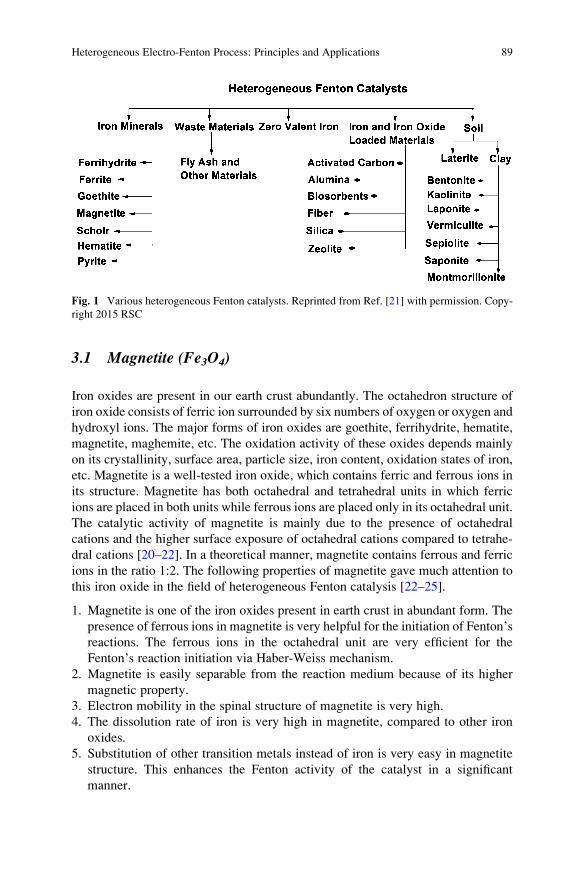
3.1 Magnetite (Fe3O4)
Iron oxides are present in our earth crust abundantly. The octahedron structure of
iron oxide consists of ferric ion surrounded by six numbers of oxygen or oxygen and
hydroxyl ions. The major forms of iron oxides are goethite, ferrihydrite, hematite,
magnetite, maghemite, etc. The oxidation activity of these oxides depends mainly
on its crystallinity, surface area, particle size, iron content, oxidation states of iron,
etc. Magnetite is a well-tested iron oxide, which contains ferric and ferrous ions in
its structure. Magnetite has both octahedral and tetrahedral units in which ferric
ions are placed in both units while ferrous ions are placed only in its octahedral unit.
The catalytic activity of magnetite is mainly due to the presence of octahedral
cations and the higher surface exposure of octahedral cations compared to tetrahe-
dral cations [20–22]. In a theoretical manner, magnetite contains ferrous and ferric
ions in the ratio 1:2. The following properties of magnetite gave much attention to
this iron oxide in the field of heterogeneous Fenton catalysis [22–25].
1. Magnetite is one of the iron oxides present in earth crust in abundant form. The
presence of ferrous ions in magnetite is very helpful for the initiation of Fenton’sreactions. The ferrous ions in the octahedral unit are very efficient for the
Fenton’s reaction initiation via Haber-Weiss mechanism.
2. Magnetite is easily separable from the reaction medium because of its higher
magnetic property.
3. Electron mobility in the spinal structure of magnetite is very high.
4. The dissolution rate of iron is very high in magnetite, compared to other iron
oxides.
5. Substitution of other transition metals instead of iron is very easy in magnetite
structure. This enhances the Fenton activity of the catalyst in a significant
manner.
Fig. 1 Various heterogeneous Fenton catalysts. Reprinted from Ref. [21] with permission. Copy-
right 2015 RSC
Heterogeneous Electro-Fenton Process: Principles and Applications 89
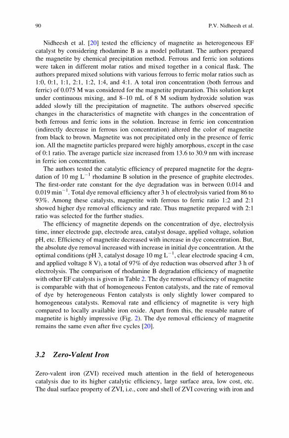
Nidheesh et al. [20] tested the efficiency of magnetite as heterogeneous EF
catalyst by considering rhodamine B as a model pollutant. The authors prepared
the magnetite by chemical precipitation method. Ferrous and ferric ion solutions
were taken in different molar ratios and mixed together in a conical flask. The
authors prepared mixed solutions with various ferrous to ferric molar ratios such as
1:0, 0:1, 1:1, 2:1, 1:2, 1:4, and 4:1. A total iron concentration (both ferrous and
ferric) of 0.075 M was considered for the magnetite preparation. This solution kept
under continuous mixing, and 8–10 mL of 8 M sodium hydroxide solution was
added slowly till the precipitation of magnetite. The authors observed specific
changes in the characteristics of magnetite with changes in the concentration of
both ferrous and ferric ions in the solution. Increase in ferric ion concentration
(indirectly decrease in ferrous ion concentration) altered the color of magnetite
from black to brown. Magnetite was not precipitated only in the presence of ferric
ion. All the magnetite particles prepared were highly amorphous, except in the case
of 0:1 ratio. The average particle size increased from 13.6 to 30.9 nm with increase
in ferric ion concentration.
The authors tested the catalytic efficiency of prepared magnetite for the degra-
dation of 10 mg L�1 rhodamine B solution in the presence of graphite electrodes.
The first-order rate constant for the dye degradation was in between 0.014 and
0.019 min�1. Total dye removal efficiency after 3 h of electrolysis varied from 86 to
93%. Among these catalysts, magnetite with ferrous to ferric ratio 1:2 and 2:1
showed higher dye removal efficiency and rate. Thus magnetite prepared with 2:1
ratio was selected for the further studies.
The efficiency of magnetite depends on the concentration of dye, electrolysis
time, inner electrode gap, electrode area, catalyst dosage, applied voltage, solution
pH, etc. Efficiency of magnetite decreased with increase in dye concentration. But,
the absolute dye removal increased with increase in initial dye concentration. At the
optimal conditions (pH 3, catalyst dosage 10 mg L�1, clear electrode spacing 4 cm,
and applied voltage 8 V), a total of 97% of dye reduction was observed after 3 h of
electrolysis. The comparison of rhodamine B degradation efficiency of magnetite
with other EF catalysts is given in Table 2. The dye removal efficiency of magnetite
is comparable with that of homogeneous Fenton catalysts, and the rate of removal
of dye by heterogeneous Fenton catalysts is only slightly lower compared to
homogeneous catalysts. Removal rate and efficiency of magnetite is very high
compared to locally available iron oxide. Apart from this, the reusable nature of
magnetite is highly impressive (Fig. 2). The dye removal efficiency of magnetite
remains the same even after five cycles [20].
3.2 Zero-Valent Iron
Zero-valent iron (ZVI) received much attention in the field of heterogeneous
catalysis due to its higher catalytic efficiency, large surface area, low cost, etc.
The dual surface property of ZVI, i.e., core and shell of ZVI covering with iron and
90 P.V. Nidheesh et al.
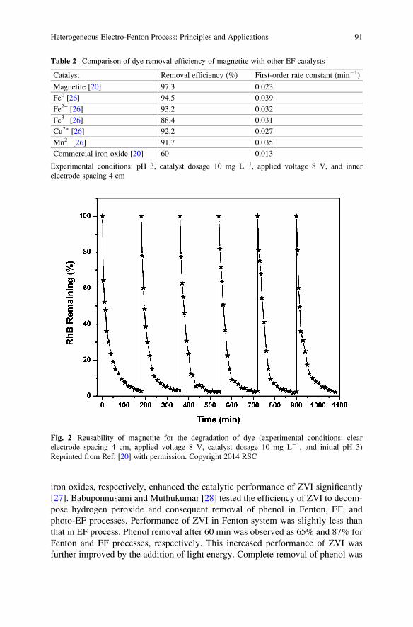
iron oxides, respectively, enhanced the catalytic performance of ZVI significantly
[27]. Babuponnusami and Muthukumar [28] tested the efficiency of ZVI to decom-
pose hydrogen peroxide and consequent removal of phenol in Fenton, EF, and
photo-EF processes. Performance of ZVI in Fenton system was slightly less than
that in EF process. Phenol removal after 60 min was observed as 65% and 87% for
Fenton and EF processes, respectively. This increased performance of ZVI was
further improved by the addition of light energy. Complete removal of phenol was
Table 2 Comparison of dye removal efficiency of magnetite with other EF catalysts
Catalyst Removal efficiency (%) First-order rate constant (min�1)
Magnetite [20] 97.3 0.023
Fe0 [26] 94.5 0.039
Fe2+ [26] 93.2 0.032
Fe3+ [26] 88.4 0.031
Cu2+ [26] 92.2 0.027
Mn2+ [26] 91.7 0.035
Commercial iron oxide [20] 60 0.013
Experimental conditions: pH 3, catalyst dosage 10 mg L�1, applied voltage 8 V, and inner
electrode spacing 4 cm
Fig. 2 Reusability of magnetite for the degradation of dye (experimental conditions: clear
electrode spacing 4 cm, applied voltage 8 V, catalyst dosage 10 mg L�1, and initial pH 3)
Reprinted from Ref. [20] with permission. Copyright 2014 RSC
Heterogeneous Electro-Fenton Process: Principles and Applications 91
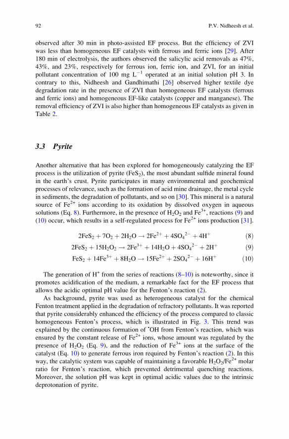
observed after 30 min in photo-assisted EF process. But the efficiency of ZVI
was less than homogeneous EF catalysts with ferrous and ferric ions [29]. After
180 min of electrolysis, the authors observed the salicylic acid removals as 47%,
43%, and 23%, respectively for ferrous ion, ferric ion, and ZVI, for an initial
pollutant concentration of 100 mg L�1 operated at an initial solution pH 3. In
contrary to this, Nidheesh and Gandhimathi [26] observed higher textile dye
degradation rate in the presence of ZVI than homogeneous EF catalysts (ferrous
and ferric ions) and homogeneous EF-like catalysts (copper and manganese). The
removal efficiency of ZVI is also higher than homogeneous EF catalysts as given in
Table 2.
3.3 Pyrite
Another alternative that has been explored for homogeneously catalyzing the EF
process is the utilization of pyrite (FeS2), the most abundant sulfide mineral found
in the earth’s crust. Pyrite participates in many environmental and geochemical
processes of relevance, such as the formation of acid mine drainage, the metal cycle
in sediments, the degradation of pollutants, and so on [30]. This mineral is a natural
source of Fe2+ ions according to its oxidation by dissolved oxygen in aqueous
solutions (Eq. 8). Furthermore, in the presence of H2O2 and Fe3+, reactions (9) and
(10) occur, which results in a self-regulated process for Fe2+ ions production [31].
2FeS2 þ 7O2 þ 2H2O ! 2Fe2þ þ 4SO42� þ 4Hþ ð8Þ
2FeS2 þ 15H2O2 ! 2Fe3þ þ 14H2Oþ 4SO42� þ 2Hþ ð9Þ
FeS2 þ 14Fe3þ þ 8H2O ! 15Fe2þ þ 2SO42� þ 16Hþ ð10Þ
The generation of H+ from the series of reactions (8–10) is noteworthy, since it
promotes acidification of the medium, a remarkable fact for the EF process that
allows the acidic optimal pH value for the Fenton’s reaction (2).
As background, pyrite was used as heterogeneous catalyst for the chemical
Fenton treatment applied in the degradation of refractory pollutants. It was reported
that pyrite considerably enhanced the efficiency of the process compared to classic
homogeneous Fenton’s process, which is illustrated in Fig. 3. This trend was
explained by the continuous formation of •OH from Fenton’s reaction, which was
ensured by the constant release of Fe2+ ions, whose amount was regulated by the
presence of H2O2 (Eq. 9), and the reduction of Fe3+ ions at the surface of the
catalyst (Eq. 10) to generate ferrous iron required by Fenton’s reaction (2). In this
way, the catalytic system was capable of maintaining a favorable H2O2/Fe2+ molar
ratio for Fenton’s reaction, which prevented detrimental quenching reactions.
Moreover, the solution pH was kept in optimal acidic values due to the intrinsic
deprotonation of pyrite.
92 P.V. Nidheesh et al.
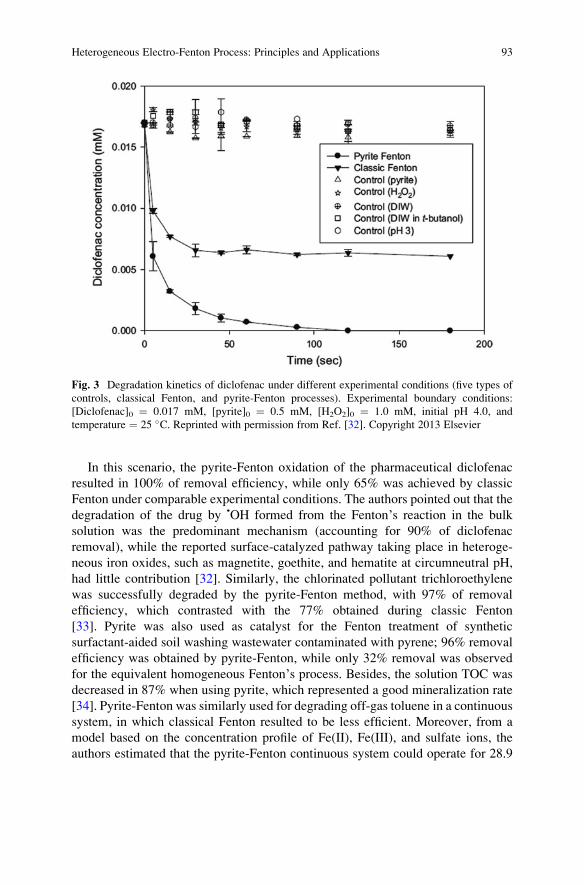
In this scenario, the pyrite-Fenton oxidation of the pharmaceutical diclofenac
resulted in 100% of removal efficiency, while only 65% was achieved by classic
Fenton under comparable experimental conditions. The authors pointed out that the
degradation of the drug by •OH formed from the Fenton’s reaction in the bulk
solution was the predominant mechanism (accounting for 90% of diclofenac
removal), while the reported surface-catalyzed pathway taking place in heteroge-
neous iron oxides, such as magnetite, goethite, and hematite at circumneutral pH,
had little contribution [32]. Similarly, the chlorinated pollutant trichloroethylene
was successfully degraded by the pyrite-Fenton method, with 97% of removal
efficiency, which contrasted with the 77% obtained during classic Fenton
[33]. Pyrite was also used as catalyst for the Fenton treatment of synthetic
surfactant-aided soil washing wastewater contaminated with pyrene; 96% removal
efficiency was obtained by pyrite-Fenton, while only 32% removal was observed
for the equivalent homogeneous Fenton’s process. Besides, the solution TOC was
decreased in 87% when using pyrite, which represented a good mineralization rate
[34]. Pyrite-Fenton was similarly used for degrading off-gas toluene in a continuous
system, in which classical Fenton resulted to be less efficient. Moreover, from a
model based on the concentration profile of Fe(II), Fe(III), and sulfate ions, the
authors estimated that the pyrite-Fenton continuous system could operate for 28.9
Fig. 3 Degradation kinetics of diclofenac under different experimental conditions (five types of
controls, classical Fenton, and pyrite-Fenton processes). Experimental boundary conditions:
[Diclofenac]0 ¼ 0.017 mM, [pyrite]0 ¼ 0.5 mM, [H2O2]0 ¼ 1.0 mM, initial pH 4.0, and
temperature ¼ 25 �C. Reprinted with permission from Ref. [32]. Copyright 2013 Elsevier
Heterogeneous Electro-Fenton Process: Principles and Applications 93
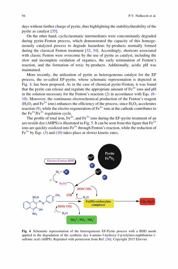
days without further charge of pyrite, thus highlighting the stability/durability of the
pyrite as catalyst [35].
On the other hand, cyclic/aromatic intermediates were concomitantly degraded
during pyrite-Fenton process, which demonstrated the capacity of this homoge-
neously catalyzed process to degrade hazardous by-products normally formed
during the classical Fenton treatment [32, 34]. Accordingly, shortcuts associated
with classic Fenton were overcome by the use of pyrite as catalyst, including the
slow and incomplete oxidation of organics, the early termination of Fenton’sreaction, and the formation of toxic by-products. Additionally, acidic pH was
maintained.
More recently, the utilization of pyrite as heterogeneous catalyst for the EF
process, the so-called EF-pyrite, whose schematic representation is depicted in
Fig. 4, has been proposed. As in the case of chemical pyrite-Fenton, it was found
that the pyrite can release and regulate the appropriate amount of Fe2+ ions and pH
in the solution necessary for the Fenton’s reaction (2) in accordance with Eqs. (8–
10). Moreover, the continuous electrochemical production of the Fenton’s reagent(H2O2 and Fe
2+ ions) enhances the efficiency of the process, since H2O2 accelerates
reaction (9), while the electro-regeneration of Fe2+ ions at the cathode contributes to
the Fe2+/Fe3+ regulation cycle.
The profile of total iron, Fe2+, and Fe3+ ions during the EF-pyrite treatment of an
azo textile dye (AHPS) is illustrated in Fig. 5. It can be seen from this figure that Fe2+
ions are quickly oxidized into Fe3+ through Fenton’s reaction, while the reduction ofFe3+ by Eqs. (3) and (10) takes place at slower kinetic rates.
SO3H
OHNH2
NN
CH3
O2 + 2
2éH2O2
Fe2+
PyriteFeIIS2Fe2+
H+
H+
H+
.OH
BDD(.OH)
BDD(.OH)
é H2O
H2Oé
Electro-Fenton-BDD
Fe(III)-carboxylatecomplexes
SO42-, NO3
-, NH4+
CO2+H2O
Fig. 4 Schematic representation of the heterogeneous EF-Pyrite process with a BDD anode
applied to the degradation of the synthetic dye 4-amino-3-hydroxy-2-p-tolylazo-naphthalene-1-
sulfonic acid (AHPS). Reprinted with permission from Ref. [36]. Copyright 2015 Elsevier
94 P.V. Nidheesh et al.
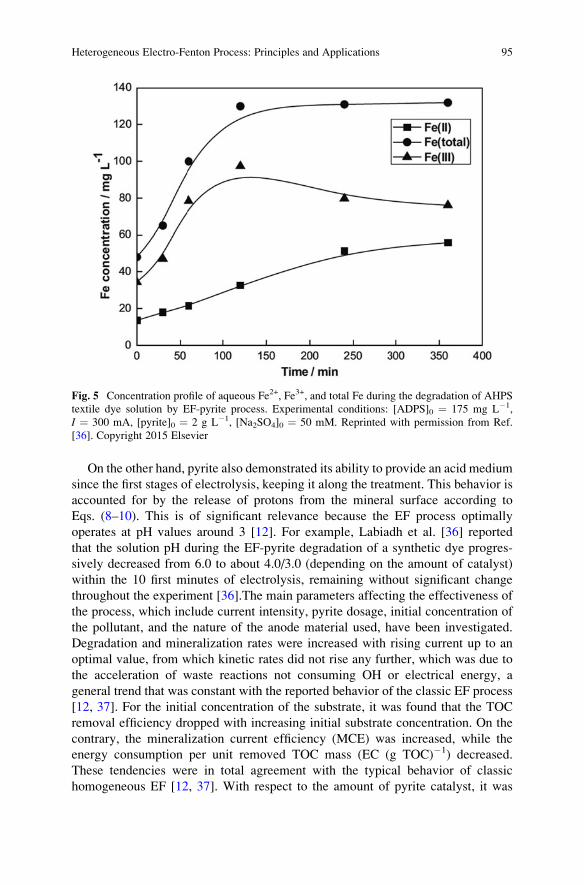
On the other hand, pyrite also demonstrated its ability to provide an acid medium
since the first stages of electrolysis, keeping it along the treatment. This behavior is
accounted for by the release of protons from the mineral surface according to
Eqs. (8–10). This is of significant relevance because the EF process optimally
operates at pH values around 3 [12]. For example, Labiadh et al. [36] reported
that the solution pH during the EF-pyrite degradation of a synthetic dye progres-
sively decreased from 6.0 to about 4.0/3.0 (depending on the amount of catalyst)
within the 10 first minutes of electrolysis, remaining without significant change
throughout the experiment [36].The main parameters affecting the effectiveness of
the process, which include current intensity, pyrite dosage, initial concentration of
the pollutant, and the nature of the anode material used, have been investigated.
Degradation and mineralization rates were increased with rising current up to an
optimal value, from which kinetic rates did not rise any further, which was due to
the acceleration of waste reactions not consuming OH or electrical energy, a
general trend that was constant with the reported behavior of the classic EF process
[12, 37]. For the initial concentration of the substrate, it was found that the TOC
removal efficiency dropped with increasing initial substrate concentration. On the
contrary, the mineralization current efficiency (MCE) was increased, while the
energy consumption per unit removed TOC mass (EC (g TOC)�1) decreased.
These tendencies were in total agreement with the typical behavior of classic
homogeneous EF [12, 37]. With respect to the amount of pyrite catalyst, it was
Fig. 5 Concentration profile of aqueous Fe2+, Fe3+, and total Fe during the degradation of AHPS
textile dye solution by EF-pyrite process. Experimental conditions: [ADPS]0 ¼ 175 mg L�1,
I ¼ 300 mA, [pyrite]0 ¼ 2 g L�1, [Na2SO4]0 ¼ 50 mM. Reprinted with permission from Ref.
[36]. Copyright 2015 Elsevier
Heterogeneous Electro-Fenton Process: Principles and Applications 95
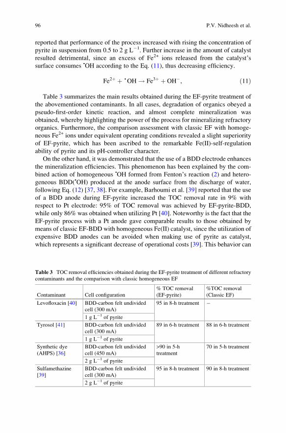
reported that performance of the process increased with rising the concentration of
pyrite in suspension from 0.5 to 2 g L�1. Further increase in the amount of catalyst
resulted detrimental, since an excess of Fe2+ ions released from the catalyst’ssurface consumes •OH according to the Eq. (11), thus decreasing efficiency.
Fe2þ þ • OH ! Fe3þ þ OH�, ð11Þ
Table 3 summarizes the main results obtained during the EF-pyrite treatment of
the abovementioned contaminants. In all cases, degradation of organics obeyed a
pseudo-first-order kinetic reaction, and almost complete mineralization was
obtained, whereby highlighting the power of the process for mineralizing refractory
organics. Furthermore, the comparison assessment with classic EF with homoge-
neous Fe2+ ions under equivalent operating conditions revealed a slight superiority
of EF-pyrite, which has been ascribed to the remarkable Fe(II)-self-regulation
ability of pyrite and its pH-controller character.
On the other hand, it was demonstrated that the use of a BDD electrode enhances
the mineralization efficiencies. This phenomenon has been explained by the com-
bined action of homogeneous •OH formed from Fenton’s reaction (2) and hetero-
geneous BDD(•OH) produced at the anode surface from the discharge of water,
following Eq. (12) [37, 38]. For example, Barhoumi et al. [39] reported that the use
of a BDD anode during EF-pyrite increased the TOC removal rate in 9% with
respect to Pt electrode: 95% of TOC removal was achieved by EF-pyrite-BDD,
while only 86% was obtained when utilizing Pt [40]. Noteworthy is the fact that the
EF-pyrite process with a Pt anode gave comparable results to those obtained by
means of classic EF-BDD with homogeneous Fe(II) catalyst, since the utilization of
expensive BDD anodes can be avoided when making use of pyrite as catalyst,
which represents a significant decrease of operational costs [39]. This behavior can
Table 3 TOC removal efficiencies obtained during the EF-pyrite treatment of different refractory
contaminants and the comparison with classic homogeneous EF
Contaminant Cell configuration
% TOC removal
(EF-pyrite)
%TOC removal
(Classic EF)
Levofloxacin [40] BDD-carbon felt undivided
cell (300 mA)
95 in 8-h treatment �
1 g L�1 of pyrite
Tyrosol [41] BDD-carbon felt undivided
cell (300 mA)
89 in 6-h treatment 88 in 6-h treatment
1 g L�1 of pyrite
Synthetic dye
(AHPS) [36]
BDD-carbon felt undivided
cell (450 mA)
>90 in 5-h
treatment
70 in 5-h treatment
2 g L�1 of pyrite
Sulfamethazine
[39]
BDD-carbon felt undivided
cell (300 mA)
95 in 8-h treatment 90 in 8-h treatment
2 g L�1 of pyrite
96 P.V. Nidheesh et al.
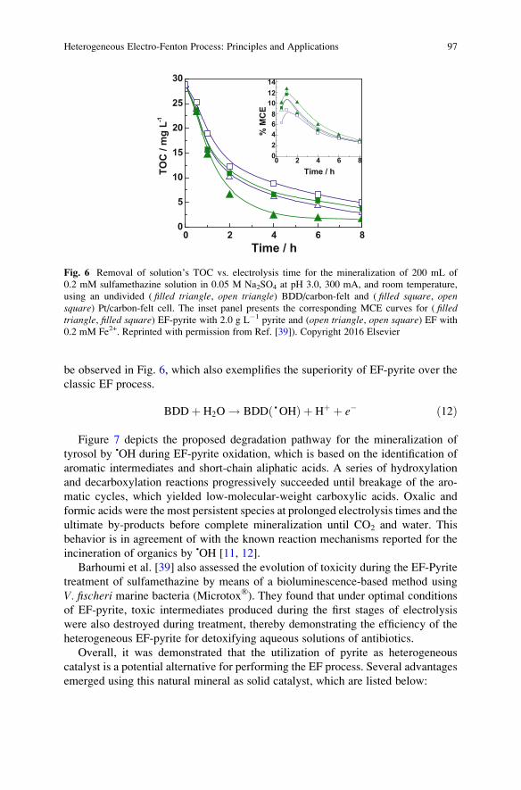
be observed in Fig. 6, which also exemplifies the superiority of EF-pyrite over the
classic EF process.
BDDþ H2O ! BDD •OHð Þ þ Hþ þ e� ð12Þ
Figure 7 depicts the proposed degradation pathway for the mineralization of
tyrosol by •OH during EF-pyrite oxidation, which is based on the identification of
aromatic intermediates and short-chain aliphatic acids. A series of hydroxylation
and decarboxylation reactions progressively succeeded until breakage of the aro-
matic cycles, which yielded low-molecular-weight carboxylic acids. Oxalic and
formic acids were the most persistent species at prolonged electrolysis times and the
ultimate by-products before complete mineralization until CO2 and water. This
behavior is in agreement of with the known reaction mechanisms reported for the
incineration of organics by •OH [11, 12].
Barhoumi et al. [39] also assessed the evolution of toxicity during the EF-Pyrite
treatment of sulfamethazine by means of a bioluminescence-based method using
V. fischeri marine bacteria (Microtox®). They found that under optimal conditions
of EF-pyrite, toxic intermediates produced during the first stages of electrolysis
were also destroyed during treatment, thereby demonstrating the efficiency of the
heterogeneous EF-pyrite for detoxifying aqueous solutions of antibiotics.
Overall, it was demonstrated that the utilization of pyrite as heterogeneous
catalyst is a potential alternative for performing the EF process. Several advantages
emerged using this natural mineral as solid catalyst, which are listed below:
0 2 4 6 80
5
10
15
20
25
30
0 2 4 6 802468
101214
Time / h
TOC
/ m
g L-1
Time / h
% M
CE
Fig. 6 Removal of solution’s TOC vs. electrolysis time for the mineralization of 200 mL of
0.2 mM sulfamethazine solution in 0.05 M Na2SO4 at pH 3.0, 300 mA, and room temperature,
using an undivided ( filled triangle, open triangle) BDD/carbon-felt and ( filled square, opensquare) Pt/carbon-felt cell. The inset panel presents the corresponding MCE curves for ( filledtriangle, filled square) EF-pyrite with 2.0 g L�1 pyrite and (open triangle, open square) EF with
0.2 mM Fe2+. Reprinted with permission from Ref. [39]). Copyright 2016 Elsevier
Heterogeneous Electro-Fenton Process: Principles and Applications 97
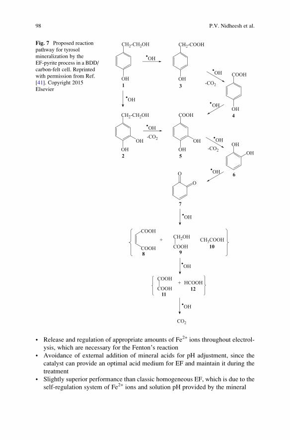
• Release and regulation of appropriate amounts of Fe2+ ions throughout electrol-
ysis, which are necessary for the Fenton’s reaction• Avoidance of external addition of mineral acids for pH adjustment, since the
catalyst can provide an optimal acid medium for EF and maintain it during the
treatment
• Slightly superior performance than classic homogeneous EF, which is due to the
self-regulation system of Fe2+ ions and solution pH provided by the mineral
CH2-CH2OH
OH
CH2-CH2OH
OH
CH2-COOH
OH
OH
COOH
OH
OHOH
OH
O
O
COOH
COOH
COOH
COOH
HCOOH
CH3COOH
1
2
3
5
6
7
12
910
11
8
COOH
OH
4
CO2
OH
OH
OH
OH
OH
OH
OH
OH
OH
-CO2
-CO2
-CO2
OH
.
.
.
..
. .
..
.
+
+
CH2OH
COOH
Fig. 7 Proposed reaction
pathway for tyrosol
mineralization by the
EF-pyrite process in a BDD/
carbon-felt cell. Reprinted
with permission from Ref.
[41]. Copyright 2015
Elsevier
98 P.V. Nidheesh et al.
• High environmental compatibility, which is related to its reusable character and
its pH-controlling ability, which prevents utilization of corrosive acids
3.4 Sludge Containing Iron
Nidheesh and Gandhimathi [42] used sludge produced after the peroxi-coagulation
of real textile wastewater as a heterogeneous EF catalyst for the treatment of the
same textile wastewater. The sludge contains higher amount of iron in the form of
Fe(OH)3, iron(III) oxide-hydroxide (FeO(OH)), FeCl2, Fe2O3, and δ-FeOOH. Afterthe peroxi-coagulation process, the sludge generated in the electrolytic system was
filtered, washed, and dried in oven at 100 �C for 24 h. The sludge was found as an
effective catalyst at the acidic condition. After the completion of 1 h electrolysis,
97% of color, 47% of COD, and 33% of TOC were removed from the textile
wastewater effectively. Mineralization efficiency of this heterogeneous catalyst is
slightly less than that of homogeneous catalyst, even the color removal efficiency of
homogeneous EF process using ferric ion and the heterogeneous EF process is the
same. Color, COD, and TOC removal efficiencies of homogeneous EF process were
observed as 97%, 64%, and 47%, respectively, under the following experimental
conditions: Initial pH 3, applied voltage 7 V, working volume 500 mL, electrode
area 25 cm2, electrode spacing 3 cm, and ferric ion concentration 10 mg L�1. The
lesser mineralization efficiency of heterogeneous EF process compared to homo-
geneous EF process may be due to the lower iron concentration in heterogeneous
EF system compared to homogeneous EF system. In both the cases, catalyst dosage
was considered as 10 mg L�1 and was found to be the optimal value in homoge-
neous system. But, in the case of heterogeneous EF system, the effective iron
concentration should be less than 10 mg L�1 as the solid catalyst contains other
ions along with iron. Thus the dosage added into the solution is insufficient for the
effective mineralization of textile wastewater.
3.5 Iron-Loaded Alginate Beads
Alginate beads are highly porous material, normally in spherical shapes. This
material contains higher concentration of carboxylic groups and can able to form
cross-links with ferric or ferrous ion, when it contacts with iron solution. The make
use of iron-loaded alginate beads is found to be an efficient EF catalyst for the
abatement of indole, a malodorous compound from the aqueous solution [19]. The
porosity of alginate beads was 9.32 m2 g�1 and can able to hold 320 mg g�1 of iron
by cross-linking. By the cross-linking with iron, alginate beads converted to its
egg-box structure. Absolute target pollutant removal was observed by the
researchers at the optimal conditions (catalyst dosage of 200 mg L�1, initial pH
of 3.0, electrolysis time of 60 min, and a current intensity of 0.53 mA cm�2). At the
Heterogeneous Electro-Fenton Process: Principles and Applications 99
same condition and after 7 h of electrolysis, 90% of mineralization efficiency was
also observed. The prepared catalyst was highly reusable and stable in nature. The
authors reused the material for four cycles without iron leaching.
Iglesias et al. [43] tested the efficiency of iron-loaded alginate beads for the
abatement of dyes in continuous flow mode. An airlift glass reactor with a working
volume of 1.5 L was used for the entire study. Reactive Black 5 and Lissamine
Green B dyes were considered as the model dyes. Based on the energy consumption
and dye removal efficiency, applied voltage of 3 V and solution pH of 2 were
considered as optimal and operated the reactor at the same conditions. The working
of the reactor was similar to a continuously stirred tank reactor. Based on the
hydrodynamic and kinetic studies, authors developed a prediction model as given
below:
D ¼ kτ
1þ kτð13Þ
where D is the dye removal efficiency, k is the first-order kinetic rate constant
(min�1), and τ is the residence time (min).
The predicted model showed a good fit with the experimental data [43]. The
standard deviations between theoretical and experimental data were below 6%.
de Dios et al. [44] prepared manganese-loaded alginate beads and verified its
heterogeneous EF catalytic performance by considering several persistent organic
pollutants like Reactive Black 5, imidacloprid, di-2-ethylhexyl phthalate, and
4-nitrophenol. Major studies were carried out by considering Reactive Black 5 as
the target compound. The researchers evaluated the competence of homogeneous
system with heterogeneous system and found that heterogeneous EF-like oxidation
with Mn-loaded alginate beads is more efficient than the homogeneous EF-like
oxidation in the presence of soluble Mn ions. The main problem with homogeneous
system was the insoluble hydroxide formation at the cathode surface. The supple-
ment of chelating compounds rectifies this drawback of homogeneous EF system to
an indicative extent. Citric acid was found to be a good chelating agent due to its
ability to stabilize hydrogen peroxide, to increase the desorption rate of entrapped
pollutant, and to form the complex with metals. The complex formation enhances
the regeneration rate of Fenton catalyst. Authors observed an entire target pollutant
removal; and the prepared catalyst was highly stable and reusable as stated above.
The authors also tested the efficiency of Mn-loaded alginate beads for the degra-
dation of other pollutants such as imidacloprid, di-2-ethylhexyl phthalate, and
4-nitrophenol [44]. After 180 min of electrolysis, 80% of di-2-ethylhexyl phthalate
degradation, complete removal of 4-nitrophenol, and 80% of imidacloprid degra-
dation were observed.
100 P.V. Nidheesh et al.
3.6 Iron-Loaded Carbon
Carbon, especially activated carbon, is a well-known adsorbent widely used for the
removal of dyes, heavy metals, phenols, pesticides, etc. Higher surface area,
sorption capacity, porosity, etc. of activated carbon made the material as popular
adsorbent. The ability of activated carbon for the sorption of heavy metals leads to
the preparation of iron-supported activated carbon catalyst for the abatement of
various organic pollutants via Fenton’s reactions. Nidheesh and Rajan [45] pre-
pared this heterogeneous Fenton catalyst and found that the iron sorption capacity
of activated carbon is in the range of 2.66 g g�1. The iron concentration in the
catalysts was around 62.3%. Bounab et al. [46] used this catalyst for the electrolytic
generation of hydroxyl radicals and for the degradation of m-cresol and tert-
butylhydroquinone. The authors used catalyst with iron concentrations 28 and
46 mg L�1. The authors observed higher catalytic efficiency for the catalyst with
lower iron concentration. The catalyst with iron concentration 28 mg L�1 took
40 min for the complete reduction of m-cresol, while the other catalyst took
120 min for reaching the same efficiency. TOC removal efficiency and energy
consumption also followed the same trend. TOC removal efficiency of the catalyst
with 46 mg L�1 iron after 120 min of electrolysis was 67.3%, while that of catalyst
with 28 mg L�1 of iron was 83%. The energy consumptions for the catalyst with
46 mg L�1 iron and 28 mg L�1 of iron were found as 29.7 kWh kg�1 and
15.1 kWh kg�1, respectively. The rate of degradation of tert-butylhydroquinone
was higher than that of m-cresol. Complete removal of tert-butylhydroquinone was
observed in 20 min of electrolysis.
Zhang et al. [47] used the modified iron–carbon catalyst for the EF oxidation of
2,4-dichlorophenol. Iron–carbon catalysts were dipped in ethanol and carried out
the sonication for 30 min. Then the catalyst was washed twice with ethanol and
dipped in solution containing various concentrations of polytetrafluoroethylene
(PTFE). The modified catalyst was filtered and dried 2 h at 100 �C with N2
protection. After the PTFE treatment, the surface of the catalyst becomes more
compacted with few pores. This was mainly due to the uniform distribution of
PTFE over the surface of catalyst and PTFE reduces the iron leaching from the
catalyst. Iron was distributed over the surface of catalyst in the form of zero-valent
iron and magnetite. The efficiency of the modified catalyst was changed insignif-
icantly after the electrolysis time of 120 min, compared to the original catalyst. The
addition of PTFE reduced the iron leaching from the synthesized catalyst notice-
ably. The iron leaching ratio of raw catalyst was 1.32% after 120 min of electrol-
ysis, while that of the catalysts modified with 20% PTFE was around 0.29%, after
the similar electrolysis time. More than 95% degradation of 2,4-dichlorophenol was
observed after 120 min of electrolysis at initial pH 6.7, current intensity 100 mA,
catalyst loading 6 g L�1.
The authors [47] also monitored the H2O2 and •OH production during the
process and compared with other related processes such as anodic oxidation and
homogeneous EF process. Compared to other processes, the accumulation of H2O2
Heterogeneous Electro-Fenton Process: Principles and Applications 101
in the anodic oxidation was very high. The concentrations of H2O2 after 120 min of
anodic oxidation, homogeneous EF process, and heterogeneous EF process were
found as 517.3 mg L�1, 330 mg L�1, and 370 mg L�1, respectively. The generation
of •OH in the anodic oxidation process was very less. The values of H2O2 and•OH
concentrations indicate the ineffective decomposition of H2O2 in anodic oxidation
process. The concentration of •OH was very high in homogeneous EF process
compared to other processes, which indicates the effective decomposition of
H2O2. But, an insignificant change in the amount of •OH was observed between
60 and 120 min of electrolysis. Compared to homogeneous EF process, the gener-
ation of •OH in heterogeneous EF process was less after 60 min of electrolysis, but
it was very high after 120 min of electrolysis.
The authors [47] tested the application of heterogeneous EF process in real
condition by spiking 120 mg L�1 of 2,4-dichlorophenol in two different wastewa-
ter, which are generated from a chemical industry plant and from an oil treatment
factory. The TOC concentrations of chemical industry and oil treatment factory
wastewater were observed as 81 mg L�1 and 277 mg L�1, respectively. The
reduction of 2,4-dichlorophenol was less in oil treatment factory wastewater com-
pared to chemical industry wastewater. This may be due to the higher competitive
reactions in oil treatment factory wastewater compared to chemical industry
wastewater.
3.7 Iron-Loaded Zeolite
Like activated carbon, zeolite is extensively used as an adsorbent and ion exchange
material. Zeolite can accommodate varieties of cations like potassium, sodium,
calcium, etc. in its structure. Iglesias et al. [48] prepared iron supported Y-zeolite
and investigated its imidacloprid and chlorpyrifos degradation efficiencies. Initial
acid treatment for Y-zeolite was carried out using 0.1 M H2SO4 and used for the
sorption of iron. The iron concentration in zeolite after the sorption process was
found to be 52.21 mg g�1. The prepared catalyst was found to be very effective for
the degradation of pesticides. Initially the authors tested for the degradation of
imidacloprid having initial concentration of 100 mg L�1 at an applied voltage of
5 V and various catalyst dosages. For all conditions, 98% of pesticide removal was
observed after 120 min of electrolysis. Based on the energy consumption, authors
selected lowest catalyst dosage for testing the degradation of chlorpyrifos and
observed 96% removal after 5 min of electrolysis. Sorption of pesticide over the
prepared catalyst was also checked and found the absence of pesticide on the
surface of prepared catalyst.
Inadequacy of pH adjustment for the effective performance is one of the
advantages of this catalyst over other heterogeneous Fenton catalyst. Fenton’sprocess is very effective at pH 3, and most of the case external addition of acid is
required for adjusting the required pH. By the action of acid-treated Y-zeolite
102 P.V. Nidheesh et al.
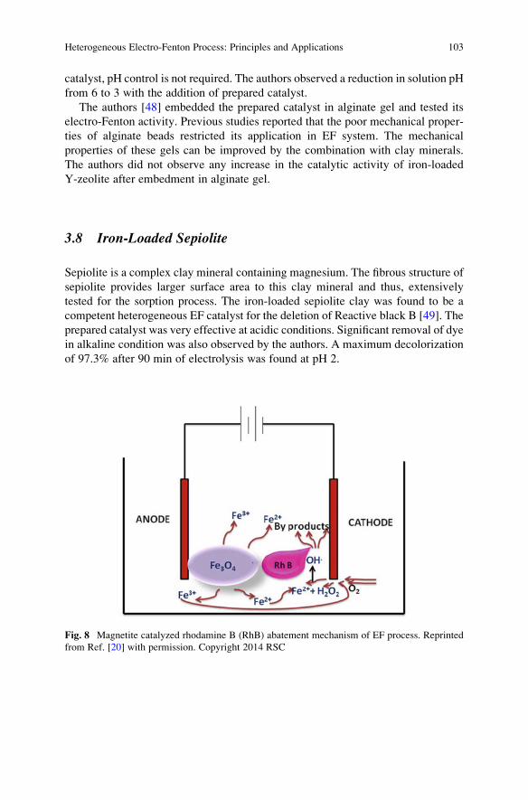
catalyst, pH control is not required. The authors observed a reduction in solution pH
from 6 to 3 with the addition of prepared catalyst.
The authors [48] embedded the prepared catalyst in alginate gel and tested its
electro-Fenton activity. Previous studies reported that the poor mechanical proper-
ties of alginate beads restricted its application in EF system. The mechanical
properties of these gels can be improved by the combination with clay minerals.
The authors did not observe any increase in the catalytic activity of iron-loaded
Y-zeolite after embedment in alginate gel.
3.8 Iron-Loaded Sepiolite
Sepiolite is a complex clay mineral containing magnesium. The fibrous structure of
sepiolite provides larger surface area to this clay mineral and thus, extensively
tested for the sorption process. The iron-loaded sepiolite clay was found to be a
competent heterogeneous EF catalyst for the deletion of Reactive black B [49]. The
prepared catalyst was very effective at acidic conditions. Significant removal of dye
in alkaline condition was also observed by the authors. A maximum decolorization
of 97.3% after 90 min of electrolysis was found at pH 2.
Fig. 8 Magnetite catalyzed rhodamine B (RhB) abatement mechanism of EF process. Reprinted
from Ref. [20] with permission. Copyright 2014 RSC
Heterogeneous Electro-Fenton Process: Principles and Applications 103
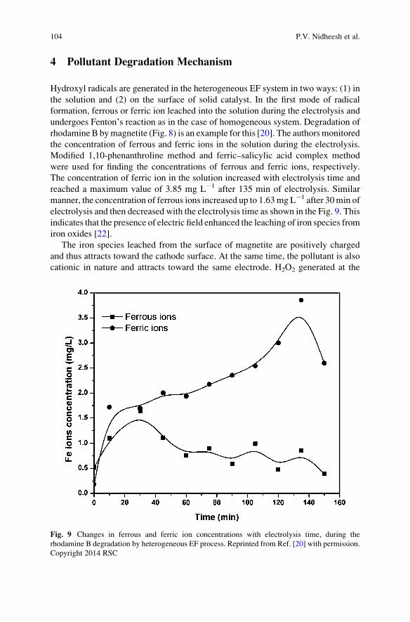
4 Pollutant Degradation Mechanism
Hydroxyl radicals are generated in the heterogeneous EF system in two ways: (1) in
the solution and (2) on the surface of solid catalyst. In the first mode of radical
formation, ferrous or ferric ion leached into the solution during the electrolysis and
undergoes Fenton’s reaction as in the case of homogeneous system. Degradation of
rhodamine B bymagnetite (Fig. 8) is an example for this [20]. The authorsmonitored
the concentration of ferrous and ferric ions in the solution during the electrolysis.
Modified 1,10-phenanthroline method and ferric–salicylic acid complex method
were used for finding the concentrations of ferrous and ferric ions, respectively.
The concentration of ferric ion in the solution increased with electrolysis time and
reached a maximum value of 3.85 mg L�1 after 135 min of electrolysis. Similar
manner, the concentration of ferrous ions increased up to 1.63mgL�1 after 30min of
electrolysis and then decreased with the electrolysis time as shown in the Fig. 9. This
indicates that the presence of electric field enhanced the leaching of iron species from
iron oxides [22].
The iron species leached from the surface of magnetite are positively charged
and thus attracts toward the cathode surface. At the same time, the pollutant is also
cationic in nature and attracts toward the same electrode. H2O2 generated at the
Fig. 9 Changes in ferrous and ferric ion concentrations with electrolysis time, during the
rhodamine B degradation by heterogeneous EF process. Reprinted from Ref. [20] with permission.
Copyright 2014 RSC
104 P.V. Nidheesh et al.

surface of cathode reacts with the leached iron species and produces •OH in the
solution. These radicals degrade the organic pollutants present in the water.
In the second mode of degradation mechanism, the radicals are generated at the
surface of catalyst. In this case, the leaching of the catalyst is insignificant. Thus the
surface of the catalyst is coveredwith iron species. TheH2O2 produced at the cathode
surface dissolves in water and contacts with the catalyst due to the external mixing.
Thus the Fenton’s reaction occurs at the surface of catalyst and produces •OH.
The degradation of persistent organic pollutants by the second method (reactions
occur on the surface of catalyst) may take place in two ways. Researchers proposed
two ways of pollutant degradation mechanism: radical and non-radical mecha-
nisms. Take goethite as an example of heterogeneous Fenton catalyst. Based on
the studies, Lin and Gurol [50] proposed the radical mechanism and Andreozzi
et al. [51] proposed the non-radical mechanism.
According to the radical mechanism of goethite, formation of a precursor surface
complex of hydrogen peroxide on the surface of goethite is the initial reaction
(Eq. 14). Then the surface hydrogen peroxide undergoes a reversible electron
transfer reaction (Eq. 15), which results in the formation of the excited state of
ligands. This excited state is unstable and deactivated by the generation of
hydroperoxyl radical and ferrous ion (Eq. 16). The ferrous ions generated from the
above reactions react with either hydrogen peroxide (Eq. 17) or oxygen (Eq. 18).
The reaction of surface ferrous ionwith oxygen is too slow and can be neglected. The
hydroperoxyl radical decomposes and forms oxygen radicals (Eq. 19). The
hydroperoxyl radical and hydroxyl radicals generated in the system react with
surface ferrous ion (Eq. 20), ferric ion (Eq. 21), and hydrogen peroxide (Eqs. 22
and 23). Finally these radicals react with each other as termination reactions (Eqs. 24
and 25).
� FeIII � OHþ H2O2 , H2O2ð ÞS ð14ÞH2O2ð ÞS ,� FeII O •
2 Hþ H2O ð15Þ� FeII O •
2 H ,� FeII þ HO•2 ð16Þ
� FeII þ H2O2⟶ � FeIII � OHþ HO• þ H2O ð17Þ� FeII þ O2⟶ � FeIII � OH þ HO•
2 ð18ÞHO•
2 , Hþ þ O•�2 ð19Þ
� FeIII � OHþ HO•2 =O
•�2 ⟶ � FeII þ H2O=OH
� þ O2 ð20ÞHO•þ � FeII⟶ � FeIII � OH ð21Þ
HO• þ H2O2ð ÞS⟶ � FeIII � OHþ H2Oþ HO•2 ð22Þ
H2O2ð ÞS þ HO•2 =O
•�2 ⟶ � FeIII � OHþ HO• þ O2 þ H2O=OH
� ð23ÞHO•
2 þ HO•2⟶ H2O2ð ÞS þ O2 ð24Þ
Heterogeneous Electro-Fenton Process: Principles and Applications 105
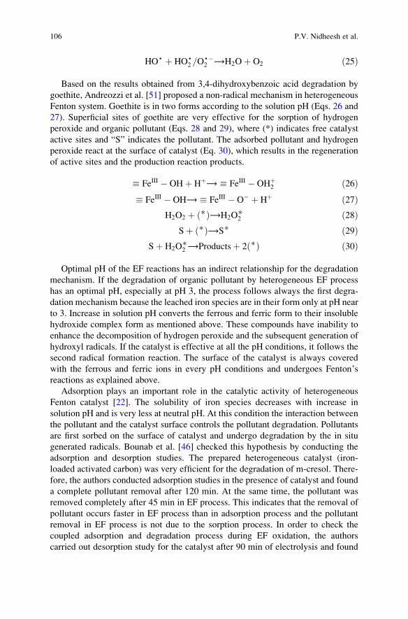
HO• þ HO•2 =O
•�2 ⟶H2Oþ O2 ð25Þ
Based on the results obtained from 3,4-dihydroxybenzoic acid degradation by
goethite, Andreozzi et al. [51] proposed a non-radical mechanism in heterogeneous
Fenton system. Goethite is in two forms according to the solution pH (Eqs. 26 and
27). Superficial sites of goethite are very effective for the sorption of hydrogen
peroxide and organic pollutant (Eqs. 28 and 29), where (*) indicates free catalyst
active sites and “S” indicates the pollutant. The adsorbed pollutant and hydrogen
peroxide react at the surface of catalyst (Eq. 30), which results in the regeneration
of active sites and the production reaction products.
� FeIII � OHþ Hþ⟶ � FeIII � OHþ2 ð26Þ
� FeIII � OH⟶ � FeIII � O� þ Hþ ð27ÞH2O2 þ ∗ð Þ⟶H2O
∗2 ð28Þ
Sþ ∗ð Þ⟶S∗ ð29ÞSþ H2O
∗2 ⟶Productsþ 2 ∗ð Þ ð30Þ
Optimal pH of the EF reactions has an indirect relationship for the degradation
mechanism. If the degradation of organic pollutant by heterogeneous EF process
has an optimal pH, especially at pH 3, the process follows always the first degra-
dation mechanism because the leached iron species are in their form only at pH near
to 3. Increase in solution pH converts the ferrous and ferric form to their insoluble
hydroxide complex form as mentioned above. These compounds have inability to
enhance the decomposition of hydrogen peroxide and the subsequent generation of
hydroxyl radicals. If the catalyst is effective at all the pH conditions, it follows the
second radical formation reaction. The surface of the catalyst is always covered
with the ferrous and ferric ions in every pH conditions and undergoes Fenton’sreactions as explained above.
Adsorption plays an important role in the catalytic activity of heterogeneous
Fenton catalyst [22]. The solubility of iron species decreases with increase in
solution pH and is very less at neutral pH. At this condition the interaction between
the pollutant and the catalyst surface controls the pollutant degradation. Pollutants
are first sorbed on the surface of catalyst and undergo degradation by the in situ
generated radicals. Bounab et al. [46] checked this hypothesis by conducting the
adsorption and desorption studies. The prepared heterogeneous catalyst (iron-
loaded activated carbon) was very efficient for the degradation of m-cresol. There-
fore, the authors conducted adsorption studies in the presence of catalyst and found
a complete pollutant removal after 120 min. At the same time, the pollutant was
removed completely after 45 min in EF process. This indicates that the removal of
pollutant occurs faster in EF process than in adsorption process and the pollutant
removal in EF process is not due to the sorption process. In order to check the
coupled adsorption and degradation process during EF oxidation, the authors
carried out desorption study for the catalyst after 90 min of electrolysis and found
106 P.V. Nidheesh et al.
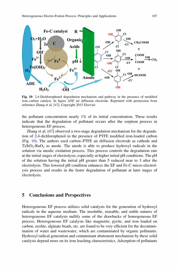
the pollutant concentration nearly 1% of its initial concentration. These results
indicate that the degradation of pollutant occurs after the sorption process in
heterogeneous EF process.
Zhang et al. [47] observed a two-stage degradation mechanism for the degrada-
tion of 2,4-dichlorophenol in the presence of PTFE modified iron-loaded carbon
(Fig. 10). The authors used carbon–PTFE air diffusion electrode as cathode and
Ti/IrO2-RuO2 as anode. The anode is able to produce hydroxyl radicals in the
solution via anodic oxidation process. This process controls the degradation rate
at the initial stages of electrolysis, especially at higher initial pH conditions. The pH
of the solution having the initial pH greater than 5 reduced near to 3 after the
electrolysis. This lowered pH condition enhances the EF and Fe-C micro-electrol-
ysis process and results in the faster degradation of pollutant at later stages of
electrolysis.
5 Conclusions and Perspectives
Heterogeneous EF process utilizes solid catalysts for the generation of hydroxyl
radicals in the aqueous medium. The insoluble, reusable, and stable natures of
heterogeneous EF catalysts nullify some of the drawbacks of homogeneous EF
process. Heterogeneous EF catalysts like magnetite, pyrite, and iron loaded on
carbon, zeolite, alginate beads, etc. are found to be very efficient for the decontam-
ination of water and wastewater, which are contaminated by organic pollutants.
Hydroxyl radical generation and contaminant abatement mechanism by these solid
catalysts depend more on its iron leaching characteristics. Adsorption of pollutants
Fig. 10 2,4-Dichlorophenol degradation mechanism and pathway in the presence of modified
iron–carbon catalyst. In figure ADE air diffusion electrode. Reprinted with permission from
reference Zhang et al. [47], Copyright 2015 Elsevier
Heterogeneous Electro-Fenton Process: Principles and Applications 107
over the surface of solid catalysts also plays the major role for the effective
degradation of organic pollutants.
Even though, these solid catalysts are very efficient for the removal/mineraliza-
tion of persistent organic pollutants in synthetic water medium, although real field
application of these catalysts are not yet tested in detail. Since, these catalysts are
solid in nature, real field implementation of heterogeneous EF process is a great
challenge. Real field water and wastewater contain several ions other than the target
pollutants. These ions may cause the deactivation of catalyst and reduce the
efficiency in a significant manner. Deactivation of heterogeneous catalyst in
water medium occurs mainly via poisoning, thermal degradation, fouling, etc.
These deactivation mechanisms reduced the effective active sites of heterogeneous
catalyst. In some of the cases, the adsorbed or deposited ions over the heteroge-
neous catalysts may act as a barrier for the effective contact between catalyst and
hydrogen peroxide.
Leaching of iron ions is one of the radical formation mechanisms as in the case
of magnetite. This continuous leaching of ions in the presence of electric field is
responsible for the higher reusability nature of magnetite as observed in Fig. 2. Due
to the higher leaching of ferrous and ferric ions to the water medium, the magnetite
surface is always active and fresh during the reaction and after the reactions as that
of newly prepared magnetite. Thus, these types of catalyst are highly reusable with
a reduction in its initial weight. But, in the real field application, the adsorbed or
deposited ions over the surface of the heterogeneous catalyst prevent the effective
leaching of ions.
References
1. Oturan MA, Pinson J (1995) Hydroxylation by electrochemically generated OH radicals.
Mono – and polyhydroxylation of benzoic acid: products and isomers distribution. J Phys
Chem 99:13948–13954
2. Oturan MA, Peiroten J, Chartrin P, Acher AJ (2000) Complete destruction of p-nitrophenol in
aqueous medium by electro-Fenton method. Environ Sci Technol 34:3474–3479
3. Oturan MA (2000) Ecologically effective water treatment technique using electrochemically
generated hydroxyl radicals for in situ destruction of organic pollutants: application to
herbicide 2,4-D. J Appl Electrochem 30:475–482
4. Brillas E, Mur E, Casado J (1996) Iron(II) catalysis of the mineralization of aniline using a
carbon-PTFEO 2 - Fed cathode. J Electrochem Soc 143:L49–L53
5. Brillas E, Calpe JC, Casado J (2000) Mineralization of 2,4-D by advanced electrochemical
oxidation processes. Water Res 34:2253–2262
6. Oturan MA, Oturan N, Lahitte C, Trevin S (2001) Production of hydroxyl radicals by
electrochemically assisted Fenton’s reagent: application to the mineralization of an organic
micropollutant, pentachlorophenol. J Electroanal Chem 507:96–102
7. Nidheesh PV, Gandhimathi R (2012) Trends in electro-Fenton process for water and waste-
water treatment: an overview. Desalination 299:1–15
8. Nidheesh PV, Gandhimathi R, Sanjini NS (2014) NaHCO3 enhanced Rhodamine B removal
from aqueous solution by graphite-graphite electro Fenton system. Sep Purif Technol
132:568–576
108 P.V. Nidheesh et al.
9. Nidheesh PV, Gandhimathi R, Ramesh ST (2013) Degradation of dyes from aqueous solution
by Fenton processes: a review. Environ Sci Pollut Res 20:2099–2132
10. El-Desoky HS, Ghoneim MM, El-Sheikh R, Zidan NM (2010) Oxidation of Levafix CA
reactive azo-dyes in industrial wastewater of textile dyeing by electro-generated Fenton’sreagent. J Hazard Mater 175:858–865
11. Oturan MA, Aaron J-J (2014) Advanced oxidation processes in water/wastewater treatment:
principles and applications. A review. Crit Rev Environ Sci Technol 44:2577–2641
12. Brillas E, Sires I, Oturan MA (2009) Electro-Fenton process and related electrochemical
technologies based on Fenton’s reaction chemistry. Chem Rev 109:6570–6631
13. Pignatello JJ, Oliveros E, MacKay A (2006) Advanced oxidation processes for organic
contaminant destruction based on the Fenton reaction and related chemistry. Crit Rev Environ
Sci Technol 36:1–84
14. Neyens E, Baeyens J (2003) A review of classic Fenton’s peroxidation as an advanced
oxidation technique. J Hazard Mater 98:33–50
15. Benefield LD, Judkins JF, Weand BL (1982) Process chemistry for water and wastewater
treatment. Prentice-Hall, Englewood Cliffs, NJ
16. Wells CF, SalamMA (1965) Hydrolysis of ferrous ions: a kinetic method for the determination
of the Fe(II) species. Nature 205:690–692
17. Wells CF, Salam MA (1968) The effect of pH on the kinetics of the reaction of iron(II) with
hydrogen peroxide in perchlorate media. J Chem Soc A Inorganic Phys Theor 24–29
18. Magario I, Garcıa Einschlag FS, Rueda EH et al (2012) Mechanisms of radical generation in
the removal of phenol derivatives and pigments using different Fe-based catalytic systems. J
Mol Catal A Chem 352:1–20
19. Hammouda SB, Fourcade F, Assadi A et al (2016) Effective heterogeneous electro-Fenton
process for the degradation of a malodorous compound, indole, using iron loaded alginate
beads as a reusable catalyst. Appl Catal B Environ 182:47–58
20. Nidheesh PV, Gandhimathi R, Velmathi S, Sanjini NS (2014) Magnetite as a heterogeneous
electro Fenton catalyst for the removal of Rhodamine B from aqueous solution. RSC Adv
4:5698–5708
21. Costa RCC, Lelis MFF, Oliveira LC et al (2006) Novel active heterogeneous Fenton system
based on Fe3-xMxO4 (Fe, Co, Mn, Ni): the role of M2+ species on the reactivity towards H2O2
reactions. J Hazard Mater 129:171–178
22. Nidheesh PV (2015) Heterogeneous Fenton catalysts for the abatement of organic pollutants
from aqueous solution: a review. RSC Adv 5:40552–40577
23. Munoz M, de Pedro ZM, Casas JA, Rodriguez JJ (2015) Preparation of magnetite-based
catalysts and their application in heterogeneous Fenton oxidation – a review. Appl Catal B
Environ 176–177:249–265
24. Rahim Pouran S, Abdul Raman AA, Wan Daud WMA (2014) Review on the application of
modified iron oxides as heterogeneous catalysts in Fenton reactions. J Clean Prod 64:24–35
25. Dhakshinamoorthy A, Navalon S, Alvaro M, Garcia H (2012) Metal nanoparticles as hetero-
geneous Fenton catalysts. ChemSusChem 5:46–64
26. Nidheesh PV, Gandhimathi R (2014) Comparative removal of Rhodamine B from aqueous
solution by electro-Fenton and electro-Fenton-like processes. Clean Soil Air Water 42
(6):779–784
27. Sun Y-P, Li X, Cao J et al (2006) Characterization of zero-valent iron nanoparticles. Adv
Colloid Interf Sci 120:47–56
28. Babuponnusami A, Muthukumar K (2012) Removal of phenol by heterogenous photo electro
Fenton-like process using nano-zero valent iron. Sep Purif Technol 98:130–135
29. George SJ, Gandhimathi R, Nidheesh PV, Ramesh ST (2014) Electro-fenton oxidation of
salicylic acid from aqueous solution: batch studies and degradation pathway. Clean Soil Air
Water 42(12):1701–1711
30. Bonnissel-Gissinger P, Alnot M, Ehrhardt JJ, Behra P (1998) Surface oxidation of pyrite as a
function of pH. Environ Sci Technol 32:2839–2845
Heterogeneous Electro-Fenton Process: Principles and Applications 109
31. Pham HT, Kitsuneduka M, Hara J et al (2008) Trichloroethylene transformation by natural
mineral pyrite: the deciding role of oxygen. Environ Sci Technol 42:7470–7475
32. Bae S, Kim D, Lee W (2013) Degradation of diclofenac by pyrite catalyzed Fenton oxidation.
Appl Catal B Environ 134–135:93–102
33. Che H, Bae S, Lee W (2011) Degradation of trichloroethylene by Fenton reaction in pyrite
suspension. J Hazard Mater 185:1355–1361
34. Choi K, Bae S, Lee W (2014) Degradation of pyrene in cetylpyridinium chloride-aided soil
washing wastewater by pyrite Fenton reaction. Chem Eng J 249:34–41
35. Choi K, Bae S, Lee W (2014) Degradation of off-gas toluene in continuous pyrite Fenton
system. J Hazard Mater 280:31–37
36. Labiadh L, Oturan MA, Panizza M et al (2015) Complete removal of AHPS synthetic dye from
water using new electro-fenton oxidation catalyzed by natural pyrite as heterogeneous catalyst.
J Hazard Mater 297:34–41
37. Brillas E, Martınez-Huitle CA (2015) Decontamination of wastewaters containing synthetic
organic dyes by electrochemical methods. An updated review. Appl Catal B Environ
166:603–643
38. Sopaj F, Oturan N, Pinson J et al (2016) Effect of the anode materials on the efficiency of the
electro-Fenton process for the mineralization of the antibiotic sulfamethazine. Appl Catal B
Environ 199:331–341
39. Barhoumi N, Oturan N, Olvera-Vargas H et al (2016) Pyrite as a sustainable catalyst in electro-
Fenton process for improving oxidation of sulfamethazine. Kinetics, mechanism and toxicity
assessment. Water Res 94:52–61
40. Barhoumi N, Labiadh L, Oturan MA et al (2015) Electrochemical mineralization of the
antibiotic levofloxacin by electro-Fenton-pyrite process. Chemosphere 141:250–257
41. Ammar S, Oturan MA, Labiadh L et al (2015) Degradation of tyrosol by a novel electro-
Fenton process using pyrite as heterogeneous source of iron catalyst. Water Res 74:77–87
42. Nidheesh PV, Gandhimathi R (2014) Effect of solution pH on the performance of three
electrolytic advanced oxidation processes for the treatment of textile wastewater and sludge
characteristics. RSC Adv 4:27946–27954
43. Iglesias O, Rosales E, Pazos M, Sanroman MA (2013) Electro-Fenton decolourisation of dyes
in an airlift continuous reactor using iron alginate beads. Environ Sci Pollut Res 20:2252–2261
44. Fernandez de Dios MA, Rosales E, Fernandez-Fernandez M et al (2015) Degradation of
organic pollutants by heterogeneous electro-Fenton process using Mn-alginate composite. J
Chem Technol Biotechnol 90:1439–1447
45. Nidheesh PV, Rajan R (2016) Removal of rhodamine B from a water medium using hydroxyl
and sulphate radicals generated by iron loaded activated carbon. RSC Adv 6:5330–5340
46. Bounab L, Iglesias O, Gonzalez-Romero E et al (2015) Effective heterogeneous electro-
Fenton process of m-cresol with iron loaded activated carbon. RSC Adv 5:31049–31056
47. Zhang C, Zhou M, Ren G et al (2015) Heterogeneous electro-Fenton using modified iron-
carbon as catalyst for 2,4-dichlorophenol degradation: influence factors, mechanism and
degradation pathway. Water Res 70:414–424
48. Iglesias O, de Dios MAF, Tavares T et al (2015) Heterogeneous electro-Fenton treatment:
preparation, characterization and performance in groundwater pesticide removal. J Ind Eng
Chem 27:276–282
49. Iglesias O, Fernandez de Dios MA, Pazos M, Sanroman MA (2013) Using iron-loaded
sepiolite obtained by adsorption as a catalyst in the electro-Fenton oxidation of reactive
black 5. Environ Sci Pollut Res 20:5983–5993
50. Lin S-S, Gurol MD (1998) Catalytic decomposition of hydrogen peroxide on iron oxide:
kinetics, mechanism, and implications. Environ Sci Technol 32:1417–1423
51. Andreozzi R, Caprio V, Marotta R (2002) Oxidation of 3,4-dihydroxybenzoic acid by means
of hydrogen peroxide in aqueous goethite slurry. Water Res 36:2761–2768
110 P.V. Nidheesh et al.
Modified Cathodes with Carbon-Based
Nanomaterials for Electro-Fenton Process
Alireza Khataee and Aliyeh Hasanzadeh
Abstract Electro-Fenton (EF) process is based on the continuous in situ produc-
tion of hydrogen peroxide (H2O2) by a two-electron reduction of oxygen on cathode
and the addition of ferrous ion to generate hydroxyl radical (•OH) at the solution
through Fenton’s reaction in acidic condition. Hence, cathode material has prom-
inent effects on the H2O2 electro-generation efficiency and regeneration of ferrous
ion. Carbonaceous materials are applied as suitable cathode in virtue of being
highly conductive, stable, nontoxic, and commercially available. Besides, modifi-
cation of cathode electrode with carbon-based nanomaterials (e.g., carbon nano-
tubes (CNTs), graphene, mesoporous carbon) can improve the electroactive surface
area and the rate of oxygen mass transfer to the electrode, which increases the H2O2
electro-generation in the EF process. This chapter is to summarize the recent
progress and advances in the modification of cathode electrode with carbon-based
nanomaterials for EF process. The ability of different carbon-based nanomaterials
to electro-generate H2O2 and degradation of pollutants is also discussed briefly.
Keywords Carbon nanomaterials, Carbon nanotubes, Electro-Fenton, Graphene,
Graphene oxide, Hydrogen peroxide, Mesoporous carbon, Reduced graphene oxide
Contents
1 Introduction . . . . . . . . . . . . . . . . . . . . . . . . . . . . . . . . . . . . . . . . . . . . . . . . . . . . . . . . . . . . . . . . . . . . . . . . . . . . . . . . . . 112
2 Modification of Cathodes with Carbon-Based Nanomaterials for EF Process . . . . . . . . . . . . 115
2.1 Carbon Nanotubes . . . . . . . . . . . . . . . . . . . . . . . . . . . . . . . . . . . . . . . . . . . . . . . . . . . . . . . . . . . . . . . . . . . . . 115
2.2 Graphene Family . . . . . . . . . . . . . . . . . . . . . . . . . . . . . . . . . . . . . . . . . . . . . . . . . . . . . . . . . . . . . . . . . . . . . . 120
2.3 Mesoporous Carbons . . . . . . . . . . . . . . . . . . . . . . . . . . . . . . . . . . . . . . . . . . . . . . . . . . . . . . . . . . . . . . . . . . 130
A. Khataee (*) and A. Hasanzadeh
Research Laboratory of Advanced Water and Wastewater Treatment Processes, Department of
Applied Chemistry, Faculty of Chemistry, University of Tabriz, Tabriz, Iran
e-mail: [email protected]
M. Zhou et al. (eds.), Electro-Fenton Process: New Trends and Scale-Up,Hdb Env Chem (2018) 61: 111–144, DOI 10.1007/698_2017_74,© Springer Nature Singapore Pte Ltd. 2017, Published online: 17 Oct 2017
111
3 Conclusion . . . . . . . . . . . . . . . . . . . . . . . . . . . . . . . . . . . . . . . . . . . . . . . . . . . . . . . . . . . . . . . . . . . . . . . . . . . . . . . . . . . 137
References . . . . . . . . . . . . . . . . . . . . . . . . . . . . . . . . . . . . . . . . . . . . . . . . . . . . . . . . . . . . . . . . . . . . . . . . . . . . . . . . . . . . . . . 138
Abbreviations
ACF Activated carbon fiber
AQS Anthraquinone monosulfonate
BDD Boron-doped diamond
CF Carbon felt
CNT Carbon nanotube
CTAB Cetyl trimethyl ammonium bromide
DETA 3-(Trimethoxysilylpropyl) diethylenetriamine
EF Electro-Fenton
ERGO Electrochemical reduction of graphene oxide
GDE Gas diffusion electrode
GO Graphene oxide
HPC Hierarchically porous carbon
MOF Metal-organic framework
MWCNTs Multiwalled carbon nanotubes
OMC Ordered mesoporous carbons
PTFE Polytetrafluoroethylene
rGO Reduced graphene oxide
Rh B Rhodamine B
RVC Reticulated vitreous carbon
SEM Scanning electron microscopy
SWNTs Single-walled nanotubes
TEM Transmission electron microscopy
TOC Total organic carbon
1 Introduction
Electro-Fenton (EF) process is based on the continuous in situ production of
hydrogen peroxide (H2O2) and the addition of Fe2+ ion as a catalyst to generate
hydroxyl radical (•OH) at the solution through Fenton’s reaction in acidic conditionas the following reaction:
Fe2þ þ H2O2 þ Hþ ! Fe3þþ • OHþ H2O ð1Þ
H2O2 can be continuously produced in an electrolytic cell from the two-electron
reduction of oxygen gas at the cathode electrode by reaction (2) (E� ¼ 0.695 V/SHE),
112 A. Khataee and A. Hasanzadeh
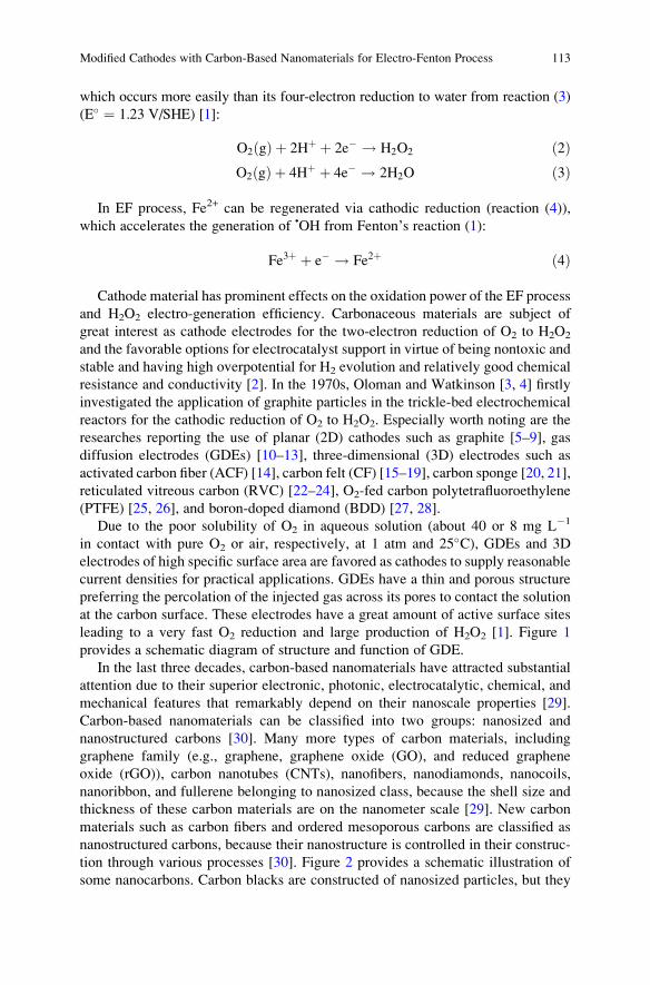
which occurs more easily than its four-electron reduction to water from reaction (3)
(E� ¼ 1.23 V/SHE) [1]:
O2 gð Þ þ 2Hþ þ 2e� ! H2O2 ð2ÞO2 gð Þ þ 4Hþ þ 4e� ! 2H2O ð3Þ
In EF process, Fe2+ can be regenerated via cathodic reduction (reaction (4)),
which accelerates the generation of •OH from Fenton’s reaction (1):
Fe3þ þ e� ! Fe2þ ð4Þ
Cathode material has prominent effects on the oxidation power of the EF process
and H2O2 electro-generation efficiency. Carbonaceous materials are subject of
great interest as cathode electrodes for the two-electron reduction of O2 to H2O2
and the favorable options for electrocatalyst support in virtue of being nontoxic and
stable and having high overpotential for H2 evolution and relatively good chemical
resistance and conductivity [2]. In the 1970s, Oloman and Watkinson [3, 4] firstly
investigated the application of graphite particles in the trickle-bed electrochemical
reactors for the cathodic reduction of O2 to H2O2. Especially worth noting are the
researches reporting the use of planar (2D) cathodes such as graphite [5–9], gas
diffusion electrodes (GDEs) [10–13], three-dimensional (3D) electrodes such as
activated carbon fiber (ACF) [14], carbon felt (CF) [15–19], carbon sponge [20, 21],
reticulated vitreous carbon (RVC) [22–24], O2-fed carbon polytetrafluoroethylene
(PTFE) [25, 26], and boron-doped diamond (BDD) [27, 28].
Due to the poor solubility of O2 in aqueous solution (about 40 or 8 mg L�1
in contact with pure O2 or air, respectively, at 1 atm and 25�C), GDEs and 3D
electrodes of high specific surface area are favored as cathodes to supply reasonable
current densities for practical applications. GDEs have a thin and porous structure
preferring the percolation of the injected gas across its pores to contact the solution
at the carbon surface. These electrodes have a great amount of active surface sites
leading to a very fast O2 reduction and large production of H2O2 [1]. Figure 1
provides a schematic diagram of structure and function of GDE.
In the last three decades, carbon-based nanomaterials have attracted substantial
attention due to their superior electronic, photonic, electrocatalytic, chemical, and
mechanical features that remarkably depend on their nanoscale properties [29].
Carbon-based nanomaterials can be classified into two groups: nanosized and
nanostructured carbons [30]. Many more types of carbon materials, including
graphene family (e.g., graphene, graphene oxide (GO), and reduced graphene
oxide (rGO)), carbon nanotubes (CNTs), nanofibers, nanodiamonds, nanocoils,
nanoribbon, and fullerene belonging to nanosized class, because the shell size and
thickness of these carbon materials are on the nanometer scale [29]. New carbon
materials such as carbon fibers and ordered mesoporous carbons are classified as
nanostructured carbons, because their nanostructure is controlled in their construc-
tion through various processes [30]. Figure 2 provides a schematic illustration of
some nanocarbons. Carbon blacks are constructed of nanosized particles, but they
Modified Cathodes with Carbon-Based Nanomaterials for Electro-Fenton Process 113
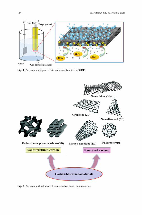
Fig. 2 Schematic illustration of some carbon-based nanomaterials
Fig. 1 Schematic diagram of structure and function of GDE
114 A. Khataee and A. Hasanzadeh
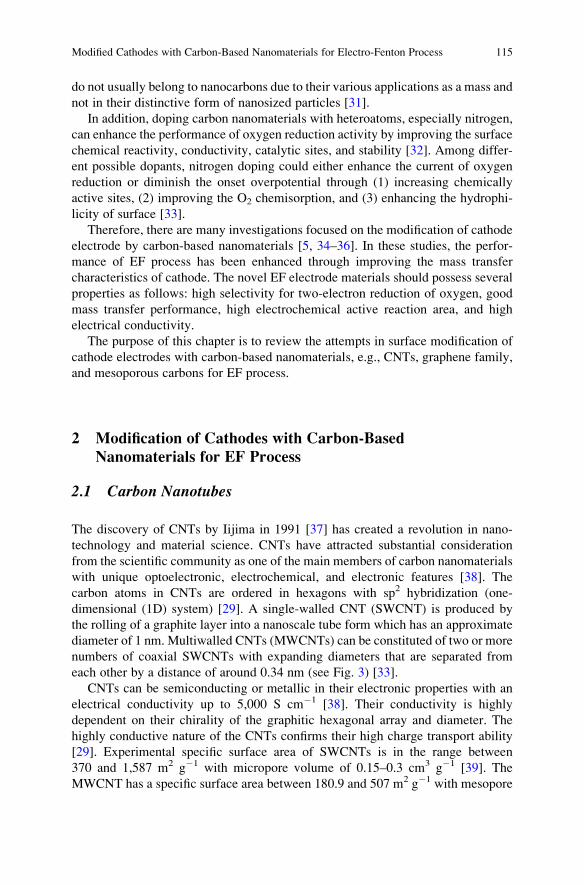
do not usually belong to nanocarbons due to their various applications as a mass and
not in their distinctive form of nanosized particles [31].
In addition, doping carbon nanomaterials with heteroatoms, especially nitrogen,
can enhance the performance of oxygen reduction activity by improving the surface
chemical reactivity, conductivity, catalytic sites, and stability [32]. Among differ-
ent possible dopants, nitrogen doping could either enhance the current of oxygen
reduction or diminish the onset overpotential through (1) increasing chemically
active sites, (2) improving the O2 chemisorption, and (3) enhancing the hydrophi-
licity of surface [33].
Therefore, there are many investigations focused on the modification of cathode
electrode by carbon-based nanomaterials [5, 34–36]. In these studies, the perfor-
mance of EF process has been enhanced through improving the mass transfer
characteristics of cathode. The novel EF electrode materials should possess several
properties as follows: high selectivity for two-electron reduction of oxygen, good
mass transfer performance, high electrochemical active reaction area, and high
electrical conductivity.
The purpose of this chapter is to review the attempts in surface modification of
cathode electrodes with carbon-based nanomaterials, e.g., CNTs, graphene family,
and mesoporous carbons for EF process.
2 Modification of Cathodes with Carbon-Based
Nanomaterials for EF Process
2.1 Carbon Nanotubes
The discovery of CNTs by Iijima in 1991 [37] has created a revolution in nano-
technology and material science. CNTs have attracted substantial consideration
from the scientific community as one of the main members of carbon nanomaterials
with unique optoelectronic, electrochemical, and electronic features [38]. The
carbon atoms in CNTs are ordered in hexagons with sp2 hybridization (one-
dimensional (1D) system) [29]. A single-walled CNT (SWCNT) is produced by
the rolling of a graphite layer into a nanoscale tube form which has an approximate
diameter of 1 nm. Multiwalled CNTs (MWCNTs) can be constituted of two or more
numbers of coaxial SWCNTs with expanding diameters that are separated from
each other by a distance of around 0.34 nm (see Fig. 3) [33].
CNTs can be semiconducting or metallic in their electronic properties with an
electrical conductivity up to 5,000 S cm�1 [38]. Their conductivity is highly
dependent on their chirality of the graphitic hexagonal array and diameter. The
highly conductive nature of the CNTs confirms their high charge transport ability
[29]. Experimental specific surface area of SWCNTs is in the range between
370 and 1,587 m2 g�1 with micropore volume of 0.15–0.3 cm3 g�1 [39]. The
MWCNT has a specific surface area between 180.9 and 507 m2 g�1 with mesopore
Modified Cathodes with Carbon-Based Nanomaterials for Electro-Fenton Process 115
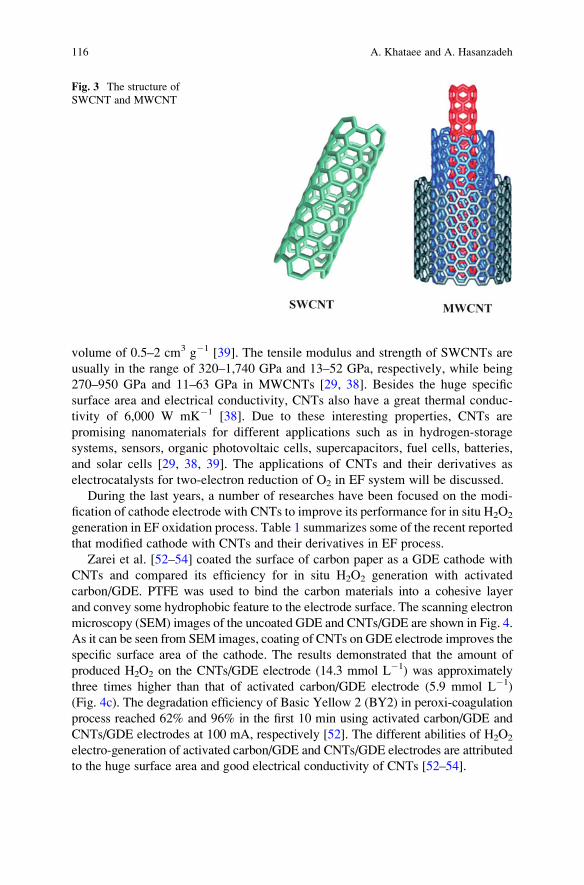
volume of 0.5–2 cm3 g�1 [39]. The tensile modulus and strength of SWCNTs are
usually in the range of 320–1,740 GPa and 13–52 GPa, respectively, while being
270–950 GPa and 11–63 GPa in MWCNTs [29, 38]. Besides the huge specific
surface area and electrical conductivity, CNTs also have a great thermal conduc-
tivity of 6,000 W mK�1 [38]. Due to these interesting properties, CNTs are
promising nanomaterials for different applications such as in hydrogen-storage
systems, sensors, organic photovoltaic cells, supercapacitors, fuel cells, batteries,
and solar cells [29, 38, 39]. The applications of CNTs and their derivatives as
electrocatalysts for two-electron reduction of O2 in EF system will be discussed.
During the last years, a number of researches have been focused on the modi-
fication of cathode electrode with CNTs to improve its performance for in situ H2O2
generation in EF oxidation process. Table 1 summarizes some of the recent reported
that modified cathode with CNTs and their derivatives in EF process.
Zarei et al. [52–54] coated the surface of carbon paper as a GDE cathode with
CNTs and compared its efficiency for in situ H2O2 generation with activated
carbon/GDE. PTFE was used to bind the carbon materials into a cohesive layer
and convey some hydrophobic feature to the electrode surface. The scanning electron
microscopy (SEM) images of the uncoated GDE and CNTs/GDE are shown in Fig. 4.
As it can be seen from SEM images, coating of CNTs on GDE electrode improves the
specific surface area of the cathode. The results demonstrated that the amount of
produced H2O2 on the CNTs/GDE electrode (14.3 mmol L�1) was approximately
three times higher than that of activated carbon/GDE electrode (5.9 mmol L�1)
(Fig. 4c). The degradation efficiency of Basic Yellow 2 (BY2) in peroxi-coagulation
process reached 62% and 96% in the first 10 min using activated carbon/GDE and
CNTs/GDE electrodes at 100 mA, respectively [52]. The different abilities of H2O2
electro-generation of activated carbon/GDE and CNTs/GDE electrodes are attributed
to the huge surface area and good electrical conductivity of CNTs [52–54].
Fig. 3 The structure of
SWCNT and MWCNT
116 A. Khataee and A. Hasanzadeh
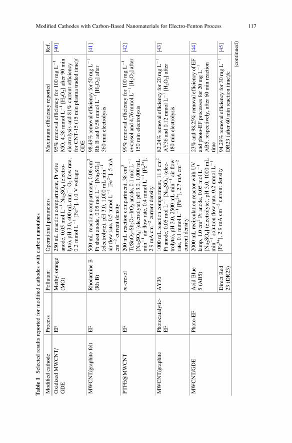
Table
1Selectedresultsreported
formodified
cathodes
withcarbonnanotubes
Modified
cathode
Process
Pollutant
Operational
param
eters
Maxim
um
efficiency
reported
Ref.
Oxidized
MWCNT/
GDE
EF
Methylorange
(MO)
250mLreactioncompartm
ent,Ptwire
anode,0.05molL�1
Na 2SO4(electro-
lyte),pH3.0,400mLmin
�1O2flowrate,
0.2
mmolL�1
[Fe2
+],1.0
Vvoltage
95%
removal
efficiency
for100mgL�1
MO,4.38mmolL�1
[H2O2]after90min
electrolysisand81%
currentefficiency
forCNT-15(15min
plasm
atraded
time)/
GDE
[40]
MWCNT/graphitefelt
EF
Rhodam
ineB
(RhB)
500mLreactioncompartm
ent,0.06cm
2
Ptsheetanode,0.05molL�1
[Na 2SO4]
(electrolyte),pH3.0,1,000mLmin
�1
airflowrate,0.5
mmolL�1[Fe2
+],5mA
cm�2
currentdensity
98.49%
removalefficiency
for50mgL�1
RhBand9.58mmolL�1[H
2O2]after
360min
electrolysis
[41]
PTFE@MWCNT
EF
m-cresol
200mLreactioncompartm
ent,38cm
2
Ti/SnO2–Sb2O5–IrO2anode,0.1
molL�1
[Na 2SO4](electrolyte),pH3.0,1,000mL
min
�1airflowrate,0.4mmolL�1
[Fe2
+],
2.9
mAcm
�2currentdensity
99%
removal
efficiency
for100mgL�1
m-cresoland4.76mmolL�1
[H2O2]after
150min
electrolysis
[42]
MWCNT/graphite
Photocatalytic-
EF
AY36
1000mLreactioncompartm
ent,11.5cm
2
Ptanode,0.05molL�1
[Na 2SO4](elec-
trolyte),pH3.0,2500mLmin
�1airflow
rate,0.1
mmolL�1[Fe2
+],2.7
mAcm
�2
currentdensity
82.24%
removalefficiency
for20mgL�1
AY36and0.12mmolL�1[H
2O2]after
180min
electrolysis
[43]
MWCNT/GDE
Photo-EF
AcidBlue
5(A
B5)
2000mLrecirculationreactorwithUV
lamp,1.0
cm2Ptanode,0.05molL�1
[Na 2SO4](electrolyte),pH3.0,1000mL
min
�1solutionflow
rate,0.2
mmolL�1
[Fe3
+],2.9
mAcm
�2currentdensity
23%
and98.25%
removalefficiency
ofEF
andphoto-EFprocesses
for20mgL�1
AB5,respectively,after60min
reaction
time
[44]
DirectRed
23(D
R23)
94.29%
removalefficiency
for30mgL�1
DR23(after
60min
reactiontime)/c
[45]
(continued)
Modified Cathodes with Carbon-Based Nanomaterials for Electro-Fenton Process 117

Table
1(continued)
Modified
cathode
Process
Pollutant
Operational
param
eters
Maxim
um
efficiency
reported
Ref.
MWCNT-surfactant/
graphite
EF
AcidRed
14(A
R14)
andAcidBlue
92(A
B92)
1000mLcontinuousreactor,26cm
2
graphiteanode,0.05molL�1[N
a 2SO4]
(electrolyte),pH3.0,5.5
mLmin
�1
solutionflowrate,0.1
mmolL�1[Fe3
+],
6.92mAcm
�2currentdensity
99%
and95%
removal
efficiency
for
50mgL�1
AR14andAB92,respec-
tively,after220min
reactiontime
[46]
Heterogeneous-
EF
250mLreactioncompartm
ent,26cm
2
graphiteanode,0.05molL�1[N
a 2SO4]
and[N
aCl](electrolyte),pH3.0,
1.0
gL�1Fe 3O4NPs,6.92mAcm
�2
currentdensity
100%
removal
efficiency
for50mgL�1
AR14andAB92in
NaC
lelectrolyte
solutionafter120min
reactiontime
[47]
Fe-CNT/GDE
EF
–250mLreactioncompartm
ent,11.4
cm2
graphiteanode,0.05molL�1[N
a 2SO4]
(electrolyte),pH3.0,400mLmin
�1O2
flowrate,0.1
mmolL�1
[Fe2
+],�0
.85V
voltage
3.23mmolL�1[H
2O2]after90min
electrolysisand58%
currentefficiency
[48]
N-doped
carbon
nanotubes
(NCNT)/
nickel
foam
(NF)/CNT
EF
p-Nitrophenol
200mLreactioncompartm
ent,2.25cm
2
Ptanode,0.05molL�1[N
a 2SO4](elec-
trolyte),pH3.0,400mLmin
�1airflow
rate,0.4
mmolL�1
[Fe3
+],20mAcm
�2
currentdensity
99%
removalefficiency
for50mgL�1
p-nitrophenoland0.62mmolL�1[H
2O2]
after180min
electrolysis
[49]
Polypyrrole@MWCNT/
graphite
EF
Basic
Blue
41(BB41)
100mLreactioncompartm
ent,10.0
cm2
Ptanodeandcathode,0.1
molL�1
[Na 2SO4](electrolyte),pH3.0,300mL
min
�1airflowrate,2.0mmolL�1
[Fe3
+],
�0.55V(vs.SCE)voltage
About94%
removal
efficiency
for
15mgL�1
BB41,0.16mmolL�1
[H2O2]after10min
electrolysis
[50]
N-CNTs-PTFE
EF
MO
250mLreactioncompartm
ent,Ptwire
anode,0.05molL�1
Na 2SO4(electro-
lyte),pH3.0,400mLmin
�1O2flowrate,
0.2
mmolL�1
[Fe2
+],�0
.85Vvoltage
100%
removal
efficiency
for50mgL�1
MO,4.28mmolL�1
[H2O2]after60min
electrolysisand62%
currentefficiency
[51]
118 A. Khataee and A. Hasanzadeh
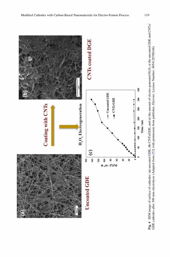
Fig.4
SEM
imageofsurfaceofcathodes:(a)uncoated
GDE,(b)CNTs/GDE,and(c)theam
ountofelectro-generated
H2O2attheuncoated
GDEandCNTs/
GDEcathodes
after300min
electrolysis(A
daptedfrom
[52]withpermissionfrom
publisher,Elsevier.License
Number:4054120708166)
Modified Cathodes with Carbon-Based Nanomaterials for Electro-Fenton Process 119
In another study, graphite electrode was modified by CNTs for treatment of Acid
Yellow 36 (AY36) by photo-EF process [5]. The electro-generated H2O2 concen-
tration using the CNTs/graphite cathode was approximately seven times greater
than that of bare graphite cathode. The decolorization efficiency of AY36 was 31.07
and 70.98% after 120 min of photo-EF treatment for bare graphite and CNTs/
graphite, respectively [5]. Also, graphite electrode was modified with MWCNTs
accompanied by a cationic surfactant (cetyl trimethyl ammonium bromide
(CTAB)) and used as a cathode to degrade two acid dyes by homogeneous and
heterogeneous EF processes [46, 47]. The electrodeposition method was used to
modify the graphite electrode surface, which was performed by applying the DC
voltage to the MWCNTs and CTAB solution. High dye removal efficiency was
achieved when MWCNT/graphite was as the cathode compared to the graphite
electrode (92% against 64% for 50 mg L�1 of dyes), due to the higher electro-
generation of H2O2 on the surface of the MWCNT/graphite cathode [46, 47].
Recently, some studies revealed that the introduction of nitrogen atoms to the
pristine CNT structure can lead to promote the chemical and electrochemical reactiv-
ity of surface for oxygen reduction reaction by the generation of extra electron density
in the graphite lattice [33, 38]. Zhang et al. [51] prepared the nitrogen functionalized
CNT (N-CNT) electrode as a GDE cathode in EF process. In this study, pulsed high
voltage discharge was applied to functionalize MWCNTs in a liquid-gas reactor. The
results showed that among three electrodes including graphite, CNTs, and N-CNTs,
the N-CNT electrode indicated the highest yield of H2O2 formation and faster color
removal in EF process. The amount of generated H2O2 on the graphite, CNT, and
N-CNTelectrodeswere 2.72, 3.06, and 4.28mmolL�1, respectively. Furthermore, the
N-CNT electrode had the greater current efficiency compared to that of CNT elec-
trode. The results confirmed that the nitrogen functionalization did facilitate the
electron transfer to improve the production of H2O2.
Nitrogen-doped MWCNTs (N-CNTs) was also used as the catalyst layer on the
GDE cathode, which was prepared by immobilizing MWCNTs as the diffusion
layer on the surface of nickel foam (NF) as the supporting material [49]. Results
showed that the N-CNT/NF/CNT GDE exhibited higher H2O2 production amount
and greater current efficiency in comparison with the CNT/NF/CNT GDE, conse-
quently, the EF degradation level and total organic carbon (TOC) removal effi-
ciency were higher.
2.2 Graphene Family
Graphene and its derivatives, such as GO, rGO, and few-layer GO, have been
thoroughly investigated since their discovery because of their special physical-
chemical properties [55]. Graphene, GO, and rGO have different morphological
and chemical characteristics as shown in Fig. 5. Pristine graphene consists of a
carbon monoatomic layer, 2D planar sheet of carbon atoms in the sp2 hybridization
state, which are densely organized into a honeycomb array (Fig. 5a) [56]. It was first
120 A. Khataee and A. Hasanzadeh
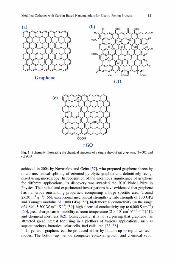
achieved in 2004 by Novoselov and Geim [57], who prepared graphene sheets by
micro-mechanical splitting of oriented pyrolytic graphite and definitively recog-
nized using microscopy. In recognition of the enormous significance of graphene
for different applications, its discovery was awarded the 2010 Nobel Prize in
Physics. Theoretical and experimental investigations have evidenced that graphene
has numerous outstanding properties, comprising a huge specific area (around
2,630 m2 g�1) [55], exceptional mechanical strength (tensile strength of 130 GPa
and Young’s modulus of 1,000 GPa) [58], high thermal conductivity (in the range
of 4,840–5,300 Wm�1 K�1) [59], high electrical conductivity (up to 6,000 S cm�1)
[60], great charge-carrier mobility at room temperature (2� 105 cm2 V�1 s�1) [61],
and chemical inertness [62]. Consequently, it is not surprising that graphene has
attracted great interest for using in a plethora of various applications, such as
supercapacitors, batteries, solar cells, fuel cells, etc. [33, 38].
In general, graphene can be produced either by bottom-up or top-down tech-
niques. The bottom-up method comprises epitaxial growth and chemical vapor
Fig. 5 Schematic illustrating the chemical structure of a single sheet of (a) graphene, (b) GO, and
(c) rGO
Modified Cathodes with Carbon-Based Nanomaterials for Electro-Fenton Process 121
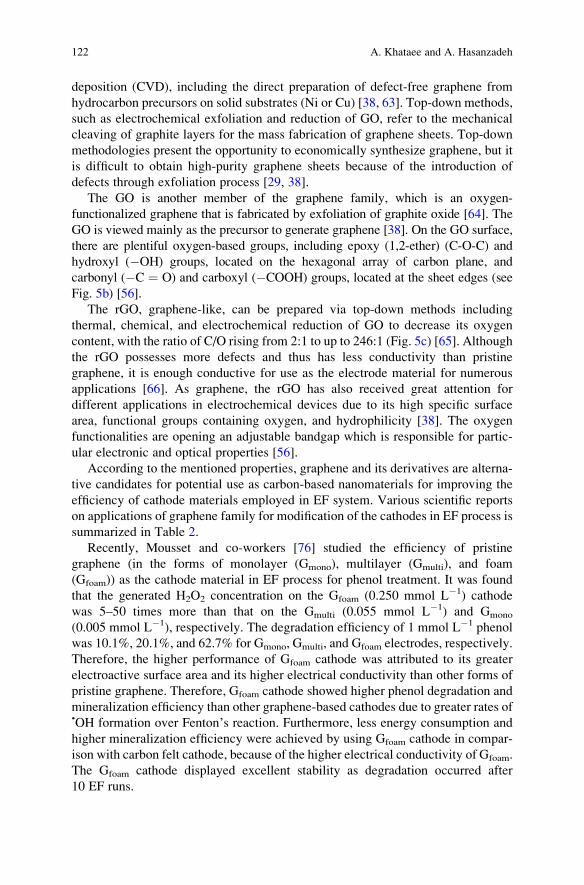
deposition (CVD), including the direct preparation of defect-free graphene from
hydrocarbon precursors on solid substrates (Ni or Cu) [38, 63]. Top-down methods,
such as electrochemical exfoliation and reduction of GO, refer to the mechanical
cleaving of graphite layers for the mass fabrication of graphene sheets. Top-down
methodologies present the opportunity to economically synthesize graphene, but it
is difficult to obtain high-purity graphene sheets because of the introduction of
defects through exfoliation process [29, 38].
The GO is another member of the graphene family, which is an oxygen-
functionalized graphene that is fabricated by exfoliation of graphite oxide [64]. The
GO is viewed mainly as the precursor to generate graphene [38]. On the GO surface,
there are plentiful oxygen-based groups, including epoxy (1,2-ether) (C-O-C) and
hydroxyl (�OH) groups, located on the hexagonal array of carbon plane, and
carbonyl (�C ¼ O) and carboxyl (�COOH) groups, located at the sheet edges (see
Fig. 5b) [56].
The rGO, graphene-like, can be prepared via top-down methods including
thermal, chemical, and electrochemical reduction of GO to decrease its oxygen
content, with the ratio of C/O rising from 2:1 to up to 246:1 (Fig. 5c) [65]. Although
the rGO possesses more defects and thus has less conductivity than pristine
graphene, it is enough conductive for use as the electrode material for numerous
applications [66]. As graphene, the rGO has also received great attention for
different applications in electrochemical devices due to its high specific surface
area, functional groups containing oxygen, and hydrophilicity [38]. The oxygen
functionalities are opening an adjustable bandgap which is responsible for partic-
ular electronic and optical properties [56].
According to the mentioned properties, graphene and its derivatives are alterna-
tive candidates for potential use as carbon-based nanomaterials for improving the
efficiency of cathode materials employed in EF system. Various scientific reports
on applications of graphene family for modification of the cathodes in EF process is
summarized in Table 2.
Recently, Mousset and co-workers [76] studied the efficiency of pristine
graphene (in the forms of monolayer (Gmono), multilayer (Gmulti), and foam
(Gfoam)) as the cathode material in EF process for phenol treatment. It was found
that the generated H2O2 concentration on the Gfoam (0.250 mmol L�1) cathode
was 5–50 times more than that on the Gmulti (0.055 mmol L�1) and Gmono
(0.005 mmol L�1), respectively. The degradation efficiency of 1 mmol L�1 phenol
was 10.1%, 20.1%, and 62.7% for Gmono, Gmulti, and Gfoam electrodes, respectively.
Therefore, the higher performance of Gfoam cathode was attributed to its greater
electroactive surface area and its higher electrical conductivity than other forms of
pristine graphene. Therefore, Gfoam cathode showed higher phenol degradation and
mineralization efficiency than other graphene-based cathodes due to greater rates of•OH formation over Fenton’s reaction. Furthermore, less energy consumption and
higher mineralization efficiency were achieved by using Gfoam cathode in compar-
ison with carbon felt cathode, because of the higher electrical conductivity of Gfoam.
The Gfoam cathode displayed excellent stability as degradation occurred after
10 EF runs.
122 A. Khataee and A. Hasanzadeh
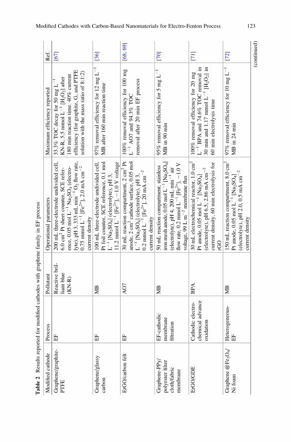
Table
2Resultsreported
formodified
cathodes
withgraphenefamilyin
EFprocess
Modified
cathode
Process
Pollutant
Operational
param
eters
Maxim
um
efficiency
reported
Ref.
Graphene/graphite-
PTFE
EF
Reactivebril-
liantblue
(KN-R)
200mLthree-electrodeundivided
cell,
6.0
cm2Ptsheetcounter,SCErefer-
ence,0.05molL�1Na 2SO4(electro-
lyte),pH3,333mLmin
�1O2flowrate,
0.75mmolL�1[Fe2
+],2.0
mAcm
�2
currentdensity
33.3%
TOCdecay
for50mgL�1
KN-R,5.5
mmolL�1
[H2O2]after
180min
reactiontime.40%
current
efficiency
(forgraphite,G,andPTFE
solutionwiththemassratioof8:1:2)
[67]
Graphene/glassy
carbon
EF
MB
100mLthree-electrodeundivided
cell,
Ptfoilcounter,SCEreference,0.1
mol
L�1
[Na 2SO4](electrolyte),pH3,
11.2
mmolL�1[Fe2
+],�1
.0V
voltage
97%
removalefficiency
for12mgL�1
MBafter160min
reactiontime
[36]
ErG
O/carbonfelt
EF
AO7
30mLreactioncompartm
ent,2cm
2Pt
anode,2cm
2cathodesurface,0.05mol
L�1
[Na 2SO4](electrolyte),pH3,
0.2
mmolL�1
[Fe2
+],20mAcm
�2
currentdensity
100%
removal
efficiency
for100mg
L�1
AO7and94.3%
TOC
removal
after20min
EFprocess
[68,69]
Graphene-PPy/
polyesterfilter
cloth/fabric
mem
brane
EF-cathodic
mem
brane
filtration
MB
50mLreactioncompartm
ent,stainless
ironmeshanode,0.05molL�1[N
a 2SO4]
(electrolyte),pH4,200mLmin�1
air
flowrate,0.2mmolL�1
[Fe2
+],�1
.0V
voltage,99Lm
�2mem
braneflux
95%
removal
efficiency
for5mgL�1
MBin
90min
[70]
ErG
O/GDE
Cathodic
electro-
chem
ical
advance
oxidation
BPA
30mLelectrochem
icalreactor,1.0cm
2
Ptanode,0.05molL�1
[Na 2SO4]
(electrolyte),pH6.5,2.86mAcm
�2
currentdensity,60min
electrolysisfor
rGO
100%
removal
efficiency
for20mg
L�1
BPA
and74.6%
TOC
removal
in
30min
and1.17mmolL�1
[H2O2]in
60min
electrolysistime
[71]
Graphene@Fe 3O4/
Nifoam
Heterogeneous-
EF
MB
150mLreactioncompartm
ent,8.0
cm2
Ptanode,0.05molL�1
[Na 2SO4]
(electrolyte),pH2.0,0.5
mAcm
�2
currentdensity
97%
removalefficiency
for10mgL�1
MBin
24min
[72]
(continued)
Modified Cathodes with Carbon-Based Nanomaterials for Electro-Fenton Process 123
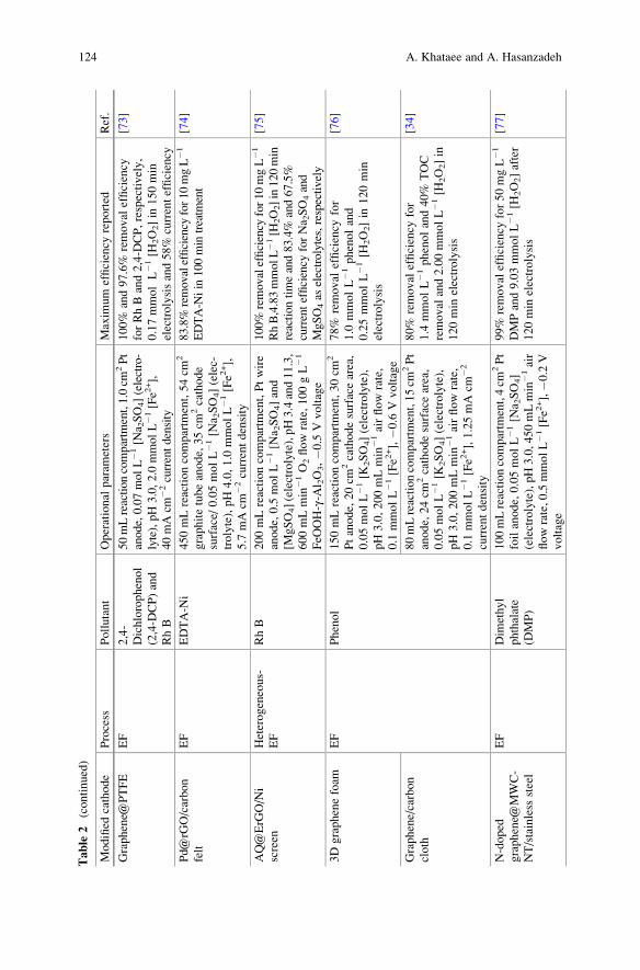
Table
2(continued)
Modified
cathode
Process
Pollutant
Operational
param
eters
Maxim
um
efficiency
reported
Ref.
Graphene@
PTFE
EF
2,4-
Dichlorophenol
(2,4-D
CP)and
RhB
50mLreactioncompartm
ent,1.0cm
2Pt
anode,0.07molL�1[N
a 2SO4](electro-
lyte),pH3.0,2.0
mmolL�1[Fe2
+],
40mAcm
�2currentdensity
100%
and97.6%
removal
efficiency
forRhBand2,4-D
CP,respectively,
0.17mmolL�1
[H2O2]in
150min
electrolysisand58%
currentefficiency
[73]
Pd@rG
O/carbon
felt
EF
EDTA-N
i450mLreactioncompartm
ent,54cm
2
graphitetubeanode,35cm
2cathode
surface/
0.05molL�1
[Na 2SO4](elec-
trolyte),pH4.0,1.0
mmolL�1
[Fe2
+],
5.7
mAcm
�2currentdensity
83.8%
removalefficiency
for10mgL�1
EDTA-N
iin
100min
treatm
ent
[74]
AQ@ErG
O/Ni
screen
Heterogeneous-
EF
RhB
200mLreactioncompartm
ent,Ptwire
anode,0.5
molL�1
[Na 2SO4]and
[MgSO4](electrolyte),pH3.4and11.3,
600mLmin
�1O2flow
rate,100gL�1
FeO
OH-γ-A
l 2O3,�0
.5Vvoltage
100%
removalefficiency
for10mgL�1
RhB,4.83mmolL�1
[H2O2]in120min
reactiontimeand83.4%
and67.5%
currentefficiency
forNa 2SO4and
MgSO4as
electrolytes,respectively
[75]
3Dgraphenefoam
EF
Phenol
150mLreactioncompartm
ent,30cm
2
Ptanode,20cm
2cathodesurfacearea,
0.05molL�1
[K2SO4](electrolyte),
pH3.0,200mLmin
�1airflowrate,
0.1
mmolL�1
[Fe2
+],�0
.6Vvoltage
78%
removal
efficiency
for
1.0
mmolL�1phenoland
0.25mmolL�1
[H2O2]in
120min
electrolysis
[76]
Graphene/carbon
cloth
80mLreactioncompartm
ent,15cm
2Pt
anode,24cm
2cathodesurfacearea,
0.05molL�1
[K2SO4](electrolyte),
pH3.0,200mLmin
�1airflowrate,
0.1
mmolL�1
[Fe2
+],1.25mAcm
�2
currentdensity
80%
removal
efficiency
for
1.4
mmolL�1phenoland40%
TOC
removal
and2.00mmolL�1
[H2O2]in
120min
electrolysis
[34]
N-doped
graphene@
MWC-
NT/stainless
steel
EF
Dim
ethyl
phthalate
(DMP)
100mLreactioncompartm
ent,4cm
2Pt
foilanode,0.05molL�1
[Na 2SO4]
(electrolyte),pH3.0,450mLmin
�1air
flowrate,0.5mmolL�1[Fe2
+],�0
.2V
voltage
99%
removalefficiency
for50mgL�1
DMPand9.03mmolL�1[H
2O2]after
120min
electrolysis
[77]
124 A. Khataee and A. Hasanzadeh
CeO
2/rGO
EF
Ciprofloxacin
(CIP)
250mLreactioncompartm
ent,0.5
cm2
Ptanode,24cm
2cathodesurfacearea,
0.05molL�1
[Na 2SO4](electrolyte),
pH3.0,100mLmin
�1O2flow
rate,
0.1
mmolL�1
[Fe2
+],53.3
mAcm
�2
currentdensity
90.97%
removal
efficiency
for
50mgL�1CIP
in6.5
htreatm
ent
[78]
Ce 0
.75Zr 0.25O2/rGO
100%
removalefficiency
for50mgL�1
CIP
in5htreatm
ent
[79]
Quinone@
graphen-
e@Fe 3O4/carbon
cloth
Heterogeneous-
EF
BPA
60mLundivided
cylindricalcell,
10.0
cm2Ptanode,10.0
cm2cathode
surfacearea,Ag/AgClreference
elec-
trode,0.05molL�1
[Na 2SO4](electro-
lyte),pH3.0,1000mLmin
�1airflow
rate,�2
.4Vvoltage
100%
removalefficiency
for5mgL�1
BPAin
90min
treatm
entand
4.37mmolL�1
[H2O2]at
pH
3
[80]
Modified Cathodes with Carbon-Based Nanomaterials for Electro-Fenton Process 125
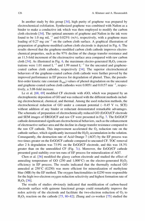
In another study by this group [34], high purity of graphene was prepared by
electrochemical exfoliation. Synthesized graphene was combined with Nafion as a
binder to make a conductive ink which was then employed to modify the carbon
cloth electrode [34]. The optimal amounts of graphene and Nafion in the ink were
found to be 1.0 mg mL�1 and 0.025% (w/v), respectively, with a graphene mass
loading of 0.27 mg cm�2 on the carbon cloth surface. A graphical illustration of
preparation of graphene-modified carbon cloth electrode is depicted in Fig. 6. The
results showed that the graphene-modified carbon cloth cathode improves electro-
chemical properties, such as the 97% decline of the charge transfer resistance and
an 11.5-fold increment of the electroactive surface area compared with raw carbon
cloth [34]. As illustrated in Fig. 6, the maximum electro-generated H2O2 concen-
trations were 1.01 mmol L�1 and 1.99 mmol L�1 for the uncoated and graphene-
coated carbon cloth cathodes, respectively [34]. The superior electrochemical
behaviors of the graphene-coated carbon cloth cathode were further proved by the
improved performance in EF process for degradation of phenol. Thus, the pseudo-
first-order kinetic rate constant (kapp) values of phenol degradation on the uncoated
and graphene-coated carbon cloth cathodes were 0.0051 and 0.0157 min�1, respec-
tively, a 3.08-fold increase.
Le et al. [68, 69] modified CF electrode with rGO, which was prepared by an
electrophoretic deposition of GO and was reduced with the different methods includ-
ing electrochemical, chemical, and thermal. Among the used reduction methods, the
electrochemical reduction of GO under a constant potential (�0.45 V vs. SCE)
without addition of any binder or reductant demonstrated remarkable advantages.
The schematic of preparation of electrochemically reduced GO (ErGO)/CF electrode
and SEM images of ERGO/CF and raw CF were presented in Fig. 7. The ErGO/CF
cathode demonstrated significant electrochemical behaviors, such as the enhancement
of electroactive surface area and the decline in charge transfer resistance compared to
the raw CF cathode. This improvement accelerated the O2 reduction rate on the
cathode surface, which significantly increased the H2O2 accumulation in the solution.
Consequently, the destruction rate of Acid Orange 7 (AO7) by the EF process was
two times greater on the ErGO/CF cathode compared to uncoated CF. TOC removal
after 2 h degradation was 73.9% on the ErGO/CF electrode, and this was 18.3%
greater than on the unmodified CF (Fig. 7c). Moreover, the ErGO/CF cathode
presented good stability over ten runs of EF process for mineralization of AO7.
Chen et al. [36] modified the glassy carbon electrode and studied the effect of
annealing temperature of GO (250 and 1,000�C) on the electro-generated H2O2
efficiency in EF process. The results indicated that the thermally reduced GO
annealed at 250�C (G250) was more efficient for mineralization of methylene
blue (MB) by the EF method. The oxygen functionalities in G250 were responsible
for the high two-electron oxygen reduction selectivity and highest formation rate of
H2O2 [36].
The results of studies obviously indicated that modification of carbon-based
electrode surface with quinone functional groups could remarkably improve the
redox activity of the electrode and facilitate the two-electron reduction of O2 to
H2O2 reaction on the cathode [75, 80–82]. Zhang and co-worker [75] studied the
126 A. Khataee and A. Hasanzadeh
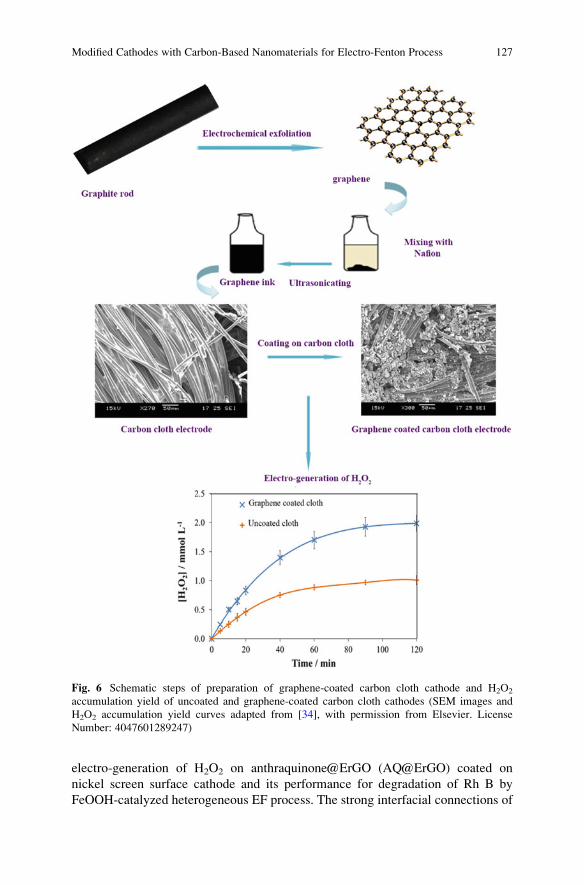
electro-generation of H2O2 on anthraquinone@ErGO (AQ@ErGO) coated on
nickel screen surface cathode and its performance for degradation of Rh B by
FeOOH-catalyzed heterogeneous EF process. The strong interfacial connections of
Fig. 6 Schematic steps of preparation of graphene-coated carbon cloth cathode and H2O2
accumulation yield of uncoated and graphene-coated carbon cloth cathodes (SEM images and
H2O2 accumulation yield curves adapted from [34], with permission from Elsevier. License
Number: 4047601289247)
Modified Cathodes with Carbon-Based Nanomaterials for Electro-Fenton Process 127
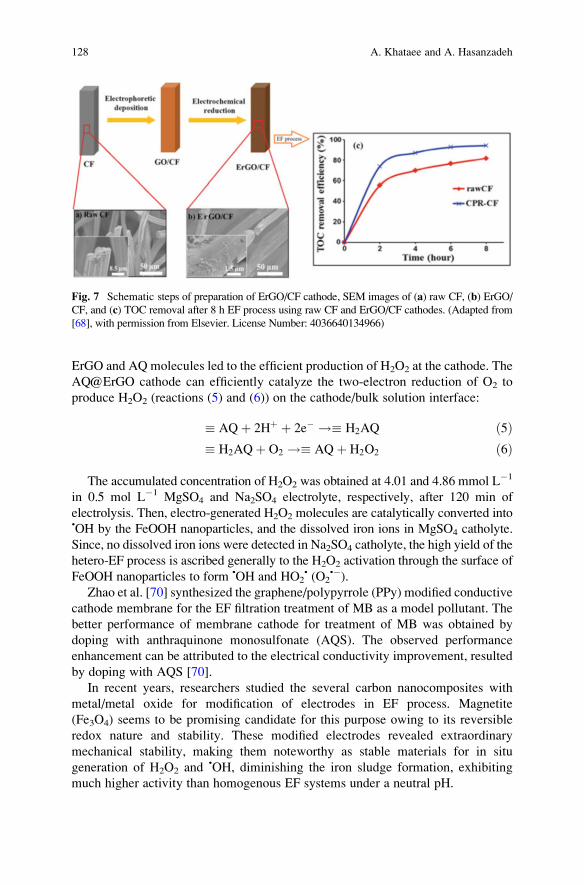
ErGO and AQ molecules led to the efficient production of H2O2 at the cathode. The
AQ@ErGO cathode can efficiently catalyze the two-electron reduction of O2 to
produce H2O2 (reactions (5) and (6)) on the cathode/bulk solution interface:
� AQþ 2Hþ þ 2e� !� H2AQ ð5Þ� H2AQþ O2 !� AQþ H2O2 ð6Þ
The accumulated concentration of H2O2 was obtained at 4.01 and 4.86 mmol L�1
in 0.5 mol L�1 MgSO4 and Na2SO4 electrolyte, respectively, after 120 min of
electrolysis. Then, electro-generated H2O2 molecules are catalytically converted into•OH by the FeOOH nanoparticles, and the dissolved iron ions in MgSO4 catholyte.
Since, no dissolved iron ions were detected in Na2SO4 catholyte, the high yield of the
hetero-EF process is ascribed generally to the H2O2 activation through the surface of
FeOOH nanoparticles to form •OH and HO2• (O2
•�).Zhao et al. [70] synthesized the graphene/polypyrrole (PPy) modified conductive
cathode membrane for the EF filtration treatment of MB as a model pollutant. The
better performance of membrane cathode for treatment of MB was obtained by
doping with anthraquinone monosulfonate (AQS). The observed performance
enhancement can be attributed to the electrical conductivity improvement, resulted
by doping with AQS [70].
In recent years, researchers studied the several carbon nanocomposites with
metal/metal oxide for modification of electrodes in EF process. Magnetite
(Fe3O4) seems to be promising candidate for this purpose owing to its reversible
redox nature and stability. These modified electrodes revealed extraordinary
mechanical stability, making them noteworthy as stable materials for in situ
generation of H2O2 and •OH, diminishing the iron sludge formation, exhibiting
much higher activity than homogenous EF systems under a neutral pH.
Fig. 7 Schematic steps of preparation of ErGO/CF cathode, SEM images of (a) raw CF, (b) ErGO/
CF, and (c) TOC removal after 8 h EF process using raw CF and ErGO/CF cathodes. (Adapted from
[68], with permission from Elsevier. License Number: 4036640134966)
128 A. Khataee and A. Hasanzadeh
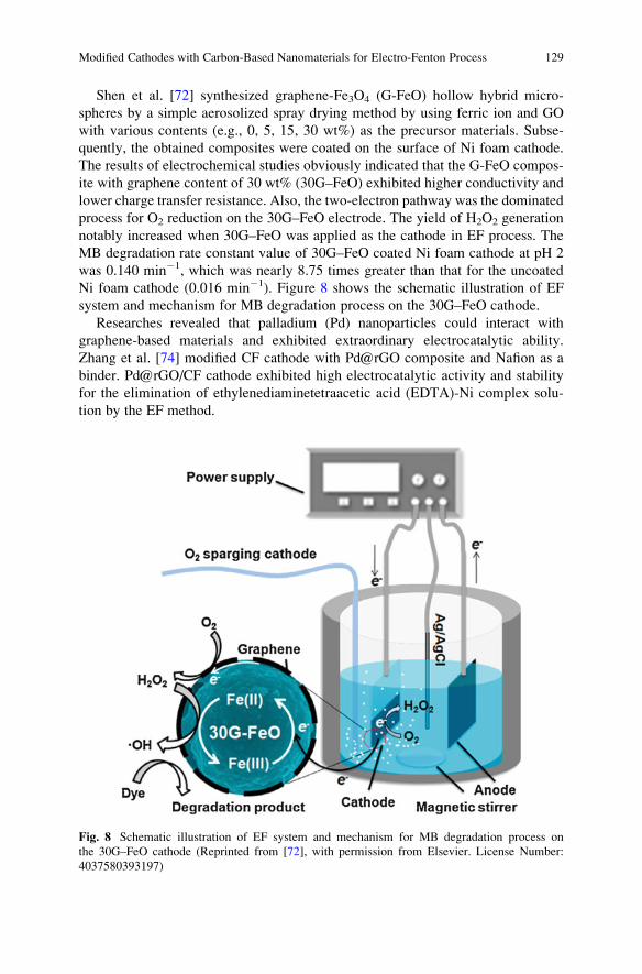
Shen et al. [72] synthesized graphene-Fe3O4 (G-FeO) hollow hybrid micro-
spheres by a simple aerosolized spray drying method by using ferric ion and GO
with various contents (e.g., 0, 5, 15, 30 wt%) as the precursor materials. Subse-
quently, the obtained composites were coated on the surface of Ni foam cathode.
The results of electrochemical studies obviously indicated that the G-FeO compos-
ite with graphene content of 30 wt% (30G–FeO) exhibited higher conductivity and
lower charge transfer resistance. Also, the two-electron pathway was the dominated
process for O2 reduction on the 30G–FeO electrode. The yield of H2O2 generation
notably increased when 30G–FeO was applied as the cathode in EF process. The
MB degradation rate constant value of 30G–FeO coated Ni foam cathode at pH 2
was 0.140 min�1, which was nearly 8.75 times greater than that for the uncoated
Ni foam cathode (0.016 min�1). Figure 8 shows the schematic illustration of EF
system and mechanism for MB degradation process on the 30G–FeO cathode.
Researches revealed that palladium (Pd) nanoparticles could interact with
graphene-based materials and exhibited extraordinary electrocatalytic ability.
Zhang et al. [74] modified CF cathode with Pd@rGO composite and Nafion as a
binder. Pd@rGO/CF cathode exhibited high electrocatalytic activity and stability
for the elimination of ethylenediaminetetraacetic acid (EDTA)-Ni complex solu-
tion by the EF method.
Fig. 8 Schematic illustration of EF system and mechanism for MB degradation process on
the 30G–FeO cathode (Reprinted from [72], with permission from Elsevier. License Number:
4037580393197)
Modified Cathodes with Carbon-Based Nanomaterials for Electro-Fenton Process 129
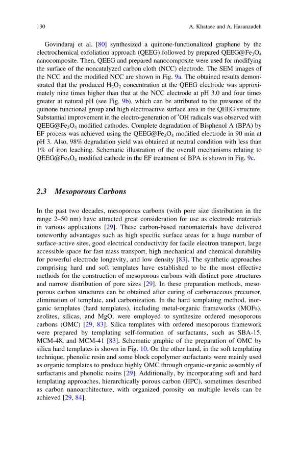
Govindaraj et al. [80] synthesized a quinone-functionalized graphene by the
electrochemical exfoliation approach (QEEG) followed by prepared QEEG@Fe3O4
nanocomposite. Then, QEEG and prepared nanocomposite were used for modifying
the surface of the noncatalyzed carbon cloth (NCC) electrode. The SEM images of
the NCC and the modified NCC are shown in Fig. 9a. The obtained results demon-
strated that the produced H2O2 concentration at the QEEG electrode was approxi-
mately nine times higher than that at the NCC electrode at pH 3.0 and four times
greater at natural pH (see Fig. 9b), which can be attributed to the presence of the
quinone functional group and high electroactive surface area in the QEEG structure.
Substantial improvement in the electro-generation of •OH radicals was observed with
QEEG@Fe3O4 modified cathodes. Complete degradation of Bisphenol A (BPA) by
EF process was achieved using the QEEG@Fe3O4 modified electrode in 90 min at
pH 3. Also, 98% degradation yield was obtained at neutral condition with less than
1% of iron leaching. Schematic illustration of the overall mechanisms relating to
QEEG@Fe3O4 modified cathode in the EF treatment of BPA is shown in Fig. 9c.
2.3 Mesoporous Carbons
In the past two decades, mesoporous carbons (with pore size distribution in the
range 2–50 nm) have attracted great consideration for use as electrode materials
in various applications [29]. These carbon-based nanomaterials have delivered
noteworthy advantages such as high specific surface areas for a huge number of
surface-active sites, good electrical conductivity for facile electron transport, large
accessible space for fast mass transport, high mechanical and chemical durability
for powerful electrode longevity, and low density [83]. The synthetic approaches
comprising hard and soft templates have established to be the most effective
methods for the construction of mesoporous carbons with distinct pore structures
and narrow distribution of pore sizes [29]. In these preparation methods, meso-
porous carbon structures can be obtained after curing of carbonaceous precursor,
elimination of template, and carbonization. In the hard templating method, inor-
ganic templates (hard templates), including metal-organic frameworks (MOFs),
zeolites, silicas, and MgO, were employed to synthesize ordered mesoporous
carbons (OMC) [29, 83]. Silica templates with ordered mesoporous framework
were prepared by templating self-formation of surfactants, such as SBA-15,
MCM-48, and MCM-41 [83]. Schematic graphic of the preparation of OMC by
silica hard templates is shown in Fig. 10. On the other hand, in the soft templating
technique, phenolic resin and some block copolymer surfactants were mainly used
as organic templates to produce highly OMC through organic-organic assembly of
surfactants and phenolic resins [29]. Additionally, by incorporating soft and hard
templating approaches, hierarchically porous carbon (HPC), sometimes described
as carbon nanoarchitecture, with organized porosity on multiple levels can be
achieved [29, 84].
130 A. Khataee and A. Hasanzadeh
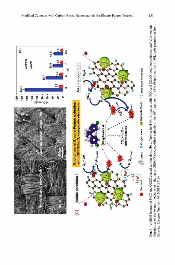
Fig.9
(a)SEM
images
ofNCCandQEEGcoated
carboncloth,(b)difference
inH2O2form
ationwithNCCandQEEGmodified
cathodes,and(c)schem
atic
illustrationoftheoverallmechanismsrelatingto
QEEG/Fe 3O4modified
cathodein
theEFtreatm
entofBPA
(Reprintedfrom
[80],withpermissionfrom
Elsevier.License
Number:4047001318719)
Modified Cathodes with Carbon-Based Nanomaterials for Electro-Fenton Process 131
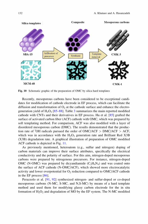
Recently, mesoporous carbons have been considered to be exceptional candi-
dates for modification of cathode electrode in EF process, which can facilitate the
diffusion and transformation of O2 at the cathode surface and enhance the electro-
generation yield of H2O2 [85–88]. Table 3 summarizes the main reported modified
cathode with CNTs and their derivatives in EF process. Hu et al. [85] grafted the
surface of activated carbon fiber (ACF) cathode with OMC, which was prepared by
soft templating method. For comparison, ACF was also modified with a layer of
disordered mesoporous carbon (DMC). The results demonstrated that the produc-
tion rate of •OH radicals pursued the order of OMC/ACF > DMC/ACF > ACF,
which was in accordance with the H2O2 generation rate and Brilliant Red X3B
(X3B) degradation rate. A graphical illustration of preparation of OMC modified
ACF cathode is depicted in Fig. 11.
As previously mentioned, heteroatom (e.g., sulfur and nitrogen) doping of
carbon materials can improve their surface attributes, specifically the electrical
conductivity and the polarity of surface. For this aim, nitrogen-doped mesoporous
carbons were prepared by nitrogenous precursors. For instance, nitrogen-doped
OMC (N-OMC) was prepared by dicyandiamide (C2H4N4) and was coated onto
the surface of ACF cathode (N-OMC/ACF), which showed more electrocatalytic
activity and lower overpotential for O2 reduction compared to OMC/ACF cathode
in the EF process [86].
Perazzolo et al. [91, 92] synthesized nitrogen- and sulfur-doped or co-doped
mesoporous carbons (N-MC, S-MC, and N,S-MC) by means of a hard template
method and used them for modifying glassy carbon electrode for the in situ
formation of H2O2 and degradation of MO by the EF system. The N-MC modified
Fig. 10 Schematic graphic of the preparation of OMC by silica hard templates
132 A. Khataee and A. Hasanzadeh

Table
3Resultsreported
formodified
cathodes
withmesoporouscarbonsin
EFprocess
Modified
cathode
Process
Pollutant
Operational
param
eters
Carbonmesoporous
characteristics
Maxim
um
efficiency
reported
Ref.
OMC/ACF
EF
X3B
200mLreactioncompartm
ent,
12cm
2Pt,9.0
cm2cathode
surface,0.1
molL�1
[Na 2SO4](electrolyte),
pH3.0,1.0
mmolL�1[Fe2
+],
600mLmin
�1airflowrate,
6.2
Vvoltage
SBET¼
722m
2g�1
Mesopore
volume¼
0.19cm
3
g�1
TheEFdegradationrate
con-
stantvalueofX3Bin
OMC/ACFcathode
(0.055min
�1)was
larger
than
inACFcathode(0.018min
�1).
80.6%
ofTOCdepletionwas
foundwithin
60min
when
usingOMC/ACFcathode.The
maxim
um
H2O2concentration
was
of9.4
μmolL�1
and
7.1
μmolL�1
inOMC/ACF
andACFcathode,respectively
[85]
N-doped
OMC/ACF
250mLreactioncompart-
ment,9.0
cm2graphiteanode,
9.0
cm2cathodesurface,
0.1
molL�1
[Na 2SO4](elec-
trolyte),pH3.0,1.0mmolL�1
[Fe2
+],600mLmin
�1airflow
rate,3.0
Vvoltage
Massof
dicyandiamide¼
1.0
g
SBET¼
501m
2g�1
Pore
volume¼
0.35cm
3g�1
Meanpore
size
¼3.5
nm
Thedegradationrate
ofX3B
byusingofN(1.0)-OMC/ACF
cathodewas
50%
higher
than
thatoftheOMC/ACFcathode.
Themaxim
um
H2O2concen-
trationwas
of40.93μm
olL�1
and21.75μm
olL�1
inN(1.0)-
OMC/ACFandOMC/ACF
cathode,respectively
[86]
OMC-5.4/
ACF
EF
RhB
200mLreactioncompartm
ent,
12cm
2Ptanode,9.0
cm2
cathodesurface,0.1
molL�1
[Na 2SO4](electrolyte),pH3.0,
1.0
mmolL�1[Fe2
+],600mL
min
�1airflowrate,�0
.1V
voltage
SBET¼
486m
2g�1
Pore
volume¼
0.45cm
3g�1
Meanpore
size
¼5.4
nm
100%
ofRhBwas
degraded
byOMC-5.4/ACFwithin
45min,whereasthedegrada-
tionrate
ofRhBin
thepres-
ence
ofOMC-3.7/ACFand
OMC-2.6/ACFdecreased
to
93.2%
and71.2%,respec-
tively.Theconcentrationof
[87]
(continued)
Modified Cathodes with Carbon-Based Nanomaterials for Electro-Fenton Process 133

Table
3(continued)
Modified
cathode
Process
Pollutant
Operational
param
eters
Carbonmesoporous
characteristics
Maxim
um
efficiency
reported
Ref.
H2O2was
2.02mmolL�1in
OMC-5.4/ACF,whileitwas
1.79mmolL�1
inOMC-3.7/
ACFas
cathodematerials
rGO@OMC/
ACF
EF
Dim
ethyl
phthalate(D
MP)
200mLreactioncompartm
ent,
12cm
2Ptanode,9.0
cm2
cathodesurface,0.1
molL�1
[Na 2SO4](electrolyte),pH3.0,
1.0
mmolL�1[Fe2
+],600mL
min
�1airflow
rate,�0
.7V
voltage
DosageofrG
O¼
30mg
SBET¼
533.3
m2g�1
Meanpore
size
¼3.8
nm
TheconcentrationofH2O2
increasedwiththedosageof
rGOfrom
0to
30mg,but
considerably
dim
inished
from
30to
90mg.Themaxim
um
H2O2concentrationwas
of
2.5
mmolL�1
withthecurrent
efficiency
of40.4%.
rGO30@OMC/ACFindicated
thehighestDMPremoval
efficiency
withan
apparent
rate
constantvalueof
0.049min
�1,about1.5
times
tothat
atOMC/ACF
[35]
CMK-3/
GDE
EF
DMP
200mLthree-electrode
undivided
cell,Ptfoilcounter,
SCEreference,4.0
cm2cath-
odesurface,0.1
molL�1
[Na 2SO4](electrolyte),
pH3.0,300mLmin
�1O2flow
rate,0.5
mmolL�1[Fe2
+],
�0.5
Vvoltage
SBET¼
992m
2g�1
Pore
volume¼
0.45cm
3g�1
Meanpore
size
¼4.3
nm
TheaccumulativeH2O2con-
centrationsobtained
atthe
CMK-3/GDE,graphiteGDE,
andcarbonpaper
were
increasedto
1.29,0.41,and
0.29mmolL�1,respectively.
Theapparentrate
constant
values
ofDMPdegradationat
theCMK-3/GDE,graphite
GDE,andcarbonpaper
cath-
odewere0.300,0.034,and
0.026min
�1,respectively
[89]
134 A. Khataee and A. Hasanzadeh

Fe-GMCAa/
Nifoam
Heterogeneous-
EF
MB
100mLthree-electrode
undivided
cell,8.0cm
2Ptsheet
counter,Ag/AgClreference,
8.0
cm2cathodesurface,
0.05molL�1[N
a 2SO4](elec-
trolyte),pH3.0,400mLmin
�1
O2flowrate,15mAapplied
current
SBET¼
479.8
m2g�1
Pore
volume¼
0.74cm
3g�1
Meanpore
size
¼3.1
nm
Theconcentrationsofgenerated
H2O2attheGMCA/Nifoam
andNifoam
cathodes
were1.26
and0.51mmolL�1,respec-
tively.Thedegradationrate
constantvalues
ofMBwere
0.072min�1,0.043min�1,and
0.030min�1
forFe-GMCA,
Fe-GCA,andFe-MCA,
respectively
[90]
N,S-doped
MC/glassy
carbon
Electrochem
ical
oxidation
Methylorange
(MO)
100mLthree-electrode
undivided
cell,graphiterod
counter,SCEreference,
6.0
cm2cathodesurface,
0.05molL�1[N
a 2SO4]
(electrolyte),pH
2.4,400mL
min
�1O2flow
rate,�0
.5V
vs.SCEvoltage
SBET(N
-doped
MC)¼
881m
2
g�1
Meanpore
size
(N-doped
MC)¼
3.7
nm
SBET(S-doped
MC)¼
1,103m
2g�1
Meanpore
size
(S-doped
MC)¼
3.7
nm
SBET(N
,S-doped
MC)¼
855m
2g�1
Meanpore
size
(N,S-doped
MC)¼
3.7
nm
Degradationefficiencies
of
MOwerearound100%,70%,
and60%
when
N-M
C,S-M
C,
andN,S-M
Cwereapplied
as
electrodematerial,
respectively
[91,92]
HPC/carbon
paper
EF
Perfluorooctanoate
(PFOA)
60mLthree-electrode
undivided
cell,6.0
cm2Pt
sheetcounter,SCEreference,
10cm
2cathodesurface,
0.05molL�1[N
a 2SO4](elec-
trolyte),pH2.0,1.0mmolL�1
[Fe2
+],�0
.4Vvs.SCE
voltage
Hydrothermal
time:
24h
SBET¼
2,130m
2g�1
Pore
size
distribution:
1.0–10.0
nm
Theelectro-generated
H2O2
concentrationonthemodified
cathodewithHPCwas
142.5
mmolL�1
withcurrent
efficiency
of91.2%.PFOA
was
degraded
withremoval
efficiency
of94.3%
in120min
[88,93]
aIronoxidecontaininggraphene/carbonnanotubebased
carbonaerogel
Modified Cathodes with Carbon-Based Nanomaterials for Electro-Fenton Process 135
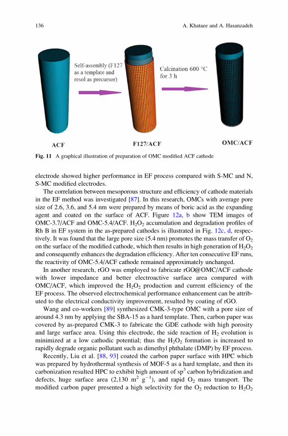
electrode showed higher performance in EF process compared with S-MC and N,
S-MC modified electrodes.
The correlation between mesoporous structure and efficiency of cathode materials
in the EF method was investigated [87]. In this research, OMCs with average pore
size of 2.6, 3.6, and 5.4 nm were prepared by means of boric acid as the expanding
agent and coated on the surface of ACF. Figure 12a, b show TEM images of
OMC-3.7/ACF and OMC-5.4/ACF. H2O2 accumulation and degradation profiles of
Rh B in EF system in the as-prepared cathodes is illustrated in Fig. 12c, d, respec-
tively. It was found that the large pore size (5.4 nm) promotes the mass transfer of O2
on the surface of the modified cathode, which then results in high generation of H2O2
and consequently enhances the degradation efficiency. After ten consecutive EF runs,
the reactivity of OMC-5.4/ACF cathode remained approximately unchanged.
In another research, rGO was employed to fabricate rGO@OMC/ACF cathode
with lower impedance and better electroactive surface area compared with
OMC/ACF, which improved the H2O2 production and current efficiency of the
EF process. The observed electrochemical performance enhancement can be attrib-
uted to the electrical conductivity improvement, resulted by coating of rGO.
Wang and co-workers [89] synthesized CMK-3-type OMC with a pore size of
around 4.3 nm by applying the SBA-15 as a hard template. Then, carbon paper was
covered by as-prepared CMK-3 to fabricate the GDE cathode with high porosity
and large surface area. Using this electrode, the side reaction of H2 evolution is
minimized at a low cathodic potential; thus the H2O2 formation is increased to
rapidly degrade organic pollutant such as dimethyl phthalate (DMP) by EF process.
Recently, Liu et al. [88, 93] coated the carbon paper surface with HPC which
was prepared by hydrothermal synthesis of MOF-5 as a hard template, and then its
carbonization resulted HPC to exhibit high amount of sp3 carbon hybridization and
defects, huge surface area (2,130 m2 g�1), and rapid O2 mass transport. The
modified carbon paper presented a high selectivity for the O2 reduction to H2O2
Fig. 11 A graphical illustration of preparation of OMC modified ACF cathode
136 A. Khataee and A. Hasanzadeh
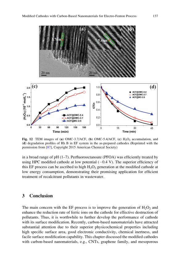
in a broad range of pH (1–7). Perfluorooctanoate (PFOA) was efficiently treated by
using HPC modified cathode at low potential (�0.4 V). The superior efficiency of
this EF process can be ascribed to high H2O2 generation at the modified cathode at
low energy consumption, demonstrating their promising application for efficient
treatment of recalcitrant pollutants in wastewater.
3 Conclusion
The main concern with the EF process is to improve the generation of H2O2 and
enhance the reduction rate of ferric ions on the cathode for effective destruction of
pollutants. Thus, it is worthwhile to further develop the performance of cathode
with its surface modification. Recently, carbon-based nanomaterials have attracted
substantial attention due to their superior physicochemical properties including
high specific surface area, good electronic conductivity, chemical inertness, and
facile surface modification capability. This chapter discussed the modified cathodes
with carbon-based nanomaterials, e.g., CNTs, graphene family, and mesoporous
Fig. 12 TEM images of (a) OMC-3.7/ACF, (b) OMC-5.4/ACF, (c) H2O2 accumulation, and
(d) degradation profiles of Rh B in EF system in the as-prepared cathodes (Reprinted with the
permission from [87], Copyright 2015 American Chemical Society)
Modified Cathodes with Carbon-Based Nanomaterials for Electro-Fenton Process 137
carbons, for EF system. Progress in the modification of cathodes with these nano-
materials for performance development of EF process has been tremendous in
recent years, opening novel alternatives in the degradation of recalcitrant pollutants
in wastewater.
Despite the extensive research on the modification of cathodes in EF processes,
several challenges still need to be addressed to optimize the design of these
cathodes for industrial applications at a large scale. First, a technique for better
coating or condensing of carbon nanomaterials needs to be further explored. Due to
the fact that nanomaterials may be leached from the coated bed, the efficient coating
approaches should be developed. Second, carbon nanomaterials generally have a
strong tendency to agglomerate owing to their nanosize and high surface energy.
Therefore, their applications are limited due to the difficulty in dispersing them in a
solvent (water or organic agent) for coating on the electrode. Improved dispersion
of carbon nanomaterials could be achieved by modifying their surfaces or optimiz-
ing the coating process. Also, this matter could be resolved by preparing of
spongelike or aerogel structure of carbon nanomaterials as an electrode and in
situ synthesis of nanomaterials on the electrode surface. In this case, the durability
of modified cathode electrodes could be improved. Third, considering the potential
effects of leached carbon nanomaterials to the environment, nanomaterial leakage
and its environmental toxicity also need to be systematically evaluated. Finally,
there are many laboratory-scale researches on the application of modified cathodes
with carbon nanomaterials in EF processes, but the industrial application of these
cathodes is still not developed. More studies are needed to investigate the cost-
effectiveness of large-scale modified cathode fabrication including the supply of
carbon nanomaterials and to monitor the long-term stability of modified cathodes
under practical application conditions.
Acknowledgment The authors thank the University of Tabriz (Iran) for all the support provided.
We also acknowledge the support of Iran Science Elites Federation.
References
1. Brillas E, Sires I, Oturan MA (2009) Electro-Fenton process and related electrochemical
technologies based on fenton’s reaction chemistry. Chem Rev 109(12):6570–6631
2. Nidheesh PV, Gandhimathi R (2012) Trends in electro-Fenton process for water and waste-
water treatment: an overview. Desalination 299:1–15
3. Oloman C, Watkinson AP (1975) The electroreduction of oxygen to hydrogen peroxide on
fluidized cathodes. Can J Chem Eng 53(3):268–273
4. Oloman C, Watkinson AP (1979) Hydrogen peroxide production in trickle-bed electrochem-
ical reactors. J Appl Electrochem 9(1):117–123
5. Khataee AR, Safarpour M, Zarei M, Aber S (2011) Electrochemical generation of H2O2 using
immobilized carbon nanotubes on graphite electrode fed with air: investigation of operational
parameters. J Electroanal Chem 659(1):63–68
138 A. Khataee and A. Hasanzadeh
6. Scialdone O, Galia A, Sabatino S (2013) Electro-generation of H2O2 and abatement of organic
pollutant in water by an electro-Fenton process in a microfluidic reactor. Electrochem
Commun 26:45–47
7. Leng WH, Zhu WC, Ni J, Zhang Z, Zhang JQ, Cao CN (2006) Photoelectrocatalytic destruc-
tion of organics using TiO2 as photoanode with simultaneous production of H2O2 at the
cathode. Appl Catal A 300(1):24–35
8. Scialdone O, Galia A, Gattuso C, Sabatino S, Schiavo B (2015) Effect of air pressure on the
electro-generation of H2O2 and the abatement of organic pollutants in water by electro-Fenton
process. Electrochim Acta 182:775–780
9. Santana-Martınez G, Roa-Morales G, Martin del Campo E, Romero R, Frontana-Uribe BA,
Natividad R (2016) Electro-Fenton and electro-Fenton-like with in situ electrogeneration of
H2O2 and catalyst applied to 4-chlorophenol mineralization. Electrochim Acta 195:246–256
10. Flox C, Ammar S, Arias C, Brillas E, Vargas-Zavala AV, Abdelhedi R (2006) Electro-Fenton
and photoelectro-Fenton degradation of indigo carmine in acidic aqueous medium. Appl Catal
B 67(1-2):93–104
11. Liang L, An Y, Zhou M, Yu F, Liu M, Ren G (2016) Novel rolling-made gas-diffusion
electrode loading trace transition metal for efficient heterogeneous electro-Fenton-like.
J Environ Chem Eng 4(4):4400–4408
12. Wang Z-X, Li G, Yang F, Chen Y-L, Gao P (2011) Electro-Fenton degradation of cellulose
using graphite/PTFE electrodes modified by 2-ethylanthraquinone. Carbohydr Polym 86
(4):1807–1813
13. Flores N, Cabot PL, Centellas F, Garrido JA, Rodrıguez RM, Brillas E, Sires I
(2017) 4-Hydroxyphenylacetic acid oxidation in sulfate and real olive oil mill wastewater by
electrochemical advanced processes with a boron-doped diamond anode. J Hazard Mater
321:566–575
14. Wang A, Qu J, Ru J, Liu H, Ge J (2005) Mineralization of an azo dye Acid Red 14 by electro-
Fenton’s reagent using an activated carbon fiber cathode. Dyes Pigments 65(3):227–233
15. Hammami S, Oturan N, Bellakhal N, Dachraoui M, Oturan MA (2007) Oxidative degradation
of direct orange 61 by electro-Fenton process using a carbon felt electrode: application of the
experimental design methodology. J Electroanal Chem 610(1):75–84
16. Pimentel M, Oturan N, Dezotti M, Oturan MA (2008) Phenol degradation by advanced
electrochemical oxidation process electro-Fenton using a carbon felt cathode. Appl Catal B
83(1-2):140–149
17. Zhou M, Tan Q, Wang Q, Jiao Y, Oturan N, Oturan MA (2012) Degradation of organics in
reverse osmosis concentrate by electro-Fenton process. J Hazard Mater 215-216:287–293
18. Zhou L, Zhou M, Zhang C, Jiang Y, Bi Z, Yang J (2013) Electro-Fenton degradation of
p-nitrophenol using the anodized graphite felts. Chem Eng J 233:185–192
19. Yahya MS, Oturan N, El Kacemi K, El Karbane M, Aravindakumar CT, Oturan MA (2014)
Oxidative degradation study on antimicrobial agent ciprofloxacin by electro-Fenton process:
kinetics and oxidation products. Chemosphere 117:447–454
20. Ozcan A, Sahin Y, Savas Koparal A, Oturan MA (2008) Carbon sponge as a new cathode
material for the electro-Fenton process: comparison with carbon felt cathode and application
to degradation of synthetic dye basic blue 3 in aqueous medium. J Electroanal Chem 616
(1–2):71–78
21. Trellu C, Pechaud Y, Oturan N, Mousset E, Huguenot D, van Hullebusch ED, Esposito G,
Oturan MA (2016) Comparative study on the removal of humic acids from drinking water
by anodic oxidation and electro-Fenton processes: mineralization efficiency and modelling.
Appl Catal B 194:32–41
22. Alvarez-Gallegos A, Pletcher D (1998) The removal of low level organics via hydrogen
peroxide formed in a reticulated vitreous carbon cathode cell, part 1. The electrosynthesis of
hydrogen peroxide in aqueous acidic solutions. Electrochim Acta 44(5):853–861
Modified Cathodes with Carbon-Based Nanomaterials for Electro-Fenton Process 139
23. Alverez-Gallegos A, Pletcher D (1999) The removal of low level organics via hydrogen
peroxide formed in a reticulated vitreous carbon cathode cell. Part 2: the removal of phenols
and related compounds from aqueous effluents. Electrochim Acta 44(14):2483–2492
24. Martınez SS, Bahena CL (2009) Chlorbromuron urea herbicide removal by electro-Fenton
reaction in aqueous effluents. Water Res 43(1):33–40
25. Thiam A, Sires I, Garrido JA, Rodrıguez RM, Brillas E (2015) Decolorization and minerali-
zation of Allura Red AC aqueous solutions by electrochemical advanced oxidation processes.
J Hazard Mater 290:34–42
26. Thiam A, Zhou M, Brillas E, Sires I (2014) Two-step mineralization of Tartrazine solutions:
study of parameters and by-products during the coupling of electrocoagulation with electro-
chemical advanced oxidation processes. Appl Catal B 150–151:116–125
27. Cruz-Gonzalez K, Torres-Lopez O, Garcıa-Leon AM, Brillas E, Hernandez-Ramırez A,
Peralta-Hernandez JM (2012) Optimization of electro-Fenton/BDD process for decolorization
of a model azo dye wastewater by means of response surface methodology. Desalination
286:63–68
28. Cruz-Gonzalez K, Torres-Lopez O, Garcıa-Leon A, Guzman-Mar JL, Reyes LH, Hernandez-
Ramırez A, Peralta-Hernandez JM (2010) Determination of optimum operating parameters for
Acid Yellow 36 decolorization by electro-Fenton process using BDD cathode. Chem Eng J
160(1):199–206
29. Su DS, Perathoner S, Centi G (2013) Nanocarbons for the development of advanced catalysts.
Chem Rev 113(8):5782–5816
30. Hassani A, Khataee AR (2017) Activated carbon fiber for environmental protection. In:
Chen JY (ed) Activated carbon fiber and textiles. Woodhead Publishing, Oxford, pp 245–280
31. Inagaki M, Kang F (2014) Fundamental science of carbon materials. Materials science and
engineering of carbon: fundamentals2nd edn. Butterworth-Heinemann, Oxford, pp 17–217
32. Wei Q, Tong X, Zhang G, Qiao J, Gong Q, Sun S (2015) Nitrogen-doped carbon nanotube and
graphene materials for oxygen reduction reactions. Catalysts 5(3):1574
33. Wang D-W, Su D (2014) Heterogeneous nanocarbon materials for oxygen reduction reaction.
Energy Environ Sci 7(2):576–591
34. Mousset E, Ko ZT, Syafiq M, Wang Z, Lefebvre O (2016) Electrocatalytic activity enhance-
ment of a graphene ink-coated carbon cloth cathode for oxidative treatment. Electrochim Acta
222:1628–1641
35. Ren W, Tang D, Lu X, Sun J, Li M, Qiu S, Fan D (2016) Novel multilayer ACF@rGO@OMC
cathode composite with enhanced activity for electro-Fenton degradation of phthalic acid
esters. Ind Eng Chem Res 55(42):11085–11096
36. Chen C-Y, Tang C, Wang H-F, Chen C-M, Zhang X, Huang X, Zhang Q (2016) Oxygen
reduction reaction on graphene in an electro-Fenton system: in situ generation of H2O2 for the
oxidation of organic compounds. ChemSusChem 9(10):1194–1199
37. Iijima S (1991) Helical microtubules of graphitic carbon. Nature 354(6348):56–58
38. Dai L, Xue Y, Qu L, Choi H-J, Baek J-B (2015) Metal-free catalysts for oxygen reduction
reaction. Chem Rev 115(11):4823–4892
39. Popov VN (2004) Carbon nanotubes: properties and application. Mater Sci Eng R Rep 43
(3):61–102
40. Zhang X, Lei L, Xia B, Zhang Y, Fu J (2009) Oxidization of carbon nanotubes through
hydroxyl radical induced by pulsed O2 plasma and its application for O2 reduction in electro-
Fenton. Electrochim Acta 54(10):2810–2817
41. Tian J, Olajuyin AM, Mu T, Yang M, Xing J (2016) Efficient degradation of rhodamine B
using modified graphite felt gas diffusion electrode by electro-Fenton process. Environ Sci
Pollut Res 23(12):11574–11583
42. Chu Y, Zhang D, Liu L, Qian Y, Li L (2013) Electrochemical degradation of m-cresol
using porous carbon-nanotube-containing cathode and Ti/SnO2–Sb2O5–IrO2 anode: kinetics,
byproducts and biodegradability. J Hazard Mater 252-253:306–312
140 A. Khataee and A. Hasanzadeh
43. Khataee AR, Safarpour M, Zarei M, Aber S (2012) Combined heterogeneous and homoge-
neous photodegradation of a dye using immobilized TiO2 nanophotocatalyst and modified
graphite electrode with carbon nanotubes. J Mol Catal A Chem 363–364:58–68
44. Khataee AR, Vahid B, Behjati B, Safarpour M, Joo SW (2014) Kinetic modeling of a
triarylmethane dye decolorization by photoelectro-Fenton process in a recirculating system:
nonlinear regression analysis. Chem Eng Res Des 92(2):362–367
45. Khataee AR, Vahid B, Behjati B, Safarpour M (2013) Treatment of a dye solution using
photoelectro-fenton process on the cathode containing carbon nanotubes under recirculation
mode: investigation of operational parameters and artificial neural network modeling. Environ
Prog Sustain Energy 32(3):557–563
46. Pajootan E, Arami M, Rahimdokht M (2014) Discoloration of wastewater in a continuous
electro-Fenton process using modified graphite electrode with multi-walled carbon nanotubes/
surfactant. Sep Purif Technol 130:34–44
47. Es’haghzade Z, Pajootan E, Bahrami H, Arami M (2017) Facile synthesis of Fe3O4
nanoparticles via aqueous based electro chemical route for heterogeneous electro-Fenton
removal of azo dyes. J Taiwan Inst Chem Eng 7:91–105
48. Fu J, Zhang X, Lei L (2007) Fe-modified multi-walled carbon nanotube electrode for produc-
tion of hydrogen peroxide. Acta Phys Chim Sin 23(8):1157–1162
49. Tang Q, Wang D, Yao DM, Yang CW, Sun YC (2016) Highly efficient electro-generation of
hydrogen peroxide using NCNT/NF/CNT air diffusion electrode for electro-Fenton degrada-
tion of p-nitrophenol. Water Sci Technol 73(7):1652–1658
50. Babaei-Sati R, Basiri Parsa J (2017) Electrogeneration of H2O2 using graphite cathode modified
with electrochemically synthesized polypyrrole/MWCNT nanocomposite for electro-Fenton
process. J Ind Eng Chem 52:270–276
51. Zhang X, Fu J, Zhang Y, Lei L (2008) A nitrogen functionalized carbon nanotube cathode
for highly efficient electrocatalytic generation of H2O2 in electro-Fenton system. Sep Purif
Technol 64(1):116–123
52. Zarei M, Salari D, Niaei A, Khataee AR (2009) Peroxi-coagulation degradation of C.I.
Basic Yellow 2 based on carbon-PTFE and carbon nanotube-PTFE electrodes as cathode.
Electrochim Acta 54(26):6651–6660
53. Zarei M, Niaei A, Salari D, Khataee AR (2010) Application of response surface methodology
for optimization of peroxi-coagulation of textile dye solution using carbon nanotube–PTFE
cathode. J Hazard Mater 173(1–3):544–551
54. Zarei M, Khataee AR, Ordikhani-Seyedlar R, Fathinia M (2010) Photoelectro-Fenton com-
bined with photocatalytic process for degradation of an azo dye using supported TiO2
nanoparticles and carbon nanotube cathode: neural network modeling. Electrochim Acta 55
(24):7259–7265
55. Geim AK, Novoselov KS (2007) The rise of graphene. Nat Mater 6(3):183–191
56. Kiew SF, Kiew LV, Lee HB, Imae T, Chung LY (2016) Assessing biocompatibility of
graphene oxide-based nanocarriers: a review. J Control Release 226:217–228
57. Novoselov KS, Geim AK, Morozov SV, Jiang D, Zhang Y, Dubonos SV, Grigorieva IV,
Firsov AA (2004) Electric field effect in atomically thin carbon films. Science 306
(5696):666–669
58. Lee C, Wei X, Kysar JW, Hone J (2008) Measurement of the elastic properties and intrinsic
strength of monolayer graphene. Science 321(5887):385–388
59. Balandin AA, Ghosh S, Bao W, Calizo I, Teweldebrhan D, Miao F, Lau CN (2008) Superior
thermal conductivity of single-layer graphene. Nano Lett 8(3):902–907
60. Marinho B, Ghislandi M, Tkalya E, Koning CE, de With G (2012) Electrical conductivity of
compacts of graphene, multi-wall carbon nanotubes, carbon black, and graphite powder.
Powder Technol 221:351–358
61. Novoselov KS (2009) Graphene: the magic of flat carbon. ECS Trans 19(5):3–7
62. Chen D, Tang L, Li J (2010) Graphene-based materials in electrochemistry. Chem Soc Rev 39
(8):3157–3180
Modified Cathodes with Carbon-Based Nanomaterials for Electro-Fenton Process 141
63. Lee HC, Liu W-W, Chai S-P, Mohamed AR, Lai CW, Khe C-S, Voon CH, Hashim U, Hidayah
NMS (2016) Synthesis of single-layer graphene: a review of recent development. Proc Chem
19:916–921
64. Shao G, Lu Y, Wu F, Yang C, Zeng F, Wu Q (2012) Graphene oxide: the mechanisms of
oxidation and exfoliation. J Mater Sci 47(10):4400–4409
65. Perreault F, Fonseca de Faria A, Elimelech M (2015) Environmental applications of graphene-
based nanomaterials. Chem Soc Rev 44(16):5861–5896
66. Liu L, Qing M, Wang Y, Chen S (2015) Defects in graphene: generation, healing, and their
effects on the properties of graphene: a review. J Mater Sci Technol 31(6):599–606
67. Xu X, Chen J, Zhang G, Song Y, Yang F (2014) Homogeneous electro-Fenton oxidative
degradation of reactive brilliant blue using a graphene doped gas-diffusion cathode. Int J
Electrochem Sci 9:569–579
68. Le TXH, Bechelany M, Lacour S, Oturan N, Oturan MA, Cretin M (2015) High removal
efficiency of dye pollutants by electron-Fenton process using a graphene based cathode.
Carbon 94:1003–1011
69. Le TXH, Bechelany M, Champavert J, Cretin M (2015) A highly active based graphene
cathode for the electro-Fenton reaction. RSC Adv 5(53):42536–42539
70. Zhao F, Liu L, Yang F, Ren N (2013) E-Fenton degradation of MB during filtration with
Gr/PPy modified membrane cathode. Chem Eng J 230:491–498
71. Dong H, Su H, Chen Z, Yu H, Yu H (2016) Fabrication of electrochemically reduced graphene
oxide modified gas diffusion electrode for in-situ electrochemical advanced oxidation process
under mild conditions. Electrochim Acta 222:1501–1509
72. Shen J, Li Y, Zhu Y, Hu Y, Li C (2016) Aerosol synthesis of graphene-Fe3O4 hollow hybrid
microspheres for heterogeneous Fenton and electro-Fenton reaction. J Environ Chem Eng 4
(2):2469–2476
73. Zhao X, Liu S, Huang Y (2016) Removing organic contaminants by an electro-Fenton system
constructed with graphene cathode. Toxicol Environ Chem 98(3-4):530–539
74. Zhang Z, Zhang J, Ye X, Hu Y, Chen Y (2016) Pd/RGO modified carbon felt cathode for
electro-Fenton removing of EDTA-Ni. Water Sci Technol 74(3):639–646
75. Zhang G, Zhou Y, Yang F (2015) FeOOH-catalyzed heterogeneous electro-Fenton system
upon anthraquinone@graphene nanohybrid cathode in a divided electrolytic cell: catholyte-
regulated catalytic oxidation performance and mechanism. J Electrochem Soc 162(6):H357–
H365
76. Mousset E, Wang Z, Hammaker J, Lefebvre O (2016) Physico-chemical properties of pristine
graphene and its performance as electrode material for electro-Fenton treatment of wastewater.
Electrochim Acta 214:217–230
77. Liu T, Wang K, Song S, Brouzgou A, Tsiakaras P, Wang Y (2016) New electro-Fenton gas
diffusion cathode based on nitrogen-doped graphene@carbon nanotube composite materials.
Electrochim Acta 194:228–238
78. Li Y, Han J, Xie B, Li Y, Zhan S, Tian Y (2017) Synergistic degradation of antimicrobial agent
ciprofloxacin in water by using 3D CeO2/RGO composite as cathode in electro-Fenton system.
J Electroanal Chem 784:6–12
79. Li Y, Li Y, Xie B, Han J, Zhan S, Tian Y (2017) Efficient mineralization of ciprofloxacin using
a 3D CexZr1-xO2/RGO composite cathode. Environ Sci Nano 4(2):425–436
80. Govindaraj D, Nambi IM, Senthilnathan J (2017) An innate quinone functionalized electro-
chemically exfoliated graphene/Fe3O4 composite electrode for the continuous generation of
reactive oxygen species. Chem Eng J 316:964–977
81. Golabi SM, Raoof JB (1996) Catalysis of dioxygen reduction to hydrogen peroxide at the
surface of carbon paste electrodes modified by 1,4-naphthoquinone and some of its derivatives.
J Electroanal Chem 416(1):75–82
82. Jürmann G, Schiffrin DJ, Tammeveski K (2007) The pH-dependence of oxygen reduction on
quinone-modified glassy carbon electrodes. Electrochim Acta 53(2):390–399
142 A. Khataee and A. Hasanzadeh
83. Walcarius A (2013) Mesoporous materials and electrochemistry. Chem Soc Rev 42
(9):4098–4140
84. Sun M-H, Huang S-Z, Chen L-H, Li Y, Yang X-Y, Yuan Z-Y, Su B-L (2016) Applications of
hierarchically structured porous materials from energy storage and conversion, catalysis,
photocatalysis, adsorption, separation, and sensing to biomedicine. Chem Soc Rev 45
(12):3479–3563
85. Hu J, Sun J, Yan J, Lv K, Zhong C, Deng K, Li J (2013) A novel efficient electrode material:
activated carbon fibers grafted by ordered mesoporous carbon. Electrochem Commun
28:67–70
86. Peng Q, Zhang Z, Za H, Ren W, Sun J (2014) N-doped ordered mesoporous carbon grafted
onto activated carbon fibre composites with enhanced activity for the electro-Fenton degra-
dation of Brilliant Red X3B dye. RSC Adv 4(104):60168–60175
87. RenW, Peng Q, Huang Z, Zhang Z, ZhanW, Lv K, Sun J (2015) Effect of pore structure on the
electro-Fenton activity of ACF@OMC cathode. Ind Eng Chem Res 54(34):8492–8499
88. Liu Y, Chen S, Quan X, Yu H, Zhao H, Zhang Y (2015) Efficient mineralization of
perfluorooctanoate by electro-Fenton with H2O2 electro-generated on hierarchically porous
carbon. Environ Sci Technol 49(22):13528–13533
89. Wang Y, Liu Y, X-Z L, Zeng F, Liu H (2013) A highly-ordered porous carbon material based
cathode for energy-efficient electro-Fenton process. Sep Purif Technol 106:32–37
90. Chen W, Yang X, Huang J, Zhu Y, Zhou Y, Yao Y, Li C (2016) Iron oxide containing
graphene/carbon nanotube based carbon aerogel as an efficient E-Fenton cathode for the
degradation of methyl blue. Electrochim Acta 200:75–83
91. Perazzolo V, Durante C, Gennaro A (2016) Nitrogen and sulfur doped mesoporous carbon
cathodes for water treatment. J Electroanal Chem 782:264–269
92. Perazzolo V, Durante C, Pilot R, Paduano A, Zheng J, Rizzi GA, Martucci A, Granozzi G,
Gennaro A (2015) Nitrogen and sulfur doped mesoporous carbon as metal-free electrocatalysts
for the in situ production of hydrogen peroxide. Carbon 95:949–963
93. Liu Y, Quan X, Fan X,Wang H, Chen S (2015) High-yield electrosynthesis of hydrogen peroxide
from oxygen reduction by hierarchically porous carbon. Angew Chem 127(23):6941–6945
Modified Cathodes with Carbon-Based Nanomaterials for Electro-Fenton Process 143
Advances in Carbon Felt Material for Electro-
Fenton Process
Thi Xuan Huong Le, Mikhael Bechelany, and Marc Cretin
Abstract In electro-Fenton process, carbon-based materials, particularly 3D car-
bon felt, are the best choices for the cathodic electrodes because of several
advantages such as low cost, excellent electrolytic efficiency, high surface area,
and porosity. In this chapter, various aspects of this material are discussed in detail.
This chapter is divided into three main sections, including (1) characterization of
carbon felt (CF), (2) modification of CF, and (3) application of CF in electro-Fenton
(EF) process to remove biorefractory pollutants. First of all, the typical character-
istics of CF such as morphology, porosity, and conductivity are discussed. Next, in
the modification section, we introduce different methods to improve the perfor-
mance of CF. We especially focus on the surface area and electrochemical activity
toward electrodes applications. Finally, both modified and non-modified CF is used
as cathode materials for EF systems like homogeneous, heterogeneous, hybrid, or
pilot-scale types.
Keywords Carbon felt, Conductivity, Electrochemical activity, Electro-Fenton
process, Hydrogen peroxide production, Modification, Surface area
Contents
1 Introduction . . . . . . . . . . . . . . . . . . . . . . . . . . . . . . . . . . . . . . . . . . . . . . . . . . . . . . . . . . . . . . . . . . . . . . . . . . . . . . . . . . 147
2 Characterization of CF Material . . . . . . . . . . . . . . . . . . . . . . . . . . . . . . . . . . . . . . . . . . . . . . . . . . . . . . . . . . . . 148
3 Method to Modify CF Material . . . . . . . . . . . . . . . . . . . . . . . . . . . . . . . . . . . . . . . . . . . . . . . . . . . . . . . . . . . . . 148
3.1 Chemical Treatment . . . . . . . . . . . . . . . . . . . . . . . . . . . . . . . . . . . . . . . . . . . . . . . . . . . . . . . . . . . . . . . . . . . 148
3.2 Thermal and Plasma Treatment . . . . . . . . . . . . . . . . . . . . . . . . . . . . . . . . . . . . . . . . . . . . . . . . . . . . . . 150
3.3 Graphene Based Modification . . . . . . . . . . . . . . . . . . . . . . . . . . . . . . . . . . . . . . . . . . . . . . . . . . . . . . . . 151
T.X.H. Le, M. Bechelany (*), and M. Cretin (*)
Institut Europeen des membranes (IEM UMR-5635, ENSCM, CNRS), Universite de
Montpellier, Place Eugene Bataillon, 34095 Montpellier Cedex 5, France
e-mail: [email protected]; [email protected]
M. Zhou et al. (eds.), Electro-Fenton Process: New Trends and Scale-Up,Hdb Env Chem (2018) 61: 145–174, DOI 10.1007/698_2017_55,© Springer Nature Singapore Pte Ltd. 2017, Published online: 9 July 2017
145
3.4 Carbon Nanotube-Based Modification . . . . . . . . . . . . . . . . . . . . . . . . . . . . . . . . . . . . . . . . . . . . . . . 152
3.5 Polymer-Based Modification . . . . . . . . . . . . . . . . . . . . . . . . . . . . . . . . . . . . . . . . . . . . . . . . . . . . . . . . . 153
3.6 Zeolite-Based Modification . . . . . . . . . . . . . . . . . . . . . . . . . . . . . . . . . . . . . . . . . . . . . . . . . . . . . . . . . . . 155
4 Carbon Felt-Based Material for Wastewater Treatment by EF Process . . . . . . . . . . . . . . . . . . . 156
4.1 Carbon Felt for EF Process . . . . . . . . . . . . . . . . . . . . . . . . . . . . . . . . . . . . . . . . . . . . . . . . . . . . . . . . . . . 156
4.2 Modified EF Systems Using Carbon Felt Cathodes . . . . . . . . . . . . . . . . . . . . . . . . . . . . . . . . . 159
5 Conclusion . . . . . . . . . . . . . . . . . . . . . . . . . . . . . . . . . . . . . . . . . . . . . . . . . . . . . . . . . . . . . . . . . . . . . . . . . . . . . . . . . . . 165
References . . . . . . . . . . . . . . . . . . . . . . . . . . . . . . . . . . . . . . . . . . . . . . . . . . . . . . . . . . . . . . . . . . . . . . . . . . . . . . . . . . . . . . . 166
Abbreviations
AHPS 4-Amino-3-hydroxy-2-p-tolylazo-naphthalene-1-sulfonic acid
ALD Atomic Layer Deposition
AO7 Acid orange 7
APPJ Atmospheric Pressure Plasma Jet
AQDS Anthraquinone-2,6-disulfonate
BDD Boron-doped diamond
BEF Bio-electro-Fenton
CF Carbon felt
CNT Carbon nanotube
CTAB Cetyl trimethylammonium bromide
CV Cyclic voltammogram
CVD Chemical vapor deposition
DCF Diclofenac
DMF N,N-dimethyl formamide
DO 61 Direct orange 61
EC Energy efficiency
EF Electro-Fenton
ENXN Enoxacin
EPD Electrophoretic deposition
FeAB Iron alginate gel beads
GF Graphite felt
GO Graphene oxide
LDH Layered double hydroxide
MCE Mineralization current efficiency
MCF Microbial fuel cell
MO Methyl orange
N-doped Nitrogen-doped
ORR Oxygen reduction reaction
PAH Polycyclic aromatic hydrocarbon
PAN-CF PolyAcryloNitrile-Carbon Felt
PAN-GF Polyacrylonitrile-graphite felt
PANi Polyaniline
PB Prussian blue
PCOC 4-Chloro-2-methylphenol
146 T.X.H. Le et al.
PEM Proton Exchange Membrane
POP Persistent Organic Pollutant
PPy Polypyrrole
RF Radiofrequency
rGO Reduced graphene oxide
RTD Residence Time Distribution
SCEs Saturated calomel electrode
SEM Scanning Electron Microscopy
SPEF Solar Photo-electro-Fenton
SWCNT Single-walled carbon nanotube
TOC Total organic carbon
TT Thermal treatment
VRFE Vanadium redox flow battery
XPS X-ray photoelectron spectroscopy
ZIF Zeolitic Imidazolate Framework
ZME Zeolite-modified electrode
1 Introduction
Owing to impressive properties such as low cost, excellent electrolytic efficiency,
high surface area, and porosity and the ability to provide abundant redox reaction
sites and mechanical stability [1–4], carbon felts (CF) are commonly used as
electrodes. However, they simultaneously have some disadvantages relevant to
their inadequate wettability and electrochemical activity in aqueous solutions
because of their hydrophobic surface nature and poor kinetics for reduction and
oxidation reactions. This partly declines the performance of pristine felts when they
are applied at electrodes [5, 6]. In the effort to make the felt electrodes more active,
several modification methods have been adopted at various conditions. Chakrabarti
et al. [7] reported for instance some modification methods to improve the catalytic
properties and the conductivity of CF electrodes such as deposition of metals and
addition of functional groups by chemical and thermal treatments on the electrode
surface. Several methods to produce vapor grown carbon fibers, carbon nanotubes
(CNTs), or nitrogenous groups on the carbon fiber surface of CF electrodes were
discussed [7]. After these modification processes, the electrochemical activity of
CF could be remarkably enhanced [6, 8]. For wastewater treatment, CF was used
widely as cathode materials for the removal of Persistent Organic Pollutants (POPs)
in aqueous medium by electro-Fenton (EF) process. According to the review of
Brillas et al., carbon electrodes present many advantages like nontoxicity, good
stability, conductivity, and chemical resistance [9]. The efficiency of EF system
using felt cathodes was studied in comparison with other materials like activated
carbon fiber, reticulated vitreous carbon, carbon sponge, etc. [10–12]. In order to
present a holistic overview about CF-based material for EF process, we will discuss
in this chapter some important aspects of this material, including (1) the fabricating
Advances in Carbon Felt Material for Electro-Fenton Process 147
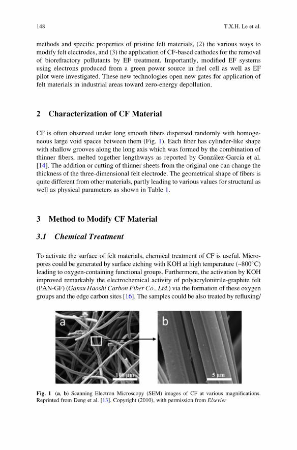
methods and specific properties of pristine felt materials, (2) the various ways to
modify felt electrodes, and (3) the application of CF-based cathodes for the removal
of biorefractory pollutants by EF treatment. Importantly, modified EF systems
using electrons produced from a green power source in fuel cell as well as EF
pilot were investigated. These new technologies open new gates for application of
felt materials in industrial areas toward zero-energy depollution.
2 Characterization of CF Material
CF is often observed under long smooth fibers dispersed randomly with homoge-
neous large void spaces between them (Fig. 1). Each fiber has cylinder-like shape
with shallow grooves along the long axis which was formed by the combination of
thinner fibers, melted together lengthways as reported by Gonzalez-Garcıa et al.
[14]. The addition or cutting of thinner sheets from the original one can change the
thickness of the three-dimensional felt electrode. The geometrical shape of fibers is
quite different from other materials, partly leading to various values for structural as
well as physical parameters as shown in Table 1.
3 Method to Modify CF Material
3.1 Chemical Treatment
To activate the surface of felt materials, chemical treatment of CF is useful. Micro-
pores could be generated by surface etching with KOH at high temperature (~800�C)leading to oxygen-containing functional groups. Furthermore, the activation by KOH
improved remarkably the electrochemical activity of polyacrylonitrile-graphite felt
(PAN-GF) (Gansu Haoshi Carbon Fiber Co., Ltd.) via the formation of these oxygen
groups and the edge carbon sites [16]. The samples could be also treated by refluxing/
Fig. 1 (a, b) Scanning Electron Microscopy (SEM) images of CF at various magnifications.
Reprinted from Deng et al. [13]. Copyright (2010), with permission from Elsevier
148 T.X.H. Le et al.
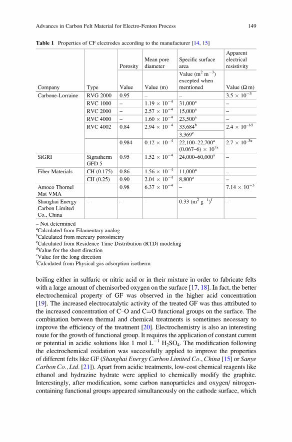
boiling either in sulfuric or nitric acid or in their mixture in order to fabricate felts
with a large amount of chemisorbed oxygen on the surface [17, 18]. In fact, the better
electrochemical property of GF was observed in the higher acid concentration
[19]. The increased electrocatalytic activity of the treated GF was thus attributed to
the increased concentration of C–O and C¼O functional groups on the surface. The
combination between thermal and chemical treatments is sometimes necessary to
improve the efficiency of the treatment [20]. Electrochemistry is also an interesting
route for the growth of functional group. It requires the application of constant current
or potential in acidic solutions like 1 mol L�1 H2SO4. The modification following
the electrochemical oxidation was successfully applied to improve the properties
of different felts like GF (Shanghai Energy Carbon Limited Co., China [15] or SanyeCarbon Co., Ltd. [21]). Apart from acidic treatments, low-cost chemical reagents like
ethanol and hydrazine hydrate were applied to chemically modify the graphite.
Interestingly, after modification, some carbon nanoparticles and oxygen/ nitrogen-
containing functional groups appeared simultaneously on the cathode surface, which
Table 1 Properties of CF electrodes according to the manufacturer [14, 15]
Company Type
Porosity
Mean pore
diameter
Specific surface
area
Apparent
electrical
resistivity
Value Value (m)
Value (m2 m�3)
excepted when
mentioned Value (Ωm)
Carbone-Lorraine RVG 2000 0.95 – – 3.5 � 10�3
RVC 1000 – 1.19 � 10�4 31,000a –
RVC 2000 – 2.57 � 10�4 15,000a –
RVC 4000 – 1.60 � 10�4 23,500a –
RVC 4002 0.84 2.94 � 10�4 33,684b 2.4 � 10–1d
3,369c
0.984 0.12 � 10�4 22,100–22,700a
(0.067–6) � 107a2.7 � 10–3e
SiGRI Sigratherm
GFD 5
0.95 1.52 � 10�4 24,000–60,000a –
Fiber Materials CH (0.175) 0.86 1.56 � 10�4 11,000a –
CH (0.25) 0.90 2.04 � 10�4 8,800a –
Amoco Thornel
Mat VMA
0.98 6.37 � 10�4 – 7.14 � 10�3
Shanghai Energy
Carbon Limited
Co., China
– – – 0.33 (m2 g�1)f –
– Not determinedaCalculated from Filamentary analogbCalculated from mercury porosimetrycCalculated from Residence Time Distribution (RTD) modelingdValue for the short directioneValue for the long directionfCalculated from Physical gas adsorption isotherm
Advances in Carbon Felt Material for Electro-Fenton Process 149
greatly improved the hydrophilicity of the surface and the electrocatalytic activity.
Contact angles decreased gradually from 141�, to 123�, to 110� for bare GF
(Shanghai Qijie Carbon Material Co., LTD), GF-ethanol, and GF-ethanol/hydrazine,respectively [22, 23].
3.2 Thermal and Plasma Treatment
The thermal treatment under gas flow containing oxygen and/or nitrogen is a simple
way for felt modification to improve the electrochemical properties and the hydro-
philicity [8]. In the study of Zhong et al. [24], a significant enhancement of the
electrochemical activity was observed on GF, based on rayon or PAN precursors
after thermal treatment under air. It was found that the electrical conductivity of the
PAN-based felts was superior to that of its rayon-based counterpart. X-ray photo-
electron spectroscopy (XPS) analysis pointed out that the rayon-based felts reacted
more easily with oxygen and forms C¼O groups, while the PAN-based felts were
more resistant to oxidation and preferentially form C–O groups. The more exten-
sive oxygen interaction in the rayon felts was thought to be due to its microcrys-
talline structure. Thermal treatment of GF electrodes was carried out under NH3
atmosphere at 600�C and 900�C. The nitrogen-doped (N-doped) felt was fabricatedwith high electrochemical performance attributed to the increased electrical con-
ductivity, the increase of active sites amount, and the improved wettability provided
by the introduction of the nitrogenous groups on the surface of GF [25, 26]. Inter-
estingly, the thermal treatment under air can also improve the surface area of the
pristine electrodes: after treatment in air at 400�C, the surface area of the modified
felts increased by more than ten times in comparison to the pristine one based on
rayon (SGL, thickness 3 mm) [27]. This value was 1,344% higher than bare
PAN-CF (Nippon Chem, thickness 3 mm) [5]. In the same way, thermal treatment
under a flux of N2/O2 with 1% of oxygen at 1,000�C for 1 h could also increase the
SBET of commercial felts (Johnson Matthey Co.,Germany, thickness 1.27 cm) up to
64 m2 g�1, i.e., around 700 times higher than raw samples. As further benefit, the
crystalline size was also ameliorated due to the selective etching of amorphous
carbon by thermal treatment [28].
Plasma treatments are also carried out to perform the growth of oxygen-
containing functional groups or/and nitrogen doping on the surface of fibers.
Oxygen plasma treatment was conducted in a radiofrequency (RF) plasma set-up
controlling treatment time, power of the RF generator, and oxygen pressure. In
2015, Chen et al. [29] reported the modification of felts (C0S1011, CeTech, Taiwan,thickness 6 mm) with Atmospheric Pressure Plasma Jets (APPJs). The APPJ
treatment was performed on the felts under the single spot and scanning modes
with the presence of N2 flow rates. The formation of specific oxygen functional
groups was observed after the plasma treatment. XPS revealed that this method
rather favored the formation of C–O groups than C¼O groups [27]. However, the
plasma treatment process only often increases the amount of functional groups on
150 T.X.H. Le et al.
felts and not remarkably the surface area. Apart from oxygen-containing functional
groups, nitrogenous groups can also improve electrocatalytic activity of carbon
electrode materials for redox reactions. This comes from the reason that carbon
atoms neighboring nitrogen dopants present a high positive charge density improv-
ing their electrocatalytic activity [30]. Furthermore, nitrogen doping can also make
CF materials more hydrophilic which increases the electrochemically active sites
[25]. Briefly, the increased amount of surface-active oxygen and nitrogenous
groups by thermal or plasma treatment can enhance electrochemical performance
of the modified material through facilitating charge transfer between felt electrodes
and electrolytes [27, 31].
3.3 Graphene Based Modification
Graphene has received extensive attention due to its remarkable electrical, physical,
thermal, optical, high specific surface area, and mechanical properties [32, 33], and
it is then widely applicable for electrochemical applications [34]. Dip-coating,
electrophoretic deposition (EPD), or voltamperometric techniques are methods
often used separately or combined together for the coating of graphene-based
materials on felt electrodes. For example, the coating of reduced graphene oxide
(rGO) on CF (Shanghai Qijie Carbon Co., Ltd.) was performed using different
steps: (1) Graphene oxide (GO) suspension was prepared by sonication in water for
1 h to exfoliate graphite. (2) GO was loaded on the CF surface by the dipping-
drying process. (3) The GO was then electrochemically reduced by applying a
constant voltage in 0.5 M Na2SO4 for 10 min. By comparing the response of cyclic
voltammograms (CVs) curves in 0.5 M Na2SO4 solution, the rGO/CF electrode has
overall a higher current density than the bare CF over the scanned voltage range
(�0.6 to 0.6 V), suggesting a larger electrode surface area and better conductivity
after modification [35].
In addition, the EPD shows several advantages for obtaining homogeneous films
on felt electrodes from suspensions containing well-dispersed charged particles like
GO solution, with high deposition rates, simple operation, easy scalability, and all
that by avoiding the use of binders [36]. A graphene-modified GF was synthesized
using EPD method by applying a voltage of 10 V for 3 h. The negative GO sheets
were moved toward the positive GF electrode. The electrode showed graphene-like
sheets on the fiber surface either in a wrinkled configuration or anchored between
them. These sheets consisted of partially rGO with oxygen content decreasing from
13 at.% in the initial GO to 3.84 at.%. To compare with other modification methods,
the chemical treatment by electrochemical oxidation in 1 M H2SO4 (GF-H2SO4) for
3 h or thermal treatment (TT-GF) at 450�C with the same time, 3 h, under air flow in
a tubular furnace was done. The electrochemical performance of graphene modifi-
cation was even higher than GF-H2SO4 or TT-GF [37]. Because of the excellent
electrochemical properties of graphene-based materials, they have still a promising
future for applications in the modification of CF electrode.
Advances in Carbon Felt Material for Electro-Fenton Process 151
3.4 Carbon Nanotube-Based Modification
Felt electrodes were attractively modified by carbon nanotubes because of their
excellent electrical and thermal conductivities, mechanical flexibility, and signifi-
cantly large surface area [38]. The coating of single-walled carbon nanotube
(SWCNT) was performed by a simple way where CF was immersed into the
SWCNT suspension. The CF was then dried at 80�C for 5 h. The SWCNT (2 wt%
relative to the amount of carbon felt) was ultrasonically dispersed previously inN,N-dimethyl formamide (DMF). The process was repeated until all the SWCNT sus-
pension adsorbed into the CF. The modified electrode showed a better catalytic
performance with higher electron transfer rate compared to the raw one [39]. On the
other hand, the carbon nanotubes (CNTs) could be directly grown on the surface of
felts by chemical vapor deposition (CVD) method without binding agent. For this
purpose, the felt sample was placed in the center of a quartz tube and heated at high
temperature (around 800�C) under Ar gas flow, followed by the injection of the
carbon precursor source. Toluene or ethylenediamine was applied as source solution
for the growth of CNTs or nitrogen-CNTs on GF. The small size (�30 nm in
diameter) of CNTs created a significant increase of the electrochemical surface
area of the felt materials. In addition, the N-doping could further improve the
electrode performance because of the modified electronic and surface properties of
CNTs on GF [40]. The CNTs/CF electrode was also obtained by growing CNTs via
CVD of methanol on cobalt and manganese metallic particles deposited on
CF. The specific surface area of CF loaded with 37.8 mg of CNTs was found to be
148 m2 g�1 instead of 1.0 m2 g�1 for non-modified one [41].
Growth of multi-walled carbon nanotubes (MWCNTs) on CF was investigated
by CVD using ferrocene in toluene as precursor (Fe(C5H5)2 at 20 g L�1 in C7H8).
CNTs with high aspect ratio were grown from the iron sites, generated by the
decomposition and the subsequent nucleation of the iron species from the ferrocene
precursor deposited on the CF substrate. The specific surface area successively
increases with an increase in CNT loading and reaches 150 m2 g�1 for a CNT
weight intake of 98%. A significant enhancement of mechanical strength and
electrical conductivity along with the effective surface area was observed. The
residual iron catalyst was removed by an acid treatment (HNO3, 65%, at 80�C for
2 h), which caused the formation of oxygenated functional groups on the CNT
surface [42]. Other CNTs/CF electrodes were prepared using the decomposition of
methanol on different metallic catalysts, including cobalt, manganese, and lithium,
supported on CF [43]. Bamboo-like structures were identified in good agreement
with the study of Rosolen et al. [44].
EPD shows noticeable advantages as a low-cost and simple method compared to
CVD [45, 46]. The first step is the dispersion of CNTs in isopropyl alcohol for 3 h in
ultrasonic bath at 1.6 g L�1. Applying a constant voltage of 40 V for 60 s, 1.05 wt%
CNTs were deposited uniformly on CF with no obvious agglomeration or acutely
curly body [47]. The studies have been enlarged with CNTs functionalized with
carboxyl and hydroxyl groups. The carboxyl MWCNTs were adhered onto the CF
152 T.X.H. Le et al.
(Shenhe Carbon Fibre Materials Co. Ltd., thickness 4 mm) by immersing in a
mixture solution of COOH-MWCNTs containing 0.02 wt.% Nafion as a binder to
guarantee the stability of the MWCNTs/CF electrode. Not only the hydrophilicity
but also the number of active sites of CF was upgraded, depending on the carboxyl
groups of MWCNTs [48]. Similarly, the COOH-MWCNTs were ultrasonically
dispersed in dimethyl formamide and then the CF was immersed in this solution.
COOH-MWCNTs/CF was obtained by drying the electrode in the oven at 100�Cfor 24 h [49].
3.5 Polymer-Based Modification
Polyaniline (PANi) and polypyrrole (PPy) are the most common conducting polymers
for electrode modification because of their high electrical conductivity, ease of
preparation, and environmental stability [50, 51]. The coating of conductive polymer
film on the surface of CF is usually conducted by the electropolymerization process in
solution containing monomers. Interestingly, electropolymerized materials have
unique properties which are not peculiar to the corresponding monomers [52, 53].
The PPy/anthraquinone-2,6-disulfonate (AQDS) conductive film was coated on CF
(Liaoyang Jingu Carbon Fiber Sci-Tech Co., Ltd., China) (Fig. 2c) in a basic three-
electrode electrochemical cell. The polymer film was formed on the CF surface by
applying a constant potential of 0.8 V vs saturated calomel electrode (SCE), control-
ling the thickness with the coulometry. The modified electrode resulted in larger
current responses when compared to the unmodified electrode (Fig. 2e) due to the
enhanced surface area and conductivity of the PPy/AQDS-modified electrode [54].
Besides electropolymerization method, the polymer-modified felts could be prepared
in a simple way by submerging CF in HCl solution adding aniline monomer and
ammonium persulfate. The polymerization was conducted for 8 h by continuously
stirring in order to coat PANi on the surface of CF [56].
In order to improve the physicochemical and electrochemical properties of the
conducting organic films, many copolymers were prepared and investigated. The
electrochemical activity of poly(aniline-co-o-aminophenol) was about four times as
high as that of PANi 0.3 mol L�1 Na2SO4 solution of pH 5. The copolymer had a
good stability and a high reversibility [57]. A poly(aniline-co-o-aminophenol) film
with average mass at 1.17 � 0.1 g was deposited on CF by Cui et al. [39] through
electrochemical synthesis in solution containing simultaneously aniline and o-aminophenol. What’s more, the biocompatibility of felt electrodes was increased
significantly when they were coated by the co-polymers containing nitrogen/oxy-
gen functional groups. The hydrophilic conductive co-polymers like poly (aniline-
co-o-aminophenol), poly (aniline-co-2, 4-diaminophenol), and poly (aniline-1,
8-diaminonaphthalene) acted as the bridge or mediator, playing the role of bonding
bacteria and CF cathode more tightly, and facilitated or improved the electron
transfer process from cathode to bacteria for microbial fuel cell application [56]. In
terms of the increase of surface area, electronic conductivity, biocompatibility, and
Advances in Carbon Felt Material for Electro-Fenton Process 153
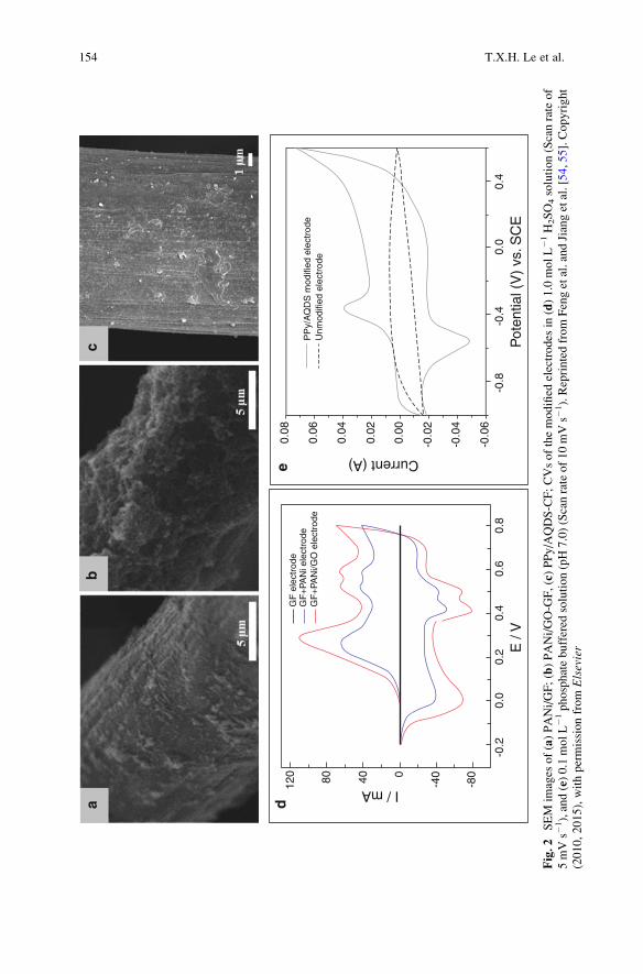
ab
c
GF
ele
ctro
de
GF
+PA
Ni/G
O e
lect
rode
G
F+
PAN
i ele
ctro
de
-0.2
0.0
0.2
0.4
0.6
0.8
-0.8
-0.4
0.0
0.4
120 80 40 -40
-800
E /
VP
oten
tial (
V)
vs. S
CE
I / mA
0.08
0.06
0.04
0.02
0.00
-0.0
2
-0.0
4
-0.0
6
Current (A)
PP
y/A
QD
S m
odifi
ed e
lect
rode
Unm
odifi
ed e
lect
rode
de
Fig.2
SEM
images
of(a)PANi/GF;(b)PANi/GO-G
F,(c)PPy/AQDS-CF;CVsofthemodified
electrodes
in(d)1.0molL�1
H2SO4solution(Scanrateof
5mVs�
1),and(e)0.1molL�1
phosphatebuffered
solution(pH7.0)(Scanrateof10mVs�
1).Reprintedfrom
Fengetal.andJiangetal.[54,55].Copyright
(2010,2015),withpermissionfrom
Elsevier
154 T.X.H. Le et al.
stability, PPy was simultaneously covered on the GF (Beijing Sanye Co. Ltd.,
thickness 5 mm) with GO. The growth of PPy/GO on GF electrode was carried
out in one step by electropolymerization of pyrrole (Py) in the solution containing
simultaneously the GO. The functional groups of GO like –OH and –COOH play
the role of external dopant for PPy formation. The new electrode exhibited
improved performance compared with PPy alone when it could increase signifi-
cantly the power density of Microbial Fuel Cell (MCF) [58]. In order to overcome
the unsatisfactory stability of PANi-modified GF electrode, GO was introduced into
PANi/GO composite for the modification of graphite (Chemshine Carbon CO.,China) by one electrochemical approach [59]. The PANi/GO-GF (Fig. 2b, d)
enhanced outstandingly the electrochemical activity as well as the hydrophilicity
of GF electrode. The stability of new electrode was actually noticeable when after
1,000 s, the oxidation current of the PANi/GO-modified GF electrode was still
higher than that of the PANi-modified GF electrode (Fig. 2a) because of the
synergistic effect of PANi and GO [55]. Moreover, conductive polymers have
been combined with CNTs to increase the effective surface area and the electrical
conductivity of the resulting material. The PANi was electropolymerized on the
surface of GF (Beijing Sanye Carbon, China, thickness 4 mm) followed by the EPD
of CNTs [60]. Using polymer for the modification of GF electrode is convenient
and effective method because it is a low-cost approach and improves the electro-
chemical performance.
3.6 Zeolite-Based Modification
Zeolites are porous crystalline aluminosilicates of SiO44� and AlO4
5� tetrahedra
connected by oxygen bridges. Zeolite-modified electrodes (ZMEs) have numerous
applications in various fields especially in electroanalytical chemistry because of
the unique molecular sieving properties of zeolites [61]. NaX zeolite consists of
sodalite cages arranged in a three-dimensional open framework leading to a micro-
porous crystalline structure. Cages are linked through double six rings creating a
large super cage cavity [62]. NaX zeolite was grown on GF during hydrothermal
synthesis at 100�C for 3 h in solution containing sodium silicate, sodium aluminate,
and sodium hydroxide with a molar composition of 3.5 Na2O:1 Al2O3:2.1
SiO2:1,000 H2O. Electrode activity was investigated in the presence of bacterial
to prove the interest of the approach for microbial biofuel cells. The GF modified
with NaX showed a higher electrochemical activity after ex situ acclimatization
compared to bare electrodes [62, 63].
Prussian blue (PB, ferric hexacyanoferrate) is another kind of zeolite interesting
for electrode modification [64, 65]. PB and its analogues have been known as
polynuclear transition metal hexacyanometalates that own the zeolite-like structure
[65–67]. Its electrochemical behavior was reported for the first time in 1978 by Neff
et al. [68]. Some years later, the PB has attracted extensive attention due to its features
relevant to inherent electrochromic [69], electrochemical [70], photophysical [71], as
Advances in Carbon Felt Material for Electro-Fenton Process 155
well as molecular magnetic properties [72]. The electrochemical and chemical depo-
sitions were used to modify the GF electrode by PB. Firstly, the conductivity of felt
electrode was improved via the electrodeposition of Platinum (Pt) on the surface of
GF, which also played the role of catalyst for PB formation. Secondly, the Pt/GF
electrode was immersed for 60 min into 20 mL of a solution containing 1.0 mmol L�1
FeCl3, 1.0 mmol L�1 K3Fe(CN)6, 0.1 mol L�1 KCl, and 0.025 mol L�1 HCl. Next, the
washing step was repeated many times before drying the electrode for 2 h at 90�C.This sample was noted as PB@Pt/GF. The SEM images of PB@Pt/GF showed the
successful deposition of PB on the GF. PB@Pt/GF electrode showed excellent
stability during 150 consecutive voltammetric cycles in 0.5 mol L�1 KCl solution
as no decrease of the current was observed [4]. On the other hand, GF electrode was
modified by a novel PB and ionic liquid 1-butyl-3-methylimidazolium tetrafluo-
roborate ([Bmim][BF4]) via simple method involving GF placed in a ultrasound
bath of [Bmim][BF4] and then in a PB precursor solution. In this case, the immobi-
lization of [Bmim][BF4] supported the anchoring PB nanoparticles on the surface of
the GF [73].
Zeolitic Imidazolate Framework (ZIF-8) was recently proposed for modification
of CF electrode from Atomic Layer Deposition of Zinc Oxide (ZnO) and its subse-
quent solvothermal conversion to ZIF-8. After heat treatments under control atmo-
sphere, ZIF-8 conversion leads to microporous carbon structure with enhanced
textural and electrochemical properties. The specific surface area of the CF was
increased from 0.0915 to 64 m2 g�1 for pristine and modified CF, respectively [74].
To give an overview of the modification methods (Fig. 3), Table 2 summarizes
advantages and drawbacks of each one.
4 Carbon Felt-Based Material for Wastewater Treatment
by EF Process
4.1 Carbon Felt for EF Process
CF are abundantly used for electrochemical applications and especially for EF
process because of their outstanding properties like (1) high specific surface area
and high efficiency for both hydrogen peroxide production and cathodic regenera-
tion of Fe2+, good mechanical integrity, and commercial availability, which make
them an attractive cathode material for EF process [23, 76]; (2) good adaptability to
various EF systems with different shapes and surfaces of electrodes from small
(2 cm2) [28, 77] to large size like 60 cm2 [78, 79] or 150 cm2 [80]; and (3) high
physicochemical stability allowing a significant decline in the cost for the EF
technology, since it can be continuously used for many cycles (at least ten cycles)
without any decrease of the treatment efficiency [81].
The application of EF technology for elimination of POPs on CF cathodes has
been preceded very early by Oturan and coworkers [82–84]. One of their first
papers in 2000s described the EF process in a divided cell allowing almost total
156 T.X.H. Le et al.
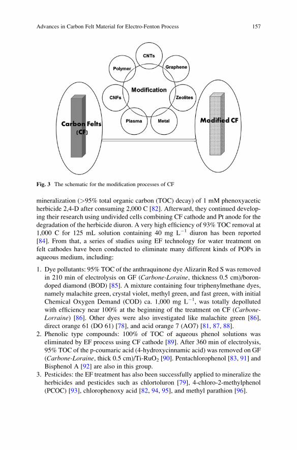
mineralization (>95% total organic carbon (TOC) decay) of 1 mM phenoxyacetic
herbicide 2,4-D after consuming 2,000 C [82]. Afterward, they continued develop-
ing their research using undivided cells combining CF cathode and Pt anode for the
degradation of the herbicide diuron. A very high efficiency of 93% TOC removal at
1,000 C for 125 mL solution containing 40 mg L�1 diuron has been reported
[84]. From that, a series of studies using EF technology for water treatment on
felt cathodes have been conducted to eliminate many different kinds of POPs in
aqueous medium, including:
1. Dye pollutants: 95% TOC of the anthraquinone dye Alizarin Red S was removed
in 210 min of electrolysis on GF (Carbone-Loraine, thickness 0.5 cm)/boron-
doped diamond (BOD) [85]. A mixture containing four triphenylmethane dyes,
namely malachite green, crystal violet, methyl green, and fast green, with initial
Chemical Oxygen Demand (COD) ca. 1,000 mg L�1, was totally depolluted
with efficiency near 100% at the beginning of the treatment on CF (Carbone-Lorraine) [86]. Other dyes were also investigated like malachite green [86],
direct orange 61 (DO 61) [78], and acid orange 7 (AO7) [81, 87, 88].
2. Phenolic type compounds: 100% of TOC of aqueous phenol solutions was
eliminated by EF process using CF cathode [89]. After 360 min of electrolysis,
95% TOC of the p-coumaric acid (4-hydroxycinnamic acid) was removed on GF
(Carbone-Loraine, thick 0.5 cm)/Ti-RuO2 [90]. Pentachlorophenol [83, 91] and
Bisphenol A [92] are also in this group.
3. Pesticides: the EF treatment has also been successfully applied to mineralize the
herbicides and pesticides such as chlortoluron [79], 4-chloro-2-methylphenol
(PCOC) [93], chlorophenoxy acid [82, 94, 95], and methyl parathion [96].
Fig. 3 The schematic for the modification processes of CF
Advances in Carbon Felt Material for Electro-Fenton Process 157
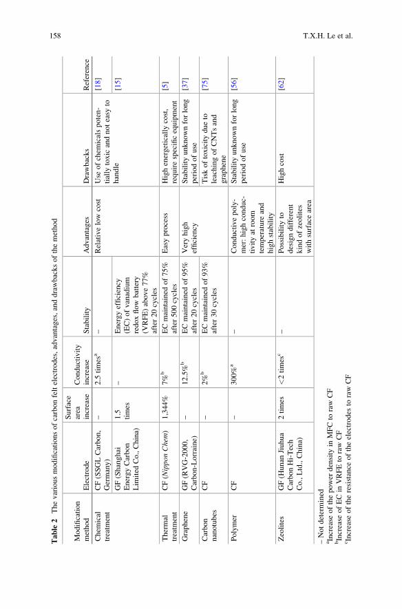
Table
2Thevariousmodificationsofcarbonfeltelectrodes,advantages,anddrawbacksofthemethod
Modification
method
Electrode
Surface
area
increase
Conductivity
increase
Stability
Advantages
Drawbacks
Reference
Chem
ical
treatm
ent
CF(SSGLCarbon,
Germany)
–2.5
times
a–
Relativelowcost
Use
ofchem
icalspoten-
tially
toxic
andnoteasy
to
handle
[18]
GF(Shanghai
EnergyCarbon
Lim
ited
Co.,China)
1.5
times
–Energyefficiency
(EC)ofvanadium
redoxflow
battery
(VRFE)above77%
after20cycles
[15]
Thermal
treatm
ent
CF(Nippon
Chem
)1,344%
7%
bECmaintained
of75%
after500cycles
Easyprocess
Highenergetically
cost,
requirespecificequipment
[5]
Graphene
GF(RVG-2000,
Carbon-Lorraine)
–12.5%
bECmaintained
of95%
after20cycles
Veryhigh
efficiency
Stabilityunknownforlong
periodofuse
[37]
Carbon
nanotubes
CF
–2%
bECmaintained
of93%
after30cycles
Tiskoftoxicitydueto
leachingofCNTsand
graphene
[75]
Polymer
CF
–300%
a–
Conductivepoly-
mer:highconduc-
tivityat
room
temperature
and
highstability
Stabilityunknownforlong
periodofuse
[56]
Zeolites
GF(H
unan
Jiuhua
CarbonHi-Tech
Co.,Ltd.,China)
2times
<2times
c–
Possibilityto
designdifferent
kindofzeolites
withsurfacearea
Highcost
[62]
–Notdetermined
aIncrease
ofthepower
density
inMFCto
rawCF
bIncrease
ofECin
VRFEto
raw
CF
cIncrease
oftheresistance
oftheelectrodes
toraw
CF
158 T.X.H. Le et al.
4. Pharmaceuticals: Chlorophene [97], triclosan, and triclocarban [97] were exam-
ples for pharmaceutical pollutants which have been degraded efficiently by EF
process using felt materials.
5. Hydrocarbons and polycyclic aromatic hydrocarbons (PAHs): EF process was
also proposed to enhance the efficiency of soil washing treatment [80, 98, 99].
By the EF process, the pollutants are degraded step by step and eventually
mineralized by reacting with hydroxyl radicals. The attack of hydroxyl radicals
gives the formation of aromatic intermediate compounds at the beginning of
electrolysis. The aromatic ring opening reactions in the next step create aliphatic
carboxylic acids (oxalic, acetic, formic acid, etc.) and inorganic ions (i.e., ammo-
nium, nitrate, sulfate, phosphate) as final end products before mineralization
[97, 100–102]. Therefore, the EF mineralization also leads to the detoxification of
treated solution [88, 91]. In particular, the toxicity of solutions disappeared after
240 min for 220 mL solution with 0.2 mM of sucralose [103], and 60 min for
200 mL solution with 50 mg L�1 of Orange II [100]. The above results allow
proposing EF process on CF cathode as an environmentally friendly method for the
treatment of wastewater effluents containing toxic and/or persistent organic pollut-
ants. Interestingly, more and more studies are focused now on CF modifications for
improving EF processes as described in the following section.
4.2 Modified EF Systems Using Carbon Felt Cathodes
4.2.1 Modified Felt Cathodes for Homogeneous EF
For homogeneous EF process, hydrogen peroxide production and its reaction with
catalyst in solution is a crucial factor for the effective destruction of POPs. Aiming
to improve the in situ generation of H2O2, various attempts have been made to
upgrade the electrocatalytic characteristic of CF cathodes. As discussed in Sect. 3.1,
chemical modification is a simple and efficient way to ameliorate the electrochem-
ical activity of the felt electrodes by changing their surface functional groups. After
treatment in a mixture composed of ethanol and hydrazine hydrate (volume ratio
90/10), the concentration of H2O2 after 120 min was 175.8 mg L�1 on the modified
felt (CF-B) (Shang-hai Qijie Carbon material Co., Ltd.) which was nearly three
times higher than 67.5 mg L�1 for commercial CF. The p-nitrophenol TOC removal
ratios were then 22.2% and 51.4% for CF and CF-B, respectively, proving that
the treated cathode could efficiently promote the degradation efficiency of the
pollutants with interesting stability and reusability (after ten cycles, the minerali-
zation ratio was still above 45%) [23]. Anthraquinone-2,6-disulfonate/polypyrrole
(AQDS/PPy) composite film was grown on graphite electrodes by electro-
polymerization of the pyrrole monomer in the presence of anthraquinone-2,6-
disulfonic acid. Positive shifts (�0.65, �0.60, and �0.52 V vs SCE for pH 3.0,
4.0, and 6.0, respectively) were recorded indicating a better kinetics for oxygen
Advances in Carbon Felt Material for Electro-Fenton Process 159
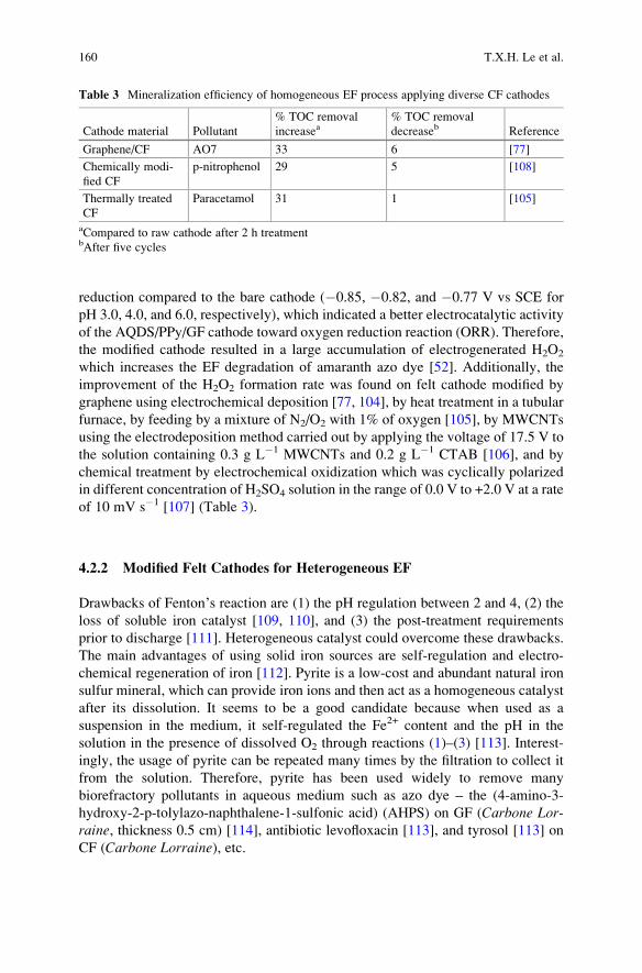
reduction compared to the bare cathode (�0.85, �0.82, and �0.77 V vs SCE for
pH 3.0, 4.0, and 6.0, respectively), which indicated a better electrocatalytic activity
of the AQDS/PPy/GF cathode toward oxygen reduction reaction (ORR). Therefore,
the modified cathode resulted in a large accumulation of electrogenerated H2O2
which increases the EF degradation of amaranth azo dye [52]. Additionally, the
improvement of the H2O2 formation rate was found on felt cathode modified by
graphene using electrochemical deposition [77, 104], by heat treatment in a tubular
furnace, by feeding by a mixture of N2/O2 with 1% of oxygen [105], by MWCNTs
using the electrodeposition method carried out by applying the voltage of 17.5 V to
the solution containing 0.3 g L�1 MWCNTs and 0.2 g L�1 CTAB [106], and by
chemical treatment by electrochemical oxidization which was cyclically polarized
in different concentration of H2SO4 solution in the range of 0.0 V to +2.0 V at a rate
of 10 mV s�1 [107] (Table 3).
4.2.2 Modified Felt Cathodes for Heterogeneous EF
Drawbacks of Fenton’s reaction are (1) the pH regulation between 2 and 4, (2) the
loss of soluble iron catalyst [109, 110], and (3) the post-treatment requirements
prior to discharge [111]. Heterogeneous catalyst could overcome these drawbacks.
The main advantages of using solid iron sources are self-regulation and electro-
chemical regeneration of iron [112]. Pyrite is a low-cost and abundant natural iron
sulfur mineral, which can provide iron ions and then act as a homogeneous catalyst
after its dissolution. It seems to be a good candidate because when used as a
suspension in the medium, it self-regulated the Fe2+ content and the pH in the
solution in the presence of dissolved O2 through reactions (1)–(3) [113]. Interest-
ingly, the usage of pyrite can be repeated many times by the filtration to collect it
from the solution. Therefore, pyrite has been used widely to remove many
biorefractory pollutants in aqueous medium such as azo dye – the (4-amino-3-
hydroxy-2-p-tolylazo-naphthalene-1-sulfonic acid) (AHPS) on GF (Carbone Lor-raine, thickness 0.5 cm) [114], antibiotic levofloxacin [113], and tyrosol [113] on
CF (Carbone Lorraine), etc.
Table 3 Mineralization efficiency of homogeneous EF process applying diverse CF cathodes
Cathode material Pollutant
% TOC removal
increasea% TOC removal
decreaseb Reference
Graphene/CF AO7 33 6 [77]
Chemically modi-
fied CF
p-nitrophenol 29 5 [108]
Thermally treated
CF
Paracetamol 31 1 [105]
aCompared to raw cathode after 2 h treatmentbAfter five cycles
160 T.X.H. Le et al.
2FeS2 þ 2H2Oþ 7O2 ! 2Fe2þ þ 4Hþ þ 4SO42� ð1Þ
2FeS2 þ 15H2O2 ! 2Fe3þ þ 4SO42� þ 2Hþ þ 14H2O ð2Þ
FeS2 þ 8H2Oþ 14Fe3þ ! 15Fe2þ þ 16Hþ þ 2SO42� ð3Þ
Iron alginate gel beads (FeAB) were also used in suspension as heterogeneous
catalyst in the EF treatment in which high imidacloprid removal (90%) was
achieved using GF cathode (Carbon Lorraine, France) for 4 h [115]. Decolorizationof Lissamine Green B and Azure B was 87% and 98%, respectively, after 30 min by
using FeAB, maintaining particle shapes throughout the oxidation process [116].
Besides operating with solid catalyst in suspension, in 2017, Ozcan et al. [117]
prepared a new iron containing Fe2O3-modified kaolin (Fe2O3-KLN) catalyst to
develop a heterogeneous EF process with three-dimensional CF cathode for the
electrochemical oxidation of enoxacin (ENXN). In the presence of Fe2O3-KLN,
mineralization efficiency is increasing and the maximal value was found in the
presence of 0.3 g catalyst at 300 mA with a very low iron quantity (�0.006 mM)
leached in solution, showing that hydroxyl radicals were mainly produced by
heterogeneous reactions of surface iron species immobilized on CF [117]. The
durability of the catalyst was tested on five runs and a small decrease of around
0.5% was monitored [117]. EF treatment with heterogeneous pyrrhotite catalyst has
also shown good stability with a stable color and COD removal of 77% and 78%,
respectively, after 45 days. [118]. On the other hand, investigation on hierarchical
CoFe-layered double hydroxide (LDH)-modified carbon felt cathode indicated that
TOC removal declined 46% compared to fresh electrode after ten cycles, proving
that stability has to be improved for this electrode [119].
The performance of the heterogeneous catalysis for the removal of pollutants by
EF was also improved compared with homogeneous one. For example, a measured
pseudo-first-order rate constant of 2.5 � 10�4 s�1 (R2 ¼ 0.990) was found for EF
using pyrite catalyst which was nearly two times higher than the constant deter-
mined in electrochemical oxidation (1.3 � 10�4 s�1 (R2 ¼ 0.992)). In addition,
Fe@Fe2O3 [120–122], pyrrhotite [118] γ-FeOOH [123, 124], and (γ-Fe2O3/Fe3O4
oxides) nanoparticles [125] and chalcopyrite [126] are interesting iron catalyst
sources. The stable performance of these heterogeneous iron catalysts open prom-
ising perspectives for fast and economical treatment of wastewater polluted by POP
contaminants using EF treatment on CF cathodes. In a very recent study, one new
kind of heterogeneous catalyst, hierarchical CoFe-Layered Double Hydroxide
(CoFe-LDH), was grown on CF by in situ solvothermal method. The CoFe-LDH/
CF cathode showed very good stability when after seven cycles of degradation the
TOC removal after 2 h was still above 60% [119] (Table 4).
Advances in Carbon Felt Material for Electro-Fenton Process 161
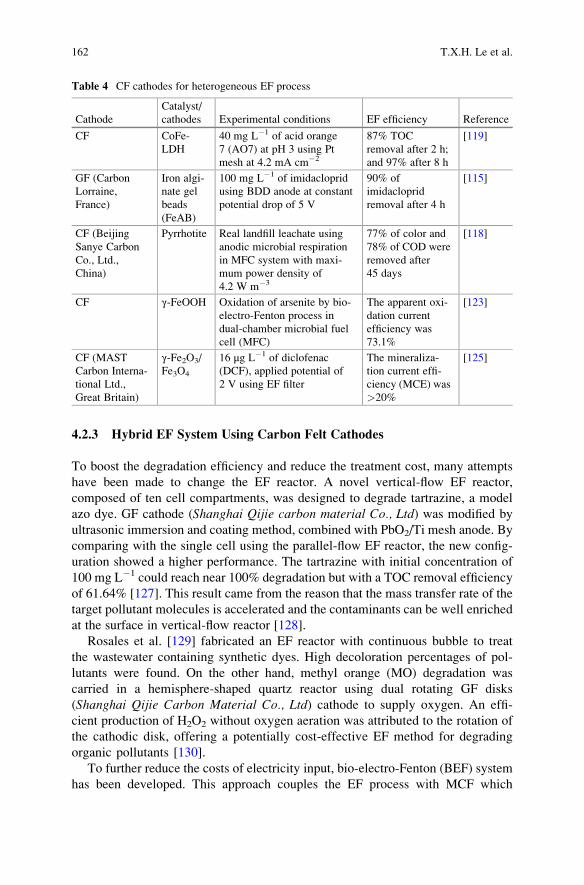
4.2.3 Hybrid EF System Using Carbon Felt Cathodes
To boost the degradation efficiency and reduce the treatment cost, many attempts
have been made to change the EF reactor. A novel vertical-flow EF reactor,
composed of ten cell compartments, was designed to degrade tartrazine, a model
azo dye. GF cathode (Shanghai Qijie carbon material Co., Ltd) was modified by
ultrasonic immersion and coating method, combined with PbO2/Ti mesh anode. By
comparing with the single cell using the parallel-flow EF reactor, the new config-
uration showed a higher performance. The tartrazine with initial concentration of
100 mg L�1 could reach near 100% degradation but with a TOC removal efficiency
of 61.64% [127]. This result came from the reason that the mass transfer rate of the
target pollutant molecules is accelerated and the contaminants can be well enriched
at the surface in vertical-flow reactor [128].
Rosales et al. [129] fabricated an EF reactor with continuous bubble to treat
the wastewater containing synthetic dyes. High decoloration percentages of pol-
lutants were found. On the other hand, methyl orange (MO) degradation was
carried in a hemisphere-shaped quartz reactor using dual rotating GF disks
(Shanghai Qijie Carbon Material Co., Ltd) cathode to supply oxygen. An effi-
cient production of H2O2 without oxygen aeration was attributed to the rotation of
the cathodic disk, offering a potentially cost-effective EF method for degrading
organic pollutants [130].
To further reduce the costs of electricity input, bio-electro-Fenton (BEF) system
has been developed. This approach couples the EF process with MCF which
Table 4 CF cathodes for heterogeneous EF process
Cathode
Catalyst/
cathodes Experimental conditions EF efficiency Reference
CF CoFe-
LDH
40 mg L�1 of acid orange
7 (AO7) at pH 3 using Pt
mesh at 4.2 mA cm�2
87% TOC
removal after 2 h;
and 97% after 8 h
[119]
GF (Carbon
Lorraine,
France)
Iron algi-
nate gel
beads
(FeAB)
100 mg L�1 of imidacloprid
using BDD anode at constant
potential drop of 5 V
90% of
imidacloprid
removal after 4 h
[115]
CF (Beijing
Sanye Carbon
Co., Ltd.,
China)
Pyrrhotite Real landfill leachate using
anodic microbial respiration
in MFC system with maxi-
mum power density of
4.2 W m�3
77% of color and
78% of COD were
removed after
45 days
[118]
CF γ-FeOOH Oxidation of arsenite by bio-
electro-Fenton process in
dual-chamber microbial fuel
cell (MFC)
The apparent oxi-
dation current
efficiency was
73.1%
[123]
CF (MAST
Carbon Interna-
tional Ltd.,
Great Britain)
γ-Fe2O3/
Fe3O4
16 μg L�1 of diclofenac
(DCF), applied potential of
2 V using EF filter
The mineraliza-
tion current effi-
ciency (MCE) was
>20%
[125]
162 T.X.H. Le et al.
generates electricity directly from organic compounds. Zhang et al. [131] used GF
at both cathode and anode without external power supply for bio-electrochemical
degradation of paracetamol. In this process, a dual-chamber MFC reactor operated
in the anode chamber to release bio-electrons by oxidizing biodegradable pollutants
in low-strength real domestic wastewater. In the cathode chamber, •OH production
is possible because the electrons coming from the anode will promote oxygen
reduction into hydrogen peroxide and then conversion into radicals in the presence
of iron as catalyst. The transfer of iron (III)/iron (II) (Fe3+/Fe2+) (sourced from
FeSO4�7H2O added directly) from cathode to anode chamber is avoided with the
use of a Proton Exchange Membrane (PEM, 6.0 cm � 5.5 cm cross-sectional area,
Nafion-117, DuPont, USA) [131].The BEF system has also been developed toward a clean treatment by using
heterogeneous catalysis to avoid iron-soluble salts adding. Birjandi et al. [121] built
up a BEF cell through the combination of anaerobic seed sludge as biocatalyst in an
anode chamber and Fe@Fe2O3/graphite as cathode (Entegris, Inc. FCBLK-508305-00004, USA). This cathode served simultaneously to produce peroxide and as the
catalyst iron source. The medicinal herb wastewater degradation was attributed to
bio-oxidation by microorganisms at anodic chamber and to the EF process at
cathodic one [121]. This BEF system was also performed by Zhuang et al. [132]
on CF (4.5 cm � 4.5 cm, Liaoyang, China). The electricity generated by MFC to in
situ generate H2O2 at a CF cathode for EF process was also investigated to remove
p-nitrophenol by Zhu et al. [133]. A power density of 143 mW m�2 was generated
by the MFC, and p-nitrophenol was completely degraded after 12 h. Similar
systems were created to remove biorefractory contaminants in wastewater sources
like acid orange 7 dye using CF (5 cm � 3 cm � 0.5 cm, Xinka Co., Shanghai,China) [134], 17β-estradiol and 17α-ethynyl-estradiol estrogens using Fe@Fe2O3/
CF (4.5 cm � 4.5 cm, Liaoyang, China) [120], azo dye (Orange II) [124] using CF
anode and CNTs (CNTs)/γ-FeOOH composite cathode, arsenite (As(III)) using γ-FeOOH/CF (4.4 cm � 4.4 cm � 0.5 cm) [123], Rhodamine B using Fe@Fe2O3/
carbon felt, landfill leachate using CF (5 mm thickness, Beijing Sanye Carbon Co.,Ltd., China) anode, and pyrrhotite/graphite (5 � 7 cm2, 5 mm thickness) (gradeG10, Hongfeng Carbon Co., Ltd., Shanghai, China) cathode [122].
Moreover, using modified felts can improve significantly the efficiency
of BEF system. The BEF with the modified electrodes, PPy/AQDS-CF
(5.0 cm � 5.0 cm � 0.6 cm, Liaoyang Jingu Carbon Fiber Sci-Tech Co., Ltd.,China), resulted in the largest rate of H2O2 generation, beneficial for the enhance-
ment in the amount of hydroxyl radicals produced and then the decolorization and
mineralization of Orange II at neutral pH [54]. In order to avoid the use of
expensive membranes in two-chamber microbial fuel cell (MFC) and to increase
the generated power densities, more efficient dual reactor systems were advanced
by using a single chamber in a modified electro-Fenton/MFC system. The power
source from MFC was transferred directly to EF reactors constituted by CF cathode
and iron plate anode as catalyst source. The TOC removal of phenol reached
75 � 2% in the EF reactor in one cycle after 22 h treatment [135].
Advances in Carbon Felt Material for Electro-Fenton Process 163

Very recently, we discussed a Fuel Cell-Fenton system (Fig. 4) to degrade AO7
in a cell powered by abiotic oxidation of glucose. The cathode (CF/porous Carbon)
was supplied by electrical energy of glucose oxidation at a CF electrode modified
with gold nanoparticles. The cathode was fabricated by Atomic Layer Deposition
(ALD) of ZnO on commercial CF followed by the solvothermal conversion of the
metal oxide to a Metal Organic Framework (here ZIF-8). The as-prepared compos-
ite material further calcined at high temperature under controlled atmosphere of the
material leads to microporous nitrogen-doped carbon. The average power output of
the system was 170 mW m�2, and a stability study was carried out for more than
2 months [74].
4.2.4 Industrial Applications
To assess industrial applications, the EF process was set up to treat large volume
of contaminated solutions. An organic micropollutant, diclofenac (DCF), was
removed from drinking water by a novel EF filter pilot working in continuous
flow. The CF was used as material for both anode and cathode. The cathode was
fabricated from iron nanoparticles (γ-Fe2O3/F3O4 oxides) playing the role of
catalyst. Because of CF electrodes high adsorption capacity of DCF, the protocol
consisted of a first adsorption step without polarization for CF saturation followed
by electrochemical degradation induced by a electrolysis step at 2 V inducing H2O2
production for EF process. Multiple cycles of adsorption/oxidation of DCF solu-
tions were investigated at room temperature. In this EF pilot scale, the feed tank
Fig. 4 Schematic diagram of the Fuel Cell-Fenton system. Reprinted fromLe et al. [74]. Copyright
(2016), with permission from ACS
164 T.X.H. Le et al.
contained 200 L. Satisfactory stability regarding both electrode integrity (no iron
leaching) and removal efficiency was attained after multiple filtration/oxidation
treatment cycles. The degradation of DCF and TOC removal was steadily achieved
85% and 36%, respectively, showing that efforts should be made to increase
mineralization [125].
Sustainable energy sources were also investigated to supply power. There are
some recent solar Photo-electro-Fenton (SPEF) systems as interesting examples: A
volume of 8.0 L of textile dye solution, acid yellow 42, was treated efficiently by
the SPEF process in a lab-scale pilot plant which decreased the energy consump-
tions [136]. The usage of sunlight as power source was also found in an autonomous
solar pre-pilot plant with a capacity of 10 L to mineralize Yellow 4 diazo dye. At
5 A, about 96–97% mineralization was rapidly attained, and a reaction pathway for
Direct Yellow 4 was proposed [137]. This solar pre-pilot plant also contributed to
mineralize 89% of the antibiotic chloramphenicol [138], or 94% of sulfanilamide
[139]. Electrode materials employed in this SPEF process were a boron-doped
diamond anode and an air-diffusion cathode. Although this pilot did not use CF
electrodes, this system was discussed here as an example of future development for
EF pilot scale using sustainable energy sources.
5 Conclusion
Thanks to excellent properties with respect to electronic conductivity, chemical
stability, light weight, and low cost, CF is widely applied as electrodes in energy
and environmental field, especially water treatment by electrochemical methods.
However, for application in aqueous medium, the high hydrophobicity of carbon
makes it difficult to apply as electrodes. To overcome this drawback, modification
methods can be used resulting in new and various benefits. Plasma, thermal, and
chemical treatments change the hydrophobic surface of pristine felts to hydrophilic.
They are easy to process but can suffer sometimes of a too high energy cost. Carbon
nanotubes and graphene modification improved significantly the conductivity and
the electrochemical active surface area; they present a risk of toxicity due to
leaching in solution. Besides these modifications, zeolite material modification
was also discussed.
Carbon-based modified material is a cheap, non-toxic, and stable cathode for
wastewater treatment by EF process. Many toxic biorefractory pollutants were
efficiently eliminated in short electrolysis time because of the significant improve-
ment of hydrogen peroxide production, an important issue of EF process. On the
other hand, to overcome the disadvantages of soluble catalyst, other solid iron
sources were successfully applied for heterogeneous EF process. For industrial
applications, new configurations like vertical-flow EF reactor stacked with ten
cell compartments and continuous bubble EF process continually improved the
efficiency of the treatment. The consumption cost was also considered by zero-
energy EF approaches where MFC or abiotic fuel cells supplied clean power. These
Advances in Carbon Felt Material for Electro-Fenton Process 165
hybrid EF systems are cost-effective for recalcitrant contaminants treatment, open-
ing up new development trend for future research in the environmental and energy-
related field. Sustainable approach using solar energy with air-diffusion cathodes
for EF pre-pilot plants is also an interesting route for the future.
References
1. Smith REG, Davies TJ, Baynes NB, Nichols RJ (2015) The electrochemical characterisation
of graphite felts. J Electroanal Chem 747:29–38. doi:10.1016/j.jelechem.2015.03.029
2. Di Blasi A, Di Blasi O, Briguglio N, Arico AS, Sebastian D, Lazaro MJ, Monforte G,
Antonucci V (2013) Investigation of several graphite-based electrodes for vanadium redox
flow cell. J Power Sources 227:15–23. doi:10.1016/j.jpowsour.2012.10.098
3. Wang Y, Hasebe Y (2009) Carbon felt-based biocatalytic enzymatic flow-through detectors:
chemical modification of tyrosinase onto amino-functionalized carbon felt using various
coupling reagents. Talanta 79(4):1135–1141. doi:10.1016/j.talanta.2009.02.028
4. Han L, Tricard S, Fang J, Zhao J, Shen W (2013) Prussian blue @ platinum nanoparticles/
graphite felt nanocomposite electrodes: application as hydrogen peroxide sensor. Biosens
Bioelectron 43:120–124. doi:10.1016/j.bios.2012.12.003
5. KimKJ, Kim Y-J, Kim J-H, ParkM-S (2011) The effects of surface modification on carbon felt
electrodes for use in vanadium redox flow batteries. Mater Chem Phys 131(1–2):547–553.
doi:10.1016/j.matchemphys.2011.10.022
6. Gonzalez Z, Sanchez A, Blanco C, Granda M, Menendez R, Santamarıa R (2011) Enhanced
performance of a Bi-modified graphite felt as the positive electrode of a vanadium redox flow
battery. Electrochem Commun 13(12):1379–1382. doi:10.1016/j.elecom.2011.08.017
7. Chakrabarti MH, Brandon NP, Hajimolana SA, Tariq F, Yufit V, Hashim MA, Hussain MA,
Lowd CTJ, Aravind PV (2014) Application of carbon materials in redox flow batteries.
J Power Sources 253:150–166. doi:10.1016/j.jpowsour.2013.12.038
8. Sun B, Kazacos MS (1992) Modification of graphite electrode materials for vanadium redox
flow battery application – I. Thermal treatment. Electrochim Acta 37(7):1253–1260
9. Brillas E, Sires I, Oturan MA (2009) Electro-Fenton process and related electrochemical
technologies based on Fenton’s reaction chemistry. Chem Rev 109:6570–6631
10. Nidheesh PV, Gandhimathi R (2012) Trends in electro-Fenton process for water and waste-
water treatment: an overview. Desalination 299:1–15. doi:10.1016/j.desal.2012.05.011
11. Rosales E, Pazos M, Sanroman MA (2012) Advances in the electro-Fenton process for
remediation of recalcitrant organic compounds. Chem Eng Technol 35(4):609–617. doi:10.
1002/ceat.201100321
12. Sires I, Brillas E (2012) Remediation of water pollution caused by pharmaceutical residues
based on electrochemical separation and degradation technologies: a review. Environ Int
40:212–229. doi:10.1016/j.envint.2011.07.012
13. Deng Q, Li X, Zuo J, Ling A, Logan BE (2010) Power generation using an activated carbon
fiber felt cathode in an upflow microbial fuel cell. J Power Sources 195(4):1130–1135.
doi:10.1016/j.jpowsour.2009.08.092
14. Gonzalez-Garcıa J, Bonete P, Exposito E, Montiel V, Aldaz A, Torregrosa-Macia R (1999)
Characterization of a carbon felt electrode structural and physical properties. J Mater Chem
9:419–426
15. Li XG, Huang KL, Liu SQ, Tan N, Chen LQ (2007) Characteristics of graphite felt electrode
electrochemically oxidized for vanadium redox battery application. Trans Nonferrous Metals
Soc China 17(1):195–199. doi:10.1016/s1003-6326(07)60071-5
166 T.X.H. Le et al.
16. Zhang Z, Xi J, Zhou H, Qiu X (2016) KOH etched graphite felt with improved wettability and
activity for vanadium flow batteries. Electrochim Acta 218:15–23. doi:10.1016/j.electacta.
2016.09.099
17. Ding C, Zhang H, Li X, Liu T, Xing F (2013) Vanadium flow battery for energy storage:
prospects and challenges. J Phys Chem Lett 4(8):1281–1294. doi:10.1021/jz4001032
18. Hidalgo D, Tommasi T, Bocchini S, Chiolerio A, Chiodoni A, Mazzarino I, Ruggeri B (2016)
Surface modification of commercial carbon felt used as anode for microbial fuel cells. Energy
99:193–201. doi:10.1016/j.energy.2016.01.039
19. Bianting S, Kazacos MS (1992) Chemical modification of graphite electrode materials for
vanadium redox flow battery application – Part II: Acid treatments. Electrochim Acta 37
(13):2459–2465
20. Flox C, Rubio-Garcıa J, Skoumal M, Andreu T, Morante JR (2013) Thermo–chemical
treatments based on NH3/O2 for improved graphite-based fiber electrodes in vanadium
redox flow batteries. Carbon 60:280–288. doi:10.1016/j.carbon.2013.04.038
21. Tang X, Guo K, Li H, Du Z, Tian J (2011) Electrochemical treatment of graphite to enhance
electron transfer from bacteria to electrodes. Bioresour Technol 102(3):3558–3560. doi:10.
1016/j.biortech.2010.09.022
22. Zhou L, Hu Z, Zhang C, Bi Z, Jin T, Zhou M (2013) Electrogeneration of hydrogen peroxide
for electro-Fenton system by oxygen reduction using chemically modified graphite felt
cathode. Sep Purif Technol 111:131–136. doi:10.1016/j.seppur.2013.03.038
23. Zhang L, Su Z, Jiang F, Yang L, Qian J, Zhou Y, Li W, Hong M (2014) Highly graphitized
nitrogen-doped porous carbon nanopolyhedra derived from ZIF-8 nanocrystals as efficient
electrocatalysts for oxygen reduction reactions. Nanoscale 6(12):6590–6602. doi:10.1039/
c4nr00348a
24. Zhong S, Padeste C, Kazacos M, Skyllas-Kazacos M (1993) Comparison of the physical,
chemical and electrochemical properties of rayon- and polyacrylonitrile-based graphite felt
electrodes. J Power Sources 45:29–41
25. He Z, Shi L, Shen J, He Z, Liu S (2015) Effects of nitrogen doping on the electrochemical
performance of graphite felts for vanadium redox flow batteries. Int J Energy Res 39
(5):709–716. doi:10.1002/er.3291
26. Wu T, Huang K, Liu S, Zhuang S, Fang D, Li S, Lu D, Su A (2011) Hydrothermal
ammoniated treatment of PAN-graphite felt for vanadium redox flow battery. J Solid State
Electrochem 16(2):579–585. doi:10.1007/s10008-011-1383-y
27. Dixon D, Babu DJ, Langner J, Bruns M, Pfaffmann L, Bhaskar A, Schneider JJ, Scheiba F,
Ehrenberg H (2016) Effect of oxygen plasma treatment on the electrochemical performance
of the rayon and polyacrylonitrile based carbon felt for the vanadium redox flow battery
application. J Power Sources 332:240–248. doi:10.1016/j.jpowsour.2016.09.070
28. Wang Y, Chen Z, Yu S, Saeed MU, Luo R (2016) Preparation and characterization of
new-type high-temperature vacuum insulation composites with graphite felt core material.
Mater Des 99:369–377. doi:10.1016/j.matdes.2016.03.083
29. Chen JZ, Liao WY, Hsieh WY, Hsu CC, Chen YS (2015) All-vanadium redox flow batteries
with graphite felt electrodes treated by atmospheric pressure plasma jets. J Power Sources
274:894–898. doi:10.1016/j.jpowsour.2014.10.097
30. Shao Y, Wang X, Engelhard M, Wang C, Dai S, Liu J, Yang Z, Lin Y (2010) Nitrogen-doped
mesoporous carbon for energy storage in vanadium redox flow batteries. J Power Sources 195
(13):4375–4379. doi:10.1016/j.jpowsour.2010.01.015
31. Ma K, Cheng JP, Liu F, Zhang X (2016) Co-Fe layered double hydroxides nanosheets
vertically grown on carbon fiber cloth for electrochemical capacitors. J Alloys Compd
679:277–284. doi:10.1016/j.jallcom.2016.04.059
32. Rao CN, Sood AK, Subrahmanyam KS, Govindaraj A (2009) Graphene: the new
two-dimensional nanomaterial. Angew Chem Int Ed Engl 48(42):7752–7777. doi:10.1002/
anie.200901678
Advances in Carbon Felt Material for Electro-Fenton Process 167
33. Jang SK, Jeon J, Jeon SM, Song YJ, Lee S (2015) Effects of dielectric material properties on
graphene transistor performance. Solid State Electron 109:8–11. doi:10.1016/j.sse.2015.03.003
34. Chen D, Tang L, Li J (2010) Graphene-based materials in electrochemistry. Chem Soc Rev
39(8):3157–3180. doi:10.1039/b923596e
35. Zhang C, Liang P, Yang X, Jiang Y, Bian Y, Chen C, Zhang X, Huang X (2016) Binder-free
graphene and manganese oxide coated carbon felt anode for high-performance microbial fuel
cell. Biosens Bioelectron 81:32–38. doi:10.1016/j.bios.2016.02.051
36. Chavez-Valdez A, Shaffer MS, Boccaccini AR (2013) Applications of graphene electropho-
retic deposition. A review. J Phys Chem B 117(6):1502–1515. doi:10.1021/jp3064917
37. Gonzalez Z, Flox C, Blanco C, Granda M, Morante JR, Menendez R, Santamarıa R (2016)
Outstanding electrochemical performance of a graphene-modified graphite felt for vanadium
redox flow battery application. J Power Sources. doi:10.1016/j.jpowsour.2016.10.069
38. Sehrawat P, Julien C, Islam SS (2016) Carbon nanotubes in Li-ion batteries: a review. Mater
Sci Eng B 213:12–40. doi:10.1016/j.mseb.2016.06.013
39. Cui H, Qian Y, An H, Sun C, Zhai J, Li Q (2012) Electrochemical removal of fluoride from
water by PAOA-modified carbon felt electrodes in a continuous flow reactor. Water Res 46
(12):3943–3950. doi:10.1016/j.watres.2012.04.039
40. Wang S, Zhao X, Cochell T, Manthiram A (2012) Nitrogen-doped carbon nanotube/graphite
felts as advanced electrode materials for vanadium redox flow batteries. J Phys Chem Lett 3
(16):2164–2167. doi:10.1021/jz3008744
41. Rosolen JM, Matsubara EY, Marchesin MS, Lala SM, Montoro LA, Tronto S (2006) Carbon
nanotube/felt composite electrodes without polymer binders. J Power Sources 162
(1):620–628. doi:10.1016/j.jpowsour.2006.06.087
42. Wang K, Chizari K, Liu Y, Janowska I, Moldovan SM, Ersen O, Bonnefont A, Savinova ER,
Nguyen LD, Pham-Huu C (2011) Catalytic synthesis of a high aspect ratio carbon nanotubes
bridging carbon felt composite with improved electrical conductivity and effective surface
area. Appl Catal A Gen 392(1–2):238–247. doi:10.1016/j.apcata.2010.11.014
43. Mauricio Rosolen J, Patrick Poa CH, Tronto S, Marchesin MS, Silva SRP (2006) Electron
field emission of carbon nanotubes on carbon felt. Chem Phys Lett 424(1–3):151–155.
doi:10.1016/j.cplett.2006.04.071
44. Rosolen JM, Tronto S, Marchesin MS, Almeida EC, Ferreira NG, Patrick Poa CH, Silva SRP
(2006) Electron field emission from composite electrodes of carbon nanotubes-boron-doped
diamond and carbon felts. Appl Phys Lett 88(8):083116. doi:10.1063/1.2178247
45. Song Q, Li K, Li H, Fu Q (2013) Increasing the tensile property of unidirectional carbon/
carbon composites by grafting carbon nanotubes onto carbon fibers by electrophoretic
deposition. J Mater Sci Technol 29(8):711–714. doi:10.1016/j.jmst.2013.05.015
46. An Q, Rider AN, Thostenson ET (2012) Electrophoretic deposition of carbon nanotubes onto
carbon-fiber fabric for production of carbon/epoxy composites with improved mechanical
properties. Carbon 50(11):4130–4143. doi:10.1016/j.carbon.2012.04.061
47. Li KZ, Li L, Li HJ, Song Q, Lu JH, Fu QG (2014) Electrophoretic deposition of carbon
nanotubes onto carbon fiber felt for production of carbon/carbon composites with improved
mechanical and thermal properties. Vacuum 104:105–110. doi:10.1016/j.vacuum.2014.01.024
48. Wei G, Jia C, Liu J, Yan C (2012) Carbon felt supported carbon nanotubes catalysts
composite electrode for vanadium redox flow battery application. J Power Sources
220:185–192. doi:10.1016/j.jpowsour.2012.07.081
49. Li W, Liu J, Yan C (2011) Multi-walled carbon nanotubes used as an electrode reaction
catalyst for /VO2+ for a vanadium redox flow battery. Carbon 49(11):3463–3470. doi:10.
1016/j.carbon.2011.04.045
50. Chandrasekhar P, Naishadham K (1999) Broadband microwave absorption and shielding
properties of a poly(aniline). Synth Met 105:115–120
51. Lin Y, Cui X, Bontha J (2006) Electrically controlled anion exchange based on polypyrrole
and carbon nanotubes nanocomposite for perchlorate removal. Environ Sci Technol 40
(12):4004–4009
168 T.X.H. Le et al.
52. Zhang G, Yang F, Gao M, Liu L (2008) Electrocatalytic behavior of the bare and the
anthraquinonedisuldonate/polypyrrole composite film modified graphite cathodes in the
electro-Fenton system. J Phys Chem C 112:8957–8962
53. Hasebe Y, Wang Y, Fukuoka K (2011) Electropolymerized poly(Toluidine Blue)-modified
carbon felt for highly sensitive amperometric determination of NADH in flow injection
analysis. J Environ Sci 23(6):1050–1056. doi:10.1016/s1001-0742(10)60513-x
54. Feng C, Li F, Liu H, Lang X, Fan S (2010) A dual-chamber microbial fuel cell with
conductive film-modified anode and cathode and its application for the neutral electro-
Fenton process. Electrochim Acta 55(6):2048–2054. doi:10.1016/j.electacta.2009.11.033
55. Jiang X, Lou S, Chen D, Shen J, Han W, Sun X, Li J, Wang L (2015) Fabrication of
polyaniline/graphene oxide composite for graphite felt electrode modification and its perfor-
mance in the bioelectrochemical system. J Electroanal Chem 744:95–100. doi:10.1016/j.
jelechem.2015.03.001
56. Li C, Ding L, Cui H, Zhang L, Xu K, Ren H (2012) Application of conductive polymers
in biocathode of microbial fuel cells and microbial community. Bioresour Technol
116:459–465. doi:10.1016/j.biortech.2012.03.115
57. Mu S (2004) Electrochemical copolymerization of aniline and o-aminophenol. Synth Met
143(3):259–268. doi:10.1016/j.synthmet.2003.12.008
58. Lv Z, Chen Y, Wei H, Li F, Hu Y, Wei C, Feng C (2013) One-step electrosynthesis of
polypyrrole/graphene oxide composites for microbial fuel cell application. Electrochim Acta
111:366–373. doi:10.1016/j.electacta.2013.08.022
59. Hui J, Jiang X, Xie H, Chen D, Shen J, Sun X, HanW, Li J, Wang L (2016) Laccase-catalyzed
electrochemical fabrication of polyaniline/graphene oxide composite onto graphite felt elec-
trode and its application in bioelectrochemical system. Electrochim Acta 190:16–24. doi:10.
1016/j.electacta.2015.12.119
60. Cui H-F, Du L, Guo P-B, Zhu B, Luong JHT (2015) Controlled modification of carbon
nanotubes and polyaniline on macroporous graphite felt for high-performance microbial fuel
cell anode. J Power Sources 283:46–53. doi:10.1016/j.jpowsour.2015.02.088
61. Walcarius A (1999) Zeolite-modified electrodes in electroanalytical chemistry. Anal Chim
Acta 384:1–16
62. Wu X, Tong F, Yong X, Zhou J, Zhang L, Jia H, Wei P (2016) Effect of NaX zeolite-modified
graphite felts on hexavalent chromium removal in biocathode microbial fuel cells. J Hazard
Mater 308:303–311. doi:10.1016/j.jhazmat.2016.01.070
63. Wu X-Y, Tong F, Song T-S, Gao X-Y, Xie J-J, Zhou CC, Zhang L-X, Wei P (2015) Effect of
zeolite-coated anode on the performance of microbial fuel cells. J Chem Technol Biotechnol
90(1):87–92. doi:10.1002/jctb.4290
64. Haghighi B, Hamidi H, Gorton L (2010) Electrochemical behavior and application of
Prussian blue nanoparticle modified graphite electrode. Sensors Actuators B Chem 147
(1):270–276. doi:10.1016/j.snb.2010.03.020
65. Ricci F, Palleschi G (2005) Sensor and biosensor preparation, optimisation and applications
of Prussian Blue modified electrodes. Biosens Bioelectron 21(3):389–407. doi:10.1016/j.
bios.2004.12.001
66. Ellis D, Eckhoff M, Neff VD (1981) Electrochromism in the mixed-valence hexacyanides.
1. Voltammetric and spectral studies of the oxidation and reduction of thin films of Prussian
Blue. J Phys Chem 85(9):1225–1231
67. Ricci F, Amine A, Palleschi G, Moscone D (2003) Prussian Blue based screen printed
biosensors with improved characteristics of long-term lifetime and pH stability. Biosens
Bioelectron 18(2–3):165–174
68. Neff VD (1978) Electrochemical oxidation and reduction of thin films of Prussian Blue.
J Electrochem Soc 125(6):886–887
69. DeLongchamp DM, Hammond PT (2004) High-contrast electrochromism and controllable
dissolution of assembled Prussian blue/polymer nanocomposites. Adv Funct Mater 14:224–232
Advances in Carbon Felt Material for Electro-Fenton Process 169
70. Itaya K, Uchida I, Neff VD (1986) Electrochemistry of polynuclear transition metal cyanides:
Prussian blue and its analogues. Acc Chem Res 19:162–168
71. Pyrasch M, Tieke B (2001) Electro- and photoresponsive films of Prussian blue prepared
upon multiple sequential adsorption. Langmuir 17:7706–7709
72. Zhou P, Xue D, Luo H, Chen X (2002) Fabrication, structure, and magnetic properties of
highly ordered Prussian blue nanowire arrays. Nano Lett 2:845–847
73. Wang L, Tricard S, Cao L, Liang Y, Zhao J, Fang J, Shen W (2015) Prussian blue/1-butyl-3-
methylimidazolium tetrafluoroborate – graphite felt electrodes for efficient electrocatalytic
determination of nitrite. Sensors Actuators B Chem 214:70–75. doi:10.1016/j.snb.2015.03.009
74. Le TXH, Esmilaire R, Drobek M, Bechelany M, Vallicari C, Nguyen DL, Julbe A, Tingry S,
Cretin M (2016) Design of novel Fuel Cell-Fenton system a smart approach to zero energy
depollution. J Mater Chem A 4:17686. doi:10.1039/C6TA05443A
75. Li W, Liu J, Yan C (2012) The electrochemical catalytic activity of single-walled carbon
nanotubes towards VO2+/VO2+ and V3+/V2+ redox pairs for an all vanadium redox flow
battery. Electrochim Acta 79:102–108. doi:10.1016/j.electacta.2012.06.109
76. Petrucci E, Da Pozzo A, Di Palma L (2016) On the ability to electrogenerate hydrogen
peroxide and to regenerate ferrous ions of three selected carbon-based cathodes for electro-
Fenton processes. Chem Eng J 283:750–758. doi:10.1016/j.cej.2015.08.030
77. Le TXH, Bechelany M, Lacour S, Oturan N, Oturan MA, Cretin M (2015) High removal
efficiency of dye pollutants by electron-Fenton process using a graphene based cathode.
Carbon 94:1003–1011. doi:10.1016/j.carbon.2015.07.086
78. Hammami S, Oturan N, Bellakhal N, Dachraoui M, Oturan MA (2007) Oxidative degradation
of direct orange 61 by electro-Fenton process using a carbon felt electrode: application of
the experimental design methodology. J Electroanal Chem 610(1):75–84. doi:10.1016/j.
jelechem.2007.07.004
79. Abdessalem AK, Oturan N, Bellakhal N, Dachraoui M, Oturan MA (2008) Experimental
design methodology applied to electro-Fenton treatment for degradation of herbicide
chlortoluron. Appl Catal B Environ 78(3–4):334–341. doi:10.1016/j.apcatb.2007.09.032
80. Mousset E, Oturan N, van Hullebusch ED, Guibaud G, Esposito G, Oturan MA (2014)
Influence of solubilizing agents (cyclodextrin or surfactant) on phenanthrene degradation
by electro-Fenton process – study of soil washing recycling possibilities and environmental
impact. Water Res 48:306–316. doi:10.1016/j.watres.2013.09.044
81. Le TXH, Nguyen DL, Yacouba ZA, Zoungrana L, Avril F, Petit E, Mendret J, Bonniol V,
Bechelany M, Lacour S, Lesage G, Cretin M (2016) Toxicity removal assessments related to
degradation pathways of azo dyes: toward an optimization of electro-Fenton treatment.
Chemosphere 161:308–318. doi:10.1016/j.chemosphere.2016.06.108
82. Oturan MA (2000) An ecologically effective water treatment technique using electrochem-
ically generated hydroxyl radicals for in situ destruction of organic pollutants: application to
herbicide 2,4-D. J Appl Electrochem 30:475–482
83. Oturan MA, Oturan N, Lahitte C, Trevin S (2001) Production of hydroxyl radicals by
electrochemically assisted Fenton’s reagent application to the mineralization of an organic
micropollutant, pentachlorophenol. J Electroanal Chem 507:96–102
84. Edelahi MC, Oturan N, Oturan MA, Padellec Y, Bermond A, Kacemi KE (2003) Degradation
of diuron by the electro-Fenton process. Environ Chem Lett 1(4):233–236
85. Panizza M, Oturan MA (2011) Degradation of alizarin red by electro-Fenton process using a
graphite-felt cathode. Electrochim Acta 56(20):7084–7087. doi:10.1016/j.electacta.2011.05.105
86. Sires I, Guivarch E, Oturan N, Oturan MA (2008) Efficient removal of triphenylmethane dyes
from aqueous medium by in situ electrogenerated Fenton’s reagent at carbon-felt cathode.Chemosphere 72(4):592–600. doi:10.1016/j.chemosphere.2008.03.010
87. Ozcan A, Oturan MA, Oturan N, Sahin Y (2009) Removal of acid Orange 7 from water by
electrochemically generated Fenton’s reagent. J Hazard Mater 163(2–3):1213–1220. doi:10.
1016/j.jhazmat.2008.07.088
170 T.X.H. Le et al.
88. Hammami S, Bellakhal N, Oturan N, Oturan MA, Dachraoui M (2008) Degradation of acid
Orange 7 by electrochemically generated (*)OH radicals in acidic aqueous medium using a
boron-doped diamond or platinum anode: a mechanistic study. Chemosphere 73(5):678–684.
doi:10.1016/j.chemosphere.2008.07.010
89. Pimentel M, Oturan N, Dezotti M, Oturan MA (2008) Phenol degradation by advanced
electrochemical oxidation process electro-Fenton using a carbon felt cathode. Appl Catal B
Environ 83(1–2):140–149. doi:10.1016/j.apcatb.2008.02.011
90. Elaoud SC, Panizza M, Cerisola G, Mhiri T (2012) Coumaric acid degradation by electro-
Fenton process. J Electroanal Chem 667:19–23. doi:10.1016/j.jelechem.2011.12.013
91. Hanna K, Chiron S, Oturan MA (2005) Coupling enhanced water solubilization with cyclo-
dextrin to indirect electrochemical treatment for pentachlorophenol contaminated soil reme-
diation. Water Res 39(12):2763–2773. doi:10.1016/j.watres.2005.04.057
92. G€ozmen B, Oturan MA, Oturan N, Erbatur O (2003) Indirect electrochemical treatment of
bisphenol A in water via electrochemically generated Fenton’s reagent. Environ Sci Technol37(16):3716–3723
93. Irmak S, Yavuz HI, Erbatur O (2006) Degradation of 4-chloro-2-methylphenol in aqueous
solution by electro-Fenton and photoelectro-Fenton processes. Appl Catal B Environ 63
(3–4):243–248. doi:10.1016/j.apcatb.2005.10.008
94. Aaron JJ, Oturan MA (2001) New photochemical and electrochemical methods for the
degradation of pesticides in aqueous media. Environmental applications. Turk J Chem
25:509–520
95. Oturan MA, Aaron JJ, Oturan N, Pinson J (1999) Degradation of chlorophenoxyacid herbi-
cides in aqueous media, using a novel electrochemical method. Pestic Sci 55:558–562
96. Diagne M, Oturan N, Oturan MA (2007) Removal of methyl parathion from water by
electrochemically generated Fenton’s reagent. Chemosphere 66(5):841–848. doi:10.1016/j.
chemosphere.2006.06.033
97. Sires I, Garrido JA, Rodrıguez RM, Brillas E, Oturan N, Oturan MA (2007) Catalytic
behavior of the Fe3+/Fe2+ system in the electro-Fenton degradation of the antimicrobial
chlorophene. Appl Catal B Environ 72(3–4):382–394. doi:10.1016/j.apcatb.2006.11.016
98. Huguenot D, Mousset E, van Hullebusch ED, Oturan MA (2015) Combination of surfactant
enhanced soil washing and electro-Fenton process for the treatment of soils contaminated by
petroleum hydrocarbons. J Environ Manag 153:40–47. doi:10.1016/j.jenvman.2015.01.037
99. Mousset E, Huguenot D, van Hullebusch ED, Oturan N, Guibaud G, Esposito G, Oturan MA
(2016) Impact of electrochemical treatment of soil washing solution on PAH degradation
efficiency and soil respirometry. Environ Pollut 211:354–362. doi:10.1016/j.envpol.2016.01.021
100. Lin H, Zhang H, Wang X, Wang L, Wu J (2014) Electro-Fenton removal of Orange II in a
divided cell: reaction mechanism, degradation pathway and toxicity evolution. Sep Purif
Technol 122:533–540. doi:10.1016/j.seppur.2013.12.010
101. Mousset E, Frunzo L, Esposito G, van Hullebusch ED, Oturan N, Oturan MA (2016) A
complete phenol oxidation pathway obtained during electro-Fenton treatment and validated
by a kinetic model study. Appl Catal B Environ 180:189–198. doi:10.1016/j.apcatb.2015.06.014
102. Oturan MA, Pimentel M, Oturan N, Sires I (2008) Reaction sequence for the mineralization
of the short-chain carboxylic acids usually formed upon cleavage of aromatics during
electrochemical Fenton treatment. Electrochim Acta 54(2):173–182. doi:10.1016/j.
electacta.2008.08.012
103. Lin H, Oturan N, Wu J, Zhang H, Oturan MA (2017) Cold incineration of sucralose in
aqueous solution by electro-Fenton process. Sep Purif Technol 173:218–225. doi:10.1016/j.
seppur.2016.09.028
104. Le TXH, Bechelany M, Champavert J, Cretin M (2015) A highly active based graphene
cathode for electro-Fenton reaction. RSC Adv 5:42536–42539. doi:10.1039/C5RA04811G
105. Le TXH, Charmette C, Bechelany M, Cretin M (2016) Facile preparation of porous carbon
cathode to eliminate Paracetamol in aqueous medium using electro-Fenton system.
Electrochim Acta 188:378–384. doi:10.1016/j.electacta.2015.12.005
Advances in Carbon Felt Material for Electro-Fenton Process 171
106. Pajootan E, Arami M, Rahimdokht M (2014) Discoloration of wastewater in a continuous
electro-Fenton process using modified graphite electrode with multi-walled carbon
nanotubes/surfactant. Sep Purif Technol 130:34–44. doi:10.1016/j.seppur.2014.04.025
107. Miao J, Zhu H, Tang Y, Chen Y, Wan P (2014) Graphite felt electrochemically modified in
H2SO4 solution used as a cathode to produce H2O2 for pre-oxidation of drinking water.
Chem Eng J 250:312–318. doi:10.1016/j.cej.2014.03.043
108. Zhou L, Zhou M, Hu Z, Bi Z, Serrano KG (2014) Chemically modified graphite felt as an
efficient cathode in electro-Fenton for p-nitrophenol degradation. Electrochim Acta
140:376–383. doi:10.1016/j.electacta.2014.04.090
109. Popuri SR, Chang C-Y, Xu J (2011) A study on different addition approach of Fenton’sreagent for DCOD removal from ABS wastewater. Desalination 277(1–3):141–146. doi:10.
1016/j.desal.2011.04.017
110. Guo S, Zhang G, Wang J (2014) Photo-Fenton degradation of rhodamine B using Fe2O3-
Kaolin as heterogeneous catalyst: characterization, process optimization and mechanism.
J Colloid Interface Sci 433:1–8. doi:10.1016/j.jcis.2014.07.017
111. Hassan H, Hameed BH (2011) Fe–clay as effective heterogeneous Fenton catalyst for the
decolorization of Reactive Blue 4. Chem Eng J 171(3):912–918. doi:10.1016/j.cej.2011.04.040
112. Sanchez-Sanchez CM, Exposito E, Casado J, Montiel V (2007) Goethite as a more effective
iron dosage source for mineralization of organic pollutants by electro-Fenton process.
Electrochem Commun 9(1):19–24. doi:10.1016/j.elecom.2006.08.023
113. Barhoumi N, Labiadh L, Oturan MA, Oturan N, Gadri A, Ammar S, Brillas E (2015)
Electrochemical mineralization of the antibiotic levofloxacin by electro-Fenton-pyrite pro-
cess. Chemosphere 141:250–257. doi:10.1016/j.chemosphere.2015.08.003
114. Labiadh L, Oturan MA, Panizza M, Hamadi NB, Ammar S (2015) Complete removal of AHPS
synthetic dye from water using new electro-Fenton oxidation catalyzed by natural pyrite as
heterogeneous catalyst. J Hazard Mater 297:34–41. doi:10.1016/j.jhazmat.2015.04.062
115. Iglesias O, Gomez J, Pazos M, Sanroman MA (2014) Electro-Fenton oxidation of
imidacloprid by Fe alginate gel beads. Appl Catal B Environ 144:416–424. doi:10.1016/j.
apcatb.2013.07.046
116. Rosales E, Iglesias O, Pazos M, Sanroman MA (2012) Decolourisation of dyes under electro-
Fenton process using Fe alginate gel beads. J Hazard Mater 213–214:369–377. doi:10.1016/j.
jhazmat.2012.02.005
117. Ozcan A, Atılır Ozcan A, Demirci Y, Sener E (2017) Preparation of Fe2O3 modified kaolin
and application in heterogeneous electro-catalytic oxidation of enoxacin. Appl Catal B
Environ 200:361–371. doi:10.1016/j.apcatb.2016.07.018
118. Li Y, Lu A, Ding H, Wang X, Wang C, Zeng C, Yan Y (2010) Microbial fuel cells using
natural pyrrhotite as the cathodic heterogeneous Fenton catalyst towards the degradation of
biorefractory organics in landfill leachate. Electrochem Commun 12(7):944–947. doi:10.
1016/j.elecom.2010.04.027
119. Ganiyu SO, Le TXH, Bechelany M, Esposito G, van Hullebusch ED, Oturan MA, Cretin M
(2017) A hierarchical CoFe-layered double hydroxide modified carbon-felt cathode for
heterogeneous electro-Fenton process. J Mater Chem A 5:3655. doi:10.1039/C6TA09100H
120. Xu N, Zhang Y, Tao H, Zhou S, Zeng Y (2013) Bio-electro-Fenton system for enhanced
estrogens degradation. Bioresour Technol 138:136–140. doi:10.1016/j.biortech.2013.03.157
121. Birjandi N, Younesi H, Ghoreyshi AA, Rahimnejad M (2016) Electricity generation through
degradation of organic matters in medicinal herbs wastewater using bio-electro-Fenton
system. J Environ Manag 180:390–400. doi:10.1016/j.jenvman.2016.05.073
122. Zhuang L, Zhou S, Yuan Y, Liu M, Wang Y (2010) A novel bioelectro-Fenton system
for coupling anodic COD removal with cathodic dye degradation. Chem Eng J 163
(1–2):160–163. doi:10.1016/j.cej.2010.07.039
123. Wang XQ, Liu CP, Yuan Y, Li FB (2014) Arsenite oxidation and removal driven by a bio-
electro-Fenton process under neutral pH conditions. J Hazard Mater 275:200–209. doi:10.
1016/j.jhazmat.2014.05.003
172 T.X.H. Le et al.
124. Feng CH, Li FB, Mai HJ, Li XZ (2010) Bio-electro-Fenton process driven by microbial fuel
cell for wastewater treatment. Environ Sci Technol 44(5):1875–1880
125. Plakas KV, Sklari SD, Yiankakis DA, Sideropoulos GT, Zaspalis VT, Karabelas AJ (2016)
Removal of organic micropollutants from drinking water by a novel electro-Fenton filter:
pilot-scale studies. Water Res 91:183–194. doi:10.1016/j.watres.2016.01.013
126. Barhoumi N, Olvera-Vargas H, Oturan N, Huguenot D, Gadri A, Ammar S, Brillas E, Oturan
MA (2017) Kinetics of oxidative degradation/mineralization pathways of the antibiotic
tetracycline by the novel heterogeneous electro-Fenton process with solid catalyst chalcopy-
rite. Appl Catal B Environ 209:637–647. doi:10.1016/j.apcatb.2017.03.034
127. Ren G, Zhou M, Liu M, Ma L, Yang H (2016) A novel vertical-flow electro-Fenton reactor
for organic wastewater treatment. Chem Eng J 298:55–67. doi:10.1016/j.cej.2016.04.011
128. Smith NAS, Knoerzer K, Ramos AM (2014) Evaluation of the differences of process vari-
ables in vertical and horizontal configurations of High Pressure Thermal (HPT) processing
systems through numerical modelling. Innovative Food Sci Emerg Technol 22:51–62. doi:10.
1016/j.ifset.2013.12.021
129. Rosales E, Pazos M, Longo MA, Sanroman MA (2009) Electro-Fenton decoloration of dyes
in a continuous reactor: a promising technology in colored wastewater treatment. Chem Eng J
155(1–2):62–67. doi:10.1016/j.cej.2009.06.028
130. Yu F, Zhou M, Zhou L, Peng R (2014) A novel electro-Fenton process with H2O2 generation
in a rotating disk reactor for organic pollutant degradation. Environ Sci Technol Lett 1
(7):320–324. doi:10.1021/ez500178p
131. Zhang L, Yin X, Li SFY (2015) Bio-electrochemical degradation of paracetamol in a
microbial fuel cell-Fenton system. Chem Eng J 276:185–192. doi:10.1016/j.cej.2015.04.065
132. Zhuang L, Zhou S, Li Y, Liu T, Huang D (2010) In situ Fenton-enhanced cathodic reaction
for sustainable increased electricity generation in microbial fuel cells. J Power Sources 195
(5):1379–1382. doi:10.1016/j.jpowsour.2009.09.011
133. Zhu X, Ni J (2009) Simultaneous processes of electricity generation and p-nitrophenol
degradation in a microbial fuel cell. Electrochem Commun 11(2):274–277. doi:10.1016/j.
elecom.2008.11.023
134. Luo Y, Zhang R, Liu G, Li J, Qin B, Li M, Chen S (2011) Simultaneous degradation of
refractory contaminants in both the anode and cathode chambers of the microbial fuel cell.
Bioresour Technol 102(4):3827–3832. doi:10.1016/j.biortech.2010.11.121
135. Zhu X, Logan BE (2013) Using single-chamber microbial fuel cells as renewable power
sources of electro-Fenton reactors for organic pollutant treatment. J Hazard Mater
252–253:198–203. doi:10.1016/j.jhazmat.2013.02.051
136. Espinoza C, Romero J, Villegas L, Cornejo-Ponce L, Salazar R (2016) Mineralization of the
textile dye acid yellow 42 by solar photoelectro-Fenton in a lab-pilot plant. J Hazard Mater
319:24–33. doi:10.1016/j.jhazmat.2016.03.003
137. Garcia-Segura S, Brillas E (2014) Advances in solar photoelectro-Fenton: Decolorization and
mineralization of the direct yellow 4 diazo dye using an autonomous solar pre-pilot plant.
Electrochim Acta 140:384–395. doi:10.1016/j.electacta.2014.04.009
138. Garcia-Segura S, Cavalcanti EB, Brillas E (2014) Mineralization of the antibiotic chloram-
phenicol by solar photoelectro-Fenton. Appl Catal B Environ 144:588–598. doi:10.1016/j.
apcatb.2013.07.071
139. El-Ghenymy A, Cabot PL, Centellas F, Garrido JA, Rodriguez RM, Arias C, Brillas E (2013)
Mineralization of sulfanilamide by electro-Fenton and solar photoelectro-Fenton in a
pre-pilot plant with a Pt/air-diffusion cell. Chemosphere 91(9):1324–1331. doi:10.1016/j.
chemosphere.2013.03.005
Advances in Carbon Felt Material for Electro-Fenton Process 173
Cathode Modification to Improve Electro-Fenton Performance
Minghua Zhou, Lei Zhou, Liang Liang, Fangke Yu, and Weilu Yang
Abstract A cost-effective cathode is vital for electrochemical production of
hydrogen peroxide and its application for organic pollutants degradation by
electro-Fenton (EF). Graphite felt is one of the most extensively used cathodes
for EF account for its good stability, conductivity, and commercial availability;
however, its performance for hydrogen peroxide yield was not so satisfactory, and
thus many cathode modification methods were investigated to improve the EF
performance. This work systematically summarized our studies on the modification
of graphite felt to improve EF performance, including chemical and electrochem-
ical modification. Also, composite graphite felts with carbon black or graphene
were reported. The preparation and characterizations of the cathode as well as their
application for organic pollutants degradation by EF were described. Further,
transition metal doping on the composite graphite felts to fulfill in situ heteroge-
neous EF was also attempted to overcome some drawbacks of homogeneous
EF. Finally, an outlook for cathode modification was proposed. All these progresses
would contribute to the application of EF using graphite felt cathode.
Keywords Cathode modification, Electro-Fenton, Graphite felt, Surface
characteristics, Transition metal doping
Contents
1 Introduction . . . . . . . . . . . . . . . . . . . . . . . . . . . . . . . . . . . . . . . . . . . . . . . . . . . . . . . . . . . . . . . . . . . . . . . . . . . . . . . . . . 176
2 Chemical Modification of Graphite Felt . . . . . . . . . . . . . . . . . . . . . . . . . . . . . . . . . . . . . . . . . . . . . . . . . . . . 177
2.1 Chemical Modification Procedure and Performance . . . . . . . . . . . . . . . . . . . . . . . . . . . . . . . . . 177
2.2 Cathode Characterization . . . . . . . . . . . . . . . . . . . . . . . . . . . . . . . . . . . . . . . . . . . . . . . . . . . . . . . . . . . . . 179
2.3 Electro-Fenton Application . . . . . . . . . . . . . . . . . . . . . . . . . . . . . . . . . . . . . . . . . . . . . . . . . . . . . . . . . . . 181
M. Zhou (*), L. Zhou, L. Liang, F. Yu, and W. Yang
Key Laboratory of Pollution Process and Environmental Criteria, Ministry of Education,
College of Environmental Science and Engineering, Nankai University, Tianjin 300350, China
e-mail: [email protected]
M. Zhou et al. (eds.), Electro-Fenton Process: New Trends and Scale-Up,Hdb Env Chem (2018) 61: 175–204, DOI 10.1007/698_2017_58,© Springer Nature Singapore Pte Ltd. 2017, Published online: 13 July 2017
175
3 Anodic Oxidation of Graphite Felt . . . . . . . . . . . . . . . . . . . . . . . . . . . . . . . . . . . . . . . . . . . . . . . . . . . . . . . . . 184
3.1 Electrochemical Modification of Cathode . . . . . . . . . . . . . . . . . . . . . . . . . . . . . . . . . . . . . . . . . . . . 184
3.2 Electrode Characteristics . . . . . . . . . . . . . . . . . . . . . . . . . . . . . . . . . . . . . . . . . . . . . . . . . . . . . . . . . . . . . . 184
3.3 EF Application . . . . . . . . . . . . . . . . . . . . . . . . . . . . . . . . . . . . . . . . . . . . . . . . . . . . . . . . . . . . . . . . . . . . . . . . 188
4 Graphite Felt Modification with Carbon Black . . . . . . . . . . . . . . . . . . . . . . . . . . . . . . . . . . . . . . . . . . . . 189
4.1 Cathode Preparation . . . . . . . . . . . . . . . . . . . . . . . . . . . . . . . . . . . . . . . . . . . . . . . . . . . . . . . . . . . . . . . . . . . 189
4.2 Cathode Characteristics . . . . . . . . . . . . . . . . . . . . . . . . . . . . . . . . . . . . . . . . . . . . . . . . . . . . . . . . . . . . . . . 191
4.3 EF Application . . . . . . . . . . . . . . . . . . . . . . . . . . . . . . . . . . . . . . . . . . . . . . . . . . . . . . . . . . . . . . . . . . . . . . . . 191
5 Heterogeneous EF . . . . . . . . . . . . . . . . . . . . . . . . . . . . . . . . . . . . . . . . . . . . . . . . . . . . . . . . . . . . . . . . . . . . . . . . . . . 194
5.1 Cathode Preparation . . . . . . . . . . . . . . . . . . . . . . . . . . . . . . . . . . . . . . . . . . . . . . . . . . . . . . . . . . . . . . . . . . . 194
5.2 Cathode Characteristics . . . . . . . . . . . . . . . . . . . . . . . . . . . . . . . . . . . . . . . . . . . . . . . . . . . . . . . . . . . . . . . 195
5.3 EF Application . . . . . . . . . . . . . . . . . . . . . . . . . . . . . . . . . . . . . . . . . . . . . . . . . . . . . . . . . . . . . . . . . . . . . . . . 198
6 Summary and Outlook . . . . . . . . . . . . . . . . . . . . . . . . . . . . . . . . . . . . . . . . . . . . . . . . . . . . . . . . . . . . . . . . . . . . . . 199
References . . . . . . . . . . . . . . . . . . . . . . . . . . . . . . . . . . . . . . . . . . . . . . . . . . . . . . . . . . . . . . . . . . . . . . . . . . . . . . . . . . . . . . . 200
1 Introduction
Many phenols, dyes, and pharmaceuticals are common persistent organic contam-
inants and typical biorefractory organic compounds, and listed as the priority toxic
pollutants by the US Environmental Protection Agency [1–3]. The discharge of these
compounds into the natural water would cause various severe environmental prob-
lems. Therefore, the abatement of these kinds of persistent organic contaminants is
very important and has attracted considerable research interests [4–6].
As an efficient and environmentally friendly electrochemical technology, electro-
Fenton (EF) is promising in removal of biorefractory pollutants [5, 7]. This process is
based on the in situ electro-generation of hydrogen peroxide, eliminating the problem
of H2O2 storage and shipment, and produces powerful hydroxyl radical (•OH) in the
presence of iron catalyst through Fenton reaction. Therefore, to improve EF process,
it is essential to choose an appropriate cathode material for effective production of
H2O2.
Carbonaceous materials are the most familiar materials used as cathode due to the
advantages such as no toxicity, good stability, high conductivity, and low catalytic
activity for H2O2 decomposition. Many carbonaceous electrodes have been attempt-
ed, including graphite [8–10], carbon or graphite felt [11–13], carbon sponge [14],
activated carbon fiber [15], carbon/carbon nanotube with polytetrafluoroethylene
(PTFE) composite electrodes [16, 17], and carbon-PTFE air-diffusion electrode [18].
Among them, graphite felt (GF) has been regarded as one of the most widely used
cathode materials due to its large 3D active surface, mechanical integrity,
commercial availability, easy acquisition, and efficient cathodic regeneration of Fe2+
via Eq. (1) [7, 13].
Fe3þ þ e� ! Fe2þ ð1Þ
Consequently this graphite felt has been widely applied to the treatment of various
wastewaters and soils polluted by persistent organic pollutants such as dyes, phenols,
176 M. Zhou et al.
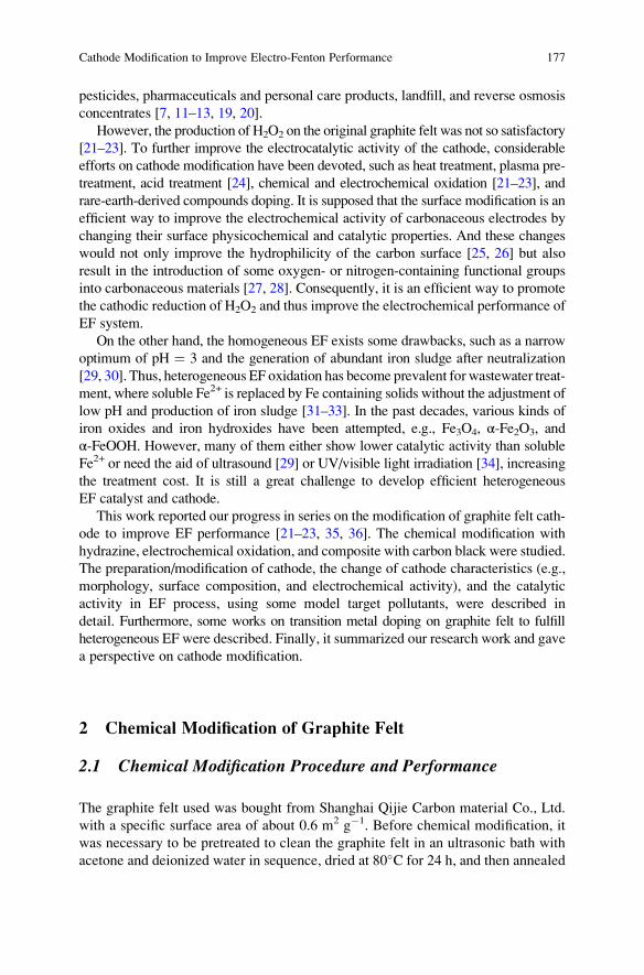
pesticides, pharmaceuticals and personal care products, landfill, and reverse osmosis
concentrates [7, 11–13, 19, 20].
However, the production of H2O2 on the original graphite felt was not so satisfactory
[21–23]. To further improve the electrocatalytic activity of the cathode, considerable
efforts on cathode modification have been devoted, such as heat treatment, plasma pre-
treatment, acid treatment [24], chemical and electrochemical oxidation [21–23], and
rare-earth-derived compounds doping. It is supposed that the surface modification is an
efficient way to improve the electrochemical activity of carbonaceous electrodes by
changing their surface physicochemical and catalytic properties. And these changes
would not only improve the hydrophilicity of the carbon surface [25, 26] but also
result in the introduction of some oxygen- or nitrogen-containing functional groups
into carbonaceous materials [27, 28]. Consequently, it is an efficient way to promote
the cathodic reduction of H2O2 and thus improve the electrochemical performance of
EF system.
On the other hand, the homogeneous EF exists some drawbacks, such as a narrow
optimum of pH ¼ 3 and the generation of abundant iron sludge after neutralization
[29, 30]. Thus, heterogeneous EF oxidation has become prevalent forwastewater treat-
ment, where soluble Fe2+ is replaced by Fe containing solids without the adjustment of
low pH and production of iron sludge [31–33]. In the past decades, various kinds of
iron oxides and iron hydroxides have been attempted, e.g., Fe3O4, α-Fe2O3, and
α-FeOOH. However, many of them either show lower catalytic activity than soluble
Fe2+ or need the aid of ultrasound [29] or UV/visible light irradiation [34], increasing
the treatment cost. It is still a great challenge to develop efficient heterogeneous
EF catalyst and cathode.
This work reported our progress in series on the modification of graphite felt cath-
ode to improve EF performance [21–23, 35, 36]. The chemical modification with
hydrazine, electrochemical oxidation, and composite with carbon black were studied.
The preparation/modification of cathode, the change of cathode characteristics (e.g.,
morphology, surface composition, and electrochemical activity), and the catalytic
activity in EF process, using some model target pollutants, were described in
detail. Furthermore, some works on transition metal doping on graphite felt to fulfill
heterogeneous EF were described. Finally, it summarized our research work and gave
a perspective on cathode modification.
2 Chemical Modification of Graphite Felt
2.1 Chemical Modification Procedure and Performance
The graphite felt used was bought from Shanghai Qijie Carbon material Co., Ltd.
with a specific surface area of about 0.6 m2 g�1. Before chemical modification, it
was necessary to be pretreated to clean the graphite felt in an ultrasonic bath with
acetone and deionized water in sequence, dried at 80�C for 24 h, and then annealed
Cathode Modification to Improve Electro-Fenton Performance 177
at 150�C for 2 h. These pretreated materials were marked as GF. A series of mod-
ified cathodes were treated by hydrazine hydrate according to the follow procedure:
the pretreated graphite felts were immersed in 100 mL mixture of ethanol and
hydrazine hydrate, and after refluxing at 60�C for 6 h, the samples were annealed at
150�C for 2 h. Since the volume concentration of the hydrazine hydrate in the
mixture were 5%, 10%, 15%, and 20%, the modified electrodes were marked as
GF-HA-5%, GF-HA-10%, GF-HA-15%, and GF-HA-20%, respectively.
Figure 1 shows the electro-generatedH2O2 and current efficiencies on different cath-
odes modified with different concentrations of hydrazine hydrate. It was observed that
the produced H2O2 for GFwas only 67.6 mg L�1 after 120 min, and after modification,
the yields of H2O2 were all increased, indicating the positive effects on H2O2 electro-
generation. The GF-HA-10% sample showed the highest yield of H2O2 (176.8 mg L�1
0 20 40 60 80 100 1200
20
40
60
80
100
120
140
160
180 GF GF-HA-5% GF-HA-10% GF-HA-15% GF-HA-20%
Conce
ntr
atio
n (
mg L
-1)
Time (min)
(a)
0 20 40 60 80 100 12065
70
75
80
85
90
95
100
CE
(%
)
Time (min)
GF GF-HA-5% GF-HA-10% GF-HA-15% GF-HA-20%
(b)
Fig. 1 The effects of the
concentration of hydrazine
hydrate on: (a) the yields ofH2O2 and (b) currentefficiency. Conditions:
E ¼ �0.65 V (vs. SCE),
0.05 M Na2SO4, pH ¼ 6.4,
and O2 flow rate at
0.4 L min�1. Adapted from
Zhou et al. [21], Copyright
2013, with permission from
Elsevier
178 M. Zhou et al.
after 120 min), indicating the optimum concentration of hydrazine hydrate for cathode
modification. When the concentration of hydrazine hydrate exceeded this optimum
value, a little decrease of H2O2 was observed. For example, the GF-HA-20% obtained
a lower H2O2 production of 158.2 mg L�1 after the same time.
Figure 1b shows the current efficiency (CE) under the potential of�0.65 V (vs. SCE)
for GF, GF-HA-5%, GF-HA-10%, GF-HA-15%, and GF-HA-20%, which were 86.6%,
83.8%, 81.8%, 75.6%, and 70.8%, respectively. The CEwas calculated according to the
following formula [21]:
CE ¼ nFCVR t0Idt
� 100% ð2Þ
where n is the number of electrons transferred for oxygen reduction for H2O2, F is
the Faraday constant (96,485 C mol�1), C is the concentration of H2O2 (mol L�1),
V is the bulk volume (L), I is the current (A), and t is the electrolysis time (s).
It was observed that the current efficiencies declined with the increasing con-
centration of hydrazine hydrate used in chemical modification. A further cyclic vol-
tammetry characterization indicated that the chemical modification increased the
current response, which might contribute to the fast formation of hydrogen perox-
ide. However, both oxygen reduction reactions (ORRs) (the two-electron transfer
for H2O2 production and the four-electron transfer for H2O production) were
encouraged, and perhaps the latter improved much, which led to the decrease of
CE after chemical modification.
2.2 Cathode Characterization
To explore the effects of chemical modifications on the characteristics of cathode,
the cathode modified with absolute ethanol (marked as GF-A), and the cathode mod-
ified with the mixture of ethanol and hydrazine hydrate of volume ratio of 90/10
(marked as GF-B) were investigated. Figure 2a–c show the SEM images of the ori-
ginal graphite felt (GF), GF-A, and GF-B. Obviously, GFwas composed of an entangled
network of carbonmicrofilaments with diameters around 15 μm. After chemical mod-
ification with absolute ethanol, many nanoscale particles and clusters, with diameters
of 100–500 nm, appeared on the fibers surface (Fig. 2b). Since no other substances
were involved during modification, the deposition could mostly be composed of car-
bon, as confirmed by the following XPS studies. The transformation from ethanol to
carbon nanoparticles mostly occurred during the heating process (150�C). The spe-cial filament-wound structure of the graphite felt rendered the ethanol vapor to be
kept within the samples, which made it possible for the nanoparticles forming or
depositing on the fiber surface.
Comparing the SEM in Fig. 2b, c, it could be noticed that the carbon nanoparticles
deposition on the surface of GF-B was far less than that of GF-A. This result should
Cathode Modification to Improve Electro-Fenton Performance 179
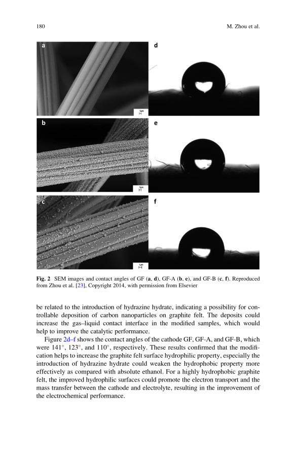
be related to the introduction of hydrazine hydrate, indicating a possibility for con-
trollable deposition of carbon nanoparticles on graphite felt. The deposits could
increase the gas–liquid contact interface in the modified samples, which would
help to improve the catalytic performance.
Figure 2d–f shows the contact angles of the cathode GF, GF-A, and GF-B, which
were 141�, 123�, and 110�, respectively. These results confirmed that the modifi-
cation helps to increase the graphite felt surface hydrophilic property, especially the
introduction of hydrazine hydrate could weaken the hydrophobic property more
effectively as compared with absolute ethanol. For a highly hydrophobic graphite
felt, the improved hydrophilic surfaces could promote the electron transport and the
mass transfer between the cathode and electrolyte, resulting in the improvement of
the electrochemical performance.
Fig. 2 SEM images and contact angles of GF (a, d), GF-A (b, e), and GF-B (c, f). Reproducedfrom Zhou et al. [23], Copyright 2014, with permission from Elsevier
180 M. Zhou et al.
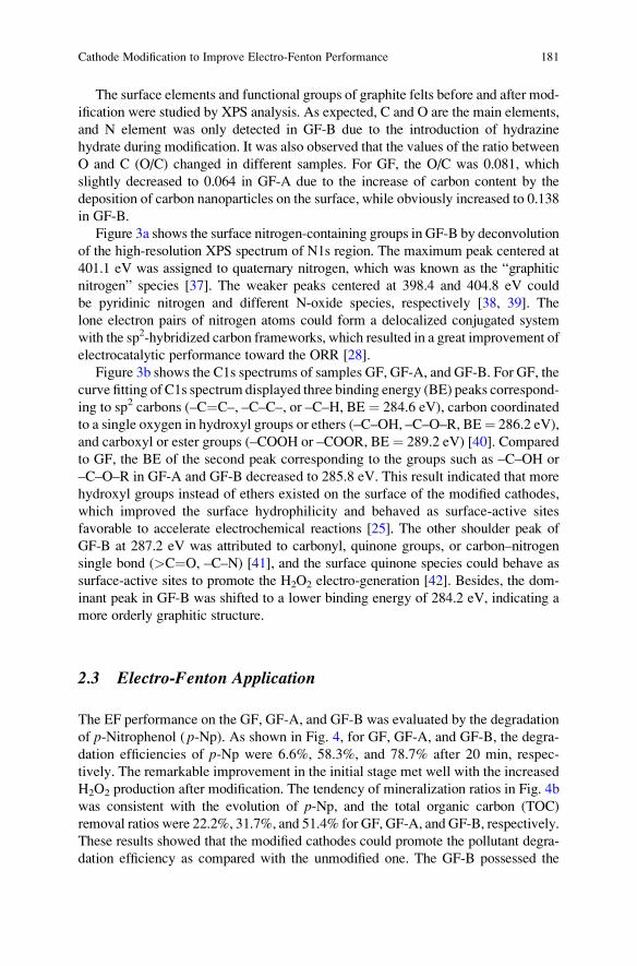
The surface elements and functional groups of graphite felts before and after mod-
ification were studied by XPS analysis. As expected, C and O are the main elements,
and N element was only detected in GF-B due to the introduction of hydrazine
hydrate during modification. It was also observed that the values of the ratio between
O and C (O/C) changed in different samples. For GF, the O/C was 0.081, which
slightly decreased to 0.064 in GF-A due to the increase of carbon content by the
deposition of carbon nanoparticles on the surface, while obviously increased to 0.138
in GF-B.
Figure 3a shows the surface nitrogen-containing groups in GF-B by deconvolution
of the high-resolution XPS spectrum of N1s region. The maximum peak centered at
401.1 eV was assigned to quaternary nitrogen, which was known as the “graphitic
nitrogen” species [37]. The weaker peaks centered at 398.4 and 404.8 eV could
be pyridinic nitrogen and different N-oxide species, respectively [38, 39]. The
lone electron pairs of nitrogen atoms could form a delocalized conjugated system
with the sp2-hybridized carbon frameworks, which resulted in a great improvement of
electrocatalytic performance toward the ORR [28].
Figure 3b shows the C1s spectrums of samples GF, GF-A, and GF-B. For GF, the
curve fitting of C1s spectrum displayed three binding energy (BE) peaks correspond-
ing to sp2 carbons (–C¼C–, –C–C–, or –C–H, BE ¼ 284.6 eV), carbon coordinated
to a single oxygen in hydroxyl groups or ethers (–C–OH, –C–O–R, BE¼ 286.2 eV),
and carboxyl or ester groups (–COOH or –COOR, BE¼ 289.2 eV) [40]. Compared
to GF, the BE of the second peak corresponding to the groups such as –C–OH or
–C–O–R in GF-A and GF-B decreased to 285.8 eV. This result indicated that more
hydroxyl groups instead of ethers existed on the surface of the modified cathodes,
which improved the surface hydrophilicity and behaved as surface-active sites
favorable to accelerate electrochemical reactions [25]. The other shoulder peak of
GF-B at 287.2 eV was attributed to carbonyl, quinone groups, or carbon–nitrogen
single bond (>C¼O, –C–N) [41], and the surface quinone species could behave as
surface-active sites to promote the H2O2 electro-generation [42]. Besides, the dom-
inant peak in GF-B was shifted to a lower binding energy of 284.2 eV, indicating a
more orderly graphitic structure.
2.3 Electro-Fenton Application
The EF performance on the GF, GF-A, and GF-B was evaluated by the degradation
of p-Nitrophenol ( p-Np). As shown in Fig. 4, for GF, GF-A, and GF-B, the degra-
dation efficiencies of p-Np were 6.6%, 58.3%, and 78.7% after 20 min, respec-
tively. The remarkable improvement in the initial stage met well with the increased
H2O2 production after modification. The tendency of mineralization ratios in Fig. 4b
was consistent with the evolution of p-Np, and the total organic carbon (TOC)
removal ratios were 22.2%, 31.7%, and 51.4% for GF, GF-A, and GF-B, respectively.
These results showed that the modified cathodes could promote the pollutant degra-
dation efficiency as compared with the unmodified one. The GF-B possessed the
Cathode Modification to Improve Electro-Fenton Performance 181
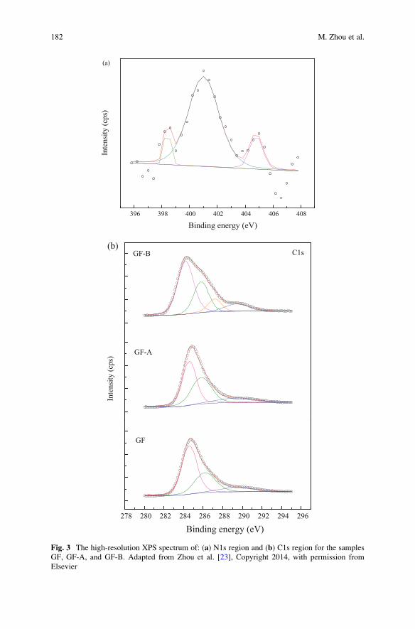
396 398 400 402 404 406 408
Inte
nsi
ty (
cps)
Binding energy (eV)
(a)
278 280 282 284 286 288 290 292 294 296
Binding energy (eV)
GF
(b)
Inte
nsi
ty (
cps)
GF-A
GF-B C1s
Fig. 3 The high-resolution XPS spectrum of: (a) N1s region and (b) C1s region for the samples
GF, GF-A, and GF-B. Adapted from Zhou et al. [23], Copyright 2014, with permission from
Elsevier
182 M. Zhou et al.
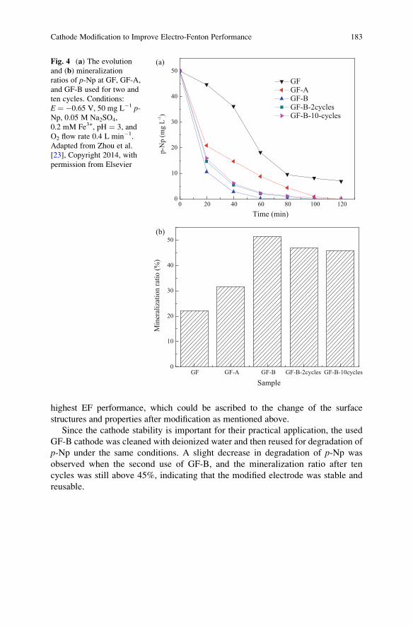
highest EF performance, which could be ascribed to the change of the surface
structures and properties after modification as mentioned above.
Since the cathode stability is important for their practical application, the used
GF-B cathode was cleaned with deionized water and then reused for degradation of
p-Np under the same conditions. A slight decrease in degradation of p-Np was
observed when the second use of GF-B, and the mineralization ratio after ten
cycles was still above 45%, indicating that the modified electrode was stable and
reusable.
0 20 40 60 80 100 1200
10
20
30
40
50
p-N
p (
mg
L-1)
Time (min)
GFGF-AGF-BGF-B-2cyclesGF-B-10-cycles
(a)
GF GF-A GF-B GF-B-2cycles GF-B-10cycles0
10
20
30
40
50
Min
eral
izat
ion r
atio
(%
)
Sample
(b)
Fig. 4 (a) The evolutionand (b) mineralization
ratios of p-Np at GF, GF-A,
and GF-B used for two and
ten cycles. Conditions:
E ¼ �0.65 V, 50 mg L�1 p-Np, 0.05 M Na2SO4,
0.2 mM Fe3+, pH ¼ 3, and
O2 flow rate 0.4 L min�1.
Adapted from Zhou et al.
[23], Copyright 2014, with
permission from Elsevier
Cathode Modification to Improve Electro-Fenton Performance 183
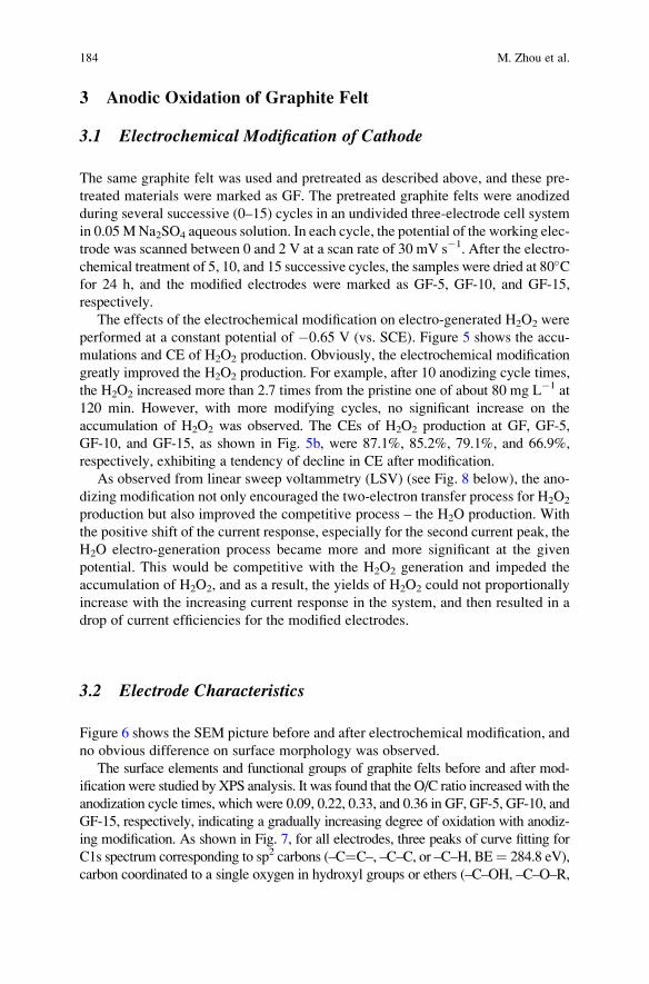
3 Anodic Oxidation of Graphite Felt
3.1 Electrochemical Modification of Cathode
The same graphite felt was used and pretreated as described above, and these pre-
treated materials were marked as GF. The pretreated graphite felts were anodized
during several successive (0–15) cycles in an undivided three-electrode cell system
in 0.05MNa2SO4 aqueous solution. In each cycle, the potential of the working elec-
trode was scanned between 0 and 2 V at a scan rate of 30 mV s�1. After the electro-
chemical treatment of 5, 10, and 15 successive cycles, the samples were dried at 80�Cfor 24 h, and the modified electrodes were marked as GF-5, GF-10, and GF-15,
respectively.
The effects of the electrochemical modification on electro-generated H2O2 were
performed at a constant potential of �0.65 V (vs. SCE). Figure 5 shows the accu-
mulations and CE of H2O2 production. Obviously, the electrochemical modification
greatly improved the H2O2 production. For example, after 10 anodizing cycle times,
the H2O2 increased more than 2.7 times from the pristine one of about 80 mg L�1 at
120 min. However, with more modifying cycles, no significant increase on the
accumulation of H2O2 was observed. The CEs of H2O2 production at GF, GF-5,
GF-10, and GF-15, as shown in Fig. 5b, were 87.1%, 85.2%, 79.1%, and 66.9%,
respectively, exhibiting a tendency of decline in CE after modification.
As observed from linear sweep voltammetry (LSV) (see Fig. 8 below), the ano-
dizing modification not only encouraged the two-electron transfer process for H2O2
production but also improved the competitive process – the H2O production. With
the positive shift of the current response, especially for the second current peak, the
H2O electro-generation process became more and more significant at the given
potential. This would be competitive with the H2O2 generation and impeded the
accumulation of H2O2, and as a result, the yields of H2O2 could not proportionally
increase with the increasing current response in the system, and then resulted in a
drop of current efficiencies for the modified electrodes.
3.2 Electrode Characteristics
Figure 6 shows the SEM picture before and after electrochemical modification, and
no obvious difference on surface morphology was observed.
The surface elements and functional groups of graphite felts before and after mod-
ification were studied by XPS analysis. It was found that the O/C ratio increasedwith the
anodization cycle times, which were 0.09, 0.22, 0.33, and 0.36 in GF, GF-5, GF-10, and
GF-15, respectively, indicating a gradually increasing degree of oxidation with anodiz-
ing modification. As shown in Fig. 7, for all electrodes, three peaks of curve fitting for
C1s spectrum corresponding to sp2 carbons (–C¼C–, –C–C, or –C–H, BE¼ 284.8 eV),
carbon coordinated to a single oxygen in hydroxyl groups or ethers (–C–OH, –C–O–R,
184 M. Zhou et al.
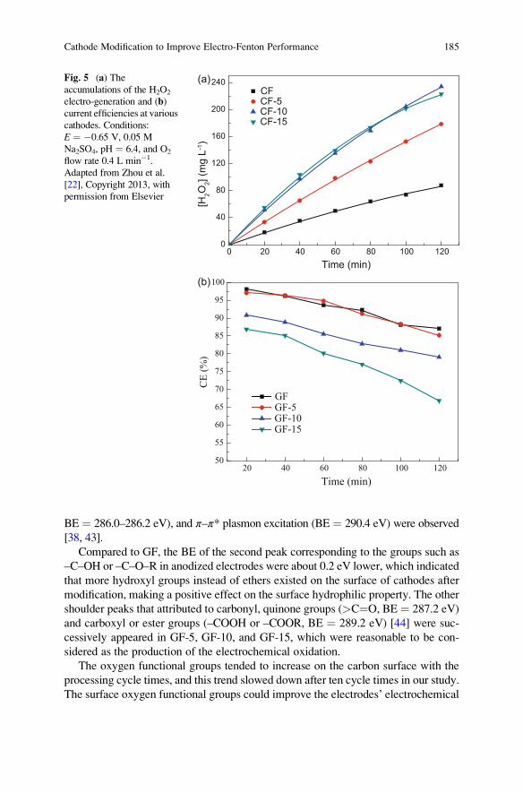
BE ¼ 286.0–286.2 eV), and π–π* plasmon excitation (BE ¼ 290.4 eV) were observed
[38, 43].
Compared to GF, the BE of the second peak corresponding to the groups such as
–C–OH or –C–O–R in anodized electrodes were about 0.2 eV lower, which indicated
that more hydroxyl groups instead of ethers existed on the surface of cathodes after
modification, making a positive effect on the surface hydrophilic property. The other
shoulder peaks that attributed to carbonyl, quinone groups (>C¼O, BE ¼ 287.2 eV)
and carboxyl or ester groups (–COOH or –COOR, BE ¼ 289.2 eV) [44] were suc-
cessively appeared in GF-5, GF-10, and GF-15, which were reasonable to be con-
sidered as the production of the electrochemical oxidation.
The oxygen functional groups tended to increase on the carbon surface with the
processing cycle times, and this trend slowed down after ten cycle times in our study.
The surface oxygen functional groups could improve the electrodes’ electrochemical
0 20 40 60 80 100 1200
40
80
120
160
200
240CFCF-5CF-10CF-15
[H2O
2] (m
g L-1
)
Time (min)
(a)
20 40 60 80 100 12050
55
60
65
70
75
80
85
90
95
100
CE
(%
)
Time (min)
GFGF-5GF-10GF-15
(b)
Fig. 5 (a) Theaccumulations of the H2O2
electro-generation and (b)current efficiencies at various
cathodes. Conditions:
E ¼ �0.65 V, 0.05 M
Na2SO4, pH ¼ 6.4, and O2
flow rate 0.4 L min�1.
Adapted from Zhou et al.
[22], Copyright 2013, with
permission from Elsevier
Cathode Modification to Improve Electro-Fenton Performance 185
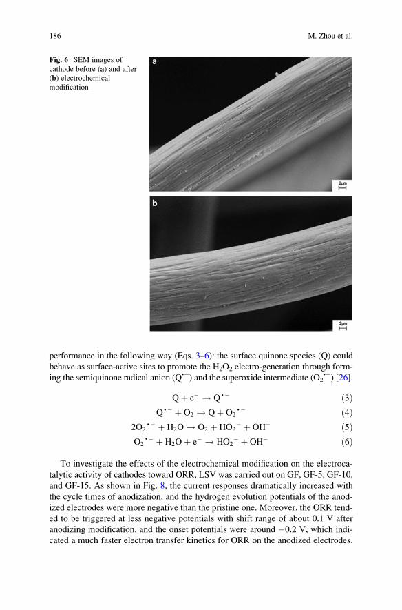
performance in the following way (Eqs. 3–6): the surface quinone species (Q) could
behave as surface-active sites to promote the H2O2 electro-generation through form-
ing the semiquinone radical anion (Q•�) and the superoxide intermediate (O2•�) [26].
Qþ e� ! Q•� ð3ÞQ•� þ O2 ! Qþ O2
•� ð4Þ2O2
•� þ H2O ! O2 þ HO2� þ OH� ð5Þ
O2•� þ H2Oþ e� ! HO2
� þ OH� ð6Þ
To investigate the effects of the electrochemical modification on the electroca-
talytic activity of cathodes toward ORR, LSV was carried out on GF, GF-5, GF-10,
and GF-15. As shown in Fig. 8, the current responses dramatically increased with
the cycle times of anodization, and the hydrogen evolution potentials of the anod-
ized electrodes were more negative than the pristine one. Moreover, the ORR tend-
ed to be triggered at less negative potentials with shift range of about 0.1 V after
anodizing modification, and the onset potentials were around �0.2 V, which indi-
cated a much faster electron transfer kinetics for ORR on the anodized electrodes.
Fig. 6 SEM images of
cathode before (a) and after
(b) electrochemical
modification
186 M. Zhou et al.
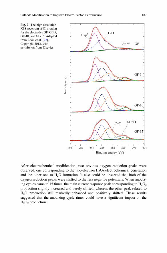
After electrochemical modification, two obvious oxygen reduction peaks were
observed, one corresponding to the two-electron H2O2 electrochemical generation
and the other one to H2O formation. It also could be observed that both of the
oxygen reduction peaks were shifted to the less negative potentials. When anodiz-
ing cycles came to 15 times, the main current response peak corresponding to H2O2
production slightly increased and barely shifted, whereas the other peak related to
H2O production still markedly enhanced and positively shifted. These results
suggested that the anodizing cycle times could have a significant impact on the
H2O2 production.
280 282 284 286 288 290 292 294
Binding energy (eV)
Inte
nsi
ty (
cps)
GF-15
O-C=OC=O
GF-10
GF-5
GF
C sp2 C-O
π−π∗
Fig. 7 The high-resolution
XPS spectrum of C1s region
for the electrodes GF, GF-5,
GF-10, and GF-15. Adapted
from Zhou et al. [22],
Copyright 2013, with
permission from Elsevier
Cathode Modification to Improve Electro-Fenton Performance 187
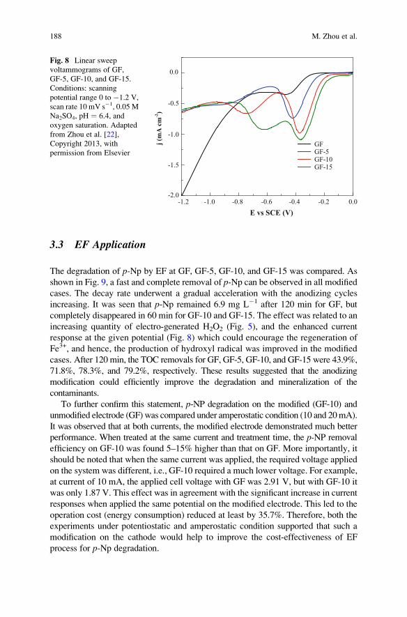
3.3 EF Application
The degradation of p-Np by EF at GF, GF-5, GF-10, and GF-15 was compared. As
shown in Fig. 9, a fast and complete removal of p-Np can be observed in all modified
cases. The decay rate underwent a gradual acceleration with the anodizing cycles
increasing. It was seen that p-Np remained 6.9 mg L�1 after 120 min for GF, but
completely disappeared in 60 min for GF-10 and GF-15. The effect was related to an
increasing quantity of electro-generated H2O2 (Fig. 5), and the enhanced current
response at the given potential (Fig. 8) which could encourage the regeneration of
Fe3+, and hence, the production of hydroxyl radical was improved in the modified
cases. After 120 min, the TOC removals for GF, GF-5, GF-10, and GF-15 were 43.9%,
71.8%, 78.3%, and 79.2%, respectively. These results suggested that the anodizing
modification could efficiently improve the degradation and mineralization of the
contaminants.
To further confirm this statement, p-NP degradation on the modified (GF-10) and
unmodified electrode (GF) was compared under amperostatic condition (10 and 20mA).
It was observed that at both currents, the modified electrode demonstrated much better
performance. When treated at the same current and treatment time, the p-NP removal
efficiency on GF-10 was found 5–15% higher than that on GF. More importantly, it
should be noted that when the same current was applied, the required voltage applied
on the system was different, i.e., GF-10 required a much lower voltage. For example,
at current of 10 mA, the applied cell voltage with GF was 2.91 V, but with GF-10 it
was only 1.87 V. This effect was in agreement with the significant increase in current
responses when applied the same potential on the modified electrode. This led to the
operation cost (energy consumption) reduced at least by 35.7%. Therefore, both the
experiments under potentiostatic and amperostatic condition supported that such a
modification on the cathode would help to improve the cost-effectiveness of EF
process for p-Np degradation.
-1.2 -1.0 -0.8 -0.6 -0.4 -0.2 0.0-2.0
-1.5
-1.0
-0.5
0.0
j (m
A c
m-2)
E vs SCE (V)
GFGF-5GF-10GF-15
Fig. 8 Linear sweep
voltammograms of GF,
GF-5, GF-10, and GF-15.
Conditions: scanning
potential range 0 to �1.2 V,
scan rate 10 mV s�1, 0.05 M
Na2SO4, pH ¼ 6.4, and
oxygen saturation. Adapted
from Zhou et al. [22],
Copyright 2013, with
permission from Elsevier
188 M. Zhou et al.
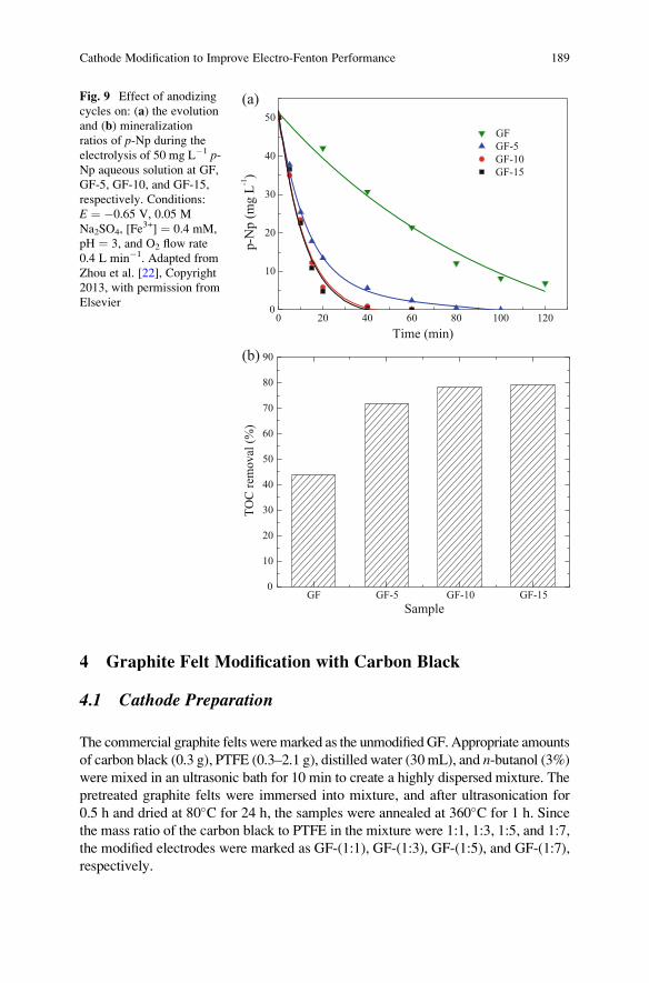
4 Graphite Felt Modification with Carbon Black
4.1 Cathode Preparation
The commercial graphite felts weremarked as the unmodified GF. Appropriate amounts
of carbon black (0.3 g), PTFE (0.3–2.1 g), distilled water (30 mL), and n-butanol (3%)
were mixed in an ultrasonic bath for 10 min to create a highly dispersed mixture. The
pretreated graphite felts were immersed into mixture, and after ultrasonication for
0.5 h and dried at 80�C for 24 h, the samples were annealed at 360�C for 1 h. Since
the mass ratio of the carbon black to PTFE in the mixture were 1:1, 1:3, 1:5, and 1:7,
the modified electrodes were marked as GF-(1:1), GF-(1:3), GF-(1:5), and GF-(1:7),
respectively.
0 20 40 60 80 100 1200
10
20
30
40
50
GF
GF-5
GF-10
GF-15
p-N
p (
mg L
-1)
Time (min)
(a)
GF GF-5 GF-10 GF-150
10
20
30
40
50
60
70
80
90
TO
C r
emoval
(%
)
Sample
(b)
Fig. 9 Effect of anodizing
cycles on: (a) the evolutionand (b) mineralization
ratios of p-Np during the
electrolysis of 50 mg L�1 p-Np aqueous solution at GF,
GF-5, GF-10, and GF-15,
respectively. Conditions:
E ¼ �0.65 V, 0.05 M
Na2SO4, [Fe3+] ¼ 0.4 mM,
pH ¼ 3, and O2 flow rate
0.4 L min�1. Adapted from
Zhou et al. [22], Copyright
2013, with permission from
Elsevier
Cathode Modification to Improve Electro-Fenton Performance 189
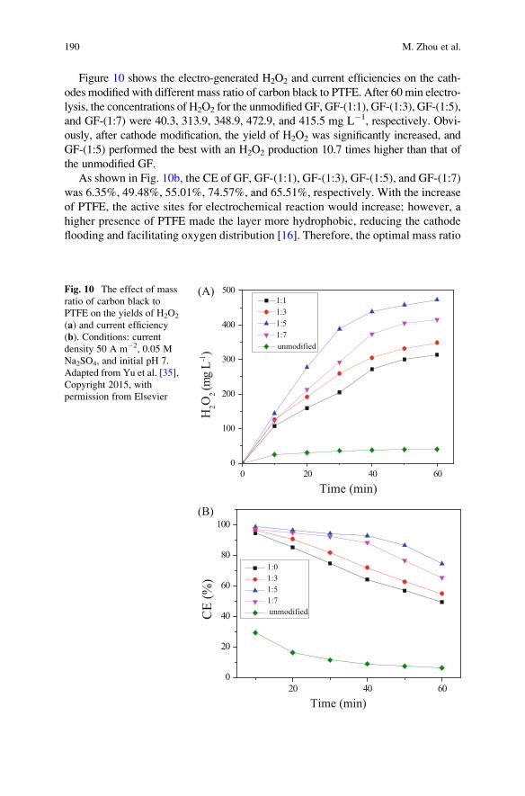
Figure 10 shows the electro-generated H2O2 and current efficiencies on the cath-
odes modified with different mass ratio of carbon black to PTFE. After 60 min electro-
lysis, the concentrations of H2O2 for the unmodified GF, GF-(1:1), GF-(1:3), GF-(1:5),
and GF-(1:7) were 40.3, 313.9, 348.9, 472.9, and 415.5 mg L�1, respectively. Obvi-
ously, after cathode modification, the yield of H2O2 was significantly increased, and
GF-(1:5) performed the best with an H2O2 production 10.7 times higher than that of
the unmodified GF.
As shown in Fig. 10b, the CE of GF, GF-(1:1), GF-(1:3), GF-(1:5), and GF-(1:7)
was 6.35%, 49.48%, 55.01%, 74.57%, and 65.51%, respectively. With the increase
of PTFE, the active sites for electrochemical reaction would increase; however, a
higher presence of PTFE made the layer more hydrophobic, reducing the cathode
flooding and facilitating oxygen distribution [16]. Therefore, the optimal mass ratio
0 20 40 60
0
100
200
300
400
500
Time (min)
H2O
2 (m
g L
-1)
(A)1:1
1:3
1:5
1:7
unmodified
20 40 60
0
20
40
60
80
100
(B)
Time (min)
1:0
1:3
1:5
1:7
unmodifiedCE
(%
)
Fig. 10 The effect of mass
ratio of carbon black to
PTFE on the yields of H2O2
(a) and current efficiency
(b). Conditions: currentdensity 50 A m�2, 0.05 M
Na2SO4, and initial pH 7.
Adapted from Yu et al. [35],
Copyright 2015, with
permission from Elsevier
190 M. Zhou et al.
of carbon black to PTFE was 1:5, which provided both sufficient active area and
oxygen diffusion ability for H2O2 production.
4.2 Cathode Characteristics
Figure 11 shows the SEM images of graphite felt (A) before and (B) after modifi-
cation (GF-(1:5)). Before modification, the graphite felt showed a clear fiber struc-
ture with uniform size of about 5–10 μm. After modification, a large number of
interconnected particles appeared on graphite felt, which would obviously change
the cathode surface characteristics. The BET surface area, pore diameter, and pore
volume of the unmodified GF were determined to be 1.565 m2 g�1, 3.005 nm, and
0.004 mL g�1, while for the modified graphite felt, it was 5.320 m2 g�1, 3.405 nm,
and 0.087 mL g�1, respectively. Clearly, the cathode modification resulted in about
2.4 times and more than 20 times increase in surface area and pore volume, respec-
tively. This special three-dimensional structure could render oxygen more easily
diffusing into the porosity of the porous carbon materials and further react on the
inner surface [45]. The dynamic balance of oxygen on the triphase surface of solid,
gas, and solution would finally increase the solubility of oxygen in solution. Thus,
after modification, the generation of H2O2 was significantly enhanced.
To explore the effect of modification on the cathode electrocatalytic activity
toward ORR, LSV investigation was carried out. As shown in Fig. 12, all modified
cathodes exhibited higher current for ORR, comparing with the unmodified one.
This result indicated that the presence of carbon black helped to increase the cata-
lytic activity toward ORR and also higher conductivity. And the GF-(1:5) electrode
received the highest current response, while the further addition of PTFE decreased
the current response. This trend agreed with the H2O2 production, which is reason-
able since an electrochemical reaction rate is determined principally by current, so
that among the investigated current ranges in this work, the higher the current, the
faster the electrochemical generation of H2O2.
4.3 EF Application
The EF performances on the unmodified and modified cathodes were evaluated by
degradation of 50 mg L�1 methyl orange (MO) under acidic and neutral conditions.
As shown in Fig. 13a, higher degradation efficiencies were observed at initial pH 3,
which was regarded as the optimum value in EF system [7, 13]. The complete
decolorization of MO was achieved within 35 min on the unmodified cathode, but it
was only taken 15 min on the modified cathode. Similar phenomena were observed
at initial pH 7, in which it took 60 min and 25 min for two cathodes, respectively. The
degradation ofMOwas confirmed following an apparent pseudo-first-order kinetics. At
initial pH 3, the rate constant on the unmodified cathode was 0.092 s�1 (R2 ¼ 0.996),
Cathode Modification to Improve Electro-Fenton Performance 191
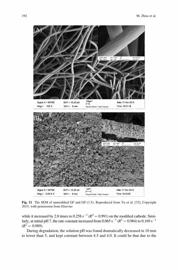
while it increased by 2.8 times to 0.258 s�1 (R2¼ 0.991) on the modified cathode. Simi-
larly, at initial pH 7, the rate constant increased from 0.065 s�1 (R2¼ 0.984) to 0.169 s�1
(R2 ¼ 0.989).
During degradation, the solution pH was found dramatically decreased in 10 min
to lower than 5, and kept constant between 4.5 and 4.0. It could be that due to the
Fig. 11 The SEM of unmodified GF and GF-(1:5). Reproduced from Yu et al. [35], Copyright
2015, with permission from Elsevier
192 M. Zhou et al.
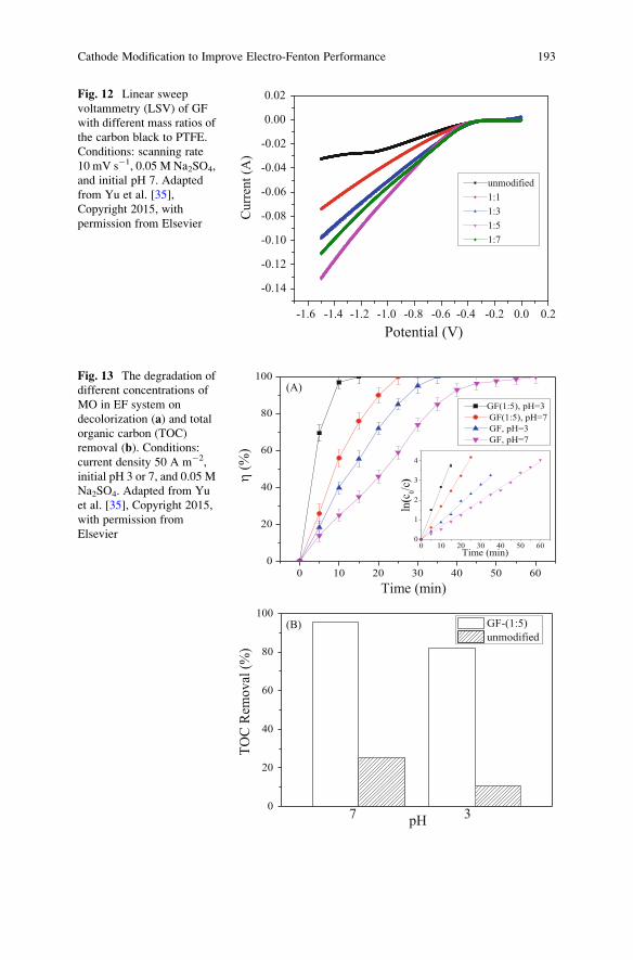
-1.6 -1.4 -1.2 -1.0 -0.8 -0.6 -0.4 -0.2 0.0 0.2
-0.14
-0.12
-0.10
-0.08
-0.06
-0.04
-0.02
0.00
0.02
Potential (V)
Curr
ent
(A)
unmodified
1:1
1:3
1:5
1:7
Fig. 12 Linear sweep
voltammetry (LSV) of GF
with different mass ratios of
the carbon black to PTFE.
Conditions: scanning rate
10 mV s�1, 0.05 M Na2SO4,
and initial pH 7. Adapted
from Yu et al. [35],
Copyright 2015, with
permission from Elsevier
0 10 20 30 40 50 60
0
20
40
60
80
100(A)
Time (min)
GF(1:5), pH=3
GF(1:5), pH=7
GF, pH=3
GF, pH=7
0
20
40
60
80
100(B)
3pH
7
TO
C R
emo
val
(%
)
GF-(1:5)
unmodified
0 10 20 30 40 50 600
1
2
3
4
Time (min)
ln(c
0/c
)η (%
)
Fig. 13 The degradation of
different concentrations of
MO in EF system on
decolorization (a) and total
organic carbon (TOC)
removal (b). Conditions:current density 50 A m�2,
initial pH 3 or 7, and 0.05 M
Na2SO4. Adapted from Yu
et al. [35], Copyright 2015,
with permission from
Elsevier
Cathode Modification to Improve Electro-Fenton Performance 193
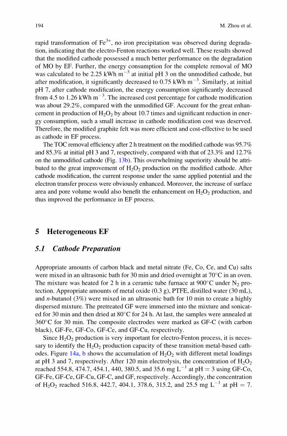
rapid transformation of Fe3+, no iron precipitation was observed during degrada-
tion, indicating that the electro-Fenton reactions worked well. These results showed
that the modified cathode possessed a much better performance on the degradation
of MO by EF. Further, the energy consumption for the complete removal of MO
was calculated to be 2.25 kWh m�3 at initial pH 3 on the unmodified cathode, but
after modification, it significantly decreased to 0.75 kWh m�3. Similarly, at initial
pH 7, after cathode modification, the energy consumption significantly decreased
from 4.5 to 1.26 kWh m�3. The increased cost percentage for cathode modification
was about 29.2%, compared with the unmodified GF. Account for the great enhan-
cement in production of H2O2 by about 10.7 times and significant reduction in ener-
gy consumption, such a small increase in cathode modification cost was deserved.
Therefore, the modified graphite felt was more efficient and cost-effective to be used
as cathode in EF process.
The TOC removal efficiency after 2 h treatment on the modified cathode was 95.7%
and 85.3% at initial pH 3 and 7, respectively, compared with that of 23.3% and 12.7%
on the unmodified cathode (Fig. 13b). This overwhelming superiority should be attri-
buted to the great improvement of H2O2 production on the modified cathode. After
cathode modification, the current response under the same applied potential and the
electron transfer process were obviously enhanced. Moreover, the increase of surface
area and pore volume would also benefit the enhancement on H2O2 production, and
thus improved the performance in EF process.
5 Heterogeneous EF
5.1 Cathode Preparation
Appropriate amounts of carbon black and metal nitrate (Fe, Co, Ce, and Cu) salts
were mixed in an ultrasonic bath for 30 min and dried overnight at 70�C in an oven.
The mixture was heated for 2 h in a ceramic tube furnace at 900�C under N2 pro-
tection. Appropriate amounts of metal oxide (0.3 g), PTFE, distilled water (30 mL),
and n-butanol (3%) were mixed in an ultrasonic bath for 10 min to create a highly
dispersed mixture. The pretreated GF were immersed into the mixture and sonicat-
ed for 30 min and then dried at 80�C for 24 h. At last, the samples were annealed at
360�C for 30 min. The composite electrodes were marked as GF-C (with carbon
black), GF-Fe, GF-Co, GF-Ce, and GF-Cu, respectively.
Since H2O2 production is very important for electro-Fenton process, it is neces-
sary to identify the H2O2 production capacity of these transition metal-based cath-
odes. Figure 14a, b shows the accumulation of H2O2 with different metal loadings
at pH 3 and 7, respectively. After 120 min electrolysis, the concentration of H2O2
reached 554.8, 474.7, 454.1, 440, 380.5, and 35.6 mg L�1 at pH ¼ 3 using GF-Co,
GF-Fe, GF-Ce, GF-Cu, GF-C, and GF, respectively. Accordingly, the concentration
of H2O2 reached 516.8, 442.7, 404.1, 378.6, 315.2, and 25.5 mg L�1 at pH ¼ 7.
194 M. Zhou et al.
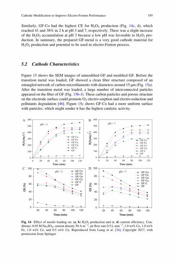
Similarly, GF-Co had the highest CE for H2O2 production (Fig. 14c, d), which
reached 41 and 38% in 2 h at pH 3 and 7, respectively. There was a slight increase
of the H2O2 accumulation at pH 3 because a low pH was favorable to H2O2 pro-
duction. In summary, the prepared GF-metal is a very good cathode material for
H2O2 production and potential to be used in electro-Fenton process.
5.2 Cathode Characteristics
Figure 15 shows the SEM images of unmodified GF and modified GF. Before the
transition metal was loaded, GF showed a clean fiber structure composed of an
entangled network of carbon microfilaments with diameters around 15 μm (Fig. 15a).
After the transition metal was loaded, a large number of interconnected particles
appeared on the fiber of GF (Fig. 15b–f). These carbon particles and porous structure
on the electrode surface could promote O2 electro-sorption and electro-reduction and
pollutants degradation [46]. Figure 15c shows GF-Co had a more uniform surface
with particles, which might render it has the highest catalytic activity.
0 20 40 60 80 100 120
0
100
200
300
400
500
600A
Time (min)
H2O
2(mg
L-1)
GF-Co GF-Fe GF-Ce GF-Cu GF-C GF
pH = 3
0 20 40 60 80 100 120
0
100
200
300
400
500
600
GF-Co GF-Fe GF-Ce GF-Cu GF-C GF
B
Time (min)
H2O
2(mg
L-1)
pH = 7
20 40 60 80 100 1200
20
40
60
80
100 GF-Co GF-Fe GF-Ce GF-Cu GF-C GF
CE
(%)
Time (min)
CpH = 3
20 40 60 80 100 1200
20
40
60
80
100 GF-Co GF-Fe GF-Ce GF-Cu GF-C GF
CE
(%)
Time (min)
DpH = 7
Fig. 14 Effect of metals loading on: (a, b) H2O2 production and (c, d) current efficiency. Con-ditions: 0.05 M Na2SO4, current density 50 A m�2, air flow rate 0.5 L min�1, 1.0 wt% Co, 1.0 wt%
Fe, 1.0 wt% Ce, and 0.5 wt% Cu. Reproduced from Liang et al. [36], Copyright 2017, with
permission from Springer
Cathode Modification to Improve Electro-Fenton Performance 195
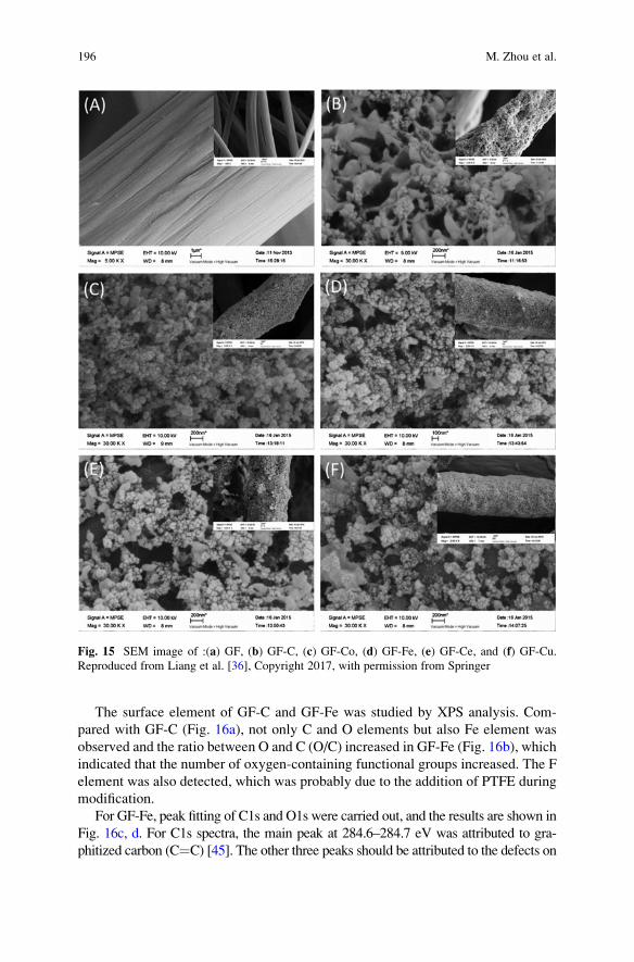
The surface element of GF-C and GF-Fe was studied by XPS analysis. Com-
pared with GF-C (Fig. 16a), not only C and O elements but also Fe element was
observed and the ratio between O and C (O/C) increased in GF-Fe (Fig. 16b), which
indicated that the number of oxygen-containing functional groups increased. The F
element was also detected, which was probably due to the addition of PTFE during
modification.
For GF-Fe, peak fitting of C1s and O1s were carried out, and the results are shown in
Fig. 16c, d. For C1s spectra, the main peak at 284.6–284.7 eV was attributed to gra-
phitized carbon (C¼C) [45]. The other three peaks should be attributed to the defects on
Fig. 15 SEM image of :(a) GF, (b) GF-C, (c) GF-Co, (d) GF-Fe, (e) GF-Ce, and (f) GF-Cu.Reproduced from Liang et al. [36], Copyright 2017, with permission from Springer
196 M. Zhou et al.
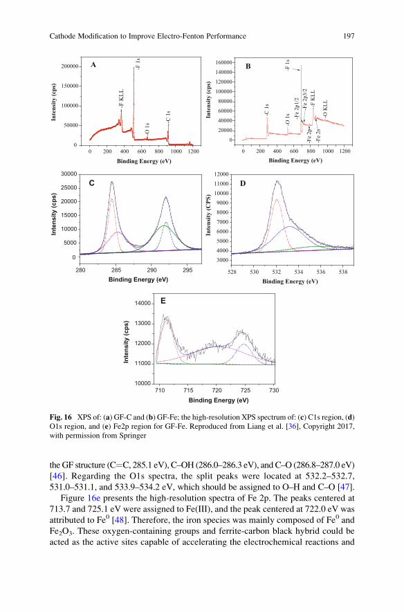
the GF structure (C¼C, 285.1 eV), C–OH (286.0–286.3 eV), and C–O (286.8–287.0 eV)
[46]. Regarding the O1s spectra, the split peaks were located at 532.2–532.7,
531.0–531.1, and 533.9–534.2 eV, which should be assigned to O–H and C–O [47].
Figure 16e presents the high-resolution spectra of Fe 2p. The peaks centered at
713.7 and 725.1 eV were assigned to Fe(III), and the peak centered at 722.0 eV was
attributed to Fe0 [48]. Therefore, the iron species was mainly composed of Fe0 and
Fe2O3. These oxygen-containing groups and ferrite-carbon black hybrid could be
acted as the active sites capable of accelerating the electrochemical reactions and
0 200 400 600 800 1000 12000
50000
100000
150000
200000 AIn
tens
ity (c
ps)
-C 1
s
-O 1
s
-F 1
s
-F K
LL
Binding Energy (eV) 0 200 400 600 800 1000 1200
0
20000
40000
60000
80000
100000
120000
140000
160000 B
-Fe
2p3/2
-C 1
s
-O 1
s-F
1s
-Fe
2p1/2
-Fe
2p
-F K
LL
-Fe
2s
-O K
LL
Binding Energy (eV)
Inte
nsity
(cps
)
280 285 290 295
0
5000
10000
15000
20000
25000
30000
C
Binding Energy (eV)
Inte
nsity
(cps
)
528 530 532 534 536 538
3000
4000
5000
6000
7000
8000
9000
10000
11000
12000
D
Binding Energy (eV)
Inte
nsity
(CPS
)
710 715 720 725 73010000
11000
12000
13000
14000 E
Binding Energy (eV)
Inte
nsity
(cps
)
Fig. 16 XPS of: (a) GF-C and (b) GF-Fe; the high-resolution XPS spectrum of: (c) C1s region, (d)O1s region, and (e) Fe2p region for GF-Fe. Reproduced from Liang et al. [36], Copyright 2017,
with permission from Springer
Cathode Modification to Improve Electro-Fenton Performance 197
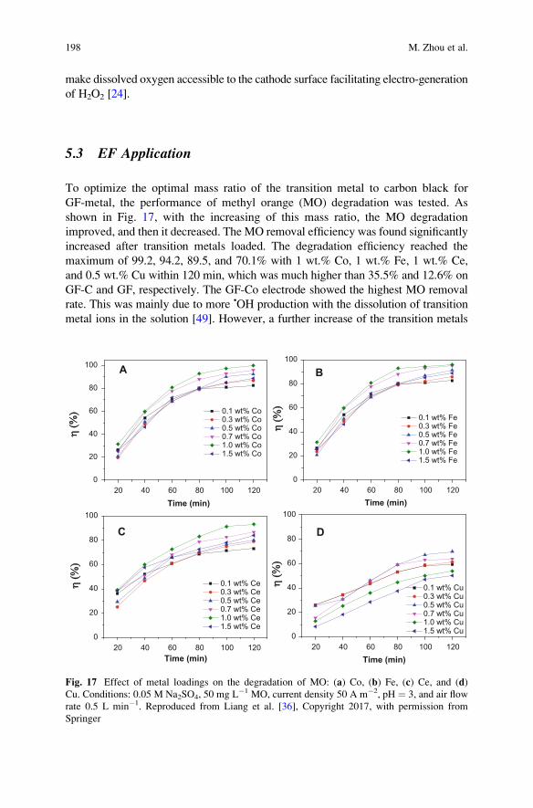
make dissolved oxygen accessible to the cathode surface facilitating electro-generation
of H2O2 [24].
5.3 EF Application
To optimize the optimal mass ratio of the transition metal to carbon black for
GF-metal, the performance of methyl orange (MO) degradation was tested. As
shown in Fig. 17, with the increasing of this mass ratio, the MO degradation
improved, and then it decreased. The MO removal efficiency was found significantly
increased after transition metals loaded. The degradation efficiency reached the
maximum of 99.2, 94.2, 89.5, and 70.1% with 1 wt.% Co, 1 wt.% Fe, 1 wt.% Ce,
and 0.5 wt.% Cu within 120 min, which was much higher than 35.5% and 12.6% on
GF-C and GF, respectively. The GF-Co electrode showed the highest MO removal
rate. This was mainly due to more •OH production with the dissolution of transition
metal ions in the solution [49]. However, a further increase of the transition metals
20 40 60 80 100 1200
20
40
60
80
100 A
Time (min)
η (%
)η
(%) 0.1 wt% Co
0.3 wt% Co 0.5 wt% Co 0.7 wt% Co 1.0 wt% Co 1.5 wt% Co
20 40 60 80 100 1200
20
40
60
80
100
B
Time (min)
η (%
)η
(%)
0.1 wt% Fe 0.3 wt% Fe 0.5 wt% Fe 0.7 wt% Fe 1.0 wt% Fe 1.5 wt% Fe
20 40 60 80 100 1200
20
40
60
80
100
C
Time (min)
η (%
)η
(%)
0.1 wt% Ce 0.3 wt% Ce 0.5 wt% Ce 0.7 wt% Ce 1.0 wt% Ce 1.5 wt% Ce
20 40 60 80 100 1200
20
40
60
80
100
D
Time (min)
η (%
)η
(%)
0.1 wt% Cu 0.3 wt% Cu 0.5 wt% Cu 0.7 wt% Cu 1.0 wt% Cu 1.5 wt% Cu
Fig. 17 Effect of metal loadings on the degradation of MO: (a) Co, (b) Fe, (c) Ce, and (d)Cu. Conditions: 0.05 M Na2SO4, 50 mg L�1 MO, current density 50 A m�2, pH ¼ 3, and air flow
rate 0.5 L min�1. Reproduced from Liang et al. [36], Copyright 2017, with permission from
Springer
198 M. Zhou et al.
content might cause an inhibition for MO degradation due to the loss of •OH by
reaction with excess transition metal ion, taken Fe2+, for example (Eq. 7) [50]:
Fe2þ þ • OH ! Fe3þ þ OH� ð7Þ
6 Summary and Outlook
This chapter summarized our works on the modification of graphite felt by chem-
ical, electrochemical, and composite hybrid method to improve EF performance.
As demonstrated, these methods are simple but effective in enhancing hydrogen
peroxide generation even more than ten times. Thus, they improved the EF perfor-
mance with less energy consumption or more suitability in wider pH conditions.
Also the transition metal doping on the composite graphite felt fulfilled in situ
heterogeneous EF in near neutral pH conditions, which partly solved the problem of
second pollution, for example, the disposal of iron sludge in conventional EF
process.
It has to be noted that these methods are not only limited to graphite felt cathode,
they are also effective for other carbon material cathode. For example, our results
on active fiber felt by modification with carbon black and PTFE confirmed that the
hydrogen peroxide generation could be much higher than that of the unmodified cath-
ode. Of course, it needs more studies to extend these methods on other carbonaceous
materials.
Our recent attempt with graphene may also reflect the future trend in cathode
modification. A novel graphite felt cathode modified with graphene and carbon black
was developed, presenting a very high H2O2 generation rate of 7.7 mg h�1 cm�2
with relatively low energy consumption (9.7 kWh kg�1 H2O2). Such graphene
modified cathode demonstrated effectiveness for the degradation of four kinds of
representative pollutants (Orange II, methylene blue, phenol, and sulfadiazine) by EF
process, proving great potential practical application for organic wastewater treat-
ment [51]. These results indicated that cathode modification with nanomaterial (e.g.,
carbon nanotube, and graphene) would be a potential hot research area in electrode
modification. And more works need to be carried out deep into the modification
mechanism to regulate the electrode preparation.
The other research direction might be the application of this cathode material in
sound electrochemical reactor. For example, the rotation of disk cathode resulted in
the efficient production of hydrogen peroxide without oxygen aeration, which solved
the problem of low oxygen utilization ratio [52]. The use of graphite felt modified with
carbon black was found to be cost-effective for flow-through EF, which was energy-
efficient and potential for degradation of organic pollutants. The methyl blue and TOC
removal efficiency of the effluents could keep above 90% and 50%, respectively, and
the energy consumption was 23.0 kWh (kg TOC)�1, which was much lower than
conventional EF process (50–1,000 kWh (kg TOC)�1) [53].
Cathode Modification to Improve Electro-Fenton Performance 199
Based on the modified graphite felt cathode with carbon black, an innovative
design incorporated a Venturi-based jet aerator to supply atmospheric oxygen.
Compared with a flow-by cell with a gas diffusion cathode under similar conditions,
the CE toward hydrogen peroxide accumulation was even higher (72 vs 65% at 1 h),
standing as a promising oxygen supply [54].
Finally, the last but not the least is the scale-up of the modification of the cathode,
which would be vital to prepare a large-area cathode in view of EF application,
especially to guarantee the good cathode performance which is as similar as that in
small lab scale.
References
1. Oturan MA, Peiroten J, Chartrin P, Acher A (2000) Complete destruction of p-nitrophenol in
aqueous medium by electro-Fenton method. Environ Sci Technol 34:3474–3479
2. Zhou M, Wu Z, Ma X, Cong Y, Ye Q, Wang D (2004) A novel fluidized electrochemical
reactor for organic pollutant abatement. Sep Purif Technol 34:81–88
3. Wei L, Zhu H, Mao X, Gan F (2011) Electrochemical oxidation process combined with UV
photolysis for the mineralization of nitrophenol in saline wastewater. Sep Purif Technol
77:18–25
4. Bo L, Quan X, Chen S, Zhao H, Zhao Y (2006) Degradation of p-nitrophenol in aqueous
solution by microwave assisted oxidation process through a granular activated carbon fixed
bed. Water Res 40:3061–3068
5. Sires I, Brillas E (2012) Remediation of water pollution caused by pharmaceutical residues
based on electrochemical separation and degradation technologies: a review. Environ Int
40:212–219
6. Zhang C, Jiang YH, Li YL, Hu ZX, Zhou L, Zhou MH (2013) Three-dimensional electro-
chemical process for wastewater treatment: a general review. Chem Eng J 228:455–467
7. Brillas E, Sires I, Oturan MA (2009) Electro-Fenton process and related electrochemical
technologies based on Fenton’s reaction chemistry. Chem Rev 109:6570–6631
8. Wang CT, Hu JL, Chou WL, Kuo YM (2008) Removal of color from real dyeing wastewater
by electro-Fenton technology using a three-dimensional graphite cathode. J Hazard Mater
152:601–606
9. Zhang GQ, Yang FL, Gao MM, Fang XH, Liu LF (2008) Electro-Fenton degradation of azo
dye using polypyrrole/anthraquinonedisulphonate composite film modified graphite cathode in
acidic aqueous solutions. Electrochim Acta 53:5155–5161
10. Scialdone O, Galia A, Sabatino S (2013) Electro-generation of H2O2 and abatement of organic
pollutant in water by an electro-Fenton process in a microfluidic reactor. Electrochem
Commun 26:45–47
11. Pimentel M, Oturan N, Dezotti M, Oturan MA (2008) Phenol degradation by advanced electro-
chemical oxidation process electro-Fenton using a carbon felt cathode. Appl Catal Environ
83:140–149
12. Panizza M, Oturan MA (2011) Degradation of alizarin red by electro-Fenton process using a
graphite-felt cathode. Electrochim Acta 56:7084–7087
13. Zhou MH, Tan QQ, Wang Q, Jiao YL, Oturan N, Oturan MA (2012) Degradation of organics
in reverse osmosis concentrate by electro-Fenton process. J Hazard Mater 215:287–293
14. Ozcan A, Sahin Y, SavasKoparal A, Oturan MA (2008) Carbon sponge as a new cathode
material for the electro-Fenton process: comparison with carbon felt cathode and application to
degradation of synthetic dye basic blue 3 in aqueous medium. J Electroanal Chem 616:71–78
200 M. Zhou et al.
15. Wang AM, Qu JH, Ru J, Liu HJ, Ge JT (2005) Mineralization of an azo dye acid red 14 by
electro-Fenton’s reagent using an activated carbon fiber cathode. Dyes Pigments 65:227–233
16. Zhou MH, Yu QH, Lei LC (2007) Electro-Fenton method for the removal of methyl red in an
efficient electrochemical system. Sep Purif Technol 57:380–387
17. Zarei M, Salari D, Niaei A, Khataee A (2009) Peroxi-coagulation degradation of C.I. Basic
Yellow 2 based on carbon-PTFE and carbon nanotube-PTFE electrodes as cathode. Electrochim
Acta 54:6651–6660
18. Brillas E, Calpe JC, Casado J (2000) Mineralization of 2,4-D by advanced electrochemical
oxidation processes. Water Res 34:2253–2262
19. Loaiza-Ambuludi S, Panizza M, Oturan N, Ozcan A, Oturan MA (2013) Electro-Fenton
degradation of anti-inflammatory drug ibuprofen in hydroorganic medium. J Electroanal
Chem 702:31–36
20. Mousset E, Oturan N, van Hullebusch ED, Guibaud G, Esposito G, Oturan MA (2014)
Treatment of synthetic soil washing solutions containing phenanthrene and cyclodextrin by
electro-oxidation. Influence of anode materials on toxicity removal and biodegradability
enhancement. Appl Catal Environ 160–161:666–675
21. Zhou L, Hu ZX, Zhang C, Bi ZH, Jin T, Zhou MH (2013) Electrogeneration of hydrogen
peroxide for electro-Fenton system by oxygen reduction using chemically modified graphite
felt cathode. Sep Purif Technol 111:131–136
22. Zhou L, Zhou MH, Zhang C, Jiang YH, Bi ZH, Yang J (2013) Electro-Fenton degradation of
p-nitrophenol using the anodized graphite felts. Chem Eng J 233:185–192
23. Zhou L, Zhou MH, Hu ZX, Bi ZH, Serrano KG (2014) Chemically modified graphite felt as an
efficient cathode in electro-Fenton for p-nitrophenol degradation. Electrochim Acta 140:376–383
24. Miao J, Zhu H, Tang Y, Chen YM,Wan PY (2014) Graphite felt electrochemically modified in
H2SO4 solution used as a cathode to produce H2O2 for pre-oxidation of drinking water. Chem
Eng J 250:312–318
25. Basova YV, Hatori H, Yamada Y, Miyashita K (1999) Effect of oxidation-reduction surface
treatment on the electrochemical behavior of PAN-based carbon fibers. Electrochem Commun
1:540–544
26. Tammeveski K, Kontturi K, Nichols RJ, Potter RJ, Schiffrin DJ (2001) Surface redox catalysis for
O2 reduction on quinone-modified glassy carbon electrodes. J Electroanal Chem 515:101–112
27. Zhang X, Fu J, Zhang Y, Lei L (2008) A nitrogen functionalized carbon nanotube cathode for
highly efficient electrocatalytic generation of H2O2 in electro-Fenton system. Sep Purif Technol
64:116–123
28. Alexeyeva N, Shulga E, Kisand V, Kink I, Tammeveski K (2010) Electroreduction of oxygen
on nitrogen-doped carbon nanotube modified glassy carbon electrodes in acid and alkaline
solutions. J Electroanal Chem 648:169–175
29. Segura Y, Martinez F, Melero JA, Molina R, Chand R, Bremner DH (2012) Enhancement of
the advanced Fenton process (Fe0/H2O2) by ultrasound for the mineralization of phenol. Appl
Catal Environ 113:100–106
30. Liang L, An YR, Yu FK, Liu MM, Ren GB, Zhou MH (2016) Novel rolling-made gas-diffusion
electrode loading trace transition metal for efficient heterogeneous electro-Fenton-like. J Environ
Chem Eng 4:4400–4408
31. Dhakshinamoorthy A, Navalon S, Alvaro M, Garcia H (2012) Metal nanoparticles as hetero-
geneous Fenton catalysts. ChemSusChem 5:46–64
32. Ammar S, Oturan MA, Labiadh L, Guersalli A, Abdelhedi R, Oturan N, Brillas E (2015)
Degradation of tyrosol by a novel electro-Fenton process using pyrite as heterogeneous source
of iron catalyst. Water Res 74:77–87
33. Zhang C, Zhou MH, Ren GB, Yu XM, Ma L, Yang J, Yu FK (2015) Heterogeneous electro-
Fenton using modified iron-carbon as catalyst for 2,4-dichlorophenol degradation: influence
factors, mechanism and degradation pathway. Water Res 70:414–424
Cathode Modification to Improve Electro-Fenton Performance 201
34. Zhao HY, Wang YJ, Wang YB, Cao TC, Zhao GH (2012) Electro-Fenton oxidation of pes-
ticides with a novel Fe3O4@Fe2O3/activated carbon aerogel cathode: high activity, wide pH
range and catalytic mechanism. Appl Catal Environ 125:120–127
35. Yu FK, Zhou MH, Yu XM (2015) Cost-effective electro-Fenton using modified graphite felt
that dramatically enhanced on H2O2 electro-generation without external aeration. Electrochim
Acta 163:182–189
36. Liang L, Yu FK, An YR, Liu MM, Zhou MH (2017) Preparation of transition metal composite
graphite felt cathode for efficient heterogeneous electro-Fenton process. Environ Sci Pollut
Res 24:1122–1132
37. Sheng ZH, Shao L, Chen JJ, Bao WJ, Wang FB, Xia XH (2011) Catalyst-free synthesis of
nitrogen-doped graphene via thermal annealing graphite oxide with melamin and its excellent
electrocatalysis. ACS Nano 5:4350–4358
38. Liu SH, Wu MT, Lai YH, Chiang CC, Yu N, Liu SB (2011) Fabrication and electrocatalytic
performance of highly stable and active platinum nanoparticles supported on nitrogen-doped
ordered mesoporous carbons for oxygen reduction reaction. J Mater Chem 21:12489–12496
39. Gavrilov N, Pasti IA, Vujkovic M, Travas-Sejdic J, Ciric-Marjanovic G, Mentus SV (2012) High-
performance charge storage by N-containing nanostructured carbon derived from polyaniline.
Carbon 50:3915–3927
40. Khare B,Wilhite P, Tran B, Teixeira E, Fresquez K, Mvondo DN, Bauschlicher C, Meyyappan J,
Meyyappan M (2005) Founctionalization of carbon nano-tubes via nitrogen glow discharge.
J Phys Chem B 109:23466–23472
41. Okpalugo TIT, Papakonstantinou P, Murphy H, McLaughlin J, Brown NMD (2005) High
resolution XPS characterization of chemical functionalised MWCNTs and SWCNTs. Carbon
43:153–161
42. Sarapuu A, Vaik K, Schiffrin DJ, Tammeveski K (2003) Electrochemical reduction of oxygen
on anthraquinone-modified glassy carbon electrodes in alkaline solution. J Electroanal Chem
541:23–29
43. Kundu S, Wang Y, Xia W, Muhler M (2008) Thermal stability and reducibility of oxygen-
containing functional groups on multiwalled carbon nanotube surfaces: a quantitative high-
resolution XPS and TPD/TPR study. J Phys Chem C 112:16869–16878
44. Roldan L, Santos I, Armenise S, Fraile JM, Garcıa-Bordeje E (2011) The formation of a
hydrothermal carbon coating on graphite microfiber felts for using as structured acid catalyst.
Carbon 50:1363–1372
45. WangY, ZhaoG, Chai S, ZhaoH (2013) Three-dimensional homogeneous ferrite carbon aerogel:
one pot fabrication and enhanced electro-Fenton reactivity. Appl Mater Interfaces 5:842–852
46. Wu MF, Jin YN, Zhao GH, Li MF, Li DM (2010) Electrosorption-promoted photodegrada-
tion of opaque wastewater on a novel TiO2/carbon aerogel electrode. Environ Sci Technol
44:1780–1785
47. Wang Y, Liu YH, Wang K, Song SQ, Tsiakaras P, Liu H (2015) Preparation and character-
ization of a novel KOH activated graphite felt cathode for the electro-Fenton process. Appl
Catal Environ 165:360–368
48. Ai ZH, Lu LR, Li JP, Zhang LZ, Qiu JR, WuMH (2007) Fe@Fe2O3 coreshell nanowires as the
iron reagent. 2. An efficient and reusable sono-Fenton system working at neutral pH. J Phys
Chem C 111:7430–7436
49. Ai ZH, Gao ZT, Zhang LZ, HeWW, Yin JJ (2013) Core-shell structure dependent reactivity of
Fe@Fe2O3 nanowires on aerobic degradation of 4-chlorophenol. Environ Sci Technol
47:5344–5352
50. Nidheesh PV, Gandhimathi R (2012) Trends in electro-Fenton process for water and waste-
water treatment: an overview. Desalination 299:1–15
51. Yang W, Zhou MH, Cai JJ, Liang L, Ren GB (2017) Ultrahigh yield of hydrogen peroxide on
graphite felt cathode modified with electrochemically exfoliated graphene. J Mater Chem
5:8070–8080
202 M. Zhou et al.

52. Yu F, ZhouMH, Zhou L, Peng R (2014) A novel electro-Fenton process with H2O2 generation in
a rotating disk reactor for organic pollutant degradation. Environ Sci Technol Lett 1:320–324
53. Ma L, Zhou MH, Ren GB, Yang WL, Liang L (2016) A highly energy-efficient flow-through
electro-Fenton process for organic pollutants degradation. Electrochim Acta 200:222–230
54. Perez JF, Llanos J, Saez C (2016) Electrochemical jet-cell for the in-situ generation of
hydrogen peroxide. Electrochem Commun 71:65–68
Cathode Modification to Improve Electro-Fenton Performance 203
Conventional Reactors and Microreactors
in Electro-Fenton
Marco Panizza and Onofrio Scialdone
Abstract The cells used for electro-Fenton process look quite different, ranging
from the simple open tanks, through the parallel-plate cells, to the sometimes
complex designs with three-dimensional moving electrodes or microelectrodes.
Recently, pressurized cells and microreactors have been used to improve the
performance of the process. This chapter presents a general overview of the main
cell configurations used in electro-Fenton process for the treatment of organic
pollutants. A global perspective on the fundamentals and experimental setups is
offered, and laboratory-scale and pilot-scale experiments are examined and
discussed.
Keywords Electrochemical reactors, Micro-reactors, Moving three-dimensional
electrodes, Parallel-plate flow cell, Pressurized reactors, Tank cell
Contents
1 Introduction . . . . . . . . . . . . . . . . . . . . . . . . . . . . . . . . . . . . . . . . . . . . . . . . . . . . . . . . . . . . . . . . . . . . . . . . . . . . . . . . . . 206
2 Tank Cell . . . . . . . . . . . . . . . . . . . . . . . . . . . . . . . . . . . . . . . . . . . . . . . . . . . . . . . . . . . . . . . . . . . . . . . . . . . . . . . . . . . . 207
3 Parallel-Plate Flow Cell . . . . . . . . . . . . . . . . . . . . . . . . . . . . . . . . . . . . . . . . . . . . . . . . . . . . . . . . . . . . . . . . . . . . . 213
4 Moving Three-Dimensional Electrodes . . . . . . . . . . . . . . . . . . . . . . . . . . . . . . . . . . . . . . . . . . . . . . . . . . . . 217
5 Pressurized Reactors . . . . . . . . . . . . . . . . . . . . . . . . . . . . . . . . . . . . . . . . . . . . . . . . . . . . . . . . . . . . . . . . . . . . . . . . 220
6 Microreactors . . . . . . . . . . . . . . . . . . . . . . . . . . . . . . . . . . . . . . . . . . . . . . . . . . . . . . . . . . . . . . . . . . . . . . . . . . . . . . . . 222
7 Conclusions . . . . . . . . . . . . . . . . . . . . . . . . . . . . . . . . . . . . . . . . . . . . . . . . . . . . . . . . . . . . . . . . . . . . . . . . . . . . . . . . . . 230
References . . . . . . . . . . . . . . . . . . . . . . . . . . . . . . . . . . . . . . . . . . . . . . . . . . . . . . . . . . . . . . . . . . . . . . . . . . . . . . . . . . . . . . . 231
M. Panizza (*)
Department of Civil, Chemical and Environmental Engineering, University of Genoa, P.le
Kennedy 1, Genoa 16129, Italy
e-mail: [email protected]
O. Scialdone
Dipartimento dell’innovazione industriale e digitale, Ingegneria chimica, gestionale,
informatica, meccanica, University of Palemo, Viale delle Scienze, Palermo 90144, Italy
M. Zhou et al. (eds.), Electro-Fenton Process: New Trends and Scale-Up,Hdb Env Chem (2018) 61: 205–240, DOI 10.1007/698_2017_39,© Springer Nature Singapore Pte Ltd. 2017, Published online: 24 May 2017
205
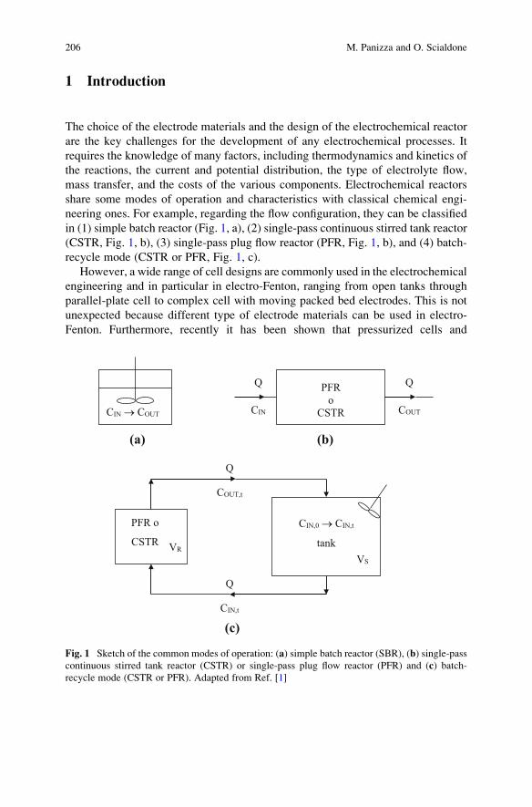
1 Introduction
The choice of the electrode materials and the design of the electrochemical reactor
are the key challenges for the development of any electrochemical processes. It
requires the knowledge of many factors, including thermodynamics and kinetics of
the reactions, the current and potential distribution, the type of electrolyte flow,
mass transfer, and the costs of the various components. Electrochemical reactors
share some modes of operation and characteristics with classical chemical engi-
neering ones. For example, regarding the flow configuration, they can be classified
in (1) simple batch reactor (Fig. 1, a), (2) single-pass continuous stirred tank reactor
(CSTR, Fig. 1, b), (3) single-pass plug flow reactor (PFR, Fig. 1, b), and (4) batch-
recycle mode (CSTR or PFR, Fig. 1, c).
However, a wide range of cell designs are commonly used in the electrochemical
engineering and in particular in electro-Fenton, ranging from open tanks through
parallel-plate cell to complex cell with moving packed bed electrodes. This is not
unexpected because different type of electrode materials can be used in electro-
Fenton. Furthermore, recently it has been shown that pressurized cells and
(a)
(c)
(b)
CIN COUT
Q QPFR
o
CSTRCIN → COUT
PFR o
CSTRVR
COUT,t
CIN,t
CIN,0 → CIN,t
tank
VS
Q
Q
Fig. 1 Sketch of the common modes of operation: (a) simple batch reactor (SBR), (b) single-pass
continuous stirred tank reactor (CSTR) or single-pass plug flow reactor (PFR) and (c) batch-
recycle mode (CSTR or PFR). Adapted from Ref. [1]
206 M. Panizza and O. Scialdone
microreactors can enhance the cathodic generation of hydrogen peroxide and the
abatement of organic pollutants by electro-Fenton process allowing to use cheap
compact graphite cathodes.
In this chapter, typical example of cell design used in the electro-Fenton process
will be discussed, and some results obtained with these cells will be presented.
2 Tank Cell
The plate-in-tank cell is one of the most common reactors used on a laboratory scale
because it offers an easy fabrication and it requires simple components. The cells
can contain only one anode and one cathode or multiple electrodes, with monopolar
or bipolar connection. In some processes, the cell can be also divided by a separator
or a membrane. Despite the simplicity of construction and operation of this type of
cell, it has the main drawback that the mass transport is limited even in the presence
of mechanical means. This type of cell is used in industrial electrochemistry in
many traditional processes such as water electrolysis, aluminum extraction, elec-
trowinning and electrorefining, and electrogeneration of many organic and inor-
ganic compounds.
Many laboratories use the tank cell for the electro-Fenton process with different
types of electrodes including graphite felt, activated carbon fiber (ACF), reticulated
vitreous carbon (RVC), gas diffusion electrodes (GDE) as cathode and platinum,
mixed metal oxide, PbO2, and boron-doped diamond (BDD) as anode. Some
examples are summarized in Table 1.
For example, the group of Panizza focused on the treatment of organic pollutants
by electrogenerated Fenton’s reagent utilized an undivided cell schematized in
Fig. 2 [2]. The laboratory cell has a variable volume from 0.20 to 35 dm�3, and it
is equipped with a heat exchanger to control the temperature. They used a carbon
felt with a thickness of 0.5 cm as cathode with a platinum wire isolated from the
solution for the electric contact. The anode was either a Pt wire placed in front of the
cathode or a Ti/RuO2 net centered in the electrolytic cell, surrounded by the
cathode, which covered the inner wall of the cell.
In this cell, •OH are produced in the bulk of the polluted solution using the
electrogenerated Fenton’s reagent (Eq. 1) where H2O2 is supplied in situ from the
two-electron reduction of O2 (Eq. 2) and Fe2+ is continually regenerated from Fe3+
reduction (Eq. 3):
Fe2þþH2O2 ! Fe3þþOH�þ�OH ð1Þ
O2þ2Hþþ2e� ! H2O2 ð2Þ
Conventional Reactors and Microreactors in Electro-Fenton 207
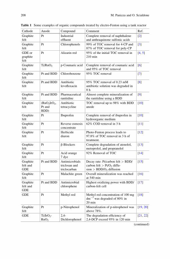
Table 1 Some examples of organic compounds treated by electro-Fenton using a tank reactor
Cathode Anode Compound Comment Ref.
Graphite
felt
Pt Industrial
effluent
Complete removal of naphthalene
and anthraquinone sulfonic acids
[2]
Graphite
felt
Pt Chlorophenols 99% of TOC removal for 4-CP and
87% of TOC removal for poly-CP
[3]
GDE or
graphite
felt
Pt Alizarin red 95% of the initial TOC removal in
210 min
[4, 5]
Graphite
felt
Ti/RuO2 p-Coumaric acid Complete removal of coumaric acid
and 95% of TOC removal
[6]
Graphite
felt
Pt and BDD Chlorobenzene 95% TOC removal [7]
Graphite
felt
Pt and BDD Antibiotic
levofloxacin
95% TOC removal of 0.23 mM
antibiotic solution was degraded in
8 h
[8]
Graphite
felt
Pt and BDD Pharmaceutical
ranitidine
Almost complete mineralization of
the ranitidine using a BDD
[9]
Graphite
felt
(RuO2IrO2,
Pt and
BDD)
Antibiotic
tetracycline
TOC removal up to 98% with BDD
anode
[10]
Graphite
felt
Pt Ibuprofen Complete removal of ibuprofen in
hydroorganic medium
[10]
Graphite
felt
Pt Reverse osmosis
concentrate
62% COD removal in 3 h [11]
Graphite
felt
Pt Herbicide
diuron
Photo-Fenton process leads to
97.8% of TOC removal in 3 h of
treatment.
[12]
Graphite
felt
Pt β-Blockers Complete degradation of atenolol,
metoprolol, and propranolol
[13]
Graphite
felt
Pt Acid orange
7 dye
92% Removal of TOC [14]
Graphite
felt and
GDE
Pt and BDD Antimicrobials
triclosan and
triclocarban
Decay rate: Pt/carbon felt > BDD/
carbon felt > Pt/O2 diffu-
sion > BDD/O2 diffusion
[15]
Graphite
felt
Pt Malachite green Overall mineralization was reached
at 540 min
[16]
Graphite
felt and
GDE
Pt and BDD Antimicrobial
chlorophene
Highest oxidizing power with BDD/
carbon-felt cell
[17]
GDE Pt Methyl red Methyl red concentration of 100 mg
dm�3 was degraded of 80% in
20 min
[18]
Graphite
felt
Pt p-Nitrophenol Mineralization of p-nitrophenol was
above 78%.
[19, 20]
GDE Ti/IrO2-
RuO2
2,4-
Dichlorophenol
The degradation efficiency of
2,4-DCP exceed 95% in 120 min
[21, 22]
(continued)
208 M. Panizza and O. Scialdone
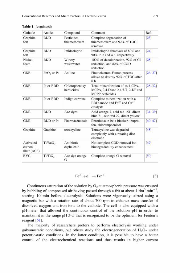
Fe3þþe� ! Fe2þ ð3Þ
Continuous saturation of the solution by O2 at atmospheric pressure was ensured
by bubbling of compressed air having passed through a frit at about 1 dm3 min�1,
starting 10 min before electrolysis. Solutions were vigorously stirred using a
magnetic bar with a rotation rate of about 700 rpm to enhance mass transfer of
dissolved oxygen and iron ions to the cathode. The cell is also equipped with a
pH-meter that allowed the continuous control of the solution pH in order to
maintain it in the range pH 3–5 that is recognized to be the optimum for Fenton’sreagent [51].
The majority of researchers prefers to perform electrolysis working under
galvanostatic conditions, but others study the electrogeneration of H2O2 under
potentiostatic conditions. In the latter condition, it is possible to have a better
control of the electrochemical reactions and thus results in higher current
Table 1 (continued)
Cathode Anode Compound Comment Ref.
Graphite
felt
BDD Pesticides
thiamethoxam
Complete degradation of
thiamethoxam and 92% of TOC
removal
[23]
Graphite
felt
BDD Imidacloprid Imidacloprid removals of 80% and
90% in 2 and 4 h, respectively
[24]
Nickel
foam
BDD Winery
wastewater
100% of decolorization, 92% of CI
reduction, and 82% of COD
reduction
[25]
GDE PbO2 or Pt Aniline Photoelectron-Fenton process
allows to destroy 92% of TOC after
6 h
[26, 27]
GDE Pt or BDD Chlorophenoxy
herbicides
Total mineralization of as 4-CPA,
MCPA, 2,4-D and 2,4,5-T, 2-DP and
MCPP herbicides
[28–32]
GDE Pt or BDD Indigo carmine Complete mineralization with a
BDD anode and Fe2+ and Cu2+
catalysts
[33]
GDE BDD Azo dyes Acid orange 7, acid red 151, direct
blue 71, acid red 29, direct yellow
[34–39]
GDE BDD or Pt Pharmaceuticals Enrofloxacin beta-blocker, ibupro-
fen, chloramphenicol
[40–47]
Graphite Graphite tetracycline Tetracycline was degraded
completely with a rotating disc
electrode
[48]
Activated
carbon
fiber (ACF)
Ti/RuO2 Antibiotic
cephalexin
Not complete COD removal but
biodegradability enhancement
[49]
RVC Ti/TiO2 Azo dye orange
G
Complete orange G removal [50]
Conventional Reactors and Microreactors in Electro-Fenton 209
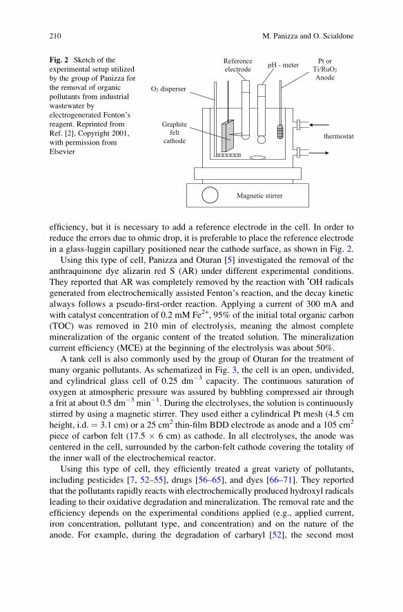
efficiency, but it is necessary to add a reference electrode in the cell. In order to
reduce the errors due to ohmic drop, it is preferable to place the reference electrode
in a glass-luggin capillary positioned near the cathode surface, as shown in Fig. 2.
Using this type of cell, Panizza and Oturan [5] investigated the removal of the
anthraquinone dye alizarin red S (AR) under different experimental conditions.
They reported that AR was completely removed by the reaction with •OH radicals
generated from electrochemically assisted Fenton’s reaction, and the decay kinetic
always follows a pseudo-first-order reaction. Applying a current of 300 mA and
with catalyst concentration of 0.2 mM Fe2+, 95% of the initial total organic carbon
(TOC) was removed in 210 min of electrolysis, meaning the almost complete
mineralization of the organic content of the treated solution. The mineralization
current efficiency (MCE) at the beginning of the electrolysis was about 50%.
A tank cell is also commonly used by the group of Oturan for the treatment of
many organic pollutants. As schematized in Fig. 3, the cell is an open, undivided,
and cylindrical glass cell of 0.25 dm�3 capacity. The continuous saturation of
oxygen at atmospheric pressure was assured by bubbling compressed air through
a frit at about 0.5 dm�3 min�1. During the electrolyses, the solution is continuously
stirred by using a magnetic stirrer. They used either a cylindrical Pt mesh (4.5 cm
height, i.d. ¼ 3.1 cm) or a 25 cm2 thin-film BDD electrode as anode and a 105 cm2
piece of carbon felt (17.5 � 6 cm) as cathode. In all electrolyses, the anode was
centered in the cell, surrounded by the carbon-felt cathode covering the totality of
the inner wall of the electrochemical reactor.
Using this type of cell, they efficiently treated a great variety of pollutants,
including pesticides [7, 52–55], drugs [56–65], and dyes [66–71]. They reported
that the pollutants rapidly reacts with electrochemically produced hydroxyl radicals
leading to their oxidative degradation and mineralization. The removal rate and the
efficiency depends on the experimental conditions applied (e.g., applied current,
iron concentration, pollutant type, and concentration) and on the nature of the
anode. For example, during the degradation of carbaryl [52], the second most
Pt or
Ti/RuO2
Anode
Magnetic stirrer
thermostat
pH - meterReference
electrode
O2 disperser
Graphite
felt
cathode
Fig. 2 Sketch of the
experimental setup utilized
by the group of Panizza for
the removal of organic
pollutants from industrial
wastewater by
electrogenerated Fenton’sreagent. Reprinted from
Ref. [2], Copyright 2001,
with permission from
Elsevier
210 M. Panizza and O. Scialdone
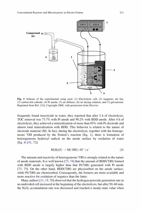
frequently found insecticide in water, they reported that after 2 h of electrolysis,
TOC removal was 73.7% with Pt anode and 90.2% with BDD anode. After 4 h of
electrolysis, they achieved a mineralization of more than 85% with Pt electrode and
almost total mineralization with BDD. This behavior is related to the nature of
electrode material (M). In fact, during the electrolysis, together with the homoge-
neous •OH produced by the Fenton’s reaction (Eq. 1), there is formation of
heterogeneous hydroxyl radical on the anode surface by oxidation of water
(Eq. 4) [51, 72]:
M H2Oð Þ ! M �OHð ÞþHþþe� ð4Þ
The amount and reactivity of heterogeneous •OH is strongly related to the nature
of anode materials. It is well known [73, 74] that the amount of BDD(•OH) formed
with BDD anode is largely higher than that Pt(•OH) generated with Pt anode
[73, 75]. On the other hand, BDD(•OH) are physisorbed on the anode surface,
while Pt(•OH) are chemisorbed. Consequently, the formers are more available and
more reactive for oxidation of organics than the latter.
Many authors [11, 15, 70] observed that the hydrogen peroxide generation rate in
an undivided cell increased at the beginning of the electrolysis, but after 50–60 min,
the H2O2 accumulation rate was decreased and reached a steady-state value when
Fig. 3 Scheme of the experimental setup used. (1) Electrolytic cell, (2) magnetic stir bar,
(3) carbon-felt cathode, (4) Pt anode, (5) air diffuser, (6) air drying solution, and (7) galvanostat.
Reprinted from Ref. [16], Copyright 2008, with permission from Elsevier
Conventional Reactors and Microreactors in Electro-Fenton 211
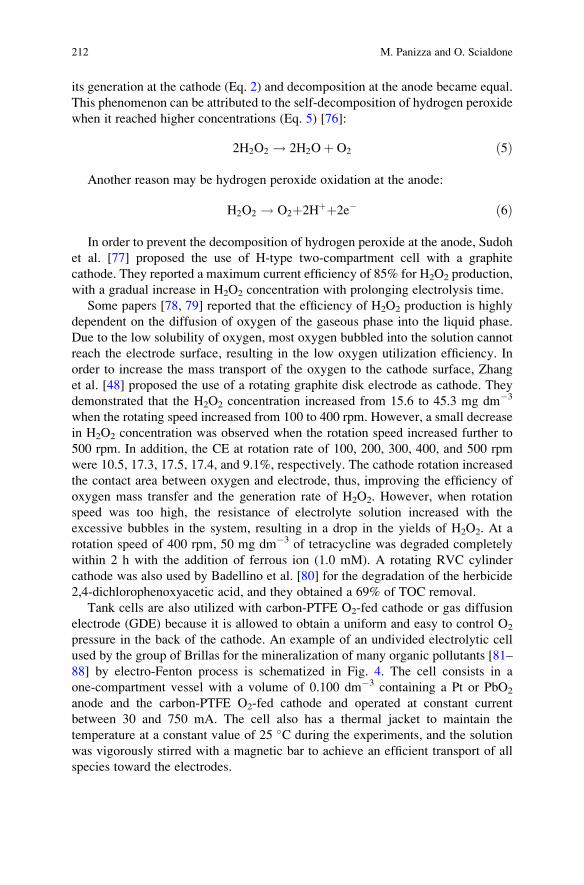
its generation at the cathode (Eq. 2) and decomposition at the anode became equal.
This phenomenon can be attributed to the self-decomposition of hydrogen peroxide
when it reached higher concentrations (Eq. 5) [76]:
2H2O2 ! 2H2Oþ O2 ð5Þ
Another reason may be hydrogen peroxide oxidation at the anode:
H2O2 ! O2þ2Hþþ2e� ð6Þ
In order to prevent the decomposition of hydrogen peroxide at the anode, Sudoh
et al. [77] proposed the use of H-type two-compartment cell with a graphite
cathode. They reported a maximum current efficiency of 85% for H2O2 production,
with a gradual increase in H2O2 concentration with prolonging electrolysis time.
Some papers [78, 79] reported that the efficiency of H2O2 production is highly
dependent on the diffusion of oxygen of the gaseous phase into the liquid phase.
Due to the low solubility of oxygen, most oxygen bubbled into the solution cannot
reach the electrode surface, resulting in the low oxygen utilization efficiency. In
order to increase the mass transport of the oxygen to the cathode surface, Zhang
et al. [48] proposed the use of a rotating graphite disk electrode as cathode. They
demonstrated that the H2O2 concentration increased from 15.6 to 45.3 mg dm�3
when the rotating speed increased from 100 to 400 rpm. However, a small decrease
in H2O2 concentration was observed when the rotation speed increased further to
500 rpm. In addition, the CE at rotation rate of 100, 200, 300, 400, and 500 rpm
were 10.5, 17.3, 17.5, 17.4, and 9.1%, respectively. The cathode rotation increased
the contact area between oxygen and electrode, thus, improving the efficiency of
oxygen mass transfer and the generation rate of H2O2. However, when rotation
speed was too high, the resistance of electrolyte solution increased with the
excessive bubbles in the system, resulting in a drop in the yields of H2O2. At a
rotation speed of 400 rpm, 50 mg dm�3 of tetracycline was degraded completely
within 2 h with the addition of ferrous ion (1.0 mM). A rotating RVC cylinder
cathode was also used by Badellino et al. [80] for the degradation of the herbicide
2,4-dichlorophenoxyacetic acid, and they obtained a 69% of TOC removal.
Tank cells are also utilized with carbon-PTFE O2-fed cathode or gas diffusion
electrode (GDE) because it is allowed to obtain a uniform and easy to control O2
pressure in the back of the cathode. An example of an undivided electrolytic cell
used by the group of Brillas for the mineralization of many organic pollutants [81–
88] by electro-Fenton process is schematized in Fig. 4. The cell consists in a
one-compartment vessel with a volume of 0.100 dm�3 containing a Pt or PbO2
anode and the carbon-PTFE O2-fed cathode and operated at constant current
between 30 and 750 mA. The cell also has a thermal jacket to maintain the
temperature at a constant value of 25 �C during the experiments, and the solution
was vigorously stirred with a magnetic bar to achieve an efficient transport of all
species toward the electrodes.
212 M. Panizza and O. Scialdone
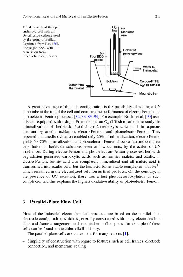
A great advantage of this cell configuration is the possibility of adding a UV
lamp tube at the top of the cell and compare the performance of electro-Fenton and
photoelectro-Fenton processes [32, 33, 89–94]. For example, Brillas et al. [90] used
this cell equipped with using a Pt anode and an O2-diffusion cathode to study the
mineralization of herbicide 3,6-dichloro-2-methoxybenzoic acid in aqueous
medium by anodic oxidation, electro-Fenton, and photoelectro-Fenton. They
reported that anodic oxidation enabled only 20% of mineralization, electro-Fenton
yields 60–70% mineralization, and photoelectro-Fenton allows a fast and complete
depollution of herbicide solutions, even at low currents, by the action of UV
irradiation. During electro-Fenton and photoelectron-Fenton processes, herbicide
degradation generated carboxylic acids such as formic, maleic, and oxalic. In
electro-Fenton, formic acid was completely mineralized and all maleic acid is
transformed into oxalic acid, but the last acid forms stable complexes with Fe3+,
which remained in the electrolyzed solution as final products. On the contrary, in
the presence of UV radiation, there was a fast photodecarboxylation of such
complexes, and this explains the highest oxidative ability of photoelectro-Fenton.
3 Parallel-Plate Flow Cell
Most of the industrial electrochemical processes are based on the parallel-plate
electrode configuration, which is generally constructed with many electrodes in a
plate-and-frame arrangement and mounted on a filter press. An example of these
cells can be found in the chlor-alkali industry.
The parallel-plate cells are convenient for many reasons [1]:
– Simplicity of construction with regard to features such as cell frames, electrode
connection, and membrane sealing.
Fig. 4 Sketch of the open
undivided cell with an
O2-diffusion cathode used
by the group of Brillas.
Reprinted from Ref. [85],
Copyright 1995, with
permission from
Electrochemical Society
Conventional Reactors and Microreactors in Electro-Fenton 213
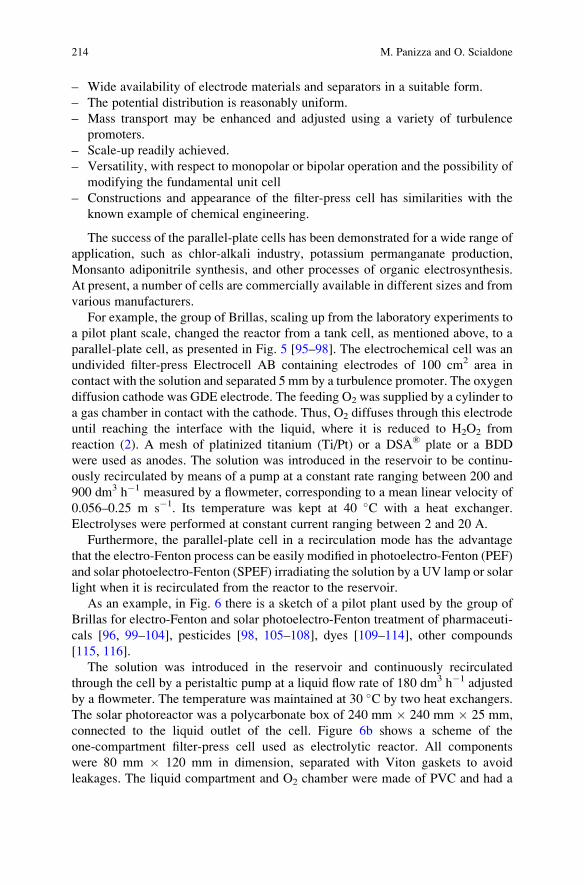
– Wide availability of electrode materials and separators in a suitable form.
– The potential distribution is reasonably uniform.
– Mass transport may be enhanced and adjusted using a variety of turbulence
promoters.
– Scale-up readily achieved.
– Versatility, with respect to monopolar or bipolar operation and the possibility of
modifying the fundamental unit cell
– Constructions and appearance of the filter-press cell has similarities with the
known example of chemical engineering.
The success of the parallel-plate cells has been demonstrated for a wide range of
application, such as chlor-alkali industry, potassium permanganate production,
Monsanto adiponitrile synthesis, and other processes of organic electrosynthesis.
At present, a number of cells are commercially available in different sizes and from
various manufacturers.
For example, the group of Brillas, scaling up from the laboratory experiments to
a pilot plant scale, changed the reactor from a tank cell, as mentioned above, to a
parallel-plate cell, as presented in Fig. 5 [95–98]. The electrochemical cell was an
undivided filter-press Electrocell AB containing electrodes of 100 cm2 area in
contact with the solution and separated 5 mm by a turbulence promoter. The oxygen
diffusion cathode was GDE electrode. The feeding O2 was supplied by a cylinder to
a gas chamber in contact with the cathode. Thus, O2 diffuses through this electrode
until reaching the interface with the liquid, where it is reduced to H2O2 from
reaction (2). A mesh of platinized titanium (Ti/Pt) or a DSA® plate or a BDD
were used as anodes. The solution was introduced in the reservoir to be continu-
ously recirculated by means of a pump at a constant rate ranging between 200 and
900 dm3 h�1 measured by a flowmeter, corresponding to a mean linear velocity of
0.056–0.25 m s�1. Its temperature was kept at 40 �C with a heat exchanger.
Electrolyses were performed at constant current ranging between 2 and 20 A.
Furthermore, the parallel-plate cell in a recirculation mode has the advantage
that the electro-Fenton process can be easily modified in photoelectro-Fenton (PEF)
and solar photoelectro-Fenton (SPEF) irradiating the solution by a UV lamp or solar
light when it is recirculated from the reactor to the reservoir.
As an example, in Fig. 6 there is a sketch of a pilot plant used by the group of
Brillas for electro-Fenton and solar photoelectro-Fenton treatment of pharmaceuti-
cals [96, 99–104], pesticides [98, 105–108], dyes [109–114], other compounds
[115, 116].
The solution was introduced in the reservoir and continuously recirculated
through the cell by a peristaltic pump at a liquid flow rate of 180 dm3 h�1 adjusted
by a flowmeter. The temperature was maintained at 30 �C by two heat exchangers.
The solar photoreactor was a polycarbonate box of 240 mm � 240 mm � 25 mm,
connected to the liquid outlet of the cell. Figure 6b shows a scheme of the
one-compartment filter-press cell used as electrolytic reactor. All components
were 80 mm � 120 mm in dimension, separated with Viton gaskets to avoid
leakages. The liquid compartment and O2 chamber were made of PVC and had a
214 M. Panizza and O. Scialdone
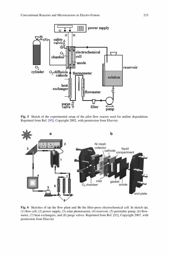
Fig. 5 Sketch of the experimental setup of the pilot flow reactor used for aniline degradation.
Reprinted from Ref. [95], Copyright 2002, with permission from Elsevier
2
a b
Ni meshcollector
V12.5 1.00
A
cathode
inlet
outletO2
O2 chamber
gasketanode
end plate
liquidcompartment
1
7
65
4
3
8
Fig. 6 Sketches of (a) the flow plant and (b) the filter-press electrochemical cell. In sketch (a),
(1) flow cell, (2) power supply, (3) solar photoreactor, (4) reservoir, (5) peristaltic pump, (6) flow-
meter, (7) heat exchangers, and (8) purge valves. Reprinted from Ref. [92], Copyright 2007, with
permission from Elsevier
Conventional Reactors and Microreactors in Electro-Fenton 215
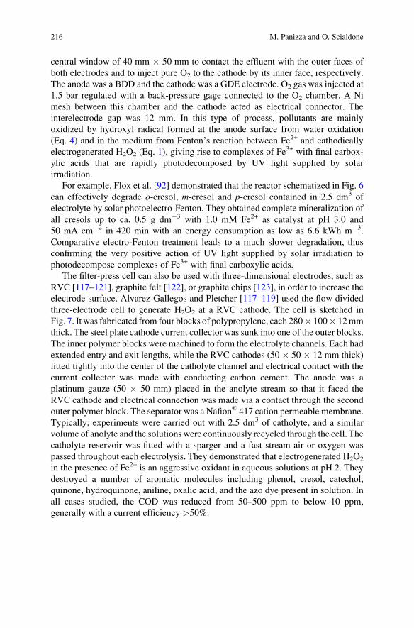
central window of 40 mm � 50 mm to contact the effluent with the outer faces of
both electrodes and to inject pure O2 to the cathode by its inner face, respectively.
The anode was a BDD and the cathode was a GDE electrode. O2 gas was injected at
1.5 bar regulated with a back-pressure gage connected to the O2 chamber. A Ni
mesh between this chamber and the cathode acted as electrical connector. The
interelectrode gap was 12 mm. In this type of process, pollutants are mainly
oxidized by hydroxyl radical formed at the anode surface from water oxidation
(Eq. 4) and in the medium from Fenton’s reaction between Fe2+ and cathodically
electrogenerated H2O2 (Eq. 1), giving rise to complexes of Fe3+ with final carbox-
ylic acids that are rapidly photodecomposed by UV light supplied by solar
irradiation.
For example, Flox et al. [92] demonstrated that the reactor schematized in Fig. 6
can effectively degrade o-cresol, m-cresol and p-cresol contained in 2.5 dm3 of
electrolyte by solar photoelectro-Fenton. They obtained complete mineralization of
all cresols up to ca. 0.5 g dm�3 with 1.0 mM Fe2+ as catalyst at pH 3.0 and
50 mA cm�2 in 420 min with an energy consumption as low as 6.6 kWh m�3.
Comparative electro-Fenton treatment leads to a much slower degradation, thus
confirming the very positive action of UV light supplied by solar irradiation to
photodecompose complexes of Fe3+ with final carboxylic acids.
The filter-press cell can also be used with three-dimensional electrodes, such as
RVC [117–121], graphite felt [122], or graphite chips [123], in order to increase the
electrode surface. Alvarez-Gallegos and Pletcher [117–119] used the flow divided
three-electrode cell to generate H2O2 at a RVC cathode. The cell is sketched in
Fig. 7. It was fabricated from four blocks of polypropylene, each 280� 100� 12mm
thick. The steel plate cathode current collector was sunk into one of the outer blocks.
The inner polymer blocks were machined to form the electrolyte channels. Each had
extended entry and exit lengths, while the RVC cathodes (50 � 50 � 12 mm thick)
fitted tightly into the center of the catholyte channel and electrical contact with the
current collector was made with conducting carbon cement. The anode was a
platinum gauze (50 � 50 mm) placed in the anolyte stream so that it faced the
RVC cathode and electrical connection was made via a contact through the second
outer polymer block. The separator was a Nafion® 417 cation permeable membrane.
Typically, experiments were carried out with 2.5 dm3 of catholyte, and a similar
volume of anolyte and the solutions were continuously recycled through the cell. The
catholyte reservoir was fitted with a sparger and a fast stream air or oxygen was
passed throughout each electrolysis. They demonstrated that electrogenerated H2O2
in the presence of Fe2+ is an aggressive oxidant in aqueous solutions at pH 2. They
destroyed a number of aromatic molecules including phenol, cresol, catechol,
quinone, hydroquinone, aniline, oxalic acid, and the azo dye present in solution. In
all cases studied, the COD was reduced from 50–500 ppm to below 10 ppm,
generally with a current efficiency >50%.
216 M. Panizza and O. Scialdone
4 Moving Three-Dimensional Electrodes
A three-dimensional electrode is attractive in industrial applications over a
two-dimensional electrode, for its larger active surface area per unit volume, even
if not all the area is available for the electrochemical process. There are many types
of three-dimensional electrodes, including graphite fiber and cloth, metal and
carbon foams (reticulates), and particulate bed of carbon granules. When small
particles are polarized in a three-dimensional electrode reactor, they form charged
microelectrodes with a short distance between the reactant and the electrode
thereby resulting in higher efficiency.
However, fluidized or moving-bed electrodes still present some problems of bed
agglomeration, poor bed-feeder contact, and nonuniform current and potential
distribution, and therefore only few works used these reactors for electro-Fenton
oxidation [124–128].
RVC Electrode Nafion Membrane
Outlet
Inlet
00 0
0
0
000
0 0 0
0
0
00
00
0
0 0 0
00
0
0 0
Contact toPt anode
OutletLuggin
CathodeInlet
gasket
1
Anolyte2
3
5
4
6
Pump
1) Flow-Cell2) SCE
4) Gas (N2/O2) Inlet5) Gas Outlet6) Sample Point
3) Potentiostat,Waveform Generatorand Chart Recorder
Catholyte
Probe
Contactto RVC
a
b
Fig. 7 Sketches of (a) the
flow cell with RVC cathode
and (b) the flow circuit.
Reprinted from Ref. [117],
Copyright 1998, with
permission from Elsevier
Conventional Reactors and Microreactors in Electro-Fenton 217
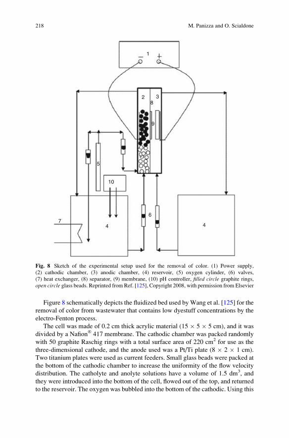
Figure 8 schematically depicts the fluidized bed used byWang et al. [125] for the
removal of color from wastewater that contains low dyestuff concentrations by the
electro-Fenton process.
The cell was made of 0.2 cm thick acrylic material (15 � 5 � 5 cm), and it was
divided by a Nafion® 417 membrane. The cathodic chamber was packed randomly
with 50 graphite Raschig rings with a total surface area of 220 cm2 for use as the
three-dimensional cathode, and the anode used was a Pt/Ti plate (8 � 2 � 1 cm).
Two titanium plates were used as current feeders. Small glass beads were packed at
the bottom of the cathodic chamber to increase the uniformity of the flow velocity
distribution. The catholyte and anolyte solutions have a volume of 1.5 dm3, and
they were introduced into the bottom of the cell, flowed out of the top, and returned
to the reservoir. The oxygen was bubbled into the bottom of the cathodic. Using this
1
2 38
9
5
10
74
6
4
Fig. 8 Sketch of the experimental setup used for the removal of color. (1) Power supply,
(2) cathodic chamber, (3) anodic chamber, (4) reservoir, (5) oxygen cylinder, (6) valves,
(7) heat exchanger, (8) separator, (9) membrane, (10) pH controller, filled circle graphite rings,
open circle glass beads. Reprinted from Ref. [125], Copyright 2008, with permission from Elsevier
218 M. Panizza and O. Scialdone
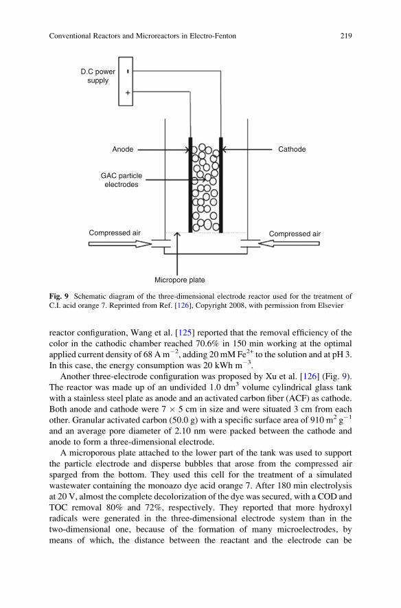
reactor configuration, Wang et al. [125] reported that the removal efficiency of the
color in the cathodic chamber reached 70.6% in 150 min working at the optimal
applied current density of 68 Am�2, adding 20 mM Fe2+ to the solution and at pH 3.
In this case, the energy consumption was 20 kWh m�3.
Another three-electrode configuration was proposed by Xu et al. [126] (Fig. 9).
The reactor was made up of an undivided 1.0 dm3 volume cylindrical glass tank
with a stainless steel plate as anode and an activated carbon fiber (ACF) as cathode.
Both anode and cathode were 7 � 5 cm in size and were situated 3 cm from each
other. Granular activated carbon (50.0 g) with a specific surface area of 910 m2 g�1
and an average pore diameter of 2.10 nm were packed between the cathode and
anode to form a three-dimensional electrode.
A microporous plate attached to the lower part of the tank was used to support
the particle electrode and disperse bubbles that arose from the compressed air
sparged from the bottom. They used this cell for the treatment of a simulated
wastewater containing the monoazo dye acid orange 7. After 180 min electrolysis
at 20 V, almost the complete decolorization of the dye was secured, with a COD and
TOC removal 80% and 72%, respectively. They reported that more hydroxyl
radicals were generated in the three-dimensional electrode system than in the
two-dimensional one, because of the formation of many microelectrodes, by
means of which, the distance between the reactant and the electrode can be
D.C powersupply
Anode
Compressed air
Micropore plate
Compressed air
Cathode
GAC particleelectrodes
Fig. 9 Schematic diagram of the three-dimensional electrode reactor used for the treatment of
C.I. acid orange 7. Reprinted from Ref. [126], Copyright 2008, with permission from Elsevier
Conventional Reactors and Microreactors in Electro-Fenton 219
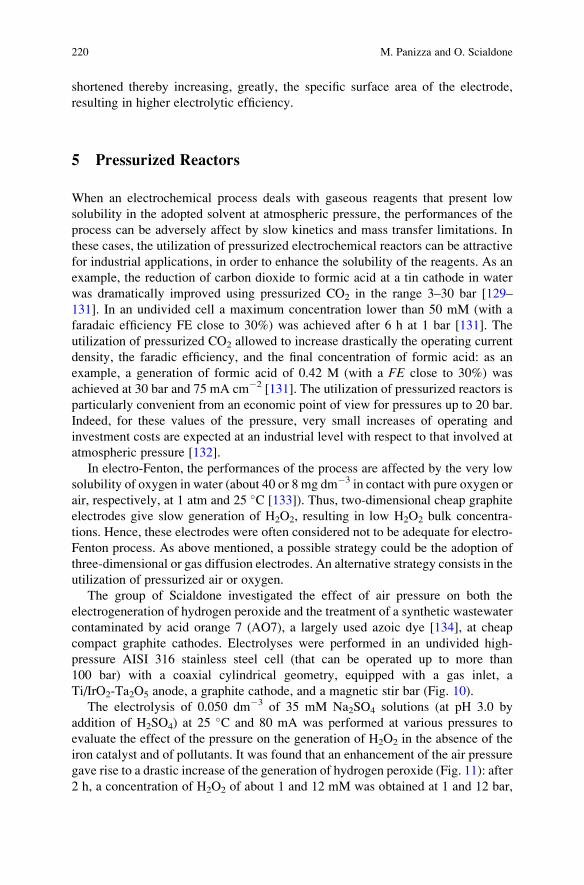
shortened thereby increasing, greatly, the specific surface area of the electrode,
resulting in higher electrolytic efficiency.
5 Pressurized Reactors
When an electrochemical process deals with gaseous reagents that present low
solubility in the adopted solvent at atmospheric pressure, the performances of the
process can be adversely affect by slow kinetics and mass transfer limitations. In
these cases, the utilization of pressurized electrochemical reactors can be attractive
for industrial applications, in order to enhance the solubility of the reagents. As an
example, the reduction of carbon dioxide to formic acid at a tin cathode in water
was dramatically improved using pressurized CO2 in the range 3–30 bar [129–
131]. In an undivided cell a maximum concentration lower than 50 mM (with a
faradaic efficiency FE close to 30%) was achieved after 6 h at 1 bar [131]. The
utilization of pressurized CO2 allowed to increase drastically the operating current
density, the faradic efficiency, and the final concentration of formic acid: as an
example, a generation of formic acid of 0.42 M (with a FE close to 30%) was
achieved at 30 bar and 75 mA cm�2 [131]. The utilization of pressurized reactors is
particularly convenient from an economic point of view for pressures up to 20 bar.
Indeed, for these values of the pressure, very small increases of operating and
investment costs are expected at an industrial level with respect to that involved at
atmospheric pressure [132].
In electro-Fenton, the performances of the process are affected by the very low
solubility of oxygen in water (about 40 or 8 mg dm�3 in contact with pure oxygen or
air, respectively, at 1 atm and 25 �C [133]). Thus, two-dimensional cheap graphite
electrodes give slow generation of H2O2, resulting in low H2O2 bulk concentra-
tions. Hence, these electrodes were often considered not to be adequate for electro-
Fenton process. As above mentioned, a possible strategy could be the adoption of
three-dimensional or gas diffusion electrodes. An alternative strategy consists in the
utilization of pressurized air or oxygen.
The group of Scialdone investigated the effect of air pressure on both the
electrogeneration of hydrogen peroxide and the treatment of a synthetic wastewater
contaminated by acid orange 7 (AO7), a largely used azoic dye [134], at cheap
compact graphite cathodes. Electrolyses were performed in an undivided high-
pressure AISI 316 stainless steel cell (that can be operated up to more than
100 bar) with a coaxial cylindrical geometry, equipped with a gas inlet, a
Ti/IrO2-Ta2O5 anode, a graphite cathode, and a magnetic stir bar (Fig. 10).
The electrolysis of 0.050 dm�3 of 35 mM Na2SO4 solutions (at pH 3.0 by
addition of H2SO4) at 25�C and 80 mA was performed at various pressures to
evaluate the effect of the pressure on the generation of H2O2 in the absence of the
iron catalyst and of pollutants. It was found that an enhancement of the air pressure
gave rise to a drastic increase of the generation of hydrogen peroxide (Fig. 11): after
2 h, a concentration of H2O2 of about 1 and 12 mM was obtained at 1 and 12 bar,
220 M. Panizza and O. Scialdone
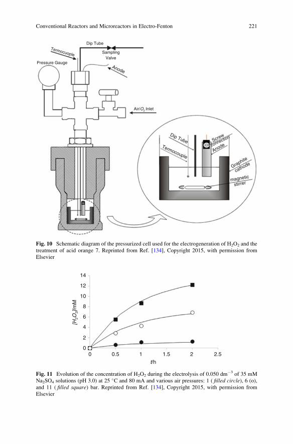
Graphite
Screw
Anode
Anode
Dip TubeTermocouple
connection
cathode
stirrermagnetic
Air/O2 Inlet
SamplingValve
Dip Tube
Pressure Gauge
Termocuople
Fig. 10 Schematic diagram of the pressurized cell used for the electrogeneration of H2O2 and the
treatment of acid orange 7. Reprinted from Ref. [134], Copyright 2015, with permission from
Elsevier
14
12
10
8
6
4
2
00 0.5 1 1.5 2 2.5
t/h
[H2O
2]/m
M
Fig. 11 Evolution of the concentration of H2O2 during the electrolysis of 0.050 dm�3 of 35 mM
Na2SO4 solutions (pH 3.0) at 25 �C and 80 mA and various air pressures: 1 ( filled circle), 6 (o),
and 11 ( filled square) bar. Reprinted from Ref. [134], Copyright 2015, with permission from
Elsevier
Conventional Reactors and Microreactors in Electro-Fenton 221
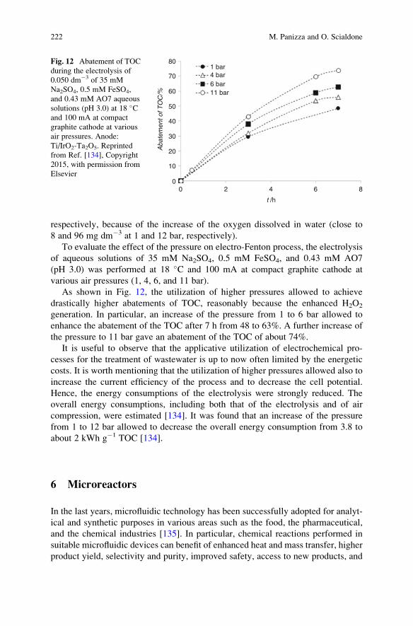
respectively, because of the increase of the oxygen dissolved in water (close to
8 and 96 mg dm�3 at 1 and 12 bar, respectively).
To evaluate the effect of the pressure on electro-Fenton process, the electrolysis
of aqueous solutions of 35 mM Na2SO4, 0.5 mM FeSO4, and 0.43 mM AO7
(pH 3.0) was performed at 18 �C and 100 mA at compact graphite cathode at
various air pressures (1, 4, 6, and 11 bar).
As shown in Fig. 12, the utilization of higher pressures allowed to achieve
drastically higher abatements of TOC, reasonably because the enhanced H2O2
generation. In particular, an increase of the pressure from 1 to 6 bar allowed to
enhance the abatement of the TOC after 7 h from 48 to 63%. A further increase of
the pressure to 11 bar gave an abatement of the TOC of about 74%.
It is useful to observe that the applicative utilization of electrochemical pro-
cesses for the treatment of wastewater is up to now often limited by the energetic
costs. It is worth mentioning that the utilization of higher pressures allowed also to
increase the current efficiency of the process and to decrease the cell potential.
Hence, the energy consumptions of the electrolysis were strongly reduced. The
overall energy consumptions, including both that of the electrolysis and of air
compression, were estimated [134]. It was found that an increase of the pressure
from 1 to 12 bar allowed to decrease the overall energy consumption from 3.8 to
about 2 kWh g�1 TOC [134].
6 Microreactors
In the last years, microfluidic technology has been successfully adopted for analyt-
ical and synthetic purposes in various areas such as the food, the pharmaceutical,
and the chemical industries [135]. In particular, chemical reactions performed in
suitable microfluidic devices can benefit of enhanced heat and mass transfer, higher
product yield, selectivity and purity, improved safety, access to new products, and
80
70
60
50
40
30
20
10
00 2
1 bar4 bar6 bar11 bar
4 6
t /h
Aba
tem
ent o
f TO
C/%
8
Fig. 12 Abatement of TOC
during the electrolysis of
0.050 dm�3 of 35 mM
Na2SO4, 0.5 mM FeSO4,
and 0.43 mM AO7 aqueous
solutions (pH 3.0) at 18 �Cand 100 mA at compact
graphite cathode at various
air pressures. Anode:
Ti/IrO2-Ta2O5. Reprinted
from Ref. [134], Copyright
2015, with permission from
Elsevier
222 M. Panizza and O. Scialdone
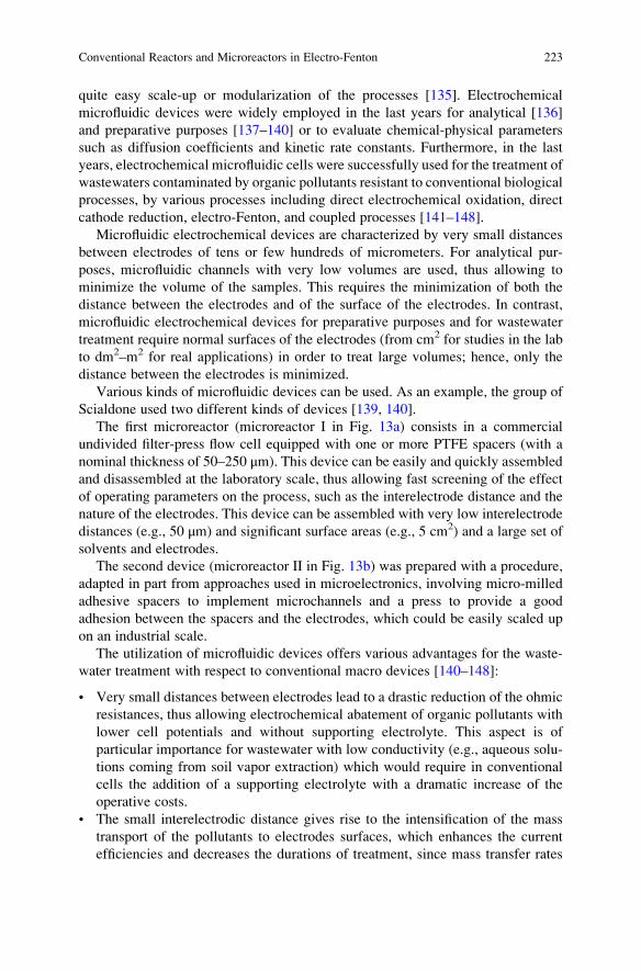
quite easy scale-up or modularization of the processes [135]. Electrochemical
microfluidic devices were widely employed in the last years for analytical [136]
and preparative purposes [137–140] or to evaluate chemical-physical parameters
such as diffusion coefficients and kinetic rate constants. Furthermore, in the last
years, electrochemical microfluidic cells were successfully used for the treatment of
wastewaters contaminated by organic pollutants resistant to conventional biological
processes, by various processes including direct electrochemical oxidation, direct
cathode reduction, electro-Fenton, and coupled processes [141–148].
Microfluidic electrochemical devices are characterized by very small distances
between electrodes of tens or few hundreds of micrometers. For analytical pur-
poses, microfluidic channels with very low volumes are used, thus allowing to
minimize the volume of the samples. This requires the minimization of both the
distance between the electrodes and of the surface of the electrodes. In contrast,
microfluidic electrochemical devices for preparative purposes and for wastewater
treatment require normal surfaces of the electrodes (from cm2 for studies in the lab
to dm2–m2 for real applications) in order to treat large volumes; hence, only the
distance between the electrodes is minimized.
Various kinds of microfluidic devices can be used. As an example, the group of
Scialdone used two different kinds of devices [139, 140].
The first microreactor (microreactor I in Fig. 13a) consists in a commercial
undivided filter-press flow cell equipped with one or more PTFE spacers (with a
nominal thickness of 50–250 μm). This device can be easily and quickly assembled
and disassembled at the laboratory scale, thus allowing fast screening of the effect
of operating parameters on the process, such as the interelectrode distance and the
nature of the electrodes. This device can be assembled with very low interelectrode
distances (e.g., 50 μm) and significant surface areas (e.g., 5 cm2) and a large set of
solvents and electrodes.
The second device (microreactor II in Fig. 13b) was prepared with a procedure,
adapted in part from approaches used in microelectronics, involving micro-milled
adhesive spacers to implement microchannels and a press to provide a good
adhesion between the spacers and the electrodes, which could be easily scaled up
on an industrial scale.
The utilization of microfluidic devices offers various advantages for the waste-
water treatment with respect to conventional macro devices [140–148]:
• Very small distances between electrodes lead to a drastic reduction of the ohmic
resistances, thus allowing electrochemical abatement of organic pollutants with
lower cell potentials and without supporting electrolyte. This aspect is of
particular importance for wastewater with low conductivity (e.g., aqueous solu-
tions coming from soil vapor extraction) which would require in conventional
cells the addition of a supporting electrolyte with a dramatic increase of the
operative costs.
• The small interelectrodic distance gives rise to the intensification of the mass
transport of the pollutants to electrodes surfaces, which enhances the current
efficiencies and decreases the durations of treatment, since mass transfer rates
Conventional Reactors and Microreactors in Electro-Fenton 223
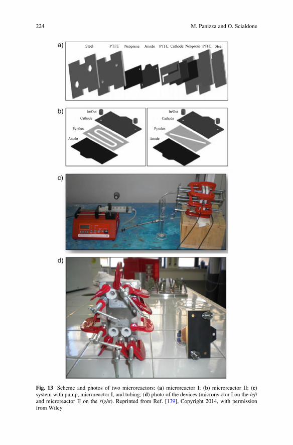
Fig. 13 Scheme and photos of two microreactors: (a) microreactor I; (b) microreactor II; (c)
system with pump, microreactor I, and tubing; (d) photo of the devices (microreactor I on the leftand microreactor II on the right). Reprinted from Ref. [139], Copyright 2014, with permission
from Wiley
224 M. Panizza and O. Scialdone
toward electrodes are usually extremely reduced at the low pollutant concentra-
tions required by regulations [143].
• The small distances between electrodes allow very high conversions of the
organic pollutants for a single passage of the water solution inside the cell,
thus allowing continuous operations. The possibility to operate in a continuous
mode potentially allows the utilization of a multistage system involving two or
more cells operating in series with different processes and/or applied current
densities in order to maximize the current efficiency and to minimize the
treatment times [148].
• Fast screening of the effect of operative parameters. As a consequence of the
very short treatment times, a screening of the effect of operative parameters on
the performances of the process can be performed in short times by fast changing
of the steady-state conditions in comparison to conventional macro-systems that
must operate in batch recycling mode [145].
• Easier scale-up procedure through simple parallelization of many small units.
However, the utilization of microdevices presents also some potential drawbacks
such as an easier fouling and clogging.
The electrogeneration of H2O2 and the abatement of the model organic pollutant
acid orange 7 (AO7) in water by an electro-Fenton process were performed both in
a microfluidic reactor (microreactor I in Fig. 13) and in a conventional undivided
glass macro-cell (with magnetic stirring) for the sake of comparison [144]. The
reduction of oxygen (with air at atmospheric pressure) at compact graphite in an
aqueous solution of sodium sulfate resulted in the conventional lab glass cell in
concentrations of H2O2 close to 0.6 mM. Under optimized operative conditions
(interelectrode distance 120 μm, current density in the range 1–2 mA cm�2,
corresponding to 10–20 A m�2), the micro-device gave rise to a concentration of
H2O2 of about 6 mM, one order of magnitude higher than that achieved in the
conventional macro-cell (Fig. 14).
To explain the higher concentrations of hydrogen peroxide achieved in the
microreactor, one has to consider that in the micro-cell a large part of the oxygen
formed at the anode is approximately uniformly distributed in the form of discrete
bubbles in all the liquid phase [149, 150]. Hence, the concentration of oxygen
should be close to its solubility also in the proximity of the cathode surface, thus
giving rise to an overall faster mass transfer of oxygen to the cathode surface with
respect to that achieved in a conventional cell.
It is worth mentioning that the microfluidic cell operated in the absence of a flux
of air, using the oxygen naturally dissolved in water and that generated by the
anodic oxidation of water.
Some experiments were performed in the micro-cell changing the interelectrodic
distance h (75, 120, and 240 μm). The maximum concentration of H2O2 was
achieved for h ¼ 120 μm. Lower h is expected to result in a more uniform
distribution of oxygen in the cell, thus favoring the generation of H2O2 formation,
and also in faster mass transport rate of H2O2 to the anode surface with consequent
Conventional Reactors and Microreactors in Electro-Fenton 225
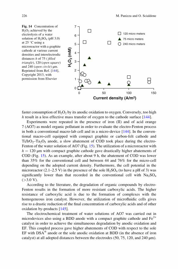
faster consumption of H2O2 by its anodic oxidation to oxygen. Conversely, too high
h result in a less effective mass transfer of oxygen to the cathode surface [144].
Experiments were repeated in the presence of iron (II) and of acid orange
7 (AO7) as model organic pollutant in order to evaluate the electro-Fenton process
in both a conventional macro-lab cell and in a micro-device [144]. In the conven-
tional macro-cell equipped with compact graphite or carbon-felt cathode and
Ti/IrO2–Ta2O5 anode, a slow abatement of COD took place during the electro-
Fenton of the water solution of AO7 (Fig. 15). The utilization of a microreactor with
h ¼ 120 μm with compact graphite cathode gave drastically higher abatements of
COD (Fig. 15). As an example, after about 9 h, the abatement of COD was lower
than 35% for the conventional cell and between 44 and 76% for the micro-cell
depending on the adopted current density. Furthermore, the cell potential in the
microreactor (2.1–2.5 V) in the presence of the sole H2SO4 (to have a pH of 3) was
significantly lower than that recorded in the conventional cell with Na2SO4
(>3.0 V).
According to the literature, the degradation of organic compounds by electro-
Fenton results in the formation of more resistant carboxylic acids. The higher
resistance of carboxylic acid is due to the formation of complexes with the
homogeneous iron catalyst. However, the utilization of microfluidic cells gives
rise to a drastic reduction of the final concentration of carboxylic acids and of other
oxidation by-products [145].
The electrochemical treatment of water solutions of AO7 was carried out in
microdevices also using a BDD anode with a compact graphite cathode and Fe2+
catalyst in order to achieve the simultaneous degradation by anodic oxidation and
EF. This coupled process gave higher abatements of COD with respect to the sole
EF with DSA® anode or the sole anodic oxidation at BDD (in the absence of iron
catalyst) at all adopted distances between the electrodes (50, 75, 120, and 240 μm).
7
6
5
4
3
2
1
0
0 50 100 150
120 micro meters
75 micro meters
240 micro meters
Current density (A/m2)
H2O
2 (m
M)
Fig. 14 Concentration of
H2O2 achieved by the
electrolysis of a water
solution of H2SO4 (pH 3.0)
at 25 �C using a
microreactor with a graphite
cathode at various current
densities and interelectrodic
distances h of 75 ( filledtriangle), 120 (open square)and 240 (open circle) μm.
Reprinted from Ref. [144],
Copyright 2013, with
permission from Elsevier
226 M. Panizza and O. Scialdone
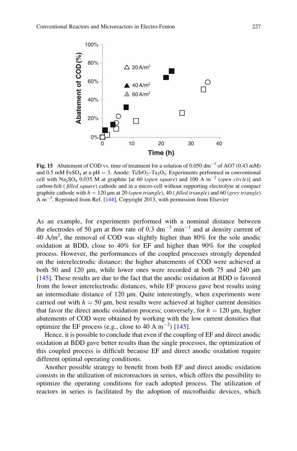
As an example, for experiments performed with a nominal distance between
the electrodes of 50 μm at flow rate of 0.3 dm�3 min�1 and at density current of
40 A/m2, the removal of COD was slightly higher than 80% for the sole anodic
oxidation at BDD, close to 40% for EF and higher than 90% for the coupled
process. However, the performances of the coupled processes strongly depended
on the interelectrodic distance: the higher abatements of COD were achieved at
both 50 and 120 μm, while lower ones were recorded at both 75 and 240 μm[145]. These results are due to the fact that the anodic oxidation at BDD is favored
from the lower interelectrodic distances, while EF process gave best results using
an intermediate distance of 120 μm. Quite interestingly, when experiments were
carried out with h ¼ 50 μm, best results were achieved at higher current densities
that favor the direct anodic oxidation process; conversely, for h ¼ 120 μm, higher
abatements of COD were obtained by working with the low current densities that
optimize the EF process (e.g., close to 40 A m�2) [145].
Hence, it is possible to conclude that even if the coupling of EF and direct anodic
oxidation at BDD gave better results than the single processes, the optimization of
this coupled process is difficult because EF and direct anodic oxidation require
different optimal operating conditions.
Another possible strategy to benefit from both EF and direct anodic oxidation
consists in the utilization of microreactors in series, which offers the possibility to
optimize the operating conditions for each adopted process. The utilization of
reactors in series is facilitated by the adoption of microfluidic devices, which
100%
80%
60%
40%
20%
0%0 10 20
20 A/m2
40 A/m2
60 A/m2
30 40
Time (h)
Ab
atem
ent
of
CO
D (%
)
Fig. 15 Abatement of COD vs. time of treatment for a solution of 0.050 dm�3 of AO7 (0.43 mM)
and 0.5 mM FeSO4 at a pH ¼ 3. Anode: Ti/IrO2–Ta2O5. Experiments performed in conventional
cell with Na2SO4 0.035 M at graphite [at 60 (open square) and 100 A m�2 (open circle)] andcarbon-felt ( filled square) cathode and in a micro-cell without supporting electrolyte at compact
graphite cathode with h¼ 120 μm at 20 (open triangle), 40 ( filled triangle) and 60 (grey triangle)A m�2. Reprinted from Ref. [144], Copyright 2013, with permission from Elsevier
Conventional Reactors and Microreactors in Electro-Fenton 227
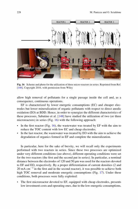
allow high removal of pollutants for a single passage inside the cell and, as a
consequence, continuous operations.
EF is characterized by lower energetic consumptions (EC) and cheaper elec-
trodes but lower mineralization of organic pollutants with respect to direct anodic
oxidation (EO) at BDD. Hence, in order to synergize the different characteristics of
these processes, Sabatino et al. [148] have studied the utilization of two (or three
microreactors) in series (Fig. 16) with the following approach:
• In the first reactor (Fig. 16), the wastewater was treated by EF with the aim to
reduce the TOC content with low EC and cheap electrodes.
• In the last reactor, the wastewater was treated by EO with the aim to achieve the
degradation of organics formed in EF and complete the mineralization.
In particular, here for the sake of brevity, we will recall only the experiments
performed with two reactors in series. Since these two processes are optimized
under very different conditions (see above), different operating conditions were set
for the two reactors (the first and the second put in series). In particular, a nominal
distance between the electrodes of 120 and 50 μmwas used for the reactors devoted
to EF and EO, respectively. By a proper differentiation of current densities (2 and
20 mA cm�2 in the first and in the second reactor), it was possible to achieve both
high TOC removal and moderate energetic consumptions (Fig. 17). Under these
conditions, both processes were fully exploited:
• The first microreactor devoted to EF, equipped with cheap electrodes, presents
low investment costs and operating ones, due to the low energetic consumptions,
Fig. 16 Scheme and photo for the utilization of three micro-reactors in series. Reprinted from Ref.
[148], Copyright 2016, with permission from Wiley
228 M. Panizza and O. Scialdone
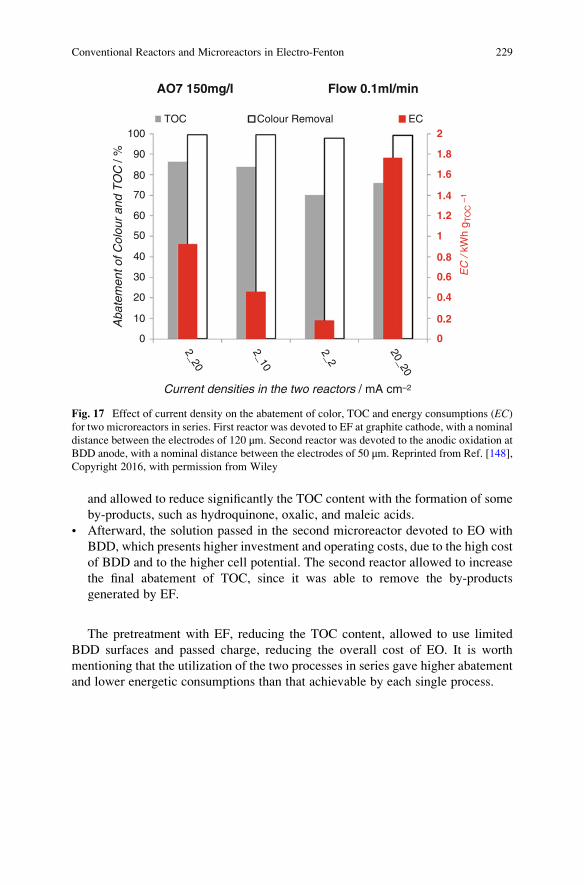
and allowed to reduce significantly the TOC content with the formation of some
by-products, such as hydroquinone, oxalic, and maleic acids.
• Afterward, the solution passed in the second microreactor devoted to EO with
BDD, which presents higher investment and operating costs, due to the high cost
of BDD and to the higher cell potential. The second reactor allowed to increase
the final abatement of TOC, since it was able to remove the by-products
generated by EF.
The pretreatment with EF, reducing the TOC content, allowed to use limited
BDD surfaces and passed charge, reducing the overall cost of EO. It is worth
mentioning that the utilization of the two processes in series gave higher abatement
and lower energetic consumptions than that achievable by each single process.
100TOC
AO7 150mg/I Flow 0.1ml/min
Colour Removal EC
90
80
70
60
50
40
30
20
10
0
2
1.8
1.6
1.4
1.2
1
0.8
0.6
0.4
0.2
EC
/ kW
h g T
OC –
1
0
Current densities in the two reactors / mA cm–2
Aba
tem
ent o
f Col
our
and
TO
C /
%
2_20
2_10
2_2
20_20
Fig. 17 Effect of current density on the abatement of color, TOC and energy consumptions (EC)for two microreactors in series. First reactor was devoted to EF at graphite cathode, with a nominal
distance between the electrodes of 120 μm. Second reactor was devoted to the anodic oxidation at
BDD anode, with a nominal distance between the electrodes of 50 μm. Reprinted from Ref. [148],
Copyright 2016, with permission from Wiley
Conventional Reactors and Microreactors in Electro-Fenton 229
7 Conclusions
In recent years, a large variety of reactors and cells were used for the treatment of
wastewater by electro-Fenton. The main kinds of cells used can be grouped as
follows:
• Simple batch reactors were widely used for lab experiments and equipped with
various kinds of three-dimensional and gas diffusion electrodes, thus allowing to
evaluate the performances of EF process for the treatment of various wastewa-
ters and a large number of organic pollutants and to evaluate the effect of various
operating parameters.
• Since industrial electrochemical processes are usually based on the parallel-plate
electrode configuration, many experiments were also performed using this kind
of cells. The system based on the parallel-plate cell in a recirculation mode can
be also slightly modified to perform photoelectro-Fenton and solar photoelectro-
Fenton irradiating the solution by a UV lamp or solar light when it is recirculated
from the reactor to the reservoir.
• Floating or rotating three-dimensional electrodes were sometimes used to
increase the mass transfer kinetics. However, these electrodes still present
some problems of poor bed-feeder contact, nonuniform current and potential
distribution and therefore only few works used these reactors for electro-Fenton
oxidation.
• Recently, it has been shown that using pressurized reactors, it is possible to
increase drastically the generation of hydrogen peroxide from the cathodic
reduction of oxygen and, therefore, the abatement of TOC in the treatment of
wastewater by EF. In addition, the utilization of pressures up to 15–20 bar allows
also to limit the investment and operating costs. Hence, the utilization of
pressurized reactors seems very appealing from an applicative point of view.
However, further studies are necessary to better characterize the utilization of
such devices and in order to evaluate the adoption of both pressurized cells and
cathodes with large surfaces.
• Micro-cells, characterized by very small distances between the electrodes, were
also used for EF process. It was demonstrated that these kinds of cells can
present various advantages, such as the possibility to work with wastewater
with low conductivity, to enhance the H2O2 generation and the abatement of the
TOC also using cheap compact graphite cathodes, and to work under continuous
mode. However, these devices present the disadvantage of an easier fouling and
clogging. Hence, their utilization could be particularly suggested for wastewater
with low conductivity and low solid contents.
230 M. Panizza and O. Scialdone
References
1. Pletcher D, Walsh FC (1990) Industrial electrochemistry. Chapman & Hall, London
2. Panizza M, Cerisola G (2001) Removal of organic pollutants from industrial wastewater by
electrogenerated Fenton’s reagent. Water Res 35:3987–3992
3. Oturan N, Panizza M, Oturan MA (2009) Cold incineration of chlorophenols in aqueous
solution by advanced electrochemical process electro-Fenton. Effect of number and position
of chlorine atoms on the degradation kinetics. J Phys Chem A 113:10988–10993
4. Panizza M, Cerisola G (2009) Electro-Fenton degradation of synthetic dyes. Water Res
43:339–344
5. Panizza M, Oturan MA (2011) Degradation of alizarin red by electro-Fenton process using a
graphite-felt cathode. Electrochim Acta 56:7084–7087
6. Elaoud SC, Panizza M, Cerisola G, Mhiri T (2012) Coumaric acid degradation by electro-
Fenton process. J Electroanal Chem 667:19–23
7. Zazou H, Oturan N, S€onmez-Celebi M, Hamdani M, Oturan MA (2016) Mineralization of
chlorobenzene in aqueous medium by anodic oxidation and electro-Fenton processes using Pt
or BDD anode and carbon felt cathode. J Electroanal Chem 774:22–30
8. Barhoumi N, Labiadh L, Oturan MA, Oturan N, Gadri A, Ammar S, Brillas E (2015)
Electrochemical mineralization of the antibiotic levofloxacin by electro-Fenton-pyrite pro-
cess. Chemosphere 141:250–257
9. Olvera-Vargas H, Oturan N, Brillas E, Buisson D, Esposito G, Oturan MA (2014) Electro-
chemical advanced oxidation for cold incineration of the pharmaceutical ranitidine: miner-
alization pathway and toxicity evolution. Chemosphere 117:644–651
10. Loaiza-Ambuludi S, Panizza M, Oturan N, Ozcan A, Oturan MA (2013) Electro-Fenton
degradation of anti-inflammatory drug ibuprofen in hydroorganic medium. J Electroanal
Chem 702:31–36
11. Zhou M, Tan Q, Wang Q, Jiao Y, Oturan N, Oturan MA (2012) Degradation of organics in
reverse osmosis concentrate by electro-Fenton process. J Hazard Mater 215–216:287–293
12. Oturan MA, Oturan N, Edelahi MC, Podvorica FI, Kacemi KE (2011) Oxidative degradation
of herbicide diuron in aqueous medium by Fenton’s reaction based advanced oxidation
processes. Chem Eng J 171:127–135
13. Sires I, Oturan N, Oturan MA (2010) Electrochemical degradation of β-blockers. Studies onsingle and multicomponent synthetic aqueous solutions. Water Res 44:3109–3120
14. Ozcan A, Oturan MA, Oturan N, Sahin Y (2009) Removal of acid orange 7 from water by
electrochemically generated Fenton’s reagent. J Hazard Mater 163:1213–1220
15. Sires I, Oturan N, Oturan MA, Rodrıguez RM, Garrido JA, Brillas E (2007) Electro-Fenton
degradation of antimicrobials triclosan and triclocarban. Electrochim Acta 52:5493–5503
16. Oturan MA, Guivarch E, Oturan N, Sires I (2008) Oxidation pathways of malachite green by
Fe3+-catalyzed electro-Fenton process. Appl Catal B-Environ 82:244–254
17. Sires I, Garrido JA, Rodrıguez RM, Brillas E, Oturan N, Oturan MA (2007) Catalytic
behavior of the Fe3+/Fe2+ system in the electro-Fenton degradation of the antimicrobial
chlorophene. Appl Catal B-Environ 72:382–394
18. Zhou M, Yu Q, Lei L, Barton G (2007) Electro-Fenton method for the removal of methyl red
in an efficient electrochemical system. Sep Purif Technol 57:380–387
19. Zhou L, Zhou M, Zhang C, Jiang Y, Bi Z, Yang J (2013) Electro-Fenton degradation of
p-nitrophenol using the anodized graphite felts. Chem Eng J 233:185–192
20. Zhou L, Zhou M, Hu Z, Bi Z, Serrano KG (2014) Chemically modified graphite felt as an
efficient cathode in electro-Fenton for p-nitrophenol degradation. Electrochim Acta
140:376–383
21. Zhang C, Zhou M, Yu X, Ma L, Yu F (2015) Modified iron-carbon as heterogeneous electro-
Fenton catalyst for organic pollutant degradation in near neutral pH condition: characteriza-
tion, degradation activity and stability. Electrochim Acta 160:254–262
Conventional Reactors and Microreactors in Electro-Fenton 231
22. Zhang C, Zhou M, Ren G, Yu X, Ma L, Yang J, Yu F (2015) Heterogeneous electro-Fenton
using modified iron–carbon as catalyst for 2,4-dichlorophenol degradation: influence factors,
mechanism and degradation pathway. Water Res 70:414–424
23. Meijide J, Gomez J, Pazos M, Sanroman MA (2016) Degradation of thiamethoxam by the
synergetic effect between anodic oxidation and Fenton reactions. J Hazard Mater 319:43–50
24. Iglesias O, Gomez J, Pazos M, Sanroman MA (2014) Electro-Fenton oxidation of
imidacloprid by Fe alginate gel beads. Appl Catal B-Environ 144:416–424
25. Iglesias O, Meijide J, Bocos E, Sanroman MA, Pazos M (2015) New approaches on
heterogeneous electro-Fenton treatment of winery wastewater. Electrochim Acta
169:134–141
26. Brillas E, Mur E, Sauleda R, S�anchez L, Peral J, Domenech X, Casado J (1998) Aniline
mineralization by AOP’s: anodic oxidation, photocatalysis, electro-Fenton and photoelectro-
Fenton processes. Appl Catal B-Environ 16:31–42
27. Sauleda R, Brillas E (2001) Mineralization of aniline and 4-chlorophenol in acidic solution by
ozonation catalyzed with Fe2+ and UVA light. Appl Catal B-Environ 29:135–145
28. Brillas E, Boye B, Sires I, Garrido JA, RMa Rodrı guez, Arias C, P-Ls C, Comninellis C
(2004) Electrochemical destruction of chlorophenoxy herbicides by anodic oxidation and
electro-Fenton using a boron-doped diamond electrode. Electrochim Acta 49:4487–4496
29. Brillas E, P-Ls C, RMa Rodrı guez, Arias C, Garrido JA, Oliver R (2004) Degradation of the
herbicide 2,4-DP by catalyzed ozonation using the O3/Fe2+/UVA system. Appl Catal
B-Environ 51:117–127
30. Brillas E, Calpe JC, Cabot P-L (2003) Degradation of the herbicide
2,4-dichlorophenoxyacetic acid by ozonation catalyzed with Fe2+ and UVA light. Appl
Catal B-Environ 46:381–391
31. Brillas E, Ba~nos MA, Skoumal M, Cabot PL, Garrido JA, Rodrıguez RM (2007) Degradation
of the herbicide 2,4-DP by anodic oxidation, electro-Fenton and photoelectro-Fenton using
platinum and boron-doped diamond anodes. Chemosphere 68:199–209
32. Flox C, Garrido JA, Rodrıguez RM, Cabot P-L, Centellas F, Arias C, Brillas E (2007)
Mineralization of herbicide mecoprop by photoelectro-Fenton with UVA and solar light.
Catal Today 129:29–36
33. Flox C, Ammar S, Arias C, Brillas E, Vargas-Zavala AV, Abdelhedi R (2006) Electro-Fenton
and photoelectro-Fenton degradation of indigo carmine in acidic aqueous medium. Appl
Catal B-Environ 67:93–104
34. Garcia-Segura S, Centellas F, Arias C, Garrido JA, Rodrıguez RM, Cabot PL, Brillas E
(2011) Comparative decolorization of monoazo, diazo and triazo dyes by electro-Fenton
process. Electrochim Acta 58:303–311
35. Almeida LC, Garcia-Segura S, Arias C, Bocchi N, Brillas E (2012) Electrochemical miner-
alization of the azo dye acid red 29 (Chromotrope 2R) by photoelectro-Fenton process.
Chemosphere 89:751–758
36. Garcia-Segura S, El-Ghenymy A, Centellas F, Rodrıguez RM, Arias C, Garrido JA, Cabot
PL, Brillas E (2012) Comparative degradation of the diazo dye direct yellow 4 by electro-
Fenton, photoelectro-Fenton and photo-assisted electro-Fenton. J Electroanal Chem
681:36–43
37. Garcia-Segura S, Dosta S, Guilemany JM, Brillas E (2013) Solar photoelectrocatalytic
degradation of acid orange 7 azo dye using a highly stable TiO2 photoanode synthesized by
atmospheric plasma spray. Appl Catal B-Environ 132–133:142–150
38. Florenza X, Solano AMS, Centellas F, Martınez-Huitle CA, Brillas E, Garcia-Segura S
(2014) Degradation of the azo dye Acid Red 1 by anodic oxidation and indirect electrochem-
ical processes based on Fenton’s reaction chemistry. Relationship between decolorization,
mineralization and products. Electrochim Acta 142:276–288
39. Pereira GF, El-Ghenymy A, Thiam A, Carlesi C, Eguiluz KIB, Salazar-Banda GR, Brillas E
(2016) Effective removal of Orange-G azo dye from water by electro-Fenton and
232 M. Panizza and O. Scialdone
photoelectro-Fenton processes using a boron-doped diamond anode. Sep Purif Technol
160:145–151
40. Guinea E, Garrido JA, Rodrıguez RM, Cabot P-L, Arias C, Centellas F, Brillas E (2010)
Degradation of the fluoroquinolone enrofloxacin by electrochemical advanced oxidation
processes based on hydrogen peroxide electrogeneration. Electrochim Acta 55:2101–2115
41. Garcia-Segura S, Cavalcanti EB, Brillas E (2014) Mineralization of the antibiotic chloram-
phenicol by solar photoelectro-Fenton: From stirred tank reactor to solar pre-pilot plant. Appl
Catal B-Environ 144:588–598
42. Moreira FC, Garcia-Segura S, Boaventura RAR, Brillas E, Vilar VJP (2014) Degradation of
the antibiotic trimethoprim by electrochemical advanced oxidation processes using a carbon-
PTFE air-diffusion cathode and a boron-doped diamond or platinum anode. Appl Catal
B-Environ 160–161:492–505
43. Antonin VS, Santos MC, Garcia-Segura S, Brillas E (2015) Electrochemical incineration of
the antibiotic ciprofloxacin in sulfate medium and synthetic urine matrix. Water Res
83:31–41
44. Isarain-Chavez E, Arias C, Cabot PL, Centellas F, Rodrıguez RM, Garrido JA, Brillas E
(2010) Mineralization of the drug β-blocker atenolol by electro-Fenton and photoelectro-
Fenton using an air-diffusion cathode for H2O2 electrogeneration combined with a carbon-
felt cathode for Fe2+ regeneration. Appl Catal B-Environ 96:361–369
45. Isarain-Chavez E, Rodrıguez RM, Garrido JA, Arias C, Centellas F, Cabot PL, Brillas E
(2010) Degradation of the beta-blocker propranolol by electrochemical advanced oxidation
processes based on Fenton’s reaction chemistry using a boron-doped diamond anode.
Electrochim Acta 56:215–221
46. Isarain-Chavez E, Cabot PL, Centellas F, Rodrıguez RM, Arias C, Garrido JA, Brillas E
(2011) Electro-Fenton and photoelectro-Fenton degradations of the drug beta-blocker pro-
pranolol using a Pt anode: identification and evolution of oxidation products. J Hazard Mater
185:1228–1235
47. Skoumal M, Rodrıguez RM, Cabot PL, Centellas F, Garrido JA, Arias C, Brillas E (2009)
Electro-Fenton, UVA photoelectro-Fenton and solar photoelectro-Fenton degradation of the
drug ibuprofen in acid aqueous medium using platinum and boron-doped diamond anodes.
Electrochim Acta 54:2077–2085
48. Zhang Y, Gao M-M, Wang X-H, Wang S-G, Liu R-T (2015) Enhancement of oxygen
diffusion process on a rotating disk electrode for the electro-Fenton degradation of tetracy-
cline. Electrochim Acta 182:73–80
49. Ledezma Estrada A, Li Y-Y, Wang A (2012) Biodegradability enhancement of wastewater
containing cefalexin by means of the electro-Fenton oxidation process. J Hazard Mater
227–228:41–48
50. Xie YB, Li XZ (2006) Interactive oxidation of photoelectrocatalysis and electro-Fenton for
azo dye degradation using TiO2–Ti mesh and reticulated vitreous carbon electrodes. Mater
Chem Phys 95:39–50
51. Brillas E, Sires I, Oturan MA (2009) Electro-Fenton process and related electrochemical
technologies based on Fenton’s reaction chemistry. Chem Rev 109:6570–6631
52. Celebi MS, Oturan N, Zazou H, Hamdani M, Oturan MA (2015) Electrochemical oxidation
of carbaryl on platinum and boron-doped diamond anodes using electro-Fenton technology.
Sep Purif Technol 156(Part 3):996–1002
53. Mbaye OMA, Gaye Seye MD, Coly A, Tine A, Oturan MA, Oturan N, Aaron JJ (2013)
Photo-induced fluorescence properties of the propanil herbicide and analytical usefulness.
Microchem J 110:579–586
54. Abdessalem AK, Bellakhal N, Oturan N, Dachraoui M, Oturan MA (2010) Treatment of a
mixture of three pesticides by photo- and electro-Fenton processes. Desalination
250:450–455
Conventional Reactors and Microreactors in Electro-Fenton 233
55. Oturan MA, Oturan N, Lahitte C, Trevin S (2001) Production of hydroxyl radicals by
electrochemically assisted Fenton’s reagent: application to the mineralization of an organic
micropollutant, pentachlorophenol. J Electroanal Chem 507:96–102
56. Olvera-Vargas H, Oturan N, Buisson D, Oturan MA (2016) A coupled bio-EF process for
mineralization of the pharmaceuticals furosemide and ranitidine: feasibility assessment.
Chemosphere 155:606–613
57. Yahya MS, Oturan N, El Kacemi K, El Karbane M, Aravindakumar CT, Oturan MA (2014)
Oxidative degradation study on antimicrobial agent ciprofloxacin by electro-fenton process:
kinetics and oxidation products. Chemosphere 117:447–454
58. Oturan MA, Pinson J, Bizot J, Deprez D, Terlain B (1992) Reaction of inflammation
inhibitors with chemically and electrochemically generated hydroxyl radicals. J Electroanal
Chem 334:103–109
59. Sopaj F, Oturan N, Pinson J, Podvorica F, Oturan MA (2016) Effect of the anode materials on
the efficiency of the electro-Fenton process for the mineralization of the antibiotic
sulfamethazine. Appl Catal B-Environ 199:331–341
60. Sopaj F, Rodrigo MA, Oturan N, Podvorica FI, Pinson J, Oturan MA (2015) Influence of the
anode materials on the electrochemical oxidation efficiency. Application to oxidative degra-
dation of the pharmaceutical amoxicillin. Chem Eng J 262:286–294
61. Ganiyu SO, van Hullebusch ED, Cretin M, Esposito G, Oturan MA (2015) Coupling of
membrane filtration and advanced oxidation processes for removal of pharmaceutical resi-
dues: a critical review. Sep Purif Technol 156(Part 3):891–914
62. El-Ghenymy A, Oturan N, Oturan MA, Garrido JA, Cabot PL, Centellas F, Rodrıguez RM,
Brillas E (2013) Comparative electro-Fenton and UVA photoelectro-Fenton degradation of
the antibiotic sulfanilamide using a stirred BDD/air-diffusion tank reactor. Chem Eng J
234:115–123
63. Haidar M, Dirany A, Sires I, Oturan N, Oturan MA (2013) Electrochemical degradation of
the antibiotic sulfachloropyridazine by hydroxyl radicals generated at a BDD anode.
Chemosphere 91:1304–1309
64. Wu J, Zhang H, Oturan N, Wang Y, Chen L, Oturan MA (2012) Application of response
surface methodology to the removal of the antibiotic tetracycline by electrochemical process
using carbon-felt cathode and DSA (Ti/RuO2–IrO2) anode. Chemosphere 87:614–620
65. Dirany A, Sires I, Oturan N, Oturan MA (2010) Electrochemical abatement of the antibiotic
sulfamethoxazole from water. Chemosphere 81:594–602
66. Le TXH, Bechelany M, Lacour S, Oturan N, Oturan MA, Cretin M (2015) High removal
efficiency of dye pollutants by electron-Fenton process using a graphene based cathode.
Carbon 94:1003–1011
67. Labiadh L, Oturan MA, Panizza M, Hamadi NB, Ammar S (2015) Complete removal of
AHPS synthetic dye from water using new electro-fenton oxidation catalyzed by natural
pyrite as heterogeneous catalyst. J Hazard Mater 297:34–41
68. Bouafia-Chergui S, Oturan N, Khalaf H, Oturan MA (2012) A photo-Fentontreatment of a
mixture of three cationic dyes. Procedia Eng 33:181–187
69. Oturan MA, Sires I, Oturan N, Perocheau S, Laborde J-L, Trevin S (2008) Sonoelectro-
Fenton process: a novel hybrid technique for the destruction of organic pollutants in water. J
Electroanal Chem 624:329–332
70. Ozcan A, Sahin Y, Savas Koparal A, Oturan MA (2008) Carbon sponge as a new cathode
material for the electro-Fenton process: comparison with carbon felt cathode and application
to degradation of synthetic dye basic blue 3 in aqueous medium. J Electroanal Chem
616:71–78
71. Hammami S, Oturan N, Bellakhal N, Dachraoui M, Oturan MA (2007) Oxidative degradation
of direct orange 61 by electro-Fenton process using a carbon felt electrode: application of the
experimental design methodology. J Electroanal Chem 610:75–84
72. Panizza M, Cerisola G (2005) Application of diamond electrodes to electrochemical pro-
cesses. Electrochim Acta 51:191–199
234 M. Panizza and O. Scialdone
73. Michaud P-A, Panizza M, Ouattara L, Diaco T, Foti G, Comninellis C (2003) Electrochem-
ical oxidation of water on synthetic boron-doped diamond thin film anodes. J Appl
Electrochem 33:151–154
74. Panizza M, Cerisola G (2003) Influence of anode material on the electrochemical oxidation of
2-naphthol. Part 1. Cyclic voltammetry and potential step experiments. Electrochim Acta
48:3491–3497
75. Foti G, Gandini D, Comninellis C, Perret A, Haenni W (1999) Oxidation of organics by
intermediates of water discharge on IrO2 and synthetic diamond anodes. Electrochem Solid
State 2:228–230
76. Zhou M, Yu Q, Lei L (2008) The preparation and characterization of a graphite–PTFE
cathode system for the decolorization of C.I. acid red 2. Dyes Pigments 77:129–136
77. Sudoh M, Kodera T, Sakai K (1986) Oxidative degradation of aqueous phenol effluent with
electrogenerated Fenton’s reagent. J Chem Eng Jpn 19:513–518
78. Petrucci E, Da Pozzo A, Di Palma L (2016) On the ability to electrogenerate hydrogen
peroxide and to regenerate ferrous ions of three selected carbon-based cathodes for electro-
Fenton processes. Chem Eng J 283:750–758
79. Zhou L, Hu Z, Zhang C, Bi Z, Jin T, Zhou M (2013) Electrogeneration of hydrogen peroxide
for electro-Fenton system by oxygen reduction using chemically modified graphite felt
cathode. Sep Purif Technol 111:131–136
80. Badellino C, Rodrigues CA, Bertazzoli R (2006) Oxidation of pesticides by in situ
electrogenerated hydrogen peroxide: study for the degradation of
2,4-dichlorophenoxyacetic acid. J Hazard Mater 137:856–864
81. Brillas E, Calpe JC, Casado J (2000) Mineralization of 2,4-D by advanced electrochemical
oxidation processes. Water Res 34:2253–2262
82. Boye B, Brillas E, Dieng MM (2003) Electrochemical degradation of the herbicide 4-chloro-
2-methylphenoxyacetic acid in aqueous medium by peroxi-coagulation and photoperoxi-
coagulation. J Electroanal Chem 540:25–34
83. Boye B, Marieme Dieng M, Brillas E (2003) Electrochemical degradation of 2,4,5-
trichlorophenoxyacetic acid in aqueous medium by peroxi-coagulation. Effect of pH and
UV light. Electrochim Acta 48:781–790
84. Brillas E, Boye B, Ba~nos MA, Calpe JC, Garrido JA (2003) Electrochemical degradation of
chlorophenoxy and chlorobenzoic herbicides in acidic aqueous medium by the peroxi-
coagulation method. Chemosphere 51:227–235
85. Brillas E, Bastida RM, Llosa E, Casado J (1995) Electrochemical destruction of aniline and
4-chloroaniline for wastewater treatment using a carbon-PTFE O2-fed cathode. J
Electrochem Soc 142:1733–1741
86. Brillas E, Mur E, Casado J (1996) Iron(II) catalysis of the mineralization of aniline using a
carbon-PTFE O2-fed cathode. J Electrochem Soc 143:49–53
87. Brillas E, Sauleda R, Casado J (1997) Peroxi-coagulation of aniline in acidic medium using
an oxygen diffusion cathode. J Electrochem Soc 144:2374–2379
88. Brillas E, Sauleda R, Casado J (1999) Use of an acidic Fe/O2 cell for wastewater treatment:
degradation of aniline. J Electrochem Soc 146:4539–4543
89. Boye B, Morieme Dieng M, Brillas E (2003) Anodic oxidation, electro-Fenton and
photoelectro-Fenton treatments of 2,4,5-trichlorophenoxyacetic acid. J Electroanal Chem
557:135–146
90. Brillas E, Ba~nos MA, Garrido JA (2003) Mineralization of herbicide 3,6-dichloro-2-
methoxybenzoic acid in aqueous medium by anodic oxidation, electro-Fenton and
photoelectro-Fenton. Electrochim Acta 48:1697–1705
91. Brillas E, Boye B, Dieng MM (2003) Peroxi-coagulation and photoperoxi-coagulation
treatments of the herbicide 4-chlorophenoxyacetic acid in aqueous medium using an
oxygen-diffusion cathode. J Electrochem Soc 150:148–154
Conventional Reactors and Microreactors in Electro-Fenton 235
92. Flox C, Cabot P-L, Centellas F, Garrido JA, Rodrıguez RM, Arias C, Brillas E (2007) Solar
photoelectro-Fenton degradation of cresols using a flow reactor with a boron-doped diamond
anode. Appl Catal B-Environ 75:17–28
93. Sires I, Arias C, Cabot PL, Centellas F, Garrido JA, Rodrıguez RM, Brillas E (2007)
Degradation of clofibric acid in acidic aqueous medium by electro-Fenton and
photoelectro-Fenton. Chemosphere 66:1660–1669
94. Guinea E, Centellas F, Garrido JA, Rodrıguez RM, Arias C, Cabot P-L, Brillas E (2009) Solar
photoassisted anodic oxidation of carboxylic acids in presence of Fe3+ using a boron-doped
diamond electrode. Appl Catal B-Environ 89:459–468
95. Brillas E, Casado J (2002) Aniline degradation by electro-Fenton® and peroxi-coagulation
processes using a flow reactor for wastewater treatment. Chemosphere 47:241–248
96. Isarain-Chavez E, Rodrıguez RM, Cabot PL, Centellas F, Arias C, Garrido JA, Brillas E
(2011) Degradation of pharmaceutical beta-blockers by electrochemical advanced oxidation
processes using a flow plant with a solar compound parabolic collector. Water Res
45:4119–4130
97. El-Ghenymy A, Garcia-Segura S, Rodrıguez RM, Brillas E, El Begrani MS, Abdelouahid BA
(2012) Optimization of the electro-Fenton and solar photoelectro-Fenton treatments of
sulfanilic acid solutions using a pre-pilot flow plant by response surface methodology. J
Hazard Mater 221–222:288–297
98. Garcıa O, Isarain-Chavez E, El-Ghenymy A, Brillas E, Peralta-Hernandez JM (2014) Deg-
radation of 2,4-D herbicide in a recirculation flow plant with a Pt/air-diffusion and a
BDD/BDD cell by electrochemical oxidation and electro-Fenton process. J Electroanal
Chem 728:1–9
99. Almeida LC, Garcia-Segura S, Bocchi N, Brillas E (2011) Solar photoelectro-Fenton degra-
dation of paracetamol using a flow plant with a Pt/air-diffusion cell coupled with a compound
parabolic collector: process optimization by response surface methodology. Appl Catal
B-Environ 103:21–30
100. Olvera-Vargas H, Oturan N, Oturan MA, Brillas E (2015) Electro-Fenton and solar
photoelectro-Fenton treatments of the pharmaceutical ranitidine in pre-pilot flow plant
scale. Sep Purif Technol 146:127–135
101. Perez T, Garcia-Segura S, El-Ghenymy A, Nava JL, Brillas E (2015) Solar photoelectro-
Fenton degradation of the antibiotic metronidazole using a flow plant with a Pt/air-diffusion
cell and a CPC photoreactor. Electrochim Acta 165:173–181
102. Sires I, Brillas E (2012) Remediation of water pollution caused by pharmaceutical residues
based on electrochemical separation and degradation technologies: a review. Environ Int
40:212–229
103. Garza-Campos B, Brillas E, Hernandez-Ramırez A, El-Ghenymy A, Guzman-Mar JL, Ruiz-
Ruiz EJ (2016) Salicylic acid degradation by advanced oxidation processes. Coupling of solar
photoelectro-Fenton and solar heterogeneous photocatalysis. J Hazard Mater 319:34–42
104. El-Ghenymy A, Cabot PL, Centellas F, Garrido JA, Rodrıguez RM, Arias C, Brillas E (2013)
Mineralization of sulfanilamide by electro-Fenton and solar photoelectro-Fenton in a
pre-pilot plant with a Pt/air-diffusion cell. Chemosphere 91:1324–1331
105. Gozzi F, Sires I, Thiam A, de Oliveira SC, Junior AM, Brillas E (2017) Treatment of single
and mixed pesticide formulations by solar photoelectro-Fenton using a flow plant. Chem Eng
J 310(Part 2):503–513
106. Pipi ARF, Sires I, De Andrade AR, Brillas E (2014) Application of electrochemical advanced
oxidation processes to the mineralization of the herbicide diuron. Chemosphere 109:49–55
107. Garza-Campos BR, Guzman-Mar JL, Reyes LH, Brillas E, Hernandez-Ramırez A, Ruiz-Ruiz
EJ (2014) Coupling of solar photoelectro-Fenton with a BDD anode and solar heterogeneous
photocatalysis for the mineralization of the herbicide atrazine. Chemosphere 97:26–33
108. Garcia-Segura S, Almeida LC, Bocchi N, Brillas E (2011) Solar photoelectro-Fenton degra-
dation of the herbicide 4-chloro-2-methylphenoxyacetic acid optimized by response surface
methodology. J Hazard Mater 194:109–118
236 M. Panizza and O. Scialdone
109. Moreira FC, Garcia-Segura S, Vilar VJP, Boaventura RAR, Brillas E (2013) Decolorization
and mineralization of sunset yellow FCF azo dye by anodic oxidation, electro-Fenton, UVA
photoelectro-Fenton and solar photoelectro-Fenton processes. Appl Catal B-Environ
142–143:877–890
110. Garcia-Segura S, Brillas E (2014) Advances in solar photoelectro-Fenton: Decolorization and
mineralization of the direct yellow 4 diazo dye using an autonomous solar pre-pilot plant.
Electrochim Acta 140:384–395
111. Antonin VS, Garcia-Segura S, Santos MC, Brillas E (2015) Degradation of Evans Blue diazo
dye by electrochemical processes based on Fenton’s reaction chemistry. J Electroanal Chem
747:1–11
112. Solano AMS, Garcia-Segura S, Martınez-Huitle CA, Brillas E (2015) Degradation of acidic
aqueous solutions of the diazo dye Congo Red by photo-assisted electrochemical processes
based on Fenton’s reaction chemistry. Appl Catal B-Environ 168–169:559–571
113. Thiam A, Sires I, Centellas F, Cabot PL, Brillas E (2015) Decolorization and mineralization
of Allura red AC azo dye by solar photoelectro-Fenton: identification of intermediates.
Chemosphere 136:1–8
114. Garcia-Segura S, Brillas E (2016) Combustion of textile monoazo, diazo and triazo dyes by
solar photoelectro-Fenton: Decolorization, kinetics and degradation routes. Appl Catal
B-Environ 181:681–691
115. Garcia-Segura S, Salazar R, Brillas E (2013) Mineralization of phthalic acid by solar
photoelectro-Fenton with a stirred boron-doped diamond/air-diffusion tank reactor: Influence
of Fe3+ and Cu2+ catalysts and identification of oxidation products. Electrochim Acta
113:609–619
116. Moreira FC, Boaventura RAR, Brillas E, Vilar VJP (2015) Remediation of a winery waste-
water combining aerobic biological oxidation and electrochemical advanced oxidation pro-
cesses. Water Res 75:95–108
117. Alvarez-Gallegos A, Pletcher D (1998) The removal of low level organics via hydrogen
peroxide formed in a reticulated vitreous carbon cathode cell, part 1. The electrosynthesis of
hydrogen peroxide in aqueous acidic solutions. Electrochim Acta 44:853–861
118. Alverez-Gallegos A, Pletcher D (1999) The removal of low level organics via hydrogen
peroxide formed in a reticulated vitreous carbon cathode cell. Part 2: the removal of phenols
and related compounds from aqueous effluents. Electrochim Acta 44:2483–2492
119. Leon CPD, Pletcher D (1995) Removal of formaldehyde from aqueous solutions via oxygen
reduction using a reticulated vitreous carbon cathode cell. J Appl Electrochem 25:307–314
120. Fockedey E, Van Lierde A (2002) Coupling of anodic and cathodic reactions for phenol
electro-oxidation using three-dimensional electrodes. Water Res 36:4169–4175
121. Hsiao Y-L, Nobe K (1993) Hydroxylation of chlorobenzene and phenol in a packed bed flow
reactor with electrogenerated Fenton’s reagent. J Appl Electrochem 23:943–946
122. Ma L, Zhou M, Ren G, Yang W, Liang L (2016) A highly energy-efficient flow-through
electro-Fenton process for organic pollutants degradation. Electrochim Acta 200:222–230
123. Lei Y, Liu H, Shen Z, WangW (2013) Development of a trickle bed reactor of electro-Fenton
process for wastewater treatment. J Hazard Mater 261:570–576
124. Anotai J, C-C S, Tsai Y-C, M-C L (2010) Effect of hydrogen peroxide on aniline oxidation by
electro-Fenton and fluidized-bed Fenton processes. J Hazard Mater 183:888–893
125. Wang C-T, J-L H, Chou W-L, Kuo Y-M (2008) Removal of color from real dyeing
wastewater by electro-Fenton technology using a three-dimensional graphite cathode. J
Hazard Mater 152:601–606
126. Xu L, Zhao H, Shi S, Zhang G, Ni J (2008) Electrolytic treatment of C.I. acid orange 7 in
aqueous solution using a three-dimensional electrode reactor. Dyes Pigments 77:158–164
127. Xiong Y, He C, Karlsson HT, Zhu X (2003) Performance of three-phase three-dimensional
electrode reactor for the reduction of COD in simulated wastewater-containing phenol.
Chemosphere 50:131–136
Conventional Reactors and Microreactors in Electro-Fenton 237
128. Liu W, Ai Z, Zhang L (2012) Design of a neutral three-dimensional electro-Fenton system
with foam nickel as particle electrodes for wastewater treatment. J Hazard Mater
243:257–264
129. Hara K, Kudo A, Sakata T (1995) Electrochemical reduction of carbon dioxide under high
pressure on various electrodes in an aqueous electrolyte. J Electroanal Chem 391:141–147
130. K€oleli F, Balun D (2004) Reduction of CO2 under high pressure and high temperature on
Pb-granule electrodes in a fixed-bed reactor in aqueous medium. Appl Catal A-Gen
274:237–242
131. Scialdone O, Galia A, Nero GL, Proietto F, Sabatino S, Schiavo B (2016) Electrochemical
reduction of carbon dioxide to formic acid at a tin cathode in divided and undivided cells:
effect of carbon dioxide pressure and other operating parameters. Electrochim Acta
199:332–341
132. Sabatino S, Galia A, Saracco G, Scialdone O (2017) Development of an electrochemical
process for the simultaneous treatment of wastewater and the conversion of carbon dioxide to
higher value products. ChemElectroChem 4:150–159
133. Do JS, Chen CP (1993) In situ oxidative degradation of formaldehyde with electrogenerated
hydrogen peroxide. J Electrochem Soc 140:1632–1637
134. Scialdone O, Galia A, Gattuso C, Sabatino S, Schiavo B (2015) Effect of air pressure on the
electro-generation of H2O2 and the abatement of organic pollutants in water by electro-
Fenton process. Electrochim Acta 182:775–780
135. Kockmann N (2006) Advanced micro and nanosystems, micro process engineering. Funda-
mentals, devices, fabrication and application. Wiley-VCH Verlag GmbH & Co. KGaA,
Weinheim
136. Erickson D, Li D (2004) Integrated microfluidic devices. Anal Chim Acta 507:11–26
137. Paddon CA, Pritchard GJ, Thiemann T, Marken F (2002) Paired electrosynthesis: micro-flow
cell processes with and without added electrolyte. Electrochem Commun 4:825–831
138. Suga S, Okajima M, Fujiwara K, Yoshida J-i (2001) “Cation flow” method: a new approach
to conventional and combinatorial organic syntheses using electrochemical microflow sys-
tems. J Am Chem Soc 123:7941–7942
139. Scialdone O, Galia A, Sabatino S, Vaiana GM, Agro D, Busacca A, Amatore C (2014)
Electrochemical conversion of dichloroacetic acid to chloroacetic acid in conventional cell
and in two microfluidic reactors. ChemElectroChem 1:116–124
140. Scialdone O, Galia A, Sabatino S, Mira D, Amatore C (2015) Electrochemical conversion of
dichloroacetic acid to chloroacetic acid in a microfluidic stack and in a series of microfluidic
reactors. ChemElectroChem 2:684–690
141. Scialdone O, Guarisco C, Galia A, Filardo G, Silvestri G, Amatore C, Sella C, Thouin L
(2010) Anodic abatement of organic pollutants in water in micro reactors. J Electroanal Chem
638:293–296
142. Scialdone O, Guarisco C, Galia A (2011) Oxidation of organics in water in microfluidic
electrochemical reactors: theoretical model and experiments. Electrochim Acta 58:463–473
143. Scialdone O, Galia A, Guarisco C, La Mantia S (2012) Abatement of 1,1,2,2-
tetrachloroethane in water by reduction at silver cathode and oxidation at boron doped
diamond anode in micro reactors. Chem Eng J 189–190:229–236
144. Scialdone O, Galia A, Sabatino S (2013) Electro-generation of H2O2 and abatement of
organic pollutant in water by an electro-Fenton process in a microfluidic reactor. Electrochem
Commun 26:45–47
145. Scialdone O, Galia A, Sabatino S (2014) Abatement of acid orange 7 in macro and micro
reactors. Effect of the electrocatalytic route. Appl Catal B-Environ 148–149:473–483
146. Khongthon W, Jovanovic G, Yokochi A, Sangvanich P, Pavarajarn V (2016) Degradation of
diuron via an electrochemical advanced oxidation process in a microscale-based reactor.
Chem Eng J 292:298–307
147. Khongthon W, Pavarajarn V (2016) Effect of nitrate and sulfate contamination on degrada-
tion of diuron via electrochemical advanced oxidation in a microreactor. Eng J 20:25–34
238 M. Panizza and O. Scialdone

148. Sabatino S, Galia A, Scialdone O (2016) Electrochemical abatement of organic pollutants in
continuous-reaction systems through the assembly of microfluidic cells in series.
ChemElectroChem 3:83–90
149. Kristal J, Kodym R, Bouzek K, Jiricny V (2008) Electrochemical microreactor and
gas-evolving reactions. Electrochem Commun 10:204–207
150. de Loos SRA, van der Schaaf J, Tiggelaar RM, Nijhuis TA, de Croon MHJM, Schouten JC
(2010) Gas-liquid dynamics at low Reynolds numbers in pillared rectangular micro channels.
Microfluid Nanofluidics 9:131–144
Conventional Reactors and Microreactors in Electro-Fenton 239
Cost-Effective Flow-Through Reactor
in Electro-Fenton
Minghua Zhou, Gengbo Ren, Liang Ma, Yinqiao Zhang, and Sijin Zuo
Abstract In order to increase the degradation efficiency and reduce the treatment
cost of electro-Fenton (EF) process, many aspects have been attempted, among
which the design of cost-effective reactors is very important. Flow-through EF
reactor, i.e., the solution flow through the anode and cathode, is able to increase
mass and electron transfer, which is favorable to improve electrochemical conver-
sion, current efficiency and reduce energy consumption. Carbon-based materials,
for example, graphite felt, are desirable cathodic electrodes for the flow-through EF
system because of their stability, conductivity, high surface area and chemical
resistance, as well as the filtration characteristics. The effects of some important
parameters including current density, pH, and flow rate on organic pollutant
removal efficiency were discussed. Moreover, some new attempts on coupled
flow-through EF with other water/wastewater treatment technology (e.g., coagula-
tion, adsorption, and ozonation) were extended to reach a higher treatment effi-
ciency. The perspective of this process was also summarized. In conclusion,
compared with conventional EF reactor, flow-through EF reactor was more
energy-efficient and potential for degradation of organic pollutants.
Keywords Adsorption, Coupled process, Electrochemical advanced oxidation
processes (EAOP), Electro-Fenton, Flow-through, Graphite felt, Peroxi-
coagulation
Contents
1 Introduction . . . . . . . . . . . . . . . . . . . . . . . . . . . . . . . . . . . . . . . . . . . . . . . . . . . . . . . . . . . . . . . . . . . . . . . . . . . . . . . . . . 242
2 The Mechanism of Flow-Through Reactor . . . . . . . . . . . . . . . . . . . . . . . . . . . . . . . . . . . . . . . . . . . . . . . . . 244
2.1 Mass Transfer . . . . . . . . . . . . . . . . . . . . . . . . . . . . . . . . . . . . . . . . . . . . . . . . . . . . . . . . . . . . . . . . . . . . . . . . . 244
M. Zhou (*), G. Ren, L. Ma, Y. Zhang, and S. Zuo
Key Laboratory of Pollution Process and Environmental Criteria, Ministry of Education,
College of Environmental Science and Engineering, Nankai University, Tianjin 300350, China
e-mail: [email protected]
M. Zhou et al. (eds.), Electro-Fenton Process: New Trends and Scale-Up,Hdb Env Chem (2018) 61: 241–262, DOI 10.1007/698_2017_66,© Springer Nature Singapore Pte Ltd. 2017, Published online: 14 Oct 2017
241
2.2 Adsorption, Desorption, and Oxidation . . . . . . . . . . . . . . . . . . . . . . . . . . . . . . . . . . . . . . . . . . . . . . 245
2.3 Electron Transfer . . . . . . . . . . . . . . . . . . . . . . . . . . . . . . . . . . . . . . . . . . . . . . . . . . . . . . . . . . . . . . . . . . . . . . 245
3 Cathode Material . . . . . . . . . . . . . . . . . . . . . . . . . . . . . . . . . . . . . . . . . . . . . . . . . . . . . . . . . . . . . . . . . . . . . . . . . . . . 245
3.1 Carbon Nanotubes (CNTs) . . . . . . . . . . . . . . . . . . . . . . . . . . . . . . . . . . . . . . . . . . . . . . . . . . . . . . . . . . . . 246
3.2 Carbon Fiber . . . . . . . . . . . . . . . . . . . . . . . . . . . . . . . . . . . . . . . . . . . . . . . . . . . . . . . . . . . . . . . . . . . . . . . . . . . 246
3.3 Graphite Felt . . . . . . . . . . . . . . . . . . . . . . . . . . . . . . . . . . . . . . . . . . . . . . . . . . . . . . . . . . . . . . . . . . . . . . . . . . . 247
3.4 Carbonaceous Materials . . . . . . . . . . . . . . . . . . . . . . . . . . . . . . . . . . . . . . . . . . . . . . . . . . . . . . . . . . . . . . . 247
4 The Application of Flow-Through EF System . . . . . . . . . . . . . . . . . . . . . . . . . . . . . . . . . . . . . . . . . . . . . 248
4.1 The Advantages of Flow-Through EF . . . . . . . . . . . . . . . . . . . . . . . . . . . . . . . . . . . . . . . . . . . . . . . . 248
4.2 Stability of the Flow-Through EF . . . . . . . . . . . . . . . . . . . . . . . . . . . . . . . . . . . . . . . . . . . . . . . . . . . . 249
4.3 Influence of Operating Parameters . . . . . . . . . . . . . . . . . . . . . . . . . . . . . . . . . . . . . . . . . . . . . . . . . . . 250
4.4 Combined Flow-Through EF Reactor . . . . . . . . . . . . . . . . . . . . . . . . . . . . . . . . . . . . . . . . . . . . . . . . 252
5 Coupling of Flow-Through EF with Other Water Treatment Technology . . . . . . . . . . . . . . . . 255
5.1 Flow-Through EF/Adsorption . . . . . . . . . . . . . . . . . . . . . . . . . . . . . . . . . . . . . . . . . . . . . . . . . . . . . . . . 255
5.2 Flow-Through Peroxi-Coagulation . . . . . . . . . . . . . . . . . . . . . . . . . . . . . . . . . . . . . . . . . . . . . . . . . . . 256
5.3 Flow-Through EF + Ozone . . . . . . . . . . . . . . . . . . . . . . . . . . . . . . . . . . . . . . . . . . . . . . . . . . . . . . . . . . . 257
6 Summary and Perspective . . . . . . . . . . . . . . . . . . . . . . . . . . . . . . . . . . . . . . . . . . . . . . . . . . . . . . . . . . . . . . . . . . . 258
References . . . . . . . . . . . . . . . . . . . . . . . . . . . . . . . . . . . . . . . . . . . . . . . . . . . . . . . . . . . . . . . . . . . . . . . . . . . . . . . . . . . . . . . 259
1 Introduction
The electrochemical advanced oxidation processes (EAOPs) have shown to be a
promising technology for degradation of refractory pollutants in wastewater
because of the advantages including environmental compatibility, amenability of
automation, high energy efficiency, versatility, and safe operation under mild
conditions. Electro-Fenton (EF) based on Fenton’s reaction chemistry is perhaps
one of the most popular EAOPs, in which H2O2 is continuously generated in situ via
cathodic reduction of O2 (Eq. 1) and can be further converted into hydroxyl radicals
(•OH) (Eq. 2) in the presence of Fe2+ [1, 2]. The hydroxyl radicals, which have a
high potential [2.8 V vs. standard hydrogen electrode (SHE)], can rapidly and
nonselectively destroy refractory pollutants [1].
O2 þ 2Hþ þ 2e� ! H2O2 ð1ÞH2O2 þ Fe2þ ! Fe3þ þ • OHþ OH� ð2Þ
While EF is effective for the degradation of many organic pollutants, such as dyes,
pesticides, phenols, and pharmaceuticals, the energy consumption is usually reported
ranging from 87.7 to 275 kWh (kg TOC)�1 [3–5]. In order to further improve EF
efficiency, quite a few researches have focused on combined EF such as photoelectro-
Fenton (PEF) [6, 7], solar photoelectron-Fenton (SPEF) [8], photoperoxi-coagulation
(PPC), and sonoelectro-Fenton (SEF) processes [9–11]. Though hybrid synergism is
observed in the combined EF processes, they are usually complicated or need
additional energy input, when compared with single EF.
The design of cost-effective EF reactor is another important approach to promote
the degradation efficiency and reduce the treatment cost. Basically, EF reactors are
242 M. Zhou et al.
divided into two main categories: undivided and divided reactor [1]. Undivided EF
reactor is that both the anode and cathode are in the same electrolyte or contaminant
solution. As for the divided reactors, the anode and cathode are located in the
anodic and cathodic chambers separated by the glass plate, membrane, or cation
exchange membrane. Sudoh et al. [12] designed a membrane reactor to test the
production of hydrogen peroxide using a three-electrode system, which was much
higher than the non-membrane system under the same conditions. It is noticeable
that the shorter contact time between the generated hydrogen peroxide and the
electrode is, the fewer electrode side reactions in the continuous-flow EF system
take place. Therefore, continuous-flow EF is generally operated in a non-membrane
reactor, which can simplify the design of EF reactor.
Over the past several decades, most of the continuous-flow EF reactors have
been focusing on flow-by reactors, i.e., the pollutants flow parallel to the anode and
cathode surface. Zhang et al. developed a Fered-Fenton system in a continuous
stirred tank reactor (CSTR) using Ti/RuO2-IrO2-SnO2-TiO2 mesh anodes and Ti
mesh cathodes to treat landfill leachate [13], proving that the complete mixing
condition was fulfilled and the COD removal followed a modified pseudo-first order
kinetic model. Rosales et al. designed a bubble EF reactor for the treatment of
wastewater containing synthetic dyes [14], which followed an ideal continuous
stirred tank reactor behavior. A pilot flow reactor in recirculation mode with a filter-
press cell using an oxygen diffusion cathode was studied to degrade aniline solution
[15]. Ling et al. designed a novel continuous multi-cell reactor using PbO2/Ti anode
and stainless steel cathode to treat 500 mg/L phenol wastewater, achieving the
effluent COD of 242 mg/L with a current efficiency of 71.8% [16]. Moreira et al.
reported a novel electrochemical filter-press cell with a BDD or Pt anode and a
carbon-PTFE air-diffusion cathode to electro-generate H2O2, and nearly 50% TOC
removal efficiency after 180 min could be achieved under the conditions of pH 3,
current intensity of 5 mA/cm2, and Fe2+ of 2 mg/L [17].
In summary, for these conventional continuous EF reactors, the pollutant removal
efficiency is still unsatisfactory due to the low space-time treatment efficiency and
mass transfer limitation. Themass transfer limitations arise since convection becomes
negligible near the electrode-water interface, and the relatively slow molecular
diffusion to the electrode surface cannot complete kinetically with electron transfer
[18]. In this regard, it is very necessary to design an efficient EF reactor to overcome
these weaknesses.
Flow-through reactor, i.e., the solution flow through the anode and cathode, are
able to increase mass transfer to the electrode surface, which will not only increase
the extent of electrochemical transformation, but will also result in improved
current efficiency and reduced energy consumption [19]. This work summarized
our works on flow-through EF reactor and its application for organic pollutants
degradation. The effects of some important parameters including current density,
pH, and flow rate on organic pollutant removal efficiency, as well as some coupled
flow-through EF processes with other water/wastewater treatment technology (e.g.,
coagulation, adsorption, and ozonation) were presented. The perspective of this
process was also summarized.
Cost-Effective Flow-Through Reactor in Electro-Fenton 243
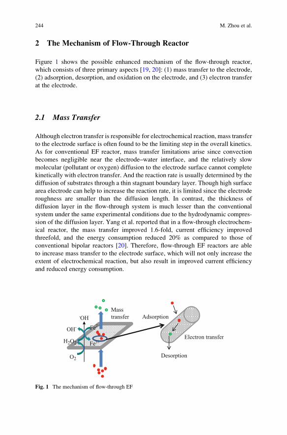
2 The Mechanism of Flow-Through Reactor
Figure 1 shows the possible enhanced mechanism of the flow-through reactor,
which consists of three primary aspects [19, 20]: (1) mass transfer to the electrode,
(2) adsorption, desorption, and oxidation on the electrode, and (3) electron transfer
at the electrode.
2.1 Mass Transfer
Although electron transfer is responsible for electrochemical reaction, mass transfer
to the electrode surface is often found to be the limiting step in the overall kinetics.
As for conventional EF reactor, mass transfer limitations arise since convection
becomes negligible near the electrode–water interface, and the relatively slow
molecular (pollutant or oxygen) diffusion to the electrode surface cannot complete
kinetically with electron transfer. And the reaction rate is usually determined by the
diffusion of substrates through a thin stagnant boundary layer. Though high surface
area electrode can help to increase the reaction rate, it is limited since the electrode
roughness are smaller than the diffusion length. In contrast, the thickness of
diffusion layer in the flow-through system is much lesser than the conventional
system under the same experimental conditions due to the hydrodynamic compres-
sion of the diffusion layer. Yang et al. reported that in a flow-through electrochem-
ical reactor, the mass transfer improved 1.6-fold, current efficiency improved
threefold, and the energy consumption reduced 20% as compared to those of
conventional bipolar reactors [20]. Therefore, flow-through EF reactors are able
to increase mass transfer to the electrode surface, which will not only increase the
extent of electrochemical reaction, but also result in improved current efficiency
and reduced energy consumption.
Mass
transfer Adsorption
Electron transfer
Desorption
H2O2
O2
OH-
Fe3+
Fe2+
.OH
Fig. 1 The mechanism of flow-through EF
244 M. Zhou et al.
2.2 Adsorption, Desorption, and Oxidation
The flow-through electrode material, especially the adsorptive electrode, can enrich
the pollutants when they flow through the electrode, resulting in increasing the
concentration of local pollutants and accelerating the oxidation rate, especially for
the low concentration of organic pollutants. As shown in Eqs. (1) and (2), the
hydrogen peroxide generated on the suitable cathode would be catalyzed by Fe2+
in the solution, producing powerful hydroxyl radicals, which lead to the Fenton
oxidation of organic pollutants. A fast adsorption of organic pollutants in the flow-
through reactor would simultaneously promote such a Fenton oxidation since
adsorption is very important for an interface reaction nearby the cathode. Moreover,
physical and chemical adsorption of species to the flow-through cathode surface
can significantly affect the electron transfer kinetics by altering its surface structure
and chemistry, leading to a shift in the Gibbs free energy of reactants [21]. These
reactions would decrease the interface pollutants concentration, resulting in desorp-
tion and adsorption capacity regeneration, which guarantee the continuous run of
the performance.
2.3 Electron Transfer
While mass transfer and adsorption are important processes that affect the overall
extent of oxidation during electrochemical oxidation, the target pollutant is ulti-
mately transformed during the electron transfer step. The influent pollutants con-
centration and cathode potential were examined to determine the electron transfer
kinetics and mechanism during electrochemical oxidation [22]. As expected, the
electron transfer increase with the increase of potential, and at high influent
pollutant concentrations when the adsorption sites are saturated, the overall reaction
rate will be limited by the electron transfer kinetics in the conventional EF system.
In the flow-through EF system, direct electron transfer can be enhanced due to the
hydrodynamic compression on the electrode surface, resulting in a higher current
response and efficiency.
3 Cathode Material
The cathode material determines the hydrogen peroxide production, which would
affect the effectiveness of pollutants decontamination by EF. Therefore, suitable
cathode is of great significance to the flow-through EF system. Carbon-based
materials are desirable cathodic electrodes because of their stability, conductivity,
high surface area, and chemical resistance.
Cost-Effective Flow-Through Reactor in Electro-Fenton 245
3.1 Carbon Nanotubes (CNTs)
Carbon nanotubes (CNTs) or CNT-based materials have potential for application in
EF system due to their combination of unique electronic, chemical, and mechanical
properties, including small dimensions of the tubes and channels [22]. Therefore,
compared with bare glass carbon, CNTs modified glass carbon electrode shows
much lower over-potential and higher peak current [23, 24]. And the CNTs can
strongly adsorb many chemical species because of a large specific surface area. For
example, CNTs have been observed to adsorb aromatic compounds and natural
organic matter via a combination of hydrophobic interactions and strong π–πinteractions [25]. In addition, utilizing CNTs as either a bulk electrode or a modified
working electrode has been observed to increase electron transfer rates [26].
CNTs were vacuum filtered onto a 5-μm polytetrafluorethylene (PTFE) mem-
brane, which was adopted as the cathode in the flow-through EF reactor [27].
The undoped CNTs (C-CNT), nitrogen-doped CNTs (N-CNT), and boron-doped
CNTs (B-CNT) were used to examine the H2O2 production as the function of
cathode potential [28, 29]. The N-CNT cathode had a maximum H2O2 production
of 3.0 mg/L, which was the lowest among the three CNT samples possibly due to
reduction of H2O2 to•OH and H2O. The C-CNT had the highest H2O2 production of
13.5 mg/L H2O2 at �0.3 V, while B-CNT had a moderate production of 8.5 mg/L.
However, such a low H2O2 production on the CNT membrane was not sufficient to
well satisfy the need of EF, which may attribute to the low concentration of
dissolved oxygen (DO) though pumping air or pure oxygen was used to increase
the DO in solution.
3.2 Carbon Fiber
Both large specific electrode areas and high mass transfer coefficients of dissolved
oxygen can be obtained due to the flow-through hydrodynamic conditions inside the
three-dimensional carbon fiber [30, 31]. Plakas et al. reported the CF-1371 (carbon
fiber with a specific surface area 1,371 m2/g and thickness 1 mm) and CF-1410
(carbon fiber with a specific surface area 1,410 m2/g and thickness 2 mm) cathode
used in flow-through EF system [32]. As for CF-1371, a linear increase of H2O2
concentration during the first 45 min of the electrolysis was observed, subsequently
exhibiting a tendency for stabilization. On the CF-1410 cathode, the electro-
generation of H2O2 was significantly higher, and thus an average current efficiency
of 70% was observed, which was much higher than that on CF-1371 (<10%).
Consequently, the CF-1410 was the desirable cathode in the flow-through EF
system. Another significant advantage of the porous carbon fibers was their negli-
gible effect on the water flux because of no pressure drop recorded during the
experiments.
246 M. Zhou et al.
3.3 Graphite Felt
Graphite felts (GF) have been regarded as one of the most widely used cathode
materials in EF process due to their large three-dimensional active surface, mechan-
ical integrity, commercial availability, easy acquisition, and efficient cathodic
regeneration of Fe2+ [33]. However, the productions of H2O2 on pristine GF was
not so satisfactory [34, 35], thus considerable efforts on GF modification have been
devoted to enhance its electrochemical activity by increasing surface oxygen content
or specific surface area using different modification methods. A high performance of
hydrogen peroxide production on GF modified by carbon black and PTFE was
achieved, which was 35 mg/L in the flow-through EF system, much higher than
that with the unmodified GF (6 mg/L) [36]. These results could be explained by the
significant increase of micropore and mesoporous pore and the pore volume, as well
as the enhancement of hydrophobic properties of the cathode surface [36].
Furthermore, it is vital to assemble the modified cathode and design a sound EF
system that can satisfy the high production of H2O2 and take the advantage of flow-
through process. In previous flow-through EF system, the solution was pretreated
by pumping air or pure oxygen to increase the concentration of DO [27, 32,
37]. Unfortunately, the production of H2O2 was found rather low, which limited
the Fenton oxidation rate due to the low DO in the solution. The modified GF has
the properties of high porosity and hydrophobicity, and allows air or oxygen to
cross the pore and contact with the active sites, providing lots of active surface sites
for catalyzing O2 reduction to H2O2 [1, 38]. Normally, modified GF is operated in a
flow-by reactor [17, 39], in our previous work, a novel flow-through reactor using
this modified GF was developed [19], in which the influent and pumped air flowed
through the cathode. The energy consumption of H2O2 production in this reactor
was only 5.2 kWh/(kg H2O2), which was much lower than other systems [40–42].
Recently, a novel Venturi-based jet reactor has been designed using the GF
modified with the same method [43]. Higher H2O2 generation rate and lower energy
consumption were obtained compared with the conventional system.
3.4 Carbonaceous Materials
The cathodic electrodes made of carbonaceous materials have been designed and
constructed [32]. The “CCB-470” was made of powdered carbon obtained from a
Coconut Carbon Black cartridge, which was compressed to form discs (diameter
4.2 cm, thickness 3.7 mm) with a specific surface area 470 m2/g. The H2O2
production could only be measured at high potential, and the steady-state H2O2
concentration was about 3.7 mg/L. Thus the H2O2 concentration and current
efficiency were very low and undesirable for the EF system. Moreover, the appli-
cation of the less porous powdered carbon discs resulted in significant pressure
drop, which was undesirable for EF practical applications.
Cost-Effective Flow-Through Reactor in Electro-Fenton 247
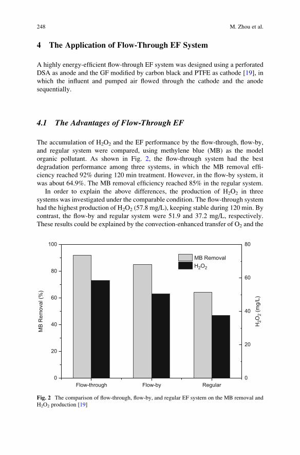
4 The Application of Flow-Through EF System
A highly energy-efficient flow-through EF system was designed using a perforated
DSA as anode and the GF modified by carbon black and PTFE as cathode [19], in
which the influent and pumped air flowed through the cathode and the anode
sequentially.
4.1 The Advantages of Flow-Through EF
The accumulation of H2O2 and the EF performance by the flow-through, flow-by,
and regular system were compared, using methylene blue (MB) as the model
organic pollutant. As shown in Fig. 2, the flow-through system had the best
degradation performance among three systems, in which the MB removal effi-
ciency reached 92% during 120 min treatment. However, in the flow-by system, it
was about 64.9%. The MB removal efficiency reached 85% in the regular system.
In order to explain the above differences, the production of H2O2 in three
systems was investigated under the comparable condition. The flow-through system
had the highest production of H2O2 (57.8 mg/L), keeping stable during 120 min. By
contrast, the flow-by and regular system were 51.9 and 37.2 mg/L, respectively.
These results could be explained by the convection-enhanced transfer of O2 and the
Flow-through Flow-by Regular0
20
40
60
80
100
MB
Rem
oval
(%)
MB Removal H2O2
H2O
2 (m
g/L)
0
20
40
60
80
Fig. 2 The comparison of flow-through, flow-by, and regular EF system on the MB removal and
H2O2 production [19]
248 M. Zhou et al.
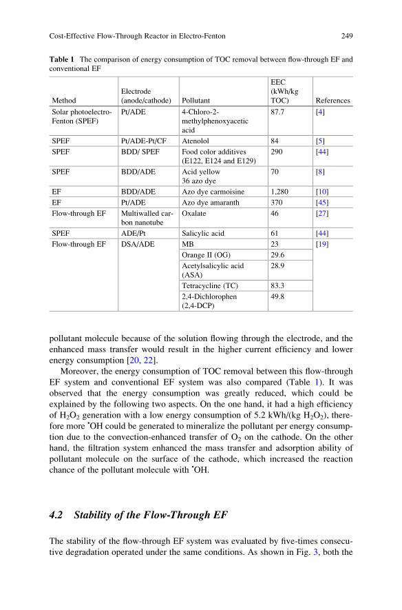
pollutant molecule because of the solution flowing through the electrode, and the
enhanced mass transfer would result in the higher current efficiency and lower
energy consumption [20, 22].
Moreover, the energy consumption of TOC removal between this flow-through
EF system and conventional EF system was also compared (Table 1). It was
observed that the energy consumption was greatly reduced, which could be
explained by the following two aspects. On the one hand, it had a high efficiency
of H2O2 generation with a low energy consumption of 5.2 kWh/(kg H2O2), there-
fore more •OH could be generated to mineralize the pollutant per energy consump-
tion due to the convection-enhanced transfer of O2 on the cathode. On the other
hand, the filtration system enhanced the mass transfer and adsorption ability of
pollutant molecule on the surface of the cathode, which increased the reaction
chance of the pollutant molecule with •OH.
4.2 Stability of the Flow-Through EF
The stability of the flow-through EF system was evaluated by five-times consecu-
tive degradation operated under the same conditions. As shown in Fig. 3, both the
Table 1 The comparison of energy consumption of TOC removal between flow-through EF and
conventional EF
Method
Electrode
(anode/cathode) Pollutant
EEC
(kWh/kg
TOC) References
Solar photoelectro-
Fenton (SPEF)
Pt/ADE 4-Chloro-2-
methylphenoxyacetic
acid
87.7 [4]
SPEF Pt/ADE-Pt/CF Atenolol 84 [5]
SPEF BDD/ SPEF Food color additives
(E122, E124 and E129)
290 [44]
SPEF BDD/ADE Acid yellow
36 azo dye
70 [8]
EF BDD/ADE Azo dye carmoisine 1,280 [10]
EF Pt/ADE Azo dye amaranth 370 [45]
Flow-through EF Multiwalled car-
bon nanotube
Oxalate 46 [27]
SPEF ADE/Pt Salicylic acid 61 [44]
Flow-through EF DSA/ADE MB 23 [19]
Orange II (OG) 29.6
Acetylsalicylic acid
(ASA)
28.9
Tetracycline (TC) 83.3
2,4-Dichlorophen
(2,4-DCP)
49.8
Cost-Effective Flow-Through Reactor in Electro-Fenton 249
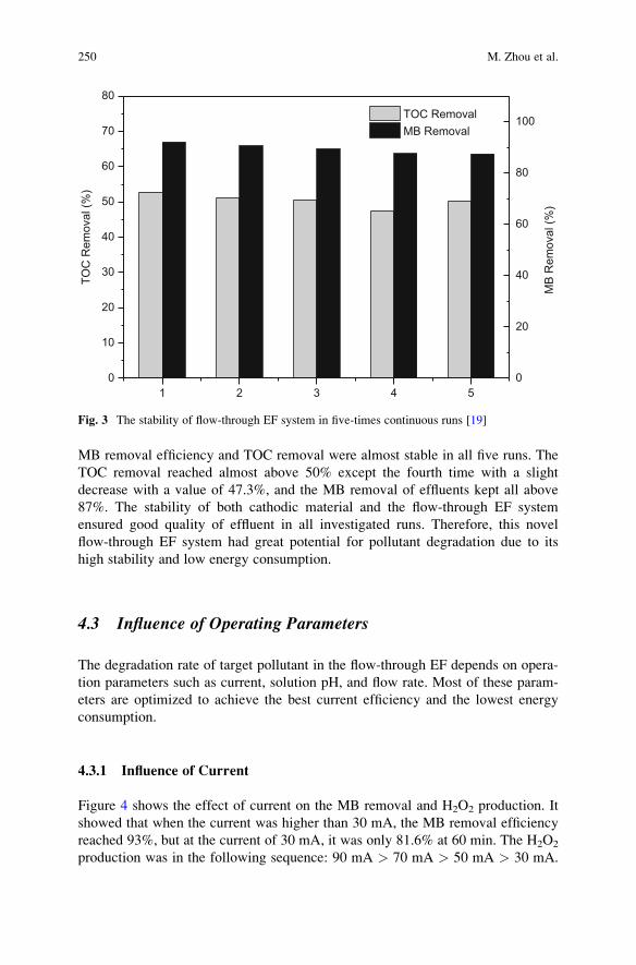
MB removal efficiency and TOC removal were almost stable in all five runs. The
TOC removal reached almost above 50% except the fourth time with a slight
decrease with a value of 47.3%, and the MB removal of effluents kept all above
87%. The stability of both cathodic material and the flow-through EF system
ensured good quality of effluent in all investigated runs. Therefore, this novel
flow-through EF system had great potential for pollutant degradation due to its
high stability and low energy consumption.
4.3 Influence of Operating Parameters
The degradation rate of target pollutant in the flow-through EF depends on opera-
tion parameters such as current, solution pH, and flow rate. Most of these param-
eters are optimized to achieve the best current efficiency and the lowest energy
consumption.
4.3.1 Influence of Current
Figure 4 shows the effect of current on the MB removal and H2O2 production. It
showed that when the current was higher than 30 mA, the MB removal efficiency
reached 93%, but at the current of 30 mA, it was only 81.6% at 60 min. The H2O2
production was in the following sequence: 90 mA > 70 mA > 50 mA > 30 mA.
1 2 3 4 50
10
20
30
40
50
60
70
80TO
C R
emov
al (%
)
TOC Removal MB Removal
0
20
40
60
80
100
MB
Rem
oval
(%)
Fig. 3 The stability of flow-through EF system in five-times continuous runs [19]
250 M. Zhou et al.
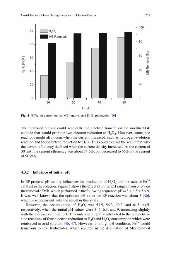
The increased current could accelerate the electron transfer on the modified GF
cathode that would promote two-electron reduction to H2O2. However, some side
reactions might also occur when the current increased, such as hydrogen evolution
reaction and four-electron reduction to H2O. This could explain the result that why
the current efficiency declined when the current density increased. At the current of
30 mA, the current efficiency was about 74.6%, but decreased to 66% at the current
of 90 mA.
4.3.2 Influence of Initial pH
In EF process, pH mainly influences the production of H2O2 and the state of Fe2+
catalyst in the solution. Figure 5 shows the effect of initial pH ranged from 3 to 9 on
the removal ofMB,whichperformed in the followingsequence:pH¼3>6.3>5>9.
It was well known that the optimum pH value for EF reaction was about 3 [46],
which was consistent with the result in this study.
However, the accumulation of H2O2 was 53.5, 56.3, 60.2, and 61.5 mg/L
respectively, when the initial pH values were 3, 5, 6.3, and 9, increasing slightly
with the increase of initial pH. This outcome might be attributed to the competitive
side reactions of four-electron reduction to H2O and H2O2 consumption which were
reinforced in acid solution [46, 47]. However, at a high pH condition, Fe2+ would
transform to iron hydroxides, which resulted in the declination of MB removal
0
20
40
60
80
100
905030 70
H2O
2 (m
g/L)
I (mA)
MB Removal
H2O2
0
20
40
60
80
100
MB
Rem
oval
(%)
Fig. 4 Effect of current on the MB removal and H2O2 production [19]
Cost-Effective Flow-Through Reactor in Electro-Fenton 251
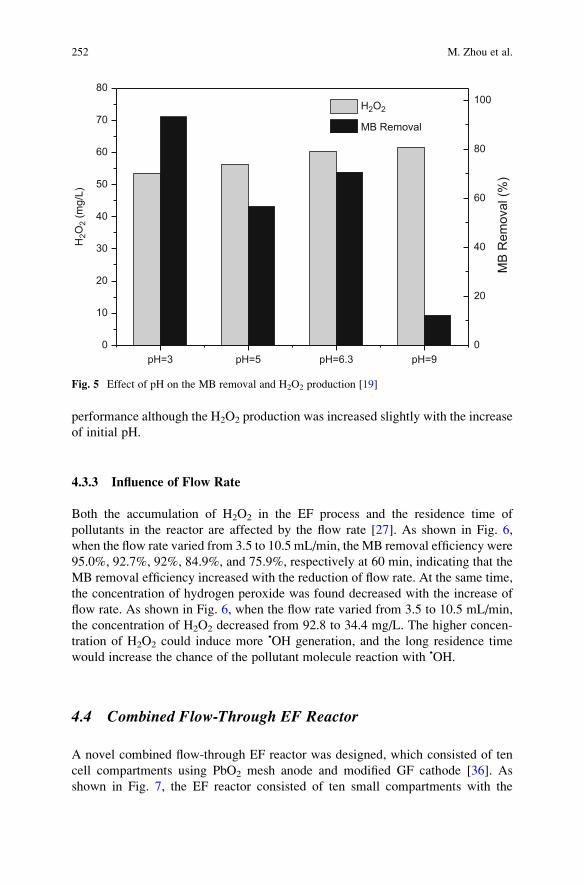
performance although the H2O2 production was increased slightly with the increase
of initial pH.
4.3.3 Influence of Flow Rate
Both the accumulation of H2O2 in the EF process and the residence time of
pollutants in the reactor are affected by the flow rate [27]. As shown in Fig. 6,
when the flow rate varied from 3.5 to 10.5 mL/min, the MB removal efficiency were
95.0%, 92.7%, 92%, 84.9%, and 75.9%, respectively at 60 min, indicating that the
MB removal efficiency increased with the reduction of flow rate. At the same time,
the concentration of hydrogen peroxide was found decreased with the increase of
flow rate. As shown in Fig. 6, when the flow rate varied from 3.5 to 10.5 mL/min,
the concentration of H2O2 decreased from 92.8 to 34.4 mg/L. The higher concen-
tration of H2O2 could induce more •OH generation, and the long residence time
would increase the chance of the pollutant molecule reaction with •OH.
4.4 Combined Flow-Through EF Reactor
A novel combined flow-through EF reactor was designed, which consisted of ten
cell compartments using PbO2 mesh anode and modified GF cathode [36]. As
shown in Fig. 7, the EF reactor consisted of ten small compartments with the
pH=3 pH=5 pH=6.3 pH=90
10
20
30
40
50
60
70
80H
2O2
(mg/
L)
MB Removal
H2O2
0
20
40
60
80
100
MB
Rem
oval
(%)
Fig. 5 Effect of pH on the MB removal and H2O2 production [19]
252 M. Zhou et al.
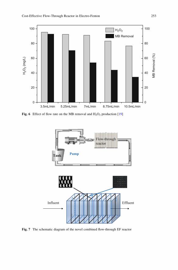
Pump Tank
Flow-through
reactor
Influent Effluent
Fig. 7 The schematic diagram of the novel combined flow-through EF reactor
3.5mL/min 5.25mL/min 7mL/min 8.75mL/min 10.5mL/min0
20
40
60
80
100
MB Removal
0
20
40
60
80
100
MB
Rem
oval
(%)
H2O
2 (m
g/L)
H2O2
Fig. 6 Effect of flow rate on the MB removal and H2O2 production [19]
Cost-Effective Flow-Through Reactor in Electro-Fenton 253
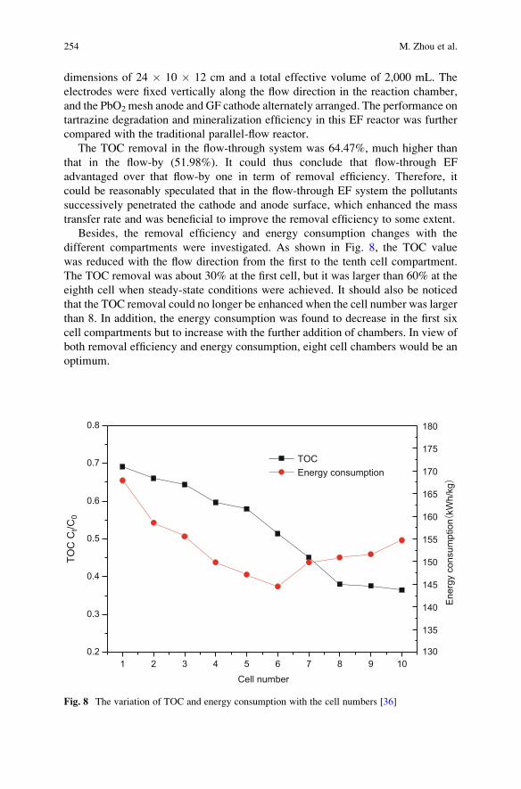
dimensions of 24 � 10 � 12 cm and a total effective volume of 2,000 mL. The
electrodes were fixed vertically along the flow direction in the reaction chamber,
and the PbO2 mesh anode and GF cathode alternately arranged. The performance on
tartrazine degradation and mineralization efficiency in this EF reactor was further
compared with the traditional parallel-flow reactor.
The TOC removal in the flow-through system was 64.47%, much higher than
that in the flow-by (51.98%). It could thus conclude that flow-through EF
advantaged over that flow-by one in term of removal efficiency. Therefore, it
could be reasonably speculated that in the flow-through EF system the pollutants
successively penetrated the cathode and anode surface, which enhanced the mass
transfer rate and was beneficial to improve the removal efficiency to some extent.
Besides, the removal efficiency and energy consumption changes with the
different compartments were investigated. As shown in Fig. 8, the TOC value
was reduced with the flow direction from the first to the tenth cell compartment.
The TOC removal was about 30% at the first cell, but it was larger than 60% at the
eighth cell when steady-state conditions were achieved. It should also be noticed
that the TOC removal could no longer be enhanced when the cell number was larger
than 8. In addition, the energy consumption was found to decrease in the first six
cell compartments but to increase with the further addition of chambers. In view of
both removal efficiency and energy consumption, eight cell chambers would be an
optimum.
1 2 3 4 5 6 7 8 9 100.2
0.3
0.4
0.5
0.6
0.7
0.8
TOC
Ct/C
0
Cell number
TOC Energy consumption
130
135
140
145
150
155
160
165
170
175
180
Ener
gy c
onsu
mpt
ion
kWh/
kg
Fig. 8 The variation of TOC and energy consumption with the cell numbers [36]
254 M. Zhou et al.
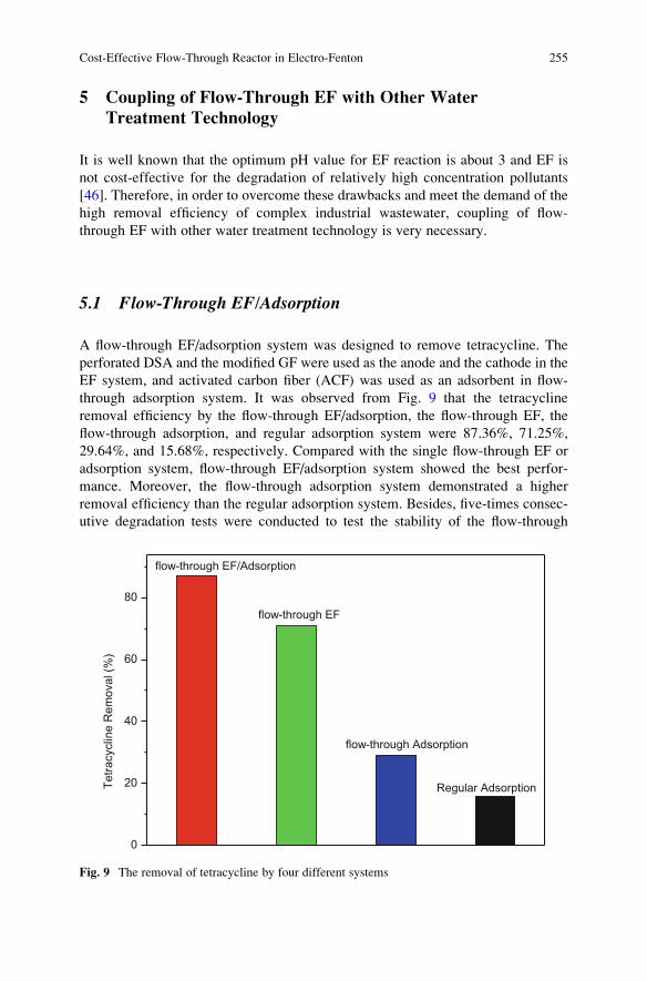
5 Coupling of Flow-Through EF with Other Water
Treatment Technology
It is well known that the optimum pH value for EF reaction is about 3 and EF is
not cost-effective for the degradation of relatively high concentration pollutants
[46]. Therefore, in order to overcome these drawbacks and meet the demand of the
high removal efficiency of complex industrial wastewater, coupling of flow-
through EF with other water treatment technology is very necessary.
5.1 Flow-Through EF/Adsorption
A flow-through EF/adsorption system was designed to remove tetracycline. The
perforated DSA and the modified GF were used as the anode and the cathode in the
EF system, and activated carbon fiber (ACF) was used as an adsorbent in flow-
through adsorption system. It was observed from Fig. 9 that the tetracycline
removal efficiency by the flow-through EF/adsorption, the flow-through EF, the
flow-through adsorption, and regular adsorption system were 87.36%, 71.25%,
29.64%, and 15.68%, respectively. Compared with the single flow-through EF or
adsorption system, flow-through EF/adsorption system showed the best perfor-
mance. Moreover, the flow-through adsorption system demonstrated a higher
removal efficiency than the regular adsorption system. Besides, five-times consec-
utive degradation tests were conducted to test the stability of the flow-through
0
20
40
60
80
Regular Adsorption
flow-through Adsorption
flow-through EF
Tetra
cycl
ine
Rem
oval
(%)
flow-through EF/Adsorption
Fig. 9 The removal of tetracycline by four different systems
Cost-Effective Flow-Through Reactor in Electro-Fenton 255
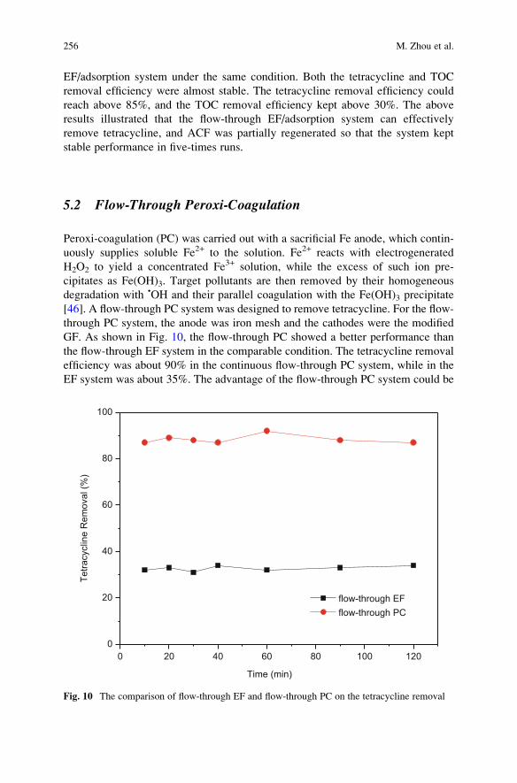
EF/adsorption system under the same condition. Both the tetracycline and TOC
removal efficiency were almost stable. The tetracycline removal efficiency could
reach above 85%, and the TOC removal efficiency kept above 30%. The above
results illustrated that the flow-through EF/adsorption system can effectively
remove tetracycline, and ACF was partially regenerated so that the system kept
stable performance in five-times runs.
5.2 Flow-Through Peroxi-Coagulation
Peroxi-coagulation (PC) was carried out with a sacrificial Fe anode, which contin-
uously supplies soluble Fe2+ to the solution. Fe2+ reacts with electrogenerated
H2O2 to yield a concentrated Fe3+ solution, while the excess of such ion pre-
cipitates as Fe(OH)3. Target pollutants are then removed by their homogeneous
degradation with •OH and their parallel coagulation with the Fe(OH)3 precipitate
[46]. A flow-through PC system was designed to remove tetracycline. For the flow-
through PC system, the anode was iron mesh and the cathodes were the modified
GF. As shown in Fig. 10, the flow-through PC showed a better performance than
the flow-through EF system in the comparable condition. The tetracycline removal
efficiency was about 90% in the continuous flow-through PC system, while in the
EF system was about 35%. The advantage of the flow-through PC system could be
0 20 40 60 80 100 1200
20
40
60
80
100
Tetra
cycl
ine
Rem
oval
(%)
Time (min)
flow-through EFflow-through PC
Fig. 10 The comparison of flow-through EF and flow-through PC on the tetracycline removal
256 M. Zhou et al.
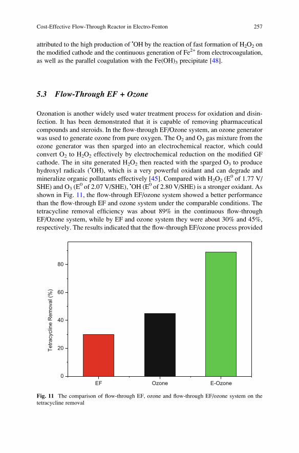
attributed to the high production of •OH by the reaction of fast formation of H2O2 on
the modified cathode and the continuous generation of Fe2+ from electrocoagulation,
as well as the parallel coagulation with the Fe(OH)3 precipitate [48].
5.3 Flow-Through EF + Ozone
Ozonation is another widely used water treatment process for oxidation and disin-
fection. It has been demonstrated that it is capable of removing pharmaceutical
compounds and steroids. In the flow-through EF/Ozone system, an ozone generator
was used to generate ozone from pure oxygen. The O2 and O3 gas mixture from the
ozone generator was then sparged into an electrochemical reactor, which could
convert O2 to H2O2 effectively by electrochemical reduction on the modified GF
cathode. The in situ generated H2O2 then reacted with the sparged O3 to produce
hydroxyl radicals (•OH), which is a very powerful oxidant and can degrade and
mineralize organic pollutants effectively [45]. Compared with H2O2 (E0 of 1.77 V/
SHE) and O3 (E0 of 2.07 V/SHE), •OH (E0 of 2.80 V/SHE) is a stronger oxidant. As
shown in Fig. 11, the flow-through EF/ozone system showed a better performance
than the flow-through EF and ozone system under the comparable conditions. The
tetracycline removal efficiency was about 89% in the continuous flow-through
EF/Ozone system, while by EF and ozone system they were about 30% and 45%,
respectively. The results indicated that the flow-through EF/ozone process provided
EF Ozone E-Ozone0
20
40
60
80
Tetra
cycl
ine
Rem
oval
(%)
Fig. 11 The comparison of flow-through EF, ozone and flow-through EF/ozone system on the
tetracycline removal
Cost-Effective Flow-Through Reactor in Electro-Fenton 257
a convenient and effective alternative to conventional advanced oxidation pro-
cesses for degrading refractory organic pollutants in wastewater.
6 Summary and Perspective
Flow-through EF reactor, has attracted much attention in recent years because of its
unique properties and advantages, such as the fast mass and electron transfer to the
electrode surface, which will not only increase the extent of electrochemical
transformation, but also result in improved current efficiencies and reduced energy
consumption. Moreover, coupling of flow-through EF with other water treatment
technology is urgently necessary to meet the demand of the high removal efficiency
of complex industrial wastewater. Compared with conventional EF, flow-through
EF was more energy-efficient and potential for the degradation of organic pollut-
ants. However, there are still many works to be done to improve the efficiency,
reduce the cost, and expand the scale of application.
The following aspects need to be strengthened:
1. Flow-through cathode material. The cathode material determines the production
of hydrogen peroxide in the EF system, thus affects the removal efficiency and
energy consumption. Therefore, a high performance cathode is of great signif-
icance to the flow-through EF system. At present, the hydrogen peroxide pro-
duction of flow-through EF cathode is still at a very low level, far from the level
of air diffusion electrode. In addition, the pressure drop on the cathode should
also be taken into consideration when the solution flow through. Therefore, the
preparation or modification of cathode should be an appropriate trend to improve
the performance of flow-through EF system.
2. Expanding the scale of flow-through EF system. The study of flow-through EF
system is presently mainly focused on a laboratory scale. In order to test the
feasibility of application, how to design a large-scale reactor and keep the high
performance as that of lab scale is still need to explore. Also, a large area of
electrode especially the cathode would be a big challenge.
3. The combination of flow-through EF with other technologies for application. Asdiscussed above, the optimum pH value for EF reaction is about 3 and EF is not
suitable to degrade relatively high concentration pollutants. In order to over-
come the limitation of EF process and meet the demand of the high removal
efficiency of complex industrial wastewater, coupling of flow-through EF with
other water treatment technology, such as adsorption, electrocoagulation, and
ozonation, is very necessary. Obviously, in viewpoint of environmental protec-
tion, this attempt is urgently required and needs reinforcement.
258 M. Zhou et al.
References
1. Brillas E, Sires I, Oturan M (2009) Electro-Fenton process and related electrochemical
technologies based on Fenton’s reaction chemistry. Chem Rev 109:6570–6631
2. Yu X, Zhou M, Ren G, Ma L (2015) A novel dual gas diffusion electrodes system for efficient
hydrogen peroxide generation used in electro-Fenton. Chem Eng J 263:92–100
3. Yavuz Y (2007) EC and EF processes for the treatment of alcohol distillery wastewater.
Sep Purif Technol 53:135–140
4. Garcia-Segura S, Almeida L, Bocchi N, Brillas E (2011) Solar photoelectro-Fenton degrada-
tion of the herbicide 4-chloro-2-methylphenoxyacetic acid optimized by response surface
methodology. J Hazard Mater 194:109–118
5. Isarain-Chavez E, Rodrıguez R, Cabot P, Centellas F, Arias C, Garrido J, Brillas E (2011)
Degradation of pharmaceutical beta-blockers by electrochemical advanced oxidation pro-
cesses using a flow plant with a solar compound parabolic collector. Water Res 45:4119–4130
6. Peralta-Hernandez J, Meas-Vong Y, Rodrıguez F, Chapmana T, Maldonado M, Godınez L
(2006) In situ electrochemical and photo-electrochemical generation of the Fenton reagent: a
potentially important new water treatment technology. Water Res 40:1754–1762
7. Moreira F, Garcia-Segura S, Vilar V, Boaventura R, Brillas E (2013) Decolorization and
mineralization of Sunset Yellow FCF azo dye by anodic oxidation, electro-Fenton, UVA
photoelectro-Fenton and solar photoelectro-Fenton processes. Appl Catal B Environ
142–143:877–890
8. Figueroa S, Vazquez L, Alvarez-Gallegos A (2009) Decolorizing textile wastewater with
Fenton’s reagent electrogenerated with a solar photovoltaic cell. Water Res 43:283–294
9. Garcia-Segura S, Garrido J, Rodrıguez R, Cabot P, Centellas F, Arias C, Brillas E (2012)
Mineralization of flumequine in acidic medium by electro-Fenton and photoelectro-Fenton
processes. Water Res 46:2067–2076
10. Oturan M, Sires I, Oturan N, Perocheau S, Laborde J, Trevin S (2008) Sonoelectro-Fenton
process: a novel hybrid technique for the destruction of organic pollutants in water.
J Electroanal Chem 624:329–332
11. Li H, Lei H, Yu Q, Li Z, Feng X, Yang B (2010) Effect of low frequency ultrasonic irradiation
on the sonoelectro-Fenton degradation of cationic red X-GRL. Chem Eng J 160:417–422
12. Sudoh M, Kodera T, Sakai K, Zhang J, Koide K (1986) Oxidative degradation of aqueous
phenol effluent with electrogenerated Fenton’s reagent. J Chem Eng Jpn 19:513–518
13. Zhang H, Ran X, Wu X (2012) Electro-Fenton treatment of mature landfill leachate in a
continuous flow reactor. J Hazard Mater 241–242:259–266
14. Zhu R, Yang C, Zhou M, Wang J (2015) Industrial park wastewater deeply treated and reused
by a novel electrochemical oxidation reactor. Chem Eng J 260:427–433
15. Vasconcelos V, Ponce-de-Leon C, Nava J, Lanza M (2016) Electrochemical degradation of
RB-5 dye by anodic oxidation, electro-Fenton and by combining anodic oxidation–electro-
Fenton in a filter-press flow cell. J Electroanal Chem 765:179–187
16. Ling Y, Xu H, Chen X (2015) Continuous multi-cell electrochemical reactor for pollutant
oxidation. Chem Eng Sci 122:630–636
17. Moreira F, Garcia-Segura S, Boaventura R, Brillas E, Vilar V (2014) Degradation of the
antibiotic trimethoprim by electrochemical advanced oxidation processes using a carbon-
PTFE air-diffusion cathode and a boron-doped diamond or platinum anode. Appl Catal B
Environ 160–161:492–505
18. Bard AJ, Faulkner LR (1983) Electrochemical methods fundamentals and applications.
J Chem Educ 60:669–676
19. Ma L, Zhou M, Ren G, Yang W, Liang L (2016) A highly energy-efficient flow-through
electro-Fenton process for organic pollutants degradation. Electrochim Acta 200:222–230
20. Liu H, Vecitis C (2012) Reactive transport mechanism for organic oxidation during electro-
chemical filtration: mass-transfer, physical adsorption, and electron-transfer. J Phys Chem C
116:374–383
Cost-Effective Flow-Through Reactor in Electro-Fenton 259
21. Yang J, Wang J, Jia J (2009) Improvement of electrochemical wastewater treatment
through mass transfer in a seepage carbon nanotube electrode reactor. Environ Sci Technol
43:3796–3802
22. Colmati F, Tremiliosi-Filho G, Gonzalez E, Berna A, Herrero E, Feliu J (2009) Surface
structure effects on the electrochemical oxidation of ethanol on platinum single crystal
electrodes. Faraday Discuss 140:379–397
23. Wang J, Li M, Shi Z, Li N, Gu Z (2002) Electrocatalytic oxidation of norepinephrine at a
glassy carbon electrode modified with single wall carbon nanotubes. Electroanalysis
14:225–230
24. Britto P, Santhanam K, Ajayan P (1996) Carbon nanotube electrode for oxidation of dopamine.
Bioelectrochem Bioenerg 41:121–125
25. Pan B, Xing B (2008) Adsorption mechanisms of organic chemicals on carbon nanotubes.
Environ Sci Technol 42:9005–9013
26. Wang J, Musameh M (2003) Carbon nanotube/teflon composite electrochemical sensors and
biosensors. Anal Chem 75:2075–2079
27. Gao G, Zhang Q, Hao Z, Vecitis C (2015) Carbon nanotube membrane stack for flow-through
sequential regenerative electro-Fenton. Environ Sci Technol 49:2375–2383
28. Chen Z, Higgins D, Chen Z (2010) Nitrogen doped carbon nanotubes and their impact on the
oxygen reduction reaction in fuel cells. Carbon 48:3057–3065
29. Chen Z, Higgins D, Tao H, Hsu R, Chen Z (2009) Highly active nitrogen-doped carbon
nanotubes for oxygen reduction reaction in fuel cell applications. J Phys Chem C
113:21008–21013
30. Schnoor M, Vecitis C (2013) Quantitative examination of aqueous ferrocyanide oxidation in
a carbon nanotube electrochemical filter: effects of flow rate, ionic strength, and cathode
material. J Phys Chem C 117:2855–2867
31. Lannoy C, Jassby D, Gloe K, Gordon A, Wiesner MR (2013) Aquatic biofouling prevention by
electrically charged nanocomposite polymer thin film membranes. Environ Sci Technol
47:2760–2768
32. Plakas K, Karabelas A, Sklari S, Zaspalis V (2013) Toward the development of a novel electro-
Fenton system for eliminating toxic organic substances from water. Part 1. In situ generation of
hydrogen peroxide. Ind Eng Chem Res 52:13948–13956
33. Panizza M, Oturan M (2011) Degradation of Alizarin Red by electro-Fenton process using a
graphite-felt cathode. Electrochim Acta 56:7084–7087
34. Zhou L, Zhou M, Hu Z, Bi Z, Serrano K (2014) Chemically modified graphite felt
as an efficient cathode in electro-Fenton for p-nitrophenol degradation. Electrochim Acta
140:376–383
35. Zhou L, Zhou M, Zhang C, Jiang Y, Bi Z, Yang J (2013) Electro-Fenton degradation of p-nitrophenol using the anodized graphite felts. Chem Eng J 233:185–192
36. Ren G, Zhou M, Liu M, Ma L, Yang H (2016) A novel vertical-flow electro-Fenton reactor for
organic wastewater treatment. Chem Eng J 298:55–67
37. Sklari S, Plakas K, Petsi P, Zaspalis V, Karabelas A (2015) Toward the development of a novel
electro-Fenton system for eliminating toxic organic substances from water. Part 2. Preparation,
characterization, and evaluation of iron-impregnated carbon felts as cathodic electrodes.
Ind Eng Chem Res 54:2059–2073
38. Zhang C, Jiang Y, Li Y, Hu Z, Zhou L, Zhou M (2013) Three-dimensional electrochemical
process for wastewater treatment: a general review. Chem Eng J 228:455–467
39. Forti J, Nunes J, Lanza M, Bertazzoli R (2007) Azobenzene-modified oxygen-fed graphite/
PTFE electrodes for hydrogen peroxide synthesis. J Appl Electrochem 37:527–532
40. Barros W, Reis R, Rocha R, Lanza M (2013) Electrogeneration of hydrogen peroxide in acidic
medium using gas diffusion electrodes modified with cobalt (II) phthalocyanine. Electrochim
Acta 104:12–18
260 M. Zhou et al.
41. Reis R, Beati A, Rocha R, Assumpc~ao M, Santos M, Bertazzoli R (2012) Use of gas diffusion
electrode for the in situ generation of hydrogen peroxide in an electrochemical flow-by reactor.
Ind Eng Chem Res 51:649–654
42. Perez J, Llanos J, Saez C, Lopez C, Ca~nizares P, RodrigoM (2016) Electrochemical jet-cell for
the in-situ generation of hydrogen peroxide. Electrochem Commun 71:65–68
43. Panizza M, Cerisola G (2009) Electro-Fenton degradation of synthetic dyes. Water Res
43:339–344
44. Guinea E, Arias C, Cabot P, Garrido J, Rodriguez R, Centellas F (2008) Mineralization of
salicylic acid in acidic aqueous medium by electrochemical advanced oxidation processes
using platinum and boron-doped diamond as anode and cathodically generated hydrogen
peroxide. Water Res 42:499–511
45. Li Z, Yuan S, Qiu C, Wang Y, Pan X, Wang J (2013) Effective degradation of refractory
organic pollutants in landfill leachate by electro-peroxone treatment. Electrochim Acta
102:174–182
46. Nidheesh P, Gandhimathi R (2014) Electrolytic removal of Rhodamine B from aqueous
solution by peroxicoagulation process. Environ Sci Pollut Res 21:8585–8594
47. Thiam A, Sires I, Brillas E (2015) Treatment of a mixture of food color additives (E122, E124
and E129) in different water matrices by UVA and solar photoelectro-Fenton. Water Res
81:178–187
48. Barros W, Franco P, Steter J, Rocha R, Lanza M (2014) Electro-Fenton degradation of the
food dye amaranth using a gas diffusion electrode modified with cobalt (II) phthalocyanine.
J Electroanal Chem 722–723:46–53
Cost-Effective Flow-Through Reactor in Electro-Fenton 261
Reactor Design for Advanced Oxidation
Processes
Jose L. Nava and Carlos Ponce de Leon
Abstract Electrochemical reactor design for oxidation processes follows similar
engineering principles used for typical electrosynthesis reactors and include con-
siderations of the components materials, electrode and cell geometries, mass
transport conditions, rate of reactions, space–time yield calculations, selectivity,
modeling, and energy efficiencies. It is common practice to optimize these charac-
teristics at laboratory scale level followed by more practical considerations to build
a larger reactor able to accomplish a required performance that can be easily
assembled and requires low maintenance and monitoring. The scaling-up process
should involve testing a variety of electrode configurations and cell designs to
maximize the degradation of a particular pollutant. In this chapter, we describe the
general principles of reactor design and list the most typical reactor configurations
and performance followed by some recent advances in modeling and further
developments.
Keywords Computational fluid dynamics, Current distributions, Electrochemical
reactor, Filter-press flow cell, Mass transport, Non-ideal electrolyte flow, Packed
bed electrode, Parallel plate electrodes, Rotating cylinder electrode, Wastewater
treatment
J.L. Nava (*)
Departamento de Ingenierıa Geomatica e Hidraulica, Universidad de Guanajuato, Av. Juarez
77, Guanajuato 3600, Mexico
e-mail: [email protected]
C. Ponce de Leon
Electrochemical Engineering Laboratory, Energy Technology Research Group, Faculty of
Engineering and the Environment, University of Southampton, Highfield, Southampton
SO17 1BJ, UK
e-mail: [email protected]
M. Zhou et al. (eds.), Electro-Fenton Process: New Trends and Scale-Up,Hdb Env Chem (2018) 61: 263–286, DOI 10.1007/698_2017_54,© Springer Nature Singapore Pte Ltd. 2017, Published online: 13 July 2017
263
Contents
1 Introduction . . . . . . . . . . . . . . . . . . . . . . . . . . . . . . . . . . . . . . . . . . . . . . . . . . . . . . . . . . . . . . . . . . . . . . . . . . . . . . . . . . 264
2 Design and Basic Considerations . . . . . . . . . . . . . . . . . . . . . . . . . . . . . . . . . . . . . . . . . . . . . . . . . . . . . . . . . . . 265
2.1 Electrode Materials . . . . . . . . . . . . . . . . . . . . . . . . . . . . . . . . . . . . . . . . . . . . . . . . . . . . . . . . . . . . . . . . . . . . 268
2.2 Cell Potential . . . . . . . . . . . . . . . . . . . . . . . . . . . . . . . . . . . . . . . . . . . . . . . . . . . . . . . . . . . . . . . . . . . . . . . . . . 269
2.3 Performance . . . . . . . . . . . . . . . . . . . . . . . . . . . . . . . . . . . . . . . . . . . . . . . . . . . . . . . . . . . . . . . . . . . . . . . . . . . 270
3 Design and Characterization of Electrochemical Reactors . . . . . . . . . . . . . . . . . . . . . . . . . . . . . . . . 271
3.1 Experimental Characterization . . . . . . . . . . . . . . . . . . . . . . . . . . . . . . . . . . . . . . . . . . . . . . . . . . . . . . . . 271
3.2 Theoretical Characterization (Modeling and Simulation) . . . . . . . . . . . . . . . . . . . . . . . . . . . 276
4 Further Developments and Perspectives . . . . . . . . . . . . . . . . . . . . . . . . . . . . . . . . . . . . . . . . . . . . . . . . . . . . 283
References . . . . . . . . . . . . . . . . . . . . . . . . . . . . . . . . . . . . . . . . . . . . . . . . . . . . . . . . . . . . . . . . . . . . . . . . . . . . . . . . . . . . . . . 284
1 Introduction
Electrochemical engineering uses the principles of chemical engineering and elec-
trochemical sciences in order to develop an interdisciplinary field that nowadays is
very diversified and extensive, covering aspects of design and performance of
electrochemical processes that might involve non-electrochemical aspects. Well-
known electrochemical engineering processes include the chlor-alkali industry,
inorganic synthesis, electrowinning, refining and recovering metals, redox flow
batteries for energy storage, batteries, and fuel cells, and in recent years, the field
has established new and effective methodologies for environmental remediation
and pollution control. Electrochemical technologies have been typically used for
metal recovery; however, advances also include electrochemical oxidation process
for recalcitrant organic materials and the electrocoagulation process that has also
been used for organic removal. This has been forced by government regulations to
clean households and industrial wastewaters before disposal and the urgent need to
include green and sustainable processes into the existing industrial manufacturing.
This chapter considers the advances of cell design and architecture and electrode
materials and analyzes current trends and developments.
Electrochemical advanced oxidation processes (EAOPs) are well-established
technologies characterized by the production of highly active hydroxyl radicals
(•OH) that can be divided into heterogeneous and homogenous processes.
Typically, boron-doped diamond electrodes or photocatalytic surfaces such as
TiO2 generate the radical in the heterogeneous process, while in the homoge-
neous process, the radical is formed by the Fenton’s Reaction by electro-
generated hydrogen peroxide and Fe2+ ions in solution. The electrochemical
cell is the center of the EAOPs and requires careful consideration of suitable
designs, electrodes, and whether or not a separator material between anode and
cathode is necessary [1–3]. In most cases, the cell design should provide
uniform current and potential distribution that promotes the optimization of
parameters such as energy consumption and increases the oxidation rate and
the selectivity.
264 J.L. Nava and C. Ponce de Leon
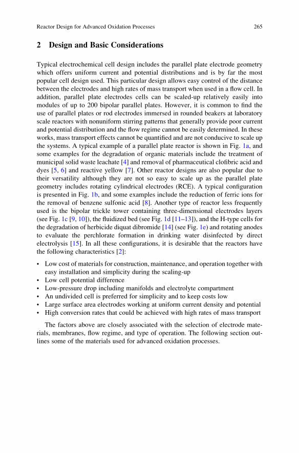
2 Design and Basic Considerations
Typical electrochemical cell design includes the parallel plate electrode geometry
which offers uniform current and potential distributions and is by far the most
popular cell design used. This particular design allows easy control of the distance
between the electrodes and high rates of mass transport when used in a flow cell. In
addition, parallel plate electrodes cells can be scaled-up relatively easily into
modules of up to 200 bipolar parallel plates. However, it is common to find the
use of parallel plates or rod electrodes immersed in rounded beakers at laboratory
scale reactors with nonuniform stirring patterns that generally provide poor current
and potential distribution and the flow regime cannot be easily determined. In these
works, mass transport effects cannot be quantified and are not conducive to scale up
the systems. A typical example of a parallel plate reactor is shown in Fig. 1a, and
some examples for the degradation of organic materials include the treatment of
municipal solid waste leachate [4] and removal of pharmaceutical clofibric acid and
dyes [5, 6] and reactive yellow [7]. Other reactor designs are also popular due to
their versatility although they are not so easy to scale up as the parallel plate
geometry includes rotating cylindrical electrodes (RCE). A typical configuration
is presented in Fig. 1b, and some examples include the reduction of ferric ions for
the removal of benzene sulfonic acid [8]. Another type of reactor less frequently
used is the bipolar trickle tower containing three-dimensional electrodes layers
(see Fig. 1c [9, 10]), the fluidized bed (see Fig. 1d [11–13]), and the H-type cells for
the degradation of herbicide diquat dibromide [14] (see Fig. 1e) and rotating anodes
to evaluate the perchlorate formation in drinking water disinfected by direct
electrolysis [15]. In all these configurations, it is desirable that the reactors have
the following characteristics [2]:
• Low cost of materials for construction, maintenance, and operation together with
easy installation and simplicity during the scaling-up
• Low cell potential difference
• Low-pressure drop including manifolds and electrolyte compartment
• An undivided cell is preferred for simplicity and to keep costs low
• Large surface area electrodes working at uniform current density and potential
• High conversion rates that could be achieved with high rates of mass transport
The factors above are closely associated with the selection of electrode mate-
rials, membranes, flow regime, and type of operation. The following section out-
lines some of the materials used for advanced oxidation processes.
Reactor Design for Advanced Oxidation Processes 265
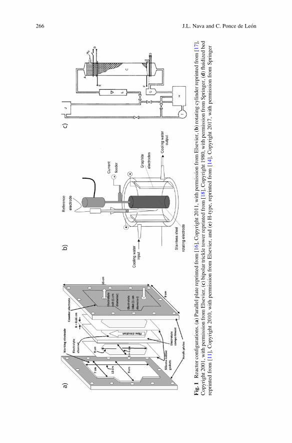
Fig.1
Reactorconfigurations.(a)Parallelplatereprintedfrom[16],Copyright2011,w
ithpermissionfromElsevier,(b)rotatingcylinderreprintedfrom[17],
Copyright2001,w
ithpermissionfromElsevier,(c)bipolartrickletowerreprintedfrom[18],Copyright1980,w
ithpermissionfromSpringer,(d)fluidized
bed
reprintedfrom
[11],Copyright2010,withpermissionfrom
Elsevier,and(e)H-type,reprintedfrom
[14],Copyright2017,withpermissionfrom
Springer
266 J.L. Nava and C. Ponce de Leon
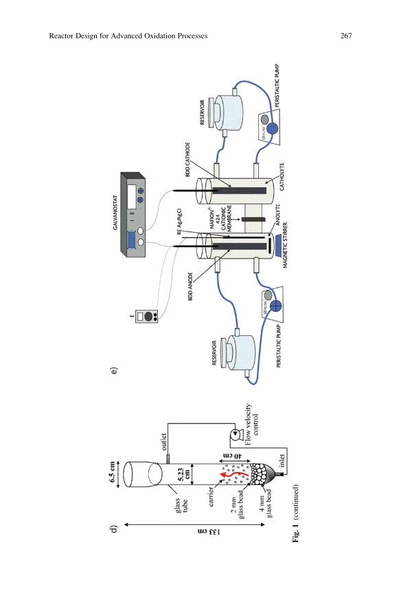
Fig.1(continued)
Reactor Design for Advanced Oxidation Processes 267
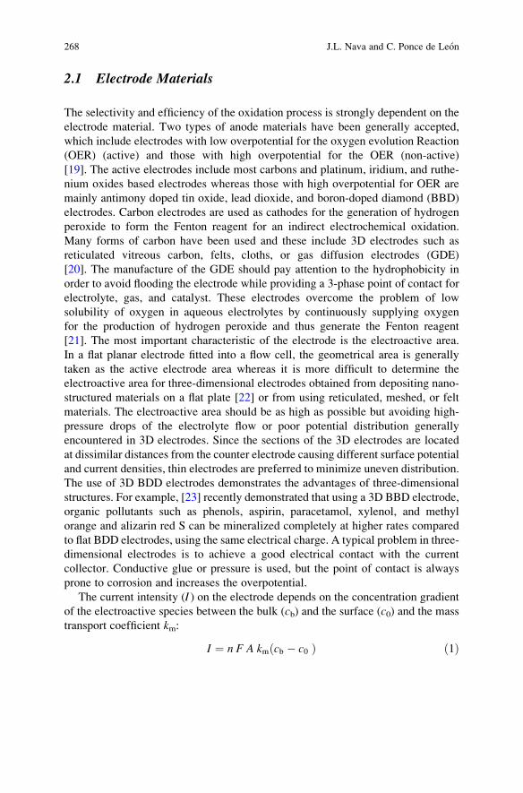
2.1 Electrode Materials
The selectivity and efficiency of the oxidation process is strongly dependent on the
electrode material. Two types of anode materials have been generally accepted,
which include electrodes with low overpotential for the oxygen evolution Reaction
(OER) (active) and those with high overpotential for the OER (non-active)
[19]. The active electrodes include most carbons and platinum, iridium, and ruthe-
nium oxides based electrodes whereas those with high overpotential for OER are
mainly antimony doped tin oxide, lead dioxide, and boron-doped diamond (BBD)
electrodes. Carbon electrodes are used as cathodes for the generation of hydrogen
peroxide to form the Fenton reagent for an indirect electrochemical oxidation.
Many forms of carbon have been used and these include 3D electrodes such as
reticulated vitreous carbon, felts, cloths, or gas diffusion electrodes (GDE)
[20]. The manufacture of the GDE should pay attention to the hydrophobicity in
order to avoid flooding the electrode while providing a 3-phase point of contact for
electrolyte, gas, and catalyst. These electrodes overcome the problem of low
solubility of oxygen in aqueous electrolytes by continuously supplying oxygen
for the production of hydrogen peroxide and thus generate the Fenton reagent
[21]. The most important characteristic of the electrode is the electroactive area.
In a flat planar electrode fitted into a flow cell, the geometrical area is generally
taken as the active electrode area whereas it is more difficult to determine the
electroactive area for three-dimensional electrodes obtained from depositing nano-
structured materials on a flat plate [22] or from using reticulated, meshed, or felt
materials. The electroactive area should be as high as possible but avoiding high-
pressure drops of the electrolyte flow or poor potential distribution generally
encountered in 3D electrodes. Since the sections of the 3D electrodes are located
at dissimilar distances from the counter electrode causing different surface potential
and current densities, thin electrodes are preferred to minimize uneven distribution.
The use of 3D BDD electrodes demonstrates the advantages of three-dimensional
structures. For example, [23] recently demonstrated that using a 3D BBD electrode,
organic pollutants such as phenols, aspirin, paracetamol, xylenol, and methyl
orange and alizarin red S can be mineralized completely at higher rates compared
to flat BDD electrodes, using the same electrical charge. A typical problem in three-
dimensional electrodes is to achieve a good electrical contact with the current
collector. Conductive glue or pressure is used, but the point of contact is always
prone to corrosion and increases the overpotential.
The current intensity (I ) on the electrode depends on the concentration gradient
of the electroactive species between the bulk (cb) and the surface (c0) and the mass
transport coefficient km:
I ¼ n F A km cb � c0ð Þ ð1Þ
268 J.L. Nava and C. Ponce de Leon
where n, F, and A are the number of electrons exchanged, the Faraday constant, and
the electroactive surface, respectively. At the mass transport limiting conditions,
i.e., when c0 ¼ 0, the equation can be simplified to:
IL ¼ n F A km cb ð2Þ
where IL is the limiting current. In porous 3D electrodes operating under complete
mass transport control such as reticulated materials, stack meshes, and packed beds,
the area of the electrode can be considered as the area per unit volume Ae (¼A/Ve)
where Ve is the electrode volume. High values for the km and Ae are desirable to
improve the reactor performance.
2.2 Cell Potential
In electrochemical rectors used for EAOPs, the ideal thermodynamic energy input
is related to the Gibbs free energy change for the cell Reaction, ΔGcell, which
relates to the cell potential, Ecell, at the equilibrium:
ΔGcell ¼ �nFE cell ð3Þ
When the current or potential is applied at the limiting current conditions, the
potential difference for any electrochemical cell is a complicated quantity with
several contributions that depend on the electrolyte, electrode materials, and the
equilibrium potentials of the anodic and cathodic reactions:
Ecell ¼ E0c � E0
a �X
ηj j �X
IRj j ð4Þ
The first and second terms on the right-hand side of Eq. (4) are the cathodic and
anodic standard potentials, whereas the third and fourth terms correspond to the
overpotentials and the electrical resistance of the components. These last two terms
represent the inefficiencies of the system and lead to a higher cell voltage requiring
additional energy to drive the Reaction. While there is some freedom to select the
anodic and cathodic reactions, it is more common to minimize the last two terms.
The overpotentials depend on the activation and mass transport polarization, which
can be minimized by operating the reactor at high temperatures and by selecting an
appropriate catalyst for the desired Reaction together with high rates of mass
transport. The term can be expanded as:
Reactor Design for Advanced Oxidation Processes 269
Xηj j ¼ η c, actj j þ η a, actj j þ η c, concj j þ η a, concj j ð5Þ
where ηc, act and ηa, act represent the electron transfer limitations and dominate at
low currents, whereas the terms ηc, conc and ηa, conc are the mass transport limitations
due to lack of supply of electroactive species and it is generally observed at high
currents when the current being withdrawn is larger than the rate at which the
electroactive species reach the electrode surface. The IR term can be expanded to:
XIRj j ¼ IRc,circuitj j þ IR a,circuitj j þ IRcatholyte
�� ��þ IRanolyte
�� ��þ IRmembranej j ð6Þ
The equation clearly shows the need to minimize the resistance of the compo-
nents of the electrochemical reactor, including electrolytes, electrodes, electrical
components, current collectors, and the membrane in the case of divided cells.
2.3 Performance
One of the most relevant parameters to evaluate the reactor performance which is
rarely reported in AOP is the space–time yield, ρST, which represents the amount of
material w, reacted per unit reactor volume V per unit time:
ρST ¼ 1
V
dw
dt¼ ∅I
nFVð7Þ
where w is the mass of materials (kg), and ϕ is the current efficiency. Typical values
of this parameter for electrochemical processes are in the order of 0.08–0.1 kg h�1
dm�3, whereas for non-electrochemical processes the values range between 0.1 and
1 kg h�1 dm�3. The challenge for electrochemical engineers is to increase this value
and recent academic studies have tried to develop changes in cell design and
electrodes.
In electrochemical process under kinetic control, the rate of electron transfer
prevails and the Reaction rate depends on the electrode potential and the choice of
catalyst; the electrode area should be high. Under these conditions, the current
varies exponentially with the overpotential [24]:
I ¼ nFAkcexpαanFηRT
� �ð8Þ
High surface area and active electrocatalyst promote high rate constants, k,which is related to the exchange current density j0; αa is the anodic charge transfercoefficient. Under these conditions, the secondary reactions are minimized. On the
contrary, under full mass transport conditions the electroactive species are con-
sumed immediately when they reach the electrode surface and the rate of reactant
270 J.L. Nava and C. Ponce de Leon
supply or product removal dominates, the system operates at the maximum limiting
current IL. At these conditions, the convective-diffusion regime and the relative
mean linear velocity u, of the electrolyte in a flow channel or the peripheral velocity
of a rotating cylinder, to the electrode surface control the limiting current, where
Eq. (2) is transformed into Eq. (9) [25]:
IL ¼ K uω ð9Þ
where K is a constant given by the properties of the electrolyte composition and
temperature while ω depends on geometry. Laminar flows are observed at ω¼ 0.33
while turbulent flows at ω > 0.5. The equation shows the importance of having
large surface electrode area, high rates of mass transport km, and high concentration.
3 Design and Characterization of Electrochemical
Reactors
The need for characterizing and modeling electrochemical reactors for EAOPs
resides on the intensification of the wastewater treatment process taking into
account the kinetic and mass transport conditions mentioned in the previous
section. Modeling helps to achieve the optimal design of the electrochemical
reactor, its understanding, and the design of compact technologies with rapid
degradation rates, high mineralization current efficiencies (MCEs), and low electric
energy consumptions (Ec). In order to achieve high MCEs, the desirable electro-
chemical reactions need to be controlled, avoiding as much as possible any parasitic
side reactions. In this context, the experimental characterization and theoretical
modeling of electrochemical reactors plays a crucial role, because it helps to design
the correct shape and size of the reactor components, such as type and length of
electrodes, nature and form of the turbulent promoters, electrolyte distributors,
frames, and current feeders. In addition, the combination of the experimental
characterization and modeling of transport phenomena, such as hydrodynamics,
mass transport, heat transfer, and potential and current distributions, allows deter-
mining the optimal operational conditions to be applied to the electrochemical
reactor.
3.1 Experimental Characterization
3.1.1 Pressure Drop and Non-ideal Flow Dispersion
In electrochemical reactors, the experimental characterization of flow pattern is
widely explored by researchers because it offers mathematical simplicity, com-
pared with those CFD predictions, and their contribution from the design of
Reactor Design for Advanced Oxidation Processes 271
electrochemical cells, flow, and pressure expressions is well described by empirical
correlations and simple mathematical functions. The residence time distribution
and pressure drop measurements are the typical techniques to characterize exper-
imentally fluid flow patterns and pressure drops within electrochemical flow cells.
Pressure drop measurements are employed to determine the pumping energy
requirements necessary to allow passage of the electrolyte streams within the
electrochemical cell. The empirical pressure drop (ΔP) is typically described by a
logarithmic function of the dimensionless Reynolds number:
ΔP ¼ aReb ð10Þ
where the Reynolds relates to the inertial and viscous forces of the electrolyte flow
and is described as:
Re ¼ ud
υð11Þ
The coefficient a and exponent b are typically associated with geometric factors
and flow patterns (i.e., laminar and turbulent flow in empty channels), respectively.
The variables u, d, and υ are the mean linear flow rate, characteristic length of the
electrochemical reactor, and kinematic viscosity. The characteristic length in rect-
angular flow cells is equal to the hydraulic diameter, while in rotating cylinder cells,
d is defined as the diameter of the inner rotating cylinder. In packed bed electro-
chemical reactors, filled with particulate material as electrodes, the diameter of the
spheroid type material employed takes the role of the characteristic length.
Several authors also report the mass transport coefficients as a function of the
pressure drop (Eq. 12), which is realized considering that the mass transport
parameter depends on the electrode geometry and the flow pattern (Eq. 13).
kmA ¼ aΔPb ð12Þ
kmA ¼ aReb ð13Þ
Table 1 shows the experimental correlations of pressure drop over the well-
known FM01-LC reactor extensively employed in EAOPs. In the case of the single-
cell configuration, the a and b parameters increase in the filled channel (with
turbulence promoter) with respect to the empty channel. This is attributed to the
obstruction of the transversal area by the plastic net (turbulence promoter), where
the electrolyte flows, which demands higher energy from the pumps. Meanwhile,
the pressure drop increases in the stack of three empty undivided cells, indicating
that this configuration demands higher energy pump consumption. The mass
transport for 3D electrodes indicates that the metal foam electrodes present a higher
kmA for a similar pressure drop across the expanded metal electrodes. The presence
of porous electrodes demands higher pumps power, although mass transport is
enhanced.
272 J.L. Nava and C. Ponce de Leon
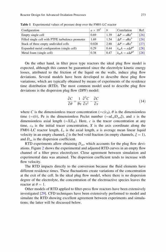
On the other hand, in filter press type reactors the ideal plug flow model is
expected, although this cannot be guaranteed since the electrolyte kinetic energy
losses, attributed to the friction of the liquid on the walls, induce plug flow
deviations. Several models have been developed to describe these plug flow
variations, which are typically obtained by means of experiments of the residence
time distribution (RTD). The most common model used to describe plug flow
deviations is the dispersion plug flow (DPF) model:
∂C∂θ
¼ 1
Pe
∂2C
∂x2� ∂C
∂xð14Þ
where C is the dimensionless tracer concentration (¼c/c0), θ is the dimensionless
time (¼t/τ), Pe is the dimensionless Peclet number (¼uLx/Daxξ), and x is the
dimensionless axial length (¼X/LX). Here, c is the tracer concentration at any
time, c0 is the initial tracer concentration, X is the axis coordinate along the
FM01-LC reactor length, Lx is the axial length, u is average mean linear liquid
velocity in an empty channel, ξ is the bed void fraction (in empty channels, ξ ¼ 1),
and Dax is the dispersion coefficient.
RTD experiments allow obtaining Dax, which accounts for the plug flow devi-
ations. Figure 2 shows the experimental and adjusted RTD curves in an empty flow
channel of a filter press electrolyzer. Close agreement between simulation and
experimental data was attained. The dispersion coefficient tends to increase with
flow velocity.
The RTD impacts directly to the conversion because the fluid elements have
different residence times. These fluctuations create variations of the concentration
at the exit of the cell. In the ideal plug flow model, where there is no dispersion
degree of the electrolyte, the concentration of the electroactive species leaves the
reactor at θ ¼ 1.
Other models of RTD applied to filter-press flow reactors have been extensively
investigated [29]. CFD techniques have been extensively performed to model and
simulate the RTD showing excellent agreement between experiments and simula-
tions; the latter will be discussed below.
Table 1 Experimental values of pressure drop over the FM01-LC reactor
Configuration a � 102 b Correlation Ref.
Empty single cell 0.69 1.39 ΔP ¼ aReb [26]
Filled single cell with PTFE turbulence promoter 1.69 1.54 ΔP ¼ aReb [26]
Stack of three empty undivided cells 0.028 2.88 ΔP ¼ aReb [27]
Expanded metal configuration (single cell) 0.29 0.44 kmA ¼ aΔPb [28]
Metal foam (single cell) 0.38 0.47 kmA ¼ aΔPb [28]
Reactor Design for Advanced Oxidation Processes 273
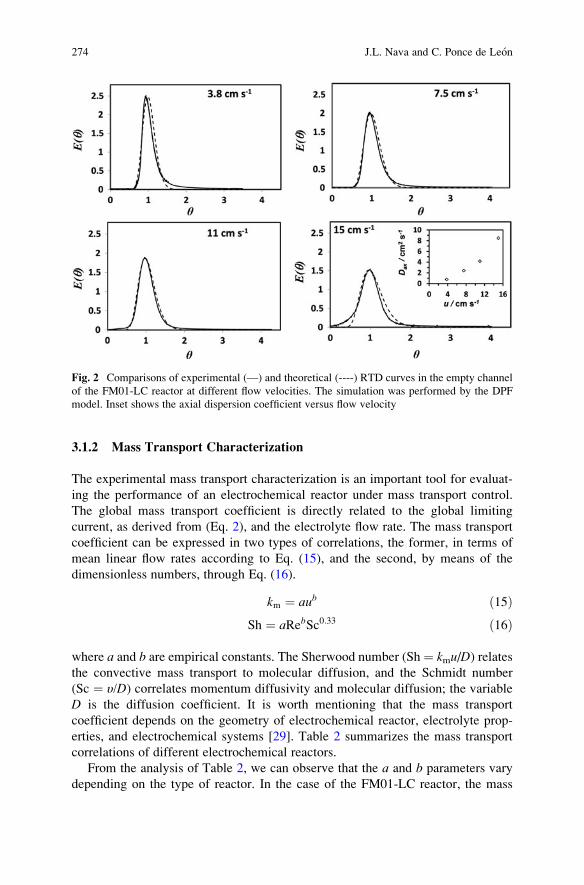
3.1.2 Mass Transport Characterization
The experimental mass transport characterization is an important tool for evaluat-
ing the performance of an electrochemical reactor under mass transport control.
The global mass transport coefficient is directly related to the global limiting
current, as derived from (Eq. 2), and the electrolyte flow rate. The mass transport
coefficient can be expressed in two types of correlations, the former, in terms of
mean linear flow rates according to Eq. (15), and the second, by means of the
dimensionless numbers, through Eq. (16).
km ¼ aub ð15ÞSh ¼ aRebSc0:33 ð16Þ
where a and b are empirical constants. The Sherwood number (Sh ¼ kmu/D) relatesthe convective mass transport to molecular diffusion, and the Schmidt number
(Sc ¼ υ/D) correlates momentum diffusivity and molecular diffusion; the variable
D is the diffusion coefficient. It is worth mentioning that the mass transport
coefficient depends on the geometry of electrochemical reactor, electrolyte prop-
erties, and electrochemical systems [29]. Table 2 summarizes the mass transport
correlations of different electrochemical reactors.
From the analysis of Table 2, we can observe that the a and b parameters vary
depending on the type of reactor. In the case of the FM01-LC reactor, the mass
Fig. 2 Comparisons of experimental (—) and theoretical (----) RTD curves in the empty channel
of the FM01-LC reactor at different flow velocities. The simulation was performed by the DPF
model. Inset shows the axial dispersion coefficient versus flow velocity
274 J.L. Nava and C. Ponce de Leon
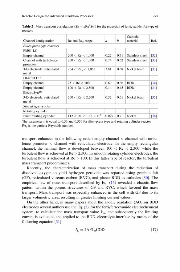
transport enhances in the following order: empty channel < channel with turbu-
lence promoter < channel with reticulated electrode. In the empty rectangular
channel, the laminar flow is developed between 100 < Re < 2,300, while the
turbulent flow is achieved at Re> 2,300. In smooth rotating cylinder electrodes, the
turbulent flow is achieved at Re > 100. In this latter type of reactor, the turbulent
mass transport predominates.
Recently, the characterization of mass transport during the reduction of
dissolved oxygen to yield hydrogen peroxide was reported using graphite felt
(GF), reticulated vitreous carbon (RVC), and planar BDD as cathodes [30]. The
empirical law of mass transport described by Eq. (15) revealed a chaotic flow
pattern within the porous structures of GF and RVC, which favored the mass
transport. Mass transport was especially enhanced in the cell with GF due to its
larger volumetric area, resulting in greater limiting current values.
On the other hand, in many papers about the anodic oxidation (AO) on BDD
electrodes several authors use the Eq. (2), for the ferri/ferrocyanide electrochemical
system, to calculate the mass transport value km, and subsequently the limiting
current is evaluated and applied to the BDD–electrolyte interface by means of the
following equation [31]:
IL ¼ 4AFkmCOD ð17Þ
Table 2 Mass transport correlations (Sh ¼ aRebScc) for the reduction of ferricyanide, for type ofreactors
Channel configuration Re and Rep range a bCathode
material Ref.
Filter-press type reactors
FM01-LC
Empty channel 200 < Re < 1,000 0.22 0.71 Stainless steel [32]
Channel with turbulence
promoter
200 < Re < 1,000 0.74 0.62 Stainless steel [32]
3-D electrode: reticulated
metal
264 < Rep < 1,065 3.81 0.68 Nickel foam [33]
DIACELL™
Empty channel 25 < Re < 100 0.69 0.36 BDD [34]
Empty channel 100 < Re < 2,500 0.14 0.45 BDD [34]
ElectroSyn™
3-D electrode: reticulated
metal
300 < Re < 2,300 0.32 0.61 Nickel foam [35]
Stirred type reactor
Rotating cylinder
Inner rotating cylinder 112 < Re < 1.62 � 105 0.079 0.7 Nickel [36]
The parameter c is equal to 0.33 and 0.356 for filter-press type and rotating cylinder reactor
Rep is the particle Reynolds number
Reactor Design for Advanced Oxidation Processes 275
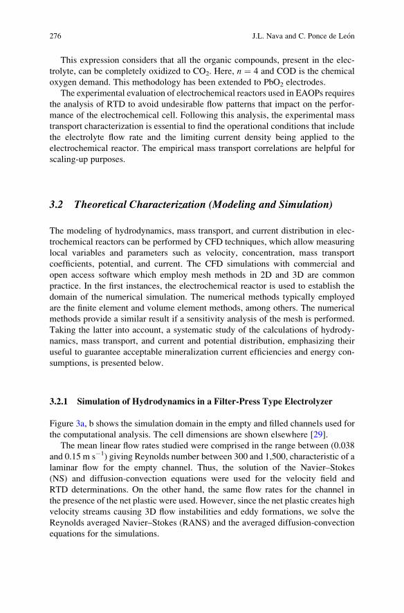
This expression considers that all the organic compounds, present in the elec-
trolyte, can be completely oxidized to CO2. Here, n ¼ 4 and COD is the chemical
oxygen demand. This methodology has been extended to PbO2 electrodes.
The experimental evaluation of electrochemical reactors used in EAOPs requires
the analysis of RTD to avoid undesirable flow patterns that impact on the perfor-
mance of the electrochemical cell. Following this analysis, the experimental mass
transport characterization is essential to find the operational conditions that include
the electrolyte flow rate and the limiting current density being applied to the
electrochemical reactor. The empirical mass transport correlations are helpful for
scaling-up purposes.
3.2 Theoretical Characterization (Modeling and Simulation)
The modeling of hydrodynamics, mass transport, and current distribution in elec-
trochemical reactors can be performed by CFD techniques, which allow measuring
local variables and parameters such as velocity, concentration, mass transport
coefficients, potential, and current. The CFD simulations with commercial and
open access software which employ mesh methods in 2D and 3D are common
practice. In the first instances, the electrochemical reactor is used to establish the
domain of the numerical simulation. The numerical methods typically employed
are the finite element and volume element methods, among others. The numerical
methods provide a similar result if a sensitivity analysis of the mesh is performed.
Taking the latter into account, a systematic study of the calculations of hydrody-
namics, mass transport, and current and potential distribution, emphasizing their
useful to guarantee acceptable mineralization current efficiencies and energy con-
sumptions, is presented below.
3.2.1 Simulation of Hydrodynamics in a Filter-Press Type Electrolyzer
Figure 3a, b shows the simulation domain in the empty and filled channels used for
the computational analysis. The cell dimensions are shown elsewhere [29].
The mean linear flow rates studied were comprised in the range between (0.038
and 0.15 m s�1) giving Reynolds number between 300 and 1,500, characteristic of a
laminar flow for the empty channel. Thus, the solution of the Navier–Stokes
(NS) and diffusion-convection equations were used for the velocity field and
RTD determinations. On the other hand, the same flow rates for the channel in
the presence of the net plastic were used. However, since the net plastic creates high
velocity streams causing 3D flow instabilities and eddy formations, we solve the
Reynolds averaged Navier–Stokes (RANS) and the averaged diffusion-convection
equations for the simulations.
276 J.L. Nava and C. Ponce de Leon
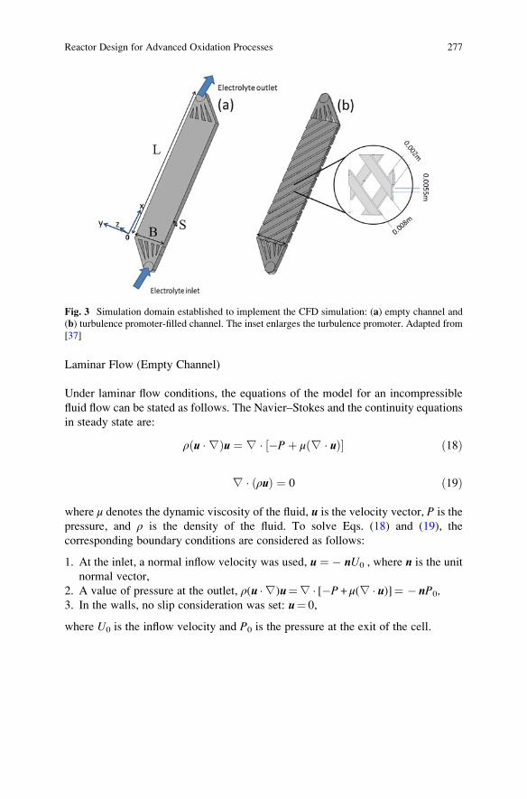
Laminar Flow (Empty Channel)
Under laminar flow conditions, the equations of the model for an incompressible
fluid flow can be stated as follows. The Navier–Stokes and the continuity equations
in steady state are:
ρ u �∇ð Þu ¼ ∇ � �Pþ μ ∇ � uð Þ½ � ð18Þ
∇ � ρuð Þ ¼ 0 ð19Þ
where μ denotes the dynamic viscosity of the fluid, u is the velocity vector, P is the
pressure, and ρ is the density of the fluid. To solve Eqs. (18) and (19), the
corresponding boundary conditions are considered as follows:
1. At the inlet, a normal inflow velocity was used, u ¼ � nU0 , where n is the unit
normal vector,
2. A value of pressure at the outlet, ρ(u �∇)u¼∇ � [�P + μ(∇ � u)]¼ � nP0,3. In the walls, no slip consideration was set: u¼ 0,
where U0 is the inflow velocity and P0 is the pressure at the exit of the cell.
Fig. 3 Simulation domain established to implement the CFD simulation: (a) empty channel and
(b) turbulence promoter-filled channel. The inset enlarges the turbulence promoter. Adapted from
[37]
Reactor Design for Advanced Oxidation Processes 277
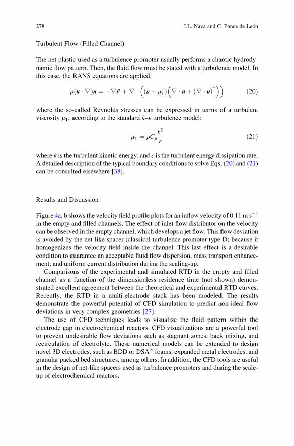
Turbulent Flow (Filled Channel)
The net plastic used as a turbulence promoter usually performs a chaotic hydrody-
namic flow pattern. Then, the fluid flow must be stated with a turbulence model. In
this case, the RANS equations are applied:
ρ u �∇ð Þu ¼ �∇Pþ∇ � μþ μTð Þ ∇ � uþ ∇ � uð ÞT� �� �
ð20Þ
where the so-called Reynolds stresses can be expressed in terms of a turbulent
viscosity μT, according to the standard k–ε turbulence model:
μT ¼ ρCμk2
εð21Þ
where k is the turbulent kinetic energy, and ε is the turbulent energy dissipation rate.A detailed description of the typical boundary conditions to solve Eqs. (20) and (21)
can be consulted elsewhere [38].
Results and Discussion
Figure 4a, b shows the velocity field profile plots for an inflow velocity of 0.11 m s�1
in the empty and filled channels. The effect of inlet flow distributor on the velocity
can be observed in the empty channel, which develops a jet flow. This flow deviation
is avoided by the net-like spacer (classical turbulence promoter type D) because it
homogenizes the velocity field inside the channel. This last effect is a desirable
condition to guarantee an acceptable fluid flow dispersion, mass transport enhance-
ment, and uniform current distribution during the scaling-up.
Comparisons of the experimental and simulated RTD in the empty and filled
channel as a function of the dimensionless residence time (not shown) demon-
strated excellent agreement between the theoretical and experimental RTD curves.
Recently, the RTD in a multi-electrode stack has been modeled. The results
demonstrate the powerful potential of CFD simulation to predict non-ideal flow
deviations in very complex geometries [27].
The use of CFD techniques leads to visualize the fluid pattern within the
electrode gap in electrochemical reactors. CFD visualizations are a powerful tool
to prevent undesirable flow deviations such as stagnant zones, back mixing, and
recirculation of electrolyte. These numerical models can be extended to design
novel 3D electrodes, such as BDD or DSA® foams, expanded metal electrodes, and
granular packed bed structures, among others. In addition, the CFD tools are useful
in the design of net-like spacers used as turbulence promoters and during the scale-
up of electrochemical reactors.
278 J.L. Nava and C. Ponce de Leon
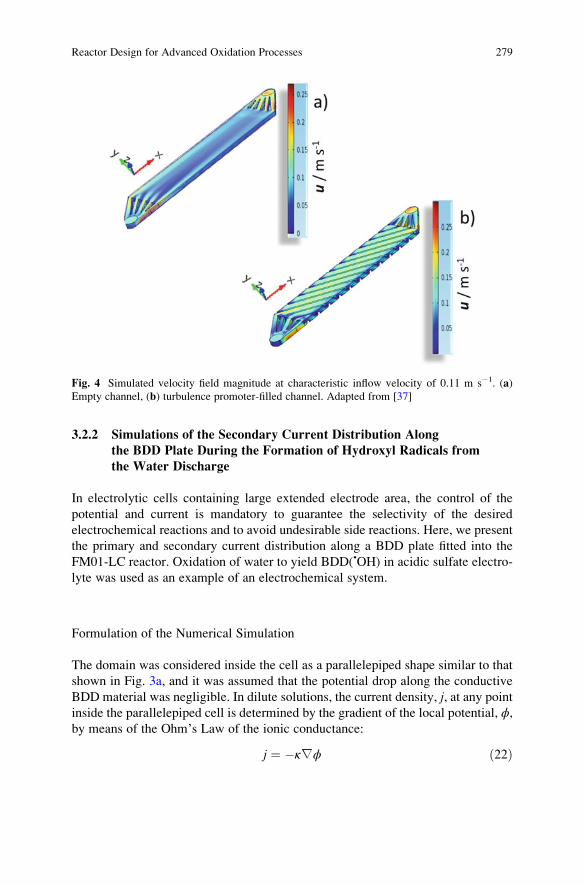
3.2.2 Simulations of the Secondary Current Distribution Along
the BDD Plate During the Formation of Hydroxyl Radicals from
the Water Discharge
In electrolytic cells containing large extended electrode area, the control of the
potential and current is mandatory to guarantee the selectivity of the desired
electrochemical reactions and to avoid undesirable side reactions. Here, we present
the primary and secondary current distribution along a BDD plate fitted into the
FM01-LC reactor. Oxidation of water to yield BDD(•OH) in acidic sulfate electro-
lyte was used as an example of an electrochemical system.
Formulation of the Numerical Simulation
The domain was considered inside the cell as a parallelepiped shape similar to that
shown in Fig. 3a, and it was assumed that the potential drop along the conductive
BDD material was negligible. In dilute solutions, the current density, j, at any pointinside the parallelepiped cell is determined by the gradient of the local potential, ϕ,by means of the Ohm’s Law of the ionic conductance:
j ¼ �κ∇ϕ ð22Þ
Fig. 4 Simulated velocity field magnitude at characteristic inflow velocity of 0.11 m s�1. (a)
Empty channel, (b) turbulence promoter-filled channel. Adapted from [37]
Reactor Design for Advanced Oxidation Processes 279
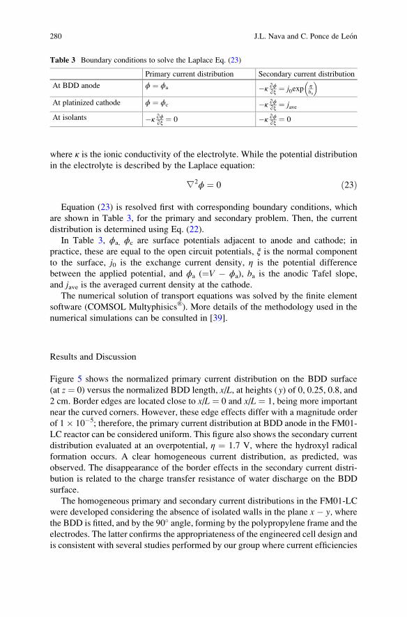
where κ is the ionic conductivity of the electrolyte. While the potential distribution
in the electrolyte is described by the Laplace equation:
∇2ϕ ¼ 0 ð23Þ
Equation (23) is resolved first with corresponding boundary conditions, which
are shown in Table 3, for the primary and secondary problem. Then, the current
distribution is determined using Eq. (22).
In Table 3, ϕa, ϕc are surface potentials adjacent to anode and cathode; in
practice, these are equal to the open circuit potentials, ξ is the normal component
to the surface, j0 is the exchange current density, η is the potential difference
between the applied potential, and ϕa (¼V � ϕa), ba is the anodic Tafel slope,
and jave is the averaged current density at the cathode.
The numerical solution of transport equations was solved by the finite element
software (COMSOL Multyphisics®). More details of the methodology used in the
numerical simulations can be consulted in [39].
Results and Discussion
Figure 5 shows the normalized primary current distribution on the BDD surface
(at z ¼ 0) versus the normalized BDD length, x/L, at heights (y) of 0, 0.25, 0.8, and2 cm. Border edges are located close to x/L ¼ 0 and x/L ¼ 1, being more important
near the curved corners. However, these edge effects differ with a magnitude order
of 1� 10�5; therefore, the primary current distribution at BDD anode in the FM01-
LC reactor can be considered uniform. This figure also shows the secondary current
distribution evaluated at an overpotential, η ¼ 1.7 V, where the hydroxyl radical
formation occurs. A clear homogeneous current distribution, as predicted, was
observed. The disappearance of the border effects in the secondary current distri-
bution is related to the charge transfer resistance of water discharge on the BDD
surface.
The homogeneous primary and secondary current distributions in the FM01-LC
were developed considering the absence of isolated walls in the plane x � y, wherethe BDD is fitted, and by the 90� angle, forming by the polypropylene frame and the
electrodes. The latter confirms the appropriateness of the engineered cell design and
is consistent with several studies performed by our group where current efficiencies
Table 3 Boundary conditions to solve the Laplace Eq. (23)
Primary current distribution Secondary current distribution
At BDD anode ϕ ¼ ϕa �κ ∂ϕ∂ξ ¼ j0exp
ηba
� �At platinized cathode ϕ ¼ ϕc �κ ∂ϕ
∂ξ ¼ jave
At isolants �κ ∂ϕ∂ξ ¼ 0 �κ ∂ϕ
∂ξ ¼ 0
280 J.L. Nava and C. Ponce de Leon
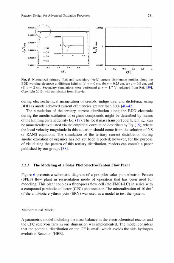
during electrochemical incineration of cresols, indigo dye, and diclofenac using
BDD as anode achieved current efficiencies greater than 80% [40–42].
The simulation of the tertiary current distribution along the BDD electrode
during the anodic oxidation of organic compounds might be described by means
of the limiting current density Eq. (17). The local mass transport coefficient, km, canbe numerically evaluated via the empirical correlation described by Eq. (15), where
the local velocity magnitude in this equation should come from the solution of NS
or RANS equations. The simulation of the tertiary current distribution during
anodic oxidation of organics has not yet been reported; however, for the purpose
of visualizing the pattern of this tertiary distribution, readers can consult a paper
published by our groups [38].
3.2.3 The Modeling of a Solar Photoelectro-Fenton Flow Plant
Figure 6 presents a schematic diagram of a pre-pilot solar photoelectron-Fenton
(SPEF) flow plant in recirculation mode of operation that has been used for
modeling. This plant couples a filter-press flow cell (the FM01-LC) in series with
a compound parabolic collector (CPC) photoreactor. The mineralization of 10 dm3
of the antibiotic erythromycin (ERY) was used as a model to test the system.
Mathematical Model
A parametric model including the mass balance in the electrochemical reactor and
the CPC reservoir tank in one dimension was implemented. The model considers
that the potential distribution on the GF is small, which avoids the side hydrogen
evolution Reaction (HER).
Fig. 5 Normalized primary (left) and secondary (right) current distribution profiles along the
BDD working electrode at different heights: (a) y ¼ 0 cm, (b) y ¼ 0.25 cm, (c) y ¼ 0.8 cm, and
(d) y ¼ 2 cm. Secondary simulations were performed at η ¼ 1.7 V. Adapted from Ref. [39],
Copyright 2013, with permission from Elsevier
Reactor Design for Advanced Oxidation Processes 281
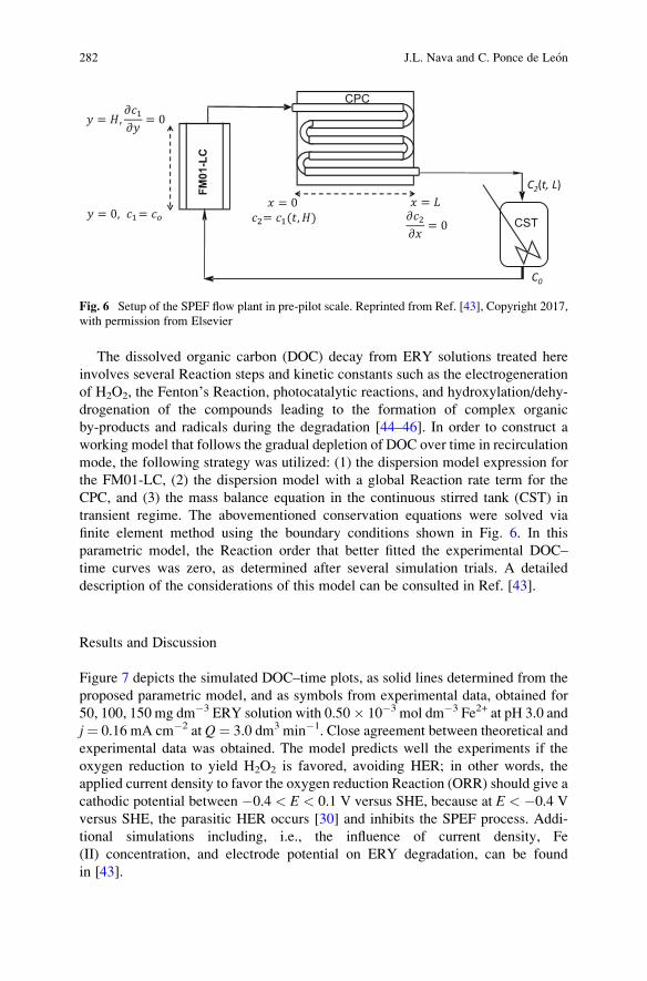
The dissolved organic carbon (DOC) decay from ERY solutions treated here
involves several Reaction steps and kinetic constants such as the electrogeneration
of H2O2, the Fenton’s Reaction, photocatalytic reactions, and hydroxylation/dehy-
drogenation of the compounds leading to the formation of complex organic
by-products and radicals during the degradation [44–46]. In order to construct a
working model that follows the gradual depletion of DOC over time in recirculation
mode, the following strategy was utilized: (1) the dispersion model expression for
the FM01-LC, (2) the dispersion model with a global Reaction rate term for the
CPC, and (3) the mass balance equation in the continuous stirred tank (CST) in
transient regime. The abovementioned conservation equations were solved via
finite element method using the boundary conditions shown in Fig. 6. In this
parametric model, the Reaction order that better fitted the experimental DOC–
time curves was zero, as determined after several simulation trials. A detailed
description of the considerations of this model can be consulted in Ref. [43].
Results and Discussion
Figure 7 depicts the simulated DOC–time plots, as solid lines determined from the
proposed parametric model, and as symbols from experimental data, obtained for
50, 100, 150 mg dm�3 ERY solution with 0.50� 10�3 mol dm�3 Fe2+ at pH 3.0 and
j¼ 0.16 mA cm�2 at Q¼ 3.0 dm3 min�1. Close agreement between theoretical and
experimental data was obtained. The model predicts well the experiments if the
oxygen reduction to yield H2O2 is favored, avoiding HER; in other words, the
applied current density to favor the oxygen reduction Reaction (ORR) should give a
cathodic potential between �0.4 < E < 0.1 V versus SHE, because at E < �0.4 V
versus SHE, the parasitic HER occurs [30] and inhibits the SPEF process. Addi-
tional simulations including, i.e., the influence of current density, Fe
(II) concentration, and electrode potential on ERY degradation, can be found
in [43].
CST
FM01
-LC
CPC
C2(t, L)
C0
Fig. 6 Setup of the SPEF flow plant in pre-pilot scale. Reprinted from Ref. [43], Copyright 2017,
with permission from Elsevier
282 J.L. Nava and C. Ponce de Leon
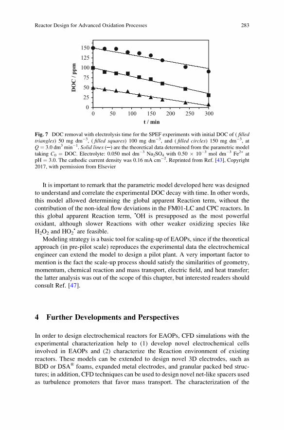
It is important to remark that the parametric model developed here was designed
to understand and correlate the experimental DOC decay with time. In other words,
this model allowed determining the global apparent Reaction term, without the
contribution of the non-ideal flow deviations in the FM01-LC and CPC reactors. In
this global apparent Reaction term, •OH is presupposed as the most powerful
oxidant, although slower Reactions with other weaker oxidizing species like
H2O2 and HO2• are feasible.
Modeling strategy is a basic tool for scaling-up of EAOPs, since if the theoretical
approach (in pre-pilot scale) reproduces the experimental data the electrochemical
engineer can extend the model to design a pilot plant. A very important factor to
mention is the fact the scale-up process should satisfy the similarities of geometry,
momentum, chemical reaction and mass transport, electric field, and heat transfer;
the latter analysis was out of the scope of this chapter, but interested readers should
consult Ref. [47].
4 Further Developments and Perspectives
In order to design electrochemical reactors for EAOPs, CFD simulations with the
experimental characterization help to (1) develop novel electrochemical cells
involved in EAOPs and (2) characterize the Reaction environment of existing
reactors. These models can be extended to design novel 3D electrodes, such as
BDD or DSA® foams, expanded metal electrodes, and granular packed bed struc-
tures; in addition, CFD techniques can be used to design novel net-like spacers used
as turbulence promoters that favor mass transport. The characterization of the
0
25
50
75
100
125
150
0 50 100 150 200 250 300
DO
C /
ppm
t / min
Fig. 7 DOC removal with electrolysis time for the SPEF experiments with initial DOC of ( filledtriangles) 50 mg dm�3, ( filled squares) 100 mg dm�3, and ( filled circles) 150 mg dm�3, at
Q ¼ 3.0 dm3 min�1. Solid lines (─) are the theoretical data determined from the parametric model
taking C0 ¼ DOC. Electrolyte: 0.050 mol dm�3 Na2SO4 with 0.50 � 10�3 mol dm�3 Fe2+ at
pH ¼ 3.0. The cathodic current density was 0.16 mA cm�2. Reprinted from Ref. [43], Copyright
2017, with permission from Elsevier
Reactor Design for Advanced Oxidation Processes 283
Reaction environment such as hydrodynamics, mass transport, heat transfer, and
potential and current distributions, allows determining the optimal operational
conditions to be applied to the reactors.
The optimal design of the electrochemical reactors allows developing compact
volumes with rapid degradation rates, high mineralization current efficiencies, and
low electric energy consumptions. One of the most valuable parameters, not often
considered in the design and evaluation of advanced oxidation processes, is the
space–time yield.
The challenges reside on the modeling of biphasic systems (including gas H2/O2
release), which have not been yet characterized, even when it is well known that gas
bubbling increases the electrolytic energy consumption. The modeling of flow
plants (containing several reactors and unit operations) also deserves special atten-
tion. The mathematical modeling is crucial during the scale-up of EAOPs.
References
1. Wendt H, Kreysa G (2010) Electrochemical engineering; science and technology in chemical
and other industries. Springer, Berlin
2. Pletcher D, Walsh FC (1990) Industrial electrochemistry, 2nd edn. Chapman and Hall, London
3. Bebelis S, Bouzek K, Cornell A, Kelsall GH, Ferreira MGS, Lapicque F, Ponce de Leon C,
Rodrigo MA, Walsh FC (2013) Highlights during the development of electrochemical engi-
neering. Chem Eng Res Des 91:1998–2020
4. Quan X, Cheng Z, Chen B, Zhu X (2013) Electrochemical oxidation of recalcitrant organic
compounds in biologically treated municipal solid waste leachate in a flow reactor. J Environ
Sci 25:2023–2030
5. Brillas E, Garrido JA, Rodrıguez RM, Arias C, Cabot PL, Centellas F (2008) Wastewaters by
electrochemical advanced oxidation processes using a BDD anode and electrogenerated H2O2
with Fe(II) and UVA light as catalysts. Port Electrochim Acta 26:15–46
6. Vasconcelos VM, Ponce-de-Leon C, Nava JL, Lanza MRV (2016) Electrochemical degrada-
tion of RB-5 dye by anodic oxidation, electro-Fenton and by combining anodic oxidation-
electro-Fenton in a filter-press flow cell. J Electroanal Chem 765:179–187
7. Bedolla-Guzman A, Feria-Reyes R, Gutierrez-Granados S, Peralta-Hernandez JM (2017)
Decolorization and degradation of reactive yellow HF aqueous solutions by electrochemical
advanced oxidation processes. Environ Sci Pollut Res 24:12506–12514
8. Ting WP, Lu MC, Huang YH (2008) The reactor design and comparison of Fenton, electro-
Fenton and photoelectro-Fenton processes for mineralization of benzene sulfonic acid (BSA).
J Hazard Mater 156:421–427
9. Koparal AS, Yavuz Y, Gürel C, O�gütveren UB (2007) Electrochemical degradation and
toxicity reduction of C.I. Basic Red 29 solution and textile wastewater by using diamond
anode. J Hazard Mater 145:100–108
10. Yavuz Y, Shahbazi R (2012) Anodic oxidation of reactive black 5 dye using boron doped
diamond anodes in a bipolar trickle tower reactor. Separ Purif Tech 85:130–136
11. Anotai J, Su CC, Tsai YC, Lu MC (2010) Effect of hydrogen peroxide on aniline oxidation by
electro-Fenton and fluidized-bed Fenton processes. J Hazard Mater 183:888–893
12. Hussain SN, Roberts EPL, Asghar HMA, Campen AK, Brown NW (2013) Oxidation of phenol
and the adsorption of breakdown products using a graphite adsorbent with electrochemical
regeneration. Electrochim Acta 92:20–30
284 J.L. Nava and C. Ponce de Leon
13. Cusick RD, Ullery ML, Dempsey BA, Logan BE (2014) Electrochemical struvite precipitation
from digestate with a fluidized bed cathode microbial electrolysis cell. Water Res 54:297–306
14. Valenzuela AL, Vazquez-Medrano R, Iba~nez JB, Frontana-Uribe BA, Prato-Garcia D (2017)
Remediation of diquat-contaminated water by electrochemical advanced oxidation processes
using boron-doped diamond (BDD) anodes. Water Air Soil Pollut 228:67
15. Bergmann MEH, Rollin J, Iourtchouk T (2009) The occurrence of perchlorate during drinking
water electrolysis using BDD anodes. Electrochim Acta 54:2102–2107
16. Recio FJ, Herrasti P, Vazquez L, Ponce de Leon C, Walsh FC (2013) Mass transfer to a
nanostructured nickel electrodeposit of high surface area in a rectangular flow channel.
Electrochim Acta 90:507–513
17. Nava-M de Oca JL, Sosa E, Ponce de Leon C, Oropeza MT (2001) Effectiveness factors in an
electrochemical reactor with rotating cylinder electrode for the acid-cupric/copper cathode
interface process. Chem Eng Sci 56:2695–2702
18. Fleischmann M, Ibrisagic Z (1980) Electrical measurement in bipolar trickle reactors. J Appl
Electrochem 10:151–156
19. Comninellis C (1994) Electrocatalysis in the electrochemical conversion/combustion of
organic pollutants for waste water treatment. Electrochim Acta 39:1857–1862
20. Pletcher D, Walsh FC (1992) Three-dimensional electrodes. In: Genders JD, Weinberg NL
(eds) Electrochemical technology for a cleaner environment. The Electrosynthesis Company
Inc, Lancaster, NY
21. Harrington T, Pletcher D (1999) The removal of low levels of organics from aqueous solutions
using Fe(II) and hydrogen peroxide formed in situ at gas diffusion electrodes. J Electrochem
Soc 146:2983–2989
22. Recio FJ, Herrasti P, Sires I, Kulak AN, Bavykin DV, Ponce de Leon C, Walsh FC (2011) The
preparation of PbO2 coatings on reticulated vitreous carbon for the electro-oxidation of organic
pollutants. Electrochim Acta 56:5158–5165
23. He Y, Lin H, Wang X, Huang W, Chen R, Li H (2016) A hydrophobic three-dimensionally
networked boron-doped diamond electrode towards electrochemical oxidation. Chem
Commun 52:8026–8029
24. Bard AJ, Faulkner LR (2001) Electrochemical methods; fundamentals and applications, 2nd
edn. Wiley, Hoboken, NJ
25. Walsh FC (1993) A first course in electrochemical engineering. The Electrochemical Consul-
tancy, Romsey
26. Trinidad P, Walsh FC (1996) Hydrodynamic behaviour of the FM01-LC reactor. Electrochim
Acta 41:493–502
27. Sandoval MA, Fuentes R, Walsh FC, Nava JL, Ponce de Leon C (2016) Computational fluid
dynamics simulations of single-phase flow having a stack of three cells. Electrochim Acta
216:490–498
28. Bengoa C, Montillet A, Legentilhomme P, Legrand J (2000) Characterization and modeling of
the hydrodynamic behaviour in the filter-press-type FM01-LC electrochemical cell by direct
flow visualization and residence time distribution. Ind Eng Chem Res 29:2199–2206
29. Rivera FF, Ponce de Leon C, Walsh FC, Nava JL (2015) The reaction environment in a filter-
press laboratory reactor: the FM01-LC cell. Electrochim Acta 161:436–452
30. Coria G, Perez T, Sires I, Nava JL (2015) Mass transport studies during dissolved oxygen
reduction to hydrogen peroxide in a filter-press electrolyzer using graphite felt, reticulated
vitreous carbon and boron-doped diamond as cathodes. J Electroanal Chem 257:225–229
31. Gherardini L, Michaud PA, Panizza M, Comninellis C, Vatistas N (2001) Electrochemical
oxidation of 4-chlorophenol for wastewater treatment. J Electrochem Soc 148:D78–D82
32. Brown CJ, Pletcher D, Walsh FC, Hammond JK, Robinson D (1992) Local mass transport
effects in the FM01 laboratory electrolyser. J Appl Electrochem 22:613–619
33. Griffiths M, Ponce de Leon C, Walsh FC (2005) Mass transport in the rectangular channel of a
filter-press electrolyzer (the FM01-LC reactor). Am Int Chem Eng J 51:682–687
Reactor Design for Advanced Oxidation Processes 285
34. Santos JLC, Geraldes V, Velizarov S, Crespo JG (2010) Characterization of fluid dynamics
and mass-transfer in an electrochemical oxidation cell by experimental and CFD studies.
Chem Eng J 157:379–392
35. Montillet A, Comiti J, Legrand J (1994) Application of metallic foams in electrochemical
reactors of filter-press type. Part II: mass transfer performance. J Appl Electrochem 24:384–389
36. Eisenberg M, Tobias CW, Wilke CR (1954) Ionic mass transfer and concentration polarization
at rotating electrode. J Electrochem Soc 101:306–320
37. Casta~neda LF (2016) Evaluation of the performance of the FM01-LC reactor in the regener-
ation of H2SO4 from depleted baths by the electrodialysis process: theoretical and practical
study. Dissertation, Centro de Investigacion y Desarrollo Tecnologico en Electroquımica S.C.
38. Perez T, Ponce de Leon C, Walsh FC, Nava JL (2015) Simulation of current distribution along
a planar electrode under turbulent flow conditions in a laboratory filter-press flow cell.
Electrochim Acta 154:352–360
39. Perez T, Leon MI, Nava JL (2013) Numerical simulation of current distribution along the
boron-doped diamond anode of a filter-press-type FM01-LC reactor during the oxidation of
water. J Electroanal Chem 707:1–6
40. Butron E, Juarez ME, Solis M, Teutli M, Gonzalez I, Nava JL (2007) Electrochemical
incineration of indigo textile dye in filter-press-type FM01-LC electrochemical cell using
BDD electrodes. Electrochim Acta 52:6888–6894
41. Coria G, Nava JL, Carre~no G (2014) Electrooxidation of diclofenac in synthetic pharmaceu-
tical wastewater using an electrochemical reactor equipped with a boron doped diamond
electrode. J Mex Chem Soc 58:303–308
42. Nava JL, Nu~nez F, Gonzalez I (2007) Electrochemical incineration of o-cresol and p-cresol inthe filter-press-type FM01-LC electrochemical cell using BDD electrodes in sulphate media at
pH 0. Electrochim Acta 52:3229–3235
43. Perez T, Sires I, Brillas E, Nava JL (2017) Solar fotoelectron-Fenton flow plant modelling
for the degradation of the antibiotic erythromycin in sulphate medium. Electrochim Acta
228:45–56
44. Brillas E, Martınez-Huitle CA (2015) Decontamination of wastewaters containing synthetic
organic dyes by electrochemical methods. An updated review. Appl Catal Environ
166–167:603–643
45. Martınez-Huitle CA, Rodrigo MA, Sires I, Scialdone O (2015) Single and coupled electro-
chemical processes and reactors for the abatement of organic water pollutants: a critical
review. Chem Rev 115:13362–13407
46. Sires I, Brillas E, Oturan MA, Rodrigo MA, Panizza M (2014) Electrochemical advanced
oxidation processes: today and tomorrow. A review. Environ Sci Pollut Res 21:8336–8367
47. Goodridge F, Scott K (1995) Electrochemical process engineering: a guide to the design of
electrochemical plant. Plenum Press, New York
286 J.L. Nava and C. Ponce de Leon
Modeling of Electro-Fenton Process
A.A. Alvarez-Gallegos and S. Silva-Martınez
Abstract From the conventional Fenton process (H2O2 and Fe2+), the electro-
Fenton process was derived to improve the hydroxylation method (partial organic
oxidation). Thereafter, electro-Fenton was adapted to water remediation. Since
then, this approach has received much attention for wastewater treatment because
it is an eco-friendly process and its technological implementation is simple.
Although electro-Fenton involves a few and very simple chemical species (H2O2,
Fe2+, Fe3+, O2), the interactions among them produce one of the most difficult set of
chemical reactions. Therefore, the predictions of the main chemical reactions are a
challenging task. The aim of this chapter is to propose a methodology for develop-
ing a general, practical, simple, semiempirical chemical model to predict organic
pollutant abatement in a reliable electrochemical reactor by electro-Fenton process.
The main outputs of this chemical model include the rate of H2O2 generation and its
activation by Fe2+ to produce a strong oxidant. The organic pollutant degradation
rate and the energy and time required to carry out the organic degradation are also
included. Although under this approach it is not possible to follow a detailed
evolution of concentration profiles of some by-products during the degradation
time, this procedure is less complicated than others already available. Moreover, it
can fulfil the main requirements of wastewater treatment: abatement of the organic
pollutant.
Keywords Decolorization kinetic model, Electro-Fenton process, Low-cost
electrodes for wastewater treatment, Unmodified carbon cathode for H2O2
generation, Wastewater treatment prediction
A.A. Alvarez-Gallegos (*) and S. Silva-Martınez
CIICAp, UAEM, Cuernavaca, Morelos, Mexico
e-mail: [email protected]
M. Zhou et al. (eds.), Electro-Fenton Process: New Trends and Scale-Up,Hdb Env Chem (2018) 61: 287–312, DOI 10.1007/698_2017_73,© Springer Nature Singapore Pte Ltd. 2017, Published online: 21 Sep 2017
287
Contents
1 Introduction . . . . . . . . . . . . . . . . . . . . . . . . . . . . . . . . . . . . . . . . . . . . . . . . . . . . . . . . . . . . . . . . . . . . . . . . . . . . . . . . . . 288
1.1 The Technological Challenge of Wastewater Treatment . . . . . . . . . . . . . . . . . . . . . . . . . . . . 288
2 Fenton Process . . . . . . . . . . . . . . . . . . . . . . . . . . . . . . . . . . . . . . . . . . . . . . . . . . . . . . . . . . . . . . . . . . . . . . . . . . . . . . . 289
2.1 Hydroxylation . . . . . . . . . . . . . . . . . . . . . . . . . . . . . . . . . . . . . . . . . . . . . . . . . . . . . . . . . . . . . . . . . . . . . . . . . 290
2.2 Wastewater Treatment . . . . . . . . . . . . . . . . . . . . . . . . . . . . . . . . . . . . . . . . . . . . . . . . . . . . . . . . . . . . . . . . 291
2.3 Kinetic Modeling . . . . . . . . . . . . . . . . . . . . . . . . . . . . . . . . . . . . . . . . . . . . . . . . . . . . . . . . . . . . . . . . . . . . . . 293
3 Electro-Fenton Processes . . . . . . . . . . . . . . . . . . . . . . . . . . . . . . . . . . . . . . . . . . . . . . . . . . . . . . . . . . . . . . . . . . . . 296
3.1 Wastewater Treatment . . . . . . . . . . . . . . . . . . . . . . . . . . . . . . . . . . . . . . . . . . . . . . . . . . . . . . . . . . . . . . . . 296
3.2 Activation of H2O2 by Iron Ions . . . . . . . . . . . . . . . . . . . . . . . . . . . . . . . . . . . . . . . . . . . . . . . . . . . . . . 297
3.3 Degradation of Organics by Fenton and EF Process . . . . . . . . . . . . . . . . . . . . . . . . . . . . . . . . 299
4 Modeling of Electro-Fenton Process . . . . . . . . . . . . . . . . . . . . . . . . . . . . . . . . . . . . . . . . . . . . . . . . . . . . . . . 300
4.1 Multistep Mechanistic Rate Laws . . . . . . . . . . . . . . . . . . . . . . . . . . . . . . . . . . . . . . . . . . . . . . . . . . . . 300
4.2 Empirical Kinetic Modeling . . . . . . . . . . . . . . . . . . . . . . . . . . . . . . . . . . . . . . . . . . . . . . . . . . . . . . . . . . 301
5 Conclusions . . . . . . . . . . . . . . . . . . . . . . . . . . . . . . . . . . . . . . . . . . . . . . . . . . . . . . . . . . . . . . . . . . . . . . . . . . . . . . . . . . 308
References . . . . . . . . . . . . . . . . . . . . . . . . . . . . . . . . . . . . . . . . . . . . . . . . . . . . . . . . . . . . . . . . . . . . . . . . . . . . . . . . . . . . . . . 309
1 Introduction
Since the beginning of synthetic dyestuff production, its manufacture was linked to
unfriendly chemistry. Under this scenario, the textile industry has been always
linked with a huge pollution problem, and it is considered the second (agriculture is
the first one) most important polluter of clean water.
1.1 The Technological Challenge of Wastewater Treatment
Daily textile mill productions of 8,000 kg of fabric require 1,600 m3 of water as
well. More than 8,000 chemicals (some of them are dosed at a rate of several tons
per month) are needed in various processes of textile manufacture [1]. As a
consequence, mills discharge thousands of m3 of hazardous wastewater containing
different concentrations of heavy metals, inorganic compounds, organic com-
pounds, and dyes, among other toxic chemicals. Although the integral treatment
of textile wastewaters is a challenging task, the main contamination source is
coming from the most obvious indicator of water pollution: the color [2]. Many
of these synthetic dyestuffs cannot be treated successfully by the conventional
methods. Hence, removal of effluent color has become the integral part of textile
wastewater treatment. Advanced oxidation processes (AOPs) are between the
promising techniques for the environmental destruction organic dyes. A broad list
of technological approaches such as supercritical water oxidation, sonolysis, elec-
tron beams γ-ray irradiation, ultraviolet (UV)-based processes, photocatalytic redoxprocesses, O3-based processes, and Fenton’s reactions comes under advanced
oxidation techniques [3].
288 A.A. Alvarez-Gallegos and S. Silva-Martınez
From the conventional Fenton process, a mixture of H2O2 and Fe2+ (Fenton
1,894), the electro-Fenton process (EF) was derived to improve the hydroxylation
process: the partial benzene oxidation to phenol [4]. Thereafter, EF process was
adapted to water remediation [5]. Since then, EF process has receivedmuch attention
for wastewater treatment because it is an eco-friendly process and its technological
implementation is simple. Although both process, conventional Fenton and EF,
involve a few and very simple chemical species (H2O2, Fe2+, Fe3+, O2), the interac-
tions among them produce one of the most difficult set of chemical reactions.
Therefore, the predictions of the main chemical reactions are a challenging task.
The aim of this chapter is to discuss the conceptual and technological problems
involved in the development of a chemical model to predict organic pollutant
abatement. In this way it is discussed, in a chronological way, how Fenton and
EF processes were evolving from an academic activity to a technological applica-
tion focused to solve a pollution problem. Then, a simple methodology for devel-
oping a general, practical, and simple semiempirical chemical model to predict
organic pollutant abatement by EF is proposed.
2 Fenton Process
The first Fenton process was documented more than a century ago by Fenton [6]
when he demonstrated a rapid and strong oxidation of tartaric acid in mildly acidic
condition by H2O2 in the presence of a small amount of Fe2+. Afterward, the Fe2+/
H2O2 mixture was known as Fenton’s reagent. The first kinetic studies were
published, and the first intermediate product was identified as an instable high
oxidation species: H2FeO4 [7]. In 1932, through a catalytic mechanism developed
by Bray and Gorin [8], a second strong oxidant produced in the Fenton process was
identified as FeO2+. A couple of years later, a third chemical species (•OH) was
proposed, by Haber and Weiss [9], as the strong oxidant. Nowadays, both main
mechanisms are accepted to theoretically describe the H2O2 activation in the
presence of Fe2+. The Haber-Weiss mechanism is:
Fe2þ þ H2O2 ! Fe3þ þ • OH þ OH� ð1Þ• OH þ H2O2 ! H2Oþ HO•
2 ð2ÞHO•
2 þ H2O2 ! O2 þ H2Oþ • OH ð3Þ• OH þ Fe2þ ! Fe3þ þ OH� ð4Þ
The active intermediate (•OH) can react with Fe2+, H2O2, and other organic
compounds. In this way, the oxidation of a simple organic molecule (ethanol to
acetaldehyde) may be described by the Haber-Weiss mechanism [10]:
Modeling of Electro-Fenton Process 289
Fe2þ þ H2O2 ! Fe3þ þ • OH þ OH� ð1Þ• OH þ CH3CH2OH! CH3CHOHþ H2O ð5Þ
CH3CHOHþ Fe3þ ! CH3CHO þ Hþ þ Fe2þ ð6Þ• OH þ Fe2þ ! Fe3þ þ OH� ð4Þ
H2O2 activation is described by Eq. (1), the rate-determining step [11]. Equations
(5 and 6) represent the oxidation and induced oxidation of ethanol, respectively.
Equation (4) represents the end of the chain mechanism.
The ethanol oxidation may also be described as well by the Bray-Gorin mech-
anism [10]:
Fe2þ þ H2O2 ! FeO2þ þ H2O ð7ÞFeO2þ þ CH3CH2OH! Fe3þ þ CH3CHOHþ OH� ð8Þ
CH3CHOHþ Fe3þ ! CH3CHO þ Hþ þ Fe2þ ð9ÞFe2þ þ 2Hþ þ FeO2þ ! þ2Fe3þ þ H2O ð10Þ
In a similar form, Eq. (7) represents the strong oxidant produced through a
catalytic decomposition of H2O2. Equations (8 and 9) represent the oxidation and
induced oxidation of ethanol, respectively. Finally, the end of the chain mechanism
is described by Eq. (10). As we can expect, both mechanism give the same
conclusions. The chemistry behind both main mechanisms is extremely compli-
cated and might involve tens of consecutive and/or parallel reactions. During the
last 70 years, a voluminous literature has been generated to describe both mecha-
nisms, the ferryl [12, 13] and radical [14, 15] species. However, the identification
and exact formation sequence of the strong oxidant are far from been clear, and it
still remains controversial.
2.1 Hydroxylation
At the end of the 1940s, it was found that an aqueous solution of acrylonitrile
showed polymerization if it were irradiated by X-rays or γ-rays. The chemical
process was explained by the hydroxyl radical formation during the irradiation
process because some similar results were obtained by the action of hydroxyl
radicals produced by Fenton’s reagent [16]. The active participation of •OH radicals
during the hydroxylation was just inferenced from the results obtained.
A clear description of the chemical mechanism of the first oxidation products
obtained during benzene oxidation and induced benzene oxidation was a challeng-
ing task; Eq. (11) describes benzene oxidation and induced benzene oxidation. In a
simplified form, at least three main parallel reactions can occur in the aqueous
solution [17]:
290 A.A. Alvarez-Gallegos and S. Silva-Martınez
• OH þ C6H6 ! C6H•5 !
2C6H•5 ! C6H5 � C6H5
C6H5 � OH
C6H6
8<: ð11Þ
A mixture of diphenyl and phenol are obtained with large amounts of oxidants.
However, at low concentration of oxidants, most of the first oxidation products
form back benzene. A controlled simultaneous addition of slightly acidified FeSO4
and diluted H2O2 to a homogeneous emulsion of benzene will produce a large
amount of diphenyl. Total yields are considerably below 100% because several
parameters (strongly linked among them) control the benzene and benzene induced
oxidations. As a result, the yield of the synthetized chemicals varied from exper-
iment to experiment indicating a weak control during the radical production [17].
2.2 Wastewater Treatment
The application of Fenton process to wastewater treatment started at the end of the
1960s [18]. It was demonstrated that the abatement of organic pollutants was carried
out in mildly, environment-friendly conditions. Therefore, Fenton process was
viewed as a feasible wastewater treatment solution. Since then, the main interest
was focused to explain that a broad type of organics (mainly contaminants) can be
degraded at lab scale by the Fenton conventional approach: commercial H2O2 is
added (its quantity was determined by a series of trial and error experiments) to a
flask reactor (0.1–2 L) containing an aqueous solution of an organic molecule
(homogenized by a magnetic stir), Fe2+ addition at suitable pH. Under this experi-
mental approach, a general kinetic degradation path can be obtained from a set of
optimal operational parameters: background electrolyte, temperature, and concen-
tration of the target organic. Most of the authors consider that the degradation rate
follows a pseudo-first-order kinetic, with respect to organic pollutant [19–21]. The
complexity of the Fenton process can be visualized by the following idealized
ethanol oxidation by Fenton process (Fig. 1). The ethanol degradation mechanism
strongly depends on the short time life ofmain key active species (i.e., •OH,HO2•, R•,
FeO2+, among others) formed during the oxidation. The Fenton conventional
approach cannot discern between both main mechanisms. Therefore, Fenton mech-
anisms, Haber-Weiss (Eqs. 1–6), and Bray-Gorin (Eqs. 7–10) give the same
conclusions.
From a practical point of view, the idealized ethanol degradation can be fitted to
a first-order kinetic reaction, according to:
Eth½ �t ¼ a e�kt� � ð12Þ
where [Eth]t is the ethanol concentration (mM), at any time t during the electrolysistime, a (mM) is a constant but does not represent the initial Eth concentration, and
Modeling of Electro-Fenton Process 291
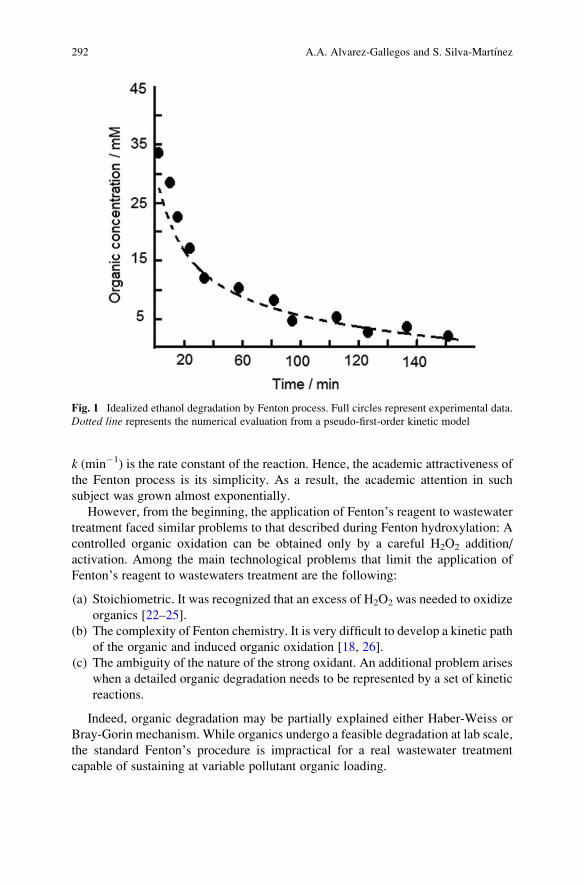
k (min�1) is the rate constant of the reaction. Hence, the academic attractiveness of
the Fenton process is its simplicity. As a result, the academic attention in such
subject was grown almost exponentially.
However, from the beginning, the application of Fenton’s reagent to wastewatertreatment faced similar problems to that described during Fenton hydroxylation: A
controlled organic oxidation can be obtained only by a careful H2O2 addition/
activation. Among the main technological problems that limit the application of
Fenton’s reagent to wastewaters treatment are the following:
(a) Stoichiometric. It was recognized that an excess of H2O2 was needed to oxidize
organics [22–25].
(b) The complexity of Fenton chemistry. It is very difficult to develop a kinetic path
of the organic and induced organic oxidation [18, 26].
(c) The ambiguity of the nature of the strong oxidant. An additional problem arises
when a detailed organic degradation needs to be represented by a set of kinetic
reactions.
Indeed, organic degradation may be partially explained either Haber-Weiss or
Bray-Gorin mechanism. While organics undergo a feasible degradation at lab scale,
the standard Fenton’s procedure is impractical for a real wastewater treatment
capable of sustaining at variable pollutant organic loading.
Fig. 1 Idealized ethanol degradation by Fenton process. Full circles represent experimental data.
Dotted line represents the numerical evaluation from a pseudo-first-order kinetic model
292 A.A. Alvarez-Gallegos and S. Silva-Martınez
2.3 Kinetic Modeling
2.3.1 Multistep Mechanistic Rate Laws
When wastewater was one of the most important applications of the Fenton process,
the kinetic studies were focused to develop detailed kinetic models for better
understanding H2O2 activation, including the organic oxidation mechanism under
the Fenton traditional laboratory approach. Under this approach, it is necessary to
describe the organic oxidation by a series of chemical reactions including its kinetic
constants. Then a set of differential equations describing the concentration changes,
as a function of time, for the main chemical species is defined. Consequently, this
kind of kinetic models is able to predict the evolution of concentration profiles of
some by-products as a function of degradation time. Nowadays, more than 1,700
rate constants for Fenton process are available. Therefore, at least in theory, from a
mechanistic standpoint, it is possible to describe a complex Fenton process by a set
of chemical equations based on the radical mechanism.
For developing such kinetic models, the following main assumptions are taken
into account: (a) the •OH is nearly stoichiometric generated from reaction (1);
(b) normally •OH is considered the unique strong oxidant responsible for the
organic degradation mechanism; (c) organic degradation by different oxidants
such as R•, RO•, and ROO• (i.e., Eq. 6) is minimized; and (d) as •OH is a very
reactive species, its concentration is considered constant. In general, the degrada-
tion of the organic compounds (RH) by Fenton process can be expressed as [27, 28]:
• OH þ RH!ki products Að Þ ð13Þ
And its reaction rate may be expressed as:
�d RH½ �=dt ¼ ki• OH
� �RH½ � ð14Þ
where products (A) are one set of products and ki is a global rate coefficient. Duringthe abatement of the target organic pollutant, their degradation products can alter the
redox potential of iron ion and thereby affecting the most important reaction rates
[29–32]. Scavenger species such as intermediates and excess of H2O2, Fe2+, •OH,
and HO2•, among others, are produced and consumed during the Fenton process
through a series of parallel and consecutive reactions (i.e., Eqs. 2–4, Eqs. 28–33),
changing its concentration and the rest of by-product concentrations. Therefore, the
reaction rate can be more complicated if other oxidants are present. In this case,
additional terms must be added to Eq. (14) [27, 28]. In a simplified form, all of them
can be represented by Sj and their degradation products:
Sj þ • OH!kj products Bð Þ ð15Þ
Modeling of Electro-Fenton Process 293
d • OH� �
=dt ¼ k1 H2O2½ � Fe2þ� �� ki RH½ � • OH� ��X
jkj Sj� �
• OH� � ð16Þ
where products (B) are a second set of products and kj is a global rate coefficient.Taking into account the assumption (d ), the Eq. (16) is simplified:
• OH� � ¼ k1 H2O2½ � Fe2þ� �
ki RH½ � þPjkj Sj� � ð17Þ
Consequently, Eq. (14) is transformed to:
�d RH½ �=dt ¼ kik1 H2O2½ � Fe2þ� �
ki RH½ � þPjkj Sj� � RH½ � ð18Þ
Consequently:
�d RH½ �=dt ¼ kap RH½ � ð19Þ
where kap takes into account k1ki[H2O2][Fe2+]/∑kj[Sj] and represent the pseudo-
first-order reaction rate with respect to HR. Most of the authors agree with this fact
[19, 21, 28, 33]. Therefore, kap ¼ f ([Fe2+], [H2O2], Sj, pH, background electrolyte,
temperature, among other parameters) [34]. For developing a Fenton process
model, a set of experimental degradations are necessary to adjust kap.Based on the above multistep mechanistic rate laws (or one adaptation of it),
commercial kinetic software or kinetic models developed by the researchers
(including from 10 to 54 chemical reactions) were tested for oxidation of different
organic molecules by Fenton process. The best kinetic models are able to predict
the evolution of concentration profiles of some by-products as a function of
degradation time. Although most of the numerical results reasonably agree with
the experimental data, some over- and underestimations of main chemical species
concentrations and important differences were also spotted among them [20, 21, 35,
36].
The main drawbacks of these approaches are the use of (a) flask ranging from
100 to 2000 mL used as chemical reactors; (b) a magnetic stir to keep the working
solution homogenized; (c) commercial H2O2 (including the cost and hazards
associated with the transport and handling of concentrated H2O2); (d) the required
H2O2 to oxidize a known amount of organics was determined by a series of trial and
error experiments; (e) low organic concentration; (f) HO• that is usually regarded as
the only powerful species for the oxidation/degradation of organic compounds;
(g) except for a fewer cases, solution ion strength was kept by salts very unlikely to
be found in real wastewater effluents (i.e., HClO4/NaClO4); and (h) the kinetic
model uses reaction rates that do not necessarily represent the same chemical
conditions at which the organic degradation was carried out.
294 A.A. Alvarez-Gallegos and S. Silva-Martınez
Accordingly, some authors have focused to obtain a practical, less difficult
kinetic model (similar to that depicted in Fig. 1), representing the kinetics of the
overall reaction. From such a model, it is possible to obtain valuable information
(a set of optimal operational parameters, cost-efficient operating conditions) for
potential application of Fenton conventional approach to treat wastewaters
containing an organic pollutant. However, this method does not give detailed
information about the evolution of concentration profiles of some by-products as
a function of degradation time [37].
2.3.2 Empirical Kinetic Modeling
From Eq. (19) versatile kinetic model can be developed to simulate a broad range of
experiments within a given experimental framework. Once the experimental setup
is defined (including chemical reactor, target organic, pH, background electrolyte,
temperature, among others), the organic degradation by Fenton process can be
studied systematically inside a selected experimental framework. Its boundaries
will be defined by a set of key (minimum/maximum) concentration parameters. As
a result, for a selected set of experiments, organic degradation (RH) will follow
pseudo-first-order reaction rate with respect to RH. A kap can be estimated for all
degradations. Therefore, experiments can be predicted within the selected experi-
mental framework. This methodology can provide valuable information on the
organic degradation as a function of key parameters.
Under this approach, a semiempirical kinetic model was developed for
the bisphenol A (BPA) degradation by a heterogeneous Fenton-like catalyst
[38]. Based on one of the main assumptions, the BPA degradation can be described
as:
• OH þ BPA!kobs products ð20Þ
where kobs is the observed rate coefficient defined in terms of key parameters:
kobs ¼ 1
C0
kap H2O2½ �0� �a
BPA½ �0� �b
Catal½ �0� �c ð21Þ
where a, b, and c represent the apparent rate orders of [H2O2]0, [BPA]0, and the
loading amount of catalyst, respectively. C0 is an arbitrary standard concentration;
kap is the apparent rate coefficient defined in terms of the temperature:
kap ¼ Að Þexp �Ea
RT
� �ð22Þ
where A is the pre-exponential coefficient and Ea is the apparent activation energy
for this reaction. For a given standard concentration (C0), the effect of key
Modeling of Electro-Fenton Process 295
parameters on kobs can be evaluated experimentally by keeping constant all param-
eters except one of them. In this way, the effect of the H2O2 on BPA degradation
can be evaluated from several experiments in which H2O2 varies, but the temper-
ature, initial load of BPA, and catalyst remain constant. From a bi-logarithmic plot
of ln(kobs) vs ln([H2O2]), a straight line is obtained; from its slope, the constant a isdetermined. The rest of the constants (b and c) are evaluated following the same
procedure [34], and Eq. (21) is useful for the prediction of BPA degradation in the
reactor.
3 Electro-Fenton Processes
Although EF process can be developed under different technological approaches
[39, 40], the main basic configurations are briefly described as follows: First, H2O2 is
continuously electro-generated on a suitable cathodic surface in the presence of Fe2+
(externally added) [5]. Second, Fe3+ is externally added, and both H2O2 and Fe2+ are
electro-generated on a suitable cathodic surface [41]. Third, H2O2 is externally
added, but Fe2+ is electro-generated via the reduction of Fe3+ on a suitable cathodic
surface [42]. However, several combined EF processes (peroxi-coagulation) are as
well feasible: H2O2 is externally added, while Fe2+ is electro-produced by a sacrifi-
cial iron anode [43]. Both species, H2O2 and Fe2+, are electro-generated, the first one
at the cathode and the second one at sacrificial anode [40].
3.1 Wastewater Treatment
One of the first works that demonstrated the feasibility to oxidize the 71% of
2.5 mM phenol by the EF process was documented at the middle of the 1980s
[5]. Fenton’s reagent was formed from the simultaneously cathodic O2 and Fe3+
reduction on a carbon surface in the presence of 2 mM Fe2+, in the pH interval of
2 < pH <3, according to:
Fe3þ þ e� ! Fe2þ ð23ÞO2 þ 2Hþ þ 2e� ! H2O2 ð24Þ
During the electrolysis, cathodic reactions (23) and (24) took place. However, at
least the following two electrochemical simultaneous reactions were expected to
occur:
2Hþ þ 2e� ! H2 ð25Þ
296 A.A. Alvarez-Gallegos and S. Silva-Martınez
O2 þ 4Hþ þ 4e� ! 2H2O ð26Þ
As a result, the electrolysis was carried out at 60% of current efficiency for the
phenol degradation in mildly conditions. Phenol degradation can be explained by
the mechanism proposed by Walling [29]. This novel process demonstrated that a
controlled generation of •OH minimizes the H2O2 waste in unwanted parallel and
consecutive reactions. During the last three decades, the EF process has been
gradually emerging as a new environmental wastewater treatment technology. As
a result, a massive amount of technical literature has been published in such subject.
Main goals were focused on the elaboration of a detailed mechanistic chemical path
during the oxidation of a given organic pollutant. A representative example is the
methyl parathion degradation through 13 by-products [44].
3.2 Activation of H2O2 by Iron Ions
The first set of equations, the most accepted, is the Haber-Weiss mechanism
[14, 45] represented by Eqs. (1–4). The efficiency of the •OH generation strongly
depends on H2O2/(FeII + FeIII) ratio. If H2O2 concentration is high, a series of
unwanted reactions take place, and H2O2 is wasted through reaction Eqs. (2 and 27),
producing a less reactive radical. Moreover, the strong oxidant is quenched by
reaction (4), scavenged by reaction (28), and lost by reaction (29). Additionally, the
available Fe2+ concentration is diminished by reaction (14) and reaction (30). The
possible regeneration of Fe2+ is carried out by a series of parallel reactions; among
the most important are reactions (27) and (31). Some of the H2O2 available can be
regenerated by the following set of competitive reactions (30) and (32):
Fe3þ þ H2O2 ! Fe2þ þ Hþ þ HO•2 ð27Þ
HO•2 þ OH• ! H2Oþ O2 ð28Þ
• OH þ • OH ! H2O2 ð29ÞFe2þ þ HO•
2 þ Hþ ! Fe3þ þ H2O2 ð30ÞFe3þ þ HO•
2 ! Fe2þ þ O2 þ Hþ ð31Þ2HO•
2 ! H2O2 þ O2 ð32Þ
It has been accepted that it is not possible to give a solid proof (experimental/
theoretical) that •OH is the strong oxidant produced from the mixture of iron ions
and H2O2 [46, 47]. The second set of equations is the generation of the strong
oxidant by Bray-Gorin mechanism represented by Eq. (7). However experimental
results, based on the time dependence of the O2 quantity evolved during the
Fenton’s reaction, suggest that the generation of the FeO2+ (initiation step) is
more complex [12, 48]:
Modeling of Electro-Fenton Process 297
Fe2þ þ H2O2 k2 !k1 Fe2þH2O2
� � �����!�H2O k3FeO2þ ð33Þ
Fenton process starts with the reversible formation of the complex Fe2+H2O2.
From it the strong oxidant is formed by losing H2O. At this point, FeO2+ may
oxidize suitable substrates, if they are present in the solution, but it can simulta-
neously react with H2O2 and both iron ions according to:
FeO2þ þH2O2 !k4 Fe2þ þ O2 þ H2O
Fe2þ þ H2O !k5 2Fe3þ þ 2OH�
Fe3þ k8 !k6 FeOFe5þ
8><>: ð34Þ
From this set of equations, the catalyst is regenerated by the reaction located at
the top. The reaction in the middle represents a possible catalyst termination
reaction. Additionally a binuclear species (FeOFe5+) can be formed by the interac-
tions between FeO2+ and Fe3+, represented by the bottom reaction (34). The course
of the above set of reactions can be influenced by the pH:
FeO2þ þ Hþ $ FeOH3þ ð35Þ
Furthermore, the complex (FeOFe5+) can react with H2O2 to form O2 and a
mixture of Fe2+/Fe3+, according to:
FeOFe5þ þ H2O2 !k7 O2 þ Fe2þ þ Fe3þ þ H2O ð36Þ
Main mechanisms based on experimental results are limited by the short time
life of the main species considered above. However, such limitation can be mini-
mized, and several complex mechanisms taking into account the water solvent and
different intermediates can be analyzed by using density functional theory. Under
this approach, the formation of the FeO2+ can be rewritten as follows [49, 50]:
Fenton process starts with the formation of the hexa-aqua-Fe2+ complex:
Fe2þ þ 6H2O! FeII H2Oð Þ6� �2þ ð37Þ
The exchange of a water molecule in the hydration shell of the hexa-aqua-Fe2+
by H2O2 gives the first intermediate:
FeII H2Oð Þ6� �2þ þ H2O2 ! FeII H2Oð Þ5H2O2
� �2þ þ H2O ð38Þ
The first intermediate follows a very complicated chemistry. At least
three parallel pathways are expected, and it might produce both strong oxidants
[51]: •OH and FeO2+:
298 A.A. Alvarez-Gallegos and S. Silva-Martınez
FeII H2Oð Þ5H2O2
� �2þ! FeIV H2Oð Þ4 OHð Þ2
� �2þ þ H2O! FeIV H2Oð Þ5O� �2þ þ H2O
þH2O! Fe H2Oð Þ6� �3þ þ • OH þ OH�
! Fe H2Oð Þ5OH� �2þ þ • OH
8><>: ð39Þ
Under some unknown experimental conditions, •OH may be the major product,
while FeO2+ may be the main product under different conditions. Therefore, it is not
a surprise that different active species can be produced in different experimental
setups [49]. However, the formation of [FeIV(H2O)5O]2+ has been as well
questioned [52].
3.3 Degradation of Organics by Fenton and EF Process
In the presence of organic molecules, both •OH and iron ions start a series of
parallel, reversible, and consecutive reactions that lead to its oxidation. The pre-
diction of the reaction paths that describes a detailed organic degradation by Fenton
process is a very challenging task. The oxidation of alcohols by Fenton’s reagentoffers a good insight about the Fenton chemistry complexity when it is described by
the Haber-Weiss mechanism. Once the •OH is produced (Eq. (1)), it can oxidize an
organic molecule (RH) producing three different hydroxyalkyl radicals through a
series of consecutive and parallel reactions according to [29, 31, 53]:
• OH þ RH !k1 R •i þ H2O ð40Þ
• OH þ RH !k2 R •j þ H2O ð41Þ
• OH þ RH !k3 R •k þ H2O ð42Þ
The rate constants (ki,j,k) are between 107 and 109 L mol�1 s�1. Therefore, thequantity of each hydroxyalkyl radicals produced is very different, and they will
further react following three main scenarios: (a) if R• is a carbonyl-conjugated
radical and reacts with Fe2+, the oxidation stops giving RH; (b) if R• is a primary or
secondary alkyl radical and reacts with a similar alkyl radical, the oxidation chain
stops giving a dimer R-R; and (c) if R• is a tertiary radical and reacts with Fe3+, it
can undergo further oxidation, regenerating Fe2+ and propagating the redox chain.
If the identification list of main by-products is not available, the theoretical infer-
ence of a particular degradation pathway is always a risky task.
Modeling of Electro-Fenton Process 299
4 Modeling of Electro-Fenton Process
According to the Haber-Weiss mechanism Eqs. (1–14), electrons are transferred
from Fe2+ to H2O2 converting it in molecular O2 and H2O, according to the global
reaction:
2Fe2þ þ 3H2O2 ! 2Fe3þ þ O2 þ 2H2Oþ 2OH� ð43Þ
The above reaction may be as well represented as:
2H2O� 4e� ! O2 þ 4Hþ ð44Þ2H2O2 þ 4Hþ þ 4e� ! 4H2O ð45Þ
2H2O2 ! O2 þ 2H2O ð46Þ
Something equivalent can be obtained if Fenton process is interpreted by the
Bray-Gorin mechanism Eqs. (7 and 10):
2Fe2þ þ 2Hþ þ H2O2 ! 2Fe3þ þ 2H2O ð47Þ
In both cases, each H2O2 mole is gaining 2e� moles according to:
H2O2 þ 2Hþ þ 2e� ! 2H2O ð48Þ
Equation (48) should be the basis to evaluate the EF efficiency. Modeling
wastewater treatment by EF process can be performed by two different approaches:
multistep mechanistic rate laws and empirical kinetic modeling.
4.1 Multistep Mechanistic Rate Laws
This approach was already discussed (see Sect. 2.3). An application of this method
is illustrated with the degradation of 200 mg L�1 4-nitrophenol (4-NP) by EF. It
was investigated in an electrochemical flow reactor (5 L) in batch recirculation
mode [54]. It was found that a controlled •OH production improved the Fenton
process. The 4-NP degradation in terms of COD decay followed pseudo-first-order
kinetics. The final COD-removed efficiency (during 120 min electrolysis) was 92%
against 54% when Fenton’s reagent alone was applied under the same experimental
condition. From experimental COD data, the electrochemical reactor was mathe-
matically modeled as a plug flow reactor and its reservoir as a continuous stirred
tank reactor. The pseudo-first-order rate constant was obtained from the model.
Although, the model does not give information about the main concentration pro-
files of some by-products during 4-NP mineralization path, it gives valuable general
300 A.A. Alvarez-Gallegos and S. Silva-Martınez
information focused to a wastewater treatment: an acceptable abatement of COD
for a given electrolysis time.
4.2 Empirical Kinetic Modeling
Modeling wastewater treatment by EF process is a challenging task because it
involves complex mechanisms and the rate constants are very difficult to evaluate.
However, once they are evaluated, they should not be used to simulate the Fenton
process in different experimental conditions. As a result, the design and scale-up of
electrochemical reactors to be used in an industrial setting became a very difficult
task. The problem can be circumvented by using an empirical model methodology
based on experimental design methodology, artificial neural networks (ANN), and
semiempirical kinetic model. All of them are useful when the process in question is
not well understood and depends on several parameters.
4.2.1 Experimental Design Methodology
This method is an important tool of experimental design for developing complex
processes and optimizing their performance. Based on statistical and mathematical
methods, an empirical model can be built, by performing a set of minimum
experiments, to predict targeted responses [55]. The experimental design is adapted
according to the complexity of the target process. Among them, complete and
fractional factorial design, central composite design, and Doehlert matrix, among
others, can be mentioned. It is important to divide the main variables into two
groups: independents (processing conditions) and dependents (experimental
response of interest). The set of independent variables may include a large number
of parameters interacting among them. In the case of Fenton process, the set of
independent variables (x) could be pH, temperature, background electrolyte, and
concentrations of target organic, H2O2, and Fe2+, among others. While the set of
dependent variables (y) could include apparent rate constants, pollutants degrada-
tion rates (expressed as COD, TOC, etc.), and energy required to abate organic
pollutants, among others. The experimental design can be developed by commer-
cial software [56]. The experimental response is not going to allow the researcher to
understand detailed mechanistic rate laws of the EF process; rather its goal is to
determine a set of key parameters (or experimental conditions) needed to achieve
the objectives of a wastewater treatment: abatement of the contamination. The
experimental response of interest (y) is associated to the experimental design by a
polynomial (quadratic or lineal) model [56, 57], for example:
Modeling of Electro-Fenton Process 301
y ¼ β0 þX k
j¼1 βjxj þX k
j¼1 βjjx2j þ
Xi
X k
<j¼2 βijxixj þ ei ð49Þ
where y is the experimental response of interest; xi, xj are independent variables;
β0 is a constant coefficient; βj, βjj, βij are interaction coefficients of linear, quadratic,and second-order terms, respectively; and the error is ei. Equation (49) can be
solved by commercial software. The effect of operational parameters (independent
variables) is shown in the response surface graphs.
Experimental design methodology has been applied to wastewater treatment by
EF process; as an example, a kinetic model developed to oxidize 150 mL of
0.05–0.2 mM chlortoluron solutions can be mentioned [57]. The electrochemical
reactor was a cylindrical cell (500 mL) with a carbon-felt cathode and a cylindrical
Pt-grid anode. The background electrolyte was 50 mM Na2SO4. During the elec-
trolysis time, the interactions of •OH with chlortoluron give the typical exponential
behavior (interpreted as a pseudo-first-order kinetic reaction) of the organic degra-
dation, expressed as TOC. The optimal experimental parameters (cell current,
chlortoluron concentration, electrolysis time) were obtained from a factorial exper-
imental design combined with Doehlert matrix. The main by-products of the EF
oxidation were identified as a function of the electrolysis time. This model allows
the prediction/sets the best experimental condition for an effective EF oxidation in a
wide variety of chlortoluron concentrations, from 0.05 mM (60 mA, 4 min) to
0.125 mM (300 mA, 8 h).
4.2.2 Artificial Neural Networks
ANN is a tool for modeling complex systems presenting nonlinearities. The method
is detailed elsewhere [58]; however, a brief description is given here. One of its
characteristics is that it does not require a kinetic description of the EF process and
no global parameters (such as apparent rate constant of the reaction, kap) are needed.However, the pollutant degradation can be predicted. ANN is built up with several
layers interacting among them. Normally three parallel interconnected structures
(layers) could be enough for an EF process [59]. The strength of these intercon-
nections is determined by a given weight. Independent variables (e.g., pollutant
concentration, applied voltage/current, pH, background electrolyte, electrolysis
time, among others) are located in the first (neuron) layer. The second structure
consists of a hidden layer (feature detectors); its neuron number is determined
iteratively and depends on the desired accuracy in the neural predictions. In this
layer, each neuron is defined as follows:
n1 ¼ W1,1ð Þ In1ð Þ þ W1,2ð Þ In2ð Þ þ . . . W1,kð Þ Inkð Þ þ b1 ð50Þ
where n1 is the first neuron, In1 is the input one,W1,1 is the weight corresponding to
neuron one and input one, and b1 is the bias corresponding to neuron one. The
inputs (independent variables) are transformed by carrying out a weighted
302 A.A. Alvarez-Gallegos and S. Silva-Martınez
summation (Eq. (50)), and then they are transferred to the hidden layer where they
are transformed using an activation function. The sum Eq. (50) is the argument of
the sigmoid transfer function f. The coefficients associated with the hidden layer areorganized as matrices W (weights) and b1 (biases). Dependent variables (pollutantdegradation in terms of COD, TOC, among others) are located in the final output
layer. The output of this hidden layer is the input to the last layer where it undergoes
a further transformation. The output layer computes the weighted sum of the signals
provided by the hidden layer, and the associated coefficients are arranged as
matrices W0 and b2. Using the matrix notation, the output layer can be given by:
Out ¼ g Wo f W � Inþ b1ð Þ þ b2ð Þ½ � ð51Þ
where f and g are any differentiable transfer function to generate their output. The
system modifies the weights using an iterative technique to minimize errors
between the calculated and the experimental values of the response variables. The
number of inputs and outputs depends on the problem to be solved, and they are
related to both variables: dependents and independents. The topology of ANN is
related to the numbers of layers, number of neurons in each layer, and the transfer
function. One of the most important tasks is the optimization of the ANN topology.
The ANN prediction accuracy is a function of the set of experimental available
values, and this condition can be regarded as one of the main drawback of this
approach. Indeed, the larger the experimental values set, the better ANN prediction
is obtained. In general, ANN has been applied to wastewater treatment by electro-
chemical process [60], sonophotocatalysis process [58], and light-enhanced Fenton
process [61, 62], but a few works have been published on wastewater treatment by
EF process. Among them it can be mentioned in the following work.
The oxidation of an aqueous solution of Basic Yellow 2 (20 mg L�1) in a 0.05 MNa2SO4 medium (pH 3) was performed by a combined EF process (peroxi-
coagulation). The electrochemical reactor was an open, undivided cylindrical
glass cell (600 mL), and it was working at constant current (100 mA); working
solutions were stirred magnetically. The cathode was a gas diffusion electrode, and
the anode was an iron sheet. The cathodic reaction expected was electro-production
of H2O2, and the anodic reaction was iron oxidation to form ferrous ion. The Basic
Yellow 2 degradation followed a pseudo-first-order reaction, and its rate constant
was determined. An ANN model was developed to predict the performance of the
Basic Yellow 2 degradation by the combined EF process. The independent vari-
ables (input layer) were electrolysis time, pH, applied current, and dye concentra-
tion. The dependent variable (output layer) was discoloration efficiency. The
hidden layer was built whit 16 nodes after several series of topology designs were
tested. The sigmoid function was used as transfer function in the hidden layer. All
experimental results were divided in three sample groups: training (70), validation
(24), and test subsets (23). The validation of ANN can be represented as graph of
predicted against experimental discoloration efficiency values. In this work, it was
found that such a graph is a straight line with a correlation coefficient of 0.9713.
Modeling of Electro-Fenton Process 303
4.2.3 Semiempirical Kinetic Models
An alternative to experimental design methodology and ANN is semiempirical
models. From wastewater treatment point of view, the target organic degradation by
Fenton process may be visualized as a pseudo-first-order reaction rate [38]. The
proposed kinetic model is based on the following assumptions: (a) both main
mechanisms that explain the Fenton process give same theoretical results, (b) the
activation of H2O2 is carried out very fast in the presence of Fe2+, and (c) during the
Fenton process, 1 mol of activated H2O2 may react as a two-equivalent reducing
agent (Eq. (48)).
As a simple illustration, the oxidation of ethanol to acetaldehyde by the Fenton
process may be described by several sets of equations: in the first one, the Haber-
Weiss mechanism through the sequenced equations, Eq. (1, 4–6); in the second one,
the Bray-Gorin mechanism through the sequenced equations, Eqs. (7–10); and in
the third one, the following simple, clear mechanism through the following
sequenced equations:
CH3CH2OH� 2e� ! CH3CHOþ 2Hþ ð52ÞH2O2 þ 2Hþ þ 2e� ! 2H2O ð53Þ
CH3CH2OHþ H2O2 ! CH3CHOþ 2H2O ð54Þ
Therefore, the ethanol degradation can be fitted to a pseudo-first-order reaction
rate (Eq. (12)). The advantage of this approach is the straightforward evaluation of
the right H2O2 amount needed to oxidize the target organic. This fact allows to
electro-generate the stoichiometric Fenton’s reagent for a given quantity of organicand assess the EF process efficiency.
From the above kinetic model, a general, simple semiempirical chemical model
can be developed to predict pollutant abatement for a wastewater treatment capable
of sustaining at variable pollutant organic loading [63]. The chemical model is
illustrated for Acid Orange 7 (AO7) abatement at room temperature in a catholyte
continuously saturated with O2 consisting of 1.5 L of 0.05 M Na2SO4, pH
2 (H2SO4), and 1 mM Fe2SO4. The anolyte was 1.5 L of 0.8 M H2SO4. The organic
degradation was performed by EF process using an electrochemical reactor divided
by a Nafion® cation membrane, fully described elsewhere [63–66]. The cathode
was a piece of unidirectional carbon fabric, and the electrochemical reaction
expected was, first, electro-generation and then activation of H2O2. The anode
was a mesh of commercial stainless steel (SS), and the electrochemical reactions
expected were SS oxidation to produce Fe2+ and then its oxidation to produce Fe3+.
Both electrodes were placed parallel to each other with an interelectrode gap of
6 mm. Electrodes were connected to a DC power supply. Catholyte and anolyte
were separated by a Nafion® cation membrane, and they were pumped at constant
flow rate (7 L min�1). Figures 2 and 4 were adapted from [63].
304 A.A. Alvarez-Gallegos and S. Silva-Martınez
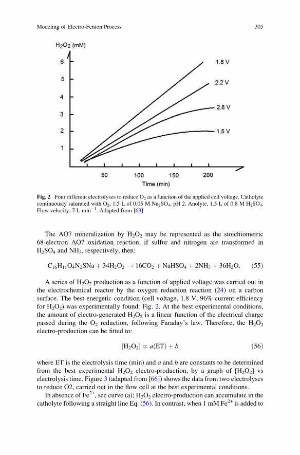
The AO7 mineralization by H2O2 may be represented as the stoichiometric
68-electron AO7 oxidation reaction, if sulfur and nitrogen are transformed in
H2SO4 and NH3, respectively, then:
C16H11O4N2SNaþ 34H2O2 ! 16CO2 þ NaHSO4 þ 2NH3 þ 36H2O: ð55Þ
A series of H2O2 production as a function of applied voltage was carried out in
the electrochemical reactor by the oxygen reduction reaction (24) on a carbon
surface. The best energetic condition (cell voltage, 1.8 V, 96% current efficiency
for H2O2) was experimentally found: Fig. 2. At the best experimental conditions,
the amount of electro-generated H2O2 is a linear function of the electrical charge
passed during the O2 reduction, following Faraday’s law. Therefore, the H2O2
electro-production can be fitted to:
H2O2½ � ¼ a ETð Þ þ b ð56Þ
where ET is the electrolysis time (min) and a and b are constants to be determined
from the best experimental H2O2 electro-production, by a graph of [H2O2] vs
electrolysis time. Figure 3 (adapted from [66]) shows the data from two electrolyses
to reduce O2, carried out in the flow cell at the best experimental conditions.
In absence of Fe2+, see curve (a); H2O2 electro-production can accumulate in the
catholyte following a straight line Eq. (56). In contrast, when 1 mM Fe2+ is added to
Fig. 2 Four different electrolyses to reduce O2 as a function of the applied cell voltage. Catholyte
continuously saturated with O2, 1.5 L of 0.05 M Na2SO4, pH 2. Anolyte, 1.5 L of 0.8 M H2SO4.
Flow velocity, 7 L min�1. Adapted from [63]
Modeling of Electro-Fenton Process 305
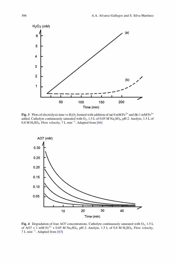
Fig. 3 Plots of electrolysis time vs H2O2 formedwith addition of (a) 0 mMFe2+ and (b) 1 mMFe2+
added. Catholyte continuously saturated with O2, 1.5 L of 0.05 M Na2SO4, pH 2. Anolyte, 1.5 L of
0.8 M H2SO4. Flow velocity, 7 L min�1. Adapted from [66]
Fig. 4 Degradation of four AO7 concentrations. Catholyte continuously saturated with O2, 1.5 L
of AO7 + 1 mM Fe2+ + 0.05 M Na2SO4, pH 2. Anolyte, 1.5 L of 0.8 M H2SO4. Flow velocity,
7 L min�1. Adapted from [63]
306 A.A. Alvarez-Gallegos and S. Silva-Martınez
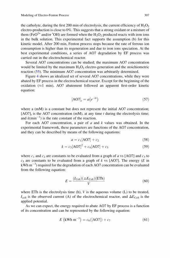
the catholyte, during the first 200 min of electrolysis, the current efficiency of H2O2
electro-production is close to 0%. This suggests that a strong oxidant or a mixture of
them (FeO2+ and/or •OH) are formed when the H2O2 produced reacts with iron ions
in the bulk solution. This experimental fact supports the assumption (b) for this
kinetic model. After 200 min, Fenton process stops because the rate of ferrous ion
consumption is higher than its regeneration and due to iron ions speciation. At the
best experimental conditions, a series of AO7 degradation by EF process was
carried out in the electrochemical reactor.
Several AO7 concentrations can be studied; the maximum AO7 concentration
would be limited by the maximum H2O2 electro-generation and the stoichiometric
reaction (55). The minimum AO7 concentration was arbitrarily determined.
Figure 4 shows an idealized set of several AO7 concentrations, while they were
abated by EF process in the electrochemical reactor. Except for the beginning of the
oxidation (�1 min), AO7 abatement followed an apparent first-order kinetic
equation:
AO7½ �t ¼ a e�kt� � ð57Þ
where a (mM) is a constant but does not represent the initial AO7 concentration;
[AO7]t is the AO7 concentration (mM), at any time t during the electrolysis time;
and k(min�1) is the rate constant of the reaction.For each AO7 concentration, a pair of a and k values was obtained. In the
experimental framework, these parameters are functions of the AO7 concentration,
and they can be described by means of the following equations:
a ¼ c1 AO7½ � þ c2 ð58Þk ¼ c3 AO7½ �2 þ c4 AO7½ � þ c5 ð59Þ
where c1 and c2 are constants to be evaluated from a graph of a vs [AO7] and c3 toc5 are constants to be evaluated from a graph of k vs [AO7]. The energy (E in
kWh m�3) required for the degradation of each AO7 concentration can be evaluatedfrom the following equation:
E ¼ ICellð Þ △ECellð Þ EThð ÞV
ð60Þ
where ETh is the electrolysis time (h), V is the aqueous volume (L) to be treated,
Icell is the observed current (A) of the electrochemical reactor, and ΔECell is the
applied potential.
As we can expect, the energy required to abate AO7 by EF process is a function
of its concentration and can be represented by the following equation:
E kWh m�3� � ¼ c6 AO7½ �ð Þ þ c7 ð61Þ
Modeling of Electro-Fenton Process 307
where c6 and c7 are constants to be evaluated from a graph of E vs [AO7]. Once the
experimental domain is established by a few experiments (4–5), good AO7 oxida-
tion predictions can be made by combining Eqs. (57–59). As an example, the
predictions of the AO7 degradation rates were predicted for the following different
concentrations: 0.24, 0.16, and 0.12 mM. In all cases, simulated degradation rates
agreed very well with experimental degradation rates. For all cases studied, the
COD abatement was almost 80%. Although under this approach it is not possible to
follow the evolution of concentration profiles of some by-products during the
degradation time, this procedure is less complicated than the others, and it can
fulfil the main requirements of wastewater treatment: abatement of the organic
pollutant. Additionally, this approach provides a simple mathematical description
of the main chemical process. This includes several important issues: (1) the rate of
H2O2 generation and its fraction that is activated by Fe2+ to produce a strong
oxidant (Eq. (56)), (2) the organic pollutant concentration range and its rate of
degradation (Eq. (57)), and (3) the energy and time required to carry out the organic
degradation (Eq. (57 and 61), respectively). This approach could be attractive to
wastewater designers since it requires few experiments and minimal physical
parameters to define an experimental domain representative of a target wastewater
treatment.
5 Conclusions
Although, wastewater treatment by means of EF process is a feasible approach, the
development of a chemical model to predict organic pollutant abatement is a
challenging task. The following approaches were discussed: multistep mechanistic
rate laws and empirical kinetic models.
While, the 1 kinetic model to predict the organic oxidation by EF process is
possible and gives valuable information (about the evolution of concentration
profiles of some by-products as a function of degradation time), its application to
a real wastewater treatment is limited by the following assumptions: (1) reactions
rates are considered to be constants and (2) •OH is usually regarded as the only
species for the oxidation/degradation of organic compounds.
Based on statistical and mathematical empirical models (experimental design
methodology and artificial neural networks), a model can be developed based on a
set of minimum experiments, to predict the organic oxidation by EF process.
Although these approaches are not going to give detailed mechanistic rate laws
during the EF process, they will determine a set of experimental conditions to
achieve the objectives of a wastewater treatment: abatement of the contamination.
The main drawbacks of both approaches are the huge quantity of experiments that
are needed to accurately predict the EF process.
In this context, a semiempirical kinetic model can be visualized as an alternative
EF procedure to predict organic pollutant abatement. Under this approach, the
following assumptions are taken into account: (1) the organic pollutant degradation
308 A.A. Alvarez-Gallegos and S. Silva-Martınez
follows a pseudo-first-order reaction rate during the EF process and (2) both main
mechanisms that explain the Fenton process can be ignored and just consider that
1 mol of activated H2O2 react as two-equivalent reducing agent. From a few organic
degradation experiments (4 or 5), it is possible to evaluate their main kinetic
parameters and express them as a function of the organic concentration. Therefore,
a semiempirical chemical model can be developed to predict H2O2 electro-
produced, oxidation rate, energy required, and electrolysis time to treat a textile
effluent with a variable pollutant organic load in the studied range. A major feature
of this approach is the minimal time and number of physical parameters needed for
a rapid reliability test to simulate a wastewater treatment.
References
1. Kant R (2012) Textile dyeing industry an environmental hazard. Nat Sci 4:22–26. doi:10.4236/
ns.2012.41004
2. Chatzisymeon E, Xekoukoulotakis NP, Coz A et al (2006) Electrochemical treatment of textile
dyes and dyehouse effluents. J Hazard Mater 137:998–1007. doi:10.1016/j.jhazmat.2006.03.
032
3. Thirugnanasambandham K, Sivakumar V, Maran JP (2014) Modeling and optimization of
biogas production from rice mill effluent using up flow anaerobic sludge blanket reactor. J
Renew Sustain Energy. doi: Artn 023129\rDoi 10.1063/1.4873400
4. Tomat R, Vecchi E (1971) Electrocatalytic production of OH radicals and their oxidative
addition to benzene. J Appl Electrochem 1:185–188. doi: 10.107/BF00616941
5. Sudoh M, Kodera T, Sakai K (1986) Oxidative degradation of aqueous phenol effluent with
electrogenerated Fenton’s reagent. J Chem Eng Jpn 19:513–518. doi:10.1252/kakoronbunshu.
11.70
6. Fenton HJH (1894) LXXIII – oxidation of tartaric acid in presence of iron. J Chem Soc Trans
65:899–910. doi:10.1039/CT8946500899
7. Van BY (1920) The catalytic decomposition of hydrogen peroxide by ferric salts. J Phys Chem
32:270–284
8. Bray WC, Gorin MH (1932) Ferryl ion, a compound of tetravalent iron. J Am Chem Soc
54:2124–2125. doi:10.1021/ja01344a505
9. Haber F, Weiss J (1934) The catalytic decomposition of hydrogen peroxide by iron salts. Proc
R Soc A 147:332–351. doi:10.1098/rspa.1934.0221
10. Kolthoff IM, Medalia AI (1949) The reaction between ferrous iron and peroxides. II. Reaction
with hydrogen peroxide, in the presence of oxygen. J Am Chem Soc 71:3784–3788. doi:10.
1021/ja01179a058
11. Baxendale JH, Evans MG, Park G (1946) Ation of polymerisation by systems. Trans Faraday
Soc 42:155–169. doi:10.1039/TF9464200155
12. Kremer ML (2003) The Fenton reaction. Dependence of the rate on pH. J Phys Chem A
107:1734–1741. doi:10.1021/jp020654p
13. Bataineh H, Pestovsky O, Bakac A (2012) pH-induced mechanistic changeover from hydroxyl
radicals to iron(iv) in the Fenton reaction. Chem Sci 3:1594. doi:10.1039/c2sc20099f
14. Walling C, El-Taliawi GM (1973) Fentons’ Reagent. II. Reactions of carbonyl compounds and
a,b-unsaturated acids. J Am Chem Soc 95:844–847
15. Liu X, Qiu M, Huang C (2011) Degradation of the reactive black 5 by Fenton and Fenton-like
system. Procedia Eng 15:4835–4840. doi:10.1016/j.proeng.2011.08.902
16. Stein G, Weiss J (1948) Chemical effects of ionizing radiations. Nature 161:650–650. doi:10.
1038/161650a0
Modeling of Electro-Fenton Process 309
17. Merz JH, Waters WA (1949) The oxidation of aromatic compounds by means of the free
hydroxyl radical. J Chem Soc 2427:2427–2433
18. Bishop DF, Stern G, Fleischman M, Marshal LS (1968) Hydrogen peroxide catalytic oxidation
of refractory organics in municipal waste waters. Ind Eng Chem Proc Des Dev 7:110–117.
doi:10.1021/i260025a022
19. Solozhenko EG, Soboleva NM, Goncharuk VV (1995) Decolourization of azodye solutions by
Fenton’s oxidation. Water Res 29:2206–2210. doi:10.1016/0043-1354(95)00042-J
20. Tang WZ, Huang CP (1997) Stoichiometry of Fenton’s reagent in the oxidation of chlorinatedaliphatic organic pollutants. Environ Technol 18:13–23. doi:10.1080/09593331808616508
21. Gallard H, Laat JDE (2000) Kinetic modelling of Fe (III)/H2O2 oxidation reactions in dilute
aqueous solution using atrazine as a model organic compound. Water Res 34:3107–3116
22. Barbeni M, Minero C, Pelizzetti E (1987) Chemical degradation of chlorophenols with
Fenton’s reagent (Fe2+ + H2O2). Chemosphere 16:2225–2237. doi: doi.org/10.1016/0045-
6535(87)90281-5
23. Murphy AP, Boegli WJ, Price MK, Moody CD (1989) A fenton-like reaction to neutralize
formaldehyde waste solutions. Environ Sci Technol 23:166–169. doi:10.1021/es00179a004
24. Zazo J, Casas J, Mohedano A et al (2005) Chemical pathway and kinetics of phenol oxidation
by Fenton’s reagent. Environ Sci Technol 39:9295–9302
25. Pham ALT, Doyle FM, Sedlak DL (2012) Kinetics and efficiency of H2O2 activation by iron-
containing minerals and aquifer materials. Water Res 46:6454–6462. doi:10.1016/j.watres.
2012.09.020
26. Zhu N, Gu L, Yuan H et al (2012) Degradation pathway of the naphthalene azo dye
intermediate 1-diazo-2- naphthol-4-sulfonic acid using Fenton’s reagent. Water Res
46:3859–3867. doi:10.1016/j.watres.2012.04.038
27. Pignatello JJ, Oliveros E, MacKay A (2006) Advanced oxidation processes for organic
contaminant destruction based on the Fenton reaction and related chemistry. Crit Rev Environ
Sci Technol 36:1–84. doi:10.1080/10643380500326564
28. Sun JH, Sun SP, Fan MH et al (2007) A kinetic study on the degradation of p-nitroaniline by
Fenton oxidation process. J Hazard Mater 148:172–177. doi:10.1016/j.jhazmat.2007.02.022
29. Walling C (1975) Fenton’s reagent revisited. Acc Chem Res 8:125–131. doi:10.1021/
ar50088a003
30. Chen R, Pignatello JJ (1997) Role of quinone intermediates as electron shuttles in Fenton and
photoassisted Fenton oxidations of aromatic compounds. Environ Sci Technol 31:2399–2406.
doi:10.1021/es9610646
31. Gozzo F (2001) Radical and non-radical chemistry of the Fenton-like systems in the presence
of organic substrates. J Mol Catal A Chem 171:1–22. doi:10.1016/S1381-1169(01)00099-1
32. Duesterberg CK, Cooper WJ, Waite TD (2005) Fenton-mediated oxidation in the presence and
absence of oxygen. Environ Sci Technol 39:5052–5058. doi:10.1021/es048378a
33. Ramirez JH, Duarte FM, Martins FG et al (2009) Modelling of the synthetic dye Orange II
degradation using Fenton’s reagent: from batch to continuous reactor operation. Chem Eng J
148:394–404. doi:10.1016/j.cej.2008.09.012
34. Zhang R, Yang Y, Huang CH et al (2016) Kinetics and modeling of sulfonamide antibiotic
degradation in wastewater and human urine by UV/H2O2 and UV/PDS. Water Res
103:283–292. doi:10.1016/j.watres.2016.07.037
35. Zazo JA, Casas JA, Mohedano AF, Rodriguez JJ (2009) Semicontinuous Fenton oxidation of
phenol in aqueous solution. A kinetic study. Water Res 43:4063–4069. doi:10.1016/j.watres.
2009.06.035
36. Pontes RFF, Moraes JEF, Machulek A, Pinto JM (2010) A mechanistic kinetic model for
phenol degradation by the Fenton process. J Hazard Mater 176:402–413. doi:10.1016/j.
jhazmat.2009.11.044
37. Sun SP, Li CJ, Sun JH et al (2009) Decolorization of an azo dye Orange G in aqueous solution
by Fenton oxidation process: effect of system parameters and kinetic study. J Hazard Mater
161:1052–1057. doi:10.1016/j.jhazmat.2008.04.080
310 A.A. Alvarez-Gallegos and S. Silva-Martınez
38. Yang X, Xu X, Xu X et al (2016) Modeling and kinetics study of Bisphenol A (BPA)
degradation over an FeOCl/SiO2 Fenton-like catalyst. Catal Today 276:85–96. doi:10.1016/
j.cattod.2016.01.002
39. Brillas E, Sires I, Oturan MA (2009) Electro-Fenton process and related electrochemical
technologies based on Fenton’s reaction chemistry. Chem Rev 109:6570–6631. doi:10.1021/
cr900136g
40. Li J, Ai Z, Zhang L (2009) Design of a neutral electro-Fenton system with Fe@Fe2O3/ACF
composite cathode for wastewater treatment. J Hazard Mater 164:18–25. doi:10.1016/j.
jhazmat.2008.07.109
41. Oturan MA, Peiroten J, Chartrin P, Acher AJ (2000) Complete destruction of p-Nitrophenol in
aqueous medium by electro-fenton method. Environ Sci Technol 34:3474–3479. doi:10.1021/
es990901b
42. Chou S, Huang YH, Lee S-N et al (1999) Treatment of high strength hexamine-containing
wastewater by electro-Fenton method. Science 33:751–759. doi: doi.org/10.1016/S0043-1354
(98)00276-0
43. Kalpana PLAT (1994) Electrochemical peroxide treatment of aqueous herbicide solutions. J
Agric Food Chem 42:209–215. doi:10.1021/jf00037a038
44. Diagne M, Oturan N, Oturan MA (2007) Removal of methyl parathion from water by
electrochemically generated Fenton’s reagent. Chemosphere 66:841–848. doi:10.1016/j.
chemosphere.2006.06.033
45. Bokare A, Choi W (2014) Review of iron-free Fenton-like systems for activating H2O2 in
advanced oxidation processes. J Hazard Mater 275:121–135. doi: doi.org/10.1016/j.
jhazmat.2014.04.054
46. Walling C (1998) Intermediates in the reactions of Fenton type reagents. Acc Chem Res
31:155–157. doi:10.1021/ar9700567
47. Goldstein S, Meyerstein D (1999) Commentary: comments on the mechanism of the “Fenton-
like” reaction. Acc Chem Res 32:547–550. doi:10.1021/ar9800789
48. Kremer ML (1999) Mechanism of the Fenton reaction. Evidence for a new intermediate. Phys
Chem Chem Phys 1:3595–3605. doi:10.1039/a903915e
49. Buda F, Ensing B, Gribnau MCM, Baerends EJ (2001) DFT study of the active intermediate in
the Fenton reaction. Chem Eur J 7:2775–2783
50. Ensing B, Buda F, Bl€ochl P, Baerends EJ (2001) Chemical involvement of solvent water
molecules in elementary steps of the Fenton oxidation reaction we gratefully acknowledge the
helpful discussions with Michiel Gribnau (Unilever-Vlaardingen) and we thank the Nether-
lands Organization for Scientific Res. Angew Chem Int Ed Engl 40:2893–2895. doi:10.1002/
1521-3773(20010803)40:15<2893::AID-ANIE2893>3.0.CO;2-B
51. Rachmilovich-Calis S, Masarwa A, Meyerstein N et al (2009) New mechanistic aspects of the
fenton reaction. Chem Eur J 15:8303–8309. doi:10.1002/chem.200802572
52. Pestovsky O, Stoian S, Bominaar EL et al (2005) Aqueous FeIV¼O: spectroscopic identifi-
cation and oxo-group exchange. Angew Chemie Int Ed 44:6871–6874. doi:10.1002/anie.
200502686
53. Walling C, Kato S (1971) Oxidation of alcohols by Fenton’s reagent. Effect of copper ion. JAm Chem Soc 93:4275–4281. doi:10.1021/ja00746a031
54. Zhang H, Lemley AT (2007) Evaluation of the performance of flow-through anodic Fenton
treatment in amide compound degradation. J Agric Food Chem 55:4073–4079. doi:10.1021/
jf070104u
55. Chau YK, Wong PTS (1998) Environmental analysis. Environ Anal. doi:10.1016/B978-0-12-
245250-5.50020-6
56. K€orbahti BK (2007) Response surface optimization of electrochemical treatment of textile dye
wastewater. J Hazard Mater 145:277–286. doi:10.1016/j.jhazmat.2006.11.031
57. Abdessalem AK, Oturan N, Bellakhal N et al (2008) Experimental design methodology
applied to electro-Fenton treatment for degradation of herbicide chlortoluron. Appl Catal B
Environ 78:334–341. doi:10.1016/j.apcatb.2007.09.032
Modeling of Electro-Fenton Process 311
58. Hamzaoui YE, Hernandez JA, Silva-Martınez S et al (2011) Optimal performance of COD
removal during aqueous treatment of alazine and gesaprim commercial herbicides by direct
and inverse neural network. Desalination 277:325–337. doi:10.1016/j.desal.2011.04.060
59. Salari D, Niaei A, Khataee A, Zarei M (2009) Electrochemical treatment of dye solution
containing C.I. Basic yellow 2 by the peroxi-coagulation method and modeling of experimen-
tal results by artificial neural networks. J Electroanal Chem 629:117–125. doi:10.1016/j.
jelechem.2009.02.002
60. Ahmed Basha C, Soloman PA, Velan M et al (2010) Electrochemical degradation of specialty
chemical industry effluent. J Hazard Mater 176:154–164. doi:10.1016/j.jhazmat.2009.10.131
61. Salari D, Daneshvar N, Aghazadeh F, Khataee AR (2005) Application of artificial neural
networks for modeling of the treatment of wastewater contaminated with methyl tert-butyl
ether (MTBE) by UV/H2O2 process. J Hazard Mater 125:205–210. doi:10.1016/j.jhazmat.
2005.05.030
62. Aleboyeh A, Kasiri MB, Olya ME, Aleboyeh H (2008) Prediction of azo dye decolorization by
UV/H2O2 using artificial neural networks. Dyes Pigments 77:288–294. doi:10.1016/j.dyepig.
2007.05.014
63. Ramırez B, Rondan V, Ortiz-Hernandez L et al (2016) Semi-empirical chemical model for
indirect advanced oxidation of acid Orange 7 using an unmodified carbon fabric cathode for
H2O2 production in an electrochemical reactor. J Environ Manag 171:29–34. doi:10.1016/j.
jenvman.2016.02.004
64. De Leon CP, Pletcher D (1995) Removal of formaldehyde from aqueous solutions via oxygen
reduction using a reticulated vitreous carbon cathode cell. J Appl Electrochem 25:307–314.
doi:10.1007/BF00249648
65. Alvarez-Gallegos A, Pletcher D (1998) The removal of low level organics via hydrogen
peroxide formed in a reticulated vitreous carbon cathode cell, part 1. The electrosynthesis of
hydrogen peroxide in aqueous acidic solutions. Electrochim Acta 44:853–861. doi:10.1016/
S0013-4686(98)00242-4
66. Figueroa S, Vazquez L, Alvarez-Gallegos A (2009) Decolorizing textile wastewater with
Fenton’s reagent electrogenerated with a solar photovoltaic cell. Water Res 43:283–294.
doi:10.1016/j.watres.2008.10.014
312 A.A. Alvarez-Gallegos and S. Silva-Martınez
Solar-Assisted Electro-Fenton Systems
for Wastewater Treatment
Enric Brillas
Abstract Herein, an overview over the performance of emerging electrochemical
advanced oxidation processes (EAOPs) such as solar photoelectro-Fenton (SPEF)
and related solar-assisted methods to remove organic pollutants from acidic waste-
waters is presented. These procedures generate •OH at the anode surface from water
oxidation and in the bulk from Fenton’s reaction between added Fe2+ and H2O2
generated at a gas diffusion electrode (GDE) fed with pure O2 or compressed air,
similarly to the electro-Fenton (EF) process. SPEF involves the additional irradia-
tion of the effluent with sunlight, which causes a synergistic effect on organic
destruction due to the formation of more •OH from the photolysis of Fe(OH)2+
species and/or the photolysis of complexes of Fe(III) with generated carboxylic
acids. Fundamentals of SPEF are explained to better clarify its characteristics on the
removal of industrial chemicals, pesticides, dyes, pharmaceuticals, and real waste-
waters. Examples with stirred tank reactors and pre-pilot flow plants equipped with
electrochemical reactors containing a Pt or a boron-doped diamond anode and a
GDE as cathode, coupled to a solar planar or CPC photoreactor, are given. The use
of an autonomous flow plant powered by sunlight is examined. Coupled methods of
SPEF with solar photocatalysis, photoelectrocatalysis, and biological treatment are
described. The effect of experimental variables on the mineralization, current
efficiency, and energy consumption is detailed. The decay kinetics of pollutants
and the evolution of intermediates and released inorganic ions are discussed. SPEF
is more efficient and less expensive than EAOPs like anodic oxidation and EF.
Keywords Coupled methods with solar photoelectro-Fenton, Degradation of dyes,
Destruction of pharmaceuticals, Oxidative action of hydroxyl radicals and sunlight,
Photolysis of Fe(III)-carboxylate complexes, Removal of pesticides, Solar
E. Brillas (*)
Departament de Quımica Fısica, Facultat de Quımica, Universitat de Barcelona, Martı i
Franques 1-11, 08028 Barcelona, Spain
e-mail: [email protected]
M. Zhou et al. (eds.), Electro-Fenton Process: New Trends and Scale-Up,Hdb Env Chem (2018) 61: 313–342, DOI 10.1007/698_2017_37,© Springer Nature Singapore Pte Ltd. 2017, Published online: 24 May 2017
313
photoelectro-Fenton treatment of wastewaters, Solar pilot plants with electrolytic
cell and CPC photoreactor
Contents
1 Introduction . . . . . . . . . . . . . . . . . . . . . . . . . . . . . . . . . . . . . . . . . . . . . . . . . . . . . . . . . . . . . . . . . . . . . . . . . . . . . . . . . . 314
2 Fundamentals of the SPEF Method . . . . . . . . . . . . . . . . . . . . . . . . . . . . . . . . . . . . . . . . . . . . . . . . . . . . . . . . . 315
3 Operation Parameters . . . . . . . . . . . . . . . . . . . . . . . . . . . . . . . . . . . . . . . . . . . . . . . . . . . . . . . . . . . . . . . . . . . . . . . 317
4 Degradation of Pure Organic Pollutants . . . . . . . . . . . . . . . . . . . . . . . . . . . . . . . . . . . . . . . . . . . . . . . . . . . . 318
4.1 Industrial Chemicals . . . . . . . . . . . . . . . . . . . . . . . . . . . . . . . . . . . . . . . . . . . . . . . . . . . . . . . . . . . . . . . . . . 318
4.2 Pesticides . . . . . . . . . . . . . . . . . . . . . . . . . . . . . . . . . . . . . . . . . . . . . . . . . . . . . . . . . . . . . . . . . . . . . . . . . . . . . . 324
4.3 Dyes . . . . . . . . . . . . . . . . . . . . . . . . . . . . . . . . . . . . . . . . . . . . . . . . . . . . . . . . . . . . . . . . . . . . . . . . . . . . . . . . . . . . 326
4.4 Pharmaceuticals . . . . . . . . . . . . . . . . . . . . . . . . . . . . . . . . . . . . . . . . . . . . . . . . . . . . . . . . . . . . . . . . . . . . . . . 330
5 Autonomous Solar Flow Plant . . . . . . . . . . . . . . . . . . . . . . . . . . . . . . . . . . . . . . . . . . . . . . . . . . . . . . . . . . . . . . 332
6 Coupled Solar-Assisted Electro-Fenton Treatments . . . . . . . . . . . . . . . . . . . . . . . . . . . . . . . . . . . . . . . 334
7 Conclusions . . . . . . . . . . . . . . . . . . . . . . . . . . . . . . . . . . . . . . . . . . . . . . . . . . . . . . . . . . . . . . . . . . . . . . . . . . . . . . . . . . 339
References . . . . . . . . . . . . . . . . . . . . . . . . . . . . . . . . . . . . . . . . . . . . . . . . . . . . . . . . . . . . . . . . . . . . . . . . . . . . . . . . . . . . . . . 339
1 Introduction
Water pollution with organic and inorganic compounds remains a pervasive threat.
A high number of synthetic organics like industrial chemicals, pesticides, dyes, and
pharmaceuticals are released daily into many wastewaters and accumulated in the
aquatic environment [1]. This pollution cannot be significantly removed by means
of conventional wastewater treatment plants because most compounds are recalci-
trant, showing a high stability to sunlight irradiation and resistance to microbial
attack and temperature. As a result, low amounts of many synthetic organics,
usually in μg L�1, have been detected in rivers, lakes, oceans, and even drinking
water in all over the world [2].
Over the past two decades, a large variety of powerful advanced oxidation
processes (AOPs) have attracted increasing interest for the efficient removal of
toxic and/or biorefractory pollutants from waters. These methods are considered
environmentally friendly and are based on the in situ production of hydroxyl
radical (•OH) as the main oxidant. The high standard reduction potential of this
radical (E�(•OH/H2O) ¼ 2.80 V/SHE) allows its nonselective reaction with
organics yielding dehydrogenated or hydroxylated derivatives, which can be in
turn mineralized to CO2, water, and inorganic ions [3, 4]. The simplest and most
typical chemical AOP is the Fenton’s reagent in which a mixture of Fe2+ and
H2O2 is used to degrade organics. Its oxidation power is significantly improved
upon illumination of the treated effluent with UV light (photo-Fenton method) or
sunlight (solar photo-Fenton method) [5]. The coupling of these methods with
electrochemistry is another way to enhance its decontamination efficiency.
Several electrochemical AOPs (EAOPs) have been recently developed,
presenting environmental compatibility, versatility, high efficiency, amenability
of automation, and safety because they operate under mild conditions [1]. In
314 E. Brillas
these treatments, organics can be oxidized at the anode and/or using the Fenton’sreagent partially or completely generated from electrode reactions. The most ubiq-
uitous EAOP is the electrochemical oxidation or anodic oxidation (AO) method
[6, 7]. When the Fenton’s reagent is electrogenerated, EAOPs based on Fenton’sreaction chemistry are utilized, being useful for the treatment of acidic wastewaters.
The most popular of these methods is the electro-Fenton (EF) process in which an
iron catalyst (Fe2+, Fe3+, or iron oxides) is added to the effluent and H2O2 is produced
at the cathode with O2 or air feeding. The degradation power of EF on organic
pollutants can be improved by combining it with other oxidizing processes [4]. The
most effective methods have been found when the effluent treated by EF is simulta-
neously exposed to UV or solar radiation, corresponding to the so-called UV
photoelectro-Fenton (PEF) and solar PEF (SPEF) methods. The latter procedure is
most interesting in practice because it uses an inexpensive and renewable energy
source as sunlight [5]. SPEF is an emerging EAOP developed in our laboratory
since 2007.
The aim of this chapter is to present a general overview on the performance of
SPEF and related methods over the destruction of organic pollutants from waters
and wastewaters, including industrial chemicals, pesticides, dyes, pharmaceuticals,
and real effluents. Fundamentals of SPEF are initially described to better analyze its
characteristics and oxidation ability. Coupled systems of SPEF and related methods
with heterogeneous solar photocatalysis (SPC), photoelectrocatalysis (PEC), and
biological treatment are also described.
2 Fundamentals of the SPEF Method
It has been well established that H2O2 can be accumulated in aqueous medium from
the cathodic two-electron reduction of dissolved O2 gas at carbonaceous electrodes
with high surface area [2]. Upon acidic conditions, this electrode reaction with
E� ¼ 0.68 V/SHE can be written as reaction (1), being easier than the four-electron
reduction of O2 to water (E� ¼ 1.23 V/SHE). The accumulation of H2O2 depends on
cell configuration, cathode material, and operating conditions. In an undivided cell,
the loss of this species is preeminently due to its electrochemical oxidation to O2
at the anode surface from reaction (2) yielding the hydroperoxyl radical (HO2•)
as intermediate [3, 8].
O2 gð Þ þ 2Hþ þ 2e� ! H2O2 ð1ÞH2O2 ! HO2
• þ Hþ þ e� ð2Þ
The SPEF treatment of acidic aqueous solutions of organic contaminants
involves the continuous generation of H2O2 from O2 directly injected as pure gas
or compressed air. It has been developed in our laboratory using an efficient gas
diffusion electrode (GDE) composed of a 3D carbon-polytetrafluoroethylene
Solar-Assisted Electro-Fenton Systems for Wastewater Treatment 315
(PTFE) sheet [5, 8]. A small catalytic quantity of Fe2+, usually <1 mM, is added to
the acidic effluent to react with electrogenerated H2O2 giving Fe3+ and •OH in the
bulk according to the classical Fenton’s reaction (3) with optimum pH near 2.8. A
key advantage of SPEF compared to the chemical photo-Fenton method is that Fe2+
is continuously regenerated from the electroreduction of Fe3+ at the cathode
according to reaction (4), with E� ¼ 0.77 V/SHE:
Fe2þþH2O2 ! Fe3þþ • OHþ H� ð3ÞFe3þ þ e� ! Fe2þ ð4Þ
In undivided cells, the quicker destruction of organics in SPEF is achieved at pH
near 3, and they are not only attacked by reactive oxygen species (ROS) such as •OH
and to smaller extent by H2O2 and HO2• but also by physisorbed •OH produced at a
high O2 overvoltage anode (M) from water oxidation by reaction (5) [4]. While the
degradation action of M(•OH) is very ineffective for active electrodes like Pt, it is
much more efficient using a non-active boron-doped diamond (BDD) thin layer
anode. At high current, reactive BDD(•OH) is produced in much greater amount
than Pt(•OH) and can mineralize completely aromatics and unsaturated compounds
such as carboxylic acids [1]. Several parasitic reactions cause the consumption of
oxidant hydroxyl radical, more extensively the anodic oxidation of M(•OH) to O2 via
reaction (6), also being feasible the dimerization of •OH in the bulk and its reaction
with H2O2 and Fe2+. Moreover, when a sulfate medium is employed, the generation
of other weaker oxidizing agents like S2O82� ion from the oxidation of the electrolyte
by reaction (7) and ozone by reaction (8) is also feasible [5, 8].
Mþ H2O ! M •OHð Þ þ Hþ þ e� ð5Þ2M •OHð Þ ! 2Mþ O2 gð Þ ! 2Hþ þ 2e� ð6Þ
2SO42� ! S2O8
2� þ 2e� ð7Þ3H2O ! O3 gð Þ þ 6 Hþ þ 6 e� ð8Þ
Apart from the electrogeneration of ROS, the SPEF process involves the
simultaneous illumination of the acidic treated effluent with sunlight. This is the
difference with the PEF process, where UVA (λ ¼ 315–400 nm), UVB
(λ ¼ 285–315 nm), or UVC (λ < 285 nm) light supplied by artificial lamps as
energy sources is employed. The mineralization action of a UV irradiation is due to
(1) higher Fe2+ regeneration and production of additional •OH from photoreduction
of Fe(OH)2+, the predominant Fe3+ species at pH 2.8–3.5, from reaction (9) and
(2) photodecarboxylation of Fe(III)-carboxylate complexes, like of oxalic acid,
also allowing Fe2+ regeneration as shown in the general reaction (10) [8].
Fe OHð Þ2þ þ hν ! Fe2þþ • OH ð9Þ
316 E. Brillas
Fe OOCRð Þ2þ þ hν ! Fe2þ þ CO2 þ R• ð10Þ
The main drawback of PEF in practice is the high electrical cost of the artificial
UV lamps utilized. The use of SPEF in which the solution is directly irradiated with
sunlight as a cheap and renewable energy source with λ> 300 nm represents a good
alternative for industrial application. The higher intensity of UV radiation of
sunlight and the additional absorption at λ > 400 nm, e.g., for the photolysis of
Fe(III)-carboxylate complexes, lead to higher degradation rate for SPEF than
for EF.
3 Operation Parameters
Several experimental parameters are determined during the SPEF treatment of an
organic pollutant in water, including the absorbance (A) at the λmax of the UV-Vis
spectrum, typically for dyes, the concentration (c) of the pollutant obtained by
reversed-phase HPLC, and the total organic carbon (TOC) of the solution. The
effect of operation variables like solution pH, applied current, and concentration of
catalyst and pollutants, among others, over the above parameters is typically
assessed to know the process performance. Detection of intermediates by GC-MS
and LC-MS, final carboxylic acid by ion exclusion HPLC, and released inorganic
ions by chromatographic techniques allows clarifying the routes of pollutant
mineralization.
Results obtained for A, c, and TOC decay are depicted as a function of electrol-
ysis time, as well as plots of the percentage of color removal and percentage of TOC
removal. The kinetic analysis of concentration decay allows a better analysis of the
performance of the degradative process. For example, the percentage of TOC
removal is determined as follows [1]:
TOC removal %ð Þ ¼ Δ TOCð ÞTOC0
100 ð11Þ
where Δ(TOC) is the experimental TOC decay (mg L�1) at electrolysis time t andTOC0 is the initial value before treatment. From TOC measurements, the mineral-
ization current efficiency (MCE) for treated solutions at a given time t (h) is
estimated from Eq. (12) [3, 9]:
MCE %ð Þ ¼ n FVsΔ TOCð Þ4:32� 107 m I t
100 ð12Þ
where n is the number of electrons exchanged in the mineralization of the com-
pound, F is the Faraday constant (96,485 C mol�1), Vs is the solution volume (L),
4.32 � 107 is a conversion factor (¼3,600 s h�1 � 12,000 mg carbon mol�1), m is
the number of carbon atoms of the compound, and I is the applied current (A). It is
Solar-Assisted Electro-Fenton Systems for Wastewater Treatment 317
noteworthy that MCE can attain a maximum value of 200% because oxidants •OH
are produced from anode and cathode reactions. Nevertheless, even superior MCE
values can be determined because the oxidative action of sunlight is not taken into
account in Eq. (12).
Energetic parameters are essential figures of merit to assess the viability of the
process for industrial application. At constant I, the energy consumption per unit
volume (EC) and unit TOC mass (ECTOC) are calculated from Eqs. (13) and (14),
respectively [10–12]:
EC kWh m�3� � ¼ Ecell I t
Vsð13Þ
ECTOC kWh ðg TOCÞ�1� �
¼ Ecell I t
Vs Δ TOCð Þ ð14Þ
where Ecell is the average potential difference of the cell (V).
An important parameter in SPEF and other solar-assisted procedures is the
intensity of the UV light supplied by sunlight over the treated solution. In our
laboratory, the SPEF trials were made during clear and sunny days of summer
months, running 360 min as maximal from the noon. The solar photoreactor was
tilted an angle of 42� corresponding to the latitude of Barcelona (latitude, 41�210 N;longitude, 2�100 E) to perpendicularly collect the direct solar rays in order to better
absorb the incident photons. An average UV intensity of 30–32 W m�2 was
measured using a Kipp & Zonen CUV 5 global UV radiometer [13].
4 Degradation of Pure Organic Pollutants
Several industrial chemicals, pesticides, dyes, and pharmaceuticals have been
degraded using SPEF since 2007. The assays were made at two levels, with stirred
tank reactors and with recirculation pre-pilot plants as a first step for its possible
application at industrial scale. This section describes the degradative characteristics
of this procedure, as well as of related methods. Table 1 collects the good percent of
TOC removal, MCE, and specific energy consumption obtained for several pollut-
ants under selected conditions operating with 2.5 and 10 L solar flow plants [10–12,
14–22].
4.1 Industrial Chemicals
The first research over SPEF was performed with a 2.5 L pre-pilot flow plant
equipped with a BDD/GDE reactor of 20 cm2 electrode area and a solar planar
photoreactor of 600 mL irradiation volume operating under batch recirculation
318 E. Brillas
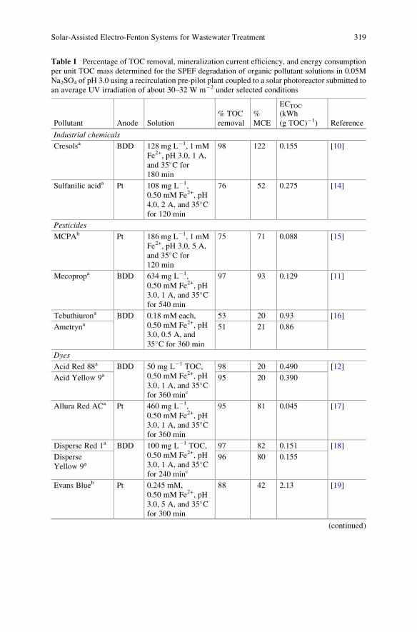
Table 1 Percentage of TOC removal, mineralization current efficiency, and energy consumption
per unit TOC mass determined for the SPEF degradation of organic pollutant solutions in 0.05M
Na2SO4 of pH 3.0 using a recirculation pre-pilot plant coupled to a solar photoreactor submitted to
an average UV irradiation of about 30–32 W m�2 under selected conditions
Pollutant Anode Solution
% TOC
removal
%
MCE
ECTOC
(kWh
(g TOC)�1) Reference
Industrial chemicals
Cresolsa BDD 128 mg L�1, 1 mM
Fe2+, pH 3.0, 1 A,
and 35�C for
180 min
98 122 0.155 [10]
Sulfanilic acida Pt 108 mg L�1,
0.50 mM Fe2+, pH
4.0, 2 A, and 35�Cfor 120 min
76 52 0.275 [14]
Pesticides
MCPAb Pt 186 mg L�1, 1 mM
Fe2+, pH 3.0, 5 A,
and 35�C for
120 min
75 71 0.088 [15]
Mecopropa BDD 634 mg L�1,
0.50 mM Fe2+, pH
3.0, 1 A, and 35�Cfor 540 min
97 93 0.129 [11]
Tebuthiurona BDD 0.18 mM each,
0.50 mM Fe2+, pH
3.0, 0.5 A, and
35�C for 360 min
53 20 0.93 [16]
Ametryna 51 21 0.86
Dyes
Acid Red 88a BDD 50 mg L�1 TOC,
0.50 mM Fe2+, pH
3.0, 1 A, and 35�Cfor 360 minc
98 20 0.490 [12]
Acid Yellow 9a 95 20 0.390
Allura Red ACa Pt 460 mg L�1,
0.50 mM Fe2+, pH
3.0, 1 A, and 35�Cfor 360 min
95 81 0.045 [17]
Disperse Red 1a BDD 100 mg L�1 TOC,
0.50 mM Fe2+, pH
3.0, 1 A, and 35�Cfor 240 minc
97 82 0.151 [18]
Disperse
Yellow 9a96 80 0.155
Evans Blueb Pt 0.245 mM,
0.50 mM Fe2+, pH
3.0, 5 A, and 35�Cfor 300 min
88 42 2.13 [19]
(continued)
Solar-Assisted Electro-Fenton Systems for Wastewater Treatment 319
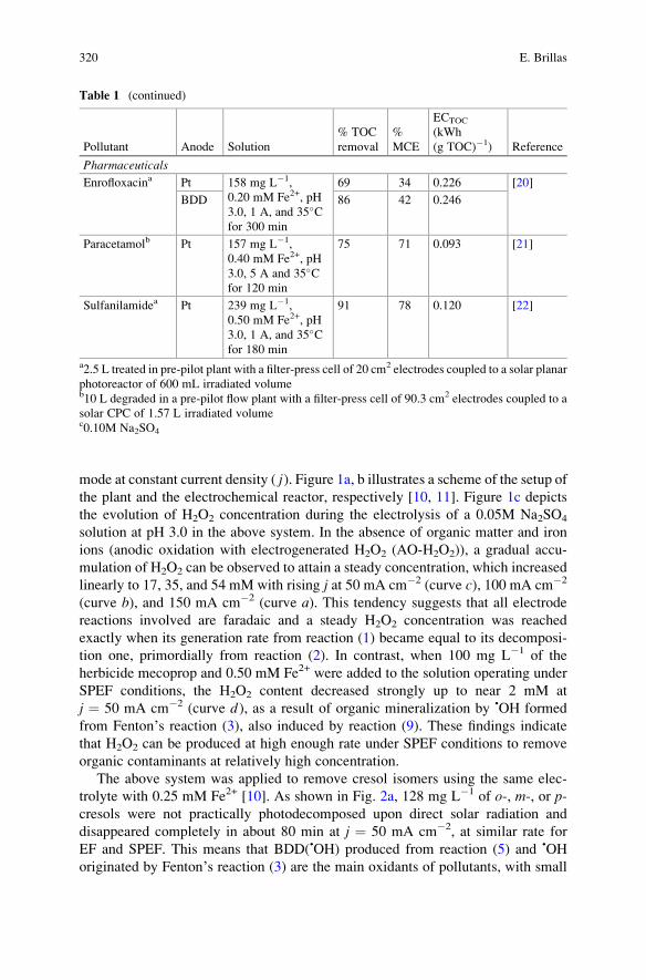
mode at constant current density ( j). Figure 1a, b illustrates a scheme of the setup of
the plant and the electrochemical reactor, respectively [10, 11]. Figure 1c depicts
the evolution of H2O2 concentration during the electrolysis of a 0.05M Na2SO4
solution at pH 3.0 in the above system. In the absence of organic matter and iron
ions (anodic oxidation with electrogenerated H2O2 (AO-H2O2)), a gradual accu-
mulation of H2O2 can be observed to attain a steady concentration, which increased
linearly to 17, 35, and 54 mM with rising j at 50 mA cm�2 (curve c), 100 mA cm�2
(curve b), and 150 mA cm�2 (curve a). This tendency suggests that all electrode
reactions involved are faradaic and a steady H2O2 concentration was reached
exactly when its generation rate from reaction (1) became equal to its decomposi-
tion one, primordially from reaction (2). In contrast, when 100 mg L�1 of the
herbicide mecoprop and 0.50 mM Fe2+ were added to the solution operating under
SPEF conditions, the H2O2 content decreased strongly up to near 2 mM at
j ¼ 50 mA cm�2 (curve d ), as a result of organic mineralization by •OH formed
from Fenton’s reaction (3), also induced by reaction (9). These findings indicate
that H2O2 can be produced at high enough rate under SPEF conditions to remove
organic contaminants at relatively high concentration.
The above system was applied to remove cresol isomers using the same elec-
trolyte with 0.25 mM Fe2+ [10]. As shown in Fig. 2a, 128 mg L�1 of o-, m-, or p-cresols were not practically photodecomposed upon direct solar radiation and
disappeared completely in about 80 min at j ¼ 50 mA cm�2, at similar rate for
EF and SPEF. This means that BDD(•OH) produced from reaction (5) and •OH
originated by Fenton’s reaction (3) are the main oxidants of pollutants, with small
Table 1 (continued)
Pollutant Anode Solution
% TOC
removal
%
MCE
ECTOC
(kWh
(g TOC)�1) Reference
Pharmaceuticals
Enrofloxacina Pt 158 mg L�1,
0.20 mM Fe2+, pH
3.0, 1 A, and 35�Cfor 300 min
69 34 0.226 [20]
BDD 86 42 0.246
Paracetamolb Pt 157 mg L�1,
0.40 mM Fe2+, pH
3.0, 5 A and 35�Cfor 120 min
75 71 0.093 [21]
Sulfanilamidea Pt 239 mg L�1,
0.50 mM Fe2+, pH
3.0, 1 A, and 35�Cfor 180 min
91 78 0.120 [22]
a2.5 L treated in pre-pilot plant with a filter-press cell of 20 cm2 electrodes coupled to a solar planar
photoreactor of 600 mL irradiated volumeb10 L degraded in a pre-pilot flow plant with a filter-press cell of 90.3 cm2 electrodes coupled to a
solar CPC of 1.57 L irradiated volumec0.10M Na2SO4
320 E. Brillas
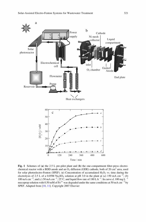
AnodeO2 chamber
Ni meshcollector Liquid
compartment
Gasketinlet
End plate
Cathode
Flowmeter
Power
supplyV5
A1
Electrochemicalcell
Solarphotoreactor
ReservoirPump
0
10
20
30
40
50
60
0 120 240 360 480 600
[H2O
2]
/ m
M
Time / min
a
b
c
d
c
outlet
a
b
Heat exchangers
Fig. 1 Schemes of (a) the 2.5 L pre-pilot plant and (b) the one-compartment filter-press electro-
chemical reactor with a BDD anode and an O2 diffusion (GDE) cathode, both of 20 cm2 area, used
for solar photoelectro-Fenton (SPEF). (c) Concentration of accumulated H2O2 vs. time during the
electrolysis of 2.5 L of a 0.05M Na2SO4 solution at pH 3.0 in the plant at (a) 150 mA cm�2, (b)100 mA cm�2, and (c) 50 mA cm�2, 25�C, and liquid flow rate of 180 L h�1. In curve d, 100 mg L�1
mecoprop solution with 0.50mMof Fe2+ was degraded under the same conditions at 50mA cm�2 by
SPEF. Adapted from [10, 11]. Copyright 2007 Elsevier
Solar-Assisted Electro-Fenton Systems for Wastewater Treatment 321
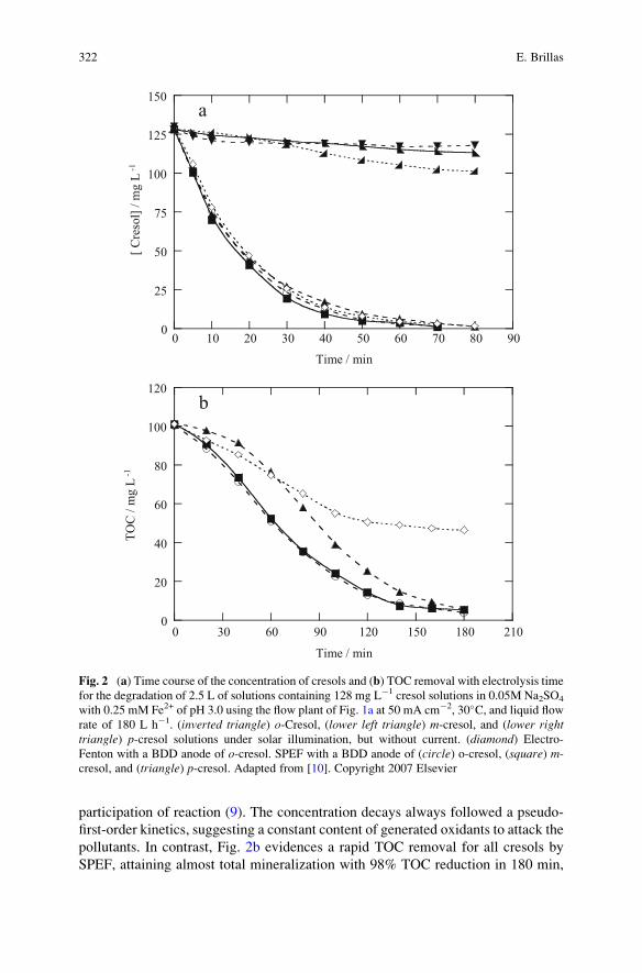
participation of reaction (9). The concentration decays always followed a pseudo-
first-order kinetics, suggesting a constant content of generated oxidants to attack the
pollutants. In contrast, Fig. 2b evidences a rapid TOC removal for all cresols by
SPEF, attaining almost total mineralization with 98% TOC reduction in 180 min,
0
20
40
60
80
100
120
0 30 60 90 120 150 180 210
TO
C /
mg
L -1
Time / min
0
25
50
75
100
125
150
0 10 20 30 40 50 60 70 80 90
[ C
reso
l] /
mg
L -1
Time / min
a
b
Fig. 2 (a) Time course of the concentration of cresols and (b) TOC removal with electrolysis time
for the degradation of 2.5 L of solutions containing 128 mg L�1 cresol solutions in 0.05M Na2SO4
with 0.25 mM Fe2+ of pH 3.0 using the flow plant of Fig. 1a at 50 mA cm�2, 30�C, and liquid flowrate of 180 L h�1. (inverted triangle) o-Cresol, (lower left triangle) m-cresol, and (lower righttriangle) p-cresol solutions under solar illumination, but without current. (diamond) Electro-
Fenton with a BDD anode of o-cresol. SPEF with a BDD anode of (circle) o-cresol, (square) m-cresol, and (triangle) p-cresol. Adapted from [10]. Copyright 2007 Elsevier
322 E. Brillas
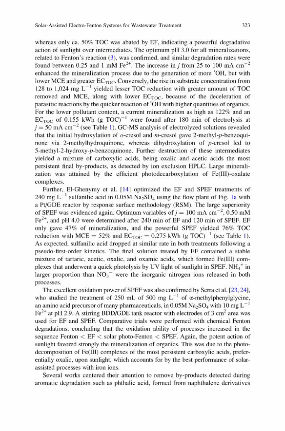
whereas only ca. 50% TOC was abated by EF, indicating a powerful degradative
action of sunlight over intermediates. The optimum pH 3.0 for all mineralizations,
related to Fenton’s reaction (3), was confirmed, and similar degradation rates were
found between 0.25 and 1 mM Fe2+. The increase in j from 25 to 100 mA cm�2
enhanced the mineralization process due to the generation of more •OH, but with
lower MCE and greater ECTOC. Conversely, the rise in substrate concentration from
128 to 1,024 mg L�1 yielded lesser TOC reduction with greater amount of TOC
removed and MCE, along with lower ECTOC, because of the deceleration of
parasitic reactions by the quicker reaction of •OH with higher quantities of organics.
For the lower pollutant content, a current mineralization as high as 122% and an
ECTOC of 0.155 kWh (g TOC)�1 were found after 180 min of electrolysis at
j ¼ 50 mA cm�2 (see Table 1). GC-MS analysis of electrolyzed solutions revealed
that the initial hydroxylation of o-cresol and m-cresol gave 2-methyl-p-benzoqui-none via 2-methylhydroquinone, whereas dihydroxylation of p-cresol led to
5-methyl-2-hydroxy-p-benzoquinone. Further destruction of these intermediates
yielded a mixture of carboxylic acids, being oxalic and acetic acids the most
persistent final by-products, as detected by ion exclusion HPLC. Large minerali-
zation was attained by the efficient photodecarboxylation of Fe(III)-oxalate
complexes.
Further, El-Ghenymy et al. [14] optimized the EF and SPEF treatments of
240 mg L�1 sulfanilic acid in 0.05M Na2SO4 using the flow plant of Fig. 1a with
a Pt/GDE reactor by response surface methodology (RSM). The large superiority
of SPEF was evidenced again. Optimum variables of j ¼ 100 mA cm�2, 0.50 mM
Fe2+, and pH 4.0 were determined after 240 min of EF and 120 min of SPEF. EF
only gave 47% of mineralization, and the powerful SPEF yielded 76% TOC
reduction with MCE ¼ 52% and ECTOC ¼ 0.275 kWh (g TOC)�1 (see Table 1).
As expected, sulfanilic acid dropped at similar rate in both treatments following a
pseudo-first-order kinetics. The final solution treated by EF contained a stable
mixture of tartaric, acetic, oxalic, and oxamic acids, which formed Fe(III) com-
plexes that underwent a quick photolysis by UV light of sunlight in SPEF. NH4+ in
larger proportion than NO3� were the inorganic nitrogen ions released in both
processes.
The excellent oxidation power of SPEF was also confirmed by Serra et al. [23, 24],
who studied the treatment of 250 mL of 500 mg L�1 of α-methylphenylglycine,
an amino acid precursor of many pharmaceuticals, in 0.05M Na2SO4 with 10 mg L�1
Fe2+ at pH 2.9. A stirring BDD/GDE tank reactor with electrodes of 3 cm2 area was
used for EF and SPEF. Comparative trials were performed with chemical Fenton
degradations, concluding that the oxidation ability of processes increased in the
sequence Fenton < EF < solar photo-Fenton < SPEF. Again, the potent action of
sunlight favored strongly the mineralization of organics. This was due to the photo-
decomposition of Fe(III) complexes of the most persistent carboxylic acids, prefer-
entially oxalic, upon sunlight, which accounts for by the best performance of solar-
assisted processes with iron ions.
Several works centered their attention to remove by-products detected during
aromatic degradation such as phthalic acid, formed from naphthalene derivatives
Solar-Assisted Electro-Fenton Systems for Wastewater Treatment 323
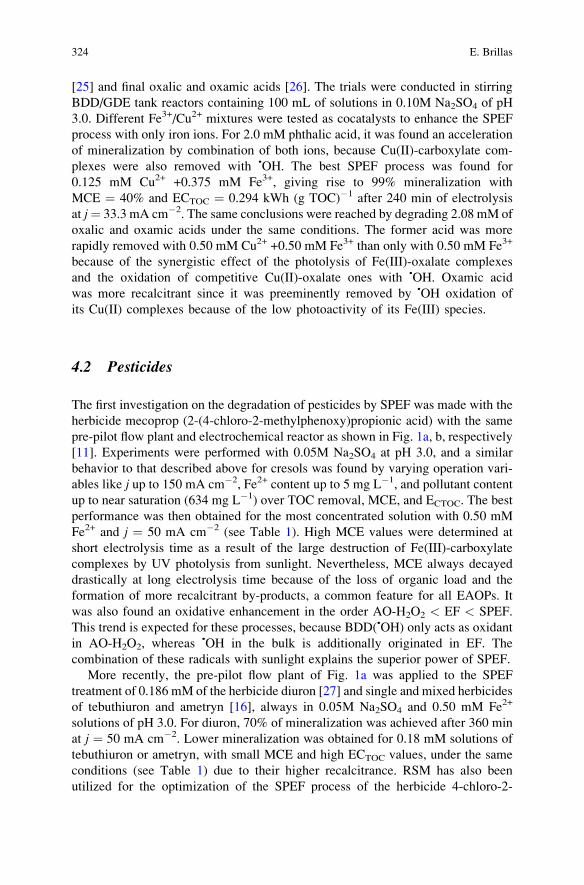
[25] and final oxalic and oxamic acids [26]. The trials were conducted in stirring
BDD/GDE tank reactors containing 100 mL of solutions in 0.10M Na2SO4 of pH
3.0. Different Fe3+/Cu2+ mixtures were tested as cocatalysts to enhance the SPEF
process with only iron ions. For 2.0 mM phthalic acid, it was found an acceleration
of mineralization by combination of both ions, because Cu(II)-carboxylate com-
plexes were also removed with •OH. The best SPEF process was found for
0.125 mM Cu2+ +0.375 mM Fe3+, giving rise to 99% mineralization with
MCE ¼ 40% and ECTOC ¼ 0.294 kWh (g TOC)�1 after 240 min of electrolysis
at j¼ 33.3 mA cm�2. The same conclusions were reached by degrading 2.08 mM of
oxalic and oxamic acids under the same conditions. The former acid was more
rapidly removed with 0.50 mM Cu2+ +0.50 mM Fe3+ than only with 0.50 mM Fe3+
because of the synergistic effect of the photolysis of Fe(III)-oxalate complexes
and the oxidation of competitive Cu(II)-oxalate ones with •OH. Oxamic acid
was more recalcitrant since it was preeminently removed by •OH oxidation of
its Cu(II) complexes because of the low photoactivity of its Fe(III) species.
4.2 Pesticides
The first investigation on the degradation of pesticides by SPEF was made with the
herbicide mecoprop (2-(4-chloro-2-methylphenoxy)propionic acid) with the same
pre-pilot flow plant and electrochemical reactor as shown in Fig. 1a, b, respectively
[11]. Experiments were performed with 0.05M Na2SO4 at pH 3.0, and a similar
behavior to that described above for cresols was found by varying operation vari-
ables like j up to 150 mA cm�2, Fe2+ content up to 5 mg L�1, and pollutant content
up to near saturation (634 mg L�1) over TOC removal, MCE, and ECTOC. The best
performance was then obtained for the most concentrated solution with 0.50 mM
Fe2+ and j ¼ 50 mA cm�2 (see Table 1). High MCE values were determined at
short electrolysis time as a result of the large destruction of Fe(III)-carboxylate
complexes by UV photolysis from sunlight. Nevertheless, MCE always decayed
drastically at long electrolysis time because of the loss of organic load and the
formation of more recalcitrant by-products, a common feature for all EAOPs. It
was also found an oxidative enhancement in the order AO-H2O2 < EF < SPEF.
This trend is expected for these processes, because BDD(•OH) only acts as oxidant
in AO-H2O2, whereas •OH in the bulk is additionally originated in EF. The
combination of these radicals with sunlight explains the superior power of SPEF.
More recently, the pre-pilot flow plant of Fig. 1a was applied to the SPEF
treatment of 0.186 mM of the herbicide diuron [27] and single and mixed herbicides
of tebuthiuron and ametryn [16], always in 0.05M Na2SO4 and 0.50 mM Fe2+
solutions of pH 3.0. For diuron, 70% of mineralization was achieved after 360 min
at j ¼ 50 mA cm�2. Lower mineralization was obtained for 0.18 mM solutions of
tebuthiuron or ametryn, with small MCE and high ECTOC values, under the same
conditions (see Table 1) due to their higher recalcitrance. RSM has also been
utilized for the optimization of the SPEF process of the herbicide 4-chloro-2-
324 E. Brillas
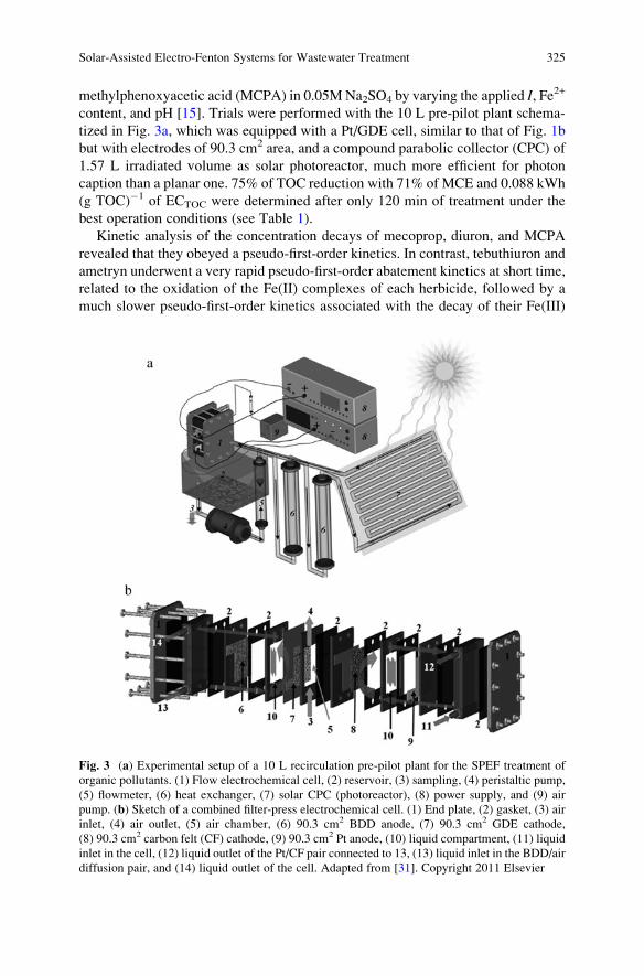
methylphenoxyacetic acid (MCPA) in 0.05M Na2SO4 by varying the applied I, Fe2+
content, and pH [15]. Trials were performed with the 10 L pre-pilot plant schema-
tized in Fig. 3a, which was equipped with a Pt/GDE cell, similar to that of Fig. 1b
but with electrodes of 90.3 cm2 area, and a compound parabolic collector (CPC) of
1.57 L irradiated volume as solar photoreactor, much more efficient for photon
caption than a planar one. 75% of TOC reduction with 71% of MCE and 0.088 kWh
(g TOC)�1 of ECTOC were determined after only 120 min of treatment under the
best operation conditions (see Table 1).
Kinetic analysis of the concentration decays of mecoprop, diuron, and MCPA
revealed that they obeyed a pseudo-first-order kinetics. In contrast, tebuthiuron and
ametryn underwent a very rapid pseudo-first-order abatement kinetics at short time,
related to the oxidation of the Fe(II) complexes of each herbicide, followed by a
much slower pseudo-first-order kinetics associated with the decay of their Fe(III)
Fig. 3 (a) Experimental setup of a 10 L recirculation pre-pilot plant for the SPEF treatment of
organic pollutants. (1) Flow electrochemical cell, (2) reservoir, (3) sampling, (4) peristaltic pump,
(5) flowmeter, (6) heat exchanger, (7) solar CPC (photoreactor), (8) power supply, and (9) air
pump. (b) Sketch of a combined filter-press electrochemical cell. (1) End plate, (2) gasket, (3) air
inlet, (4) air outlet, (5) air chamber, (6) 90.3 cm2 BDD anode, (7) 90.3 cm2 GDE cathode,
(8) 90.3 cm2 carbon felt (CF) cathode, (9) 90.3 cm2 Pt anode, (10) liquid compartment, (11) liquid
inlet in the cell, (12) liquid outlet of the Pt/CF pair connected to 13, (13) liquid inlet in the BDD/air
diffusion pair, and (14) liquid outlet of the cell. Adapted from [31]. Copyright 2011 Elsevier
Solar-Assisted Electro-Fenton Systems for Wastewater Treatment 325
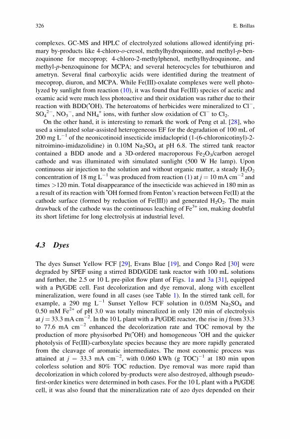
complexes. GC-MS and HPLC of electrolyzed solutions allowed identifying pri-
mary by-products like 4-chloro-o-cresol, methylhydroquinone, and methyl-p-ben-zoquinone for mecoprop; 4-chloro-2-methylphenol, methylhydroquinone, and
methyl-p-benzoquinone for MCPA; and several heterocycles for tebuthiuron and
ametryn. Several final carboxylic acids were identified during the treatment of
mecoprop, diuron, and MCPA. While Fe(III)-oxalate complexes were well photo-
lyzed by sunlight from reaction (10), it was found that Fe(III) species of acetic and
oxamic acid were much less photoactive and their oxidation was rather due to their
reaction with BDD(•OH). The heteroatoms of herbicides were mineralized to Cl�,SO4
2�, NO3�, and NH4
+ ions, with further slow oxidation of Cl� to Cl2.
On the other hand, it is interesting to remark the work of Peng et al. [28], who
used a simulated solar-assisted heterogeneous EF for the degradation of 100 mL of
200 mg L�1 of the neonicotinoid insecticide imidacloprid (1-(6-chloronicotinyl)-2-
nitroimino-imidazolidine) in 0.10M Na2SO4 at pH 6.8. The stirred tank reactor
contained a BDD anode and a 3D-ordered macroporous Fe2O3/carbon aerogel
cathode and was illuminated with simulated sunlight (500 W He lamp). Upon
continuous air injection to the solution and without organic matter, a steady H2O2
concentration of 18 mg L�1 was produced from reaction (1) at j¼ 10 mA cm�2 and
times >120 min. Total disappearance of the insecticide was achieved in 180 min as
a result of its reaction with •OH formed from Fenton’s reaction between Fe(II) at thecathode surface (formed by reduction of Fe(III)) and generated H2O2. The main
drawback of the cathode was the continuous leaching of Fe3+ ion, making doubtful
its short lifetime for long electrolysis at industrial level.
4.3 Dyes
The dyes Sunset Yellow FCF [29], Evans Blue [19], and Congo Red [30] were
degraded by SPEF using a stirred BDD/GDE tank reactor with 100 mL solutions
and further, the 2.5 or 10 L pre-pilot flow plant of Figs. 1a and 3a [31], equipped
with a Pt/GDE cell. Fast decolorization and dye removal, along with excellent
mineralization, were found in all cases (see Table 1). In the stirred tank cell, for
example, a 290 mg L�1 Sunset Yellow FCF solution in 0.05M Na2SO4 and
0.50 mM Fe2+ of pH 3.0 was totally mineralized in only 120 min of electrolysis
at j¼ 33.3 mA cm�2. In the 10 L plant with a Pt/GDE reactor, the rise in j from 33.3
to 77.6 mA cm�2 enhanced the decolorization rate and TOC removal by the
production of more physisorbed Pt(•OH) and homogeneous •OH and the quicker
photolysis of Fe(III)-carboxylate species because they are more rapidly generated
from the cleavage of aromatic intermediates. The most economic process was
attained at j ¼ 33.3 mA cm�2, with 0.060 kWh (g TOC)�1 at 180 min upon
colorless solution and 80% TOC reduction. Dye removal was more rapid than
decolorization in which colored by-products were also destroyed, although pseudo-
first-order kinetics were determined in both cases. For the 10 L plant with a Pt/GDE
cell, it was also found that the mineralization rate of azo dyes depended on their
326 E. Brillas
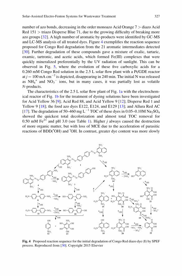
number of azo bonds, decreasing in the order monoazo Acid Orange 7> diazo Acid
Red 151 > triazo Disperse Blue 71, due to the growing difficulty of breaking more
azo groups [32]. A high number of aromatic by-products were identified by GC-MS
and LC-MS analysis of all treated dyes. Figure 4 exemplifies the reaction sequence
proposed for Congo Red degradation from the 21 aromatic intermediates detected
[30]. Further degradation of these compounds gave a mixture of oxalic, tartaric,
oxamic, tartronic, and acetic acids, which formed Fe(III) complexes that were
quickly mineralized preferentially by the UV radiation of sunlight. This can be
observed in Fig. 5, where the evolution of these five carboxylic acids for a
0.260 mM Congo Red solution in the 2.5 L solar flow plant with a Pt/GDE reactor
at j¼ 100 mA cm�2 is depicted, disappearing in 240 min. The initial N was released
as NH4+ and NO3
� ions, but in many cases, it was partially lost as volatile
N-products.The characteristics of the 2.5 L solar flow plant of Fig. 1a with the electrochem-
ical reactor of Fig. 1b for the treatment of dyeing solutions have been investigated
for Acid Yellow 36 [9]; Acid Red 88, and Acid Yellow 9 [12]; Disperse Red 1 and
Yellow 9 [18]; the food azo dyes E122, E124, and E129 [13]; and Allura Red AC
[17]. The degradation of 50–460 mg L�1 TOC of these dyes in 0.05–0.10M Na2SO4
showed the quickest total decolorization and almost total TOC removal for
0.50 mM Fe2+ and pH 3.0 (see Table 1). Higher j always caused the destruction
of more organic matter, but with loss of MCE due to the acceleration of parasitic
reactions of BDD(•OH) and •OH. In contrast, greater dye content was more slowly
NN
NN
NH2
SO3−
NH2
SO3−
NN
OH
NH2
SO3−
NN
NH2
NH2
SO3−
H2N
SO3−
NH2
HO NH2
NH2
H2N
SO3−
O
OH
O
OH
NH2
O2N
SO3−
O
OH
O
OH
OH
HO
SO3−
O
OH
O
OH
.OH.
OH
.OH
1
4 7
8 9
1011
−NH4+
−2NO3−
1417
21
20
18
O
OH
O
OH
22
−NO3− −NH4
+
−2NH4+
.OH
− SO42−
NO2
OH
+HO
HO
NH2
OH
OH
OH12 13
O2N
SO3−
NO2
15
O2N
OH
NO216
.OH
.OH
.OH
− SO42−
+
OH
O
OH
O
H2N
NH2
19
.OH
.OH
.OH
− SO42−
H2N NH2
HO OHO2N NO2
.OH
.OH
.OH
.OH
.OH
.OH
−NH4+
.OH
.OH
−NH4+
.OH
− 2NH4+ HO
SO3−
HO
47
Fig. 4 Proposed reaction sequence for the initial degradation of Congo Red diazo dye (1) by SPEF
process. Reproduced from [30]. Copyright 2015 Elsevier
Solar-Assisted Electro-Fenton Systems for Wastewater Treatment 327
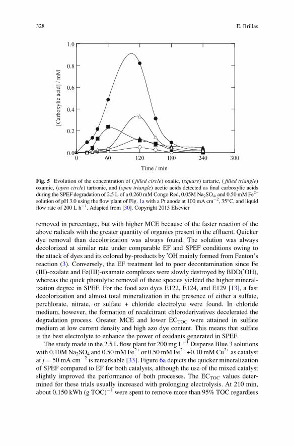
removed in percentage, but with higher MCE because of the faster reaction of the
above radicals with the greater quantity of organics present in the effluent. Quicker
dye removal than decolorization was always found. The solution was always
decolorized at similar rate under comparable EF and SPEF conditions owing to
the attack of dyes and its colored by-products by •OH mainly formed from Fenton’sreaction (3). Conversely, the EF treatment led to poor decontamination since Fe
(III)-oxalate and Fe(III)-oxamate complexes were slowly destroyed by BDD(•OH),
whereas the quick photolytic removal of these species yielded the higher mineral-
ization degree in SPEF. For the food azo dyes E122, E124, and E129 [13], a fast
decolorization and almost total mineralization in the presence of either a sulfate,
perchlorate, nitrate, or sulfate + chloride electrolyte were found. In chloride
medium, however, the formation of recalcitrant chloroderivatives decelerated the
degradation process. Greater MCE and lower ECTOC were attained in sulfate
medium at low current density and high azo dye content. This means that sulfate
is the best electrolyte to enhance the power of oxidants generated in SPEF.
The study made in the 2.5 L flow plant for 200 mg L�1 Disperse Blue 3 solutions
with 0.10M Na2SO4 and 0.50 mM Fe2+ or 0.50 mM Fe2+ +0.10 mMCu2+ as catalyst
at j¼ 50 mA cm�2 is remarkable [33]. Figure 6a depicts the quicker mineralization
of SPEF compared to EF for both catalysts, although the use of the mixed catalyst
slightly improved the performance of both processes. The ECTOC values deter-
mined for these trials usually increased with prolonging electrolysis. At 210 min,
about 0.150 kWh (g TOC)�1 were spent to remove more than 95% TOC regardless
0.0
0.2
0.4
0.6
0.8
1.0
0 60 120 180 240 300
[Car
boxyli
c ac
id]
/ m
M
Time / min
Fig. 5 Evolution of the concentration of ( filled circle) oxalic, (square) tartaric, ( filled triangle)oxamic, (open circle) tartronic, and (open triangle) acetic acids detected as final carboxylic acids
during the SPEF degradation of 2.5 L of a 0.260 mMCongo Red, 0.05M Na2SO4, and 0.50 mM Fe2+
solution of pH 3.0 using the flow plant of Fig. 1a with a Pt anode at 100 mA cm�2, 35�C, and liquidflow rate of 200 L h�1. Adapted from [30]. Copyright 2015 Elsevier
328 E. Brillas
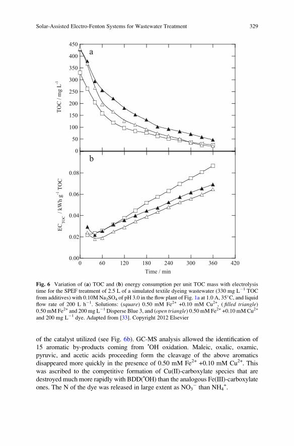
of the catalyst utilized (see Fig. 6b). GC-MS analysis allowed the identification of
15 aromatic by-products coming from •OH oxidation. Maleic, oxalic, oxamic,
pyruvic, and acetic acids proceeding form the cleavage of the above aromatics
disappeared more quickly in the presence of 0.50 mM Fe2+ +0.10 mM Cu2+. This
was ascribed to the competitive formation of Cu(II)-carboxylate species that are
destroyed much more rapidly with BDD(•OH) than the analogous Fe(III)-carboxylate
ones. The N of the dye was released in large extent as NO3� than NH4
+.
0
50
100
150
200
250
300
350
400
450
TO
C /
mg
L-1
0.00
0.02
0.04
0.06
0.08
0 60 120 180 240 300 360 420
EC
TO
C /
kW
h g
-1 T
OC
Time / min
b
a
Fig. 6 Variation of (a) TOC and (b) energy consumption per unit TOC mass with electrolysis
time for the SPEF treatment of 2.5 L of a simulated textile dyeing wastewater (330 mg L�1 TOC
from additives) with 0.10MNa2SO4 of pH 3.0 in the flow plant of Fig. 1a at 1.0 A, 35�C, and liquidflow rate of 200 L h�1. Solutions: (square) 0.50 mM Fe2+ +0.10 mM Cu2+, ( filled triangle)0.50 mM Fe2+ and 200 mg L�1 Disperse Blue 3, and (open triangle) 0.50 mM Fe2+ +0.10 mMCu2+
and 200 mg L�1 dye. Adapted from [33]. Copyright 2012 Elsevier
Solar-Assisted Electro-Fenton Systems for Wastewater Treatment 329
Espinoza et al. [34] constructed an 8 L solar flow plant similar to that of
Fig. 3a with an electrochemical BDD/GDE filter-press reactor similar to that of
Fig. 1b of 50 cm2 electrode active area and a solar CPC photoreactor of 0.70 L. For
284 mg L�1 of the diazo dye Acid Yellow 42 in 0.05M Na2SO4 with 1.0 mM Fe2+ at
pH 3.0 and j¼ 80 mA cm�2, total dye removal and decolorization were achieved at
60 and 150 min, respectively, whereas 83% mineralization with MCE ¼ 35% and
an energy cost of US $6.5/m3 were obtained after 270 min of electrolysis. The
decolorization of the solution was enhanced in the order AO-H2O2 < EF < SPEF.
Complete disappearance of the Fe(III) complexes of citric, maleic, malic, acetic,
formic, oxalic, and oxamic acids as final carboxylic acids at the end of the latter
process was found. NO3� was released in larger proportion than NH4
+, but a
balance of total N showed a loss of this heteroatom in the form of N2 and NxOy.
On the other hand, Zhao et al. [35] treated 100 mL of 20 mg L�1 of rhodamine B
under the same experimental conditions as explained in Sect. 4.2 for the
imidacloprid treatment of Peng et al. [28], but using a (Fe/Co) carbon aerogel
cathode. The simulated solar-assisted heterogeneous EF at j¼ 10 mA cm�2 and pH
3.0 led to 100% color removal in 45 min and 91% mineralization in 600 min. It was
found that the cathode showed an efficient degradation for rhodamine B in the pH
range 3–9 and good reusability with very low iron and cobalt leaching (<0.5 ppm)
even in an acidic medium.
4.4 Pharmaceuticals
The first studies to show the excellent performance of the SPEF process to degra-
dation pharmaceuticals were made for salicylic acid [36], ibuprofen [37], and
enrofloxacin [20] using a stirred tank reactor with a Pt or BDD anode and a GDE
cathode, all of 3 cm2 area. In the case of ibuprofen, for example, a saturated solution
with 41 mg L�1 drug, 0.05M Na2SO4, and 0.50 mM Fe2+ of pH 3.0 electrolyzed at
j¼ 33.3 mA cm�2 was mineralized to a larger extent using a BDD anode instead of
a Pt one owing to the greater oxidizing power of BDD(•OH) than Pt(•OH) to remove
the contaminants. The concentration decay for both electrodes followed a pseudo-
first-order kinetics. Similar results were found for the other organics tested, show-
ing that SPEF was more powerful with BDD. In all cases, pH 3.0 was found
optimal, near the optimum pH of 2.8 for Fenton’s reaction (3), as expected if •OH
is the main oxidant of organic pollutants. Moreover, higher amounts of TOC were
removed with increasing j and drug concentration, the same behavior as described
above for the other kinds of organic pollutants. Analysis of treated solutions revealed
the formation of aromatic intermediates like 2,3-, 2,5-, and 2,6-dihydroxybenzoic acids
for salicylic acid; 4-ethylbenzaldehyde, 4-isobutylacetophenone, 4-isobutylphenol,
and 1-(1-hydroxyethyl)-4-isobutylbenzene for ibuprofen; and polyols, ketones, and
N-derivatives for enrofloxacin. Ion exclusion HPLC allowed identifying and quanti-
fying generated carboxylic acids. Oxalic acid was accumulated to a larger extent, and
the quick photodecomposition of Fe(III)-oxalate complexes under sunlight exposition
330 E. Brillas
explained the greatest mineralization degree attained in SPEF compared to EF. The
initial F of enrofloxacin was totally transformed into F� ion, and its initial N was
primordially converted into NH4+ ion and in smaller proportion into NO3
� ion.
The treatment of 158 mg L�1 of enrofloxacin was extended to the 2.5 L solar
pre-pilot plant of Fig. 1a containing BDD/GDE and Pt/GDE cells like of Fig. 1b
[20]. Table 1 shows that better mineralization and MCE were found for BDD, but
lower ECTOC was obtained when using Pt. It was also confirmed for each anode the
superiority of SPEF over other EAOPs, their oxidation power raising in the
sequence AO-H2O2 < EF < SPEF, as found in most compounds studied by these
methods. Further researches with the same system with a Pt anode were focused in
the degradation of the antibiotics sulfanilamide [22] and ranitidine [38] in 0.05M
Na2SO4 and 0.50 mM Fe2+ solutions of pH 3.0. Good mineralization with 91%
TOC decay was obtained when treating 239 mg L�1 of sulfanilamide in only
180 min at j ¼ 50 mA cm�2 (see Table 1). In contrast, ranitidine was much more
recalcitrant, and 16 mg L�1 of this antibiotic electrolyzed at j ¼ 100 mA cm�2 only
underwent 37% TOC reduction with MCE ¼ 8.7% and ECTOC ¼ 0.94 kWh
(g TOC)�1 in 360 min. The decay kinetics of both antibiotics obeyed a pseudo-
first-order reaction. Catechol, resorcinol, hydroquinone, and p-benzoquinone weredetected as products of the attack of sulfanilamide by Pt(•OH) and mainly •OH. In
both cases, the preponderant generated Fe(III)-oxalate complexes were efficiently
photolyzed by UV radiation of sunlight, and NH4+, NO3
�, and SO42� ions were
released from their N and S heteroatoms.
The research with the 10 L solar pre-pilot plant of Fig. 3a was initially centered
in the optimization of the treatment of 157 mg L�1 of paracetamol with 0.05M
Na2SO4 by RSM [21]. A Pt/GDE cell was chosen for these trials since less energy
consumption than using a BDD anode was required, because of its lower Ecell. The
best operation variables were I ¼ 5 A, 0.40 mM Fe2+, and pH 3.0 leading to 75%
TOC removal, 71% current efficiency, and 0.093 kWh (g TOC)�1 energy con-
sumption (EC ¼ 7.2 kWh m�3) at 120 min (see Table 1). From the HPLC analysis
of electrolyzed solutions, hydroquinone, p-benzoquinone, 1,2,4-trihydroxy-
benzene, 2,5-dihydroxy-p-benzoquinone, and tetrahydroxy-p-benzoquinone were
detected as aromatic by-products, preeminently removed by •OH in the bulk. Final
carboxylic acids such as maleic, fumaric, succinic, lactic, formic, oxalic, and
oxamic acids were mainly destroyed via photolysis of their Fe(III) complexes.
The viability of the SPEF process was also confirmed for chloramphenicol [39]
and metronidazole [40] using the same arrangement of the 10 L solar pre-pilot
plant. For a 245 mg L�1 chloramphenicol solution in 0.05M Na2SO4 with 0.50 mM
Fe2+ at pH 3.0, 89% mineralization with MCE ¼ 36% and EC ¼ 30.8 kWh m�3
were obtained after 180 min of electrolysis at j ¼ 100 mA cm�2. The best process
for a 1.39 mM metronidazole solution in 0.10M Na2SO4 with 0.50 mM Fe2+ at pH
3.0 was found at j¼ 55.4 mA cm�2 giving rise to 53%mineralization, MCE¼ 36%,
and ECTOC ¼ 0.339 kWh (g TOC)�1 in 300 min.
Isarain-Chavez et al. [31] studied the SPEF degradation of 10 L of 100 mg L�1
TOC of the β-blockers atenolol, metoprolol tartrate, and propranolol hydrochloride
in 0.10MNa2SO4 with 0.50 mM Fe2+ at pH 3.0 using single Pt/GDE and BDD/GDE
Solar-Assisted Electro-Fenton Systems for Wastewater Treatment 331
cells and their combination with a Pt/CF cell to enhance Fe2+ regeneration from Fe3+
reduction via reaction (4). Figure 3b shows a sketch of the combined BDD/GDE-Pt/
CF cell used. Figure 7a–c exemplifies the superiority of combined cells over single
ones, BDD over Pt, and SPEF over EF regarding the normalized drug decay, TOC
abatement, and MCE, respectively, for a 0.246 mMmetoprolol tartrate solution. This
can be accounted for by the greater production of •OH from Fenton’s reaction (3) in
the combined cells, the higher oxidizing power of BDD(•OH), and the photolytic
action of sunlight in SPEF, as can also be deduced from the pseudo-first-order decay
for tartrate concentration shown in the inset panel of Fig. 7a for the different cells
checked. Nevertheless, the combined Pt/GDE-Pt/CF cell allowed the lowest ECTOC
of 0.080 kWh (g TOC)�1 for 88–93% mineralization, thereby being the most viable
system for industrial application. This indicates that the oxidation power of the anode
is less significant in SPEF, suggesting the use of Pt and even cheaper dimensionally
stable anodes due to the efficient degradation by •OH in the bulk combined with
sunlight.
The aforementioned suggestion was also confirmed by Moreira et al. [41], who
tested the degradative behavior of 20 mg L�1 of trimethoprim in 7.0 g L�1 Na2SO4
and 2.0 mg L�1 Fe2+ of pH 3.5 using a 2.2 L solar flow plant similar to that Fig. 1a
containing a filter-press BDD/GDE or Pt/GDE cell of 10 cm2 electrode area
connected to a CPC photoreactor of 0.694 L irradiated volume. It is noteworthy
that at j¼ 5 mA cm�2 and liquid flow rate of 40 L h�1, the influence of the anode in
SPEF was almost negligible. After 420 min of electrolysis, 77 and 73% minerali-
zation with 30 and 26% current efficiency and 1.2 and 0.9 kWh m�3 energy
consumption were obtained for BDD and Pt, respectively. Up to 18 aromatic
products and 19 hydroxylated derivatives were detected from trimethoprim degra-
dation by LC-MS, and a high content of hardly oxidizable N-derivatives, containingthe major part of N, was finally produced, along with small loses of NH4
+ and NO3�
ions.
5 Autonomous Solar Flow Plant
Despite the more cost-effective treatment of organic pollutants from wastewaters
by SPEF than other EAOPs, as pointed out above, the electrolytic reactor used in
this process spends energy since it needs the electrical current provided by a power
supply. This still represents an economical problem for its possible application to
water remediation at industrial level. To solve this problem, our group designed an
autonomous solar flow plant in which the electrical energy required by the electro-
lytic cell was supplied by a solar photovoltaic panel, thereby making an energeti-
cally free SPEF process. A sketch of this autonomous plant is shown in Fig. 8
[42]. It consisted of the solar flow plant of Fig. 3 powered by a photovoltaic panel of
50W, providing I¼ 5.0 A as maximum when a Pt/GDE reactor (Ecell¼ 10.0 V) was
used. The operation characteristics of this plant were assessed by studying the
removal and mineralization of the diazo dye Direct Yellow 4 in a 0.05M Na2SO4
332 E. Brillas
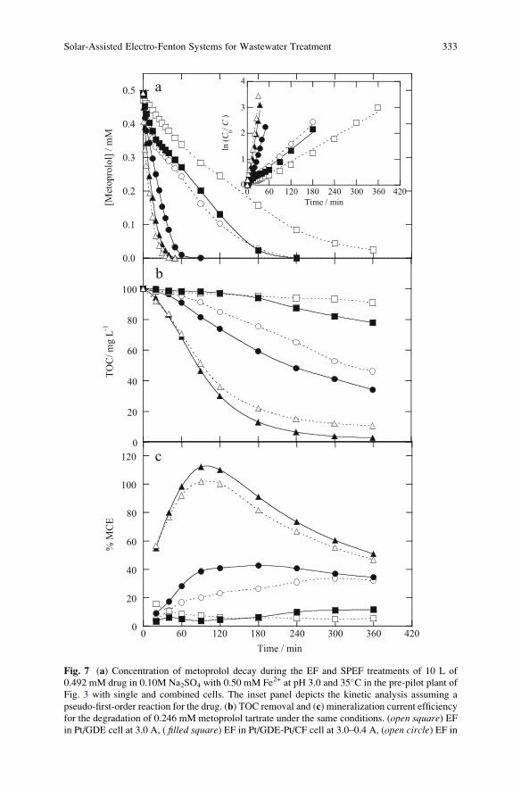
0
20
40
60
80
100
TO
C/
mg L
-1
0
20
40
60
80
100
120
0 60 120 180 240 300 360 420
% M
CE
Time / min
0.0
0.1
0.2
0.3
0.4
0.5
[Met
opro
lol]
/ m
M
b
a
c
0
1
2
3
4
0 60 120 180 240 300 360 420
ln (
C 0/ C
)
Time / min
Fig. 7 (a) Concentration of metoprolol decay during the EF and SPEF treatments of 10 L of
0.492 mM drug in 0.10M Na2SO4 with 0.50 mM Fe2+ at pH 3.0 and 35�C in the pre-pilot plant of
Fig. 3 with single and combined cells. The inset panel depicts the kinetic analysis assuming a
pseudo-first-order reaction for the drug. (b) TOC removal and (c) mineralization current efficiency
for the degradation of 0.246 mM metoprolol tartrate under the same conditions. (open square) EFin Pt/GDE cell at 3.0 A, ( filled square) EF in Pt/GDE-Pt/CF cell at 3.0–0.4 A, (open circle) EF in
Solar-Assisted Electro-Fenton Systems for Wastewater Treatment 333
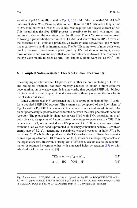
solution of pH 3.0. As illustrated in Fig. 9, 0.16 mM of the dye with 0.50 mM Fe2+
underwent about 96–97% mineralization in 180 min at 5.0 A, whereas a longer time
of 240 min, but with higher MCE values, was required for a lower current of 3.0.
This means that the free SPEF process is feasible to be used with much high
currents to shorten the operation time. In all cases, Direct Yellow 4 was removed
following a pseudo-first-order kinetics. LC-MS and ion exclusion HPLC revealed
the presence of 11 aromatic products, 22 hydroxylated derivatives, and 9 short-
linear carboxylic acids as intermediates. The Fe(III) complexes of most acids were
quickly removed, preeminently photolyzed by UV radiation of sunlight, except
those of acetic and oxamic acids that were more slowly destroyed. The N atoms of
the dye were mainly released as NH4+ ion, and its S atoms were lost as SO4
2� ion.
6 Coupled Solar-Assisted Electro-Fenton Treatments
The coupling of solar-assisted EF process with other methods including SPC, PEC,
and biological treatment has been recently checked to obtain a more effective
decontamination of wastewaters. It is noteworthy that coupled SPEF with biolog-
ical treatment has been applied to real wastewaters, thereby opening the door for its
use at industrial scale.
Garza-Campos et al. [43] constructed the 3 L solar pre-pilot plant of Fig. 10 useful
for a coupled SPEF-SPC process. The system was composed of the flow plant of
Fig. 1a with a Pt/GDE filter-press electrochemical reactor and an additional solar
planar photocatalytic photoreactor connected between the solar photoreactor and the
reservoir. The photocatalytic photoreactor was filled with TiO2 deposited on small
borosilicate glass spheres of 5 mm diameter in average to generate extra •OH. This
occurs when TiO2 is illuminated with UV photons of λ < 380 nm, since an electron
from the filled valence band is promoted to the empty conduction band (e�cb) with an
energy gap of 3.2 eV, generating a positively charged vacancy or hole (h+vb) byreaction (15). The holes thus produced at the TiO2 surface can oxidize either organics
or water giving adsorbed •OH from reaction (16), which can subsequently attack also
the organic species. However, a strong loss of efficiency occurs due to the recombi-
nation of promoted electrons either with unreacted holes by reaction (17) or with
adsorbed •OH by reaction (18) [5].
TiO2 þ hν ! e�cb þ hþvb ð15Þhþvb þ HO2! • OHþ Hþ ð16Þ
Fig. 7 (continued) BDD/GDE cell at 3.0 A, ( filled circle) EF in BDD/GDE-Pt/CF cell at
3.0–0.4 A, (open triangle) SPEF in Pt/GDE-Pt/CF cell at 3.0–0.4 A, and ( filled triangle) SPEFin BDD/GDE-Pt/CF cell at 3.0–0.4 A. Adapted from [31]. Copyright 2011 Elsevier
334 E. Brillas
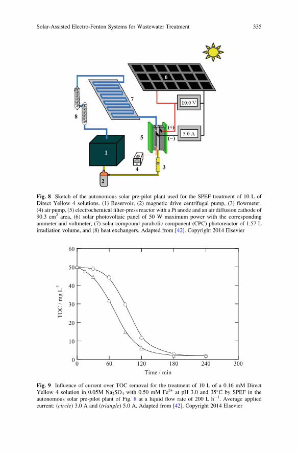
Fig. 8 Sketch of the autonomous solar pre-pilot plant used for the SPEF treatment of 10 L of
Direct Yellow 4 solutions. (1) Reservoir, (2) magnetic drive centrifugal pump, (3) flowmeter,
(4) air pump, (5) electrochemical filter-press reactor with a Pt anode and an air diffusion cathode of
90.3 cm2 area, (6) solar photovoltaic panel of 50 W maximum power with the corresponding
ammeter and voltmeter, (7) solar compound parabolic component (CPC) photoreactor of 1.57 L
irradiation volume, and (8) heat exchangers. Adapted from [42]. Copyright 2014 Elsevier
0
10
20
30
40
50
60
0 60 120 180 240 300
TO
C /
mg L
-1
Time / min
Fig. 9 Influence of current over TOC removal for the treatment of 10 L of a 0.16 mM Direct
Yellow 4 solution in 0.05M Na2SO4 with 0.50 mM Fe2+ at pH 3.0 and 35�C by SPEF in the
autonomous solar pre-pilot plant of Fig. 8 at a liquid flow rate of 200 L h�1. Average applied
current: (circle) 3.0 A and (triangle) 5.0 A. Adapted from [42]. Copyright 2014 Elsevier
Solar-Assisted Electro-Fenton Systems for Wastewater Treatment 335
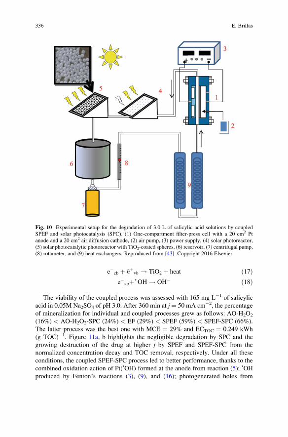
e�cb þ hþvb ! TiO2 þ heat ð17Þe�cbþ • OH ! OH� ð18Þ
The viability of the coupled process was assessed with 165 mg L�1 of salicylic
acid in 0.05M Na2SO4 of pH 3.0. After 360 min at j ¼ 50 mA cm�2, the percentage
of mineralization for individual and coupled processes grew as follows: AO-H2O2
(16%) < AO-H2O2-SPC (24%) < EF (29%) < SPEF (59%) < SPEF-SPC (66%).
The latter process was the best one with MCE ¼ 29% and ECTOC ¼ 0.249 kWh
(g TOC)�1. Figure 11a, b highlights the negligible degradation by SPC and the
growing destruction of the drug at higher j by SPEF and SPEF-SPC from the
normalized concentration decay and TOC removal, respectively. Under all these
conditions, the coupled SPEF-SPC process led to better performance, thanks to the
combined oxidation action of Pt(•OH) formed at the anode from reaction (5); •OH
produced by Fenton’s reactions (3), (9), and (16); photogenerated holes from
Fig. 10 Experimental setup for the degradation of 3.0 L of salicylic acid solutions by coupled
SPEF and solar photocatalysis (SPC). (1) One-compartment filter-press cell with a 20 cm2 Pt
anode and a 20 cm2 air diffusion cathode, (2) air pump, (3) power supply, (4) solar photoreactor,
(5) solar photocatalytic photoreactor with TiO2-coated spheres, (6) reservoir, (7) centrifugal pump,
(8) rotameter, and (9) heat exchangers. Reproduced from [43]. Copyright 2016 Elsevier
336 E. Brillas
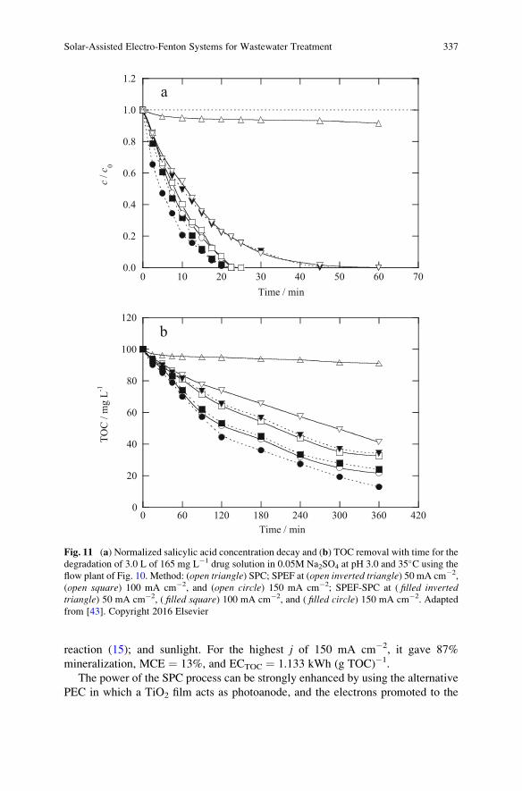
reaction (15); and sunlight. For the highest j of 150 mA cm�2, it gave 87%
mineralization, MCE ¼ 13%, and ECTOC ¼ 1.133 kWh (g TOC)�1.
The power of the SPC process can be strongly enhanced by using the alternative
PEC in which a TiO2 film acts as photoanode, and the electrons promoted to the
0.0
0.2
0.4
0.6
0.8
1.0
1.2
0 10 20 30 40 50 60 70
c /
c 0
Time / min
0
20
40
60
80
100
120
0 60 120 180 240 300 360 420
TO
C /
mg
L-1
Time / min
b
a
Fig. 11 (a) Normalized salicylic acid concentration decay and (b) TOC removal with time for the
degradation of 3.0 L of 165 mg L�1 drug solution in 0.05M Na2SO4 at pH 3.0 and 35�C using the
flow plant of Fig. 10. Method: (open triangle) SPC; SPEF at (open inverted triangle) 50 mA cm�2,
(open square) 100 mA cm�2, and (open circle) 150 mA cm�2; SPEF-SPC at ( filled invertedtriangle) 50 mA cm�2, ( filled square) 100 mA cm�2, and ( filled circle) 150 mA cm�2. Adapted
from [43]. Copyright 2016 Elsevier
Solar-Assisted Electro-Fenton Systems for Wastewater Treatment 337
conduction band are continuously extracted to the cathode through the circulating
electrical current, avoiding their loss by reactions (17) and (18). The feasibility of
using a SPEF-PEC process has been tested by Peng et al. [44], who prepared a
photoanode composed of TiO2 nanotubes of 40–50 nm modified with Fe2O3 and
treated an O2-saturated rhodamine B solution in a cell containing an activated
carbon fiber cathode for H2O2 production from reaction (1). Upon optimum condi-
tions, 96% of color removal was obtained in 60 min with a rate constant of
0.055 min�1. Hydroxyl radicals and photogenerated holes contributed in 76.6%
and 16.6%, respectively, to the rhodamine B decolorization.
The good coupling of SPEF with biological treatment has been investigated for
winery [45], landfill leachate [46–48], and slaughterhouse [49] wastewaters. In the
case of a winery wastewater, for example, the biological oxidation led to above
97% removals of TOC, chemical oxygen demand (COD), and 5-day biochemical
oxygen demand (BOD5), but it resulted inefficient on a bioresistant fraction
corresponding to 130 mg L�1 of TOC, 380 mg O2 L�1 of COD, and 8.2 mg caffeic
acid equivalent L�1 of total dissolved polyphenols. In a subsequent SPEF process
with the 2.2 L solar pre-pilot plant with a BDD/GDE cell stated in Sect. 4.4, using
35 mg L�1 Fe2+ at pH 2.8 and applying j ¼ 25 mA cm�2, additional removals of
86% TOC and 68% COD in 240 min were obtained, with EC ¼ 5.1 kWh m�3 and
ECTOC ¼ 0.045 kWh (g TOC)�1. The resulting water complied with all legislation
targets, including a total dissolved polyphenol content of 0.35 mg caffeic acid
equivalent L�1.
Landfill leachates previously digested by anaerobic-aerobic systems were fur-
ther treated by different solar-assisted processes. Ye et al. [48] utilized a 1.7 L solar
Fered-Fenton pre-pilot plant with an electrochemical tank reactor containing a
Ti/IrO2-RuO2-TiO2 plate anode and a Ti plate cathode of 150 cm2 area coupled
to a solar CPC photoreactor of 0.70 L irradiation volume, at liquid flow rate of
13.6 L h�1. Trials conducted upon optimum conditions by adding 47 mM H2O2 and
0.29 mM Fe2+ at pH 3.0 yielded 66% COD removal with respect to the biologically
treated water and ECTOC¼ 0.074 kWh (g TOC)�1 after 120 min at j¼ 60 mA cm�2.
The coupled treatment led to more than 98% removals of COD, ammonium, nitrate,
nitrite, total nitrogen, and total phosphorous.
Vidal et al. [49] treated a slaughterhouse effluent by anaerobic oxidation during
30 days to obtain a wastewater with 52, 137, and 183 mg L�1 of TOC, COD, and
BOD5, respectively. Further degradation of 100 mL of this wastewater with 1.0 mM
Fe2+ by SPEF using a BDD/GDE stirred tank reactor of 2.5 cm2 electrode area at
j ¼ 50 mA cm�2 allowed the reduction of the above parameters up to 2, 10, and
6 mg L�1. These excellent results were accompanied by total loss of odor and
suspended and volatile solids as well as a strong reduction of dissolved organic
nitrogen.
338 E. Brillas
7 Conclusions
The recent development of SPEF and related solar-assisted processes has corrob-
orated the viability of these EAOPs to remove toxic and refractory aromatic
pollutants such as industrial chemicals, pesticides, dyes and pharmaceuticals, as
well as real wastewaters, upon acidic conditions. However, their use is limited by
the weather and disposal of sunlight. High mineralization with good current effi-
ciency was found for these environmentally friendly methods, which are simple, are
safe, and can be easily scaled up to industrial level using recirculation flow plants.
Very stable anodes like BDD or Pt and GDE cathodes for an efficient H2O2
generation can be utilized in SPEF. The main drawback for industrial application
is the electrical consumption for running the electrochemical cell, even using
inexpensive sunlight as photon source. The coupling of photovoltaic panels to
power the electrochemical reactor allows the application of autonomous solar
flow plants as an excellent free alternative way for SPEF. The coupling of the
reactor with an efficient solar CPCs photoreactor represents an interesting arrange-
ment for enhancing the degradation process. The SPEF treatment of organic
pollutants with a BDD anode was more efficient and less expensive than other
EAOPs like AO-H2O2, EF, and PEF operating under comparable conditions,
because of the potent degradation action of sunlight. Similar results were obtained
with a Pt anode, being less significant the use of the expensive BDD one in SPEF.
The coupling with SPC, PEC, or biological treatment can enhance the oxidation
power of the method. The mineralization rate slowed down as applied current
dropped, but with greater MCE and lower energy consumption. This trend was
also found when pollutant concentration increased due to the inhibition of parasitic
reactions of oxidant •OH by its quicker reaction with higher organic load. The
kinetics of contaminant decay obeyed a pseudo-first-order reaction. Aromatic
intermediates were oxidized to short-linear aliphatic carboxylic acids that exten-
sively form Fe(III) complexes, most of which are rapidly photolyzed by the potent
UV radiation of sunlight. Heteroatoms present in organics are released as inorganic
ions such as F�, Cl�, SO42�, NH4
+, and NO3�.
References
1. Brillas E, Martinez-Huitle CA (2015) Decontamination of wastewaters containing synthetic
organic dyes by electrochemical methods. An updated review. Appl Catal B Environ
166–167:603–643
2. Oturan N, Sires I, Oturan MA, Brillas E (2009) Degradation of pesticides in aqueous medium
by electro-Fenton and related methods. A review. J Environ Eng Manage 19:235–255
3. Sires I, Brillas E, Oturan MA, Rodrigo MA, Panizza M (2014) Electrochemical advanced
oxidation processes: today and tomorrow. A review. Environ Sci Pollut Res 21:8336–8367
4. Moreira FC, Boaventura RAR, Brillas E, Vilar VJP (2017) Electrochemical advanced oxida-
tion processes: a review on their application to synthetic and real wastewaters. Appl Catal B
Environ 202:217–261
Solar-Assisted Electro-Fenton Systems for Wastewater Treatment 339
5. Brillas E (2014) Electro-Fenton, UVA photoelectro-Fenton and solar photoelectro-Fenton
treatments of organics in waters using a boron-doped diamond anode: a review. J Mex
Chem Soc 58:239–255
6. Sires I, Brillas E (2012) Remediation of water pollution caused by pharmaceutical residues
based on electrochemical separation and degradation technologies: a review. Environ Int
40:212–229
7. Yu X, Zhou M, Hu Y, Groenen-Serrano K, Yu F (2014) Recent updates on electrochemical
degradation of bio-refractory organic pollutants using BDD anode: a mini review. Environ Sci
Pollut Res 21:8417–8431
8. Brillas E (2014) A review on the degradation of organic pollutants in waters by UV
photoelectro-Fenton and solar photoelectro-Fenton. J Braz Chem Soc 25:393–417
9. Ruiz EJ, Arias C, Brillas E, Hernandez-Ramırez A, Peralta-Hernandez JM (2011) Minerali-
zation of Acid Yellow 36 azo dye by electro-Fenton and solar photoelectro-Fenton processes
with a boron-doped diamond anode. Chemosphere 8:495–501
10. Flox C, Cabot PL, Centellas F, Garrido JA, Rodrıguez RM, Arias C, Brillas E (2007) Solar
photoelectro-Fenton degradation of cresols using a flow reactor with a boron-doped diamond
anode. Appl Catal B Environ 75:17–28
11. Flox C, Garrido JA, Rodrıguez RM, Cabot PL, Centellas F, Arias C, Brillas E (2007)
Mineralization of herbicide mecoprop by photoelectro-Fenton with UVA and solar light.
Catal Today 129:29–36
12. Ruiz EJ, Hernandez-Ramırez A, Peralta-Hernandez JM, Arias C, Brillas E (2011) Application
of solar photoelectro-Fenton technology to azo dyes mineralization: effect of current density,
Fe2+ and dye concentration. Chem Eng J 171:385–392
13. Thiam A, Sires I, Brillas E (2015) Treatment of a mixture of food color additives (E122, E124
and E129) in different water matrices by UVA and solar photoelectro-Fenton. Water Res
81:178–187
14. El-Ghenymy A, Garcia-Segura S, Rodrıguez RM, Brillas E, El Begrani MS, Abdelouahid BA
(2012) Optimization of the electro-Fenton and solar photoelectro-Fenton treatments of
sulfanilic acid solutions using a pre-pilot flow plant by response surface methodology.
J Hazard Mater 221–222:288–297
15. Garcia-Segura S, Almeida LC, Bocchi N, Brillas E (2011) Solar photoelectro-Fenton degra-
dation of the herbicide 4-chloro-2-methylphenoxyacetic acid optimized by response surface
methodology. J Hazard Mater 194:109–118
16. Gozzi F, Sires I, Thiam A, de Oliveira SC, Machulek Jr A, Brillas E (2017) Treatment of single
and mixed pesticide formulations by solar photoelectro-Fenton using a flow plant. Chem Eng J
310:503–513
17. Thiam A, Sires I, Centellas F, Cabot PL, Brillas E (2015) Decolorization and mineralization of
Allura Red AC azo dye by solar photoelectro-Fenton: identification of intermediates.
Chemosphere 136:1–8
18. Salazar R, Garcia-Segura S, Ureta-Za~nartu MS, Brillas E (2011) Degradation of disperse azo
dyes from waters by solar photoelectro-Fenton. Electrochim Acta 56:6371–6379
19. Antonin VS, Garcia-Segura S, Santos MC, Brillas E (2015) Degradation of Evans Blue diazo
dye by electrochemical processes based on Fenton’s reaction chemistry. J Electroanal Chem
747:1–11
20. Guinea E, Garrido JA, Rodriguez RM, Cabot PL, Arias C, Centellas F, Brillas E (2010)
Degradation of the fluoroquinolone enrofloxacin by electrochemical advanced oxidation
processes based on hydrogen peroxide electrogeneration. Electrochim Acta 55:2101–2115
21. Almeida LC, Garcia-Segura S, Bocchi N, Brillas E (2011) Solar photoelectro-Fenton degra-
dation of paracetamol using a flow plant with a Pt/air-diffusion cell coupled with a compound
parabolic collector: process optimization by response surface methodology. Appl Catal B
Environ 103:21–30
340 E. Brillas
22. El-Ghenymy A, Cabot PL, Centellas F, Garrido JA, Rodrıguez RM, Arias C, Brillas E (2013)
Mineralization of sulfanilamide by electro-Fenton and solar photoelectro-Fenton in a pre-pilot
plant with a Pt/air-diffusion cell. Chemosphere 91:1324–1331
23. Serra A, Domenech X, Arias C, Brillas E, Peral J (2009) Oxidation of α-methylphenylglycine
under Fenton and electro-Fenton conditions in the dark and in the presence of solar light. Appl
Catal B Environ 89:12–21
24. Serra A, Domenech X, Peral J, Arias C, Brillas E (2008) Electrochemical advanced oxidation
treatments of acidic aqueous solutions containing the amino acid α-methylphenylglycine using
a boron-doped diamond anode. J Environ Eng Manage 18:173–181
25. Garcia-Segura S, Salazar R, Brillas E (2013) Mineralization of phthalic acid by solar
photoelectro-Fenton with a stirred boron-doped diamond/air-diffusion tank reactor: influence
of Fe3+ and Cu2+ catalysts and identification of oxidation products. Electrochim Acta
113:609–619
26. Garcia-Segura S, Brillas E, Cornejo-Ponce L, Salazar R (2016) Effect of the Fe3+/Cu2+ ratio on
the removal of the recalcitrant oxalic and oxamic acids by electro-Fenton and solar
photoelectro-Fenton. Sol Energy 124:242–253
27. Pipi ARF, Sires I, De Andrade AR, Brillas E (2014) Application of electrochemical advanced
oxidation processes to the mineralization of the herbicide diuron. Chemosphere 109:49–55
28. Peng Q, Zhao H, Qian L, Wang Y, Zhao G (2015) Design of a neutral photoelectro-Fenton
system with 3D-ordered macroporous Fe2O3/carbon aerogel cathode: high activity and low
energy consumption. Appl Catal B Environ 174–175:157–166
29. Moreira FC, Garcia-Segura S, Vilar VJP, Boaventura RAR, Brillas E (2013) Decolorization
and mineralization of Sunset Yellow FCF azo dye by anodic oxidation, electro-Fenton,
UVA photoelectro-Fenton and solar photoelectro-Fenton processes. Appl Catal B Environ
142–143:877–890
30. Solano AMS, Garcia-Segura S, Martınez-Huitle CA, Brillas E (2015) Degradation of acidic
aqueous solutions of the diazo dye Congo Red by photo-assisted electrochemical processes
based on Fenton’s reaction chemistry. Appl Catal B Environ 168:559–571
31. Isarain-Chavez E, Rodrıguez RM, Cabot PL, Centellas F, Arias C, Garrido JA, Brillas E (2011)
Degradation of pharmaceutical beta-blockers by electrochemical advanced oxidation pro-
cesses using a flow plant with a solar compound parabolic collector. Water Res 45:4119–4130
32. Garcia-Segura S, Brillas E (2016) Combustion of textile monoazo, diazo and triazo dyes by
solar photoelectro-Fenton: decolorization, kinetics and degradation routes. Appl Catal B
Environ 181:681–691
33. Salazar R, Brillas E, Sires I (2012) Finding the best Fe2+/Cu2+ combination for the solar
photoelectro-Fenton treatment of simulated wastewater containing the industrial textile dye
Disperse Blue 3. Appl Catal B Environ 115–116:107–116
34. Espinoza C, Romero J, Villegas L, Cornejo-Ponce L, Salazar R (2016) Mineralization of the
textile dye Acid Yellow 42 by solar photoelectro-Fenton in a lab.-pilot plant. J Hazard Mater
319:24–33
35. Zhao H, Chen Y, Peng Q, Wang Q, Zhao G (2017) Catalytic activity of MOF(2Fe/Co)/carbon
aerogel for improving H2O2 and•OH generation in solar photoelectro-Fenton process. Appl
Catal B Environ 203:127–137
36. Guinea E, Arias C, Cabot PL, Garrido JA, Rodriguez RM, Centellas F, Brillas E (2008)
Mineralization of salicylic acid in acidic aqueous medium by electrochemical advanced
oxidation processes using platinum and boron-doped diamond as anode and cathodically
generated hydrogen peroxide. Water Res 42:499–511
37. Skoumal M, Rodrıguez RM, Cabot PL, Centellas F, Garrido JA, Arias C, Brillas E (2009)
Electro-Fenton, UVA photoelectro-Fenton and solar photoelectro-Fenton degradation of the
drug ibuprofen in acid aqueous medium using platinum and boron-doped diamond anodes.
Electrochim Acta 54:2077–2085
Solar-Assisted Electro-Fenton Systems for Wastewater Treatment 341
38. Olvera-Vargas H, Oturan N, Oturan MA, Brillas E (2015) Electro-Fenton and solar
photoelectro-Fenton treatments of the pharmaceutical ranitidine in pre-pilot flow plant scale.
Sep Purif Technol 146:127–135
39. Garcia-Segura S, Cavalcanti EB, Brillas E (2014) Mineralization of the antibiotic chloram-
phenicol by solar photoelectro-Fenton. From stirred tank reactor to solar pre-pilot plant. Appl
Catal B Environ 144:588–598
40. Perez T, Garcia-Segura S, El-Ghenymy A, Nava JL, Brillas E (2015) Solar photoelectro-
Fenton degradation of the antibiotic metronidazole using a flow plant with a Pt/air-diffusion
cell and a CPC photoreactor. Electrochim Acta 165:173–181
41. Moreira FC, Garcia-Segura S, Boaventura RAR, Brillas E, Vilar VJP (2014) Degradation of
the antibiotic trimethoprim by electrochemical advanced oxidation processes using a carbon-
PTFE air-diffusion cathode and a boron-doped diamond or platinum anode. Appl Catal B
Environ 160–161:492–505
42. Garcia-Segura S, Brillas E (2014) Advances in solar photoelectro-Fenton: decolorization and
mineralization of the Direct Yellow 4 diazo dye using an autonomous solar pre-pilot plant.
Electrochim Acta 140:384–395
43. Garza-Campos B, Brillas E, Hernandez-Ramırez A, El-Ghenymy A, Guzman-Mar JL, Ruiz-
Ruiz J (2016) Salicylic acid degradation by advanced oxidation processes. Coupling of solar
photoelectro-Fenton and solar heterogeneous photocatalysis. J Hazard Mater 319:34–42
44. Peng Z, Yu Z, Wang L, Liu Y, Xiang G, Chen Y, Sun L, Huang J (2016) Synthesis of Fe2O3/
TiO2 nanotube and its application in photoelectrocatalytic/photoelectro-Fenton decolorization
of rhodamine B. J Adv Oxide Technol 19:34–42
45. Moreira FC, Boaventura RAR, Brillas E, Vilar VJP (2015) Remediation of a winery waste-
water combining aerobic biological oxidation and electrochemical advanced oxidation pro-
cesses. Water Res 75:95–108
46. Moreira FC, Soler J, Fonseca A, Saraiva I, Boaventura RAR, Brillas E, Vilar VJP (2015)
Incorporation of electrochemical advanced oxidation processes in a multistage treatment
system for sanitary landfill leachate. Water Res 81:375–387
47. Moreira FC, Soler J, Fonseca A, Saraiva I, Boaventura RAR, Brillas E, Vilar VJP (2016)
Electrochemical advanced oxidation processes for sanitary landfill leachate remediation:
evaluation of operational variables. Appl Catal B Environ 182:161–171
48. Ye Z, Zhang H, Yang L, Wu L, Qian Y, Geng J, Chen M (2016) Effect of a solar Fered-Fenton
system using a recirculation reactor on biologically treated landfill leachate. J Hazard Mater
319:51–60
49. Vidal J, Huilinir C, Salazar R (2016) Removal of organic matter contained in slaughterhouse
wastewater using a combination of anaerobic digestion and solar photoelectro-Fenton pro-
cesses. Electrochim Acta 210:163–170
342 E. Brillas
Electro-Fenton Applications in the Water
Industry
Konstantinos V. Plakas and Anastasios J. Karabelas
Abstract In this chapter critical discussion is provided on the recent innovations
and the potential of the Electro-Fenton (EF) and EF-related processes as
eco-engineered technologies in the field of water treatment. Emphasis is placed
on the treatment of water and wastewater to eliminate a wide variety of synthetic
organic pollutants, such as pesticides, pharmaceuticals, and dyes, the refractory
nature of which requires the application of strong oxidants for their total elimina-
tion. In comparison to the general public acceptance of traditional and/or advanced
water treatment technologies (e.g., activated carbon, membrane technologies, etc.),
there is ambiguity or skepticism regarding EF adaptation. This is due to the lack of
technology certification, the limited large-scale applications, or even the small
number of demonstrations in realistic operational environments. In view of this
state of technology, the parameters involved in designing and operating EF systems
are discussed together with the appropriate engineering rules that can support
optimal system design and operation so that these systems can be used at an
efficient, effective, and profitable manner at industrial scale.
Keywords Applications in water and wastewater treatment, Design and operation
aspects, Electrochemical advanced oxidation, Electro-Fenton related patents,
Electro-Fenton technology, Optimization of operation, Refractory organic
pollutants, Scale-up
Contents
1 Electro-Fenton: A “Newcomer” in the Water Industry . . . . . . . . . . . . . . . . . . . . . . . . . . . . . . . . . . . . 344
2 Electro-Fenton Applications in the Water and Wastewater Sector . . . . . . . . . . . . . . . . . . . . . . . . 349
2.1 Purification of Potable Water Sources . . . . . . . . . . . . . . . . . . . . . . . . . . . . . . . . . . . . . . . . . . . . . . . . 351
K.V. Plakas (*) and A.J. Karabelas
Laboratory of Natural Resources and Renewable Energies, Chemical Process and Energy
Resources Institute, Centre for Research and Technology Hellas, Thermi, Thessaloniki, Greece
e-mail: [email protected]
M. Zhou et al. (eds.), Electro-Fenton Process: New Trends and Scale-Up,Hdb Env Chem (2018) 61: 343–378, DOI 10.1007/698_2017_52,© Springer Nature Singapore Pte Ltd. 2017, Published online: 11 June 2017
343
2.2 Treatment of Secondary Municipal Effluents . . . . . . . . . . . . . . . . . . . . . . . . . . . . . . . . . . . . . . . . 353
2.3 Chemical Industry Wastewater . . . . . . . . . . . . . . . . . . . . . . . . . . . . . . . . . . . . . . . . . . . . . . . . . . . . . . . 355
2.4 Treatment of Agro-Industrial Wastewater . . . . . . . . . . . . . . . . . . . . . . . . . . . . . . . . . . . . . . . . . . . 358
2.5 Remediation of Landfill Leachate . . . . . . . . . . . . . . . . . . . . . . . . . . . . . . . . . . . . . . . . . . . . . . . . . . . . 359
2.6 Other Applications . . . . . . . . . . . . . . . . . . . . . . . . . . . . . . . . . . . . . . . . . . . . . . . . . . . . . . . . . . . . . . . . . . . . 360
3 Patent Survey . . . . . . . . . . . . . . . . . . . . . . . . . . . . . . . . . . . . . . . . . . . . . . . . . . . . . . . . . . . . . . . . . . . . . . . . . . . . . . . . 361
4 Design and Operation Aspects Towards EF Optimization . . . . . . . . . . . . . . . . . . . . . . . . . . . . . . . . 367
4.1 Design of EF Reactors . . . . . . . . . . . . . . . . . . . . . . . . . . . . . . . . . . . . . . . . . . . . . . . . . . . . . . . . . . . . . . . . 367
4.2 Optimization of EF Operation . . . . . . . . . . . . . . . . . . . . . . . . . . . . . . . . . . . . . . . . . . . . . . . . . . . . . . . . 370
5 Recommendations for Future Research . . . . . . . . . . . . . . . . . . . . . . . . . . . . . . . . . . . . . . . . . . . . . . . . . . . . 373
References . . . . . . . . . . . . . . . . . . . . . . . . . . . . . . . . . . . . . . . . . . . . . . . . . . . . . . . . . . . . . . . . . . . . . . . . . . . . . . . . . . . . . . . 375
1 Electro-Fenton: A “Newcomer” in the Water Industry
More than 120 years ago, when Henry John Horstman Fenton published his funda-
mental work on the strong oxidation effects of the Fe(II)–H2O2 system to some
organic acids [1], he could not imagine that this mixture, later called Fenton reagent,
would open visionary research in the field of water science and technology. Beyond
the synthesis of hydroxylated organic compounds or the analysis of tartaric acid in
the early 1900s, Fenton reagent proved to be an efficient oxidation agent for various
organic substrates [2]; later connected with radical reactions that promote the
formation of highly reactive hydroxyl radicals (•OH) [3]. The •OH is the strongest
oxidant species known after fluorine with E� (•OH/H2O) ¼ 2.80 V and is capable of
completely mineralizing non-selectively most organic pollutants to CO2, water, and
inorganic ions.
The widespread interest in Fenton’s reagent potential to oxidize organics
appeared in the mid-1960s [4], while in 1990s commercial reactors became avail-
able for wastewater treatment and for in situ groundwater treatment. Most of the
original utilization of Fenton’s reagent was in relatively low concentrations in
wastewater applications and the main criteria was to have a sufficient quantity of
H2O2 in respect of the target organic chemical. The distinct drawbacks of Fenton
reactions, such as the generation of significant amount of iron sludge [Fe(OH)3precipitate] that needs further treatment, separation and disposal, and the wastage of
oxidants due to the radical scavenging effect of hydrogen peroxide and its self-
decomposition [5, 6], motivated scientists to investigate new alternatives of Fenton
process that allow an efficient use of H2O2 and the recovery/regeneration of iron
ions for their subsequent recycle and reuse.
The Electro-Fenton (EF) process, which can be defined as an electrochemically
assisted Fenton process, was the first method proposed among the so-called elec-
trochemical advanced oxidation processes (EAOPs) and laid the foundation for a
large variety of related processes [7]. It is an emerging technology that has been
successfully applied to the treatment mostly of acidic aqueous solutions containing
organic pollutants including pesticides, organic synthetic dyes, pharmaceuticals
and personal care products (PPCPs), as well as a great deal of industrial pollutants.
344 K.V. Plakas and A.J. Karabelas
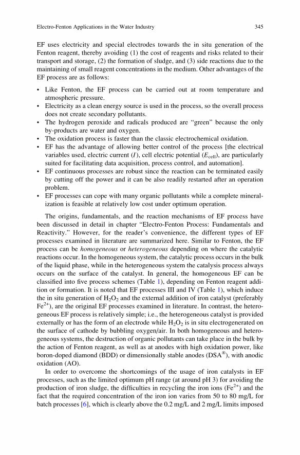
EF uses electricity and special electrodes towards the in situ generation of the
Fenton reagent, thereby avoiding (1) the cost of reagents and risks related to their
transport and storage, (2) the formation of sludge, and (3) side reactions due to the
maintaining of small reagent concentrations in the medium. Other advantages of the
EF process are as follows:
• Like Fenton, the EF process can be carried out at room temperature and
atmospheric pressure.
• Electricity as a clean energy source is used in the process, so the overall process
does not create secondary pollutants.
• The hydrogen peroxide and radicals produced are “green” because the only
by-products are water and oxygen.
• The oxidation process is faster than the classic electrochemical oxidation.
• EF has the advantage of allowing better control of the process [the electrical
variables used, electric current (I), cell electric potential (Ecell), are particularly
suited for facilitating data acquisition, process control, and automation].
• EF continuous processes are robust since the reaction can be terminated easily
by cutting off the power and it can be also readily restarted after an operation
problem.
• EF processes can cope with many organic pollutants while a complete mineral-
ization is feasible at relatively low cost under optimum operation.
The origins, fundamentals, and the reaction mechanisms of EF process have
been discussed in detail in chapter “Electro-Fenton Process: Fundamentals and
Reactivity.” However, for the reader’s convenience, the different types of EF
processes examined in literature are summarized here. Similar to Fenton, the EF
process can be homogeneous or heterogeneous depending on where the catalytic
reactions occur. In the homogeneous system, the catalytic process occurs in the bulk
of the liquid phase, while in the heterogeneous system the catalysis process always
occurs on the surface of the catalyst. In general, the homogeneous EF can be
classified into five process schemes (Table 1), depending on Fenton reagent addi-
tion or formation. It is noted that EF processes III and IV (Table 1), which induce
the in situ generation of H2O2 and the external addition of iron catalyst (preferably
Fe2+), are the original EF processes examined in literature. In contrast, the hetero-
geneous EF process is relatively simple; i.e., the heterogeneous catalyst is provided
externally or has the form of an electrode while H2O2 is in situ electrogenerated on
the surface of cathode by bubbling oxygen/air. In both homogeneous and hetero-
geneous systems, the destruction of organic pollutants can take place in the bulk by
the action of Fenton reagent, as well as at anodes with high oxidation power, like
boron-doped diamond (BDD) or dimensionally stable anodes (DSA®), with anodic
oxidation (AO).
In order to overcome the shortcomings of the usage of iron catalysts in EF
processes, such as the limited optimum pH range (at around pH 3) for avoiding the
production of iron sludge, the difficulties in recycling the iron ions (Fe2+) and the
fact that the required concentration of the iron ion varies from 50 to 80 mg/L for
batch processes [6], which is clearly above the 0.2 mg/L and 2 mg/L limits imposed
Electro-Fenton Applications in the Water Industry 345
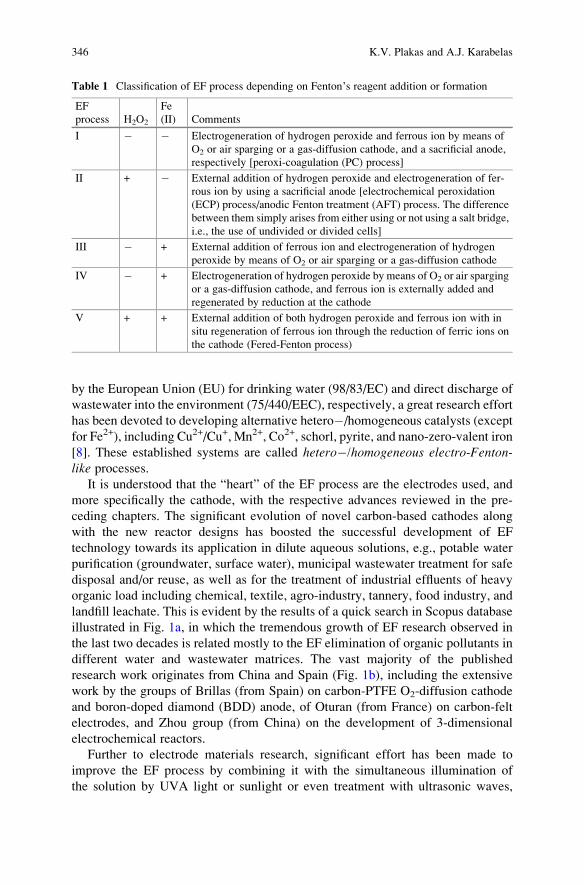
by the European Union (EU) for drinking water (98/83/EC) and direct discharge of
wastewater into the environment (75/440/EEC), respectively, a great research effort
has been devoted to developing alternative hetero�/homogeneous catalysts (except
for Fe2+), including Cu2+/Cu+, Mn2+, Co2+, schorl, pyrite, and nano-zero-valent iron
[8]. These established systems are called hetero�/homogeneous electro-Fenton-like processes.
It is understood that the “heart” of the EF process are the electrodes used, and
more specifically the cathode, with the respective advances reviewed in the pre-
ceding chapters. The significant evolution of novel carbon-based cathodes along
with the new reactor designs has boosted the successful development of EF
technology towards its application in dilute aqueous solutions, e.g., potable water
purification (groundwater, surface water), municipal wastewater treatment for safe
disposal and/or reuse, as well as for the treatment of industrial effluents of heavy
organic load including chemical, textile, agro-industry, tannery, food industry, and
landfill leachate. This is evident by the results of a quick search in Scopus database
illustrated in Fig. 1a, in which the tremendous growth of EF research observed in
the last two decades is related mostly to the EF elimination of organic pollutants in
different water and wastewater matrices. The vast majority of the published
research work originates from China and Spain (Fig. 1b), including the extensive
work by the groups of Brillas (from Spain) on carbon-PTFE O2-diffusion cathode
and boron-doped diamond (BDD) anode, of Oturan (from France) on carbon-felt
electrodes, and Zhou group (from China) on the development of 3-dimensional
electrochemical reactors.
Further to electrode materials research, significant effort has been made to
improve the EF process by combining it with the simultaneous illumination of
the solution by UVA light or sunlight or even treatment with ultrasonic waves,
Table 1 Classification of EF process depending on Fenton’s reagent addition or formation
EF
process H2O2
Fe
(II) Comments
I � � Electrogeneration of hydrogen peroxide and ferrous ion by means of
O2 or air sparging or a gas-diffusion cathode, and a sacrificial anode,
respectively [peroxi-coagulation (PC) process]
II + � External addition of hydrogen peroxide and electrogeneration of fer-
rous ion by using a sacrificial anode [electrochemical peroxidation
(ECP) process/anodic Fenton treatment (AFT) process. The difference
between them simply arises from either using or not using a salt bridge,
i.e., the use of undivided or divided cells]
III � + External addition of ferrous ion and electrogeneration of hydrogen
peroxide by means of O2 or air sparging or a gas-diffusion cathode
IV � + Electrogeneration of hydrogen peroxide by means of O2 or air sparging
or a gas-diffusion cathode, and ferrous ion is externally added and
regenerated by reduction at the cathode
V + + External addition of both hydrogen peroxide and ferrous ion with in
situ regeneration of ferrous ion through the reduction of ferric ions on
the cathode (Fered-Fenton process)
346 K.V. Plakas and A.J. Karabelas
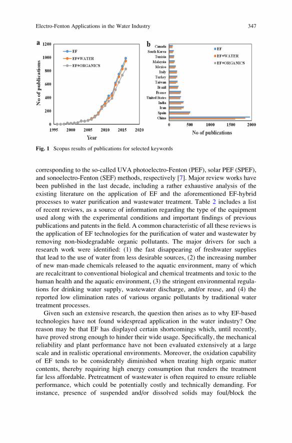
corresponding to the so-called UVA photoelectro-Fenton (PEF), solar PEF (SPEF),
and sonoelectro-Fenton (SEF) methods, respectively [7]. Major review works have
been published in the last decade, including a rather exhaustive analysis of the
existing literature on the application of EF and the aforementioned EF-hybrid
processes to water purification and wastewater treatment. Table 2 includes a list
of recent reviews, as a source of information regarding the type of the equipment
used along with the experimental conditions and important findings of previous
publications and patents in the field. A common characteristic of all these reviews is
the application of EF technologies for the purification of water and wastewater by
removing non-biodegradable organic pollutants. The major drivers for such a
research work were identified: (1) the fast disappearing of freshwater supplies
that lead to the use of water from less desirable sources, (2) the increasing number
of new man-made chemicals released to the aquatic environment, many of which
are recalcitrant to conventional biological and chemical treatments and toxic to the
human health and the aquatic environment, (3) the stringent environmental regula-
tions for drinking water supply, wastewater discharge, and/or reuse, and (4) the
reported low elimination rates of various organic pollutants by traditional water
treatment processes.
Given such an extensive research, the question then arises as to why EF-based
technologies have not found widespread application in the water industry? One
reason may be that EF has displayed certain shortcomings which, until recently,
have proved strong enough to hinder their wide usage. Specifically, the mechanical
reliability and plant performance have not been evaluated extensively at a large
scale and in realistic operational environments. Moreover, the oxidation capability
of EF tends to be considerably diminished when treating high organic matter
contents, thereby requiring high energy consumption that renders the treatment
far less affordable. Pretreatment of wastewater is often required to ensure reliable
performance, which could be potentially costly and technically demanding. For
instance, presence of suspended and/or dissolved solids may foul/block the
Fig. 1 Scopus results of publications for selected keywords
Electro-Fenton Applications in the Water Industry 347
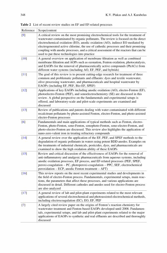
Table 2 List of recent review studies on EF and EF-related processes
Reference Scope/content
[9] A critical review on the most promising electrochemical tools for the treatment of
wastewater contaminated by organic pollutants. The review is focused on the direct
electrochemical oxidation (EO), anodic oxidation (AO), indirect EO mediated by
electrogenerated active chlorine, the use of cathodic processes and their promising
coupling with anodic processes, and a critical assessment of the reactors that can be
used to put these technologies into practice
[10] A general overview on application of membrane filtration as well as combined
membrane filtration and AOPs such as ozonation, Fenton oxidation, photocatalysis,
and EAOPs for the removal of pharmaceutically active compounds (PhACs) from
different water systems (including AO, EF, PEF, and hybrids)
[11] The goal of this review is to present cutting-edge research for treatment of three
common and problematic pollutants and effluents: dyes and textile wastewater,
olive processing wastewater, and pharmaceuticals and hospital wastewater by
EAOPs (including EF, PEF, Bio-EF, SPEF)
[12] Applications of key EAOPs including anodic oxidation (AO), electro-Fenton (EF),
photoelectro-Fenton (PEF), and sonoelectrochemistry (SE) are discussed in this
review. A global perspective on the fundamentals and experimental setups is
offered, and laboratory-scale and pilot-scale experiments are examined and
discussed
[13] Review of publications and patents dealing with water contaminated with different
recalcitrant pollutants by photo-assisted Fenton, electro-Fenton, and photo-assisted
electro-Fenton processes
[6] Fundamentals and main applications of typical methods such as Fenton, electro-
Fenton, photo-Fenton, sono-Fenton, sonophoto-Fenton, sono-electro-Fenton, and
photo-electro-Fenton are discussed. This review also highlights the application of
nano-zero-valent iron in treating refractory compounds
[14] A general review over the application of the EF, PEF, and SPEF methods to the
degradation of organic pollutants in waters using potent BDD anodes. Examples on
the treatments of industrial chemicals, pesticides, dyes, and pharmaceuticals are
examined to show the high oxidation ability of these EAOPs
[15] Review and critical discussion of the effectiveness of EAOPs for the removal of
anti-inflammatory and analgesic pharmaceuticals from aqueous systems, including
anodic oxidation processes, EF process, and EF-related processes (PEF, SPEF,
peroxi-coagulation – PC, photoperoxi-coagulation – PPC, SEF, electrochemical
peroxidation – ECP, anodic Fenton treatment – AFT)
[16] This review reports on the most recent experimental studies and developments in
the field of electro-Fenton process. Fundamentals, experimental setups, main reac-
tions, the parameters that affect these processes, and various applications are
discussed in detail. Different cathodes and anodes used for electro-Fenton process
are also analyzed
[17] A general review of lab and pilot-plant experiments related to the most relevant
applications of several electrochemical and photoassisted electrochemical methods,
including electrocoagulation (EC), EO, EF, PEF
[7] A largely cited review paper on the origins of Fenton’s reaction chemistry for
wastewater treatment and Fenton-based EAOPs developed until 2008. Fundamen-
tals, experimental setups, and lab and pilot-plant experiments related to the major
applications of EAOPs to synthetic and real effluents are described and thoroughly
discussed
348 K.V. Plakas and A.J. Karabelas
electrode surfaces, while bicarbonate ions (HCO3�) can appreciably reduce the
concentration of •OH due to scavenging processes that yield H2O and much less
reactive species (e.g., CO3•�). Moreover, there is a need to minimize the formation
of toxic by-products and the loss of efficiency caused by mass transfer limitations
and undesirable side reactions. The robustness (service life time), the scale-up, and
the cost of the special electrodes applied are also a matter of concern. Recognition
of the situations where these limitations pose potential health risks is a necessary
step in the design and operation of EF systems. At the same time, existing,
competing techniques, such as nanofiltration, ultra-low pressure reverse osmosis,
or adsorption on composite materials, have improved in performance. This means
that EF has to catch and overtake a moving target.
In view of the above considerations, the scope of this chapter is to review our
current understanding and knowledge gained from the extensive research on the
mineralization by EF-based processes of biorefractory organic contaminants from
water and wastewater. Particular attention is paid to the parameters affecting the
design and the performance of the systems, along with scale-up and optimization
issues. The results of a patent search are also included. Finally, future R&D needs
are discussed, both at the scientific and the technological level that would facilitate
the development and penetration of EF-based systems into the water/wastewater
treatment market.
2 Electro-Fenton Applications in the Water
and Wastewater Sector
Considering the scope of this chapter, an effort is made in this section to summarize
the applications of the EF-based processes in water and wastewater treatment. The
objective of this summary is not the replication of the lab-, pilot-scale studies
already reviewed by previous researchers (Table 2), but rather the description of
the target wastewaters that can be effectively treated by EF and other related
electrochemical technologies. Figure 2 illustrates the source of the water and
wastewater investigated in literature, along with typical examples of organic
pollutants contained in the respective effluents. According to Fig. 2, the efficiency
and flexibility of EF technology has been proven with a wide diversity of effluents
from municipal, chemical, and other related industries or activities, including
pharmaceutical, pulp and paper, textile, food, cork processing, and landfilling
among others. These wastewaters contain a cocktail of pollutants in a wide range
of concentrations. The development of cost-effective technical solutions based on
EF processes has been proven by several researchers, although the conclusions
drawn are in many cases based on laboratory-scale results and with feedwater
compositions that are not necessarily realistic, e.g., high organic concentrations
(especially in the case of experiments with pure water solutions simulating potable
Electro-Fenton Applications in the Water Industry 349
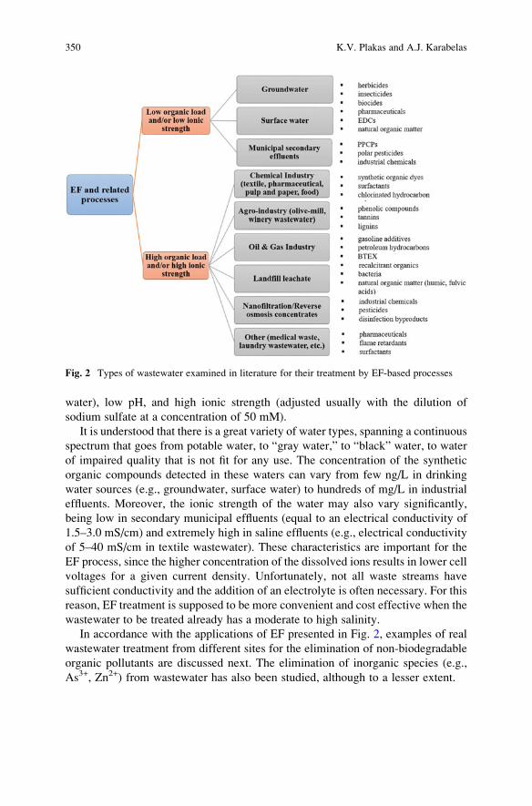
water), low pH, and high ionic strength (adjusted usually with the dilution of
sodium sulfate at a concentration of 50 mM).
It is understood that there is a great variety of water types, spanning a continuous
spectrum that goes from potable water, to “gray water,” to “black” water, to water
of impaired quality that is not fit for any use. The concentration of the synthetic
organic compounds detected in these waters can vary from few ng/L in drinking
water sources (e.g., groundwater, surface water) to hundreds of mg/L in industrial
effluents. Moreover, the ionic strength of the water may also vary significantly,
being low in secondary municipal effluents (equal to an electrical conductivity of
1.5–3.0 mS/cm) and extremely high in saline effluents (e.g., electrical conductivity
of 5–40 mS/cm in textile wastewater). These characteristics are important for the
EF process, since the higher concentration of the dissolved ions results in lower cell
voltages for a given current density. Unfortunately, not all waste streams have
sufficient conductivity and the addition of an electrolyte is often necessary. For this
reason, EF treatment is supposed to be more convenient and cost effective when the
wastewater to be treated already has a moderate to high salinity.
In accordance with the applications of EF presented in Fig. 2, examples of real
wastewater treatment from different sites for the elimination of non-biodegradable
organic pollutants are discussed next. The elimination of inorganic species (e.g.,
As3+, Zn2+) from wastewater has also been studied, although to a lesser extent.
Fig. 2 Types of wastewater examined in literature for their treatment by EF-based processes
350 K.V. Plakas and A.J. Karabelas
2.1 Purification of Potable Water Sources
The findings of a literature search on EF application for potable water treatment
showed that the majority of the experimental studies have been performed with
small stirred tank reactors (electrochemical cells) at laboratory scale using synthetic
organic solutions of varying composition (solutions prepared usually with
deionized water), without considering their viability for industrial application.
Moreover, the feed concentrations of the target pollutants were many orders of
magnitude higher than the actual concentrations identified in potable water sources
(groundwater, surface water). It is understood that the achievement of high mass
transfer rates in the EF reactors for such low concentrations is of paramount
importance and it is one of the main issues that needs to be tackled before
electrochemical oxidation can be applied successfully for potable water purifica-
tion. In the last 5 years, however, several research groups orientate their research
activities to pilot-scale experiments, taking advantage of the knowledge gained
from the basic research carried out over the past 20 years.
Garcia et al. made a first step to demonstrate the efficiency of EO and EF
processes with 3 L recirculation flow plants as a first step for the further scale-up
of both EAOPs at industrial level [18, 19]. The undivided filter-press reactors
consisted of (1) a Pt sheet anode and a carbon–PTFE air-diffusion cathode and
(2) a BDD anode and cathode supported on niobium. In the first one, large amounts
of •OH are produced by Fenton reaction owing to the high H2O2 generation at the
air-diffusion cathode, whereas a small participation of Pt(•OH) produced during the
mineralization process is also expected. In contrast, in the latter, much lower H2O2
is generated at the BDD cathode, yielding smaller quantities of •OH, but organics
can also be mineralized by the more reactive BDD(•OH) formed by the anode. In
this work it has been demonstrated that the decontamination of a herbicide solution
(92 mg/L 2,4-D) at pH 3.0 was more efficient in the case of a single BDD/BDD cell
instead of a single Pt/air-diffusion one, obviously due to the higher ability of •OH at
the BDD surface to mineralize organic intermediates. The most potent EF process
with this cell gave 59% mineralization with 23% efficiency and 0.42 kWh/g TOC
specific energy after 300 min at 0.5 A. It is noticed that the final solution of the EO
process with a BDD/BDD cell contained a mixture of carboxylic acids as major
component.
An undivided electrochemical reactor with a volume capacity of 1.5 L and a fixed
bed of glassy carbon pellets three-dimensional cathode that was developed in the past
by EDF (Electricite de France) to treat aqueous effluent containing heavy metal was
used by Chmayssem et al. [20] for the application of EF at semi-pilot-plant scale.
Experiments with Bisphenol A (BPA) demonstrated the high efficiency of the system
to degrade the specific molecule (an absolute rate of BPA degradation was deter-
mined as 4.3 � 109 M�1 s�1) at an applied current intensity 0.8 A and acidic
pH. Considering that the system does not achieve a total TOC mineralization
Electro-Fenton Applications in the Water Industry 351
(small organic acids present in the effluent, regardless the initial BPA concentration),
a subsequent biological treatment is necessary prior to the discharge of the final
effluent.
El-Ghenymy et al. [21] performed a comparative study of sulfanilamide degra-
dation (drug frequently detected in surface water) by EF and SPEF using a 2.5 L
pre-pilot plant equipped with a Pt/air-diffusion cell. The solar photoreactor was a
polycarbonate box (600 mL irradiated volume), with a mirror at the bottom and an
inclination of 41� to better collect the sun rays [the average UV irradiation intensity
(300–400 nm) supplied by sunlight was measured 30–32 W/m2]. A mineralization
up to 94% was achieved using SPEF, whereas EF yielded much poorer degradation.
Recent studies suggested that flow-through EF reactors (i.e., the feedwater flows
through and not by the anode and cathode) tend to improve the degradation rate and
efficiency due to the enhanced convective transfer of the pollutants to the electrode
surface [22–24]. In these works, the solution was either pretreated by pumping
air/oxygen to increase the concentration of the dissolved oxygen in solution [22] or
electrolysis was taking place relying only on the dissolved oxygen of the feedwater
(approx. 8–9 mg/L in tap water at room temperature) [24]. The novel electrochem-
ical device developed by Plakas et al. [24] has the form of a “filter” that consists of a
stack of carbon anodic and cathodic electrode pairs for operation in continuous
mode. This “filter”-type design facilitates the scale-up of the device and promotes
the uniform distribution of the water throughout the electrodes, thus ensuring the
effective fluid contact with the in situ produced oxidants. Bench-scale tests with one
pair of anode/cathode electrodes, using the pharmaceutical diclofenac as a model
micropollutant [25], resulted in optimized cathodic electrodes (employing carbon
felts and optimumprocedures of iron nanoparticle impregnation), “filter” design, and
operating conditions (cathodic potential, feed flow). These results paved the way for
the design and construction of a fully automated laboratory-scale pilot system [26],
which was tested under real operating conditions (continuous treatment of tap water,
without the addition of electrolyte or the sparging of air/O2), as a necessary step
towards applications. Pilot studies with the pharmaceutical diclofenac, with
three pairs of anode/cathode electrodes made of carbon felt (of total geometric
area 175 cm2 and effective surface area of approx. 4,000 m2) and with cathodes
impregnated with iron nanoparticles (γ-Fe2O3/F3O4), various feedwater flow rates
(10–40 L/h), and applied potentials (1.4–3.2 V), showed that the best “filter”
performance was obtained at applied potential of 2 V per pair of electrodes, and
low water superficial velocities (~0.09 cm/s), i.e., the overall mineralization current
efficiency (MCE) was >20%, during continuous steady state treatment of tap water
with low DCF concentrations (16 μg/L DCF, TOC of tap water 0.56 mg/L). It is
noteworthy that the EF “filter” exhibited satisfactory stability regarding both elec-
trode integrity (no iron leaching) and removal efficiency, even after multiple filtra-
tion/oxidation treatment cycles, achieving (under steady conditions) DCF and TOC
removal 85% and 36%, respectively. This performance is considered satisfactory
because the EF process took place under rather unfavorable conditions, such as
neutral pH, low dissolved O2 concentration, low electrical conductivity (~700 μS/cm), and presence of natural organic matter and inorganic ions in tap water.
352 K.V. Plakas and A.J. Karabelas
Progress on the aforementioned flow-through EF reactors was made in the work
of Ma et al. [27]. Specifically, an energy-efficient flow-through EF reactor was
designed, whereas the feed solution passed through a modified graphite felt cathode
and a perforated Dimensionally Stable Anode (DSA®) anode sequentially,
companying the pumped air. The flow-through EF system was compared to the
flow-by and regular one, and confirmed to be best for the removal of the model
organic pollutant used (methylene blue-MB) and TOC degradation. The MB and
TOC removal efficiency of the effluents were kept above 90% and 50%, respec-
tively, and the energy consumption was 23.0 kWh/kg TOC at current of 50 mA, pH
3, 0.3 mM Fe2+, and flow rate of 7 mL/min. It is noticed that the flow rate in flow-
through cells has a great impact not only on the residence time of pollutants but also
on the accumulation of H2O2 in the EF process. The choice of a suitable flow rate is
thus, critical for the process efficiency, which in turn can be limited by the cross-
sectional area of the inlet/outlet tubing.
In an effort to improve oxygen utilization efficiency, Xu et al. [28] fabricated a
novel dual tubular membrane electrodes reactor which consists of a tubular mem-
brane Ti/IrO2–Ta2O5 anode and a carbon black polytetrafluoroethylene (CB-PTFE)
modified graphite membrane as cathode. It was demonstrated that Ti/IrO2–Ta2O5
anode provided enough oxygen to electrogenerate H2O2, up to 1,586 mg/m2 h, at
10 A/m2 without aeration in acidic solution. Experiments with the pesticide
tricyclazole showed a stable removal of 79% after 20 min of treatment without
recirculation.
Motivated by the pollution of drinking water sources by arsenic and organo-
arsenic compounds such as monomethylarsinate (MMA) and dimethylarsinate
(DMA), Lan et al. [29] developed a FeCx/N-doped carbon fiber composite
(FeCx/NCNFs) as a catalyst for the degradation of DMA, and as an absorbent of
the produced inorganic arsenic (As(V)), with degradation and adsorption occurring
simultaneously, in an EF process. For an initial concentration of DMA 5 mg/L, 96%
was degraded after reaction time of 360 min, with TOC efficiently removed at the
same time. The residual As(V) concentration in solution was below the allowable
limit of 0.01 mg/L under the optimum treatment conditions.
2.2 Treatment of Secondary Municipal Effluents
A large part of synthetic organic compounds (SOCs) identified into the aquatic
environment are in their original form or metabolite due to the low removal
efficiency of standard wastewater treatment plants (WWTPs) on such compounds.
This fact combined with the special effects of specific organics (e.g., pharmaceu-
ticals, pesticides, nonylphenols) on target even unintended organisms at low doses
makes it urgent to develop more efficient technologies for their elimination. EF and
related electrochemical technologies have been investigated as an advanced oxida-
tion process to address a variety of objectives including the preliminary reduction of
high percentages of organic load in terms of COD or TOC and removal of
Electro-Fenton Applications in the Water Industry 353
recalcitrant and toxic pollutants, thus allowing for further conventional biological
treatment (pretreatment) or for the final polishing of the secondary effluent
(posttreatment) [11].
Xu et al. [30] investigated the feasibility of removing trace estrogens that are
frequently detected in municipal wastewaters [17β-estradiol (E2) and 17α-ethynyl-estradiol (EE2)] by a bio-electro-Fenton (BEF) system equipped with a Fe@Fe2O3/
non-catalyzed carbon felt composite cathode. The system consisted of two similar
chambers of 75 mL separated by proton exchange membrane while the anodic
chamber was filled with granular graphite to enhance the anodic power density.
Under closed-circuit condition, 81% of E2 and 56% of EE2 were removed within
10 h in the system, in which the highest concentration of total iron ions and H2O2
reached 81 and 1.2 mg/L, respectively. The reported maximum power density of
BEF system was 4.35 W/m3.
Kishimoto et al. [31] examined two combined processes, namely an activated
sludge process followed by the EF with an oxidation–reduction potential (ORP)
control (AS-EF process) and the EF process with an ORP control followed by an
activated sludge process (EF-AS process), by using 1,4-dioxane contaminated
municipal wastewater. The reactor comprised of a glass beaker with 300 mL of
wastewater content, two electrochemical flow cells, two direct current power
supplies, an ORP controller, an interflow cell, and a peristaltic pump (to feed the
wastewater to the two electrochemical flow cells at a flow rate of 6.17 mL/s for each
cell). The function of one flow cell was the onsite generation of HOCl, while that
of the other was the onsite generation of Fe2+. The former cell had a plate DSE®
anode and a plate cathode made of stainless steel, with an effective surface area of
42 cm2 for both electrodes. The latter had a plate anode made of titanium, coated
with ruthenium oxide and a plate cathode made of stainless steel, with an effective
surface area of 63 cm2 for both electrodes. AS-EF process was found to be superior
to the EF-AS process in respect of both energy consumption and the performance of
COD removal, as well as removal of 1,4-dioxane. Specifically, in the AS-EF
process, the activated sludge process mainly contributed to the COD and BOD
removal, whereas the EF process was responsible for 1,4-dioxane removal.
Recently, significant research effort was focused on the application of EF for
wastewater disinfection. It was found that microorganisms can be inactivated
electrochemically directly on a BDD anode or via the generation of •OH
[32]. The combined elimination of refractory pollutants with microbial disinfection
of wastewater in a single treatment step constitutes an attractive compact alterna-
tive, especially in the field of water reclamation and reuse where effective elimi-
nation of pathogens is crucial to protect public health. Many experimental studies
have been carried out in this field, but the majority have been performed at
laboratory scale and only lately have investigations begun at pilot scale by
electrooxidation and peroxi-coagulation [33].
354 K.V. Plakas and A.J. Karabelas
2.3 Chemical Industry Wastewater
The chemical industry is a major contributor to problem of industrial wastewaters,
not only in terms of discharge volumes, but also regarding the hazardous nature of
many of the pollutants found in the effluents. The increasingly stringent regulations
have prompted the application of advanced technologies for complying with dis-
charge regulations and allowing for water recycling. Considerable study of the
application of EF process in industrial wastewater treatment has been undertaken to
date. The process efficiency has been experimentally confirmed by different authors
for the treatment of media containing pharmaceuticals, dyes, pesticides, surfactants,
and other recalcitrant organics.
2.3.1 Pharmaceutical Industry
Treatment of pharmaceutical wastewaters has always been problematic owing to
the wide variety of chemicals used in drug manufacturing, which leads to waste-
waters of variable composition and fluctuations in pollutant concentrations. The
substances synthesized by the pharmaceutical industry are in most cases structur-
ally complex organic chemicals that are resistant to biological degradation. EF
oxidation has proved to be a suitable pretreatment for pharmaceutical wastewaters,
leading to an improvement of the wastewater biodegradability and a reduction of
the toxicity of these effluents. Considering recent researches, the most frequently
removed non-steroidal anti-inflammatory drugs (NSAIDs) by EF-based processes
are ibuprofen, paracetamol, and diclofenac.
A hybrid process coupling EF and a biological degradation-step was investigated
by Mansour et al. [34] in order to mineralize synthetic and industrial pharmaceu-
tical effluents containing trimethoprim (TMP), a bacteriostatic antibiotic. The
effluent contained a high TMP concentration (3.56 g/L; diluted to 58 mg/L for
the scope of the experiments), it was characterized by a conductivity of 4.36 mS/
cm, COD of 438.50 g/L, and TOC of 125.40 g/L. EF using an undivided two
electrode Pt/carbon felt cylindrical glass cell of 1 L exhibited at optimum opera-
tional conditions (0.69 mM Fe2+, pH 3, 466 mA, and 2 L/min recirculation flow
rate) an almost total removal of TMP after 180 min of electrolysis. Although TOC
removal was low, the biodegradability of the treated industrial effluent was
improved. Overall removal yields were 80 and 89% for 180 and 300 min of EF
pretreatment followed by 15 days activated sludge culture, respectively.
2.3.2 Pulp and Paper Industry
More than 250 chemicals may be present in the effluents resulting from the different
stages of papermaking. Some of these pollutants are naturally occurring wood
extractives (tannins, resin acids, lignin, etc.) while others are xenobiotic compounds
Electro-Fenton Applications in the Water Industry 355
formed mostly in pulp manufacture (polyphenols, chlorinated organic compounds,
aromatic compounds, dioxins and furans, cyanide, etc.) [35]. The latter are resistant
to biological treatment, and therefore, strong oxidation processes in the form of
integrated schemes with other physical and biological methods are usually consid-
ered for achieving the discharge standards. In a recent study by Jaafarzadeh et al.
[36] the integration of permanganate (PM) (oxidation/precipitation), EF, and
Co3O4/UV/peroxymonosulfate (sulfate radical, SO4•�) was investigated for COD
removal from a real wastewater collected from a pulp and paper industry. The
authors measured a COD reduction from 1,450 to 62 mg/L (~95%) as well as an
enhanced biodegradability of the final effluent by employing the integrated process.
The EF process was carried out by means of an electrochemical cell consisting of
two iron sheets as anode and cathode (effective surface area 60 cm2) which was
immersed in the acidic effluent of the PM process (pH 2.7). After 60 min of
electrolysis at 0.5 mA/cm2 current density, and addition of 12 mM H2O2, a COD
removal of 57.8% was observed. The sludge produced during the PM and EF
process included a considerable amount of organic pollutants which means that
coagulation mechanism contributed to the overall performance. In such a process,
the obtained sludge should be considered for remediation and recovery of manga-
nese and iron.
2.3.3 Textile Industry
Textile industry is particularly known for its high water consumption as well as the
amount and variety of chemicals used throughout the different operations. The
environmental issues in the textile industry are associated with the bio-refractory
nature of the wastewaters produced from the dyeing and finishing stages, including
various dyestuffs and chemical additives (such as polyvinyl alcohol and surfac-
tants). Estimates indicate that approximately, 7 � 105 tons of dyestuffs are pro-
duced annually and 280,000 tons of the textile dyes are discharged into water sinks
through textile effluents [37]. That explains why textile effluent is characterized by
high COD (150–10,000 mg/L), BOD (100–4,000 mg/L), pH (6–10), and color
content (50–2,500) [38]. Fenton-based EAOPs have been largely investigated for
the efficient mineralization of dyestuff [11, 14, 16, 38]. Among the different
techniques examined, SPEF proved to be the most promising one achieving almost
total mineralization and higher degradation compared to UVA-illuminated PEF due
to the higher UV intensity of sunlight, which can quickly photolyze Fe(III)–
carboxylate complexes that could not be destroyed by •OH in traditional EF
processes.
Pilot-scale experiments by Garcia-Segura and Brillas [39] with an autonomous
SPEF flow plant with a Pt/air-diffusion cell coupled to a compound parabolic
collector (CPC) photoreactor showed the viability of the process for the combustion
of acidic solutions of textile monoazo, diazo, and triazo dyes. Comparative trials
were made by electrolyzing 10 L of 50 mg/L of dissolved organic carbon of each
azo dye in 50 mM Na2SO4 with 0.50 mM Fe2+ of pH 3.0. The monoazo Acid
356 K.V. Plakas and A.J. Karabelas
Orange 7 solution underwent the faster decolorization, azo dye decay, and DOC
removal, attaining an almost total mineralization with 97% DOC abatement in
about 180 min. The diazo Acid Red 151 solution was degraded more slowly than
the triazo Disperse Blue 71 one, but in both cases the final solution still contained
8–10% of residual DOC due to the formation of very recalcitrant products. Ren
et al. [40] developed recently a novel vertical-flow EF reactor of total effective
volume of 2 L, comprised of 10 cell compartments using PbO2 anode (10� 12 cm),
and modified graphite felt mesh cathode (10 � 12 cm); the latter was found to be
more complete and efficient in organic pollutants degradation when comparing with
the traditional parallel-flow reactor, using a model azo dye (tartrazine). The optimal
operating conditions for this reactor were pH 3, voltage 4.0 V, flow rate 40 mL/min,
Fe2+ of 0.4 mM, aeration rate 80 mL/min. Within 120 min of treatment tartrazine
degradation efficiency could reach near 100% and the TOC removal efficiency was
higher than 60%. According to the authors, the novel vertical-flow EF is versatile,
since the cell numbers can be easily controlled to adapt to different concentration of
pollutants to achieve an ideal treatment performance in practical applications.
The degradation of different dyes by EF oxidation was carried out also success-
fully in a continuous two electrode stainless steel/graphite bubble reactor by Rosales
et al. [41]. The EF bubble reactor had a working volume of 0.675 L, andwas operated
in batch mode with total reflux or continuous mode. Steel or graphite bars were
employed as electrodes. Each bar was 100 mm long with a diameter of 6.35 mm for
graphite and 10 mm for stainless steel, resulting in a total contact surface area of
1.27 cm2 for graphite and 3.14 cm2 for stainless steel. A constant potential difference
(15 V) was applied and a continuous saturation of air at atmospheric pressure was
ensured by bubbling compressed air near the cathode at about 1 L/min. Under
continuous treatment and an operating residence time of 21 h the reactor achieved
a high decoloration efficiency (dyes tested Methyl Orange, Reactive Black 5 and
Fuchsin Acid) close to 43% which is squared with a TOC reduction around 46%.
El-Desoky et al. [42] employed an optimized EF system successfully, using a
reticulated vitreous carbon cathode (60 PPI, dimensions 5 � 7 cm and thickness of
0.9 cm) and a platinum gauze anode (of an area 3.8 cm2 placed at the center of the
electrochemical cell), for complete degradation and significant mineralization
(approx. 85–90%) of Levafix blue and red reactive azo dyes in real industrial
wastewater samples of a textile dyeing house. Experiments were carried out in a
three-electrode undivided glass electrochemical cell (reactor) containing 250 mL of
the supporting electrolyte of pH 3.0, 50 mg (200 mg/L) of the investigated azo dye,
and a catalyst quantity (0.5 mM) of Fe2+ or Fe3+ ions. The optimized cathode applied
potential was �1.0 V vs. SCE. Wang et al. [43] studied the efficiency of COD
removal from real dyeing wastewater (COD: 1,224 mg/L, TOC: 394.6 mg/L) by
using Fe2+ in combination with electrogenerated hydrogen peroxide at a
polyacrylonitrile-based activated carbon fiber cloth cathode. In this study a platinum
wire (with a diameter of 0.05 cm) was used as anode while the cathode was designed
as a hollow cylindrical structure with a diameter of 2.9 cm and height of 7 cm.
Oxygen gas from an oxygen cylinder was dispensed directly at the bottom of the
hollow cylindrical cathode at a rate ranging from 50 to 250 mL/min. The highest
Electro-Fenton Applications in the Water Industry 357
COD removal efficiency (75.2%) was achieved at an applied current density 3.2 mA/
cm2, oxygen sparging rate 150 mL/min, pH 3, and the addition of 2 mM Fe2+.
Recently, bio-electro-Fenton (Bio-EF) has been successfully applied to degrade
organic pollutants (i.e., p-nitrophenol and azo dyes) in a microbial fuel cell
catholyte at neutral pH [44]. In such a system, electrons are released from the
bio-reactions at the anode and transported to the cathode via an external load
circuit. H2O2 is continuously generated by the two-electron reduction of oxygen
on a carbon felt in the cathode chamber. Simultaneously, the Fe2+ ions can be
generated in situ at neutral pH by direct electro-reduction of iron oxide in the
cathode chamber. The feasibility of using such a system, consisting of a carbon
felt/γ-FeOOH composite cathode, to oxidize As(III) in aqueous solutions at neutral
pH was also investigated by Wang et al. [45]. The results indicated that the process
was capable of inducing As(III) oxidation with an apparent As(III) depletion first-
order rate constant of 0.208 h�1 and an apparent oxidation current efficiency as high
as 73.1%. According to the authors, the γ-FeOOH dosage in the cathode was
determined to be an important factor in the system performance while there is
place for the operational parameters, such as the composition of the cathode or
anode chamber and retention time, to be optimized.
2.4 Treatment of Agro-Industrial Wastewater
The EF technology, alone or in form of an integrated process, has also proved to be
effective for the treatment of wastewaters generated by the food industry. This
includes wastewaters from olive oil extraction plants, commonly named olive mill
wastewaters (OMW) [46, 47] and winery wastewaters [48]. The composition of
these wastewaters is heterogeneous including various contaminants, such as nitro-
gen or phenolic compounds, ethanol, sugars, organic acids, aldehydes in addition to
some recalcitrant compounds. Moreover, the chelating character of some com-
pounds present in these effluents leads to the presence of some toxic heavy metals
in solution. In a recent work of Flores et al. [47] 100 mL of OMW solution (TOC
598� 42 mg/L, COD 2,368� 1 mg/L) was treated by AO (3 cm2 BDD anode and a
3 cm2 air-diffusion cathode at 16.7 mA/cm2), EF (with 0.5 mM Fe2+), and PEF
(with 0.5 mM Fe2+ and 6 W UVA radiation). The oxidation capability of the
processes increased in the order AO-H2O2 < EF < PEF with PEF exhibiting a
maximum efficiency of up to 80% mineralization. A new two sequential column
reactor design based on PEF technology combined with light emitting diode (LED)
radiation has been also demonstrated by Dıez et al. [48] as a viable alternative for
the treatment of winery wastewaters (named LED-EF2CR). The sequential treat-
ment was carried out in two-column reactors (glass columns of 40 mL capacity
each) connected in series. The first column was equipped with two electrodes of
different size: anode (18 cm2: 12 � 1.5 cm) and cathode (24 cm2: 12 � 2 cm) with
an electrode gap of 1 cm. Graphite sheet was used as anode and various materials
were used as cathode (graphite sheet, niquel foam, handmade activated carbon
358 K.V. Plakas and A.J. Karabelas
polytetrafluoroethylene). Air was pumped on the cathode surface (0.5 L/min),
permitting the generation of H2O2 and the homogenization of the fluid into the
column. The LED irradiation was carried out in the second glass column by placing
the LED lamp of 40 W (λ max 365 nm) 1 cm from the column wall. A slight
agitation was provided in this column by bubbling air at a flow rate of 0.1 L/min.
The experiments were carried out at different voltage drops (1, 3, and 5 V). The
degradation of simulated and real winery wastewater was efficiently accomplished
in this work; i.e., TOC removal between 50 and 70% was achieved, depending on
the sample initial TOC (simulated: 4,427 and 33,200 mg/L, real: 60,100 mg/L).
Furthermore, the new designed reactor was proved to be cost effective, since the
energy consumption was found to be 1 kWh/g TOC removed.
2.5 Remediation of Landfill Leachate
Landfill leachate is a polluting liquid which can have harmful effects on the
groundwater and surface water surrounding a landfill site, unless returned to the
environment in a carefully controlled manner. The volumetric flow and chemical
composition of the leachate may vary significantly while the most significant factor
affecting leachate nature is the age of the landfill. Generally, “young” leachate with
less than 5 years of landfilling is recalcitrant but readily biodegradable, while “old”
leachate with more than five or 10 years of landfilling is non-biodegradable [49]. To
treat these aged or refractory landfill leachates, different methods have been used
such as flocculation–precipitation, adsorption on activated carbon, evaporation,
chemical oxidation, and incineration. Among them, growing interest has been
focused on EAOPs, which can achieve a substantial reduction of COD and improve
the biodegradability.
Studies on the capacity of EF process to treat mature landfill leachate date back
to 2000 [50–54]. The majority of the EF processes investigated involve the external
addition of hydrogen peroxide rather than its continuous electrogeneration. This is
due to the fact that a long treatment time is required for high strength wastewater
such as mature leachate (the COD value is as high as several thousand mg/L) when
H2O2 is electrogenerated in situ. Mohajeri et al. [53] used Fered-Fenton process
where both H2O2 and ferrous ion were applied into the electrolytic cell. Experi-
ments were carried out at laboratory scale using 500 mL beakers with a pair of
anodic and cathodic aluminum electrodes, each 3 � 5 cm (active electrode area
dipped in leachate). Optimized conditions under specified constraints were obtained
at pH 3, H2O2/Fe2+ molar ratio 1, current density 49 mA/cm2, and reaction time
43 min. At these conditions 94% of COD (of initial average COD 2,950 mg/L) was
removed from the leachate. The Fered-Fenton method has also been examined by
Zhang et al. [51, 55] in rectangular plexiglass electrolytic reactors (containing
200 mL of leachate) with one pair of 5 � 11.9 cm anodic (Ti/RuO2–IrO2) and
cathodic (Ti mesh) electrodes. For an initial COD of 5,000 mg/L, removal of 87.2%
and 68.8% was achieved when batch and batch recirculation modes were employed,
Electro-Fenton Applications in the Water Industry 359
respectively, under optimum H2O2/Fe2+ molar ratio and current. Considering that
landfill leachate is produced continuously, Zhang et al. [49] investigated the
treatment of a mature landfill leachate by Fered-Fenton in a continuous stirred
tank reactor (CSTR) using Ti/RuO2–IrO2–SnO2–TiO2 mesh anodes and Ti mesh
cathodes. Out of the 73 organics detected in the leachate, 52 were completely
removed by the Fered-Fenton process.
Beyond the removal of recalcitrant organics from landfill leachate, the EF
process could potentially be applied for the removal of bacteria and other patho-
genic microorganisms. The superiority of EF process over the simple Fenton, to
remove coliform bacteria from two different leachates, was exhibited by Aziz et al.
[56]. The optimum amounts of ferrous sulfate heptahydrate and hydrogen peroxide
for both Fenton and EF treatments were determined in this study; 1,700 mg/L H2O2
and 2,800 mg/L Fe2+ with H2O2/Fe2+ molar ratio 1:3. Disinfection efficiency was
higher in the case of EF due to the synergistic anodic deactivation of the coliform
bacteria and the destruction induced by the H2O2 and the electro-peroxidation.
However, further treatment is necessary after the EF process in order for the final
effluent to satisfy the maximum permissible limits of organic (COD) and iron
content for direct discharge.
2.6 Other Applications
EF and EF-related technologies have been examined in literature for the decon-
tamination of special wastewaters such as thin film transistor-liquid crystal display
(TFT-LCD) wastewater [57], petrochemical wastewater [58], coal gasification
wastewater [59], reverse osmosis concentrates [60], wastewater from liquid organic
fertilizer plant [61], leather tanning industry wastewater [62], slaughterhouse efflu-
ent [63], tissue paper wastewater [64], spent caustic from ethylene plant [65].
Except from liquid effluents, the performance of EF was also assessed as an ex
situ technique for the treatment of soils contaminated by petroleum hydrocarbons
[66]. Authors implemented for the first time an innovative combination of soil
column washing with Tween® 80 and EF treatment on a genuinely diesel-
contaminated soil. Results showed that the EF treatment of the extracted eluates
using an undivided two electrode BDD/carbon felt electrochemical reactor at
1,000 mA resulted to a quasi-complete mineralization (>99.5%) of the hydrocar-
bons within 32 h. However, the complete mineralization of the hydrocarbons in
solution was not related to the toxicity of the solution, which increased throughout
the degradation. The biodegradability (BOD5/COD ratio) reached a maximum of
20% after 20 h of EF treatment, which is not enough to implement a combined
treatment with a biological treatment process. Further improvement of the overall
process is feasible and could pave the way for a new application of EF technique.
A novel system integrating three-dimensional catalytic electro-Fenton (3DCEF,
catalyst of sewage sludge-based activated carbon loaded with Fe3O4) with mem-
brane bioreactor (3DCEF–MBR) was recently developed by Jia et al. [59] as a
360 K.V. Plakas and A.J. Karabelas
promising technology for advanced treatment in engineering applications.
Laboratorial-scale results with biologically pretreated coal gasification wastewater
indicated that 3DCEF–MBR can achieve significant enhancement on the COD and
TOC removal, giving the efficiencies of 80% and 75%, respectively with 6 mA/cm2
current density and 2 g/L catalyst dosage. 3DCEF significantly increased the enzy-
matic activities and promoted the membrane fouling mitigation thus, allowing the
hybrid system to be operated for a long term.
3 Patent Survey
In this section a non-exhaustive list of patents in the field of electro-Fenton is
presented. Table 3 lists 18 inventions published the last decade, related to processes
and apparatus/devices that implement EF reactions. The list does not include
equipment, devices, or methods where EF or other Fenton oxidation processes are
only coupled to other installation arrangements (e.g., vortex diodes, high centrifu-
gal forces, etc.). As with most water/wastewater treatment technologies, patents
related to EF process have evolved from a direction to broader, more general
concepts (for example, WO2016056994 which is directed to decomposing organic
chemical compounds in a multitude of wastewater matrices) to another direction to
more specific applications (for example, CN101844822 A which is directed to the
treatment of heavy organic load wastewater or CN1629083 A patent which pro-
vides an electro-Fenton method and apparatus for removing multi-algae toxins from
water). From Table 3 it is obvious that Chinese inventors have been very active in
seeking patent protection in this field. However, based on the number of recently
issued patents, it appears that patent activity in this field is increasing, and that this
activity is worldwide. Given this increased activity, entities conducting research
and development in this field should be mindful of the potential patent-related
pitfalls which may await them in the future.
It is worth mentioning in this section the patent on “Electrolytic purification of
contaminated waters by using oxygen diffusion cathodes” by J. Casado, E. Brillas,
R.M. Bastida, M. Vandermeiren (US6224744) (Applicant: Sociedad Espa~nola De
Carburos Metalicos, S.A.) issued in 2001, which was previously published as
EP694501 in January 1996. The specific invention has also been protected in
several national patent organizations [EP0694501 (B1); PT694501 (E);
ES2144915 (A1); ES2144915 (B1); WO9522509 (A1); ES2080686 (A1);
ES2080686 (B1); CA2160578 (A1); CA2160578 (C); AU1707695 (A);
AT210604 (T)].
Patents that describe the preparation of cathode electrodes for use in EF were not
included in Table 3. Examples of patents in this direction are as follows:
CN 105110423 A issued in December 2, 2015 discloses a method for preparing
carbon-aerogel-carried bimetal organic framework as electro-Fenton cathode.
US 20150376817 issued in August 4, 2015 discloses a method for preparing an
oxygen and nitrogen co-doped polyacrylonitrile-based carbon fiber for EF
Electro-Fenton Applications in the Water Industry 361
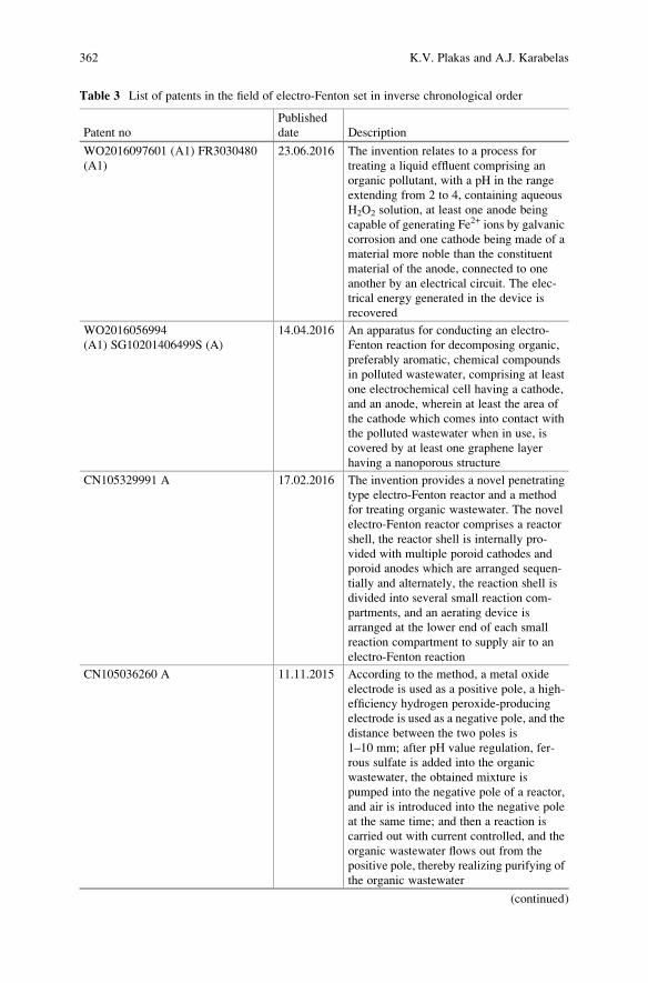
Table 3 List of patents in the field of electro-Fenton set in inverse chronological order
Patent no
Published
date Description
WO2016097601 (Α1) FR3030480
(A1)
23.06.2016 The invention relates to a process for
treating a liquid effluent comprising an
organic pollutant, with a pH in the range
extending from 2 to 4, containing aqueous
H2O2 solution, at least one anode being
capable of generating Fe2+ ions by galvanic
corrosion and one cathode being made of a
material more noble than the constituent
material of the anode, connected to one
another by an electrical circuit. The elec-
trical energy generated in the device is
recovered
WO2016056994
(A1) SG10201406499S (A)
14.04.2016 An apparatus for conducting an electro-
Fenton reaction for decomposing organic,
preferably aromatic, chemical compounds
in polluted wastewater, comprising at least
one electrochemical cell having a cathode,
and an anode, wherein at least the area of
the cathode which comes into contact with
the polluted wastewater when in use, is
covered by at least one graphene layer
having a nanoporous structure
CN105329991 A 17.02.2016 The invention provides a novel penetrating
type electro-Fenton reactor and a method
for treating organic wastewater. The novel
electro-Fenton reactor comprises a reactor
shell, the reactor shell is internally pro-
vided with multiple poroid cathodes and
poroid anodes which are arranged sequen-
tially and alternately, the reaction shell is
divided into several small reaction com-
partments, and an aerating device is
arranged at the lower end of each small
reaction compartment to supply air to an
electro-Fenton reaction
CN105036260 A 11.11.2015 According to the method, a metal oxide
electrode is used as a positive pole, a high-
efficiency hydrogen peroxide-producing
electrode is used as a negative pole, and the
distance between the two poles is
1–10 mm; after pH value regulation, fer-
rous sulfate is added into the organic
wastewater, the obtained mixture is
pumped into the negative pole of a reactor,
and air is introduced into the negative pole
at the same time; and then a reaction is
carried out with current controlled, and the
organic wastewater flows out from the
positive pole, thereby realizing purifying of
the organic wastewater
(continued)
362 K.V. Plakas and A.J. Karabelas
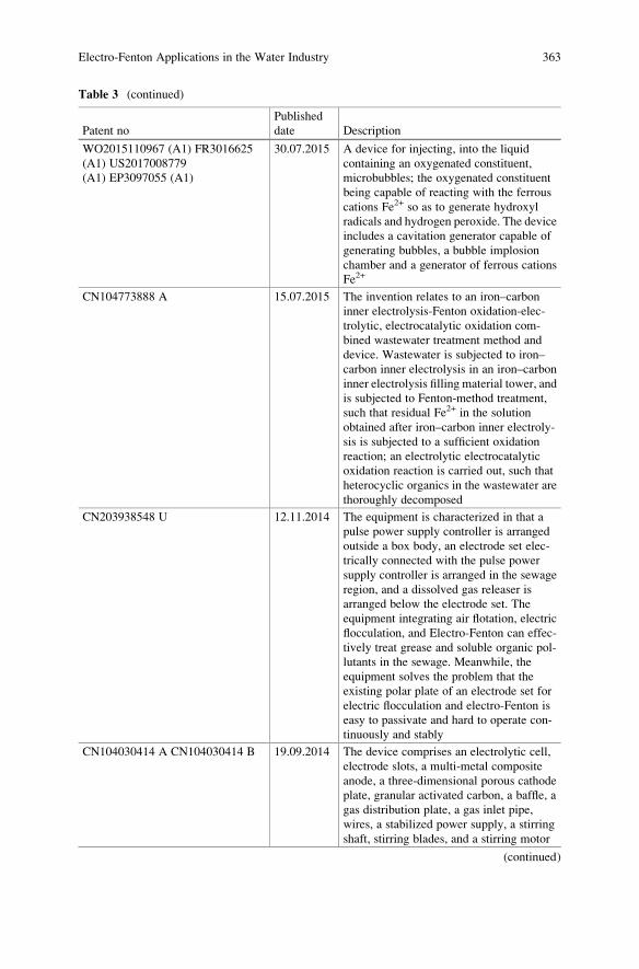
Table 3 (continued)
Patent no
Published
date Description
WO2015110967 (A1) FR3016625
(A1) US2017008779
(A1) EP3097055 (A1)
30.07.2015 A device for injecting, into the liquid
containing an oxygenated constituent,
microbubbles; the oxygenated constituent
being capable of reacting with the ferrous
cations Fe2+ so as to generate hydroxyl
radicals and hydrogen peroxide. The device
includes a cavitation generator capable of
generating bubbles, a bubble implosion
chamber and a generator of ferrous cations
Fe2+
CN104773888 A 15.07.2015 The invention relates to an iron–carbon
inner electrolysis-Fenton oxidation-elec-
trolytic, electrocatalytic oxidation com-
bined wastewater treatment method and
device. Wastewater is subjected to iron–
carbon inner electrolysis in an iron–carbon
inner electrolysis filling material tower, and
is subjected to Fenton-method treatment,
such that residual Fe2+ in the solution
obtained after iron–carbon inner electroly-
sis is subjected to a sufficient oxidation
reaction; an electrolytic electrocatalytic
oxidation reaction is carried out, such that
heterocyclic organics in the wastewater are
thoroughly decomposed
CN203938548 U 12.11.2014 The equipment is characterized in that a
pulse power supply controller is arranged
outside a box body, an electrode set elec-
trically connected with the pulse power
supply controller is arranged in the sewage
region, and a dissolved gas releaser is
arranged below the electrode set. The
equipment integrating air flotation, electric
flocculation, and Electro-Fenton can effec-
tively treat grease and soluble organic pol-
lutants in the sewage. Meanwhile, the
equipment solves the problem that the
existing polar plate of an electrode set for
electric flocculation and electro-Fenton is
easy to passivate and hard to operate con-
tinuously and stably
CN104030414 A CN104030414 B 19.09.2014 The device comprises an electrolytic cell,
electrode slots, a multi-metal composite
anode, a three-dimensional porous cathode
plate, granular activated carbon, a baffle, a
gas distribution plate, a gas inlet pipe,
wires, a stabilized power supply, a stirring
shaft, stirring blades, and a stirring motor
(continued)
Electro-Fenton Applications in the Water Industry 363
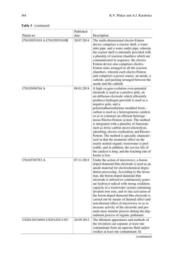
Table 3 (continued)
Patent no
Published
date Description
CN103951018 A CN103951018B 30.07.2014 The multi-dimensional electro-Fenton
device comprises a reactor shell, a water
inlet pipe, and a water outlet pipe, wherein
the reactor shell is internally provided with
a plurality of reaction chambers which are
communicated in sequence; the electro-
Fenton device also comprises electro-
Fenton units arranged in all the reaction
chambers, wherein each electro-Fenton
unit comprises a power source, an anode, a
cathode, and packing arranged between the
anode and the cathode
CN103496764 A 08.01.2014 A high oxygen evolution over-potential
electrode is used as a positive pole, an
air-diffusion electrode which efficiently
produces hydrogen peroxide is used as a
negative pole, and a
polytetrafluoroethylene modified ferric-
carbon is used as a heterogeneous catalyst,
so as to construct an efficient heteroge-
neous Electro-Fenton system. The method
is integrated with a plurality of functions
such as ferric-carbon micro-electrolysis,
adsorbing, electro-oxidization, and Electro-
Fenton. The method is specially character-
ized in that the treatment effect on the
nearly neutral organic wastewater is pref-
erable, and in addition, the service life of
the catalyst is long, and the leaching rate of
ferrite is low
CN102765783 A 07.11.2012 Under the action of microwave, a boron-
doped diamond film electrode is used as an
anode material for electrochemical degra-
dation processing. According to the inven-
tion, the boron-doped diamond film
electrode is utilized to continuously gener-
ate hydroxyl radical with strong oxidation
capacity in a wastewater system containing
divalent iron ions, and in situ activation of
the boron-doped diamond film electrode is
carried out by means of thermal effect and
non-thermal effect of microwave so as to
increase activity of the electrode and pro-
mote mass transfer process during the deg-
radation process of organic pollutants
US20120234694 US20120211367 20.09.2012 The filtration apparatuses and methods of
the invention can separate at least one
contaminant from an aqueous fluid and/or
oxidize at least one contaminant. In
(continued)
364 K.V. Plakas and A.J. Karabelas
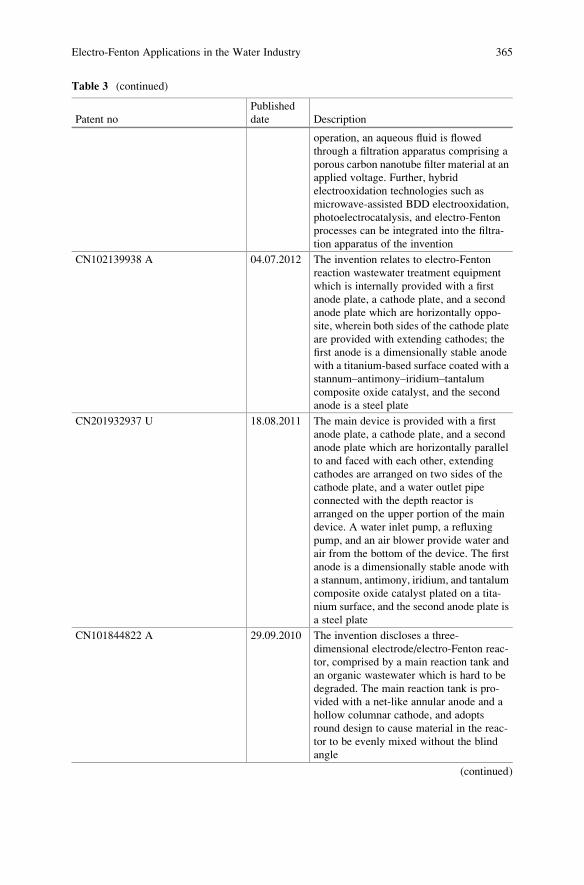
Table 3 (continued)
Patent no
Published
date Description
operation, an aqueous fluid is flowed
through a filtration apparatus comprising a
porous carbon nanotube filter material at an
applied voltage. Further, hybrid
electrooxidation technologies such as
microwave-assisted BDD electrooxidation,
photoelectrocatalysis, and electro-Fenton
processes can be integrated into the filtra-
tion apparatus of the invention
CN102139938 A 04.07.2012 The invention relates to electro-Fenton
reaction wastewater treatment equipment
which is internally provided with a first
anode plate, a cathode plate, and a second
anode plate which are horizontally oppo-
site, wherein both sides of the cathode plate
are provided with extending cathodes; the
first anode is a dimensionally stable anode
with a titanium-based surface coated with a
stannum–antimony–iridium–tantalum
composite oxide catalyst, and the second
anode is a steel plate
CN201932937 U 18.08.2011 The main device is provided with a first
anode plate, a cathode plate, and a second
anode plate which are horizontally parallel
to and faced with each other, extending
cathodes are arranged on two sides of the
cathode plate, and a water outlet pipe
connected with the depth reactor is
arranged on the upper portion of the main
device. A water inlet pump, a refluxing
pump, and an air blower provide water and
air from the bottom of the device. The first
anode is a dimensionally stable anode with
a stannum, antimony, iridium, and tantalum
composite oxide catalyst plated on a tita-
nium surface, and the second anode plate is
a steel plate
CN101844822 A 29.09.2010 The invention discloses a three-
dimensional electrode/electro-Fenton reac-
tor, comprised by a main reaction tank and
an organic wastewater which is hard to be
degraded. The main reaction tank is pro-
vided with a net-like annular anode and a
hollow columnar cathode, and adopts
round design to cause material in the reac-
tor to be evenly mixed without the blind
angle
(continued)
Electro-Fenton Applications in the Water Industry 365
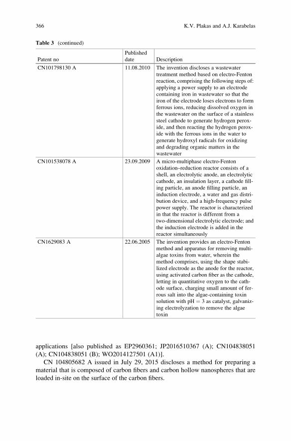
applications [also published as EP2960361; JP2016510367 (A); CN104838051
(A); CN104838051 (B); WO2014127501 (A1)].
CN 104805682 A issued in July 29, 2015 discloses a method for preparing a
material that is composed of carbon fibers and carbon hollow nanospheres that are
loaded in-site on the surface of the carbon fibers.
Table 3 (continued)
Patent no
Published
date Description
CN101798130 A 11.08.2010 The invention discloses a wastewater
treatment method based on electro-Fenton
reaction, comprising the following steps of:
applying a power supply to an electrode
containing iron in wastewater so that the
iron of the electrode loses electrons to form
ferrous ions, reducing dissolved oxygen in
the wastewater on the surface of a stainless
steel cathode to generate hydrogen perox-
ide, and then reacting the hydrogen perox-
ide with the ferrous ions in the water to
generate hydroxyl radicals for oxidizing
and degrading organic matters in the
wastewater
CN101538078 A 23.09.2009 A micro-multiphase electro-Fenton
oxidation–reduction reactor consists of a
shell, an electrolytic anode, an electrolytic
cathode, an insulation layer, a cathode fill-
ing particle, an anode filling particle, an
induction electrode, a water and gas distri-
bution device, and a high-frequency pulse
power supply. The reactor is characterized
in that the reactor is different from a
two-dimensional electrolytic electrode; and
the induction electrode is added in the
reactor simultaneously
CN1629083 A 22.06.2005 The invention provides an electro-Fenton
method and apparatus for removing multi-
algae toxins from water, wherein the
method comprises, using the shape stabi-
lized electrode as the anode for the reactor,
using activated carbon fiber as the cathode,
letting in quantitative oxygen to the cath-
ode surface, charging small amount of fer-
rous salt into the algae-containing toxin
solution with pH ¼ 3 as catalyst, galvaniz-
ing electrolyzation to remove the algae
toxin
366 K.V. Plakas and A.J. Karabelas
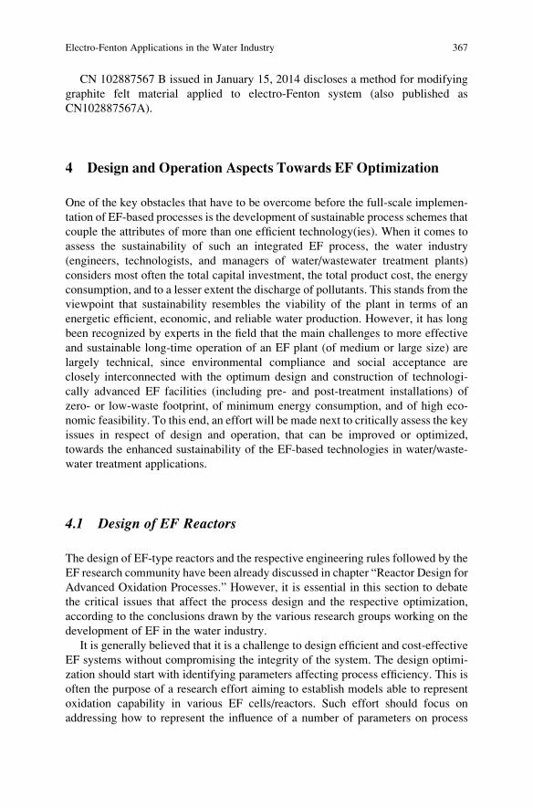
CN 102887567 B issued in January 15, 2014 discloses a method for modifying
graphite felt material applied to electro-Fenton system (also published as
CN102887567A).
4 Design and Operation Aspects Towards EF Optimization
One of the key obstacles that have to be overcome before the full-scale implemen-
tation of EF-based processes is the development of sustainable process schemes that
couple the attributes of more than one efficient technology(ies). When it comes to
assess the sustainability of such an integrated EF process, the water industry
(engineers, technologists, and managers of water/wastewater treatment plants)
considers most often the total capital investment, the total product cost, the energy
consumption, and to a lesser extent the discharge of pollutants. This stands from the
viewpoint that sustainability resembles the viability of the plant in terms of an
energetic efficient, economic, and reliable water production. However, it has long
been recognized by experts in the field that the main challenges to more effective
and sustainable long-time operation of an EF plant (of medium or large size) are
largely technical, since environmental compliance and social acceptance are
closely interconnected with the optimum design and construction of technologi-
cally advanced EF facilities (including pre- and post-treatment installations) of
zero- or low-waste footprint, of minimum energy consumption, and of high eco-
nomic feasibility. To this end, an effort will be made next to critically assess the key
issues in respect of design and operation, that can be improved or optimized,
towards the enhanced sustainability of the EF-based technologies in water/waste-
water treatment applications.
4.1 Design of EF Reactors
The design of EF-type reactors and the respective engineering rules followed by the
EF research community have been already discussed in chapter “Reactor Design for
Advanced Oxidation Processes.” However, it is essential in this section to debate
the critical issues that affect the process design and the respective optimization,
according to the conclusions drawn by the various research groups working on the
development of EF in the water industry.
It is generally believed that it is a challenge to design efficient and cost-effective
EF systems without compromising the integrity of the system. The design optimi-
zation should start with identifying parameters affecting process efficiency. This is
often the purpose of a research effort aiming to establish models able to represent
oxidation capability in various EF cells/reactors. Such effort should focus on
addressing how to represent the influence of a number of parameters on process
Electro-Fenton Applications in the Water Industry 367
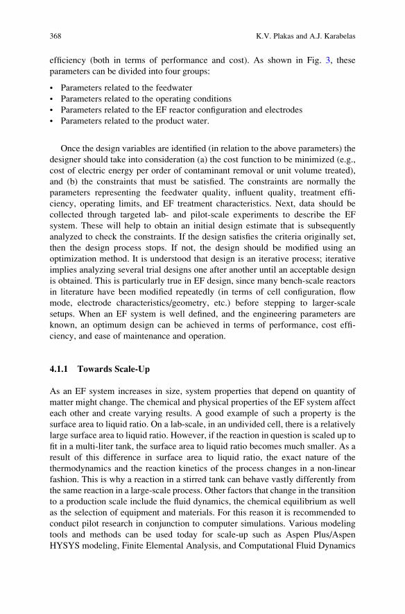
efficiency (both in terms of performance and cost). As shown in Fig. 3, these
parameters can be divided into four groups:
• Parameters related to the feedwater
• Parameters related to the operating conditions
• Parameters related to the EF reactor configuration and electrodes
• Parameters related to the product water.
Once the design variables are identified (in relation to the above parameters) the
designer should take into consideration (a) the cost function to be minimized (e.g.,
cost of electric energy per order of contaminant removal or unit volume treated),
and (b) the constraints that must be satisfied. The constraints are normally the
parameters representing the feedwater quality, influent quality, treatment effi-
ciency, operating limits, and EF treatment characteristics. Next, data should be
collected through targeted lab- and pilot-scale experiments to describe the EF
system. These will help to obtain an initial design estimate that is subsequently
analyzed to check the constraints. If the design satisfies the criteria originally set,
then the design process stops. If not, the design should be modified using an
optimization method. It is understood that design is an iterative process; iterative
implies analyzing several trial designs one after another until an acceptable design
is obtained. This is particularly true in EF design, since many bench-scale reactors
in literature have been modified repeatedly (in terms of cell configuration, flow
mode, electrode characteristics/geometry, etc.) before stepping to larger-scale
setups. When an EF system is well defined, and the engineering parameters are
known, an optimum design can be achieved in terms of performance, cost effi-
ciency, and ease of maintenance and operation.
4.1.1 Towards Scale-Up
As an EF system increases in size, system properties that depend on quantity of
matter might change. The chemical and physical properties of the EF system affect
each other and create varying results. A good example of such a property is the
surface area to liquid ratio. On a lab-scale, in an undivided cell, there is a relatively
large surface area to liquid ratio. However, if the reaction in question is scaled up to
fit in a multi-liter tank, the surface area to liquid ratio becomes much smaller. As a
result of this difference in surface area to liquid ratio, the exact nature of the
thermodynamics and the reaction kinetics of the process changes in a non-linear
fashion. This is why a reaction in a stirred tank can behave vastly differently from
the same reaction in a large-scale process. Other factors that change in the transition
to a production scale include the fluid dynamics, the chemical equilibrium as well
as the selection of equipment and materials. For this reason it is recommended to
conduct pilot research in conjunction to computer simulations. Various modeling
tools and methods can be used today for scale-up such as Aspen Plus/Aspen
HYSYS modeling, Finite Elemental Analysis, and Computational Fluid Dynamics
368 K.V. Plakas and A.J. Karabelas
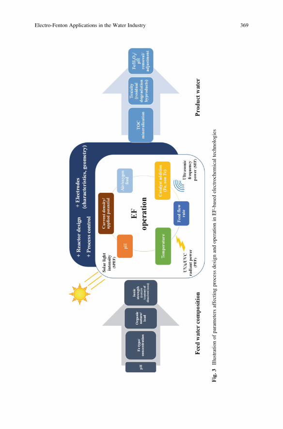
Fig.3
Illustrationofparam
etersaffectingprocess
designandoperationin
EF-based
electrochem
ical
technologies
Electro-Fenton Applications in the Water Industry 369
(CFD). These modeling tools could lead to finalized mass and energy balances,
prediction of pollutant behavior, optimized system design and capacity, equipment
requirements, and system limitations. Moreover, the progress in the development of
consistent mathematical models that describe the complex scenarios and reactions
involved in the electrooxidation of multicomponent mixtures of various pollutants,
and its integration with knowledge about reactor hydrodynamics, will undoubtedly
contribute to the scale-up.
4.2 Optimization of EF Operation
The improvements in EF reactor design are closely interconnected with the opti-
mization of the operating conditions so that the process can be used at an efficient,
effective, and profitable industrial scale. Indeed, when designing an EF process it is
crucial to have a good understanding of the effect of the operating conditions on
process performance, such as the electric potential, the water flux, the pH, the
air/oxygen feed, the catalyst dosage rate (where applicable), the UV radiant power
per unit volume (in photo-induced EF processes), the ultrasonic frequency power
(in case of SEF), and to a lesser extent of the operating temperature (Fig. 3). An
effort is made next to summarize the knowledge gained from the substantive
research carried out at lab- and pilot-scale on this direction.
4.2.1 Operating pH
As a chemical component of the water/wastewater, pH has direct influence on its
treatability by EF since acidity has a profound effect on the iron and hydrogen
peroxide speciation, and consequently on the type of oxidizing species available in
the reaction medium; it is reported that superoxide radical O2•� is dominant at
alkaline pH while •OH is dominant at acidic condition [67]. The efficiency of the
Fenton reagent to degrade organic compounds is reduced both at high and low pH,
with the optimum value being around 3, regardless of the target wastewater.
Specifically, at alkaline pH the activity of Fenton reagent is reduced due to the
presence of relatively inactive iron oxohydroxides and formation of ferric hydrox-
ide precipitate. It is reported also that the oxidation potential of •OH decreases with
increasing pH [68] while H2O2 can be auto-decomposed to water and O2 [69]. On
the other hand, at very low pH values, iron complex species [Fe(H2O)6]2+ may
prevail, which reacts more slowly with hydrogen peroxide than other species
[70]. Fe2+ regeneration by the reaction of Fe3+ with H2O2 is also inhibited by
excessive H+ ions in the solution, while H2O2 can be solvated to form stable
oxonium ion [H3O2]+. Oxonium ions make H2O2 more stable and reduce its
reactivity with Fe2+ [6].
The importance of pH on process efficiency makes its control a necessity. This
adds of course to the complexity of the system, increases the operating cost (for
370 K.V. Plakas and A.J. Karabelas
acidification and subsequent neutralization), while the corrosivity hazard requires
the selection of resistant to corrosion materials. For a continuous process, pH
should be controlled throughout the process by adding appropriate amounts of
acid (sulfuric, acetic, phosphoric) or caustic (sodium hydroxide). The selection of
the acid/base agents may also affect the oxidation efficiency as noted by several
researchers. In the work of Benitez et al. [71] acetic acid/acetate buffer gave
maximum oxidation efficiency whereas a decreased oxidation was observed with
phosphate and sulfate buffers. This can be attributed to the formation of stable Fe3+
complexes that are formed under those conditions [72].
The pH adjustment is feasible in the case of wastewaters; however, it is not
recommended for drinking water treatment. In the latter case, great research effort
is devoted to the development of systems and catalysts to overcome the low pH
requirement. One approach is the development of heterogeneous EF processes in
which iron can be supported on various materials (carbon, resin, or nafion) or on the
working electrodes to promote the presence of the Fenton mixture in the solution,
thus avoiding the use of dissolved Fe salts and the operation at low pH values. The
progress in this field is discussed in detail in chapter “Heterogeneous Electro-
Fenton Process.” Another approach proposed by Wang et al. [73] was a novel
Electro-Fenton-Like (EFL) system that can be applied to neutral water treatment
without any pH adjustment. Such system uses the Keggin-type iron-substituted
heteropolytungstate anion PW11O39Fe(III)(H2O)4� to substitute for Fe3+ in the
conventional EF system.
4.2.2 Applied Potential or Electric Current
The importance of the applied potential or electric current is directly related to the
electrogeneration of H2O2 or the degradation rate of organics under galvanostatic
electrolysis, respectively [7]. One would expect that high current densities are
beneficial to the EF process. However, this is not true, since significant decrease
of the current efficiency is usually observed due to the production of oxygen, the
activation of side reactions, and the polarization. Moreover, current efficiency is
low at the acidic operating pH (�3) due to the low solubility of O2. These facts
should be taken into consideration by the operator before deciding on the applied
voltage/electric current, since electricity does not only affect the oxidation of
pollutants but also the operating expenses of the treatment.
4.2.3 Air/O2 Addition
An excessive air or pure O2 aeration is usually leading to a high production rate of
H2O2, especially in divided electrochemical cells where the separator (glass frits,
diaphragms, cationic membranes) prevents the mixing of the cathodically produced
H2O2, avoiding its destruction at the anode. In the case of undivided cells the
sparging of air/O2 is necessarily accompanied with an appropriate agitation of the
Electro-Fenton Applications in the Water Industry 371
feed solution in order to increase the oxygen utilization efficiency (the fraction of
oxygen consumed for the production of H2O2 over the total amount of oxygen
added) and the effective mass transfer of the organic pollutants to the electrodes
surface. However, the agitation may induce a lot of H2O2 transferring on the anode
surface where it can be oxidized to O2.
Except from the sparging rate, the air pressure has been proved to greatly affect
the electrogeneration of H2O2 and the EF abatement of organic pollutants in water
[74]. Specifically an increase of the pressure may drastically enhance the concen-
tration of H2O2. In systems pressurized with air at 11 bar, the electro-reduction of
oxygen at a graphite cathode gave rise to a concentration of H2O2 of about 12 mM,
i.e., one order of magnitude higher than that achieved at atmospheric pressure. This
result is attributed to the mass transfer intensification induced by the higher local
concentration of molecular oxygen dissolved in the aqueous phase [74].
Considering that air/O2 sparging adds to the complexity and the cost of the
system, especially for small-scale drinking water systems, it is important to fabri-
cate EF reactors/cells without the need for an external aeration device. Recently the
feasibility of H2O2 production without aeration was demonstrated in a flow-through
“filter” type device [24, 26], in a novel dual tubular membrane electrodes reactor
[28], a rotating disk reactor [75], as well as with the usage of modified graphite felt
electrodes [76].
The importance of O2 control on the efficiency of the EF process was recently
examined by Yu et al. [77]. These researchers studied the potential of on-line
monitoring of Oxidation Reduction Potential (ORP) and Dissolved Oxygen
(DO) as key parameters for controlling the EF process in treating textile wastewa-
ter. Their results showed that the DO and ORP profiles have high correlation with
the variations in H2O2, Fe+2, and Fe+3, which can help identify over-dosing of
H2O2. They concluded that monitoring DO and ORP has great potential to effec-
tively control the EF process and could result in chemical cost savings.
4.2.4 Catalyst Addition
The catalyst dose (in form of iron on non-iron species) is a critical operating
parameter since Fenton or Fenton-like reactions are strongly affected by the type
and the concentration of the catalyst in the bulk. The optimal dose range can vary
between wastewaters depending on the organic load and the presence of other
constituents (e.g., inorganic ions) that scavenge the Fenton-type reactions. Obvi-
ously, there should be flexibility regarding the catalyst dose, which should be easily
altered to be adapted to any variation of the feedwater composition. In case of iron
the rate of organics degradation remains the same above a certain concentration.
Typical ranges are 1 part Fe per 5–25 parts H2O2 (wt/wt). For most applications, it
does not matter whether Fe2+ or Fe3+ salts are used to catalyze the reaction; the
catalytic cycle begins quickly if H2O2 and organic material are in abundance.
However, ferrous iron may be preferred in case of negligible cathodic reduction
of Fe3+, even if the cathode is capable of producing large quantities of H2O2.
372 K.V. Plakas and A.J. Karabelas
Neither does it matter whether a chloride or sulfate salt of the iron is used, although
with the former, chlorine may be generated at high rates of application.
4.2.5 Feed Flow Rate
The feed flow rate defines the hydraulic residence time (HRT) of the wastewater in
the EF system. This is of great significance in continuous processes where
feedwater is continuously treated and discharged. In determining HRT it is impor-
tant to know the actual reaction kinetics which again are influenced by the variables
already discussed (Fig. 3), most notably the H2O2/Fe2+ ratio and the wastewater
composition (concentration and refractory nature of the organics). Values of HRT
from several minutes to few hours can be determined depending on the treatment
targets set (e.g., compliance with discharge standards or BOD5/COD limit for
subsequent biological posttreatment).
4.2.6 Operating Temperature
The effect of temperature on the overall efficiency of the electrooxidation process
has not been widely studied. Most studies have been performed at ambient tem-
perature and to a lesser extent at fixed temperatures (regulated with the aid of
thermostatic baths). Considering that chemical reactions are greatly affected by
temperature, it is assumed that Fenton reaction will be also influenced by the
temperature in an EF system. In principle, higher temperatures can provide more
energy to overcome the reaction activation energy [78] and then accelerate the
reaction by increasing the reaction rate constant according to the Arrhenius equa-
tion [79]. On the other hand, an increase in operating temperature can favor the
decomposition of H2O2 towards O2 and H2O, whose rate increases around 2.2 times
each 10 �C in the range 20–100 �C [80]. Moreover, the solubility of oxygen in water
decreases as temperature increases, which in turn may negatively affect the in situ
electrogeneration of H2O2.
5 Recommendations for Future Research
Following successful proof-of-concept work, significant progress has been made
during the last decade on EF-based electrochemical technologies, regarding the
development of new electrode materials, the design and construction of lab-scale
pilot plants, and finally the investigation of process performance with synthetic or
real wastewaters. The variants EF, PEF, SPEF, Fered-Fenton as well as integrated
processes with other physical, chemical, and biological methods have generally
proven to be efficient and versatile, capable of degrading/mineralizing a wide
variety of synthetic organic compounds present in wastewater. However, more
Electro-Fenton Applications in the Water Industry 373
research effort is needed towards the development of larger-scale systems that will
aid the scientific/research community to assess the dynamic potential of these
technologies to address the water treatment challenges. Moreover, while patent
activity has been rather intensive in pursuing commercialization of the EF technol-
ogy, there appears to be little progress in licensing and sale of intellectual property.
However, the literature suggests that there is potential in the EF technology, which
may eventually pave the way towards substantial improvements in the water
treatment sector, regarding cost and sustainable process performance. Along these
lines, the following recommendations for future research are suggested towards the
development of efficient, cost competitive, and sustainable processes.
• Development of high-performance and cost-effective (low cost/life ratio) anodes
and cathodes with enhanced electrocatalytic properties (long service time)
which will result in smaller operating and capital costs. Emphasis on 3-D
electrode technology.
• Further development of promising hybrid technologies, such as Bio-EF and (SP)
EF followed by membrane bioreactor (MBR) or biological activated carbon.
• Use of renewable energy sources (photovoltaic modules, wind turbines) as a
cheap source of electrical power (energy self-sufficient processes).
• Process modeling and pollutant behavior prediction. Studies on the degradation
mechanisms, comprising the parent compounds and the possible by-products in
a broader and more comprehensive approach.
• Detailed toxicological assessment of the treated water/wastewater. This will
assist in the environmental verification of the developed technologies.
• Application of optimization strategies to the design of large-scale reactors in
order to overcome the technical shortcomings (leading to reduced capital and
energy costs) which have hindered the widespread commercialization of the EF
reactors.
• Application of computer simulations and modeling tools towards optimized EF
reactor design and scale-up.
• Extensive investigation of the robustness and feasibility (validation) of full-scale
EF technologies in a real operating environment.
• Detailed studies on economic assessment of EF-based technologies, considering
operating and investment costs that enable comparison with other conventional
or advanced water treatment technologies, currently used.
Once the practical and economic constraints of the final application are appro-
priately factored in, it will become possible to set a rational design of an effective
EF technology. This is verified by examples of successful EAOPs developments,
some of which are commercially available by the Swiss RedElec Technologie S.A.,
Ever-Clear Co. from Taiwan, Global Advantech from UK, E. Elgressy Ltd. from
Israel, Xh2o Solutions Pvt. Ltd. from India, AQUALOGY S.A. from Spain, and
VentilAQUA S.A. from Portugal. EAOPs based on diamond electrodes (AO) are
also marketed by CONDIAS GmbH from Germany and Advanced Diamond
Technologies Inc. from the USA.
374 K.V. Plakas and A.J. Karabelas
References
1. Fenton HJH (1894) Oxidation of tartaric acid in presence of iron. J Chem Soc 65:899–910
2. Wieland H, Franke W (1927) Mechanism of the oxidation process. XII. The activation of
hydrogen peroxide by iron. Justus Liebigs Ann Chem 457:1–70
3. Haber F, Willstattter R (1931) Unpaarigheit und radikalketten im reaktion-mechanismus
organischer und enzymatischer vorgange. Chem Ber 64:2844–2856
4. Brown RF, Jamison SE, Pandit K et al (1964) The reaction of Fenton’s reagent with
phenoxyacetic acid and some halogen-substituted phenoxyacetic acids. J Org Chem
29:146–153
5. Pignatello JJ, Oliveros E, MacKay A (2006) Advanced oxidation processes for organic
contaminant destruction based on the Fenton reaction and related chemistry. Crit Rev Environ
Sci Technol 36:1–84
6. Babuponnusami A, Muthukumar K (2014) A review on Fenton and improvements to the
Fenton process for wastewater treatment. J Environ Manage 2:557–572
7. Brillas E, Sires I, Oturan MA (2009) Electro-Fenton process and related electrochemical
technologies based on Fenton’s reaction chemistry. Chem Rev 109:6570–6631
8. Wang N, Zheng T, Zhang G et al (2016) A review on Fenton-like processes for organic
wastewater treatment. J Environ Chem Eng 4:762–787
9. Martınez-Huitle CA, Rodrigo MA, Sires I et al (2015) Single and coupled electrochemical
processes and reactors for the abatement of organic water pollutants: a critical review. Chem
Rev 115(24):13362–13407
10. Ganiyu SO, van Hullebusch ED, Cretin M et al (2015) Coupling of membrane filtration and
advanced oxidation processes for removal of pharmaceutical residues: a critical review. Sep
Purif Technol 156:891–914
11. Ganzenko O, Huguenot D, van Hullebusch ED et al (2014) Electrochemical advanced oxida-
tion and biological processes for wastewater treatment: a review of the combined approaches.
Environ Sci Pollut Res 21:8493–8524
12. Sires I, Brillas E, Oturan MA et al (2014) Electrochemical advanced oxidation processes:
today and tomorrow. A review. Environ Sci Pollut Res 21:8336–8367
13. Ba~nuelos JA, Rodrıguez FJ, Manrıquez J et al (2014) A review on arrangement and reactors for
Fenton-based water treatment processes. In: Peralta-Hernandez JM, Rodrigo MA, Martınez-
Huitle CA (eds) Evaluation of electrochemical reactors as a new way to environmental
protection, Kerala, India, pp 97–137
14. Brillas E (2014) Electro-Fenton, UVA photoelectro-Fenton and solar photoelectro-Fenton
treatments of organics in waters using a boron-doped diamond anode: a review. J Mex
Chem Soc 58(3):239–255
15. Feng L, van Hullebusch ED, Rodrigo MA et al (2013) Removal of residual anti-inflammatory
and analgesic pharmaceuticals from aqueous systems by electrochemical advanced oxidation
processes. A review. Chem Eng J 228:944–964
16. Nidheesh PN, Gandhimathi R (2012) Trends in electro-Fenton process for water and waste-
water treatment: an overview. Desalination 299:1–15
17. Martınez-Huitle CA, Brillas E (2009) Decontamination of wastewaters containing synthetic
organic dyes by electrochemical methods: a general review. Appl Catal Environ 87:105–145
18. Garcıa O, Isarain-Chavez E, El-Ghenymy A et al (2014) Degradation of 2,4-D herbicide in a
recirculation flow plant with a Pt/air-diffusion and a BDD/BDD cell by electrochemical
oxidation and electro-Fenton process. J Electroanal Chem 728:1–9
19. Garcıa O, Isarain-Chavez E, Garcia-Segura S et al (2013) Degradation of
2,4-dichlorophenoxyacetic acid by electro-oxidation and electro-Fenton/BDD processes
using a pre-pilot plant. Electrocatalysis 4:224–234
20. Chmayssem A, Taha S, Hauchard D (2017) Scaled-up electrochemical reactor with a fixed bed
three-dimensional cathode for electro-Fenton process: application to the treatment of
bisphenol A. Electrochim Acta 225:435–442
Electro-Fenton Applications in the Water Industry 375
21. El-Ghenymy A, Cabot PL, Centellas F et al (2013) Mineralization of sulfanilamide byelectro-
Fenton and solar photoelectro-Fenton in a pre-pilot plant with a Pt/air-diffusion cell.
Chemosphere 91:1324–1331
22. Khataee AR, Safarpour M, Zarei M et al (2012) Combined heterogeneous and homogeneous
photodegradation of a dye using immobilized TiO2 nanophotocatalyst and modified graphite
electrode with carbon nanotubes. J Mol Catal A Chem 363–364:58–68
23. Liu H, Vecitis CD (2012) Reactive transport mechanism for organic oxidation during electro-
chemical filtration: mass-transfer, physical adsorption, and electron transfer. J Phys Chem C
116:374–383
24. Plakas KV, Karabelas AJ, Sklari SD et al (2013) Toward the development of a novel electro-
Fenton system for eliminating toxic organic substances from water. Part 1. In situ generation of
hydrogen peroxide. Ind Eng Chem Res 52:13948–13956
25. Sklari SD, Plakas KV, Petsi PN et al (2015) Toward the development of a novel electro-Fenton
system for eliminating toxic organic substances from water. Part 2. Preparation characteriza-
tion, and evaluation of iron-impregnated carbon felts as cathodic electrodes. Ind Eng Chem
Res 54:2059–2073
26. Plakas KV, Sklari SD, Yiankakis DA et al (2016) Removal of organic micropollutants from
drinking water by a novel electro-Fenton filter: pilot-scale studies. Water Res 91:183–194
27. Ma L, Zhou M, Ren G et al (2016) A highly energy-efficient flow-through electro-Fenton
process for organic pollutants degradation. Electrochim Acta 200:222–230
28. Xu A, HanW, Li J (2016) Electrogeneration of hydrogen peroxide using Ti/IrO2–Ta2O5 anode
in dual tubular membranes electro-Fenton reactor for the degradation of tricyclazole without
aeration. Chem Eng J 295:152–159
29. Lan H, Li J, Sun M et al (2016) Efficient conversion of dimethylarsinate into arsenic and its
simultaneous adsorption removal over FeCx/N-doped carbon fiber composite in an electro-
Fenton process. Water Res 100:57–64
30. Xu N, Zhang Y, Tao H et al (2013) Bio-electro-Fenton system for enhanced estrogens
degradation. Bioresour Technol 138:136–140
31. Kishimoto N, Hatta M, Kato M et al (2017) Effects of oxidation–reduction potential control
and sequential use of biological treatment on the electrochemical Fenton-type process. Process
Saf Environ 105:134–142
32. Polcaro AM, Vacca A, Mascia M et al (2007) Characterization of a stirred tank electrochem-
ical cell for water disinfection processes. Electrochim Acta 52:2595–2602
33. Cotillas S, Llanos J, Rodrigo MA et al (2015) Use of carbon felt cathodes for the electro-
chemical reclamation of urban treated wastewaters. Appl Catal B Environ 162:252–259
34. Mansour D, Fourcade F, Soutrel I et al (2015) Mineralization of synthetic and industrial
pharmaceutical effluent containing trimethoprim by combining electro-Fenton and activated
sludge treatment. J Taiwan Inst Chem Eng 53:58–67
35. Kamali M, Khodaparast Z (2015) Review on recent developments on pulp and paper mill
wastewater treatment. Ecotoxicol Environ Saf 114:326–342
36. Jaafarzadeh N, Ghanbari F, Ahmadi M et al (2017) Efficient integrated processes for pulp and
paper wastewater treatment and phytotoxicity reduction: permanganate, electro-Fenton and
Co3O4/UV/peroxymonosulfate. Chem Eng J 308:142–150
37. Eren Z (2012) Ultrasound as a basic and auxiliary process for dye remediation: a review. J
Environ Manage 104:127–141
38. Asghar A, Abdul Raman AA, Ashri Wan Daud WM (2015) Advanced oxidation processes for
in-situ production of hydrogen peroxide/hydroxyl radical for textile wastewater treatment: a
review. J Clean Prod 87:826–838
39. Garcia-Segura S, Brillas E (2016) Combustion of textile monoazo, diazo and triazo dyes by
solar photoelectro-Fenton: decolorization, kinetics and degradation routes. Appl Catal B
Environ 181:681–691
40. Ren G, Zhou M, Liu M et al (2016) A novel vertical-flow electro-Fenton reactor for organic
wastewater treatment. Chem Eng J 298:55–67
376 K.V. Plakas and A.J. Karabelas
41. Rosales E, Pazos M, Longo MA et al (2009) Electro-Fenton decoloration of dyes in a
continuous reactor: a promising technology in colored wastewater treatment. Chem Eng J
155(1–2):62–67
42. El-Desoky HS, Ghoneim MM, El-Sheikh R et al (2010) Oxidation of Levafix CA reactive
azo-dyes in industrial wastewater of textile dyeing by electrogenerated Fenton’s reagent. J
Hazard Mater 175:858–865
43. Wang CT, Chou WL, Chung MH et al (2010) COD removal from real dyeing wastewater by
electro-Fenton technology using an activated carbon fiber cathode. Desalination 253:129–134
44. Feng C, Li F, Liu H et al (2010) A dual-chamber microbial fuel cell with conductive film-
modified anode and cathode and its application for the neutral electro-Fenton process.
Electrochim Acta 55:2048–2054
45. Wang X-Q, Liu C-P, Yuan Y et al (2014) Arsenite oxidation and removal driven by a bio-
electro-Fenton process under neutral pH conditions. J Hazard Mater 275:200–209
46. Khoufi S, Aloui F, Sayadi S (2006) Treatment of olive oil mill wastewater by combined
process electro-Fenton reaction and anaerobic digestion. Water Res 40:2007–2016
47. Flores N, Cabot PL, Centellas F, Garrido JA, Rodrıguez RM, Brillas E, Sires I (2017)
4-Hydroxyphenylacetic acid oxidation in sulfate and real olive oil mill wastewater by electro-
chemical advanced processes with a boron-doped diamond anode. J Hazard Mater
321:566–575
48. Dıez AM, Rosales E, Sanroman MA et al (2017) Assessment of LED-assisted electro-Fenton
reactor for the treatment of winery wastewater. Chem Eng J 310:399–406
49. Zhang H, Ran X, Wu X (2012) Electro-Fenton treatment of mature landfill leachate in a
continuous flow reactor. J Hazard Mater 241–242:259–266
50. Lin SH, Chang CC (2000) Treatment of landfill leachate by combined electro-Fenton oxida-
tion and sequencing batch reactor method. Water Res 34:4243–4249
51. Zhang H, Zhang DB, Zhou JY (2006) Removal of COD from landfill leachate by electro-
Fenton method. J Hazard Mater 135:106–111
52. Atmaca E (2009) Treatment of landfill leachate by using electro-Fenton method. J Hazard
Mater 163:109–114
53. Mohajeri S, Aziz HA, Isa MH et al (2010) Statistical optimization of process parameters for
landfill leachate treatment using electro-Fenton technique. J Hazard Mater 176:749–758
54. Orkun MO, Kuleyin A (2012) Treatment performance evaluation of chemical oxygen demand
from landfill leachate by electro-coagulation and electro-Fenton technique. Environ Prog
Sustain Energy 31:59–67
55. Zhang H, Cheng ZH, Zhang DB (2007) Treatment of landfill leachate by electro-Fenton
process. Fresen Environ Bull 16:1216–1219
56. Aziz HA, Othman OM, Abu Amr SS (2013) The performance of electro-Fenton oxidation in
the removal of coliform bacteria from landfill leachate. Waste Manag 33:396–400
57. Colades JI, de Luna MDG, Su C-C et al (2015) Treatment of thin film transistor-liquid crystal
display (TFT-LCD) wastewater by the electro-Fenton process. Sep Purif Technol 145:104–112
58. Cho SH, Lee HJ, Moon SH (2008) Integrated electroenzymatic and electrochemical treatment
of petrochemical wastewater using a pilot scale membraneless system. Process Biochem
43:1371–1376
59. Jia S, Han H, Hou B et al (2015) Advanced treatment of biologically pretreated coal gasifi-
cation wastewater by a novel integration of three-dimensional catalytic electro-Fenton and
membrane bioreactor. Bioresour Technol 198:918–921
60. Zhou M, Tan Q, Wang Q et al (2012) Degradation of organics in reverse osmosis concentrate
by electro-Fenton process. J Hazard Mater 215–216:287–293
61. Akyol A, Can OT, Demirbas E (2013) A comparative study of electrocoagulation and electro-
Fenton for treatment of wastewater from liquid organic fertilizer plant. Sep Purif Technol
112:11–19
62. Kurt U, Apaydin O, Gonullu MT (2007) Reduction of COD in wastewater from an organized
tannery industrial region by electro-Fenton process. J Hazard Mater 143:33–40
Electro-Fenton Applications in the Water Industry 377
63. Paramo-Vargas J, Camargo AME, Gutierrez-Granados S et al (2015) Applying electro-Fenton
process as an alternative to a slaughterhouse effluent treatment. J Electroanal Chem 754:80–86
64. Un UT, Topal S, Oduncu E et al (2015) Treatment of tissue paper wastewater: application of
electro-Fenton method. Int J Environ Sci Develop 6(6):415–418
65. Gameel A, Malash G, Mubarak AA et al (2015) Treatment of spent caustic from ethylene plant
using electro-Fenton technique. Am J Environ Eng Sci 2(4):37–46
66. Huguenot D, Mousset E, van Hullebusch ED (2015) Combination of surfactant enhanced soil
washing and electro-Fenton process for the treatment of soils contaminated by petroleum
hydrocarbons. J Environ Manage 153:40–47
67. Fang G-D, Zhou D-M, Dionysiou DD (2013) Superoxide mediated production of hydroxyl
radicals by magnetite nanoparticles: demonstration in the degradation of 2-chlorobiphenyl. J
Hazard Mater 250–251:68–75
68. Bossmann SH, Oliveros E, Gob S et al (1998) New evidence against hydroxyl radicals as
reactive intermediates in the thermal and photochemically enhanced Fenton reaction. J Phys
Chem 102:5542–5550
69. Szpyrkowicz L, Juzzolino C, Kaul SN (2001) A comparative study on oxidation of disperse
dye by electrochemical process, ozone, hypochlorite and Fenton reagent. Water Res
35:2129–2136
70. Xu XR, Li XY, Li XZ et al (2009) Degradation of melatonin by UV, UV/H2O2, Fe2+/H2O2 and
UV/Fe2+/H2O2 processes. Sep Purif Technol 68:261–266
71. Benitez FJ, Acero JL, Real FJ et al (2001) The role of hydroxyl radicals for the decomposition
of p-hydroxy phenylacetic acid in aqueous solutions. Water Res 35:1338–1343
72. Pignatello JJ (1992) Dark and photoassisted Fe3+-catalyzed degradation of chlorophenoxy
herbicides by hydrogen peroxide. Environ Sci Technol 26:944–951
73. Wang C, Hua Y, Tong Y (2010) A novel electro-Fenton-like system using PW11O39Fe3+
(H2O)4� as an electrocatalyst for wastewater treatment. Electrochim Acta 55(22):6755–6760
74. Scialdone O, Galia A, Gattuso A et al (2015) Effect of air pressure on the electro-generation of
H2O2 and the abatement of organic pollutants in water by electro-Fenton process. Electrochim
Acta 182:775–780
75. Liu H (2007) A novel electro-Fenton process for water treatment: reaction-controlled pH
adjustment and performance assessment. Environ Sci Technol 41:2937–2942
76. Yu F, Zhou M, Yu X (2015) Cost-effective electro-Fenton using modified graphite felt that
dramatically enhanced on H2O2 electro-generation without external aeration. Electrochim
Acta 163:182–189
77. Yu R-F, Lin C-H, Chen H-W et al (2013) Possible control approaches of the electro-Fenton
process for textile wastewater treatment using on-line monitoring of DO and ORP. Chem Eng J
218:341–349
78. Xu HY, Liu WC, Qi SY et al (2014) Kinetics and optimization of the decoloration of dyeing
wastewater by a schorl-catalyzed Fenton-like reaction. J Serb Chem Soc 79:361–377
79. Ifelebuegu AO, Ezenwa CP (2011) Removal of endocrine disrupting chemicals in wastewater
treatment by Fenton-like oxidation. Water Air Soil Pollut 217:213–220
80. Bautista P, Mohedano AF, Casas JA et al (2008) An overview of the application of Fenton
oxidation to industrial wastewaters treatment. J Chem Technol Biotechnol 83:1323–1338
378 K.V. Plakas and A.J. Karabelas
The Application of Electro-Fenton Process
for the Treatment of Artificial Sweeteners
Heng Lin, Nihal Oturan, Jie Wu, Mehmet A. Oturan, and Hui Zhang
Abstract This chapter presents the degradation and mineralization of
emerging trace contaminants artificial sweeteners (ASs) in aqueous solution
by electro-Fenton process in which hydroxyl radicals were formed concomitantly
by •OH formed from electrocatalytically generated Fenton’s reagent in the bulk
solution and M(•OH) from water oxidation at the anode surface. Experiments were
performed in an undivided cylindrical glass cell with a carbon-felt cathode and a Pt
or boron-doped diamond (BDD) anode. The effect of catalyst (Fe2+) concentration
and applied current on the degradation and mineralization kinetics of ASs was
evaluated. The absolute rate constants for the reaction between ASs and •OH were
determined. The formation and evolution of short-chain carboxylic acids as well as
released inorganic ions, and toxicity assessment during the electro-Fenton process
have been reported and compared.
Keywords Artificial sweeteners, Electro-Fenton, Hydroxyl radicals,
Mineralization, Wastewater treatment
Contents
1 Introduction . . . . . . . . . . . . . . . . . . . . . . . . . . . . . . . . . . . . . . . . . . . . . . . . . . . . . . . . . . . . . . . . . . . . . . . . . . . . . . . . . . 380
2 Treatment of ASs by Electro-Fenton Process . . . . . . . . . . . . . . . . . . . . . . . . . . . . . . . . . . . . . . . . . . . . . . 384
2.1 Oxidation Kinetics of ASs . . . . . . . . . . . . . . . . . . . . . . . . . . . . . . . . . . . . . . . . . . . . . . . . . . . . . . . . . . . . 384
H. Lin and H. Zhang (*)
Department of Environmental Engineering, Wuhan University, Wuhan 430079, China
e-mail: [email protected]
N. Oturan and M.A. Oturan (*)
Laboratoire Geomateriaux et Environnement (EA 4605), Universite Paris-Est, 5 Bd. Descartes,
77454 Marne-la-Vallee Cedex 2, France
e-mail: [email protected]
J. Wu
Fuzhou Environmental Monitoring Center, Fuzhou 350011, China
M. Zhou et al. (eds.), Electro-Fenton Process: New Trends and Scale-Up,Hdb Env Chem (2018) 61: 379–398, DOI 10.1007/698_2017_59,© Springer Nature Singapore Pte Ltd. 2017, Published online: 21 July 2017
379
2.2 Determination of the Rate Constants for ASs by •OH . . . . . . . . . . . . . . . . . . . . . . . . . . . . . . . 387
2.3 Mineralization of ASs in Electro-Fenton Process . . . . . . . . . . . . . . . . . . . . . . . . . . . . . . . . . . . . 387
2.4 Evaluation of Mineralization Current Efficiency (MCE) and Energy Consumption
(EC) . . . . . . . . . . . . . . . . . . . . . . . . . . . . . . . . . . . . . . . . . . . . . . . . . . . . . . . . . . . . . . . . . . . . . . . . . . . . . . . . . . . . 389
2.5 Identification and Evolution of Short-Chain Carboxylic Acids and Inorganic Ions 390
2.6 Toxicity Assessment During Treatment . . . . . . . . . . . . . . . . . . . . . . . . . . . . . . . . . . . . . . . . . . . . . . 393
3 Conclusions . . . . . . . . . . . . . . . . . . . . . . . . . . . . . . . . . . . . . . . . . . . . . . . . . . . . . . . . . . . . . . . . . . . . . . . . . . . . . . . . . . 394
References . . . . . . . . . . . . . . . . . . . . . . . . . . . . . . . . . . . . . . . . . . . . . . . . . . . . . . . . . . . . . . . . . . . . . . . . . . . . . . . . . . . . . . . 394
1 Introduction
Advance oxidation processes (AOPs) have been proved to be effective for the
degradation of many toxic/persistent organic contaminants from aqueous medium
such as coloring matters, pesticides, and pharmaceuticals and personal care prod-
ucts (PPCPs) [1–6]. The most commonly used AOPs for the removal of organic
pollutants from aqueous medium is based on the Fenton’s reagent (an aqueous
mixture of Fe2+ and H2O2 which can produce hydroxyl radicals (•OH)) [7–
9]. Fenton’s reaction has been used as an attractive and effective technology for
the degradation of various organic pollutants [10–13] due to the lack of toxicity of
the reagents, eventually leaving no residues and the simplicity of the technology
[14, 15]. However, the conventional Fenton process has the disadvantages of
high Fe2+ concentration addition and Fe sludge formation which limit its
application [16].
Electro-Fenton process, in which H2O2 is produced electrochemically and Fe2+
can be regenerated at the same time, overcomes these disadvantages of conven-
tional Fenton’s process. H2O2 is generated by the 2-electron reduction of the
dissolved oxygen on the cathode surface (Eq. 1) in an electrolytic cell. H2O2 can
then react with the externally added Fe2+ to produce •OH according to the well-
known Fenton’s reaction (Eq. 2). Moreover, Fe2+, consumed in Fenton’s reaction, isregenerated at the cathode by the reduction of Fe3+ generated in Fenton’s reaction(Eq. 3). This electrocatalysis allows reducing significantly the initial Fe2+ concen-
tration to a catalytic amount. This low Fe2+ concentration also prevents the forma-
tion of process sludge contrarily to the classical Fenton’s process [17].
O2 þ 2Hþþ 2e� ! H2O2 ð1ÞFe2þ þ H2O2 ! Fe3þþ OH� þ • OH ð2Þ
Fe3þþ e� ! Fe2þ ð3Þ
The cathode materials favoring electrogeneration of H2O2 are gas diffusion
electrodes (GDEs) [18–21], graphite [22, 23], and three-dimensional electrodes
such as carbon-felt [24–26], activated carbon fiber (ACF) [27–29], reticulated
vitreous carbon (RVC) [30, 31], and carbon sponge [32]. Recently, boron-doped
diamond (BDD) electrode is also reported as a cathode material favoring H2O2
380 H. Lin et al.
generation [33]. The commonly used anode materials in electro-Fenton process are
high oxygen overvoltage anodes (M), such as dimensionally stable anodes (DSA),
Pt, PbO2, BDD, and recently reported sub-stoichiometric titanium oxide [34]. The
higher the value of oxygen evolution overvoltage, the higher the possibility of
generation of heterogeneous hydroxyl radicals M(•OH) at the surface of the anode
(Eq. 4) [17].
M H2Oð Þ ! M •OHð ÞþHþþe� ð4Þ
The simultaneous production of •OH in the bulk of solution and M(•OH) at the
anode surface enhances oxidation power of the process [35].
As sugar substitutes in food, beverages, and sanitary products, artificial
sweeteners (ASs) have been used considerably all over the world [36]. They
provide negligible energy and thus are ingredients of dietary products [37]. The
most popular ASs are aspartame (ASP), saccharin (SAC), sucralose (SUC),
acesulfame (ACE), and its potassium salt acesulfame K (ACE-K). The chemical
structure and main characteristics of the commonly used ASs were presented in
Table 1.
ASs are water contaminants that are highly specific to wastewater. Different
from other emerging trace contaminants, such as PPCPs, ASs have been considered
in environmental sciences only recently [36, 38–41]. Excretion after human con-
sumption is one of the major sources of ASs in the environment [42]. ASs can also
enter into wastewater treatment plants from households and industrial effluents and
they eventually reside in the receiving environmental bodies [43].
Since they are used as food additives [37, 44, 45], ASs are extensively tested for
potential adverse health effects on humans. Although the measured concentrations
of some ASs range up to microgram per liter levels in surface water, groundwater,
and drinking water, there is a huge safety margin regarding potential adverse health
effects [36]. Acceptable daily intake value of ASs is 5 mg kg�1 of body weight per
day and is thus three to four orders of magnitude above the maximum possible daily
human intake by drinking water. Adverse human health effects for the application
of ASs have been reported in several studies [36, 46]. However, the long-term
health effects resulting from the chronic exposure to low levels of these compounds
are largely unknown [47].
Some of the ASs are difficult to degrade by conventional wastewater treatments
processes [48]. Consequently, different AOPs have been proposed as an alternative
method to degrade ASs effectively [49]. Toth et al. [46] studied the reaction kinetics
for •OH reaction with some ASs. The rate constants for ACE-K, ASP, SAC, and
SUC with •OH were (3.87� 0.27)� 109, (2.28� 0.02)� 109, (1.85� 0.01)� 109,
and (1.50 � 0.01) � 109 M–1 s–1, respectively.
Soh et al. [50] degraded 1 μM ASs by applying 100 μM ozone. Six percent SUC
remained after 60 min and ACE-K was not detected in a 5-min reaction. Oxidation
by ozone can occur through direct reaction with ozone and radical mediated
oxidation [51]. When adding 0.5 mM t-butanol as a radical quench, the degradationof SUC was completely hindered while ACE-K was still completely degraded,
The Application of Electro-Fenton Process for the Treatment of Artificial Sweeteners 381
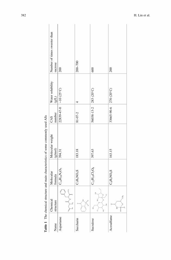
Table
1Thechem
ical
structure
andmaincharacteristicsofsomecommonly
usedASs
Nam
e
Chem
ical
structure
Molecular
form
ula
Molecularweight
(g/m
ol)
CAS
number
Water
solubility
(g/L)
Number
oftimes
sweeterthan
sucrose
Aspartame
OH
O
NH2
N H
O
O
OCH3
C14H18N2O5
394.31
22839-47-0
~10(25� C
)200
Saccharin
NH
S
OO
OC7H5NO3S
183.18
81-07-2
4200–700
Sucralose
O
OH
HO
Cl
HO
OO Cl
OH
HO
C12H19Cl 3O8
397.63
56038-13-2
283(20� C
)600
Acesulfam
e
HN S
OO
CH3
O
O
C4H5NO4S
163.15
33665-90-6
270(20� C
)200
382 H. Lin et al.
though at slower rates [50]. Since SUC does not have any evident sites for direct
oxidation by ozone, the removal of SUC was mainly caused by hydroxyl radicals
generated in the oxidative system [49, 50]. It can be concluded that the harsher and
less selective degradation pathway of radical mediated oxidation is necessary for
the breakdown of sucralose. Hollender et al. [52] treated a secondary effluent
containing SUC at the scale of a municipal WWTP by ozonation. The elimination
efficiency of SUC was only 31%, which confirmed ozonation was not an effective
technology for SUC elimination.
The study of Soh et al. indicated SUC was not degraded after 5 h UV exposure
[50]. Therefore, UV was combined with oxidant (H2O2 and peroxydisulfate) or
catalyst to degrade SUC. In UV/H2O2 process, 0.5 mg L�1 SUC was able to be
efficiently degraded at high irradiation intensity, i.e., 4,000 mJ cm�2 [53]. Xu et al.
[54] investigated the mineralization of SUC by UV/peroxydisulfate (PDS) and
UV/H2O2 process. The results indicated the UV/PDS system can completely
mineralize 0.126 mM SUC in a 60-min reaction using a 30-fold excess of PDS
over SUC molar concentration. The study of Calza et al. [55] suggested that both
heterogeneous TiO2 and homogeneous photo-Fenton photocatalytic treatments
are suitable for the elimination of SUC from the aqueous medium. In TiO2
photocatalytic process, 15 mg L�1 SUC can be completely degraded in a 30-min
reaction and be totally mineralized after 240 min of irradiation. Calza et al. [56] also
investigated the degradation of ACE using cerium doped ZnO as a solar light
photocatalyst. The rate constant of ACE decomposition using ZnO doped with
cerium as photocatalyst under solar was 0.011 min–1.
Except for ozonation and UV-based AOPs, other AOPs also began to be applied
in the degradation of ASs, e.g., ferrate(VI) and electrochemical advanced oxidation
processes (EAOPs). Ferrate(VI) is a potential water treatment chemical due to its
dual functions as an oxidant and a subsequent coagulant/precipitant as ferric
hydroxide [57]. Sharma et al. [58] oxidized SUC by ferrate(VI) at neutral
pH. Comparison of the reactivity of ferrate(VI) with other oxidants showed that
free radical species such as •OH have much higher reactivity than Fe(VI) towards
SUC. Therefore, ferrate(VI) may not be feasible to degrade sucralose in water,
similar to ozonation [49]. Punturat et al. [59] degraded ACE-K by electro-oxidation
in aqueous solution. At current density of 100 mA cm�2 and 25 �C, the degradationof ACE-K on tested anodes followed the order BDD > PbO2 > Pt.
Due to the successful application of electro-Fenton process to the degradation of
various organic compounds, it can be estimated that ASs can be mineralized by this
process. Therefore, in this chapter, electro-Fenton process was employed to treat
ASs in aqueous medium. The oxidation kinetics and mineralization behavior of ASs
during electro-Fenton process were assessed. The absolute rate constants for the
reaction between ASs and •OH were determined. The formation and evolution of
aliphatic short-chain carboxylic acids, formed as end-products before complete
mineralization, the evolution of inorganic ions released into the solution, and
toxicity assessment were monitored during treatment.
The Application of Electro-Fenton Process for the Treatment of Artificial Sweeteners 383
2 Treatment of ASs by Electro-Fenton Process
Bulk experiments were carried out at room temperature in a 250 mL undivided
cylindrical glass cell of 6 cm diameter containing 220 mL ASs solution. DSA
(24 cm2, mixed metal oxide Ti/RuO2–IrO2, Baoji Xinyu GuangJiDian Limited
Liability Company, China), Pt (4.5 cm height, i.d. ¼ 3.1 cm, Platecxis, France),
and BDD (24 cm2, COMDIAS GmbH, Germany) anodes, which were centered in
the cell, were used in electro-Fenton process to degrade ASs [60]. Carbon-felt
(17.5 � 5 cm) was used as cathode which covered the inner wall of the 250 mL
capacity glass cell.
2.1 Oxidation Kinetics of ASs
Figure 1a shows that 0.2 mM SAC could be completely removed in a 25-min
reaction for all the anode materials. SAC concentration decay followed pseudo-
first-order kinetics. The apparent rate constant (kapp) values for SAC degradation
with DSA, Pt, and BDD anodes were 0.18, 0.19, and 0.21 min�1, respectively.
However, when it comes to mineralization, BDD anode showed its great superior-
ity. In a 360-min treatment time, the TOC removal efficiencies for SAC were
55.8%, 76.1%, and 96.2% for DSA, Pt, and BDD anodes, respectively (Fig. 1b).
On the one hand, the BDD(•OH) radicals can effectively mineralize short chain
carboxylic acids generated in electro-Fenton process, which are relatively recalci-
trant to homogeneous •OH produced in the bulk solution from Fenton’s reaction(Eq. 2) [61]. On the other hand, the loosely bound BDD(•OH) could readily react
with organic pollutant, in contrast to the chemisorbed Pt(•OH) (Eq. 4) which limited
the oxidation ability of Pt anode [6, 62, 63].
It is well known that catalyst (Fe2+) concentration and applied current are
significant parameters affecting the performance of electro-Fenton process
[17]. The generation rate of •OH from Fenton’s reaction (Eq. 2) is dependent on
the availability of free Fe2+ [64, 65]. On the other hand, an excess of Fe2+ can harm
process efficiency because of enhancement of its reaction with •OH [6, 9]. The
applied current controls the production of hydroxyl radicals both at the anode
surface via Eq. (4) and in the bulk solution through Eqs. (1)–(3) [64]. Moreover,
the value of applied current is crucial for the operational cost and process
efficiency [66].
The effect of catalyst concentration and applied current on SAC oxidation during
electro-Fenton process was investigated by using BDD as anode and carbon-felt as
cathode (Fig. 2) [60]. The degradation of SAC followed pseudo-first-order kinetics
and the apparent rate constants (kapp) calculated from insets were given in Table 2.
SAC disappeared in a 30-min reaction at all operating conditions. The optimal Fe2+
concentration for SAC removal was 0.2 mM. When Fe2+ concentration increased
from 0.2 to 0.5 mM, SAC removal efficiency decreased evidently (Fig. 2). The
384 H. Lin et al.
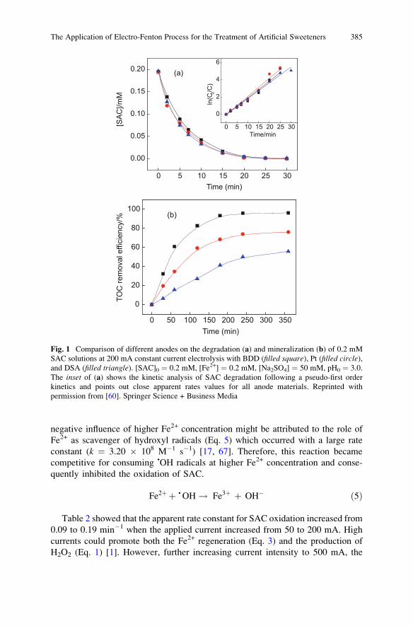
negative influence of higher Fe2+ concentration might be attributed to the role of
Fe2+ as scavenger of hydroxyl radicals (Eq. 5) which occurred with a large rate
constant (k ¼ 3.20 � 108 M�1 s�1) [17, 67]. Therefore, this reaction became
competitive for consuming •OH radicals at higher Fe2+ concentration and conse-
quently inhibited the oxidation of SAC.
Fe2þ þ • OH ! Fe3þ þ OH� ð5Þ
Table 2 showed that the apparent rate constant for SAC oxidation increased from
0.09 to 0.19 min�1 when the applied current increased from 50 to 200 mA. High
currents could promote both the Fe2+ regeneration (Eq. 3) and the production of
H2O2 (Eq. 1) [1]. However, further increasing current intensity to 500 mA, the
0 5 10 15 20 25 30
0.00
0.05
0.10
0.15
0.20
[SAC
]/mM
Time (min)
(a)
0 5 10 15 20 25 30
0
2
4
6
ln(C
0/C)
Time/min
0 50 100 150 200 250 300 350
0
20
40
60
80
100
TOC
rem
oval
effi
cien
cy/%
Time (min)
(b)
Fig. 1 Comparison of different anodes on the degradation (a) and mineralization (b) of 0.2 mM
SAC solutions at 200 mA constant current electrolysis with BDD (filled square), Pt (filled circle),and DSA (filled triangle). [SAC]0 ¼ 0.2 mM, [Fe2+] ¼ 0.2 mM, [Na2SO4] ¼ 50 mM, pH0 ¼ 3.0.
The inset of (a) shows the kinetic analysis of SAC degradation following a pseudo-first order
kinetics and points out close apparent rates values for all anode materials. Reprinted with
permission from [60]. Springer Science + Business Media
The Application of Electro-Fenton Process for the Treatment of Artificial Sweeteners 385
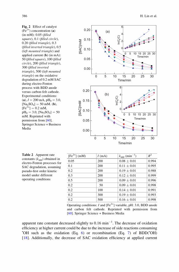
apparent rate constant decreased slightly to 0.16 min�1. The decrease of oxidation
efficiency at higher current could be due to the increase of side reactions consuming•OH such as the oxidation (Eq. 6) or recombination (Eq. 7) of BDD(•OH)
[18]. Additionally, the decrease of SAC oxidation efficiency at applied current
0 5 10 15 20 25 30
0.00
0.05
0.10
0.15
0.20 (a)
[SAC
]/mM
Time/min
0 5 10 15 20 25 30
0
2
4
6
ln(C
0/C)
Time/min
0 5 10 15 20 25 30
0.00
0.05
0.10
0.15
0.20 (b)
[SAC
]/mM
Time/min
0 5 10 15 20 25 30
0
2
4
6
ln(C
0/C)
Time/min
Fig. 2 Effect of catalyst
(Fe2+) concentration (a)
(in mM): 0.05 (filledsquare), 0.1 (filled circle),0.20 (filled triangle), 0.3(filled inverted triangle), 0.5(left mounted triangle) andapplied current (b) (in mA):
50 (filled square), 100 (filledcircle), 200 (filled triangle),300 (filled invertedtriangle), 500 (left mountedtriangle) on the oxidative
degradation of 0.2 mM SAC
during electro-Fenton
process with BDD anode
versus carbon-felt cathode.
Experimental conditions:
(a), I ¼ 200 mA, pH0 ¼ 3.0,
[Na2SO4] ¼ 50 mM. (b),
[Fe2+] ¼ 0.2 mM,
pH0 ¼ 3.0, [Na2SO4] ¼ 50
mM. Reprinted with
permission from [60].
Springer Science + Business
Media
Table 2 Apparent rate
constants (kapp) obtained in
electro-Fenton processes for
SAC degradation, assuming
pseudo-first order kinetic
model under different
operating conditions
[Fe2+] (mM) I (mA) kapp (min�1) R2
0.05 200 0.08 � 0.01 0.994
0.1 200 0.11 � 0.01 0.995
0.2 200 0.19 � 0.01 0.988
0.3 200 0.12 � 0.01 0.999
0.5 200 0.09 � 0.01 0.996
0.2 50 0.09 � 0.01 0.998
0.2 100 0.14 � 0.01 0.991
0.2 300 0.19 � 0.01 0.993
0.2 500 0.16 � 0.01 0.998
Operating conditions: I and [Fe2+] variable, pH: 3.0, BDD anode
and carbon felt cathode. Reprinted with permission from
[60]. Springer Science + Business Media
386 H. Lin et al.
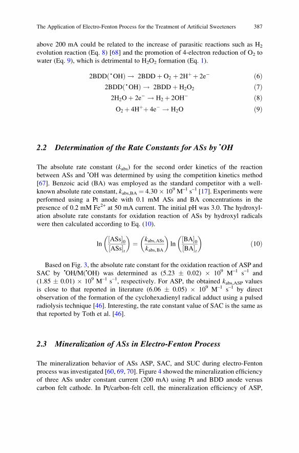
above 200 mA could be related to the increase of parasitic reactions such as H2
evolution reaction (Eq. 8) [68] and the promotion of 4-electron reduction of O2 to
water (Eq. 9), which is detrimental to H2O2 formation (Eq. 1).
2BDD •OHð Þ ! 2BDD þ O2 þ 2Hþ þ 2e� ð6Þ2BDD •OHð Þ ! 2BDD þ H2O2 ð7Þ2H2Oþ 2e� ! H2þ 2OH� ð8ÞO2þ 4Hþþ 4e� ! H2O ð9Þ
2.2 Determination of the Rate Constants for ASs by •OH
The absolute rate constant (kabs) for the second order kinetics of the reaction
between ASs and •OH was determined by using the competition kinetics method
[67]. Benzoic acid (BA) was employed as the standard competitor with a well-
known absolute rate constant, kabs,BA ¼ 4.30 � 109 M–1 s–1 [17]. Experiments were
performed using a Pt anode with 0.1 mM ASs and BA concentrations in the
presence of 0.2 mM Fe2+ at 50 mA current. The initial pH was 3.0. The hydroxyl-
ation absolute rate constants for oxidation reaction of ASs by hydroxyl radicals
were then calculated according to Eq. (10).
lnASs½ �0ASs½ �t
� �¼ kabs,ASs
kabs,BA
� �ln
BA½ �0BA½ �t
� �ð10Þ
Based on Fig. 3, the absolute rate constant for the oxidation reaction of ASP and
SAC by •OH/M(•OH) was determined as (5.23 � 0.02) � 109 M–1 s–1 and
(1.85 � 0.01) � 109 M–1 s–1, respectively. For ASP, the obtained kabs,ASP values
is close to that reported in literature (6.06 � 0.05) � 109 M–1 s–1 by direct
observation of the formation of the cyclohexadienyl radical adduct using a pulsed
radiolysis technique [46]. Interesting, the rate constant value of SAC is the same as
that reported by Toth et al. [46].
2.3 Mineralization of ASs in Electro-Fenton Process
The mineralization behavior of ASs ASP, SAC, and SUC during electro-Fenton
process was investigated [60, 69, 70]. Figure 4 showed the mineralization efficiency
of three ASs under constant current (200 mA) using Pt and BDD anode versus
carbon felt cathode. In Pt/carbon-felt cell, the mineralization efficiency of ASP,
The Application of Electro-Fenton Process for the Treatment of Artificial Sweeteners 387
SAC, and SUC in 360-min electrolysis were 81.7%, 76.1%, and 95.2%, respec-
tively, indicating the mineralization of SUC was under a much faster reaction rate
in electro-Fenton process using Pt as anode. The mineralization efficiency in BDD/
carbon-felt cell for ASP, SAC, and SUC were 97.5%, 96.2%, and 98.9%, respec-
tively, which was higher than that in Pt/carbon-felt cell, confirming the great
superiority of BDD anode on mineralization.
0.0 0.5 1.0 1.5 2.0
0.0
0.5
1.0
1.5
2.0
2.5
ln([BA]0/[BA])
ln([A
SP] 0/[
ASP]
)
y = 1.2035x R2 = 0.998(a)
0 1 2 3 4
0.0
0.5
1.0
1.5
2.0
y = 0.4303x R2 =0.996
ln([S
AC] 0/[
SAC
])
ln([BA]0/[BA])
(b)
Fig. 3 Determination of the absolute rate constant of the reaction between ASs (ASP (a) and SAC
(b)) and •OH by using competition kinetics method. Benzoic acid (BA) was selected as standard
competitor. Experimental conditions: [ASs]0 ¼ 0.1 mM, [BA]0 ¼ 0.1 mM, [Fe2+] ¼ 0.2 mM,
[Na2SO4] ¼ 50 mM, I ¼ 50 mA, pH0 3.0. Reprinted with permission from [60, 69]. Springer
Science + Business Media and Elsevier
388 H. Lin et al.
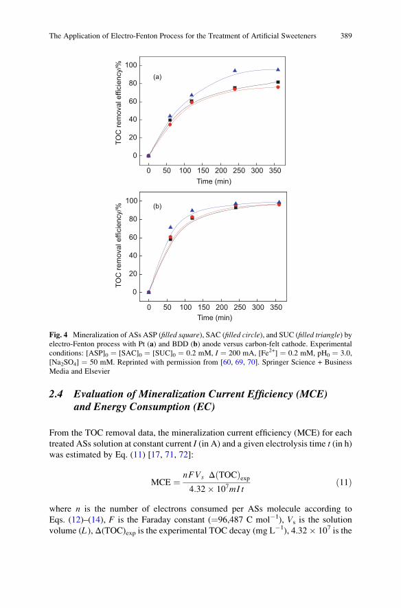
2.4 Evaluation of Mineralization Current Efficiency (MCE)and Energy Consumption (EC)
From the TOC removal data, the mineralization current efficiency (MCE) for each
treated ASs solution at constant current I (in A) and a given electrolysis time t (in h)was estimated by Eq. (11) [17, 71, 72]:
MCE ¼ nFVs Δ TOCð Þexp4:32� 107mI t
ð11Þ
where n is the number of electrons consumed per ASs molecule according to
Eqs. (12)–(14), F is the Faraday constant (¼96,487 C mol�1), Vs is the solution
volume (L ), Δ(TOC)exp is the experimental TOC decay (mg L�1), 4.32� 107 is the
0 50 100 150 200 250 300 350
0
20
40
60
80
100(a)
TOC
rem
oval
effi
cien
cy/%
Time (min)
0 50 100 150 200 250 300 350
0
20
40
60
80
100
TOC
rem
oval
effi
cien
cy/%
Time (min)
(b)
Fig. 4 Mineralization of ASs ASP (filled square), SAC (filled circle), and SUC (filled triangle) byelectro-Fenton process with Pt (a) and BDD (b) anode versus carbon-felt cathode. Experimental
conditions: [ASP]0 ¼ [SAC]0 ¼ [SUC]0 ¼ 0.2 mM, I ¼ 200 mA, [Fe2+] ¼ 0.2 mM, pH0 ¼ 3.0,
[Na2SO4] ¼ 50 mM. Reprinted with permission from [60, 69, 70]. Springer Science + Business
Media and Elsevier
The Application of Electro-Fenton Process for the Treatment of Artificial Sweeteners 389
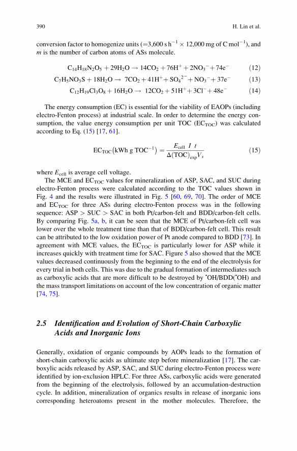
conversion factor to homogenize units (¼3,600 s h�1� 12,000 mg of C mol�1), and
m is the number of carbon atoms of ASs molecule.
C14H18N2O5 þ 29H2O ! 14CO2 þ 76Hþ þ 2NO3�þ 74e� ð12Þ
C7H5NO3Sþ 18H2O ! 7CO2þ 41Hþþ SO42�þNO3
�þ 37e� ð13ÞC12H19Cl3O8þ 16H2O ! 12CO2þ 51Hþþ 3Cl�þ 48e� ð14Þ
The energy consumption (EC) is essential for the viability of EAOPs (including
electro-Fenton process) at industrial scale. In order to determine the energy con-
sumption, the value energy consumption per unit TOC (ECTOC) was calculated
according to Eq. (15) [17, 61].
ECTOC kWh g TOC�1� � ¼ Ecell I t
Δ TOCð ÞexpVsð15Þ
where Ecell is average cell voltage.
The MCE and ECTOC values for mineralization of ASP, SAC, and SUC during
electro-Fenton process were calculated according to the TOC values shown in
Fig. 4 and the results were illustrated in Fig. 5 [60, 69, 70]. The order of MCE
and ECTOC for three ASs during electro-Fenton process was in the following
sequence: ASP > SUC > SAC in both Pt/carbon-felt and BDD/carbon-felt cells.
By comparing Fig. 5a, b, it can be seen that the MCE of Pt/carbon-felt cell was
lower over the whole treatment time than that of BDD/carbon-felt cell. This result
can be attributed to the low oxidation power of Pt anode compared to BDD [73]. In
agreement with MCE values, the ECTOC is particularly lower for ASP while it
increases quickly with treatment time for SAC. Figure 5 also showed that the MCE
values decreased continuously from the beginning to the end of the electrolysis for
every trial in both cells. This was due to the gradual formation of intermediates such
as carboxylic acids that are more difficult to be destroyed by •OH/BDD(•OH) and
the mass transport limitations on account of the low concentration of organic matter
[74, 75].
2.5 Identification and Evolution of Short-Chain CarboxylicAcids and Inorganic Ions
Generally, oxidation of organic compounds by AOPs leads to the formation of
short-chain carboxylic acids as ultimate step before mineralization [17]. The car-
boxylic acids released by ASP, SAC, and SUC during electro-Fenton process were
identified by ion-exclusion HPLC. For three ASs, carboxylic acids were generated
from the beginning of the electrolysis, followed by an accumulation-destruction
cycle. In addition, mineralization of organics results in release of inorganic ions
corresponding heteroatoms present in the mother molecules. Therefore, the
390 H. Lin et al.
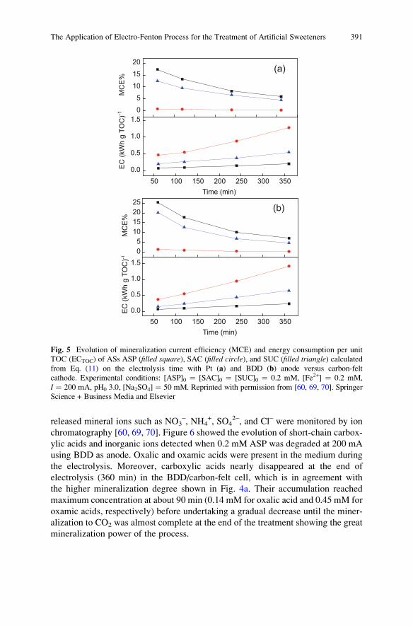
released mineral ions such as NO3–, NH4
+, SO42–, and Cl– were monitored by ion
chromatography [60, 69, 70]. Figure 6 showed the evolution of short-chain carbox-
ylic acids and inorganic ions detected when 0.2 mM ASP was degraded at 200 mA
using BDD as anode. Oxalic and oxamic acids were present in the medium during
the electrolysis. Moreover, carboxylic acids nearly disappeared at the end of
electrolysis (360 min) in the BDD/carbon-felt cell, which is in agreement with
the higher mineralization degree shown in Fig. 4a. Their accumulation reached
maximum concentration at about 90 min (0.14 mM for oxalic acid and 0.45 mM for
oxamic acids, respectively) before undertaking a gradual decrease until the miner-
alization to CO2 was almost complete at the end of the treatment showing the great
mineralization power of the process.
05
101520
50 100 150 200 250 300 3500.0
0.5
1.0
1.5M
CE%
EC (k
Wh
g TO
C)-1
Time (min)
05
10152025
50 100 150 200 250 300 3500.0
0.5
1.0
1.5
MC
E%EC
(kW
h g
TOC
)-1
Time (min)
(a)
(b)
Fig. 5 Evolution of mineralization current efficiency (MCE) and energy consumption per unit
TOC (ECTOC) of ASs ASP (filled square), SAC (filled circle), and SUC (filled triangle) calculatedfrom Eq. (11) on the electrolysis time with Pt (a) and BDD (b) anode versus carbon-felt
cathode. Experimental conditions: [ASP]0 ¼ [SAC]0 ¼ [SUC]0 ¼ 0.2 mM, [Fe2+] ¼ 0.2 mM,
I ¼ 200 mA, pH0 3.0, [Na2SO4] ¼ 50 mM. Reprinted with permission from [60, 69, 70]. Springer
Science + Business Media and Elsevier
The Application of Electro-Fenton Process for the Treatment of Artificial Sweeteners 391
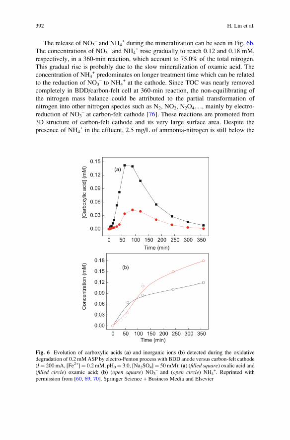
The release of NO3– and NH4
+ during the mineralization can be seen in Fig. 6b.
The concentrations of NO3– and NH4
+ rose gradually to reach 0.12 and 0.18 mM,
respectively, in a 360-min reaction, which account to 75.0% of the total nitrogen.
This gradual rise is probably due to the slow mineralization of oxamic acid. The
concentration of NH4+ predominates on longer treatment time which can be related
to the reduction of NO3– to NH4
+ at the cathode. Since TOC was nearly removed
completely in BDD/carbon-felt cell at 360-min reaction, the non-equilibrating of
the nitrogen mass balance could be attributed to the partial transformation of
nitrogen into other nitrogen species such as N2, NO2, N2O4. . ., mainly by electro-
reduction of NO3– at carbon-felt cathode [76]. These reactions are promoted from
3D structure of carbon-felt cathode and its very large surface area. Despite the
presence of NH4+ in the effluent, 2.5 mg/L of ammonia-nitrogen is still below the
0 50 100 150 200 250 300 350
0.00
0.03
0.06
0.09
0.12
0.15
[Car
boxy
lic a
cid]
(mM
)
Time (min)
(a)
0 50 100 150 200 250 300 3500.00
0.03
0.06
0.09
0.12
0.15
0.18(b)
Time (min)
Con
cent
ratio
n (m
M)
Fig. 6 Evolution of carboxylic acids (a) and inorganic ions (b) detected during the oxidative
degradation of 0.2 mMASP by electro-Fenton process with BDD anode versus carbon-felt cathode
(I¼ 200 mA, [Fe2+]¼ 0.2 mM, pH0¼ 3.0, [Na2SO4]¼ 50 mM): (a) (filled square) oxalic acid and(filled circle) oxamic acid; (b) (open square) NO3
– and (open circle) NH4+. Reprinted with
permission from [60, 69, 70]. Springer Science + Business Media and Elsevier
392 H. Lin et al.
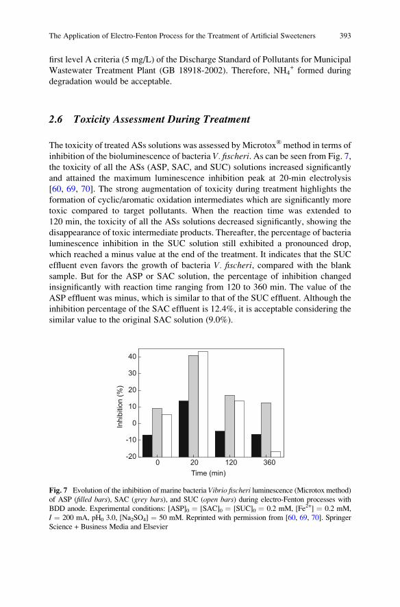
first level A criteria (5 mg/L) of the Discharge Standard of Pollutants for Municipal
Wastewater Treatment Plant (GB 18918-2002). Therefore, NH4+ formed during
degradation would be acceptable.
2.6 Toxicity Assessment During Treatment
The toxicity of treated ASs solutions was assessed by Microtox®method in terms of
inhibition of the bioluminescence of bacteria V. fischeri. As can be seen from Fig. 7,
the toxicity of all the ASs (ASP, SAC, and SUC) solutions increased significantly
and attained the maximum luminescence inhibition peak at 20-min electrolysis
[60, 69, 70]. The strong augmentation of toxicity during treatment highlights the
formation of cyclic/aromatic oxidation intermediates which are significantly more
toxic compared to target pollutants. When the reaction time was extended to
120 min, the toxicity of all the ASs solutions decreased significantly, showing the
disappearance of toxic intermediate products. Thereafter, the percentage of bacteria
luminescence inhibition in the SUC solution still exhibited a pronounced drop,
which reached a minus value at the end of the treatment. It indicates that the SUC
effluent even favors the growth of bacteria V. fischeri, compared with the blank
sample. But for the ASP or SAC solution, the percentage of inhibition changed
insignificantly with reaction time ranging from 120 to 360 min. The value of the
ASP effluent was minus, which is similar to that of the SUC effluent. Although the
inhibition percentage of the SAC effluent is 12.4%, it is acceptable considering the
similar value to the original SAC solution (9.0%).
-20
-10
0
10
20
30
40
Inhi
bitio
n (%
)
Time (min)0 20 120 360
Fig. 7 Evolution of the inhibition of marine bacteria Vibrio fischeri luminescence (Microtox method)
of ASP (filled bars), SAC (grey bars), and SUC (open bars) during electro-Fenton processes with
BDD anode. Experimental conditions: [ASP]0 ¼ [SAC]0 ¼ [SUC]0 ¼ 0.2 mM, [Fe2+] ¼ 0.2 mM,
I ¼ 200 mA, pH0 3.0, [Na2SO4] ¼ 50 mM. Reprinted with permission from [60, 69, 70]. Springer
Science + Business Media and Elsevier
The Application of Electro-Fenton Process for the Treatment of Artificial Sweeteners 393
3 Conclusions
Electro-Fenton process was proved to be an effective method on the degradation of
ASs in aqueous medium. The ASs under study (ASP, SAC, and SUC) were quickly
oxidized in about 25 min. When initial ASs concentration was 0.2 mM, Fe2+
concentration was 0.2 mM, applied current was 200 mA, pH0 was 3.0, and
Na2SO4 concentration was 50 mM, all the treated ASs (ASP, SAC, and SUC) can
be totally mineralized in a 360-min reaction by electro-Fenton process using BDD
as anode and carbon-felt as cathode. Short-chain carboxylic acids and inorganic
ions were generated during the mineralization of ASs but they can be mineralized
under longer treatment time. The toxicity of treated ASs solutions was assessed
using a Microtox method showing the formation of toxic intermediates during the
initial stage of the treatment. The toxic intermediates were effectively destroyed
with the progress of the reaction and the percentage of bacteria luminescence
inhibition in the effluent was close to or even lower than that in the original
solution.
Acknowledgments Lin H. would like to acknowledge the financial support by the Fundamental
Research Funds for the Central Universities (No. 2042016kf0060) and Natural Science Foundation
of Hubei Province, China (Grant No. 2016CFB112).
References
1. Lin H, Zhang H, Wang X, Wang L, Wu J (2014) Electro-Fenton removal of Orange II in a
divided cell: reaction mechanism, degradation pathway and toxicity evolution. Sep Purif
Technol 122:533–540
2. El-Ghenymy A, Centellas F, Garrido JA, Rodrıguez RM, Sires I, Cabot PL, Brillas E (2014)
Decolorization and mineralization of Orange G azo dye solutions by anodic oxidation with a
boron-doped diamond anode in divided and undivided tank reactors. Electrochim Acta
130:568–576
3. Rodrigo MA, Oturan N, Oturan MA (2014) Electrochemically assisted remediation of pesti-
cides in soils and water: a review. Chem Rev 114(17):8720–8745
4. Wu J, Zhang H, Oturan N, Wang Y, Chen L, Oturan MA (2012) Application of response
surface methodology to the removal of the antibiotic tetracycline by electrochemical process
using carbon-felt cathode and DSA (Ti/RuO2–IrO2) anode. Chemosphere 87(6):614–620
5. Kim I, Tanaka H (2009) Photodegradation characteristics of PPCPs in water with UV
treatment. Environ Int 35(5):793–802
6. Sires I, Brillas E, Oturan M, Rodrigo M, Panizza M (2014) Electrochemical advanced
oxidation processes: today and tomorrow. A review. Environ Sci Pollut Res 21(14):8336–8367
7. Pignatello JJ, Oliveros E, MacKay A (2006) Advanced oxidation processes for organic
contaminant destruction based on the Fenton reaction and related chemistry. Crit Rev Environ
Sci Technol 36(1):1–84
8. Neyens E, Baeyens J (2003) A review of classic Fenton’s peroxidation as an advanced
oxidation technique. J Hazard Mater 98(1–3):33–50
9. Oturan MA, Aaron J-J (2014) Advanced oxidation processes in water/wastewater treatment:
principles and applications. A review. Crit Rev Environ Sci Technol 44(23):2577–2641
394 H. Lin et al.
10. Zazo JA, Casas JA, Mohedano AF, Rodriguez JJ (2009) Semicontinuous Fenton oxidation of
phenol in aqueous solution. A kinetic study. Water Res 43(16):4063–4069
11. Kuo WG (1992) Decolorizing dye wastewater with Fenton’s reagent. Water Res 26
(7):881–886
12. Zhang H, Choi HJ, Huang C-P (2005) Optimization of Fenton process for the treatment of
landfill leachate. J Hazard Mater 125(1–3):166–174
13. Bautista P, Mohedano AF, Casas JA, Zazo JA, Rodriguez JJ (2008) An overview of the
application of Fenton oxidation to industrial wastewaters treatment. J Chem Technol
Biotechnol 83(10):1323–1338
14. Sun J-H, Sun S-P, Fan M-H, Guo H-Q, Qiao L-P, Sun R-X (2007) A kinetic study on the
degradation of p-nitroaniline by Fenton oxidation process. J Hazard Mater 148(1–2):172–177
15. Zhang H, Choi HJ, Huang C-P (2006) Treatment of landfill leachate by Fenton’s reagent in a
continuous stirred tank reactor. J Hazard Mater 136(3):618–623
16. Zhang H, Zhang D, Zhou J (2006) Removal of COD from landfill leachate by electro-Fenton
method. J Hazard Mater 135(1–3):106–111
17. Brillas E, Sires I, Oturan MA (2009) Electro-Fenton process and related electrochemical
technologies based on Fenton’s reaction chemistry. Chem Rev 109(12):6570–6631
18. Garcia-Segura S, Brillas E (2011) Mineralization of the recalcitrant oxalic and oxamic acids by
electrochemical advanced oxidation processes using a boron-doped diamond anode. Water
Res 45(9):2975–2984
19. Panizza M, Cerisola G (2009) Electro-Fenton degradation of synthetic dyes. Water Res 43
(2):339–344
20. Yu X, Zhou M, Ren G, Ma L (2015) A novel dual gas diffusion electrodes system for efficient
hydrogen peroxide generation used in electro-Fenton. Chem Eng J 263:92–100
21. Bedolla-Guzman A, Sires I, Thiam A, Peralta-Hernandez JM, Gutierrez-Granados S, Brillas E
(2016) Application of anodic oxidation, electro-Fenton and UVA photoelectro-Fenton to
decolorize and mineralize acidic solutions of reactive yellow 160 azo dye. Electrochim Acta
206:307–316
22. Yuan S, Tian M, Cui Y, Lin L, Lu X (2006) Treatment of nitrophenols by cathode reduction
and electro-Fenton methods. J Hazard Mater 137(1):573–580
23. Nidheesh PV, Gandhimathi R, Sanjini NS (2014) NaHCO3 enhanced Rhodamine B removal
from aqueous solution by graphite–graphite electro Fenton system. Sep Purif Technol
132:568–576
24. Pimentel M, Oturan N, Dezotti M, Oturan MA (2008) Phenol degradation by advanced
electrochemical oxidation process electro-Fenton using a carbon felt cathode. Appl Catal B
Environ 83(1–2):140–149
25. Diagne M, Sharma V, Oturan N, Oturan M (2014) Depollution of indigo dye by anodic
oxidation and electro-Fenton using B-doped diamond anode. Environ Chem Lett 12
(1):219–224
26. Olvera-Vargas H, Oturan N, Aravindakumar CT, Paul MMS, Sharma V, Oturan M (2014)
Electro-oxidation of the dye azure B: kinetics, mechanism, and by-products. Environ Sci
Pollut Res 21(14):8379–8386
27. Wang A, Qu J, Ru J, Liu H, Ge J (2005) Mineralization of an azo dye Acid Red 14 by electro-
Fenton’s reagent using an activated carbon fiber cathode. Dyes Pigments 65(3):227–233
28. Wang C-T, Chou W-L, Chung M-H, Kuo Y-M (2010) COD removal from real dyeing
wastewater by electro-Fenton technology using an activated carbon fiber cathode. Desalination
253(1–3):129–134
29. Lei H, Li H, Li Z, Li Z, Chen K, Zhang X, Wang H (2010) Electro-Fenton degradation of
cationic red X-GRL using an activated carbon fiber cathode. Process Saf Environ Prot 88
(6):431–438
30. Xie YB, Li XZ (2006) Interactive oxidation of photoelectrocatalysis and electro-Fenton for
azo dye degradation using TiO2–Ti mesh and reticulated vitreous carbon electrodes. Mater
Chem Phys 95(1):39–50
The Application of Electro-Fenton Process for the Treatment of Artificial Sweeteners 395
31. Martınez SS, Bahena CL (2009) Chlorbromuron urea herbicide removal by electro-Fenton
reaction in aqueous effluents. Water Res 43(1):33–40
32. Ozcan A, Sahin Y, Savas Koparal A, Oturan MA (2008) Carbon sponge as a new cathode
material for the electro-Fenton process: comparison with carbon felt cathode and application to
degradation of synthetic dye basic blue 3 in aqueous medium. J Electroanal Chem 616
(1–2):71–78
33. Cruz-Gonzalez K, Torres-Lopez O, Garcıa-Leon A, Guzman-Mar JL, Reyes LH, Hernandez-
Ramırez A, Peralta-Hernandez JM (2010) Determination of optimum operating parameters for
acid yellow 36 decolorization by electro-Fenton process using BDD cathode. Chem Eng J 160
(1):199–206
34. Ganiyu SO, Oturan N, Raffy S, Cretin M, Esmilaire R, van Hullebusch E, Esposito G, Oturan
MA (2016) Sub-stoichiometric titanium oxide (Ti4O7) as a suitable ceramic anode for
electrooxidation of organic pollutants: a case study of kinetics, mineralization and toxicity
assessment of amoxicillin. Water Res 106:171–182
35. Oturan N, Wu J, Zhang H, Sharma VK, Oturan MA (2013) Electrocatalytic destruction of the
antibiotic tetracycline in aqueous medium by electrochemical advanced oxidation processes:
effect of electrode materials. Appl Catal B Environ 140–141:92–97
36. Lange F, Scheurer M, Brauch H-J (2012) Artificial sweeteners – a recently recognized class of
emerging environmental contaminants: a review. Anal Bioanal Chem 403(9):2503–2518
37. Kroger M, Meister K, Kava R (2006) Low-calorie sweeteners and other sugar substitutes: a
review of the safety issues. Compr Rev Food Sci Food Saf 5(2):35–47
38. Richardson SD, Ternes TA (2011) Water analysis: emerging contaminants and current issues.
Anal Chem 83(12):4614–4648
39. Richardson SD (2010) Environmental mass spectrometry: emerging contaminants and current
issues. Anal Chem 82(12):4742–4774
40. Loos R, Gawlik BM, Locoro G, Rimaviciute E, Contini S, Bidoglio G (2009) EU-wide survey
of polar organic persistent pollutants in European river waters. Environ Pollut 157(2):561–568
41. Mead RN, Morgan JB, Avery Jr GB, Kieber RJ, Kirk AM, Skrabal SA, Willey JD (2009)
Occurrence of the artificial sweetener sucralose in coastal and marine waters of the United
States. Mar Chem 116(1–4):13–17
42. Kokotou MG, Asimakopoulos AG, Thomaidis NS (2012) Artificial sweeteners as emerging
pollutants in the environment: analytical methodologies and environmental impact. Anal
Methods 4(10):3057–3070
43. Houtman CJ (2010) Emerging contaminants in surface waters and their relevance for the
production of drinking water in Europe. J Integr Environ Sci 7(4):271–295
44. Schiffman SS, Gatlin CA (1993) Sweeteners: state of knowledge review. Neurosci Biobehav
Rev 17(3):313–345
45. Rodero AB, de Souza Rodero L, Azoubel R (2009) Toxicity of sucralose in humans: a review.
Int J Morphol 27(1):239–244
46. Toth JE, Rickman KA, Venter AR, Kiddle JJ, Mezyk SP (2012) Reaction kinetics and
efficiencies for the hydroxyl and sulfate radical based oxidation of artificial sweeteners in
water. J Phys Chem A 116(40):9819–9824
47. Mawhinney DB, Young RB, Vanderford BJ, Borch T, Snyder SA (2011) Artificial sweetener
sucralose in U.S. drinking water systems. Environ Sci Technol 45(20):8716–8722
48. Bernardo EC, Fukuta T, Fujita T, Ona EP, Kojima Y, Matsuda H (2006) Enhancement of
saccharin removal from aqueous solution by activated carbon adsorption with ultrasonic
treatment. Ultrason Sonochem 13(1):13–18
49. Sharma V, Oturan M, Kim H (2014) Oxidation of artificial sweetener sucralose by advanced
oxidation processes: a review. Environ Sci Pollut Res 21(14):8525–8533
50. Soh L, Connors KA, Brooks BW, Zimmerman J (2011) Fate of sucralose through environ-
mental and water treatment processes and impact on plant indicator species. Environ Sci
Technol 45(4):1363–1369
396 H. Lin et al.
51. Hoigne J, Bader H (1983) Rate constants of reactions of ozone with organic and inorganic
compounds in water – I. Water Res 17(2):173–183
52. Hollender J, Zimmermann SG, Koepke S, Krauss M, McArdell CS, Ort C, Singer H,
von Gunten U, Siegrist H (2009) Elimination of organic micropollutants in a municipal
wastewater treatment plant upgraded with a full-scale post-ozonation followed by sand
filtration. Environ Sci Technol 43(20):7862–7869
53. Keen OS, Linden KG (2013) Re-Engineering an artificial sweetener: transforming sucralose
residuals in water via advanced oxidation. Environ Sci Technol 47(13):6799–6805
54. Xu Y, Lin Z, Zhang H (2016) Mineralization of sucralose by UV-based advanced oxidation
processes: UV/PDS versus UV/H2O2. Chem Eng J 285:392–401
55. Calza P, Sakkas VA, Medana C, Vlachou AD, Dal Bello F, Albanis TA (2013) Chemometric
assessment and investigation of mechanism involved in photo-Fenton and TiO2 photocatalytic
degradation of the artificial sweetener sucralose in aqueous media. Appl Catal B Environ
129:71–79
56. Calza P, Gionco C, Giletta M, Kalaboka M, Sakkas VA, Albanis T, Paganini MC (2017)
Assessment of the abatement of acelsulfame K using cerium doped ZnO as photocatalyst.
J Hazard Mater 323:471–477
57. Lee Y, Zimmermann SG, Kieu AT, von Gunten U (2009) Ferrate (Fe(VI)) application for
municipal wastewater treatment: a novel process for simultaneous micropollutant oxidation
and phosphate removal. Environ Sci Technol 43(10):3831–3838
58. Sharma VK, Sohn M, Anquandah GAK, Nesnas N (2012) Kinetics of the oxidation of
sucralose and related carbohydrates by ferrate(VI). Chemosphere 87(6):644–648
59. Punturat V, Huang K-L (2016) Degradation of acesulfame in aqueous solutions by electro-
oxidation. J Taiwan Inst Chem Eng 63:286–294
60. Lin H, Wu J, Oturan N, Zhang H, Oturan MA (2016) Degradation of artificial sweetener
saccharin in aqueous medium by electrochemically generated hydroxyl radicals. Environ Sci
Pollut Res 23(5):4442–4453
61. Mhemdi A, Oturan MA, Oturan N, Abdelhedi R, Ammar S (2013) Electrochemical advanced
oxidation of 2-chlorobenzoic acid using BDD or Pt anode and carbon felt cathode.
J Electroanal Chem 709:111–117
62. Panizza M, Cerisola G (2009) Direct and mediated anodic oxidation of organic pollutants.
Chem Rev 109(12):6541–6569
63. Rodrigo MA, Ca~nizares P, Sanchez-Carretero A, Saez C (2010) Use of conductive-diamond
electrochemical oxidation for wastewater treatment. Catal Today 151(1–2):173–177
64. Barhoumi N, Oturan N, Olvera-Vargas H, Brillas E, Gadri A, Ammar S, Oturan MA (2016)
Pyrite as a sustainable catalyst in electro-Fenton process for improving oxidation of
sulfamethazine. Kinetics, mechanism and toxicity assessment. Water Res 94:52–61
65. Ozcan A, Sahin Y, Koparal AS, Oturan MA (2008) Degradation of picloram by the electro-
Fenton process. Environ Sci Technol 153(1–2):718–727
66. Ozcan A, Sahin Y, Koparal AS, Oturan MA (2009) A comparative study on the efficiency of
electro-Fenton process in the removal of propham from water. Appl Catal B Environ 89
(3–4):620–626
67. Oturan MA, Edelahi MC, Oturan N, El Kacemi K, Aaron J-J (2010) Kinetics of oxidative
degradation/mineralization pathways of the phenylurea herbicides diuron, monuron and
fenuron in water during application of the electro-Fenton process. Appl Catal B Environ 97
(1–2):82–89
68. Dirany A, Sires I, Oturan N, Ozcan A, Oturan MA (2012) Electrochemical treatment of the
antibiotic sulfachloropyridazine: kinetics, reaction pathways, and toxicity evolution. Environ
Sci Technol 46(7):4074–4082
69. Lin H, Oturan N, Wu J, Zhang H, Oturan MA (2017) Cold incineration of sucralose in aqueous
solution by electro-Fenton process. Sep Purif Technol 173:218–225
The Application of Electro-Fenton Process for the Treatment of Artificial Sweeteners 397
70. Lin H, Oturan N, Wu J, Sharma VK, Zhang H, Oturan MA (2017) Removal of artificial
sweetener aspartame from aqueous media by electrochemical advanced oxidation processes.
Chemosphere 167:220–227
71. Hamza M, Abdelhedi R, Brillas E, Sires I (2009) Comparative electrochemical degradation
of the triphenylmethane dye methyl violet with boron-doped diamond and Pt anodes.
J Electroanal Chem 627(1–2):41–50
72. Skoumal M, Arias C, Cabot PL, Centellas F, Garrido JA, Rodrıguez RM, Brillas E (2008)
Mineralization of the biocide chloroxylenol by electrochemical advanced oxidation processes.
Chemosphere 71(9):1718–1729
73. Oturan N, Hamza M, Ammar S, Abdelhedi R, Oturan MA (2011) Oxidation/mineralization of
2-nitrophenol in aqueous medium by electrochemical advanced oxidation processes using Pt/
carbon-felt and BDD/carbon-felt cells. J Electroanal Chem 661(1):66–71
74. Ozcan A, Sahin Y, Oturan MA (2008) Removal of propham from water by using electro-
Fenton technology: kinetics and mechanism. Chemosphere 73(5):737–744
75. Sires I, Arias C, Cabot PL, Centellas F, Garrido JA, Rodrıguez RM, Brillas E (2007)
Degradation of clofibric acid in acidic aqueous medium by electro-Fenton and photoelectro-
Fenton. Chemosphere 66(9):1660–1669
76. Li M, Feng C, Zhang Z, Sugiura N (2009) Efficient electrochemical reduction of nitrate to
nitrogen using Ti/IrO2–Pt anode and different cathodes. Electrochim Acta 54(20):4600–4606
398 H. Lin et al.
Soil Remediation by Electro-Fenton Process
Emmanuel Mousset, Clement Trellu, Nihal Oturan, Manuel A. Rodrigo,
and Mehmet A. Oturan
Abstract Soil remediation by electro-Fenton (EF) process has been recently pro-
posed in literature. Being applied for solution treatment, EF is mainly combined
with soil washing (SW)/soil flushing (SF) separation techniques to remove the
organic pollutants. The main criteria influencing the combined process have been
identified as (1) operating parameters (electrode materials, current density, and
catalyst (Fe2+) concentration), (2) the matrix composition (nature and dose of
extracting agent, pH, complexity of SW/SF solutions), and (3) the environmental
impact (acute ecotoxicity and biodegradability of effluent as well as impact on soil
microbial activity). The influence of these parameters on the SW/EF and SF/EF
integrated processes has been reviewed. Energy consumption calculations have
been finally considered as it constitutes the main source of operating cost in EF
process.
Keywords Bioassays, Cyclodextrins, Electrode materials, Hydrocarbons, Soil
washing, Surfactant
Contents
1 Introduction . . . . . . . . . . . . . . . . . . . . . . . . . . . . . . . . . . . . . . . . . . . . . . . . . . . . . . . . . . . . . . . . . . . . . . . . . . . . . . . . . . 400
2 Influence of Operating Parameters . . . . . . . . . . . . . . . . . . . . . . . . . . . . . . . . . . . . . . . . . . . . . . . . . . . . . . . . . 403
E. Mousset (*)
Laboratoire Reactions et Genie des Procedes, CNRS – Universite de Lorraine (UMR 7274),
1 rue Grandville, Nancy, Cedex 54001, France
e-mail: [email protected]
C. Trellu, N. Oturan, and M.A. Oturan
Universite Paris-Est, Laboratoire Geomateriaux et Environnement (EA 4508), UPEM, 77454
Marne-la-Vallee, France
M.A. Rodrigo
Department of Chemical Engineering, University of Castilla-LaMancha, Enrique Costa
Novella Building, Campus Universitario s/n, 13071 Ciudad Real, Spain
M. Zhou et al. (eds.), Electro-Fenton Process: New Trends and Scale-Up,Hdb Env Chem (2018) 61: 399–424, DOI 10.1007/698_2017_38,© Springer Nature Singapore Pte Ltd. 2017, Published online: 24 May 2017
399

2.1 Influence of Electrode Materials . . . . . . . . . . . . . . . . . . . . . . . . . . . . . . . . . . . . . . . . . . . . . . . . . . . . . . 403
2.2 Influence of Current Density . . . . . . . . . . . . . . . . . . . . . . . . . . . . . . . . . . . . . . . . . . . . . . . . . . . . . . . . . . 406
2.3 Influence of Catalyst (Fe2+) Concentration . . . . . . . . . . . . . . . . . . . . . . . . . . . . . . . . . . . . . . . . . . . 408
3 Effect of the Matrix . . . . . . . . . . . . . . . . . . . . . . . . . . . . . . . . . . . . . . . . . . . . . . . . . . . . . . . . . . . . . . . . . . . . . . . . . 409
3.1 Influence of Nature of Extracting Agent and Possibility of Recovery . . . . . . . . . . . . . . 410
3.2 Influence of pH . . . . . . . . . . . . . . . . . . . . . . . . . . . . . . . . . . . . . . . . . . . . . . . . . . . . . . . . . . . . . . . . . . . . . . . . 412
3.3 Synthetic vs. Real Effluent . . . . . . . . . . . . . . . . . . . . . . . . . . . . . . . . . . . . . . . . . . . . . . . . . . . . . . . . . . . . 413
4 Impacts on Ecotoxicity, Biodegradability, and Soil Respirometry . . . . . . . . . . . . . . . . . . . . . . . . 415
5 Energy Considerations and Concluding Remarks . . . . . . . . . . . . . . . . . . . . . . . . . . . . . . . . . . . . . . . . . . 419
References . . . . . . . . . . . . . . . . . . . . . . . . . . . . . . . . . . . . . . . . . . . . . . . . . . . . . . . . . . . . . . . . . . . . . . . . . . . . . . . . . . . . . . . 421
1 Introduction
Nowadays, soil pollution is a topic of the major importance not only because of the
direct consequences of this pollution on ecosystems but also because it may lead to
the pollution of supply water reservoirs and, consequently, prevent their use. This is
especially important in regions that traditionally lack water and in areas where
periodic droughts (now intensified with the climate change) make water a very
valuable resource, which may even limit its economic and social subsistence. One
of the types of pollution, which is gaining more and more attention in the scientific
community because of its relevance, is the pollution with organic compounds, in
particular with non-biodegradable anthropogenic organic species such as solvents,
hydrocarbons, and pesticides. It is not a simple problem because these species can
have very different characteristics in terms of hazardousness, biodegradability,
solubility in water, and volatility, and, hence, there is not a unique efficient
treatment that can be successfully applied for their depletion [1–3].
Instead, there are many types of competing technologies that can be applied to
solve this important problem, and, nowadays, scientists are trying to shed light on
the choice of the best for each type of pollutant and soil. Some of them, like soil
washing (SW) of vapor extraction, transfer the pollutant from the soil to a different
phase (liquid or gas), which is later treated ex situ in a more efficient way, removing
rapidly the pollution from soil and avoiding its dispersion. They are very important,
in fact, key technologies in the solution of the problem, because treatment of a large
volume of soil affected by diffuse pollution is more difficult and, overall, more
expensive than the treatment of a much lower volume of soil highly polluted with
the same contaminant.
Regarding the transport of pollution from soil to a liquid, there are two main
technologies: SW (ex situ) or soil flushing (SF) (in situ). The first needs the
excavation of the soil and its transport to a washing unit, in which pollutants are
removed in the best operation conditions by selecting the optimal washing fluid
composition and volume, mixing rate, temperature, and contact time [2, 4, 5]. It
may attain a very good removal of pollutants from the chemical point of view, but
other soil characteristics like compaction are dramatically modified during this
treatment, and special care should be taken after the treatment to try to come
400 E. Mousset et al.
back to the pristine properties, once the soil is cleaned and placed again in the zone
that it occupied before the pollution event. The composition of the SW fluid is
rather important and in case of removal of low-solubility pollutants, the addition of
extracting agents is key to extract them in efficient conditions [1, 2, 6]. Treatment of
the SW wastes produced becomes a very important point to have an integrated
solution to the problem, because it typically consists of highly loaded wastewater
containing the soil pollutant, extracting agents, and many other species extracted
from soil. Selective removal of pollutant in order to try to regenerate the SW fluid
for reuse is the optimum solution looked for, because it may lead to a very efficient
treatment technology from the viewpoint of sustainability and economy.
The other alternative consists of flushing a fluid throughout the soil to drag the
pollutants contained and to collect this fluid into a special zone, where the flushing
fluid is pumped to a subsequent liquid treatment [7–9]. This alternative modifies
much less importantly soil characteristics, but it is more difficult to select the best
extraction operation conditions because soil remains in its position during the
treatment. In case of high permeability soil, the flushing fluid is pumped and
collected directly without further requirements, using the gradient of hydrostatic
pressure (pump and treat technology) as driving force for the transport of fluid. For
low-permeability soils, this driving force is not efficient, and, here, the application
of an electric field between pairs of anode-cathode may activate more complex
transport processes such as electroosmosis, electromigration, and electrophoresis,
commonly known as electrokinetic treatment. As in the SW technologies, these
processes can be combined with an efficient composition of flushing fluid, which
helps to drag efficiently pollutants that cannot be dragged directly by water. At this
point, extracting agents may play a very important role as in the SW processes,
although in SF, interactions are much more complex. These treatments also produce
a polluted flushing fluid which should be treated once produced and the ideal final
point of this treatment is to remove pollutants without affecting extracting agents
and other possible additives in order to regenerate the flushing fluid and recycle it to
the treatment.
There are many technologies that can be used to treat the SW and SF wastes.
Initially, biological process should be the primary election because of their lower
cost. However, it is important to remind that SW and SF are applied when in situ
bioremediation technologies are not efficient and this means that pollutant should
be hardly removed by microorganisms either in soil or in a liquid waste. In this
context, advanced physicochemical technologies become the target for the treat-
ment of these types of wastes. Among them, electrochemical advanced oxidation
processes (EAOPs) are very promising [10], and one of them is going to be widely
described in this chapter, i.e., the electro-Fenton (EF) process. In parallel, there
have been many work carried out in the recent years in the development of other
EAOPs such as anodic oxidation, photoelectrolysis, and sonoelectrolysis [11–
15]. EF has the advantages (1) to generate in situ Fenton’s reagent leading to the
formation of •OH, (2) to be less dependent on the mass transport of the pollutants
thanks to homogeneous catalysis, (3) to avoid sludge formation and •OH wasting
reactions thanks to controlled generation of H2O2 and Fe2+, and (4) to favor some
selective oxidation as discussed later in this chapter.
Soil Remediation by Electro-Fenton Process 401
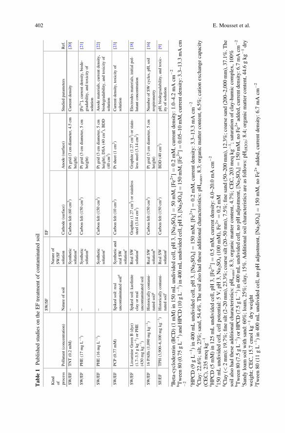
Table
1Published
studiesontheEFtreatm
entofcontaminated
soil
Kind
of
process
Pollutant(concentration)
SW/SF
EF
Studiedparam
eters
Ref.
Nature
ofsoil
Nature
of
SW/SF
solution
Cathode(surface)
Anode(surface)
SW/EF
TNT(0.2
mM)
–Synthetic
solutiona
Carbonfelt(60cm
2)
Ptgrid(3
cmdiameter,4.5cm
height)
Currentdensity
[20]
SW/EF
PHE(17mgL�1)
–Synthetic
solutionb
Carbonfelt(150cm
2)
Ptgrid(3
cmdiameter,5cm
height)
[Fe2
+],currentdensity,biode-
gradability,andtoxicityof
solution
[21]
SW/EF
PHE(16mgL�1)
–Synthetic
solutionc
Carbonfelt(150cm
2)
Ptgrid(3
cmdiameter,5cm
height),DSA(40cm
2),BDD
(40cm
2)
Anodematerials,currentdensity,
biodegradability,andtoxicityof
solution
[22]
SW/EF
PCP(0.77mM)
Spiked
soil:real
uncontaminated
soild
Synthetic
and
real
SW
solutione
Carbonfelt(10cm
2)
Ptsheet(1
cm2)
Currentdensity,toxicityof
solution
[23]
SW/EF
LissamineGreen
B(dye)
(1.7–3.5
gkg�1)orPHE
(430mgkg�1)
Spiked
soil:kaolinite
clay
orreal
uncontaminated
soil
RealSW
solutionf
Graphite(1.27cm
2)orstainless
steel(3.14cm
2)
Graphite(1.27cm
2)orstain-
less
steel(3.14cm
2)
Electrodes
materials,initialpol-
lutantconcentration
[18]
SW/EF
16PAHs(1,090mgkg�1)
Historicallycontami-
nated
soilg
RealSW
solutionh
Carbonfelt(150cm
2)
Ptgrid(3
cmdiameter,5cm
height)
Number
ofSW
cycles,pH,soil
respirometry
[16]
SF/EF
TPH(3,900–6,100mgkg�1)
Historicallycontami-
nated
soili
RealSW
solutionj
Carbonfelt(150cm
2)
BDD(40cm
2)
pH,biodegradability,andtoxic-
ityofsolution
[9]
aBeta-cyclodextrin
(BCD)(1
mM)in
150mLundivided
cell,pH3,[N
a 2SO4]¼
50mM,[Fe2
+]¼
0.2
mM,currentdensity:1.0–4.2
mAcm
�2
bTween80(0.75gL�1)andHPCD(10gL�1)in
400mLundivided
cell,pH3,[N
a 2SO4]¼150mM,[Fe2
+]¼0.05–10mM,currentdensity:3.3–13.3mAcm
�2
cHPCD
(9gL�1)in
400mLundivided
cell,pH3,[N
a 2SO4]¼
150mM,[Fe2
+]¼
0.2
mM,currentdensity:3.3–13.3
mAcm
�2dClay:22.6%;silt,23%;sand,54.4%.Thesoilalso
had
theseadditionalcharacteristics:pHwater,8.3;organicmattercontent,6.5%;cationexchangecapacity
(CEC),235meq
kg�1
eHPCD
(5mM)in
125mLundivided
cell,pH3,[Fe2
+]¼
0.5
mM,currentdensity:4.0–20.0
mAcm
�2f 150mLundivided
cell,cellpotential:5V,pH3,Na 2SO4(100mM),Fe2
+¼
0.2
mM
gClay(<
2mm):19.7%;finesilt(2–20mm),23.3%;coarse
silt(20–50mm),7.5%;finesand(50–200mm),12.3%;coarse
sand(200–2,000mm),37.1%.The
soilalso
had
theseadditional
characteristics:pHwater:8.3;organic
mattercontent,4.7%;CEC,203meq
kg�1;saturationofclay-humic
complex,100%
hTween80(7.5gL�1)orHPCD(7.5gL�1)in
400mLundivided
cell,nopHadjustment,[N
a 2SO4]¼150mM,noFe2
+added,currentdensity:6.7mAcm
�2i Sandyloam
soilwithsand:60%;loam
,25%;clay,15%.Additionalsoilcharacteristicsareas
follows:pH(H
2O):8.4;organicmattercontent,44.6
gkg�1
dry
weight;CEC,15.7
cmolkg�1
dry
weight
j Tween80(11gL�1)in
400mLundivided
cell,nopHadjustment,[N
a 2SO4]¼
150mM,noFe2
+added,currentdensity:6.7
mAcm
�2
402 E. Mousset et al.
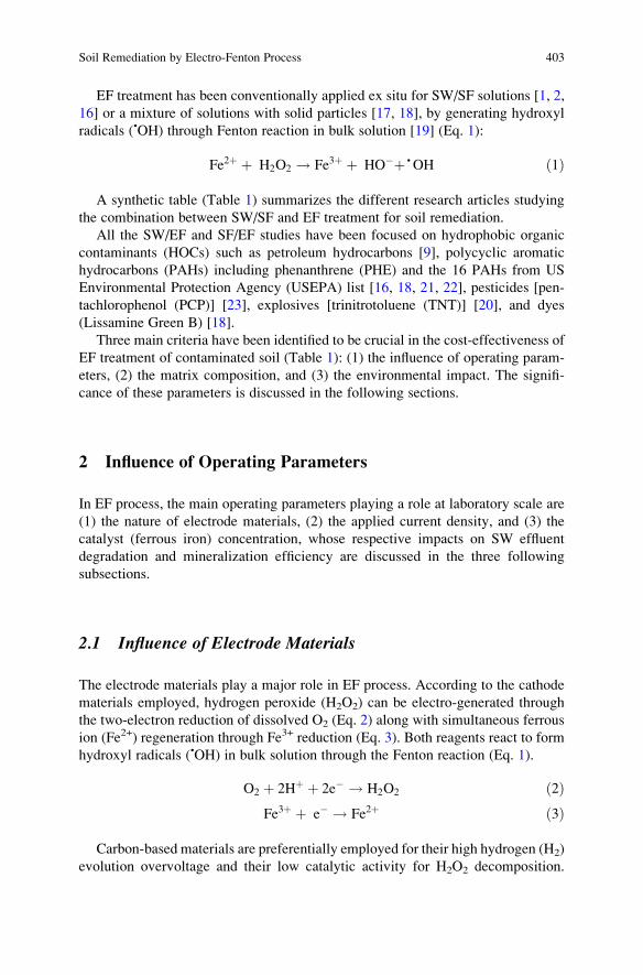
EF treatment has been conventionally applied ex situ for SW/SF solutions [1, 2,
16] or a mixture of solutions with solid particles [17, 18], by generating hydroxyl
radicals (•OH) through Fenton reaction in bulk solution [19] (Eq. 1):
Fe2þ þ H2O2 ! Fe3þ þ HO�þ • OH ð1Þ
A synthetic table (Table 1) summarizes the different research articles studying
the combination between SW/SF and EF treatment for soil remediation.
All the SW/EF and SF/EF studies have been focused on hydrophobic organic
contaminants (HOCs) such as petroleum hydrocarbons [9], polycyclic aromatic
hydrocarbons (PAHs) including phenanthrene (PHE) and the 16 PAHs from US
Environmental Protection Agency (USEPA) list [16, 18, 21, 22], pesticides [pen-
tachlorophenol (PCP)] [23], explosives [trinitrotoluene (TNT)] [20], and dyes
(Lissamine Green B) [18].
Three main criteria have been identified to be crucial in the cost-effectiveness of
EF treatment of contaminated soil (Table 1): (1) the influence of operating param-
eters, (2) the matrix composition, and (3) the environmental impact. The signifi-
cance of these parameters is discussed in the following sections.
2 Influence of Operating Parameters
In EF process, the main operating parameters playing a role at laboratory scale are
(1) the nature of electrode materials, (2) the applied current density, and (3) the
catalyst (ferrous iron) concentration, whose respective impacts on SW effluent
degradation and mineralization efficiency are discussed in the three following
subsections.
2.1 Influence of Electrode Materials
The electrode materials play a major role in EF process. According to the cathode
materials employed, hydrogen peroxide (H2O2) can be electro-generated through
the two-electron reduction of dissolved O2 (Eq. 2) along with simultaneous ferrous
ion (Fe2+) regeneration through Fe3+ reduction (Eq. 3). Both reagents react to form
hydroxyl radicals (•OH) in bulk solution through the Fenton reaction (Eq. 1).
O2 þ 2Hþ þ 2e� ! H2O2 ð2ÞFe3þ þ e� ! Fe2þ ð3Þ
Carbon-based materials are preferentially employed for their high hydrogen (H2)
evolution overvoltage and their low catalytic activity for H2O2 decomposition.
Soil Remediation by Electro-Fenton Process 403
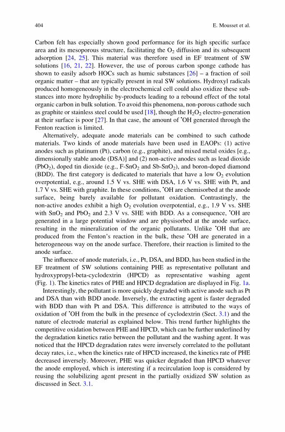
Carbon felt has especially shown good performance for its high specific surface
area and its mesoporous structure, facilitating the O2 diffusion and its subsequent
adsorption [24, 25]. This material was therefore used in EF treatment of SW
solutions [16, 21, 22]. However, the use of porous carbon sponge cathode has
shown to easily adsorb HOCs such as humic substances [26] – a fraction of soil
organic matter – that are typically present in real SW solutions. Hydroxyl radicals
produced homogeneously in the electrochemical cell could also oxidize these sub-
stances into more hydrophilic by-products leading to a rebound effect of the total
organic carbon in bulk solution. To avoid this phenomena, non-porous cathode such
as graphite or stainless steel could be used [18], though the H2O2 electro-generation
at their surface is poor [27]. In that case, the amount of •OH generated through the
Fenton reaction is limited.
Alternatively, adequate anode materials can be combined to such cathode
materials. Two kinds of anode materials have been used in EAOPs: (1) active
anodes such as platinum (Pt), carbon (e.g., graphite), and mixed metal oxides [e.g.,
dimensionally stable anode (DSA)] and (2) non-active anodes such as lead dioxide
(PbO2), doped tin dioxide (e.g., F-SnO2 and Sb-SnO2), and boron-doped diamond
(BDD). The first category is dedicated to materials that have a low O2 evolution
overpotential, e.g., around 1.5 V vs. SHE with DSA, 1.6 V vs. SHE with Pt, and
1.7 V vs. SHE with graphite. In these conditions, •OH are chemisorbed at the anode
surface, being barely available for pollutant oxidation. Contrastingly, the
non-active anodes exhibit a high O2 evolution overpotential, e.g., 1.9 V vs. SHE
with SnO2 and PbO2 and 2.3 V vs. SHE with BDD. As a consequence, •OH are
generated in a large potential window and are physisorbed at the anode surface,
resulting in the mineralization of the organic pollutants. Unlike •OH that are
produced from the Fenton’s reaction in the bulk, these •OH are generated in a
heterogeneous way on the anode surface. Therefore, their reaction is limited to the
anode surface.
The influence of anode materials, i.e., Pt, DSA, and BDD, has been studied in the
EF treatment of SW solutions containing PHE as representative pollutant and
hydroxypropyl-beta-cyclodextrin (HPCD) as representative washing agent
(Fig. 1). The kinetics rates of PHE and HPCD degradation are displayed in Fig. 1a.
Interestingly, the pollutant is more quickly degraded with active anode such as Pt
and DSA than with BDD anode. Inversely, the extracting agent is faster degraded
with BDD than with Pt and DSA. This difference is attributed to the ways of
oxidation of •OH from the bulk in the presence of cyclodextrin (Sect. 3.1) and the
nature of electrode material as explained below. This trend further highlights the
competitive oxidation between PHE and HPCD, which can be further underlined by
the degradation kinetics ratio between the pollutant and the washing agent. It was
noticed that the HPCD degradation rates were inversely correlated to the pollutant
decay rates, i.e., when the kinetics rate of HPCD increased, the kinetics rate of PHE
decreased inversely. Moreover, PHE was quicker degraded than HPCD whatever
the anode employed, which is interesting if a recirculation loop is considered by
reusing the solubilizing agent present in the partially oxidized SW solution as
discussed in Sect. 3.1.
404 E. Mousset et al.
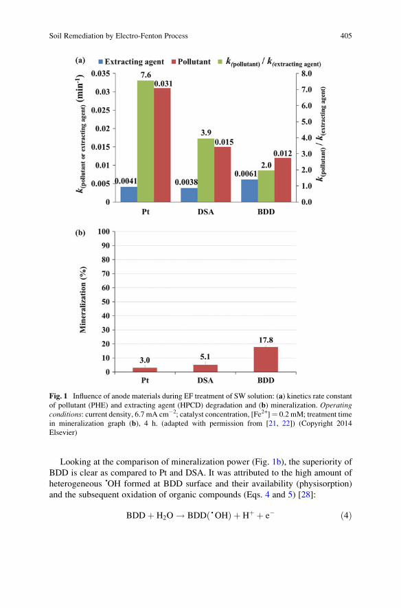
Looking at the comparison of mineralization power (Fig. 1b), the superiority of
BDD is clear as compared to Pt and DSA. It was attributed to the high amount of
heterogeneous •OH formed at BDD surface and their availability (physisorption)
and the subsequent oxidation of organic compounds (Eqs. 4 and 5) [28]:
BDDþ H2O ! BDD •OHð Þ þ Hþ þ e� ð4Þ
Fig. 1 Influence of anode materials during EF treatment of SW solution: (a) kinetics rate constant
of pollutant (PHE) and extracting agent (HPCD) degradation and (b) mineralization. Operatingconditions: current density, 6.7 mA cm�2; catalyst concentration, [Fe2+]¼ 0.2 mM; treatment time
in mineralization graph (b), 4 h. (adapted with permission from [21, 22]) (Copyright 2014
Elsevier)
Soil Remediation by Electro-Fenton Process 405
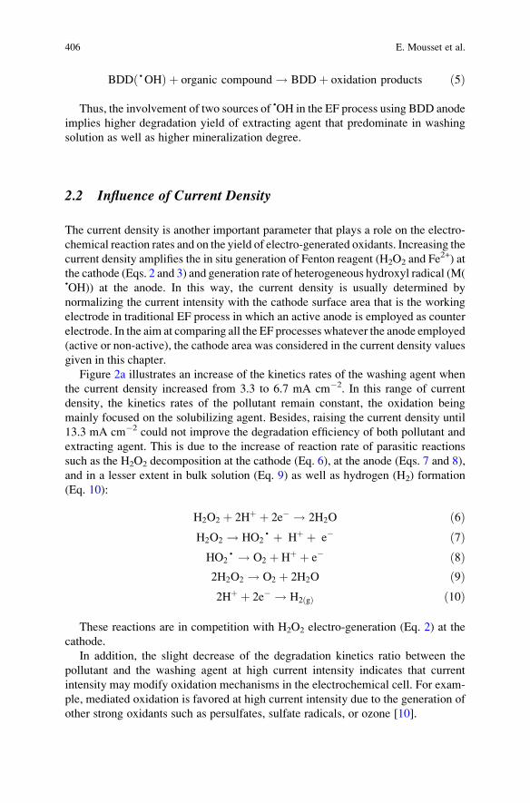
BDD •OHð Þ þ organic compound ! BDD þ oxidation products ð5Þ
Thus, the involvement of two sources of •OH in the EF process using BDD anode
implies higher degradation yield of extracting agent that predominate in washing
solution as well as higher mineralization degree.
2.2 Influence of Current Density
The current density is another important parameter that plays a role on the electro-
chemical reaction rates and on the yield of electro-generated oxidants. Increasing the
current density amplifies the in situ generation of Fenton reagent (H2O2 and Fe2+) at
the cathode (Eqs. 2 and 3) and generation rate of heterogeneous hydroxyl radical (M(•OH)) at the anode. In this way, the current density is usually determined by
normalizing the current intensity with the cathode surface area that is the working
electrode in traditional EF process in which an active anode is employed as counter
electrode. In the aim at comparing all the EF processes whatever the anode employed
(active or non-active), the cathode area was considered in the current density values
given in this chapter.
Figure 2a illustrates an increase of the kinetics rates of the washing agent when
the current density increased from 3.3 to 6.7 mA cm�2. In this range of current
density, the kinetics rates of the pollutant remain constant, the oxidation being
mainly focused on the solubilizing agent. Besides, raising the current density until
13.3 mA cm�2 could not improve the degradation efficiency of both pollutant and
extracting agent. This is due to the increase of reaction rate of parasitic reactions
such as the H2O2 decomposition at the cathode (Eq. 6), at the anode (Eqs. 7 and 8),
and in a lesser extent in bulk solution (Eq. 9) as well as hydrogen (H2) formation
(Eq. 10):
H2O2 þ 2Hþ þ 2e� ! 2H2O ð6ÞH2O2 ! HO2
• þ Hþ þ e� ð7ÞHO2
• ! O2 þ Hþ þ e� ð8Þ2H2O2 ! O2 þ 2H2O ð9Þ2Hþ þ 2e� ! H2 gð Þ ð10Þ
These reactions are in competition with H2O2 electro-generation (Eq. 2) at the
cathode.
In addition, the slight decrease of the degradation kinetics ratio between the
pollutant and the washing agent at high current intensity indicates that current
intensity may modify oxidation mechanisms in the electrochemical cell. For exam-
ple, mediated oxidation is favored at high current intensity due to the generation of
other strong oxidants such as persulfates, sulfate radicals, or ozone [10].
406 E. Mousset et al.
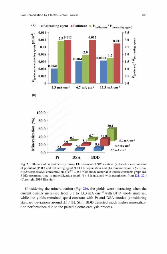
Considering the mineralization (Fig. 2b), the yields were increasing when the
current density increased from 3.3 to 13.3 mA cm�2 with BDD anode material,
while the yields remained quasi-constant with Pt and DSA anodes (considering
standard deviations around �1.4%). Still, BDD depicted much higher mineraliza-
tion performance due to the paired electro-catalysis process.
Fig. 2 Influence of current density during EF treatment of SW solution: (a) kinetics rate constant
of pollutant (PHE) and extracting agent (HPCD) degradation and (b) mineralization. Operatingconditions: catalyst concentration, [Fe2+]¼ 0.2 mM; anode material in kinetic constants graph (a),
BDD; treatment time in mineralization graph (b), 4 h (adapted with permission from [21, 22])
(Copyright 2014 Elsevier)
Soil Remediation by Electro-Fenton Process 407
2.3 Influence of Catalyst (Fe2+) Concentration
Ferrous ion acts as a catalyst in the EF process and is therefore added at a catalytic
amount in the solution.
By varying the concentration of Fe2+ from 0.05 to 10 mM in a synthetic SW
solution containing PHE and HPCD (Fig. 3a), the decay rate of the pollutant
increased until a ferrous ion concentration of 0.2 mM. Increasing the catalyst
concentration makes increase the amount of hydroxyl radicals formed through the
Fenton reaction (Eq. 1).
Remarkably, higher Fe2+ concentration did not improve the kinetics rate of
the pollutant degradation. It can be explained by the progressive inhibition of the
oxidant generation, because of the greater extent of the waste reaction between Fe2+
and •OH (Eq. 11):
Fe2þþ • OH ! Fe3þ þ HO� ð11Þ
In these conditions, 0.2 mM was defined as the optimal Fe2+ concentration,
which is in the range of concentration (0.1–0.2 mM) usually employed in EF
processes at lab scale in batch experiments [18, 21, 22, 29].
The difference of the presence or absence of Fe2+ has been tested by Rosales
et al. [18] in a soil slurry batch reactor. It is noticed that the dye decoloration
rates was 1.35-fold higher with ferrous ion (2.3 h�1) than without addition of Fe2+
(1.7 h�1) by using graphite material as cathode and anode. It highlights the high
oxidation efficiency of •OH formed by Fenton reaction (Eq. 1) as compared to the
direct electro-oxidation treatment. In addition, the comparison between a BDD
anode treatment in synthetic SW solution without the addition of Fe2+ � namely,
anodic oxidation (AO) – and the mineralization efficiency of EF is displayed in
Fig. 3b. By treating the same synthetic SW solution (PHE and HPCD), EF process
gave 1.3 times higher efficiency as compared to AO process, and the mineralization
yield was higher whatever the applied current density. This again emphasized the
superiority of EF due to the double source of •OH production, by the additional
presence of Fe2+ leading to •OH generation in the bulk.
More excitingly, the combination between SW/SF and EF treatment remains
interesting since the presence of iron extracted from soil in SW/SF solution can be
used as an iron source for the electrochemical treatment. This was evidenced by
treating real SF solution [9] and real SW solution [16] by EF process without any
addition of iron, since dissolved iron was present initially in the SW/SF solution at a
concentration ranging from 0.02 to 0.06 mM. These amounts of concentration are
sufficient to involve the Fenton reaction (Eq. 1). Thus, this parameter also strongly
depends on the nature of the soil treated (particularly the concentration and avail-
ability of iron in the soil).
408 E. Mousset et al.
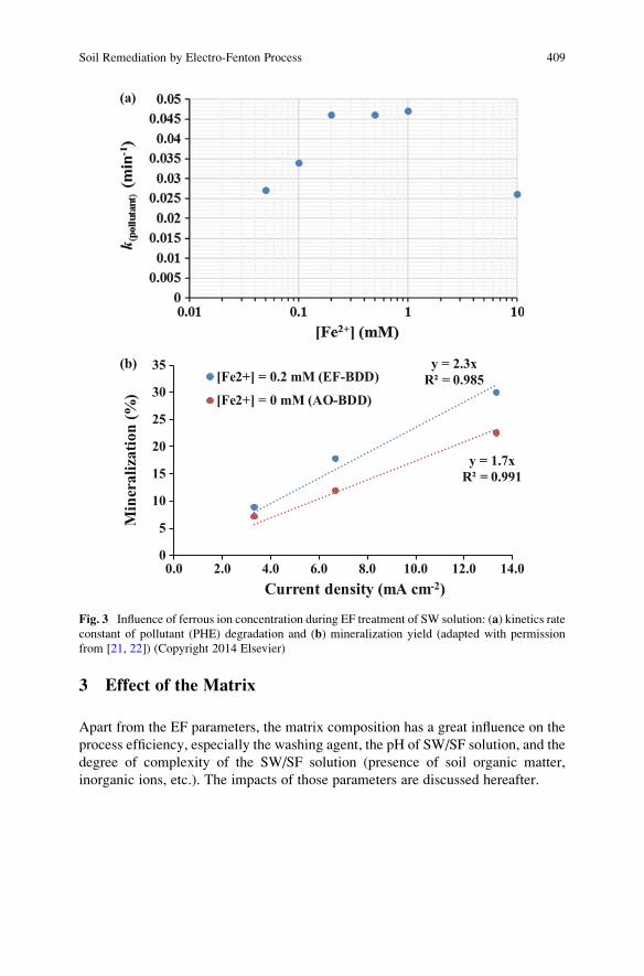
3 Effect of the Matrix
Apart from the EF parameters, the matrix composition has a great influence on the
process efficiency, especially the washing agent, the pH of SW/SF solution, and the
degree of complexity of the SW/SF solution (presence of soil organic matter,
inorganic ions, etc.). The impacts of those parameters are discussed hereafter.
y = 2.3xR² = 0.985
y = 1.7xR² = 0.991
0
5
10
15
20
25
30
35
0.0 2.0 4.0 6.0 8.0 10.0 12.0 14.0
Min
eral
izat
ion
(%)
Current density (mA cm-2)
[Fe2+] = 0.2 mM (EF-BDD)
[Fe2+] = 0 mM (AO-BDD)
(a)
(b)
Fig. 3 Influence of ferrous ion concentration during EF treatment of SW solution: (a) kinetics rate
constant of pollutant (PHE) degradation and (b) mineralization yield (adapted with permission
from [21, 22]) (Copyright 2014 Elsevier)
Soil Remediation by Electro-Fenton Process 409
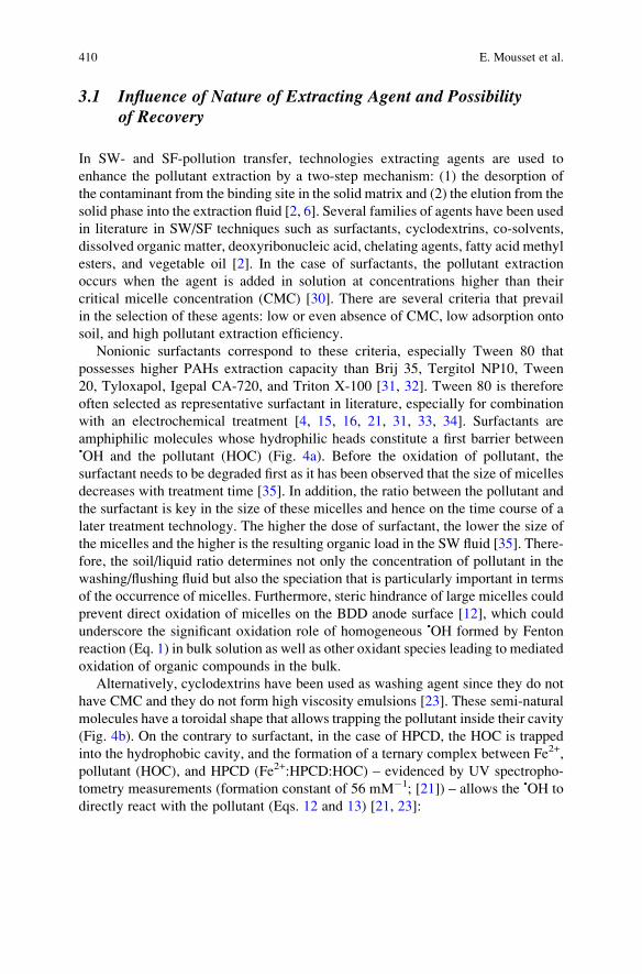
3.1 Influence of Nature of Extracting Agent and Possibilityof Recovery
In SW- and SF-pollution transfer, technologies extracting agents are used to
enhance the pollutant extraction by a two-step mechanism: (1) the desorption of
the contaminant from the binding site in the solid matrix and (2) the elution from the
solid phase into the extraction fluid [2, 6]. Several families of agents have been used
in literature in SW/SF techniques such as surfactants, cyclodextrins, co-solvents,
dissolved organic matter, deoxyribonucleic acid, chelating agents, fatty acid methyl
esters, and vegetable oil [2]. In the case of surfactants, the pollutant extraction
occurs when the agent is added in solution at concentrations higher than their
critical micelle concentration (CMC) [30]. There are several criteria that prevail
in the selection of these agents: low or even absence of CMC, low adsorption onto
soil, and high pollutant extraction efficiency.
Nonionic surfactants correspond to these criteria, especially Tween 80 that
possesses higher PAHs extraction capacity than Brij 35, Tergitol NP10, Tween
20, Tyloxapol, Igepal CA-720, and Triton X-100 [31, 32]. Tween 80 is therefore
often selected as representative surfactant in literature, especially for combination
with an electrochemical treatment [4, 15, 16, 21, 31, 33, 34]. Surfactants are
amphiphilic molecules whose hydrophilic heads constitute a first barrier between•OH and the pollutant (HOC) (Fig. 4a). Before the oxidation of pollutant, the
surfactant needs to be degraded first as it has been observed that the size of micelles
decreases with treatment time [35]. In addition, the ratio between the pollutant and
the surfactant is key in the size of these micelles and hence on the time course of a
later treatment technology. The higher the dose of surfactant, the lower the size of
the micelles and the higher is the resulting organic load in the SW fluid [35]. There-
fore, the soil/liquid ratio determines not only the concentration of pollutant in the
washing/flushing fluid but also the speciation that is particularly important in terms
of the occurrence of micelles. Furthermore, steric hindrance of large micelles could
prevent direct oxidation of micelles on the BDD anode surface [12], which could
underscore the significant oxidation role of homogeneous •OH formed by Fenton
reaction (Eq. 1) in bulk solution as well as other oxidant species leading to mediated
oxidation of organic compounds in the bulk.
Alternatively, cyclodextrins have been used as washing agent since they do not
have CMC and they do not form high viscosity emulsions [23]. These semi-natural
molecules have a toroidal shape that allows trapping the pollutant inside their cavity
(Fig. 4b). On the contrary to surfactant, in the case of HPCD, the HOC is trapped
into the hydrophobic cavity, and the formation of a ternary complex between Fe2+,
pollutant (HOC), and HPCD (Fe2+:HPCD:HOC) – evidenced by UV spectropho-
tometry measurements (formation constant of 56 mM�1; [21]) – allows the •OH to
directly react with the pollutant (Eqs. 12 and 13) [21, 23]:
410 E. Mousset et al.
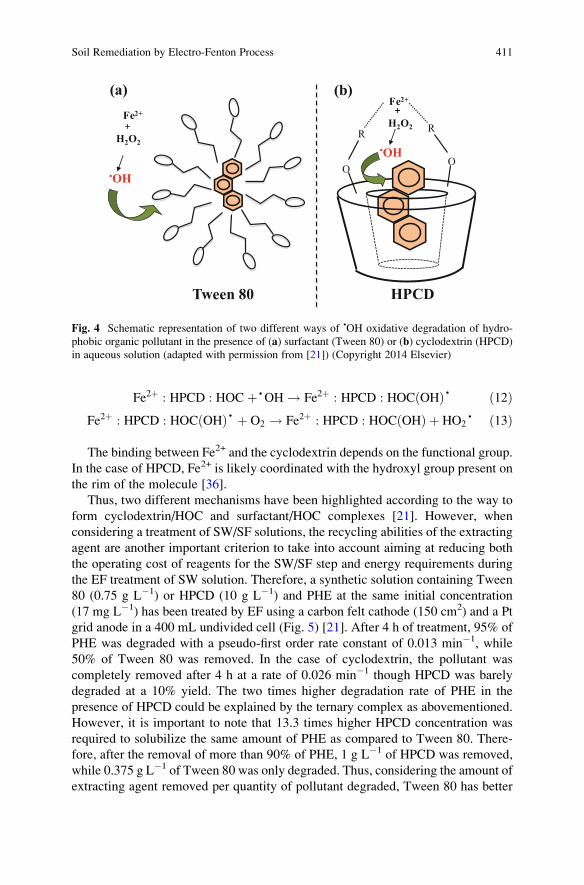
Fe2þ : HPCD : HOC þ • OH ! Fe2þ : HPCD : HOC OHð Þ • ð12ÞFe2þ : HPCD : HOC OHð Þ • þ O2 ! Fe2þ : HPCD : HOC OHð Þ þ HO2
• ð13Þ
The binding between Fe2+ and the cyclodextrin depends on the functional group.
In the case of HPCD, Fe2+ is likely coordinated with the hydroxyl group present on
the rim of the molecule [36].
Thus, two different mechanisms have been highlighted according to the way to
form cyclodextrin/HOC and surfactant/HOC complexes [21]. However, when
considering a treatment of SW/SF solutions, the recycling abilities of the extracting
agent are another important criterion to take into account aiming at reducing both
the operating cost of reagents for the SW/SF step and energy requirements during
the EF treatment of SW solution. Therefore, a synthetic solution containing Tween
80 (0.75 g L�1) or HPCD (10 g L�1) and PHE at the same initial concentration
(17 mg L�1) has been treated by EF using a carbon felt cathode (150 cm2) and a Pt
grid anode in a 400 mL undivided cell (Fig. 5) [21]. After 4 h of treatment, 95% of
PHE was degraded with a pseudo-first order rate constant of 0.013 min�1, while
50% of Tween 80 was removed. In the case of cyclodextrin, the pollutant was
completely removed after 4 h at a rate of 0.026 min�1 though HPCD was barely
degraded at a 10% yield. The two times higher degradation rate of PHE in the
presence of HPCD could be explained by the ternary complex as abovementioned.
However, it is important to note that 13.3 times higher HPCD concentration was
required to solubilize the same amount of PHE as compared to Tween 80. There-
fore, after the removal of more than 90% of PHE, 1 g L�1 of HPCD was removed,
while 0.375 g L�1 of Tween 80 was only degraded. Thus, considering the amount of
extracting agent removed per quantity of pollutant degraded, Tween 80 has better
++Fe2+
•OH
H2O2
H2O2
OO
RR
Fe2+
•OH
HPCDTween 80
(b)(a)
Fig. 4 Schematic representation of two different ways of •OH oxidative degradation of hydro-
phobic organic pollutant in the presence of (a) surfactant (Tween 80) or (b) cyclodextrin (HPCD)
in aqueous solution (adapted with permission from [21]) (Copyright 2014 Elsevier)
Soil Remediation by Electro-Fenton Process 411
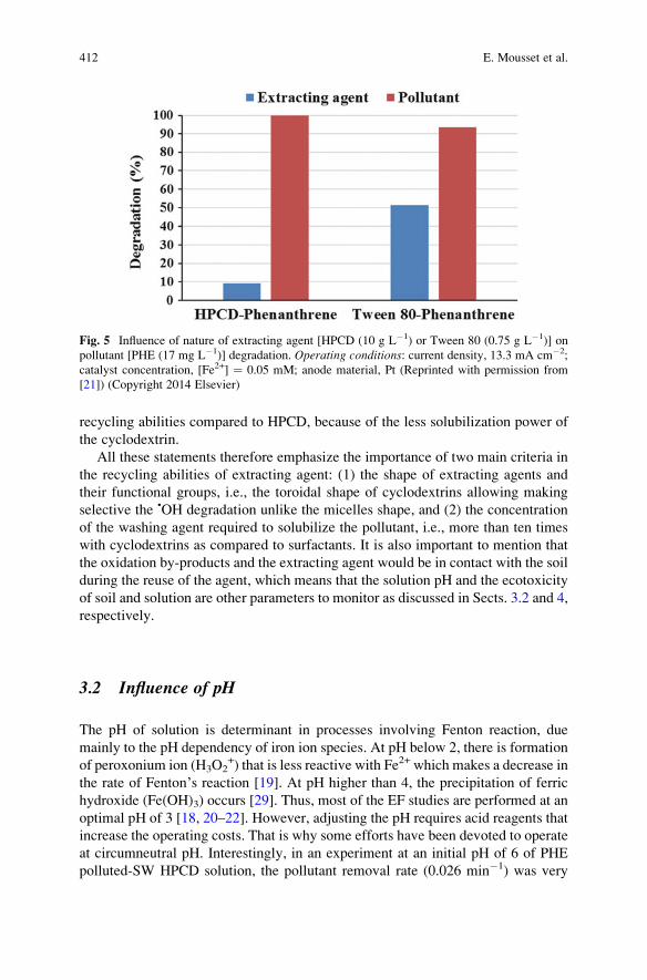
recycling abilities compared to HPCD, because of the less solubilization power of
the cyclodextrin.
All these statements therefore emphasize the importance of two main criteria in
the recycling abilities of extracting agent: (1) the shape of extracting agents and
their functional groups, i.e., the toroidal shape of cyclodextrins allowing making
selective the •OH degradation unlike the micelles shape, and (2) the concentration
of the washing agent required to solubilize the pollutant, i.e., more than ten times
with cyclodextrins as compared to surfactants. It is also important to mention that
the oxidation by-products and the extracting agent would be in contact with the soil
during the reuse of the agent, which means that the solution pH and the ecotoxicity
of soil and solution are other parameters to monitor as discussed in Sects. 3.2 and 4,
respectively.
3.2 Influence of pH
The pH of solution is determinant in processes involving Fenton reaction, due
mainly to the pH dependency of iron ion species. At pH below 2, there is formation
of peroxonium ion (H3O2+) that is less reactive with Fe2+ which makes a decrease in
the rate of Fenton’s reaction [19]. At pH higher than 4, the precipitation of ferric
hydroxide (Fe(OH)3) occurs [29]. Thus, most of the EF studies are performed at an
optimal pH of 3 [18, 20–22]. However, adjusting the pH requires acid reagents that
increase the operating costs. That is why some efforts have been devoted to operate
at circumneutral pH. Interestingly, in an experiment at an initial pH of 6 of PHE
polluted-SW HPCD solution, the pollutant removal rate (0.026 min�1) was very
Fig. 5 Influence of nature of extracting agent [HPCD (10 g L�1) or Tween 80 (0.75 g L�1)] on
pollutant [PHE (17 mg L�1)] degradation. Operating conditions: current density, 13.3 mA cm�2;
catalyst concentration, [Fe2+] ¼ 0.05 mM; anode material, Pt (Reprinted with permission from
[21]) (Copyright 2014 Elsevier)
412 E. Mousset et al.
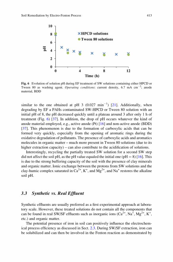
similar to the one obtained at pH 3 (0.027 min�1) [21]. Additionally, when
degrading by EF a PAHs contaminated SW-HPCD or Tween 80 solution with an
initial pH of 8, the pH decreased quickly until a plateau around 3 after only 1 h of
treatment (Fig. 6) [37]. In addition, the drop of pH occurs whatever the kind of
anode material employed, e.g., active anode (Pt) [16] and non-active anode (BDD)
[37]. This phenomenon is due to the formation of carboxylic acids that can be
formed very quickly, especially from the opening of aromatic rings during the
oxidative degradation of pollutants. The presence of carboxylic acids and aromatics
molecules in organic matter – much more present in Tween 80 solutions (due to its
higher extraction capacity) – can also contribute to the acidification of solutions.
Interestingly, recycling the partially treated SW solution for a second SW step
did not affect the soil pH, as the pH value equaled the initial one (pH¼ 8) [16]. This
is due to the strong buffering capacity of the soil with the presence of clay minerals
and organic matter. Ionic exchange between the protons from SW solutions and the
clay-humic complex saturated in Ca2+, K+, and Mg2+, and Na+ restores the alkaline
soil pH.
3.3 Synthetic vs. Real Effluent
Synthetic effluents are usually preferred as a first experimental approach at labora-
tory scale. However, these treated solutions do not contain all the components that
can be found in real SW/SF effluents such as inorganic ions (Ca2+, Na+, Mg2+, K+,
etc.) and organic matter.
The potential presence of iron in soil can positively influence the electrochem-
ical process efficiency as discussed in Sect. 2.3. During SW/SF extraction, iron can
be solubilized and can then be involved in the Fenton reaction as demonstrated by
Fig. 6 Evolution of solution pH during EF treatment of SW solutions containing either HPCD or
Tween 80 as washing agent. Operating conditions: current density, 6.7 mA cm�2; anode
material, BDD
Soil Remediation by Electro-Fenton Process 413
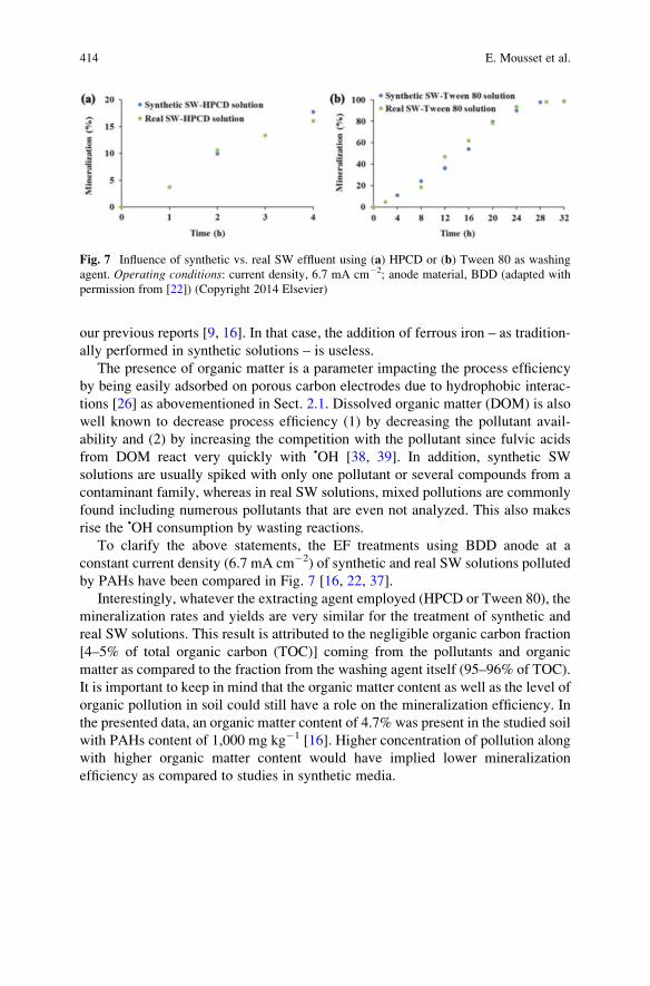
our previous reports [9, 16]. In that case, the addition of ferrous iron – as tradition-
ally performed in synthetic solutions – is useless.
The presence of organic matter is a parameter impacting the process efficiency
by being easily adsorbed on porous carbon electrodes due to hydrophobic interac-
tions [26] as abovementioned in Sect. 2.1. Dissolved organic matter (DOM) is also
well known to decrease process efficiency (1) by decreasing the pollutant avail-
ability and (2) by increasing the competition with the pollutant since fulvic acids
from DOM react very quickly with •OH [38, 39]. In addition, synthetic SW
solutions are usually spiked with only one pollutant or several compounds from a
contaminant family, whereas in real SW solutions, mixed pollutions are commonly
found including numerous pollutants that are even not analyzed. This also makes
rise the •OH consumption by wasting reactions.
To clarify the above statements, the EF treatments using BDD anode at a
constant current density (6.7 mA cm�2) of synthetic and real SW solutions polluted
by PAHs have been compared in Fig. 7 [16, 22, 37].
Interestingly, whatever the extracting agent employed (HPCD or Tween 80), the
mineralization rates and yields are very similar for the treatment of synthetic and
real SW solutions. This result is attributed to the negligible organic carbon fraction
[4–5% of total organic carbon (TOC)] coming from the pollutants and organic
matter as compared to the fraction from the washing agent itself (95–96% of TOC).
It is important to keep in mind that the organic matter content as well as the level of
organic pollution in soil could still have a role on the mineralization efficiency. In
the presented data, an organic matter content of 4.7% was present in the studied soil
with PAHs content of 1,000 mg kg�1 [16]. Higher concentration of pollution along
with higher organic matter content would have implied lower mineralization
efficiency as compared to studies in synthetic media.
Fig. 7 Influence of synthetic vs. real SW effluent using (a) HPCD or (b) Tween 80 as washing
agent. Operating conditions: current density, 6.7 mA cm�2; anode material, BDD (adapted with
permission from [22]) (Copyright 2014 Elsevier)
414 E. Mousset et al.
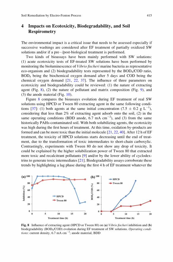
4 Impacts on Ecotoxicity, Biodegradability, and Soil
Respirometry
The environmental impact is a critical issue that needs to be assessed especially if
successive washings are considered after EF treatment of partially oxidized SW
solutions and/or if a pre�/post-biological treatment is performed.
Two kinds of bioassays have been mainly performed with SW solutions:
(1) acute ecotoxicity tests of EF-treated SW solutions have been performed by
monitoring the bioluminescence of Vibrio fischerimarine bacteria as representative
eco-organism and (2) biodegradability tests represented by the BOD5/COD ratio,
BOD5 being the biochemical oxygen demand after 5 days and COD being the
chemical oxygen demand [21, 22, 37]. The influence of three parameters on
ecotoxicity and biodegradability could be reviewed: (1) the nature of extracting
agent (Fig. 8), (2) the nature of pollutant and matrix composition (Fig. 9), and
(3) the anode material (Fig. 10).
Figure 8 compares the bioassays evolution during EF treatment of real SW
solutions using HPCD or Tween 80 extracting agent in the same following condi-
tions [37]: (1) both agents at the same initial concentration (7.5 � 0.2 g L�1),
considering that less than 2% of extracting agent adsorb onto the soil, (2) in the
same operating conditions (BDD anode, 6.7 mA cm�2), and (3) from the same
historically PAHs-contaminated soil. With both solubilizing agents, the ecotoxicity
was high during the first hours of treatment. At this time, oxidation by-products are
formed and can be more toxic than the initial molecule [21, 22, 40]. After 12 h of EF
treatment, the toxicity of HPCD solutions starts decreasing until the end of treat-
ment, due to the transformation of toxic intermediates to short-chain carboxylic.
Contrastingly, experiments with Tween 80 do not show any drop of toxicity. It
could be explained by the higher solubilization power of Tween 80 that extracted
more toxic and recalcitrant pollutants [9] and/or by the lower ability of cyclodex-
trins to generate toxic intermediates [21]. Biodegradability assays corroborate these
trends by highlighting a lag phase during the first 4 h of EF treatment whatever the
Fig. 8 Influence of extracting agent (HPCD or Tween 80) on (a) Vibrio fischeri inhibition and (b)biodegradability (BOD5/COD) evolution during EF treatment of SW solutions. Operating condi-tions: current density, 6.7 mA cm�2; anode material, BDD
Soil Remediation by Electro-Fenton Process 415
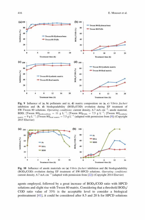
agents employed, followed by a great increase of BOD5/COD ratio with HPCD
solutions and slight rise with Tween 80 matrix. Considering that a threshold BOD5/
COD ratio value of 33% is the acceptable level to consider a biological
posttreatment [41], it could be considered after 8.5 and 20 h for HPCD solutions
Fig. 9 Influence of (a, b) pollutants and (c, d) matrix composition on (a, c) Vibrio fischeriinhibition and (b, d) biodegradability (BOD5/COD) evolution during EF treatment of
SW-Tween 80 solutions. Operating conditions: current density, 6.7 mA cm�2; anode material,
BDD; [Tween 80]hydrocarbons ¼ 11 g L�1; [Tween 80]PAHs ¼ 7.5 g L�1; [Tween 80]synthetic
matrix ¼ 9 g L�1; [Tween 80]real matrix ¼ 7.5 g L�1 (adapted with permission from [9]) (Copyright
2015 Elsevier)
Fig. 10 Influence of anode materials on (a) Vibrio fischeri inhibition and (b) biodegradability
(BOD5/COD) evolution during EF treatment of SW-HPCD solutions. Operating conditions:current density, 6.7 mA cm�2 (adapted with permission from [22]) (Copyright 2014 Elsevier)
416 E. Mousset et al.
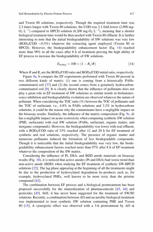
and Tween 80 solutions, respectively. Though the required treatment time was
2.3 times longer with Tween 80 solutions, the COD was 2.1-fold lower (2,900 mg-
O2 L�1) compared to HPCD solution (6,200 mg-O2 L
�1), meaning that a shorter
biological treatment time would be then needed with Tween 80 effluent. It is further
interesting to note that the initial biodegradability of SW solutions was very low
(BOD5/COD <0.5%) whatever the extracting agent employed (Tween 80 or
HPCD). However, the biodegradability enhancement factor (Eq. 14) reached
more than 98% in all the cases after 8 h of treatment proving the high ability of
EF process to increase the biodegradability of SW solutions.
Ebiodeg ¼ 100� 1� Ri=Rð Þ ð14Þ
Where R and Ri are the BOD5/COD ratio and BOD5/COD initial ratio, respectively.
Figure 9a, b compare the EF experiments performed with Tween 80 present in
two different kinds of matrix: (1) one is coming from a historically PAHs-
contaminated soil [37] and (2) the second comes from a genuinely hydrocarbon-
contaminated soil [9]. It is clearly shown that the influence of pollutants does not
play a great role in EF treatment of SW solutions as similar trends in biolumines-
cence inhibition and biodegradability evolution are observed whatever the nature of
pollutant. When considering the TOC ratio (%) between the TOC of pollutants and
the TOC of surfactant, i.e., 4.8% in PAHs solutions and 3.2% in hydrocarbons
solutions, it could be the reason why the contaminants have a negligible impact on
the bioassay results. Similarly, the influence of the matrix composition (Fig. 9c, d)
has a negligible impact on acute ecotoxicity when comparing synthetic SW solution
(PHE, surfactant) with real SW solution (PAHs, surfactant, organic matter, and
inorganic compounds). However, the biodegradability was lower with real effluent,
with a BOD5/COD ratio of 33% reached after 12 and 20 h for EF treatment of
synthetic and real solutions, respectively. The presence of organic matter and
numerous pollutants induced the formation of less biodegradable compounds.
Though it is noticeable that the initial biodegradability was very low, the biode-
gradability enhancement factors reached more than 97% after 8 h of EF treatment
whatever the composition of the SW matrix.
Considering the influence of Pt, DSA, and BDD anode materials on bioassay
results (Fig. 10), it is noticed that active anodes (Pt and DSA) had worse trend than
non-active anode (BDD) when studying the EF treatment of synthetic SW-HPCD
solutions [22]. The lag phase appearing at the beginning of all the treatments might
be due to the production of hydroxylated degradation by-products such as, for
example, hydroxylated PHEs, well known to be more toxic than the pristine
compound [42].
The combination between EF process and a biological posttreatment has been
proposed successfully for the mineralization of pharmaceuticals [43, 44] and
pesticides [45]. Still, it has never been suggested for the treatment of SW/SF
solutions. Recently, a combination between AO and an aerobic biological treatment
was implemented to treat synthetic SW solution containing PHE and Tween
80 [15]. A synergistic effect was observed with a 3-h pretreatment by AO at
Soil Remediation by Electro-Fenton Process 417
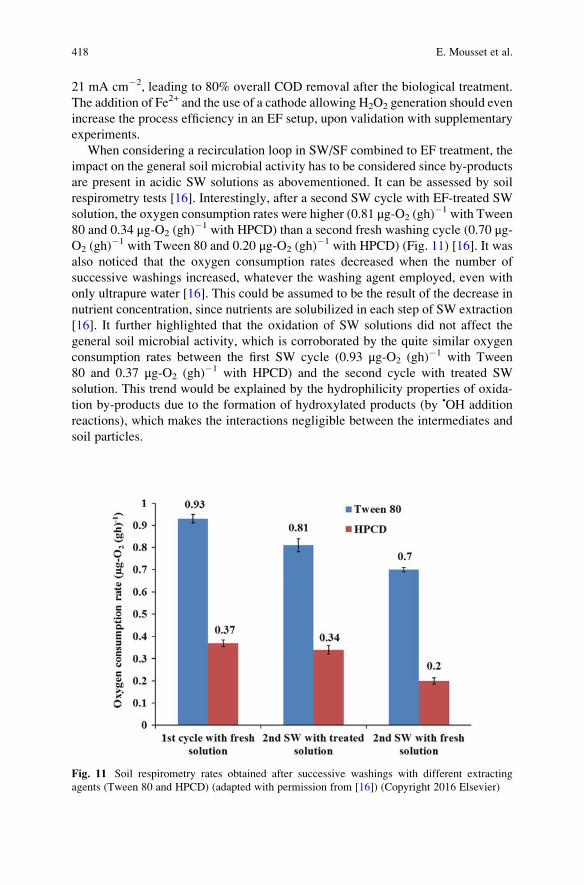
21 mA cm�2, leading to 80% overall COD removal after the biological treatment.
The addition of Fe2+ and the use of a cathode allowing H2O2 generation should even
increase the process efficiency in an EF setup, upon validation with supplementary
experiments.
When considering a recirculation loop in SW/SF combined to EF treatment, the
impact on the general soil microbial activity has to be considered since by-products
are present in acidic SW solutions as abovementioned. It can be assessed by soil
respirometry tests [16]. Interestingly, after a second SW cycle with EF-treated SW
solution, the oxygen consumption rates were higher (0.81 μg-O2 (gh)�1 with Tween
80 and 0.34 μg-O2 (gh)�1 with HPCD) than a second fresh washing cycle (0.70 μg-
O2 (gh)�1 with Tween 80 and 0.20 μg-O2 (gh)
�1 with HPCD) (Fig. 11) [16]. It was
also noticed that the oxygen consumption rates decreased when the number of
successive washings increased, whatever the washing agent employed, even with
only ultrapure water [16]. This could be assumed to be the result of the decrease in
nutrient concentration, since nutrients are solubilized in each step of SW extraction
[16]. It further highlighted that the oxidation of SW solutions did not affect the
general soil microbial activity, which is corroborated by the quite similar oxygen
consumption rates between the first SW cycle (0.93 μg-O2 (gh)�1 with Tween
80 and 0.37 μg-O2 (gh)�1 with HPCD) and the second cycle with treated SW
solution. This trend would be explained by the hydrophilicity properties of oxida-
tion by-products due to the formation of hydroxylated products (by •OH addition
reactions), which makes the interactions negligible between the intermediates and
soil particles.
Fig. 11 Soil respirometry rates obtained after successive washings with different extracting
agents (Tween 80 and HPCD) (adapted with permission from [16]) (Copyright 2016 Elsevier)
418 E. Mousset et al.
5 Energy Considerations and Concluding Remarks
Energy requirement represents the main part in operating cost of such electrochem-
ical process. Therefore, authors try to reduce as much as possible the energy
consumption in order to be competitive. The energy (Econsumption) is usually calcu-
lated as follows (Eq. 15) [29]:
Econsumption kWhm�3� � ¼ EcellIt
Vs
ð15Þ
where Ecell is the average cell voltage (V), I is the applied current intensity (A), t isthe electrolysis time (h), and Vs is the solution volume (L).
The energy requirements are compared according to the washing agent
employed, the degree of complexity of the treated SW solution, and the minerali-
zation time [partial mineralization or quasi-complete (>99%)] (Table 2) [9, 22, 37].
EF treatment of SW-HPCD solutions required between 1.4 and 2.8 times less
energy than SW-Tween 80 solutions [37]. However, in such combined process, the
solubilization efficiency of the extracting agent needs to be also taken into account
in the calculations. Considering that ten more SW cycles are required with HPCD to
extract the same PAHs concentration than with Tween 80, the energy required to
treat the SW solutions would be ten times more, by assuming a linear relation
between the initial organic load and the EF treatment time [37]. Another interesting
feature would be to estimate the energy consumed per amount of pollutant
degraded, so that the energy efficiency comparison could be more reliable. How-
ever, at the time to reach 33% of biodegradability or quasi end of mineralization, all
the pollutants are already degraded. It means that global parameter such as COD or
TOC of pollutant removed needs to be taken into account. The challenge will be
Table 2 Energy consumption calculations comparison
Kind of soil remediation process SW/EFa SW/EFa SF/EFa
Kind of washing agent HPCD Tween 80 Tween
80
Degree of solution complexity Syntheticb Realc Syntheticd Reale Realf
Econsumption (kWh m�3) after reaching 33%
of biodegradabilityg96 112 182 316 nd
Econsumption (kWh m�3) after complete
mineralization
275 320 425 443 508
nd not determined since biodegradability was lower than 33% all along the treatmentaOperating conditions of EF: carbon felt cathode; BDD anode; applied current density, 6.7 mA cm�2
bContain PHE (0.09 mM) and HPCD (9 g L�1)cReal PAHs-contaminated SW solutions with HPCD (7.5 g L�1)dContain PHE (0.09 mM) and Tween 80 (9 g L�1)eReal PAHs-contaminated SW solutions with Tween 80 (7.5 g L�1)fReal hydrocarbon-contaminated SF solution with Tween 80 (11 g L�1)gConsidering the ratio BOD5/COD
Soil Remediation by Electro-Fenton Process 419
then to estimate the TOC coming from the washing agent and its intermediates as
well as the TOC coming from the pollutants and their oxidation by-products.
The SF/EF treatment of real Tween 80 solution required more energy
(508 kWh m�3) than the EF treatment of SW-Tween 80 solutions (443 kWh m�3).
Considering the pollutant removal efficiency, SW could extract around 41% of
PAHs pollutant (1,090 mg kg�1 initially) after one cycle (24 h), while SF could
extract only 1% of hydrocarbons (3,900–6,100 mg kg�1 initially) in 24 h. Further
experiments would be required to compare the efficiency of SW with SF techniques
in similar conditions as the energy calculation only takes into account the EF
treatment and not the whole process.
Furthermore, achieving an EF treatment until quasi-complete mineralization
with BDD anode material was less energy efficient per volume of treated effluent
than reaching 33% of biodegradability whatever the washing agent employed and
the degree of complexity of solution. Thus, the EF combination with a biological
treatment has to be considered and experimented for the treatment of SW/SF
solutions as only biodegradability assays have been performed for now. An optimal
EF treatment time could be determined at a minimal energy consumed.
In addition, the energy required to completely degrade PHE from a synthetic
HPCD solution was around 41 kWh m�3 with BDD anode [22]. Interestingly, it was
around 60 times less than the energy consumed in another electrochemical setup
developed to treat a synthetic SW-HPCD solution spiked with 35 mg L�1 of PHE
[11]. The superiority of the EF process was imputed to the electrocatalytic forma-
tion of •OH radicals.
Though EF treatment of SW/SF solutions was efficient, the electric energy
devoted to the pollutant degradation itself is low as compared to the energy devoted
to the waste reactions and washing agent oxidation, which makes the energy
strongly depend on the concentration of extracting agent used. Still, the possibility
to implement an EF process allowing to reuse SW/SF solution and to recycle
extracting agent is an interesting research area in order to improve the cost-
effectiveness of the whole integrated process (SW/EF or SF/EF) and needs further
development. In parallel, experiments could be performed to optimize EF treatment
of soil slurry without addition of solubilizing agent or at concentration close to their
CMC (ranging from 10 to 200 mg L�1) as proposed by Rosales et al. [18]. In such
conditions, appropriate electrode materials would be required to avoid electrode
fouling while keeping a high oxidant generation efficiency by minimizing the
adverse effect on soil integrity due to strong oxidizing conditions. It could be an
alternative to the in situ electrokinetic-Fenton proposed in literature. Finally, EF
treatment can be a good alternative to replace or improve existing soil remediation
technologies as it is clean (electron reagent), safe (mild conditions), easy to handle
(simple equipment required), and versatile (adaptable to wide ranges of flow rates
and organic load). The next step would be to scale up the suggested integrated
processes by combining kinetics, hydrodynamics, and modeling studies to optimize
the reactor design, the removal rates, and the energy efficiency. It will bring EF
closer to industrial development.
420 E. Mousset et al.
References
1. Trellu C, Mousset E, Pechaud Y, Huguenot D, Van HED, Esposito G, Oturan MA (2016)
Removal of hydrophobic organic pollutants from soil washing/flushing solutions: a critical
review. J Hazard Mater 306:149–174
2. Mousset E, Oturan MA, Van Hullebusch ED, Guibaud G, Esposito G (2014) Soil washing/
flushing treatments of organic pollutants enhanced by cyclodextrins and integrated treatments:
state of the art. Crit Rev Environ Sci Technol 44:705–795
3. Rodrigo MA, Oturan N, Oturan MA (2014) Electrochemically assisted remediation of pesti-
cides in soils and water: a review. Chem Rev 114:8720–8745
4. Saez C, Lopez-Vizcaıno R, Canizares P, Rodrigo MA (2010) Conductive-diamond electro-
chemical oxidation of surfactant-aided soil-washing effluents. Ind Eng Chem Res
49:9631–9635
5. Lopez-Vizcaıno R, Saez C, Ca~nizares P, Rodrigo MA (2012) The use of a combined process of
surfactant-aided soil washing and coagulation for PAH-contaminated soils treatment. Sep
Purif Technol 88:46–51
6. Paria S (2008) Surfactant-enhanced remediation of organic contaminated soil and water. Adv
Colloid Interface Sci 138:24–58
7. Risco C, Rubı-juarez H, Rodrigo S, Lopez-vizcaıno R, Saez C, Ca~nizares P, Barrera-dıaz C,
Navarro V, Rodrigo MA (2016) Removal of oxyfluorfen from spiked soils using electrokinetic
soil flushing with the surrounding arrangements of electrodes. Sci Total Environ 559:94–102
8. dos Santos EV, Souza F, Saez C, Canizares P, Lanza MRV, Martinez-huitle CA, Rodrigo MA
(2016) Application of electrokinetic soil flushing to four herbicides: a comparison.
Chemosphere 153:205–211
9. Huguenot D, Mousset E, van Hullebusch ED, Oturan MA (2015) Combination of surfactant
enhanced soil washing and electro-Fenton process for the treatment of soils contaminated by
petroleum hydrocarbons. J Environ Manage 153:40–47
10. Sires I, Brillas E, Oturan MA, Rodrigo MA, Panizza M (2014) Electrochemical advanced
oxidation processes: today and tomorrow. A review. Environ Sci Pollut Res Int 21:8336–8367
11. Gomez J, Alcantara MT, Pazos M, Sanroman MA (2010) Soil washing using cyclodextrins and
their recovery by application of electrochemical technology. Chem Eng J 159:53–57
12. dos Santos EV, Saez C, Martınez-Huitle CA, Ca~nizares P, Rodrigo MA (2015) The role of
particle size on the conductive diamond electrochemical oxidation of soil-washing effluent
polluted with atrazine. Electrochem Commun 55:26–29
13. dos Santos EV, Saez C, Martınez-huitle CA, Ca~nizares P, Rodrigo MA (2016) Removal of
oxyfluorfen from ex-situ soil washing fluids using electrolysis with diamond anodes. J Environ
Manage 171:260–266
14. dos Santos EV, Saez C, Ca~nizares P, Martınez-huitle CA, Rodrigo MA (2017) Treating soil-
washing fluids polluted with oxyfluorfen by sono-electrolysis with diamond anodes. Ultrason
Sonochem 34:115–122
15. Trellu C, Ganzenko O, Papirio S, Pechaud Y, Oturan N, Huguenot D, van Hullebusch ED,
Esposito G, Oturan MA (2016) Combination of anodic oxidation and biological treatment for
the removal of phenanthrene and Tween 80 from soil washing solution. Chem Eng J
306:588–596
16. Mousset E, Huguenot D, Van Hullebusch ED, Oturan N, Guibaud G, Esposito G, Oturan MA
(2016) Impact of electrochemical treatment of soil washing solution on PAH degradation
efficiency and soil respirometry. Environ Pollut 211:354–362
17. Pazos M, Iglesias O, Gomez J, Rosales E, Sanroman MA (2013) Remediation of contaminated
marine sediment using electrokinetic-Fenton technology. J Ind Eng Chem 19:932–937
18. Rosales E, Pazos M, Longo MA, Sanroman MA (2009) Influence of operational parameters on
electro-Fenton degradation of organic pollutants from soil. J Environ Sci Health A Tox Hazard
Subst Environ Eng 44:1104–1110
Soil Remediation by Electro-Fenton Process 421
19. Oturan MA, Aaron J-J (2014) Advanced oxidation processes in water/wastewater treatment:
principles and applications. A review. Crit Rev Environ Sci Technol 44:2577–2641
20. Murati M, Oturan N, van Hullebusch ED, Oturan MA (2009) Electro-Fenton treatment of TNT
in aqueous media in presence of cyclodextrin. Application to ex-situ treatment of contaminated
soil. J Adv Oxid Technol 12:29–36
21. Mousset E, Oturan N, van Hullebusch ED, Guibaud G, Esposito G, Oturan MA (2014)
Influence of solubilizing agents (cyclodextrin or surfactant) on phenanthrene degradation by
electro-Fenton process – study of soil washing recycling possibilities and environmental
impact. Water Res 48:306–316
22. Mousset E, Oturan N, van Hullebusch ED, Guibaud G, Esposito G, Oturan MA (2014)
Treatment of synthetic soil washing solutions containing phenanthrene and cyclodextrin by
electro-oxidation. Influence of anode materials on toxicity removal and biodegradability
enhancement. Appl Catal Environ 160–161:666–675
23. Hanna K, Chiron S, Oturan MA (2005) Coupling enhanced water solubilization with cyclo-
dextrin to indirect electrochemical treatment for pentachlorophenol contaminated soil reme-
diation. Water Res 39:2763–2773
24. Sires I, Garrido JA, Rodrıguez RM, Brillas E, Oturan N, Oturan MA (2007) Catalytic behavior
of the Fe3+/Fe2+ system in the electro-Fenton degradation of the antimicrobial chlorophene.
Appl Catal Environ 72:382–394
25. Hu J, Sun J, Yan J, Lv K, Zhong C, Deng K, Li J (2013) A novel efficient electrode material:
activated carbon fibers grafted by ordered mesoporous carbon. Electrochem Commun
28:67–70
26. Trellu C, Pechaud Y, Oturan N, Mousset E, Huguenot D, van Hullebusch ED, Esposito G,
Oturan MA (2016) Comparative study on the removal of humic acids from drinking water by
anodic oxidation and electro-Fenton processes: mineralization efficiency and modelling. Appl
Catal Environ 194:32–41
27. Sopaj F (2013) Study of the influence of electrode material in the application of electrochem-
ical advanced oxidation processes to removal of pharmaceutical pollutants from water.
University of Paris-Est
28. Panizza M, Cerisola G (2009) Direct and mediated anodic oxidation of organic pollutants.
Chem Rev 109:6541–6569
29. Brillas E, Sires I, Oturan MA (2009) Electro-Fenton process and related electrochemical
technologies based on Fenton’s reaction chemistry. Chem Rev 109:6570–6631
30. Rosen MJ (2004) Surfactants and interfacial phenomena, 3rd edn. Wiley, New York
31. Alcantara MT, Gomez J, Pazos M, Sanroman MA (2008) Combined treatment of PAHs
contaminated soils using the sequence extraction with surfactant-electrochemical degradation.
Chemosphere 70:1438–1444
32. Dhenain A, Mercier G, Blais J-F, Bergeron M (2006) PAH removal from black sludge from
Aluminium industry by flotation using non-ionic surfactants. Environ Technol 27:1019–1030
33. Gomez J, Alcantara MT, Pazos M, Sanroman MA (2010) Remediation of polluted soil by a
two-stage treatment system: desorption of phenanthrene in soil and electrochemical treatment
to recover the extraction agent. J Hazard Mater 173:794–798
34. Mousset E, Oturan N, van Hullebusch ED, Guibaud G, Esposito G, Oturan MA (2013) A new
micelle-based method to quantify the Tween 80® surfactant for soil remediation. Agron
Sustain Dev 33:839–846
35. dos Santos EV, Saez C, Martinez-Huitle CA, Canizares P, Rodrigo MA (2015) Combined soil
washing and CDEO for the removal of atrazine from soils. J Hazard Mater 300:129–134
36. Lindsey ME, Xu G, Lu J, Tarr MA (2003) Enhanced Fenton degradation of hydrophobic
organics by simultaneous iron and pollutant complexation with cyclodextrins. Sci Total
Environ 307:215–229
37. Mousset E (2013) Integrated processes for removal of persistent organic pollutants: soil
washing and electrochemical advanced oxidation processes combined to a possible biological
422 E. Mousset et al.
post-treatment. University of Paris-Est – University of Cassino and The Southern Lazio –
UNESCO-IHE for Water Education
38. Westerhoff P, Aiken G, Amy G, Debroux J (1999) Relationships between the structure of
natural organic matter and its reactivity towards molecular ozone and hydroxyl radicals. Water
Res 33:2265–2276
39. Lindsey ME, Tarr MA (2000) Inhibited hydroxyl radical degradation of aromatic hydrocar-
bons in the presence of dissolved fulvic acid. Water Res 34:3–7
40. Dirany A, Sires I, Oturan N, Ozcan A, Oturan MA (2012) Electrochemical treatment of the
antibiotic sulfachloropyridazine: kinetics, reaction pathways, and toxicity evolution. Environ
Sci Technol 46:4074–4082
41. Rodier J, Legube B, Merlet N (2009) Analyse de l’eau (water analysis), 9th edn. Dunod, Paris,(in French)
42. Fernandes D, Porte C (2013) Hydroxylated PAHs alter the synthesis of androgens and
estrogens in subcellular fractions of carp gonads. Sci Total Environ 447:152–159
43. Mansour D, Fourcade F, Huguet S, Soutrel I, Bellakhal N, Dachraoui M, Hauchard D, Amrane
A (2014) Improvement of the activated sludge treatment by its combination with electro
Fenton for the mineralization of sulfamethazine. Int Biodeter Biodegr 88:29–36
44. Olvera-Vargas H, Oturan N, Buisson D, Oturan MA (2016) A coupled bio-EF process for
mineralization of the pharmaceuticals furosemide and ranitidine: feasibility assessment.
Chemosphere 155:606–613
45. Fontmorin J-M, Fourcade F, Geneste F, Floner D, Huguet S, Amrane A (2013) Combined
process for 2,4-dichlorophenoxyacetic acid treatment – coupling of an electrochemical system
with a biological treatment. Biochem Eng J 70:17–22
Soil Remediation by Electro-Fenton Process 423
Index
AAcesulfame (ACE), 381, 382
Acesulfame K (ACE-K), 381
Acetic acid, 45, 159, 323, 326–330, 334, 371
Acid Blue 92, 118
Acid Orange 7 (AO7), 126, 157, 162, 208–225,
304, 327, 356
Acid Orange II, 19, 50
Acid Red 14, 118
Acid Red 88, 319, 327
Acid Red 151, 327, 357
Acid Yellow 9, 319, 327
Acid Yellow 36 (AY36), 120, 249, 327
Acid Yellow 42, 165, 330
Activated carbon fiber (ACF), 7, 76, 113, 132
Adsorption, 21, 51, 76, 85, 106, 164, 241, 349,
359, 404
Advanced oxidation processes (AOPs), 3, 29,
32, 85, 207, 209, 219, 255, 263, 380
Aerobic biological treatment (ABT), 36
Alginate, 19, 85, 99–103, 107, 161
Alizarin Red S (AR), 157, 210
Allura Red AC, 327
Ametryn, 319, 324–326
4-Amino-3-hydroxy-2-p-tolylazo-
naphthalene-1-sulfonic acid (AHPS),
94, 160
Aniline, 153, 209, 215, 216, 243
Anthraquinone, 6, 59, 157, 210
Anthraquinone-2,6-disulfonate/polypyrrole
(AQDS/PPy), 159
Anthraquinone monosulfonate (AQS), 128
Aromatics, 21, 44, 65, 70, 316, 329, 413
Arsenic, 353, 358
Arsenic(V), 353
Arsenic(III), oxidation, 50
Artificial neural networks (ANN), 302
Artificial sweeteners, 379, 381
Aspartame (ASP), 381
Aspirine, 268
Atrazine, 60
Autonomous solar flow plant, 332
Average oxidation state (AOS), 33
BBasic Yellow 2, 116, 303
Benzene, 2, 68, 289–291
Benzene sulfonic acid, 265 2
ρ-Benzoquinone, 331Beta-blockers, 31, 38, 208, 331
Bicarbonate, 349
Bioassays, 399, 415
Biodegradability, 29, 33, 60, 355, 399, 415
indicators, 33
Bio-electro-Fenton (Bio-EF), 29, 36
Biological treatment, 29
Bioluminescence-based toxicity test, 33, 97,
393, 415
Bisphenol A (BPA), 130, 157, 295, 351
Boron-doped diamond (BDD), 7, 34, 70, 113,
207, 264, 268, 316, 345, 380, 404
Bray-Gorin mechanism, 289, 290, 297,
300, 304
Brilliant Red X3B (X3B), 132
Bromate, 60, 62, 67
Bromide, 60, 62, 67
tert-Butylhydroquinone, 101
M. Zhou et al. (eds.), Electro-Fenton Process: New Trends and Scale-Up,Hdb Env Chem (2018) 61: 425–430, DOI 10.1007/978-981-10-6406-7,© Springer Nature Singapore Pte Ltd. 2017
425
CCaffeic acid, 338
Caffeine, 39, 44
Carbamazepine, 31
Carbaryl, 210
Carbon, 85
cathode, unmodified, 287
felt, 113, 145, 156, 159
fiber, 113, 146, 176, 207, 219, 246
iron-loaded, 101
mesoporous, 111, 130
nanomaterials, 111
sponge, 7, 15, 113, 147, 176, 380, 404
Carbon nanotubes (CNTs), 7, 50, 111–115,
152, 176, 246
boron-doped (B-CNTs), 246
multiwalled (MWCNTs), 8, 115, 152
single-walled (SWCNTs), 115, 152
Carboxylic acids, 6, 21, 32, 37, 45, 70,
86, 97, 159, 226, 313–339, 351,
379, 390, 413
Carmoisine, 22
Catalysts, concentration, 408
iron, 18
solid, 85
Catechol, 216, 331
CCB-470, 247
Cell potential, 222, 229, 269
CF-1371, 246
CF-1410, 246
Chalcopyrite, 161
Chemical oxygen demand (COD), 33, 157,
276, 338, 415
Chloramphenicol, 165, 209, 331
Chloride, 5, 21, 80, 328, 373
Chlorine, 21–24, 67, 80, 373
Chlorobenzene, 68, 69, 73, 208
ρ-Chlorobenzoic acid (ρ-CBA), 65, 664-Chloro-2-methylphenol, 157, 326
4-Chloro-2-methylphenoxyacetic acid
(MCPA), 249, 319, 325
Chlorophene, 159
Chlorophenols, 208
Chlorophenoxy acid, 157, 209
Chlorpyrifos, 102
Chlortoluron, 157, 302
Citric acid, 100, 330
Clay minerals, 413
Clofibric acid, 265
CoFe-layered double hydroxide
(CoFe-LDH), 161
Combined process, 29
Conductivity, 7, 37, 113, 145, 175, 191, 241,
350, 355
Congo Red, 326–328
Copper, 2, 92
ρ-Coumaric acid (4-hydroxycinnamic acid), 157
Coupled process, 241
Coupled solar-assisted electro-fenton
treatments, 334
CPC photoreactor, 281, 313, 330, 356
Cresols, 101, 106, 216, 319, 322
Crystal violet, 157
Current density, 8, 18, 63, 151, 219,
241, 406
Current distribution, 263, 271, 281
Cyanides, 3, 356
Cyclodextrins, 399, 404, 410–412, 415
D2,4-D, 101, 107, 124, 157, 351
Decolorization, kinetic model, 287
Degradation kinetics, 1, 16, 70, 93, 404
2,4-Dichlorophenol, 101, 107, 124, 157, 351
Diclofenac, 74, 75, 78, 93, 162, 164, 281,
352, 355
Dicyandiamide, 132
Di-2-ethylhexyl phthalate, 100
3,4-Dihydroxybenzoic acid, 106
Dimensionally stable anodes (DSA), 381
Dimethylarsinate (DMA), 353
Dimethyl phthalate (DMP), 124, 134, 136
1,4-Dioxane, 60, 70–73, 354
Dioxins, 356
Diphenyl, 291
Diquat dibromide, 265
Direct Yellow 4, 165, 332, 334, 335
Disordered mesoporous carbon (DMC), 132
Disperse Blue 71, 327, 357
Dissolved organic carbon (DOC), 33, 66, 75,
282, 356
Diuron, 157, 324
Drinking water, 60, 75, 164, 265, 314, 346,
371, 381
Dyes, degradation, 15, 30, 47, 100, 120, 157,
176, 210, 214, 242, 265, 288, 313, 326,
343, 403
EE122, 249, 327, 328
E124, 249, 327, 328
E129, 249, 327, 328
426 Index
Ecotoxicity, 399, 412, 415
Effluent organic matter (EfOM), 75
Electrochemical activity, 145
Electrochemical advanced oxidation processes
(EAOPs), 29, 32, 57, 59, 241, 264, 314,
383, 401
Electrochemical reactors, 205
Electrodes, low-cost, 287
materials, 399
packed bed, 263
parallel plate, 263
rotating cylinder, 263, 271, 275
three-dimensional, moving, 205, 217
Electro-Fenton, 1, 15, 29, 34, 59, 85, 111, 145,
175, 241, 296, 343
catalyst source, 1
heterogeneous, 85
Electrolyte flow, non-ideal, 263
Electrolytic cells, 1, 313
Electron transfer, 3, 5, 105, 152, 179, 245,
251, 270
Electro-peroxone, 57
Emerging contaminants, 31
Energy requirements, 419
Enoxacin (ENXN), 161
Enrofloxacin, 209, 320, 330
E-peroxone process, 57, 61
Estrogens, 163, 354
Ethanol, 101, 149, 159, 179, 180, 289–292,
304, 358
Ethylene, 360
Evans Blue, 326
FFast green, 157
Fe(III)-carboxylate complexes, 313
Fenton’s reagent, 2, 3, 22, 34, 49, 94, 207, 289,314, 344, 379, 401
FeOOH, 50, 99, 128, 161, 177, 358
Fered-Fenton, 3, 243, 338, 346, 359, 373
Ferrate(VI), 32, 383
Ferric chloride, 87
Ferric hydroxide, 370, 383
Ferric ions, 86–92, 99, 104, 129, 265
Ferric–salicylic acid, 104
Ferrous iron (Fe2+), 58, 90, 212, 303, 307, 346,
359, 372, 403, 414
Ferrous sulfate, 87, 360, 362
Ferryl ions, 2–5, 290
Filter-press flow cell, 263
Flow cell, parallel-plate, 205
Flow-through, 241
Fluid dynamics, computational, 263
5-Fluorouracil, 44
Formic acid, 33, 97, 220
Fuchsin Acid, 357
Furosemide, 43, 45
GGas diffusion electrode (GDE), 6, 113, 207,
313, 380
Gemfibrozil, 74, 75, 78
Geosmin, 74, 75, 79
Goethite, 105
Graphene, 111, 120
Graphene oxide, 111, 113, 122
reduced, 111
Graphite felt, 175, 241, 247
HHaber-Weiss mechanism, 289, 297
Heavy metals, 101, 288, 351, 358
Herbicides, 157, 213, 265, 320, 324
Hierarchically porous carbon (HPC), 130
Hydrocarbons, 159, 399, 420
Hydrogen peroxide, 1, 6, 57, 111, 145, 287
Hydrophilicity, 115, 122, 150, 177, 181, 418
Hydrophobicity, 165, 247, 268
Hydrophobic organic contaminants (HOCs), 403
Hydroquinone, 229, 331
Hydroxyalkyl radicals, 299
Hydroxylation, 3, 97, 282, 290, 323, 387
Hydroxyl radicals, 29, 85, 104, 111, 379
Hydroxypropyl-beta-cyclodextrin
(HPCD), 404
Hypochlorous acid, 21
IIbuprofen, 31, 60, 72, 75, 78, 208, 330, 355
Imidacloprid, 100, 102, 161, 209, 326, 330
Indole, 99
Iron, 2, 18
zero-valent (ZVI), 90
Iron alginate gel beads (FeAB), 161
Iron hydroxides, 177, 251
Iron oxides, 85, 89, 104, 177, 315, 358
Iron sludge, 6, 19, 60, 128, 177, 199, 344
KKetones, 330
Ketoprofen, 31
Index 427
LLandfill leachate, 30, 47, 163, 243, 338,
346, 359
Lead dioxide, 404
Levafix blue, 357
Levofloxacin, 40, 96, 160, 208
Lipid peroxidation, 2
Lissamine Green B, 100, 161, 403
Luminescence inhibition, 33, 97, 393, 415
MMagnetite, 89, 104, 107, 128
Malachite green, 157
Maleic acid, 45, 213, 229, 329–331
Manganese, 92, 100, 152, 356
Mass transfer/transport, 7, 64, 70, 111,
162, 180, 206, 220, 244, 263,
349, 372
MCPA, 319, 325
Mecoprop (2-(4-chloro-2-methylphenoxy)
propionic acid), 324
Metal-organic frameworks (MOFs), 130
Methanol, 2, 152
Methylene blue (MB), 126, 199, 248, 353
Methyl green, 157
5-Methyl-2-hydroxy-p-benzoquinone, 323
2-Methylisoborneol (MIB), 75
Methyl orange (MO), 117, 135, 162, 191, 198,
268, 357
Methylparaben, 22
Methyl parathion, 157, 297
2-Methyl-p-benzoquinone, 323
α-Methylphenylglycine, 323
Metoprolol, 38, 46
Metronidazole, 331
Microbial fuel cell (MFC), 49, 155, 163, 358
Micropollutants, 30, 57, 164, 352
Microreactors, 205–229
Mineralization, 30, 379, 417
Mineralization current efficiency (MCE),
35, 95, 210, 271, 317, 352, 389
Monomethylarsinate (MMA), 353
NNafion 324, 8, 9
Nafion 417, 10, 216–218
Nafion 424, 9
Naproxen, 31
Nitrate, 5, 21, 159, 194, 328, 338
Nonsteroidal anti-inflammatory drugs
(NSAIDs), 31, 355
OOrdered mesoporous carbons (OMC), 130
Oxalic acid, 33, 45, 72, 97, 159, 213, 216, 229,
316, 323, 391
Oxamic acid, 45, 323–331, 334, 391, 392
Oxoiron, 2, 5
Oxygen evolution reaction (OER), 268
Oxygen reduction reactions (ORRs), 120, 160,
179, 282, 305
Ozonation, 32, 51, 57, 241, 257, 383
Ozone, 21, 57–80, 257, 316, 381, 406
PPacked bed electrode, 263
Palladium, 129
Paracetamol, 160, 163, 268, 320
Parallel plate electrodes, 213, 263
Parathion, 157, 297
Patents, 343, 361
Pentachlorophenol (PCP), 157, 403
Perfluorooctanoate (PFOA), 137
Permanganate, 356
Peroxicoagulation, 241, 256, 303
Peroxidation, lipids, 2
Peroxodisulfate, 21
Peroxone, 58
Peroxonium ion, 412
Persistent organic pollutants (POPs), 147, 156
Persulfates, 153, 406
Pesticides, 15, 30, 102, 313, 319, 324
Petroleum hydrocarbons, 360, 403
pH, 412
Pharmaceuticals and personal care products
(PPCPs), 344, 381
Pharmaceuticals, degradation, 15, 30, 47, 70,
159, 176, 242, 313, 343, 380
mineralization, 417
Phenanthrene, 36, 403
Phenol(s), 2, 70, 73, 91, 101, 122, 176, 242,
268, 297
Photoelectro-Fenton (PEF), 47
Photoelectro-peroxone (PE-peroxone)
process, 67
Photolysis, 5, 58, 69, 313, 317, 331
Photoreactors, 214, 281, 313–339, 352
Phthalic acid, 323, 324
Platinum, 156, 207, 216, 268, 357, 404
ρ-Nitrophenol (PNP), 75, 80, 100, 118, 159,163, 181, 300, 358
Polyaniline (PANi), 153
Polycyclic aromatic hydrocarbons (PAHs),
159, 403
428 Index
Polyphenols, 338, 356
Polypyrrole (PPy), 153
Polytetrafluoroethylene (PTFE), 101, 113, 246
Prussian blue (ferric hexacyanoferrate), 155
Pulp and paper industry, 6, 349, 355
Pyrite, 19, 85, 92–98, 107, 160, 161, 346
Pyrrhotite, 162
QQuinone-functionalized graphene,
electrochemical exfoliation approach
(QEEG), 130
RRanitidine, 35, 43, 45, 208, 331
Reactive Black 5, 100, 103, 357
Reactive oxygen species (ROS), 4, 20, 316
Reactive Yellow, 265
Reactors, electrochemical, 263
flow-through, 241
pressurized, 205, 220
Reduced graphene oxide (rGO), 113, 120, 151
Refractory organic pollutants, 343
Resorcinol, 331
Reticulated vitreous carbon (RVC), 7, 59, 113,
147, 207, 268, 275, 357, 380
Rhodamine B, 90, 103, 163, 330, 338
Rotating cylinder electrode, 263, 271, 275
SSaccharin (SAC), 381
Salicylic acid, 92, 104, 249, 330, 336
Sepiolite, iron-loaded, 103
Slaughterhouse effluent, 42, 338, 360
Sludge, iron, 6, 19, 60, 128, 177, 199, 344
Sodium sulfate, 222, 302
Soil flushing (SF), 400
Soil respirometry, 415
Soil washing, 36, 93, 159, 400
Solar photoelectro-Fenton (SPEF), 47, 165, 313
Solar photoreactor, 214, 281, 318, 334, 338, 352
Solar pilot plants, 313
Sucralose (SUC), 381
Sulfamethazine, 41, 49, 96, 97
Sulfanilamide, 165, 320, 331, 352
Sulfanilic acid, 319, 323
Sunlight, 3, 165, 313, 339, 346, 356
Sunset Yellow FCF, 326
Surface area, 3, 19, 89, 101, 111, 145, 177, 191,
217, 241, 315, 352, 368, 406
Surface characteristics, 175, 191
Surface water, 11, 30, 65, 74, 79, 346
Surfactants, 130, 355, 399, 412
nonionic, 410
Synthetic organic compounds (SOCs), 353
TTank cells, 205, 207, 326
Tartaric acid, 2, 289, 323, 327, 344
Tartrazine, 162, 254, 357
Tebuthiuron, 324
Tetracycline, 37, 208, 209, 212, 249,
255–257
Textile industry, 288, 356
Tissue paper wastewater, 360
Total organic carbon (TOC), 22, 33,
57, 60, 120, 157, 181, 193, 210,
317, 414
mineralization, 57
Toxicity, 29
ecotoxicity, 399, 412, 415
tests, 38
Transition metals, 19, 58, 67, 89, 155,
194, 198
doping, 175, 177
Triclocarban, 159
Triclosan, 159, 208
Trimethoprim, 332, 355
Trinitrotoluene (TNT), 403
Triton X-100, 410
Tween 80, 36, 410–420
Tyloxapol, 410
Tyrosol, 96–98, 160
UUltraviolet, 58, 288
UVA, 3, 316, 346, 358
UVB/UVC, 316
UV/H2O2 processes, 58
WWastewater, acidic, 315
chemical industry, 355
domestic, 163
industrial, 255, 258, 264, 355
leather tanning industry, 360
medicinal herbs, 163
soil pollutants, 401
textile, 288, 350, 372
winery, 209, 338, 358
Wastewater treatment, 57, 85, 147, 156, 263,
291, 296, 343, 379
agro-industrial, 358
prediction, 287
Index 429

Wastewater treatment plants (WWTPs),
30, 75, 353
Water treatment, 29, 57, 85, 343
XXylenol, 268
ZZahn-Wellens assays, 33
Zeolite-modified electrodes (ZMEs), 155
Zeolites, 6, 85, 102, 155–158
iron-supported, 85, 102
Zeolitic imidazolate framework
(ZIF-8), 156
430 Index
Related Documents


![LIBURUAK Aballi, Ignasi [et al.]](https://static.cupdf.com/doc/110x72/62b8b7060632f07ccc0b5300/liburuak-aballi-ignasi-et-al.jpg)


