y f (M ) 1 q -*^fesQEc 1 0 i94i ; ftofcmr x ^ classification cancelled CJ*^ PROVISIONAL NOTE j ON TH E ACOUSTIC GONIOMETER MILITARY TELEGRAPH TYPE 1 INCLUDING AN EXTRACT ON T H E USE O F SEARCHLIGHTS; A ND NOTE ON T HE APPLI- CATION O F T H E ACOUSTIC GONIOMETER TO FIRING B Y SOUND A N D T O TH E ORIENTATION O F SEARCHLIGHTS T -% TRANSLATED AN D EDITED AT THE ARMY W AR COLLEGE WASHINGTON, 1917 WASHINGTON GOVERNMENT PRINTING OFFICE 1917

Welcome message from author
This document is posted to help you gain knowledge. Please leave a comment to let me know what you think about it! Share it to your friends and learn new things together.
Transcript

8/8/2019 Military Telegraph
http://slidepdf.com/reader/full/military-telegraph 1/51
yf (M) 1q -*^fesQEc 10 i94i; ftofcmr x^ classification cancelled
CJ*^
PROVISIONAL NOTEj
ON THE
ACOUSTIC GONIOMETER
MILITARY TELEGRAPH TYPE 1INCLUDING AN EXTRACT ON THE USE OFSEARCHLIGHTS; ANDNOTE ONTHE APPLI-
CATION OF THE ACOUSTIC GONIOMETER
TO FIRING BY SOUND AND TO THE
ORIENTATION OF SEARCHLIGHTS
T
-%
TRANSLATED AND EDITED AT THE ARMY WAR COLLEGE
WASHINGTON, 1917
WASHINGTON
GOVERNMENT PRINTING OFFICE
1917
8/8/2019 Military Telegraph
http://slidepdf.com/reader/full/military-telegraph 2/51
THE GENERAL SERVICE SCHOOLS \
LIBRARY
CLASSNUMBER___M_AP^Bll
War Depahtment.
Document No. 690.Office of The Adjutant General.
«
-v \u25a0'.- -,x
8/8/2019 Military Telegraph
http://slidepdf.com/reader/full/military-telegraph 3/51
WAR DEPARTMENT,
Washington, October 29, 1917.
The following pamphlet, entitled ."Provisional Notes on the
Acoustic Goniometer, Military Type 1," is published for the in-
formation of all concerned.[062.1 A. G. O.]
order of the Secretary of War.
JOHNBIDDLE,
Major General, Acting Chief of Staff.Official
h. p. McCain,
The Adjutant General.
War Department,
TheAdjutant
General'sOffice,
Washington, June 19, 1917.
To all officers of the Army:You are advised that this and all subsequent documents of a
similar character, which may be furnished to you from this office,
are to be regarded as strictlyHMR. They are to be kept
at all times in your personal possession, and are not to be copied,
nor are any parts of their contents to be communicated either
directly or indirectly to the press, nor to any persons not in the
military or naval service of the United States. InEurope thesedocuments are not to be carried into the front-line trenches, norfarther to the front than the usual post of the officers to whom
issued.
Strict compliance with this injunction is enjoined upon every
officer into whose hands any of these \u25a0\u25a0^\u25a0\u25a0\u25a01 documents may
come.
order of the Secretary of War
H. P. McCain,
The Adjutant General.3
»^\nn\

8/8/2019 Military Telegraph
http://slidepdf.com/reader/full/military-telegraph 4/51
8/8/2019 Military Telegraph
http://slidepdf.com/reader/full/military-telegraph 5/51
TABLE OF CONTENTS.
I.Notice Provisoire sur la Goniometre Acoustique —Provisional note on the acoustic goniometer Mili-
tary telegraph, type No.1
Review of the principles of the binauricular method .
Acoustic goniometer for azimuth and elevation(Model A)
Observation of aircraftDirect connection of the acoustic goniometer
and the searchlight
IIExtract from the Provisional Instruction
onthe Use ofthe Searchlights
Appendix 111. Training of sound observersA. Ear training of the listeners
B. Training of the observers of the acousticgoniometers for binauricular listening
5
Page.
7
7
7
8
8
11
12
12
-14
15
15
15
15
16
16
18
20
24
24
25
25
26
26
27
28
28
28
30
8/8/2019 Military Telegraph
http://slidepdf.com/reader/full/military-telegraph 6/51
6 TABLE OF CONTENTS.
111. Note on the application of the acoustic goniometer to Page.
firingbysound, and
tothe orientation of
searchlights .. 32
Use of the acoustic goniometer
Practical rules
Fire by soundPreliminary remarksExtracts from the service rules
(A) Dirigible
(B) Aeroplanes'
Appendix to the note on the acoustic goniometer
telegraph, type No.1
Influence of an error of level on measurements
the acoustic goniometer1. Influence on the azimuth2. Influence on the elevation
On the precision of the observationstions
1. Observations for azimuth
2. Observations of elevation
32
33
34
34
35
36
-39—Military
40made with
40
40
41
for variable eleva-
41
41
41
On the advantage of the interposition of a screen betweenthe receivers 42
Application to the azimuth receivers 43Application to the receivers for elevation 43
Note on the determination of the direction o£ an air-craft by sound without the aid of instruments 46
Instruments for determining the position of the headof the observer in the two preceding cases' 48

8/8/2019 Military Telegraph
http://slidepdf.com/reader/full/military-telegraph 7/51
I. Notice Provisoire sur la Goniometre Acoustique.
PROVISIONAL NOTE ON THE ACOUSTIC GONIOMETER
Military Telegraph, Type No. 1.
«
REVIEW. OF THE PRINCIPLES OF THE BINAURICULAR METHOD.
-"If the sound waves issuing from a source S reach both earsof an observer at the same time, he experiences the impression
of hearing the sound by both ears at once. If,on the contrary,
one ear is struck before the other, the listener has the impres
sion of hearing the sound by this ear alone. By turning the head
from right to left and vice verjsa, from one side to the other of
the direction of the sound source, he will have a very distinct
impression of the passage of the sound from one ear to the other.At the moment of passing the source of sound willbe equidistant
from both ears ;that is, in front of the observer.
Itis partly by virtue of this physiological phenomenon that wehave the sense of direction for azimuthal sound.
This effect willbe greatly strengthened if, instead of the earsalone, two horns are used, the apices being connected with both
ears respectively by tubes of equal length.
To obtain a direction, the combination of the two horns will
be rotated to and fro around a point of the straight line which
joins them so as to give the impression of the passage of the
sound from the right ear to the left. The angle made by*the
line joining the horns with the direction North-South at the
moment of the passage of the sound from one ear tor the other is
read on a graduated scale. If the two horns are movable on ahorizontal plane, the azimuthal of the source will be obtained
from the reading of the circle.
We have just said that the impression of the passage of the
sound from one ear to the other is produced when the same wavestrikes both ears of the observer at the same or, inoment,
other words, when the difference S of the paths followed by this
wavebefore reaching one or the other ear is zero.Really this is not exactly the case, and an impression is re-
tained for the very small value of 5 comprised between two
7
8/8/2019 Military Telegraph
http://slidepdf.com/reader/full/military-telegraph 8/51
8 ACOUSTIC GONIOMETER.
limits very near together. One may say that for an experienced
observer are about ±1 centimeter.Itis clear that with such an instrument, as has just been de-
scribed, the precision of the direction is proportional to the dis-
tance between the two receivers.—Remark. The system of binauricular sound perception makes
possible obtaining the azimuthal orientation of a sound sourceof the ear unassisted,by means but does not make possible orien-
tation in elevation since both ears move only in a horizontal
plane. However, if receivers other than the ears are used, they,
may be turned in any plane desired, and particularly in thevertical plane passing through the source. The binauricular
method of sound perception willthen permit the determination of
both the azimuth and the elevation of this source.
ACOUSTIC GONIOMETER FOR AZIMUTH AND ELEVATION(MODEL A).
The MilitaryTelegraph Service has devised an apparatus based
on this principle (the acoustic goniometer) intended for listen-
ing for aircraft. It permits the separate measurement of their
two coordinates, as has just been described.
Itconsists of four receivers, having by pairs the same orienta-
tion. The first two are supported by the same horizontal armcapable of moving on a vertical axis passing through its center.
The two others turn on a horizontal axis, forming a single piece
with the preceding combination. The symmetrical axes of these
two receivers move in this rotation in the same vertical plane.
While the line joining tRe first two is kept constantly perpen-
dicular to the direction of the aircraft, the two others are mov-
able in the instantaneous vertical plane of this aircraft.
The receivers forming the first pair are connected by two tubes
of equal length with the two branches of an earpiece; they areused for measuring the azimuths. The two others are connected
by two tubes of equal length to the two branches of a second
earpiece. They are used to determine the elevations.
DESCRIPTION OF THE APPARATUS.
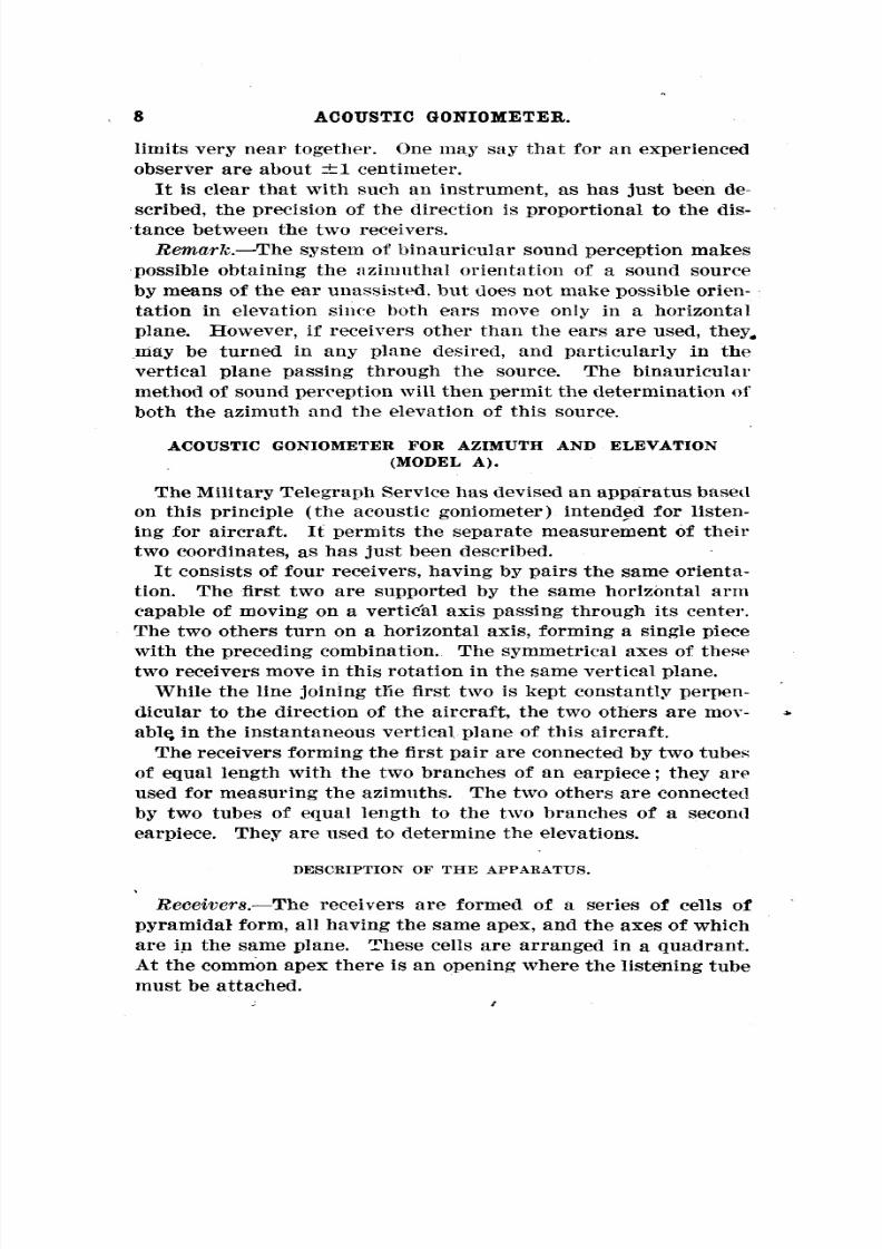
—Receivers. The receivers are formed of a series of cells of
pyramidal form, all having the same apex, and the axes of which
are in the same plane. These cells are arranged in a quadrant.
At the common apex there is an opening where the listening tube
must be attached./

8/8/2019 Military Telegraph
http://slidepdf.com/reader/full/military-telegraph 9/51
ACOUSTIC GONIOMETER. 9
The two receivers for determining the azimuth are placed at a
distance of 2 meters, 50 centimeters from each other, so that theaxes of the corresponding cells are parallel and that the diam-
etral planes of the receivers are vertical and perpendicular
to the line joining the apices. The extreme partitions of each
of them are vertical and horizontal, respectively. They permit
the application with excellent results of the binauricular method'
of listening to the determination of the azimuth of an aircraft.
In fact, there will always be one of the cells of each of them
the axis of which will have approximately the same angle of
elevation as this aircraft.The two receivers for determining the elevation are in all
respects similar to these for the azimuth. The axes of the
corresponding cells are still parallel with each other. The dis-
tance between the two apices is 1meter.—
Note. The experiments made with this instrument have led
to the decision of introducing into it in future the two following
improvements:
1. Each receiver will consist of a* pair of horns like those de-scribed above. The diametral planes of these two horns willbe
parallel and 30 centimeters apart. Their apices
will be connected with the listening tube by
two tubes of equal length. When the diametral
plane D D of the combination of the two horns
passes through the sound source sought, the
sound waves received by each willcome in con-
tact at the common point P, and the sound in
the listening tube T willreach a maximum ofintensity.
With this arrangement the maximum inten-\Dsity of sound will be obtained simultaneously
with the impression of the passage of the sound from one ear
to the other. This is attended with a very notable augmentation
\u25a0in the magnifying power of the instrument.
The mouth of the instrument willbe drawn back, an undoubted
advantage in itself. Furthermore, if several fly overaircraftthe station at the same time, the maximum intensity of sound
willbe noted whenever the instrument is pointed at one of them.
Thus between the sound produced by this and byll confusionthe other aircraft will be avoided.
2. In the acoustic goniometer type "la" the distance between,
the receivers elevation will be increased to 2for in future22615°— 17 2

8/8/2019 Military Telegraph
http://slidepdf.com/reader/full/military-telegraph 10/51
10 ACOUSTIC GONIOMETER.
meters. For this purpose the circular movable disk will be
lowered20
centimetersand the
horizontalaxis will be raised 30
centimeters. This modification is very important. It willresult
in a precision of the same order in aiming for elevation and fordirection.
The symmetrical axes of these two receivers are parallel with
each other, perpendicular to the line joining the. apices, and they
are situated in a same plane perpendicular to the horizontal axis
of rotation.
These two receivers are held firmly together by three parallel
arms of steel tubing, perpendicular to their diametral planes
and to the horizontal axis of rotation.
The apparatus consists of three distinct pieces :
1. The stand, composed of a horizontal circular cast-iron plate,
resting on three steel tubes. This plate is pierced in the center
by a circular opening prolonged by a vertical socket 30 milli
meters in diameter. This socket is closed at its extremity by asteel plug which is screwed into its side. It is intended to offer
passage to the vertical axis of rotation.
2. The fork, composed of a cast-iron horizontal arm forming
a single piece with the vertical axis of rotation, with the receivers for the azimuth, and with the two vertical uprights on
which the horizontal axis rests. The horizontal cast-iron arm
has the form of a circular plate prolonged along one diameter by
two projections on which two arms of angle iron 75 centimeters
long are bolted. To the extremities of these two arms are
bolted the receivers for the azimuth. The vertical axis is
screwed tothe
center of the plate perpendicularly to its plane.
Itbears at its extremity a ball bearing on which it turns. The
diameter of this plate is the same as that of the fixed plate of
the stand over which, moreover, it is exactly superimposed.
The edge of the fixed plate of the stand is graduated to 10 mils.
An^index traced on the edge of the moving plate moves in front
of this graduation. Finally, the two supports of the horizontal
axis of rotation are each formed of two .vertical steel tubes
united at their top by a U piece in which is screwed a bolt, the
extremity of which is pointed.It
is around the points of thesetwo bolts that the rotation of the horizontal axis takes place. A
hole at the center of the movable plate allows for the oiling of
the vertical axis without dismounting the apparatus. Itis gen
erally closed by a littlecopper screw which will only have to be
8/8/2019 Military Telegraph
http://slidepdf.com/reader/full/military-telegraph 11/51
11COUSTIC GONIOMETER.
removed whenever it is desired to oil the vertical axis of rota-
tion.3. The combination of the two receivers for elevation. The
two elevation receivers are, as has been said, connected rigidly
by three steel tubes which are parallel and perpendicular to the
diametral planes of the receivers. One of these three fixed tubes
is fastened to the two receivers near their apex. The" points
where the two others are fastened are placed symmetrically on
the two outside partitions near the opening of the receivers.
These last two tubes form a single piece with the horizontal
axis of rotation to which they are perpendicular. Finally, atthe two extremities of the horizontal axis there are two conical
holes intended to allow passage for the two points about which
this axis should turn and of which mention has already been
made. A quadrant graduated in degrees forms one piece with
this system and moves with it.
COLLIMATOE.
A collimator intended for the optical verification of theacoustic aimings forms a single piece with the receiving equip-
ment for angles of elevation.
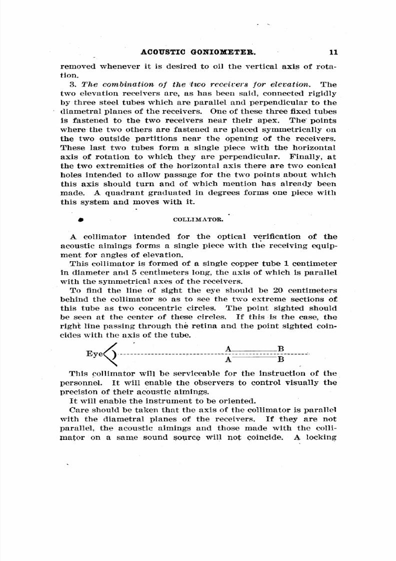
This collimator is formed of a single copper tube 1centimeter
in diameter and 5 centimeters long, the axis of which is parallel
with the symmetrical axes of the receivers.
To find the line of sight the eye should be 20 centimeters
behind the collimator so as to see the two extreme sections of
this tube as two concentric circles. The point sighted should
be seen at the center of these circles. Ifthis is the case, theright line passing through the retina and the point sighted coin-
cides with the axis of the tube.
A. BEyeQ
A B
This collimator willbe serviceable for the instruction of the
personnel. Itwillenable the observers to control visually theprecision of their acoustic aimings.
Itwillenable the instrument to be oriented.
Care should be taken that the axis of the collimator is parallel
with the diametral planes of the receivers. If they are not
parallel, the acoustic aimings and those made with the colli-
mator on a same sound source will not coincide. A locking
8/8/2019 Military Telegraph
http://slidepdf.com/reader/full/military-telegraph 12/51
12 ACOUSTIC GONIOMETER.
screw makes it possible to correct the error of orientation of
the collimator.
EARPIECES.
The earpieces are of the model employed for the stethescopes
for mine listening. They consist of two nickeled tubes termi-
nated at one extremity by two nipples of galaith and vulcanized
rubber for insertion in the ears of the listener. The two other
extremities are connected by a spring. They are connected with
the two listening tubes by two rubber tubes of equal length. Theextremities with the nipples
arecurved
so as topenetrate
easily into the ear channel. The two nipples are of different
colors ;the black one should be placed in the right ear ;the other,
which is white, should be placed in the left ear. Itis important
not to invert them, for the transmission of sound would then
become poor. One should also let the spring alone press the
nipples into the ears. This pressure should be gentle, and it
can readily be proved that by pressing the nipples against*the
ears with the hands the unserviceable sounds developed in the
interior of the instrument are increased, the listener is fatigued,and there is no gain in intensity of sound perception.—
Important recommendation. It is essential that the two rub-
ber tubes of the same earpiece should have the same length. A
variation of the length of one of these tubes would involve the
displacement of the zero. Ifany reason (as for instance the
wearing out of the rubber) leads to the shortening of one of the
tubes the other must be shortened an equal amount.
FOREIGN NOISES DEVELOPED IN THE INTERIOR OF THE INSTRUMENT.
The greatest importance is attached to the preservation of the
purity of the sound.
Unless precautions are taken the receivers and tubes transmit
to the ears, under" the influence of the foreign waves, a continuous
noise, which obscures the significant sound. This may be called
the interior sound of the instrument.
These foreign waves strike the exterior surfaces of the tubes
and of the receivers and make them vibrate, producing a noisein the earpieces. On the other hand, a part of these noisespenetrate directly or by diffraction into the interior of the tubes
or of the horns, and after a series of reflections on their interior
surfaces are transmitted to the earpieces. Experiments have
8/8/2019 Military Telegraph
http://slidepdf.com/reader/full/military-telegraph 13/51
13COUSTIC GONIOMETER.
shown that tubes of small diameter vibrate very little. The in
terior sound in this case seems to be due to the reflections of the
foreign waves in the interior of the tubes, the intensity and pitch
of these foreign noises varying with the length of the tubes.—Note. Recent investigations have shoivn that the foreign
noises can he very greatly reduced by introducing into the in
terior a very light material which would entirely obturate the
tube without -forming an acoustic stopper.
For this purpose use is made either of wadding, which has firstbeen rendered very flaky, or simply a cigarette paper stretched
across the interior of the tube perpendicularly to the axis.that the most favorablexperience has taught conditions are
realized when the deadening membrane divides the tube into two
unequal parts in the ratio of 4/5, the smaller one being next to
the receiver.
The foreign noise is then greatly reduced without loss of in
tensity of audition.
In the most recent types of instruments provision has been
made for the introduction of a sound-deadening membrane, based
on this principle, into the listening tube, the membrane ofpaper is stretched in the interior of a copper tube 6 centimeters
long and of the same diameter as the listening tube.
The latter is formed of two tubes with lengths in the ratio
4/5. The sound-deadening tube can be inserted between the two
parts of the listening tube. By means of screws the three sec
tions are united into a single tube.
If the membrane is to be replaced the sound-deadening tube
willbe released by removing the screws. The membrane willbechanged and the tube replaced in position.
The sound-deadening tube can also be replaced by an ordinary
tube of the same diameter and length, which willbe delivered forthis purpose with the instrument. The officers commanding in
the artillery command posts can therefore use the instrument
with or without the sound deadener as they prefer.
On the other hand, the receivers, of which the walls present a
large surface, vibrate under the influence of the sound waves
which strike them on the exterior, and the resulting noise forms
the greater part of the foreign noises of the instrument.
Accordingly, the desire to reduce as much as possible the for
eign noises has led, on the one hand, to the reduction of the
listening tubes to a minimum, on the other to the envelopment

8/8/2019 Military Telegraph
http://slidepdf.com/reader/full/military-telegraph 14/51
14 ACOUSTIC GONIOMETER.
of the exterior surfaces pro-f the receivers with a felt sheathtected in turn from the inclemency of the weather by a rubber
cover. This felt sheath suffices to protect the exterior surfacesof the horns from the action of the foreign waves.
The same result lias also been produced by adopting receivers
of paper paste. This material vibrates very little under the
influence of the sound waves. The interior surfaces are var-
nished with ripelin in such a way that the sound waves are
reflected from them in the most advantageous manner.There are three different types of receivers :
Those of thin wood covered with felt.
Those of iron covered with felt.
Those of paper paste not covered with felt.Experience will show which should he preferred for future
models.
INDEX.
Ithas already been said that the azimuth circle was gradu-
ated in mils and the quadrant for elevation in degrees. The
indicesof
these circlesare
themselves capableof receiving
small
displacements and of being clamped by a vise.
The index of the azimuth circle is formed by a circular copper
plate applied to the edge of the horizontal plate and capable of
moving around the latter. A mark is engraved on the lower
border of this copper plate, opposite the graduation in mils of
the stationary plate. It serves as index for this graduation.
Furthermore, the copper plate bears on its upper border a gradu-
ation in mils. The regular displacement of the index is. read on
this graduation by means of a reference mark engraved on themovable plate.
The index of the elevation quadrant is formed by a mark
engraved on a needle which is made fast at the moment of obser-
vation, but which can receive small angular displacements read
on an auxiliary graduation.
The displacements provided for in the indices of the circles
of azimuth and elevation enable the station commander to cor-rect the readings of the error due to the movement of the air-
craft during the time consumed by the sound in reaching thelistener. —
Lighting. The lighting of the indices is provided by two little
electric bulbs, each mounted in front of a reflector. The cur-
rent for each is furnished by two batteries borne by the movable

8/8/2019 Military Telegraph
http://slidepdf.com/reader/full/military-telegraph 15/51
15COUSTIC GONIOMETER.
plate. A screw placed over each bulb serves as cut-off. The current is closed by tightening the screw in the opposite direction.
Two extra bulbs are delivered with each instrument.
MOUNTING THE APPARATUS.
The apparatus is delivered, dismounted, in six parts :
1. The stand.
2. The movable plate and the combination of two receivers for
elevation.
3 and 4. The two receivers for the azimuth, mounted on the
angle iron, which connects them with the movable plate.
5 and 6. The two earpieces with their rubber tubes.
To mount it, it is only necessary to bolt the pieces of angle
iron pertaining to the receivers for azimuth onto the projections
of the movable plate, and to place the movable plate on the
stand by inserting the vertical axis in the socket of the stand.
Each of the two earpieces will then be attached to the corresponding—istening tube.
Cover. A canvas waterproof cover is delivered with each
instrument. —Spare parts. The military telegraph service can supply the
following spare parts :
Receivers (specify whether for azimuth or elevation).
Felt sheath for receivers with rubber cover.Earpieces with rubber.
Elbows of copper tubing (specify diameter).
Bulbs and batteries.
USE OF THE ACOUSTIC GONIOMETER.
EMPLACEMENT OF THE APPARATUS.
The acoustic goniometer ought to be placed in the open, as far
as possible, on an elevation.'It ought especially to be installed
far from any noise. Ifit is considered necessary to place it in
the immediate vicinity of a gun, the station commander ought
to insist upon fee greatest silence on the part of his men during
an investigation.
ORIENTATION- AND LEVELING OF THE INSTRUMENT.
The collimator willbe kept in aim on a reference point of the
horizon situated at an angle of direction known beforehand, and
tentative adjustments will be applied to the stand until the
index, previously placed opposite the zero graduation of the

8/8/2019 Military Telegraph
http://slidepdf.com/reader/full/military-telegraph 16/51
16 ACOUSTIC GONIOMETER.
movable disk, marks on the graduated disk the azimuth re-quired.
The horizontality of the axis of rotation of the receivers forelevation for two rectangular azimuths must be tested by meansof a level. This operation willbe greatly simplified by placing
the legs of the instrument on ground leveled in advance.
After these operations of adjustment and orientation have
been performed once for all, the stand of the instrument willbe
imbedded in the soil.
PERSONAL EQUATION.The impression of the passage of the sound from one ear to
the other will not necessarily be registered at the same instant
by all the observers. The intensity of sound perception is, in
fact, for a great many people, greater in one ear than in the other.
Itwill be necessary, therefore, for each observer to determine
carefully his own personal equation, by which he will correct
once for all his observations by giving a corresponding displace
ment to the index.
To determine this personal equation,- a stationary sound sourcewillbe placed on a known point a of the azimuth, and the instru
ment willbe aimed acoustically at this source. Ifa+e is read
on the azimuthal circle, c is the personal equation of the ob-
server. If the instrument has been improperly oriented, this
quantity would be the sum of the error of orientation and of
the personal eqtiation of the listener. The readings of both
will be corrected at the same time. It is advisable to perform
these operations on a windless day.
INSTRUCTION OF THE LISTENERS.
The determination of the position of aircraft by the acoustic
goniometer is much more difficult than that of stationary sources
of sound. Listeners can not succeed in making accurate meas-urements before they have completed of graduateda course ex-ercises to familiarize themselves with the instrument and the
methods of observation.
They must be trained at the same time to determine the position of a sound source with the ear unaided and with the instru
ment. Itis more difficult to perform the determination without
the instrument, and those who can do itwillsurely be very good
observers with the goniometer.
8/8/2019 Military Telegraph
http://slidepdf.com/reader/full/military-telegraph 17/51
17COUSTIC GONIOMETER.
The best exercise without the instrument seems to be the fol-
lowing:
The observer, with eyes bandaged, assumes the position of"attention." Two assistants take positions in front of him. By
moving his entire body in accordance with the indications of
the sound the observer seeks a position directly opposite one"of the two assistants, who remains motionless and cries, Hep,
hep, hep," until the observer makes a sign for him to cease. Inconnection with this proceeding the observer moves his head to
and fro in order to make sure that in the position of his body
he receives the impression of the passage of sound from one earto the other directly in front. If this situation has not been
realized, he alters his position and repeats the same experiment.
When this experiment has been completed the first assistant,"
without moving, cries, Hep." The other assistant replies,"Hep." The observer determines whether the second is on the
right or left of the first and makes a sign with his hand whether
he should /move to the left or right. The movements of the
second assistant should always be short (a single pace, for
instance).
The assistants will then cry "Hep" alternately, and the ob-
of his direction,server will make a second determination and
the same operation willbe repeated in succession.
When he judges that the two assistants are both directly in
front of him, the observer takes the bandage from his eyes. Ifhis judgment has been correct he should find the two assistants
in the same direction.
For the successful performance of thisexperiment
the firstassistant should remain motionless during the entire operation.
The observer should also remain motionless, so as always to
face the first assistant. For this reason he must remain during"
the entire exercise in the position of attention.""Reference should be made to the notice on The Perception of
Aerial Sounds by Means of the Methods Devised by the Military
Telegraph Service for the Instruction of Listeners."
The instruction of the goniometer observers should be carried
out in three stages :
1. On a fixed terrestrial sound source (klaxon, drum, rattle,—etc.). The instructor willverify the exactitude of the aimings
made by the observer with the collimator mounted on the in-
strument.
22615°— 17 3
8/8/2019 Military Telegraph
http://slidepdf.com/reader/full/military-telegraph 18/51
18 ACOUSTIC GONIOMETER.
—2. On a movable terrestrial sound source. The sound source
willbe shifted to and fro in front of the observer, and he mustundertake to follow it acoustically by means of the instrument
in accordance with the rules concerning the observation of air:
craft which are given later (page 20).—
3. On aircraft. The followingexercise relative to the observa-
tion of a movable sound source deserves being especially recom-mended :
The assistant carrying the sound soux^ce moves across the field
some distance in front of the goniometer. The observer follows
him acoustically with this instrument.
The instructor selects a certain number of reference points
on the terrain, and whenever the sound source passes in front of"one of them he cries top." An assistant reads the circle at
the moment of the signal. Every time the sound source passes
a same reference point the reading made should Jbe the same.
The instructor can thus judge of the precision of the aimings
and of the progress of the observers.
Very good observers should be able to keep the margin of
error down to about 10 mils.
As regards the instruction of the observers on the goniometer
<the note relative to the development of the sound observers for
the antiaircraft posts included in the present note (extract from
the Provisional Instruction on the Use of Projectors, p. 46) canbe read with profit.
The observers should be trained every day systematically,
either to follow the aircraft when they fly over the post, or to
follow movable terrestrial noises by means of acoustic goni-
ometers.
Furthermore, they should practice daily the exercises in de-termining position by sound without the aid of instruments.
This daily practice is absolutely indispensable. The officers
commanding the posts must regard it as an important part of
the maneuver.Ifthey should allow it to lapse, the observers would quickly
lose the efficiency acquired.
ANGLE OV SENSATION.
If the observer moves the instrument very slightly from the
direction in which he has the feeling of the passage of the sound,he has the sensation that the source of sound moves from right
to left or from left to right very quickly.
8/8/2019 Military Telegraph
http://slidepdf.com/reader/full/military-telegraph 19/51
19COUSTIC GONIOMETER.
At a certain point lie willhave the sensation that it passes
completely to his right or to his left. The angular deflectionrequired to produce this sensation is extremely small (a few de
grees) ;let a represent this angle.
As long as the observer moves the instrument to right or left
of the direction of the sound source to an extent less than the
angle a he has the sensation that the source moves, but if he
turns it to an extent greater than the angle a he retains the
impression of hearing the sound at his right or left, as the case
may be, but he no longer has the feeling that the sound source
moves.For this reason the angle a has been called the angle of sen-
sation.
This angle seems to be determined by the condition that when
the observer begins to have the impression of hearing the sound
absolutely on his right or left, the difference of the coursestraversed by the same sound wave to reach one ear or the other
is equal to the distance of the two ears.The angle
ofsensation is therefore inversely proportional to
the distance of the two receivers (base) and for this reason
the precision of the aimings is proportional to the base.
But the oscillations which the observer applies to the instru
ment should be smaller the larger the base. Ifhe revolves the
instrument to right or left of the direction of the sound source
to an extent exceeding the angle greater than a he willno longer
have the sensation that the source moves. He must then use his
reason to find again the direction of the source of the sound.
Hewill
advance the receiver on the right or -the receiver on theleft, according as he hears the sound on the left or right.
This explains why beginners sometimes cease suddenly to fol
low acoustically the source and subsequently have great diffi
culty in replacing their instrument in the proper direction. For
this reason also they generally find it easier to follow the sourcewith an instrument with short base than with one of long base.
Proficient observers will readily acquire the ability of keeping
the range of the oscillations applied to the instrument within
the limitof the angle a on one side or the other of the directionof passage.
These observations should suffice to show the great importance
of maintaining the regular and systematic training of the ob -
servers without interruption.
8/8/2019 Military Telegraph
http://slidepdf.com/reader/full/military-telegraph 20/51
20 ACOUSTIC GONIOMETER.
By reason of the existence of the angle of sensation, skilled
observers will succeed in getting theirdirections in spite of the
simultaneous presence of several aircraft above the post. An
aeroplane at which a goniometer is aimed ought to be in a
direction within the angle of sensation, and consequently the
observer willhave the impression that the aeroplane is moving.
The case willbe different with the other aeroplanes.
Proficient observers will not be disturbed by noises perceived
directly by the ears. In fact it will be sufficient for them tcr
fix their attention on the movement of the sound from right to
left or from left to right, and only the sound perceived throughthe receivers will give him this sensation.
OBSERVATION OF AIRCRAFT.
/
The determination of the direction of a sound of a motor
willbe performed by the two listeners operating together, each
withone of the earpieces in his ear.They willdetermine uninterruptedly, one the azimuth of the
aircraft, the other its elevation. The first will take a positionfor this purpose behind the instrument, opposite the line joining
the two receivers for the azimuth. He willhold in the left hand
the horizontal arm and with the right hand the vertical upright
on the same side, and he willmanipulate them in such a way as togive the combination of the two receivers the suitable angular
displacements.— " " " "Note. The terms right and are here applied to theleft
receiversaccording
asthey
are connected with the right or leftear, respectively.
An assistant stationed at his right will read the azimuth and
will give to the index the deflections corresponding to the
velocity of the sound. The observer for elevation will take
position facing the plane of the rotation of the elevation re-ceivers, either behind the apparatus, on the right of his com-rades, or in front of the instrument on their left. (In the latter
case he will stand between the left azimuth receiver and the
elevation receivers.) He will give the elevation receivers the
displacements required by moving the steel tube's which join
them.
An assistant placed in front of the instrument between theright azimuth receiver and the elevation receivers will read the

8/8/2019 Military Telegraph
http://slidepdf.com/reader/full/military-telegraph 21/51
21coustic Goniometer.
elevation angles and give the index the displacements corre-sponding to the velocity of the sound*
To follow an aircraft, each of the two observers will proceed
by bracketing. They will move the appliance slightly back and
forth to right and left of the position sought so as to hear the
noise of the motor pass successively from one ear to the other.
The direction and elevation of the aircraft, as has been seen,
can only be accurately determined if the instrument is made to
oscillate within the limit of the angle of sensation. The aim
must be, therefore, to bracket the aircraft within an angular
range of oscillation of very small extent.
During the course of a single oscillation the aircraft moves on
its trajectory. Ifthe goniometer is aimed a little in front of the
aeroplane and then maintained in an immovable position the
impression of the passage of sound from one ear to the other, as
from the right to the left, will be produced in consequence of
the continuous movement of the aeroplane. After the passage
of the aeroplane itwillonly be necessary to turn the goniometer
slightly to have the impression of the passage in the opposite
direction (from left to right). Ifimmediately after the pas
sage the instrument is left immovable, the impression of thepassage of the sound from the-right ear to the left will be pro
duced by the movement of the aeroplane, and so on in succes-sion. In this manner the operator willsucceed in obtaining extremely short brackets, and the movement of the goniometer
willbe practically almost continuous.
These considerations lead to the adoption of the followingrules
for the observations :
When an aeroplane has been reported the azimuth observer
immediately turns completely toward the sound heard, moveshis head two or three times to right and left to be sure that he
has the sensation of the passage of the sound at approximately
the position where the line of his ears is parallel with that of
his shoulders. Ifthe case is otherwise he willmodify his posi
tion.
Then he gives the goniometer an approximate orientation in
which the horizontal rod supporting the azimuth receivers will
be parallel with the line of his shoulders.
Then he inserts the earpieces in his ears.Itis indispensable that the above-mentioned operations be per
formed very rapidly. Their purpose as to give the instrumentgeneral orientation in the aiming direction.
8/8/2019 Military Telegraph
http://slidepdf.com/reader/full/military-telegraph 22/51
22 ACOUSTIC GONIOMETER.
For the observer of elevation this preliminary investigation of
the target without the use of an instrument is impossible, as has
been said on page 41. But this is not a serious impediment,
since the angle of elevation of an aeroplane is generally slight
(included between 10 and 30 degrees) when it is first heard.
The observer of elevation will therefore place the earpiece
in his ears at the same time as his companion.
He must be sure that the listening tube connected with the
upper receiver is always attached to the right ear and the listen
ing tube connected with the lower receiver to the left ear. Itis
indispensable that the observer should always conform with
this rule. In these conditions, when he hears the sound on the
right, he willadvance the lower receiver. When he hears it onthe left, he will advance the upper receiver. This operation
should be performed automatically. It is clear that if the ob-
server should invert the listening tubes the sensations of right
and left would be inverted, and since he would not be accus-
tomed to operate in this manner, he would follow the source of
the sound withmuch less accuracy.
The method of observation will therefore be the same for both
observers.
Ifthe observer hears the sound on his right or his left, he will
turn the instrument by advancing, in the first case, the receiver
on the left (or lower receiver) ; in the second case, the receiver
on the right (or upper receiver), so as to make the sound pass
from one ear to the other.
He will then restore the goniometer as nearly as possible to
the direction in which he has noticed the passage of the sound,
and he willkeep it stationary in this direction for a short time.
Four situations are possible :—First situation. In consequence of the movement of tlje air-
craft, the observer willhave the impression that the sound passes
to his right.
He will accordingly turn the instrument a little by moving
forward the receiver on the left (lower receiver). He will then
have the impression of the passage of the sound to left. He will
keep the instrument motionless until he has heard the sound onhis left. In consequence of the movement of the aircraft, the
sound will then pass to his right. As soon as he has receivedthe impression of the passage of the sound he will turn the in-
strument a little in the same direction as before, and proceed by
a succession of the same operations.
8/8/2019 Military Telegraph
http://slidepdf.com/reader/full/military-telegraph 23/51
23COUSTIC GONIOMETER.
He will continue, therefore, by this method of progressive
bracketing by making the instrument turn intermittently and
always in the same direction, as has been stated above. 1
Second situation— -The observer has the impression that the
sound passes to his left.
This is the opposite of the preceding. It is only necessary toreverse the terms right and left in the preceding directions.
—Third situation. The orientation angle of the aircraft is zero.
The azimuth is constant.
Ifthe observer for azimuth has oriented the instrument in the
direction in which he has the exact impression of passage, and
if he keeps it motionless in this position the sound will pass
neither to right nor to left.He willhave the impression of always hearing it in front of
him. He should then produce the impression of passage by giv
ing the instrument slight oscillations on both sides of the neutral
direction (oscillations less than the angle of sensation).
He willmake the instrument oscillate as long as the azimuth
of the aircraft remains constant.
If the angle of orientation of the aircraft changes he will
have the feeling thatthe
sound becomes more distant on theright or the left. He will then follow the aeroplane by bracket
ing as explained above (first and second situations).—
Fourth situation. The orientation angle of the aircraft is 90
degrees. In this situation the elevation of the aeroplane is con-stant.
This situation leads back to the preceding. The observer for
elevation will proceed as has been explained for the observer
of azimuth in the preceding situation.
Itmay happen that the variations of the coordinates of the
aircraft change direction suddenly during the observation.
For instance, the observer having heard the sound on the right
turns the instrument a little, so as to make the sound pass to
the left. Then he keeps the instrument motionless. The sound
does not pass to the right. Ifthe angle at which the instrument
has been turned is clearly less than the sensation angle, the
observer will have the feeling that the sound source does not
1 This mannerof observation is
entirelysuccessful with
theacousticgoniometer and insures a high degree of precision in the aimings. It
should be remarked that the fact that the aircraft can be followedalmost continuously in the two coordinates is largely doe to the very
great independence of the receivers of elevation and direction attainedin this instrument.

8/8/2019 Military Telegraph
http://slidepdf.com/reader/full/military-telegraph 24/51
24 ACOUSTIC GONIOMETER.
move, then that it recedes. Ifthe instrument has been turned atan angle greater than the sensation angle, he willawait in vain
for the sound to pass to the right. Furthermore, if after a fewx
seconds he does not have the impression of the passage it is tobe inferred that the aeroplane has changed its course. To verify
this conjecture, the observer will make the instrument oscillatea few degrees so as to give him the impression of the passage
and the indication of the position of the aeroplane and on the
direction of its displacement. "He will then follow it as has been
said before.
ORIENTATION OF SEARCHLIGHTS.
The listening instrument is kept acoustically fixed on thetarget. An attendant follows the line of sight *soas to estimate
the deviation of this line from the direction of the rays; he" " " "orders higher," lower," to left," to right," so as to reducethis deviation to its theoretical value. (The rays ought to be
bracketed in advance of the position indicated by the listening
instrument , to a distance varying from 100 down to 50 mils,
according to the speed and transversal movement of the target.) 2
Thus he explores a surface of several square degrees in case
the target is not immediately found.3
ACOUSTIC GONIOMETER FOR THE AZIMUTH (MODEL B).
The Military Telegraph Service has also undertaken the con-struction of instruments based on the same principle, but record
ing only the azimuth of the aircraft. These instruments are
especially intended to be used in the lateral observation stations
for antiaircraft fire.
They differ slightly from the preceding in construction. Thedistance between the two receivers is two meters.—
Note. In the instruments with factory number higher than
18 the receivers willbe of the twin type described in connection
with the'acoustic goniometer, type I,model E (p. 26).
1This line is determined by the axis of the collimator.2An aiming wheel mounted in accordance with the principles set
forth in the Instruction on Anti-Aircraft Fire on the axis of sight
enables the observer to make an exact estimation of the value of this
deviation.3 The preceding is an extract from the Provisional Instruction on the
Use of Searchlights in the Search for Aerial Targets, published by thePractical School for Anti-Aircraft Fire at Arnouville.

8/8/2019 Military Telegraph
http://slidepdf.com/reader/full/military-telegraph 25/51
25COUSTIC GONIOMETER.
Furthermore, in these instruments the distance separating the
two receivers willbe increased, to 2.50 meters. Finally, sections
of tubing for deadening foreign sounds like those described onpage 13 of the present note willbe inserted in the listening
tubes.
The two arms which hold these receivers are of angle iron and
are maintained in a horizontal position by two ironbraces, which
connect the base of the receivers with the extremity of a vertical
cylindrical tube forming a single piece with the movable hori-
zontal plate. Through this cylindrical tube passes the stationary
vertical axis which forms a single piece with the stand. Therotary motion is effected on ball bearings.
As this instrument is much lighter than the preceding, it has
been possible to design the stand as a vertical iron column ter-
minating below in four horizontal iron branches with angles of
90 degrees between them.
The movable portion of the instrument supporting the re-ceivers has a socket at its center into which the axis of rotation
is inserted. This forms a single piece with the horizontal gradu-
ated circle and can be bolted onto the standard. This locks theaxis and the circle on the standard.
ORIENTATION OF THE INSTRUMENT.
To orient the instrument the bolt willbe slowly unscrewed.
The instrument will be aimed at a known azimuthal reference
sound. The circle will then be turned on the vertical axis until
the graduation indicated by the index corresponds to this azi-
muth. The orientationwill
be completed by the displacement ofthe idex.
PERSONAL EQUATION.
Corrections for the personal equation willbe applied to the
readings by adjustment on the index.
Provision has been made for a possible displacement of 50 mils
on the index for the correction for orientation and for personal
equation.1
On the other hand, no provision has been made for a dis-
placement of the index for a correction relative to the velocity
1In all instruments with a factory number higher than 18, provisionhas been made for a possible displacement of 500 mils on both sides of
the mean position, which enables the observers to apply the correctionsfor the velocity of the sound to all their readings.
22615°—17 4

8/8/2019 Military Telegraph
http://slidepdf.com/reader/full/military-telegraph 26/51
26 ACOUSTIC GONIOMETER.
of the sound. These instruments should therefore be operated
as provided for in the Maneuver Regulations for Building Plat-
forms, Model 1915.(Regulations
ofJan.
28,1917,
par.71.)—Lighting. The lighting of the index is effected by a little elec-
tric bulb of the same type as those used for the acoustic goniom-—eter Model A. The current is likewise furnished by two bat-teries inclosed in a wooden case borne by the movable plate.—
Case. A case is delivered with each instrument. It includes
an envelope for each of the receivers and also an envelope for
the central part (axis and circle). It is important to keep the
instrument covered when not in use, in order especially to avoid
the clogging of the ball bearings by dust.
MOUNTING.
The instrument is delivered dismounted in three parts :
1. The stand.
2. The movable appliance mounted on the rotation axis and
the two receivers.
3. The earpiece mounted on rubber tubes.
To mountit
the appliance must be clasped onto the standand the receivers must be attached to the two extremities of the
movable horizontal arm. As in the case of the goniometer, Model
A, the stand should be set firmly in the ground as soon as the
instrument has been oriented.—Spare parts. The Military Telegraph Service can deliver the
following spare parts :
1. Receivers (indicate whether for the instrument Model B).
2. Felt sheaths for the receivers with waterproof covers.
3. Earpieces with rubber tubes.4. Elbows of copper tubing (indicate in this case, also,
whether intended for the instrument Model B, and indicate
diameter of the tube).
5. Bulbs and batteries.
OBSERVATION Otf AIRCRAFT,
The apparatus is intended for use in the lateral posts for
acoustic telemetry on a wide basis. The observer will followthe aircraft acoustically in a continuous manner in accordancewith the rules given for goniometers, Model E. An assistant will
make the readings. The same aircraft willbe followed acousti-
cally by an instrument at the central station and by the instru-

8/8/2019 Military Telegraph
http://slidepdf.com/reader/full/military-telegraph 27/51
27COUSTIC GONIOMETER.
ments Bin the lateral posts. At the same instant as indicated" "by the call top transmitted by telephone to the lateral posts
the attendants of the different listening instruments willmake
readings which they will immediately transmit to the central
station.
DIRECT CONNECTION OF THE ACOUSTIC GONIOMETER AND THE SEARCH-
LIGHT.
Finally, in the antiaircraft stations at Paris they have tried to
attach the receivers onto the searchlight itself. The axes of the
listening instrument are then the same as those of the projector,
and the operation commands are the same for both instruments.
The displacement of the indices is effected by little trombones
attached to the listening tubes. The displacement of zero is
obtained by the lengthening of one or the other listening tube,
effected by drawing out one of the trombones.Since the experiments were not completed at the time of pub-
lishing this note itis impossible to give the details of the results.
Nevertheless, itmay be said that such an arrangement presents
a priori the advantage of eliminating the loss of time inmaneu-vering.
If the experiments now in progress yield satisfactory results,
the Military Telegraph Service willbe able to construct receiv-
ers furnished with trombones with adjustment pieces and listen-
ing tubes intended for different types of projectors used by the
Antiaircraft Service.
8/8/2019 Military Telegraph
http://slidepdf.com/reader/full/military-telegraph 28/51
8/8/2019 Military Telegraph
http://slidepdf.com/reader/full/military-telegraph 29/51
29COUSTIC GONIOMETER.
mentioned above. Its importance consists (1) in exaggerating
the sensation of right and left; (2) in bracketing the position
sought between two adjacent known limits, boundingthe
range
of possible error.1
The following exercise should be performed as often as possi-
ble for the training of the personnel :
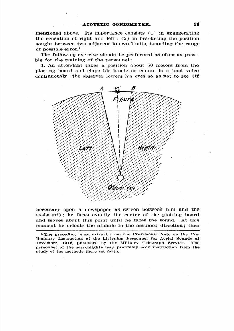
1. An attendant takes a position about 50 meters from the
plotting board and claps his hands or counts in a loud voice
continuously; the observer lowers his eyes so as not to see (if
necessary open a newspaper as screen between him and the
assistant) ; he faces exactly the center of the plotting boardand moves about this point until he faces the sound. At this
moment he orients the alidade in the assumed direction; then
1The preceding is an extract from the Provisional Note on the Pre-liminary Instruction of the Listening Personnel for Aerial Sounds ofDecember, 1916, published by the Military Telegraph Service. Thepersonnel of the searchlights may profitably seek instruction from thestudy of the methods there set forth.
8/8/2019 Military Telegraph
http://slidepdf.com/reader/full/military-telegraph 30/51
30 ACOUSTIC GONIOMETER.
he turns his eyes toward the assistant nnd tests the accuracy of
his aim.
Perform this exercise preferably in calm weather to avoid the
deflection of sound by the wind.
2. Every time an aeroplane passes within the range of sound
the observer determines the direction of the sound on the plot-
tingboard, taking care not to look at the aeroplane ;subsequently
he verifies the exactitude of his determination by looking at the
target and taking into account that the aim obtained must have
been 50-100 mils behind the aeroplane.
B. TRAINING OF THE OBSERVERS OF THE ACOUSTIC GONI-
OMETERS FOR BINAURICULAR LISTENING.
The instruction should be conducted in five stages :
1. The observer practices in the observation of a distant fixed
sound source at a hundred meters (assistant counting in a loud
voice, clapping the hands, or sounding a horn).
After each determination of azimuth the assistant moves side-
wise and the observer endeavors to indicate the direction of the
displacement. The extent of the displacements is diminished
progressively. The observer endeavors to reduce the time neces-sary to orient the instrument.
These experiments bring out the eccentricities in the sense of
sound which may be exhibited by the student listeners.
There will thus be an opportunity of eliminating those whose
acoustic aimings deviate too conspicuously from the symmetrical
plan of the goniometer.
2. The exercises are resumed and the assistant moves con-tinually at the rate of 1meter per second at a distance of 150
to 200 meters.
The instructor keeps in a position between the assistant and
the observer and whistles from time to time.
At this signal the observer ceases moving the acoustic instru-
ment, while the assistant halts immediately and maintains
silence ;it is then an easy matter to verify the exactitude of the
acoustic aim.
3. The observer is trained in following an aeroplane in direc-
tion, the elevation being given by an assistant who aims at sight
a little behind the target.
The observer must follow the aeroplane by moving from one
side to the other of the supposed position so as to maintain the
sensation of the passage of the sound from one ear to the other.
8/8/2019 Military Telegraph
http://slidepdf.com/reader/full/military-telegraph 31/51
31COUSTIC GONIOMETER.
"This sensation is a far more reliable guide than that of the
aeroplane in front."4. The observer is trained to follow an aeroplane in elevation,
the direction being given by an assistant.
5. Two observers are trainee! to follow an aeroplane simul-
taneously, one operating for direction, the other for elevation.
For optical aimings on an aeroplane a sighting instrument
with aiming wheel is used, which enables the operators to take
account of the movement of the aeroplane during the transmis-
sion of the sound. The front sight of this instrument is formed
by a peephole 4 millimeters in diameter.
The aiming circle has a radius of 70 millimeters and isplaced at a distance of 670 millimeters from the peephole ;it is
held in a horizontal position by a perpendicular, the right line
passing from the center of the peephole to the center of the
circle is parallel with the acoustic axis of the instrument.
When the listeners follow accurately the target, an observer
who keeps his eye at the peephole ought to see the aeroplane on
the aiming circle with the tail toward the center of the circle.

8/8/2019 Military Telegraph
http://slidepdf.com/reader/full/military-telegraph 32/51
111. Note on the Application of the Acoustic Goniometer to Firing by
Sound, and to the Orientation of Searchlights.
[Published by the Practical Training School for Antiaircraft Fire at
Arnouville, January, 1917.]
USE OF THE ACOUSTIC GONIOMETER.
The acoustic goniometer serves to determine the direction of
the source of a sound.
Itis in no wise serviceable for the determination of the nature
of this sound. Only the ear unassisted can distinguish the sound
of an aeroplane from that of a dirigible. No instrument, what-
ever its nature may be, ever renders accurately the timbre and
intensity of the sound, and the use of any instrument with this
in view is liable to create confusion.
The acoustic goniometer can be used either to direct the ob-servations of the searchlight, or to direct the fire by sound on an
invisible target, the presence of which has been noticed, without
an instrument, by the artillery commander, who alone is re-sponsible for the opening of fire.
—{a) To direct the observations of a searchlight. This is the
normal use on cloudless nights. In this case the target is as arule an aeroplane, since the approach of dirigibles is improbable
on account of their great vulnerability.
The instrument may be attached to the searchlight. Thismanner of use willbe considered in a special note.
When it is mounted on a separate standard it is furnished
with graduations both for azimuth and elevation corresponding
to similar graduations on the searchlight. The reading is madeby means of an index which can be moved a definite space on
a scale on which each interval is 10 mils.
The purpose of this deflection is to take into account the dis-
placement of the target during the time T, the sum of the time
required by the sound to arrive and of the time B, which may beestimated as five or six seconds, required for transmitting tothe searchlight the indications of the acoustic goniometer. With-
out this precaution the direction given to the searchlight would
be that for a position of the target which ithad already left.
8/8/2019 Military Telegraph
http://slidepdf.com/reader/full/military-telegraph 33/51
33COUSTIC GONIOMETER.
Itis not necessary to take the wind into account. Itinfluences
the indications received by the instrument to exactly the extentrequired for accounting for its influence on the course of the
target (exclusive of the time 0,which is unimportant).
Let Sh and <ni be the corrections to be given to the direction
and elevation, respectively, v the velocity of the target, h its
altitude, Ao and A the positions of the target at the departure
of the sound wave and at the instant when the target is to be
illuminated, Do and D the distances of these points from the
instrument, So and S their angle of elevation, ao and a the ori
entation of the instrument at these two points ; we have theformulae :
(1)' -_- sm av
sin 88h=T=rDo cos 505
0
cos a+a 0
(2)Bm^^sm^—
2
The principal difficulty in the application of these formulae
arises from the fact that a and ao are unknown. Enlightenment
may be sought by comparing the rapidity of variation of the
direction and elevation, but it is hardly possible in the present"state of the instruments to use them as acoustic goniometers"for orientation like optical telescopes. Itneed only be said
that well-trained operators can quickly attain a degree of cer-tainty in respect to the direction of variation of the azimuth and
elevation.
This being the case, one should not attempt to derive precise
rules from the formulae (1) and (2), but only approximate ones,
which are sufficient, however, in view of the usual dispersion ofthe searchlight rays.
PRACTICAL RULES.
The two aimers follow the sound source, and as soon as they
are in a position to do this with accuracy they give their indica
tionsconcerning
the direction of movement with the expressions" " " to right," to left," stationary for the observer of direction,"" "and higher," lower," stationary for the observer of ele-
vation.
Twc assistants then move the two indices in the direction of
the movement indicated and for distances of which the maxima
8/8/2019 Military Telegraph
http://slidepdf.com/reader/full/military-telegraph 34/51
34 ACOUSTIC GONIOMETER.
correspond to the orientations 0 for <ru and ±90° for 3h and aregiven by the following table :
Elevation. Vo—3o° 15 5
30—50° 20 10
50—70° 30 15
They move one of the indices the maximum indicated in the" "table, if the indication stationary which has been given by
the aimer has caused him not to move the other ;in the contrary
case the movement is reduced by a third.
Then they read the azimuth and the elevationand report them
to the searchlight. •
Ifthe aircraft is not overtaken by the rays of the searchlight,
the aimers continue to follow it with the acoustic goniometer.
One of the assistants accustomed to account for the deflection
which exists for the direction of the movement of the target,
which has been reported to him, between the direction given by
sight and the direction given by sound, surveys the line of sight
determined by the telescope and directs the movements of the
searchlight by the orders "right," "left," "higher," "lower."The operation can also be undertaken by orienting the searchlight
by sound without the goniometer and only using the goniometer
to direct the movements, as just described, after the searchlight
has once been turned on.
FIRE BY SOUND.
PRELIMINARY REMARKS.
I. The firing of a round when the listeners are engaged with
the acoustic telescope would deafen, if not wound them, andwould render them incapable of continuing their service.
To avoid this misfortune, it is indispensable that periods of
firingbe broken up by listening intervals. During the alternate
intervals of fire in this combination the personnel attached tothe service of the goniometer remove the appliances from their
ears, while during each listening period they seek to gain data
of importance for the next firing period.
11. It is necessary for firing to account for the displacement—
of the target during the time T, including
1. The time required for the sound to reach the instrument.
2. The time consumed in manipulations from starting opera-
tions with the instrument to the firingof the round.
3. Half of the period of fire.
4. The time of flight of the projectile.
8/8/2019 Military Telegraph
http://slidepdf.com/reader/full/military-telegraph 35/51
35ACOUSTIC GONIOMETER.
Thus itis possible to obtain corrections much superior to those
expected in operating with the first method.111. Inview of the errors likely to be committed, it is neces-
sary to distribute the fire of each period over an extensive zoneso as to be sure of delivering some rounds near the target which
willat least produce, failing any material effects, a certain moral
effect.
When tracers are used, shell fire is dangerous over a wide
extent. Itis only necessary, therefore, for,battering an extensive
zone in all directions to vary the direction and inclination of
the gun.These remarks throw light on the paragraphs 29 and 71 of the
Service Rules for Platforms, Model 1915, which deal with firing
by sound.The goniometer, as considered in these service rules, is without
index capable of deflection for taking account of the corrections
for azjmuth and elevation. But with goniometers furnishedwith such indices the operations there regarded as incumbent
upon the commander of fire and the reader of the telemeter for
altitultitu ide willbe very readily performed by the asde willbe very readily performed by the as isistant enijsistant enij Moyedoyed
in coi nnection with thenectionn goniometer.ith the goniometer.oi
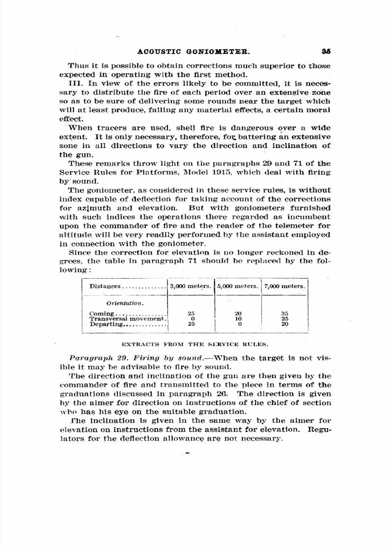
Sinin tee the correction for elevation is no longeir reckonedee reckonedhe correction for elevation is no longei in den de-grees,rees, , the table in paragraph 71 should be repthe table in paragraph 71 should be rep laced byaced tly tl le fole fol-
lowinowin Lg:g: _.__
Distances 3,0istancesistancesistances 3,0XX)meterX)meterrs.s. 5,000,0,000,000,000,0XX)meeters.eters.eters.eters.X)me 7,000 meters.,000 meters.,000 meters.,000 meters.
Orientation.rientation.
Comingoming 255 200 355Transversal movement.ransversal movement. 0 100 255Departingeparting 255 0 200
EXTRACTS FROM THE SLRVICE BULKS.
—Paragraph 29. Firing by sound. When the target is not vis
ible itmay be advisable to fire by sound.
The direction and inclination of the gun are then given by the
commander of fire and transmitted to the piece in terms ofthegraduations discussed in paragraph 26. The direction is given
by the aimer for direction on instructions of the chief of section
who has his eye on the suitable graduation.
The inclination is given in the same way by the aimer for
elevation on instructions from the assistant for elevation. Regu
lators for the deflection allowance are not necessary.
8/8/2019 Military Telegraph
http://slidepdf.com/reader/full/military-telegraph 36/51
36 ACOUSTIC GONIOMETER.
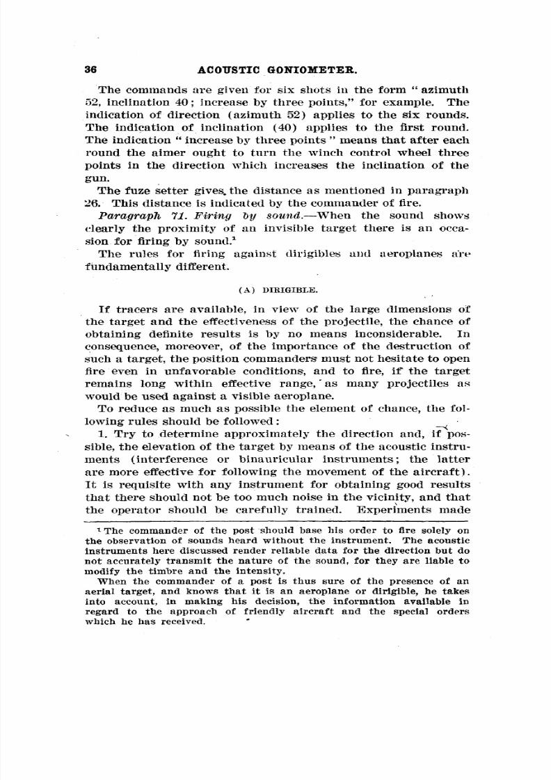
"The commands are given for six shots in the form azimuth
52, inclination 40 ; increase by three points," for example. The
indication of direction (azimuth 52) applies to the six rounds.
The indication of inclination (40) applies to the first round." "The indication increase by three points means that after each
round the aimer ought to turn the winch control wheel three
points in the direction which increases the inclination of the
gun.
The fuze setter gives, the distance as mentioned in paragraph
26. This distance is indicated by the commander of fire.—
Paragraph 11. Firing by sound. When the sound showsclearly the proximity of an invisible target there is an occa-
sion for firing by sound. 1
The rules for firing against dirigibles and aeroplanes art1
fundamentally different.
(A ) DIBIGIBLE.
If tracers are available, in view of the large dimensions of
the target and the effectiveness of the projectile, the chance of
obtaining definite results is by no means inconsiderable. In
consequence, moreover, of the importance of the destruction of
such a target, the position commanders 1 must not hesitate to open
fire even in unfavorable conditions 1, and' to fire, if the target
remains long within effective range, as many projectiles as
would be used against a visible aeroplane.
To reduce as much as possible the element of chance, the fol-
lowing rules should be followed : -><
1. Try to determine approximately the direction and, if pos-
sible, the elevation of the target by means of the acoustic instru-
ments (interference or binauricular instruments; the latterare more effective for following the movement of the aircraft).
It is requisite with any instrument for obtaining good results
that there should not be too much noise in the vicinity, and that
the operator should be carefully trained. Experiments made
1The commander of the post should base his order to fire solely on
the observation of sounds heard without the instrument. The acoustic
instruments here discussed render reliable data for the direction but donot accurately transmit the nature of the sound, for they are liable to
modify the timbre and the intensity.
When the commander of a post is thus sure of the presence of an
aerial target, and knows that it is an aeroplane or dirigible, he takesinto account, in making his decision, the information available inregard to the approach of friendly aircraft and the special orderswhich he has received.

8/8/2019 Military Telegraph
http://slidepdf.com/reader/full/military-telegraph 37/51
ACOUSTIC GONIOMETER. 37
by day with the eyes of the observer bandaged will serve to
indicate the degree of precision obtained ; remember that the
direction revealed by the sound is behind the direction as givenby sight.
2. While following the target at an interval of about 10
seconds, notice the direction of the sound movement (whether
coming or going, to right or left).
In accordance with the indication made by the observer and
the azimuth read on the acoustic apparatus, the commander 'of
fire gives the azimuth for the first six rounds of each piece by
the application of the following rule :To take into account the displacement of the target during
the transmission of the sound and the time consumed inmanipu
lations (reckon to the mean point of fire) and the time of flight,
he makes in the suitable direction the following corrections in
the azimuth as read on the instrument :
25, if the observer reports a transversal displacement
with the distance apparently remaining constant.
15, if the observer reports a transversal displacement
and
avariation of elevation
atthe
sametime.
(With these figures the supposition is that the azimuths aregraduated from 0 to 640, each interval having consequently avalue of 10 mils. )
They are applicable only for small elevations and must be in
creased by half for elevations of 15-20 and doubled for elevations
of 60.
In the case of two-piece positions the first piece increases the
indicated azimuthal deflection angle by 5, the second diminishes
itby
5(substitute 10 for
5if
experiencehas shown that great
accuracy can not be expected from the instrument or the ob-server). —
3. As a rule the commander of fire gives as distance3,000, if the dirigible flies almost over the post (eleva
tion indicated by the instrument greater- than 45 de-
grees).
5,000, if the sound produces the impression that the
target is near without flying over the post (the elevation
in this case must be included between 25 and 50Ldegrees).7,000, if the impression is of a distant target, but one
heard without instrument (elevation between 15 ana" 30).
Do not forget that the indications derived from the elevation
depend on the altitude, and that this willusually be less for a
dirigible approaching than for one departing when relieved of

8/8/2019 Military Telegraph
http://slidepdf.com/reader/full/military-telegraph 38/51
38 ACOUSTIC GONIOMETER.
the weight of the explosives which it carried (altitude probably
2,000 to 2,500 for the approaching target, 2,500 to 3,500 for the
departing target).Every possible effort willbe made to determine accurately the
position of the target on the basis of the information furnished
by the distant observer. Whether or not he has an acoustic
instrument, ask him for the approximate azimuth of the target
ancl deduce the distance with the help of the telemetric ap-
paratus. 1
If the dirigible is clearly in the direction of the observation
Station deduce the azimuthal angle of deflection received only in
case the aircraft flies over the observation station or if the dirigi-ble appears to the observer on the side of the command post oron the opposite side.
Inany case give the distances- inmultiples of 1,000 meters, for,
in view of the nature of the projectile, itis not necessary to seek
greater precision, which, moreover, would be illusory.
4. The inclination of the gun is transmitted to the pieces in" the form so many degrees," increase by intervals of 3." 2
rc command is given by the non>command is given by the non> commission*ommission* ed officerd wfficer who iso is
;hehe niiormal reader of the telemeter irmal reader of the telemeter i 'or altitudeor altitude ;he obtaine obtain is thes the
lumbumb >er of degrees by adding to theer of degrees by adding to the elevation ilevation iindicated b;ndicated b; y thethe
icous ;tic instrument the quantityticicous giv<nstrument the quantity giv< m by the foby the fo•Mowing tabMowing tab •le:le:
IDistancesistances .. 3,000,000 meters.eters.
j5,000,000 meters.eters. 7,000,000 meters.eters.
Orientation.rientation.I
Comingoming
TransversalransversalDepartingeparting
,lag:lag:t
1550
155
10050
200155100
it:t: ie idea is to obtain a rough indication.e idea is to obtain a rough indication. Consequently it is notonsequently it is notnecessary to take into account the fact that the time required for the
sound to reach the observation station and the command post is not
the same.
Itis possible, after a first operation of this sort, to estimate whetherthe target is nearer the command post or the observation station. If,
for instance, the target is thought to be two kilometers nearer the" "observation station than the command post, give two tops separatedby
six seconds;at the
firstread the
azimuth atthe
observation station"and give no attention to the command post until the second top.""2 See paragraph 28 ; revise this paragraph by substituting six" " " " " "
rounds for four rounds and increase by intervals of 3 for in-crease by intervals of 2."
8/8/2019 Military Telegraph
http://slidepdf.com/reader/full/military-telegraph 39/51
39COUSTIC GONIOMETER.
5. When the firing data are transmitted to the pieces the com-mander of fire gives, by whistle, the signal for opening fire. At
this signal, or even at the moment when he gives the expected
directions, the observer at the acoustic instrument removes the
connection from his ears (he would otherwise be deafened or
even injured by the detonation), and the fire begins.
At the termination of fire the commander gives the order
"cease firing" by two short blasts of the whistle. No round
should be fired after this signal under any pretext ; the projec-
tiles with fuzes set, which in consequence of the accidents of
firehave not
been fired,are preserved
forthe subsequent
period
of fire (it not being necessary to set the fuzes with great ac-curacy, they willbe suitable for subsequent fire).
At the command the observer "resumes observations as for the
first fire. The comparison of the azimuths and of the elevations
obtained with those of the first fire furnishes a test for the
accuracy of his estimation of the direction of the movement of
the target. A second period of firing follows in the same condi-
tions as the first, and so on successively.—Remark I. The dirigible protects itself against this sort of
fire by stopping the motors, reducing ballast, and mounting
rapidly. Therefore, if the sound of a dirigible, after being
clearly heard, stops suddenly, it may be assumed that it has
stopped its motors and is somewhat in front of and considerably
above the last position reported (at most, 5,000 meters above).
Firing can be tried again, nearly in the same direction as before
and with an inclination of the gun increased by 5 degrees.
After this fire no further fire is undertaken unless the target has
been heard again.—Remark II. The preceding method, which has not yet re-ceived the sanction of experience, is given tentatively and sub-
ject to modification. Especially, in view of the necessity of set-
ting off an interval of pause between two firing periods, and for
increasing the mean velocity of fire,itmay be found advisable to
allot eight rounds per piece to the periods of fire and mount by
intervals of two.
(B) AEROPLANES.
Inview of the effectiveness of fire by day against aeroplanes,
the practical effectiveness of fireby sound is inconsiderable. But
a moral effect may be expected.
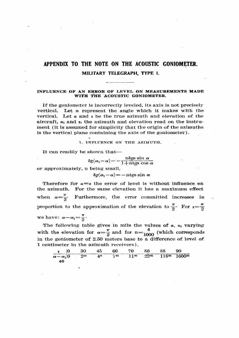
8/8/2019 Military Telegraph
http://slidepdf.com/reader/full/military-telegraph 40/51

8/8/2019 Military Telegraph
http://slidepdf.com/reader/full/military-telegraph 41/51
41COUSTIC GONIOMETER.
2. INFLUENCE ON THE ELEVATION.—Furthermore, it is easily shown that Si S is at its maximum
when q. is zero ; that is, when the source is in the vertical plane
of the axis of the instrument. —We then have, whatever S may be, Si S=ij.
—In the preceding case, Si S=/*.
—Conclusion. The error committed is clearly greater for direc-
tion than for elevation, but it should never be regarded asnegligible.
Itis therefore essential that the instrument should be leveledwith care, and, furthermore, that it should be sufficiently stable
that no displacement of the ensemble of the receivers should be
possible during the course of the observations. The acoustic
goniometers of the military telegraph have been designed with
this requirement in view.
ON THE PRECISION OF THE OBSERVATIONS FO R VARIABLEELEVATIONS.
An observer not otherwise informed has the impression that
the position of an aircraft is less accurately determined acousti-
cally by the goniometer when the elevation increases. This,
however, is not the case.
1. OBSERVATIONS FOR, AZIMUTH.
Let Aao and Aas be the errors that may be committed in respect
to the azimuth of an aircraft of elevation zero, and on that of
an aircraft of elevation s, situated at equal distance from theobservation station.
——
It is shown that Aas= .cos a-
The error of angle committed depends therefore on the eleva-
tion. But it is easy to see that these angles Aao and Aas corre-spond to equal linear displacements of the airship. For the samedistance from the observer the error committed in the position
of an aircraft in space is therefore numerically the same, what-
ever its elevation may be .
2. OBSERVATIONS OF ELEVATION.
With the two horns for elevation constantly moving in the
azimuth of the aircraft, the angular precision of the aimings does

8/8/2019 Military Telegraph
http://slidepdf.com/reader/full/military-telegraph 42/51
42 ACOUSTIC GONIOMETEE.
not vary with the elevation. At an equal distance the position
of the aircraft is determined witha
precision independent of
the elevation.
In fact, when an aircraft passes near the zenith the necessity
of giving the instrument large angular displacements to follow
it is an embarrassment, but by always keeping the acoustic
axis of the instrument within the angle of sensation the observer
willbe almost certain of not losing it, since he willbe constantly
aware of the direction of the sound displacement. The angle
Acoustic goniometer, military telegraph, type 1, Model A.
of sensation will be extremely large near the zenith, and this
willmake the operation very easy.
ON THE ADVANTAGE OF THE INTERPOSITION OF A SCREENBETWEEN THE RECEIVERS.
Experience shows that if a screen is interposed between the
two receivers the acoustic aimings are greatly facilitated.This can as yet be only partially explained. Itwillbe observed
that a very effective screen is interposed between the human

8/8/2019 Military Telegraph
http://slidepdf.com/reader/full/military-telegraph 43/51
43COUSTIC GONIOMETER.
ears, the head (cheeks, nose, etc.), which is a very real factor
in listening withoutan
instrument.The idea ofplacing
a screenbetween the two receivers of the instrument would naturally
suggest itself therefore.
APPLICATION TO THE AZIMUTHRECEIVERS.
The shield consists of two penthouses in the form of a quarter
circle with a radius of 1 meter set up in a position to cover
goniometer, military telegraph, type 1, Model B.Acoustic
each of the receivers, respectively, and parallel to the diametral
plane of the latter, as shown in figure 1.
APPLICATION TO THE RECEIVERS FOR ELEVATION.
The arrangement is the same, except that the two penthouses
forming the screens are cut off in such a way as not to impede
the movement of the receivers about the horizontal axis (fig. 2).

8/8/2019 Military Telegraph
http://slidepdf.com/reader/full/military-telegraph 44/51
44 ACOUSTIC GONIOMETER,
This arrangement will have a particularly important appli-
cation in the goniometers of type la with factory numbers lessthan 30.
In these instruments the space separating the receivers is only
1meter, and experience shows that observers experience greater
difficulty in this case in following the sound source correctly

8/8/2019 Military Telegraph
http://slidepdf.com/reader/full/military-telegraph 45/51
45COUSTIC GONIOMETER.
than in azimuth. The insertion of the screens seems to make
the feeling ofright
and left clearer, so that the observer willmore readily follow the course of the aircraft, and will thus
more surely obtain good aimings.
Acoustic-Gonioaeter MilitaryTelegraph Type 1.
Model B giving the aiimuth and theiving the aiimuth and the elevationlevation.Side view.
de prolll.
It is even possible that the precision of the aimings willbe in-
creased, but the experiments thus far made are not sufficient for
a categorical statement to this effect.
NOTE ON THE DETERMINATION OF THE DIRECTION OF ANAIRCRAFT BY SOUND WITHOUT THE AID OF INSTRUMENTS.
Itwas stated in the remark on page 8 that the binauricular
method of listening, while enabling the observer to obtain an
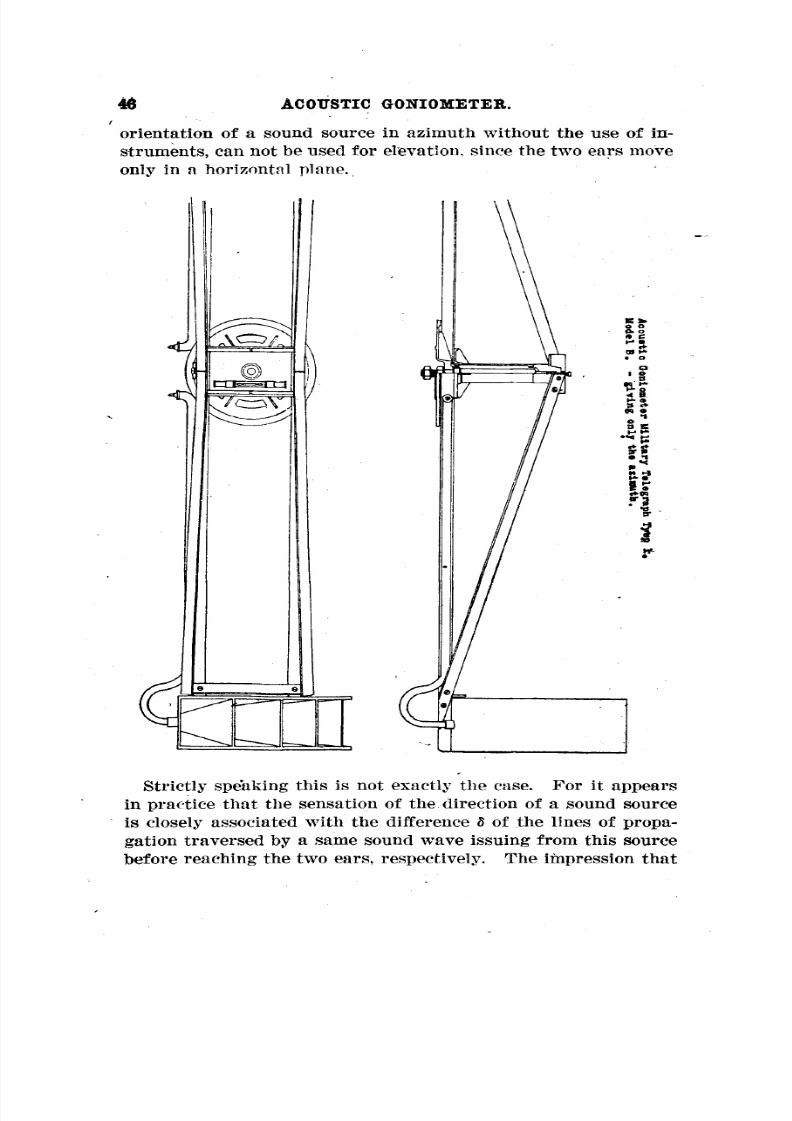
8/8/2019 Military Telegraph
http://slidepdf.com/reader/full/military-telegraph 46/51
46 ACOUSTIC GONIOMETER.
orientation of a sound source in azimuth without the use of in-
struments, can not be used forelevation, since
the two ears moveonly in a horizontal plane.
Strictly speaking this is not exactly thecase.
Forit
appearsin practice that the sensation of the direction of a sound source
is closely associated with the difference 5 of the lines of propa-
gation traversed by a same sound wave issuing from this source
before reaching the two ears, respectively. The impression that

8/8/2019 Military Telegraph
http://slidepdf.com/reader/full/military-telegraph 47/51
47COUSTIC GONIOMETER.
is directly in front is produced when 8 is zero, and
the source seems to move toward the right or left when 8 varies
one way or the other.
The variation of 8 is caused by the rotation of the head on its
axis. Since this axis is vertical, the impression of the move-
ment of the sound source is naturally in the horizontal plane.
This is the general rule.
But it is possible to vary 8 by turning the head on a horizontal
axis.
Ifthe observer reclines on the ground facing the sound source
and turns his head on its axis back and forth, he willhave the
the source
impression of the passage of the sound from one ear to the other
when the line of his ears makes an angle with the vertical equal
to the elevation of the sound source. But this proceeding is too
laborious to be recommended.
There is an easier way of turning the two ears on a horizontal
plane, which is simply to incline the head to right or left and
turn it about the neck as a hinge. To produce a variation in the
difference 8 in this movement, it is only necessary to make the
line of the ears conform with the azimuth of the sound source.The method of auricular observation of an aircraft without
listening instruments will be as follows:—(1) Determination for azimuth. The observer, assuming the"
position of attention," moves his head to and fro on its axis
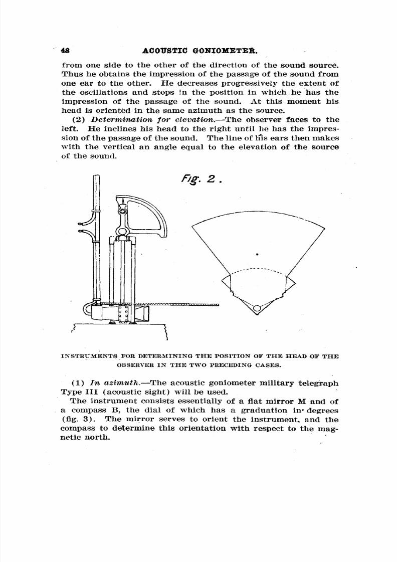
8/8/2019 Military Telegraph
http://slidepdf.com/reader/full/military-telegraph 48/51
48 ACOUSTIC GONIOMETER.
from one side to the other of the direction of the sound source.Thus he obtains the impression of the passage of the sound from
one ear to the other. He decreases progressively the extent of
the oscillations and stops in the position in which he has the
impression of the passage of the sound. At this moment his
head is oriented in the same azimuth as the source.—
(2) Determination for elevation. The observer faces to the
left. He inclines his head to the right until he has the impres-
sion of the passage of the sound. The line of his ears then makes
with the vertical an angle equal to the elevation of the source
of the sound.
INSTRUMENTS FOR DETERMINING THE POSITION OF THE HEAD OF THE
OBSERVER IN THE TWO PRECEDING CASES.
—(1) In azimuth. The acoustic goniometer military telegraph
Type 111 (acoustic sight) willbe used.
The instrument consists essentially of a flatmirror M and of
a compass B, the dial of which has a graduation in* degrees
(fig. 3). The mirror serves to orient the instrument, and thecompass to determine this orientation with respect to the mag-
netic north.

8/8/2019 Military Telegraph
http://slidepdf.com/reader/full/military-telegraph 49/51
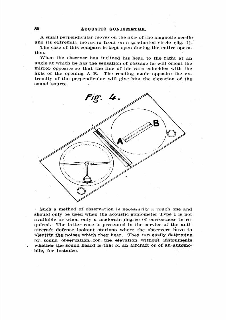
8/8/2019 Military Telegraph
http://slidepdf.com/reader/full/military-telegraph 50/51
50 ACOUSTIC GONIOMETER.
A small perpendicular moves on the axis of the magnetic needle
and its extremity
movesin front on
agraduated
circle(fig. 4).
The case of this compass is kept open during the entire opera-
tion.
When the observer has inclined his head to the right at anangle at which lie has the sensation of passage he willorient the
mirror opposite so that the line of his ears coincides with the
axis of the opening A B. The reading made opposite the ex-tremity of the perpendicular will give him the elevation of the
sound source.
Such a method of observation is necessarily a rough one and
should only be used when the acoustic goniometer Type Is not
available or when only a moderate degree of correctness is re-
quired. The latter case is presented in the service of the anti-aircraft defense lookout stations where the observers have to
identify the noises.which they hear. They can easily determineby, soun/l observation... for. the, elevation without instrumentswhether the sound heard is that of an aircraft or of an automo-
\u25a0bile, for instance.

8/8/2019 Military Telegraph
http://slidepdf.com/reader/full/military-telegraph 51/51
61COUSTIC GONIOMETER.
The military "telegraph has had constructed for the lookout
stations of the antiaircraft defense a class of very light, inex-
pensive goniometers which can be used for this purpose. These
are the acoustic goniometers military telegraph, Type I, model
E. (See special note.)
o
Related Documents