I NOT MEASUREMENT SENSITIVE I MIL-A-8625F 1-0September 1993 SUPERSEDING MIL-A-8625E ,.. .,.. .,- 25Aprll 1988 MILITARY SPECIFICATION ANOC)ICCOATINGS FOR ALUMINUM AND ALUMINUMALLOYS “ This spec!ffcatlonIs approved for use by all Departments and Agencies of the Department of Defense. 1. SCOPE 1.1 Scope. This specification covers the requirements for SIX types and two classes of electrolyticallyformed anodic coatings on aluminum and aluminum alloys for non-architecturalapplications (see 6.1). 1.2 Classification. The anodic coating Types and Classes covered by this specificationare as specified herein (see 6.2 and 6.21): 1.2.1 Types Type I - Chromic acid anodizing, conventional coatings produced from chromic acid bath (see 3.4.1) Type IB - Chromic acid anodizing, low voltage process, 22~ 2V, (see 3.4.1) Type IC - Non-chromic acid anodizing, for use as a non-chromate alternative for Type I and 16 coatings (see 3.4.1 and 6.1.2) Type II - Sulfuric acid anodizing, conventionalcoatings produced from sulfurlc acid bath (see 3.4.2) Type 116 - Thin sulfuric acid anodizing, for use as a non-chromate alternative for Type I and 16 coatings (see 3.4.2 and 6.1.2) Type III - Hard Anod\c Coatings (see 3.4.3) 1.2.2 Classes. :Class 1 - Non-dyed (see 3.5.) Class 2 -Dyed (see 3.6.) Benefic~al comments (recommendations,additions, deletions) and any pertinent data which may be of use In Improving this document should be addressed to: Commanding Officer, Naval Alr Warfare Center Aircraft Dlvlsion Lakehurst,Code SR3, Lakehurst, NJ 08733-5100, by using the self-addressedStandardlzatlonDocument ImprovementProposal (00 Form ?426) appearlnq at the end of this document or by letter. AMSC N/A AREA MFFP DISTRIBUTION STATEMENT A: Approved for public release; distribution Is unlimited. ———- .—.. - — ——— — —- ---——--———- .

Welcome message from author
This document is posted to help you gain knowledge. Please leave a comment to let me know what you think about it! Share it to your friends and learn new things together.
Transcript
INOT MEASUREMENTSENSITIVE I
MIL-A-8625F1-0September 1993
SUPERSEDINGMIL-A-8625E,...,...,- 25Aprll 1988
MILITARYSPECIFICATION
ANOC)ICCOATINGS FOR ALUMINUM AND ALUMINUMALLOYS “
This spec!ffcatlonIs approved for use by all Departmentsand Agencies of the Department of Defense.
1. SCOPE
1.1 Scope. This specification covers the requirements for SIX types andtwo classes of electrolyticallyformed anodic coatings on aluminum andaluminum alloys for non-architecturalapplications (see 6.1).
1.2 Classification. The anodic coating Types and Classes covered by thisspecificationare as specified herein (see 6.2 and 6.21):
1.2.1 Types
Type I - Chromic acid anodizing, conventional coatings produced fromchromic acid bath (see 3.4.1)
Type IB - Chromic acid anodizing, low voltage process, 22~ 2V,(see 3.4.1)
Type IC - Non-chromic acid anodizing, for use as a non-chromatealternative for Type I and 16 coatings (see 3.4.1 and 6.1.2)
Type II - Sulfuric acid anodizing, conventionalcoatings produced fromsulfurlc acid bath (see 3.4.2)
Type 116 - Thin sulfuric acid anodizing, for use as a non-chromatealternative for Type I and 16 coatings (see 3.4.2 and 6.1.2)
Type III - Hard Anod\c Coatings (see 3.4.3)
1.2.2 Classes.
:Class 1 - Non-dyed (see 3.5.)Class 2 -Dyed (see 3.6.)
Benefic~al comments (recommendations,additions, deletions) and anypertinent data which may be of use In Improving this document should beaddressed to: Commanding Officer, Naval Alr Warfare Center AircraftDlvlsion Lakehurst,Code SR3, Lakehurst, NJ 08733-5100, by using theself-addressedStandardlzatlonDocument ImprovementProposal (00 Form ?426)appearlnq at the end of this document or by letter.
AMSC N/A AREA MFFPDISTRIBUTION STATEMENT A: Approved for public release; distribution Is unlimited.
———- .—.. - — ——— — —- -- -——-- ———- .
—
MIL-A-8625F
2. APPLICABLE DOCUMENTS
2.1 Government documents,
2.1.1 Speciflcattonsand standards. The followlng speclflcatlonsandstandards form a part of this document to the extent speclfled herein. Unless uotherwise speclfled, the issues of these documents are those l~sted h theissue of the I)epartmentof Defense Index of Specificationsand Standards(0001SS) and supplementthereto, cited In the solicitation.
SPECIFICATIONS.
MILITARY
MIL-P-23377 - Primer Coating, Epoxy-Polyamide,Chemical and SolventResistant
MIL-C-81706 - Chemical Conversion Materials for Coating Alumlnum andAluminum Alloys
MIL-P-85582 - Primer Coatings: Epoxy, Waterborne
FEDERAL
QQ-A-250/4 - Aluminum Alloy 2024, Plate and Sheet
STANDARDS
FEDERAL
FED-sTD-141 - Paint, Varnish, Lacquer, and RelatedMaterials: MethodsFor Sampltng and Testing
FED-STD-151 - Metals; Test Methods
MILITARY
MIL-STD-105 - Sampling Procedures and Tables For Inspect~on By Attribute
(Unless otherulse Indicated,copies of federal and military specificationsandstandards are available from DODSSP-CustomerService, StandardlzatlonDocumentsOrder Desk, 700 Robblns Avenue, Building 4D, Phlladelphla, PA 19111-5094.)
2.2 Non-Governmentpublications. The followtng documentsform a part ofthis-documentto the extent specified herein. Unless otherwise speclfled, the~ssues of the documents which are DOD adopted are those llsted In the Issue ofthe 0001SS cited In the solicitation. Unless otherwise speclfled, the issuesof documents not llsted In the DODISSare the issues of the documents cited fnthe sollcltatlon(see 6.2).
AMERICAN SOCIETY FOR TESTING AND MATERIALS (ASTH)
ASTM B 117ANSI/ASTM B 137 =
ASTM B 244 -
ASTMD 822 -
Method of Salt Spray (Fog) TestingHeight of Coating on Anod~callyCoated Aluminum,MeasurefnentofThickness of Anodic Coatings on Alumlnum and of OtherNonconductiveCoatings on NonmagneticBasis Metalswith Eddy Current Instruments,MeasurementofLight and Water Exposure Apparatus (Carbon-Arc Type)for Testing Paint, Varnish, Lacquer and RelatedProducts, Standard Practice for Operating
M~L-A-8625F
ASTMD 2244 - Color D“lfferencesof OpaquOflter~alsi Instrumental.,.Evaluation of
, J
ASTMG 23 - Standard Practice for Opera$@g Light Exposure Apparatus(Carbon-Aic Type) bllthandllf’thoutWater for Exposure ofNon-metallic Materials
ASTMG26 - Operating Light-Exposure Apparatus (Xenon-Arc Type) Withand bllthoutIlaterfor Exposureof Non-metalllc materials
(Applicationfor cop~es should be addressed to the American Society forTesting and Materials, 1916 Race Street, Phlladelphla,PA 19103.) .
32.3 Order of precedence. In the event of a conflict between the text of
this document and the references cited herein, the text of this document takesprecedence. Nothing In this document, however, supersedes applicable laws andregulat~onsunless a speclflc exemption has been obtained.
3. REQUIREMENTS
3.{ Materials. The materials used shall be such as to produce coatingswhich meet the requirements of this specification.
3.1.1 Base metal. The base metal shall be free from surface defects,caused by machining, cutting, scratching, polishlng, buffing, roughening,bending, stretching, deforming, rolling, sandblasting,vaporblastlng, etching,heat treatment condltlon, alloy chemtstry Imbalance and inclusions, that willcause coated test panels or parts to fafl any of the requirements of thisspecification. The base metal shall be subjected to cleaning, etching,anodlzlng and seallng procedures as necessary to yteld coatings meeting allrequirementsof th!s specification.
3.2 Equipment and processes. The equipment and processes employed shallbe such as to produce coatings which meet the requirementsof th~sspecification.-Unless otherwise specified In the contract, purchase order orapplicabledrawfng (see 6.2), process operating conditions shall be at theoption of the supplfer.
3.3 General.
3.3.1 Anodlztng of parts and assemblies.
3.3.1.1 Anodlzlng of parts. Unless otherwise specified in the contract,purchaseortieror ap@Jicable dr$u?fig(see’6:2), parts shall be anodized after, , ,al? heat treatment,~.machining, ~e?dlr!g?formingand perforating have beencompleted.
.!
3.3.1.2 Anod~zhd of assemb~ies. ‘Unlessotherwise speclfled In thecontract, purchase”brderor applicable drawi%g, anodic coatings shall not beapplied to-assemblteswhtch’will’entrapthe’electrolyte In joints or recesses(componentsshall be anodized separately prior to assembly). Nhen anodlzlngof assemblies is authorized by the;coit~actj purchase,orderor applicabledrawing, the proce,sslng,fflet~odused ’s~allnot result in subsequent damage tothe assembly from electrolyte entraprnent[(Type I or”IA coatings shall be usedunless another coating Type Is specl,fied). Assemblies which containnon-aluminumparts such as steel, brass or organic substances, which would beattacked by pretreatment or anodizing solutlons or would prevent un{formformationof the anodlc coating, shall not be anodized as assemblies, unlessthe non-aluminum surfaces are masked or electrically insulated In a mannerwhich produces anodlc coatings meeting the requirementsof this specification.
3
MIL-A-8625F
3.3.1.2 Anodtzlng of complex .shapes. Hhen anodizing complex shapes whichuIII entrap the electrolyte in recesses, the processing method used shall notresult in subsequentdamage to the part from electrolyte entrapment (Type I or1A coatings shall be used unless another coating Type Is speclfled).
3.3.2 Handllng and cleanlnq. Parts shall be so handled during allpretreatment, anodizing and post treatments that mechanical damage orcontaminationwI1l be avoided. Parts shall be free of all forefgn substances,oxides and soils, such as greases, oIL pafnt and welding flux< Parts shallhave oxide and other interfering films removed by the use of pr~per cleanlng~roceduresso as to be clean and have water break free surfaces. AbrasfvescontatntngIron, such as steel wool, Iron oxide rouge and steel wire, whfchmaY become embedded in the metal and accelerate corrosion of alumlnum andalfimlnumalloys. are prohibited as a means of mechanical cleanlng, prtor toanodlzlng. If special cleaning requirements are required they shall bespectfled In the contract or purchase order (see 6.2).
3.3.3 Reflective surfaces. When spectffed In the contractor purchaseorder (see 6.2), parts fabricated to produce a highly reflective surface shallbe chemicallyor electrochemicallybrightened, prior to anodlc coating (see6.9).
3.3.4 Touch UP (mechanlcd d~maqe and contact marks). Unless otherwisespecified(see 6.2), mechanically damaged areas from which the anodlc coatinghas been removed without damage to the part may be touched up us~ng chemicalconversionmaterials approved on QPL-81706 for Class 1A coatings and theapplicablemethod of application. Touch up shall apply only to inadvertentmechanicaldamage such as scratch marks. For Type HI coatings, touch upshall only be allowed In areas which will not be subjected to abrasion (see6.1.1). The mechanicallydamaged area(s) shall not exceed 5 percent of thetotal anodized area of the Item or touch up shall not be permitted. Hhenspecified in the contract or purchase order (see 6.2), contact marks shall betouched up using the above method required for mechanical damage.
3.4 Coatings. Conventional anodic coatings as specified in the contract,purchaseorder or applicable drawings (see 6.2), shall be prepared by anyprocessor operation to produce the specified coating on alumlnum and alumlnumalloys.
3.4.1 Type I, 16, and IC coatings. Type I and lB coatings shall be theresultof treatinlgalumlnum and alumtnum alloys electrolyticallyin a bathcontaWng chromic acid to produce a unl@rrn anodlc coa.tlngon the metalsurface. Type IC coatings shall be the result of treating aluminum andaluminum alloys electrolyticallyIn a bath containing mineral or mixedmineral/organicactds (non-chromic acid) to produce a uniform anodic coatingon the metal surfac,e.Uqless otherwise spec~fied In the contract, purchaseorder or applicabledrawing, Type I coatings shall not be a,ppliedto alumlnumalloys with a nqninal copper content in excess of 5.0 percent; nornl,nalsiliconcontents in excess of 7.0 percent; or when the total allowable contents ofnominal alloying element; exceed 7.5 percent. Heat treatable alloyiwhlch areto receive a Type X, IB, or IC coating shall be In the required temperobtained by heat treatment, such as -T4, -T6, or 773, prior toanod~zlng.
3.4.1.1 Type IC coatings. Type IC coatings provide a non-chromatealternativeto Type I and 16 coatings. Unless approved.by the procuringactivity,substitutionof a Type IC coattng where Type I or 16 Is specified u’shall be prohibited.
4
lvIIL-A-86Z5F
3.4.2 Type II and 116 coatings. Type II and IIE$~coathgs shall be,theresult of treating alumlnum and aluml’numalloys elect’rOlyt-~callyIn a bathcontaining sulfuric acid to produce a“unlforrnanod!c coating on the metalsurface. Heat treatablealloys shall be In the requ~,qedtemper obtained byheat treatment, such as -T4, -T6, or T73, prior toanodfzing.
3.4.2.1 Type 116 coatings. Type 116 coatings provide a non-chromatealternativeto Type I and IB coatings. Unless approved by the procuringactivity, substitutionof a Type HB coating where Type I or 16 Is spec~fledshall be prohibited.
$3.4.3 Type III coatlnqs. Type III coattngs shall be the result of
treating aluminum and aluminum alloys electrolytically to produce a uniformanodic coating on the metal surface. Type III coatings shall be prepared byany processoperation to produce a heavy dense coat.lngof speclfled th~cknesson alumlnum alloys (see 3.7.2.1). Unless otherwise specified In the contract,purchaseorder or applicable drawing, Type III coatings shall not be applledto aluminum alloys with a nominal copper content h excess of 5 percent or anominal silicon content in excess of 8.0 percent. Alloys with a nominalsilicon content higher than 8.0 percent may be anodized subject to approval ofthe procuring activity. Heat treatable alloys shall be in a temper obtainedby heat treatment, such as -T4, -T6, or T73, prior to anodizing.
3.5 Class 1. bJhenclass 1 is specified in the contract or purchase order,(see 6.2), the anodic coating shall not be ,dyedor pigmented,. Any naturalcolorationresulting from anodic treatmentwith the various alloy compostttonsshall not be consideredcoloration. The characteristic color imparted by theseallng process shall also be considered as non-dyed.
3.6 Class 2. bJhenclass 2 Is specified in the contract or purchase orderu (see 6.2), the anodic coating shall be uniformly dyed or pigmented by exposure
to a solutionof a suitabletype dye or stain. The color on wrought alloysshall be uniform. Cast alloys may exhlblt dye bleed-out or lackof color (orcolor uniformity)associated-with-theInherent porosity of the casting.dyes and pigments used shall not be damaging to the anodlccoatlngs.
3.6.1 Dye color. When dyed or pigmented coathgs are required, theand color uniformity requirementsshall be as specified on the contractpurchase order or applicable drawing (see 6.2).
3.6.1.11Castlnq alloys. Dyed casting Alloys may show a slight lackcolor uniformity. The degree of non+~lformlty that Is acceptable shalestablishedby the procuring actlvlty fsee 6.21. ‘ .
The
color
ofbe
3.7 Detail requirements.
3.7.1 Twes I, IB,’IC, II, and IIB coatings.
3.7.1.1II, and IIBwhen tested
,,
Wetqht of coating. Prior to:dy.ehg or Sealing, Type I, IB, IC,coatings shall meet the coating weight requirements of Table IIn accordancewith 4.5.2 (see 6.10,6).
5
— —
MIL-A-8625F
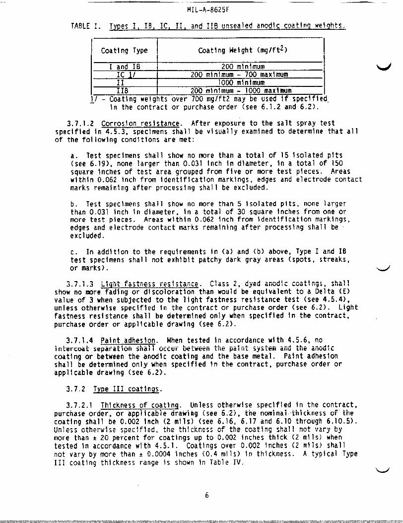
TABLE I. Types I, IB, ICI 11, and IIB unsealed anod!c coating wetqhts.
I I
I Coating Type I Coating Height (mg/ft2)
I 1 and IB 200 minimumIC 1/ 200 minimum- 700 maximum
I II 1000 minimumIIB 200m10imum - 1000 maxlnfum I
~J - Coating weights over 700mg/ft2 may be used if speclfled.h the contract or purchase order (see 6.1.2 and 6.2).
3.7.1.2 Corrosion resistance. After exposure to the salt spray testspecified In 4.5.3, specimens shall be visually examined to determtne that allof the following conditions are met:
a. Test specimens shall show no more than a total of 15 Isolated pits(see 6.19), none larger than 0.031 Inch in diameter, in a total of 150square inches of test area grouped from five or more test pieces. Areaswithin 0.062 Inch from tdentlflcatlonmarkings, edges and electrode contactmarks remalnlng after processing shall be excluded.
b. Test specimens shall show no more than 5 isolated pits, none largerthan 0.031 inch in diameter, In a total of 30 square tnches from one ormore test pieces. Areas wlthln 0.062 inch from Identfficatlonmarkings,edges and electrode contact marks remaining after processing shall be +excluded.
c. In add!tlon to the requirements in (a) and (b) above, Type I and 16test specimens shall not exhibit patchy dark gray areas (spots, streaks,or marks).
3.7.1.3 Light fastness resistance. Class 2, dyed anodic coatings, shallshow no more fading or discoloration than would be equivalent to a Delta (E)value of 3 when subjected to the light fastness resistance test (see 4.5.4),unless otherwise speclfled In the contractor purchase order (see 6.2). Lightfastness resistance shall be determined only when specified in the contract. .purchase order or applicable drawing (see 6.2).
3.7.1.4 Paint adhesion. Hhen tested In accordance with 4.5.6, nointercoat separation shall occur between the paint system and the anodlccoating or between the anodlc coathg and the base metal. Paint adhesionshall be determined only when speclfled in the contract, purchase order orapplicabledrawing (see 6.2).
3.7.2 Type III coatlnqs.
3.7.2.1 Thickness of coatinq. Unless otherwise spec~fied in the contract,purchase order, or applicable drawifig(see 6.2), the nodnalth!ckness of”thecoating shall be 0.002 inch (2 roils)(see 6.16, 6.17 and 6.10 through 6.10.5).Unless otherwise speclfled, the thickness of the coatfng shall not vary bymore than * 20 percent for coatings up to 0.002 inches thick (2 rolls)whentested in accordance with 4.5.1. Coatingsover 0.002 Inches (2 rolls)shallnot vary by more than * 0.0004 hches (0.4 roils)in thickness. A typical TypeIII coating thickness range !s shown fn Table IV.
6
MIL-A-HbZbt
3.7.2.1.1 Weiclhtofcoatlnq. The coatfng weight may be determined In lleuof the coatlnu thickness (see 3.7.2.1), at the option of the procuringactlvlty. Un~ealed Type III coatings shall have a mtnlmum coatlngwelghtof4320 miil\grams per square foot for every 0.001 fnch of coating when tested Inaccordance with 4.5.2 (see 6.2).
‘u 3.7.2.2 Abrasion resistance. When tested In accordance with 4.5.5,unsealed Type 111 coatings shall provide a hard abrasion resistant ffnish asspeclfled herein (see 6.17). The anod~c coattng shall have a maximum wearIndex of3.5 mg/1000 cycles on alumlnum alloys having a copper contentzof 2percent or higher (see 6.13). The wear Index for all other alloys shall notexceed 1.5 mg/1000 cycles.
3.8 Sealinq.
3.8.1 Types I, 16, IC, II, and IIB. All Types I, IB, IC, II, and IIBanodfc coatlnm shall be completely sealed, unless otherwise speclfled In thecontract, pur;hase order or applicable drawing (see 6.2). They shall besealedln accordance with 3.8.1.1 or 3.8.1.2 as applicable. If wetting agentsare used they shall be of the non-ionic type.
3.8.1.1 Class 1. Hhen class 1 is specified, sealing shall beaccomplishedby immersion in a sealing medium such as a 5 percent aqueoussolutlon of sodium or potassium bichromate (PH 5.0 to 6.0) for 15 minutes at90”C to 100*C (194°F to 212*F), in boiling deionized water, cobalt or nickelacetate, or other suitable chemical solutlons (see 6.15).
3.8.1.2 Class 2. When class 2 Is specified, sealing shall be accomplishedafter dyeing by immersion in a seallng medium, such as a hot aqueous solutioncontaining 0.5 percent nickel or cobalt acetate (pH 5.5 to 5.8), bolllng
b’ detonlzed water, duplex sealing with hot aqueous solutlons of nickel acetateand sodium bichromate (see 6.11), or other suitable chemical solutions.
3.8.2 Type IIL Type III coatings shall not be sealed where the mainfunctlonof application Is to obtain the max!mum degree of abrasion or wearreslstanceo Hhere Type III coatings are used for exter~or non-mainta~nedapplicationsrequiring corros~on resistance but permitting reduced abrasionresistance, the contract or purchase order shall specify that sealing Rrequired. Seallng for such Type 111 coatings shall be accomplished byimmersion in a medium, such as bollhgdelonfzed water, In a hot aqueous 5percent sodium dlchromate solution,:In ajhot aqueous solution contaln~ngnickel or cobalt acetate or other suitable chemical solutions (see 6.2). NhenType III coatings are provided unsealed, parts shall be thoroughly rinsed incold, clean water and dried after anodizfng.
7,!,‘3.9 Ohnensions of coated’art\~cles.~:lArtlclesor parts shall comply with
the dimensionalrequirements ofltheappllcable,d!rawings after appl~catlon ofthe anodfc coating (see 6.1OJ). (!ForInterference In close fits of parts orassemblies see 6.10.5).
3.10 Toxicity. The coatings and e?ectrlcal/chemicalprocesses used todevelop these anodlc coatings shallhave no adverse effect on the health ofpersonnel when used for their Intended purp,oses. Questtons pertinent to thfseffect shall be referred by the contracting actlvlty to the appropriatedepartmentalmedical service who will act as an advisor to the contracting
u agency.
7
MIL-A-8625F
3.11 Palntlng/coatln~. Palntlng/coatingoperations shall be performed assoon as pract~calafter the anodizfng process on clean coatings. If partsrequire storage prior to palntlng/coating,they shall be stored In a mannerthat wI1l avo!d contamination. If the parts become contaminated,they shallbe cleaned In a manner that will not be detrimental to the anodlc coatlngorthe base metal (see 6.3).
3.12 Dyeing or colorln$ Anodic coatings shall not be allowed to drybefore dyeing or colorlng. Items to be dyed or colored should be preferablycoated by the Type II anodlzhg treatment (see 6.12). Dyed or coloredcoatings shall not be allowed to remain In rinse waters for more than 5minutes before sealing.
3.13 Workmanship. Except for touch up areas In accordance with 3.3.4 andas noted below, the applled anodic coating shall be continuous,smooth,adherent, uniform in appearance, free from powdery areas, loose films, breaks,scratchesand other defects which will reduce the serviceabilityof anodizedparts or assembles. Differences in anodic coating appearanceresulting frominherent base metal differences h a component such as the presence of welds,components containingcast and machined surfaces,and differences tn grainsize within a forging shall not be cause to reject the anodic coating unlessotherwise specifiedIn the contract or purchaseorder (see 6.2). Slightdiscolorationfrom dripping or rundown of the sealing solutlonfrom designedcrevices in a component shall be allowed.
3.13.1 Contact marks. The size and number of contact marks shall be at aminimum consistentwith qood practice (see 6.14). If a specific location forcontact marks is desired; the-location shall be specified-onthe contract orpurchase order (see 6.2).
4. QUALITY ASSURANCE PROVISIONS
4.1 Responslb!lityfor Inspection. Unless otherwise specified In thecontract or purchaseorder, th@ contractor Is responsible for the performanceof all inspectionrequirements (examlnatlonsand tests) as spectfled herein.Except as otherulse specified ~n the contract or purchase order, thecontractor may use his own or any other facilities suitablefor theperformanceof the inspection requirements specified herein, unlessdisapproved by the Government. The Government reserves the rtght to performany of the InspectIonsset forth h the specificationwhere such InspectIonsare deemed necessaryto ensure supplies and services conform to prescribedrequirements.
4.1.1 Respons~billtyfor compliance. All Items must meet all recfulrementsof Section 3. The InspectIon set forth In this specificationshall become apartof the contractor’soverall inspection system or quality program. Theabsence of any Inspectionrequirements In the specificationshall not rellevethe contractorof the responslbilityof ensuring that all productsor suppliessubmittedto the Government for acceptance comply with all requirementsof thecontract. Sampling inspection,as part of manufacturingoperations, is anacceptable pract!ce to ascertain conformance to requirements,however, thisdoes not authorize submission of known defective material, either indicatedoractual, nor does it commit the Government to acceptance of defective material.
4.2 Classificationof !nspection. The inspection requirementsspecifiedherein are classifiedas follows:
8
MIL-A-8625F
a. Process control lnspectl~n (see 4.3).b. Quality conformance Inspection (see 4.4).
!. ::4.3 Process control Inspection. ‘-1
‘w 4.3.1 Process control document (PCD). The anodtzer shall develop,maintain,and adhere to a-PCD describing the anodizing process and proceduresused to meet the requirements of this specification. As a minimum, the PCDshall describe the following:
-All steps in the processing sequence.●
-Ranges for hnmersfon time and temperaturefor each step in the process.-Chemical constituents used and allowable solution control ranges to beused for solut~on analysls (see 4.3.2) for each stepW’i the process.
-Ranges for temperature,current density and anodizing the (or voltageramps and hold times) as applled to individual alloys or alloy series.
4.3.2 Solutlon analysts. Solutlon analysis shall be performed on all theprocessingsolutlons h the anodlzlng llneto determine If the solutioncontrolsire within the acceptable ranges established In the PCD (see-4.3.1).Solutionanalysis shall be performed at least once every two weeks unlessotherwise specified byv’t~,eprocurfng activity. The processor shall malntatn arecord of the history of each processing bath, showing all chemicalsOFtreatmentsolutions added to the baths and the results of all chemicalanalysisperformed. Upon request of the procuring activity, such records, aswell as reports of the test results, shall be made available. These recordsshall be maintained for not less than one year after completion of thecontractor purchase order.
‘~.’
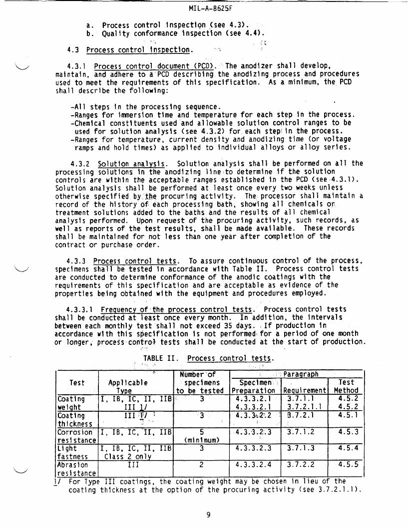
4.3.3 Process control tests. To assure continuous control of the process,specimensshall be tested tn accordance with Table II. Process control testsare conducted to determine conformance of the anodic coatings with therequirementsof this specification and are acceptable as evidence of thepropertiesbeing obtained with the equipment and procedures employed.
4.3.3.1 Frequency of’the process control tests. Process control testsshall be conducted at least once every month. In addlt~on, the intervalsbetweeneach monthly test ’shallnot exceed35 days. .If production inaccordancewith this s~eclflcatlon IS not performedfor a period of one monthor longer; processcontrol tests shall be conducted at the start of production.
J..-
TABLE II. Process control tests.~!,.3 .f,1<,$ IWnberof Paraqraph
Test Applicable spectmens Specimen :’ ~ TestType to be tested Preparation Requirement Method
Coating I, IB, IC, II, IIB “3 4.3.3.2.1 3.7.1.1 4.5.2welqht III / 4.3.3.2.1 3.7.2.1.1 4.5.2Coating III+] ; ‘3 4.3.3?02;.2 ~ 3.7.2.1 4.5.1thickness .. ,: , ,..Corrosion I, IB, It,”II, IIB 5 4.3*3.2.3 3.7.1.2 4.5.3resistance (minimum)Light I, IB, IC, 11, 116 3 4.3.3.2.3 3.7.1.3 4.5.4fastness Class 2 onlyAbrasion 111 2 4.3.3.2.4 3.7.2.2 4.5.5...w’ resistance~/ For Type 111 coatings, the coating weight may be chosen in lieu of the
coating thickness at the option of the procuring activity (see 3.7.2.1.1).
9
MIL-A-8625F
4.3.3.2 process control test specimens. Productionparts shall be usedfor process control ~nspectlonprovtded they can be adapted to the applicabletest. If the production parts can not be adapted to a particular test, testpanels shall be used. At the optlonof the supplier,test panels shall becomposedof either 2024-T3 per QQ-A-250/4 or the alloy representing thelargest percent of work anodized during the monthly process control period.Hhenever possible, the specfmen panels shall be anodized with an actual
M
production run. Additional details for the specimen panels shall be asspecified in 4.3.3.2.1 through 4.3.3.2.4.
4.3.3.2.1 Test specimens for coattng weight. Coating weight shall bedeterminedon undyed and unsealed production parts or specimen panels (see4.3.3.2). Mhen specimen panels are used, they shall have a mlnlmumwldthof 3Inches, a mlnlmum length of 3 Inches, and a mlnlmum nominal thickness of 0.032Inches.
4.3.3.2.2 Test specimens for coating thickness. Coating thickness shallbe determined on Type III production parts or spectmen panels (see 4.3.3.2).Hhen specimen panels are used, they shall have a minimum width of 3 Inches, amlnlmum length of 3 Inches, and a minimum nominal thickness of 0.032 tnches.
4.3.3.2.3 Test specimens for corrosion and light fastness resistance.Corros~on res~stance shall be determined on dyed (Class 2 only) and sealedproductionparts or specimen panels (see 4.3.3.2). Light fastness testing Isperformed onlyon dyed (Class 2) coatings and only when specified (see 6.2).Hhen specimen panels are used, they shall have a mlnlmum width of 3 inches, aminimum length of 10 Inches, and a minimum nominal thickness of 0.032 inches.
4.3.3.2.4 Test specimens for abrasion resistance. Abrasion resistanceshall be determinedon Type 111 production parts or specltnenpanels (see4.3.3.2). Hhen specimen panels are used, they shall have a wtdth of 4 fnches, #a length Of 4 inches, and a minimum nominal thicknessof 0.063 Inches.
4.3.4 Failure. Failure to conform to any of the process controlrequirementsspecifted tn Table II shall result In Immedtate halt ofproduction. The reason for failure shall be determined and corrected beforeproductionresumes. All traceable work from the time the failed processcontrol specimens were anodized to the time when production was halted shallbe re$ected unless otherwise speclf~ed by the contractingoff~cer. Traceablework shall be defined as all work in which the location is know. Processcontrol testing shall be performed at the start of production.
4.4 Qual~ty conformance (ie. lot acceptance) inspection. Qualityconformance tnspectlon shall consist of-tilw-al(see 4.4.2.1) and dlmens!onal(see4.4.2.2) examlnattons.(see 6.2.1). bihenspecified in the contractorpurfhaseorder (see 6.2), quality conformance InspectIonshall also Includepaint adhesion testing In accordance with 4.5L6.
4.4.1 Lot. A lot shall consist of all Items of the same part numberanodized Ifihe same tank using the same process and of the same coating typeand class offered for acceptance at one time. In addition, the lot size shallnot exceed the number of Items processed in one shtft.
10
MIL-A-8625F
4.4.z Sampl\nq for vlsuahand d~menslonal ekarn$natlons. Samples forvisual and dimensionalexaminations “(see’4.4.2-.land’4.4.2.2) shall beselected from each lot of anodized parts in accorda~ce with the provisions ofMIL-STD-105, InspectIon Level 11. The acceptancecrriteria shall be asspecified In the contract or purchase order (see 6.2 and 6.20). If no
“v acceptance cr~teria Is specified, the crl”teriaglvem In 6.20 shall be used... .
4.4.2.1 Visual examination. Samples selected In accordance with 4.4.2shall be inspected and visually examined for compliance with 3.13 afteranod!zlng, seallng and dyeing (tf applicable). .
4.4.2.2 Dimensional examdnatlon. Samples, seJected in accordance with4.4.2, shall be dimensionally \nspected for compliance with 3.9, unlessotherwise specified by the procur~ng activity (see 6.10.5).
4.4.3 Sampling for paint adhesion testing. Hhen the paint adhesion testis s~ec~fied (see 4.4), two test panels shall be tested In accordance with4.5.6 to determine conformanceto”3.7.1.4. The test panels shall be 3 Inches\nwidth by 10 Inches In length with a minimum nominal thickness of 0.032inches. Unless otherwise spedfled, the test-panels shall be composed ofeither 2024-T3 per mA-250/4 or the predoinlnafitalloy In the lot from whichthe paint adheston test is required to be performed. Unless another pahtsystem \s speclfled (see 6.2), the paint system in 4.4.3.1 shall be applied tothe anodized panels.
4.4.3.1 Preparationof paint adhesion specimens. Specimen panels (see4.4.3) shall be flnlshed with one coat of an epoxy-polyamide primer conformingto either fvIIL-P-23377(Class 1 or 2) or MIL-P-85582. In either case theprimer shall be applied to a dry film thickness of 0.0006 to O.0009 inch (0.6to O.9mll) and dried In accordance with the applicable primer specificationbefore testing In accordance w~th 4.5.6.
4.4.4 Failure. Failure to conform to any of the quallty conformancerequirementsshall result in rejection of the represented lot.
4.5 Test methods.
4.5.1 Anodlc coatlnq thickness. Test spec~mens prepared In accordancewith 4.3.3.2.2, shall be tested for anodtc coating %hlckness In accordancewith ASTM B 244, Method S20 or Method 520.1 of FEO-STD-151 to determineconformance to the requlrement$of 3.7.2.1. If either ASTM B 244 or Method520 of FED-STD-151 Is used, the thickness shall be computed as the average ofnot less than eight me?surement!s. In.case ofdlspute, anodlc coattng thicknessshall,be determined by;measurebnt of a perpendicular cross section of theanodized specimen ustng a metall[ogra,phlcmicrosco~e~ with a calibratedeyepiece.
,,.4.5.2 Anodfc coating welq’ht”jT@st%peclmens prepared In accordance with
4.3.3.2.1 shall be tested for’anodic cda’tlngwdlgh~telther in accordance withANSI/ASTM B 137, or the method spec~ifiedih-4.5.2.1. Type I, IB, IC, II, andIIB coatings shall be tested for conformance with the requirements of3.7.1.1. If the procuring activity chooses to have coating weight tested Inlleuof the coating thickness for Type 111 hard anodized coatings, it shall betested for conformancewith 3.7.2.1.1.
‘i_/
11
MIL-A-8625F
4.5.2.1 Method. Artodfc coating weight determinationsshall beaccomplishedh the followlng manner:
a. Test specimens shall be weighed Mnediatelyafter anodlzlng, prior todyeing or sealing. An analytical balance or other instrumentsenslttve toat least 10 percent of the net Anodlc coatfng weight on test spechnen 4shall be used. Speclrrtensshall be cleaned and dried for a minimum of 30minutes at 93ef 6*C (200°~ 10”F) and allowed to cml to room temperaturebefore weighing.
b. Immediatelyafter weightng, the test specimens shall be stripped byimmersion in a phosphoric-chromicacid solutionfor amhlmumof 5minutes, (not to exceed 6 minutes), at 100*~6°C (212°~ 10*F). Thesolution shall consist of the followlng:
Phosphoric acid, 85 percent 35 millilitersChrodc acid (Cr03) 20 gramsWater to make 1,000 rnlllfliters
c. The test specimens shall be removed from the solution, washed Indlst~lled water, dried, and weighed. The 5-fnhwte exposure shall berepeated until the coating h completely removed, whtch is Indicated bythe specimen’sweight remalntng constant. The stripping solutlon shall bediscarded after l-liter of the solutlon has dissolved 5 grams of theanodlc coating.
d. After final we~ghtng, the total surface area of the test specimenshall be accurately determined.
e. The unit film weight shall be determined by subtracting the weight hmilligrams of the stripped specimen from its weight In ndllfgrams prior to ~stripping and dividing by the surface area expressed in square feet.
4.5.3 Corrosion resistance.
4.5.3.1 Method. Test specimens, prepared in accordance with 4.3.3.2.3,shall be washed In distilled or deionized water, dried with a soft cloth andthen subjected to a 5 percent salt spray test tn accordance with ASTMB 117,except that the slgntflcantsurface shall be inclined 6 degrees from thevertical. Spechens shall be exposed for 336 hours. After exposure, specfmnsshall be examined to determine compliance with 3.7.1.2.
4.5.4 Light fastness resistance (Class 2 only). Test specfmens,preparedin accordance with 4.3.3.2.3, shall be tested for light fastness resistance byexposure to ultravioletradiation In accordance with-eitherASTM G 23, ASTM D-822 or ASTM G 26, for a period of 200 hours, except that the spec~mens wII1 beexposed continuously to llght without water spray. After exposure, specimensshall be compared with duplicate specimens not exposed to a light source forthe same period of time to determ~ne the Delta (E) value In accordance withASTM D 2244. The Delta (E) value shall be used to determine conformancewith3.7.1.3.
12
ldIL-A-8625F
4.5.5 Abrasion rieisistzu!ce.Te,s.,s-peel~ns, prepa~ed in accordance WIth4.3.3.2.4, shall be tested in accordance wj=thMetho~ 6192.l:of F~D-STD-141using CH7 wheels with a 1000.gr,a~:l.oad. ThelU&@JSshall revolve on theanod!c coatfng at a speed of 70 revolutions per minute (RPM) for 10,000cycles. The abrasion wheels shallbe refaced at,least once every 10,000cycles. The wear index shall be determined after the 10,000 cycle period bydlvldlng the weight loss by 10. The wear index shall meet the requirements of3.7.2.2.
4.5.6 Paint adhesion test. Hhen speclfled (see 4.4), spec~men panelsprepared In accordancerwith 4.4.3shall be tested for wet tape adhesion. Thetest shall be conducted as described in method 6301 of FED-STD-141 todeterfnlneconformance with paragraph 3.7.1.4.
5. PACKAGING (Not applicable to this speclflcation)
6. NOTES (This section contains informationof a general or explanatorynature that may be helpful but is not mandatory)
6.1 Intended use. The coatings covered in this.documentare Intended toylpvide corrosion resistance, improvedpalnt adhesion and abrasion resistanceas speclffed In 6.1.lthrough 6.1.3. .Thisdocument Is not Intended tosufficientlycover anodlc coatfngs for use in structuraladhesive bonding.
6.1.1 Types I, IB-andII. The:conventional Types I, IB and II anodiccoatingsare tntended to improve surface corrosion protection,under severeservice conditions or as a base for paint systems. Anodlc coatings can becolored wjth a large variety of dyes and pigments. Types I, IB and IIcoatings prov~de better corrosion.projection ,#thlgher cost than the chemicalconversion systems. Repair of mechanically damaged areas by the use ofmaterials conforming to MIL-C-8?706 (see 3.3.4) wII1 not restore abrasionresistancebut will iprovldean effective means of reestabl.,ishlngcorros~onresistance. Hhere anodic coatings are required on fatigue criticalcomponents,Type I and 16 coatings (see 6.1.2) are used due to the thtnness ofthe coating (see 6.10.7).
6.1.2 Type ICand 116. Type IC and HB coatings provideinon-chromatealternativesto Type I and IB coatings where~orroslon resistance, paintadhesion, and fatjguereslstance is required.~.Please note that Type ICor IIBnay not serve as suitable replacements when theeffects of electrolyteentrapments the pvlrnary:concern (see 3.3.1.2 and 3.3.1. ). Maximum Type IC
2and Type 116 coating weights of 700 mg/ft2 and 1000mg/ft , respectively, arespecified In Table I for fatigue purposes (see 6.10.7). If higher Type Kcoating weights are permissible for the Intended use, It should be specifiedIn the contract or purchase order (see 6.2). If Mgher Type IIB coathgweights are permissible for the intended use, Type II should be specified.
gf:: ?.------- ,..
6.1.3 Type 111. Type III coatings are intended to provide wear andabrasion resistant&Maces with Improved cofi~oslonprotection due to greaterthicknessand weight than the conventional anodic coatings. Sealing of Type111 coatings Is not!recommended unless corros~on resistance Is also a factor.Hear resistance Is reduced by seallng. tAnodlc;,coatingsform an excellent basefor most types of patfitsystems,adhesives and dryifllm lubricants. Hardcoatingsmay reduce fatigue strength. These factors should be considered Inproposed use of parts subjected to cyclic loads. Generally, these hardcoatings should not be used on parts or portions of parts which normallyduring rework would require restoring of dimensional tolerances because ofwear of hard coated surfaces.
13
MIL-A-8625F
6.1.3.1 Appllcatlons. Tj@e MI coat!ngs are used In such appllcat!ons asvalves, slidlng parts, hinge inechanlsms,cams, gears, swivel joints, pistons,rocket nozzles, Insulationplates, blast sh~elds, etc.
6.2 Acquisition requirements. Acqulsit~on documents should specify thefollowing: u
a.b.
::e.
f.
h.1.
1.m.
n.
o.
P*
Title, number and date of this specification.Type of anodic coating (see 1.2.1).Class ofanodic coating (see 1.2.2).Special process operating conditions, If applicable”(see 3:2).Special cleaning and fabrkatlon requirements (see 3.3.1, 3.3.2,and 3.3.3).If coating uelght for Type IC can exceed the maximum specified hTable 1.Color and uniformityof Class 2 coatings, if applicable (see 3.6.1and 3.12).Degree of non-uniformityof dyed casting alloys (see 3.6.1.1).Light fastness resistance, if applicable,and a Delta E value Ifdifferent than 3 (see 3.7.1.3).Type III coating thickness, Inapplicable (see 3.7.2.1).Coating weight for thickness, Type HI, If substituted(see 3.7.2.1.1).Special sealing requirements (see 3.8).Hhen applicable, the allowable difference In anodlc coatingappearance resulting from Inherent base metal differences(see 3.13).Provide the specific locatfon of contact marks if importantto thefunction of the part (see 3.13.1 and 6.14).Acceptance criteria for quality conformance inspections(see4.4.2 and 6.20).If paint adhesion testing Is required for quallty conformancetesting (see 4.4) and the required patnt system (if different thanthat in 4.4.3.1).
6.2.1 Consideration of data requirements. The followlng data requirementsshould be considered when this specification is applied on a contract. TheapplicableData Item i)escrlption-(DID) should be reviewed In conjunctionwiththe specific acquisition to ensure that only essential data arerequested/provtdedand that the DID is tailored to reflect the requirementsofthe spec!fic acquisition. To ensure correct contractual applicationof thedata requirements,a Contract Data RequirementsList (DD Form 1423) must beprepared to obtain the data, except where DOD FAR Supplement 27-4.75-1exemptsthe requirementfor a 00 Form 1423.
SuggestedReferencePara. DID Number DID TNle Tallorlnq
4;4 DI-NDTI-80809A TEST/INSPECTIONREPORTS 10.2.7.1
The above DID was cleared as of the date of this specification. The currentIssue of DCMl501O.12-L, Acquisition Management Systems and Data RequirementsCo’ntrolList (AMSDL), must be researched to ensure that only current, clearedDID’s are cited on the 00 Form 1423.
‘“%/
‘u
MIL-A-8625F
6.2.2 Exceptions’~odrawlnqs for types I, IB, IC, H, and:IIB. coatWs.Hhen the anodlc coating, type is not speclfled,on the drawtng,s’FjpeI; 18, IC,H, or HB maybe furnished within thellmltsof this spec~f!catton,at theoption of the contractor. When the+coating c~ass Is not speclfledon thedrawing, either Class 1 or Class 2 maybe supplted wlthln the llmltsofth~sspecification,at the option of the contractor.
6.3 Palntlng/coatlnq. When anodlccoatlngs are required to’bepainted/coated,the~piirtsshould be dried and @ainted as prcxii~tlyas possible,during which time, $posure to contam~n~atlonshould be kept to a mintmum.Prior to pa!ntlngor coating anodized parts, wiping, buffing or mechanicaloperations should be kept to a min~mum. This may’damage the less denseoutside layer of the anodlc coating making It susceptible to subsequentadhesion failures. Sealing processes can have a slgnfftcanteffect onadhesion of prfmers and other polymeric materials to the anodized surface aswell as the cohesive strength of the anodized layer. If these factors areImportantto the application, such as subsequentpainting operations, specificdetails for (or the omlsslon of) the sealing process should b.especlfled inthe contract or purchase order.
6.4 Electrolyticaction. Severe attack by the electrolyteon castings orwelds may be occasioned either by unsound cast!ngs, improper welding practice,a difference In composition between the weld and the base metal or,particularly In the case of the sulfuric acid process, the retentionof thesolution in cracks, creytces, or Irregular surfaces. Severe attack by theelectrolytemay also be caused by contaminants In the electrolyte,particularlychlorides or by Improper racking of the parts.
6.5 Anodlzlng rate. Alumlnum and alunhumalloys may be convenientlygrouped by anodlztng rate, especially In the case of the chromic acid process(Type I) for conventional coatings. However, either the chromic (Type I) orthe sulfurlc acid process (Type II) wI1l anodize mixed loads’satisfactorily,depending upon local processing preference. Suppllers are”cautioned that,especially in the sulfuric acid process, the anodizing time will have to besufficiently long to assure that the slower anodlzlng alloys”have at least aminimum coating thickness. In some cases, this may result InImpropercoatingson the fast anodizing alloys.
6.6 Color match. FED-STD-595 maybe used as a gu~de for specifying colorof anodic coatings. ‘Thecolor standards In FED-STD-595 are intendedfor paintfinishes and should be used for approximate comparison only $dth the anod”iccoatfngs (see 6.2).
.}, , .
6.7 Lapplnq. The Type III anodlc coatings generally have increasedsurface roughness as well as having the property of being less dense on thetop surface than in the core of the coating toward the base metal. Suchcoatfngsmay be processed oversized and then lapped or honed down to the finaldesired dimension.
6.8 Coating bat~s,,,,,For information, It should be notpd that processesproviding’other coatifig electrolyte; for the conventional coatings may beaqueous solutlons cpn-talningoxallc acid, boric acid plus ammonium borate andnitrides. There are proprietary processes requiring coating electrolytes,other than sulfuricacid, for the Type 111 coatings; for example, the various
MIL-A-8625F— .
Alumilltes, the Hartln Hard Coat, the Sanford, the Hardas and others. One ofthe Alumilite processes requires an aqueous solutlon contatnlng both sulfuricand oxal~c acids for the bath. Other baths used less frequently and forspecial purposes employ sulfosallcyllc,sulfamlc or sulfophthal~cacidsolutlons.
6.9 Chemical brlghtenlnq and pollshln~. Chemical brightening can bebeneficial by Improving the appearance and corrosfon resistance, In smoothingthe metall~c surface by removing certain contaminants and h enhancing thecontinuityof the anod~c coathgs on alumlnum alloys (see 3.3.3). The.percentageof reflectivity obtained from a part which has been electrolyticallybrightenedand subsequently anodized will depend on the alloy and the coatingthfckness. Certain alloys are more capable of obtaining a highly brightenedsurface and thicker anodlc coatings will reduce reflectivity.
6.10 Design information.
6.10.1 Surface dlmensfon of parts. On spectfytng the thickness ofcoatings, especially for the Type III coatings, allowance must be made fordtmenslonal Increase. Both amachtning dimension and a coated ditnenslonshouldbe placed on applicable drawings. An increase In d!menslon, equal to one halfof the thicknessof the applied coating, can be expected for each surfacecoated due to surface growth. For example, for a 0.004 inch (4 mtls) coatingon close tolerance parts, a pre-machiningallowance of 0.002 fnch (2 rni?s)persurface must be made prior to hard coating. If close fits are spec~fied indesign drawings, buildup tn thickness caused by anodfc coatings, especiallyType 111, may result In interferenceon assembly.
6.10.1.1 Holes. In the case of small holes and tapped holes, coatingthickness can.vary from no film to a full normal coating. Holes, both tappedand not tapped, over 1/4 inch should be anodized. Parts with Type IIcoatings,external or internal, with a total tolerance of 0.0004 Inch or less,If lapped, honed or stoned to size after anodizing, should be subsequentlytreated with QPL-81706 materials to provide surface protection. Dlscoloratlonon the surface that has been sized Is acceptable (see 6.6). The designer Iscautioned to require adequate thread and hole sealing operations h subsequentassembles as may be required to produce the necessary corrosion resistance.
6.10.2 Thread dimensions. All anodic coattngs will affect threadd~menslons for external and Internal threads; the major and minor diameterwIII be increased2 ttmes the amount of growth (see 6.10.1). The pitchdiameter for threads having an included angle of 60° wtll increase 4 t~mes theamount of growth. For threads having an Included angle, other than 60°, thepitch diameter will Increase 2 times the amount of growth (see 6.10.1) dlvldedby the sine of 1/2 the included angle.
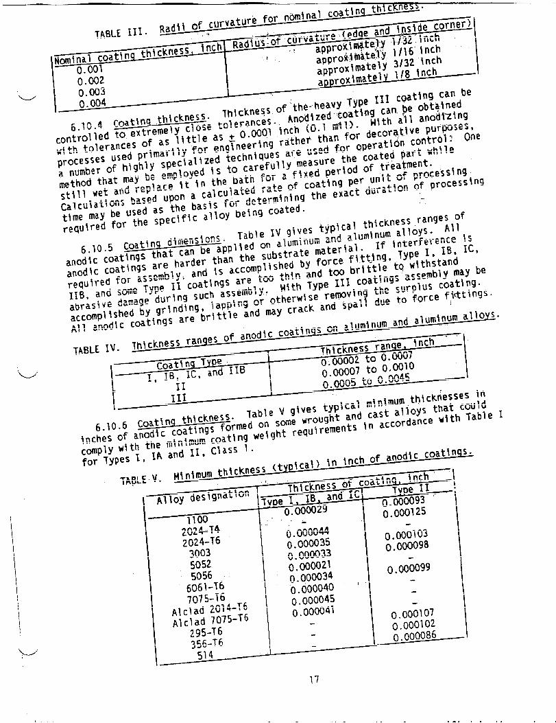
6.10.3 Fabrication. Successful use ofanodlc coatings, especially thehard Type III, depends on proper product design. Because of the manner offormation,anodlc coatings will develop vo~ds at sharp corners and edges.Sharp edges and corners are dlff!cult to anodize satisfactorilyand In generalshould be avoided. All edges and Inside corners should be radfused prior toanodizing. Chattering should not be used unless resulting sharp edges areradlused. In general, to avoid any uncoated edges or inside corners, theplerclng and blank!ng operations should comply with the radii of curvature fornominal coating thicknesses as in Table III.
16
..- ~h{fkness.
‘L/’”
approXlma~~.lJ...approx~mately 3/3:●–.LA1W 1/8
—
z inch~nch I
I
0.002().003
approx~ma~~~1~~,.
().()()4.— *TT -+ting can be
6.10.4 Coatlna thickness.
!obtatne.d
controlled to extremely close t~with tolerances
of as little as
_ 1 anodizing
used pr~marlly for en
;~a,tjvepurFJoses,
processesa number of highly specialized
.tid~ co~t~d~~ one
-Pd Dart while
method that may be employed k
lent.
still wet and replace \t \O th(based upon a calcl
pr0cess~n9
Calculations
~;lon of process~ng
—-..ha ~~q~das the b ‘-‘timemaY UC “...required for the
-----,(j~c COat
~ ~~~ckne$s of’t~e.~eavy Type 1~1 ‘W”o~eranceso Anod~zed:coatlngcan.be~~th all
+ 0.0001 ,inch(0.1 roll).lg~neerlngrather
than for dec(
techniques areused for opera
to carefully measure the coat:- ,Q bath for a ftxed period of treatrulated rate of
coating per unlf of
)as~s for determ~nlng the exact dur~-speciflc alloy t)e~ngcoated.
. - Table N givestypical thickness
~plted on aluminum and aluminum all
an the substrate materlal~ Ifaccomplished by force fittjn!
IS are tw thin and too br~ttl[lssemblYQ Mlth Type 111 coat~
g, \aPP~~9‘r otherwise remvtng th
ings are brittle and may crack and span W .
PSS ran@ of anodlc coatings on alumlnu~ and
ITh~ckness r?.
Tuna n fi
-~. Table V gives typtcal m~llin9s formed on some wrought and cas
mlnlmum coat~ng weight requirements In aand 11, Class 1.
..*_*-t*m thickness (tYP\cal) in Inchof
6.10.5 Coating d~menslons.anodlc coat~ngs that can be a{
~.-i~ter~erenCeIsg, Type 1$ ~B, IC,
anod\C coat~n9S are ‘ar~n~ ~~’requ!red for assembly,116, and sme Type 11 coating
e to withstandngs assembly may be
abrasive dama9e ‘urlng ‘“c!-!
~e surplus coating.
accompl~~hedby grlndin(
IQ to force fittings.f
All anoalumlnum allofi
TABLE IV. Th\ckn$me, \nch - ‘
.
1-
r0at\n9w~: ..- I “.WW2 to 0.W07--L- n Mlo
‘1L* *W,
! 11 -
111I
0.0005 to U.uuw”. —‘-,imum,thicknessesin
6.10.6 Coatin~ th!c~ne~Inches nf andtc coatl
,talloys that could~rcnrdance with Table
Cmp ~:for ~ anodlc coatln~s.
TA~LEV. rn~ni’’’”’”‘“.- , , .
Alloy designation
I I-~nn
\ i:
2024-T4 ()● 000044Z024-T6 ().0000353003 0 ● 000033s052 ().0000215056 ().0000346061-T6 ()● 0000407075-T6
Alclad 2014-T60.000045
Alclad 7075-T6().00004~
295-T6
I 356-T6514
1
0.0001030.000098
().ooio99:1
0.000107().000102().000086: i
●
MIL-A-8625F
6.10.7 Effect on fatlwe. The fatigue propertiesof ahmlf’wm alloys can beseverely reduced by anodlc coatings. The arnountof reductionvaries with theprocess= As a general rule, the ~hlcker the coating the greater the reductionIn fatigue will be.
6.11 Duplex seallnq. The corros~on resistance of dyed parts, especiallythose anodized in a sulfuric acid bath, Type II and HB, may be enhanced by
u
treatmentIn a sodfum bichromate solutton-eitherduring or after conventionalsealing u~th nickel acetate. This treatment can cause slight changes In thecolor of the dye. Paint systems adhere very sat!sfactorllyto.duplex-sealeddyed coattngs. However, where any objection with such duplex sealingapplicationIs warranted because of a firmly desired coloration,the dualprocess for seal!ng should not be used.
6.12 Dyelnq or coloring Type 1, IB, IC, and IIB coatings. Type I, IB, andIC coatings have a different pore structure and along with Type 116 coatingsare thinner than Type 11 coatings which makes them more dlfflcult to dye. Asa result, Type I, 16, IC, and IIB black anodized may not readtly obtainable.
6.13 Alloys havhq 2 percent or more copper content. Aluminum alloyshaving a nominal copper content of 2 percent or higher Includeall 2XXX seriesalloys, 7050 and 7178 (see 3.7.2.2).
6.14 Size of contact marks. In order toobtaln the desired currentdensity ufthout burning the parts, the size or number of contact marks will begreater on parts having higher surface areas. Because current density fS ameasure of the requtred current per square foot of aluminum being anodized, apart having twice as much surface area relative to another will require twiceas much current. Trying to force the higher currents required for largerparts through smaller contact areas sufficient for parts with lower surfaceareas may result In burning.
6.15 S.eallnq. The hot deionized water seal Is advantagesfrom anenvironmentalvlew~olnt. In addltlon, The use of a hot deionized water sealon Type I and IB coatings yields good-corrosion resistanceand may ellmlnatethe appearanceof patchy dark gray areas after salt spray exposure (see 6.18and 3.7.1.2).
6.16 Effects on coating thl.ckness. A hardcoat of 2 mfls or more hextremelydifficult to obtain on’high sll~cone die castings such as 360, 380,and 383.- It is recommended that this be considered when specifyinga coatingthicknessfor high sfllcone castings.
6.17 Effects of Type III coating thfckness on abras~on resistance. Theabrasionresistanceof Type III coatings will decrease as the coathg thicknessapproaches3 roils. In general, the abrasion resistancedoes not Increase withIncreasingcoating thickness.
6.18 Corrosion resistance of T.YpeI and IB coatings. Although plttlng maynot be visually evtdent with the unaided eye, the appearanceof dark grayareas on the surface after salt spray exposure is an WHcation of coatingdegradation. .
6.19 Definition of a Pit. A pit is defined as an areaof localizedcorrosionhaving a depth greater than its width. As a general rule, a pltusually displays a characteristic tall or llne (see 3.7.1.2). U’
18
MIL-A-8625F
6.20 Acceptance crlterla. Previous revisions of this document specifiedan Acceptable Quality Level (AQL) of 1.5 percent defective.
6.21 Supersedure data. Type 1, conventional chromic acid anodlzlng,referenced throughout th~s specification is the same as the Type IA designated
-’w” In the D revision and the Type I in all versions preceding the D revision.
6.22 Changes from previous Issue. Asterisks are not used in this revlslonto identify changes w!th respect to the previous Issue due to the extensivenessof the changes. .
6.23 Subject term (keyword) llstinq.
AluminumAluminum alloysAnodlc coatingsAnodlzlngChromatesChromic AcidPotassium BichromateSodium Bichromate
ik+=; Custodian:Army - MRNavy - ASAlr Force - H
Review activltles:Army - AR, AV, MINavy - OS, SHAlr Force - 70, 71, 80, 82, 85, 99
User activities:Army - AT, CR, ME
‘w’
Preparing actlvlty:Navy - AS
(Project no. MFFP-0493)
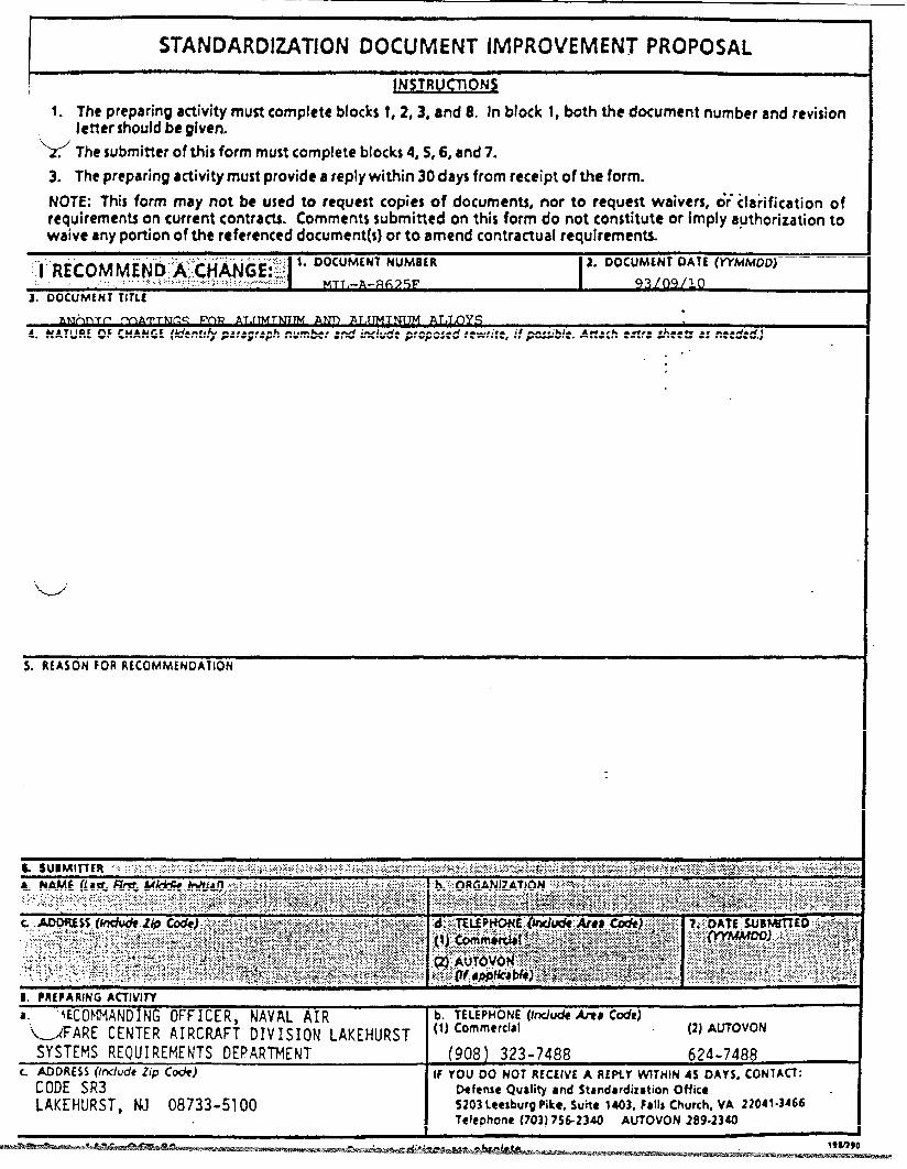
rSTANDARDIZATIONDOCUMENT IMPROVEMENT PROPOSAL
~14STRUCT10N$
I. Thepreparingactivitymust complete blocks !, 2, 34 and 8. In block 1,both the document numberand revisionJetter shouldbegiven.
“1< The submittef ofthisformmust completeblocks 4,5,6,and7.3. The preparingactivitymustprovide a reply within 30 days from receiptoftheform.
NOTE: This form may not be used to request copies of documents,nor to request waivers, d~Clarification ofrequirementson currentcontfads. Comments submitted on this form do not con$titutc or irnp~yauthorizationtowaiveanyportion of the referenceddocument(s)or to amend contractual requirements.
1. DOCUMENT NUMB[R‘“1’’RECOMME~’D::A:ttitiGE:::
X DOCUMLMY0A7t(YYMhfOOj.. ,....y,,.... .. .“ .’“.’:. .:::.....,.’.:.:..’..,’>’.’:“,.:::y..,.....:......’......... MT1..-
3. OOCUMENT TiTLC●
MATTNC.S& NATURE OF CHANGE (kdtntlfypatagtaph nutntw and inducit proposed rewrite, if ~“ble. Attach ●flra $/wets as needed.)
..“ ,.
‘d”
S. RfA$ON FOR RtCOMMtNDAllON
8. PRtPARltfG ACTIVIW
a. !ECOFMA~OING OFFICER, NAVAL AIR b. TELEPHONE(Mude tit Code)
‘G{FARE CENTER AIRCRAFT DIVISION LAKEHURST (1)Commercial (2) AUTOVON
SYSTEMS REQUIREMENTS DEPARTMENT (908).323-7488 624-7488L ADOFKSSOchdezipC*)
CODE SR3W YOU 00 NOT RECtlVt A REPLY WITHIN 45 OAY$, CONIA~:
Mfense Quality ●nd Standardization Office
LAKEHURST, NJ 08733-5100 5203 Ltesburg Pike, Suite 1403, falls Church, VA 22041-M66 “Telephone (703) 7S&23a AUTOVON 289.2340
Related Documents


