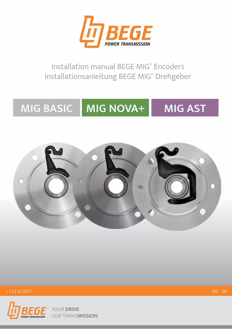
YOUR DRIVE. OUR TRANSMISSION. POWER TRANSMISSION POWER TRANSMISSION MIG NOVA+ MIG AST MIG BASIC Installation manual BEGE MIG ® Encoders Installationsanleitung BEGE MIG ® Drehgeber EN · DE v 1.2 | 10-2021

Welcome message from author
This document is posted to help you gain knowledge. Please leave a comment to let me know what you think about it! Share it to your friends and learn new things together.
Transcript
YOUR DRIVE. OUR TRANSMISSION.POWER TRANSMISSION
POWER TRANSMISSION
MIG NOVA+ MIG ASTMIG BASIC
Installation manual BEGE MIG® EncodersInstallationsanleitung BEGE MIG® Drehgeber
EN · DEv 1.2 | 10-2021
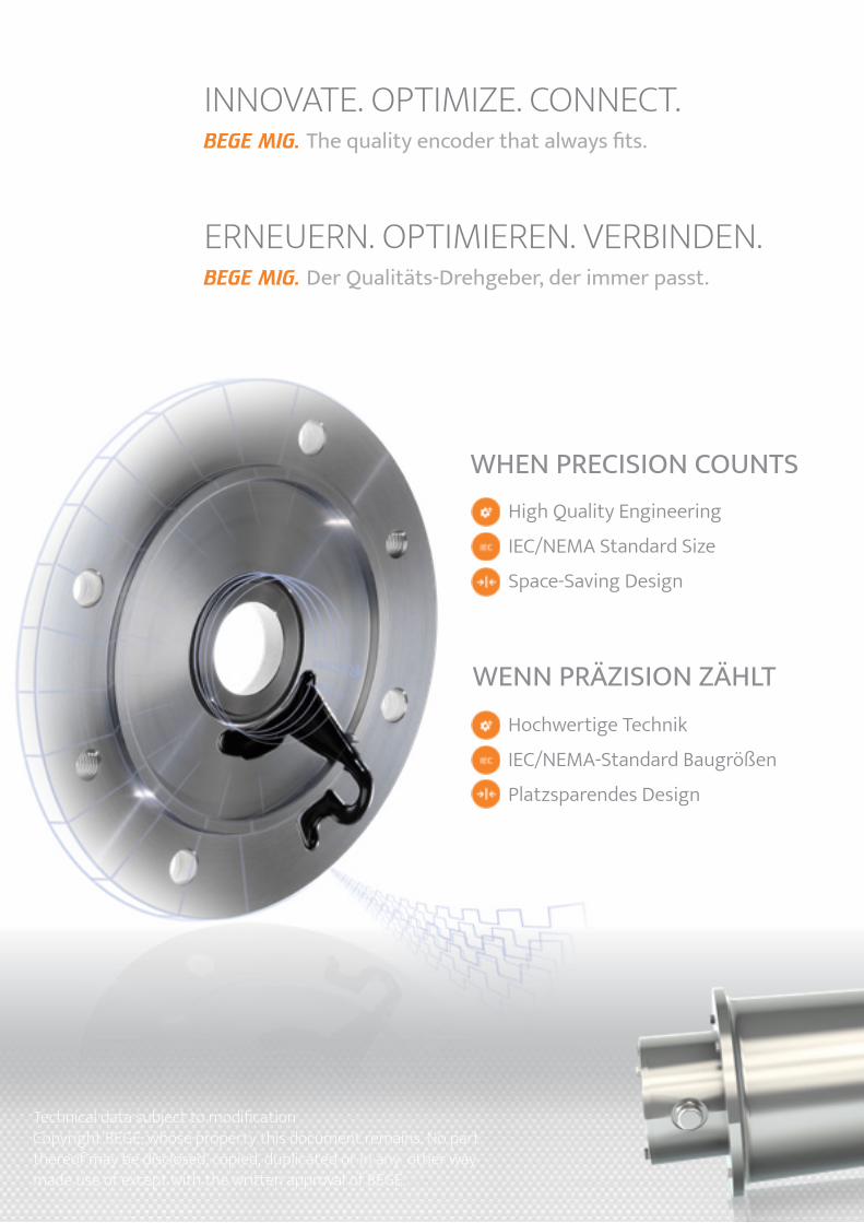
Der Qualitäts-Drehgeber, der immer passt.BEGE MIG.
ERNEUERN. OPTIMIEREN. VERBINDEN.
The quality encoder that always fits.BEGE MIG.
INNOVATE. OPTIMIZE. CONNECT.
Technical data subject to modificationCopyright BEGE, whose property this document remains. No part thereof may be disclosed, copied, duplicated or in any other way made use of except with the written approval of BEGE.
High Quality Engineering
IEC/NEMA Standard Size
Space-Saving Design
WENN PRÄZISION ZÄHLTHochwertige Technik
IEC/NEMA-Standard Baugrößen
Platzsparendes Design
WHEN PRECISION COUNTS
INHALTCONTENTS
ALLGEMEINE INFORMATIONEN
Sicherheitshinweise 4
Installationshinweise 5
Montage MIG® Drehgeber 6
MIG NOVA+ INKREMENTAL DREHGEBER
Technische Daten MIG NOVA+ 10
Anschlussbelegung und Signale MIG NOVA+ 11
MIG AST ABSOLUT DREHGEBER
Technische Daten MIG AST 12
Anschlussbelegung und Signale MIG AST 13
Kalibrieren MIG AST 14
GENERAL INFORMATION
Safety notes 4
Installation notes 5
Installation of the MIG encoder 6
MIG NOVA+ INCREMENTAL ENCODERS
Technical data MIG NOVA+ 10
Terminals & signals MIG NOVA+ 11
MIG AST ABSOLUTE ENCODERS
Technical data MIG AST 12
Terminals & signals MIG AST 13
Calibrating the MIG AST 14
MIG BASIC INKREMENTAL DREHGEBER
Technische Daten MIG BASIC 8
Anschlussbelegung und Signale MIG BASIC 9
MIG BASIC INCREMENTAL ENCODERS
Technical data MIG BASIC 8
Terminals & signals MIG BASIC 9

SICHERHEITSHINWEISE
4 SAFETY NOTES · SICHERHEITSHINWEISE
SAFETY NOTES
General safety notes BEGE MIG encoders are measuring instruments produced in accordance with recognized industrial regulations. The following basic safety instructions should be followed to avoid personal injury and damage to property.• The owner/operator must ensure, that the basic safety
instructions are respected and followed. Verify, that persons responsible for the system and the operation as well as those persons who work on the device of their own accord, have read and understood the documentation and installation manual completely. If anything is unclear or if further information is required, please contact us.
Qualified operating personnel are persons who have an appropriate professional qualification and are familiar with the execution of the work specified above.
Serious personal injuries and property damage can occur due to• improper use• incorrect installation or operation• prohibited removal of the necessary protective covers
BEGE can not be held responsible for any injury or damage caused.
Installation safety notes• Observe the professional safety and accident
prevention regulations applicable to your country.• Switch off the voltage to all the devices/machines
related to the (de-)installation of the encoder. Never electrically connect or disconnect the encoder with the voltage switched on, this may lead to damage of the encoder.
• Always avoid damaging the encoder in any way• For proper operation of the devices close attention
must be paid to good earthing of the screen connection according to EMC standard. (Cable screening and MIG body both should carefully be connected to earth.)
• All handling concerning the transport, storage, installation/assembly, start-up procedures and maintenance may only be performed by qualified personnel. To be observed thereby:
• the information contained in the instruction manual• the identification on the encoder• the system-specific provisions and requirements• the professional safety and accident prevention
regulations applicable to your country• that, during all work, personal protective equipment
(e.g. safety shoes, gloves, safety glasses) is to be worn.
Allgemeine SicherheitshinweiseBEGE MIG-Drehgeber sind Messgeräte, die nach den anerkannten Regeln der Technik hergestellt werden. Die folgenden grundlegenden Sicherheitshinweise dienen der Vermeidung von Personen- und Sachschäden.• Der Betreiber hat dafür Sorge zu tragen, dass die
grundlegenden Sicherheitshinweise beachtet und eingehalten werden. Stellen Sie sicher, dass die für das System und den Betrieb verantwortlichen Personen sowie die Personen, die eigenverantwortlich am Gerät arbeiten, die Dokumentation vollständig gelesen und verstanden haben. Wenn etwas unklar ist oder weitere Informationen benötigt werden, kontaktieren Sie uns bitte.
Qualifiziertes Bedienpersonal sind Personen, die über eine entsprechende fachliche Qualifikation verfügen und mit der Durchführung der oben genannten Arbeiten vertraut sind.
Es kann zu schweren Personen- und Sachschäden kommen• fehlerhafte Verwendung• falsche Installation oder Bedienung• verbotene Entfernung der notwendigen Schutzabdeckungen
BEGE haftet nicht für Fehler und möglicherweise dadurch verursachte Schäden oder Mängel.
Sicherheitshinweise zur Installation• Beachten Sie die in Ihrem Land geltenden
berufsgenossenschaftlichen Sicherheits- und Unfallverhütungsvorschriften.
• Schalten Sie alle an der (De-) Installation des Drehgebers beteiligten Geräte/Maschinen spannungsfrei. Niemals den Geber bei eingeschalteter Spannung elektrisch anschließen oder trennen, da sonst der Drehgeber beschädigt werden kann.
• Vermeiden Sie immer, den Drehgeber zu beschädigen.• Für den ordnungsgemäßen Betrieb des Drehgebers ist auf
eine gute Erdung des Schirmanschlusses nach EMV-Norm zu achten. (Kabelabschirmung und MIG-Flansch müssen sorgfältig geerdet werden.)
• Die Arbeiten bezüglich Transport, Lagerung, Installation/Montage, Inbetriebnahme, Wartung und Instandhaltung dürfen nur von qualifiziertem Fachpersonal durchgeführt werden. Dabei zu beachten:
• die in dieser Anleitung enthaltenen Informationen• der Angabe auf dem Typenschild des Drehgebers• die anlagenspezifischen Bestimmungen und Anforderungen• die in Ihrem Land geltenden berufsgenossenschaftlichen
Sicherheits- und Unfallverhütungsvorschriften• dass bei allen Arbeiten die persönliche Schutzausrüstung
(z. B. Sicherheitsschuhe, Handschuhe, Schutzbrille) getragen werden muss.
5INSTALLATION NOTES · INSTALLATIONSHINWEISE
Before commissioning, all required wires are to be connected according to the instruction manual.
Please isolate unused connection wires to protect against short-circuits.
This symbol indicates a general danger
In order to obtain CE-Conformity, EMC installation conformity should be observed.
Continuous shielded cables with twisted wire pairs should be used pairs.
The cable shield should ideally be connected fully enclosed (360 °C) by shielded connectors or cable glands. This has to be done at the encoder and transmission end.
The protection earth should preferably be connected with low impedance on both front and rear side of the encoder and the transmission end.
In case of earth loop problems, the protection earth at the encoder side has to be removed. In this instance, the encoder should be mounted electrically isolated from the transmission.
The encoder cable should run separately to cables with high noise levels and high power cables (e.g. frequency converter etc.)
Consumers with high interference levels, e.g. frequency converters, solenoid valves, contactors etc. should not be connected to the same voltage supply.
Vor Inbetriebnahme sind alle benötigten Kabeladern laut Datenblatt anzuschließen!
Isolieren Sie alle nicht benötigten Enden sauber, um Kurzschlüsse zu vermeiden.
Dieses Symbol weist auf eine allgemeine Gefahr hin
Um CE-Konformität zu erreichen, ist eine EMV-gerechte Installation Voraussetzung:
Als Steuerleitungen sind durchgehend geschirmte Kabel mit verdrillten Aderpaaren zu verwenden.
Der Kabelschirm wird idealerweise rundum (360 °C) über schirmbare Stecker oder Kabeldurchführungen an den Drehgeber und die Auswertung angelegt.
Die Schutzerde (PE) ist bevorzugt beidseitig, am Drehgeber und an der Auswertung, impedanzarm aufzulegen.
Bei Problemen durch Erdschleifen ist die Schutzerde (PE) auf der Drehgeberseite aufzutrennen. Der Drehgeber sollte hierfür gegenüber dem Antrieb elektrisch isoliert angebaut werden.
Die Drehgeberleitungen sind getrennt von Leitungen mit hohem Störpegel und Hochleistungsleitungen (z.B. Frequenzumrichter usw.) zu verlegen.
An der Spannungsversorgung des Gebers sollten keine Verbraucher mit hohem Störpegel, wie z.B. Frequenzumrichter, Magnetventile, Schütze usw. angeschlossen werden. Andernfalls ist für eine geeignete Spannungsfilterung zu sorgen.
INSTALLATIONSHINWEISEINSTALLATION NOTES
1 32
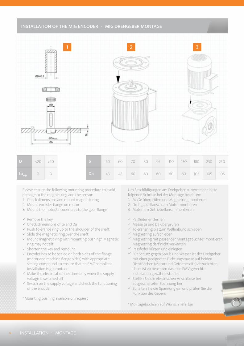
Um Beschädigungen am Drehgeber zu vermeiden bitte folgende Schritte bei der Montage beachten:1. Maße überprüfen und Magnetring montieren2. Drehgeberflansch am Motor montieren3. Motor am Getriebeflansch montieren
3 Paßfeder entfernen 3 Masse ta und Da überprüfen 3 Toleranzring bis zum Wellenbund schieben 3 Magnetring aufschieben 3 Magnetring mit passender Montagebuchse* montieren Magnetring darf nicht verkanten
3 Passfeder kürzen und einlegen 3 Für Schutz gegen Staub und Wasser ist der Drehgeber mit einer geeigneter Dichtungsmasse auf beiden Dichtflächen (Motor und Getriebeseite) abzudichten, dabei ist zu beachten das eine EMV-gerechte Installation gewährleistet ist
3 Stellen Sie die elektrischen Anschlüsse bei ausgeschalteter Spannung her
3 Schalten Sie die Spannung ein und prüfen Sie die Funktion des Gebers
* Montagebuchsen auf Wunsch lieferbar
INSTALLATION OF THE MIG ENCODER · MIG DREHGEBER MONTAGE
Please ensure the following mounting procedure to avoid damage to the magnet ring and the sensor:1. Check dimensions and mount magnetic ring 2. Mount encoder flange on motor 3. Mount the motor/encoder unit to the gear flange
3 Remove the key 3 Check dimensions of ta and Da 3 Push tolerance ring up to the shoulder of the shaft 3 Slide the magnetic ring over the shaft 3 Mount magnetic ring with mounting bushing*. Magnetic ring may not tilt
3 Shorten the key and remount 3 Encoder has to be sealed on both sides of the flange (motor and machine flange sides) with appropriate sealing compound, to ensure that an EMC compliant installation is guaranteed
3 Make the electrical connections only when the supply voltage is switched off
3 Switch on the supply voltage and check the functioning of the encoder
* Mounting bushing available on request
6 INSTALLATION · MONTAGE
D <20 >20
tamin 2 3
b 50 60 70 80 95 110 130 180 230 250
Da 43 43 60 60 60 60 60 105 105 105
7INSTALLATION · MONTAGE
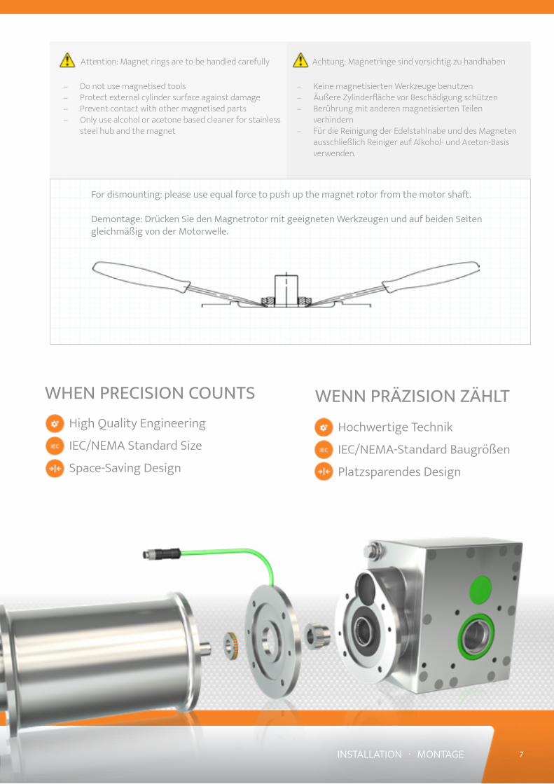
Achtung: Magnetringe sind vorsichtig zu handhaben
– Keine magnetisierten Werkzeuge benutzen – Äußere Zylinderfläche vor Beschädigung schützen – Berührung mit anderen magnetisierten Teilen
verhindern – Für die Reinigung der Edelstahlnabe und des Magneten
ausschließlich Reiniger auf Alkohol- und Aceton-Basis verwenden.
Attention: Magnet rings are to be handled carefully
– Do not use magnetised tools – Protect external cylinder surface against damage – Prevent contact with other magnetised parts – Only use alcohol or acetone based cleaner for stainless
steel hub and the magnet
For dismounting: please use equal force to push up the magnet rotor from the motor shaft.
Demontage: Drücken Sie den Magnetrotor mit geeigneten Werkzeugen und auf beiden Seiten gleichmäßig von der Motorwelle.
High Quality Engineering
IEC/NEMA Standard Size
Space-Saving Design
WENN PRÄZISION ZÄHLTHochwertige Technik
IEC/NEMA-Standard Baugrößen
Platzsparendes Design
WHEN PRECISION COUNTS
MIG BASIC INKREMENTAL DREHGEBER
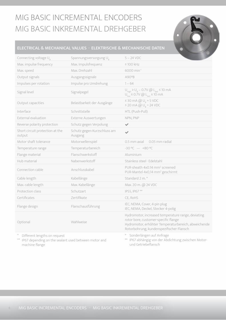
8 MIG BASIC INCREMENTAL ENCODERS · MIG BASIC INKREMENTAL DREHGEBER
MIG BASIC INCREMENTAL ENCODERS
ELECTRICAL & MECHANICAL VALUES · ELEKTRISCHE & MECHANISCHE DATEN
Connecting voltage UB Spannungsversorgung UB 5 – 24 VDC
Max. impulse frequency Max. Impulsfrequenz ≤ 100 kHz
Max. speed Max. Drehzahl 6000 min-1
Output signals Ausgangssignale A90°B
Impulses per rotation Impulse pro Umdrehung 1 – 64
Signal level Signalpegel Uhigh ≥ UB – 0.7V @ Llast ≤ 10 mAUlow ≤ 0.7V @ Llast ≤ 10 mA
Output capacities Belastbarkeit der Ausgänge ≤ 30 mA @ UB = 5 VDC≤ 20 mA @ UB = 24 VDC
Interface Schnittstelle HTL (Push-Pull)
External evaluation Externe Auswertungen NPN, PNP
Reverse polarity protection Schutz gegen Verpolung
Short circuit protection at the output
Schutz gegen Kurzschluss am Ausgang
Motor shaft tolerance Motorwellenspiel 0.5 mm axial 0.05 mm radial
Temperature range Temperaturbereich -30 °C — +80 °C
Flange material Flanschwerkstoff Aluminium
Hub material Nabenwerkstoff Stainless steel · Edelstahl
Connection cable Anschlusskabel PUR-sheath 4x0.14 mm2 screenedPUR-Mantel 4x0,14 mm2 geschirmt
Cable length Kabellänge Standard 2 m. *
Max. cable length Max. Kabellänge Max. 20 m. @ 24 VDC
Protection class Schutzart IP55, IP67 **
Certificates Zertifikate CE, RoHS
Flange design Flanschausführung IEC, NEMA, Cover, 4-pin plugIEC, NEMA, Deckel, Stecker 4-polig
Optional Wahlweise
Hydromotor, increased temperature range, deviating rotor bore, customer-specific flange Hydromotor, erhöhter Temperaturbereich, abweichende Rotorbohrung, kundenspezifischer Flansch
Sonderlängen auf AnfrageIP67 abhängig von der Abdichtung zwischen Motor- und Getriebeflansch
Different lengths on requestIP67 depending on the sealant used between motor and machine flange
***
***
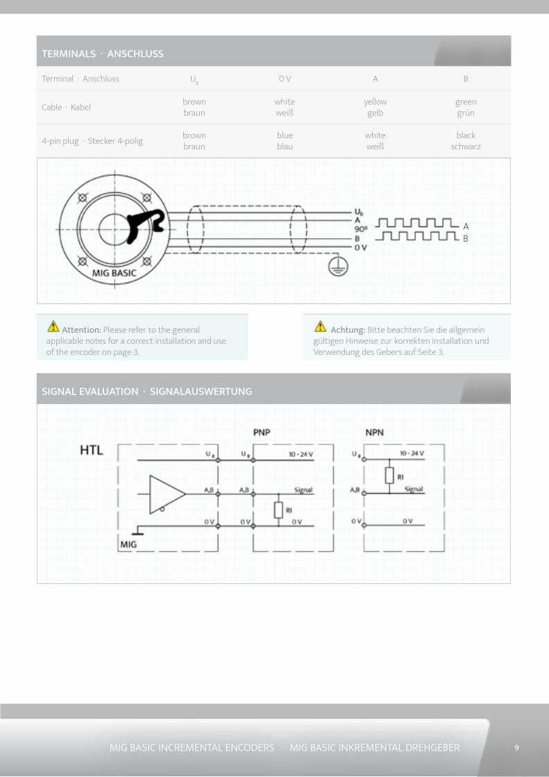
Attention: Please refer to the general applicable notes for a correct installation and use of the encoder on page 3.
Achtung: Bitte beachten Sie die allgemein gültigen Hinweise zur korrekten Installation und Verwendung des Gebers auf Seite 3.
SIGNAL EVALUATION · SIGNALAUSWERTUNG
AB
MIG BASIC INCREMENTAL ENCODERS · MIG BASIC INKREMENTAL DREHGEBER 9
TERMINALS · ANSCHLUSS
Terminal · Anschluss UB 0 V A B
Cable · Kabel brown braun
white weiß
yellow gelb
green grün
4-pin plug · Stecker 4-polig brown braun
blue blau
white weiß
black schwarz
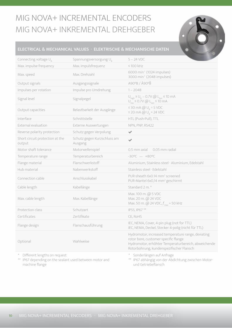
MIG NOVA+ INKREMENTAL DREHGEBERMIG NOVA+ INCREMENTAL ENCODERS
ELECTRICAL & MECHANICAL VALUES · ELEKTRISCHE & MECHANISCHE DATEN
Connecting voltage UB Spannungsversorgung UB 5 – 24 VDC
Max. impulse frequency Max. Impulsfrequenz ≤ 100 kHz
Max. speed Max. Drehzahl 6000 min-1 (1024 impulses) 3000 min-1 (2048 impulses)
Output signals Ausgangssignale A90°B / Ā90°B
Impulses per rotation Impulse pro Umdrehung 1 – 2048
Signal level Signalpegel Uhigh ≥ UB – 0.7V @ Llast ≤ 10 mAUlow ≤ 0.7V @ Llast ≤ 10 mA
Output capacities Belastbarkeit der Ausgänge ≤ 30 mA @ UB = 5 VDC≤ 20 mA @ UB = 24 VDC
Interface Schnittstelle HTL (Push-Pull), TTL
External evaluation Externe Auswertungen NPN, PNP, RS422
Reverse polarity protection Schutz gegen Verpolung
Short circuit protection at the output
Schutz gegen Kurzschluss am Ausgang
Motor shaft tolerance Motorwellenspiel 0.5 mm axial 0.05 mm radial
Temperature range Temperaturbereich -30°C — +80°C
Flange material Flanschwerkstoff Aluminium, Stainless steel · Aluminium, Edelstahl
Hub material Nabenwerkstoff Stainless steel · Edelstahl
Connection cable Anschlusskabel PUR-sheath 6x0.14 mm2 screenedPUR-Mantel 6x0,14 mm2 geschirmt
Cable length Kabellänge Standard 2 m. *
Max. cable length Max. KabellängeMax. 100 m. @ 5 VDCMax. 20 m. @ 24 VDCMax. 50 m. @ 24 VDC, ƒmax = 50 kHz
Protection class Schutzart IP55, IP67 **
Certificates Zertifikate CE, RoHS
Flange design Flanschausführung IEC, NEMA, Cover, 4-pin plug (not for TTL) IEC, NEMA, Deckel, Stecker 4-polig (nicht für TTL)
Optional Wahlweise
Hydromotor, increased temperature range, deviating rotor bore, customer-specific flange Hydromotor, erhöhter Temperaturbereich, abweichende Rotorbohrung, kundenspezifischer Flansch
Sonderlängen auf AnfrageIP67 abhängig von der Abdichtung zwischen Motor- und Getriebeflansch
Different lengths on requestIP67 depending on the sealant used between motor and machine flange
***
***
10 MIG NOVA+ INCREMENTAL ENCODERS · MIG NOVA+ INKREMENTAL DREHGEBER
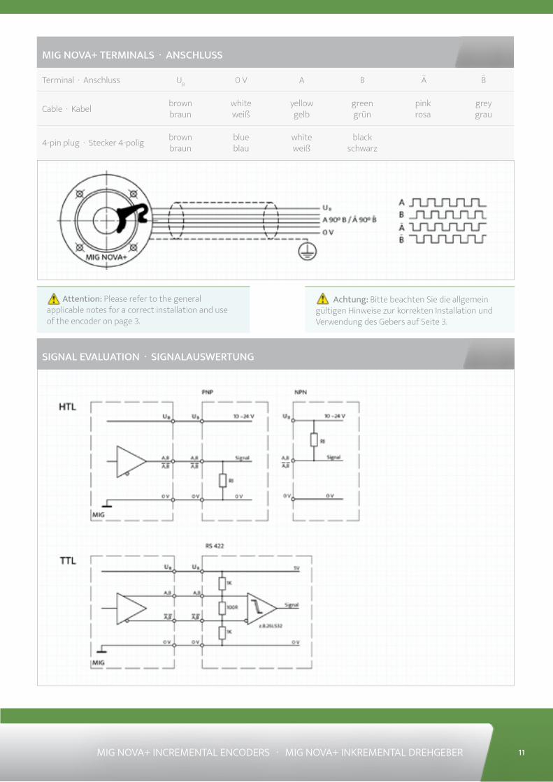
Attention: Please refer to the general applicable notes for a correct installation and use of the encoder on page 3.
Achtung: Bitte beachten Sie die allgemein gültigen Hinweise zur korrekten Installation und Verwendung des Gebers auf Seite 3.
SIGNAL EVALUATION · SIGNALAUSWERTUNG
MIG NOVA+ TERMINALS · ANSCHLUSS
Terminal · Anschluss UB 0 V A B A B
Cable · Kabel brown braun
white weiß
yellow gelb
green grün
pink rosa
grey grau
4-pin plug · Stecker 4-polig brown braun
blue blau
white weiß
black schwarz
MIG NOVA+ INCREMENTAL ENCODERS · MIG NOVA+ INKREMENTAL DREHGEBER 11
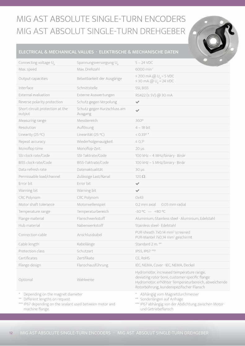
12 MIG AST ABSOLUTE SINGLE-TURN ENCODERS · MIG AST ABSOLUT SINGLE-TURN DREHGEBER
ELECTRICAL & MECHANICAL VALUES · ELEKTRISCHE & MECHANISCHE DATEN
Connecting voltage UB Spannungsversorgung UB 5 – 24 VDC
Max. speed Max. Drehzahl 6000 min-1
Output capacities Belastbarkeit der Ausgänge ≤ 200 mA @ UB = 5 VDC≤ 30 mA @ UB = 24 VDC
Interface Schnittstelle SSI, BiSS
External evaluation Externe Auswertungen RS422 (± 5V) @ 30 mA
Reverse polarity protection Schutz gegen Verpolung
Short circuit protection at the output
Schutz gegen Kurzschluss amAusgang
Measuring range Messbereich 360°
Resolution Auflösung 4 – 18 bit
Linearity (25 °C) Linearität (25 °C) < 0.35° *
Repeat accuracy Wiederholgenauigkeit ≤ 0,1°
Monoflop time Monoflop-Zeit. 20 µs
SSI clock rate/Code SSI-Taktrate/Code 100 kHz – 4 MHz/binary · Binär
BiSS clock rate/Code BiSS-Taktrate/Code 100 kHz – 5 MHz/binary · Binär
Data refresh rate Datenaktualität 30 µs
Permissable load/channel Zulässige Last/Kanal 120 Ω
Error bit Error bit
Warning bit Warning bit
CRC Polynom CRC Polynom 0x43
Motor shaft tolerance Motorwellenspiel 0.2 mm axial 0.05 mm radial
Temperature range Temperaturbereich -30 °C — +80 °C
Flange material Flanschwerkstoff Aluminium, Stainless steel · Aluminium, Edelstahl
Hub material Nabenwerkstoff Stainless steel · Edelstahl
Connection cable Anschlusskabel PUR-sheath 7x0.14 mm2 screened PUR-Mantel 7x0,14 mm2 geschirmt
Cable length Kabellänge Standard 2 m. **
Protection class Schutzart IP55, IP67 ***
Certificates Zertifikate CE, RoHS
Flange design Flanschausführung IEC, NEMA, Cover · IEC, NEMA, Deckel
Optional Wahlweise
Hydromotor, increased temperature range, deviating rotor bore, customer-specific flange Hydromotor, erhöhter Temperaturbereich, abweichende Rotorbohrung, kundenspezifischer Flansch
MIG AST ABSOLUTE SINGLE-TURN ENCODERSMIG AST ABSOLUT SINGLE-TURN DREHGEBER
Abhängig vom MagnetdurchmesserSonderlängen auf AnfrageIP67 abhängig von der Abdichtung zwischen Motor- und Getriebeflansch
Depending on the magnet diameterDifferent lengths on requestIP67 depending on the sealant used between motor and machine flange.
******
******
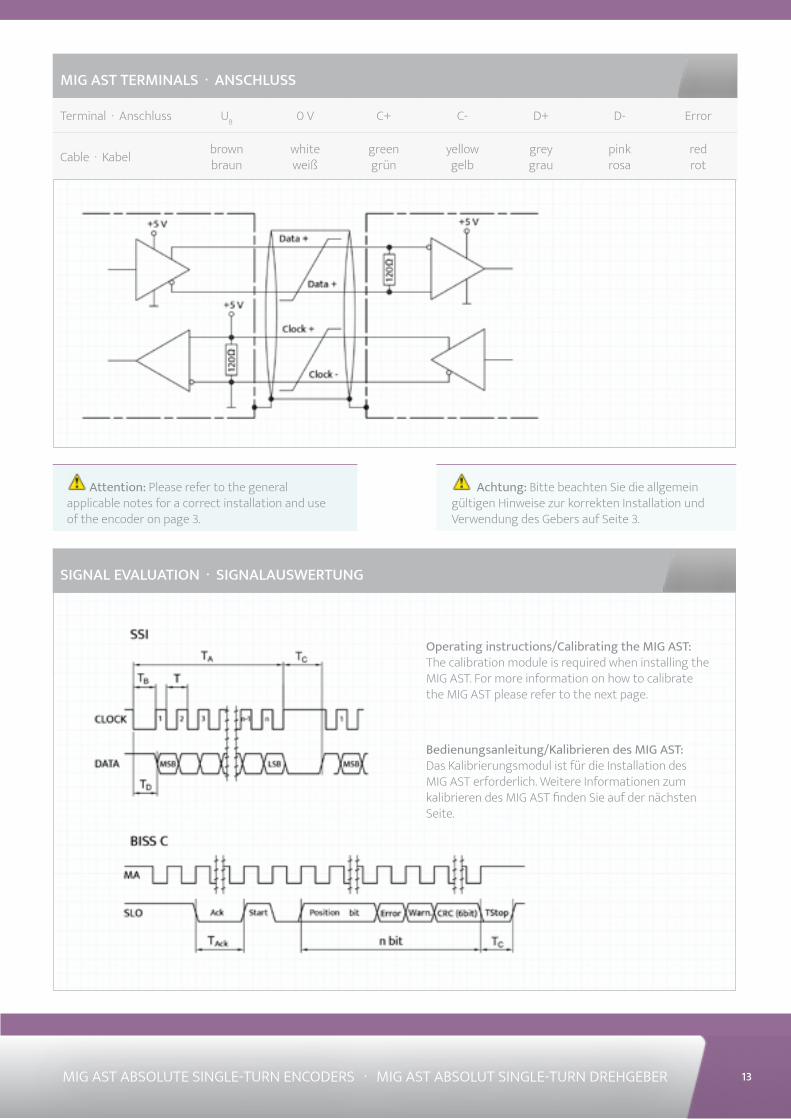
MIG AST TERMINALS · ANSCHLUSS
Terminal · Anschluss UB 0 V C+ C- D+ D- Error
Cable · Kabel brown braun
white weiß
green grün
yellow gelb
grey grau
pink rosa
red rot
13MIG AST ABSOLUTE SINGLE-TURN ENCODERS · MIG AST ABSOLUT SINGLE-TURN DREHGEBER
Attention: Please refer to the general applicable notes for a correct installation and use of the encoder on page 3.
Achtung: Bitte beachten Sie die allgemein gültigen Hinweise zur korrekten Installation und Verwendung des Gebers auf Seite 3.
SIGNAL EVALUATION · SIGNALAUSWERTUNG
Operating instructions/Calibrating the MIG AST: The calibration module is required when installing the MIG AST. For more information on how to calibrate the MIG AST please refer to the next page.
Bedienungsanleitung/Kalibrieren des MIG AST: Das Kalibrierungsmodul ist für die Installation des MIG AST erforderlich. Weitere Informationen zum kalibrieren des MIG AST finden Sie auf der nächsten Seite.
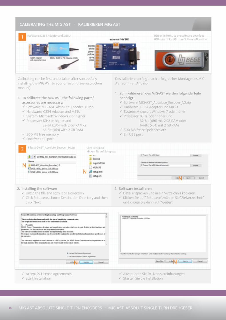
1
2
Das kalibrieren erfolgt nach erfolgreicher Montage des MIG-AST auf Ihren Antrieb.
1. Zum kalibrieren des MIG-AST werden folgende Teile benötigt.
3 Software: MIG-AST_Absolute_Encoder_1.0.zip 3 Hardware: IC334 Adapter und MB5U 3 System: Microsoft Windows 7 oder höher 3 Processor: 1GHz oder höher und
32-Bit (x86) mit 2 GB RAM oder64-Bit (x64) mit 2 GB RAM
3 500 MB freier Speicherplatz 3 Ein USB port
CALIBRATING THE MIG AST · KALIBRIEREN MIG AST
Calibrating can be first undertaken after successfully installing the MIG AST to your drive unit (see instruction manual).
1. To calibrate the MIG AST, the following parts/accessories are necessary:
3 Software: MIG-AST_Absolute_Encoder_1.0.zip 3 Hardware: IC334 Adaptor and MB5U 3 System: Microsoft Windows 7 or higher 3 Processor: 1GHz or higher and
32-Bit (x86) with 2 GB RAM or64-Bit (x64) with 2 GB RAM
3 500 MB free memory 3 One free USB port
Hardware: IC334 Adaptor and MB5U USB or link/URL to the software download USB oder Link / URL zum Software-Download
NN
File: MIG-AST_Absolute_Encoder_1.0.zip Click Setup.exeKlicken Sie auf Setup.exe
N
2. Software installieren 3 Datei entpacken und in ein Verzeichnis kopieren 3 Klicken Sie auf “Setup.exe”, wählen Sie “Zielverzeichnis” und klicken Sie dann auf “Weiter”.
2. Installing the software 3 Unzip the file and copy it to a directory 3 Click Setup.exe, choose Destination Directory and then click ‘Next’
N N
3 Akzeptieren Sie 2x Lizenzvereinbarungen 3 Starten Sie die Installation
3 Accept 2x License Agreements 3 Start Installation
14 MIG AST ABSOLUTE SINGLE-TURN ENCODERS · MIG AST ABSOLUT SINGLE-TURN DREHGEBER
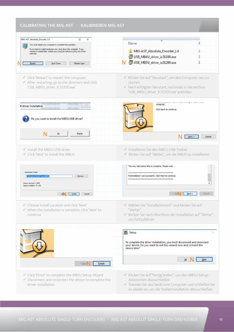
NN
N N
N N
NN
3 Klicken Sie auf “Neustart”, um den Computer neu zu starten
3 Nach erfolgten Neustart, nochmals in Verzeichnis ‘USB_MB5U_driver_IC31200.exe’ anklicken
CALIBRATING THE MIG AST · KALIBRIEREN MIG AST
3 Click ‘Restart’ to restart the computer 3 After restarting, go to the directory and click ‘USB_MB5U_driver_IC31200.exe’
3 Installieren Sie den MB5U-USB-Treiber 3 Klicken Sie auf “Weiter”, um die MBU5 zu installieren
3 Install the MB5U-USB driver 3 Click ‘Next’ to install the MBU5
3 Wählen Sie “Installationsort” und klicken Sie auf “Weiter”.
3 Klicken Sie nach Abschluss der Installation auf “Weiter”, um fortzufahren
3 Choose Install Location and click ‘Next’ 3 When the installation is complete, click ‘Next’ to continue
3 Klicken Sie auf “Fertig stellen”, um den MB5U-Setup-Assistenten abzuschließen
3 Trennen Sie das Gerät vom Computer und schließen Sie es wieder an, um die Treiberinstallation abzuschließen
3 Click ‘Finish’ to complete the MB5U Setup Wizard 3 Disconnect and reconnect the device to complete the driver installation
15MIG AST ABSOLUTE SINGLE-TURN ENCODERS · MIG AST ABSOLUT SINGLE-TURN DREHGEBER
16 MIG AST ABSOLUTE SINGLE-TURN ENCODERS · MIG AST ABSOLUT SINGLE-TURN DREHGEBER
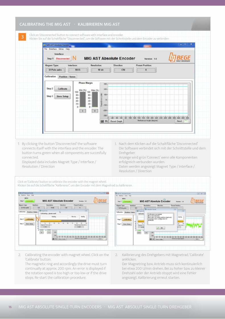
3
1. Nach dem Klicken auf die Schaltfläche ‘Disconnected’ Die Software verbindet sich mit der Schnittstelle und dem Drehgeber. Anzeige wird grün ‘Connect’ wenn alle Komponenten erfolgreich verbunden wurden. Daten werden angezeigt Magnet Type / Interface / Resolution / Direction
CALIBRATING THE MIG AST · KALIBRIEREN MIG AST
1. By clicking the button ‘Disconnected’ the software connects itself with the interface and the encoder. The button turns green when all components are succesfully connected. Displayed data includes Magnet Type / Interface / Resolution / Direction
2. Kalibrierung des Drehgebers mit Magnetrad. ‘Calibrate’ anklicken. Der Magnetring bzw. Antrieb muss sich kontinuierlich bei etwa 200 U/min drehen. Bei zu hoher bzw. zu kleiner Drehzahl oder der Antrieb stoppt wird eine Fehler angezeigt. Kalibrierung erneut starten.
2. Calibrating the encoder with magnet wheel. Click on the ‘Calibrate’ button. The magnetic ring and accordingly the drive must turn continually at approx. 200 rpm. An error is displayed if the rotation speed is too high or too low or if the drive stops. Re-start the calibration procedure.
N
Click on ‘Disconnected’ button to connect software with interface and encoder.Klicken Sie auf die Schaltfläche “Disconnected”, um die Software mit der Schnittstelle und dem Encoder zu verbinden
N
Click on ‘Calibrate’ button to calibrate the encoder with the magnet wheel. Klicken Sie auf die Schaltfläche “Kalibrieren”, um den Encoder mit dem Magnetrad zu kalibrieren.
17MIG AST ABSOLUTE SINGLE-TURN ENCODERS · MIG AST ABSOLUT SINGLE-TURN DREHGEBER
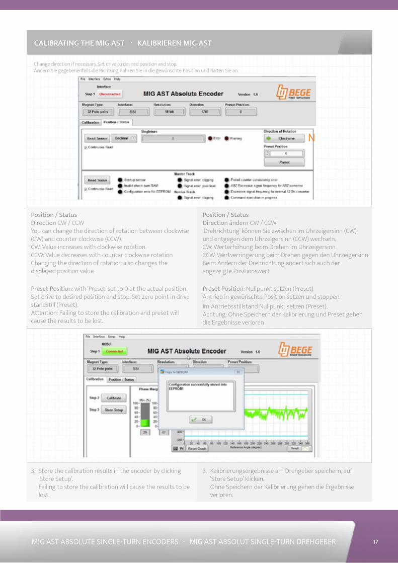
Position / StatusDirection ändern CW / CCW‘Drehrichtung’ können Sie zwischen im Uhrzeigersinn (CW) und entgegen dem Uhrzeigersinn (CCW) wechseln.CW: Werterhöhung beim Drehen im Uhrzeigersinn.CCW: Wertverringerung beim Drehen gegen den UhrzeigersinnBeim Ändern der Drehrichtung ändert sich auch der angezeigte Positionswert
Preset Position: Nullpunkt setzen (Preset)Antrieb in gewünschte Position setzen und stoppen. Im Antriebsstillstand Nullpunkt setzen (Preset).Achtung: Ohne Speichern der Kalibrierung und Preset gehen die Ergebnisse verloren
CALIBRATING THE MIG AST · KALIBRIEREN MIG AST
Position / StatusDirection CW / CCWYou can change the direction of rotation between clockwise (CW) and counter clockwise (CCW).CW: Value increases with clockwise rotation.CCW: Value decreases with counter clockwise rotationChanging the direction of rotation also changes the displayed position value
Preset Position: with ‘Preset’ set to 0 at the actual position.Set drive to desired position and stop. Set zero point in drive standstill (Preset).Attention: Failing to store the calibration and preset will cause the results to be lost.
N
Change direction if necessary. Set drive to desired position and stop. Ändern Sie gegebenenfalls die Richtung. Fahren Sie in die gewünschte Position und halten Sie an.
3. Kalibrierungsergebnisse am Drehgeber speichern, auf ‘Store Setup’ klicken. Ohne Speichern der Kalibrierung gehen die Ergebnisse verloren.
3. Store the calibration results in the encoder by clicking ‘Store Setup’. Failing to store the calibration will cause the results to be lost.
YOUR DRIVE. OUR TRANSMISSION..TOGETHER
WWW.BEGE.NL
BEGE Power Transmission B.V. Anton Philipsweg 302171 KX SassenheimThe Netherlands+31 252-220 [email protected]
Related Documents